Cadence Analog Circuit Tutorial Schematic Entry for Analog Designs- Passive Circuits (RLC Circuit) In this tutorial, we will build the circuit shown in figure 1 below, using the Cadence Composer tool. Note: This example follows the example of University of Minnesota, Duluth. 1. Accessing Cadence Using Exceed Hummingbird Connectivity 9.0 Exceed Exceed XDMCP Broadcast Choose ees2 (129.118.19.10) Type user name and password 2. Invoking the Command Interpreter Window (CIW) Find icfb file. It is located at /cadence/tools/dfII/bin/icfb

Welcome message from author
This document is posted to help you gain knowledge. Please leave a comment to let me know what you think about it! Share it to your friends and learn new things together.
Transcript
Cadence Analog Circuit Tutorial
Schematic Entry for Analog Designs- Passive Circuits (RLC Circuit)In this tutorial, we will build the circuit shown in figure 1 below, using the Cadence Composer tool.
Note: This example follows the example of University of Minnesota, Duluth.
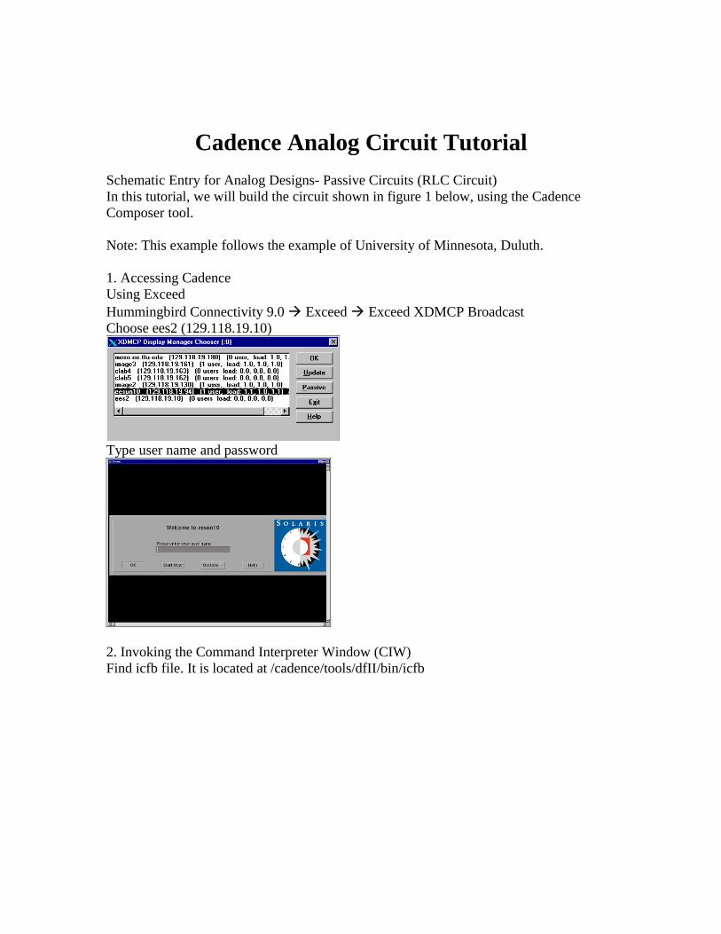
1. Accessing CadenceUsing ExceedHummingbird Connectivity 9.0 Exceed Exceed XDMCP Broadcast Choose ees2 (129.118.19.10)
Type user name and password
2. Invoking the Command Interpreter Window (CIW)Find icfb file. It is located at /cadence/tools/dfII/bin/icfb
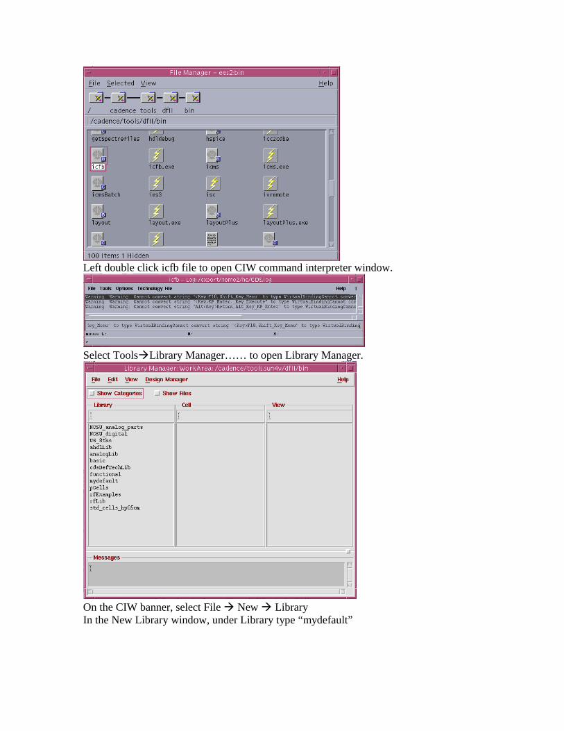
Left double click icfb file to open CIW command interpreter window.
Select ToolsLibrary Manager…… to open Library Manager.
On the CIW banner, select File New LibraryIn the New Library window, under Library type “mydefault”
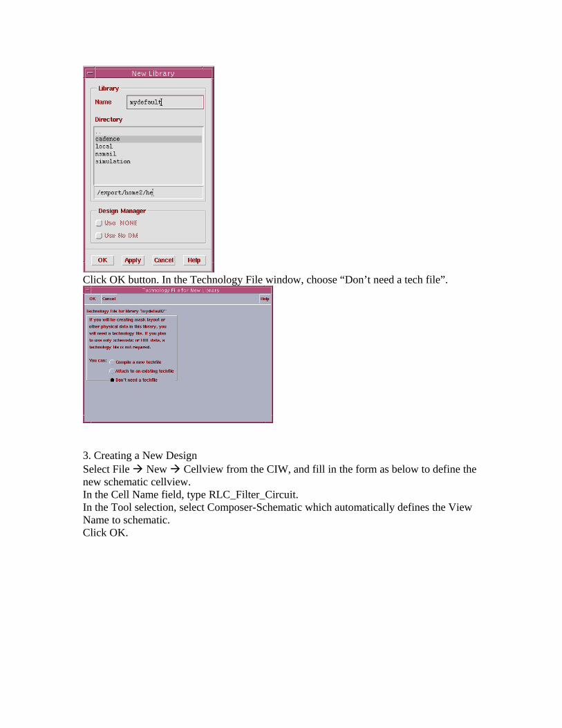
Click OK button. In the Technology File window, choose “Don’t need a tech file”.
3. Creating a New DesignSelect File New Cellview from the CIW, and fill in the form as below to define the new schematic cellview. In the Cell Name field, type RLC_Filter_Circuit. In the Tool selection, select Composer-Schematic which automatically defines the View Name to schematic. Click OK.

An empty Window appears as next figure.
4. Schematic Capture4.1 Placing the IntancesClick on the Instance Icon and then click the Browse button in the form to open Libraries browse window. Select the following: Under the Library column, select analogLib.Under Cell, select res.Under View, select symbol

Edit the Add Instance form by modifying the Resistance value to 22K Ohms, as shown below if Resistance value is not 22K Ohms.
Click in the composer window to place the resistor. Add the other instances symbols from the analoglib as indicated below: C (analoglib, cap) = 47n FL (analoglib, ind) = 500m HR (analoglib, res) = 75 ohm Ground (analoglib, gnd) Click on Cancel.
4.2 Adding the I/O PinsIn the lower left side of the Composer window click on the Pin icon. Add the input and output pins, shown as following.Under Pin Names, type Vin or Vout. Note that Direction in the form reads input or output.
4.3 Connecting WiresClick on the icon Wire (narrow) to connect wires,Click two ends the wire to be connected to connect a wire between these two ends.Wire the components as show below.
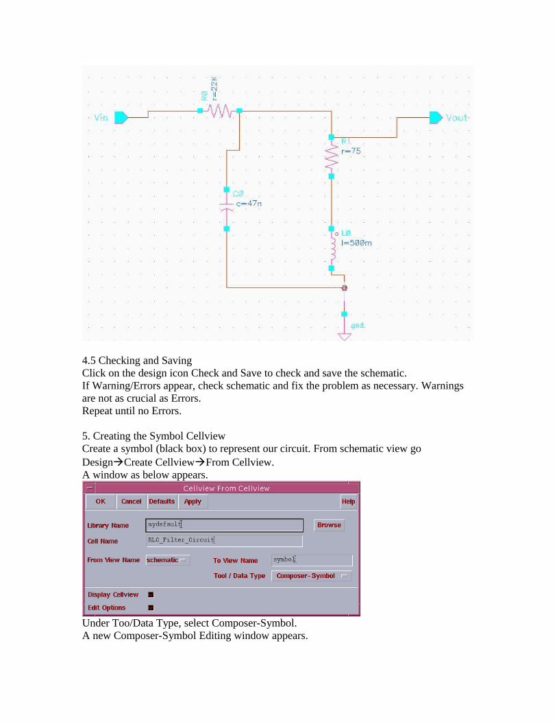
4.5 Checking and SavingClick on the design icon Check and Save to check and save the schematic.If Warning/Errors appear, check schematic and fix the problem as necessary. Warnings are not as crucial as Errors.Repeat until no Errors.
5. Creating the Symbol CellviewCreate a symbol (black box) to represent our circuit. From schematic view go DesignCreate CellviewFrom Cellview.A window as below appears.
Under Too/Data Type, select Composer-Symbol.A new Composer-Symbol Editing window appears.

6. Creating the TestFixture (testbench)Create a new schematic cell using the above circuit symbol as one of its instances. In Cadence CIW, choose: File New Cellview... Creating a new Cell called Test_RLC_Filter_Circuit and fill it as shown below,
Click OK to open a new Composer-Schematic window. Add components according to the following table, and wire those components as figure below.
Table RLC filter test circuit componentsLibrary Name Cell Name View Name Properies/Comments
mydefault RLC_Filter_Circuit Symbol N/AanalogLib Vsin Symbol AC Magnitude=1
Amplitude=50mFrequency=1M
Offset Voltage=0analogLib Cap Symbol Capacitance=1panalogLib Gnd Symbol N/A
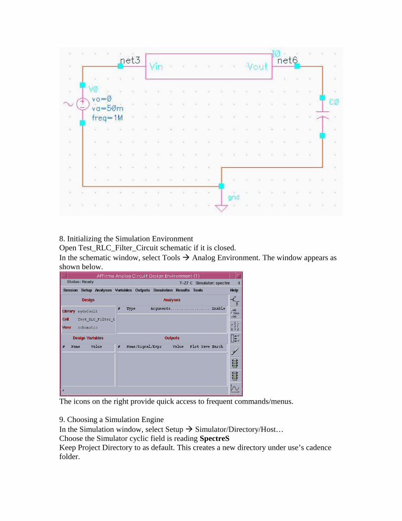
8. Initializing the Simulation EnvironmentOpen Test_RLC_Filter_Circuit schematic if it is closed. In the schematic window, select Tools Analog Environment. The window appears as shown below.
The icons on the right provide quick access to frequent commands/menus.
9. Choosing a Simulation EngineIn the Simulation window, select Setup Simulator/Directory/Host… Choose the Simulator cyclic field is reading SpectreS Keep Project Directory to as default. This creates a new directory under use’s cadence folder.
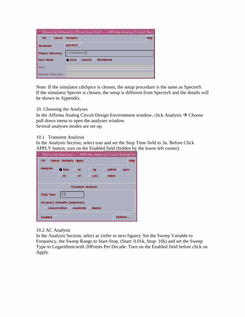
Note: If the simulator cdsSpice is chosen, the setup procedure is the same as SpectreS. If the simulator Spectre is chosen, the setup is different from SpectreS and the details will be shown in Appendix.
10. Choosing the Analyses In the Affirma Analog Circuit Design Environment window, click Analysis Choose pull down menu to open the analyses window. Several analyses modes are set up.
10.1 Transient Analysis In the Analysis Section, select tran and set the Stop Time field to 3u. Before Click APPLY button, turn on the Enabled field (hidden by the lower left corner).
10.2 AC AnalysisIn the Analysis Section, select ac (refer to next figure). Set the Sweep Variable to Frequency, the Sweep Range to Start-Stop, (Start: 0.01k, Stop: 10k) and set the Sweep Type to Logarithmicwith 20Points Per Decade. Turn on the Enabled field before click on Apply.
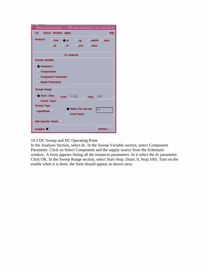
10.3 DC Sweep and DC Operating PointIn the Analysis Section, select dc. In the Sweep Variable section, select Component Parameter. Click on Select Component and the supply source from the Schematic window. A form appears listing all the instances parameters. In it select the dc parameter. Click OK. In the Sweep Range section, select Start-Stop. (Start: 0, Stop:100). Turn on the enable when it is done, the form should appear as shown next.
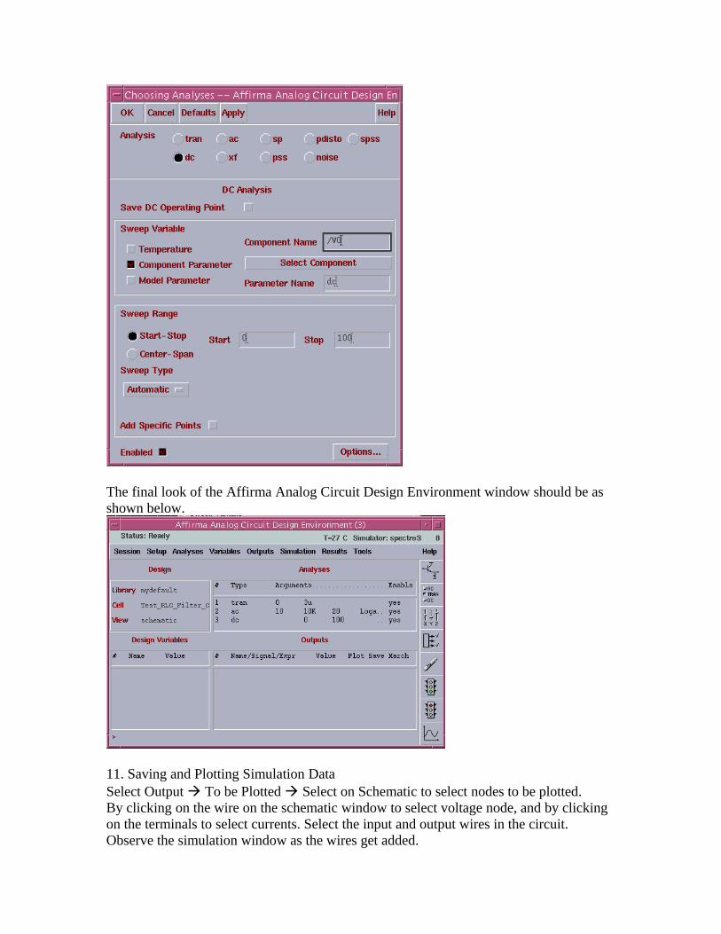
The final look of the Affirma Analog Circuit Design Environment window should be as shown below.
11. Saving and Plotting Simulation DataSelect Output To be Plotted Select on Schematic to select nodes to be plotted.By clicking on the wire on the schematic window to select voltage node, and by clicking on the terminals to select currents. Select the input and output wires in the circuit. Observe the simulation window as the wires get added.

12. Running the Simulation – The Waveform WindowClick on the Run Simulation icon. When it complete, the plots are shown automatically.We’ll next modify the appearance of the displayed waveforms as following figure.
13. Exiting Close every window.Right click desktop, a menu pops up as next. Then click log out to exit.

AppendixSimulation using Spectre
1. Choosing the SimulatorAfter reaching the step 9 in the tutorial you have to choose a simulator for
simulating the circuit. In the tutorial we showed the set up for SpectreS simulator. If you want to use Spectre instead of SpectreS select Spectre in the command window as shown below.
Test Circuit for Simulation with Spectre
Choosing Spectre as the Simulator
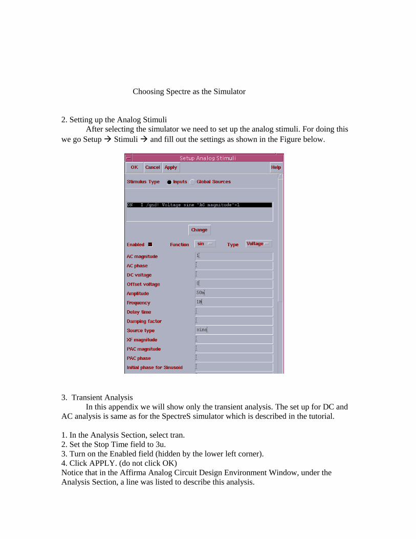
2. Setting up the Analog StimuliAfter selecting the simulator we need to set up the analog stimuli. For doing this
we go Setup Stimuli and fill out the settings as shown in the Figure below.
3. Transient Analysis In this appendix we will show only the transient analysis. The set up for DC and
AC analysis is same as for the SpectreS simulator which is described in the tutorial.
1. In the Analysis Section, select tran. 2. Set the Stop Time field to 3u. 3. Turn on the Enabled field (hidden by the lower left corner). 4. Click APPLY. (do not click OK) Notice that in the Affirma Analog Circuit Design Environment Window, under the Analysis Section, a line was listed to describe this analysis.

4. Saving and Plotting Simulation DataThe simulation environment is configured to save all node voltages in the design
by default. You can modify the default to save all terminal currents also, or you can select specific set of nodes to save. We’ll select these nodes from the schematic window.Select Output To be Plotted Select on Schematic.Node voltages can be selected by clicking on the wire on the schematic window, and currents by clicking on the terminals. Unselecting can be performed either by clicking on the terminal/node again, or by selecting the corresponding line in the Outputs section of the Simulation window and clicking on the Delete icon. Select the input and output wires to the circuit. Observe the simulation window as the wires get added.
The final look of Affirma Analog Simulator is shown below
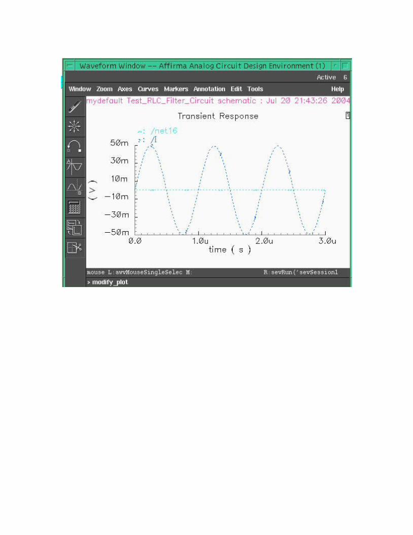
5. Running the Simulation To run the simulation click SimlationRun. The following graph will be plotted.

Reference
1) Shaer, Bassam, University of Minnesota, Duluth http://www.d.umn.edu/~bshaer/cadence/AnalogTutorials/Passive_Circuit_Cadence_Tutorial.htm
Related Documents