CAD-CAE Integration Yogesh Kulkarni Software Development Manager, Autodesk, Pune, India

CAD-CAE Integration Yogesh Kulkarni Software Development Manager, Autodesk, Pune, India.
Dec 16, 2015
Welcome message from author
This document is posted to help you gain knowledge. Please leave a comment to let me know what you think about it! Share it to your friends and learn new things together.
Transcript

CAD-CAE Integration
Yogesh Kulkarni
Software Development Manager, Autodesk, Pune, India
Speaker’s Bio-data
• Currently, Software Development Manager at Autodesk, Pune, India
• Before Autodesk, worked in companies like PTC, SDRC, UGS, with total CAD software development experience of about 14-15 years.
• Bachelors and Master’s degree in Mechanical Engineering.

Agenda
• Introduction• CAD-CAE interop• Idealization/Model Simplification• Can features help?• Feature info export and issues• References/Videos

Introduction• CAD: Computer Aided Design• CAE: Computer Aided Engineering (FEA : Finite Element Analysis)• CAD->CAE happens “over the wall”.
– Once CAD design is done, designer passes model “over the wall” to CAE analyst.
– After reviewing results, Analyst may suggest design changes.
– Model is sent back again “over the wall”.– This process may happen multiple times (iterative)

Typical Workflow


Model Pre-Processing
• Healing • Tweaking Geometry • Removing Geometric Features • Regularizing Geometry • Finding Surface Overlap • Validating Geometry • Dimension Reduction
CAD-CAE Interop – Its different !!
• CAD-CAD interop between system aims at preserving Geometry-Topology-Intent as intact as possible.
• Whereas, CAD to CAE interop:– Can Involve change in dimension of entities– Will Usually Employ Differing Amounts of Detail– Most Often Requires Idealization (using Engineer’s
Judgment)
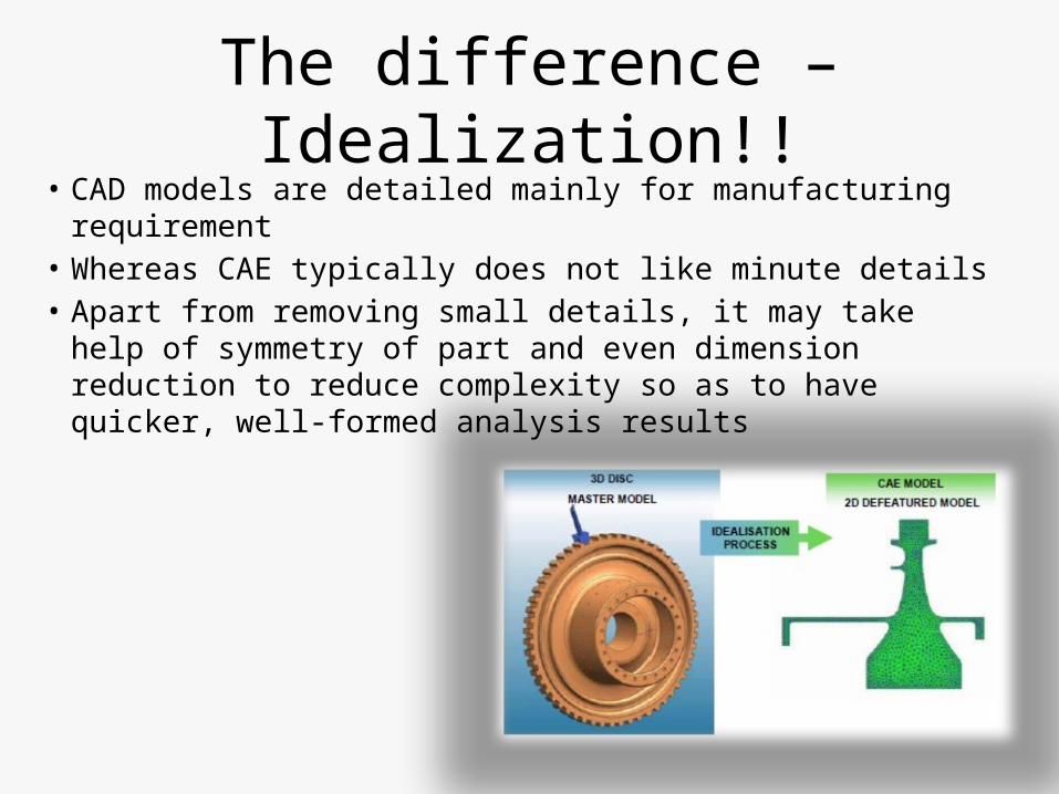
The difference – Idealization!!• CAD models are detailed mainly for manufacturing
requirement• Whereas CAE typically does not like minute details• Apart from removing small details, it may take help of
symmetry of part and even dimension reduction to reduce complexity so as to have quicker, well-formed analysis results

CAD centric or CAE centric
• In the CAD-centric process, the design is done in CAD system and then in an iterative design process, where design changes and analysis is repeatedly performed, is used to improve or refine the design.
• In the CAE-centric process, engineering analyses are performed initially to define and refine a design concept using idealized analysis models before establishing the CAD product model.
• Model Simplification discussed in this presentation is of CAD-Centric approach.
Idealization in CAD model• To safeguard proprietary knowledge many CAD
modelers do not expose feature information. • Also, data capture methods like laser scanning,
neutral data translators give CAD models which do not have feature information.
• Idealization on such ‘dumb’ CAD models is classified into two types:– Tessellated : faceted geometry, typically triangles,
generated from point cloud data– Exact: either Boundary Representation [B-rep] or
Constructive Solid Geometry [CSG]
CAD model idealization approaches
• Surfaces : low pass filtering, face cluster based simplification and size based entity decimation.
• Volumes : voxel based and effective volume based techniques. It is advantageous for multi-resolution modeling and capable of LOD (Level of Details) simplification of features
• Dimension Reduction: Medial axis, Mid-surface generation, Skeletal shape

Surfaces : Low Pass Filtering
• Electrical signals often carry noises which are equivalent to the small features we wish to remove.
• Noises are smoothed out by discarding the extra frequency terms after representing the signal by sinusoidal functions
• Challenge is to define Shape as function which is combination of Sinusoidal Functions.
• Each vertex location is changed to the weighted average of neighboring vertex locations. Averaging has the effect of low-pass filtering

Face Clusters
• Clusters(groups) are regions of interest• Faces are grouped based on certain geometric
properties, say, distance or angles.• Based on Error criterion, Face groups are
further grouped by collapsing edges in between.

Size based
• Works typically on cellular topology. Shapes have explicit volumetric representation called cells.
• Edges in cells are ranked by geometric error introduced if they are removed. Edges are then contracted starting with lowest cost.
• Volumes below certain threshold are suppressed.

Voxel based
• Octree is generated.• Shape is divided into cubes which are further
classified into Inside (Black),Outside (White), Border (Grey). Greys are further divided up to a set level.
• Surface is passed through Grey nodes.

Dimension Reduction• Reducing the dimensions of CAD models is also
beneficial in some application areas. • For example, if long slender round bar is modeled as a
1D beam , there is negligible effect on the accuracy of the analysis but the computational time will reduce dramatically.
• Techniques are:– volume-based, where the input is iteratively thinned until a
final skeleton is derived. – Boundary based, boundaries are extracted and skeletons
are generated directly from the boundary data.

1D Lines, Curves
2D Surfaces
3D Volumes
Beams, TrussesAxisymmetric Shells
Plates & Shells
3D Solid Elasticity
Creating Engineering Analysis Models
Idealized Type Element Type
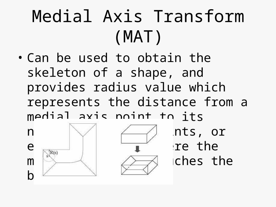
Medial Axis Transform (MAT)
• Can be used to obtain the skeleton of a shape, and provides radius value which represents the distance from a medial axis point to its nearest boundary points, or equivalently, to where the medial axis ball touches the boundary.
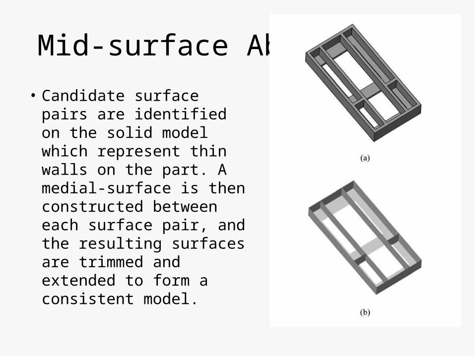
Mid-surface Abstraction
• Candidate surface pairs are identified on the solid model which represent thin walls on the part. A medial-surface is then constructed between each surface pair, and the resulting surfaces are trimmed and extended to form a consistent model.
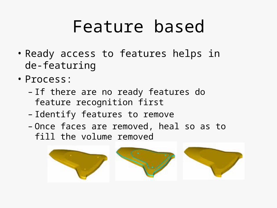
Feature based• Ready access to features helps in de-featuring• Process:
– If there are no ready features do feature recognition first
– Identify features to remove– Once faces are removed, heal so as to fill the
volume removed

What is feature?
• “Features are defined as geometric and topological patterns of interest in a part model and which represent high level entities useful in part analysis.” – Henderson, 1990
• Examples:– functional feature: for example, a pivot,– design feature: Extrude, revolve– manufacturing feature: a turned cylinder, a milled slot– application specific feature: these could be any combination
of topological, geometric, metric, color and texture attributes or non-visual features
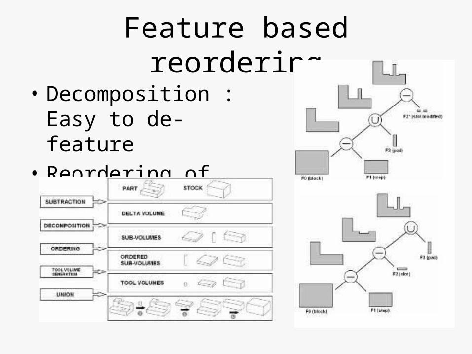
Feature based reordering
• Decomposition : Easy to de-feature
• Reordering of Features

Summary of Simplification techniques

Problems in adopting feature based approach
• Most of CAD-CAE integrations are without design intent i.e. features.
• Features are typically not fully exported by CAD software to protect intellectual property captured in design intent.
• But, there ARE ways in which feature information can be transferred…

Need ready feature info
• Designer intent is captured in CAD data model mainly in form of features. Better integration with downstream applications is possible if this intent gets translated as much as possible, but that's not the typical case.
• To correct the loss of feature data, wherever available, Feature Recognition (FR) is carried out.
• FR is a difficult problem and even with heuristic algorithms, its far from being useful on complex models.

Direct Modelers
• Off-late some Direct Modelers like Space-claim, Autodesk Fusion do provide edit-ability to model even though feature tree did not get exchanged.
• These, typically, do not do true feature-editing-update operations but just minor modifications/tweaking , giving a feel of feature editing.

Feature Export
• Neutral File formats supporting features : say, STEP. Need to mold your feature info into neutral format which may not be possible.
• API : Using programming. Limited by what has been exposed by APIs.
• Macros: Log files sometimes do reveal feature recipes but again to a level they have been allowed to expose.

STEP
• International Organization for Standardization (ISO) Technical Committee 184 has been working to cover parameterization of models, geometrical constraints commonly used into product shape modeling.
• This can transfer parametric information and constraints in 2D sketches only.
• Construction history of the shape configurations generated by extruding or revolving 2D sketches can only be transferred.

Application Programming Interfaces (APIs)
• Some modelers provide APIs to customize their application as well as building 3rd party sofwtare on top.
• These APIs can be used as neutral-command-map

Macro Parametric approach
• A macro file that records modeling command sequence is exchanged.
• Even if some CAD modelers do log operations, they may not be revealing enough to reconstruct model exactly.

Dual Model approach
• The primary model defines the construction history. It has an associated secondary model of the B-rep type.
• The secondary model can be used in the receiving system to check the validity of model transfer.
• The model is reconstructed in receiving system by transferring primary model.
Neutral Commands, XML approach
• To transfer parametric information including design history, a set of standard commands is defined and used as a neutral format.
• Neutral format can be extensible mark up language (XML) technology to express a set of standard modeling commands extracted from a CAD model.
• This approach transfers model history, however it can transfer design history based only on limited set of modeling commands.

Problems : Persistent naming• In Feature based modeling system, feature is defined
referring to entities (faces, edges, vertices) in the explicit (B-rep) geometry. Each feature, however, introduces a modification in the model which is regenerated when a feature is added to the tree.
• In many cases the entities that have been used to dene a feature may be split-ed or deleted by the feature itself or by subsequent features. For this reason references to entities used during the design process can be re-evaluated in an erroneous way, resulting in unexpected results.

What are others doing?• Ansys supports bidirectional connections with the CAD environments like
CATIA V5, Siemens NX etc. The associative capabilities of these geometry interfaces allow users to change a model’s geometry without having to reapply loads. Not sure if full or localized re-meshing happens as well as about Model Simplification.
• Automatic associative import allows to transfer models from a Catia V5 session to an Abaqus/CAE session. Any features you create in Abaqus, such as partitions, loads, boundary conditions, sets and surfaces, are regenerated each time you import the modified Catia model into Abaqus.
• Autodesk Project Centaur: Uses Inventor parameter table driven optimization in cloud to come up with best solution. Not sure if it does optimized re-meshing and model simplification.

References:
• “Closing the CAD/CAE gap” – Scientific Computing• “Software offers full associativity with Design changes”• An Analyst’s View : STEP-Enabled CAD-CAE Integration• "A Survey of CAD Model Simplification Techniques for Physics-based
Simulation Applications", Atul Thakur, Ashis Gopal Banerjee, and Satyandra K. Gupta
• An approach to B-rep model simplification based on region suppression
• “Geometry Simplification”, Carlos Andujar• "Medial Object Extraction - A State of the Art"; Yogesh Kulkarni, Dr. Sh
ailesh Deshpande• “Bridging the Gap Between CAD and CAE”; David A. Selliman, James
Ackron,• “Feature-based Techniques for Handling Geometric Models”, Dinesh
Shikhare• Exchange of CAD Part Models Based on the Macro-Parametric Appro
ach, Choi et al.

Related Documents