San Jose State University San Jose State University SJSU ScholarWorks SJSU ScholarWorks Master's Projects Master's Theses and Graduate Research Fall 2017 CACHE MANAGEMENT SCHEMES FOR USER EQUIPMENT CACHE MANAGEMENT SCHEMES FOR USER EQUIPMENT CONTEXTS IN 5TH GENERATION CLOUD RADIO ACCESS CONTEXTS IN 5TH GENERATION CLOUD RADIO ACCESS NETWORKS NETWORKS Gurpreet Kaur San Jose State University Follow this and additional works at: https://scholarworks.sjsu.edu/etd_projects Part of the Computer Sciences Commons Recommended Citation Recommended Citation Kaur, Gurpreet, "CACHE MANAGEMENT SCHEMES FOR USER EQUIPMENT CONTEXTS IN 5TH GENERATION CLOUD RADIO ACCESS NETWORKS" (2017). Master's Projects. 563. DOI: https://doi.org/10.31979/etd.vbfn-d72u https://scholarworks.sjsu.edu/etd_projects/563 This Master's Project is brought to you for free and open access by the Master's Theses and Graduate Research at SJSU ScholarWorks. It has been accepted for inclusion in Master's Projects by an authorized administrator of SJSU ScholarWorks. For more information, please contact [email protected].

Welcome message from author
This document is posted to help you gain knowledge. Please leave a comment to let me know what you think about it! Share it to your friends and learn new things together.
Transcript
San Jose State University San Jose State University
SJSU ScholarWorks SJSU ScholarWorks
Master's Projects Master's Theses and Graduate Research
Fall 2017
CACHE MANAGEMENT SCHEMES FOR USER EQUIPMENT CACHE MANAGEMENT SCHEMES FOR USER EQUIPMENT
CONTEXTS IN 5TH GENERATION CLOUD RADIO ACCESS CONTEXTS IN 5TH GENERATION CLOUD RADIO ACCESS
NETWORKS NETWORKS
Gurpreet Kaur San Jose State University
Follow this and additional works at: https://scholarworks.sjsu.edu/etd_projects
Part of the Computer Sciences Commons
Recommended Citation Recommended Citation Kaur, Gurpreet, "CACHE MANAGEMENT SCHEMES FOR USER EQUIPMENT CONTEXTS IN 5TH GENERATION CLOUD RADIO ACCESS NETWORKS" (2017). Master's Projects. 563. DOI: https://doi.org/10.31979/etd.vbfn-d72u https://scholarworks.sjsu.edu/etd_projects/563
This Master's Project is brought to you for free and open access by the Master's Theses and Graduate Research at SJSU ScholarWorks. It has been accepted for inclusion in Master's Projects by an authorized administrator of SJSU ScholarWorks. For more information, please contact [email protected].
CACHE MANAGEMENT SCHEMES FOR USER EQUIPMENT CONTEXTS
IN 5TH GENERATION CLOUD RADIO ACCESS NETWORKS
A Writing Project
Presented to
The Faculty of the Department of Computer Science
San Jose State University
In Partial Fulfillment
Of the Requirements for the Degree
Master of Science in Computer Science
By
Gurpreet Kaur
December 2017

ii
© 2017
Gurpreet Kaur
iii
ALL RIGHTS RESERVED
The Designated Project Committee Approves the Project Titled
CACHE MANAGEMENT SCHEMES FOR USER EQUIPMENT CONTEXTS IN 5th GENERATION CLOUD RADIO ACCESS NETWORKS
By
Gurpreet Kaur
APPROVED FOR THE DEPARTMENT OF COMPUTER SCIENCE
SAN JOSE STATE UNIVERSITY
DECEMBER 2017
Dr. Melody Moh Department of Computer Science
Dr. Thomas Austin Department of Computer Science
Dr. Robert Chun Department of Computer Science

iv
ABSTRACT
By Gurpreet Kaur
Advances in cellular network technology continue to develop to address
increasing demands from the growing number of devices resulting from the Internet of
Things, or IoT. IoT has brought forth countless new equipment competing for service on
cellular networks. The latest in cellular technology is 5th Generation Cloud Radio Access
Networks, or 5G C-RAN, which consists of an architectural design created specifically to
meet novel and necessary requirements for better performance, reduced latency of
service, and scalability. As part of this design is the inclusion of a virtual cache, there is a
necessity for useful cache management schemes and protocols, which ultimately will
provide users better performance on the cellular network. This paper explores a few
different cache management schemes, and analyzes their performance in comparison to
each other. They include a probability based scoring scheme for cache elements; a
hierarchical, or tiered, approach aimed at separating the cache into different levels or
sections; and enhancements to previously existing approaches including reverse random
marking as well as a scheme based on an exponential decay model. These schemes aim to
offer better hit ratios, reduced latency of request service, preferential treatment based on
users’ service levels and mobility, and a reduction in network traffic compared to other
traditional and classic caching mechanisms.

v
TABLE OF CONTENTS
LIST OF TABLES vii
LIST OF FIGURES viii
LIST OF ACRONYMS x
1. INTRODUCTION 1
2. BACKGROUND 3
2.1. Evolution of Cellular Network Technologies 3
2.2. 5G C-RAN 5
2.3. Cache Management 9
3. RELATED WORK 11
4. CACHE MANAGEMENT SCHEMES 14
4.1. Probability-Based Popularity Scoring 16
4.2. PBPS with Hierarchy 19
4.3. Reverse Random Marking 22
4.4. Reverse Random Marking with PBPS 23
4.5. EXD-AHP 26
4.6. Baseline Comparisons 30
5. PERFORMANCE EVALUATION 32
5.1. Hit Rates 36
5.2. Miss Rates 40
5.3. Latency 42
5.4. Cloud Writes 46
vi
5.5. Network Traffic 49
6. CONCLUSION 54
7. REFERENCES 56
vii
LIST OF TABLES
Table 1. Example Analytical Hierarchical Process Matrix with Weights 28
Table 2. Simulated Algorithms 32
Table 3. Simulation Parameters and Values 33

viii
LIST OF FIGURES
Figure 1. Traditional Distributed RAN 6
Figure 2. Cloud-RAN 8
Figure 3. Cache Management Flowchart 14
Figure 4. Visual Example of Tiered Cache 21
Figure 5. Hit Rates with Cache Size 1250 MB 37
Figure 6. Hit Rates with Cache Size 2500 MB 37
Figure 7. Hit Rates with Cache Size 3750 MB 38
Figure 8. Hit Rates with Cache Size 5000 MB 39
Figure 9. Miss Rates with Cache Size 1250 MB 40
Figure 10. Miss Rates with Cache Size 2500 MB 41
Figure 11. Miss Rates with Cache Size 3750 MB 41
Figure 12. Miss Rates with Cache Size 5000 MB 42
Figure 13. Average Latency with Cache Size 1250 MB 43
Figure 14. Average Latency with Cache Size 2500 MB 44
Figure 15. Average Latency with Cache Size 3750 MB 45
Figure 16. Average Latency with Cache Size 5000 MB 45
Figure 17. Average Number of Cloud Writes with Cache Size 1250 MB 47
Figure 18. Average Number of Cloud Writes with Cache Size 2500 MB 47
Figure 19. Average Number of Cloud Writes with Cache Size 3750 MB 48
Figure 20. Average Number of Cloud Writes with Cache Size 5000 MB 49
Figure 21. Network Traffic with Cache Size 1250 MB 50
ix
Figure 22. Network Traffic with Cache Size 1250 MB 51
Figure 23. Network Traffic with Cache Size 1250 MB 51
Figure 24. Network Traffic with Cache Size 1250 MB 52

x
LIST OF ACRONYMS
BBU – Broadband Base Unit
CDMA – Code Division Multiple Access
C-RAN – Cloud Radio Access Network
EDGE – Enhanced Data Rates for Global System for Mobile Communication Evolution
EPC – Evolved Packet Core
EXD-AHP – Exponential Decay with Analytical Hierarchical Process
GPRS – General Packet Radio Service
HO – Handover
IoT – Internet of Things
IP – Internet Protocol
LFU – Least Frequently Used
LTE – Long Term Evolution
LTE-A – Long Term Evolution Advanced
MME – Mobility Management Entity
OFDMA – Orthogonal Frequency Division Multiple Access
PBPS – Probability-Based Popularity Scoring
PCRF – Policy and Charging Rules Function
PGW – Packet Data Network Gateway
RAN – Radio Access Network
RRH – Remote Radio Head
RRM – Reverse Random Marking
xi
SGW – Serving Gateway
TDMA – Time Division Multiple Access
VM – Virtual Machine
VoIP – Voice Over Internet Protocol
1
1. INTRODUCTION
Cellular networking technology has been advancing at impressive rates since its
emergence in the technological market. With the onset of new devices, cellular networks
have had to keep up with a growing demand for connectivity. This explosion of activity is
evident by the Internet of Things, or IoT. IoT consists of more recently emerging devices
that are not classic computers, including “smart” devices such as, for example, phones,
interactive watches, televisions, and even household appliances such as thermostats.
Technologies needing an Internet connection have even been projected to reach a
staggering fifty billion devices within the next few years. IoT applications can, and will
be, seen in developing areas such as smart grids, health services, homes, and even cities.
IoT has had an incredible opportunity to flourish due to advances in physical sensors that
can detect temperature and moisture, an increase in energy efficiency with better batteries,
improvements in chip architecture resulting in smaller processing units, and also the
adaptation of cloud computing. However, technological research is not the only thing
aiding its growth. IoT is also expanding due to it being a lucrative field for business and
consumerism.
With countless new equipment needing Internet access and constant connectivity,
cellular networks have also advanced to be able to offer successful communication, speed
of services, and scalability. The use of data centers has tremendously aided the future of
cellular networks. Cloud data centers have allowed for the consolidation of computing
resources on a massive scale, resulting in better utilization of both hardware and software

2
resources as well as being able to enjoy the advantages of centralization, including
virtualization, cost cutting, and uniform maintenance.
Since an important aspect of cellular networks is not just the support of massive
numbers of users and devices, but also acceptable speeds of service, newer cellular
architectures have included the presence of a cache [5]. Naturally, the cache must be
efficiently maintained in order to make the best use of limited and available resources and
offer users the quality of service they were promised.
This paper is organized as follows: The next section goes into brief detail about
how cellular network services and architectures have evolved over time, as well as discuss
the specifics about 5G C-RAN and the significance of cache management. Section III will
cover related works on the topic of caching, followed by Section IV, which will dive into
various cache management schemes and mechanisms. Section V will consist of a
performance evaluation of those aforementioned schemes based on simulated data and
results, and is followed by the conclusion in Section VI.
3
2. BACKGROUND
2.1 Evolution of Cellular Network Technologies
Cellular networks have grown and developed impressively since the invention of
the first mobile phone, Motorola’s famous DynaTac 8000X. As generations progressed,
users were provided with all manner of advances and service improvements. Over time,
cellular networks attained capabilities for not just supporting mobile phones, but for
millions of additional devices.
1G introduced people to a new way of communication. Unlike ever before, users
who could afford the early cellular phones could make calls while on the move. The
architecture of these first generation networks was the simplest that would be seen, and
telecommunication itself was analog based. Base stations would provide the subscribers,
who were the customers of the cellular network, access to communication. The standards
were based on the Advanced Mobile Phone System (AMPS), which was developed by
Bell Labs in the 1980s. This technology utilized separate channels for each call that
needed to be made, and therefore made use of Frequency Division Multiple Access
(FDMA) [10]. Cells that were directly neighboring each other would operate on different
frequencies in order to avoid any interference. The first generation of cellular networks
was certainly a breakthrough, but had its fair share of limitations as well, including limited
scalability due to an individual channel only being able to support a single user at any
given particular time. In addition, analog transmissions used for voice communication
were not ideally efficient in using the available frequency spectrum.

4
The next generation, 2G, introduced digital communication standards, replacing
and upgrading the old analog signals and allowing for digital voice, which consisted of
smaller packages that were compressed, as well as its encryption. Unlike in 1G, this
second generation started to also offer data to its customers, in the form of SMS messages,
also known as texting. 2G technologies made use of Time Division Multiple Access [10].
The second generation was ultimately able to make better use of the available spectrum as
it allowed support for more than one user over a single channel. 2G evolved into 2.5G and
2.75G, which respectively incorporated General Packet Radio Service (GPRS), which
allowed for packet switching, and Enhanced Data Rates for GSM Evolution (EDGE),
which allowed for better rates for transmitting data.
The third generation of telecommunication technology offered voice just as the
previous generations had, but now offered high-speed data as well. Transfer rates were
found to be between roughly 384 Kbps and 2 Mbps, and were considered a substantial
improvement. Code Division Multiple Access (CDMA) was used for multiplexing in 3G,
which helped utilize the available signal spectrum to a much greater degree than seen
before [10]. The third generation evolved to offer continuing higher speeds of data transfer
rates in 3.5G, and also later was able to offer Voice Over IP (VoIP) as well as utilize
Orthogonal Frequency Division Multiple Access as part of 3.9G. The 3.9G technology
also brought forth Long Term Evolution (LTE), which is a high speed standard specific to
wireless telecommunications.
More recently, 4G has been offering data at very high speeds, ranging from 100
Mbps to as much as 1 Gbps. 4G offers increases in stability and speed, and has made
5
enhancements to techniques using multiple antennas for communications. Channels were
made wider with the user of OFDMA, and the core network has been more simplified and
the architecture flattened [10]. Flat network architecture allows for the use of less
equipment, therefore preserving resources. As an improvement to the prior generation, 4G
offers Long Term Evolution Advanced (LTE-A). Compared to previous generations of
cellular network technology, this fourth generation has offered a greater amount of data
capacity to accommodate the growing number of devices craving Internet access.
Furthermore, LTE-A is more stable than just LTE in terms of signal and data transfer.
Though strives have been made thus far with cellular networks, the ever increasing
need for Internet access and that too at great speeds, in addition to the growth of the
numbers of mobile devices, is what is fueling further improvements in this field.
Furthermore, there are still many challenges, obstacles, and aspects in cellular networks
that need to be addressed or can be enhanced [5]. As a result, the fifth generation of
cellular networks is actively being researched, hoping to provide even better service yet.
2.2 5G C-RAN
The fifth and newest generation ultimately aims to make substantial improvements
over existing technologies. 5G will ideally have a peak data rate between 10 to 20 Gbps,
the former being always offered to mobile devices and the latter under some very specific
conditions set by the cellular providers. Latency of communication, in sending and
receiving, should be decreased. 5G should offer connections to greater numbers of devices
6
than previous generations, and should also have better handles on efficiency, including
that of both energy consumption and spectral usage. In order to address these areas and
make a number of these improvements, a more centralized architecture has been proposed
for 5G, known as the Cloud Radio Access Network, or C-RAN [10, 18].
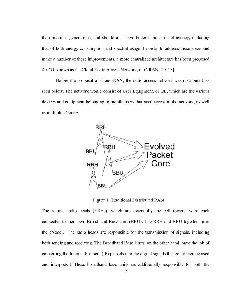
Before the proposal of Cloud-RAN, the radio access network was distributed, as
seen below. The network would consist of User Equipment, or UE, which are the various
devices and equipment belonging to mobile users that need access to the network, as well
as multiple eNodeB.
Figure 1. Traditional Distributed RAN
The remote radio heads (RRHs), which are essentially the cell towers, were each
connected to their own Broadband Base Unit (BBU). The RRH and BBU together form
the eNodeB. The radio heads are responsible for the transmission of signals, including
both sending and receiving. The Broadband Base Units, on the other hand, have the job of
converting the Internet Protocol (IP) packets into the digital signals that could then be used
and interpreted. These broadband base units are additionally responsible for both the
7
management and maintenance of the mobility of different users and their corresponding
promised quality of services. The 5G and LTE-A architecture includes both the distributed
Radio Access Network and its subsequent connection to the Evolved Packet Core (EPC).
The EPC contains the fundamental framework for the network and how it operates, and
includes a variety of components. Some of the main components are described briefly in
the following. For instance, the Mobility Management Entity (MME) functions as the
main node that is responsible for signaling. The MME plays an important role in the
authentication of individual user devices on the network. Specifically, it tracks the user’s
location and will ultimately decide which gateway to access when a user registers with the
network. Another component, called the Serving Gateway (SGW), takes instructions from
the Mobility Management Entity on how to begin and end sessions with individual User
Equipment. In addition, it aids in signaling between the MME and PGW. The Packet Data
Network Gateway (PGW) can inspect and filter packets from users, in addition to the
enforcement of data rates. Another element in the Evolved Packet Core is the Policy and
Charging Rules Function (PCRF), which is responsible for managing and upholding the
service rules. The PCRF can make decisions with user requests based on currently set
policies, and is an important component in providing different Quality of Service (QoS)
levels in the cellular network [10, 18].
In order to address some of the previously mentioned challenges present in 5th
generation cellular networks, a different type of architecture was proposed, which is
Cloud-RAN, seen as follows [5, 18].

8
Figure 2. Cloud-RAN
There are some important and notable differences with this enhanced architecture. Firstly,
C-RAN involves the radio heads being connected to a cloud data center. In the data center,
the Broadband Base Units are pooled together. This pooling allows for a sharing of
resources and provides the potential for better management of available resources, as
centralization provides better control. In addition, the data center will consist of hosts, on
which are running Virtual Machines (VMs). It is in these machines that the virtual base
units are present. The virtualization of resources also aids in flexible programmability as
well as lowered operational and maintenance costs compared to those of hardware
resources [4]. Furthermore, the Cloud-RAN architecture is much better suited for
scalability in the long run compared to its previous distributed counterpart. Lastly, the
Cloud-RAN architecture is much better equipped to deal with handovers (HO). Handovers
are basically when users are moving physically and need to connect or disconnect from
the current tower and base unit and subsequently connect to a new radio head. There is a
certain extent of the latency and performance compromises when this handover needs to
occur in the previously distributed RAN architecture. After all, there is physical distance
9
between the towers. Fortunately, in the cloud model, the Broadband Base Units are all
pooled together and resources are shared. This way, handovers are handled in the same
cloud data center, reducing the chance of users being dropped or going momentarily
without service, and potentially reducing the time it takes to achieve connectivity when
being mobile.
Next, it is important to understand the role of users in the network, and how the
network is able to handle so many mobile devices at a time. Each user’s device has a User
Equipment Context (UEC). The UEC is what enables the unique identification of, for
example, a particular phone or tablet. Each UEC will have an ID number to recognize its
distinction from every other device. This context will also hold pertinent information
about a user’s session, and will have a record of what kind of subscription this user’s
device has as well as maintain the state of the device in relation to the session at the
moment. A copy of all the UECs will be present in the physical storage of the cloud, but
there must be a mechanism to provide quicker access to them. Because the information
contained in the UEC must be present and up to date for all active users, and going to and
from cloud storage takes extra time, a number of the UECs are also going to be stored in
the virtual broadband base units as part of a cache.
2.3 Cache Management
Caching has been a useful tool in many applications and technologies, the latest of
which is cellular networks. Since 5G aims to offer faster service than previous cellular
10
generations, the use of a cache becomes altogether beneficial. Storing some number of
User Equipment Contexts in the cache will allow them to be quickly accessed when
needed, quickly read to obtain information, and quickly written to update the context. The
delay that occurs in the cellular service will also be reduced, since caching will help
prevent trips over the data center network to go back and forth from the physical storage
in the cloud data center [4, 18].
Naturally, the management of cache resources becomes a very important aspect
for the architecture of 5G C-RAN. Cache is a limited resource, so it must be used
optimally. As a result, particular cache management schemes must be created in order to
keep hit rates high, and subsequently miss rates, cloud write rates and latency low. These
traits help define and implement the better service promises of 5G C-RAN. The following
section will discuss related work in the context of fifth generation cellular networks,
followed by a section explaining proposed, and enhancements of, caching schemes.
11
3. RELATED WORK
Much research is constantly being done in handling a cache and improving its
performance. For instance, Wang and Li [14] discussed ways of making cache both
temporally and spatially aware by improving the organization of the cache design. Their
design consisted of having two dynamically adjusting regions of cache, known as prefetch
and victim regions. The purpose of the prefetch region is to take advantage of spatial
locality by analyzing addresses, and the victim region would catch any elements evicted
from higher in the memory stack. They combined these ideas with routing that was aware
of bursts in the network, and were able to reduce the misses by up to a quarter. Their study
brought to attention for this research the importance of having caching schemes that can
adapt to changing workloads.
In another study, Ye et al. [16] aimed to ameliorate the performance of Solid State
Drives (SSDs) by using a caching algorithm that would analyze the popularity of entire
disk blocks and determine whether or not to replace an entire block. This scheme was able
to reduce the number of times blocks were replaced, and could help in prolonging the
longevity of the SSDs themselves. Relatedly, another study by Baek, Cho and Choi [2]
involved caching for SSDs using probability models, specifically a geometric probability
model, to determine which elements to place in the cache and which ones to evict. This
study explained that good caching schemes do not have to be overly complex or
computationally heavy, and can be based on simple mathematical models, as well as be
optimized based on workload and either system or architecture specific parameters. Both
12
these studies motivated this research by showcasing the usefulness of having a system to
compare caching elements that looks beyond just primitive counters.
Floratou et al. [6] performed research for caching in the context of databases,
specifically those of Big SQL and the Hadoop Distributed File System (HDFS). Elements
in the cache would be given a score, which would be determined by some model, such as
exponential decay, or simply assigned based on the number of accesses an element
receives. The latter would be similar to caching done using the popular Least Frequently
Used or Least Recently Used algorithms. The elements of the cache would consistently be
ordered based on their scores, which would allow for eviction on one end of the list that
contained the lowest scoring elements. Their algorithm was able to perform well in a
variety of different types of workloads. The idea to score elements numerically motivated
research behind the algorithms presented in this paper.
In a separate study about general caching, Zaidenberg, Gavish, and Meir [17]
discussed novel caching algorithms that could potentially be applied to a variety of
contexts and technologies. Amongst their multiple researched approaches included a
Reverse Random Marking (RRM) algorithm, in which elements are flagged as unmarked
when they enter the cache, and are flagged marked when they are accessed for the first
time. Eviction is performed as a random selection out of the unmarked elements when
needed. RRM is explained in more detail in the section discussing the caching algorithms,
as well as its newly enhanced version. The authors also present a novel algorithm, in
which the cache would be sectioned into a hierarchy of ordered lists. The popularly
accessed elements would move up the hierarchy and unpopular elements would move
13
down the hierarchy. The popularity of an element would be determined by the number of
accesses that element receives, and the eviction of an element is done from the least
popular end. The concept of using a hierarchy has been used in one of the algorithms
presented in this paper, and has proved ultimately very useful in 5G C-RAN.
Huang, Zhao, and Zang [8] studied the effects on latency of a caching scheme
specific to the traditional distributed Radio Access Network. As there are multiple
eNodeB in that architecture, they researched and experimented with using a master and
slave setup amongst the base stations. The master base station would help coordinate
communication amongst the slave base stations, and the goal was to improve content
delivery to users. If one eNodeB did not have content, the master base station could
coordinate to get the content to the user from the appropriate node that had it, or as a last
resort retrieve it from the cloud storage. Their experiments showed a decrease in the
latency for accessing content. This study certainly brought forth the importance of
maintaining good speeds of service.
Lastly, Anand and Barua [1] discussed the use of locking mechanisms in
instruction cache in order to improve system performance, specifically that found in
embedded systems. By locking particular lines of cache, they could assure certain
elements remain in the cache for the duration of some system activity or event. This is
especially useful when the most frequently and recently used items are locked and cannot
be evicted, so hits are assured for those elements.
14
4. CACHE MANAGEMENT SCHEMES
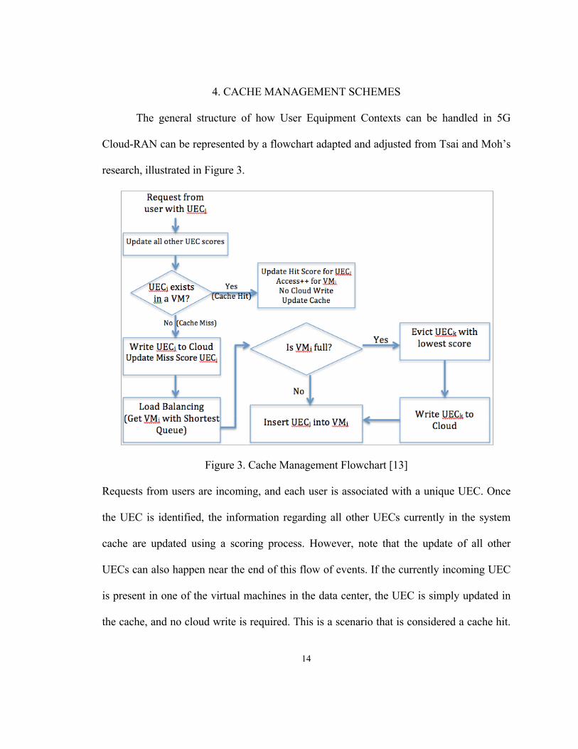
The general structure of how User Equipment Contexts can be handled in 5G
Cloud-RAN can be represented by a flowchart adapted and adjusted from Tsai and Moh’s
research, illustrated in Figure 3.
Figure 3. Cache Management Flowchart [13]
Requests from users are incoming, and each user is associated with a unique UEC. Once
the UEC is identified, the information regarding all other UECs currently in the system
cache are updated using a scoring process. However, note that the update of all other
UECs can also happen near the end of this flow of events. If the currently incoming UEC
is present in one of the virtual machines in the data center, the UEC is simply updated in
the cache, and no cloud write is required. This is a scenario that is considered a cache hit.
15
On the other hand, if the UEC is not present in one of the virtual machines, meaning there
is a cache miss, it must be written to the cloud, and a load balancing algorithm must be
performed in order to determine in which virtual machine the UEC is to be placed. The
algorithm chosen to load balance involves finding the virtual machine that has the shortest
queue of elements waiting to be processed. This particular method was chosen based on a
study which determined the shortest queue approach was the most preferred for load
balancing in 5G C-RAN due to its ability to offer a significantly even distribution of
incoming requests with reasonable computational effort in comparison to other load
balancing methodologies [4, 5]. Once the virtual machine is successfully chosen, a check
is performed to determine whether or not that virtual machine has room to accommodate
an additional UEC. If the virtual machine has room, meaning the cache is not full, the
UEC is simply inserted into the chosen virtual machine’s cache. If the virtual machine is
full, then the cache management scheme will choose a UEC to evict, typically one with
the lowest score. Once the eviction is performed, the evicted UEC must be written to the
cloud and the previously incoming UEC can be inserted into the cache.
In this general structure, there is much room for how exactly to handle the UECs,
specifically how to handle insertion, eviction, and writes. This is where the various cache
management schemes come into play. The succeeding schemes all present and discuss
different ways of managing the UEC elements in the context of the cache.

16
4.1 Probability-Based Popularity Scoring (PBPS)
As mentioned in Baek, Cho, and Choi’s research, probability based models and
functions can be used to aid in effective cache management [2]. Consider, for instance,
the geometric probability model as follows:
y = p(1 – p)k (1)
This function will determine the probability of an event occurring based on success factor
“p” and fail factor “k.” A function like this can potentially be very useful in cache
management for a few reasons.
Firstly, success in the context of caching can be defined as getting a hit in the
cache. Likewise, failure can be considered experiencing a cache miss. The above function
can be altered and adjusted to take into consideration hit and miss ratios to determine the
popularity of a particular element. The hit ratio, which is calculated as a score,
representing the hits a particular UEC has received in the cache based on its service level,
divided by the total number of requests so far, can take the place of “p.” Similarly, the
miss ratio, which is the score representing the misses a particular UEC experiences
divided by the total number of requests, can take the place of “k.” By changing the above
function to adapt to a cache management scheme for 5G, a new function that is proposed
and can be used for handling and scoring each UEC becomes the following:
!!" !"#$% !"#$% !" !_!# !"#$"%&%
(1− !!" !"#$% !"#$% !" !_!# !"#$"%&%
)!"## !"#$%# !"#$"%&% (2)
This function takes into consideration both the hits and misses for each UEC at any given
point in the cache management scheme, and evaluates to an overall score. The overall

17
score of a UEC represents how popular the UEC is based on its hits and misses. A greater
score of a UEC indicates a greater popularity of the UEC. Because the number of requests
is constantly changing, this function works by dynamically scoring UECs in the system,
therefore providing justice to both frequency and recency. This equation no longer
evaluates to a strict probability, since the definitions of success and failure have been
altered. However, since it is probability based, the overall scores evaluate to numbers
between 0 and 1 inclusive. Furthermore, the hit and miss scores seen in the equation can
be calculated depending on the quality of service promised to a particular user. This
system can use a point reward for hits, in which the quantity of the reward is dependent on
service level. As an example, a UEC in a better service level would have the hit score
updated by a larger reward amount than a UEC in a lower service level that also
experienced a hit. This is how differentiations are made between service levels and
preferential treatment provided to better service quality subscriptions. The exact quantity
of reward given based on service level can vary and be adjusted based on individual
system needs. Furthermore, due to the structure of this scoring equation, the hit and miss
scores for all UECs can be initialized to 1 by default, to prevent excess recurring scores of
0. Initializing with 1 will assure that scores are always calculated to nonzero values,
allowing for the accurate and fair comparison of popularity and the avoidance of multiple
0 values that would complicate eviction. The following are the steps taken for this
Probability-Based Popularity Scoring scheme:
Probability-Based Popularity Scoring Algorithm
1. For each user request UECj with Li

18
2. If UECj is present in one of the VMs (cache hit)
3. Update hit score of UECj based on service level and calculate new overall score
using equation (2)
4. Update content of UECj in the cache
5. Return;
6. Else if UECj is not present in one of the VMs (cache miss)
7. Update miss score of UECj and calculate new overall score using equation (2)
8. Write UECj to the cloud
9. Load balance: select VMi with the shortest queue
10. If the VMi has space for the current UECj
11. Insert UECj into the VMi’s cache
12. Return;
13. Else if the VMi is full
14. Find UECk which has the lowest score
15. Evict UECk from the VMi’s cache
16. Write UECk to the cloud
17. Insert UECi into the VMi’s cache
18. Return;
19. Update all other UECs in the cache using equation (2) with total number request
parameter updated
This algorithm presents multiple advantages that are extremely useful in this 5G
setting. As previously mentioned, the reward system for hits differentiates service levels.

19
Also, since the equation factors in the total number of requests that have come through the
network, it tackles a problem that is persistent in primitive algorithms such as ones like
LFU or LRU. For example, in LFU, an element in the cache that was very popular over
some time will have had many accesses and will remain in the cache for a very long
period of time. Even if the item is no longer accessed or popular, it stays in the cache
because at some point in the past it did receive very many accesses. However, items which
are no longer popular, even if they once were, should not be kept sitting idle and taking up
space in the limited resource that is the cache. In the PBPS function, the total number of
requests is always an increasing parameter in the equation. This way, if a once-popular
element is sitting in the cache and no longer being accessed, its overall score will steadily
be decreasing, and it will be in a better position for eviction. PBPS therefore is able to
dynamically account for changes in user requests and workloads.
4.2 Probability-Based Popularity Scoring (PBPS) with Hierarchy
The previously mentioned caching scheme handles the UECs and the cache well in
that it dynamically adjusts scores for all the UECs in the system, and also makes
differentiations based on service levels. However, the Probability-Based Popularity
Scoring scheme can be further adjusted and aided with the sheer setup and calculated
organization of the cache resources. Though PBPS differentiates between service levels by
updating hit scores using different numbers of rewards for different quality of services,
there is a question of fairness in service as those rewards are arbitrary. In the worst case

20
for PBPS, better service levels can be overwhelmingly preferred for remaining in the
cache while lower service levels overwhelmingly are facing eviction from the cache. This
is a form of extreme behavior that would result in a great hit rate for the best service level,
and a catastrophic hit rate for lower service levels. Because of the presence of this worst-
case scenario, another enhanced approach to caching is proposed, which consists of the
cache itself being separated into hierarchies or tiers.
The cache can be separated into particular sections, in which case each service
level would have a section of the cache. This would form a type of hierarchy, in which
particular User Equipment Contexts can only be added to or evicted from the section of
cache that is dedicated to the service level to which they belong. In order to maintain the
preferential treatment of better service levels, a larger amount of the cache can be
dedicated to better service levels.
Figure 4. Visual Example of Tiered Cache
As an example, consider the case in which there is an average quality of service, and a
superior quality of service. A caching separation and hierarchy could be maintained by
dedicating, say, 60% of the cache to the superior service elements, and 40% of the cache
SLA 1
SLA 2
SLA 3
SLA 4
21
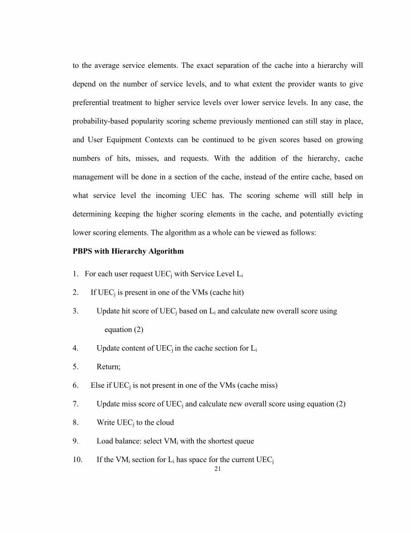
to the average service elements. The exact separation of the cache into a hierarchy will
depend on the number of service levels, and to what extent the provider wants to give
preferential treatment to higher service levels over lower service levels. In any case, the
probability-based popularity scoring scheme previously mentioned can still stay in place,
and User Equipment Contexts can be continued to be given scores based on growing
numbers of hits, misses, and requests. With the addition of the hierarchy, cache
management will be done in a section of the cache, instead of the entire cache, based on
what service level the incoming UEC has. The scoring scheme will still help in
determining keeping the higher scoring elements in the cache, and potentially evicting
lower scoring elements. The algorithm as a whole can be viewed as follows:
PBPS with Hierarchy Algorithm
1. For each user request UECj with Service Level Li
2. If UECj is present in one of the VMs (cache hit)
3. Update hit score of UECj based on Li and calculate new overall score using
equation (2)
4. Update content of UECj in the cache section for Li
5. Return;
6. Else if UECj is not present in one of the VMs (cache miss)
7. Update miss score of UECj and calculate new overall score using equation (2)
8. Write UECj to the cloud
9. Load balance: select VMi with the shortest queue
10. If the VMi section for Li has space for the current UECj
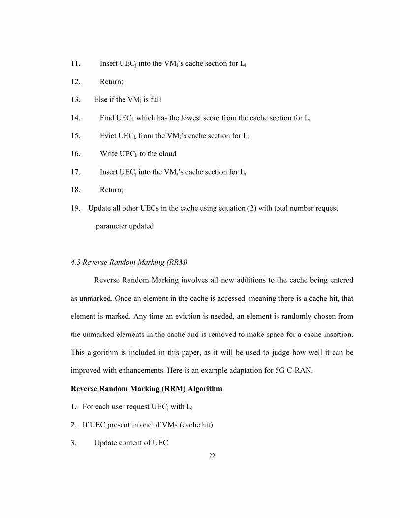
22
11. Insert UECj into the VMi’s cache section for Li
12. Return;
13. Else if the VMi is full
14. Find UECk which has the lowest score from the cache section for Li
15. Evict UECk from the VMi’s cache section for Li
16. Write UECk to the cloud
17. Insert UECj into the VMi’s cache section for Li
18. Return;
19. Update all other UECs in the cache using equation (2) with total number request
parameter updated
4.3 Reverse Random Marking (RRM)
Reverse Random Marking involves all new additions to the cache being entered
as unmarked. Once an element in the cache is accessed, meaning there is a cache hit, that
element is marked. Any time an eviction is needed, an element is randomly chosen from
the unmarked elements in the cache and is removed to make space for a cache insertion.
This algorithm is included in this paper, as it will be used to judge how well it can be
improved with enhancements. Here is an example adaptation for 5G C-RAN.
Reverse Random Marking (RRM) Algorithm
1. For each user request UECj with Li
2. If UEC present in one of VMs (cache hit)
3. Update content of UECj

23
4. If UEC is unmarked
5. Mark UECj
6. Else if UECj is already marked
6. Return
7. Else if UECj not present in one of VMs (cache miss)
8. Write UECj to cloud storage
9. Select VMi using shortest queue load balancing algorithm
10. If VMi has space for current UECj
11. Insert UECj into VMi’s cache
12. Else if VM is full
13. If there are unmarked elements
14. Evict random UECk from unmarked elements
15. Else if all elements are marked
16. Evict random UECk
17. Write UECk to cloud storage
18. Insert UECj into VMi cache
19. Return
4.4 Reverse Random Marking (RRM) with PBPS
The authors of the Reverse Random Marking algorithm performed their work and
research around enhancing a prior Random Marking (RM) caching algorithm [17].
24
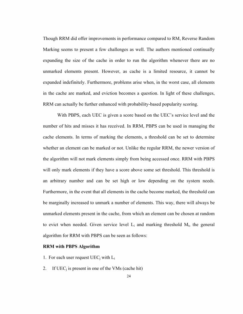
Though RRM did offer improvements in performance compared to RM, Reverse Random
Marking seems to present a few challenges as well. The authors mentioned continually
expanding the size of the cache in order to run the algorithm whenever there are no
unmarked elements present. However, as cache is a limited resource, it cannot be
expanded indefinitely. Furthermore, problems arise when, in the worst case, all elements
in the cache are marked, and eviction becomes a question. In light of these challenges,
RRM can actually be further enhanced with probability-based popularity scoring.
With PBPS, each UEC is given a score based on the UEC’s service level and the
number of hits and misses it has received. In RRM, PBPS can be used in managing the
cache elements. In terms of marking the elements, a threshold can be set to determine
whether an element can be marked or not. Unlike the regular RRM, the newer version of
the algorithm will not mark elements simply from being accessed once. RRM with PBPS
will only mark elements if they have a score above some set threshold. This threshold is
an arbitrary number and can be set high or low depending on the system needs.
Furthermore, in the event that all elements in the cache become marked, the threshold can
be marginally increased to unmark a number of elements. This way, there will always be
unmarked elements present in the cache, from which an element can be chosen at random
to evict when needed. Given service level Li and marking threshold Mt, the general
algorithm for RRM with PBPS can be seen as follows:
RRM with PBPS Algorithm
1. For each user request UECj with Li
2. If UECj is present in one of the VMs (cache hit)
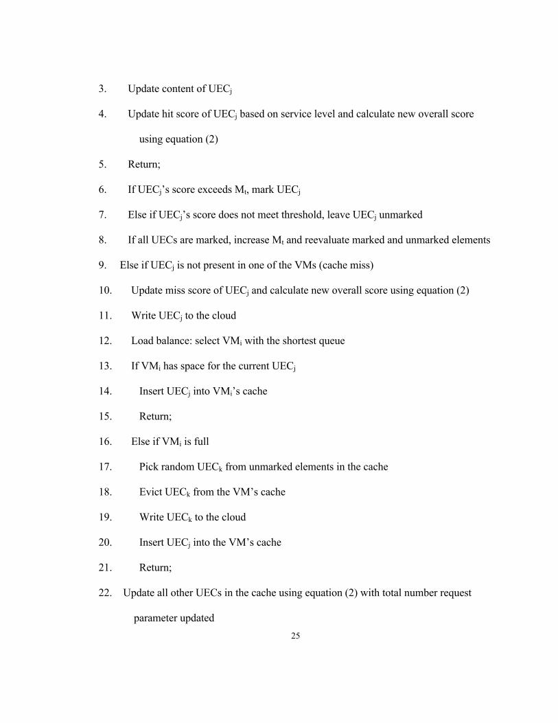
25
3. Update content of UECj
4. Update hit score of UECj based on service level and calculate new overall score
using equation (2)
5. Return;
6. If UECj’s score exceeds Mt, mark UECj
7. Else if UECj’s score does not meet threshold, leave UECj unmarked
8. If all UECs are marked, increase Mt and reevaluate marked and unmarked elements
9. Else if UECj is not present in one of the VMs (cache miss)
10. Update miss score of UECj and calculate new overall score using equation (2)
11. Write UECj to the cloud
12. Load balance: select VMi with the shortest queue
13. If VMi has space for the current UECj
14. Insert UECj into VMi’s cache
15. Return;
16. Else if VMi is full
17. Pick random UECk from unmarked elements in the cache
18. Evict UECk from the VM’s cache
19. Write UECk to the cloud
20. Insert UECj into the VM’s cache
21. Return;
22. Update all other UECs in the cache using equation (2) with total number request
parameter updated
26
This algorithm, combining Reverse Random Marking with a scoring system, has
brought forth an interesting revelation in regards to caching for 5G C-RAN. Note that
RRM alone was certainly an algorithm not intended to be used for the cellular network
setting, at least not well. However, its combination with the probability-based scoring
system has now made it a reasonable algorithm that could be used to manage the cache in
this particular architecture. This shows that it is possible to take a caching algorithm not
originally intended for 5G C-RAN, combine it with a scoring system, and make it a
feasible option for cache management.
4.5 EXD-AHP
A fourth scheme useful in managing the cache that also uses a type of scoring
system is Exponential Delay – Analytical Hierarchical Process, or EXD-AHP for short,
which is a combination of preexisting caching schemes [6, 12, 13]. This approach
combines both an exponential decay model to determine the recency and frequency of
UECs in the cache, as well as an Analytical Hierarchical Process (AHP) matrix to
differentiate between service levels. This way, more recent and frequent items are
maintained in the cache while less frequent and less recent items are more likely to be
evicted, and higher quality of service is given preferential treatment and priority in the
cache over the lower quality of service. The EXD-AHP scheme will be simulated along
all other caching schemes, and will also newly be tested for latency to better understand
27
its performance. In this scheme, the following equation is used to calculate the score of
an incoming UEC:
Si(ui1+Δu) = Si(ui1)*e-aΔu+WAHP (3)
Relatedly, the following equation is used to evaluate the scores of all other UECs in the
cache:
Si(ui1+Δu) = Si(ui1)*e-aΔu (4)
In the above equations, the scores of UECs are calculated based on the time taken
between requests of the same UEC. If a particular UEC is not accessed or requested
between the time ui1 up to ui1+Δu, the score of that particular UEC in the cache is updated
using equation 4. If a particular UEC is being accessed within the allotted time frame,
then the score is updated using equation 3. Both equations take into consideraton the
exponential decay model, in which the value of the variable “a” can be set higher to focus
the model on recency. In the first equation, the analytical hierarchical process matrix is
used in part to determine the score of a UEC that is being accessed in a timely manner.
AHP will be used in that each service level will be compared with every other service
level, and preferential treatment can be given by specifying how many times more
important one level is than the other. The typical AHP matrix is then used to calculate a
weight which is added as part of the UEC score. Consider Table 1 on the following page,
which illustrates the Analytical Hierarchical Process Matrix. The service levels are each
given a row and column in the matrix, and are compared to each other in terms of how
many times more improtant one level is than the other. In this case, a higher service level
is five times more important than the immediately lower service level. The final weights
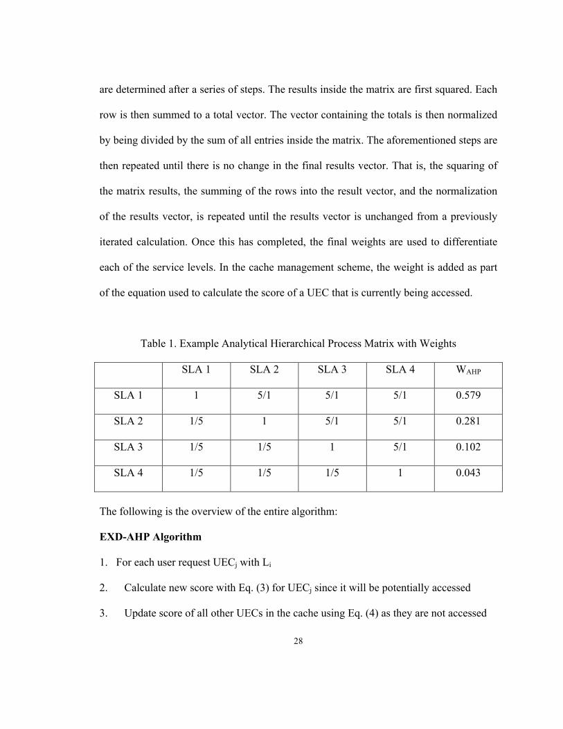
28
are determined after a series of steps. The results inside the matrix are first squared. Each
row is then summed to a total vector. The vector containing the totals is then normalized
by being divided by the sum of all entries inside the matrix. The aforementioned steps are
then repeated until there is no change in the final results vector. That is, the squaring of
the matrix results, the summing of the rows into the result vector, and the normalization
of the results vector, is repeated until the results vector is unchanged from a previously
iterated calculation. Once this has completed, the final weights are used to differentiate
each of the service levels. In the cache management scheme, the weight is added as part
of the equation used to calculate the score of a UEC that is currently being accessed.
Table 1. Example Analytical Hierarchical Process Matrix with Weights
SLA 1 SLA 2 SLA 3 SLA 4 WAHP
SLA 1 1 5/1 5/1 5/1 0.579
SLA 2 1/5 1 5/1 5/1 0.281
SLA 3 1/5 1/5 1 5/1 0.102
SLA 4 1/5 1/5 1/5 1 0.043
The following is the overview of the entire algorithm:
EXD-AHP Algorithm
1. For each user request UECj with Li
2. Calculate new score with Eq. (3) for UECj since it will be potentially accessed
3. Update score of all other UECs in the cache using Eq. (4) as they are not accessed

29
4. If UECj is present in one of VMs (cache hit)
5. Update score and content of UECj
6. Return
7. Else if UECj is not present in one of VMs (cache miss)
8. Write UECj to cloud storage
9. Select VMi using shortest queue load balancing algorithm
10. If VMi has space for the current UECj
11. Insert UECj into VMi’s cache
12. Return
13. Else if VMi is full
14. If UECj score is more than smallest score present in cache
15. Evict lowest scoring entries whose sum is less than UECj score
16. Write evicted UECs to the cloud
17. Else if UECj score is smaller than lowest score
18. Evict UECk with smallest score
19. Write UECk to the cloud
20. Insert UECj into VMi cache
21. Return

30
4.6 Baseline Comparisons
In order to assess the benefit and performance of the various caching schemes, it is
useful to compare them to a known classic scheme. Comparison will therefore be made
with Least Frequently Used (LFU). LFU involves keeping track of the number of times a
particular UEC element in the cache is accessed. In the event that eviction needs to be
performed when the cache is full and space is needed for new elements, the element with
the lowest number of accesses will be evicted [17].
An important aspect of LFU should be taken into consideration in the context of
cellular network caching. Least Frequently Used simply counts the number of accesses an
element gets in the cache. It does not have a mechanism to differentiate between requests
of different service levels. Regardless of the quality of service, a UEC will be given an
increment towards the number of accesses when the request for that particular UEC comes
through. Because of this, the performance of LFU is related to the traffic distribution itself
and not related to or based directly on service levels. Least Frequently Used will treat
requests across all the service levels the same. With that said, LFU can still be used as a
caching mechanism in 5G C-RAN. In the worse case scenario, the traffic load is equally
distributed between all service levels. That is, there are roughly an equal number of users
in each service level. In this case, performance from LFU would be poor in that not much
differentiation would be seen between service levels. In the best case scenario, the traffic
load is unevenly distributed between service levels, with better service levels having more
user requests. In this case, since LFU is related to the traffic distribution, a clear
distinction would be seen in performance based on service levels. For the purposes of this
31
project, the best case scenario for LFU is used, which showcases the best scenario for LFU
in terms of performance, as a base comparison. This knowledge about LFU also indicates
the importance of needing more tailored algorithms to use in 5G C-RAN, which can offer
both a proper way of managing the cache in any type of traffic distribution or workload,
and consistently making appropriate differentiations between quality of services.
32
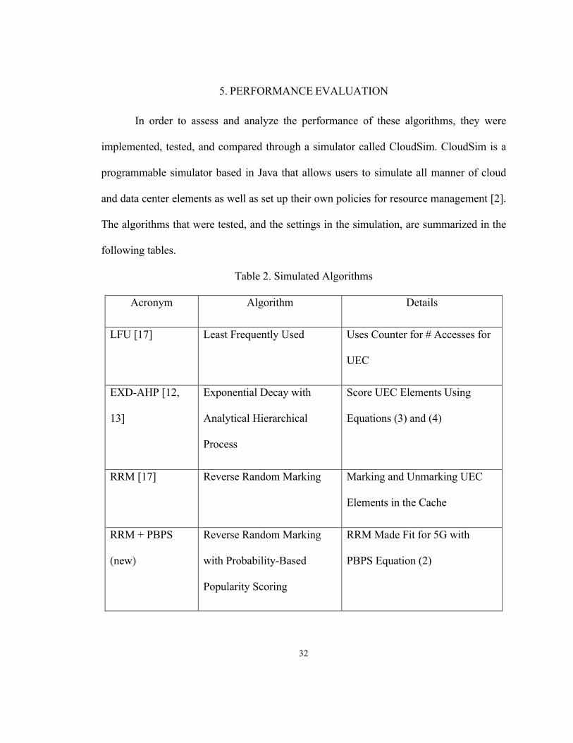
5. PERFORMANCE EVALUATION
In order to assess and analyze the performance of these algorithms, they were
implemented, tested, and compared through a simulator called CloudSim. CloudSim is a
programmable simulator based in Java that allows users to simulate all manner of cloud
and data center elements as well as set up their own policies for resource management [2].
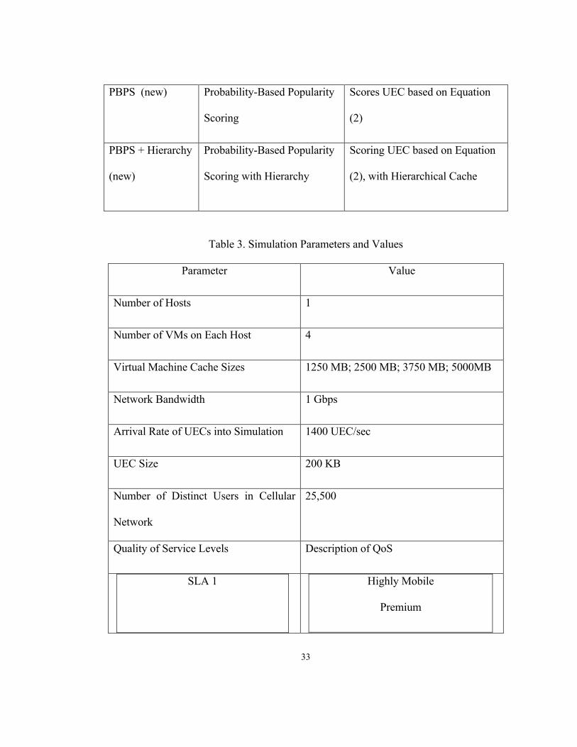
The algorithms that were tested, and the settings in the simulation, are summarized in the
following tables.
Table 2. Simulated Algorithms
Acronym Algorithm Details
LFU [17] Least Frequently Used Uses Counter for # Accesses for
UEC
EXD-AHP [12,
13]
Exponential Decay with
Analytical Hierarchical
Process
Score UEC Elements Using
Equations (3) and (4)
RRM [17] Reverse Random Marking Marking and Unmarking UEC
Elements in the Cache
RRM + PBPS
(new)
Reverse Random Marking
with Probability-Based
Popularity Scoring
RRM Made Fit for 5G with
PBPS Equation (2)
33
PBPS (new) Probability-Based Popularity
Scoring
Scores UEC based on Equation
(2)
PBPS + Hierarchy
(new)
Probability-Based Popularity
Scoring with Hierarchy
Scoring UEC based on Equation
(2), with Hierarchical Cache
Table 3. Simulation Parameters and Values
Parameter Value
Number of Hosts 1
Number of VMs on Each Host 4
Virtual Machine Cache Sizes 1250 MB; 2500 MB; 3750 MB; 5000MB
Network Bandwidth 1 Gbps
Arrival Rate of UECs into Simulation 1400 UEC/sec
UEC Size 200 KB
Number of Distinct Users in Cellular
Network
25,500
Quality of Service Levels Description of QoS
SLA 1 Highly Mobile
Premium
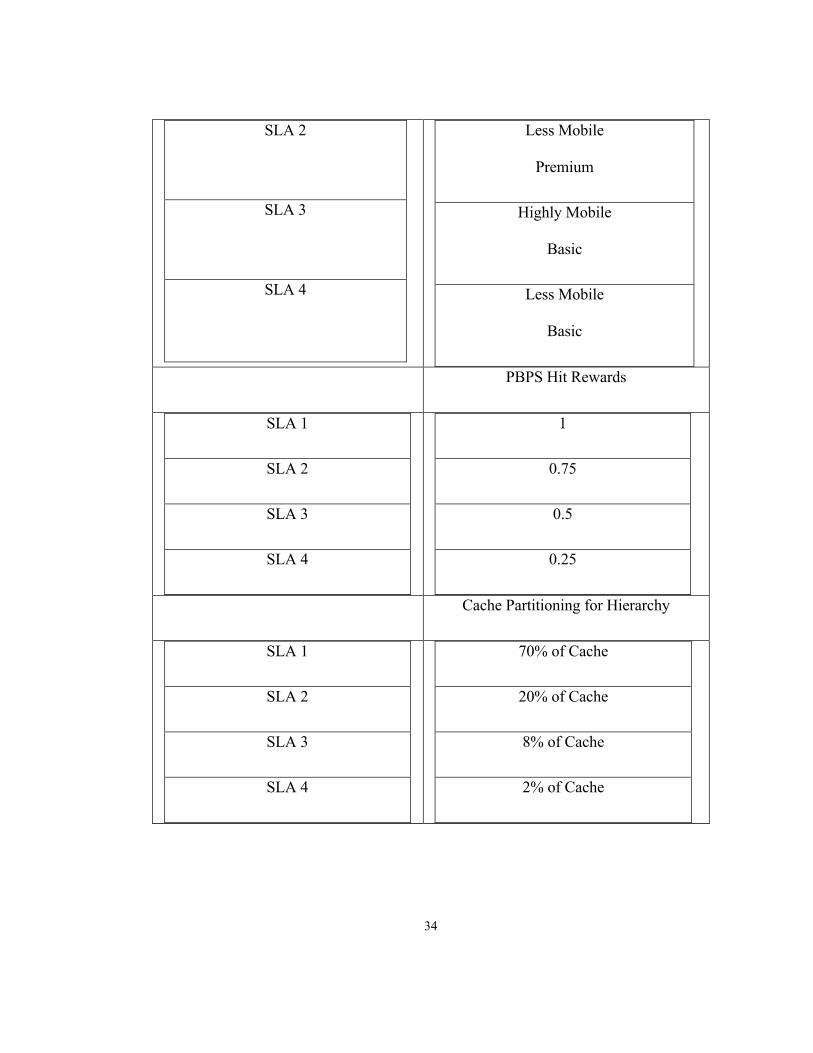
34
SLA 2
SLA 3
SLA 4
Less Mobile
Premium
Highly Mobile
Basic
Less Mobile
Basic
PBPS Hit Rewards
SLA 1
SLA 2
SLA 3
SLA 4
1
0.75
0.5
0.25
Cache Partitioning for Hierarchy
SLA 1
SLA 2
SLA 3
SLA 4
70% of Cache
20% of Cache
8% of Cache
2% of Cache
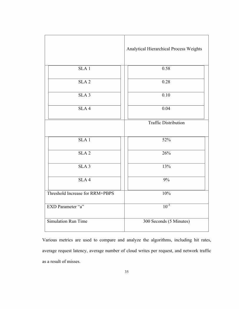
35
Analytical Hierarchical Process Weights
SLA 1
SLA 2
SLA 3
SLA 4
0.58
0.28
0.10
0.04
Traffic Distribution
SLA 1
SLA 2
SLA 3
SLA 4
52%
26%
13%
9%
Threshold Increase for RRM+PBPS 10%
EXD Parameter “a” 10-3
Simulation Run Time 300 Seconds (5 Minutes)
Various metrics are used to compare and analyze the algorithms, including hit rates,
average request latency, average number of cloud writes per request, and network traffic
as a result of misses.

36
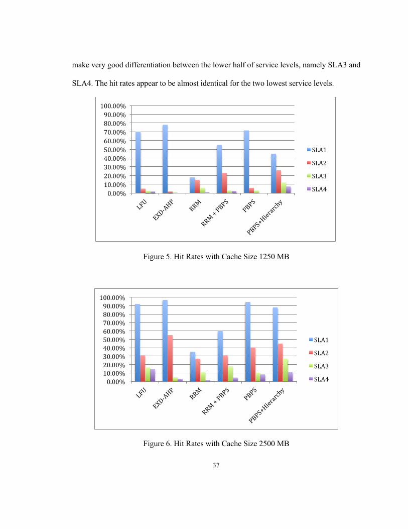
5.1 Hit Rates
Hit rates can simply be defined as follows for each service level Li:
Cache Hit Rate L_i = # !" !"# !"#$ !" !_!# !" !"# !"#$"%&% !"#$ !_!
Figures 5 through 8 illustrate how hit rates are supported for each of the four service levels
in the simulation, and how the hit rates change and are affected by cache size. When the
cache size is small, as seen in the first two charts, EXD-AHP tends to provide the best
preferential treatment to the best service level, SLA1. However, it also provides close to
no hits on the rest of the service levels and shows a starvation in SLA2, SLA3, and SLA4.
PBPS alone also shows a similar pattern in hit rates compared to EXD-AHP, though with
a slightly lower hit rate on the best service level. The tradeoff in performance is seen with
PBPS + Hierarchy. The PBPS + Hierarchy algorithm offers the best distribution of the
cache hits, so each level has a reasonable number of hits while still being differentiated
based on service quality. However, the hit rate on the best service level, SLA1, is much
lower with PBPS + Hierarchy compared to EXD-AHP or PBPS. RRM maintains the
lowest hit rate, but has been improved as RRM + PBPS. With the inclusion of Probability-
Based Popularity Scoring, RRM has been enhanced, with its new combination offering
substantially better results than the previous RRM alone, including triple the number of
hits on the best service level. Lastly, Least Frequently Used has a good hit rate on the best
service level, but like EXD-AHP and PBPS, tends to neglect the other lower three service
levels. It should be noted that LFU has another weakness in that it does not appear to
37
make very good differentiation between the lower half of service levels, namely SLA3 and
SLA4. The hit rates appear to be almost identical for the two lowest service levels.
Figure 5. Hit Rates with Cache Size 1250 MB
Figure 6. Hit Rates with Cache Size 2500 MB
0.00%10.00%20.00%30.00%40.00%50.00%60.00%70.00%80.00%90.00%100.00%
SLA1
SLA2
SLA3
SLA4
0.00%10.00%20.00%30.00%40.00%50.00%60.00%70.00%80.00%90.00%100.00%
SLA1
SLA2
SLA3
SLA4
38
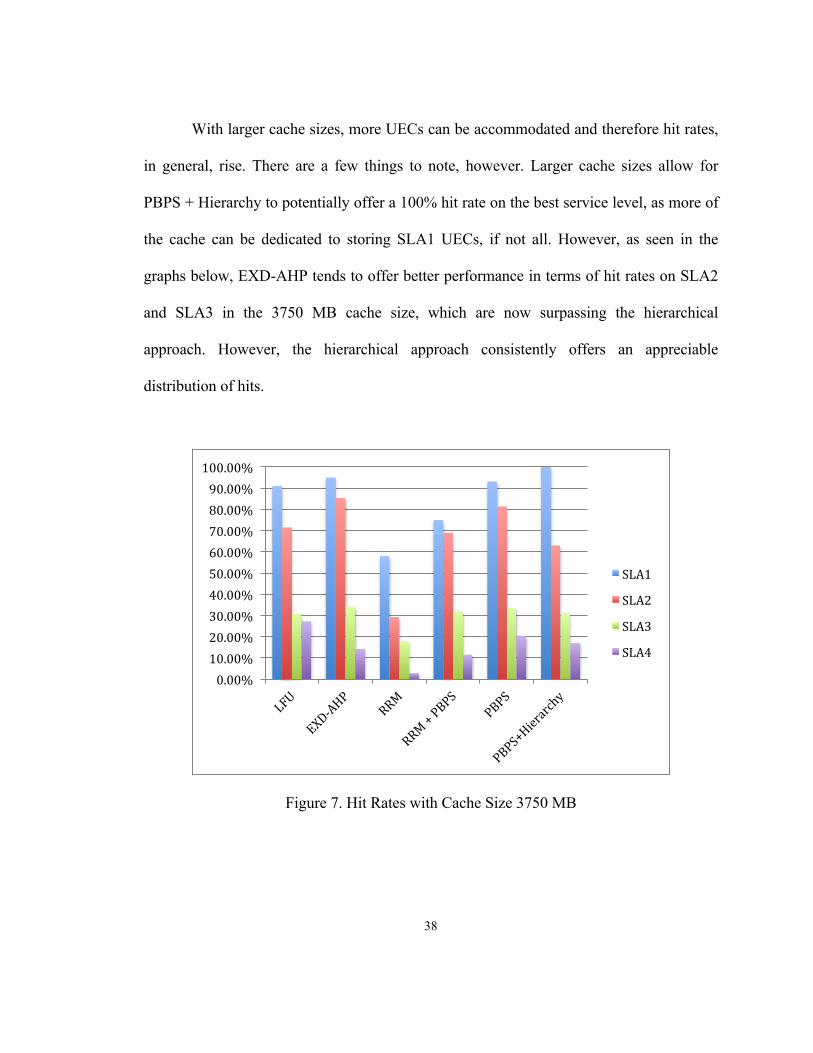
With larger cache sizes, more UECs can be accommodated and therefore hit rates,
in general, rise. There are a few things to note, however. Larger cache sizes allow for
PBPS + Hierarchy to potentially offer a 100% hit rate on the best service level, as more of
the cache can be dedicated to storing SLA1 UECs, if not all. However, as seen in the
graphs below, EXD-AHP tends to offer better performance in terms of hit rates on SLA2
and SLA3 in the 3750 MB cache size, which are now surpassing the hierarchical
approach. However, the hierarchical approach consistently offers an appreciable
distribution of hits.
Figure 7. Hit Rates with Cache Size 3750 MB
0.00%10.00%20.00%30.00%40.00%50.00%60.00%70.00%80.00%90.00%100.00%
SLA1
SLA2
SLA3
SLA4

39
Figure 8. Hit Rates with Cache Size 5000 MB
Lastly, it should be noted that PBPS on its own is certainly an acceptable
algorithm, but performs better and gives better distribution with the hierarchy in place.
RRM all around tends to be the least impressive in terms of performance, but can be
greatly improved with incorporating PBPS at any cache size. The enhanced RRM + PBPS
then becomes an algorithm that is better suited for this type of architecture. LFU’s lack of
proper differentiation between the lower service levels again emphasizes the reason why
different, more tailored caching schemes are needed for 5th Generation Cloud Radio
Access Networks. Even in its best scenario, LFU is not sufficient enough for these newer
performance necessities and demands.
0.00%10.00%20.00%30.00%40.00%50.00%60.00%70.00%80.00%90.00%100.00%
SLA1
SLA2
SLA3
SLA4

40
5.2 Miss Rates
Miss rates can similarly be defined as follows for each service level Li:
Cache Miss Rate L_i = # !" !"# !"##$# !" !_!# !" !"# !"#$"%&% !"#$ !_!
The following graphs demonstrate how the miss rates amongst the six algorithms vary,
and how the four service levels are supported on different sizes of VM cache. Since the
miss rate is proportional to the hit rate, similar patterns are visible. LFU and EXD-AHP
have astounding miss rates on lower service levels, and RRM in general has a balance
between higher miss rates and distribution that is too close and not well as well
differentiated among service levels. PBPS and, even better, PBPS + Hierarchy both show
better results in the form of lower miss rates for smaller cache sizes. These two algorithms
would be the better options to take given smaller caches. Also note that the hit rate on
RRM + PBPS has been significantly improved over the older RRM alone.
Figure 9. Miss Rate with Cache Size 1250 MB
0.00%10.00%20.00%30.00%40.00%50.00%60.00%70.00%80.00%90.00%100.00%
SLA1
SLA2
SLA3
SLA4
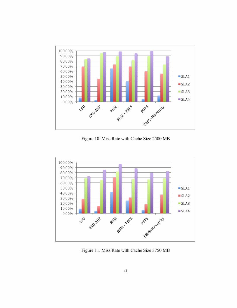
41
Figure 10. Miss Rate with Cache Size 2500 MB
Figure 11. Miss Rate with Cache Size 3750 MB
0.00%10.00%20.00%30.00%40.00%50.00%60.00%70.00%80.00%90.00%100.00%
SLA1
SLA2
SLA3
SLA4
0.00%10.00%20.00%30.00%40.00%50.00%60.00%70.00%80.00%90.00%100.00%
SLA1
SLA2
SLA3
SLA4

42
These larger cache sizes indicate a preference of different algorithms than the
smaller caches. With a larger cache, EXD-AHP offers one of the best overall miss rates,
whereas PBPS + Hierarchy brings the miss rate down to zero for the highest service level
in the cache sizes of 3750 MB and 5000 MB.
Figure 12. Miss Rate with Cache Size 5000 MB
5.3 Latency
Another metric used in evaluating the performance of all of the
algorithms is latency. Specifically, the latency will be analyzed in terms of how long it
takes to process a hit or a miss in the system. In the simulation, latency regarding hits and
misses are judged separately, but their average is taken to analyze the general
performance. With hits, the latency is simply the amount of time it takes in accessing and
updating the UEC in the cache. With misses, the latency is the collective time it takes to
0%10%20%30%40%50%60%70%80%90%100%
SLA1
SLA2
SLA3
SLA4
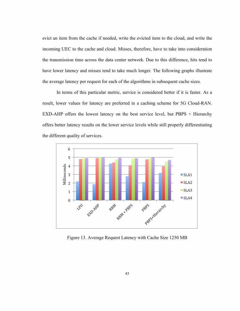
43
evict an item from the cache if needed, write the evicted item to the cloud, and write the
incoming UEC to the cache and cloud. Misses, therefore, have to take into consideration
the transmission time across the data center network. Due to this difference, hits tend to
have lower latency and misses tend to take much longer. The following graphs illustrate
the average latency per request for each of the algorithms in subsequent cache sizes.
In terms of this particular metric, service is considered better if it is faster. As a
result, lower values for latency are preferred in a caching scheme for 5G Cloud-RAN.
EXD-AHP offers the lowest latency on the best service level, but PBPS + Hierarchy
offers better latency results on the lower service levels while still properly differentiating
the different quality of services.
Figure 13. Average Request Latency with Cache Size 1250 MB
0
1
2
3
4
5
6
Milliseconds
SLA1
SLA2
SLA3
SLA4

44
Figure 14. Average Request Latency with Cache Size 2500 MB
As seen in the larger two cache sizes in Figures 15 and 16, PBPS, PBPS +
Hierarchy, and EXD-AHP all offer better latency values overall amongst the various
service levels than the other algorithms. PBPS + Hierarchy, due to the partitioning of the
cache for various service levels, has the potential to offer the minimal amount of latency
in the best service level.
0
1
2
3
4
5
6
Milliseconds
SLA1
SLA2
SLA3
SLA4

45
Figure 15. Average Request Latency with Cache Size 3750 MB
Figure 16. Average Request Latency with Cache Size 5000 MB
0
1
2
3
4
5
6
Milliseconds
SLA1
SLA2
SLA3
SLA4
0
1
2
3
4
5
6
Milliseconds
SLA1
SLA2
SLA3
SLA4
46
RRM does not offer substantial improvement in the latency of each request even
with larger cache sizes, but its combination with PBPS has proven to be quite useful.
LFU in larger cache sizes, though seemingly competitive, has trouble again
differentiating between the lower two service levels.
5.4 Cloud Writes
The number of cloud writes based on the service levels is another metric useful in
comparing and understanding the algorithms better. Cloud writes are represented as an
average number of writes to cloud storage per UEC request in a particular algorithm.
That is, whenever there is a cache hit, there is no write to the cloud and so the number of
cloud writes is 0. When there is a cache miss, the evicted UEC must be written to the
cloud and the incoming UEC must also be written to the cloud, resulting in 2 writes to the
cloud. The average number of writes per request, therefore, will be a number between 0
and 2. The number of cloud writes can be calculated using the following formula.
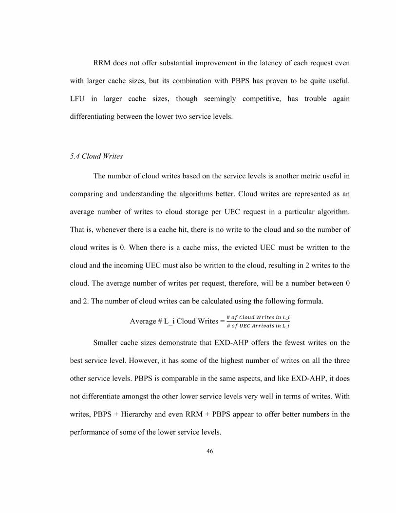
Average # L_i Cloud Writes = # !" !"#$% !"#$%& !" !_!# !" !"# !""#$%&' !" !_!
Smaller cache sizes demonstrate that EXD-AHP offers the fewest writes on the
best service level. However, it has some of the highest number of writes on all the three
other service levels. PBPS is comparable in the same aspects, and like EXD-AHP, it does
not differentiate amongst the other lower service levels very well in terms of writes. With
writes, PBPS + Hierarchy and even RRM + PBPS appear to offer better numbers in the
performance of some of the lower service levels.
47
Figure 17. Average Number of Cloud Writes with Cache Size 1250 MB
Figure 18. Average Number of Cloud Writes with Cache Size 2500 MB
00.20.40.60.81
1.21.41.61.82
Num
berofW
rites
SLA1
SLA2
SLA3
SLA4
00.20.40.60.81
1.21.41.61.82
Num
berofW
rites
SLA1
SLA2
SLA3
SLA4
48
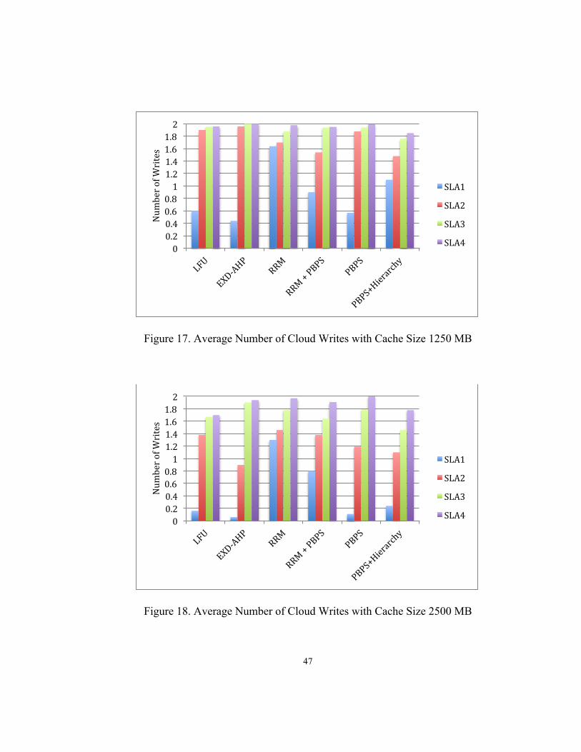
With larger cache sizes, EXD-AHP substantially reduces the writes on the higher
half of service levels, as does PBPS following in second. However, PBPS + Hierarchy
offers potentially no writes on the best service level, since enough of the cache could be
allotted to SLA1 to store all SLA1 users.
Figure 19. Average Number of Cloud Writes with Cache Size 3750 MB
00.20.40.60.81
1.21.41.61.82
Num
berofW
rites
SLA1
SLA2
SLA3
SLA4

49
Figure 20. Average Number of Cloud Writes with Cache Size 5000 MB
RRM may be somewhat acceptable at the smallest cache size, but in general its
combination with PBPS is preferred to decrease the number of writes. RRM and LFU
both show that classic or older caching mechanisms are not good enough for 5G C-RAN,
and that better alternatives can be created and are preferred.
5.5 Network Traffic
A third metric used to compare the performance of these algorithms is that of
network traffic. Whenever there is a cache miss on a UEC request, there is a need to
travel across the data center network from the cache to the cloud storage in order to
perform the necessary writes. As a result, there is a certain amount of traffic that is
00.20.40.60.81
1.21.41.61.82
Num
berofW
rites
SLA1
SLA2
SLA3
SLA4

50
generated on the network as a result of misses. Therefore, the traffic can be calculated as
follows:
Network Traffic = (# 𝑊𝑟𝑖𝑡𝑒𝑠 ∗ 200 !"!"#
∗ 8 !"#$!"#$
∗ 1000 !"#$%!"
)
After calculating the network traffic, here is the comparative performance of all the
algorithms in different cache sizes. With smaller cache sizes, EXD-AHP and PBPS both
result in less traffic on the network, resulting in better and faster service, since they offer
the best service to the highest service level, SLA, which contains the most number of
users. They are followed closely by LFU, PBPS + Hierarchy, and RRM + PBPS.
Figure 21. Network Traffic with Cache Size 1250 MB
0
0.5
1
1.5
2
2.5
3
NetworkTrafic(M
bps)

51
Figure 22. Network Traffic with Cache Size 2500 MB
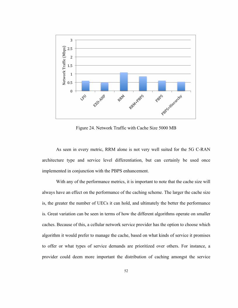
As seen in Figures 23 and 24, as the cache sizes get larger, EXD-AHP always
offers the lowest amount of network traffic resulting from misses. At the larger cache
sizes, PBPS + Hierarchy outperforms PBPS alone.
Figure 23. Network Traffic with Cache Size 3750 MB
0
0.5
1
1.5
2
2.5
3
NetworkTraffic(M
bps)
0
0.5
1
1.5
2
2.5
3
NetworkTraffic(M
bps)
52
Figure 24. Network Traffic with Cache Size 5000 MB
As seen in every metric, RRM alone is not very well suited for the 5G C-RAN
architecture type and service level differentiation, but can certainly be used once
implemented in conjunction with the PBPS enhancement.
With any of the performance metrics, it is important to note that the cache size will
always have an effect on the performance of the caching scheme. The larger the cache size
is, the greater the number of UECs it can hold, and ultimately the better the performance
is. Great variation can be seen in terms of how the different algorithms operate on smaller
caches. Because of this, a cellular network service provider has the option to choose which
algorithm it would prefer to manage the cache, based on what kinds of service it promises
to offer or what types of service demands are prioritized over others. For instance, a
provider could deem more important the distribution of caching amongst the service
0
0.5
1
1.5
2
2.5
3
NetworkTraffic(M
bps)

53
levels, or perhaps simply assuring that higher service levels are satisfied before other
lower service levels. Whatever the demands and priorities are for a particular cellular
network, these results showcase the effects of using different caching schemes, and allows
the provider many options in cache management suitable to network needs.
54
6. CONCLUSION
The research conducted in this paper and through subsequent experiments and
simulation aimed to look at different caching techniques for User Equipment Contexts
(UECs) in the 5th Generation Cloud-RAN architecture. In terms of hit rates, latency, and
cloud writes, there were tradeoffs found between EXD-AHP and PBPS + Hierarchy.
EXD-AHP consistently offered great service to the highest service levels, whereas PBPS
+ Hierarchy offered more competitive distributions of results amongst the four service
levels. PBPS + Hierarchy may be preferred with smaller cache sizes, but EXD-AHP
performs best with larger cache sizes. PBPS on its own certainly does offer acceptable
results, but its combination with the hierarchy yields the greatest benefits.
The RRM algorithm, which generally is not built to properly support service
levels in Cloud-RAN, can be enhanced with PBPS for better performance in every sense
and metric. The enhanced version of the original RRM + PBPS is now a feasible option
for use in 5G C-RAN if the cellular network provider wanted to utilize it.
Results obtained from the Least Frequently Used algorithm, even in its best case
scenario, in the 5G C-RAN Context consistently demonstrate the need for newer
algorithms which can better serve this cellular architecture.
Future work and research can be done in finding better and improved caching
techniques, which both offer faster service and can differentiate and provide appropriate
treatment of service levels among users. Research could continue in the use of
hierarchical or partitioned caches, and possibly how to dynamically adjust partitions or
levels of the cache to best serve users and service levels. Another aspect that could be

55
researched in the future is how to get appropriate hit rates in cache management systems
with the lowest possible computational effort. Outside of caching, other areas can also be
researched to improve service in 5G C-RAN, including the internal handlings of cloud
data center resources in order to maximize utilization and lower costs in other areas, such
as energy consumption, and maintaining their efficiency.
56
7. REFERENCES
[1] Anand, K. and Barua, R. “Instruction-Locking for Improving Embedded Systems
Performance,” ACM Transactions on Embedded Computing Systems, Vol. 14, No. 3,
Article 53, April 2015.
[2] Baek, S., Cho, S., and Choi, J. “Don’t Make Cache Too Complex: A Simple
Probability-Based Cache Management Scheme for SSDs,” Public Library of Science
ONE, 12(3): e0174375, March 2017.
[3] Calheiros, R. N. et al. “CloudSim: A ToolKit for Modeling and Simulation of Cloud
Computing Environments and Evaluation of Resource Provisioning Algorithms,”
Software: Practice and Experience, 41.1, 23 – 50, 2011.
[4] Chow, F. “Why Virtualization is Essential for 5G,” Silicon Valley 5G Summit, 2015.
[5] Fan, C. Zhang, Y. J., and Yuan, X. “Advances and Challenges Towards a Scalable
Cloud Radio Access Network,” IEEE Communications Magazine, Vol. 54, Issue 6,
June 2016.
[6] Floratou, A., et al. “Adaptive Caching in Big SQL using the HDFS Cache,”
Proceedings of the Seventh ACM Symposium on Cloud Computing (SoCC ’16), New
York, NY, USA, 321-333, 2016.
[7] Gaur, J., Alameldeen, A. R., and Subramoney, S. “Base-Victim Compression: An
Opportunistic Cache Compression Architecture,” 2016 ACM/IEEE 43rd Annual
International Symposium on Computer Architecture (ISCA), Seoul, South Korea,
June 2016.
57
[8] Huang, X., Zhao, Z. and Zhang, H. “Latency Analysis of Cooperative Caching with
Multicast for 5G Wireless Networks,” 2016 IEEE/ACM 9th International Conference
on Utility and Cloud Computing (UCC), Shanghai, China, Dec. 2016.
[9] Karneyenka, U. Mohta, K. and Moh, M. “Location and Mobility Aware Resource
Management for 5G Cloud Radio Access Networks,” 2017 International Conference
on High Performance Computing and Simulatin (HPCS), Genoa, Italy, July 2017.
[10] Kumar, B. A. and Rao, P. T. “Overview of Advances in Communication
Technologies,” 2015 13th International Conference on Electromagnetic Interference
and Compatibility (INCEMIC), Visakhpatnam, India, July 2015.
[11] Reguri, V. R., Kogatam, S. and Moh, M. “Energy Efficient Traffic-Aware Virtual
Machine Migration in Green Cloud Data Centers,” Proceedings of the Second IEEE
International Conference on High Performance and Smart Computing, New York,
April 2016.
[12] Tsai, C. and Moh, M. “Abstract: Cache Management and Load Balancing for 5G
Cloud Radio Access Networks,” ACM Symposium on Cloud Computing, Santa
Clara, USA, Sept 2017.
[13] Tsai, C. and Moh, M. "Cache Management for 5G Cloud Radio Access Networks,"
Proceedings of ACM International Conference on Ubiquitous Information
Management and Communication, to be held in Langkawi, Malaysia, January 2018.
[14] Wang, M. and Li, Z. “A Spatial and Temporal Locality-Aware Adaptive Cache
Design with Netowrk Optimization for Tiled Many-Core Architectures,” IEEE
58
Transactions on Very Large Scale Integration (VLSI) Systems, Volume 25, Issue 9,
Sept. 2017.
[15] Wang, X., et al. “Cache in the Air: Exploiting Content Caching and Delivery
Techniques for 5G Systems,” IEEE Communications Magazine, Vol. 52, Issue 2,
February 2014.
[16] Ye, F., et al. “A Regional Popularity-Aware Cache Replacement Algorithm to
Improve the Performance and Lifetime of SSD-Based Disk Cache,” 2015 IEEE
International Conference on Networking, Architecture and Storage (NAS), Boston,
MA, USA, Aug. 2015.
[17] Zaidenberg, N., Gavish, L., and Meir, Y. “New Caching Algorithms Performance
Evaluation,” International Symposium on Performance Evaluation of Computer and
Telecommunication Systems (SPECTS), Chicago, IL, USA, July 2015.
[18] “5G Network Architecture: A High Level Perspective,” Huawei Technologies Co.,
Ltd. Whitepaper, 2016.
Related Documents