BRITISH STANDARD BS EN 61537:2007 Cable management — Cable tray systems and cable ladder systems The European Standard EN 61537:2007 has the status of a British Standard ICS 29.120.10

Welcome message from author
This document is posted to help you gain knowledge. Please leave a comment to let me know what you think about it! Share it to your friends and learn new things together.
Transcript
BRITISH STANDARD
BS EN 61537:2007Cable management — Cable tray systems and cable ladder systems
The European Standard EN 61537:2007 has the status of a British Standard
ICS 29.120.10
�������������� ���������������������������������������������������
BS EN 61537:2007
This British Standard was published under the authority of the Standards Policy and Strategy Committee on 28 February 2007
© BSI 2007
ISBN 978 0 580 50168 5
National foreword
This British Standard was published by BSI. It is the UK implementation of EN 61537:2007. It is identical with IEC 61537:2006. It supersedes BS EN 61537:2002, which will be withdrawn on 1 December 2009.The UK participation in its preparation was entrusted to Technical Committee PEL/213, Cable management.A list of organizations represented on PEL/213 can be obtained on request to its secretary.This publication does not purport to include all the necessary provisions of a contract. Users are responsible for its correct application.Compliance with a British Standard cannot confer immunity from legal obligations.
Amendments issued since publication
Amd. No. Date Comments
EUROPEAN STANDARD EN 61537 NORME EUROPÉENNE
EUROPÄISCHE NORM January 2007
CENELEC European Committee for Electrotechnical Standardization
Comité Européen de Normalisation Electrotechnique Europäisches Komitee für Elektrotechnische Normung
Central Secretariat: rue de Stassart 35, B - 1050 Brussels
© 2007 CENELEC - All rights of exploitation in any form and by any means reserved worldwide for CENELEC members.
Ref. No. EN 61537:2007 E
ICS 29.120.10 Supersedes EN 61537:2001
English version
Cable management - Cable tray systems and cable ladder systems
(IEC 61537:2006) Systèmes de câblage - Systèmes de chemin de câbles et systèmes d'échelle à câbles (CEI 61537:2006)
Führungssysteme für Kabel und Leitungen - Kabelträgersysteme für elektrische Installationen (IEC 61537:2006)
This European Standard was approved by CENELEC on 2006-12-01. CENELEC members are bound to comply with the CEN/CENELEC Internal Regulations which stipulate the conditions for giving this European Standard the status of a national standard without any alteration. Up-to-date lists and bibliographical references concerning such national standards may be obtained on application to the Central Secretariat or to any CENELEC member. This European Standard exists in three official versions (English, French, German). A version in any other language made by translation under the responsibility of a CENELEC member into its own language and notified to the Central Secretariat has the same status as the official versions. CENELEC members are the national electrotechnical committees of Austria, Belgium, Cyprus, the Czech Republic, Denmark, Estonia, Finland, France, Germany, Greece, Hungary, Iceland, Ireland, Italy, Latvia, Lithuania, Luxembourg, Malta, the Netherlands, Norway, Poland, Portugal, Romania, Slovakia, Slovenia, Spain, Sweden, Switzerland and the United Kingdom.

EN 61537:2007 – 2 –
Foreword
The text of document 23A/513/FDIS, future edition 2 of IEC 61537, prepared by SC 23A, Cable management systems, of IEC TC 23, Electrical accessories, was submitted to the IEC-CENELEC parallel vote and was approved by CENELEC as EN 61537 on 2006-12-01.
This European Standard supersedes EN 61537:2001.
It incorporates additional tables, annexes and figures as well as revisions to such that appeared in EN 61537:2001. In places, the text has been substantially altered including:
– the classification system,
– tests for resistance against corrosion,
– re-written SWL test procedure,
– re-written section on electrical non-conductivity.
The following dates were fixed:
– latest date by which the EN has to be implemented at national level by publication of an identical national standard or by endorsement
(dop)
2007-09-01
– latest date by which the national standards conflicting with the EN have to be withdrawn
(dow)
2009-12-01
Annexes ZA and ZB have been added by CENELEC.
__________
Endorsement notice
The text of the International Standard IEC 61537:2006 was approved by CENELEC as a European Standard without any modification.
__________
– 3 – EN 61537:2007
CONTENTS
1 Scope ........................................................................................................................... H6 2 Normative references .................................................................................................... ��H6 3 Terms and definitions .................................................................................................... ��H7 4 General requirements .................................................................................................... ��H9 5 General conditions for tests ......................................................................................... ��H10 6 Classification............................................................................................................... ��H11 7 Marking and documentation ......................................................................................... ��H14 8 Dimensions ................................................................................................................. ��H15 9 Construction................................................................................................................ ��H16 10 Mechanical properties ................................................................................................. ��H17 11 Electrical properties..................................................................................................... ��H29 12 Thermal properties ...................................................................................................... ��H31 13 Fire hazards ................................................................................................................ ��H31 14 External influences ...................................................................................................... ��H33 15 Electromagnetic compatibility (EMC)............................................................................ ��H35 Annex A (informative) Sketches of typical cable tray lengths and cable ladder lengths ....... ��H53 Annex B (informative) Sketches of typical support devices ................................................ ��H54 Annex C (informative) Protective earth (PE) function ......................................................... ��H56 Annex D (normative) Methods of applying and distributing a UDL for SWL tests using load distribution plates....................................................................................................... ��H57 Annex E (informative) Typical methods of applying a UDL for SWL tests ........................... ��H65 Annex F (informative) Example for the determination of TDF ............................................. ��H67 Annex G (informative) Example for clarification of allowed creep ....................................... ��H69 Annex H (informative) Information for a safe installation of pendants with cantilever brackets ............................................................................................................................ ��H70 Annex I (informative) Summary of compliance checks ....................................................... ��H72 Annex J (normative) Compliance checks to be carried out for cable tray systems and cable ladder systems already complying with IEC 61537:2001............................................ ��H74 Annex K (informative) Environmental categories and corrosion rates for zinc only galvanising ........................................................................................................................ ��H76 Annex L (informative) Illustrative flow chart for the SWL tests............................................ ��H77 Annex ZA (normative) Normative references to international publications with their
corresponding European publications ...........................................................................81 Annex ZB (informative) A-deviations ...................................................................................82 Bibliography .......................................................................................................................80
EN 61537:2007 – 4 –
�HFigure 1 – Safe working load test − General arrangement .................................................. ��H36 �HFigure 2 – Safe working load test types I, II and III (see 10.3.1 to 10.3.3) ........................... ��H38 �HFigure 3 – Safe working load test IV (see 10.3.4) ............................................................... ��H39 �HFigure 4 – Safe working load for single span test (see 10.4)............................................... ��H39 �HFigure 5 – Safe working load test for fittings ...................................................................... ��H42 �HFigure 6 – Test set-up for cantilever brackets .................................................................... ��H45 �HFigure 7 – Test set-up for pendants ................................................................................... ��H46 �HFigure 8 – Impact test stroke arrangement ......................................................................... ��H47 �HFigure 9 – Test set-up for electrical continuity .................................................................... ��H48 �HFigure 10 – Arrangement for the flame test ........................................................................ ��H49 ��HFigure 11 – Enclosure for the flame test ............................................................................ ��H50 ��HFigure 12 – Load and temperature diagrams with respect to time for test 10.2.1.3 .............. ��H51 ��HFigure 13 – Typical arrangement of surface resistivity test ................................................. ��H52 ��HFigure A.1 – Solid bottom cable tray lengths ...................................................................... ��H53 ��HFigure A.2 – Perforated cable tray lengths ......................................................................... ��H53 ��HFigure A.3 – Mesh cable tray lengths ................................................................................. ��H53 ��HFigure A.4 – Cable ladder lengths...................................................................................... ��H53 ��HFigure B.1 – Cantilever brackets........................................................................................ ��H54 ��HFigure B.2 – Pendants ....................................................................................................... ��H55 ��HFigure B.3 – Fixing brackets .............................................................................................. ��H55 ��HFigure D.1 – Examples of distribution load points across the width ..................................... ��H57 ��HFigure D.2 – Typical arrangement of load distribution plates .............................................. ���H58 ��HFigure D.3 – Example of equispaced point loads along the length ...................................... ���H59 ��HFigure D.4 – Examples of test load distribution on cable ladder lengths.............................. ���H60 ��HFigure D.5 – n rungs.......................................................................................................... ���H61 ��HFigure D. 6 – Example of loading on three rungs................................................................ ���H62 ��HFigure D.7 – Two rungs ..................................................................................................... ���H63 ��HFigure D.8 – One rung....................................................................................................... ���H63 ��HFigure D.9 – Cantilever with extension............................................................................... ���H64 ��HFigure E.1 – Point loads applied through a mechanical linkage (testing upside down)......... ���H65 ��HFigure E.2 – Point loads applied individually ...................................................................... ���H66 ��HFigure E.3 – Block loads.................................................................................................... ���H66 ��HFigure G.1 – Example for clarification of allowed creep ...................................................... ���H69 ��HFigure H.1 – Forces on pendant and cantilever bracket...................................................... ���H70 ��HFigure H.2 – Illustration of the safe area ............................................................................ ���H71 ��HTable 1 – classification for resistance against corrosion..................................................... ���H12 ��HTable 2 – Minimum temperature classification.................................................................... ���H12 ��HTable 3 – Maximum temperature classification ................................................................... ���H13 ��HTable 4 – Perforation base area classification.................................................................... ���H13 ��HTable 5 – Free base area classification.............................................................................. ���H13 ��HTable 6 – Impact test values .............................................................................................. ���H29
– 5 – EN 61537:2007
��HTable 7 – System component compliance and classification for resistance against corrosion ........................................................................................................................... ���H33 ��HTable 8 – Zinc coating thickness of reference materials ..................................................... ���H34 ��HTable 9 – Salt spray test duration ...................................................................................... ���H35 ��HTable D.1 – Number of point loads across the width........................................................... ���H57 ��HTable D.2 – Number of point loads along the length ........................................................... ���H58 ��HTable F.1 – Manufacturer’s declared sizes ......................................................................... ���H67 ��HTable F.2 – Cable tray length, 100 mm wide ...................................................................... ���H67 ��HTable F.3 – Cable tray, 400 mm wide................................................................................. ���H68 ��HTable I.1 – Summary of compliance checks ....................................................................... ���H72 ��HTable J.1 – Required compliance checks ........................................................................... ���H74 ��HTable K.1 – Environmental categories and corrosion rates for zinc only galvanising ........... ���H76
EN 61537:2007 – 6 –
CABLE MANAGEMENT − CABLE TRAY SYSTEMS AND CABLE LADDER SYSTEMS
1 Scope
This International Standard specifies requirements and tests for cable tray systems and cable ladder systems intended for the support and accommodation of cables and possibly other electrical equipment in electrical and/or communication systems installations. Where necessary, cable tray systems and cable ladder systems may be used for the division or arrangement of cables into groups.
This standard does not apply to conduit systems, cable trunking systems and cable ducting systems or any current-carrying parts.
NOTE Cable tray systems and cable ladder systems are designed for use as supports for cables and not as enclosures.
2 Normative references
The following referenced documents are indispensable for the application of this document. For dated references, only the edition cited applies. For undated references, the latest edition of the referenced document (including any amendments) applies.
IEC 60068-2-75:1997, Environmental testing – Part 2-75: Tests – Test Eh: Hammer tests
IEC 60364-5-52:2001, Electrical installations of buildings – Part 5-52: Selection and erection of electrical equipment – Wiring systems
IEC 60695-2-11:2000,: Fire hazard testing - Part 2-11:Glowing/hot-wire based test methods – Glow-wire flammability test method for end-products
IEC 60695-11-2:2003, Fire hazard testing - Part 11-2: Test flames - 1 kW nominal pre-mixed flame - Apparatus, confirmatory test arrangement and guidance
ISO 1461:1999, Hot dip galvanized coatings on fabricated iron and steel articles – Specifications and test methods
ISO 2178:1982, Non-magnetic coatings on magnetic substrates - Measurement of coating thickness - Magnetic method
ISO 2808:1997, Paints and varnishes - Determination of film thickness
ISO 4046 (all parts), Paper, board, pulp and related terms – Vocabulary
ISO 9227:1990, Corrosion tests in artificial atmospheres – Salt spray tests
ISO 10289:1999, Methods for corrosion testing of metallic and other inorganic coatings on metallic substrates - Rating of test specimens and manufactured articles subjected to corrosion tests
– 7 – EN 61537:2007
3 Terms and definitions
For the purpose of this document, the following definitions apply.
3.1 cable tray system or cable ladder system assembly of cable supports consisting of cable tray lengths or cable ladder lengths and other system components
3.2 system component part used within the system. System components are as follows: a) cable tray length or cable ladder length b) cable tray fitting or cable ladder fitting c) support device d) mounting device e) system accessory
NOTE System components may not necessarily be included together in a system. Different combinations of system components may be used.
3.3 cable tray length system component used for cable support consisting of a base with integrated side members or a base connected to side members
NOTE Typical examples of cable tray types are shown in Figures A.1 to A.3.
3.4 cable ladder length system component used for cable support consisting of supporting side members, fixed to each other by means of rungs
NOTE Typical examples of cable ladder types are shown in Figure A.4.
3.5 fitting system component used to join, change direction, change dimension or terminate cable tray lengths or cable ladder lengths
NOTE Typical examples are couplers, bends, tees, crosses.
3.6 cable runway assembly comprised of cable tray lengths or cable ladder lengths and fittings only
3.7 support device system component designed to provide mechanical support and which may limit movement of a cable runway
NOTE Typical examples of support devices are shown in Annex B.
3.8 mounting device system component used to attach or fix other devices to the cable runway

EN 61537:2007 – 8 –
3.9 apparatus mounting device part used to accommodate electrical apparatus like switches, socket outlets, circuit- breakers, telephone outlets, etc. which can be an integral part of the electrical apparatus and which is not part of the cable tray system and cable ladder system
3.10 system accessory system component used for a supplementary function such as cable retention, and covers, etc.
3.11 BLANK
3.12 metallic system component system component which consists of metal only. Screws for connections and other fasteners are not considered
3.13 non-metallic system component system component which consists of non-metallic material only. Screws for connections and other fasteners are not considered
3.14 composite system component system component which consists of both metallic and non-metallic materials. Screws for connections and other fasteners are not considered
3.15 non-flame propagating system component system component which may catch fire as a result of an applied flame and the resulting flame does not propagate and extinguishes itself within a limited time after the applied flame is removed
3.16 external influence presence of water, oil, building materials, corrosive and polluting substances, and external mechanical forces such as snow, wind, and other environmental hazards
3.17 safe working load SWL maximum load that can be applied safely in normal use
3.18 uniformly distributed load UDL load applied evenly over a given area
NOTE Methods of applying uniformly distributed loads are shown in Annexes D and E.
3.19 span distance between the centres of two adjacent support devices
– 9 – EN 61537:2007
3.20 internal fixing device device for joining and/or fixing system components to other system components. This device is part of the system but not a system component
NOTE Typical examples are nuts and bolts.
3.21 external fixing device device used for fixing a support device to walls, ceilings or other structural parts. This device is not part of the system
NOTE Typical examples are anchor bolts.
3.22 base area of cable tray length or cable ladder length plan area available for cables
3.23 free base area part of the base area which is open to the flow of the air. Holes in cable ladder rungs are included in the free base area
3.24 load distribution plate means through which a point load is applied to the sample for testing purposes
3.25 product type group of system components which vary in the case of – cable runways in the width only – cantilever brackets in the length only – pendants in the length only NOTE Different jointing methods or different jointing positions constitute different product types.
3.26 topological shape group of product types which varies in thickness and height only
3.27 transverse deflection vertical deflection across the width of the base area, omitting the longitudinal deflection, when mounted horizontally
4 General requirements
Cable tray systems and cable ladder systems shall be so designed and so constructed that in normal use, when installed according to the manufacturer’s or responsible vendor's instructions, they ensure reliable support to the cables contained therein. They shall not impose any unreasonable hazard to the user or cables.
Compliance is checked by carrying out all the relevant tests specified in this standard.
The system components shall be designed to withstand the stresses likely to occur during recommended transport and storage.
EN 61537:2007 – 10 –
Cable tray systems and cable ladder systems according to this standard are not intended to be used for human support.
5 General conditions for tests
5.1 Tests according to this standard are type tests.
5.2 Unless otherwise specified, tests shall be carried out with cable tray system components or cable ladder system components assembled and installed as in normal use according to the manufacturer's or responsible vendor's instructions.
5.3 Tests on non-metallic system components or composite system components shall not commence earlier than 168 h after manufacture.
5.4 Unless otherwise specified, tests shall be carried out at an ambient temperature of 20 °C ± 5 °C.
Unless otherwise specified, all tests are carried out on new samples.
5.5 When toxic or hazardous processes are used, precautions should be taken to safeguard the person performing the test.
5.6 Unless otherwise specified, three samples are subjected to the tests and the requirements are satisfied if all the tests are met.
If only one of the samples does not satisfy a test due to an assembly or a manufacturing fault, that test and any preceding one which may have influenced the results of the test shall be repeated and also the tests which follow shall be made in the required sequence on another full set of samples, all of which shall comply with the requirements.
NOTE The applicant, when submitting a set of samples, may also submit an additional set of samples which may be necessary, should one sample fail. The testing station will then, without further request, test the additional set of samples and will reject only if a further failure occurs. If the additional set of samples is not submitted at the same time, the failure of one sample will entail rejection.
5.7 If the relative humidity of the atmosphere has a significant effect on the classified properties of the samples under test, the manufacturer or responsible vendor shall declare this information.
5.8 If a system component or system is coated in paint or any other substance which is likely to affect its classified properties, then the relevant tests in this standard shall be performed on the coated sample.
5.9 For the SWL test specified in subclauses from 10.2 to 10.8, deflections shall be measured by instruments with a resolution of 0,5 mm or better and a precision of 0,1 mm or better in all the range of measurement.
The total applied load for each of the SWL tests shall have a tolerance of 0 to + 3 %.
– 11 – EN 61537:2007
6 Classification
6.1 According to material
6.1.1 Metallic system component
6.1.2 Non-metallic system component
6.1.3 Composite system component
6.2 According to resistance to flame propagation
6.2.1 Flame propagating system component
6.2.2 Non-flame propagating system component
6.3 According to electrical continuity characteristics
6.3.1 Cable tray system or cable ladder system without electrical continuity characteristics
6.3.2 Cable tray system or cable ladder system with electrical continuity characteristics
NOTE For cable tray systems and cable ladder systems with PE function, see Annex C.
6.4 According to electrical conductivity
6.4.1 Electrically conductive system component
6.4.2 Electrically non-conductive system component
6.5 According to resistance against corrosion
If system components within the cable tray system or cable ladder system have different classifications, then the manufacturer or responsible vendor shall declare all relevant classifications.
Within this clause, only normal atmospheric conditions are considered; special local environmental conditions are not considered in this standard.
6.5.1 Non-metallic system components
6.5.2 System component made of steel with metallic finishes or stainless steel
Resistance against corrosion is classified according to Table 1. This table lists the most commonly used finishes and materials. These are to be used as a reference against which other finishes or materials are measured for classification purposes.
NOTE To indicate the life to first maintenance refer to informative Annex K.
EN 61537:2007 – 12 –
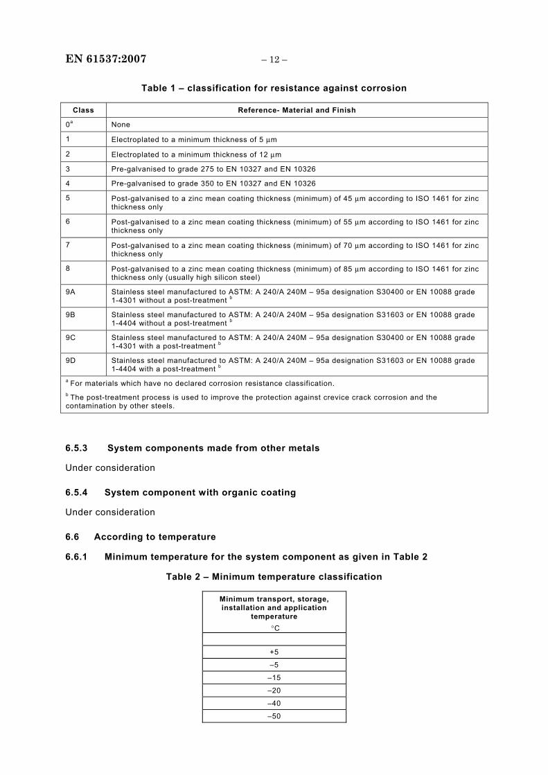
Table 1 – classification for resistance against corrosion
Class Reference- Material and Finish
0a None
1 Electroplated to a minimum thickness of 5 μm
2 Electroplated to a minimum thickness of 12 μm
3 Pre-galvanised to grade 275 to EN 10327 and EN 10326
4 Pre-galvanised to grade 350 to EN 10327 and EN 10326
5 Post-galvanised to a zinc mean coating thickness (minimum) of 45 μm according to ISO 1461 for zinc thickness only
6 Post-galvanised to a zinc mean coating thickness (minimum) of 55 μm according to ISO 1461 for zinc thickness only
7 Post-galvanised to a zinc mean coating thickness (minimum) of 70 μm according to ISO 1461 for zinc thickness only
8 Post-galvanised to a zinc mean coating thickness (minimum) of 85 μm according to ISO 1461 for zinc thickness only (usually high silicon steel)
9A Stainless steel manufactured to ASTM: A 240/A 240M – 95a designation S30400 or EN 10088 grade 1-4301 without a post-treatment b
9B Stainless steel manufactured to ASTM: A 240/A 240M – 95a designation S31603 or EN 10088 grade 1-4404 without a post-treatment b
9C Stainless steel manufactured to ASTM: A 240/A 240M – 95a designation S30400 or EN 10088 grade 1-4301 with a post-treatment b
9D Stainless steel manufactured to ASTM: A 240/A 240M – 95a designation S31603 or EN 10088 grade 1-4404 with a post-treatment b
a For materials which have no declared corrosion resistance classification. b The post-treatment process is used to improve the protection against crevice crack corrosion and the contamination by other steels.
6.5.3 System components made from other metals
Under consideration
6.5.4 System component with organic coating
Under consideration
6.6 According to temperature
6.6.1 Minimum temperature for the system component as given in Table 2
Table 2 – Minimum temperature classification
Minimum transport, storage, installation and application
temperature °C
+5
–5
–15
–20
–40
–50
– 13 – EN 61537:2007
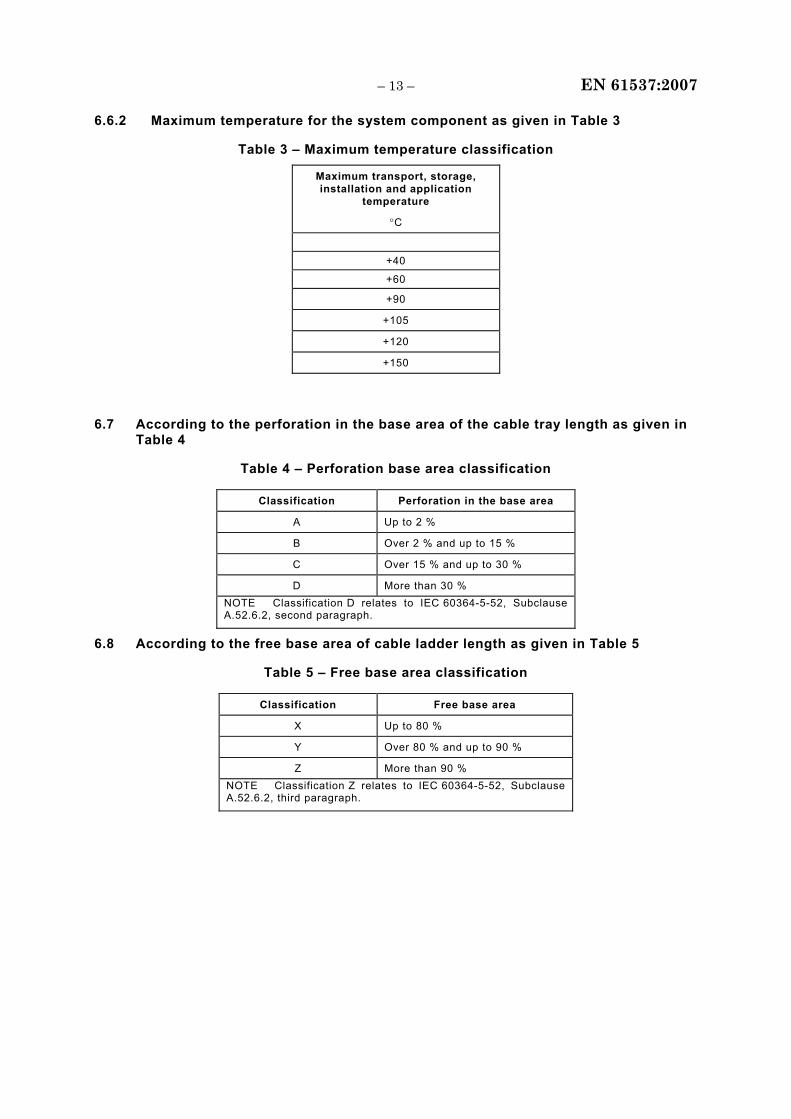
6.6.2 Maximum temperature for the system component as given in Table 3
Table 3 – Maximum temperature classification
Maximum transport, storage, installation and application
temperature
°C
+40
+60
+90
+105
+120
+150
6.7 According to the perforation in the base area of the cable tray length as given in Table 4
Table 4 – Perforation base area classification
Classification Perforation in the base area
A Up to 2 %
B Over 2 % and up to 15 %
C Over 15 % and up to 30 %
D More than 30 % NOTE Classification D relates to IEC 60364-5-52, Subclause A.52.6.2, second paragraph.
6.8 According to the free base area of cable ladder length as given in Table 5
Table 5 – Free base area classification
Classification Free base area
X Up to 80 %
Y Over 80 % and up to 90 %
Z More than 90 % NOTE Classification Z relates to IEC 60364-5-52, Subclause A.52.6.2, third paragraph.
EN 61537:2007 – 14 –
6.9 According to impact resistance
6.9.1 System component offering impact resistance up to 2 J
6.9.2 System component offering impact resistance up to 5 J
6.9.3 System component offering impact resistance up to 10 J
6.9.4 System component offering impact resistance up to 20 J
6.9.5 System component offering impact resistance up to 50 J
7 Marking and documentation
7.1 Each system component shall be durably and legibly marked with – the manufacturer's or responsible vendor's name or trade mark or identification mark; – a product identification mark which may be, for example, a catalogue number, a symbol,
or the like.
When system components other than cable tray lengths and cable ladder lengths are supplied in a package, the product identification mark may be, as an alternative, marked on the smallest package unit.
NOTE 1 The necessity to mark flame propagating system components is under consideration.
Compliance is checked by inspection and, for marking on the product, by rubbing by hand for 15 s with a piece of cotton cloth soaked with water and again for 15 s with a piece of cotton cloth soaked with petroleum spirit.
After the test, the marking shall be legible.
NOTE 2 Petroleum spirit is defined as the aliphatic solvent hexane with a content of aromatics of maximum 0,1 % volume, a kauributanol value of 29, an initial boiling point of 65 °C, a dry point of 69 °C and a specific gravity of approximately 0,68 kg/l.
NOTE 3 Marking may be applied, for example, by moulding, pressing, engraving, printing, adhesive labels, or water slide transfers.
NOTE 4 Marking made by moulding, pressing, or engraving is not subjected to the rubbing test.
7.2 If a system component can, by taking precautions, be stored and transported at a temperature outside the declared temperatures according to Tables 2 and 3, the manufacturer or responsible vendor shall declare the precautions and the alternative temperature limits.
Compliance is checked by inspection.
7.3 The manufacturer or responsible vendor shall provide in his literature all information necessary for the proper and safe installation and use of the cable tray system and cable ladder system. The SWL and impact resistance is valid for the whole temperature classification declared. The information shall include
a) instructions for the assembly and installation of system components and for the precautions required to avoid excessive transverse deflection, which could cause damage to the cables (see 5.2, 9.2, 10.3, 10.7, 10.8, and 14.1),
b) thermal expansion properties and precautions to be taken, if necessary,
c) classification according to Clause 6,
d) relative humidity if it affects the classifications (see 5.7),
e) information on holes or devices when provided for equipotential bonding (see 6.3.2) in particular when a specific electrical connection device is necessary,
– 15 – EN 61537:2007
f) precautions for transport and storage outside the declared temperature classification, where applicable (see 7.2),
g) product dimensions (see Clause 8),
h) torque settings in Nm for screwed connections and internal fixing devices as well as threads, where applicable (see 9.3d) and 9.3.1),
i) end span limitations (see 10.3),
j) position and type of coupling along the span, where applicable,
k) SWL in N/m for the fittings when not directly supported and the distance Y from the supports adjacent to the fittings (see 10.7),
l) fixing method for installing cable tray or cable ladder to the supports when declared for the test (see 10.3, 10.4 and 10.8.1),
m) SWL in N/m for the cable tray lengths or cable ladder lengths including joints, where applicable for one or more of the following installation methods (see 10.1):
i) mounted in the horizontal plane running horizontally on multiple spans (see 10.3) ii) mounted in the horizontal plane running horizontally on a single span (see 10.4) iii) mounted in the vertical plane running horizontally (see 10.5) iv) mounted in the vertical plane running vertically (see 10.6),
n) SWL in N for cantilever brackets and if used for cable tray only (see 10.8.1),
o) SWL for pendants as a bending moment in Nm and/or as a force in N (see 10.8.2), p) the appropriate material specification and environmental conditions, chemical
environments or aggressive agents for which the product is suitable (see 14.2). NOTE SWL information can be given in the form of a diagram, table, or similar.
Compliance is checked by inspection.
8 Dimensions
The manufacturer or responsible vendor shall give the following information:
− the overall envelope of the cross-section of the cable tray length or cable ladder length;
− the width of the base area of cable tray length or cable ladder length;
− the height of the cable tray length or cable ladder length available for the accommodation of cables when a cover is fitted;
− the minimum internal radius of fittings available for the accommodation of cables;
− the dimensions of the perforations, and their arrangements on the cable tray lengths;
− the dimensions of the rungs including perforations, if any, and the centre line spacing of the rungs.
NOTE System components, such as fittings, when used as part of the system, may change the effective area available for the accommodation of cables.
Compliance is checked by inspection.
EN 61537:2007 – 16 –
9 Construction
The same sample may be used for all the tests in this clause.
9.1 Surfaces of system components which are likely to come into contact with cables during installation or use shall not cause damage to the cables when installed according to the manufacturer's or responsible vendor's instructions.
Compliance is checked by inspection and, if necessary, by manual test.
9.2 Where the manufacturer or responsible vendor does not declare the use of gloves for installation purposes, then the surfaces of system components shall be safe for handling.
Compliance is checked by inspection and, if necessary, by manual test.
9.3 Screwed connections and other internal fixing devices shall be so designed to withstand the mechanical stresses occurring during installations according to the manufacturer's or responsible vendor's instructions and normal use. They shall not cause damage to the cable when correctly inserted.
Screwed connections can be either
a) ISO metric threads, or b) a thread forming type, or c) a thread cutting type if suitable design provisions are made, or d) threads other than a) to c) as specified by the manufacturer or responsible vendor.
Compliance is checked by 9.3.1 or 9.3.2 or 9.3.3.
9.3.1 Sudden or jerky motions shall not be used to tighten reusable screwed connections. To test the screwed connection, it shall be tightened and removed
• 10 times for metal screwed connections in engagement with a thread of non-metallic material and for screwed connections of non-metallic material,
or
• 5 times in all other cases.
The test is carried out using a suitable screwdriver or spanner to apply the torque as specified by the manufacturer or responsible vendor.
After the test, there shall be no breakage or damage, that will impair the further use of the screwed connection.
9.3.2 Reusable connections other than screwed connections, for example push-on and clamping connections, shall be tightened and removed 10 times.
After the test, there shall be no damage to impair the further use of the reusable connections.
9.3.3 Non-reusable connections are checked by inspection and, if necessary, by manual test.
9.4 Any apparatus mounting device shall meet the requirement of the appropriate standard.
– 17 – EN 61537:2007
9.5 Cable tray lengths, when perforated, shall exhibit a regular perforation pattern over the base area.
Compliance is checked by inspection and measurement.
9.6 Cable ladder lengths shall exhibit a regular rung pattern over the base area.
Compliance is checked by inspection and measurement.
10 Mechanical properties
10.1 Mechanical strength
Cable tray systems and cable ladder systems shall provide adequate mechanical strength.
The main criterion for the SWL is safety in use of the product.
For the declared application, the manufacturer or responsible vendor shall declare the SWL to be tested
– in N/m for each type of cable tray length or cable ladder length at specified distances, preferably in spans of 0,5 m increments, between the support devices,
– in N/m for each type of fitting which is not directly supported by a support device, – in N or N/m for each type of support device. NOTE 1 This information can be given in the form of a diagram or table or similar.
Compliance for cable runways is checked by carrying out the relevant tests according to the manufacturer's or responsible vendor's declaration as specified in 10.3, 10.4, 10.5, 10.6 and 10.7 on samples of the widest and narrowest width for each product type. For the intermediate widths the SWLs shall then be determined by interpolation of the test results. The alternative is to test only the widest product. For the tests specified in 10.3, 10.4 and 10.7, the SWL of an untested narrower width may be derived by multiplying the SWL of the tested widest width by the factor of the narrower width divided by the widest (tested) width.
Compliance for support devices is checked by carrying out the tests specified in 10.8.
NOTE 2 An overview of the SWL test procedure is shown in Annex L.
Cable tray system components and cable ladder system components shall withstand impacts occurring during transport, storage and installation.
Compliance is checked by the test specified in 10.9.
10.2 SWL test procedure
In 10.2.1 and 10.2.2, the general procedure and alternative procedures for particular cases are respectively described.
EN 61537:2007 – 18 –
10.2.1 General procedure
Two tests shall be carried out:
• minimum temperature test according to 10.2.1.1;
• maximum temperature test according to 10.2.1.2 or 10.2.1.3.
NOTE For alternative test conditions, see 10.2.2.
10.2.1.1 Minimum temperature test
The test shall be carried out at minimum temperature declared according to the classification of Table 2. During this test, the uniformity of the temperature shall be maintained within the tolerance of ± 5° C, 0,25 m around the samples.
The mounted sample shall be conditioned for a minimum of 2 h at the minimum temperature before loading.
All loads shall be uniformly distributed over the length and width of the sample as shown in Annex D.
The load shall be applied in such a way that a UDL is ensured even in the case of extreme deformation of the sample.
Typical methods of applying a UDL are shown in Annex E.
To allow for settlement of the sample, a pre-load of 10 % of the SWL, unless otherwise specified, shall be applied for 5 min ± 30 s and then removed. At this time, the measurement apparatus shall be calibrated to zero.
The load shall then be increased by increments or continuously on each sample through the load distribution plates, evenly longitudinally and transversely up to the SWL. Increments shall not be heavier than a quarter of the SWL.
After loading, the deflection shall be measured at the points specified for each test arrangement.
For the tests in 10.3, 10.4, 10.5, 10.6, and 10.7, the mid span deflection of each sample is the arithmetic mean of the deflections at the two measuring points near the side members as shown in Figure 1, key 8.
Where visible transversal deformation occurs, a third measurement of deflection shall be taken in the centre of the cable tray base or cable ladder base at mid-span as shown in Figure 1, key 7 or Figure 5, point s for fittings. The transverse deflection shall be calculated by subtracting the mid-span deflection from the third readings.
The sample shall be left loaded and the deflections measured every 5 min ± 30 s until the difference between two consecutive sets of readings is less than 2 % with regard to the first set of the two consecutive sets of readings. The first set of readings measured at this point are the deflections measured at the SWL. For an example see Annex G.
– 19 – EN 61537:2007
When subjected to the SWL, the sample, its joints and internal fixing devices shall show no damage or crack visible to normal view or corrected vision without magnification and the deflections of each sample shall not exceed the values specified in 10.3, 10.4, 10.5, 10.6, 10.7, and 10.8.
The load on the sample shall then be increased to 1,7 times the SWL.
The sample shall be left and the deflections measured every 5 min ± 30 s until the difference between two consecutive sets of readings is less than 2 % with regard to the first set of the two consecutive sets of readings.
The sample shall sustain the increased loading without collapsing. Buckling and deformation of the sample are permissible at this loading.
10.2.1.2 Maximum temperature test for temperatures ≤ 60°C
The test shall be carried out at maximum temperature declared according to the classification of Table 3. During this test, the uniformity of the temperature shall be maintained within the tolerance of ± 5° C, 0,25 m around the samples.
The mounted sample shall be conditioned for a minimum of 2 h at the maximum temperature before loading.
All loads shall be uniformly distributed over the length and width of the sample as shown in Annex D.
The load shall be applied in such a way that a UDL is ensured even in the case of extreme deformation of the sample.
Typical methods of applying a UDL are shown in Annex E.
To allow for settlement of the sample, a pre-load of 10 % of the SWL, unless otherwise specified, shall be applied for 5 min ± 30 s and then removed. At this time, the measurement apparatus shall be calibrated to zero.
The load shall then be increased by increments or continuously on each sample through the load distribution plates, evenly longitudinally and transversely up to the SWL. Increments shall not be heavier than a quarter of the SWL.
After loading, the deflection shall be measured at the points specified for each test arrangement.
For the tests in 10.3, 10.4, 10.5, 10.6, and 10.7, the mid span deflection of each sample is the arithmetic mean of the deflections at the two measuring points near the side members as shown in Figure 1, key 8.
Where visible transversal deformation occurs, a third measurement of deflection shall be taken in the centre of the cable tray base or cable ladder base at mid-span as shown in Figure 1, key 7 or Figure 5, point s for fittings. The transverse deflections shall be calculated by subtracting the mid-span deflection from the third readings.
EN 61537:2007 – 20 –
The sample shall be left loaded and the deflections measured every 5 min ± 30 s until the difference between two consecutive sets of readings is less than 2 % with regard to the first set of the two consecutive sets of readings. The first set of readings measured at this point are the deflections measured at the SWL. For an example, see Annex G.
When subjected to the SWL, the sample, its joints and internal fixing devices shall show no damage or crack visible to normal view or corrected vision without magnification and the deflections of each sample shall not exceed the values specified in 10.3, 10.4, 10.5, 10.6, 10.7, and 10.8.
The load on the sample shall then be increased to 1,7 times the SWL.
The sample shall be left and the deflections measured every 5 min ± 30 s until the difference between two consecutive sets of readings is less than 2 % with regard to the first set of the two consecutive sets of readings.
The sample shall sustain the increased loading without collapsing. Buckling and deformation of the sample are permissible at this loading.
10.2.1.3 Maximum temperature test for temperatures > 60°C
The test is carried out as sub-tests A and B. The number of samples for each sub-test is determined from the sample requirement detailed in tests 10.3 to 10.8. The number of samples shall be equal for each sub-test.
Sub-tests A and B shall be carried out from phase 1 through to phase 3 as shown in Figure 12.
Phase 1: loading from zero to SWL for sub-test A and from zero to 1,7 SWL for sub-test B
This phase shall be carried out at ambient temperature.
All loads shall be uniformly distributed over the length and width of each sample as shown in Annex D.
The load shall be applied in such a way that a UDL is ensured even in the case of extreme deformation of the samples.
Typical methods of applying a UDL are shown in Annex E.
To allow for settlement of each sample, a pre-load of 10 % of the SWL, unless otherwise specified, shall be applied for 5 min ± 30 s and then removed. At this time, the measurement apparatus shall be calibrated to zero.
The load shall then be increased by increments or continuously on each sample through the load distribution plates, evenly longitudinally and transversely up to the SWL for sub-test A and up to 1,7 SWL for sub-test B. Increments shall not be heavier than a quarter of the SWL.
– 21 – EN 61537:2007
Phase 2: temperature rise
Immediately after phase 1 sub-tests A and B shall be continued by elevating the temperature on the samples from ambient temperature to the maximum temperature declared according to Table 3. The declared temperature shall be reached no sooner than 24 h and no later than 48 h after starting the temperature rise.
Phase 3: evaluation of test results
This phase shall be carried out immediately after phase 2 at the declared temperature according to Table 3. During this phase, the uniformity of the temperature shall be maintained within the tolerance of ± 5° C, 0,25 m around the samples.
This phase requires different procedures for sub-tests A and B.
Sub-test A (measurement of deflection)
During this phase the deflection of the sample, subjected to SWL, shall be measured at the points specified for each test arrangement.
For the tests in 10.3, 10.4, 10.5, 10.6 and 10.7, the mid-span deflection of each sample is the arithmetic mean of the deflections at the two measuring points near the side members as shown in Figure 1, key 8.
Where visible transversal deformation occurs, a third measurement of deflection shall be taken in the centre of each cable tray base or cable ladder base at mid span as shown in Figure 1, key 7, or Figure 5, point s for fittings.
The transverse deflections shall be calculated by subtracting the mid span deflections from the third readings.
The sample shall be left and the deflections measured every 5 min ± 30 s until the difference between two consecutive sets of readings is less than 2 % with regard to the first set of the two consecutive set of readings. The first set of readings, measured at this point, is all the deflections measured at the SWL. For an example, see Annex G.
When subjected to the SWL, the sample, its joints and internal fixing devices shall show no damage or crack visible to normal view or corrected vision without magnification and the deflections shall not exceed the values specified in 10.3, 10.4, 10.5, 10.6, 10.7 and 10.8.
Sub-test B (evaluation of no collapsing)
The sample shall be left and the deflections measured every 5 min ± 30 s until the difference between two consecutive sets of readings is less than 2 % with regard to the first set of the two consecutive sets of readings.
The sample shall sustain the increased loading without collapsing. Buckling and deformation of the sample is permissible at this loading.
EN 61537:2007 – 22 –
10.2.2 Alternative test conditions for 10.2.1
The procedure according to 10.2.1 can be modified by the conditions detailed in either a) or b) or c) below. Different conditions, as detailed in a) or b) or c) can be used for different system components:
a) at any temperature within the declared range if documentation is available which states that the relevant mechanical properties of the materials as used within the samples do not differ by more than ± 5 % of the average between the maximum and minimum property values due to temperature change within the declared temperature range; NOTE An example of a material that fulfils this condition is steel in a range of temperature from -20 ºC to + 120 ºC.
b) only at maximum temperature within the range according to 10.2.1.2 or 10.2.1.3, if documentation is available which states that the relevant mechanical properties of the materials improve when the temperature is decreasing.
c) at maximum and minimum temperature within the range according to 10.2.1 only for the smallest and largest sizes of cable tray lengths or cable ladder lengths having the same material, joint and topological shape. The other sizes can be tested at ambient temperature only.
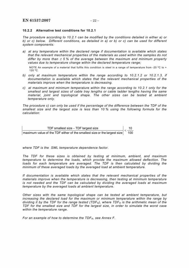
The procedure c) can only be used if the percentage of the difference between the TDF of the smallest size and the largest size is less than 10 % using the following formula for the calculation:
where TDF is the SWL temperature dependence factor.
The TDF for these sizes is obtained by testing at minimum, ambient, and maximum temperature to determine the loads, which provide the maximum allowed deflection. The loads for each temperature are averaged. The TDF is then calculated by dividing the minimum of these averaged loads by the averaged load at ambient temperature.
If documentation is available which states that the relevant mechanical properties of the materials improve when the temperature is decreasing, then testing at minimum temperature is not needed and the TDF can be calculated by dividing the averaged loads at maximum temperature by the averaged loads at ambient temperature.
Other sizes with the same topological shape can be tested at ambient temperature, but increasing the declared load for the maximum or minimum temperature within the range by dividing it by the TDF for the range tested (TDFR), where TDFR is the arithmetic mean of the TDF for the smallest size and TDF for the largest size, in order to simulate the worst case within the temperature range.
For an example of how to determine the TDFR, see Annex F.
10010
size largest the or size smallest the of either TDF the of value maximumsize largest TDFsize smallest TDF
<−
– 23 – EN 61537:2007
10.3 Test for SWL of cable tray lengths and cable ladder lengths mounted in the horizontal plane running horizontally on multiple spans
The test shall be carried out on one sample. If the sample does not satisfy the test, the test shall be repeated on two new samples, both of which shall comply with the requirements.
The test is carried out on cable tray lengths and joints or cable ladder lengths and joints to verify the declared SWL when mounted over multiple spans with the cable tray or cable ladder in the flat and horizontal plane.
The test is carried out with the samples consisting of two or more cable tray lengths or cable ladder lengths. These shall be coupled, as shown in Figure 1 to form two full spans plus a cantilever. Joints are to be positioned as required for each test type following the manufacturer's or responsible vendor's instructions.
The samples shall be placed on fixed, rigid supports a, b and c, which shall be horizontal and level with a width of 45 mm ± 5 mm. The samples shall not be fixed to the supports unless a fixing method is declared by the manufacturer or responsible vendor in which case this fixing method shall be used.
For all test types, full standard cable tray lengths or cable ladder lengths shall be used for all intermediate lengths. Cut lengths shall only be used at the end positions required.
The cantilever of 0,4L can be increased slightly in length as described in Annex D, if necessary, to ensure a UDL on the cantilever.
Depending on the installation method(s) declared by the manufacturer or responsible vendor, one or more of the test types in accordance with 10.3.1 to 10.3.5 shall be used.
The tests for 10.3.1 to 10.3.5 shall be carried out in accordance with 10.2
The practical mid-span deflection of each span at the SWL shall not exceed 1/100th of the span.
The transverse deflection of each span at the SWL shall not exceed 1/20th of the width of the sample and the samples shall still ensure reliable support to any cables that would normally be contained therein without imposing any unreasonable hazard or danger to the user or cables.
10.3.1 Test type I
Test type I shall be used when the manufacturer or responsible vendor does not declare any end span limitations and where the joints shall be placed on all installations. In this case, joints can occur anywhere on an installation. The test arrangement shall be as shown in Figure 2a.
10.3.2 Test type II
Test type II shall be used when the manufacturer or responsible vendor declares that on all installations there shall be no joints in the end span. The test arrangement shall be as shown in Figure 2b.
If the manufacturer or responsible vendor declares that on all installations the end span shall be reduced in length, the end span X shall then be declared.
EN 61537:2007 – 24 –
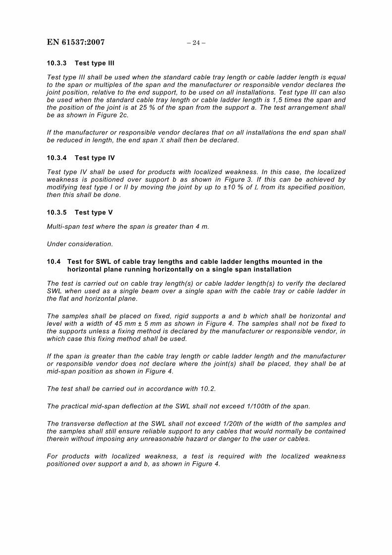
10.3.3 Test type III
Test type III shall be used when the standard cable tray length or cable ladder length is equal to the span or multiples of the span and the manufacturer or responsible vendor declares the joint position, relative to the end support, to be used on all installations. Test type III can also be used when the standard cable tray length or cable ladder length is 1,5 times the span and the position of the joint is at 25 % of the span from the support a. The test arrangement shall be as shown in Figure 2c.
If the manufacturer or responsible vendor declares that on all installations the end span shall be reduced in length, the end span X shall then be declared.
10.3.4 Test type IV
Test type IV shall be used for products with localized weakness. In this case, the localized weakness is positioned over support b as shown in Figure 3. If this can be achieved by modifying test type I or II by moving the joint by up to ±10 % of L from its specified position, then this shall be done.
10.3.5 Test type V
Multi-span test where the span is greater than 4 m.
Under consideration.
10.4 Test for SWL of cable tray lengths and cable ladder lengths mounted in the horizontal plane running horizontally on a single span installation
The test is carried out on cable tray length(s) or cable ladder length(s) to verify the declared SWL when used as a single beam over a single span with the cable tray or cable ladder in the flat and horizontal plane.
The samples shall be placed on fixed, rigid supports a and b which shall be horizontal and level with a width of 45 mm ± 5 mm as shown in Figure 4. The samples shall not be fixed to the supports unless a fixing method is declared by the manufacturer or responsible vendor, in which case this fixing method shall be used.
If the span is greater than the cable tray length or cable ladder length and the manufacturer or responsible vendor does not declare where the joint(s) shall be placed, they shall be at mid-span position as shown in Figure 4.
The test shall be carried out in accordance with 10.2.
The practical mid-span deflection at the SWL shall not exceed 1/100th of the span.
The transverse deflection at the SWL shall not exceed 1/20th of the width of the samples and the samples shall still ensure reliable support to any cables that would normally be contained therein without imposing any unreasonable hazard or danger to the user or cables.
For products with localized weakness, a test is required with the localized weakness positioned over support a and b, as shown in Figure 4.
– 25 – EN 61537:2007
If this can be achieved by moving the joint by up to ±10 % of span L from its specific position, this shall be done.
If the manufacturer or responsible vendor does not declare where the joints shall be placed, then this additional test shall be done, independent of the joint location.
This test is carried out identically to the standard test as described in 10.3 using the same SWL as the standard test.
10.5 Test for SWL of cable tray lengths and cable ladder lengths mounted in the vertical plane running horizontally
Under consideration.
10.6 Test for SWL of cable tray lengths and cable ladder lengths mounted in the vertical plane running vertically
Under consideration.
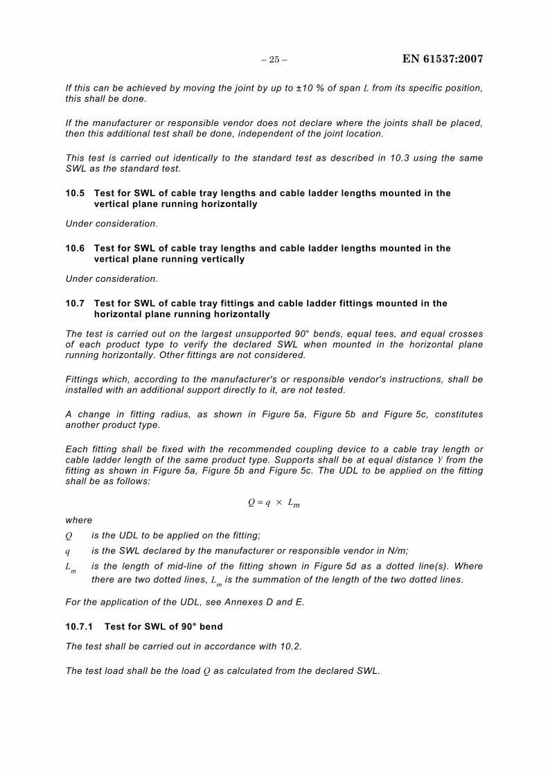
10.7 Test for SWL of cable tray fittings and cable ladder fittings mounted in the horizontal plane running horizontally
The test is carried out on the largest unsupported 90° bends, equal tees, and equal crosses of each product type to verify the declared SWL when mounted in the horizontal plane running horizontally. Other fittings are not considered.
Fittings which, according to the manufacturer's or responsible vendor's instructions, shall be installed with an additional support directly to it, are not tested.
A change in fitting radius, as shown in Figure 5a, Figure 5b and Figure 5c, constitutes another product type.
Each fitting shall be fixed with the recommended coupling device to a cable tray length or cable ladder length of the same product type. Supports shall be at equal distance Y from the fitting as shown in Figure 5a, Figure 5b and Figure 5c. The UDL to be applied on the fitting shall be as follows:
LqQ ×= m
where Q is the UDL to be applied on the fitting;
q is the SWL declared by the manufacturer or responsible vendor in N/m;
Lm
is the length of mid-line of the fitting shown in Figure 5d as a dotted line(s). Where there are two dotted lines, L
m is the summation of the length of the two dotted lines.
For the application of the UDL, see Annexes D and E.
10.7.1 Test for SWL of 90° bend
The test shall be carried out in accordance with 10.2.
The test load shall be the load Q as calculated from the declared SWL.
EN 61537:2007 – 26 –
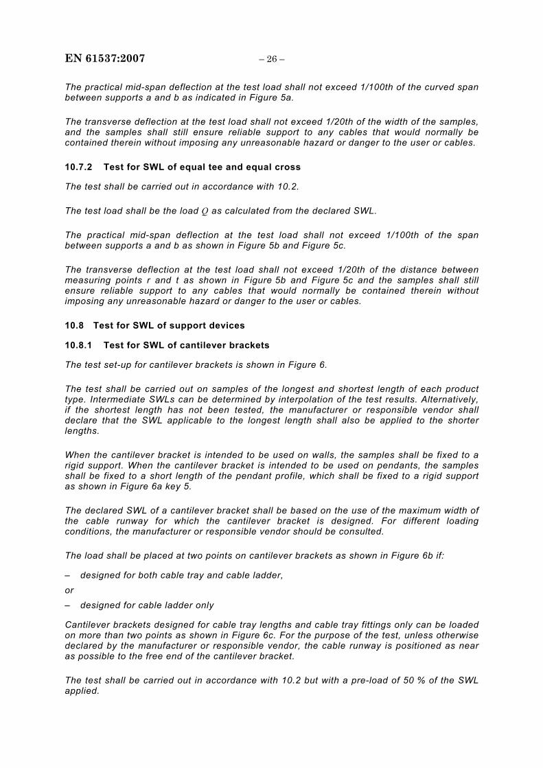
The practical mid-span deflection at the test load shall not exceed 1/100th of the curved span between supports a and b as indicated in Figure 5a.
The transverse deflection at the test load shall not exceed 1/20th of the width of the samples, and the samples shall still ensure reliable support to any cables that would normally be contained therein without imposing any unreasonable hazard or danger to the user or cables.
10.7.2 Test for SWL of equal tee and equal cross
The test shall be carried out in accordance with 10.2.
The test load shall be the load Q as calculated from the declared SWL.
The practical mid-span deflection at the test load shall not exceed 1/100th of the span between supports a and b as shown in Figure 5b and Figure 5c.
The transverse deflection at the test load shall not exceed 1/20th of the distance between measuring points r and t as shown in Figure 5b and Figure 5c and the samples shall still ensure reliable support to any cables that would normally be contained therein without imposing any unreasonable hazard or danger to the user or cables.
10.8 Test for SWL of support devices
10.8.1 Test for SWL of cantilever brackets
The test set-up for cantilever brackets is shown in Figure 6.
The test shall be carried out on samples of the longest and shortest length of each product type. Intermediate SWLs can be determined by interpolation of the test results. Alternatively, if the shortest length has not been tested, the manufacturer or responsible vendor shall declare that the SWL applicable to the longest length shall also be applied to the shorter lengths.
When the cantilever bracket is intended to be used on walls, the samples shall be fixed to a rigid support. When the cantilever bracket is intended to be used on pendants, the samples shall be fixed to a short length of the pendant profile, which shall be fixed to a rigid support as shown in Figure 6a key 5.
The declared SWL of a cantilever bracket shall be based on the use of the maximum width of the cable runway for which the cantilever bracket is designed. For different loading conditions, the manufacturer or responsible vendor should be consulted.
The load shall be placed at two points on cantilever brackets as shown in Figure 6b if:
– designed for both cable tray and cable ladder, or – designed for cable ladder only
Cantilever brackets designed for cable tray lengths and cable tray fittings only can be loaded on more than two points as shown in Figure 6c. For the purpose of the test, unless otherwise declared by the manufacturer or responsible vendor, the cable runway is positioned as near as possible to the free end of the cantilever bracket.
The test shall be carried out in accordance with 10.2 but with a pre-load of 50 % of the SWL applied.
– 27 – EN 61537:2007
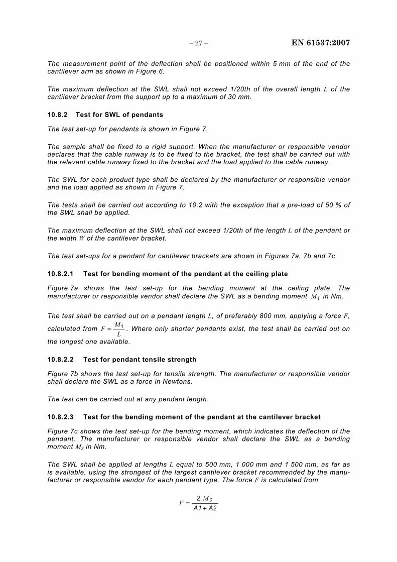
The measurement point of the deflection shall be positioned within 5 mm of the end of the cantilever arm as shown in Figure 6.
The maximum deflection at the SWL shall not exceed 1/20th of the overall length L of the cantilever bracket from the support up to a maximum of 30 mm.
10.8.2 Test for SWL of pendants
The test set-up for pendants is shown in Figure 7.
The sample shall be fixed to a rigid support. When the manufacturer or responsible vendor declares that the cable runway is to be fixed to the bracket, the test shall be carried out with the relevant cable runway fixed to the bracket and the load applied to the cable runway.
The SWL for each product type shall be declared by the manufacturer or responsible vendor and the load applied as shown in Figure 7.
The tests shall be carried out according to 10.2 with the exception that a pre-load of 50 % of the SWL shall be applied.
The maximum deflection at the SWL shall not exceed 1/20th of the length L of the pendant or the width W of the cantilever bracket.
The test set-ups for a pendant for cantilever brackets are shown in Figures 7a, 7b and 7c.
10.8.2.1 Test for bending moment of the pendant at the ceiling plate
Figure 7a shows the test set-up for the bending moment at the ceiling plate. The manufacturer or responsible vendor shall declare the SWL as a bending moment 1M in Nm.
The test shall be carried out on a pendant length L, of preferably 800 mm, applying a force F,
calculated from L
MF 1= . Where only shorter pendants exist, the test shall be carried out on
the longest one available.
10.8.2.2 Test for pendant tensile strength
Figure 7b shows the test set-up for tensile strength. The manufacturer or responsible vendor shall declare the SWL as a force in Newtons.
The test can be carried out at any pendant length.
10.8.2.3 Test for the bending moment of the pendant at the cantilever bracket
Figure 7c shows the test set-up for the bending moment, which indicates the deflection of the pendant. The manufacturer or responsible vendor shall declare the SWL as a bending moment M2 in Nm.
The SWL shall be applied at lengths L equal to 500 mm, 1 000 mm and 1 500 mm, as far as is available, using the strongest of the largest cantilever bracket recommended by the manu-facturer or responsible vendor for each pendant type. The force F is calculated from
A2A12 2
+=
MF
EN 61537:2007 – 28 –
where A1 and A2 are shown in Figure 7c.
NOTE The strongest cantilever bracket can be determined from the test results from 10.8.1.
Information for a safe installation of a pendant with cantilever brackets is given in Annex H.
10.8.2.4 Test for SWL of the pendant with mid-supported bracket
The SWL test set-up for a pendant with a mid-supported bracket is shown in Figure 7d.
10.8.2.5 Test for SWL of the pendant with end-supported bracket
The SWL test set-up for a pendant with an end-supported bracket is shown in Figure 7e.
10.8.3 Test for SWL of the fixing brackets when used to support cable tray lengths and cable ladder lengths vertically
Under consideration.
10.9 Test for impact resistance
The test is performed according to IEC 60068-2-75 using the pendulum hammer.
The test is carried out on samples of cable tray lengths or cable ladder lengths, 250 mm ± 5 mm long.
Samples of ladder shall consist of two side members with two rungs positioned centrally, and the sample length has to be increased accordingly. Samples of mesh trays shall be prepared in such a way that there will be a transverse wire in the centre.
Before the test, non-metallic and composite components are aged at a temperature of 60 °C ± 2 °C for 168 h continuously.
The samples shall be mounted on a wooden fibreboard of thickness 20 mm ± 2 mm. The samples to be tested shall be placed in a refrigerator, the temperature within is maintained at the declared temperature according to Table 2, with a tolerance of ±2 °C.
After a minimum of 2 h, the samples shall, in turn, be removed from the refrigerator and immediately placed in the test apparatus.
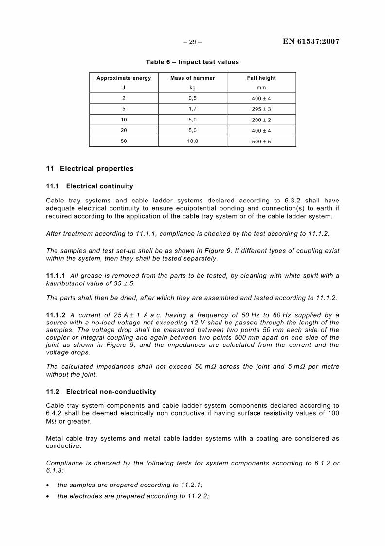
At 10 s ± 1 s after removal of each sample from the refrigerator, the hammer shall be allowed to fall with the declared impact energy according to 6.9. The mass of the hammer and the fall height shall be as given in Table 6 and shall be applied as shown in Figure 8.
The impact shall be applied to the base, or respectively a rung, in the first sample, to one of the side members in the second sample, and to the other side member in the third sample.
In each case, the impact is applied to the centre of the face being tested.
After the test, the samples shall show no signs of disintegration and/or deformation that impairs safety.
– 29 – EN 61537:2007
Table 6 – Impact test values
Approximate energy
J
Mass of hammer
kg
Fall height
mm
2 0,5 400 ± 4
5 1,7 295 ± 3
10 5,0 200 ± 2
20 5,0 400 ± 4
50 10,0 500 ± 5
11 Electrical properties
11.1 Electrical continuity
Cable tray systems and cable ladder systems declared according to 6.3.2 shall have adequate electrical continuity to ensure equipotential bonding and connection(s) to earth if required according to the application of the cable tray system or of the cable ladder system.
After treatment according to 11.1.1, compliance is checked by the test according to 11.1.2.
The samples and test set-up shall be as shown in Figure 9. If different types of coupling exist within the system, then they shall be tested separately.
11.1.1 All grease is removed from the parts to be tested, by cleaning with white spirit with a kauributanol value of 35 ± 5.
The parts shall then be dried, after which they are assembled and tested according to 11.1.2.
11.1.2 A current of 25 A ± 1 A a.c. having a frequency of 50 Hz to 60 Hz supplied by a source with a no-load voltage not exceeding 12 V shall be passed through the length of the samples. The voltage drop shall be measured between two points 50 mm each side of the coupler or integral coupling and again between two points 500 mm apart on one side of the joint as shown in Figure 9, and the impedances are calculated from the current and the voltage drops.
The calculated impedances shall not exceed 50 mΩ across the joint and 5 mΩ per metre without the joint.
11.2 Electrical non-conductivity
Cable tray system components and cable ladder system components declared according to 6.4.2 shall be deemed electrically non conductive if having surface resistivity values of 100 MΩ or greater.
Metal cable tray systems and metal cable ladder systems with a coating are considered as conductive.
Compliance is checked by the following tests for system components according to 6.1.2 or 6.1.3:
• the samples are prepared according to 11.2.1;
• the electrodes are prepared according to 11.2.2;
EN 61537:2007 – 30 –
• the samples are subjected to the humidity treatment according to 11.2.3;
• the samples are mounted according to 11.2.4;
• the surface resistance values are measured according to 11.2.5;
• the surface resistivity value is calculated according to 11.2.6.
11.2.1 Preparation of samples
For cable tray systems, prepare plate samples having a width of (25 ± 0,5) mm and a length of 50 mm.
For cable ladder systems, prepare plate samples from the side rail having a width of (25 ± 0,5) mm and a length of 50 mm.
11.2.2 Preparation of electrodes
The two electrodes:
• shall be made of a suitable conductive material not subjected to corrosion under the conditions of the test and not reacting with the material being tested;
• shall have the dimensions: 10 mm x 10 mm x 50 mm.
11.2.3 Humidity treatment of samples
The humidity treatment shall be carried out in a humidity cabinet with a relative humidity between 91 % and 95 % at a temperature t, maintained within ± 1 oC of any convenient value between 20 oC and 30 oC.
Before being placed in the humidity cabinet, the samples are brought to a temperature between t and (t + 4) oC. This may be achieved by keeping them at this temperature for at least 4 h before the humidity treatment.
The samples are kept in the humidity cabinet for 24 h.
A relative humidity between 91 % and 95 % can be obtained by placing in the humidity cabinet a saturated solution of sodium sulphate (Na2SO4) or potassium nitrate (KNO3) in water having a substantially large contact surface with air.
In order to achieve the specified conditions within the cabinet, it is necessary to ensure constant circulation of the air within and, in general, to use a cabinet which is thermally insulated.
11.2.4 Mounting of electrodes on samples
The electrodes shall be mounted on the samples for measurement according to Figure 13. The electrodes shall be spaced (25 ± 0,5) mm.
11.2.5 Measurement of surface resistance
The samples shall be subjected to a d.c. voltage equal to (500 ± 10) V for 1 min.
At the end of this time, while maintaining the voltage, the surface resistance shall be measured.
The surface resistance may be determined either by a bridge method or by measuring the current and voltage.
– 31 – EN 61537:2007
The measurement system shall guarantee an overall accuracy of surface resistance measurement of at least ± 10 %.
11.2.6 Calculation of surface resistivity
The surface resistivity shall be calculated from the following formula:
σ = Rx x p/g
where:
σ is the surface resistivity in ohm; Rx is the measured surface resistance in ohm;
p is twice the width of the sample in mm;
g is the distance between the electrodes in mm.
12 Thermal properties
Under consideration.
13 Fire hazards
13.1 Reaction to fire
13.1.1 Initiation of fire
This item is not relevant for cable tray systems and cable ladder systems.
13.1.2 Contribution to fire
System components declared according to 6.1.2 and 6.1.3 which might be exposed to abnormal heat due to an electrical fault shall have limited ignitability.
NOTE Only parts that can be in contact with electrical cables should be considered.
Compliance is checked by the test according to IEC 60695-2-11:2000, Clauses 4 to 10, with a glow-wire temperature of 650 °C.
Small parts, such as washers, are not subject to the test of this subclause.
The test is not carried out on parts made of ceramic or metallic material.
The test is carried out on one sample, which may be tested at more than one point.
The test is carried out applying the glow-wire once for 30 s.
The sample is regarded as having passed the glow-wire test if
– there is no visible flame and no substantial glowing, or – flames and glowing at the sample extinguish within 30 s after removal of the glow-wire.
There shall be no ignition of the tissue paper or scorching of the board.

EN 61537:2007 – 32 –
In case of doubt, the test shall be repeated on two further samples.
NOTE Requirements for the rate of heat release are under consideration.
13.1.3 Spread of fire
Non-flame propagating systems components shall either not ignite or, if ignited, shall have a limited spread of fire.
Compliance is checked as follows:
– for system components of non-metallic or composite material other than cable tray lengths or cable ladder lengths by the test of 13.1.2 at a glow wire temperature of 650 °C. Parts that have already been tested in accordance with 13.1.2 are not tested again;
– for cable tray lengths or cable ladder lengths of non-metallic or composite material, by the following flame test.
The flame test is carried out on samples that have a length of 675 mm ± 10 mm.
The test is performed using the burner specified in IEC 60695-11-2.
The samples shall be placed as shown in Figure 10 in a rectangular metal enclosure with one open face as shown in Figure 11 in an area substantially free from draughts. Each sample shall be clamped at both ends, in order to prevent distortion or movement of the sample itself under flame application conditions. In the case of cable ladder lengths, the top face of the rung shall be positioned 100 mm from the upper extremity of the lower clamp.
The burner is positioned as shown in Figure 10 with the flame applied
− to the middle of the side rail of the inside face of the cable ladder length,
− to the inside face at the junction between the base and the side flange of the cable tray length.
The internal lower surface of the enclosure shall be covered with a piece of pine or particle board, approximately 10 mm thick, covered with a single layer of tissue paper of a density between 12 g/m2 and 30 g/m2, in accordance with ISO 4046.
The samples shall be subjected to the exposure of the flame for 60 s ± 2 s.
The sample shall be regarded to have passed the test if
− it does not ignite, or if
− in the case of ignition, the following three conditions are fulfilled: a) the flame extinguishes within 30 s after removal of the test flame, b) there is no ignition of the tissue paper or scorching of the board, c) there is no evidence of burning or charring above 50 mm below the lower extremity of
the upper clamp.
NOTE If perforated system components are made from unperforated system components, the unperforated system component need not be tested.
13.1.4 Additional reaction to fire characteristics
Under consideration.
– 33 – EN 61537:2007
13.2 Resistance to fire
Under consideration.
14 External influences
14.1 Resistance against environmental forces
Snow, wind loading and other environmental forces are not considered to be the responsibility of the manufacturer or responsible vendor.
NOTE The designer of the installation should take into consideration the effects of snow, wind and other environmental forces where necessary.
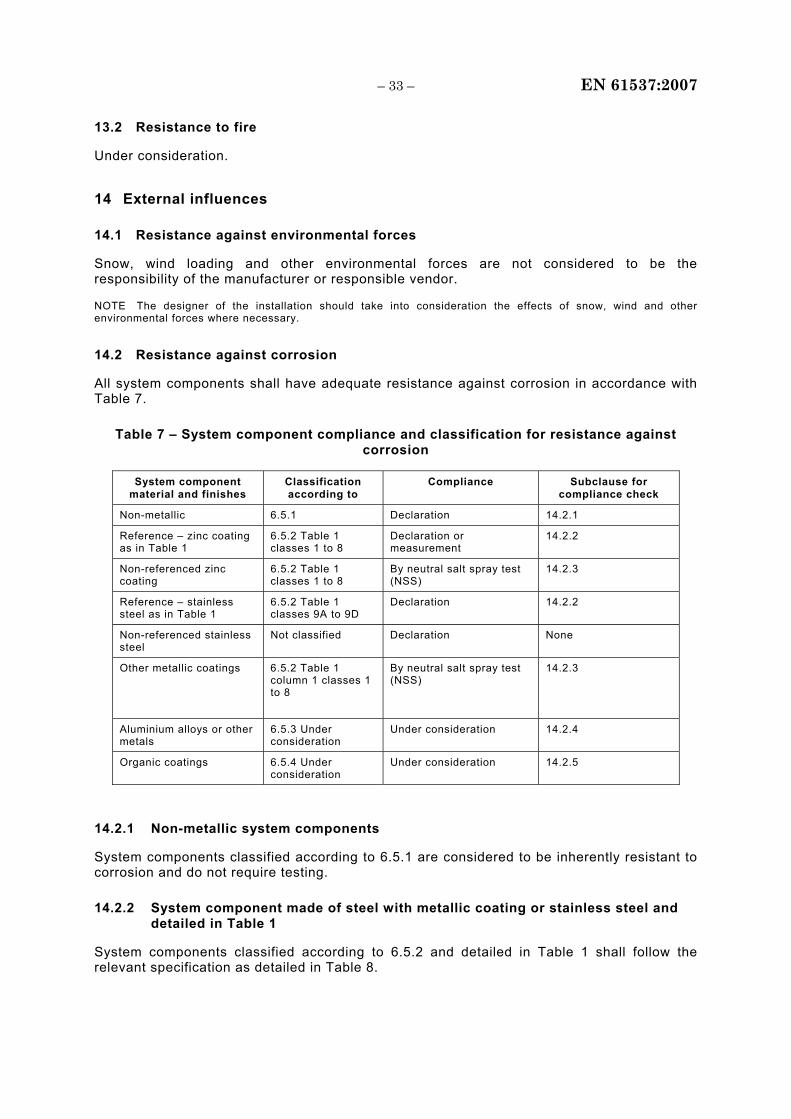
14.2 Resistance against corrosion
All system components shall have adequate resistance against corrosion in accordance with Table 7.
Table 7 – System component compliance and classification for resistance against corrosion
System component material and finishes
Classification according to
Compliance Subclause for compliance check
Non-metallic 6.5.1 Declaration 14.2.1
Reference – zinc coating as in Table 1
6.5.2 Table 1 classes 1 to 8
Declaration or measurement
14.2.2
Non-referenced zinc coating
6.5.2 Table 1 classes 1 to 8
By neutral salt spray test (NSS)
14.2.3
Reference – stainless steel as in Table 1
6.5.2 Table 1 classes 9A to 9D
Declaration 14.2.2
Non-referenced stainless steel
Not classified Declaration None
Other metallic coatings 6.5.2 Table 1 column 1 classes 1 to 8
By neutral salt spray test (NSS)
14.2.3
Aluminium alloys or other metals
6.5.3 Under consideration
Under consideration 14.2.4
Organic coatings 6.5.4 Under consideration
Under consideration 14.2.5
14.2.1 Non-metallic system components
System components classified according to 6.5.1 are considered to be inherently resistant to corrosion and do not require testing.
14.2.2 System component made of steel with metallic coating or stainless steel and detailed in Table 1
System components classified according to 6.5.2 and detailed in Table 1 shall follow the relevant specification as detailed in Table 8.
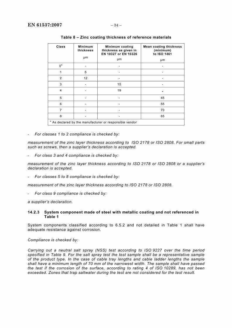
EN 61537:2007 – 34 –
Table 8 – Zinc coating thickness of reference materials
Class Minimum thickness
µm
Minimum coating thickness as given in EN 10327 or EN 10326
µm
Mean coating thickness (minimum) to ISO 1461
µm
0a - - -
1 5 - -
2 12 - -
3 - 15 -
4 - 19 - 5 - - 45
6 - - 55
7 - - 70
8 - - 85 a As declared by the manufacturer or responsible vendor
- For classes 1 to 2 compliance is checked by:
measurement of the zinc layer thickness according to ISO 2178 or ISO 2808. For small parts such as screws, then a supplier’s declaration is accepted.
- For class 3 and 4 compliance is checked by:
measurement of the zinc layer thickness according to ISO 2178 or ISO 2808 or a supplier’s declaration is accepted.
- For classes 5 to 8 compliance is checked by:
measurement of the zinc layer thickness according to ISO 2178 or ISO 2808.
- For class 9 compliance is checked by:
a supplier’s declaration.
14.2.3 System component made of steel with metallic coating and not referenced in Table 1
System components classified according to 6.5.2 and not detailed in Table 1 shall have adequate resistance against corrosion.
Compliance is checked by:
Carrying out a neutral salt spray (NSS) test according to ISO 9227 over the time period specified in Table 9. For the salt spray test the test sample shall be a representative sample of the product type. In the case of cable tray lengths and cable ladder lengths the sample shall have a minimum length of 70 mm of the narrowest width. The sample shall have passed the test if the corrosion of the surface, according to rating 4 of ISO 10289, has not been exceeded. Zones that trap saltwater during the test are not considered for the test result.
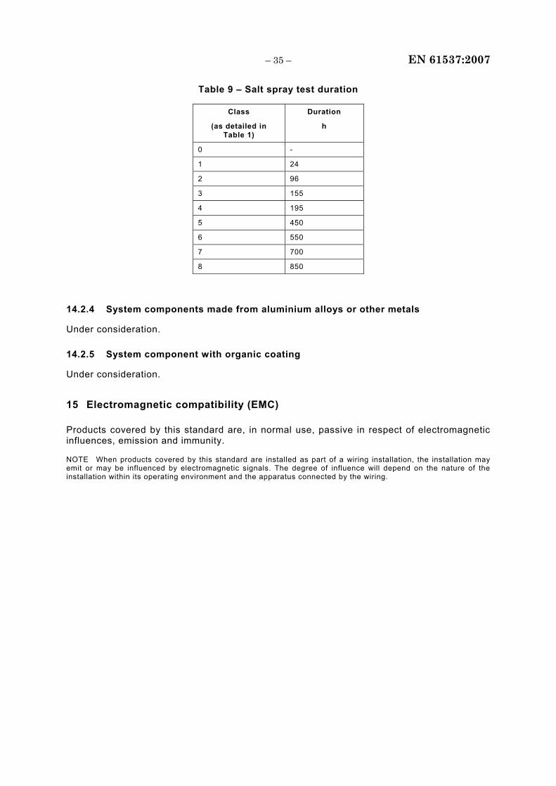
– 35 – EN 61537:2007
Table 9 – Salt spray test duration
Class
(as detailed in Table 1)
Duration
h
0 -
1 24
2 96
3 155
4 195
5 450
6 550
7 700
8 850
14.2.4 System components made from aluminium alloys or other metals
Under consideration.
14.2.5 System component with organic coating
Under consideration.
15 Electromagnetic compatibility (EMC)
Products covered by this standard are, in normal use, passive in respect of electromagnetic influences, emission and immunity.
NOTE When products covered by this standard are installed as part of a wiring installation, the installation may emit or may be influenced by electromagnetic signals. The degree of influence will depend on the nature of the installation within its operating environment and the apparatus connected by the wiring.
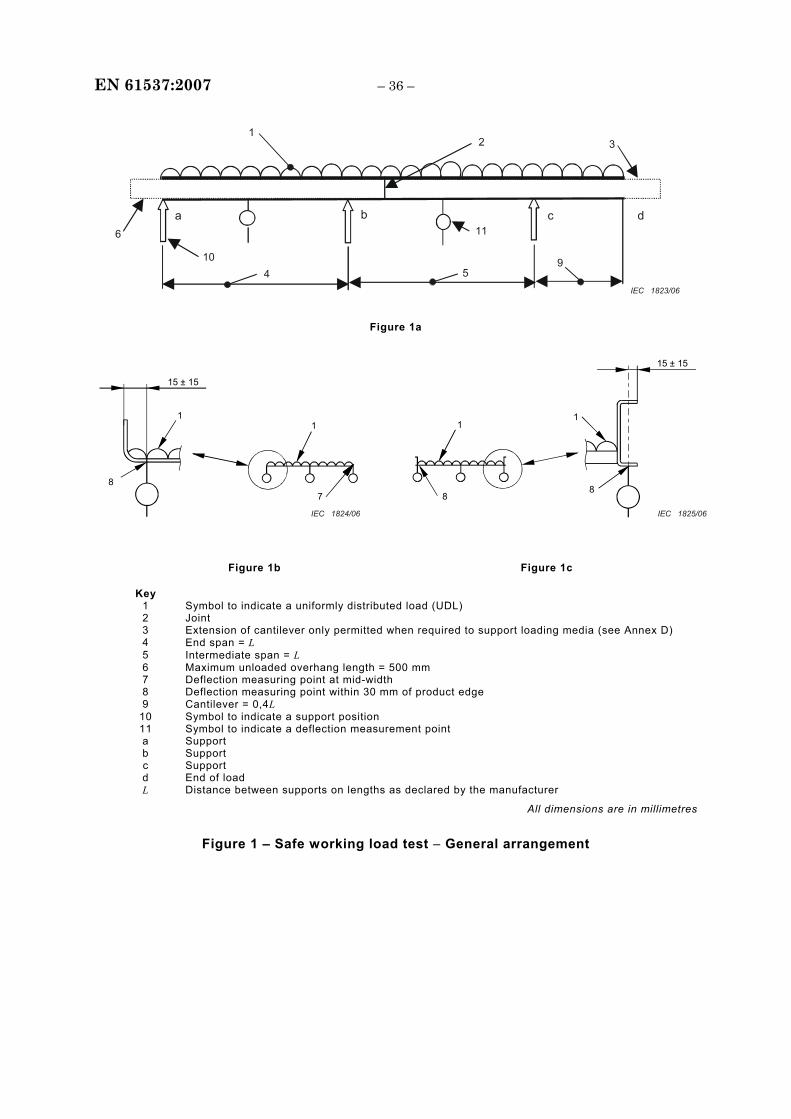
EN 61537:2007 – 36 –
1 2 3
6 10
4 59
11a b c d
IEC 1823/06
Figure 1a
15 ± 15
7
1 1
8 8
1
8
1
15 ± 15
IEC 1824/06 IEC 1825/06
Figure 1b Figure 1c
Key 1 Symbol to indicate a uniformly distributed load (UDL) 2 Joint 3 Extension of cantilever only permitted when required to support loading media (see Annex D) 4 End span = L 5 Intermediate span = L 6 Maximum unloaded overhang length = 500 mm 7 Deflection measuring point at mid-width 8 Deflection measuring point within 30 mm of product edge 9 Cantilever = 0,4L
10 Symbol to indicate a support position 11 Symbol to indicate a deflection measurement point a Support b Support c Support d End of load L Distance between supports on lengths as declared by the manufacturer
All dimensions are in millimetres
Figure 1 – Safe working load test − General arrangement
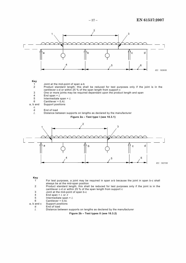
– 37 – EN 61537:2007
4
21 3
5 6
ba c d
IEC 1826/06
Key 1 Joint at the mid-point of span a-b 2 Product standard length; this shall be reduced for test purposes only if the joint is in the
cantilever c-d or within 25 % of the span length from support c 3 One or more joints may be required dependant upon the product length and span 4 End span = L 5 Intermediate span = L 6 Cantilever = 0,4L
a, b and c
Support positions
d End of load L Distance between supports on lengths as declared by the manufacturer
Figure 2a – Test type I (see 10.3.1)
4
21 3
5 6
ba c d
IEC 1827/06
Key
1 For test purposes, a joint may be required in span a-b because the joint in span b-c shall always be at the mid-span position
2 Product standard length; this shall be reduced for test purposes only if the joint is in the cantilever c-d or within 25 % of the span length from support c
3 Joint at the mid-point of span b-c 4 End span = L or X 5 Intermediate span = L 6 Cantilever = 0,4L
a, b and c Support positions d End of load L Distance between supports on lengths as declared by the manufacturer
Figure 2b – Test types II (see 10.3.2)
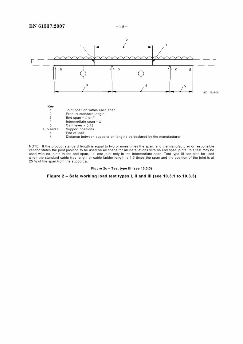
EN 61537:2007 – 38 –
3
2
1 1
4 5
ba c d
IEC 1828/06
Key 1 Joint position within each span 2 Product standard length 3 End span = L or X 4 Intermediate span = L 5 Cantilever = 0,4L
a, b and c Support positions d End of load L Distance between supports on lengths as declared by the manufacturer
NOTE If the product standard length is equal to two or more times the span, and the manufacturer or responsible vendor states the joint position to be used on all spans for all installations with no end span joints, this test may be used with no joints in the end span, i.e. one joint only in the intermediate span. Test type III can also be used when the standard cable tray length or cable ladder length is 1,5 times the span and the position of the joint is at 25 % of the span from the support a.
Figure 2c – Test type III (see 10.3.3)
Figure 2 – Safe working load test types I, II and III (see 10.3.1 to 10.3.3)
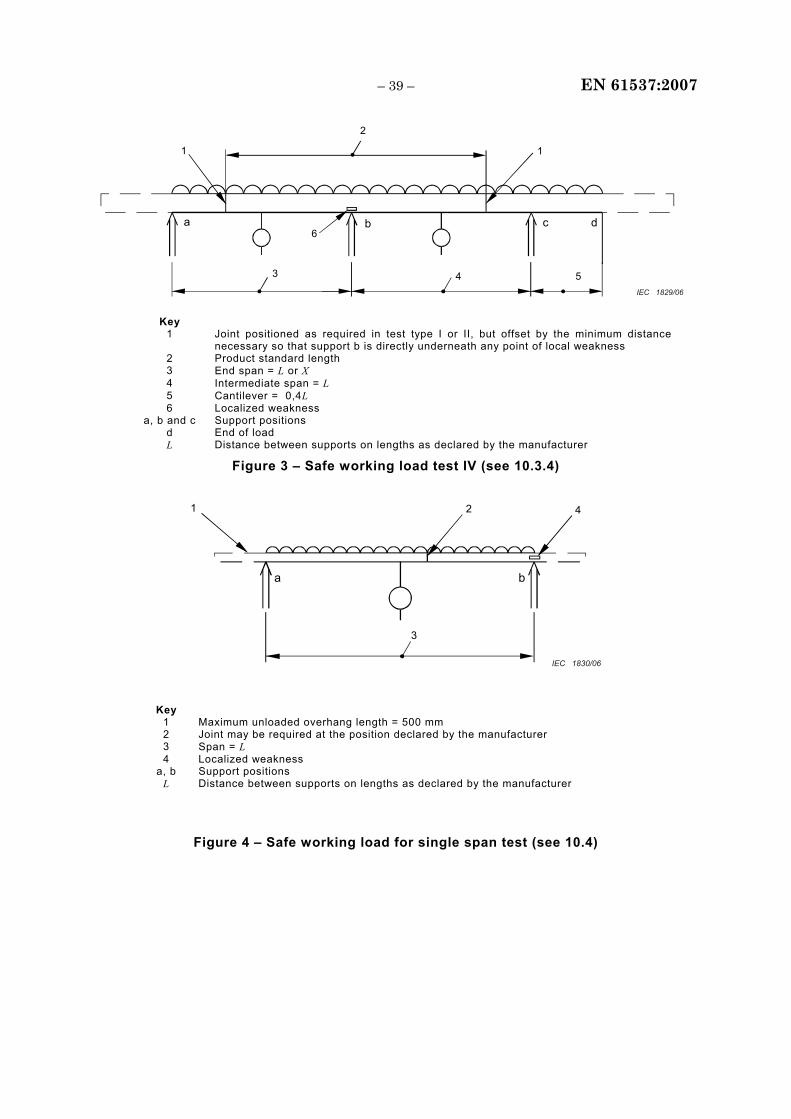
– 39 – EN 61537:2007
3
2
1 1
4 5
ba c d 6
IEC 1829/06
Key 1 Joint positioned as required in test type I or II, but offset by the minimum distance
necessary so that support b is directly underneath any point of local weakness 2 Product standard length 3 End span = L or X 4 Intermediate span = L 5 Cantilever = 0,4L 6 Localized weakness
a, b and c Support positions d End of load L Distance between supports on lengths as declared by the manufacturer
Figure 3 – Safe working load test IV (see 10.3.4)
3
21 4
a b
IEC 1830/06
Key
1 Maximum unloaded overhang length = 500 mm 2 Joint may be required at the position declared by the manufacturer 3 Span = L 4 Localized weakness
a, b Support positions L Distance between supports on lengths as declared by the manufacturer
Figure 4 – Safe working load for single span test (see 10.4)
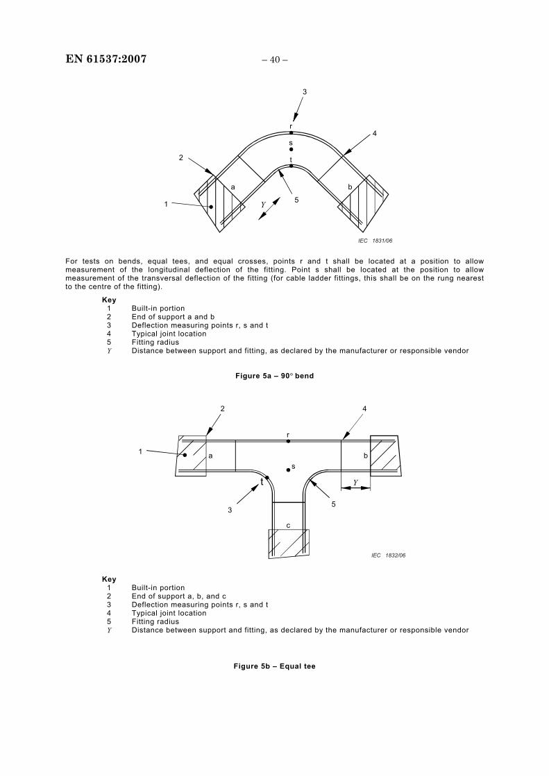
EN 61537:2007 – 40 –
5
3
4
1
2
Y
ba
r
s
t
IEC 1831/06
For tests on bends, equal tees, and equal crosses, points r and t shall be located at a position to allow measurement of the longitudinal deflection of the fitting. Point s shall be located at the position to allow measurement of the transversal deflection of the fitting (for cable ladder fittings, this shall be on the rung nearest to the centre of the fitting).
Key 1 Built-in portion 2 End of support a and b 3 Deflection measuring points r, s and t 4 Typical joint location 5 Fitting radius Y Distance between support and fitting, as declared by the manufacturer or responsible vendor
Figure 5a – 90° bend
53
2
1
4
c
ba s
t
r
Y
IEC 1832/06
Key 1 Built-in portion 2 End of support a, b, and c 3 Deflection measuring points r, s and t 4 Typical joint location 5 Fitting radius Y Distance between support and fitting, as declared by the manufacturer or responsible vendor
Figure 5b – Equal tee
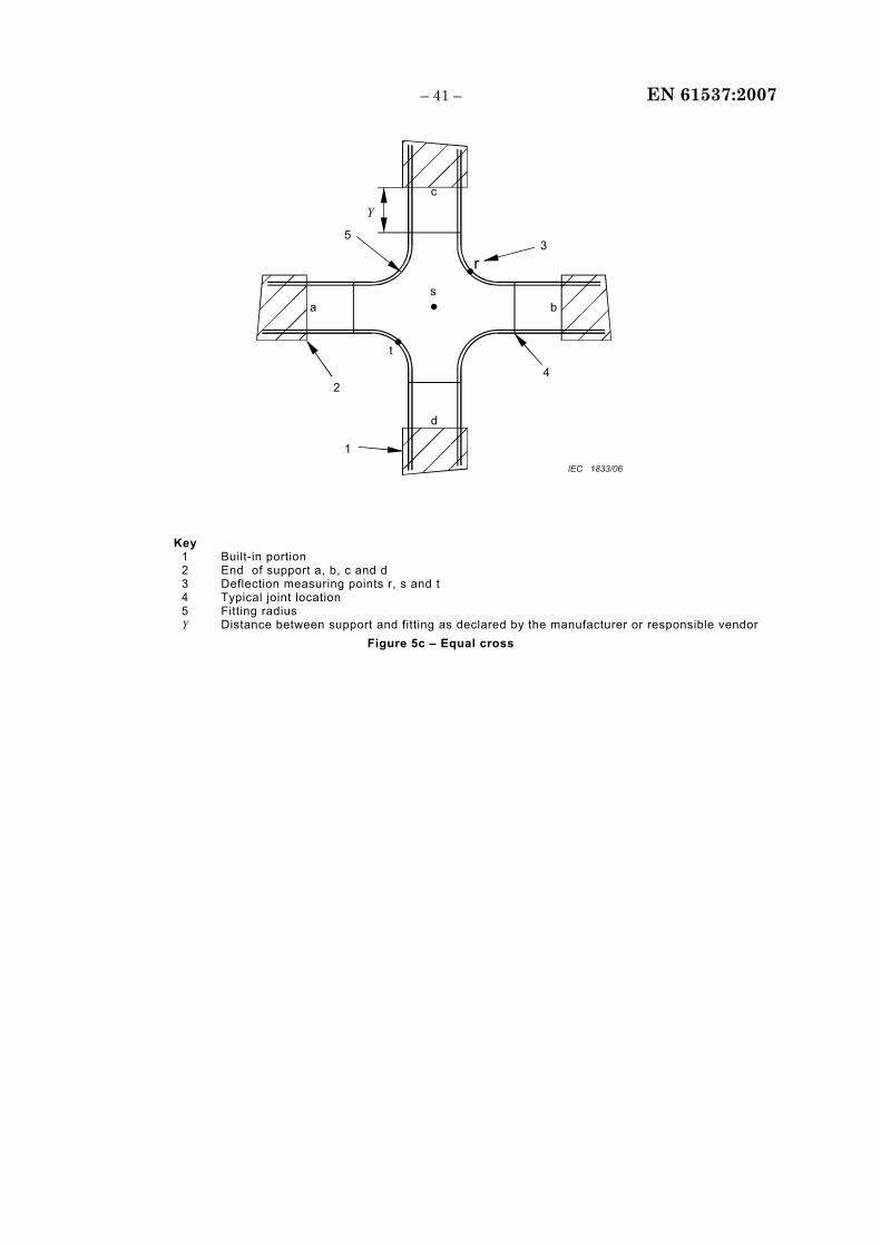
– 41 – EN 61537:2007
42
1
5 3
d
c
ba
rs
t
Y
IEC 1833/06
Key 1 Built-in portion 2 End of support a, b, c and d 3 Deflection measuring points r, s and t 4 Typical joint location 5 Fitting radius Y Distance between support and fitting as declared by the manufacturer or responsible vendor
Figure 5c – Equal cross
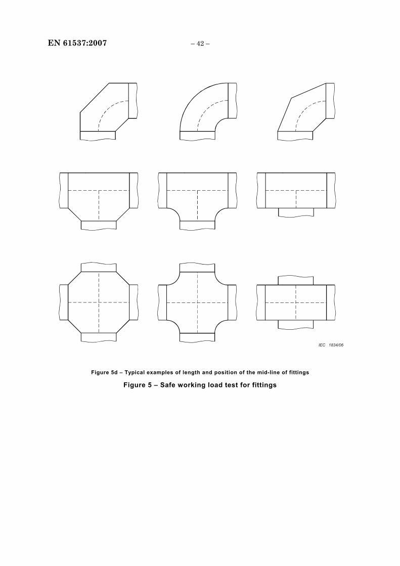
EN 61537:2007 – 42 –
IEC 1834/06
Figure 5d – Typical examples of length and position of the mid-line of fittings
Figure 5 – Safe working load test for fittings
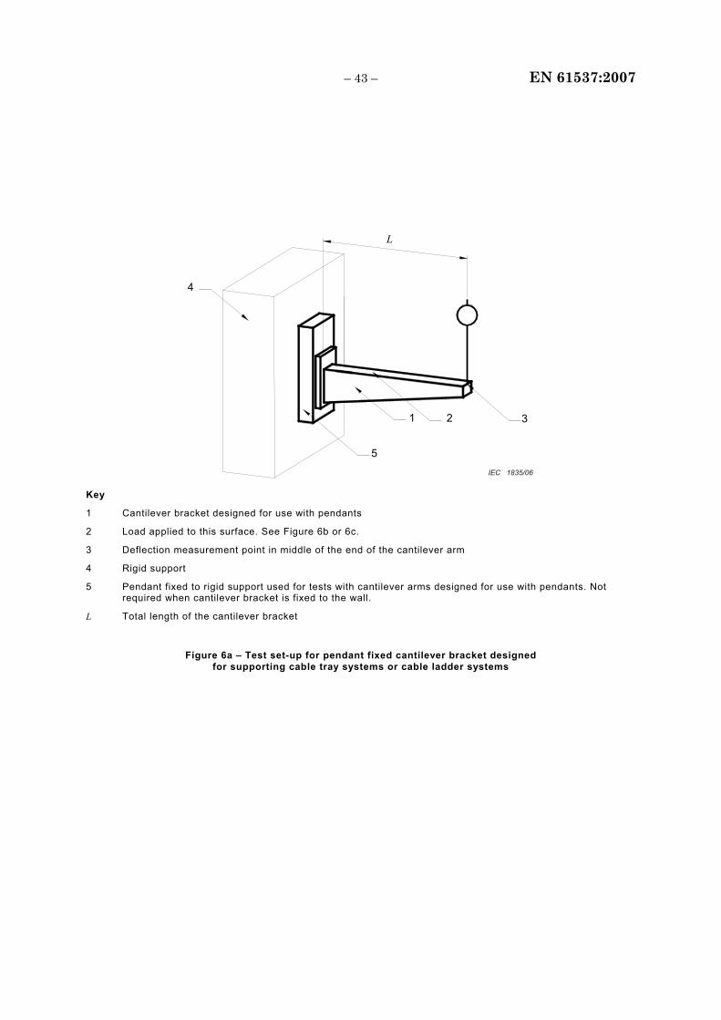
– 43 – EN 61537:2007
1
5
3 2
L
4
IEC 1835/06
Key
1 Cantilever bracket designed for use with pendants
2 Load applied to this surface. See Figure 6b or 6c.
3 Deflection measurement point in middle of the end of the cantilever arm
4 Rigid support
5 Pendant fixed to rigid support used for tests with cantilever arms designed for use with pendants. Not required when cantilever bracket is fixed to the wall.
L Total length of the cantilever bracket
Figure 6a – Test set-up for pendant fixed cantilever bracket designed for supporting cable tray systems or cable ladder systems
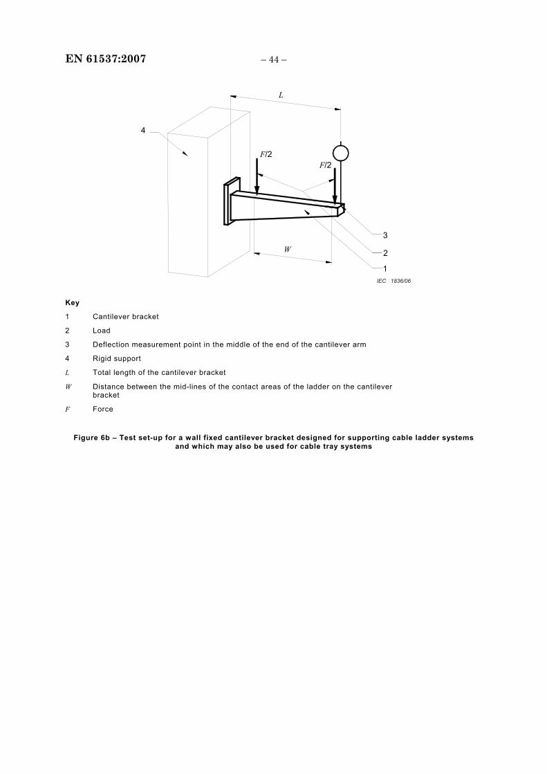
EN 61537:2007 – 44 –
F/2
4
W 2
L
1
3
F/2
IEC 1836/06
Key
1 Cantilever bracket
2 Load
3 Deflection measurement point in the middle of the end of the cantilever arm
4 Rigid support
L Total length of the cantilever bracket
W Distance between the mid-lines of the contact areas of the ladder on the cantilever bracket
F Force
Figure 6b – Test set-up for a wall fixed cantilever bracket designed for supporting cable ladder systems and which may also be used for cable tray systems
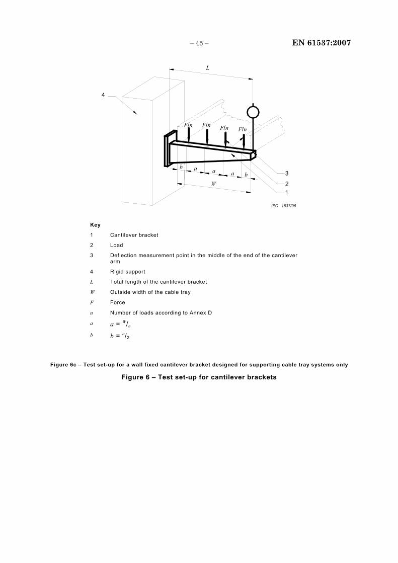
– 45 – EN 61537:2007
a
F/n
b
4
W
a a b
1
3
L
2
F/n F/n F/n
IEC 1837/06
Key
1 Cantilever bracket
2 Load
3 Deflection measurement point in the middle of the end of the cantilever arm
4 Rigid support
L Total length of the cantilever bracket
W Outside width of the cable tray
F Force
n Number of loads according to Annex D
a a = W/n b b = a/2
Figure 6c – Test set-up for a wall fixed cantilever bracket designed for supporting cable tray systems only
Figure 6 – Test set-up for cantilever brackets
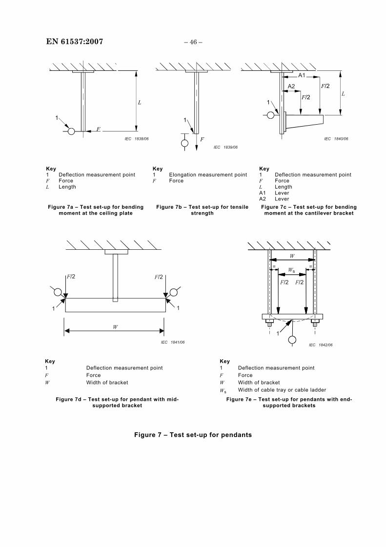
EN 61537:2007 – 46 –
L
F
1 1
F
1F/2 L
F/2
A1
A2
IEC 1838/06
IEC 1839/06
IEC 1840/06
Key Key Key 1 Deflection measurement point 1 Elongation measurement point 1 Deflection measurement point F Force F Force F Force L Length L Length A1 Lever A2 Lever Figure 7a – Test set-up for bending
moment at the ceiling plate Figure 7b – Test set-up for tensile
strength Figure 7c – Test set-up for bending
moment at the cantilever bracket
F/2
1 1
W
W = =
1
F/2F/2 F/2
Ws
IEC 1842/06 IEC 1841/06
Key Key 1 Deflection measurement point 1 Deflection measurement point F Force F Force W Width of bracket W Width of bracket Ws Width of cable tray or cable ladder
Figure 7d – Test set-up for pendant with mid-supported bracket
Figure 7e – Test set-up for pendants with end-supported brackets
Figure 7 – Test set-up for pendants
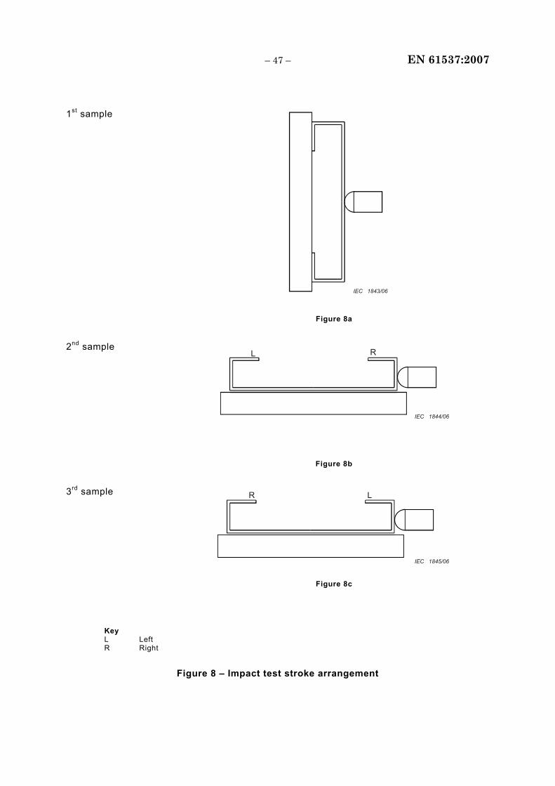
– 47 – EN 61537:2007
1st sample
IEC 1843/06
Figure 8a
2nd sample L R
IEC 1844/06
Figure 8b
3rd sample R L
IEC 1845/06
Figure 8c
Key L Left R Right
Figure 8 – Impact test stroke arrangement
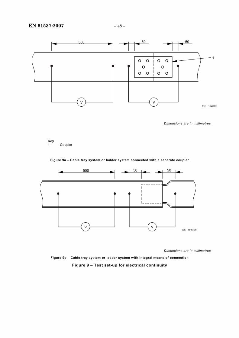
EN 61537:2007 – 48 –
1
50 50 500
V VIEC 1846/06
Dimensions are in millimetres
Key 1 Coupler
Figure 9a – Cable tray system or ladder system connected with a separate coupler
50 500 50
V VIEC 1847/06
Dimensions are in millimetres
Figure 9b – Cable tray system or ladder system with integral means of connection
Figure 9 – Test set-up for electrical continuity
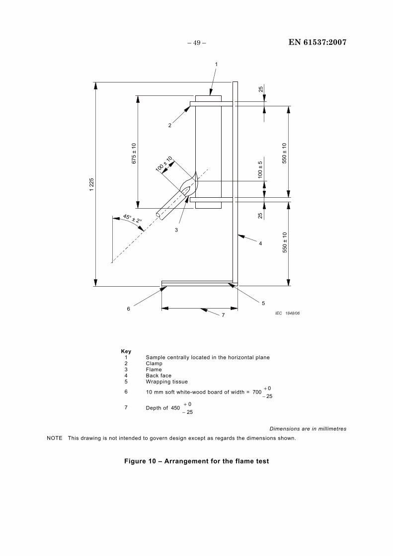
– 49 – EN 61537:2007
4
6
3
1
2
1 22
5
675
± 10
100 ±
10 550
± 10
100
± 5
2525
45° ± 2°
550
± 10
7
5
IEC 1848/06
Key 1 Sample centrally located in the horizontal plane 2 Clamp 3 Flame 4 Back face 5 Wrapping tissue
6 10 mm soft white-wood board of width = 25 0
700−+
7 Depth of 250
450−+
Dimensions are in millimetres
NOTE This drawing is not intended to govern design except as regards the dimensions shown.
Figure 10 – Arrangement for the flame test
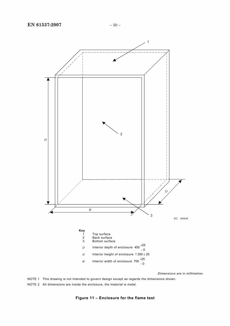
EN 61537:2007 – 50 –
1
2
3W
H
D
IEC 1849/06
Key 1 Top surface 2 Back surface 3 Bottom surface
D Interior depth of enclosure 0
25450
−+
H Interior height of enclosure 253001 ±
W Interior width of enclosure 0
25700
−+
Dimensions are in millimetres
NOTE 1 This drawing is not intended to govern design except as regards the dimensions shown.
NOTE 2 All dimensions are inside the enclosure, the material is metal.
Figure 11 – Enclosure for the flame test
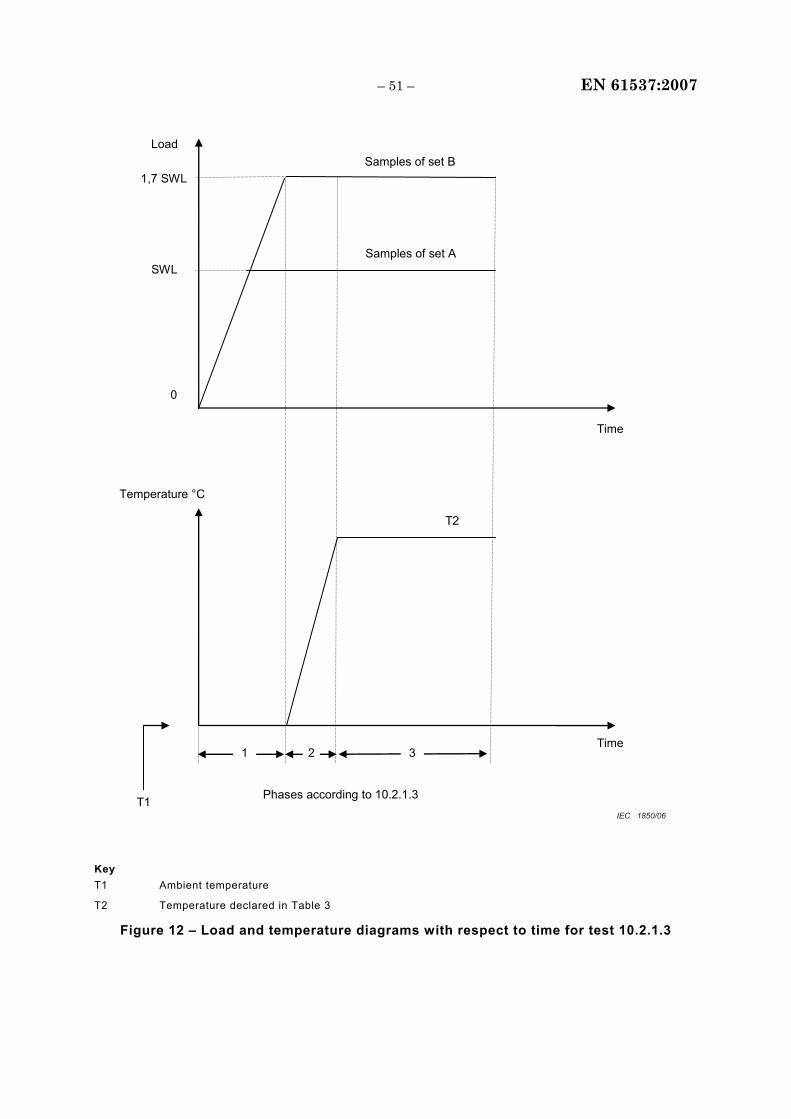
– 51 – EN 61537:2007
Load
Temperature °C
Time
Phases according to 10.2.1.3
T2
0
Samples of set B
Samples of set A
1,7 SWL
SWL
T1
Time 2 3 1
IEC 1850/06
Key T1 Ambient temperature
T2 Temperature declared in Table 3
Figure 12 – Load and temperature diagrams with respect to time for test 10.2.1.3
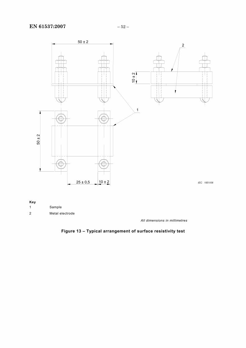
EN 61537:2007 – 52 –
50 ± 2
10 ±
2
50 ±
2
10 ± 225 ± 0,5
1
2
IEC 1851/06
Key 1 Sample
2 Metal electrode
All dimensions in millimetres
Figure 13 – Typical arrangement of surface resistivity test
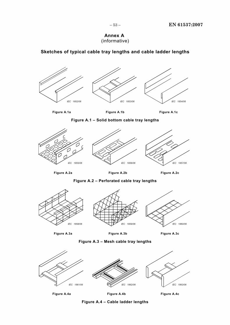
– 53 – EN 61537:2007
Annex A (informative)
Sketches of typical cable tray lengths and cable ladder lengths
IEC 1852/06 IEC 1853/06 IEC 1854/06
Figure A.1a Figure A.1b Figure A.1c
Figure A.1 – Solid bottom cable tray lengths
IEC 1855/06 IEC 1856/06 IEC 1857/06
Figure A.2a Figure A.2b Figure A.2c
Figure A.2 – Perforated cable tray lengths
IEC 1858/06 IEC 1859/06 IEC 1860/06
Figure A.3a Figure A.3b Figure A.3c
Figure A.3 – Mesh cable tray lengths
IEC 1861/06 IEC 1862/06 IEC 1863/06
Figure A.4a Figure A.4b Figure A.4c
Figure A.4 – Cable ladder lengths
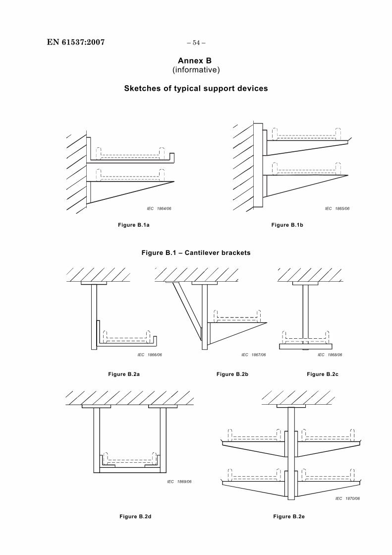
EN 61537:2007 – 54 –
Annex B (informative)
Sketches of typical support devices
IEC 1864/06 IEC 1865/06
Figure B.1a Figure B.1b
Figure B.1 – Cantilever brackets
IEC 1866/06 IEC 1867/06 IEC 1868/06
Figure B.2a Figure B.2b Figure B.2c
IEC 1870/06
IEC 1869/06
Figure B.2d Figure B.2e
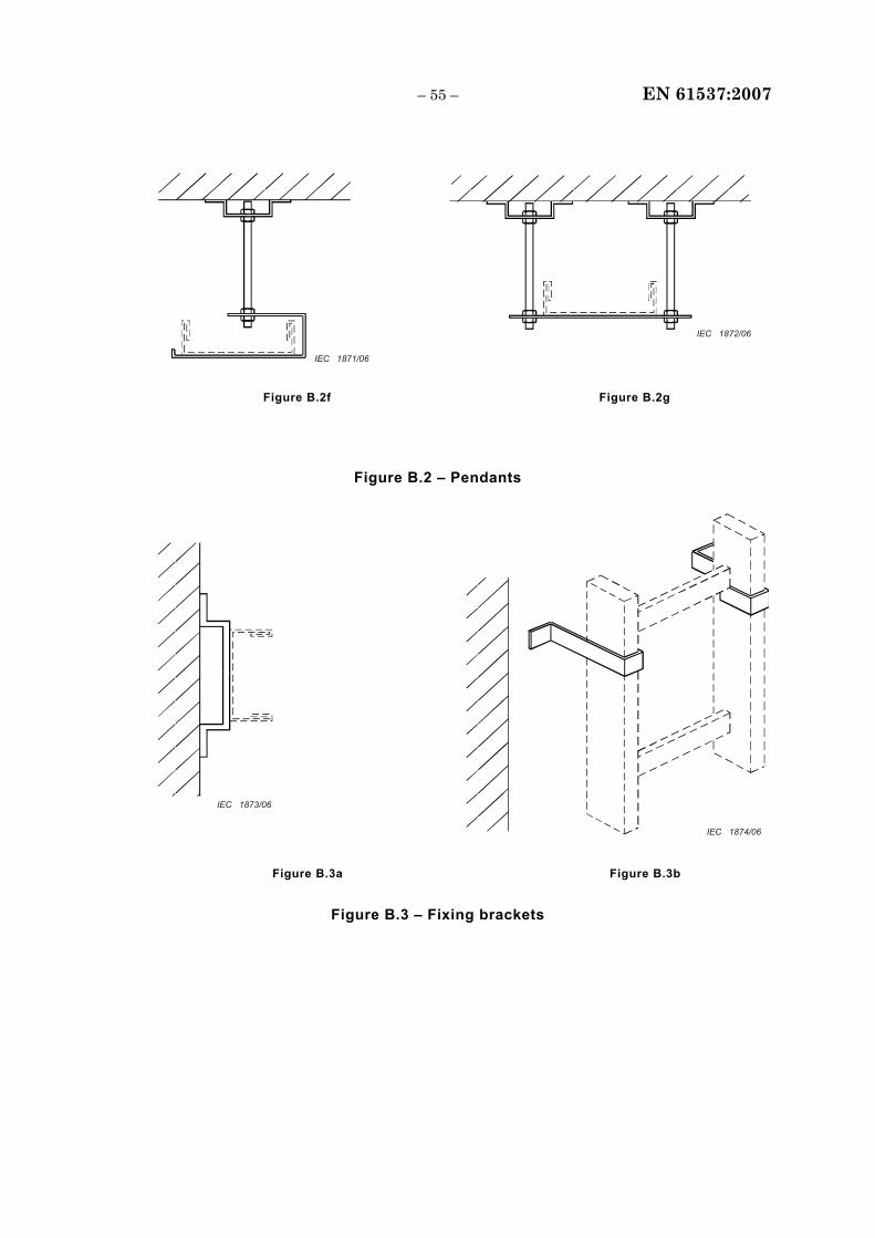
– 55 – EN 61537:2007
IEC 1872/06
IEC 1871/06
Figure B.2f Figure B.2g
Figure B.2 – Pendants
IEC 1874/06
IEC 1873/06
Figure B.3a Figure B.3b
Figure B.3 – Fixing brackets

EN 61537:2007 – 56 –
Annex C (informative)
Protective earth (PE) function
Under consideration.
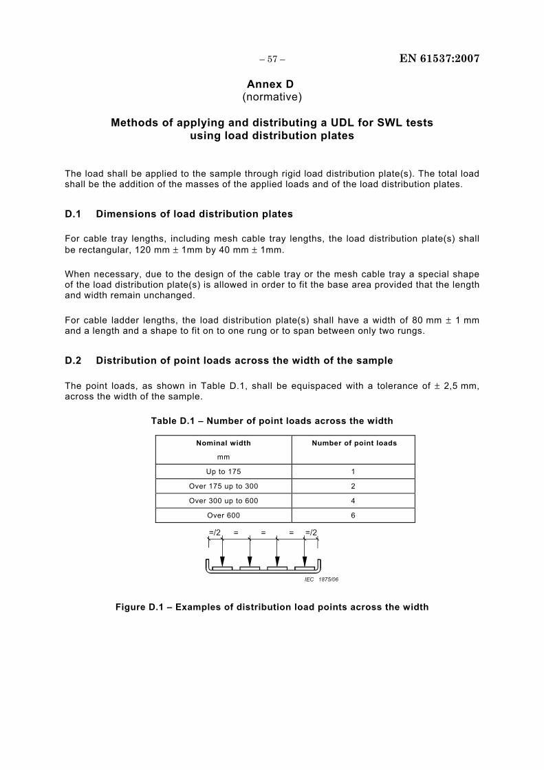
– 57 – EN 61537:2007
Annex D (normative)
Methods of applying and distributing a UDL for SWL tests
using load distribution plates
The load shall be applied to the sample through rigid load distribution plate(s). The total load shall be the addition of the masses of the applied loads and of the load distribution plates.
D.1 Dimensions of load distribution plates
For cable tray lengths, including mesh cable tray lengths, the load distribution plate(s) shall be rectangular, 120 mm ± 1mm by 40 mm ± 1mm.
When necessary, due to the design of the cable tray or the mesh cable tray a special shape of the load distribution plate(s) is allowed in order to fit the base area provided that the length and width remain unchanged.
For cable ladder lengths, the load distribution plate(s) shall have a width of 80 mm ± 1 mm and a length and a shape to fit on to one rung or to span between only two rungs.
D.2 Distribution of point loads across the width of the sample
The point loads, as shown in Table D.1, shall be equispaced with a tolerance of ± 2,5 mm, across the width of the sample.
Table D.1 – Number of point loads across the width
Nominal width
mm
Number of point loads
Up to 175 1
Over 175 up to 300 2
Over 300 up to 600 4
Over 600 6
=/2 = =/2= =
IEC 1875/06
Figure D.1 – Examples of distribution load points across the width
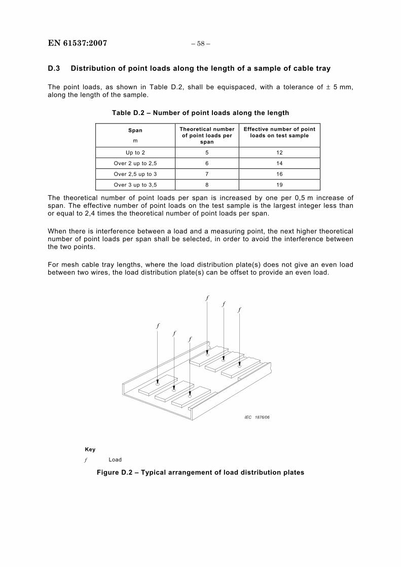
EN 61537:2007 – 58 –
D.3 Distribution of point loads along the length of a sample of cable tray
The point loads, as shown in Table D.2, shall be equispaced, with a tolerance of ± 5 mm, along the length of the sample.
Table D.2 – Number of point loads along the length
Span
m
Theoretical number of point loads per
span
Effective number of point loads on test sample
Up to 2 5 12
Over 2 up to 2,5 6 14
Over 2,5 up to 3 7 16
Over 3 up to 3,5 8 19
The theoretical number of point loads per span is increased by one per 0,5 m increase of span. The effective number of point loads on the test sample is the largest integer less than or equal to 2,4 times the theoretical number of point loads per span.
When there is interference between a load and a measuring point, the next higher theoretical number of point loads per span shall be selected, in order to avoid the interference between the two points.
For mesh cable tray lengths, where the load distribution plate(s) does not give an even load between two wires, the load distribution plate(s) can be offset to provide an even load.
f f
f
f f
f
IEC 1876/06
Key
f Load
Figure D.2 – Typical arrangement of load distribution plates
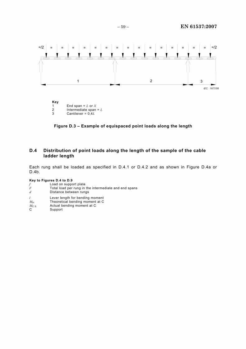
– 59 – EN 61537:2007
= = ==/2 =/2
1 2 3
= = = = = = = = = = = =
IEC 1877/06
Key 1 End span = L or X 2 Intermediate span = L 3 Cantilever = 0,4L
Figure D.3 – Example of equispaced point loads along the length
D.4 Distribution of point loads along the length of the sample of the cable ladder length
Each rung shall be loaded as specified in D.4.1 or D.4.2 and as shown in Figure D.4a or D.4b.
Key to Figures D.4 to D.9 f Load on support plate F Total load per rung in the intermediate and end spans d Distance between rungs
l Lever length for bending moment M th Theoretical bending moment at C MC.S. Actual bending moment at C C Support
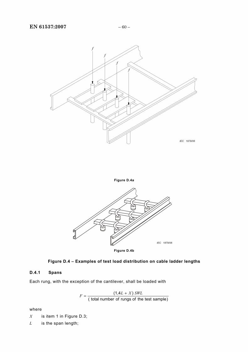
EN 61537:2007 – 60 –
f
f
f
f
IEC 1878/06
Figure D.4a
IEC 1879/06 Figure D.4b
Figure D.4 – Examples of test load distribution on cable ladder lengths
D.4.1 Spans
Each rung, with the exception of the cantilever, shall be loaded with
)sampletesttheofrungsofnumbertotal()(1,4 SWLXLF +
=
where X is item 1 in Figure D.3;
L is the span length;
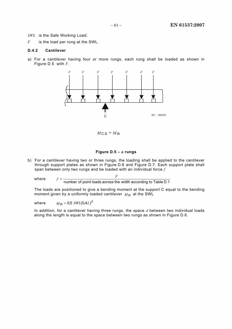
– 61 – EN 61537:2007
SWL is the Safe Working Load;
F is the load per rung at the SWL.
D.4.2 Cantilever
a) For a cantilever having four or more rungs, each rung shall be loaded as shown in Figure D.5 with F.
F
C
F F F F F F
IEC 1880/06
MM thC.S. =
Figure D.5 – n rungs
b) For a cantilever having two or three rungs, the loading shall be applied to the cantilever through support plates as shown in Figure D.6 and Figure D.7. Each support plate shall span between only two rungs and be loaded with an individual force f
where D.1 Tabletoaccordingwidththe across loadspoint ofnumber
Ff =
The loads are positioned to give a bending moment at the support C equal to the bending moment given by a uniformly loaded cantilever M th at the SWL
where 2th )4,0(5,0 LSWLM =
In addition, for a cantilever having three rungs, the space d between two individual loads along the length is equal to the space between two rungs as shown in Figure D.6.
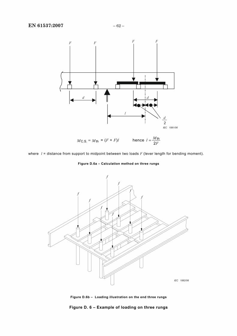
EN 61537:2007 – 62 –
F
d
l
2
d
d
F F F
IEC 1881/06
MM thC.S. = = (F + F)l hence F
Ml2
th=
where l = distance from support to midpoint between two loads F (lever length for bending moment).
Figure D.6a – Calculation method on three rungs
f
f
f
f
f
f
f
f
IEC 1882/06
Figure D.6b – Loading illustration on the end three rungs
Figure D. 6 – Example of loading on three rungs
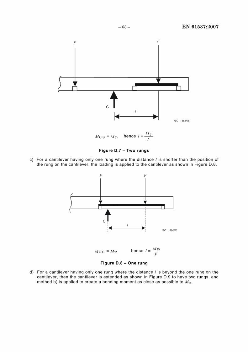
– 63 – EN 61537:2007
F
lC
F
IEC 1883/06
MM thC.S. = hence F
Ml th=
Figure D.7 – Two rungs
c) For a cantilever having only one rung where the distance l is shorter than the position of the rung on the cantilever, the loading is applied to the cantilever as shown in Figure D.8.
F
l C
F
IEC 1884/06
MM thC.S. = hence F
Ml th=
Figure D.8 – One rung
d) For a cantilever having only one rung where the distance l is beyond the one rung on the cantilever, then the cantilever is extended as shown in Figure D.9 to have two rungs, and method b) is applied to create a bending moment as close as possible to Mth.
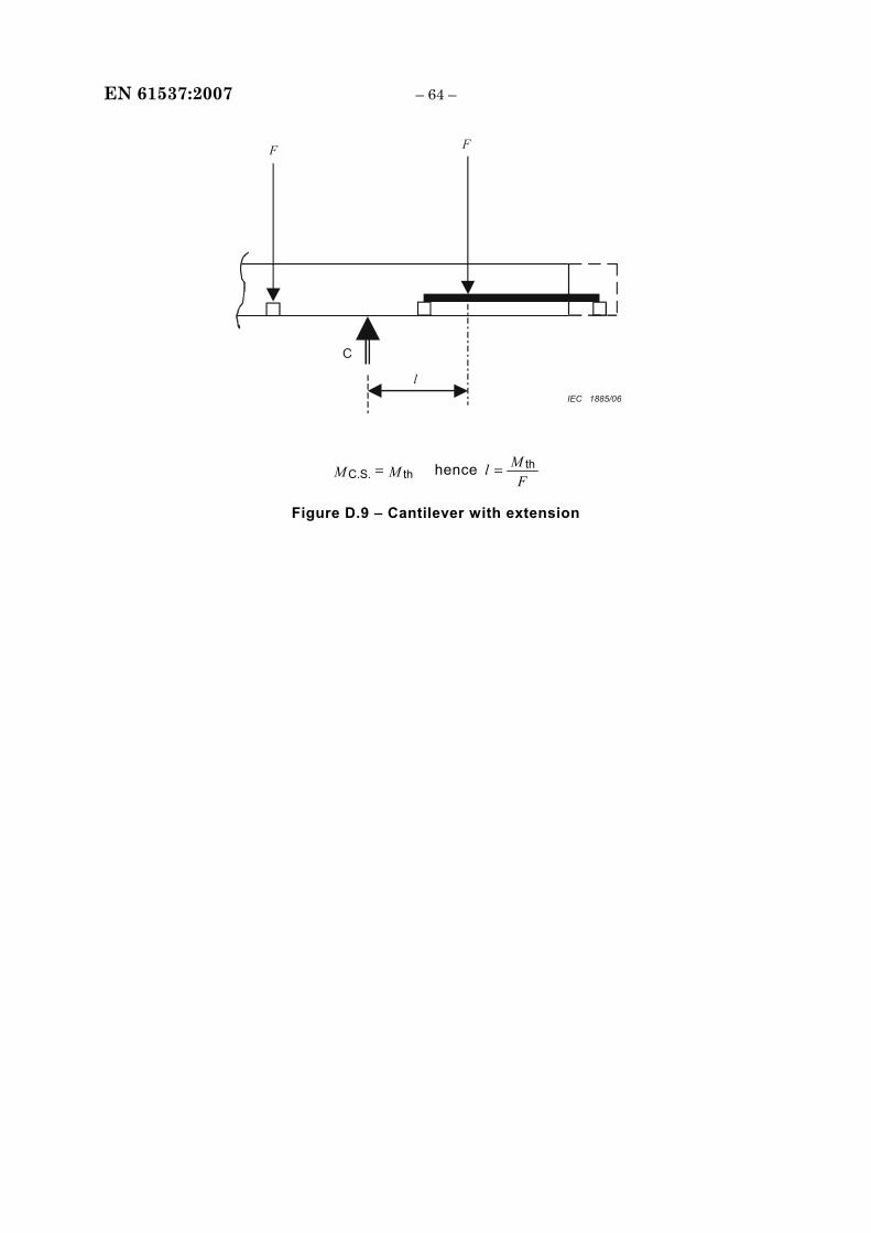
EN 61537:2007 – 64 –
F F
C
l IEC 1885/06
MM thC.S. = hence F
Ml th=
Figure D.9 – Cantilever with extension
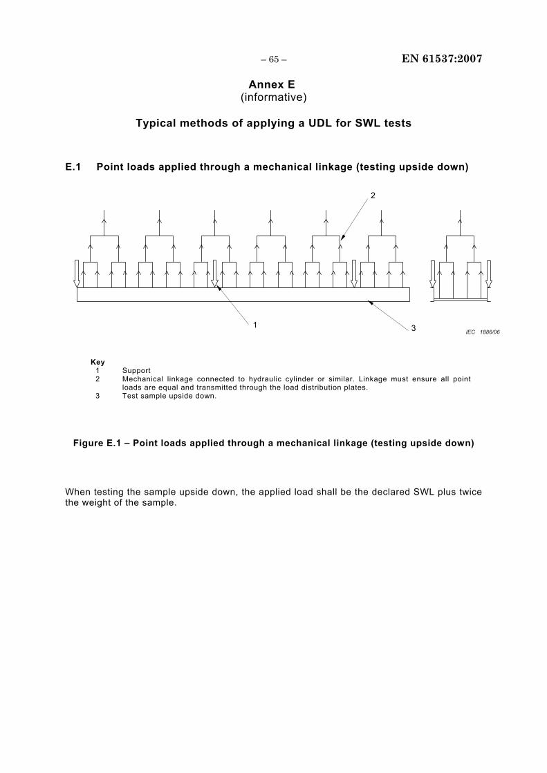
– 65 – EN 61537:2007
Annex E (informative)
Typical methods of applying a UDL for SWL tests
E.1 Point loads applied through a mechanical linkage (testing upside down)
1 3
2
IEC 1886/06
Key 1 Support 2 Mechanical linkage connected to hydraulic cylinder or similar. Linkage must ensure all point
loads are equal and transmitted through the load distribution plates. 3 Test sample upside down.
Figure E.1 – Point loads applied through a mechanical linkage (testing upside down)
When testing the sample upside down, the applied load shall be the declared SWL plus twice the weight of the sample.
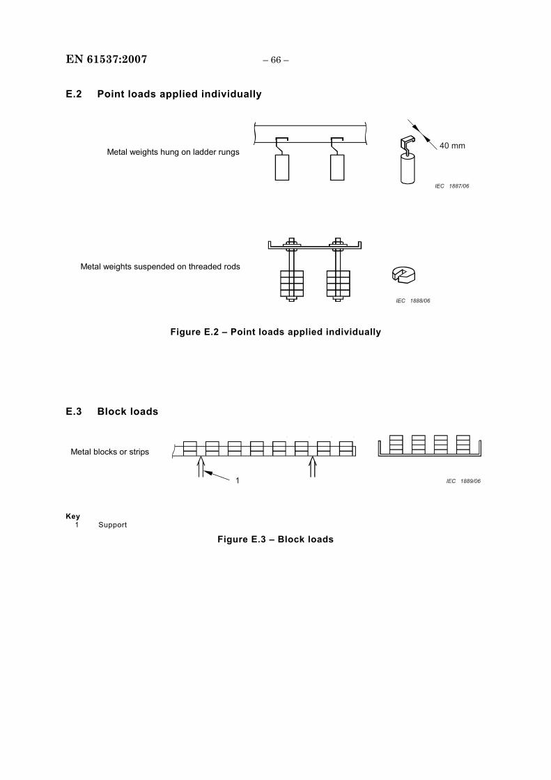
EN 61537:2007 – 66 –
E.2 Point loads applied individually
40 mm
Metal weights suspended on threaded rods
Metal weights hung on ladder rungs
IEC 1887/06
IEC 1888/06
Figure E.2 – Point loads applied individually
E.3 Block loads
1
Metal blocks or strips
IEC 1889/06
Key 1 Support
Figure E.3 – Block loads
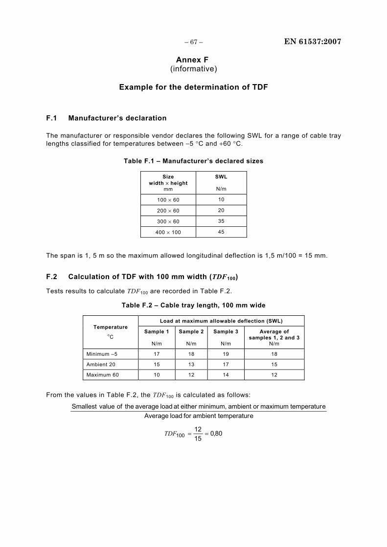
– 67 – EN 61537:2007
Annex F (informative)
Example for the determination of TDF
F.1 Manufacturer’s declaration
The manufacturer or responsible vendor declares the following SWL for a range of cable tray lengths classified for temperatures between −5 °C and +60 °C.
Table F.1 – Manufacturer’s declared sizes
Size width × height
mm
SWL
N/m
100 × 60 10
200 × 60 20
300 × 60 35
400 × 100 45
The span is 1, 5 m so the maximum allowed longitudinal deflection is 1,5 m/100 = 15 mm.
F.2 Calculation of TDF with 100 mm width (TDF100)
Tests results to calculate TDF100 are recorded in Table F.2.
Table F.2 – Cable tray length, 100 mm wide
Load at maximum allowable deflection (SWL) Temperature
oC Sample 1
N/m
Sample 2
N/m
Sample 3
N/m
Average of samples 1, 2 and 3
N/m
Minimum –5 17 18 19 18
Ambient 20 15 13 17 15
Maximum 60 10 12 14 12
From the values in Table F.2, the TDF100 is calculated as follows:
etemperatur ambient for load Averageetemperatur maximum or ambient minimum, either at load average theofvalueSmallest
80,01512
100 ==TDF
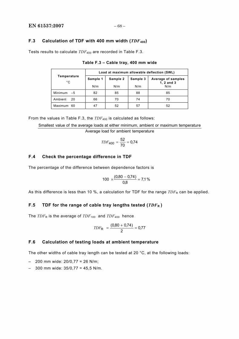
EN 61537:2007 – 68 –
F.3 Calculation of TDF with 400 mm width (TDF400)
Tests results to calculate TDF400 are recorded in Table F.3.
Table F.3 – Cable tray, 400 mm wide
Load at maximum allowable deflection (SWL) Temperature
°C Sample 1
N/m
Sample 2
N/m
Sample 3
N/m
Average of samples 1, 2 and 3
N/m
Minimum –5 82 85 88 85
Ambient 20 66 70 74 70
Maximum 60 47 52 57 52
From the values in Table F.3, the TDF400 is calculated as follows:
etemperaturambientforloadAverageetemperaturmaximumorambientminimum,eitheratloadsaveragetheofvalueSmallest
74,07052
400 ==TDF
F.4 Check the percentage difference in TDF
The percentage of the difference between dependence factors is
%1,78,0
)74,080,0(100 =−
×
As this difference is less than 10 %, a calculation for TDF for the range TDFR can be applied.
F.5 TDF for the range of cable tray lengths tested (TDFR )
The TDFR is the average of TDF100 and TDF400 hence
77,02
)74,080,0(R =
+=TDF
F.6 Calculation of testing loads at ambient temperature
The other widths of cable tray length can be tested at 20 °C, at the following loads:
– 200 mm wide: 20/0,77 = 26 N/m; – 300 mm wide: 35/0,77 = 45,5 N/m.
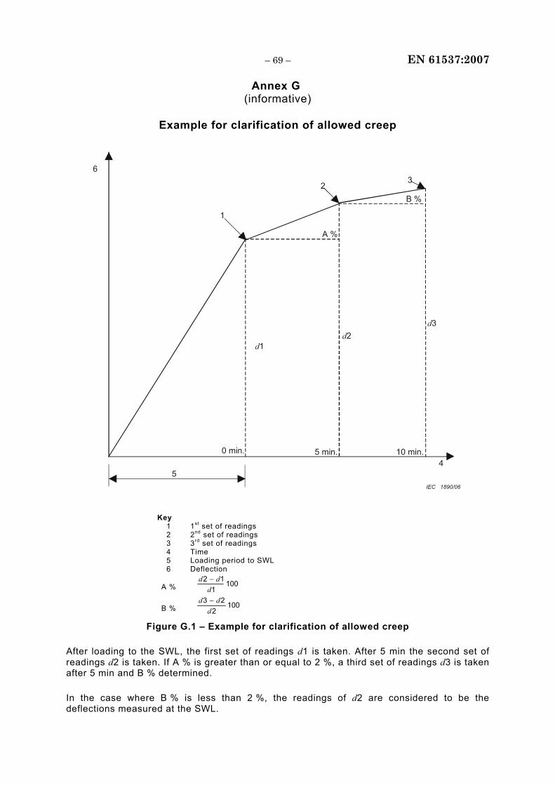
– 69 – EN 61537:2007
Annex G (informative)
Example for clarification of allowed creep
6
5 4
1
23
A %
B %
d1
0 min. 5 min. 10 min.
d2d3
IEC 1890/06
Key 1 1st set of readings 2 2nd set of readings 3 3rd set of readings 4 Time 5 Loading period to SWL 6 Deflection
A % 1001
12d
dd −
B % 1002
23d
dd −
Figure G.1 – Example for clarification of allowed creep
After loading to the SWL, the first set of readings d1 is taken. After 5 min the second set of readings d2 is taken. If A % is greater than or equal to 2 %, a third set of readings d3 is taken after 5 min and B % determined.
In the case where B % is less than 2 %, the readings of d2 are considered to be the deflections measured at the SWL.
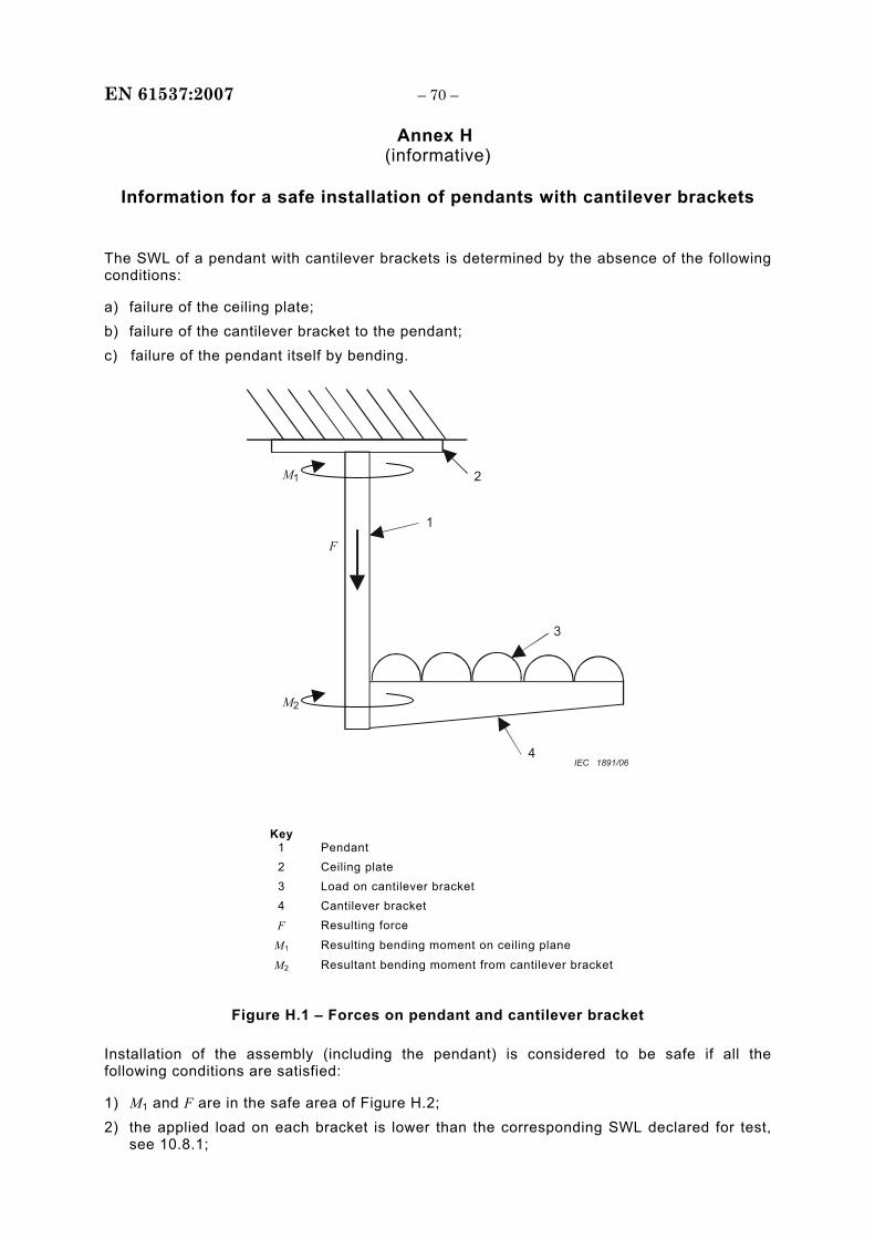
EN 61537:2007 – 70 –
Annex H (informative)
Information for a safe installation of pendants with cantilever brackets
The SWL of a pendant with cantilever brackets is determined by the absence of the following conditions:
a) failure of the ceiling plate; b) failure of the cantilever bracket to the pendant; c) failure of the pendant itself by bending.
2
1
M1
F
3
4
M2
IEC 1891/06
Key
1 Pendant 2 Ceiling plate 3 Load on cantilever bracket 4 Cantilever bracket
F Resulting force
M1 Resulting bending moment on ceiling plane
M2 Resultant bending moment from cantilever bracket
Figure H.1 – Forces on pendant and cantilever bracket
Installation of the assembly (including the pendant) is considered to be safe if all the following conditions are satisfied:
1) M1 and F are in the safe area of Figure H.2; 2) the applied load on each bracket is lower than the corresponding SWL declared for test,
see 10.8.1;
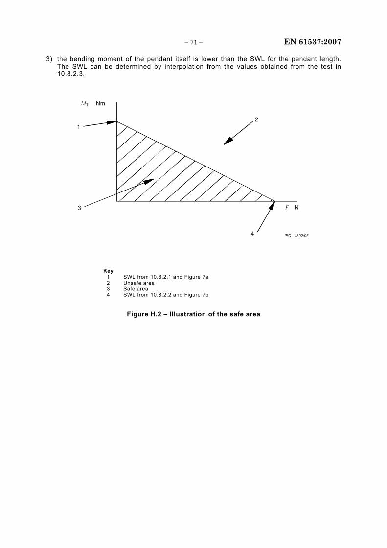
– 71 – EN 61537:2007
3) the bending moment of the pendant itself is lower than the SWL for the pendant length. The SWL can be determined by interpolation from the values obtained from the test in 10.8.2.3.
M1 Nm
F N
1
3
4
2
IEC 1892/06
Key 1 SWL from 10.8.2.1 and Figure 7a 2 Unsafe area 3 Safe area 4 SWL from 10.8.2.2 and Figure 7b
Figure H.2 – Illustration of the safe area
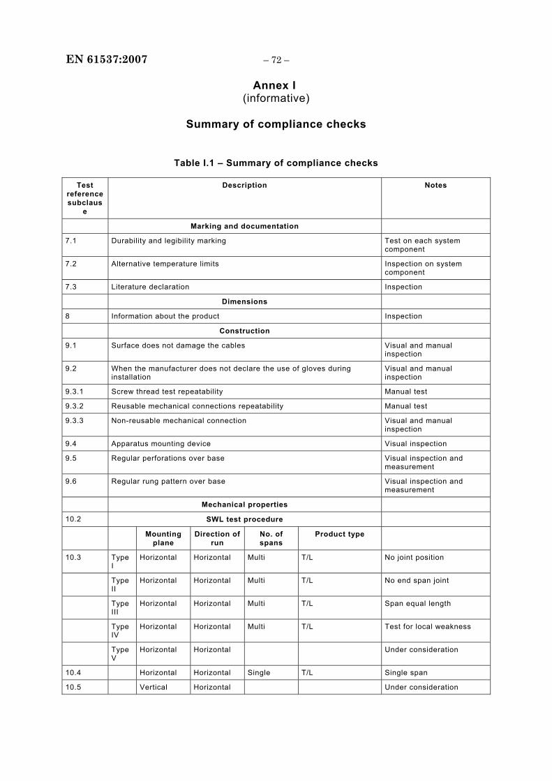
EN 61537:2007 – 72 –
Annex I (informative)
Summary of compliance checks
Table I.1 – Summary of compliance checks
Test reference subclaus
e
Description Notes
Marking and documentation
7.1 Durability and legibility marking Test on each system component
7.2 Alternative temperature limits Inspection on system component
7.3 Literature declaration Inspection
Dimensions
8 Information about the product Inspection
Construction
9.1 Surface does not damage the cables Visual and manual inspection
9.2 When the manufacturer does not declare the use of gloves during installation
Visual and manual inspection
9.3.1 Screw thread test repeatability Manual test
9.3.2 Reusable mechanical connections repeatability Manual test
9.3.3 Non-reusable mechanical connection Visual and manual inspection
9.4 Apparatus mounting device Visual inspection
9.5 Regular perforations over base Visual inspection and measurement
9.6 Regular rung pattern over base Visual inspection and measurement
Mechanical properties
10.2 SWL test procedure
Mounting plane
Direction of run
No. of spans
Product type
10.3 Type I
Horizontal Horizontal Multi T/L No joint position
Type II
Horizontal Horizontal Multi T/L No end span joint
Type III
Horizontal Horizontal Multi T/L Span equal length
Type IV
Horizontal Horizontal Multi T/L Test for local weakness
Type V
Horizontal Horizontal Under consideration
10.4 Horizontal Horizontal Single T/L Single span
10.5 Vertical Horizontal Under consideration
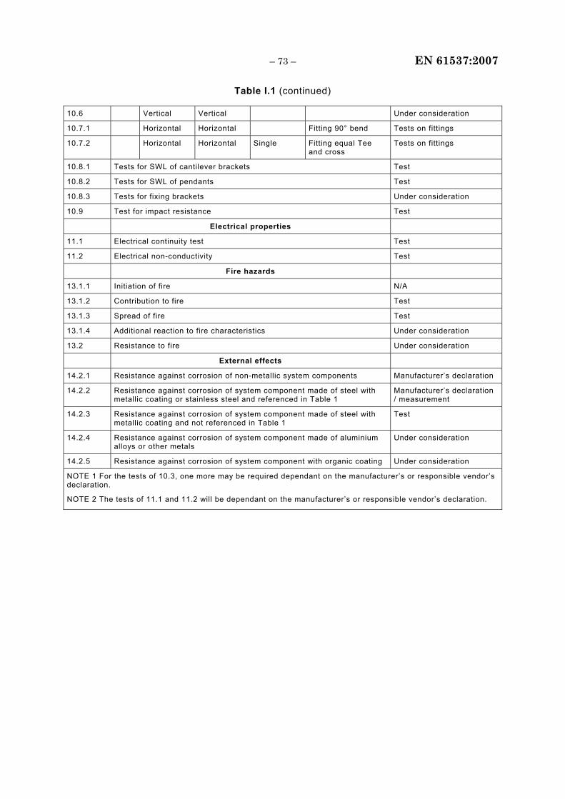
– 73 – EN 61537:2007
Table I.1 (continued)
10.6 Vertical Vertical Under consideration
10.7.1 Horizontal Horizontal Fitting 90° bend Tests on fittings
10.7.2 Horizontal Horizontal Single Fitting equal Tee and cross
Tests on fittings
10.8.1 Tests for SWL of cantilever brackets Test
10.8.2 Tests for SWL of pendants Test
10.8.3 Tests for fixing brackets Under consideration
10.9 Test for impact resistance Test
Electrical properties
11.1 Electrical continuity test Test
11.2 Electrical non-conductivity Test
Fire hazards
13.1.1 Initiation of fire N/A
13.1.2 Contribution to fire Test
13.1.3 Spread of fire Test
13.1.4 Additional reaction to fire characteristics Under consideration
13.2 Resistance to fire Under consideration
External effects
14.2.1 Resistance against corrosion of non-metallic system components Manufacturer’s declaration
14.2.2 Resistance against corrosion of system component made of steel with metallic coating or stainless steel and referenced in Table 1
Manufacturer’s declaration / measurement
14.2.3 Resistance against corrosion of system component made of steel with metallic coating and not referenced in Table 1
Test
14.2.4 Resistance against corrosion of system component made of aluminium alloys or other metals
Under consideration
14.2.5 Resistance against corrosion of system component with organic coating Under consideration
NOTE 1 For the tests of 10.3, one more may be required dependant on the manufacturer’s or responsible vendor’s declaration.
NOTE 2 The tests of 11.1 and 11.2 will be dependant on the manufacturer’s or responsible vendor’s declaration.
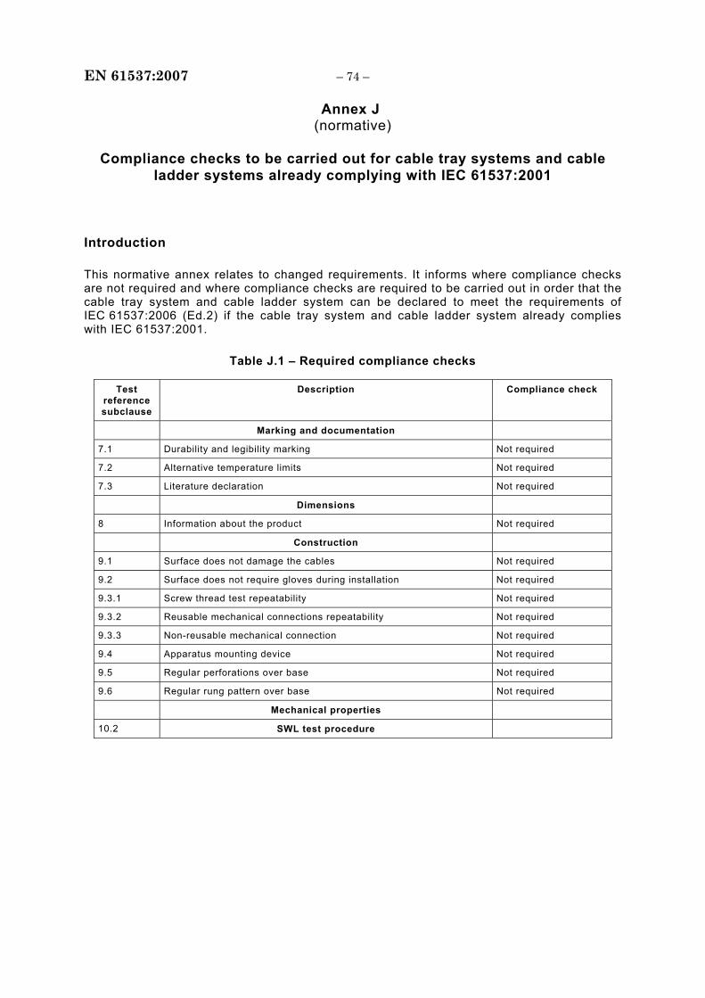
EN 61537:2007 – 74 –
Annex J (normative)
Compliance checks to be carried out for cable tray systems and cable
ladder systems already complying with IEC 61537:2001
Introduction
This normative annex relates to changed requirements. It informs where compliance checks are not required and where compliance checks are required to be carried out in order that the cable tray system and cable ladder system can be declared to meet the requirements of IEC 61537:2006 (Ed.2) if the cable tray system and cable ladder system already complies with IEC 61537:2001.
Table J.1 – Required compliance checks
Test reference subclause
Description Compliance check
Marking and documentation
7.1 Durability and legibility marking Not required
7.2 Alternative temperature limits Not required
7.3 Literature declaration Not required
Dimensions
8 Information about the product Not required
Construction
9.1 Surface does not damage the cables Not required
9.2 Surface does not require gloves during installation Not required
9.3.1 Screw thread test repeatability Not required
9.3.2 Reusable mechanical connections repeatability Not required
9.3.3 Non-reusable mechanical connection Not required
9.4 Apparatus mounting device Not required
9.5 Regular perforations over base Not required
9.6 Regular rung pattern over base Not required
Mechanical properties
10.2 SWL test procedure
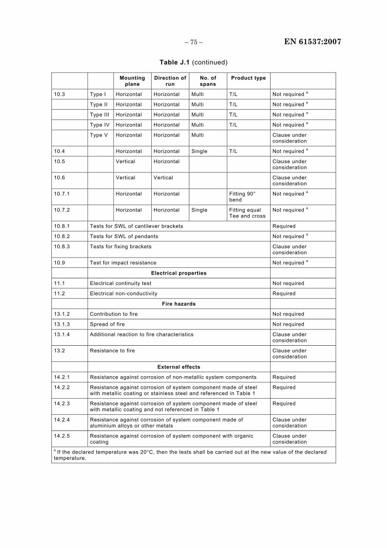
– 75 – EN 61537:2007
Table J.1 (continued)
Mounting plane
Direction of run
No. of spans
Product type
10.3 Type I Horizontal Horizontal Multi T/L Not required a
Type II Horizontal Horizontal Multi T/L Not required a
Type III Horizontal Horizontal Multi T/L Not required a
Type IV Horizontal Horizontal Multi T/L Not required a
Type V Horizontal Horizontal Multi Clause under consideration
10.4 Horizontal Horizontal Single T/L Not required a
10.5 Vertical Horizontal Clause under consideration
10.6 Vertical Vertical Clause under consideration
10.7.1 Horizontal Horizontal Fitting 90° bend
Not required a
10.7.2 Horizontal Horizontal Single Fitting equal Tee and cross
Not required a
10.8.1 Tests for SWL of cantilever brackets Required
10.8.2 Tests for SWL of pendants Not required a
10.8.3 Tests for fixing brackets Clause under consideration
10.9 Test for impact resistance Not required a
Electrical properties
11.1 Electrical continuity test Not required
11.2 Electrical non-conductivity Required
Fire hazards
13.1.2 Contribution to fire Not required
13.1.3 Spread of fire Not required
13.1.4 Additional reaction to fire characteristics Clause under consideration
13.2 Resistance to fire Clause under consideration
External effects
14.2.1 Resistance against corrosion of non-metallic system components Required
14.2.2 Resistance against corrosion of system component made of steel with metallic coating or stainless steel and referenced in Table 1
Required
14.2.3 Resistance against corrosion of system component made of steel with metallic coating and not referenced in Table 1
Required
14.2.4 Resistance against corrosion of system component made of aluminium alloys or other metals
Clause under consideration
14.2.5 Resistance against corrosion of system component with organic coating
Clause under consideration
a If the declared temperature was 20°C, then the tests shall be carried out at the new value of the declared temperature.
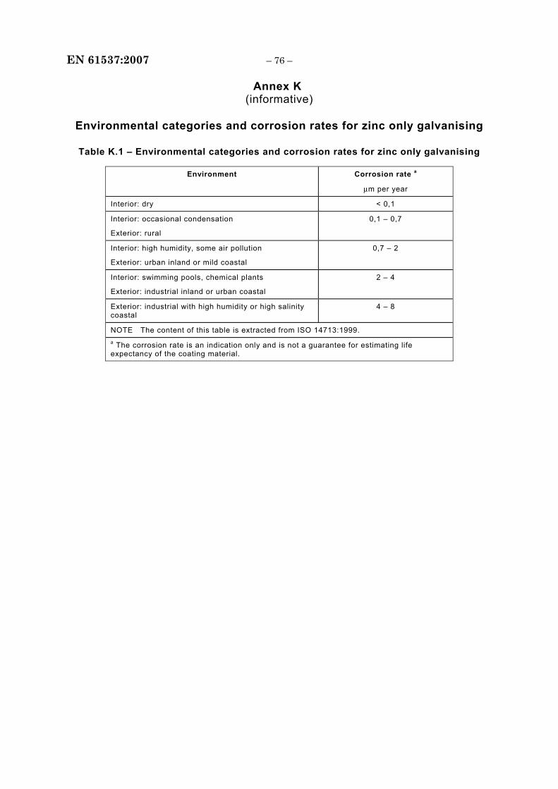
EN 61537:2007 – 76 –
Annex K (informative)
Environmental categories and corrosion rates for zinc only galvanising
Table K.1 – Environmental categories and corrosion rates for zinc only galvanising
Environment Corrosion rate a
μm per year
Interior: dry < 0,1
Interior: occasional condensation
Exterior: rural
0,1 – 0,7
Interior: high humidity, some air pollution
Exterior: urban inland or mild coastal
0,7 – 2
Interior: swimming pools, chemical plants
Exterior: industrial inland or urban coastal
2 – 4
Exterior: industrial with high humidity or high salinity coastal
4 – 8
NOTE The content of this table is extracted from ISO 14713:1999. a The corrosion rate is an indication only and is not a guarantee for estimating life expectancy of the coating material.
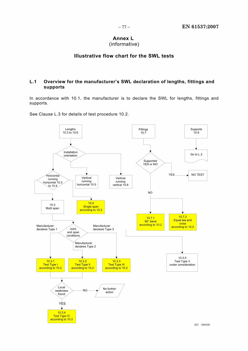
– 77 – EN 61537:2007
Annex L (informative)
Illustrative flow chart for the SWL tests
L.1 Overview for the manufacturer’s SWL declaration of lengths, fittings and supports
In accordance with 10.1, the manufacturer is to declare the SWL for lengths, fittings and supports.
See Clause L.3 for details of test procedure 10.2.
Lengths
10.3 to 10.6 Fittings
10.7 Supports
10.8
Installation orientation
Vertical running
horizontal 10.5
Vertical running
vertical 10.6
Horizontal running
horizontal 10.3 to 10.4
10.3 Multi span
10.4 Single span
according to 10.2
10.3.1 Test Type I
according to 10.2
10.3.5 Test Type V
under consideration
Joint, end span conditions
Local weakness
found NO
YES
Manufacturer declares Type 3
No further action
10.7.2 Equal tee and
cross according to 10.2
Supported YES or NO
NO TEST
Go to L.2
Manufacturer declares Type 1
Manufacturer declares Type 2
10.3.4 Test Type IV
according to 10.2
10.7.1 90° bend
according to 10.2
NO
YES
10.3.2 Test Type II
according to 10.2
10.3.3 Test Type III
according to 10.2
IEC 1893/06
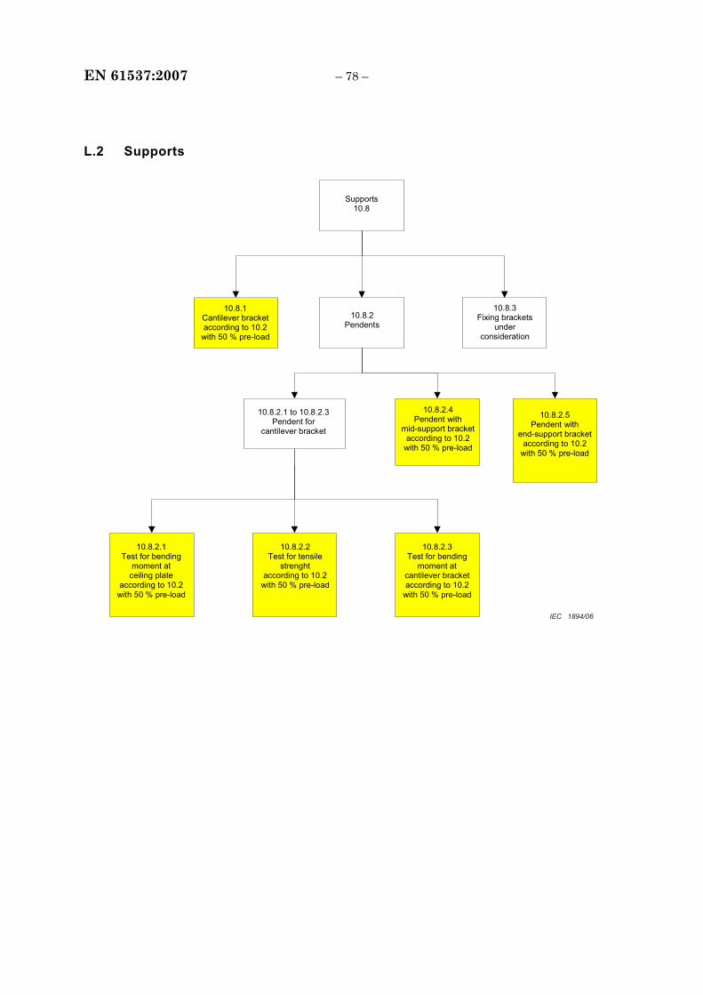
EN 61537:2007 – 78 –
L.2 Supports
Supports
10.8
10.8.1 Cantilever bracket according to 10.2
with 50 % pre-load
10.8.2 Pendents
10.8.3 Fixing brackets
under consideration
10.8.2.1 to 10.8.2.3Pendent for
cantilever bracket
10.8.2.4 Pendent with
mid-support bracket according to 10.2
with 50 % pre-load
10.8.2.5 Pendent with
end-support bracket according to 10.2
with 50 % pre-load
10.8.2.1 Test for bending
moment at ceiling plate
according to 10.2 with 50 % pre-load
10.8.2.2 Test for tensile
strenght according to 10.2
with 50 % pre-load
10.8.2.3 Test for bending
moment at cantilever bracket according to 10.2
with 50 % pre-load
IEC 1894/06
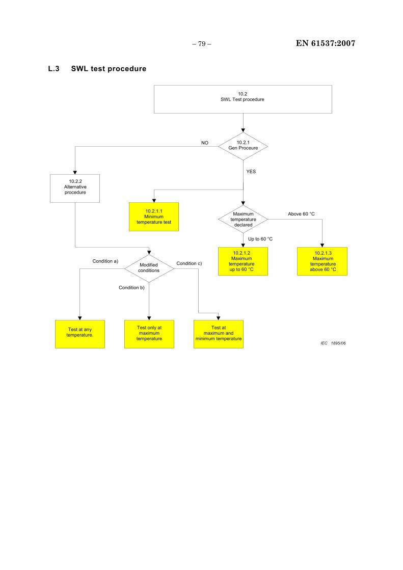
– 79 – EN 61537:2007
L.3 SWL test procedure
10.2
SWL Test procedure
10.2.1.1 Minimum
temperature test
10.2.1.2 Maximum
temperature up to 60 °C
10.2.1.3 Maximum
temperature above 60 °C
Maximum temperature
declared
Test only at maximum
temperature
10.2.1 Gen Proceure
10.2.2 Alternative procedure
NO
YES
Test at any temperature.
Modified conditions
Condition a) Condition c)
Condition b)
Above 60 °C
Up to 60 °C
Test at maximum and
minimum temperatureIEC 1895/06

EN 61537:2007 – 80 –
Bibliography
IEC 60093:1980, Methods of test for volume resistivity and surface resistivity of solid electrical insulating materials
IEC 60364-5-54:2002, Electrical installations of buildings – Part 5-54: Selection and erection of electrical equipment – Earthing arrangements, protective conductors and protective bonding conductors
ISO 14713:1999, Protection against corrosion of iron and steel in structures – Zinc and aluminium coatings - Guidelines
ASTM: A 240/A 240M – 95a Standard Specification for Heat-Resisting Chromium and Chromium-Nickel Stainless Steel Plate, Sheet, and Strip for Pressure Vessels
EN 10088-1:1995, Stainless steels. List of stainless steels
EN 10326:2004, Continuously hot-dip coated strip and sheet of structural steels – Technical delivery conditions
EN 10327:2004, Continuously hot-dip coated strip and sheet of low carbon steels for cold forming - Technical delivery conditions
___________
NOTE Harmonized as HD 429 S1:1983 (not modified).
NOTE Harmonized as EN ISO 14713:1999 (not modified).
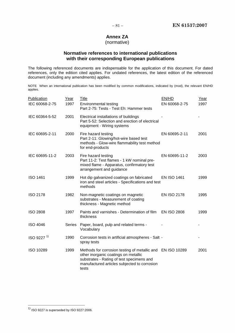
– 81 – EN 61537:2007
Annex ZA (normative)
Normative references to international publications
with their corresponding European publications The following referenced documents are indispensable for the application of this document. For dated references, only the edition cited applies. For undated references, the latest edition of the referenced document (including any amendments) applies. NOTE When an international publication has been modified by common modifications, indicated by (mod), the relevant EN/HD applies. Publication Year Title EN/HD Year IEC 60068-2-75 1997 Environmental testing
Part 2-75: Tests - Test Eh: Hammer tests EN 60068-2-75 1997
IEC 60364-5-52 2001 Electrical installations of buildings Part 5-52: Selection and erection of electrical equipment - Wiring systems
- -
IEC 60695-2-11 2000 Fire hazard testing Part 2-11: Glowing/hot-wire based test methods - Glow-wire flammability test method for end-products
EN 60695-2-11 2001
IEC 60695-11-2 2003 Fire hazard testing Part 11-2: Test flames - 1 kW nominal pre-mixed flame - Apparatus, confirmatory test arrangement and guidance
EN 60695-11-2 2003
ISO 1461 1999 Hot dip galvanized coatings on fabricated iron and steel articles - Specifications and test methods
EN ISO 1461 1999
ISO 2178 1982 Non-magnetic coatings on magnetic substrates - Measurement of coating thickness - Magnetic method
EN ISO 2178 1995
ISO 2808 1997 Paints and varnishes - Determination of film thickness
EN ISO 2808 1999
ISO 4046 Series Paper, board, pulp and related terms - Vocabulary
- -
ISO 9227 1) 1990 Corrosion tests in artificial atmospheres - Salt spray tests
- -
ISO 10289 1999 Methods for corrosion testing of metallic and other inorganic coatings on metallic substrates - Rating of test specimens and manufactured articles subjected to corrosion tests
EN ISO 10289 2001
1) ISO 9227 is superseded by ISO 9227:2006.

EN 61537:2007 – 82 –
Annex ZB (informative)
A-deviations
A-deviation: National deviation due to regulations, the alteration of which is for the time being outside the competence of the CENELEC member.
This European Standard falls under Directive 73/23/EEC.
NOTE (from CEN/CENELEC IR Part 2:2006, 2.17) Where standards fall under EC Directives, it is the view of the Commission of the European Communities (OJ No C 59, 1982-03-09) that the effect of the decision of the Court of Justice in case 815/79 Cremonini/Vrankovich (European Court Reports 1980, p. 3583) is that compliance with A-deviations is no longer mandatory and that the free movement of products complying with such a standard should not be restricted except under the safeguard procedure provided for in the relevant Directive.
A-deviations in an EFTA-country are valid instead of the relevant provisions of the European Standard in that country until they have been removed.
Clause Deviation
6.2.1 France (Decree from Equipment and Accommodation Minister for low voltage installations dated 22 October 1969)
Classification not allowed.
Annex C France (Decree from Equipment and Accommodation Minister for low voltage installations dated 22 October 1969)
The use of cable tray systems and cable ladder systems as a PE conductor is not allowed.
__________

blank
BS EN 61537:2007
BSI389 Chiswick High RoadLondonW4 4AL
BSI — British Standards InstitutionBSI is the independent national body responsible for preparing British Standards. It presents the UK view on standards in Europe and at the international level. It is incorporated by Royal Charter.
Revisions
British Standards are updated by amendment or revision. Users of British Standards should make sure that they possess the latest amendments or editions.
It is the constant aim of BSI to improve the quality of our products and services. We would be grateful if anyone finding an inaccuracy or ambiguity while using this British Standard would inform the Secretary of the technical committee responsible, the identity of which can be found on the inside front cover. Tel: +44 (0)20 8996 9000. Fax: +44 (0)20 8996 7400.
BSI offers members an individual updating service called PLUS which ensures that subscribers automatically receive the latest editions of standards.
Buying standards
Orders for all BSI, international and foreign standards publications should be addressed to Customer Services. Tel: +44 (0)20 8996 9001. Fax: +44 (0)20 8996 7001. Email: [email protected]. Standards are also available from the BSI website at http://www.bsi-global.com.
In response to orders for international standards, it is BSI policy to supply the BSI implementation of those that have been published as British Standards, unless otherwise requested.
Information on standards
BSI provides a wide range of information on national, European and international standards through its Library and its Technical Help to Exporters Service. Various BSI electronic information services are also available which give details on all its products and services. Contact the Information Centre. Tel: +44 (0)20 8996 7111. Fax: +44 (0)20 8996 7048. Email: [email protected].
Subscribing members of BSI are kept up to date with standards developments and receive substantial discounts on the purchase price of standards. For details of these and other benefits contact Membership Administration. Tel: +44 (0)20 8996 7002. Fax: +44 (0)20 8996 7001. Email: [email protected].
Information regarding online access to British Standards via British Standards Online can be found at http://www.bsi-global.com/bsonline.
Further information about BSI is available on the BSI website at http://www.bsi-global.com.
Copyright
Copyright subsists in all BSI publications. BSI also holds the copyright, in the UK, of the publications of the international standardization bodies. Except as permitted under the Copyright, Designs and Patents Act 1988 no extract may be reproduced, stored in a retrieval system or transmitted in any form or by any means – electronic, photocopying, recording or otherwise – without prior written permission from BSI.
This does not preclude the free use, in the course of implementing the standard, of necessary details such as symbols, and size, type or grade designations. If these details are to be used for any other purpose than implementation then the prior written permission of BSI must be obtained.
Details and advice can be obtained from the Copyright & Licensing Manager. Tel: +44 (0)20 8996 7070. Fax: +44 (0)20 8996 7553. Email: [email protected].
Related Documents