TEST REPORT IEC 62275 Cable management systems – Cable ties for electrical installations Report Number. ..............................: 70.410.15.1127.01-00 Date of issue ...................................: 2016-03-11 Total number of pages .................... 18 Applicant’s name ............................: Yueqing Xinguang Plastic Co., Ltd. Address ...........................................: No.317, Wei 19 Road, Yueqing Economic Development Zone 325604, Yueqing, People's Republic of China Test specification: Standard ..........................................: IEC 62275:2013 Test procedure................................: TÜV SÜD product service Non-standard test method.............: N/A Test Report Form No. .....................: TÜV SÜD IEC 62275:2013_A Test Report Form(s) Originator.....: TÜV SÜD Master TRF ......................................: Dated 14. Feb, 2016 This test report is based on the content of the standard (see above). The test report considered selected clauses of the a.m. standard(s) and experience gained with product testing. It was prepared by TUV SUD Product Service GmbH. TUV SUD Group takes no responsibility for and will not assume liability for damages resulting from the reader’s interpretation of the reproduced material due to its placement and context. Test item description .....................: Cable ties Trade Mark ......................................: Yueqing Xinguang Plastic Co., Ltd. Manufacturer ...................................: Yueqing Xinguang Plastic Co., Ltd. Model/Type reference ....................: 2.5 x (100-200); 3.6 x (100-370); 4.8 x (100-550); 7.6 x (150-550); 9 x (400-1200) Ratings ............................................: See page5 ~7

Welcome message from author
This document is posted to help you gain knowledge. Please leave a comment to let me know what you think about it! Share it to your friends and learn new things together.
Transcript

TEST REPORT IEC 62275
Cable management systems –
Cable ties for electrical installations
Report Number. .............................. : 70.410.15.1127.01-00
Date of issue ................................... : 2016-03-11
Total number of pages .................... 18
Applicant’s name ............................ : Yueqing Xinguang Plastic Co., Ltd.
Address ........................................... : No.317, Wei 19 Road, Yueqing Economic Development Zone
325604, Yueqing, People's Republic of China
Test specification:
Standard .......................................... : IEC 62275:2013
Test procedure................................ : TÜV SÜD product service
Non-standard test method ............. : N/A
Test Report Form No. ..................... : TÜV SÜD IEC 62275:2013_A
Test Report Form(s) Originator ..... : TÜV SÜD
Master TRF ...................................... : Dated 14. Feb, 2016
This test report is based on the content of the standard (see above). The test report considered selected clauses of the a.m. standard(s) and experience gained with product testing. It was prepared by TUV SUD Product Service GmbH.
TUV SUD Group takes no responsibility for and will not assume liability for damages resulting from the reader’s interpretation of the reproduced material due to its placement and context.
Test item description ..................... : Cable ties
Trade Mark ...................................... : Yueqing Xinguang Plastic Co., Ltd.
Manufacturer ................................... : Yueqing Xinguang Plastic Co., Ltd.
Model/Type reference .................... : 2.5 x (100-200); 3.6 x (100-370); 4.8 x (100-550);
7.6 x (150-550); 9 x (400-1200)
Ratings ............................................ : See page5 ~7


Page 3 of 18 Report No.70.410.15.1127.01-00
TÜV SÜD IEC 62275:2013_A
List of Attachments (including a total number of pages in each attachment):
Test report IEC 62275:2013 (this part, 18 pages)
Photo documentation (5 pages)
Data form for electrical equipment and machinery
Summary of testing:
Tests performed (name of test and test clause):
1. Full test on representative models 2.5 x 100 and 7.6 x 550.
2. All applicable hazards are covered by the harmonized standard.
3. Determination of the test result includes consideration of measurement uncertainty from the test equipment and methods.
4. We conclude that the products described in this test report comply with the standard according to the testing results on the submitted samples.
5. These test results comply with the requirements of IEC 62275:2013 and EN 62275:2015
Testing location:
TÜV SÜD Certification and Testing (China) Co., Ltd. Shanghai Branch
No. 1999, Duhui Road, Shanghai, 201108, P. R. China
Summary of compliance with National Differences
List of countries addressed:
The text of the International Standard IEC 62275:2013 was approved by CENELEC as a European
Standard with agreed common modifications.
The product fulfills the requirements of EN 62275:2015

Page 4 of 18 Report No.70.410.15.1127.01-00
TÜV SÜD IEC 62275:2013_A
Copy of marking plate
Mark on the packaging:
(Only the model name is different for different models.)
Yueqing Xinguang Plastic Co., Ltd.
2.5 x 100

Page 5 of 18 Report No.70.410.15.1127.01-00
TÜV SÜD IEC 62275:2013_A
Test item particulars...................................................:
Material ..................................................................... : Metallic component
/ Non-metallic component
/ composite component
loop tensile strength for cable ties (N) ..................... : See page 6 and page 7
Mechanical strength for fixing devices .................... : Type 1 / Type 2
Maximum operating temperature for application (°C) .................................................................................. :
50 / 60 / 75 / 85 / 105 / 120 / 150
Minimum operating temperature for application (°C) .................................................................................. :
0 / -5 /-15 / -25 /-40 /-60
Minimum temperature during installation as declared by the manufacturer(°C) .......................................... :
-10°C
Contribution to fire for non-metallic and composite cable ties .................................................................. :
Flame propagating
/ Non-flame propagating
Resistance to ultraviolet light for non-metallic and composite components ............................................ :
Not declared / Resistant to ultraviolet light
Resistance to corrosion for metallic and composite components.............................................................. :
Not declared / Resistant to corrosion
Possible test case verdicts:
- test case does not apply to the test object ........... : N/A
- test object does meet the requirement .................. : P (Pass)
- test object does not meet the requirement ........... : F (Fail)
Testing .......................................................................... :
Date of receipt of test item ........................................ : 2015-08-24
Date (s) of performance of tests ............................... : 2015-08-24 to 2016-03-04
General remarks:
The test results presented in this report relate only to the object tested. This report shall not be reproduced, except in full, without the written approval of the Issuing testing laboratory. "(See Enclosure #)" refers to additional information appended to the report. "(See appended table)" refers to a table appended to the report. Throughout this report a comma / point is used as the decimal separator.
Manufacturer’s Declaration per sub-clause 4.2.5 of IECEE 02:
The application for obtaining a CB Test Certificate includes more than one factory location and a declaration from the Manufacturer stating that the sample(s) submitted for evaluation is (are) representative of the products from each factory has been provided ............................................................... :
Yes
Not applicable
When differences exist; they shall be identified in the General product information section.

Page 6 of 18 Report No.70.410.15.1127.01-00
TÜV SÜD IEC 62275:2013_A
Name and address of factory (ies) .......................... :
General product information:
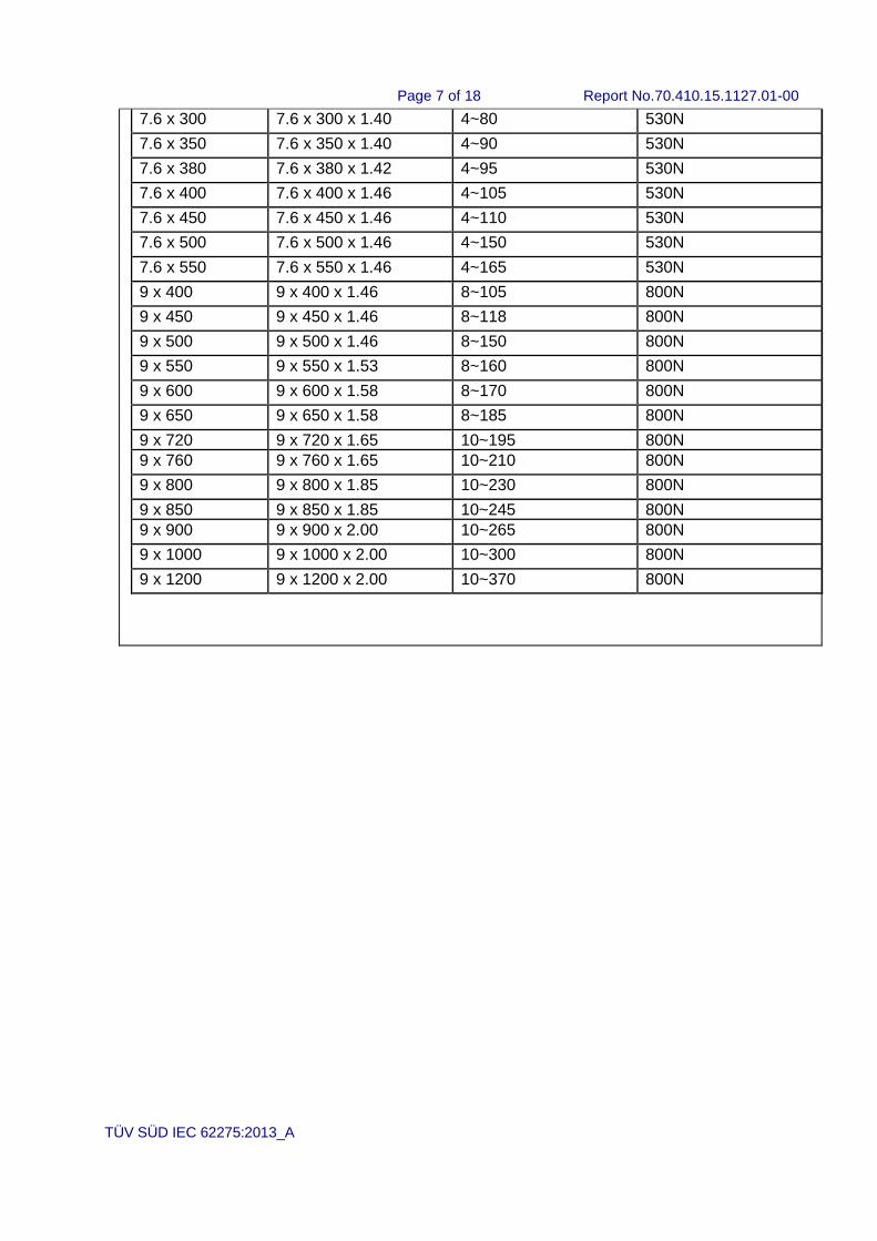
The cable ties of Yueqing Xinguang Plastic Co., Ltd. are made of PA66. They are type 1, with a maximum operating temperature for application of 85°C, with a minimum operating temperature for application of -15°C, with Minimum temperature during installation of -10°C, Non-flame propagating, resistant to ultraviolet light and have 8 colors: red, yellow, blue, green, orange, black, white and purple. The dimension and loop tensile strength for cable ties are:
Model Dimension W x L x T
(mm)
Bundle diameter (mm)
loop tensile strength (N)
2.5 x 100 2.5 x 100 x 1.00 2~22 80N
2.5 x 150 2.5 x 150 x 1.02 2~35 80N
2.5 x 200 2.5 x 200 x 1.06 3~50 80N
3.6 x 100 3.6 x 100 x 1.15 3~22 180N
3.6 x 150 3.6 x 150 x 1.15 3~35 180N
3.6 x 180 3.6 x 180 x 1.15 3~40 180N
3.6 x 200 3.6 x 200 x 1.15 3~50 180N
3.6 x 250 3.6 x 250 x 1.15 3~65 180N
3.6 x 300 3.6 x 300 x 1.15 3~80 180N
3.6 x 370 3.6 x 370 x 1.15 3~10 180N
4.8 x 100 4.8 x 100 x 1.20 3~22 220N
4.8 x 120 4.8 x 120 x 1.20 3~26 220N
4.8 x 150 4.8 x 150 x 1.20 3~40 220N
4.8 x 180 4.8 x 180 x 1.20 3~45 220N
4.8 x 200 4.8 x 200 x 1.20 3~50 220N
4.8 x 250 4.8 x 250 x 1.20 3~65 220N
4.8 x 300 4.8 x 300 x 1.20 3~80 220N
4.8 x 350 4.8 x 350 x 1.20 3~90 220N
4.8 x 370 4.8 x 370 x 1.20 3~98 220N
4.8 x 400 4.8 x 400 x 1.25 3~105 220N
4.8 x 450 4.8 x 450 x 1.35 3~130 220N
4.8 x 500 4.8 x 500 x 1.35 3~150 220N
4.8 x 550 4.8 x 550 x 1.35 3~170 220N
7.6 x 150 7.6 x 150 x 1.40 3~40 530N
7.6 x 200 7.6 x 200 x 1.40 3~50 530N
7.6 x 250 7.6 x 250 x 1.40 4~65 530N
Page 7 of 18 Report No.70.410.15.1127.01-00
TÜV SÜD IEC 62275:2013_A
7.6 x 300 7.6 x 300 x 1.40 4~80 530N
7.6 x 350 7.6 x 350 x 1.40 4~90 530N
7.6 x 380 7.6 x 380 x 1.42 4~95 530N
7.6 x 400 7.6 x 400 x 1.46 4~105 530N
7.6 x 450 7.6 x 450 x 1.46 4~110 530N
7.6 x 500 7.6 x 500 x 1.46 4~150 530N
7.6 x 550 7.6 x 550 x 1.46 4~165 530N
9 x 400 9 x 400 x 1.46 8~105 800N
9 x 450 9 x 450 x 1.46 8~118 800N
9 x 500 9 x 500 x 1.46 8~150 800N
9 x 550 9 x 550 x 1.53 8~160 800N
9 x 600 9 x 600 x 1.58 8~170 800N
9 x 650 9 x 650 x 1.58 8~185 800N
9 x 720 9 x 720 x 1.65 10~195 800N
9 x 760 9 x 760 x 1.65 10~210 800N
9 x 800 9 x 800 x 1.85 10~230 800N
9 x 850 9 x 850 x 1.85 10~245 800N
9 x 900 9 x 900 x 2.00 10~265 800N
9 x 1000 9 x 1000 x 2.00 10~300 800N
9 x 1200 9 x 1200 x 2.00 10~370 800N

Page 8 of 18 Report No.70.410.15.1127.01-00
IEC 62275:2013
Clause Requirement + Test Result - Remark Verdict
TÜV SÜD IEC 62275:2013_A
5 General notes on tests P
5.2 For tests on non-metallic and composite components: the samples are removed from their packaging, then stabilised at a temperature of (23±5) °C and at a relative humidity of (50±5) %, for a period as indicated in Table 1. ............................. :
See page 6 ~ 7 for thickness.
Stabilization time: 35days
P
7 Marking and documentation P
7.1 Each cable tie and fixing device is marked with the manufacturer's or responsible vendor's name or trademark and identifying symbol.
N/A
Where it is not possible, then this symbol is marked on the packaging.
P
7.2 Marking on the cable ties or fixing device is clearly legible and durable. Rubbing test as specified.
N/A
7.3 In literature: P
a) the classification according to Clause 6, P
b) the maximum and minimum bundle diameter in mm in relation to each cable tie,
P
c) the recommended method of installation, including the tool to be used, if any, and the load to be applied,
P
d) recommendations on transport and storage, P
e) the manufacturer’s declared mechanical strength for a fixing device, and
P
f) specific mounting or assembly conditions such as mounting hole sizes, material thicknesses, mounting orientations, etc., for fixing devices according to 5.8.
N/A
8 Construction P
The surface of the cable tie or fixing device is free from burrs and similar inconsistencies.
P
Edges are smooth so as not to damage the cables or to inflict injury to the installer or user.
P
9 Mechanical properties P
9.2 The cable tie is capable of fixing the maximum and minimum bundle diameter declared by the manufacturer.
P

Page 9 of 18 Report No.70.410.15.1127.01-00
IEC 62275:2013
Clause Requirement + Test Result - Remark Verdict
TÜV SÜD IEC 62275:2013_A
9.3 The cable tie is able to be installed at the minimum temperature declared by the manufacturer.
P
Non-metallic and composite cable ties are dried out for (72±1) h at the maximum operating temperature declared by the manufacturer.
P
The sample and a steel or aluminium mandrel is placed separately in a refrigerator, the temperature in which shall be maintained at the declared minimum temperature for installation with a tolerance of 2 °C. When the sample has attained this temperature or after 2 h, whichever is the longer period, the sample is installed on the mandrel.
P
After the test, there are no sign of disintegration nor crack visible to normal or corrected vision.
P
9.4 The cable tie is resistant to the effect of impact forces at the minimum operating temperature declared by the manufacturer
P
Two hours after the refrigerator has recovered to the declared temperature, the sample is removed from the refrigerator and placed on a V block
P
An impact is applied on the strap by a free fall hammer (12 ± 2) s after removal of the test assembly from the refrigerator.
P
After the test, it has not broken open, nor crack visible to normal or corrected vision.
P
9.5 Loop tensile strength test for Type 1 cable ties P
9.5.1 The test is carried out on a new set of ten cable ties. Each sample is installed on a test mandrel
P
Each sample is subjected to a tensile pull. The maximum force is measured. .................................. :
2.5 x 100: min. 179,8N
(declared 80N)
7.6 x 550: min. 615,3N
(declared 530N)
P
No individual value is less than the loop tensile strength declared according to 6.2.
P
9.5.2 The test is carried out on a new set of ten cable ties. Each sample is installed on a test mandrel
P
The samples are aged in a full draft circulating-air oven with forced air at the maximum declared temperature increased by (15 ± 1) °C for (10000
+48 )
h.
100°C, 1000h P
then stabilised at a temperature of (23±5) °C and at a relative humidity of (50±5) %, for a period as indicated in Table 1. ................................................ :
See page 6 and page 7for thickness.
Stabilization time: 35days
P
Page 10 of 18 Report No.70.410.15.1127.01-00
IEC 62275:2013
Clause Requirement + Test Result - Remark Verdict
TÜV SÜD IEC 62275:2013_A
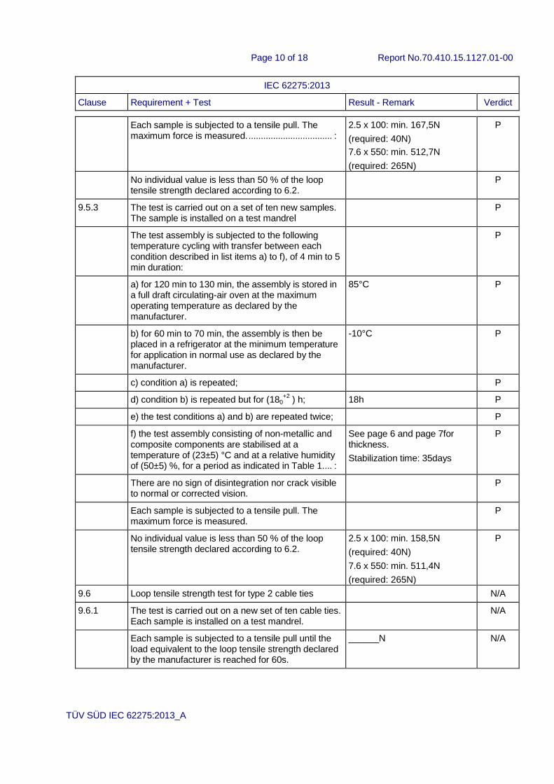
Each sample is subjected to a tensile pull. The maximum force is measured. .................................. :
2.5 x 100: min. 167,5N
(required: 40N)
7.6 x 550: min. 512,7N
(required: 265N)
P
No individual value is less than 50 % of the loop tensile strength declared according to 6.2.
P
9.5.3 The test is carried out on a set of ten new samples. The sample is installed on a test mandrel
P
The test assembly is subjected to the following temperature cycling with transfer between each condition described in list items a) to f), of 4 min to 5 min duration:
P
a) for 120 min to 130 min, the assembly is stored in a full draft circulating-air oven at the maximum operating temperature as declared by the manufacturer.
85°C P
b) for 60 min to 70 min, the assembly is then be placed in a refrigerator at the minimum temperature for application in normal use as declared by the manufacturer.
-10°C P
c) condition a) is repeated; P
d) condition b) is repeated but for (180+2
) h; 18h P
e) the test conditions a) and b) are repeated twice; P
f) the test assembly consisting of non-metallic and composite components are stabilised at a temperature of (23±5) °C and at a relative humidity of (50±5) %, for a period as indicated in Table 1.... :
See page 6 and page 7for thickness.
Stabilization time: 35days
P
There are no sign of disintegration nor crack visible to normal or corrected vision.
P
Each sample is subjected to a tensile pull. The maximum force is measured.
P
No individual value is less than 50 % of the loop tensile strength declared according to 6.2.
2.5 x 100: min. 158,5N
(required: 40N)
7.6 x 550: min. 511,4N
(required: 265N)
P
9.6 Loop tensile strength test for type 2 cable ties N/A
9.6.1 The test is carried out on a new set of ten cable ties. Each sample is installed on a test mandrel.
N/A
Each sample is subjected to a tensile pull until the load equivalent to the loop tensile strength declared by the manufacturer is reached for 60s.
______N N/A
Page 11 of 18 Report No.70.410.15.1127.01-00
IEC 62275:2013
Clause Requirement + Test Result - Remark Verdict
TÜV SÜD IEC 62275:2013_A
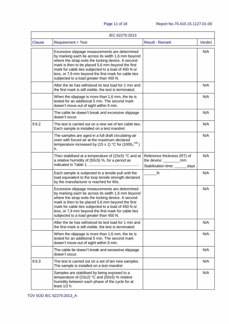
Excessive slippage measurements are determined by marking each tie across its width 1,6 mm beyond where the strap exits the locking device. A second mark is then to be placed 5,6 mm beyond the first mark for cable ties subjected to a load of 450 N or less, or 7,9 mm beyond the first mark for cable ties subjected to a load greater than 450 N.
N/A
After the tie has withstood its test load for 1 min and the first mark is still visible, the test is terminated.
N/A
When the slippage is more than 1,6 mm, the tie is tested for an additional 5 min. The second mark doesn’t move out of sight within 5 min.
N/A
The cable tie doesn’t break and excessive slippage doesn’t occur.
N/A
9.6.2 The test is carried out on a new set of ten cable ties. Each sample is installed on a test mandrel.
N/A
The samples are aged in a full draft circulating-air oven with forced air at the maximum declared temperature increased by (15 ± 1) °C for (10000
+48 )
h.
N/A
Then stabilised at a temperature of (23±5) °C and at a relative humidity of (50±5) %, for a period as indicated in Table 1. ................................................ :
Reference thickness (RT) of the device: ________mm
Stabilization time: ______days
N/A
Each sample is subjected to a tensile pull until the load equivalent to the loop tensile strength declared by the manufacturer is reached for 60s.
______N N/A
Excessive slippage measurements are determined by marking each tie across its width 1,6 mm beyond where the strap exits the locking device. A second mark is then to be placed 5,6 mm beyond the first mark for cable ties subjected to a load of 450 N or less, or 7,9 mm beyond the first mark for cable ties subjected to a load greater than 450 N.
N/A
After the tie has withstood its test load for 1 min and the first mark is still visible, the test is terminated.
N/A
When the slippage is more than 1,6 mm, the tie is tested for an additional 5 min. The second mark doesn’t move out of sight within 5 min.
N/A
The cable tie doesn’t break and excessive slippage doesn’t occur.
N/A
9.6.3 The test is carried out on a set of ten new samples. The sample is installed on a test mandrel
N/A
Samples are stabilised by being exposed to a temperature of (23±2) °C and (50±5) % relative humidity between each phase of the cycle for at least 1/2 h.
N/A
Page 12 of 18 Report No.70.410.15.1127.01-00
IEC 62275:2013
Clause Requirement + Test Result - Remark Verdict
TÜV SÜD IEC 62275:2013_A
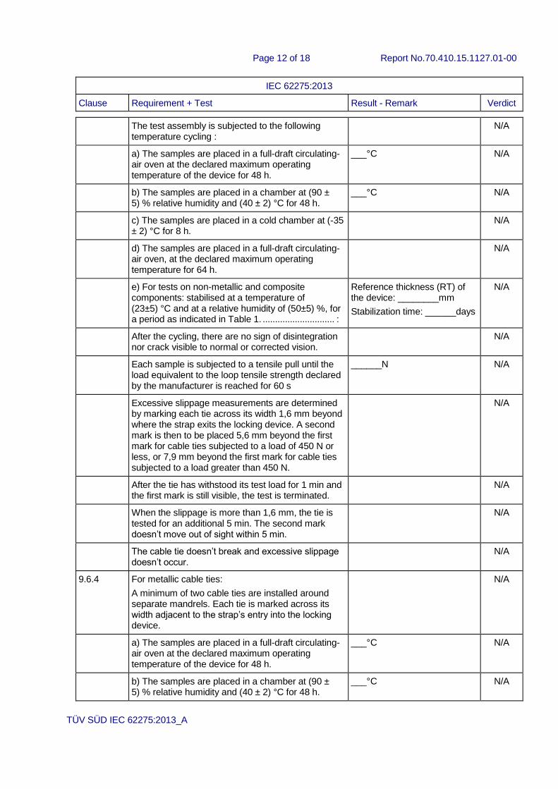
The test assembly is subjected to the following temperature cycling :
N/A
a) The samples are placed in a full-draft circulating-air oven at the declared maximum operating temperature of the device for 48 h.
___°C N/A
b) The samples are placed in a chamber at (90 ± 5) % relative humidity and (40 ± 2) °C for 48 h.
___°C N/A
c) The samples are placed in a cold chamber at (-35 ± 2) °C for 8 h.
N/A
d) The samples are placed in a full-draft circulating-air oven, at the declared maximum operating temperature for 64 h.
N/A
e) For tests on non-metallic and composite components: stabilised at a temperature of (23±5) °C and at a relative humidity of (50±5) %, for a period as indicated in Table 1. ............................. :
Reference thickness (RT) of the device: ________mm
Stabilization time: ______days
N/A
After the cycling, there are no sign of disintegration nor crack visible to normal or corrected vision.
N/A
Each sample is subjected to a tensile pull until the load equivalent to the loop tensile strength declared by the manufacturer is reached for 60 s
______N N/A
Excessive slippage measurements are determined by marking each tie across its width 1,6 mm beyond where the strap exits the locking device. A second mark is then to be placed 5,6 mm beyond the first mark for cable ties subjected to a load of 450 N or less, or 7,9 mm beyond the first mark for cable ties subjected to a load greater than 450 N.
N/A
After the tie has withstood its test load for 1 min and the first mark is still visible, the test is terminated.
N/A
When the slippage is more than 1,6 mm, the tie is tested for an additional 5 min. The second mark doesn’t move out of sight within 5 min.
N/A
The cable tie doesn’t break and excessive slippage doesn’t occur.
N/A
9.6.4 For metallic cable ties:
A minimum of two cable ties are installed around separate mandrels. Each tie is marked across its width adjacent to the strap’s entry into the locking device.
N/A
a) The samples are placed in a full-draft circulating-air oven at the declared maximum operating temperature of the device for 48 h.
___°C N/A
b) The samples are placed in a chamber at (90 ± 5) % relative humidity and (40 ± 2) °C for 48 h.
___°C N/A

Page 13 of 18 Report No.70.410.15.1127.01-00
IEC 62275:2013
Clause Requirement + Test Result - Remark Verdict
TÜV SÜD IEC 62275:2013_A
c) The samples are placed in a cold chamber at (-35 ± 2) °C for 8 h.
N/A
d) The samples are placed in a full-draft circulating-air oven, at the declared maximum operating temperature for 64 h.
N/A
e) For tests on non-metallic and composite components: stabilised at a temperature of (23±5) °C and at a relative humidity of (50±5) %, for a period as indicated in Table 1. ............................. :
Reference thickness (RT) of the device: ________mm
Stabilization time: ______days
N/A
After the cycling, there are no sign of disintegration nor crack visible to normal or corrected vision.
N/A
The mandrels are securely mounted to the vibration table such that the direction of the vibration is parallel to the plane of the circular configuration of the assembled tie.
N/A
The mandrels are subjected to the vibration test:
– frequency range: 10 Hz to 150 Hz, logarithmic
ramp and return;
– duration 8 h: 10 sweep cycles, 1 octave/min;
– maximum peak amplitude: 0,35 mm (0,7 mm
from peak to peak);
– maximum acceleration: 50 m/s2;
– crossover frequency between 58 Hz and 62 Hz.
N/A
Each sample is subjected to a tensile pull until the load equivalent to the loop tensile strength declared by the manufacturer is reached for 60s.
N/A
Excessive slippage measurements are determined by marking each tie across its width 1,6 mm beyond where the strap exits the locking device. A second mark is then to be placed 5,6 mm beyond the first mark for cable ties subjected to a load of 450 N or less, or 7,9 mm beyond the first mark for cable ties subjected to a load greater than 450 N.
N/A
After the tie has withstood its test load for 1 min and the first mark is still visible, the test is terminated.
N/A
When the slippage is more than 1,6 mm, the tie is tested for an additional 5 min. The second mark doesn’t move out of sight within 5 min.
N/A
The cable tie doesn’t break and excessive slippage doesn’t occur.
N/A
9.7 Mechanical strength test for fixing devices P
9.7.1 The samples are fixed firmly to a rigid support. An appropriate cable tie is assembled to the fixing device and then to a steel or aluminium mandrel.
P
Page 14 of 18 Report No.70.410.15.1127.01-00
IEC 62275:2013
Clause Requirement + Test Result - Remark Verdict
TÜV SÜD IEC 62275:2013_A
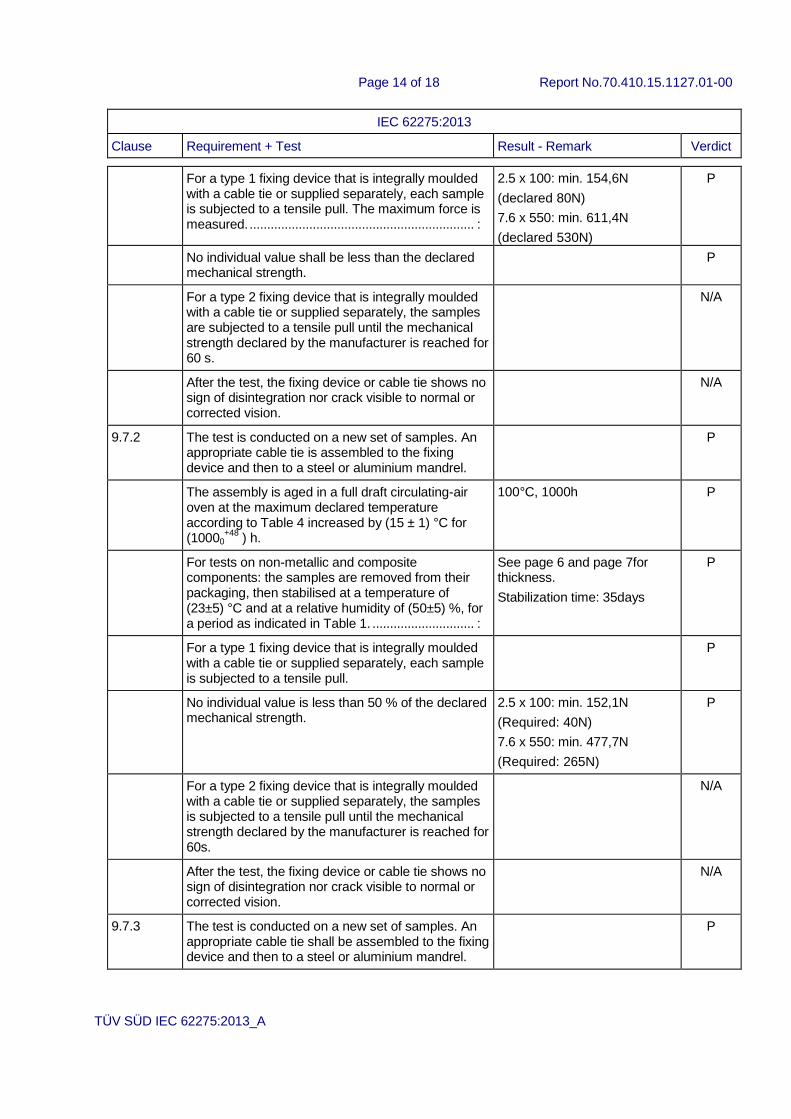
For a type 1 fixing device that is integrally moulded with a cable tie or supplied separately, each sample is subjected to a tensile pull. The maximum force is measured. ................................................................ :
2.5 x 100: min. 154,6N
(declared 80N)
7.6 x 550: min. 611,4N
(declared 530N)
P
No individual value shall be less than the declared mechanical strength.
P
For a type 2 fixing device that is integrally moulded with a cable tie or supplied separately, the samples are subjected to a tensile pull until the mechanical strength declared by the manufacturer is reached for 60 s.
N/A
After the test, the fixing device or cable tie shows no sign of disintegration nor crack visible to normal or corrected vision.
N/A
9.7.2 The test is conducted on a new set of samples. An appropriate cable tie is assembled to the fixing device and then to a steel or aluminium mandrel.
P
The assembly is aged in a full draft circulating-air oven at the maximum declared temperature according to Table 4 increased by (15 ± 1) °C for (10000
+48 ) h.
100°C, 1000h P
For tests on non-metallic and composite components: the samples are removed from their packaging, then stabilised at a temperature of (23±5) °C and at a relative humidity of (50±5) %, for a period as indicated in Table 1. ............................. :
See page 6 and page 7for thickness.
Stabilization time: 35days
P
For a type 1 fixing device that is integrally moulded with a cable tie or supplied separately, each sample is subjected to a tensile pull.
P
No individual value is less than 50 % of the declared mechanical strength.
2.5 x 100: min. 152,1N
(Required: 40N)
7.6 x 550: min. 477,7N
(Required: 265N)
P
For a type 2 fixing device that is integrally moulded with a cable tie or supplied separately, the samples is subjected to a tensile pull until the mechanical strength declared by the manufacturer is reached for 60s.
N/A
After the test, the fixing device or cable tie shows no sign of disintegration nor crack visible to normal or corrected vision.
N/A
9.7.3 The test is conducted on a new set of samples. An appropriate cable tie shall be assembled to the fixing device and then to a steel or aluminium mandrel.
P

Page 15 of 18 Report No.70.410.15.1127.01-00
IEC 62275:2013
Clause Requirement + Test Result - Remark Verdict
TÜV SÜD IEC 62275:2013_A
a) for 120 min to 130 min, the assembly is stored in a full draft circulating-air oven at the maximum operating temperature as declared by the manufacturer.
85°C P
b) for 60 min to 70 min, the assembly is then be placed in a refrigerator at the minimum temperature for application in normal use as declared by the manufacturer.
-15°C P
c) condition a) is repeated; P
d) condition b) is repeated but for (180+2
) h; 18h P
e) the test conditions a) and b) are repeated twice; P
f) the test assembly consisting of non-metallic and composite components are stabilised at a temperature of (23±5) °C and at a relative humidity of (50±5) %, for a period as indicated in Table 1.... :
See page 6 and page 7for thickness.
Stabilization time: 35days
P
For a type 1 fixing device that is integrally moulded with a cable tie or supplied separately, each sample is subjected to a tensile pull.
P
No individual value is less than 50 % of the declared mechanical strength.
2.5 x 100: min. 152,4N
(Required: 40N)
7.6 x 550: min. 467,7N
(Required: 265N)
P
For a type 2 fixing device that is integrally moulded with a cable tie or supplied separately, the samples are subjected to a tensile pull until the mechanical strength declared by the manufacturer is reached for 60s.
N/A
After the test, the fixing device or cable tie shows no sign of disintegration nor crack visible to normal or corrected vision.
N/A
10 Contribution to fire P
Non-metallic and composite cable ties classified as Non-flame propagating have adequate resistance to flame propagation.
P
The sample is installed on a solid steel or aluminium mandrel. The remaining end of the tie is cut away.
P
The sample is submitted to the needle flame test as specified in IEC 60695-11-5:2004.
P
– 30 s after the test flame is removed, there is no
flaming of the sample
Flame extinguished in 5s. P
– there is no ignition of the tissue paper. no ignition P
Page 16 of 18 Report No.70.410.15.1127.01-00
IEC 62275:2013
Clause Requirement + Test Result - Remark Verdict
TÜV SÜD IEC 62275:2013_A
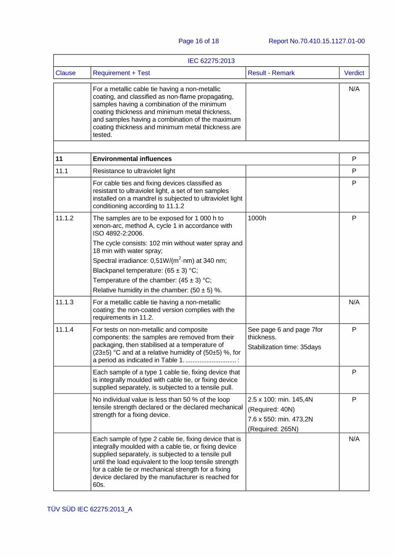
For a metallic cable tie having a non-metallic coating, and classified as non-flame propagating, samples having a combination of the minimum coating thickness and minimum metal thickness, and samples having a combination of the maximum coating thickness and minimum metal thickness are tested.
N/A
11 Environmental influences P
11.1 Resistance to ultraviolet light P
For cable ties and fixing devices classified as resistant to ultraviolet light, a set of ten samples installed on a mandrel is subjected to ultraviolet light conditioning according to 11.1.2
P
11.1.2 The samples are to be exposed for 1 000 h to xenon-arc, method A, cycle 1 in accordance with ISO 4892-2:2006.
The cycle consists: 102 min without water spray and 18 min with water spray;
Spectral irradiance: 0,51W/(m2·nm) at 340 nm;
Blackpanel temperature: (65 ± 3) °C;
Temperature of the chamber: (45 ± 3) °C;
Relative humidity in the chamber: (50 ± 5) %.
1000h P
11.1.3 For a metallic cable tie having a non-metallic coating: the non-coated version complies with the requirements in 11.2.
N/A
11.1.4 For tests on non-metallic and composite components: the samples are removed from their packaging, then stabilised at a temperature of (23±5) °C and at a relative humidity of (50±5) %, for a period as indicated in Table 1. ............................. :
See page 6 and page 7for thickness.
Stabilization time: 35days
P
Each sample of a type 1 cable tie, fixing device that is integrally moulded with cable tie, or fixing device supplied separately, is subjected to a tensile pull.
P
No individual value is less than 50 % of the loop tensile strength declared or the declared mechanical strength for a fixing device.
2.5 x 100: min. 145,4N
(Required: 40N)
7.6 x 550: min. 473,2N
(Required: 265N)
P
Each sample of type 2 cable tie, fixing device that is integrally moulded with a cable tie, or fixing device supplied separately, is subjected to a tensile pull until the load equivalent to the loop tensile strength for a cable tie or mechanical strength for a fixing device declared by the manufacturer is reached for 60s.
N/A

Page 17 of 18 Report No.70.410.15.1127.01-00
IEC 62275:2013
Clause Requirement + Test Result - Remark Verdict
TÜV SÜD IEC 62275:2013_A
Excessive slippage measurements are determined by marking each tie across its width 1,6 mm beyond where the strap exits the locking device. A second mark is then to be placed 5,6 mm beyond the first mark for cable ties subjected to a load of 450 N or less, or 7,9 mm beyond the first mark for cable ties subjected to a load greater than 450 N.
N/A
After the tie has withstood its test load for 1 min and the first mark is still visible, the test is terminated.
N/A
When the slippage is more than 1,6 mm, the tie is tested for an additional 5 min. The second mark doesn’t move out of sight within 5 min.
N/A
The cable tie doesn’t break and excessive slippage doesn’t occur.
N/A
After the test, there are no sign of disintegration nor crack visible to normal or corrected vision.
N/A
Each sample of a fixing device shall be subjected to a tensile pull until the mechanical strength declared by the manufacturer is reached for 60 s.
N/A
After the test, there are no sign of disintegration nor crack visible to normal or corrected vision.
N/A
11.2 Resistance to corrosion N/A
Cable ties and fixing devices classified as resistant to corrosion, are exposed to a neutral salt spray (NSS) in accordance with ISO 9227 for 192 h followed by 12 h at (40 ± 2) °C.
N/A
Samples of non-metallic coated devices are subjected to heat age conditioning in accordance with 9.5.2, 9.6.2 or 9.7.2 as appropriate before exposure to the salt spray.
N/A
The samples are rinsed in demineralised water. Metallic cable ties and fixing devices are dried. Composite cable ties and fixing devices are stabilised according to 5.2.
N/A
After the test, the samples show no cracks visible to normal or corrected vision. There are no red rust visible to normal or corrected vision.
N/A
Each sample of a composite cable tie classified according to 6.2.2 (Type 1), are subjected to the tensile pull according to 9.5.1. No individual value is less than 50 % of the loop tensile strength declared according to 6.2.
N/A

Page 18 of 18 Report No.70.410.15.1127.01-00
IEC 62275:2013
Clause Requirement + Test Result - Remark Verdict
TÜV SÜD IEC 62275:2013_A
Each sample of a metallic or composite cable tie classified according to 6.2.3 (Type 2), is subjected to the tensile pull according to 9.6.1 until the load equivalent to the loop tensile strength declared by the manufacturer is reached. This load is maintained for 60 s.
The samples are tested according to the requirements in 9.6.1.
Each sample of a fixing device are subjected to the tensile pull according to 9.7.1.
After the test, there shall be no sign of disintegration of a fixing device or any crack visible to normal or corrected vision.
A metallic cable tie having a non-metallic coating that is depended upon to provide resistance to corrosion, and that is declared as having resistance to ultraviolet light, are subjected to the conditioning in 11.1 followed by the appropriate requirements in 11.2 for metallic cable ties.
The requirements in 11.2 are not applicable for a metallic cable tie with a non-metallic coating when the uncoated version has been determined to meet the requirements in 11.2.
Related Documents