Cable-stayed bridge connected to a chained floating bridge – A case study Anna Tranell Civil Engineering, masters level 2017 Luleå University of Technology Department of Civil, Environmental and Natural Resources Engineering

Welcome message from author
This document is posted to help you gain knowledge. Please leave a comment to let me know what you think about it! Share it to your friends and learn new things together.
Transcript
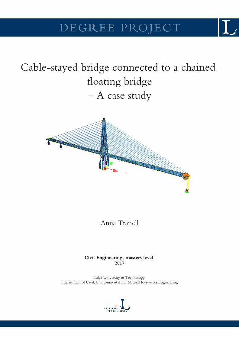
Cable-stayed bridge connected to a chained
floating bridge
– A case study
Anna Tranell
Civil Engineering, masters level
2017
Luleå University of Technology
Department of Civil, Environmental and Natural Resources Engineering

[email protected] [email protected]
Author:
Anna Tranell
Title:
“Cable-stayed bridge connected to a chained floating bridge
– A case study”
Department of Civil, Environmental and Natural resources engineering
Luleå University of Technology
Titel:
“Snedkabelbro sammankopplad med en kedjeflytbro
– en fallstudie”
Instititutionen Samhällsbyggnad och Naturresurser
Luleå Tekniska Universitet

Cable-stayed bridge connected to a chained floating bridge – A case study [email protected]
Preface/Abstract/Sammanfattning
Anna Tranell April 2, 2017 Page ii
Preface My work with this thesis started in October 2013 and I finalized it in April 2017. Over the years I took
the time to mature the ideas, resulting in a more advanced and comprehensive study than initially
planned. Although the thesis has continued longer than usual, the estimated 20 weeks for a master
thesis has not been extensively exceeded.
I consider the subject and the analytical work of this thesis of great personal interest. With all things
of great interest to individuals it’s always a balance in when to stop improving and analyzing, resulting
in vast amounts of data. In this report I have tried to select the most important and scientific results of
my study.
Working with my thesis has had the added benefit in that I’ve learnt about the construction, design
and global behavior of cable-stayed bridges. I have also learnt about creating and optimizing analytical
models with finite-elements in the software SOFiSTiK. Unexpected discoveries included some of my
own limitations as well as the RAM-limits of my computer.
I would like to express my thanks to Multiconsult AS for initiating this exceptional study, as well as
providing the necessary means to perform it. These thanks include Birger Oppgård at Multiconsult
AS/Degree of Freedom Engineers. A special thanks to Lene Stavang Olsen and Per Olav Laukli at
Multiconsult AS for support and approval of study leave.
I’m grateful to my mentor Felice Allievi from Degree of Freedom Engineers who supported me through
this time period and shared his expertise in structural engineering. Thank you for your patience,
mentoring and constructive discussions about the study and about being an engineer.
I would like to acknowledge Luleå University of Technology and the Department of Civil, Environmental
and Natural resources Engineering together with my supervisor Peter Collin for providing me with the
education and the confidence to execute this study. I’m grateful for the comments by Simon Marklund
during the opposing of the thesis.
My gratitude also include Gellert Keresztes for support and discussion about scientific methods and
disposition of the thesis. The gratitude extends further more to colleagues, friends and family.
I sincerely hope that you will enjoy reading the thesis and be amazed of the possibilities with a chained
floating bridge.
Luleå, April 2017
Anna Tranell
Cable-stayed bridge connected to a chained floating bridge – A case study [email protected]
Preface/Abstract/Sammanfattning
Anna Tranell April 2, 2017 Page ii
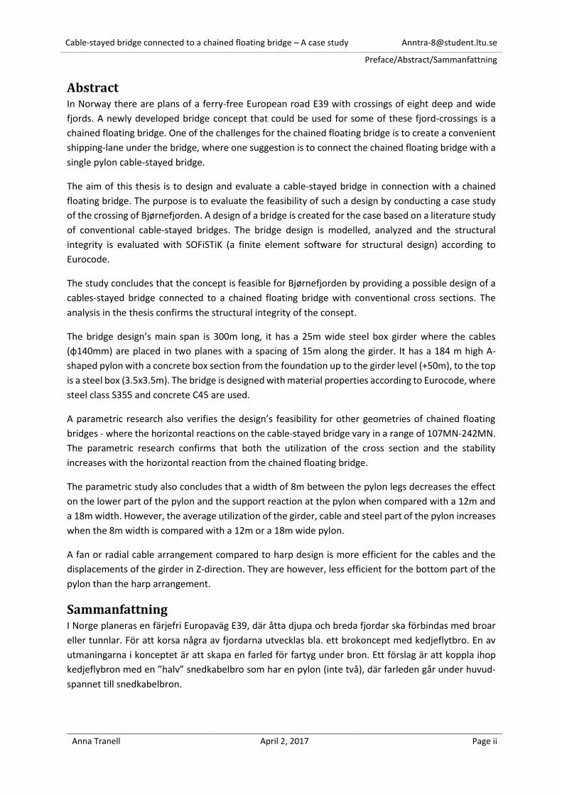
Abstract In Norway there are plans of a ferry-free European road E39 with crossings of eight deep and wide
fjords. A newly developed bridge concept that could be used for some of these fjord-crossings is a
chained floating bridge. One of the challenges for the chained floating bridge is to create a convenient
shipping-lane under the bridge, where one suggestion is to connect the chained floating bridge with a
single pylon cable-stayed bridge.
The aim of this thesis is to design and evaluate a cable-stayed bridge in connection with a chained
floating bridge. The purpose is to evaluate the feasibility of such a design by conducting a case study
of the crossing of Bjørnefjorden. A design of a bridge is created for the case based on a literature study
of conventional cable-stayed bridges. The bridge design is modelled, analyzed and the structural
integrity is evaluated with SOFiSTiK (a finite element software for structural design) according to
Eurocode.
The study concludes that the concept is feasible for Bjørnefjorden by providing a possible design of a
cables-stayed bridge connected to a chained floating bridge with conventional cross sections. The
analysis in the thesis confirms the structural integrity of the consept.
The bridge design’s main span is 300m long, it has a 25m wide steel box girder where the cables
(φ140mm) are placed in two planes with a spacing of 15m along the girder. It has a 184 m high A-
shaped pylon with a concrete box section from the foundation up to the girder level (+50m), to the top
is a steel box (3.5x3.5m). The bridge is designed with material properties according to Eurocode, where
steel class S355 and concrete C45 are used.
A parametric research also verifies the design’s feasibility for other geometries of chained floating
bridges - where the horizontal reactions on the cable-stayed bridge vary in a range of 107MN-242MN.
The parametric research confirms that both the utilization of the cross section and the stability
increases with the horizontal reaction from the chained floating bridge.
The parametric study also concludes that a width of 8m between the pylon legs decreases the effect
on the lower part of the pylon and the support reaction at the pylon when compared with a 12m and
a 18m width. However, the average utilization of the girder, cable and steel part of the pylon increases
when the 8m width is compared with a 12m or a 18m wide pylon.
A fan or radial cable arrangement compared to harp design is more efficient for the cables and the
displacements of the girder in Z-direction. They are however, less efficient for the bottom part of the
pylon than the harp arrangement.
Sammanfattning I Norge planeras en färjefri Europaväg E39, där åtta djupa och breda fjordar ska förbindas med broar
eller tunnlar. För att korsa några av fjordarna utvecklas bla. ett brokoncept med kedjeflytbro. En av
utmaningarna i konceptet är att skapa en farled för fartyg under bron. Ett förslag är att koppla ihop
kedjeflybron med en ”halv” snedkabelbro som har en pylon (inte två), där farleden går under huvud-
spannet till snedkabelbron.
Cable-stayed bridge connected to a chained floating bridge – A case study [email protected]
Preface/Abstract/Sammanfattning
Anna Tranell April 2, 2017 Page ii
Avsikten med detta examensarbete är att konstruera och utvärdera en snedkabelbro ihopkopplad med
en kedjeflytbro. Syftet är att utvärdera om konceptet med snedkabelbro är genomförbart, med hjälp
av en fallstudie av Bjørnefjordsförbindelsen. En konventionell design av en snedkabelbro upprättas
efter fallets villkor med hjälp av en literaturstudie. Designen modelleras, analyseras och dimensioneras
enligt Eurokod med analysverktyget SOFiSTiK.
Slutsatsen är att konceptet med en snedkabelbro ihopkopplad med en kedjeflytbro är gjenomförbart
då det är möjligt att designa en sådan med konventionella tvärsnitt. Analysen i rapporten bekräftar att
designen har tillräcklig bärförmåga.
I designen är huvudspannet 300m långt och består av en 25m bred brobalk upphängd av (φ140mm)
kablar placerade i två plan var 15m. Bron har en 184m hög A-formad pylon med ett lådtvärsnitt i betong
från fundament till brobalksnivån (+50m), därifrån till pylontoppen är tvärsnittet en stålbox (3.5x3.5m).
Bron är dimensionerad med materialparameterar enligt Eurokod, där stålkvalitet S355 och Betong C45
har använts.
En utförd parameterstudie bekräftar också konceptets genomförbarhet för andra geometrier av
kedjeflytbron – där den horisontella reaktionen på snedkabelbron varierar mellan 107MN och 242MN.
Parameterstudein bekräftar att både utnyttjandet av tvärsnittskapasiteten och stabiliteten ökar med
den horisontella reaktionen från kedjeflytbron.
Dessutom konkluderar parameterstudien att bredden 8m mellan pylonbenen minskar lasteffekten på
den nedre delen av pylonen och stödreaktionen vid pylonen jämfört med bredden 12m och 18m.
Däremot ökar medelutnyttjandet av tvärsnittaskapasiteten för brobalken, kablarna och ståldelen av
pylonen för bredden 8m jämfört med 12m eller 18m.
En radiell- eller solfjäderformad kabelkonfiguration jämfört med parallellformad design är mer effektiv
för kablarna och nedböjning av brobalken. De gör däremot så att den den nedre delen av pylonen får
större snittkrafter än för den parallellformade kabelkonfigurationen.
Cable-stayed bridge connected to a chained floating bridge – A case study [email protected]
1 Introduction
Anna Tranell April 2, 2017 Page 5 of 93
Contents 1. Introduction ..................................................................................................................................... 7
1.1 Purpose .................................................................................................................................... 8 1.2 General delimitation................................................................................................................ 8 1.3 Summary of contents .............................................................................................................. 8
2. Context .......................................................................................................................................... 10 2.1 Background ............................................................................................................................ 10 2.2 Concept ................................................................................................................................. 11
2.2.1 Concept of the chained floating bridge ......................................................................... 12 2.3 Shipping-lane for a chained floating bridge .......................................................................... 15
3. Method .......................................................................................................................................... 17 3.1 Design of cable-stayed bridge (Model0) ............................................................................... 17 3.2 Parametric research of the design ........................................................................................ 18
4. Case premises ................................................................................................................................ 19 4.1 Actions on Cable-Stayed Bridge from Chained-Floating Bridge ............................................ 21
5. Theory: Cable–stayed bridges ....................................................................................................... 23 5.1 General Layout (Concept) ...................................................................................................... 23
5.1.1 Long-span cable-stayed bridges .................................................................................... 25 5.2 Components of a cable-stayed bridge ................................................................................... 26
5.2.1 Cables ............................................................................................................................ 26 5.2.2 Girder ............................................................................................................................. 28 5.2.3 Pylon .............................................................................................................................. 30 5.2.4 Anchorages of the cables .............................................................................................. 31
5.3 Construction of a cable-stayed bridge .................................................................................. 32 5.4 Design of a cable-stayed bridge ............................................................................................ 34
5.4.1 Dynamic loads ............................................................................................................... 35 5.5 Study of three existing cable-stayed bridges ........................................................................ 36
5.5.1 Surgut Bridge, Surgut, Russia ........................................................................................ 36 5.5.2 The Third Nanjing Bridge, Shanghai, China ................................................................... 37 5.5.3 Sutong Bridge, Suzhou, China ........................................................................................ 37
6. Design of the cable-stayed bridge ................................................................................................. 39 6.1 Step 1: First design attempt – Model0_0 .............................................................................. 39
6.1.1 Global geometry ............................................................................................................ 39 6.1.2 Girder ............................................................................................................................. 39 6.1.3 Cables ............................................................................................................................ 41 6.1.4 Pylon .............................................................................................................................. 41 6.1.5 FEA Model0_0 in SOFiSTiK ............................................................................................. 44
6.2 Step 2: Interim design – Model0_1 ....................................................................................... 45 6.2.1 Permanent loads ........................................................................................................... 46 6.2.2 Variable Loads ............................................................................................................... 47 6.2.3 Intermediate Load Combinations .................................................................................. 49 Preliminary evaluation (design) ..................................................................................................... 51 6.2.4 Summary: Interim model (Model0_1) ........................................................................... 52 6.2.5 Results Model0_0.1 ....................................................................................................... 54
6.3 Step 3: Final design – Model0_2 ........................................................................................... 55 6.3.1 Design combinations ..................................................................................................... 55 6.3.2 Analyzing the design combinations ............................................................................... 57 6.3.3 Evaluate structural integrity .......................................................................................... 57 6.3.4 Optimization .................................................................................................................. 58
Cable-stayed bridge connected to a chained floating bridge – A case study [email protected]
1 Introduction
Anna Tranell April 2, 2017 Page 6 of 93
6.4 Result: Model0_2 .................................................................................................................. 60 6.4.1 Design and Structural Integrity ...................................................................................... 60 6.4.2 Extreme Internal Forces ................................................................................................ 64 6.4.3 Reaction forces .............................................................................................................. 67
7. Parametric Research ..................................................................................................................... 68 7.1 Definition of Parameters ....................................................................................................... 68
7.1.1 Parameter A: Tension from the chained floating bridge (variable raise). ..................... 68 7.1.2 Parameter B: Stiffness of pylon (variable width between pylon legs) .......................... 68 7.1.3 Parameter C: Cable arrangement (Harp, Fan and Radial) ............................................. 69
7.2 Results Parametric Research ................................................................................................. 71 7.2.1 Result Parameter A: Tension from the chained floating bridge (variable raise) ........... 71 7.2.2 Result Parameter B: Stiffness of pylon (variable width between pylon legs) ............... 74 7.2.3 Result Parameter C: Cable arrangement (Harp, Fan and Radial) .................................. 77
8. Discussion and conclusions ........................................................................................................... 80 8.1 Purpose and general method ................................................................................................ 80
8.1.1 Design approach ............................................................................................................ 80 8.2 Final design (Model0_2) ........................................................................................................ 83
8.2.1 Design and Structural integrity ...................................................................................... 83 8.2.2 Internal forces ............................................................................................................... 83 8.2.3 Supports ........................................................................................................................ 85
8.3 Parametric research .............................................................................................................. 87 8.3.1 Parameter A: Tension from the chained floating bridge (variable raise). ..................... 87 8.3.2 Parameter B: Stiffness of pylon (variable width between pylon legs) .......................... 88 8.3.3 Parameter C: Cable arrangement (Harp, Fan and Radial) ............................................. 89
8.4 Conclusions ............................................................................................................................ 91 8.4.1 Suggestions for further research ................................................................................... 91
9. References ..................................................................................................................................... 92
Appendix Appendix A – Drawings and calculations of global geometry for Model0_0
Appendix B – Definition of geometry and loads for Model0_0
Appendix C – SOFiSTiK Model0_0, First design attempt
Appendix D – SOFiSTiK Model0_1, Interim design
Appendix E – SOFiSTiK Model0_2, Final design
Appendix F – SOFiSTiK Model0_2A1, Parameter A1: Tension from floating bridge (R=242 MN)
Appendix G – SOFiSTiK Model0_2A2, Parameter A2: Tension from floating bridge (R=108 MN)
Appendix H – SOFiSTiK Model0_2B1, Parameter B1: Stiffness of pylon (W=8m)
Appendix I – SOFiSTiK Model0_2B2, Parameter B2: Stiffness of pylon (W=18m)
Appendix J – SOFiSTiK Model0_2C1, Parameter C1: Cable arrangement (Fan)
Appendix K – SOFiSTiK Model0_2C2, Parameter C2: Cable arrangement (Radial)
Cable-stayed bridge connected to a chained floating bridge – A case study [email protected]
1 Introduction
Anna Tranell April 2, 2017 Page 7 of 93
1. Introduction An expanding and interesting research field, especially in Norway where new bridge concepts are
developed, are bridge designs for wide and deep crossings. The main motivation is plans of a ferry-free
European road E39. E39 is a part of the European road trunk system and service the western coastline
of Norway from Kristiansand to Trondheim. The plans for E39 includes eight crossings over Norwegian
fjords. Connecting these crossings will require development of new and conventional bridge concepts
[1].
One of these newly developed bridge concepts is a chained floating bridge. Whereas, a conventional
floating bridge is a rigid structure, a chained floating bridge is flexible in the transversal direction. The
flexibility would make it more effective and economical since it allows actions to redistribute into
mainly axial forces in the bridges deck [2].
Shipping in the fjord is a challenge for the concept of a chained floating bridge. In conventional floating
bridges there are mainly two solutions for shipping; either using a high bridge, or by creating a movable
opening in the bridge. Only the first option is feasible for the chained floating bridge due to the axial
forces in bridge deck.
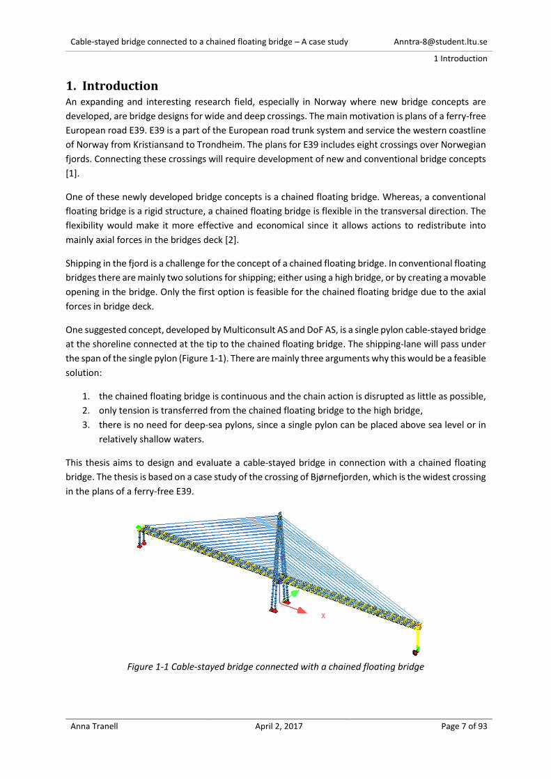
One suggested concept, developed by Multiconsult AS and DoF AS, is a single pylon cable-stayed bridge
at the shoreline connected at the tip to the chained floating bridge. The shipping-lane will pass under
the span of the single pylon (Figure 1-1). There are mainly three arguments why this would be a feasible
solution:
1. the chained floating bridge is continuous and the chain action is disrupted as little as possible,
2. only tension is transferred from the chained floating bridge to the high bridge,
3. there is no need for deep-sea pylons, since a single pylon can be placed above sea level or in
relatively shallow waters.
This thesis aims to design and evaluate a cable-stayed bridge in connection with a chained floating
bridge. The thesis is based on a case study of the crossing of Bjørnefjorden, which is the widest crossing
in the plans of a ferry-free E39.
Figure 1-1 Cable-stayed bridge connected with a chained floating bridge

Cable-stayed bridge connected to a chained floating bridge – A case study [email protected]
1 Introduction
Anna Tranell April 2, 2017 Page 8 of 93
1.1 Purpose The aim of this thesis is to design and evaluate a cable-stayed bridge in connection with a chain floating
bridge. The purpose is to evaluate the feasibility of such a design by conducting a case study of the
crossing of Bjørnefjorden. The feasibility-evaluation contain two integral parts:
1. Design a cable-stayed bridge connected to a chained floating bridge with cross sections as
conventional cable-stayed bridges.
2. Evaluate the design with a parametric research. Three geometrical parameters of main
structural parts of the bridge are selected for the research:
A. geometry of the chained floating bridge, (this parameter impact the action from the
chained floating bridge on the cable-stayed bridge)
B. stiffness of pylon,
C. cable arrangement.
1.2 General delimitation Input values such as environmental loads and other preconditions are based on the case where the
bridge crosses Bjørnefjorden in Norway.
The chained floating bridge is connected to the cable-stayed after construction. This means that the
effect on the cable-stayed bridge from the chained floating bridge arise after completion of the
construction. Therefore, all the analysis of the cable-stayed bridge is performed on the final stage when
the bridge is open for traffic. The effects on the final stage from construction phase is thus not included
in the analysis.
The delimitation of the construction phases make the analysis unsuitable for a detailed design.
However, the delimitation will not impact the result of the parametric study due to it’s self-
comparative nature.
All analysis is performed on static design situations; dynamic effects and fatigue are not considered.
The cable-stayed bridge is analyzed as an independent structure where the effect of the chained
floating bridge is included as an equivalent force acting on the cable-stayed bridge. The full global
system with both cable-stayed and chained floating bridge is not modelled or analyzed.
Not all loads and load combination are included, due to the complexity of the analysis. The included
loads and load combinations are estimated to give the most extreme global results of the structure.
A simplified (not detailed) evaluation of the structural integrity is performed including, design of the
main cross sections (girder, pylon and cables) in ultimate limit state, a simple global buckling analysis
and evaluation of the displacements in serviceability limit state. Design of the supports and details,
such as stiffeners or connections, are not performed. Neither are evaluations performed of the cross
sections in serviceability limit state.
1.3 Summary of contents The report starts with a summary describing the plans of a ferry-free E39 and the concept of chained
floating bridge. This is a relatively new concept and consequently there is limited available literature
about chained floating bridges.

Cable-stayed bridge connected to a chained floating bridge – A case study [email protected]
1 Introduction
Anna Tranell April 2, 2017 Page 9 of 93
The following chapters 3, 4 and 5 addresses the method, case premises and theory of cable-stayed
bridges and their design.
Chapter 6, addresses design of a cable-stayed bridge connected to a chained floating bridge. Chapter
7, addresses the parametric research. Each of these chapters contain a specific description of the
methods, analysis and results.
The thesis ends with a discussion and conclusions.
Cable-stayed bridge connected to a chained floating bridge – A case study [email protected]
2 Context
Anna Tranell April 2, 2017 Page 10 of 93
2. Context
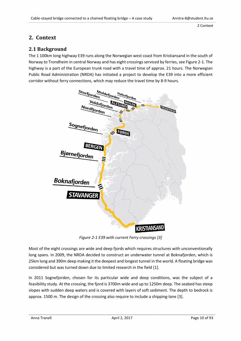
2.1 Background The 1 100km long highway E39 runs along the Norwegian west coast from Kristiansand in the south of
Norway to Trondheim in central Norway and has eight crossings serviced by ferries, see Figure 2-1. The
highway is a part of the European trunk road with a travel time of approx. 21 hours. The Norwegian
Public Road Administration (NRDA) has initiated a project to develop the E39 into a more efficient
corridor without ferry connections, which may reduce the travel time by 8-9 hours.
Figure 2-1 E39 with current Ferry crossings [3]
Most of the eight crossings are wide and deep fjords which requires structures with unconventionally
long spans. In 2009, the NRDA decided to construct an underwater tunnel at Boknafjorden, which is
25km long and 390m deep making it the deepest and longest tunnel in the world. A floating bridge was
considered but was turned down due to limited research in the field [1].
In 2011 Sognefjorden, chosen for its particular wide and deep conditions, was the subject of a
feasibility study. At the crossing, the fjord is 3700m wide and up to 1250m deep. The seabed has steep
slopes with sudden deep waters and is covered with layers of soft sediment. The depth to bedrock is
approx. 1500 m. The design of the crossing also require to include a shipping-lane [3].
Cable-stayed bridge connected to a chained floating bridge – A case study [email protected]
2 Context
Anna Tranell April 2, 2017 Page 11 of 93
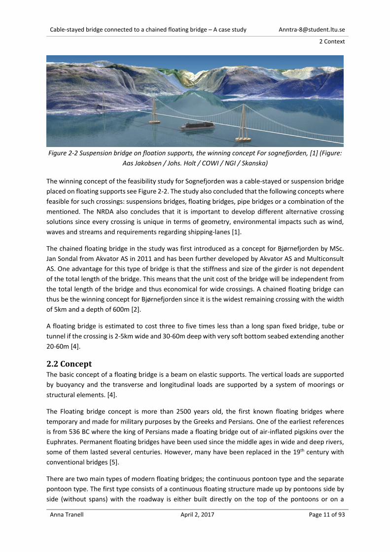
Figure 2-2 Suspension bridge on floation supports, the winning concept For sognefjorden, [1] (Figure:
Aas Jakobsen / Johs. Holt / COWI / NGI / Skanska)
The winning concept of the feasibility study for Sognefjorden was a cable-stayed or suspension bridge
placed on floating supports see Figure 2-2. The study also concluded that the following concepts where
feasible for such crossings: suspensions bridges, floating bridges, pipe bridges or a combination of the
mentioned. The NRDA also concludes that it is important to develop different alternative crossing
solutions since every crossing is unique in terms of geometry, environmental impacts such as wind,
waves and streams and requirements regarding shipping-lanes [1].
The chained floating bridge in the study was first introduced as a concept for Bjørnefjorden by MSc.
Jan Sondal from Akvator AS in 2011 and has been further developed by Akvator AS and Multiconsult
AS. One advantage for this type of bridge is that the stiffness and size of the girder is not dependent
of the total length of the bridge. This means that the unit cost of the bridge will be independent from
the total length of the bridge and thus economical for wide crossings. A chained floating bridge can
thus be the winning concept for Bjørnefjorden since it is the widest remaining crossing with the width
of 5km and a depth of 600m [2].
A floating bridge is estimated to cost three to five times less than a long span fixed bridge, tube or
tunnel if the crossing is 2-5km wide and 30-60m deep with very soft bottom seabed extending another
20-60m [4].
2.2 Concept The basic concept of a floating bridge is a beam on elastic supports. The vertical loads are supported
by buoyancy and the transverse and longitudinal loads are supported by a system of moorings or
structural elements. [4].
The Floating bridge concept is more than 2500 years old, the first known floating bridges where
temporary and made for military purposes by the Greeks and Persians. One of the earliest references
is from 536 BC where the king of Persians made a floating bridge out of air-inflated pigskins over the
Euphrates. Permanent floating bridges have been used since the middle ages in wide and deep rivers,
some of them lasted several centuries. However, many have been replaced in the 19th century with
conventional bridges [5].
There are two main types of modern floating bridges; the continuous pontoon type and the separate
pontoon type. The first type consists of a continuous floating structure made up by pontoons side by
side (without spans) with the roadway is either built directly on the top of the pontoons or on a
Cable-stayed bridge connected to a chained floating bridge – A case study [email protected]
2 Context
Anna Tranell April 2, 2017 Page 12 of 93
superstructure on top of the pontoons. The second type has individual pontoons placed transversely
to the structure and are spanned by a superstructure of steel and concrete.
There are two floating bridges in Norway as of 2016, the 1246m long Nordhordland Bridge and the
845m long Bergøysund Bridge, which were constructed in the early 1990’s. Both are of the separate
pontoon type, with concrete pontoons and steel superstructures [4]. The Norwegian bridges are not
moored along the structure, they are only supported transversally and longitudinally at the supports
at the shorelines [6].
In other words these structures are rigid and continuous. The transverse and longitudinal loads are
transferred as bending moment in the deck to the support. The bending effects will increase quadratic
with the length of the bridge and result in massive structures for wide-span crossings. To improve the
floating bridge concept for wide-span crossings the chained floating bridge concept emerged [2].
2.2.1 Concept of the chained floating bridge
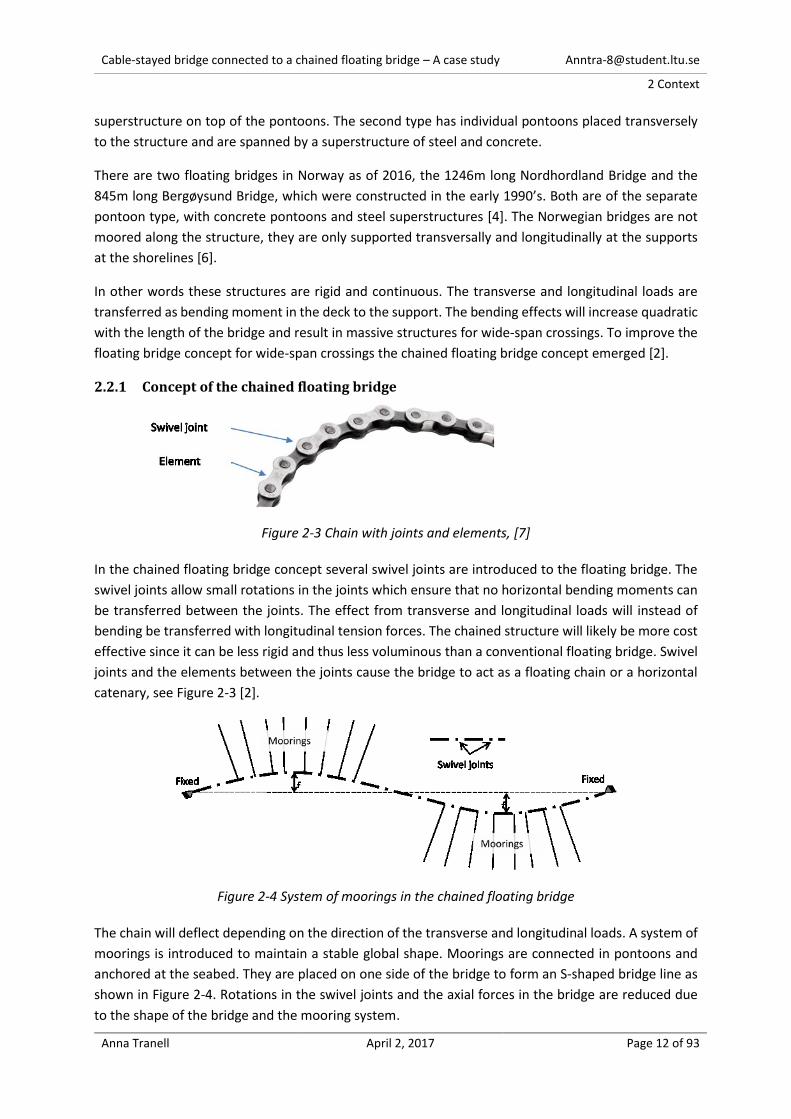
Figure 2-3 Chain with joints and elements, [7]
In the chained floating bridge concept several swivel joints are introduced to the floating bridge. The
swivel joints allow small rotations in the joints which ensure that no horizontal bending moments can
be transferred between the joints. The effect from transverse and longitudinal loads will instead of
bending be transferred with longitudinal tension forces. The chained structure will likely be more cost
effective since it can be less rigid and thus less voluminous than a conventional floating bridge. Swivel
joints and the elements between the joints cause the bridge to act as a floating chain or a horizontal
catenary, see Figure 2-3 [2].
Figure 2-4 System of moorings in the chained floating bridge
The chain will deflect depending on the direction of the transverse and longitudinal loads. A system of
moorings is introduced to maintain a stable global shape. Moorings are connected in pontoons and
anchored at the seabed. They are placed on one side of the bridge to form an S-shaped bridge line as
shown in Figure 2-4. Rotations in the swivel joints and the axial forces in the bridge are reduced due
to the shape of the bridge and the mooring system.
Cable-stayed bridge connected to a chained floating bridge – A case study [email protected]
2 Context
Anna Tranell April 2, 2017 Page 13 of 93
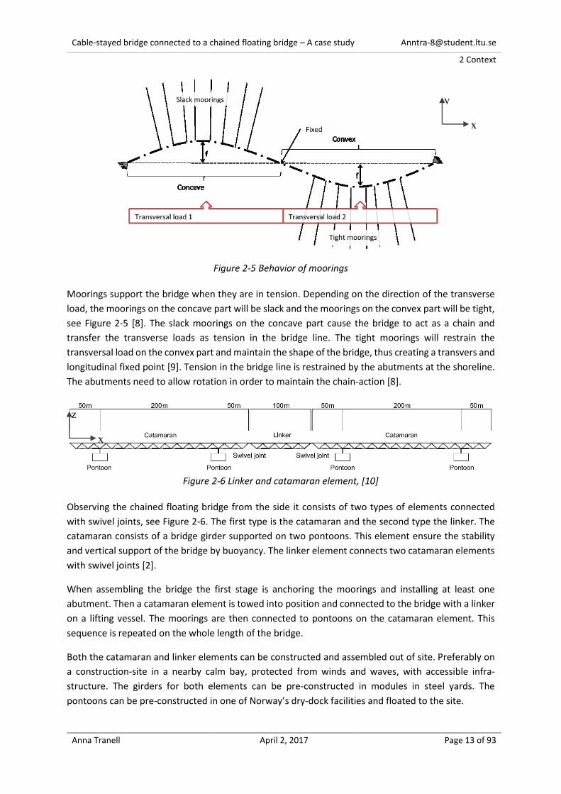
Figure 2-5 Behavior of moorings
Moorings support the bridge when they are in tension. Depending on the direction of the transverse
load, the moorings on the concave part will be slack and the moorings on the convex part will be tight,
see Figure 2-5 [8]. The slack moorings on the concave part cause the bridge to act as a chain and
transfer the transverse loads as tension in the bridge line. The tight moorings will restrain the
transversal load on the convex part and maintain the shape of the bridge, thus creating a transvers and
longitudinal fixed point [9]. Tension in the bridge line is restrained by the abutments at the shoreline.
The abutments need to allow rotation in order to maintain the chain-action [8].
Figure 2-6 Linker and catamaran element, [10]
Observing the chained floating bridge from the side it consists of two types of elements connected
with swivel joints, see Figure 2-6. The first type is the catamaran and the second type the linker. The
catamaran consists of a bridge girder supported on two pontoons. This element ensure the stability
and vertical support of the bridge by buoyancy. The linker element connects two catamaran elements
with swivel joints [2].
When assembling the bridge the first stage is anchoring the moorings and installing at least one
abutment. Then a catamaran element is towed into position and connected to the bridge with a linker
on a lifting vessel. The moorings are then connected to pontoons on the catamaran element. This
sequence is repeated on the whole length of the bridge.
Both the catamaran and linker elements can be constructed and assembled out of site. Preferably on
a construction-site in a nearby calm bay, protected from winds and waves, with accessible infra-
structure. The girders for both elements can be pre-constructed in modules in steel yards. The
pontoons can be pre-constructed in one of Norway’s dry-dock facilities and floated to the site.
y
x
z
x
Cable-stayed bridge connected to a chained floating bridge – A case study [email protected]
2 Context
Anna Tranell April 2, 2017 Page 14 of 93
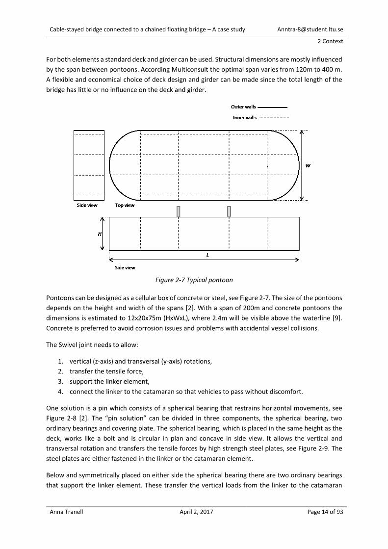
For both elements a standard deck and girder can be used. Structural dimensions are mostly influenced
by the span between pontoons. According Multiconsult the optimal span varies from 120m to 400 m.
A flexible and economical choice of deck design and girder can be made since the total length of the
bridge has little or no influence on the deck and girder.
Figure 2-7 Typical pontoon
Pontoons can be designed as a cellular box of concrete or steel, see Figure 2-7. The size of the pontoons
depends on the height and width of the spans [2]. With a span of 200m and concrete pontoons the
dimensions is estimated to 12x20x75m (HxWxL), where 2.4m will be visible above the waterline [9].
Concrete is preferred to avoid corrosion issues and problems with accidental vessel collisions.
The Swivel joint needs to allow:
1. vertical (z-axis) and transversal (y-axis) rotations,
2. transfer the tensile force,
3. support the linker element,
4. connect the linker to the catamaran so that vehicles to pass without discomfort.
One solution is a pin which consists of a spherical bearing that restrains horizontal movements, see
Figure 2-8 [2]. The “pin solution” can be divided in three components, the spherical bearing, two
ordinary bearings and covering plate. The spherical bearing, which is placed in the same height as the
deck, works like a bolt and is circular in plan and concave in side view. It allows the vertical and
transversal rotation and transfers the tensile forces by high strength steel plates, see Figure 2-9. The
steel plates are either fastened in the linker or the catamaran element.
Below and symmetrically placed on either side the spherical bearing there are two ordinary bearings
that support the linker element. These transfer the vertical loads from the linker to the catamaran

Cable-stayed bridge connected to a chained floating bridge – A case study [email protected]
2 Context
Anna Tranell April 2, 2017 Page 15 of 93
element and prohibit longitudinal rotation (x-axis). In Figure 2-8 the bearings are supported by a steel
truss since the girders for catamaran and linker are steel trusses.
On top of the deck a covering plate is placed. To maintain the roadway and allow vertical (z-axis)
rotations the plate has a circular shape with the same diameter as the width of the deck. To allow
transversal (y-axis) rotations hinges are placed across the plate [9].
This solution has been developed similar to the rotational connection in membered busses [8].
Figure 2-8 Swivel joint, plan and side view [10]
Figure 2-9 left: side view, Right: detail of the spherical bearing and connected steel plates, Plan and
side view [10]
2.3 Shipping-lane for a chained floating bridge Somewhere along the bridge there must be navigational openings to ensure the passage for everything
between smaller pleasure boats to larger vessels. The openings can either be provided in the middle
or at the ends of the bridge. For large vessels that demand excessive horizontal and vertical clearances
it is common to have a movable span in the mid part of the bridge to provide a shipping-lane [4].

Cable-stayed bridge connected to a chained floating bridge – A case study [email protected]
2 Context
Anna Tranell April 2, 2017 Page 16 of 93
Figure 2-10 Example of a movable floating bridge for shipping-lane [4]
For the chained floating bridge however a movable span cannot be constructed without disrupting the
tension caused by the chain-action. The option for the chained floating bridge is to make a high bridge
over the shipping-lane. For crossings that require excessive horizontal and vertical clearances the
proposed solution is to place a high bridge close to the shore. For crossings with smaller clearances
one of the catamaran elements can be modified as a high bridge to allow the shipping-lane. In this case
it is convenient to place the opening in the mid part of the bridge where the fairway usually is located
[2].
The clearances for Bjørnefjorden is approximately 50m high and 200m wide which is considered to be
too excessive for a modified catamaran solution. The most feasible solution is to have a single pylon
cable-stayed bridge at the shoreline connected at the tip to the chained floating bridge as a high bridge,
se Figure 2-11. There are mainly three reasons for this:
1. the chained floating bridge is continuous and the chain actions is disrupted as little as possible
2. only tension is transferred from the chained floating bridge to the high bridge
3. there’s no need for deep-sea foundations, since the single pylon can be placed in relatively
shallow waters
Since the cable-stayed bridge is located at the shoreline the depth to seabed is relatively small which
makes it possible to anchor the last catamaran element for transversal movement. This ensures that
only tension is transferred from the chained floating bridge to the cables-stayed bridge.
Figure 2-11 Elevation and plan of the Nordhordland bridge (a single pylon cable-stayed bridge in
connection with floating bridge) [5]

Cable-stayed bridge connected to a chained floating bridge – A case study [email protected]
3 Method
Anna Tranell April 2, 2017 Page 17 of 93
3. Method This thesis has two distinct parts:
1. A design a cable-stayed bridge connected to a chained floating bridge.
2. Perform a parametric research based on the design and evaluate the effect of the parameters.
The design is created for Bjørnefjorden crossing based on a literature study of conventional cable-
stayed bridges. The literature study addresses the following topics:
The general concept of a cable-stayed bridge,
components of a cable stayed bridge,
construction of a cable stayed bridge,
design of a cable stayed bridge,
study of three existing cable stayed bridges in similar size of the case study.
The bridge is designed, modelled and analyzed with SOFiSTiK, a finite element software specialized in
analyses and design of all types of construction including bridge design.
3.1 Design of cable-stayed bridge (Model0) The design method of the cable-stayed bridge connected to a chained floating bridge divides into three
steps, se Figure 3-1.
Figure 3-1 Schematic of bridge design, part 1 of the feasability-evaluation
Step1, starts with estimating materials and geometry of the bridge for all key components as a first
design attempt. All assumptions regarding design in the first attempt bases on the case premises,
results from the literature study and simple hand calculations. Thereafter the first design attempt is
modelled in SOFiSTiK as Model0_0.
In Step2 loads are determined and applied according to Eurocode. The global parameters are adjusted
with a preliminary evaluation and design.
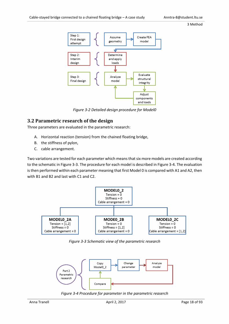
Lastly in step3, load combinations are determined and applied in the model according to Eurocode,
see Figure 3-2. The model is analyzed and the structural integrity of all main components evaluated.
Components and loads are adjusted, if necessary redo of the analysis until an optimized model is
completed.
Cable-stayed bridge connected to a chained floating bridge – A case study [email protected]
3 Method
Anna Tranell April 2, 2017 Page 18 of 93
Figure 3-2 Detailed design procedure for Model0
3.2 Parametric research of the design Three parameters are evaluated in the parametric research:
A. Horizontal reaction (tension) from the chained floating bridge,
B. the stiffness of pylon,
C. cable arrangement.
Two variations are tested for each parameter which means that six more models are created according
to the schematic in Figure 3-3. The procedure for each model is described in Figure 3-4. The evaluation
is then performed within each parameter meaning that first Model 0 is compared with A1 and A2, then
with B1 and B2 and last with C1 and C2.
Figure 3-3 Schematic view of the parametric research
Figure 3-4 Procedure for parameter in the parametric reaserch
Cable-stayed bridge connected to a chained floating bridge – A case study [email protected]
4 Case premises
Anna Tranell April 2, 2017 Page 19 of 93
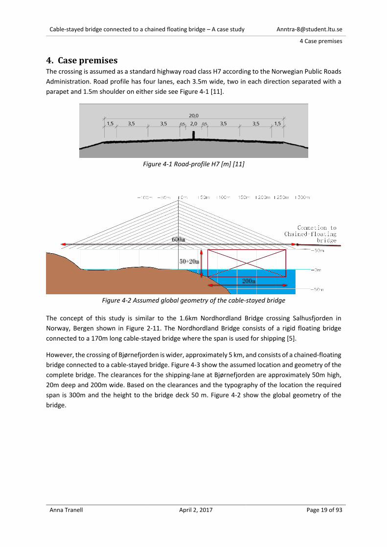
4. Case premises The crossing is assumed as a standard highway road class H7 according to the Norwegian Public Roads
Administration. Road profile has four lanes, each 3.5m wide, two in each direction separated with a
parapet and 1.5m shoulder on either side see Figure 4-1 [11].
Figure 4-1 Road-profile H7 [m] [11]
Figure 4-2 Assumed global geometry of the cable-stayed bridge
The concept of this study is similar to the 1.6km Nordhordland Bridge crossing Salhusfjorden in
Norway, Bergen shown in Figure 2-11. The Nordhordland Bridge consists of a rigid floating bridge
connected to a 170m long cable-stayed bridge where the span is used for shipping [5].
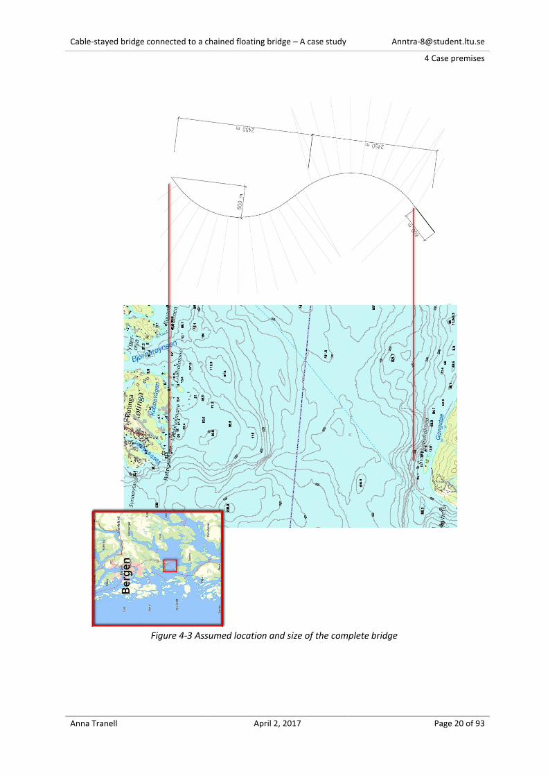
However, the crossing of Bjørnefjorden is wider, approximately 5 km, and consists of a chained-floating
bridge connected to a cable-stayed bridge. Figure 4-3 show the assumed location and geometry of the
complete bridge. The clearances for the shipping-lane at Bjørnefjorden are approximately 50m high,
20m deep and 200m wide. Based on the clearances and the typography of the location the required
span is 300m and the height to the bridge deck 50 m. Figure 4-2 show the global geometry of the
bridge.
Cable-stayed bridge connected to a chained floating bridge – A case study [email protected]
4 Case premises
Anna Tranell April 2, 2017 Page 20 of 93
Figure 4-3 Assumed location and size of the complete bridge
Cable-stayed bridge connected to a chained floating bridge – A case study [email protected]
4 Case premises
Anna Tranell April 2, 2017 Page 21 of 93
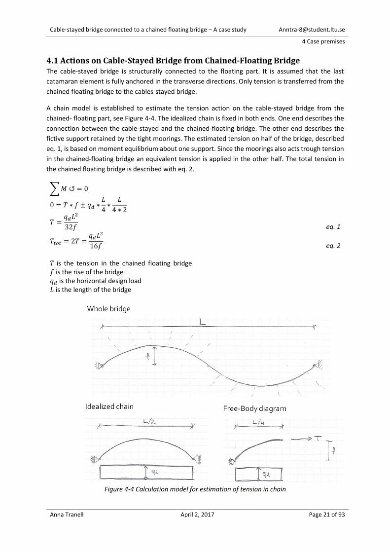
4.1 Actions on Cable-Stayed Bridge from Chained-Floating Bridge The cable-stayed bridge is structurally connected to the floating part. It is assumed that the last
catamaran element is fully anchored in the transverse directions. Only tension is transferred from the
chained floating bridge to the cables-stayed bridge.
A chain model is established to estimate the tension action on the cable-stayed bridge from the
chained- floating part, see Figure 4-4. The idealized chain is fixed in both ends. One end describes the
connection between the cable-stayed and the chained-floating bridge. The other end describes the
fictive support retained by the tight moorings. The estimated tension on half of the bridge, described
eq. 1, is based on moment equilibrium about one support. Since the moorings also acts trough tension
in the chained-floating bridge an equivalent tension is applied in the other half. The total tension in
the chained floating bridge is described with eq. 2.
∑ 𝑀 ↺ = 0
0 = 𝑇 ∗ 𝑓 ± 𝑞𝑑 ∗𝐿
4∗
𝐿
4 ∗ 2
𝑇 =𝑞𝑑𝐿2
32𝑓
eq. 1
𝑇𝑡𝑜𝑡 = 2𝑇 =𝑞𝑑𝐿2
16𝑓
eq. 2 𝑇 is the tension in the chained floating bridge 𝑓 is the rise of the bridge 𝑞𝑑 is the horizontal design load 𝐿 is the length of the bridge
Figure 4-4 Calculation model for estimation of tension in chain

Cable-stayed bridge connected to a chained floating bridge – A case study [email protected]
4 Case premises
Anna Tranell April 2, 2017 Page 22 of 93
Multiconsult AS has investigated the results from this simple estimation and the results deviate ±15%
from non-linear form-finding analysis, see Figure 4-5. The horizontal loads from wind, waves and
current are difficult to estimate regarding both magnitude and extent1. However, for Bjørnefjorden
the present estimation of the horizontal loads are; from wind 28kN/m, waves 34kN/m. Current is
neglected. The loads are combined without any load factor and applied uniformly distributed along
the entire length of the bridge. The studies of Multiconsult AS also concludes that a change of 20° of
the incoming angle of the horizontal load increase the maximum tension with 33%.
With the horizontal loads 𝑞𝑑 of 28+34kN/m, the rise 𝑓 of 600m and length 𝐿 of 5000m the tension
from the chained floating bridge is estimated with eq. 2 to:
𝑇𝑡𝑜𝑡 =(28 + 34) ∗ 50002
16 ∗ 600= 161.5 𝑀𝑁
Figure 4-5 Results from non-linear form-finding analysis of the chained-floating bridge
1 There is currently (2016) research project investigating loads from wind, waves and currents with measuring stations at Bjørnefjorden.
Cable-stayed bridge connected to a chained floating bridge – A case study [email protected]
5 Theory: Cable–stayed bridges
Anna Tranell April 2, 2017 Page 23 of 93
5. Theory: Cable–stayed bridges The literature study addresses the following topics:
The general concept of a cable stayed bridge,
components of a cable stayed bridge,
construction of a cable stayed bridge,
design of a cable stayed bridge,
study of two existing cable stayed bridges in similar size of the case study.
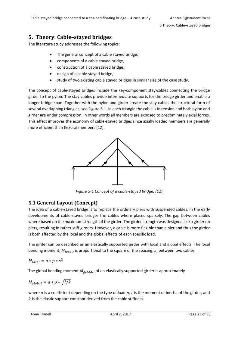
The concept of cable-stayed bridges include the key-component stay-cables connecting the bridge
girder to the pylon. The stay-cables provide intermediate supports for the bridge girder and enable a
longer bridge-span. Together with the pylon and girder create the stay-cables the structural form of
several overlapping triangles, see Figure 5-1. In each triangle the cable is in tension and both pylon and
girder are under compression. In other words all members are exposed to predominately axial forces.
This effect improves the economy of cable-stayed bridges since axially loaded members are generally
more efficient than flexural members [12].
Figure 5-1 Concept of a cable-stayed bridge, [12]
5.1 General Layout (Concept) The idea of a cable-stayed bridge is to replace the ordinary piers with suspended cables. In the early
developments of cable-stayed bridges the cables where placed sparsely. The gap between cables
where based on the maximum strength of the girder. The girder strength was designed like a girder on
piers, resulting in rather stiff girders. However, a cable is more flexible than a pier and thus the girder
is both affected by the local and the global effects of each specific load.
The girder can be described as an elastically supported girder with local and global effects. The local
bending moment, 𝑀𝑙𝑜𝑐𝑎𝑙, is proportional to the square of the spacing, 𝑠, between two cables
𝑀𝑙𝑜𝑐𝑎𝑙 = 𝑎 ∗ 𝑝 ∗ 𝑠2
The global bending moment,𝑀𝑔𝑙𝑜𝑏𝑎𝑙, of an elastically supported girder is approximately
𝑀𝑔𝑙𝑜𝑏𝑎𝑙 = 𝑎 ∗ 𝑝 ∗ √𝐼/𝑘
where 𝑎 is a coefficient depending on the type of load 𝑝, 𝐼 is the moment of inertia of the girder, and
𝑘 is the elastic support constant derived from the cable stiffness.

Cable-stayed bridge connected to a chained floating bridge – A case study [email protected]
5 Theory: Cable–stayed bridges
Anna Tranell April 2, 2017 Page 24 of 93
In a global perspective the quantity of cables to carry the load on the girder is practically unrelated to
the number and spacing of cables. However, the local effects depend on the spacing between cables.
A smaller spacing between cables allows for a more flexible girder which also results in smaller global
effects, since the moment of inertia decreases. Consequently, many modern cable-stayed bridges have
a very flexible girder and densely spaced cables.
At least one cable is usually required to be de-tensioned, dismantled and replaced under reduced
traffic during maintenance of the bridge. To ensure that the bending moment of the girder doesn’t
increase unreasonably, a small spacing between the cables is desirable.
In the early development of cable-stayed bridges concerns where aroused about buckling stability
because of the very flexible girder. Nevertheless, the buckling load depends more on the stiffness of
cables than the stiffness of the girder. In theory a cable-stayed bridge can be stable in most cases even
if the stiffness of the girder is neglected [12].
Multi-stay systems with increasing numbers of cables are only possible to accurate analyze by aid of
computers. The multi-stayed bridges are highly indeterminate since each stay cable represents one
redundancy [13].
The cables can have different arrangements which is divided into three types; harp, fan and radial, see
Figure 5-2. The arrangement can have a major effect on the behavior of very long span bridges.
Figure 5-2 Different cable arrangements, [12]
The harp cable arrangement offers the possibility to start the construction of the girder before the
complete pylon is constructed.
Whit a fan cable arrangement, the cables are working more efficiently in the vertical direction which
decreases the horizontal components from the cables and thus the compression in the girder. For
longer span bridges compression in the girder can be critical to the design of the bridge and can thus
be helped with a fan arrangement.
The cables works even more efficient in the radial arrangement but it can be difficult to design the
detail where the cables connect to the pylon [12].
Cable-stayed bridges with harp cable arrangement have generally higher pylons, larger cross sections
of cables and stiffening girder than for fan or radial cable arrangement. Consequently, the cable stayed
bridges with harp cable arrangement tend to have an increased stiffness compared to fan or radial
cable arrangement.
Cable-stayed bridge connected to a chained floating bridge – A case study [email protected]
5 Theory: Cable–stayed bridges
Anna Tranell April 2, 2017 Page 25 of 93
When the lower cables in harp (and to some extent fan) cable arrangement are in tension a bending
moment occurs in the pylon. A method to reduce this effect is to anchor the cables in the side span to
e.g. intermediate piers.
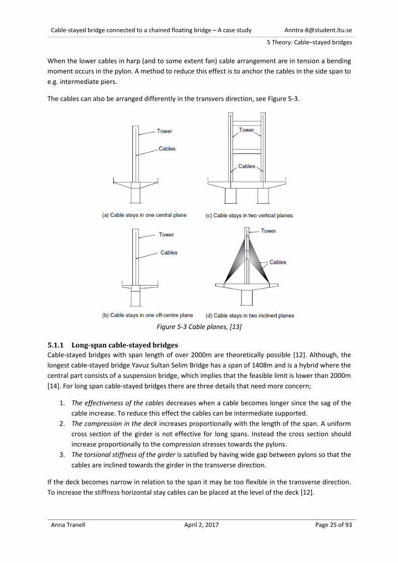
The cables can also be arranged differently in the transvers direction, see Figure 5-3.
Figure 5-3 Cable planes, [13]
5.1.1 Long-span cable-stayed bridges
Cable-stayed bridges with span length of over 2000m are theoretically possible [12]. Although, the
longest cable-stayed bridge Yavuz Sultan Selim Bridge has a span of 1408m and is a hybrid where the
central part consists of a suspension bridge, which implies that the feasible limit is lower than 2000m
[14]. For long span cable-stayed bridges there are three details that need more concern;
1. The effectiveness of the cables decreases when a cable becomes longer since the sag of the
cable increase. To reduce this effect the cables can be intermediate supported.
2. The compression in the deck increases proportionally with the length of the span. A uniform
cross section of the girder is not effective for long spans. Instead the cross section should
increase proportionally to the compression stresses towards the pylons.
3. The torsional stiffness of the girder is satisfied by having wide gap between pylons so that the
cables are inclined towards the girder in the transverse direction.
If the deck becomes narrow in relation to the span it may be too flexible in the transverse direction.
To increase the stiffness horizontal stay cables can be placed at the level of the deck [12].

Cable-stayed bridge connected to a chained floating bridge – A case study [email protected]
5 Theory: Cable–stayed bridges
Anna Tranell April 2, 2017 Page 26 of 93
5.2 Components of a cable-stayed bridge
5.2.1 Cables
The function of the cables is to carry the load of the girder and transfer it to the pylon and to the back
stay cable anchorage [12].
The cables are composed of a bundle of tensile elements [15]. The tensile elements are usually cold-
drawn high performance steel wires [13]. The cable stays can be divided into three different categories
based on the tensile elements.
Parallel Strand Cable (PSC)
Figure 5-4 Principle of a Sheathed PSC [15]
The tensile elements in PSC’s are 7 pre-stressing wires bundled into to a spiral called a “7-wire strand”
15.2 or 15.7mm in dia. Each cable consists of multiple strands where each strand is individually
anchored.
The cable category is divided into two types of corrosion protection methods; sheathed or ducted. In
the sheathed cables are each 7-wire strand protected with an individual sheath and filling. Whereas in
ducted PSC’s the strands are placed in a duct which protects the strands. The duct can then be filled
with a blocking product [15]. PCS’s are manageable, economic and the most common in recent
construction [12] [16].
Parallel Wire Cable (PWC)
Figure 5-5 Principle of a PWC, [15]
The tensile element consists of smooth wires 7mm in dia. bundled into ducts. Each wire is anchored
with a machine-formed buttonhead. [15]. The cables are prefabricated with exact length and
transported in coils to the construction site. [12].
Cable-stayed bridge connected to a chained floating bridge – A case study [email protected]
5 Theory: Cable–stayed bridges
Anna Tranell April 2, 2017 Page 27 of 93
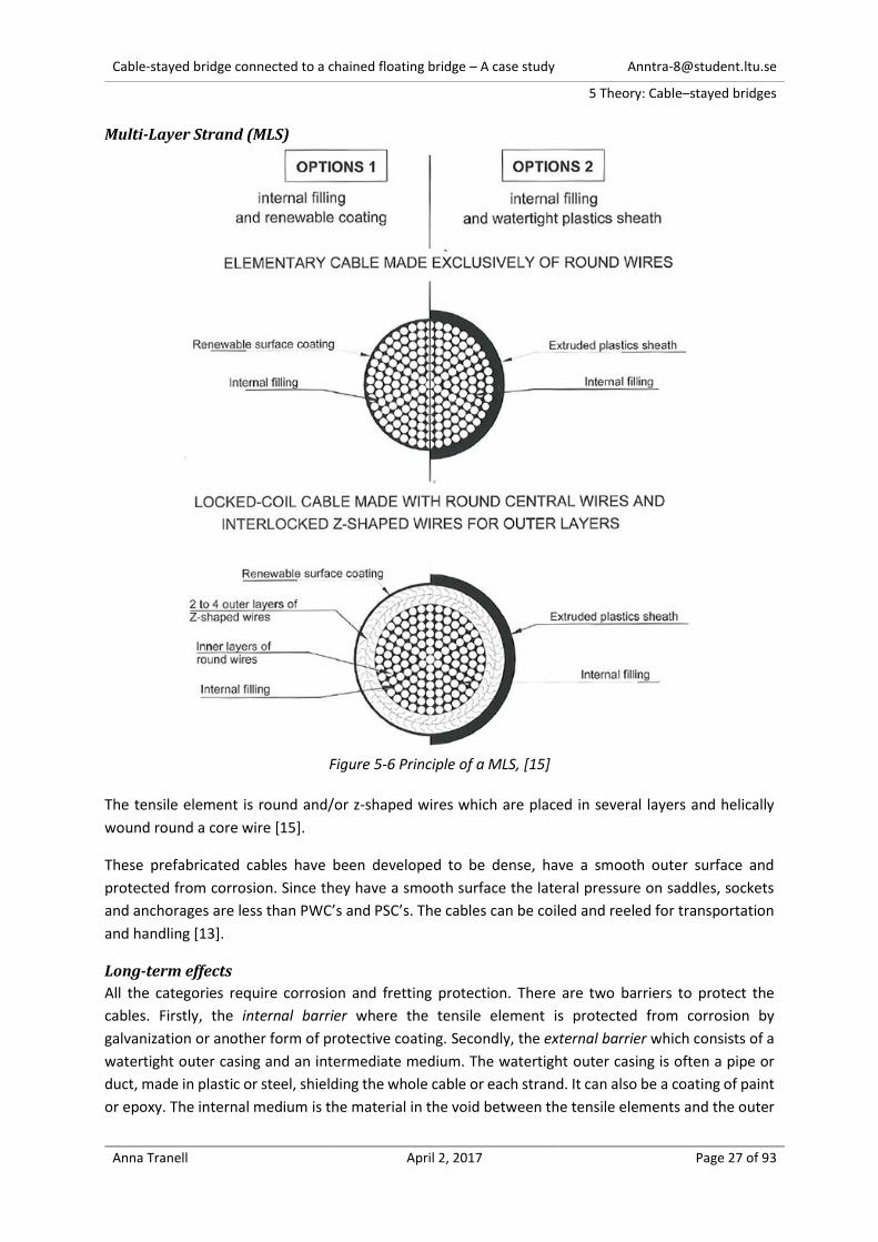
Multi-Layer Strand (MLS)
Figure 5-6 Principle of a MLS, [15]
The tensile element is round and/or z-shaped wires which are placed in several layers and helically
wound round a core wire [15].
These prefabricated cables have been developed to be dense, have a smooth outer surface and
protected from corrosion. Since they have a smooth surface the lateral pressure on saddles, sockets
and anchorages are less than PWC’s and PSC’s. The cables can be coiled and reeled for transportation
and handling [13].
Long-term effects
All the categories require corrosion and fretting protection. There are two barriers to protect the
cables. Firstly, the internal barrier where the tensile element is protected from corrosion by
galvanization or another form of protective coating. Secondly, the external barrier which consists of a
watertight outer casing and an intermediate medium. The watertight outer casing is often a pipe or
duct, made in plastic or steel, shielding the whole cable or each strand. It can also be a coating of paint
or epoxy. The internal medium is the material in the void between the tensile elements and the outer
Cable-stayed bridge connected to a chained floating bridge – A case study [email protected]
5 Theory: Cable–stayed bridges
Anna Tranell April 2, 2017 Page 28 of 93
casing. It can either be a blocking medium (such as wax, grease or resin) or a controlled-humidity air
flow. A controlled-humidity air flow is a system that prevents condensations between the tensile
elements. It is the internal blocking medium/filling that prevents fretting [15].
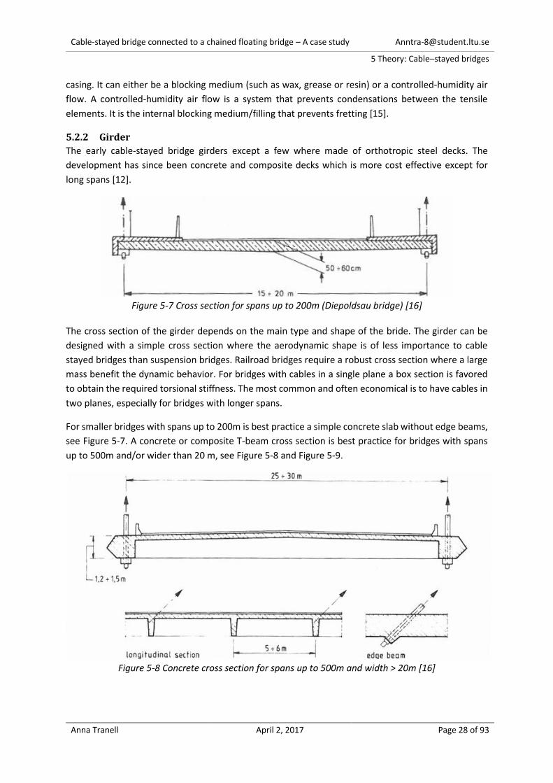
5.2.2 Girder
The early cable-stayed bridge girders except a few where made of orthotropic steel decks. The
development has since been concrete and composite decks which is more cost effective except for
long spans [12].
Figure 5-7 Cross section for spans up to 200m (Diepoldsau bridge) [16]
The cross section of the girder depends on the main type and shape of the bride. The girder can be
designed with a simple cross section where the aerodynamic shape is of less importance to cable
stayed bridges than suspension bridges. Railroad bridges require a robust cross section where a large
mass benefit the dynamic behavior. For bridges with cables in a single plane a box section is favored
to obtain the required torsional stiffness. The most common and often economical is to have cables in
two planes, especially for bridges with longer spans.
For smaller bridges with spans up to 200m is best practice a simple concrete slab without edge beams,
see Figure 5-7. A concrete or composite T-beam cross section is best practice for bridges with spans
up to 500m and/or wider than 20 m, see Figure 5-8 and Figure 5-9.
Figure 5-8 Concrete cross section for spans up to 500m and width > 20m [16]

Cable-stayed bridge connected to a chained floating bridge – A case study [email protected]
5 Theory: Cable–stayed bridges
Anna Tranell April 2, 2017 Page 29 of 93
Figure 5-9 Composite deck for spans up to 500m and width > 20m (Sunshine Skyway Bridge) [16]
Best practice for an even wider bridges and/or longer spans is an orthotropic steel deck. An orthotropic
steel deck reduces the self-weight of the structure. From a structural point of view a cross section with
simple edge beams is sufficient. With a box section however, the wind nose reduces the wind load. A
box section has a dry inside that is more protected from corrosion and which can reduce the
maintenance costs after competition. Two examples are shown in Figure 5-10 and Figure 5-11.
Figure 5-10 Orthotropic steel deck for spans longer than 500m and wider than 25m [16]
Figure 5-11 orthotropic steel box suitable for very long spans [16]
The transversal span, the width of the bridge, governs the height of the cross section. Due to the larger
normal forces close to the pylon, the cross section area often increases towards the pylon. Effective
measures to increase compression capacity is; either by increasing the slab height or construct the
edge beams in concrete. Another alternative is to increase stiffeners [16].
Cable-stayed bridge connected to a chained floating bridge – A case study [email protected]
5 Theory: Cable–stayed bridges
Anna Tranell April 2, 2017 Page 30 of 93
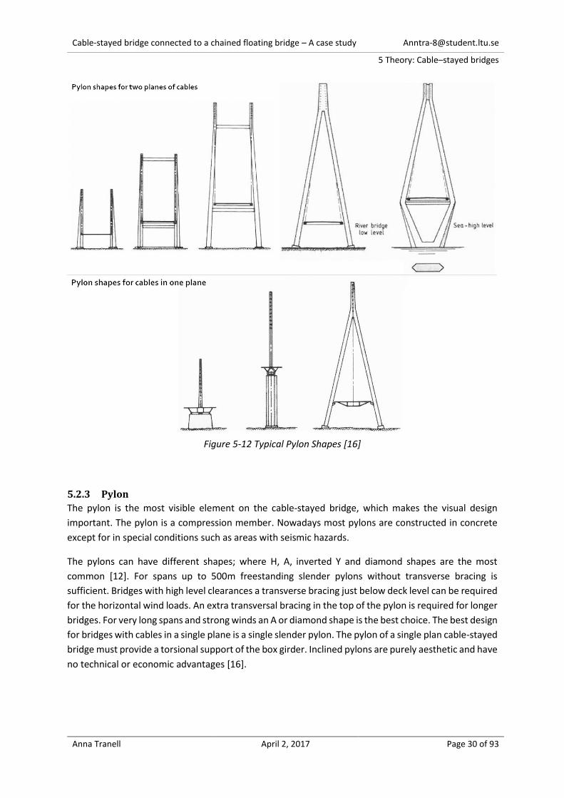
Figure 5-12 Typical Pylon Shapes [16]
5.2.3 Pylon
The pylon is the most visible element on the cable-stayed bridge, which makes the visual design
important. The pylon is a compression member. Nowadays most pylons are constructed in concrete
except for in special conditions such as areas with seismic hazards.
The pylons can have different shapes; where H, A, inverted Y and diamond shapes are the most
common [12]. For spans up to 500m freestanding slender pylons without transverse bracing is
sufficient. Bridges with high level clearances a transverse bracing just below deck level can be required
for the horizontal wind loads. An extra transversal bracing in the top of the pylon is required for longer
bridges. For very long spans and strong winds an A or diamond shape is the best choice. The best design
for bridges with cables in a single plane is a single slender pylon. The pylon of a single plan cable-stayed
bridge must provide a torsional support of the box girder. Inclined pylons are purely aesthetic and have
no technical or economic advantages [16].
Cable-stayed bridge connected to a chained floating bridge – A case study [email protected]
5 Theory: Cable–stayed bridges
Anna Tranell April 2, 2017 Page 31 of 93
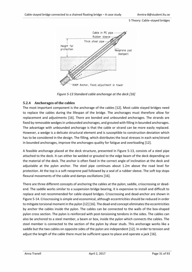
Figure 5-13 Standard cable anchorage at the deck [16]
5.2.4 Anchorages of the cables
The most important component is the anchorage of the cables [12]. Most cable stayed bridges need
to replace the cables during the lifespan of the bridge. The anchorages must therefore allow for
replacement and adjustments [16]. There are bonded and unbounded anchorages. The strands are
fixed by removable wedges in unbounded anchorages, and grouted with filling in bounded anchorages.
The advantage with unbounded anchorage is that the cable or strand can be more easily replaced.
However, a wedge is a delicate structural element and is susceptible to construction deviation which
has to be considered in the design. The filling, which distributes the local stresses in each wire/strand
in bounded anchorages, improve the anchorages quality for fatigue and overloading [12].
A feasible anchorage placed at the deck structure, presented in Figure 5-13, consists of a steel pipe
attached to the deck. It can either be welded or grouted to the edge beam of the deck depending on
the material of the deck. The anchor is often fixed in the correct angle of inclination at the deck and
adjustable at the pylon anchor. The steel pipe continues about 1.2m above the road level for
protection. At the top is a soft neoprene pad followed by a seal of a rubber sleeve. The soft top stops
flexural movements of the cable and damps oscillations [16].
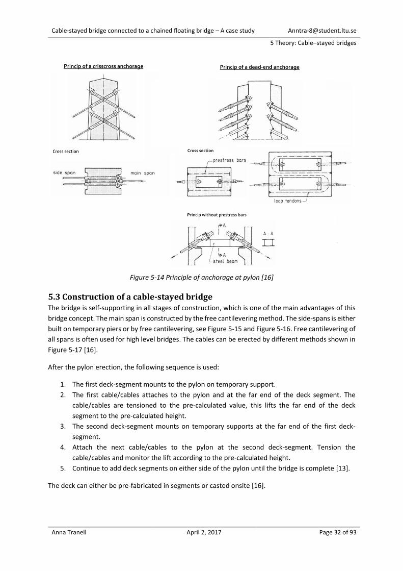
There are three different concepts of anchoring the cables at the pylon; saddle, crisscrossing or dead-
end. The saddle works similar to a suspension bridge bearing, it is expensive to install and difficult to
replace and not recommended for cable-stayed bridges. Crisscrossing and dead-anchor are shown in
Figure 5-14. Crisscrossing is simple and economical, although eccentricities should be reduced in order
to mitigate torsional moment in the pylon [12] [16]. The dead-end concept eliminates the eccentricities
by anchor the cables inside the pylon. The cables can be connected to the walls of the box-shaped
pylon cross section. The pylon is reinforced with post-tensioning tendons in the sides. The cables can
also be anchored to a steel member, a beam or box, inside the pylon which connects the cables. The
steel member is connected to the section of the pylon by shear studs. This anchorage works like a
saddle but the two cables on opposite sides of the pylon are independent [12]. In order to tension and
adjust the length of the cable there must be sufficient space to place and operate a jack [16].
Cable-stayed bridge connected to a chained floating bridge – A case study [email protected]
5 Theory: Cable–stayed bridges
Anna Tranell April 2, 2017 Page 32 of 93
Figure 5-14 Principle of anchorage at pylon [16]
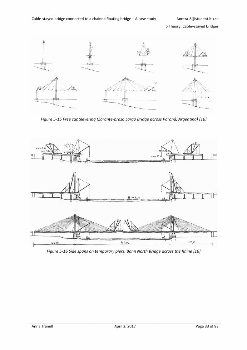
5.3 Construction of a cable-stayed bridge The bridge is self-supporting in all stages of construction, which is one of the main advantages of this
bridge concept. The main span is constructed by the free cantilevering method. The side-spans is either
built on temporary piers or by free cantilevering, see Figure 5-15 and Figure 5-16. Free cantilevering of
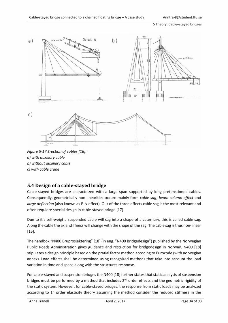
all spans is often used for high level bridges. The cables can be erected by different methods shown in
Figure 5-17 [16].
After the pylon erection, the following sequence is used:
1. The first deck-segment mounts to the pylon on temporary support.
2. The first cable/cables attaches to the pylon and at the far end of the deck segment. The
cable/cables are tensioned to the pre-calculated value, this lifts the far end of the deck
segment to the pre-calculated height.
3. The second deck-segment mounts on temporary supports at the far end of the first deck-
segment.
4. Attach the next cable/cables to the pylon at the second deck-segment. Tension the
cable/cables and monitor the lift according to the pre-calculated height.
5. Continue to add deck segments on either side of the pylon until the bridge is complete [13].
The deck can either be pre-fabricated in segments or casted onsite [16].
Cable-stayed bridge connected to a chained floating bridge – A case study [email protected]
5 Theory: Cable–stayed bridges
Anna Tranell April 2, 2017 Page 33 of 93
Figure 5-15 Free cantilevering (Zárante-brazo Largo Bridge across Paraná, Argentina) [16]
Figure 5-16 Side spans on temporary piers, Bonn North Bridge across the Rhine [16]
Cable-stayed bridge connected to a chained floating bridge – A case study [email protected]
5 Theory: Cable–stayed bridges
Anna Tranell April 2, 2017 Page 34 of 93
Figure 5-17 Erection of cables [16]:
a) with auxiliary cable
b) without auxiliary cable
c) with cable crane
5.4 Design of a cable-stayed bridge Cable-stayed bridges are characteized with a large span supported by long pretenstioned cables.
Consequentlly, geometrically non-linearities occure mainly form cable sag, beam-column effect and
large deflection (also known as P--effect). Out of the three effects cable sag is the most relevant and
often requiere special design in cable-stayed bridge [17].
Due to it’s self-weigt a suspended cable will sag into a shape of a caternary, this is called cable sag.
Along the cable the axial stiffness will change with the shape of the sag. The cable sag is thus non-linear
[15].
The handbok “N400 Bruprosjektering” [18] (in eng. ”N400 Bridgedesign”) published by the Norwegian
Public Roads Administration gives guidance and restriction for bridgedesign in Norway. N400 [18]
stipulates a design principle based on the pratial factor method accoding to Eurocode (with norwegian
annex). Load effects shall be determined using recognized methods that take into account the load
variation in time and space along with the structures response.
For cable-stayed and suspension bridges the N400 [18] further states that static analysis of suspension
bridges must be performed by a method that includes 2nd order effects and the geometric rigidity of
the static system. However, for cable-stayed bridges, the response from static loads may be analyzed
according to 1st order elasticity theory assuming the method consider the reduced stiffness in the
Cable-stayed bridge connected to a chained floating bridge – A case study [email protected]
5 Theory: Cable–stayed bridges
Anna Tranell April 2, 2017 Page 35 of 93
cables due to sag. Analysis of global stability of pylons and girders shall take into account 2nd order
effects.
Design values for loads on suspension bridges spanning> 500 meters may be determined according to
Eurocode 1990 (EC0) [19] Table NA.A2.4 (B) NOTE 4. In equation 6.10 a) can 𝛾𝐺 be divided into 𝛾𝑔 =
1.15 which ensures the uncertainties in the self-weight and 𝛾𝑆𝑑 = 1.05 that ensures the uncertainty
in the calculation method.
When verifying the ultimate limit state shall the capacity of cable-stays be determined by:
𝐹𝑅𝐷 =𝐹𝑢𝑘
1.5𝛾𝑚
eq. 3 𝐹𝑅𝐷 - cable design capacity 𝐹𝑢𝑘 - cable specified minimum breaking load 𝛾𝑚 - material factor = 1.2
5.4.1 Dynamic loads
Cable-stayed bridges are less sensitive to vibrations compared to suspension bridges, however the
effects are not negligible [16]. The major dynamic loads are aerodynamic and seismic loads. Seismic
loads seldom govern the design of cable-stayed bridges [12].
The following limits of the bridge deck reduces the global aerodynamic sensitivity:
Bridges in concrete with cables in two planes, should satisfy:
o 𝐵 ≥ 10𝐻, 𝐵 ≥ 𝐿/30 or be constructed with a “wind nose”.
Lightweight steel decks with spans longer than 400 m, should:
o have an A-shaped pylons and/or,
o 𝐵 ≥ 𝐿/25 or be constructed with a “wind nose”.
With an aerodynamically well-shaped cross section the limits for wind stability is 𝐵 > 𝐿/40 and 𝐻 >
𝐿/500. 𝐵 and 𝐻 is the width resp. the height of the bridge deck, and 𝐿 is the length of the main span.
One aerodynamic effect is buffeting. Buffeting is caused by the atmospheric turbulence and can be
analyzed with non-linear simulations and wind tunnel tests [16]. The effects are often worst in the
construction phase and can be reduced using stabilizing tie-downs [13].
Another aerodynamic effect is cable vibration. The cables sway with large amplitudes in low wind
forces and low rainfall. The vibrations occur when the cables have similar or lower eigenfrequency
than the global structure [16]. Dampers and special design of the duct-surface around the cable reduce
cable vibration [15].
Cable-stayed bridge connected to a chained floating bridge – A case study [email protected]
5 Theory: Cable–stayed bridges
Anna Tranell April 2, 2017 Page 36 of 93
5.5 Study of three existing cable-stayed bridges The cable-stayed bridge designed in this thesis has a 300m main span supported with a single pylon
and it’s comparable to a 600m main span supported with 2 pylons.
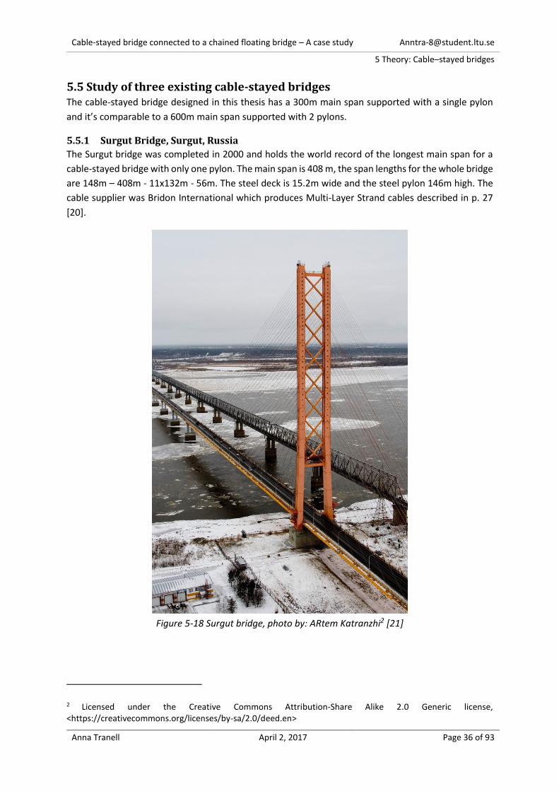
5.5.1 Surgut Bridge, Surgut, Russia
The Surgut bridge was completed in 2000 and holds the world record of the longest main span for a
cable-stayed bridge with only one pylon. The main span is 408 m, the span lengths for the whole bridge
are 148m – 408m - 11x132m - 56m. The steel deck is 15.2m wide and the steel pylon 146m high. The
cable supplier was Bridon International which produces Multi-Layer Strand cables described in p. 27
[20].
Figure 5-18 Surgut bridge, photo by: ARtem Katranzhi2 [21]
2 Licensed under the Creative Commons Attribution-Share Alike 2.0 Generic license, <https://creativecommons.org/licenses/by-sa/2.0/deed.en>

Cable-stayed bridge connected to a chained floating bridge – A case study [email protected]
5 Theory: Cable–stayed bridges
Anna Tranell April 2, 2017 Page 37 of 93
5.5.2 The Third Nanjing Bridge, Shanghai, China
The Third Nanjing Bridge (opened in 2005) has 2 pylons, steel box girder and 5 spans 63-257-684-257-
63m. The bridge is designed for 3+3 lanes and maximum 100 km/h velocity. The girder is a streamlined
steel box 37.2m wide with a structural height of 3.2m. The 215m high pylons have a curved A-shape
transversally connected with 4 cross-beams. The part of the pylon from the bottom to the deck level
is concrete whereas the top parts consist of a steel box [22].
Elevation and Plan
Pylon
Cross section
Figure 5-19 Drawings of the Third Nanjing Bridge [22]
5.5.3 Sutong Bridge, Suzhou, China
The Sutong Bridge was between completion in 2008 to 2012 the cable-stayed bridge with longest span
of 1088m [23]. Drawings of the bridge are shown in Figure 5-20.
The girder is a streamlined steel box girder with a width of 41m for the 8+8 traffic lanes. The cross
section is 4m high and has transverse diaphragms with a typical distance of 4m that decreases to 2.27m
close to the pylons. The structural steel has the yield strengths of 345 and 370 MPa.
The concrete pylons, with grade C50, are 300m high and have the shape of an inverted Y. The two
pylon legs are connected under the bridge deck with a post- tensioned beam. There are steel boxes
connected to the concrete with shear studs at the top of the pylon where the cable stays are anchored.
The stay cables are arranged in two planes and anchored to the girder with a spacing of 12 to 15m.
The cables are parallel strand, described in p. 26, with steel grade 1770 MPa and 7mm wires each with
a cross sections of 38.48 mm2 [24].

Cable-stayed bridge connected to a chained floating bridge – A case study [email protected]
5 Theory: Cable–stayed bridges
Anna Tranell April 2, 2017 Page 38 of 93
Elevation
Cross section
Main span
Figure 5-20 Sutong Bridge, Suzhou, China [24]
The Global Static Analysis where made with a finite element model of the bridge. Each cable stay was
divided into 8 sub-elements to consider sag effects. Also P--effects, large displacements and shear
displacements were considered in the model. The flexibility of the pylon foundations were modeled
with spring elements and the damped connections between girder and pylon with non-linear springs.
The final stage was designed with adjustments of the cables to minimize bending effects in the deck
and pylons. Also the construction stages where analyzed, using a forward analysis method, and pre-
camber was calculated with 3rd order effects.
The effects of the geometrical non-linearity’s where compared to linear analysis and showed a net
offset on the maximum/minimum stresses in the girder and pylons of 10-20% including a shift of the
critical locations. [24]
Cable-stayed bridge connected to a chained floating bridge – A case study [email protected]
6 Design of the cable-stayed bridge
Anna Tranell April 2, 2017 Page 39 of 93
6. Design of the cable-stayed bridge
6.1 Step 1: First design attempt – Model0_0 In this chapter the geometries of the main components of the bridge is estimated and modelled in
SOFiSTiK (see Figure 6-1).
Figure 6-1: Schematics of Part 1: Step 1
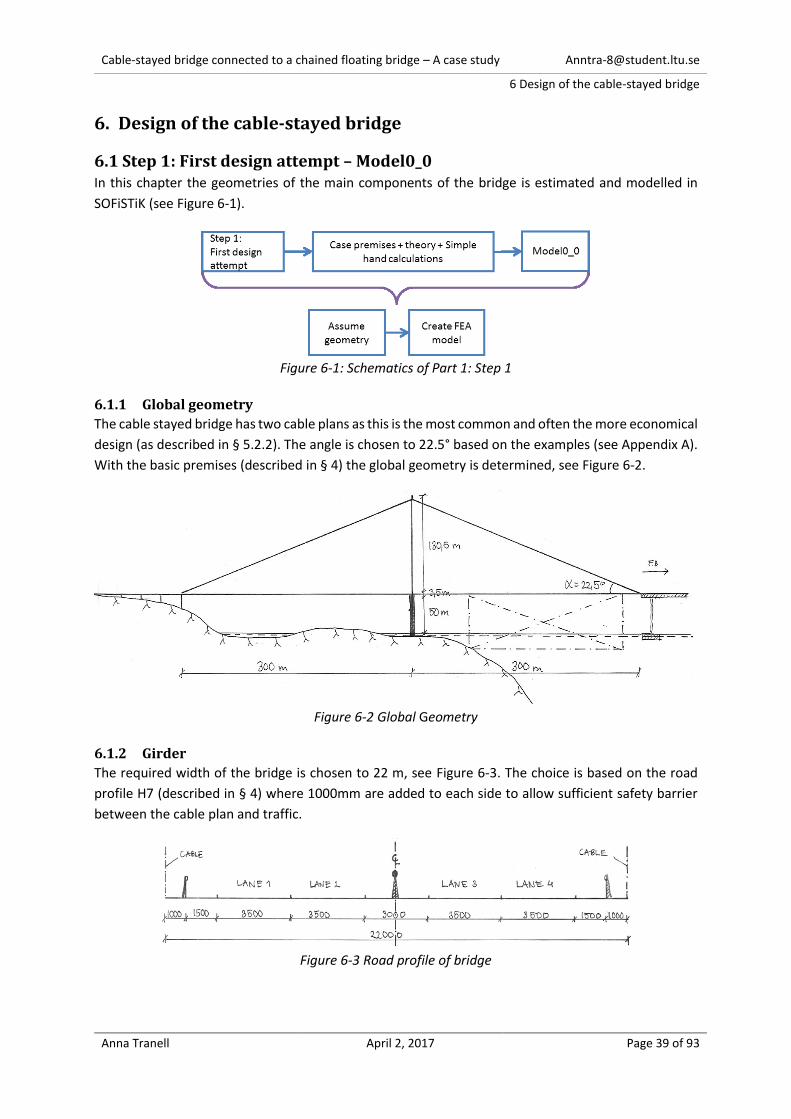
6.1.1 Global geometry
The cable stayed bridge has two cable plans as this is the most common and often the more economical
design (as described in § 5.2.2). The angle is chosen to 22.5° based on the examples (see Appendix A).
With the basic premises (described in § 4) the global geometry is determined, see Figure 6-2.
Figure 6-2 Global Geometry
6.1.2 Girder
The required width of the bridge is chosen to 22 m, see Figure 6-3. The choice is based on the road
profile H7 (described in § 4) where 1000mm are added to each side to allow sufficient safety barrier
between the cable plan and traffic.
Figure 6-3 Road profile of bridge

Cable-stayed bridge connected to a chained floating bridge – A case study [email protected]
6 Design of the cable-stayed bridge
Anna Tranell April 2, 2017 Page 40 of 93
A closed orthotropic steel section is considered best practice for cable-stayed bridges with main spans
over 500 m (as described in § 5.2.2). Since the cable-stayed bridge in this study can be compared a
main span of 600m a closed orthotropic steel section is chosen. The assumed geometry of the cross
section in Figure 6-4 is based on the cross sections in Appendix A. The width and height of the deck
satisfies the aerodynamic requirements (described in § 5.4.1):
𝐵 = 25𝑚 ≥𝐿
25=
600𝑚
25= 24𝑚
𝐻 = 2.5𝑚 >𝐿
500=
600𝑚
500= 1.2𝑚
It is assumed that three stiffening plates are required in the cross section. There are also diaphragms
placed every 5m along the bridge line in coherence with Figure 5-10 and Sutong Bridge.
Figure 6-4 Girder
The box-shaped stiffeners are assumed based on measurements in Appendix A of “Example of
orthotropic steel box cross section” due to similarity in size. Figure 6-5 show the box-stiffeners where
the thickness is chosen at 7mm. Another presumption is that all other plates require stiffening every
1000mm with a T-stiffener. The T-stiffener is made by the cross section of a half IPE 300.
Figure 6-5 Stiffeners
In SOFiSTiK the section is modelled according to Figure 6-6 where the thickness is assumed to be 20mm
for plate A1-A3 and 15mm for A4-A6. All the other stiffeners and diaphragms are presumed to be
needed in distributing the loads transversally and to prevent local buckling. They are added in the
model as dead load, see Appendix B1. Structural steel class S355 is chosen similar to Sutong Bridge.
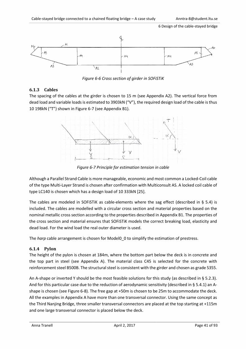
Cable-stayed bridge connected to a chained floating bridge – A case study [email protected]
6 Design of the cable-stayed bridge
Anna Tranell April 2, 2017 Page 41 of 93
Figure 6-6 Cross section of girder in SOFiSTiK
6.1.3 Cables
The spacing of the cables at the girder is chosen to 15 m (see Appendix A2). The vertical force from
dead load and variable loads is estimated to 3903kN (“V”), the required design load of the cable is thus
10 198kN (“T”) shown in Figure 6-7 (see Appendix B1).
Figure 6-7 Principle for estimation tension in cable
Although a Parallel Strand Cable is more manageable, economic and most common a Locked-Coil cable
of the type Multi-Layer Strand is chosen after confirmation with Multiconsult AS. A locked coil cable of
type LC140 is chosen which has a design load of 10 333kN [25].
The cables are modeled in SOFiSTiK as cable-elements where the sag effect (described in § 5.4) is
included. The cables are modelled with a circular cross section and material properties based on the
nominal metallic cross section according to the properties described in Appendix B1. The properties of
the cross section and material ensures that SOFiSTiK models the correct breaking load, elasticity and
dead load. For the wind load the real outer diameter is used.
The harp cable arrangement is chosen for Model0_0 to simplify the estimation of prestress.
6.1.4 Pylon
The height of the pylon is chosen at 184m, where the bottom part below the deck is in concrete and
the top part in steel (see Appendix A). The material class C45 is selected for the concrete with
reinforcement steel B500B. The structural steel is consistent with the girder and chosen as grade S355.
An A-shape or inverted Y should be the most feasible solutions for this study (as described in § 5.2.3).
And for this particular case due to the reduction of aerodynamic sensitivity (described in § 5.4.1) an A-
shape is chosen (see Figure 6-8). The free gap at +50m is chosen to be 25m to accommodate the deck.
All the examples in Appendix A have more than one transversal connector. Using the same concept as
the Third Nanjing Bridge, three smaller transversal connectors are placed at the top starting at +115m
and one large transversal connector is placed below the deck.

Cable-stayed bridge connected to a chained floating bridge – A case study [email protected]
6 Design of the cable-stayed bridge
Anna Tranell April 2, 2017 Page 42 of 93
The pylon width (in the longitudinal direction of the bridge) is proportional to the Sutong Bridge, where
the width at the top is chosen to 5m and the width at the bottom 10m (see Appendix A).
Parameter B, the stiffness of pylon is investigated in the longitudinal direction of the bridge since it is
the same directions as the action from the floating bridge. In order to avoid a change in reference area
for wind load in the parametric research the pylon is designed with two legs in the longitudinal
direction of the bridge (see Figure 6-8). The cables are attached to the legs with a dead end-anchorage
without pre-stress (as described in Figure 5-14). The two legs are joined at each cable anchorage with
a connector.
Figure 6-8 Pylon
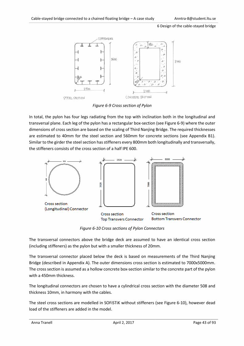
Cable-stayed bridge connected to a chained floating bridge – A case study [email protected]
6 Design of the cable-stayed bridge
Anna Tranell April 2, 2017 Page 43 of 93
Figure 6-9 Cross section of Pylon
In total, the pylon has four legs radiating from the top with inclination both in the longitudinal and
transversal plane. Each leg of the pylon has a rectangular box-section (see Figure 6-9) where the outer
dimensions of cross section are based on the scaling of Third Nanjing Bridge. The required thicknesses
are estimated to 40mm for the steel section and 560mm for concrete sections (see Appendix B1).
Similar to the girder the steel section has stiffeners every 800mm both longitudinally and transversally,
the stiffeners consists of the cross section of a half IPE 600.
Figure 6-10 Cross sections of Pylon Connectors
The transversal connectors above the bridge deck are assumed to have an identical cross section
(including stiffeners) as the pylon but with a smaller thickness of 20mm.
The transversal connector placed below the deck is based on measurements of the Third Nanjing
Bridge (described in Appendix A). The outer dimensions cross section is estimated to 7000x5000mm.
The cross section is assumed as a hollow concrete box-section similar to the concrete part of the pylon
with a 450mm thickness.
The longitudinal connectors are chosen to have a cylindrical cross section with the diameter 508 and
thickness 10mm, in harmony with the cables.
The steel cross sections are modelled in SOFiSTiK without stiffeners (see Figure 6-10), however dead
load of the stiffeners are added in the model.

Cable-stayed bridge connected to a chained floating bridge – A case study [email protected]
6 Design of the cable-stayed bridge
Anna Tranell April 2, 2017 Page 44 of 93
Figure 6-11 Model of geometry in SOFiSTiK
6.1.5 FEA Model0_0 in SOFiSTiK
The girder, pylon legs and columns are modelled as beam elements, see Figure 6-11. The cables are
modelled with cable-elements and are connected with the girder with fixed constraints. Connectors,
both transversal and longitudinal, are modelled as truss-elements except for the bottom transversal
connector (in concrete) which is modelled as a beam. The truss-elements have a pin-pin connection
and transfer only loads in the axial direction.
The supports of the global system and connection of the deck to the sub structure are described in
Table 6-1 and Figure 6-11. The elastic spring, SPRING2, at position C models the buoyancy of a pontoon
with dimensions 12x20x75m (HxWxL), the axial stiffness is estimated by Multiconult AS to 14.1MN/m
[9].
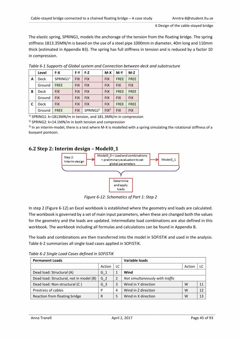
Cable-stayed bridge connected to a chained floating bridge – A case study [email protected]
6 Design of the cable-stayed bridge
Anna Tranell April 2, 2017 Page 45 of 93
The elastic spring, SPRING1, models the anchorage of the tension from the floating bridge. The spring
stiffness 1813.35MN/m is based on the use of a steel pipe 1000mm in diameter, 40m long and 110mm
thick (estimated in Appendix B3). The spring has full stiffness in tension and is reduced by a factor 10
in compression.
Table 6-1 Supports of Global system and Connection between deck and substructure
Level F-X F-Y F-Z M-X M-Y M-Z
A Deck SPRING11 FIX FIX FIX FREE FREE
Ground FREE FIX FIX FIX FIX FIX
B Deck FIX FIX FIX FIX FREE FREE
Ground FIX FIX FIX FIX FIX FIX
C Deck FIX FIX FIX FIX FREE FREE
Ground FREE FIX SPRING22 FIX3 FIX FIX 1) SPRING1: k=1813MN/m in tension, and 181.3MN/m in compression 2) SPRING2: k=14.1MN/m in both tension and compression 3) In an interim-model, there is a test where M-X is modelled with a spring simulating the rotational stiffness of a buoyant pontoon.
6.2 Step 2: Interim design – Model0_1
Figure 6-12: Schematics of Part 1: Step 2
In step 2 (Figure 6-12) an Excel workbook is established where the geometry and loads are calculated.
The workbook is governed by a set of main input parameters, when these are changed both the values
for the geometry and the loads are updated. Intermediate load combinations are also defined in this
workbook. The workbook including all formulas and calculations can be found in Appendix B.
The loads and combinations are then transferred into the model in SOFiSTiK and used in the analysis.
Table 6-2 summarizes all single load cases applied in SOFiSTiK.
Table 6-2 Single Load Cases defined in SOFiSTiK
Permanent Loads Variable loads
Action LC Action LC
Dead load: Structural (A) G_1 1 Wind
Dead load: Structural, not in model (B) G_2 2 Not simultaneously with traffic
Dead load: Non-structural (C ) G_3 3 Wind in Y direction W 11
Prestress of cables P 4 Wind in Z direction W 12
Reaction from floating bridge R 5 Wind in X direction W 13
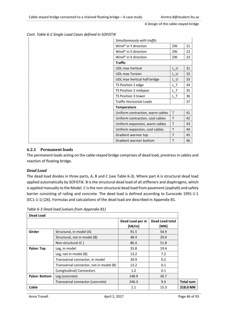
Cable-stayed bridge connected to a chained floating bridge – A case study [email protected]
6 Design of the cable-stayed bridge
Anna Tranell April 2, 2017 Page 46 of 93
Cont. Table 6-2 Single Load Cases defined in SOFiSTiK
Simultaneously with traffic
Wind* in Y direction ZW 21
Wind* in Z direction ZW 22
Wind* in X direction ZW 23
Traffic
UDL max Vertical L_U 31
UDL max Torsion L_U 32
UDL max Vertical half bridge L_U 33
TS Position 1 edge L_T 34
TS Position 2 midspan L_T 35
TS Position 3 tower L_T 36
Traffic Horizontal Loads 37
Temperature
Uniform contraction, warm cables T 41
Uniform contraction, cool cables T 42
Uniform expansion, warm cables T 43
Uniform expansion, cool cables T 44
Gradient warmer top T 45
Gradient warmer bottom T 46
6.2.1 Permanent loads
The permanent loads acting on the cable-stayed bridge comprises of dead load, prestress in cables and
reaction of floating bridge.
Dead Load
The dead load divides in three parts, A, B and C (see Table 6-3). Where part A is structural dead load
applied automatically by SOFiSTiK. B is the structural dead load of all stiffeners and diaphragms, which
is applied manually to the Model. C is the non-structural dead load from pavement (asphalt) and safety
barrier consisting of railing and concrete. The dead load is defined according to Eurocode 1991-1-1
(EC1-1-1) [26]. Formulas and calculations of the dead load are described in Appendix B1.
Table 6-3 Dead load (values from Appendix B1)
Dead Load
Dead Load per m
[kN/m]
Dead Load total
[MN]
Girder Structural, in model (A) 91.5 54.9
Structural, not in model (B) 48.4 29.0
Non-structural (C ) 86.4 51.8
Pylon: Top Leg, in model 35.8 19.4
Leg, not in model (B) 13.2 7.2
Transversal connector, in model 30.9 0.2
Transversal connector, not in model (B) 13.2 0.1
(Longitudinal) Connectors 1.2 0.1
Pylon: Bottom Leg (concrete) 148.9 30.7
Transversal connector (concrete) 246.3 9.4 Total sum
Cable 1.1 15.3 218.0 MN

Cable-stayed bridge connected to a chained floating bridge – A case study [email protected]
6 Design of the cable-stayed bridge
Anna Tranell April 2, 2017 Page 47 of 93
Prestress in Cables
The prestress is adjusted to counteract the dead load, the preliminary estimation is 4500kN (see
Appendix B1).
Horizontal reaction from Chained Floating Bridge
The reaction from the chained floating bridge is estimated to 162 MN (in § 4.1). It is assumed that 121
MN (75%) of the reaction from the floating bridge is a permanent action. It is also assumed that the
possible variation of the reaction from the floating bridge is between 50% and 100% of the estimated
162 MN. This results in a maximum of 162 MN and a minimum 81 MN horizontal force that is applied
in the model for ultimate limit state, see Figure 6-13.
Figure 6-13 Horizontal reaction from chained floating bridge 161.5 MN applied in the model
6.2.2 Variable Loads
The variable loads comprises of loads from wind, traffic and temperature.
Wind Load
The wind load is calculated according to Eurocode 1991-1-4 (EC1-1-4) [27]. Static load conditions are
assumed. EC1-1-4 [27] § 1.1 (2) states that the code can be used for structures less than 200m high
and for bridges with spans length that are less than 200m long without a dynamic response.
Two values of the fundamental basic wind velocity are used; 36.4 m/s for combinations without traffic
and 23 m/s in combination with traffic. It is assumed that the bridge is closed for traffic when the wind
velocity exceeds 23 m/s. The wind load for girder and pylon is shown in Table 6-4. The calculations of
wind load along with wind load for all structural elements are presented in Appendix B2.
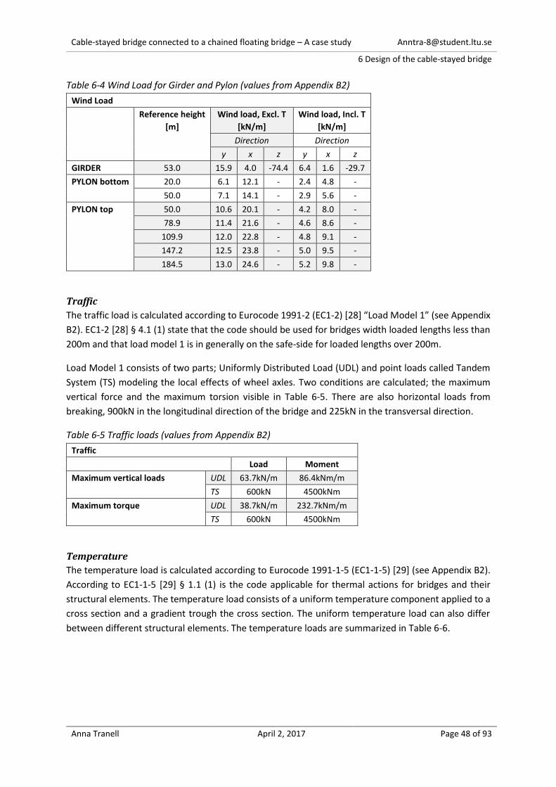
Cable-stayed bridge connected to a chained floating bridge – A case study [email protected]
6 Design of the cable-stayed bridge
Anna Tranell April 2, 2017 Page 48 of 93
Table 6-4 Wind Load for Girder and Pylon (values from Appendix B2)
Wind Load
Reference height
[m]
Wind load, Excl. T
[kN/m]
Wind load, Incl. T
[kN/m]
Direction Direction
y x z y x z
GIRDER 53.0 15.9 4.0 -74.4 6.4 1.6 -29.7
PYLON bottom 20.0 6.1 12.1 - 2.4 4.8 -
50.0 7.1 14.1 - 2.9 5.6 -
PYLON top 50.0 10.6 20.1 - 4.2 8.0 -
78.9 11.4 21.6 - 4.6 8.6 -
109.9 12.0 22.8 - 4.8 9.1 -
147.2 12.5 23.8 - 5.0 9.5 -
184.5 13.0 24.6 - 5.2 9.8 -
Traffic
The traffic load is calculated according to Eurocode 1991-2 (EC1-2) [28] “Load Model 1” (see Appendix
B2). EC1-2 [28] § 4.1 (1) state that the code should be used for bridges width loaded lengths less than
200m and that load model 1 is in generally on the safe-side for loaded lengths over 200m.
Load Model 1 consists of two parts; Uniformly Distributed Load (UDL) and point loads called Tandem
System (TS) modeling the local effects of wheel axles. Two conditions are calculated; the maximum
vertical force and the maximum torsion visible in Table 6-5. There are also horizontal loads from
breaking, 900kN in the longitudinal direction of the bridge and 225kN in the transversal direction.
Table 6-5 Traffic loads (values from Appendix B2)
Traffic
Load Moment
Maximum vertical loads UDL 63.7kN/m 86.4kNm/m
TS 600kN 4500kNm
Maximum torque UDL 38.7kN/m 232.7kNm/m
TS 600kN 4500kNm
Temperature
The temperature load is calculated according to Eurocode 1991-1-5 (EC1-1-5) [29] (see Appendix B2).
According to EC1-1-5 [29] § 1.1 (1) is the code applicable for thermal actions for bridges and their
structural elements. The temperature load consists of a uniform temperature component applied to a
cross section and a gradient trough the cross section. The uniform temperature load can also differ
between different structural elements. The temperature loads are summarized in Table 6-6.
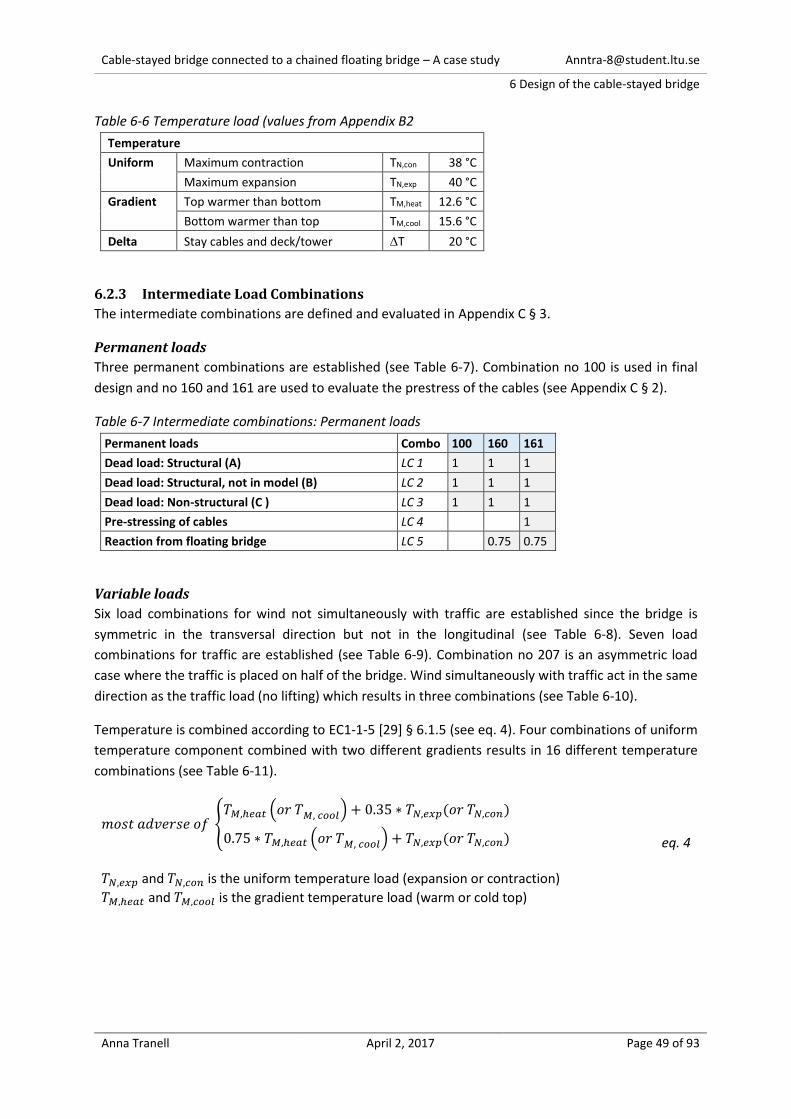
Cable-stayed bridge connected to a chained floating bridge – A case study [email protected]
6 Design of the cable-stayed bridge
Anna Tranell April 2, 2017 Page 49 of 93
Table 6-6 Temperature load (values from Appendix B2
Temperature
Uniform Maximum contraction TN,con 38 °C
Maximum expansion TN,exp 40 °C
Gradient Top warmer than bottom TM,heat 12.6 °C
Bottom warmer than top TM,cool 15.6 °C
Delta Stay cables and deck/tower T 20 °C
6.2.3 Intermediate Load Combinations
The intermediate combinations are defined and evaluated in Appendix C § 3.
Permanent loads
Three permanent combinations are established (see Table 6-7). Combination no 100 is used in final
design and no 160 and 161 are used to evaluate the prestress of the cables (see Appendix C § 2).
Table 6-7 Intermediate combinations: Permanent loads
Permanent loads Combo 100 160 161
Dead load: Structural (A) LC 1 1 1 1
Dead load: Structural, not in model (B) LC 2 1 1 1
Dead load: Non-structural (C ) LC 3 1 1 1
Pre-stressing of cables LC 4 1
Reaction from floating bridge LC 5 0.75 0.75
Variable loads
Six load combinations for wind not simultaneously with traffic are established since the bridge is
symmetric in the transversal direction but not in the longitudinal (see Table 6-8). Seven load
combinations for traffic are established (see Table 6-9). Combination no 207 is an asymmetric load
case where the traffic is placed on half of the bridge. Wind simultaneously with traffic act in the same
direction as the traffic load (no lifting) which results in three combinations (see Table 6-10).
Temperature is combined according to EC1-1-5 [29] § 6.1.5 (see eq. 4). Four combinations of uniform
temperature component combined with two different gradients results in 16 different temperature
combinations (see Table 6-11).
𝑚𝑜𝑠𝑡 𝑎𝑑𝑣𝑒𝑟𝑠𝑒 𝑜𝑓 {𝑇𝑀,ℎ𝑒𝑎𝑡 (𝑜𝑟 𝑇𝑀, 𝑐𝑜𝑜𝑙) + 0.35 ∗ 𝑇𝑁,𝑒𝑥𝑝(𝑜𝑟 𝑇𝑁,𝑐𝑜𝑛)
0.75 ∗ 𝑇𝑀,ℎ𝑒𝑎𝑡 (𝑜𝑟 𝑇𝑀, 𝑐𝑜𝑜𝑙) + 𝑇𝑁,𝑒𝑥𝑝(𝑜𝑟 𝑇𝑁,𝑐𝑜𝑛)
eq. 4 𝑇𝑁,𝑒𝑥𝑝 and 𝑇𝑁,𝑐𝑜𝑛 is the uniform temperature load (expansion or contraction)
𝑇𝑀,ℎ𝑒𝑎𝑡 and 𝑇𝑀,𝑐𝑜𝑜𝑙 is the gradient temperature load (warm or cold top)
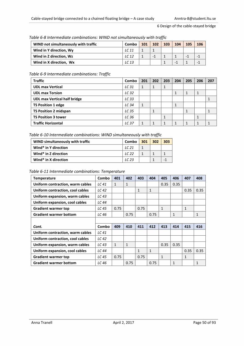
Cable-stayed bridge connected to a chained floating bridge – A case study [email protected]
6 Design of the cable-stayed bridge
Anna Tranell April 2, 2017 Page 50 of 93
Table 6-8 Intermediate combinations: WIND not simultaneously with traffic
WIND not simultaneously with traffic Combo 101 102 103 104 105 106
Wind in Y direction, Wy LC 11 1 1
Wind in Z direction, Wz LC 12 1 -1 1 1 -1 -1
Wind in X direction, Wx LC 13 1 -1 1 -1
Table 6-9 Intermediate combinations: Traffic
Traffic Combo 201 202 203 204 205 206 207
UDL max Vertical LC 31 1 1 1
UDL max Torsion LC 32 1 1 1
UDL max Vertical half bridge LC 33 1
TS Position 1 edge LC 34 1 1
TS Position 2 midspan LC 35 1 1 1
TS Position 3 tower LC 36 1 1
Traffic Horizontal LC 37 1 1 1 1 1 1 1
Table 6-10 Intermediate combinations: WIND simultaneously with traffic
WIND simultaneously with traffic Combo 301 302 303
Wind* in Y direction LC 21 1
Wind* in Z direction LC 22 1 1 1
Wind* in X direction LC 23 1 -1
Table 6-11 Intermediate combinations: Temperature
Temperature Combo 401 402 403 404 405 406 407 408
Uniform contraction, warm cables LC 41 1 1 0.35 0.35
Uniform contraction, cool cables LC 42 1 1 0.35 0.35
Uniform expansion, warm cables LC 43
Uniform expansion, cool cables LC 44
Gradient warmer top LC 45 0.75 0.75 1 1
Gradient warmer bottom LC 46 0.75 0.75 1 1
Cont.
Combo 409 410 411 412 413 414 415 416
Uniform contraction, warm cables LC 41
Uniform contraction, cool cables LC 42
Uniform expansion, warm cables LC 43 1 1 0.35 0.35
Uniform expansion, cool cables LC 44 1 1 0.35 0.35
Gradient warmer top LC 45 0.75 0.75 1 1
Gradient warmer bottom LC 46 0.75 0.75 1 1

Cable-stayed bridge connected to a chained floating bridge – A case study [email protected]
6 Design of the cable-stayed bridge
Anna Tranell April 2, 2017 Page 51 of 93
Preliminary evaluation (design)
The variable intermediate load combinations (described in Table 6-8 to Table 6-11) are analyzed with
the permanent loads in combination no 161 from (from Table 6-7). The displacement and utilization
level of the cross sections are evaluated.
Evaluation of displacements
The limit of displacement’s in the preliminary design is assumed 𝐿/300 = 1000 𝑚𝑚. It’s exceeded by
combinations no 103, 104, 106 and 207. Combination no 207 “UDL max V/2 + TS2” give the largest
displacement of 2224 mm (see Figure 6-14). For all other combinations see Appendix C § 3.1.1.
Due to structural concerns the design (Model0_1) is adjusted with an extra support at the side span.
Similar extra supports are used in the side spans of both the Third Nanjing Bridge and Sutong Bridge
(see § 5.5).
Figure 6-14 Displacement of combination 207 for Model0_0 (max 2224mm)
(from Appendix C § 3.1.1)
Evaluation of design
Steel cross sections are analyzed in an elastic stress check/test with SOFiSTiK according to Eurocode
1993-1-1 (EC3-1-1) [30] § 6.3.1.1 and § 6.2.1 (5). The concrete parts of pylon, legs and transvers
connector, are designed with SOFiSTiK in accordance with Eurocode 1992-1-1 (EC2-1-1) [31] § 6.
The stresses in the girder, cables and transversal connectors are lower than the stress limit. However,
both the main cross section of the pylon and the longitudinal connectors exceed the limit (see Table
6-12).
The steel section of the pylon leg has a utilization of 163% in combination no 207. This indicates that
the pylon is too weak in the longitudinal direction. In Model0_1, the cross section of the pylon is
therefore increased from 2.5m to 3.5m, also the longitudinal gap between the legs is increased from
7.5m to 12m. The longitudinal connectors are utilized 110% in Model0_0 so, in Model0_1, the diameter
is increased from 508mm to 813mm.
On the other hand, the top transversal connectors are only utilized to 6%. In Model0_1 the top
transversal connectors are therefore reduced to a 2.5mx2.5m box with thickness of 10 mm.
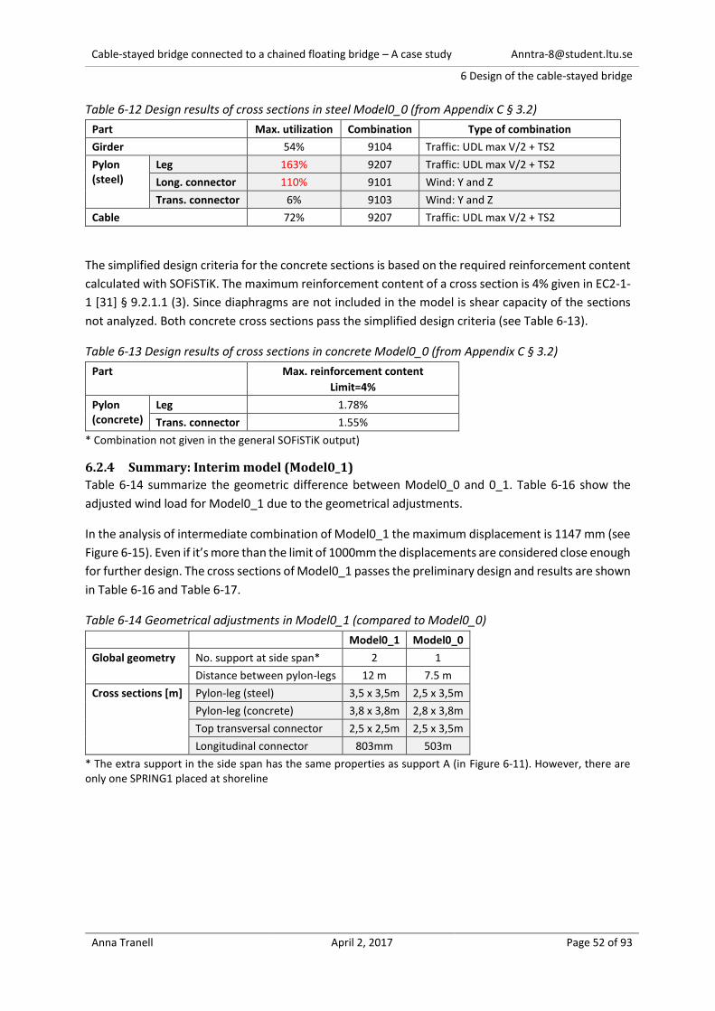
Cable-stayed bridge connected to a chained floating bridge – A case study [email protected]
6 Design of the cable-stayed bridge
Anna Tranell April 2, 2017 Page 52 of 93
Table 6-12 Design results of cross sections in steel Model0_0 (from Appendix C § 3.2)
Part Max. utilization Combination Type of combination
Girder 54% 9104 Traffic: UDL max V/2 + TS2
Pylon (steel)
Leg 163% 9207 Traffic: UDL max V/2 + TS2
Long. connector 110% 9101 Wind: Y and Z
Trans. connector 6% 9103 Wind: Y and Z
Cable 72% 9207 Traffic: UDL max V/2 + TS2
The simplified design criteria for the concrete sections is based on the required reinforcement content
calculated with SOFiSTiK. The maximum reinforcement content of a cross section is 4% given in EC2-1-
1 [31] § 9.2.1.1 (3). Since diaphragms are not included in the model is shear capacity of the sections
not analyzed. Both concrete cross sections pass the simplified design criteria (see Table 6-13).
Table 6-13 Design results of cross sections in concrete Model0_0 (from Appendix C § 3.2)
Part Max. reinforcement content
Limit=4%
Pylon (concrete)
Leg 1.78%
Trans. connector 1.55%
* Combination not given in the general SOFiSTiK output)
6.2.4 Summary: Interim model (Model0_1)
Table 6-14 summarize the geometric difference between Model0_0 and 0_1. Table 6-16 show the
adjusted wind load for Model0_1 due to the geometrical adjustments.
In the analysis of intermediate combination of Model0_1 the maximum displacement is 1147 mm (see
Figure 6-15). Even if it’s more than the limit of 1000mm the displacements are considered close enough
for further design. The cross sections of Model0_1 passes the preliminary design and results are shown
in Table 6-16 and Table 6-17.
Table 6-14 Geometrical adjustments in Model0_1 (compared to Model0_0)
Model0_1 Model0_0
Global geometry No. support at side span* 2 1
Distance between pylon-legs 12 m 7.5 m
Cross sections [m] Pylon-leg (steel) 3,5 x 3,5m 2,5 x 3,5m
Pylon-leg (concrete) 3,8 x 3,8m 2,8 x 3,8m
Top transversal connector 2,5 x 2,5m 2,5 x 3,5m
Longitudinal connector 803mm 503m
* The extra support in the side span has the same properties as support A (in Figure 6-11). However, there are only one SPRING1 placed at shoreline

Cable-stayed bridge connected to a chained floating bridge – A case study [email protected]
6 Design of the cable-stayed bridge
Anna Tranell April 2, 2017 Page 53 of 93
Table 6-15 Wind Load for Girder and Pylon Model0_1 (estimated with formulas in Appendix B2)
Wind Load
Reference height
[m]
Wind load, Excl. T
[kN/m]
Wind load, Incl. T
[kN/m]
Direction Direction
y x z y x z
PYLON bottom 20.0 11.4 11.4 - 4.6 4.6 -
50.0 13.3 13.3 - 5.3 5.3 -
PYLON top 50.0 17.6 17.6 - 7.0 7.0 -
78.9 18.9 18.9 - 7.6 7.6 -
109.9 19.9 19.9 - 8.0 8.0 -
147.2 20.8 20.8 - 8.3 8.3 -
184.5 21.5 21.5 - 8.6 8.6 -
Figure 6-15 Displacement of combination 207 for Model0_1 (max 1147mm)
(from Appendix D § 3.1.1)
Table 6-16 Design results of cross sections in steel Model0_1 (from Appendix D § 3.2)
Part Max. utilization Combination Type of combination
Girder 49% 9101 Traffic: UDL max V/2 + TS2
Pylon (steel)
Leg 99% 9207 Traffic: UDL max V/2 + TS2
Long. connector 44% 9101 Wind: Y and Z
Trans. connector 13% 9103 Wind: Y and Z
Cable 70% 9411 Traffic: UDL max V/2 + TS2
Table 6-17 Design results of cross sections in concrete Model0_0 (from Appendix C § 3.2)
Part Max. reinforcement content
Limit=4%
Pylon (concrete)
Leg 2.25%
Trans. connector 1.33%
* Combination not given in the general SOFiSTiK output)
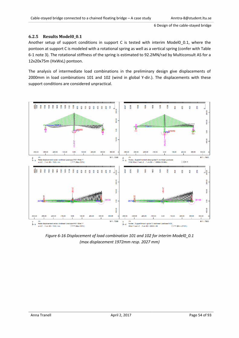
Cable-stayed bridge connected to a chained floating bridge – A case study [email protected]
6 Design of the cable-stayed bridge
Anna Tranell April 2, 2017 Page 54 of 93
6.2.5 Results Model0_0.1
Another setup of support conditions in support C is tested with interim Model0_0.1, where the
pontoon at support C is modeled with a rotational spring as well as a vertical spring (confer with Table
6-1 note 3). The rotational stiffness of the spring is estimated to 92.2MN/rad by Multiconsult AS for a
12x20x75m (HxWxL) pontoon.
The analysis of intermediate load combinations in the preliminary design give displacements of
2000mm in load combinations 101 and 102 (wind in global Y-dir.). The displacements with these
support conditions are considered unpractical.
Figure 6-16 Displacement of load combination 101 and 102 for interim Model0_0.1
(max displacement 1972mm resp. 2027 mm)

Cable-stayed bridge connected to a chained floating bridge – A case study [email protected]
6 Design of the cable-stayed bridge
Anna Tranell April 2, 2017 Page 55 of 93
6.3 Step 3: Final design – Model0_2
Figure 6-17: Schematics of Part 1: Step 3
6.3.1 Design combinations
eq. 5 is used for Ultimate Limit States (ULS) according with EC0 [19] § 6.4.3.2. eq. 5 applies directly on
the loads (not the load effects) in the combinations since the relationship between actions and their
effects are not linear. Method a) in EC0 [19] § 6.3.2(4) is used.
𝛾𝐺,𝑗,𝑠𝑢𝑝𝐺𝑘𝑗,𝑠𝑢𝑝 + (𝛾𝐺,𝑗,𝑖𝑛𝑓𝐺𝑘𝑗,𝑖𝑛𝑓) + 𝛾𝑝𝑃 + 𝛾𝑄,1𝑄𝑘,1 + 𝛾𝑄,𝑖𝜓0,𝑖𝑄𝑘,𝑖 eq. 5
Combination rare, eq. 6, is used for irreversible design conditions in Serviceability Limit State (SLS)
according with EC0 [19] § 6.5.3 (2) a). Combination frequent, eq. 7, is used for reversible design
conditions in SLS, according with EC0 [19] § 6.5.3 (2) b).
𝐺𝑘𝑗,𝑠𝑢𝑝 + (𝐺𝑘𝑗,𝑖𝑛𝑓) + 𝑃 + 𝑄𝑘,1 + 𝜓0,𝑖𝑄𝑘,𝑖 eq. 6
𝐺𝑘𝑗,𝑠𝑢𝑝 + (𝐺𝑘𝑗,𝑖𝑛𝑓) + 𝑃 + 𝜓1,1𝑄𝑘,1 + 𝜓2,𝑖𝑄𝑘,𝑖 eq. 7 𝐺𝑘𝑗,𝑠𝑢𝑝 and 𝐺𝑘𝑗,𝑖𝑛𝑓 is unfavorable and favorable dead load
𝑃 is prestress 𝑄𝑘,1 and 𝑄𝑘,i is leading and non-leading variable load 𝛾 is a factor for safety (see Table 6-19) 𝜓 is a factor for combination (see Table 6-19)
Selection of intermediate load combinations
In order to limit the number of design combinations in ultimate and serviceability limit state, only the
”worst” intermediate combinations are selected. An intermediate combination is selected if it
produces either an extreme displacement (Ux, Uy or Uz) or extreme load effect (N, Mt, My, Mz) in the
girder, cable or the pylon. The reason being that these are considered key structural elements.
The selected intermediate combinations are defined in Table 6-18 and the selections can be found in
Appendix D § 3.1.
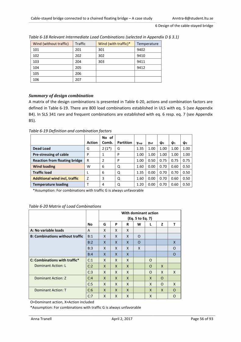
Cable-stayed bridge connected to a chained floating bridge – A case study [email protected]
6 Design of the cable-stayed bridge
Anna Tranell April 2, 2017 Page 56 of 93
Table 6-18 Relevant Intermediate Load Combinations (selected in Appendix D § 3.1)
Wind (without traffic) Traffic Wind (with traffic)* Temperature
101 201 301 9402
102 202 302 9410
103 204 303 9411
104 205 9412
105 206
106 207
Summary of design combination
A matrix of the design combinations is presented in Table 6-20, actions and combination factors are
defined in Table 6-19. There are 800 load combinations established in ULS with eq. 5 (see Appendix
B4). In SLS 341 rare and frequent combinations are established with eq. 6 resp. eq. 7 (see Appendix
B5).
Table 6-19 Definition and combination factors
Action No of Comb. Partition γsup γinf ψ0 ψ1 ψ2
Dead Load G 2 (1*) G 1.35 1.00 1.00 1.00 1.00
Pre-stressing of cable P 1 P 1.00 1.00 1.00 1.00 1.00
Reaction from floating bridge R 2 P 1.00 0.50 0.75 0.75 0.75
Wind loading W 6 Q 1.60 0.00 0.70 0.60 0.50
Traffic load L 6 Q 1.35 0.00 0.70 0.70 0.50
Additional wind incl, traffic Z 3 Q 1.60 0.00 0.70 0.60 0.50
Temperature loading T 4 Q 1.20 0.00 0.70 0.60 0.50
*Assumption: For combinations with traffic G is always unfavorable
Table 6-20 Matrix of Load Combinations
No
With dominant action
(Eq. 5 to Eq. 7)
G P R W L Z T
A: No variable loads A X X X
B: Combinations without traffic
B:1 X X X O
B:2 X X X O X
B:3 X X X X O
B:4 X X X O
C: Combinations with traffic*
Dominant Action: L
C:1 X X X O
C:2 X X X O X
C:3 X X X O X X
Dominant Action: Z
C:4 X X X X O
C:5 X X X X O X
Dominant Action: T
C:6 X X X X X O
C:7 X X X X O
O=Dominant action, X=Action included
*Assumption: For combinations with traffic G is always unfavorable
Cable-stayed bridge connected to a chained floating bridge – A case study [email protected]
6 Design of the cable-stayed bridge
Anna Tranell April 2, 2017 Page 57 of 93
6.3.2 Analyzing the design combinations
Model0_1 is analyzed with a nonlinear solver that includes non-linear behavior of springs and cables.
The analysis ensures that no cables are in compression. However, it does not take into account non-
linearity such as cable sag, beam-column effect and effects of large deflections (described in § 5.4).
6.3.3 Evaluate structural integrity
Steel sections, ULS
The steel cross sections are designed in ULS with an elastic cross section check in SOFiSTiK according
to Eurocode 1993-1-1 (EC3-1-1) [30] § 6.2.1 (5) and with flexural buckling according to EC3-1-1 [30] §
6.3.1.1. The elastic stresses are analyzed in SOFiSTiK for each element and compared to the limit stress,
𝜎𝑑 , in eq. 8.
𝜎𝑑 =𝑓𝑦
𝛾𝑀0
eq. 8 𝛾𝑀0 = 1.1 for all sections except for cables 𝛾𝑀0,cables = 1.2 (in accordance with eq.3 in § 5.4)
In the analysis SOFiSTiK also include the reduction due to buckling (𝜒). The buckling lengths are defined
in the structural lines in SOFiSTiK. This means that the cables and connectors are designed correctly
according to EC3-1-1 [30] § 6.3.1.1, the pylon and girder are designed without a correct reduction due
to global buckling.
The pylon and girder are analyzed in a global 2nd order buckling analysis since EC3-1-1 [30] § 6.3.1.1 (3)
states that the global stability should be analyzed with 2nd order theory for members with varying cross
section and/or varying axial force.
The buckling analysis is an iterative analysis of the stability of a structure. It derives a critical load from
a primary load case, PLC. If the critical load is exceeded the structure will buckle. In a buckling analysis
both the PLC and imperfections on the structures impact the results. Due to complexity, the global
buckling analysis for this study is performed without imperfections on only three PLC’s. The three PLC’s
correspond to the ULS design cases giving the highest compression in the girder, the pylon legs steel
section and the pylon legs concrete section. This means that if the design pass the buckling test it can
still be unstable when a detailed analysis is performed. However, if the design fails this test the design
definitely unstable as well as unfeasible.
Concrete sections, ULS
The design of the concrete parts, pylon-legs and transversal connector is for the purpose of this study
a simplification. The capacity of the cross sections is analyzed in ULS according to EC2-1-1 [31] § 6, with
the SOFiSTiK design tool for concrete sections.
The cross sections is defined with four simple “reinforcement layers”, one layer along each side of the
cross section. Each layer has a minimum reinforcement of φ16c100 and unlimited maximum
reinforcement. Shear capacity of the sections are not analyzed, it is assumed that diaphragms are used
in areas with high shear forces.
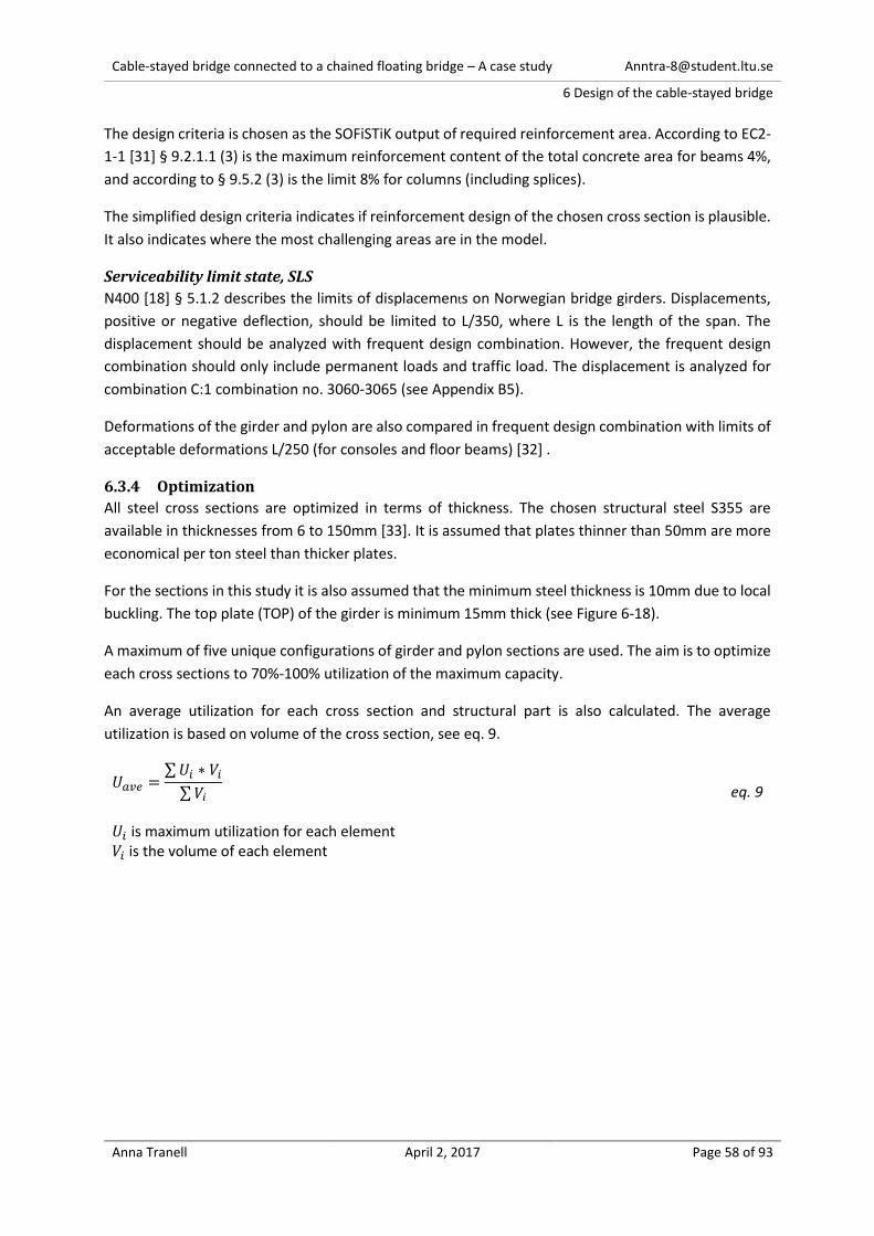
Cable-stayed bridge connected to a chained floating bridge – A case study [email protected]
6 Design of the cable-stayed bridge
Anna Tranell April 2, 2017 Page 58 of 93
The design criteria is chosen as the SOFiSTiK output of required reinforcement area. According to EC2-
1-1 [31] § 9.2.1.1 (3) is the maximum reinforcement content of the total concrete area for beams 4%,
and according to § 9.5.2 (3) is the limit 8% for columns (including splices).
The simplified design criteria indicates if reinforcement design of the chosen cross section is plausible.
It also indicates where the most challenging areas are in the model.
Serviceability limit state, SLS
N400 [18] § 5.1.2 describes the limits of displacements on Norwegian bridge girders. Displacements,
positive or negative deflection, should be limited to L/350, where L is the length of the span. The
displacement should be analyzed with frequent design combination. However, the frequent design
combination should only include permanent loads and traffic load. The displacement is analyzed for
combination C:1 combination no. 3060-3065 (see Appendix B5).
Deformations of the girder and pylon are also compared in frequent design combination with limits of
acceptable deformations L/250 (for consoles and floor beams) [32] .
6.3.4 Optimization
All steel cross sections are optimized in terms of thickness. The chosen structural steel S355 are
available in thicknesses from 6 to 150mm [33]. It is assumed that plates thinner than 50mm are more
economical per ton steel than thicker plates.
For the sections in this study it is also assumed that the minimum steel thickness is 10mm due to local
buckling. The top plate (TOP) of the girder is minimum 15mm thick (see Figure 6-18).
A maximum of five unique configurations of girder and pylon sections are used. The aim is to optimize
each cross sections to 70%-100% utilization of the maximum capacity.
An average utilization for each cross section and structural part is also calculated. The average
utilization is based on volume of the cross section, see eq. 9.
𝑈𝑎𝑣𝑒 =∑ 𝑈𝑖 ∗ 𝑉𝑖
∑ 𝑉𝑖
eq. 9 𝑈𝑖 is maximum utilization for each element 𝑉𝑖 is the volume of each element
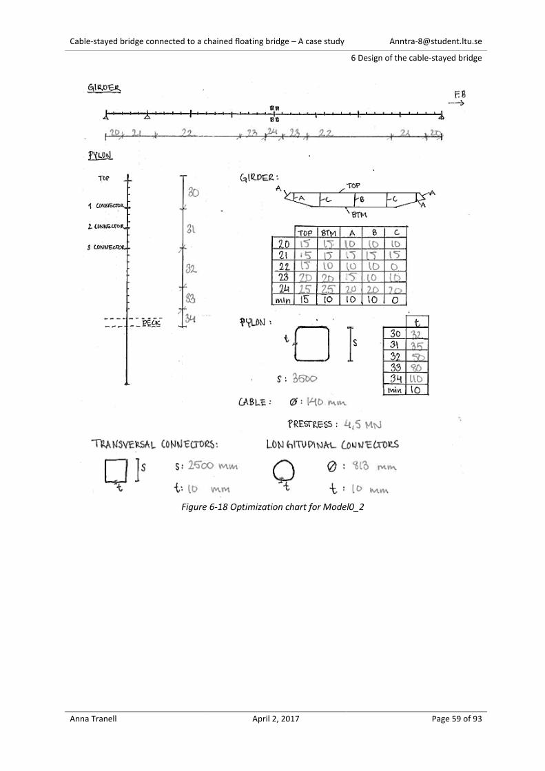
Cable-stayed bridge connected to a chained floating bridge – A case study [email protected]
6 Design of the cable-stayed bridge
Anna Tranell April 2, 2017 Page 59 of 93
Figure 6-18 Optimization chart for Model0_2

Cable-stayed bridge connected to a chained floating bridge – A case study [email protected]
6 Design of the cable-stayed bridge
Anna Tranell April 2, 2017 Page 60 of 93
6.4 Result: Model0_2
6.4.1 Design and Structural Integrity
Figure 6-18 show the optimization chart of Model0_2. Table 6-21 summarize the maximum and
average utilization of the cross sections, all sections are utilized less than 100%. Figure 6-19 show the
required reinforcement. Graphs of the maximum utilization for girder and pylon leg (steel) are shown
in Figure 6-20 and Figure 6-21. Data for each element and more graphs are presented in Appendix E §
5.
Table 6-21 Utilization of cross section
Figure 6-19 Required reinforcement area (4%=2830cm2, 8%=5660cm2) (from Appendix E § 5.3)
Part CS no.1 Max Utilization Average Utilization
Combination of
max utilization
Girder Tot - 69.5 % -
20 99.2 % 79.6 % ULS B:2, LC 1033
21 95.6 % 72.2 % ULS B:2, LC 1033
22 98.4 % 66.5 % ULS B:2, LC 1043
23 87.0 % 65.0 % ULS B:2, LC 1031
24 93.8 % 72.9 % ULS B:2, LC 1031
Pylon Leg Tot - 66.6 % -
30 91.5 % 50.3 % ULS B:2, LC 1035
31 92.1 % 60.7 % ULS B:2, LC 1035
32 90.3 % 61.1 % ULS B:2, LC 1031
33 85.6 % 57.8 % ULS B:2, LC 1031
34 93.0 % 69.1 % ULS C:3, LC 1416
Leg (concrete2) 35 99.8 % 33.8 % -
Trans. Con. (concrete2) 45 30.9 % 22.5 % -
Transversal Connector 46 16.9 % 9.4 % ULS C:3, LC 1317
Longitudinal Connector 40 85.6 % 62.3 % ULS C:3, LC 1313
Cable 1 95.3 % 72.0 % ULS B:3, LC 11501) CS no. is cross section number in SOFiSTiK. "Tot" means all cross sections of the specific part2) Based on reinforcement content, max=8%
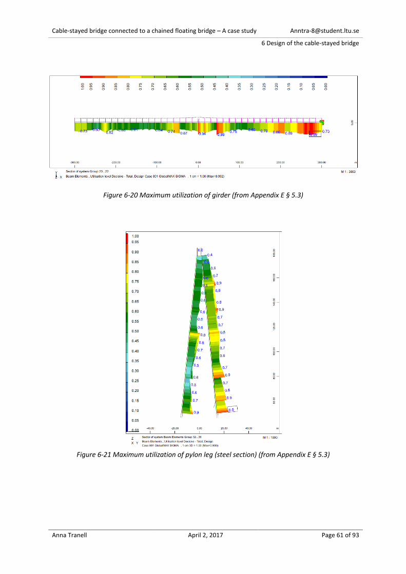
Cable-stayed bridge connected to a chained floating bridge – A case study [email protected]
6 Design of the cable-stayed bridge
Anna Tranell April 2, 2017 Page 61 of 93
Figure 6-20 Maximum utilization of girder (from Appendix E § 5.3)
Figure 6-21 Maximum utilization of pylon leg (steel section) (from Appendix E § 5.3)
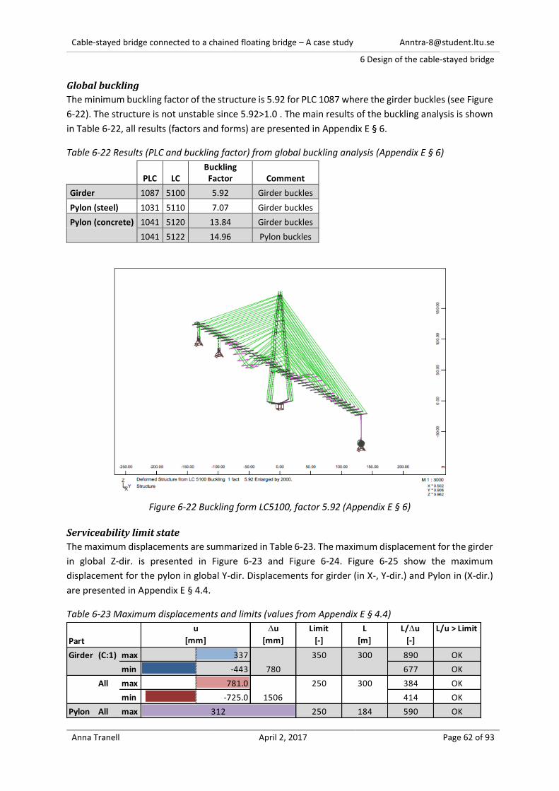
Cable-stayed bridge connected to a chained floating bridge – A case study [email protected]
6 Design of the cable-stayed bridge
Anna Tranell April 2, 2017 Page 62 of 93
Global buckling
The minimum buckling factor of the structure is 5.92 for PLC 1087 where the girder buckles (see Figure
6-22). The structure is not unstable since 5.92>1.0 . The main results of the buckling analysis is shown
in Table 6-22, all results (factors and forms) are presented in Appendix E § 6.
Table 6-22 Results (PLC and buckling factor) from global buckling analysis (Appendix E § 6)
PLC LC Buckling Factor Comment
Girder 1087 5100 5.92 Girder buckles
Pylon (steel) 1031 5110 7.07 Girder buckles
Pylon (concrete) 1041 5120 13.84 Girder buckles
1041 5122 14.96 Pylon buckles
Figure 6-22 Buckling form LC5100, factor 5.92 (Appendix E § 6)
Serviceability limit state
The maximum displacements are summarized in Table 6-23. The maximum displacement for the girder
in global Z-dir. is presented in Figure 6-23 and Figure 6-24. Figure 6-25 show the maximum
displacement for the pylon in global Y-dir. Displacements for girder (in X-, Y-dir.) and Pylon in (X-dir.)
are presented in Appendix E § 4.4.
Table 6-23 Maximum displacements and limits (values from Appendix E § 4.4)
u
[mm]
u
[mm]
Limit
[-]
L
[m]
L/u
[-]
L/u > Limit
Girder (C:1) max 337 350 300 890 OK
min -443 677 OK
All max 781.0 250 300 384 OK
min -725.0 414 OK
Pylon All max 250 184 590 OK312
Part
1506
780
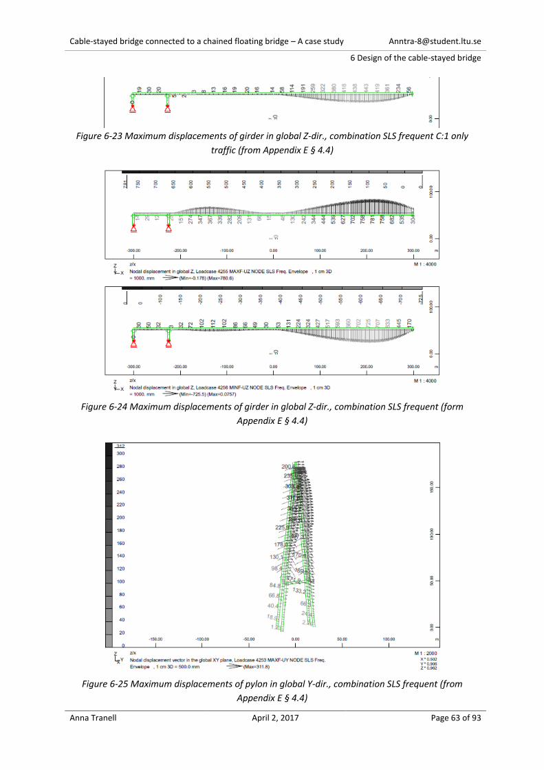
Cable-stayed bridge connected to a chained floating bridge – A case study [email protected]
6 Design of the cable-stayed bridge
Anna Tranell April 2, 2017 Page 63 of 93
Figure 6-23 Maximum displacements of girder in global Z-dir., combination SLS frequent C:1 only
traffic (from Appendix E § 4.4)
Figure 6-24 Maximum displacements of girder in global Z-dir., combination SLS frequent (form
Appendix E § 4.4)
Figure 6-25 Maximum displacements of pylon in global Y-dir., combination SLS frequent (from
Appendix E § 4.4)

Cable-stayed bridge connected to a chained floating bridge – A case study [email protected]
6 Design of the cable-stayed bridge
Anna Tranell April 2, 2017 Page 64 of 93
6.4.2 Extreme Internal Forces
The extreme ULS internal forces, normal force (N) in local x-dir. and moments (My and Mz) around
local y- and z-dir., are summarized in Table 6-24. Local x-dir. is always in the direction of the beam,
local y-dir. has the same or opposite direction of global Y. The local directions are defined in Appendix
E § 1.3. Negative normal force is in compression.
Graphs of extreme ULS internal forces N, Mz and My for girder, cable and pylon are presented in Figure
6-26, Figure 6-27 and Figure 6-28.
Tables of extreme internal forces (N, Vy, Vz, Mt, My and Mz) for ULS, SLS rare and frequent are
presented in Appendix E § 4.1. Graphs in ULS are presented in Appendix E § 4.3 (SLS are not presented).
Table 6-24 Summarization of Extreme ULS internal forces, N, My and Mz (from Appendix E § 4.1)
Part Combination
Girder N Max 175.6 [MN] ULS B:2, LC 1061
Min -181.4 [MN] ULS B:2, LC 1087
My Max 172.5 [MNm] ULS B:2, LC 1118
Min -171.2 [MNm] ULS C:3, LC 1414
Mz Max 187.5 [MNm] ULS B:2, LC 1054
Min -565.4 [MNm] ULS B:2, LC 1054
Pylon N Max 25.3 [MN] ULS B:2, LC 1035
Min -111.2 [MN] ULS B:2, LC 1031
My Max 294.3 [MNm] ULS C:3, LC 1416
Min -171.6 [MNm] ULS B:2, LC 1118
Mz Max 196.0 [MNm] ULS B:2, LC 1037
Min -63.1 [MNm] ULS B:2, LC 1054
Pylon concrete N Max 42.4 [MN] ULS B:2, LC 1058
Min -183.9 [MN] ULS B:2, LC 1041
My Max 331.3 [MNm] ULS B:3, LC 1198
Min -334.6 [MNm] ULS B:3, LC 1198
Mz Max 158.8 [MNm] ULS B:2, LC 1031
Min -154.3 [MNm] ULS B:2, LC 1043
Cable N Max 9.9 [MN] ULS B:3, LC 1150
Extreme value, N, My and Mz
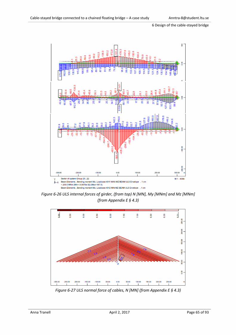
Cable-stayed bridge connected to a chained floating bridge – A case study [email protected]
6 Design of the cable-stayed bridge
Anna Tranell April 2, 2017 Page 65 of 93
Figure 6-26 ULS internal forces of girder, (from top) N [MN], My [MNm] and Mz [MNm]
(from Appendix E § 4.3)
Figure 6-27 ULS normal force of cables, N [MN] (from Appendix E § 4.3)
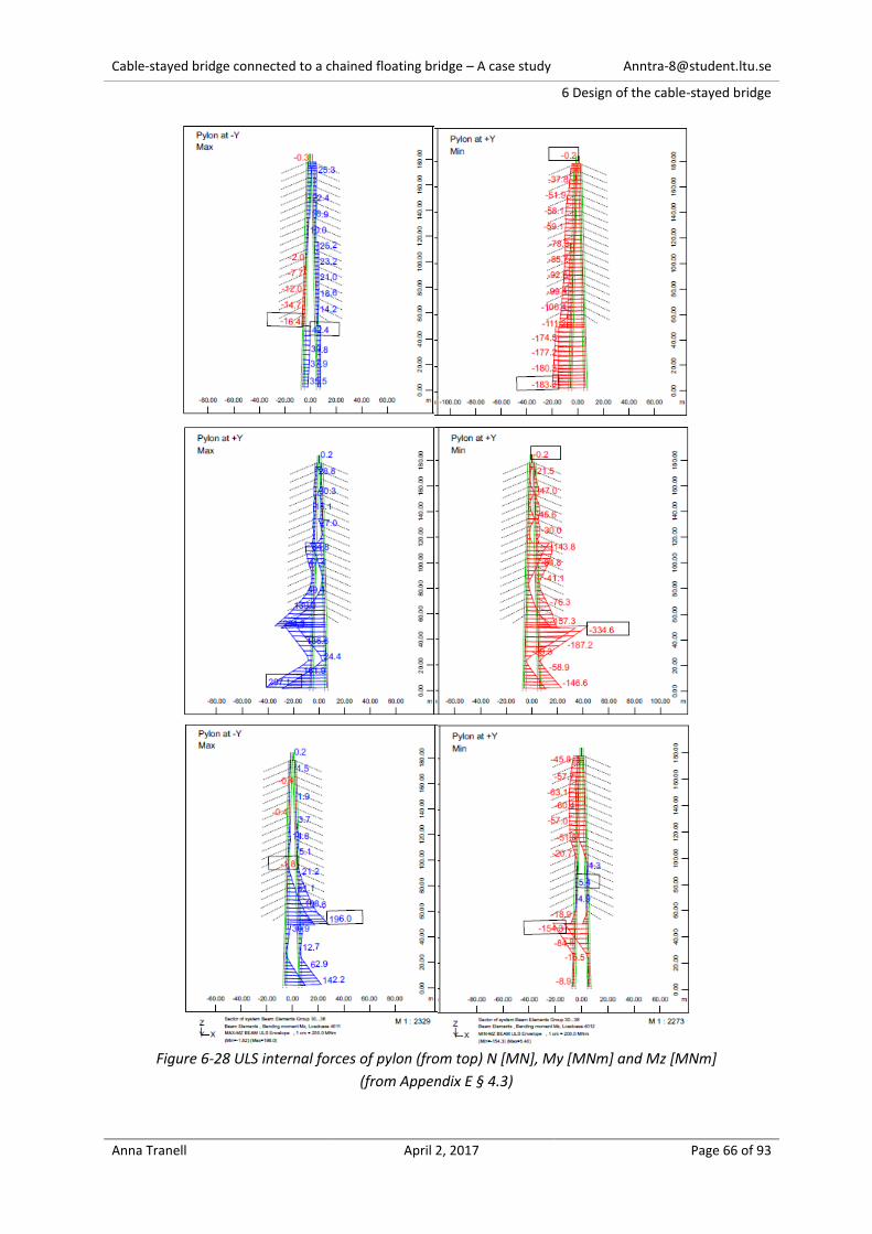
Cable-stayed bridge connected to a chained floating bridge – A case study [email protected]
6 Design of the cable-stayed bridge
Anna Tranell April 2, 2017 Page 66 of 93
Figure 6-28 ULS internal forces of pylon (from top) N [MN], My [MNm] and Mz [MNm]
(from Appendix E § 4.3)
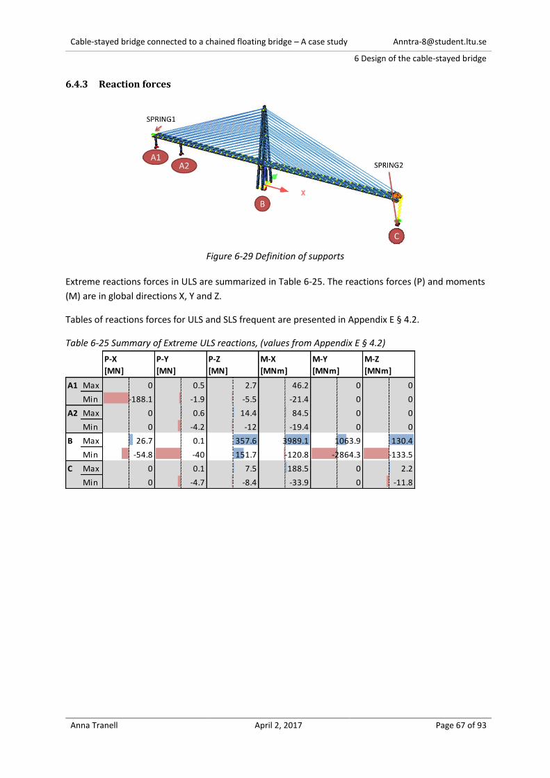
Cable-stayed bridge connected to a chained floating bridge – A case study [email protected]
6 Design of the cable-stayed bridge
Anna Tranell April 2, 2017 Page 67 of 93
6.4.3 Reaction forces
Figure 6-29 Definition of supports
Extreme reactions forces in ULS are summarized in Table 6-25. The reactions forces (P) and moments
(M) are in global directions X, Y and Z.
Tables of reactions forces for ULS and SLS frequent are presented in Appendix E § 4.2.
Table 6-25 Summary of Extreme ULS reactions, (values from Appendix E § 4.2)
P-X
[MN]
P-Y
[MN]
P-Z
[MN]
M-X
[MNm]
M-Y
[MNm]
M-Z
[MNm]
A1 Max 0 0.5 2.7 46.2 0 0
Min -188.1 -1.9 -5.5 -21.4 0 0
A2 Max 0 0.6 14.4 84.5 0 0
Min 0 -4.2 -12 -19.4 0 0
B Max 26.7 0.1 357.6 3989.1 1063.9 130.4
Min -54.8 -40 151.7 -120.8 -2864.3 -133.5
C Max 0 0.1 7.5 188.5 0 2.2
Min 0 -4.7 -8.4 -33.9 0 -11.8
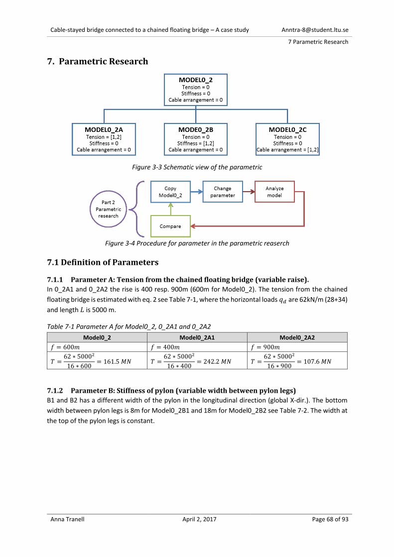
Cable-stayed bridge connected to a chained floating bridge – A case study [email protected]
7 Parametric Research
Anna Tranell April 2, 2017 Page 68 of 93
7. Parametric Research
Figure 3-3 Schematic view of the parametric
Figure 3-4 Procedure for parameter in the parametric reaserch
7.1 Definition of Parameters
7.1.1 Parameter A: Tension from the chained floating bridge (variable raise).
In 0_2A1 and 0_2A2 the rise is 400 resp. 900m (600m for Model0_2). The tension from the chained
floating bridge is estimated with eq. 2 see Table 7-1, where the horizontal loads 𝑞𝑑 are 62kN/m (28+34)
and length 𝐿 is 5000 m.
Table 7-1 Parameter A for Model0_2, 0_2A1 and 0_2A2
Model0_2 Model0_2A1 Model0_2A2
𝑓 = 600𝑚 𝑓 = 400𝑚 𝑓 = 900𝑚
𝑇 =62 ∗ 50002
16 ∗ 600= 161.5 𝑀𝑁 𝑇 =
62 ∗ 50002
16 ∗ 400= 242.2 𝑀𝑁 𝑇 =
62 ∗ 50002
16 ∗ 900= 107.6 𝑀𝑁
7.1.2 Parameter B: Stiffness of pylon (variable width between pylon legs)
B1 and B2 has a different width of the pylon in the longitudinal direction (global X-dir.). The bottom
width between pylon legs is 8m for Model0_2B1 and 18m for Model0_2B2 see Table 7-2. The width at
the top of the pylon legs is constant.

Cable-stayed bridge connected to a chained floating bridge – A case study [email protected]
7 Parametric Research
Anna Tranell April 2, 2017 Page 69 of 93
Table 7-2 Parameter B for Model0_2, 0_2B1 and 0_2B2
Model0_2 Model0_2B1 Model0_2B2
W=12m W=8m W=18m
7.1.3 Parameter C: Cable arrangement (Harp, Fan and Radial)
Model0_2C1 and 0_2C2 has a different cable arrangement than Model0_2. The cable arrangement of
Model0_2C1 is a fan where all cables are distributed on a third of the pylon height (125m/3=41.7m).
It is chosen to uniformly distribute the cables between the pylon top (+177.8m) and the middle
transversal connector at +134.3, which give result in a center distance between cables (c) of 2.3m.
The second cable arrangement for Model0_2C2 is radial. It’s assumed that a closer placement than 1m
give unreasonable cable anchoring. It is chosen to uniformly distribute the cables between the pylon
top (+177.8m) and the top transversal connector at +152.9. The distribution length is 25m and c is
1.3m. The cable arrangement is shown in Table 7-3.
Also, the wind load on the cables vary between the three models since the height of the cables varies
(see Table 7-4).
Table 7-3 Parameter C for Model0_2, 0_2C1 and 0_2C2
Model0_2 Model0_2C1 Model0_2C2
Harp, c=6.2m Fan, c=2.3m Radial, c=1.3m
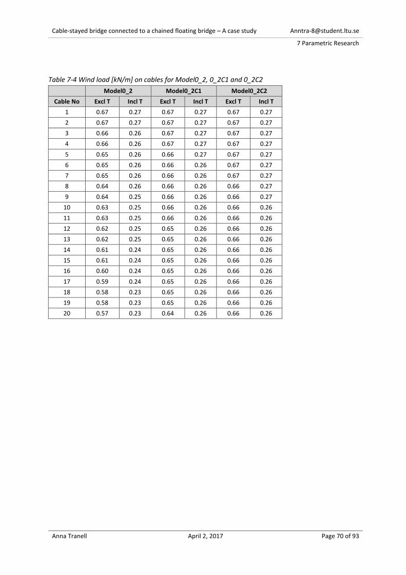
Cable-stayed bridge connected to a chained floating bridge – A case study [email protected]
7 Parametric Research
Anna Tranell April 2, 2017 Page 70 of 93
Table 7-4 Wind load [kN/m] on cables for Model0_2, 0_2C1 and 0_2C2
Model0_2 Model0_2C1 Model0_2C2
Cable No Excl T Incl T Excl T Incl T Excl T Incl T
1 0.67 0.27 0.67 0.27 0.67 0.27
2 0.67 0.27 0.67 0.27 0.67 0.27
3 0.66 0.26 0.67 0.27 0.67 0.27
4 0.66 0.26 0.67 0.27 0.67 0.27
5 0.65 0.26 0.66 0.27 0.67 0.27
6 0.65 0.26 0.66 0.26 0.67 0.27
7 0.65 0.26 0.66 0.26 0.67 0.27
8 0.64 0.26 0.66 0.26 0.66 0.27
9 0.64 0.25 0.66 0.26 0.66 0.27
10 0.63 0.25 0.66 0.26 0.66 0.26
11 0.63 0.25 0.66 0.26 0.66 0.26
12 0.62 0.25 0.65 0.26 0.66 0.26
13 0.62 0.25 0.65 0.26 0.66 0.26
14 0.61 0.24 0.65 0.26 0.66 0.26
15 0.61 0.24 0.65 0.26 0.66 0.26
16 0.60 0.24 0.65 0.26 0.66 0.26
17 0.59 0.24 0.65 0.26 0.66 0.26
18 0.58 0.23 0.65 0.26 0.66 0.26
19 0.58 0.23 0.65 0.26 0.66 0.26
20 0.57 0.23 0.64 0.26 0.66 0.26
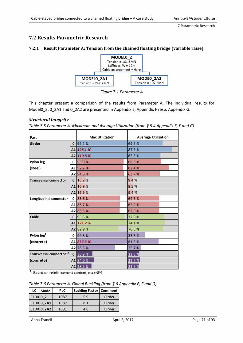
Cable-stayed bridge connected to a chained floating bridge – A case study [email protected]
7 Parametric Research
Anna Tranell April 2, 2017 Page 71 of 93
7.2 Results Parametric Research
7.2.1 Result Parameter A: Tension from the chained floating bridge (variable raise)
Figure 7-1 Parameter A
This chapter present a comparison of the results from Parameter A. The individual results for
Model0_2, 0_2A1 and 0_2A2 are presented in Appendix E, Appendix F resp. Appendix G.
Structural Integrity
Table 7-5 Parameter A, Maximum and Average Utilization (from § 5.4 Appendix E, F and G)
Table 7-6 Parameter A, Global Buckling (from § 6 Appendix E, F and G)
Part Max Utilization Average Utilization
Girder 0 99.2 % 69.5 %
A1 128.1 % 87.5 %
A2 110.8 % 65.3 %
Pylon leg 0 93.0 % 66.6 %
(steel) A1 92.2 % 82.4 %
A2 94.6 % 63.7 %
Transversal connector 0 16.9 % 9.4 %
A1 16.9 % 9.5 %
A2 16.9 % 9.4 %
Longitudinal connector 0 85.6 % 62.3 %
A1 85.7 % 62.9 %
A2 85.5 % 62.0 %
Cable 0 95.3 % 72.0 %
A1 121.7 % 74.1 %
A2 82.9 % 70.5 %
Pylon leg1)0 99.8 % 33.8 %
(concrete) A1 833.3 % 61.2 %
A2 76.3 % 25.7 %
Transversal connector1)0 30.9 % 22.5 %
(concrete) A1 34.0 % 23.7 %
A2 28.9 % 21.9 %1) Based on reinforcement content, max=8%
LC Model PLC Buckling Factor Comment
5100 0_2 1087 5.9 Girder
5100 0_2A1 1087 8.1 Girder
5100 0_2A2 1091 4.8 Girder
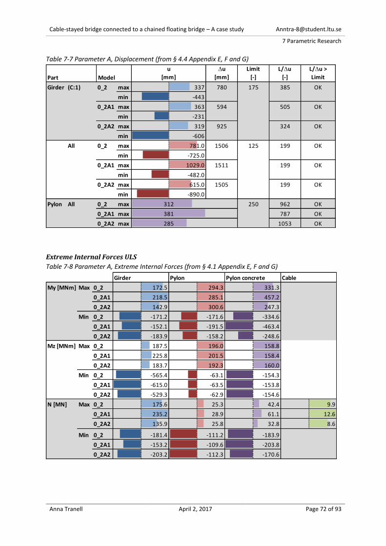
Cable-stayed bridge connected to a chained floating bridge – A case study [email protected]
7 Parametric Research
Anna Tranell April 2, 2017 Page 72 of 93
Table 7-7 Parameter A, Displacement (from § 4.4 Appendix E, F and G)
Extreme Internal Forces ULS
Table 7-8 Parameter A, Extreme Internal Forces (from § 4.1 Appendix E, F and G)
Part Model
u
[mm]
u
[mm]
Limit
[-]
L/u
[-]
L/u >
Limit
Girder (C:1) 0_2 max 337 780 175 385 OK
min -443
0_2A1 max 363 594 505 OK
min -231
0_2A2 max 319 925 324 OK
min -606
All 0_2 max 781.0 1506 125 199 OK
min -725.0
0_2A1 max 1029.0 1511 199 OK
min -482.0
0_2A2 max 615.0 1505 199 OK
min -890.0
Pylon All 0_2 max 312 250 962 OK
0_2A1 max 381 787 OK
0_2A2 max 285 1053 OK
Girder Pylon Pylon concrete Cable
My [MNm] Max 0_2 172.5 294.3 331.3
0_2A1 218.5 285.1 457.2
0_2A2 142.9 300.6 247.3
Min 0_2 -171.2 -171.6 -334.6
0_2A1 -152.1 -191.5 -463.4
0_2A2 -183.9 -158.2 -248.6
Mz [MNm] Max 0_2 187.5 196.0 158.8
0_2A1 225.8 201.5 158.4
0_2A2 183.7 192.3 160.0
Min 0_2 -565.4 -63.1 -154.3
0_2A1 -615.0 -63.5 -153.8
0_2A2 -529.3 -62.9 -154.6
N [MN] Max 0_2 175.6 25.3 42.4 9.9
0_2A1 235.2 28.9 61.1 12.6
0_2A2 135.9 25.8 32.8 8.6
Min 0_2 -181.4 -111.2 -183.9
0_2A1 -153.2 -109.6 -203.8
0_2A2 -203.2 -112.3 -170.6

Cable-stayed bridge connected to a chained floating bridge – A case study [email protected]
7 Parametric Research
Anna Tranell April 2, 2017 Page 73 of 93
Support reactions
Table 7-9 Parameter A, Support Reactions (from § 4.2 Appendix E, F and G)
Figure 6-29 Definition of support
P-X
[MN]
P-Y
[MN]
P-Z
[MN]
M-X
[MNm]
M-Y
[MNm]
M-Z
[MNm]
A1 Max 0_2 0.0 0.5 2.7 46.2 0.0 0.0
0_2A1 0.0 0.4 2.3 47.0 0.0 0.0
0_2A2 0.0 0.5 3.0 45.8 0.0 0.0
Min 0_2 -188.1 -1.9 -5.5 -21.4 0.0 0.0
0_2A1 -248.5 -2.0 -6.3 -21.2 0.0 0.0
0_2A2 -147.8 -1.9 -5.0 -21.6 0.0 0.0
A2 Max 0_2 0.0 0.6 14.4 84.5 0.0 0.0
0_2A1 0.0 0.8 13.5 82.4 0.0 0.0
0_2A2 0.0 0.4 14.9 85.9 0.0 0.0
Min 0_2 0.0 -4.2 -12.0 -19.4 0.0 0.0
0_2A1 0.0 -4.1 -13.6 -23.7 0.0 0.0
0_2A2 0.0 -4.3 -10.9 -16.6 0.0 0.0
B Max 0_2 26.7 0.1 357.6 3989.1 1063.9 130.4
0_2A1 16.6 0.1 361.5 3996.0 552.2 184.6
0_2A2 33.5 0.2 355.1 3984.8 1405.6 95.5
Min 0_2 -54.8 -40.0 151.7 -120.8 -2864.3 -133.5
0_2A1 -74.9 -40.2 153.6 -118.2 -3887.6 -111.6
0_2A2 -41.3 -40.0 150.4 -122.6 -2180.8 -148.1
C Max 0_2 0.0 0.1 7.5 188.5 0.0 2.2
0_2A1 0.0 0.1 6.7 191.9 0.0 2.1
0_2A2 0.0 0.1 7.9 186.3 0.0 2.2
Min 0_2 0.0 -4.7 -8.4 -33.9 0.0 -11.8
0_2A1 0.0 -4.7 -9.9 -32.6 0.0 -11.9
0_2A2 0.0 -4.6 -7.5 -34.8 0.0 -11.7
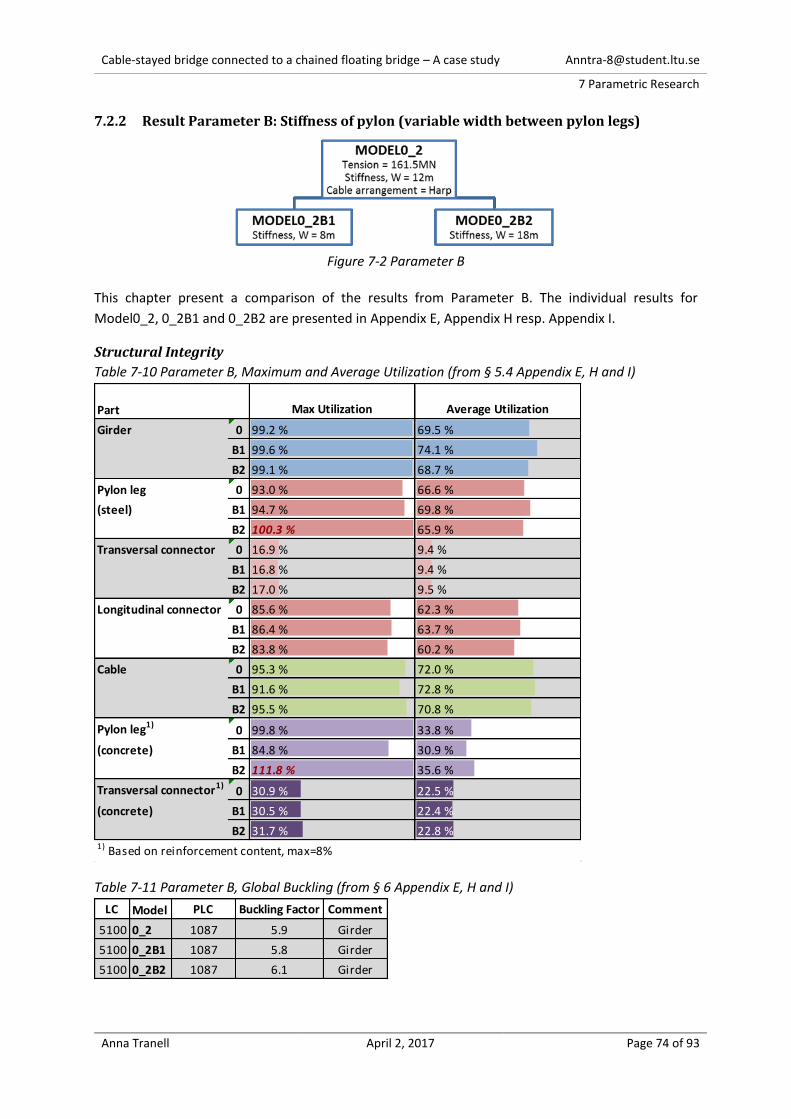
Cable-stayed bridge connected to a chained floating bridge – A case study [email protected]
7 Parametric Research
Anna Tranell April 2, 2017 Page 74 of 93
7.2.2 Result Parameter B: Stiffness of pylon (variable width between pylon legs)
Figure 7-2 Parameter B
This chapter present a comparison of the results from Parameter B. The individual results for
Model0_2, 0_2B1 and 0_2B2 are presented in Appendix E, Appendix H resp. Appendix I.
Structural Integrity
Table 7-10 Parameter B, Maximum and Average Utilization (from § 5.4 Appendix E, H and I)
Table 7-11 Parameter B, Global Buckling (from § 6 Appendix E, H and I)
Part Max Utilization Average Utilization
Girder 0 99.2 % 69.5 %
B1 99.6 % 74.1 %
B2 99.1 % 68.7 %
Pylon leg 0 93.0 % 66.6 %
(steel) B1 94.7 % 69.8 %
B2 100.3 % 65.9 %
Transversal connector 0 16.9 % 9.4 %
B1 16.8 % 9.4 %
B2 17.0 % 9.5 %
Longitudinal connector 0 85.6 % 62.3 %
B1 86.4 % 63.7 %
B2 83.8 % 60.2 %
Cable 0 95.3 % 72.0 %
B1 91.6 % 72.8 %
B2 95.5 % 70.8 %
Pylon leg1)0 99.8 % 33.8 %
(concrete) B1 84.8 % 30.9 %
B2 111.8 % 35.6 %
Transversal connector1)0 30.9 % 22.5 %
(concrete) B1 30.5 % 22.4 %
B2 31.7 % 22.8 %1) Based on reinforcement content, max=8%
LC Model PLC Buckling Factor Comment
5100 0_2 1087 5.9 Girder
5100 0_2B1 1087 5.8 Girder
5100 0_2B2 1087 6.1 Girder

Cable-stayed bridge connected to a chained floating bridge – A case study [email protected]
7 Parametric Research
Anna Tranell April 2, 2017 Page 75 of 93
Table 7-12 Parameter B, Displacement (from § 4.4 Appendix E, H and I)
Extreme Internal Forces ULS
Table 7-13 Parameter B, Extreme Internal Forces (from § 4.1 Appendix E, H and I)
Part Model
u
[mm]
u
[mm]
Limit
[-]
L/u
[-]
L/u >
Limit
Girder (C:1) 0_2 max 337 780 175 385 OK
min -443
0_2B1 max 375 856 350 OK
min -481
0_2B2 max 302 702 427 OK
min -400
All 0_2 max 781.0 1506 125 199 OK
min -725.0
0_2B1 max 779.0 1550 194 OK
min -771.0
0_2B2 max 784.0 1451 207 OK
min -667.0
Pylon All 0_2 max 312 250 962 OK
0_2B1 max 332 904 OK
0_2B2 max 305 984 OK
Girder Pylon Pylon concrete Cable
My [MNm] Max 0_2 172.5 294.3 331.3
0_2B1 169.2 276.4 318.6
0_2B2 174.4 307.7 340.5
Min 0_2 -171.2 -171.6 -334.6
0_2B1 -180.2 -176.2 -296.8
0_2B2 -159.3 -169.6 -362.7
Mz [MNm] Max 0_2 187.5 196.0 158.8
0_2B1 186.7 191.6 154.5
0_2B2 189.1 202.0 165.2
Min 0_2 -565.4 -63.1 -154.3
0_2B1 -557.8 -62.3 -152.2
0_2B2 -572.5 -64.2 -157.2
N [MN] Max 0_2 175.6 25.3 42.4 9.9
0_2B1 179.9 29.6 44.7 9.5
0_2B2 170.7 25.3 38.0 9.9
Min 0_2 -181.4 -111.2 -183.9
0_2B1 -183.2 -109.2 -180.5
0_2B2 -178.4 -116.7 -185.5

Cable-stayed bridge connected to a chained floating bridge – A case study [email protected]
7 Parametric Research
Anna Tranell April 2, 2017 Page 76 of 93
Support reactions
Table 7-14 Parameter B, Support Reactions (from § 4.2 Appendix E, H and I)
Figure 6-29 Definition of supports
P-X
[MN]
P-Y
[MN]
P-Z
[MN]
M-X
[MNm]
M-Y
[MNm]
M-Z
[MNm]
A1 Max 0_2 0 0.5 2.7 46.2 0 0
0_2B1 0 0.5 2.6 46.3 0 0
0_2B2 0 0.5 2.9 46.1 0 0
Min 0_2 -188.1 -1.9 -5.5 -21.4 0 0
0_2B1 -192.4 -1.9 -5.6 -21.4 0 0
0_2B2 -182.9 -1.9 -5.4 -21.4 0 0
A2 Max 0_2 0 0.6 14.4 84.5 0 0
0_2B1 0 0.5 14.2 83.7 0 0
0_2B2 0 0.6 14.9 85.6 0 0
Min 0_2 0 -4.2 -12 -19.4 0 0
0_2B1 0 -4.1 -12.4 -18.9 0 0
0_2B2 0 -4.3 -11.5 -20.1 0 0
B Max 0_2 26.7 0.1 357.6 3989.1 1063.9 130.4
0_2B1 25.2 0.1 358.8 3959.8 911.4 120.8
0_2B2 27.5 0.1 356.2 4034.1 1465.1 145.6
Min 0_2 -54.8 -40 151.7 -120.8 -2864.3 -133.5
0_2B1 -49.1 -39.8 151.1 -120.4 -2246.9 -130.9
0_2B2 -59.8 -40.5 152.3 -121.7 -3800.7 -141.2
C Max 0_2 0 0.1 7.5 188.5 0 2.2
0_2B1 0 0.1 7.5 187.9 0 2.2
0_2B2 0 0.1 7.3 189.4 0 2.2
Min 0_2 0 -4.7 -8.4 0 0 -11.8
0_2B1 0 -4.7 -8.5 0 0 -11.7
0_2B2 0 -4.7 -8.4 0 0 -11.8
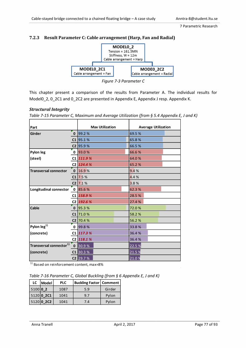
Cable-stayed bridge connected to a chained floating bridge – A case study [email protected]
7 Parametric Research
Anna Tranell April 2, 2017 Page 77 of 93
7.2.3 Result Parameter C: Cable arrangement (Harp, Fan and Radial)
Figure 7-3 Parameter C
This chapter present a comparison of the results from Parameter A. The individual results for
Model0_2, 0_2C1 and 0_2C2 are presented in Appendix E, Appendix J resp. Appendix K.
Structural Integrity
Table 7-15 Parameter C, Maximum and Average Utilization (from § 5.4 Appendix E, J and K)
Table 7-16 Parameter C, Global Buckling (from § 6 Appendix E, J and K)
Part Max Utilization Average Utilization
Girder 0 99.2 % 69.5 %
C1 95.1 % 65.8 %
C2 95.9 % 66.5 %
Pylon leg 0 93.0 % 66.6 %
(steel) C1 111.9 % 64.0 %
C2 124.4 % 65.2 %
Transversal connector 0 16.9 % 9.4 %
C1 7.5 % 4.4 %
C2 7.1 % 3.8 %
Longitudinal connector 0 85.6 % 62.3 %
C1 158.9 % 28.5 %
C2 192.6 % 27.4 %
Cable 0 95.3 % 72.0 %
C1 71.0 % 58.2 %
C2 70.4 % 56.2 %
Pylon leg1)0 99.8 % 33.8 %
(concrete) C1 117.3 % 36.4 %
C2 118.1 % 36.4 %
Transversal connector1)0 30.9 % 22.5 %
(concrete) C1 30.3 % 21.5 %
C2 29.7 % 21.0 %1) Based on reinforcement content, max=8%
LC Model PLC Buckling Factor Comment
5100 0_2 1087 5.9 Girder
5120 0_2C1 1041 9.7 Pylon
5120 0_2C2 1041 7.4 Pylon

Cable-stayed bridge connected to a chained floating bridge – A case study [email protected]
7 Parametric Research
Anna Tranell April 2, 2017 Page 78 of 93
Table 7-17 Parameter C, Displacement (from § 4.4 Appendix E, J and K)
Extreme Internal Forces ULS
Table 7-18 Parameter C, Extreme Internal Forces (from § 4.1 Appendix E, J and K)
Part Model
u
[mm]
u
[mm]
Limit
[-]
L/u
[-]
L/u >
Limit
Girder (C:1) 0_2 max 337 780 175 385 OK
min -443
0_2C1 max 294 351 855 OK
min -57
0_2C2 max 278 319 940 OK
min -41
All 0_2 max 781.0 1506 125 199 OK
min -725.0
0_2C1 max 861.0 1155 260 OK
min -294.0
0_2C2 max 903.0 1144 262 OK
min -241.0
Pylon All 0_2 max 312 250 962 OK
0_2C1 max 300 1000 OK
0_2C2 max 300 1000 OK
Girder Pylon Pylon concrete Cable
My [MNm] Max 0_2 172.5 294.3 331.3
0_2C1 229.7 124.6 365.7
0_2C2 240.4 116.0 368.3
Min 0_2 -171.2 -171.6 -334.6
0_2C1 -111.6 -132.7 -366.6
0_2C2 -114.0 -126.2 -368.2
Mz [MNm] Max 0_2 187.5 196.0 158.8
0_2C1 225.2 166.7 172.4
0_2C2 225.6 162.2 171.8
Min 0_2 -565.4 -63.1 -154.3
0_2C1 -641.4 -72.9 -156.8
0_2C2 -644.2 -70.5 -156.3
N [MN] Max 0_2 175.6 25.3 42.4 9.9
0_2C1 171.8 27.3 36.1 7.4
0_2C2 171.2 25.4 37.9 7.3
Min 0_2 -181.4 -111.2 -183.9
0_2C1 -98.8 -114.8 -189.0
0_2C2 -91.1 -114.9 -189.4

Cable-stayed bridge connected to a chained floating bridge – A case study [email protected]
7 Parametric Research
Anna Tranell April 2, 2017 Page 79 of 93
Support reactions
Table 7-19 Parameter C, Support Reactions (from § 4.2 Appendix E, J and K)
Figure 6-29 Definition of support
P-X
[MN]
P-Y
[MN]
P-Z
[MN]
M-X
[MNm]
M-Y
[MNm]
M-Z
[MNm]
A1 Max 0_2 0 0.5 2.7 46.2 0 0
0_2C1 0 0.5 2.9 49.6 0 0
0_2C2 0 0.4 3 50.6 0 0
Min 0_2 -188.1 -1.9 -5.5 -21.4 0 0
0_2C1 -184.3 -2.2 -5.3 -20.1 0 0
0_2C2 -183.7 -2.2 -5.4 -19.9 0 0
A2 Max 0_2 0 0.6 14.4 84.5 0 0
0_2C1 0 1.6 12.6 85.4 0 0
0_2C2 0 1.6 12.1 85.3 0 0
Min 0_2 0 -4.2 -12 -19.4 0 0
0_2C1 0 -4.3 -13.7 -33.5 0 0
0_2C2 0 -4.2 -13.8 -32.8 0 0
B Max 0_2 26.7 0.1 357.6 3989.1 1063.9 130.4
0_2C1 20.9 0.3 364.5 4391.3 1028.8 352.8
0_2C2 20.3 0.2 366 4468.3 1017.5 355.8
Min 0_2 -54.8 -40 151.7 -120.8 -2864.3 -133.5
0_2C1 -53.6 -42.4 154.4 -141 -2783.4 -157.3
0_2C2 -54 -42.7 155.2 -142 -2790.1 -141.1
C Max 0_2 0 0.1 7.5 188.5 0 2.2
0_2C1 0 0.2 6.9 200.2 0 1.6
0_2C2 0 0.2 6.9 198.9 0 1.5
Min 0_2 0 -4.7 -8.4 -11.8 0 -11.8
0_2C1 0 -5 -9.2 -11.5 0 -11.5
0_2C2 0 -5 -9.4 -11.3 0 -11.3
Cable-stayed bridge connected to a chained floating bridge – A case study [email protected]
8 Discussion and conclusions
Anna Tranell April 2, 2017 Page 80 of 93
8. Discussion and conclusions
8.1 Purpose and general method The aim of this thesis is to evaluate a design of a cable-stayed bridge connected to a chained floating
bridge. With a geography of a crossing being 2-5km wide and 30-60m deep with soft bottom extending
another 20-60m the prospect of such a bridge would be three to five times more economical than a
long span fixed bridge, tube or tunnel (as described in § 2.1).
Since bridge building usually requires extensive investment, it is logical to explore a design of a cable-
stayed bridge connected to a chained floating bridge. As of 2017, there are no design attempts of such
a bridge exploring its challenges and potentials. A case study is the best method to achieve a
reasonable assumption of geometrical and environmental limitations required to perform any kind of
structural design. Bridge length, traffic requirements and actions (wind, traffic etc.) are examples of
such geometrical and environmental limitations.
Bjørnefjorden is a rational choice for this case study, with a span of 5 km, 600m depth and sheltered
by a thin archipelago (confer Figure 4-3). It is realistic since there are already designs attempting a
crossing with a chained floating bridge, however not connected to a cable-stayed bridge. The width of
the crossing is in the upper range of feasible widths for the concept and thus, the value this study
provides is potent. If the concept is feasible for Bjørnefjorden it is also reasonable to believe that it
would be feasible for similar or narrower crossings as well.
The design approach of the cable-stayed bridge connected to a chained floating bridge is based on
conventional cable stayed bridges, using conventional geometry and cross sections. Therefore, if the
final design with conventional geometry and cross sections has structural integrity, it is probable to
presume that the concept and the bridge design is feasible.
The conventional cable-stayed design theory used in this study (described in § 5) is mainly based on
“Bridge Engineering Handbook” by M-C. Tang (2000) and “Past, present and future of cable-stayed
bridges” proceedings from a seminar by F. Leonhardt and W. Zellner (1991). All three notable structural
engineers and specialized in cable-stayed bridges.
The design is also based trough the study of the three example bridges. The bridges were chosen due
to their similarity (or larger) in span lengths to the case study, and all of them being construction from
recent years (2000, 2003 and 2012) with available structural information. It is however not certain that
these examples provide the norm of conventional cable-stayed bridge design. Despite this notion,
since they are successfully constructed they are all to be considered evidently feasible designs
8.1.1 Design approach
The design approach to model, analyze and evaluate the structural integrity of the design with a finite
element software is the norm in structural design. Accurate cable-stayed bridge designs are
accomplished through the use of computer aided analysis (as described in § 5.1).
Finite element model
It is sensible for analyses of global behavior to use a finite model with simple finite elements, such as
3-dimensional lines and points. It is also reasonable that beam-elements are used on members with
Cable-stayed bridge connected to a chained floating bridge – A case study [email protected]
8 Discussion and conclusions
Anna Tranell April 2, 2017 Page 81 of 93
both axial and bending resistance such as girder and pylon legs. The cables are logically modeled with
cable-elements and all other minor structural elements as trusses.
The constraints of the girder, at the supports A1, A2, B and C, are modelled similar to a conventional
bridge deck supported with bearings. Other constraints could be utilized, for example restraining
rotation around Mz at the pylon (B). The chosen constraints are probably conservative for the cable
and the pylon design.
Loads and load combinations
The permanent loads on the structure are within realistic levels. However, it might be possible to
reduce thickness of the pavement and thus reduce the superimposed dead load. The thickness of
pavement is chosen for regular bridges and can be reduced for bridges with a larger spans. Also the
the stiffeners in the girder and pylon may need adjustments but the assumption is to be considered
realistic.
The prestress of the cables is sensible, it result in a +200mm displacement of the girder in global Z
when exposed to permanent loads (confer Appendix E § 2). In detailed cable-stayed bridge design each
cable would have an optimized length and prestress. The optimization require a detailed construction
phase analysis (as described in § 5.3).
In the concept, the cable-stayed bridge is completed before the chained floating bridge is constructed.
Therefore are the construction phases irrelevant for this study. It’s rational to assume that the bridge
in the thesis is possible to construct, since the global geometry and components of the cable-stayed
bridge in this study is based on conventional and constructed cable-stayed bridges.
Since the reaction from the chained floating bridge is based on preliminary load estimation (confer
with § 4.1), there is an uncertainty regarding the magnitude. The effect of this uncertainty is limited as
the reaction from the floating bridge is evaluated in the parametric research.
It is assumed that the moorings are tightened to stabilize the shape of the chained floating bridge, this
will induce a permanent tension. The reaction also has a variable part, the assumed variation of 50%
in ULS is the ratio between the slack and tight side (see Figure 4-5).
The variable loads wind, traffic and temperature are based on Eurocode. The wind and traffic load are
reasonable, although the codes for wind and traffic are designed for bridges with spans less than 200m.
The bridge is designed considering the aerodynamic limits (from § 5.4.1). In future detailed designs,
further aerodynamic analysis is required.
All major load cases and combinations are analyzed in this thesis but for a future detailed design more
cases and combinations will need to be considered. Singular uniform temperature without warm or
cold cables should be prioritized in such a design, as this load case will presumably be governing for
displacements.
The design combinations are based on the intermediate load combinations causing the largest global
response (N, Mt , My and Mz) for the cable, girder and pylon (both steel and concrete). The design
combinations provides reasonable internal forces used for design of the cross section. There may be
unanalyzed combinations that would possibly give a higher response, yet it is credible to believe that
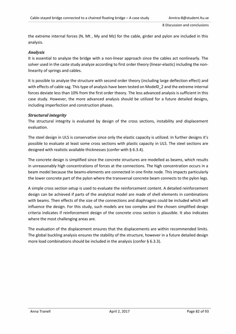
Cable-stayed bridge connected to a chained floating bridge – A case study [email protected]
8 Discussion and conclusions
Anna Tranell April 2, 2017 Page 82 of 93
the extreme internal forces (N, Mt , My and Mz) for the cable, girder and pylon are included in this
analysis.
Analysis
It is essential to analyze the bridge with a non-linear approach since the cables act nonlinearly. The
solver used in the caste study analyze according to first order theory (linear-elastic) including the non-
linearity of springs and cables.
It is possible to analyze the structure with second order theory (including large deflection effect) and
with effects of cable sag. This type of analysis have been tested on Model0_2 and the extreme internal
forces deviate less than 10% from the first order theory. The less advanced analysis is sufficient in this
case study. However, the more advanced analysis should be utilized for a future detailed designs,
including imperfection and construction phases.
Structural integrity
The structural integrity is evaluated by design of the cross sections, instability and displacement
evaluation.
The steel design in ULS is conservative since only the elastic capacity is utilized. In further designs it’s
possible to evaluate at least some cross sections with plastic capacity in ULS. The steel sections are
designed with realistic available thicknesses (confer with § 6.3.4).
The concrete design is simplified since the concrete structures are modelled as beams, which results
in unreasonably high concentrations of forces at the connections. The high concentration occurs in a
beam model because the beams-elements are connected in one finite node. This impacts particularly
the lower concrete part of the pylon where the transversal concrete beam connects to the pylon legs.
A simple cross section setup is used to evaluate the reinforcement content. A detailed reinforcement
design can be achieved if parts of the analytical model are made of shell elements in combinations
with beams. Then effects of the size of the connections and diaphragms could be included which will
influence the design. For this study, such models are too complex and the chosen simplified design
criteria indicates if reinforcement design of the concrete cross section is plausible. It also indicates
where the most challenging areas are.
The evaluation of the displacement ensures that the displacements are within recommended limits.
The global buckling analysis ensures the stability of the structure, however in a future detailed design
more load combinations should be included in the analysis (confer § 6.3.3).

Cable-stayed bridge connected to a chained floating bridge – A case study [email protected]
8 Discussion and conclusions
Anna Tranell April 2, 2017 Page 83 of 93
8.2 Final design (Model0_2) The final design is the result of a feasibility-evaluation where there is an attempt to design a cable-
stayed bridge, connected to a chained floating bridge in the case study of Bjørnefjorden, with
conventional cross sections. The conventional steel thicknesses are in a range of 10-150mm (as
described in § 6.3.4).
8.2.1 Design and Structural integrity
The maximum utilization of the girder ranges from 87% to 99% for the five unique cross section
configurations. The steel thickness of the cross sections configurations are in a conventional range of
10 to 25mm. The average utilization of the steel in the girder is 69.5%.
The maximum utilization of the pylon leg ranges from 85% to 93% for the five unique cross section
configurations. The steel thickness of the cross sections are in a range of 32 to 110mm. A thickness of
110mm is not unfeasible but probably expensive. Cross section no. 34 and 35 could be redesigned with
an inner ring of steel plates (similar to a cardboard structure) or with a concrete core connected to the
steel with shear studs. The average utilization of the steel in the pylon is 66.6%.
Since the wind load is only applied in the positive Y-dir. and not in the negative the average utilization
of the pylon is underrated.
The concrete pylon section is utilized to maximum 99.8% (with the simplified design criteria) and an
average of 33.8% and is within the feasible limit. The peak reinforcement areas occur as predicted at
the transversal connection and at the foundation. These peaks may be reduced with a more detailed
model.
The 140mm locked coil cables are utilized to maximum 95% and average 72%. All connectors
transversal and longitudinal connectors are utilized less than 100 % with a feasible cross section.
The bridge is not unstable since the global buckling analysis yields a higher buckling factor than 1.0.
The lowest buckling factor is 5.9 where the girder buckle.
In serviceability limit state are the displacements within the limits of L/250 for the girder and pylon.
The girder is the most flexible of these structures.
The analysis show that the cable-stayed bridge connected to a chained floating bridge in this case study
has structural integrity. Optimization and detailed future studies will enhance the concept but none of
the analysis indicate that this is an unfeasible design.
8.2.2 Internal forces
Girder
The magnitude of maximum ULS axial force is by chance balanced and vary less then ±5% between
compression and tension. The maximum compression (-181MN) occur as expected at the middle of
the girder (pylon support B) and the maximum tension (176MN) at the ends of the girder. The
maximum axial force at the middle of the bridge is 70MN, which implies that about half of the reaction
of the floating bridge (162MN) is carried by the girder to the support at A1. The other half is carried
with the system of cables.
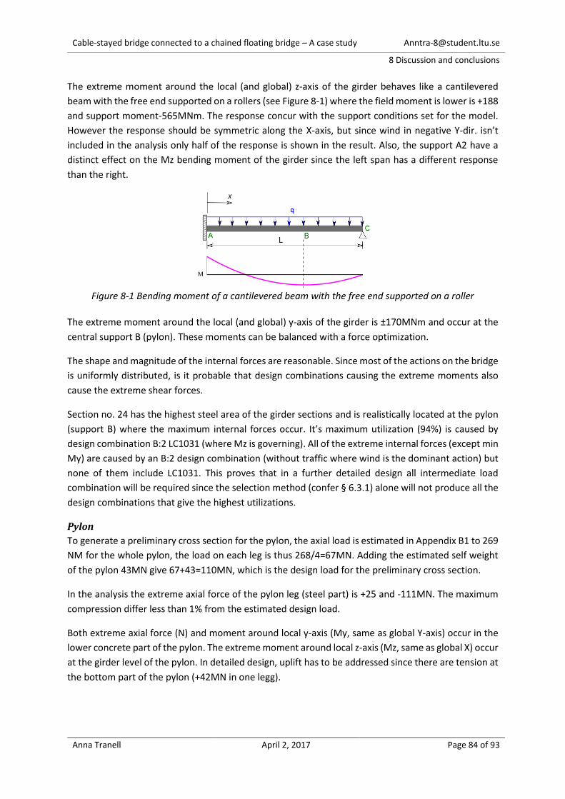
Cable-stayed bridge connected to a chained floating bridge – A case study [email protected]
8 Discussion and conclusions
Anna Tranell April 2, 2017 Page 84 of 93
The extreme moment around the local (and global) z-axis of the girder behaves like a cantilevered
beam with the free end supported on a rollers (see Figure 8-1) where the field moment is lower is +188
and support moment-565MNm. The response concur with the support conditions set for the model.
However the response should be symmetric along the X-axis, but since wind in negative Y-dir. isn’t
included in the analysis only half of the response is shown in the result. Also, the support A2 have a
distinct effect on the Mz bending moment of the girder since the left span has a different response
than the right.
Figure 8-1 Bending moment of a cantilevered beam with the free end supported on a roller
The extreme moment around the local (and global) y-axis of the girder is ±170MNm and occur at the
central support B (pylon). These moments can be balanced with a force optimization.
The shape and magnitude of the internal forces are reasonable. Since most of the actions on the bridge
is uniformly distributed, is it probable that design combinations causing the extreme moments also
cause the extreme shear forces.
Section no. 24 has the highest steel area of the girder sections and is realistically located at the pylon
(support B) where the maximum internal forces occur. It’s maximum utilization (94%) is caused by
design combination B:2 LC1031 (where Mz is governing). All of the extreme internal forces (except min
My) are caused by an B:2 design combination (without traffic where wind is the dominant action) but
none of them include LC1031. This proves that in a further detailed design all intermediate load
combination will be required since the selection method (confer § 6.3.1) alone will not produce all the
design combinations that give the highest utilizations.
Pylon
To generate a preliminary cross section for the pylon, the axial load is estimated in Appendix B1 to 269
NM for the whole pylon, the load on each leg is thus 268/4=67MN. Adding the estimated self weight
of the pylon 43MN give 67+43=110MN, which is the design load for the preliminary cross section.
In the analysis the extreme axial force of the pylon leg (steel part) is +25 and -111MN. The maximum
compression differ less than 1% from the estimated design load.
Both extreme axial force (N) and moment around local y-axis (My, same as global Y-axis) occur in the
lower concrete part of the pylon. The extreme moment around local z-axis (Mz, same as global X) occur
at the girder level of the pylon. In detailed design, uplift has to be addressed since there are tension at
the bottom part of the pylon (+42MN in one legg).

Cable-stayed bridge connected to a chained floating bridge – A case study [email protected]
8 Discussion and conclusions
Anna Tranell April 2, 2017 Page 85 of 93
Section no. 34 has the highest steel area of the pylon sections. The maximum utilization of section no.
34 (93%) is caused by design combination C:3 LC1416, where max My is governing. Design combination
C:3 include traffic, wind and temperature load where traffic is the dominant action.
Cable
The maximum tension in the cable is 9.9MN it is caused by design combination B:3 without traffic
where temperature is dominant load. The estimated design load in Appendix B1 is 10.2MN. It is logical
that the estimated design load is less than the design load from the analysis, since the estimated design
load does not consider the effects of the supports (A1, A2 and C).
The maximum tension in the cable and the design combination LC 1150 correspond as expected with
the design combination giving the maximum utilization level.
8.2.3 Supports
The supports in this case study are assumed to be feasible. To fully evaluate the feasibility of the
concept of a cable-stayed bridge connected to a chained floating bridge, these supports are required
to be designed. The design actions to the supports can be found in Appendix E2 in both ULS and SLS.
As with conventional cables-stayed bridges the main support is located at the pylon foundation
(support B) where most of the reaction is concentrated. Unlike conventional cable-stayed bridges, this
bridge is connected to a chained floating bridge. It is more logical to restrain the global X-dir. at the
shoreline (support A1) compared to the pylon foundation (B), since the lever arm of the reaction from
the floating bridge is smaller and the bedrock is more accessible for anchoring. A support restraining
global X at the shoreline (A1) will also give a more balanced response to the cable-stayed bridge, since
the reaction from the floating bridge is transferred through the whole (not half) structure.
A support in global X-direction is therefore placed at the shoreline in A1. This support A1, could be
designed similar to an anchorage of the main suspension cables in a suspension bridge. However, it’s
is also realistic that this support (A1) is not completely fixed and some part of the reaction in X-direction
is also restrained by the pylon. In this study, the stiffness of the support (SPRING1) is assumed to have
the properties of a 40m long steel pipe. The pipe would be attached like a dead-end anchor in a bedrock
chamber (confer Figure 5-14).
There is also a support at the connection to the chained floating bridge (support C). In the concept,
this support consist partly of an anchored pontoon and partly of the global inertia of the chained
floating bridge. The stiffness of this restraint is only possible to estimate with a pontoon design. A
pontoon in turn is not possible to design without design actions (which this study provides). Therefore,
are the properties of the support in C stiffness roughly estimated for the purpose of this study.
It is reasonable that the support at C is the least rigid compared to all other supports. It is also probable
that a more flexible support at C give conservative results. The stiffness of support C (SPRING2) is
estimated with the buoyancy of a pontoon. However, this pontoon was designed only for vertical loads,
without mooring and for a bridge deck 20m above sea level. In the premises of this study the pontoon
should be design for a bridge deck 50m above sea level with both vertical and horizontal actions
including the effect of mooring. The pontoon-design for this case study would therefore probably be
more rigid than the one used for estimating SPRING2.
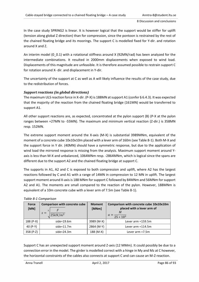
Cable-stayed bridge connected to a chained floating bridge – A case study [email protected]
8 Discussion and conclusions
Anna Tranell April 2, 2017 Page 86 of 93
In the case study SPRING2 is linear. It is however logical that the support would be stiffer for uplift
(tension along global Z direction) than for compression, since the pontoon is restrained by the rest of
the chained floating bridge and its moorings. The support C is modelled fixed for Y-dir. and rotation
around X and Z.
An interim model (0_0.1) with a rotational stiffness around X (92MN/rad) has been analyzed for the
intermediate combinations. It resulted in 2000mm displacements when exposed to wind load.
Displacements of this magnitude are unfeasible. It is therefore assumed possible to restrain support C
for rotation around X- dir. and displacement in Y-dir.
The uncertainty of the support at C as well as A will likely influence the results of the case study, due
to the redistribution of forces.
Support reactions (in global directions)
The maximum ULS reaction force in X-dir. (P-X) is 188MN at support A1 (confer § 6.4.3). It was expected
that the majority of the reaction from the chained floating bridge (161MN) would be transferred to
support A1.
All other support reactions are, as expected, concentrated at the pylon support (B) (P-X at the pylon
ranges between +27MN to -55MN). The maximum and minimum vertical reaction (Z-dir.) is 358MN
resp. 152MN.
The extreme support moment around the X-axis (M-X) is substantial 3989MNm, equivalent of the
moment of a concrete cube 10x10x10m placed with a lever arm of 160m (see Table 8-1). Both M-X and
the support force in Y dir. (40MN) should have a symmetric response, but due to the application of
wind load the mirrored response is missing from the analysis. Maximum support moment around Y-
axis is less than M-X and unbalanced, 1064MNm resp. -2864MNm, which is logical since the spans are
different due to the support A2 and the chained floating bridge at support C.
The supports in A1, A2 and C is exposed to both compression and uplift, where A2 has the largest
reactions followed by C and A1 with a range of 14MN in compression to 12 MN in uplift. The largest
support moment around X-axis is 188 MNm for support C followed by 84MNm and 56MNm for support
A2 and A1. The moments are small compared to the reaction of the pylon. However, 188MNm is
equivalent of a 10m concrete cube with a lever arm of 7.5m (see Table 8-1).
Table 8-1 Comparison
Force
[MN]
Comparison with concrete cube
𝑠 = √𝐹
25𝑘𝑁/𝑚3
3
Moment
[MNm]
Comparison with concrete cube 10x10x10m placed with a lever arm of
𝑎 =𝑀
25 ∗ 103
188 (P-X) side=19.6m 3989 (M-X) Lever arm =159.5m
40 (P-Y) side=11.7m 2864 (M-Y) Lever arm =114.5m
358 (P-Z) side=24.3m 188 (M-X) Lever arm =7.5m
Support C has an unexpected support moment around Z-axis (12 MMm). It could possibly be due to a
connection error in the model. The girder is modelled correct with a hinge in My and Mz at C however,
the horizontal constraints of the cables also connects at support C and can cause an M-Z-reaction.
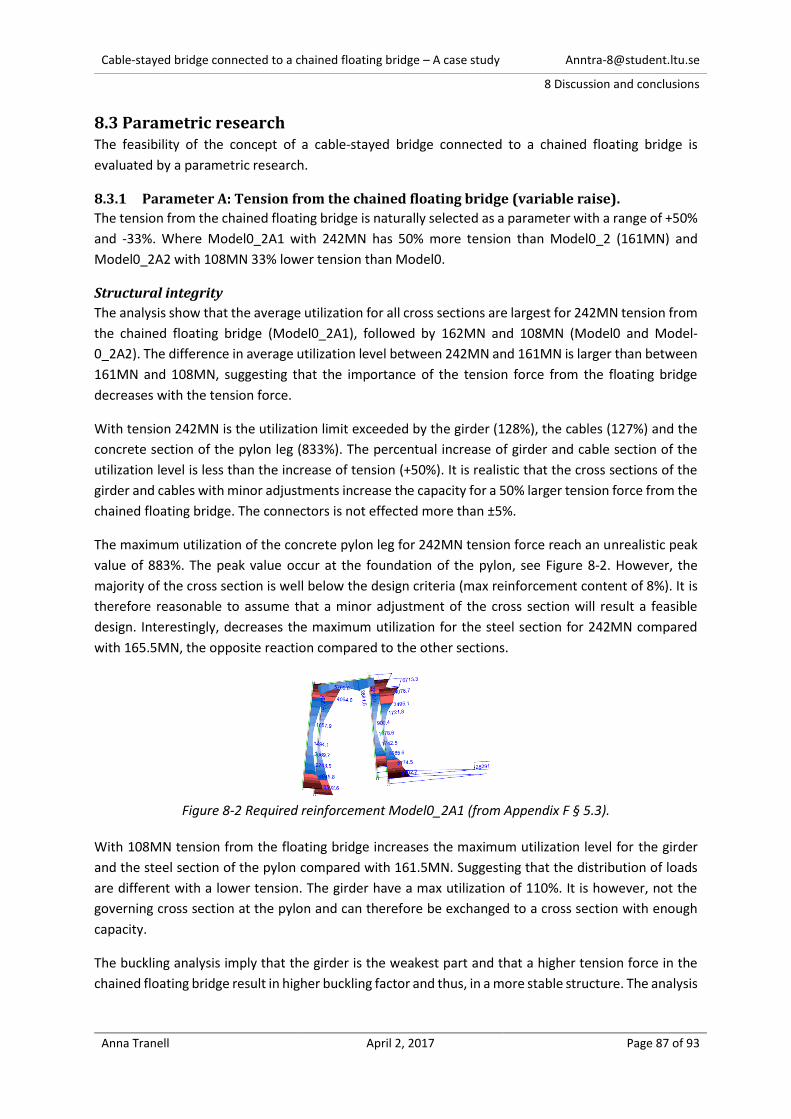
Cable-stayed bridge connected to a chained floating bridge – A case study [email protected]
8 Discussion and conclusions
Anna Tranell April 2, 2017 Page 87 of 93
8.3 Parametric research The feasibility of the concept of a cable-stayed bridge connected to a chained floating bridge is
evaluated by a parametric research.
8.3.1 Parameter A: Tension from the chained floating bridge (variable raise).
The tension from the chained floating bridge is naturally selected as a parameter with a range of +50%
and -33%. Where Model0_2A1 with 242MN has 50% more tension than Model0_2 (161MN) and
Model0_2A2 with 108MN 33% lower tension than Model0.
Structural integrity
The analysis show that the average utilization for all cross sections are largest for 242MN tension from
the chained floating bridge (Model0_2A1), followed by 162MN and 108MN (Model0 and Model-
0_2A2). The difference in average utilization level between 242MN and 161MN is larger than between
161MN and 108MN, suggesting that the importance of the tension force from the floating bridge
decreases with the tension force.
With tension 242MN is the utilization limit exceeded by the girder (128%), the cables (127%) and the
concrete section of the pylon leg (833%). The percentual increase of girder and cable section of the
utilization level is less than the increase of tension (+50%). It is realistic that the cross sections of the
girder and cables with minor adjustments increase the capacity for a 50% larger tension force from the
chained floating bridge. The connectors is not effected more than ±5%.
The maximum utilization of the concrete pylon leg for 242MN tension force reach an unrealistic peak
value of 883%. The peak value occur at the foundation of the pylon, see Figure 8-2. However, the
majority of the cross section is well below the design criteria (max reinforcement content of 8%). It is
therefore reasonable to assume that a minor adjustment of the cross section will result a feasible
design. Interestingly, decreases the maximum utilization for the steel section for 242MN compared
with 165.5MN, the opposite reaction compared to the other sections.
Figure 8-2 Required reinforcement Model0_2A1 (from Appendix F § 5.3).
With 108MN tension from the floating bridge increases the maximum utilization level for the girder
and the steel section of the pylon compared with 161.5MN. Suggesting that the distribution of loads
are different with a lower tension. The girder have a max utilization of 110%. It is however, not the
governing cross section at the pylon and can therefore be exchanged to a cross section with enough
capacity.
The buckling analysis imply that the girder is the weakest part and that a higher tension force in the
chained floating bridge result in higher buckling factor and thus, in a more stable structure. The analysis
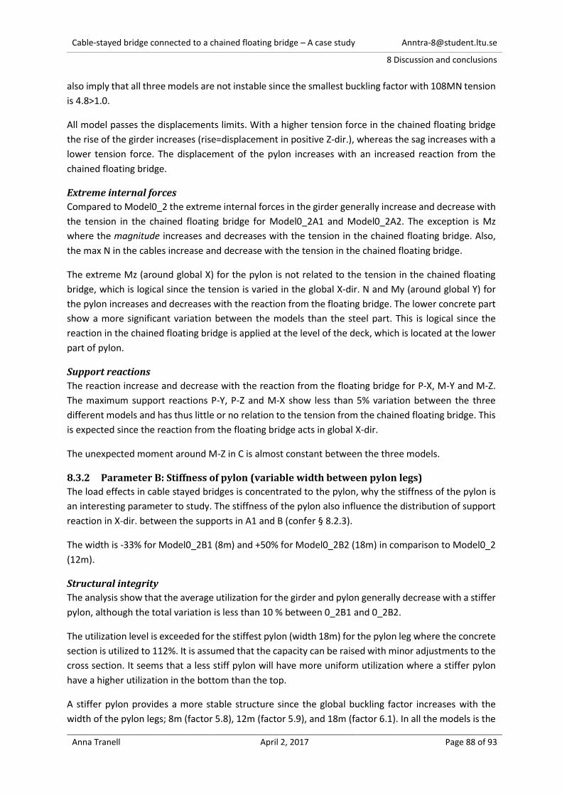
Cable-stayed bridge connected to a chained floating bridge – A case study [email protected]
8 Discussion and conclusions
Anna Tranell April 2, 2017 Page 88 of 93
also imply that all three models are not instable since the smallest buckling factor with 108MN tension
is 4.8>1.0.
All model passes the displacements limits. With a higher tension force in the chained floating bridge
the rise of the girder increases (rise=displacement in positive Z-dir.), whereas the sag increases with a
lower tension force. The displacement of the pylon increases with an increased reaction from the
chained floating bridge.
Extreme internal forces
Compared to Model0_2 the extreme internal forces in the girder generally increase and decrease with
the tension in the chained floating bridge for Model0_2A1 and Model0_2A2. The exception is Mz
where the magnitude increases and decreases with the tension in the chained floating bridge. Also,
the max N in the cables increase and decrease with the tension in the chained floating bridge.
The extreme Mz (around global X) for the pylon is not related to the tension in the chained floating
bridge, which is logical since the tension is varied in the global X-dir. N and My (around global Y) for
the pylon increases and decreases with the reaction from the floating bridge. The lower concrete part
show a more significant variation between the models than the steel part. This is logical since the
reaction in the chained floating bridge is applied at the level of the deck, which is located at the lower
part of pylon.
Support reactions
The reaction increase and decrease with the reaction from the floating bridge for P-X, M-Y and M-Z.
The maximum support reactions P-Y, P-Z and M-X show less than 5% variation between the three
different models and has thus little or no relation to the tension from the chained floating bridge. This
is expected since the reaction from the floating bridge acts in global X-dir.
The unexpected moment around M-Z in C is almost constant between the three models.
8.3.2 Parameter B: Stiffness of pylon (variable width between pylon legs)
The load effects in cable stayed bridges is concentrated to the pylon, why the stiffness of the pylon is
an interesting parameter to study. The stiffness of the pylon also influence the distribution of support
reaction in X-dir. between the supports in A1 and B (confer § 8.2.3).
The width is -33% for Model0_2B1 (8m) and +50% for Model0_2B2 (18m) in comparison to Model0_2
(12m).
Structural integrity
The analysis show that the average utilization for the girder and pylon generally decrease with a stiffer
pylon, although the total variation is less than 10 % between 0_2B1 and 0_2B2.
The utilization level is exceeded for the stiffest pylon (width 18m) for the pylon leg where the concrete
section is utilized to 112%. It is assumed that the capacity can be raised with minor adjustments to the
cross section. It seems that a less stiff pylon will have more uniform utilization where a stiffer pylon
have a higher utilization in the bottom than the top.
A stiffer pylon provides a more stable structure since the global buckling factor increases with the
width of the pylon legs; 8m (factor 5.8), 12m (factor 5.9), and 18m (factor 6.1). In all the models is the
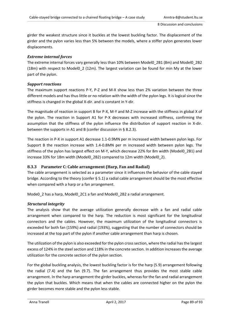
Cable-stayed bridge connected to a chained floating bridge – A case study [email protected]
8 Discussion and conclusions
Anna Tranell April 2, 2017 Page 89 of 93
girder the weakest structure since it buckles at the lowest buckling factor. The displacement of the
girder and the pylon varies less than 5% between the models, where a stiffer pylon generates lower
displacements.
Extreme internal forces
The extreme internal forces vary generally less than 10% between Model0_2B1 (8m) and Model0_2B2
(18m) with respect to Model0_2 (12m). The largest variation can be found for min My at the lower
part of the pylon.
Support reactions
The maximum support reactions P-Y, P-Z and M-X show less than 2% variation between the three
different models and has thus little or no relation with the width of the pylon legs. It is logical since the
stiffness is changed in the global X-dir. and is constant in Y-dir.
The magnitude of reaction in support B for P-X, M-Y and M-Z increase with the stiffness in global X of
the pylon. The reaction in Support A1 for P-X decreases with increased stiffness, confirming the
assumption that the stiffness of the pylon influence the distribution of support reaction in X-dir.
between the supports in A1 and B (confer discussion in § 8.2.3).
The reaction in P-X in support A1 decrease 1.1-0.9MN per m increased width between pylon legs. For
Support B the reaction increase with 1.4-0.8MN per m increased width between pylon legs. The
stiffness of the pylon has largest effect on M-Y, which decrease 22% for 8m width (Model0_2B1) and
increase 33% for 18m width (Model0_2B2) compared to 12m width (Model0_2).
8.3.3 Parameter C: Cable arrangement (Harp, Fan and Radial)
The cable arrangement is selected as a parameter since it influences the behavior of the cable stayed
bridge. According to the theory (confer § 5.1) a radial cable arrangement should be the most effective
when compared with a harp or a fan arrangement.
Mode0_2 has a harp, Model0_2C1 a fan and Model0_2B2 a radial arrangement.
Structural integrity
The analysis show that the average utilization generally decrease with a fan and radial cable
arrangement when compared to the harp. The reduction is most significant for the longitudinal
connectors and the cables. However, the maximum utilization of the longitudinal connectors is
exceeded for both fan (159%) and radial (193%), suggesting that the number of connectors should be
increased at the top part of the pylon if another cable arrangement than harp is chosen.
The utilization of the pylon is also exceeded for the pylon cross section, where the radial has the largest
excess of 124% in the steel section and 118% in the concrete section. In addition increases the average
utilization for the concrete section of the pylon section.
For the global buckling analysis, the lowest buckling factor is for the harp (5.9) arrangement following
the radial (7.4) and the fan (9.7). The fan arrangement thus provides the most stable cable
arrangement. In the harp arrangement the girder buckles, whereas for the fan and radial arrangement
the pylon that buckles. Which means that when the cables are connected higher on the pylon the
girder becomes more stable and the pylon less stable.
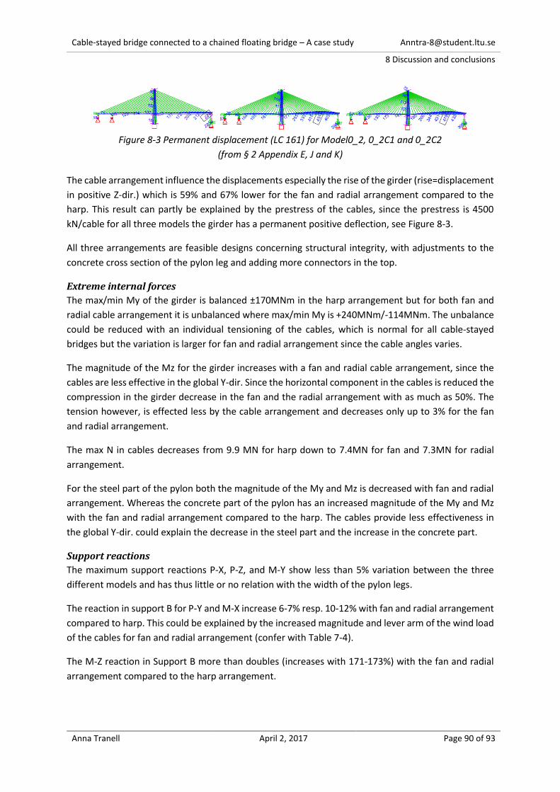
Cable-stayed bridge connected to a chained floating bridge – A case study [email protected]
8 Discussion and conclusions
Anna Tranell April 2, 2017 Page 90 of 93
Figure 8-3 Permanent displacement (LC 161) for Model0_2, 0_2C1 and 0_2C2
(from § 2 Appendix E, J and K)
The cable arrangement influence the displacements especially the rise of the girder (rise=displacement
in positive Z-dir.) which is 59% and 67% lower for the fan and radial arrangement compared to the
harp. This result can partly be explained by the prestress of the cables, since the prestress is 4500
kN/cable for all three models the girder has a permanent positive deflection, see Figure 8-3.
All three arrangements are feasible designs concerning structural integrity, with adjustments to the
concrete cross section of the pylon leg and adding more connectors in the top.
Extreme internal forces
The max/min My of the girder is balanced ±170MNm in the harp arrangement but for both fan and
radial cable arrangement it is unbalanced where max/min My is +240MNm/-114MNm. The unbalance
could be reduced with an individual tensioning of the cables, which is normal for all cable-stayed
bridges but the variation is larger for fan and radial arrangement since the cable angles varies.
The magnitude of the Mz for the girder increases with a fan and radial cable arrangement, since the
cables are less effective in the global Y-dir. Since the horizontal component in the cables is reduced the
compression in the girder decrease in the fan and the radial arrangement with as much as 50%. The
tension however, is effected less by the cable arrangement and decreases only up to 3% for the fan
and radial arrangement.
The max N in cables decreases from 9.9 MN for harp down to 7.4MN for fan and 7.3MN for radial
arrangement.
For the steel part of the pylon both the magnitude of the My and Mz is decreased with fan and radial
arrangement. Whereas the concrete part of the pylon has an increased magnitude of the My and Mz
with the fan and radial arrangement compared to the harp. The cables provide less effectiveness in
the global Y-dir. could explain the decrease in the steel part and the increase in the concrete part.
Support reactions
The maximum support reactions P-X, P-Z, and M-Y show less than 5% variation between the three
different models and has thus little or no relation with the width of the pylon legs.
The reaction in support B for P-Y and M-X increase 6-7% resp. 10-12% with fan and radial arrangement
compared to harp. This could be explained by the increased magnitude and lever arm of the wind load
of the cables for fan and radial arrangement (confer with Table 7-4).
The M-Z reaction in Support B more than doubles (increases with 171-173%) with the fan and radial
arrangement compared to the harp arrangement.
Cable-stayed bridge connected to a chained floating bridge – A case study [email protected]
8 Discussion and conclusions
Anna Tranell April 2, 2017 Page 91 of 93
8.4 Conclusions The study concludes that the concept is feasible for Bjørnefjorden by providing a possible design of a
cables-stayed bridge connected to a chained floating bridge with conventional cross sections. The
analysis in the thesis confirms the structural integrity of the concept.
The conclusion of the parametric research also verifies the design’s feasibility for other geometries of
chained floating bridges - where the reactions on the cable-stayed bridge vary in a range of 107MN-
242MN. The parametric research confirms that both the utilization of the cross section and the stability
increases with the reaction from the chained floating bridge.
The parametric study also concludes that a width of 8m between the pylon legs decreases the effect
on the lower part of the pylon and the support reaction at the pylon when compared with a 12m and
a 18m width. However, the average utilization of the girder, cable and steel part of the pylon increases
when the 8m width is compared with a 12m or a 18m wide pylon.
A fan or radial cable arrangement compared to harp design is more efficient for the cables and the
displacements of the girder in Z-direction. They are however, less efficient for the bottom part of the
pylon than the harp arrangement.
8.4.1 Suggestions for further research
To advance the concept further research is required of the supports/foundations of the cable-stayed
bridge. The reaction forces provided in this study could be utilized in that research.
When the foundations are designed, it is essential to analyze the behavior of the full concept with both
the cable-stayed bridge and the chained floating bridge when exposed to environmental loads,
especially wind. Since design combination with wind loads are governing for the utilization level of
most cross section. The aerodynamic and seismic behavior of the cable-stayed bridge should also be
analyzed.
The cable-stayed bridge further requires detailed designs where more loads and combination should
be included. Along with connections are modeled with shells and a finer mesh. The effect of
construction and imperfections should be included in the analysis as well as a detailed evaluation of
the structural integrity (both global and local).

Cable-stayed bridge connected to a chained floating bridge – A case study [email protected]
9 References
Anna Tranell April 2, 2017 Page 92 of 93
9. References
[1] Statens vegvesen, "Ferjefri E39 - HOVEDRAPPORT," 2012. [Online]. Available: http://www.vegvesen.no/_attachment/415285/binary/711216?fast_title=Hovedrapport+Ferjefri+E39%2C+desember+2012.pdf. [Accessed 10 12 2013].
[2] B. Opgård and F. Allievi, "Chained Floating Bridge," in Strait Crossings 2013 - Proceedings, Bergen, 2013.
[3] O. Ellevset, "Coastal Highway Route E39 - Project Overview," Statens vegvesen, 2012. [Online]. Available: http://www.vegvesen.no/Vegprosjekter/ferjefriE39/Konferanse/BransjemoteJan2012/_attachment/301517?_ts=1350fe62b08&fast_title=General+orientation+on+the+overall+project.pdf. [Accessed 1 12 2013].
[4] M. Myint Lwin, "22 Floating Bridges," in Bridge Engineering Handbook, Boca Raton, CRC, 2000.
[5] L. Fernández Troyano, Bridge Engineering - A Global Perspective, London: Thomas Thelford, 2003.
[6] Wikipedia, "Bergsøysundbrua," 2013. [Online]. Available: http://no.wikipedia.org/wiki/Bergsøysundbrua. [Accessed 17 12 2013].
[7] MEC, "MEC," 2013. [Online]. Available: http://www.mec.ca/product/4012-312/sram-pc-971-9-speed-chain/. [Accessed 18 12 2013].
[8] B. L. M. Caguiat, "Design and Analysis of Chained Floating Bridge," Departement of Structural Engineering, Norwegian University of Science and Technology, Trondheim, 2013.
[9] Multiconsult, The structural concept of a chained floating bridge, - (internal document), 2013.
[10] P. T. Tran, Artist, [Art]. Multiconsult, 2013.
[11] Statens vegvesen, Håndbok N100 - Veg- og gateutformning, Statens vegvesen (Norwegian Public Roads Administration), 2014.
[12] M.-C. Tang, "19 Cable-Stayed Bridges," in Bridge Engineering Handbook, Boca Raton, CRC, 2000.
[13] S. Chatterjee, The Design of Modern Steel Bridges, 2nd edition ed., Wiley-Blackwell, 2003.
[14] Wikipedia, "Yavuz Sultan Selim Bridge," 2017. [Online]. Available: https://en.wikipedia.org/wiki/Yavuz_Sultan_Selim_Bridge. [Accessed 23 03 2017].
[15] SETRA, Cable Stays - Recomendations of French interministerial commisions on Prestressing, Paris: SETRA (Service d'etudes techniques des routes et autoroutes), 2002.
[16] F. Leonhardt and W. Zellner, "Past, present and future of cable-stayed bridges," in Proc. Cable-Stayed Bridges - Recent Developments and their Future, Yokahoma, Japan, 10-11 Decemeber 1991, Yokahoma, Japan, 1991.
[17] J. N. A. L. A.M.S. Freire, "Geometrical nonlinearities on the static analysis of highly flexible steel cable-stayed bridges," Computers and Structures, vol. 84, p. 2128–2140, 2006.
[18] Statens Vegvesen, "Håndbok N400 Bruprosjektering," 2015. [Online]. Available: http://www.vegvesen.no/Fag/Publikasjoner/Handboker/om-handbokene/vegnormalene/n400. [Accessed 28 05 2015].
[19] CEN, Eurocode 0: Basis of structural design, Bruxelles: CEN, European Committee for Standardization, 2002.
[20] N. Janberg, "Surgut Bridge (Surgut, 2000)," Structurae, [Online]. Available: http://en.structurae.de/structures/surgut-bridge. [Accessed 28 May 2015].
[21] A. Katranzhi, Artist, IMG_2854 [CC BY-SA 2.0 (http://creativecommons.org/licenses/by-sa/2.0)]. [Art]. Wikimedia Commons, 2012.
[22] J. Virola, "The Third Nanjing Bridge - Great Cable-Stayed bridge in China," Suara Perunding, no. Q2, pp. 20-21, 2009.

Cable-stayed bridge connected to a chained floating bridge – A case study [email protected]
9 References
Anna Tranell April 2, 2017 Page 93 of 93
[23] Wikipedia, "Sutong Yangtze River Bridge," 2015. [Online]. Available: http://en.wikipedia.org/wiki/Sutong_Yangtze_River_Bridge. [Accessed 28 May 2015].
[24] Bentley, "The Sutong Bridge - A structural Analysis," 2009. [Online]. Available: http://ftp2.bentley.com/dist/collateral/docs/bentley_structural/Bentley-Structural_the_sutong_bridge-analysis-hi-res.pdf. [Accessed 28 May 2015].
[25] Bridon, "Cable Stayed Bridge Ropes - Stay Cables: Locked Coil Strand," Bridon, 2015. [Online]. Available: http://www.bridon.com/uk/construction-industry/cable-stayed-bridge-ropes/stay-cables/locked-coil-strand/. [Accessed 11 June 2015].
[26] CEN, Eurocode 1: Actions on structures - Part 1-1: General actions - Densities, self-weight, imposed loads for buildings, Bruxelles: CEN, European Committee for Standardization, 2002.
[27] CEN, Eurocode 1: Actions on structures - Part 1-4: General actions - Wind actions, Bruxelles: CEN, European Committee for Standardization, 2009.
[28] CEN, Eurocode 1: Actions on structures - Part 2: Traffic loads on bridges, Bruxelles: CEN, European Committee for Standardization, 2010.
[29] CEN, Eurocode 1: Actions on structures - Part 1-5: General actions - Thermal actions, Bruxelles: CEN, European Committee for Standardization, 2008.
[30] CEN, Eurocode 3: Design of steel structures - Part 1-1: General rules and rules for buildings, Bruxelles: CEN, European Committee for Standardization, 2005.
[31] CEN, Eurocode 2: Design of concrete structures - Part 1-1: General rules and rules for buildings, Bruxelles: CEN, European Committee for Standardization, 2004.
[32] T. Isaksson, A. Mårtensson and S. Thelandesrsson, "Chapter 10," in Byggkonstruktion, Lund, Studentlittaratur, 2010, p. 440.
[33] Oakley Steel, "Structural Steel Plate," 2016. [Online]. Available: http://www.oakleysteel.co.uk/structural-steel-plate-2. [Accessed 09 15 2016].
[34] E. J. Bjertnæs, "Nordhordlandsbrua," 2015. [Online]. Available: http://broer.no/bro/index.php?ID=43. [Accessed 2015 May 26].
[35] A. Katranzhi, Artist, IMG_2854. [Art]. Flickr, 2012.
Related Documents