ECX SERIES CABLE REEL MANUAL 962410.1.0 1 Cable Reel Manual Series ECX

Welcome message from author
This document is posted to help you gain knowledge. Please leave a comment to let me know what you think about it! Share it to your friends and learn new things together.
Transcript
ECX SERIES CABLE REEL MANUAL962410.1.0
www.conductix.us
1
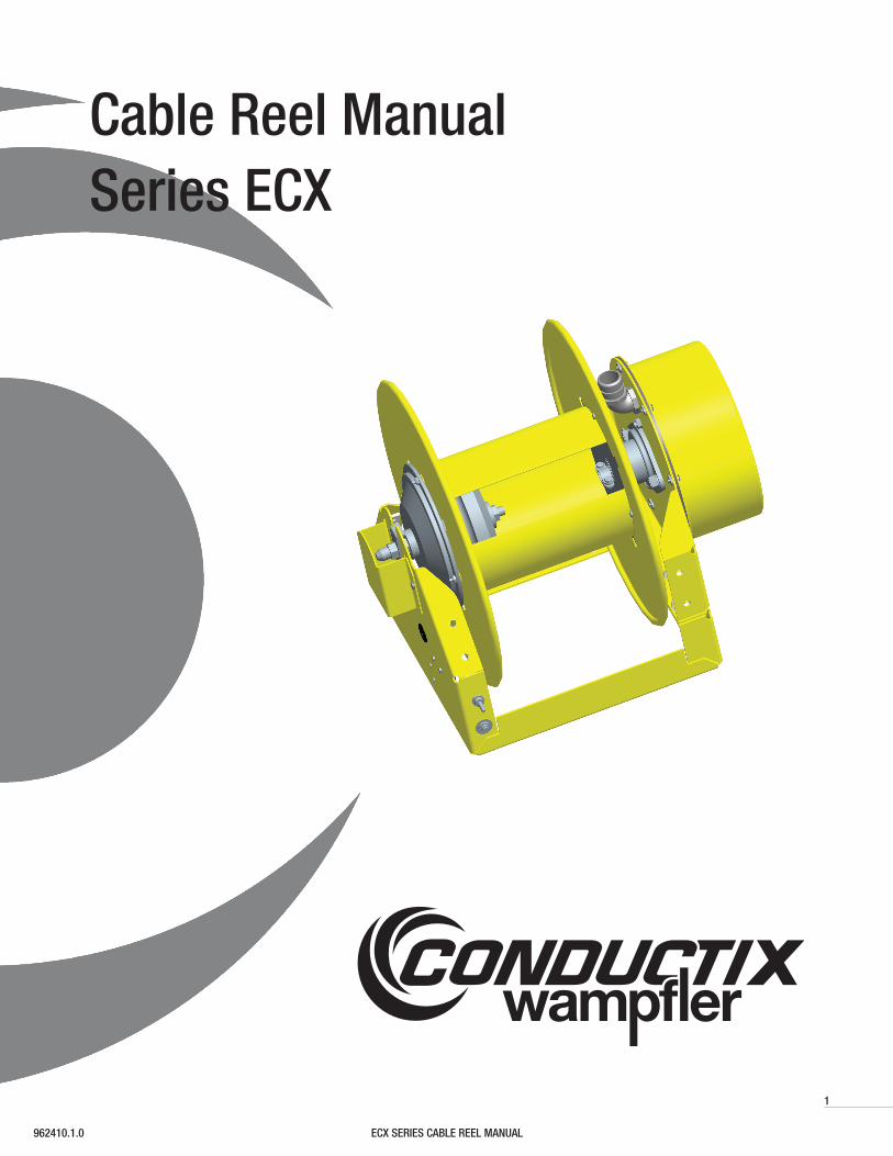
Cable Reel ManualSeries ECX
2 ECX SERIES CABLE REEL MANUAL 962410.1.0
The technical data and images which appear in this manual are for informational purposes only. NO WARRANTIES, EXPRESS OR IMPLIED, INCLUDING WARRANTIES OF MERCHANTABILITY OR FITNESS FOR A PARTICULAR PURPOSE, ARE CREATED BY THE DESCRIPTIONS AND DEPICTIONS OF THE PRODUCTS SHOWN IN THIS MANUAL. Conductix makes no warranty (and assumes no liability) as to function of equipment or operation of systems built according to customer design or of the ability of any of its products to interface, operate or function with any portions of customer systems not provided by Conductix.
Seller agrees to repair or exchange the goods sold hereunder necessitated by reason of defective workmanship and material discovered and reported to Seller within one year after shipment of such goods to Buyer.
Except where the nature of the defect is such that it is appropriate, in Seller’s judgment, to effect repairs on site, Seller’s obligation hereunder to remedy defects shall be limited to repairing or replacing (at Seller’s option) FOB point of original shipment by Seller, any part returned to Seller at the risk and cost of Buyer. Defective parts replaced by Seller shall become the property of Seller.
Seller shall only be obligated to make such repair or replacement if the goods have been used by Buyer only in service recommended by Seller and altered only as authorized by Seller. Seller is not responsible for defects which arise from improper installation, neglect, or improper use or from normal wear and tear.
Additionally, Seller’s obligation shall be limited by the manufacturer’s warranty (and is not further warranted by Seller) for all parts procured from others according to published data, specifications or performance information not designed by or for Seller.
Seller further agrees to replace or at Seller’s option to provide a refund of the sales price of any goods that do not conform to applicable specifications or which differ from that agreed to be supplied which non-conformity is discovered and forthwith reported to Seller within thirty (30) days after shipment to the Buyer. Seller’s obligation to replace or refund the purchase price for non-conforming goods shall arise once Buyer returns such goods FOB point of original shipment by Seller at the risk and cost of Buyer. Goods replaced by Seller shall become the property of Seller.
There is no guarantee or warranty as to anything made or sold by Seller, or any services performed, except as to title and freedom from encumbrances and, except as herein expressly stated and particularly, and without limiting the foregoing, there is no guarantee or warranty, express or implied, of merchantability or of fitness for any particular purpose or against claim of infringement or the like.
Seller makes no warranty (and assumes no liability) as to function of equipment or operation of systems built to Buyer’s design or of the ability of any goods to interface, operate or function with any portions of Buyer’s system not provided by Seller.
Seller’s liability on any claim, whether in contract, tort (including negligence), or otherwise, for any loss or damage arising out of, connected with, or resulting from the manufacture, sale, delivery, resale, repair, replacement or use of any products or services shall in no case exceed the price paid for the product or services or any part thereof which give rise to the claim. In no event shall Seller be liable for consequential, special, incidental or other damages, nor shall Seller be liable in respect of personal injury or damage to property not the subject matter hereof unless attributable to gross misconduct of Seller, which shall mean an act or omission by Seller demonstrating reckless disregard of the foreseeable consequences thereof.
Seller is not responsible for incorrect choice of models or where products are used in excess of their rated and recommended capacities and design functions or under abnormal conditions. Seller assumes no liability for loss of time, damage or injuries to property or persons resulting from the use of Seller’s products. Buyer shall hold Seller harmless from all liability, claims, suits and expenses in connection with loss or damage resulting from operation of products or utilization of services, respectively, of Seller and shall defend any suit or action which might arise there from in Buyer’s name - provided that Seller shall have the right to elect to defend any such suit or action for the account of Buyer. The foregoing shall be the exclusive remedies of the Buyer and all persons and entitles claiming through the Buyer.
Conductix Incorporated
3ECX SERIES CABLE REEL MANUAL962410.1.0
1.0 Introduction
2.0 Specifications2.1 Cable Capacities2.2 Drive Motor
3.0 Component Overview
4.0 Installation4.1 Mounting4.2 Electrical Connections4.3 Drive Motor Power4.4 Roller Guide
5.0 Operation5.1 Cable Payout5.2 Cable Retraction
6.0 Maintenance6.1 Routine Inspections6.2 Repair
INDEX
RECORDThe catalog number of the reel and the serial number of the reel are required when ordering replacement parts or discussing the reel with the factory. Please record this information now in the spaces provided below.
CATALOG NO. OF REEL __________________________
SERIAL NO. ____________________________________
DATE INSTALLED _______________________________
4 ECX SERIES CABLE REEL MANUAL 962410.1.0
1.0 Introduction
The Conductix-Wampfler ECX series cable reel is designed specifically for vehicle mounted cable reeling applications. It is de-signed to store and manage a portable power cable. The reel is typically connected to an auxiliary generator on the vehicle and retracts the cable onto the storage spool using electrical power from the vehicle’s electrical system.
2.1 Cable Capacities2.1.1 Maximum Voltage: 600V Standard
2.1.2 Maximum Ampacity: 30A Standard 75A Special
2.1.3 Conductors: 3 or 4
2.2 Drive Motor2.1.1 Voltage: 12V DC Standard
24V DC Special
2.1.2 Amperage: 10A Continuous, 40A Start-up
2.1.3 Protection: 15A Thermal Breaker with Manual Reset
2.0 Specifications
5ECX SERIES CABLE REEL MANUAL962410.1.0
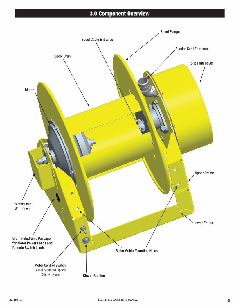
3.0 Component Overview
Spool Flange
Feeder Cord Entrance
Slip Ring Cover
Upper Frame
Lower Frame
Roller Guide Mounting Holes
Circuit Breaker
Motor Control Switch(Reel Mounted Option
Shown Here)
Grommeted Wire Passage for Motor Power Leads and Remote Switch Leads
Motor Lead Wire Cover
Motor
Spool Drum
Spool Cable Entrance
6 ECX SERIES CABLE REEL MANUAL 962410.1.0
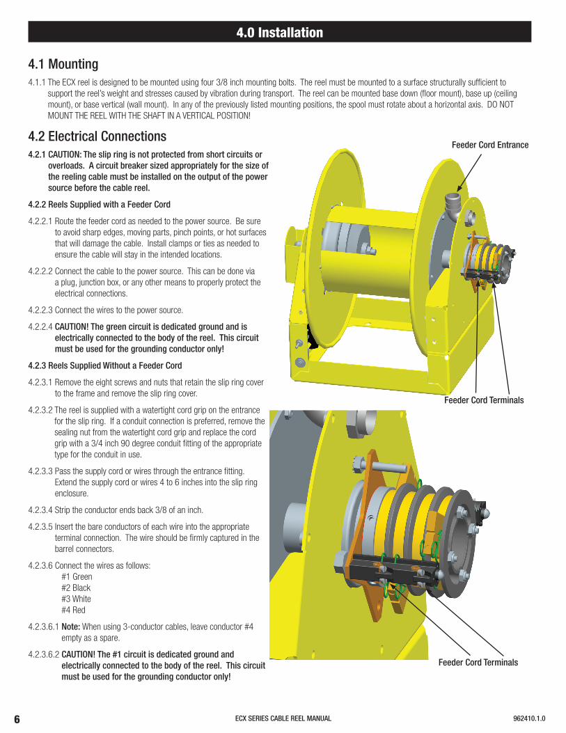
4.0 Installation
4.1 Mounting4.1.1 The ECX reel is designed to be mounted using four 3/8 inch mounting bolts. The reel must be mounted to a surface structurally sufficient to
support the reel’s weight and stresses caused by vibration during transport. The reel can be mounted base down (floor mount), base up (ceiling mount), or base vertical (wall mount). In any of the previously listed mounting positions, the spool must rotate about a horizontal axis. DO NOT MOUNT THE REEL WITH THE SHAFT IN A VERTICAL POSITION!
4.2 Electrical Connections4.2.1 CAUTION: The slip ring is not protected from short circuits or
overloads. A circuit breaker sized appropriately for the size of the reeling cable must be installed on the output of the power source before the cable reel.
4.2.2 Reels Supplied with a Feeder Cord
4.2.2.1 Route the feeder cord as needed to the power source. Be sure to avoid sharp edges, moving parts, pinch points, or hot surfaces that will damage the cable. Install clamps or ties as needed to ensure the cable will stay in the intended locations.
4.2.2.2 Connect the cable to the power source. This can be done via a plug, junction box, or any other means to properly protect the electrical connections.
4.2.2.3 Connect the wires to the power source.
4.2.2.4 CAUTION! The green circuit is dedicated ground and is electrically connected to the body of the reel. This circuit must be used for the grounding conductor only!
4.2.3 Reels Supplied Without a Feeder Cord
4.2.3.1 Remove the eight screws and nuts that retain the slip ring cover to the frame and remove the slip ring cover.
4.2.3.2 The reel is supplied with a watertight cord grip on the entrance for the slip ring. If a conduit connection is preferred, remove the sealing nut from the watertight cord grip and replace the cord grip with a 3/4 inch 90 degree conduit fitting of the appropriate type for the conduit in use.
4.2.3.3 Pass the supply cord or wires through the entrance fitting. Extend the supply cord or wires 4 to 6 inches into the slip ring enclosure.
4.2.3.4 Strip the conductor ends back 3/8 of an inch.
4.2.3.5 Insert the bare conductors of each wire into the appropriate terminal connection. The wire should be firmly captured in the barrel connectors.
4.2.3.6 Connect the wires as follows:#1 Green #2 Black#3 White#4 Red
4.2.3.6.1 Note: When using 3-conductor cables, leave conductor #4 empty as a spare.
4.2.3.6.2 CAUTION! The #1 circuit is dedicated ground and electrically connected to the body of the reel. This circuit must be used for the grounding conductor only!
Feeder Cord Terminals
Feeder Cord Entrance
Feeder Cord Terminals
7ECX SERIES CABLE REEL MANUAL962410.1.0
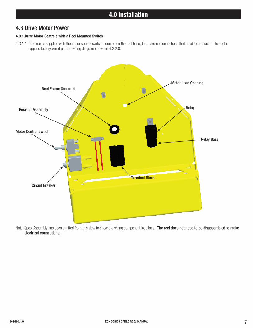
4.3 Drive Motor Power4.3.1.Drive Motor Controls with a Reel Mounted Switch
4.3.1.1 If the reel is supplied with the motor control switch mounted on the reel base, there are no connections that need to be made. The reel is supplied factory wired per the wiring diagram shown in 4.3.2.8.
4.0 Installation
Note: Spool Assembly has been omitted from this view to show the wiring component locations. The reel does not need to be disassembled to make electrical connections.
Reel Frame Grommet
Motor Control Switch
Circuit Breaker
Relay Base
Terminal Block
Relay
Motor Lead Opening
Resistor Assembly
8 ECX SERIES CABLE REEL MANUAL 962410.1.0
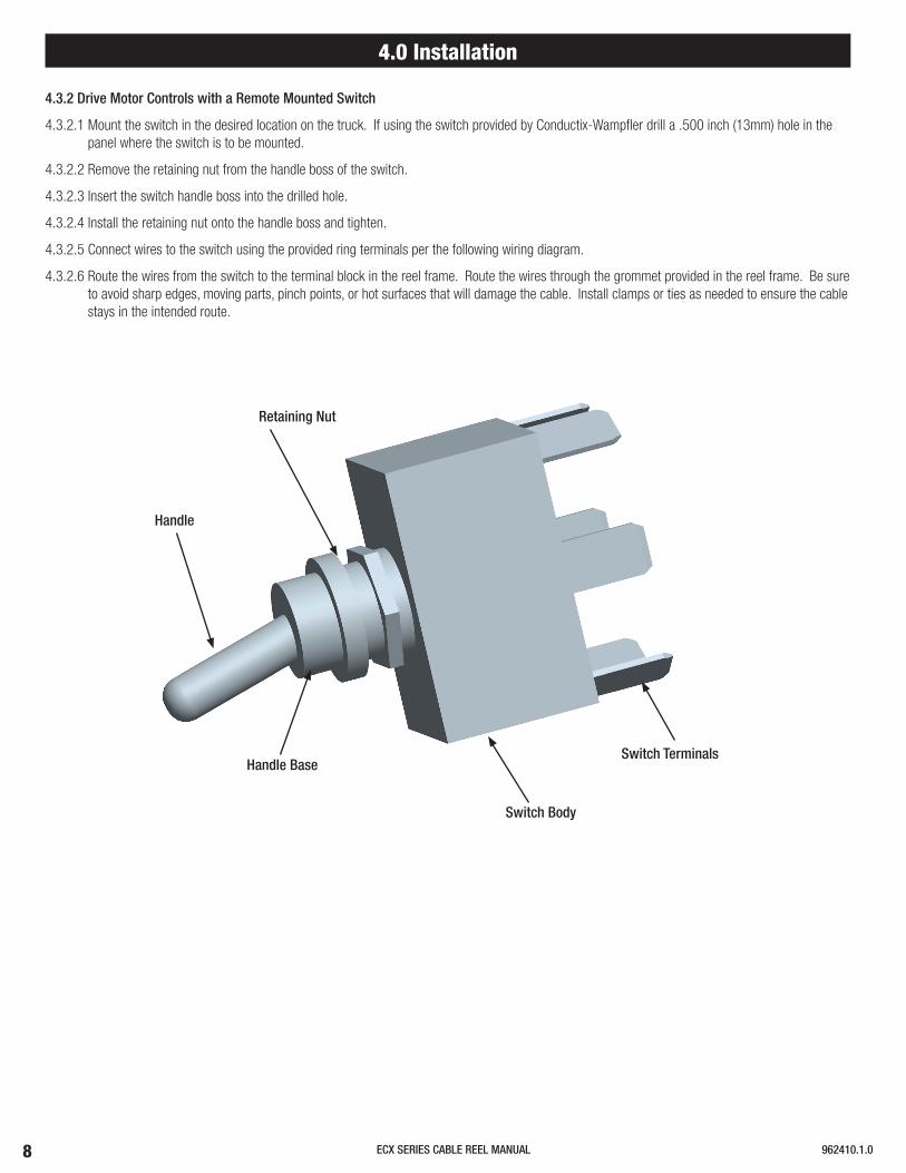
Retaining Nut
Handle
Handle Base
Switch Body
Switch Terminals
4.3.2 Drive Motor Controls with a Remote Mounted Switch
4.3.2.1 Mount the switch in the desired location on the truck. If using the switch provided by Conductix-Wampfler drill a .500 inch (13mm) hole in the panel where the switch is to be mounted.
4.3.2.2 Remove the retaining nut from the handle boss of the switch.
4.3.2.3 Insert the switch handle boss into the drilled hole.
4.3.2.4 Install the retaining nut onto the handle boss and tighten.
4.3.2.5 Connect wires to the switch using the provided ring terminals per the following wiring diagram.
4.3.2.6 Route the wires from the switch to the terminal block in the reel frame. Route the wires through the grommet provided in the reel frame. Be sure to avoid sharp edges, moving parts, pinch points, or hot surfaces that will damage the cable. Install clamps or ties as needed to ensure the cable stays in the intended route.
4.0 Installation
9ECX SERIES CABLE REEL MANUAL962410.1.0
4.0 Installation
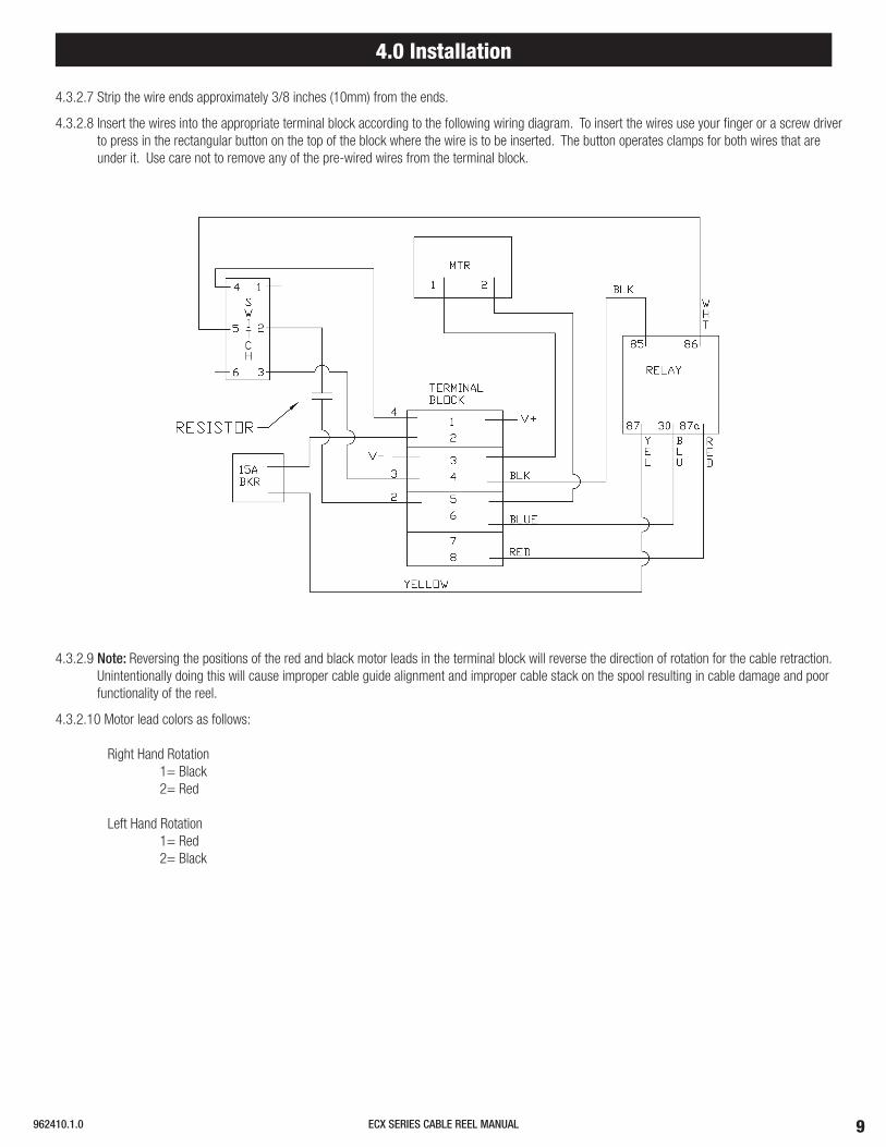
4.3.2.7 Strip the wire ends approximately 3/8 inches (10mm) from the ends.
4.3.2.8 Insert the wires into the appropriate terminal block according to the following wiring diagram. To insert the wires use your finger or a screw driver to press in the rectangular button on the top of the block where the wire is to be inserted. The button operates clamps for both wires that are under it. Use care not to remove any of the pre-wired wires from the terminal block.
4.3.2.9 Note: Reversing the positions of the red and black motor leads in the terminal block will reverse the direction of rotation for the cable retraction. Unintentionally doing this will cause improper cable guide alignment and improper cable stack on the spool resulting in cable damage and poor functionality of the reel.
4.3.2.10 Motor lead colors as follows:
Right Hand Rotation 1= Black 2= Red
Left Hand Rotation 1= Red 2= Black
10 ECX SERIES CABLE REEL MANUAL 962410.1.0
4.0 Installation
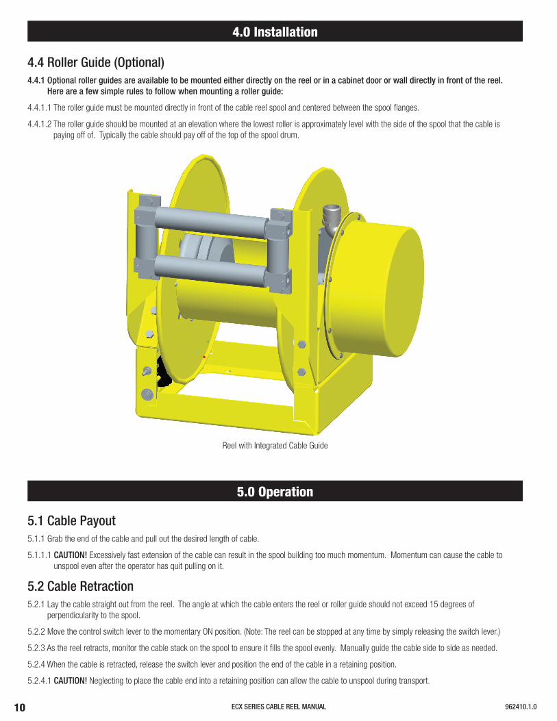
4.4 Roller Guide (Optional)4.4.1 Optional roller guides are available to be mounted either directly on the reel or in a cabinet door or wall directly in front of the reel.
Here are a few simple rules to follow when mounting a roller guide:
4.4.1.1 The roller guide must be mounted directly in front of the cable reel spool and centered between the spool flanges.
4.4.1.2 The roller guide should be mounted at an elevation where the lowest roller is approximately level with the side of the spool that the cable is paying off of. Typically the cable should pay off of the top of the spool drum.
5.0 Operation
5.1 Cable Payout5.1.1 Grab the end of the cable and pull out the desired length of cable.
5.1.1.1 CAUTION! Excessively fast extension of the cable can result in the spool building too much momentum. Momentum can cause the cable to unspool even after the operator has quit pulling on it.
5.2 Cable Retraction5.2.1 Lay the cable straight out from the reel. The angle at which the cable enters the reel or roller guide should not exceed 15 degrees of
perpendicularity to the spool.
5.2.2 Move the control switch lever to the momentary ON position. (Note: The reel can be stopped at any time by simply releasing the switch lever.)
5.2.3 As the reel retracts, monitor the cable stack on the spool to ensure it fills the spool evenly. Manually guide the cable side to side as needed.
5.2.4 When the cable is retracted, release the switch lever and position the end of the cable in a retaining position.
5.2.4.1 CAUTION! Neglecting to place the cable end into a retaining position can allow the cable to unspool during transport.
Reel with Integrated Cable Guide

11ECX SERIES CABLE REEL MANUAL962410.1.0
6.0 Maintenance
6.1 Routine Inspections6.1.1 Inspect the cable for any damaged sections. Replace the cable if there is any damage to the jacket or any irregular bulges in the jacket.6.1.2 Check for loose or missing hardware. Tighten or replace as needed.6.1.3 Remove the slip ring cover. Clean to remove dust and dirt from the slip ring housing area and all slip ring surfaces using compressed air only. 6.1.4 Check the frame for cracks or other structural damage.
6.2 Repair
6.2.1 Slip Ring Replacement
6.2.1.1 Removal:A) Disconnect all power to both the slip ring and the motor of the reel.B) Remove the slip ring cover by removing the eight screws around the mounting flange of the slip ring cover.C) Disconnect the supply wires from the slip ring brush leads by unscrewing barrel connectors.D) Pull the supply wires out of the terminals.E ) Disconnect the spool cable wire leads from the slip ring core wires removing crimp connectors.F) Loosen (2) 1/4-20 setscrews in drive collar.G) Pull the slip ring body off of the reel shaft.
Feeder Cord Entrance
Set Screw
12 ECX SERIES CABLE REEL MANUAL 962410.1.0
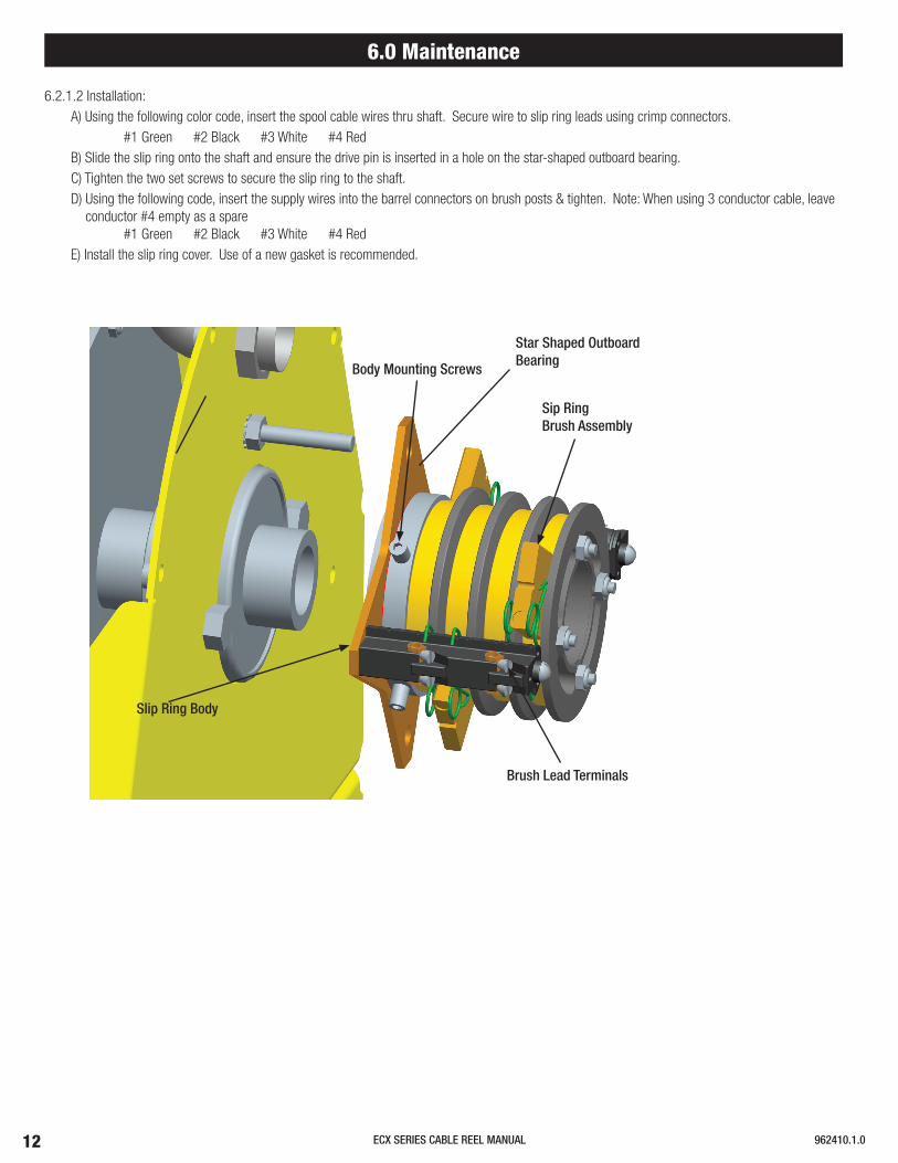
6.2.1.2 Installation:A) Using the following color code, insert the spool cable wires thru shaft. Secure wire to slip ring leads using crimp connectors.
#1 Green #2 Black #3 White #4 RedB) Slide the slip ring onto the shaft and ensure the drive pin is inserted in a hole on the star-shaped outboard bearing.C) Tighten the two set screws to secure the slip ring to the shaft.D) Using the following code, insert the supply wires into the barrel connectors on brush posts & tighten. Note: When using 3 conductor cable, leave
conductor #4 empty as a spare#1 Green #2 Black #3 White #4 Red
E) Install the slip ring cover. Use of a new gasket is recommended.
6.0 Maintenance
Slip Ring Body
Body Mounting Screws
Sip Ring Brush Assembly
Brush Lead Terminals
Star Shaped Outboard Bearing
13ECX SERIES CABLE REEL MANUAL962410.1.0
6.0 Maintenance
6.2.2 Motor Replacement
6.2.2.1 Removal:
A) Disconnect all power to both the slip ring and the motor of the reel.B) Unspool the cable from the reel to expose the four flange screws on the motor side of the spool.C) Remove the motor lead wire cover by removing the two mounting nuts.D) Disconnect the motor leads from the wiring terminal inside the reel frame. Note which terminals the black and red wires are attached to.
(Reversing them will cause the new motor to run backwards!) Use your finger or a screw driver to depress the button on the top of the terminal block directly over the wire port and pull out the wire.
E) Pull the motor lead wire through the slot in the frame.F) Unscrew the plastic wire protector from the end of the motor shaft.G) Unscrew the nut from the motor shaft and remove the retaining plate from under the nut.H) Remove the two frame bolts connecting the lower frame assembly to the upper frame assembly on the slip ring side of the reel.I ) Lift the spool, motor, and slip ring assembly from the lower frame assembly.J) Remove the four flange screws from the motor side of the spool.K) Pull the motor out of the spool.
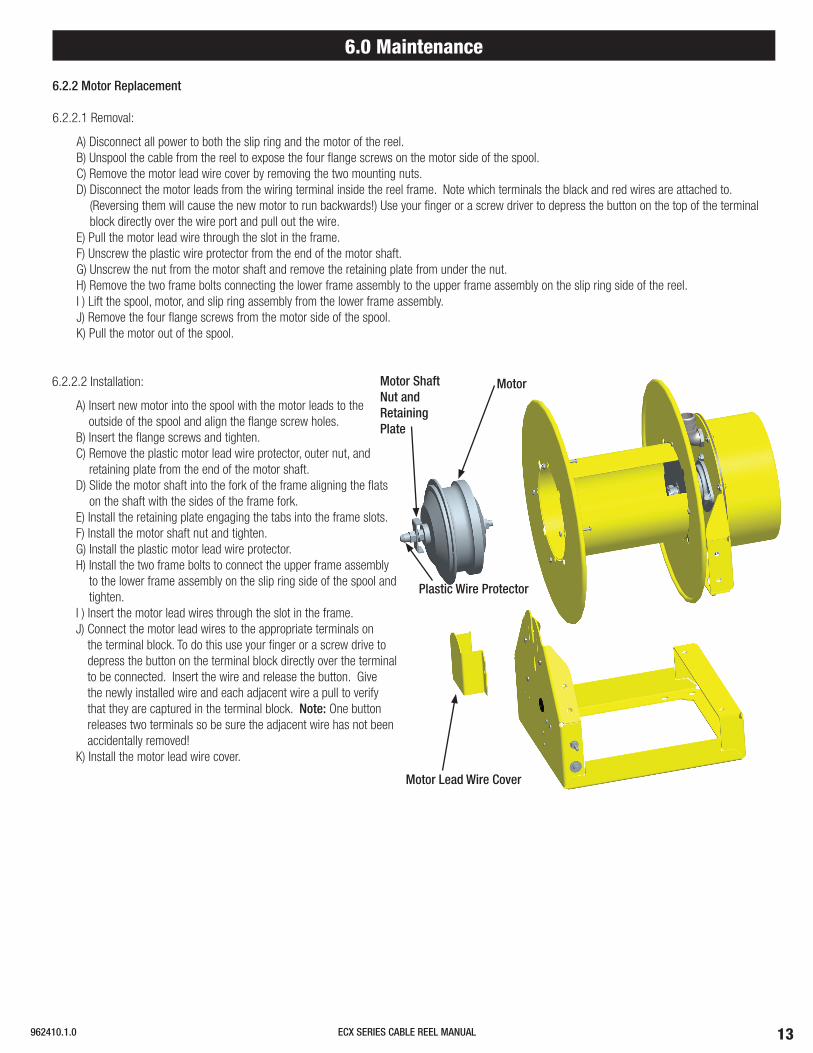
6.2.2.2 Installation:
A) Insert new motor into the spool with the motor leads to the outside of the spool and align the flange screw holes.
B) Insert the flange screws and tighten.C) Remove the plastic motor lead wire protector, outer nut, and
retaining plate from the end of the motor shaft.D) Slide the motor shaft into the fork of the frame aligning the flats
on the shaft with the sides of the frame fork.E) Install the retaining plate engaging the tabs into the frame slots.F) Install the motor shaft nut and tighten.G) Install the plastic motor lead wire protector.H) Install the two frame bolts to connect the upper frame assembly
to the lower frame assembly on the slip ring side of the spool and tighten.
I ) Insert the motor lead wires through the slot in the frame.J) Connect the motor lead wires to the appropriate terminals on
the terminal block. To do this use your finger or a screw drive to depress the button on the terminal block directly over the terminal to be connected. Insert the wire and release the button. Give the newly installed wire and each adjacent wire a pull to verify that they are captured in the terminal block. Note: One button releases two terminals so be sure the adjacent wire has not been accidentally removed!
K) Install the motor lead wire cover.
MotorMotor Shaft Nut and Retaining Plate
Plastic Wire Protector
Motor Lead Wire Cover
14 ECX SERIES CABLE REEL MANUAL 962410.1.0
6.0 Maintenance
6.2.3 Relay Replacement
6.2.3.1 Note: Replacement relays must have a minimum rating of 30 amps, 12 volts DC (24 volts in some instances).
6.2.3.2 Unplug the relay base from the relay.
6.2.3.3 Remove the relay mounting screw.
6.2.3.4 Mount the new relay to the relay mounting hole in the frame.
6.2.3.5 Plug the relay base into the new relay.
6.2.4 Motor Control Switch Replacement
6.2.4.1 Note: Replacement switches must be of a dual pole, dual throw type with momentary and maintained off positions.
6.2.4.2 Disconnect all power to the motor of the reel.
6.2.4.3 Remove the retaining nut from the front of the switch.
6.2.4.4 Pull the switch out of the mounting hole to the inside of the frame.
6.2.4.5 Mark and disconnect the lead wires.
6.2.4.6 Install the lead wires on the new switch. Due to variations in switches the terminal identification may be different than the original switch. Check the function of the new switch with that of the original switch to verify proper connections. The reel motor should activate with the switch in the momentary on position.
6.2.4.7 Mount the switch into the frame and tighten the retaining nut. The switch should be mounted in a position where falling objects will not activate the reel motor.
15ECX SERIES CABLE REEL MANUAL962410.1.0
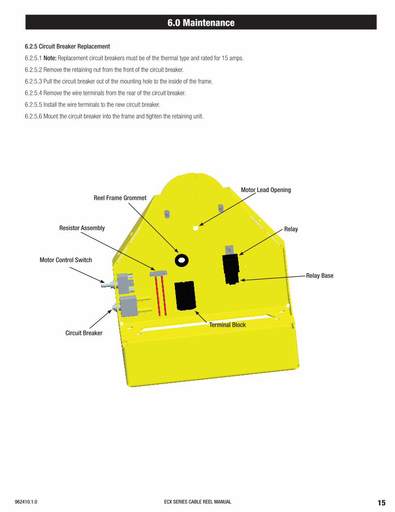
Reel Frame Grommet
Motor Control Switch
Circuit Breaker
Relay Base
Terminal Block
Relay
Motor Lead Opening
6.0 Maintenance
6.2.5 Circuit Breaker Replacement
6.2.5.1 Note: Replacement circuit breakers must be of the thermal type and rated for 15 amps.
6.2.5.2 Remove the retaining nut from the front of the circuit breaker.
6.2.5.3 Pull the circuit breaker out of the mounting hole to the inside of the frame.
6.2.5.4 Remove the wire terminals from the rear of the circuit breaker.
6.2.5.5 Install the wire terminals to the new circuit breaker.
6.2.5.6 Mount the circuit breaker into the frame and tighten the retaining unit.
Resistor Assembly

ECX SERIES CABLE REEL MANUAL 962410.1.0
Contact us for our Global Sales Offices
www.conductix.us
USA / LATIN AMERICA
10102 F Street
Omaha, NE 68127
Customer Support
Phone +1-800-521-4888
Phone +1-402-339-9300
Fax +1-402-339-9627
CANADA
1435 Norjohn Court
Unit 5
Burlington, ON L7L 0E6
Customer Support
Phone +1-800-667-2487
Phone +1-450-565-9900
Fax +1-450-951-8591
MÉXICO
Calle Treviño 983-C
Zona Centro
Apodaca, NL México 66600
Customer Support
Phone (+52 81) 1090 9519
(+52 81) 1090 9025
(+52 81) 1090 9013
Fax (+52 81) 1090 9014
BRAZIL
Rua Luiz Pionti, 110
Vila Progresso
Itu, São Paulo, Brasil
CEP: 13313-534
Customer Support
Phone (+55 11) 4813 7330
Fax (+55 11) 4813 7357
© C
ondu
ctix-
Wam
pfler
| 20
17 |
Subj
ect t
o Te
chni
cal M
odifi
catio
ns W
ithou
t Prio
r Not
ice
16
Related Documents