www.crouse-hinds.com US: 1-866-764-5454 CAN: 1-800-265-0502 Copyright © 2010 Cooper Crouse-Hinds 65 4F 4F Cable Glands and Cable Accessories Hazardous and Non-hazardous Cable Glands - Accessories A Series see page 98 B Series see page 102 C Series see page 103 D Series see page 104 E Series see page 105 Breathers and Drains see page 106 Cable Tray Clamps Conduit LCC, LCCF Series see page 107 Grounding Conductor TGC Series see page 108 Description Page No. Cable/Conduit Sealing Devices Thru-Wall Barrier ® TW Series see pages 109–110 Link Seal – For Conduit Environmental Seal see pages 115–116 Fire Seal see pages 117–118 Description Page No. Application see page 66 Cable Glands - International Standards Quick Selection Guide see pages 67–70 Flameproof and Increased Safety ADE 1F see page 71 ADE 4F see page 72 ADE 6F see page 73 ADE 6FC see page 74 TWAB see page 75 TWAX see page 76 TWAE see page 77 Ex - e see page 78 Ex - i see page 79 Trumpet see page 80 Enlargement and Multiple see page 81 Industrial ADE 4I see page 82 TWA see page 83 TUA see page 84 Cable Glands - North American Standards Quick Selection Guide see pages 67–70 Explosionproof TMCX see page 85 ADE 6FC see page 86 ADE 1FC see page 87 CGBS see page 88 EBY see page 88 General Pupose TMC see page 89 TECK see page 90 CGB see pages 91–92 CGD see page 93 CGE see page 94 CGB1013 see page 95 CGFP see page 96 NCG see page 97 NCGB see page 97

Welcome message from author
This document is posted to help you gain knowledge. Please leave a comment to let me know what you think about it! Share it to your friends and learn new things together.
Transcript

www.crouse-hinds.com US: 1-866-764-5454 CAN: 1-800-265-0502 Copyright© 2010 Cooper Crouse-Hinds 65
4F
4FCable Glands and Cable AccessoriesHazardous and Non-hazardous
Cable Glands - Accessories
A Series see page 98
B Series see page 102
C Series see page 103
D Series see page 104
E Series see page 105
Breathers and Drains see page 106
Cable Tray Clamps
Conduit
LCC, LCCF Series see page 107
Grounding Conductor
TGC Series see page 108
Description Page No.
Cable/Conduit Sealing Devices
Thru-Wall Barrier®
TW Series see pages 109–110
Link Seal – For Conduit
Environmental Seal see pages 115–116
Fire Seal see pages 117–118
Description Page No.
Application see page 66
Cable Glands - InternationalStandards
Quick Selection Guide see pages 67–70
Flameproof and IncreasedSafety
ADE 1F see page 71
ADE 4F see page 72
ADE 6F see page 73
ADE 6FC see page 74
TWAB see page 75
TWAX see page 76
TWAE see page 77
Ex - e see page 78
Ex - i see page 79
Trumpet see page 80
Enlargement and Multiple see page 81
Industrial
ADE 4I see page 82
TWA see page 83
TUA see page 84
Cable Glands - North AmericanStandards
Quick Selection Guide see pages 67–70
Explosionproof
TMCX see page 85
ADE 6FC see page 86
ADE 1FC see page 87
CGBS see page 88
EBY see page 88
General Pupose
TMC see page 89
TECK see page 90
CGB see pages 91–92
CGD see page 93
CGE see page 94
CGB1013 see page 95
CGFP see page 96
NCG see page 97
NCGB see page 97
aro
Standard
www.crouse-hinds.com US: 1-866-764-5454 CAN: 1-800-265-0502 Copyright© 2010 Cooper Crouse-Hinds66
4F
Cable Glands and Cable Accessories
Application and Selection
Applications:
Cable glands and cord fittings:
• Provide means for passing a cord, cable (armored or unarmored)or flexible conduit into an enclosure, through a bulkhead or into arigid conduit
• Form a mechanical grip and water and/or oil resistant seal for cordand unarmored or jacketed armored, round cables
• Form a non-slip connection or termination for flexible cord, cable(armored or unarmored), or flexible conduit
• Provide grounding continuity for cable armor and flexible conduit
Cable glands with sealing fitting or epoxy are installed to:
• Provide means for passing armored, metal clad, jacketed orunjacketed and unarmored cables through a bulkhead orenclosure in hazardous areas. These fittings are suitable for use inClass I, Groups C, D, locations only when Chico® A sealingcompound or TSC epoxy (TMCX) is used to make the seal in thefitting.*
• Form a mechanical grip and water and/or oil-resistant termination
• Provide ground continuity of cable armor and flexible conduit
TMC (non-hazardous) and TMCX (hazardous) fittings are designedfor use with Type MC jacketed steel or aluminum metal clad cableswith interlocked or corrugated armor and Type TC tray cable (TMCX).
LCC cable tray conduit clamps are used for installation on cable trayside rails with inside flanges (requiring inside tray mounting) andoutside flanges; LCCF clamps are for use exclusively on insideflanges. LCC/LCCF series cable tray conduit clamps are installed to:
• Provide a means of clamping metal conduit (rigid steel oraluminum, IMC and EMT) to cable tray for the exit of power and/orcontrol cables from tray
• Provide a means to firmly bond exiting conduit to cable tray forbest grounding continuity
TW series THRU-WALL BARRIER® cable/conduit sealing devices areinstalled to:
• Seal cables or conduits penetrating firerated walls, ceilings orfloors
• Restrict entrance of water and dust and contain treated air
• Provide a seal for cable/conduit penetrations through steel,masonry or concrete; to restrict the entrance of contaminantsthrough cable/conduit penetrations into clean areas
TGC cable tray grounding conductor clamp provides a means forsecurely attaching a grounding conductor to cable tray to providegrounding continuity for the entire tray system. TGC cable traygrounding conductor clamps provide a reliable method for carryingground fault current for equipment protection. TGC clamp may beinstalled on most types of cable trays – with inside or outsideflanges.
Considerations for Selection:
• Selection of the proper cable gland involves consideration of thetype of cable to be installed and the environment that will surroundthe cable after installation.
• A proper matching of the cable and its gland is necessary toprevent physical damage to the cable when installed. Some typesof cable glands depend on gripping methods (set screws etc.)which may lead to damage of the cable outer covering. CooperCrouse-Hinds cable glands and cord fittings utilize compression ofsplit lead or tapered neoprene bushings to provide high grippingstrength for adequate cable support and strain relief withoutdamage to the cable sheath.
• Compression of bushing provides a strong electrical bond thatassures grounding continuity.
• Compression of a tapered neoprene bushing, assures thewatertight integrity of Cooper Crouse-Hinds cable glands.Additional watertightness, to prevent water seepage into the fittingbody, can be obtained by use of a potting head filled with a hotpouring compound.
• To meet National Electrical Code requirements for electricalinstallations in hazardous atmospheres, a sealing fitting may berequired in conjunction with the cable or cord fitting.
*With specific cords and cables when installed in accordance with NEC/CEC requirements.
4F
aro
Standard

www.crouse-hinds.com US: 1-866-764-5454 CAN: 1-800-265-0502 Copyright© 2010 Cooper Crouse-Hinds 67
4F
Global Cable Glands
ADE 1F(page 71)
Non-armoured,armoured and traycable (does notterminate the armour)
Non-armoured Nickel-plated brass Flameproof &Increased Safety
ADE 1FC(page 87)
Non-armoured,armoured and traycable (does notterminate the armour)
Non-armouredbarrier Nickel-plated brass Flameproof &
Increased Safety
ADE 4F(page 72)
SWA, SWB, STA,braided marineshipboard and leadsheathed (withaddition of earthingwasher)
Armoured Nickel-plated brass Flameproof &Increased Safety
ADE 6F(page 73)
SWA, SWB, STA andbraided marineshipboard
Armoured Nickel-plated brass Flameproof &Increased Safety
CABLE
GLAND ILLUSTRATION
CABLE
TYPE
GLAND
TYPE
STANDARD
MATERIAL CERTIFICATION
PROTECTION
TYPE
ADE 6FC(page 74)
SWA, SWB, STA,braided marineshipboard and leadsheathed (withaddition of earthingwasher)
Armouredbarrier Nickel-plated brass Flameproof &
Increased Safety
TWAB(page 75) SWA Armoured
barrier Nickel-plated brass Flameproof
TWAX(page 76) SWA Armoured Nickel-plated brass Flameproof
4F
Quick Selection Guide - International Standards
aro
Standard

www.crouse-hinds.com US: 1-866-764-5454 CAN: 1-800-265-0502 Copyright© 2010 Cooper Crouse-Hinds68
4F
TWAE(page 77) SWA Armoured Nickel-plated brass Increased Safety
EX-e(page 78)
Non-armoured Non-armoured Polyamide Increased Safety
EX-i(page 79)
Non-armoured Non-armoured Polyamide Increased Safety
Trumpet(page 80)
Non-armoured Non-armoured Polyamide Increased Safety
Enlargementand Multiple(page 81)
Non-armoured Non-armoured Polyamide Increased Safety
ADE 4I(page 82)
SWA, SWB,STA, braidedmarineshipboardand leadsheathed(with additionof earthingwasher)
Armoured Nickel-plated brass Industrial
CABLE
GLAND ILLUSTRATION
CABLE
TYPE
GLAND
TYPE
STANDARD
MATERIAL CERTIFICATION
PROTECTION
TYPE
TWA(page 83) SWA Armoured Nickel-plated brass Industrial
TUA(page 84)
Non-armoured Non-armoured Nickel-plated brass Industrial
Global Cable Glands4F
Quick Selection Guide - International Standards
aro
Standard
www.crouse-hinds.com US: 1-866-764-5454 CAN: 1-800-265-0502 Copyright© 2010 Cooper Crouse-Hinds 69
4F
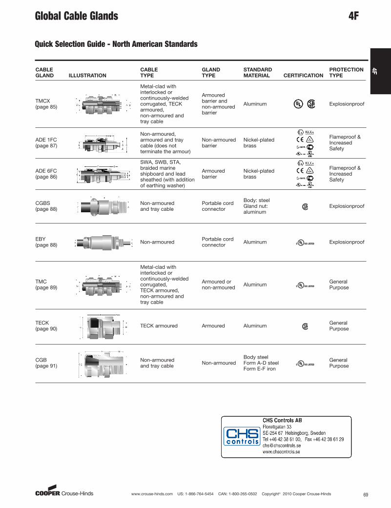
Quick Selection Guide - North American Standards
TMCX(page 85)
Metal-clad withinterlocked orcontinuously-weldedcorrugated, TECKarmoured, non-armoured and tray cable
Armouredbarrier andnon-armouredbarrier
Aluminum Explosionproof
ADE 1FC(page 87)
Non-armoured,armoured and traycable (does notterminate the armour)
Non-armouredbarrier
Nickel-platedbrass
Flameproof &IncreasedSafety
ADE 6FC(page 86)
SWA, SWB, STA,braided marineshipboard and leadsheathed (with additionof earthing washer)
Armouredbarrier
Nickel-platedbrass
Flameproof &IncreasedSafety
CGBS(page 88)
Non-armoured and tray cable
Portable cordconnector
Body: steelGland nut:aluminum
Explosionproof
EBY(page 88) Non-armoured Portable cord
connector Aluminum Explosionproof
TMC(page 89)
Metal-clad withinterlocked orcontinuously-weldedcorrugated, TECK armoured, non-armoured and tray cable
Armoured ornon-armoured Aluminum General
Purpose
TECK(page 90) TECK armoured Armoured Aluminum General
Purpose
CABLE
GLAND ILLUSTRATION
CABLE
TYPE
GLAND
TYPE
STANDARD
MATERIAL CERTIFICATION
PROTECTION
TYPE
CGB(page 91)
Non-armoured and tray cable Non-armoured
Body steelForm A-D steelForm E-F iron
GeneralPurpose
Global Cable Glands 4F
aro
Standard
www.crouse-hinds.com US: 1-866-764-5454 CAN: 1-800-265-0502 Copyright© 2010 Cooper Crouse-Hinds70
4F
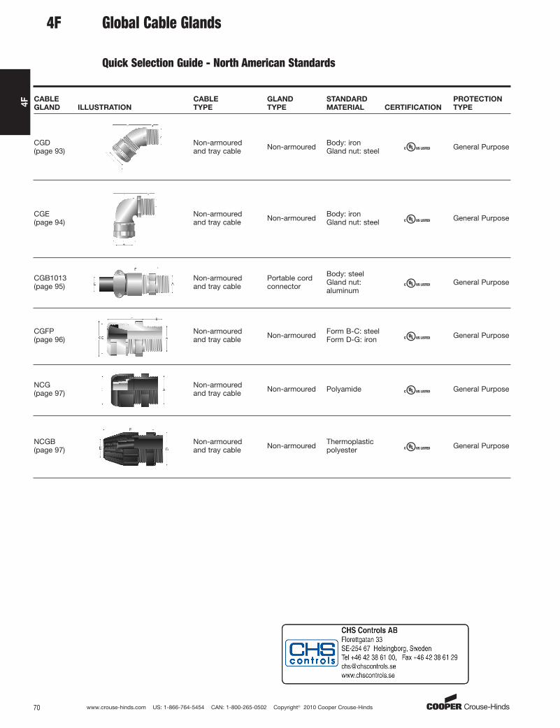
CGE(page 94)
Non-armoured and tray cable Non-armoured Body: iron
Gland nut: steel General Purpose
CGB1013(page 95)
Non-armoured and tray cable
Portable cordconnector
Body: steelGland nut:aluminum
General Purpose
CGFP(page 96)
Non-armoured and tray cable Non-armoured Form B-C: steel
Form D-G: iron General Purpose
CGD(page 93)
Non-armoured and tray cable Non-armoured Body: iron
Gland nut: steel General Purpose
CABLE
GLAND ILLUSTRATION
CABLE
TYPE
GLAND
TYPE
STANDARD
MATERIAL CERTIFICATION
PROTECTION
TYPE
NCG(page 97)
Non-armoured and tray cable Non-armoured Polyamide General Purpose
NCGB(page 97)
Non-armoured and tray cable Non-armoured Thermoplastic
polyester General Purpose
4F Global Cable Glands
Quick Selection Guide - North American Standards
aro
Standard

–
www.crouse-hinds.com US: 1-866-764-5454 CAN: 1-800-265-0502 Copyright© 2010 Cooper Crouse-Hinds 71
4F
ATEXIECExcULus Listed for Class I Zone 2cULus Marine Listed for Class I Zone 2
CEPELGOST-RNEPSINEMA 4X and IP68
Gland Type
Non-armoured
Cable Type
Non-armoured, armoured and tray cable (does not terminate thearmour)
Certifications and Compliances:
• ATEX LCIE 97 ATEX 6008X – Exd IIC/Exe II/Ex tD /Ex II 2 GD
• IECEx LCI 05.0004X
• cULus Listed for Class I Zone 2 AEx e II/Ex e II E310130
• cULus Marine Listed for Class I Zone 2 AEx e II/Ex e II E314047
• NEMA 4X and IP68
• CEPEL cepel-EX-558/05X
• GOST-R POCC FR.B02011
• NEPSI N° GYJ071336U & GYJ071337U
Features:
• Standard material is nickel-plated brass for superior corrosionresistance
• Provides a flameproof and weatherproof seal on the outer sheathof the cable
• Standard neoprene seal suitable for use in operating temperaturesATEX (-60°C to 100°C), IECEx and cULus (-40°C to 100°C)
• Available with optional silicone seal for extreme temperatures
• Available with metric or NPT threads
• See pages 98–101 for related accessories
ADE 1F
International Standards - Flameproof and Increased Safety
Gland
Size
Entry Thread Size ‘A’ Thread
Length ‘B’
Metric
(NPT)
Cable AcceptanceGland
Length ‘F’
(less entry)
Hexagon Dimensions
Metric
Size
Metric
Catalog #
NPT
SizeNPT
Catalog #
Outer Sheath‘E’Across
Flats
Across
Corners ‘G’Min Max
4 M12 CAP816404 1/4" CAP818404 15 (12.0) 4.0 8.0 20 – 16.54 M16 CAP816594 3/8" CAP818594 15 (12.0) 4.0 8.5 20 – 20.95 M16 CAP816504 1/2" CAP818694 15 (12.0) 6.0 12.0 22 – 20.94 M20 CAP816674 1/2" CAP818674 15 (20.2) 4.0 8.5 20 – 26.45 M20 CAP816694 1/2" CAP818694 15 (20.2) 6.0 12.0 22 – 26.46 M20 CAP816604 1/2" CAP818604 15 (20.2) 8.5 16.0 25 – 26.45 M25 CAP816774 3/4" CAP818774 15 (20.2) 6.0 12.0 22 – 336 M25 CAP816794 3/4" CAP818794 15 (20.2) 8.5 16.0 25 – 337 M25 CAP816704 3/4" CAP818704 15 (20.2) 12.0 21.0 27 – 337 M32 CAP816894 1" CAP818894 15 (25.3) 12.0 21.0 27 – 39.68 M32 CAP816804 1" CAP818804 15 (25.3) 16.0 27.5 34 – 45.18 M40 CAP816994 11/4" CAP818994 15 (26.0) 16.0 27.5 34 – 48.49 M40 CAP816904 11/4" CAP818904 15 (26.0) 21.0 34.0 36 – 52.89 M50 CAP817094 11/2" CAP819094 15 (26.5) 21.0 34.0 36 – 60.510 M50 CAP817004 11/2" CAP819004 15 (26.5) 27.0 41.0 39 – 60.511 M63 CAP817294 2" CAP819294 17 (27.2) 33.0 48.0 41 – 73.712 M63 CAP817204 2" CAP819204 17 (27.2) 40.0 56.0 43 – 79.212 M75 CAP817394 21/2" CAP819494 18 (40.5) 40.0 56.0 43 – 8813 M75 CAP817304 21/2" CAP819404 18 (40.5) 47.0 65.0 49 – 93.514 M90 CAP817594 3" CAP819594 22 (42.0) 54.0 74.0 56 – 104.515 M90 CAP817504 3" CAP819504 22 (42.0) 63.0 78.0 61 – 12116 M110 CAP817794 31/2" CAP819604 22 (43.2) 72.0 92.0 62 132
SELECTION TABLE
4F
aro
Standard
www.crouse-hinds.com US: 1-866-764-5454 CAN: 1-800-265-0502 Copyright© 2010 Cooper Crouse-Hinds72
4F
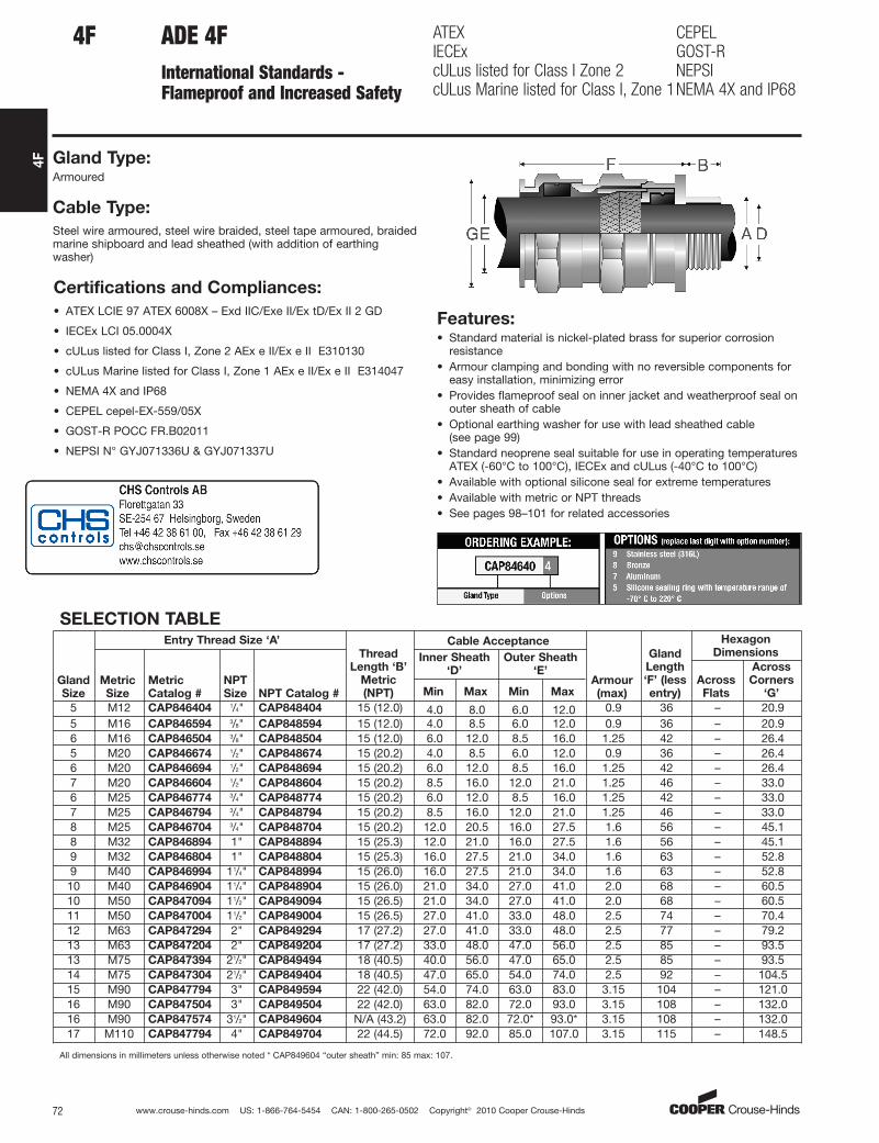
ADE 4FInternational Standards - Flameproof and Increased Safety
ATEXIECExcULus listed for Class I Zone 2cULus Marine listed for Class I, Zone 1
CEPELGOST-RNEPSINEMA 4X and IP68
Gland Type:Armoured
Cable Type:
Steel wire armoured, steel wire braided, steel tape armoured, braidedmarine shipboard and lead sheathed (with addition of earthingwasher)
Certifications and Compliances:
• ATEX LCIE 97 ATEX 6008X – Exd IIC/Exe II/Ex tD/Ex II 2 GD
• IECEx LCI 05.0004X
• cULus listed for Class I, Zone 2 AEx e II/Ex e II E310130
• cULus Marine listed for Class I, Zone 1 AEx e II/Ex e II E314047
• NEMA 4X and IP68
• CEPEL cepel-EX-559/05X
• GOST-R POCC FR.B02011
• NEPSI N° GYJ071336U & GYJ071337U
Features:• Standard material is nickel-plated brass for superior corrosion
resistance• Armour clamping and bonding with no reversible components for
easy installation, minimizing error• Provides flameproof seal on inner jacket and weatherproof seal on
outer sheath of cable• Optional earthing washer for use with lead sheathed cable
(see page 99)• Standard neoprene seal suitable for use in operating temperatures
ATEX (-60°C to 100°C), IECEx and cULus (-40°C to 100°C)• Available with optional silicone seal for extreme temperatures• Available with metric or NPT threads• See pages 98–101 for related accessories
4F
SELECTION TABLE
Gland
Size
Entry Thread Size ‘A’
Thread
Length ‘B’
Metric
(NPT)
Cable Acceptance
Armour
(max)
Gland
Length
‘F’ (less
entry)
Hexagon
Dimensions
Metric
Size
Metric
Catalog #
NPT
Size NPT Catalog #
Inner Sheath
‘D’
Outer Sheath
‘E’Across
Flats
Across
Corners
‘G’Min Max Min Max
5 M12 CAP846404 1/4" CAP848404 15 (12.0) 4.0 8.0 6.0 12.0 0.9 36 – 20.95 M16 CAP846594 3/8" CAP848594 15 (12.0) 4.0 8.5 6.0 12.0 0.9 36 – 20.96 M16 CAP846504 3/8" CAP848504 15 (12.0) 6.0 12.0 8.5 16.0 1.25 42 – 26.45 M20 CAP846674 1/2" CAP848674 15 (20.2) 4.0 8.5 6.0 12.0 0.9 36 – 26.46 M20 CAP846694 1/2" CAP848694 15 (20.2) 6.0 12.0 8.5 16.0 1.25 42 – 26.47 M20 CAP846604 1/2" CAP848604 15 (20.2) 8.5 16.0 12.0 21.0 1.25 46 – 33.06 M25 CAP846774 3/4" CAP848774 15 (20.2) 6.0 12.0 8.5 16.0 1.25 42 – 33.07 M25 CAP846794 3/4" CAP848794 15 (20.2) 8.5 16.0 12.0 21.0 1.25 46 – 33.08 M25 CAP846704 3/4" CAP848704 15 (20.2) 12.0 20.5 16.0 27.5 1.6 56 – 45.18 M32 CAP846894 1" CAP848894 15 (25.3) 12.0 21.0 16.0 27.5 1.6 56 – 45.19 M32 CAP846804 1" CAP848804 15 (25.3) 16.0 27.5 21.0 34.0 1.6 63 – 52.89 M40 CAP846994 11/4" CAP848994 15 (26.0) 16.0 27.5 21.0 34.0 1.6 63 – 52.810 M40 CAP846904 11/4" CAP848904 15 (26.0) 21.0 34.0 27.0 41.0 2.0 68 – 60.510 M50 CAP847094 11/2" CAP849094 15 (26.5) 21.0 34.0 27.0 41.0 2.0 68 – 60.511 M50 CAP847004 11/2" CAP849004 15 (26.5) 27.0 41.0 33.0 48.0 2.5 74 – 70.412 M63 CAP847294 2" CAP849294 17 (27.2) 27.0 41.0 33.0 48.0 2.5 77 – 79.213 M63 CAP847204 2" CAP849204 17 (27.2) 33.0 48.0 47.0 56.0 2.5 85 – 93.513 M75 CAP847394 21/2" CAP849494 18 (40.5) 40.0 56.0 47.0 65.0 2.5 85 – 93.514 M75 CAP847304 21/2" CAP849404 18 (40.5) 47.0 65.0 54.0 74.0 2.5 92 – 104.515 M90 CAP847794 3" CAP849594 22 (42.0) 54.0 74.0 63.0 83.0 3.15 104 – 121.016 M90 CAP847504 3" CAP849504 22 (42.0) 63.0 82.0 72.0 93.0 3.15 108 – 132.016 M90 CAP847574 31/2" CAP849604 N/A (43.2) 63.0 82.0 72.0* 93.0* 3.15 108 – 132.017 M110 CAP847794 4" CAP849704 22 (44.5) 72.0 92.0 85.0 107.0 3.15 115 – 148.5
All dimensions in millimeters unless otherwise noted * CAP849604 “outer sheath” min: 85 max: 107.
aro
Standard
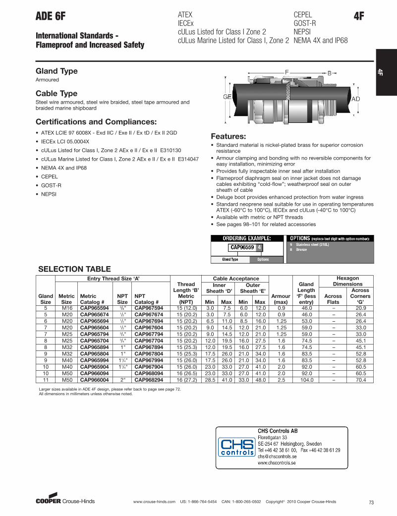
5 M16 CAP965594 3/8" CAP967594 15 (12.0) 3.0 7.5 6.0 12.0 0.9 46.0 – 20.95 M20 CAP965674 1/2" CAP967674 15 (20.2) 3.0 7.5 6.0 12.0 0.9 46.0 – 26.46 M20 CAP965694 1/2" CAP967694 15 (20.2) 6.5 11.0 8.5 16.0 1.25 53.0 – 26.47 M20 CAP965604 1/2" CAP967604 15 (20.2) 9.0 14.5 12.0 21.0 1.25 59.0 – 33.07 M25 CAP965794 3/4" CAP967794 15 (20.2) 9.0 14.5 12.0 21.0 1.25 59.0 – 33.08 M25 CAP965704 3/4" CAP967704 15 (20.2) 12.0 19.5 16.0 27.5 1.6 74.5 – 45.18 M32 CAP965894 1" CAP967894 15 (25.3) 12.0 19.5 16.0 27.5 1.6 74.5 – 45.19 M32 CAP965804 1" CAP967804 15 (25.3) 17.5 26.0 21.0 34.0 1.6 83.5 – 52.89 M40 CAP965994 11/4" CAP967994 15 (26.0) 17.5 26.0 21.0 34.0 1.6 83.5 – 52.8
10 M40 CAP965904 11/4" CAP967904 15 (26.0) 23.0 33.0 27.0 41.0 2.0 92.0 – 60.510 M50 CAP966094 CAP968094 16 (26.5) 23.0 33.0 27.0 41.0 2.0 92.0 – 60.511 M50 CAP966004 2" CAP968294 16 (27.2) 28.5 41.0 33.0 48.0 2.5 104.0 – 70.4
www.crouse-hinds.com US: 1-866-764-5454 CAN: 1-800-265-0502 Copyright© 2010 Cooper Crouse-Hinds 73
4F
SELECTION TABLE
Gland
Size
Entry Thread Size ‘A’Thread
Length ‘B’
Metric
(NPT)
Cable Acceptance
Armour
(max)
Gland
Length
‘F’ (less
entry)
Hexagon
Dimensions
Metric
Size
Metric
Catalog #
NPT
Size
NPT
Catalog #
Inner
Sheath ‘D’
Outer
Sheath ‘E’Across
Flats
Across
Corners
‘G’Min Max Min Max
Larger sizes available in ADE 4F design, please refer back to page see page 72.All dimensions in millimeters unless otherwise noted.
4FADE 6F
International Standards - Flameproof and Increased Safety
ATEXIECExcULus Listed for Class I Zone 2cULus Marine Listed for Class I, Zone 2
CEPELGOST-RNEPSINEMA 4X and IP68
Gland TypeArmoured
Cable TypeSteel wire armoured, steel wire braided, steel tape armoured andbraided marine shipboard
Certifications and Compliances:
• ATEX LCIE 97 6008X - Exd IIC / Exe II / Ex tD / Ex II 2GD
• IECEx LCI 05.0004X
• cULus Listed for Class I, Zone 2 AEx e II / Ex e II E310130
• cULus Marine Listed for Class I, Zone 2 AEx e II / Ex e II E314047
• NEMA 4X and IP68
• CEPEL
• GOST-R
• NEPSI
Features:• Standard material is nickel-plated brass for superior corrosion
resistance• Armour clamping and bonding with no reversible components for
easy installation, minimizing error• Provides fully inspectable inner seal after installation• Flameproof diaphragm seal on inner jacket does not damage
cables exhibiting “cold-flow”; weatherproof seal on outer sheath of cable
• Deluge boot provides enhanced protection from water ingress• Standard neoprene seal suitable for use in operating temperatures
ATEX (-60°C to 100°C), IECEx and cULus (-40°C to 100°C)• Available with metric or NPT threads• See pages 98–101 for related accessories
aro
Standard

www.crouse-hinds.com US: 1-866-764-5454 CAN: 1-800-265-0502 Copyright© 2010 Cooper Crouse-Hinds74
4F
4F ADE 6FC
International Standards - Flameproof and Increased Safety
ATEXIECExcULus listed for Class I, Zone 2cULus Marine listed for Class I, Div. 1
CEPELGOST-RNEMA 4X and IP68
Gland TypeArmoured barrier
Cable TypeSteel wire armoured, steel wire braided, steel tape armoured, braidedmarine shipboard and lead sheathed (with addition of earthingwasher)
Certifications and Compliances:
• ATEX LCIE 97 ATEX 6008X - Exd IIC/Exe II/Ex tD/Ex II GD
• IECEx LCI 05.0004X
• cULus listed for Class I, Zone 2 AEx e II/Ex e II
• cULus Marine listed for Class I, Div. 2 AEx e II/Ex e II
• NEMA 4X and IP68
• CEPEL
• GOST-R
Features:• Standard material is nickel-plated brass for superior corrosion
resistance
• Armour clamping with no reversible components for easyinstallation, minimizing error
• Provides exposionproof compound seal (denoted by red back nut)on conductors and weatherproof seal on outer sheath of cable
• Deluge boot provides enhanced protection from water ingress
• Standard neoprene seal suitable for use in operating temperatures-60°C to 80°C
• Available with metric or NPT threads
• See pages 98-101 for related accessories
SELECTION TABLE
Gland
Size
Entry Thread Size ‘A’
Thread
Length
‘B’
Metric
(NPT)
Cable Acceptance
Armour
(max)
Gland
Length
‘F’ (less
entry)
Hexagon
Dimensions
Metric
Size
Metric
Catalog #
NPT
Size
NPT
Catalog #
Inner Sheath
and Cores
Outer
Sheath ‘E’
Across
Flats
Across
Corners
‘G’
Max
Over
Cores
'C'
Max
Inner
Sheath
'D'
Max
No. of
Cores Min Max
5 M16 CAP969594 3/8" CAP974594 15 (12.0) 6.5 7.5 6.0 6.0 12.0 0.9 46.0 – 20.9
5 M20 CAP969674 1/2" CAP971674 15 (20.2) 6.5 7.5 6.0 6.0 12.0 0.9 46.0 – 26.4
6 M20 CAP969694 1/2" CAP971674 15 (20.2) 9.5 11.0 6.0 8.5 16.0 1.25 53.0 – 26.4
7 M20 CAP969604 1/2" CAP971604 15 (20.2) 12.0 14.5 10.0 12.0 21.0 1.25 59.0 – 33.0
7 M25 CAP969794 3/4" CAP971794 15 (20.5) 12.0 14.5 10.0 12.0 21.0 1.25 59.0 – 33.0
8 M25 CAP969704 3/4" CAP971704 15 (20.5) 17.0 19.5 21.0 16.0 27.5 1.6 74.5 – 45.1
8 M32 CAP969894 1" CAP971894 15 (25.3) 17.0 19.5 21.0 16.0 27.5 1.6 74.5 – 45.1
9 M32 CAP969804 1" CAP971804 15 (25.3) 23.0 28.0 42.0 21.0 34.0 1.6 83.5 – 52.8
9 M40 CAP969994 11/4" CAP971994 15 (26.0) 23.0 28.0 42.0 21.0 34.0 1.6 83.5 – 52.8
10 M40 CAP969904 11/4" CAP971904 15 (26.0) 29.0 33.0 60.0 27.0 41.0 2.0 92.0 – 60.5
10 M50 CAP970094 11/2" CAP972094 16 (26.5) 29.0 33.0 60.0 27.0 41.0 2.0 92.0 – 60.5
11 M50 CAP970004 2" CAP972004 16 (27.2) 36.5 41.0 80.0 33.0 48.0 2.5 104.0 – 70.4
Larger sizes available soon. All dimensions in millimeters unless otherwise noted.
aro
Standard

www.crouse-hinds.com US: 1-866-764-5454 CAN: 1-800-265-0502 Copyright© 2010 Cooper Crouse-Hinds 75
4F
4FTWAB
International Standards - Flameproof and Increased Safety
IECEx IP66 and 67
Gland Type
Armoured barrier
Cable Type
Steel wire armoured
Certifications and Compliances:
• IECEx TSA 08.0004 - Exd IIC
• IP66 and 67 Features:
• Standard material is nickel-plated brass
• Armour clamping and bonding for steel wire armoured cable
• Provides flameproof compound seal on conductors andweatherproof seal on outer sheath of cable
• Standard neoprene seal suitable for use in operating temperatures-20° to 40°C
• Available with metric, NPT or BSP threads
• See page 103 for related accessories
SELECTION TABLE
Gland
Size
Entry Thread Size ‘A’
Thread
Length
‘B’
Metric
Cable Acceptance
Armour
Range
Gland
Length
‘F’ (less
entry)
Hexagon
Dimensions
Metric
Size
Metric
Catalog #
NPT
Size
NPT
Catalog #
Inner
Sheath ‘D’
Outer
Sheath ‘E’Across
Flats
Across
Corners
‘G’Min Max Min Max
20 M20 TWAB1M16 1/2" TWAB1N16 14 6.0 8.0 10.2 15.8 0.9 - 1.25 58.0 27.0 31.020 M20 TWAB1M20 1/2" TWAB1N20 14 7.0 12.0 14.0 20.8 0.9 - 1.25 58.0 30.4 34.025 M25 TWAB2M27 3/4" TWAB2N27 16 11.0 18.0 18.0 27.2 1.25 - 1.6 60.0 38.1 43.032 M32 TWAB3M34 1" TWAB3N34 20 17.0 25.0 25.0 33.5 1.6 - 2.0 72.0 47.6 53.040 M40 TWAB4M40 11/4" TWAB4N40 20 24.0 31.0 30.0 35.9 1.6 - 2.0 74.0 55.0 63.550 M50 TWAB5M53 11/2" TWAB5N53 20 30.0 41.0 36.0 52.6 2.0 - 2.5 82.0 70.0 78.063 M63 TWAB6M66 2" TWAB6N66 22 40.0 54.0 51.0 65.3 2.0 - 2.5 90.0 80.0 88.075 M75 TWAB7M78 21/2" TWAB7N78 22 53.0 65.0 63.0 78.0 2.5 - 3.5 98.0 101.0 112.0
All dimensions in millimeters unless otherwise noted.
aro
Standard
www.crouse-hinds.com US: 1-866-764-5454 CAN: 1-800-265-0502 Copyright© 2010 Cooper Crouse-Hinds76
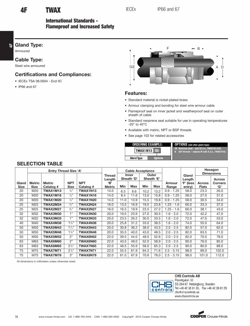
4F
TWAXInternational Standards -Flameproof and Increased Safety
IECEx IP66 and 67
Gland Type:Armoured
Cable Type:Steel wire armoured
Certifications and Compliances:
• IECEx TSA 08.0004 - Exd IIC
• IP66 and 67
Features:
• Standard material is nickel-plated brass
• Armour clamping and bonding for steel wire armour cable
• Flameproof seal on inner jacket and weatherproof seal on outersheath of cable
• Standard neoprene seal suitable for use in operating temperatures-20° to 40°C
• Available with metric, NPT or BSP threads
• See page 103 for related accessories
4F
SELECTION TABLE
Gland
Size
Entry Thread Size ‘A’
Thread
Length
‘B’
Metric
Cable Acceptance
Armour
Range
Gland
Length
‘F’ (less
entry)
Hexagon
Dimensions
Metric
Size
Metric
Catalog #
NPT
Size
NPT
Catalog #
Inner
Sheath ‘D’
Outer
Sheath ‘E’
Across
Flats
Across
Corners
‘G’Min Max Min Max
20 M20 TWAX1M13 1/2" TWAX1N13 14.0 6.3 8.6 10.2 13.2 0.9 - 1.25 58.0 23.3 26.020 M20 TWAX1M16 1/2" TWAX1N16 14.0 8.4 11.6 13.0 15.8 0.9 - 1.25 58.0 27.0 31.020 M20 TWAX1M20 1/2" TWAX1N20 14.0 11.0 13.9 15.5 19.8 0.9 - 1.25 58.0 30.5 34.025 M25 TWAX2M24 3/4" TWAX2N24 16.0 13.5 16.9 19.5 23.8 1.25 - 1.6 60.0 33.3 37.025 M25 TWAX2M27 3/4" TWAX2N27 16.0 16.5 19.9 23.5 27.2 1.25 - 1.6 60.0 38.1 43.032 M32 TWAX3M30 1" TWAX3N30 20.0 19.5 23.9 27.0 30.5 1.6 - 2.0 72.0 42.2 47.032 M32 TWAX3M33 1" TWAX3N33 20.0 23.5 26.2 30.0 33.5 1.6 - 2.0 72.0 47.0 53.040 M40 TWAX4M38 11/4" TWAX4N38 20.0 25.8 31.2 33.0 38.5 1.6 - 2.0 74.0 55.0 64.050 M50 TWAX5M43 11/2" TWAX5N43 20.0 30.8 36.2 38.0 43.5 2.0 - 2.5 82.0 57.0 62.050 M50 TWAX5M48 11/2" TWAX5N48 20.0 35.5 40.0 43.0 48.5 2.0 - 2.5 82.0 63.5 71.050 M50 TWAX5M52 2" TWAX6N52 22.0 39.5 44.0 48.0 52.6 2.0 - 2.5 82.0 70.0 78.063 M63 TWAX6M60 2" TWAX6N60 22.0 43.5 49.0 52.0 58.9 2.0 - 2.5 90.0 76.0 85.063 M63 TWAX6M65 21/2" TWAX7N65 22.0 48.5 55.9 58.0 65.3 2.0 - 2.5 90.0 80.0 88.075 M75 TWAX7M71 21/2" TWAX7N71 22.0 55.5 61.9 64.3 71.6 2.5 - 3.15 98.0 89.0 102.075 M75 TWAX7M78 3" TWAX8N78 22.0 61.0 67.9 70.6 78.0 2.5 - 3.15 98.0 101.0 112.0
All dimensions in millimeters unless otherwise noted.
aro
Standard
www.crouse-hinds.com US: 1-866-764-5454 CAN: 1-800-265-0502 Copyright© 2010 Cooper Crouse-Hinds 77
4F
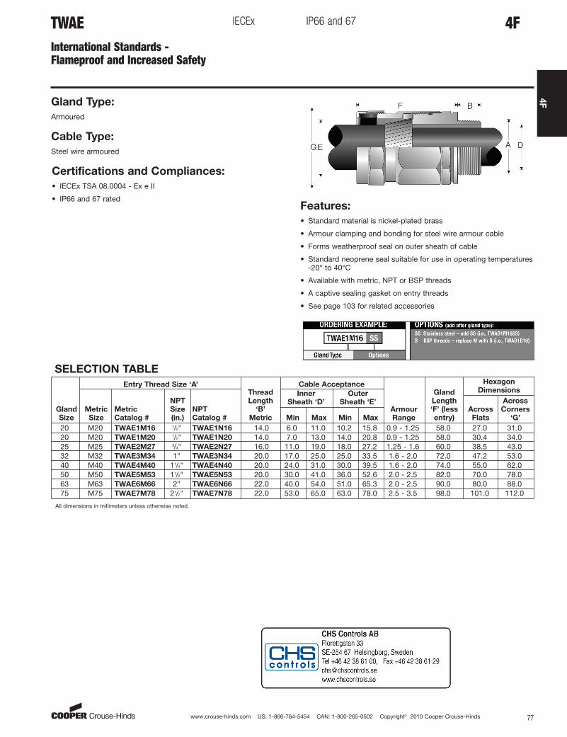
TWAEInternational Standards -Flameproof and Increased Safety
IECEx IP66 and 67
Gland Type:
Armoured
Cable Type:
Steel wire armoured
Certifications and Compliances:
• IECEx TSA 08.0004 - Ex e II
• IP66 and 67 ratedFeatures:
• Standard material is nickel-plated brass
• Armour clamping and bonding for steel wire armour cable
• Forms weatherproof seal on outer sheath of cable
• Standard neoprene seal suitable for use in operating temperatures-20° to 40°C
• Available with metric, NPT or BSP threads
• A captive sealing gasket on entry threads
• See page 103 for related accessories
SELECTION TABLE
Gland
Size
Entry Thread Size ‘A’Thread
Length
‘B’
Metric
Cable Acceptance
Armour
Range
Gland
Length
‘F’ (less
entry)
Hexagon
Dimensions
Metric
Size
Metric
Catalog #
NPT
Size
(in.)
NPT
Catalog #
Inner
Sheath ‘D’
Outer
Sheath ‘E’Across
Flats
Across
Corners
‘G’Min Max Min Max
20 M20 TWAE1M16 1/2" TWAE1N16 14.0 6.0 11.0 10.2 15.8 0.9 - 1.25 58.0 27.0 31.020 M20 TWAE1M20 1/2" TWAE1N20 14.0 7.0 13.0 14.0 20.8 0.9 - 1.25 58.0 30.4 34.025 M25 TWAE2M27 3/4" TWAE2N27 16.0 11.0 19.0 18.0 27.2 1.25 - 1.6 60.0 38.5 43.032 M32 TWAE3M34 1" TWAE3N34 20.0 17.0 25.0 25.0 33.5 1.6 - 2.0 72.0 47.2 53.040 M40 TWAE4M40 11/4" TWAE4N40 20.0 24.0 31.0 30.0 39.5 1.6 - 2.0 74.0 55.0 62.050 M50 TWAE5M53 11/2" TWAE5N53 20.0 30.0 41.0 36.0 52.6 2.0 - 2.5 82.0 70.0 78.063 M63 TWAE6M66 2" TWAE6N66 22.0 40.0 54.0 51.0 65.3 2.0 - 2.5 90.0 80.0 88.075 M75 TWAE7M78 21/2" TWAE7N78 22.0 53.0 65.0 63.0 78.0 2.5 - 3.5 98.0 101.0 112.0
All dimensions in millimeters unless otherwise noted.
4F
aro
Standard
www.crouse-hinds.com US: 1-866-764-5454 CAN: 1-800-265-0502 Copyright© 2010 Cooper Crouse-Hinds78
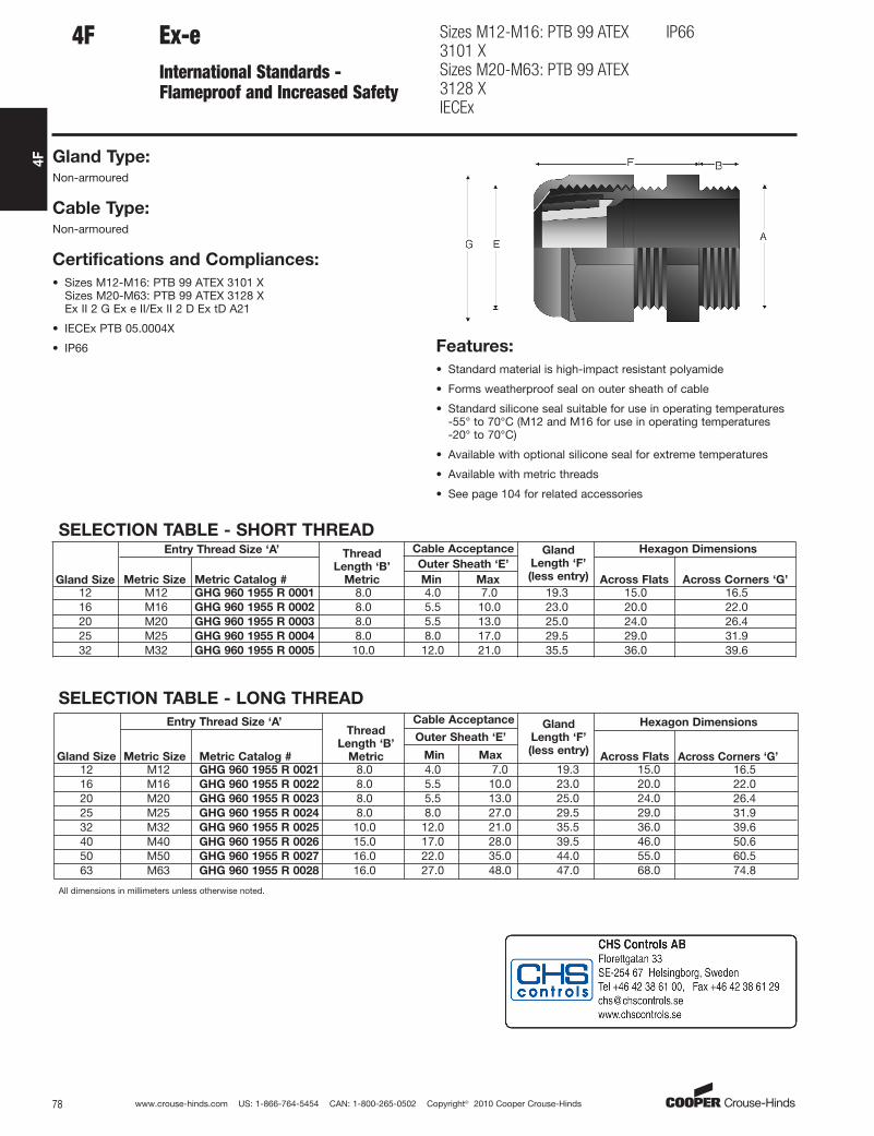
4F
Ex-eInternational Standards -Flameproof and Increased Safety
Sizes M12-M16: PTB 99 ATEX3101 XSizes M20-M63: PTB 99 ATEX3128 XIECEx
IP66
Gland Type:Non-armoured
Cable Type:Non-armoured
Certifications and Compliances:
• Sizes M12-M16: PTB 99 ATEX 3101 XSizes M20-M63: PTB 99 ATEX 3128 XEx II 2 G Ex e II/Ex II 2 D Ex tD A21
• IECEx PTB 05.0004X
• IP66 Features:
• Standard material is high-impact resistant polyamide
• Forms weatherproof seal on outer sheath of cable
• Standard silicone seal suitable for use in operating temperatures -55° to 70°C (M12 and M16 for use in operating temperatures -20° to 70°C)
• Available with optional silicone seal for extreme temperatures
• Available with metric threads
• See page 104 for related accessories
SELECTION TABLE - LONG THREAD
Gland Size
Entry Thread Size ‘A’Thread
Length ‘B’
Metric
Cable Acceptance Gland
Length ‘F’
(less entry)
Hexagon Dimensions
Metric Size Metric Catalog #
Outer Sheath ‘E’
Across Flats Across Corners ‘G’Min Max
12 M12 GHG 960 1955 R 0021 8.0 4.0 7.0 19.3 15.0 16.516 M16 GHG 960 1955 R 0022 8.0 5.5 10.0 23.0 20.0 22.02025
M20 GHG 960 1955 R 0023 8.0 5.5 13.0 25.0 24.0 26.4M25 GHG 960 1955 R 0024 8.0 8.0 27.0 29.5 29.0 31.9
32 M32 GHG 960 1955 R 0025 10.0 12.0 21.0 35.5 36.0 39.640 M40 GHG 960 1955 R 0026 15.0 17.0 28.0 39.5 46.0 50.650 M50 GHG 960 1955 R 0027 16.0 22.0 35.0 44.0 55.0 60.563 M63 GHG 960 1955 R 0028 16.0 27.0 48.0 47.0 68.0 74.8
All dimensions in millimeters unless otherwise noted.
4F
SELECTION TABLE - SHORT THREAD
Gland Size
Entry Thread Size ‘A’ Thread
Length ‘B’
Metric
Cable Acceptance Gland
Length ‘F’
(less entry)
Hexagon Dimensions
Metric Size Metric Catalog #
Outer Sheath ‘E’
Across Flats Across Corners ‘G’Min Max
12 M12 GHG 960 1955 R 0001 8.0 4.0 7.0 19.3 15.0 16.516 M16 GHG 960 1955 R 0002 8.0 5.5 10.0 23.0 20.0 22.020 M20 GHG 960 1955 R 0003 8.0 5.5 13.0 25.0 24.0 26.425 M25 GHG 960 1955 R 0004 8.0 8.0 17.0 29.5 29.0 31.932 M32 GHG 960 1955 R 0005 10.0 12.0 21.0 35.5 36.0 39.6
aro
Standard

www.crouse-hinds.com US: 1-866-764-5454 CAN: 1-800-265-0502 Copyright© 2010 Cooper Crouse-Hinds 79
4F
Ex-iInternational Standards -Flameproof and Increased Safety
Sizes M12-M16: PTB 99 ATEX3101 XSizes M20-M63: PTB 99 ATEX3128 XIECEx
IP66
Gland Type:Non-armoured
Cable Type:Non-armoured
Certifications and Compliances:
• Sizes M12-M16: PTB 99 ATEX 3101 XSizes M20-M63: PTB 99 ATEX 3128 XEx II 2 G Ex e II/Ex II 2 D Ex tD A21
• IECEx PTB 05.0004X
• IP66 Features:
• Standard material is high-impact resistant polyamide (gland nut isblue for intrinsically safe circuits)
• Forms weatherproof seal on outer sheath of cable
• Standard silicone seal suitable for use in operating temperatures -55° to 70°C (M12 and M16 for use in operating temperatures -20° to 70°C)
• Available with metric threads
• See page 104 for related accessories
SELECTION TABLE – LONG THREAD
Gland Size
Entry Thread Size ‘A’ Thread
Length ‘B’
Metric
Cable Acceptance Gland
Length ‘F’
(less entry)
Hexagon Dimensions
Metric Size Metric Catalog #
Outer Sheath ‘E’Across Flats Across Corners ‘G’
Min Max
12 M12 GHG 960 1955 R 0121 12.0 4.0 7.0 19.3 15.0 16.516 M16 GHG 960 1955 R 0122 12.0 5.5 10.0 23.0 20.0 22.020 M20 GHG 960 1955 R 0123 13.0 5.5 13.0 25.0 24.0 26.425 M25 GHG 960 1955 R 0124 13.0 8.0 17.0 29.5 29.0 31.932 M32 GHG 960 1955 R 0125 15.0 12.0 21.0 35.5 36.0 39.640 M40 GHG 960 1955 R 0126 15.0 17.0 28.0 39.5 46.0 50.650 M50 GHG 960 1955 R 0127 16.0 22.0 35.0 44.0 55.0 60.563 M63 GHG 960 1955 R 0128 16.0 27.0 48.0 47.0 68.0 74.8
All dimensions in millimeters unless otherwise noted.
4F
SELECTION TABLE – SHORT THREAD
Gland Size
Entry Thread Size ‘A’ Thread
Length ‘B’
Metric
Cable Acceptance Gland
Length ‘F’
(less entry)
Hexagon Dimensions
Metric Size Metric Catalog #
Outer Sheath ‘E’Across Flats Across Corners ‘G’
Min Max
12 M12 GHG 960 1955 R 0101 8.0 4.0 7.0 19.3 15.0 16.516 M16 GHG 960 1955 R 0102 8.0 5.5 10.0 23.0 20.0 22.020 M20 GHG 960 1955 R 0103 8.0 5.5 13.0 25.0 24.0 26.425 M25 GHG 960 1955 R 0104 8.0 8.0 17.0 29.5 29.0 31.932 M32 GHG 960 1955 R 0105 10.0 12.0 21.0 35.5 36.0 39.6
aro
Standard

www.crouse-hinds.com US: 1-866-764-5454 CAN: 1-800-265-0502 Copyright© 2010 Cooper Crouse-Hinds80
4F
TrumpetInternational Standards -Flameproof and Increased Safety
ATEX IP66
Gland Type:
Non-armoured
Cable Type:
Non-armoured
Certifications and Compliances:
• ATEX PTB 00ATEX3121X Ex II 2 G Ex e II/Ex II 2 D Ex tD A21
• IP66 Features:
• Standard material is high-impact resistant polyamide
• Forms weatherproof seal on outer sheath of cable
• Flared rear seal provides protection for cable
• Standard neoprene seal suitable for use in operating temperatures-40° to 85°C
• Available with metric threads
• See page 104 for related accessories
SELECTION TABLE
Entry Thread Size ‘A’
Thread Length
‘B’ Metric
Cable Acceptance Gland
Length ‘F’
(less entry)
Hexagon Dimensions
Metric
Size
Metric
Catalog #Outer Sheath ‘E’ Across
Flats
Across
Corners ‘G’Min Max
20 M20 GHG 960 1949 R0111 15.0 8.0 13.0 49.0 26.0 28.625 M25 GHG 960 1949 R0112 15.0 11.0 16.0 50.0 32.0 35.232 M32 GHG 960 1949 R0113 15.0 15.0 20.0 65.0 41.0 45.140 M40 GHG 960 1949 R0114 15.0 19.0 27.0 71.0 50.0 55.050 M50 GHG 960 1949 R0115 16.0 26.0 34.0 79.0 60.0 66.060 M60 GHG 960 1949 R0116 16.0 35.0 46.0 89.0 75.0 82.5
All dimensions in millimeters unless otherwise noted.
4F
Gland
Size
aro
Standard

SELECTION TABLE – MULTIPLE
www.crouse-hinds.com US: 1-866-764-5454 CAN: 1-800-265-0502 Copyright© 2010 Cooper Crouse-Hinds 81
4F
Enlargement and MultipleInternational Standards -Flameproof and Increased Safety
Sizes M16: PTB 99 ATEX 3101 XSizes M20-M63: PTB 99 ATEX3128 XIECEx
IP66
Gland Type:
Non-armoured
Cable Type:
Non-armoured
Certifications and Compliances:
• Sizes M16: PTB 99 ATEX 3101 XSizes M20-M63: PTB 99 ATEX 3128 XEx II 2 G Ex e II/Ex II 2 D Ex tD A21
• IECEx PTB 05.0004X
• IP66
Features:• Standard material is high-impact resistant polyamide• Forms weatherproof seal on outer sheath of cable• Provides reduced entry threads for larger gland size• Standard silicone seal suitable for use in operating temperatures
-55° to 70°C (M16 for use in operating temperatures -20° to 70°C)• Available with metric threads• See page 104 for related accessories
SELECTION TABLE – ENLARGEMENT
Gland
Size
Entry Thread Size ‘A’ Thread
Length ‘B’
Metric
Cable Acceptance Gland
Length ‘F’
(less entry)
Hexagon Dimensions
Metric
Size
Metric
Catalog #
Outer Sheath ‘E’ Across
Flats
Across
Corners ‘G’Min Max
16/20 M16 GHG 960 1956 R0002 12.0 5.5 13.0 25.0 24.0 26.420/25 M20 GHG 960 1956 R0003 13.0 8.0 17.0 29.5 29.0 31.925/32 M25 GHG 960 1956 R0004 13.0 12.0 21.0 35.5 36.0 39.632/40 M32 GHG 960 1956 R0005 15.0 16.0 28.0 39.5 46.0 50.640/50 M40 GHG 960 1956 R0006 15.0 21.0 35.0 44.0 55.0 60.550/63 M50 GHG 960 1956 R0007 16.0 27.0 48.0 47.0 68.0 74.8
4F
Gland
Size
Entry Thread Size ‘A’ Thread
Length ‘B’
Metric
Cable Acceptance Maximum
Number of
Conductors
Gland
Length ‘F’
(less entry)
Hexagon Dimensions
Metric
Size Metric Catalog #
Outer Sheath ‘E’ Across
Flats
Across
Corners ‘G’Min Max
25 M25 GHG 960 1955 R0054 8.0 4.5 7.0 2 29.5 36.0 39.632 M32 GHG 960 1955 R0055 10.0 4.5 7.0 4 39.5 46.0 50.6
All dimensions in millimeters unless otherwise noted.
aro
Standard

www.crouse-hinds.com US: 1-866-764-5454 CAN: 1-800-265-0502 Copyright© 2010 Cooper Crouse-Hinds82
4F
4F ADE 4I
International Standards - Industrial
NEMA 4X and IP68
Gland TypeArmoured
Cable TypeSteel wire armoured, steel wire braided, steel tape armoured,braided marine shipboard lead sheathed (with addition of earthingwasher) and tray cable
Certifications and Compliances:• NEMA 4X and IP68 Features:
• Standard material is nickel-plated brass for superior corrosionresistance
• Armour clamping and bonding with no reversible components foreasy installation, minimizing error
• Provides seal on inner jacket and weatherproof seal on outersheath of the cable
• An optional earthing washer for use with lead sheathed cable (see page 99)
• Standard neoprene seal suitable for use in operating temperaturesof -60°C to 100°C
• Available with optional silicone seal for extreme temperatures• Available with metric or NPT threads• See pages 98–101 for related accessories
SELECTION TABLE
Gland
Size
Entry Thread Size ‘A’
Thread
Length
‘B’ Metric
(NPT)
Cable Acceptance
Armour
(max)
Gland
Length
‘F’ (less
entry)
Hexagon
Dimensions
Metric
Size
Metric
Catalog #
NPT
Size
NPT
Catalog #
Inner Sheath
‘D’
Outer Sheath
‘E’ Across
Flats
Across
Corners
‘G’Min Max Min Max
5 M12 CAP946404 1/4" CAP948404 15 (12.0) 4.0 8.0 6.0 12.0 0.9 36.0 – 20.95 M16 CAP946594 3/8" CAP948594 15 (12.0) 4.0 8.5 6.0 12.0 0.9 36.0 – 20.96 M16 CAP946504 3/8" CAP948504 15 (12.0) 6.0 12.0 8.5 16.0 1.25 42.0 – 26.45 M20 CAP946674 1/2" CAP948674 15 (20.2) 4.0 8.5 6.0 12.0 0.9 36.0 – 26.46 M20 CAP946694 1/2" CAP948694 15 (20.2) 6.0 12.0 8.5 16.0 1.25 42.0 – 26.47 M20 CAP946604 1/2" CAP948604 15 (20.2) 8.5 16.0 12.0 21.0 1.25 46.0 – 33.06 M25 CAP946774 3/4" CAP948774 15 (20.2) 6.0 12.0 8.5 16.0 1.25 42.0 – 33.07 M25 CAP946794 3/4" CAP948795 15 (20.2) 8.5 16.0 12.0 21.0 1.25 46.0 – 33.08 M25 CAP946704 3/4" CAP948704 15 (20.2) 12.0 20.5 16.0 27.5 1.6 56.0 – 45.18 M32 CAP946894 1" CAP948894 15 (25.3) 12.0 21.0 16.0 27.5 1.6 56.0 – 45.19 M32 CAP946804 1" CAP948804 15 (25.3) 16.0 27.5 21.0 34.0 1.6 63.0 – 52.89 M40 CAP946994 11/4" CAP948994 15 (26.0) 16.0 27.5 21.0 34.0 1.6 63.0 – 52.8
10 M40 CAP946904 11/4" CAP948904 15 (26.0) 21.0 34.0 27.0 41.0 2.0 68.0 – 60.510 M50 CAP947094 11/2" CAP949904 16 (26.5) 21.0 34.0 27.0 41.0 2.0 68.0 – 60.511 M50 CAP947004 11/2" CAP949004 16 (26.5) 27.0 41.0 33.0 48.0 2.5 74.0 – 70.412 M63 CAP947294 2" CAP949294 17 (27.2) 27.0 41.0 33.0 48.0 2.5 77.0 – 79.213 M63 CAP947204 2" CAP949204 17 (27.2) 33.0 48.0 40.0 56.0 2.5 85.0 – 93.513 M75 CAP947394 21/2" CAP949949 18 (40.5) 40.0 56.0 47.0 65.0 2.5 85.0 – 93.514 M75 CAP947304 21/2" CAP949404 18 (40.5) 47.0 65.0 54.0 74.0 2.5 92.0 – 104.515 M90 CAP947594 3" CAP949564 22 (42.0) 54.0 74.0 63.0 83.0 3.15 104.0 – 121.016 M90 CAP947504 3" CAP949504 22 (42.0) 63.0 82.0 72.0 93.0 3.15 108.0 – 132.016 – – 31/2" CAP949604 – (43.2) 63.0 82.0 72.0 93.0 3.15 108.0 – 132.017 M110 CAP947794 4" CAP949704 22 (44.5) 72.0 92.0 85.0 107.0 3.15 115.0 – 148.5
All dimensions in millimeters unless otherwise noted.
aro
Standard
www.crouse-hinds.com US: 1-866-764-5454 CAN: 1-800-265-0502 Copyright© 2010 Cooper Crouse-Hinds 83
4F
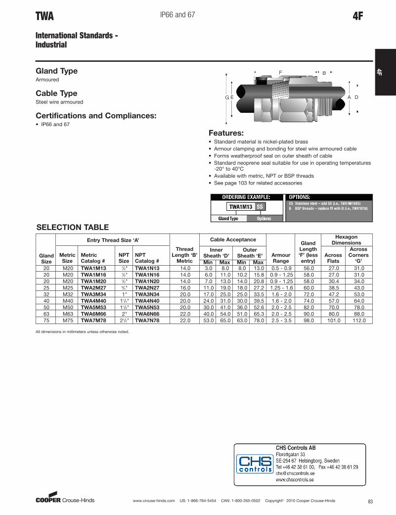
4FTWA
International Standards - Industrial
IP66 and 67
Gland TypeArmoured
Cable TypeSteel wire armoured
Certifications and Compliances:• IP66 and 67
Features:• Standard material is nickel-plated brass• Armour clamping and bonding for steel wire armoured cable• Forms weatherproof seal on outer sheath of cable• Standard neoprene seal suitable for use in operating temperatures
-20° to 40°C• Available with metric, NPT or BSP threads• See page 103 for related accessories
SELECTION TABLE
Gland
Size
Entry Thread Size ‘A’
Thread
Length ‘B’
Metric
Cable Acceptance
Armour
Range
Gland
Length
‘F’ (less
entry)
Hexagon
Dimensions
Metric
Size
Metric
Catalog #
NPT
Size
NPT
Catalog #
Inner
Sheath ‘D’
Outer
Sheath ‘E’ Across
Flats
Across
Corners
‘G’Min Max Min Max
20 M20 TWA1M13 1/2" TWA1N13 14.0 8.0 8.0 13.0 0.5 - 0.9 56.0 27.0 31.020 M20 TWA1M16 1/2" TWA1N16 14.0 6.0 11.0 10.2 15.8 0.9 - 1.25 58.0 27.0 31.020 M20 TWA1M20 1/2" TWA1N20 14.0 7.0 13.0 14.0 20.8 0.9 - 1.25 58.0 30.4 34.025 M25 TWA2M27 3/4" TWA2N27 16.0 11.0 19.0 18.0 27.2 1.25 - 1.6 60.0 38.5 43.032 M32 TWA3M34 1" TWA3N34 20.0 17.0 25.0 25.0 33.5 1.6 - 2.0 72.0 47.2 53.040 M40 TWA4M40 11/4" TWA4N40 20.0 24.0 31.0 30.0 39.5 1.6 - 2.0 74.0 57.0 64.050 M50 TWA5M53 11/2" TWA5N53 20.0 30.0 41.0 36.0 52.6 2.0 - 2.5 82.0 70.0 78.063 M63 TWA6M66 2" TWA6N66 22.0 40.0 54.0 51.0 65.3 2.0 - 2.5 90.0 80.0 88.075 M75 TWA7M78 21/2" TWA7N78 22.0 53.0 65.0 63.0 78.0 2.5 - 3.5 98.0 101.0 112.0
All dimensions in millimeters unless otherwise noted.
3.0
aro
Standard

www.crouse-hinds.com US: 1-866-764-5454 CAN: 1-800-265-0502 Copyright© 2010 Cooper Crouse-Hinds84
4F
4F TUA
International Standards - Industrial
IP66 and 67
Gland TypeNon-armoured
Cable TypeNon-armoured
Certifications and Compliances:• IP66 and 67
Features:• Standard material is nickel-plated brass• Forms weatherproof seal on outer sheath of cable• Standard neoprene seal suitable for use in operating temperatures
-20° to 40°C• Available with metric, NPT or BSP threads• See page 103 for related accessories
SELECTION TABLE
Gland
Size
Entry Thread Size ‘A’Thread
Length ‘B’
Metric
Cable Acceptance Gland
Length ‘F’
(less
entry)
Hexagon Dimensions
Metric
Size
Metric
Catalog #
NPT
Size
NPT
Catalog #
Outer Sheath ‘E’Across
Flats
Across
Corners ‘G’Min Max
16 M16 TUA16M7 N/A N/A 14.0 10.2 13.2 58.0 23.3 26.020 M20 TUA1M10 1/2" TUA1N10 14.0 13.0 15.8 58.0 27.0 31.020 M20 TUA1M12 1/2" TUA1N12 14.0 15.5 19.8 58.0 30.5 34.020 M20 TUA1M15 3/4" TUA1N15 16.0 19.5 23.8 60.0 33.3 37.025 M25 TUA2M18 3/4" TUA2N18 16.0 23.5 27.2 60.0 38.1 43.032 M32 TUA3M23 1" TUA3N23 20.0 27.0 30.5 72.0 42.2 47.032 M32 TUA3M25 1" TUA3N25 20.0 30.0 33.5 72.0 47.0 53.040 M40 TUA4M29 11/4" TUA4N29 20.0 33.0 38.5 74.0 55.0 64.050 M50 TUA5M34 11/2" TUA5N34 20.0 38.0 43.5 82.0 57.0 62.050 M50 TUA5M38 11/2" TUA5N38 20.0 43.0 48.5 82.0 63.5 71.050 M50 TUA5M42 2" TUA5N42 22.0 48.0 52.6 82.0 70.0 78.063 M63 TUA6M48 2" TUA6N48 22.0 52.0 58.9 90.0 76.0 85.063 M63 TUA6M54 21/2" TUA7N54 22.0 58.0 65.3 90.0 80.0 88.075 M75 TUA7M60 21/2" TUA7N60 22.0 64.3 71.6 98.0 89.0 102.075 M75 TUA7M66 3" TUA8N66 22.0 70.6 78.0 98.0 101.0 112.0
All dimensions in millimeters unless otherwise noted.
aro
Standard
www.crouse-hinds.com US: 1-866-764-5454 CAN: 1-800-265-0502 Copyright© 2010 Cooper Crouse-Hinds 85
4F
SELECTION TABLEEntry Thread Size ‘A’
Thread
Length
‘B’ NPT
Cable Acceptance
Gland Length
‘F’ (less entry)
Hexagon Dimensions
NPT
Size
NPT
Catalog #
Armour Range ‘H’ Outer Sheath ‘E’Across
Flats
Across
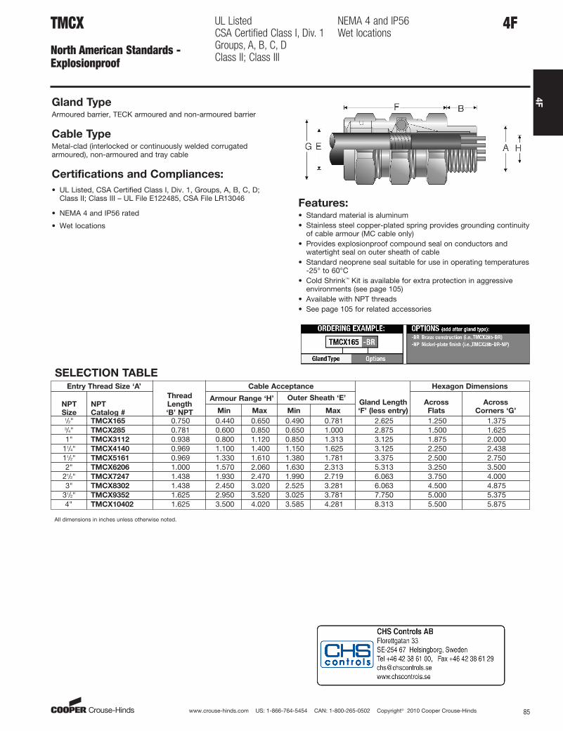
Corners ‘G’Min Max Min Max1/2" TMCX165 0.750 0.440 0.650 0.490 0.781 2.625 1.250 1.3753/4" TMCX285 0.781 0.600 0.850 0.650 1.000 2.875 1.500 1.6251" TMCX3112 0.938 0.800 1.120 0.850 1.313 3.125 1.875 2.000
11/4" TMCX4140 0.969 1.100 1.400 1.150 1.625 3.125 2.250 2.43811/2" TMCX5161 0.969 1.330 1.610 1.380 1.781 3.375 2.500 2.7502" TMCX6206 1.000 1.570 2.060 1.630 2.313 5.313 3.250 3.500
21/2" TMCX7247 1.438 1.930 2.470 1.990 2.719 6.063 3.750 4.0003" TMCX8302 1.438 2.450 3.020 2.525 3.281 6.063 4.500 4.875
31/2" TMCX9352 1.625 2.950 3.520 3.025 3.781 7.750 5.000 5.3754" TMCX10402 1.625 3.500 4.020 3.585 4.281 8.313 5.500 5.875
All dimensions in inches unless otherwise noted.
4FTMCX
North American Standards - Explosionproof
UL Listed CSA Certified Class I, Div. 1Groups, A, B, C, DClass II; Class III
NEMA 4 and IP56Wet locations
Gland TypeArmoured barrier, TECK armoured and non-armoured barrier
Cable TypeMetal-clad (interlocked or continuously welded corrugatedarmoured), non-armoured and tray cable
Certifications and Compliances:
• UL Listed, CSA Certified Class I, Div. 1, Groups, A, B, C, D; Class II; Class III – UL File E122485, CSA File LR13046
• NEMA 4 and IP56 rated
• Wet locations
Features:• Standard material is aluminum• Stainless steel copper-plated spring provides grounding continuity
of cable armour (MC cable only)• Provides explosionproof compound seal on conductors and
watertight seal on outer sheath of cable• Standard neoprene seal suitable for use in operating temperatures
-25° to 60°C• Cold Shrink™ Kit is available for extra protection in aggressive
environments (see page 105)• Available with NPT threads• See page 105 for related accessories
aro
Standard
www.crouse-hinds.com US: 1-866-764-5454 CAN: 1-800-265-0502 Copyright© 2010 Cooper Crouse-Hinds86
4F
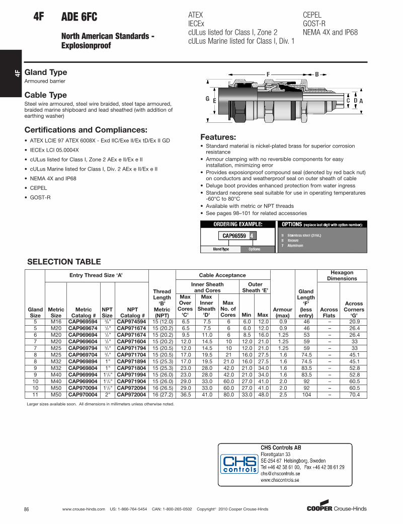
ADE 6FC ATEXIECExcULus listed for Class I, Zone 2cULus Marine listed for Class I, Div. 1
CEPELGOST-RNEMA 4X and IP68
Cable TypeSteel wire armoured, steel wire braided, steel tape armoured,braided marine shipboard and lead sheathed (with addition ofearthing washer)
Features:• Standard material is nickel-plated brass for superior corrosion
resistance• Armour clamping with no reversible components for easy
installation, minimizing error• Provides exposionproof compound seal (denoted by red back nut)
on conductors and weatherproof seal on outer sheath of cable• Deluge boot provides enhanced protection from water ingress• Standard neoprene seal suitable for use in operating temperatures
-60°C to 80°C• Available with metric or NPT threads• See pages 98–101 for related accessories
SELECTION TABLE
Gland
Size
Entry Thread Size ‘A’
Thread
Length
‘B’
Metric
(NPT)
Cable Acceptance
Armour
(max)
Gland
Length
‘F’
(less
entry)
Hexagon
Dimensions
Metric
Size
Metric
Catalog #
NPT
Size
NPT
Catalog #
Inner Sheath
and Cores
Outer
Sheath ‘E’
Across
Flats
Across
Corners
‘G’
Max
Over
Cores
'C'
Max
Inner
Sheath
'D'
Max
No. of
Cores Min Max
5 M16 CAP969594 3/8" CAP974594 15 (12.0) 6.5 7.5 6 6.0 12.0 0.9 46 – 20.95 M20 CAP969674 1/2" CAP971674 15 (20.2) 6.5 7.5 6 6.0 12.0 0.9 46 – 26.46 M20 CAP969694 1/2" CAP971674 15 (20.2) 9.5 11.0 6 8.5 16.0 1.25 53 – 26.47 M20 CAP969604 1/2" CAP971604 15 (20.2) 12.0 14.5 10 12.0 21.0 1.25 59 – 337 M25 CAP969794 3/4" CAP971794 15 (20.5) 12.0 14.5 10 12.0 21.0 1.25 59 – 338 M25 CAP969704 3/4" CAP971704 15 (20.5) 17.0 19.5 21 16.0 27.5 1.6 74.5 – 45.18 M32 CAP969894 1" CAP971894 15 (25.3) 17.0 19.5 21.0 16.0 27.5 1.6 74.5 – 45.19 M32 CAP969804 1" CAP971804 15 (25.3) 23.0 28.0 42.0 21.0 34.0 1.6 83.5 – 52.89 M40 CAP969994 11/4" CAP971994 15 (26.0) 23.0 28.0 42.0 21.0 34.0 1.6 83.5 – 52.810 M40 CAP969904 11/4" CAP971904 15 (26.0) 29.0 33.0 60.0 27.0 41.0 2.0 92 – 60.510 M50 CAP970094 11/2" CAP972094 16 (26.5) 29.0 33.0 60.0 27.0 41.0 2.0 92 – 60.511 M50 CAP970004 2" CAP972004 16 (27.2) 36.5 41.0 80.0 33.0 48.0 2.5 104 – 70.4
Larger sizes available soon. All dimensions in millimeters unless otherwise noted.
4F
Gland TypeArmoured barrier
Certifications and Compliances:
• ATEX LCIE 97 ATEX 6008X - Exd IIC/Exe II/Ex tD/Ex II GD
• IECEx LCI 05.0004X
• cULus listed for Class I, Zone 2 AEx e II/Ex e II
• cULus Marine listed for Class I, Div. 2 AEx e II/Ex e II
• NEMA 4X and IP68
• CEPEL
• GOST-R
North American Standards - Explosionproof
aro
Standard
www.crouse-hinds.com US: 1-866-764-5454 CAN: 1-800-265-0502 Copyright© 2010 Cooper Crouse-Hinds 87
4F
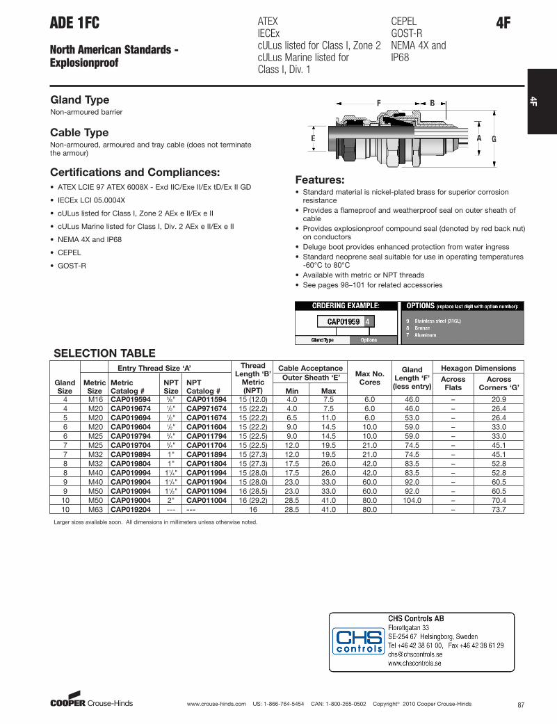
4FADE 1FC ATEXIECExcULus listed for Class I, Zone 2cULus Marine listed for Class I, Div. 1
CEPELGOST-RNEMA 4X andIP68
Gland TypeNon-armoured barrier
Cable TypeNon-armoured, armoured and tray cable (does not terminate the armour)
Certifications and Compliances:
• ATEX LCIE 97 ATEX 6008X - Exd IIC/Exe II/Ex tD/Ex II GD
• IECEx LCI 05.0004X
• cULus listed for Class I, Zone 2 AEx e II/Ex e II
• cULus Marine listed for Class I, Div. 2 AEx e II/Ex e II
• NEMA 4X and IP68
• CEPEL
• GOST-R
SELECTION TABLE
Gland
Size
Entry Thread Size ‘A’ Thread
Length ‘B’
Metric
(NPT)
Cable AcceptanceMax No.
Cores
Gland
Length ‘F’
(less entry)
Hexagon Dimensions
Metric
Size
Metric
Catalog #
NPT
Size
NPT
Catalog #
Outer Sheath ‘E’ Across
Flats
Across
Corners ‘G’Min Max
4 M16 CAP019594 3/8" CAP011594 15 (12.0) 4.0 7.5 6.0 46.0 – 20.94 M20 CAP019674 1/2" CAP971674 15 (22.2) 4.0 7.5 6.0 46.0 – 26.45 M20 CAP019694 1/2" CAP011674 15 (22.2) 6.5 11.0 6.0 53.0 – 26.46 M20 CAP019604 1/2" CAP011604 15 (22.2) 9.0 14.5 10.0 59.0 – 33.06 M25 CAP019794 3/4" CAP011794 15 (22.5) 9.0 14.5 10.0 59.0 – 33.07 M25 CAP019704 3/4" CAP011704 15 (22.5) 12.0 19.5 21.0 74.5 – 45.17 M32 CAP019894 1" CAP011894 15 (27.3) 12.0 19.5 21.0 74.5 – 45.18 M32 CAP019804 1" CAP011804 15 (27.3) 17.5 26.0 42.0 83.5 – 52.88 M40 CAP019994 11/4" CAP011994 15 (28.0) 17.5 26.0 42.0 83.5 – 52.89 M40 CAP019904 11/4" CAP011904 15 (28.0) 23.0 33.0 60.0 92.0 – 60.59 M50 CAP019094 11/2" CAP011094 16 (28.5) 23.0 33.0 60.0 92.0 – 60.510 M50 CAP019004 2" CAP011004 16 (29.2) 28.5 41.0 80.0 104.0 – 70.410 M63 CAP019204 --- --- 16 28.5 41.0 80.0 – 73.7
Larger sizes available soon. All dimensions in millimeters unless otherwise noted.
North American Standards - Explosionproof
Features:• Standard material is nickel-plated brass for superior corrosion
resistance• Provides a flameproof and weatherproof seal on outer sheath of
cable• Provides explosionproof compound seal (denoted by red back nut)
on conductors• Deluge boot provides enhanced protection from water ingress• Standard neoprene seal suitable for use in operating temperatures
-60°C to 80°C• Available with metric or NPT threads• See pages 98–101 for related accessories
aro
Standard

www.crouse-hinds.com US: 1-866-764-5454 CAN: 1-800-265-0502 Copyright© 2010 Cooper Crouse-Hinds88
4F
4F CGBS and EBY
North American Standards - Explosionproof
Gland TypePortable cord connector
Cable TypeNon-armoured and tray cable
Certifications and Compliances:
• CSA Certified Class I, Div. 1, Groups C, D
• Class II, Div. 1 & 2, Groups E, F, G
• Class III – CSA File LR13046CGBS Features:• Body – steel with zinc electroplate and chromate finish coat• Gland nut – aluminum• Body well for Chico A sealing compound (for ordering
information please contact customer service)• Standard neoprene seal suitable for use in operating
temperatures -25° to 40°C• Available with NPT threads
SELECTION TABLE
Entry Thread Size ‘A’ FormOuter Sheath ‘E’
Gland Length ‘F’ (less entry)NPT Size NPT Catalog # Min Max
1/2" CGBS1013 A 0.312 0.437 51/4"3/4" CGBS2013 A 0.312 0.437 51/4"3/4" CGBS2014 A 0.375 0.500 51/4"1" CGBS3015 B 0.500 0.625 27/8"1" CGBS3016 B 0.625 0.750 215/16"
11/4" CGBS4017 B 0.750 0.875 213/16"11/4" CGBS4018 B 0.875 1.000 31/2"11/4" CGBS4019 B 1.000 1.188 39/16"
All dimensions in inches unless otherwise noted.
Gland TypePortable cord connector
Cable TypeNon-armoured
EBY Features:• Standard material is aluminum• Factory sealed conductors and seal on outer sheath of cable• Three, 12-inch long, #12 type SF-2 (150°C rating) stranded
pigtails; two circuit wires and one identified grounding wire
• Three pressure connectors for 3-conductor cord, range #18 to #12 AWG
• Standard neoprene seal suitable for use in operating temperatures -25° to 40°C
• Available with NPT threads
SELECTION TABLE
Entry Thread Size ‘A’ Outer Sheath ‘E’
NPT Size NPT Catalog # Min Max3/4" EBY2672 0.250 0.4373/4" EBY2682 0.375 0.5003/4" EBY26102 0.500 0.625
All dimensions in inches unless otherwise noted.
CGBS:CSA Certified Class I,Div 1. Groups C, DClass II, Div. 1 & 2, Groups E, F, GClass III
EBY:UL, cUL Listed Class I,Div. 1 Groups, B, C, DClass II, Div. 1 Groups, F, G
Certifications and Compliances• UL, cUL Listed Class I, Div. 1, Groups, B, C, D
• Class II, Div. 1, Groups, F, G – UL File E10279
aro
Standard
www.crouse-hinds.com US: 1-866-764-5454 CAN: 1-800-265-0502 Copyright© 2010 Cooper Crouse-Hinds 89
4F
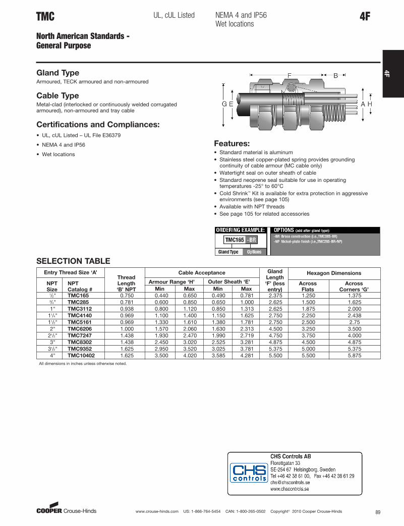
4FTMC
North American Standards - General Purpose
UL, cUL Listed NEMA 4 and IP56Wet locations
Gland TypeArmoured, TECK armoured and non-armoured
Cable TypeMetal-clad (interlocked or continuously welded corrugatedarmoured), non-armoured and tray cable
Certifications and Compliances:
• UL, cUL Listed – UL File E36379
• NEMA 4 and IP56
• Wet locations
Features:• Standard material is aluminum• Stainless steel copper-plated spring provides grounding
continuity of cable armour (MC cable only)• Watertight seal on outer sheath of cable• Standard neoprene seal suitable for use in operating
temperatures -25° to 60°C• Cold Shrink™ Kit is available for extra protection in aggressive
environments (see page 105)• Available with NPT threads• See page 105 for related accessories
SELECTION TABLE
Entry Thread Size ‘A’Thread
Length
‘B’ NPT
Cable Acceptance Gland
Length
‘F’ (less
entry)
Hexagon Dimensions
NPT
Size
NPT
Catalog #
Armour Range ‘H’ Across
Flats
Across
Corners ‘G’Min Max Min Max1/2" TMC165 0.750 0.440 0.650 0.490 0.781 2.375 1.250 1.3753/4" TMC285 0.781 0.600 0.850 0.650 1.000 2.625 1.500 1.6251" TMC3112 0.938 0.800 1.120 0.850 1.313 2.625 1.875 2.000
11/4" TMC4140 0.969 1.100 1.400 1.150 1.625 2.750 2.250 2.43811/2" TMC5161 0.969 1.330 1.610 1.380 1.781 2.750 2.500 2.752" TMC6206 1.000 1.570 2.060 1.630 2.313 4.500 3.250 3.500
21/2" TMC7247 1.438 1.930 2.470 1.990 2.719 4.750 3.750 4.0003" TMC8302 1.438 2.450 3.020 2.525 3.281 4.875 4.500 4.875
31/2" TMC9352 1.625 2.950 3.520 3.025 3.781 5.375 5.000 5.3754" TMC10402 1.625 3.500 4.020 3.585 4.281 5.500 5.500 5.875
All dimensions in inches unless otherwise noted.
Outer Sheath ‘E’
aro
Standard

www.crouse-hinds.com US: 1-866-764-5454 CAN: 1-800-265-0502 Copyright© 2010 Cooper Crouse-Hinds90
4F
4F TECK
North American Standards - General Purpose
CSA Certified Class II, Div. 1, Div 2 Groups, E, F, GClass III - CSA
Type 4 and IP56Wet locations
Gland TypeArmoured
Cable TypeTECK armoured
Certifications and Compliances:
• CSA Certified Class II, Div. 1 & Div. 2, Groups, E, F, G; Class III –CSA File LR13046
• Type 4 and IP56
• Wet locationsFeatures:• Standard material is aluminum• Stainless steel copper-plated spring provides grounding continuity
of cable armour (TECK cable only)• Watertight seal on outer sheath of cable• Standard neoprene seal suitable for use in operating temperatures
-25° to 60°C• Cold Shrink™ Kit is available for extra protection in aggressive
environments ( see page 105)• An integral o-ring seal on entry threads• Available with NPT threads• See page 105 for related accessories
SELECTION TABLE
Aluminum
Catalog #
Steel
Catalog #
Stainless
Steel
Catalog # PVC Catalog #
Entry
Thread
Size ‘A’ Thread
Length
‘B’ NPT
Cable Acceptance Gland
Length
‘F’
(less
entry)
Hexagon
Dimensions
NPT
Size
Armour Range ‘H’ Outer Sheath ‘E’Across
Flats
Across
Corners
‘G’Min Max Min Max
TECK050 1 TECK050 1S TECK050 1SS TECK050 1PVC 1/2" 0.630 0.415 0.570 0.525 0.650 2.300 1.250 1.350TECK050 2 TECK050 2S TECK050 2SS TECK050 2 PVC 1/2" 0.630 0.490 0.680 0.600 0.760 2.300 1.375 1.500
TECK050 3 TECK050 3S TECK050 3SS TECK0503PVC 1/2" 0.630 0.615 0.805 0.725 0.885 2.300 1.500 1.600
TECK050 4 TECK050 4S TECK050 4SS TECK050 4PVC 1/2" 0.630 0.715 0.905 0.825 0.985 2.300 1.500 1.600TECK075 5 TECK075 5S TECK075 5SS TECK075 5PVC 3/4" 0.630 0.770 0.985 0.880 1.065 2.500 2.000 2.125TECK075 6 TECK075 6S TECK075 6SS TECK075 6PVC 3/4" 0.630 0.915 1.125 1.025 1.205 2.500 2.000 2.125TECK100 7 TECK100 7S TECK100 7SS TECK1007PVC 1" 0.750 1.077 1.295 1.187 1.375 2.625 2.250 2.400TECK125 8 TECK125 8S – TECK125 8PVC 11/4" 0.800 1.240 1.545 1.350 1.625 3.500 3.000 3.125TECK125 9 TECK125 9S – TECK125 9PVC 11/4" 0.800 1.390 1.545 1.500 1.625 3.400 3.000 3.125TECK125 10 TECK125 10S – TECK125 10PVC 11/4" 0.800 1.490 1.795 1.600 1.875 3.500 3.000 3.125TECK150 11 TECK150 11S – TECK150 11PVC 11/2" 0.800 1.590 1.885 1.700 1.965 3.800 3.750 3.600TECK150 12 TECK150 12S – TECK150 12PVC 11/2" 0.800 1.790 2.107 1.900 2.187 3.900 3.500 3.750TECK200 13 TECK200 13S – TECK200 13PVC 2" 0.825 1.790 2.107 1.900 2.187 4.000 3.750 4.000TECK200 14 TECK200 14S – TECK200 14PVC 2" 0.825 1.990 2.280 2.100 2.375 4.000 3.750 4.000TECK200 15 TECK200 15S – TECK200 15PVC 2" 0.875 2.190 2.485 2.300 2.565 4.000 4.125 4.400TECK200 16 TECK200 16S – TECK200 16PVC 2" 0.875 2.390 2.656 2.500 2.750 4.000 4.125 4.400TECK250 17 TECK250 17S – TECK250 17PVC 21/2" 1.300 2.240 2.560 2.380 2.640 5.000 4.500 4.750TECK250 18 TECK250 18S – TECK250 18PVC 21/2" 1.300 2.440 2.750 2.580 2.840 5.000 4.500 4.750TECK300 19 TECK300 19S – TECK300 19PVC 3" 1.400 2.640 2.970 2.790 3.060 5.000 4.600 4.900TECK300 20 TECK300 20S – TECK300 20PVC 3" 1.400 2.870 3.190 3.000 3.270 5.000 4.900 5.250TECK300 21 TECK300 21S – TECK300 21PVC 3" 1.400 3.042 3.390 3.210 3.480 5.000 5.000 5.250TECK350 22 TECK350 22S – TECK350 22PVC 31/2" 1.400 3.270 3.590 3.420 3.690 5.000 5.600 5.900TECK350 23 TECK350 23S – TECK350 23PVC 31/2" 1.400 3.440 3.770 3.610 3.870 5.000 5.500 5.900TECK400 24 TECK400 24S – – 4" 1.400 3.600 3.930 3.810 4.030 5.000 6.125 6.500TECK400 25 TECK400 25S – – 4" 1.400 3.755 4.065 3.965 4.185 5.000 6.125 6.500TECK400 26 TECK400 26S – – 4" 1.400 3.910 4.220 4.120 4.340 5.000 6.125 6.500All dimensions in inches unless otherwise noted.
aro
Standard

www.crouse-hinds.com US: 1-866-764-5454 CAN: 1-800-265-0502 Copyright© 2010 Cooper Crouse-Hinds 91
4F
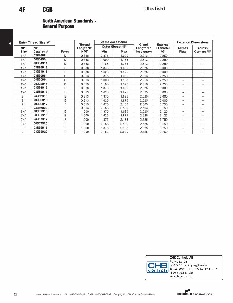
CGB
North American Standards - General Purpose
cULus Listed
Gland TypeNon-armoured
Cable TypeNon-armoured and tray cable
Certifications and Compliances:• cULus Listed - UL File E23223
Features:• Form A - D bodies and gland nuts – steel with zinc electroplate
and chromate finish coat• Form E - F bodies and gland nuts – Feraloy® iron alloy with
electrogalvanized and aluminum acrylic paint• Weatherproof seal on outer sheath of cable• Standard neoprene seal suitable for use in operating temperatures
-25° to 40°C• Available with NPT threads• Available in all aluminum construction• See page 105 for related accessories
SELECTION TABLE
3/8" CGB3814 A 0.438 0.125 0.250 1.063 – 0.750 0.8753/8" CGB3816 A 0.438 0.250 0.375 1.063 – 0.750 0.8753/8" CGB3817 A 0.438 0.375 0.437 1.063 – 0.750 0.8753/8" CGB3892 B 0.438 0.125 0.250 1.313 – 1.000 1.1883/8" CGB3893 B 0.438 0.250 0.375 1.313 – 1.000 1.1883/8" CGB3894 B 0.438 0.375 0.500 1.313 – 1.000 1.1881/2" CGB114† A 0.625† 0.125 0.250 1.000 – 0.875 1.1881/2" CGB116† A 0.625† 0.250 0.375 1.000 – 0.875 1.1881/2" CGB117† A 0.625† 0.375 0.437 1.000 – 0.875 1.1881/2" CGB192*† B 0.750*† 0.125 0.250 1.313 – 1.000 1.1881/2" CGB193*† B 0.750*† 0.250 0.375 1.313 – 1.000 1.1881/2" CGB194*† B 0.750*† 0.375 0.500 1.313 – 1.000 1.1881/2" CGB195*† B 0.750*† 0.500 0.625 1.313 – 1.000 1.1881/2" CGB196* C 0.625* 0.625 0.750 1.750 – 1.500 1.6561/2" CGB197*† C 0.625*† 0.750 0.875 1.750 – 1.500 1.6563/4" CGB292† B 0.625† 0.125 0.250 1.375 – 1.060 1.2503/4" CGB293† B 0.625† 0.250 0.375 1.375 – 1.060 1.2503/4" CGB294† B 0.625† 0.375 0.500 1.375 – 1.060 1.2503/4" CGB295† B 0.625† 0.500 0.625 1.375 – 1.060 1.2503/4" CGB296*† C 0.625*† 0.625 0.750 1.750 – 1.630 1.6563/4" CGB297*† C 0.625*† 0.750 0.875 1.750 – 1.630 1.6563/4" CGB298*† D 0.625*† 0.875 1.000 2.500 2.250 – –1" CGB393† B 0.688† 0.250 0.375 1.375 – 1.375 1.6251" CGB394† B 0.688† 0.375 0.500 1.375 – 1.375 1.6251" CGB395*† C 0.688*† 0.500 0.625 1.688 – 1.500 1.8751" CGB396*† C 0.688*† 0.625 0.750 1.688 – 1.500 1.8751" CGB397*† C 0.688*† 0.750 0.875 1.688 – 1.500 1.8751" CGB3239† C 0.688† 0.875 1.000 1.688 – – 1.8751" CGB398*† D 0.625*† 0.875 1.000 2.375 2.375 – –1" CGB399*† D 0.625*† 1.000 1.188 2.375 2.375 – –1" CGB3911*† D 0.625*† 1.188 1.375 2.375 2.375 – –
All dimensions in inches unless otherwise noted.
*With optional Sealing Gasket.
†With optional Aluminum Construction.
4F
Min Max
NPT
Size
NPT
Catalog #
Outer Sheath ‘E’Across
Flats
Across
Corners ‘G’
Entry Thread Size ‘A’
Form
Thread
Length ‘B’
NPT
Cable AcceptanceGland
Length ‘F’
(less entry)
External
Diameter
‘G’
Hexagon Dimensions
aro
Standard
www.crouse-hinds.com US: 1-866-764-5454 CAN: 1-800-265-0502 Copyright© 2010 Cooper Crouse-Hinds92
4F
11/4" CGB498 D 0.688 0.875 1.000 2.313 2.250 – –11/4" CGB499 D 0.688 1.000 1.188 2.313 2.250 – –11/4" CGB4911 D 0.688 1.188 1.375 2.313 2.250 – –11/4" CGB4913 E 0.688 1.375 1.625 2.625 3.000 – –11/4" CGB4915 E 0.688 1.625 1.875 2.625 3.000 – –11/2" CGB598 D 0.813 0.875 1.000 2.313 2.250 – –11/2" CGB599 D 0.813 1.000 1.188 2.313 2.250 – –11/2" CGB5911 D 0.813 1.188 1.375 2.313 2.250 – –11/2" CGB5913 E 0.813 1.375 1.625 2.625 3.000 – –11/2" CGB5915 E 0.813 1.625 1.875 2.625 3.000 – –2" CGB6913 E 0.813 1.375 1.625 2.625 3.000 – –2" CGB6915 E 0.813 1.625 1.875 2.625 3.000 – –2" CGB6917 F 0.813 1.875 2.188 2.563 3.750 – –2" CGB6920 F 0.813 2.188 2.500 2.563 3.750 – –
21/2" CGB7913 E 1.000 1.375 1.625 2.625 3.125 – –21/2" CGB7915 E 1.000 1.625 1.875 2.625 3.125 – –21/2" CGB7917 F 1.000 1.875 2.188 2.625 3.750 – –21/2" CGB7920 F 1.000 2.188 2.500 2.625 3.750 – –3" CGB8917 F 1.000 1.875 2.188 2.625 3.750 – –3" CGB8920 F 1.000 2.188 2.500 2.625 3.750 – –
Min Max
NPT
Size
NPT
Catalog #
Outer Sheath ‘E’Across
Flats
Across
Corners ‘G’
Entry Thread Size ‘A’
Form
Thread
Length ‘B’
NPT
Cable AcceptanceGland
Length ‘F’
(less entry)
External
Diameter
‘G’
Hexagon Dimensions
CGB
North American Standards -General Purpose
cULus Listed4F
aro
Standard

www.crouse-hinds.com US: 1-866-764-5454 CAN: 1-800-265-0502 Copyright© 2010 Cooper Crouse-Hinds 93
4F
CGDNorth American Standards -General Purpose
cULus Listed
Gland TypeNon-armoured
Cable TypeNon-armoured and tray cable
Certifications and Compliances:• cULus Listed - Ul File E23223
SELECTION TABLE
Entry Thread Size ‘A’
Thread Length
‘B’ NPT
Cable Acceptance
Gland Length
‘F’ (less entry)
External
Diameter ‘G’NPT Size NPT Catalog #
Outer Sheath ‘E’
Min Max1/2" CGD192 0.630 0.125 0.250 1.688 1.1881/2" CGD193 0.630 0.250 0.375 1.688 1.1881/2" CGD194 0.630 0.375 0.500 1.688 1.1881/2" CGD195 0.630 0.500 0.625 1.688 1.1881/2" CGD196 0.630 0.625 0.750 2.063 1.6251/2" CGD197 0.630 0.750 0.875 2.063 1.6253/4" CGD292 0.630 0.125 0.250 1.938 1.1413/4" CGD293 0.630 0.250 0.375 1.938 1.1413/4" CGD294 0.630 0.375 0.500 1.938 1.1253/4" CGD295 0.630 0.500 0.625 1.938 1.1253/4" CGD296 0.630 0.625 0.750 2.000 1.6253/4" CGD297 0.630 0.750 0.875 2.000 1.625
All dimensions in inches unless otherwise noted.
4F
Features:• 45° angle with male thread• Standard body material is Feraloy® iron alloy• Standard gland nut material is steel• Weatherproof seal on outer sheath of cable• Standard neoprene seal suitable for use in operating temperatures
-25° to 40°C• Available with NPT threads• See page 105 for related accessories
aro
Standard

www.crouse-hinds.com US: 1-866-764-5454 CAN: 1-800-265-0502 Copyright© 2010 Cooper Crouse-Hinds94
4F
CGENorth American Standards -General Purpose
cULus Listed
Gland TypeNon-armoured
Cable TypeNon-armoured and tray cable
Certifications and Compliances:• cULus Listed - UL File E23223
SELECTION TABLEEntry Thread Size ‘A’
Thread
Length
‘B’ NPT
Cable Acceptance
Gland Length
‘F’ (less entry)
External
Diameter ‘G’
NPT
Size
NPT
Catalog #
Outer Sheath ‘E’
Min Max
1/2" CGE192 0.710 0.1250 0.2500 1.438 1.1881/2" CGE193 0.710 0.2500 0.3750 1.438 1.1881/2" CGE194 0.710 0.3750 0.5000 1.438 1.1881/2" CGE195 0.710 0.5000 0.6250 1.438 1.1881/2" CGE196 0.710 0.6250 0.7500 2.000 1.6251/2" CGE197 0.710 0.7500 0.8750 2.000 1.6253/4" CGE292 0.710 0.1250 0.2500 1.406 1.1883/4" CGE293 0.710 0.2500 0.3750 1.406 1.1883/4" CGE294 0.710 0.3750 0.5000 1.406 1.1883/4" CGE295 0.710 0.5000 0.6250 1.406 1.1883/4" CGE296 0.710 0.6250 0.7500 1.875 1.6253/4" CGE297 0.710 0.7500 0.8750 1.875 1.6251" CGE395 0.710 0.5000 0.6250 2.063 1.6251" CGE396 0.710 0.6250 0.7500 2.094 1.6251" CGE397 0.710 0.7500 0.8750 2.094 1.6251" CGE3239 0.710 0.8750 1.0000 2.094 2.2501" CGE398 0.710 0.8750 1.0000 2.656 2.2501" CGE399 0.710 1.0000 1.1880 2.656 1.6251" CGE3911 0.710 1.1880 1.3750 2.656 2.250
All dimensions in inches unless otherwise noted.
4F
Features:• 90° angle with male thread• Standard body material is Feraloy® iron alloy• Standard gland nut material is steel• Weatherproof seal on outer sheath of cable• Standard neoprene seal suitable for use in operating temperatures
-25° to 40°C• Available with NPT threads• See page 105 for related accessories
aro
Standard
www.crouse-hinds.com US: 1-866-764-5454 CAN: 1-800-265-0502 Copyright© 2010 Cooper Crouse-Hinds 95
4F
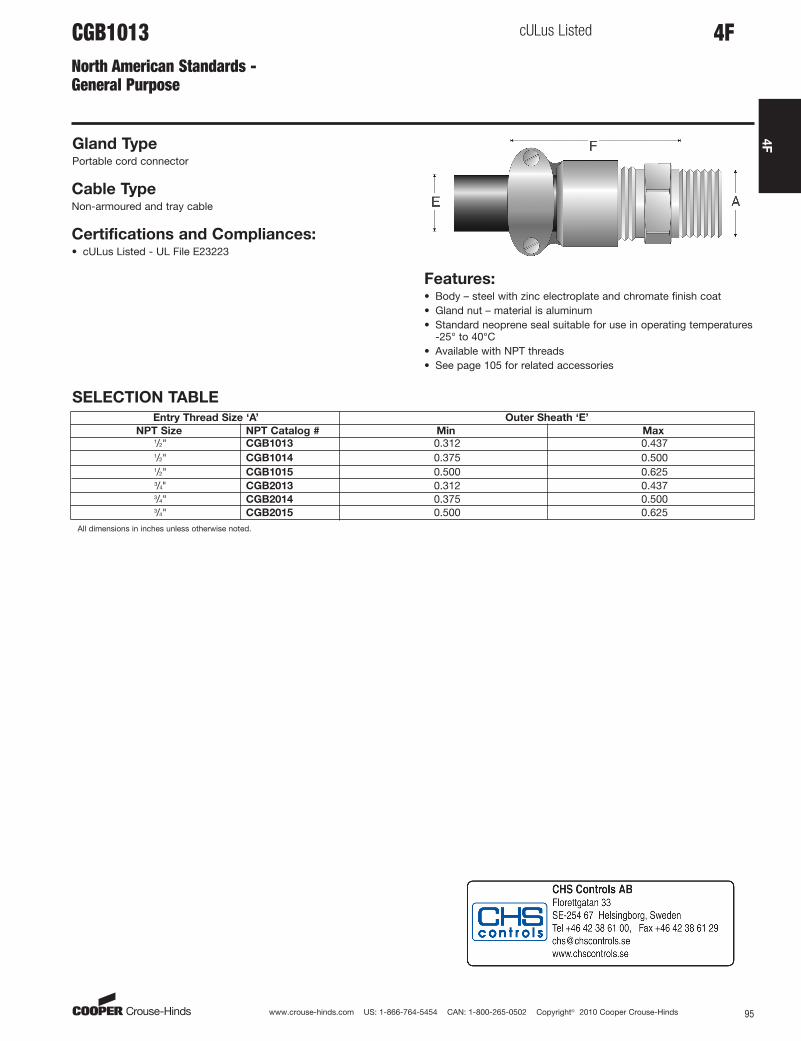
4FCGB1013North American Standards -General Purpose
cULus Listed
Gland TypePortable cord connector
Cable TypeNon-armoured and tray cable
Certifications and Compliances:• cULus Listed - UL File E23223
Features:• Body – steel with zinc electroplate and chromate finish coat• Gland nut – material is aluminum• Standard neoprene seal suitable for use in operating temperatures
-25° to 40°C• Available with NPT threads• See page 105 for related accessories
SELECTION TABLE
Entry Thread Size ‘A’ Outer Sheath ‘E’
NPT Size NPT Catalog # Min Max1/2" CGB1013 0.312 0.4371/2" CGB1014 0.375 0.5001/2" CGB1015 0.500 0.6253/4" CGB2013 0.312 0.4373/4" CGB2014 0.375 0.5003/4" CGB2015 0.500 0.625
All dimensions in inches unless otherwise noted.
aro
Standard
www.crouse-hinds.com US: 1-866-764-5454 CAN: 1-800-265-0502 Copyright© 2010 Cooper Crouse-Hinds96
4F
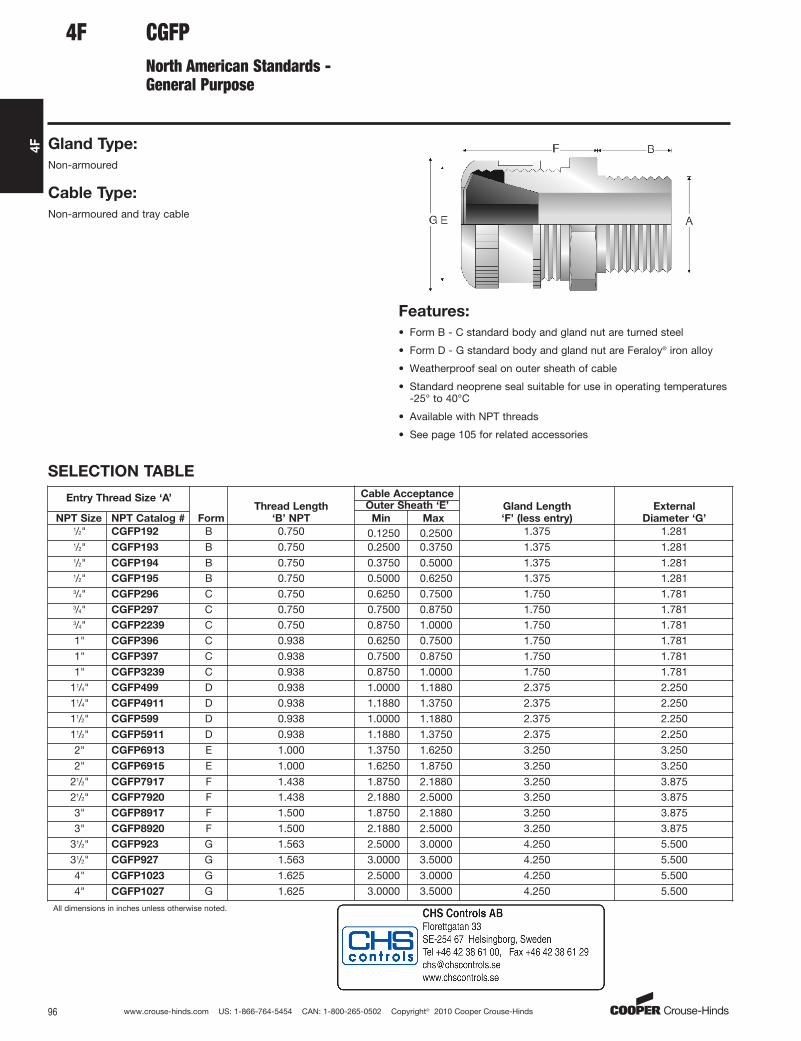
CGFPNorth American Standards -General Purpose
Gland Type:
Non-armoured
Cable Type:
Non-armoured and tray cable
Features:
• Form B - C standard body and gland nut are turned steel
• Form D - G standard body and gland nut are Feraloy® iron alloy
• Weatherproof seal on outer sheath of cable
• Standard neoprene seal suitable for use in operating temperatures-25° to 40°C
• Available with NPT threads
• See page 105 for related accessories
SELECTION TABLE
Entry Thread Size ‘A’
Form
Thread Length
‘B’ NPT
Cable Acceptance
Gland Length
‘F’ (less entry)
External
Diameter ‘G’NPT Size NPT Catalog #
Outer Sheath ‘E’
Min Max1/2" CGFP192 B 0.750 0.1250 0.2500 1.375 1.2811/2" CGFP193 B 0.750 0.2500 0.3750 1.375 1.2811/2" CGFP194 B 0.750 0.3750 0.5000 1.375 1.2811/2" CGFP195 B 0.750 0.5000 0.6250 1.375 1.2813/4" CGFP296 C 0.750 0.6250 0.7500 1.750 1.7813/4" CGFP297 C 0.750 0.7500 0.8750 1.750 1.7813/4" CGFP2239 C 0.750 0.8750 1.0000 1.750 1.7811" CGFP396 C 0.938 0.6250 0.7500 1.750 1.7811" CGFP397 C 0.938 0.7500 0.8750 1.750 1.7811" CGFP3239 C 0.938 0.8750 1.0000 1.750 1.781
11/4" CGFP499 D 0.938 1.0000 1.1880 2.375 2.25011/4" CGFP4911 D 0.938 1.1880 1.3750 2.375 2.25011/2" CGFP599 D 0.938 1.0000 1.1880 2.375 2.25011/2" CGFP5911 D 0.938 1.1880 1.3750 2.375 2.2502" CGFP6913 E 1.000 1.3750 1.6250 3.250 3.250
2" CGFP6915 E 1.000 1.6250 1.8750 3.250 3.25021/2" CGFP7917 F 1.438 1.8750 2.1880 3.250 3.87521/2" CGFP7920 F 1.438 2.1880 2.5000 3.250 3.8753" CGFP8917 F 1.500 1.8750 2.1880 3.250 3.8753" CGFP8920 F 1.500 2.1880 2.5000 3.250 3.875
31/2" CGFP923 G 1.563 2.5000 3.0000 4.250 5.50031/2" CGFP927 G 1.563 3.0000 3.5000 4.250 5.500
4" CGFP1023 G 1.625 2.5000 3.0000 4.250 5.5004" CGFP1027 G 1.625 3.0000 3.5000 4.250 5.500
All dimensions in inches unless otherwise noted.
4F
aro
Standard
www.crouse-hinds.com US: 1-866-764-5454 CAN: 1-800-265-0502 Copyright© 2010 Cooper Crouse-Hinds 97
4F
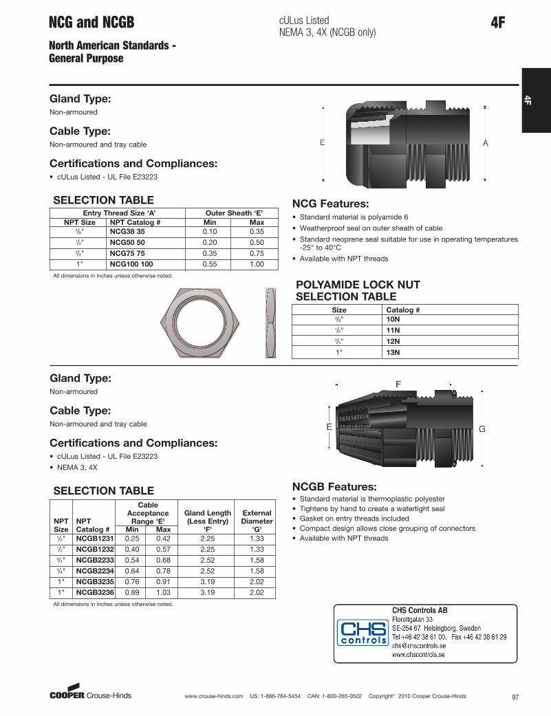
NCG and NCGBNorth American Standards -General Purpose
cULus ListedNEMA 3, 4X (NCGB only)
Gland Type:Non-armoured
Cable Type:Non-armoured and tray cable
Certifications and Compliances:• cULus Listed - UL File E23223
NCG Features:• Standard material is polyamide 6
• Weatherproof seal on outer sheath of cable
• Standard neoprene seal suitable for use in operating temperatures-25° to 40°C
• Available with NPT threads
SELECTION TABLEEntry Thread Size ‘A’ Outer Sheath ‘E’
NPT Size NPT Catalog # Min Max3/8" NCG38 35 0.10 0.351/2" NCG50 50 0.20 0.503/4" NCG75 75 0.35 0.751" NCG100 100 0.55 1.00
All dimensions in inches unless otherwise noted.
Gland Type:Non-armoured
Cable Type:Non-armoured and tray cable
Certifications and Compliances:• cULus Listed - UL File E23223
• NEMA 3, 4X
SELECTION TABLE
NPT
Size
NPT
Catalog #
Cable
Acceptance
Range 'E'
Gland Length
(Less Entry)
'F'
External
Diameter
'G'Min Max1/2" NCGB1231 0.25 0.42 2.25 1.331/2" NCGB1232 0.40 0.57 2.25 1.333/4" NCGB2233 0.54 0.68 2.52 1.583/4" NCGB2234 0.64 0.78 2.52 1.581" NCGB3235 0.76 0.91 3.19 2.021" NCGB3236 0.89 1.03 3.19 2.02
All dimensions in inches unless otherwise noted.
4F
POLYAMIDE LOCK NUT SELECTION TABLE
Size Catalog #3/8" 10N
1/2" 11N
3/4" 12N
1" 13N
NCGB Features:• Standard material is thermoplastic polyester• Tightens by hand to create a watertight seal• Gasket on entry threads included• Compact design allows close grouping of connectors• Available with NPT threads
aro
Standard

www.crouse-hinds.com US: 1-866-764-5454 CAN: 1-800-265-0502 Copyright© 2010 Cooper Crouse-Hinds98
4F
4F Accessories – A Series
A Series – Lock Nut – Standard material is nickel-plated brass
METRIC SELECTION TABLEEntry Thread A B Catalog #
M16 3 18 CAP221694M20 3 23 CAP222094M25 3 28 CAP222594M32 3.5 36 CAP223294M40 4 44 CAP224094M50 5 54 CAP225094M63 6 70 CAP226394M75 8 85 CAP227594
* For stainless steel replace last digit with "9".
NPT SELECTION TABLEEntry Thread A B Catalog #
1/2" 3.5 24 CAP2801243/4" 3.5 30 CAP280134
1" 4.5 37 CAP280144
11/4" 4.5 47 CAP280154
11/2" 5 52 CAP280164
2" 5.5 64 CAP280174
21/2" 6.5 77 CAP280184
A Series – Sealing Washer
METRIC SELECTION TABLE
Metric
Size
Metric
Catalog #
Metric
Diam.
‘D’
Metric
Thickness
‘E’
10 CAP221049 15.0 1.212 CAP221249 18.0 1.216 CAP221649 22.0 1.220 CAP222049 24.0 1.225 CAP222549 30.0 1.532 CAP223249 42.0 1.540 CAP224049 52.0 1.550 CAP225049 63.0 1.563 CAP226349 77.0 2.0– – – –– – – –
NPT SELECTION TABLE
NPT
Size
NPT
Catalog #
NPT
Diam.
‘D’
NPT
Thickness
‘E’
1/4" CAP229014 20.0 1.53/8" CAP229038 22.0 1.51/2" CAP229012 27.0 1.53/4" CAP229034 33.0 1.51" CAP229010 41.0 1.511/4" CAP229114 52.0 1.511/2" CAP229112 57.0 1.52" CAP229020 71.0 2.021/2" CAP229212 85.0 2.03" CAP229300 104.0 2.031/2" CAP229312 120.0 2.0
4F
A Series – Earth Tag – Standard material is nickel-plated brass
METRIC SELECTION TABLEEntry Thread A B C D Catalog #
M16 48.75 30 6.75 24.5 CAP567034M20 53.8 33 7 28.6 CAP567054M25 61.5 36 10.5 34 CAP567074M32 73 41 12.2 42 CAP567094M40 86.5 44.5 13.5 54 CAP567124M50 111.5 58 13.5 67 CAP567154M63 125.5 67 13.5 77 CAP567184M75 137.5 73 13.5 89 CAP567194
NPT SELECTION TABLEEntry Thread A B C D Catalog #
1/2" 61.5 36 10.5 34 CAP5670643/4" 73 41 12.2 42 CAP5670841" 73 41 12.2 42 CAP56710411/4" 86.5 44.5 13.5 54 CAP56713411/2" 111.5 58 13.5 67 CAP5671542" 125.5 67 13.5 77 CAP56717421/2" 137.5 73 13.5 89 CAP567194
All dimensions in millimeters unless otherwise noted.
– Standard material is neoprene
aro
Standard

www.crouse-hinds.com US: 1-866-764-5454 CAN: 1-800-265-0502 Copyright© 2010 Cooper Crouse-Hinds 99
4F
4FAccessories – A Series
A Series – Serrated Lock Washer
– Standard material is stainless steel
SELECTION TABLEMetric Size External Diameter Catalog #
16 25.5 CAP28006920 32.5 CAP28002925 39.5 CAP28025932 49.5 CAP28032940 64.5 CAP28040950 80.5 CAP28050963 100 CAP28063975 112 CAP28075990 123 CAP280099
A-Series – Shroud
– Standard material is PVC
SELECTION TABLEGland Size Catalog #
4 CAP5060405 CAP5060506 CAP5060607 CAP5060708 CAP5060809 CAP50609010 CAP50610011 CAP50611012 CAP50612013 CAP50613014 CAP50614015 CAP50615016 CAP506160
A Series – Clamping Module– Standard materials are nickel-plated brass body with stainless steel screws and washers
SELECTION TABLECable Range Gland Size Across Flats Width Thickness Catalog #
4-8.5 4 15 18 5 CAP8104346-11 5 19 22 5 CAP8105348.5-16 6 24 27.5 6 CAP81063412-21 7 30 33.5 8 CAP81073416-27.5 8 41 45 8 CAP81083421-34 9 48 52 9.5 CAP81093427-41 10 55 59 9.5 CAP81103433-48 11 64 69 12 CAP81113440-56 12 72 78 12 CAP81123447-65 13 85 92 16 CAP81133454-74 14 95 103 16 CAP81143463-83 15 110 118 18 CAP81153472-93 16 120 128 18 CAP811634
A Series – Earthing Washer – Standard material is brass
METRIC SELECTION TABLE
Gland Size
Lead Sheath Sealing RangeCable
Diameter Catalog #Min Max
5 4 7.5 10 CAP5605306 6 11 13.9 CAP5606307 9 15 18.3 CAP5607308 12 20 23.8 CAP5608309 16 26.5 31 CAP56093010 21 32.5 38.3 CAP56103011 28 39.5 45.3 CAP56113012 33 46.5 52.8 CAP56123013 40 54.5 60.8 CAP56133014 46.5 61 71 CAP56143015 54 72.5 80.5 CAP56153016 63 81.5 89.5 CAP561630
All dimensions in millimeters unless otherwise noted.
aro
Standard

www.crouse-hinds.com US: 1-866-764-5454 CAN: 1-800-265-0502 Copyright© 2010 Cooper Crouse-Hinds100
4F
METRIC x NPT SELECTION TABLEFemale →→
Male 1/4" 3/8" 1/2" 3/4" 1" 11/4" 11/2" 2" 21/2" 3" 31/2"
M12 744104M16 744194 744694M20 744204 744214 744704 744964M25 744714 744974 745234M32 744724 744984 745244 745504M40 744994 745254 745514 745774M50 745264 745524 745784 746044M63 745794 746054 746314M75 746064 746324 746584M90 744304M110
Accessories – A Series
A Series – Adaptors and Reducers
METRIC x METRIC SELECTION TABLEFemale →→
Male M12 M16 M20 M25 M32 M40 M50 M63 M75 M80 M90 M110
M12 745334M16 745834 740274M20 745844 740024 740544M25 740034 740294 740814M32 740304 740564 741084M40 740574 740834 741354M50 740844 741104 741624M63 741114 741374 741894M75 741384 741644 745394M90 745864M110
Size available – no part number
Size not available
NPT x METRIC SELECTION TABLEFemale →→
Male M12 M16 M20 M25 M32 M40 M50 M63 M75 M90 M100 M1101/4" 740614 7406243/8" 740884 740894 7409041/2" 740914 740194 740454 7407143/4" 740204 740464 740724 7409841" 740474 740734 740994 741264 741524
11/4" 740744 741004 741274 741534 74179411/2" 741104 741284 741544 741804 7420642" 741554 741814
21/2" 7418243"
31/2"4"
NPT x NPT SELECTION TABLEFemale →→
Male 1/4" 3/8" 1/2" 3/4" 1" 11/4" 11/2" 2" 21/2" 3" 31/2" 4"
1/4"3/8" 745574 7446241/2" 745594 7451343/4" 744884 7454041" 744894 745154 745674
11/4" 745164 745424 74594411/2" 745434 745694 7462142" 745704 745964 746484
21/2" 7462343" 746244 746504
31/2"4"
* For stainless steel replace last digit with "9".
4F
– Standard material is nickel-plated brass
ATEX Exe Exd with LCIE 98 ATEX 00010
aro
Standard

www.crouse-hinds.com US: 1-866-764-5454 CAN: 1-800-265-0502 Copyright© 2010 Cooper Crouse-Hinds 101
4F
Accessories – A Series
A Series – Stopping Plug
METRIC SELECTION TABLEMetric
Size Metric Catalog #*
Across Flats
‘A’
Hex Thickness
‘B’
Thread Length
‘E’
12 CAP190124 14 2.8 1516 CAP190164 18 3.0 1520 CAP190204 23 3.0 1525 CAP190254 28 3.5 1532 CAP190324 36 4.0 1540 CAP190404 44 4.0 1550 CAP190504 54 5.0 1663 CAP190634 67 5.5 1775 CAP190754 80 6.0 1880 CAP190804 85 7.0 2090 CAP199904 95 8.0 22100 CAP191004 110 10.0 22* For stainless steel replace last digit with "9".
NPT SELECTION TABLENPT Size NPT Catalog #* Across Flats ‘A’ Hex Thickness ‘B’ Thread Length ‘E’
1/4" CAP190194 14 2.8 123/8" CAP109294 18 2.8 121/2" CAP190394 22 3.0 163/4" CAP190494 28 3.0 161" CAP190594 36 3.5 2011/4" CAP190694 44 4.0 2011/2" CAP190794 50 5.0 202" CAP190894 64 5.5 2021/2" CAP190994 75 6.0 283" CAP191094 90 6.0 3031/2" CAP191194 110 10.0 32All dimensions in millimeters unless otherwise noted.
*For stainless steel replace last digit with "9".
*For stainless steel replace last digit with "9".
A Series – Nonmetallic Stopping Plug – Standard material is polyamide 6; ATEX
certified Ex e II with LCIE 97ATEX6007X
Washer and locknut are required for non-threaded holes (not included) see page 98
4F
POLYAMIDE SELECTION TABLEMetric
Size
Metric
Catalog #*
Across
Flats ‘A’
Hex
Thickness ‘B’
Thread
Length ‘E’
12 CAP191127 15 4 1516 CAP191167 19 4 1520 CAP191207 23 4 1525 CAP191257 28 5 1532 CAP191327 36 5.5 1540 CAP191407 44 5.5 1550 CAP191507 54 6 1663 CAP191637 67 6.5 17
– Standard material is nickel-plated brass;
ATEX Exe Exd with LCIE 98 ATEX 00010
aro
Standard

www.crouse-hinds.com US: 1-866-764-5454 CAN: 1-800-265-0502 Copyright© 2010 Cooper Crouse-Hinds102
4F
Accessories – B Series
B Series – Lock Nut – Standard material is brass
NPT SELECTION TABLENPT Entry Thread Catalog #
1/2" BLN/050NPT3/4" BLN/075NPT1" BLN/100NPT11/4" BLN/125NPT11/2" BLN/150NPT2" BLN/200NPT21/2" BLN/250NPT3" BLN/300NPT31/2" BLN/350NPT4" BLN/400NPT
B Series – Sealing Washer – Standard material is nylon
NPT SELECTION TABLENPT Entry Thread Catalog #
1/2" RNSW/050NPT3/4" RNSW/075NPT1" RNSW/100NPT11/4" RNSW/125NPT11/2" RNSW/150NPT2" RNSW/200NPT21/2" RNSW/250NPT3" RNSW/300NPT31/2" RNSW/350NPT4" RNSW/400NPT
B Series – Earth Tag – Standard material is brass
METRIC SELECTION TABLEMetric Entry Thread Catalog #
M16 BET/M16M20 BET/M20M25 BET/M25M32 BET/M32M40 BET/M40M50 BET/M50M63 BET/M63M75 BET/M75M80 BET/M80M85 BET/M85M90 BET/M90M100 BET/M100
NPT SELECTION TABLENPT Entry Thread Catalog #
1/2" BET/050NPT3/4" BET/075NPT1" BET/100NPT11/4" BET/125NPT11/2" BET/150NPT2" BET/200NPT21/2" BET/250NPT3" BET/300NPT31/2" BET/350NPT4" BET/400NPT
B Series – Shroud
PVC SELECTION TABLESize (Gland Size) Catalog #
L24 (16, 20s) PVC-L24L30 (20) PVC-L30L38 (25) PVC-L38L46 (32) PVC-L46L55 (40) PVC-L55L65 (50, 50s) PVC-L65L80 (63, 63s) PVC-L80L90 (75, 75s) PVC-L90L104 (80,85) PVC-L104L114 (90, 100) PVC-L114
PCP SELECTION TABLESize Catalog #
L24 (16, 20s) PCP-L24L30 (20) PCP-L30L38 (25) PCP-L38L46 (32) PCP-L46L55 (40) PCP-L55L65 (50, 50s) PCP-L65L80 (63, 63s) PCP-L80L90 (75, 75s) PCP-L90L104 (80, 85) PCP-L104
All dimensions in millimeters unless otherwise noted.
METRIC SELECTION TABLEMetric Entry Thread Catalog #
M16 BLN/M16M20 BLN/M20M25 BLN/M25M32 BLN/M32M40 BLN/M40M50 BLN/M50M63 BLN/M63M75 BLN/M75M80 BLN/M80M85 BLN/M85M90 BLN/M90M100 BLN/M100
METRIC SELECTION TABLEMetric Entry Thread Catalog #
M16 RNSW/M16M20 RNSW/M20M25 RNSW/M25M32 RNSW/M32M40 RNSW/M40M50 RNSW/M50M63 RNSW/M63M75 RNSW/M75M80 RNSW/M80M85 RNSW/M85M90 RNSW/M90M100 RNSW/M100
4F
PCP
PVC
aro
Standard

www.crouse-hinds.com US: 1-866-764-5454 CAN: 1-800-265-0502 Copyright© 2010 Cooper Crouse-Hinds 103
4F
Accessories – C Series
C Series – Lock Nut – Standard material is brass
METRIC SELECTION TABLE
Metric Entry Diameter Catalog #
20 LNM125 LNM232 LNM340 LNM450 LNM563 LNM675 LNM780 LNM8
NPT SELECTION TABLE
NPT Entry Diameter Catalog #
1/2" LNN13/4" LNN21" LNN311/4" LNN411/2" LNN52" LNN621/2" LNN73" LNN8
C Series – Sealing Washer/Gaskets – Standard material is nylon
METRIC SELECTION TABLE
Metric Entry Diameter Catalog #
20 SGM125 SGM232 SGM340 SGM450 SGM563 SGM675 SGM780 SGM8
NPT SELECTION TABLE
NPT Entry Diameter Catalog #
1/2" SGN13/4" SGN21" SGN311/4" SGN411/2" SGN52" SGN621/2" SGN73" SGN8
C Series – Earth Tag – Standard material is nickel-plated brass
SELECTION TABLE
Metric Entry
Diameter
NPT Entry
Thread Catalog #
20 1/2" ET125 3/4" ET232 1" ET340 11/4" ET450 11/2" ET563 2" ET675 21/2" ET780 3" ET8
C Series – Shroud – Standard material is PVC
SELECTION TABLECatalog
Number To Suit Gland
SH1 TUA1M10 TUA1M12TUA1M15 TWA1M13 – TWAX1M13 –
SH2 – TWA1M16 TWAE1M16 TWAX1M16 TWAB1M16 TWAB1M20SH3 – TWA1M20 TWAE1M20 TWAX1M20 –SH4 TUA2M18 – – TWAX2M24 –SH5 TUA3M23 TWA2M27 TWAE2M27 TWAX2M27 TWAB2M27SH6 TUA3M25 – – TWAX3M30 –SH7 – TWA3M34 TWAE3M34 TWAX3M33 TWAB3M34SH8 TUA5M34 TWA4M40 TWAE4M40 TWAX4M38 TWAX5M43 TWAB4M40SH9 TUA5M38 TUA5M42 – – TWAX5M48 –SH10 TUA6M48 – – TWAX5M52 TWAB5M53SH11 – TWA5M53 TWAE5M53 TWAX6M60 TWAX6M65 TWAB6M66SH12 TUA6M54 TUA7M60 TWA6M66 TWAE6M66 TWAX7M71 –SH13 TUA7M66 – – – –SH14 – TWA7M78 TWAE7M78 TWAX7M78 TWAB7M78
4F
aro
Standard
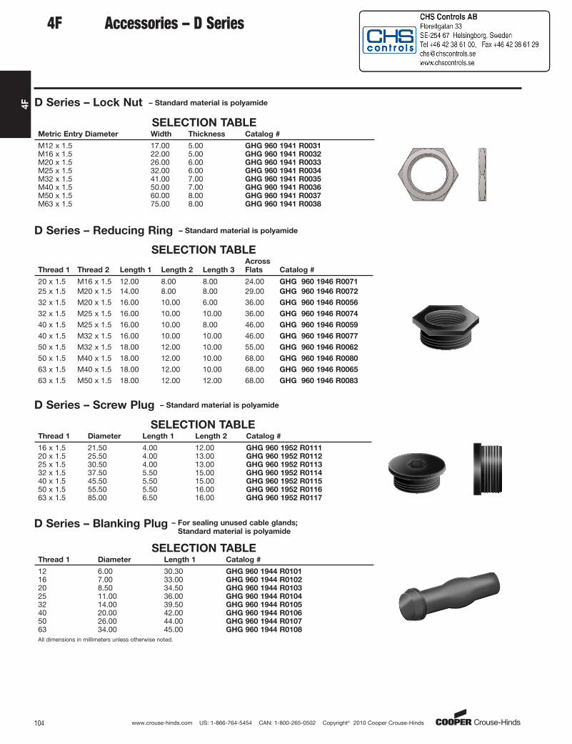
www.crouse-hinds.com US: 1-866-764-5454 CAN: 1-800-265-0502 Copyright© 2010 Cooper Crouse-Hinds104
4F
Accessories – D Series
D Series – Lock Nut – Standard material is polyamide
SELECTION TABLEMetric Entry Diameter Width Thickness Catalog #
M12 x 1.5 17.00 5.00 GHG 960 1941 R0031M16 x 1.5 22.00 5.00 GHG 960 1941 R0032M20 x 1.5 26.00 6.00 GHG 960 1941 R0033M25 x 1.5 32.00 6.00 GHG 960 1941 R0034M32 x 1.5 41.00 7.00 GHG 960 1941 R0035M40 x 1.5 50.00 7.00 GHG 960 1941 R0036M50 x 1.5 60.00 8.00 GHG 960 1941 R0037M63 x 1.5 75.00 8.00 GHG 960 1941 R0038
D Series – Reducing Ring – Standard material is polyamide
SELECTION TABLE
Thread 1 Thread 2 Length 1 Length 2 Length 3
Across
Flats Catalog #
20 x 1.5 M16 x 1.5 12.00 8.00 8.00 24.00 GHG 960 1946 R0071
25 x 1.5 M20 x 1.5 14.00 8.00 8.00 29.00 GHG 960 1946 R0072
32 x 1.5 M20 x 1.5 16.00 10.00 6.00 36.00 GHG 960 1946 R0056
32 x 1.5 M25 x 1.5 16.00 10.00 10.00 36.00 GHG 960 1946 R0074
40 x 1.5 M25 x 1.5 16.00 10.00 8.00 46.00 GHG 960 1946 R0059
40 x 1.5 M32 x 1.5 16.00 10.00 10.00 46.00 GHG 960 1946 R0077
50 x 1.5 M32 x 1.5 18.00 12.00 10.00 55.00 GHG 960 1946 R0062
50 x 1.5 M40 x 1.5 18.00 12.00 10.00 68.00 GHG 960 1946 R0080
63 x 1.5 M40 x 1.5 18.00 12.00 10.00 68.00 GHG 960 1946 R0065
63 x 1.5 M50 x 1.5 18.00 12.00 12.00 68.00 GHG 960 1946 R0083
D Series – Screw Plug – Standard material is polyamide
SELECTION TABLEThread 1 Diameter Length 1 Length 2 Catalog #
16 x 1.5 21.50 4.00 12.00 GHG 960 1952 R011120 x 1.5 25.50 4.00 13.00 GHG 960 1952 R011225 x 1.5 30.50 4.00 13.00 GHG 960 1952 R011332 x 1.5 37.50 5.50 15.00 GHG 960 1952 R011440 x 1.5 45.50 5.50 15.00 GHG 960 1952 R011550 x 1.5 55.50 5.50 16.00 GHG 960 1952 R011663 x 1.5 85.00 6.50 16.00 GHG 960 1952 R0117
D Series – Blanking Plug – For sealing unused cable glands;
Standard material is polyamide
SELECTION TABLEThread 1 Diameter Length 1 Catalog #
12 6.00 30.30 GHG 960 1944 R010116 7.00 33.00 GHG 960 1944 R010220 8.50 34.50 GHG 960 1944 R010325 11.00 36.00 GHG 960 1944 R010432 14.00 39.50 GHG 960 1944 R010540 20.00 42.00 GHG 960 1944 R010650 26.00 44.00 GHG 960 1944 R010763 34.00 45.00 GHG 960 1944 R0108
All dimensions in millimeters unless otherwise noted.
4F
aro
Standard
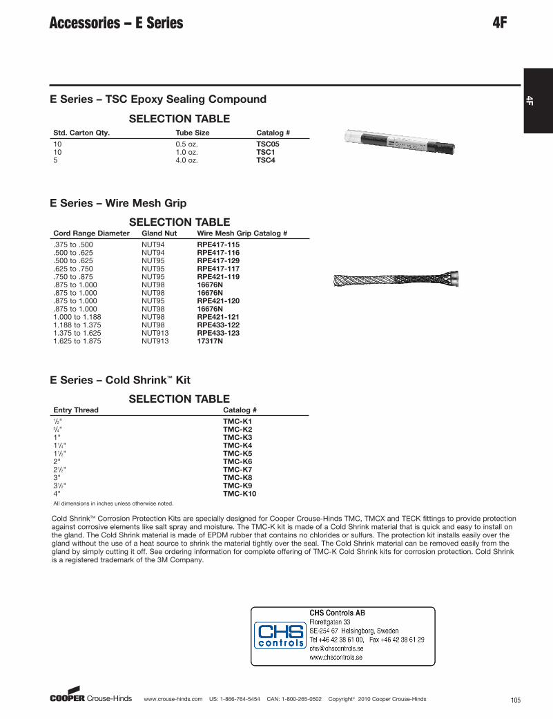
www.crouse-hinds.com US: 1-866-764-5454 CAN: 1-800-265-0502 Copyright© 2010 Cooper Crouse-Hinds 105
4F
Accessories – E Series
E Series – TSC Epoxy Sealing Compound
SELECTION TABLE
Std. Carton Qty. Tube Size Catalog #
10 0.5 oz. TSC0510 1.0 oz. TSC15 4.0 oz. TSC4
E Series – Wire Mesh Grip
SELECTION TABLECord Range Diameter Gland Nut Wire Mesh Grip Catalog #
.375 to .500 NUT94 RPE417-115
.500 to .625 NUT94 RPE417-116
.500 to .625 NUT95 RPE417-129
.625 to .750 NUT95 RPE417-117
.750 to .875 NUT95 RPE421-119
.875 to 1.000 NUT98 16676N
.875 to 1.000 NUT98 16676N
.875 to 1.000 NUT95 RPE421-120
.875 to 1.000 NUT98 16676N1.000 to 1.188 NUT98 RPE421-1211.188 to 1.375 NUT98 RPE433-1221.375 to 1.625 NUT913 RPE433-1231.625 to 1.875 NUT913 17317N
E Series – Cold Shrink™ Kit
SELECTION TABLEEntry Thread Catalog #
1/2" TMC-K13/4" TMC-K21" TMC-K311/4" TMC-K411/2" TMC-K52" TMC-K621/2" TMC-K73" TMC-K831/2" TMC-K94" TMC-K10
All dimensions in inches unless otherwise noted.
Cold ShrinkTM Corrosion Protection Kits are specially designed for Cooper Crouse-Hinds TMC, TMCX and TECK fittings to provide protectionagainst corrosive elements like salt spray and moisture. The TMC-K kit is made of a Cold Shrink material that is quick and easy to install onthe gland. The Cold Shrink material is made of EPDM rubber that contains no chlorides or sulfurs. The protection kit installs easily over thegland without the use of a heat source to shrink the material tightly over the seal. The Cold Shrink material can be removed easily from thegland by simply cutting it off. See ordering information for complete offering of TMC-K Cold Shrink kits for corrosion protection. Cold Shrinkis a registered trademark of the 3M Company.
4F
aro
Standard
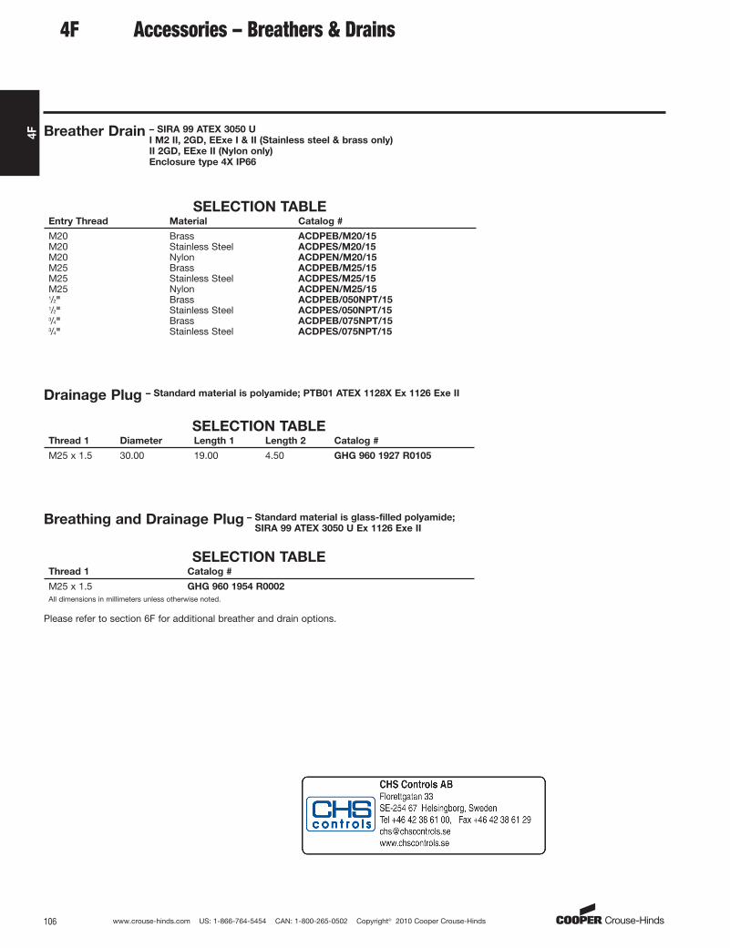
www.crouse-hinds.com US: 1-866-764-5454 CAN: 1-800-265-0502 Copyright© 2010 Cooper Crouse-Hinds106
4F
Accessories – Breathers & Drains
Breather Drain – SIRA 99 ATEX 3050 U
I M2 II, 2GD, EExe I & II (Stainless steel & brass only)
II 2GD, EExe II (Nylon only)
Enclosure type 4X IP66
SELECTION TABLEEntry Thread Material Catalog #
M20 Brass ACDPEB/M20/15M20 Stainless Steel ACDPES/M20/15M20 Nylon ACDPEN/M20/15M25 Brass ACDPEB/M25/15M25 Stainless Steel ACDPES/M25/15M25 Nylon ACDPEN/M25/151/2" Brass ACDPEB/050NPT/151/2" Stainless Steel ACDPES/050NPT/153/4" Brass ACDPEB/075NPT/153/4" Stainless Steel ACDPES/075NPT/15
Breathing and Drainage Plug – Standard material is glass-filled polyamide;
SIRA 99 ATEX 3050 U Ex 1126 Exe II
SELECTION TABLEThread 1 Catalog #
M25 x 1.5 GHG 960 1954 R0002
All dimensions in millimeters unless otherwise noted.
Please refer to section 6F for additional breather and drain options.
4F
Drainage Plug – Standard material is polyamide; PTB01 ATEX 1128X Ex 1126 Exe II
SELECTION TABLEThread 1 Diameter Length 1 Length 2 Catalog #
M25 x 1.5 30.00 19.00 4.50 GHG 960 1927 R0105
aro
Standard

www.crouse-hinds.com US: 1-866-764-5454 CAN: 1-800-265-0502 Copyright© 2010 Cooper Crouse-Hinds 107
4F
LCC Series Cable TrayConduit Clamps
Applications:LCC cable tray conduit clamps are used for installation on cable trayside rails with inside flanges (requiring inside tray mounting) andoutside flanges; LCCF clamps are for use exclusively on insideflanges.
LCC/LCCF cable tray conduit clamps:
• Provide a means of clamping metal conduit (rigid steel oraluminum, IMC and EMT) to cable tray to provide for the exit ofpower and/or control cables from tray
• Provide a means to firmly bond exit conduit to cable tray for bestgrounding continuity
• Provide strong mechanical support for exit conduits and cables
• Can be used indoors or outdoors, wherever cable tray systems areinstalled
• Facilitate the safe exit of cables from tray – insure protection ofcables from damage
Features:• Quick and easy installation – low installed cost. Merely tighten
clamp nut and/or set screw(s)
• Swivel hook clears conduit. No disassembly required forinstallation
• No drilling or welding necessary for installation
• Provides superior ground continuity between conduit and cabletray
• Clamps conduit at any angle with relation to tray – facilitates wirepulling, minimizes conduit bending
• Malleable iron body provides great strength
• Knurled body has no-slip surface for conduit and tray – positivegrip assured
• Compact design has low profile – minimum tray space required forassembly
• Design accommodates all popular types of cable tray
• Accommodates wide range of conduit sizes – 1/2" through 4"
LCCF features:
• Outside mounting facilitates inside rail installation
• Adjustable hook assures positive grip on inside rail
• Accommodates 3/4" through 13/4" wide flange
Standard Materials:• Body – cast iron
• Hook – steel
• Set screws and clamping nut – steel
• Hook cap – vinyl
Standard Finishes:• Cast iron – electrogalvanized and aluminum acrylic paint
• Steel – zinc electroplate
• Vinyl – natural
Conduit Size Ranges:• 1/2" to 4"
Certifications and Compliances:• UL Standard: 467 (Grounding and Bonding Equipment)
LCC LCCF
For use with outside rail tray For use with inside rail tray
DimensionsIn Inches:
LCC LCCF
LCC LCCFConduit Size a b a b c
1/2 33/16 111/16 31/8 15/8 111/323/4 37/16 111/16 311/32 15/8 111/32
1 39/16 111/16 319/32 15/8 111/32
11/4 4 111/16 315/16 15/8 111/32
11/2 413/16 211/16 43/4 23/4 111/16
2 55/16 211/16 51/4 23/4 111/16
21/2 513/16 211/16 53/4 23/4 111/16
3 613/16 33/4 63/4 311/16 23/16
31/2 75/16 33/4 71/4 311/16 23/16
4 713/16 33/4 73/4 311/16 23/16
Ordering InformationConduit Size Cat. # Cat. #
1/2 LCC1 LCCF13/4 LCC2 LCCF21 LCC3 LCCF311/4 LCC4 LCCF411/2 LCC5 LCCF52 LCC6 LCCF621/2 LCC7 LCCF73 LCC8 LCCF831/2 LCC9 LCCF94 LCC010 LCCF010
4F
aro
Standard
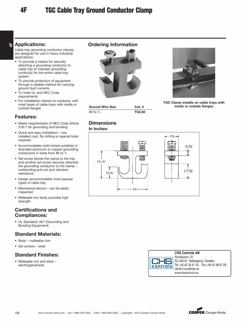
www.crouse-hinds.com US: 1-866-764-5454 CAN: 1-800-265-0502 Copyright© 2010 Cooper Crouse-Hinds108
4F
TGC Cable Tray Ground Conductor Clamp
Applications:Cable tray grounding conductor clampsare designed for use in heavy industrialapplications:• To provide a means for securely
attaching a grounding conductor tocable tray to maintain groundingcontinuity for the entire cable traysystem
• To provide protection of equipmentthrough a reliable method for carryingground fault currents
• To meet UL and NEC Coderequirements
• For installation indoors or outdoors, withmost types of cable trays with inside oroutside flanges
Features:
• Meets requirements of NEC Code Article318-7 for grounding and bonding
• Quick and easy installation – lowinstalled cost. No drilling or special toolsrequired.
• Accommodates solid (where suitable) orstranded aluminum or copper groundingconductors in sizes from #6 to 2/0
• Set screw bonds the clamp to the trayand another set screw securely attachesthe grounding conductor to the clamp –outstanding pull-out and vibrationresistance
• Design accommodates most populartypes of cable tray
• Mechanical device – can be easilyinspected
• Malleable iron body provides highstrength
Standard Materials:
• Body – malleable iron
• Set screws – steel
Standard Finishes:
• Malleable iron and steel –electrogalvanized
Certifications andCompliances:
• UL Standard: 467 (Grounding andBonding Equipment)
Ordering Information
Ground Wire Size Cat. #
#6 to 2/0 TGC40
TGC Clamp installs on cable trays with
inside or outside flanges
DimensionsIn Inches:
4F
aro
Standard
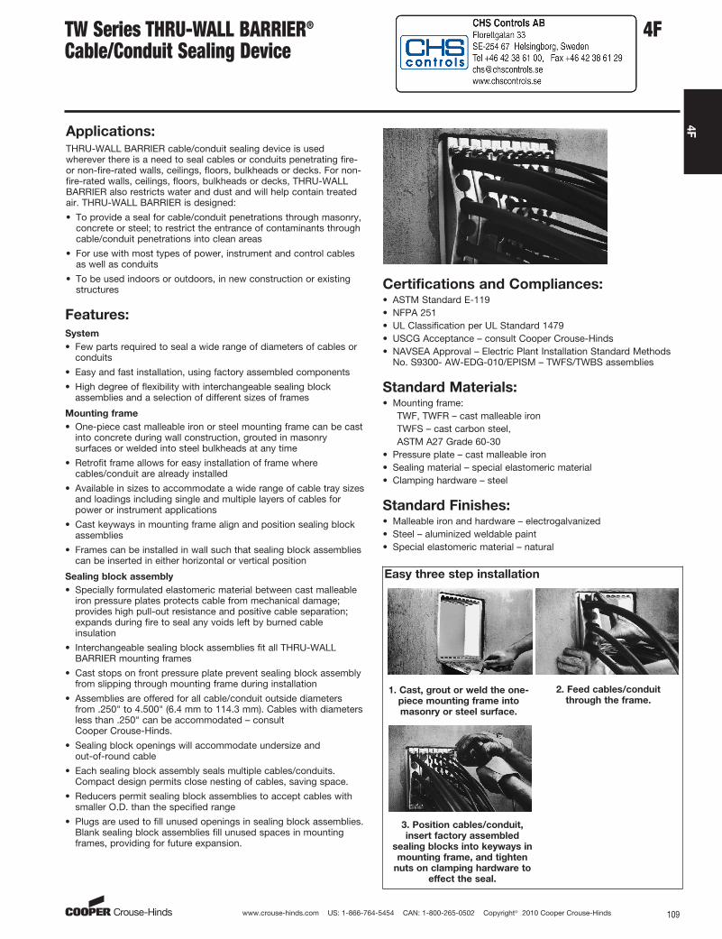
www.crouse-hinds.com US: 1-866-764-5454 CAN: 1-800-265-0502 Copyright© 2010 Cooper Crouse-Hinds 109
4F
TW Series THRU-WALL BARRIER®
Cable/Conduit Sealing Device
Applications:THRU-WALL BARRIER cable/conduit sealing device is usedwherever there is a need to seal cables or conduits penetrating fire-or non-fire-rated walls, ceilings, floors, bulkheads or decks. For non-fire-rated walls, ceilings, floors, bulkheads or decks, THRU-WALLBARRIER also restricts water and dust and will help contain treatedair. THRU-WALL BARRIER is designed:
• To provide a seal for cable/conduit penetrations through masonry,concrete or steel; to restrict the entrance of contaminants throughcable/conduit penetrations into clean areas
• For use with most types of power, instrument and control cablesas well as conduits
• To be used indoors or outdoors, in new construction or existingstructures
Features:
System
• Few parts required to seal a wide range of diameters of cables orconduits
• Easy and fast installation, using factory assembled components
• High degree of flexibility with interchangeable sealing blockassemblies and a selection of different sizes of frames
Mounting frame
• One-piece cast malleable iron or steel mounting frame can be castinto concrete during wall construction, grouted in masonrysurfaces or welded into steel bulkheads at any time
• Retrofit frame allows for easy installation of frame wherecables/conduit are already installed
• Available in sizes to accommodate a wide range of cable tray sizesand loadings including single and multiple layers of cables forpower or instrument applications
• Cast keyways in mounting frame align and position sealing blockassemblies
• Frames can be installed in wall such that sealing block assembliescan be inserted in either horizontal or vertical position
Sealing block assembly
• Specially formulated elastomeric material between cast malleableiron pressure plates protects cable from mechanical damage;provides high pull-out resistance and positive cable separation;expands during fire to seal any voids left by burned cableinsulation
• Interchangeable sealing block assemblies fit all THRU-WALLBARRIER mounting frames
• Cast stops on front pressure plate prevent sealing block assemblyfrom slipping through mounting frame during installation
• Assemblies are offered for all cable/conduit outside diametersfrom .250" to 4.500" (6.4 mm to 114.3 mm). Cables with diametersless than .250" can be accommodated – consult Cooper Crouse-Hinds.
• Sealing block openings will accommodate undersize and out-of-round cable
• Each sealing block assembly seals multiple cables/conduits.Compact design permits close nesting of cables, saving space.
• Reducers permit sealing block assemblies to accept cables withsmaller O.D. than the specified range
• Plugs are used to fill unused openings in sealing block assemblies.Blank sealing block assemblies fill unused spaces in mountingframes, providing for future expansion.
Standard Materials:• Mounting frame:
TWF, TWFR – cast malleable ironTWFS – cast carbon steel,ASTM A27 Grade 60-30
• Pressure plate – cast malleable iron• Sealing material – special elastomeric material• Clamping hardware – steel
Standard Finishes:• Malleable iron and hardware – electrogalvanized• Steel – aluminized weldable paint• Special elastomeric material – natural
Certifications and Compliances:• ASTM Standard E-119• NFPA 251• UL Classification per UL Standard 1479• USCG Acceptance – consult Cooper Crouse-Hinds• NAVSEA Approval – Electric Plant Installation Standard Methods
No. S9300- AW-EDG-010/EPISM – TWFS/TWBS assemblies
Easy three step installation
1. Cast, grout or weld the one-
piece mounting frame into
masonry or steel surface.
2. Feed cables/conduit
through the frame.
3. Position cables/conduit,
insert factory assembled
sealing blocks into keyways in
mounting frame, and tighten
nuts on clamping hardware to
effect the seal.
4F
aro
Standard

www.crouse-hinds.com US: 1-866-764-5454 CAN: 1-800-265-0502 Copyright© 2010 Cooper Crouse-Hinds110
4F
.500–.750.250–.500Opening
Size
Range
.750–1.000
4F TW Series THRU-WALL BARRIER®
Cable/Conduit Sealing DeviceSealing Block Assemblies & Mounting FramesOrdering Information
TWB Sealing Block Assemblies
TWB sealing block assemblies are offeredfor cable/conduit outside diameters (O.D.)from .250" to 4.500" (6.4 mm to 114.3mm). Cables with diameters less than.250" can be accommodated – consultCooper Crouse-Hinds. Each assemblyopening will accommodate a .250" (6.4 mm) O.D. range. When clampinghardware is tightened, the elastomericmaterial is uniformly compressed aroundall cable/conduits for a completely tight fit.
TWB2063
Depending on opening size range, a
standard sealing block assembly will
seal from one to eleven cables
In.mm
1.000–1.250 1.250–1.500 1.500–1.750 1.750–2.000 2.000–2.250 2.250–2.500
6.4–12.7 12.7–19.1 19.1–25.4 25.4–31.8 31.8–38.1 38.1–44.5 44.5–50.8 50.8–57.2 57.2–63.5
No. Openings
In Block11 11
Added* 6 11Added* 6 5 4 3 3 3 2
Sealing
Block
Assembly
Cat. #
TWB2111 TWB2062
TWB2063 TWB3054 TWB3045 TWB30355 TWB4036 TWB40366 TWB5027TWB1111 TWB2112
Frame
Spaces
Required
2 1 2 2 2 3 3 3 4 4 5
Plug Cat. # TWP1 TWP3 TWP5 TWP6 TWP7
Reducer
Cat. # §— TWR2 TWR3 TWR4 TWR5 TWR55 TWR6 TWR66 TWR7
TWF Mounting FramesTWF(S) mounting frames may be installedeither horizontally or vertically. TWFR retrofitframes are used wherever cables/conduitsare already installed through a fire- or non-fire-rated wall, floor or ceiling. They aredesigned with a removable section to permitinstallation around cables/conduits. TWFRretrofit frames can be grouted into walls,floors, or ceilings, or welded into steelbulkheads or decks. TWFR retrofit frameswill perform in the same manner as the one-piece TWF(S) frames.
TWFS steel mounting frames are weldeddirectly into steel bulkheads, decks andprepared sleeves. For marine applications,keeper bars are provided to securely holdTWBS sealing block assemblies in positionwhen installed.
TWF12
TWF6
TWF10TWFS10
No. of Spaces
Available Frame Cat. #
Retrofit
Frame Cat. #
Cast Steel
Frame Cat. #
6 TWF6 TWFR610 TWF10 TWFR10 TWFS1012 TWF12J TWFR12‡20 TWF20 TWFR20 TWFS2024 TWF24 TWFR2430 TWF30 TWFR30 TWFS30
‡Includes removable partition.
†For 3.5" - 4" cable/conduit – use TWB7011010 assembly and reduce down using TWR reducers.*Catalog # TWB1111 and TWB2112 are used between TWB2111 and TWB2062 in cases where the number of cables to be sealed in .250-.750 range exceeds the number of openings instandard assemblies. Use as many of these higher density assemblies as needed, sandwiched between halves of a standard assembly.§TWR reducers match TWB sealing block assemblies shown in column above Cat. No. and reduce openings to accept cable size ranges shown in adjacent column to the left (in direction ofarrow).
Sealing block assemblies are offered foruse in marine applications. Each assemblyhas the required lubrication and sealinggaskets to meet U.S. Navy HydrostaticPressure Test Requirements. Assembliesfor marine applications are available forcable/conduit outside diameters (O.D.)from .250" (6.4 mm) through 3.500" (88.9mm). To order, add suffix S to TWBsealing block assembly Cat. No. Example:TWBS4036.
aro
Standard

www.crouse-hinds.com US: 1-866-764-5454 CAN: 1-800-265-0502 Copyright© 2010 Cooper Crouse-Hinds 111
4F
5
4FTW Series THRU-WALL BARRIER®
Cable/Conduit Sealing DevicePlugs, Reducers, Closure Cover Kits, Anchors & LubricantOrdering Information
TWB2112 TWB2062
TWP Plugs
TWP plugs will close any unused openingsin sealing block assemblies. See table forplug catalog numbers which matchspecific sealing block assemblies.
TWR Reducers
TWR reducers will reduce openings by.250" (6.4 mm) in sealing blockassemblies. See table for reducer catalognumbers which match specific sealingblock assemblies. More than one reducercan be used in a single opening.
It is possible to increase cable fill density with double-sided sealing block assemblies (TWB1111 and TWB2112) sandwiched between halvesof a standard assembly.
2.500–2.750 2.750–3.000 3.000–3.250 3.250–3.500 3.500–4.250† 4.250–4.500 Blank – NoOpenings63.5–69.9 69.9–76.2 76.2–82.6 82.6–88.9 101.6–108.0 108.0–114.3
2 2 2 2 1 1 None None
TWB50277 TWB5028 TWB60288 TWB6029 TWB7011010 TWB70111 TWB1 TWB3
5 6 6 7 7 1 3
TWP7 TWP8 TWP9 TWP10 TWP11 —
TWR77 TWR8 TWR88TWR9 TWR1010
TWR11 —TWR99 TWR10
TWB Closure Cover KitsTWB closure cover kits offer an optional method to close TWFframes installed for future expansion or those that are abandoned.Closure cover kits include two covers clamped to opposite sides ofthe frame with hardware provided. The insulating material provided issandwiched between the two covers to maintain the fire rating of theassembly. See table below for closure kit catalog numbers.
No. of
Spaces
Available
Closure
Cover Kit
Cat. #*
6 TWB600‡10 TWB100012 TWB600‡20 TWB200024 TWB240030 TWB3000
*TWB closure cover kits are not designed to provide awatertight seal in marine/shipboard applications orwashdown areas. One kit seals one unused frameopening of same size. Example: use one TWB2000 kit toseal one TWF20, or TWFR20 frame.‡Use two TWB600 kits to seal one TWF12 or TWFR12frame opening.
TWK AnchorsTWK anchor assemblies are used to attach mounting frames to wall,ceiling or floor when grouting in frames.
Mounting Type Cat. #
Flush TWK1Recessed TWK2
aro
Standard

www.crouse-hinds.com US: 1-866-764-5454 CAN: 1-800-265-0502 Copyright© 2010 Cooper Crouse-Hinds112
4F
TW Series THRU-WALL BARRIER®
Cable/Conduit Sealing DeviceOrdering Example A
Product InformationSelecting and specifying THRU-WALLBARRIER components is a simpleprocedure. Primary components for theTHRU-WALL BARRIER consist of TWFmounting frames in various sizes and TWBsealing block assemblies for cable/conduitoutside diameters (O.D.) in 1/4-inchincrements from .250" to 4.500" (6.4 mmto 114.3 mm). Cables with diameters lessthan .250" can be accommodated –consult Cooper Crouse-Hinds.
Cable/conduit sizes can be mixed within asealing block assembly by inserting TWRreducers to accommodate smallerdiameters. The use of reducers candecrease the number of sealing blockassemblies required. More than onereducer can be used in a single opening.
Another way to increase density is to useTWB1111 and TWB2112 sealing blockassemblies wherever there is a largenumber of cables/conduits in sizes rangingfrom .250" to .750".
TWB2112
TWB2062 TWB2062
Shown here is a double-sided sealing
block assembly (TWB2112) sandwiched
between halves of a standard sealing
block assembly (TWB2062). Additional
double-sided sealing block assemblies
may be used to accommodate larger
quantities of cables or conduits.
Unused sealing block openings must beclosed with TWP plugs. Blank sealingblock assemblies TWB1 and TWB3 areused to fill each unused space in themounting frame and permit futureexpansion of the system. Typical practiceis to include space allowance of 20 to50% for future expansion. TWB closurekits are used to seal entire frames andpermit future system expansion.
Specifying & OrderingThe selection of components is based onthe quantity and sizes of cables orconduits going through the penetrations.Once these are known, the sealing blockassemblies and frames can be selected.
Step 1. Group cables/conduits by outsidediameter (O.D.) and rank from the largestto the smallest.
Step 2. Keeping in mind that sealing blockassemblies are available in one-quarterinch increments, group cables/conduitsthat fall within the same sealing blockassembly O.D. size range.
Step 3. Starting with the largest cable/conduit O.D., select the sealing blockassemblies required. All openings in eachsealing block assembly must be filled.
Ordering Example A:Cable tray size: 24"
Cables specified: 5 power cables – sizesranging from 1.960" to 2.200" O.D.
Spare capacity required: 50%Step 1. Group cables by O.D. and rankfrom largest to smallest.
Cable Qty.
Cable
O.D.
4 2.2001 1.960
Total 5Step 2. Group cables that fall within thesame sealing block assembly size.
Cable Qty.
Sealing Block
O.D. Range
4 2.000–2.2501 1.750–2.000
Total 5Step 3. Starting with the largest cableO.D., select the quantity of sealing block assemblies required. Specify TWR reducers to accommodate smaller
Note: In the example, one TWR66 reducer is required toaccommodate the cable with 1.960 O.D. and one TWP6plug is required for the unused opening.
Step 4. Total the frame spaces required forsealing block assemblies and selectappropriate size mounting frame. Factor inspare capacity required for futureexpansion.
Total frame spaces required 8Specification requires 50%spare capacity 4
Total spaces 12
Selection: One TWF12 mounting framewith capacity of 12 spaces. Four TWB1blank sealing block assemblies to fillunused frame space. (Choice of framecould vary based on future expansionneeds and/or specific cable arrangement.)
Sealing Block
Assy Cat. # O.D. Range
Number of
Openings
Cables to
be Sealed
Number of
Openings
Cables to
be Sealed
TWB40366 2.000–2.250 3 3 — 4TWB40366 2.000–2.250 3 2 1 4
Totals 66 5 1 8
Step 5. Bill of materials forspecification/order should read:
(1) TWF12(2) TWB40366(4) TWB1(1) TWR66(1) TWP6
Example A diagram
4F
Specify TWR reducers to accommodatesmaller diameter cables where possibleand TWP plugs to fill openings not used.
Step 4. Total the frame spaces required forthe specified sealing block assemblies andselect an appropriate mounting frame(s).Frames are available in 6-, 10-, 12-, 20-,24- and 30-space sizes. Keep futureexpansion requirements in mind whenspecifying frame. Specify blank sealingblock assemblies to fill unused mountingframe space and TWB closure cover kitsto fill unused frames.
Step 5. Check specification/order to besure it includes 1) frames, 2) sealing blockassemblies, 3) plugs and 4) reducers.
diameter cables where possible and TWP plugs to fill openings not used. (See Example A diagram.)
aro
Standard

www.crouse-hinds.com US: 1-866-764-5454 CAN: 1-800-265-0502 Copyright© 2010 Cooper Crouse-Hinds 113
4F
4FTW Series THRU-WALL BARRIER®
Cable/Conduit Sealing DeviceOrdering Example BDimensions
Ordering Example B:Cable tray size: 24"
Cables specified: 6 power cables – sizesranging from 2.140" to 2.180" O.D. 31control cables – sizes ranging from .550" to.945" O.D.
Spare capacity required: 25%
Step 1. Group cables by O.D. and rankfrom largest to smallest.
Cable Qty. Cable O.D.
4 2.1802 2.1401 .9454 .8907 .7009 .63710 .550
Total 37
Step 2. Group cables that fall within thesame sealing block assembly size.
Cable Qty.
Sealing Block
O.D. Range
6 2.000–2.2505 .750–1.00026 .500–.750
Total 37Step 3. Starting with the largest cable O.D.,select the quantity of sealing blockassemblies required. Specify TWR reducersto accommodate smaller diameter cableswhere possible and TWP plugs to fillopenings not used. (See Example Bdiagram.)
Sealing Block
Assy Cat. # O.D. Range
Number of
Openings
Cables to
be Sealed
Openings
Not Used
Frame Spaces
Required
TWB40366 2.000–2.250 3 3 — 4TWB40366 2.000–2.250 3 3 — 4TWB2063 .750–1.000 6 5 1 2TWB2062 .500–.750 6 6 — 2TWB2112 .500–.750 11 11 — 2TWB2112 .500–.750 11 9 2 2
Totals 40 37 3 16
Note: In this example, two TWB2112 sealing blockassemblies are sandwiched between two halves of aTWB2062. This dramatically increases cable density inminimum frame space. One TWP3 plug is required forunused opening in TWB2063 and two TWP1 plugs arerequired for unused openings in the TWB2112.
Step 4. Total the frame spaces required forsealing block assemblies and selectappropriate size mounting frame(s). Factorin spare capacity required for futureexpansion.
Total frame spaces required 16Specification requires 25%spare capacity 4
Total 20
Selection: Two TWF10 (or one TWF20)mounting frames with total capacity of 20spaces. One TWB3 and one TWB1 blanksealing block assembly to fill unused framespace. (Choice of frame could vary basedon future expansion needs and/or specificcable/conduit arrangement.)
Step 5. Bill of materials forspecification/order should read:(2) TWF10 or (1) TWF20(2) TWB40366(1) TWB2063(1) TWB2062(2) TWB2112(1) TWP3(2) TWP1(1) TWB3(1) TWB1
*For TWFS mounting frame hole dimensions, contactCooper Crouse-Hinds ECM field representative orheadquarters.
DimensionsIn Inches:
Example B diagram
aro
Standard

www.crouse-hinds.com US: 1-866-764-5454 CAN: 1-800-265-0502 Copyright© 2010 Cooper Crouse-Hinds114
4F
TW Series THRU-WALL BARRIER®
Cable/Conduit Sealing DeviceDimensions*
DimensionsIn Inches:
TWF6 (20 lbs.) TWF12 (38 lbs.)
TWF10 (25 lbs.)TWF20 (82 lbs.)
TWF24 (88 lbs.)
TWB
TWF30 (97 lbs.)
TWK
*For TWF mounting frame hole dimensions, contact Cooper Crouse-Hinds ECM field representative or headquarters.
1. Dimensions are shown as inches (mm).2. Dimensions shown for TWF frames also apply for TWFR retrofit frames.
4F
aro
Standard

www.crouse-hinds.com US: 1-866-764-5454 CAN: 1-800-265-0502 Copyright© 2010 Cooper Crouse-Hinds 115
4F
Link-Seal® DevicesEnvironmental Seal forConduit passing throughConcrete Walls, Floors or Ceilings
Link-Seal Devices
Wet LocationsCorrosive Environments
Applications:• Cooper Crouse-Hinds Link-Seal® is the
quick, economical way to seal aroundconduit in concrete walls, floors andcasings. Link-Seal is a modularmechanical seal used for any type ofpenetration.
Features and Benefits:• Saves time and money – Link-Seal
installs in up to 75% less time thancompetition products
• Positive Hydrostatic Sealing – properlyinstalled, Link-Seal is rated at 20 psig (40 feet of head), which exceeds theperformance requirements of mostapplications
• Environment Seals – Link-Sealenvironmental seal is designed for longlife and use as a permanent seal. Sealelements are specially compounded toresist aging, ozone, sunlight, water and awide range of chemicals
• Fire Seals – for fire protection in floorand wall penetrations Link-Seal isFactory Mutual approved
• Resistance to high and low temperatures– Link-Seal environmental seal ismanufactured from special compoundsthat resist temperatures from –40°F to +250°F. Link-Seal Fire Seal is manufactured from a siliconematerial that resists temperatures from–67°F to +400°F
• Corrosion protection – where installationagainst galvanic corrosion (orelectrolysis) is required, Link-Sealprovides complete separation pipe andcasing. Metal-to-metal contact iseliminated
• Compensates for misalignment – Link-Seal allows for some angular andoff-center conduit conditions and stillseals effectively
• Absorbs shock, sound and vibration –this inherent benefit of Link-Seal helpsreduce conduit failure due to fatigue andthreaded connections
Standard Materials:• Rubber Seal Elements:EPDM (Black) – Environmental SealsSilicone (Grey) – Fire Seals• Pressure Plates:Glass Reinforced Nylon – EnvironmentalSealsSteel w/Zinc Dichromate Plate – Fire Seals• Fasteners:Carbon Steel, Zinc Dichromate Plate –Environmental Seals316 Stainless Steel – Environmental withOption S316Carbon Steel w/Zinc Dichromate – FireSeals
Environmental ConduitSeal
Ordering Information:It’s easy. Locate the conduit size and typeyou are installing in the columns on theleft. Then locate the seal and sleeve partnumbers under the installation methodyou’ve selected. No sleeve is needed forcored or cast hole installation.
Cored or Cast HoleMethod:Note the appropriate hole diameter andselect the seal part number. Example: For 3/4" EMT conduit through a cored hole – Core a 2" diameter hole and installthe conduit using Link-Seal Part numberLSA200-C-04.
Sleeve Methods:Select either the plastic or metal sleeve.Both types of sleeves are designed to becast into concrete walls or floors. Sleevesare ordered separately. Remember to addthe wall or floor thickness to the steelsleeve part number to insure the sleeve isprovided in the proper length. Plasticsleeves are a standard 16 long and can bemodified in the field.
Materials:The standard product for environmentalconduit seals is made from EPDM suppliedwith steel bolts and nuts with a zincdichromate finish. These seals are suitablefor use in water, direct ground burial andatmospheric conditions. They provideelectrical insulation where cathodicprotection is required. EPDM rubber isresistant to most inorganic acids andalkalis, and some organic chemicals(acetone, alcohol, ketones).
Options:To order the standard product with 316stainless steel bolts and nuts, for corrosiveenvironments, replace the "C" in the sealcatalog number with "S316". For example,a 1/2" seal for rigid steel conduit for a coredhole is an LSA200-C-04; ordered withstainless steel bolts and nuts the catalognumber becomes LSA200-S316-04.
4F
aro
Standard

www.crouse-hinds.com US: 1-866-764-5454 CAN: 1-800-265-0502 Copyright© 2010 Cooper Crouse-Hinds116
4F
The last two digits of the seal part number indicate the number of links (and the number of bolts) per seal.
Ordering Information - Environmental Conduit Seal
Conduit
Nominal
Size
Conduit
Type*
Conduit
Actual O.D.
(inches)
Cast/Cored
Hole Dia.
(inches)
Seal for
Cast/Cored Hole
Cat. #
Plastic
Sleeve
Cat. #
Seal for
Plastic Sleeve
Cat. #
Steel
Sleeve
Cat. #
Seal for
Steel Sleeve
Cat. #
1/2" EMT .706 2.000 LSA275 C 04 LS CS 2 16 LSA200 C 04 WS2 15 ➀ LSA275 C 041/2" IMC .815 2.000 LSA200 C 04 LS CS 2 16 LSA200 C 04 WS2 21 ➀ LSA200 C 041/2" RSC .840 2.000 LSA200 C 04 LS CS 2 16 LSA200 C 04 WS2 21 ➀ LSA200 C 04
3/4" EMT .922 2.000 LSA200 C 04 LS CS 3 16 LSA315 C 04 WS2 15 ➀ LSA200 C 043/4" IMC 1.029 2.500 LSA275 C 06 LS CS 3 16 LSA315 C 04 WS2 15 ➀ LSA200 C 043/4" RSC 1.050 2.500 LSA275 C 06 LS CS 3 16 LSA315 C 04 WS2.5 20 ➀ LSA275 C 06
1" EMT 1.163 2.500 LSA315 C 04 LS CS 3 16 LSA300 C 04 WS2.5 20 ➀ LSA275 C 061" IMC 1.290 3.000 LSA300 C 04 LS CS 3 16 LSA300 C 04 WS2.5 10 ➀ LSA275 C 061" RSC 1.315 3.000 LSA300 C 04 LS CS 3 16 LSA300 C 04 WS2.5 20 ➀ LSA200 C 05
11/4" EMT 1.510 3.000 LSA300 C 04 LS CS 3.5 16 LSA315 C 05 WS3.5 22 ➀ LSA315 C 0511/4" IMC 1.638 3.000 LSA275 C 07 LS CS 3.5 16 LSA300 C 05 WS3.5 22 ➀ LSA315 C 0511/4" RSC 1.660 3.000 LSA275 C 07 LS CS 3 16 LSA200 C 06 WS3.5 22 ➀ LSA315 C 05
11/2" EMT 1.740 3.500 LSA315 C 05 LS CS 3.5 16 LSA300 C 05 WS3.5 32 ➀ LSA315 C 0511/2" IMC 1.883 3.500 LSA300 C 05 LS CS 3.5 16 LSA275 C 08 WS3.5 22 ➀ LSA300 C 0511/2" RSC 1.900 3.500 LSA300 C 05 LS CS 3.5 16 LSA275 C 08 WS3.5 22 ➀ LSA300 C 05
2" EMT 2.197 4.000 LSA315 C 06 LS CS 4 16 LSA315 C 06 WS4 23 ➀ LSA315 C 062" IMC 2.360 4.000 LSA300 C 06 LS CS 4 16 LSA300 C 06 WS4 23 ➀ LSA300 C 062" RSC 2.375 4.000 LSA300 C 06 LS CS 4 16 LSA300 C 06 WS4 23 ➀ LSA300 C 06
21/2" EMT/RSC 2.875 4.000 LSA200 C 09 LS CS 4 16 LSA200 C 09 WS4 23 ➀ LSA200 C 0921/2" IMC 2.857 4.000 LSA200 C 09 LS CS 4 16 LSA200 C 09 WS4 23 ➀ LSA200 C 09
3" EMT/RSC 3.500 5.000 LSA300 C 08 LS CS 5 16 LSA300 C 08 WS5 25 ➀ LSA300 C 083" IMC 3.476 5.000 LSA300 C 08 LS CS 5 16 LSA300 C 08 WS5 25 ➀ LSA300 C 08
31/2" EMT/RSC 4.000 6.000 LSA325 C 05 LS CS 6 16 LSA325 C 05 WS6 28 ➀ LSA325 C 0531/2" IMC 3.971 6.000 LSA325 C 05 LS CS 6 16 LSA325 C 05 WS6 28 ➀ LSA325 C 05
4" EMT/RSC 4.500 6.000 LSA300 C 10 LS CS 6 16 LSA300 C 10 WS6 28 ➀ LSA300 C 104" IMC 4.466 6.000 LSA300 C 10 LS CS 6 16 LSA300 C 10 WS6 28 ➀ LSA300 C 10
5" RSC 5.563 8.000 LSA425 C 06 LS CS 8 16 LSA425 C 06 WS8 32 ➀ LSA425 C 06
6" RSC 6.625 10.000 LSA475 C 10 LS CS 10 16 LSA475 C 10 WS8 18 ➀ LSA300 C 15
*EMT – Electrical Metallic Tubing; IMC – Intermediate Metal Conduit; RSC – Rigid Steel Conduit➀Specify length of steel sleeve in inches. Example: S6-28-08 is 8" long. All plastic sleeves come in standard 16" lengths and can be field cut to desired length.
4F Link-Seal® DevicesEnvironmental Seal forConduit passing throughConcrete Walls, Floors or Ceilings
Wet LocationsCorrosive Environments
aro
Standard

1/2"1/2"1/2"3/4"3/4"3/4"1"1"1"11/4"11/4"11/4"11/2"11/2"11/2"2"2"2"21/2"21/2"3"3"31/2"31/2"4"4"5"6"
www.crouse-hinds.com US: 1-866-764-5454 CAN: 1-800-265-0502 Copyright© 2010 Cooper Crouse-Hinds 117
4F
Link-Seal® DevicesFire Seal for Conduit passing through Concrete Walls, Floors or Ceilings
Fire Rated
Fire Conduit Seal
Ordering Information:Locate the conduit size and type you areinstalling in the columns on the left. Thenlocate the seal and sleeve part numberunder the installation method you'veselected. No sleeve is needed for cored orcast hole installation.
Cored or Cast HoleMethod:
Note the appropriate hole diameter andselect the seal part number. Example: For3/4" EMT conduit through a cored hole–Core a 2" diameter hole and install theconduit using Link-Seal Part numberLSA200-T-04.
Sleeve Methods:
Select the appropriate metal sleeve for thesize and type of conduit being installed.The sleeve should be ordered separately.Remember to add the wall or floorthickness to the steel sleeve part numberto insure the sleeve is provided in theproper length.
Materials:
The standard product for fire conduit sealsis made from grey silicone supplied withsteel bolts and nuts with a zinc dichromatefinish. These seals are Factory Mutualapproved for use as a 1-hour fire stop andcan handle temperature extremes of –67°Fto +400°F.
Options:
To order the fire seal for a 3-hour rating,replace the "T" in the seal catalog numberwith a "FS". For example, a 1/2" seal forrigid steel conduit for a cored hole is anLSA200-T-04; ordered with option FS thecatalog number becomes LSA200-FS-04.A 3-hour fire seal can also be made byusing two Model T’s back-to-back.The Model FS is basically two Model T'sback-to-back. In Model FS, a tie rodtightens both seals simultaneously – foruse when only one side of an opening isaccessible.
4F
Fire Conduit Seal - Ordering Information
Conduit
Nominal
Size
Conduit
Type*
Conduit
Actual O.D.
(inches)
Cast/Cored
Hole Dia.
(inches)
Seal for
Cast/Cored Hole
Cat. #
Steel
Sleeve
Cat. #
Seal for
Steel Sleeve
Cat. #
EMT 0.706 2.000 LSA275 T 04 WS2 15 ➀ LSA275 T 04
IMC 0.815 2.000 LSA200 T 04 WS2 21 ➀ LSA200 T 04
RSC 0.840 2.000 LSA200 T 04 WS2 21 ➀ LSA200 T 04
EMT 0.922 2.000 LSA200 T 04 WS2 15 ➀ LSA200 T 04
IMC 1.029 2.500 LSA275 T 06 WS2 15 ➀ LSA200 T 04
RSC 1.050 2.500 LSA275 T 06 WS2.5 20 ➀ LSA275 T 06
EMT 1.163 3.000 LSA315 T 04 WS2.5 20 ➀ LSA275 T 06
IMC 1.290 3.000 LSA300 T 04 WS2.5 10 ➀ LSA275 T 06
RSC 1.315 3.000 LSA300 T 04 WS2.5 20 ➀ LSA200 T 05
EMT 1.510 3.000 LSA300 T 04 WS3.5 22 ➀ LSA315 T 05
IMC 1.638 3.000 LSA275 T 07 WS3.5 22 ➀ LSA315 T 05
RSC 1.660 3.000 LSA275 T 07 WS3.5 22 ➀ LSA300 T 05
EMT 1.740 3.500 LSA315 T 05 WS3.5 32 ➀ LSA300 T 05
IMC 1.883 3.500 LSA300 T 05 WS3.5 22 ➀ LSA300 T 05
RSC 1.900 3.500 LSA300 T 05 WS3.5 22 ➀ LSA275 T 08
EMT 2.197 4.000 LSA315 T 06 WS4 23 ➀ LSA315 T 06
IMC 2.360 4.000 LSA300 T 06 WS4 23 ➀ LSA300 T 06
RSC 2.375 4.000 LSA300 T 06 WS4 23 ➀ LSA300 T 06
EMT/RSC 2.875 4.000 LSA200 T 09 WS4 23 ➀ LSA200 T 09
IMC 2.857 4.000 LSA200 T 09 WS4 23 ➀ LSA200 T 09
EMT/RSC 3.500 5.000 LSA300 T 08 WS5 25 ➀ LSA300 T 08
IMC 3.476 5.000 LSA300 T 08 WS5 25 ➀ LSA300 T 08
EMT/RSC 4.000 6.000 LSA325 T 05 WS6 28 ➀ LSA325 T 05
IMC 3.971 6.000 LSA325 T 05 WS6 28 ➀ LSA325 T 05
EMT/RSC 4.500 6.000 LSA300 T 10 WS6 28 ➀ LSA300 T 10
IMC 4.466 6.000 LSA300 T 10 WS6 28 ➀ LSA300 T 10
RSC 5.563 8.000 LSA425 T 06 WS8 32 ➀ LSA425 T 06
RSC 6.625 10.000 LSA475 T 10 WS8 18 ➀ LSA300 T 15
➀Specify length of steel sleeve in inches. Example: WS6-28-08 is 8" long.*EMT – Electrical Metallic Tubing; IMC – Intermediate Metal Conduit; RSC – Rigid Steel ConduitThe last two digits of the seal part number indicate the number of links (and the number of bolts) per seal.
aro
Standard
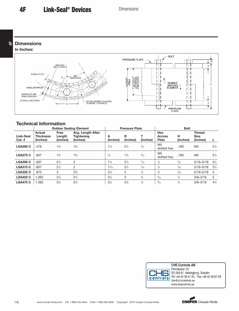
www.crouse-hinds.com US: 1-866-764-5454 CAN: 1-800-265-0502 Copyright© 2010 Cooper Crouse-Hinds118
4F
Link-Seal® Devices Dimensions
Dimensions
In Inches:
4F
Technical InformationRubber Sealing Element Pressure Plate Bolt
Link-Seal
Cat. #
Actual
Thickness
(inches)
Free
Length
(inches)
Avg. Length After
Tightening
(inches)
A
(inches)
R
(inches)
T
(inches)
Hex
Across
Flats
H
(inches)
Thread
Size
(inches) L
LSA200 C .478 13/4 13/8 11/6 21/45/16
M5slotted hex .180 M5 21/2
LSA275 C .607 13/4 13/87/8 17/8
5/16M5slotted hex .180 M5 21/2
LSA300 C .687 21/2 2 11/2 21/27/16
1/27/32 5/16–5/18 31/2
LSA315 C .807 21/2 2 17/16 21/27/16
1/27/32 5/16–5/18 31/2
LSA325 C .875 3 23/8 31/8 2 1/21/2
7/32 5/16–5/18 4
LSA425 C 1.062 31/2 23/4 31/2 3 3/49/16
1/4 3/8–3/16 5
LSA475 C 1.562 31/2 23/4 31/2 31/21/2
9/161/4 3/8–3/16 41/2
aro
Standard
Related Documents