Rev. Sci. Technol., Synthèse Vol 25, numéro 1: 33-44 (2019) I. Touaibia & E. Azzag ©UBMA - 2019 33 Cable fault location in medium voltage of Sonelgaz underground network Recherche de défaut de câblé dans le réseau souterrain de Sonelgaz Imene Touaibia* & El-Bahi Azzag Department of Electrical Engineering, Badji Mokhtar Annaba University, PO Box 12, 23000, Annaba, Algeria. Article Info ABSTRACT Article history: Received 06/02/2017 Revised 20/12/2018 Accepted 21/12/2018 Power supply networks are growing continuously and their reliability is becoming more important than ever. The complexity of the whole network comprises numerous components that can fail and interrupt the power supply. Underground distribution systems are normally exposed to permanent faults, due to specific construction characteristics. In these systems, visual inspection cannot be performed. In order to enhance service restoration, accurate fault location techniques must be used. The present paper describes the different faults affecting the underground distribution system of SONELGAZ, and cable fault location procedure using Time Domain Reflectometry (TDR) method. This method is based on the analysis of the cable electromagnetic impulse response that allows cable fault pre-location. Results obtained from real tests conducted on underground distribution feeders of electrical network of Energy Distribution Company. The objective of these tests is to know the influence of cable characteristics on the types and frequency of faults, and how the TDR method contributes in obtaining an accurate fault location. RÉSUMÉ Les réseaux électriques de distribution se développent continuellement et leur fiabilité est devenue indispensable que jamais. Les composants du réseau électrique peuvent échouer et interrompre l'alimentation électrique. Les réseaux de distribution souterrains sont toujours exposés à des défauts permanents, vue leurs caractéristiques de construction spécifiques. Dans ces systèmes, l'inspection visuelle ne peut être effectuée. Afin d'améliorer la qualité de service, des techniques précises de localisation des défauts doivent être appliquées. Cet article décrit les différents défauts qui affectent le réseau de distribution souterraine de SONELGAZ, et la procédure de localisation de défaut de câble avec la méthode d'échométrie basse tension(TDR), basée sur les analyses de la réponse du câble à l'impulsion électromagnétique, qui permet la pré-localisation des défauts de câble. Des résultats sont obtenus à partir des essais réels dans des départs souterrains du réseau électrique de la société de distribution de Souk-Ahras, afin de connaître l'influence des caractéristiques des câbles dans les types et la fréquence des défauts et comment contribue la méthode TDR à leur localisation précise. Keyword: Distribution networks - Fault location - TDR (Time Domain Reflectometer) - Underground cable Mots clés: Réseaux de distribution - Localisation des défauts - TDR () - Câble souterrain * Corresponding Author Imene Touaibia Department of Electrical Engineering, Badji Mokhtar University, Po Box 12, Annaba, 23000, Algeria. Email: [email protected]

Welcome message from author
This document is posted to help you gain knowledge. Please leave a comment to let me know what you think about it! Share it to your friends and learn new things together.
Transcript

Rev. Sci. Technol., Synthèse Vol 25, numéro 1: 33-44 (2019) I. Touaibia & E. Azzag
©UBMA - 2019 33
Cable fault location in medium voltage of Sonelgaz underground
network
Recherche de défaut de câblé dans le réseau souterrain de
Sonelgaz
Imene Touaibia* & El-Bahi Azzag
Department of Electrical Engineering, Badji Mokhtar Annaba University, PO Box 12, 23000, Annaba, Algeria.
Article Info ABSTRACT
Article history:
Received 06/02/2017
Revised 20/12/2018
Accepted 21/12/2018
Power supply networks are growing continuously and their reliability is
becoming more important than ever. The complexity of the whole network
comprises numerous components that can fail and interrupt the power
supply. Underground distribution systems are normally exposed to
permanent faults, due to specific construction characteristics. In these
systems, visual inspection cannot be performed. In order to enhance service
restoration, accurate fault location techniques must be used.
The present paper describes the different faults affecting the underground
distribution system of SONELGAZ, and cable fault location procedure
using Time Domain Reflectometry (TDR) method. This method is based on
the analysis of the cable electromagnetic impulse response that allows cable
fault pre-location. Results obtained from real tests conducted on
underground distribution feeders of electrical network of Energy
Distribution Company. The objective of these tests is to know the influence
of cable characteristics on the types and frequency of faults, and how the
TDR method contributes in obtaining an accurate fault location.
RÉSUMÉ
Les réseaux électriques de distribution se développent
continuellement et leur fiabilité est devenue indispensable que
jamais. Les composants du réseau électrique peuvent échouer et
interrompre l'alimentation électrique. Les réseaux de distribution
souterrains sont toujours exposés à des défauts permanents, vue leurs
caractéristiques de construction spécifiques. Dans ces systèmes,
l'inspection visuelle ne peut être effectuée. Afin d'améliorer la qualité
de service, des techniques précises de localisation des défauts doivent
être appliquées. Cet article décrit les différents défauts qui affectent
le réseau de distribution souterraine de SONELGAZ, et la procédure
de localisation de défaut de câble avec la méthode d'échométrie basse
tension(TDR), basée sur les analyses de la réponse du câble à
l'impulsion électromagnétique, qui permet la pré-localisation des
défauts de câble. Des résultats sont obtenus à partir des essais réels
dans des départs souterrains du réseau électrique de la société de
distribution de Souk-Ahras, afin de connaître l'influence des
caractéristiques des câbles dans les types et la fréquence des défauts
et comment contribue la méthode TDR à leur localisation précise.
Keyword:
Distribution networks - Fault
location - TDR (Time Domain
Reflectometer) - Underground
cable
Mots clés:
Réseaux de distribution -
Localisation des défauts - TDR
() - Câble souterrain
* Corresponding Author
Imene Touaibia Department of Electrical Engineering, Badji Mokhtar University,
Po Box 12, Annaba, 23000, Algeria.
Email: [email protected]

Rev. Sci. Technol., Synthèse Vol 25, numéro 1: 33-44 (2019) I. Touaibia & E. Azzag
©UBMA - 2019 34
1. INTRODUCTION
The urban development zones and environmental considerations have preferred the use of underground
power cables instead of overhead lines. Underground cables have many advantages compared to overhead lines.
In fact, they do not require practical maintenance and they are particularly not affected by the weather and
climatic conditions. However, in the case of underground cable fault, it takes usually more time to repair it, due
to the various stages of fault location, identification and classification [1], [2]. In order to guarantee the
continuity of power energy, the electricity distribution companies need to identify and locate rapidly and
precisely the faulted segment to reduce outage time [2], [3]. Methods based on the principle of time domain
reflectometry (TDR, or PE: Pulse Echo) [4], [5] are currently used for faults location in cables and lines. Time
Domain Reflectometry (TDR) is a well-known technique that is usually used for measuring the impedance
discontinuity as a function of time (or distance) in electronic systems [6], [7].
This paper presents TDR method for easier and faster faults location in a medium voltage underground
power cable. The methodology used to locate faults, including fault type classification and exact fault location is
presented. All required steps are illustrated in the diagram shown bellow. Finally, results of real tests conducted
on different faulted sections of underground network in Distribution Company are presented as well as the
results of the TDR method applied in these sections.
2. CABLE TYPES AND CHARACTERISTICS
Cable types are basically defined as low, medium and high voltage cables. According to the cable type,
different requirements to cable testing, cable fault location as well as maintenance strategy are defined. The
tendency within the last years shows a shifting to single-core systems as they are less costly, reduced in weight
and maintenance cost. Furthermore oil impregnated or oil filled cables are used less and less, as the
environmental sustainability cannot be guaranteed. Especially in industrialized countries, these types of cables
have been replaced and are no longer installed.
Today PE insulated cables are mainly used. The improvement of the PE insulation material combined
with modern design of the cable enable to manufacture cables even for extra high voltage level. Figure 1
illustrates the equivalent circuit of underground cable.
Figure 1 : Equivalent circuit of healthy cable
The different types of cables used by the SONELGAZ company are noted in Table 1.
Table 1 : Cable types used in Sonelgaz
3. TYPES OF CABLE FAULTS
Cable faults can be categorized into three main types: open conductor faults, shorted faults, and high
impedance faults [8], [9].
Voltage Type of cable Nature and style of conductive
core Type of insulating material
10 kV
Unipolar
Three-pole
Aluminum 185 mm²
Aluminum 240 mm²
Copper 120 mm² Impregnated paper (IP)
Synthetic Insulation (PRC, PVC,
PE) 30 kV
Aluminum 120 mm²
Aluminum 185 mm² Copper 70 mm²

Rev. Sci. Technol., Synthèse Vol 25, numéro 1: 33-44 (2019) I. Touaibia & E. Azzag
©UBMA - 2019 35
3.1. Open Conductor Fault
An open conductor fault occurs where the cable conductor is completely broken or interrupted at the
location of cable fault. It is possible to have a high resistance shunted faults (to ground) on one or both sides of
the faulted conductor’s location.
3.2. Shorted Fault
A shorted fault is characterized by a low resistance continuity path to ground (insulating fault). The
resistance from the conductor to ground is lower than the surge impedance of the cable for a shorted low
resistance fault.
3.3. High Impedance Fault
A high impedance fault contains a resistive path to ground (shunted fault) that is large in comparison to
the cable surge impedance. This type of fault may also demonstrate non-linear resistive characteristics which
allow the apparent resistance to vary with the level of applied voltage or current.
4. IDENTIFICATION OF FAULT TYPES
A multimeter is used as ohmmeter or insulation tester to determine the fault type. This is important to
decide which method of fault location is best suited.
Tow values of fault resistance Rd are important to know the type of fault (Table 2):
Table 2 : Values of fault resistance
Category Rd value
1 < 130 to 150 Ω
2 between 130 to 150 Ω and some megohm
3 More than some megohm
If the resistance value is situated in category 1, then it can be confirmed that it is an insulation fault, but
if Rd value is situated in category 2 or 3 then the continuity measure or dielectric test have to be used (Fig. 2 &
Fig. 3).
Figure 2 : Test for insulation (fault) resistance using an insulation tester
Figure 3 : Loop test for continuity using an insulation tester
5. TYPES OF FAULTS DETECTION (PRE-LOCATION METHODS)
The faults occurring in the power lines and cables can be classified into four main categories: short
circuit to another conductor in the cable, short circuit to earth (ground), high resistance to earth and open circuit.

Rev. Sci. Technol., Synthèse Vol 25, numéro 1: 33-44 (2019) I. Touaibia & E. Azzag
©UBMA - 2019 36
Not all approaches provide satisfactory results for each type of fault. Four methods that are mostly used for
detecting fault location are described hereafter.
A-Frame
Thumper
Bridge methods
Time Domain Reflectometer (TDR)
A persistent short circuit to earth fault can be most easily located using the A-Frame method. For high
resistance earth faults, the A-Frame method is not always sufficient. In this case, thumper method has to be used
to reduce fault resistance. Thumper method alone may be sufficient for fault location but when applied for a
longer duration, it may damage the cable insulation. A-Frame is not useful for locating faults which are not
connected to the ground. Time Domain Reflectometer (TDR) is suitable for determining the locations of most
faults.
5.1. A-Frame Method
In A-Frame method, a pulsed direct current (DC) is injected into the faulted cable and earth terminal to
locate the ground fault. The DC pulse will flow through the conductor and returns via earth from the earth fault
location back to the ground stake as shown in Figure 4.
Figure 4. An A-Frame method for finding cable fault location
The flow of pulsed DC through the ground will produce a small DC voltage. A sensitive voltmeter is
used to measure the magnitude and direction of the DC voltage in segments of the earth along the cable route.
Analyzing the results of the measuring voltage along the route, the location of the fault in the cable can be
pinpointed.
A-Frame is an accurate method but it is not the fastest, since the operator has to walk along the length
of the cable from the transmitter to the ground fault. This method may face a problem if the return DC finds
some easier path back to the earth stake of transmitter instead of returning through the ground. If the ground is
sandy or paved, which provides high resistance and consequently, less current flows through the ground. In this
case, the voltmeter fails to measure the voltage and fault detection becomes complicated.
5.2. Thumper Method
The Thumper technique is basically a high voltage surge generator which is used to apply a reasonable
high voltage to the faulty core of an underground cable to generate a high current arc resulting in a loud noise to
hear above the ground. This method requires very high current thump at voltages as high as 25 kV to make
underground noise loud enough to be heard from the ground.
As the A-Frame method, the thumper method requires an operator who has to walk along the path of the
cable and listen to the sound from above the ground. Different ground conditions, nearby traffic and noises may
make this sound hard to listen to make a clear distinction.
5.3. Bridge Method
Bridge methods used for locating faults in underground cables are based on modified Wheatstone
circuit where direct current is used to measure the resistance in order to calculate distance of the fault in
percentage of the total line length. Murray and Glaser bridges [8] use the similar principal for calculating the
distance of the fault. Brief description of these bridges is given below.

Rev. Sci. Technol., Synthèse Vol 25, numéro 1: 33-44 (2019) I. Touaibia & E. Azzag
©UBMA - 2019 37
Figure 5 shows the Wheatstone bridge circuit where R1, R2, R3 are the known resistances and Rx is
unknown resistance.
Figure 5: Basic Wheatstone bridge
When the galvanometer represented by the circle in the figure shows zero current flow, the unknown
resistor Rx value can be found from the other known resistances value using the following equation:
3
21
R
RRRx
(1)
A variation on the Wheatstone bridge is the Murray Loop Bridge. Figure 6 shows the adjacent
resistances, RC1 of a faulted cable in a loop with RC2 of a good cable designed to represent Rx and R2 of the
Wheatstone bridge. Similarly, corresponding portions of a slide wire resistor RB1 and RB2 can be designed to
represent the resistances R1 and R3. At balance in the Murray Loop Bridge, RC1/ RC2 is equal to RB1/RB2.
Figure 6 : Murray Loop Bridge application
When it is assumed that the resistance of a uniform conductor is linear and proportional to its length,
and the total length of the cable section under test is L, the distance to the fault, Lx, is calculated as follows:
2
12B
Bx
R
RLL (2)
5.4. Time Domain Reflectometry (TDR)
The TDR method is the most established and widely used measuring method for the determination of:
the total length of a cable
the location of low resistive cable faults
the location of cable interruptions
the location of joints along the cable
Rev. Sci. Technol., Synthèse Vol 25, numéro 1: 33-44 (2019) I. Touaibia & E. Azzag
©UBMA - 2019 38
In the Time Domain reflectometry (TDR) method, a low energy signal is sent through the cable where
the perfect cable with the uniform characteristic impedance returns the signal within a known time and with a
known profile. This time and profile of the signal is altered once the cable has an impedance variation due to any
fault. The impedance variation causes a portion of the signal reflected back to the source.
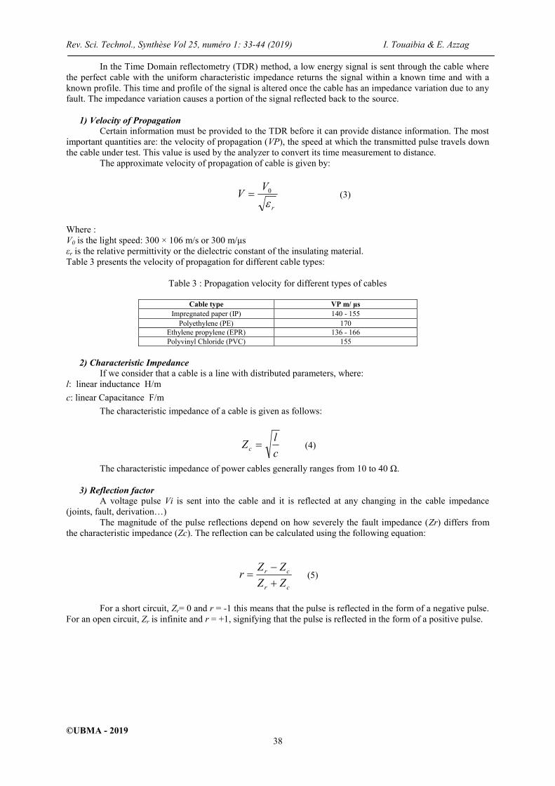
1) Velocity of Propagation
Certain information must be provided to the TDR before it can provide distance information. The most
important quantities are: the velocity of propagation (VP), the speed at which the transmitted pulse travels down
the cable under test. This value is used by the analyzer to convert its time measurement to distance.
The approximate velocity of propagation of cable is given by:
r
VV
0 (3)
Where :
V0 is the light speed: 300 × 106 m/s or 300 m/μs
εr is the relative permittivity or the dielectric constant of the insulating material.
Table 3 presents the velocity of propagation for different cable types:
Table 3 : Propagation velocity for different types of cables
Cable type VP m/ μs
Impregnated paper (IP) 140 - 155
Polyethylene (PE) 170
Ethylene propylene (EPR) 136 - 166
Polyvinyl Chloride (PVC) 155
2) Characteristic Impedance
If we consider that a cable is a line with distributed parameters, where:
l: linear inductance H/m
c: linear Capacitance F/m
The characteristic impedance of a cable is given as follows:
c
lZc (4)
The characteristic impedance of power cables generally ranges from 10 to 40 Ω.
3) Reflection factor
A voltage pulse Vi is sent into the cable and it is reflected at any changing in the cable impedance
(joints, fault, derivation…)
The magnitude of the pulse reflections depend on how severely the fault impedance (Zr) differs from
the characteristic impedance (Zc). The reflection can be calculated using the following equation:
cr
cr
ZZ
ZZr
(5)
For a short circuit, Zr= 0 and r = -1 this means that the pulse is reflected in the form of a negative pulse.
For an open circuit, Zr is infinite and r = +1, signifying that the pulse is reflected in the form of a positive pulse.

Rev. Sci. Technol., Synthèse Vol 25, numéro 1: 33-44 (2019) I. Touaibia & E. Azzag
©UBMA - 2019 39
Figure 7 : Schematic diagram of TDR reflection graphs
Figure 8 : TDR test for cable length
Figure 9 : TDR test for continuity
A low voltage TDR is an excellent tool for the pre-location of open circuits and conductor to conductor
shorts. Cable faults with a resistance higher than 150 Ω are almost impossible to distinguish from normal clutter
reflections on the cable. And almost all faults on underground distribution cable are high resistance faults in the
area of thousands of ohms or even megohm. Due to the reflection characteristics of these high resistance faults it
is impossible to see using only the low voltage TDR. In this case, we use the high voltage method to reduce this
resistance to make it easier to know the fault location using the TDR method.
Arc Reflection Method (ARM)
The standard conversion of a high-impedance to a low-impedance fault with a high-capacity burn down
unit is used in decreasing cases. Today, high-power burns down units are used for the modification of the fault
resistance faulty cables for prelocation in connection with ARM burning (arc reflection burning).
In the ARC refection method, a TDR is coupled through a power separation filter to a high-voltage
surge generator (Fig. 10). The filter protects the pulse reflection instrument from the applied high voltage while
allowing the low energy TDR pulse to pass.

Rev. Sci. Technol., Synthèse Vol 25, numéro 1: 33-44 (2019) I. Touaibia & E. Azzag
©UBMA - 2019 40
Figure 10 : Arc Reflexion fault location
Decay Method
The Decay Method is the conventional fault location method for high resistance cable faults with a flash
over voltage higher than 32kV.
The Decay Method is based on voltage decoupling by a capacitive voltage divider. The faulted cable is
charged by applying DC or VLF voltage (Very Low Frequency voltage) up to the level of the breakdown. This
breakdown creates a transient wave (due to discharge of the stored energy of the charged cable) which travels
between faulted point and the high voltage (HV) generator. This transient wave is recorded by the echometer via
the capacitive voltage divider (Fig. 11).
Figure 11 : Decay Method
Impulse Current Method (ICM)
The ICM is the conventional location method for high resistance cable faults, especially on long cables.
A high voltage impulse is sent into the cable under test up to the level of the breakdown (Fig. 12). This high
voltage impulse ignites an arc at the faulted position. The created current impulse travels along the cable and is
recorded by an echometer via an inductive coupler (current converter).
Figure 12 : Impulse Current Method

Rev. Sci. Technol., Synthèse Vol 25, numéro 1: 33-44 (2019) I. Touaibia & E. Azzag
©UBMA - 2019 41
6. LOCATING OR PINPOINTING METHODS
6.1. Acoustic Fault Location
For pinpointing high resistive and intermittent faults in buried cables the acoustic method is used to spot
the exact fault location. As signal source, a surge generator is used in repetitive pulsing mode. High energy
pulses which are released by a surge generator force a voltage pulse to travel along the cable. At the fault, the
flashover happens. This causes a high acoustic signal that is locally audible. These noises are detected on the
ground surface by means of a ground microphone, receiver and headphone. At the fault position the highest level
of flashover noise can be detected.
6.2. Methods of audible frequencies
Approximately 2% of cable faults require such method [10]. We use this method when the resistance
fault Rd is less than 5 Ω. It was not possible to locate the cable fault with the acoustic method.
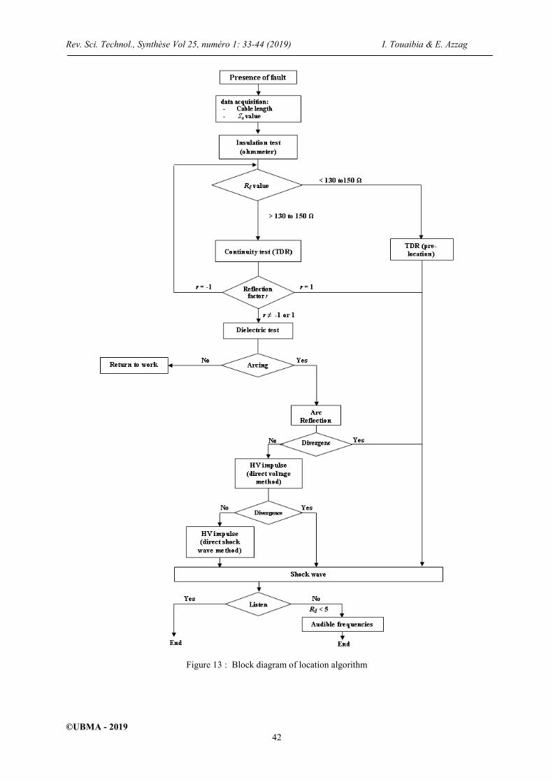
7. ALGORITHM FOR LOCATING CABLE FAULT
In this section, we propose an algorithm for different steps of fault location. The bloc diagram that we
made to follow steps in faulty cables is presented in figure 13.
The tests were conducted with SONELGAZ Company, Distribution Company of electric and Gas of
Souk-Ahras. Several tests were conducted on different underground cables with different section core and
insulation, with two different voltages 10 kV and 30 kV, using the steps presented in the block diagram (figure
13).
The results of the tests are shown in next section.
The proposed algorithm is divided into three principal parts:
1) Identify the type of faults:
- Isolating test
- Continuity test
- Dielectric test
2) Cable fault pre-location:
With TDR method or thumper method (Arc reflection method, direct voltage method or direct shock
wave method)
3) Cable fault pinpointing: with acoustic method or audible frequencies method.
When a fault happens, the isolating measure is first put to use. If Rd is less than the range 130 to 150 Ω
then it can be confirmed that it is an isolating fault for which the pre-locating method is well adapted. But if Rd
is beyond the range 130 to 150 Ω than the continuity test can be utilized. The reflection factor is hence
calculated. If r = +1 then it is a continuity fault the pinpointing fault is detected, or if r=-1 then it is an insulating
fault.
If r ≠ ± 1, then the dielectric test is considered, if an arcing is obtained then it is a high impedance fault and the
cable fault pre-location using thumper methods is implemented.
Finally if we do not have an arcing then we have to return to normal work (there’s no cable fault).
Rev. Sci. Technol., Synthèse Vol 25, numéro 1: 33-44 (2019) I. Touaibia & E. Azzag
©UBMA - 2019 42
Figure 13 : Block diagram of location algorithm

Rev. Sci. Technol., Synthèse Vol 25, numéro 1: 33-44 (2019) I. Touaibia & E. Azzag
©UBMA - 2019 43
8. TEST RESULTS AND DISCUSSIONS
Firstly after data acquisition, we show in table 4 the results of insulation resistance value for different
sections of cables:
Table 4 : Results of insulation tests
It is noted that Rd value is less than the standard value, so it can be confirmed that it is an insulating
fault (Shorted Fault) in these sections of underground network. In this case, we use the pre-location with TDR
method in one of faulted sections.
The low voltage impulse is applied in two phases, the faulted and healthy phase, for comparison
between the forms of both the pulses. Figure 14 bellow shows the reflectogram obtained after the test.
The blue signal represents the reflected impulse of the healthy phase. It is observed that its length is of
480 m, and the black signal represents the reflected impulse of the faulted phase, that it is a negative reflection
(insulating fault).The negative reflection is at 290.5 m from the beginning of the cable, thus we can locate the
fault.
Figure 14 : Reflectogram of test result
The TDR method helps to know the pre-location of faults, and avoid walking along the length of the
cable, making the fault cable pinpointing easier and faster.
Voltage
(kV)
Cable section
(mm²)
linear resistance
(Ω/km)
linear inductance
(Ω/km)
Type of insulating
material
Insulating
resistance (Ω)
10
185 0.184 0.100
PRC
62.79
240 0.140 0.100 110.04
120 0.176 0.100 51.97
185 0.184 0.100
PVC
18.83
240 0.140 0.100 33.01
120 0.176 0.100 15.59
30
120 0.284 0.100
PRC
81.10
185 0.184 0.100 49.20
70 0.300 0.100 56.40
120 0.284 0.100
PVC
7.00
185 0.184 0.100 0.678
70 0.300 0.100 18.00
Positive reflection at the cable end, healthy phase
(L1)
Negative reflection at the faulty point (short circuit),
faulty phase (L2)

Rev. Sci. Technol., Synthèse Vol 25, numéro 1: 33-44 (2019) I. Touaibia & E. Azzag
©UBMA - 2019 44
9. CONCLUSION
This paper shows the importance of faults location in the distribution network and reviews some of the
cable fault locating methods that are mostly used in practical fields.
The conducted work has confirmed that TDR technique can detect faults and other features along the
length of the cable including joints.
This method is in general very accurate but also very manpower- and time consuming.
However, IEEE recommends that Fault locating techniques that enable the detection at the lowest
possible voltage with the shortest time should be selected. Wherefore many of the offline methods are
problematic to use [11]. Thus, various research studies have been conducted to develop numerical methods for
fault identification and detection in underground systems by using algorithms injected into the digital relays.
Nevertheless, sometimes, numerical relays in faulty network are not available, so TDR method remains
necessary.
ACKNOWLEDGMENTS
The authors like to thank the general direction of research and technological developments (DGRDT)
for their financial support.
REFERENCES
[1] D.A. Tziouvaras, 2006. Protection of high-voltage AC cables, In Power Systems Conference: Advanced Metering,
Protection, Control, Communication, and Distributed Resources, PS'06 (pp. 316-328). IEEE.
[2] J. Suonan, 2005. An accurate fault location algorithm for transmission line based on R–L model parameter
identification, Electric Power Systems Research, Vol.76 (2005) 17-24.
[3] T.E.D. El Sayed et al., 2006. Fault Location Scheme for Combined Overhead Line with Underground Power Cable,
Electric Power Systems Research, Vol.76 (2006) 928-935.
[4] L.P. Van Biesen et al., 1990. High accuracy location of faults on electrical lines using digital processing of sampled
data records from a reflectogram, IEEE transactions on instrumentation and measurement, 39(1), 175-179., pp. 462–
466.
[5] E. Windl, 1962. FEHLERORTUNGEN,Veb. Verlag Technik Berlin, Hüthig Verlag Gmbh Heidelberg.
[6] Time Domain Reflectometry Theory, Agilent Technologies, USA, Application Note 1304-2, 2006.
[7] H. Songoro et al., 2010. Keeping Time with Maxwell’s Equations, IEEE Microwave Magazine, vol. 11, no. 2, pp. 42-
49.
[8] R.C. Bascom, 1892. Computerized underground cable fault location expertise, in Proc. IEEE Power Eng. Soc. General
Meeting, Apr. 10–15,1994, pp. 376–382.J. Clerk Maxwell, A Treatise on Electricity and Magnetism, 3rd ed., vol. 2.
Oxford: Clarendon, pp.68–73.
[9] K.K. Kuan and K. Warwick, 1992. Real-time expert system for fault location on high voltage underground distribution
cables, IEEE PROCEEDINGS-C, Vol. 139, No. 3, MAY 1992.
[10] H. Kuzyk, 2008. Câbles d’énergie : méthodes de localisation des défauts, Techniques de l’Ingénieurs D 4541, 2008.
11] IEEE guide for fault locating techniques on shielded power cable systems, 2007. IEEE Std 1234– 2007, pp. 1–37.
Related Documents