en z w a:: w al ...J ...J iii ::,-: al z < a:: 0 2" co ;:.... 40" 18" 14" BACK -- TYPE B MODIFIED SERVICE CABINET 24" m XFMR-S (TRANSFORMER - SMALL) (UP TO 12.5 KVA) 48 1/2" 6" (TYP.) 13" FRONT 2" co ;:.... TYPE 33xD CABINET 0) - - 28" BACK ;J lg~ 24" TYPED SERVICE CABINET CONDUIT PLACEMENT LOCATION AREA SERVICE: UTILITY CONDUIT AREA TRANSFORMER: HIGH VOLTAGE CONDUIT AREA 32" 2"(TYP.) 4 1/2" (TYP.) 24" 6" FRONT 52" - : a.: NE, TYPEE SERVICE CABINET POLICE PANEL (NOTE 8) GENERATOR TRANSFER SWITCH (NOTE 8) TYPE 33x CABINET XFMR-L (TRANSFORMER - LARGE) (12.6 TO 37.5 KVA) POLICE PANEL (NOTE 8) GENERATOR 6"(TYP.) 44" aACK ''' 'I' ''' TRANSFER SWITCH (NOTE 8) • :1:. 'I' ~~--+-~ ' ' ' : ! : FRONT 2"MIN. (TYP.) 1/2" 1F ANCHOR BOLT (SEE NOTE 1) CABINET REFERENCE TABLE SERVICE SIZE CAPACITY STANDARD CABINETS WxD CONDUIT PLAN (IN) DIAMETER (IN) TYPEBMOD. 40" X 19" 12" J-10.20 TYPED 28" X 19" 24" J-10.21 TYPE E 52" X 19" 48" J-10.22 TRANSFORMER SIZE CABINETS WxD (IN) XFMR-S 24" X 20" 12" J-10.25 (UP TO 12.5 KVA) XFMR-L 32" X 30" 15" J-10.25 (12.6 TO 37.5 KVA) SIGNAL AND SIZE WxD ITS CABINETS (IN) TYPE 33x 24" X 30" 12" J-12.15 TYPE 33xD 48.5" X 30" 24"0 J-12.16 TYPE 342LX 44" X 26" 24"0 J-12.16 NEMAP44 44" X 26" 15" N/A <y 12" (IN) OF CONDUIT IN EACH LOCATION SHOWN 44" BACK 4"(TYP.) 30" FRONT POLICE PANEL POLICE PANEL GENERATOR TRANSFER SWITCH TYPE 342LX CABINET NEMA P44 CABINET PLAN VIEWS CABINET ORIENTATION, FOOTPRINT, AND CONDUIT PLACEMENT LOCATIONS GENERAL NOTES 1. Each pad mounted cabinet shall be attached to the foundation with four 1/2" (in.) x 10" (in.) x 2" (in.) x 4" (in.) anchor bolts (see Anchor Bolt Detail this Sheet). Bolts, washers, and nuts shall be hot-dip galvanized in accordance with AASHTO M232 and meet the requirements of Standard Specification 9-06.5(1) . Stainless steel epoxy anchors may be used as an alternative, and shall be 1/2" (in.) diameter x 9" (in.) or 5/8" (in.) diameter x 8" (in.). Epoxy anchors shall use Type 304 stainless steel hardware: ASTM F593 all threaded rod, ASTM A240 washers, and ASTM F594 nuts. Anchor bolts shall extend 1 1/2" (in.) min. to 2" (in.) max. above the concrete pad. 2. All reinforcing steel shall be embedded 2" (in.) below the surface of concrete. 3. A 1/2" (in .) bead of silicone is required between each cabinet and the concrete foundation. 4. Concrete shall be Class 3000, in accordance with Standard Specification 8-20.3(4). All concrete corners shall have a 1" (in.) chamfer, unless abutting sidewalk, where it shall be square and seaparated from the sidewalk with joint filler. 5. Foundations installed in, or adjacent to, sidewalks shall be constructed with the top flush with the sidewalk surface and grade, not including concrete risers for cabinets. 6. Foundations require additional level clear space to achieve a minimum of 4 feet of level clear space between the face of any cabinet or cabinet riser and the edge of the level clear space. Clear space beyond the edge of the concrete pad shall be made up of crushed surfacing meeting the requirements of Standard Specification 9-03.9(1). Special design may be required where slopes are 3H : 1V or steeper. As an alternative, the concrete pad may be extended out to provide the required clear space. 7. Verify overall pad and concrete riser dimensions with the Engineer prior to placing concrete. 8. Not all Type 33x and 33xD cabinets have a police panel and/or a generator transfer switch (GTS) panel. See Contract for specific cabinet requirements. , Jackson. l'li nl ~--#' /~ Aug24 20209:36A CABINET ORIENTATION CONDUIT LAYOUT AND FOUNDATION DETAIL STANDARD PLAN J-10.10-04 SHEET 1 OF 6 SHEETS APPROVED FOR PUBLICATION ~ --- STATE DESIGN ENGINEER ... VI Washington State Department of Transportation (EXI

Welcome message from author
This document is posted to help you gain knowledge. Please leave a comment to let me know what you think about it! Share it to your friends and learn new things together.
Transcript
en z w a:: w al ...J ...J
iii ::,-: al
z ~ < a:: 0
2"
co
;:....
40"
18" 14"
BACK
- -TYPE B MODIFIED SERVICE CABINET
24" m
XFMR-S (TRANSFORMER - SMALL)
(UP TO 12.5 KVA)
48 1/2"
6" (TYP.) 13"
FRONT
2"
co
;:....
TYPE 33xD CABINET
0)
--
28"
BACK ;J lg~
24"
TYPED SERVICE CABINET
CONDUIT PLACEMENT LOCATION AREA
SERVICE: UTILITY CONDUIT AREA TRANSFORMER: HIGH VOLTAGE CONDUIT AREA
32"
2"(TYP.)
4 1/2"
(TYP.)
24"
6"
FRONT
52"
-: a.: NE,
TYPEE SERVICE CABINET
POLICE PANEL (NOTE 8)
GENERATOR TRANSFER SWITCH (NOTE 8)
TYPE 33x CABINET
XFMR-L (TRANSFORMER - LARGE)
(12.6 TO 37.5 KVA)
POLICE PANEL (NOTE 8)
GENERATOR
6"(TYP.)
44"
aACK
''' 'I' ''' TRANSFER
SWITCH (NOTE 8)
• :1:. 'I' ~~--+-~ ' ' '
: ! :
FRONT
2"MIN.
(TYP.)
1/2"
1F
ANCHOR BOLT (SEE NOTE 1)
CABINET REFERENCE TABLE
SERVICE SIZE CAPACITY STANDARD CABINETS
WxD CONDUIT PLAN (IN) DIAMETER (IN)
TYPEBMOD. 40" X 19" 12" J-10.20
TYPED 28" X 19" 24" J-10.21
TYPE E 52" X 19" 48" J-10.22
TRANSFORMER SIZE
CABINETS WxD
(IN)
XFMR-S 24" X 20" 12" J-10.25 (UP TO 12.5 KVA)
XFMR-L 32" X 30" 15" J-10.25 (12.6 TO 37.5 KVA)
SIGNAL AND SIZE WxD
ITS CABINETS (IN)
TYPE 33x 24" X 30" 12" J-12.15
TYPE 33xD 48.5" X 30" 24"0 J-12.16
TYPE 342LX 44" X 26" 24"0 J-12.16
NEMAP44 44" X 26" 15" N/A
<y 12" (IN) OF CONDUIT IN EACH LOCATION SHOWN
44"
BACK
4"(TYP.) 30"
FRONT
POLICE PANEL
POLICE PANEL GENERATOR TRANSFER SWITCH
TYPE 342LX CABINET NEMA P44 CABINET
PLAN VIEWS CABINET ORIENTATION, FOOTPRINT, AND CONDUIT PLACEMENT LOCATIONS
GENERAL NOTES
1. Each pad mounted cabinet shall be attached to the foundation with four 1/2" (in.) x 10" (in.) x 2" (in.) x 4" (in.) anchor bolts (see Anchor Bolt Detail this Sheet). Bolts, washers, and nuts shall be hot-dip galvanized in accordance with AASHTO M232 and meet the requirements of Standard Specification 9-06.5(1) . Stainless steel epoxy anchors may be used as an alternative, and shall be 1/2" (in.) diameter x 9" (in.) or 5/8" (in.) diameter x 8" (in.). Epoxy anchors shall use Type 304 stainless steel hardware: ASTM F593 all threaded rod, ASTM A240 washers, and ASTM F594 nuts. Anchor bolts shall extend 1 1/2" (in.) min. to 2" (in.) max. above the concrete pad.
2. All reinforcing steel shall be embedded 2" (in.) below the surface of concrete.
3. A 1/2" (in .) bead of silicone is required between each cabinet and the concrete foundation.
4. Concrete shall be Class 3000, in accordance with Standard Specification 8-20.3(4). All concrete corners shall have a 1" (in.) chamfer, unless abutting sidewalk, where it shall be square and seaparated from the sidewalk with joint filler.
5. Foundations installed in, or adjacent to, sidewalks shall be constructed with the top flush with the sidewalk surface and grade, not including concrete risers for cabinets.
6. Foundations require additional level clear space to achieve a minimum of 4 feet of level clear space between the face of any cabinet or cabinet riser and the edge of the level clear space. Clear space beyond the edge of the concrete pad shall be made up of crushed surfacing meeting the requirements of Standard Specification 9-03.9(1). Special design may be required where slopes are 3H : 1V or steeper. As an alternative, the concrete pad may be extended out to provide the required clear space.
7. Verify overall pad and concrete riser dimensions with the Engineer prior to placing concrete.
8. Not all Type 33x and 33xD cabinets have a police panel and/or a generator transfer switch (GTS) panel. See Contract for specific cabinet requirements.
, ~ Jackson. l'linl ~--#'/~ Aug24 20209:36A ~ CABINET ORIENTATION CONDUIT LAYOUT AND FOUNDATION DETAIL
STANDARD PLAN J-10.10-04 SHEET 1 OF 6 SHEETS
APPROVED FOR PUBLICATION
~ ---STATE DESIGN ENGINEER ... VI Washington State Department of Transportation
en z w a:: w al ...J ...J
iii
~
I 0
l(')
7' - O" REINFORCING STEEL BENDING DIAGRAM
2' - O" 3' - O" SEE STD. SPEC. 9-07.1(2) FOR BENDING DIAMETER
12" I
I
-1'-3" , 1'-6"
(TYP.) i [ l:__ 1. 2' - 6" .1
-~ ,----------..
,r --n I II '_lJ
I I I I I I I I L_
PLAN VIEW
11 11 ~1 111111 11
:: :: ~.J ~ :· J :~:: :: i: A5 ;: :: I~ \ \ A4 A6 / / A3 /I
\\ .. ::' :: :: = = = = = = = = = = = = = = = = = == :: ~,, = = = = : = :: .. ~','
FRONT ELEVATION VIEW
2" CLR.
(TYP.) N '
1. 2' - 8"
ALL DIMENSIONS ARE OUT TO OUT
END BELL (PVC) OR ,L----J;----~ GROUND END
BUSHING (RMC)
CABINET WALL (FLOOR)
THREADED SEALING COUPLER W/ SILICONE CAULK BEAD (PVC) OR SEALING LOCKNUTS (RMC)
CODUIT TERMINATION DETAIL
3' - O"
G)(TYP.)
A1 A4
RIGHT SIDE ELEVATION VIEW
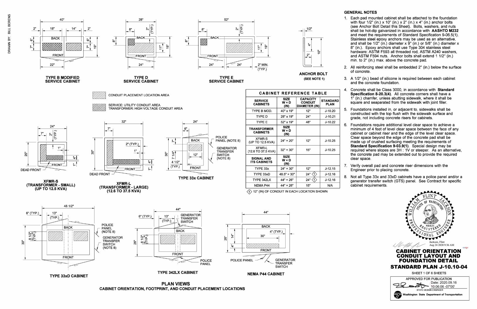
STRUT MOUNT SERVICE CABINET (TYPE B MODIFIED SERVICE CABINET SHOWN)
.1
A9
A9
: z C\I -.... 6
NOTES - SINGLE STRUT MOUNT CABINET (SHEET 2 OF 6)
A1 . Drive gound rods before placing concrete. Ground rods shall be a minimum of 6 feet apart. See Standard Plan J-60.05 for additional details .
A2. Welded Wire Fabirc (WWF) shall be 4.0 (in.) x 4.0 (in.) - W4.0 x W4.0 - meeting the requirements of Standard Specification 9-07.7. As an alternative, a grid of #3 rebar may be used, with bars spaced at 1 '- O" centers laterally and longitudinally.
A3. Install conduit couplings on all conduits. Couplers shall be installed with the top of the coupler flush with the top of concrete. For PVC conduits, the conduit segment above the coupler shall not be glued to the coupler.
A4. Vertical steel supports shall be two continuous 1 5/8" (in.) x 1 5/8" (in.) 12-gage slotted steel channels installed back-to-back (3 pairs required) - see Strut Mount Support Details this sheet for connection details. As an alternative, continuous 1 5/8" (in.) x 3 1/4" (in.) 12-gage slotted steel channel may be used in place of each channel pair. Channels shall be embedded a minimum of 12" (in.) into the concrete foundation. Supports shall be evenly spaced, with the center support centered in the concrete riser, and the outer supports tied to the riser rebar hoop.
A5. Horizontal steel supports shall be continuous 1 5/8" (in.) x 1 5/8" (in.) 12-gage slotted steel channels (two required).
A6. Cabinet height shall be determined by the required height of the utility meter - verify height with serving utilty (typically 5 to 6 feet) .
A7. Serving utility may require meter socket to be installed on the outside of the cabinet. Utility feeder conduit shall still terminate in the utility section of the cabinet unless otherwise required by the utility.
A8. Additional gravel pad not shown. Gravel pad shall extend two feet in front of the concrete pad for the full width of the concrete pad. If the utility meter socket is installed on the outside of the service cabinet, gravel pad shall also extend three feet from the utility side of the cabinet pad. Final gravel area shall be a rectangle.
TWO 1 5/8" (IN) x 1 5/8" (IN) 12-GAGE BACK TO BACK CONTINUOUS SLOTIED STEEL CHANNEL
FIELD WELD OR BOLT POINT - SEE SECTION A OR SECTION BAS APPLICABLE
ELEVATION VIEW (FIELD WELDED OR BOLTED)
SECTION 0 (WELDED CONNECTION)
STRUT MOUNT SUPPORT DETAILS (SEE NOTE A4)
KEY NOTES - SHEET 2 OF 6
@ Ground rod - See Note A 1, this sheet.
@ Ground rod well (Ground tile) - 12" diameter concrete
@ Service ground electrode conduits .
@ Welded wire fabric - See Note A2, this sheet.
@ Utility entrance conduit. Conduit shall terminate in the utility section of the service cabinet.
@ Conduits to field equipment. Conduits shall terminate in the customer section of the service cabinet.
@ Conduit couplers - See Note A3, this sheet.
1" (IN) MIN. FROM EACH END
3/8" (IN) DIAM. x 1 1/4" (IN) ~[~ : LONG BOLT WITH TWO
WASHERS AND LOCK NUT - SPACED AT
12" (IN) MAX. CENTERS
SECTION 0 (BOLTED CONNECTION)
, @_ Jackson, f lint ,(/ ~# / V- Aug 24 2020 9:37 AM cozj-1
CABINET ORIENTATION CONDUIT LAYOUT AND FOUNDATION DETAIL
STANDARD PLAN J-10.10-04 SHEET 2 OF 6 SHEETS
APPROVED FOR PUBLICATION
@ Vertical support steel channel - See Note A4, this sheet.
@ Horizontal support steel channel - See Note A5, this sheet. ~
STATE DES..,.,IGN-,E,--NG,,--IN...,,.EE=R-----... VI Washington State Department of Transportation
en z w a:: w al ...J ...J
iii
~
I 0
>
X
2' - O" A 2' - O"
12" 1" 1" r ~
Ill
" 2" CLR. --" (TYP.) " b " " " M
N ~
PLAN VIEW
3' - O"
G)(TYP.)
I I II
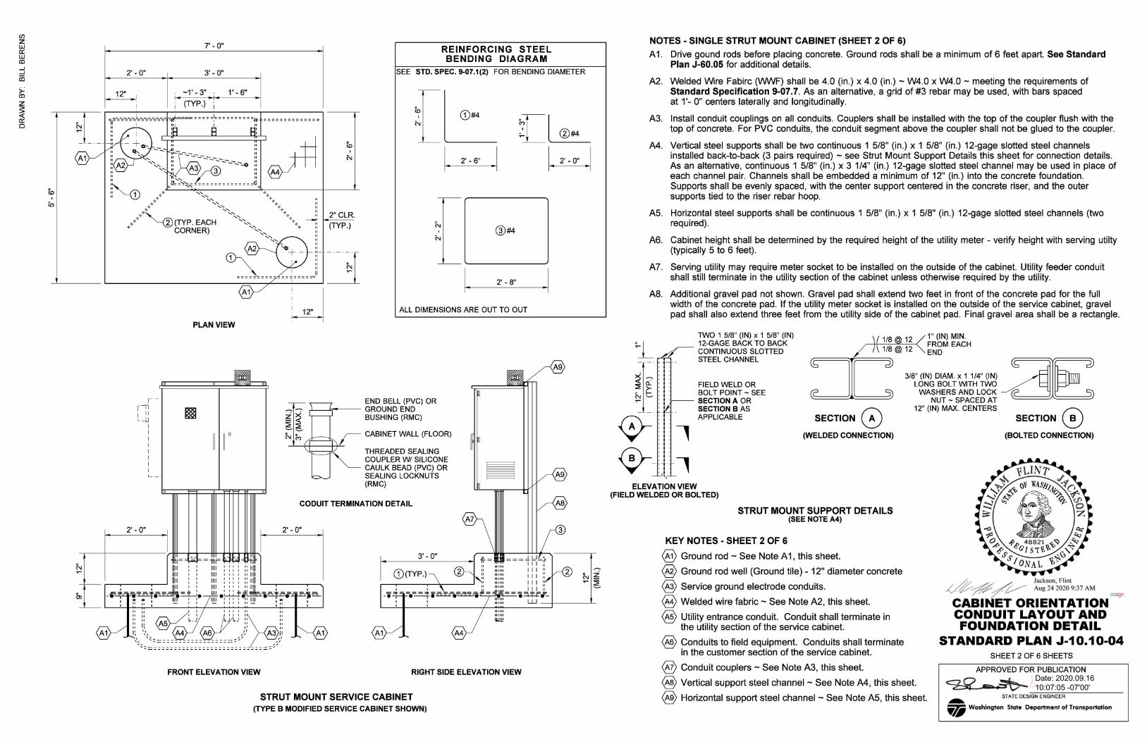
KEY NOTES - SHEET 3 OF 6
@ Ground rod - See Note 81, this sheet.
@ Ground rod well (Ground tile) - 12" diameter concrete
@ Service ground electrode conduits.
@ Welded wire fabric - See Note 82, this sheet.
@ Utility entrance (service cabinet) or input power (transformer cabinet) conduit. Conduit shall terminate in the utility or high-voltage section of the cabinet (as applicable).
@ Conduits to field equipment. Conduits shall terminate in the customer section (service cabinet) or low-voltage (transformer cabinet) of the cabinet.
@ Conduit couplers - See Note 84, this sheet.
@ 4" (in.) diam. x 1/2" (in.) deep sump.Slope foundation within cabinet footprint toward sump.
@ 3/8" (in.) diam. polyethylene or copper tubing for drain. Tubing shall be straight, but slope downward a minimum of 1" (in .).
SERVICE CABINETS
TYPED
TYPEE
TRANSFORMER CABINETS
XFMR-S (UP TO 12.5 KVA)
XFMR-L
NOTES - SINGLE PAD MOUNT SERVICE OR TRANSFORMER CABINET (SHEET 3 OF 6) 81. Drive gound rods before placing concrete. Ground rods shall be a minimum of 6 feet apart .
See Standard Plan J-60.05 for additional details.
82. Welded Wire Fabirc (WWF) shall be 4.0 (in.) x 4.0 (in.) - W4.0 x W4.0 - meeting the requirements of Standard Specification 9-07.7. As an alternative, a grid of #3 rebar may be used, with bars spaced at 1'-0" centers laterally and longitudinally.
83. Omit concrete riser and bar #3 for Type D and Type E service cabinets.
84. Install conduit couplings on all conduits. Couplers shall be installed with the top of the coupler flush with the top of concrete. For PVC conduits, the conduit segment above the coupler shall not be glued to the coupler.
85. Conduits shall extend a minimum of 2" (in.) and a maximum of 3" (in.) into the cabinet, as measured from the concrete surface to the top of the end bell (PVC) or ground bushing (RMC).
86. Serving utility may require meter socket to be installed on the outside of the cabinet. Utility feeder conduit shall still terminate in the utility section of the cabinet unless otherwise required by the utility.
87. Additional gravel pad not shown. Gravel pad shall extend two feet in front of the concrete pad for the full width of the concrete pad. If the utility meter socket is installed on the outside of the service cabinet, gravel pad shall also extend three feet from the side of the cabinet pad where the meter is installed. Final gravel area shall be a rectangle.
88. See Standard Plan J-10.14 for additional details when service or transformer cabinet is installed in fence line.
FOUNDATION SIZE REFERENCE TABLE
PAD PAD RISER RISER HOOP@ HOOP@ WIDTH (X) DEPTH (Y) WIDTH (A) DEPTH (B) WIDTH (BA) DEPTH (BB)
6' -4" 3' -8" N/A N/A N/A N/A
8' -4" 3' -8" N/A N/A N/A N/A
PAD PAD RISER RISER HOOP@ HOOP@ WIDTH (X) DEPTH (Y) WIDTH (A) DEPTH (B) WIDTH (BA) DEPTH (BB)
6' - 2" 4' - 11" 2' - 2" 1' - 11" 1' - 10" 1' - 7"
(12.6 TO 37.5 KVA) 6' - 10" 5' -8" 2' - 10" 2' - 8" 2' - 6" 2' - 4"
" ' II I I II
REINFORCING STEEL BENDING DIAGRAM
-• = : = - =• = = = ~ i C:: ~ ~:: = ':j : .. » = = • = = = ~ =~=-=-: i =~ ·--~=.J~:~:,¥li:-::;:,_ ' ' .. I I : 1 1 :
SEE STD. SPEC. 9-07.1(2) FOR BENDING DIAM. ALL DIMENSIONS ARE OUT TO OUT
' ' "" '' " ,~,, " " §-f''~4'' " II II !c J I I le: • .,! 11
:: I~ 86 :: :: 1: \\ // 83 B5 JI
\\~ ' :' ~:: = = = =:: ~ ... = -= = = = = = = = = = = = = = = = = =,., ... ~ ~,
· ~ ' ' ~.) 85
FRONT ELEVATION VIEW RIGHT SIDE ELEVATION VIEW
SINGLE PAD MOUNT SERVICE OR TRANSFORMER CABINET
(XFMR-L CABINET SHOWN)
[ l:__ z[~ cc al
1. 2'-6" .1 ~ I BA I NOTE: BAR 3 DIMENSIONS ARE ALWAYS FOUR INCHES SMALLER ._,~ ------• THAN THEIR ASSOCIATED CONCRETE RISER DIMENSIONS.
, @ _ Jackson , Flint ij~-# ./ ~ Aug 24 2020 9:37 AM
CABINET ORIENTATION CONDUIT LAYOUT AND FOUNDATION DETAIL
STANDARD PLAN J-10.10-04 SHEET 3 OF 6 SHEETS
APPROVED FOR PUBLICATION
STATE DESIGN ENGINEER ... VI Washington State Department of Transportation
en z w a:: w al ...J ...J
iii
~
I 0
>- m Q
b ' N
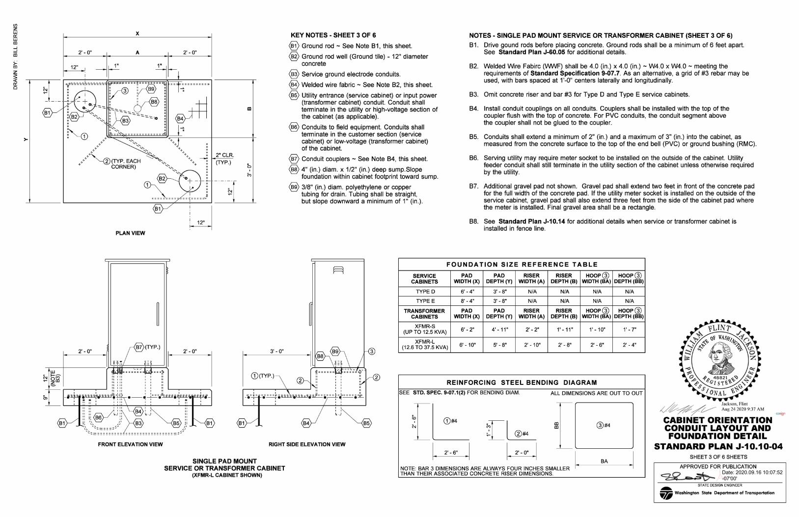
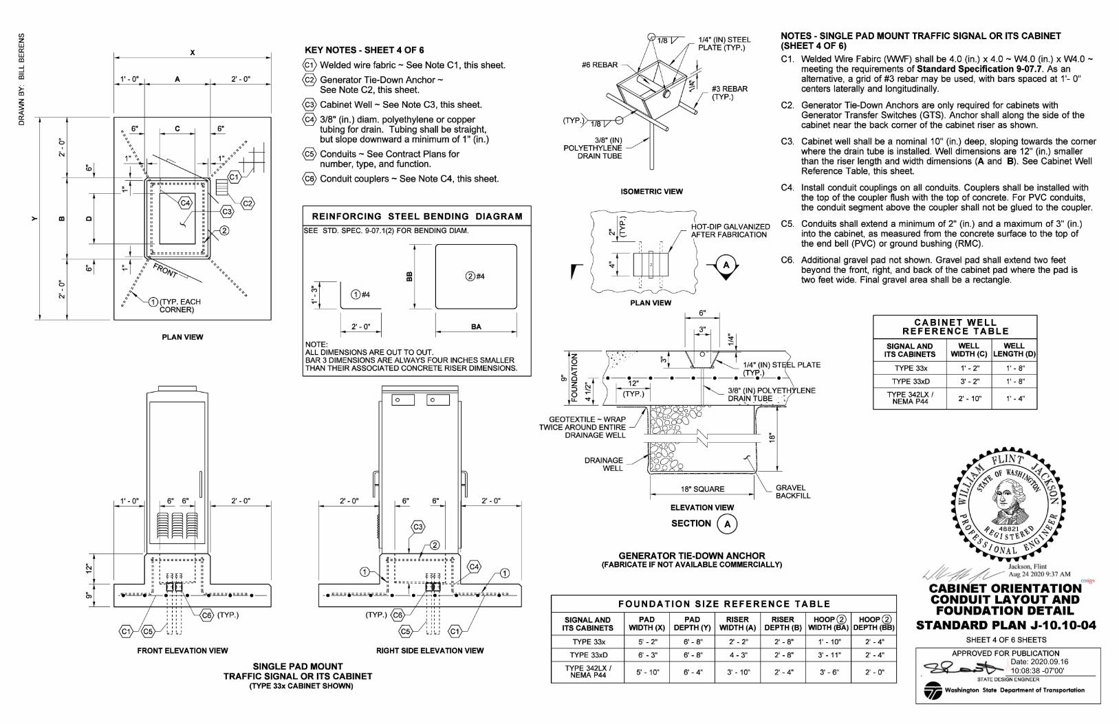
X KEY NOTES - SHEET 4 OF 6
1' - O" A 2' -0"
@ Welded wire fabric - See Note C 1 , this sheet.
@ Generator Tie-Down Anchor -See Note C2, this sheet.
. ,, 6" C 6"
@ Cabinet Well - See Note C3, this sheet.
@ 3/8" (in.) diam. polyethylene or copper tubing for drain. Tubing shall be straight, but slope downward a minimum of 1" (in.) ,, ,, ,, ,, ,,
: ,:, ..... ,, ,, ,, " ,,
,
./~(TYP. EACH CORNER)
1' - O"
PLAN VIEW
6" 6"
f.-~--------~-~ " ' " ' :: : ~H~
' " ' " ' " ' "
2' -0"
@ Conduits - See Contract Plans for number, type, and function.
@ Conduit couplers - See Note C4, this sheet.
REINFORCING STEEL BENDING DIAGRAM
SEE STD. SPEC. 9-07.1(2) FOR BENDING DIAM.
NOTE:
m m
ALL DIMENSIONS ARE OUT TO OUT.
1. BA .1
BAR 3 DIMENSIONS ARE ALWAYS FOUR INCHES SMALLER THAN THEIR ASSOCIATED CONCRETE RISER DIMENSIONS.
2' -0"
(TYP.)
EJ EJ
: :: : I II I I II I c .. .. ..
2' - O"
FRONT ELEVATION VIEW RIGHT SIDE ELEVATION VIEW
SINGLE PAD MOUNT TRAFFIC SIGNAL OR ITS CABINET
(TYPE 33x CABINET SHOWN)
#6 REBAR
(TYP. ),>--.--,1 /8""-+'1
3/8" (IN) POLYETHYLENE
DRAIN TUBE
1/4" (IN) STEEL PLATE (TYP.)
#3 REBAR (TYP.)
NOTES - SINGLE PAD MOUNT TRAFFIC SIGNAL OR ITS CABINET (SHEET 4 OF 6)
C1. Welded Wire Fabirc (VWVF) shall be 4.0 (in.) x 4.0 - W4.0 (in.) x W4.0 -meeting the requirements of Standard Specification 9-07.7. As an alternative, a grid of #3 rebar may be used, with bars spaced at 1 '- O" centers laterally and longitudinally.
C2. Generator Tie-Down Anchors are only required for cabinets with Generator Transfer Switches (GTS). Anchor shall along the side of the cabinet near the back corner of the cabinet riser as shown.
C3. Cabinet well shall be a nominal 1 O" (in.) deep, sloping towards the corner where the drain tube is installed. Well dimensions are 12" (in.) smaller than the riser length and width dimensions (A and 8). See Cabinet Well Reference Table, this sheet.
ISOMETRIC VIEW C4. Install conduit couplings on all conduits. Couplers shall be installed with the top of the coupler flush with the top of concrete. For PVC conduits, the conduit segment above the coupler shall not be glued to the coupler.
r
z 0 i==
&, £3 z C
::J ~ 0 ..... u. '<I"
~ 1 ~ ~
£
DRAINAGE WELL
~ ,, ,, '
,, '
' ' ,, ~
,, ~
PLAN VIEW
HOT-DIP GALVANIZED C5. Conduits shall extend a minimum of 2" (in.) and a maximum of 3" (in.) AFTER FABRICATION into the cabinet, as measured from the concrete surface to the top of
the end bell (PVC) or ground bushing (RMC).
C6. Additional gravel pad not shown. Gravel pad shall extend two feet beyond the front, right, and back of the cabinet pad where the pad is two feet wide. Final gravel area shall be a rectangle.
1/4" (IN) ST L PLATE (TYP.) •-•-•-•
3/8" (IN) POL YETH LENE DRA[N !UE!E : :
,.-·-·- ·-I l
CABINET WELL REFERENCE TABLE
SIGNAL AND WELL WELL ITS CABINETS WIDTH(C) LENGTH (D)
TYPE 33x 1' - 2" 1' - 8"
TYPE 33xD 3' - 2" 1' - 8"
TYPE 342LX / 2' - 10" 1' - 4" NEMA P44
ELEVATION VIEW
SECTION 0 GENERA TOR TIE-DOWN ANCHOR
(FABRICATE IF NOT AVAILABLE COMMERCIALLY)
FOUNDATION SIZE REFERENCE TABLE
SIGNAL AND PAD PAD RISER RISER HOOP@ ITS CABINETS WIDTH (X) DEPTH (Y) WIDTH (A) DEPTH (B) WIDTH(BA)
TYPE 33x 5' - 2" 6' - 8" 2' - 2" 2' - 8" 1' - 10"
TYPE 33xD 6' - 3" 6' - 8" 4 - 3" 2' - 8" 3' - 11"
TYPE 342LX / 5' - 10" 6' - 4" 3' - 10" 2' - 4" NEMA P44 3' - 6"
HOOP@ DEPTH (BB)
2' - 4"
2' - 4"
2' - O"
~ ~N'{tc;R~;~;;;;~N-CONDUIT LAYOUT AND FOUNDATION DETAIL
STANDARD PLAN J-10.10-04 SHEET 4 OF 6 SHEETS
APPROVED FOR PUBLICATION
~ STATE DESl=GN-cE--,NG,---IN=EE=-R-----... VI Washington State Department of Transportation

en z w a:: w al ...J ...J
iii
~
I 0
D1
>-
12" I
I
,; = = = = L = = = = = = = = = = = = • II I
" " ·~ " ~ 1
,,
,, ,, ,, ~---~ ,,
,,,,/'~ (TYP. EACH ~ CORNER)
X
A
PLAN VIEW
-f. " "
(UTILITY AND FIELD CONDUITS NOT SHOWN FOR CLARITY) FOR THE EXAMPLE PAD SHOWN HERE: - SPACE BETWEEN TYPE B MOD. CABINET
AND 33x CABINET IS 6" (IN.) - SPACE BETWEEN 33x AND 33xD CABINET
IS 1' - O" - OVERALL PAD WIDTH (X) = 14' - 8" - OVERALL PAD DEPTH (Y) = 6' - 8" - OVERALL RISER WIDTH (A)= 9' - 8" - OVERALL RISER DEPTH (B) = 2' - 8"
3' - 0"
FOUNDATION PAD DIMENSIONS X, Y, A, AND B SHOULD BE PROVIDED IN THE CONTRACT PLANS.
33x 33xD 5"
5" 5"
'--+--5· _ __, '------+--' h
2" CLR.
(TYP.)
_____ JJ~--------~--------~---- --------~------ ------ ------------A-~ ... ... - ----::-:-------- .-------- ,--------------.------ - ----- - ----------- :-:: G)(TYP.) II 111111 I II
,: ::: ::: , , , : n n , , n n n n : :, I :: :::::: : : : ... --"H _-_-_... lc-==t-}t-t===:=====a-fj==-=- ::
.:::~::-::::::-;~;;;;;;;;~--- · " 111111 I I I ~ ~~ ~ c:::::dlc;;;:;;;:;;;:;;;:~;;;:;;;:_;;;:-;;;:;;;:i;;;:= - • .~..-...=..==-=-e===.-----1J~L--•-' ,_, •-•-----t-•• •-•-•-•"'T"""1"""• e------1•~•----==-=-..-,----e- -- • .....a...
: ~ :: : :::.:: ~ ~: : : : : : : : : : : : : : ~ :
FRONT ELEVATION VIEW
TYPE A (NARROW) MUL Tl-CABINET FOUNDATION PAD (TYPE B MODIFIED SERVICE CABINET, TYPE 33x CABINET, AND TYPE 33xD CABINET SHOWN)
m
NOTES - TYPE A (NARROW) AND TYPE B (WIDE) MUL Tl-CABINET FOUNDATION PAD (SHEETS 5 AND 6 OF 6)
D1 . Drive gound rods before placing concrete. Ground rods shall be a minimum of 6 feet apart. See Standard Plan J-60.05 for additional details .
D2. Welded Wire Fabirc (WWF) shall be 4.0 (in.) x 4.0 (in.) - W4.0 x W4.0 - meeting the requirements of Standard Specification 9-07.7. As an alternative, a grid of #3 rebar may be used, with bars spaced at 1 '-0" centers laterally and longitudinally.
D3. See Sheet 3 for reinforcing steel bending diagrams.
D4. Concrete riser shall not include Type D or Type E Service Cabinets.
D5. Install conduit couplings on all conduits. Couplers shall be installed with the top of the coupler flush with the top of concrete. For PVC conduits, the conduit segment above the coupler shall not be glued to the coupler.
D6. Conduits shall extend a minimum of 2" (in.) and a maximum of 3" (in.) into the cabinet, as measured from the concrete surface to the top of the end bell (PVC) or ground bushing (RMC).
D7. Serving utility may require meter socket to be installed on the outside of the cabinet. Utility feeder conduit shall still terminate in the utility section of the cabinet unless otherwise required by the utility.
D8. Additional gravel pad not shown. Gravel pad shall extend two feet in front of the concrete pad for the full width of the concrete pad. If the utility meter socket is installed on the outside of the service cabinet, gravel pad shall also extend three feet from the side of the cabinet pad where the meter is installed. Final gravel area shall be a rectangle.
D9. Cabinet wells shall be provided for all Type 33x, Type 33xD, Type 342LX, and NEMA P44 Cabinets. See Note C3 on sheet 4 for Cabinet Well dimensions.
D10. At least one Generator Tie-Down Anchor shall be provided for each multi-cabinet pad foundation. A second Anchor shall be provided if there is a second cabinet with a Generator Transfer Switch (GTS). If a service or transformer cabinet is present, install one Anchor at either of the locations shown, closest to the cabinet with the GTS. If there is no service or transformer cabinet, install Anchors only at the ends of the cabinet riser.
KEY NOTES - SHEET 5 OF 6
@ Ground rod - See Note D1 , this sheet.
@ Ground rod well (Ground tile) - 12" diameter concrete
@ Service ground electrode conduits.
@ Welded wire fabric - See Note D2, this sheet.
@ Utility entrance (service cabinet) or input power (transformer cabinet) conduit. Conduit shall terminate in the utility or high voltage section of the cabinet (as applicable) .
@ Conduits to field equipment. Conduits shall terminate in the customer section (service cabinet) or low-voltage (transformer cabinet) of the cabinet.
@ Conduit couplers - See Note D5, this sheet.
@ Cabinet Well - See Note D9, this sheet.
@ 3/8" (in.) diam. polyethylene or copper tubing for drain. Tubing shall be straight, but slope downward a minimum of 1" (in.)
§ Generator Tie-Down Anchor - See Note D10, this sheet.
§ Riser lip shall be 1" (in.) from the base edge of the largest cabinet to the face of the concrete riser. Smaller cabinets shall be positioned so that the front riser lip is 1" (in.) wide.
§ For a Type A (Narrow) Pad, cabinet spacing shall be as follows: a. 12" (in.) between cabinets where at least one cabinet
has a police panel or GTS door. b. 6" (in.) between cabinets where no police panel or GTS
door is present.
d--;#'/v- ~:~s;; 2~~t9:37AM OOS91 CABINET ORIENTATION CONDUIT LAYOUT AND FOUNDATION DETAIL
STANDARD PLAN J-10.10-04 SHEET 5 OF 6 SHEETS
APPROVED FOR PUBLICATION
STATE DESIGN ENGINEER ... VI Washington State Department of Transportation
en z w a:: w al ...J ...J
iii
~
I 0
>
SERVICE CABINETS
12" I
I
..-..: = = = = ~ = = = = = =======:I l(
" ·~ " ~ 1
TYPE E SERVICE
--:::::::::
X
A
•'' /:. ,,,, l?o,-, ,,'' •v7'
,//''--@(TYP. EACH ~ CORNER)
PLAN VIEW (UTILITY AND FIELD CONDUITS NOT SHOWN FOR CLARITY)
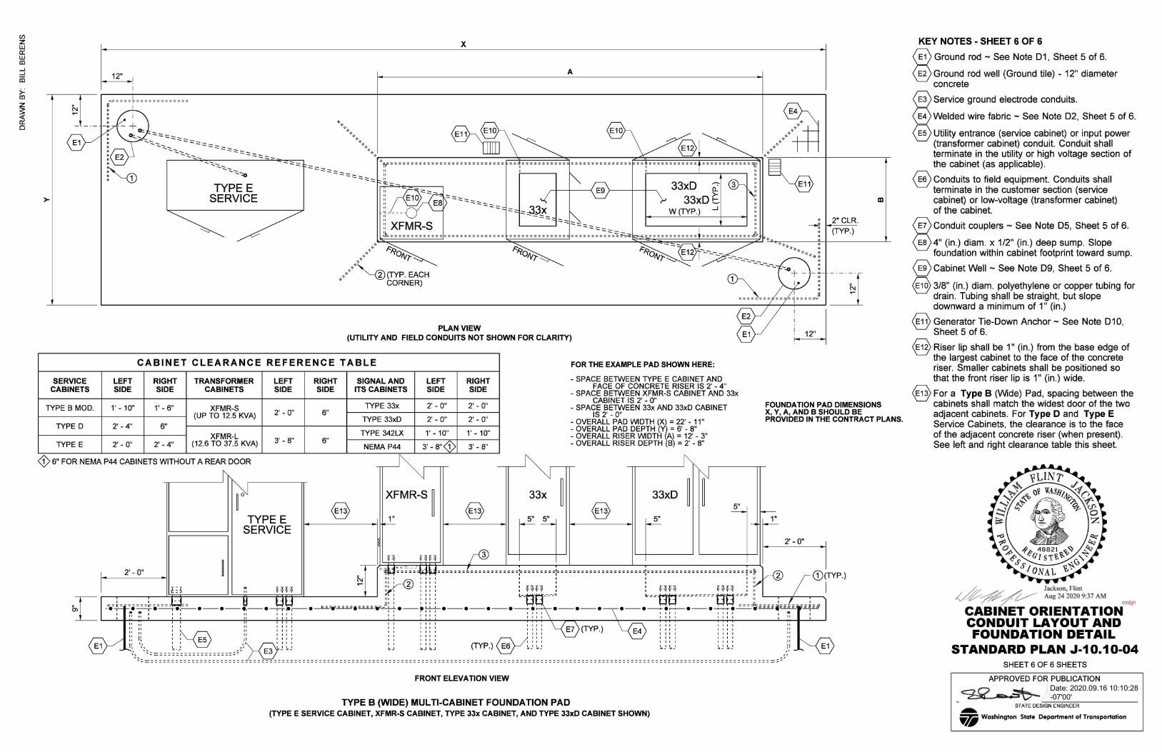
CABINET CLEARANCE REFERENCE TABLE FOR THE EXAMPLE PAD SHOWN HERE:
LEFT RIGHT TRANSFORMER LEFT SIDE SIDE CABINETS SIDE
RIGHT SIGNAL AND SIDE ITS CABINETS
LEFT SIDE
RIGHT SIDE
- SPACE BETWEEN TYPE E CABINET AND FACE OF CONCRETE RISER IS 2' - 4"
- SPACE BETWEEN XFMR-S CABINET AND 33x CABINET IS 2' - O"
2" CLR.
(TYP.)
ID
TYPE B MOD. 1' - 10" 1' - 6" XFMR-S 2' - O" 6" TYPE 33x 2' - O" 2' - O" - SPACE BETWEEN 33x AND 33xD CABINET FOUNDATION PAD DIMENSIONS
X, Y, A, AND B SHOULD BE IS 2' -0" - OVERALL PAD WIDTH (X) = 22' - 11" - OVERALL PAD DEPTH (Y) = 6' - 8" - OVERALL RISER WIDTH (A)= 12' - 3" - OVERALL RISER DEPTH (B) = 2' - 8"
PROVIDED IN THE CONTRACT PLANS. (UP TO 12.5 KVA)
TYPED 2' - 4" 6" XFMR-L
TYPE E 2' - O" 2' - 4" (12.6 TO 37.5 KVA)
TYPE 33xD 2' - O" 2' - O"
TYPE 342LX 1' - 10" 1' - 10" 3' - 8" 6"
3' - 8"(1) 3' - 8" NEMA P44
0 6" FOR NEMA P44 CABINETS WITHOUT A REAR DOOR -r~-~-'N-~ r
TYPE E SERVICE
I 2· -0" ~ ~ =M-=r-=--= "~H======[============:=========:=====================:========================:=~ ~ G)(TYP.)
I ~~~ :: nn .... ::: ; 2 ! ! ! ! L_nn _____ j ~== ~=Wl ========= ~_=1_~_=1 ==j ( / I L ' ' ·-~ .v.. .......... JJ: : : : : : ~ 00 oa c--1~----~-~f----;-~ l = -~•=•=:.:.===i=.,===T' •-•- -• HI;,' .~"r=e='lll"..<....L..J..•-"'J....L...J_•-•-•-•~• •-•-•·\•-•~•~•-•~•-•= .. ~ ,.......,..._ 0) ,.- a -;---r ----_ .- I ~ ... .- I I r" I I I 1 1 1 1 I I I I I I I I I a I
: II II : : : :: : : : : I I I 11 I I 11 I I 11 I I 11 I I II I
II II II 1111 11 1111 1111 ~ \-@ 1111 1111 II II II , , II , , , , , , , , , , 1 1 1 , E7 (TYP) E4 , 1 1 1 , , , , 11
11 11 I~ II 1111 11 1111 IIII ' 1111 1111 II II II I I II I I I I I I I I I I /;';;\ ~ I I I I I I I I I I I II ~ o/ ,,1: , , ES ;, ,,,, ,, ,,,, ~
1,,, ,,,, ,,,, "L... ~
..,',:<~~~ ~ ~~ ~ ~ ~/~ ~ ~ ~ ~~ ~ ~ ~~~ ~~=~~:>-® _ _;_ :~ ----------------------_ :~_ ------~~-:~ --------~~~~~~ --------~J- ~~ - - - - - - - - - = = = = = = = = = = = = = = = = = = = ~ ~ ~ =·= = = = = = = = = = ~ ~ ~ =·= = = = = = = = = = =~} _ .._ E1
FRONT ELEVATION VIEW
TYPE B (WIDE) MULTI-CABINET FOUNDATION PAD (TYPE E SERVICE CABINET, XFMR-S CABINET, TYPE 33x CABINET, AND TYPE JJxD CABINET SHOWN)
KEY NOTES - SHEET 6 OF 6
@Ground rod - See Note D1, Sheet 5 of 6.
@Ground rod well (Ground tile) - 12" diameter concrete
@service ground electrode conduits.
@welded wire fabric - See Note D2, Sheet 5 of 6.
@utility entrance (service cabinet) or input power (transformer cabinet) conduit. Conduit shall terminate in the utility or high voltage section of the cabinet (as applicable).
@conduits to field equipment. Conduits shall terminate in the customer section (service cabinet) or low-voltage (transformer cabinet) of the cabinet.
@conduit couplers - See Note D5, Sheet 5 of 6.
@4" (in.) diam. x 1/2" (in.) deep sump. Slope foundation within cabinet footprint toward sump.
@cabinet Well - See Note D9, Sheet 5 of 6.
@318" (in.) diam. polyethylene or copper tubing for drain. Tubing shall be straight, but slope downward a minimum of 1" (in.)
@Generator Tie-Down Anchor - See Note D10, Sheet 5 of 6.
@Riser lip shall be 1" (in.) from the base edge of the largest cabinet to the face of the concrete riser. Smaller cabinets shall be positioned so that the front riser lip is 1" (in.) wide.
@For a Type B (Wide) Pad, spacing between the cabinets shall match the widest door of the two adjacent cabinets. For Type D and Type E Service Cabinets, the clearance is to the face of the adjacent concrete riser (when present) . See left and right clearance table this sheet.
APPROVED FOR PUBLICATION
~.===-----STATE DESIGN ENGINEER ... VI Washington State Department of Transportation
Related Documents