Ref. No: CA18/2/3/7943 12/08/2010 South African Civil Aviation Authority Page 1 of 25 CA18/2/3/7943 SOUTH AFRICAN CIVIL AVIATION AUTHORITY ACCIDENT REPORT – EXECUTIVE SUMMARY Aircraft Registration ZU-PHA Date of Accident 5 April 2005 Time of Accident 1210Z Type of Aircraft Interavia I-3 Type of Operation Private Pilot-in-command Licence Type Airline Transport Pilot Age 41 Licence Valid Yes Pilot-in-command Flying Experience Total Flying Hours 8 500 Hours on Type 29 Last point of departure Stellenbosch Aerodrome (FASH) Next point of intended landing Stellenbosch Aerodrome (FASH) Location of the accident site with reference to easily defined geographical points (GPS readings if possible) 7nm south-east of Stellenbosch Aerodrome on Vergelegen Estate, Somerset West Meteorological Information Number of people on board 1 + 1 No. of people injured 0 No. of people killed 1 + 1 Synopsis The pilot of the aircraft, accompanied by second pilot (who was also the aeroplane’s owner) took off from Stellenbosch aerodrome at approximately 1200Z on what appears to have been an aerobatic practice flight. Prior to departure, the aircraft was refuelled to capacity with 100 litres of avgas 100LL. The pair flew south-east over the Heidelberg mountain range towards Somerset West. At about 1210Z, several eye-witnesses saw the aircraft crash in the Somerset West region performing aerobatic manoeuvres. The aircraft was destroyed and both occupants were fatally injured. The eye-witnesses observed both the left and right wing sections separating from the aircraft before the fuselage dived to the ground. Inspection of the wings revealed that the aileron “spades”, which are designed to relieve aileron stick forces, had been removed. They were later found in a hangar. The designer stated that the aileron spades served two purposes. The first was to relieve pilot loads on the ailerons and the second was to serve as mass balances to the ailerons. Probable Cause Whilst conducting aerobatic manoeuvres and pulling out from a dive, both wings failed and separated from the aircraft. The failure of the wing probably resulted from the removal of the spades/mass balances from the ailerons induced aileron flutter during the dive. IARC Date Release Date

Welcome message from author
This document is posted to help you gain knowledge. Please leave a comment to let me know what you think about it! Share it to your friends and learn new things together.
Transcript

Ref. No: CA18/2/3/7943
12/08/2010 South African Civil Aviation Authority Page 1 of 25
CA18/2/3/7943
SOUTH AFRICAN CIVIL AVIATION AUTHORITY
ACCIDENT REPORT – EXECUTIVE SUMMARY
Aircraft Registration ZU-PHA Date of Accident 5 April 2005 Time of Accident 1210Z
Type of Aircraft Interavia I-3 Type of Operation Private
Pilot-in-command Licence Type Airline Transport Pilot Age 41 Licence Valid Yes
Pilot-in-command Flying Experience Total Flying Hours 8 500 Hours on Type 29
Last point of departure Stellenbosch Aerodrome (FASH)
Next point of intended landing Stellenbosch Aerodrome (FASH)
Location of the accident site with reference to easily defined geographical points (GPS readings if possible)
7nm south-east of Stellenbosch Aerodrome on Vergelegen Estate, Somerset West
Meteorological Information
Number of people on board 1 + 1 No. of people injured 0 No. of people killed 1 + 1
Synopsis
The pilot of the aircraft, accompanied by second pilot (who was also the aeroplane’s owner) took off from Stellenbosch aerodrome at approximately 1200Z on what appears to have been an aerobatic practice flight. Prior to departure, the aircraft was refuelled to capacity with 100 litres of avgas 100LL. The pair flew south-east over the Heidelberg mountain range towards Somerset West. At about 1210Z, several eye-witnesses saw the aircraft crash in the Somerset West region performing aerobatic manoeuvres. The aircraft was destroyed and both occupants were fatally injured. The eye-witnesses observed both the left and right wing sections separating from the aircraft before the fuselage dived to the ground. Inspection of the wings revealed that the aileron “spades”, which are designed to relieve aileron stick forces, had been removed. They were later found in a hangar. The designer stated that the aileron spades served two purposes. The first was to relieve pilot loads on the ailerons and the second was to serve as mass balances to the ailerons.
Probable Cause
Whilst conducting aerobatic manoeuvres and pulling out from a dive, both wings failed and separated from the aircraft. The failure of the wing probably resulted from the removal of the spades/mass balances from the ailerons induced aileron flutter during the dive.
IARC Date Release Date
Ref. No: CA18/2/3/7943
12/08/2010 South African Civil Aviation Authority Page 2 of 25
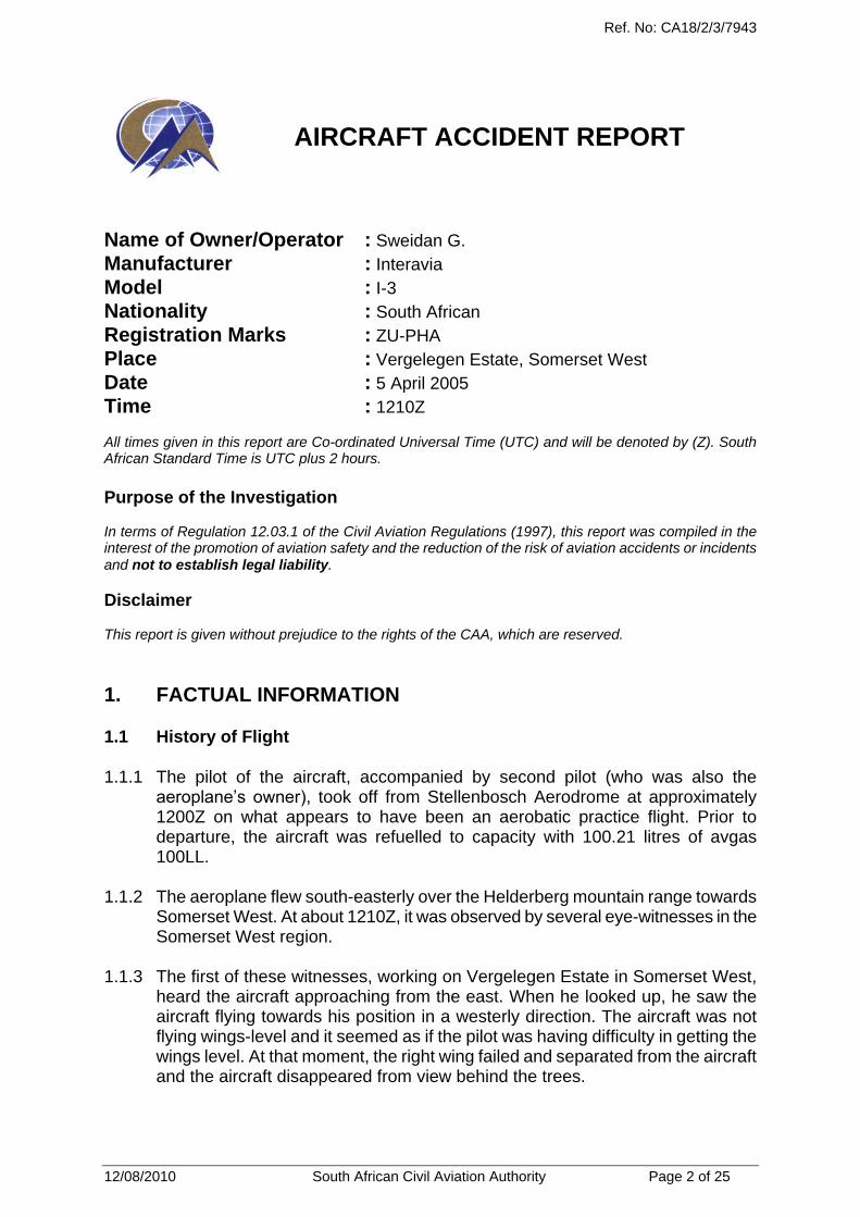
AIRCRAFT ACCIDENT REPORT
Name of Owner/Operator : Sweidan G.
Manufacturer : Interavia
Model : I-3
Nationality : South African
Registration Marks : ZU-PHA
Place : Vergelegen Estate, Somerset West
Date : 5 April 2005
Time : 1210Z All times given in this report are Co-ordinated Universal Time (UTC) and will be denoted by (Z). South African Standard Time is UTC plus 2 hours.
Purpose of the Investigation In terms of Regulation 12.03.1 of the Civil Aviation Regulations (1997), this report was compiled in the interest of the promotion of aviation safety and the reduction of the risk of aviation accidents or incidents and not to establish legal liability.
Disclaimer This report is given without prejudice to the rights of the CAA, which are reserved.
1. FACTUAL INFORMATION
1.1 History of Flight
1.1.1 The pilot of the aircraft, accompanied by second pilot (who was also the
aeroplane’s owner), took off from Stellenbosch Aerodrome at approximately 1200Z on what appears to have been an aerobatic practice flight. Prior to departure, the aircraft was refuelled to capacity with 100.21 litres of avgas 100LL.
1.1.2 The aeroplane flew south-easterly over the Helderberg mountain range towards
Somerset West. At about 1210Z, it was observed by several eye-witnesses in the Somerset West region.
1.1.3 The first of these witnesses, working on Vergelegen Estate in Somerset West,
heard the aircraft approaching from the east. When he looked up, he saw the aircraft flying towards his position in a westerly direction. The aircraft was not flying wings-level and it seemed as if the pilot was having difficulty in getting the wings level. At that moment, the right wing failed and separated from the aircraft and the aircraft disappeared from view behind the trees.

Ref. No: CA18/2/3/7943
12/08/2010 South African Civil Aviation Authority Page 3 of 25
1.1.4 A second witness, standing outside his house in the Somerset West area, noticed the aircraft flying in a westerly direction. It appeared to be flying relatively slowly and the engine was making a strange sound. He continued observing the aeroplane until it disappeared from view behind tall trees.
1.1.5 Another witness on Vergelegen Estate noticed the aircraft flying in a westerly
direction (from Stellenbosch) in what appeared to be a steep climb. He too stated that the engine sounded “strange”. He saw the aircraft continue to climb and then execute a loop. Instead of levelling out and completing the loop, however, the aircraft continued straight down in a vertical dive. The aircraft rolled 180° to the right and left, and then pulled out of the dive. It was during this last manoeuvre that the wings failed and separated, according to the witness. The fuselage continued in a westerly direction and crashed to the ground.
1.1.6 Investigation revealed that the wings had failed in flight. Both the left and right
wing-sections separated from the fuselage before the aircraft struck the ground. 1.1.7 Both occupants were fatally injured in the impact.
1.2 Injuries to Persons
Injuries Pilot Crew Pass. Other
Fatal 1 - 1 -
Serious - - - -
Minor - - - -
None - - - -
1.3 Damage to Aircraft
1.3.1 The aircraft was destroyed during the accident.
1.4 Other Damage 1.4.1 None.
1.5 Personnel Information
1.5.1 The occupants were both pilots. One was an airline transport pilot and flight
instructor. The other, who was the owner of the aircraft, was a private pilot. According to the aircraft flight folio, the airline transport pilot had signed as pilot-in-command for this flight. Neither pilot’s flying logbook was recovered and their exact flying experience could not be determined.
1.5.2 Airline Transport Pilot (presumably seated in rear seat)
Nationality South African Gender Male Age 40
Licence Number *************** Licence Type Airline Transport Pilot

Ref. No: CA18/2/3/7943
12/08/2010 South African Civil Aviation Authority Page 4 of 25
Licence valid Yes Type Endorsed Yes
Ratings Instrument Rating, Instructor Rating – Grade III
Medical Expiry Date 30 September 2005
Restrictions None
Previous Accidents SACAA No. 7303, 23 Jan 2001, ZS-MDG (Pitts S-2B): engine failure during spin training – forced landing
Flying Experience
Total Hours 8 500
Total Past 90 Days 150
Total on Type Past 90 Days 15
Total on Type 29
1.5.3 Private Pilot (presumably seated in front seat)
Nationality South African Gender Male Age 50
Licence Number ***************** Licence Type Private Pilot
Licence valid Yes Type Endorsed No
Ratings None
Medical Expiry Date 31 July 2005
Restrictions None
Previous Accidents None
Flying Experience
Total Hours Unknown
Total Past 90 Days 22.9
Total on Type Past 90 Days 22.9
Total on Type 22.9
1.6 Aircraft Information
Airframe
Type I-3
Serial Number 0306
Manufacturer Interavia
Year of Manufacture 1999
Total Airframe Hours (at time of accident) 59.3 (excluding accident flight)
Last MPI (Date & Hours) 25 October 2004 New Aircraft
Hours since Last MPI 59.3 (excluding accident flight)
Private Operation Authority To Fly (Issue Date)
28 October 2004
C of R (Issue Date) (Present Owner) 4 March 2004

Ref. No: CA18/2/3/7943
12/08/2010 South African Civil Aviation Authority Page 5 of 25
Engine
Type Vedeneyev M14P
Serial Number RA 9112004
Hours since New 59.3
Propeller
Type Oros Raigto
Serial Number 4000363
Hours since New Unknown
Hours since Overhaul 40.8
1.6.1 The aircraft is a high-performance, stressed-skin monoplane designed to
withstand 11g manoeuvres and initially designed as a training aircraft.
ZS-PHA photographed on a previous flight.
1.7 Meteorological Information
1.7.1 Various eye-witnesses in the vicinity of the accident said that the weather was
fine at the time and the wind was calm. It was a warm, sunny day. 1.7.2 According to the South African Weather Service, no official weather observations
were available at the time and place of the accident, but the most likely weather conditions were as follows:
Wind direction 320° Wind speed 6 kts Visibility 10 km+
Aileron spades / mass balances in position.

Ref. No: CA18/2/3/7943
12/08/2010 South African Civil Aviation Authority Page 6 of 25
Temperature 32°C Cloud cover Nil Cloud base N/A
Dew point 13°C
1.8 Aids to Navigation 1.8.1 The aircraft was fitted with standard navigational aids certified for the type, and
there were no reports of failures prior to the accident.
1.9 Communications 1.9.1 Stellenbosch aerodrome is unmanned and no record of any communication
with the aircraft was available. 1.9.2 The aircraft was fitted with standard communication equipment for the type and
there was no report of failures with the system before the accident.
1.10 Aerodrome Information 1.10.1 The accident occurred 7 nm south-east of Stellenbosch aerodrome on
Vergelegen Estate, Somerset West.
1.11 Flight Recorders 1.11.1 The aircraft was not fitted with a cockpit voice recorder or flight data recorder.
Neither was required by regulations to be fitted to this type of aircraft.
1.12 Wreckage and Impact Information 1.12.1 The wings of the aircraft had failed in flight and separated into two pieces, which
were located approximately 190 m apart and approximately 500 m from the fuselage. The GPS coordinates of the wings and fuselage were as follows:
R/H wing: S34°04.191’ and E018°54.549’ at an elevation of 414 ft ± 83 ft L/H wing: S34°04.277’ and E018°54.616’ at an elevation of 452 ft ± 84 ft Fuselage: S34°04.375’ and E018°54.298’ at an elevation of 553 ft ± 105 ft 1.12.2 The diagram below shows where the three main sections of the aircraft fell:

Ref. No: CA18/2/3/7943
12/08/2010 South African Civil Aviation Authority Page 7 of 25
1.12.3 Various views of the right wing:.
R/H wing: lower surface R/H wing: upper surface
R/H wing: leading edge R/H wing: upper surface – root area
R/H Wing
L/H Wing
Fuselage
190m
500 m on bearing of 263°M

Ref. No: CA18/2/3/7943
12/08/2010 South African Civil Aviation Authority Page 8 of 25
R/H wing: rear spar – fuselage attachment R/H wing: main spar failure
R/H wing: close-up of rear spar / fuselage attachment.
1.12.3.1 Close inspection of the bottom surface of the right wing showed evidence of compression buckles with an orientation from leading edge root to trailing edge tip. See photograph below.

Ref. No: CA18/2/3/7943
12/08/2010 South African Civil Aviation Authority Page 9 of 25
1.12.3.2 Right aileron: the upper surface leading edge of the aileron had two well-
defined compression buckles in the root area, as can be seen below.

Ref. No: CA18/2/3/7943
12/08/2010 South African Civil Aviation Authority Page 10 of 25
1.12.4 Various views of the left wing:
L/H wing: lower surface L/H wing: upper surface
L/H wing: upper surface L/H wing: root area
1.12.4.1 Close inspection of the left wing revealed compression buckles on the upper
surface running from the leading edge root to the trailing edge tip as shown below.

Ref. No: CA18/2/3/7943
12/08/2010 South African Civil Aviation Authority Page 11 of 25
1.12.4.2 Compression buckles on the lower surface run in the opposite direction –
from the trailing edge root to the leading edge tip area – as shown below:
1.12.4.3 The leading edge of the bottom surface of the left aileron is shown below
with several compression buckles evident along the leading edge of the aileron:

Ref. No: CA18/2/3/7943
12/08/2010 South African Civil Aviation Authority Page 12 of 25
1.12.4.4 A closer view of the leading edge of the bottom surface of the left aileron is
shown below.
1.12.4.5 The leading edge of the upper surface of the left aileron is shown below.
Significant compression damage is evident towards the tip of the wing.

Ref. No: CA18/2/3/7943
12/08/2010 South African Civil Aviation Authority Page 13 of 25
1.12.4.8 A close-up of the upper surface leading edge of the left aileron root area:
1.12.5 The remains of the fuselage are shown below. 1.12.6 The direction of impact of the fuselage was measured as 250°M. As is evident
from the views above, ground impact was extremely severe and the fuselage was extensively distorted and compressed by the high impact forces.
1.12.7 The fuselage came to rest only 5 m from the initial impact point, which, combined
with the degree of deformation, is evidence of a very steep impact angle. Various aircraft components were, however, still strewn up to 80 m from the initial impact point.

Ref. No: CA18/2/3/7943
12/08/2010 South African Civil Aviation Authority Page 14 of 25
1.12.8 Due to the degree of deformation, it was not possible to determine the cockpit
settings of throttle, pitch, elevator trim or flapperon position, or the cockpit instrument readings.
1.12.9 Inspection of both wings revealed that the aileron “spades”, which are designed
to relieve aileron stick forces and also serve as mass balances to the control surfaces (ailerons), had been removed. They were later found in the hangar at Stellenbosch aerodrome.
Aileron spades / mass balances later discovered in the hangar.
1.13 Medical and Pathological Information 1.13.1 The bodies of both occupants were severely mutilated and dismembered, and it
was not possible to conduct any meaningful post-mortem, histology or toxicology examinations.
1.14 Fire 1.14.1 There was no pre- or post-impact fire..
1.15 Survival Aspects 1.15.1 Although no evidence was found that the occupants had been wearing
parachutes, it is considered very doubtful whether either of them would have been able to make use of a parachute due to the low altitude at which the wing failures occurred.

Ref. No: CA18/2/3/7943
12/08/2010 South African Civil Aviation Authority Page 15 of 25
1.16 Tests and Research
1.16.1 Flutter [Ref: AP3456 Manual, Section 1-1-1-9.] 1.16.1.1 Torsional Aileron Flutter. This is caused by the wing twisting under loads
imposed on it by the movement of the aileron. A sequence for a half-cycle is described below.
1.16.1.2 The aileron is displaced
slightly downwards, exert- ing an increased lifting force on the aileron hinge.
1.16.1.3 The wing twists about the torsional axis, the trailing edge rising, taking the aileron up with it. The CG (Centre of Gravity) of the aileron is behind the hinge line; its inertia tends to make it lag behind, increasing aileron lift, and so increasing the twisting moment.
1.16.1.4 The torsional reaction of the wing has arrested the twisting motion but the air
loads on the aileron, the stretch of its control circuit, and its upward momentum, cause it to overshoot the neutral position, placing a down- load on the trailing edge of the wing.
1.16.1.5 The energy stored in the
twisted wing and the reversed aerodynamic load of the aileron cause the wing to twist in the opposite direction. The cycle is then repeated.

Ref. No: CA18/2/3/7943
12/08/2010 South African Civil Aviation Authority Page 16 of 25
1.16.1.6 Torsional aileron flutter can be prevented either by mass-balancing the ailerons so that their CG is on, or slightly ahead of, the hinge line, or by making the controls irreversible. Both methods are employed in modern aircraft; those aircraft with fully powered controls and no manual reversion do not require mass-balancing; all other aircraft have their control surfaces mass-balanced.
1.16.1.7 Flexural Aileron Flutter. This is generally similar to torsional aileron flutter,
but is caused by the movement of the aileron lagging behind the rise and fall of the outer portion of the wings as it flexes, this tending to increase the oscillation. This type of flutter is prevented by mass-balancing the aileron. The positioning of the mass-balance weight is important – the nearer the wing tip, the smaller the weight required. On many aircraft, the weight is distributed along the whole length of the aileron in the form of a leading edge spar, this increasing the stiffness of the aileron and preventing a concentrated weight starting torsional vibrations in the aileron itself.
1.16.1.8 So far, only wing flutter has been discussed, but a few moments’
consideration will show that mass-balancing must be applied to elevators and rudders to prevent their inertia and the springiness of the fuselage starting similar troubles.
1.16.1.9 Mass balancing is extremely critical; hence to avoid upsetting it, the painting
of aircraft markings etc. is no longer allowed on any control surface. The danger of all forms of flutter is that the extent of each successive vibration is greater than its predecessor, so that in a second or two, the structure may be bent beyond its elastic limit and fail.
1.16.2 Mass Balance [Ref: Mechanics of Flight, A.C. Kermode, 10th edition] 1.16.2.2 Control surfaces are often balanced in quite a different sense. A mass is fitted
in front of the hinge. This is partly to provide a mechanical balancing of the mass of the control surface behind the hinge but may also be partly to help prevent an effect known as “flutter” which is liable to occur at high speeds.
1.16.2.3 This flutter is a vibration which is caused by the combined effects of the
changes in pressure distribution over the surface as the angle of attack is altered, and the elastic forces set up by the distortion of the structure itself. All structures are distorted when loads are applied. If the structure is elastic, as all good structures must be, it will tend to spring back as soon as the load is removed, or changes its point of application.
1.16.2.4 In short, a distorted structure is like a spring that has been wound up and is
ready to spring back. An aeroplane wing or fuselage can be distorted in two

Ref. No: CA18/2/3/7943
12/08/2010 South African Civil Aviation Authority Page 17 of 25
ways, by bending and by twisting, and each distortion can result in an independent vibration. Like all vibrations, this flutter is liable to become dangerous if the two effects add up. The flutter may affect the control surfaces such as an aileron, or the main planes, or both.
1.16.2.5 The whole problem is very complicated, but we do know of two features
which help to prevent it – a rigid structure and mass balance of the control surfaces. When the old types of aerodynamic balance were used, i.e. the inset hinge or horn balance, the mass could be concealed inside the forward portion of the control surface and thus two birds were killed with one stone; but when the tab type of balance is used alone the mass must be placed on a special arm sticking out in front of the control surface. In general, however, the problems of flutter are best tackled by increasing the rigidity of the structure and control-system components. Large aircraft and military types now invariably have powered controls and these are much less sensitive to problems of flutter as the actuating system is very rigid.
1.16.2.6 Perhaps it should be emphasised that the mass is not simply a weight for the
purpose of balancing the control surface statically, i.e. to keep the aileron floating when the control mechanism is not connected; it may have this effect, but it also serves to alter the moments of inertia of the surface, and thus alter the period of vibration and the liability to flutter. It may help to make this clear if we realise that mass balance is just as effective on a rudder, where the weight is not involved, as on an elevator or aileron.
1.16.2.7 On old military biplane aircraft, the exact distribution of mass on the control
surfaces was so important that strict orders had to be introduced concerning the application of paint and dope to these surfaces. It is for this reason that the red, white and blue stripes which used to be painted on the rudders of Royal Air Force machines were removed (they were later restored, but only on the fixed fin), and why the circles on the wings were not allowed to overlap the ailerons. Rumour has it that when this order was first promulgated, some units in their eagerness to comply with the order, but ignorant as to its purpose, painted over the circles and stripes with further coats of dope!
1.16.2.8 Flutter [Ref: Flight Safety
Aerodynamics, 2nd Edition] 1.16.2.9 Flutter is a divergent aero-elastic
problem. If a wing during flight through turbulence bends and twists so as to increase the air load, the bending and twisting may lead to divergence and cause the wing to fail. At high speeds the oscillations may lead to wing failure in a fraction of a second.
1.16.2.10 Flutter considerations deter- mine
structural rigidity and weight distri-bution. If the centre of gravity of a

Ref. No: CA18/2/3/7943
12/08/2010 South African Civil Aviation Authority Page 18 of 25
structure (a wing) is located behind the elastic axis, a positive g-load will twist the wing in load-increasing directions. For the same reason, unbalanced control surfaces with the CG located behind the axis of rotation may begin to flutter. Mass balances are used to prevent this.
1.16.2.11 Flutter problems may be investigated in a wind-tunnel and during flight tests
or analyzed theoretically. The tests are very expensive. A flutter model of a supersonic fighter for wind-tunnel testing costs roughly the same as fifty small Volkswagens. Flight and ground testing of full-scale structures require flutter-guns to start the vibrations and expensive test equipment to take measurements. For these reasons flutter tests are usually only made for expensive military and transport aircraft. However, theoretical considerations and practical experience help the designers of light aircraft to avoid flutter in their designs.
1.16.2.12 Flutter risks can never be completely avoided. Avoidance within the flight
envelope of an aircraft is achieved by designing for flutter speeds considerably higher than the maximum dive speeds. All aeroplanes are flight-tested for flutter up to these speeds. The risk of divergent flutter should therefore be nil. However, this is not the case. Changes in balancing weights, control system sloppiness and reduced structural stiffness may reduce the critical flutter speed to normal operational speeds
1.16.4.1 Flutter [Ref. Aircraft Accident Investigation, Richard H. Wood, Robert W. Sweginnis, 1995] 1.16.4.2 A short description of aileron flutter is shown below.
1.16.3 On the photographs below, the spades are clearly visible on the aircraft:.

Ref. No: CA18/2/3/7943
12/08/2010 South African Civil Aviation Authority Page 19 of 25
1.16.4 The designer/manufacturer of the aircraft was contacted and the issue
regarding aileron flutter was discussed. The designer stated that the aileron spades served two purposes. The first was to relieve pilot loads on ailerons and the second was to serve as mass balances to the ailerons.
1.16.5 Flight without the aileron spades is strictly forbidden as the control surfaces
would not be balanced, which would result in aileron flutter.

Ref. No: CA18/2/3/7943
12/08/2010 South African Civil Aviation Authority Page 20 of 25
1.16.6 Frequency tests showed that without the spades attached (with the ailerons
unbalanced) the critical speed at which aileron flutter could occur was 280 km/h.
1.16.7 Photographs were sent to the designer, who confirmed that the distortion of
the wings and ailerons (especially the left wing) indicated that flutter had occurred.
1.17 Organisational and Management Information 1.17.1 According to available information, this was a private flight.
1.18 Additional Information 1.18.1 Eye-witness accounts 1.18.1.1 The position of each eye-witness was recorded. In addition, each eye-witness
was asked to point to where he or she had seen the aircraft, and the indicated elevation angle and magnetic bearing to the aeroplane was measured. The values were as follows:
Witness No. 1
Position: S34°04.468’ and E018°53.512’ at an elevation of 332 ft ±100 ft. Distance from accident site (wings): 1 700m Bearing to aircraft: 96°M Indicated elevation angle: 11°
Witness No. 2 Position: S34°04.864’ and E018°54.407’ at an elevation of 584 ft ± 92ft. Distance from accident site: 1 200 m (when wings failed) Bearing to aircraft when first observed: uncertain Indicated elevation angle: 15° Bearing to where loop was executed: uncertain Indicated elevation angle at top of loop: 18° Bearing to aircraft when wings failed: 42°M Indicated elevation angle: 8° Bearing to fuselage where it disappeared from view: uncertain
Witness No. 3
Position: S34°07.428’ and E018°55.445’ at an elevation of 581 ft ± 101ft Distance from accident site: 5 900 m

Ref. No: CA18/2/3/7943
12/08/2010 South African Civil Aviation Authority Page 21 of 25
Bearing to aircraft when first observed: 72°M Indicated elevation angle: 42° Bearing to aircraft when it disappeared from view: 14°M Indicated elevation angle: 9° 1.18.1.2 From the above, it is clear that witness no. 3 did not observe the aircraft at
the same time as the other two; he was approximately 5 900 m from where the aircraft crashed. From his indicated elevation angles (which are considered to be fairly accurate due to the fact that he referred to the heights of trees in the vicinity), it is clear that when he saw the aircraft, it was flying in a north-westerly direction away from him. It is also clear that when he first saw the aircraft, it was flying very close to his position as his indicated elevation angle was 42° and he could clearly hear the aircraft.
1.18.1.3 The observations of the first two witnesses are therefore more credible as
they both saw the wings fail and were thus observing the same event/s. 1.18.1.4 Witness No. 1 was positioned 1 700 m from where the wings were located,
with the aircraft flying towards him. With the indicated elevation angle of 11° (also made with reference to trees in the vicinity) and his distance of 1 700 m from the aircraft, the height of the aeroplane above the ground when the wings failed can be calculated to be about 330 m (1 000 ft). If the witness’s elevation of 300 ft (neglecting altitudinal variation) is added, the aircraft’s altitude can be established at 1 300 ft AMSL.
1.18.1.5 Witness No. 2 was positioned approximately 1 300 m from where the wings
were found. This witness indicated an elevation angle of 8° from his position. Considering that he was at an elevation of about 600 ft (neglecting altitudinal variation) and a distance of 1 300 m away, the aircraft height can be calculated to be 182 m (600 ft). If 600 ft is added for witness elevation, the aircraft’s altitude can be established at 1 200 ft AMSL.
In the hangar where the aircraft had been parked and where the aileron
spades were found, there was a white board describing a loop, aileron roll, spin roll and stall turn. The g-forces during a loop as well as the entry and exit speeds for a loop and a roll were also written down.

Ref. No: CA18/2/3/7943
12/08/2010 South African Civil Aviation Authority Page 22 of 25
The board in the hangar showing the manoeuvres.
1.18.1.6 The entry and exit speeds for the loop were shown as 300 km/h. For the
aileron roll, they were given as 250 km/h. 1.18.1.7 Inspection of the wreckage site uncovered a small piece of paper on which
several manoeuvres were written. These were:
3 Vertical Rolls
Tail Slide
Offset Loop
Smear Turn (Inverted)
Stall Turn R
Multiple Rolls
Fig 8
….°/270° Roll (not entirely legible)
…. Loop (not entirely legible)
1.19 Useful or Effective Investigation Techniques 1.19.1 None.
2. ANALYSIS 2.1 From the observations of the eye-witnesses, it is evident that the aircraft had
been executing aerobatic manoeuvres when the accident occurred.

Ref. No: CA18/2/3/7943
12/08/2010 South African Civil Aviation Authority Page 23 of 25
2.2 This is supported by the fact that several aerobatic manoeuvres were described on a whiteboard in the hangar where the aileron spades were found, and a piece of paper listing various aerobatic manoeuvres was also discovered at the scene of the accident.
2.3 From the description of one of the eye-witnesses, the aircraft was in the process
of pulling out of a dive when the wings failed. This is considered very likely, as the airspeed in the dive would have been high and the load on the airframe commensurately so.
2.4 From various eye-witness accounts and wreckage distribution, it is evident that
both wings failed in flight and separated from the fuselage, which came to rest 500 m from where the wings were located.
2.5 The left wing upper surface showed evidence of compression buckles with an
orientation from the root leading edge to the tip trailing edge. The bottom surface of the same wing also had compression buckles with an opposite orientation – from root trailing edge to tip leading edge.
2.6 This deformation of the wing structure is typical of a leading-edge-up / trailing-
edge-down twisting moment on the wing. 2.7 Examination of the left aileron also revealed significant distortion of the aileron
leading edge, with various compression buckles present on its leading edge. The compression buckles on the bottom surface of the aileron are believed to have resulted from excessive upward twist of the aileron and with the aileron push rod offering the only restraint to the aileron twisting moment.
2.8 Except for leading edge damage, the right wing was not distorted to the same
extent as the left. It did, however, show some evidence of compression buckles on the bottom surface of the wing and upper surface of the aileron leading edge.
2.9 The compression buckles on the lower surface of the right wing were orientated
from the root leading edge to the tip trailing edge, which suggest a leading-edge- down / trailing-edge-up torsion moment, which is opposite to the indications on the left-hand wing.
2.10 The compression buckles on the upper surface of the aileron leading edge of the
right wing suggest an upward twisting moment on the aileron, with the control rod restraining the twisting moment, similar to but not as severe as that found on the left aileron.
2.11 From the above, it is evident that severe control surface flutter must have
occurred in order to twist the ailerons to the extent that was found. 2.12 Similarly, it is evident that the left wing had been subjected to an excessive
leading-edge-up torsion moment which ultimately caused the wing to fail due to the + G or - G.
2.13 Once the left wing failed, the right wing would have been unsupported and would
have separated from the aircraft.

Ref. No: CA18/2/3/7943
12/08/2010 South African Civil Aviation Authority Page 24 of 25
2.14 From the fact that both wing halves were located equidistant from the fuselage wreckage on a symmetrical plane, it is clear that both had separated at more or less the same time.
2.15 As mentioned earlier, it is evident that the aileron spades had been removed at
some stage prior to the fateful flight. This meant that the mass balance of both ailerons would have been adversely affected in that their balancing weights were no longer present.
2.16 The aileron spade is positioned some distance in front of the aileron hinge-line,
thus moving the centre of mass of the aileron forwards. 2.17 Designers are well aware of the need to balance the mass of a control surface,
whether it is an aileron, elevator or rudder. The centre of mass of the control surface needs to be as close as possible to the control surface hinge-line or slightly in front of it.
2.18 If the centre of mass is located behind the hinge-line, the likelihood of aileron
flutter is dramatically increased, as aileron movement will not be damped and could reach excessive levels of movement, which could overload the wing structure. This is believed to have occurred in this case due to the removal of the spades.
2.19 Aileron flutter occurs suddenly and with hardly any warning, and can reach
excessive proportions very quickly, giving a pilot almost no time to react. Even if he had realised what was happening, there would have been little that the pilot of ZS-PHA could have done before the deflections of the ailerons and wing structure reached catastrophic proportions.
2.20 The only way to prevent flutter in such a scenario is to reduce airspeed
dramatically, which would not have been possible in this case.
3. CONCLUSION
3.1 Findings
3.1.1 The pilot in command held a valid airline transport pilot’s licence and Grade III
instructor’s rating, and was appropriately rated on the aircraft type. 3.1.2 The pilot was executing aerobatic manoeuvres when the accident occurred. 3.1.3 The aircraft was in almost level flight after pulling out of a dive when both wings
failed and separated from the airframe. 3.1.4 Neither of the two occupants made any attempt to bail out of the aircraft and
both were fatally injured when the fuselage struck the ground approximately 500 m from where the wings had failed.
3.1.5 The aileron spades had been removed some time prior to the flight, which
rendered the certificate of airworthiness invalid.

Ref. No: CA18/2/3/7943
12/08/2010 South African Civil Aviation Authority Page 25 of 25
3.1.6 Due to the removal of the aileron spades, the centre of mass of each aileron
moved significantly aft of the control surface hinge-line, making it possible for aileron flutter to occur.
3.1.7 Due to the aileron flutter, the left wing was subjected to catastrophic torsional
and bending loads, which resulted in its failure.
3.2 Probable Cause/s 3.2.1 Whilst conducting aerobatic manoeuvres and pulling out from a dive, both wings
failed and separated from the aircraft. The failure of the wing probably resulted from the removal of the spades/mass balances from the ailerons induced aileron flutter during the dive.
4. SAFETY RECOMMENDATIONS 4.1 None
5. APPENDICES 5.1 None.
Report reviewed and amended by the Advisory Safety Panel on 20 April 2010 -END-
Related Documents