Security Guide r12 CA Mainframe Network Management

Welcome message from author
This document is posted to help you gain knowledge. Please leave a comment to let me know what you think about it! Share it to your friends and learn new things together.
Transcript

Security Guide
r12
CA Mainframe Network
Management
This documentation and any related computer software help programs (hereinafter referred to as the
"Documentation") are for your informational purposes only and are subject to change or withdrawal by CA at any time.
This Documentation may not be copied, transferred, reproduced, disclosed, modified or duplicated, in whole or in part,
without the prior written consent of CA. This Documentation is confidential and proprietary information of CA and may
not be used or disclosed by you except as may be permitted in a separate confidentiality agreement between you and
CA.
Notwithstanding the foregoing, if you are a licensed user of the software product(s) addressed in the Documentation,
you may print a reasonable number of copies of the Documentation for internal use by you and your employees in
connection with that software, provided that all CA copyright notices and legends are affixed to each reproduced copy.
The right to print copies of the Documentation is limited to the period during which the applicable license for such
software remains in full force and effect. Should the license terminate for any reason, it is your responsibility to certify
in writing to CA that all copies and partial copies of the Documentation have been returned to CA or destroyed.
TO THE EXTENT PERMITTED BY APPLICABLE LAW, CA PROVIDES THIS DOCUMENTATION "AS IS" WITHOUT
WARRANTY OF ANY KIND, INCLUDING WITHOUT LIMITATION, ANY IMPLIED WARRANTIES OF MERCHANTABILITY,
FITNESS FOR A PARTICULAR PURPOSE, OR NONINFRINGEMENT. IN NO EVENT WILL CA BE LIABLE TO THE END USER
OR ANY THIRD PARTY FOR ANY LOSS OR DAMAGE, DIRECT OR INDIRECT, FROM THE USE OF THIS DOCUMENTATION,
INCLUDING WITHOUT LIMITATION, LOST PROFITS, LOST INVESTMENT, BUSINESS INTERRUPTION, GOODWILL, OR
LOST DATA, EVEN IF CA IS EXPRESSLY ADVISED IN ADVANCE OF THE POSSIBILITY OF SUCH LOSS OR DAMAGE.
The use of any software product referenced in the Documentation is governed by the applicable license agreement and
is not modified in any way by the terms of this notice.
The manufacturer of this Documentation is CA.
Provided with "Restricted Rights." Use, duplication or disclosure by the United States Government is subject to the
restrictions set forth in FAR Sections 12.212, 52.227-14, and 52.227-19(c)(1) - (2) and DFARS Section
252.227-7014(b)(3), as applicable, or their successors.
Copyright © 2010 CA. All rights reserved. All trademarks, trade names, service marks, and logos referenced herein
belong to their respective companies.
CA Product References
This document references the following CA products:
■ CA ACF2™ for z/OS (CA ACF2 for z/OS)
■ CA NetMaster® File Transfer Management (CA NetMaster FTM)
■ CA NetMaster® Network Automation (CA NetMaster NA)
■ CA NetMaster® Network Management for SNA (CA NetMaster NM for SNA)
■ CA NetMaster® Network Management for TCP/IP (CA NetMaster NM for
TCP/IP)
■ CA SOLVE:Access™ Session Management (CA SOLVE:Access)
■ CA SOLVE:FTS
■ CA SOLVE:InfoMaster™
■ CA SOLVE:NetMail™
■ CA SOLVE:Operations® Automation
■ CA SOLVE:Operations® Automation for CICS
■ CA Top Secret® for z/OS (CA Top Secret for z/OS)
Contact CA
Contact Technical Support
For your convenience, CA provides one site where you can access the information
you need for your Home Office, Small Business, and Enterprise CA products. At
http://ca.com/support, you can access the following:
■ Online and telephone contact information for technical assistance and
customer services
■ Information about user communities and forums
■ Product and documentation downloads
■ CA Support policies and guidelines
■ Other helpful resources appropriate for your product
Provide Feedback
If you have comments or questions about CA product documentation, you can
send a message to [email protected].
If you would like to provide feedback about CA product documentation, complete
our short customer survey, which is also available on the CA Support website,
found at http://ca.com/docs.
Contents 5
Contents
Chapter 1: Understanding Security 15
Security System Options ........................................................................ 15
UAMS....................................................................................... 16
Partial Security Exit ......................................................................... 16
NMSAF Solution ............................................................................. 16
Full Security Exit ............................................................................ 16
Product Libraries ............................................................................ 17 Choosing a Security System ..................................................................... 18
Recommended Options ...................................................................... 18
Implementing Security .......................................................................... 19
Controlling Signon Access ................................................................... 19
Controlling Access to Functions and Resources ............................................... 20
Additional Security Options ...................................................................... 21
Chapter 2: Using the NMSAF Security Solution 23
Components of NMSAF .......................................................................... 24
Using Groups and Modeling with NMSAF ......................................................... 25
Benefits of Using Groups and Modeling ....................................................... 25 Implementing NMSAF ........................................................................... 26
Defining Your User Groups................................................................... 26
Modeling Your User Groups .................................................................. 27
Enabling NMSAF............................................................................. 28
Customizing the SXCTL Parameter File ........................................................... 30
Additional Security Exits......................................................................... 31
Using the NMSECDSN and NMSECDSS Exits .................................................. 31
Chapter 3: Working with UAMS 33
Understanding UAMS ............................................................................ 33
Implementing Security for the First Time......................................................... 34 Sample Group Definitions.................................................................... 34
Sample Model Definitions .................................................................... 35
Background User IDs ........................................................................ 36
Defining Users to the System .................................................................... 38
Security Planning ........................................................................... 38
Defining a User ID .......................................................................... 39
Defining a Model User ID .................................................................... 41
6 Security Guide
Defining a System Console User ID .......................................................... 42
Defining Background Environment User IDs .................................................. 47 Accessing User ID Definitions Using NCL ......................................................... 49
Accessing User ID Information ............................................................... 49
Chapter 4: Working with an External Security Exit for User IDs 51
Understanding User ID Security Exits ............................................................ 51
Source Code for Sample Exits ............................................................... 51
Partial Security Exits ........................................................................ 52
PARTSAF Partial Security Exit ................................................................ 52
Full Security Exits ........................................................................... 52
Considerations When Using a Security Exit ................................................... 53
Functions Performed by a User ID Security Exit .................................................. 53 Controlling Access to Your System ........................................................... 54
Allowing Logon Verification .................................................................. 57
Allowing Users to Change Their Password .................................................... 58
Allowing User ID Information to be Retrieved ................................................. 59
Allowing Updates of User IDs ................................................................ 60
Adding Security Functions ................................................................... 60
Allowing User IDs to Be Listed—Full Security Exit Only ........................................ 62
Allowing User IDs to Be Added ............................................................... 62
Allowing User IDs to Be Deleted ............................................................. 62 Accessing User ID Attributes ................................................................. 63
Chapter 5: Implementing SmartTrace Security 65
Defining NETMSTR.PKTTRACE.region............................................................. 65
CA Top Secret .............................................................................. 66
CA ACF2 .................................................................................... 66
RACF ....................................................................................... 66
Chapter 6: Implementing Resource-Level Security 67
Sample Group Definitions ....................................................................... 68
Controlling Access to Functions and Resources by Using NPF ...................................... 69
Sample NPF Members ....................................................................... 70 Modifying NPF Members ..................................................................... 71
Controlling Access to Menu Options .......................................................... 72
Controlling Access to the Knowledge Base .................................................... 72
Controlling Access to System Images ........................................................ 74
Controlling Access to Commands............................................................. 74
Controlling Access to Customizer Parameter Groups .......................................... 78
Changing an NPF Table ...................................................................... 79

Contents 7
Controlling Access Using an External Security Package............................................ 80
Sample Security Profiles ..................................................................... 81 Defining Security Profiles .................................................................... 82
Modifying Security Members ................................................................. 82
Controlling Access to Menu Options .......................................................... 83
Controlling Access to the Knowledge Base .................................................... 83
Controlling Access to System Images ........................................................ 87
Controlling Access to Automation Services Commands ........................................ 87
Controlling Access to System Commands ..................................................... 88
Controlling Access to Product Commands..................................................... 89
Controlling Access to Customizer Parameter Groups .......................................... 90 Securing Data Set Members ..................................................................... 90
Chapter 7: Administering Security 93
Customizing Command Authority Levels ......................................................... 93
Changing Command Authority Levels ........................................................ 93
Disabling Commands ........................................................................ 93
Replacing Commands with NCL Procedures ................................................... 94
Customizing Parameters that Affect Security ..................................................... 94
Command Replacement ..................................................................... 94
Synchronizing Updates Across Linked Regions ................................................ 95
Understanding User Profiles ..................................................................... 98 Defining User Profiles ........................................................................... 99
Specifying a User’s Details ..................................................................100
Customizing a User’s Primary Menu Format Control ..........................................100
Customizing a User’s Alert Monitor ..........................................................101
Customizing a User’s Resource Monitor Display ..............................................101
Customizing a User’s Message Monitor Profile ...............................................102
Customizing a User’s Consolidated Console ..................................................103
Customizing a User’s SNA Network Summary Display ........................................104
Maintaining User Profiles .......................................................................104 Updating User Profiles ......................................................................105
Deleting a User Profile Definition ............................................................105
Chapter 8: Implementing Security Exits 107
Implementing Security for File Access...........................................................108
Activating the NCL Authorization Exit .......................................................109
Pre-loading the NCL Authorization Exit ......................................................110
Providing Additional Checking in the NCL Authorization Exit ..................................110
Correlating Authorization with Security Exit Authorization ....................................111
Implementing INMC Link Security ..............................................................112

8 Security Guide
Primary Exit ...............................................................................113
Secondary Exit .............................................................................114 Implementing Data Set Allocation Authority .....................................................114
Using NMDSNCHK with CA SOLVE:FTS ......................................................115
Sample Distributed Exit ....................................................................116
Implementing Security for Data Set Services ....................................................116
Sample Distributed Exit ....................................................................117
Chapter 9: Setting Up SNMP Security 119
About SNMP Security ...........................................................................119
Community Names .........................................................................120
User-based Security Details ................................................................120
Access Lists ................................................................................120 Define SNMP Security ..........................................................................121
Identify the SNMP Host.........................................................................121
Define an SNMP Host Record ...................................................................122
Chapter 10: Implementing WebCenter Security 123
Implementing WebCenter Security Using SSL ...................................................123
Control Access to WebCenter Menu Options .....................................................125
Appendix A: SXCTL Parameters 127
SXCTL Parameters .............................................................................128
Appendix B: Security Settings for Group Definitions 137
Security Settings for $RMADMIN ................................................................137
Security Settings for $RMOPER .................................................................139 Security Settings for $RMNOPER ................................................................140
Security Settings for $RMMON ..................................................................141
Security Settings for $RMBUSER ................................................................142
Appendix C: Structured Fields 143
Understanding Structured Fields ................................................................143
Format of Structured Fields.....................................................................144
Updating a Structured Field .................................................................146
Structured Field Error Conditions ...........................................................146
Structured Field Sequences .................................................................146
Structured Field Descriptions ...................................................................146 SF X‘0010’—User ID Name .................................................................147
Contents 9
SF X‘0011’—User Name ....................................................................147
SF X‘0012’—User Location ..................................................................148 SF X‘0013’—User Telephone Number ........................................................148
SF X‘0014’—User Language Code ...........................................................149
SF X‘0015’—User ID Suspend Date .........................................................149
SF X‘0016’—Terminal Restrictions ...........................................................150
SF X‘0017’—Time-out Control...............................................................150
SF X‘0018’—Date/Time User ID Last Updated ...............................................151
SF X‘0019’—Multiple Signon Capability ......................................................152
SF X‘001A’—Group Definition for User .......................................................152
SF X‘001B’—User ID Definition Type ........................................................153 SF X‘001C’—User Password Expiry Action Indicator ..........................................153
SF X‘001D’—User Email Address ............................................................154
SF X‘001E’—Model User ID Name ...........................................................154
SF X‘0020’—OCS Access Privilege ...........................................................155
SF X‘0021’—Broadcast Services Privilege ....................................................155
SF X‘0022’—Network Services Access Privilege ..............................................156
SF X‘0023’—System Support Privilege.......................................................156
SF X'0025'—CA SOLVE:FTS Access Privilege .................................................157
SF X‘0026’—NEWS Access Privilege .........................................................157 SF X‘0027’—MAI-FS Access Privilege ........................................................158
SF X‘0028’—User Services Procedure Name .................................................158
SF X‘0029’—User’s NCL Procedure Library ...................................................159
SF X‘002A’—UAMS Access Privilege .........................................................159
SF X‘002B’—Operations Management Privilege ..............................................159
SF X‘002C’—TSO Autologon Privilege........................................................160
SF X‘002D’—NCS Access Privilege ...........................................................160
SF X‘002E’—User’s SPLIT/SWAP Privilege ...................................................161
SF X‘002F’—Library Services Path Name ....................................................161 SF X‘0030’—User’s Time Zone Name ........................................................162
SF X‘0050’—OCS Command Authority Level .................................................162
SF X‘0051’—OCS Monitor Status ............................................................162
SF X‘0052’—NPF Command Member ........................................................163
SF X‘0053’—MSGPROC Member .............................................................163
SF X‘0054’—OCS Mode Initial Command ....................................................164
SF X‘0055’—PPO Message Receipt Option ...................................................164
SF X‘0056’—PPO Severity Level .............................................................165
SF X‘0057’—NPF Message Restriction Option ................................................165 SF X‘0058’—Message Code Value ...........................................................166
SF X‘0059’—OCS MSG Message Receipt .....................................................166
SF X‘005A’—OCS Unsolicited Message Receipt Option ........................................166
SF X‘005B’—Resource List Member..........................................................167
SF X‘005C’—User Time-out (1) Period .......................................................167

10 Security Guide
SF X‘005D’—User Time-out (2) Period.......................................................167
SF X‘005E’—User Time-out (1) Action .......................................................168 SF X‘005F’—User Time-out (2) Action .......................................................168
SF X‘0060’—User’s APPC Access Key ........................................................169
SF X‘0061’—User’s APPC Access Lock .......................................................169
SF X‘0070’—Installation Attribute Field 1 ....................................................170
SF X‘0071’—Installation Attribute Field 2 ....................................................170
SF X‘0072’—Installation Attribute Field 3 ....................................................171
SF X‘0073’—Installation Attribute Field 4 ....................................................171
SF X‘0074’—Installation Attribute Field 5 ....................................................172
SF X‘0075’—Installation Attribute Field 6 ....................................................172 SF X‘0076’—Installation Attribute Field 7 ....................................................173
SF X‘0077’—Installation Attribute Field 8 ....................................................173
SF X‘0078’—Installation Attribute Field 9 ....................................................174
SF X‘0079’—Installation Attribute Field 10 ...................................................174
SF X‘0080’—Access to CA SOLVE:InfoMaster Maintenance Functions .........................175
SF X‘0081’—Access to Information Management .............................................175
SF X‘0090’—Access to NCPView .............................................................176
SF X'0100'—CA SOLVE:FTS Definition Privilege ..............................................176
SF X'0101'—CA SOLVE:FTS Private Request Privilege ........................................177 SF X'0102'—CA SOLVE:FTS System Request Privilege .......................................177
SF X'0103'—CA SOLVE:FTS Private Control Privilege .........................................178
SF X'0104'—CA SOLVE:FTS System Control Privilege ........................................178
SF X'0105'—CA SOLVE:FTS Private Function Mask ...........................................179
SF X'0106'—CA SOLVE:FTS System Function Mask ..........................................180
SF X‘0150’—NEWS Reset Privilege ..........................................................181
SF X‘0151’—NTS Access Privilege ...........................................................181
SF X‘0180’—AOM Message Delivery and Routing Codes ......................................182
SF X‘0181’—AOM MVS SYSCMD Console Authority ...........................................183 SF X‘0182’—AOM MSG Level ................................................................184
SF X‘0183’—AOM z/VM SYSCMD Authority ..................................................185
SF X‘0185’—AOM VOS3/JSS4 SYSCMD Command Authority ..................................185
SF X‘0200’—MAI-FS Privilege Class .........................................................186
SF X‘0201’—MAI-FS Model User ID..........................................................186
SF X‘0202’—MAI-FS A and E Command Capability ...........................................186
SF X‘0203’—MAI-FS Active Session Limit ....................................................187
SF X‘0500’—PSM Primary Menu Access ......................................................187
SF X‘0501’—PSM Maintenance Access .......................................................188 SF X‘0502’—PSM Administration Access .....................................................188
SF X‘0503’—PSM Ability to Change Print Request Priority ....................................189
SF X‘0504’—PSM Queue Access for All Print Output ..........................................189
SF X‘0505’—PSM Queue Access for Their Own Print Output ..................................190
SF X‘0510’—Panel Command Access Authority...............................................190
Contents 11
SF X‘0511’—System Services Access ........................................................191
SF X‘0520’—Notification Details (First Rule) .................................................192 SF X‘0521’—Notification Details (Second Rule) ..............................................193
SF X‘0522’—Notification Details (Third Rule).................................................194
SF X‘0523’—Notification Details (Fourth Rule) ...............................................196
SF X‘0530’—TCP/IP Services Access Privilege ................................................197
SF X‘0550’—Report Writer Primary Menu Access .............................................198
SF X‘0551’—Report Writer Administration Access ............................................198
SF X‘0552’—Report Writer Maintenance Access ..............................................198
SF X‘0553’—Report Writer Public Report Access .............................................199
SF X‘0554’—Report Writer Access to Their Own Reports .....................................199 SF X‘0555’—Report Writer Private Report Access for All Users ................................200
SF X‘0556’—Report Writer Schedule Maintenance Access ....................................200
SF X‘0580’—Access to SOLVE:NetMail .......................................................201
SF X‘0601’—Access to Managed Objects Development Services (MODS) ......................201
SF X‘0605’—Object Services Access .........................................................201
SF X‘0609’—Object Services Security Access ................................................202
Appendix D: User ID Security Exit Support 203
External Security Packages .....................................................................203
Sample Exits ...............................................................................204
NMSAFPX Partial Security Exit ..............................................................205 Writing Your Own User ID Security Exit .........................................................205
Exit Execution..............................................................................207
Supported Exit Calls ........................................................................208
System Initialization Parameter List.............................................................209
Return Codes from Initialization Call ........................................................210
System Close Down Parameter List .............................................................211
Return Codes from Closedown Call ..........................................................212
Logon Request Parameter List ..................................................................212
Return Codes from Logon Call ..............................................................217 Logoff Request Parameter List ..................................................................219
Return Codes from Logoff Calls .............................................................220
Logon Verification Call Parameter List ...........................................................221
Return Codes from Logon Verification Call ...................................................224
Change Password Parameter List ...............................................................226
Return Codes from Change Call .............................................................229
Return User ID Information Parameter List ......................................................230
Return Codes from Return User ID Information Call..........................................232
Update User ID Parameter List .................................................................233 Return Codes from Update User ID Information Call .........................................235
&SECCALL EXIT Parameter List .................................................................236
12 Security Guide
Return Codes from &SECCALL EXIT Call .....................................................238
Return Sequential User ID Information Parameter List ...........................................239 NWM--Return Codes from Return Next User ID Information Call ..............................241
Add User ID Parameter List .....................................................................242
Return Codes from the Add User ID Call.....................................................244
Delete User ID Parameter List ..................................................................245
Return Codes from the Delete User ID Call ..................................................247
Appendix E: Data Set Authorization Exits Support 249
Writing a Data Set Access Authorization Exit ....................................................249
Registers on Entry to the Exit ...............................................................249
Parameters Passed to the Exit ..............................................................250
Calls Made to the Exit ......................................................................251 Modifying Transmission Information.........................................................252
Return Codes From the Exit ................................................................253
Installing the Data Set Access Authorization Exit ................................................253
Writing a Data Set Services Authorization Exit...................................................254
Function Calls Made to the Exit .............................................................254
Exit Environment ...........................................................................255
Registers on Entry to the Exit ...............................................................256
Installing the Data Set Services Authorization Exit ...............................................258
Appendix F: INMC Security Exit Support 259
Writing an INMC Security Exit ..................................................................259 Identifying the Primary Exit.................................................................259
Identifying the Secondary Exit ..............................................................260
Changing Exit Names Dynamically ..........................................................260
Registers on Entering INMC Exits ...........................................................261
Writing a Primary Exit ..........................................................................262
Specifying Initialization Processing ..........................................................262
Specifying Message Delivery Processing .....................................................266
Specifying Termination of Link Notification Processing .......................................268
Writing a Secondary Exit .......................................................................271 Specifying Initialization Processing ..........................................................271
Specifying Message Delivery Processing .....................................................273
Specifying Termination Processing ..........................................................276
Appendix G: NMSAF Public Correlator 279
Understanding the NMSAF Public Correlator .....................................................279
Using the NMSAF Public Correlator ..............................................................280
Using the $NMUCORH Macro ...................................................................280

Contents 13
DSECTs in the $NMUCORH Macro ...........................................................280
Fields in the UCOR DSECT ..................................................................281 Fields in the UGIN DSECT ..................................................................283
Appendix H: External Security Definitions for Modeled Users 285
Defining Your External Security System Resources ..............................................285
CA ACF2 Setup .............................................................................285
CA Top Secret Setup .......................................................................286
RACF Setup ................................................................................286
Appendix I: Command Authority Levels 287
Understanding Command Authority Levels ......................................................287
Command Authority Summary Table ............................................................288
Appendix J: Changes that Affect Resource-Level Security 301
Monitor Commands ............................................................................301 r12 Monitor Command Changes.............................................................301
r11.6 SP1 Monitor Command Changes ......................................................302
r11.6 Monitor Command Changes ...........................................................303
Menu Options ..................................................................................304
r12 Menu Option Changes ..................................................................304
r11.6 Menu Option Changes ................................................................306
Index 311

Chapter 1: Understanding Security 15
Chapter 1: Understanding Security
This chapter provides an overview of security for users of your regions.
Your products require a sophisticated security system, because:
■ Each product has many features.
■ The features often have varied security requirements.
■ The products have many users.
Setting up a security regime is an important part of the implementation of each
product. This guide will help you to make the best choice of security system, and
will guide you through the necessary implementation steps.
Note: This guide contains descriptive text and procedures about options and
products that you may not be licensed for or have not enabled. Inclusion of the
descriptions of these options and products in this guide in no way implies that
you are licensed for these options or products.
This section contains the following topics:
Security System Options (see page 15)
Choosing a Security System (see page 18)
Implementing Security (see page 19)
Additional Security Options (see page 21)
Security System Options
Your product region can use internal or external security systems, or a
combination of the two. The options available are:
■ UAMS—the internal security interface
■ Partial security exit
■ The NMSAF solution
■ Full security exit
Security System Options
16 Security Guide
UAMS
The internal security configuration that your product region can use is UAMS
(User ID Access Maintenance System). In this configuration, all information
about authorized users, including user ID, password, name, and privileges, is
stored in a VSAM data set.
Because this is an internal security interface, your product region does not
interface to any external security system or product.
Partial Security Exit
The partial security exit configuration that your product region can use is a
hybrid. The UAMS data set still exists, but an exit is used in conjunction with it.
The exit interfaces to an external security system, and performs (at least) user
ID and password validation. In this case, the UAMS data set still contains user
information and privileges. Passwords are not stored in the UAMS data set.
This is the most useful configuration. As described in the following section, a
comprehensive hybrid security solution, NMSAF, is provided that uses a partial
security exit.
NMSAF Solution
A comprehensive security solution is shipped with your product. This solution is
known as NMSAF.
The NMSAF solution is built around a partial security exit. It uses the UAMS data
set to store specific information for your product region, and uses whatever
security product is installed (through the IBM-defined SAF interfaces) to perform
user validation and password checking.
NMSAF uses its own parameter file (SXCTL) to provide flexible implementation.
Full Security Exit
The full security exit configuration that your product region can use consists of
just an exit. In this case, the exit performs all user authentication. It also
supplies all user attributes and privilege information. There is no UAMS data set.
Security System Options
Chapter 1: Understanding Security 17
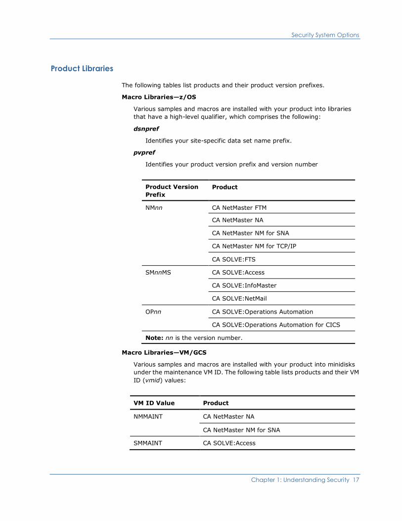
Product Libraries
The following tables list products and their product version prefixes.
Macro Libraries—z/OS
Various samples and macros are installed with your product into libraries
that have a high-level qualifier, which comprises the following:
dsnpref
Identifies your site-specific data set name prefix.
pvpref
Identifies your product version prefix and version number
Product Version
Prefix
Product
NMnn CA NetMaster FTM
CA NetMaster NA
CA NetMaster NM for SNA
CA NetMaster NM for TCP/IP
CA SOLVE:FTS
SMnnMS CA SOLVE:Access
CA SOLVE:InfoMaster
CA SOLVE:NetMail
OPnn CA SOLVE:Operations Automation
CA SOLVE:Operations Automation for CICS
Note: nn is the version number.
Macro Libraries—VM/GCS
Various samples and macros are installed with your product into minidisks
under the maintenance VM ID. The following table lists products and their VM
ID (vmid) values:
VM ID Value Product
NMMAINT CA NetMaster NA
CA NetMaster NM for SNA
SMMAINT CA SOLVE:Access

Choosing a Security System
18 Security Guide
Choosing a Security System
From the options available, which is the best choice for you? This depends on:
■ Whether you are running your product region for production or testing
purposes
■ How specific or stringent your security requirements are
More information:
Security System Options (see page 15)
Recommended Options
We recommend the following options to suit different requirements:
■ For a product region used for production—we recommend use of the NMSAF
solution. You can implement this solution with minimal work. It provides a
comprehensive set of facilities that make administration of security for your
product region straightforward.
■ For a product region used for testing—you can use NMSAF. However, in some
cases, just using UAMS may be sufficient (for example, if the product region
is used by only one or two people).
■ If you have specific or very stringent requirements—you may need to
consider writing your own partial or full security exit. This is not a trivial task.
Note: The NMSAF solution has flexibility, and may be able to meet all or most of
your needs.
More information:
Using the NMSAF Security Solution (see page 23)
Implementing Security
Chapter 1: Understanding Security 19
Implementing Security
Security is implemented on two levels:
■ Signon access
■ Access to functions and resources
There are also additional security options (see page 21) available, in the form of
exits.
Note: Background User IDs must be defined to the security system. If you are
using an external security package, you must create these definitions within your
security system; if you are using UAMS, the definitions are created
automatically.
More information:
Defining Background Environment User IDs (see page 47)
Controlling Signon Access
Signon access to a region is controlled by one or more of the following:
■ The User ID Access Maintenance Subsystem (UAMS)
■ The NMSAF security solution
■ An external security package that performs some or all of the security
functions through a full or partial security exit.
UAMS
UAMS is a database of user details and access authority levels used by your
product. You can maintain all security details (including user passwords) in
UAMS, or you can replace UAMS, either partially or fully, with an external security
package.
You can either define each user’s user ID separately or add users with the same
security requirements by using a UAMS group.
NMSAF Security Solution
The NMSAF security solution (see page 23) is based on the partial security exit
facility. It does not replace UAMS but works in conjunction with it.
Implementing Security
20 Security Guide
User ID Security Exits
If your organization has an external security package, such as CA ACF2, CA
Top Secret, or IBM RACF, access to that package is provided through one of the
following types of exit:
■ Partial security exit—password and logon access maintenance is
controlled by the external security package while UAMS stores the user
access authorities.
■ Full security exit—all security functions are maintained and stored by your
external security package.
More information:
User ID Security Exit Support (see page 203)
Controlling Access to Functions and Resources
A user's privileges (as defined in their UAMS record or by a full security exit)
provide a base level of control over their access authorities to your product
region.
You can implement a more granular level of control by implementing
resource-level security. This level of security can allow or deny user access to the
following functions and resources:
■ Individual menus and menu options
■ Specific Automation Services system images and resources
■ Individual commands
■ Individual Customizer parameter groups
You can implement resource-level security by using the Network Partitioning
Facility (NPF), or by using an external security option.
NPF uses resource tables to contain access permissions. For resource security to
be activated for a user, the user's UAMS record (or its associated group
definition) must include an NPF resource list member name.
Alternatively, your external security package can provide resource-level security
if it supports SAF. With this option, SAF calls to your external security packages
are used to check a user's access permissions. Sample definitions are distributed
for CA ACF2, CA Top Secret, and RACF. SAF security checking is performed if the
user's UAMS record (or its associated group definition) includes a special,
reserved name.
You can also implement a combination of NPF and SAF checking.

Additional Security Options
Chapter 1: Understanding Security 21
More information:
Implementing Security Exits (see page 107)
Additional Security Options
Your product provides additional security options in the following areas:
■ File access from NCL—can be restricted by using the NCL authorization exit,
NCLEX01
■ INMC link activation—can be checked for authority by using the INMC
security exit
■ The ALLOCATE command and CA SOLVE:FTS—can be secured by using the
data set access authorization exit
■ The data set services interface ($DSCALL)—can be secured by using the data
set services authorization exit
More information:
Implementing Security Exits (see page 107)


Chapter 2: Using the NMSAF Security Solution 23
Chapter 2: Using the NMSAF Security
Solution
This chapter describes how to set up the NMSAF security solution, an integrated
security management system for users of your regions.
The NMSAF security solution is based on the partial security exit facility and
works in conjunction with UAMS. It provides:
■ A complete security solution for your region, using whatever external
security system is in use
■ A sensible balance between what is stored in the external security system for
your users and resources, and what is maintained on UAMS
■ Control and customizing options that allow for flexible implementation
The NMSAF security solution minimizes duplication between external security
definitions and UAMS. By using the NMSAF security solution, it is possible to
eliminate almost all maintenance issues associated with using a UAMS data set.
This section contains the following topics:
Components of NMSAF (see page 24)
Using Groups and Modeling with NMSAF (see page 25)
Implementing NMSAF (see page 26)
Customizing the SXCTL Parameter File (see page 30)
Additional Security Exits (see page 31)
Components of NMSAF
24 Security Guide
Components of NMSAF
The NMSAF security solution consists of the following components:
■ UAMS—NMSAF uses the UAMS file to store user records that contain the
many access authorization details for a user ID. User records can be
manually added, modified, or deleted from the UAMS file, but this might not
be necessary. If NMSAF is installed as recommended (with grouping and
modeling enabled), then NMSAF automatically updates the UAMS file as
needed. This means that you do not need to perform any maintenance on
your UAMS records.
■ Partial security exit—NMSAF uses a partial security exit to interface with
your external security package for password checking. Passwords are not
stored in UAMS.
■ Modeling—You can use the modeling facility to significantly reduce the
number of users that must be manually defined to your product region (by
using UAMS). When you use modeling, a set of model users is defined. Each
model user definition is used to define the privileges that a specific type of
user has.
The NMSAF parameter file defines a list of resource names and associated
model names. When a user (that is not defined to UAMS) logs on, this list is
searched and each resource name is tested to see if the user has (at least)
READ access. The model user ID of the first one that matches is then used as
the basis of a new user ID definition.
If you simply give users PERMIT access to the appropriate resource(s), user
definitions are automatically created when a user logs on to your product
region for the first time.
■ SXCTL parameter file—The SXCTL file is the control file used by NMSAF.
You can use the SXCTL file as supplied or you can tailor it to your
requirements by using parameters.
■ Additional security exits—NMDSNCHK and NMDSSCHK can work in
conjunction with NMSAF. Several other exits are supplied.
More information:
Understanding Security (see page 15)
Using Groups and Modeling with NMSAF
Chapter 2: Using the NMSAF Security Solution 25
Using Groups and Modeling with NMSAF
With user groups, you can classify users by the type of functions that they have
access to. User groups are defined in the UAMS file. The following default groups
are defined during installation:
■ Administrator
■ Network Operator
■ Operator
■ Monitor
If these groups do not suit your requirements, you can define others.
Benefits of Using Groups and Modeling
User groups simplify the definition of user records—a user is allocated to a group,
inheriting all of its access authorizations.
Using both groups and modeling provides the following combination of benefits:
■ When your region models a user, a copy of the model user ID record is
produced.
■ By containing only the group name in this record, you ensure that the UAMS
records (created as users are modeled) contain only unique user-specific
information (such as user ID, user name, and phone number).
■ To change the profiles of all users in a group, you need only change the group
entry in UAMS.
■ To move a user from one group to another, you need only update the user's
UAMS record to point to the correct group name.
■ When a user logs on to your product region for the first time, that user is
tested against the listed resource names. When a resource that the user has
permission to access is found, the associated model definition is used to
create the user's UAMS record. The user is prompted to supply specific
information, such as name and phone number. However, everything else is
taken from the model user for the appropriate group.
Implementing NMSAF
26 Security Guide
Implementing NMSAF
To implement the NMSAF security solution with user groups and modeling
enabled, you must perform the following tasks:
1. Defining Your User Groups (see page 26)
2. Modeling Your User Groups (see page 27)
3. Enabling NMSAF (see page 28)
Note: If your UAMS data set is empty, you must log on with the INSTALL user ID
before you perform these tasks. For more information, see Installation Guide.
Defining Your User Groups
To define your user groups
1. Define a set of logical user groups. Each group will have specific authority
needs in your region. As well as the default user groups, there is also a
special group for background user IDs.
Note: You must manually define users with significant privileges using UAMS
(see page 33).
2. For each group, create a UAMS GROUP user definition with the appropriate
set of privileges. These are the only comprehensive UAMS definitions that
you must create.
The following default groups are created automatically when a region starts
for the first time:
■ $RMADMIN
■ $RMOPER
■ $RMNOPER
■ $RMMON
■ $RMBUSER
You can recreate these GROUP definitions at any time by executing the
supplied NCL procedure $NMUAINI.
Note: For CA SOLVE:FTS, CA SOLVE:Access Session Management, CA
SOLVE:InfoMaster, and CA SOLVE:NetMail, you must create your groups
manually, because no default groups are created.
To run $NMUAINI:
a. Enter CMD from the primary menu to display the Command Entry panel.
b. Enter $NMUAINI at the command prompt (===>).
Implementing NMSAF
Chapter 2: Using the NMSAF Security Solution 27
Modeling Your User Groups
To model your user groups
1. For each defined GROUP user, create a single model user ID.
The following default MODEL definitions are created automatically when a
region starts for the first time:
■ $MDADMIN
■ $MDOPER
■ $MDNOPER
■ $MDMON
Notes:
■ For CA SOLVE:FTS, CA SOLVE:Access Session Management, CA
SOLVE:InfoMaster, and CA SOLVE:NetMail, you must create your model
definitions manually, because no default definitions are created.
■ $RMBUSER has no model created, because it is used by background user
IDs only.
2. Using your external security package, create resource names for each
defined group. These must use the same resource class name as the SXCTL
RCLASS setting (default FACILITY); for example:
■ NETMASTR.ADMIN, for an administrator
■ NETMASTR.OPER, for a system operator
■ NETMASTR.NOPER, for a network operator
■ NETMASTR.MON, for a monitor user
Notes:
■ These resource names are generic. If you have several product regions,
and you want users to have different profiles on each, you could use the
ACB name or domain name of each region as part of the name (for
example, NETMASTR.ADMIN.NM01).
■ If you use a different class name, you must define the class to the
security system.
3. Issue commands to define and activate the resources in your external
security system. Give PERMIT privileges with (at least) READ access to the
appropriate resource, to all users that will access your region.

Implementing NMSAF
28 Security Guide
4. Set up the SXCTL file with the following statements:
MODEL LIST
MODELGROUP resource.name.1 model1
MODELGROUP resource.name.2 model2
MODELGROUP resource.name.3 model3
MODELGROUP resource.name.4 model4
Note: You must list the resource names in the order that you want them to
be tested.
If you want to allow a generic logon for any other users, add an additional
line:
MODELGROUP * dfltmodel
More information:
External Security Definitions for Modeled Users (see page 285)
User ID Modeling (see page 56)
Enabling NMSAF
To enable the NMSAF security solution
1. Set the JCL parameter SEC to SEC=NMSAF.
You can set SEC=NMSAF either during initial implementation of your
product, or later.
When you set SEC=NMSAF, you activate the NMSAF partial security exit, and
so enable the NMSAF security solution.
If you require other components of the NMSAF security solution, you must
activate them separately.
Use the procedures described in Customizing the SXCTL Parameter File (see
page 30) and Additional Security Exits (see page 31) in this chapter.
Note: For a full description of the JCL parameter SEC, see the Reference
Guide.
Note: If your Security product is CA Top Secret, you must create a region
control definition for signon (see page 30).
2. Restart your region (to allow the security exit to pick up the definitions).
Implementing NMSAF
Chapter 2: Using the NMSAF Security Solution 29
Remote Background User IDs and NMSAF
When regions are linked, a remote region’s background user (nnnnBSYS) may
need to log on to the local region. To define the remote background user ID to the
local region, perform the following tasks:
■ Define the remote nnnnBSYS user ID to the local region’s UAMS.
For products that use the link and synchronize process to link regions, the
remote region’s user ID is automatically added to UAMS during
synchronization. If this process fails or if links are established manually, the
nnnnBSYS user must be added manually. Assign the user ID to group
$RMBUSER.
■ Define the remote nnnnBSYS user ID as a user to the external security
package. No password is required:
– For CA ACF2, use the following commands:
ACF
SET LID
INSERT nnnnBSYS NAME(bsys_user_name) PASSWORD(NOPW)
– For CA Top Secret, use the following command:
TSS CRE(nnnnBSYS) TYPE(USER) DEPT(dept_acid) NAME('bsys_user_name')
PASS(NOPW,0)
– For RACF, use the following command:
ADDUSER nnnnBSYS NAME('bsys_user_name')
bsys_user_name specifies a text string to identify the user (for example,
BSYS User 1).
Customizing the SXCTL Parameter File
30 Security Guide
Signon and Signoff with CA Top Secret
External security includes security for signon and signoff. The CA Top Secret
security administrator must create a region control ACID, FACILITY and Started
Task definition for the online STC (NETMASTR).
To create this definition
1. Create a region control ACID using the following commands:
TSS CRE(netmacid) NAME('region_acid NETMASTR') DEPT(netmdept) PASS(NOPW,0)
FAC(STC,NETMASTR) MASTFAC(NETMASTR) NOVOLCHK NORESCHK NOLCFCHK NODSNCHK NOSUBCHK
2. Create a NETMASTR FACILITY by placing the following statements into the
CA Top Secret startup parameter file member:
FAC(user15=NAME=NETMASTR)
FAC(NETMASTR=NOABEND,ASUBM)
FAC(NETMASTR=INSTDATA,KEY=8,LCFCMD,LOCKTIME=0,NOLUMSG)
FAC(NETMASTR=MULTIUSER,PGM=NM0,NORNDPW,RES,SIGN(M))
FAC(NETMASTR=SHRPRF,NOSTMSG,NOTSOC,WARNPW,NOXDEF)
3. Define the NETMASTR STC to the CA Top Secret STC Table using the
following command:
TSS ADD(STC) PROCNAME(NETMASTR) ACID(netmacid)
4. For any region control ACID to be used to sign on, authorize it to the
NETMASTR FACILITY using the following command:
TSS ADD(user1) IBMFAC(NETMASTR)
Customizing the SXCTL Parameter File
If SEC=NMSAF is in effect, there is an optional parameter file, accessed through
DD SXCTL. You can use this file to customize the NMSAF facility to suit the
security needs of your installation.
There is a sample SXCTL file in the PARMLIB member SXPARMS. For more
information, see the comments in this sample file.
Note: If the SXCTL file is not allocated, then default settings are used for all
parameters.
More information:
SXCTL Parameters (see page 127)

Additional Security Exits
Chapter 2: Using the NMSAF Security Solution 31
Additional Security Exits
There are specific additional security exits available to use with NMSAF:
■ NMSECDSN (for the NMDSNCHK exit type)
■ NMSECDSS (for the NMDSSCHK exit type)
The NMSECDSN exit works in conjunction with the NMSAF security solution to
provide user-level security authorization for CA SOLVE:FTS functions and the
ALLOCATE command.
The NMSECDSS exit works in conjunction with the NMSAF security solution to
provide user-level security authorization for data set services functions.
More information:
Implementing Security Exits (see page 107)
Using the NMSECDSN and NMSECDSS Exits
To use the NMSECDSN and NMSECDSS exits, you must identify them to your
product region by using the NMSECURITY parameter group (enter /PARMS).
More information:
Data Set Authorization Exits Support (see page 249)

Chapter 3: Working with UAMS 33
Chapter 3: Working with UAMS
This chapter provides information about defining users in UAMS.
This section contains the following topics:
Understanding UAMS (see page 33)
Implementing Security for the First Time (see page 34)
Defining Users to the System (see page 38)
Accessing User ID Definitions Using NCL (see page 49)
Understanding UAMS
UAMS is designed to provide a fully self-contained system for user security. It
allows you to define user IDs for each user of your regions. User IDs provide
logon and password checking and can be added, deleted, or updated.
You can use UAMS to define:
■ Each user ID separately
■ A group ID to be used as a model for each user that requires similar access
and authority
UAMS by itself is independent of any external security system. For example,
passwords stored in UAMS are not synchronized with RACF.
A single UAMS data set can be shared by any number of regions.
Implementing Security for the First Time
34 Security Guide
Implementing Security for the First Time
When a region starts for the first time, the following UAMS definitions are
automatically generated:
■ Sample group definitions
■ Sample model definitions
Note: Sample group definitions and sample model definitions do not apply to
CA SOLVE:FTS, CA SOLVE:Access Session Management, CA
SOLVE:InfoMaster, and CA SOLVE:NetMail.
■ Background user IDs
Note: All background user definitions are linked to the $RMBUSER group
definition.
If any of the default background group definitions are not defined in UAMS, you
can create them by running $NMUAINI, which builds any of the definitions that
do not already exist.
Note: For CA SOLVE:FTS, CA SOLVE:Access, CA SOLVE:InfoMaster, and CA
SOLVE:NetMail, you must create your groups manually, because no default
groups are created and the $NMUAINI procedure is not available.
To run $NMUAINI
1. Enter CMD from the primary menu to display the Command Entry panel.
2. Enter $NMUAINI at the command prompt (===>).
Sample Group Definitions
The following group definitions are created:
■ $RMADMIN—administrators
■ $RMOPER—operators
■ $RMNOPER—network operators
■ $RMMON—monitors
■ $RMBUSER—background users
You can use these group definitions to simplify the creation of user definitions.
If used as distributed, these groups also implement resource-level security.

Implementing Security for the First Time
Chapter 3: Working with UAMS 35
More information:
Security Settings for Group Definitions (see page 137)
Implementing Resource-Level Security (see page 67)
Sample Model Definitions
The following model definitions are created:
■ $MDADMIN—corresponding to group $RMADMIN
■ $MDOPER—corresponding to group $RMOPER
■ $MDNOPER—corresponding to group $RMNOPER
■ $MDMON—corresponding to group $RMMON
No model is defined for $RMBUSER, because modeling is not used with
background users.
You can use the generated model and group definitions in conjunction with
NMSAF.
More information:
Using the NMSAF Security Solution (see page 23)

Implementing Security for the First Time
36 Security Guide
Background User IDs
The following UAMS background user definitions (where nnnn is the domain ID)
are defined when a region is started for the first time.
Note: The AOM procedure does not apply to CA SOLVE:FTS, CA SOLVE:Access,
CA SOLVE:InfoMaster, and CA SOLVE:NetMail. The CNM procedure applies only
to CA NetMaster NM for SNA.
User ID Description
nnnnAOMP AOM procedure
nnnnBLOG Logger
nnnnBMON Monitor
nnnnBSVR Server
nnnnBSYS System
nnnnCNMP CNM procedure
nnnnLOGP Log procedure

Implementing Security for the First Time
Chapter 3: Working with UAMS 37
Background User Considerations for Existing UAMS File
If you set up your region by using a pre-existing UAMS file in which the
background users are already defined for your region, those background user
definitions are not replaced. If this is the case, both of the following happen:
■ The following message is displayed in the job log:
N10107 USERID xxxxBSYS NOT AUTHORIZED FOR REQUESTED COMMAND
■ Parameter group ABENDCMD fails.
To enable the new region to work correctly, you must update those background
user definitions by associating the definitions to the $RMBUSER group ID. To do
this:
1. Enter /UAMS to access the UAMS maintenance function.
2. Update each of the background user IDs by entering $RMBUSER in the Group
ID field.
3. Press F3 to file the changes, and again to exit.
4. Enter CMD to display the Command Entry panel.
5. Enter the SUBMIT background-name SIGNON command at the command
prompt to invoke the changes.
Note: background-name is the last four characters of the background user
ID, for example, BSYS.
6. Repeat step 5. for each of the background user IDs that you changed in
step 2.
7. Press F3 to exit from the Command Entry panel.
The $RMBUSER group ID provides the minimum security settings needed for a
background user. However, additional settings can be added to meet your
requirements.
Note: This process can be done at any stage, including during initial
customization when the region is first started.

Defining Users to the System
38 Security Guide
Defining Users to the System
There are different types of user ID that can be defined to your system:
■ Individual user
■ Model
■ System console
■ Background environments
– Background process
– System procedure
The following sections describe how to define each of these user IDs.
Security Planning
Note: This section only applies to CA SOLVE:FTS.
The transmission of a file from one location to another implies access to two data
sets: the one being transmitted and the one into which the transmitted data set
is being received. If those data sets are of a production nature, it is probable that
the individual who requests the transmission is not allowed personal access to
either of the data sets. By classifying a transmission definition as a system
definition, CA SOLVE:FTS regards the access to the data sets as being access by
CA SOLVE:FTS rather than as personal access by the user that issues the
transmission request (such as when a user requests a private transmission).

Defining Users to the System
Chapter 3: Working with UAMS 39
Defining a User ID
Before anyone can access your region, they must be defined as an authorized
user. A one- to eight-character user identifier (the user ID), together with a
password, is used to associate an individual to the privileges and authorities
allocated them. The password can be maintained by UAMS or by an external
security system.
In addition to identifying an individual user of the system, the user ID also
defines the following information about a user:
■ Statistical information—personal information such as name, location,
telephone number, as well as user ID expiry date and start times of last
session.
■ Control information—identifies the functions the user is allowed to perform
and the features they can access when logged on to the system. This
information determines, for example, whether a user is allowed to act as an
OCS operator and if so, their authority level .
To define an individual user ID for a new user
1. Enter /UAMS at the command prompt.
The UAMS : Primary Menu is displayed.
2. Type A at the Select Option prompt.
3. Type in the User Name.
4. Type USER in the Definition Type field and press Enter.
The first of several panels of user ID definition details is displayed. These
describe a user’s access to various features.
Note: You can associate a user with a group definition (for example, one of
the groups generated when your region was installed). To associate a user
with a group definition, simply enter the group name in the Group ID field on
the first panel. Doing this means that the user inherits the privileges set in
the group definition.
5. Type the required information on each following panel, scrolling forward (F8)
to review the next panel.
6. Press F3 (File) to save the new user ID definition when all the panels have
been reviewed and the required attributes specified.
You are returned to the UAMS : Primary Menu.
Note: If the user ID you are defining is similar to another ID, you can save
time by copying an existing user ID to a new user you wish to add. Do this by
selecting option L (List) to list the existing users, and then option C (Copy) to
copy the user definition. UAMS retrieves the details for that user ID and then
enters Add mode. You must now enter the new user ID name and change any
fields required, before filing the new definition under the new name.

Defining Users to the System
40 Security Guide
Maintaining User IDs
You can obtain a selection list of the user IDs defined to your system. The list
allows you to browse, force a password, update, delete, or copy any of the listed
user IDs. If you are not authorized for UAMS maintenance functions, only the
browse function is allowed.
The following information is displayed about each user ID:
■ Name
■ Location
■ Telephone number
■ Type (Group or User definition)
■ Access privileges
To maintain an existing user ID
1. Type L at the Select Option prompt on the UAMS : Primary Menu.
2. To obtain a partial listing, enter a prefix in the User field to list only those user
IDs beginning with that prefix.
3. To display the command authority and access privileges information, press
F11 (Right) twice.
Defining Users to the System
Chapter 3: Working with UAMS 41
Forcing a Password Change for a User ID
If a user forgets their password, you can allocate a new password using the Force
User’s Password Change facility.
To allocate a new password using the Force User’s Password Change
facility
1. Enter /UAMS at the command prompt.
The UAMS : Primary Menu is displayed.
2. Type F at the Select Option prompt on the UAMS : Primary Menu, change the
User field to the user ID you want to change the password for, and press
Enter.
The UAMS : User Details panel for the specified User ID is displayed.
3. Type the new password in the New Password field, and press Enter.
The following message displays:
PASSWORD VERIFICATION COMPLETE
4. Press F3 (File) to save the changes.
When the user next logs on to the region, they are prompted to change the
forced password. If a security exit is provided for password processing, this
option can be suppressed by the exit.
Note: This function is not available from the special Install User ID.
Defining a Model User ID
Many installations have numerous users who access only one or two functions.
Defining and maintaining system access for individual users requires
considerable administrative effort. To minimize this effort, you can set up a
model user ID so that users can automatically log on and register.
A model user ID is defined in the SYSPARMS MODLUSER operand. It has the
following format:
SYSPARMS MODLUSER={ userid | NONE }
Note: For a detailed description of the MODLUSER operand, see the Reference
Guide.

Defining Users to the System
42 Security Guide
How It Works
If no security exit is in place and a model user ID is defined, a user who tries to
log on with an undefined user ID, but using the password of the model user ID,
causes the following to occur:
■ The model user ID definition is read.
■ A new user ID is created using the user ID specified during the logon request
with the attributes of the model user ID.
■ The new user ID is saved and flagged as a new user.
■ The user ID creation is recorded on the log.
■ Logon is allowed to proceed.
■ The new user is prompted to change their password and fill in personal
details (name, telephone, location, and so on) before the logon is complete.
Note: Creating new user IDs from model definitions is not suitable when defining
high authority user IDs.
If no security exit is in place, and no model user ID has been defined, logon
attempts from user IDs that are not defined are rejected.
If a model user ID has been specified in the SYSPARMS MODLUSER operand but
has not been defined to UAMS, logon requests by undefined users will fail as if no
model was defined.
If a security exit is in place, model user IDs work differently (see page 56).
Defining a System Console User ID
The system console needs a special type of user ID. This is because:
■ It only receives messages
■ It has no full screen capabilities
■ User logon is not possible
The system console user ID can be defined in the same manner as any other user
ID, however, only fields that are applicable to message receipt are valid. For
example, by defining the system console user ID as a monitor status OCS
operator with PPO authority and an appropriate command authority, the system
console can be profiled as a fully functional OCS operator console in the same
manner as any other user ID.
The following sections describe how the system console user ID is created. See
the section that applies to your operating environment.

Defining Users to the System
Chapter 3: Working with UAMS 43
Defining the System Console User ID in z/OS
The z/OS environment supports named consoles as well as extended MCS
consoles, RACF signon, and security for consoles.
If necessary, the console user ID can be reproduced in UAMS so that a user who
has limited authority cannot circumvent that authority by going to a console and
issuing a MODIFY command.
Default OPER Environment
A default CONSOLE environment allows messages to be delivered to the
operator. These messages are then delivered using the routing and descriptor
codes set by the SYSPARMS ROUTCDE and DESC operands. This environment is
built after INIT has finished.
The default terminal name for the system console environment is CONSOLE. The
user ID for the console is automatically assigned using the following process:
1. The value of the SYSPARMS SYSCONUI operand is examined.
2. If no value is defined, it looks at the default—ppppOPER, where pppp is the
system user prefix as defined in the NMSUP region JCL parameter.
3. If there is no definition for ppppOPER, the system assigns .DFLTOP as the
user ID.
If .DFLTOP is used because no other value is defined, problems with ROF routing
to other systems might result.
For more information about the SYSPARMS DESC, ROUTCDE, and SYSCONUI
operands, see the Reference Guide.
Actual Console Environments
A system console environment is signed on the first time that a command is sent
from the console to the system (for example, MODIFY).
The terminal name used is one of the following:
■ The MVS console name if:
– SYSPARMS SYSCONNM=ALL is in effect
– It is an extended MVS console
■ CONS#nn or CONS#nnn
Defining Users to the System
44 Security Guide
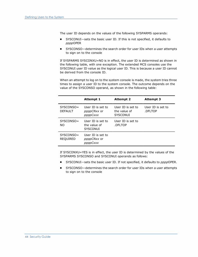
The user ID depends on the values of the following SYSPARMS operands:
■ SYSCONUI—sets the basic user ID. If this is not specified, it defaults to
ppppOPER
■ SYSCONSO—determines the search order for user IDs when a user attempts
to sign on to the console
If SYSPARMS SYSCONXU=NO is in effect, the user ID is determined as shown in
the following table, with one exception. The extended MCS consoles use the
SYSCONUI user ID value as the logical user ID. This is because a user ID cannot
be derived from the console ID.
When an attempt to log on to the system console is made, the system tries three
times to assign a user ID to the system console. The outcome depends on the
value of the SYSCONSO operand, as shown in the following table:
Attempt 1 Attempt 2 Attempt 3
SYSCONSO=
DEFAULT
User ID is set to
ppppCNxx or
ppppCxxx
User ID is set to
the value of
SYSCONUI
User ID is set to
.DFLTOP
SYSCONSO=
NO
User ID is set to
the value of
SYSCONUI
User ID is set to
.DFLTOP
SYSCONSO=
REQUIRED
User ID is set to
ppppCNxx or
ppppCxxx
If SYSCONXU=YES is in effect, the user ID is determined by the values of the
SYSPARMS SYSCONSO and SYSCONUI operands as follows:
■ SYSCONUI—sets the basic user ID. If not specified, it defaults to ppppOPER.
■ SYSCONSO—determines the search order for user IDs when a user attempts
to sign on to the console

Defining Users to the System
Chapter 3: Working with UAMS 45
When an attempt to log on to the system console is made, the system tries three
times to assign a user ID to the system console. The outcome depends on the
value of the SYSCONSO operand. The following table describes this process:
Attempt 1 Attempt 2 Attempt 3
SYSCONSO=
DEFAULT
User ID is set to
the RACF user ID
signed on at the
console
User ID is set to
the value of
SYSCONUI
User ID is set to
.DFLTOP
SYSCONSO=
NO
User ID is set to
the value of
SYSCONUI
User ID is set to
.DFLTOP
SYSCONSO=
REQUIRED
User ID is set to
the RACF user ID
signed on at the
console
The console is signed on by trying each attempt in turn until one succeeds.
For detailed information about the SYSPARMS SYSCONUI, SYSCONSO,
SYSCONXU, and SYSCONNM operands, see the Reference Guide.
When a RACF user ID is signed on at the system console, there are two special
cases, as follows:
■ If a user is not signed on at the master console, RACF uses an internal name
of *BYPASS*. This defaults to .MASTOP in this case.
If .MASTOP is encountered, the signon always succeeds, with system
assigned defaults.
■ If the user is not signed on for other consoles, an internal user ID of
.NOTSIGN is used.
If .NOTSIGN is encountered, the signon of that user ID fails, leading to a try
of the next user ID, and so on. If it is the last, the signon fails completely.
Receiving Command Replies on the System Console
All commands entered at the system console in an MVS system are treated as
private to that console. The results of the commands entered are returned only
to that console.
Defining Users to the System
46 Security Guide
Defining the System Console User ID in z/VM Environments
The system console for a z/VM environment is created during system
initialization. The logical terminal name is CONSOLE. The system console is used
as a target to deliver messages to the operator.
The system console is automatically signed on during system initialization (after
INIT has finished). The user ID for the console is automatically assigned using
the following process:
1. The value of the SYSPARMS SYSCONUI operand is examined.
2. If no value is defined, it looks at the default—ppppOPER.
3. If there is no definition for ppppOPER, the system assigns .DFLTOP as the
user ID.
If .DFLTOP is used because no other value is defined, problems with ROF routing
to other systems might result.
Note: For detailed information about the SYSPARMS SYSCONUI operand, see
the Reference Guide.
Note: z/VM environments do not support multiple operating system consoles.
Using ROF with System Consoles
System consoles can establish ROF sessions with remote domains.
If a user ID has been defined to UAMS for a specific console, then a
corresponding user ID must be defined on every other domain to which the
console user ID can establish a ROF connection.
If no specific console user ID has been defined and the console is operating with
the same privileges as defined for the console user, the console user ID may
establish ROF connections to any other domain without specific user ID
definitions being required by the other domains. The console user ID uses the
ROF attributes of the console user instead.
MSGPROC and System Console User IDs
The user ID environment for a system console can have a standard MSGPROC
associated with it. MSGPROC processing is activated automatically during the
console’s signon.

Defining Users to the System
Chapter 3: Working with UAMS 47
Unsolicited Output to the System Console
To have the system console receive unsolicited messages, for example, PPO
messages or Monitor class messages, direct them to a console user ID. The
default system routing codes then determine which physical consoles receive the
messages.
For example, if your region receives PPO messages and has no one to report
them to, the messages are automatically sent to ppppOPER so that they will be
seen on the system console. It is the system routing codes (as set by the
SYSPARMS ROUTCDE operand) that then determine which consoles receive the
messages.
You must ensure that the system console routing codes applying in your
installation allows your region to route PPO messages successfully to the system
console if no PPO authorized users are logged on as native users.
If at least one signed-on console is profiled as a PPO receiver, then messages are
regarded as deliverable, and are not sent to the console user automatically.
Defining Background Environment User IDs
There are two types of background environments:
■ Background processes, which include:
– BMON—background monitor
– BLOG—background logger
– BSYS—background system process
■ System procedures, which execute in special system-level environments
logically signed on before the procedure starts; examples include:
– LOGPROC
– PPOPROC
– AOMPROC
– CNMPROC
Defining Users to the System
48 Security Guide
Initialization User IDs
Each background environment is assigned a special user ID by the system at
initialization. These user IDs are formed by using the system user prefix as
defined in the NMSUP initialization parameter. For example, if your system has a
system user prefix of NM01:
■ The background environment user ID is defined as NM01BMON.
■ The LOGPROC system procedure user ID is defined as NM01LOGP.
Note: Background environments cannot be canceled.
To see the names of these processes on your own system, enter a SHOW USERS
command to list background environment users.
Initialization Privileges
When the system initializes, the background environment users are logically
signed on. If a UAMS user ID is defined for a background environment, the
attributes and privileges for it are determined from the user ID definition. If no
user ID is defined, the system assigns the background environment with the
following privileges:
■ Time zone of the system
■ Maximum command authority
■ OCS authority
Note: UAMS background user ID definitions are created automatically when
your product region starts for the first time.
Using ROF with Background Environments
Background environments can have ROF sessions with connected domains.
Background environments must have their user IDs defined to all of the remote
domains that they will log on to.
MSGPROC and Background Environment User IDs
Background environment user IDs can have standard MSGPROCs associated with
them. To associate a MSGPROC with a background environment user ID, update
the user ID in UAMS to include MSGPROC.

Accessing User ID Definitions Using NCL
Chapter 3: Working with UAMS 49
Accessing User ID Definitions Using NCL
The NCL verb &SECCALL allows you to access the entire contents, privilege
levels, and attributes of any nominated user ID defined to UAMS. The &SECCALL
GET statement retrieves a nominated user ID and presents the requested user ID
information to an NCL procedure.
Accessing User ID Information
You can access all the information about a specified user ID or you can specify
the structured fields (see page 143) that identify particular fields within the user
ID. The following syntax is used to obtain this information:
&SECCALL GET USERID=userid FIELDS=(nnnn,...,nnnn)
Each field that is retrieved from the user ID is given a default name generated as
follows:
&SECnnnn
where &SEC is the default prefix, and nnnn is a 4-digit number corresponding to
one of the structured field keys used to identify fields within the user ID.
Example:
The structured field key used to identify the user ID name is 0010. When this
field is retrieved, it has a name of &SEC0010.
Note: Only those user ID privileges relevant to the configuration of the system in
which the &SECCALL GET statement is executed can be retrieved. The &SECCALL
GET statement operates in the same manner if a full security exit is implemented
that supports the relevant calls generated by these statements.
More information:
Structured Fields (see page 143)


Chapter 4: Working with an External Security Exit for User IDs 51
Chapter 4: Working with an External
Security Exit for User IDs
This chapter describes how to implement an external exit to provide partial or full
security processing for user IDs.
This section contains the following topics:
Understanding User ID Security Exits (see page 51)
Functions Performed by a User ID Security Exit (see page 53)
Understanding User ID Security Exits
A user ID security exit can be used to provide partial or full security processing:
■ A partial security exit supplements UAMS by replacing the password checking
part of UAMS with external security system validation of the user ID and
password. Other user profile information is still maintained on UAMS,
although the exit has the option of supplementing or overriding this
information.
■ A full security exit replaces UAMS. All security and user profile information
must be supplied by the exit.
Source Code for Sample Exits
Source code for sample exits is distributed with your product. These include a
SAF partial exit, CA ACF2 full exits, and RACF full exits. These are supplied as-is,
to show how an exit should be written.
Note: Using any form of security exit can have ramifications on some products;
for example, on system user IDs. These issues are explained in more detail in the
following sections.

Understanding User ID Security Exits
52 Security Guide
Partial Security Exits
If your region operates with a partial security exit, then UAMS password checking
functions are disabled. Instead, the exit is called to validate a user ID and
password. Typically, this is done with a call to the external security system (for
example, RACF).
The exit can also supply overriding or additional user profile attributes. The exit
can also control modeling, whereby users can be dynamically created in the
UAMS data set the first time that they use this product.
PARTSAF Partial Security Exit
Your product includes a standard partial security exit that uses SAF to
communicate with your external security package. If the JCL parameter
SEC=PARTSAF is coded, then your region operates with this partial security exit.
This exit performs straightforward processing; for example, for logons, it
requires the user to be defined to the external security system and validates the
password. If a model name is set (by using the SYSPARMS MODLUSER
command), and the user is not known to the region, then the user is defined to
the region and the nominated model user ID is used to build the user's profile in
UAMS.
Full Security Exits
If your region operates with a full security exit, then no UAMS data set is used.
The security exit must perform all required security functions. Specifically, it
must provide all information about user authority on the region.
Functions Performed by a User ID Security Exit
Chapter 4: Working with an External Security Exit for User IDs 53
Considerations When Using a Security Exit
Some products might not operate correctly if a security exit is in use. This is
because many products make use of system users to perform work. A system
user is an internal user, automatically logged on. System users do not
correspond to any real user. The internal logon occurs even if the security exit
says that the user is not defined. These users can log on to other regions.
However, when this occurs, the target region's security exit attempts to validate
the user.
Thus, if you are using a security exit, these user IDs (that log on to other regions)
must be defined to the external security system. However, no specific password
is required, because the validation call simply checks that the user is known.
If you have many regions that interconnect, then, by using the NMSUP JCL
parameter, you can reduce the number of unique user IDs that must be defined
this way. Set the value of NMSUP for all the regions to the same value (for
example, NETM). The system user IDs in each region will then have the same
names (for example, NETMBSYS, NETMBLOG, NETMAOMP). By default, the
prefix is the value of the NMDID parameter.
Functions Performed by a User ID Security Exit
The following security functions can be implemented by using the user ID
security exit:
■ Control access to your system
■ Perform logon verification
■ Allow users to change their password
■ Retrieve user ID definitions
■ Update user ID definitions
■ Add additional security exit functions
■ List user ID definitions
■ Add user ID definitions
■ Delete user ID definitions
Each of these functions is described below.
More information:
User ID Security Exit Support (see page 203)
Functions Performed by a User ID Security Exit
54 Security Guide
Controlling Access to Your System
Access to your system is controlled by providing user logon security. Your exit
needs to be able to perform the following functionality:
■ Verify whether the user ID is authorized to access the system
■ Confirm the attributes and privileges that the user has when logged on to the
system
The exit is called to accept logon attempts from the following sources:
■ Native terminal logons
■ TSO/TSS interface logons from the External Interface Package (EIP)
■ ROF logons
■ Operating system console logons
■ System environment logons
■ APPC user region logons
■ Model user ID logons
When a user attempts to logon, the user ID and password (if applicable) is
passed to the exit for confirmation that the logon can proceed.
When a partial security exit is installed, and the user ID is defined on the UAMS
data set, the user ID attributes are also passed to the exit.
External Interface Package (EIP) Logons
EIP logons can originate from TSO or BCI. These calls do not need to supply a
password.
Note: A z/VM system can receive a TSO interface logon from an OS/VS system,
so the exit should be written to handle this.
Functions Performed by a User ID Security Exit
Chapter 4: Working with an External Security Exit for User IDs 55
ROF Logons
ROF logon requests might originate from domains that implement differing levels
of security. In order to assist the exit to reach a decision with ROF logon
requests, the following information is provided to the exit:
■ The INMC link name of the domain from which the request came
■ The domain ID (if available) of the originating domain
■ A flag byte indicating whether the domain ID is present
■ A flag byte indicating whether the ROF request originated from a domain that
is different from the one identified by the INMC link name
The SIGNON command allows a password to be specified. The exit can check
whether a password was specified for a ROF logon, and refuse the logon if no
password was specified.
Operating System Console Logon
When an operating system console is first attached, a logon request is made. The
exit can return user ID information applicable to the profile required for the
particular console or it can indicate that the user ID is unknown.
More information:
Defining a System Console User ID (see page 42)
System Environment Logons
A logon call is generated for each system environment during system or
procedure initialization. No passwords are associated with system environment
logons.
If the exit rejects the logon by setting return code 24, default values are assigned
for the system environment logon.
More information:
Working with UAMS (see page 33)

Functions Performed by a User ID Security Exit
56 Security Guide
APPC User Region Logon
When an APPC transaction is defined with conversation level security, an APPC
user region logon is performed to validate and sign on the partner transaction
program region.
Depending on the type of APPC logon being performed, a password may or may
not be provided. If one is provided, it should be checked. If none is provided, it
indicates that the region is being started from a known, valid environment. In
this case the user ID should be validated, with no password check.
User ID Modeling
Using a partial security exit allows more flexibility with model user IDs. The
following scenarios can be specified in the exit:
■ The SYSPARMS MODLUSER command can provide a system default model
name that is supplied to the exit to create a new user ID.
■ The SYSPARMS MODLUSER model user ID can be used, or an alternative
model can be nominated to define a new user ID.
■ A model user ID can be nominated to override the existing attributes of an
already defined user ID.
■ The exit can modify any or all of the individual attributes of that user ID by
supplying a group of structured fields.
In this manner, the exit has complete control over both known and unknown
users wishing to log on to your region.
When a model is specified, the exit changes the value of the 8-character user ID
name addressed by word 3 of the Logon Request parameter list, to the user ID
name for the nominated model user ID. You can define many model user IDs, for
example, ADMIN, NETOP, SYSOP, or SYSPROG.
The exit should validate both user ID and password before allowing an
automatically modeled user creation. Otherwise, simple mistakes from mistyped
user IDs might generate spurious user ID definitions on the UAMS data set.
Note: Model users take precedence over changes to the user ID. If the exit
specifies a model user ID but the model is itself not defined on UAMS the logon
attempt is rejected with a user not known condition. This is the case regardless of
whether the user is defined on UAMS or not, and the logon fails.
Functions Performed by a User ID Security Exit
Chapter 4: Working with an External Security Exit for User IDs 57
Password Status of Modeled User IDs
By default, all users defined using the model user ID are new users, and all new
users have to change their password when they first log on. This is not
convenient if users have the same password for all systems.
To avoid this situation, the partial security exit must indicate that the logon
password is correct and that the user ID is to be created and treated as an
existing user ID. This means that a password change is not enforced before
allowing the logon.
If an unknown user logs on and is automatically given a new user ID based on a
model designated by the exit, the new user ID is created on UAMS:
■ If the exit sets return code 0, then the new user ID is created but the user is
not asked to change their password.
■ If the exit sets return code 4, then the user is requested to change their
password since the exit is indicating the password for that user ID has
expired.
■ If the exit sets return code 8, then the new user ID is created but the user is
prompted to change their password since they are classified as a new user.
Allowing Logon Verification
When a user is logged on to the system, there are times when their password
needs to be verified. Password verification is needed in the following
circumstances:
■ When a user enters their password to resume use of a locked terminal
■ When a user attempts to alter the MAI-FS details that utilize the &USERPW
function
■ For any NCL procedure using &SECCALL CHECK
Logon verification functionality is supplied by the &SECCALL CHECK verb. When
there is no external security package being used, &SECCALL CHECK is handled
by UAMS.
Functions Performed by a User ID Security Exit
58 Security Guide
Using Model User IDs
The following points should be considered when model user IDs are subject to
logon verification:
■ Consistent logic should be used in the coding of user logon and logon
verification calls, and they should use the same model user IDs.
■ If a user ID is not defined to UAMS then the exit can be coded to either reject
the user ID or specify a user ID to be used as a model.
■ If the SYSPARMS MODLUSR operand is specified, all calls that pass the user
ID to the exit also pass the model user ID.
APPC Link Verification
Verification is also required when an APPC link is started and the link is defined
with PASSWORD=EXIT.
The exit is designed to use SAF APPCLU class. When a request for an APPC link is
made, session partners are passed to the exit as an entity defined to the SAF
security system in the following form:
NETID.LU1.LU2
where LU1 is the requesting system and LU2 is the target system. To remove the
necessity to define NETID.LU1.LU2 and NETID.LU2.LU1 with the same session
key, you should specify the security exit to swap LU1 and LU2.
Allowing Users to Change Their Password
To ensure the security of your system, users must have the ability to change
their password in the following circumstances:
■ At any time by using the PASSWORD command or /CHGPWD
■ When they log on and their password has expired
Functions Performed by a User ID Security Exit
Chapter 4: Working with an External Security Exit for User IDs 59
Allowing User ID Information to be Retrieved
When a user is logged on to your system, they can enter commands that require
the retrieval of their user ID attributes. You must provide this functionality in the
following circumstances:
■ When a SHOW OCS command is issued—name and location is obtained for all
users currently using OCS
■ When a PROFILE INITCMD command is issued— retrieves a copy of the user
ID definition to update their OCS profile
■ When a CA SOLVE:FTS TRANSMIT command is issued—verifies the user ID’s
CA SOLVE:FTS privileges
■ For any NCL procedure using &SECCALL GET
■ When a user ID definition is updated
The required user ID information is returned as a set of structured fields.
If you have a partial security system, your region retrieves the definition of the
required user ID from UAMS and presents its definition to the exit as a set of
structured fields for inspection or modification before completing the request.
If you have a full security system, the security exit must provide all the
structured fields for the user definition.
More information:
Accessing User ID Attributes (see page 63)
Functions Performed by a User ID Security Exit
60 Security Guide
Allowing Updates of User IDs
User IDs must be updated when information pertaining to the user has changed.
You must provide this functionality in the following circumstances:
■ When a user ID requires a change in its privileges
■ When a user needs to update their user details
■ For any NCL procedure using &SECCALL UPDATE
■ For any NCL procedure using &SECCALL CHANGE with the FIELDS or
DETAILS operands
Updating a user ID requires the ability to retrieve user ID information.
If you do not want to override any user attributes from UAMS, then the
parameter list should be returned unchanged and the return code set to zero.
This applies to partial security exits only.
The exit does not need to support the ability to update user IDs, but if it does not,
some other method of changing a user’s INITCMD and user details must be
available.
Adding Security Functions
You can add your own functions to the security exit; for example, to obtain
statistics about the exit’s performance. The &SECCALL EXIT statement provides
this functionality by allowing you to communicate between the security exit and
NCL procedures. Communication is performed by passing the contents of
nominated variables to your security exit.
On return to the NCL procedure the contents of the variables, passed as
parameter areas, are placed in individual NCL variables named &1, &2, &3, and
so on. A parameter area that was assigned a zero data length by the exit sets a
null value.
Note: The exit can return only as many variables to the NCL procedure as were
nominated on the original &SECCALL EXIT statement.
Example:
To obtain statistics about the number of logons performed by the security exit,
set the following variables:
&A=GETSTATS
&B=LOGONCOUNT
&C=

Functions Performed by a User ID Security Exit
Chapter 4: Working with an External Security Exit for User IDs 61
These variables are passed to the exit as parameters by the &SECCALL EXIT
VARS=(A,B,C) statement. The exit modifies the contents of these parameters,
setting the data length in the first 2 bytes of the parameter area. The maximum
length of the parameter area is 256 bytes.
The following diagram shows how the exit deals with an &SECCALL EXIT call.
When the exit returns the variables to the NCL procedure, the values of the
parameter areas are placed in &1, &2, and &3.
The exit can also set a return code that is passed back to the NCL procedure as
the value of the system variable &RETCODE. In addition, the exit can supply a
message which is returned to the procedure in &SYSMSG.
&SECCALL EXIT is available for use in any NCL procedure, but is valid only in
systems which are configured with a security exit.
Note: For detailed information about &SECCALL EXIT, see the Network Control
Language Reference Guide.

Functions Performed by a User ID Security Exit
62 Security Guide
Allowing User IDs to Be Listed—Full Security Exit Only
You can obtain a list of all the user IDs defined to your system. To build this list,
you must retrieve sequential user IDs. This functionality is performed by the
OPT=KGT or OPT=KLT option of the &SECCALL GET NCL statement. This
statement retrieves user ID definition details for an NCL procedure of the next
(KGT) or previous (KLT) user ID defined following a nominated user ID name.
If you use a partial security exit, this call is not made to the exit. A sequential get
is performed on the UAMS data set and then a specific return user ID information
call is passed to the security exit.
Allowing User IDs to Be Added
You must be able to add a new user ID definition so that a new user can access
the system. This functionality is provided by the following:
■ The UAMS Add function
■ Any NCL procedure using &SECCALL ADD USERID
If you use a partial security exit, and you do not want to override any of the
attributes, the return code must be set to zero and the parameter list returned
unchanged for the user definition to be added to the UAMS data set.
If you use a full security exit, this function need not be implemented as it is
performed by your external security package.
Allowing User IDs to Be Deleted
You must be able to delete a user ID definition. This functionality is provided by:
■ The UAMS Delete function
■ Any NCL procedure using &SECCALL DELETE USERID
If you use a full security exit, this function need not be implemented as it is
performed by your external security package.
Functions Performed by a User ID Security Exit
Chapter 4: Working with an External Security Exit for User IDs 63
Accessing User ID Attributes
If the user logging on is defined to UAMS, their user ID definition privileges are
presented to the exit as a list of structured fields (see page 143). This list is
addressed by word ten of the logon request parameter list.
By translating the definition of a known user ID into structured fields and
presenting them to the exit at logon time, the exit is given the opportunity to
inspect or modify the attributes and privileges of the user who wishes to log on.
The exit cannot add structured fields to the list provided on the call but the
following actions can be taken:
■ Any structured field passed to the exit can be modified.
■ A structured field can be logically deleted from the list by clearing its address
pointer from the list.
■ A complete replacement set of structured fields can be provided by the exit
by replacing the address pointer in word ten of the parameter list.

Chapter 5: Implementing SmartTrace Security 65
Chapter 5: Implementing SmartTrace
Security
Note: This chapter only applies to CA NetMaster Network Management for
TCP/IP.
The SmartTrace feature lets users view IP packets flowing into and out of your
z/OS systems, while providing instant access to IP packet data.
The following levels of security are associated with SmartTrace:
■ Using SmartTrace—To use SmartTrace, a user's UAMS definition or group
definition must have a TCP/IP Services value of 2. This allows them to define,
delete, start and stop tracing, and view any traced packet headers.
■ Viewing Packet Data—Because IP packets can contain sensitive
information, a further level of authority is required for users to view packet
payload data. This authority must be granted by your external security
system (CA ACF2 for z/OS, CA Top Secret for z/OS, or RACF). The user must
have READ access to NETMSTR.PKTTRACE.region, where region is the
region's ACB name, as specified in the PRI= parameter in the RUNSYSIN
member.
This section contains the following topics:
Defining NETMSTR.PKTTRACE.region (see page 65)
Defining NETMSTR.PKTTRACE.region
This section contains examples that show how to define the
NETMSTR.PKTTRACE.region resource.
Details are given for the three most common external security systems (CA
ACF2, CA Top Secret, and IBM RACF).
Defining NETMSTR.PKTTRACE.region
66 Security Guide
CA Top Secret
To set up definitions to allow access to SmartTrace in your region with ACB
NMTEST, issue the following commands:
TSS ADD(dept) IBMFAC(NETMSTR)
TSS PERMIT(USER1) IBMFAC(NETMSTR.PKTTRACE.*) ACCESS(NONE)
To allow user USER1 to access SmartTrace data, issue the following command:
TSS PERMIT(USER1) IBMFAC(NETMSTR.PKTTRACE.NMTEST) ACCESS(CONTROL)
CA ACF2
To set up definitions to allow access to SmartTrace in your region with ACB
NMTEST, issue the following commands:
[ACF]
SET RESOURCE(FAC)
COMPILE *
$KEY(NETMSTR.PKTTRACE.*) TYPE(FAC)
To allow user USER1 to access SmartTrace data, issue the following command:
$KEY(NETMSTR.PKTTRACE.NMTEST) TYPE(FAC) USER1(USER1) READ(ALLOW)
STORE
[END]
RACF
To set up definitions to allow access to SmartTrace in your region with ACB
NMTEST, issue the following commands:
RDEFINE FACILITY NETMSTR.PKTTRACE.* UACC(NONE)
RDEFINE FACILITY NETMSTR.PKTTRACE.NMTEST UACC(NONE)
SETROPTS RACLIST(FACILITY) REFRESH
To allow user USER1 to access SmartTrace data, issue the following command:
PERMIT NETMSTR.PKTTRACE.NMTEST CLASS(FACILITY) ID(USER1) ACCESS(READ)
Chapter 6: Implementing Resource-Level Security 67
Chapter 6: Implementing
Resource-Level Security
This chapter describes how to implement resource-level security for your product
regions.
Note: This chapter does not apply to CA SOLVE:FTS, CA SOLVE:Access Session
Management, CA SOLVE:InfoMaster, and CA SOLVE:NetMail.
A user's privileges (as defined in UAMS) provide a base level of control over their
access authorities to your product region.
You can implement a more granular level of control by implementing
resource-level security. This level of security can allow or deny user access to the
following functions and resources:
■ Individual menus and menu options
■ Specific Automation Services system images and resources
■ Individual commands
■ Individual Customizer parameter groups
Access to these functions and resources is controlled using the Network
Partitioning Facility (NPF), your external security package, or both.
This section contains the following topics:
Sample Group Definitions (see page 68)
Controlling Access to Functions and Resources by Using NPF (see page 69)
Controlling Access Using an External Security Package (see page 80)
Securing Data Set Members (see page 90)
Sample Group Definitions
68 Security Guide
Sample Group Definitions
Your product comes with sample resource-level security definitions based on the
supplied sample UAMS group definitions.
The following sample group definitions are generated when a region starts for the
first time:
■ $RMADMIN—administrator—this group of users has access to all
administrative functions, such as adding user IDs and user profiles. An
administrator has access to all menu options and is authorized to delete
database records.
■ $RMOPER—operator—this group of users has access to a restricted subset of
functions. An operator does not have access to all menu options and is not
authorized to delete database records.
■ $RMNOPER—network operator—this group of users has similar access as an
operator. Network operators can manage network operations but are not
authorized to manage system operations. Use this group for network
operators managing network resources from your product region.
■ $RMMON—monitor—this group of users has access to a restricted subset of
menu options, and can browse, but not update or delete database records.
These users can display information about monitored resources but cannot
act on those resources.
■ $RMBUSER—Background User—this group of users has region or engine
component authorization. Do not modify the supplied $RMBUSER group
definition, because this could impede the operation of your product region.

Controlling Access to Functions and Resources by Using NPF
Chapter 6: Implementing Resource-Level Security 69
Controlling Access to Functions and Resources by Using NPF
The Network Partitioning Facility (NPF) contains the access permissions for user’s
requests to menus, resources, or commands. This is enabled when an NPF
resource list member is specified in a UAMS definition.
By specifying structured strings, access can be restricted or allowed to menu
options, system images, commands, and Customizer parameter groups. These
strings are stored in resource tables and referenced by the NPF resource list
members. Resource tables and resource list members are read from the
NPTABLE file.
The following diagram shows the relationship between UAMS and NPF.
Controlling Access to Functions and Resources by Using NPF
70 Security Guide
Sample NPF Members
The sample NPF members in the CC2DEXEC data set contain predefined tables
that permit or restrict access for the supplied sample groups of users. These NPF
members and their content are shown in the following table. For more
information about these members, see the comments within the members.
Important! The NPF members must have names that start with $RMSX. If you
rename a member, ensure that its name has the correct prefix.
$RMSXADM
Specifies permissions for administrators.
$RMSXOPR
Specifies permissions for operators.
$RMSXNOP
Specifies permissions for network operators.
$RMSXMON
Specifies permissions for monitors.
When a user accesses a menu, accesses a database record, or tries to issue a
command, NPF is called. The region checks the NPF member specified in the user
ID definition and its corresponding permissions. The region then responds by
allowing or disallowing the requested action.
By using NPF, you can also restrict certain users to certain groups of resources.
For example, one operator can influence all the resources in REGION1 only, while
another operator can influence all the resources in REGION2. Any attempt by the
first operator to influence the resources in REGION2 will be rejected.
Note: The region does not perform read access controls, so all users are able to
browse data. Users who attempt to update data they are not authorized to
update are presented with a warning message, and the data is not modified.

Controlling Access to Functions and Resources by Using NPF
Chapter 6: Implementing Resource-Level Security 71
Modifying NPF Members
You can alter sample members to meet your own security requirements by
changing the structured strings that are stored in the NPF resource tables.
Following is a list of the NPF resource tables and the functions that can be
secured by each.
$RMMENU
Secures menu options.
$RMDB
Secures databases.
$RMSYS
Secures system images.
$RMCMD
Secures commands.
$RMICS
Secures Customizer parameter groups.
The rest of this section explains how to alter the NPF resource tables.
Important! Use the method documented here to control access to commands.
Do not use the command authority function, because changing the authority
level of commands can interfere with the operation of the region.
Controlling Access to Functions and Resources by Using NPF
72 Security Guide
Controlling Access to Menu Options
Access to menus and their options is controlled by using the $RMMENU table.
To allow access to all menu options, specify the following:
$RMMENU=*.*
To restrict access to menus and options, specify the following:
$RMMENU=$RMSXnnn
where $RMSXnnn is the control member for menu options for one user group. In
this control member, you must list all the menus and menu options for the user
group. Use the following format:
RM.menu-id.option-code
menu-id
Identifies the menu. The ID of the main Primary Menu is $NM001. To display
the ID of another menu, enter MENUID at the Select Option prompt.
option-code
Identifies the option (for example, A for the Administration and Definition
option on the main Primary Menu).
To indicate that certain menu options are invalid, you must comment them by
placing an asterisk (*) beside them. To make the menu option valid again,
uncomment the option by removing the asterisk.
Controlling Access to the Knowledge Base
Access to the knowledge base is controlled by the $RMDB table. Controlling
access to the knowledge base allows you to control the type of access a user has
to definitions by systems, classes, and resources.

Controlling Access to Functions and Resources by Using NPF
Chapter 6: Implementing Resource-Level Security 73
Controlling the Type of Access
The type of access is controlled by specifying the actions that can be performed
on systems, classes, and resources. If no restriction is required, specify the
following:
$RMDB=ACT.*
To restrict the type of access allowed, specify the following:
$RMDB=ACT.$RMSXnnn
where $RMSXnnn is the control member for the type of access to databases for
one user group. In this control member, you must list the actions that are
available, and comment or uncomment them as required. The valid actions are
CREATE, DELETE, and SET.
Controlling Access by System Images
If all systems are to have the type of access defined above, specify the following:
$RMDB=SYS.*
To restrict the defined access to only certain systems, specify the following:
$RMDB=SYS.$RMSXnnn
where $RMSXnnn is the control member for systems with restricted access for
one user group. In this control member, you must list the systems that will have
the defined access.
Controlling Access by Classes
If all classes are to have the type of access defined above, specify the following:
$RMDB=CLS.*
To restrict the defined access to only certain classes, specify the following:
$RMDB=CLS.$RMSXnnn
where $RMSXnnn is the control member for classes with restricted access for one
user group. In this control member, you must list the available classes, their
short names, and their description, and comment or uncomment them as
required.
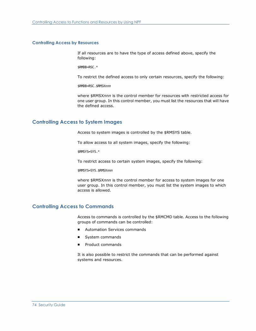
Controlling Access to Functions and Resources by Using NPF
74 Security Guide
Controlling Access by Resources
If all resources are to have the type of access defined above, specify the
following:
$RMDB=RSC.*
To restrict the defined access to only certain resources, specify the following:
$RMDB=RSC.$RMSXnnn
where $RMSXnnn is the control member for resources with restricted access for
one user group. In this control member, you must list the resources that will have
the defined access.
Controlling Access to System Images
Access to system images is controlled by the $RMSYS table.
To allow access to all system images, specify the following:
$RMSYS=SYS.*
To restrict access to certain system images, specify the following:
$RMSYS=SYS.$RMSXnnn
where $RMSXnnn is the control member for access to system images for one
user group. In this control member, you must list the system images to which
access is allowed.
Controlling Access to Commands
Access to commands is controlled by the $RMCMD table. Access to the following
groups of commands can be controlled:
■ Automation Services commands
■ System commands
■ Product commands
It is also possible to restrict the commands that can be performed against
systems and resources.
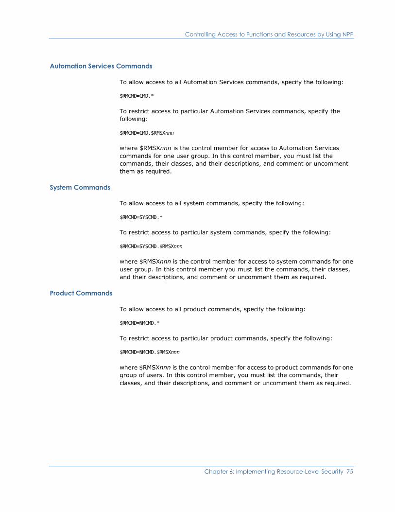
Controlling Access to Functions and Resources by Using NPF
Chapter 6: Implementing Resource-Level Security 75
Automation Services Commands
To allow access to all Automation Services commands, specify the following:
$RMCMD=CMD.*
To restrict access to particular Automation Services commands, specify the
following:
$RMCMD=CMD.$RMSXnnn
where $RMSXnnn is the control member for access to Automation Services
commands for one user group. In this control member, you must list the
commands, their classes, and their descriptions, and comment or uncomment
them as required.
System Commands
To allow access to all system commands, specify the following:
$RMCMD=SYSCMD.*
To restrict access to particular system commands, specify the following:
$RMCMD=SYSCMD.$RMSXnnn
where $RMSXnnn is the control member for access to system commands for one
user group. In this control member you must list the commands, their classes,
and their descriptions, and comment or uncomment them as required.
Product Commands
To allow access to all product commands, specify the following:
$RMCMD=NMCMD.*
To restrict access to particular product commands, specify the following:
$RMCMD=NMCMD.$RMSXnnn
where $RMSXnnn is the control member for access to product commands for one
group of users. In this control member, you must list the commands, their
classes, and their descriptions, and comment or uncomment them as required.
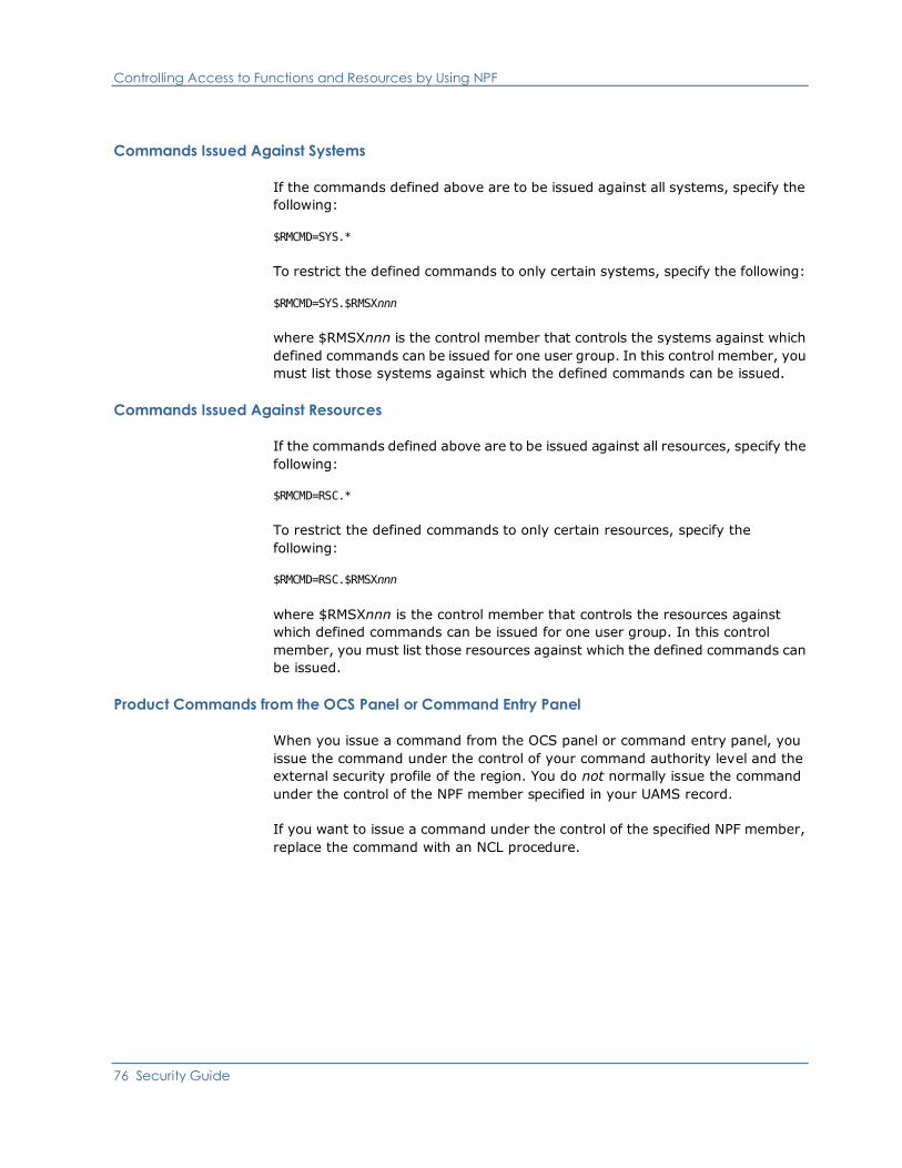
Controlling Access to Functions and Resources by Using NPF
76 Security Guide
Commands Issued Against Systems
If the commands defined above are to be issued against all systems, specify the
following:
$RMCMD=SYS.*
To restrict the defined commands to only certain systems, specify the following:
$RMCMD=SYS.$RMSXnnn
where $RMSXnnn is the control member that controls the systems against which
defined commands can be issued for one user group. In this control member, you
must list those systems against which the defined commands can be issued.
Commands Issued Against Resources
If the commands defined above are to be issued against all resources, specify the
following:
$RMCMD=RSC.*
To restrict the defined commands to only certain resources, specify the
following:
$RMCMD=RSC.$RMSXnnn
where $RMSXnnn is the control member that controls the resources against
which defined commands can be issued for one user group. In this control
member, you must list those resources against which the defined commands can
be issued.
Product Commands from the OCS Panel or Command Entry Panel
When you issue a command from the OCS panel or command entry panel, you
issue the command under the control of your command authority level and the
external security profile of the region. You do not normally issue the command
under the control of the NPF member specified in your UAMS record.
If you want to issue a command under the control of the specified NPF member,
replace the command with an NCL procedure.

Controlling Access to Functions and Resources by Using NPF
Chapter 6: Implementing Resource-Level Security 77
The following NCL procedures are provided to replace product commands:
■ ALLOCATE
■ FSTOP
■ OPSYS
■ ROUTE
■ SHUTDOWN
■ SUBMIT
■ SYSCMD
■ UNLOAD
If you must create other replacement NCL procedures, do the following:
1. Create an NCL procedure in the security PDS (see page 90) with the same
name as the command you want to replace.
2. Ensure the NCL procedure contains the following:
-EXEC $RMSXTPL cmdname &ALLPARMS
&IF &RETCODE EQ 0 &THEN +
-cmdname &ALLPARMS
3. Enter /PARMS from the command prompt to display the
Customizer : Parameter Groups panel.
4. Add your replacement NCL procedure name to the parameter group ID
CMDREPLS in category SECURITY.
CMDREPLS can contain up to 21 entries. If you have more than 21 entries,
place the command SYSPARMS CMDREPL=cmdname for each extra entry in
the NMINIT procedure.
5. Press F6 (Action) if you want to use the replacement NCL procedure
immediately (otherwise, it will only be available after the region has been
restarted.)
Important! The NPF security rule, $RMCMD.REPLUNLD, controls whether a user
can use the UNLOAD PROCEDURE command to unload the command
replacement NCL procedures. Ensure that you provide sufficient security for the
resource $RMCMD.REPLUNLD, to prevent unauthorized unloading (disabling) of
the listed NCL procedures.
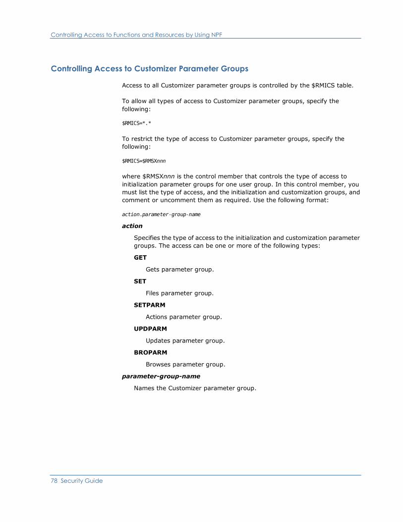
Controlling Access to Functions and Resources by Using NPF
78 Security Guide
Controlling Access to Customizer Parameter Groups
Access to all Customizer parameter groups is controlled by the $RMICS table.
To allow all types of access to Customizer parameter groups, specify the
following:
$RMICS=*.*
To restrict the type of access to Customizer parameter groups, specify the
following:
$RMICS=$RMSXnnn
where $RMSXnnn is the control member that controls the type of access to
initialization parameter groups for one user group. In this control member, you
must list the type of access, and the initialization and customization groups, and
comment or uncomment them as required. Use the following format:
action.parameter-group-name
action
Specifies the type of access to the initialization and customization parameter
groups. The access can be one or more of the following types:
GET
Gets parameter group.
SET
Files parameter group.
SETPARM
Actions parameter group.
UPDPARM
Updates parameter group.
BROPARM
Browses parameter group.
parameter-group-name
Names the Customizer parameter group.
Controlling Access to Functions and Resources by Using NPF
Chapter 6: Implementing Resource-Level Security 79
Changing an NPF Table
If you make changes to an NPF table, these changes are only activated when you
have done the following:
■ Executed the NPTAB resource-group REP=table-name command; for
example, NPTAB $RMMENU REP=$RMSX110.
■ Executed a SIGNON command, or logged off and logged back on again.
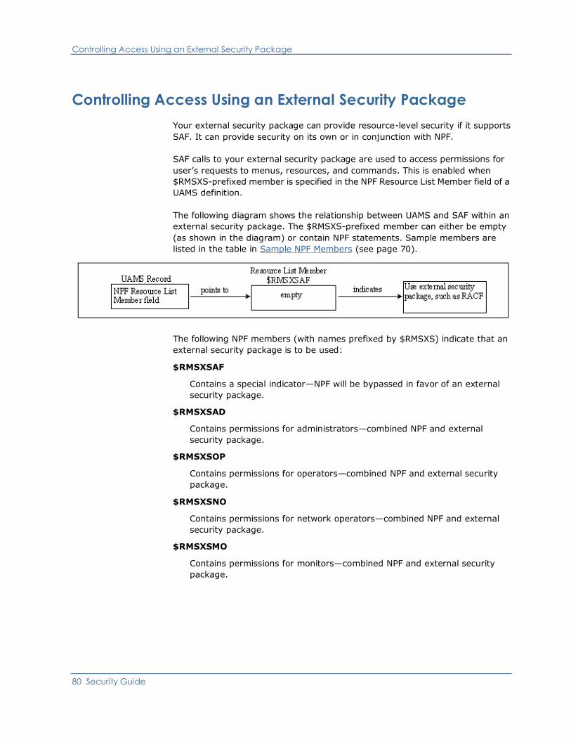
Controlling Access Using an External Security Package
80 Security Guide
Controlling Access Using an External Security Package
Your external security package can provide resource-level security if it supports
SAF. It can provide security on its own or in conjunction with NPF.
SAF calls to your external security package are used to access permissions for
user’s requests to menus, resources, and commands. This is enabled when
$RMSXS-prefixed member is specified in the NPF Resource List Member field of a
UAMS definition.
The following diagram shows the relationship between UAMS and SAF within an
external security package. The $RMSXS-prefixed member can either be empty
(as shown in the diagram) or contain NPF statements. Sample members are
listed in the table in Sample NPF Members (see page 70).
The following NPF members (with names prefixed by $RMSXS) indicate that an
external security package is to be used:
$RMSXSAF
Contains a special indicator—NPF will be bypassed in favor of an external
security package.
$RMSXSAD
Contains permissions for administrators—combined NPF and external
security package.
$RMSXSOP
Contains permissions for operators—combined NPF and external security
package.
$RMSXSNO
Contains permissions for network operators—combined NPF and external
security package.
$RMSXSMO
Contains permissions for monitors—combined NPF and external security
package.

Controlling Access Using an External Security Package
Chapter 6: Implementing Resource-Level Security 81
Sample Security Profiles
Sample security profiles are provided for each of the supported external security
packages in the following libraries:
■ The SMP target zone library, dsnpref.pvpref.CC2DSAMP
■ The SMP distribution zone library, dsnpref.pvpref.AC2DSAMP
dsnpref
Specifies your site-specific data set name prefix.
pvpref
Specifies your product version prefix.
Note: On z/VM systems, these profiles are on the vmid 293 G-disk.
Each library includes the following security profiles:
$RMSXACF
Specifies permissions for all groups of users for CA ACF2 versions earlier than
Version 6.
$RMSXAC6
Specifies permissions for all groups of users for CA ACF2 Version 6 and later.
$RMSXTSS
Specifies permissions for all groups of users for CA Top Secret.
$RMSXRCF
Specifies permissions for all groups of users for RACF.

Controlling Access Using an External Security Package
82 Security Guide
Defining Security Profiles
To define the appropriate security profiles to an external security package,
complete these steps:
1. Copy the required security member to the security PDS (which is the first
library in the COMMANDS concatenation of libraries).
2. If necessary, modify the members to suit your requirements.
3. Add a valid job card to run the batch job.
4. When the job has completed successfully, enter a $RMSXS-prefixed member
in the NPF Resource List Member field of your user’s group or user ID
definition, to indicate that an external security package is required to control
security.
The security requirements for the sample groups—$RMADMIN, $RMOPER,
$RMNOPER, and $RMMON—are now defined to your external security package
and will apply to users attached to these groups.
More information:
Securing Data Set Members (see page 90)
Modifying Security Members (see page 82)
Modifying Security Members
The supplied security members define each group’s access to functions and
resources. These security members can be modified to suit your own security
requirements. Use the syntax specified in the following sections to specify your
own requirements for access to menu options, the knowledge base, system
images, Automation Services commands, system commands, and product
commands.

Controlling Access Using an External Security Package
Chapter 6: Implementing Resource-Level Security 83
Controlling Access to Menu Options
To control access to menu options, specify:
$RMMENU.menu-id.option-code
menu-id
Identifies the menu. The ID of the main Primary Menu is $NM001. To display
the ID of another menu, enter MENUID at the Select Option prompt.
option-code
Identifies the option (for example, A for the Administration and Definition
option on the main Primary Menu).
■ Use an asterisk (*) to represent all menu options; for example,
$RMMENU.menu-id.* means all options from menu-id.
■ Use $RMMENU.** to allocate access to all menus and their options.
Note: The asterisk (*) represents null, or one or more characters. Two asterisks
(**) represent any suffix. This may not apply to your security system, in which
case, you must use the equivalent wildcard character that does apply.
Controlling Access to the Knowledge Base
The knowledge base contains definitions of Automation Services components. To
control access to knowledge base definitions, specify:
$RMDB.system-image-name.system-image-version.class-number.
definition-name.action-type
system-image-name
Names the system image.
system-image-version
Identifies the version of the system image.
class-number
Identifies the class of component. The following table lists the valid classes.
A product uses a subset of these classes.
class-number Component Definition
01 System image
02 Started task
03 SNA group
04 CICS transaction
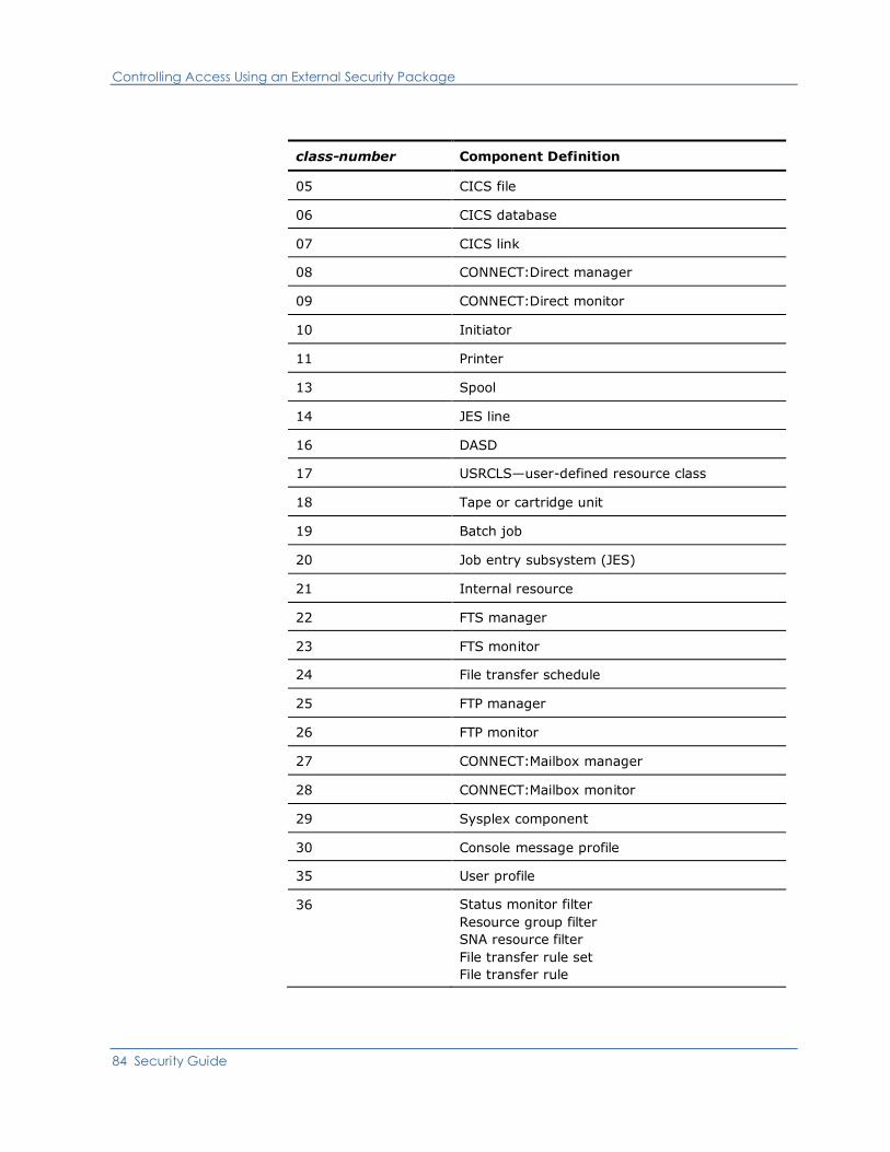
Controlling Access Using an External Security Package
84 Security Guide
class-number Component Definition
05 CICS file
06 CICS database
07 CICS link
08 CONNECT:Direct manager
09 CONNECT:Direct monitor
10 Initiator
11 Printer
13 Spool
14 JES line
16 DASD
17 USRCLS—user-defined resource class
18 Tape or cartridge unit
19 Batch job
20 Job entry subsystem (JES)
21 Internal resource
22 FTS manager
23 FTS monitor
24 File transfer schedule
25 FTP manager
26 FTP monitor
27 CONNECT:Mailbox manager
28 CONNECT:Mailbox monitor
29 Sysplex component
30 Console message profile
35 User profile
36 Status monitor filter
Resource group filter
SNA resource filter
File transfer rule set
File transfer rule
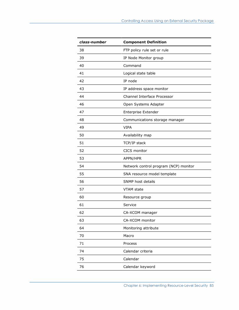
Controlling Access Using an External Security Package
Chapter 6: Implementing Resource-Level Security 85
class-number Component Definition
38 FTP policy rule set or rule
39 IP Node Monitor group
40 Command
41 Logical state table
42 IP node
43 IP address space monitor
44 Channel Interface Processor
46 Open Systems Adapter
47 Enterprise Extender
48 Communications storage manager
49 VIPA
50 Availability map
51 TCP/IP stack
52 CICS monitor
53 APPN/HPR
54 Network control program (NCP) monitor
55 SNA resource model template
56 SNMP host details
57 VTAM state
60 Resource group
61 Service
62 CA-XCOM manager
63 CA-XCOM monitor
64 Monitoring attribute
70 Macro
71 Process
74 Calendar criteria
75 Calendar
76 Calendar keyword

Controlling Access Using an External Security Package
86 Security Guide
class-number Component Definition
78 Activity schedule
80 Icon
81 Icon panel
90 Prompt list
93 Rule set
94 Message rule
95 Message group rule
96 Learnt message
98 Timer rule
9A Included rule set
9B Initial action
Note: Resource classes 30, 35, 36, 39, 40, 41, 56, 60, 61, 64, 70, 74 to 76,
78, 80, 81, 90, 93 to 96, 98, 9A, and 9B are independent of system images.
definition-name
Identifies the component definition.
action-type
Identifies the action to be performed on the definition. Valid values are:
CREATE
Creates a new definition.
DELETE
Deletes an existing definition.
SET
Updates a definition.
■ Use an asterisk (*) to represent all knowledge base components. The
following example shows the ability to create started task resource
definitions for all versions of system-image-name:
$RMDB.system-image-name.*.02.*.CREATE
■ Use $RMDB.** to allow all knowledge base functions on all knowledge base
components.
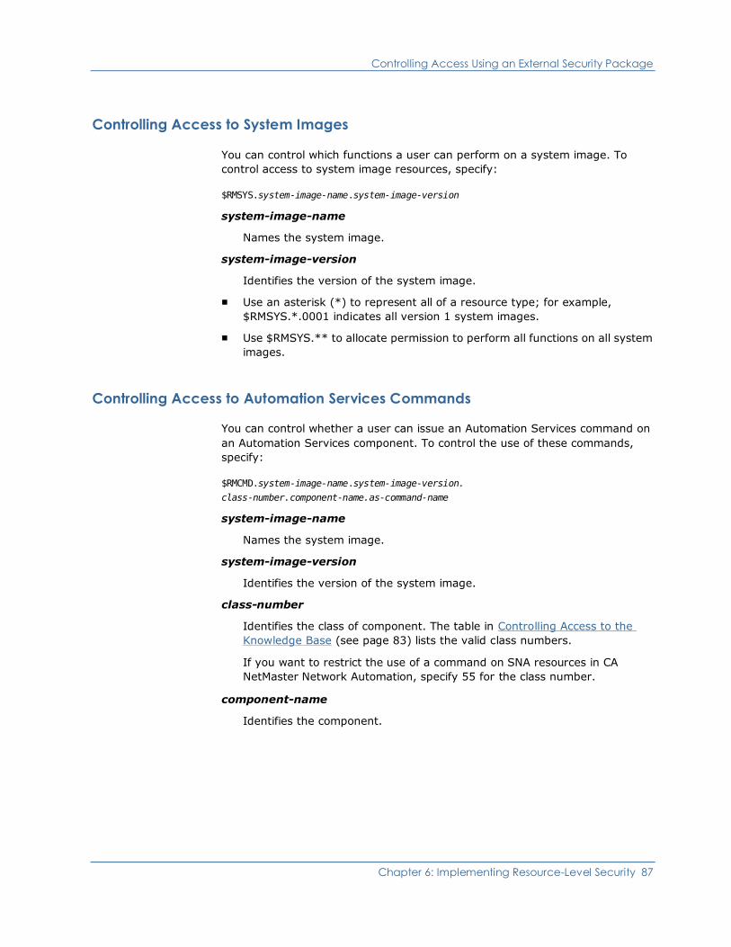
Controlling Access Using an External Security Package
Chapter 6: Implementing Resource-Level Security 87
Controlling Access to System Images
You can control which functions a user can perform on a system image. To
control access to system image resources, specify:
$RMSYS.system-image-name.system-image-version
system-image-name
Names the system image.
system-image-version
Identifies the version of the system image.
■ Use an asterisk (*) to represent all of a resource type; for example,
$RMSYS.*.0001 indicates all version 1 system images.
■ Use $RMSYS.** to allocate permission to perform all functions on all system
images.
Controlling Access to Automation Services Commands
You can control whether a user can issue an Automation Services command on
an Automation Services component. To control the use of these commands,
specify:
$RMCMD.system-image-name.system-image-version.
class-number.component-name.as-command-name
system-image-name
Names the system image.
system-image-version
Identifies the version of the system image.
class-number
Identifies the class of component. The table in Controlling Access to the
Knowledge Base (see page 83) lists the valid class numbers.
If you want to restrict the use of a command on SNA resources in CA
NetMaster Network Automation, specify 55 for the class number.
component-name
Identifies the component.
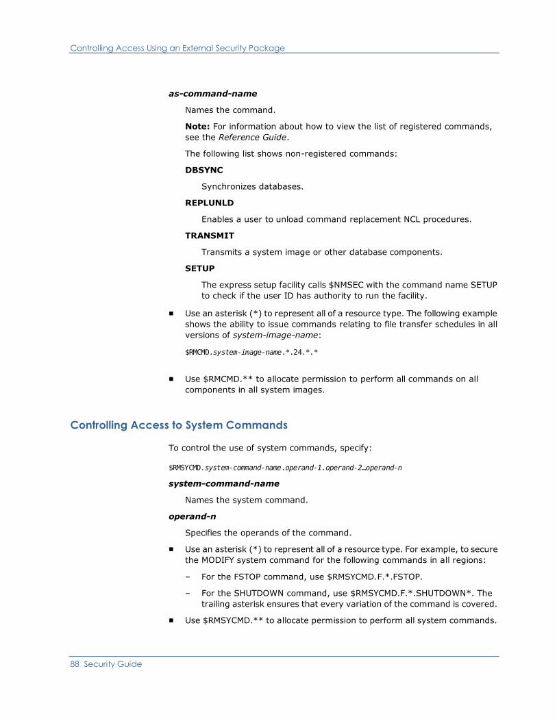
Controlling Access Using an External Security Package
88 Security Guide
as-command-name
Names the command.
Note: For information about how to view the list of registered commands,
see the Reference Guide.
The following list shows non-registered commands:
DBSYNC
Synchronizes databases.
REPLUNLD
Enables a user to unload command replacement NCL procedures.
TRANSMIT
Transmits a system image or other database components.
SETUP
The express setup facility calls $NMSEC with the command name SETUP
to check if the user ID has authority to run the facility.
■ Use an asterisk (*) to represent all of a resource type. The following example
shows the ability to issue commands relating to file transfer schedules in all
versions of system-image-name:
$RMCMD.system-image-name.*.24.*.*
■ Use $RMCMD.** to allocate permission to perform all commands on all
components in all system images.
Controlling Access to System Commands
To control the use of system commands, specify:
$RMSYCMD.system-command-name.operand-1.operand-2…operand-n
system-command-name
Names the system command.
operand-n
Specifies the operands of the command.
■ Use an asterisk (*) to represent all of a resource type. For example, to secure
the MODIFY system command for the following commands in all regions:
– For the FSTOP command, use $RMSYCMD.F.*.FSTOP.
– For the SHUTDOWN command, use $RMSYCMD.F.*.SHUTDOWN*. The
trailing asterisk ensures that every variation of the command is covered.
■ Use $RMSYCMD.** to allocate permission to perform all system commands.
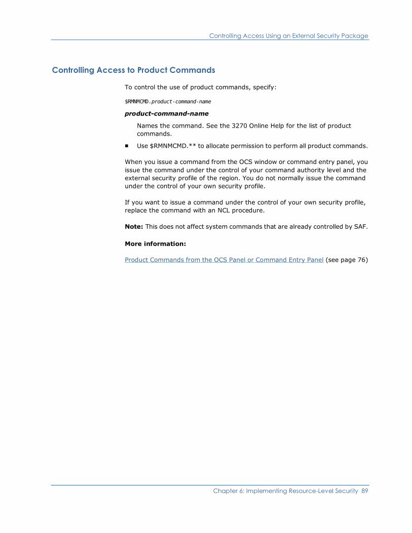
Controlling Access Using an External Security Package
Chapter 6: Implementing Resource-Level Security 89
Controlling Access to Product Commands
To control the use of product commands, specify:
$RMNMCMD.product-command-name
product-command-name
Names the command. See the 3270 Online Help for the list of product
commands.
■ Use $RMNMCMD.** to allocate permission to perform all product commands.
When you issue a command from the OCS window or command entry panel, you
issue the command under the control of your command authority level and the
external security profile of the region. You do not normally issue the command
under the control of your own security profile.
If you want to issue a command under the control of your own security profile,
replace the command with an NCL procedure.
Note: This does not affect system commands that are already controlled by SAF.
More information:
Product Commands from the OCS Panel or Command Entry Panel (see page 76)
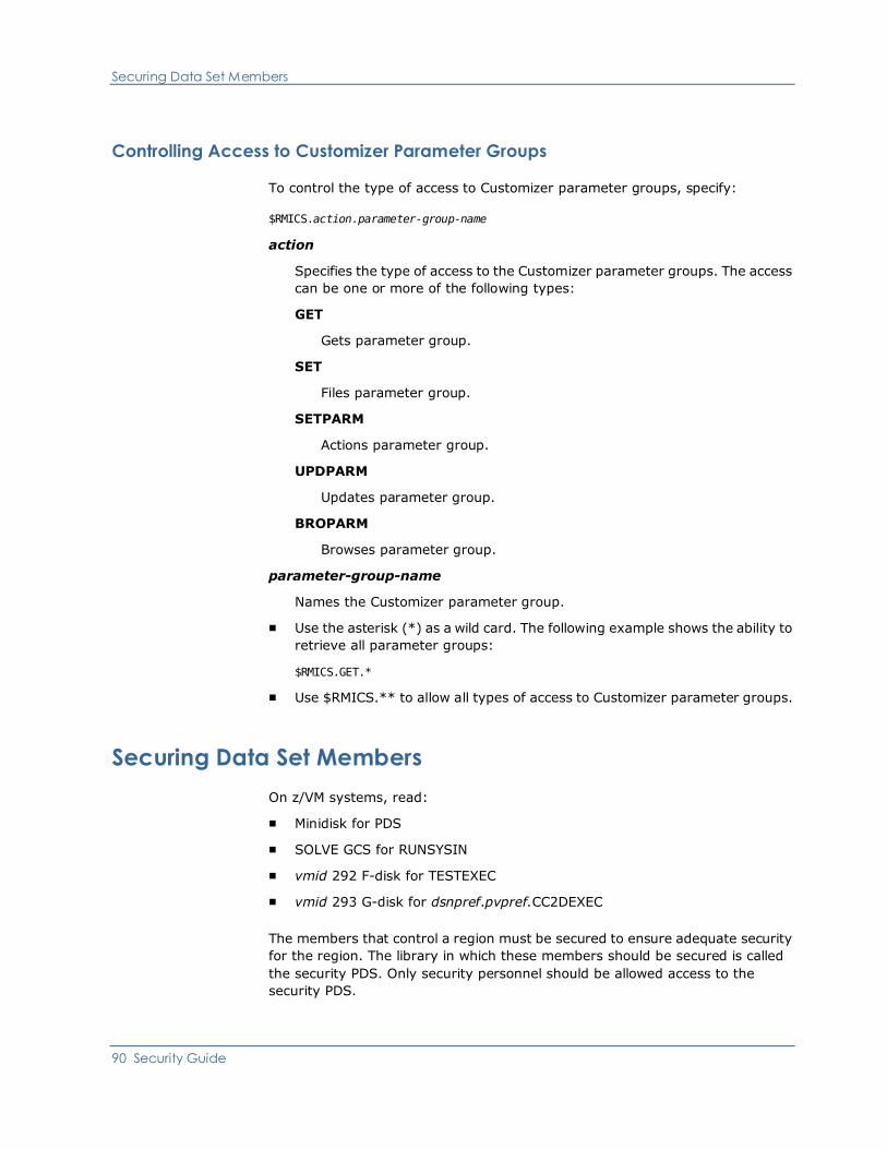
Securing Data Set Members
90 Security Guide
Controlling Access to Customizer Parameter Groups
To control the type of access to Customizer parameter groups, specify:
$RMICS.action.parameter-group-name
action
Specifies the type of access to the Customizer parameter groups. The access
can be one or more of the following types:
GET
Gets parameter group.
SET
Files parameter group.
SETPARM
Actions parameter group.
UPDPARM
Updates parameter group.
BROPARM
Browses parameter group.
parameter-group-name
Names the Customizer parameter group.
■ Use the asterisk (*) as a wild card. The following example shows the ability to
retrieve all parameter groups:
$RMICS.GET.*
■ Use $RMICS.** to allow all types of access to Customizer parameter groups.
Securing Data Set Members
On z/VM systems, read:
■ Minidisk for PDS
■ SOLVE GCS for RUNSYSIN
■ vmid 292 F-disk for TESTEXEC
■ vmid 293 G-disk for dsnpref.pvpref.CC2DEXEC
The members that control a region must be secured to ensure adequate security
for the region. The library in which these members should be secured is called
the security PDS. Only security personnel should be allowed access to the
security PDS.
Securing Data Set Members
Chapter 6: Implementing Resource-Level Security 91
The security PDS is not created during the installation of your product, and must
be created manually before you proceed to implement security. To establish a
valid security PDS that secures all members controlling access to Automation
Services functions, complete the following steps:
1. Create a security PDS, and ensure that it is the first library in the COMMANDS
concatenation of libraries.
Note: The COMMANDS concatenation of libraries is in your RUNSYSIN
member. The default first library is TESTEXEC.
2. Copy the following members from the CC2EXEC data set into the security
PDS:
$NMSEC
Controls access to functions.
ALLOCATE, FSTOP, OPSYS, ROUTE, SHUTDOWN, SUBMIT, SYSCMD,
and UNLOAD
Controls access by message monitor users to commands. These
members are command replacement NCL procedures.
3. Copy the following members from the CC2DEXEC data set into the security
PDS:
$RMSXxxx
Provides sample SAF security profiles for CA ACF2 (if you are using it to
control access to the region), NPF members (if you are using NPF to
control access to the region), or RACF.
4. Copy any user-defined command replacement NCL procedures into the
security PDS.
5. Restrict access to this security PDS to security personnel, and the region
(read access only).
6. Ensure that the NPTABLES DD points to your security PDS.
Note: The NPTABLES DD in your RUNSYSIN member points to
dsnpref.pvpref.CC2DEXEC by default.


Chapter 7: Administering Security 93
Chapter 7: Administering Security
This chapter provides information about administering security for users of your
regions.
This section contains the following topics:
Customizing Command Authority Levels (see page 93)
Customizing Parameters that Affect Security (see page 94)
Understanding User Profiles (see page 98)
Defining User Profiles (see page 99)
Maintaining User Profiles (see page 104)
Customizing Command Authority Levels
Product commands and VTAM commands that your product can execute are each
assigned a default authority level. These are within the range of 0 to 255.
Users of your product region are also allocated a command authority level. This
is in their user ID definition. The authority level set corresponds to the authority
level for the commands they are authorized to issue.
Changing Command Authority Levels
To allocate a different command authority to a particular command, use the
SYSPARMS CMDAUTH operand.
Example:
To allocate a command authority of 5 to the CANCEL command, enter the
following command:
SYSPARMS CMDAUTH=(CANCEL,5)
Disabling Commands
You can disable a command by allocating an authority level higher than that
available to any user.
Customizing Parameters that Affect Security
94 Security Guide
Replacing Commands with NCL Procedures
To replace native commands with an NCL procedure of the same name, use the
CMDREPLS parameter group in Customizer.
To run an NCL procedure in place of the CANCEL command, do this:
1. Enter /PARMS at the command prompt.
The Customizer : Parameter Groups panel is displayed.
2. Enter U beside the CMDREPLS parameter group.
The Customizer : Parameter Group panel for the CMDREPLS parameter
group is displayed.
3. Type CANCEL in the next available position in the Replaced Command ID
field.
4. Press one of the following function keys:
■ F3 (File) to file the changes—the changes are not applied to the current
region, but are applied when the region is restarted.
■ F6 (Action) to apply the changes to this region—the changes are not
saved.
Note: This rest of this chapter does not apply to CA SOLVE:FTS, CA
SOLVE:Access Session Management, CA SOLVE:InfoMaster, and
CA SOLVE:NetMail.
Customizing Parameters that Affect Security
Note: This section does not apply to CA SOLVE:FTS, CA SOLVE:Access, CA
SOLVE:InfoMaster, and CA SOLVE:NetMail.
Review the following Customizer parameter groups (/PARMS) for security:
■ CMDREPLS
■ SECSHIPPING
Command Replacement
The CMDREPLS parameter group specifies which commands are to be
intercepted and have an NCL procedure of the same name started instead of the
command being executed. This allows you to perform additional security
checking on these commands.
Important! If you change the default set of replacements, the functioning of
some of the supplied applications may be impacted.
Customizing Parameters that Affect Security
Chapter 7: Administering Security 95
More information:
Product Commands from the OCS Panel or Command Entry Panel (see page 76)
Synchronizing Updates Across Linked Regions
To automatically update UAMS records across all active linked regions, you must
enable the automatic propagation facility, known as security shipping.
Note: If security shipping is enabled, it occurs when a user ID or group definition
is added, updated, or deleted.
Synchronization depends on whether you make an update from a focal point
region or a subordinate region as follows:
■ If the update is in a focal point region, the update is synchronized across all
active linked regions that are enabled for this feature.
■ If the update is in a subordinate region, the update is synchronized across
only those active linked focal point regions that are enabled for this feature.
Customizing Parameters that Affect Security
96 Security Guide
Enabling or disabling the update of UAMS records across multiple regions is the
function of parameter group SECSHIPPING. To set or alter this parameter group:
1. Enter /PARMS at the command prompt to display the
Customizer : Parameter Groups panel.
2. Apply the U (Update) action to SECSHIPPING, which is located in the
SECURITY category.
With the SECSHIPPING - Ship UAMS Maintenance panel displayed, you can
make various settings, by choosing one of the following:
■ Respond YES to both questions.
This allows all add, update, delete, and password change operations for
UAMS records to be propagated to linked regions. (This setting is for
regions that do not share a UAMS file and do not use NMSAF or a partial
security exit.)
■ Respond YES to the question Ship to Linked Systems? and NO to the
question Including Password Changes?
This allows all add, update and delete operations for UAMS records to be
propagated to the linked regions. Update requests from linked regions
are processed, but changes to the password field are not. (This setting is
for regions that do not share a UAMS file and use NMSAF or a partial
security exit.)
■ Respond NO to both questions.
This means that no UAMS records changes are propagated. If an update
is requested from a remote region via this facility, it is refused. If linked
regions share a UAMS file, you should choose this setting. Otherwise,
you will get error messages when updating shared values on the User
Description panel of the user profile.
UAMS updates are sent to linked regions immediately, for security reasons. A
UAMS update report is displayed immediately, indicating the success or failure of
those updates.
More information:
Defining User Profiles (see page 99)
Customizing Parameters that Affect Security
Chapter 7: Administering Security 97
Troubleshooting
Possible reasons for a remote region update not working include the following:
■ The region is not profiled for remote updates. To profile it for remote
updates, specify YES in the Ship to Linked Systems? field of its
SECSHIPPING parameter group.
■ The link or remote region is not active. (Because UAMS update records are
not written to a staging file, no record of the update is retained, and the
UAMS record in the remote region is not updated.)
■ The user does not have UAMS administration authority on the remote region.
■ The record or database is locked.
■ The UAMS record does not exist. This condition occurs when an administrator
updates a user profile record, without providing a new initial password, and
there is no associated UAMS record for the remote region. The administrator
can remedy this by supplying an initial password. This results in the
automatic generation of a UAMS record for the remote region, and resets the
users password across all regions.
■ You based the user access on a customized user group that does not exist in
the remote region.

Understanding User Profiles
98 Security Guide
Understanding User Profiles
Note: This section does not apply to CA SOLVE:FTS, CA SOLVE:Access Session
Management, CA SOLVE:InfoMaster, and CA SOLVE:NetMail.
User profiles set user preferences and tailoring options. User profiles work with a
user’s UAMS definition to set the user’s working environment.
The following illustration shows examples of user access and privilege. Profiles
that are specific to a particular product are identified in parentheses.
■ At the lowest level, UAMS uses the security rules to control basic functions,
security, and logon access to the region. Only a system administrator should
have the authority to maintain UAMS definitions.
■ At the next level, user profiles contain default settings (which are within any
UAMS limitations) for the operational environment. Users can update their
own profiles, and the system administrator can update any user profile.
■ At the highest level, the specific environments seen by a user are determined
by the defaults set in that user’s profile record. A user can, however, change
those defaults (within any UAMS or user profile limitations) for the duration
of a work session.

Defining User Profiles
Chapter 7: Administering Security 99
Defining User Profiles
Note: This section does not apply to CA SOLVE:FTS, CA SOLVE:Access Session
Management, CA SOLVE:InfoMaster, and CA SOLVE:NetMail.
User profile information controls what resources and messages a user sees on
monitors and consoles. User profile records are automatically propagated to all
linked regions when created.
To assist with ease of administration if a UAMS user ID definition does not
already exist, a UAMS user ID definition is automatically generated when a user
profile is created for a user and a group ID is specified.
Note: If you are using a full security exit, user ID definitions are not
automatically generated.
To create a profile for a new user, complete the following steps:
1. Enter /ASADMIN from the primary menu to display the Automation
Services Administration Menu.
2. Select option UP - User Profiles to display the User Profile List.
3. Press F4 (Add) to add a new user profile. The action presents you with the
first panel in the user profile definition. The following sections describe some
of the panels. Use F8 (Forward) to scroll to each new panel.
4. File or save the new record.
A UAMS Update Report is displayed if the following conditions apply:
■ You have completed fields on the User Description panel.
■ The SECSHIPPING parameter group is set in the current region to enable
automatic propagation of UAMS updates.
PROD--------------- Automation Services : UAMS Update Report ------------------ Command ===> Function=Browse Scroll ===> PAGE A UAMS update request was sent to all linked regions for user BROWNP with the following results: Region Message PROD13 RM350008 UAMS ADD PROCESSED SUCCESSFULLY PROD14 RM350403 UAMS ADD PROCESSED SUCCESSFULLY PROD15 RM350403 UAMS ADD PROCESSED SUCCESSFULLY ******************************* BOTTOM OF DATA ********************************
Note: When you have defined one user profile, you can use the C (Copy) action
to duplicate an existing user profile and change the values for another user in the
copied record as required.
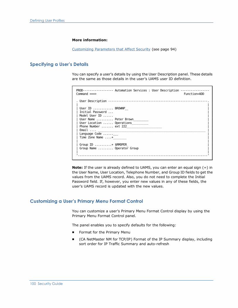
Defining User Profiles
100 Security Guide
More information:
Customizing Parameters that Affect Security (see page 94)
Specifying a User’s Details
You can specify a user’s details by using the User Description panel. These details
are the same as those details in the user’s UAMS user ID definition.
PROD------------------ Automation Services : User Description ----------------- Command ===> Function=ADD . User Description -----------------------------------------------------------. | | | User ID ............ BROWNP__ | | Initial Password ... | | Model User ID ...... | | User Name .......... Peter Brown_________ | | User Location ...... Operations__________ | | Phone Number ....... ext 222_____________________ | | Email .... ________________________________________________________________ | | Language Code ......___ | | Time Zone Name ....+________ | | | | Group ID ..........+ $RMOPER_ | | Group Name ......... Operator Group | | | ’-----------------------------------------------------------------------------’
Note: If the user is already defined to UAMS, you can enter an equal sign (=) in
the User Name, User Location, Telephone Number, and Group ID fields to get the
values from the UAMS record. Also, you do not need to complete the Initial
Password field. If, however, you enter new values in any of these fields, the
user’s UAMS record is updated with the new values.
Customizing a User’s Primary Menu Format Control
You can customize a user’s Primary Menu Format Control display by using the
Primary Menu Format Control panel.
The panel enables you to specify defaults for the following:
■ Format for the Primary Menu
■ (CA NetMaster NM for TCP/IP) Format of the IP Summary display, including
sort order for IP Traffic Summary and auto-refresh
Defining User Profiles
Chapter 7: Administering Security 101
Customizing a User’s Alert Monitor
You can customize a user’s default alert monitor display by using the Alert
Monitor Profile panel.
The panel enables you to specify defaults for the following:
■ Alert monitor filter that restricts the displayed alerts (You can define the
filters at the Filter Definition List panel. To access the list, enter
/ALADMIN.F.)
■ Display format that determines what alert information is displayed (You can
define the format at the List Definition List panel. To access the list, enter
/ALADMIN.L.)
■ Alert sort criteria to be applied when the user accesses the alert monitor
Customizing a User’s Resource Monitor Display
Note: This section only applies to CA NetMaster NA, CA NetMaster FTM, CA
SOLVE:Operations Automation for z/OS, and CA SOLVE:Operations Automation
for CICS.
Besides the resource monitor profile, there are profiles for other types of
monitors that you may customize. Depending on the products running in your
region, you have different types of monitors available to you.
You can customize a user’s resource monitor display by using the Resource
Monitor Profile panel.
The panel displays the following information:
■ Resource monitor filter
■ Display format
■ The number of display COLUMNS
■ Sort criteria
■ Extended display control (ON|OFF)
Defining User Profiles
102 Security Guide
Customizing a User’s Message Monitor Profile
Note: This section only applies to CA NetMaster Network Automation, CA
NetMaster File Transfer Management, CA SOLVE:Operations Automation for
z/OS, and CA SOLVE:Operations Automation for CICS.
You can customize a user’s message monitor (or Operator Console Services)
profile by entering the relevant information on the following four panels:
■ Message Monitor Screen Control
■ Message Monitor Command Control
■ Message Monitor Message Receipt
■ Message Monitor Message Formatting
To access these panels, enter /ASADMIN.UP.
Note: Customized values (that is, values other than the default) are set for the
message monitor only if the $RMCCOCS procedure is run. The procedure is
specified in the user ID definition.
See the Online Help for information about the fields on these panels.
Entering a Command String
The Message Monitor Command Control panel includes an Initial Command field.
You can use this field to enter a command string that is issued when the user
selects the message monitor.

Defining User Profiles
Chapter 7: Administering Security 103
Customizing a User’s Consolidated Console
Note: This section only applies to CA NetMaster NA, CA NetMaster FTM, CA
SOLVE:Operations Automation, and CA SOLVE:Operations Automation for CICS.
You can specify the message profiles to activate when a user accesses the
consolidated console by using the Console Consolidation Profile panel.
The panel lists the message profiles available to the user. (These message
profiles are specified as the console routing codes in the user definition and
correspond to the message profile IDs).
For each profile, the panel displays the following:
■ Name of the profile
■ ID of the profile
■ User status indicating whether the profile is enabled to the consolidated
console
Note: If a profile is enabled, it is not effective unless its global status is also
ACTIVE.
■ Global status indicating whether the profile is defined to be active (that is,
whether the profile can be loaded)
■ Description of the profile
A profile has a status of either DISABLED or ENABLED.
To change the status of a profile from the Console Consolidation Profile
panel
1. Press F10 (ScrLst).
The list of profiles becomes scrollable. When you press F7 (Backward) and F8
(Forward), you scroll through the list (instead of scrolling through the user
profile panels).
2. Type D next to the profiles you want to disable and E next to the profiles you
want to enable, and press Enter.
The user statuses of the selected profiles are updated.
3. Press F3 (OK) to accept the settings; press F3 (File) to file the settings.
Maintaining User Profiles
104 Security Guide
Customizing a User’s SNA Network Summary Display
If you are using CA NetMaster NA, you can specify the VTAM domains to be
monitored in the SNA network summary display by using the VTAM Domain
Consolidation Profile panel.
The panel lists the domains that are included in the SNA network summary
display.
To change which domains are included and excluded
1. Press F10 (LstRegn), and then enter S or I next to the domains to be
included and X next to the domains to be excluded.
The domains selected for inclusion are flagged.
2. Press F3 (OK) to accept the settings; press F3 (File) to file the settings.
Maintaining User Profiles
Note: This section does not apply to CA SOLVE:FTS, CA SOLVE:Access Session
Management, CA SOLVE:InfoMaster, and CA SOLVE:NetMail.
User profile records are maintained by applying actions to items on the User
Profile list. You can update, copy, or delete listed profile records.
Maintaining User Profiles
Chapter 7: Administering Security 105
Updating User Profiles
To update a user profile definition
1. Enter /ASADMIN.UP from the primary menu to display the User Profile List.
2. Apply the U (Update) action to the item you want to update.
The Panel Display List panel is displayed.
3. Select the panel you want to update.
4. Update the fields on this panel as required. If you want to update further
fields on other user profile panels, use F7 (Backward) and F8 (Forward) to
move between panels and F11 (Menu) to return to the Panel Display List.
5. File (F3) the updated definition.
Note: You can customize parts of your own user profile from certain associated
panels. For example, you can customize your resource monitor profile from the
status monitor by using the PROFILE command.
Users who have sufficient authority can update their own user profiles. Enter
U.UP on the primary menu to display the list of user profile panels, then select
the panel to be updated. (The sequence of panels can be scrolled by using F7 and
F8.)
Deleting a User Profile Definition
If you want to delete a user profile record and its associated UAMS record, apply
the D (delete) action to that item on the User Profile list. To delete the user
profile record while retaining the UAMS record, apply the DP (delete profile)
action.


Chapter 8: Implementing Security Exits 107
Chapter 8: Implementing Security Exits
This chapter describes how to implement the various security exits that can be
used to provide additional security for your systems.
Your product provides some special-purpose exits that you can use to perform
security checks. The following exits are supported:
■ NCL authorization exit
■ INMC security exit
■ Data set access authorization exit
■ Data set services authorization exit
This chapter describes the functionality and implementation of each of these
exits.
This section contains the following topics:
Implementing Security for File Access (see page 108)
Implementing INMC Link Security (see page 112)
Implementing Data Set Allocation Authority (see page 114)
Implementing Security for Data Set Services (see page 116)
Implementing Security for File Access
108 Security Guide
Implementing Security for File Access
The NCL authorization exit, NCLEX01, controls access to the following:
■ User databases (UDBs)
■ SQL databases in a DB2 environment
■ Writing SMF records (z/OS systems)
■ Network databases (NDBs)
Access can be restricted to certain levels, or can be denied altogether. For
example, the level of access to a database can be used to restrict users to read
only or update without delete.
The exit is invoked automatically the first time an NCL procedure attempts to
open a database, using the &FILE OPEN, &EDB, or &NDBOPEN statement, or
write a record using the &SMFWRITE statement. The level of access permitted is
set by a return code from the exit and is made available to the NCL procedure.
Note: If an exit controls the writing of SMF records in z/OS systems, it needs to
provide clearance for a user to use the &SMFWRITE verb.
You can also define other uses for the NCL exit by tailoring the supplied NCLEX01
or writing your own.
More information:
Activating the NCL Authorization Exit (see page 109)

Implementing Security for File Access
Chapter 8: Implementing Security Exits 109
Activating the NCL Authorization Exit
To activate the NCL authorization exit, specify the name of the load module to be
invoked in the SYSPARMS NCLEX01 operand. To ensure that the exit is always
activated during system initialization, place the SYSPARMS command in the INIT
initialization member. If no exit is required specify SYSPARMS NCLEX01=NO. If
necessary the name of the exit can be changed online and a new module
invoked.
Note: For information about the SYSPARM NCLEX01 operand, see the Reference
Guide.
Note: If you are using a security product, such as RACF, to control VSAM file
access, ensure that your product region itself is authorized for file access.
The exit executes within a subtask and can therefore issue a WAIT or SVC that
causes suspension of the task without affecting the primary task.
The exit is passed a parameter list that provides information about the request.
Write the exit as a reentrant facility so that multiple concurrent requests are
possible.
For performance reasons, calls to NCLEX01 are not generated to the high-usage
system files MODS and $PSPOOL.
Errors in the Exit
If an ABEND occurs within the exit, any current request is rejected as though
access had been denied. Although this can impact the requesting NCL procedure,
other processing is not affected. Subsequent requests to the exit continue
without impact.
Parameters Passed to the Exit
When the exit is invoked, it is passed a communication area that provides
information about the request and the requestor. The $NMNCEX1 macro, as
supplied in the macro library, describes this area. The macro is distributed as
follows:
■ (z/OS systems) dsnpref.pvpref.CC2DMAC
dsnpref
Specifies your site-specific data set name prefix.
pvpref
Specifies your product version prefix.
■ (z/VM systems) NMMACLIB MACLIB on the vmid 193 C-disk
Implementing Security for File Access
110 Security Guide
More information:
Product Libraries (see page 17)
Pre-loading the NCL Authorization Exit
You can load a single copy of the exit into the region in advance to avoid the
overhead of the loading process. To do this, specify the name of the exit in the
LOAD MODULE operand.
If the exit is link edited with the RENT (reentrant) attribute, this single copy is
shared concurrently among multiple requestors.
Important! It is strongly recommended that you make the NCL exit module
reentrant. Failure to do so causes significant additional disk activity and resource
consumption in a busy system, and can impact overall performance.
Providing Additional Checking in the NCL Authorization Exit
You can provide additional checking for access through the NCL authorization
exit. This additional information is specified on the &FILE OPEN statement.
Example:
To have the exit ask for the user’s password to confirm access to a particular
UDB, the password information should be coded in the exit as follows:
&FILE OPEN ID=MYFILE DATA=&MYPASSWD
&FILE OPEN ID=MYFILE FORMAT=UNMAPPED DATA=&MYPASSWD
The exit will interrogate the password and set an appropriate return code to
control the subsequent processing in the NCL procedure.
A maximum of 50 characters of data can be passed. This data is available to the
exit in the NEXUDATA field. The length of the data passed is set in the NEXUDLEN
field. No validation is performed on passed data.
Implementing Security for File Access
Chapter 8: Implementing Security Exits 111
Correlating Authorization with Security Exit Authorization
If you have a partial or full security exit you can correlate access to UDBs by
sharing information between your external security exit and the NCL
authorization exit.
The NEXCORR field of the communications area in the NCL authorization exit is
the standard correlator that can be used by your external security exit. This
could, for example, be used to address a control block that contains information
associated with that user.
If your external security exit supports a SAF user token, then this is also available
in the NEXUTOKN field in the communications area. This user token is the
UTOKEN provided by the external security exit when the user logs on, and can be
used in a security authorization call to verify the user’s access to the UDB.
Sample Distributed NCL Authorization Exit
A sample exit, NCLEX01, is supplied in the SMP target zone library,
dsnpref.pvpref.CC2DSAMP where:
■ dsnpref is your site-specific data set name prefix
■ pvpref is your product version prefix
■ CC2DSAMP is the data set for all products
More information:
Product Libraries (see page 17)
Implementing INMC Link Security
112 Security Guide
Implementing INMC Link Security
A security exit is provided as one of the facilities of INMC (Inter-Network
Management Connection). This provides security for the connections between
domains.
The security exit is coded as an assembler language exit routine. An exit must
exist in each of the domains that are being linked. The exits are installed with the
following components:
■ Primary exit—communicates with the secondary exit in the other domain
and decides whether to establish the link and allow traffic flow
■ Secondary exit—responds to messages received from the primary exit and
makes no decisions whether a link is established or terminated
This allows each end of an INMC link to determine independently whether a link
should be activated, without having to depend on cooperation from the remote
domain in order to enforce the decision.
These components are described in more detail in the following sections.

Implementing INMC Link Security
Chapter 8: Implementing Security Exits 113
Primary Exit
The INMC primary exit decides whether a newly opened INMC link to a remote
domain should be made available for general traffic. The secondary exit is not
involved in this decision.
In order to pass control to the exit to make this decision the following calls are
made by INMC to the exit:
■ The Initialization Call—made when an INMC link to another domain is
activated. The primary exit is notified of the event and whether the remote
domain is configured with a secondary exit.
■ The Deliver Call—made to the primary exit when INMC receives the reply
from the (remote) secondary exit to a message sent to it earlier by the
primary exit.
■ The Notify Call—made to the primary exit when INMC determines that an
unexpected event (for example, link outage) has occurred, which results in
the deactivation of the link.
For every piece of data sent by the primary exit, there is always a response from
the secondary exit. This response can be one of the following:
■ Data exchange is complete.
■ Link outage has occurred and no reply is possible.
If any protocol errors occur, a hang or stalemate condition might occur between
the primary and secondary exits. Care, therefore, must be taken when designing
the flow of information between the exit pairs and the rules defined for the
various parameter lists passed to the exits must be adhered to.
More information:
INMC Security Exit Support (see page 259)
Implementing Data Set Allocation Authority
114 Security Guide
Secondary Exit
The function of the secondary exit is to act solely as a respondent to any
messages received from the primary exit in the remote domain. The secondary
exit has no power to recommend activation or closure of the link.
Calls made to the secondary exit are as follows:
■ The Initialization Call—made when an INMC link becomes active. The exit
can then perform any initialization required before returning to INMC.
■ The Deliver Call—made to the secondary exit to deliver a message from the
primary exit. The secondary exit must respond with a reply to the message,
even if that reply is a null message.
■ The Disconnect Call—made if the primary exit decides that the
conversation is to be ended or when a link outage occurs.
This call allows the secondary exit to end cleanly and tidy up any allocated
resources.
More information:
INMC Security Exit Support (see page 259)
Implementing Data Set Allocation Authority
The data set access authorization exit (NMDSNCHK) allows you to check whether
a user attempting to dynamically allocate a data set is permitted to do so. This
exit is invoked in two situations:
■ When an ALLOCATE command is issued
■ During FTS transmission processing
The data set access authorization exit is specified in the NMSECURITY parameter
group (enter /PARMS). The default value is usually NMDSNCHK. If you have
implemented the NMSAF solution, the default is NMSECDSN.
You can write your own data set access authorization exit to perform any
required security checking, and implement it by updating the NMSECURITY
parameter group.
More information:
Installing the Data Set Access Authorization Exit (see page 253)
Implementing Data Set Allocation Authority
Chapter 8: Implementing Security Exits 115
Using NMDSNCHK with CA SOLVE:FTS
Note: This section only applies to CA SOLVE:FTS.
CA SOLVE:FTS does not attempt to control or prevent access by private users to
any data sets. The system does, however, provide an exit to an
installation-provided routine that may verify that access is to be granted to the
requesting user and indicate to CA SOLVE:FTS that the transmission request may
or may not proceed.
When a transmission definition is created, it is classified as either a private or
system definition. A private definition is usually associated with an individual
user, whereas a system definition is usually associated with the installation as a
whole and would often be part of the regular operational schedule.
When a private transmission request is scheduled, CA SOLVE:FTS drives the exit
at both the transmitting and receiving hosts, with information that includes the
user ID of the requestor, the data set to be accessed, and the function to be
performed (read for the transmitting host and write for the receiving host).
The user-provided exit may decide whether the user is entitled to request
personal access to the data set in question and, if necessary, refer to a
proprietary security package in use by the installation, for example, CA ACF2, CA
Top Secret, or RACF.
When a system request is scheduled, CA SOLVE:FTS drives the exit specifying
that access is required by CA SOLVE:FTS itself, not by the individual user that
issued the transmission request. The user exit may therefore identify access
requests to sensitive data sets and determine whether the requests are a
legitimate part of normal operations or are illegal attempts by individuals to
reference data sets to which they should not have access.
Installations that use a security system to govern access to data sets may have
to take steps to enable CA SOLVE:FTS itself to access the data sets that it is to
transmit. Failure to do this may result in the transmission request failing with a
security violation termination. Certain proprietary security packages (for
example, RACF) allow access to data sets to be read and written under the
auspices of the requesting user ID, rather than CA SOLVE:FTS itself, allowing
greater security control at an individual level. For more information, see the
Administration Guide.
In addition to the authorization of access to data sets, this exit can be used to fail
requests for allocation of new data sets that exceed installation space allocations,
attempt to allocate on reserved volumes, or use restricted transmission classes.
If no existing security package is in place, this exit could also be used to verify
passwords associated with the access of data sets.
Implementing Security for Data Set Services
116 Security Guide
More information:
Writing a Data Set Access Authorization Exit (see page 249)
Sample Distributed Exit
A sample data set access authorization exit called NMDSNCHK is supplied in the
distribution libraries. It comes in both load module format and source form. The
distributed version authorizes all requests. The source contains extensive
documentation and can be used as the base product for tailoring to your
installation’s requirements.
A second exit (called NMSECDSN (see page 31)) is supplied for use with NMSAF.
More information:
Data Set Authorization Exits Support (see page 249)
Implementing Security for Data Set Services
The data set services authorization exit, NMDSSCHK, is called periodically during
data set services processing to perform security related functions. You can use
this exit to implement security procedures at the user level rather than at the
region level.
The data set services authorization exit is similar to the data set access
authorization exit. It is used by data set services functions, including the data set
services ALLOC and UNALLOC operations.
The data set access authorization exit is specified in the NMSECURITY parameter
group (enter /PARMS). The default value is usually NMDSSCHK. If you have
implemented the NMSAF solution, the default is NMSECDSS.
You can write your own data set access authorization exit to perform any
required security checking, and implement it by updating the NMSECURITY
parameter group.
Note: For information about the data set services interface ($DSCALL) see the
Network Control Language Reference.
More information:
Installing the Data Set Services Authorization Exit (see page 258)

Implementing Security for Data Set Services
Chapter 8: Implementing Security Exits 117
Sample Distributed Exit
A sample data set services authorization exit called NMDSSCHK is supplied in the
distributed libraries. This is in load module format and in source form. This
distributed version authorizes all requests and contains extensive
documentation. The sample exit is provided as a base for you to implement your
own exit procedure.
A second exit (called NMSECDSS (see page 31)) is supplied for use with NMSAF.
More information:
Data Set Authorization Exits Support (see page 249)


Chapter 9: Setting Up SNMP Security 119
Chapter 9: Setting Up SNMP Security
This section contains the following topics:
About SNMP Security (see page 119)
Define SNMP Security (see page 121)
Identify the SNMP Host (see page 121)
Define an SNMP Host Record (see page 122)
About SNMP Security
Simple Network Management Protocol (SNMP) enables data to be collected by a
management system from remote hosts containing an SNMP agent. Data on the
remote hosts is stored in a Management Information Base (MIB). MIB data is
accessed by SNMP requests.
SNMP is used to collect data from stacks, routers, and other network devices. The
data is used for the following:
■ Performance monitoring of some attributes
■ Building diagnostic displays and use of MIBinsight
Note: CA NetMaster NM for TCP/IP needs read access to MIBs for the above
functions.
The MIBinsight browser provides a method of accessing MIB data. The browser
can also be used to update MIB data.
All SNMP requests issued use SNMP Version 1 and a community name of public
(in lower case) as the default. If this is not suitable, you must create an SNMP
Host Details Definition (see page 122), which describes the release of SNMP and
the security details to use. The information in the host details definition is used
when the monitoring or diagnostic functions require SNMP.
Note: The MIBinsight browser does not use the details stored in the SNMP host
details registry. You must enter SNMP security details when you use the browser.
If you want to use the browser to perform updates on the host, you must provide
a suitable SET community name or Version 3 details that allow a SET request to
be performed.
SNMP uses the following to control user access to data from devices:
■ Community names (SNMP Version 1 and SNMP Version 2c)
■ User-based security (SNMP Version 3)
■ Access lists
About SNMP Security
120 Security Guide
Community Names
SNMP Version 1 and SNMP Version 2c use community names to determine the
level of access you have to a particular SNMP device. For example, different
community names might be required depending on whether you want to browse
or have write access to MIB objects.
Note: Community names are case-sensitive and must correspond to the
community name set in the target device with which you are communicating. An
incorrect community name results in SNMP or monitoring errors for attributes
that use SNMP on that resource.
User-based Security Details
SNMP Version 3 introduces user-based security, which provides a higher level of
security than that provided by community names.
SNMP Version 3 offers the following security features:
Authentication
Provides data integrity of SNMP requests and responses using the MD5 or
SHA authentication protocols.
Privacy
Provides encryption of SNMP requests and responses.
CA NetMaster NM for TCP/IP supports SNMP Version 3 under the terms of
RFC2574, as a command generator application. This means that SNMP Version 3
requests can be issued and responses interpreted with full support of the SNMP
Version 3 authentication and privacy protocols.
Access Lists
An access list is used to specify the IP addresses from which a device responds to
SNMP requests. The IP address of the host making SNMP requests (the host
running this product) should be defined in the devices’ SNMP access list;
otherwise, SNMP requests fail.
Note: You must configure SNMP on the resource host and on the stack to which
the region is connected using the SOCKETS parameter group. The community
names must also match.
Define SNMP Security
Chapter 9: Setting Up SNMP Security 121
Define SNMP Security
All SNMP requests issued use SNMP Version 1 and a community name of public
(in lower case) as the default. If this is not suitable, you must create an SNMP
Host Details Definition, which describes the version of SNMP and the security
details to use. The information in the host details definition is used when
monitoring or diagnostic functions require SNMP.
Identify the SNMP Host
You can build a host definition for a single IP address, or for a range of addresses.
The IP address specified to identify the host must always be made up of four
elements separated by periods (.). You can enter a specific value, a range, or a
mask for each element. The dash (-) is used to specify a range and the asterisk
(*) is used as a mask. These can be used in combinations, for example,
192.168.80.*, 172.24.10.15-30, and 192.168.16-24.*.
Performance monitoring and diagnostic functions take the definition that more
clearly represents that IP address. For example, 172.16.0.0 overrides *.*.*.*
settings.
Important! You must not use ranges that overlap when you define community
names. For example, the following IP address ranges will cause an error
condition:
192.168.10.15-30
192.168.10.20-40

Define an SNMP Host Record
122 Security Guide
Define an SNMP Host Record
To define an SNMP host record
1. Enter /IPADMIN.S at the prompt.
The TCP/IP : SNMP Host Details List appears. This panel displays a list of the
current definitions.
2. Press F4 (Add).
The TCP/IP : SNMP Host Details Definition panel appears.
3. Enter the details of the security that you want. Press F1 (Help) for more
information about the fields.
Note: If you specify a range, ensure that all devices associated with the
range being monitored all have the same SNMP configuration.
4. Press F3 (File).
The definition is saved.
Chapter 10: Implementing WebCenter Security 123
Chapter 10: Implementing WebCenter
Security
This section contains the following topics:
Implementing WebCenter Security Using SSL (see page 123)
Control Access to WebCenter Menu Options (see page 125)
Implementing WebCenter Security Using SSL
You can use the Secure Sockets Layer (SSL) feature to implement WebCenter
security. This feature lets you support encrypted conversations between the
WebCenter web server and client web browsers.
Note: Using this feature is an all-or-nothing decision. Either all pages are
encrypted, or none of them are.
At the start of a conversation, SSL delivers a server certificate from the server to
the client. This certificate identifies the server, so that the client can be sure that
the server is who it claims to be. You must obtain a certificate from a Certificate
Authority, install it on the LPAR where the product is running, and identify it to
the product so that WebCenter can access it and send it to the client.
You might already have a server certificate installed in your security system. If
WebCenter shares the domain name that the certificate refers to, you can use
that certificate.
Note: For information about implementing SSL certificates and key
management on z/OS systems, see the IBM publication z/OS System SSL
Programming Manual.
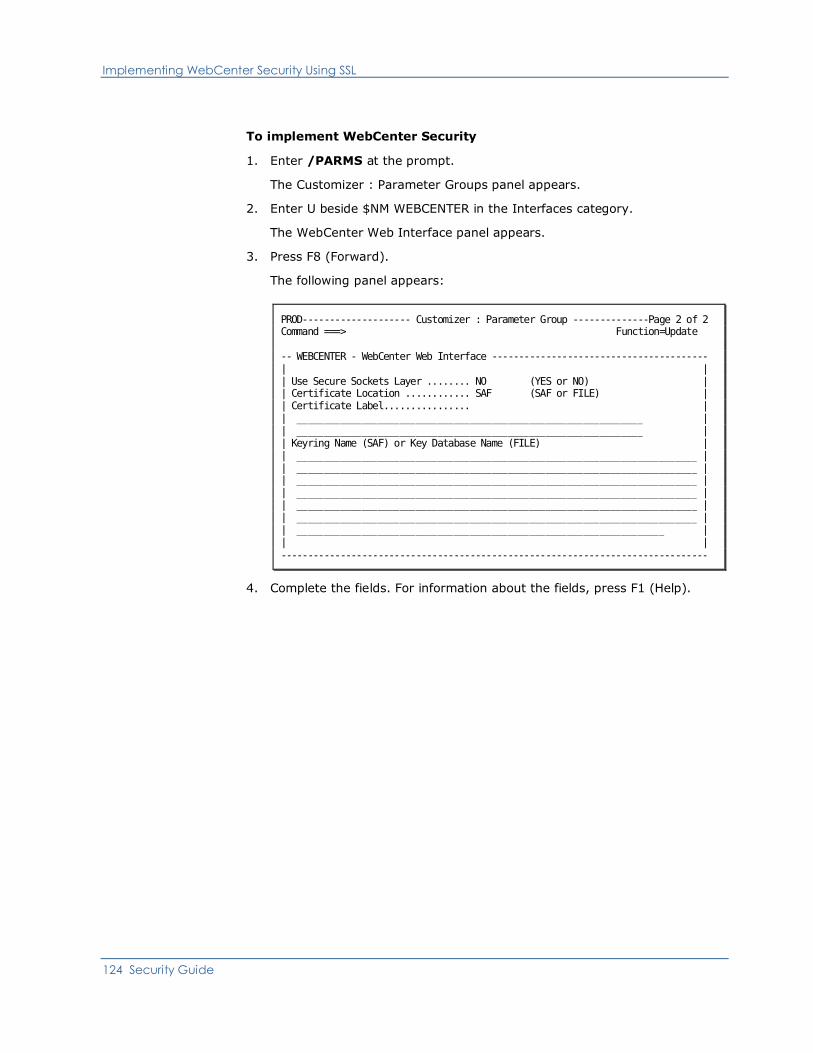
Implementing WebCenter Security Using SSL
124 Security Guide
To implement WebCenter Security
1. Enter /PARMS at the prompt.
The Customizer : Parameter Groups panel appears.
2. Enter U beside $NM WEBCENTER in the Interfaces category.
The WebCenter Web Interface panel appears.
3. Press F8 (Forward).
The following panel appears:
PROD-------------------- Customizer : Parameter Group --------------Page 2 of 2 Command ===> Function=Update -- WEBCENTER - WebCenter Web Interface ---------------------------------------- | | | Use Secure Sockets Layer ........ NO (YES or NO) | | Certificate Location ............ SAF (SAF or FILE) | | Certificate Label................ | | ________________________________________________________________ | | ________________________________________________________________ | | Keyring Name (SAF) or Key Database Name (FILE) | | __________________________________________________________________________ | | __________________________________________________________________________ | | __________________________________________________________________________ | | __________________________________________________________________________ | | __________________________________________________________________________ | | __________________________________________________________________________ | | ____________________________________________________________________ | | | -------------------------------------------------------------------------------
4. Complete the fields. For information about the fields, press F1 (Help).

Control Access to WebCenter Menu Options
Chapter 10: Implementing WebCenter Security 125
Control Access to WebCenter Menu Options
You can control access to WebCenter menu options programmatically by using
the variables in the CC2DEXEC($W3MH01X) WebCenter menu user exit.
The exit contains a menu control variable for each menu option in WebCenter.
These variables are initially set to TRUE. To prevent access to a particular option,
change the value of the control variable for that option to FALSE.
The exit is called when a user logs in to WebCenter. You can update this exit to
suit your requirements.
Important! If modifications are required, we recommend that you create an
SMP/E ++USERMOD to record and control the changes. Alternatively, you can
copy the distributed member to the region’s TESTEXEC data set for modification.
If you want to control access to a menu option for a user, use the &SECCALL NCL
verb to query the user's access as defined in UAMS. Then, set the appropriate
variables to TRUE or FALSE. The exit contains some sample code.
Note: For more information about the verb, see the Network Control Language
Reference Guide.
If you want to control access to a menu option for all users, update the value of
its control variable but do not perform an &SECCALL query.
Changes to this exit are not dynamic. For changes to the exit to take effect, the
user must log in to WebCenter with a new advanced program-to-program
communications (APPC) connection. That is, if a user is logged in when the
changes take effect, the changes are not evident for that user until they log out
of WebCenter and log in again.
Important! Preventing access to a menu option does not mean preventing
access to the underlying function. What it does is to prevent users from using the
menu option to access the function.

Appendix A: SXCTL Parameters 127
Appendix A: SXCTL Parameters
This appendix describes the parameters that you can use in the SXCTL parameter
file for the NMSAF security solution (see page 23).
This section contains the following topics:
SXCTL Parameters (see page 128)
SXCTL Parameters
128 Security Guide
SXCTL Parameters
The NMSAF security exit reads the SXCTL file during initialization of your region:
■ Blank lines and lines with an asterisk (*) as the first non-blank character are
ignored.
■ Other lines must contain a valid SXCTL parameter.
You can specify any of these parameters in the SXCTL file.
APPCCHECK { NO | YES }
Controls whether APPC user sessions are validated against security.
Note: Do not set this parameter to NO.
APPCMODEL { NO | YES }
Controls whether an APPC user is eligible for model processing (if not known
by this region).
NO
(Default) The logon is rejected.
YES
A model can be used (subject to model processing rules).
CHANGEPWD { NO | YES }
Blocks the use of the Password Change facility in your region.
NO
(Default) Blocks attempts to use the UAMS Password Change facility, or
any other password change interface (for example, using EASINET), and
produces an error message. This setting prevents users from using these
region features to change their passwords (whether in UAMS or external
security) and can be useful in distributed security environments where
passwords must be changed by using a particular mechanism.
YES
Allows the Password Change facility to be used (although the security
system can reject or ignore it).

SXCTL Parameters
Appendix A: SXCTL Parameters 129
CONCHECK { YES | NO }
Controls the checking of console user IDs. These are user IDs for system
consoles.
YES
(Default) The console user ID is presented to SAF.
NO
The console user ID is not presented to SAF.
Note: If CONCHECK YES is specified, this user ID is presented before the
CONUID user ID is presented, if one is set.
CONUID { - | userid }
Provides a single SAF user ID to use for all console environments for this
region. This parameter can prevent the need to define individual console
users to the security system. If CONCHECK YES is set, the value of CONUID
is presented to SAF only if verification of the specific console user ID failed.
-
Specifies that the value is to be cleared (blank).
userid
Specifies the user ID.
Limits: One through eight characters, with all characters alphanumeric
or national
Note: Regardless of the settings of CONCHECK and CONUID, the logon
procedure ignores a failure of a console user logon. The procedure allows the
logon and, if the user is also not defined on UAMS, supplies default values.
DSSDSSEC { NO | YES }
This parameter controls whether data set services register system users for
data set resource checking. This feature requires the NMSECDSS exit to be
active.
DSSDUSEC { YES | NO }
Controls whether data set services register normal users for data set
resource checking. This feature requires the NMSECDSS exit to be active.
DSSHSSEC { NO | YES }
This parameter controls whether data set services register system users for
HFS file resource checking. This feature requires the NMSECDSS exit to be
active.
DSSHUSEC { YES | NO }
This parameter controls whether data set services register normal users for
HFS file resource checking. This feature requires the NMSECDSS exit to be
active.
SXCTL Parameters
130 Security Guide
MODEL { NO | SYSPARM | SINGLE | LIST }
Controls the use of the MODEL user facility.
NO
(Default) No modeling is to be performed.
SYSPARM
The setting of the SYSPARMS MODLUSER is to be used.
SINGLE
If a model name is specified in SXCTL, it is used as the model.
LIST
If a resource or model list is defined, then it is used to determine the
model name.
Modeling applies only if a user logs on to the region and no UAMS definition
exists. You can control which logon types can participate in modeling.
MODELGROUP { saf.resource.name | * } modelname
Supplies an entry in a list of SAF resource names and associated model
names. The parameter can be repeated up to 20 times in the SXCTL file. The
order in which the pairs of resource names and model names are specified is
the order in which the resource names are tested. Specifying a resource
name of * always matches (no SAF AUTH call is made).
If MODEL LIST is specified and modeling is required (that is, the user is not
known to the region), then each defined resource name is tested (using the
class as set by the RCLASS parameter) in turn, until a resource is found that
the user has at least READ access to (or the * entry is reached). If a match
is found, the associated model name is returned. If no match is found (and
no * entry is found), then no model name is returned and the logon is
rejected.
saf.resource.name modelname
Must be in valid PDSNAME format. The length must be one through eight
characters; the first character must be alphabetic or national (@,#,$)
and the rest must be alphanumeric or national.

SXCTL Parameters
Appendix A: SXCTL Parameters 131
MODELNAME { - | userid }
Supplies the model name to use for modeling if MODEL SINGLE is specified
(otherwise it is ignored). If no model name is specified (the default), it is as
if MODEL NO is specified.
-
Specifies that the value is to be cleared (blank). This setting can cause
substitution by a default value.
userid
Names the model.
Limits: One through eight characters, with all characters alphanumeric
or national
RAPPL { - | name }
Sets the APPL value to use on RACROUTE calls.
-
(Default) A dash means none; the primary ACBNAME is then used.
name
Must be in valid PDSNAME format. The length must be one through eight
characters; the first character must be alphabetic or national (@,#,$)
and the rest must be alphanumeric or national.
RCLASS { - | name }
Sets the SAF resource class to use for most RACROUTE AUTH checks (for
example, for model determination).
-
(Default) A dash (-) means none; FACILITY is then used.
name
Must be in valid PDSNAME format. The length must be one through eight
characters; the first character must be alphabetic or national (@,#,$)
and the rest must be alphanumeric or national.
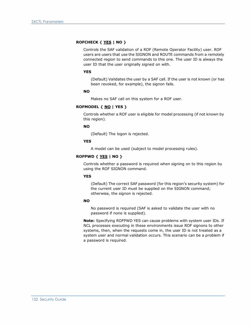
SXCTL Parameters
132 Security Guide
ROFCHECK { YES | NO }
Controls the SAF validation of a ROF (Remote Operator Facility) user. ROF
users are users that use the SIGNON and ROUTE commands from a remotely
connected region to send commands to this one. The user ID is always the
user ID that the user originally signed on with.
YES
(Default) Validates the user by a SAF call. If the user is not known (or has
been revoked, for example), the signon fails.
NO
Makes no SAF call on this system for a ROF user.
ROFMODEL { NO | YES }
Controls whether a ROF user is eligible for model processing (if not known by
this region).
NO
(Default) The logon is rejected.
YES
A model can be used (subject to model processing rules).
ROFPWD { YES | NO }
Controls whether a password is required when signing on to this region by
using the ROF SIGNON command.
YES
(Default) The correct SAF password (for this region’s security system) for
the current user ID must be supplied on the SIGNON command;
otherwise, the signon is rejected.
NO
No password is required (SAF is asked to validate the user with no
password if none is supplied).
Note: Specifying ROFPWD YES can cause problems with system user IDs. If
NCL processes executing in these environments issue ROF signons to other
systems, then, when the requests come in, the user ID is not treated as a
system user and normal validation occurs. This scenario can be a problem if
a password is required.

SXCTL Parameters
Appendix A: SXCTL Parameters 133
SYSCHECK { YES | NO }
Controls the checking of system (or background) user IDs; for example, the
BSYS and BLOG users, and the PPOP and AOMP regions.
Note: If SYSCHECK YES is specified, this user ID is presented before the
SYSUID user ID is presented, if one is set.
YES
(Default) The user ID is presented to SAF for validation (no password is
required). If SAF verifies the user ID, then it is accepted.
NO
The generated user ID is not presented to SAF.
SYSUID { - | userid }
This parameter provides a single SAF user ID to use for all the system (or
background) user IDs for this region. This feature prevents the need to
define multiple user IDs (such as NM01BSYS and NM01BMON) to the security
system. If SYSCHECK YES is set, the value of SYSUID is presented to SAF
only if verification of the specific system user ID failed.
-
Specifies that the value is to be cleared (blank). This setting can cause
substitution by a default value.
userid
Specifies the user ID.
Limits: One through eight characters, with all characters alphanumeric
or national
Note: Regardless of the settings of SYSCHECK and SYSUID, the initialization
procedure ignores a failure of a system user logon. The procedure continues
initializing and, if the user is also not defined on UAMS, supplies default
values.
TRACE { NO | YES }
Enables tracing to the SXTRACE data set.
NO
Disables all tracing, regardless of other trace options.
YES
Enables tracing (provided the SXTRACE file can be opened during
initialization), but other trace options must be set to cause actual tracing
to occur.

SXCTL Parameters
134 Security Guide
TRACEMOD { NO | YES }
Enables tracing of the security exit module flow. Typically, this feature is
used only if requested by Technical Support to track down errors in the exit.
Note: This option produces a large amount of trace output.
TRACEPL { NO | YES }
Enables tracing of the security exit call parameter list on entry and exit. The
trace includes the fields pointed to by parameters that are not null (except
passwords).
TRACESAF { NO | ERROR | YES }
Enables tracing of the results of RACROUTE (SAF) macro calls.
NO
Disables all tracing.
ERROR
Causes tracing of those RACROUTE calls that failed in some way.
YES
Traces all RACROUTE calls. The trace includes the parameter list and
return codes.
TSOMODEL { NO | YES }
Controls whether a TSO user is eligible for model processing (if not known by
this region).
NO
(Default) Automatic model processing is not used and the user (if not
defined to UAMS) is presented with a blank logon panel that uses normal
logon processing rules.
YES
Means that a model can be used (subject to model processing rules).
TSOPWD { YES | NO }
Controls the requirement for a password when using the TSO pass through
facility (the NMLOGON TSO command). Values are:
YES
(Default) The user is presented with a normal logon screen and must
enter the user ID and password to gain access.
NO
The user can be logged on (using the current TSO user ID) with no
password (provided that this is not blocked in the UAMS definition for this
user).

SXCTL Parameters
Appendix A: SXCTL Parameters 135
USERFLAGn { NO | YES }
These parameters (up to 8) set flags in the global area accessible to other
exits. They can be used to control logic in installation-written exits, such as
NCLEX01.
USERNAMEn { - | name }
These parameters (up to 4) set name values in the global area accessible to
other exits. They can be used as input data in installation-written exits, such
as NCLEX01.
-
The value is to be cleared (blank). This setting can cause substitution by
a default value.
name
Must be in valid PDSNAME format. The length must be one through eight
characters; the first character must be alphabetic or national (@,#,$)
and the rest must be alphanumeric or national.
USERUIDn { - | uid }
These parameters (up to 4) set user ID values in the global area accessible to
other exits. They can be used as input data in installation-written exits (such
as NCLEX01).
-
The value is to be cleared (blank). This setting can cause substitution by
a default value.
uid
Specifies a user ID.
Limits: One through eoght characters, with all characters alphanumeric
or national
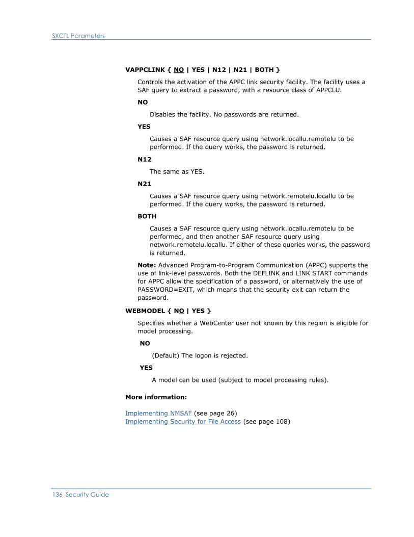
SXCTL Parameters
136 Security Guide
VAPPCLINK { NO | YES | N12 | N21 | BOTH }
Controls the activation of the APPC link security facility. The facility uses a
SAF query to extract a password, with a resource class of APPCLU.
NO
Disables the facility. No passwords are returned.
YES
Causes a SAF resource query using network.locallu.remotelu to be
performed. If the query works, the password is returned.
N12
The same as YES.
N21
Causes a SAF resource query using network.remotelu.locallu to be
performed. If the query works, the password is returned.
BOTH
Causes a SAF resource query using network.locallu.remotelu to be
performed, and then another SAF resource query using
network.remotelu.locallu. If either of these queries works, the password
is returned.
Note: Advanced Program-to-Program Communication (APPC) supports the
use of link-level passwords. Both the DEFLINK and LINK START commands
for APPC allow the specification of a password, or alternatively the use of
PASSWORD=EXIT, which means that the security exit can return the
password.
WEBMODEL { NO | YES }
Specifies whether a WebCenter user not known by this region is eligible for
model processing.
NO
(Default) The logon is rejected.
YES
A model can be used (subject to model processing rules).
More information:
Implementing NMSAF (see page 26)
Implementing Security for File Access (see page 108)

Appendix B: Security Settings for Group Definitions 137
Appendix B: Security Settings for Group
Definitions
Note: This appendix does not apply to CA SOLVE:FTS, CA SOLVE:Access, CA
SOLVE:InfoMaster, and CA SOLVE:NetMail.
This appendix specifies the recommended security settings for each of the
supplied group IDs. These settings can be used if you want to create group IDs
for your external security package. The settings are presented as they are in
UAMS providing the panel, field, value, and structured field for each setting.
Note: The structured field information will only be useful to installations that
have an external security package controlling user access with a partial or full
security exit.
This section contains the following topics:
Security Settings for $RMADMIN (see page 137)
Security Settings for $RMOPER (see page 139)
Security Settings for $RMNOPER (see page 140)
Security Settings for $RMMON (see page 141)
Security Settings for $RMBUSER (see page 142)More information:
Structured Fields (see page 143)
Security Settings for $RMADMIN
$RMADMIN is the group ID for administrators. The recommended security
settings are given in this table.
Panel (Page
Number)
Field Value Structured
Field
User Authorities (2) Authority Level 255 0050
Multiple Signon
Authority
Y 0019
Split/Swap
Authority
Y 002E
APPC Access Key ALL 0060
APPC Access Lock ALL 0061
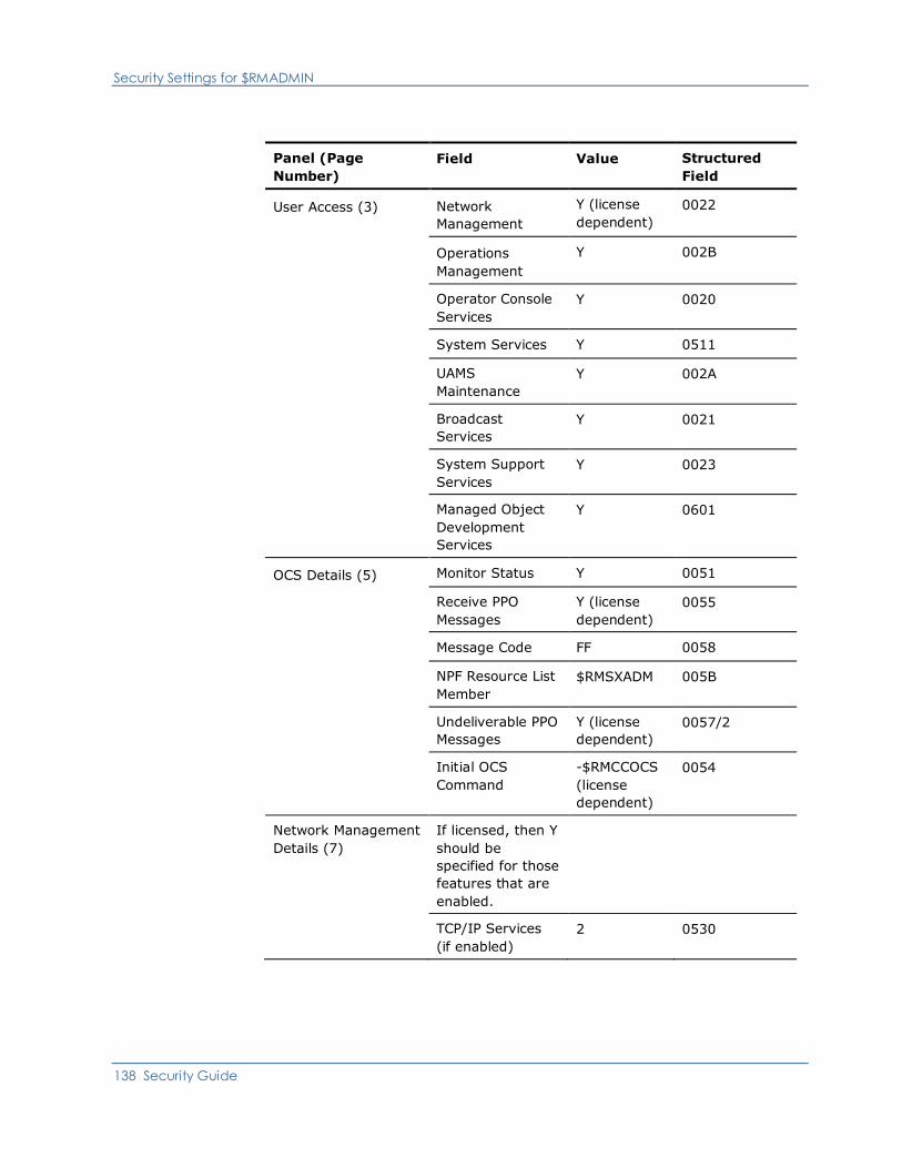
Security Settings for $RMADMIN
138 Security Guide
Panel (Page
Number)
Field Value Structured
Field
User Access (3)
Network
Management
Y (license
dependent)
0022
Operations
Management
Y 002B
Operator Console
Services
Y 0020
System Services Y 0511
UAMS
Maintenance
Y 002A
Broadcast
Services
Y 0021
System Support
Services
Y 0023
Managed Object
Development
Services
Y 0601
OCS Details (5) Monitor Status Y 0051
Receive PPO
Messages
Y (license
dependent)
0055
Message Code FF 0058
NPF Resource List
Member
$RMSXADM 005B
Undeliverable PPO
Messages
Y (license
dependent)
0057/2
Initial OCS
Command
-$RMCCOCS
(license
dependent)
0054
Network Management
Details (7)
If licensed, then Y
should be
specified for those
features that are
enabled.
TCP/IP Services
(if enabled)
2 0530
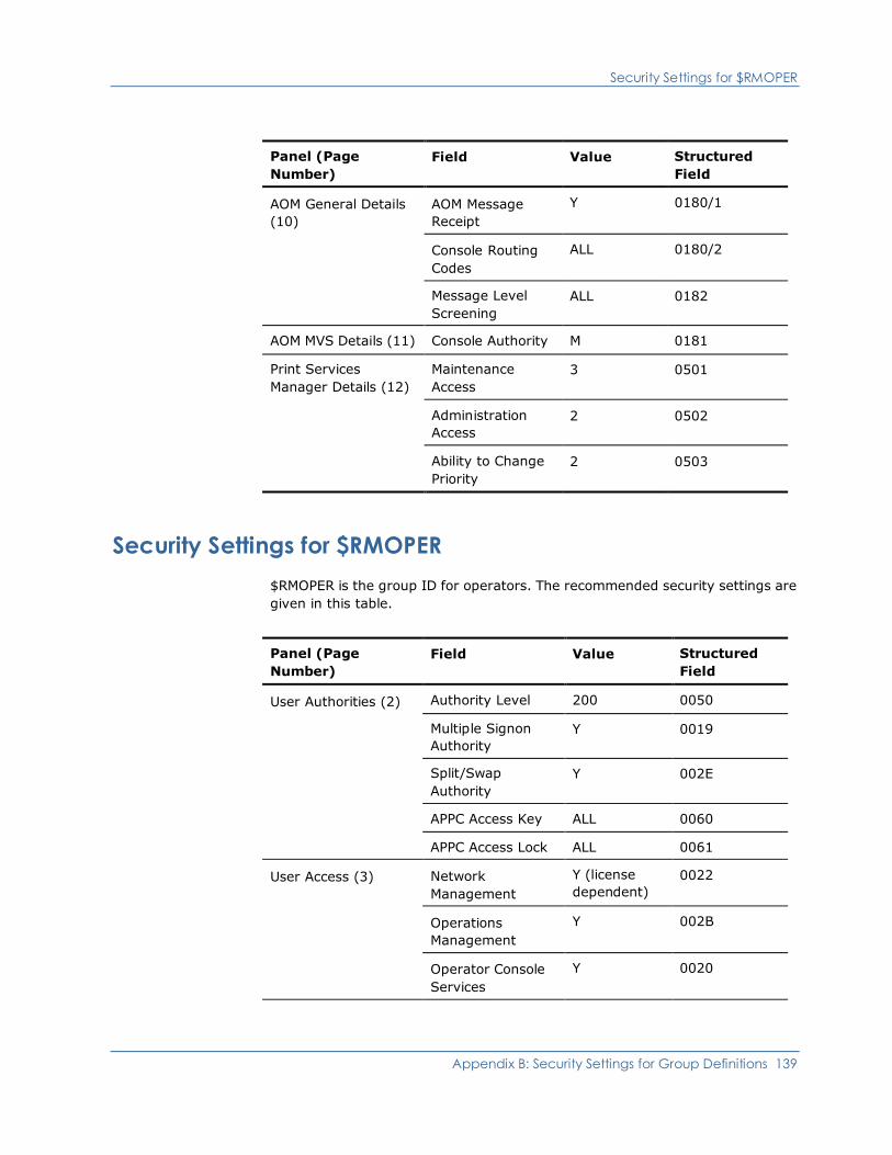
Security Settings for $RMOPER
Appendix B: Security Settings for Group Definitions 139
Panel (Page
Number)
Field Value Structured
Field
AOM General Details
(10)
AOM Message
Receipt
Y 0180/1
Console Routing
Codes
ALL 0180/2
Message Level
Screening
ALL 0182
AOM MVS Details (11) Console Authority M 0181
Print Services
Manager Details (12)
Maintenance
Access
3 0501
Administration
Access
2 0502
Ability to Change
Priority
2 0503
Security Settings for $RMOPER
$RMOPER is the group ID for operators. The recommended security settings are
given in this table.
Panel (Page
Number)
Field Value Structured
Field
User Authorities (2) Authority Level 200 0050
Multiple Signon
Authority
Y 0019
Split/Swap
Authority
Y 002E
APPC Access Key ALL 0060
APPC Access Lock ALL 0061
User Access (3)
Network
Management
Y (license
dependent)
0022
Operations
Management
Y 002B
Operator Console
Services
Y 0020

Security Settings for $RMNOPER
140 Security Guide
Panel (Page
Number)
Field Value Structured
Field
Broadcast Services Y 0021
Network Management
Details (7)
If licensed, then Y
should be specified
for those features
that are enabled.
AOM General Details
(10)
AOM Message
Receipt
Y 0180/1
Console Routing
Codes
ALL 0180/2
Message Level
Screening
ALL 0182
AOM MVS Details (11) Console Authority M 0181
Security Settings for $RMNOPER
$RMNOPER is the group ID for network operators. The recommended security
settings are given in this table.
Panel (Page
Number)
Field Value Structured
Field
User Authorities (2) Authority Level 200 0050
Multiple Signon
Authority
Y 0019
Split/Swap
Authority
Y 002E
APPC Access Key ALL 0060
APPC Access Lock ALL 0061
Network Management
Details (7)
If licensed, then Y
should be specified
for those features
that are enabled.
AOM General Details
(10)
AOM Message
Receipt
Y 0180/1
Console Routing
Codes
ALL 0180/2

Security Settings for $RMMON
Appendix B: Security Settings for Group Definitions 141
Panel (Page
Number)
Field Value Structured
Field
Message Level
Screening
ALL 0182
AOM MVS Details (11) Console Authority M 0181
Security Settings for $RMMON
$RMMON is the group ID for monitors. The recommended security settings are
given in this table.
Panel (Page
Number)
Field Value Structured
Field
User Authorities (2) Authority Level 002 0050
Multiple Signon
Authority
Y 0019
Split/Swap
Authority
Y 002E
APPC Access Key ALL 0060
APPC Access Lock ALL 0061
User Access (3) Network
Management
Y (license
dependent)
0022
Operations
Management
Y 002B
Network Management
Details (7)
If licensed, then Y
should be specified
for those features
that are enabled.
AOM General Details
(10)
AOM Message
Receipt
Y 0180/1
Console Routing
Codes
ALL 0180/2
Message Level
Screening
ALL 0182
AOM MVS Details (11) Console Authority I 0181
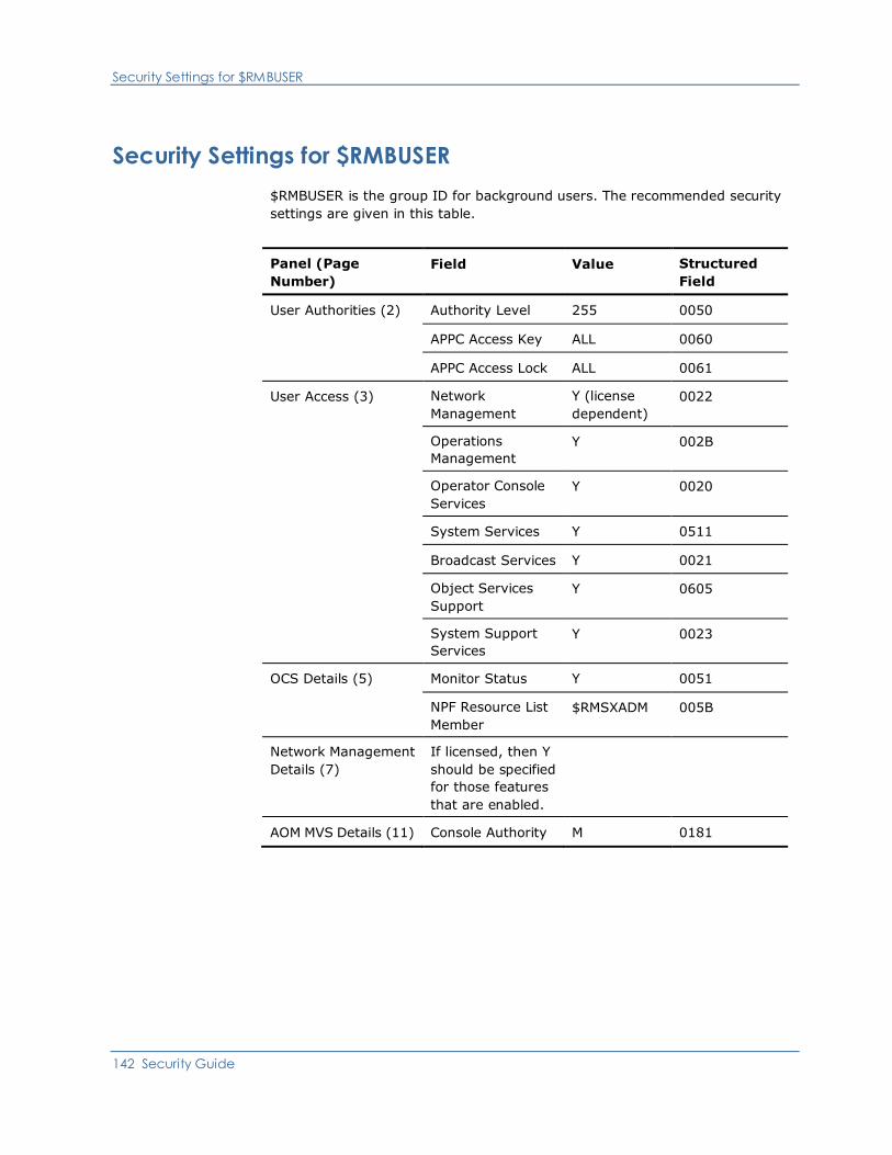
Security Settings for $RMBUSER
142 Security Guide
Security Settings for $RMBUSER
$RMBUSER is the group ID for background users. The recommended security
settings are given in this table.
Panel (Page
Number)
Field Value Structured
Field
User Authorities (2) Authority Level 255 0050
APPC Access Key ALL 0060
APPC Access Lock ALL 0061
User Access (3) Network
Management
Y (license
dependent)
0022
Operations
Management
Y 002B
Operator Console
Services
Y 0020
System Services Y 0511
Broadcast Services Y 0021
Object Services
Support
Y 0605
System Support
Services
Y 0023
OCS Details (5) Monitor Status Y 0051
NPF Resource List
Member
$RMSXADM 005B
Network Management
Details (7)
If licensed, then Y
should be specified
for those features
that are enabled.
AOM MVS Details (11) Console Authority M 0181
Appendix C: Structured Fields 143
Appendix C: Structured Fields
This appendix provides information about structured fields and provides a
description of each field available to your product region.
This section contains the following topics:
Understanding Structured Fields (see page 143)
Format of Structured Fields (see page 144)
Structured Field Descriptions (see page 146)
Understanding Structured Fields
Each structured field identifies an item of information that can be specified when
a user ID is defined. For example, user name, user location, and so on. These
structured fields provide the same information as the fields in the UAMS function
for defining a user ID.
Structured fields are used to exchange information between security exits and
system services. When an exit returns user ID information to system services it
is always in the form of a list of pointers to one or more structured fields. By
processing the fields returned by the exit, system services build an internal
representation of the user ID.
Your system services also translate this internal representation of a user ID into
the same set of structured fields when a request is passed to an exit.
More information:
Working with UAMS (see page 33)
Format of Structured Fields
144 Security Guide
Format of Structured Fields
The format of a structured field is as follows:
Bytes 00 to 01
Specifies the field key—a hexadecimal value that defines the item of
information described by this field.
Bytes 02 to 03
Specifies the subfield count—a hexadecimal count of the number of subfields
within this structured field.
Bytes 04 to 05
Specifies the subfield length—the hexadecimal length of the following
subfield.
Bytes 06 to nn
Specifies the subfield data.
Subfield length and subfield data are repeated according to the number specified
in subfield count.

Format of Structured Fields
Appendix C: Structured Fields 145
Example:
The following diagram shows structured field X’0011’. This field is used to define
a user’s name. This name can be associated with the user ID so that the person
can be identified when they log on.
Structured field X’0011’ consists of:
■ Field key of X‘0011’
■ Subfield count of X‘0001’ (1 subfield)
■ Subfield length of X‘0014’ (20 characters)
■ Subfield data of JOHN SMITH (padded with blanks on the right to make up
the 20 characters).
The following diagram shows structured field X‘0023’. This too has a single
subfield with a value of Y and is used to indicate that the user is entitled to access
the System Support Services function.
Structured Field Descriptions
146 Security Guide
Updating a Structured Field
For examples of how to update structured fields, including those with multiple
subfields, see the description of the &SECCALL verb in the Network Control
Language Reference.
Structured Field Error Conditions
Error conditions can occur during the processing of a set of structured fields due
to one of the following reasons:
■ The omission of a structured field.
■ An invalid value has been specified in a structured field.
If an error does occur during structured field processing, then:
■ The structured field is assigned its default value.
■ An error message is written to the log.
If error conditions occur, a user might not have all the expected privileges when
logged on to the system.
Structured Field Sequences
Your product region processes structured fields in the order in which they appear.
While most structured fields are independent of other fields, certain fields must
be processed before others. Where such dependencies exist, they are noted in
the description of the fields concerned.
Structured Field Descriptions
All structured fields that are supported by your product region are described in
the remainder of this appendix. The description of each field includes comments
on special processing or validation requirements.
Note: The length of each subfield is fixed and cannot be varied. Where
applicable, data fields must be blank padded to the full length of the subfield.
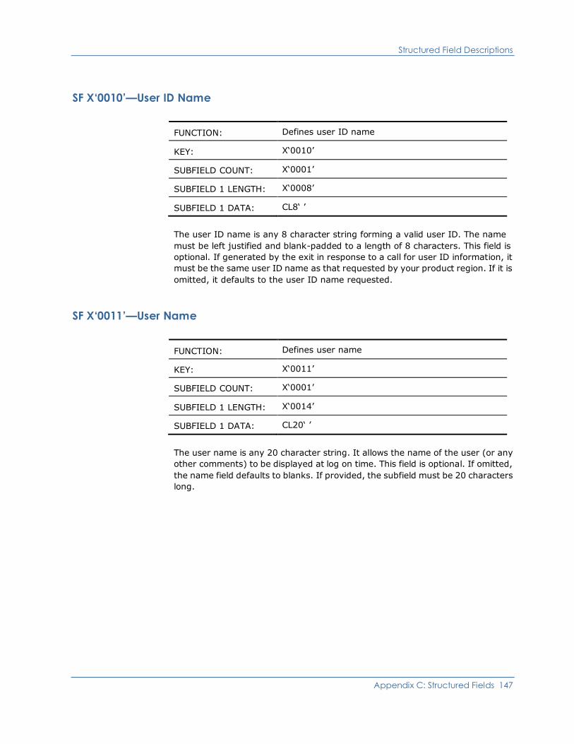
Structured Field Descriptions
Appendix C: Structured Fields 147
SF X‘0010’—User ID Name
FUNCTION: Defines user ID name
KEY: X‘0010’
SUBFIELD COUNT: X‘0001’
SUBFIELD 1 LENGTH: X‘0008’
SUBFIELD 1 DATA: CL8‘ ’
The user ID name is any 8 character string forming a valid user ID. The name
must be left justified and blank-padded to a length of 8 characters. This field is
optional. If generated by the exit in response to a call for user ID information, it
must be the same user ID name as that requested by your product region. If it is
omitted, it defaults to the user ID name requested.
SF X‘0011’—User Name
FUNCTION: Defines user name
KEY: X‘0011’
SUBFIELD COUNT: X‘0001’
SUBFIELD 1 LENGTH: X‘0014’
SUBFIELD 1 DATA: CL20‘ ’
The user name is any 20 character string. It allows the name of the user (or any
other comments) to be displayed at log on time. This field is optional. If omitted,
the name field defaults to blanks. If provided, the subfield must be 20 characters
long.

Structured Field Descriptions
148 Security Guide
SF X‘0012’—User Location
FUNCTION: Defines user location
KEY: X‘0012’
SUBFIELD COUNT: X‘0001’
SUBFIELD 1 LENGTH: X‘0014’
SUBFIELD 1 DATA: CL20‘ ’
The user location is any 20 character string. This field is optional. If omitted, the
location field defaults to blanks. If provided, the subfield must be 20 characters
long.
SF X‘0013’—User Telephone Number
FUNCTION: Defines user telephone number
KEY: X‘0013’
SUBFIELD COUNT: X‘0001’
SUBFIELD 1 LENGTH: X‘0014’
SUBFIELD 1 DATA: CL32‘ ’
The user telephone number field is any 32 character string. This field is optional.
If omitted, the field will default to blanks. If provided, the subfield must be 32
characters long.
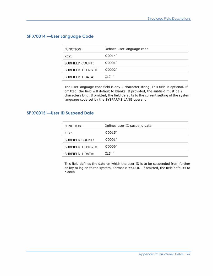
Structured Field Descriptions
Appendix C: Structured Fields 149
SF X‘0014’—User Language Code
FUNCTION: Defines user language code
KEY: X‘0014’
SUBFIELD COUNT: X‘0001’
SUBFIELD 1 LENGTH: X‘0002’
SUBFIELD 1 DATA: CL2‘ ’
The user language code field is any 2 character string. This field is optional. If
omitted, the field will default to blanks. If provided, the subfield must be 2
characters long. If omitted, the field defaults to the current setting of the system
language code set by the SYSPARMS LANG operand.
SF X‘0015’—User ID Suspend Date
FUNCTION: Defines user ID suspend date
KEY: X‘0015’
SUBFIELD COUNT: X‘0001’
SUBFIELD 1 LENGTH: X‘0006’
SUBFIELD 1 DATA: CL6‘ ’
This field defines the date on which the user ID is to be suspended from further
ability to log on to the system. Format is YY.DDD. If omitted, the field defaults to
blanks.
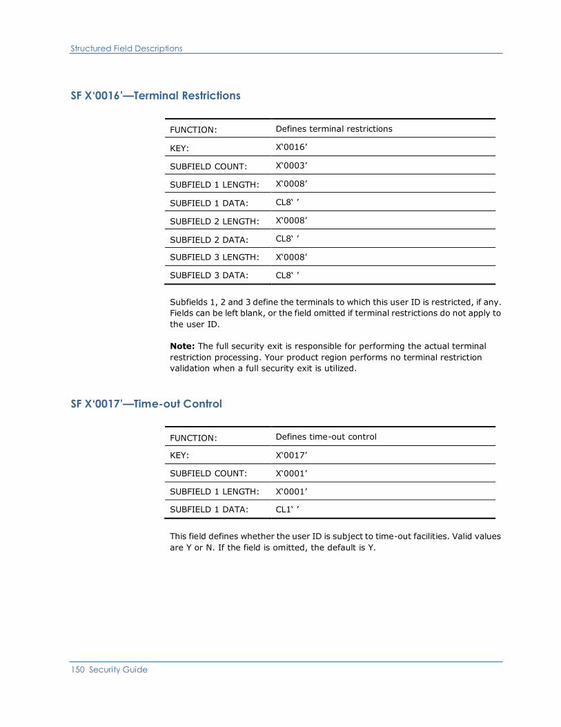
Structured Field Descriptions
150 Security Guide
SF X‘0016’—Terminal Restrictions
FUNCTION: Defines terminal restrictions
KEY: X‘0016’
SUBFIELD COUNT: X‘0003’
SUBFIELD 1 LENGTH: X‘0008’
SUBFIELD 1 DATA: CL8‘ ’
SUBFIELD 2 LENGTH: X‘0008’
SUBFIELD 2 DATA: CL8‘ ’
SUBFIELD 3 LENGTH: X‘0008’
SUBFIELD 3 DATA: CL8‘ ’
Subfields 1, 2 and 3 define the terminals to which this user ID is restricted, if any.
Fields can be left blank, or the field omitted if terminal restrictions do not apply to
the user ID.
Note: The full security exit is responsible for performing the actual terminal
restriction processing. Your product region performs no terminal restriction
validation when a full security exit is utilized.
SF X‘0017’—Time-out Control
FUNCTION: Defines time-out control
KEY: X‘0017’
SUBFIELD COUNT: X‘0001’
SUBFIELD 1 LENGTH: X‘0001’
SUBFIELD 1 DATA: CL1‘ ’
This field defines whether the user ID is subject to time-out facilities. Valid values
are Y or N. If the field is omitted, the default is Y.

Structured Field Descriptions
Appendix C: Structured Fields 151
SF X‘0018’—Date/Time User ID Last Updated
FUNCTION: Defines date/time user ID last updated
KEY: X‘0018’
SUBFIELD COUNT: X‘0002’
SUBFIELD 1 LENGTH: X‘0014’
SUBFIELD 1 DATA: CL20‘ ’
SUBFIELD 2 LENGTH: X‘0010’
SUBFIELD 2 DATA: CL16‘ ’
SUBFIELD 3 LENGTH: X‘0008’
SUBFIELD 3 DATA: CL8‘ ’
Subfield 1
■ Value—Date and time that this user ID last logged on to system
■ Format—15-character last logged on date, for example,
MON 09-FEB-2006, and a 5-character last logged on time, for example,
08.30
Subfield 2
■ Value—Date and time that this user ID was last updated
■ Format—11-character last updated date, for example, 09-FEB-2006,
and a 5-character last logged on time, for example, 08.30
Subfield 3
■ Value—User ID of the user who last updated this field
■ Format—Eight characters
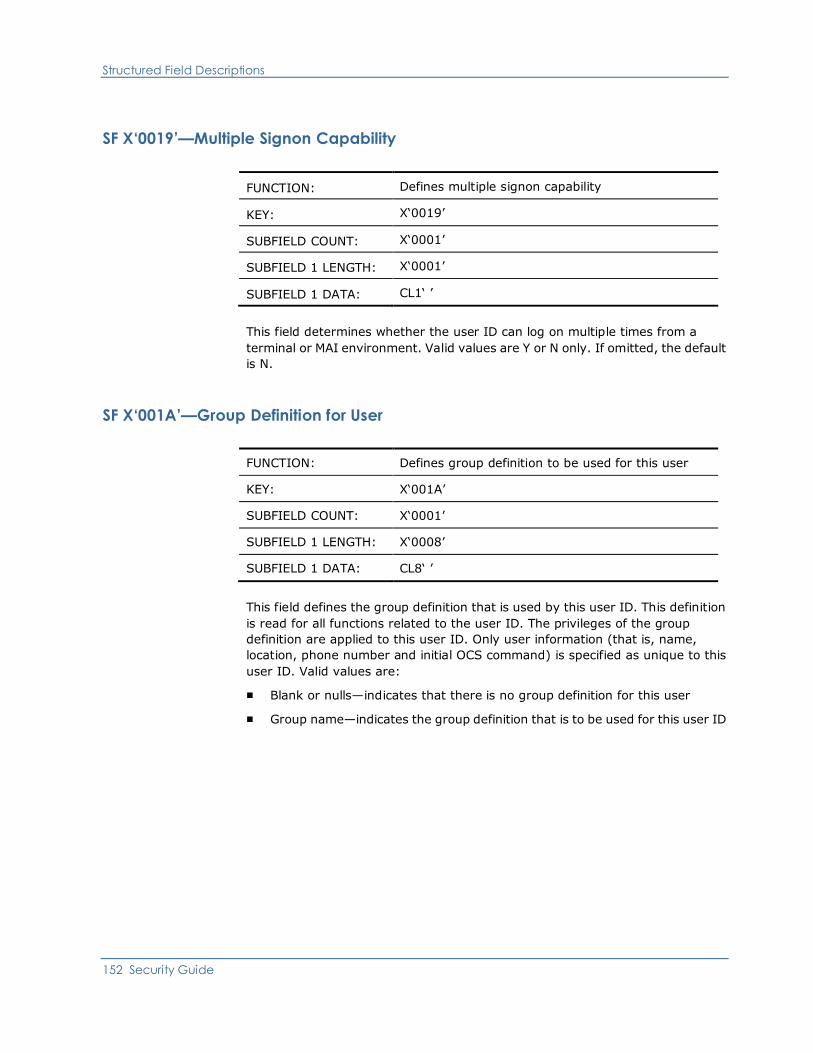
Structured Field Descriptions
152 Security Guide
SF X‘0019’—Multiple Signon Capability
FUNCTION: Defines multiple signon capability
KEY: X‘0019’
SUBFIELD COUNT: X‘0001’
SUBFIELD 1 LENGTH: X‘0001’
SUBFIELD 1 DATA: CL1‘ ’
This field determines whether the user ID can log on multiple times from a
terminal or MAI environment. Valid values are Y or N only. If omitted, the default
is N.
SF X‘001A’—Group Definition for User
FUNCTION: Defines group definition to be used for this user
KEY: X‘001A’
SUBFIELD COUNT: X‘0001’
SUBFIELD 1 LENGTH: X‘0008’
SUBFIELD 1 DATA: CL8‘ ’
This field defines the group definition that is used by this user ID. This definition
is read for all functions related to the user ID. The privileges of the group
definition are applied to this user ID. Only user information (that is, name,
location, phone number and initial OCS command) is specified as unique to this
user ID. Valid values are:
■ Blank or nulls—indicates that there is no group definition for this user
■ Group name—indicates the group definition that is to be used for this user ID
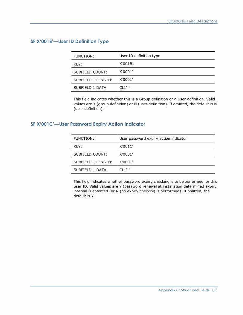
Structured Field Descriptions
Appendix C: Structured Fields 153
SF X‘001B’—User ID Definition Type
FUNCTION: User ID definition type
KEY: X‘001B’
SUBFIELD COUNT: X‘0001’
SUBFIELD 1 LENGTH: X‘0001’
SUBFIELD 1 DATA: CL1‘ ’
This field indicates whether this is a Group definition or a User definition. Valid
values are Y (group definition) or N (user definition). If omitted, the default is N
(user definition).
SF X‘001C’—User Password Expiry Action Indicator
FUNCTION: User password expiry action indicator
KEY: X‘001C’
SUBFIELD COUNT: X‘0001’
SUBFIELD 1 LENGTH: X‘0001’
SUBFIELD 1 DATA: CL1‘ ’
This field indicates whether password expiry checking is to be performed for this
user ID. Valid values are Y (password renewal at installation determined expiry
interval is enforced) or N (no expiry checking is performed). If omitted, the
default is Y.
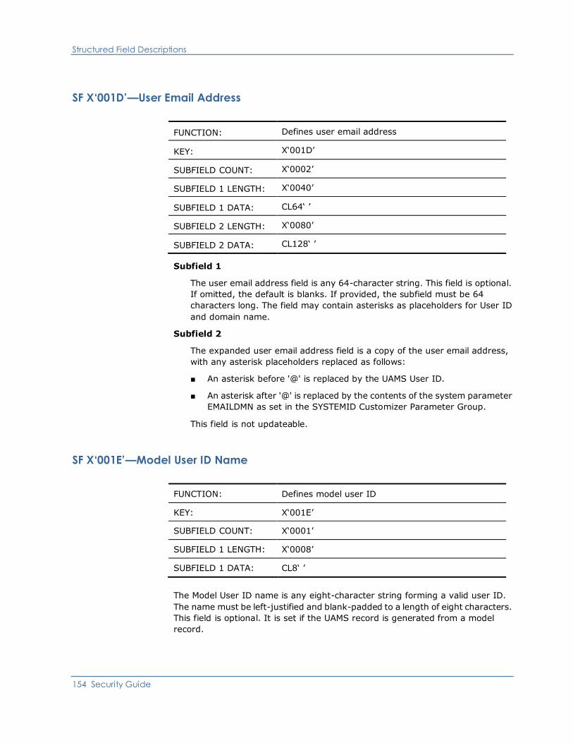
Structured Field Descriptions
154 Security Guide
SF X‘001D’—User Email Address
FUNCTION: Defines user email address
KEY: X‘001D’
SUBFIELD COUNT: X‘0002’
SUBFIELD 1 LENGTH: X‘0040’
SUBFIELD 1 DATA: CL64‘ ’
SUBFIELD 2 LENGTH: X‘0080’
SUBFIELD 2 DATA: CL128‘ ’
Subfield 1
The user email address field is any 64-character string. This field is optional.
If omitted, the default is blanks. If provided, the subfield must be 64
characters long. The field may contain asterisks as placeholders for User ID
and domain name.
Subfield 2
The expanded user email address field is a copy of the user email address,
with any asterisk placeholders replaced as follows:
■ An asterisk before '@' is replaced by the UAMS User ID.
■ An asterisk after '@' is replaced by the contents of the system parameter
EMAILDMN as set in the SYSTEMID Customizer Parameter Group.
This field is not updateable.
SF X‘001E’—Model User ID Name
FUNCTION: Defines model user ID
KEY: X‘001E’
SUBFIELD COUNT: X‘0001’
SUBFIELD 1 LENGTH: X‘0008’
SUBFIELD 1 DATA: CL8‘ ’
The Model User ID name is any eight-character string forming a valid user ID.
The name must be left-justified and blank-padded to a length of eight characters.
This field is optional. It is set if the UAMS record is generated from a model
record.

Structured Field Descriptions
Appendix C: Structured Fields 155
SF X‘0020’—OCS Access Privilege
FUNCTION: Defines OCS access privilege
KEY: X‘0020’
SUBFIELD COUNT: X‘0001’
SUBFIELD 1 LENGTH: X‘0001’
SUBFIELD 1 DATA: CL1‘ ’
This field indicates whether the user has access to OCS. Valid values are Y or N.
If omitted, or an invalid value is specified, the default is N.
SF X‘0021’—Broadcast Services Privilege
FUNCTION: Defines Broadcast Services privilege
KEY: X‘0021’
SUBFIELD COUNT: X‘0001’
SUBFIELD 1 LENGTH: X‘0001’
SUBFIELD 1 DATA: CL1‘ ’
This field indicates whether the user has access to Broadcast Services. Valid
values are Y or N. If omitted, or an invalid value is specified, the default is N.
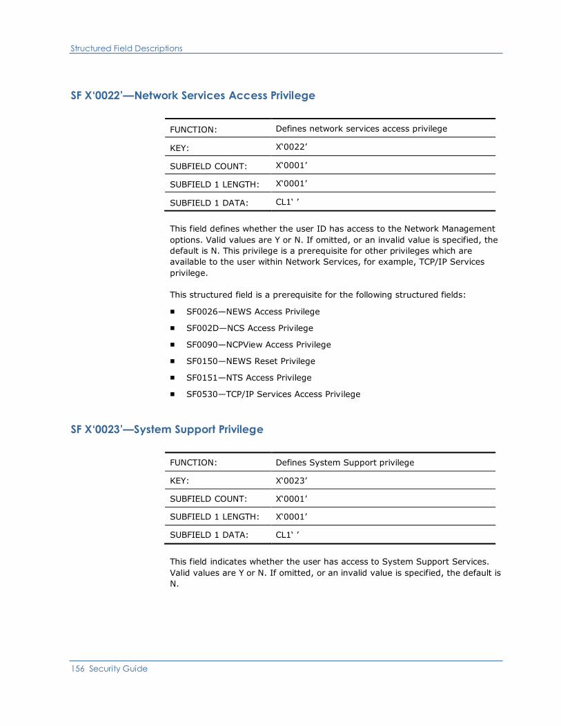
Structured Field Descriptions
156 Security Guide
SF X‘0022’—Network Services Access Privilege
FUNCTION: Defines network services access privilege
KEY: X‘0022’
SUBFIELD COUNT: X‘0001’
SUBFIELD 1 LENGTH: X‘0001’
SUBFIELD 1 DATA: CL1‘ ’
This field defines whether the user ID has access to the Network Management
options. Valid values are Y or N. If omitted, or an invalid value is specified, the
default is N. This privilege is a prerequisite for other privileges which are
available to the user within Network Services, for example, TCP/IP Services
privilege.
This structured field is a prerequisite for the following structured fields:
■ SF0026—NEWS Access Privilege
■ SF002D—NCS Access Privilege
■ SF0090—NCPView Access Privilege
■ SF0150—NEWS Reset Privilege
■ SF0151—NTS Access Privilege
■ SF0530—TCP/IP Services Access Privilege
SF X‘0023’—System Support Privilege
FUNCTION: Defines System Support privilege
KEY: X‘0023’
SUBFIELD COUNT: X‘0001’
SUBFIELD 1 LENGTH: X‘0001’
SUBFIELD 1 DATA: CL1‘ ’
This field indicates whether the user has access to System Support Services.
Valid values are Y or N. If omitted, or an invalid value is specified, the default is
N.

Structured Field Descriptions
Appendix C: Structured Fields 157
SF X'0025'—CA SOLVE:FTS Access Privilege
FUNCTION: Defines CA SOLVE:FTS access privilege
KEY: X'0025'
SUBFIELD COUNT: X'0001'
SUBFIELD 1 LENGTH: X'0001'
SUBFIELD 1 DATA: CL1' '
This field indicates whether the user is entitled to access CA SOLVE:FTS. Valid
values for the subfield data are Y or N. N is assumed if the field is omitted or
specifies a value other than Y. This field is ignored if the system is not configured
with the CA SOLVE:FTS product.
SF X‘0026’—NEWS Access Privilege
FUNCTION: Defines CA NetMaster Network Management for SNA
NEWS access privilege
KEY: X‘0026’
SUBFIELD COUNT: X‘0001’
SUBFIELD 1 LENGTH: X‘0001’
SUBFIELD 1 DATA: CL1‘ ’
This field indicates whether the user has access to NEWS. Valid values are Y or N.
The default is N.
This field is ignored if the user ID has not been given access privileges to Network
Management, that is, if the user ID does not have structured field key X‘0022’.

Structured Field Descriptions
158 Security Guide
SF X‘0027’—MAI-FS Access Privilege
FUNCTION: Defines CA SOLVE:Access Session Management
MAI-FS access privilege
KEY: X‘0027’
SUBFIELD COUNT: X‘0001’
SUBFIELD 1 LENGTH: X‘0001’
SUBFIELD 1 DATA: CL1‘ ’
This field indicates whether the user has access to MAI-FS. Valid values are Y or
N. If omitted, or an invalid value is specified, the default is N. Specifying Y in this
field allows the user to issue SETMODE MAI and use the MAISESS command. In
addition, the supplied primary menu offers an option to select the MAI-FS
primary menu.
SF X‘0028’—User Services Procedure Name
FUNCTION: Defines User Services procedure name
KEY: X‘0028’
SUBFIELD COUNT: X‘0001’
SUBFIELD 1 LENGTH: X‘0008’
SUBFIELD 1 DATA: CL8‘ ’
This field identifies the 8-character name of the NCL procedure to be invoked
when the user selects the User Services option from the Primary Menu. The name
specified must be a valid NCL procedure name, padded with blanks to 8
characters if required. Imbedded blanks within the name cause truncation.
This field is only valid if the user has access privileges for User Services. If this
field is omitted, no User Services procedure name is assigned to the user ID.

Structured Field Descriptions
Appendix C: Structured Fields 159
SF X‘0029’—User’s NCL Procedure Library
FUNCTION: Defines user’s NCL procedure library
KEY: X‘0029’
SUBFIELD COUNT: X‘0001’
SUBFIELD 1 LENGTH: X‘0008’
SUBFIELD 1 DATA: CL8‘ ’
This field provides the DD name in the JCL (z/OS) or the filetype (z/VM) that
defines the NCL procedure library to be used by this user. Whenever the user
executes an NCL procedure, this library is searched for the procedure. If omitted,
the library defined by the COMMANDS DD statement is used.
SF X‘002A’—UAMS Access Privilege
FUNCTION: Defines UAMS access privilege
KEY: X‘002A’
SUBFIELD COUNT: X‘0001’
SUBFIELD 1 LENGTH: X‘0001’
SUBFIELD 1 DATA: CL1‘ ’
This field defines whether the user ID has access to the UAMS maintenance
functions. Valid values are Y or N. If omitted, or if an invalid value is specified, the
default is N.
SF X‘002B’—Operations Management Privilege
FUNCTION: Defines Operations Management privilege
KEY: X‘002B’
SUBFIELD COUNT: X‘0001’
SUBFIELD 1 LENGTH: X‘0001’
SUBFIELD 1 DATA: CL1‘ ’
This field defines whether the user ID has access to the facilities of Operations
Management. Valid values are Y or N. The default is N.

Structured Field Descriptions
160 Security Guide
SF X‘002C’—TSO Autologon Privilege
FUNCTION: Defines TSO auto-logon privilege
KEY: X‘002C’
SUBFIELD COUNT: X‘0001’
SUBFIELD 1 LENGTH: X‘0001’
SUBFIELD 1 DATA: CL1‘ ’
This field defines whether the user ID can automatically log on to the system
using an EIP component, such as a TSO address space, without having to reenter
their user ID/password combination. If omitted, the default is N. This field is only
valid if you are licensed for EIP.
SF X‘002D’—NCS Access Privilege
FUNCTION: Defines NCS access privilege
KEY: X‘002D’
SUBFIELD COUNT: X‘0001’
SUBFIELD 1 LENGTH: X‘0001’
SUBFIELD 1 DATA: CL1‘ ’
This field defines whether the user ID has access to the facilities of NCS. Valid
values are Y or N. If omitted, or an invalid value is specified, the default is N.
This field is ignored if the user ID has not been given access privileges to Network
Management, that is, if the user ID does not have structured field key X‘0022’.

Structured Field Descriptions
Appendix C: Structured Fields 161
SF X‘002E’—User’s SPLIT/SWAP Privilege
FUNCTION: Defines user’s SPLIT/SWAP privileges
KEY: X‘002E’
SUBFIELD COUNT: X‘0001’
SUBFIELD 1 LENGTH: X‘0001’
SUBFIELD 1 DATA: CL1‘ ’
This field defines whether the user ID is entitled to use the SPLIT/SWAP facility
for operating two screen windows. Valid values are Y or N. If the field is omitted,
the default is Y.
SF X‘002F’—Library Services Path Name
FUNCTION: Defines Library Services path name
KEY: X‘002F’
SUBFIELD COUNT: X‘0001’
SUBFIELD 1 LENGTH: X‘0008’
SUBFIELD 1 DATA: CL8‘ ’
This field defines the user’s library path name. If a library path name is to be used
to control the sequence of access to the panels data sets, enter the name of the
path name to be used. See the LIBRARY command for information about the path
name definition. The default value is blanks, indicating that no path name is to be
used.
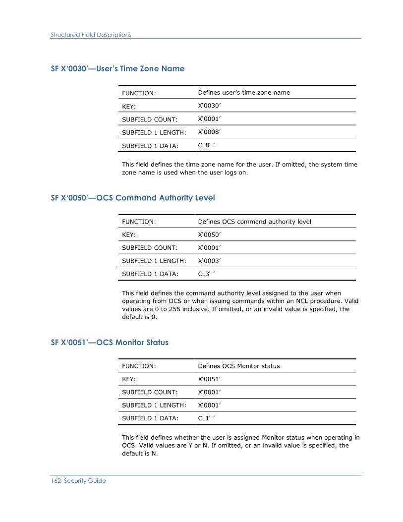
Structured Field Descriptions
162 Security Guide
SF X‘0030’—User’s Time Zone Name
FUNCTION: Defines user’s time zone name
KEY: X‘0030’
SUBFIELD COUNT: X‘0001’
SUBFIELD 1 LENGTH: X‘0008’
SUBFIELD 1 DATA: CL8‘ ’
This field defines the time zone name for the user. If omitted, the system time
zone name is used when the user logs on.
SF X‘0050’—OCS Command Authority Level
FUNCTION: Defines OCS command authority level
KEY: X‘0050’
SUBFIELD COUNT: X‘0001’
SUBFIELD 1 LENGTH: X‘0003’
SUBFIELD 1 DATA: CL3‘ ’
This field defines the command authority level assigned to the user when
operating from OCS or when issuing commands within an NCL procedure. Valid
values are 0 to 255 inclusive. If omitted, or an invalid value is specified, the
default is 0.
SF X‘0051’—OCS Monitor Status
FUNCTION: Defines OCS Monitor status
KEY: X‘0051’
SUBFIELD COUNT: X‘0001’
SUBFIELD 1 LENGTH: X‘0001’
SUBFIELD 1 DATA: CL1‘ ’
This field defines whether the user is assigned Monitor status when operating in
OCS. Valid values are Y or N. If omitted, or an invalid value is specified, the
default is N.
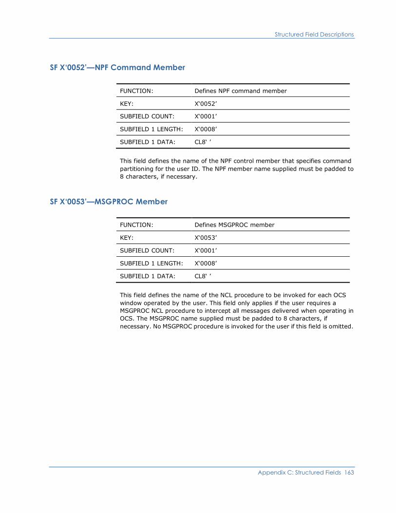
Structured Field Descriptions
Appendix C: Structured Fields 163
SF X‘0052’—NPF Command Member
FUNCTION: Defines NPF command member
KEY: X‘0052’
SUBFIELD COUNT: X‘0001’
SUBFIELD 1 LENGTH: X‘0008’
SUBFIELD 1 DATA: CL8‘ ’
This field defines the name of the NPF control member that specifies command
partitioning for the user ID. The NPF member name supplied must be padded to
8 characters, if necessary.
SF X‘0053’—MSGPROC Member
FUNCTION: Defines MSGPROC member
KEY: X‘0053’
SUBFIELD COUNT: X‘0001’
SUBFIELD 1 LENGTH: X‘0008’
SUBFIELD 1 DATA: CL8‘ ’
This field defines the name of the NCL procedure to be invoked for each OCS
window operated by the user. This field only applies if the user requires a
MSGPROC NCL procedure to intercept all messages delivered when operating in
OCS. The MSGPROC name supplied must be padded to 8 characters, if
necessary. No MSGPROC procedure is invoked for the user if this field is omitted.
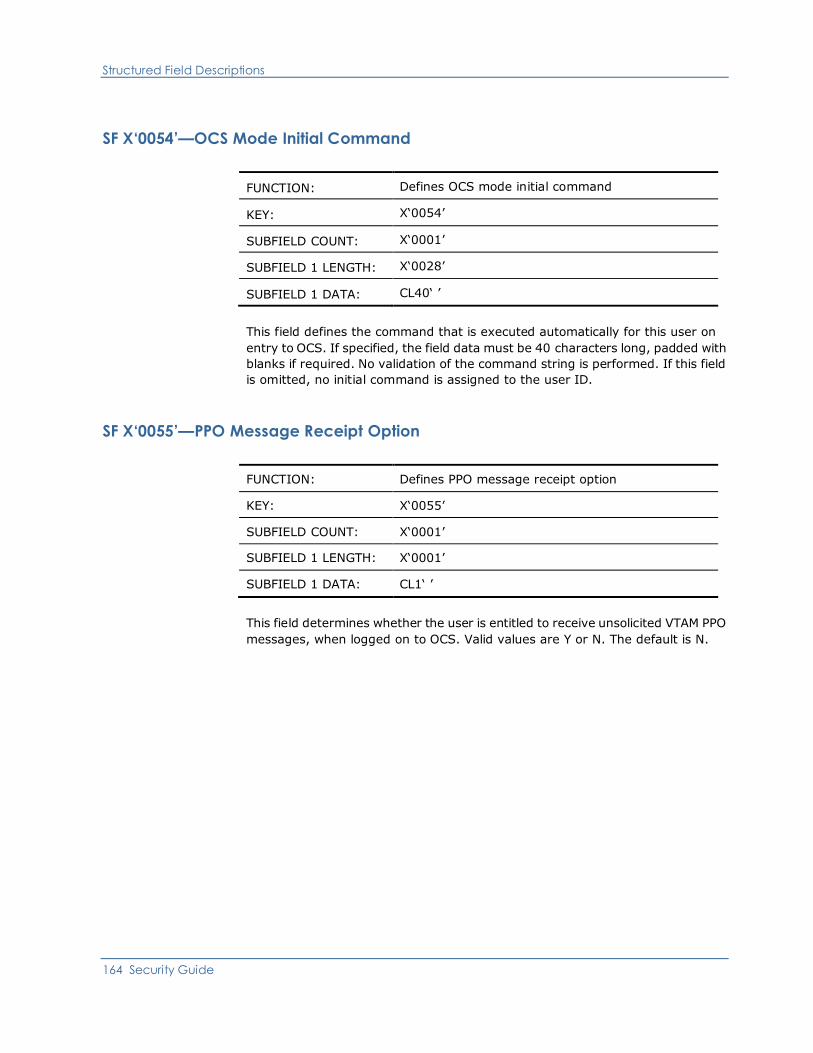
Structured Field Descriptions
164 Security Guide
SF X‘0054’—OCS Mode Initial Command
FUNCTION: Defines OCS mode initial command
KEY: X‘0054’
SUBFIELD COUNT: X‘0001’
SUBFIELD 1 LENGTH: X‘0028’
SUBFIELD 1 DATA: CL40‘ ’
This field defines the command that is executed automatically for this user on
entry to OCS. If specified, the field data must be 40 characters long, padded with
blanks if required. No validation of the command string is performed. If this field
is omitted, no initial command is assigned to the user ID.
SF X‘0055’—PPO Message Receipt Option
FUNCTION: Defines PPO message receipt option
KEY: X‘0055’
SUBFIELD COUNT: X‘0001’
SUBFIELD 1 LENGTH: X‘0001’
SUBFIELD 1 DATA: CL1‘ ’
This field determines whether the user is entitled to receive unsolicited VTAM PPO
messages, when logged on to OCS. Valid values are Y or N. The default is N.

Structured Field Descriptions
Appendix C: Structured Fields 165
SF X‘0056’—PPO Severity Level
FUNCTION: Defines PPO severity level
KEY: X‘0056’
SUBFIELD COUNT: X‘0001’
SUBFIELD 1 LENGTH: X‘0004’
SUBFIELD 1 DATA: CL4‘ ’
This field indicates the severity level of PPO messages to be delivered to this
user. This field only applies if the user is to have unsolicited VTAM PPO messages
delivered when operating in OCS. Valid values are INFO, NORM, WARN, or SER.
If omitted, or an invalid value is specified, the default is NORM.
SF X‘0057’—NPF Message Restriction Option
FUNCTION: Defines NPF message restriction option
KEY: X‘0057’
SUBFIELD COUNT: X‘0002’
SUBFIELD 1 LENGTH: X‘0008’
SUBFIELD 1 DATA: CL8‘ ’
SUBFIELD 2 LENGTH: X‘0001’
SUBFIELD 2 DATA: CL1‘ ’
This field defines the NPF message member that specifies the nodes from which
the user receives unsolicited VTAM PPO messages.
This field has 2 subfields. The first subfield specifies the name of the NPF
member. The second subfield determines whether the user is to receive
undeliverable messages: that is, unsolicited messages that refer to network
resources which are outside the user’s normal NPF restrictions but which cannot
be delivered to any other user. Valid values are Y or N. The default is N.
This field is ignored if the user ID has not been authorized for PPO message
receipt, that is, if the user ID does not have structured field key X‘0055’.
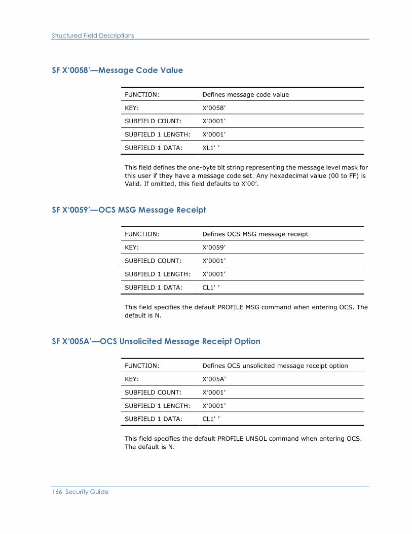
Structured Field Descriptions
166 Security Guide
SF X‘0058’—Message Code Value
FUNCTION: Defines message code value
KEY: X‘0058’
SUBFIELD COUNT: X‘0001’
SUBFIELD 1 LENGTH: X‘0001’
SUBFIELD 1 DATA: XL1‘ ’
This field defines the one-byte bit string representing the message level mask for
this user if they have a message code set. Any hexadecimal value (00 to FF) is
Valid. If omitted, this field defaults to X‘00’.
SF X‘0059’—OCS MSG Message Receipt
FUNCTION: Defines OCS MSG message receipt
KEY: X‘0059’
SUBFIELD COUNT: X‘0001’
SUBFIELD 1 LENGTH: X‘0001’
SUBFIELD 1 DATA: CL1‘ ’
This field specifies the default PROFILE MSG command when entering OCS. The
default is N.
SF X‘005A’—OCS Unsolicited Message Receipt Option
FUNCTION: Defines OCS unsolicited message receipt option
KEY: X‘005A’
SUBFIELD COUNT: X‘0001’
SUBFIELD 1 LENGTH: X‘0001’
SUBFIELD 1 DATA: CL1‘ ’
This field specifies the default PROFILE UNSOL command when entering OCS.
The default is N.
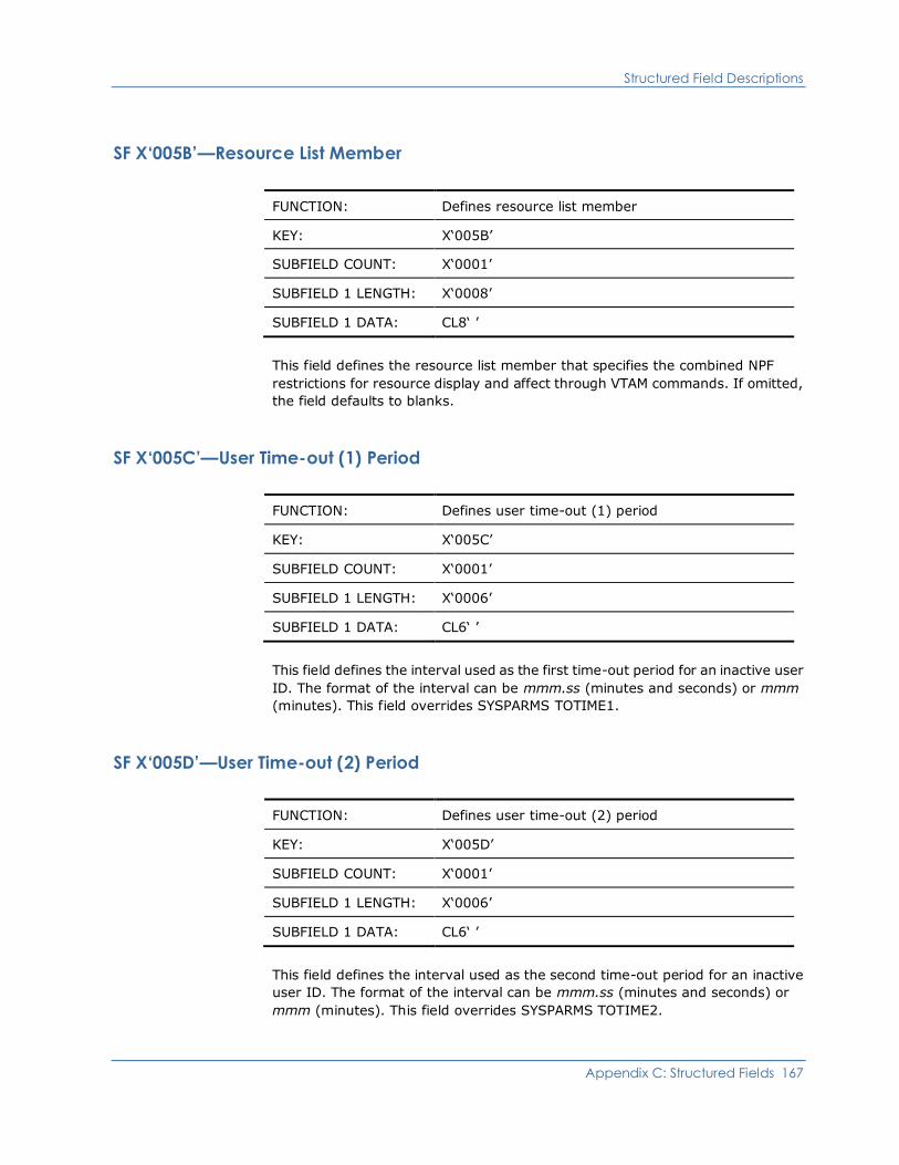
Structured Field Descriptions
Appendix C: Structured Fields 167
SF X‘005B’—Resource List Member
FUNCTION: Defines resource list member
KEY: X‘005B’
SUBFIELD COUNT: X‘0001’
SUBFIELD 1 LENGTH: X‘0008’
SUBFIELD 1 DATA: CL8‘ ’
This field defines the resource list member that specifies the combined NPF
restrictions for resource display and affect through VTAM commands. If omitted,
the field defaults to blanks.
SF X‘005C’—User Time-out (1) Period
FUNCTION: Defines user time-out (1) period
KEY: X‘005C’
SUBFIELD COUNT: X‘0001’
SUBFIELD 1 LENGTH: X‘0006’
SUBFIELD 1 DATA: CL6‘ ’
This field defines the interval used as the first time-out period for an inactive user
ID. The format of the interval can be mmm.ss (minutes and seconds) or mmm
(minutes). This field overrides SYSPARMS TOTIME1.
SF X‘005D’—User Time-out (2) Period
FUNCTION: Defines user time-out (2) period
KEY: X‘005D’
SUBFIELD COUNT: X‘0001’
SUBFIELD 1 LENGTH: X‘0006’
SUBFIELD 1 DATA: CL6‘ ’
This field defines the interval used as the second time-out period for an inactive
user ID. The format of the interval can be mmm.ss (minutes and seconds) or
mmm (minutes). This field overrides SYSPARMS TOTIME2.

Structured Field Descriptions
168 Security Guide
SF X‘005E’—User Time-out (1) Action
FUNCTION: Defines user time-out (1) action
KEY: X‘005E’
SUBFIELD COUNT: X‘0001’
SUBFIELD 1 LENGTH: X‘0028’
SUBFIELD 1 DATA: CL40‘ ’
This field defines the action to be performed when a user ID’s first time-out
interval expires. The action can be any command string, for example, LOCK,
DISC, CANCEL LU=*. These commands have equivalents in the SYSPARMS
time-out actions. A value of NONE can be used to disable the time-out action.
This structured field overrides SYSPARMS TOACT1.
SF X‘005F’—User Time-out (2) Action
FUNCTION: Defines user time-out (2) action
KEY: X‘005F’
SUBFIELD COUNT: X‘0001’
SUBFIELD 1 LENGTH: X‘0028’
SUBFIELD 1 DATA: CL40‘ ’
This field defines the action to be performed when a user ID’s second time-out
interval expires. The action can be any command string, for example, LOCK,
DISC, CANCEL LU=*. These commands have equivalents in the SYSPARMS
time-out actions. A value of NONE can be used to disable the time-out action.
This structured field overrides SYSPARMS TOACT2.

Structured Field Descriptions
Appendix C: Structured Fields 169
SF X‘0060’—User’s APPC Access Key
FUNCTION: Defines user’s APPC access key
KEY: X‘0060’
SUBFIELD COUNT: X‘0001’
SUBFIELD 1 LENGTH: X‘0002’
SUBFIELD 1 DATA: BL2‘00’
This field defines the user’s APPC access key. The mask contains 16 bits,
representing, from right to left, the access codes 1 to 16. These are used,
together with the APPC lock to allow this user to act on behalf of another user,
without supplying the target user’s password.
A 16-bit key indicating the APPC access key must be specified. If omitted, the
field defaults to zeroes.
SF X‘0061’—User’s APPC Access Lock
FUNCTION: Defines user’s APPC access lock
KEY: X‘0061’
SUBFIELD COUNT: X‘0001’
SUBFIELD 1 LENGTH: X‘0002’
SUBFIELD 1 DATA: BL2‘00’
This field defines the user’s APPC access lock. The key contains 16 bits,
representing, from right to left, the access codes 1 to 16. These are used,
together with the APPC key, to allow another user to act on behalf of this user,
without supplying this user’s password. If omitted, the field defaults to zeroes.
Valid value is a 16-bit mask indicating the APPC access lock.
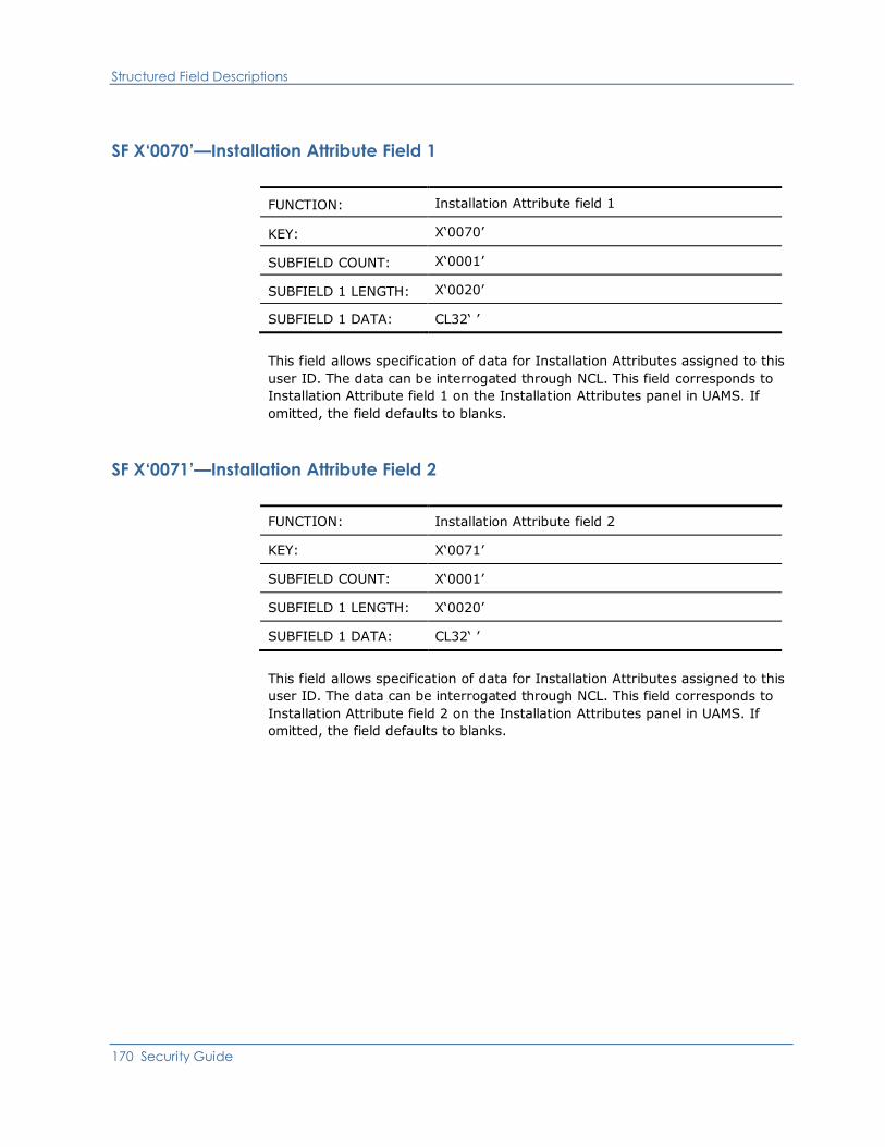
Structured Field Descriptions
170 Security Guide
SF X‘0070’—Installation Attribute Field 1
FUNCTION: Installation Attribute field 1
KEY: X‘0070’
SUBFIELD COUNT: X‘0001’
SUBFIELD 1 LENGTH: X‘0020’
SUBFIELD 1 DATA: CL32‘ ’
This field allows specification of data for Installation Attributes assigned to this
user ID. The data can be interrogated through NCL. This field corresponds to
Installation Attribute field 1 on the Installation Attributes panel in UAMS. If
omitted, the field defaults to blanks.
SF X‘0071’—Installation Attribute Field 2
FUNCTION: Installation Attribute field 2
KEY: X‘0071’
SUBFIELD COUNT: X‘0001’
SUBFIELD 1 LENGTH: X‘0020’
SUBFIELD 1 DATA: CL32‘ ’
This field allows specification of data for Installation Attributes assigned to this
user ID. The data can be interrogated through NCL. This field corresponds to
Installation Attribute field 2 on the Installation Attributes panel in UAMS. If
omitted, the field defaults to blanks.
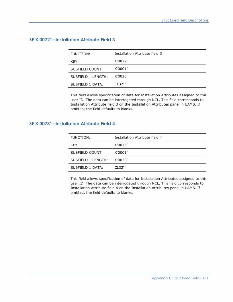
Structured Field Descriptions
Appendix C: Structured Fields 171
SF X‘0072’—Installation Attribute Field 3
FUNCTION: Installation Attribute field 3
KEY: X‘0072’
SUBFIELD COUNT: X‘0001’
SUBFIELD 1 LENGTH: X‘0020’
SUBFIELD 1 DATA: CL32‘ ’
This field allows specification of data for Installation Attributes assigned to this
user ID. The data can be interrogated through NCL. This field corresponds to
Installation Attribute field 3 on the Installation Attributes panel in UAMS. If
omitted, the field defaults to blanks.
SF X‘0073’—Installation Attribute Field 4
FUNCTION: Installation Attribute field 4
KEY: X‘0073’
SUBFIELD COUNT: X‘0001’
SUBFIELD 1 LENGTH: X‘0020’
SUBFIELD 1 DATA: CL32‘ ’
This field allows specification of data for Installation Attributes assigned to this
user ID. The data can be interrogated through NCL. This field corresponds to
Installation Attribute field 4 on the Installation Attributes panel in UAMS. If
omitted, the field defaults to blanks.

Structured Field Descriptions
172 Security Guide
SF X‘0074’—Installation Attribute Field 5
FUNCTION: Installation Attribute field 5
KEY: X‘0074’
SUBFIELD COUNT: X‘0001’
SUBFIELD 1 LENGTH: X‘0020’
SUBFIELD 1 DATA: CL32‘ ’
This field allows specification of data for Installation Attributes assigned to this
user ID. The data can be interrogated through NCL. This field corresponds to
Installation Attribute field 5 on the Installation Attributes panel in UAMS. If
omitted, the field defaults to blanks.
SF X‘0075’—Installation Attribute Field 6
FUNCTION: Installation Attribute field 6
KEY: X‘0075’
SUBFIELD COUNT: X‘0001’
SUBFIELD 1 LENGTH: X‘0020’
SUBFIELD 1 DATA: CL32‘ ’
This field allows specification of data for Installation Attributes assigned to this
user ID. The data can be interrogated through NCL. This field corresponds to
Installation Attribute field 6 on the Installation Attributes panel in UAMS. If
omitted, the field defaults to blanks.
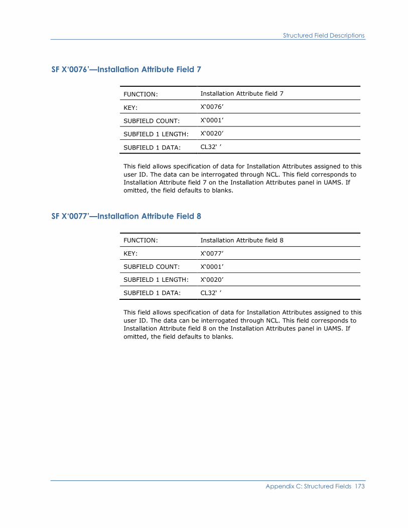
Structured Field Descriptions
Appendix C: Structured Fields 173
SF X‘0076’—Installation Attribute Field 7
FUNCTION: Installation Attribute field 7
KEY: X‘0076’
SUBFIELD COUNT: X‘0001’
SUBFIELD 1 LENGTH: X‘0020’
SUBFIELD 1 DATA: CL32‘ ’
This field allows specification of data for Installation Attributes assigned to this
user ID. The data can be interrogated through NCL. This field corresponds to
Installation Attribute field 7 on the Installation Attributes panel in UAMS. If
omitted, the field defaults to blanks.
SF X‘0077’—Installation Attribute Field 8
FUNCTION: Installation Attribute field 8
KEY: X‘0077’
SUBFIELD COUNT: X‘0001’
SUBFIELD 1 LENGTH: X‘0020’
SUBFIELD 1 DATA: CL32‘ ’
This field allows specification of data for Installation Attributes assigned to this
user ID. The data can be interrogated through NCL. This field corresponds to
Installation Attribute field 8 on the Installation Attributes panel in UAMS. If
omitted, the field defaults to blanks.

Structured Field Descriptions
174 Security Guide
SF X‘0078’—Installation Attribute Field 9
FUNCTION: Installation Attribute field 9
KEY: X‘0078’
SUBFIELD COUNT: X‘0001’
SUBFIELD 1 LENGTH: X‘0020’
SUBFIELD 1 DATA: CL32‘ ’
This field allows specification of data for Installation Attributes assigned to this
user ID. The data can be interrogated through NCL. This field corresponds to
Installation Attribute field 9 on the Installation Attributes panel in UAMS. If
omitted, the field defaults to blanks.
SF X‘0079’—Installation Attribute Field 10
FUNCTION: Installation Attribute field 10
KEY: X‘0079’
SUBFIELD COUNT: X‘0001’
SUBFIELD 1 LENGTH: X‘0020’
SUBFIELD 1 DATA: CL32‘ ’
This field allows specification of data for Installation Attributes assigned to this
user ID. The data can be interrogated through NCL. This field corresponds to
Installation Attribute field 10 on the Installation Attributes panel in UAMS. If
omitted, the field defaults to blanks.
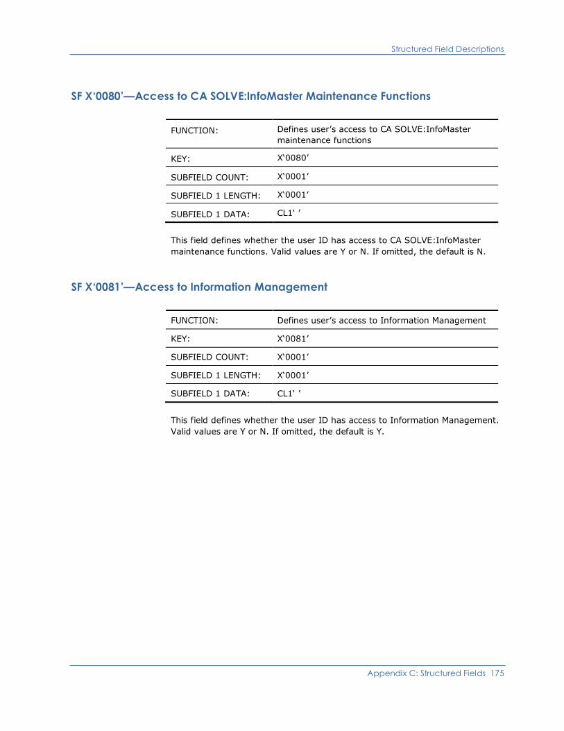
Structured Field Descriptions
Appendix C: Structured Fields 175
SF X‘0080’—Access to CA SOLVE:InfoMaster Maintenance Functions
FUNCTION: Defines user’s access to CA SOLVE:InfoMaster
maintenance functions
KEY: X‘0080’
SUBFIELD COUNT: X‘0001’
SUBFIELD 1 LENGTH: X‘0001’
SUBFIELD 1 DATA: CL1‘ ’
This field defines whether the user ID has access to CA SOLVE:InfoMaster
maintenance functions. Valid values are Y or N. If omitted, the default is N.
SF X‘0081’—Access to Information Management
FUNCTION: Defines user’s access to Information Management
KEY: X‘0081’
SUBFIELD COUNT: X‘0001’
SUBFIELD 1 LENGTH: X‘0001’
SUBFIELD 1 DATA: CL1‘ ’
This field defines whether the user ID has access to Information Management.
Valid values are Y or N. If omitted, the default is Y.
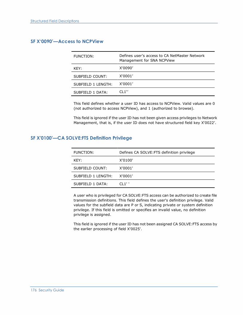
Structured Field Descriptions
176 Security Guide
SF X‘0090’—Access to NCPView
FUNCTION: Defines user’s access to CA NetMaster Network
Management for SNA NCPView
KEY: X‘0090’
SUBFIELD COUNT: X‘0001’
SUBFIELD 1 LENGTH: X‘0001’
SUBFIELD 1 DATA: CL1‘’
This field defines whether a user ID has access to NCPView. Valid values are 0
(not authorized to access NCPView), and 1 (authorized to browse).
This field is ignored if the user ID has not been given access privileges to Network
Management, that is, if the user ID does not have structured field key X‘0022’.
SF X'0100'—CA SOLVE:FTS Definition Privilege
FUNCTION: Defines CA SOLVE:FTS definition privilege
KEY: X'0100'
SUBFIELD COUNT: X'0001'
SUBFIELD 1 LENGTH: X'0001'
SUBFIELD 1 DATA: CL1' '
A user who is privileged for CA SOLVE:FTS access can be authorized to create file
transmission definitions. This field defines the user's definition privilege. Valid
values for the subfield data are P or S, indicating private or system definition
privilege. If this field is omitted or specifies an invalid value, no definition
privilege is assigned.
This field is ignored if the user ID has not been assigned CA SOLVE:FTS access by
the earlier processing of field X'0025'.
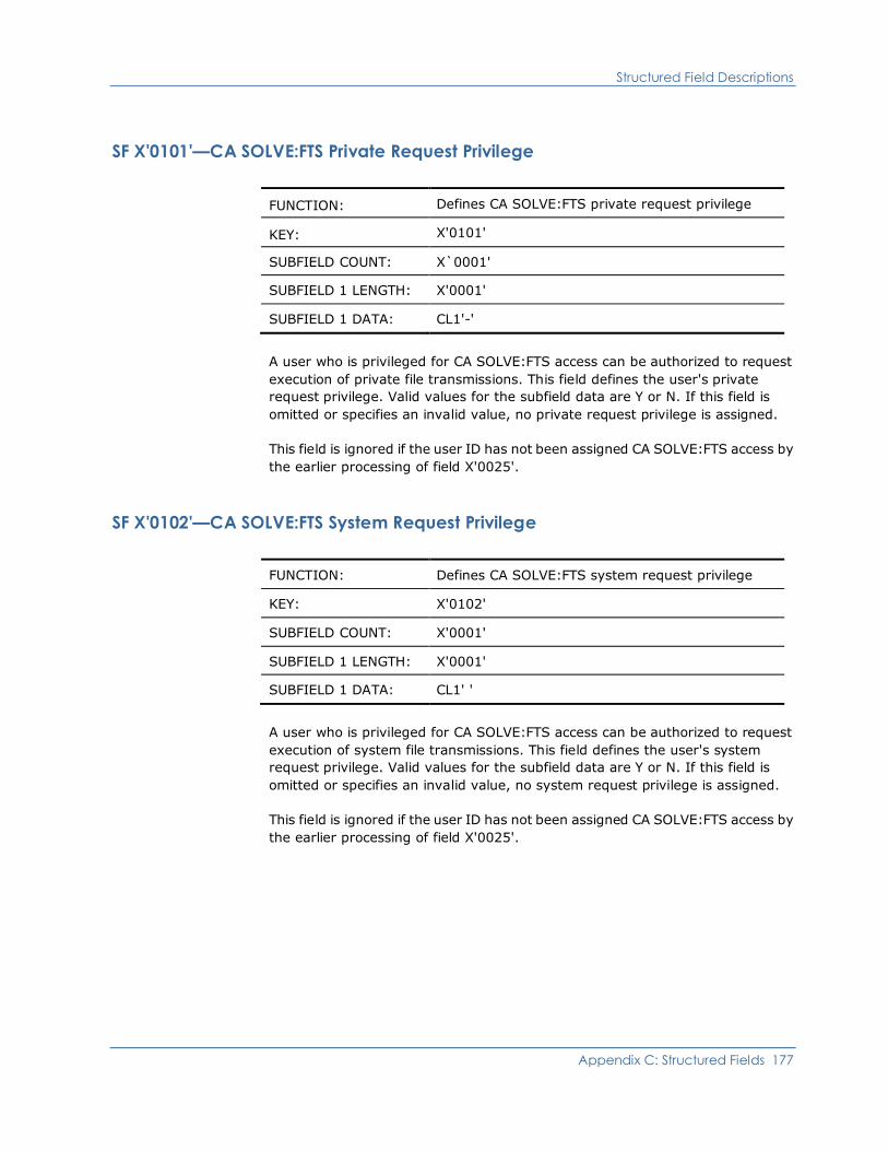
Structured Field Descriptions
Appendix C: Structured Fields 177
SF X'0101'—CA SOLVE:FTS Private Request Privilege
FUNCTION: Defines CA SOLVE:FTS private request privilege
KEY: X'0101'
SUBFIELD COUNT: X`0001'
SUBFIELD 1 LENGTH: X'0001'
SUBFIELD 1 DATA: CL1'-'
A user who is privileged for CA SOLVE:FTS access can be authorized to request
execution of private file transmissions. This field defines the user's private
request privilege. Valid values for the subfield data are Y or N. If this field is
omitted or specifies an invalid value, no private request privilege is assigned.
This field is ignored if the user ID has not been assigned CA SOLVE:FTS access by
the earlier processing of field X'0025'.
SF X'0102'—CA SOLVE:FTS System Request Privilege
FUNCTION: Defines CA SOLVE:FTS system request privilege
KEY: X'0102'
SUBFIELD COUNT: X'0001'
SUBFIELD 1 LENGTH: X'0001'
SUBFIELD 1 DATA: CL1' '
A user who is privileged for CA SOLVE:FTS access can be authorized to request
execution of system file transmissions. This field defines the user's system
request privilege. Valid values for the subfield data are Y or N. If this field is
omitted or specifies an invalid value, no system request privilege is assigned.
This field is ignored if the user ID has not been assigned CA SOLVE:FTS access by
the earlier processing of field X'0025'.

Structured Field Descriptions
178 Security Guide
SF X'0103'—CA SOLVE:FTS Private Control Privilege
FUNCTION: Defines CA SOLVE:FTS private control privilege
KEY: X'0103'
SUBFIELD COUNT: X'0001'
SUBFIELD 1 LENGTH: X'0001'
SUBFIELD 1 DATA: CL1' '
A user who is privileged for CA SOLVE:FTS access can be authorized to supervise
(control) execution of private file transmissions. This field defines the user's
private control privilege. Valid values for the subfield data are Y or N. If this field
is omitted or specifies an invalid value, no private control privilege is assigned.
This field is ignored if the user ID has not been assigned CA SOLVE:FTS access by
the earlier processing of field X'0025'.
SF X'0104'—CA SOLVE:FTS System Control Privilege
FUNCTION: Defines CA SOLVE:FTS system control privilege
KEY: X'0104'
SUBFIELD COUNT: X'0001'
SUBFIELD 1 LENGTH: X'0001'
SUBFIELD 1 DATA: CL1' '
A user who is privileged for CA SOLVE:FTS access can be authorized to supervise
(control) execution of system file transmissions. This field defines the user's
system control privilege. Valid values for the subfield data are Y or N. If this field
is omitted or specifies an invalid value, no system control privilege is assigned.
This field is ignored if the user ID has not been assigned CA SOLVE:FTS access by
the earlier processing-of field X'0025'.
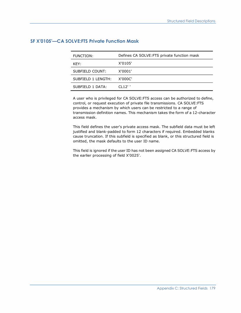
Structured Field Descriptions
Appendix C: Structured Fields 179
SF X'0105'—CA SOLVE:FTS Private Function Mask
FUNCTION: Defines CA SOLVE:FTS private function mask
KEY: X'0105'
SUBFIELD COUNT: X'0001'
SUBFIELD 1 LENGTH: X'000C'
SUBFIELD 1 DATA: CL12' '
A user who is privileged for CA SOLVE:FTS access can be authorized to define,
control, or request execution of private file transmissions. CA SOLVE:FTS
provides a mechanism by which users can be restricted to a range of
transmission definition names. This mechanism takes the form of a 12-character
access mask.
This field defines the user's private access mask. The subfield data must be left
justified and blank-padded to form 12 characters if required. Embedded blanks
cause truncation. If this subfield is specified as blank, or this structured field is
omitted, the mask defaults to the user ID name.
This field is ignored if the user ID has not been assigned CA SOLVE:FTS access by
the earlier processing of field X'0025'.
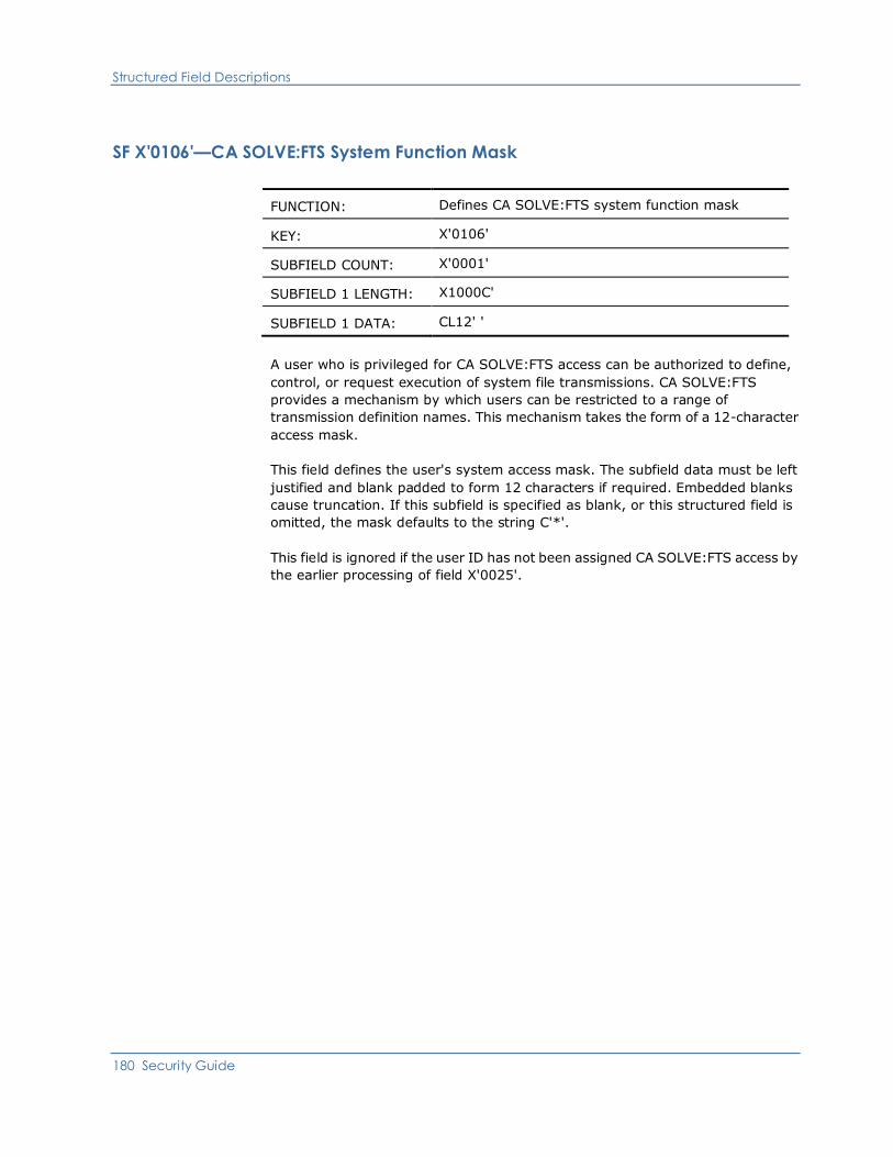
Structured Field Descriptions
180 Security Guide
SF X'0106'—CA SOLVE:FTS System Function Mask
FUNCTION: Defines CA SOLVE:FTS system function mask
KEY: X'0106'
SUBFIELD COUNT: X'0001'
SUBFIELD 1 LENGTH: X1000C'
SUBFIELD 1 DATA: CL12' '
A user who is privileged for CA SOLVE:FTS access can be authorized to define,
control, or request execution of system file transmissions. CA SOLVE:FTS
provides a mechanism by which users can be restricted to a range of
transmission definition names. This mechanism takes the form of a 12-character
access mask.
This field defines the user's system access mask. The subfield data must be left
justified and blank padded to form 12 characters if required. Embedded blanks
cause truncation. If this subfield is specified as blank, or this structured field is
omitted, the mask defaults to the string C'*'.
This field is ignored if the user ID has not been assigned CA SOLVE:FTS access by
the earlier processing of field X'0025'.

Structured Field Descriptions
Appendix C: Structured Fields 181
SF X‘0150’—NEWS Reset Privilege
FUNCTION: Defines CA NetMaster Network Management for SNA
NEWS reset privilege
KEY: X‘0150’
SUBFIELD COUNT: X‘0001’
SUBFIELD 1 LENGTH: X‘0001’
SUBFIELD 1 DATA: CL1‘ ’
A user who has NEWS access can be authorized to reset (delete) database
records. Valid values are Y or N. The default is N.
Specifying Y in this field enables the user to reset statistics within the Summary
Statistics Subsystem, and results in the &NEWSRSET system variable being set
to YES when tested within an NCL procedure invoked by the user.
This field is ignored if the user ID has not been given access privileges to Network
Management and to NEWS, that is, if the user ID does not have structured field
keys X‘0022’ and X‘0026’.
SF X‘0151’—NTS Access Privilege
FUNCTION: Defines CA NetMaster Network Management for SNA
NTS access privilege
KEY: X‘0151’
SUBFIELD COUNT: X‘0001’
SUBFIELD 1 LENGTH: X‘0001’
SUBFIELD 1 DATA: CL1‘ ’
This field defines whether a user can access the facilities of the Network Tracking
System. Valid values are Y or N. The default is N.
This field is ignored if NTS is not configured on your system.
This field is ignored if the user ID has not been given access privileges to Network
Management, that is, if the user ID does not have structured field key X‘0022’.
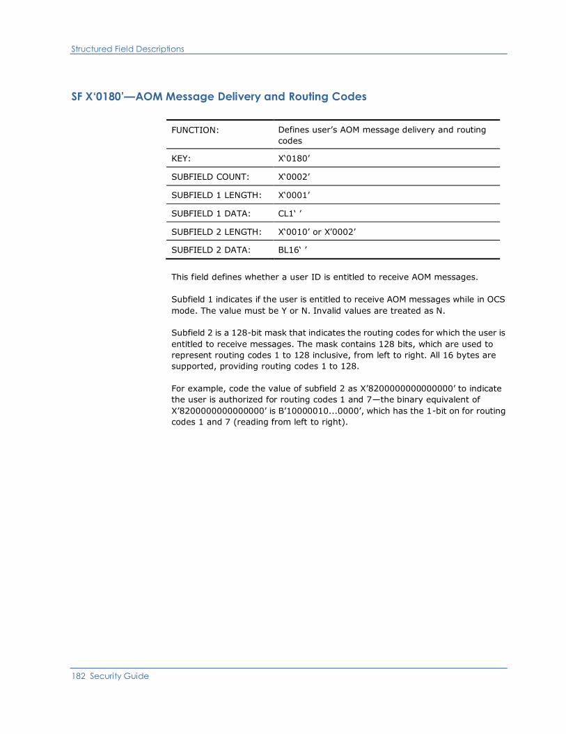
Structured Field Descriptions
182 Security Guide
SF X‘0180’—AOM Message Delivery and Routing Codes
FUNCTION: Defines user’s AOM message delivery and routing
codes
KEY: X‘0180’
SUBFIELD COUNT: X‘0002’
SUBFIELD 1 LENGTH: X‘0001’
SUBFIELD 1 DATA: CL1‘ ’
SUBFIELD 2 LENGTH: X‘0010’ or X’0002’
SUBFIELD 2 DATA: BL16‘ ’
This field defines whether a user ID is entitled to receive AOM messages.
Subfield 1 indicates if the user is entitled to receive AOM messages while in OCS
mode. The value must be Y or N. Invalid values are treated as N.
Subfield 2 is a 128-bit mask that indicates the routing codes for which the user is
entitled to receive messages. The mask contains 128 bits, which are used to
represent routing codes 1 to 128 inclusive, from left to right. All 16 bytes are
supported, providing routing codes 1 to 128.
For example, code the value of subfield 2 as X’8200000000000000’ to indicate
the user is authorized for routing codes 1 and 7—the binary equivalent of
X’8200000000000000’ is B’10000010...0000’, which has the 1-bit on for routing
codes 1 and 7 (reading from left to right).
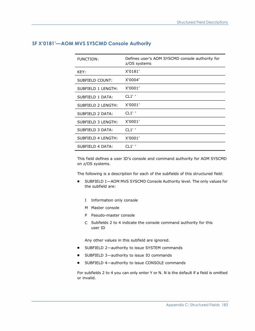
Structured Field Descriptions
Appendix C: Structured Fields 183
SF X‘0181’—AOM MVS SYSCMD Console Authority
FUNCTION: Defines user’s AOM SYSCMD console authority for
z/OS systems
KEY: X‘0181’
SUBFIELD COUNT: X‘0004’
SUBFIELD 1 LENGTH: X‘0001’
SUBFIELD 1 DATA: CL1‘ ’
SUBFIELD 2 LENGTH: X‘0001’
SUBFIELD 2 DATA: CL1‘ ’
SUBFIELD 3 LENGTH: X‘0001’
SUBFIELD 3 DATA: CL1‘ ’
SUBFIELD 4 LENGTH: X‘0001’
SUBFIELD 4 DATA: CL1‘ ’
This field defines a user ID’s console and command authority for AOM SYSCMD
on z/OS systems.
The following is a description for each of the subfields of this structured field:
■ SUBFIELD 1—AOM MVS SYSCMD Console Authority level. The only values for
the subfield are:
I Information only console
M Master console
P Pseudo-master console
C Subfields 2 to 4 indicate the console command authority for this
user ID
Any other values in this subfield are ignored.
■ SUBFIELD 2—authority to issue SYSTEM commands
■ SUBFIELD 3—authority to issue IO commands
■ SUBFIELD 4—authority to issue CONSOLE commands
For subfields 2 to 4 you can only enter Y or N. N is the default if a field is omitted
or invalid.
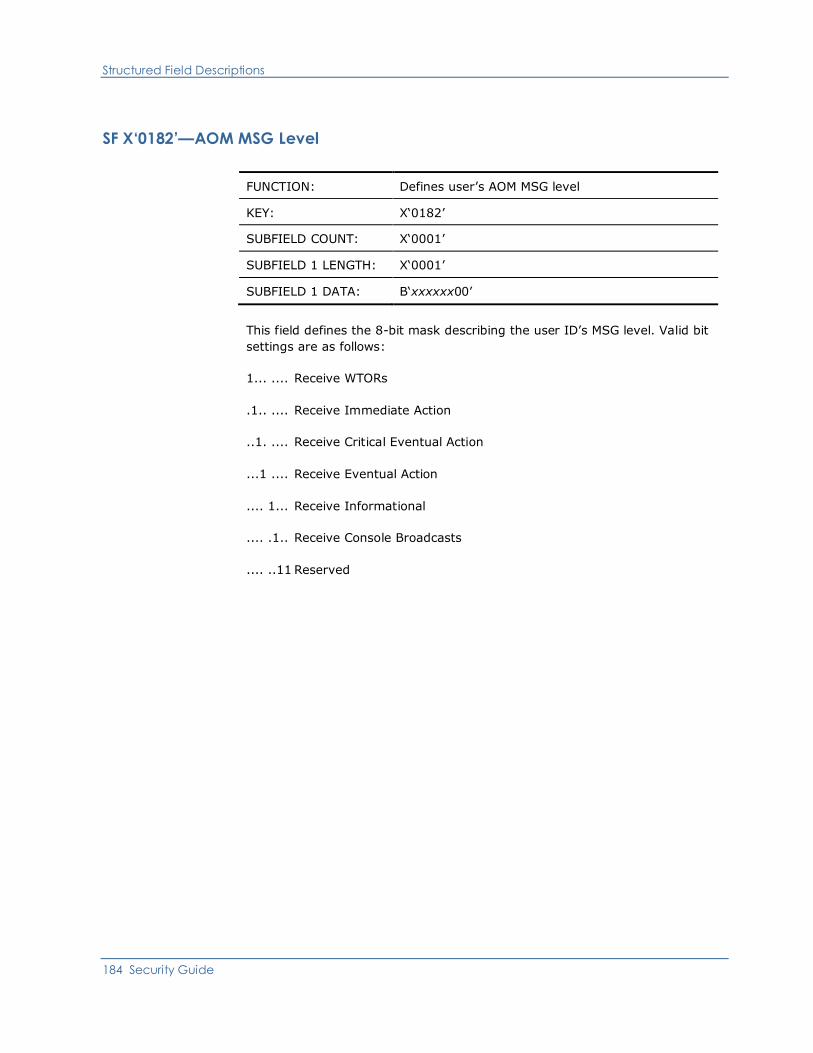
Structured Field Descriptions
184 Security Guide
SF X‘0182’—AOM MSG Level
FUNCTION: Defines user’s AOM MSG level
KEY: X‘0182’
SUBFIELD COUNT: X‘0001’
SUBFIELD 1 LENGTH: X‘0001’
SUBFIELD 1 DATA: B‘xxxxxx00’
This field defines the 8-bit mask describing the user ID’s MSG level. Valid bit
settings are as follows:
1... .... Receive WTORs
.1.. .... Receive Immediate Action
..1. .... Receive Critical Eventual Action
...1 .... Receive Eventual Action
.... 1... Receive Informational
.... .1.. Receive Console Broadcasts
.... ..11 Reserved

Structured Field Descriptions
Appendix C: Structured Fields 185
SF X‘0183’—AOM z/VM SYSCMD Authority
FUNCTION: Defines user’s AOM SYSCMD authority for z/VM
systems
KEY: X‘0183’
SUBFIELD COUNT: X‘0002’
SUBFIELD 1 LENGTH: X‘0001’
SUBFIELD 1 DATA: CL1‘ ’
SUBFIELD 2 LENGTH: X‘0001’
SUBFIELD 2 DATA: CL1‘ ’
This field defines a user ID’s AOM SYSCMD authority on z/VM systems.
The first subfield controls whether the user is authorized to issue SYSCMD
DEST=PROP. Valid values are Y or N. Invalid values are treated as N.
The second subfield controls whether the user is authorized to issue SYSCMD
DEST=GCS. Valid values are Y or N. Invalid values are treated as N.
This structured field is ignored by AOM on z/OS systems. It allows shared
security profile for z/OS and z/VM systems.
SF X‘0185’—AOM VOS3/JSS4 SYSCMD Command Authority
FUNCTION: Defines user’s AOM SYSCMD command authority for
VOS3/JSS4 systems
KEY: X‘0185’
SUBFIELD COUNT: X‘000’
SUBFIELD 1 LENGTH: X‘0001’ or X‘0002’
SUBFIELD 1 DATA: CL1‘n ’ or CL2‘nn’
This field provides the VOS3/JSS4 command authority level for SYSCMD. It is
ignored by AOM when not in a VOS3/JSS4 environment. This allows shared
security profile across all systems.
Note: The UAMS panel that displays AOM SYSCMD authority always shows this
field and allows update. The field is not used by SYSCMD unless the system is
actually VOS3/JSS4.

Structured Field Descriptions
186 Security Guide
SF X‘0200’—MAI-FS Privilege Class
FUNCTION: Defines user’s CA SOLVE:Access Session
Management MAI-FS privilege class
KEY: X‘0200’
SUBFIELD COUNT: X‘0001’
SUBFIELD 1 LENGTH: X‘0001’
SUBFIELD 1 DATA: CL1‘ ’
This field defines the MAI-FS privilege class for the user ID. Valid values are A, B,
C, or D. If this field is omitted, the default is D (at user logon).
SF X‘0201’—MAI-FS Model User ID
FUNCTION: Defines user’s SOLVE:Access Session Management
MAI-FS model user ID
KEY: X‘0201’
SUBFIELD COUNT: X‘0001’
SUBFIELD 1 LENGTH: X‘0008’
SUBFIELD 1 DATA: CL8‘ ’
This field supplies an MAI-FS user ID on whose stored session definitions this
user ID is to be modeled. If this field is omitted, the field is left blank.
SF X‘0202’—MAI-FS A and E Command Capability
FUNCTION: Defines user’s CA SOLVE:Access Session
Management MAI-FS A and E command capability
KEY: X‘0202’
SUBFIELD COUNT: X‘0001’
SUBFIELD 1 LENGTH: X‘0001’
SUBFIELD 1 DATA: CL1‘ ’
This field specifies whether a user is entitled to use the A and E commands. Valid
values are Y and N. If this field is omitted, the default is N.

Structured Field Descriptions
Appendix C: Structured Fields 187
SF X‘0203’—MAI-FS Active Session Limit
FUNCTION: Defines user’s CA SOLVE:Access Session
Management MAI-FS Active Session Limit
KEY: X‘0203’
SUBFIELD COUNT: X‘0001’
SUBFIELD 1 LENGTH: X‘0001’
SUBFIELD 1 DATA: CL3‘ ’
This field determines whether a user is limited in the number of sessions that
they can have active at the same time. Possible values are 0–255. A value of 0
indicates no limit applies. This is the default when this field is omitted.
SF X‘0500’—PSM Primary Menu Access
FUNCTION: Defines user’s PSM primary menu access
KEY: X‘0500’
SUBFIELD COUNT: X‘0001’
SUBFIELD 1 LENGTH: X‘0001’
SUBFIELD 1 DATA: CL1‘ ’
This field indicates whether the user is authorized to access the PSM : Primary
Menu. Valid values are 0 (not authorized) and 1 (authorized). If this field is
omitted, the default is 1 (authorized).

Structured Field Descriptions
188 Security Guide
SF X‘0501’—PSM Maintenance Access
FUNCTION: Defines user’s PSM maintenance access
KEY: X‘0501’
SUBFIELD COUNT: X‘0001’
SUBFIELD 1 LENGTH: X‘0001’
SUBFIELD 1 DATA: CL1‘ ’
This field defines the level of access a user has to PSM printer, form, and setup
definitions, and to default printer assignment. Valid values are 0 (not
authorized), 1 (browse access only), 2 (browse, add, and update access), and 3
(browse, add, update, and delete access). If this field is omitted, the default is 1
(browse).
SF X‘0502’—PSM Administration Access
FUNCTION: Defines user’s PSM administration access
KEY: X‘0502’
SUBFIELD COUNT: X‘0001’
SUBFIELD 1 LENGTH: X‘0001’
SUBFIELD 1 DATA: CL1‘ ’
This field defines the level of access a user has to PSM administration functions.
Valid values are 0 (not authorized), 1 (browse, and update default definitions), 2
(browse and update default definitions, and clear the spool). If this field is
omitted, the default is 0 (not authorized).
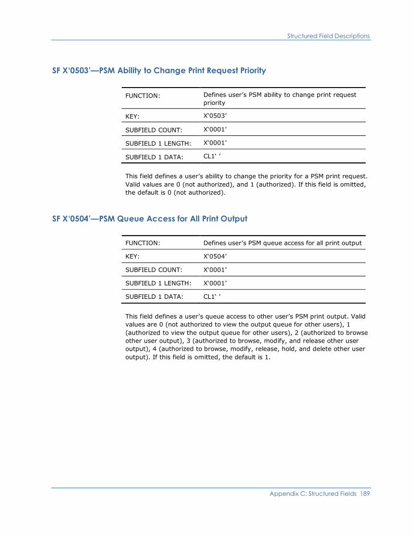
Structured Field Descriptions
Appendix C: Structured Fields 189
SF X‘0503’—PSM Ability to Change Print Request Priority
FUNCTION: Defines user’s PSM ability to change print request
priority
KEY: X‘0503’
SUBFIELD COUNT: X‘0001’
SUBFIELD 1 LENGTH: X‘0001’
SUBFIELD 1 DATA: CL1‘ ’
This field defines a user’s ability to change the priority for a PSM print request.
Valid values are 0 (not authorized), and 1 (authorized). If this field is omitted,
the default is 0 (not authorized).
SF X‘0504’—PSM Queue Access for All Print Output
FUNCTION: Defines user’s PSM queue access for all print output
KEY: X‘0504’
SUBFIELD COUNT: X‘0001’
SUBFIELD 1 LENGTH: X‘0001’
SUBFIELD 1 DATA: CL1‘ ’
This field defines a user’s queue access to other user’s PSM print output. Valid
values are 0 (not authorized to view the output queue for other users), 1
(authorized to view the output queue for other users), 2 (authorized to browse
other user output), 3 (authorized to browse, modify, and release other user
output), 4 (authorized to browse, modify, release, hold, and delete other user
output). If this field is omitted, the default is 1.
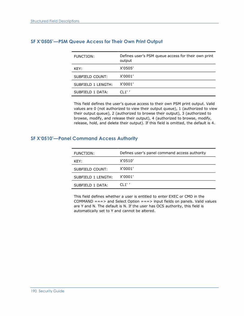
Structured Field Descriptions
190 Security Guide
SF X‘0505’—PSM Queue Access for Their Own Print Output
FUNCTION: Defines user’s PSM queue access for their own print
output
KEY: X‘0505’
SUBFIELD COUNT: X‘0001’
SUBFIELD 1 LENGTH: X‘0001’
SUBFIELD 1 DATA: CL1‘ ’
This field defines the user’s queue access to their own PSM print output. Valid
values are 0 (not authorized to view their output queue), 1 (authorized to view
their output queue), 2 (authorized to browse their output), 3 (authorized to
browse, modify, and release their output), 4 (authorized to browse, modify,
release, hold, and delete their output). If this field is omitted, the default is 4.
SF X‘0510’—Panel Command Access Authority
FUNCTION: Defines user’s panel command access authority
KEY: X‘0510’
SUBFIELD COUNT: X‘0001’
SUBFIELD 1 LENGTH: X‘0001’
SUBFIELD 1 DATA: CL1‘ ’
This field defines whether a user is entitled to enter EXEC or CMD in the
COMMAND ===> and Select Option ===> input fields on panels. Valid values
are Y and N. The default is N. If the user has OCS authority, this field is
automatically set to Y and cannot be altered.
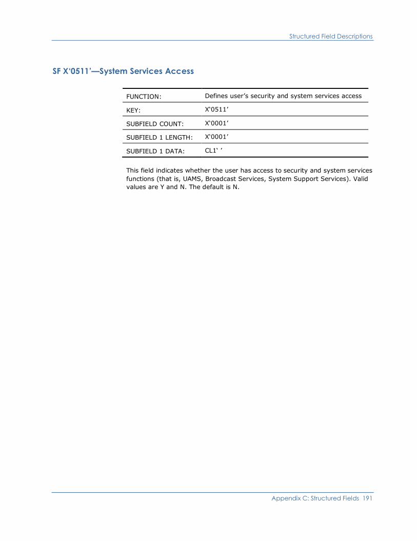
Structured Field Descriptions
Appendix C: Structured Fields 191
SF X‘0511’—System Services Access
FUNCTION: Defines user’s security and system services access
KEY: X‘0511’
SUBFIELD COUNT: X‘0001’
SUBFIELD 1 LENGTH: X‘0001’
SUBFIELD 1 DATA: CL1‘ ’
This field indicates whether the user has access to security and system services
functions (that is, UAMS, Broadcast Services, System Support Services). Valid
values are Y and N. The default is N.

Structured Field Descriptions
192 Security Guide
SF X‘0520’—Notification Details (First Rule)
FUNCTION: Defines user’s notification details (first rule)
KEY: X‘0520’
SUBFIELD COUNT: X‘0008’
SUBFIELD 1 LENGTH: X‘0008’
SUBFIELD 1 DATA: CL8‘ ’
SUBFIELD 2 LENGTH: X‘0004’
SUBFIELD 2 DATA: CL4‘ ’
SUBFIELD 3 LENGTH: X‘0007’
SUBFIELD 3 DATA: CL7‘ ’
SUBFIELD 4 LENGTH: X‘0004’
SUBFIELD 4 DATA: CL4‘ ’
SUBFIELD 5 LENGTH: X‘0004’
SUBFIELD 5 DATA: CL4‘ ’
SUBFIELD 6 LENGTH: X‘0020’
SUBFIELD 6 DATA: CL32‘ ’
SUBFIELD 7 LENGTH: X‘0008’
SUBFIELD 7 DATA: CL8‘ ’
SUBFIELD 8 LENGTH: X‘0040’
SUBFIELD 8 DATA: CL64‘ ’
This field defines the mode or method by which the user wishes to be notified of
an event that the user has been nominated to receive. These notification details
are used by various applications. Broadcast services also supports the use of the
UAMS Notification Details when sending a broadcast to a specific user via the N
option.

Structured Field Descriptions
Appendix C: Structured Fields 193
This structured field has multiple subfields containing the following information:
SUBFIELD 1—Notification Mode
SUBFIELD 2—Notification Domain
SUBFIELD 3—Day of Notification
SUBFIELD 4—Low Time
SUBFIELD 5—High Time
SUBFIELD 6—User ID
SUBFIELD 7—Exit Name
SUBFIELD 8—Parameters
If omitted, the fields are left blank.
SF X‘0521’—Notification Details (Second Rule)
FUNCTION: Defines user’s notification details (second rule)
KEY: X‘0521’
SUBFIELD COUNT: X‘0008’
SUBFIELD 1 LENGTH: X‘0008’
SUBFIELD 1 DATA: CL8‘ ’
SUBFIELD 2 LENGTH: X‘0004’
SUBFIELD 2 DATA: CL4‘ ’
SUBFIELD 3 LENGTH: X‘0007’
SUBFIELD 3 DATA: CL7‘ ’
SUBFIELD 4 LENGTH: X‘0004’
SUBFIELD 4 DATA: CL4‘ ’
SUBFIELD 5 LENGTH: X‘0004’
SUBFIELD 5 DATA: CL4‘ ’
SUBFIELD 6 LENGTH: X‘0020’
SUBFIELD 6 DATA: CL32‘ ’
SUBFIELD 7 LENGTH: X‘0008’
SUBFIELD 7 DATA: CL8‘ ’
SUBFIELD 8 LENGTH: X‘0040’
SUBFIELD 8 DATA: CL64‘ ’

Structured Field Descriptions
194 Security Guide
This field defines the mode or method by which the user wishes to be notified of
an event that the user has been nominated to receive. These notification details
are used by various applications. Broadcast services also supports the use of the
UAMS Notification Details when sending a broadcast to a specific user via the N
option.
This structured field has multiple subfields containing the following information:
SUBFIELD 1—Notification Mode
SUBFIELD 2—Notification Domain
SUBFIELD 3—Day of Notification
SUBFIELD 4—Low Time
SUBFIELD 5—High Time
SUBFIELD 6—User ID
SUBFIELD 7—Exit Name
SUBFIELD 8—Parameters
If omitted, the fields are left blank.
SF X‘0522’—Notification Details (Third Rule)
FUNCTION: Defines user’s notification details (third rule)
KEY: X‘0522’
SUBFIELD COUNT: X‘0008’
SUBFIELD 1 LENGTH: X‘0008’
SUBFIELD 1 DATA: CL8‘ ’
SUBFIELD 2 LENGTH: X‘0004’
SUBFIELD 2 DATA: CL4‘ ’
SUBFIELD 3 LENGTH: X‘0007’
SUBFIELD 3 DATA: CL7‘ ’
SUBFIELD 4 LENGTH: X‘0004’
SUBFIELD 4 DATA: CL4‘ ’
SUBFIELD 5 LENGTH: X‘0004’
SUBFIELD 5 DATA: CL4‘ ’
SUBFIELD 6 LENGTH: X‘0020’
SUBFIELD 6 DATA: CL32‘ ’
SUBFIELD 7 LENGTH: X‘0008’

Structured Field Descriptions
Appendix C: Structured Fields 195
SUBFIELD 7 DATA: CL8‘ ’
SUBFIELD 8 LENGTH: X‘0040’
SUBFIELD 8 DATA: CL64‘ ’
This field defines the mode or method by which the user wishes to be notified of
an event that the user has been nominated to receive. These notification details
are used by various applications. Broadcast services also supports the use of the
UAMS Notification Details when sending a broadcast to a specific user via the N
option.
This structured field has multiple subfields containing the following information:
SUBFIELD 1—Notification Mode
SUBFIELD 2—Notification Domain
SUBFIELD 3—Day of Notification
SUBFIELD 4—Low Time
SUBFIELD 5—High Time
SUBFIELD 6—User ID
SUBFIELD 7—Exit Name
SUBFIELD 8—Parameters
If omitted, the fields are left blank.

Structured Field Descriptions
196 Security Guide
SF X‘0523’—Notification Details (Fourth Rule)
FUNCTION: Defines user’s notification details (fourth rule)
KEY: X‘0523’
SUBFIELD COUNT: X‘0008’
SUBFIELD 1 LENGTH: X‘0008’
SUBFIELD 1 DATA: CL8‘ ’
SUBFIELD 2 LENGTH: X‘0004’
SUBFIELD 2 DATA: CL4‘ ’
SUBFIELD 3 LENGTH: X‘0007’
SUBFIELD 3 DATA: CL7‘ ’
SUBFIELD 4 LENGTH: X‘0004’
SUBFIELD 4 DATA: CL4‘ ’
SUBFIELD 5 LENGTH: X‘0004’
SUBFIELD 5 DATA: CL4‘ ’
SUBFIELD 6 LENGTH: X‘0020’
SUBFIELD 6 DATA: CL32‘ ’
SUBFIELD 7 LENGTH: X‘0008’
SUBFIELD 7 DATA: CL8‘ ’
SUBFIELD 8 LENGTH: X‘0040’
SUBFIELD 8 DATA: CL64‘ ’
This field defines the mode or method by which the user wishes to be notified of
an event that the user has been nominated to receive. These notification details
are used by various applications. Broadcast services also supports the use of the
UAMS Notification Details when sending a broadcast to a specific user via the N
option.

Structured Field Descriptions
Appendix C: Structured Fields 197
This structured field has multiple subfields containing the following information:
SUBFIELD 1—Notification Mode
SUBFIELD 2—Notification Domain
SUBFIELD 3—Day of Notification
SUBFIELD 4—Low Time
SUBFIELD 5—High Time
SUBFIELD 6—User ID
SUBFIELD 7—Exit Name
SUBFIELD 8—Parameters
If omitted, the fields are left blank.
SF X‘0530’—TCP/IP Services Access Privilege
FUNCTION: Defines a user’s TCP/IP Services authority level.
KEY: X‘0530’
SUBFIELD COUNT: X‘0001’
SUBFIELD 1 LENGTH: X‘0001’
SUBFIELD 1 DATA: CL1‘ ’
Defines the authority level for a user using TCP/IP Services. Valid values are 0
(not authorized to access TCP/IP Services), 1 (browse only authority), and 2 (full
update authority which is necessary to: run Obeyfiles, drop connections, perform
packet tracing, start and stop devices, and use the SNMP Set option). If omitted,
the default is 0.
This field is ignored if the user ID has not been given access privileges to Network
Management, that is, if the user ID does not have structured field key X‘0022’.

Structured Field Descriptions
198 Security Guide
SF X‘0550’—Report Writer Primary Menu Access
FUNCTION: Defines user’s Report Writer primary menu access
KEY: X‘0550’
SUBFIELD COUNT: X‘0001’
SUBFIELD 1 LENGTH: X‘0001’
SUBFIELD 1 DATA: CL1‘ ’
This field defines whether a user ID is authorized to access the Report Writer
primary menu. Valid values are 0 (not authorized), and 1 (authorized). If
omitted, the default is 1.
SF X‘0551’—Report Writer Administration Access
FUNCTION: Defines user’s Report Writer administration access
KEY: X‘0551’
SUBFIELD COUNT: X‘0001’
SUBFIELD 1 LENGTH: X‘0001’
SUBFIELD 1 DATA: CL1‘ ’
This field defines whether a user ID is authorized to access Report Writer table
maintenance administration functions. Valid values are 0 (not authorized), and 1
(authorized). If omitted, the default is 0.
SF X‘0552’—Report Writer Maintenance Access
FUNCTION: Defines user’s Report Writer maintenance access
KEY: X‘0552’
SUBFIELD COUNT: X‘0001’
SUBFIELD 1 LENGTH: X‘0001’
SUBFIELD 1 DATA: CL1‘ ’
This field defines whether a user is authorized to access the Report Writer report
definition menu. Valid values are 0 (not authorized for menu access), and 1
(menu access authorized). If omitted, the default is 1.
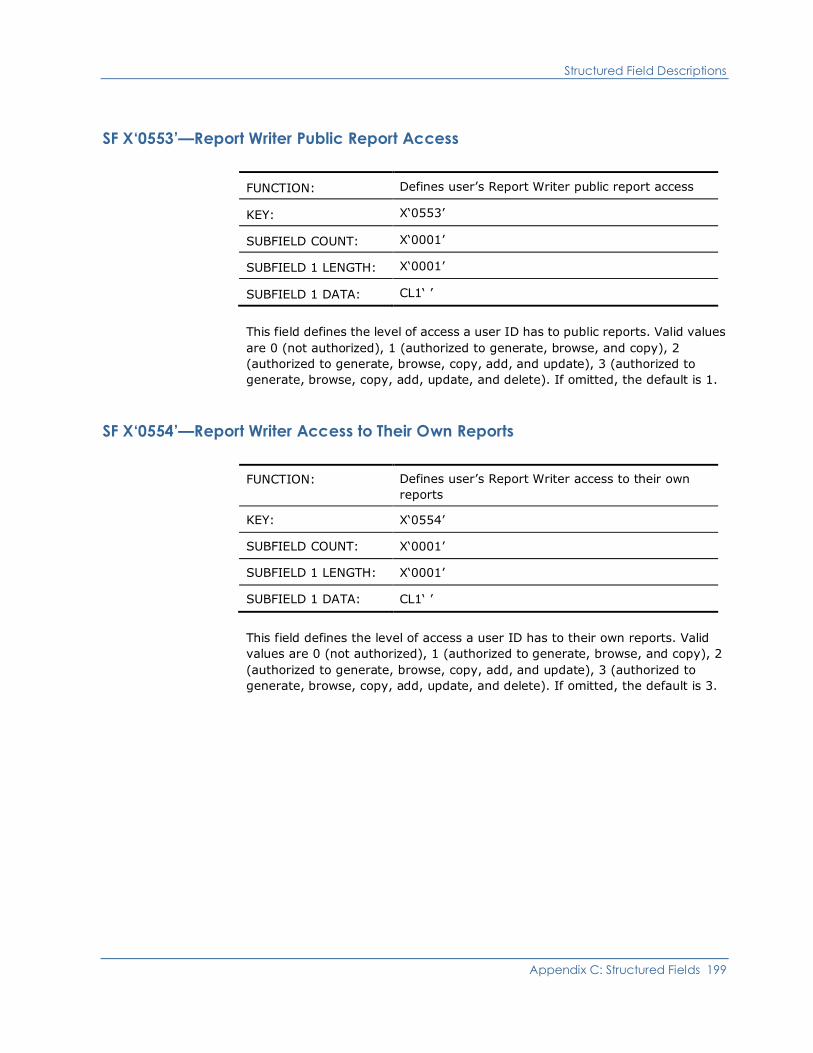
Structured Field Descriptions
Appendix C: Structured Fields 199
SF X‘0553’—Report Writer Public Report Access
FUNCTION: Defines user’s Report Writer public report access
KEY: X‘0553’
SUBFIELD COUNT: X‘0001’
SUBFIELD 1 LENGTH: X‘0001’
SUBFIELD 1 DATA: CL1‘ ’
This field defines the level of access a user ID has to public reports. Valid values
are 0 (not authorized), 1 (authorized to generate, browse, and copy), 2
(authorized to generate, browse, copy, add, and update), 3 (authorized to
generate, browse, copy, add, update, and delete). If omitted, the default is 1.
SF X‘0554’—Report Writer Access to Their Own Reports
FUNCTION: Defines user’s Report Writer access to their own
reports
KEY: X‘0554’
SUBFIELD COUNT: X‘0001’
SUBFIELD 1 LENGTH: X‘0001’
SUBFIELD 1 DATA: CL1‘ ’
This field defines the level of access a user ID has to their own reports. Valid
values are 0 (not authorized), 1 (authorized to generate, browse, and copy), 2
(authorized to generate, browse, copy, add, and update), 3 (authorized to
generate, browse, copy, add, update, and delete). If omitted, the default is 3.
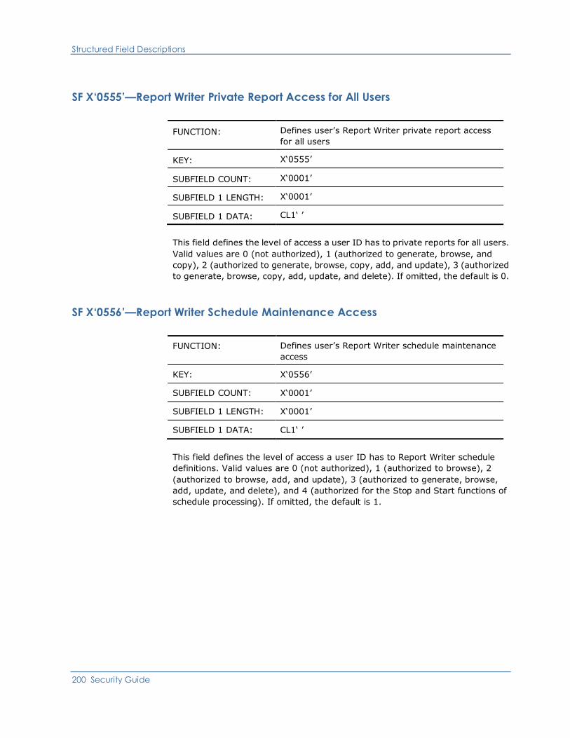
Structured Field Descriptions
200 Security Guide
SF X‘0555’—Report Writer Private Report Access for All Users
FUNCTION: Defines user’s Report Writer private report access
for all users
KEY: X‘0555’
SUBFIELD COUNT: X‘0001’
SUBFIELD 1 LENGTH: X‘0001’
SUBFIELD 1 DATA: CL1‘ ’
This field defines the level of access a user ID has to private reports for all users.
Valid values are 0 (not authorized), 1 (authorized to generate, browse, and
copy), 2 (authorized to generate, browse, copy, add, and update), 3 (authorized
to generate, browse, copy, add, update, and delete). If omitted, the default is 0.
SF X‘0556’—Report Writer Schedule Maintenance Access
FUNCTION: Defines user’s Report Writer schedule maintenance
access
KEY: X‘0556’
SUBFIELD COUNT: X‘0001’
SUBFIELD 1 LENGTH: X‘0001’
SUBFIELD 1 DATA: CL1‘ ’
This field defines the level of access a user ID has to Report Writer schedule
definitions. Valid values are 0 (not authorized), 1 (authorized to browse), 2
(authorized to browse, add, and update), 3 (authorized to generate, browse,
add, update, and delete), and 4 (authorized for the Stop and Start functions of
schedule processing). If omitted, the default is 1.
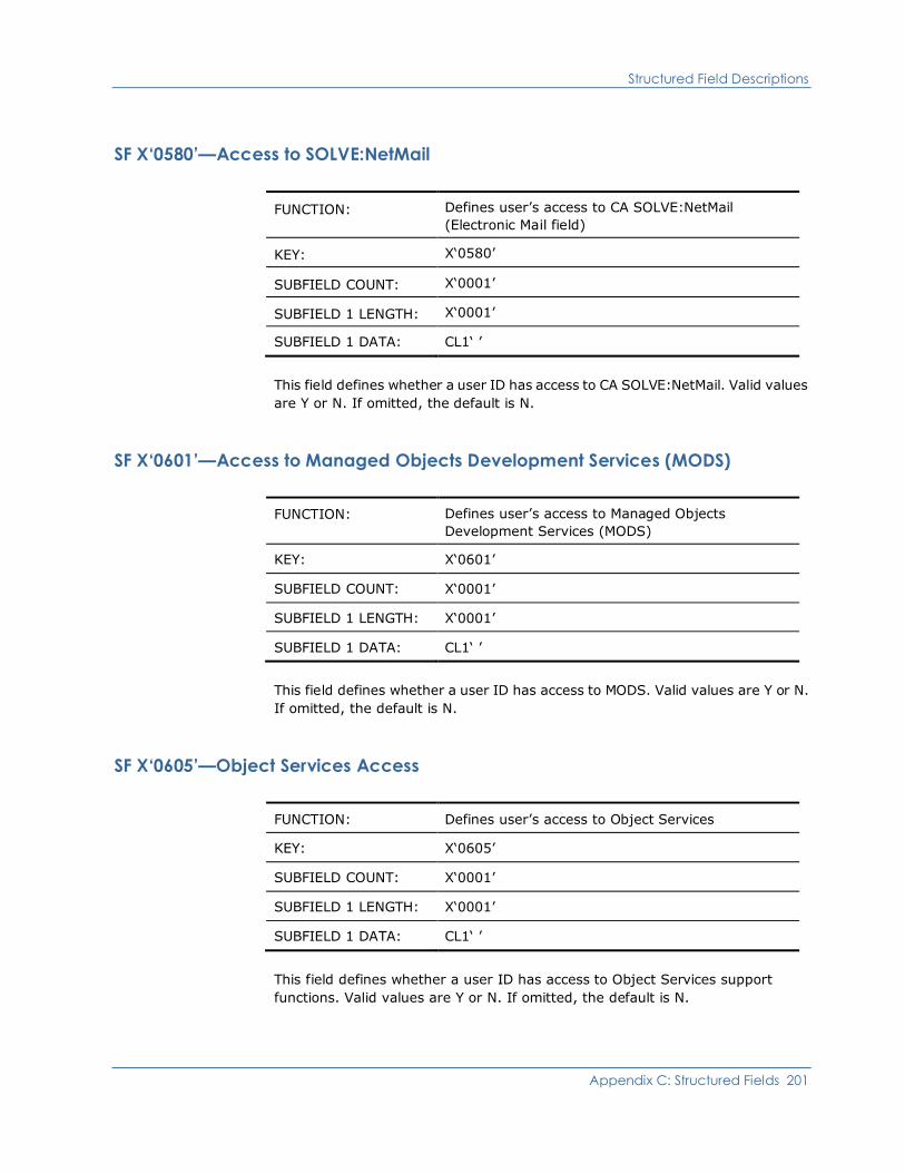
Structured Field Descriptions
Appendix C: Structured Fields 201
SF X‘0580’—Access to SOLVE:NetMail
FUNCTION: Defines user’s access to CA SOLVE:NetMail
(Electronic Mail field)
KEY: X‘0580’
SUBFIELD COUNT: X‘0001’
SUBFIELD 1 LENGTH: X‘0001’
SUBFIELD 1 DATA: CL1‘ ’
This field defines whether a user ID has access to CA SOLVE:NetMail. Valid values
are Y or N. If omitted, the default is N.
SF X‘0601’—Access to Managed Objects Development Services (MODS)
FUNCTION: Defines user’s access to Managed Objects
Development Services (MODS)
KEY: X‘0601’
SUBFIELD COUNT: X‘0001’
SUBFIELD 1 LENGTH: X‘0001’
SUBFIELD 1 DATA: CL1‘ ’
This field defines whether a user ID has access to MODS. Valid values are Y or N.
If omitted, the default is N.
SF X‘0605’—Object Services Access
FUNCTION: Defines user’s access to Object Services
KEY: X‘0605’
SUBFIELD COUNT: X‘0001’
SUBFIELD 1 LENGTH: X‘0001’
SUBFIELD 1 DATA: CL1‘ ’
This field defines whether a user ID has access to Object Services support
functions. Valid values are Y or N. If omitted, the default is N.

Structured Field Descriptions
202 Security Guide
SF X‘0609’—Object Services Security Access
FUNCTION: Defines user’s security access to Object Services
KEY: X‘0609’
SUBFIELD COUNT: X‘0001’
SUBFIELD 1 LENGTH: X‘0001’
SUBFIELD 1 DATA: CL1‘ ’
This field defines whether a user ID has access to Object Services. Valid values
are Y or N. If omitted, the default is N.

Appendix D: User ID Security Exit Support 203
Appendix D: User ID Security Exit Support
This appendix provides information on how to code the user ID security exit and
provides the parameter lists for all the user ID security exit calls.
This section contains the following topics:
External Security Packages (see page 203)
Writing Your Own User ID Security Exit (see page 205)
System Initialization Parameter List (see page 209)
System Close Down Parameter List (see page 211)
Logon Request Parameter List (see page 212)
Logoff Request Parameter List (see page 219)
Logon Verification Call Parameter List (see page 221)
Change Password Parameter List (see page 226)
Return User ID Information Parameter List (see page 230)
Update User ID Parameter List (see page 233)
&SECCALL EXIT Parameter List (see page 236)
Return Sequential User ID Information Parameter List (see page 239)
Add User ID Parameter List (see page 242)
Delete User ID Parameter List (see page 245)
External Security Packages
External security packages such as CA ACF2 or RACF can provide minimal or full
security checking.
If your organization has an external security package, access to that package is
provided through one of the following types of exit:
■ Partial security exit—password and logon access maintenance is controlled
by the external security package while UAMS stores the user definitions.
■ Full security exit—all security functions are maintained and stored by your
external security package.
External Security Packages
204 Security Guide
Sample Exits
The following sample security exits are provided:
CCACF2FX
Is a full security exit for CA ACF2.
CCRACFFX
Is a full security exit for RACF.
NMSAFPX
Is a SAF partial security exit.
Sample exits are in the following libraries:
■ The SMP target zone library, dsnpref.pvpref.CC2DSAMP, where:
– dsnpref is your site-specific data set name prefix
– pvpref is your product version prefix
– CC2DSAMP is the data set for all products
■ The SMP distribution zone library, dsnpref.pvpref.AC2SAMP, where:
– dsnpref is your site-specific data set name prefix.
– pvpref is your product version prefix.
– AC2DSAMP is the data set for all products.
Note: The SMP target zone is updated when you SMP APPLY maintenance,
whereas the SMP distribution zone is updated only when you subsequently SMP
ACCEPT the maintenance. To ensure that you include all applied maintenance, it
is recommended that you use the member in the SMP target zone
(dsnpref.pvpref.CC2DSAMP).
Note: On z/VM systems, these exits are on the vmid 193 C-disk.
More information:
Product Libraries (see page 17)

Writing Your Own User ID Security Exit
Appendix D: User ID Security Exit Support 205
NMSAFPX Partial Security Exit
The NMSAFPX partial security exit is a SAF-based security exit that supports
UTOKENS. SAF is the IBM System Authorization Facility and is the agreed
standard for the encoding of requests that require security checking.
Note: SAF is documented in IBM’s Security Server RACROUTE Macro Reference
manual. See the documentation for your security package to find out whether the
package supports SAF-formatted calls.
You can make a copy of NMSAFPX and change it to suit your requirements. To
assemble and link your exit, use the sample JCL member NMSAFPXL, which is in
the same data set as the NMSAFPX sample exit.
The load module created by the link-edit step should be placed in the load library,
or in another library concatenated to the load library through the STEPLIB DD
statement in the started task JCL. Change the JCL parameters to include
SEC=name, where name identifies the load module. This causes the security exit
to be used.
Note: The supplied SEC=PARTSAF option is functionally equivalent to the
NMSAFPX sample.
Writing Your Own User ID Security Exit
The security exit is coded as an assembler language module, or suite of modules.
These modules must be able to:
■ Accept the various parameter lists passed to it
■ Return the designated return codes associated with those parameter lists
When the exit has been written, you link it into a standalone load module. The
name of this load module is arbitrary (for example, MYEXIT). The load module is
placed in an APF authorized library or another library concatenated to the load
library in the JCL STEPLIB DD statement. Change the JCL parameters to include
SEC=name, where name identifies the load module (for example, SEC=MYEXIT).
Your region determines the type (partial or full security) of exit being provided. It
does this by examining the data at the entry point of the exit load module.

Writing Your Own User ID Security Exit
206 Security Guide
The entry point of the security exit load module must look like this:
ENTRY B SKIP-ENTRY(,R15) Skip descriptor
DC C’S’ Required, constant ’S’
DC AL1 (0) Required, interface version,
DC AL1 (type) Required, exit type,
0: partial
4: full
DC C’X’ Required, constant ’X’
The security exit can be AMODE 24 or 31, and RMODE 24 or ANY. All data areas
and parameter lists passed to it are located in storage below 16M.
This diagram shows how a region loads and identifies a full security exit and how
your region locates the entry point of the exit’s code.
This diagram shows how a region loads and identifies a partial security exit and
how your region locates the entry point of the exit’s code.
Writing Your Own User ID Security Exit
Appendix D: User ID Security Exit Support 207
Exit Execution
The exit executes within an operating system subtask and can therefore issue
WAITs or SVCs that suspend the task without affecting the primary task.
Note: In z/OS systems, the subtask is attached sharing subpool 50 with the
main task. This allows other exits (which also use subpool 50) to share common
storage areas with the security exit.
Calls to the exit are serialized across the system—if one call to the exit is in
progress, any subsequent calls are queued and processed one-by-one, in
request order. Serial request processing means that the exit does not have to be
written as reentrant.
The exit is called for two reasons:
■ Information—to keep the security system informed of developments or
system changes
■ Function request—to request that a function be performed
Important! If an abend occurs in the exit and the requested function cannot be
performed it is regarded as a security exposure and the region terminates with
the internal abend 268-01.
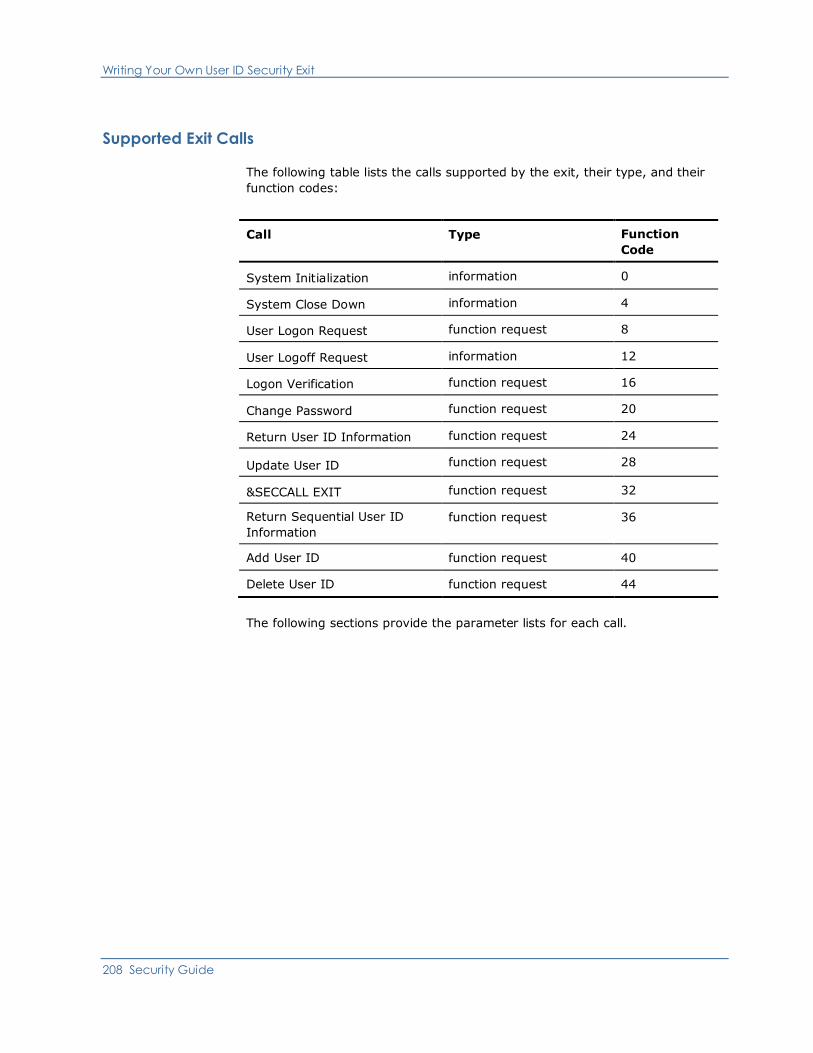
Writing Your Own User ID Security Exit
208 Security Guide
Supported Exit Calls
The following table lists the calls supported by the exit, their type, and their
function codes:
Call Type Function
Code
System Initialization information 0
System Close Down information 4
User Logon Request function request 8
User Logoff Request information 12
Logon Verification function request 16
Change Password function request 20
Return User ID Information function request 24
Update User ID function request 28
&SECCALL EXIT function request 32
Return Sequential User ID
Information
function request 36
Add User ID function request 40
Delete User ID function request 44
The following sections provide the parameter lists for each call.

System Initialization Parameter List
Appendix D: User ID Security Exit Support 209
System Initialization Parameter List
On entry to the security exit, Register 1 points to a list of ten full words, as shown
in this diagram.
The contents of the parameter list are as follows:
Word 1
Is a full word containing the address of function code F‘0’.
Word 2
Is set to zero.

System Initialization Parameter List
210 Security Guide
Word 3
Is a 24-character area containing the following:
■ The 8-character primary ACB name field (padded to the right with blanks
if necessary). The primary ACB name is as specified on the PRI JCL
initialization parameter.
■ Four blanks
■ The 4-character system domain ID as coded on the NMDID initialization
parameter. If the NMDID parameter is omitted the domain ID defaults to
the first 4-characters of the primary ACB name used by your region
(blank padded if required), or the ACB name itself if less than
5-characters long.
■ The 4-character system user prefix as coded on the NMSUP initialization
parameter. It defaults to the NMDID value if not coded.
■ The 4-character product version, for example, V5.1.
These characters are passed to the exit to identify the system that is
executing and might be regarded as the user ID of the system. The exit
might want to know this to determine whether, for example, it is a production
system.
Word 4
Is the address of two full words. These are as follows:
■ First word—can contain any value. This value is returned in the system
closedown call, so it can be used as a region correlator. The exit can use
this to relate this region to a set of control blocks or other information
maintained by the exit in relation to the region.
■ Second word—the region user token (UTOKEN), if one is available.
Words 5 to 10
Are set to zeros.
Return Codes from Initialization Call
The exit must return a completion code in Register 15 on return. Successful
initialization must be signified by return code F‘0’. Your product region
terminates if any other value is returned in Register 15 on completion of this call.
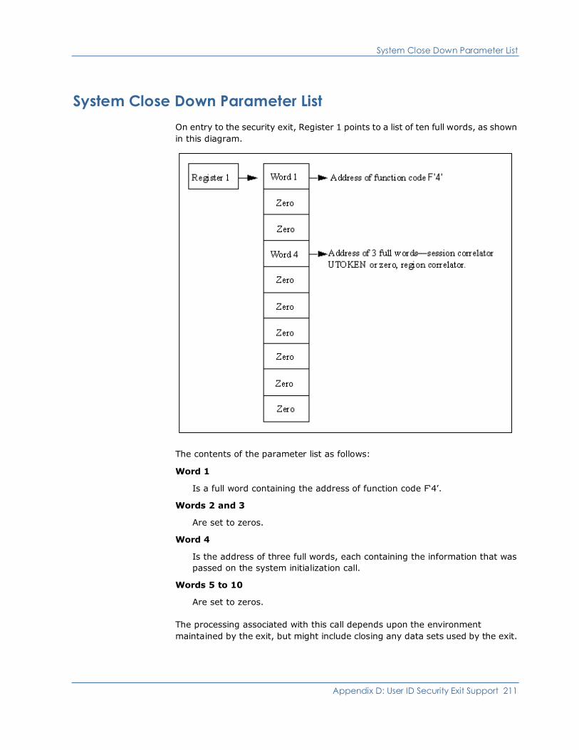
System Close Down Parameter List
Appendix D: User ID Security Exit Support 211
System Close Down Parameter List
On entry to the security exit, Register 1 points to a list of ten full words, as shown
in this diagram.
The contents of the parameter list as follows:
Word 1
Is a full word containing the address of function code F‘4’.
Words 2 and 3
Are set to zeros.
Word 4
Is the address of three full words, each containing the information that was
passed on the system initialization call.
Words 5 to 10
Are set to zeros.
The processing associated with this call depends upon the environment
maintained by the exit, but might include closing any data sets used by the exit.
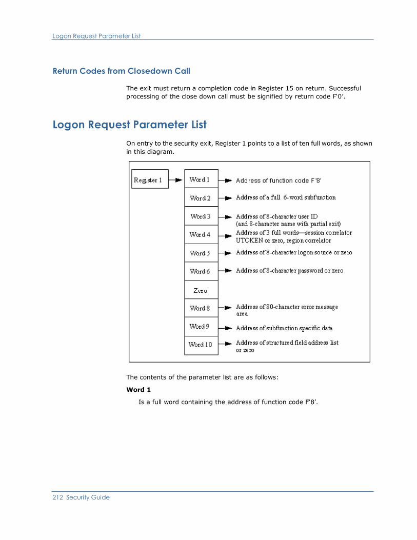
Logon Request Parameter List
212 Security Guide
Return Codes from Closedown Call
The exit must return a completion code in Register 15 on return. Successful
processing of the close down call must be signified by return code F‘0’.
Logon Request Parameter List
On entry to the security exit, Register 1 points to a list of ten full words, as shown
in this diagram.
The contents of the parameter list are as follows:
Word 1
Is a full word containing the address of function code F‘8’.
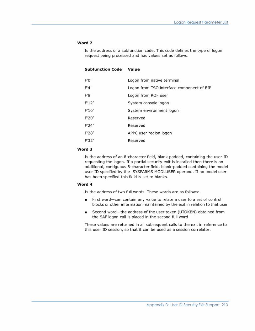
Logon Request Parameter List
Appendix D: User ID Security Exit Support 213
Word 2
Is the address of a subfunction code. This code defines the type of logon
request being processed and has values set as follows:
Subfunction Code Value
F‘0’ Logon from native terminal
F‘4’ Logon from TSO interface component of EIP
F‘8’ Logon from ROF user
F‘12’ System console logon
F‘16’ System environment logon
F‘20’ Reserved
F‘24’ Reserved
F‘28’ APPC user region logon
F‘32’ Reserved
Word 3
Is the address of an 8-character field, blank padded, containing the user ID
requesting the logon. If a partial security exit is installed then there is an
additional, contiguous 8-character field, blank-padded containing the model
user ID specified by the SYSPARMS MODLUSER operand. If no model user
has been specified this field is set to blanks.
Word 4
Is the address of two full words. These words are as follows:
■ First word—can contain any value to relate a user to a set of control
blocks or other information maintained by the exit in relation to that user
■ Second word—the address of the user token (UTOKEN) obtained from
the SAF logon call is placed in the second full word
These values are returned in all subsequent calls to the exit in reference to
this user ID session, so that it can be used as a session correlator.
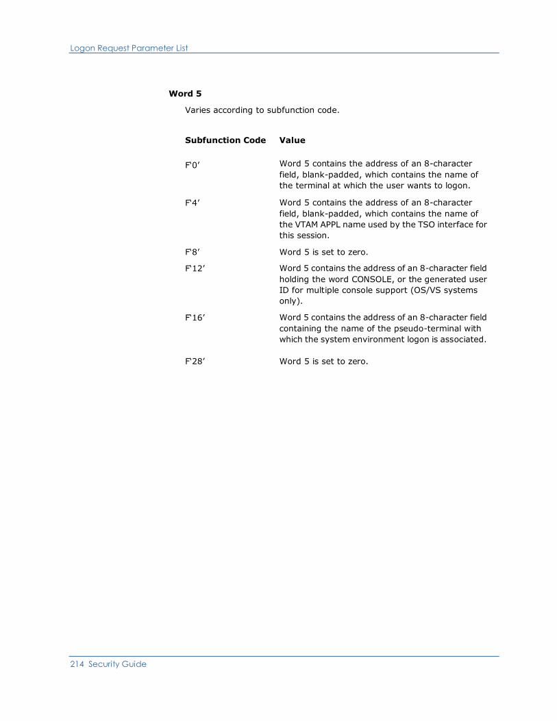
Logon Request Parameter List
214 Security Guide
Word 5
Varies according to subfunction code.
Subfunction Code Value
F‘0’ Word 5 contains the address of an 8-character
field, blank-padded, which contains the name of
the terminal at which the user wants to logon.
F‘4’ Word 5 contains the address of an 8-character
field, blank-padded, which contains the name of
the VTAM APPL name used by the TSO interface for
this session.
F‘8’ Word 5 is set to zero.
F‘12’ Word 5 contains the address of an 8-character field
holding the word CONSOLE, or the generated user
ID for multiple console support (OS/VS systems
only).
F‘16’ Word 5 contains the address of an 8-character field
containing the name of the pseudo-terminal with
which the system environment logon is associated.
F‘28’ Word 5 is set to zero.
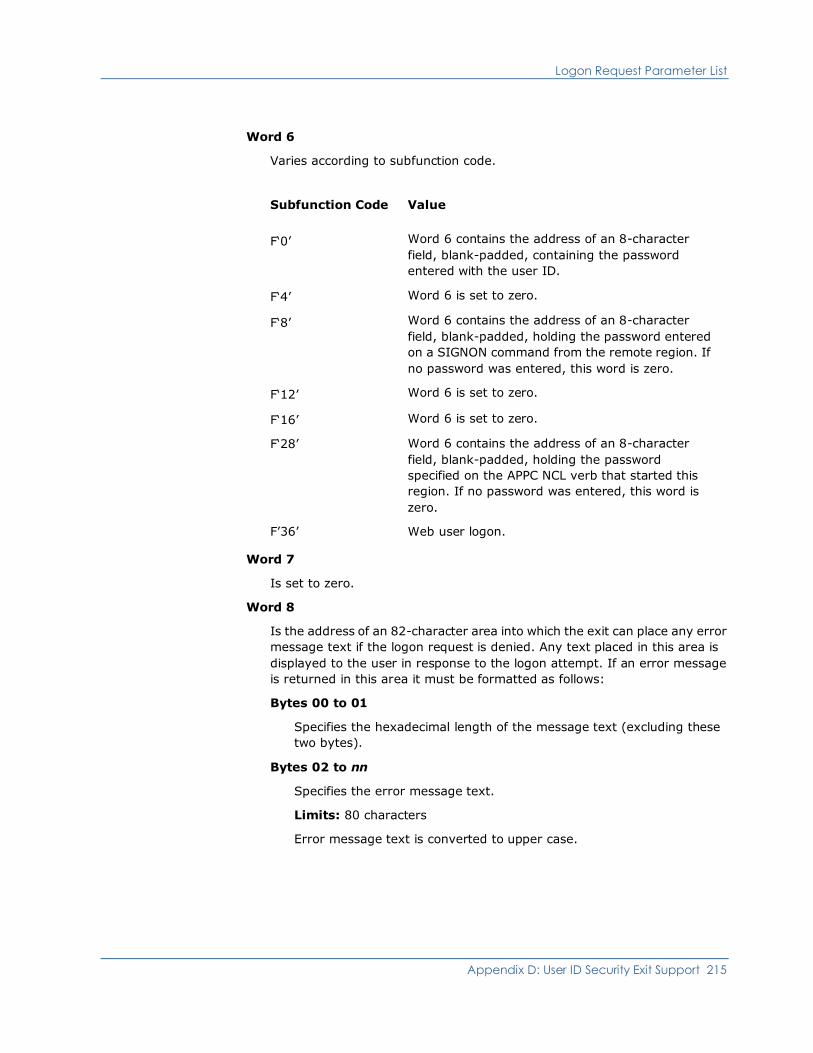
Logon Request Parameter List
Appendix D: User ID Security Exit Support 215
Word 6
Varies according to subfunction code.
Subfunction Code Value
F‘0’ Word 6 contains the address of an 8-character
field, blank-padded, containing the password
entered with the user ID.
F‘4’ Word 6 is set to zero.
F‘8’ Word 6 contains the address of an 8-character
field, blank-padded, holding the password entered
on a SIGNON command from the remote region. If
no password was entered, this word is zero.
F‘12’ Word 6 is set to zero.
F‘16’ Word 6 is set to zero.
F‘28’ Word 6 contains the address of an 8-character
field, blank-padded, holding the password
specified on the APPC NCL verb that started this
region. If no password was entered, this word is
zero.
F’36’ Web user logon.
Word 7
Is set to zero.
Word 8
Is the address of an 82-character area into which the exit can place any error
message text if the logon request is denied. Any text placed in this area is
displayed to the user in response to the logon attempt. If an error message
is returned in this area it must be formatted as follows:
Bytes 00 to 01
Specifies the hexadecimal length of the message text (excluding these
two bytes).
Bytes 02 to nn
Specifies the error message text.
Limits: 80 characters
Error message text is converted to upper case.
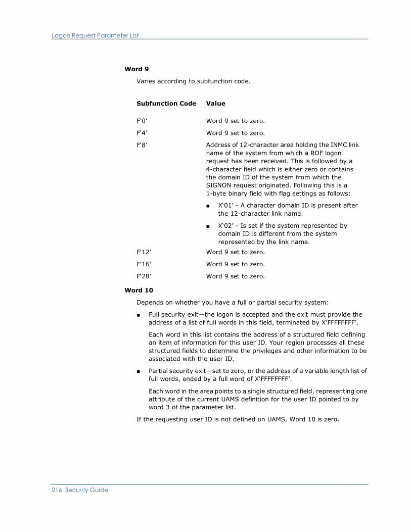
Logon Request Parameter List
216 Security Guide
Word 9
Varies according to subfunction code.
Subfunction Code Value
F‘0’ Word 9 set to zero.
F‘4’ Word 9 set to zero.
F‘8’ Address of 12-character area holding the INMC link
name of the system from which a ROF logon
request has been received. This is followed by a
4-character field which is either zero or contains
the domain ID of the system from which the
SIGNON request originated. Following this is a
1-byte binary field with flag settings as follows:
■ X‘01’ - A character domain ID is present after
the 12-character link name.
■ X‘02’ - Is set if the system represented by
domain ID is different from the system
represented by the link name.
F‘12’ Word 9 set to zero.
F‘16’ Word 9 set to zero.
F‘28’ Word 9 set to zero.
Word 10
Depends on whether you have a full or partial security system:
■ Full security exit—the logon is accepted and the exit must provide the
address of a list of full words in this field, terminated by X‘FFFFFFFF’.
Each word in this list contains the address of a structured field defining
an item of information for this user ID. Your region processes all these
structured fields to determine the privileges and other information to be
associated with the user ID.
■ Partial security exit—set to zero, or the address of a variable length list of
full words, ended by a full word of X‘FFFFFFFF’.
Each word in the area points to a single structured field, representing one
attribute of the current UAMS definition for the user ID pointed to by
word 3 of the parameter list.
If the requesting user ID is not defined on UAMS, Word 10 is zero.
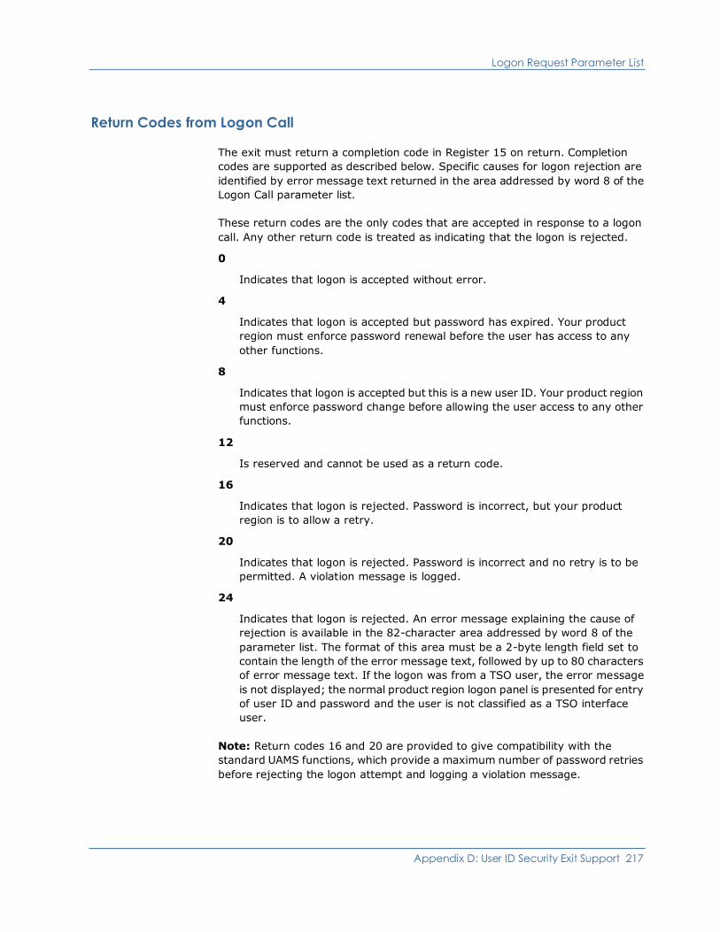
Logon Request Parameter List
Appendix D: User ID Security Exit Support 217
Return Codes from Logon Call
The exit must return a completion code in Register 15 on return. Completion
codes are supported as described below. Specific causes for logon rejection are
identified by error message text returned in the area addressed by word 8 of the
Logon Call parameter list.
These return codes are the only codes that are accepted in response to a logon
call. Any other return code is treated as indicating that the logon is rejected.
0
Indicates that logon is accepted without error.
4
Indicates that logon is accepted but password has expired. Your product
region must enforce password renewal before the user has access to any
other functions.
8
Indicates that logon is accepted but this is a new user ID. Your product region
must enforce password change before allowing the user access to any other
functions.
12
Is reserved and cannot be used as a return code.
16
Indicates that logon is rejected. Password is incorrect, but your product
region is to allow a retry.
20
Indicates that logon is rejected. Password is incorrect and no retry is to be
permitted. A violation message is logged.
24
Indicates that logon is rejected. An error message explaining the cause of
rejection is available in the 82-character area addressed by word 8 of the
parameter list. The format of this area must be a 2-byte length field set to
contain the length of the error message text, followed by up to 80 characters
of error message text. If the logon was from a TSO user, the error message
is not displayed; the normal product region logon panel is presented for entry
of user ID and password and the user is not classified as a TSO interface
user.
Note: Return codes 16 and 20 are provided to give compatibility with the
standard UAMS functions, which provide a maximum number of password retries
before rejecting the logon attempt and logging a violation message.
Logon Request Parameter List
218 Security Guide
Return codes 4 and 8 provide compatibility with the UAMS convention of
enforcing password change at logon time if the user’s password has expired, or
for the first logon of a new user ID.
The exit might not be able to determine that a user ID is new, depending upon
the information available to it from the external security system in use. If
required, the exit can be written to provide two return codes only, 0 or 24, with
an appropriate error message if the logon is rejected.
The ability to deny a logon with return code 24 and an error message of the exit’s
choice allows the installation to extend the security exit’s function beyond that of
simple password validation. For example, the exit might deny logons after a
certain time of day or reject ROF logons from certain remote systems.
System console and system environment logon calls take default attributes if the
exit causes the logon to fail.
More information:
Controlling Access to Your System (see page 54)
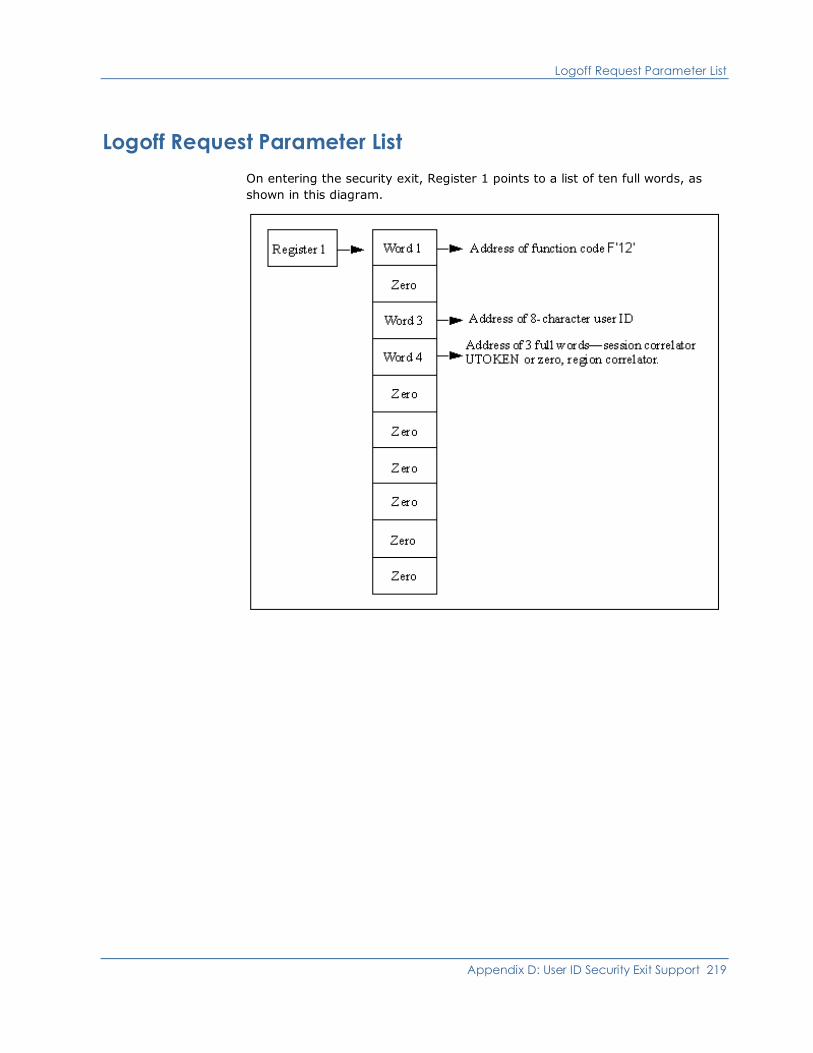
Logoff Request Parameter List
Appendix D: User ID Security Exit Support 219
Logoff Request Parameter List
On entering the security exit, Register 1 points to a list of ten full words, as
shown in this diagram.
Logoff Request Parameter List
220 Security Guide
The contents of the parameter list are as follows:
Word 1
Is a full word containing the address of function code F‘12’.
Word 2
Is set to zero.
Word 3
Is the address of 8-character field, blank-padded, containing the user ID
logging off.
Word 4
Is the address of three full words containing the user session correlator (if
any) and the user token (UTOKEN) address, set by the exit when this user ID
logged on, or zero.
Words 5 to 10
Are set to zero.
Return Codes from Logoff Calls
The exit must return a completion code in register 15 on return. The only valid
completion code is F‘0’.
Note: It is possible for the exit to receive a logoff call for a user who has never
successfully logged on. This might occur when a user abandons their logon
attempt due to a forgotten password. The exit must be written to accept such
calls and to ignore them.
Your system services generate a logoff call during DISCONNECT processing on
behalf of an internally created environment. Because there was no logon request
call for this environment, there is no session correlator created, and it is,
therefore, null.
When a users logs back on to reconnect, a logon request call is made to the
security exit. A new session correlator is created at this time. When the user
selects a RECONNECT or CANCEL of all disconnected environments, a logoff
request call is made to the security exit with the original user session correlator.
The reconnected or new session continues with a new user session correlator
that is presented to the security exit upon that session’s logoff.
A zero user session correlator on a logoff request call to the security exit is valid
for a DISCONNECT request only.

Logon Verification Call Parameter List
Appendix D: User ID Security Exit Support 221
Logon Verification Call Parameter List
On entry to the security exit, Register 1 points to a list of ten full words, as shown
in this diagram.
The contents of the parameter list are as follows:
Word 1
Is a full word containing the address of function code F‘16’.
Word 2
Is the address of a subfunction code. This code defines the source of the
logon verification call and has values set as follows:
Subfunction Code Value
F‘0’ Call is from an &SECCALL CHECK verb, the LOCK
facility, or APPC region validation.
F‘4’ Call is from INMC link activation.
F‘8’ Call is from APPC link activation.

Logon Verification Call Parameter List
222 Security Guide
Word 3
Is the address of a 16-character field, blank-padded, containing the
8-character-character user ID whose password and logon capability is to be
verified, followed by the 8-character system default MODLUSER name, or
blanks if no model user has been defined.
Word 4
Is the address of three full words containing the user session correlator and
the address of the user token (UTOKEN) of the submitter of the logon
verification call, or zero if called from EASINET.
Word 5
Varies according to subfunction code:
Subfunction Code Value
F‘0’ Address of the 8-character terminal ID, followed by
the 8-character user ID of the submitting user. This
field can be blank; if so, treat the user ID being
checked as the submitting user.
F‘4’ Address of the 8-character LU name of the link,
followed by the 12-character NMPCID.
F‘8’ Address of the 35-character APPC link partners.
The format of the link session partners is
NETID.LU1.LU2 where NETID.LU1 is the source
partner and LU2 is the destination LU of the APPC
link.
Word 6
Varies according to subfunction code:
Subfunction Code Value
Subfunction F‘0’ Address of the 8-character, blank-padded user ID
password.
Subfunction F‘4’ Word 6 is set to zero.
Subfunction F‘8’ Address of an 8-character area into which the exit
can place the session key for this APPC link.
Word 7
Is set to zero.
Logon Verification Call Parameter List
Appendix D: User ID Security Exit Support 223
Word 8
Is the address of an 82-character area into which the exit can place an error
message. If an error message is returned, it must be formatted as follows:
Bytes 00 to 01
Specifies the hexadecimal length of the message text (excluding these
two bytes).
Bytes 02 to nn
Specifies the error message text.
Limits: 80 characters
Error message text is converted to upper case. An error message might
be returned in this area for return codes 20 or 24. A message set in this
area for any other return code is ignored.
Word 9
Is set to zero.
Word 10
If you have a full security exit, this word is set to zero.
If you have a partial security exit this word is set to zero if the user ID is not
defined on the UAMS data set. Otherwise word 10 points to a list of full
words, ended by a full word of X‘FFFFFFFF’. Each address in the list points to
a single structured field representing one attribute of the user ID to be
verified. This list therefore provides the exit with access to the entire current
definition of this user ID.
Logon Verification Call Parameter List
224 Security Guide
Return Codes from Logon Verification Call
The exit must return a completion code in Register 15 on return. Completion
codes are supported as described below.
The return codes listed below are for subfunction codes 0 and 4. They are the
only codes that are accepted in response to a Logon Verification call. Any other
return code is rejected and set to 24.
0
Indicates that the password is valid. Logon is successful.
4
Indicates that the password is valid but expired. This is not a new user ID.
The user is prompted to change the password before logon is successful.
8
Indicates that the password is valid but this is a new user ID. The user is
prompted to change the password before logon is successful.
16
Indicates that the password is wrong.
20
Indicates that the password is correct but logon is rejected. The exit might
return an explanatory message in the error message area addressed by word
8 of the parameter list.
24
Indicates that the request failed or function is not supported by the exit. The
exit might return an explanatory message in the error message area
addressed by word 8 of the parameter list.

Logon Verification Call Parameter List
Appendix D: User ID Security Exit Support 225
The return codes listed below are for subfunction code 8. They are the only codes
that are accepted in response to an APPC link establishment Logon Verification
call. Any other return code is rejected and set to 24.
0
Indicates that link activation is successful. The session key is addressed by
word 6 of the parameter list.
4
Indicates that link activation is successful. No session key is available.
8
N/A
16
Indicates that link activation is unsuccessful.
20
N/A
24
Indicates that the function is not supported. The link establishment is to
continue without a session key.
Notes:
■ When a Logon Verification Call to the exit is made by a &SECCALL CHECK
statement or by NMPC link activation, no user correlator information can be
provided. Word 4 of the parameter list is set to zero.
■ The Logon Verification Call return codes do not strictly correlate with the
&SECCALL CHECK return code values. For an explanation of &SECCALL
CHECK return codes, see the Network Control Language Reference.
■ If the Logon Verification call is made by the LOCK facility, the call is being
made on behalf of a logged-on user. Consequently, the parameter list
provides the address of the appropriate user session correlator.
The Logon Verification Call is primarily a means of querying the validity of a
password, and the exit can be written to provide only this function. The option of
supporting return code 20 is provided to complement support of return code 24
from the Logon Request Call, which allows the exit to refuse a logon request for
reasons other than password error.

Change Password Parameter List
226 Security Guide
Change Password Parameter List
On entry to the security exit, Register 1 points to a list of ten full words, as shown
in this diagram.
The contents of the parameter list are as follows:
Word 1
Is a full word containing the address of function code F‘20’.
Word 2
Is the address of a subfunction code. This code defines the source of the
change password request and has values set as follows:
Subfunction Code Value
F‘0’ User has requested password change
F‘4’ Change required because password expired
F‘8’ Forced change by UAMS user
F‘12’ &SECCALL CHANGE request issued from an
EASINET procedure
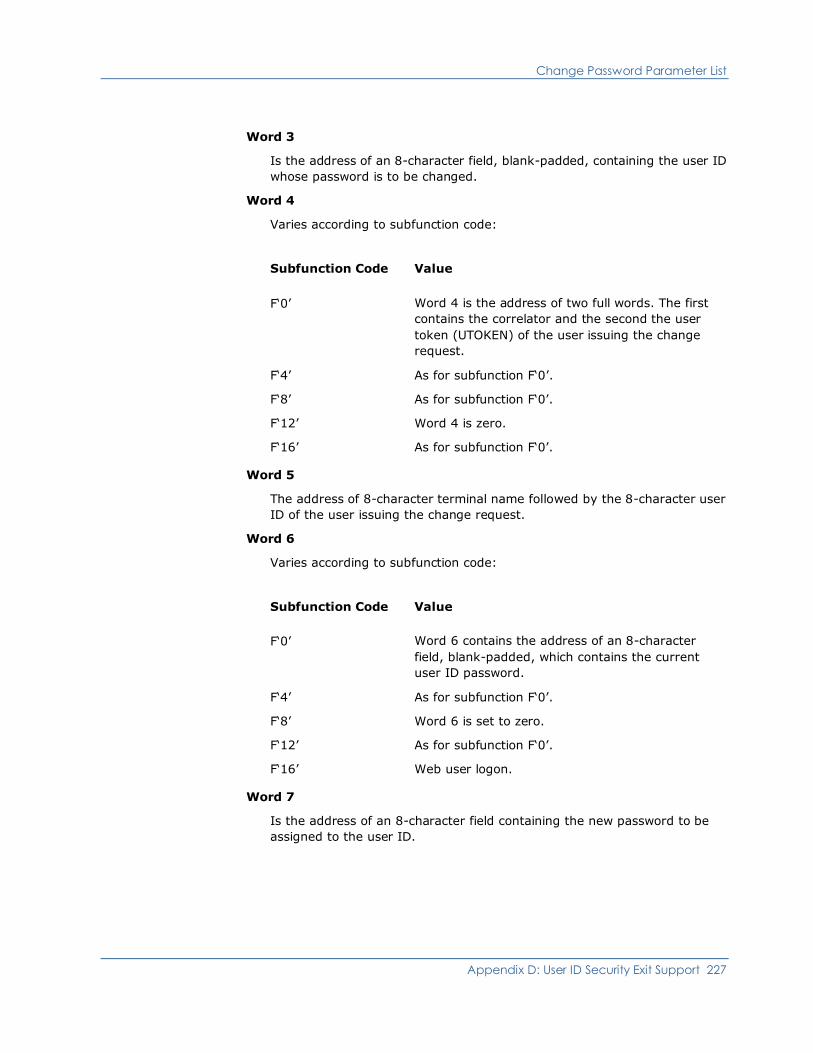
Change Password Parameter List
Appendix D: User ID Security Exit Support 227
Word 3
Is the address of an 8-character field, blank-padded, containing the user ID
whose password is to be changed.
Word 4
Varies according to subfunction code:
Subfunction Code Value
F‘0’ Word 4 is the address of two full words. The first
contains the correlator and the second the user
token (UTOKEN) of the user issuing the change
request.
F‘4’ As for subfunction F‘0’.
F‘8’ As for subfunction F‘0’.
F‘12’ Word 4 is zero.
F‘16’ As for subfunction F‘0’.
Word 5
The address of 8-character terminal name followed by the 8-character user
ID of the user issuing the change request.
Word 6
Varies according to subfunction code:
Subfunction Code Value
F‘0’ Word 6 contains the address of an 8-character
field, blank-padded, which contains the current
user ID password.
F‘4’ As for subfunction F‘0’.
F‘8’ Word 6 is set to zero.
F‘12’ As for subfunction F‘0’.
F‘16’ Web user logon.
Word 7
Is the address of an 8-character field containing the new password to be
assigned to the user ID.
Change Password Parameter List
228 Security Guide
Word 8
The address of an 82-character area into which the exit can place any error
message text if the change request is denied or failed. Any text placed in this
area is displayed to the user in response to the change request. If an error
message is returned in this area it must be formatted as follows:
Bytes 00 to 01
Specifies the hexadecimal length of the message text (excluding these
two bytes).
Bytes 02 to nn
Specifies the error message text.
Limits: 80 characters
Words 9 to 10
Are set to zero.

Change Password Parameter List
Appendix D: User ID Security Exit Support 229
Return Codes from Change Call
The exit must return a completion code in Register 15 on return. The supported
completion codes are described below. Specific causes for change rejection are
identified by error message text returned in the area addressed by word 8 of the
Change Call parameter list.
The return codes listed below are the only codes that are accepted in response to
a Change Call. Any other return code is regarded as indicating that the password
was not changed.
0
Indicates that the password has been changed.
4
Indicates that subfunction is not supported by exit or other error. A message
explaining the cause of error might be placed in the 80-character area
addressed by word 8 of the parameter list.
8
Indicates that the password has not been changed. A message explaining the
cause of rejection is available in the 80-character area addressed by word 8
of the parameter list.
Notes:
■ Your product region does not apply minimum password length checks, nor is
automatic password expiry provided. The exit is responsible for all
maintenance and knowledge of passwords.
■ A user’s current password is provided as a parameter for the change call only
for subfunctions 0, 4, and 12. That is, when the change request is made by
the user after logging on, when the user is required to change the password
because it has expired or by EASINET using the &SECCALL CHECK
statement.
■ For subfunction 8, when a UAMS privileged user requests a forced password
change for another user ID it is almost certainly because the current
password for that user ID has been forgotten, and is therefore not available
for presentation as a parameter for this call.

Return User ID Information Parameter List
230 Security Guide
Return User ID Information Parameter List
On entry to the security exit, Register 1 points to a list of ten full words, as shown
in this diagram.
The contents of the parameter list are as follows:
Word 1
Is a full word containing the address of function code F‘24’.
Word 2
Is set to zero.
Word 3
Is the address of an 8-character field, blank-padded, containing the user ID
for which information is required.
Word 4
Is the address of three full words containing the session correlator and the
user token (UTOKEN) associated with the user issuing the request (not
necessarily the correlator for the user ID whose information is being
requested).

Return User ID Information Parameter List
Appendix D: User ID Security Exit Support 231
Word 5
Is the address of an 8-character field, blank-padded, containing the user ID
requesting the information (or zero).
Word 6
Is set to zero.
Word 7
Is set to zero.
Word 8
Is the address of an 82-character area into which the exit can place any error
message text if the function request is denied or failed. Any text placed in
this area is displayed to the user in response to the command that caused
this request. If an error message is returned it must be formatted as follows:
Bytes 00 to 01
Specifies the hexadecimal length of the message text (excluding these
two bytes).
Bytes 02 to nn
Specifies the error message text.
Limits: 80 characters
Word 9
Is set to zero.
Word 10
Is set differently depending on the type of exit you have:
■ Full security exit—if the request is honored, the exit must place in this
word the address of a list of full words, terminated by X‘FFFFFFFF’. Each
full word in this list in turn points to a structured field that defines an item
of information relevant to the user ID.
■ Partial security exit—the address of a list of full words, terminated by
X‘FFFFFFFF’. Each full word in this list in turn points to a structured field
that defines an item of information relevant to the user ID.
More information:
Structured Fields (see page 143)

Return User ID Information Parameter List
232 Security Guide
Return Codes from Return User ID Information Call
The exit must return a completion code in Register 15 on return. Completion
codes are supported as described below. Causes for rejection are identified by
error message text returned in the area addressed by word 8 of the Information
Call parameter list.
The return codes listed below are the only codes that are accepted in response to
an Information Call. Any other return code is treated as information not
available.
0
Indicates that information is available. Word 10 of the parameter list points
to an address list that provides pointers to structured fields describing the
user ID.
4
Indicates that information is not available. An error message should be
available in the 80-character area addressed by word 8 of the parameter list.
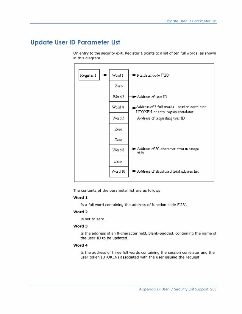
Update User ID Parameter List
Appendix D: User ID Security Exit Support 233
Update User ID Parameter List
On entry to the security exit, Register 1 points to a list of ten full words, as shown
in this diagram.
The contents of the parameter list are as follows:
Word 1
Is a full word containing the address of function code F‘28’.
Word 2
Is set to zero.
Word 3
Is the address of an 8-character field, blank-padded, containing the name of
the user ID to be updated.
Word 4
Is the address of three full words containing the session correlator and the
user token (UTOKEN) associated with the user issuing the request.

Update User ID Parameter List
234 Security Guide
Word 5
Is the address of an 8-character field containing the user ID of the user
making the update request.
Word 6
Is set to zero.
Word 7
Is set to zero.
Word 8
Is the address of an 82-character area into which the exit can place any error
message text if the function request is denied or failed. Any text placed in
this area is displayed to the user in response to the command that caused
this request. If an error message is returned in this area it must be formatted
as follows:
Bytes 00 to 01
Specifies the hexadecimal length of the message text (excluding these
two bytes).
Bytes 02 to nn
Specifies the error message text. Error message text is converted to
upper case.
Limits: 80 characters
Word 9
Is set to zero.
Word 10
Is set to the address of a list of full words, terminated by X‘FFFFFFFF’. Each
full word in this list in turn points to a structured field that defines an item of
user ID information that is to be changed.
More information:
Structured Fields (see page 143)

Update User ID Parameter List
Appendix D: User ID Security Exit Support 235
Return Codes from Update User ID Information Call
The exit must return a completion code in Register 15 on return. Completion
codes are supported as described below. Causes for update rejection are
identified by error message text returned in the area addressed by word 8 of the
Update Call parameter list.
The return codes listed below are the only codes that are accepted in response to
an Update Call. Any other return code is regarded as update rejected.
0
Indicates that update has completed.
4
Indicates that update is rejected. An error message might be available in the
80-character area addressed by word 8 of the parameter list.

&SECCALL EXIT Parameter List
236 Security Guide
&SECCALL EXIT Parameter List
On entry to the security exit, Register 1 points to a list of ten full words, as shown
in this diagram.
The contents of the parameter list are as follows:
Word 1
Is a full word containing the address of function code F‘32’.
Word 2
Is set to zero.
Word 3
Is the address of an 8-character field, blank-padded, containing the user ID
executing the procedure in which &SECCALL EXIT was issued. If &SECCALL
EXIT was issued from an EASINET procedure, this word is set to zero.

&SECCALL EXIT Parameter List
Appendix D: User ID Security Exit Support 237
Word 4
Is the address of three full words containing the session correlator and the
user token (UTOKEN) associated with the user issuing the &SECCALL EXIT
statement. If no user ID is involved because the &SECCALL EXIT statement
has been issued from an EASINET procedure, this word is set to zero.
Word 5
Is the address of 8-character terminal name.
Word 6
Is set to zero.
Word 7
Is set to zero.
Word 8
Is the address of an 82-character area into which the exit can place any
message text. If a message is placed in this area it is returned to the issuing
NCL procedure in the system variable &SYSMSG. If a message is returned in
this area it must be formatted as follows:
Bytes 00 to 01
Specifies the hexadecimal length of the message text (excluding these
two bytes).
Bytes 02 to nn
Specifies the error message text. Message text is converted to upper
case.
Limits: 80 characters
Word 9
Is set to zero.
Word 10
Is the address of a variable length list of contiguous full words, ended by a
full word containing a value of X‘FFFFFFFF’. Each word in the list points at an
area that represents an NCL variable, where the format of this area is
always:
Bytes 00 to 01
Specifies the length of parameter data present (excluding these two
length bytes).
Bytes 02 to 257
Specifies the parameter data, padded to 256 bytes with blanks.

&SECCALL EXIT Parameter List
238 Security Guide
Return Codes from &SECCALL EXIT Call
The exit can pass information back to the calling NCL procedure in the following
ways:
■ A return code can be set by the exit in Register 15 on exit. Valid return codes
are 0 to 99. Any other return code is forced to 99. The return code is available
to the procedure in the system variable &RETCODE after the &SECCALL EXIT
statement.
■ A message (error or otherwise) can be returned in the 82-character message
area addressed by word 8 of the parameter list, as described above.
■ Information can be returned in the parameter areas addressed by word 10 of
the &SECCALL EXIT parameter list. The exit can return information only in
those areas originally passed in the parameter list.
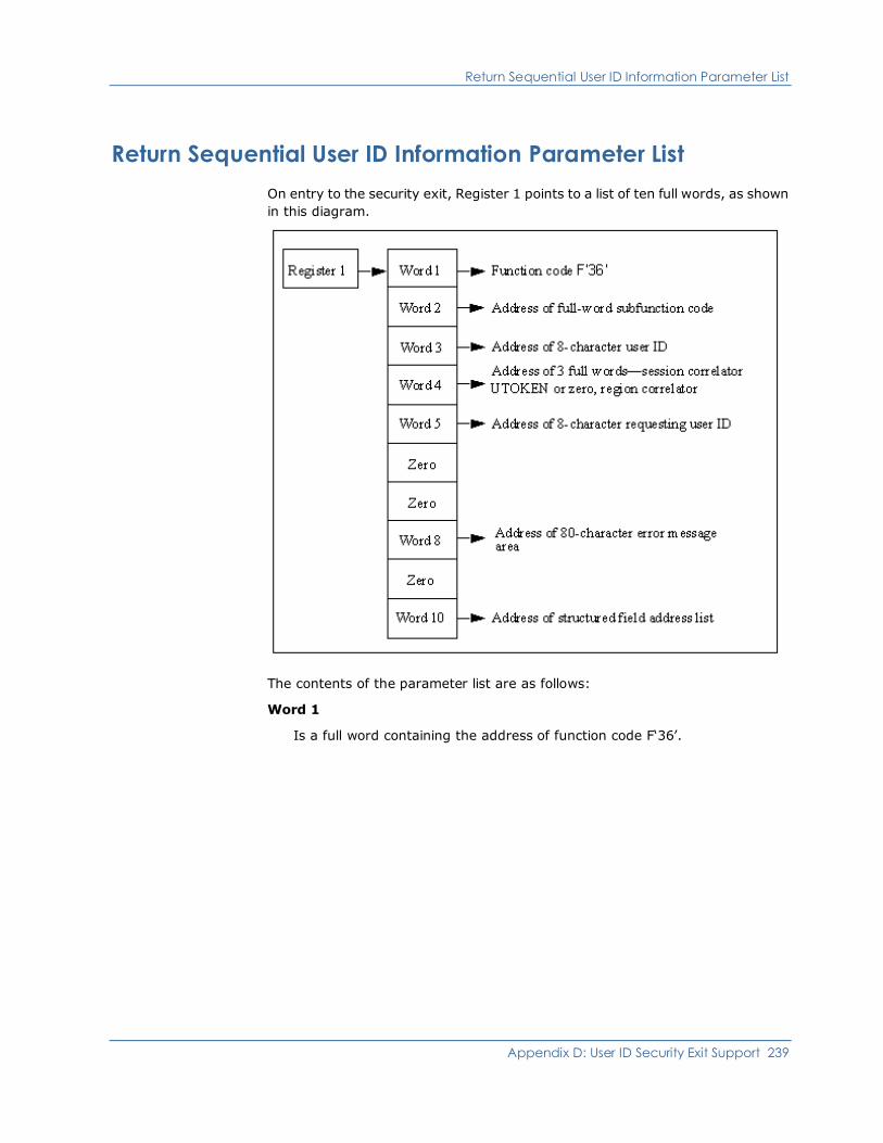
Return Sequential User ID Information Parameter List
Appendix D: User ID Security Exit Support 239
Return Sequential User ID Information Parameter List
On entry to the security exit, Register 1 points to a list of ten full words, as shown
in this diagram.
The contents of the parameter list are as follows:
Word 1
Is a full word containing the address of function code F‘36’.
Return Sequential User ID Information Parameter List
240 Security Guide
Word 2
Is the address of a subfunction code. The code defines the type of sequential
call being requested and has values set as follows:
Subfunction Code Value
F‘0’ Retrieve the next user definition following the key
user ID (provided in word 3). The user ID for which
information is being requested is the next user ID in
the collating sequence.
F‘4’ Retrieve the previous user definition preceding the
key user ID (provided in word 3). The user ID for
which information is being requested is the previous
user ID in the collating sequence.
Word 3
Is the address of an 8-character field, blank-padded, containing the key user
ID for the call, or set to zero if the request is issued for the first (next), or last
(previous) user ID in the collating sequence.
Word 4
Is the address of three full words containing the session correlator and the
user token associated with the user issuing the request (not necessarily the
correlator for the user ID whose information is being requested).
Word 5
Is the address of an 8-character field containing the requesting user ID.
Word 6
Is set to zero.
Word 7
Is set to zero.

Return Sequential User ID Information Parameter List
Appendix D: User ID Security Exit Support 241
Word 8
Is the address of an 82-character area into which the exit can place any error
message text if the function request is denied or failed. Any text placed in
this area is returned to the issuing procedure in the &SYSMSG system
variable. If an error message is returned it must be formatted as follows:
Bytes 00 to 01
Specifies the hexadecimal length of the message text (excluding these
two bytes).
Bytes 02 to nn
Specifies the error message text. Message text is converted to upper
case.
Limits: 80 characters
Word 9
Is set to zero.
Word 10
If the request is honored, the exit must place in this word the address of a list
of full words, terminated by X‘FFFFFFFF’. Each full word in this list in turn
points to a structured field that defines an item of information relevant to the
user ID.
More information:
Structured Fields (see page 143)
NWM--Return Codes from Return Next User ID Information Call
The exit must return a completion code in Register 15 on return. Completion
codes are supported as described below. Causes for rejection are identified by
error message text returned in the area addressed by word 8 of the parameter
list.
The return codes listed below are the only codes that are accepted in response to
the call. Any other return code is treated as return code 4.
0
Indicates that information is available. Word 10 of the parameter list points
to an address list that provides pointers to structured fields describing the
user ID.
4
Indicates that information is not available. An error message might be
available in the 80-character area addressed by word 8 of the parameter list.

Add User ID Parameter List
242 Security Guide
Add User ID Parameter List
On entry to the security exit, Register 1 (R1) points to a list of ten full words, as
shown in this diagram.
The contents of the parameter list are as follows:
Word 1
Is a full word containing the address of function code F‘40’.
Word 2
Is the address of a subfunction code. The code defines the type of user to be
added and has values set as follows:
Subfunction Code Value
F‘0’ A USER definition is to be added.
F‘4’ A GROUP definition is to be added.
Add User ID Parameter List
Appendix D: User ID Security Exit Support 243
Word 3
Is the address of an 8-character field, padded with blanks, containing the
user definition to be added.
Word 4
Is the address of three full words containing the session correlator and the
user token (UTOKEN) associated with the user issuing the request.
Word 5
Is the address of a 8-character field containing the user ID of the user issuing
the ADD request.
Word 6
Is the address of a 8-character field containing the initial password of the
user to be added or set to zero if a password is not provided.
This field is optional on the &SECCALL ADD function when using a security
exit. It is the responsibility of the installation to take appropriate action on
the requirement for this password.
Word 7
Is set to zero.
Word 8
Is the address of an 82-character message area into which the exit can place
any error message text if the add request is denied or failed. Any text placed
in this area is displayed to the user in response to the command that caused
this request. If an error message is returned in this area, it must be
formatted as follows:
Bytes 00 to 01
Specifies the hexadecimal length of the message text (excluding these
two bytes).
Bytes 02 to nn
Specifies the error message text. Message text is converted to upper
case.
Limits: 80 characters
Word 9
Is set to zero.
Word 10
Is set to the address of a list of full words, terminated by X‘FFFFFFFF’. Each
full word in this list in turn points to a structured field that defines an item of
user ID information that is to be added.

Add User ID Parameter List
244 Security Guide
More information:
Structured Fields (see page 143)
Return Codes from the Add User ID Call
The exit must return a completion code in Register 15 (R15) on return.
Completion codes are supported as described below. Causes for rejection of add
calls are identified by error message text returned in the area addressed by word
8 of the add call parameter list.
The return codes listed below are the only codes that are accepted in response to
an add call. Any other return codes are regarded as a rejection of the add call.
0
Indicates that ADD is complete.
4
Indicates that ADD is rejected. An error message might be available in the
80-character area addressed by word 8 of the parameter list.
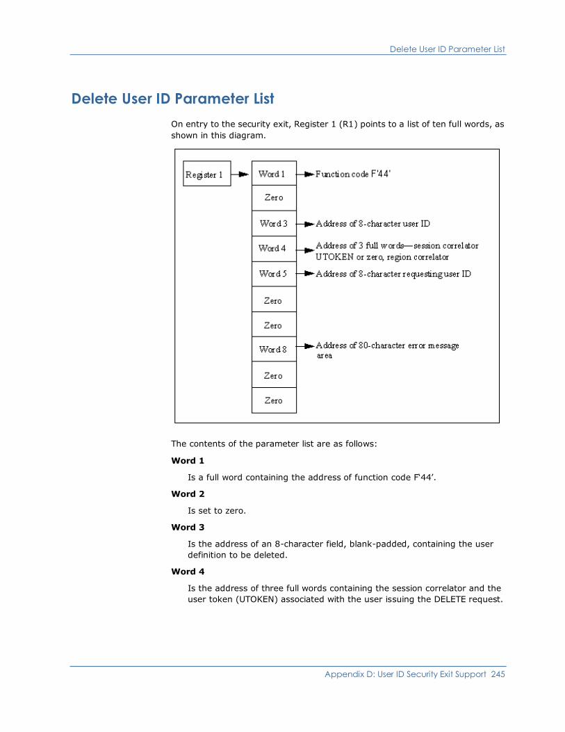
Delete User ID Parameter List
Appendix D: User ID Security Exit Support 245
Delete User ID Parameter List
On entry to the security exit, Register 1 (R1) points to a list of ten full words, as
shown in this diagram.
The contents of the parameter list are as follows:
Word 1
Is a full word containing the address of function code F‘44’.
Word 2
Is set to zero.
Word 3
Is the address of an 8-character field, blank-padded, containing the user
definition to be deleted.
Word 4
Is the address of three full words containing the session correlator and the
user token (UTOKEN) associated with the user issuing the DELETE request.
Delete User ID Parameter List
246 Security Guide
Word 5
Is the address of a 8-character field containing the user ID of the user issuing
the DELETE request.
Word 6
Is set to zero.
Word 7
Is set to zero.
Word 8
Is the address of a 82-character message area into which the exit can place
any error message text if the delete request is denied or failed. Any text
placed in this area is displayed to the user in response to the command that
caused this request. If an error message is returned in this area, it must be
formatted as follows:
Bytes 00 to 01
Specifies the hexadecimal length of the message text (excluding these
two bytes).
Bytes 02 to nn
Specifies the error message text. Message text is converted to upper
case.
Limits: 80 characters
Word 9
Is set to zero.
Word 10
Is set to zero.

Delete User ID Parameter List
Appendix D: User ID Security Exit Support 247
Return Codes from the Delete User ID Call
The exit must return a completion code in Register 15 (R15) on return.
Completion codes are supported as described below. Causes for delete rejection
are identified by error message text returned in the area addressed by word 8 of
the DELETE call parameter list.
The following return codes are the only codes that are accepted in response to a
delete call. Any other return codes are regarded as a rejection of the delete call.
0
Indicates that Delete is complete.
4
Indicates that Delete is rejected. An error message might be available in the
80-character area addressed by word 8 of the parameter list.

Appendix E: Data Set Authorization Exits Support 249
Appendix E: Data Set Authorization Exits
Support
This appendix describes how to write and install the data set access authorization
exit (NMDSNCHK) and the data set services authorization exit (NMDSSCHK).
This section contains the following topics:
Writing a Data Set Access Authorization Exit (see page 249)
Installing the Data Set Access Authorization Exit (see page 253)
Writing a Data Set Services Authorization Exit (see page 254)
Installing the Data Set Services Authorization Exit (see page 258)
Writing a Data Set Access Authorization Exit
The authorization exit is attached and operates as a subtask. Therefore, complex
processing, WAITs, or SVCs do not impact overall performance.
Review the source code for the sample data set access authorization exit
NMDSNCHK and use it as a guide to writing your own exit.
Registers on Entry to the Exit
When the exit is invoked, Register 1 contains the address of a communication
area containing various parameters. This communication area can be mapped
using the macro $NMDSNCK, supplied in the distribution libraries. This macro
provides a DSECT expansion to perform the mapping, and detailed information
on the content of each field.
Standard linkage conventions apply. On entry, the exit must save the contents of
all registers (Register 13 contains the address of a save area), and on exit all
registers must be restored to their content on entry, with the exception of
Register 15 which should contain a return code.

Writing a Data Set Access Authorization Exit
250 Security Guide
Parameters Passed to the Exit
The data set access authorization exit is provided so that the installation can
determine whether access to a data set is to be permitted.
■ When invoked as a result of an ALLOCATE command, a communication area
containing the following information is passed to the exit:
– Data set name
– User ID of requestor
■ When invoked as a result of a CA SOLVE:FTS operation, a communication
area containing the following information is passed to the exit:
– Data set names
– DD statement names
– Class of transmission
– Type of access required (READ at the sending end, READ/WRITE at the
receiving end)
– Whether this request is a SYSTEM or PRIVATE request
– Type of data set allocation (NEW, SHR, and so on)
– CA SOLVE:FTS ID
– Transmission Definition password
– CA SOLVE:FTS user ID of requestor
– Space allocation and volume information, if this is a NEW data set
The format of this area is mapped by the supplied $NMDSNCK DSECT.
Writing a Data Set Access Authorization Exit
Appendix E: Data Set Authorization Exits Support 251
Calls Made to the Exit
Whenever you use the ALLOCATE command to allocate a data set, a call is made
to the authorization exit. A call is also made to the authorization exit when CA
SOLVE:FTS identifies the data set that is to be transmitted or received. Calls are
therefore made both at the transmitting and at the receiving end of a
transmission operation.
On return from the initial call, the exit may set indicator flags (see the DSNCFLG
field in the $NMDSNCK DSECT) that determine which subsequent calls CA
SOLVE:FTS is to make to the exit during the progress of the transmission
operation.
The following additional calls are made as requested by the exit:
■ Preallocation call—made before the target data set is dynamically
allocated
■ Pre-open call—made just before the target data set is opened
■ Pre-deallocation call—made just before the target data set is dynamically
deallocated
Identifying the Type of Call
The type of call being made to the exit is identified by the DSNSTYPE field in the
exit communication area. This field is set as follows:
F’0’
Indicates a call for CA SOLVE:FTS access authorization.
F’4’
Indicates a call for the CA SOLVE:FTS allocation subtask.
F’8’
Indicates a call for the CA SOLVE:FTS open subtask or file.
F’12’
Indicates a call for the CA SOLVE:FTS deallocation subtask.
F’16’
Indicates a call for an ALLOCATE command.
If your installation uses RACF security software, the exit can make a call to RACF
to associate the allocation with the requesting user ID rather than with your
product region.
Writing a Data Set Access Authorization Exit
252 Security Guide
Modifying Transmission Information
Note: This section only applies to CA SOLVE:FTS.
In the initial access authorization call to NMDSNCHK, at the receiving end of a
transmission, you can use the exit to overwrite some of the values passed to it in
$NMDSNCK, and use these new values for the transmission, thereby enforcing
your organization's security, naming, and allocation standards on incoming
transmissions.
You can overwrite the following fields:
DSNCDSN
The receiving data set name
For new data sets only, you can overwrite the following fields:
DSNCVOL
The volume on which the data set is to be allocated
DSNCDEVT
The device type on which the data set is to be allocated
DSNCSPCE
The space allocation units to be used (CYLS, BLKS, or TRKS)
DSNCPRIM
The primary allocation amount
DSNCSECN
The secondary allocation amount
DSNCDIR
The directory blocks to be allocated
If you change any of these fields, you must set the DSNMODR flag to indicate
that the changed values are to be substituted for the defined values for this
transmission. If invalid values are returned in any field, the transmission will be
terminated.
Note: You can only change these fields on the initial call for incoming
transmissions. If the above fields are modified or the DSNMODR bit set at any
other time, the modifications will be ignored.
Installing the Data Set Access Authorization Exit
Appendix E: Data Set Authorization Exits Support 253
Return Codes From the Exit
A return code is set in Register 15 on return from all calls to the exit, indicating
the action that should be taken:
0
Indicates that access is permitted. Allocation can proceed.
4
Indicates that access is denied. An error message can be placed in the field
DSNCTMSG, and its length in the field DSNCLMSG, in the communication
area.
If the authorization exit is called by CA SOLVE:FTS and elects to receive the calls
subsequent to the initial authorization call, return code 4, set in register 15 on
return from any of those calls, will cause termination of the transmission at that
point. The exit indicates which, if any, of the subsequent calls are required.
The additional calls to the exit allow greater control over the significant
data set-specific operations that are involved in a transmission, letting the exit
perform ENQ/DEQ functions to prevent duplicate access to data sets.
For RACF security software, the exit may call RACF at these times to associate
the security responsibility for the action against the requesting user ID, rather
than against CA SOLVE:FTS itself.
Installing the Data Set Access Authorization Exit
When you have created your own data set access authorization load module,
place it in your product’s load library, or in another library concatenated to the
load library through the STEPLIB DD statement in the started task JCL.
To identify your exit to your product region
1. Enter /PARMS at the command prompt. The Customizer : Parameter
Groups list is displayed.
2. Enter U beside the NMSECURITY parameter group. The
Customizer : Parameter Group panel for the NMSECURITY parameter group
is displayed.
3. Enter the name of your load module in the Dataset Access Authorization Exit
(NMDSNCHK) field.
4. Press F6 (Action) to set the changes; press F3 (File) to save the changes and
exit.
Writing a Data Set Services Authorization Exit
254 Security Guide
Writing a Data Set Services Authorization Exit
The data set services authorization exit is loaded by a data set services subtask
and is called synchronously by the subtask. The exit can issue WAIT or other
SVCs without impacting your product region’s main task.
Review the source code for the sample data set services authorization exit
NMDSSCHK and use it as a guide to writing your own exit.
The exit load module must be link edited as AMODE 24, RMODE 24. The exit
procedure can be coded as reentrant; however, this is not required because an
explicit load is performed for each task using the exit. The exit is always called in
24-bit address mode.
Function Calls Made to the Exit
There are three main types of calls made to the exit:
■ Exit Initialization—performs any initialization required.
■ Logical Function—represents a function that has been requested by the
user. For example, a data set allocation request or an OPEN request for a
data set.
■ Exit Termination—allows the exit to clean up any allocated storage areas
and, if applicable, break the connection with any security subsystem that is
being used.
Check the DSSCFUNC field to determine the type of call being made.
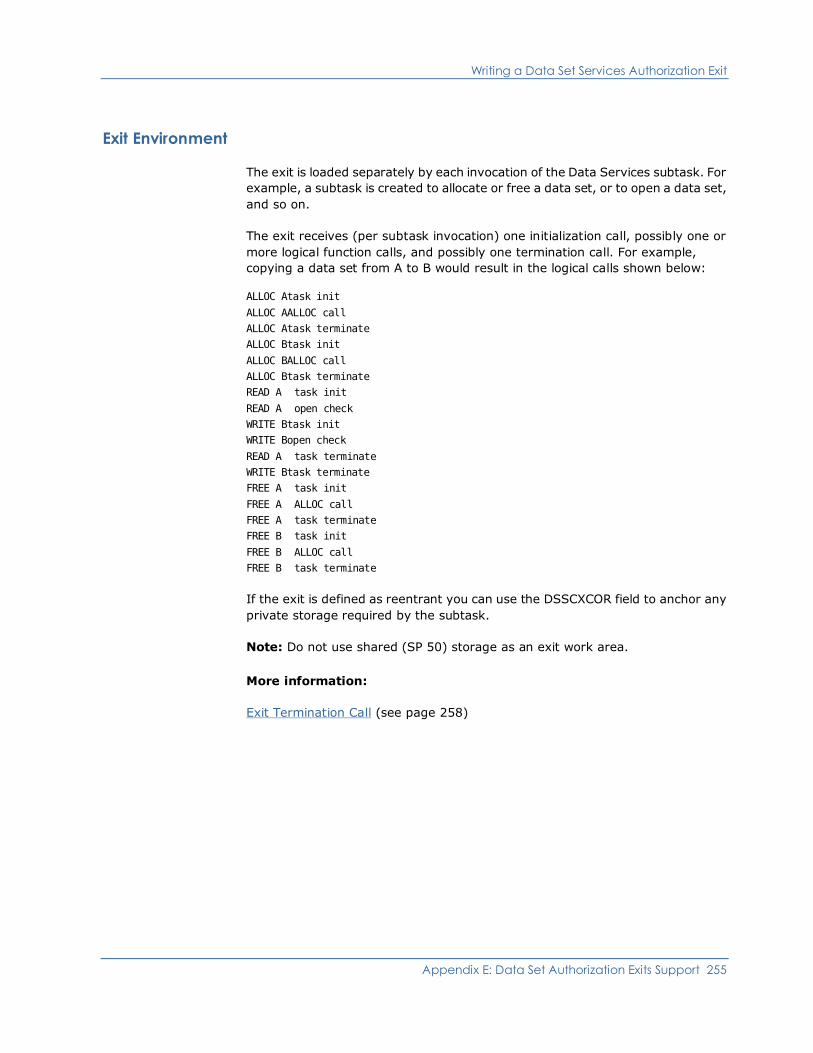
Writing a Data Set Services Authorization Exit
Appendix E: Data Set Authorization Exits Support 255
Exit Environment
The exit is loaded separately by each invocation of the Data Services subtask. For
example, a subtask is created to allocate or free a data set, or to open a data set,
and so on.
The exit receives (per subtask invocation) one initialization call, possibly one or
more logical function calls, and possibly one termination call. For example,
copying a data set from A to B would result in the logical calls shown below:
ALLOC Atask init
ALLOC AALLOC call
ALLOC Atask terminate
ALLOC Btask init
ALLOC BALLOC call
ALLOC Btask terminate
READ A task init
READ A open check
WRITE Btask init
WRITE Bopen check
READ A task terminate
WRITE Btask terminate
FREE A task init
FREE A ALLOC call
FREE A task terminate
FREE B task init
FREE B ALLOC call
FREE B task terminate
If the exit is defined as reentrant you can use the DSSCXCOR field to anchor any
private storage required by the subtask.
Note: Do not use shared (SP 50) storage as an exit work area.
More information:
Exit Termination Call (see page 258)

Writing a Data Set Services Authorization Exit
256 Security Guide
Registers on Entry to the Exit
On entry to the exit, Register 1 contains the address of a parameter list area that
is used to pass information to the exit. This communication area is mapped by
the $NMDSSCK macro, that is distributed with your product. This macro provides
a DSECT expansion to perform mapping and contains detailed information on the
contents of each field.
Standard module linkage conventions apply; on entry, the exit must save the
contents of all registers (Register 13 contains the address of a save area that can
be used by the exit) and on exit all registers must be restored to the value they
had on entry with the exception of Register 15 that should contain a return code
relevant to the function call.
Exit Initialization Call
This call allows the exit to perform any initialization required. This could include
authorizing the subtask against the authority level of the user. This call is not
specific to any request from the user: logical function calls identify the functions
that have been requested by a user and you can perform more specific
processing for these calls.
The parameter area passed to the exit contains the user ID of the user, any User
Token or Security Exit Correlator associated with the user (drawn from the main
security exit, if one is being used) and information about the region in which the
exit is running (for example, the NMID).
The exit must return with Register 15 set to a return code that indicates the
success or failure of exit initialization. A return code can be set to indicate that no
more security processing is required for the function.
The following return codes are allowed for this call:
0
Indicates that exit initialization completed successfully.
4 (see page 257)
Indicates that exit initialization completed successfully. No more logical
function calls are required for this user—note that the termination call is still
performed, however.
8
Indicates that exit initialization failed.
If Register 15 is set to 8, you can use the DSSCLMSG and DSSCTMSG fields to
return a message indicating the reason for the failure. See the $NMDSSCK macro
for full details. If no message is returned, data set services sets a default
message. The message returned by the exit is recorded on the activity log.
Writing a Data Set Services Authorization Exit
Appendix E: Data Set Authorization Exits Support 257
More information:
Using Return Code 4 (see page 257)
Using Return Code 4
If you set return code 4 on initialization, this means that the host does not need
to participate on any subsequent logical function authorization.
You might do this, for example, if you issue a RACINIT during initialization to
register the subtask as relating to a specific user ID (that is, when you have a
security exit installed). In this case, for example, an OPEN DATASET call would
result in an S913 OPEN ABEND since RACF does the security checking.
Note: Data set services handles this situation correctly.
If you set return code 0, but still connect the subtask to the security system, you
can do additional checking on some calls (for example, rename PDS member)
that the security system does not specifically check.
Logical Function Call
This call represents a function that has been requested by the user. For example,
a data set allocation request or a request to open a data set. The DSSCTYPE field
is used to indicate the function to be performed.
The parameter area passed to the exit contains all information passed on the exit
initialization call as well as any specific information requested by the user for the
function. For example, if the call is for an allocation request the data set name,
disposition, volume name, and so on, might be available. The $NMDSSCK macro
contains a full description of each logical function call and the parameters that
are passed on each call.
The exit can return with Register 15 set to a return code that indicates whether
the function is permitted.
The following return codes are allowed for this call:
0
Indicates that the function is authorized.
4
Indicates that the function is not authorized.
If Register 15 is set to 4, a message indicating the reason for the failure can be
returned using the DSSCLMSG and DSSCTMSG fields. See the $NMDSSCK macro
for full details. If no message is returned by the exit, data set services sets a
default message. The message returned by the exit is recorded on the activity
log.

Installing the Data Set Services Authorization Exit
258 Security Guide
Exit Termination Call
This call allows the exit to clean up any allocated storage areas and, if applicable,
break the connection with any security subsystem that is being used. The exit
load module is deleted from storage on return from this call.
Note: This call may not occur. If, for example, an NCL process using data set
services is flushed, the subtask(s) are force detached. You should be aware of
this and allocate any private storage in a non-shared subpool (this can include
subpool SP0 but not SP50), which results in the storage being automatically
freed.
The parameter passed to the exit contains all information passed on the exit
initialization call. Register 15 must contain 0 on return from this call.
Installing the Data Set Services Authorization Exit
When you have created your own data set services authorization load module,
place it in your product’s load library, or in another library concatenated to the
load library through the STEPLIB DD statement in the started task JCL.
To identify your exit to your product region
1. Enter /PARMS at the command prompt. The Customizer : Parameter
Groups list is displayed.
2. Enter U beside the NMSECURITY parameter group. The
Customizer : Parameter Group panel for the NMSECURITY parameter group
is displayed.
3. Enter the name of your load module in the Dataset Services Authorization
Exit (NMDSSCHK) field.
4. Press F6 (Action) to set the changes; press F3 (File) to save the changes and
exit.
Appendix F: INMC Security Exit Support 259
Appendix F: INMC Security Exit Support
This appendix describes how to code the INMC security exit and details the
parameter lists exchanged between your product region and the exit.
This section contains the following topics:
Writing an INMC Security Exit (see page 259)
Writing a Primary Exit (see page 262)
Writing a Secondary Exit (see page 271)
Writing an INMC Security Exit
You must write a primary and secondary exit for each system that is to be
controlled by the INMC security exit when connected by an INMC link.
The exits must be assembled and linked to form an executable load module and
must be placed in a load library accessible to your product region during
execution.
When the exit is called, standard assembler language linkage conventions apply.
When invoked, the exit operates under your product region’s main task, and
therefore extensive processing, I/O operations, or WAITs issued within the exit
can impact the overall performance of the system.
Identifying the Primary Exit
One INMC primary exit is available for any one system and must be identified by
using the following command:
SYSPARMS INMCEX01=exitname
where exitname is the load module of the primary exit. This command must be
included in the INIT initialization procedure or issued as a command before a link
is activated.
When an INMC link is activated, INMC attempts to load a copy of the exit. If the
load fails for any reason it is regarded as a security exposure and the link is
disabled automatically. The exit should be written to be reentrant if possible
since a load is issued for each link that is activated.
Writing an INMC Security Exit
260 Security Guide
Identifying the Secondary Exit
One INMC secondary exit is available for any one system and must be identified
by the command:
SYSPARMS INMCEX02=exitname
where exitname is the load module of the secondary exit. This command must be
included in the INIT initialization procedure or issued as a command before a link
is activated.
When an INMC link is activated, INMC attempts to load a copy of the exit. If the
load fails for any reason the primary exit of the remote system is notified that no
secondary exit exists in this system. In this case the remote primary exit decides
whether to allow link activation.
Changing Exit Names Dynamically
The name of the load module that forms either the primary or secondary INMC
exit can be changed dynamically at any time by reissuing the SYSPARMS
command to identify the new exit name. Either exit can be disabled at any time
by issuing the following commands:
SYSPARMS INMCEX01=NONE
SYSPARMS INMCEX02=NONE
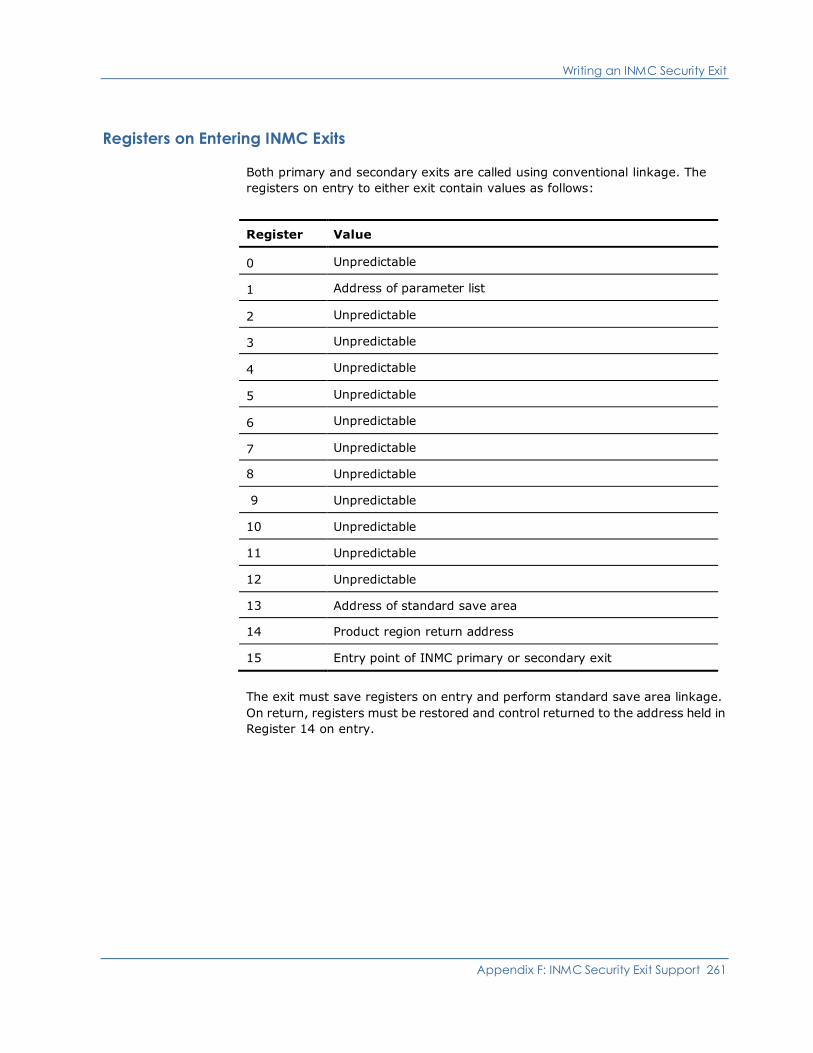
Writing an INMC Security Exit
Appendix F: INMC Security Exit Support 261
Registers on Entering INMC Exits
Both primary and secondary exits are called using conventional linkage. The
registers on entry to either exit contain values as follows:
Register Value
0 Unpredictable
1 Address of parameter list
2 Unpredictable
3 Unpredictable
4 Unpredictable
5 Unpredictable
6 Unpredictable
7 Unpredictable
8 Unpredictable
9 Unpredictable
10 Unpredictable
11 Unpredictable
12 Unpredictable
13 Address of standard save area
14 Product region return address
15 Entry point of INMC primary or secondary exit
The exit must save registers on entry and perform standard save area linkage.
On return, registers must be restored and control returned to the address held in
Register 14 on entry.
Writing a Primary Exit
262 Security Guide
Writing a Primary Exit
The primary exit is called by your product region with Register 1 containing the
address of a parameter list which is always ten consecutive full words in length.
Depending upon the reason for the call, some of these words might be set to
binary zeroes.
The first word of the parameter list is always the address of a full word that
contains a function code identifying the type of call being made.
The other parameters passed depend upon the value of this function code and
the exit must therefore determine the function code first in order to decide which
parameters to expect.
The parameter list passed to the exit is also used as a parameter list returned
from the exit, allowing the exit to indicate the processing required and to pass
the appropriate information to your product region.
Note: On a call to the exit, addresses of various fields are included in the
parameter list. Only these fields can be used to return information from the exit;
the exit cannot pass parameters back to your product region in any other
locations.
Specifying Initialization Processing
Initialization processing notifies the primary exit of two things:
■ The INMC link to the specified remote system has been activated
■ Whether the remote system is configured with a secondary exit to which the
primary exit can send messages
To provide this functionality in your exit, you must code the initialization call to
correspond with the parameter list in the following section.
You must take into consideration any special processing you want to perform,
such as, password exchange between the connecting systems.
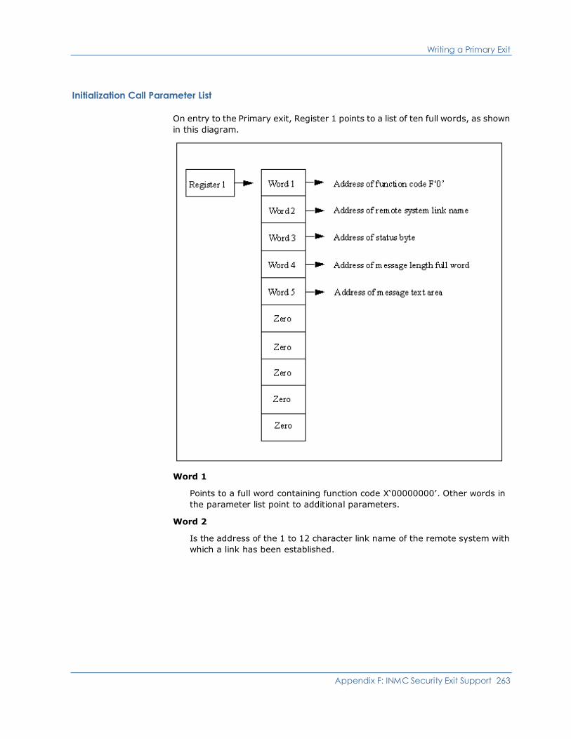
Writing a Primary Exit
Appendix F: INMC Security Exit Support 263
Initialization Call Parameter List
On entry to the Primary exit, Register 1 points to a list of ten full words, as shown
in this diagram.
Word 1
Points to a full word containing function code X‘00000000’. Other words in
the parameter list point to additional parameters.
Word 2
Is the address of the 1 to 12 character link name of the remote system with
which a link has been established.

Writing a Primary Exit
264 Security Guide
Word 3
Is the address of a 1-byte field that specifies the status of the secondary exit
in the remote system. Values of this field and the meanings are as follows:
Field Value Definition
X‘00’ A secondary exit is available for communications.
X‘04’ The remote system does not have a secondary exit
defined. No SYSPARMS INMCEX02 command has been
issued in the remote system.
X‘08’ The remote system has a secondary exit defined but the
load module (or phase) was not loaded successfully.
Word 4
Is the address of a full word, value F‘0’. The primary exit can place in this
field the length of a message that is to be sent to the secondary exit in the
remote system. The maximum length is 256 bytes (decimal). If a longer
length is specified it is truncated to 256. If a negative length is specified it is
forced to 256.
Word 5
Is the address of an area in which the primary exit can place the text of a
message that is to be sent to the secondary exit in the remote system. The
message is assumed to be left aligned in this message area. The maximum
message text length is 256 (decimal) bytes. The data in the message can be
binary or character and is transparent to your region. The meaning and
format of the message sent to the secondary exit is determined by the
installation.
Words 6 to 10
Are set to zero.

Writing a Primary Exit
Appendix F: INMC Security Exit Support 265
Return Codes from Initialization Call
On return from the initialization call, the primary exit signals what it wants done
next. The choices that are available are:
■ Send a message to the secondary exit in the remote system.
■ Terminate exit processing.
The exit indicates which option is required by using the same ten full words of the
parameter list with which it was called, to pass back its own instructions to your
region. When the exit returns therefore, the ten full word parameter list must be
formatted as follows:
Word 1
Is the address of a function code specifying the action that the exit wishes
your region to take. Values of this function code and their meanings are as
follows:
Function Code Definition
F‘0’ A message is to be sent to the secondary exit in the
remote system.
F‘4’ Exit processing is to terminate.
Word 2
Is unchanged and not used.
Word 3
Is the address of a 1-byte field. This is the same address as was passed to
the exit in word 3 of the parameter list. The value of this 1-byte field depends
upon the function code returned by the exit in word 1. Valid values and their
meanings are:
Function Code Meaning
F‘0’ Function code not used.
F‘4’ X‘00’ Allow normal link activation
X‘04’ Allow link to remain open but allow no traffic to flow
X‘08’ Close the link
Writing a Primary Exit
266 Security Guide
Word 4
Is not used for function code F‘4’. For function code F‘0’ this word holds the
address of a full word in which the primary exit can place the binary length of
a message that is to be sent to the secondary exit in the remote system. The
maximum length is 256 bytes (decimal). If a longer length is specified it is
truncated to 256. If a negative length is specified it is forced to 256. This is
the same address as passed to the exit in word 4 of the parameter list.
Word 5
Is not used for function code F‘4’. For function code F‘0’ this word holds the
address of an area in which the primary exit can place the text of a message
that is to be sent to the secondary exit in the remote system. The message is
assumed to be left aligned in this message area. The maximum message text
length is 256 (decimal) bytes. The data in the message can be binary or
character and is transparent to your region. The meaning and format of the
message sent to the secondary exit is determined by the installation. This is
the same address as passed to the exit in word 5 of the parameter list.
Words 6 to 10
Are set to zero.
Specifying Message Delivery Processing
When the primary exit sends a message to the secondary exit in a remote
system, the secondary exit always responds with a reply. That reply can be a null
message of zero length. The reply message is presented to the primary exit for
processing by using a Deliver Call.
The primary exit performs whatever processing is required and then returns to
your region with the ten full word parameter list set to indicate the processing
required next.
On return, the exit can request one of two options:
■ Exit processing is to terminate.
■ A message is to be sent to the secondary exit.
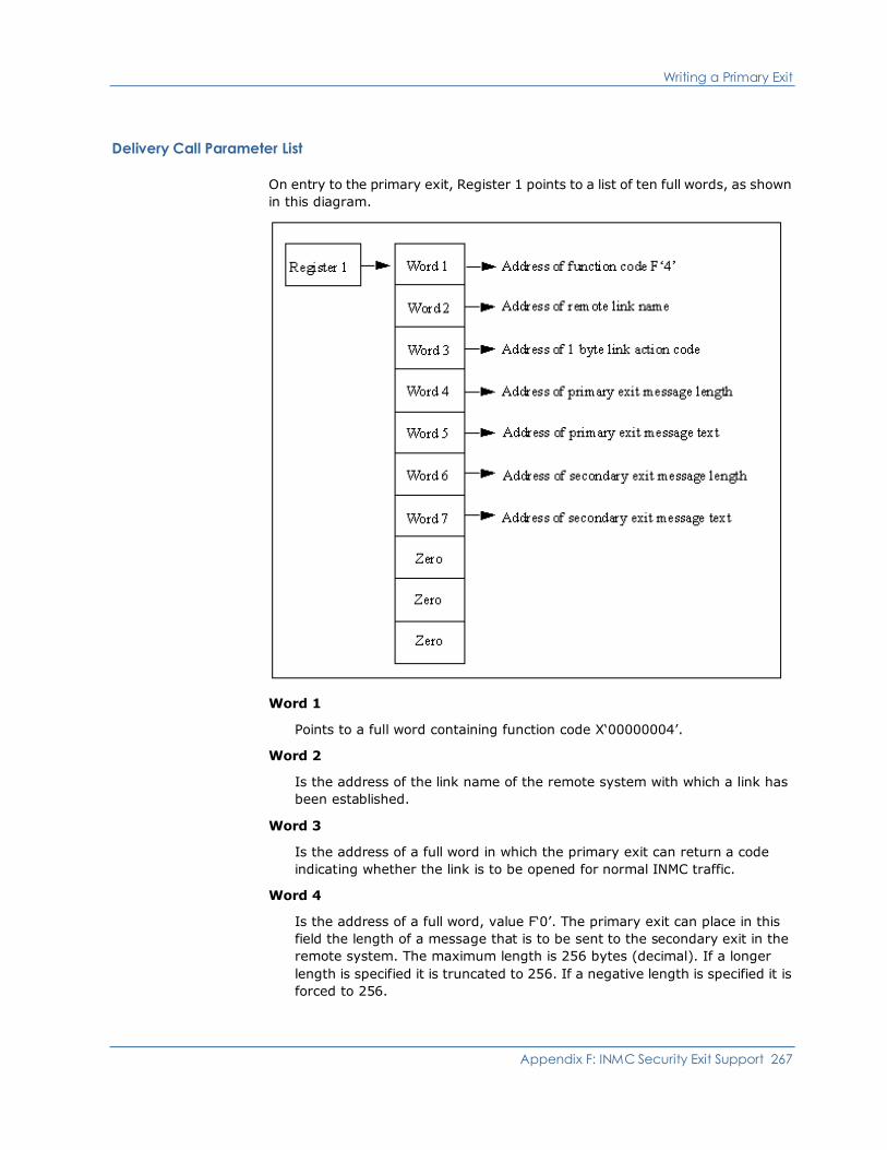
Writing a Primary Exit
Appendix F: INMC Security Exit Support 267
Delivery Call Parameter List
On entry to the primary exit, Register 1 points to a list of ten full words, as shown
in this diagram.
Word 1
Points to a full word containing function code X‘00000004’.
Word 2
Is the address of the link name of the remote system with which a link has
been established.
Word 3
Is the address of a full word in which the primary exit can return a code
indicating whether the link is to be opened for normal INMC traffic.
Word 4
Is the address of a full word, value F‘0’. The primary exit can place in this
field the length of a message that is to be sent to the secondary exit in the
remote system. The maximum length is 256 bytes (decimal). If a longer
length is specified it is truncated to 256. If a negative length is specified it is
forced to 256.
Writing a Primary Exit
268 Security Guide
Word 5
Is the address of an area in which the primary exit can place the text of a
message that is to be sent to the secondary exit in the remote system. The
message is assumed to be left aligned in this message area. The maximum
message text length is 256 bytes (decimal). The data in the message can be
binary or character and is transparent to your region. The meaning and
format of the message sent to the secondary exit is determined by the
installation.
Word 6
Is the address of a full word containing the length of a message sent from the
secondary exit in the remote system. The maximum length is 256 bytes
(decimal), minimum is zero (which would be a null message).
Word 7
Is the address of the message sent from the secondary exit.
Words 8 to 10
Are set to zero.
Return Codes from Delivery Call
When the primary exit completes its processing of the message returned from
the secondary exit it formats the ten word parameter list to indicate the
processing required next and then returns to your region.
The parameter list must be set exactly.
More information:
Return Codes from Initialization Call (see page 265)
Specifying Termination of Link Notification Processing
If a link to a remote system is lost before a reply is received from the secondary
exit, your region indicates this to the primary exit via a notify call. This call tells
the primary exit that no further communications can be received from the
secondary exit and that the INMC link to the remote system has been lost.
A notify call is also made in response to the primary exit attempting to
communicate with a secondary exit when the remote system is not configured
with a secondary exit or the secondary exit failed to initialize.
When the exit has been notified of a lost link, it should then perform whatever
termination processing it needs to do then return to your region, indicating that
exit processing is to terminate. Any other action results in repetitive notify calls
until the exit signals that exit processing is to end.

Writing a Primary Exit
Appendix F: INMC Security Exit Support 269
Notify Call Parameter List
On entry to the primary exit, Register 1 points to a list of ten full words, as shown
in this diagram.
Word 1
Points to a full word containing function code X‘00000008’.
Word 2
Is the address of the link name of the remote system with which contact has
been lost.
Writing a Primary Exit
270 Security Guide
Word 3
Is the address of 1-byte field containing a notify code. Valid values are as
follows:
Field Value Definition
X‘04’ The remote system does not have a secondary exit
defined. No SYSPARMS INMCEX02 command has been
issued in the remote system.
X‘08’ The remote system has a secondary exit defined but the
load module (or phase) was not loaded successfully.
X‘0C’ The link has been lost.
Words 4 to 10
Are set to zero.
Return Codes from Notify Call
When the primary exit completes its processing of the notify call it should format
the ten word parameter list as follows:
Word 1
Is the address of a function code specifying the action that the exit requires
your region to take. The values of this function code must be F’4’ (Exit
processing is to terminate).
The remaining nine full words should be returned unchanged.
Writing a Secondary Exit
Appendix F: INMC Security Exit Support 271
Writing a Secondary Exit
The secondary exit is called by your region with Register 1 containing the address
of a parameter list which is always ten consecutive full words in length.
Depending upon the reason for the call, some of these words can be set to binary
zeroes.
The first word of the secondary exit parameter list is always the address of a full
word that contains a function code identifying the type of call being made.
The other parameters passed depend upon the value of this function code, and
the exit must therefore determine the function code first in order to decide which
parameters to expect.
The parameter list passed to the exit is also used as a parameter returned from
the exit, allowing the exit to indicate the processing required and to pass the
appropriate information to your region.
Note: On a call to the exit, addresses are included in the parameter list of
various fields. Only these fields can be used to return information from the exit;
the exit cannot pass parameters back to your region in any other locations.
Specifying Initialization Processing
Initialization processing indicates to the secondary exit that a link has become
active. There is no indication whether a primary exit exists in the remote system,
or, if there is, whether that exit is going to attempt to communicate with the
secondary exit. The secondary exit must therefore be written to expect whatever
processing is implemented in the remote primary exit.

Writing a Secondary Exit
272 Security Guide
Initialization Call Parameter List
On entry to the secondary exit, Register 1 points to a list of ten full words, as
shown in this diagram.
Word 1
Points to a full word containing function code X‘00000000’. Other words in
the parameter list point to additional parameters.
Word 2
Is the address of the link name of the remote system with which a link has
been established. There may or may not be a primary exit defined for that
system. If there is, it is up to the primary exit to determine whether it wants
to communicate with this secondary exit.
Words 3 to 10
Are set to zero.
Writing a Secondary Exit
Appendix F: INMC Security Exit Support 273
Return Codes from the Initialize Call
The secondary exit does not have an opportunity to respond to the initialize call.
On completion of any processing it chooses to perform when passed control, the
secondary exit should return to your region with its ten full word parameter list
unchanged.
Specifying Message Delivery Processing
When the primary exit sends a message to the secondary exit the message is
presented to the secondary exit for processing using the Deliver Call.
The secondary exit performs whatever processing is required and then returns to
your region. On return, your region expects the secondary exit to have set the
message-length and message-text areas pointed to by words 6 and 7 of the
parameter list with which it was called.
The secondary exit can, if necessary, indicate that a null message is to be
returned to the primary exit, perhaps as an acknowledgment to the message
sent by the primary.

Writing a Secondary Exit
274 Security Guide
Deliver Call Parameter List
On entry to the secondary exit, Register 1 points to a list of ten full words, as
shown in this diagram.
Word 1
Points to a full word containing function code X‘00000004’.
Word 2
Is the address of the link name of the remote system from which the
message has been received.
Word 3
Is set to zero.
Word 4
Is the address of a full word containing the length of a message sent from the
primary exit in the remote system. The maximum length is 256 bytes
(decimal), minimum is zero (which would be a null message).
Word 5
Is the address of the message sent from the primary exit.

Writing a Secondary Exit
Appendix F: INMC Security Exit Support 275
Word 6
Is the address of a full word, value F‘0’. The secondary exit can place in this
field the length of a message that is to be sent to the primary exit in the
remote system. The maximum length is 256 bytes (decimal). If a longer
length is specified it is truncated to 256. If a negative length is specified it is
forced to 256.
Word 7
Is the address of an area in which the secondary exit can place the text of a
message that is to be sent to the primary exit in the remote system. The
message is assumed to be left aligned in this message area. The maximum
message text length is 256 bytes (decimal). The data in the message can be
binary or character and is transparent to your region.
The meaning and format of the message sent to the primary exit is
determined by the installation.
Words 8 to 10
Are set to zero.
Return Codes from Secondary Exit Deliver Call
The secondary exit should set the full word pointed to by word 6 of the call
parameter list to the length of the message text that is to be returned to the
primary exit as a reply to the message just delivered.
The message length has a range of 0 to 256 in hexadecimal. Any text outside the
specified range is truncated to 256 bytes decimal. A zero length is accepted.
Negative length settings are forced to a zero value.
Word 7 of the call parameter list points to a 256-byte area in which the secondary
exit can place the text of the message to be returned to the primary exit. The
format and content of the message returned is decided by the installation.
No other return information is accepted from the secondary exit.

Writing a Secondary Exit
276 Security Guide
Specifying Termination Processing
When the primary exit in a remote system decides that the primary/secondary
exit exchange of information is complete, it returns to your region, indicating
that exit processing is to terminate, and also specifies whether the link is to be
activated or closed down.
The decision to finish communication is reported to the secondary exit as a
disconnect call. This allows the secondary exit to determine that no further
messages are to be received from the primary exit and to release any exit
dependent resources it acquired.
The disconnect call is also issued when the link to the primary exit’s remote
system is lost.
Disconnect Call Parameter List
On entry to the secondary exit, Register 1 points to a list of ten full words, as
shown in this diagram.
Writing a Secondary Exit
Appendix F: INMC Security Exit Support 277
Word 1
Points to a full word containing function code X‘00000008’.
Word 2
Is the address of the link name of the remote system from which the
message has been received.
Word 3
The address of 1 byte disconnect reason code. Valid values are:
Field Value Definition
X‘00’ Orderly termination of communication by choice of the
primary exit.
X‘04’ Disconnection caused by loss of contact.
Words 4 to 10
Are set to zero.
Return Codes from the Disconnect Call
The secondary exit should clean up any resources allocated during the
conversation with the primary exit and perform any required termination
processing. No further communication is possible with the primary exit.
No parameters can be returned to your region.
On return to management service, the link either is out of action (if caused by a
link outage) or is activated or deactivated according to the choice of the primary
exit in the remote system.


Appendix G: NMSAF Public Correlator 279
Appendix G: NMSAF Public Correlator
This appendix describes the public security correlator for NMSAF.
This section contains the following topics:
Understanding the NMSAF Public Correlator (see page 279)
Using the NMSAF Public Correlator (see page 280)
Using the $NMUCORH Macro (see page 280)
Understanding the NMSAF Public Correlator
The NMSAF solution is built around the partial security exit facility.
Your product provides the security exit with the ability to supply the following
information for each user that logs on:
■ A security correlator—This is typically used to anchor useful control blocks
(such as an ACEE).
■ A UTOKEN pointer—This (if used) must point to a valid SAF UTOKEN that can
be used by your product region.
Source for the NMSAF exit is not supplied. However, to allow you to write other
exits that can take advantage of the information that it associates with a user,
part of the security correlator information is made public.
For example, you may wish to write an NCLEX01 exit that performs resource
checking using the ACEE associated with a user.
The NMSAF solution also allows you to set various global options by using the
USERxxx options in the SXCTL file. A facility is provided that allows you to locate
this information.
More information:
SXCTL Parameters (see page 128)
Using the NMSAF Public Correlator
280 Security Guide
Using the NMSAF Public Correlator
When you are using NMSAF, any exit for your product region (such as
NMDSNCHK and NMDSSCHK) that receives the security correlator can access the
public information.
The security correlator includes:
■ A storage area, mapped by the DSECT in the $NMUCORH macro
This area contains data such as the product region user ID and the SAF user
ID (which can be different), the ACEE address, and the user logon type.
■ A global area, mapped by a provided DSECT
This area contains the values of the global user flags and fields.
Using the $NMUCORH Macro
When the NMSAF security facility is being used, the $NMUCORH macro can be
used to map the area pointed to by the security correlator field provided in many
exits in your product region.
The first part of the area is regarded as public but is read-only. Each logged on
user has a separate area (if a user ID is logged on more than once, each instance
has a separate area).
Important! You must not alter any of the fields.
DSECTs in the $NMUCORH Macro
The $NMUCORH macro expands into two DSECTs:
■ A UCOR DSECT (if you place a label on the macro request, that label is used
as the DSECT name instead of UCOR)
■ A UGIN DSECT, which maps the global information area (see below)

Using the $NMUCORH Macro
Appendix G: NMSAF Public Correlator 281
Fields in the UCOR DSECT
The UCOR (or renamed) DSECT contains the following fields. For more
information about these fields, including equated values, see the source code of
the $NMUCORH macro.
Important! This list shows only the public header portion of the area. Other
fields follow the header. However, they are not documented and must not be
altered.
UCOREYEC
Specifies an eye catcher.
Type: Character
UCORUID
Specifies the user ID.
Type: Character
UCORSUID
Specifies the SAF user ID, which is normally UCRUID, except when a system
region and a common SAF user ID is used, or when system regions are not
SAF validated (in which case this field is blank).
Type: Character
UCORUTYP
Specifies the user logon type. It can have various equated values.
Type: Number
UCOR@ACE
Specifies the address of the SAF ACEE for this user (0 if no SAF user ID).
Type: Address
UCOR@TOK
Specifies the address of the UTOKEN area (generally provided as a
parameter to the exit as well).
Type: Address
UCORUGIN
Specifies the address of the UGIN global area. This is a constant value and
points to the area mapped by the UGIN DSECT.
Type: Address
UCOR@USX
Specifies the address of a site-specific extension area. It is initially zero.
Type: Address
Using the $NMUCORH Macro
282 Security Guide
UCORLUSX
Specifies the length of a site-specific extension area. It is initially zero.
Type: Number
UCORUSER
Specifies anything that can be used by user exits.
Limits: Six full words (24 bytes)
Type: *
You can use the UCOR@USX and UCORLUSX fields to provide the address and
length of a site-specific extension:
■ If they are both set, then the NMSAF exit issues a FREEMAIN when the user
correlator is freed (during logoff processing). The storage must be allocated
in your product region shared subpool (SP 50).
■ Setting only the address does not cause a FREEMAIN; this is handy for
anchoring, for example, some global area.
More information:
Fields in the UGIN DSECT (see page 283)
Using the $NMUCORH Macro
Appendix G: NMSAF Public Correlator 283
Fields in the UGIN DSECT
The UGIN DSECT contains the following fields. This is a common area that
contains global information. Some of it is system information and some is
available for your use.
UGINEYEC
Is an eye catcher.
Type: Character
UGINSFLG
Is the system flag area (eight flags).
Type: Bits
UGINSFL1 to UGINSFL8
Are the system flags.
Type: Bits
UGINSCFL
Is the system character field area (8-byte fields).
Type: Character
UGINSCF1 to UGINSCF8
Are the character fields.
Type: Character
UGINUPT1 to UGINUPT4
Are the pointer fields (4-byte fields) that are available for installation use
(any storage anchored must be obtained in SP 50).
Type: Pointer
UGINUFL1 to UGINUFL8
Are eight user flags set by the USERFLAGn input file statements in SXCTL
(corresponding to the 8 bits in the byte 80..01).
Type: Bits
UGINUCF1 to UGINUCF8
Are the eight-character fields that can be set by SXCTL for input file
statements by using NMSAF.
UGINUCF1 to UGINUCF4 are user names, as set by USERNAMEn.
UGINUCF5 to UGINUCF8 are user IDs, as set by USERUIDn.


Appendix H: External Security Definitions for Modeled Users 285
Appendix H: External Security Definitions
for Modeled Users
This appendix describes how to set up external security definitions when you are
using modelling with NMSAF.
This section contains the following topics:
Defining Your External Security System Resources (see page 285)
Defining Your External Security System Resources
This section describes how to define your external security system resources.
Details are given for the three most common external security systems (CA
ACF2, CA Top Secret, and RACF).
CA ACF2 Setup
If your external security system is CA ACF2, then to define and activate the
resources in CA ACF2, issue the following commands in TSO:
[ACF]
SET RESOURCE(FAC)
COMPILE *
$KEY(NETMASTR) TYPE(FAC)
ADMIN UID(USER1) SERVICE(READ) ALLOW
OPER UID(USER2) SERVICE(READ) ALLOW
NOPER UID(USER3) SERVICE(READ) ALLOW
MON UID(*) SERVICE(READ) ALLOW
STORE
[END]
Note: Instead of using TSO, you can use the ACFBATCH utility in JCL. If you do
this, omit the [ACF] and [END] lines.

Defining Your External Security System Resources
286 Security Guide
CA Top Secret Setup
If your external security system is CA Top Secret, then to define and activate the
resources in CA Top Secret, issue the following commands in TSO:
TSS ADD(dept) IBMFAC(NETMASTR)
TSS PER(USER1) IBMFAC(NETMASTR.ADMIN)
TSS PER(USER2) IBMFAC(NETMASTR.OPER)
TSS PER(USER3) IBMFAC(NETMASTR.NOPER)
TSS PER(USERPROF) IBMFAC(NETMASTR.MON)
RACF Setup
If your external security system is RACF:
1. To define and activate the resources in RACF, issue the following RACF
commands:
RDEFINE FACILITY NETMASTR.ADMIN UACC(NONE)
RDEFINE FACILITY NETMASTR.OPER UACC(NONE)
RDEFINE FACILITY NETMASTR.NOPER UACC(NONE)
RDEFINE FACILITY NETMASTR.MON UACC(READ) (see note)
SETROPTS RACLIST(FACILITY) REFRESH
Note: If you do not want to allow general browse access, specify:
RDEFINE FACILITY NETMASTR.MON UACC(NONE)
2. To connect users to the resources, issue commands like the following:
PERMIT NETMASTR.ADMIN CLASS(FACILITY) ID(USER1)
PERMIT NETMASTR.NOPER CLASS(FACILITY) ID(USER2)
Note: The default access is READ, which is sufficient.

Appendix I: Command Authority Levels 287
Appendix I: Command Authority Levels
This appendix provides information about command authority levels. It lists all
the product commands and the default authority level required to execute each
one.
This section contains the following topics:
Understanding Command Authority Levels (see page 287)
Command Authority Summary Table (see page 288)
Understanding Command Authority Levels
Each product command has an assigned authority level in the range 0 to 255. For
a user to be authorized to execute a particular command, their corresponding
command authority level must be equal to or higher than the authority level
assigned to the command. Command authority levels for users are allocated in
their user ID definition.
Default command authority levels have been allocated to each product command
according to the importance or power associated with each command. For
example, VTAM display commands have an authority level of 0. A user with a
corresponding command authority level of 0 can execute display commands,
however, they cannot execute commands that might affect or change the status
of the network, as those commands require a higher authority.
The default command authority level of product commands can be changed. For
more information about this, see the Reference Guide.

Command Authority Summary Table
288 Security Guide
Command Authority Summary Table
The following table describes the available commands and their default authority
level. Where a special authority applies to certain operands of a command, the
authority levels are expressed as normal/special, for example, 0/2. These are the
commands for which the opauth sub-parameter of the SYSPARMS CMDAUTH
operand can be used.
Note: For more information about using this operand, see the Reference Guide.
Commands with an authority level of T are controlled by the TCP/IP access level.
For more information about each product command, see the Online Help.
Command Description Auth
ACT Activates a VTAM network node 1
ACTLOGON Activates previously suspended logon
paths
3
AFTER Issues commands or a message after the
specified time interval
0/2
ALLOCATE Allocates a cataloged or sysout or VSAM
data set
0/3
AOM GO Restarts the local AOM operating system
after a pause
2
AOM NEWTAB Compiles and (optionally) loads a new
AOM Screening Table
2
AOM PAUSE Suspends the local AOM operating
system interface
2
AOM START Starts the local AOM operating system
interface
2
AOM STOP Terminates the local AOM operating
system interface
2
AT Issues commands or a message AT the
specified time of day
0/2
ATF DEFINE Defines a new translation name 2
ATF LOAD Loads translation tables for a specific
translation name into storage
2
ATF UNLOAD Unloads translation tables for a specific
translation name
2
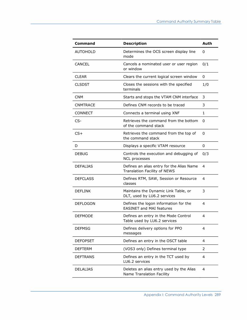
Command Authority Summary Table
Appendix I: Command Authority Levels 289
Command Description Auth
AUTOHOLD Determines the OCS screen display line
mode
0
CANCEL Cancels a nominated user or user region
or window
0/1
CLEAR Clears the current logical screen window 0
CLSDST Closes the sessions with the specified
terminals
1/0
CNM Starts and stops the VTAM CNM interface 3
CNMTRACE Defines CNM records to be traced 3
CONNECT Connects a terminal using XNF 1
CS- Retrieves the command from the bottom
of the command stack
0
CS+ Retrieves the command from the top of
the command stack
0
D Displays a specific VTAM resource 0
DEBUG Controls the execution and debugging of
NCL processes
0/3
DEFALIAS Defines an alias entry for the Alias Name
Translation Facility of NEWS
4
DEFCLASS Defines RTM, SAW, Session or Resource
classes
4
DEFLINK Maintains the Dynamic Link Table, or
DLT, used by LU6.2 services
3
DEFLOGON Defines the logon information for the
EASINET and MAI features
4
DEFMODE Defines an entry in the Mode Control
Table used by LU6.2 services
4
DEFMSG Defines delivery options for PPO
messages
4
DEFOPSET Defines an entry in the OSCT table 4
DEFTERM (VOS3 only) Defines terminal type 2
DEFTRANS Defines an entry in the TCT used by
LU6.2 services
4
DELALIAS Deletes an alias entry used by the Alias
Name Translation Facility
4
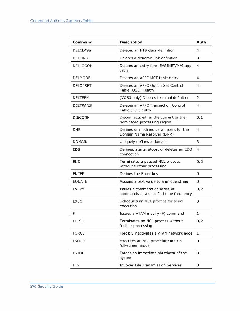
Command Authority Summary Table
290 Security Guide
Command Description Auth
DELCLASS Deletes an NTS class definition 4
DELLINK Deletes a dynamic link definition 3
DELLOGON Deletes an entry form EASINET/MAI appl
table
4
DELMODE Deletes an APPC MCT table entry 4
DELOPSET Deletes an APPC Option Set Control
Table (OSCT) entry
4
DELTERM (VOS3 only) Deletes terminal definition 2
DELTRANS Deletes an APPC Transaction Control
Table (TCT) entry
4
DISCONN Disconnects either the current or the
nominated processing region
0/1
DNR Defines or modifies parameters for the
Domain Name Resolver (DNR)
4
DOMAIN Uniquely defines a domain 3
EDB Defines, starts, stops, or deletes an EDB
connection
4
END Terminates a paused NCL process
without further processing
0/2
ENTER Defines the Enter key 0
EQUATE Assigns a text value to a unique string 0
EVERY Issues a command or series of
commands at a specified time frequency
0/2
EXEC Schedules an NCL process for serial
execution
0
F Issues a VTAM modify (F) command 1
FLUSH Terminates an NCL process without
further processing
0/2
FORCE Forcibly inactivates a VTAM network node 1
FSPROC Executes an NCL procedure in OCS
full-screen mode
0
FSTOP Forces an immediate shutdown of the
system
3
FTS Invokes File Transmission Services 0

Command Authority Summary Table
Appendix I: Command Authority Levels 291
Command Description Auth
FTSINIT Modifies the status of FTS initiators 0
FTSMOD Modifies the status of incoming or
outgoing FTS transmissions
0
GO Resumes processing for a paused NCL
process
0/2
INACT Inactivates a VTAM network node 1
INTQUE Passes data to an NCL procedure’s
&INTREAD statement
0/2
ISR Changes the status of ISR (Inter System
Routing) conversations
2
JOURNAL Controls the journal data set 2
K Clears the current OCS window 0
LIBPATH Controls library path definitions 4
LIBRARY Controls library definitions 4
LINK Defines or changes the status of the
INMC/NVS/APPC links
3
LINK START Defines the attributes and then starts a
link to a domain
3
LIST Lists statements in a specific member of
the procedure library
0
LOAD Preloads copies of procedures, ASN.1
maps, or load modules into storage.
4
LOCK Suspends current screen processing 0
LOG Writes messages to the activity log 0
LOGSWAP Swaps logging to the next available log 3
LSRPOOL Sets attributes for the VSAM shared
resource pool
2
LTITLE Sets the title for your product region logo
panel
4
LUTRACE Traces session traffic to selected
terminals
4
MAIDISC Forces disconnection of an MAI-OC
session
0
MAIINT Interrupts an MAI-OC application 0

Command Authority Summary Table
292 Security Guide
Command Description Auth
MAILOGON Creates an MAI-OC session with another
application
0
MAISEND Sends data to an application connected
by an MAI-OC session
0
MAISESS Provides functions for the control of
MAI/FS sessions
0/4
MAXUSERS Displays and limits the maximum number
of concurrent users
3
MSG Sends a message to the specified OCS
operators
0
NCLCHECK Tests syntax for an NCL procedure
without execution
0
NCLTEST Sets, resets, or displays NCL test status
for this window
0
NCLTRACE Dynamically alters the trace status of an
executing NCL process
0/2
NDB ALTER Builds, rebuilds, or validates the key
indexes for an NDB, or a field
2
NDB CREATE Initializes a new NCL database 2
NDB FIELD Allows a database field definition to be
added, deleted, or updated
2
NDB PURGE Frees up a locked or halted database 2
NDB RESET Deletes all data from an NCL database 2
NDB START Starts an NCL database 2
NDB STOP Flags an NCL database as stopping 2
NDB UNLOAD Unloads a copy of an NCL database 2
NETM (VOS3 only) Passes a command to NETM
for execution
2
NETMCNTL (VOS3 only) Controls communication
with NETM
2
NETSTAT Invokes the TCP/IP NETSTAT command T
NOTIFY Sends a message to TSO/TSS users or
CMS users
0
NOTRACE Terminates a VTAM network trace 1
NPTAB Changes the status of a user’s NPF table 0/4
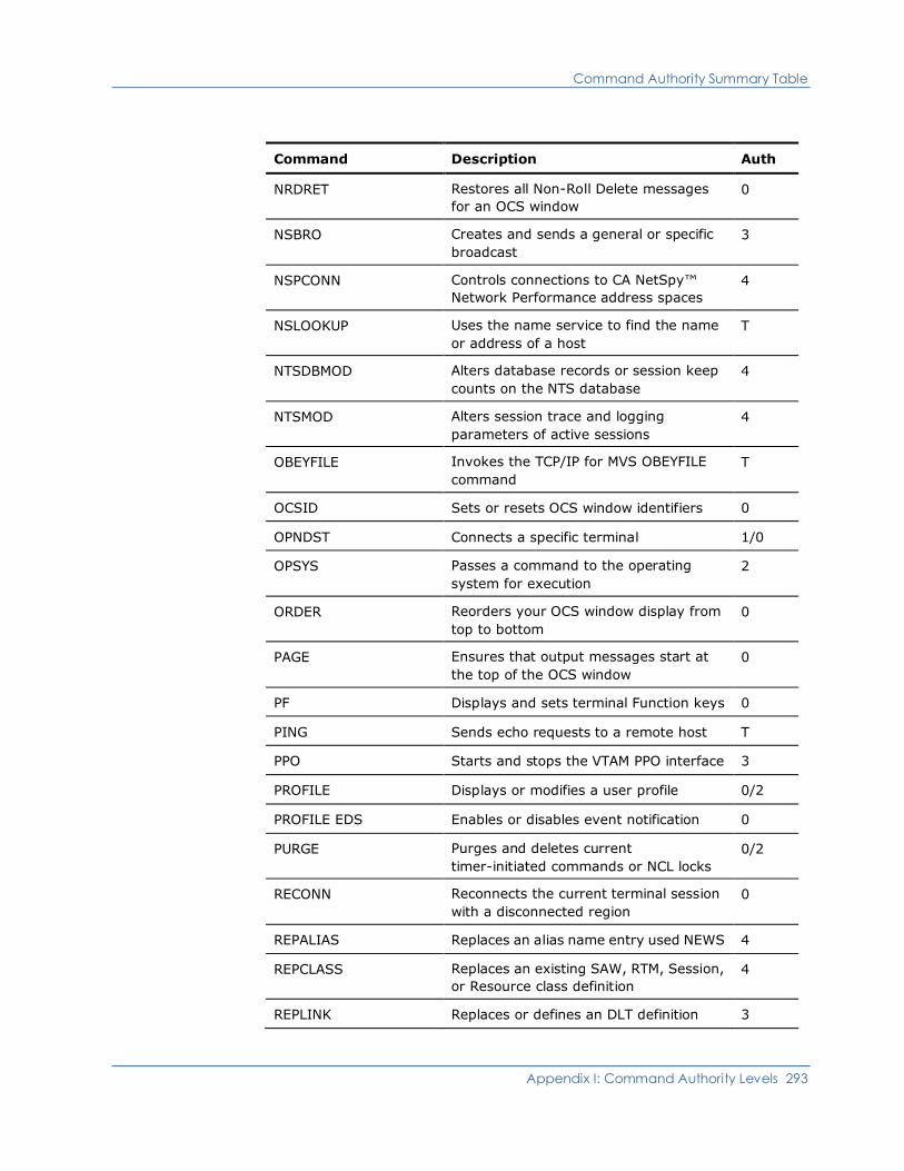
Command Authority Summary Table
Appendix I: Command Authority Levels 293
Command Description Auth
NRDRET Restores all Non-Roll Delete messages
for an OCS window
0
NSBRO Creates and sends a general or specific
broadcast
3
NSPCONN Controls connections to CA NetSpy™
Network Performance address spaces
4
NSLOOKUP Uses the name service to find the name
or address of a host
T
NTSDBMOD Alters database records or session keep
counts on the NTS database
4
NTSMOD Alters session trace and logging
parameters of active sessions
4
OBEYFILE Invokes the TCP/IP for MVS OBEYFILE
command
T
OCSID Sets or resets OCS window identifiers 0
OPNDST Connects a specific terminal 1/0
OPSYS Passes a command to the operating
system for execution
2
ORDER Reorders your OCS window display from
top to bottom
0
PAGE Ensures that output messages start at
the top of the OCS window
0
PF Displays and sets terminal Function keys 0
PING Sends echo requests to a remote host T
PPO Starts and stops the VTAM PPO interface 3
PROFILE Displays or modifies a user profile 0/2
PROFILE EDS Enables or disables event notification 0
PURGE Purges and deletes current
timer-initiated commands or NCL locks
0/2
RECONN Reconnects the current terminal session
with a disconnected region
0
REPALIAS Replaces an alias name entry used NEWS 4
REPCLASS Replaces an existing SAW, RTM, Session,
or Resource class definition
4
REPLINK Replaces or defines an DLT definition 3
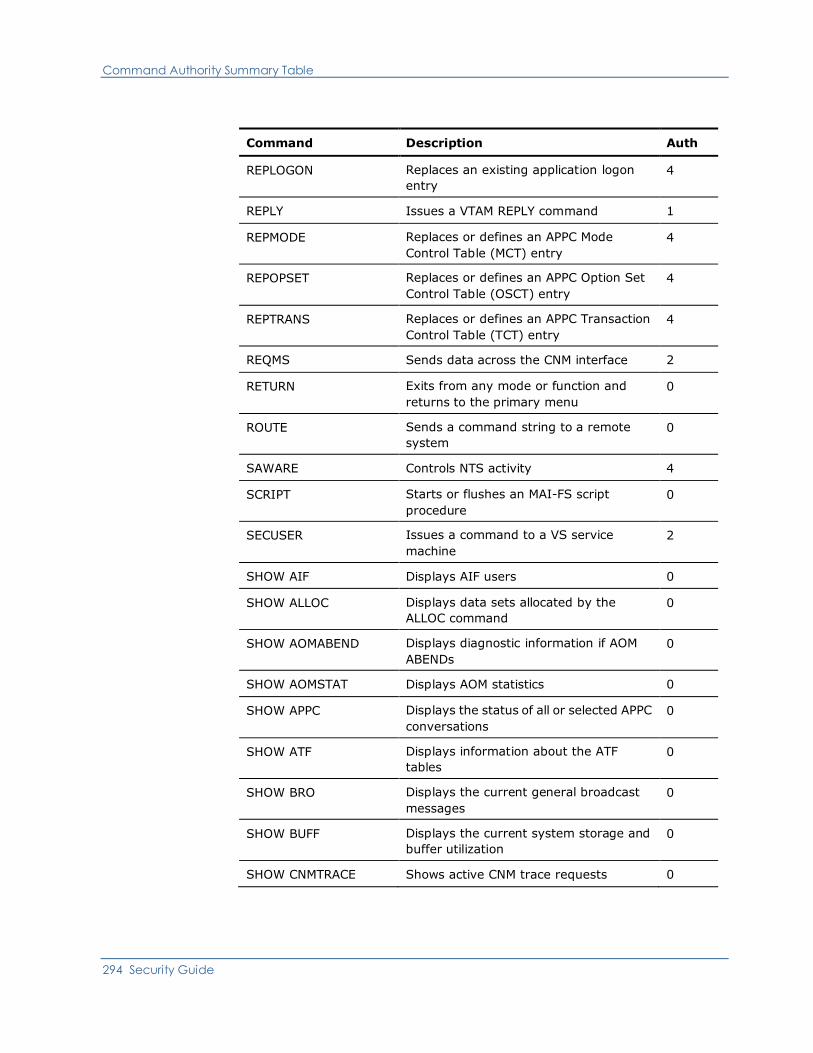
Command Authority Summary Table
294 Security Guide
Command Description Auth
REPLOGON Replaces an existing application logon
entry
4
REPLY Issues a VTAM REPLY command 1
REPMODE Replaces or defines an APPC Mode
Control Table (MCT) entry
4
REPOPSET Replaces or defines an APPC Option Set
Control Table (OSCT) entry
4
REPTRANS Replaces or defines an APPC Transaction
Control Table (TCT) entry
4
REQMS Sends data across the CNM interface 2
RETURN Exits from any mode or function and
returns to the primary menu
0
ROUTE Sends a command string to a remote
system
0
SAWARE Controls NTS activity 4
SCRIPT Starts or flushes an MAI-FS script
procedure
0
SECUSER Issues a command to a VS service
machine
2
SHOW AIF Displays AIF users 0
SHOW ALLOC Displays data sets allocated by the
ALLOC command
0
SHOW AOMABEND Displays diagnostic information if AOM
ABENDs
0
SHOW AOMSTAT Displays AOM statistics 0
SHOW APPC Displays the status of all or selected APPC
conversations
0
SHOW ATF Displays information about the ATF
tables
0
SHOW BRO Displays the current general broadcast
messages
0
SHOW BUFF Displays the current system storage and
buffer utilization
0
SHOW CNMTRACE Shows active CNM trace requests 0

Command Authority Summary Table
Appendix I: Command Authority Levels 295
Command Description Auth
SHOW COMMANDS Displays commands available to user or
system
0
SHOW COMP Displays 3270 data stream compression
statistics
0
SHOW CONSOLES Displays the consoles currently allocated
for use by AOM
0
SHOW DEBUG Displays NCL debug sessions 0/2
SHOW DEFALIAS Displays one or more DEFALIAS entries 0
SHOW DEFCLASS Displays NTS class definitions 0
SHOW DEFLINK Displays current dynamic link definitions 0
SHOW DEFLOGON Displays the current entries in the
DEFLOGON table
0
SHOW DEFMODE Displays APPC Mode Control Table (MCT)
entries
0
SHOW DEFMSG Displays the current DEFMSG delivery
options
0
SHOW DEFOPSET Displays APPC Option Set Control
Table (OSCT) entries
0
SHOW DEFTERM (VOS3 only) Displays terminal definitions 0
SHOW DEFTRANS Displays APPC Transaction Control
Table (TCT) entries
0
SHOW DNR Displays parameters or statistics for the
Domain Name Resolver (DNR)
0
SHOW DOMAINS Displays the domain information of
connected systems
0
SHOW EDB Displays information about external
database connections
0
SHOW EDBSTAT Displays statistics about currently
defined EDB connections
0
SHOW EDBUSER Displays information about EDB users 0
SHOW EDBUSTAT Displays statistics about EDB users 0
SHOW EDS Displays current Event Distribution
Services PROFILE definitions
0
SHOW EPS Displays EndPoint Services information 0

Command Authority Summary Table
296 Security Guide
Command Description Auth
SHOW EQUATES Displays the current EQUATE strings
available to this user
0
SHOW EXEC (OS/VS only) Displays the names of
members in a procedure library
0
SHOW FTS Displays the status of file transmissions 0
SHOW ISR Displays ISR status information 0
SHOW ISRSTATS Displays ISR statistics 0
SHOW LIB Displays libraries which have been
defined to the system
0
SHOW LICENSE Displays the active licensing details and
expiry dates
0
SHOW LINK Displays the status of INMC or APPC links 0
SHOW LOCKS Displays the status of all locks held within
the system
0
SHOW LOGS Displays the current status of the system
activity logs
0
SHOW LSR Displays LSR status information 0
SHOW LUTRACE Displays the status of all LUTRACE
requests
0
SHOW MAI Displays information about MAI sessions
for this user or all users
0
SHOW MAISTAT Displays information about the status of
MAI subtasks
0
SHOW MAP Displays information about defined
Mapping Services maps
0
SHOW MSGQ Displays message queue depths 0
SHOW NCL Displays the status of active NCL
processes
0/2
SHOW NCLGLBL Displays the names of any defined NCL
global variables
2
SHOW NCLLOCKS Displays the status of all NCL locks held
within the system
0
SHOW NCLSTAT Displays the status of NCL procedures
currently in storage
0
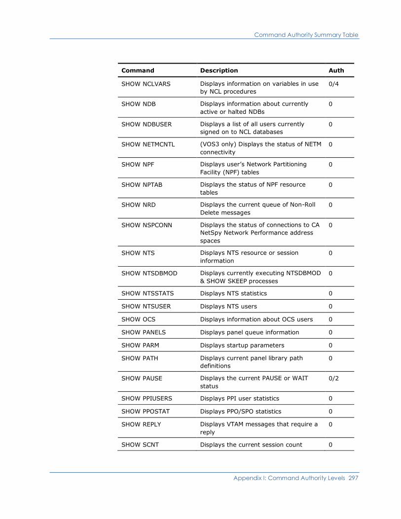
Command Authority Summary Table
Appendix I: Command Authority Levels 297
Command Description Auth
SHOW NCLVARS Displays information on variables in use
by NCL procedures
0/4
SHOW NDB Displays information about currently
active or halted NDBs
0
SHOW NDBUSER Displays a list of all users currently
signed on to NCL databases
0
SHOW NETMCNTL (VOS3 only) Displays the status of NETM
connectivity
0
SHOW NPF Displays user’s Network Partitioning
Facility (NPF) tables
0
SHOW NPTAB Displays the status of NPF resource
tables
0
SHOW NRD Displays the current queue of Non-Roll
Delete messages
0
SHOW NSPCONN Displays the status of connections to CA
NetSpy Network Performance address
spaces
0
SHOW NTS Displays NTS resource or session
information
0
SHOW NTSDBMOD Displays currently executing NTSDBMOD
& SHOW SKEEP processes
0
SHOW NTSSTATS Displays NTS statistics 0
SHOW NTSUSER Displays NTS users 0
SHOW OCS Displays information about OCS users 0
SHOW PANELS Displays panel queue information 0
SHOW PARM Displays startup parameters 0
SHOW PATH Displays current panel library path
definitions
0
SHOW PAUSE Displays the current PAUSE or WAIT
status
0/2
SHOW PPIUSERS Displays PPI user statistics 0
SHOW PPOSTAT Displays PPO/SPO statistics 0
SHOW REPLY Displays VTAM messages that require a
reply
0
SHOW SCNT Displays the current session count 0
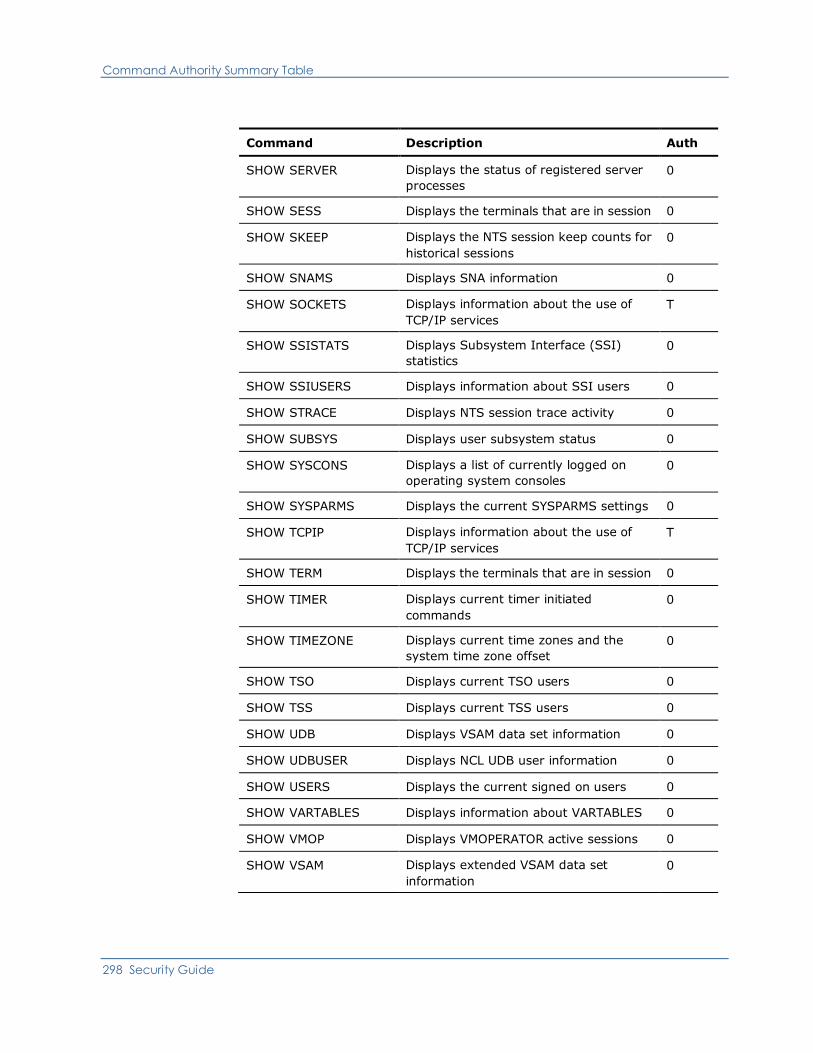
Command Authority Summary Table
298 Security Guide
Command Description Auth
SHOW SERVER Displays the status of registered server
processes
0
SHOW SESS Displays the terminals that are in session 0
SHOW SKEEP Displays the NTS session keep counts for
historical sessions
0
SHOW SNAMS Displays SNA information 0
SHOW SOCKETS Displays information about the use of
TCP/IP services
T
SHOW SSISTATS Displays Subsystem Interface (SSI)
statistics
0
SHOW SSIUSERS Displays information about SSI users 0
SHOW STRACE Displays NTS session trace activity 0
SHOW SUBSYS Displays user subsystem status 0
SHOW SYSCONS Displays a list of currently logged on
operating system consoles
0
SHOW SYSPARMS Displays the current SYSPARMS settings 0
SHOW TCPIP Displays information about the use of
TCP/IP services
T
SHOW TERM Displays the terminals that are in session 0
SHOW TIMER Displays current timer initiated
commands
0
SHOW TIMEZONE Displays current time zones and the
system time zone offset
0
SHOW TSO Displays current TSO users 0
SHOW TSS Displays current TSS users 0
SHOW UDB Displays VSAM data set information 0
SHOW UDBUSER Displays NCL UDB user information 0
SHOW USERS Displays the current signed on users 0
SHOW VARTABLES Displays information about VARTABLES 0
SHOW VMOP Displays VMOPERATOR active sessions 0
SHOW VSAM Displays extended VSAM data set
information
0
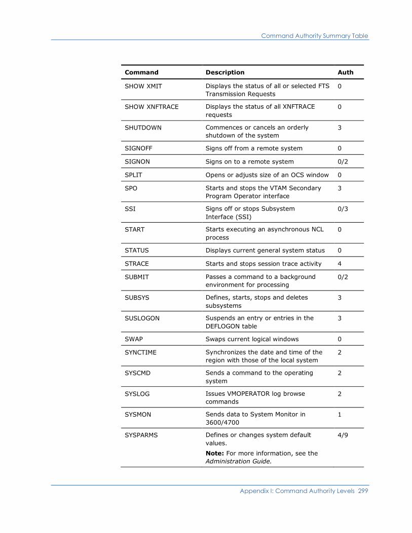
Command Authority Summary Table
Appendix I: Command Authority Levels 299
Command Description Auth
SHOW XMIT Displays the status of all or selected FTS
Transmission Requests
0
SHOW XNFTRACE Displays the status of all XNFTRACE
requests
0
SHUTDOWN Commences or cancels an orderly
shutdown of the system
3
SIGNOFF Signs off from a remote system 0
SIGNON Signs on to a remote system 0/2
SPLIT Opens or adjusts size of an OCS window 0
SPO Starts and stops the VTAM Secondary
Program Operator interface
3
SSI Signs off or stops Subsystem
Interface (SSI)
0/3
START Starts executing an asynchronous NCL
process
0
STATUS Displays current general system status 0
STRACE Starts and stops session trace activity 4
SUBMIT Passes a command to a background
environment for processing
0/2
SUBSYS Defines, starts, stops and deletes
subsystems
3
SUSLOGON Suspends an entry or entries in the
DEFLOGON table
3
SWAP Swaps current logical windows 0
SYNCTIME Synchronizes the date and time of the
region with those of the local system
2
SYSCMD Sends a command to the operating
system
2
SYSLOG Issues VMOPERATOR log browse
commands
2
SYSMON Sends data to System Monitor in
3600/4700
1
SYSPARMS Defines or changes system default
values.
Note: For more information, see the
Administration Guide.
4/9
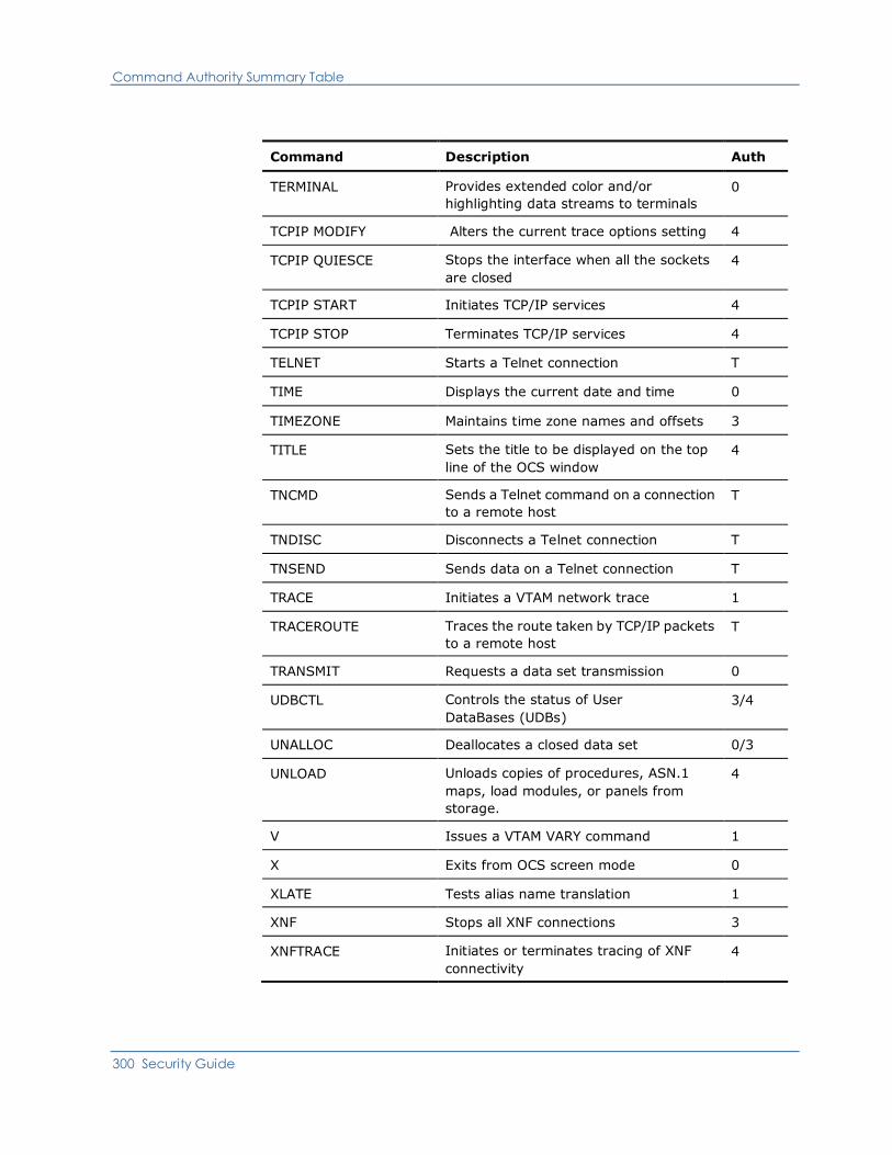
Command Authority Summary Table
300 Security Guide
Command Description Auth
TERMINAL Provides extended color and/or
highlighting data streams to terminals
0
TCPIP MODIFY Alters the current trace options setting 4
TCPIP QUIESCE Stops the interface when all the sockets
are closed
4
TCPIP START Initiates TCP/IP services 4
TCPIP STOP Terminates TCP/IP services 4
TELNET Starts a Telnet connection T
TIME Displays the current date and time 0
TIMEZONE Maintains time zone names and offsets 3
TITLE Sets the title to be displayed on the top
line of the OCS window
4
TNCMD Sends a Telnet command on a connection
to a remote host
T
TNDISC Disconnects a Telnet connection T
TNSEND Sends data on a Telnet connection T
TRACE Initiates a VTAM network trace 1
TRACEROUTE Traces the route taken by TCP/IP packets
to a remote host
T
TRANSMIT Requests a data set transmission 0
UDBCTL Controls the status of User
DataBases (UDBs)
3/4
UNALLOC Deallocates a closed data set 0/3
UNLOAD Unloads copies of procedures, ASN.1
maps, load modules, or panels from
storage.
4
V Issues a VTAM VARY command 1
X Exits from OCS screen mode 0
XLATE Tests alias name translation 1
XNF Stops all XNF connections 3
XNFTRACE Initiates or terminates tracing of XNF
connectivity
4
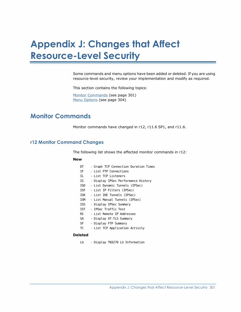
Appendix J: Changes that Affect Resource-Level Security 301
Appendix J: Changes that Affect
Resource-Level Security
Some commands and menu options have been added or deleted. If you are using
resource-level security, review your implementation and modify as required.
This section contains the following topics:
Monitor Commands (see page 301)
Menu Options (see page 304)
Monitor Commands
Monitor commands have changed in r12, r11.6 SP1, and r11.6.
r12 Monitor Command Changes
The following list shows the affected monitor commands in r12:
New
DT - Graph TCP Connection Duration Times
IF - List FTP Connections
IL - List TCP Listeners
IS - Display IPSec Performance History
ISD - List Dynamic Tunnels (IPSec)
ISF - List IP Filters (IPSec)
ISK - List IKE Tunnels (IPSec)
ISM - List Manual Tunnels (IPSec)
ISS - Display IPSec Summary
IST - IPSec Traffic Test
RI - List Remote IP Addresses
SA - Display AT-TLS Summary
SF - Display FTP Summary
TC - List TCP Application Activity
Deleted
LU - Display TN3270 LU Information

Monitor Commands
302 Security Guide
r11.6 SP1 Monitor Command Changes
The following list shows the affected monitor commands in r11.6 SP1:
Changed
A-CLOSE - Close all alerts displayed
A-DATE - Set the Date for Alert History
A-DEFINE - Define an Alert Filter or Format
A-FILTER - Apply an Alert Filter
A-FORMAT - Set the monitor list format
A-HISTOR - Go to Alert History display
A-HOLD - Hold Alert display
A-PROFIL - Set User Profile defaults
A-RESUME - Resume Alert display
A-SORT - Sort the displayed Alerts
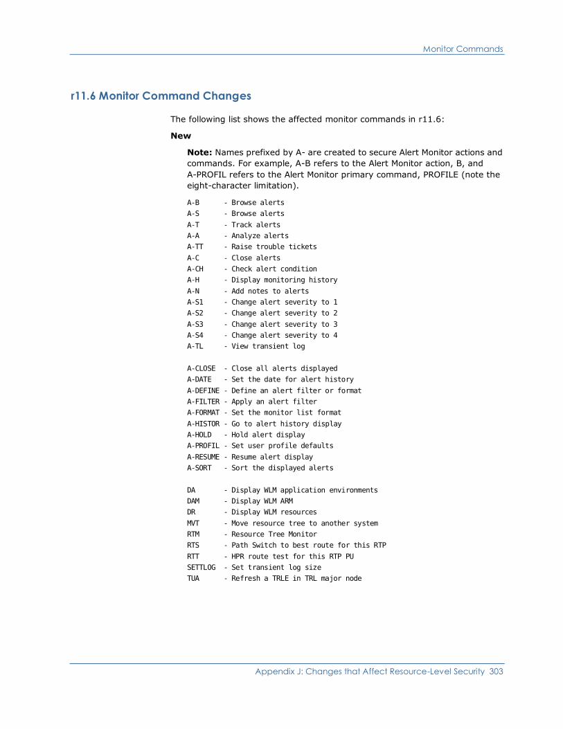
Monitor Commands
Appendix J: Changes that Affect Resource-Level Security 303
r11.6 Monitor Command Changes
The following list shows the affected monitor commands in r11.6:
New
Note: Names prefixed by A- are created to secure Alert Monitor actions and
commands. For example, A-B refers to the Alert Monitor action, B, and
A-PROFIL refers to the Alert Monitor primary command, PROFILE (note the
eight-character limitation).
A-B - Browse alerts
A-S - Browse alerts
A-T - Track alerts
A-A - Analyze alerts
A-TT - Raise trouble tickets
A-C - Close alerts
A-CH - Check alert condition
A-H - Display monitoring history
A-N - Add notes to alerts
A-S1 - Change alert severity to 1
A-S2 - Change alert severity to 2
A-S3 - Change alert severity to 3
A-S4 - Change alert severity to 4
A-TL - View transient log
A-CLOSE - Close all alerts displayed
A-DATE - Set the date for alert history
A-DEFINE - Define an alert filter or format
A-FILTER - Apply an alert filter
A-FORMAT - Set the monitor list format
A-HISTOR - Go to alert history display
A-HOLD - Hold alert display
A-PROFIL - Set user profile defaults
A-RESUME - Resume alert display
A-SORT - Sort the displayed alerts
DA - Display WLM application environments
DAM - Display WLM ARM
DR - Display WLM resources
MVT - Move resource tree to another system
RTM - Resource Tree Monitor
RTS - Path Switch to best route for this RTP
RTT - HPR route test for this RTP PU
SETTLOG - Set transient log size
TUA - Refresh a TRLE in TRL major node
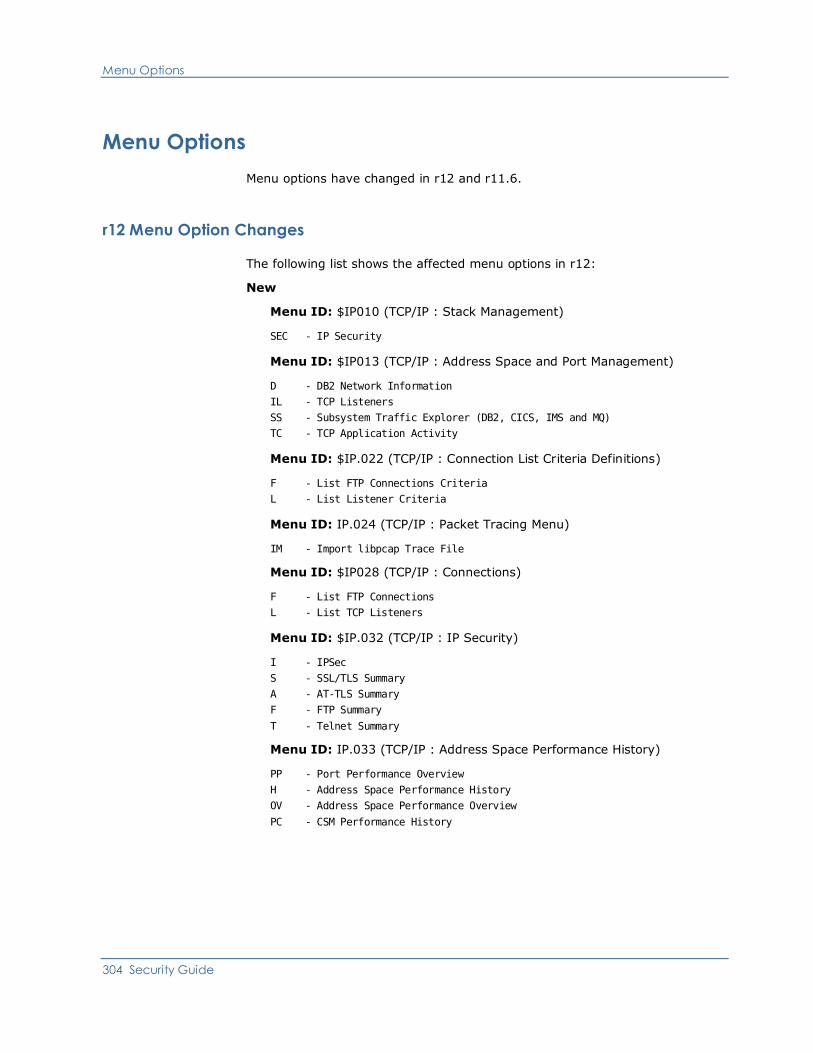
Menu Options
304 Security Guide
Menu Options
Menu options have changed in r12 and r11.6.
r12 Menu Option Changes
The following list shows the affected menu options in r12:
New
Menu ID: $IP010 (TCP/IP : Stack Management)
SEC - IP Security
Menu ID: $IP013 (TCP/IP : Address Space and Port Management)
D - DB2 Network Information
IL - TCP Listeners
SS - Subsystem Traffic Explorer (DB2, CICS, IMS and MQ)
TC - TCP Application Activity
Menu ID: $IP.022 (TCP/IP : Connection List Criteria Definitions)
F - List FTP Connections Criteria
L - List Listener Criteria
Menu ID: IP.024 (TCP/IP : Packet Tracing Menu)
IM - Import libpcap Trace File
Menu ID: $IP028 (TCP/IP : Connections)
F - List FTP Connections
L - List TCP Listeners
Menu ID: $IP.032 (TCP/IP : IP Security)
I - IPSec
S - SSL/TLS Summary
A - AT-TLS Summary
F - FTP Summary
T - Telnet Summary
Menu ID: IP.033 (TCP/IP : Address Space Performance History)
PP - Port Performance Overview
H - Address Space Performance History
OV - Address Space Performance Overview
PC - CSM Performance History

Menu Options
Appendix J: Changes that Affect Resource-Level Security 305
Menu ID: $IP.035 (TCP/IP : DB2 for z/OS Network Information Center)
IC - DB2 DDF IP Connections
ICF - DB2 DDF IP Connections (Advanced)
IL - DB2 DDF TCP Listeners
TRS - DB2 DDF Real-Time Server Port Traffic
TC - DB2 DDF TCP Application Activity
SS - Subsystem Traffic Explorer (DB2, CICS, IMS and MQ)
AS - DB2 Address Space Information
S - SQL Error Codes
D - DB2 Error Codes
ST - DB2 DDF SmartTrace
T - Tutorial
Menu ID: $NM.020 (System Support : Messages and Codes Menu)
TCP - TCP Codes and Errors
Menu ID: NM.021 (System Support : TCP Errors and Codes Menu)
FTP - FTP Reply Codes
CTR - TCP Connection Termination Reason Codes
TNT - Telnet Termination Codes
TNR - Telnet Error Return Codes for ERR (x'09')
SSL - SSL Function Return Codes
DEP - Deprecated SSL Function Return Codes
ASN - ASN.1 Status Codes
CMS - Certificate Management Services Codes
Menu ID: $NM.060 (Network Diagnosis : Primary Menu)
CIP - CIPS and Printers
Deleted
Menu ID: $IP.013 (TCP/IP : Address Space and Port Management)
OV - Address Space Performance Overview
PC - CSM Performance Overview
PP - Port Performance Overview
Menu ID: $NM.020 (System Support : Messages and Codes Menu)
F - FTP Reply Codes
Menu ID: $NM060 (Network Diagnosis : Primary Menu)
CR - CIPS, Routers and Printers
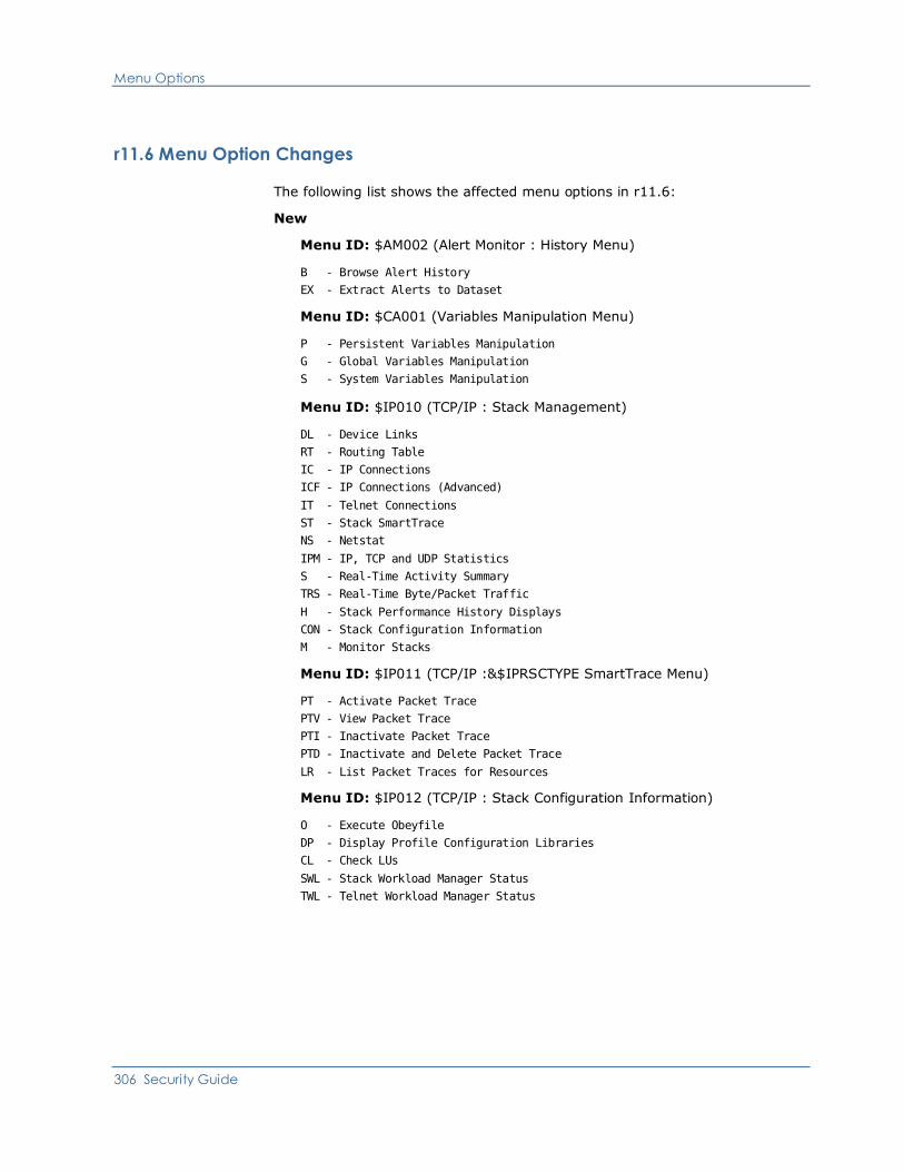
Menu Options
306 Security Guide
r11.6 Menu Option Changes
The following list shows the affected menu options in r11.6:
New
Menu ID: $AM002 (Alert Monitor : History Menu)
B - Browse Alert History
EX - Extract Alerts to Dataset
Menu ID: $CA001 (Variables Manipulation Menu)
P - Persistent Variables Manipulation
G - Global Variables Manipulation
S - System Variables Manipulation
Menu ID: $IP010 (TCP/IP : Stack Management)
DL - Device Links
RT - Routing Table
IC - IP Connections
ICF - IP Connections (Advanced)
IT - Telnet Connections
ST - Stack SmartTrace
NS - Netstat
IPM - IP, TCP and UDP Statistics
S - Real-Time Activity Summary
TRS - Real-Time Byte/Packet Traffic
H - Stack Performance History Displays
CON - Stack Configuration Information
M - Monitor Stacks
Menu ID: $IP011 (TCP/IP :&$IPRSCTYPE SmartTrace Menu)
PT - Activate Packet Trace
PTV - View Packet Trace
PTI - Inactivate Packet Trace
PTD - Inactivate and Delete Packet Trace
LR - List Packet Traces for Resources
Menu ID: $IP012 (TCP/IP : Stack Configuration Information)
O - Execute Obeyfile
DP - Display Profile Configuration Libraries
CL - Check LUs
SWL - Stack Workload Manager Status
TWL - Telnet Workload Manager Status

Menu Options
Appendix J: Changes that Affect Resource-Level Security 307
Menu ID: $IP013 (TCP/IP : Address Space and Port Management)
IC - IP Connections
ICF - IP Connections (Advanced)
ST - Address Space SmartTrace
TRS - Real-time Byte/Packet Traffic
PP - Port Performance Overview
H - Address Space Performance History
OV - Address Space Performance Overview
PC - CSM Performance Overview
A - Add Address Space to Monitor
T - Telnet Server Address Space Information
I - Address Space Information
M - Monitor Address Spaces
Menu ID: $IP014 (TCP/IP : OSA Management)
D - Display Summary Information
DL - Device List
H - Performance History
OAT - OSA OAT Table
OV - Performance Overview
M - Monitor OSAs
Menu ID: $IP015 (TCP/IP : VIPA Management)
D - VIPA Information
IC - IP Connections
ICF - IP Connections (Advanced)
IT - Telnet Connections
ITF - Telnet Connections (Advanced)
OV - Performance Overview
H - Performance History
M - Modify VIPA Definition Using Obeyfile
MV - Monitor VIPAs
Menu ID: $IP016 (TCP/IP : Enterprise Extender Management)
S - XCA Major Node Summary
ST - Enterprise Extender SmartTrace
OV - Performance Overview
H - Performance History
UA - UDP Port Activity
M - Monitor Enterprise Extenders
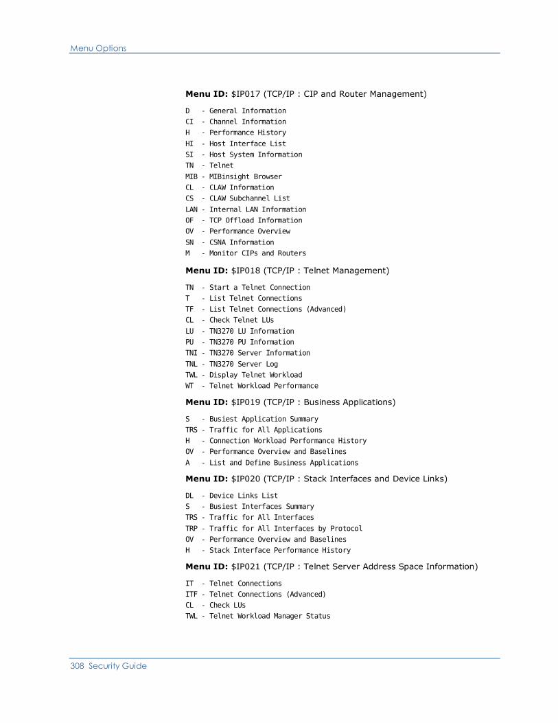
Menu Options
308 Security Guide
Menu ID: $IP017 (TCP/IP : CIP and Router Management)
D - General Information
CI - Channel Information
H - Performance History
HI - Host Interface List
SI - Host System Information
TN - Telnet
MIB - MIBinsight Browser
CL - CLAW Information
CS - CLAW Subchannel List
LAN - Internal LAN Information
OF - TCP Offload Information
OV - Performance Overview
SN - CSNA Information
M - Monitor CIPs and Routers
Menu ID: $IP018 (TCP/IP : Telnet Management)
TN - Start a Telnet Connection
T - List Telnet Connections
TF - List Telnet Connections (Advanced)
CL - Check Telnet LUs
LU - TN3270 LU Information
PU - TN3270 PU Information
TNI - TN3270 Server Information
TNL - TN3270 Server Log
TWL - Display Telnet Workload
WT - Telnet Workload Performance
Menu ID: $IP019 (TCP/IP : Business Applications)
S - Busiest Application Summary
TRS - Traffic for All Applications
H - Connection Workload Performance History
OV - Performance Overview and Baselines
A - List and Define Business Applications
Menu ID: $IP020 (TCP/IP : Stack Interfaces and Device Links)
DL - Device Links List
S - Busiest Interfaces Summary
TRS - Traffic for All Interfaces
TRP - Traffic for All Interfaces by Protocol
OV - Performance Overview and Baselines
H - Stack Interface Performance History
Menu ID: $IP021 (TCP/IP : Telnet Server Address Space Information)
IT - Telnet Connections
ITF - Telnet Connections (Advanced)
CL - Check LUs
TWL - Telnet Workload Manager Status
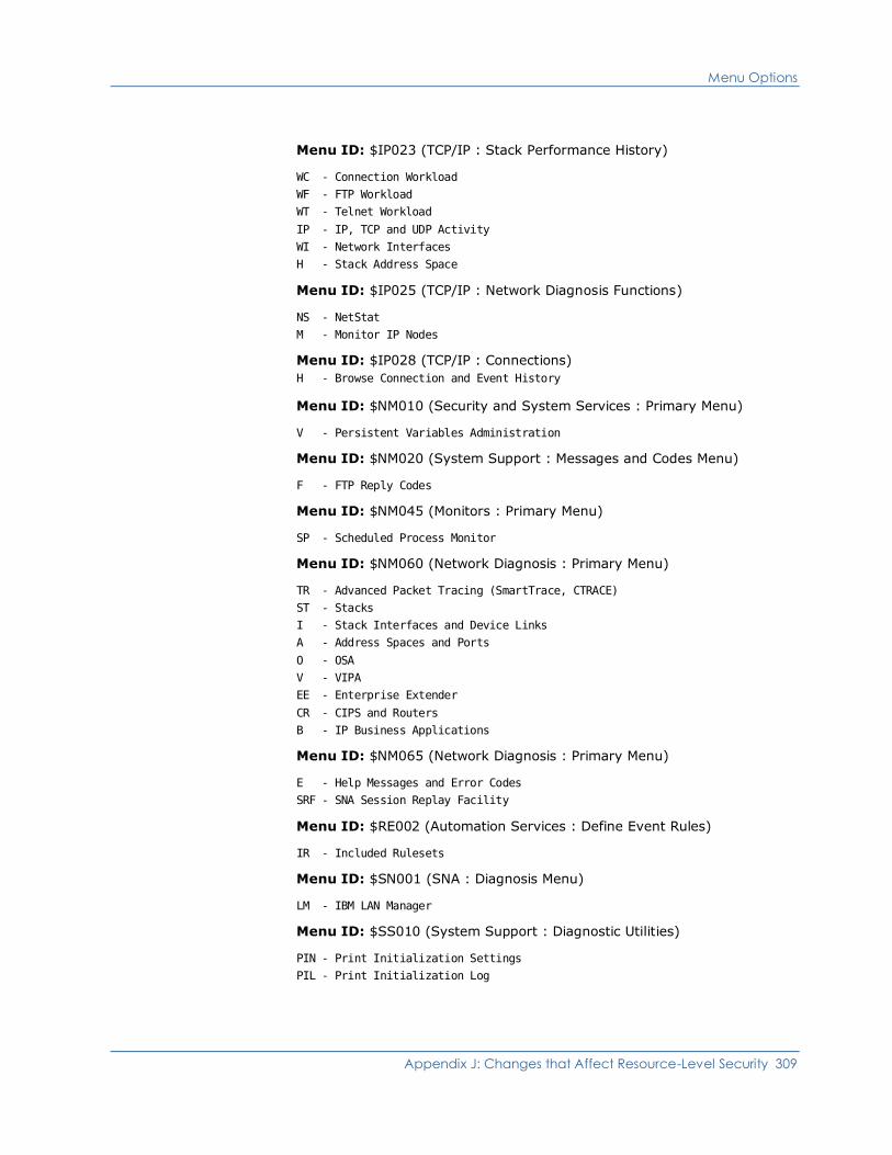
Menu Options
Appendix J: Changes that Affect Resource-Level Security 309
Menu ID: $IP023 (TCP/IP : Stack Performance History)
WC - Connection Workload
WF - FTP Workload
WT - Telnet Workload
IP - IP, TCP and UDP Activity
WI - Network Interfaces
H - Stack Address Space
Menu ID: $IP025 (TCP/IP : Network Diagnosis Functions)
NS - NetStat
M - Monitor IP Nodes
Menu ID: $IP028 (TCP/IP : Connections)
H - Browse Connection and Event History
Menu ID: $NM010 (Security and System Services : Primary Menu)
V - Persistent Variables Administration
Menu ID: $NM020 (System Support : Messages and Codes Menu)
F - FTP Reply Codes
Menu ID: $NM045 (Monitors : Primary Menu)
SP - Scheduled Process Monitor
Menu ID: $NM060 (Network Diagnosis : Primary Menu)
TR - Advanced Packet Tracing (SmartTrace, CTRACE)
ST - Stacks
I - Stack Interfaces and Device Links
A - Address Spaces and Ports
O - OSA
V - VIPA
EE - Enterprise Extender
CR - CIPS and Routers
B - IP Business Applications
Menu ID: $NM065 (Network Diagnosis : Primary Menu)
E - Help Messages and Error Codes
SRF - SNA Session Replay Facility
Menu ID: $RE002 (Automation Services : Define Event Rules)
IR - Included Rulesets
Menu ID: $SN001 (SNA : Diagnosis Menu)
LM - IBM LAN Manager
Menu ID: $SS010 (System Support : Diagnostic Utilities)
PIN - Print Initialization Settings
PIL - Print Initialization Log

Menu Options
310 Security Guide
Deleted
Menu ID: $NM060 (Network Diagnosis : Primary Menu)
LM - IBM LAN Manager (moved to under Menu ID $SN001)
PT - IP Packet Tracing Menu (replaced by TR)
SRF - SNA Session Replay Facility (moved to under Menu ID $NM065)
Menu ID: $RE002 (Automation Services : Define Event Rules)
I - Included Rulesets (replaced by IR)
Index 311
Index
$
$NMNCEX1 macro • 109
$NMUCORH macro • 280
$PSPOOL • 109
&
&EDB statement • 108
&FILE OPEN statement • 108
&NDBOPEN statement • 108
&SECCALL verb • 49, 221
&SMFWRITE statement • 108
A
administrator, group ID • 68
security settings • 137
alert monitor, customizing • 101
APPC links • 128
authority levels, commands • 71
summary table • 288
B
background
region, defining user IDs • 68
background environments
MSGPROC procedure • 48
ROF, using with • 48
user IDs, defining • 47
background processes
defining user IDs • 47
types • 47
background users
group ID • 68
pre-existing definitions, updating • 37
security settings • 142
BUSER, background user definition • 68
C
calling user ID security exit • 208
CMDAUTH operand • 93, 288
CMDREPLS parameter group • 94
commands
SHOW USERS • 48
commands, authority levels • 71
customization • 93
summary table • 288
communication area, NCL authorization exit •
109
consolidated console profile, customization •
103
control information, user ID • 39
controlling access using NPF
commands • 74
definitions by classes • 73
definitions by resources • 74
definitions by system images • 73
functions • 67
knowledge base • 72
menu options • 72
parameter groups • 78
resources • 67
system images • 74
controlling access using SAF
commands • 87, 88, 89
knowledge base • 83
menu options • 83
parameter groups • 90
system images • 87
controlling access using UAMS • 19
correlating authorization, NCL • 111
correlator, NMSAF • 279
Customizer parameter groups
CMDREPLS • 94
controlling access • 78, 90
NMSECURITY • 31, 114, 116
customizing
security parameter groups • 94
customizing, user profiles
alert monitor display • 101
consolidated console • 103
message monitor • 102
primary menu format • 100
status monitor display • 101
D
data set access authorization exit (NMDSNCHK)
• 249
data set services authorization exit
(NMDSSCHK) • 116
deliver call, INMC
primary exit • 266

312 Security Guide
secondary exit • 273
disconnect call, INMC exit • 276
E
errors
in NCL authorization exit • 109
in structured fields • 146
exits provided • 107
external security packages • 19, 51, 203
accessing • 20
CA ACF2 • 80
CA Top Secret • 80
calling using SAF • 80
controlling access to functions and resources
• 80
full security exit • 20
partial security exit • 20
RACF • 80
external security packages, defining modeled
resources
CA ACF2 • 285
CA Top • 286
RACF • 286
F
forcing new password • 41
full security exit • 51
functions, controlling access to • 67
G
group IDs
administrator • 68, 137
associating with user ID • 39
background user • 68, 142
monitor • 68, 141
network operator • 68, 140
operator • 68, 139
I
initialization call, INMC
primary exit • 262
secondary exit • 271
INMC links, security exit • 112
INMCEX01 operand • 259
INMCEX02 operand • 260
L
LOAD MODULE operand • 110
logon verification, security exit • 57
M
macros
$NMNCEX1 • 109
$NMUCORH • 280
model user ID
overview • 41
with a partial security exit • 56
modeling for NMSAF • 24
MODLUSER operand • 41, 212
MODS and NCL authorization exit • 109
monitor user, group ID • 68
security settings • 141
MSGPROC procedure
background environments • 48
system console user ID • 46
N
NCL authorization exit • 108
activating • 109
additional checking • 110
and $PSPOOL • 109
and MODS • 109
communication area • 109
NEXCORR field • 111
NEXUTOKN field • 111
controlling access levels • 108
correlating authorization • 111
errors • 109
NDB • 108
preloading • 110
sample • 111
SQL database access • 108
UDB access • 108
writing SMF records • 108
NCL, accessing user IDs • 49
NCLEX01 exit • 108
NCLEX01 operand • 108
NDB, controlling access • 108
network operator, group ID • 68
security settings • 140
network partitioning facility. See NPF • 69
NEXCORR field • 111
NEXUTOKN field • 111
NMDSNCHK exit • 114, 250
NMDSSCHK exit • 116, 254
NMSAF
components • 24
Index 313
correlator • 279
enabling • 28
exits • 31
implementing • 26
modeling • 27
security solution • 19, 23
SXCTL parameter file • 30, 128
user groups • 26
NMSECDSN exit • 31
NMSECDSS exit • 31
NMSECURITY parameter group • 31, 114, 116
notify call, INMC exit • 268
NPF (network partitioning facility)
relationship with UAMS • 69
resource list members • 69
resource tables • 69, 71, 79
NPF, controlling access to
commands • 74
databases • 73
definitions • 73, 74
functions • 69
menu options • 72
parameter groups • 78
resources • 69
system images • 74
O
OCS command authority levels • 287
OCS panel, user profile customization • 102
operator, group ID • 68
security settings • 139
P
parameters, SXCTL • 30, 128
partial security exit
for NMSAF • 24
model user IDs • 56
passwords, forcing change • 41
R
RACF user ID, signing on • 43
regions, background, user definition • 68
registers, INMC security exit • 261
resources, controlling access • 67
ROF
background environments, with • 48
system console, with • 46
ROUTCDE operand • 47
S
SAF (System Authorization Facility)
calling an external security package • 80
relationship with UAMS • 80
sample security templates • 81
user token • 111, 279
SAF, controlling access to
commands • 87, 88, 89
knowledge base • 83
menu options • 83
parameter groups • 90
system images • 87
Secure Sockets Layer feature • 123
security
combined NPF and external options • 80
UAMS • 19, 33
users, for existing • 37
security exit • 19
CA ACF2, SAF partial exit • 51
full • 51
RACF • 51
security exit, INMC • 112
changing name dynamically • 260
execution • 259
registers • 261
security exit, INMC, primary • 112
calls • 113
deliver call • 266
initialization call • 262
linking to MS • 259
notify call • 268
writing • 262
security exit, INMC, secondary • 112, 114
calls • 114
deliver call • 273
disconnect call • 276
initialization call • 271
linking to MS • 260
writing • 271
security exit, partial
for NMSAF • 24
using model user IDs • 56
security, controlling access to
commands • 74, 87, 88, 89
functions • 67
knowledge base • 72, 83
menu options • 72, 83
parameter groups • 78, 90
resources • 67
314 Security Guide
system images • 74, 87
security, implementing • 33, 93, 94
additional • 107
command replacement • 94
for the first time • 34
updates across linked regions • 95
user IDs • 51
security, supplied group IDs
administrator • 68
background user • 68
monitor • 68
network operator • 68
operator • 68
sequence of structured fields • 146
SHOW USERS command • 48
SmartTrace • 65
SMF records, controlling write access • 108
SQL databases, controlling access • 108
SSL, using to implement WebCenter security •
123
statistical information for user ID • 39
status monitor
customization • 101
extended display • 101
structured fields • 143
descriptions • 146
error conditions • 146
sequence • 146
structured strings • 69
SXCTL parameter file • 30, 128
SYSCONUI operand • 46
SYSPARMS operands
CMDAUTH • 93, 288
INMCEX01 • 259
INMCEX02 • 260
MODLUSER • 41, 212
NCLEX01 • 108
ROUTCDE • 47
SYSCONUI • 46
system console
command replies • 43
MSGPROC procedure • 46
ROF, using with • 46
unsolicited output • 47
system console, defining user ID • 42
VM • 46
z/OS • 43
system procedures, background • 47
U
UAMS (User Access Maintenance Facility) • 33
controlling signon access • 19
for NMSAF • 24
NPF • 69
SAF • 80
update report • 99
updates across linked regions • 95
UDB, controlling access • 108
user ID • 205
accessing from NCL • 49
adding definitions • 62
adding new functionality • 60
associating with group ID • 39
background environment, for • 47
calls • 208
changing passwords • 58
control information • 39
controlling access to system • 54
defining • 39
deleting definitions • 62
execution • 207
functions • 53
generating background users • 36
listing defined • 40
listing definitions • 62
logon verification • 57
model • 41
RACF, signing on • 43
retrieving definitions • 59
statistical information • 39
synchronization, troubleshooting • 97
types • 38
updating definitions • 60
user profiles
copying • 99
defining • 99
deleting • 105
maintaining • 104
updating • 105
user description panel • 100
UTOKEN • 111, 279
V
verb, &SECCALL • 221
W
WebCenter security • 123
Index 315
writing security exits
NMDSNCHK • 249
NMDSSCHK • 254
primary, INMC • 262
secondary, INMC • 271
user ID • 205
Related Documents