This is an Open Access document downloaded from ORCA, Cardiff University's institutional repository: http://orca.cf.ac.uk/129521/ This is the author’s version of a work that was submitted to / accepted for publication. Citation for final published version: Gunjakar, Jayavant L., Inamdar, Akbar I., Hou, Bo, Cha, SeungNam, Pawar, S. M., Abu Talha, A. A., Chavan, Harish S., Kim, Jongmin, Cho, Sangeun, Lee, Seongwoo, Jo, Yongcheol, Kim, Hyungsang and Im, Hyunsik 2018. Direct growth of 2D nickel hydroxide nanosheets intercalated with polyoxovanadate anions as a binder-free supercapacitor electrode. Nanoscale 10 (19) , pp. 8953-8961. 10.1039/C7NR09626G file Publishers page: http://dx.doi.org/10.1039/C7NR09626G <http://dx.doi.org/10.1039/C7NR09626G> Please note: Changes made as a result of publishing processes such as copy-editing, formatting and page numbers may not be reflected in this version. For the definitive version of this publication, please refer to the published source. You are advised to consult the publisher’s version if you wish to cite this paper. This version is being made available in accordance with publisher policies. See http://orca.cf.ac.uk/policies.html for usage policies. Copyright and moral rights for publications made available in ORCA are retained by the copyright holders.

Welcome message from author
This document is posted to help you gain knowledge. Please leave a comment to let me know what you think about it! Share it to your friends and learn new things together.
Transcript

This is an Open Access document downloaded from ORCA, Cardiff University's institutional
repository: http://orca.cf.ac.uk/129521/
This is the author’s version of a work that was submitted to / accepted for publication.
Citation for final published version:
Gunjakar, Jayavant L., Inamdar, Akbar I., Hou, Bo, Cha, SeungNam, Pawar, S. M., Abu Talha, A.
A., Chavan, Harish S., Kim, Jongmin, Cho, Sangeun, Lee, Seongwoo, Jo, Yongcheol, Kim,
Hyungsang and Im, Hyunsik 2018. Direct growth of 2D nickel hydroxide nanosheets intercalated
with polyoxovanadate anions as a binder-free supercapacitor electrode. Nanoscale 10 (19) , pp.
8953-8961. 10.1039/C7NR09626G file
Publishers page: http://dx.doi.org/10.1039/C7NR09626G <http://dx.doi.org/10.1039/C7NR09626G>
Please note:
Changes made as a result of publishing processes such as copy-editing, formatting and page
numbers may not be reflected in this version. For the definitive version of this publication, please
refer to the published source. You are advised to consult the publisher’s version if you wish to cite
this paper.
This version is being made available in accordance with publisher policies. See
http://orca.cf.ac.uk/policies.html for usage policies. Copyright and moral rights for publications
made available in ORCA are retained by the copyright holders.
1
Direct growth of 2D nickel hydroxide nanosheets intercalated with
polyoxovanadate anions as a binder-free supercapacitor electrode
Jayavant L. Gunjakar, Akbar I. Inamdar, Bo Hou, SeungNam Cha, S. M. Pawar, Abu Talha A.
A., Harish S. Chavan, Jongmin Kim, Sangeun Cho, Seongwoo Lee, Yongcheol Jo, Hyungsang
Kim and Hyunsik Im
Division of Physics and Semiconductor Science, Dongguk University, Seoul 04620,
South Korea
Department of Engineering Science, University of Oxford, Parks Road, OX1 3PJ, UK
TOC graphic
2
ABSTRACT
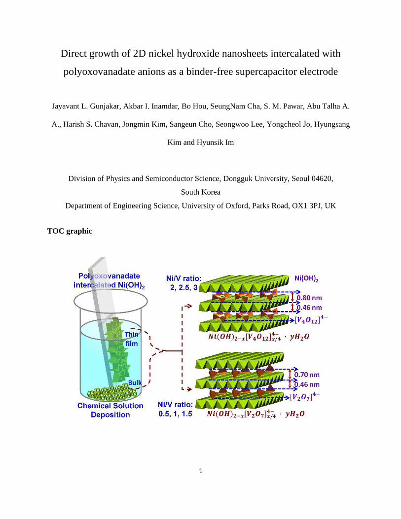
A mesoporous nanoplate network of two-dimensional (2D) layered nickel hydroxide Ni(OH)2
intercalated with zero-dimensional (0D) polyoxovanadate (Ni(OH)2−POV) was built using a
chemical solution deposition method. This approach will provide high flexibility in
controlling the chemical composition and the pore structure of the resulting Ni(OH)2−POV
nanohybrids. The layer-by-layer ordered growth of the Ni(OH)2 −POV is demonstrated by
powder X-ray diffraction and cross-sectional high-resolution transmission electron
microscopy. The random growth of the intercalated Ni(OH)2−POV nanohybrids leads to the
formation of an interconnected network morphology with a highly porous stacking structure
whose porosity is controlled by changing the ratio of Ni(OH)2 and POV. The lateral size and
thickness of the Ni(OH)2−POV nanoplates are ~ 400 nm and from ~ 5 nm to 7 nm,
respectively. The obtained thin films are highly active electrochemical capacitor electrodes
with a maximum specific capacity of 1440 Fg−1 at a current density of 1 mA/g, and they
withstand up to 2000 cycles with an excellent capacity retention of 85%. The superior
electrochemical performance of the Ni(OH)2−POV nanohybrids is attributed to the
expanded mesoporous surface area and the intercalation of the 0D POV. The experimental
findings highlight the outstanding electrochemical functionality of the 2D Ni(OH)2−POV
nanoplate network that will provide a facile route for the synthesis of low-dimensional hybrid
nanomaterials for highly-active electrochemical electrode applications.
3
INTRODUCTION
One of the key challenges in thin film technology is integrating novel complex material
architectures with tailored and emergent properties into functional devices. The ultimate properties
of such complex materials with thin-film structures are not easy to predict due to their structural
and electronic complexity. The deposition of such systems, with the requirements regarding the
complex structure, uniformity, crystallinity and homogeneity of their compositions as well as the
requisite extreme control over the thickness, is difficult to monitor over a large area with the use
of the existing physical/chemical vapour deposition (CVD) methods.1, 2
The rapid depletion of fossil fuels, the growing environmental pollution, and global
warming are central threats to the sustainable development of human beings. Due to the anticipated
energy crisis, novel methods for the attainment of alternative and renewable energies are under
investigation. Particularly, the fabrication of highly efficient and environmentally friendly energy
storage systems are highly desirable.3, 4 The electrochemical capacitor that is popularly known as
the “supercapacitor” is a very attractive energy-storage device due to its high specific power (> 10
kW kg−1) and excellent cycle life with a moderate specific energy (∼10 Wh kg−1).5,6 The
functionality of supercapacitors is based on the charge-storage mechanism of ion adsorption
(electrochemical double layer capacitors, EDLCs) or surface redox reactions (pseudocapacitors).7
Taking into account the fact that EDLCs can store an electrical charge near the electrode surface
through the ion adsorption mechanism and the redox reactions of the surface species
(pseudocapacitors), high-surface-area low-dimensional transition metal oxides (TMOs),
hydroxides, and conducting polymers are promising candidates for electrochemical capacitors.8-11
Several layered TMO and hydroxide nanostructures have received special attention because of
their use in applications like photocatalysts, electrodes, electrocatalysts, gas adsorbents, and drug
4
delivery vectors, among others.12-16 Among many of the layered materials, layered double
hydroxide (LDH) materials with the general formula [M2+1−x M3+
x(OH)2]x+[A n− x/n]x−∙mH2O, in
which M2+, M3+, and An− are the suitable divalent metal ions, trivalent metal ions, and charge-
balancing anions, respectively, have garnered special attention as a pseudocapacitive electrode
material with very high specific capacitances owing to their diverse chemical composition, which
makes it easier to tune their specific capacitances by varying the type and concentration of the
redoxable transition metal ions.10, 17 Moreover, the LDHs crystallize in a sheet-like morphology
composed of diverse transition metal ions that are stabilized in the octahedral sites of an LDH
lattice, and their accessibility in the hydrated gallery space between the hydroxide layers affords
the accumulation of significant charge amounts at the expanded surface through the electrical
double layer and the Faradaic (redox) process of the surface species.18,19
In recent years, extensive research has been devoted to the study of a particular class of
LDH compounds for which x =0 and that consists of a single type of metal cation. The cation is
formed by the stacking of positively charged hydroxyl-deficient layers, which are represented by
the general formula [M2+(OH)2−xAn−x/n yH2O], where x = 0.2 - 0.4; M = Ni, Co, Zn, and Mg; An−
= Cl−, NO3−, SO4
2−, and CO32−; and y = 0.6 - 1.20-22 Initially, efforts were directed toward
deposition of LDH thin films from their bulk counterpart, which leads to an aggregation of the
powdery translucent LDHs with many cracks. The cracks are due to surface strains that originate
from the substrate surface, which does not adhere well to the substrate.23,24 High electrostatic
attraction between the positively charged LDH nanosheets and the charge-balancing anions with
a high charge-to-size ratio are incorporated into the LDH interlayer gallery space, thereby creating
LDH materials that suffer from a limited accessibility regarding their inter-gallery space and
functionality.25 To circumvent this drawback, several attempts were made to synthesize LDH
5
crystals with an expanded gallery space and with the incorporation of bulky inorganic anions to
hybridize the LDH crystals with various guest species, such as inorganic, organic, polymeric, and
biomolecules/nanostructures.12,13,26-30
Here we fabricated a nanoplate network of 2D layered Ni(OH)2 that is intercalated with 0D
polyoxovanadate (Ni(OH)2−POV) using a simple and efficient chemical solution deposition
(CSD) technique. The intercalation of the 0D polyoxovanadate into the 2D Ni(OH)2 remarkably
improves the ionic conductivity and diffusion, which results in a superior electrochemical energy-
storage performance. Our study elucidates the intercalation effects on the electrochemical activity
and stability of the Ni(OH)2−POV based electrodes. The optimised Ni(OH)2−POV electrode
exhibited a high specific capacitance of 1440 F/g at a scan rate of 50 mV/s and an excellent cycling
performance over 2000 cycles with a capacity retention of 85%.
Results and Discussion
Film Formation and Reaction Mechanism
The CSD of thin films is a controlled precipitation technique that is based on the principle of the
solid-phase formation during the transformation from a supersaturated to a saturated state.31 For
the synthesis of the Ni(OH)2−POV nanosheet thin films, a supersaturated aqueous solution of a
hexamine Ni(NH3)4+2 complex, and sodium orthovanadate (Na3VO4
−) is transformed to the
saturated state via the gradual evaporation of ammonia (NH3). The CSD bath is kept at a constant
temperature of 50 ºC. The dissolution of the NiCl2 in water initially facilitates the emergence of
an octahedral hexa-aqua nickel (II) complex ion, as follows:32 NiC₃ + H O → [Ni H O ] aq+ + C₃ − (1)
6
During the addition of the liquid NH3, a greenish precipitate of hydrated Ni(OH)2 is formed
according to the hydroxide-group-derived ‘olation’ process of the stepwise replacement of the H2O
ligand molecules, as follows: [Ni H O �] + + �� − ↔ [Ni OH H O �− ] − + at pH < 9
and [Ni H O �] + + �� − ↔ Ni OH � � + � − �+ at pH > 9 (2)
Upon the further addition of excess NH3 solution, the green precipitate of the Ni(OH)2 is
transformed into a clear blue solution of the hexammine nickel complex (Ni(NH3)q2+), where q is
the coordination number with the most stable value of 6 for the Ni2+.33, 34 The formation of the
hexammine nickel complex prevents a spontaneous precipitation, which leads to the formation of
a supersaturated solution, as follows: Nix OH x + qNH+ + q OH − ↔ Nix NH qx+ + qH O + x OH − at pH > (3)
The aqueous solution of the vanadium precursor produces a large variety of isopolyvanadate
species that exhibit diverse structures ranging from chain metavanadates [VO3−]n to layered oxides
[V2O5] and compact polyanions [V10O28]6−. The structural nature of these species is highly
dependent on the concentration and pH.35, 36 The V5+ ions induce the [V(OH2)6]5+ solvated species
that are formed in the aqueous solution and are surrounded by dipolar H2O molecules.
Since the V5+ and H2O possess a strong polarizing power and Lewis properties, respectively,
some of the electrons can be transferred from the 3a1 orbital of the water molecule to the empty 3d
orbitals of the V5+. The resultant spontaneous acidification and deprotonation of the H2O molecules
are represented by the following hydrolysis reaction: [V OH ] + + ℎH O → [V OH ℎ OH −ℎ] −ℎ + + ℎH O+ (4)
7
where the hydrolysis ratio h increases with the pH leading to the formation of aquo, hydroxo, or
oxo species. Initially, the pH of the Na3VO4 solution is close to ~ 12, producing a monomeric
tetrahedral-vanadate oxo-anionic VO43− species in which four equivalent oxygen atoms surround
the V-V. A Ni(OH)2−POV CSD bath is formed by the addition of a monomeric-orthovanadate
VO43− solution to a supersaturated solution of the hexammine nickel complex. The addition of the
above solution creates a transparent supersaturated CSD bath with a slight increase in the pH
depending on the amount of the VO43− precursor and a colour change from a transparent blue to a
dark cyan. The CSD bath is maintained at an elevated temperature (~ 50 ºC) along with the
vertically immersed substrates; consequently, the ionic product exceeds the solubility product
through its release of the H2O and NH3. The CSD bath gradually becomes saturated, and
precipitation occurs through the heterogeneous growth of the -Ni(OH)2, which is pillared with
the polyoxovanadate species on the substrate, as well as the homogeneous growth in the solution
phase.
The type of intercalated species can be predicted by observing the change of the pH. As the
precipitation process proceeds, the pH changes from 12.5 to ~ 7. As the pH drops gradually to ~
9, condensation occurs due to a continuous deprotonation that leads to the transformation of the
VO43− species to dimeric pyrovanadates [V2O7]4−. In the pH span from 7 to 9, a more condensed
cyclic-metavanadate [V4O12]4− can be formed;36 consequently, the intercalated polyoxovanadium
species are most likely to be either [V2O7]4− or [V4O12]4−.
8
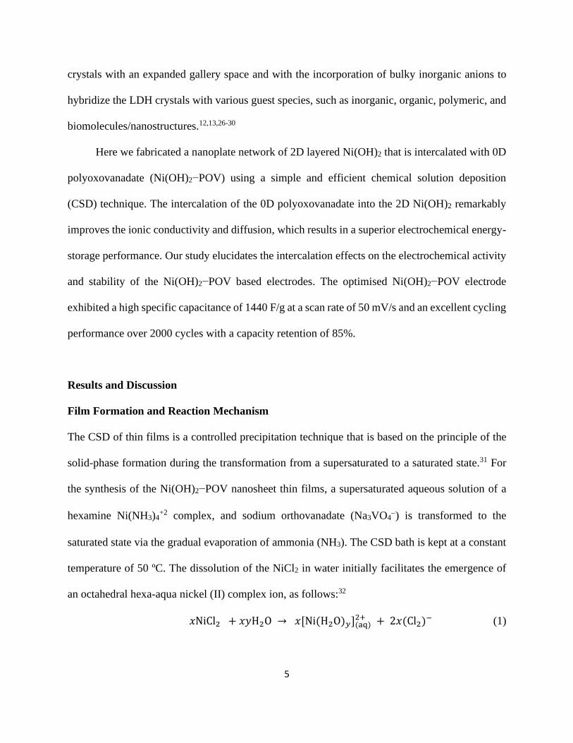
Fig. 1 (Left) XRD patterns of (a) LNHV-3, (b) LNHV-2.5, (c) LNHV-2, (d) LNHV-1.5, (e)
LNHV-1, (f) LNHV-0.5, (g) LNHV-0, and (h) Ni(OH)2 (JCPDS 38-0715). (Right) Structural
schematic model of the LNHV nanohybrids.
To probe the effect of the pillared polyoxovanadate content on the physicochemical properties,
Ni(OH)2−POV nanohybrids are synthesized with various nickel/vanadium precursor ratios of 0,
0.5, 1, 1.5, 2, 2.5, and 3, and the obtained Ni(OH)2−POV nanohybrids are denoted as LNHV-0,
LNHV-0.5, LNHV-1, LNHV-1.5, LNHV-2, LNHV-2. 5, and LNHV-3, respectively. The
evolution of the crystallographic structure of the pristine Ni(OH)2, namely LNHV-0, upon the
pillaring of the 0D polyoxovanadate is studied using the powder XRD analysis. Figure 1 represents
the powder XRD patterns of the Ni(OH)2−POV nanohybrids. The LNHV-0 sample displays a
series of well-developed {00l} Bragg reflections of the turbostratic -Ni(OH)2 structure. The
lattice parameters of the -Ni(OH)2 of a = 0.31 nm and c = 0.46 nm are determined according to
the least-squares fitting analysis, which is in good agreement with the lattice parameters of the -
Ni(OH)2 structure.20,37 Similar to the -Ni(OH)2, all of the Ni(OH)2−POV materials display a series
9
of well-developed {00l} Bragg reflections at the low 2 regions, indicating the formation of a
layer-by-layer ordered pillared structure with an expanded basal spacing. According to the least-
squares fitting analysis, the basal spacing of the Ni(OH)2−POV is estimated to be from 1.31 nm to
1.16 nm. The expanded basal spacing of the Ni(OH)2−POV demonstrates the intercalation of the
polyoxovanadium species that are between the host Ni(OH)2 sheets. The basal spacing decreases
gradually from 1.31 to 1.16 as the Ni/V ratio decreases from 3 to 1.5. For the Ni/V ratios below
1.5, a constant value of 1.16 is obtained. The larger basal spacing for higher reactant ratios clearly
indicates the intercalation of the more condensed polyoxovanadium species [V4O12]4−, which is
due to a rapid fall in the pH to ~ 8 during a given deposition time (a rapid drop in the pH from 13
to 8 corresponds to a Ni/V reactant ratio from 3 to 2). However, for the other reactant Ni/V ratios
below 2, a pH reduction occurs slowly from 13 to ~ 10, which leads to the decrease of the basal
spacing of 1.16, and this is ascribed to the less condensed polyoxovanadium species [V2O7]4−. The
thickness of the Ni(OH)2−POV crystallite along the c-axis is estimated to be ~ 5 nm to ~ 6 nm
using the Scherrer calculation with the full-width-at-half-maximum (FWHM) of {001} reflections.
This finding suggests that these crystallites are nanosheets consisting of ~ 3 to ~ 4 POV-pillared
Ni(OH)2 monolayers. For the hexagonal Ni(OH)2 sheets, all of the Ni(OH)2−POV show an in-
plane (110) peak and a broad hump peak at 2 = ~ 60.4 and 2 = ~ 32 to 44, respectively,
which highlights the maintenance of the in-plane structure of the Ni(OH)2 with a turbostratic
structure.
10
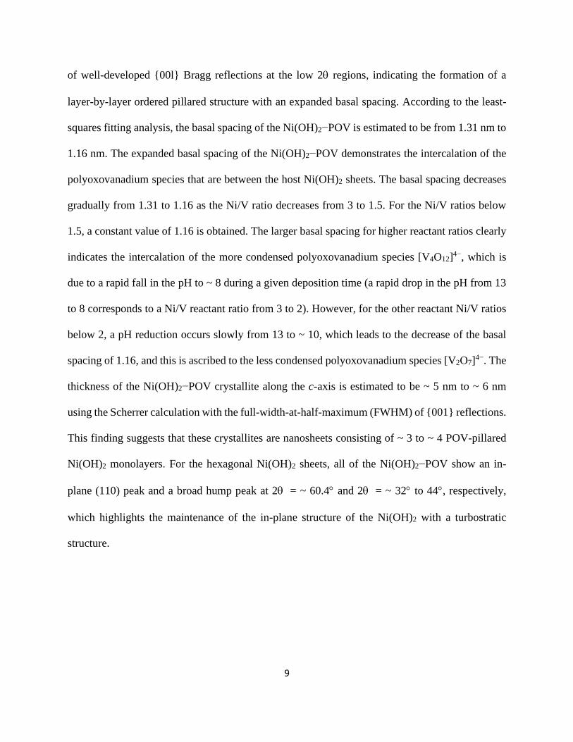
Fig. 2 (a,b) TEM and (c) HRTEM images of the Ni(OH)2−POV (LNHV-1 sample); (d,e) TEM
and HRTEM images exemplifying the moiré fringe patterns from the as-prepared Ni(OH)2−POV.
(f) SAED pattern of the Ni(OH)2−POV; The scale bars in the HRTEM images are equal to 1 nm.
The local crystal structure, morphology, and formation of the layer-by-layer-ordered nature of the
as-prepared Ni(OH)2-POV are determined by the HRTEM and the selected area electron
diffraction (SAED) analyses. As illustrated in Figs. 2 (a) and (b), the low-magnification TEM
images of the Ni(OH)2-POV (LNHV-1) demonstrate the interconnected house-of-cards-type
network of the hetero-layered Ni(OH)2-POV crystallites. The series of equally-spaced fringes that
correspond to the host Ni(OH)2 hexagonal lattice are observed, as shown in Fig. 2(c). The interline
11
distance between the two consecutive lattice fringes is approximately 0.25 nm, and this value is in
good agreement with the hexagonal Ni(OH)2 bulk value (JCPDS 38-0715).37 The development of a
well-ordered moiré-fringe pattern depicts the formation of the layer-by-layer-ordered structure of
Ni(OH)2 nanosheets that are intercalated with isopolyoxovanadate. These lattice distances between
these fringes are separated by a distance of ~ 1 nm, which is attributed to the expanded Ni(OH)2
gallery after the intercalation of the 0D isopolyoxovanadate nanoclusters. The estimated moiré-
fringe spacing is in good agreement with the c-axis lattice parameter determined from the XRD
analysis.38 The present assignment is further confirmed by the HRTEM and SAED analyses. As
shown in Fig. 2(f), a typical hexagonal pattern diffraction feature is resolved from the as-prepared crystals.39
As highlighted in Figure 2(f), the sharp diffraction rings can be assigned as the (100), (101), and
(102) reflection from the host-Ni(OH)2 crystals. Besides the sharp diffraction rings, several diffuse
and broad rings are also observed. These rings are identified as the diffraction arising from the
polycrystalline polyoxovanadate nanoclusters which are stabilized within the Ni(OH)2
nanosheets.39
12
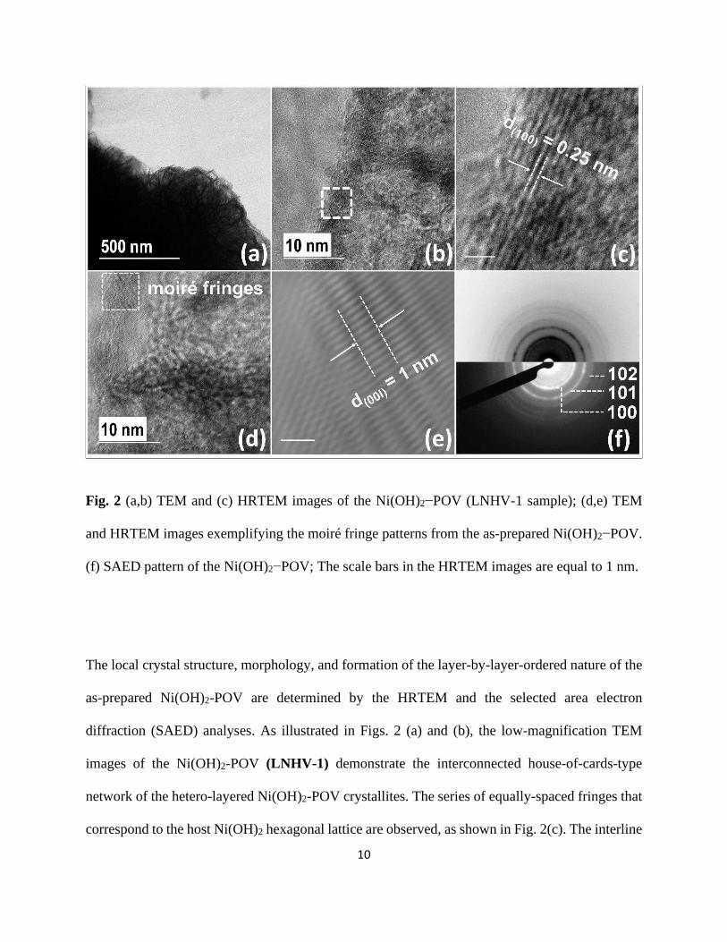
Fig. 3. (a) HAADF STEM image of as-prepared Ni(OH)2-POV, (b) element line scans along the
dotted line in (a) and HAADF STEM element mapping for (c) Ni, (d) V, and (e) O in the Ni(OH)2-
POV (LNHV-1) nanohybrid.
Moreover, the localized elemental distributions in the Ni(OH)2–POV nanosheets are investigated using high
angle annular dark field (HAADF) scanning transmission electron microscope (STEM). In Figs. 3(a, b), the
elemental EDS line-scan profile which is generated from a randomly selected region exhibits the vertically
homogeneous distributions of nickel (Ni), vanadium (V) and oxygen (O) elements. The HAADF-STEM
element-mapping results in Figs. 3 (c) to (e) further confirm the intimate and lateral homogeneous
intercalation of POV nanoclusters into the interlayer of the Ni(OH)2 nanosheets.
13
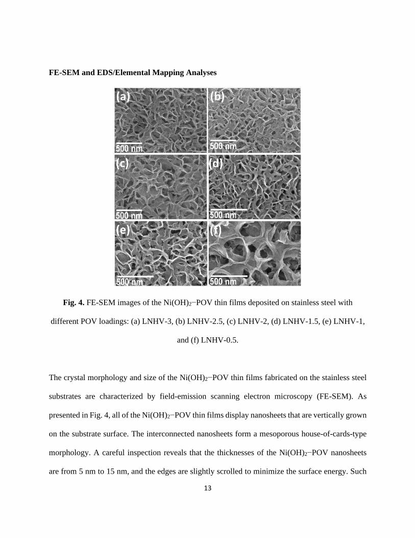
FE-SEM and EDS/Elemental Mapping Analyses
Fig. 4. FE-SEM images of the Ni(OH)2−POV thin films deposited on stainless steel with
different POV loadings: (a) LNHV-3, (b) LNHV-2.5, (c) LNHV-2, (d) LNHV-1.5, (e) LNHV-1,
and (f) LNHV-0.5.
The crystal morphology and size of the Ni(OH)2−POV thin films fabricated on the stainless steel
substrates are characterized by field-emission scanning electron microscopy (FE-SEM). As
presented in Fig. 4, all of the Ni(OH)2−POV thin films display nanosheets that are vertically grown
on the substrate surface. The interconnected nanosheets form a mesoporous house-of-cards-type
morphology. A careful inspection reveals that the thicknesses of the Ni(OH)2−POV nanosheets
are from 5 nm to 15 nm, and the edges are slightly scrolled to minimize the surface energy. Such
14
a nanosheet morphology is commonly observed for CSD-deposited hydroxide materials.40,41 The
estimated thicknesses of 5 nm to 15 nm suggest the presence of approximately 3 to 6 stacked layers
of 2D Ni(OH)2 with the polyoxovanadate. The intercalation of the polyoxovanadate is further
confirmed using the EDS and elemental analyses (Supplementary Information). All of the
constituent elements, i.e., nickel (Ni), vanadium (V) and oxygen (O), are uniformly distributed
across all the Ni(OH)2−POV thin films, which re-confirms that the intercalation of the
polyoxovanadate nanoclusters in the gallery spacing of the Ni(OH)2 nanosheets are homogeneous
and without any spatial-phase separation. The EDS elemental analysis demonstrates the tuning of
the chemical composition of the Ni(OH)2−POV thin films (Supplementary Information).
FT-IR and Micro-Raman Spectroscopy
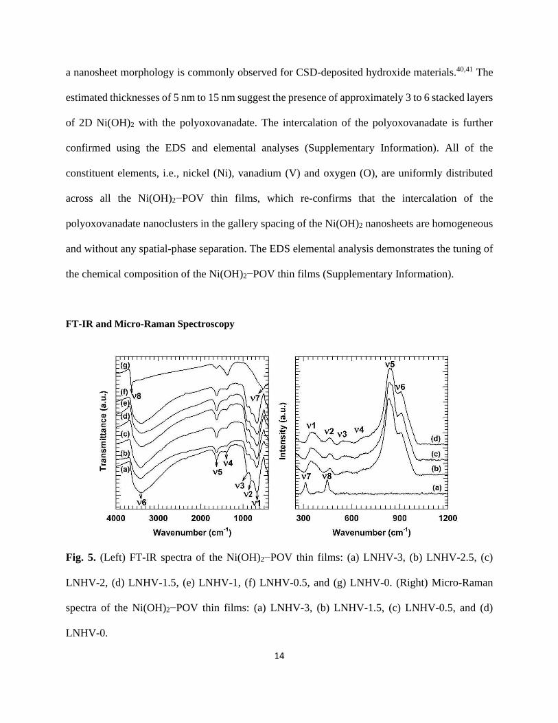
Fig. 5. (Left) FT-IR spectra of the Ni(OH)2−POV thin films: (a) LNHV-3, (b) LNHV-2.5, (c)
LNHV-2, (d) LNHV-1.5, (e) LNHV-1, (f) LNHV-0.5, and (g) LNHV-0. (Right) Micro-Raman
spectra of the Ni(OH)2−POV thin films: (a) LNHV-3, (b) LNHV-1.5, (c) LNHV-0.5, and (d)
LNHV-0.
15
The chemical bonding nature of the polyoxovanadium species in the Ni(OH)2−POV thin films is
examined with Fourier transform infrared (FT-IR) spectroscopy. As plotted in Fig. 5 (left), all of
the Ni(OH)2−POV thin films show very similar spectral features. The strong and sharp absorption
peak at 1 (670 cm−1) and the shoulder band at 2 (810 cm−1) are attributed to the antisymmetric
and symmetric stretching modes of the V-O-V chains, respectively.42 Furthermore, the second
shoulder band at a higher wavenumber 3 (910 cm−1) is assigned to the symmetric stretching mode
of the terminal V=O groups.43,44 The presence of these bands confirms the incorporation of the
polyoxovanadate ions into the interlayer space of the Ni(OH)2.45-47 It should be noted that a mild
band 4 (1386 cm−1) is presented among all samples, which is attributed to the absorbed carbonate
moieties on the external surface of the particles due to the high pH of the CSD. The other IR bands
at 6 (3420 cm−1) and 5 (1600 cm−1 to 1630 cm−1) are assigned to the Ni(OH)2 and the free H2O
O-H stretching and bending modes respectively.48
Micro-Raman spectroscopy is also employed to further probe the successful intercalation of
polyoxovanadate. As indexed in Fig. 5 (right panel), the as-prepared nano hybrid thin films exhibit
1 to 10 characteristic Raman peaks that belong to the characteristic Raman shift from the 0D-
POV species (see Supplementary Information for details). These characteristic features underscore
the intercalation of the 0D-POV species inside the Ni(OH)2 gallery. The peaks at 330 cm−1 and
460 cm−1 are attributed to the Eg and A1g lattice modes of the Ni(OH)2. The LNHV-0 nanohybrid
with no POV revealed peaks at 313 and 448 cm-1 without any POV signature peak, and they are
attributed to the Raman-active vibrations of the Eg and A1g modes of the -Ni(OH)2, respectively.
The peak at 540 cm−1 is attributed to the second-order acoustic mode of Ni(OH)2. A weak peak
feature centred at 1617 cm−1 is composed of the superposition of the O-H bending mode of the
16
intercalated water at 1600 cm−1 and the surface-adsorbed/structure-trapped water at 1630 cm−1.
The broad signature peak from 3500 cm−1 to 3690 cm−1 is attributed to the internal O−H stretching
modes from the lattice OH and the intersheet H2O. All of the LNHV nanohybrids show a high-
intensity broad peak centred at 838 cm−1 with the signature shoulder at 910 cm−1. The observed
feature is the superposition of three characteristic peaks at 790 cm−1, 838 cm−1, and 910 cm−1,
which are attributed to the second-order lattice mode of the -Ni(OH)2, and the symmetric-
stretching vibrational modes of the [V2O7]4− and [V4O12]4−, respectively. A careful observation of
the peaks highlights a trend of a signal shifting to lower frequencies, and this is attributed to the
decreasing polyoxovanadium chain length. The observed Raman features indicate the intercalation
of the [V2O7]4− in the nanohybrids of the LNHV-0.5 to LNHV-1.5 and the [V4O12]4− in the
nanohybrids of the LNHV-2 to LNHV-3.
17
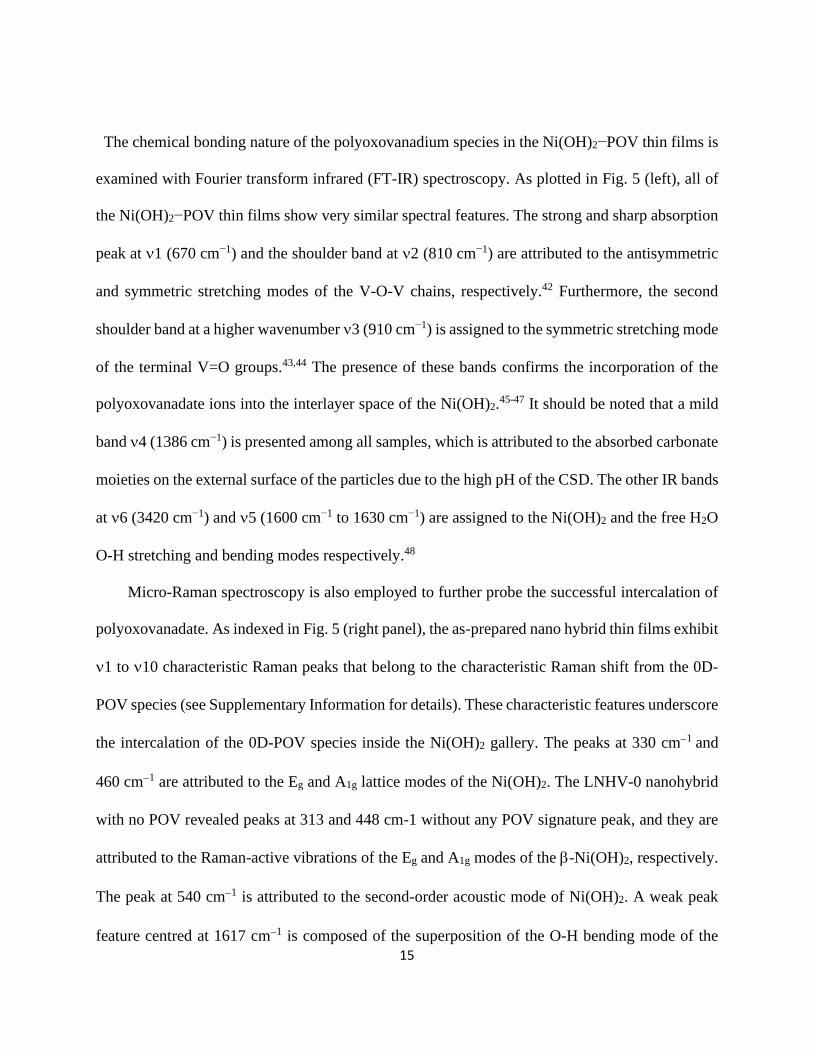
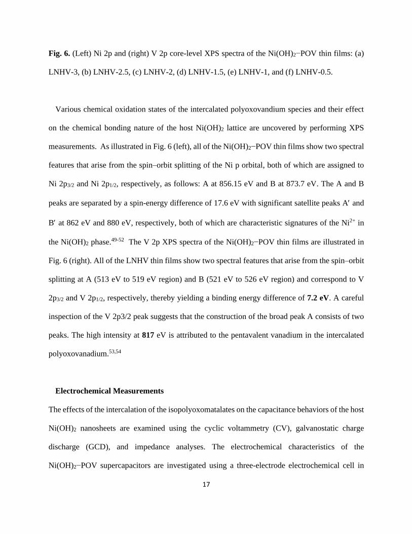
Fig. 6. (Left) Ni 2p and (right) V 2p core-level XPS spectra of the Ni(OH)2−POV thin films: (a)
LNHV-3, (b) LNHV-2.5, (c) LNHV-2, (d) LNHV-1.5, (e) LNHV-1, and (f) LNHV-0.5.
Various chemical oxidation states of the intercalated polyoxovandium species and their effect
on the chemical bonding nature of the host Ni(OH)2 lattice are uncovered by performing XPS
measurements. As illustrated in Fig. 6 (left), all of the Ni(OH)2−POV thin films show two spectral
features that arise from the spin–orbit splitting of the Ni p orbital, both of which are assigned to
Ni 2p3/2 and Ni 2p1/2, respectively, as follows: A at 856.15 eV and B at 873.7 eV. The A and B
peaks are separated by a spin-energy difference of 17.6 eV with significant satellite peaks A and
B at 862 eV and 880 eV, respectively, both of which are characteristic signatures of the Ni2+ in
the Ni(OH)2 phase.49-52 The V 2p XPS spectra of the Ni(OH)2−POV thin films are illustrated in
Fig. 6 (right). All of the LNHV thin films show two spectral features that arise from the spin–orbit
splitting at A (513 eV to 519 eV region) and B (521 eV to 526 eV region) and correspond to V
2p3/2 and V 2p1/2, respectively, thereby yielding a binding energy difference of 7.2 eV. A careful
inspection of the V 2p3/2 peak suggests that the construction of the broad peak A consists of two
peaks. The high intensity at 817 eV is attributed to the pentavalent vanadium in the intercalated
polyoxovanadium.53,54
Electrochemical Measurements
The effects of the intercalation of the isopolyoxomatalates on the capacitance behaviors of the host
Ni(OH)2 nanosheets are examined using the cyclic voltammetry (CV), galvanostatic charge
discharge (GCD), and impedance analyses. The electrochemical characteristics of the
Ni(OH)2−POV supercapacitors are investigated using a three-electrode electrochemical cell in
18
which the Ni(OH)2−POV thin films are used as the working electrode, a platinum mesh serves as
the counter and a saturated calomel electrode (SCE) serves as the reference electrode. Figure 7
represents the CV curves of the Ni(OH)2−POV thin film electrodes.
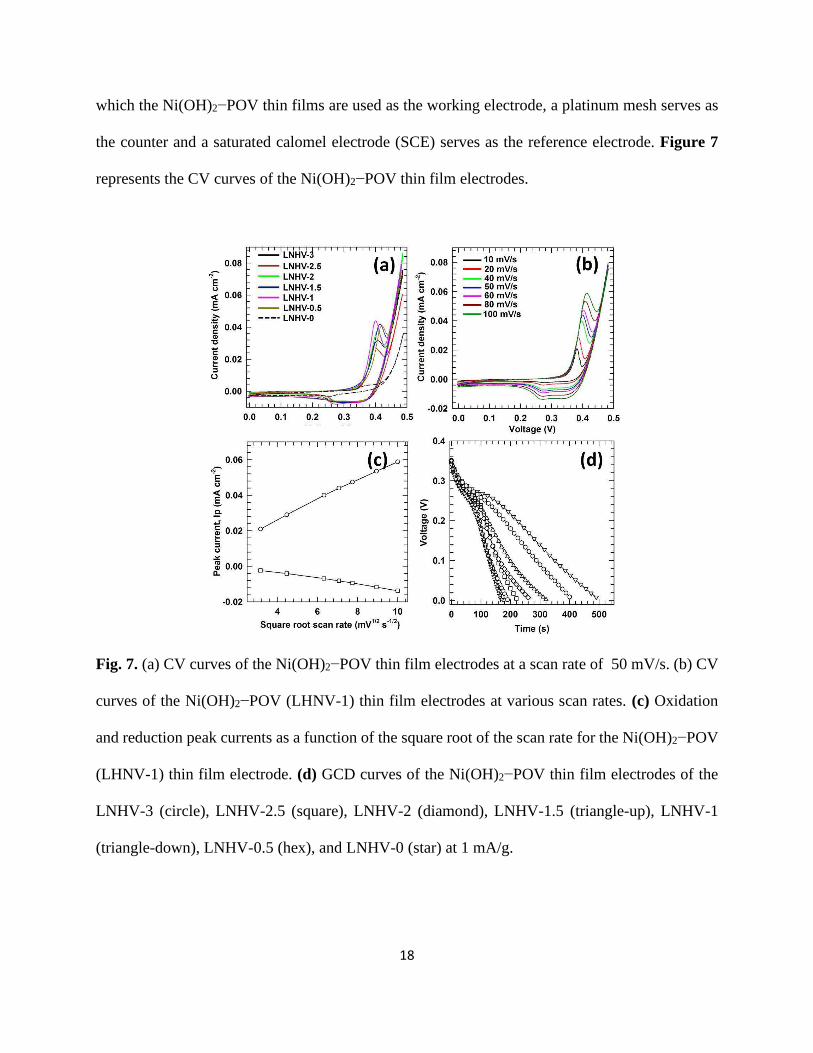
Fig. 7. (a) CV curves of the Ni(OH)2−POV thin film electrodes at a scan rate of 50 mV/s. (b) CV
curves of the Ni(OH)2−POV (LHNV-1) thin film electrodes at various scan rates. (c) Oxidation
and reduction peak currents as a function of the square root of the scan rate for the Ni(OH)2−POV
(LHNV-1) thin film electrode. (d) GCD curves of the Ni(OH)2−POV thin film electrodes of the
LNHV-3 (circle), LNHV-2.5 (square), LNHV-2 (diamond), LNHV-1.5 (triangle-up), LNHV-1
(triangle-down), LNHV-0.5 (hex), and LNHV-0 (star) at 1 mA/g.
19
All of the intercalated Ni(OH)2−POV thin film electrodes display typical discernible redox peaks
that correspond to the Faradaic redox reactions between Ni(OH)2 and NiOOH. This demonstrates
that the electrochemical activity of these electrodes mainly originates from the pseudocapacitive
behavior that is based on the following redox mechanism: Ni OH + OH− → NiOOH + H O + e− (???)
The POV intercalation remarkably increases the integral area of the CV curves of the pristine
Ni(OH)2 thin film electrode, as shown in Fig. 7(a), which highlights the crucial role of the POV
intercalation in the improvement of the electrochemical activity of the Ni(OH)2−POV. Among the
Ni(OH)2−POV thin film electrodes, LNHV-1 has the largest area, which highlights its superior
electrochemical performance.
Figure 7(b) shows the CV curves at different scan rates ranging from 10 mV/s to 100 mV/s
for the LNHV-1 electrode. As the scan rate increases, the cathodic peak current also increases,
indicating its pseudocapacitive behavior. As shown in Fig. 7(c), the linear increase of the redox
peak current densities demonstrates a pseudocapacitive behavior that is limited by the diffusion
controlled electrochemical reaction of the Ni(OH)2−POV electrode.
The electrochemical performance of the Ni(OH)2−POV thin film electrode (LNHV-1) is
further evaluated by measuring its galvanometric charge-discharge properties. As illustrated in Fig.
7(d), all of the Ni(OH)2−POV thin film electrodes show typical nonlinear charge-discharge
behaviours. This implies that the reversible Faradaic reactions significantly contribute to the
specific capacitance of the Ni(OH)2−POV thin film electrodes. The specific capacitance value
obtained from the LNHV-3, LNHV-2.5, LNHV-2, LNHV-1.5, LNHV-1, LNHV-0.5, and LNHV-
0 Ni(OH)2−POV samples is 536 F/g, 637 F/g, 771 F/g, 897 F/g, 1440 F/g, 1170 F/g, and 611 F/g
respectively. All of the intercalated Ni(OH)2−POV thin film electrodes demonstrate considerably
20
enhanced specific capacitance compared with the pristine Ni(OH)2, which highlights the advantage
of the POV intercalation for the improvement of the electrochemical supercapacitor activity. The
observed improvement of the supercapacitor performance upon the intercalation with the POV
nanoclusters is attributable to the expanded interlayer gallery height of the host Ni(OH)2 nanosheet
lattice, which leads to an increase in the freely accessible interlayer gallery space for the redox-
reaction electrolyte ions. The mesoporous house-of-cards morphology of the Ni(OH)2−POV thin
film electrodes additionally contributes to the redox reactions by enhancing the efficient adsorption
of the electrolyte ions. The specific capacitance is increased from 536 F/g for the sample with a
higher POV content (LNHV-3), it reaches the maximum value of 1440 F/g for the sample with an
optimum POV content (LNHV-1) and again it decreases to 1170 F/g for the sample with the lowest
POV content (LNHV-0.5). This finding elucidates the crucial role of the intercalated POV species
in determining the supercapacitor performance of the Ni(OH)2−POV thin film electrodes. The
experimental results provide strong evidence for the tunability of the supercapacitor performance
of the Ni(OH)2-based nanohybrid electrodes through the selection of the intercalated POV content.
To probe the effective charge-discharge mechanism of the Ni(OH)2−POV thin film
electrodes, the dependence of the specific capacitance of the Ni(OH)2−POV thin film electrodes
on the current density is examined (see ESI). As illustrated in Fig. S3, all of the electrodes show a
decrease in the specific capacitance with an increasing charge–discharge current density. The
capacitive behaviour of the layered inorganic materials is governed by the following two
contributing mechanisms: the adsorption/desorption of the solvated ions on the surface of the
layered inorganic material and the intercalation/de-intercalation of the solvated ions into/out of the
interlayer space of the layered electrode material. The observed decrease in the specific
capacitance with the current density is ascribed to the diffusion effect of the solvated electrolyte
21
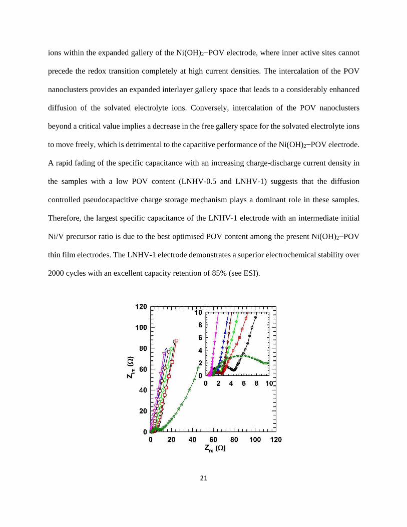
ions within the expanded gallery of the Ni(OH)2−POV electrode, where inner active sites cannot
precede the redox transition completely at high current densities. The intercalation of the POV
nanoclusters provides an expanded interlayer gallery space that leads to a considerably enhanced
diffusion of the solvated electrolyte ions. Conversely, intercalation of the POV nanoclusters
beyond a critical value implies a decrease in the free gallery space for the solvated electrolyte ions
to move freely, which is detrimental to the capacitive performance of the Ni(OH)2−POV electrode.
A rapid fading of the specific capacitance with an increasing charge-discharge current density in
the samples with a low POV content (LNHV-0.5 and LNHV-1) suggests that the diffusion
controlled pseudocapacitive charge storage mechanism plays a dominant role in these samples.
Therefore, the largest specific capacitance of the LNHV-1 electrode with an intermediate initial
Ni/V precursor ratio is due to the best optimised POV content among the present Ni(OH)2−POV
thin film electrodes. The LNHV-1 electrode demonstrates a superior electrochemical stability over
2000 cycles with an excellent capacity retention of 85% (see ESI).
22
Fig. 8. Nyquist plots of the Ni(OH)2−POV thin film electrodes. (circle) LNHV-3, (square) LNHV-
2.5, (diamond) LNHV-2, (triangle-up) LNHV-1.5, (triangle-down) LNHV-1, (hex) LNHV-0.5,
and (star) LNHV-0. The inset shows an enlarged view of the EIS spectra in the high frequency
region.
To further elucidate the charge transport mechanisms that contribute to the superior
electrochemical activity of the Ni(OH)2−POV thin film electrodes, EIS measurements are
conducted. Figure 8 shows the Nyquist plots for the Ni(OH)2−POV thin film electrodes. All of the
electrodes show partially overlapping semicircles in the high-frequency region. The presence of a
semicircle is linked to the resistance of the electrolyte (Re) and the charge transfer resistance (Rct).
All of the Ni(OH)2−POV thin film electrodes show much smaller Re values compared with the
pristine Ni(OH)2 electrode, which indicates the improvements in the charge transfer and the
electrical conductivity with the POV intercalation. The Ni(OH)2−POV electrode with the
optimised POV content (LNHV-1) has the smallest semi-circle compared with the other electrodes.
As discussed earlier, because the surface areas of all of the electrode materials are comparable, the
size of the arches is likely to be determined by the electrical conductivity of the Ni(OH)2−POV
electrodes. The inclined lines in the low-frequency region correspond to the Warburg impedance,
which is associated with the diffusion of the electrolyte ions into the bulk electrodes. Compared
with the bare Ni(OH)2 electrode (LNHV-0), the slopes of the other Ni(OH)2−POV samples are
much larger, and this implies a lower resistance for the diffusion of the electrolyte ions throughout
the electrode. Therefore, the performance enhancement in the Ni(OH)2−POV electrode is due to
the improved electrical conductivity and diffusion of the electrolyte ions.
23
Conclusion
In summary, an interconnected network of 2D Ni(OH)2 nanosheets that are intercalated with 0D
polyoxovandate nanoclusters was fabricated using chemical solution deposition, and it exhibited
a promising applicability as a binder-free electrode for the improvement of the electrochemical
activity of bare Ni(OH)2. Given that the pristine Ni(OH)2 phase is one of the most efficient
supercapacitor electrodes, the presented Ni(OH)2−POV nanohybrids showed a significantly
enhanced level of electrochemical-activity as a supercapacitor electrode, thereby underscoring the
beneficial effect of the POV intercalation on the supercapacitor performance of the pristine metal
hydroxide material. The highest specific capacitance of 1400 Fg−1 was obtained from the most
optimized Ni(OH)2−POV electrode. We attributed the remarkable enhancement of the
electrochemical energy storage ability of the pristine Ni(OH)2 with the POV intercalation not only
to the formation of a highly porous house-of-cards-type interconnected network morphology but
also to an increased freely accessible gallery space and electrical conductivity. This study
demonstrated the effectiveness of the chemical solution deposition (CSD) method for the
deposition of highly porous metal hydroxide materials that are intercalated with 0D
polyoxomatalate for exploring efficient hydroxide-based electrode materials. Taking into account
the fact that it is possible that CSD-deposited Ni(OH)2 materials might boast numerous excellent
functionalities, like electrochemical water splitting and battery electrodes, the intercalation of the
0D polyoxomatalates into the host matrix can provide a universal methodology for the CSD-based
deposition of novel functional materials from the reported OH2 deposition database. This synthetic
CSD-based strategy is readily extendible for diverse couples of metal hydroxide nanosheets and
anionic 0D nanoclusters. Currently, the exploration of efficient electrochemical energy harvesting
24
from the intercalated assembly between Ni(OH)2 and other 0D polyoxomatalate nanoclusters is
underway.
Experimental Section
Materials. Nickel chloride (NiCl2), Sodium orthovanadate (Na3VO4), and ammonium
hydroxide (NH4OH; 28 %), were purchased from Sigma-Aldrich and used without further
purification. Stainless steel (SS) substrates were used for the deposition of the Ni(OH)2−POV thin
films.
Experimental Details.
The chemical bath for the deposition of the Ni(OH)2−POV comprised an aqueous solution of 0.1
M NiCl2 that was combined with an aqueous NH3 solution (6.5 M; 2.5 mL) under constant stirring.
During addition of NH3, an initially apple-green coloured precipitate, the Ni(OH)2 was formed,
which was subsequently dissolved back into the solution by the further addition of an excess NH3
solution. The pH of the solution at this stage was ~12.5. For a vanadium (V) precursor, an aqueous
solution of 0.1M Na VO was prepared. The chemical deposition bath was obtained by the mixing
of the stock solutions into a 50 mL glass beaker with the sequential addition of 20 ml of a Ni-
amine complex and the requisite amount of the V precursor. The final pH of the bath was adjusted
to ~ 13 using the aqueous NH3. Since the substrate provided nucleation centres for the
25
heterogeneous growth of the deposited material, the cleaning step of the substrate played a crucial
role in the successful deposition of the uniform film. The stainless steel substrates were cleaned
with zero grade polish paper followed by washing with de-ionized water. After the cleaning
process, the substrates were stored in distilled water to avoid any possible dust contamination.
Before the film deposition, the substrates were again cleaned with distilled water and dried with
an Ar flow. A pre-cleaned SS substrate was immersed and placed vertically in the solution. The
solution was maintained at a pH of approximately 13 and a temperature of 50 °C for 3 h, resulting
in the direct growth of the LNHV nanosheet network on the glass substrate. After the deposition,
the LNHV nanosheet-deposited substrates were retrieved from the bath, washed with the deionized
water, and dried under the Ar flow. The bulk LNHV samples formed using homogeneous
precipitation were collected from the same bath using successive centrifugation and washing
procedures.
The crystal structures of the LNHV thin film were examined using the powder X-ray
diffraction (XRD) analysis for which a Rigaku diffractometer with Ni-filtered Cu K (K =
1.54056 A) radiation was employed. The surface morphology, nanosheet size, and elemental
distribution of the LNHVs were probed with the use of FE-SEM (Hitachi S-4800) for which is
equipped with energy-dispersive spectrometry (EDS). For further insight into the microstructure
of the LNHV nanosheets, transmission electron microscopy (TEM), high-resolution TEM
(HRTEM) and selected area electron diffraction (SAED) images are recorded using the JEOL-
3000F at 300 kV with a camera length of 255.8 mm. High angle annular dark field (HAADF)
scanning transmission electron microscope (STEM) and element mapping were carried out at 200
kV using a JEOL-2010 microscope with an X-ray EDS accessory. The Fourier-transform infra-red
(FT-IR) spectroscopic analysis was performed in a frequency range of 400 cm−1 to 4000 cm−1
26
using the Jasco FT/IR-6100 FT spectrometer, and this allowed us to study the chemical bonding
nature of the LNHV nanosheets. The Raman spectra were recorded with the Horiba Jobin-Yvon
LabRam Aramis spectrometer. The 514 nm line of an Ar-ion laser was used as the excitation
source.
Electrochemical measurements
The electrochemical activity of the LNHV nanosheet thin films was investigated using cyclic
voltammetry (CV), galvanostatic charge/discharge (GCD), and electrochemical impedance
spectroscopy (EIS) analysis. All of the electrochemical measurements were carried out using the
electrochemical workstation Versa-stat-3 (Princeton Applied Research) with a standard three
electrode electrochemical cell. Precisely deposited unit area LNHV nanosheet thin films, a
saturated calomel electrode (SCE), and a platinum mesh served as the working, reference, and
counter electrodes, respectively. An aqueous solution (2 M) of potassium hydroxide (KOH) was
employed as the electrolyte.
Acknowledgements
This research is supported by the National Research Foundation (NRF) of Korea (Grant nos.
2016R1A6A1A03012877, 2015M2A2A6A02045251, 2015R1A2A2A01004782,
2015R1D1A1A01058851 and 2015R1D1A1A01060743).
Electronic Supplementary Information (ESI) available:
Characterization results including EDS, EDS-elemental mapping, micro-Raman, electrochemical
performance high current density, electrochemical stability.
27
1. K. L. Choy, Progress in Materials Science, 2003, 48, 57-170.
2. R. S. Mane and C. D. Lokhande, Materials Chemistry and Physics, 2000, 65, 1-31.
3. C. Liu, F. Li, L. P. Ma and H. M. Cheng, Advanced Materials, 2010, 22, E28-+.
4. Y. Xiang, S. F. Lu and S. P. Jiang, Chem Soc Rev, 2012, 41, 7291-7321.
5. J. R. Miller and P. Simon, Science, 2008, 321, 651-652.
6. D. P. Dubal, O. Ayyad, V. Ruiz and P. Gomez-Romero, Chem Soc Rev, 2015, 44, 1777-1790.
7. G. Wang, L. Zhang and J. Zhang, Chem Soc Rev, 2012, 41, 797-828.
8. U. Patil, S. C. Lee, S. Kulkarni, J. S. Sohn, M. S. Nam, S. Han and S. C. Jun, Nanoscale, 2015, 7, 6999-
7021.
9. A. I. Inamdar, Y. Kim, S. M. Pawar, J. H. Kim, H. Im and H. Kim, J Power Sources, 2011, 196, 2393-
2397.
10. T. H. Gu, J. L. Gunjakar, I. Y. Kim, S. B. Patil, J. M. Lee, X. Jin, N. S. Lee and S. J. Hwang, Small, 2015,
11, 3921-3931.
11. A. I. Inamdar, Y. S. Kim, J. S. Sohn, H. Im, H. Kim, D. Y. Kim, R. S. Kalubarme and C. Park, J Korean
Phys Soc, 2011, 59, 145-149.
12. J. L. Gunjakar, I. Y. Kim, J. M. Lee, Y. K. Jo and S. J. Hwang, Journal of Physical Chemistry C, 2014,
118, 3847-3863.
13. D. H. Park, S. J. Hwang, J. M. Oh, J. H. Yang and J. H. Choy, Prog Polym Sci, 2013, 38, 1442-1486.
14. K. Yan, G. S. Wu and W. Jin, Energy Technol-Ger, 2016, 4, 354-368.
15. Q. Wang and D. O'Hare, Chem Rev, 2012, 112, 4124-4155.
16. G. L. Fan, F. Li, D. G. Evans and X. Duan, Chem Soc Rev, 2014, 43, 7040-7066.
17. X. Long, Z. L. Wang, S. Xiao, Y. M. An and S. H. Yang, Mater Today, 2016, 19, 213-226.
18. U. M. Patil, J. S. Sohn, S. B. Kulkarni, S. C. Lee, H. G. Park, K. V. Gurav, J. H. Kim and S. C. Jun, Acs
Applied Materials & Interfaces, 2014, 6, 2450-2458.
19. V. Rives, Layered double hydroxides : present and future, Nova Science Publishers, Huntington,
N.Y., 2001.
20. P. V. Kamath, G. H. A. Therese and J. Gopalakrishnan, J Solid State Chem, 1997, 128, 38-41.
21. Y. Du and D. O'Hare, Inorg Chem, 2008, 47, 3234-3242.
22. J. Demel, J. Hynek, P. Kovar, Y. Dai, C. Taviot-Gueho, O. Demel, M. Pospisil and K. Lang, Journal of
Physical Chemistry C, 2014, 118, 27131-27141.
23. E. Gardner, K. M. Huntoon and T. J. Pinnavaia, Advanced Materials, 2001, 13, 1263-1266.
24. X. X. Guo, F. Z. Zhang, D. G. Evans and X. Duan, Chemical Communications, 2010, 46, 5197-5210.
25. R. Z. Ma, Z. P. Liu, L. Li, N. Iyi and T. Sasaki, Journal of Materials Chemistry, 2006, 16, 3809-3813.
26. L. Mohapatra, K. Parida and M. Satpathy, Journal of Physical Chemistry C, 2012, 116, 13063-13070.
27. S. K. Yun and T. J. Pinnavaia, Inorg Chem, 1996, 35, 6853-6860.
28. S. Omwoma, W. Chen, R. Tsunashima and Y. F. Song, Coordin Chem Rev, 2014, 258, 58-71.
29. D. G. Evans and D. A. Xue, Chemical Communications, 2006, DOI: 10.1039/b510313b, 485-496.
30. L. Li, R. Z. Ma, Y. Ebina, K. Fukuda, K. Takada and T. Sasaki, J Am Chem Soc, 2007, 129, 8000-8007.
31. G. Hodes, Chemical solution deposition of semiconductor films, Marcel Dekker, New York, 2003.
28
32. C. F. Baes and R. E. Mesmer, The hydrolysis of cations, R.E. Krieger, Malabar, Fla., 1986.
33. Y. G. Li, B. Tan and Y. Y. Wu, Chemistry of Materials, 2008, 20, 2602-2602.
34. I. Ichinose, K. Kurashima and T. Kunitake, J Am Chem Soc, 2004, 126, 7162-7163.
35. C. F. Baes and R. E. Mesmer, The hydrolysis of cations, Wiley, New York, 1976.
36. J. Livage, Coordin Chem Rev, 1998, 178, 999-1018.
37. D. S. Hall, D. J. Lockwood, C. Bock and B. R. MacDougall, P Roy Soc a-Math Phy, 2015, 471.
38. L. A. Burton, T. J. Whittles, D. Hesp, W. M. Linhart, J. M. Skelton, B. Hou, R. F. Webster, G. O'Dowd,
C. Reece, D. Cherns, D. J. Fermin, T. D. Veal, V. R. Dhanak and A. Walsh, J Mater Chem A, 2016, 4,
1312-1318.
39. B. Hou, D. Parker, G. P. Kissling, J. A. Jones, D. Cherns and D. J. Fermin, Journal of Physical
Chemistry C, 2013, 117, 6814-6820.
40. S. B. Kulkarni, A. D. Jagadale, V. S. Kumbhar, R. N. Bulakhe, S. S. Joshi and C. D. Lokhande, Int J
Hydrogen Energ, 2013, 38, 4046-4053.
41. D. P. Dubal, R. Holze and P. Gomez-Romero, Sci Rep-Uk, 2014, 4.
42. F. Kooli and W. Jones, Inorg Chem, 1995, 34, 6237-&.
43. F. Kooli, W. Jones, V. Rives and M. A. Ulibarri, Journal of Materials Science Letters, 1997, 16, 27-
29.
44. J. L. Gunjakar, A. M. More, K. V. Gurav and C. D. Lokhande, Applied Surface Science, 2008, 254,
5844-5848.
45. C. Barriga, W. Jones, P. Malet, V. Rives and M. A. Ulibarri, Inorg Chem, 1998, 37, 1812-1820.
46. J. L. Gunjakar, Y. K. Jo, I. Y. Kim, J. M. Lee, S. B. Patil, J. C. Pyun and S. J. Hwang, J Solid State Chem,
2016, 240, 115-121.
47. J. L. Gunjakar, I. Y. Kim and S. J. Hwang, Eur J Inorg Chem, 2015, DOI: 10.1002/ejic.201402480,
1198-1202.
48. R. A. Nyquist and R. O. Kagel, Infrared spectra of inorganic compounds (3800- cm⁻¹), Academic
Press, New York,, 1971.
49. K. Fan, H. Chen, Y. Ji, H. Huang, P. M. Claesson, Q. Daniel, B. Philippe, H. Rensmo, F. Li, Y. Luo and
L. Sun, Nat Commun, 2016, 7, 11981.
50. H. B. Li, M. H. Yu, F. X. Wang, P. Liu, Y. Liang, J. Xiao, C. X. Wang, Y. X. Tong and G. W. Yang, Nat
Commun, 2013, 4, 1894.
51. J. Yan, Z. J. Fan, W. Sun, G. Q. Ning, T. Wei, Q. Zhang, R. F. Zhang, L. J. Zhi and F. Wei, Adv Funct
Mater, 2012, 22, 2632-2641.
52. J. W. Lee, T. Ahn, D. Soundararajan, J. M. Ko and J. D. Kim, Chemical Communications, 2011, 47,
6305-6307.
53. S. J. Wu, X. H. Yang, J. F. Hu, H. W. Ma, Z. G. Lin and C. W. Hu, Crystengcomm, 2015, 17, 1625-
1630.
54. G. Silversmit, D. Depla, H. Poelman, G. B. Marin and R. De Gryse, J Electron Spectrosc, 2004, 135,
167-175.
Related Documents


![[Papercraft] Orca](https://static.cupdf.com/doc/110x72/552887e04a7959d8448b4789/papercraft-orca.jpg)