For further information, contact: PROCONTECHNOLOGY PO Box 655, Mt.Waverley VIC 3149. Ph: 03 98306288 Or on the internet: www.procontechnology.com.au METALWORKING MACHINE ITEM NO. CJ 9518 D MODEL SIEG 350 VARIABLE SPEED MINI LATHE C3 OPERATING & MAINTENANCE GUIDE Disclaimer: The information provided in this Guide has been gathered from various sources, including the original manual supplied with the Lathe. In many instances, the supplied data has been rewritten to more accurately represent the metric Mini Lathe C3 machine supplied for use in Australia. This Guide document is for information only and does not purport to contain instructions on the safe operation of the machine.

Welcome message from author
This document is posted to help you gain knowledge. Please leave a comment to let me know what you think about it! Share it to your friends and learn new things together.
Transcript

For further information, contact:
PROCON TECHNOLOGY PO Box 655, Mt.Waverley
VIC 3149. Ph: 03 98306288
Or on the internet: www.procontechnology.com.au
METALWORKING MACHINE
ITEM NO. CJ 9518 D
MODEL SIEG 350
VARIABLE SPEED
MINI LATHE C3
OPERATING & MAINTENANCE
GUIDE Disclaimer: The information provided in this Guide has been gathered from various sources, including the original manual supplied with the Lathe. In many instances, the supplied data has been rewritten to more accurately represent the metric Mini Lathe C3 machine supplied for use in Australia.
This Guide document is for information only and does not purport to contain instructions on the safe operation of the machine.

- 2 - www.procontechnology.com.au Phone: (03) 98306288
CONTENTS
1 GENERAL SAFETY INSTRUCTIONS .................................................................................................. 3
2 SPECIFICATIONS............................................................................................................................................ 4
3 LEGEND........................................................................................................................................................... 5
4 FEATURES ...................................................................................................................................................... 7
4.1 The Headstock ............................................................................................................................. 7
4.2 The Tailstock ................................................................................................................................ 7
4.3 The Running Gears....................................................................................................................... 8
4.4 The Saddle ................................................................................................................................... 8
4.5 The Tool Post ............................................................................................................................... 9
4.6 The Motor ..................................................................................................................................... 9
5 INSTALLATION .............................................................................................................................................. 10
5.1 Mounting the Lathe ..................................................................................................................... 10
6 STARTING PROCEDURE .........................................................................………………… ................... 10
6.1 Initial Start Up ............................................................................................................................. 10
7 OPERATION ................................................................................................................................................. 11
7.1 SIMPLE TURNING ..................................................................................................................... 11
7.2 SIMPLE TURNING WITH POWER FEED ................................................................................... 12
7.3 BEVEL CUTTING ....................................................................................................................... 13
7.4 SCREW CUTTING ..................................................................................................................... 14
7.4.1 Screw Cutting with the Stop/Start Method ................................................................................ 14
7.4.2 Screw Cutting with the Thread Dial Indicator ........................................................................... 15
7.4.3 Thread Dial Indicator Tables ................................................................................................... 16
7.5 SCREW CUTTING GEARS......................................................................................................... 17
7.6 GEAR CHANGING ..................................................................................................................... 18
7.7 GEAR CHART FOR CUTTING METRIC SCREW THREADS ...................................................... 19
7.8 DETAILS OF ISO METRIC THREADS (Bolts) ............................................................................. 20
7.9 GEAR CHART FOR CUTTING IMPERIAL SCREW THREADS ................................................... 21
8 MAINTENANCE ............................................................................................................................................ 22
8.1 BEFORE USE ............................................................................................................................ 22
8.2 AFTER USE ............................................................................................................................... 22
8.3 MOTOR-BRUSHES................................................................................................................................ 22
8.4 SETTINGS AND ADJUSTMENTS ............................................................................................... 22
8.4.1 Cross Slide Adjustments ......................................................................................................... 22
8.4.2 Cross-Slide Feed Handle ........................................................................................................ 23
8.4.3 Compound Slide Adjustment ................................................................................................... 23
9 ACCESSORIES ............................................................................................................................................ 24
9.1 Optional Items ............................................................................................................................. 24
9.2 External Jaws for the 3-Jaw Chuck............................................................................................... 24
10 COMPONENT LEGEND ..................................................................................................................... 25
APPENDIX
Drawing Sheet 1 Diagrammatic View of the Components of the Lathe
Drawing Sheet 2 Diagrammatic View of the Bed Mounted Component
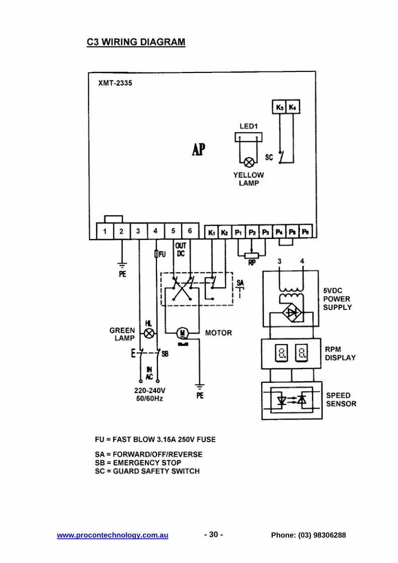
Drawing Sheet 3 Wiring Diagram of Lathe

- 3 - www.procontechnology.com.au Phone: (03) 98306288
1 GENERAL SAFETY INSTRUCTIONS • KNOW YOUR MACHINE TOOL
Before switching on and attempting to operate this machine tool, become familiar with its features and construction. Be aware of the potential hazards of the rotating headstock and the possible interaction with the tool post and other components forming part of this lathe.
• AVOID POTENTIALLY DANGEROUS ENVIRONMENT
Do not locate this machine tool in damp or wet locations. Ensure that the machine tool is mounted onto a rigid bench. Understand that out-of-balance forces may cause the lathe to move unexpectedly. Ensure the work area is well lit, and provide task lighting. Provide adequate surrounding work space. Ensure adequate ventilation. Do not operate in the presence of hazardous gases that may cause combustion, or may cause drowsiness in the Operator.
• KEEP THE WORK AREA CLEAN
Cluttered areas and benches tend to promote accidents. The floor must be clear of items that could cause tripping, and must not be slippery. A heavy duty rubber floor mat is recommended for the operator to stand on.
• WEAR PROPER APPAREL
Do not wear loose clothing, gloves, neckties or jewellery (rings, neck chains, bracelets, wrist watches) that could get caught in rotating or moving parts. Wear nonslip footwear. Use protective hair covering to contain long hair. Roll long sleeves up above the elbow, if the sleeves cannot be held in tightly around the wrist. Do not over-reach the lathe during operation; stop the lathe before making any adjustment.
• WEAR SAFETY GLASSES
Wear safety glasses at all times. Everyday eyeglasses only have impact resistant lenses, and are NOT safety glasses. It is recommended that a full face protector is used and that ear protectors (plugs or muffs) are also used during extended periods of operation.
• KEEP CHILDREN AWAY
All children should be kept well away from the lathe work area. As the operator, you must concentrate on the operation of the machine; consequently you will not be able to supervise any children in the vicinity, without risk to yourself or the others. To prevent unauthorized persons from using the machine consider pad locking the emergency stop switch as shown on page 5.
• TOOL POST SADDLE POWER FEED
Before operating the machine ensure that the leadscrew tool post feed is disengaged. Check by moving the saddle manually with the main feed handle.
• NEVER LEAVE TOOL RUNNING UNATTENDED
Do not leave the machine running unattended. Ensure the machine comes to a complete stop, and turn off the power.
• KEEP HEADSTOCK CHUCK GUARD DOWN
The lathe cannot be operated unless the chuck guard is in the down position. This prevents inadvertent operation with, for example, the chuck key still in the chuck. Under no circumstances interfere with the circuitry to defeat this important safety feature. Always check that the guard is operating normally (listen for the click of the micro-switch as the guard is closed and opened) before operating the lathe.
• REMOVE ADJUSTING KEYS AND WRENCHES
Form the habit of checking to see that all keys and tools are removed from the machine tool before starting.

- 4 - www.procontechnology.com.au Phone: (03) 98306288
2 SPECIFICATIONS
Max. swing over bed 180mm (7”)
Max. length of workpiece 350mm (14”)
Headstock spindle taper Morse No.3
Tailstock taper Morse No.2
Spindle bore diameter 20mm (0.787”)
Cross slide travel 65mm (2.559”)
Compound slide travel 55mm (2.165”) effective
Spindle speed (variable) 100-3000 rpm effective
Longitudinal feeds 0.1 - 0.2 mm
Metric model screw thread pitch 0.4 - 2.0 mm in 10 steps
Imperial model - Threads Per Inch (TPI) 12 - 52 TPI in 18 steps

- 5 - www.procontechnology.com.au Phone: (03) 98306288
3 LEGEND
25/26 24 27 1 2 3 4 5 6 7 8 9 12 10 11
22/23 21 20 19 17 18 16 15 14 13
Fig 1- Front View
1 Yellow warning lamp 16 Automatic feed engage lever
2 Green power lamp 17 Cross-slide feed handle
3 Headstock 18 Apron
4 Spindle speed display (rpm) 19 Saddle feed handle
5 Chuck guard 20 Leadscrew
6 3-jaw chuck 21 Forward/Off/Reverse selector switch
7 Tool post 22 Metric thread gear change table
8 Cross-slide 23 Running gear cover
9 Compound slide 24 Speed control knob
10 Tailstock 25 Leadscrew Fwd/Neutral/Rev lever
11 Tailstock locking nut 26 High/Iow speed change gear lever
12 Machine bed 27 Emergency stop switch
13 RH leadscrew bearing
14 Compound slide feed handle
15 Thread dial Indicator (optional)
a
The picture opposite illustrates how the emergency stop may be padlocked to prevent unauthorized use of the lathe

- 6 - www.procontechnology.com.au Phone: (03) 98306288
LEGEND AND GEAR IDENTIFICATION
25 26 Gear A Gear B Gear C Gear D
Power Supply
Fig 2 - Gear End View
25 Leadscrew Forward/Neutral/Reverse lever
26 High/Low speed change gear lever
- 7 - www.procontechnology.com.au Phone: (03) 98306288
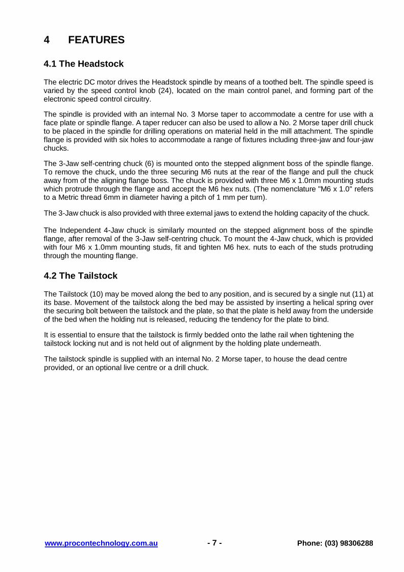
4 FEATURES 4.1 The Headstock
The electric DC motor drives the Headstock spindle by means of a toothed belt. The spindle speed is varied by the speed control knob (24), located on the main control panel, and forming part of the electronic speed control circuitry.
The spindle is provided with an internal No. 3 Morse taper to accommodate a centre for use with a face plate or spindle flange. A taper reducer can also be used to allow a No. 2 Morse taper drill chuck to be placed in the spindle for drilling operations on material held in the mill attachment. The spindle flange is provided with six holes to accommodate a range of fixtures including three-jaw and four-jaw chucks.
The 3-Jaw self-centring chuck (6) is mounted onto the stepped alignment boss of the spindle flange. To remove the chuck, undo the three securing M6 nuts at the rear of the flange and pull the chuck away from of the aligning flange boss. The chuck is provided with three M6 x 1.0mm mounting studs which protrude through the flange and accept the M6 hex nuts. (The nomenclature "M6 x 1.0" refers to a Metric thread 6mm in diameter having a pitch of 1 mm per turn).
The 3-Jaw chuck is also provided with three external jaws to extend the holding capacity of the chuck.
The Independent 4-Jaw chuck is similarly mounted on the stepped alignment boss of the spindle flange, after removal of the 3-Jaw self-centring chuck. To mount the 4-Jaw chuck, which is provided with four M6 x 1.0mm mounting studs, fit and tighten M6 hex. nuts to each of the studs protruding through the mounting flange.
4.2 The Tailstock
The Tailstock (10) may be moved along the bed to any position, and is secured by a single nut (11) at its base. Movement of the tailstock along the bed may be assisted by inserting a helical spring over the securing bolt between the tailstock and the plate, so that the plate is held away from the underside of the bed when the holding nut is released, reducing the tendency for the plate to bind.
It is essential to ensure that the tailstock is firmly bedded onto the lathe rail when tightening the tailstock locking nut and is not held out of alignment by the holding plate underneath.
The tailstock spindle is supplied with an internal No. 2 Morse taper, to house the dead centre provided, or an optional live centre or a drill chuck.

- 8 - www.procontechnology.com.au Phone: (03) 98306288
4.3 The Running Gears
The Running Gears are protected by a cover (22), which may be removed by unscrewing the two 4mm hex socket head M5 bolts.
Fig 3 - Gear Cover Removed The gear train transmits the drive to the lead screw, which moves the saddle when the Auto Feed Lever (16) is engaged, thereby providing a power feed for screw cutting or general turning operations.
The rotational speed of the leadscrew and consequently the rate of feed of the cutting tool is determined by the configuration of the gear train. Refer to the section on Screw Cutting for more detailed information.
The drive to the leadscrew may be disconnected by moving the three position lever (25) on the rear of the headstock. This three position lever also changes the direction of travel provided by the leadscrew from forward to reverse. In the mid position, neutral, no drive is connected. Take care when selecting the neutral position, to avoid gear clashing.
4.4 The Saddle
The Saddle carries the Cross Slide (8) on to which is mounted the Compound Slide (9) and Tool Post (7). The Saddle is moved along the bed by means of the saddle feed handwheel (19). The saddle feed may be fixed in any given position along the bed, by engaging the automatic feed lever (16) with the leadscrew in the neutral position.

- 9 - www.procontechnology.com.au Phone: (03) 98306288
The Compound Slide, carrying the Tool Post, may be moved relative to the Saddle by operation of the compound and cross feed screw handles, respectively.
The position of the tool post and tool is effected by turning the cross-slide feed handle (17), which moves it across the lathe, and the saddle or manual feed handle (19) which moves it longitudinally.
Additionally the compound slide feed handle (14) may be used to move the tool by small amounts at right angles to the cross-slide, or the slide may be set at an angle to the cross-slide so that short tapers or bevels may be cut. Refer also to 'Bevel Cutting'
The cross-slide and compound slide feeds are both provided with a scale on the shaft of the operating handle. These are used to move the tool by precise amounts - one division being equivalent to 0.001" or 0.025mm. As the feed handle is turned, so does the scale. The scale on the cross-slide feed may also be held stationary whilst the handle is turned, allowing the scale to be 'zero-ed', Refer also to 'Operation'.
4.5 The Tool Post
The Tool Post carries eight 5mm hex socket head M6 setscrews which are used to secure the cutting tools.
The tool post is rotated by slackening the tool post lever sufficient for the post to be lifted slightly and then turned anti-clockwise to the desired position.
Always ensure that the post and the tools are securely tightened before attempting to cut.
4.6 The Motor
Disassembly of the 220V DC driving motor is not recommended. The armature brushes may be replaced if necessary, as described under 'Maintenance'.

- 10 - www.procontechnology.com.au Phone: (03) 98306288
5 INSTALLATION 5.1 Mounting the Lathe
The lathe should be mounted on a strong, heavy workbench of sufficient height so that the operator does not need to bend their back during use.
It is recommended that the machine be bolted firmly to a strong workbench utilising the tapped holes used to secure the feet to the lathe. This is to provide added stability.
Remove the four M6 screws which secure the rubber feet and chip waste collection tray to the machine and discard the feet. Drill four M6 clearance holes in the worktop at 496mm x 72mm centres, and bolt the lathe to the worktop with suitable length M8 bolts and washers (not supplied).
6 STARTING PROCEDURE
6.1 Initial Start Up
• Activate the Emergency Stop (27) by pressing down to latch it.
• Set the High-Low range lever (26) to Low, and the speed control knob (24) to Off.
• Close the headstock chuck guard (5), and ensure the cross-slide is clear of the chuck.
• Ensure the automatic feed engage lever (16) is up; i.e. disengaged from the leadscrew.
• Position the leadscrew drive lever (25) in neutral. i.e. centre position.
• Plug in and switch on the power to the machine.
• Release the Emergency Stop Switch (27) and the green indicator lamp (2) should light.
• Select Forward using the Forward/Off/Reverse (FOR) switch (21) on the control panel.
• Operate the machine by slowly rotating the Variable Speed Control Knob (24) clockwise.
• The spindle speed is indicated on the read-out (4) on the headstock.
• Note that the drive motor will not operate unless the chuck guard is down and the yellow warning lamp is extinguished. If the yellow lamp is on, return the selector switch (21) and the speed control knob (24) to off. The yellow lamp should now be off, permitting the lathe to operate when the selector switch is in the Forward position and the speed control knob is rotated.
CAUTION
Always turn the machine OFF at the Forward/Reverse switch and activate the emergency stop
before attempting to change any settings or make any adjustments.
- 11 - www.procontechnology.com.au Phone: (03) 98306288
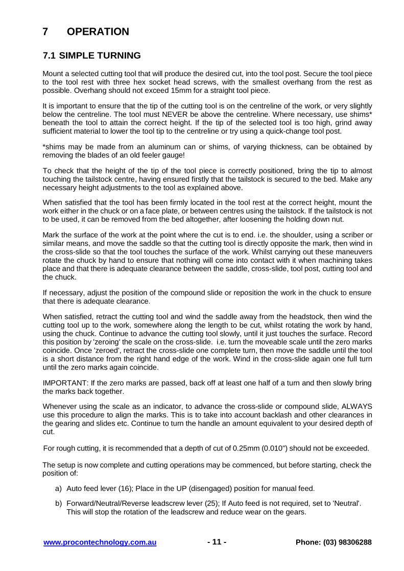
7 OPERATION 7.1 SIMPLE TURNING
Mount a selected cutting tool that will produce the desired cut, into the tool post. Secure the tool piece to the tool rest with three hex socket head screws, with the smallest overhang from the rest as possible. Overhang should not exceed 15mm for a straight tool piece.
It is important to ensure that the tip of the cutting tool is on the centreline of the work, or very slightly below the centreline. The tool must NEVER be above the centreline. Where necessary, use shims* beneath the tool to attain the correct height. If the tip of the selected tool is too high, grind away sufficient material to lower the tool tip to the centreline or try using a quick-change tool post.
*shims may be made from an aluminum can or shims, of varying thickness, can be obtained by removing the blades of an old feeler gauge!
To check that the height of the tip of the tool piece is correctly positioned, bring the tip to almost touching the tailstock centre, having ensured firstly that the tailstock is secured to the bed. Make any necessary height adjustments to the tool as explained above.
When satisfied that the tool has been firmly located in the tool rest at the correct height, mount the work either in the chuck or on a face plate, or between centres using the tailstock. If the tailstock is not to be used, it can be removed from the bed altogether, after loosening the holding down nut.
Mark the surface of the work at the point where the cut is to end. i.e. the shoulder, using a scriber or similar means, and move the saddle so that the cutting tool is directly opposite the mark, then wind in the cross-slide so that the tool touches the surface of the work. Whilst carrying out these maneuvers rotate the chuck by hand to ensure that nothing will come into contact with it when machining takes place and that there is adequate clearance between the saddle, cross-slide, tool post, cutting tool and the chuck.
If necessary, adjust the position of the compound slide or reposition the work in the chuck to ensure that there is adequate clearance.
When satisfied, retract the cutting tool and wind the saddle away from the headstock, then wind the cutting tool up to the work, somewhere along the length to be cut, whilst rotating the work by hand, using the chuck. Continue to advance the cutting tool slowly, until it just touches the surface. Record this position by 'zeroing' the scale on the cross-slide. i.e. turn the moveable scale until the zero marks coincide. Once 'zeroed', retract the cross-slide one complete turn, then move the saddle until the tool is a short distance from the right hand edge of the work. Wind in the cross-slide again one full turn until the zero marks again coincide.
IMPORTANT: If the zero marks are passed, back off at least one half of a turn and then slowly bring the marks back together.
Whenever using the scale as an indicator, to advance the cross-slide or compound slide, ALWAYS use this procedure to align the marks. This is to take into account backlash and other clearances in the gearing and slides etc. Continue to turn the handle an amount equivalent to your desired depth of cut.
For rough cutting, it is recommended that a depth of cut of 0.25mm (0.010") should not be exceeded.
The setup is now complete and cutting operations may be commenced, but before starting, check the position of:
a) Auto feed lever (16); Place in the UP (disengaged) position for manual feed.
b) Forward/Neutral/Reverse leadscrew lever (25); If Auto feed is not required, set to 'Neutral'. This will stop the rotation of the leadscrew and reduce wear on the gears.

- 12 - www.procontechnology.com.au Phone: (03) 98306288
c) High/Low speed change lever (26); Select required speed range Switch the machine ON as described under 'Starting Procedure' and slowly feed the cutting tool into the work using the Manual Feed Handle. Proceed until reaching the previously marked line on the work and then retract the tool one or two complete turns on the Cross-Slide feed handle. Wind the saddle back to the beginning then wind the tool the same number of turns 'in', plus the depth of desired cut, and proceed to cut once more.
NOTE: This describes the procedure for general, rough cutting. For other types of cuts - finishing, cutting shoulders etc., consult a suitable specialised handbook on metal turning.
7.2 SIMPLE TURNING WITH POWER FEED
The same basic setup is used as described above, except that, before starting, the Leadscrew F/N/R Lever (25) is set to the 'Forward' position and The Auto Feed Lever (16), is engaged in order drive the saddle.
The rotational speed of the leadscrew, and hence the rate of feed of the tool, is dependant upon the gear configuration of the gear train. The feed rate for normal turning is considerably less than that used for screw cutting, and is factory set for normal turning power feed. The leadscrew has a thread pitch of 1.5mm, and with the factory configured gears of 20T: 80T / 20T: 80T, the leadscrew will rotate once for every 16 revolutions of the headstock spindle, and will move the saddle 1.5mm. Consequently at 800 RPM spindle speed, the saddle will move along the bed at 75mm per minute.
1. Position the cutting tool a short distance to the right of the workpiece with the appropriate
depth of cut set on the cross-slide.
2. Ensure the leadscrew F/N/R lever is set to 'Forward' and select 'Forward' on the Forward/Off/Reverse switch on the main control panel. Switch on the machine.
3. Turn the speed control knob to achieve the desired spindle speed, and with the right hand, push down on the auto feed lever until the nut becomes firmly engaged with the leadscrew.
IMPORTANT: The left hand should always be free to press the emergency stop button should it become necessary.
4. Carefully observe the movement of the tool and as it approaches the mark on the surface, denoting the end of cut, pull the Auto Lever UP sharply and ensure it stays UP. If a degree of accuracy is required, it is recommended that the cut is finished by hand. It is recommended that a carriage stop and manual feed be used for best accuracy.
NOTE: If it is required to form a shoulder with perfectly clean corners, then it will be necessary to use an appropriately shaped tool.
5. Retract the tool one or two complete turns on the cross-slide feed and then wind the saddle so
that the tool is at the start point once again. Advance the tool the same number of turns, plus the depth of cut, and when ready, push down on the auto-feed lever and proceed to take another cut.
Refer also to Page 18 for the explanation of how to change the gears, and the chart on Page 19, which shows the gear configurations.

- 13 - www.procontechnology.com.au Phone: (03) 98306288
7.3 BEVEL CUTTING Bevel cutting involves the use of the compound slide, which is mounted on the cross-slide and set at right angles to it for all normal cutting operations. This is indicated by the zero mark, on the scale, lining up with the mark etched on the body of the cross-slide.
To set the compound slide so that the cutting tool will cut a bevel, first retract the slide until the two hex socket head screws are revealed. Slacken the screws sufficiently to allow the compound slide to be turned to the desired angle as indicated on the scale, and secure the slide in this position by retightening the hex socket head screws.
The taper, or bevel, is cut by using the compound side feed handle to advance the cutting tool in the preset direction of the slide.

- 14 - www.procontechnology.com.au Phone: (03) 98306288
7.4 SCREW CUTTING 7.4.1 Screw Cutting with the Stop/Start Method
This operation requires a degree of skill and accuracy, and should not be attempted unless completely familiar with all aspects of the lathe.
Essentially, the saddle will move towards the headstock under power, in the same way as turning using the auto feed, except that the rate of feed is far greater, as determined by the gear configuration. As a consequence, the cutting tool will approach the rotating chuck at a significant rate. Great care and concentration must therefore be exercised to ensure that the two do not meet when the machine is operating, as the resultant damage caused could be very significant.
The lathe is supplied with a leadscrew, that will produce metric threads in a range from 0.4mm-2.0mm pitch (As an option, Imperial threads can be cut in a range from 12 to 5 threads per inch, assuming installation of the appropriate leadscrew and gears.)
It is important to acknowledge, that the type of thread that is required, e.g. Metric, UNF, BA, BSP, BSW etc., will be totally dependant upon the cutting tool profile, as profiles differ from thread to thread The Metric thread profile has an included angle of 60°. The Whitworth thread profile has an included angle of 55°.
The procedure for screw cutting with the Stop/Start Method is as follows:
1. Arrange for as much distance from the chuck to the end of the proposed screw thread as possible, and if possible, cut a 'run-off' into the workpiece which is of a smaller diameter than the root diameter of the proposed screw thread. Also, long threads may require the use of one or more 'steadies'.
2. Install the appropriate gears for the thread required, and correctly mount the cutting tool.
Set the required depth of cut, and position the tool ready to begin cutting. Note that the depth of cut is vitally important and may be calculated or obtained from an appropriate reference manual.
3. Take all necessary precautions previously stated, and start the machine with the automatic
feed lever in the UP or disengaged position and set the speed of the lathe as appropriate.
4. Set the depth of cut for an initial test pass. Engage the auto-feed lever sharply whilst your left hand is on the FORWARD/OFF/REVERSE (F/O/R) switch. As the tool approaches the end of the desired thread, turn the switch to 'OFF'. Do not disengage the auto-feed lever. Use a thread pitch gauge to check that the pitch is as required.
5. Retract the tool, using the cross-slide feed handle, noting the exact position on the scale and
the exact number of turns. Turn the F/O/R switch to 'REVERSE', whereupon the saddle will wind back to the beginning and turn the switch to 'OFF'. Reset the tool by winding in the cross-slide the exact number of turns previously wound out, plus the desired depth of cut.
6. Turn the F/O/R switch to FORWARD. As the tool approaches the end of the desired thread,
turn the switch to 'OFF'. Do not disengage the auto-feed lever.
7. Repeat steps 5 & 6 until the thread is completed.

- 15 - www.procontechnology.com.au Phone: (03) 98306288
7.4.2 Screw Cutting with the Thread Dial Indicator
N.B. This section assumes that the thread cutting dial indicator has been fitted to the Lathe. The dial indicator is an optional extra to the basic lathe.
The Metric leadscrew on the lathe is a 20mm diameter shaft with a 1.5mm pitch, (modified) square thread.
Mounted on the Apron, adjacent to the Auto Feed Lever, is the Thread Dial Indicator. This dial indicator has a 16 tooth gear permanently meshed with the leadscrew and, as the leadscrew turns, the 'dial' rotates, at the rate of one revolution per 16 turns of the leadscrew.
Eight radial marks are etched on the dial and these are used to determine the exact position of the leadscrew thread in relation to the saddle. When the automatic feed lever is engaged, the dial indicator travels with the saddle and remains unaltered opposite its set mark.
The numbers in the 'Dial Numbers' column of the Thread Dial Indicator Table below, refer to the numbers on the radial lines on the indicator dial. For example, if a 0.4mm pitch thread is to be cut, the marks 1, 3, 5 or 7 may be used.
Screw Cutting Procedure:
1. Observe the rotating dial. In particular, concentrate on one of the numbered marks etched on the dial which corresponds to the scale number given in the Indicator Table. (In the example above, this could be 1,3,5 or 7) As the selected line passes the mark on the body of the dial indicator, engage the auto lever sharply and thread cutting will commence.
2. As the tool approaches the end of the desired thread, DISENGAGE THE AUTO FEED LEVER. Do not switch the machine OFF.
3. Retract the tool, using the cross-slide feed handle, noting the exact position on the scale and
the exact number of turns used to retract the tool. Wind the saddle back to the beginning and reset the tool by winding in the cross-slide the exact number of turns previously wound out. Continue to wind in to the desired depth of cut.
4. With the machine still running, observe the dial indicator and as the SAME NUMBERED LINE,
passes the mark on the body, engage the auto feed lever once again. Proceed in this manner until the thread is completed.
Engaging the auto feed lever as the selected line on the dial passes the mark on the body of the indicator, ensures that the half nuts of the auto feed mechanism engage in the same thread on the leadscrew each time. This also ensures that the cutting tool is in the same place for each pass which in turn produces a geometrically correct thread, assuming always, that the profile of the cutting tool is correctly shaped.

- 16 - www.procontechnology.com.au Phone: (03) 98306288
7.4.3 Thread Dial Indicator Tables
IMPERIAL (with optional leadscrew)
Threads per inch, TPI Dial Numbers
12 1, 3, 5, 7
13 1
14 1, 5
16 1 - 8
18 1, 5
19 1
20 1, 3, 5, 7
22 1, 5
24 1 - 8
26 1, 5
28 1, 3, 5, 7
32 1 - 8
36 1, 3, 5, 7
38 1, 5
40 1 - 8
44 1, 3, 5, 7
48 1 - 8
52 1, 3, 5, 7
METRIC (with standard leadscrew)
Pitch; mm/turn Dial Numbers
0.4 1, 3, 5, 7
0.5 1 - 8
0.6 1 - 8
0.7 1, 4.5
0.8 1, 5
1.0 1 - 8
1.25 1, 3.5
1.5 1 - 8
1.75 1, 4.5
2.0 1-8

- 17 - www.procontechnology.com.au Phone: (03) 98306288
7.5 SCREW CUTTING GEARS
The leadscrew, which as previously indicated, has a pitch of 1.5mm, and is driven by a gear on the spindle, via a gear train. The gear ratio will therefore dictate the rotational speed of the leadscrew with respect to the spindle; i.e. one turn of the spindle will turn the leadscrew an amount determined by the gear ratio.
By setting the gears of the gear train to a known ratio, screw threads may be cut to a known size, and as the leadscrew supplied with the lathe, produces Metric threads, the known values will be in mm pitch (mm per turn), or threads per inch (TPI) if the optional Imperial leadscrew is installed.
Note that the actual thread produced will be totally dependant upon the profile of the cutting tool. Detailed information regarding types of cutting tool, cutting speeds and working with various types of material etc., will need to be obtained from appropriate handbooks.
The chart in clause 7.7 shows the thread sizes that may be cut using the gear configuration shown in the corresponding columns.
NOTE: The factory setup for the lathe provides for normal turning using the power or auto feed, and the gear configuration is as shown in Fig 4, and as follows:
Gear A; 20T Gear B; 80T Gear C; 20T Gear D; 80T To change the gears of the gear train for screw cutting, ensure the machine is switched OFF and disconnected from the mains supply.
Remove the gear train cover which is secured with two 4mm hex socket head M5 bolts. Gear A is considered to be the Driver, and Gear D as the Driven gear fixed to the leadscrew.
When a simple gear train is configured, with the drive from Gear A through Gear B to Gear D, the gear at B acts as an Idler and its size is therefore irrelevant, although a suitable gear size is indicated, to connect A and D. In this instance Gear C plays no part and is denoted by a blank space in the Gear C column in the gear chart.
In a compound gear train, Gear C forms part of, and is driven by Gear B and changes the ratio of the overall drive train.

- 18 - www.procontechnology.com.au Phone: (03) 98306288
7.6 GEAR CHANGING The positions of the shafts carrying gears A and D are fixed; therefore all adjustments to the meshing of the gears must be carried out on the shaft carrying gears Band C, using the Adjusting Bracket.
1. Unscrew the hex socket head screws, securing gears A and D to their respective shafts,
followed by the screw securing gears B and C. 2. To allow the gears B and C to disengage completely and to permit easier reassembly, un-
screw the nut securing the shaft carrying B and C, and the nut securing the adjuster bracket. 3. Remove the gears, taking care to retain the small keys on each shaft, and replace the gears
with those necessary to produce the required screw thread. They may be mounted either way round. The number of teeth on each gear is clearly marked. Replace the securing screws, ensuring the flat washer bears up against the gear hub in each case.
4. If a compound gear train is required, ensure the spacer (which is keyed to the shaft carrying
gear D) is located on the shaft, BEFORE the gear, in order to align gear D with gear C. 5. Proceed to move the shaft carrying B and C and the adjuster bracket so that all gears mesh
correctly, then tighten the adjuster securing nuts. This may take one or two attempts but make sure there is as little backlash as possible without being over tight. (Turn the spindle by hand to test for backlash).
6. Replace the cover and secure with the two hex socket head bolts.
Gear B 80t Gear A 20t Spindle Gear 45t F/N/R Idler Gears Driver Gear 45t
Gear C 20t Gear D 80t
Fig 4 – Factory Set Gears Shown
- 19 - www.procontechnology.com.au Phone: (03) 98306288
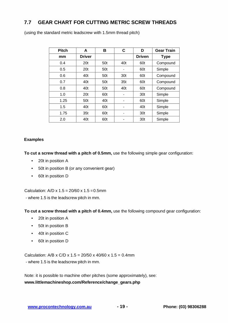
7.7 GEAR CHART FOR CUTTING METRIC SCREW THREADS
(using the standard metric leadscrew with 1.5mm thread pitch)
Pitch A B C D Gear Train
mm Driver Driven Type
0.4 20t 50t 40t 60t Compound
0.5 20t 50t - 60t Simple
0.6 40t 50t 30t 60t Compound
0.7 40t 50t 35t 60t Compound
0.8 40t 50t 40t 60t Compound
1.0 20t 60t - 30t Simple
1.25 50t 40t - 60t Simple
1.5 40t 60t - 40t Simple
1.75 35t 60t - 30t Simple
2.0 40t 60t - 30t Simple
Examples To cut a screw thread with a pitch of 0.5mm, use the following simple gear configuration:
• 20t in position A
• 50t in position B (or any convenient gear)
• 60t in position D
Calculation: A/D x 1.5 = 20/60 x 1.5 = 0.5mm
- where 1.5 is the leadscrew pitch in mm.
To cut a screw thread with a pitch of 0.4mm, use the following compound gear configuration:
• 20t in position A
• 50t in position B
• 40t in position C
• 60t in position D
Calculation: A/B x C/D x 1.5 = 20/50 x 40/60 x 1.5 = 0.4mm
- where 1.5 is the leadscrew pitch in mm.
Note: it is possible to machine other pitches (some approximately), see:
www.littlemachineshop.com/Reference/change_gears.php

- 20 - www.procontechnology.com.au Phone: (03) 98306288
7.8 DETAILS OF ISO METRIC THREADS (Bolts)
Included Angle of the Metric Thread Form: 60°
Nominal
Size
Outside
Diameter
Root
Diameter
Coarse
Thread
Pitch
Fine
Thread
Pitch
mm mm mm mm
M1.6 1.6 1.17 0.35 0.20
M2 2.0 1.51 0.40 0.25
M2.5 2.5 1.95 0.45 0.35
M3 3.0 2.39 0.50 0.35
M4 4.0 3.14 0.70 0.50
M5 5.0 4.02 0.80 0.50
M6 6.0 4.77 1.00 0.75
M8 8.0 6.47 1.25 1.0, 0.75
M10 10.0 8.16 1.50 1.25, 1.0, 0.75
M12 12.0 9.85 1.75 1.5, 1.25, 1.0
M14 14.0 11.55 2.00 1.5, 1.25, 1.0
M16 16.0 13.55 2.00 1.5, 1.0
M18 18.0 14.93 2.50 2.0, 1.5, 1.0
M20 20.0 16.93 2.50 2.0, 1.5, 1.0
Pitch dimensions shown in italics are not available on this lathe as supplied.
Table information source: Machinery's Handbook 21st Edition, pp 1357, 1361
- 21 - www.procontechnology.com.au Phone: (03) 98306288
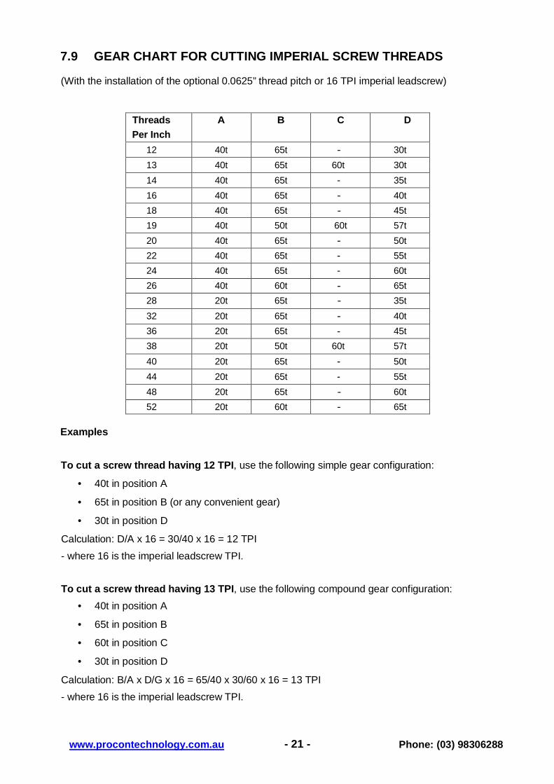
7.9 GEAR CHART FOR CUTTING IMPERIAL SCREW THREADS
(With the installation of the optional 0.0625” thread pitch or 16 TPI imperial leadscrew)
Threads
Per Inch
A B C D
12 40t 65t - 30t
13 40t 65t 60t 30t
14 40t 65t - 35t
16 40t 65t - 40t
18 40t 65t - 45t
19 40t 50t 60t 57t
20 40t 65t - 50t
22 40t 65t - 55t
24 40t 65t - 60t
26 40t 60t - 65t
28 20t 65t - 35t
32 20t 65t - 40t
36 20t 65t - 45t
38 20t 50t 60t 57t
40 20t 65t - 50t
44 20t 65t - 55t
48 20t 65t - 60t
52 20t 60t - 65t
Examples
To cut a screw thread having 12 TPI, use the following simple gear configuration:
• 40t in position A
• 65t in position B (or any convenient gear)
• 30t in position D
Calculation: D/A x 16 = 30/40 x 16 = 12 TPI
- where 16 is the imperial leadscrew TPI.
To cut a screw thread having 13 TPI, use the following compound gear configuration:
• 40t in position A
• 65t in position B
• 60t in position C
• 30t in position D
Calculation: B/A x D/G x 16 = 65/40 x 30/60 x 16 = 13 TPI
- where 16 is the imperial leadscrew TPI.

- 22 - www.procontechnology.com.au Phone: (03) 98306288
8 MAINTENANCE For maximum performance, it is essential that the lathe is properly maintained. Always switch off and unplug the lathe before doing any maintenance!
8.1 BEFORE USE
Always inspect the lathe before use. Any damage should be repaired and maladjustments rectified. Damage to machined surfaces should be repaired with an oil stone. Test by hand to ensure smooth operation of all parts before use.
Inject a few drops of oil into the oilways of both leadscrew bearings (each end bracket) and once or twice during the day if used continuously. It will be necessary to remove the gear train cover, in order to lubricate the left hand bearing.
Inject a few drops also to the compound slide oilways, located on the top surface of the slides, between the two hex socket head screws.
8.2 AFTER USE
Remove all chip waste from the machine and thoroughly clean all surfaces. If coolant has been used, ensure that it has completely drained away from the tray.
Components should be dry, and all machined surfaces should be lightly oiled. Always remove cutting tools and store in a safe place
8.3 MOTOR-BRUSHES
The DC Driving Motor brushes may be changed by unscrewing the securing caps, visible at the front and rear of the machine, beneath the Headstock.
8.4 SETTINGS AND ADJUSTMENTS
Occasionally, it may be necessary to readjust various components in order to maintain optimum performance. Adjustments that may be performed are as follows:
8.4.1 Cross Slide Adjustments
The Cross-Slide is mounted on parallel dovetail slides. Between the sloping surfaces on one side of the dovetail, a 'jib strip' is inserted, which may be tightened against the dovetail by tightening the three adjuster, or 'jib' screws complete with locking nuts, mounted along the length of the slide.
The jib screws are to be found on the right hand side of the slide, directly beneath the compound slide handle. In time, wear will occur on the mating surfaces resulting in a 'sloppiness' of the action.

- 23 - www.procontechnology.com.au Phone: (03) 98306288
To adjust the jib strip, in order to compensate for wear and ensure the slide moves evenly and smoothly, proceed as follows:
1. Slacken off the lock nuts and screw in the jib screws evenly by using the same torque for each
screw. The slide should be held firmly. Test by trying to turn the handle, but do not force it. 2. Screw out each jib screw by one quarter of a turn ONLY and tighten the lock nuts.
3. Test again, by turning the handle. The movement should be even and smooth along its
complete length.
4. If the movement is too slack, screw all adjusters 'in' by one eighth of a turn, and re-try. Similarly, if the movement is too stiff, screw 'out' the adjusters by one eighth of a turn until the correct adjustment is attained.
5. Tighten all lock nuts taking care to ensure you do not move the jib screws whilst doing so.
6. When completed, retract the slide fully and apply oil to all mating surfaces and the feed screw thread, then wind the slide back to its normal position.
8.4.2 Cross-Slide Feed Handle
The cross slide feed should run smoothly, and the scale must rotate with the handle.
If any stiffness occurs, it is probably the result of turning waste chips lodging between the mating surfaces. Undo the securing hex socket head screw securing the handle. Remove the handle and pull off the collar with the scale taking great care to retain the small spring plate which sits in a groove beneath the collar.
Clean the assembly and reassemble in reverse order. It will be necessary to hold the spring plate in place with a small screwdriver, or similar tool, whilst pushing down on it to allow the collar to be correctly located on to the shaft.
8.4.3 Compound Slide Adjustment
Compound slide adjustments are made in the same way as those for the cross slide. The jib screws are to be found on the left hand side of the lathe.
It is important that the cross-slide and compound slide adjustments are correctly carried out and that there is no 'sloppiness' in the action of either. Any unwanted movement will have a serious effect on the quality of the work, as this will be transferred to the tool piece.

- 24 - www.procontechnology.com.au Phone: (03) 98306288
9 ACCESSORIES 9.1 Optional Items
• 3-Jaw Chuck, 100mm diameter with flange
• 4-Jaw Chuck, independent, 80mm
• 4-Jaw Chuck, independent, 100mm diameter with flange
• Face Plate - 160mm diameter (clamping kit optional)
• Moving and Fixed Steadies
• Mill attachment or vertical slider (mill chuck set optional)
• Rolling (live) Centre (Tailstock - Morse Taper No.2)
• Rolling Drill Chuck (Tailstock - Morse Taper No.2)
• Imperial Leadscrew and gears for imperial thread cutting
• Thread Dial Indicator (metric and imperial)
• Cutting Tool Sets (5, 6 or 11 piece)
• Digital Readout (DRO) for cross and horizontal slides
• Quick Change Tool Post with 3 tool holders
• Grinding Wheel Attachment (240VAC operation)
• Knurling Tool, Woodturning Kit, Lathe Dog and more 9.2 External Jaws for the 3-Jaw Chuck
To change the jaws of the three jaw chuck, insert the chuck key and open the jaws to their fullest extent. It will then be possible to remove each jaw in turn.
Replace them with the external jaws, noting the following:
The thread segments of the jaws are progressively 'stepped'. They are also numbered 1, 2 & 3. This is to take into account the lead of the screw thread within the chuck. It is therefore necessary to assemble the jaws in the correct order.
Place them into the chuck as required to operate as an external jaw, and assemble in the same order, clockwise, in the slots in the chuck, turning the chuck key as they are inserted. Close the jaws fully and check that they meet at the centre. If a jaw is out of adjustment, open the jaws fully, and retain pressure on the particular jaw, whilst turning the chuck key, until it snaps into position. Re-check to ensure all jaws meet at the centre.
NOTE: 4-jaw chucks have reversible jaws!

- 25 - www.procontechnology.com.au Phone: (03) 98306288
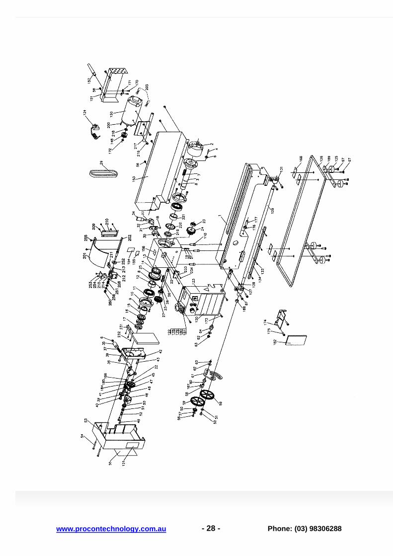
10 COMPONENT LEGEND
1 Lathe bed 47 Parallel key 3*8
2 3-jaw chuck 48 Outer bearing
3 Spindle 49 Screw M5*18
4 Screw M6*25 50 Gearwheel 20t
5 Spindle boss 51 WasherM6
6 Nut M6 52 Screw M6*8
7 Key 5*40 53 Gear box cover
8 Key 4*8 54 Screw M5*65
9 Screw M5*12 55 Thread cutting chart
10 Spindle bearing cover 56 Screw M5*8
11 Ball Bearing 57 Washer M5
12 Spacer 58 Keyed bush
13 Headstock casting 59 Gearwheel 80t
14 H/L gear 21t / 29t 60 Idler stub shaft
15 Spacer 61 Idler gear support plate
16 Spur gear 45t 62 WasherM8
17 C spanner locking ring M27*1.5 63 Nut M8
18 Set screw M5*8 64 Hex shaft
19 Steel ball 5 65 Thread Dial 8 position; 16t (optional)
20 Compression spring 66 Thread dial shaft (optional)
21 Set screw M6*8 67 Capscrew M6*16 (optional)
22 Circlip retaining ring 12 68 Dial Indicator body (optional)
23 Ball bearing 69 Gib adjusting screw and locknut
24 H/L gear 12t 1 20t 70 Apron
25 Parallel key 4*45 71 Gib strip
26 H/L gear shaft 72 Washer
27 Driven 31 toothed pulley 73 Screw M4*8
28 Retaining ring 10 74 Shaft
29 Timing belt L 136 1.5x70x10 75 Half nut base
30 Shifting fork 76 Angle block
31 Shifting arm 77 Screw M4*10
32 Shifting arm shaft 78 Grooved cam plate
33 Shifting lever shaft 79 Lead screw engaging handle
34 Shifting grip 80 Shaft
35 Handle spring loaded pin 81 Feeding gear 11t / 54t
36 Reversing rear mounting plate 82 Feeding gear 24t
37 Spacer with keyway 83 Screw M6*10
38 Indexing pin 84 Handwheel
39 Pinion gear 25t 85 Handle
40 Hex bolt bearing mount 86 Cross slide feed screw assembly
41 Pinion gear 20t 87 Dial
42 Fixed cover 88 Bracket
43 Screw M6"20 89 Feeding screw
44 Plate retaining screw 90 Saddle slide adjusting screws and nuts M5
45 Gearwheel 45t 91 Screw M6*12
46 Shaft 92 Saddle slide plate

- 26 - www.procontechnology.com.au Phone: (03) 98306288
COMPONENT LEGEND (Sheet 2)
93 Cross slide saddle 144 Clamping stud M8*40
94 Gib strip 145 Clamp
95 Cross slide feed nut 146 Clamping handle
96 Swivel mounting disk 148 Toothed motor pulley 17 teeth
97 Apron capscrew M8*20 150 Motor
98 Nut M4 151 Cover
99 Gib adjusting screw and locknut 152 Cable gland
100 Cross slide 153 Rear splash guard
101 Screw M5*10 154 Forward/Neutral/Reverse label
102 Screw M4*8 155 High/Low label
105 Compound slide base 156 Top warning label
106 Gib adjusting screw and locknut 157 Gearwheel 30t
107 Gib strip 158 Gearwheel 35t
108 Compound slide 159 Gearwheel 40t
109 Position pin 160 Gearwheel 45t
110 Cap screws M6*25 161 Gearwheel 50t
111 Clamping lever 162 Gearwheel 55t (optional)
112 Tool post 163 Gearwheel 57t (optional)
113 Stud M10*65 164 Gearwheel 60t
114 Compound feed screw assembly 165 Gearwheel 65t (optional)
115 Bracket 166 External jaws (set of 3)
116 Screw M4*12 167 3-jaw chuck key
119 Nut M18 168 Rubber pad
120 Model label 169 Mounting bracket
121 Gear change label 170 Screw M3*5
122 Switch label 171 Clamp nut
123 Control box 172 Check ring 8
124 Power cable and plug top 173 Screw M5*10
125 Rubber feet 174 Protector
126 Chip waste tray 175 Screw M5*10
127 Lead screw pillow block LHS 176 Nut M6
128 Key M3*16 177 Screw M6*25
129 Lead screw - Metric 178 Emergency Stop Switch
131 Lead screw pillow block RHS 179 Fuse holder and fuse
180 Variable speed control knob
133 Screw M3*10 181 Forward/Off/Reverse switch
134 Rack 182 Electronic speed control PCB
135 Clamp plate
136 Washer M10 184 Screw M5*10
137 Quill retaining screw and nut M5*16 185 Spring washer 5
138 Tailstock screw 186 Washer 5
139 Tailstock casting 187 Key 3*16
140 Bracket 188 Spacer
141 Screw M4*10
142 Tailstock Quill 190 Spring
143 Centre 191 Washer 8

- 27 - www.procontechnology.com.au Phone: (03) 98306288
COMPONENT LEGEND (Sheet 3)
192 Spring washer 6 300 Oil dispenser
193 Handle bolt M8*55 301 Hex keys 3mm 4mm 5mm 6mm
194 Half nut adjusting screw M4*38 302 Spanner 8mm 10mm
195 Nut M4 303 Spanner 14mm 17mm
196 Tailstock base plate
197 Base clamping screw M5*16
198 Screw retaining flange
199 Screw M5*25
200 Key 3*12
201 Chuck protective cover
202 Hinge shaft
203 Motor brushes
208 Washer 5
209 Screw M3*6
210 Sensor cable cover
211 Screw M5*16
212 Hinge mount
213 Pin 4*50
214 Screw M2*12
215 Micro switch
216 Screw M6*8
217 Motor fixed plate
218 Washer
219 Spacer.
220 Light beam interrupter
221 Spacer
232 Screw M4*6
233 Photoelectric switch (RPM)
234 Screw M3*8
250 Nut M6
251 Compression spring
252 Dial
253 Screw ST2.9*10
254 Cover
255 Screw M4*8
256 Nut M6
- 28 - www.procontechnology.com.au
Phone: (03) 98306288

- 29 - www.procontechnology.com.au
Phone: (03) 98306288
- 30 - www.procontechnology.com.au
Phone: (03) 98306288
Related Documents