5999.501-01B HM Collamat AG Pfeffingerring 201 CH-4147 Aesch Switzerland Phone +41 61 756 28 28 Fax +41 61 756 29 29 [email protected] www.collamat.ch Collamat 2600 Operating Instructions

C2600 Operating Instructions
Dec 14, 2015
collamat c2600
Welcome message from author
This document is posted to help you gain knowledge. Please leave a comment to let me know what you think about it! Share it to your friends and learn new things together.
Transcript
5999
.501
-01B
HM Collamat AG
Pfeffingerring 201
CH-4147 Aesch
Switzerland
Phone +41 61 756 28 28Fax +41 61 756 29 29
Collamat 2600Operating Instructions
5999.501-01B 06.03.2006 WM 2
1 Index1 Index..................................................................................................................22 Important warnings............................................................................................33 Danger indications.............................................................................................34 Introduction........................................................................................................45 Mechanical adjustment of the dispenser ...........................................................45.1 Threading of the label web ................................................................................45.2 Adjust paper brake powert ................................................................................55.3 Adjust coupler power of rewinder ......................................................................55.4 Adjust set flap adapter.......................................................................................65.5 Set pressure roller of the adapter ......................................................................66 Operating elements / Setting elements .............................................................76.1 Optical label scanner (Label scanner) ...............................................................76.2 Label predispensing ..........................................................................................86.3 Dispensing speed..............................................................................................97 Maintenance......................................................................................................98 Technical Data ................................................................................................108.1 Dimensions......................................................................................................10
5999.501-01B 06.03.2006 WM 3
2 Important warnings
Before installing and operating the Collamat 2600 read the following safety instructions:
The labeler C2600 is exclusively determinated for labelling goods.
The installation of a Collamat 2600 has to be done by a trained specialist.
For this you have to consider the national specific regulations of.
• prevention of accidents• mechanical stability• construction of electrical and mechanical systems• noise suppression
Take notice of the technical data of the Collamat 2600. Especially the envi-ronment conditions must be observed.
The operation of the Collamat 2600 must be done by trained personnel.
In case of non-authorized modifica- tions, guarantee will fall.
Before connecting non-standard products, ask your competent technical sup-porter.
3 Danger indications
The safety symbols and danger advices on the Collamat 2600 and in this ma-nual must strictly be observed.
Before connecting or disconnecting the labeler C2600 it must be switched off.
The labeler C2600 may only be opened by authorized personnel.
It exists danger of pinching hair, jewelry, ties, clothes etc. into the traction unit.
It exists danger of injury by cutting in the area of the paperweb.
It exists danger of injury in the area of the dancers of the unwinder of the Collamat 2600.
To operate the labeler the operating personnel must keep to a safe place to prevent injury by the products being labeled.
5999.501-01B 06.03.2006 WM 4
4 Introduction
Characteristic features of the Collamat 2600-system:
• low wearing, no clutch/brake system• compact, easy handling due to flying modular design• easy to operate
The modular concept allows homogeneous fastening of the peripheral de-vices on one module-bar (position bar with integrated scale).
The communication between each peripheral device happens via the bus-sy-stem which is placed in the module-bar of this system.
The operating elements for the dispensing speed, predispensing, optical la-bel scanner as well as the main switch with the optical display are placed di-rectly on the traction unit case.
All parts are corrosion-resisting and the tractionroller of the traction unit is fur-nished with a special coating to assure a lasting slip-free transmission of the torque onto the carrier paper of the label strip. The rewinding power of rewin-der spindle as well as the brake force of the paper brake can be adjusted on the traction unit from the outside.
5 Mechanical adjustment of the dispenser
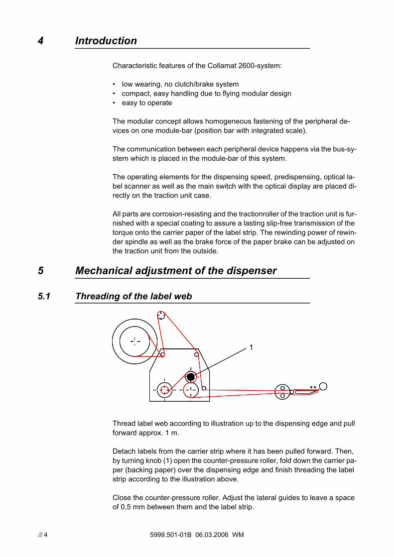
5.1 Threading of the label web
Thread label web according to illustration up to the dispensing edge and pull forward approx. 1 m.
Detach labels from the carrier strip where it has been pulled forward. Then, by turning knob (1) open the counter-pressure roller, fold down the carrier pa-per (backing paper) over the dispensing edge and finish threading the label strip according to the illustration above.
Close the counter-pressure roller. Adjust the lateral guides to leave a space of 0,5 mm between them and the label strip.
1
5999.501-01B 06.03.2006 WM 5
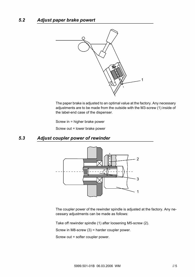
5.2 Adjust paper brake powert
The paper brake is adjusted to an optimal value at the factory. Any necessary adjustments are to be made from the outside with the M3-screw (1) inside of the label-end case of the dispenser.
Screw in = higher brake power
Screw out = lower brake power
5.3 Adjust coupler power of rewinder
The coupler power of the rewinder spindle is adjusted at the factory. Any ne-cessary adjustments can be made as follows:
Take off rewinder spindle (1) after loosening M5-screw (2).
Screw in M8-screw (3) = harder coupler power.
Screw out = softer coupler power.
1
1
3
2
5999.501-01B 06.03.2006 WM 6
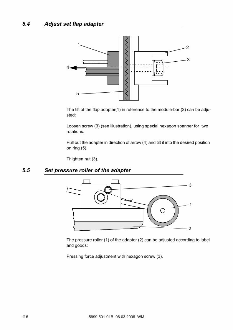
5.4 Adjust set flap adapter
The tilt of the flap adapter(1) in reference to the module-bar (2) can be adju-sted:
Loosen screw (3) (see illustration), using special hexagon spanner for two rotations.
Pull out the adapter in direction of arrow (4) and tilt it into the desired position on ring (5).
Thighten nut (3).
5.5 Set pressure roller of the adapter
The pressure roller (1) of the adapter (2) can be adjusted according to label and goods:
Pressing force adjustment with hexagon screw (3).
1 2
34
5
1
3
2
5999.501-01B 06.03.2006 WM 7
6 Operating elements / Setting elements
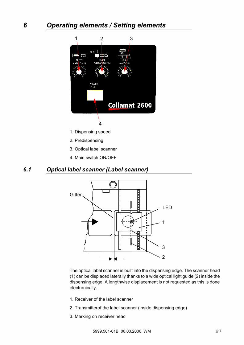
1. Dispensing speed
2. Predispensing
3. Optical label scanner
4. Main switch ON/OFF
6.1 Optical label scanner (Label scanner)
The optical label scanner is built into the dispensing edge. The scanner head (1) can be displaced laterally thanks to a wide optical light guide (2) inside the dispensing edge. A lengthwise displacement is not requested as this is done electronically.
1. Receiver of the label scanner
2. Transmitterof the label scanner (inside dispensing edge)
3. Marking on receiver head
4
2 31
Gitter
LED
1
2
3
5999.501-01B 06.03.2006 WM 8
6.1.1 Setting:
Switch on traction unit (Power ON), main switch lights up.
Set potentiometer LABEL SCANNER for optical label scanning to zero. LED lamp on receiver (1) lights up.
Move label interval (labelweb) right underneath marking (3) of the receiver head (1). Turn potentiometer LABEL SCANNER until LED lamp on receiver (1) goes off. Please note figure on potentiometer scale.
Move label right underneath marking (3), the LED lamp on the receiver head (1) lights up again. Continue to turn the potentiometer LABEL SCANNER un-til the LED lamp switches off. Please note the new figure on the potentiometer scale.
The optimal setting of the potentiometer for the optical scanning is between the above two figures.
6.1.2 Example:
Setting of the potentiometer on label screen:
LED lamp switches off at 3
Setting of potentiometer on label:
LED switches off at 6
Therefore, the optimal setting of the potentiometer is at 4.5.
6.1.3 Note:
If the optical scanning is set incorrectly the label interval cannot be recogni-zed and the dispenser stops after dispensing approx. 0.75 m of the label strip.
6.2 Label predispensing
The potentiometer LABEL PREDISPENSING allows to predispense to a ma-ximum of 100 mm from the marking on the receiver head.
ATTENTION:If the predispensing length exceeds the label lengt, the labeller may not ope-rate accurately.
5999.501-01B 06.03.2006 WM 9
6.3 Dispensing speed
The dispensing speed is set with the potentiometer SPEED in m/min.
Dispensing speeds:
Collamat 2610: 3 to 15 m/min.
7 Maintenance
On the Collamat 2600 the winder clutch and the unwinder must periodically be serviced. The interval of the service depends on the duty and environment conditions of the labeller. Usually every 2000 working hours or 500'000 labels of 100mm feeding length the service must be performed. Then depending on the status of the labeller it must be figured out to do the service in shorter of longer intervals. The the following items must be regarded:
The traction roll must be checked for wear. It must have grip. Otherwise it must be replaced. To check just compare the grip at the location where the backing paper is transported to the the lateral parts which are not used for paper transport.
Also the dispensing edge must be checked for wear. If there is a tactual notch at the backingpaper's location the dispensing edge must be replaced. A wea-red dispensing edge can lead to breaks of the paperwebs.
The unwinder must be lubricated during every maintenance cycle. The dan-cer-axle and also the axle of the labelroll-holder must be greased.
The rewinder coupler must be disassembled while doing the maintenance cy-cle. If necessary replace the feltdisks. Apply three drops of non acid oil to the feltdisks before reassembling the coupler. You will find more information about the adjustment of the coupler in the technical handbook.
For further details refer to the technical handbook. This book can be ordered at your local Collamat representation.
5999.501-01B 06.03.2006 WM 10
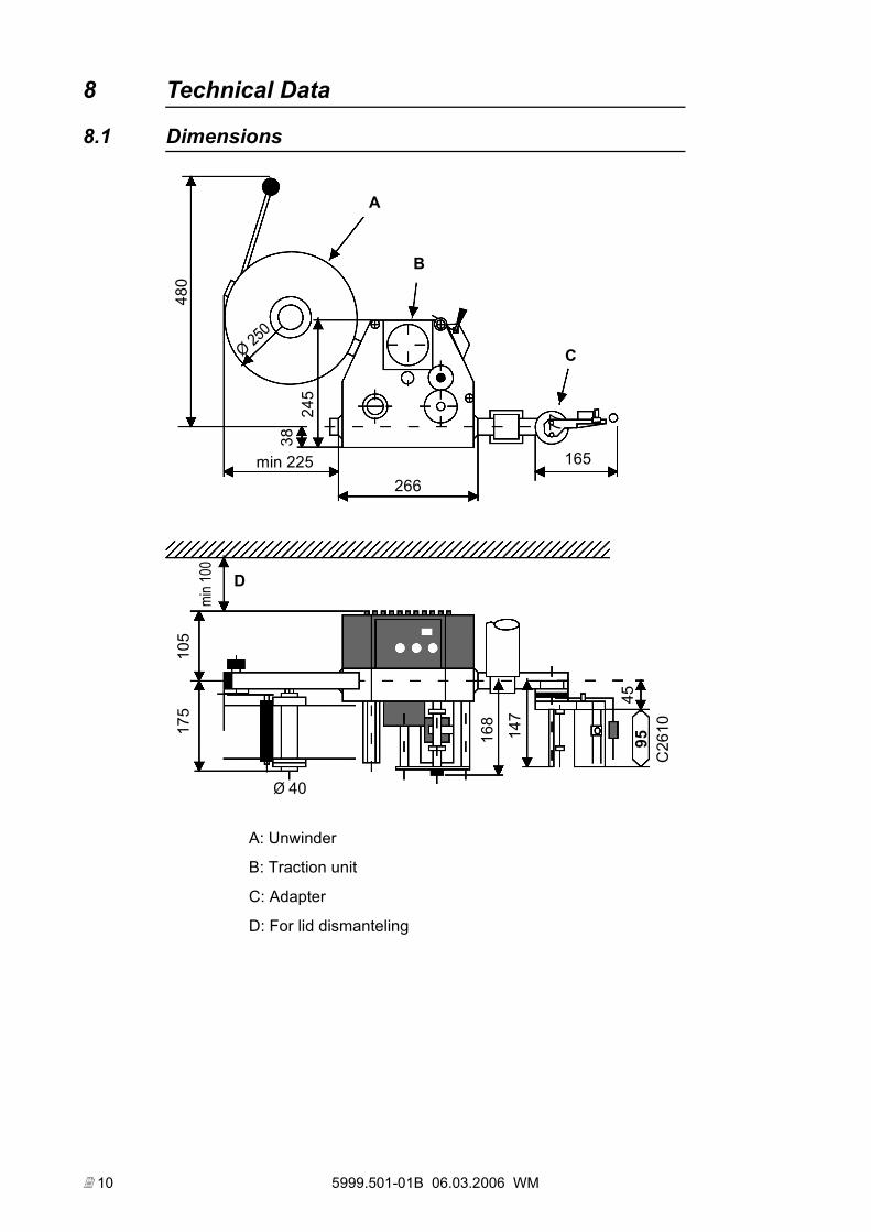
8 Technical Data
8.1 Dimensions
A: Unwinder
B: Traction unit
C: Adapter
D: For lid dismanteling
480
245
165
266min 225
77
Ø 250
A
B
C
C26
1095
105
175
168
45
147
min 1
00
Ø 40
D
38
5999.501-01B 06.03.2006 WM 11
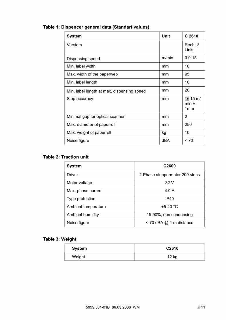
Table 1: Dispencer general data (Standart values)
System Unit C 2610
Versiom Rechts/Links
Dispensing speed m/min 3.0-15
Min. label width mm 10
Max. width of the paperweb mm 95
Min. label length mm 10
Min. label length at max. dispensing speed mm 20
Stop accuracy mm @ 15 m/min ± 1mm
Minimal gap for optical scanner mm 2
Max. diameter of paperroll mm 250
Max. weight of paperroll kg 10
Noise figure dBA < 70
Table 2: Traction unit
System C2600
Driver 2-Phase steppermotor 200 steps
Motor voltage 32 V
Max. phase current 4.0 A
Type protection IP40
Ambient temperature +5-40 °C
Ambient humidity 15-90%, non condensing
Noise figure < 70 dBA @ 1 m distance
Table 3: Weight
System C2610
Weight 12 kg
5999.501-01B 06.03.2006 WM 12
The informations in this handbook reflect the state of the publication date.
We reserve the right to make design modifications.
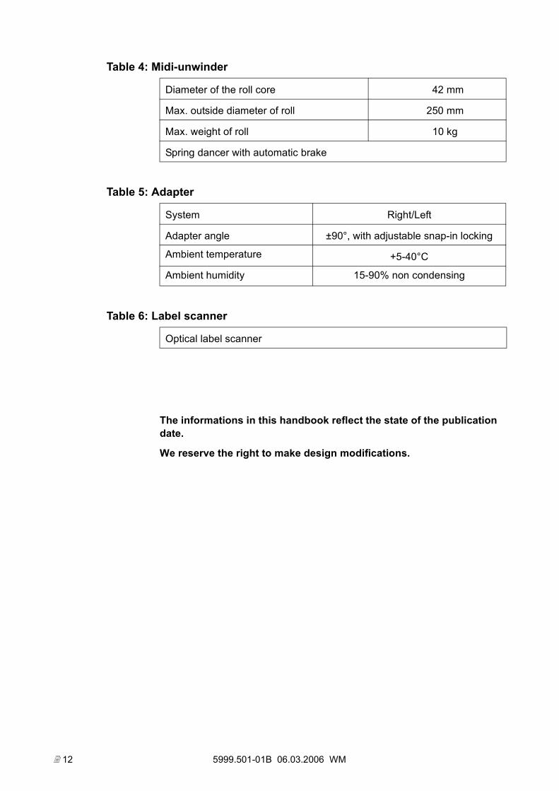
Table 4: Midi-unwinder
Diameter of the roll core 42 mm
Max. outside diameter of roll 250 mm
Max. weight of roll 10 kg
Spring dancer with automatic brake
Table 5: Adapter
System Right/Left
Adapter angle ±90°, with adjustable snap-in locking
Ambient temperature +5-40°C
Ambient humidity 15-90% non condensing
Table 6: Label scanner
Optical label scanner
Related Documents