C18 Junebug / PICkit2 Tutorial 1 Light a LED In this tutorial we will explore the program and hardware needed to light a LED. Turning on the LED is easy, the challenge is getting to the point where you are ready to do it. We will learn to configure the PIC18F1320 hardware. More importantly we will learn where to find the needed information in the processor data sheet and processor header file. We will introduce C functions. Advanced readers will find most of what they need to work the tutorial in the left column. The right column is used to provide background and additional detail regarding the material in the left column. Page 1 Copyright 2008 by 3v0 and BCHS

C18 Junebug / PICkit2 Tutorial 1
Jun 28, 2015
Welcome message from author
This document is posted to help you gain knowledge. Please leave a comment to let me know what you think about it! Share it to your friends and learn new things together.
Transcript
C18 Junebug / PICkit2 Tutorial 1
Light a LED
In this tutorial we will explore the program and hardware needed to light a LED. Turning on the LED is easy, the challenge is getting to the point where you are ready to do it.
We will learn to configure the PIC18F1320 hardware. More importantly we will learn where to find the needed information in the processor data sheet and processor header file.
We will introduce C functions.
Advanced readers will find most of what they need to work the tutorial in the left column. The right column is used to provide background and additional detail regarding the material in the left column.
Page 1 Copyright 2008 by 3v0 and BCHS
C18 Junebug / PICkit2 Tutorial 1 Illustration 1 is a photograph of the Microchip PIC18F1320 used in the BlueroomElectronic's Junebug. In this tutorial will take a somewhat simplistic view of the 18F1320.
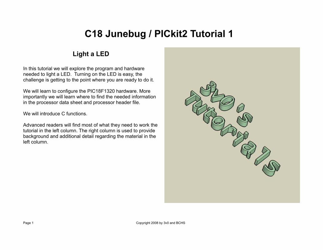
As shown in Illustration 2 our PIC consists of a CPU (Central Processing Unit) and MEMORY. The CPU reads instructions from the MEMORY. The CPU also reads and writes data to MEMORY.Memory comes in two basic types. Memory that the CPU can change is call RAM or Random Access Memory. Memory that the CPU can not change is called ROM or Read Only Memory.
ROM memory would be useless if it could not be written by some means. Our ROM is of a type that can be rapidly written to by a programmer-tool1 such as the Junebug. For this reason our ROM is called FLASH ROM.
In illustration 3 we have divided our memory in to RAM and FLASH ROM. RAM memory is colored GREEN and FLASH ROM memory is RED. The CPU can read and write the RAM (GREEN) but it can only read from the ROM (RED).
1A person who writes a computer program is called a programmer as it the device use to program or write ROM memory. We will use the programmer to refer to a person who programmes.. When talking about the device that programs ROM will use programmer-tool or Junebug.
Page 2 Copyright 2008 by 3v0 and BCHS
Illustration 1:
Illustration 2:
Illustration 3:
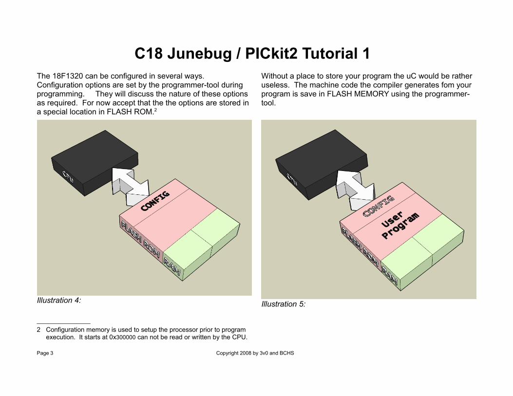
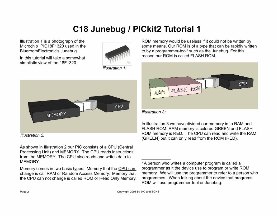
C18 Junebug / PICkit2 Tutorial 1 The 18F1320 can be configured in several ways. Configuration options are set by the programmer-tool during programming. They will discuss the nature of these options as required. For now accept that the the options are stored in a special location in FLASH ROM.2
2 Configuration memory is used to setup the processor prior to program execution. It starts at 0x300000 can not be read or written by the CPU.
Without a place to store your program the uC would be rather useless. The machine code the compiler generates fom your program is save in FLASH MEMORY using the programmer-tool.
Page 3 Copyright 2008 by 3v0 and BCHS
Illustration 4: Illustration 5:

C18 Junebug / PICkit2 Tutorial 1 The introduction to this text I said we were going to turn on a LED. We have looked at enough hardware to program and run a program do not know how we are going to interface with the led. Bit first lets take a look at what it takes to illuminate an LED without a uC.
In Schematic 1: a battery is used to power the circuit. If we do not limit the amount of current to an LED it will take as much as they can get. That is where R1 comes it. It provides resistance in the circuit to limit the current flow. When a resistor is used in this way it is called a current limiting resistor, or limit resistor. Red LEDs powered by 5 volts do well with a limit resistor between 330 and 1K (1000) ohms.
LEDs only light when the current flows in the correction direction. Notice the bar on the right side of LED1. The bar indicates which end of the LED should be connected to the minus side of the battery. Current flows in the direction indicated by the arrow.
Rather than a battery we will be using our PIC to power the LED circuit.
Page 4 Copyright 2008 by 3v0 and BCHS
Illustration 6:
Schematic 1:
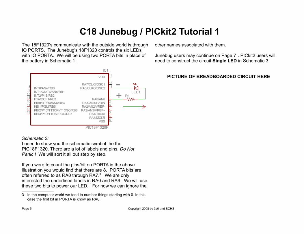
C18 Junebug / PICkit2 Tutorial 1 The 18F1320's communicate with the outside world is through IO PORTS. The Junebug's 18F1320 controls the six LEDs with IO PORTA. We will be using two PORTA bits in place of the battery in Schematic 1 .
I need to show you the schematic symbol the the PIC18F1320. There are a lot of labels and pins. Do Not Panic ! We will sort it all out step by step.
If you were to count the pins/bit on PORTA in the above illustration you would find that there are 8. PORTA bits are often referred to as RA0 through RA7.3 We are only interested the underlined labels in RA0 and RA6. We will use these two bits to power our LED. For now we can ignore the
3 In the computer world we tend to number things starting with 0. In this case the first bit in PORTA is know as RA0.
other names associated with them.
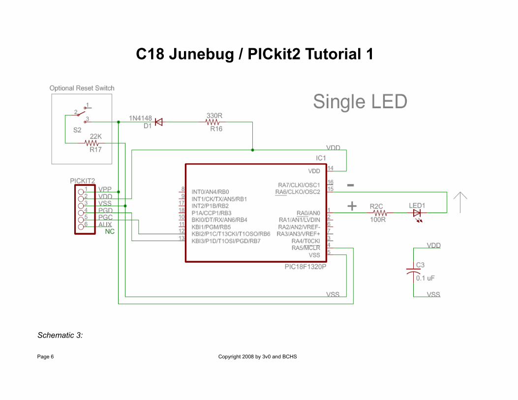
Junebug users may continue on Page 7 . PICkit2 users will need to construct the circuit Single LED in Schematic 3.
PICTURE OF BREADBOARDED CIRCUIT HERE
Page 5 Copyright 2008 by 3v0 and BCHS
Schematic 2:
C18 Junebug / PICkit2 Tutorial 1
Page 6 Copyright 2008 by 3v0 and BCHS
Schematic 3:
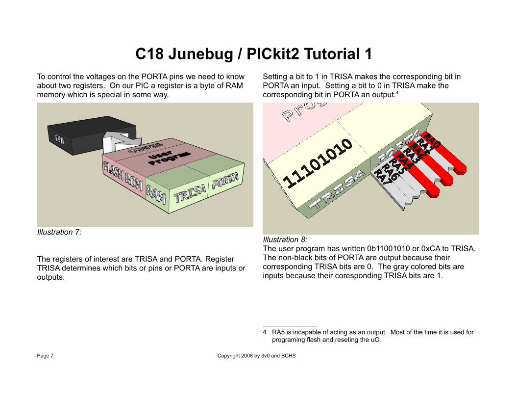
C18 Junebug / PICkit2 Tutorial 1 To control the voltages on the PORTA pins we need to know about two registers. On our PIC a register is a byte of RAM memory which is special in some way.
The registers of interest are TRISA and PORTA. Register TRISA determines which bits or pins or PORTA are inputs or outputs.
Setting a bit to 1 in TRISA makes the corresponding bit in PORTA an input. Setting a bit to 0 in TRISA make the corresponding bit in PORTA an output.4
The user program has written 0b11001010 or 0xCA to TRISA. The non-black bits of PORTA are output because their corresponding TRISA bits are 0. The gray colored bits are inputs because their coresponding TRISA bits are 1.
4 RA5 is incapable of acting as an output. Most of the time it is used for programing flash and reseting the uC.
Page 7 Copyright 2008 by 3v0 and BCHS
Illustration 7: Illustration 8:
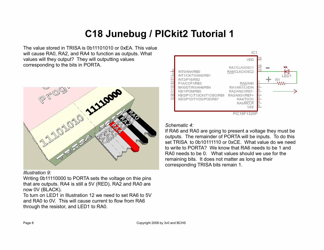
C18 Junebug / PICkit2 Tutorial 1 The value stored in TRISA is 0b11101010 or 0xEA. This value will cause RA0, RA2, and RA4 to function as outputs. What values will they output? They will outputting values corresponding to the bits in PORTA.
Writing 0b11110000 to PORTA sets the voltage on thie pins that are outputs. RA4 is still a 5V (RED), RA2 and RA0 are now 0V (BLACK).To turn on LED1 in Illustration 12 we need to set RA6 to 5V and RA0 to 0V. This will cause current to flow from RA6 through the resistor, and LED1 to RA0.
If RA6 and RA0 are going to present a voltage they must be outputs. The remainder of PORTA will be inputs. To do this set TRISA to 0b10111110 or 0xCE. What value do we need to write to PORTA? We know that RA6 needs to be 1 and RA0 needs to be 0. What values should we use for the remaining bits. It does not matter as long as their corresponding TRISA bits remain 1.
Page 8 Copyright 2008 by 3v0 and BCHS
Illustration 9:
Schematic 4:
C18 Junebug / PICkit2 Tutorial 1
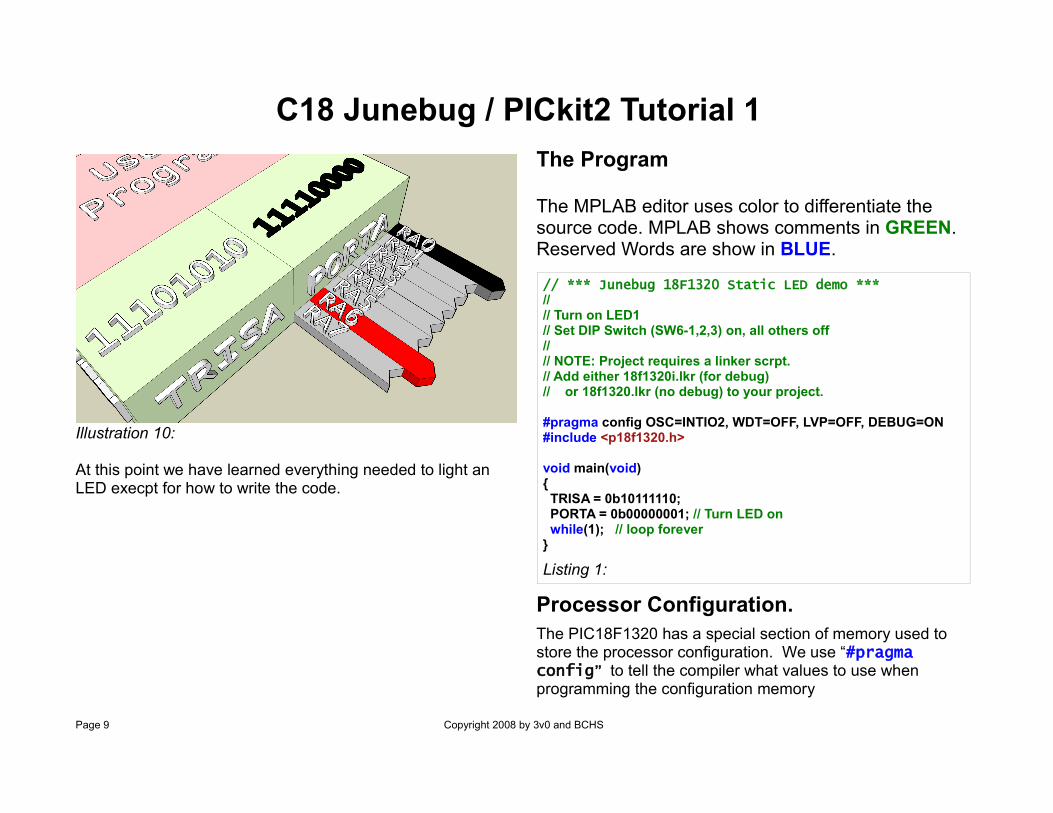
At this point we have learned everything needed to light an LED execpt for how to write the code.
The Program
The MPLAB editor uses color to differentiate the source code. MPLAB shows comments in GREEN. Reserved Words are show in BLUE.
Processor Configuration.The PIC18F1320 has a special section of memory used to store the processor configuration. We use “#pragma config” to tell the compiler what values to use when programming the configuration memory
Page 9 Copyright 2008 by 3v0 and BCHS
Illustration 10:
// *** Junebug 18F1320 Static LED demo ***//// Turn on LED1 // Set DIP Switch (SW6-1,2,3) on, all others off//// NOTE: Project requires a linker scrpt.// Add either 18f1320i.lkr (for debug) // or 18f1320.lkr (no debug) to your project.
#pragma config OSC=INTIO2, WDT=OFF, LVP=OFF, DEBUG=ON#include <p18f1320.h>
void main(void){ TRISA = 0b10111110; PORTA = 0b00000001; // Turn LED on while(1); // loop forever}
Listing 1:
C18 Junebug / PICkit2 Tutorial 1 Def in i t i on : Source CodeProgrammers write source code. Source code is the sequence of statements and declarations in the original form, in this case C. The source code for a program may exist in one or several files.
De f in i t i on : CommentComments make the program easier for people to understand and are ignored by the compiler. When the compiler sees the two characters “//” it ignores them and the remainder of the text on that line.
De f in i t i on : Reserved Words These words have special meaning defined in C’s formal specifications. Reserved words include labels for low level data types and identify programming constructs such as loops, blocks, conditionals, and branches.
PragmaThe #pragma keyword is used to pass information to the compiler. It does not cause code or instructions to be generated. It is one of several compiler directive.
Page 10 Copyright 2008 by 3v0 and BCHS
C18 Junebug / PICkit2 Tutorial 1 The list of available configuration directives for the uC can be found using HELP from the MPLAB main menu.
HELP>TOPICS>LANGUAGE_TOOLS/PIC18_CONFIG SETTINGS
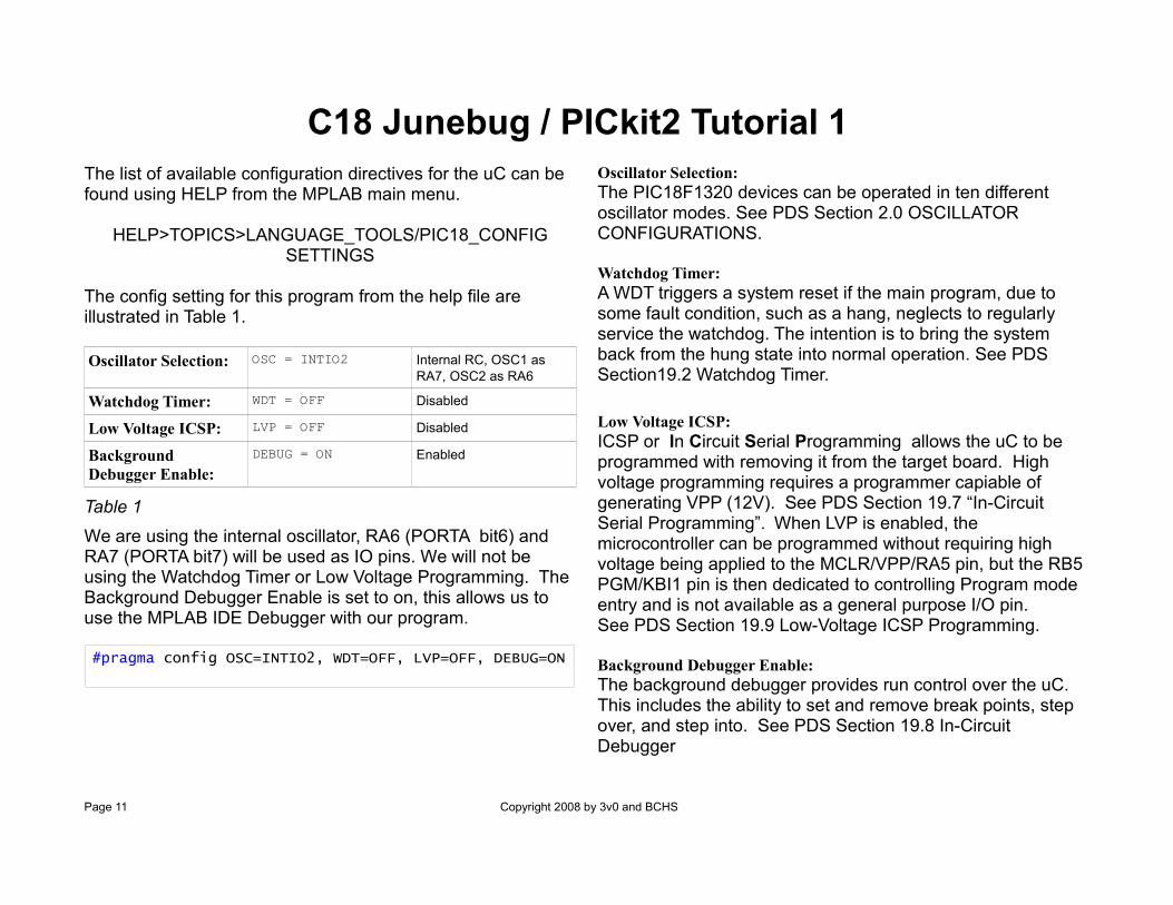
The config setting for this program from the help file are illustrated in Table 1.
Oscillator Selection: OSC = INTIO2 Internal RC, OSC1 as RA7, OSC2 as RA6
Watchdog Timer: WDT = OFF Disabled
Low Voltage ICSP: LVP = OFF Disabled
Background Debugger Enable:
DEBUG = ON Enabled
Table 1We are using the internal oscillator, RA6 (PORTA bit6) and RA7 (PORTA bit7) will be used as IO pins. We will not be using the Watchdog Timer or Low Voltage Programming. The Background Debugger Enable is set to on, this allows us to use the MPLAB IDE Debugger with our program.
Oscillator Selection:The PIC18F1320 devices can be operated in ten different oscillator modes. See PDS Section 2.0 OSCILLATOR CONFIGURATIONS.
Watchdog Timer:A WDT triggers a system reset if the main program, due to some fault condition, such as a hang, neglects to regularly service the watchdog. The intention is to bring the system back from the hung state into normal operation. See PDS Section19.2 Watchdog Timer.
Low Voltage ICSP:ICSP or In Circuit Serial Programming allows the uC to be programmed with removing it from the target board. High voltage programming requires a programmer capiable of generating VPP (12V). See PDS Section 19.7 “In-Circuit Serial Programming”. When LVP is enabled, the microcontroller can be programmed without requiring high voltage being applied to the MCLR/VPP/RA5 pin, but the RB5 PGM/KBI1 pin is then dedicated to controlling Program mode entry and is not available as a general purpose I/O pin.See PDS Section 19.9 Low-Voltage ICSP Programming.
Background Debugger Enable:The background debugger provides run control over the uC. This includes the ability to set and remove break points, step over, and step into. See PDS Section 19.8 In-Circuit Debugger
Page 11 Copyright 2008 by 3v0 and BCHS
#pragma config OSC=INTIO2, WDT=OFF, LVP=OFF, DEBUG=ON
C18 Junebug / PICkit2 Tutorial 1
Processor Header FileThe processor header file describes the processor and peripheral registers. The processor we are using is the PIC18F1320, the processor header file can be found at:
C:\MCC18\h\p18F1320.h
Our MPLAB is setup such that the compiler knows where to find p18F1320.h. All we need in our program is the line.
Our program refer to the processor registers TRISA and PORTA. These registers are defined in p18F1320.h. If it were not included the compiler would generate these errors..
The #include directive to tell the compiler to read source code from another file. From the compilers viewpoint it is if you had typed or included the source code from the included file at the point #include was used.
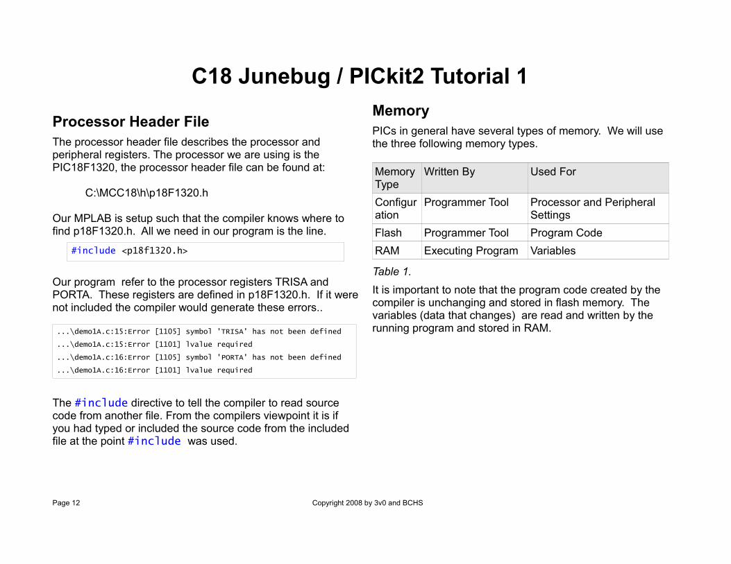
MemoryPICs in general have several types of memory. We will use the three following memory types.
Memory Type
Written By Used For
Configuration
Programmer Tool Processor and Peripheral Settings
Flash Programmer Tool Program Code RAM Executing Program Variables
Table 1.It is important to note that the program code created by the compiler is unchanging and stored in flash memory. The variables (data that changes) are read and written by the running program and stored in RAM.
Page 12 Copyright 2008 by 3v0 and BCHS
...\demo1A.c:15:Error [1105] symbol 'TRISA' has not been defined
...\demo1A.c:15:Error [1101] lvalue required
...\demo1A.c:16:Error [1105] symbol 'PORTA' has not been defined
...\demo1A.c:16:Error [1101] lvalue required
#include <p18f1320.h>
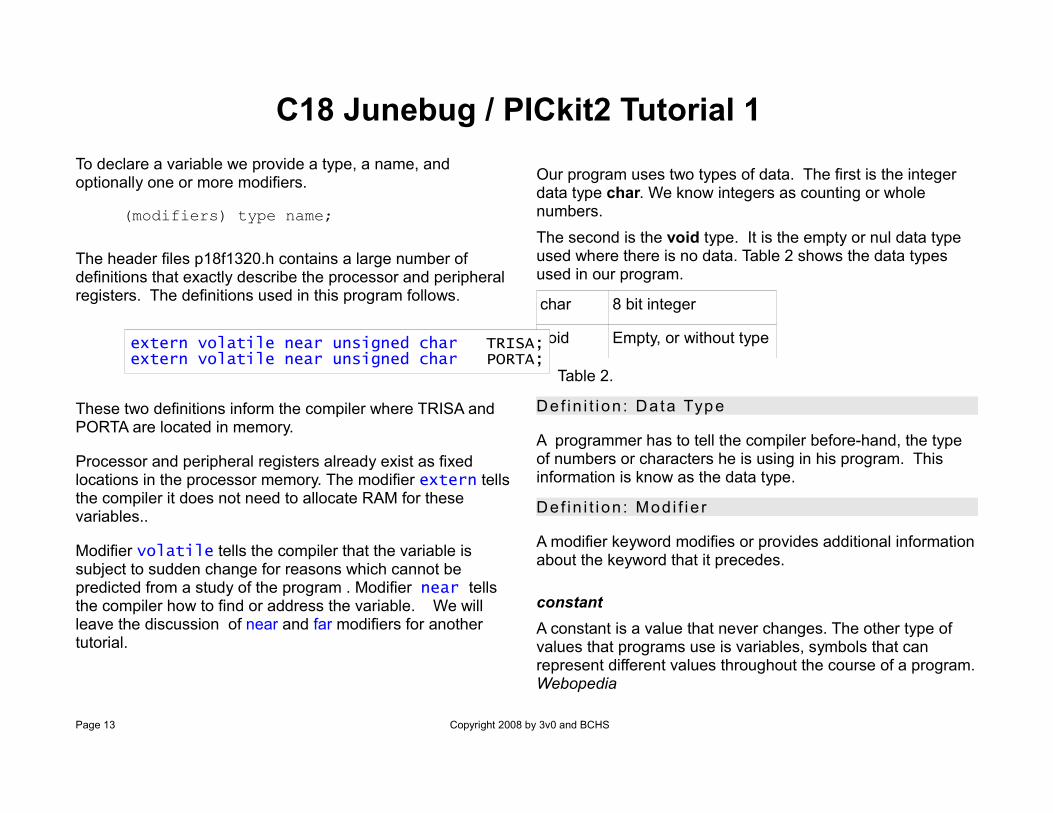
C18 Junebug / PICkit2 Tutorial 1 To declare a variable we provide a type, a name, and optionally one or more modifiers.
(modifiers) type name;
The header files p18f1320.h contains a large number of definitions that exactly describe the processor and peripheral registers. The definitions used in this program follows.
These two definitions inform the compiler where TRISA and PORTA are located in memory.
Processor and peripheral registers already exist as fixed locations in the processor memory. The modifier extern tells the compiler it does not need to allocate RAM for these variables..
Modifier volatile tells the compiler that the variable is subject to sudden change for reasons which cannot be predicted from a study of the program . Modifier near tells the compiler how to find or address the variable. We will leave the discussion of near and far modifiers for another tutorial.
Our program uses two types of data. The first is the integer data type char. We know integers as counting or whole numbers. The second is the void type. It is the empty or nul data type used where there is no data. Table 2 shows the data types used in our program.
char 8 bit integer
void Empty, or without type
Table 2.
De f in i t i on : Da ta Type
A programmer has to tell the compiler before-hand, the type of numbers or characters he is using in his program. This information is know as the data type.
De f in i t i on : Mod i f i e r
A modifier keyword modifies or provides additional information about the keyword that it precedes.
constantA constant is a value that never changes. The other type of values that programs use is variables, symbols that can represent different values throughout the course of a program. Webopedia
Page 13 Copyright 2008 by 3v0 and BCHS
extern volatile near unsigned char TRISA;extern volatile near unsigned char PORTA;
C18 Junebug / PICkit2 Tutorial 1 compilerA compiler is a computer program (or set of programs) that translates text written in a computer language (the source language) into another computer language (the target language). The original sequence is usually called the source code and the output called object code.
compiler directive Commands embedded in source code to tell compilers some intention about compilation. A compiler directive often tells the compiler how to compile; other source code tells the compiler what to compile. In the case of the C18 compiler the config directive is used to tell the compiler what value(s) to store in the chip's configuration memory.
dataData in everyday language is a synonym for information. In computer science we classify data by it nature, and how it is stored or represented.
variableA symbol or name that stands for a value.
Questions
It is best to always write a value to PORTA prior to setting any TRISA bits to 1. Why?
What is special about RA5 ?
Page 14 Copyright 2008 by 3v0 and BCHS
C18 Junebug / PICkit2 Tutorial 1 Revisions4/27/2008 It is MPLAB's editor and not the COMPILER that colors source code.
Page 15 Copyright 2008 by 3v0 and BCHS
Related Documents