S 2/e C D A Computer Systems Design and Architecture Second Edition © 2004 Prentice Hall Chapter 9: Peripheral Devices—Overview Magnetic disk drives: ubiquitous and complex Other moving media devices: tape and CD ROM Display devices Video monitors: analog characteristics Video terminals Memory mapped video displays Flat panel displays Printers: dot matrix, laser, inkjet Manual input: keyboards and mice A to D and D to A converters: the analog world

Welcome message from author
This document is posted to help you gain knowledge. Please leave a comment to let me know what you think about it! Share it to your friends and learn new things together.
Transcript
S
2/e
C
DA
Computer Systems Design and Architecture Second Edition © 2004 Prentice Hall
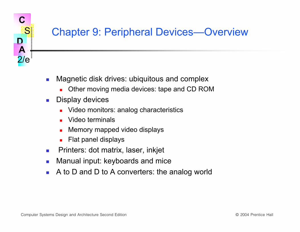
Chapter 9: Peripheral Devices—Overview
Magnetic disk drives: ubiquitous and complex Other moving media devices: tape and CD ROM
Display devices Video monitors: analog characteristics
Video terminals
Memory mapped video displays
Flat panel displays
Printers: dot matrix, laser, inkjet
Manual input: keyboards and mice
A to D and D to A converters: the analog world
S
2/e
C
DA
Computer Systems Design and Architecture Second Edition © 2004 Prentice Hall
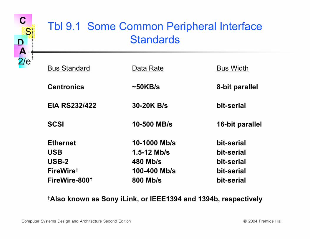
Tbl 9.1 Some Common Peripheral InterfaceStandards
Bus Standard Data Rate Bus Width
Centronics ~50KB/s 8-bit parallel
EIA RS232/422 30-20K B/s bit-serial
SCSI 10-500 MB/s 16-bit parallel
Ethernet 10-1000 Mb/s bit-serialUSB 1.5-12 Mb/s bit-serialUSB-2 480 Mb/s bit-serialFireWire† 100-400 Mb/s bit-serialFireWire-800† 800 Mb/s bit-serial
†Also known as Sony iLink, or IEEE1394 and 1394b, respectively
S
2/e
C
DA
Computer Systems Design and Architecture Second Edition © 2004 Prentice Hall
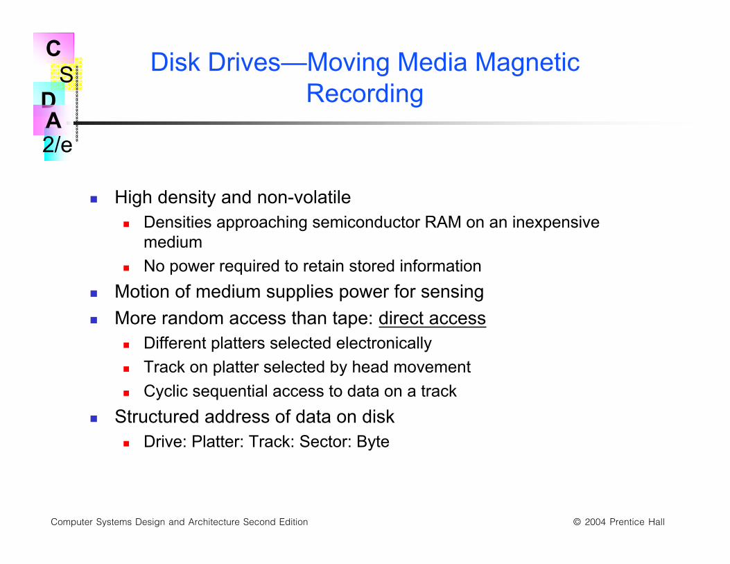
Disk Drives—Moving Media MagneticRecording
High density and non-volatile Densities approaching semiconductor RAM on an inexpensive
medium
No power required to retain stored information
Motion of medium supplies power for sensing
More random access than tape: direct access Different platters selected electronically
Track on platter selected by head movement
Cyclic sequential access to data on a track
Structured address of data on disk Drive: Platter: Track: Sector: Byte

S
2/e
C
DA
Computer Systems Design and Architecture Second Edition © 2004 Prentice Hall
Fig 9.3 Cutaway View of a Multi-Platter HardDisk Drive
S
2/e
C
DA
Computer Systems Design and Architecture Second Edition © 2004 Prentice Hall
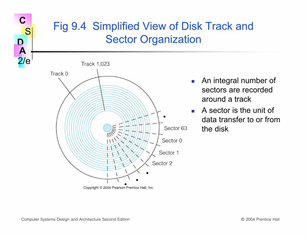
Fig 9.4 Simplified View of Disk Track andSector Organization
An integral number ofsectors are recordedaround a track
A sector is the unit ofdata transfer to or fromthe disk
S
2/e
C
DA
Computer Systems Design and Architecture Second Edition © 2004 Prentice Hall
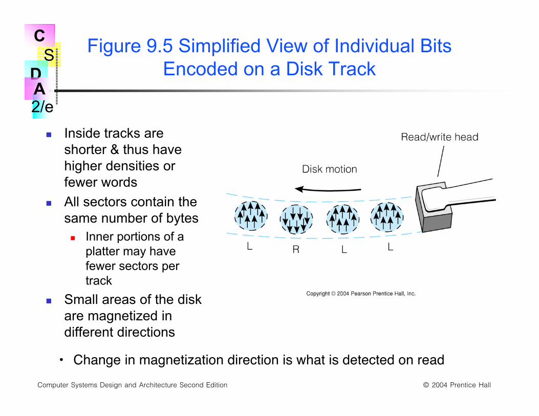
Figure 9.5 Simplified View of Individual BitsEncoded on a Disk Track
Inside tracks areshorter & thus havehigher densities orfewer words
All sectors contain thesame number of bytes Inner portions of a
platter may havefewer sectors pertrack
Small areas of the diskare magnetized indifferent directions
• Change in magnetization direction is what is detected on read
S
2/e
C
DA
Computer Systems Design and Architecture Second Edition © 2004 Prentice Hall
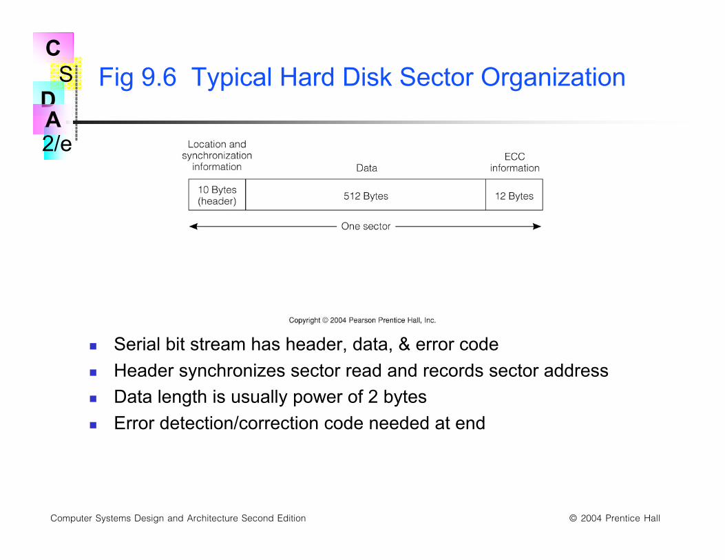
Fig 9.6 Typical Hard Disk Sector Organization
Serial bit stream has header, data, & error code
Header synchronizes sector read and records sector address
Data length is usually power of 2 bytes
Error detection/correction code needed at end
S
2/e
C
DA
Computer Systems Design and Architecture Second Edition © 2004 Prentice Hall
Disk Formatting
Disks are pre-formatted with track and sector addresswritten in headers
Disk surface defects may cause some sectors to bemarked unusable for the software
S
2/e
C
DA
Computer Systems Design and Architecture Second Edition © 2004 Prentice Hall
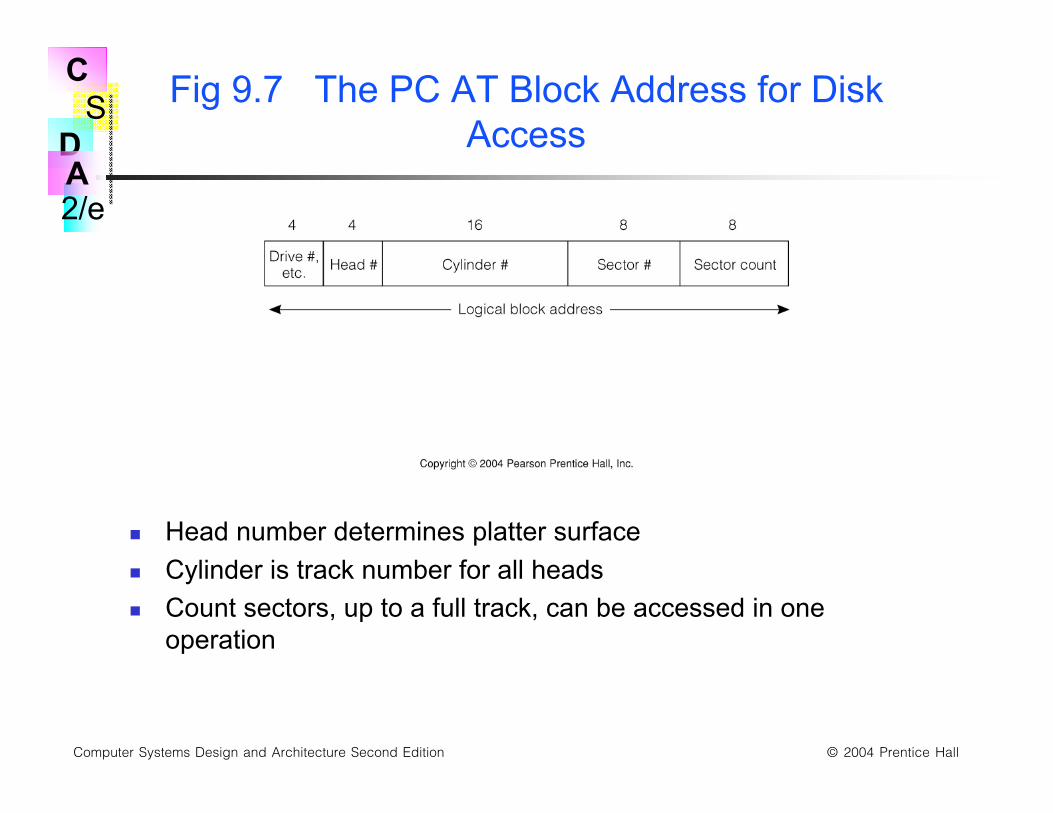
Fig 9.7 The PC AT Block Address for DiskAccess
Head number determines platter surface
Cylinder is track number for all heads
Count sectors, up to a full track, can be accessed in oneoperation
S
2/e
C
DA
Computer Systems Design and Architecture Second Edition © 2004 Prentice Hall
The Disk Access Process
1. OS Communicates LBA to the disk interface, and issues a READcommand.
2. Drive seeks to the correct track by moving heads to correctposition, and enabling the appropriate head. 3. Sector data andECC stream into buffer. ECC is done "on the fly."
4. When correct sector is found data is streamed into a buffer.
5. Drive communicates "data ready" to the OS
6. OS reads data byte by byte or by using DMA.
S
2/e
C
DA
Computer Systems Design and Architecture Second Edition © 2004 Prentice Hall
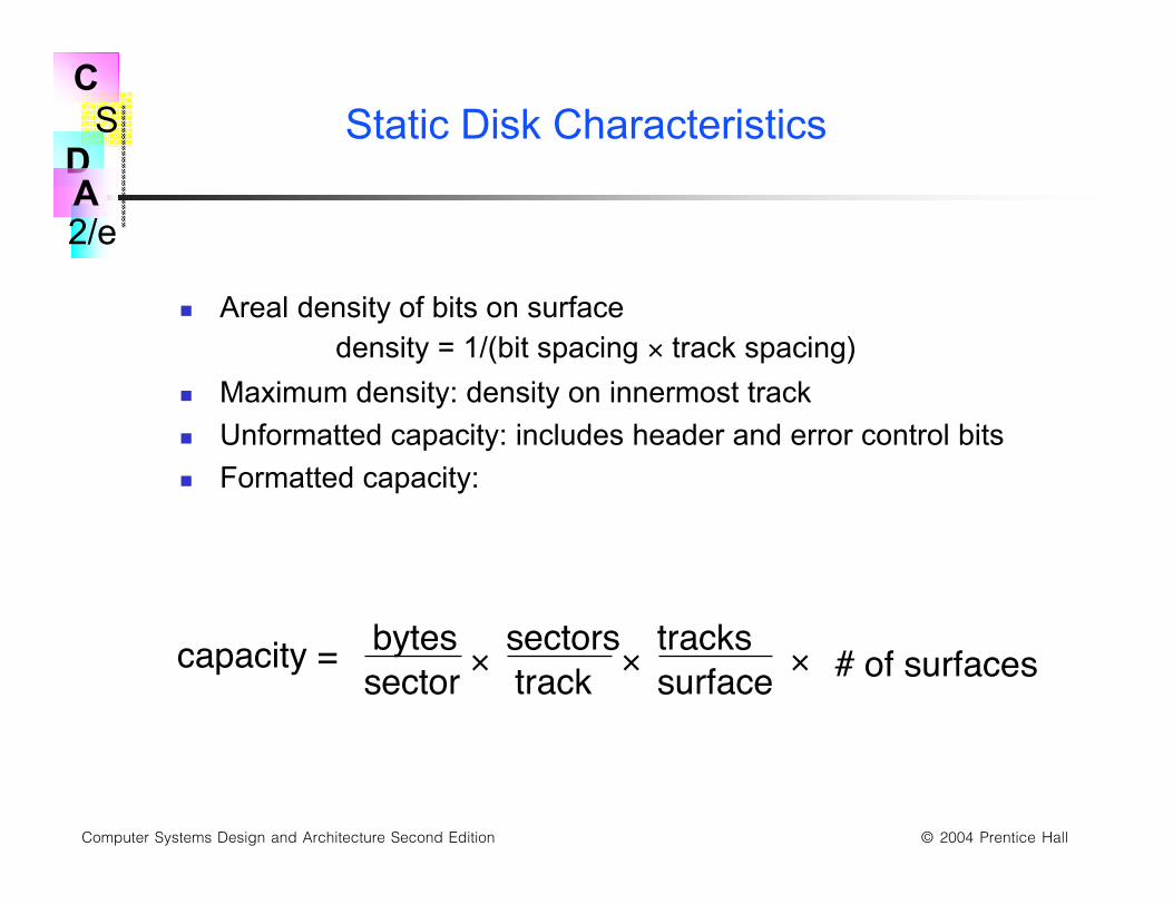
Static Disk Characteristics
Areal density of bits on surfacedensity = 1/(bit spacing × track spacing)
Maximum density: density on innermost track
Unformatted capacity: includes header and error control bits
Formatted capacity:
capacity = bytessector
sectorstrack
trackssurface # of surfaces×× ×
S
2/e
C
DA
Computer Systems Design and Architecture Second Edition © 2004 Prentice Hall
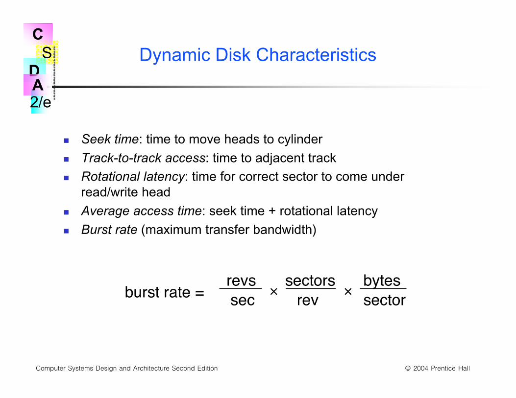
Dynamic Disk Characteristics
Seek time: time to move heads to cylinder
Track-to-track access: time to adjacent track
Rotational latency: time for correct sector to come underread/write head
Average access time: seek time + rotational latency
Burst rate (maximum transfer bandwidth)
burst rate =revssec
sectorsrev
bytessector× ×

S
2/e
C
DA
Computer Systems Design and Architecture Second Edition © 2004 Prentice Hall
Improving Disk Reliability: RAID, RedundantArray of Inexpensive Disks
Raid LEVEL 0: Speed improvement only, by "striping" data acrossseveral disks so they can be accessed in parallel.
RAID Level 1: "Mirroring," writing the exact same data to two differentdisk drives. If one drive fails, the other can be used.
RAID Level 2: Data is striped at the bit level across several disks withadditional ECC bits to recover data if one drive fails.
RAID Level 3: Striped as in level 0, but at the byte level, and ECC datais written to a separate drive.
RAID Level 4: Same as level 3, but blocks are used instead of bytes,and data are written asynchronously. Often used in transaction-basedsystems, such as in airline reservation systems.
RAID Level 5: Similar to level 4, but both data and ECC bits are bothstriped across 3 or more drives.
S
2/e
C
DA
Computer Systems Design and Architecture Second Edition © 2004 Prentice Hall
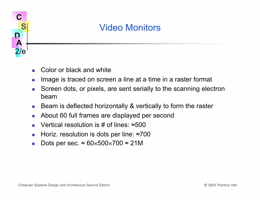
Video Monitors
Color or black and white
Image is traced on screen a line at a time in a raster format
Screen dots, or pixels, are sent serially to the scanning electronbeam
Beam is deflected horizontally & vertically to form the raster
About 60 full frames are displayed per second
Vertical resolution is # of lines: ≈500
Horiz. resolution is dots per line: ≈700 Dots per sec. ≈ 60×500×700 ≈ 21M
S
2/e
C
DA
Computer Systems Design and Architecture Second Edition © 2004 Prentice Hall
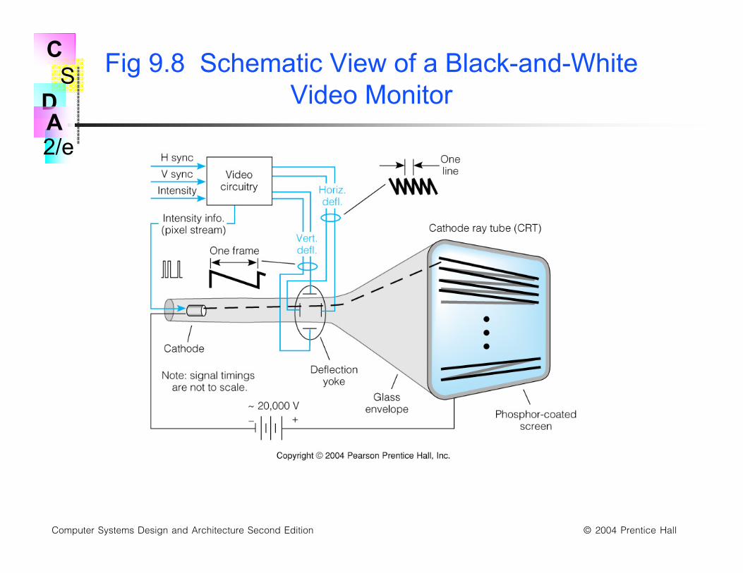
Fig 9.8 Schematic View of a Black-and-WhiteVideo Monitor
S
2/e
C
DA
Computer Systems Design and Architecture Second Edition © 2004 Prentice Hall
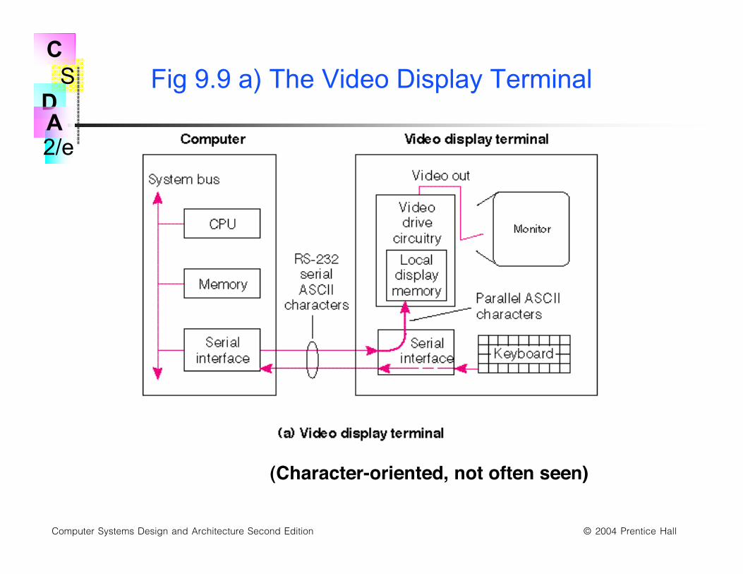
Two Video Display Types: Terminal & MemoryMapped
Video monitor can be packaged with display memory andkeyboard to form a terminal
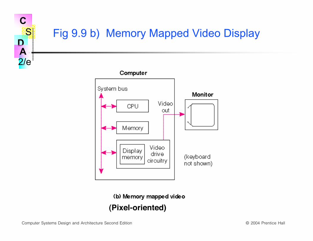
Video monitor can be driven from display memory that ismemory mapped
Video display terminals are usually character oriented devices Low bandwidth connection to the computer
Memory mapped displays can show pictures and motion High bandwidth connection to memory bus allows fast changes
S
2/e
C
DA
Computer Systems Design and Architecture Second Edition © 2004 Prentice Hall
Fig 9.9 a) The Video Display Terminal
(Character-oriented, not often seen)
S
2/e
C
DA
Computer Systems Design and Architecture Second Edition © 2004 Prentice Hall
Fig 9.9 b) Memory Mapped Video Display
(Pixel-oriented)
S
2/e
C
DA
Computer Systems Design and Architecture Second Edition © 2004 Prentice Hall
Memory Representations of DisplayedInformation
Bit mapped displays Each pixel represented by a memory datum
Black & white displays can use a bit per pixel
Gray scale or color needs several bits per pixel
Character oriented (alphanumeric) displays Only character codes stored in memory
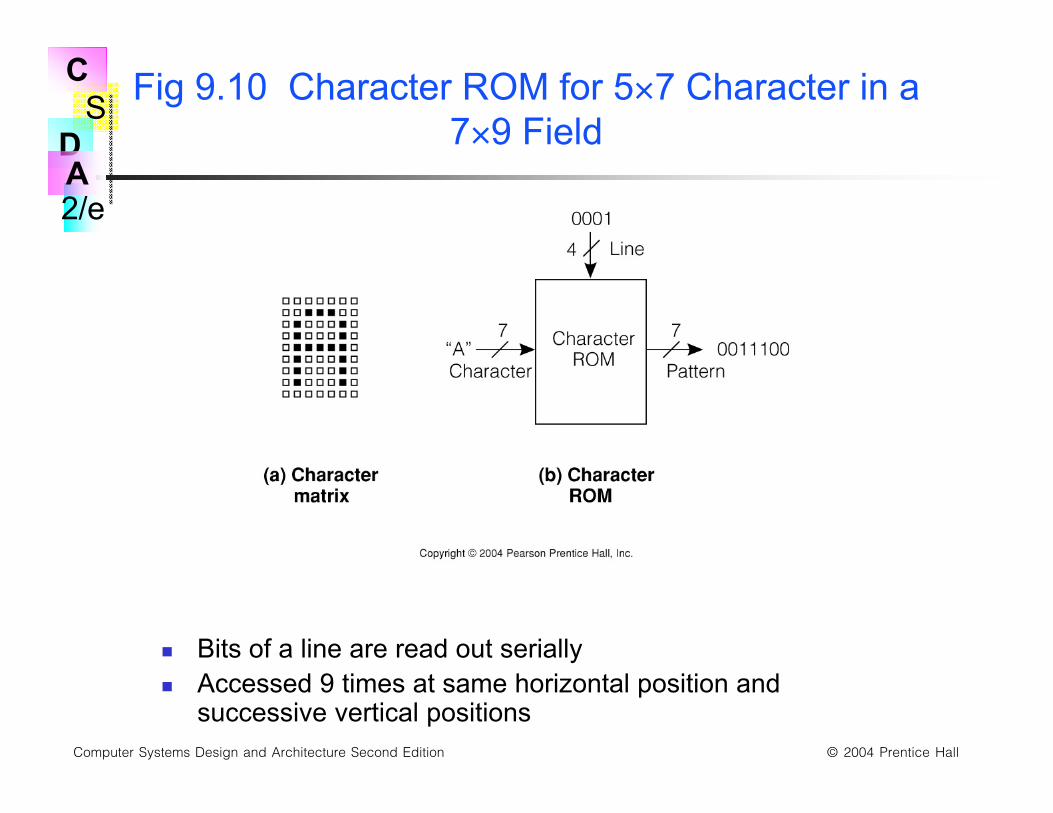
Character code converted to pixels by a character ROM
A character generates several successive pixels on severalsuccessive lines
S
2/e
C
DA
Computer Systems Design and Architecture Second Edition © 2004 Prentice Hall
Fig 9.10 Character ROM for 5×7 Character in a7×9 Field
Bits of a line are read out serially Accessed 9 times at same horizontal position and
successive vertical positions
S
2/e
C
DA
Computer Systems Design and Architecture Second Edition © 2004 Prentice Hall
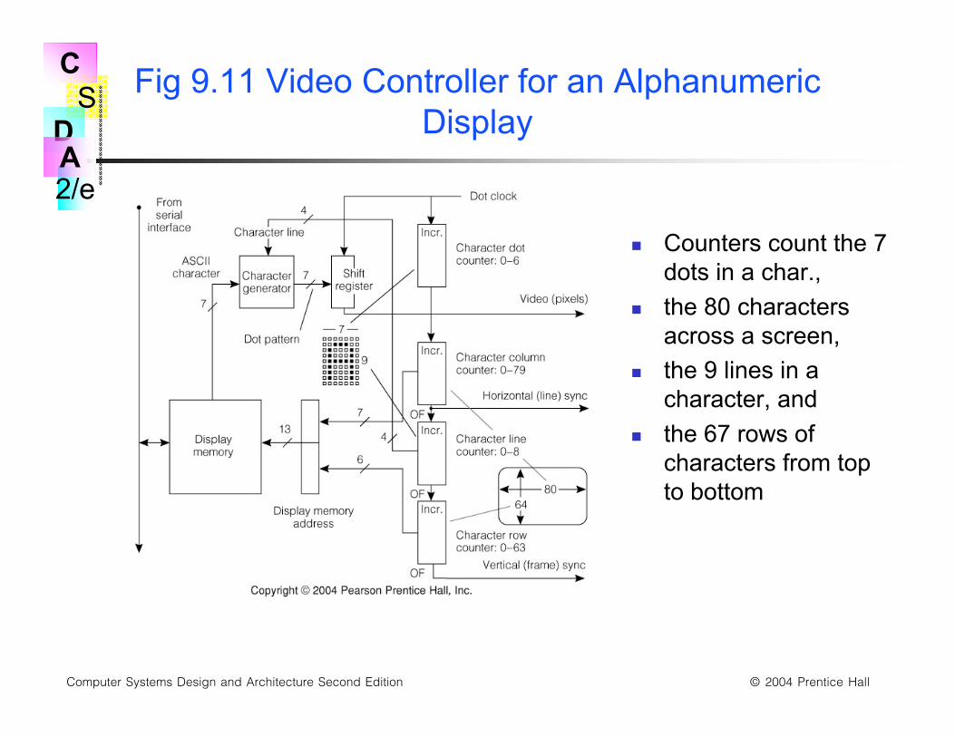
Fig 9.11 Video Controller for an AlphanumericDisplay
Counters count the 7dots in a char.,
the 80 charactersacross a screen,
the 9 lines in acharacter, and
the 67 rows ofcharacters from topto bottom
S
2/e
C
DA
Computer Systems Design and Architecture Second Edition © 2004 Prentice Hall
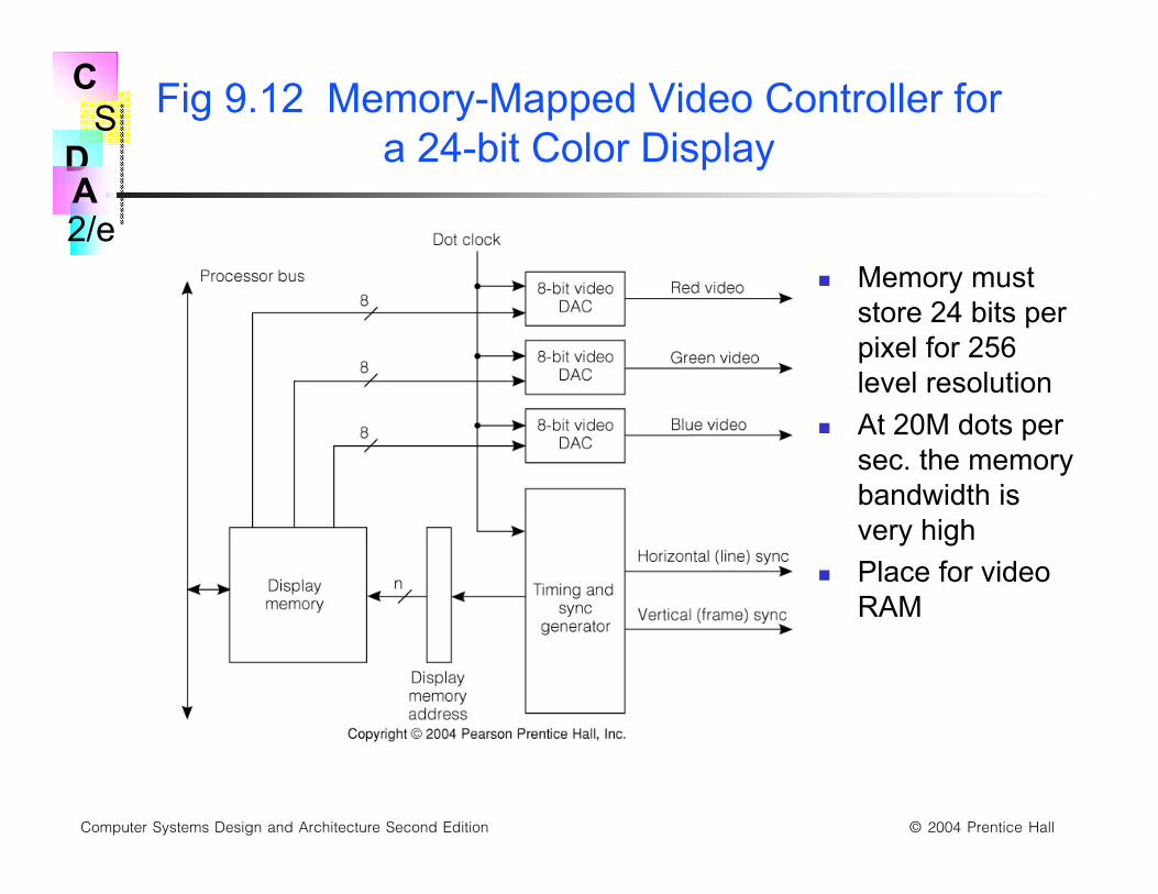
Fig 9.12 Memory-Mapped Video Controller fora 24-bit Color Display
Memory muststore 24 bits perpixel for 256level resolution
At 20M dots persec. the memorybandwidth isvery high
Place for videoRAM
S
2/e
C
DA
Computer Systems Design and Architecture Second Edition © 2004 Prentice Hall
Flat Panel Displays
Allow electrical control over the transparency of a liquid crystalmaterial sandwiched between glass plates, dot by dot
3 dots per pixel for color, one for black&white
Dots are scanned in a raster format, so controller similar to thatfor video monitor
Passive matrix has X & Y drive transistors at edges
Active matrix has one (or 3) transistor per dot
S
2/e
C
DA
Computer Systems Design and Architecture Second Edition © 2004 Prentice Hall
Printers—Ways of Getting Ink on Paper
Dot matrix printer: Row of solenoid actuated pins, could be height of char. matrix
Inked ribbon struck by pin to mark paper
Low resolution
Laser printer: Positively charged drum scanned by laser to discharge individual
pixels
Ink adheres to remaining positive surface portions
300 to 1200 dots per inch resolution
Ink-jet printers: Ultrasonic transducer squirts very small jet of ink at correct pixels
as head moves across paper
Intermediate between the 2 in price and resolution
S
2/e
C
DA
Computer Systems Design and Architecture Second Edition © 2004 Prentice Hall
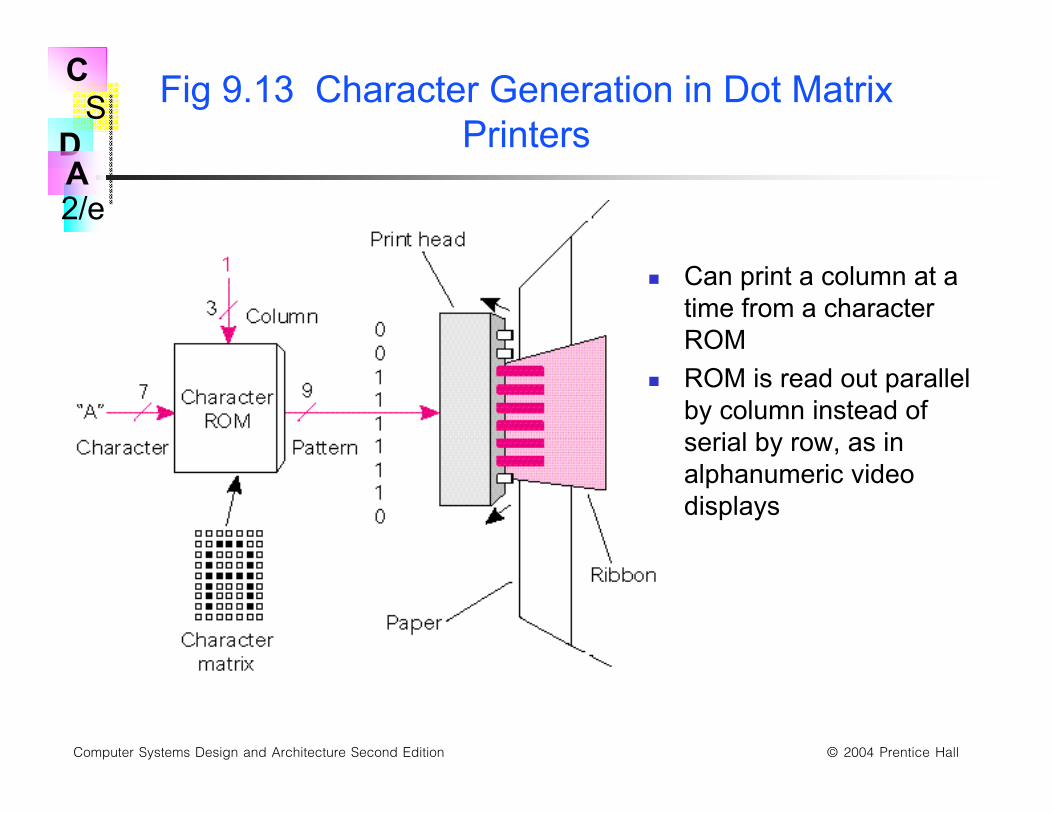
Fig 9.13 Character Generation in Dot MatrixPrinters
Can print a column at atime from a characterROM
ROM is read out parallelby column instead ofserial by row, as inalphanumeric videodisplays
S
2/e
C
DA
Computer Systems Design and Architecture Second Edition © 2004 Prentice Hall
Manual Input Input Devices—Keyboards andMice
Very slow input rates
10 characters of 8 bits per sec. on keyboard
Mouse tracking somewhat faster: few X & Y position change bitsper millisecond
Mouse click: bit per 1/10 second
Main thrust in manual input design is to reduce number ofmoving parts
S
2/e
C
DA
Computer Systems Design and Architecture Second Edition © 2004 Prentice Hall
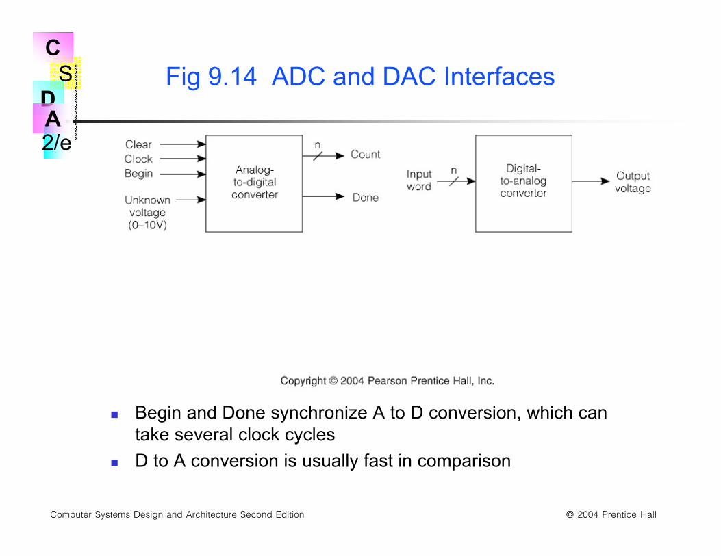
Fig 9.14 ADC and DAC Interfaces
Begin and Done synchronize A to D conversion, which cantake several clock cycles
D to A conversion is usually fast in comparison
S
2/e
C
DA
Computer Systems Design and Architecture Second Edition © 2004 Prentice Hall
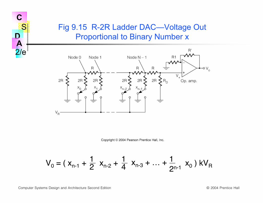
Fig 9.15 R-2R Ladder DAC—Voltage OutProportional to Binary Number x
V0 = ( xn-1 + 12 xn-2 +14 xn-3 + … + 1
2n-1 x0 ) kVR
S
2/e
C
DA
Computer Systems Design and Architecture Second Edition © 2004 Prentice Hall
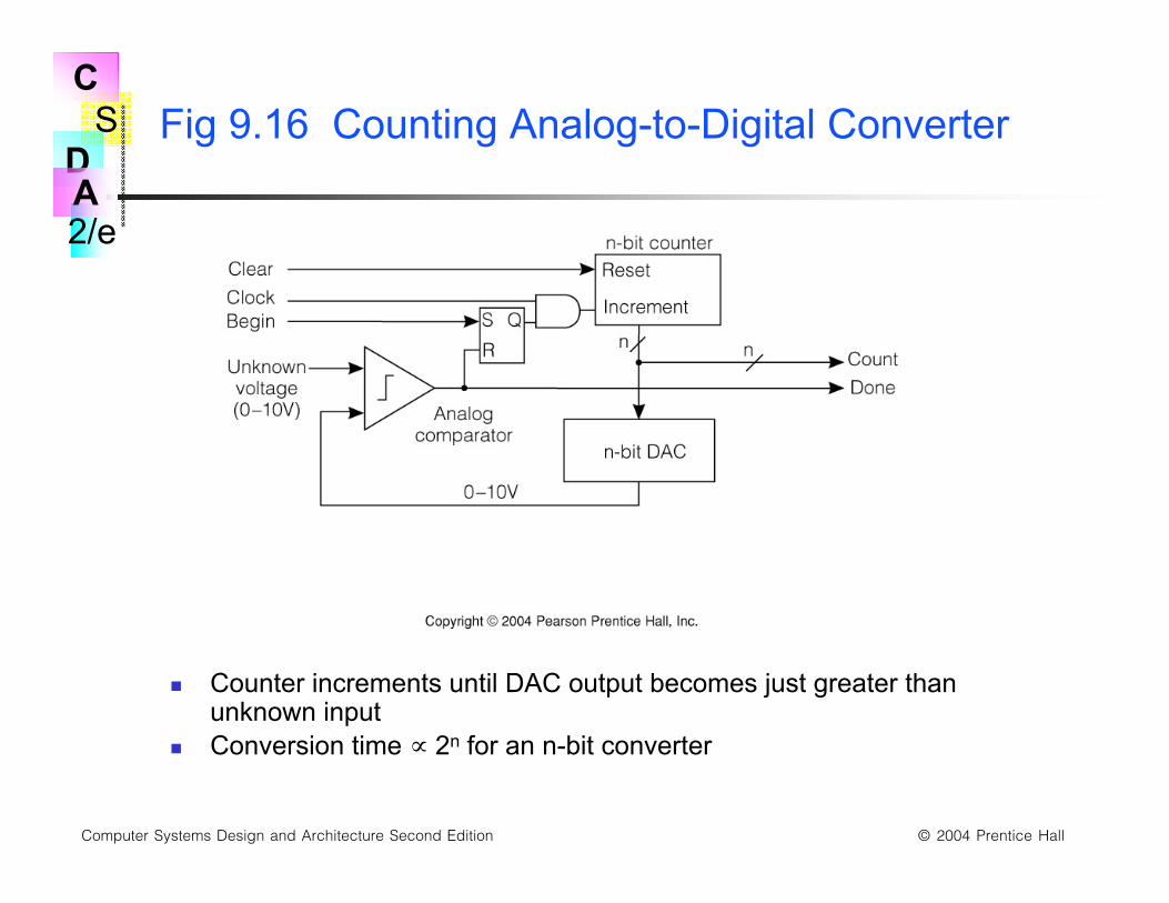
Fig 9.16 Counting Analog-to-Digital Converter
Counter increments until DAC output becomes just greater thanunknown input
Conversion time ∝ 2n for an n-bit converter
S
2/e
C
DA
Computer Systems Design and Architecture Second Edition © 2004 Prentice Hall
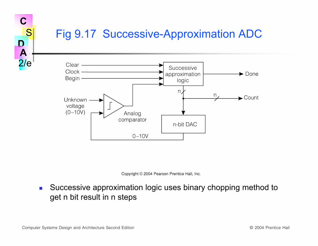
Fig 9.17 Successive-Approximation ADC
Successive approximation logic uses binary chopping method toget n bit result in n steps
S
2/e
C
DA
Computer Systems Design and Architecture Second Edition © 2004 Prentice Hall
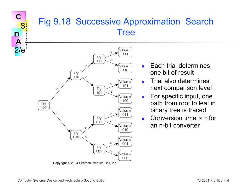
Fig 9.18 Successive Approximation SearchTree
Each trial determinesone bit of result
Trial also determinesnext comparison level
For specific input, onepath from root to leaf inbinary tree is traced
Conversion time ∝ n foran n-bit converter
S
2/e
C
DA
Computer Systems Design and Architecture Second Edition © 2004 Prentice Hall
Errors in ADC and DAC
Full scale error: voltage produced by all 1’s input in DAC orvoltage producing all 1’s in ADC
Offset error: DAC output voltage with all 0’s input
Missing codes: digital values that are never produced by anADC (skips over as voltage increased)
Lack of monotonicity:DAC monotonicity means voltage alwaysincreases as value increases
Quantization error: always present in DAC or ADC as atheoretical result of conversion process
S
2/e
C
DA
Computer Systems Design and Architecture Second Edition © 2004 Prentice Hall
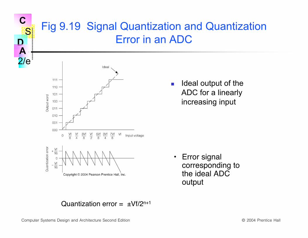
Fig 9.19 Signal Quantization and QuantizationError in an ADC
Ideal output of theADC for a linearlyincreasing input
• Error signalcorresponding tothe ideal ADCoutput
Quantization error = ±Vf/2n+1
S
2/e
C
DA
Computer Systems Design and Architecture Second Edition © 2004 Prentice Hall
Chapter 9 Recap
Structure and characteristics of moving magnetic media storage,especially disks
Display devices: Analog monitor characteristics
Video display terminals
Memory mapped video displays
Printers: dot matrix, laser, & ink jet
Manual input devices: keyboards & mice
Digital to analog and analog to digital conversion
Related Documents