CRISTAL-FLO TM HIGH RATE SAND FILTERS O W N E R’ S M A N U A L INSTALLATION, OPERATION & PARTS MODELS T-150BP-1 T-170BP-1 T-200BP-1 T-240BP-1 T-300BP-2 Sta-Rite Pool/Spa Group © 2005, Sta-Rite Industries This manual should be furnished to the end user of this filter; its use will reduce service calls and chance of injury and will lengthen filter life. 729 0294 Pentair Pool Products, Inc. 1620 Hawkins Ave. Sanford, NC 27330 Tel 919-774-4151 • Fax 919-774-4841 S242 (Rev. B 6/28/06)

Welcome message from author
This document is posted to help you gain knowledge. Please leave a comment to let me know what you think about it! Share it to your friends and learn new things together.
Transcript

CRISTAL-FLOTM
HIGH RATE SAND FILTERSO W N E R ’ S M A N U A L
INSTALLATION, OPERATION & PARTS
MODELST-150BP-1 T-170BP-1 T-200BP-1 T-240BP-1 T-300BP-2
Sta-Rite Pool/Spa Group
293 Wright Street, Delavan, WI 53115International: 262-728-5551, FAX: 262-728-7550www.starite.comUnion City, TN • Delavan, WI • Mississauga, ON
© 2005, Sta-Rite Industries S242 (Rev. 12/2/05)
This manual should be furnished tothe end user of this filter; its use willreduce service calls and chance ofinjury and will lengthen filter life.
RECIRCULATE
BA
C
KW
AS
H
E
W
AS
TE
FILTER
Aquatools.WATERFORD, WI.
53185USA
729 0294
Pentair Pool Products, Inc.1620 Hawkins Ave.Sanford, NC 27330Tel 919-774-4151 • Fax 919-774-4841
S242 (Rev. B 6/28/06)
2
HIGH RATE SAND FILTERSTo avoid unneeded service calls, prevent possible injuries, and get the mostout of your filter, READ THIS MANUAL CAREFULLY!
The Sta-Rite Top Mounted Series High Rate Sand Filter:• Is designed to filter water for swimming pools.• Is an excellent performer; durable, reliable.
Table of ContentsSafety Instructions .....................................................................................2-3Dimensions/Specifications ............................................................................4General Information .....................................................................................5Installation ................................................................................................5-7
Filter Mount/Piping....................................................................................5Filter Set-up...............................................................................................6Loading Sand Media..................................................................................6Valve Installation .......................................................................................6Startup/Operation ......................................................................................7
Maintenance ................................................................................................8Water Maintenance ...................................................................................8
Storage/Winterizing .................................................................................8-10Mult-Port Valve Service .............................................................................9Drain Fitting Installation/Removal ............................................................10
Troubleshooting Guide................................................................................11Repair Parts List .....................................................................................12-13Pressure Drop Curve...................................................................................14Warranty ....................................................................................................15
READ AND FOLLOW SAFETYINSTRUCTIONS!
This is the safety-alert symbol. When you see this symbol on your valveor in this manual, look for one of the following signal words and be alert to thepotential for personal injury.
warns about hazards that will cause serious personal injury,death or major property damage if ignored.
warns about hazards that can cause serious personal injury,death or major property damage if ignored.
warns about hazards that will or can cause minor personal in-jury or property damage if ignored.
The label NOTICE indicates special instructions which are important but notrelated to hazards.
Carefully read and follow all safety instructions in this manual and on filter.
Keep safety labels in good condition.Replace missing or damaged safety labels.
3
Incorrectly installed or tested equipment may fail, causing se-vere injury or property damage. Read and follow instructionsin owner's manual when installing and operating equipment.Have a trained pool professional perform all pressure tests.
1. Do not connect system to a high pressure or city water system.
2. Use equipment only in a swimming pool installation.
3. Trapped air in system can cause explosion. BE SURE all air is out of systembefore operating or testing equipment.
Before pressure testing, make the following safety checks:
• Check all clamps, bolts, lids, and system accessories before testing.
• BE SURE all air is out of system before testing.
• Tighten Sta-Rite trap lids to 30 ft. lbs. (4.1 kg-cm) torque for testing.
• Water pressure for test must be less than 25 PSI (172 kPa).
• Water temperature for test must be less than 95˚ F. (35˚ C).
• Limit test to 24 hours. After test, visually check system to be sure it is readyfor operation. Remove trap lid and retighten hand tight only.
NOTICE: These parameters apply to Sta-Rite equipment only. For non-Sta-Rite equipment, consult manufacturer.
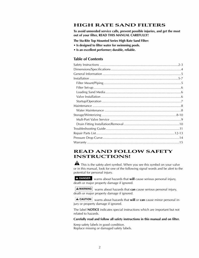
Hazardous Pressure!Can cause severe injury or major property damage fromtank explosion.
BEFORE WORKINGON FILTER:
1. Stop pump.
2. Open air releasevalve.
3. Release all pressurefrom system.
Filter pumps requirehazardous voltagewhich can shock, burn,or cause death.
BEFORE WORKINGON PUMP OR MOTOR
Disconnect power tomotor.

4
See Page 14 for Pressure Drop Curve.
RECOMMENDED SAND GRADES:
Use only: #20 Silica Sand, Size Range .40-.55mm., Uniformity Coefficient lessthan 1.75.
NOTICE: Use of other sands will reduce filter performance, may damagepump, and will void warranty.
Recommended:1. Wedron Silica/Best Sand Co., Sand Grade: Wedron .45-.55mm., Effective
Size .46mm, Uniformity Coefficient 1.22.2. U.S. Silica - Silurian Filter Sand, Sand Grade.45-.55 mm., Effective Size
.48mm, Uniformity Coefficient 1.18.
Max.Filter Filter Flow RateModel Size in GPM (L/M)
Dia. in Area in Ft2
Inches (mm) (M2)T-150BP-1 15 (381) 1.26 (.117) 25.2 (95)T-170BP-1 17 (432) 1.57 (.146) 31.5 (123)T-200BP-1 20 (508) 2.18 (.203) 43.6 (165)T-240BP-1 24 (610) 3.10 (.288) 62.0 (234.7)T-240BP-2 24 (610) 3.10 (.288) 62.0 (234.7)T-300BP-2 30 (762) 4.90 (.455) 98 (371)
Turnover in Hours SandFilter VolumeModel 6 8 10 12 in lbs. (kg.)
gal. (L) gal. (L) gal. (L) gal. (L)
T-150BP-1 9,070(34 330) 12,100(45 799) 15,120(57 229) 18,144(68 675) 100 (45.4)
T-170BP-1 11,340(42 922) 15,120(57 229) 18,900(71 536) 22,680(85 844) 150 (68)
T-200BP-1 15,700(59 424) 20,930(79 220) 26,160(99 016) 31,390(118 811) 200 (90.7)
T-240BP-1 22,230(84 481) 29,760(112 642) 37,200(140 802) 44,640(168 962) 300 (136)
T-240BP-2 22,230(84 481) 29,760(112 642) 37,200(140 802) 44,640(168 962) 300 (136)
T-300BP-2 35,280(133 535) 47,040(178 046) 58,800(222 558) 70,560(267 070) 600 (272)
Base Base PipingWidth Length Port
Filter Model No. A B C D (E) (F) Size
T-150BP-1 27 (686) 33-13/16 (859) 15-3/4 (400) 24-11/16 (627) 13 (330) 16-1/4 (413) 1-1/2” SLIPT-170BP-1 29-9/16 (751) 36-3/8 (924) 17-3/4 (451) 27-1/4 (692) 13 (330) 16-1/4 (413) 1-1/2” SLIPT-200BP-1 31-5/8 (803) 38-1/2 (978) 20-3/4 (527) 29-3/8 (746) 13 (330) 16-1/4 (413) 1-1/2” SLIPT-240BP-1 35-3/16 (897) 42 (1067) 24-3/4 (629) 32-7/8 (835) 16-7/8 (429) 21 (533) 1-1/2” SLIPT-240BP-2 35-1/4 (895) 44-1/2 (1130) 24-3/4 (629) 32-7/8 (835) 16-7/8 (429) 21 (533) 2” (NPT)T-300BP-2 42 (1067) 51-1/4 (1302) 31 (787) 39-5/8 (1008) 16-7/8 (429) 21 (533) 2” (NPT)
TABLE I - FILTER OPERATIONAL DATA
TABLE II - DIMENSIONAL DATA In Inches (mm)
*NOTE: 1 cubic foot of sand weighs approx. 100 lbs. (45.4 kg). Do not use finer orcoarser grade than recommended for best performance.
CDia. B
AD
2.88 (73)
Pump Inlet 1-1/2"
Waste Outlet 1-1/2"Union connection
Return Outlet1-1/2" Slip
E,F1355 1094
C
D
A
B
9.25 (235)
2" NPT Outlet(Waste)
2" NPT Inlet(Pump)
2" NPT Outlet(Return)
E,F
8.00(203)1356 1094
Fig. 1: Dimensions, T-150BP-1,T-170BP-1 T-200BP-1, T240BP-1
Fig. 2: Dimensions, T-300BP-2, T240BP-2

5
GENERAL INFORMATION• Clean a new pool as well as possible before filling pool and operating filter.
Excess dirt and large particles of foreign matter in the system can cause seriousdamage to the filter and pump.
NEVER test this filter with compressed air.
Do not operate filter at water temperatures above 95°F (35°C).
NEVER operate this filter system at more than 50 pounds per square inch(50 PSI/345 kPa) pressure!
INSTALLATIONInstallation of filter should only be done by qualified, licensed personnel.For assembly and filling instructions, see page 6.
Filter mount must:• Provide weather and freezing protection.• Provide space and lighting for easy access for routine maintenance. (See
Figures 1 and 2, Table II, Page 4, for space requirements.)• Be on a reasonably level surface and provide adequate drainage.• Be as close to pool as possible to reduce line loss from pipe friction.
Piping:• Piping must conform to local/state plumbing and sanitary codes.• Use pipe joint sealing compound or teflon tape on all male connections of
metal pipe and fittings (except unions). Use teflon tape or Plasto-Joint Stik1 onall male connections of plastic pipe and fittings. DO NOT use pipe dope onplastic pipe; it will cause the pipe to crack. Do not use sealant or tape onunions – assemble them dry and hand tight.
• Do not damage union sealing surfaces and “O” Rings.• Support pipe independently to prevent strains on filter or valve.• Use 1-1/2 or 2” pipe to reduce pressure losses as much as possible.
NOTICE: Filter may be located away from pool, but for adequate flow largerpipe may be needed. Check local codes when considering remote installation.
• Fittings restrict flow; for best efficiency use fewest possible fittings.• Keep piping tight and free of leaks: pump suction line leaks may cause trapped
air in filter tank or loss of prime at pump; pump discharge line leaks may showup as dampness or jets of water.
• When unions are provided, use as follows for leak free connections:1. O-Ring and sealing surfaces must be clean.2. Assemble hand tight only (no wrenches).3. No pipe compound or teflon tape on unions.
Valves:• A check valve installed between filter and heater will prevent hot water from
backing up into filter and deforming internal components.
• Use care before assembly not to damage union sealing surfaces or O Ring.
Wastewater:• Be sure all provisions for waste water disposal meet applicable local, state or
national codes. 100 gallons (379 liters) or more of pool water will be dis-charged during filter backwashing. Do not discharge where water will causeflooding or damage.
1 Lake Chemical Co., Chicago, IL

6
Filter SetupAssembly: See Figures 2 through 5 for filter assembly.
Loading Sand Media1.To keep sand out of collector assembly, place plastic sand shield over top
of collector tube before pouring sand into filter (See Figure 5).
2.To support laterals and prevent lateral breakage during loading, fill tankabout half full of water before loading sand.
3.Pour sand into filter tank. See Page 4, for correct type and quantity of sandto use.
NOTICE: Make sure gasket area on top of tank is free of sand before in-stalling valve and clamp.
4.Before installing valve, double-check that correct quantity of sand hasbeen loaded (see Page 4).
5.Remove plastic sand loading shield and keep for future use.
Valve Installation:See Figures 6, 7, and 8
1. Install O-Ring on valve flange; make sure O-Ring is clean, dry, and hasno nicks, tears, or scrapes.
2. Make sure tank and valve flanges are clean and free of sand; put valveon top of tank. Vertical pipe of collector assembly inserts into base ofvalve.
3.Install clamp; make sure knob is positioned for easy access for filtermaintenance. Valve port labeled “PUMP” should point toward pump.
4.Tighten clamp knob until clamp ends (under bolt) are 1/4” (6mm) apart.Tap around outside of clamp with a mallet to help seat clamp.
Hazardous pressure. Clamp will not hold unless it isseated properly! DO NOT START PUMP until clamp ends are 1/4”(6mm) apart or less.
5.If clamp will not pull up to 1/4” (6mm) gap, wait 15-30 minutes andretighten. Tap clamp gently with mallet to help seat clamp.
6.Connect pipe from pump discharge to valve port labeled “PUMP”; useunion half provided. Assemble union as follows for leakfree operation:A. O-Ring and sealing surfaces must be clean.B. Assemble hand tight only (no wrenches).C. NO pipe compound or teflon tape on unions.
7.Complete all plumbing connections (see Page 5 for piping require-ments).A. Pipe from valve RETURN port to pool return.B. Pipe from valve WASTE port to waste.C. Suction piping from pool to trap inlet on pump.
8.System is ready for startup.NOTICE: If there are leaks from beneath valve/clamp area, STOPPUMP, release all pressure, remove clamp and valve and clean sealingsurfaces.
B. Insert assembly into top of filter tank.
A. Insert first lateral into socket; twist clockwise 1/4 turn to lock lateral into hub. Lateral is correctly installed when slots face down.
731 0294
C. Hold assembly up near top of tank and add remaining laterals.
732 0294
D. After all laterals are securely in sockets, position assembly on centering boss in bottom of tank.
733 0294
SAND
::::::::::::::::::::::::::::::::::::::::::::::::
::::::::::::::::::::::::
::::
::::
::::
::::
::::
::::
::::
::::
::::
::::
::::
::::
::::
::::
::::
::::
::::
::::
::::
::::
:::: ::::
::::
:::: ::::
::::
:::: ::::
::::
::::
::::
::::
:::::::
::::
::::
::::
::::
::::
::::
::::
::::
:
::::
::::
::::
::::
::::
::::
::::
::::
::::::::
::::
:::: ::
:::::
::::
::::
::::
::::
: ::::
::::
:::: ::::
::::
::::
::::
::::
::::
::::
::::
:::: ::::
::::
::::
::::
::::
::::
::::
::::
::::
::::
::::
:::: ::::
::::
::::
::::
::::
::::
::::
::::
::::
:::::::::::::::::::::::: ::::::::::::::::
::::
::::
::::
::::
::::
::::
::::
::::
::::
::::
::::::::
::::
::::
::::
::::
::::
::::
::::
::::
::::
::::
::::::::
::::
::::
::::
::::
:::: :::
::::
::::
: ::::
::::
:::: ::::
::::
::::
::::
::::
:::: :::
::::
::::
: ::::
::::
::::
::::
::::
::::
::::
::::
::::
::::
::::
:::: :::
::::
::::
:
::::
::::
::::
Fill tank abouthalf full of waterbeforeaddingsand.
Sand Shieldkeeps collectorhub assembly clean whenloading filter.
734 0294
Fig. 2
Fig. 3
Fig. 4
Fig. 5
7
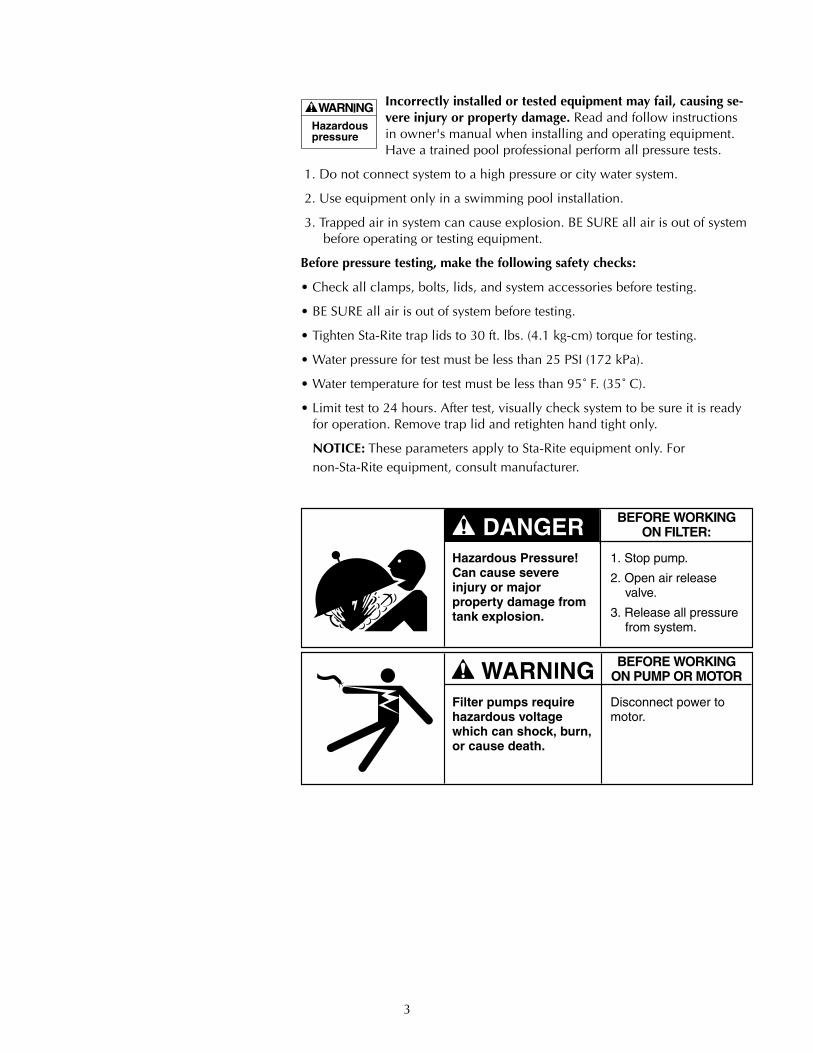
Startup/Operation (See Figure 9)
Hazardous pressure. To avoid explosion and possible se-vere or fatal injury, filter system pressure must not exceed 50 PSI (345kPa) under any circumstances. NEVER test this filter system with com-pressed air; never operate system with water temperature above 95° F(35° C).
To prevent equipment damage and possible injury, turnpump OFF before changing valve position.
NOTICE: Do not add chemicals directly into the pool skimmer. Addingundiluted chemicals may damage equipment and void warranty.
1. Open system valves and make sure pump is filled with water. Makesure pool water level is 2” (51mm) above bottom of skimmer open-ing.
2. With pump OFF, set valve to ‘BACKWASH’ position.
3. Start pump, circulating water backwards through filter to waste. Donot install pressure gauge until a steady stream of water runs out ofgauge port; then stop pump and install gauge.
NOTICE: To prevent pump from running dry, be sure water levelnever drops below bottom of skimmer inlet. Add water to pool if necessary to keep skimmer flooded while backwashing and rinsing.
4. Backwash until water runs clear (3-5 minutes).
5. Stop pump; set valve to ‘RINSE’ position.
6. Start pump; run pump for one minute.
7. Stop pump; set valve to ‘FILTER’ position.
8. Filter is now ready for service.
9. Record clean starting filter pressure gauge reading as a reference.
10. When pool is first filled, backwash once a day until pool water issparkling clear. After that, backwash when pressure gauge shows 5 to7 PSI (34.5 to 48 kPa) higher than starting pressure.
RREECCIIRRCCUULLAATTEE
BBAA
CCKK
WWAA
SSHH
EE
WWAA
SSTTEE
FFIILLTTEERR
1. Install O-Ring on valve flange.
2. Install valve on tank. Tank flange must be clean; insert collector pipe into bottom of valve.
Delavan, WI.53115USA
1/4" Max.
Port labeled"PUMP" shouldpoint towardpump.
Install clampand tightenuntil clampends (underbolt) are 1/4" apart.
If unable toclose gapto 1/4" or less, wait 15-30 minutes and retighten.
Tap around clamp while tightening to help seat clamp.
.WATERFORD, WI.53185USA
736 0294
RREECCIIRRCCUULLAATTEE
BBAA
CCKK
WWAA
SSHH
EE
WWAA
SSTTEE
FFIILLTTEERR
Fig. 6
Fig. 7
RE
CIR
CU
LAT
E
BACKWASHCLOSED
WIN
TE
RIZ
EW
AST
E
FILTER
RINSE
Valve Setting Purpose/Flow
FILTERNormal filtration and vacuuming; water goes through filter to pool.
RINSEFor initial startup cleaning and sand bed leveling after backwash; water goes through filter to waste.
RECIRCULATECirculates pool water; bypasses filter.
RE
CIR
CU
LAT
E
BACKWASHCLOSED
WIN
TE
RIZ
EW
AST
E
FILTERRINSE
RE
CI R
CU
LATE
BACKWASH
CLOSED
WIN
TE
RIZ
E
WASTE
FILTER
RIN
SE
737 029
BACKWASHReverses flow for cleaning; watergoes through filterto waste.
CLOSEDShuts off all flow tofilter and pool.
WINTERIZELeaves all valve portspartially open forwinter storage.
RE
CIR
CU
LA
TE
BACKWASHCLOSED
WIN
TE
RIZ
E
WASTE
FILTER
RIN
SE
Valve Setting Purpose/Flow
RE
CIR
CU
LA
TE
BACKWASHCLOSEDW
INT
ER
IZE
WASTE
FILTER
RIN
SE
RE
CI R
CU
LAT
E
BACKWASHCLOSED
WIN
TER
IZE
WASTE
FILTER
RINS
E
738 029
WASTELowers pool level ordrains pool; waterbypasses filter, goes to waste.
Valve Setting Purpose/Flow
RE
CIR
CU
LA
TE
BACKWASHCLOSED
WIN
TE
RIZ
EW
ASTEFILTER
RIN
SE
743 0294
Fig. 8
RE
CIR
CU
LAT
E
BACKWASHCLOSED
WIN
TE
RIZ
E
WASTE
FILTER
RINS
E
g
RE
CIR
CU
LA
TE
BACKWASHCLOSED
WIN
TE
RIZ
EW
AST
E
FILTERRINSE
RE
CIR
CU
LAT
E
BACKWASHCLOSED
WIN
TER
IZE
WA
STE
FILTER
RINS
E
Fig. 9: Valve settings for startup. Stoppump before changing valve position.

8
MAINTENANCEGeneral:• Wash outside of filter with a mild detergent and water. Rinse off with hose.
NOTICE: DO NOT use solvents to clean filter; solvents may damage plasticcomponents in system.
• Inspect sand bed at least once a year to remove foreign material which has notbeen backwashed out of system.NOTICE: When the sand bed gets hard and crusty on top, remove all the oldsand and replace it with new sand.
Weekly Pool Equipment Inspection:1. Check pressure during operation. When pressure is 5 to 7 PSI (34.5 to 48
kPa) higher than initial operating pressure, backwash filter (see instructionsunder “Startup/Operation”, Page 7).
2. Except during hot weather with heavy swimmer loads, operating filter 6 to 12hours per day should be sufficient. Carefully monitor water chemical balanceand follow recommendations of your local pool professional.
Water Maintenance• Keep water level at least 2” (51mm) above bottom of skimmer opening.
Failure to do so can allow air to enter system, causing pump to lose primeand air to enter filter.
• Maintain pH at 7.2 to 7.6 in pool.
To prevent damage to system components, keep water temperature below95° F. (35° C) at all times.
Vacuum Pool:1. Fill vacuum hose by submerging in water from one end to the other.2. To vacuum, insert hose into skimmer suction manifold or into vacuum line
in pool wall. See instructions provided by pool builder or pool manufac-turer. Start pump, making sure it is primed and pumping.
3. After vacuuming, clean pump trap to remove accumulated debris, thencheck filter pressure gage. If reading is 5 to 7 PSI (34.5 to 48 kPa) higherthan initial operating pressure, backwash filter.
Lower or Drain Pool1. Turn pump ‘OFF’; set valve handle to ‘WASTE’.2. Use vacuum cleaner hose and head.3. Start pump; run until pool is lowered to desired level.4. Turn pump ‘OFF’; set valve handle to ‘FILTER’.5. Start pump.
STORAGE/WINTERIZINGPool chemicals may give off corrosive fumes. Store chemicals
away from system in a well ventilated area.NOTICE: Allowing water to freeze will damage filter and void warranty. If an-tifreeze is needed, use propylene glycol; it’s plastic compatible and non-toxic.Follow manufacturers instructions. Do not use ethylene glycol based anti-freeze – it’s toxic and it may damage plastic components.1. Open all system valves. Set multiport valve at ‘WINTERIZE’ to allow air pas-
sage to all ports.
RE
CIR
CU
LAT
E
BACKWASHCLOSED
WIN
TER
IZE
WASTE
FILTER
RINS
ER
EC
IRC
ULA
TE
BACKWASHCLOSED
WIN
TER
IZE
WAS
TE
FILTER
RINSE
Fig. 10: Valve settings to lowerpool water level. Stop pumpbefore changing valve position.
RE
CI R
CU
LAT
E
BACKWASHCLOSED
WIN
TE
RIZ
E
WASTE
FILTER
RINSE
Fig. 11: Valve setting for winterstorage. Stop pump beforechanging valve position.
9
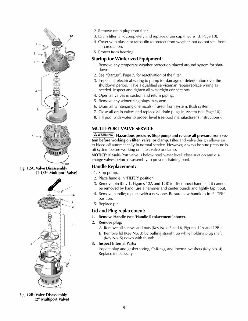
2. Remove drain plug from filter.3. Drain filter tank completely and replace drain cap (Figure 13, Page 10).4. Cover with plastic or tarpaulin to protect from weather, but do not seal from
air circulation.5. Protect from freezing.
Startup for Winterized Equipment:1. Remove any temporary weather protection placed around system for shut-
down.2. See “Startup”, Page 7, for reactivation of the filter.3. Inspect all electrical wiring to pump for damage or deterioration over the
shutdown period. Have a qualified serviceman repair/replace wiring asneeded. Inspect and tighten all watertight connections.
4. Open all valves in suction and return piping.5. Remove any winterizing plugs in system.6. Drain all winterizing chemicals (if used) from system; flush system.7. Close all drain valves and replace all drain plugs in system (see Page 10).8. Fill pool with water to proper level (see pool manufacturer’s instructions).
MULTI-PORT VALVE SERVICEHazardous pressure. Stop pump and release all pressure from sys-
tem before working on filter, valve, or clamp. Filter and valve design allows airto bleed off automatically in normal service. However, always be sure pressure isoff system before working on filter, valve or clamp.NOTICE: if Multi-Port valve is below pool water level, close suction and dis-charge valves before disassembly to prevent draining pool.
Handle Replacement:1. Stop pump.2. Place handle in ‘FILTER’ position.3. Remove pin (Key 1, Figures 12A and 12B) to disconnect handle. If it cannot
be removed by hand, use a hammer and center punch and lightly tap it out.4. Remove handle; replace with a new one. Be sure new handle is in ‘FILTER’
position.5. Replace pin.
Lid and Plug replacement:1. Remove Handle (see ‘Handle Replacement’ above).2. Remove plug:
A. Remove all screws and nuts (Key Nos. 2 and 6, Figures 12A and 12B).B. Remove lid (Key No. 3) by pulling straight up while holding plug shaft
(Key No. 5) down with thumb.3. Inspect Internal Parts:
Inspect plug and gasket spring, O-Rings, and internal washers (Key No. 4).Replace if necessary.
RECIRCULATE
BAC
KW
AS
H
CLO
SED
WINTERIZE
WA
ST
E
FILTERRINSE
1
1A
2
3
4
5
6
Aquatools.WATERFORD, WI.
53185USA
744 0294
Fig. 12A: Valve Disassembly (1-1/2” Multiport Valve)
Fig. 12B: Valve Disassembly (2” Multiport Valve)
1344 1094
1
1A
2
3
5
6
4
10
4. Reassemble Valve:A. Replace plug gasket and shaft, mounting spring, washers, and O-Ring on
plug shaft. Lubricate O-Ring with Amojel.B. Replace lid; match screw holes in lid and body.C. Press down on lid to allow screws to engage nuts; tighten each nut se-
curely.D. Replace top washer (Key No. 1A) and handle, making sure indexing pin
on plug shaft points in same direction as pointer on handle. Replace han-dle pin.
E. Tighten all lid screws to 55 inch-lbs. (63.4 kg-cm) torque.
Valve RemovalHazardous pressure. Stop pump and release all pressure from sys-
tem before working on filter, valve, or clamp.NOTICE: If multi-Port Valve is below pool water level, close suction and dis-charge valves before disassembly to prevent draining pool.1. Disconnect piping from pump and pool.2. Remove clamp.3. Remove valve from filter top.4. To reinstall valve, follow instructions, Figures 6 and 7, Page 7. BE SURE to
follow clamp tightening instructions.
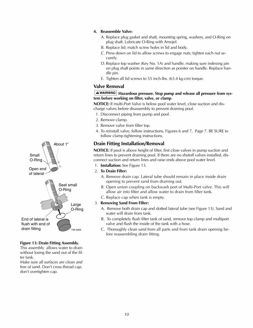
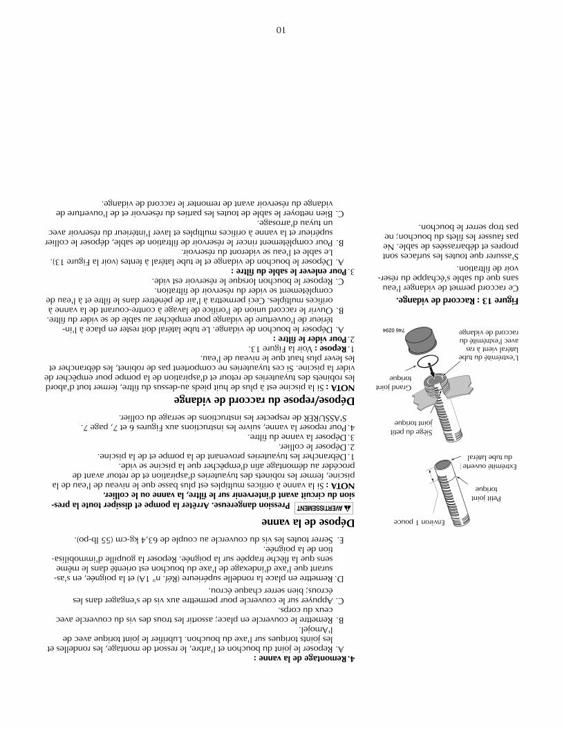
Drain Fitting Installation/RemovalNOTICE: If pool is above height of filter, first close valves in pump suction andreturn lines to prevent draining pool. If there are no shutoff valves installed, dis-connect suction and return lines and raise ends above pool water level.1. Installation: See Figure 13.2. To Drain Filter:
A. Remove drain cap. Lateral tube should remain in place inside drainopening to prevent sand from draining out.
B. Open union coupling on backwash port of Multi-Port valve. This willallow air into filter and allow water to drain from filter tank.
C. Replace cap when tank is empty.3. Removing Sand From Filter:
A. Remove both drain cap and slotted lateral tube (see Figure 13). Sand andwater will drain from tank.
B. To completely flush filter tank of sand, remove top clamp and multiportvalve and flush the inside of the tank with a hose.
C. Thoroughly clean sand from all parts and from tank drain opening be-fore reassembling drain fitting.
About 1"
SmallO-Ring
Open endof lateral
Seat smallO-Ring
LargeO-Ring
End of lateral isflush with end ofdrain fitting 746 0294
Figure 13: Drain Fitting Assembly.This assembly allows water to drainwithout losing the sand out of the fil-ter tank.Make sure all surfaces are clean andfree of sand. Don’t cross thread cap;don’t overtighten cap.
11
TROUBLESHOOTING GUIDE
1. Short Cycle between backwashes:NOTICE: Time between backwashes will vary with each installation and be-tween different areas of the country. Ask installer about normal backwash in-terval in your area. The following causes and remedies are for cycle timesshorter than normal for your area.A. Flow rate too high or filter too small; consult dealer for system sizing rec-
ommendations.B. Water is chemically out of balance; consult pool serviceman.C. Excess dirt/dust in pool; vacuum pool directly to waste.D. Body oil/lotion build-up in filter; consult dealer for chemical filter clean-
ers and follow cleaner manufacturer’s instructions.E. Filter inadequately backwashed. See instructions under
“Startup/Operation”, Page 7.F. Algae in pool. Consult pool professional about proper chemical mainte-
nance.G. Residual chlorine level too low. Consult pool professional about proper
chemical maintenance.H. Inspect filter sand for solidification caused by dust, calcium, skin oils, of
suntan lotions.
2. Low Flow:A. Pipe blocked downstream from filter; remove obstruction.B. Piping too small; use larger pipe (consult dealer for sizing).C. Plugged pump; plugged hair and lint trap or skimmer basket. Clean thor-
oughly.
3. Pool Water Not Clear:A. Water is chemically out of balance; consult pool professional.B. Filter is too small; consult dealer about equipment sizing.C. Sand in pool means broken lateral. Drain both water and sand out of
tank. Remove valve; follow procedure under “Filter Setup”, Page 6, andinstructions with new lateral to replace broken part.
To avoid severe injury or major property damage, followinstructions under 'Valve Installation', Figures 6 and 7, Page 7).1. Follow valve removal procedure, Page 10.2. Replace lateral according to instructions supplied with new lateral.3. Reassemble filter according to instructions under “Filter Setup”, Page 6.
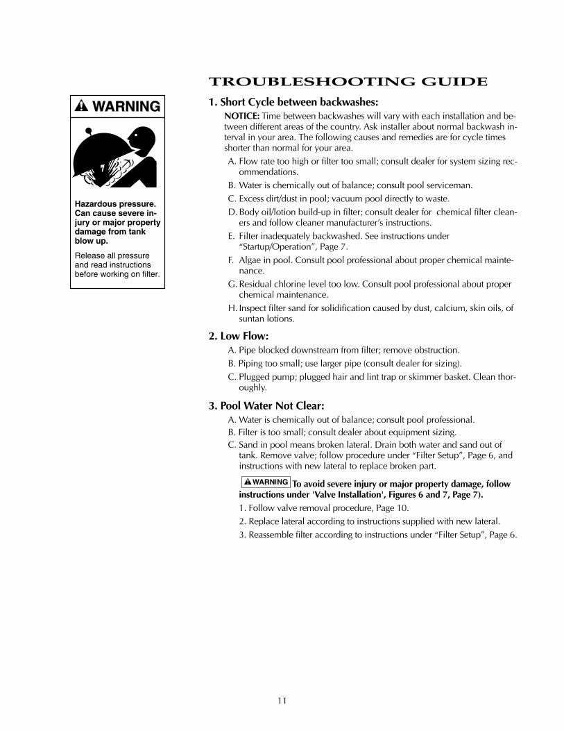
Hazardous pressure.Can cause severe in-jury or major propertydamage from tankblow up.
Release all pressureand read instructionsbefore working on filter.
RECIRCULATE
BAC
KW
AS
H
E
W
AS
TE
FILTER
Aquatools.WATERFORD, WI.
53185USA
1
2
3A3
4
5
6
7
8
9
10
11
12
13
757 0294
Model
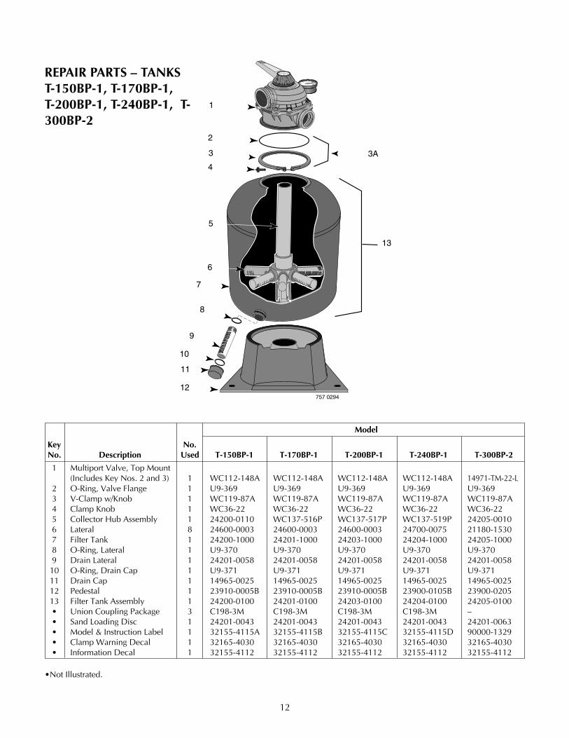
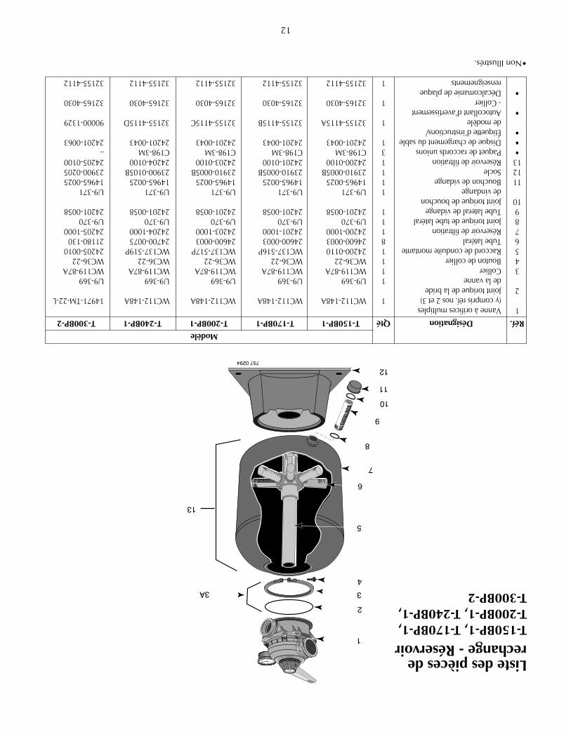
Key No.No. Description Used T-150BP-1 T-170BP-1 T-200BP-1 T-240BP-1 T-300BP-2
1 Multiport Valve, Top Mount(Includes Key Nos. 2 and 3) 1 WC112-148A WC112-148A WC112-148A WC112-148A 14971-TM-22-L
2 O-Ring, Valve Flange 1 U9-369 U9-369 U9-369 U9-369 U9-3693 V-Clamp w/Knob 1 WC119-87A WC119-87A WC119-87A WC119-87A WC119-87A4 Clamp Knob 1 WC36-22 WC36-22 WC36-22 WC36-22 WC36-225 Collector Hub Assembly 1 24200-0110 WC137-516P WC137-517P WC137-519P 24205-00106 Lateral 8 24600-0003 24600-0003 24600-0003 24700-0075 21180-15307 Filter Tank 1 24200-1000 24201-1000 24203-1000 24204-1000 24205-10008 O-Ring, Lateral 1 U9-370 U9-370 U9-370 U9-370 U9-3709 Drain Lateral 1 24201-0058 24201-0058 24201-0058 24201-0058 24201-005810 O-Ring, Drain Cap 1 U9-371 U9-371 U9-371 U9-371 U9-37111 Drain Cap 1 14965-0025 14965-0025 14965-0025 14965-0025 14965-002512 Pedestal 1 23910-0005B 23910-0005B 23910-0005B 23900-0105B 23900-020513 Filter Tank Assembly 1 24200-0100 24201-0100 24203-0100 24204-0100 24205-0100• Union Coupling Package 3 C198-3M C198-3M C198-3M C198-3M –• Sand Loading Disc 1 24201-0043 24201-0043 24201-0043 24201-0043 24201-0063• Model & Instruction Label 1 32155-4115A 32155-4115B 32155-4115C 32155-4115D 90000-1329• Clamp Warning Decal 1 32165-4030 32165-4030 32165-4030 32165-4030 32165-4030• Information Decal 1 32155-4112 32155-4112 32155-4112 32155-4112 32155-4112
•Not Illustrated.
12
REPAIR PARTS – TANKST-150BP-1, T-170BP-1,T-200BP-1, T-240BP-1, T-300BP-2

13
2
34
7
12
12A
9A
10
8
13
14
18
19
17
6
15
16
11
1343 1094
14
15
16
RECIRCULATE
BAC
KWASH
CLOSED
WINTERIZE
WASTE
FILTER
RINSE
1
2
3
45
6
7
89A
10
11
9B
13
12
REPAIR PARTS – MULTI-PORT VALVES
WC112-148A #14971-TM-22-L
Key PartNo. Description Qty. WC112-148A 14971-TM-22-L1 Valve Handle Decal 1 14965-0021 ––2 Handle 1 14962-0032 14971-SM10E13 Dowel Pin 1 35857-0021 14971-SM10E24 Washer 1 14965-0007 14971-SM10E35 Operating Instruction Decal 1 14965-0020 ––6 Screw 37337-3056(7) 14971-SM10E4(10)7 Valve Cover 1 14965-0011 14971-SM20E68 O-Ring 1 35505-1228 14971-SM10E10
9A Washer 2 14965-0007 14971-SM10E89B Washer 1 14965-0007 ––10 Spring 1 14965-0006 14971-SM10E911 Pressure Guage 1 15060-0000T 15060-0000T12 Plug & Gasket Assembly 1 14965-0028 14971-SM20E11
12A Gasket 1 –– 14971-SM20E1213 Cover O-Ring 1 35505-1275 14971-SM20E714 Valve Body Assembly 1 14965-0013 14971-SM20E1315 Nut 35407-0071(7) 14971-SM10E14(10)16 Tank Flange O-Ring 1 U9-369 U9-36917 Sight Glass Gasket 1 –– 14971-SM20E1718 Sight Glass 1 –– 14971-SM10E1619 Stand Pipe O-Ring (EPDM) 1 –– 35505-1243

14
0 20 40 60 80 100 120
2
4
6
8
10
12
14
16
Capacity (GPM)
P.S
.I.Lo
ss
T-150BP-1
T-170BP-1,T-200BP-1
T-300BP-2
T-240BP-1
Figure 14 – Pressure Drop Curve - Filter Position
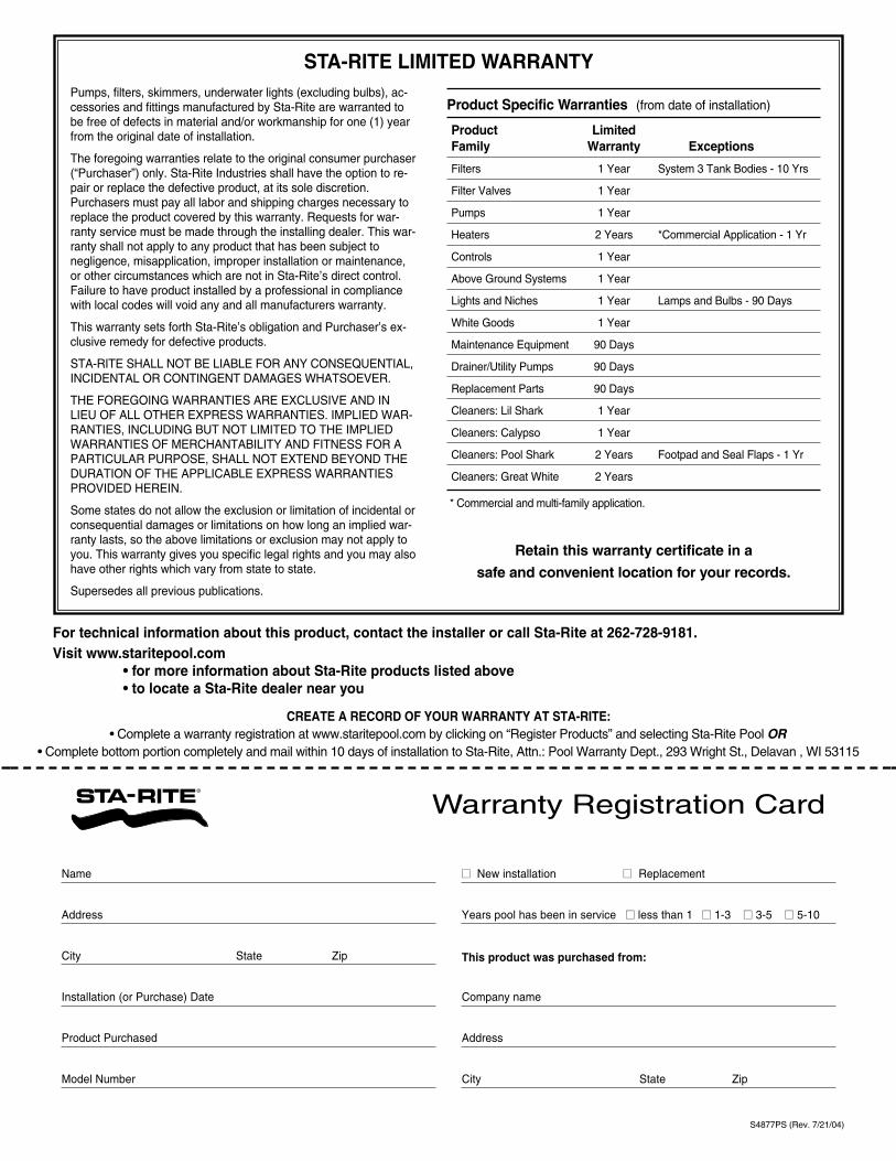
CREATE A RECORD OF YOUR WARRANTY AT STA-RITE:• Complete a warranty registration at www.staritepool.com by clicking on “Register Products” and selecting Sta-Rite Pool OR
• Complete bottom portion completely and mail within 10 days of installation to Sta-Rite, Attn.: Pool Warranty Dept., 293 Wright St., Delavan , WI 53115
Warranty Registration Card
Name
Address
City State Zip
Installation (or Purchase) Date
Product Purchased
Model Number
�� New installation �� Replacement
Years pool has been in service �� less than 1 �� 1-3 �� 3-5 �� 5-10
This product was purchased from:
Company name
Address
City State Zip
STA-RITE LIMITED WARRANTY
For technical information about this product, contact the installer or call Sta-Rite at 262-728-9181.Visit www.staritepool.com
• for more information about Sta-Rite products listed above• to locate a Sta-Rite dealer near you
Product Specific Warranties (from date of installation)
Product Limited Family Warranty Exceptions
Filters 1 Year System 3 Tank Bodies - 10 Yrs
Filter Valves 1 Year
Pumps 1 Year
Heaters 2 Years *Commercial Application - 1 Yr
Controls 1 Year
Above Ground Systems 1 Year
Lights and Niches 1 Year Lamps and Bulbs - 90 Days
White Goods 1 Year
Maintenance Equipment 90 Days
Drainer/Utility Pumps 90 Days
Replacement Parts 90 Days
Cleaners: Lil Shark 1 Year
Cleaners: Calypso 1 Year
Cleaners: Pool Shark 2 Years Footpad and Seal Flaps - 1 Yr
Cleaners: Great White 2 Years
* Commercial and multi-family application.
Retain this warranty certificate in a
safe and convenient location for your records.
Pumps, filters, skimmers, underwater lights (excluding bulbs), ac-cessories and fittings manufactured by Sta-Rite are warranted tobe free of defects in material and/or workmanship for one (1) yearfrom the original date of installation.
The foregoing warranties relate to the original consumer purchaser(“Purchaser”) only. Sta-Rite Industries shall have the option to re-pair or replace the defective product, at its sole discretion.Purchasers must pay all labor and shipping charges necessary toreplace the product covered by this warranty. Requests for war-ranty service must be made through the installing dealer. This war-ranty shall not apply to any product that has been subject tonegligence, misapplication, improper installation or maintenance,or other circumstances which are not in Sta-Rite’s direct control.Failure to have product installed by a professional in compliancewith local codes will void any and all manufacturers warranty.
This warranty sets forth Sta-Rite’s obligation and Purchaser’s ex-clusive remedy for defective products.
STA-RITE SHALL NOT BE LIABLE FOR ANY CONSEQUENTIAL,INCIDENTAL OR CONTINGENT DAMAGES WHATSOEVER.
THE FOREGOING WARRANTIES ARE EXCLUSIVE AND INLIEU OF ALL OTHER EXPRESS WARRANTIES. IMPLIED WAR-RANTIES, INCLUDING BUT NOT LIMITED TO THE IMPLIEDWARRANTIES OF MERCHANTABILITY AND FITNESS FOR APARTICULAR PURPOSE, SHALL NOT EXTEND BEYOND THEDURATION OF THE APPLICABLE EXPRESS WARRANTIESPROVIDED HEREIN.
Some states do not allow the exclusion or limitation of incidental orconsequential damages or limitations on how long an implied war-ranty lasts, so the above limitations or exclusion may not apply toyou. This warranty gives you specific legal rights and you may alsohave other rights which vary from state to state.
Supersedes all previous publications.
S4877PS (Rev. 7/21/04)


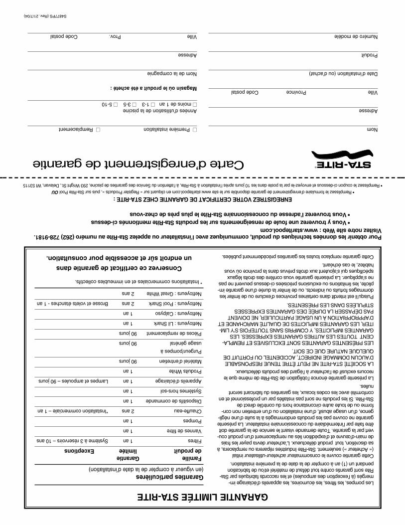
ENREGISTREZVOTRECERTIFICATDEGARANTIECHEZSTA-RITE:•Remplissezleformulaired’enregistrementdegarantiedisponiblesurlesitewww.staritepool.comencliquantsur«RegisterProducts»,puissurSta-RitePoolOU
•Remplissezlecouponci-dessousetenvoyez-leparlapostedansles10joursaprèsl’installationàSta-Rite,àl’attentionduServicedesgarantiesdepiscine,293WrightSt.,Delavan,WI53115
Carted’enregistrementdegarantie
Nom
Adresse
VilleProvinceCodepostal
Dated’installation(oud’achat)
Produit
Numérodemodèle
��Premièreinstallation��Remplacement
Annéesd’utilisationdelapiscine��moinsde1an��1-3��3-5��5-10
Magasinoùleproduitaétéacheté:
Nomdelacompagnie
Adresse
VilleProv.Codepostal
GARANTIELIMITÉESTA-RITE
Pourobtenirlesdonnéestechniquesduproduit,communiquezavecl’installateurouappelezSta-Riteaunuméro(262)728-9181.VisiteznotresiteWeb:www.staritepool.com
•VousytrouverezunefoulederenseignementssurlesproduitsSta-Ritementionnésci-dessus•Voustrouverezl’adresseduconcessionnaireSta-Riteleplusprèsdechez-vous
Garantiesparticulières(envigueuràcompterdeladated’installation)
FamilleGarantiedeproduitlimitéeExceptions
Filtres1anSystèmeà3réservoirs–10ans
Vannesdefiltre1an
Pompes1an
Chauffe-eau2ans*Installationcommerciale–1an
Dispositifsdecommande1an
Systèmeshors-sol1an
Appareilsd’éclairage1anLampesetampoules–90jours
ProduitsWhite1an
Matérield’entretien90jours
Purgeur/pompesà
usagegénéral90jours
Piècesderemplacement90jours
Nettoyeurs:LilShark1an
Nettoyeurs:Calpyso1an
Nettoyeurs:PoolShark2ansBrosseetvoletsétanches-1an
Nettoyeurs:GreatWhite2ans
*Installationscommercialesetenimmeublescollectifs.
Conservezcecertificatdegarantiedans
unendroitsûretaccessiblepourconsultation.
Lespompes,lesfiltres,lesécumoires,lesappareilsd’éclairageim-mergés(àl’exceptiondesampoules)etlesraccordsfabriquésparSta-Ritesontgarantiscontretoutdéfautdematérielet/oudefabricationpendantun(1)anàcompterdeladatedelapremièreinstallation.
Cettegarantiecouvreleconsommateuracheteur-utilisateurinitial(«Acheteur»)seulement.Sta-RiteIndustriesrépareraouremplacera,àsadiscrétion,toutproduitdéfectueux.L’acheteurdevrapayerlesfraisdemain-d’œuvreetd’expéditionliésauremplacementd’unproduitcou-vertparlagarantie.Toutedemandevisantleservicedelagarantiedoitêtrefaiteparl’intermédiaireduconcessionnaireinstallateur.Laprésentegarantienecouvrepaslesproduitsendommagésàlasuited’unenégli-gence,d’unusageabusif,d’uneinstallationoud’unentretiennoncon-formeoudetouteautrecirconstancehorsducontrôledirectdeSta-Rite.Silesproduitsnesontpasinstallésparunprofessionneletenconformitéaveclescodeslocaux,lesgarantiesdufabricantserontnulles.
Laprésentegarantieénoncel’obligationdeSta-Ritedemêmequelerecoursexclusifdel’acheteuràl’égarddesproduitsdéfectueux.
LASOCIÉTÉSTA-RITENEPEUTÊTRETENUERESPONSABLED’AUCUNDOMMAGEINDIRECT,ACCIDENTELOUFORTUITDEQUELQUENATUREQUECESOIT.
LESPRÉSENTESGARANTIESSONTEXCLUSIVESETREMPLA-CENTTOUTESLESAUTRESGARANTIESEXPRESSES.LESGARANTIESIMPLICITES,YCOMPRISSANSTOUTEFOISS’YLIM-ITER,LESGARANTIESIMPLICITESDEQUALITÉMARCHANDEETD’APPROPRIATIONÀUNUSAGEPARTICULIER,NEDOIVENTPASDÉPASSERLADURÉEDESGARANTIESEXPRESSESSTIPULÉESDANSLESPRÉSENTES.
Puisqu’ilestinterditdanscertainesprovincesd’exclureoudelimiterlesdommagesfortuitsouindirects,oudelimiterladuréed’unegarantieim-plicite,leslimitationsouexclusionspréciséesci-dessuspeuventnepasnes’appliquer.Laprésentegarantievousconfèredesdroitslégauxspécifiquesquis’ajoutentauxdroitsprévusdanslaprovinceoùvoushabitez,lecaséchéant.
Cettegarantieremplacetouteslesgarantiesprécédemmentpubliées.
S4877PS(Rev.21/7/04)
14
020406080100120
2
4
6
8
10
12
14
16
Capacity (GPM)
P.S
.I.Loss
T-150BP-1
T-170BP-1,T-200BP-1
T-300BP-2
T-240BP-1
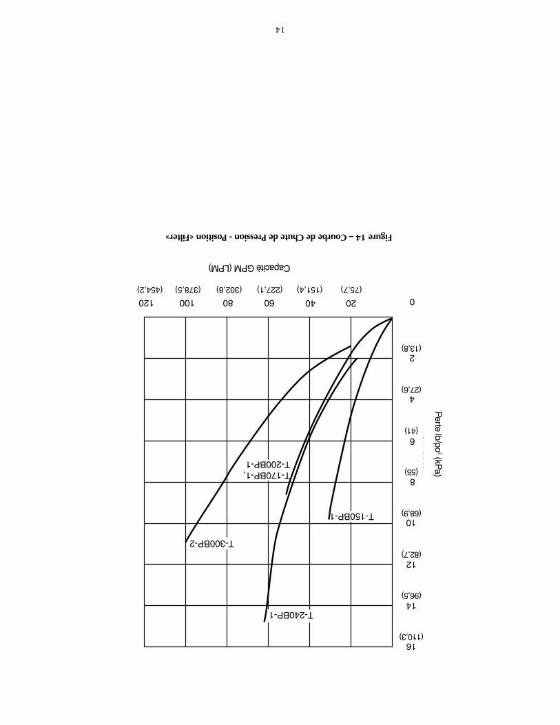
Figure14–CourbedeChutedePression-Position«Filter»
(75,7)(151,4)(227,1)(302,8)(378,5)(454,2)
CapacitèGPM(LPM)
Perte
lb/po2(kP
a)
(110,3)
(96,5)
(82,7)
(68,9)
(55)
(41)
(27,6)
(13,8)

13
2
34
7
12
12A
9A
10
8
13
14
18
19
17
6
15
16
11
1343 1094
14
15
16
RECIRCULATE
BAC
KWASH
CLOSED
WINTERIZE
WASTE
FILTER
RINSE
1
2
3
45
6
7
89A
10
11
9B
13
12
Listedespiècesderechange-VanneWC112-148A#14971-TM-22-L
Réf.DescriptionQté.WC112-148A14971-TM-22-L
1Décalcomanie-Poignéedelavanne114965-0021––2Poignée114962-003214971-SM10E13Goupilled’immobilisation135857-002114971-SM10E24Rondelle114965-000714971-SM10E35Décalcomanie-Instructionsdefonctionnement114965-0020––6Vis37337-3056(7)14971-SM10E4(10)7Couvercledelavanne114965-001114971-SM20E68Jointtorique135505-122814971-SM10E10
9ARondelle214965-000714971-SM10E89BRondelle114965-0007––10Ressort114965-000614971-SM10E911Manométre115060-0000T15060-0000T12Bouchonetjoint114965-002814971-SM20E11
12AJoint1––14971-SM20E1213Jointtoriquedecouvercle135505-127514971-SM20E714Corpsdelavanne114965-001314971-SM20E1315Ècrou35407-0071(7)14971-SM10E14(10)16Jointtoriquedelabrideduréservoir1U9-369U9-36917Jointdevoyant1––14971-SM20E1718Voyant1––14971-SM10E1619Jointtoriquedelacolonnemontante(EPDM)1––35505-1243
RECIRCULATE
BAC
KW
AS
H
E
W
AS
TE
FILTER
Aquatools.WATERFORD, WI.
53185USA
1
2
3A 3
4
5
6
7
8
9
10
11
12
13
757 0294
•NonIllustrés.
12
Listedespiècesderechange-RéservoirT-150BP-1,T-170BP-1,T-200BP-1,T-240BP-1,T-300BP-2
Modèle
Réf.DésignationQtéT-150BP-1T-170BP-1T-200BP-1T-240BP-1T-300BP-21Vanneàorificesmultiples
(ycomprisréf.nos2et3)1WC112-148AWC112-148AWC112-148AWC112-148A14971-TM-22-L2Jointtoriquedelabride
delavanne1U9-369U9-369U9-369U9-369U9-3693Collier1WC119-87AWC119-87AWC119-87AWC119-87AWC119-87A4Boutondecollier1WC36-22WC36-22WC36-22WC36-22WC36-225Raccorddeconduitemontante124200-0110WC137-516PWC137-517PWC137-519P24205-00106Tubelatéral824600-000324600-000324600-000324700-007521180-1307Réservoirdefiltration124200-100024201-100024203-100024204-100024205-10008Jointtoriquedetubelatéral1U9-370U9-370U9-370U9-370U9-3709Tubelateraldevidange124201-005824201-005824201-005824201-005824201-005810Jointtoriquedebouchon
devindange1U9-371U9-371U9-371U9-371U9-37111Bouchondevidange114965-002514965-002514965-002514965-002514965-002512Socle123910-0005B23910-0005B23910-0005B23900-0105B23900-020513Réservoirdefiltration124200-010024201-010024203-010024204-010024205-0100•Paquetderaccordsunions3C198-3MC198-3MC198-3MC198-3M–•Disquedechargementdusable124201-004324201-004324201-004324201-004324201-0063•Étiquetted’instructions/
demodèle132155-4115A32155-4115B32155-4115C32155-4115D90000-1329•Autocollantd’avertissement
-Collier132165-403032165-403032165-403032165-403032165-4030•Décalcomaniedeplaque
renseignements132155-411232155-411232155-411232155-411232155-4112

11
GUIDEDEDIAGNOSTICDESPANNES
1.Intervallesdefonctionnementcourtsentreleslavagesàcontre-courant:NOTA:L'intervalleentreleslavagesvarieavecchaqueinstallationetselonlesrégionsdupays.Demanderàl'installateurquelssontlesintervallesnormauxpourlelavageàcontre-courantdanslarégion.Lescausesetlesremèdesquisuivents'appliquentàdesduréesdefonctionnementpluscourtesquelanor-maledanslarégionoùlapompefonctionne.A.Ledébitdel'eauesttropélevéoulefiltreesttroppetit;consulterlemarc-
handpourconnaîtrelesrecommandationsconcernantlesdimensionsdusys-tème.
B.L'eauestchimiquementdéséquilibrée;consulterletechnicienenpiscines.C.Tropdesaletéoudepoussièredanslapiscine;passerlapiscineàl'aspirateur
etenvoyerl'eaudirectementàl'égout.D.Accumulationdelotion/d'huilecorporelledanslefiltre;consulterlemarc-
handpourlesnettoyantsdefiltrechimiquesàutiliseretobserverlesinstruc-tionsdufabricantdunettoyant.
E.Lefiltreestmallavéàcontre-courant.Voirlesinstructionssous«Miseenser-vice/fonctionnement»àlapage7.
F.Alguesdanslapiscine.Consulterunprofessionnelenpiscinespourconnaîtrelabonnequantitédeproduitschimiquesàutiliserdanslapiscine.
G.Niveaudechlorerésidueltropbas.Consulterunprofessionnelenpiscinespourconnaîtrelabonnequantitédeproduitschimiquesàutiliserdanslapiscine.
H.Inspecterlesabledufiltreàlarecherchedesolidificationscauséesparlapoussière,lecalcium,l'huiledelapeauouleslotionsdebronzage.
2.Débitfaible:A.Letuyauestbouchéenavaldufiltre;enleverl'obstruction.B.Tuyauteriestroppetites;utiliserdestuyauteriesdeplusgrosdiamètre(consul-
terlemarchand).C.Lapompeestbouchée;enleverlescheveuxetlacharpieemprisonnésdans
lacrépineoulepanierdel'écumoire.Bienlesnettoyer.
3.L'eaudelapiscinen'estpasclaire:A.L'eauestchimiquementdéséquilibrée;consulterletechnicienenpiscines.B.Lefiltreesttroppetit;consulterlemarchandpourconnaîtrelabonnedimen-
siondel'équipementàutiliser.C.S'ilyadusabledanslapiscine,ceciindiquequ'untubelatéralestcassé.
Danscecas,viderl'eauetlesableduréservoirdefiltration.Déposerlavanne;procédercommeilestindiquésous«Montagedufiltre»àlapage6etlesinstructionsfourniesavecletubelatéralneufpourremplacerlapiècecassée.
Pouréviterdegravesblessuresoud'importantsdommagesmatériels,suivrelesinstructionssous«Posedelavanne»,(Figures6et7àlapage7).1.Suivrelaméthodededéposedelavanneàlapage10.2.Remplacerletubelatéralconformémentauxinstructionsfourniesavecle
tubeneuf.3.Remonterlefiltreconformémentauxinstructionsfigurantsous«Montage
dufiltreȈlapage6.
Pressiondangereuse!Risquedegravesbless-uresoudedommagesmatérielsimportantsencasd'explosionduréser-voir.
Dissipertoutelapressionetlirelesinstructionsavantd'intervenirsurlefiltre.
AVERTISSEMENT
10
4.Remontagedelavanne:A.Reposerlejointdubouchonetl'arbre,leressortdemontage,lesrondelleset
lesjointstoriquessurl'axedubouchon.Lubrifierlejointtoriqueavecdel'Amojel.
B.Remettrelecouvercleenplace;assortirlestrousdesvisducouvercleavecceuxducorps.
C.Appuyersurlecouverclepourpermettreauxvisdes'engagerdanslesécrous;bienserrerchaqueécrou.
D.Remettreenplacelarondellesupérieure(Réf.n°1A)etlapoignée,ens'as-surantquel'axed'indexagedel'axedubouchonestorientédanslemêmesensquelaflèchefrappéesurlapoignée.Reposerlagoupilled'immobilisa-tiondelapoignée.
E.Serrertouteslesvisducouvercleaucouplede63,4kg-cm(55lb-po).
DéposedelavannePressiondangereuse.Arrêterlapompeetdissipertoutelapres-
sionducircuitavantd'intervenirsurlefiltre,lavanneoulecollier.NOTA:Silavanneàorificesmultiplesestplusbassequeleniveaudel'eaudelapiscine,fermerlesrobinetsdestuyauteriesd'aspirationetderetouravantdeprocéderaudémontageafind'empêcherquelapiscinesevide.1.Débrancherlestuyauteriesprovenantdelapompeetdelapiscine.2.Déposerlecollier.3.Déposerlavannedufiltre.4.Pourreposerlavanne,suivrelesinstructionsauxFigures6et7,page7.
S'ASSURERderespecterlesinstructionsdeserrageducollier.
Dépose/reposeduraccorddevidangeNOTA:Silapiscineestàplusdehuitpiedsau-dessusdufiltre,fermertoutd'abordlesrobinetsdestuyauteriesderetouretd'aspirationdelapompepourempêcherdeviderlapiscine.Sicestuyauteriesnecomportentpasderobinet,lesdébrancheretlesleverplushautqueleniveaudel'eau.1.Repose:VoirlaFigure13.2.Pourviderlefiltre:
A.Déposerlebouchondevidange.Letubelatéraldoitresterenplaceàl'in-térieurdel'ouverturedevidangepourempêcherausabledeseviderdufiltre.
B.Ouvrirleraccorduniondel'orificedelavageàcontre-courantdelavanneàorificesmultiples.Cecipermettraàl'airdepénétrerdanslefiltreetàl'eaudecomplètementseviderduréservoirdefiltration.
C.Reposerlebouchonlorsqueleréservoirestvide.3.Pourenleverlesabledufiltre:
A.Déposerlebouchondevidangeetletubelatéralàfentes(voirlaFigure13).Lesableetl'eauseviderontduréservoir.
B.Pourcomplètementrincerleréservoirdefiltrationdesable,déposerlecolliersupérieuretlavanneàorificesmultiplesetlaverl'intérieurduréservoiravecuntuyaud'arrosage.
C.Biennettoyerlesabledetouteslespartiesduréservoiretdel'ouverturedevidangeduréservoiravantderemonterleraccorddevidange.
About 1"
SmallO-Ring
Open endof lateral
Seat smallO-Ring
LargeO-Ring
End of lateral isflush with end ofdrain fitting746 0294
Figure13:Raccorddevidange.Ceraccordpermetdevidangerl'eausansquedusables'échappeduréser-voirdefiltration.S'assurerquetouteslessurfacessontpropresetdébarrasséesdesable.Nepasfausserlesfiletsdubouchon;nepastropserrerlebouchon.
Environ1pouce
Petitjointtorique
Extrémitéouvertedutubelatéral
Siègedupetitjointtorique
Grandjointtorique
L'extrémitédutubelatéralvientàrasavecl'extrémitéduraccorddevidange

9
d'antigelàbased'éthylène-glycol-ceproduitesttoxiqueetilrisqued'endom-magerlesélémentsenplastique.1.Ouvrirtouslesrobinetsdusystème.Réglerlavanneàorificesmultiplessur
«WINTERIZE»pourpermettreàl'airdepénétrerdanstouslesorifices.2.Déposerlebouchondevidangedufiltre.3.Vidertoutleréservoirdefiltration,puisreposerlebouchondevidange(voirla
Figure13,page10).4.Couvrirleréservoiravecunefeuilledeplastiqueetouunebâchepourlepro-
tégercontrelesintempéries.5.Leprotégerdugel.
Remiseenservicedel'équipementaprèsl'hiver:1.Déposertouteslesprotectionstemporairesplacéessurlesystèmeavantl'hiver.2.Sereporteràlapage7«Miseenservice»pourremettrelefiltreenservice.3.Inspectertoutlecâblageélectriquepours'assurerqu'iln'apasétéendommagé
nidétériorépendantlapérioded'arrêt.Demanderàuntechnicienqualifiéderé-parerouderemplacerlecâblageaubesoin.Inspecteretresserrertouslesrac-cordsétanches.
4.Ouvrirtouslesrobinetsdestuyauteriesd'aspirationetderetour.5.Enlevertouslesbouchonsposéspourl'hiver.6.Vidangertouslesproduitschimiquesd'hivérisation(lecaséchéant)dusystème;
rincerlesystème.7.Fermertouslesrobinetsdevidangeetreposertouslesbouchonsdevidangedu
système(voirlapage10).8.Fairelepleindelapiscinejusqu'aubonniveau(sereporterauxinstructionsdu
fabricantdelapiscine).
ENTRETIENDESVANNESÀORIFICESMULTIPLES
Pressiondangereuse.Arrêterlapompeetdissipertoutelapres-siondusystèmeavantd'intervenirsurlefiltre,lavanneoulecollier.Laconcep-tion du filtre et de la vanne permet à l’air d’être automatiquement purgé en servicenormal. Toutefois, toujours s’assurer que la pression a été dissipée du systèmeavant d’intervenir sur le filtre, sur la vanne ou sur le collier.NOTA:Silavanneàorificesmultiplesestplusbassequeleniveaudel'eaudelapiscine,fermerlesrobinetsdestuyauteriesd'aspirationetderetouravantdeprocéderaudémontageafind'empêcherquelapiscinesevide.
Remplacementdelapoignée:1.Arrêterlapompe.2.Mettrelapoignéedelavannesurlaposition«FILTER».3.Déposerlagoupilled'immobilisation(Réf.1,Figures12Aet12B)pourdésoli-
dariserlapoignée.Silagoupillenepeutpasêtreenlevéeàlamain,utiliserunmarteauetunpointeauetlachasserentapantlégèrementdessus.
4.Déposerlapoignée.Laremplacerparuneneuve.S'assurerquelapoignéeestdanslaposition«FILTER».
5.Reposerlagoupilled'immobilisation.
Remplacementducouvercleetdubouchon:1.Déposerlapoignée(voir«Remplacementdelapoignée»ci-dessus).2.Déposerlebouchon:
A.Débouchertouteslesvisettouslesécrous(Réf.nos2et6,Figures12Aet12B).
B.Déposerlecouvercle(Réf.3)entirantdroitdessustoutenimmobilisantl'axedubouchon(Réf.5)aveclepouce.
3.Inspectiondespiècesinternes:Inspecterlebouchonetleressortdejoint,lesjointstoriquesetlesrondellesin-ternes(Réf.4).Lesremplacerselonlebesoin.
RECIRCULATE
BAC
KW
AS
H
CLO
SED
WINTERIZE
WA
ST
E
FILTER
RINSE
1
1A
2
3
4
5
6
Aquatools.WATERFORD, WI.
53185USA
744 0294
Fig.12A:Démontagedelavanne.(Vanneàorificesmultiples,1-1/2po)
Fig.12B:Démontagedelavanne.(Vanneàorificesmultiples,2po)
1344 1094
1
1A
2
3
5
6
4

8
ENTRETIEN
Généralités:•Laverl'extérieurdufiltreavecundétergentdouxetdel'eau.Lerinceravecun
tuyaud'arrosage.NOTA:NEPASutiliserdedissolvantspournettoyerlefiltre,carilsrisquentd'en-dommagerlesélémentsenplastiquedusystème.
•Inspecterlelitdesableaumoinsunefoisparannéepourenleverlescorpsétrangersquin'ontpasétéchassésparleslavagesàcontre-courant.NOTA:Lorsquelelitdesabledevientdurousiledessusformecroûte,viderlevieuxsableduréservoiretleremplacerpardusableneuf.
Inspectionhebdomadairedel'équipementdelapiscine:1.Vérifierlapressiondusystèmependantsonfonctionnement.Dèsquelapression
estsupérieurede34,5à48Kpa(5à7lb/po2)àlapressiondemiseenservice
initiale,laveràcontre-courant(voirlesInstructionssous«Miseenservice/fonc-tionnement»àlapage7).
2.Saufpartempschaudslorsquelapiscineestintensivementutilisée,fairefonc-tionnerlefiltrede6à12heuresparjourdevraitêtresuffisant.Surveilleratten-tivementl'équilibrechimiquedanslapiscineetsuivrelesrecommandationsd'unprofessionnellocalenmatièredepiscines.
Entretiendel'eau•Garderleniveaudel'eauà2pouces(51mm)aumoinsau-dessusdelapartie
inférieuredel’écumoire.L’airpeutpénétrerdanslesystèmeetlefiltreetlapompepeutsedésamorcersil’onnerespectepascetterecommandation.
•MaintenirlepHdelapiscineentre7,2et7,6.
Pournepasendommagerlesélémentsdusystème,toujoursgarderlatem-pératuredel'eauinférieureà35°C(95°F).
Passagedel'aspirateurdanslapiscine:1.Remplirletuyausoupledel'aspirateurenl'immergeantcomplètementdansl'eau.2.Pourpasserl'aspirateur,introduireletuyaudanslecollecteurd'aspirationde
l'écumoireoudanslaconduited'aspirationquidébouchedanslaparoidelapiscine.Sereporterauxinstructionsfourniesparleconstructeurdelapiscineoulefabricantdelapiscine.Démarrerlapompe,s'assurerqu'elleestamorcéeetqu'ellepompe.
3.Aprèsavoirpassél'aspirateur,nettoyerlacrépinedelapompepourenlevertouslesdébrisquis'ysontaccumulés,puisvérifierlemanomètredufiltre.Aprèsavoirlavélefiltreàcontre-courant,ildoitindiquerunepressionvariantentre34,5et48Kpa(5à7lb/po
2)supérieureàlapressiondemiseenserviceinitiale.
Pourabaisserleniveaudel'eaudanslapiscineoupourviderlapiscine1.ARRÊTERlapompe;réglerlapoignéedelavannesur«WASTE».2.Utiliserletuyausoupledel'aspirateuretlatête.3.Démarrerlapompe;fairefonctionnerlapompejusqu'àcequeleniveaud'eau
désirédanslapiscinesoitatteint.4.ARRÊTERlapompe;réglerlapoignéedelavannesur«FILTER».5.Démarrerlapompe.
ENTREPOSAGEETPRÉPARATIONPOURL'HIVER
Lesproduitschimiquesàutiliserdanslespiscinesdégagentdesvapeurscorrosives.Lesentreposerloindusystèmedansunendroitbienaéré.NOTA:Silefiltregèle,ilseraendommagéetlagarantieseraannulée.Sil'onutilisedel'antigel,utiliserdupropylène-glycol;ceproduitestcompatibleaveclesplastiquesetilestnontoxique.Suivrelesinstructionsdufabricant.Nepasutiliser
RE
CIR
CU
LAT
E
BACKWASHCLOSED
WIN
TER
IZE
WASTE
FILTER
RIN
SE
RE
CIR
CU
LATE
BACKWASH CLOSED
WIN
TE
RIZ
EW
ASTE
FILTER
RINSE
Fig.10:Réglagesdelavannepourabaisserleniveaudel'eaudanslapiscine.Arrêterlapompeavantdechangerlapo-sitiondelavanne.
RE
CIR
CU
LAT
E
BACKWASH CLOSED
WIN
TE
RIZ
E
WASTE
FILTER
RINSE
Fig.11:Réglagedelavannepourl'entreposaged'hiver.Arrêterlapompeavantdechangerlapositiondelavanne.
7
Miseenservice/fonctionnement(VoirlaFigure9)
Pressiondangereuse.Pouréviteruneexplosionetdesblessuresgravespossible,voiremortelles,lapressiondusystèmedefiltrationnedoitjamaisdépasser345Kpa(50lb/pi
2).NEJAMAIScontrôlercesystème
defiltrationàl'aircomprimé;nejamaisfairefonctionnerlesystèmesilatempératuredel'eauestsupérieureà35°C(95°F).
Pourempêcherquel'équipementsoitendommagéettoutesblessurespossibles,ARRÊTERlapompeavantdechangerlapositiondelavanne.NOTA:Nejamaisajouterdeproduitschimiquesdirectementdansl'écumoiredelapiscine.L'ajoutdeproduitschimiquesnondiluésrisqued'endommagerl'équipementetd'annulerlagarantie.1.Ouvrirlesrobinetsdusystèmeets'assurerquelapompeestpleined'eau.
Ouvrirlesvannesdusystèmeets’assurerquelapompeestpleined’eau.S’assurerqueleniveaudel’eaudelapiscinearriveà2pouces(51mm)au-dessusdelapartieinférieuredel’ouverturedel’écumoire.
2.LapompeétantARRÊTÉE,réglerlavannesurlaposition«BACKWASH».3.Démarrerlapompe;l'eaucirculeraàcontre-courantdanslefiltreetsera
envoyéelàoùl'ondésireendisposer.Nepasposerlemanomètretantqu’un jet continu d’eau ne sort pas par l’orifice prévu pour la pose dumanomètre. Dès que l’eau sort par cet orifice, arrêter la pompe puis poserle manomètre.NOTA:Pourempêcherquelapompefonctionneàsec,s’assurerqueleniveaudel’eaunechutejamaissouslapartieinférieuredel’admissiondel’écumoire.Aubesoin,ajouterdel’eaudanslapiscinepourgarderl’écumoirepleind’eaupendantquel’onprocèdeaulavageàcontre-courantetaurinçage.
4.Procéderaulavageàcontre-courantdufiltrejusqu'àcequel'eaucouleclaire(3à5minutes).
5.Arrêterlapompe;réglerlavannesurlaposition«RINSE».6.Démarrerlapompe;lafairefonctionnerpendantuneminute.7.Arrêterlapompe;réglerlavannesurlapositon«FILTER».8.Lefiltreestmaintenantprêtàêtreremisenservice.9.Releverlapressiondedémarragedufiltrepropreindiquéeparle
manomètre(elleserviraderéférenceultérieure).10.Lorsquel'onremplitlapiscinepourlapremièrefois,laverlefiltreàcon-
tre-courantunefoisparjourjusqu'àcequel'eaudelapiscinesoittrèspropre.Aprèscela,laverlefiltreàcontre-courantlorsquelemanomètreindiqueunepressionde34,5à48Kpa(5à7lb/po
2)supérieureàlapres-
siondelamiseenserviceinitiale.
RREECCIIRRCCUULLAATTEE
BBAA
CCKK
WWAA
SSHH
EE
WWAA
SSTTEE
FFIILLTTEERR
.Install O-Ring on valve flange.
Install valve on tank. Tank flange must be clean; insert collector pipe into bottom of valve.
Delavan, WI.53115USA
1/4" Max.
Port labeled"PUMP" shouldpoint towardpump.
Install clampand tightenuntil clampends (underbolt) are 1/4" apart.
If unable toclose gapto 1/4" or less, wait 15-30 minutes and retighten.
Tap around clamp while tightening to help seat clamp.
.WATERFORD, WI.53185USA
736 0294
RREECCIIRRCCUULLAATTEE
BBAA
CCKK
WWAA
SSHH
EE
WWAA
SSTTEE
FFIILLTTEERR
Fig.6
Fig.7
RE
CIR
CU
LA
TE
BACKWASH CLOSED
WIN
TE
RIZ
EW
ASTE
FILTER
RINS
E
Valve SettingPurpose/Flow
FILTERNormal filtration and vacuuming; water goes through filter to pool.
RINSEFor initial startup cleaningand sand bed leveling after backwash; water goethrough filter to waste.
RECIRCULATECirculates pool water; bypasses filter.
RE
CIR
CU
LA
TE
BACKWASH CLOSED
WIN
TE
RIZ
EW
ASTE
FILTERRIN
SER
EC
IRC
ULA
TE
BACKWASH
CLOSED
WIN
TE
RIZ
E
WASTE
FILTER
RIN
SE
7370
BACKWASHReverses flow for cleaning; watergoes through filterto waste.
CLOSEDShuts off all flow tofilter and pool.
WINTERIZELeaves all valve portspartially open forwinter storage.
RE
CIR
CU
LAT
E
BACKWASHCLOSED
WIN
TE
RIZ
E
WASTE
FILTER
RINS
E
Valve SettingPurpose/Flow
RE
CIR
CU
LA
TE
BACKWASH CLOSEDW
INT
ER
IZE
WASTE
FILTER
RIN
SE
RE
CIR
CU
LAT
E
BACKWASH CLOSED
WIN
TER
IZE
WASTE
FILTER
RINSE
7380294Fig.8
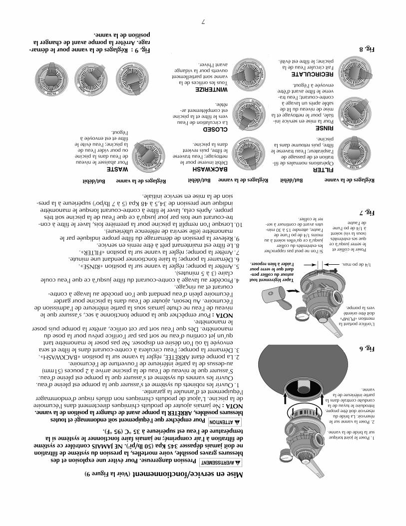
Taperlégèrementtoutautourducollierpen-dantqueleserrepourl'aideràbienreposer.
Poserlecollieretleserrerjusqu'àcequesesextrémités(souslavis)soientà1/4depol'unedel'autre
BACKWASHDébitinversepourlenettoyage;l'eautraverselefiltre,puisrevientdanslapiscine.
CLOSEDLacirculationdel'eauverslefiltreetlapiscineestcomplètementar-rêtée.
WINTERIZETouslesorificesdelavannesontpartiellementouvertspourlavidangeavantl'hiver.
RéglagesdelavanneBut/débitRéglagesdelavanneBut/débit
1/4depomax.
WASTELowers pool level ordrains pool; waterbypasses filter, goes to waste.
Valve SettingPurpose/Flow
RE
CIR
CU
LA
TE
BACKWASHCLOSED
WIN
TER
IZE
WASTE
FILTER
RIN
SE
743 0294
RE
CIR
CU
LA
TE
BACKWASHCLOSED
WIN
TE
RIZ
E
WASTE
FILTER
RIN
SE
RE
CIR
CU
LAT
E
BACKWASH CLOSED
WIN
TE
RIZ
EW
ASTE
FILTERRIN
SE
RE
CIR
CU
LA
TE
BACKWASH CLOSED
WIN
TE
RIZ
EW
AS
TE
FILTER
RINS
E
Fig.9:Réglagesdelavannepourledémar-rage.Arrêterlapompeavantdechangerlapositiondelavanne.
WASTEPourabaisserleniveaudel'eaudanslapiscineoupourviderl'eaudelapiscine;l'eauévitelefiltreetestenvoyéeàl'égout.
RéglagesdelavanneBut/débit
FILTEROpérationsnormalesdefil-trationetdepassagedel'aspirateur;l'eautraverselefiltre,puisretournedanslapiscine.
RINSEPourlamiseenserviceini-tiale,pourlenettoyageetlamisedeniveaudulitdesableaprèsunlavageàcontre-courant;l'eautra-verselefiltreavantd'êtreenvoyéeàl'égout.
RECIRCULATEFaitcirculerl'eaudelapiscine;lefiltreestévité.
1.Poserlejointtoriquesurlabridedelavanne.
2.Poserlavannesurleréservoir.Labrideduréservoirdoitêtrepropre.Introduireletuyaudelaconduitecentraledanslapartieinférieuredelavanne.
L'orificeportantlamention«PUMP»doitêtreorientéverslapompe.
Sil'onnepeutpasrapprocherlesextrémitésducollierjusqu'àcequ'ellessoientàaumoins1/4depol'unedel'autre,attendre15à30min-utesavantdecontinueràser-rerlecollier.

6
Eauusée:•S'assurerquetouteslesdispositionsprisespourl'éliminationdel'eauuséese
conformentauxcodesnational,provinciauxoumunicipaux.Pendantl'opéra-tiondelavagedufiltreàcontre-courant,379litres(100gallons)d'eaudelapiscine,voireplus,serontéliminés.Nepasenvoyerl'eaulàoùellerisquedecauserdesinondationsoudesdommages.
MontagedufiltreAssemblage:VoirlesFigures2à5pourl'assemblagedufiltre.
Chargementdusablefiltrant1.Nepasverserdesabledanslaconduitecentrale;poserleprotecteurdesableen
plastiquesurlaconduitecentraleavantdeverserlesabledanslefiltre(voirlaFigure5).
2.Defaçonàsupporterlestubeslatérauxetpourempêcherqu'ilssecassentpen-dantlechargement,remplirleréservoiràmoitiéd'eauavantdeviderlesabledanslefiltre.
3.Verserlesabledansleréservoirdefiltration.Sereporteràlapage4pourcon-naîtrelebontypeetlabonnequantitédesableàutiliser.NOTA:S'assurerquelasurfaced'étanchéitédudessusduréservoirestdébar-rasséedesableavantdeposerlavanneetlecollier.
4.Avantdeposerlavanne,vérifierunedeuxièmefoissilabonnequantitédesableabienétéchargée(voirlapage4).
5.Déposerleprotecteurdechargementdesableenplastiqueetleconserverpourlaprochainefois.
Installationdelavanne:VoirlesFigures6,7et81.Poserlejointtoriquesurlabridedelavanne.S'assurerquelejointtoriqueest
propre,sec,qu'ilnecomportepasd'entaillesnidedéchirures.2.S'assurerquelesbridesduréservoiretdelavannesontpropresetdébarrassées
desable;poserlavannesurledessusduréservoir.Letuyauverticaldelacon-duitecentrales'insèredanslabasedelavanne.
3.Poserlecollier;s'assurerqueleboutonducollierestpositionnédefaçonàpou-voiryaccéderfacilementlorsdel'entretiendufiltre.L'orificedelavannepor-tantlamention«PUMP»doitêtreorientéverslapompe.
4.Serrerleboutonducollierjusqu'àcequelesextrémitésducollier(souslavis)soientà6mm(1/4depo)l'unedel'autre.Al'aided'unemassetteencaoutchouc,tapertoutautourducollierpourluipermettredebienreposer.
Pressiondangereuse.Lecollierneresterapasenplaces'ilnereposepasbien!NEPASDÉMARRERLAPOMPEsilesextrémitésducolliernesontpasà6mm(1/4depo)l'unedel'autre.5.Silecollierneseserrepasjusqu'àcequesesextrémitéssoientà6mm(1/4de
po)l'unedel'autre,attendre15à30minutes,puisleresserrer.Àl'aided'unemassetteencaoutchouc,taperlégèrementsurlecollierpourl'aideràbienre-poser.
6.Brancherletuyauvenantducôtéretourdelapompesurl'orificedelavanneportantlamention«PUMP»;utiliserlamoitiéduraccordunionfourni.Pourqu'iln'yaitpasdefuites,assemblerleraccordunionenprocédantcommesuit:A.Lessurfacesd'étanchéitéetlesjointstoriquesdoiventêtrepropres.B.Neserrerleraccordqu'àlamain(pasavecuneclé).C.Aucunepâted'étanchéitépourraccordsfiletésnirubanTéflonnedoitêtre
utilisésurlesraccordsunions.7.Terminertouslesraccordsdelaplomberie(serapporteràlapage5pourles
tuyauteries).A.Letuyaudel'orificeRETOUR(RETURN)delavannedoitêtreorientéversle
retourdelapiscine.B.Letuyauvenantdel'orificeEAUUSÉE(WASTE)delavannedoitêtreorienté
verslecôtéoùl'eauuséeseraenvoyée.C.Letuyaud'aspirationprovenantdelapompedoitêtreorientéverslecôté
arrivéedelacrépinedelapompe.8.Lesystèmeestmaintenantprêtàêtremisenservice.
NOTA:Sil'onremarquedesfuitessouslapartievanne/collier,ARRÊTERLAPOMPE,dissipertoutelapressiondanslesystème,déposerlecollieretlavanneetnettoyerleurssurfacesd'étanchéité.
B. Insert assembly into top of filter tank.
A. Insert first lateral into socket; twist clockwise 1/4 turn to lock lateral into hub. Lateral is correctly installed when slots face down.
731 0294
C. Hold assembly up near top of tank and add remaining laterals.
732 0294
D. After all laterals are securely in sockets, position assembly on centering boss in bottom of tank.
733 0294
SAND
:::: :::: :::: :::: :::: :::::::: :::: :::: :::: :::: ::::
:::: :::: :::: :::: :::: ::::
::::::::::::::::::::::::
::::::::::::
::::::::::::::::::::::::::::::::::::
::::::::::::::::::::::::::::::::::::::::::::::::
::::::::::::
::::::::::::
::::::::::::
::::::::::::
::::::::::::
:::::::::::::::::::::::: ::::::::::::::::
::::::::
::::::::::::::::::::::::::::::::::::::::::::::::::::::::::::::::::::::::::::::::::::
::::::::::::
::::::::::::::::::::::::
::::::::::::
::::::::::::
:::: :::: :::: :::: :::: :::::::: :::: :::::::::::::::::::::::::::::::::::::::::::::::::::: ::::::::::::
::::::::::::::::::::::::::::::::::::::::::::::::
::::::::::::::::
::::::::::::
::::::::::::::::::::
::::::::::::::::::::::::::::::::::::::::::::::::::::::::::::::::::::::::::::
::::::::
::::::::::::
Fill tank abouthalf full ofwaterbeforeaddingsand.
Sand Shieldkeeps collectorhub assembly clean whenloading filter.
734 0294
Fig.2
Fig.3
Fig.4
Fig.5
A.Introduirelepremiertubelatéraldansladouille:letourneràdroitede1/4detourpourleverrouillerdansleraccord.Letubelatéralestbienposélorsquesesfentessontorientéesverslebas.
B.Introduirel'ensem-bleparlehautdufiltreduréservoir.
C.Tenirl'ensembleprèsduhautduréservoiretposerlesautres
tubes
D.Aprèsquetouslestubeslatérauxsontretenusentoutesécuritédanslesdouilles,positionnerl'ensemblesurlebossagedecentragepratiquédanslefondduréservoir.
Leprotecteurdesableéviteradeverserdusablesurleraccorddelaconduitecentralepen-dantlechargementdufiltre.
Remplirleréservoiràmoitiéd'eauavantd'yajouterlesable.
SABLE
5
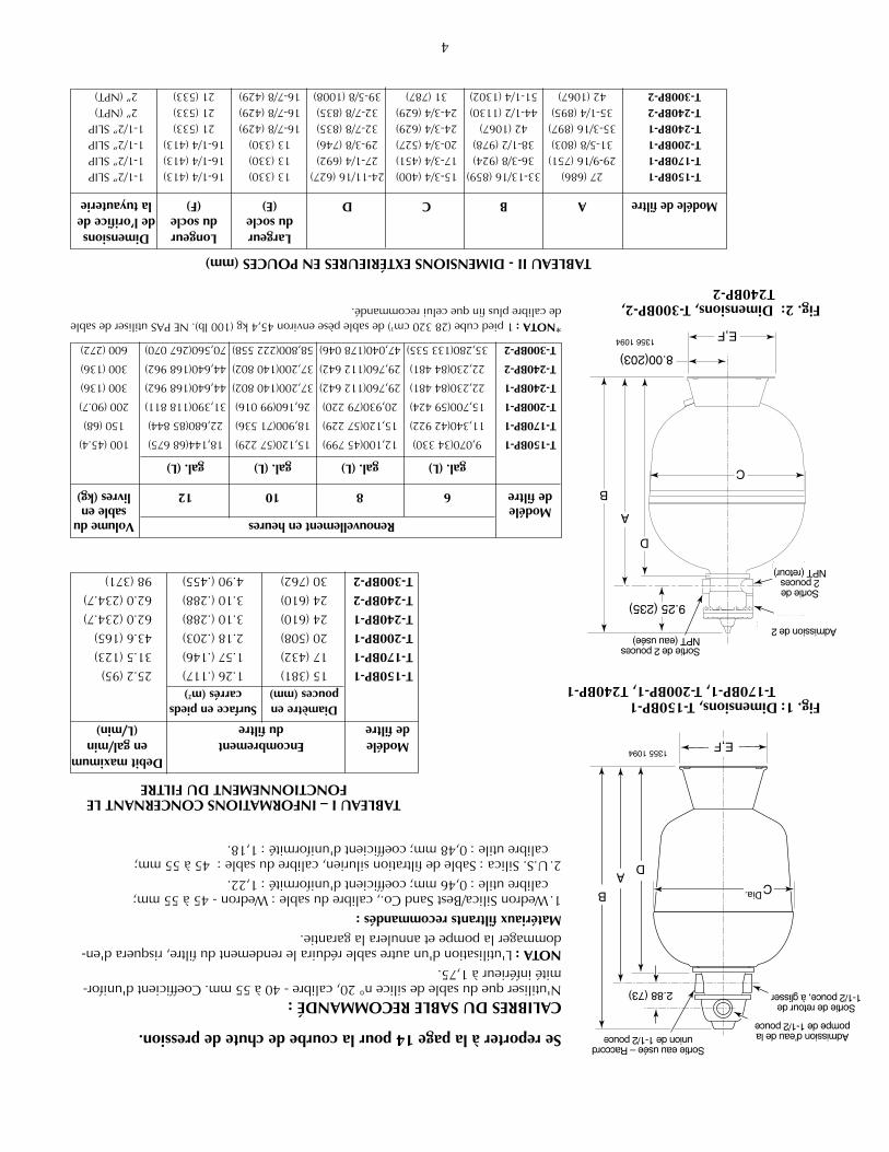
RENSEIGNEMENTSGÉNÉRAUX•Silapiscineestneuve,lanettoyerlemieuxpossibleavantdelarempliretdefaire
fonctionnerlefiltre.Lefiltreetlapomperisquentd'êtresérieusementendommagéssilesystèmecontienttropdesaletésetdegrossesparticulesdecorpsétrangers.
NEJAMAIScontrôlercefiltreàl'aircomprimé.
Ne pas faire fonctionner le filtre si la température de l'eau est supérieure à 35°C(95°F).
NEJAMAISfairefonctionnercesystèmedefiltrationpardespressionssupérieuresà50lb/po
2(345Kpa)!
INSTALLATIONL'installationdufiltrenedoitêtreeffectuéequepardupersonnelqualifié.Pourcon-naîtrelesinstructionsd'assemblageetderemplissage,sereporteràlapage6.
L'assisedufiltredoit:•assureruneprotectioncontrelegeletlesintempéries;•assurersuffisammentd'espaceetd'éclairagepourunaccèsfacilelorsdesentretiens
périodiques.(VoirlaFigures1et2etleTableau2àlapage4pourlesdégagementsexigés.)
•reposersurunesurfaceraisonnablementdeniveauetassurerundrainageadéquat;•êtreaussiprèsquepossibledelapiscinepourréduirelespertesparfrictiondansles
tuyauteries.
Tuyauteries:•Ellesdoiventseconformerauxcodessanitairesetdelaplomberiedelaprovinceet/ou
delamunicipalité.•Utiliserdelapâted'étanchéitépourraccordsfiletésoudurubanTéflonsurlesrac-
cordementsmâlesdestuyauxetdesraccordsmâlesmétalliques(àl'exceptiondesrac-cordsunions).UtiliserdurubanTéflonouduPlasto-JointStik
1surtousles
raccordementsmâlesdesraccordsetlestuyauxenplastique.NEPASutiliserdepâtepourraccordsfiletéssurlestuyauxenplastique,sinonlestuyauxsefissureront.Nepasutiliserdepâted'étanchéitépourraccordsfiletésniderubansurlesraccordsunions-lesassembleràsecetnelesserrerqu'àlamain.
•Nepasendommagerlessurfacesd'étanchéitédesraccordsunionsnilesjointstoriques.
•Supporterchaquetuyauteriedefaçonàempêchertoutecontraintesurlefiltreousurlavanne.
•Utiliserdestuyauxde1-1/2pooude2popourminimiserautantquepossiblelespertesdepression.NOTA:Lefiltrepeutêtreplacéloindelapiscine.Danscecas,toutefois,etpouras-surerundébitadéquat,destuyauxdeplusgrosdiamètredoiventêtreutilisés.Étudierlescodesmunicipauxlorsquel'onconsidèreuneinstallationàdistance.
•Lesraccordsdiminuentledébit;pourunemeilleureefficacité,utiliserlemoinspossi-blederaccords.
•Lestuyauxdoiventêtretoujoursbienserrésetnepasfuir:unefuitedelaconduited'aspirationdelapomperisqued'emprisonnerdel'airdansleréservoirdefiltrationoudedésamorcerlapompe;onremarqueraunefuitedelaconduitederetourdelapompepardel'humiditéoudesjetsd'eau.
•Lorsquedesraccordsunionssontfournis,etpourobtenirdesraccordementsquinefuientpas,lesutilisercommesuit:
1.Lessurfacesd'étanchéitéetlesjointstoriquesdoiventêtrepropres.2.Lesraccordsnedoiventêtreserrésqu'àlamain(pasavecuneclé).3.Aucunepâted'étanchéitépourraccordsfiletésnirubanTéflonnedoitêtreutilisésur
lesraccordsunions.
Clapets:•Unclapetantiretourposéentrelefiltreetlechauffe-eauempêcheral'eauderetourner
danslefiltreetdecauserladéformationdesélémentsinternes.•Ilfautêtretrèsprudentavantdeprocéderàl'assemblageafindenepasendommager
lessurfacesd'étanchéitédesraccordsunionsnilesjointstoriques.
1LakeChemicalCo.,Chicago,IL
4
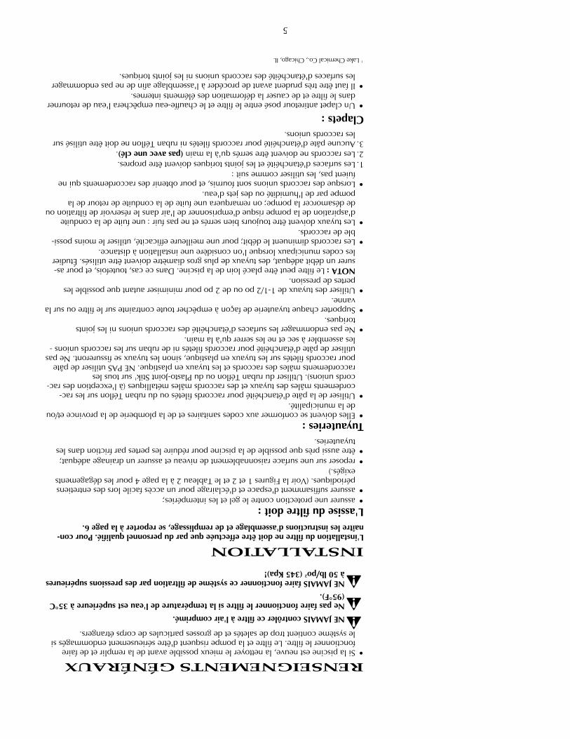
Sereporteràlapage14pourlacourbedechutedepression.
CALIBRESDUSABLERECOMMANDÉ:N'utiliserquedusabledesilicen°20,calibre-40à55mm.Coefficientd'unifor-mitéinférieurà1,75.NOTA:L'utilisationd'unautresableréduiralerendementdufiltre,risquerad'en-dommagerlapompeetannuleralagarantie.Matériauxfiltrantsrecommandés:1.WedronSilica/BestSandCo.,calibredusable:Wedron-45à55mm;
calibreutile:0,46mm;coefficientd'uniformité:1,22.2.U.S.Silica:Sabledefiltrationsilurien,calibredusable:45à55mm;
calibreutile:0,48mm;coefficientd'uniformité:1,18.
DebitmaximumModéleEncombrementengal/mindefiltredufiltre(L/min)
DiamètreenSurfaceenpiedspouces(mm)carrés(m
2)
T-150BP-115(381)1.26(.117)25.2(95)T-170BP-117(432)1.57(.146)31.5(123)T-200BP-120(508)2.18(.203)43.6(165)T-240BP-124(610)3.10(.288)62.0(234.7)T-240BP-224(610)3.10(.288)62.0(234.7)T-300BP-230(762)4.90(.455)98(371)
RenouvellementenheuresVolumeduModélesableendefiltre681012livres(kg)
gal.(L)gal.(L)gal.(L)gal.(L)
T-150BP-19,070(34330)12,100(45799)15,120(57229)18,144(68675)100(45.4)
T-170BP-111,340(42922)15,120(57229)18,900(71536)22,680(85844)150(68)
T-200BP-115,700(59424)20,930(79220)26,160(99016)31,390(118811)200(90.7)
T-240BP-122,230(84481)29,760(112642)37,200(140802)44,640(168962)300(136)
T-240BP-222,230(84481)29,760(112642)37,200(140802)44,640(168962)300(136)
T-300BP-235,280(133535)47,040(178046)58,800(222558)70,560(267070)600(272)
LargeurLongeurDimensionsdusocledusocledel’orificede
ModéledefiltreABCD(E)(F)latuyauterie
T-150BP-127(686)33-13/16(859)15-3/4(400)24-11/16(627)13(330)16-1/4(413)1-1/2”SLIPT-170BP-129-9/16(751)36-3/8(924)17-3/4(451)27-1/4(692)13(330)16-1/4(413)1-1/2”SLIPT-200BP-131-5/8(803)38-1/2(978)20-3/4(527)29-3/8(746)13(330)16-1/4(413)1-1/2”SLIPT-240BP-135-3/16(897)42(1067)24-3/4(629)32-7/8(835)16-7/8(429)21(533)1-1/2”SLIPT-240BP-235-1/4(895)44-1/2(1130)24-3/4(629)32-7/8(835)16-7/8(429)21(533)2”(NPT)T-300BP-242(1067)51-1/4(1302)31(787)39-5/8(1008)16-7/8(429)21(533)2”(NPT)
TABLEAUI–INFORMATIONSCONCERNANTLEFONCTIONNEMENTDUFILTRE
TABLEAUII-DIMENSIONSEXTÉRIEURESENPOUCES(mm)
*NOTA:1piedcube(28320cm3)desablepèseenviron45,4kg(100lb).NEPASutiliserdesable
decalibreplusfinqueceluirecommandé.
CDia.B
AD
2.88 (73)
Pump Inlet 1-1/2"
Waste Outlet 1-1/2"Union connection
Return Outlet1-1/2" Slip
E,F1355 1094
C
D
A
B
9.25 (235)
2" NPT Outlet(Waste)
2" NPT Inlet(Pump)
2" NPT Outlet(Return)
E,F
8.00(203)1356 1094
Fig. 1: Dimensions, T-150BP-1T-170BP-1, T-200BP-1, T240BP-1
Fig. 2: Dimensions, T-300BP-2,T240BP-2
Sortieeauusée–Raccordunionde1-1/2pouce Admissiond’eaudela
pompede1-1/2pouce
Sortiederetourde1-1/2pouce,àglisser
Sortiede2poucesNPT(eauusée)
Admissionde2
Sortiede2pouces
NPT(retour)
3
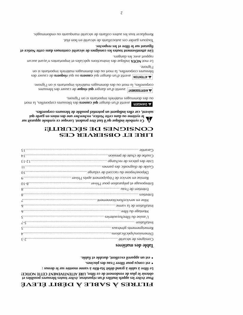
Unéquipementmalinstalléoumalcontrôlépeuttomberenpanne,causerdegravesblessuresoudesdommagesmatériels.LireetsuivrelesinstructionsfigurantdanslaNoticedel'utilisateurpourinstalleretutiliserl'équipement.Demanderàunepersonne
connaissantbienlespiscinesdeprocéderauxcontrôlesdelapression.
1.Ne pas brancher le système sur une pression élevée ou sur l'eau de la ville.
2.N'utiliser l'équipement qu'avec une piscine ou une cuve à remous.
3.De l'air emprisonné dans le système risque de causer une explosion. S'ASSURER que tout l'air est chassé du système avant de faire fonctionnerl'équipement ou de le contrôler.
Avant de procéder à un contrôle de pression, procéder aux vérifications de sécurité suivantes :
•Vérifiertouslescolliers,couvercles,accessoiresettouteslesvisdusystème.
•S'ASSURERquetoutl'airestpurgédusystème.
•ResserrerlecouvercledelacrépinedespompesSta-Riteaucouplede4,1kg-cm(30lb-pi).
•Lapressiondel'eaudoitêtreinférieureà172Kpa(25lb/po2).
•Latempératuredel'eaudoitêtreinférieureà35°C(95°F).
•Limiterlecontrôleà24heures.Aprèsavoirprocédéaucontrôle,examinervisuellementlesystèmepours'assurerqu'ilestprêtàêtreutilisé.Déposerlecouvercledelacrépineetneleresserrerqu'àlamain.
NOTA:Cesparamètresnes'appliquentqu'àdel'équipementSta-Rite.Pourunéquipementd'uneautremarquequedemarqueSta-Rite,consulterlefabricant.
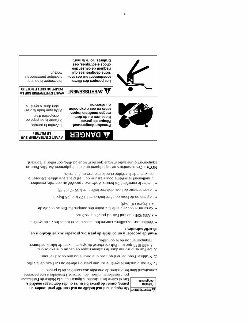
Pressiondangereuse!Risquedegravesblessuresoudedom-magesmatérielsimpor-tantsencasd'explosionduréservoir.
AVANTD'INTERVENIRSURLEFILTRE:
1.Arrêterlapompe.2.Ouvrirlasoupapede
dissipationd'air.3.Dissipertoutelapres-
siondanslesystème.
Lespompesdesfiltresfonctionnentsurdesten-sionsdangereusesquirisquentdecauserdeschocsélectriques,desbrûlures,voirelamort.
AVANTD'INTERVENIRSURLAPOMPEOUSURLEMOTEUR
Interromprelecourantélectriqueparvenantaumoteur.
AVERTISSEMENT
2
FILTRESÀSABLEÀDÉBITÉLEVÉPouréviterlesappelsinutilesd'unréparateur,évitertoutesblessurespossiblesetobtenirleplusderendementdecefiltre,LIREATTENTIVEMENTCETTENOTICE!LefiltreàsableàgranddébitSta-Riteàvannemontéesurledessus:•estconçupourfiltrerl'eaudespiscines.•estunappareilexcellent,durableetfiable.
TabledesmatièresConsignesdesécurité.......................................................................................2-3Dimensions/spécifications....................................................................................4Renseignementsgénéraux....................................................................................5Installation.......................................................................................................5-7
L'assisedufiltre/tuyauteries.............................................................................5Montagedufiltre.............................................................................................6
Installationdelavanne........................................................................................6Miseenservice/fonctionnement......................................................................7
Entretien..............................................................................................................8Entretiendel'eau............................................................................................8
Entreposageetpréparationpourl'hiver...........................................................8-10Remiseenservicedel'équipementaprèsl'hiver..............................................9Dépose/reposeduraccorddevidange...........................................................10
Guidedediagnosticdespannes.........................................................................11Listedespiècesderechange.........................................................................12-13Courbedechutedepression...............................................................................14Garantie............................................................................................................15
LIREETOBSERVERCESCONSIGNESDESÉCURITÉ!
Cesymboleindiquequ'ilfautêtreprudent.LorsquecesymboleapparaîtsurlesystèmeoudanscetteNotice,rechercherunedesmisesengardequi
suivent,carellesindiquentunpotentielpossibledeblessurescorporelles.
avertit d'un danger qui causerades blessures corporelles, la mortou des dommages matériels importants si on l'ignore.
avertit d'un danger qui risquede causer des blessures corporelles, la mort ou des dommages matériels importants si on l'ignore.
avertit d'un danger qui causeraouqui risquerade causer desblessures corporelles, la mort ou des dommages matériels importants si on l'ignore.
Lemot NOTAindique des instructions spéciales et importantes n'ayant aucun rapport avec les dangers.
LireattentivementtouteslesconsignesdesécuritécontenuesdanscetteNoticeetfigurantsurlefiltreetlesrespecter.
Toujoursgardercesautocollantsdesécuritéenbonétat.
Remplacertouslesautrescollantsdesécuritémanquantsouendommagés.

FILTRESÀSABLEÀGRANDDÉBITCRISTAL-FLO
TM
NOTICED’UTILISATION
POSE,FONCTIONNEMENTETPIÈCES
MODÈLEST-150BP-1T-170BP-1T-200BP-1T-240BP-1T-300BP-2
Sta-RitePool/SpaGroup
293WrightStreet,Delavan,WI53115International:262-728-5551,FAX:262-728-7550www.starite.comUnionCity,TN•Delavan,WI•Mississauga,ON
©2005,Sta-RiteIndustriesS242(Rév.2/12/05)
CetteNoticedoitêtreremiseàl'utilisa-teurdecefiltre;elleserviraàréduirelesappelsdedépannageetlespossibil-itésdeblessures,demêmequ'àpro-longerladuréedufiltre.
RECIRCULATE
BA
C
K
WA
S
H
E
W
AS
TE
FILTER
Aquatools.WATERFORD, WI.
53185USA
729 0294
Pentair Pool Products,Inc.1620 Hawkins Ave.Sanford, NC 27330Tel 919-774-4151 • Fax 919-774-4841
S242(Rev.B 6/28/06)
Related Documents