Process Controller with Setpoint Programmer 1 / 16 DIN - 48 x 48 M5 line c User Manual • M.I.U.M5-4/03.01 • Cod. J30-478-1AM5 IE ASCON spa 20021 Bollate (Milano) Italy via Falzarego, 9/11 Tel. +39 02 333 371 Fax +39 02 350 4243 http://www.ascon.it e-mail [email protected] ASCON spa ISO 9001 Certified U L C US LISTED

Welcome message from author
This document is posted to help you gain knowledge. Please leave a comment to let me know what you think about it! Share it to your friends and learn new things together.
Transcript

Process Controller with Setpoint Programmer1/16 DIN - 48 x 48
M5 line ccU s e r M a n u a l • M . I . U . M 5 - 4 / 0 3 . 0 1 • C o d . J 3 0 - 4 7 8 - 1 A M 5 I E
ASCON spa20021 Bollate(Milano) Italyvia Falzarego, 9/11Tel. +39 02 333 371 Fax +39 02 350 4243http://www.ascon.ite-mail [email protected]
ASCON spa
ISO 9001C e r t i f i e d UL
C US
LISTED
M5 UK•ed4 10-12-2004 16:20 Pagina 1

Process Controller with Setpoint Programmer1/16 DIN - 48 x 48
M5 line cc
48.5048.50
123
REMSP 1SP 2
RUNMAN
A / M
ULC US
LISTED
M5 UK•ed4 10-12-2004 16:20 Pagina 1

2
Indications
ccNOTES
ON ELECTRIC
SAFETY AND
ELECTROMAGNETIC
COMPATIBILITY
Please, read carefully these instructions before proceeding with the instal-lation of the controller.Class II instrument, real panel mounting.
This controller has been designed with compliance to:Regulations on electrical apparatus (appliance, systems and installations)according to the European Community directive 73/23/EEC amended by theEuropean Comunity directive 93/68/EEC and the Regulations on the essen-tial protection requirements in electrical apparatus EN61010-1 : 93 + A2:95.
Regulations on Electromagnetic Compatibility according to the EuropeanCommunity directive n089/336/EEC, amended by the European Communitydirective n° 92/31/EEC, 93/68/EEC, 98/13/EECand the following regulations:Regulations on RF emissionsEN61000-6-4 : 2001 industrial environmentsRegulation on RF immunity EN61000-6-2 : 2001 industrial equipment and system
It is important to understand that it’s responsibility of the installer to ensurethe compliance of the regulations on safety requirements and EMC.The device has no user serviceable parts and requires special equipmentand specialised engineers. Therefore, a repair can be hardly carried on direct-ly by the user. For this purpose, the manufacturer provides technical assistanceand the repair service for its Customers. Please, contact your nearest Agent for further information.All the information and warnings about safety and electromagnetic com-patibility are marked with the B sign, at the side of the note.
M5 UK•ed4 10-12-2004 16:20 Pagina 2

3
Table of Contents
TABLE OF CONTENTS 1 INTRODUCTION....................................................................................................................................PAGE 41.1 PRODUCT CODING.................................................................................................................PAGE 5
2 INSTALLATION ........................................................................................................................................PAGE 62.1 DESCRIPTION ...............................................................................................................................PAGE 62.2 OPERATING CONDITIONS ..................................................................................................PAGE 72.3 INSTALLATION ...............................................................................................................................PAGE 7
3 ELECTRICAL CONNECTIONS.......................................................................................PAGE 83.1 TERMINATION UNIT ................................................................................................................PAGE 83.2 CABLING LAYOUT....................................................................................................................PAGE 83.3 ELECTRICAL CONNECTIONS .......................................................................................PAGE 9
4 OPERATIONS .............................................................................................................................................PAGE 154.1 FRONT PANEL..............................................................................................................................PAGE 154.2 CONFIGURATION .......................................................................................................................PAGE 164.3 PARAMETER SETTING.........................................................................................................PAGE 204.4 ACCESS LEVELS ........................................................................................................................PAGE 27
5 DISPLAYS.........................................................................................................................................................PAGE 29
6 COMMANDS ...............................................................................................................................................PAGE 306.1 COMMANDS FROM KEYBOARD ...............................................................................PAGE 316.2 COMMANDS FROM DIGITAL INPUTS ................................................................PAGE 336.3 COMMANDS FROM SERIAL COMMUNICATION
(PLEASE, REFER THE ADDENDUM ON THE SERIAL COMMUNICATION)
7 SETPOINT PROGRAMMER ( OPTIONAL )..........................................................PAGE 347.1 PROGRAM ORGANISATION............................................................................................PAGE 347.2 OPERATING CONDITIONS ...............................................................................................PAGE 367.3 PROGRAM INPUT AND EDITING ................................................................................PAGE 377.4 RUN/STOP OF A PROGRAM........................................................................................PAGE 38
8 TECHNICAL SPECIFICATIONS ....................................................................................PAGE 39
M5 UK•ed4 10-12-2004 16:20 Pagina 3

4
1 - Introduction
1 INTRODUCTION POWERFUL FEATURES AND A WIDE RANGE OF FUNCTIONALITIES
Congratulations for having chosenthese universal controllers. They are thebest result of our experience in design-ing and manufacturing of smart, pow-erful and high reliable controllers.
The process controllers of the M5series have been designed for theindustrial environment, are providedwith a complete set of functions, asa true universal instrument.
They can be used as Controllers-Programmers with 1 Setpoint pro-file of 16 segments.
Main universal input
Two digital inputs
Control Alarms Retransmission
Resources
OP1PV
AUX
IL1IL2
OP2
OP3
OP4(option)
Modbus RS485ParameterisationSupervision(option)
M5
Setpoint
Digital inputs (IL1, IL2) functions
Tuning
One shotAuto tuning
Adaptive
Auxiliary input (option)
Operating mode
PV/SP
Memory ChipData Copy/Data Store(option)
2 Single OP4 OP1 OP2 OP3action
3 Double OP1 OP2 OP3 OP4action
4 Double OP1 OP4 OP2 OP3action
5 Double OP4 OP2 OP1 OP3action
1 Single OP1 OP2 OP3 OP4action
6 Valve OP1 OP2 OP3 OP4
M5 UK•ed4 10-12-2004 16:20 Pagina 4

5
1 - Introduction
1.1 PRODUCT CODING
The complete code is displayed onthe instrument label.
The information about product cod-ing are accessible from the front panelby mean of a particular proceduredescribed at section 5.1 pag 29
Power Supply A100 - 240V~ (- 15% + 10%) 324V~ (- 25% + 12%) or 24V– (- 15% + 25%) 5
Outputs OP1 (OP2) BRelay - Relay 1Relay - Triac 2Triac - Relay 4Triac - Triac 5
Serial Comms. C
Not fitted
000000
OptionsNone [2]
Auxiliary Input
Feedback potentiometer [2]
Auxiliary Output SSR drive/analogue + Remote Setpoint [1] [2]
SSR drive/analogueCurrent TransformerRemote Setpoint [1]
D012345
RS485 Modbus/Jbus protocol
55Auxiliary
Input 5Feedback potentiometer [2]
55
01
None [2]
23Current Transformer
Remote Setpoint [1]
4SSR drive/analogue auxiliary output
Model:
Power SupplyOutputsSerial comm.s/Options
–
Line Model Basic Accessories
ColourInstruction handbook
Setpoint
0M5 A B C D E F G
C DB
3150Hard
123
REMSP 1SP 2
RUNMAN
A / M
P/NCONFS/NV~(L-N).85÷264V 50/60 Hz - 3W
; M5-3150-0000:: A0A-9809/0011
Basic product code
Instrument label
[1] Not available with Setpoint programmer installed (E = 1)[2] Second digital input (IL2) not available
Fitted 1
Instruction handbook F
Not fitted
Italian-English (std) 0
0Setpoint Programmer E
French-English 1German-English 2Spanish-English 3
Front panel Colour GDark (std) 0Beige 1
M5 UK•ed4 10-12-2004 16:20 Pagina 5

6
2 - Installation
2 INSTALLATION
Installation must only be carriedout by qualified personnel.
Before proceeding with the installationof this controller, follow the instructionsillustrated in this manual and, partic-ularly the installation precautionsmarked with the B symbol, relat-ed to the European Community direc-tive on electrical protection and elec-tromagnetic compatibility.
BTo prevent hands or metal touchingparts that may be electrically live, thecontrollers must be installed in anenclosure and/or in a cubicle.
2.1 INSTALLATION DESCRIPTION
Product code label
Sealing front panel gasket
Mounting Clamps
Front PanelIP65 protection
EN 60529 (IEC 529)
Panel surface
Memory Chipconnector
IP 20 Termination UnitEN61010 - 1 (IEC1010 - 1)
2.1.1 DIMENSIONAL DETAILS
48 mm1.89 in
150 mm5.9 in
20 mm max0.79 in max
48 mm1.89 in
2.1.2 PANEL CUT-OUT
65 mm min2.56 in min
45+0.6 mm1.78+0.023 in
45+
0.6
mm
1.78
+0.
023
in
65 m
m m
in2.
56 i
n m
in
M5 UK•ed4 10-12-2004 16:20 Pagina 6

7
2 - Installation
2.2 ENVIRONMENTAL RATINGS B
Operating Conditions
M Altitude up to 2000 m
T Temperature 0…50°C
%Rh Relative Humidity 5…95 %Rh non-condensing
Special Conditions
M Altitude > 2000 m
T Temperature >50°C
%Rh Humidity > 95 %Rh
P Conducting atmosphere Use filters
Warm up
Use forced air ventilation
Use 24V~ supply version
Suggestions
Forbidden ConditionsD
C Corrosive atmosphere
E Explosive atmosphere
1
1
1
2
2.3.1 INSERT THE INSTRUMENT
1 Prepare panel cut-out2 Check front panel gasket position3 Insert the instrument
through the cut-out
2.3 PANEL MOUNTING [1]
2.3.2 INSTALLATION SECURING
1 Fit the mounting clamps2 Push the mounting clamps towards
the panel surface to secure theinstrument
1
32
2.3.3 CLAMPS REMOVING
1 Insert the screwdriver in the clipsof the clamps
2 Rotate the screwdriver
1
2
2.3.4 INSTRUMENT UNPLUGGINGB
1 Push and 2 Pull to remove the instrumentElectrostatic discharges can damagethe instrumentBefore removing the instrument theoperator must discharge himself to ground
1
2
1
1MΩ
UL note
[1] For Use on a Flat Surface of a Type 2 and Type 3 ‘raintight’ Enclosure.
M5 UK•ed4 10-12-2004 16:20 Pagina 7

8
3 - Electrical Connections
3 ELECTRICAL CONNECTIONS
PRECAUTIONS
B
Despite the fact that the instrumenthas been designed to work in anharsh and noisy environmental (levelIV of the industrial standard IEC 801-4), it is strongly recommended to fol-low the following suggestions.
AAll the wiring must comply with thelocal regulations.
The supply wiring should be routedaway from the power cables.Avoid to use electromagnetic con-tactors, power relays and high powermotors nearby.Avoid power units nearby, especiallyif controlled in phase angle
Keep the low level sensor input wiresaway from the power lines and theoutput cables.If this is not achievable, use shieldedcables on the sensor input, with theshield connected to earth.
UL note[1] Use 60/70 °C copper (Cu) conduc-
tor only.
3.1 TERMINATION UNIT [1]B 3.2 RECOMMENDED ROUTING OF WIRES B
0,5Nm
6
5
4
3
2
1
12
11
10
9
8
7
18
17
16
15
14
13
Rearterminalcovers
Wire size1 mm2
(18 AWGSolid/Stranded)
5.7 mm0.22 in
6
5
4
3
2
1
12
11
10
9
8
7
18
17
16
15
14
13
6
5
4
3
2
1
12
11
10
9
8
7
18
17
16
15
14
13
Conduit for supply and output cables
Conduit for low level sensor cables
A
L
N
BB
C DE
A
L
N
BB
C DE
A = SupplyB = Relay/Triac OutputC = Analog InputsD = Serial
CommunicationE = Auxiliary
Inputs/OutputsF = Digital Inputs
F F
18 screw terminals
Option terminals
Holding screw 0.5 Nm
Positive screwdriver PH1Negative screwdriver 0,8 x 4 mm
TerminalsPin connector q 1.4 mm0.055 in max
ØFork-shape AMP 165004Ø 5.5 mm - 0.21 in
LStripped wireL 5.5 mm - 0.21 in
M5 UK•ed4 10-12-2004 16:20 Pagina 8

9
3 - Electrical Connections
3.3 TYPICAL INSTRUMENT WIRING (valve control) B
Supervisory
RS485
6
OP1
V~
18V–
5
4
3
2
1
12
11
10
9
8
7
18
17
16
15
14
13PTC
OP2
OP3 Supply V ~
L
N
L
N
PV
mA mV-V Tc Pt100
A
B
B
2 wirestransmitter
C
Alarm
V~
Fuse2A ~T
[6]
V~
Fuse
Fuse
[6]
[6]
DigitalInput
PLC
Commands
Power switch
M
Positioner module
Bufferrelays
Raise
Lower
6
5
4
12
11
10
9
18
17
16
15
14
13
C
RS
485
DIGITAL INPUT
mA V
18 V
—OU
TO
P3
OP
4(R
EM)
N
LNO
C
TC CT
OP
2
NO
C
NO
[5]
[5]
71
82
3
12
11
10RTD POT
100%
0%
OP
1
1
2A
b
B
Option terminals
Notes:1] Make sure that the power supply volt-
age is the same indicated on theinstrument.
2] Switch on the power supply only afterthat all the electrical connections havebeen completed.
3] In accordance with the safety regu-lations, the power supply switch shallbring the identification of the relevantinstrument. The power supply switchshall be easily accessible from theoperator.
4] The instrument is PTC protected. Incase of failure it is suggested to returnthe instrument to the manufacturer forrepair.
5] To protect the instrument internal cir-cuits use:- 2 A~ T fuses for Relay outputs- 1 A~ T fuses for Triac outputs
6] Relay contacts are already protectedwith varistors.Only in case of 24 V ~ inductiveloads, use model A51-065-30D7varistors (on request)
M5 UK•ed4 10-12-2004 16:20 Pagina 9

10
3 - Electrical Connections
3.3.1 POWER SUPPLY B
Switching power supply with multipleisolation and internal fuse• Standard version:
nominal voltage:100 - 240V~ (-15% + 10%)Frequency 50/60Hz
• Low Voltage version:Nominal voltage:24V~ (-25% + 12%)Frequency 50/60Hz or 24V– (-15% + 25%)
• Power consumption 3Wmax
3.3.2 PV CONTROL INPUT B
A For J L T K S R thermocouple type• Use always compensation cable of
the correct type for the thermo-couple used
• Use always compensation cable ofthe correct type for the thermo-couple used
• The shield, if present, must be con-nected to a proper earth.
B For PT100 resistance thermometer
• If a 3 wire system is used, usealways cables of the same diame-ter (1mm2 min).Maximum resistance/line 20 Ω
• If a 2 wire system is used, usealways cables of the same diame-ter (1.5mm2 min).
A When the distance between thecontroller and the sensor is 15meters, using a cable of 1.5mm2
diameter, produces an error in themeasure of 1°C .
B1 For ∆T (2x Pt100)• Use wires of the same length.
Maximum resistance/line 20 Ω.
R1 + R2 must be <320Ω
6
5
150Ω/lead maximum
14
13
included PTC
L
N
6
5
4A
b
B
When using a 2 wiresystem, put a jumper
between terminals 5 and 6
6
5
4A
B
A
R1
R2
M5 UK•ed4 10-12-2004 16:20 Pagina 10

11
3 - Electrical Connections
3.3.2 PV CONTROL INPUTS (cont.) B 3.3.3 AUXILIARY INPUTS (OPTION) B
C For DC inputInput resistance = 30Ω for mAInput resistance = 10MΩ for mVInput resistance = 10KΩ for Volt
A For current transformer CTfor the measure of the load current
• Primary coil 10A…100A• Secondary coil 50 mA default
100mA jumper selectable
C1 For 2 wires transmitters• Power supply to the transmitter
18V– ±10%30mA maxInput resistance = 30Ω
C2 For 3 or 4 wires transmitters• Power supply to the transmitter
18V– ±10%30mA maxInput resistance = 30Ω
6
5
mA mV-V
Rj
6
5Rj
18V–3PV
Transmitters
mA
6
5Rj
18V–3PV
mA
Transmitters
12
11
10…100A50/100mA
loadCT
~
5 watt burden resistor0.5Ω for 1A secondarytransformer coil0.1Ω for 5A secondarytransformer coil
Option Module for CT
Jumper for 100 mA
secondary transformer coil
M5 UK•ed4 10-12-2004 16:20 Pagina 11

12
3 - Electrical Connections
3.3.5 OP1 OP2 OP3 AND OP4 OUTPUTS B
The functionality associated to each of the OP1 OP2 OP3 and OP4 outputsis defined during the configuration of the instrument.The possible choices are:
Note[1] In case of OP4 analogue output, its status is not visualised by any red led[2] When the OP4 SSR drive output is selected, the status of OP1 and OP2, as alarms,
is not displayed by any red led
where:3.3.4 DIGITAL INPUTS B
• The associated function is activewhen the digital input is ON(see table on page 33)
• The second digital input (IL2) isavailable only with the followingoptions:Remote Setpoint (D = 2)Current transformer (D = 3)SSR drive / analogue output (D = 4)
OP1 - OP2
OP4
Relay or Triac output
Analogue output
Analogue or SSR drive output
OP4-C
9
10
15
TTLopen collector
NPNopen collector
Isolatedcontact
Com.
IL 2
IL 1C1
C2
C From Position PotentiometerTo read the real position of the motoror the valve
12
11
10100%
0% Totaltraveldistance
OperatingTraveldistance
pot.h
pot.I
0%
100% From 100Ω to 10KΩ max
3.3.3 AUXILIARY INPUTS (cont.) B
B From Remote SetpointCurrent0/4…20mAInput resistance = 30Ω
Voltage1…5V, 0…5V, 0…10VInput resistence = 300KΩ
e If the analogue input is provided, theterminals for the Remote Setpointare 10(+) and 9(-)
12
11
mAmV-V
Rj
OP3 Relay output
Alarms
OP1Raise
Retransm.
OP1Heat
OP2 OP3 OP4-C
OP4Heat
OP1 OP2 OP3
OP1Heat
OP2Cool
OP3 OP4-C
OP1Heat
OP4 [1]Cool
OP2[2]
OP3
OP4 [1]Heat
OP2Cool
OP1[2]
OP3
PV-SP
OP2Lower
OP3 OP4-CValve
Doubleaction
Doubleaction
Doubleaction
Singleaction
Singleaction
Control
6
5
4
3
2
1
M5 UK•ed4 10-12-2004 16:20 Pagina 12

13
3 - Electrical Connections
3.3.5-A SINGLE RELAY OUTPUT (TRIAC) B
3.3.5-B SINGLE SSR DRIVE OUTPUT (OPTION) B
OP117
16V~
Load
OP412
11Load
V~
OP1
18
17
16
OP2 Cool
Load
Load
Heat
V~
3.3.5-C SINGLE ANALOGUEOUTPUT (OPTION) B
3.3.5-E HEAT COOL OUTPUT RELAY/RELAY (TRIAC/TRIAC) B
3.3.5-F HEAT COOL OUTPUT RELAY (TRIAC)/SSR DRIVE (OPTION)B
3.3.5-H HEAT COOL OUTPUT RELAY(TRIAC)/ANALOGUE (OPTION)B
3.3.5-G HEAT COOL OUTPUT SSR DRIVE (OPTION)/RELAY (TRIAC)B
3.3.5-D VALVE OUTPUT B
mA
12
11Load
mV,V
OP117
16V~
Load
Heat OP412
11LoadCool
mA mV,V
OP412
11Load
V~Heat OP218
17V~
Load
Cool
OP1
18
17
16
OP2V~
Lower
Raise
M~
OP117
16V~
Load
Heat OP412
11Load
V~Cool
1 NO contact
2 NO contacts
Output 0…22V– ±20% (20mA max)galvanic isolated
galvanic isolated500 V~/ 1min750Ω / 15V max if current output500Ω / 20mA max if voltage output
3 pole output with NO contacts (raise, lower, stop)
M5 UK•ed4 10-12-2004 16:20 Pagina 13

14
3 - Electrical Connections
3.3.5-I HEAT COOL OUTPUT DC (OPTION)/RELAY (TRIAC) B
3.3.6 ALARM OUTPUTS OP1, OP2, OP3 B
3.3.7 RETRANSMISSION OUTPUT (OPTION) B
3.3.8 SERIAL COMMUNICATION (OPTION) B
OP412
11LoadHeat
mA mV,V
OP218
17V~
Load
Cool
OP1
18
17
16
OP2
Load
Load
V~
2
1V~
Load
OP3
mA
12
11Load
mV,V
9
8
7
CommonGround
2 NO contacts
1 NO contact
galvanic isolated500 V~/ 1min750Ω / 15V max if current output500Ω / 20mA max if voltage outpute The analogue/SSR drive output OP4
can be used for signal retransmis-sion only if it is not used as controloutput.
e The relay/triac output OP1, OP2 andOP3, can be used as alarm outputsonly if they are not used as controloutputs.
• Galvanic isolation 500V~/1 minCompliance to the EIA RS485 stan-dard for Modbus/Jbus
A Please, read:gammadue® and deltadue® con-troller series serial communicationand configuration
M5 UK•ed4 10-12-2004 16:20 Pagina 14

15
4 - Operation
4 OPERATION
274.8275.0
123
REMSP 1SP 2
RUNMAN
A / M
Setpointsetting
Run/stopof a program
5 Status LED’s (green):REM - Remote setpoint activeSP1 - first stored setpoint activeSP2 - second stored setpoint activeRUN - program runningMAN - manual operating mode
Output statusLED’s(reds):
OP1 output ONOP2 output ONOP3 output ON
Automatic/manual
Menuaccess
Entry key forselection andvalue settingconfirmation
PV measurein engineering units
OperatingSetpoint
(local/remoteor stored)
Parametersetting
Entry key forselection andvalue settingconfirmation
Access to the menu for:- configuration- parameter setting- access definition
Parameter value
Parameter mnemonic
35.0p.b.
123
REMSP 1SP 2
RUNMAN
A / M
4.1.A KEYS FUNCTION AND DISPLAY IN OPERATOR MODE
4.1.B KEYS FUNCTION AND DISPLAY IN PROGRAMMING MODE
4.1.1 NUMERIC ENTRY(i.e. the modification of the value of a storedSetpoint from 275.0 to 240.0)
4.1.2 MNEMONIC SETTING(Way to modified configuration page 16 / 18)
Press $ or % momentarily tochange the value of 1 unit every push.Continued pressing of $ or %changes the value, at rate that dou-bles every second. Releasing the but-ton the rate of change decreases.In any case the change of the valuestops when it has reached the max/minlimit set for the parameter.
s.p. 21253
s.p. 21100
s.p. 21350
Unit. °C
Unit °f
Unit MA
Unit ph
Press the $ or % to display thenext or previous mnemonic for the select-ed parameter. Continued pressing of$or %will display further mnemon-ics at a rate of one mnemonic every 0.5seconds. The mnemonic displayed at thetime the next parameter is selected, isthe one stored in the parameter.
2nd stored Setpoint
2nd stored Setpoint
2nd stored Setpoint
Centigrade DegreesEngineering Units
Fahrenheit DegreesEngineering Units
mAEngineering Units
Ph Engineering units
—lower
—raise
The new value isentered when the nextparameter is selectedby mean of theRkey.
M5 UK•ed4 10-12-2004 16:20 Pagina 15

16
4 - Operation
4.2 CONFIGURATION PROCEDURE
Conf
Inp.
sC.dd
sc.lo
sc.Hi
sqr
CHar
Conf
rs.p.C
rs.In
C.pas
275.8 Menu
Unit
Inp
s.p.tM
s.p.
33
274.8 Conf
OK
é0=10
é 0
é 0
é9999
éno
éno
énone
éLoc
é4=20
éP:Sec
Input type see table 1
N° of decimals(linear input only)0 / 1 / 2 / 3
Low range(linear input only)from min range up tosc.Hi
High range(linear input only)from sc.lo to maxrange
Square root(linear input only)no / yes
Linear inputs characterisationno / yes
Engineering Unitssee table 2
Inputs Configuration
Operator Mode
Press the key until
YES
Enter the configuration password
NO
Configuration menu
Setpoint Configuration
Setpoint selectionsee Table 3
Remote Setpoint input(remote input only)see Table 4
Time unitsand Setpoint slopep.sec/ p.Min / .phr
Back to the1st parameter inp.=Conf
Back to the 1st parameters.p.=ConfIf the entered password
corresponds to the value set inthe parameter C.pas at pag. 27,
proceed to YES
from -999 to 9999(33 as default from the factory)
If the configured hardware option is not installed, the display shows an hardware error message
H.Err 100 100 Analog output not installed
101 Current trasformer not installed
102 Remote Setpoint input not installed
103 Potentiometer input not installed
104 Analogue output + Remote Setpoint not installed
M5 UK•ed4 10-12-2004 16:20 Pagina 16

17
4 - Operation
ConfConf
O.Ity
H.C.OP
s.Out
rtH
Conf
Il1 Al.1
AI.Ou
ltch
bloc
Al.2
A2.Ou
ltch
Al.3
A3.Ou
ltch
bloc
Al.4
A4.Ou
Il2
bloc
Out L.inP AlM
ltchC.C.OP
O.r.ty
rt.lo
rt.Hi
éPid:r
éOFF
éOFF
énone
é4=20
é0
é9999
éOFF
éOFF
éOFF
éOFF
éOP1
éno
éno
éOFF
éOP1
éno
éno
éOFF
éOP1
éno
éno
éOFF
éOP1
éno
CONFIGURATION MENU
Output Configuration
Digital inputsconfiguration
Alarm sconfiguration
Type of Controlsee Table 5
Heat control outputsee Table 6
Control outputsafety value
Off/ -100…100%
Retransmission output(available for DC outputonly)none / pU / s.p.
Retransmission outputtype(available for DC output only)see Table 4
Retransmission low rangewhole range
Retransmission high rangewhole range
Cool control outputsee Table 7
AL1 alarm typesee Table 9
AL1 addressing(not available when AL1 isOFF)OpI / Op2/ Op3
AL1 latching(not available when AL1 isOFF)no / yes
AL1 start-up disabling(not available when AL1 isOFF)no / yes
AL2 alarm typesee Table 9
AL2 addressing(not available when AL2 isOFF)OpI / Op2/ Op3
AL2 latching(not available when AL2 isOFF)no / yes
AL2 start-up disabling(not available when AL2 isOFF)no / yes
AL3 alarm typesee Table 9
AL3 addressing(not available when AL3 isOFF)OpI / Op2/ Op3
AL3 latching(not available when AL3 isOFF)no / yes
AL3 start-up disabling(not available when AL3 isOFF)no / yes
AL4 alarm typesee Table 9
AL4 addressing(not available when AL4 isOFF)OpI / Op2/ Op3
AL4 latching(not available when AL4 isOFF)no / yes
AL4 start-up disabling(not available when AL4 isOFF)no / yes
Back to the 1st parameter of Out=Conf
IL1 functionsee Table 8
IL2 function see Table 8
Back to the 1st parameter of L.inp=Conf
M5 UK•ed4 10-12-2004 16:20 Pagina 17

Value
Description
18
4 - Operation
ConfEHit
Ht.f.C
Ht.on
blocéno
é100
éOFF
Output Configuration
CT High range(available if at least onealarm is Htr)10…100
CT decimal point(available if at least onealarm is Htr)Off / On
Back to operator mode
Back to the 1st parameterAlM=Conf
Tab. 4
Value Description0=5 0…5 Volt1=5 1…5 Volt
0=20 0…20 mA4=20 4…20 mA
Tab. 5 Control type
Of.re Reverse actionOn - Off
Of.di Direct actionpid.d Direct action
P.I.D.pid.r Reverse actionU.dir Direct action Modulating
valvesU.reU Reverse actionH.C.ln Linear
Heat/CoolH.C.Ol Oil charac.
H.C.H2 Water charac.
Tab. 6 Heat control output Value Description éH.C.OP Off Not usedrI Relay 1
Digital signallog SSR drive0=5 0…5 Volt
Analoguesignal
1=5 1…5 Volt0=10 0…10 Volt0=20 0…20 mA4=20 4…20 mA
Rem. Setpoint
Value Description éOI.ty
Tab. 7 Cool control outputValue Description ééC.C.OP Off not usedr2 relay 2
Digital signallog SSR drive0=5 0…5 Volt
Analoguesignal
1=5 1…5 Volt0=10 0…10 Volt0=20 0…20 mA4=20 4…20 mA
Tab. 8 Digital Inputs functionéIl1
Value éIl2 Off Not usedl=r Local/remoteA.Man Auto/manuals.p.1 1st stored Setpoints.p.2 2nd stored Setpointkeb.I Keypadslo.1 s.p. slope disableH.pU Measure holdr.=H. Run/stop of a program
Tab. 9 Alarm typeéAl1 éAl2
Off Not usedfs.H Active high
Absolutefs.l Active lowdeU.H Active high
DeviationdeU.l Active lowband Out active Htr Active highlba Loop break alarm (Al1 only)
Heater BreakBand
Tab. 1 Input type éInp. Value
Value
tc. j 0…600°C
Description
tc. l
éUnit
tc. Ktc. s
Tab. 2 Engineering units
none None°C Centigrade Degrees°f Fahrenheit DegreesMA mAMU mVU Voltbar barpsI PSI
0=10
MU
tc. ttc. r
rtd1cuSt
1=50=5
rtd2del.t
4=200=20
rh Rhph Ph
Tab. 3 Setpoint type
reM.t Remote - trimloc.t Local - triml=r Local/remote onlyreM Remote onlyloc Local only
Value Description érs.p.C.
éAl3 éAl4
Description
Description
32…1112°F
4…20 mA0…20 mA0…10 Volt1…5 Volt0…5 Volt0…50 mV-50.0…50.0°C-99.9...300.0°C-200…600°CCustom range on request-200…400°C0…1600°C0…1600°C0…1200°C0…600°C
Engineeringunits
-58.0…122.0°F-99.9…572.0°F-328…1112°F
-328…752°F32…2912°F32…2912°F32…2192°F32…1112°F
0=10 0…10 Volt
érs.In Retransmission éO.r.ty
M5 UK•ed4 10-12-2004 16:20 Pagina 18

19
4 - Operation
It is possible to configure up to 4 alarms:AL1, AL2, AL3, AL4 (see pag. 17), select-ing, for each of them:A the type and the operating condition of
the alarm (table 9 page 18)
B the functionality of the alarm acknowl-edgement (latching) àltch
C the start-up disabling (blocking) àblocD the physical output of the alarm àOpI àOp2 àOp3
The outputs can be used for alarms ifthey are not used as control outputs (see par. 3.3.5 page12)It is possible to route up to 4 alarm to a sin-gle output (OR of the alarms).
Alarm occurrence displayThis function can be enabled by theconfiguration software.(please read the user instruction onthe "M5 LINE MODBUS /JBUS PRO-TOCOL", supplied separately)
The range of the alarm threshold corre-spond to the whole span and it is not lim-ited by the SP Setpoint span.
[A] OPERATING CONDITIONS
4.2.1 AL1, AL2, AL3, AL4 ALARMS CONFIGURATION
[B] ALARM ACKNOWLEDGEFUNCTION
The alarm, once occurred, is presented onthe display until to the time of acknowl-edge. The acknowledge operation consistsin pressing any key.
After this operation, the alarm leaves thealarm state only when the alarm conditionis no longer present.
ltchyes
[C] START-UP DISABLING
[D] LOOP BREAK ALARM LBA
When the controller connection to the sen-sor is discontinued or other faults aredetected in the control loop, the AL1 alarmbecomes active, after a predefined time of1 to 9999 s, from the detection of the fail-ure.The alarm state ceases when the fault con-dition is no longer present.
275.0
123 2f.5.H
The red led of the activated alarm outputis on.
The type of alarm is presentedflashing, on the front panel inalternation with the PV value.
eIn case of ON-OFF control, the LBAalarm is not active.
275.0A / M
123 Ilba
mA
°C
OP1
∆SPDisable
SP
OnOff
Start-up
rampdown
rampup
∆SP Threshold
=SP ± range
SP∆SP
OnOff
Disable
Start-up
Absolute alarm
active highé-fsH
active lowé-fsl
hyd hyuOn
Off
On
Off
Alarm thresholdhigh rangelow range
Deviation alarm
active high
active lowé-del
hyd hyuOn
Off
On
Off
SP
Alarm threshold+ range- range
é-deH
Band alarm
active outé-bnd
hyd hyu
On
Off
SP
Alarm thresholdfull scalefull scale
hyd hyu
∆SP
∆SP ∆SP
blocyes
M5 UK•ed4 10-12-2004 16:20 Pagina 19

éIn:sPcala
é loc
é 0
é 0
énone
éf:sPcala
é Off
é Off
é 1:00
é 0
é 0
é 0
é 0
é 0
é 1
é 1
Menu275.8
s.sel
l=r
s.p. 1
s.p. 2
Menu Menu274.8 s.p. prog Al
s.p. l
s.p. H
sl. u
sl. d
rtio
bias
1---
2---
3---
4---
hy.Iu
hy.Id
20
4 - Operation
Setpoint selectionlocal/remote(local or remote configura-tion only)loc / reM1st stored Setpoint(local only)full scale
2nd stored Setpoint(local only)full scale
Stored Setpoint selection (local only)none / s.s.p.I / s.s.p.2
Setpoint low limitfrom low scale up tospH
Setpoint high limitfrom splto full scale
Slope up(user enabled/disabled)Off/1 digit/…[1]
Slop down(user enabled/disabled)Off/1 digit/…[1]
Ratio Setpoint(only if local - trim or remote - trim)-9.99…99.99
Remote Setpoint bias(only if local - trim orremote - trim)-span…+span
Note[1] The units of theslope parameters areDigit/s, digit/min.digit/hr, according tothe choice defined dur-ing the configuration.
Alarm threshold 1[2] see table
Alarm threshold 2[2] see table
Alarm threshold 3[2] see table
Alarm threshold 4[2] see table
Alarm 1 hysteresisasymmetric upper0...span/20 in engineeringunits
Alarm 1 hysteresisasymmetric lower0...span/20 in engineeringunits
AThe parameter setting procedure hasa timeout. If no keys are pressed for,at least, 30 seconds, the controllerswitches back, automatically, to theoperator mode.
After having selected the parameteror the code, press $ or % tomodify the value (see pag 15 and 31)The value is entered when the nextparameter is selected, by pressingthe è key.
Pressing the í key, the operatormode is presented on the display.
Back to the 1st parameter of the Setpoint menu.
Operator mode
Setpoint menu
Setpoint programmer menu(if the option is installed.see page 37)
Alarm smenu
4.3 PARAMETER SETTING
M5 UK•ed4 10-12-2004 16:20 Pagina 20

PARAMETER MENU
é 1
é 1
é 1
é 1
é 1
é 1é 5:0 é 12:0
éOFF
é 1:00
é 50
é no
é noé 60
é 5:0
é 60
é 12:0
MenupId
hy.2u
hy.2d
hy.3u
hy.3d
hy.4u
hy.4d
t.d.
d.Err
O.C.
Mres
p.b. C
t.i. C
t.d. C
tune
Adpt
p.b.
t.i.
t.d.
Menutune
p.b.
t.i.
-bndActive out of band
21
4 - Operation
Alarm 2 hysteresisasymmetric upper0...span/20 in engineeringunits
Alarm 2 hysteresisasymmetric lower0...span/20 in engineeringunits
Alarm 3 hysteresisasymmetric upper0...span/20 in engineeringunits
Alarm 3 hysteresisasymmetric lower0...span/20 in engineeringunits
Alarm 4 hysteresisasymmetric upper0...span/20 in engineeringunits
Alarm 4 hysteresisasymmetric lower0...span/20 in engineeringunits
Proportional band(PID algorithm only)0.1…999.9 % of span
Integral time(user enabled/disabled) (PID algorithm only)Off/1…9999 seconds
Initial Tune start(one shot tune)no/yes
Continuous Tune start(adaptive tune)(not available with set prGh) no/yes.
Calculated Proportionalband [3] (display only)(available when adaptivetune is selected)
Calculated Integral time[3] (display only)
(available when adaptivetune is selected)
Calculated derivativetime [3] (display only)(available when adaptivetune is selected)
Derivative time(user enabled/disabled)(PID algorithm only)Off/0.1…999.9 seconds
Errordead band0ff/0.1...10.0 digit
Overshoot control(user enabled/disabled)(PID algorithm only)0.01…1.00
Manual reset(user enabled/disabled)(PID algorithm only)Off/1…100% output
Proportional bandCool channel(Heat/Cool configuration only)0.1…999.9% full scale
Cool Integral time(user enabled/disabled)(Heat/Cool configuration only)Off/1…9999 seconds
Cool Derivative time(user enabled/disabled)(Heat/Cool configuration only)Off/0.1…999.9 seconds
Back to the 1st parameter of the Alarms menu. Back to the
1st parameter of the PID menu
Back to the 1st parameter
of the Tuning menu.
PID menu
Tuningmenu
Note [2] A code, specifying the n° andthe alarm type that has been configured,is displayed. At this point, the user mustenter the threshold value, according to thefollowing table.
Type and value Mode N° and Param.
AbsoluteActive high -fsHActive low -fsl
DeviationActive high -deHActive low -del
Bandfull scale
Load Threshold1…100A0.1…20A
Active high -Htr
AL1 activationdelay1…9999 s
Active high Ilba
Nota [3]These values are notautomatically stored onthe PID menu parame-ters P.b.,t.i.,t.d.
M5 UK•ed4 10-12-2004 16:20 Pagina 21

é 0
é Off
é 0:1
é 0.5
é 10:.0
é 0.0
é100.0
é Off
é Off
é 10
é 0.5
é 60
é 0ff
é100.0
é 0.5
é 10:.0 é 1
é9600
éjbus
t.fil
In.sh
t.saM
OP.Hy
t.c.
Op. l
Op. H
Op.r
st.Op
tc.C
d.bnd
Op.CH
Op.rC
MU.hy
Addr
baud
prot
MenuInP
MenuOut
MU.tM
st.tM
MenuCoMM
MenuAccs
MenuConf
22
4 - Operation
Filter time constant(user enabled/disabled)Off/0.2…999.9 seconds
Measure biasOff/-60…60 digit
Sampling time0.1…10 seconds
Output hysteresis(single parameter in case ofON-OFF control algorithm)0....5% full scale
Control Output cycle time(time proportioning only)0.2…100.0 seconds
Control Output low limit(not available in Heat/Coolconfiguration)0…100.0%
Control output high limit0…100.0%
Control output rate limit(user enabled/disabled)Off/0.01…99.99%/s
Control Output soft start value(user enabled/disabled) Off/0.1…100.0%
Soft start function activation time(not available if st.Op = Off)1…9999 seconds
Cool output cycle time(only with Heat/Cooltime proportioning)0.2…100.0 seconds
Dead band(only with Heat/Cool config.)0.0…5.0%
Cool output high limit(user enabled/disabled)(only with Heat/Cool config.)0.0…100.0%
Cool output rate limit(user enabled/disabled)(only with Heat/Cool config.)Off/0.01…99.99%/ s
Motor travel time(only for motorised positioners)15…600 seconds
Minimum output step(only for motorised positioners)0.1…5.0%
AddressOff/1…247
Baud rate1200/ 2400/ 48009600/ 19.200
Communication protocol
Modb/ jbus
Back to the 1st parameterof the input menu
Backto the 1st parameterof the Output menu
Back to the 1st parameter of the Serial Communication menu
Input menu
Output menu
Serial communication menu
Accessmenu(see page 27)
Configurationmenu(see page 16)
M5 UK•ed4 10-12-2004 16:20 Pagina 22

23
4 - Operation
4.3.1 PARAMETERS
The controller parameters have been organised in group, according to their functionality area.
1st stored Setpoint2nd stored Setpoint
Values of the two Setpoints, that areactivated by mean of digital inputs,communication parameters, and key-board. The Setpoint active is indicat-ed by the â or ä green led.
Setpoint low limitSetpoint high limit
High and low limit of the Setpoint SP.The minimum span (sp1-sp2) mustbe greater than 100 digit.
Setpoint ramp upSetpoint ramp down
This parameter specifies the maxi-mum rate of change of the Setpoint.Its units are: digit/s, digit/min anddigit/hour.When the parameter is Off , thisfunction is disabled and the newSetpoint value is reached immediatelyafter being entered (through the key-board, the digital inputs and the ser-ial communication). Otherwise, the
#s.l. d#s.l. u
#s.p. H#s.p. l
#s.p. 2#s.p. 1 value entered is reached according
to the configured rate of change.
Remote Setpoint Ratio
This parameter defines the maximumspan of the Remote Setpoint.
Remote Setpoint Bias
It defines the low range of the RemoteSetpoint, in engineering units.
#bias.
#rtio
SETPOINT MENU
Remote Setpoint Bias and Ratio
bias = 20ratio = 0.1
ratio = –0.1
Remotesignal
Range600100200
RemoteSetpoint span
10V
bias = 100
a b
a´ b´
-200 °CHRa (b´ ) b (a´ )LR
PV = Process variableLR = PV low limitHR = PV high limitSR = Remote Setpointa (a´) = SR starting pointb (b´) = SR ending point
M5 UK•ed4 10-12-2004 16:20 Pagina 23

24
4 - Operation
ALARM MENU(see page 19)
PID MENU
Proportional Band
Cool Proportional Band
This parameter specifies the propor-tional band coefficient that multipliesthe error (SP - PV)
Integral TimeCool integral Time
It is the integral time value, that spec-ifies the time required by the integralterm to generate an output equiva-lent to the proportional termWhen Off the integral term is notincluded in the control algorithm.
Derivative TimeCool Derivative Time
It is the derivative term coefficient thatspecifies the time required by the pro-portional term P to reach the level of D.When Off the derivative term is notincluded in the control algorithm.
#t.d. Càt.d.
#t.i. C#t.i.
#p.b. C#p.b.
Working Setpoint (SP) as com-bination of Local Setpoint (SL)and remote signal
Setpoint type Loc.t(table 3, page 18)SP = SL + (rtio • REM)
+ biaS
Setpoint type reM.t (table 3, page 18)SP = REM + (rtio • SL)
+ biaS
SIGN = Remote signal percentage
SPAN = HR-LR
REM =SIGN * SPAN
100
Examples:Local Setpoint (SL) with an externalTrim with multiplying coeff. of 1/10:Setpoint type = Loc.trtio= 0.1biaS= 0
Remote Setpoint (SR) with an inter-nal Trim with multiplying coeff. of 1/5:Setpoint type = reM.trtio= 0.2biaS= 0
Remote Setpoint range equal to theInput range:Setpoint type = Loc.trtio = 1biaS= LRSL = 0
If SR starting point is lower then theending point, both expressed in engi-neering units:
biaS= starting point = a
rtio=
Example:biaS= 20rtio=
If SR starting point is higher then theending point, both expressed in engi-neering units
biaS= starting point = a´
rtio=
Example:biaS= 100rtio=
20 - 100600 - (-200)
- 80800
= - 0.1=
b´ - a´
HR - LR
100 - 20600 - (-200)
80800
= 0.1=
b - aHR - LR
M5 UK•ed4 10-12-2004 16:20 Pagina 24

25
4 - Operation
4.3.1 PARAMETERS (cont.)
Overshoot control
(Automatically disabled when theadaptive tune is running)This parameter specifies the span ofaction of the overshoot control.Setting lower values (1—>0.01) theovershoot generated by a Setpointchange is reduced. The overshootcontrol doesn’t affect the effective-ness of the PID algorithm.Setting 1, the overshoot control is disabled.
Manual reset
This term specifies the value of thecontrol output when PV = SP, in a PDonly algorithm (lack of the Integralterm).
TUNING
Two tuning method are provided:• Initial one shoot Autotuning • Continuous, self learning Adaptive
Tuning
When the Autotuning is started, thecontroller generates a rapid burst ofON - OFF transition and monitors theresponse, in order to calculate theoptimal PID terms parameters. Oncecalculated the terms values are imme-diately used in the control algorithm.(a minimun error of 5% of span isneeded to start the Autotuning)
#M.res
#O.C. INPUT MENU
Input filter
Time constant, in seconds, of the RCinput filter on the PV input. When thisparameter is Off the filter isbypassed.
Measure Bias
This value is added to the measuredPV input value. Its effect is to shift thewhole PV scale of its value (±60 dig-its).
Sampling Time
Sampling time, in seconds, of theinstrument. This parameter is normallyused when controlling slow process,increasing the sampling time from 0.1to 10 seconds.
#t.saM.
#In.sh
Filter reponse
100%
0
PV63,2%
FilterTime
Time
#t.fil
The self-learning adaptive autotune,is not intrusive. It doesn’t affect theprocess, at all, during the phase ofcalculation of the optimal terms para-meters.It is particularly suitable for con-trolling process whose controlcharacteristics change with timeor are not linear in relation to theSetpoint values.It doesn’t require any operation by theuser. It is simple and works fine: itsamples continuously the processresponse to the various perturbations,determining the frequency and theamplitude of the signals. On the basisof this data and their statistical val-ues, stored in the instrument, it mod-ifies automatically the PID term para-meters.It is the ideal for all applications whereit is required to change continuous-ly the PID terms parameters, in orderto adjust the PID to the changes ofthe process dynamic conditions.
One shot initial autotuning
SP
End of the tuningoperation and startof control with thenew terms values
Autotune start
Setpointchange
PV variable
Controloutput In case of power off with the
Adaptive Tune enabled, the valuesof the PID terms parameters arestored, in order to be reused at thenext power on.At power on the Adaptive Tunestarts automatically.
Perturbation
Newparameters
Continuous adaptive tune
M5 UK•ed4 10-12-2004 16:20 Pagina 25

26
4 - Operation
OUTPUT MENU
Control output hysteresis
Control output hysteresis span, hy,set in % of the full scale.
Control output cycle timeCool cycle time
It’s the cycle time of the time propo-tioning control output. The PID con-trol output is provided by the pulsewidth modulation of the waveform.
Control Output low limit
It specifies the minimum value of thecontrol output signal.It is applied in manual mode, too.
Control output high limitCool output high limit
It specifies the maximum value thecontrol output can be set. It is appliedin manual mode, too.
#Op.C.H#Op. H
#Op. l
#t.c. C#t.c.
Off
SPOn
hy
#Op.hy
Heat output maximum rateCool output maximum rate
This value, specified in %/seconds,with range from 0.01 to 99.99%/sprovides the maximum rate of changeof the output. When set to Off thisfunction is disabled.
Soft start of the control output
It specifies the value at which the con-trol output is set during the start upphase.
Soft start time
This value specifies the time the startup phase lasts. The start up phasestarts at power up of the controller.
àst.Op
àOp.r
Time
Soft startphase
Start up
Speedin %/sec.
100%OP
#st.tM
#st.Op
#Op.rC
#Op.r Heat/Cool deadband
This parameter specifies the width ofthe deadband between the Cool andthe Heat channel
Travel time
It provides the time required to themotor positioner to go from the 0%position to 100%
Minimum step
It specifies the minimum allowed timeof activation of the output to a motorpositioner that produces a sensibleeffect. It is related to the deadbandof the positioner
#MU.hy
#MU.tM
Heat / Cool algorithm
àOpC.HàOp.H.
0100% 100%0
SP
d.bnd P.b. / CP.b.
Heat Cool100%
Cool outputHeat output
Heat
#d.bnd SERIAL COMMUNICATION MENU
Controller address
The address range is from 1 to 247and must be unique for each con-troller on the communication bus tothe supervisor.When set to Off the controller is notcommunicating
Baud rate
It provides the baud rate in the rangefrom 1200 to 19.200 bit/s.
Communication protocol
Modb/ jbusThis Slave protocol allows the super-visor to read and write (when it is pos-sible) all the parameters of the con-troller.
ACCESS MENU(see page 27)
CONFIGURATION MENU (see page 16)
#Prot
#baud
#Addr
M5 UK•ed4 10-12-2004 16:20 Pagina 26

27
4 - Operation
4.4 ACCESS LEVEL - PASSWORD - CALIBRATION
NO
YES
Access menu
Enter password for access enable
Access to all the levels[1]
Execute the following operations
A/M enable/ nO
NotePressing í
go back to the Operator mode
[1] With the level of access set to full, allthe related parameters are displayed.
from -999 to 9999
(11 default value from factory)
If the password entered corre-sponds to the one stored in the
A.pas [A] parameter, the accessconfiguration page is displayed.
Press until
Operator mode
Ac.le Ac.le
E.AMn
275.8
A.pas
Menu
II
274.8 Accs
OK
Ac.lefUll
EHecnone
yesC.pas
Oper
EHecC.pas
33A.pas
Edit
EHecA.pas
II
Operator level Access
Change the Configuration password
Enter the Configuration password
Access to the edit level
Change the Access password
Enter [A]the Access password
M5 UK•ed4 10-12-2004 16:20 Pagina 27

28
4 - Operation
With the access level Edit, the userdefines which groups and para-meters are accessible to the oper-ator
After selecting and confirming theaccess level Edit, enter in the para-meters menu.The code of the access level is dis-played on the front panel.
Press the $ and % keys toselect the proper level.
The parameters in the access levelfast are recalled on the front panelthrough the procedure of fast para-meter access illustrated in par. 5.2pag 29. The maximum number of fastparameters is 10.
At the end of the parameter list of theselected group, the controller quitsfrom the Edit access level.Therefore, the Edit level must beselected for each group of para-meters
The access level of groups and para-meters, is activated through
Ac.leOper
4.4 ACCESS LEVELS PASSWORD CALIBRATION
Access level operator
Confirm
Group of parameters Code Access level
read Visible
Hide Not visible
Parameters Code Access level
AItr Visible and changeable
fast Included in “Fast view”
read Visible only
Hide Not visible and not changeable
MenupId
p.b. 35.0
EHecload
EHecstor
potH
EHecC.pot
potl O
255
Calibrate the potentiometer (if present)
The valve go to low scale
The valve go to full scale
Load the data from Memory chip
Download the data to Memory chip
When the indication(the valve) is stopped,confirm the calibration
value using $ or %
Confirm andreturn back tothe Operator
mode
M5 UK•ed4 10-12-2004 16:20 Pagina 28

29
5 - Displays
5 DISPLAYS 5.1 STANDARD DISPLAY 5.2 FAST VIEW(fast access to the parameters)
With this procedure, simple and fast,up to 10 parameters, selected throughthe fast view (see par 4.4 page 28) aredisplayed and can be modified by theoperator without requiring the stan-dard parameter setting procedure.Press $% in order to modify theparameters The value is entered by pressing èkey
Example of common parametersincluded in the fast view (fast access)
275.0275.8
°C274.8
274.8 274.8MAN
Op 63.0
t.s.p.300.0
t.Cur 50
rel. 00A
tune no
3fs.H365.8
s.selnone
Hard3150
A B C D
Operator mode
Manualmode
Automatic mode
Engineering units
OP1 output value(not displayed if ON-Off)
Target Setpoint valuelocal mode only(not displayed if the Slopesare disabled)
Load current in Ampere(CT option only)
Software release
Baseproduct code(see page 5)
One shot tune startno/yes
Alarm 3 threshold(high absolute alarm)full scale
Stored Setpoint selectionnone/s.s.p.I/s.s.p.2
SW releaseand first partof instrument
code (HW)
Back to the operator modeBack to the Operator mode
M5 UK•ed4 10-12-2004 16:20 Pagina 29
30
6 - Commands
6 COMMANDS COMMANDS TO THE CONTROLLER AND OPERATING PHASES
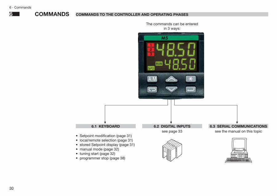
The commands can be entered in 3 ways:
48.5048.50
123
REMSP 1SP 2
RUNMAN
A / M
6.1 KEYBOARD
• Setpoint modification (page 31)• local/remote selection (page 31)• stored Setpoint display (page 31)• manual mode (page 32)• tuning start (page 32)• programmer stop (page 38)
6.2 DIGITAL INPUTSsee page 33
6.3 SERIAL COMMUNICATIONSsee the manual on this topic
M5 UK•ed4 10-12-2004 16:20 Pagina 30

275.0 Menu274.8 s.p.
l=r
l=rloc
l=rreM
locs.sel
s.selnone
s.sels.s.p.1
s.s.p.2
31
6 - Commands
6.1 KEYBOARD COMMANDS
A. SETPOINT MODIFICATION
The Setpoint is directly modified withthe $% keys.Once entered, the new value is checkedand becomes operating after 2 seconds.The end of this phase is flagged by flash-ing momentarily the display with SP.
B. LOCAL/REMOTE C. STORED SETPOINTS SELECTION
The Setpoint is directly modified with the $% keys.Once entered, the new value is checked and becomesoperating after 2 seconds. This phase is flagged by flash-ing momentarily the display with SP.
Note: When the Setpoint value is changed, the entered value is reached with a maximumrate set by the ramp up àsl .u and ramp down, àsl. d parameter. This applies toall the models and in all the operating modes.It is suggested to set àsl. u and àsl. d to Offwhen the remote Setpoint is operating.The entered Setpoint is defined as target Setpoint. It is displayed in the function menu atthe parameter t.=s.p.If the slope parameter is set to zero the Setpoint variation occurs instantaneously.
275.0274.8
350.0274.8
350.0274.8
Operator mode
Example of Setpoint modi-fication from 275 to 350
Modified Setpoint value
Flash momentarily the SP value to confirm that ithas become operating.back to the operator mode
Operator mode
Setpoint menu
Local/remote selection
Select remote
Select local
Stored Setpoint display
1st stored Setpoint
2nd stored Setpoint
The selected Setpointbecomes operating
pressing the è key.
when in remote, thegreen led is on
Ü
The selected Setpointbecomes operating
pressing the è key.
The two âäleds flag the Setpoint
operating.
after 2 seconds
Back to the operator mode Back to the operator mode
Press until
Setpoint change
Target Setpoint = 350°C
t t = 10 minutes
àsI. u = 10 digit/minutes
Example
Initial Setpoint= 250°C
M5 UK•ed4 10-12-2004 16:20 Pagina 31

275.0 Menu274.8 tune
tune
tune no
tune yes
notune
Adpt no
tune yes
no
32
6 - Commands
6.1.2 AUTO/MANUAL MODE
Operator mode(automatic)
Select manualgreen led on
Modify the output value
6.1.3 TUNING
Confirm yes to start
Confirm no
to stop
Confirm yes to start
Confirm no
to stop
The command start/stop isexecuted pressing the
è key.When the controller is
calculating the PID terms parameters, the
led is flashing
The commandstart/stop is executed
pressing the èkey.
press untilpress until
(Not present withprogrammedSetpoint)
AUTO AUTO
SP = PV
OPMAN=OPAUTO
SP (PV)
OPY
0
0
MAN
Op.r
ST
SP
changeOP
100%Setpoint SP
co
100%output OP
OPAUTO=OPMAN
PV
OP
275.0274.8MAN
50.0274.8MAN
35.0274.8MAN
This controller is provided with 2 dif-ferent Tuning algorithm
• One shot tune for calculating theoptimal PID terms parameters.
• Continuous tuning (adaptive tune)for a continuous calculation of thePID terms parameters in order toadapt the control to dynamicallychanging process or not linearones.
After the execution of the tuning, thecalculated values are automaticallypresented in the PID menu.
When this function is in progress, thecalculated values are visible in theTuning menu but cannot be modified.(see page 21)
Back to theoperatormode
One shot tune Continuous tune (adaptive tune)
M5 UK•ed4 10-12-2004 16:20 Pagina 32

33
6 - Commands
6.2 DIGITAL INPUT COMMANDS
A function is assigned, through theconfiguration procedure to each IL1and IL2 digital input. (see the para-meters setting at tab 8 at pag 17).The configured function is activatedwhen the digital input (free voltagecontact or open collector output) isin the On state . It is deactivated bysetting the input to the Off state.The activation of the function throughthe digital input has the highest pri-ority than through the keyboard orthrough the serial communication.
FunctionParameter
value
Performed operationNote
None ànone — — Not used
Set manual mode àA.Man Automatic Manual
Keypad lock àKeb.I Unlock LockedWith the keypad locked the commands fromdigital inputs and serial communication are stilloperating
PV measure hold àH.pU Normal
operationPV is hold
The value of PV is “frozen” at the time the digital input goes to the close state
Setpoint slopes inhibition àslo.1Rate limiting
is activeNormal
operationWhen the input is in the on state, the Setpointis changed in steps
àsp.1 Local 1st SPIf more than one digital input is selecting aSetpoint, the last to be activated is the oneoperating.
àsp.2 Local 2nd SP
àl=r. Local Remote
àH.=r. Hold/Run The status (RUN/HOLD) changes every timethe digital input switches from Off to On.
1st stored Setpoint
Remote Setpoint
2nd stored Setpoint
Sta
ndar
dS
etp
oint
Off On
Start/stopof a program
Pro
gram
med
Set
poi
nt
M5 UK•ed4 10-12-2004 16:20 Pagina 33

34
7 - Programmed Setpoint
7 PROGRAMMED SETPOINT
INTRODUCTION
The controller supplied with the Setpointprogrammer option (mod. M5-3… &)offers, in alternative to the adaptive tun-ing, the functionality to define, store,display and execute a program con-sisting in the Setpoint profile in time.
MAIN CHARACTERISTICS
• 1 program, 16 segments/program• start, stop, hold etc, commands
from the keyboard• time base in seconds, minutes or
hours• continuous or up to 1…9999 time
cycling of the program• 1 OP3 digital output with the state
profile defined by the program• setting of the maximum allowed
deviation from the Setpoint
The program consists of a sequenceof segments.
For each segment, it is specified:• the Setpoint to reach
às.p. • the duration
of the segmentàt.i.
• the state of the OP3 output
The program consists of:• 1 initial segment named O• 1 end segment named f• 1…14 normal segments
Initial segmentIts main purpose is to define the valuethe process variable has to maintainbefore starting the program.
End segmentIts main purpose is to define the valuethe process variable has to maintainat the end of the program and untilfurther changes of Setpoint.
àsp==
àti==
alwayspresent
Normal segmentsThese segments build up the profileprogram. There are 3 types of seg-ments:
àsp.==
Step
àti.== = 0
s.p. = Target setpointti. = Duration
= Previous segment= Current segment= Next segment
àti.==àsp.==
Dwell
Ramp
àti.==
àsp.==
7.1 PROGRAM STRUCTURE
M5 UK•ed4 10-12-2004 16:20 Pagina 34

35
7 - Programmed Setpoint
EXAMPLE OF SETPOINT PROFILE
300
250
200
150
100
50
350
1° 2° 3° 4° 5° 9° 10° 11°/12° 13° 14° End
300 50 70 80 110 170 190 210 230 250 time
t1 t2 t3 t4 t5 t9 t10 t11/t12 t13 t14
Segment Initial
Time t0
Programstart
°C Setpoint
àsp. I
àsp. 2
àsp. 3
àsp. 4 àsp. 9àsp.10
àsp.11
àsp.13
àsp.12
Maximumallowed
deviation
àCIo
àOpnOP3 Digital Output
band
àsp.14
àsp. f
àsp. 0
The OP3 digital output state, during thesegments, is defined in the program
àCIo contact close (On)
àOpn contact open (Off)
M5 UK•ed4 10-12-2004 16:20 Pagina 35

36
7 - Programmed Setpoint
7.2.1 MAXIMUM ALLOWEDDEVIATION ( bbaanndd )
If the PV controlled input value exceedsthe band, centred around the SP, thesegment time is extended of the sametime the PV input stays out of the band.The band width is defined in a para-meter of the program segment.The actual segment period is calcu-lated as ti..==+Ti
B. Dwell
àti.--
ti.-- + Ti
Ti
PV
SP
àband
àband
A. Ramp
àti.--
àti.-- + Ti
Ti
àband
PV
SPàband
The parameter #fail . specifiesthe behaviour of the programmer atpower up (see pag.37). Selectedbetween the following 3 choices:
#Cont Continue
#res Reset
#raMp Ramp
If #Cont is selected,the execution of the program starts
from the point reached at the powerfailure time.
All the parameters, like Setpointand the remaining time are restoredat the values they had at power off.
If #res is selected, at power on the program ends andgoes back to local mode.
If #raMp is selected, the execution of the program startsfrom the point reached at the powerfailure time.In this case, the programs contin-ue with PV reaching SV with aramp, whose slope corresponds tothe one of the segment running atthe power off.
PV
ti
SP Power Off
Power Off time
The drawing below illustrates thesituation.
Power off during a dwell
Power off during a ramp
ti
Power Off
Power Off
7.2 SETPOINT PROGRAMMER OPERATION
7.2.2 RE-START OF A PROGRAM AFTER A POWER FAILURE
M5 UK•ed4 10-12-2004 16:20 Pagina 36

37
7 - Programmed Setpoint
7.3 CREATION AND MODIFICATION OF A PROG.
band dO. I
275.8
Menu274.8prog
stat
fail
Unit
n.seg
Cyc.
ti. O
sp. 0
dO. O
ti. I
sp. 1
sp. f
dO. f
Program statusres = resetHold= holdrun = start
Restart after a power offCont= continueres = resetraMp= continue with
the slope
Time unitsp.sec = secondsp.Min = minutesp.hr = hours
N° of segments1…14 max
N° of program cyclesOff / 1…9999
Allowed deviationOff / 0…span/20
Segment 0 time0.1…999.9 Unit
Segment 0 Setpointwhole range
Segment 0 Digital output [1]Clo = closedOpn = openOff = inhibited
Segment 1 time0.1…999.9 Unit
Segment 1 SetpointIntera scala
Segment 1 Digital output [1]
End segment Setpointwhole range
End segment digital output[1]Clo = closedOpn = openOff = inhibited
Operator mode
Program menu(if present)
Back to the 1st parameter
[1] One digital output is providedwhich can be controlled by theprogram. This output is OP3. If thisfunctionality is not required, it canbe inhibited by setting Off theparameter àd.O.--
PARAMETER MENU
Continue for all the 14 normal
segments
M5 UK•ed4 10-12-2004 16:20 Pagina 37

38
7 - Programmed Setpoint
7.4 START/STOP OF A PROGRAM DIRECT MODE WITH THROUGH THE PARAMETER MENU
The various commands, supported by the controller, are dif-ferent for each of the following operating phases:A] when in Local Setpoint modeB]during the execution of a program C]when the program is in hold
Commands supported by the controllers
The different phase are displayed in a chained way, justfor easing the understanding of the functionality.Two different mode for starting and stopping a program areprovided:direct mode with the ê keythrough the parameter menu
AThe Ö green led is flashed at high rate when the controlled
variable is out of the allowed deviation bandThe current time of a segment is hold up to the time the variable
re-enter in the band.
275.0274.8
Menuprog
statrun
statHold
statres
275.0274.8
RUN
333.0329.0
RUN
Program runningÖ led
continuously on
Program start
Program Hold
Program start
Program hold
Program resetContinue up to the program end
Program holdÖ led flashing
Operator mode(local Setpoint)
Programmenu
PARAMETER MENU
Press until
Type ofoperatingsetpoint
Local Programmed Programmed
Phase Start of aprogram
Supportedcommands
Executionof a program
Holdof a program
Settingof Localsetpoint
When theprogram is
ended it comesback to normal
mode
Programstart
Programstop
in local mode
Programhold
Programstop
in local mode
Programcontinuation
Programstop
in local mode
BA C
M5 UK•ed4 10-12-2004 16:20 Pagina 38

Motor minimum stepMotor travel time
8 TECHNICAL SPECIFICATIONS8 - Technical Specifications
Featuresat 25 °C env. temp.
Description
Total configurability
Operating modes
Control mode
PV input (see table 1page 18 for thesignal ranges)
The choices are: input type, operating mode, type of control, safety strategies, alarm strategies
PID control
1 loop with single/double output
Accuracy0.25% ± 1 digits for temperature sensors0.1% ± 1 digits (for mV and mA)
1 loop as the latter with the addition of the Setpoint programmer
Discontinuous control
Between 100…240V~the error is minimal
AlgorithmPID with overshoot control or On-offPID with velocity algorithm, for controlling motorised positioners
Proportional band (P) 0.1…999.9%Integral time (I) 1…9999 s
ON-Off control
Derivative time (D) 0.1…999.9 s
Heat/Cool control
Error band 0.1…10.0 digit
Cycle time 0.2…100.0 sHysteresis 0.1…5.0%Dead band 0.0…5.0%Cool proportional band 0.1…999.9%
Motorised positioner
Cool Integral time 1…9999 sCool Derivative time 0.1…999.9 s
(user enabled/disabled)
Cool cycle time 0.2…100.0 s15…600 s0.1…5.0%
Feedback potentiometer 100Ω…10KΩ
(user enabled/disabled)
Common characteristics
A/D converter with resolution of 160.000 pointsUpdate measurement time: 50 msSampling time (max update time of the output) : 0.1…10.0 s configurableInput bias: - 60…+ 60 digitInput filter with enable/disable 0.1…999.9 s
Time proportioning controlManual reset 1…100% output (user enabled/disabled)
39
M5 UK•ed4 10-12-2004 16:20 Pagina 39

40
8 - Technical Specifications
Description
Auxiliary inputs(options)
Digitalinputs
Control output(cont.)
PV input
Resistance thermometer(for ∆T: R1+ R2 must be <320Ω)
Pt100Ω a 0°C(IEC 751)°C/°F selectable
2 or 3 wires or2 Pt100 for ∆T
Single or double channel, direct or reverse action
0…100.0% (OP1 heat), -100.0…0% (OP2 cool)Maximum limitMinimum limit 0…100.0% (OP1 heat)
Max. wire res.: 20Ω (3 wires)Input drift0.1°C/10°C Env. temperature<0.1°C/10Ω Wire Resistance
Thermocouple
L,J,T,K,R,S(IEC 548)°C/°F selectable
Internal cold junction compensation
Max. wire res.: 150ΩInput drift<2µV/°C Env. temperature<5µV/10Ω Wire Resistance
DC input (current)0/4…20mARj = 30Ω
Engineering unitsConfigurable decimal point positionwith or without √–
Initial scale.: - 999…9999Full scale.: -999…9999(minimum range of 100 digits)
Input drift<0.1% / 20°C Env. Temp.<5µV / 10Ω Wire Res.DC input (voltage)
0…50 mVRj = 10MΩ1-5/0-5/0-10VRj = 10KΩ
Remote SetpointNot isolatedaccuracy 0.1%
Current0/4…20mARj = 30Ω
Bias in engineering units and ± range
Voltage 1-5/ 0-5/ 0-10VRj = 300KΩ
Ratio from -9.99…+99.99
Local + Remote Setpoint
CT current transformer
max span 50 or 100 mAhdw selectable
Display from 10 to 200 Aresolution of 1A with alarm threshold (Heater break alarm)
Potentiometer100Ω…10KΩsupply 300mV
Position feedback measurement
2 logicThe closure of the externalcontact produces any of thefollowing actions:
Auto/Man mode change, Local/Remote Setpoint mode change, StoredSetpoints activation, keypad lock, measure hold and slopes inhibit.
Start, stop, hold of a program(only with Setpoint programmer)
Featuresat 25 °C env. temp.
M5 UK•ed4 10-12-2004 16:20 Pagina 40

Galvanic insulation 500V~/1min. Resol.: 12 bit (0.025%)Accur. 0.1%. Short circuit protection
41
8 - Technical Specifications
Featuresat 25 °C env. temp.
Description
Control output
Alarms
OP4 analogueoutput(optional)
Setpoint
Whole scale
± range
1A/250V~~ resistive loads
0…1/5/10V 500Ω / 20mA max
Current0/4…20mA 750Ω/10V max
Deviation threshold
Voltage1-5/0-5/0-10V 500Ω/20mA max
Galvanic insulated: 500 V~~/1min. Resolution: 12 bit (0.025%)Accuracy: 0.1% . Short circuit protected
Local plus 2 stored Setpoints
Retransmission of PV or SP
0…range
Maximum slope 0.01…99.99%/s up and down
Absolute threshold
Safety value -100…100% . (user enabled/disabled)
Related to the program (optional) (OP3)
Time proportioning
Relays
Band width
Heater Break detection
Triac
Action type
Acknowledge (latching)
SSR drive
NO 2A/250V~~ resistive loads
AnalogueCurrent
Activation inhibit (blocking)
Voltage
Loop Break Alarm
Motor positioner (3 states)Raise - Stop - Lower
Time programmable (optional)
SPST NO, 2A/250V~~ resistive loadHysteresis 0.1…5.0% symmetrical
Remote with trimLocal with trimLocal and RemoteOnly Remote
Actions
Active high
Active low
0/4…20mA max 750Ω/10V max
Special functions
0…22V–, 20mA max (for static switches)
Double action 2 poles NO, 2A/250V~ resistive load
Ramp up and down, with slope in digit/s,digit/minute or digit/hourbetween 0.0…10.0% of the rangeHigh and low limits
M5 UK•ed4 10-12-2004 16:20 Pagina 41

42
8 - Technical Specifications
Featuresat 25 °C env. temp.
Description
ProgrammableSetpoint(optional)
Tuning
Auto/Manual station Serial com.(optional)Auxil. supply
Operational safety
Generalcharacteristics
18V– ± 20%, 30mA max for transmitters (2, 3, 4 wires)
Measureinput
Detection of out of range, short circuit or sensor break with automatic activation of the safety strategies andalerts on display
DimensionsProtection EN650529
Electromagnetic compatibilityElectric safety
Supply
Access protection
Parameters
Control output
1/16 DIN - 48 x 48, depth 150 mm, weight 230 g approx.IP20 termination unit, IP65 front panel
Compliance to the CE standards for industrial system and equipmentCompliance to EN61010, installation class 2 (2500V) pollution class 2
100 - 240V~ (- 15% + 10%) 50/60Hz or 24V~ (- 25% + 12%) 50/60Hz and 24V– (- 15% + 25%)power consumption 3W max
Password to access the configuration data and the parameter protection menu
Parameters and configuration data are stored in a non volatile memory for an unlimited time.They are organised in functionally homogeneous groups, like: visible and changeable, visible and notchangeable, not visible.
Safety value: -100…+100%. (user enabled/disabled)
1 program, 16 segments (1 initial and 1 end)From 1 to 9999 cycles or continuous cycling (Off)Time values in seconds, minutes and hoursStart, stop, hold, etc. activated from the keyboard, digital input and serial communications.
One shot Tune- step response method for calculating the PID terms parameters
Adaptive Tune self-learning, not intrusive, analysis of the process response to perturbations and continuously calculation of the PIDparameters (not available with the Setpoint Programmer option)
Integrated in the controller, bumplessOperated from keyboard, digital input and serial communication.
RS485 isolated, Modbus-Jbus, 1200, 2400, 4800, 9600, 19200 bit/s, 2 wires
UL and cUL Omologation File E176452
M5 UK•ed4 10-12-2004 16:20 Pagina 42

43
Warranty
1 WARRANTY
We warrant that the productswil l be free from defects inmaterial and workmanship for 3years from the date of delivery.The warranty above shall notapply for any failure caused bythe use of the product not inl ine with the instructionsreported on this manual.
G.&
P. G
rafic
a &
Pub
blic
ità •
Gaz
zani
ga (B
G) •
e-m
ail:
G&
P@
ma
il-
ga
te.n
et
M5 UK•ed4 10-12-2004 16:20 Pagina 43

SUBSIDIARY
FRANCEASCON FRANCE
Phone 0033 1 64 30 62 62Fax 0033 1 64 30 84 98
AGENCE SUD-EST
Phone 0033 4 74 27 82 81Fax 0033 4 74 27 81 71
AGENCE RÉGION-EST
Phone 0033 3 89 76 99 89Fax 0033 3 89 76 87 03
ARGENTINAMEDITECNA S.R.L.Phone +5411 4585 7005Fax +5411 4585 3437
AUSTRALIAIPA INDUSTRIAL PYROMETER
(AUST) PTY.LTDPhone +61 8 8352 3688Fax +61 8 8352 2873
FINLAND & ESTONIATIM-TOOL OY
Phone +358 50 501 2000Fax +358 9 50 55 144
GERMANYMESA INDUSTRIE ELEKTRONIK GMBHPhone +49 2365 915 220Fax +49 2365 915 225
GREECECONTROL SYSTEM
Phone +30 23 10 521 055-6 Fax +30 23 10 515 495BRANCH OFFICE
Phone +30 1 646 6276Fax +30 1 646 6862
HOLLANDTEMPCONTROL I.EP. B.V.Phone +31 70 347 64 31Fax +31 70 38 22 55 16
PORTUGALREGIQUIPAMENTOS LDAPhone +351 21 989 0738Fax +351 21 989 0739
SPAININTERBIL S.L.Phone +34 94 453 50 78Fax +34 94 453 51 45
BRANCH OFFICES
Phone +34 93 311 98 11 Fax +34 93 311 93 65 Phone +34 91 656 04 71Fax +34 91 656 04 71
SWITZERLANDCONTROLTHERM GMBHPhone +41 1 954 37 77Fax +41 1 954 37 78
TURKEY KONTROL SISTEMLERI LTDPhone +90 216 527 96 15Fax +90 216 527 96 20
UNITED KINGDOMEUKERO CONTROLS LTDPhone +44 20 8568 4664Fax +44 20 8568 4115
ASCON’S WORLDWIDE SALES NETWORK
DISTRIBUTORS
M5 UK•ed4 10-12-2004 16:20 Pagina 44
Related Documents