C-418EM Instruction Manual, March 2015 VOLTAGE ALARM INDICATOR GROUND FAULT INDICATION VIA

Welcome message from author
This document is posted to help you gain knowledge. Please leave a comment to let me know what you think about it! Share it to your friends and learn new things together.
Transcript
C-418EM Instruction Manual, March 2015
VOLTAGE ALARM INDICATORGROUND FAULT INDICATIONVIA
I-Gard’s commitment to electrical safety provides both industrial and commercial
customers with the products needed to protect their electrical equipment and the
people that operate them.
As the only electrical-safety focused company whose product portfolio includes
neutral grounding resistors, high-resistance grounding systems and optical arc
mitigation, we take pride in our technologies that reduce the frequency and
impact of electrical hazards, such as arc flash and ground faults.
For those customers who have purchased from us over the last 30 years, you
know us for the quality and robustness of our products, our focus on customer
service and technical leadership. We build on this foundation by investing
in developing new products in electrical safety education - including EFC
scholarship program - by actively participating in the IEEE community programs
on technical and electrical safety standard, and working with local universities
at discovering new technologies. We remain unrelenting in our goal of improving
electrical safety in the workplace.
Our commitment to excellence is validated by long-standing relationships with
industry leaders in fields as diverse as petroleum and gas, hospitals, automotive,
data centers, food processing, aerospace, water and waste water plants, and
telecommunications. We provide our customers with the product and application
support required to ensure that their electrical distribution system is safe and reliable.
ABOUT I-GARD
SUBJECT PAGE
1. Features ........................................................................................................................................... 22. Introduction ......................................................................................................................................23. Operation ......................................................................................................................................... 34. Indication ......................................................................................................................................... 35. Installation Instructions .................................................................................................................. 76. Service ............................................................................................................................................. 87. Technical Specifications ................................................................................................................. 88. Dimensional Drawings .................................................................................................................. 10
TABLES
Table 2.0 Catalogue Numbers ............................................................................................................ 2Table 4.0 VIA Indication Summary ..................................................................................................... 4Table 4.1 Auxiliary Relay Operation Summary .................................................................................. 4Table 5.0 Mounting Hardware Included with VIA .............................................................................. 5Table 5.1 Mounting hardware included with VIA-R .......................................................................... 6
FIGURES
Figure 3.0 VIA Internal Operation Diagram ...................................................................................... 3Figure 5.0 Connections and Mounting - mm (inches) ...................................................................... 6FIgure 5.1 VIA-R Cut-out Dimensions for flush mounting - mm (inches) ....................................... 7Figure 5.2 VIA Connected to System Through Potential Transformers (PT’s) .............................. 7Figure 8.0 VIA/VIA-R Dimensions - mm (Inches) ............................................................................ 10Figure 8.1 VIA-R Display Dimensions - mm (Inches) ...................................................................... 11
TABLE OF CONTENTS
1. FEATURES
• POWERED DIRECTLY FROM 3 PHASES
• BRIGHT LED LAMP TECHNOLOGY USED FOR INDICATION
• ALL PHASES FUSED INTERNALLY
• CONTAINS 2 AUXILIARY RELAYS FOR EXTERNAL INDICATION
• PLASTIC ENCLOSURE WITH KNOCKOUTS FOR CONVENIENT MOUNTING
• ISOLATED FLUSHMOUNT EXTERNAL DISPLAYS ARE OPTIONAL
2. INTRODUCTION
The I-Gard VIA is a 3-phase ground fault indicator unit and is designed specifically for ground fault Indication on
wye or delta-connected, three-phase, three-wire, resistance grounded or ungrounded power systems. It may be
used on systems between 120V and 600V (up to 690 without CSA approval) or up to any voltage with the use of
120V or 240V potential transformers (PT’s).
One or more optional flush mounted external displays can be mounted on panel doors or other locations. Up to four
displays can be connected using an RJ-45 (networking) cable in a daisy-chain configuration. Isolation inside the VIA
protects the external display from high voltages. Up to several kilometers of cable can be used between the VIA and
VIA-R display. Refer to table 2.0 for catalogue numbers.
The VIA is designed to provide an alarm when a single ground fault occurs, and to indicate on which phase the fault
occurred. Additionally the VIA can indicate both phase loss as well as DC ground faults. Each phase is fused inside
the VIA enclosure; therefore it does not require any external hardware.
When a second fault, on another phase, occurs in the distribution system, the only limitation on the amount of
ground fault current is the impedances of the faults, the impedance of the source (transformer windings feeding the
faults) and the ground circuit between them. Under this condition, extensive damage can occur, making it necessary
to clear the first fault as soon as possible. The prime advantage, then, of using the VIA ground alarm indicator unit,
is that the user is given early warning of ground faults allowing time to locate and clear the fault to ensure maximum
service continuity.
VIA VIA (Voltage Indication Alarm)
VIA-R Remote VIA
catalogue number description
Table 2.0 Catalogue Numbers
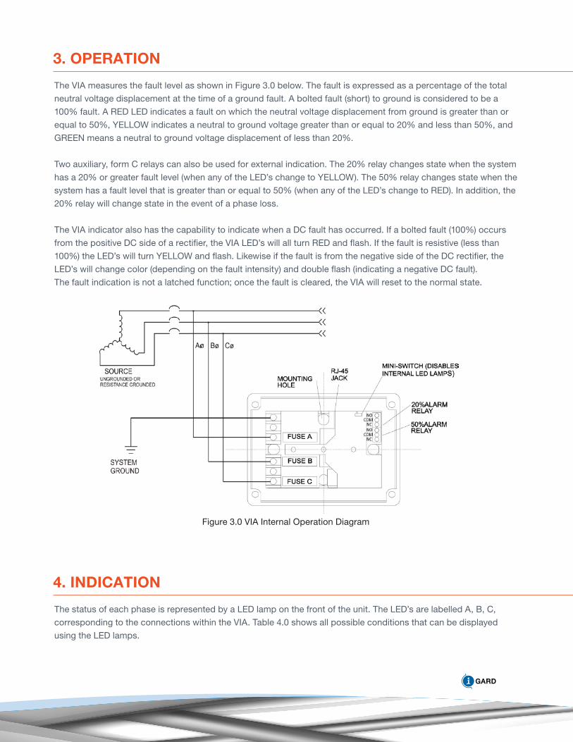
3. OPERATION
The VIA measures the fault level as shown in Figure 3.0 below. The fault is expressed as a percentage of the total
neutral voltage displacement at the time of a ground fault. A bolted fault (short) to ground is considered to be a
100% fault. A RED LED indicates a fault on which the neutral voltage displacement from ground is greater than or
equal to 50%, YELLOW indicates a neutral to ground voltage greater than or equal to 20% and less than 50%, and
GREEN means a neutral to ground voltage displacement of less than 20%.
Two auxiliary, form C relays can also be used for external indication. The 20% relay changes state when the system
has a 20% or greater fault level (when any of the LED’s change to YELLOW). The 50% relay changes state when the
system has a fault level that is greater than or equal to 50% (when any of the LED’s change to RED). In addition, the
20% relay will change state in the event of a phase loss.
The VIA indicator also has the capability to indicate when a DC fault has occurred. If a bolted fault (100%) occurs
from the positive DC side of a rectifier, the VIA LED’s will all turn RED and flash. If the fault is resistive (less than
100%) the LED’s will turn YELLOW and flash. Likewise if the fault is from the negative side of the DC rectifier, the
LED’s will change color (depending on the fault intensity) and double flash (indicating a negative DC fault).
The fault indication is not a latched function; once the fault is cleared, the VIA will reset to the normal state.
Figure 3.0 VIA Internal Operation Diagram
4. INDICATION
The status of each phase is represented by a LED lamp on the front of the unit. The LED’s are labelled A, B, C,
corresponding to the connections within the VIA. Table 4.0 shows all possible conditions that can be displayed
using the LED lamps.
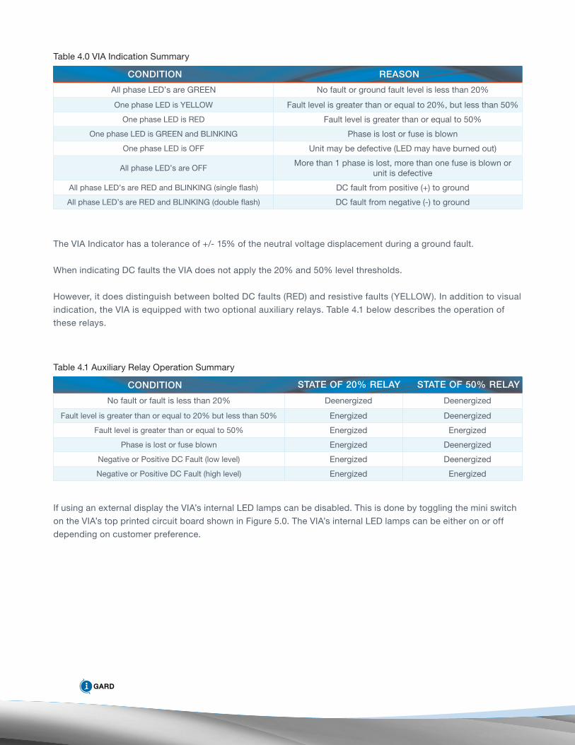
All phase LED’s are GREEN No fault or ground fault level is less than 20%
One phase LED is YELLOW Fault level is greater than or equal to 20%, but less than 50%
One phase LED is RED Fault level is greater than or equal to 50%
One phase LED is GREEN and BLINKING Phase is lost or fuse is blown
One phase LED is OFF Unit may be defective (LED may have burned out)
All phase LED’s are OFFMore than 1 phase is lost, more than one fuse is blown or
unit is defective
All phase LED’s are RED and BLINKING (single flash) DC fault from positive (+) to ground
All phase LED’s are RED and BLINKING (double flash) DC fault from negative (-) to ground
condition reason
Table 4.0 VIA Indication Summary
The VIA Indicator has a tolerance of +/- 15% of the neutral voltage displacement during a ground fault.
When indicating DC faults the VIA does not apply the 20% and 50% level thresholds.
However, it does distinguish between bolted DC faults (RED) and resistive faults (YELLOW). In addition to visual
indication, the VIA is equipped with two optional auxiliary relays. Table 4.1 below describes the operation of
these relays.
No fault or fault is less than 20% Deenergized Deenergized
Fault level is greater than or equal to 20% but less than 50% Energized Deenergized
Fault level is greater than or equal to 50% Energized Energized
Phase is lost or fuse blown Energized Deenergized
Negative or Positive DC Fault (low level) Energized Deenergized
Negative or Positive DC Fault (high level) Energized Energized
condition state of 20% relay
Table 4.1 Auxiliary Relay Operation Summary
If using an external display the VIA’s internal LED lamps can be disabled. This is done by toggling the mini switch
on the VIA’s top printed circuit board shown in Figure 5.0. The VIA’s internal LED lamps can be either on or off
depending on customer preference.
state of 50% relay
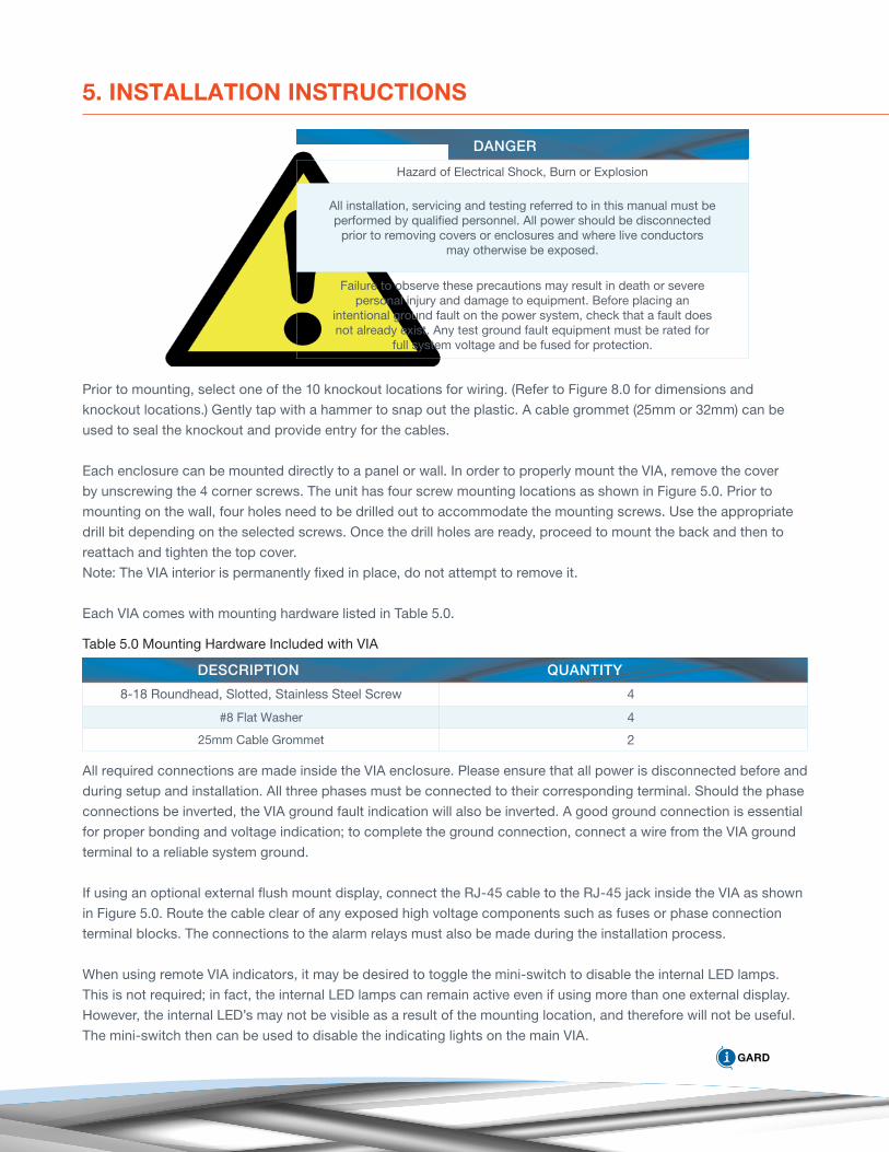
5. INSTALLATION INSTRUCTIONS
Hazard of Electrical Shock, Burn or Explosion
All installation, servicing and testing referred to in this manual must be performed by qualified personnel. All power should be disconnected
prior to removing covers or enclosures and where live conductors may otherwise be exposed.
Failure to observe these precautions may result in death or severe personal injury and damage to equipment. Before placing an
intentional ground fault on the power system, check that a fault does not already exist. Any test ground fault equipment must be rated for
full system voltage and be fused for protection.
Prior to mounting, select one of the 10 knockout locations for wiring. (Refer to Figure 8.0 for dimensions and
knockout locations.) Gently tap with a hammer to snap out the plastic. A cable grommet (25mm or 32mm) can be
used to seal the knockout and provide entry for the cables.
Each enclosure can be mounted directly to a panel or wall. In order to properly mount the VIA, remove the cover
by unscrewing the 4 corner screws. The unit has four screw mounting locations as shown in Figure 5.0. Prior to
mounting on the wall, four holes need to be drilled out to accommodate the mounting screws. Use the appropriate
drill bit depending on the selected screws. Once the drill holes are ready, proceed to mount the back and then to
reattach and tighten the top cover.
Note: The VIA interior is permanently fixed in place, do not attempt to remove it.
Each VIA comes with mounting hardware listed in Table 5.0.
Table 5.0 Mounting Hardware Included with VIA
8-18 Roundhead, Slotted, Stainless Steel Screw 4
#8 Flat Washer 4
25mm Cable Grommet 2
description
All required connections are made inside the VIA enclosure. Please ensure that all power is disconnected before and
during setup and installation. All three phases must be connected to their corresponding terminal. Should the phase
connections be inverted, the VIA ground fault indication will also be inverted. A good ground connection is essential
for proper bonding and voltage indication; to complete the ground connection, connect a wire from the VIA ground
terminal to a reliable system ground.
If using an optional external flush mount display, connect the RJ-45 cable to the RJ-45 jack inside the VIA as shown
in Figure 5.0. Route the cable clear of any exposed high voltage components such as fuses or phase connection
terminal blocks. The connections to the alarm relays must also be made during the installation process.
When using remote VIA indicators, it may be desired to toggle the mini-switch to disable the internal LED lamps.
This is not required; in fact, the internal LED lamps can remain active even if using more than one external display.
However, the internal LED’s may not be visible as a result of the mounting location, and therefore will not be useful.
The mini-switch then can be used to disable the indicating lights on the main VIA.
danger
Quantity
There are no limits on the distance between the VIA base and the VIA-R remote display. The unit comes with a
5-meter cable, but this can be replaced with any length. The cable cannot be cross wired (must be a straight
through cable) with 8 conductors and a modular RJ-45 plug at both ends.
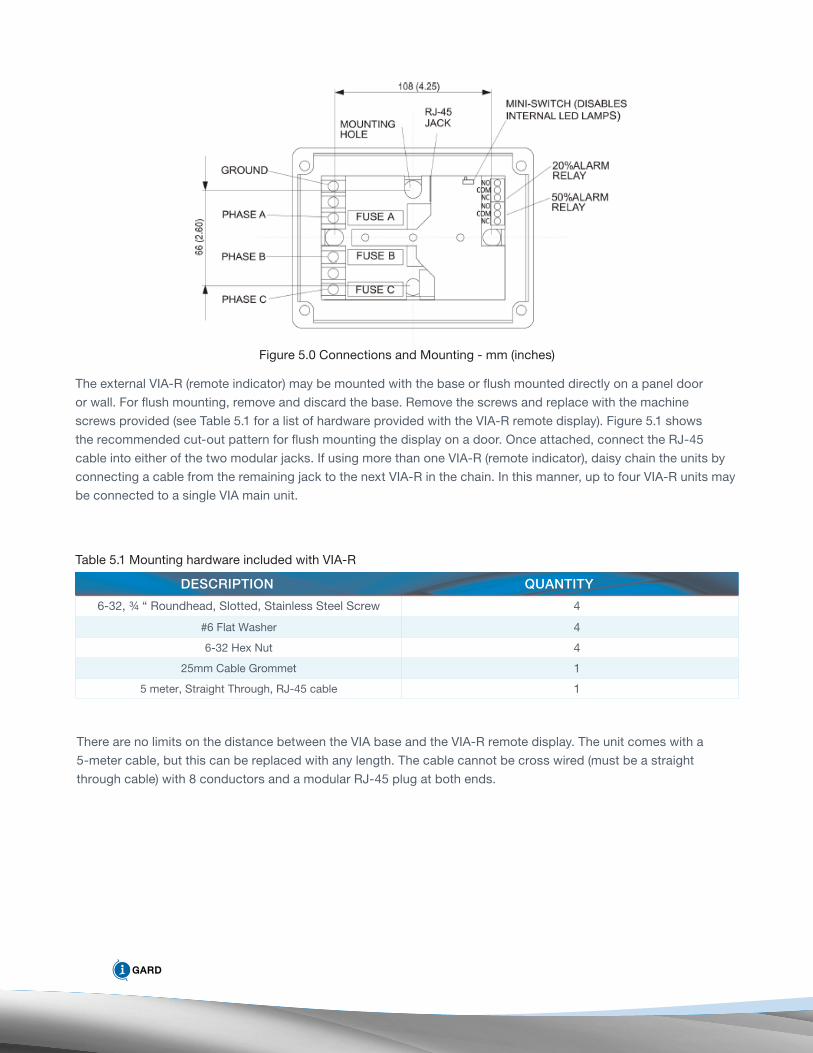
Figure 5.0 Connections and Mounting - mm (inches)
The external VIA-R (remote indicator) may be mounted with the base or flush mounted directly on a panel door
or wall. For flush mounting, remove and discard the base. Remove the screws and replace with the machine
screws provided (see Table 5.1 for a list of hardware provided with the VIA-R remote display). Figure 5.1 shows
the recommended cut-out pattern for flush mounting the display on a door. Once attached, connect the RJ-45
cable into either of the two modular jacks. If using more than one VIA-R (remote indicator), daisy chain the units by
connecting a cable from the remaining jack to the next VIA-R in the chain. In this manner, up to four VIA-R units may
be connected to a single VIA main unit.
6-32, ¾ “ Roundhead, Slotted, Stainless Steel Screw 4
#6 Flat Washer 4
6-32 Hex Nut 4
25mm Cable Grommet 1
5 meter, Straight Through, RJ-45 cable 1
description Quantity
Table 5.1 Mounting hardware included with VIA-R
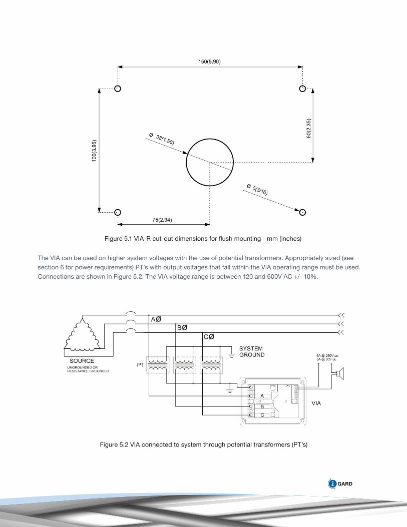
Figure 5.1 VIA-R cut-out dimensions for flush mounting - mm (inches)
The VIA can be used on higher system voltages with the use of potential transformers. Appropriately sized (see
section 6 for power requirements) PT’s with output voltages that fall within the VIA operating range must be used.
Connections are shown in Figure 5.2. The VIA voltage range is between 120 and 600V AC +/- 10%.
Figure 5.2 VIA connected to system through potential transformers (PT’s)
6. SERVICE
For assistance in installation, set-up or testing please contact I-Gard (www.i-gard.com).
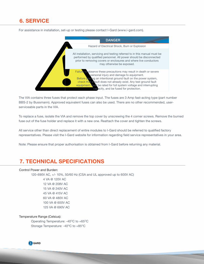
Hazard of Electrical Shock, Burn or Explosion
All installation, servicing and testing referred to in this manual must beperformed by qualified personnel. All power should be disconnected
prior to removing covers or enclosures and where live conductorsmay otherwise be exposed.
Failure to observe these precautions may result in death or severepersonal injury and damage to equipment.
Before placing an intentional ground fault on the power system,check that a fault does not already exist. Any test ground fault
equipment must be rated for full system voltage and interruptingcapacity, and be fused for protection.
danger
The VIA contains three fuses that protect each phase input. The fuses are 3 Amp fast-acting type (part number
BBS-2 by Bussmann). Approved equivalent fuses can also be used. There are no other recommended, user-
serviceable parts in the VIA.
To replace a fuse, isolate the VIA and remove the top cover by unscrewing the 4 corner screws. Remove the burned
fuse out of the fuse holder and replace it with a new one. Reattach the cover and tighten the screws.
All service other than direct replacement of entire modules to I-Gard should be referred to qualified factory
representatives. Please visit the I-Gard website for information regarding field service representatives in your area.
Note: Please ensure that proper authorisation is obtained from I-Gard before returning any material.
7. TEChNICAL SPECIFICATIONSControl Power and Burden:
120-690V AC, +/- 10%, 50/60 Hz (CSA and UL approved up to 600V AC)
4 VA @ 120V AC
12 VA @ 208V AC
15 VA @ 240V AC
45 VA @ 415V AC
60 VA @ 480V AC
100 VA @ 600V AC
125 VA @ 690V AC
Temperature Range (Celsius):
Operating Temperature: -40OC to +65OC
Storage Temperature: -40OC to +85OC
Isolation Voltage for External Display:
AC Voltage (60 seconds): 3000V
Peak Voltage (1 second): 6000V
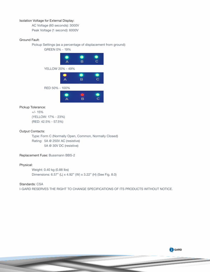
Ground Fault:
Pickup Settings (as a percentage of displacement from ground):
GREEN 0% - 19%
YELLOW 20% - 49%
RED 50% - 100%
Pickup Tolerance:
+/- 15%
(YELLOW: 17% - 23%)
(RED: 42.5% - 57.5%)
Output Contacts:
Type: Form C (Normally Open, Common, Normally Closed)
Rating: 5A @ 250V AC (resistive)
5A @ 30V DC (resistive)
Replacement Fuse: Bussmann BBS-2
Physical:
Weight: 0.40 kg (0.88 lbs)
Dimensions: 6.57” (L) x 4.92” (W) x 3.22” (H) (See Fig. 8.0)
Standards: CSA
I-GARD RESERVES THE RIGHT TO CHANGE SPECIFICATIONS OF ITS PRODUCTS WITHOUT NOTICE.
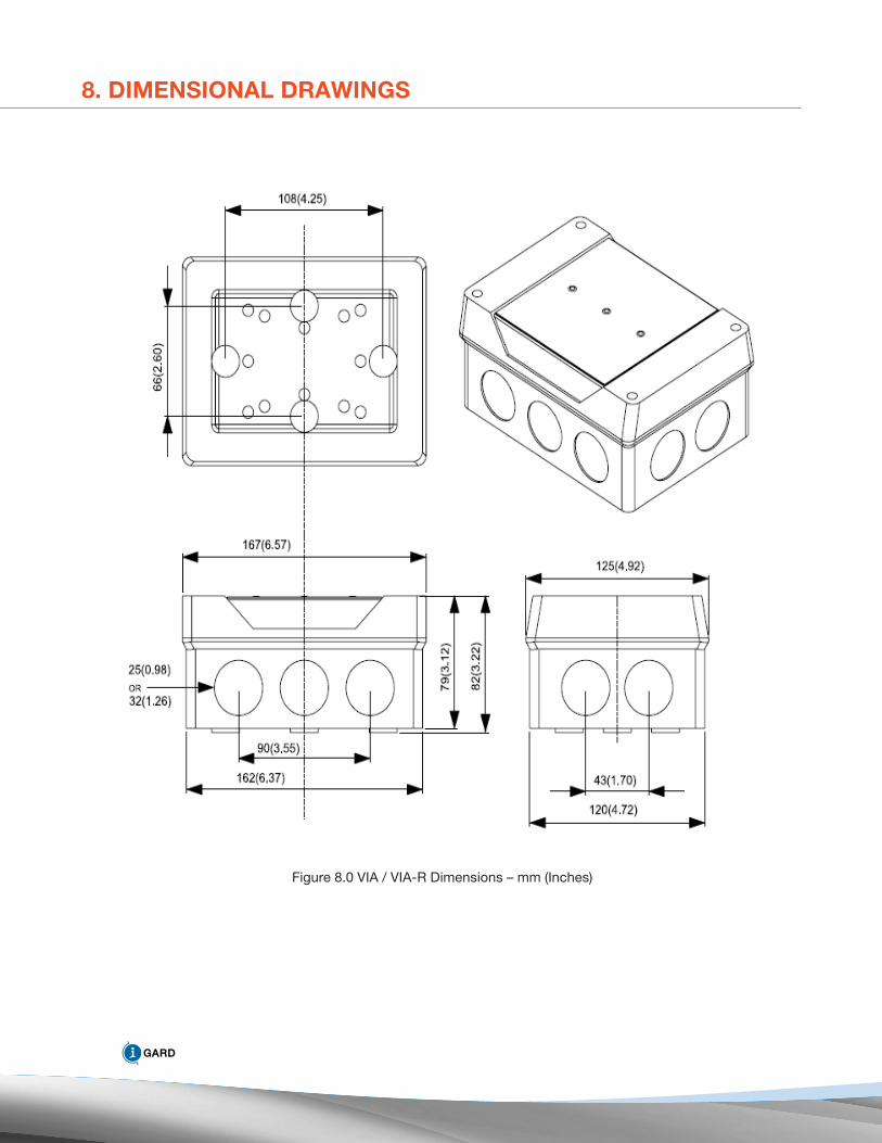
8. DImENSIONAL DRAwINGS
Figure 8.0 VIA / VIA-R Dimensions – mm (Inches)
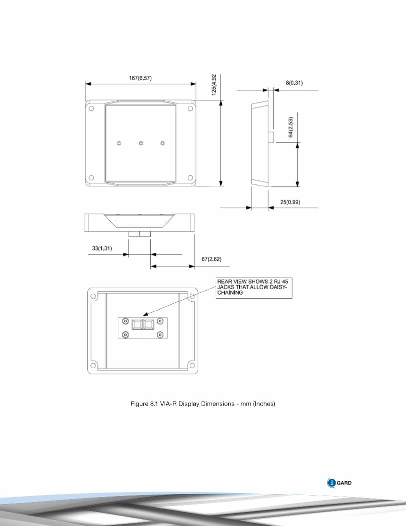
Figure 8.1 VIA-R Display Dimensions - mm (Inches)

Related Documents