BY ORDER OF THE SECRETARY OF THE AIR FORCE AIR FORCE MANUAL 11-2C-130H VOLUME 3 27 SEPTEMBER 2021 Flying Operations C-130H OPERATIONS PROCEDURES COMPLIANCE WITH THIS PUBLICATION IS MANDATORY ACCESSIBILITY: Publications and forms are available on the e-Publishing website at www.e-Publishing.af.mil for downloading or ordering. RELEASABILITY: There are no releasability restrictions on this publication. OPR: AMC/A3VX Supersedes: AFMAN11-2C-130HV3, 12 December 2019 Certified by: AF/A3T (Maj Gen Albert G. Miller) Pages: 199 This manual implements Air Force Policy Directive (AFPD) 11-2, Aircrew Operations. It establishes guidance for the operation of the C-130H aircraft to safely and successfully accomplish worldwide mobility missions. This is a specialized publication intended for use by Airmen who have graduated from technical training related to this publication. It is used in conjunction with Air Force Manual (AFMAN) 11-202, Volume 3, Flight Operations, the appropriate Major Air Command (MAJCOM) supplement, and Air Force Tactics Techniques and Procedures (AFTTP) 3-3.C-130H. This manual applies to all civilian employees and uniformed members of the Regular Air Force, Air Force Reserve and Air National Guard who operate or maintain C-130H aircraft. This manual does not apply to the United States Space Force. This manual requires the collection and or maintenance of information protected by the Privacy Act of 1974 authorized by 37 U.S.C. 301a, Incentive Pay: Public Law (P.L.) 92-204; P.L. 93-570; P.L. 93-294) Aviation Career Incentive Act of 1974 (“ACIA of 1974”), P.L. 93-294, and the Aviation Career Improvement Act of 1989 (“ACIA of 1989”) (in P.L. 101-189), and the National Defense Authorization Acts (NDAA) of Fiscal Year (FY) 96 (P.L. 104-106), FY 99 (P.L. 105- 261) and FY 00 (P.L. 160-65). The applicable SORNs are Military Personnel Records System (F036 AF PC C) (Authority: 10 USC 8013), Secretary of the Air Force: Powers and duties; delegation by; Personnel Data System (MILPDS)(F036 AF PC Q) (Authority: 10 U.S.C., various sections); and Aviation Resource Management System of Records Notice (ARMS) (F011 AF XO A) are available at: http://dpclo.defense.gov/Privacy/SORNs.aspx. Ensure all records generated as a result of processes prescribed in this publication adhere to Air Force Instruction 33-322, Records Management and Information Governance Program, and are disposed in accordance with the Air

Welcome message from author
This document is posted to help you gain knowledge. Please leave a comment to let me know what you think about it! Share it to your friends and learn new things together.
Transcript

BY ORDER OF THE
SECRETARY OF THE AIR FORCE
AIR FORCE MANUAL 11-2C-130H
VOLUME 3
27 SEPTEMBER 2021
Flying Operations
C-130H OPERATIONS PROCEDURES
COMPLIANCE WITH THIS PUBLICATION IS MANDATORY
ACCESSIBILITY: Publications and forms are available on the e-Publishing website at
www.e-Publishing.af.mil for downloading or ordering.
RELEASABILITY: There are no releasability restrictions on this publication.
OPR: AMC/A3VX
Supersedes: AFMAN11-2C-130HV3,
12 December 2019
Certified by: AF/A3T
(Maj Gen Albert G. Miller)
Pages: 199
This manual implements Air Force Policy Directive (AFPD) 11-2, Aircrew Operations. It
establishes guidance for the operation of the C-130H aircraft to safely and successfully accomplish
worldwide mobility missions. This is a specialized publication intended for use by Airmen who
have graduated from technical training related to this publication. It is used in conjunction with
Air Force Manual (AFMAN) 11-202, Volume 3, Flight Operations, the appropriate Major Air
Command (MAJCOM) supplement, and Air Force Tactics Techniques and Procedures (AFTTP)
3-3.C-130H. This manual applies to all civilian employees and uniformed members of the Regular
Air Force, Air Force Reserve and Air National Guard who operate or maintain C-130H aircraft.
This manual does not apply to the United States Space Force. This manual requires the collection
and or maintenance of information protected by the Privacy Act of 1974 authorized by 37 U.S.C.
301a, Incentive Pay: Public Law (P.L.) 92-204; P.L. 93-570; P.L. 93-294) Aviation Career
Incentive Act of 1974 (“ACIA of 1974”), P.L. 93-294, and the Aviation Career Improvement Act
of 1989 (“ACIA of 1989”) (in P.L. 101-189), and the National Defense Authorization Acts
(NDAA) of Fiscal Year (FY) 96 (P.L. 104-106), FY 99 (P.L. 105- 261) and FY 00 (P.L. 160-65).
The applicable SORNs are Military Personnel Records System (F036 AF PC C) (Authority: 10
USC 8013), Secretary of the Air Force: Powers and duties; delegation by; Personnel Data System
(MILPDS)(F036 AF PC Q) (Authority: 10 U.S.C., various sections); and Aviation Resource
Management System of Records Notice (ARMS) (F011 AF XO A) are available at:
http://dpclo.defense.gov/Privacy/SORNs.aspx. Ensure all records generated as a result of
processes prescribed in this publication adhere to Air Force Instruction 33-322, Records
Management and Information Governance Program, and are disposed in accordance with the Air

2 AFMAN11-2C-130HV3 27 SEPTEMBER 2021
Force Records Disposition Schedule, which is located in the Air Force Records Information
Management. Refer recommended changes and questions about this manual to the OPR listed
above using the Air Force Form 847, Recommendation for Change of Publication; route AF Form
847s from the field through the appropriate chain of command. This manual may be supplemented
at any level, but all supplements that directly implement this manual must be routed to the Office
of Primary Responsibility (OPR) for coordination prior to certification and approval. The
authorities to waive wing/unit level requirements in this manual are identified with a Tier (“T-0,
T-1, T-2, T-3”) number following the compliance statement. See Department of the Air Force
(DAFI) 33-360, Publications and Forms Management, for a description of the authorities
associated with the Tier numbers. Submit requests for waivers through the chain of command to
the appropriate Tier waiver approval authority, or alternately, to the requestor’s commander for
non-tiered compliance items. The use of the name or mark of any specific manufacturer,
commercial product, commodity, or service in this publication does not imply endorsement by the
Air Force. Compliance with the attachments in this publication is mandatory.
SUMMARY OF CHANGES
This publication has been substantially revised and needs to be completely reviewed. Major
changes include Mobilitity Pilot Development (MPD) Phase I takeoff and landing guidance.
Added Automatic Dependent Surveillance-Broadcast (ADS-B) guidance. Clarified element lead
duties in a multiple element formation. Added unprepared surface takeoff and landing
recommendations. Added guidance requiring the use of airport diagram or airfield depiction
during taxi operations. Simplified reduced power operations guidance. Visual Flight Rules (VFR)
tactical approaches now allow for 60 degrees angle of bank. Updated formation ballistic wind
guidance. Updated unaided night visual formation requirements. Additional publication changes,
Changed all AFI11-2C-130HV1 and AFI11-231 references to AFMAN. Changed all AFI 33-360
references to DAFI 33-360. Deleted all AFMAN 11-217 references and replaced with AFMAN
11-202V3. Changed all AFI13-217 references to DAFMAN. Chapter 2, Table 2.1 (note 7).
Only one LM required for single LCLA unilaterally using ramp/single bundle drift back
procedures; 2.2.4.1.2 Changed to only allow element lead duties in a multiple element formation;
2.2.4.3.1, 2.2.4.3.2 Clarified IP supervision requirement. -Chapter 3, All GTC, APU and APN-
59 Radar requirements were removed from tables. Table 3.13 (TCAS). Updated
remarks/limitations/exceptions; Table 3.13 Added ADS-B guidance; 3.11 Autopilot pitch axis
requirements were replaced with altitude hold requirements. Chapter 4, 4.2.1.1 Removed
Exception allowing MPD trained pilots to takeoff/land during emergencies with direct IP
supervision; 4.2.3.1 Updated MPD Phase I takeoff/landing guidance; 4.6.1 Added aircraft lighting
guidance; 4.8.4, 4.8.4.1 Added unprepared surface recommendations; 4.9.3.1 Added airport
diagram requirement; 4.9.4.4 Added reverse taxi to combat offload exception; 4.13.1 Added
additional RAD ALT illumination guidance for maneuvering airplane; 4.15 Simplified reduced
power operations guidance. Chapter 5, Deleted variable visibility/ceiling reports guidance.
Information now in AFMAN 11-202V3_AMCSUP. Formerly 5.20.3.4; 5.6 Changed to allow
electronic forms in mission kits; 5.20.5.1.1 Updated ILS PRM communications requirement;
Chapter 7, 7.1.3 Added exception for carrying passengers while airdropping during exercises.
Added Tier waiver; 7.3.2.3 Clarified throttle setting for simulated engine failure on T-56-15A
engines. Chapter 8, 8.2.1.4 Changed to allow any MAJCOM approved mission planning system.
Deleted True Airspeed Check Procedure. Formerly 8.9. Chapter 9, Removed all GTC/ATM

AFMAN11-2C-130HV3 27 SEPTEMBER 2021 3
references; 9.8.1 Added eTOLD option for Pilot Information Card; 9.9.2 Removed mandate for
the FE to complete AF Form 4108. Chapter 10, Removed requirement for weight and balance
supplemental handbook to include T.O. 1C-130E-5 and AFMAN 11-2C-130HV3; 10.2 Added
“Responsibilities for Aircraft Loading” guidance; 10.3 Added “Emergency Exits and Safety
Aisles” guidance; 10.4 Added “Pre-Mission Duties” guidance; 10.5 Added “Enroute and
PostFlight Duties” guidance; 10.6. Added “Loaded Weapons” guidance. Chapter 11, 11.4.3.1
Depressurization fuel removed comparing to Alternate Fuel, now only compares to Reserve;
Figure 11.1 Removed Alternate Fuel from depressurization fuel calculation; 11.5.2 Deleted
CFPS Fuel Planning instructions. Redundant information. Renumbered. Chapter 12, 12.3.2.1
Changed multiple points of impact guidance; 12.3.2.1.1 Added MPI guidance during training;
12.4.9 Changed. SKE contracts are no longer mandatory, just recommended. Chapter 13
(Chapter 13 was substantially revised and must be reviewed in its entirety); 13.2 Added
“Passengers on Tactical Flights” guidance; 13.6 Added Emergency Airlift planning information;
13.7.4.1 Removed requirement for navigator to call altitude alerts every 100’on final. Removed
requirement for navigator to call 50’ on departure; 13.8.1 Updated. AOB will not exceed 45
degrees at night or when flaps are extended. 60 degrees is permitted otherwise. Deleted section
13B (enroute navigation), 13C (objective area), 13D (approaches), 13F (Departures). Information
was repetitive and is available in AFTTP 3-3.C-130H. Chapter 14, Deleted TFM min line breast
spacing of 6,000feet. Now Mission Commander discretion; 14.7.2.2 Updated unaided night visual
formation requirements; 14.9.3.3 Added data link for TFM restrictions; 14.17.3.1 Changed.
Crews should now verify two OAPs during the run-in, and one OAP active from the 1-minute
advisory through the escape point; 14.17.4.2 Updated formation ballistic wind guidance. Chapter
15, 15.8.2 Added flight examiner restraint harness exception; 15.10 Clarifies that DAFMAN 13-
217 wind limit tables will take precedence; 15.22.5 Added WARNING about lowering paratroop
doors onto jump platforms; 15.25.1. Added CAADS capability.
Chapter 1—GENERAL INFORMATION 12
1.1. General. .................................................................................................................... 12
1.2. Key Words Explained. ............................................................................................. 12
1.3. Deviations and Waivers. .......................................................................................... 12
1.4. Supplemental Procedures. ........................................................................................ 13
1.5. Local Supplement Coordination Process. ................................................................ 13
1.6. Definitions. .............................................................................................................. 13
1.7. Roles and Responsibilities. ...................................................................................... 13
1.8. Aircrew Operational Reports. .................................................................................. 14
Chapter 2—AIRCREW COMPLEMENT/MANAGEMENT 15
2.1. General. .................................................................................................................... 15
2.2. Aircrew Complement. .............................................................................................. 15
Table 2.1. Aircrew Complement. .............................................................................................. 16
2.3. Aircrew Member Qualification. ............................................................................... 18

4 AFMAN11-2C-130HV3 27 SEPTEMBER 2021
2.4. Pilots. ....................................................................................................................... 18
2.5. Navigators. ............................................................................................................... 18
2.6. Flight Engineers and Loadmasters. .......................................................................... 19
2.7. Scheduling Restrictions. .......................................................................................... 19
2.8. Crew Rest/Enroute Ground Time. ........................................................................... 19
2.9. Alerting Procedures. ................................................................................................ 20
2.10. Orientation Flights and Incentive Flights. ............................................................... 20
2.11. Interfly. .................................................................................................................. 20
2.12. Mission Essential Personnel (MEP). ........................................................................ 20
Chapter 3—AIRCRAFT OPERATING RESTRICTIONS 21
3.1. Objective. ................................................................................................................. 21
3.2. Minimum Equipment List (MEL) Guidance. .......................................................... 21
3.3. Waiver Protocol. ...................................................................................................... 22
3.4. Technical Assistance. ............................................................................................... 22
3.5. MEL Table Definitions/Column Identifiers. ............................................................ 22
3.6. C-130H MEL. .......................................................................................................... 23
Table 3.1. Engines/Auxiliary Power Unit (APU). .................................................................... 23
Table 3.2. Propellers. ................................................................................................................ 25
Table 3.3. Electrical System. .................................................................................................... 25
Table 3.4. Anti-Ice/De-Ice System. .......................................................................................... 26
Table 3.5. Air Conditioning, Pressurization and Bleed Air. ..................................................... 27
Table 3.6. Doors and Ramp Systems. ....................................................................................... 28
Table 3.7. Hydraulics. ............................................................................................................... 28
Table 3.8. Landing Gear. .......................................................................................................... 29
Table 3.9. Brake/Antiskid Systems. .......................................................................................... 30
Table 3.10. Fuel System.............................................................................................................. 30
Table 3.11. Flight Recorder/Locating Systems. .......................................................................... 32
Table 3.12. Fire Protection/WARNING Systems. ...................................................................... 33
Table 3.13. Flight Instruments. ................................................................................................... 33
Table 3.14. Navigation Systems. ................................................................................................ 35
Table 3.15. Aircraft Exterior/Interior Lighting. .......................................................................... 36
3.7. Supplements. ............................................................................................................ 37
3.8. Navigation Systems. ................................................................................................ 37
AFMAN11-2C-130HV3 27 SEPTEMBER 2021 5
3.9. Gear Down Flight Operations. ............................................................................... 38
3.10. NVG Minimum Operating Equipment. ................................................................. 38
3.11. Autopilot Considerations. ...................................................................................... 38
Chapter 4—OPERATIONAL PROCEDURES 39
4.1. Duty Station. ............................................................................................................ 39
4.2. Takeoff and Landing Guidance. .............................................................................. 39
4.3. Landing Gear and Flap Operating Guidance. .......................................................... 39
4.4. Outside Observer Duties. ......................................................................................... 39
4.5. Seat Belts. ................................................................................................................ 40
4.6. Aircraft Lighting. ..................................................................................................... 40
4.7. Advisory Calls. ........................................................................................................ 41
4.8. Runway, Taxiway, and Airfield Requirements. ....................................................... 41
Table 4.1. RCR Values. ............................................................................................................ 42
4.9. Aircraft Taxi and Taxi Obstruction Clearance Criteria and FOD Avoidance. ........ 43
4.10. Aircraft Speed. ......................................................................................................... 45
4.11. Participation in Aerial Events. ................................................................................. 45
4.12. Traffic Alerting and Collision Avoidance System (TCAS). .................................... 45
4.13. Radar Altimeter. ....................................................................................................... 45
4.14. Buddy and Windmill Taxi Starts. ............................................................................ 45
4.15. Reduced Power Operations. ..................................................................................... 45
4.16. Hand-held (HH) GPS for Laptops with Moving Map Display (MMD). ................. 46
Chapter 5—AIRCREW PROCEDURES 47
Section 5A—Pre-Mission 47
5.1. Aircrew Uniform. ..................................................................................................... 47
5.2. Personal Requirements. ........................................................................................... 47
5.3. Pre-Mission Actions. ............................................................................................... 48
5.4. Aircrew Publications Requirements. ....................................................................... 49
Table 5.1. Aircrew Publications. ............................................................................................... 49
Section 5B—Predeparture 49
5.5. Global Decision Scheduling System (GDSS) Account. .......................................... 49
5.6. Mission Kits. ............................................................................................................ 49
5.7. Flight Plan/Data Verification. ................................................................................ 51

6 AFMAN11-2C-130HV3 27 SEPTEMBER 2021
5.8. Departure Planning. ................................................................................................. 51
5.9. Weather Minimums for Takeoff. ........................................................................... 52
Table 5.2. Weather Minimums for Takeoff. ............................................................................. 52
5.10. Adverse Weather. ................................................................................................... 52
Section 5C—Preflight 52
5.11. Hazard Identification and Mitigation. ...................................................................... 52
5.12. Aircraft Servicing and Ground Operations. ............................................................. 52
5.13. Aircraft Recovery Away from Main Operating Base (MOB). ................................ 54
5.14. Aircrew Flight Equipment Requirements. ............................................................... 54
5.15. Oxygen and Oxygen Mask Requirements. .............................................................. 54
5.16. NVG Departures. ..................................................................................................... 56
Section 5D—Enroute 56
5.17. Flight Progress. ........................................................................................................ 56
5.18. Weather (WX) Forecasts.......................................................................................... 56
Section 5E—Arrival 56
5.19. Descent..................................................................................................................... 56
5.20. Instrument Approach Procedures. ............................................................................ 57
5.21. NVG Approach and Landing. .................................................................................. 59
Section 5F—Miscellaneous 59
5.22. Cockpit Voice Recorder (CVR). .............................................................................. 59
5.23. Data link. .................................................................................................................. 59
5.24. Anti-Exposure Suits. ................................................................................................ 59
5.25. Cockpit Congestion and Loose Objects. .................................................................. 59
5.26. Ordnance Procedures. .............................................................................................. 59
Chapter 6—AIRCRAFT SECURITY 61
6.1. General. .................................................................................................................... 61
6.2. Security. ................................................................................................................... 61
6.3. Integrated Defense. .................................................................................................. 61
Chapter 7—TRAINING AND OPERATING LIMITATIONS 62
7.1. Passengers on Training Missions. ............................................................................ 62
7.2. Touch-and-go Landing Limitations. ........................................................................ 62
7.3. Simulated Emergency Flight Procedures. ................................................................ 63

AFMAN11-2C-130HV3 27 SEPTEMBER 2021 7
7.4. Flight Maneuvers. .................................................................................................... 63
7.5. Briefing Requirements. ............................................................................................ 64
7.6. Simulated Instrument Flight. ................................................................................... 64
7.7. Operating Limitations. ............................................................................................. 64
7.8. Landing Limitations. ................................................................................................ 65
7.9. Actual Engine Shutdown and Airstart. .................................................................... 66
7.10. Windmill Taxi Start. ................................................................................................ 66
7.11. Aborted Normal Takeoff.......................................................................................... 66
7.12. Aborted Maximum Effort Takeoff. .......................................................................... 66
7.13. Maximum Effort Takeoff. ........................................................................................ 67
7.14. Night Vision Goggle (NVG) Training. .................................................................... 67
7.15. Training Flight Restrictions. .................................................................................... 67
Table 7.1. Training Flight Restrictions. .................................................................................... 67
Chapter 8—NAVIGATION PROCEDURES 70
8.1. Navigation Databases / Flight Plan / Data verification. ........................................... 70
8.2. Master Flight Plan / Plotting Chart. ......................................................................... 70
8.3. Navigation Capability / Airspace Requirements. ..................................................... 72
8.4. Enroute / Flight Progress. ........................................................................................ 73
8.5. Laptop Computers. ................................................................................................... 74
8.6. Flight Records. ......................................................................................................... 74
8.7. Celestial Procedures. ................................................................................................ 76
8.8. Heading Deviation Check Procedures. .................................................................... 76
8.9. In-flight Fuel Management Procedures. .................................................................. 77
8.10. Self-Contained Approaches (SCA) – Airborne Radar Approach (ARA)
Procedures. ............................................................................................................... 79
8.11. Grid Procedures. ...................................................................................................... 81
Figure 8.1. ETP. ......................................................................................................................... 84
Figure 8.2. Example AF Form 4116 (1). .................................................................................... 85
Figure 8.3. Example AF Form 4116 (2). .................................................................................... 86
Figure 8.4. Example AF Form 4116 (3). .................................................................................... 87
Figure 8.5. Example AF Form 4116 (4). .................................................................................... 88
Figure 8.6. Example AF Form 4116 (5). .................................................................................... 89
Figure 8.7. AF Form 4125, Range Control Chart. ..................................................................... 90

8 AFMAN11-2C-130HV3 27 SEPTEMBER 2021
8.12. VFR ARA Pattern Construction Procedures. ........................................................... 91
Figure 8.8. Approach – Required Obstruction Clearance (ROC). ............................................. 91
Figure 8.9. Descent Profile and MAP. ....................................................................................... 91
Figure 8.10. Missed Approach – Obstruction Clearance. ............................................................ 92
Chapter 9—FLIGHT ENGINEER / AIRCREW MAINTENANCE SUPPORT
PROCEDURES 93
9.1. General. .................................................................................................................... 93
9.2. Responsibilities. ....................................................................................................... 93
9.3. Authority to Clear a Red X. ..................................................................................... 93
9.4. Aircraft Servicing and Ground Operations. ............................................................. 93
9.5. Aircraft Recovery Away from Main Operating Base (MOB). ................................ 94
9.6. Aircraft Structural Integrity Program. ...................................................................... 95
9.7. Aircraft Systems/Forms Management. .................................................................... 95
9.8. Performance Data, including TOLD Card. .............................................................. 95
9.9. Fuel Management/Monitoring. ................................................................................ 96
9.10. HOSTILE ENVIRONMENT REPAIR PROCEDURES. ....................................... 99
Table 9.1. Hostile Environment Repair Kit (HERK) Parts List. ............................................... 111
Figure 9.1. Alternate DC Power Connections. ........................................................................... 113
Figure 9.2. Reverse Current Relay. ............................................................................................ 113
Figure 9.3. APU (Right Side View). .......................................................................................... 114
Figure 9.4. APU (Right Side View). .......................................................................................... 115
Figure 9.5. APU (Left Side View). ............................................................................................ 115
Figure 9.6. APU (Left Side View). ............................................................................................ 116
Figure 9.7. APU Inlet Door Assembly. ...................................................................................... 117
Figure 9.8. APU Inlet Door Assembly. ...................................................................................... 118
Figure 9.9. Engine Accessory Locations. ................................................................................... 119
Figure 9.10. Gear Box Accessory Locations. ............................................................................... 119
Figure 9.11. Prewired Cannon Plugs (Speed Sensitive Control and Ignition Relay). .................. 120
Figure 9.12. Bypassing the INS Reverse Current Relay. ............................................................. 120
Figure 9.13. Jumping Bus Switching Unit (BSU). ....................................................................... 121
Figure 9.14. BSU #1 Cannon plug. .............................................................................................. 122
Figure 9.15. BSU#2 Cannon Plug. ............................................................................................... 122

AFMAN11-2C-130HV3 27 SEPTEMBER 2021 9
Chapter 10—CARGO AND PASSENGER HANDLING PROCEDURES 123
10.1. General. .................................................................................................................... 123
10.2. Responsibilities for Aircraft Loading. ..................................................................... 123
10.3. Emergency Exits and Safety Aisles. ........................................................................ 124
10.4. Pre-Mission Duties. ................................................................................................. 124
10.5. Enroute and PostFlight Duties. ................................................................................ 125
10.6. Loaded Weapons. ..................................................................................................... 125
10.7. Weight and Balance. ................................................................................................ 126
10.8. Emergency Airlift of Personnel. .............................................................................. 126
Chapter 11—FUEL PLANNING AND CONSERVATION 127
11.1. General. .................................................................................................................... 127
11.2. Fuel Conservation. ................................................................................................... 127
11.3. Fuel Planning Procedures. ....................................................................................... 128
11.4. Fuel Requirements. .................................................................................................. 129
11.5. Fuel Planning. .......................................................................................................... 130
Table 11.1. Fuel Load Components. ........................................................................................... 132
Figure 11.1. CFPS 4116 Fuel Plan. .............................................................................................. 134
Chapter 12—MISSION PLANNING 135
12.1. General. .................................................................................................................... 135
12.2. Mission Planning. .................................................................................................... 135
12.3. Planning Restrictions. .............................................................................................. 136
12.4. Route Planning. ........................................................................................................ 136
12.5. Briefings................................................................................................................... 141
Chapter 13—AIRLAND EMPLOYMENT 142
13.1. General. .................................................................................................................... 142
13.2. Passengers on Tactical Flights. ................................................................................ 142
13.3. Airfield Requirements. ............................................................................................. 142
13.4. Engine Running Onload and Offload (ERO) Procedures. ....................................... 142
13.5. Combat Offload Procedures. .................................................................................... 144
13.6. Emergency Airlift of Personnel. .............................................................................. 146
13.7. NVG Operations. ..................................................................................................... 147
13.8. Tactical IFR/VFR Approaches. ............................................................................... 147

10 AFMAN11-2C-130HV3 27 SEPTEMBER 2021
Chapter 14—AIRCRAFT FORMATION 148
14.1. General. .................................................................................................................... 148
14.2. Weather Minimums. ................................................................................................ 148
14.3. Ground Operations. ................................................................................................ 148
14.4. Takeoff. .................................................................................................................... 148
14.5. Altimeter Setting. ..................................................................................................... 148
14.6. Formations. .............................................................................................................. 148
14.7. Visual Geometries. ................................................................................................... 148
14.8. Visual Rejoins. ......................................................................................................... 149
14.9. Tactical Formation Maneuver Restrictions. ............................................................. 149
14.10. Visual Slowdown Procedures. ................................................................................ 149
14.11. Visual Airdrop Procedures. .................................................................................... 149
14.12. Visual Recovery. ...................................................................................................... 149
14.13. Landing. ................................................................................................................... 149
14.14. SKE Procedures. ...................................................................................................... 150
14.15. Loss of SKE-Individual Aircraft. ............................................................................. 150
14.16. SKE Rejoins. ............................................................................................................ 150
14.17. SKE Airdrop Procedures.......................................................................................... 151
14.18. SKE Formation Landing. ....................................................................................... 152
14.19. C-130H and C-130J Integration/Interfly Procedures. .............................................. 152
Chapter 15—AIRDROP 153
15.1. General. .................................................................................................................... 153
15.2. Identification of Airdrop Items. ............................................................................... 153
15.3. Airdrop Kits. ............................................................................................................ 154
15.4. Airdrop Load Information........................................................................................ 154
Table 15.1. Load Planning Restrictions. ..................................................................................... 154
15.5. Verification of Load Information. .......................................................................... 155
15.6. Marking Airdrop Loads. ........................................................................................ 155
15.7. DZ Markings. ........................................................................................................... 155
15.8. Safety Equipment. .................................................................................................... 156
15.9. Secure Enroute Communications Package (SECOMP). .......................................... 157
15.10. Airdrop Weather Minimums and Wind Restrictions. .............................................. 157
15.11. Airdrop Checklist. .................................................................................................... 157

AFMAN11-2C-130HV3 27 SEPTEMBER 2021 11
15.12. Airdrop Altitudes and Airspeeds. ............................................................................ 158
15.13. No Drop Decisions. .................................................................................................. 158
15.14. Drop Zone Communications. ................................................................................... 158
15.15. Methods of Aerial Delivery. .................................................................................... 158
15.16. High Altitude Airdrop Oxygen Requirements. ........................................................ 162
Table 15.2. Oxygen/Prebreathing Requirements and Exposure Limits for High Altitude
Operations. ............................................................................................................... 163
15.17. High Altitude Operational Requirements for Physiology Technicians (PT). .......... 164
15.18. High Altitude Airdrop PT Duties. ............................................................................ 164
15.19. High Altitude Airdrop Conduct of Operations. ....................................................... 164
15.20. High Altitude Personnel Airdrop Procedures. CAUTION: .................................... 165
15.21. High Altitude Cargo Airdrop Procedures. ............................................................... 165
15.22. Personnel Airdrops. ................................................................................................. 165
15.23. Tailgate Airdrop Procedures. ................................................................................... 167
15.24. Combination Airdrops. ............................................................................................ 167
15.25. Door Bundle Airdrops. ............................................................................................ 168
15.26. Equipment Airdrops. ................................................................................................ 169
15.27. Heavy Equipment airdrops with EPJS. .................................................................... 169
15.28. CDS Airdrops. ......................................................................................................... 169
15.29. Combat Rubber Raiding Craft (CRRC) Airdrops. ................................................... 170
15.30. Free-Fall Airdrops. ................................................................................................... 170
15.31. High Velocity CDS Airdrops. .................................................................................. 170
15.32. Container Ramp Bundles. ........................................................................................ 170
15.33. Low Cost Low Altitude Airdrop (LCLA). ............................................................... 172
15.34. SATBs. ..................................................................................................................... 173
15.35. NVG Airdrop Procedures. ....................................................................................... 173
15.36. Emergency Procedures. ........................................................................................... 173
15.37. Emergency Parachutist Bail Out Procedures. .......................................................... 173
15.38. Towed Parachutist. ................................................................................................... 174
15.39. Equipment Emergency Procedures. ......................................................................... 176
15.40. CDS Emergency Procedures. ................................................................................... 177
15.41. High Altitude Emergency Procedures. .................................................................... 177
Attachment 1—GLOSSARY OF REFERENCES AND SUPPORTING INFORMATION 178

12 AFMAN11-2C-130HV3 27 SEPTEMBER 2021
Chapter 1
GENERAL INFORMATION
1.1. General.
1.1.1. This manual provides guidance for operating the C-130H and LC-130H. It is an original
source document for many areas, but for efficiency reaffirms information found in aircraft
flight manuals, flight information publications (FLIP), and other Air Force directives. When
guidance in this manual conflicts with another basic/source document, that document takes
precedence. For matters where this manual is the source document, waiver authority is in
accordance with paragraph 1.3 For matters where this manual repeats information in another
document, follow waiver authority outlined in the basic/source document.
1.1.2. Unit commanders and agency directors involved with or supporting C-130H and LC-
130H operations shall make current copies (electronic or hardcopy) of this manual available to
appropriate personnel. (T-3) Transportation and base operations passenger manifesting
agencies should maintain a current copy of this manual.
1.2. Key Words Explained.
1.2.1. "Will", "Shall" or “Must” indicate a mandatory requirement.
1.2.2. "Should" indicates a preferred, but not mandatory, method of accomplishment.
1.2.3. "May" indicates an acceptable or suggested means of accomplishment.
1.2.4. "Note" indicates operating procedures, techniques, etc., considered essential to
emphasize.
1.2.5. “CAUTION” indicates operating procedures, techniques, etc., which could result in
damage to equipment if not carefully followed.
1.2.6. “WARNING” indicates operating procedures, techniques, etc., which could result in
personal injury or loss of life if not carefully followed.
1.3. Deviations and Waivers. Do not deviate from policies in this manual except when the
situation demands immediate action to ensure safety. The pilot in command (PIC) is vested with
ultimate mission authority and is responsible for each course-of-action taken.
1.3.1. Deviations. The PIC shall report deviations or exceptions taken without a waiver
through command channels to the Chief, MAJCOM Stan/Eval who in-turn shall notify the
Chief, AMC Stan/Eval (lead command), as appropriate, for follow-on action. (T-2)
1.3.2. Waivers. The authorities to waive wing/unit level requirements in this publication are
identified with a Tier (“T-0, T-1, T-2, T-3”) number following the compliance statements. See
DAFI 33-360, Publications and Forms Management, for a description of the authorities
associated with the Tier numbers. Submit requests for waivers through the chain of command
to the appropriate Tier waiver approval authority, or alternately, to the requestors commander
for non-tiered compliance items.
1.3.3. Waivers affecting theater unique circumstances without an expiration date must be
approved by, or coordinated through, the MAJCOM/A3. (T-2)

AFMAN11-2C-130HV3 27 SEPTEMBER 2021 13
1.3.4. Long-term waivers with specific expiration dates affecting multiple aircraft or missions
must be approved by the applicable MAJCOM/A3 and sent from the appropriate MAJCOM
Stan/Eval to AMC Stan/Eval. (T-2)
1.4. Supplemental Procedures. This manual is a basic directive. Each user MAJCOM or
operational theater may supplement this manual according to Air Force Policy Directive (AFPD)
11-2, and DAFI 33-360. MAJCOMs stipulate unique procedures (cannot be less restrictive than
this basic document) and publish MAJCOM Directorate of Operations (MAJCOM/A3) approved
permanent waivers in the MAJCOM supplement.
1.4.1. Combined Command Operations. Plan and conduct all operations that include forces
from multiple MAJCOMs using provisions in this manual. Do not assume or expect aircrews
to perform MAJCOM theater unique procedures without owning MAJCOM/A3 approval and
advance training.
1.4.2. Coordination Process. Forward MAJCOM-proposed supplements (attach AF Form
673, Request to Issue Publication) to Air Mobility Command/Standards and Evaluations
Division (AMC/A3V) for mandatory coordination prior to approval.
1.5. Local Supplement Coordination Process. Operations Group commanders (OG/CCs) may
define operating procedures to this manual in a unit supplement or locally generated guidance.
OG/CCs must obtain approval from MAJCOM prior to releasing their supplement or Operating
guidance. (T-2) Send an electronic copy of the approved version to MAJCOM/A3V.
MAJCOM/A3V will send approved copies to Air Mobility Command/Standards and Evaluation
Division (AMC/A3V).
1.6. Definitions. Find explanations or definitions of terms and abbreviations commonly used in
the aviation community in CFR Title 14, Part 1; Department of Defense (DoD) FLIP, General
Planning, Chapter 2; and Joint Publication 1-02, DoD Dictionary of Military and Associated
Terms. See Attachment 1 for common terms used in this manual.
1.7. Roles and Responsibilities.
1.7.1. Major Command Operations Directorate (MAJCOM/A3). MAJCOMs will provide
guidance and approve waivers (as required), where specified throughout this manual. (T-1)
1.7.2. Pilot in Command (PIC). The PIC is the aircrew member designated by competent
authority, regardless of rank, as being responsible for, and is the final authority for the
operation of the aircraft. The PIC will ensure the aircraft is not operated in a careless, reckless,
or irresponsible manner that could endanger life or property. (T-3) The PIC will ensure
compliance with this manual and the following: (T-3)
1.7.2.1. HAF, MAJCOM, and Mission Design Series (MDS)-specific guidance.
1.7.2.2. Flight Information Publications (FLIP) and Foreign Clearance Guide (FCG).
1.7.2.3. Air Traffic Control (ATC) clearances.
1.7.2.4. Notices to Airmen (NOTAMs).
1.7.2.5. Aircraft Technical Orders (T.O.).
1.7.2.6. Combatant Commander's instructions and other associated directives.

14 AFMAN11-2C-130HV3 27 SEPTEMBER 2021
1.7.3. Aircrew. Individuals designated on the flight authorization (FA) are responsible to
fulfill specific aeronautical tasks regarding operating USAF aircraft as specified in this
AFMAN or by other competent, supplemental authority.
1.8. Aircrew Operational Reports. The reporting requirements in this manual are exempt from
licensing in accordance with AFI 33-324, The Air Force Information Collections and Reports
Management Program.

AFMAN11-2C-130HV3 27 SEPTEMBER 2021 15
Chapter 2
AIRCREW COMPLEMENT/MANAGEMENT
2.1. General. This chapter provides guiding principles to form/manage mobility aircrews. This
guidance assists commanders at all levels to form aircrews and to develop aircrew-related work
and rest schedules. Correct utilization of aircrews optimizes efficiency of mobility forces engaged
in worldwide operations.
2.2. Aircrew Complement. Squadron Commanders (SQ/CCs) shall form aircrews based on the
fragmentation order (FRAG)/mission directive, crew duty time (CDT) and flight duty period
(FDP) requirements, aircrew member qualifications, and other constraints to safely accomplish the
mission tasking. (T-3) Table 2.1 below summarizes crew position requirements for different crew
types. Exception: Crew complement for specialized missions (e.g., Aerial spray, ski, and modular
airborne fire fighting system (MAFFS)) is addressed in the addendum covering those missions.
2.2.1. The minimum aircrew member complement for a local training flight is an Aircraft
Commander (AC), Mobility Pilot Development (MPD) pilot, Flight Engineer (FE), and
Loadmaster (LM). (T-1) When a mission requires more than one aircrew member at a position,
the SQ/CC may determine whether an instructor and non-mission ready (NMR) crewmember
meet mission requirements.
2.2.2. SQ/CCs shall form augmented aircrews for missions planned to take longer than a basic
CDT. Augmenting aircrew members must be current, qualified, and mission ready (MR) in
accordance with AFMAN 11-2C-130HV1, C-130H Aircrew Training. (T-3) Exception: A
crewmember who is NMR may augment provided the event(s) they are NMR in will not be
performed on that flight. (T-2) SQ/CC shall augment an aircrew for the full FDP. (T-3) (See
AFMAN 11-202V3_AMCSUP, Flight Operations, for more on CDT/FDP).

16 AFMAN11-2C-130HV3 27 SEPTEMBER 2021
Table 2.1. Aircrew Complement.
AFMAN11-2C-130HV3 27 SEPTEMBER 2021 17
2.2.3. An additional FE or scanner may be used for basic or augmented crews in those units
without LM unit manning document authorizations, provided no more than 30 passengers are
carried or cargo exceeds 500-lbs. (100-lbs. maximum per single item) or requires special
handling in accordance with AFMAN 24-604/TM 38-250/NAVSUP PUB 505/MCO
P4030.19J/DLAI 4145.3, Preparing Hazardous Materials for Military Air Shipments.
2.2.4. Tactical Airlift Formation Lead Requirements.
2.2.4.1. Definitions:
2.2.4.1.1. Flight lead crew: consists of a pilot and navigator who are either flight lead
certified or are receiving lead upgrade training from an instructor of like crew position.
A flight lead crew can accomplish mission commander duties, lead multiple element
formations, and perform element lead duties in a multiple element formation.
2.2.4.1.2. Element lead crew: consists of a pilot and navigator who are either element
lead certified or are receiving element lead upgrade training from an instructor of like
crew position. Can perform element lead duties in a multiple element formation.
2.2.4.1.3. Deputy lead crew: a flight lead crew that is ready to assume formation lead
duties if the formation lead aborts. A deputy lead is required for formations greater
than 4 aircraft. (T-3) Deputy lead may fly as the number 2 aircraft in the first element
or may fly as second element lead. If another aircraft (not the deputy) occupies the
number 2 position, the mission commander must brief a plan for number 2 in case lead
breaks out of the formation. (T-3)
2.2.4.1.4. An Element consists of 2 aircraft. A Flight consists of 3 or 4 aircraft.
2.2.4.2. Unilateral training visual meteorological conditions (VMC) - no special
requirements.
2.2.4.3. Unilateral training Instrument Meteorological Conditions (IMC).
2.2.4.3.1. Single-element formations. A flight lead crew is required or one instructor
pilot (IP) is required in the formation (any position). (T-3) Units will apply sound Crew
Resource Management (CRM) principles for determining if the IP needs to provide
direct or indirect supervision. (T-3) For IMC airdrops, a flight lead crew is required in
the formation lead position. (T-3)
2.2.4.3.2. Multiple-element formation. A flight lead crew or IP is required in the
formation lead and deputy lead (if required) positions and in each flight lead position.
(T-3) Units will apply sound CRM principles for determining if the IP needs to provide
direct or indirect supervision. (T-3) Element lead positions require a flight lead crew,
element lead crew or IP. If deputy lead or element lead aborts after station time, any
crew can assume their position with the concurrence of the mission commander (MC).
Any crew can fly the last ship of a formation even if it is a deputy lead or element lead
position. (T-2) Exception: Multiple-element formation consisting of two aircraft (one
in the flight lead and one in the element lead positions) may use single-element
formation crew complement criteria specified in paragraph 2.2.4.3.1.
2.2.4.4. Other than unilateral (IMC and VMC). A flight lead crew is required in the
formation lead and deputy lead positions. (T-3) Element lead positions require a flight
lead or element lead crew. Any crew can fly the last ship of a formation even if it is a

18 AFMAN11-2C-130HV3 27 SEPTEMBER 2021
deputy or element lead position. For IMC airdrops, every flight, deputy lead and element
lead required crew must also be an Radar Verified Airdrop (RVAD) crew. (T-2)
2.2.5. Night vision goggle (NVG) Aircrew Complement. An NVG crew consists of an NVG
certified crewmember in each of the primary crew positions (a crewmember in upgrade
supervised by a qualified instructor in that position meets this requirement). (T-1) However,
the pilots, navigator, and engineer may use NVGs even if the LM is not NVG certified. LMs
may use NVGs even if the pilots, navigator, or FE are not NVG certified.
2.2.6. Joint precision airdrop system (JPADS) aircrew complement. JPADS/Improved-CDS
(ICDS) crews consist of JPADS extra-light (XL) certified basic airdrop crew and a precision
airdrop system (PADS) operator (PO). Navigators can serve as a primary crewmember and
PO on C-130H aircraft. The PO does not have to be mission design series (MDS) qualified
but must be a rated airdrop qualified officer. (T-2) It is essential the PO receive a thorough
briefing prior to performing duties on aircraft other than their primary MDS. (T-2)
2.3. Aircrew Member Qualification. An aircrew member will be qualified, or in qualification
training, to perform duties as a primary aircrew member. (T-2) Refer to DAFMAN 11-401,
Aviation Management, for procedures and requirements governing senior leader flying.
2.4. Pilots. An IP must supervise non-current or unqualified pilots regaining currency or
qualification (direct IP supervision during critical phases of flight). (T-2)
2.4.1. SQ/CCs shall augment the PIC for missions over 16 hours FDP and designate those
additional pilots authorized to perform PIC duties. (T-3) The PIC shall brief the aircrew on
the plan to transfer PIC duties. (T-3)
2.4.2. Missions with passengers. Only current and qualified pilots (possessing an AF Form 8,
Certificate of Aircrew Qualification) will occupy pilot seats with passengers on board (N/A
Mission Essential Personnel (MEP)). (T-2) A non-current but qualified pilot under direct IP
supervision may fly with passengers on board.
2.4.3. ACs may perform max effort landings from the right seat when authorized by SQ/CC
and while under direct IP supervision. (T-3)
2.4.4. See paragraph 7.1.3 for additional training restrictions.
2.5. Navigators. A non-current or unqualified navigator may serve as a primary aircrew member
on any mission when supervised by a qualified instructor. SQ/CCs or deployed MCs may generate
aircrews without a navigator when weather, area navigation (RNAV) capability, or mission
requirements allow. The SQ/CC or deployed MC will publish procedures for navigators to
enplane/deplane on proficiency trainers. (T-3)
2.5.1. Grid Navigator Requirement. SQ/CC shall include a grid-certified navigator on
aircrews tasked to fly north of 65°N latitude, south of 70°S latitude, or in airspace where FLIP
enroute charts indicate compass indications may be erratic or depict airways, tracks, or
navigational aids as oriented to true or grid north (e.g., northern Canadian airspace). (T-2)
Exceptions: 1) Flights within Alaskan airspace; 2) Flights on published airways using
magnetic references (destination and alternates must have published magnetic instrument
approaches); 3) Aircraft equipped with two or more operable independent navigational
systems.

AFMAN11-2C-130HV3 27 SEPTEMBER 2021 19
2.5.2. Adhere to the following criteria to determine if an aircrew requires a navigator for
flights within Alaskan airspace: (T-2)
2.5.2.1. SQ/CC may form aircrews without a navigator for flights on published airways
based on magnetic references as long as the destination and alternate airfields have
published instrument approaches based on magnetic headings (weather permitting).
2.5.2.2. SQ/CC may form aircrews without a navigator when the aircraft is equipped with
two or more operable independent navigational systems, weather permitting.
2.5.2.3. SQ/CC shall include a grid-certified navigator on aircrews postured to perform
rescue alert at Joint Base Elmendorf-Richardson or Keflavik Naval Air Station (NAS). (T-
2)
2.6. Flight Engineers and Loadmasters. A non-current or unqualified FE or LM may serve as
a primary aircrew member on any mission when supervised by a qualified instructor.
2.7. Scheduling Restrictions. In accordance with AFMAN 11-202V3, Flight Operations.
2.8. Crew Rest/Enroute Ground Time. The Prime Knight program streamlines the process of
getting aircrews from aircraft parking ramp into lodging/crew rest. It is only successful when
billeting agents receive accurate aircrew/mission information in a timely manner.
2.8.1. Off-station/Enroute Ground Time. Mobility planners shall provide aircrews at least 16
hours ground time (nuclear airlift missions will be in accordance with AFMAN 13-526,
Nuclear Airlift Operations) between engine shutdown and subsequent takeoff. (T-2)
2.8.1.1. Mission planners, PICs, or Command and Control (C2) agents may modify ground
time as follows:
2.8.1.1.1. In the interest of safety.
2.8.1.1.2. To start (mission reporting time) no earlier than 12 hours from the time the
aircrew entered crew rest. Before reducing ground time, PICs will consider time to
complete mission planning, cargo on/off-load, and non-standard mission related duties.
(T-3) C2 agents will not ask PICs to accept less than 16 hours ground time. (T-2)
2.8.1.2. Mobility planners should construct mission itineraries with enroute ground times
longer than 16 hours to afford aircrew members opportunities to recover from the
cumulative effects of fatigue caused by flying on several consecutive days or due to
transiting several time zones. If practical, make the enroute ground time 36 hours
(maximum) after three consecutive near maximum FDPs.
2.8.2. Command and Control Center (C2) Agent Responsibilities. A MAJCOM C2 agent will
forward information on the departing aircrew’s orders to a Point of Contact (POC) for the next
crew rest location’s Prime Knight function. (T-3)
2.8.3. PIC Responsibilities. If departing from a location with a C2 agency, ensure a C2 agent
has accurate aircrew/mission information to forward to the next Prime Knight POC. If
departing from a facility without a C2 agency, the PIC will call the next crew rest location
Prime Knight POC to pass aircrew/mission information. (T-3)
2.8.4. SQ/CC or designated authenticating official shall ensure temporary duty (TDY) Flight
Authorizations clearly indicate the unit fund cite so that the PIC may make Prime Knight

20 AFMAN11-2C-130HV3 27 SEPTEMBER 2021
reservations in advance. (T-3) Without a unit fund cite on the TDY Flight Authorizations, the
PIC must make advance reservations using a government travel card to participate in the Prime
Knight program. (T-3)
2.9. Alerting Procedures. Aircrew alert time is normally 3+15 hours (3+45 for actual/unilateral
airdrop missions) before scheduled takeoff time (allows 1 hour for reporting and 2+15 hours [2+45
for actual/unilateral airdrop missions] for mission preparation). Operations Group Commanders
(OG/CCs) may establish self-alert procedures for local training missions.
2.10. Orientation Flights and Incentive Flights. Refer to DODI (Department of Defense
Instruction) 4515.13, Air Transportation Eligibility, DAFMAN 11-401, and the appropriate
MAJCOM supplement.
2.11. Interfly. In accordance with AFMAN 11-202V3_AMCSUP. Aircrew members shall be
current and qualified in the MDS, as well as unique systems or configuration required to fly the
aircraft/mission unless under the direct supervision of an instructor. (T-1)
2.12. Mission Essential Personnel (MEP). In accordance with AFMAN 11-202V3_AMCSUP.

AFMAN11-2C-130HV3 27 SEPTEMBER 2021 21
Chapter 3
AIRCRAFT OPERATING RESTRICTIONS
3.1. Objective. Redundant systems may allow crews to safely perform some missions when a
component/system is degraded. The PIC is the final authority in determining the overall suitability
of an aircraft for the mission. The PIC will ensure a detailed explanation of the discrepancy is
entered in the Air Force Technical Order (AFTO) Form 781A, Maintenance Discrepancy and
Work Document; include the following maintenance identifiers to effectively communicate aircraft
maintenance status. (T-3)
3.1.1. Mission Essential (ME). The PIC will designate an item, system, or subsystem
component essential for safe aircraft operation as ME. (T-3)
3.1.2. Mission Contributing (MC). The PIC will designate an item, system, or subsystem
component, which is not currently essential for safe aircraft operation as MC. (T-1) These
discrepancies should be cleared at the earliest opportunity. If circumstances change or mission
safety would be compromised, re-designate as ME. Do not delay a mission to clear a MC
discrepancy. (T-3)
3.1.3. Open Item (OI). The PIC will designate discrepancies not expected to adversely impact
the current mission or any subsequent mission as an OI. (T-3) These items are normally
cleared at home station.
3.2. Minimum Equipment List (MEL) Guidance. The MEL is a pre-launch document that lists
the minimum equipment/systems to operate the aircraft. It is impractical to prepare a list that
would anticipate all possible combinations of equipment malfunctions and contingent
circumstances. Consider equipment/systems in the MEL with no listed exceptions as grounding
items. A PIC who accepts an aircraft with degraded equipment/systems is not committed to
subsequent operations with the same degraded equipment. PICs are not committed to operations
with degraded equipment accepted by another PIC.
3.2.1. The PIC shall account for the possibility of additional failures during continued
operation with inoperative (INOP) systems or components. (T-3) The MEL is not intended
for continued operation over an indefinite period with systems/subsystems INOP.
3.2.2. All emergency equipment will be installed unless specifically exempted by mission
requirements/directives. (T-3)
3.2.3. Waiver Guidance. A PIC prepared to operate with a degraded MEL item shall request
a waiver through C2 channels. (T-3) The PIC shall provide the C2 agent: 1) nature of request,
2) individual crewmember qualification, 3) mission leg(s) requiring the waiver, 4) weather or
other adverse condition, and 5) the governing directive of waiver request to include volume,
chapter, or paragraph. (T-3) Initiate waiver requests as soon as possible; plan at least a 1-hour
waiver process time. (T-3)
3.2.4. PICs operating with waiver(s) for degraded equipment shall coordinate mission
requirements (e.g., revised departure times, fuel requirements, maintenance requirements) with
the controlling C2 agency and/or flight manager (FM). (T-3)
3.2.5. If beyond C2 communication capability, or when it is necessary to protect the crew or
aircraft from a situation not covered by this chapter and immediate action is needed, the PIC

22 AFMAN11-2C-130HV3 27 SEPTEMBER 2021
may deviate according to paragraph 1.4 Report deviations (without waiver) through channels
to MAJCOM/A3/DO within 48-hours. (T-2) OG/CCs shall collect background information
and submit a follow-up written report upon request. (T-3)
3.3. Waiver Protocol. Waivers to operate with degraded equipment are granted on a case-by-
case basis. The PIC determines the need for a waiver after coordinating with the lowest practical
level of command. MEL waiver authority is as follows:
3.3.1. The MEL waiver authority is the Wing Commander (WG/CC) or equivalent with
mission execution authority, delegable no lower than the OG/CC. Exception: For missions
where the OG/CC is the execution authority, the MEL waiver authority is the OG/CC.
3.3.2. Other Than MEL Waivers. Determine governing source document (e.g., AFI, AFMAN,
Flight Manual, Maintenance T.O.) to ascertain the waiver authority. Use C2 channels to notify
the appropriate waiver authority. Waivers of this nature may require an extended response
time.
3.3.3. Engineering Dispositions (ED). Dispositions are requested when aircraft are damaged
and/or established maintenance technical order procedures cannot be followed or do not exist.
The on-site maintenance authority is responsible for requesting Engineering Dispositions.
Most EDs allow maintenance to repair the aircraft and return it to unrestricted maintenance
status; dispositions of this nature do not concern aircrews. However, EDs affecting aircrew
operations require MEL waiver authority approval. (T-2)
3.3.3.1. PICs shall coordinate dispositions containing flight restrictions, prohibitions,
additional operating limits, or modified/nonstandard operating procedures with the
appropriate MEL waiver authority. (T-3)
3.3.3.2. PICs will not accept dispositions appearing incomplete, in error, or unsafe. (T-3)
Prior to rejecting a disposition, the PIC will contact the appropriate MEL waiver authority.
(T-3) Resolution of the issue is the responsibility of the waiver authority.
3.4. Technical Assistance. The PIC may request technical support and additional assistance from
their home unit or MAJCOM C2 agency.
3.5. MEL Table Definitions/Column Identifiers. MEL Tables 3.1 through 3.15 are arranged
by aircraft system to provide the PIC a mechanism to determine minimum system requirements.
Components are listed by number installed and minimum required for flight. An asterisk (*) in
the Required column indicates the number required and is situation dependent; refer to the
Remarks/ Limitations/Exceptions column for clarification. The PIC determines if the asterisk (*)
applies. Waivers are not required for asterisk (*) items. Requirements will not normally be waived
when transiting a facility that has the parts and maintenance required to bring the aircraft to full
mission capable status. (T-3) Asterisk items marked “must be repaired upon reaching a facility
that has the parts/maintenance capability” are required for local training operations originating and
terminating at home station (not off-station training).
3.5.1. Remarks/Limitations/Exceptions. Some technical information and procedures are
contained in this column. This is not all-inclusive; crewmembers shall refer to the flight
manual and other directives for procedures, techniques, limitations, etc. (T-3)
3.5.2. One-time flight clarification: A red X discrepancy must be downgraded through
maintenance channels prior to flight. (T-3) MEL waiver may still be required. This condition

AFMAN11-2C-130HV3 27 SEPTEMBER 2021 23
does not preclude carrying cargo and passengers unless stipulated otherwise by the waiver.
The priority is to move the airplane to a repair capable facility. PICs must coordinate with
appropriate agencies to ensure repair capability exists at the destination. (T-3) One-time flights
may include enroute stops only when necessary to recover the airplane. Example: An airplane
departs on a gear down flight from Djibouti initial approach point and requires an enroute fuel
stop (Cairo) before landing at the nearest repair capable facility, Sigonella NAS.
3.5.2.1. One-time flight to nearest repair capable facility: Flight is limited to the nearest
(shortest enroute time) repair capable base.
3.5.2.2. One-time flight to a repair capable facility: Flight is not restricted to the nearest
repair capable facility.
3.5.3. Other mission and repair clarifications:
3.5.3.1. Shall be repaired at next repair capable facility: Mission may continue as
scheduled. (T-2) Item shall be repaired upon reaching a repair facility. Designate item
ME upon reaching repair facility. Once maintenance action is initiated, and it is determined
repairs are not possible (e.g., no parts/maintenance specialists), the PIC will discuss
possible courses of action with C2 agency to return aircraft to service. (T-2)
3.5.3.2. Mission dictates requirement: PIC shall consider the entire mission profile, not
just the next leg. (T-3) Example: An airplane is departing an enroute station with repair
capability, after engine start the FE discovers the #1 engine anti-ice is INOP. Icing
conditions are not forecasted for the next leg. However, because the mission spans several
days and repair capability does not exist at the scheduled enroute stops, the PIC elects to
have the item repaired prior to departing.
3.6. C-130H MEL. This MEL lists the minimum equipment and systems to launch the aircraft
under routine operations. The MEL does not include all equipment or systems essential to
airworthiness. The MEL is not intended to promote continued operation of the aircraft for an
indefinite period with systems/subsystems INOP. Due to the various configurations of C-130Hs,
the number in the “Installed” column is a representation of the majority of the aircraft. If the series
requirement is different than the number shown, there is no waiver requirement for the number
installed.
Table 3.1. Engines/Auxiliary Power Unit (APU).
Item/System Installe
d
Required Remarks/Limitations/Exceptions
Engines 4 4
Do not takeoff with nonstandard aircraft
configuration or power unless a hostile
threat to the aircraft and/or crew makes it
imperative.
Do not takeoff unless all four engines
achieve takeoff power settings. Torquemeter 4 4
Tachometer 4 4
Turbine Inlet
Temperature Indicators
4 4

24 AFMAN11-2C-130HV3 27 SEPTEMBER 2021
Fuel Flow Gauges 4 4
Oil Temperature Gauges 4 4
Oil Pressure Gauges 4 4
Oil Quantity Gauges 4 4* One oil quantity gauge may be INOP
provided the oil quantity is verified prior
to flight and the Low Oil Quantity light
is operational.
Low Oil Quantity Light 1 1* If INOP, all four oil quantity gauges
must be operational. (T-3)
Oil Cooler Flap 4 4* Oil Cooler Flap may be INOP if the
Flap can be manually positioned to
open and fixed and oil temperature can
be maintained within normal limits.
Oil Cooler Flap
Position Indicator
4 4* Oil Cooler Flap Position
Indicator may be INOP provided
oil temperature can be
maintained within normal
operating limits. APU 1 1* If the APU fails, flight in VMC is
authorized provided no other electrical
malfunctions exist. If the APU
generator is INOP, the generator will be
removed and padded prior to operation
of the APU. (T-3)

AFMAN11-2C-130HV3 27 SEPTEMBER 2021 25
Table 3.2. Propellers.
Table 3.3. Electrical System.
Item/System Installe
d
Require
d
Remarks/Limitations/Exceptions
B
Generators, Engine-
Driven
4 4* One generator may be INOP provided:
If the AC generator is not equipped
with a generator disconnect, the shaft
will be removed or the generator will be
removed and the generator mount
padded before flight. (T-3) Local
training missions may continue after a
generator is disconnected or removed
and the mount padded, provided no
other electrical malfunction exists.
Bus Switching Unit
(BSU)
2 2* One may be INOP provided: The #1
BSU is operational.
Transformer Rectifiers
(TR)
4 4* One Essential TR unit may be INOP for
one-time flight to a repair capable
facility provided no other electrical
malfunction exists.
LH DC Transformer
Rectifier
1 1* Theater Specific Instructions (SPINS)
dictate requirements.

26 AFMAN11-2C-130HV3 27 SEPTEMBER 2021
APU Generator 1 1* If the APU generator fails, flight in VMC
is authorized provided no other electrical
malfunctions exist. APU generator will
be removed and padded before operation
of the APU. (T-3)
Generator Out Lights 4 4* If a generator has been disconnected or
removed and padded, its associated
indicators do not have to be
operational. All associated equipment
and indicators will be operational for
each operative engine-driven generator
(e.g., generator control panel, Generator
Control Unit (GCU), voltage regulator,
generator out/caution light, AC
loadmeter). (T-3)
AC Loadmeter 4 4* If a generator has been disconnected or
removed and padded, its associated
indicators do not have to be
operational. All associated equipment
and indicators will be operational for
each operative engine-driven generator
(e.g., generator control panel, GCU,
voltage regulator, generator out/caution
light, AC loadmeter). (T-3)
Table 3.4. Anti-Ice/De-Ice System.
Item/System Installe
d
Require
d
Remarks/Limitations/Exceptions
B
Ice Detection System 1 1* Mission dictates requirement. Will be
operational for flight into known or
forecast icing conditions. (T-3)
Pitot-Heat System 2 2
TAS Probe Heat 1 1* Mission dictates requirement. Will be
operational for flight into known or
forecast icing conditions. (T-3)
Wing/Empennage
Anti-Icing System
2 2* Mission dictates requirement. Will be
operational for flight into known or
forecast icing conditions. (T-3)
Engine Inlet Air Duct
Anti-Icing Systems
4 4* Mission dictates requirement. Will be
operational for flight into known or
forecast icing conditions. (T-3) Leading Edge
Temperature Indicators
6 6

AFMAN11-2C-130HV3 27 SEPTEMBER 2021 27
Wing Leading Edge and
Wheel Well
Overtemperature
WARNING Lights
7 7
Propeller Anti-Icing and
De-icing Systems
4 4* Mission dictates requirement.
Propeller Blade De-Icing will be
operational for flight into known or
forecast icing conditions. (T-3)
Windshield Anti-Icing
Systems
2 2
Table 3.5. Air Conditioning, Pressurization and Bleed Air.
Item/System Installe
d
Require
d
Remarks/Limitations/Exceptions
B
Flight Deck and
Cargo Compartment
Air Conditioning
Units
2 2*
Pressurization and both air
conditioning systems should be
operational for special weapons
missions.
Repair as soon as practical. Ensure that
an acceptable pressure and temperature
can be maintained with operable
systems.
Coordinate with the senior medical
AECM when patients are carried.
Brief passengers and patients on the
possibility that discomfort may be
encountered.
Air conditioning and pressurization are
not required for low-level missions if a
reasonable temperature can be
maintained.
Auxiliary Vent Valve 1 1
Safety Valve 1 1
Flight Deck/Cargo
Compartment
Temperature Control
System
2 2* Automatic or manual system may be
INOP if the other is operable.
Under Floor Heat
System
1 1* Mission dictates requirement.
Cabin Pressure
Controller
1 1* Automatic controller may be INOP for
pressurized flight provided the manual
controller is operative. May be INOP
for unpressurized flight.
Cabin Altimeter 1 1* May be INOP for unpressurized flight.

28 AFMAN11-2C-130HV3 27 SEPTEMBER 2021
Cabin Differential
Pressure Indicator
1 1* May be INOP for unpressurized flight.
Cabin Rate of Climb
Indicator
1 1* May be INOP for unpressurized flight.
Emergency De-
Pressurization Switch
1 1
Table 3.6. Doors and Ramp Systems.
Item/System Installed Require
d
Remarks/Limitations/Exceptions
B
Ramp Locking System 1 1* Ensure WARNING light, latching
mechanisms, and locking system are
operative for pressurized flight.
Aircraft will not be released for flight
with a malfunctioning ramp lock
system, with cargo on the ramp. (T-3)
Aircraft may continue to destination if
ramp locks malfunction in-flight.
Cargo ramp will not be operated in
flight, with cargo on the ramp, with
malfunctioning locks. (T-3)
Unpressurized flight, with no cargo on
the ramp, may be performed with a
cargo ramp lock malfunction when
mission requirements dictate.
Aft Cargo Door
Locking System
1 1* Mission may continue. Pressurized
flight may be performed with an aft
cargo door lock malfunction when
mission requirements dictate.
Crew Entrance Door
and WARNING Light
1 1
Table 3.7. Hydraulics.
Item/System Installed Required Remarks/Limitations/Exceptions
B
Engine-driven
Hydraulic Pumps
4 4
Utility/Booster
System Engine
Pump Pressure
WARNING Lights
4 4

AFMAN11-2C-130HV3 27 SEPTEMBER 2021 29
Utility System
Hydraulic Pressure
Indicator
1 1
Booster System
Hydraulic Pressure
Indicator
1 1
Hydraulic Suction
Boost Pumps
2 2
Auxiliary Hydraulic
Pump
1 1
Auxiliary Hydraulic
Pressure Indicator
1 1* Direct reading gauge in cargo
compartment may be INOP.
Rudder Boost
Pressure Indicators
2 2
Table 3.8. Landing Gear.
Item/System Installed Require
d
Remarks/Limitations/Exceptions
B
Landing Gear System 1 1* Must be repaired upon reaching a
facility that has the parts/maintenance
capability. (T-3)
In the event of an actual or suspected
landing gear malfunction, the gear will
not be moved from the down and
locked position. (T-3) If landing gear
has been tied down in accordance with
Flight Manual emergency procedures,
no further flights are authorized until
repair is made or inspected by
authorized maintenance personnel.
Flight (including enroute stops) with
landing gear doors removed may be
accomplished to a destination with
repair capability.
Landing Gear
Position Indicators
3 3* Must be repaired upon reaching a
facility that has the parts/maintenance
capability. Gear will not be moved
from the down and locked position. (T-
3)

30 AFMAN11-2C-130HV3 27 SEPTEMBER 2021
Landing Gear
WARNING Light
1 1* Must be repaired upon reaching a
facility that has the parts/maintenance
capability. Gear will not be moved
from the down and locked position.
(T-3)
Table 3.9. Brake/Antiskid Systems.
Item/System Installed Required Remarks/Limitations/Exceptions
B
Wheel Brakes 4 4
Parking Brake 1 1
Antiskid 1 1* Maximum effort landings with antiskid
INOP are not authorized. A local
training flight may continue if the
antiskid fails provided the system is
turned off. Multiple landings or
formation landings will not be
accomplished. (T-3)
Table 3.10. Fuel System.
Item/System Installed Required Remarks/Limitations/Exceptions
B
Main Tank Fuel Pumps 4 4* On aircraft with dump mast shutoff
valve switches, one main tank fuel
boost pump may be INOP for one-
time flight to a repair capable facility,
provided the respective fuel dump
pump is operational.
Main Tank Dump
Pumps
4 4
Auxiliary Tank Fuel
Pumps (per tank)
1 1* Mission dictates requirement.
Auxiliary tank fuel pumps will be
operational for any tank containing
fuel. (T-3)
External Tank Fuel
Pumps (per tank)
2 2* Mission dictates requirement. One (1)
pump will be operational for any tank
containing fuel. (T-3)

AFMAN11-2C-130HV3 27 SEPTEMBER 2021 31
Main Fuel Quantity
Indicators (See Note 1)
4 4* One main fuel tank indicator may be
INOP provided:
Both the tank with the INOP indicator
and its symmetrical tank quantity are
visually verified by a crewmember
using the fuel tank dip stick.
Reference Fuel Quantity Conversion
Data chart in 1C-130H-2-12JG-10-1
for applicable fuel type with foam.
At enroute stops when engines are
shut down, the tank with the INOP
indicator and the symmetrically
opposite tank will be dip checked. (T-
3)
Crossfeed operation will begin when
the symmetrically opposite quantity
indicator has decreased to 1,500 lbs.
(inboards) and 2,500 lbs. (outboards).
(T-3)
Engine out training using the engine
corresponding to the INOP indicator or
its symmetrical opposite will not be
conducted during tank to engine
operation. (T-3) Flights consisting of
multiple stops when the mission
profile does not allow dipping of tanks
(e.g., Engine Running Onload/Offload
(ERO), local trainers) will terminate
with a minimum of 8,000 lbs.
calculated main tank fuel. (T-3)
Local training flights may be
conducted with two INOP main tank
indicators provided:
INOP indicators are asymmetrical.
Main tanks fuel quantity is visually
verified by a crewmember using
the fuel tank dip stick.
Engine out training is not performed
unless all engines are on crossfeed
from auxiliary or external tanks with
operative indicators. Mission will
terminate with a minimum of 8,000
lbs. calculated main tank fuel. (T-3)

32 AFMAN11-2C-130HV3 27 SEPTEMBER 2021
External Fuel quantity
Indicator
(See Note 1)
2 2* One external fuel tank indicator may
be INOP provided both external fuel
tanks are checked full or empty.
Both external fuel tank indicators may
be INOP provided both external tanks
are verified empty. When an external
tank indicator is INOP and the tank
cannot be visually checked empty due
to foam modification, comply with the
following prior to flight:
Check pressure with each pump in the
external tank. If no pressure is
obtained, the tank is verified empty.
If pressure is obtained, ground transfer
the fuel from the external tank.
Defuel the external tank if unable to
ground transfer.
When unable to verify an external tank
is empty prior to engine start, the tank
will be placed on crossfeed until no
pressure is obtained prior to takeoff. (T-
3)
Exception: LC-130Hs conducting
Antarctic Operations may operate with
partial fuel loads in the external fuel
tanks with one external fuel quantity
indicator INOP provided both tanks are
visually verified and all main tank fuel
quantity indicators are operational. Auxiliary Tank Fuel
Quantity Indicators
2 2* If fuel quantity indicator is INOP,
fuel quantity will be verified with the
magnetic sight gauge. (T-3)
Note 1: Both a main and external fuel tank indicator may be INOP on the same wing
provided the limitations listed for a single INOP main fuel tank indicator and a single
external fuel tank indicator are followed.
Table 3.11. Flight Recorder/Locating Systems.
Item/S
ystem
Installed Required Remarks/Limitations/Exceptions
B
Flight Data
Recorder
(FDR)
1 1* If the FDR is INOP but the CVR is
operational, flight is authorized but
must be repaired upon reaching a
facility that has the parts/maintenance
capability. (T-3)

AFMAN11-2C-130HV3 27 SEPTEMBER 2021 33
Cockpit Voice
Recorder
(CVR)
1 1* If the CVR is INOP but the FDR is
operational, flight is authorized but
must be repaired upon reaching a
facility that has the parts/maintenance
capability. (T-3)
Emergency
Locator
Transmitter
1 1
Underwater
Acoustical
Locator
Beacon
(UAB)
1 1
Table 3.12. Fire Protection/WARNING Systems.
Item/System Installed Required Remarks/Limitations
/Exceptions
B
Fire Extinguisher
System
2 2
Engine Fire and
Turbine
Overheat
WARNING Systems
4 4
Nacelle Overheat
WARNING System
4 4
APU Fire
WARNING System
1 1
Table 3.13. Flight Instruments.
Item/System Installed Required Remarks/Limitations/Exception
s
B
Airspeed Indicator 3/2 2* Both pilot airspeed indicators
must be operational. (T-3)
LC-130H-L2 Aircraft require all
3 airspeed indicators to be
operational.
Vertical
Velocity
Indicator or
Vertical
Velocity Speed
Indicator
2 2* One may be INOP. Exception:
two must be operational for
NVG airland missions and
flights in Reduced Vertical
Separation Minimum (RVSM)
airspace. (T-3)
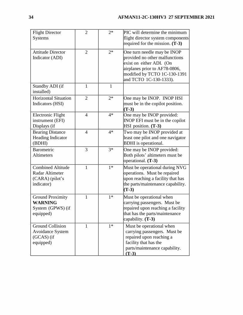
34 AFMAN11-2C-130HV3 27 SEPTEMBER 2021
Flight Director
Systems
2 2* PIC will determine the minimum
flight director system components
required for the mission. (T-3)
Attitude Director
Indicator (ADI)
2 2* One turn needle may be INOP
provided no other malfunctions
exist on either ADI. (On
airplanes prior to AF78-0806,
modified by TCTO 1C-130-1391
and TCTO 1C-130-1333).
Standby ADI (if
installed)
1 1
Horizontal Situation
Indicators (HSI)
2 2* One may be INOP. INOP HSI
must be in the copilot position.
(T-3)
Electronic Flight
instrument (EFI)
Displays (if
installed)
4 4* One may be INOP provided:
INOP EFI must be in the copilot
HSI position. (T-3)
Bearing Distance
Heading Indicator
(BDHI)
4 4* Two may be INOP provided at
least one pilot and one navigator
BDHI is operational.
Barometric
Altimeters
3 3* One may be INOP provided:
Both pilots’ altimeters must be
operational. (T-3)
Combined Altitude
Radar Altimeter
(CARA) (pilot’s
indicator)
1 1* Must be operational during NVG
operations. Must be repaired
upon reaching a facility that has
the parts/maintenance capability.
(T-3)
Ground Proximity
WARNING System (GPWS) (if
equipped)
1 1* Must be operational when
carrying passengers. Must be
repaired upon reaching a facility
that has the parts/maintenance
capability. (T-3)
Ground Collision
Avoidance System
(GCAS) (if
equipped)
1 1* Must be operational when
carrying passengers. Must be
repaired upon reaching a
facility that has the
parts/maintenance capability.
(T-3)

AFMAN11-2C-130HV3 27 SEPTEMBER 2021 35
Traffic Collision
and Avoidance
System (TCAS) (if
equipped)
1 1* Must be operational when
carrying passengers/troops. (T-
3)
Must be operational during
other than day VFR operation.
(T-3)
Must be repaired upon reaching
a facility that has the
parts/maintenance capability.
(T-3)
OPSEC/EMCON guidance
may require turning system off.
Digital/Central
Air Data
Computer (if
installed)
1 1
#1 Ultra High
Frequency (UHF)
Manual Control
Head Radio (SCNS
only)
1 1
HF Radio 2 2* Both may be INOP. Mission
dictates requirement.
ADS-B 1 1* Only required if mission
profile or airspace requires
ADS-B out. OPSEC/EMCON
guidance may require turning
system off.
Table 3.14. Navigation Systems.
Item/System Installed Required Remarks/Limitations/Exceptions
B
Standby
Magnetic
Compass
1 1
Heading Systems 2 2*
1*
See paragraph 3.8.
VHF Omni-
Directional Range
(VOR)/Instrument
Landing System
(ILS)
2 2* One may be INOP for training
sorties.
Automatic
Direction Finder
(ADF)
2 2* Both may be INOP. Mission
dictates requirement.
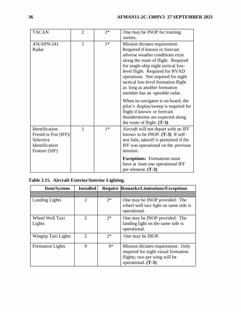
36 AFMAN11-2C-130HV3 27 SEPTEMBER 2021
TACAN 2 2* One may be INOP for training
sorties.
AN/APN-241
Radar
1 1* Mission dictates requirement.
Required if known or forecast
adverse weather conditions exist
along the route of flight. Required
for single-ship night tactical low-
level flight. Required for RVAD
operations. Not required for night
tactical low-level formation flight
as long as another formation
member has an operable radar.
When no navigator is on board, the
pilot’s display/sweep is required for
flight if known or forecast
thunderstorms are expected along
the route of flight. (T-3)
Identification
Friend or Foe (IFF)/
Selective
Identification
Feature (SIF)
1 1* Aircraft will not depart with an IFF
known to be INOP. (T-3) If self-
test fails, takeoff is permitted if the
IFF was operational on the previous
mission.
Exceptions: Formations must
have at least one operational IFF
per element. (T-3)
Table 3.15. Aircraft Exterior/Interior Lighting.
Item/System Installed Require
d
Remarks/Limitations/Exceptions
Landing Lights 2 2* One may be INOP provided: The
wheel well taxi light on same side is
operational.
Wheel Well Taxi
Lights
2 2* One may be INOP provided: The
landing light on the same side is
operational.
Wingtip Taxi Lights 2 2* One may be INOP.
Formation Lights 9 9* Mission dictates requirement. Only
required for night visual formation
flights; two per wing will be
operational. (T-3)

AFMAN11-2C-130HV3 27 SEPTEMBER 2021 37
Navigation Lights 6 6* For night operations, the left and
right wingtip Navigation lights
must be operational in addition to
one of the white lights on the tail
cone. (T-3) Other lights may be
INOP. Anti-
Collision/Strobe
Lights
2 2* One may be INOP provided: Must
be repaired upon reaching a facility
that has the parts/maintenance
capability. (T-3)
Wing Leading Edge
Lights
2 2* Both may be INOP. Mission dictates
requirement.
Primary Instrument
Cockpit Lighting
1 1* Mission dictates requirement. All
edge "peanut" lighting or backlit
lighting (depending on aircraft
model) will be operational for night
operations for the following
instruments: airspeed, altimeters,
Vertical Velocity Indicator
(VVI)/Vertical Speed Indicator
(VSI), ADI, and HSI. (T-3)
3.7. Supplements. Each MAJCOM may supplement the MEL (see Chapter 1).
3.8. Navigation Systems.
3.8.1. For flights in North Atlantic High Level Airspace (NAT-HLA) or the routes connecting
Composite Hawaii to Mainland US Route System, the following fully operable navigation
systems are considered the minimum necessary to permit compliance.
3.8.1.1. Self-Contained Navigation System (SCNS) aircraft. Fully operational SCNS, to
include the navigator’s Integrated Display Computer Unit (IDCU) and either the pilot or
copilot’s IDCU. (T-3)
3.8.1.2. Compass systems. Two independent heading references required (e.g., 2
compasses or 1 compass and SCNS). When two systems are installed, both should be
operational. If one system fails, refer to the flight manual to determine what other
equipment is affected. (T-3)
3.8.2. For flights on all other Class II routes (formerly known as Category I routes), the PIC
determines the minimum navigational capability required to safely accomplish the mission.
Consider the following: length and route of flight, weather, and experience and proficiency of
the crew.
3.8.3. Equipment listed in DoD FLIP AP/2, Area Planning Europe-Africa-Middle East, for
permitting compliance with NAT-HLA is mandatory. (T-0). Loss of any component before
track entry requires return to a station with maintenance capability or re-filing via specified
routes.

38 AFMAN11-2C-130HV3 27 SEPTEMBER 2021
3.8.4. Performance Based Navigation (PBN) certifications (Required Navigation Performance
(RNP)-10/B-RNAV) are contingent on receiving a medium accuracy alignment of the INU
and operating with at least one fully operational INU with autopilot engaged.
3.9. Gear Down Flight Operations. Limit gear down flight operations to sorties required to
move the aircraft to a suitable repair facility. Consider gear down flight only after the PIC exhausts
all avenues to repair the aircraft in place.
3.9.1. Standard climb-out flight path charts in T.O. 1C-130H-1-1, C-130H Performance Data,
assume gear retraction initiated three seconds after takeoff. For gear down operations, drag
index must be applied using the Effect of Variant Configurations on Climbout Flight Path
charts. (T-3). PICs shall not takeoff until there is reasonable assurance that they will
achieve/maintain adequate obstacle clearance (to include enroute stops and alternates). (T-3)
3.9.2. Time and communications capability permitting, validate takeoff data with MAJCOM
STAN/EVAL or Operations Group STAN/EVAL (OGV).
3.10. NVG Minimum Operating Equipment. The following equipment is required for NVG
operations:
3.10.1. TCAS. Exception: System must be operational but OPSEC/Emissions Control
(EMCON) guidance may require turning system off. (T-3)
3.10.2. Pilot's radar altimeter. (T-3)
3.10.3. SCNS with a minimum of one Global Positioning System (GPS) or inertial navigation
system (INS) must be operational for low-level flights flown using NVG enroute altitudes. (T-
3) If the GPS and the INS (both INSs if 2 are installed) are INOP, climb to Minimum Safe
Altitude (MSA). Exception: Wingmen may fly in-trail at NVG enroute altitudes as long as a
GPS or INS is operational in the lead aircraft.
3.10.4. AN/APN-241.(T-3) Radar is required for single-ship, night, low-level flight. Not
required for formation, night, low-level flight as long as another formation member has an
operable radar. Note: Not required for local LZ operations.
3.10.5. Vertical Velocity Indicator or Vertical Speed Indicator. (T-3)
3.11. Autopilot Considerations. Multiple variations in installed autopilot systems allow for
different axis engagement. Crews should apply ORM techniques to determine if the autopilot is
operational for each specific mission based on their installed autopilot type (automatic flight
control system/FCS-105). At a minimum the altitude hold will be operational. (T-3)

AFMAN11-2C-130HV3 27 SEPTEMBER 2021 39
Chapter 4
OPERATIONAL PROCEDURES
4.1. Duty Station. Both pilots and the FE shall be in their seats during flight. (T-0). One of the
pilots, or the FE, may be out of their seat for brief periods to meet physiological needs. Only one
pilot, or the FE, may be absent from their duty station at time. With both pilots in their seats, a
PIC may authorize rest periods for one pilot occupying a primary duty station during non-critical
phases of flight, with the other pilot being awake and alert. (T-3) Aircrew members should notify
the PIC prior to departing assigned primary duty station.
4.2. Takeoff and Landing Guidance. An AC, or above, will occupy either the left or the right
seat during all takeoffs and landings. (T-3) The designated PIC (A-code) is not required to occupy
a primary position, but still retains overall authority for conduct of the mission.
4.2.1. An AC or IP will make all takeoffs and landings during:
4.2.1.1. Aircraft emergencies, unless conditions prevent compliance. (T-3)
4.2.1.2. Airlift of nuclear weapons. (T-3)
4.2.1.3. Max effort operations or landings with unimproved airfield operations. Only IPs
or ACs under the direct supervision of an IP may conduct maximum effort or substandard
airfield operations from the right seat. (T-3)
4.2.2. Unless the pilot in the other seat is a certified AC or higher, pilots in command (PIC)
with less than 100 hours primary assigned hours (PAH) hours since AC certification will make
all takeoffs and landings under any of the following conditions: (T-3)
4.2.2.1. Ceiling/visibility less than 300 feet and/or Runway Visual Range (RVR) 4000 (3/4
Statue Mile (SM) visibility). (T-3)
4.2.2.2. RCR less than 12. (T-3)
4.2.2.3. Crosswind component greater than 15 knots. (T-3)
4.2.3. MPD takeoff/landing guidance:
4.2.3.1. Phase I MPD Pilots (FPCs) are only authorized to fly in the right seat. (T-2)
4.2.3.2. Phase II MPD Pilots (FPQs) are authorized to perform all takeoffs and landings
from the left seat (including all Mission (MSN) events) under the direct supervision of an
IP.
4.2.3.2.1. FPQs are not authorized to perform left seat max effort operations at
substandard, unimproved or semi-prepared surfaces. (T-2)
4.2.3.2.2. FPQs are not authorized to perform right seat max effort operations. (T-2)
4.3. Landing Gear and Flap Operating Guidance. The pilot flying (PF) the aircraft will
command configuration changes. (T-2) The pilot monitoring (PM) the aircraft will verify
appropriate limitations and acknowledge the command by repeating it. (T-2) The landing gear
will be operated by the pilot in the right seat. (T-2) The flaps will be operated by the PM. (T-2)
4.4. Outside Observer Duties. Available crewmembers will assist in clearing during taxi
operations, and any time the aircraft is below 10,000 feet MSL. (T-3)

40 AFMAN11-2C-130HV3 27 SEPTEMBER 2021
4.5. Seat Belts.
4.5.1. All occupants will have a designated seat with a seat belt. (T-3) Crewmembers fasten
seatbelts when occupying a duty position, unless crew duties dictate otherwise.(T-3) LMs (or
other crewmembers) required to be in the paratroop door at the scanning position will have a
designated seat (other than the scanning seat) with a seat belt. (T-3) Exception: When the
loadmaster crashworthy seat is installed, additional designated seat not required.
4.5.2. All crewmembers fasten seat belts during takeoff and landing, unless crew duties dictate
otherwise. Fasten shoulder harness, unless crew duties dictate otherwise. Crewmembers
performing instructor or flight examiner duties, or are in upgrade training to instructor or flight
examiner, are exempt from seat belt requirements if not occupying a primary crew position;
however, they will have a seat available with an operable seat belt. (T-3)
4.5.3. Loadmasters present in the cargo compartment during takeoff or landing, or while
performing scanner duties will occupy the loadmasters crashworthy seat (excludes touch-and-
go landings). (T-3) If there are more than two loadmasters in the cargo compartment, e.g.,
traveling to the Area of Responsibility (AOR), the seats are for the primary loadmasters.
Helmets are to be worn and paratroop door armor will be installed in actual threat areas. (T-3)
Exception: Loadmasters in MAFFS configured aircraft will sit in the appropriate MAFFS unit
control panel seats for takeoffs and landings. (T-3) AMC/A3 approves the removal of the left
crashworthy seat stanchion for C-130H aircraft for the entire MAFFS season for all designated
primary and spare aircraft.
4.5.3.1. When LMs (or other crewmembers) are required to be positioned in the paratroop
door for scanning and the loadmaster crashworthy seat is unavailable, use a restraint
harness in accordance with AFTTP 3-3.C-130H, Combat Fundamentals C-130H.
4.5.3.2. The use of locally manufactured seats or other commercially manufactured seats
obtained for LM comfort while performing threat scanning, including takeoffs and
landings, are only authorized in conjunction with the restraint harness method outlined
above.
4.6. Aircraft Lighting. Aircraft lighting procedures are in accordance with AFMAN 11-202V3,
AFMAN 11-218 Aircraft Operations and Movement on the Ground, and applicable TOs.
4.6.1. NVG Lighting. Follow the exterior lighting guide in AFTTP 3-3.C-130H for all NVG
training situations.
4.6.1.1. Lights-out operations during peacetime will be conducted in accordance with
AFMAN 11-202V3. (T-1)
4.6.1.2. Total lights out operations are authorized with concurrence of the controlling
agency in restricted airspace and warning areas, or locally designated airfields documented
in a Letter of Agreement (LOA).
4.6.2. Cargo compartment lighting is determined by the situation and is coordinated between
the mission commander/PIC and LM(s). During cargo compartment emergencies, the LM
should discontinue NVG use and select full bright on the cargo compartment lights (situation
permitting).
4.6.3. Interior lighting will be set-up using night vision imaging system (NVIS) compatible
lighting for all NVG airland operations (C-130H harness filter kit or Glendale Filter system

AFMAN11-2C-130HV3 27 SEPTEMBER 2021 41
are also acceptable). (T-3) Taping with NVG compatible chemical lights is not an acceptable
primary lighting scheme for NVG airland operations. WARNING: NVGs adjust to the
brightest source of light; for that reason, poor cockpit lighting discipline may prevent a
successful transition to landing during IMC. Therefore, do not perform an instrument approach
in IMC to an NVG landing without NVIS compatible flight deck lighting. (T-2)
4.6.4. Aircraft Preparation. For NVG enroute and airdrop operations, aircrews are allowed to
tape incompatible lighting and use NVG compatible chemical glow sticks. Some techniques
for taping are outlined in AFTTP 3-3.C-130H. NVIS compatible lighting (including lighting
harness) is required for all NVG airland operations. (T-3)
4.6.5. LM Aircraft Preparation. Taping of lights may be accomplished; however, no more
than one layer of tape should be used.
4.7. Advisory Calls. Takeoff. Stating “GO” is only a required call when refusal speed is less
than rotate speed. State “GO” at refusal speed if applicable (refusal speed is less than takeoff
speed). State “ROTATE” at rotate speed. If takeoff speed is adjusted for wind gusts or Air
Minimum Control Speed (Vmca), state “ROTATE” five knots below the adjusted takeoff speed.
Any crewmember noting a safety of flight malfunction before hearing “GO” or “ROTATE” (if
refusal speed is greater than takeoff speed) will state “REJECT” and a brief description of the
malfunction (e.g., “REJECT, number two engine flameout.”). (T-3) For additional advisory calls,
reference AFMAN 11-202V3_AMCSUP.
4.8. Runway, Taxiway, and Airfield Requirements.
4.8.1. Minimum Runway and Taxiway Requirements. For peace-time do not use runways less
than 3,000 feet. Minimum runway width is 80 feet (60 feet for max effort). Minimum taxiway
width is 30 feet. (T-3)
4.8.2. Runway Length for Takeoff and Landing. Minimum runway length for normal takeoff
is Critical Field Length (CFL) or Minimum Field Length for Maximum Effort Takeoff for max
effort operations. Minimum runway for normal landing is Landing Distance or Ground Roll
plus 500 feet for max efforts. For peacetime, compute landing performance with two engines
in reverse and two engines in ground idle.
4.8.2.1. Runway Length for Takeoff and Intersection Takeoffs. Normally, the PF initiates
takeoffs from the beginning of the approved usable portion of the runway. The decision to
make intersection takeoffs rests solely with the PIC.
4.8.2.2. Pilots may accomplish intersection takeoffs provided the operating environment
(e.g., Gross Weight (GW), obstructions, climb criteria, weather) allows a safe takeoff and
departure. Calculate takeoff performance based on the runway remaining from the point
at which the takeoff is initiated.
4.8.2.3. During operations on runways partially covered with snow or ice, base takeoff
computations on the reported runway surface condition (RSC) or runway condition reading
(RCR) for the cleared portion of the runway. A minimum of 40 feet either side of centerline
should be cleared (30 feet for maximum effort operations). If 40 feet either side of
centerline is not cleared (30 feet for max effort ops), compute takeoff data based on the
uncleared portion.

42 AFMAN11-2C-130HV3 27 SEPTEMBER 2021
4.8.2.4. Use of Overruns. If approach end overruns are available and stressed or
authorized for normal operations, they may be used to increase the runway available for
takeoff. Departure end overruns (if stressed and authorized) may also be used for landing
if needed.
4.8.3. Maximum Effort Operations. Use maximum effort procedures when conditions
(runway dimensions and/or obstacles) or directives require their use. All maximum effort
operations must fall in the "recommended" area of charts (corrected for RCR). (T-3)
4.8.3.1. Maximum Effort Landing: A maximum effort qualified crew and procedures will
be used whenever the runway available for landing is less than that required for a normal
landing. (T-3) When runway widths less than 80 feet have lengths that fall within
performance requirements for a normal landing, max effort crews are required but max
effort landing procedures are not. (T-3) Note: Max effort wind limitations always apply
to runways less than 80 feet wide.
4.8.3.2. Maximum Effort Takeoff: Runways less than 80 feet wide require a maximum
effort qualified crew but only require maximum effort procedures if runway available is
less than critical field length (CFL).
4.8.4. Unprepared Surfaces. Damage to equipment on the underside of the aircraft, AN/ALR-
69 antennas in particular, may result when landing on other-than-hard surfaces. Coordinate
with maintenance to prepare aircraft by taping or otherwise protecting belly antennas and
equipment. When possible, crews should inspect underside equipment following an
unprepared surface landing to ensure proper system operation. Note: Gravel-surfaced landing
strips have increased damage potential; loose aggregate creates increased engine Foreign
Object Damage (FOD) potential and can cut tires or hydraulic lines. If the surface aggregate
exceeds ½ inch size, consider limiting the number of passes at the LZ.
4.8.5. Other Airfield Requirements.
4.8.5.1. A current LZ survey (within the past 5 years as specified in DAFMAN 13-217,
Drop Zone, Landing Zone, and Helicopter Landing Zone Operations, is needed before
using other than hard-surfaced runways or taxiways (regardless of surface type).
4.8.5.2. RCR and RSC. The performance charts used to determine braking action are
based on concrete runways. The RCR values for the following runway surfaces in Table
4.1 are estimates based on operational experience and should be used only as a guide.
Table 4.1. RCR Values.
TYPE SURFACE RCR (DRY) RCR (WET)
Asphalt 23 12
Aluminum Matting 20 10
M8A1/With Antiskid (PSP) 20 8
Clay 16 5
Crushed Rock 16 5

AFMAN11-2C-130HV3 27 SEPTEMBER 2021 43
Sand 16 5
M8A1/Without Antiskid (PSP) 13 3
4.8.5.3. Limit C-130H operations into and out of slush or water covered runways to a
covering of one inch. This number is based on performance charts where an RSC of 10 is
equal to one inch of slush or water. Performance data where more than one inch of slush
or water is present may not be accurate.
4.8.6. Takeoff Speeds. If Maximum Effort Takeoff Speed (Vmeto) is used for takeoff, climb
until clear of the obstacle at max effort obstacle clearance speed. If Vmca is used for takeoff,
climb until clear of the real or simulated obstacle at Vmca + 10 knots.
4.8.6.1. During operational missions only, if obstacles are a factor, use Vmeto and max
effort obstacle clearance speed without Vmca corrections. If unable to clear obstacles
using Vmeto and maximum effort obstacle clearance speed, reduce aircraft GW or delay
mission for more favorable conditions.
4.8.6.2. The PIC makes the decision to use Vmeto or Vmca on operational missions based
on a consideration of all available data including: weather, runway length, Vmeto, Refusal
Speed (Vr), Vmca, Ground Minimum Control Speed (Vmcg), applicable airfield survey,
and a review of hazards, obstructions, and terrain both laterally and along the climb out
flight path. WARNING: Max effort operations at high altitude, GW, and temperatures
are critical; climb angles as low as 2.5 degrees may prevent the aircraft from accelerating.
Any further climb angle increase may result in the loss of airspeed and the onset of a pre-
stall buffet.
4.8.7. Anti-icing fluid. AMS 1428, Type II and IV anti-icing fluid is authorized for use in
extreme climatic conditions. Due to the shearing properties of Type II/IV anti-icing fluid, it
may be necessary to increase takeoff speed. When Type II/IV anti-icing fluid is used, increase
takeoff speed to a minimum of 110 knots indicated airspeed (KIAS) and make necessary
distance corrections to performance data.
4.9. Aircraft Taxi and Taxi Obstruction Clearance Criteria and FOD Avoidance.
4.9.1. In accordance with AFMAN 11-218 and this manual, do not taxi an aircraft within 25
feet of obstructions without wing walkers monitoring the clearance between aircraft and
obstruction. With wing walkers, avoid taxi obstructions by at least 10 feet. Exception: With
WG/CC approval, aircraft may taxi without marshallers/wing walkers at home station along
fixed taxi lines which have been measured to ensure a minimum of 10 feet clearance from any
obstruction and the obstruction is permanent. Adjacent aircraft are also considered a
permanent obstruction, provided the aircraft is parked properly in its designated spot and is not
moving. Aerospace ground equipment (AGE) and vehicles are considered a permanent
obstruction, provided they are parked entirely within a designated area. Areas will be
designated by permanent markings such as painted boxes or lines on the ramp or another
suitable means. (T-3)
4.9.2. When obstruction clearance is doubtful for taxiing, use one or more wing walkers. If
wing walkers are unavailable, deplane one or more crewmembers to maintain obstruction
clearance and provide marshalling using AFMAN 11-218 signals. Use wing walkers, deplaned
crewmembers, or a crewmember on interphone positioned at the paratroop door(s) to act as an

44 AFMAN11-2C-130HV3 27 SEPTEMBER 2021
observer while maneuvering on narrow taxiways. During night taxi operations, marshallers
will have an illuminated wand in each hand. (T-3) Wing walkers are only required to have
one illuminated wand. Observers will be in a position to see wing walkers at all times (through
door or windows) and communicate with the pilot. (T-3)
4.9.3. FOD Avoidance. Make every effort to minimize the potential for engine FOD.
CAUTION: Prop blast during ground operations is capable of causing extensive damage to
other aircraft, flight line equipment, and airport facilities. Crews should:
4.9.3.1. Carefully review airfield layout paying particular attention to taxi routes, turn
requirements, and areas for potential FOD. Aircrew should have an airport diagram or
airfield depiction (paper or electronic) out for reference, when available, during all taxi
operations. (excludes home station or familiar airfields). (T-3)
4.9.3.2. Minimize power settings during all taxi operations.
4.9.3.3. Use low speed ground idle whenever possible.
4.9.3.4. Where possible, avoid 180 degree turns. If it becomes necessary to accomplish a
180 degree turn on a narrow runway, the turn should be accomplished at an intersection of
a link taxiway or at a designated turn around pad.
4.9.3.5. Where possible, avoid taxi operations that position an engine over an unprepared
or un-swept surface. If unavoidable, leave the engine in idle (to the maximum extent
possible) until the engine is over an improved surface.
4.9.4. Reverse Taxi. The PIC coordinates reverse taxi directions and signals with the LM and
marshaller (when available). Before reverse taxiing, the LM will:
4.9.4.1. Secure all cargo and ensure all passengers are seated. (T-3)
4.9.4.2. Open the aft cargo door and lower the ramp to approximately 12-inches above
horizontal. (T-3)
4.9.4.3. Position themselves on the aircraft ramp to direct reverse taxi and report any
hazards. Provide timely interphone instructions on turns, distance remaining, conditions
of the maneuvering area, and stopping point. (T-3)
4.9.4.4. Stop no less than 25 feet from an obstruction. (T-3) Exception: If reverse taxiing
to perform multiple COLs, the LM should ensure the aircraft is not offset and directs the
aircraft to a stop with the off-loaded pallet no closer than 5 feet from the aft edge of the
aircraft tail.
4.9.4.5. With the PIC, ensure the taxi area is sufficiently illuminated during night reverse
taxi operations without NVGs. (T-3)
4.9.5. After landing and clearing the runway, and with approval of the PIC, the LM may open
the aft cargo door and lower the ramp to approximately 12 inches above horizontal to prepare
for cargo off/onload provided equipment, cargo, and passengers remain secure in the cargo
compartment.
4.9.6. Additional aircraft taxi/taxi obstruction clearance and FOD avoidance information can
be found in AFMAN 11-218 and applicable MAJCOM supplements.

AFMAN11-2C-130HV3 27 SEPTEMBER 2021 45
4.10. Aircraft Speed. In accordance with AFMAN 11-202V3, this manual, and the applicable
flight manual.
4.11. Participation in Aerial Events. See DAFI 11-209, Participation in Aerial Events,
AFMAN 11-246 Volume 6, Aircraft Demonstrations (C-17, C-130, KC/NKC-135), and
appropriate MAJCOM supplements/Aerial Demo Concept of Operations (CONOPs).
4.12. Traffic Alerting and Collision Avoidance System (TCAS). It is imperative to follow
resolution advisories (RAs) to obtain aircraft separation computed by TCAS. Failure to follow the
computed RA may increase the probability of a midair collision. Pilots who deviate from an ATC
clearance in response to an RA shall notify ATC of the deviation as soon as practical and promptly
return to the ATC clearance when the traffic conflict is resolved or obtain a new clearance. (T-3)
4.12.1. TCAS event documentation. The PIC will document all pertinent information
surrounding an RA event on an AF Form 651, Hazardous Air Traffic Report (HATR), and
submit to the nearest Air Force Safety Office. (T-3)
4.12.2. The investigating safety office will determine if the event is, in fact, reportable, and
will notify the individual or unit submitting the HATR of this determination and/or pending
actions. (T-3)
4.13. Radar Altimeter.
4.13.1. Any crewmember detecting the illumination of the radar altimeter Low Altitude
Warning light will immediately notify the PF. (T-3) If terrain can’t be visually identified and
avoidance ensured, perform the flight manual escape maneuver until the light goes out or
terrain clearance is visually assured. (T-3)
4.13.2. Before departure, set the radar altimeter for emergency return.
4.13.3. The navigator and pilot will use the same radar altimeter setting unless briefed
otherwise. (T-3)
4.13.4. Set the radar altimeter to the height above touchdown/height above aerodrome
(HAT/HAA) during instrument approaches.
4.14. Buddy and Windmill Taxi Starts. Buddy and windmill taxi starts may be performed when
approved by the OG/CC. Compliance with (-1) recommendations are mandatory during training.
This authority may be delegated to the squadron or MC when the unit is deployed. This
authorization will not be construed to allow repeated buddy or windmill starts at various scheduled
enroute stops.(T-3) Nonessential crewmembers and all passengers will be loaded after completion
of a buddy or windmill taxi start. (T-3)
4.15. Reduced Power Operations. HQ AMC/A3V authorizes reduced power operations in
accordance with applicable flight manuals. Pilots should normally use reduced power for takeoffs
provided refusal speed (Vr) is equal to or greater than takeoff speed. Use normal takeoff power if
Vr is less than takeoff speed. (T-3)
4.15.1. Reduced power is not authorized for max effort takeoffs. (T-2)
4.15.2. Formation leaders will brief takeoff Torque/TIT when different engine variations are
in the same formation. (T-3)

46 AFMAN11-2C-130HV3 27 SEPTEMBER 2021
4.16. Hand-held (HH) GPS for Laptops with Moving Map Display (MMD).
4.16.1. The HH GPS and MMD are designed as a SA tool. The pilot monitoring and
navigators are designated the primary users of MMD. PICs may authorize other crewmembers
to use the MMD to assist with SA. Falcon View or Joint Mission Planning System (JMPS) are
the only AMC approved software for MMD use.
4.16.2. Aircrew members using MMD will immediately discontinue monitoring if safety of
flight is inhibited or during any other situation the PIC determines it unsafe to use. (T-3)
4.16.3. Do not use HH GPS/MMD for primary navigation. (T-3) All chart and fixing
requirements are still required. The hand-held GPS will not be used to update navigation
equipment (SCNS/INS). (T-3)
4.16.4. Only GPS units approved for use with laptop computers will be used. (T-2)

AFMAN11-2C-130HV3 27 SEPTEMBER 2021 47
Chapter 5
AIRCREW PROCEDURES
Section 5A—Pre-Mission
5.1. Aircrew Uniform.
5.1.1. Aircrew will wear the aircrew uniform, as outlined in DAFI 36-2903, Dress and
Personal Appearance of Air Force Personnel, and the appropriate MAJCOM supplement, on
all missions, unless otherwise authorized. When the Foreign Clearance Guide (FCG) requires
civilian attire, dress conservatively. (T-1)
5.1.2. OG/CCs will determine clothing and equipment to be worn or carried aboard all flights
commensurate with mission, climate, and terrain involved. (T-3)
5.1.2.1. See T.O. 14-1-1, U.S. Air Force Aircrew Flight Equipment Clothing and
Equipment, for authorized aircrew clothing and aircrew flight equipment (AFE)
combinations as well as AFMAN 11-202V3 and DAFI 36-2903. All crewmembers will
have Nomex gloves in their possession. (T-3) Only aircrew boots listed on the Air Force
Life Cycle Management Center (AFLCMC) Air Force Safe-to-Fly list are authorized.
5.1.2.2. Crewmembers will remove rings and scarves before performing aircrew duties.
(T-3)
5.2. Personal Requirements.
5.2.1. Helmets and Oxygen Masks. (N/A for Aeromedical Evacuation (AE crewmembers)).
Crewmembers will carry a personal helmet:
5.2.1.1. Anytime parachutes are required to be carried by the mission directive. (T-3)
5.2.1.2. Whenever the aircrew requires helmet mounted NVGs. (T-3)
5.2.1.3. When required for wear of the aircrew chemical Biological Radiological and
Nuclear (ACBRN) equipment. (T-3)
5.2.1.4. When required to be mobile in the cargo compartment during airdrop operations.
(T-3)
5.2.2. Flashlights. Each crewmember must carry an operable flashlight. (T-3)
5.2.3. A reflective belt or suitable substitute will be worn on flight lines during hours of
darkness or periods of reduced visibility. (T-3)
5.2.4. Tool and Airdrop Kits. At least one tool kit will be on board for all missions. (T-3)
One airdrop kit will also be aboard the aircraft for aerial delivery missions. (T-3) Units will
identify tool kit contents and inventory procedures in their local supplement. (T-3) As a
minimum, the tool kit will contain the tools necessary to perform the emergency actions in
section 3 of the flight manual and hostile environment repair procedures (HERP). (T-3) One
NVG aircraft preparation kit will be on board for NVG missions. (T-3)
5.2.5. Hostile Environment Repair Kit (HERK). One HERK will be onboard for all Outside
the Continental United States (OCONUS) and contingency deployment missions. (T-3) The
HERK should not be onboard the aircraft for Continental United States (CONUS), OCONUS

48 AFMAN11-2C-130HV3 27 SEPTEMBER 2021
based units on missions in the local area, and non-contingency missions. Units will identify
where the HERK will be stored on the aircraft in the local supplement to this manual. (T-3)
The FE will ensure the HERK is onboard and serviceable (sealed) during the aircraft preflight
prior to departure. (T-3) Additionally, the fight engineer will ensure one-each generator and
starter pad is onboard the aircraft for missions requiring the HERK. (T-3) The HERK will not
be removed from the aircraft until mission completion, and then only by the owning unit. (T-
3)
5.2.6. NVGs. All crewmembers will preflight and carry their own NVGs for each flight when
the mission requires NVGs. (T-3) If available, one spare set of NVGs will be carried per crew
and will be preflighted by the PIC. (T-3) Each crewmember will carry approved spare batteries
for their own NVGs. (T-3) Both Pilots will wear the same type NVGs. (T-3)
5.3. Pre-Mission Actions.
5.3.1. Passenger Restrictions. Release space available seats to the maximum extent possible
unless overriding safety, legal or security concerns prohibit space available travelers from
flying on specific missions. (T-3) The only passengers on missions transporting DVs are those
of the official party and those space available passengers authorized by the lead POC for the
traveling party. (T-3) Authorization must be approved 24 hours in advance. (T-3) Any
training that will prohibit passengers must be declared prior to mission execution phase to
allow planning for downline stations. (T-3)
5.3.2. Space Available Passengers. For other than revenue and White House missions, PICs
are authorized to release space available seats on mission legs when no official passengers are
aboard (positioning and de-positioning legs). Coordinate with C2 agency to release available
seats to the passenger terminal. PICs are encouraged to release maximum space available seats
subject to the following restrictions:
5.3.2.1. Revenue Missions. These are missions for which the using agency (typically a
government agency other than DoD) is reimbursing DoD for use of the aircraft. Space
available passengers on revenue missions must be approved 24 hours in advance by USAF
Vice Chief of Staff (USAF/CVAM), theater Air Mobility Division (AMD) or Joint
Operational Support Airlift Center (JOSAC) (as appropriate) and the using agency contact
officer through unit C2 agencies. (T-0). This is essential to ensure proper funding and
reimbursement. Consult C2 to determine mission revenue status if in doubt. Congressional
Delegations (CODEL) are not revenue missions.
5.3.2.2. White House Support Missions. Space available passengers are generally not
permitted aboard White House support mission aircraft without express permission of
USAF/CVAM. This is normally due to the security status of the aircraft, which may
include positioning and de-positioning legs. When it is necessary to move aircrew
members or support personnel on White House support mission aircraft, the White House
Military Office (WHMO) is advised and permission obtained through the unit C2 and
CVAM. On de-positioning legs space available passengers are usually permitted if the
aircraft is no longer required to maintain an upgraded security status.
5.3.3. The PIC is responsible for ensuring all passengers receive all required passenger
briefings regardless of the category of passenger. (T-3)
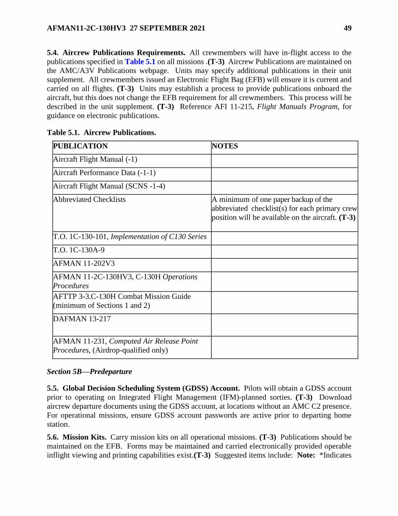
AFMAN11-2C-130HV3 27 SEPTEMBER 2021 49
5.4. Aircrew Publications Requirements. All crewmembers will have in-flight access to the
publications specified in Table 5.1 on all missions .(T-3) Aircrew Publications are maintained on
the AMC/A3V Publications webpage. Units may specify additional publications in their unit
supplement. All crewmembers issued an Electronic Flight Bag (EFB) will ensure it is current and
carried on all flights. (T-3) Units may establish a process to provide publications onboard the
aircraft, but this does not change the EFB requirement for all crewmembers. This process will be
described in the unit supplement. (T-3) Reference AFI 11-215, Flight Manuals Program, for
guidance on electronic publications.
Table 5.1. Aircrew Publications.
PUBLICATION NOTES
Aircraft Flight Manual (-1)
Aircraft Performance Data (-1-1)
Aircraft Flight Manual (SCNS -1-4)
Abbreviated Checklists A minimum of one paper backup of the
abbreviated checklist(s) for each primary crew
position will be available on the aircraft. (T-3)
T.O. 1C-130-101, Implementation of C130 Series
T.O. 1C-130A-9
AFMAN 11-202V3
AFMAN 11-2C-130HV3, C-130H Operations
Procedures
AFTTP 3-3.C-130H Combat Mission Guide
(minimum of Sections 1 and 2)
DAFMAN 13-217
AFMAN 11-231, Computed Air Release Point
Procedures, (Airdrop-qualified only)
Section 5B—Predeparture
5.5. Global Decision Scheduling System (GDSS) Account. Pilots will obtain a GDSS account
prior to operating on Integrated Flight Management (IFM)-planned sorties. (T-3) Download
aircrew departure documents using the GDSS account, at locations without an AMC C2 presence.
For operational missions, ensure GDSS account passwords are active prior to departing home
station.
5.6. Mission Kits. Carry mission kits on all operational missions. (T-3) Publications should be
maintained on the EFB. Forms may be maintained and carried electronically provided operable
inflight viewing and printing capabilities exist.(T-3) Suggested items include: Note: *Indicates

50 AFMAN11-2C-130HV3 27 SEPTEMBER 2021
mandatory for all Air Operations Center (AOC) Tanker Airlift Control Center (TACC) or AMC
missions away from home station and as directed by C2 authority.
5.6.1. Publications:
5.6.1.1. *DAFMAN 11-401, Aviation Management.
5.6.1.2. DoD Manual 4140.25-M, Volume 2, DoD Management of Bulk Petroleum
Products, Natural Gas, and Coal, Chapter 16.
5.6.1.3. *AFMAN 24-204, Preparing Hazardous Materials for Military Air Shipments.
5.6.1.4. *AMCI 11-208, Mobility Air Forces Management.
5.6.1.5. *Airfield Suitability and Restrictions Report (ASRR).
5.6.1.6. *AMC Aircrew Border Clearance Guide.
5.6.1.7. *Flight Crew Bulletin (FCB).
5.6.1.8. AFI 11-289, Phoenix Banner, Silver, Copper Operations.
5.6.1.9. * AMCI 24-6051 V11, Cargo and Mail Policy.
5.6.1.10. *AMCI 90-903, Aviation Operational Risk Management.
5.6.1.11. AFTTP Series 3-3.C-130H, Combat Aircraft Fundamentals.
5.6.2. Forms:
5.6.2.1. *CBP Form 6059B, Customs Declaration Form.
5.6.2.2. DD Form 1748-2, Airdrop Malfunction Report (Personnel-Cargo).
5.6.2.3. *DD Form 2131, Cargo/Passenger Manifest.
5.6.2.4. *CBP Form 7507, General Declaration Outward/Inward.
5.6.2.5. Standard Forms 44, Purchase Order-Invoice-Voucher.
5.6.2.6. AF Form 457, USAF Hazard Report.
5.6.2.7. *AF Form 651, Hazardous Air Traffic Report (HATR).
5.6.2.8. *AFTO Form 781, Aviation Resource Management System (ARMS)
Aircrew/Mission Flight Data Document.
5.6.2.9. *AF Form 1297, Temporary Issue Receipt.
5.6.2.10. AFTO Form 761, Customer Questionnaire.
5.6.2.11. *AF Form 4108, C-130 Fuel Log.
5.6.2.12. *C-130 Flight Data Worksheet.
5.6.2.13. AMC Form 54, Aircraft Commander’s Report on Services/Facilities.
5.6.2.14. AF Form 711B, USAF Mishap Report.
5.6.2.15. *AMC FM 4031, Crew Resource Management (CRM)/Threat and Error
Management (TEM) Skills Criteria Training/Evaluation.
5.6.2.16. *AF Form 4075, Aircraft Load Data Worksheet.
AFMAN11-2C-130HV3 27 SEPTEMBER 2021 51
5.6.2.17. Japanese Customs Service Forms.
5.6.2.18. AMC Form 97, AMC In-Flight Emergency and Unusual Occurrence Worksheet.
5.6.2.19. AF Form 853, Air Force Wildlife Strike Report.
5.6.2.20. *AMC Aviation Operational Risk Management (AvORM) Worksheet.
5.6.3. Orders:
5.6.3.1. DD Form 1610, Request and Authorization for TDY Travel of DoD Personnel.
5.6.3.2. AF Form 1631, North Atlantic Treaty Organization (NATO) Travel Orders (when
required).
5.6.3.3. *AF Form 4327A, Flight Authorization (or MAJCOM prescribed according to
DAFMAN 11-401).
5.6.4. Miscellaneous:
5.6.4.1. *Box car seals.
5.6.4.2. *Masking tape.
5.7. Flight Plan/Data Verification. The FE will complete TO 1C-130H-1-1 C-130 Takeoff and
Landing Data (TOLD) Card and Pilot Information Card, as specified in Chapter 9. (T-2) Pilots
and copilots will use the Pilot Information Card. (T-2) A qualified pilot, or additional FE, will
cross-check the TOLD card for accuracy by using the performance manual or approved tabulated
data. (T-2) As a minimum, the person checking the data will:
5.7.1. Verify GW independently from the TOLD card. (T-2)
5.7.2. Cross-check air minimum control Vmca (one engine INOP in ground effect), takeoff,
and landing speeds. (T-2)
5.7.3. Review and compare the computed distances, ground roll, and climb gradient (if
applicable) with the actual conditions, runway available, and departure procedures. (T-2)
5.8. Departure Planning. Use AFMAN 11-202V3 and the appropriate MAJCOM supplements.
Regardless of the type of departure flown (Instrument Flight Rules (IFR)/Visual Flight Rules
(VFR)), review the following (as appropriate): IFR Departure Procedure, instrument approach
plate, NOTAMS, GDSS2 Giant Report, and suitable terrain charts. The PIC will provide the
obstacle height, distance, and gradient information necessary for performance computations to the
FE. (T-2) All performance data will be computed by the FE and checked by a qualified pilot or
another FE using performance manual or approved tabulated data. (T-2)
5.8.1. VFR Departures. Reference AFMAN 11-202V3_AMCSUP, VFR Departures.
5.8.2. IFR Departures: Aircrews must use an approved IFR departure method as outlined in
AFMAN 11-202V3. (T-0).
5.8.3. Critical Field Length. Takeoff GW can never exceed that which would require CFL in
excess of the runway available for a normal takeoff. (T-2) In some cases, a minimum altitude
is required at the published screen height.
5.8.4. Gross Weight (GW). Ensure that the aircraft does not exceed the maximum GW, zero
fuel weight, or center of gravity (CG) limitations specified in the aircraft flight manual. (T-2)

52 AFMAN11-2C-130HV3 27 SEPTEMBER 2021
GW may be further restricted by operating conditions such as, icing, temperature, pressure
altitude, runway length and slope, aerodrome weight bearing capacity, departure maneuvering,
required climb gradients, and obstacles.
5.9. Weather Minimums for Takeoff. Use Table 5.2
Table 5.2. Weather Minimums for Takeoff.
MISSION VIS REMARKS
Operational 1000 When less than RVR 1600, but equal to or greater than RVR 1000, the
RVR crew may takeoff if mission priority dictates, provided the runway has
(305
meters)
dual RVR readouts (touchdown and rollout) and displays (minimum
RVR 1000 on both) and runway centerline lighting is operational. For
any takeoff below 1600 RVR, the crew must be fully qualified. (T-2)
All others 1600 For runways with more than one operating RVR readout, it is
mandmandatoryRVR must RVR mandatory the RVR reads a minimum of 1600 on all.
(488
Meters)
Notes:
If no RVR readout is available for the departure runway, visibility must be reported to be 1/2
mile (800 meters).
When weather is below approach and landing minimums (ceiling or visibility) a departure
alternate is required (See AFMAN 11-202V3_AMCSUP, paragraph. 5.1.1.2). (T-2)
5.10. Adverse Weather. The C-130H is a category II aircraft for turbulence. AF produced
turbulence products are based upon category II aircraft. If referencing other products or reports,
crews should confirm the type of aircraft the forecast turbulence applies to, or what type of aircraft
reported the encounter, to gain a more accurate picture for their route of flight. Turbulence
category charts are found in the AFH 11-203V2, Weather for Aircrews – Products and Services.
Section 5C—Preflight
5.11. Hazard Identification and Mitigation. After the entire crew is assembled at the aircraft,
the PIC will brief the primary flight threat(s) facing the crew during takeoff and climb-out and
associated threat mitigation plan(s). (T-3)
5.12. Aircraft Servicing and Ground Operations.
5.12.1. APU Usage. For fuel conservation, minimize use of APU. Use ground power units
when practical.
5.12.2. Aircraft Refueling. Aircrew members certified in ground refueling may perform
refueling duties. FEs acting as refueling supervisors and panel operators will comply with
T.O. 00-25-172 Ground Servicing of Aircraft and Static Grounding/Bonding and refueling job
guide. (T-3) Aircrews will only refuel in cases when maintenance support is not readily
available and the mission would be delayed. (T-3) Crewmembers may augment maintenance
refueling teams at enroute stops. Units will not refuel to a “standard” ramp load. (T-3) The

AFMAN11-2C-130HV3 27 SEPTEMBER 2021 53
aircraft will be refueled after the aircraft tail number is assigned and the exact mission-specific
fuel requirement is known. (T-3) The goal is to provide an accurate fuel requirement before
refueling begins to prevent defueling or having a second refueling.
5.12.3. Aircrew T.O. 1C-130XX-1 Preflight Inspection Requirements.
5.12.3.1. The aircrew T.O. 1C-130XX-1 preflight inspection will remain valid until either:
5.12.3.1.1. Aircraft ground time exceeds 12 hours (72 hours provided the aircraft is
sealed, not flown, and documented entry control is maintained). (T-3)
5.12.3.1.2. Another maintenance preflight is performed. (T-3)
5.12.3.2. Aircrew will perform a thorough visual inspection when they assume a
preflighted spare or an aircraft not requiring a preflight. (T-3) Same day, as referenced
from T.O. 1C-130XX-1, is defined as the time period from 0001 to 2359 local.
5.12.4. Fire Protection and Crash Rescue.
5.12.4.1. The aircraft engine fire extinguisher system fulfills the minimum requirements
for fire protection during engine start.
5.12.4.2. A fireguard is required for all engine starts including the APU. (T-3) A
crewmember or ground controller may act as fireguard.
5.12.5. Aircrew and Maintenance Engine Runs.
5.12.5.1. A mixture of aircrew and maintenance personnel will not normally accomplish
engine runs. (T-3) When an aircrew member is required to start or run up engines for
maintenance purposes, the following procedures apply:
5.12.5.1.1. Maintenance personnel will accomplish all necessary inspections and
preparations for the engine run. (T-3) These actions include but are not limited to:
intake/exhaust inspections, access panel security servicing, and AFTO Form 781
documentation.
5.12.5.1.2. Use the pilot, FE, and LM checklists. Begin with the "cockpit checklist,"
and complete all appropriate checklists through the "before leaving the airplane"
checklist. (T-3)
5.12.5.1.3. Operate symmetrical engines when power settings above ground idle are
required. (T-3)
5.12.5.2. Only deviate from the flight crew checklist when maintenance requires less than
four engines to be started. (T-3)
5.12.6. Towing. Aircrew members normally do not participate in towing operations. If
required to occupy cockpit positions during towing operations conducted by personnel not
familiar with C-130 towing procedures, the PIC will coordinate with the senior maintenance
officer or superintendent to ensure the towing supervisor and crew are qualified. (T-3) At non-
USAF installations, the PIC must have approval from the airfield operations officer or manager
prior to towing. (T-3) The PIC will ensure the tow team supervisor briefs all personnel on
their duties and the associated hazards. (T-3) Proper checklists will be used. (T-3) If any
doubt exists as to the qualification of tow team personnel or the safety of the operation, make

54 AFMAN11-2C-130HV3 27 SEPTEMBER 2021
no attempt to tow the aircraft until qualified Air Force personnel can be located. Under no
circumstances will any crewmember act as the towing supervisor. (T-3)
5.12.7. Aircrew members are prohibited from climbing onto the upper fuselage or wing
surfaces unless there is an operational necessity. When operational conditions dictate that
aircrew members must climb onto upper fuselage or wing surfaces (without active or passive
fall protection), they will do so only when conditions are dry, lightning is not observed within
10 NM, and wind speed is below 20 knots. (T-3) Consider use of additional ground members,
if available, to assist in identifying hazardous conditions (e.g., approaching inclement
weather). Additional information can be found in the Job Safety Analysis (JSA) – C-130
Aircrew Fall Protection, located on the AMC/A3V_Publications_C130 SharePoint site:
https://cs2.eis.af.mil/sites/12679/Aircrew%20Pubs%20Library/Forms/Better.aspx?Root
Folder=%2Fsites%2F12679%2FAircrew%20Pubs%20Library%2FMaster%5FLibrar
y%5FVerified&FolderCTID=0x01200021370D19BF5D9F459D8FD907C237955A&Vie
w={701BF038-D3D9-416D-BBEC-BF178FBE44E9} ACs will ensure no other personnel
(excluding qualified ops/maintenance personnel) have access to, or be allowed to, climb onto
the fuselage or wings. (T-3)
5.13. Aircraft Recovery Away from Main Operating Base (MOB). Refer to Chapter 9 for
procedures.
5.14. Aircrew Flight Equipment Requirements.
5.14.1. Life preserver units (LPUs). LPUs will be placed within easy reach of each passenger
and aircrew member before takeoff on overwater flights. (T-2) Crewmembers will fit and
adjust LPUs (if applicable) for overwater flights and will wear them on overwater missions
below 2,000 feet. (T-3) Exception: LPUs need not be worn for takeoffs, landings, or
approaches. Ensure the appropriate number and type of life preservers are aboard for
overwater missions carrying children and infants.
5.14.2. Parachutes:
5.14.2.1. Personnel performing duties near an open (or suspected open) door/hatch/ramp
in-flight will be restrained by a safety harness, or wear a parachute. (T-2)
5.14.2.2. All crewmembers will preflight/pre-position parachutes for ready access in case
of bailout during contingency missions with hostilities and/or hazardous
functional/acceptance check flights. (T-3) LMs will wear a restraining harness instead of
a parachute during airdrops below 800 feet AGL or when performing duties near an open
exit above 25,000 feet MSL. (T-2)
5.15. Oxygen and Oxygen Mask Requirements. Aircrew members will comply with the
oxygen requirements in AFMAN 11-202V3. (T-1)
5.15.1. Oxygen. Oxygen on board for takeoff must be sufficient to accomplish the planned
flight from the equal time point (ETP) to a suitable recovery airfield, should oxygen be required
(minimum 5 liters for all flights). (T-3) Calculate crew requirements using the Oxygen
Duration Chart or Tab Data in the flight manual, regulator setting 100% and altitude 10,000
feet.
5.15.1.1. Since the C-130H flight deck can accommodate more crewmembers than there
are oxygen regulators, all C-130H aircraft will have three emergency passenger oxygen

AFMAN11-2C-130HV3 27 SEPTEMBER 2021 55
systems (EPOS), or protective breathing equipment (PBE) permanently pre-positioned on
the aircraft. (T-3) The EPOS/PBEs may be stored on the overhead storage rack when not
required on the flight deck.
5.15.1.2. On missions carrying passengers/patients, one EPOS per passenger/patient will
be available regardless of planned flight altitude. (T-3) EPOS will be distributed or placed
throughout the cabin/cargo area in accordance with AFMAN11-2C-130HV3ADDA, C-
130 Operations Configurations/Mission Planning. (T-3)
5.15.1.3. Do not remove the LM's emergency equipment (cargo compartment quick dons)
for use by flight deck crewmembers.
5.15.1.4. Crewmembers occupying a crew station will have an oxygen mask with
communication connected and readily available for use from before engine start until
engine shutdown. (T-2)
5.15.1.5. Crewmembers that do not have access to the aircraft oxygen system will have an
EPOS or PBE within arm's reach for flights above 10,000 feet. (T-2)
5.15.1.6. Normally, unpressurized flight will not be planned above 20,000 feet cabin
altitude (except certain airdrop missions). (T-3) Aircrews required to fly unpressurized
missions above 20,000 feet MSL will pre-breathe 100 percent oxygen in accordance with
Chapter 15. (T-2)
5.15.2. MA-1 Portable Oxygen Bottles.
5.15.2.1. There are three types of A-21 regulators on MA-1 portable oxygen bottles,
unmodified, modified and modified2. Except for fill times, operation of the bottles are
identical. Refill valve type is determined by viewing the inside of the fill nozzle and/or
identaplate as specified below:
5.15.2.1.1. Unmodified: Refill valves have a push valve inside the nozzle resembling
a standard tire valve stem.
5.15.2.1.2. Modified: Refill valves have a brass plate/filter covering inside of the
nozzle and no valve stem is visible.
5.15.2.1.3. Modified2 (Fast Fill): Refill valves have a brass plate/filter covering inside
of the nozzle and no valve stem is visible. Part number on the identaplate is one of the
following: 9010A4, 9010A5, 9010A6, 9010A7, 3260007-0201, 3260007-0103.
5.15.2.2. Ensure a minimum of two unmodified/modified2 bottles are installed on the
aircraft, one in the cargo compartment and the other in the pilot position. (T-2) Additional
unmodified/modified2 bottles should be installed in the cargo compartment first.
5.15.2.2.1. Home Station Departures. A waiver to the minimum number of required
unmodified/modified2 bottles may be granted on a case-by-case basis. (See paragraph
3.3)
5.15.2.2.2. Enroute Departures. Maintain minimum number of
unmodified/modified2. If unable, continue until reaching a location with replacement
bottle(s).

56 AFMAN11-2C-130HV3 27 SEPTEMBER 2021
5.16. NVG Departures.
5.16.1. NVG Departure Weather Minimums. Weather minimums for NVG departures for
pilots who are non-current and/or unqualified will adhere to VFR minimums in accordance
with AFMAN 11-202V3. (T-1) Weather minimums for NVG departures for current and
qualified aircrews are no different than normal takeoffs.
5.16.2. NVG Malfunctions During Takeoff. During an NVG takeoff, if the PF experiences
NVG failure, the takeoff may be continued at the discretion of the PIC. The PM will be ready
to immediately assume aircraft control if the PF experiences spatial disorientation or an NVG
malfunction. (T-3) See AFTTP 3-3.C-130H for additional NVG emergency information.
Section 5D—Enroute
5.17. Flight Progress. In-flight, use all available navigational aids to monitor SCNS/GPS/INS
performance. Immediately report malfunctions or any loss of navigation capability that degrades
centerline accuracy to the controlling air route traffic control center (ARTCC). Use the following
procedures for flight progress:
5.17.1. Before an oceanic flight, plot the oceanic portion on an appropriate chart. Annotate
the chart with the mission number and date. If practical, charts may be reused. Refer to
Chapter 8 for chart requirements.
5.17.2. Another pilot or navigator will verify waypoint data inserted into the SCNS/INS. (T-
3) Check both the coordinate information and the distances between waypoints against the
flight plan.
5.17.3. Class II Routes (formerly known as Category I Routes). Maintaining SA during Class
II routes is essential to the safe conduct of the flight. SA includes, but is not limited to,
positional awareness and accurate fuel updates. This requires due diligence on the part of all
aircrew members.
5.17.3.1. When approaching each waypoint on a Class II route, the PM will recheck
coordinates for the next two waypoints. (T-3)
5.17.3.2. Navigators will use the procedures in Chapter 8 for flight following. (T-2)
5.17.4. See Chapter 8 for more enroute navigation procedures.
5.18. Weather (WX) Forecasts. It is the pilot’s responsibility to obtain destination weather prior
to descent. The primary sources are 618 AOC (TACC) weather operations, Operational Weather
Squadrons (OWS), and USAF weather flights via pilot-to-meteorologist service (PMSV) or
through a USAF aeronautical station. For aircraft flying in EUCOM AOR (Europe, North Africa
and Middle East operations) contact United States Air Forces Europe (USAFE)/OWS at Sembach
AB GE. SOUTHCOM AOR contact 612 SPTS/WX at Davis-Monthan AFB, AZ. PACOM AOR
contact 17 OWS at Joint Base Pearl Harbor-Hickam, HI. The ATC system can provide weather
information to enroute aircraft.
Section 5E—Arrival
5.19. Descent. Night and Marginal Weather Operations. Fly a precision approach, if available,
at night or during marginal weather. If a precision approach is not available, fly any available

AFMAN11-2C-130HV3 27 SEPTEMBER 2021 57
approved instrument approach. A visual approach may be flown during night VFR conditions if
an approved instrument approach to the landing runway is not available or operational missions
require a tactical approach. Note: For VFR or visual approaches at locations other than home
station, an ILS glide slope indicator or a visual glide slope indicator (e.g., Vertical Approach Slope
Indicator (VASI), Precision Approach Path Indicator (PAPI), or SCNS glide slope is required. (T-
2)
5.20. Instrument Approach Procedures.
5.20.1. Aircraft category. The C-130H is a category "C" aircraft. If approach speeds exceed
140 knots, the minimums for category "D" will be used. (T-2)
5.20.2. Prior to starting an instrument approach, pilots will confirm their aircraft can comply
with the missed approach climb gradient requirements established in AFMAN 11-202V3. (T-
1)
5.20.3. Weather minimums. Before starting an instrument approach, or beginning an enroute
descent, pilots will confirm the existing weather is reported to be:
5.20.3.1. At or above required visibility for straight-in or sidestep .1approaches. (T-1)
5.20.3.2. At or above required ceiling and visibility for circling approaches. (T-1) For
circling approaches with no published ceiling requirement, the required ceiling shall be
computed by taking the published HAA plus 100 feet rounded up to the next one hundred
foot value. (T-2) For example, if the HAA is 747 feet, add 100 feet to get 847 feet and
then round up to the next one hundred foot value which would be 900 feet. A mandatory
ceiling of 900 feet or above is needed for the approach. When circling minimums are
published, but not by category, circling approach minimums are as published, but in no
case lower than 600 feet and 2 miles visibility.
5.20.3.3. Increase the published visibility minimums of an instrument approach by ½ or
as noted in NOTAMs, on Automated Terminal Information Service (ATIS), or on the
approach plate, when the runway approach lighting system (ALS) is INOP. (This applies
only to the ALS itself, not to VASIs, PAPIs, and other lights that are not a component of
the ALS.)
5.20.3.4. For PAR approaches, Decision Altitude (DA) and visibility will be no lower than
200 feet HAT and RVR 2400 (730 meters) or 1/2 mile visibility (800 meters) with no RVR
readout available.
5.20.4. Flight Instrumentation Requirements.
5.20.4.1. If full flight instrumentation is not available and operational, aircraft are limited
to a DA/ Minimum Descent Altitude (MDA) based on a HAT of 300 feet and RVR 4000,
or ¾ mile visibility (1220 meters) with no RVR.
5.20.4.2. Category I ILS. Full flight instrumentation consists of: dual flight displays (one
flight director plus ADI repeat), complete differential pressure instruments,
heading/compass systems, and attitude indicators in the pilot and copilot positions.
5.20.4.3. Full flight instrumentation for a precision approach radar (PAR) consists of:
complete differential pressure instruments, heading/compass systems, and attitude
indicators in the pilot and copilot positions.

58 AFMAN11-2C-130HV3 27 SEPTEMBER 2021
5.20.5. Category I ILS Procedures. Decision altitude for precision approaches will be as
published, but no lower than 200 feet HAT. (T-2)
5.20.5.1. ILS Precision Runway Monitor (PRM) Approaches. Both pilots must be
certified to conduct an ILS PRM approach. (T-0) Comply with the following operational
procedures:
5.20.5.1.1. See AFMAN 11-202V3 for specifics on flying PRM approaches.
5.20.5.1.2. The approach must be briefed as an ILS/PRM approach. (T-2)
5.20.5.1.3. Pilots must reference the PRM Attention All Users Page (AAUP) for
specific PRM guidance at a given location. (T-2)
5.20.5.1.4. All breakouts from the approach shall be hand flown. (T-3) Autopilots
shall be disengaged when a breakout is directed. (T-3)
5.20.5.1.5. Should a TCAS Resolution Advisory (RA) be received, the pilot shall
immediately respond to the RA. (T-2) If following an RA requires deviating from an
ATC clearance, the pilot shall advise ATC as soon as practical. (T-3) While following
an RA, comply with the turn portion of the ATC breakout instruction unless the pilot
determines safety to be a factor.
5.20.6. Non-Directional Beacon (NDB) Procedures. NDB approaches may be flown during
day, night, or IMC conditions after compliance with any airfield restrictions in GDSS and the
ASRR. Back up each approach with available navaids/GPS to include loading the NDB
coordinates in SCNS.
5.20.7. C-130H aircrews are not authorized to fly RNAV (RNP) approaches until aircraft
navigation equipment is upgraded/certified, aircrews are trained, and MAJCOM/A3 has issued
operational approval. (e.g., RNP, RNP AR, RNAV (RNP), RNAV (GPS). (T-1)
5.20.8. After Beginning Descent or Approach. If the reported weather decreases below
minimums after starting a descent, receiving radar vectors for an approach, or established on
any segment of an approach prior to the Missed Approach Point (MAP), the approach may be
continued to the MAP and either execute a missed approach or continue to land if conditions
permit. Reference AFMAN 11-202V3.
5.20.8.1. Do not continue the approach below minimums unless the runway environment
is in sight and the aircraft is in a position to make a safe landing.
5.20.8.2. If the approach is continued, sufficient fuel must be available to complete the
approach and missed approach, and proceed to a suitable alternate with normal fuel reserve.
(T-2)
5.20.8.3. The PIC has final responsibility for determining when the destination is below
designated minimums, and for initiating proper clearance request.
5.20.9. Holding. An aircraft may hold at a destination that is below landing minimums, but
forecast to improve to or above minimums provided:
5.20.9.1. The aircraft has more fuel remaining than that required to fly to the alternate and
hold for the appropriate holding time, and the weather at the alternate is forecast to remain
at or above alternate filing minimums for the period, including the holding time.

AFMAN11-2C-130HV3 27 SEPTEMBER 2021 59
5.20.9.2. Destination weather is forecast to be at or above minimums before excess fuel
will be consumed.
5.21. NVG Approach and Landing.
5.21.1. NVG Approach Weather Minimums. Weather minimums for NVG visual approaches,
NVG visual pattern work, and pilots who are non-current and/or unqualified will adhere to
VFR minimums in accordance with AFMAN 11-202V3. (T-2) Current and qualified NVG
aircrews may fly IFR approaches with weather at approach minimums.
5.21.2. NVG Malfunction during Approach and Landing. If one of the pilots experiences
NVG failure on short final, it will be at the discretion of the PIC to transition to normal lights
or perform a go-around. The PM will be ready to immediately assume aircraft control if the
PF experiences spatial disorientation or an NVG malfunction. (T-2) See AFTTP 3-3.C-130H
for additional NVG emergency information.
Section 5F—Miscellaneous
5.22. Cockpit Voice Recorder (CVR). If involved in a mishap or incident, after landing and
terminating the emergency, pull the CVR and DFDR power circuit breakers. This procedure keeps
the CVR from recording over itself and retains the DFDR data. Note: Some series of the C-130H
also contain the FLT/VOICE RECORDER – INHIBIT circuit breaker. If this circuit breaker is
pulled, the CVR and DFDR will continue operating with external AC power applied to the aircraft.
5.23. Data link. If a data link system is used and the aircraft is involved in a mishap or incident,
after landing and terminating the emergency, extract and store all mission data for a minimum of
90 days to aid in mishap investigations. (T-2)
5.24. Anti-Exposure Suits. Missions scheduled to conduct operations north of 78 degrees and
south of 60 degrees latitude are required to carry anti-exposure suits for all crewmembers. (T-2)
5.25. Cockpit Congestion and Loose Objects.
5.25.1. Limit personnel on the flight deck to the minimum commensurate with the mission
requirements. At no time will this exceed seven. (T-3)
5.25.2. No items (checklists, charts, etc.) will be placed behind the condition levers or on the
throttle quadrant during critical phases of flight. (T-2)
5.25.3. Place only soft items on the top bunk. (T-3)
5.26. Ordnance Procedures. Conduct the following procedures after the live firing of
chaff/flares or the crew suspects aircraft battle damage:
5.26.1. After landing, taxi to the de-arm area or another suitable safe location to check for
hung ordnance.
5.26.2. A qualified crewmember will deplane the aircraft and check all chaff/flare dispensers
for hung ordnance or damage. (T-3) Note: ALE-47 flare squibs that fail to fire are not
considered hung ordnance.
5.26.3. If hung ordnance is found, identified by a protruding or partially ejected flare cartridge,
the aircraft will remain in a de-arm area until Explosive Ordnance Disposal (EOD) personnel

60 AFMAN11-2C-130HV3 27 SEPTEMBER 2021
meet the aircraft. (T-3) The aircraft must remain in the designated safe area until EOD
personnel can clear all hung ordnance. (T-3)

AFMAN11-2C-130HV3 27 SEPTEMBER 2021 61
Chapter 6
AIRCRAFT SECURITY
6.1. General. This chapter provides guidance on aircraft security and preventing and resisting
aircraft piracy (hijacking) of the C-130H aircraft. AFI 13-207-O, Preventing and Resisting
Aircraft Piracy (Hijacking), DAFI 31-101, Integrated Defense (CUI), and specific MAJCOM
security publications contain additional guidance. Aircrews will not release information
concerning hijacking attempts or identify armed aircrew members or missions to the public. (T-0)
6.2. Security. The C-130H is a “Protection Level 3” resource. Aircraft security at non-U.S.
military installations is the responsibility of the controlling agency.
6.3. Integrated Defense. The following security procedures implement AFI 31-101,
requirements for C-130H aircraft:
6.3.1. The aircraft will be parked in an established restricted area and afforded protection in
accordance with DAFI 31-101. (T-3)
6.3.2. When no permanent or established restricted area parking space is available, establish
a temporary restricted area consisting of a raised rope barrier, and post with restricted area
signs. (T-3) Portable security lighting will be provided during the hours of darkness if
sufficient permanent lighting is not available. (T-3) Post security forces in accordance with
DAFI 31-101. (T-3)
6.3.3. At non- U.S. military installations, the PIC determines the adequacy of local security
capabilities to provide aircraft security commensurate with this chapter. If the PIC determines
security to be inadequate, the aircraft will depart to a station where adequate security is
available. (T-3)
6.3.4. The security force must be made aware of all visits to the aircraft.(T-3) The security
force POC must be identified to the PIC. (T-3)
6.3.5. Security support is a continual requirement and is not negated by the presence of aircrew
or ground crewmembers. Security force support terminates only after the aircraft doors are
closed and the aircraft taxis.
6.3.6. Locking and Sealing. Lock or seal the aircraft during a “Remain Over Night” (RON)
on non-secure ramps.

62 AFMAN11-2C-130HV3 27 SEPTEMBER 2021
Chapter 7
TRAINING AND OPERATING LIMITATIONS
7.1. Passengers on Training Missions.
7.1.1. Passengers are not authorized during initial qualification or re-qualification training
(N/A with MEP). (T-2)
7.1.2. Mission qualification/certification training, evaluations, off station trainers, and
JA/ATTs may carry passengers only if the pilot in training has met basic aircraft qualification
requirements per AFMAN 11-2C-130HV1, and any unqualified NAV, FE, or LM is under the
direct supervision of an instructor. (T-2)
7.1.3. Multiple practice approaches, touch-and-go landings, stop-and-go landings, simulated
emergency training, and airdrops are prohibited with passengers on board. (T-2) Exception:
Personnel scheduled to jump following a heavy/CDS airdrop, safeties, Mission Essential
Personnel (MEP) (defined in DAFMAN 11-401), exercise participants that will be offloaded
by “airland” procedures following the airdrop, or any personnel authorized by the JA/ATT
tasking order may be transported on airdrop training missions. Nonparticipants in the exercise,
OST, or JA/ATT are prohibited. (T-2)
7.1.4. Reference DAFMAN 11-401 MAJCOM SUP for additional restrictions.
7.2. Touch-and-go Landing Limitations.
7.2.1. Ground idle touch-and-go landings may be performed by any pilot from any seat with
direct IP/EP supervision.
7.2.2. Minimum runway length for 50% flap flight idle touch-and-go landings is 5,000 feet.
Minimum runway length for all other touch-and-go landings is 6,000 feet.
7.2.3. Minimum ceiling/visibility: 300 feet and RVR 4000 (3/4 SM visibility) with an IP, 600
foot ceiling and 2 miles visibility for touch-and-go certified ACs. (T-3)
7.2.4. Only authorized when crosswind component corrected for RCR is within the
recommended zone for the landing crosswind chart.
7.2.5. Do not accomplish touch-and-go landings on slush covered runways. (T-3)
7.2.6. Authorized when normal wake turbulence criterion is met.
7.2.7. Do not perform a no-flap ground idle touch-and-go landing. (T-3)
7.2.8. Touch-and-go landings may be performed with cargo onboard provided the PIC and
LM determine suitability of the cargo. Pilots shall not fly touch-and-go landings with airdrop-
configured cargo (with the intent to drop).(T-3) Exception: Touch-and-go landings are
authorized with Air Force unilateral loads provided the loadmaster visually confirms the
bundles/platforms still meet the after loading inspection requirements prior to being
airdropped. Touch-and-go landings are authorized with MEP on board. Touch-and-go
landings with hazardous cargo onboard are prohibited. (T-3)
7.2.9. Cargo security is checked prior to the first touch-and-go and thereafter at an interval
determined by the PIC (should not exceed 1 hour). PICs must allow additional time required
for this inspection. (T-3)

AFMAN11-2C-130HV3 27 SEPTEMBER 2021 63
7.2.10. Include type of touch-and-go as part of the landing briefing (e.g., ground-idle or flight-
idle). (T-3)
7.3. Simulated Emergency Flight Procedures.
7.3.1. Simulated emergency flight procedures will be conducted in accordance with AFMAN
11-202V3, AFMAN 11-202V3_AMCSUP and this manual. (T-1)
7.3.1.1. The PIC or IP will alert all crewmembers prior to practicing emergency
procedures. (T-3)
7.3.1.2. In an actual emergency, terminate all training. Training will be resumed only
when the PIC determines it is safe. (T-3)
7.3.1.3. Practice emergencies that require simulating an engine shutdown, placing
switches in other the their normal position, or an abnormal configuration, only during
training, evaluation, or currency flights when an instructor or flight examiner pilot is in one
of the pilot seats. Preface all simulated emergencies with the word “simulated” and
terminate simulated emergencies when an actual emergency arises. Do not conduct aircraft
system emergency procedures training during any tactical training (operating in low level
environment or during tactical approaches). (T-3)
7.3.2. Simulated Engine Failure Limitations. (T-3)
7.3.2.1. Do not simulate failure of two engines in flight. (T-3)
7.3.2.2. Direct IP supervision required. (T-3)
7.3.2.3. Do not simulate engine failure below Vmca (one engine INOP, out of ground
effect) and not less than 300 feet AGL. Set the torque on the simulated failed engine to
zero to 1,000 for T-56A-15 aircraft and flight idle for T-56A-15A aircraft and add four (4)
knots to the charted Vmca speeds. (T-3)
7.3.2.4. Simulated engine-out no-flap landings are restricted to AC upgrades and above.
(T-3)
7.3.2.5. Planned go-around from simulated engine-out no-flap approaches are not
authorized. (T-3)
7.3.2.6. Required go-around from simulated engine-out no-flap approaches require setting
the flaps to 50% and using all four engines.
7.3.2.7. Do not compound engine-out circling approaches with any other simulated
malfunctions. (T-3)
7.3.2.8. Weather Minimums. Crosswind component must be within the recommended
zone of the landing crosswind chart. (T-3)
7.3.2.8.1. Day IMC – at or above circling minimums for the approach being flown
(600/2 if none published). (T-3)
7.3.2.8.2. Night – 1,000 feet ceiling and 2 statute miles visibility or circling minimums
for the approach being flown, whichever is higher. (T-3)
7.4. Flight Maneuvers.
7.4.1. Practice of the following maneuvers is prohibited in flight: (T-1)

64 AFMAN11-2C-130HV3 27 SEPTEMBER 2021
7.4.1.1. Full stalls. (T-1)
7.4.1.2. Unusual attitudes. (T-1)
7.4.1.3. Simulated hydraulic system loss by turning engine driven hydraulic pumps off.
(T-1)
7.4.1.4. Rudder force reversal/spins. (T-1)
7.4.1.5. Simulated runaway trim malfunctions. (T-1)
7.4.1.6. Simulated 2-Engine approaches/landings. (T-1)
7.4.1.7. Simulated engine-out takeoffs. (T-1)
7.4.2. Permissible in-flight maneuvers. The maneuvers listed below are authorized for
qualification and continuation training (or formal upgrade training where indicated). They are
applicable to all C-130H aircraft except when prohibited or restricted by the flight manual or
other applicable directives. The pilot or IP will alert all crewmembers before accomplishing
the following: (T-3)
7.4.2.1. Approach to Stalls: Direct IP supervision required. Authorized during formal
upgrade training in day VMC at a minimum of 10,000 feet above the ground or 5,000 feet
above the cloud deck, whichever is higher. (T-3)
7.4.2.2. Instrument Steep Turns: Authorized during daylight VMC with up to 60-degrees
bank. Restricted to 5,000 feet AGL or cloud deck for bank angles in excess of 45-degrees.
Check stall speed prior to making instrument steep turns. (T-3)
7.4.2.3. Slow Flight: Direct IP supervision required. Authorized at or above 5,000 feet
AGL. Fly at approach, threshold, and 1.2 power off stall speed with gear down and flaps
0%, 50%, or 100%. Do not exceed 15-degrees of bank. (T-3)
7.5. Briefing Requirements.
7.5.1. Training/Evaluation Briefing. Before all training/evaluation missions, instructor/flight
examiners will brief the crew on requirements and objectives for each student or examinee.
(T-3)
7.5.2. Debriefing. Review and evaluate overall training performed. Each student or aircrew
member should understand thoroughly what training has been accomplished. Ensure all
training is documented.
7.5.3. The PIC will use approved MAF and MDS-specific debrief guides. (T-3)
7.6. Simulated Instrument Flight. Artificial vision restricting devices are not authorized for any
phase of flight.(T-3) Simulated instrument flight may be flown and logged without the use of a
vision-restricting device.
7.7. Operating Limitations.
7.7.1. Unless specifically authorized elsewhere, do not practice emergency procedures that
degrade aircraft performance or flight control capabilities. (T-3)
7.7.2. In an actual emergency, terminate all training and flight maneuvers practice. (T-3)

AFMAN11-2C-130HV3 27 SEPTEMBER 2021 65
7.7.3. Planned Go-Arounds and Visual Low Approaches. Initiate a planned go-around or
missed approach not later than:
7.7.3.1. Precision approach – DA (or 200 feet HAT, whichever is higher). (T-3)
7.7.3.2. Non-precision approach – Missed Approach Point (MAP). (T-3)
7.7.3.3. Visual Approach or VFR pattern – 200 feet AGL for simulated emergencies (no
minimum for non-emergency). (T-3)
7.7.3.4. Restricted Low Approach (aircraft, equipment, or personnel are on the runway) –
500 feet AGL. (T-3)
7.8. Landing Limitations.
7.8.1. No-Flap Landing Limitations:
7.8.1.1. Direct IP supervision required. (T-3)
7.8.1.2. Do not combine no-flap circling approaches with any other simulated
emergencies. (T-3)
7.8.1.3. Maximum GW is 120,000 lbs. (T-3)
7.8.1.4. Crosswind component must be within the recommended zone on the crosswind
chart. (T-3)
7.8.1.5. Authorized in daylight IMC if the weather is at or above circling minimums and
at night with weather at or above 1,000 foot ceiling and 2 SM visibility or circling
minimums whichever is higher. (T-3)
7.8.1.6. Use 50% flaps for a go-around.(T-3) Note: Check no-flap landing distance with
runway available.
7.8.2. Stop-and-Go Landing Criteria:
7.8.2.1. Authorized only on designated training or evaluation missions. (T-3)
7.8.2.2. Authorized to be performed by any C-130H qualified pilot.
7.8.2.3. Runway remaining for takeoff must be greater than or equal to CFL. (T-3)
7.8.2.4. Crosswind component corrected for RCR must be in the recommended zone of
the landing crosswind chart. (T-3)
7.8.2.5. Ceiling and visibility must be at least 300 feet and ¾ mile (RVR 4000). (T-3)
7.8.2.6. Do not perform stop-and-go landings:
7.8.2.6.1. In conjunction with no-flap landings. (T-3)
7.8.2.6.2. When normal wake turbulence criterion is not met. (T-3)
7.8.3. Max effort landing limitations and brake cooling procedures (this applies to all brake
systems). A lack of consideration for the heat generated in the wheel brakes can result in fused
or hot brakes leading to possible tire explosion or fire. Crews are reminded to review the flight
manual regarding use of wheel brakes and hot weather procedures. During training, follow the
procedures below while conducting multiple max effort landings using partial brake landing
criteria: (T-3)

66 AFMAN11-2C-130HV3 27 SEPTEMBER 2021
7.8.3.1. Outside ambient air temperatures of < 35° Celsius. Crews will not perform more
than three consecutive max effort landings without an approximate 15 minute airborne gear
down brake cooling period (e.g., VFR pattern to either a touch-and-go or a low approach).
(T-3)
7.8.3.2. Outside ambient air temperatures of > 35° Celsius. Crews will not perform more
than two consecutive max effort landings without an approximate 15 minute airborne gear
down brake cooling period (e.g., VFR pattern to either a touch-and-go or a low approach).
(T-3)
7.8.3.3. Crews should not terminate or conduct operations requiring extended brake
applications (e.g., ERO, seat swap) following a max effort or no-flap landing. On normal
landings, crews should consider extending rollout to minimize the use of the brakes.
7.8.3.4. After performing a series of two max-effort landings, crews should perform one
additional 10 minute airborne gear-down brake cooling period (e.g., VFR pattern to either
a touch-and-go or a low approach) before raising the landing gear to prevent a buildup of
heat in the brake and wheel assembly. If hot brakes are suspected, follow the flight manual
procedures and do not set the parking brake, but chock the nose wheel prior to ground
evacuation/engine shutdown.
7.8.3.5. If conducting a series of full antiskid braked or partially braked landings, no
tailwind factor is permissible.
7.9. Actual Engine Shutdown and Airstart. Direct IP supervision required. One engine may
be shutdown at no lower than 2,500 feet AGL or MSA (whichever is higher) in daylight VMC.
(T-3)
7.10. Windmill Taxi Start. Direct IP supervision required. Authorized during daylight.
Crosswind component must be within the recommended zone of the flight manual takeoff
crosswind chart. (T-3) Runway must be dry, hard-surfaced, and at least 147 feet wide. (T-3)
Requires OG/CC approval.
7.11. Aborted Normal Takeoff. Direct IP supervision required. Authorized during formal
upgrade training in daylight. Crosswind component must be within the recommended zone of the
takeoff crosswind chart. (T-3) Runway must be dry, hard-surfaced, and long enough to allow
refusal and takeoff speeds to be equal. (T-3) Initiate the abort by stating “REJECT” before refusal
speed. Do not practice aborts from touch-and-go landings. Do not shut down an engine due to
simulated malfunctions.
7.12. Aborted Maximum Effort Takeoff. Direct IP supervision required. Authorized for AC
upgrades and above during formal upgrade training. Restricted to the main runway during
daylight. Crosswind component must be within the recommended zone of the takeoff crosswind
chart. (T-3) Runway must be dry, hard-surfaced, 147 feet wide and long enough to allow refusal
and takeoff speeds to be equal. (T-3) Simulate a runway length less than CFL. Initiate the abort
by stating “REJECT” at or below a refusal speed based on simulated runway length. Compare the
distance traveled to runway length and point out the ramifications of operating with less than CFL.
Cool brakes between aborted takeoffs. Do not shut down an engine due to simulated malfunctions.
Do not practice aborted max effort takeoffs from stop-and-go landings. Requires OG/CC approval.

AFMAN11-2C-130HV3 27 SEPTEMBER 2021 67
7.13. Maximum Effort Takeoff. ACs may accomplish maximum effort takeoffs. Maximum
effort takeoffs should be performed from the main runway when it is available (e.g., safe and
practical to taxi from an assault landing zone (ALZ)). Takeoff at Vmeto is not authorized (N/A
for operational). (T-3)
7.14. Night Vision Goggle (NVG) Training. Crews will accomplish aircrew training according
to AFMAN 11-2C-130HV1 and MAJCOM approved training guides before performing NVG
operations. (T-3)
7.14.1. NVG touch-and-go landings are authorized. Pilots who are both touch-and-go
certified and NVG Airland certified may perform NVG touch-and-go landings. WARNING:
Crews must be thoroughly familiar with the visual cues required to identify the amount of
runway remaining when performing touch-and-go operations. (T-3)
7.14.2. Ground Operations Training. NVG combat offloads and ground maneuvering are
approved. Lights will be kept to a minimum during all NVG operations. (T-3) Blacked out
(no-light) operations in the cargo compartment are not authorized. (T-3)
7.14.3. Runway lighting will be in accordance with DAFMAN 13-217. (T-1)
7.15. Training Flight Restrictions. Use Table 7.1.
Table 7.1. Training Flight Restrictions.
Maneuver Altitude Remarks
Instrument
Missed/Low
Approaches
MDA/DA Initiate practice instrument missed approaches
no lower than the minimum altitude for the type
of approach executed. (T-3)
Visual Low
Approach/Planned
Go Around
200 Feet for
simulated
emergencies. (T-
3) No minimum
for non-
emergency.
Men and Equipment
on the runway
Initiate above
500 feet AGL.
(T-3)
Simulated Engine
Failure
Direct IP supervision required.
Prohibited during tactical operations. (T-3)
Do not simulate engine failure below Vmca
(one engine INOP, out of ground effect) and
not less than 300 feet AGL.(T-3) Set the
torque on the simulated failed engine to zero to
1,000 and add four (4) knots to the charted
speed.

68 AFMAN11-2C-130HV3 27 SEPTEMBER 2021
Authorized day IMC if WX at or above circling
minimums or night if WX is at or above 1,000
foot ceiling and 2 SM visibility. (T-3)
Crosswind component must be in the
recommended zone.(T-3) Engine out no-flap
landings are restricted to ACs and above, and
planned go-arounds are not authorized. (T-3)
Engine out circling approaches will not be
compounded with any other simulated
malfunctions. (T-3)
No-Flap Landing Direct IP supervision required.
No-flap circling approaches will not be
combined with any other simulated
emergencies. (T-3)
Max GW is 120,000 lbs. and crosswind
component must be within the recommended
range.(T-3) Authorized in day IMC if WX is at
or above circling minimums, and at night with
WX or 1,000 foot ceilings and 2 SM visibility
or circling minimum, whichever is higher. (T-
3)
Touch-and-Go
Landings
Ground idle touch-and-go landings may be
performed by any pilot from any seat with
direct IP/EP supervision.
No-flap ground idle touch-and-go landings not
authorized. (T-3)
Minimum runway length: flaps 50 percent,
5,000 feet – for all other, 6,000 feet. (T-3)
Crosswind component corrected for RCR is
within recommended zone. (T-3)
Minimum ceiling of 600 feet and minimum
visibility of 2 SM (300-feet and RVR 4000 (3/4
SM visibility) if an IP is in either seat). (T-3)
Stop-and-Go
Landings
Authorized only on designated training or
evaluation missions. (T-3) Authorized to be
performed by any C-130H qualified pilot.
Runway remaining for takeoff must be equal to
or greater than limiting CFL. (T-3)
Crosswind component corrected for RCR must
be in recommended zone of the landing
crosswind chart. (T-3) Ceiling and visibility

AFMAN11-2C-130HV3 27 SEPTEMBER 2021 69
must be at least 300-feet and ¾ mile (RVR
4000). (T-3)
Slow Flight
Demonstration
At or above
5,000 feet AGL.
(T-3)
Direct IP supervision required.
Fly at approach, threshold, and 1.2 power off
stall speed with gear down and flaps 0%, 50%,
or 100%. (T-3)
Do not exceed 15-degrees of bank. (T-3)
Approach to Stalls At or above
10,000 feet AGL
or 5,000 feet
above the cloud
deck. (T-3)
Direct IP supervision required.
Authorized during formal upgrade training Day
VMC.
Steep Turns 5,000 feet AGL
for bank angles
in excess of 45-
degrees. (T-3)
Not applicable during tactical maneuvers.
Authorized during day VMC with up to 60-
degrees of bank.
Review stall speeds before performing turns.

70 AFMAN11-2C-130HV3 27 SEPTEMBER 2021
Chapter 8
NAVIGATION PROCEDURES
8.1. Navigation Databases / Flight Plan / Data verification.
8.1.1. The PIC and navigator will jointly verify routing, altitude, and fuel load prior to
departure. (T-3) On flight managed sorties, the PIC and navigator will review the flight plan
provided by the FM.(T-3) Any disagreements/discrepancies/requests for change will be
coordinated with the FM.(T-3) Navigator crew changes (engine running crew change or
augmented crews) will include, as a minimum, a briefing on equipment and fuel status. (T-3)
8.1.2. When practical, plan the most direct routing possible or utilize wind optimized
Computerized Flight Plan (CFP) routing to enhance fuel conservation.
8.1.3. A MAJCOM-approved CFP, AF Form 70, Pilot’s Flight Plan and Flight Log, or AF
Form 4116, C-130 Navigator Flight Plan and Log, is required for all flights except local area
training flights with an established standard procedure. (T-3) A copy of the navigator’s flight
plan will be provided to the copilot to verify routing and aid in position reporting. (T-3)
8.1.4. A fuel plan is required for all flights except routine local area training flights where the
fuel requirement has been verified. (T-2)
8.1.5. The navigator will sign in the indicated block on AF Form 4116, Section II, Fuel/ETP
Planning to certify accuracy of all entries. (T-3) Any entries not required for a particular
mission on the AF Form 4116 may be left blank.
8.2. Master Flight Plan / Plotting Chart.
8.2.1. Flight Planning. General instructions for completion of AF Form 4116 are provided in
this section. MAJCOM-approved computer flight and fuel plans may be used as a substitute
for those sections of the AF Form 4116.
8.2.1.1. The AF Form 4116 was developed to provide a tool for all possible missions of
the C-130H. Most missions will not require all sections of the Form. In the interest of
conservation navigators are encouraged to print and use those sections of the AF Form
4116 required for their respective mission.
8.2.1.2. Most entries on the AF Form 4116 are self-explanatory or explained below.
8.2.1.2.1. HIGHEST ACC FL – Highest Acceptable FL. This altitude is obtained from
the appropriate aircraft performance manual.
8.2.1.2.2. WPT – Waypoint. Use this column to indicate the number of each waypoint
as entered in the aircraft computer.
8.2.1.2.3. A/B – Ahead or Behind. Compare ETA based on the original flight plan to
Actual Time of Arrival (ATA) at each waypoint. Record the difference in this column.
If the flight plan changes in-flight, non-applicable ATA spaces may be left blank.
8.2.1.3. When an alternate destination is required, use a flight planning line to indicate, as
a minimum, the name of the alternate and the time, course, and distance to the alternate.
8.2.1.4. Aircrews may use any MAJCOM approved mission planning system (MPS) e.g.,
Advanced Computer Flight Plan (ACFP), Portable Flight Planning Software (PFPS), Joint

AFMAN11-2C-130HV3 27 SEPTEMBER 2021 71
Mission Planning Software (JMPS). On a flight managed sortie, the FM uses AMC
certified ACFP to create the CFP.
8.2.2. Equal Time Point Computations. During mission planning for all oceanic sectors,
aircrews are required to calculate an ETP. (T-2) Use the worksheet on the AF Form 4116,
Section II to calculate the time to the ETP.
8.2.2.1. First Suitable Airfield (FSAF) and Last Suitable Airfield (LSAF) are used in the
ETP calculation. These are represented as the First Nearest and the Last Nearest airports
in the ETP calculation. They are airports closest to the coast out and coast in waypoints
that meet applicable destination alternate requirements except weather. Forecast weather
conditions for FSAF/LSAF (ETA +/- 1 hour) will meet or exceed minimums for the lowest
compatible approach or 500/1, whichever is greater. (T-2) ACFP plans to arrive overhead
at the recovery location with 0+45 minutes reserve fuel.
8.2.2.2. Log procedures are required on Class II (formerly known as Category I) routes or
Class II portions of routes when the total time between the last suitable airfield (LSAF) and
the FSAF is 3-hours or more.(T-3) (see Figure 8.1).
8.2.2.3. Re-compute ETP in-flight when the ATA at a reporting point is 15 minutes or
more ahead or behind the planned time if the change was caused by erroneous wind
information.
8.2.2.4. Oxygen Requirement. When an ETP is required calculate the oxygen requirement
use “T” time and 10,000 feet with the regulator set to 100% oxygen for all crewmembers.
Include any augmented, or MEP as crewmembers. Use the “Duration of Oxygen Supply”
chart in the applicable T.O. 1C-130XX-1.
8.2.2.5. Additional guidance on calculating an ETP can be found on the AMC/A3V
SharePoint in the Pubs section under Miscellaneous Documents and Illustrations.
8.2.3. Charts. The navigator will flight follow on all missions using a suitable plotting chart
(JNC, JNCA, OPC, or GNC). (T-3) On missions that do not require plotting fixes, for SA
only, navigators may use a moving map in lieu of printing charts.
8.2.3.1. Show the following items on the chart:
8.2.3.1.1. Flight plan course line and waypoints (if not pre-labeled) will be annotated
with waypoint number, identifier, radial and distance measuring equipment (DME), or
latitude (LAT) and longitude (LONG). (T-3)
8.2.3.1.2. Annotate suitable emergency airfields. Optimum emergency airfields are
located within 50 NM of the intended route. Refer to the GDSS/ASRR for suitability.
8.2.3.1.3. Portions of Air Defense Identification Zones (ADIZ)/FIR boundaries (if not
depicted accurately) pertinent to the route will be annotated. (T-3).
8.2.3.1.4. Annotate the approximate location of the ETP.
8.2.3.1.5. Chart variation (VAR) lines should be updated to the most current available
variation. See paragraph 8.8.2.2 for where to find up-to-date magnetic variation.
8.2.3.2. Plot each fix or position along with the time at that position. Use standard symbols
from AFPAM 11-216, Air Navigation.

72 AFMAN11-2C-130HV3 27 SEPTEMBER 2021
8.2.3.3. In the interest of conservation, flight charts for high level missions may be reused
whenever such reuse would not affect plotting accuracy of fixes or position determination.
8.2.3.4. MPS produced “Lambert-Conformal” charts may be used.
8.2.3.5. On approach or departure, the navigator will monitor the aircraft position using an
appropriately scaled chart (ONC, TPC, JOG). (T-3) Use the NGA approved terrain data,
host nation chart, or the most current USAF approved chart updating data tool to update
charts within 10-NM of the approach, departure, emergency and divert bases for airfields
without a DoD or an approved Jeppesen approach plate. MPS generated charts with
updated overlays fulfill this requirement.
8.2.3.6. The navigator will use all available navigational aids (including aircraft radar) to
keep the aircraft clear of all terrain and obstructions. (T-3).
8.3. Navigation Capability / Airspace Requirements.
8.3.1. In addition to reviewing DoD FLIP AP/2, all aircrews planning to operate in Atlantic
Oceanic airspace will conduct a detailed review of the NAT-HLA airspace operations manual
and review the associated FIR Oceanic NOTAMS. (T-2) In the event that conflicting
information is discovered between FLIP and the NAT-HLA manual, the NAT-HLA manual
takes precedence. Note: Airspace and associated navigational aid equipment capability are
rapidly evolving. Pilots must maintain an in depth knowledge or current requirements/policies.
(T-3) Aircraft that lose required equipment prior to oceanic airspace will return to the nearest
maintenance facility. (T-2)
8.3.2. Special certification airspace requirements and procedures. Airspace where
performance based navigation (PBN) is applied, will be considered special certification
airspace. Types of PBN special certification airspace include North Atlantic High Level
Airspace (NAT-HLA), RVSM, Required Navigation Performance (RNP), Area Navigation
(RNAV) and Basic-Area Navigation (B-RNAV) airspace. Pilots will immediately notify ATC
of any equipment failures that could affect the aircraft’s ability to maintain navigation
accuracy, after entry into PBN special certification airspace. (T-3) The pilot will state their
intentions, coordinate a plan of action and obtain a revised ATC clearance. (T-2) Document
in the aircraft forms any malfunctions or failures of PBN required equipment. (T-2) Note:
The C-130H aircraft is approved for certain PBN operations but requires a qualified navigator
at the navigator’s station and must be operating with at least one fully operational INU with
autopilot engaged. (T-2)
8.3.2.1. The C-130H navigation system is certified for RNP-10 and B-RNAV airspace,
but with operational time restrictions based on the aircraft navigation equipment. Note:
These certifications are contingent on receiving a medium accuracy alignment of the INU
and operating with at least one fully operational INU with autopilot engaged.
8.3.2.1.1. RNP-10 (Also known as RNAV-10). RNP-10 is defined as RNAV that
meets a track keeping accuracy equal to or better than +/- 10 NM for 95% of the flight
time. RNP-10 is applicable to oceanic and remote area operations only.
8.3.2.1.1.1. C-130H aircraft may operate up to 6.2 hours (after entering the NAV
mode in SCNS) of flight in RNP-10 airspace without an update. If an automatic
update is made, the aircraft may continue for an additional 5.7 hours in RNP-10
AFMAN11-2C-130HV3 27 SEPTEMBER 2021 73
airspace after the update is complete.
8.3.2.1.1.2. If a manual update is made, the aircraft may continue for an additional
5.2 hours in RNP-10 airspace after the update is complete. Manual updates may be
accomplished using the radar or by updating the I-INS and I-DOP solutions using
the GPS if a Figure Of Merit (FOM) of 3 or better is indicated.
8.3.2.1.2. B-RNAV (Also known as RNP-5/RNAV-5). B-RNAV is defined as RNAV
that meets a track keeping accuracy equal to or better than +/- 5 NM for 95% of the
flight time. B-RNAV is used for airways in the Middle East, South American, and
European regions designated as either B-RNAV, RNP-5, or RNAV-5 airspace. Note:
The PBN airspace in the U.S. National Airspace (NAS) is either RNAV-2 (enroute) or
RNAV-1 (terminal); C-130H aircraft cannot file/fly RNAV routes (Q- and T-routes) in
the NAS. Exception: The C-130H may only file/fly GPS Point-to-Point and over-
water RNAV routes (Q-routes in the Gulf of Mexico, Caribbean and Alaskan airspace)
in the NAS. C-130H aircraft may operate up to 7.0 hours (after entering the NAV mode
in SCNS) of flight in B-RNAV airspace without an update.
8.3.2.2. Use of Laptop Computers during Flight. Certified laptop computers with
automated flight planning software are approved for in-flight use in accordance with
AFMAN 11-202V3. Portable automated flight planning systems, to include moving map
capability, are intended to enhance aircrew situational awareness. Consequently,
independent GPS-fed laptop computers, which do not fall under the category of CNS/ATM
avionic systems, will not be considered RNAV equipment for IFR enroute or terminal
navigation, regardless if the required navigation performance (RNP) value of that airspace
can be maintained.
8.3.2.3. PICs will ensure that aircraft RNAV capabilities are correctly annotated on filed
flight plans in accordance with FLIP GP. (T-2) As a minimum, include the following:
8.3.2.3.1. In Block 10 of the DD Form 1801 International Flight Plan, include the
letters “R” and “S” to indicate PBN capable and standard nav/com equipment available.
8.3.2.3.2. In Block 18 of the DD Form 1801 include:
8.3.2.3.2.1. "PBN/A1B1" to indicate RNP-10 (RNAV-10) and B-RNAV (RNAV-
5 (all permitted sensors)) capable.
8.3.2.3.2.2. "NAV/RNVE99" and “RMK/PTP TCAS” to indicate RNAV Point-to-
Point capable but not RNAV-1 or RNAV-2 capable.
8.4. Enroute / Flight Progress.
8.4.1. The navigator will monitor the primary command radio unless directed to do otherwise.
(T-3) The navigator will record ATC clearances and monitor the read back.(T-3) This will
normally include all ATC instructions involving departure, enroute, and approach procedures.
This procedure is not applicable when ATC instructions require immediate execution by the
pilot, or when such action interferes with the timely performance of other time-sensitive
navigator duties.
8.4.2. On Class II routes, when the time between the LSAF and FSAF is 3-hours or more, the
following procedures are required: ETP calculations, and in-flight fuel management. (T-3)

74 AFMAN11-2C-130HV3 27 SEPTEMBER 2021
8.4.3. On Class II routes or route segments of 3-hours or longer, maintain a flight log and
comply with the following procedures:
8.4.3.1. Fix: Time between fix/Computer position/Most Probable Position (MPP) plots
will not exceed 1 hour. (T-3) Note: Malfunctions or loss of navigational capability, which
degrade course centerline accuracy, will be reported immediately to ATC. (T-2) See
paragraph 8.6 for further details.
8.4.3.2. Headings: Compute heading deviation for each compass system as soon as
practical after initial level-off or coast-out. Use the procedures in paragraph 8.8.
8.5. Laptop Computers. Laptop computers running MPS moving map software and connected
to a HH GPS provide invaluable SA. Laptop computers and HH GPS must be approved for
unrestricted use in flight in accordance with AFMAN 11-202V3. (T-2)
8.5.1. Navigators should carry a USAF approved laptop on all missions.
8.5.2. HH GPS units should be connected and the MPS Moving Map Display should be
operating.
8.5.3. Laptop computers with HH GPS MPS moving map displays will not be used as the
primary source of navigation. (T-2)
8.5.4. If involved in a mishap or incident save and store all Mission Planning Laptop computer
mission data for a minimum of 90 days to aid in mishap investigations.
8.6. Flight Records. Flight progress will be recorded for Class II routes of 3-hours or longer.(T-
3) Units may publish local standards for log procedures in the unit supplement. See Figure 8.2
thru Figure 8.6 for an example of a completed AF Form 4116. The procedures below are general
in nature and designed to accommodate a wide range of C-130H navigation equipment
configurations.
8.6.1. Standard Log Procedures. The AF Form 4116 consists of planning and in-flight
progress data. It will be completed in sufficient detail to fully evaluate or reconstruct the flight.
(T-3)
8.6.1.1. AF Form 4116, Section I, FLIGHT DATA will be completed when a CFP or CFPS
flight plan is not available on Class II routes. (T-3)
8.6.1.2. As soon as practical after level-off or coast-out, whichever occurs latest,
navigators will verify aircraft position with a coast-out fix, utilizing navigation aid(s)
and/or radar. (T-2)
8.6.1.2.1. Record the fix on AF Form 4116, Section VIII, RADAR/NAVAID DATA
and plot on the chart.
8.6.1.2.2. At the time of the fix, record the primary navigation solution and
corresponding deltas (or Lat/Long) for all other navigation solutions on AF Form 4116,
Section VI, FIX/COMPUTER POSITION. Plot the primary computer position
corresponding to the fix time on the chart.
8.6.1.2.3. At the time of the fix, record as a minimum (on AF Form 4116, Section IX,
IN-FLIGHT DATA); Greenwich Mean Time (GMT), position symbol, spot w/v, drift
angle (DA), HDG (either True Heading (TH), Compass Heading (CH), or Grid Heading

AFMAN11-2C-130HV3 27 SEPTEMBER 2021 75
(GH)), TAS, Ground Speed (GS), ETA to the next waypoint, and Altitude (ALT). This
data may be annotated all on the fix line, or partly on the fix line and partly under the
spot readings/remarks area, just as long as all the items are recorded.
8.6.1.3. After coast-out, every 30 minutes, record (on AF Form 4116, Section VI,
FIX/COMPUTER POSITION) the primary navigation solution and the corresponding
deltas (or Lat/Long) for all other navigation solutions.
8.6.1.4. Plot the primary navigation solution every hour or within 10 minutes of crossing
a reporting point, whichever occurs first. For all plotted primary navigation solutions,
record (on AF Form 4116, Section IX, IN-FLIGHT DATA); GMT, position symbol, spot
w/v, DA, HDG (either TH, CH or GH), TAS, GS, ETA to the next waypoint, and ALT.
This data may be annotated all on the fix line or partly on the fix line and partly under to
spot readings/remarks area, just as long as all items are recorded. Additionally, record (in
Section VI, FIX/COMPUTER POSITION) the primary navigation solution and
corresponding deltas (or Lat/Long) for all other navigation solutions.
8.6.1.5. Between recorded positions, monitor instruments and record spot readings, as
required, to allow for calculating a DR in the event full log procedures become required.
Record spot readings at regular intervals to allow for calculating a DR in the event of a
navigation system failure. Spot readings are recommended with unplanned HDG/DA
changes of 4 degrees and/or unplanned GS/TAS changes of 10 knots occur. Spot readings
should include time, HDG, (TH, CH, or GH), DA, GS, spot W/V and TAS.
8.6.1.6. As soon as practical prior to coast-in, navigators will verify aircraft position with
a coast-in fix utilizing navigation aid(s) and/or radar. (T-2)
8.6.2. Full Log Procedures. In the event of a navigation system failure in excess of 15 minutes
full log procedures will be implemented (e.g., “Inertial Navigation Unit (INU) FAIL”, “GPS
FAIL”, or “GPS NAV FAIL”). (T-2) Full log procedures include a Dead Reckoning (DR)
substantiation/fix/computer position line, and an alter heading line for each recorded and
plotted position. If the navigation system failure is resolved, the navigator may resume log
procedures as outlined in paragraph 8.6.1. Note: For LC-130H aircraft, an alter heading line
is not required if full log procedures are being used for a reason other than a navigation system
failure.
8.6.2.1. From the last plotted position, compute a DR for the next position. A DR
associated with the fix/MPP will be plotted on the chart prior to plotting the fix/MPP. (T-
3) As a minimum, record the following on AF Form 4116, Section IX, IN-FLIGHT
DATA; GMT of the DR, position symbol, averaged GS, time interval, averaged HDG (TH,
CH or GH), and averaged DA. Use elapsed time and averaged GS to compute total ground
distance (DIST). Work right to left from the average HDG (TH, CH or GH) to obtain the
True or Grid Course (TC or GC). Plot the DR using TC or GC and ground distance.
8.6.2.2. Plot a fix/computer position/MPP at least once per hour or within 10 minutes of
crossing a reporting point, whichever occurs first.
8.6.2.2.1. At the time of the fix/computer position/MPP, record the primary navigation
solution and corresponding deltas (or lat/long) for all other navigation solutions on AF
Form 4116, Section VI, FIX/COMPUTER POSITION. Plot the primary computer
position corresponding to the fix time on the chart.

76 AFMAN11-2C-130HV3 27 SEPTEMBER 2021
8.6.2.2.2. At the time of the fix record, as a minimum (on AF Form 4116, Section IX,
IN-FLIGHT DATA); GMT, position symbol, spot w/v, DA, HDG (TH, CH or GH),
TAS, and GS. This data may be annotated all on the fix line, or partly on the fix line
and partly under the spot readings/remarks area, just as long as all items are recorded.
8.6.2.3. Between recorded positions, monitor instruments and record spot readings, as
required, to allow for calculating a DR.
8.6.2.3.1. Record spot readings at regular intervals to allow for calculating a DR in the
event of a navigation system failure. Spot readings are recommended with unplanned
HDG/DA changes of 4 degrees and/or unplanned GS/TAS changes of 10 knots occur.
Spot readings should include time, HDG, (TH, CH, or GH), DA, GS, spot W/V and
TAS.
8.6.2.3.2. In the event where both the INU and the GPS fail, as a minimum, record spot
readings at regular intervals, when changes of 2 degrees or more in HDG or DA occur,
or when GS or TAS changes by 5 knots or more. Spot readings should include: time,
HDG (TH, CH or GH), DA, GS, spot w/v and TAS.
8.6.2.4. On the alter heading (A/H) line; record the GMT, action (A/H), TC, DA, GS, ETA
to next 2 waypoints, and work left to right to obtain a compass heading. Use best known
or calculated DA and GS.
8.6.2.5. As soon as practical prior to coast-in, navigators will verify aircraft position by
either navigation aid fix and/or radar fix. (T-2)
8.7. Celestial Procedures. See AFPAM 11-216 Air Navigation, for a comprehensive discussion
of celestial concepts.
8.8. Heading Deviation Check Procedures.
8.8.1. On Class II routes or route segments of 3-hours or longer, heading deviation for each
compass system will be computed in Section V of AF Form 4116 as soon as practical after
initial level-off or coast-out. (T-2) Compute and record the deviation (DEV) for all compass
systems (mid-time celestial heading checks may be recorded in the Section X). Note: The AF
Form 4116 Section V deviation check format solves for “deviation” for all heading reference
systems not for “correction.”
8.8.1.1. Heading deviation checks are not required on Dual INU equipped aircraft, Class I
routes and tactical routes. A deviation check is not required on Class II routes of less than
3 hours if the aircraft is equipped with 2 or more operable heading systems (the standby
compass is not considered a system for this requirement), and the difference between
systems does not exceed 2-degrees.
8.8.1.2. Compass deviation is not necessarily constant over time or after significant course
changes. Navigators will reconfirm deviation on Class II legs every 3 hours or after
planned course changes of greater than 30-degrees. (T-2)
8.8.1.3. Dual INU equipped aircraft should consider doing a whiskey compass deviation
check. In the event of a total SCNS failure, this deviation check correction would be
beneficial in plotting an accurate DR.

AFMAN11-2C-130HV3 27 SEPTEMBER 2021 77
8.8.2. INU/SCNS Heading Checks. Record and compare the INU/SCNS true heading with all
compass systems.
8.8.2.1. To compute the compass deviation check, take the INU true heading and apply
the most up-to-date magnetic variation available for the current location, compare that
solution to the C-12 compass systems and the whisky compass. Use the resulting DEV to
determine most accurate compass and use that DEV on AF Form 4116, Section IX, IN-
FLIGHT DATA.
8.8.2.2. The navigator should input compass “correction” into SCNS on class II routes or
route segments of 3 hours or longer. An accurate SCNS correction is computed by
comparing the INU mag heading to the headings shown on the BICU input page for
compass 1 and 2. Reverse the sign of the calculated “deviation” from AF Form 4116,
Section V, DEVIATION CHECK to determine the “correction” to input into SCNS to
correct the SCNS I-DOP solution. See Figure 8.7.
8.8.3. In order to obtain an accurate celestial heading check, the exact Azimuth Angle (ZN)
must be derived.(T-3) Exact ZN is obtained by interpolating using exact longitude, latitude,
declination, and Local Hour Angle (LHA). ZN may also be derived from SCNS immediate
page and the subpoint of the celestial body used for the heading check.
8.9. In-flight Fuel Management Procedures.
8.9.1. Record the fuel readings listed below at level-off time and regular time intervals
(coinciding with entries on aircraft performance record), not to exceed 1-hour and 30-minutes.
(T-2) Use Section VII, IN-FLIGHT FUEL MANAGEMENT of the AF Form 4116 to complete
in-flight fuel management computations.
8.9.1.1. ETA DESTINATION. Best known arrival time at destination.
8.9.1.2. TIME. Time of the fuel reading.
8.9.1.3. TERMINAL FUEL FLOW. Taken from the ENROUTE FUEL
COMPUTATION WORKSHEET, AF Form 4116, Section II, FUEL/ETP PLANNING.
8.9.1.4. CURRENT FUEL FLOW.
8.9.1.5. AVERAGE FUEL FLOW. Calculate by adding terminal fuel flow to current fuel
flow and dividing the sum by 2.
8.9.1.6. FUEL REMAINING. Fuel quantity at time of calculation. In the interest of
safety, use the lower of the calculated or gauge fuels.
8.9.1.7. MINIMUM DIVERT/REQUIRED OVERHEAD DESTINATION FUEL (MIN
DIV/REQ OVHD DEST). Required overhead fuel (item 12 of AF Form 4116, Section II,
FUEL/ETP PLANNING).
8.9.1.8. USABLE FUEL. Subtract MIN DIV/REQ OVHD DEST from FUEL
REMANING.
8.9.1.9. FUEL ETE. Calculated using formula in paragraph 8.10.2.3.
8.9.1.10. ETE DESTINATION. Subtract TIME from ETA DESTINATION.

78 AFMAN11-2C-130HV3 27 SEPTEMBER 2021
8.9.1.11. EXTRA TIME. Subtract ETE DESTINATION from FUEL ETE. Report this
value to the pilot. If this is a negative value, check the computation and values for errors.
If they are correct, evaluate the destination options.
8.9.2. Use the following formulas to accomplish in-flight fuel management:
8.9.2.1. [(TERMINAL FUEL FLOW + CURRENT FUEL FLOW)] / 2 = AVERAGE
FUEL FLOW.
8.9.2.2. FUEL REMAINING – (MIN DIV/REQ OVHD DEST) = USABLE FUEL.
8.9.2.3. USABLE FUEL / AVERAGE FUEL FLOW = FUEL ETE.
8.9.2.4. FUEL ETE – ETE DESTINATION = EXTRA TIME.
8.9.3. AF Form 4125, Range Control Chart may be used for in-flight fuel management.
Manual construction (Figure 8.8) is as follows:
8.9.3.1. “POINT NUMBER” represents the approximate level-off point (initial cruise
altitude), 25, 50, 75, and 100 percent of the flight plan distance as indicated on AF Form
4116 or CFP.
8.9.3.2. To compute Column A, “ENROUTE FUEL.”
8.9.3.3. Record in Block 1 (L/O) the AF Form 4116, Section II, FUEL/ETP PLANNING,
Block 7 TOTAL TAKEOFF Fuel.
8.9.3.4. Divide the AF Form 4116, Section II, FUEL/ETP PLANNING, Block 1
ENROUTE Fuel by 4 and record that number in each -25% Enroute block. Optionally, a
more accurate method is to compute the fuel at each point and subtract them to obtain the
enroute fuel burn between each point. Put this number in the corresponding -25% Enroute
block. This method takes into account the initial higher burn rates.
8.9.3.5. Subtract this number going down the chart to obtain the enroute fuel at each point.
(e.g., 1. L/O -25% Enroute Block = 2 (25%) ENROUTE fuel).
8.9.3.6. The destination block will be TOTAL TAKEOFF fuel minus the full ENROUTE
fuel.
8.9.3.7. To compute Column B, “MINIMUM FUEL.”
8.9.3.8. Record in Block 5 DEST (100%) the AF Form 4116, Section II, FUEL/ETP
PLANNING, Block 12 MIN DIV/REQ OVHD DEST.
8.9.3.9. Divide the AF Form 4116, Section II, FUEL/ETP PLANNING, Block 1
ENROUTE Fuel by 4 and record that number in each -25% Enroute block. Optionally, a
more accurate method is to compute the fuel at each point and subtract them to obtain the
enroute fuel burn between each point. Put this number in the corresponding -25% Enroute
block. This method takes into account the initial higher burn rates.
8.9.3.10. Add this number going up the chart to obtain the minimum fuel at each point.
(e.g., 5. Dest + 25% Enroute Block = 4 (75%) min fuel).
8.9.3.11. This fuel is the minimum, at each given point, to fly from that point to destination
with sufficient fuel to make a missed approach (if required), continue to the destination
alternate, hold, make the planned approach, and land with 4,000 lbs. of fuel. Minimum

AFMAN11-2C-130HV3 27 SEPTEMBER 2021 79
fuel will also include any identified extra fuel needed overhead the alternate (e.g., excess
holding, for succeeding legs).
8.9.3.12. Column C. “DISTANCE”: The flight plan distance for the given points listed
in paragraph 8.10.3.1, obtained from AF Form 4116. This can be graphically depicted as
either distance flown or distance remaining.
8.9.3.13. “DISTANCE FLOWN/REMAINING”: Label the nautical miles to the
destination along the horizontal scale. For distance flown, start with 0 at the left and allow
the major blocks to represent convenient increments of mileage. The distance scale should
be expanded to the maximum to give as large a presentation as possible.
8.9.3.14. Draw a vertical line on the graph representing total distance to destination and
label this line with the destination name. If required, plot vertical lines representing ETPs
at the appropriate distance flown/remaining.
8.9.3.15. Estimated Performance Line. Estimated performance is based on planned fuel
at T/O, level off, and arrival plotted column A versus distance in column C. The difference
between the estimated performance line and the minimum arrival line is contingency and
identified extra fuel.
8.9.3.16. Minimum Arrival Fuel Lines. A “minimum arrival” line will be constructed by
plotting fuel in column B versus distance in column C.
8.10. Self-Contained Approaches (SCA) – Airborne Radar Approach (ARA) Procedures.
8.10.1. IFR Operations. In accordance with AFMAN 11-202V3, SCAs or ARAs are approved
for IMC when developed by Terminal Instrument Procedures (TERPS) authority and approved
for use by the MAJCOM.
8.10.1.1. When unable to develop a procedure in accordance with AFMAN 11-230,
Instrument Procedures, by a TERPS authority, see AFMAN 11-202V3. Crews are only
authorized to perform ARAs in IMC with an approach validated by TERPS authority. (T-
1)
8.10.1.2. Weather minimums will be established by the approach, but will be no lower
than 500-feet and 1-mile or 300-feet and 1-mile for a computer ARA. (T-3)
8.10.2. VFR Operations. Units will construct VFR ARA approaches with the guidance below,
but not less restrictive than AFMAN 11-230. (T-2) VFR minimums will be in accordance with
AFMAN 11-202V3. (T-2)
8.10.2.1. Minimum Safe Altitude. The MSA will be calculated using either the Iron Cross
or Concentric Circles as defined in AFTTP 3-3.C-130H.(T-3) The MSA is calculated per
paragraph 12.4.1.5 within 10 NM, and the MSA will be used by the FE for a missed
approach. (T-3). The MSA can be found quickly with FalconView Route Elevation
Profile.
8.10.2.2. Required Obstruction Clearance (ROC). A Trapezoid will be created to the
approach corridor with 2 NM left and right of centerline at the approach end, and it will
extend 5 NM left or right to 10 NM from the approach end. (T-3) Inside this trapezoid, the
ROC will be 300 feet AGL clearance of all obstacles in this area (man-made or terrain) for
the decent altitudes per NM created in the ARA.(T-3) If needed, the planner may use the

80 AFMAN11-2C-130HV3 27 SEPTEMBER 2021
option to angle the approach up to 15-degrees either side of centerline to facilitate a 300
feet/NM rate of descent. See Figure 8.8 and Figure 8.9.
8.10.2.3. Missed Approach Point (MAP). The MAP should be 1 NM from the threshold
and 300 feet above the Touchdown Zone Elevation (TDZE), but it may be adjusted as
required for mission accomplishment. See Figure 8.9.
8.10.2.4. Missed Approach. During planning, the planners and aircrew should look at the
Missed Approach Obstacle Clearance for the possibility of a missed approach. This
process is taking a trapezoid corridor from the MAP to 15 NM from the MAP. At the
MAP, the width is 2 NM left/right, and it is a trapezoid that is 6 NM left/right at 15 NM.
The planner should assume 200 feet/NM for a climb out and assure the aircraft can clear
all obstacles. MAJCOM/A3 may authorize the subtraction of 48 ft/NM if operationally
necessary. See Figure 8.10.
8.10.2.5. Published VFR ARA Approaches. Units will submit locally used VFR ARA
approach plates for approval to OGV. (T-3) Publish approved VFR ARA approaches in
local supplements. The local supplement should include SCNS LZ input data. If available,
pilots will back up the navigator using a published instrument approach. (T-3)
8.10.3. Planning and Coordination. Prior to entering the terminal area, the navigator will
utilize the T.O. 1C-130XX-1CL-3 Descent Checklist, ARA Brief, to coordinate with the PF.
(T-3)
8.10.4. Terminology and Procedures.
8.10.4.1. Pattern Control. The navigator will advise the PF when positive radar
identification of the airfield complex is made. (T-3)
8.10.4.2. The navigator will direct the aircraft by headings to the final approach course.
(T-3) When flying computer ARAs, navigators, after verifying/updating the SCNS
solution with an Offset Aim Point (OAP) on the radar may advise the PF to intercept the
bank steering bar (as required).
8.10.4.3. During the approach, the navigator should advise the PF of the drift and
groundspeed. If PFs can view this information on the selected SCNS/INS display, this
advisory is not required.
8.10.4.4. The turn onto base leg (if required) should be made to allow for a 10 NM final
(or as required).
8.10.4.5. The navigator will state the distance from touchdown each NM from the end of
the runway beginning 10-NMs out from the touchdown zone, until the MAP. (T-3) A glide
path warning should be given 10 seconds prior to the begin descent point.
8.10.4.6. The navigator will give heading information at least every NM during the final
approach, beginning 10-NMs out from the touchdown zone, until the MAP. (T-3) For
RVAD equipped aircraft and certified crews, when flying computer ARAs, navigators will
advise the PF of their SCNS course centerline deviation (with radar OAP verification), at
least every NM during the final approach. (T-3)
8.10.4.7. Use AFMAN 11-202V3_AMCSUP procedures for required non-precision
approach calls upon reaching the MDA.
AFMAN11-2C-130HV3 27 SEPTEMBER 2021 81
8.10.4.8. Computer ARAs are authorized in VMC or IMC according to paragraph 8.10.1
and paragraph 8.10.2 One OAP will be active on the radar until the field is called in sight
or a missed approach is executed. (T-3)
8.11. Grid Procedures.
8.11.1. Definitions and formulas. See AFPAM 11-216.
8.11.2. Grid Log. The navigator will use page 6 of the AF Form 4116 when grid navigation
procedures are required.(T-3) Block entries are as follows:
8.11.2.1. TIME. Time of celestial heading/system heading observation.
8.11.2.2. TH. Observed/computed true heading.
8.11.2.3. LONG/CA. Enter +W –E longitude (polar chart) or convergence angle (CA).
8.11.2.4. GH. Observed/computed grid heading.
8.11.2.5. GYRO #1, GYRO #2. On aircraft equipped with two independent gyro
stabilized systems with numbers corresponding to aircraft systems (e.g., C-12 No. 1, N-1
No. 2), circled number denotes the primary steering gyro. On aircraft whose systems are
not numbered or do not correspond to the aircraft system, identify the primary steering
gyro in “REMARKS.”
8.11.2.6. GR. Gyro reading. Record the reading from the primary compass.
8.11.2.7. PREC. The amount of precession since the last heading shot (period precession):
GH – GR = PREC.
8.11.2.8. RATE/CUM. The hourly precession rate based upon the precession indicated at
the time of observation. Precession rate is derived from the period precession and the
applicable elapsed time period (since the last compass reset). Example: 2-degrees
precession in 40 minutes equals a 3-degree/hour precession rate. This entry is required
only when period precession is greater than one degree. The cumulative portion of the
block is used for tracking the cumulative precession rate once a false latitude has been set.
8.11.2.9. LAT. The mid-latitude between the current observation and the next proposed
observation.
8.11.2.10. FALSE LAT. The False Latitude setting being used to eliminate precession.
This entry is required only when a False Latitude setting is used.
8.11.2.11. RESET. Whenever a gyro is reset, place a check mark in this block.
8.11.2.12. GC. Measured grid course to the next checkpoint.
8.11.2.13. DRIFT. The number of degrees (+ or -) of drift.
8.11.2.14. DGH (Desired grid heading). Apply anticipated drift to GC.
8.11.2.15. RT/2 CORR. See formula on the bottom of the AF Form 4116.
8.11.2.16. IGH (Initial grid heading). Used for alter heading.
8.11.2.17. GRID ENTRY. Apply grivation (GRIV) to magnetic heading (MH) to obtain
desired grid heading (DGH); or apply longitude (LONG) or convergence angle (CA) to
true heading (TH) to obtain DGH. See formulas on the AF Form 4116.

82 AFMAN11-2C-130HV3 27 SEPTEMBER 2021
8.11.2.18. GRID EXIT. Apply GRIV to DGH to obtain MH; or apply LONG or CA to
DGH to obtain TH. See formulas on the AF Form 4116.
8.11.3. Grid Celestial Computations.
8.11.3.1. When plotting celestial lines of position in grid reference, apply longitude (polar
chart) or convergence angle to the true azimuth and plot the grid azimuth.
8.11.3.2. When taking heading checks at high latitudes, it is advisable to place data into
the periscopic sextant to give the true heading and convert this heading to grid by applying
the assumed LONG/CA.
8.11.4. Construction and use of the ZN graph is optional. The ZN graph is based upon the
route of flight and dead reckoning. See AFPAM 11-216 for construction procedures.
8.11.5. Departure Requirements.
8.11.5.1. Polar true/grid courses as reflected in FLIP terminal charts will be used for
departures in polar areas. (T-2) Before takeoff, visually align the aircraft with the runway
heading and set the polar true/grid course of the runway in the aircraft’s directional gyros.
The navigator will set applicable systems in gyro mode with the correct latitude set. (T-2)
8.11.5.2. After reaching flight altitude, determine the polar true grid heading and reset the
primary and secondary gyros. The type of chart being used will determine whether the
heading will be polar grid heading or convergence grid heading.
8.11.6. Enroute Requirements.
8.11.6.1. The Grid Entry/Exit section of the AF Form 4116 will be completed prior to
heading reference changes.(T-3) When entering grid operation, spot variation should be
applied to the computed magnetic heading to obtain DGH. The aircraft will be established
on the computed magnetic heading prior to resetting the heading references. (T-3) When
exiting grid, the computed magnetic headings will be the target heading when the compass
systems are reset. (T-3) In both cases, the computed magnetic headings will be compared
to the flight plan to verify the accuracy of the courses measured and conversion data used.
(T-2) This will ensure the validity of initial entry headings and provide precise target
headings for exit.
8.11.6.2. Normally, the grid heading should be checked each 30-minutes after grid entry.
If the compasses are precessing 3-degrees per hour or less, hourly checks may be obtained
after the first hour. Note: On aircraft with reliable SCNS/INS, if the SCNS/INS heading
is within 2-degrees of the initial celestial-derived grid heading, the SCNS/INS may be used
to determine gyro precession.
8.11.6.3. Determine the precession information for each gyro after each heading check.
When a gyro’s precession is greater the 1-degree, reset the gyro to correct grid heading.
When the period precession is 1-degree or less, the navigator may either reset the gyro or
treat the precession as zero.
8.11.6.4. Whenever the period precession is greater the 1-degree (optional for 1-degree or
less), the hourly precession rate may be removed by use of a false latitude setting. When
the combined earth rate and gyro precession are less than +15 degrees/hour, the false
latitude setting will totally compensate for precession. Two considerations are necessary:

AFMAN11-2C-130HV3 27 SEPTEMBER 2021 83
8.11.6.4.1. Predicted precession becomes zero.
8.11.6.4.2. It may be necessary to adjust previous DR and air plot positions if the
precession rate changes at subsequent heading checks. If this occurs, adjustments
normally will be small and have negligible effect on DR and air plot accuracy; however,
the effect should be considered.
8.11.6.5. To determine false latitude correction, enter the earth rate table with the desired
latitude and extract the tabulated earth rate value. Algebraically combine the earth rate
value and the observed hourly precession rate (use cumulative precession rate once a false
latitude has been set). Re-enter the earth rate table with the combined value and extract
the corresponding false latitude.
8.11.6.6. Only 15-degrees/hour can be removed by a false latitude setting. When the sum
of earth and primary gyro precession rates exceed +15 degrees, the navigator must
artificially steer the aircraft (in effect, the aircraft will fly a gentle arc) to compensate for
the amount of precession in excess of +15 degrees/hour. (T-2) The formula used to correct
the DGH to an initial grid heading (IGH) to fly appears on the AF Form 4116 as “RT/2
CORR” (note that the formula produces a correction, so the precession rate must be given
its opposite sign). The precession rate used in the formula must be adjusted to reflect the
time period in the DR ahead. (T-2) When “carrying” precession as suggested above, the
navigator should consider several aspects of the navigational problem. Note: When
precession exceeds 15-degrees per hour, consider the compasses unusable.
8.11.6.6.1. If alter headings are not made at heading check times, precession will have
accumulated by alter heading times and a correction (opposite sign of precession)
should be applied to the IGH using the total precession correction portion of the AF
Form 4116.
8.11.6.6.2. If the precession rate changes at subsequent heading checks, it may be
advisable to adjust previous DR and air plot positions.
8.11.7. Miscellaneous Procedures:
8.11.7.1. Normally, when changing charts or crossing the 180-degree meridian, only the
reference changes; the heading of the aircraft is not altered. The change is made by
comparing the grid courses and applying the difference to the gyro reading (old chart GC
350 degrees; new chart GC 331 degrees; GR 353; 350-331 = 019 = 334; reset the gyro to
read 334).
8.11.7.2. Do not use the combined rhumb line/Coriolis correction when flying directional
gyro. Use only Coriolis correction for celestial observations.
8.11.7.3. Always recheck computations and formulas when a radical change in precession
is observed.
8.11.7.4. Grid certified navigators will maintain proficiency in grid procedures. (T-2)

84 AFMAN11-2C-130HV3 27 SEPTEMBER 2021
Figure 8.1. ETP.
Computations.
1. WIND FACTOR COMPUTATION (USE OPTION 1, 2, 3 OR 4):
A. TOTAL WIND FACTOR:
TOTAL WIND FACTOR DISTANCE = AVERAGE GS
TOTAL WIND FACTOR TIME
B. FIRST HALF WIND FACTOR (WF1):
DISTANCE FROM BEGIN PT TO APPROX MID-POINT = AVERAGE GS
TIME FROM BEGIN PT TO APPORX MID-POINT
NOTE: “BEGIN PT” IS THE LSAF OR L/O, WHICHEVER OCCURS LATER
AVERAGE GS – PLANNED AVERAGE TAS = WF1
C. SECOND HALF WIND FACTOR (WF2):
DISTANCE FROM APPROX MID-POINT TO END PT = AVERAGE GS
TIME FROM APPROX MID-POINT TO END PT
NOTE: “END PT” IS THE FSAF OR DESTINATION, WHICHEVER OCCURS
FIRST

AFMAN11-2C-130HV3 27 SEPTEMBER 2021 85
AVERAGE GS – PLANNED AVERAGE TAS = WF2
2. ETP COMPUTATION
A. TOTAL ETP DISTANCE (LSAF TO FSAF) = “T” (TIME IN MIN FROM
ETP TO FSAF)
(WF2 – WF1) + 2 * (PLANNED AVG TAS) 60
B. TIME (FROM DEPARTURE) TO ETP = TOTAL TIME TO FSAF - “T”
Figure 8.2. Example AF Form 4116 (1).

86 AFMAN11-2C-130HV3 27 SEPTEMBER 2021
Figure 8.3. Example AF Form 4116 (2).

AFMAN11-2C-130HV3 27 SEPTEMBER 2021 87
Figure 8.4. Example AF Form 4116 (3).

88 AFMAN11-2C-130HV3 27 SEPTEMBER 2021
Figure 8.5. Example AF Form 4116 (4).

AFMAN11-2C-130HV3 27 SEPTEMBER 2021 89
Figure 8.6. Example AF Form 4116 (5).

90 AFMAN11-2C-130HV3 27 SEPTEMBER 2021
Figure 8.7. AF Form 4125, Range Control Chart.

AFMAN11-2C-130HV3 27 SEPTEMBER 2021 91
8.12. VFR ARA Pattern Construction Procedures.
Figure 8.8. Approach – Required Obstruction Clearance (ROC).
Figure 8.9. Descent Profile and MAP.

92 AFMAN11-2C-130HV3 27 SEPTEMBER 2021
Figure 8.10. Missed Approach – Obstruction Clearance.
AFMAN11-2C-130HV3 27 SEPTEMBER 2021 93
Chapter 9
FLIGHT ENGINEER / AIRCREW MAINTENANCE SUPPORT PROCEDURES
9.1. General. This chapter contains FE procedures not contained in the flight manual, other
portions of this manual, or other publications.
9.2. Responsibilities. The FE is responsible to the PIC for all inspections and procedures required
by the applicable technical orders and regulations.
9.3. Authority to Clear a Red X. If a situation is encountered where the aircraft is on a Red X
and qualified maintenance personnel are not available to clear it, the highest qualified FE on scene
may obtain authorization to sign off the Red X from the home station Maintenance Group
Commander (MXG/CC) or designated representative, in accordance with T.O. 00-20-1, Aerospace
Equipment Maintenance Inspection. Other crewmembers are not authorized to clear a Red X.
Exception: The FE may clear Red Xs for engine panels and covers, pitot covers, gear pins and
Single Point Refueling (SPR) drains when qualified maintenance personnel are not available,
unless prohibited by the home station MXG/CC or OG/CC.
9.4. Aircraft Servicing and Ground Operations. The FE is certified and authorized to
accomplish these duties when maintenance personnel are not available. This guidance is designed
for support of the aircraft and its mission while away from home station. The applicable refueling
and de-fueling checklists will be used during all refueling and de-fueling operations. (T-3) If
ground support personnel are not available, the AC will designate other crewmembers to assist the
FE. (T-3) A FE may assist the normal maintenance function when critical taskings dictate their
use, provided this action does not impact crew duty and crew rest limits specified in AFMAN 11-
202V3_AMCSUP. WARNING: Do not load/offload cargo containing explosives, oxygen,
flammable gases or liquids during any fuel servicing operations.
9.4.1. Fuel Servicing Operations. Unless servicing JP-4, simultaneous servicing of fuel while
loading passengers, cargo, performing maintenance, aircrew members performing inspections,
or operating aircraft systems is considered to be a normal fuel servicing operation. If
refueling/defueling with JP-4, Concurrent Servicing operations are required in accordance with
T.O. 00-25-172. Aircrew members certified in ground refueling may perform fuel servicing
duties. Aircrews will only refuel in cases when maintenance support is not readily available
and the mission would be delayed. (T-3)
9.4.1.1. When crewmembers are required to refuel, the FE will act as the refueling team
supervisor. (T-3) FEs will comply with T.O. 00-25-172 and applicable T.O. 1C-130XX
series. (T-3) Two other crewmembers are required to assist in the refueling, one for safety
duties and the other to act as fire guard.
9.4.1.2. Designate a current and qualified maintenance personnel or aircrew member to
remain on the flight deck to monitor interphone and be prepared to broadcast a request for
emergency assistance on a radio tuned to the appropriate agency with ready access to an
emergency response team anytime aircrew members are in the aircraft and fuel servicing
is being conducted. The PA may be used to direct passenger evacuation in an emergency.
9.4.1.3. With passengers on board, a current and qualified aircrew member will be
designated the passenger compartment monitor (PCM) and shall continuously monitor

94 AFMAN11-2C-130HV3 27 SEPTEMBER 2021
passengers during fuel servicing operations. (T-3) PCMs will not perform other duties
during fuel servicing. (T-3)
9.4.1.4. The PCM shall brief passengers on emergency egress, exits, prohibitions, and
hazards. (T-3) Passengers will remain seated except for brief physiological needs, but will
not wear seat belts. (T-3) When possible, conduct this briefing prior to fuel servicing. If
fuel servicing is in progress, the briefing will be given immediately after boarding. (T-3)
9.4.1.5. When authorized, passengers may board or exit the aircraft for the express purpose
of loading for departure or offloading upon arrival. Boarding or exiting must be opposite
of fuel servicing operations. (T-3) Once onboard, except for emergencies, passengers shall
not deplane once fuel servicing commences. (T-3)
9.4.1.6. Passengers are not required to ground themselves.
9.4.1.7. The PIC, or designated maintenance/aircrew representative will advise PCMs
when to evacuate passengers. (T-3)
9.4.1.8. The PCM shall set the interior lighting as bright as possible to suit the combat
environment. (T-3)
9.4.1.9. The LM shall ensure cargo loading or unloading does not jeopardize passenger
safety. (T-3) Winching is prohibited with passengers on board.
9.4.1.10. Simultaneous fuel and oxygen servicing is not authorized.
9.4.1.11. Winching of rolling stock and non-spark producing (e.g., wooden) pallets is
authorized. Driving vehicles equipped with spark arresters is authorized during fuel
servicing. When loading vehicles without spark arresters, the vehicles must be either
completely inside the cargo compartment, or outside of the established fuel servicing safety
zone, before fuel servicing lines can be pressurized. (T-2) Exception: Diesel and turbo-
charged (without waste gates) gasoline-powered vehicles can be onloaded or offloaded
without having to stop fuel flow.
9.4.1.12. Electronic equipment may be on and operated to include operations performed
by aircrew members during required inspections. Exceptions:
9.4.1.12.1. Radar Altimeters and Tactical Air Navigation (TACANs) must be turned
off. (T-2)
9.4.1.12.2. Radar may be in STBY but, if time permits, should be turned off.
9.4.1.12.3. IFF/SIF may be in standby but, if time permits, should be turned off.
9.4.1.12.4. SCNS/INU may be on and may be updated. Do not turn on or off during
refuel operations.
9.4.1.12.5. HF radios must be turned off. (T-2)
9.4.2. Hot Refueling. Hot refueling (refueling with aircraft engines running) will only be
conducted by crews that have been authorized and certified according to AFI 11-235,
Specialized Refueling Operations. (T-2)
9.5. Aircraft Recovery Away from Main Operating Base (MOB). The PIC is responsible for
ensuring the aircraft is turned to meet subsequent mission taskings. (T-3) If qualified maintenance

AFMAN11-2C-130HV3 27 SEPTEMBER 2021 95
specialists are unavailable, the aircrew is responsible for turning the aircraft to meet subsequent
mission taskings. (T-3)
9.5.1. The PIC is responsible for the recovery items including:
9.5.1.1. Parking and receiving.
9.5.1.2. Aircraft servicing, including AGE usage.
9.5.1.3. Supervision of minor maintenance within local capability.
9.5.1.4. Minor configuration changes to meet mission tasking.
9.5.1.5. Securing the aircraft before entering crew rest.
9.5.1.6. Coordinating aircraft security requirements.
9.5.1.7. Documenting AFTO 781-series forms.
9.5.2. In all cases where aircrews must service the aircraft without qualified maintenance
specialist assistance, comply with the appropriate maintenance T.O. (T-2)
9.5.3. Aircrews are not qualified to accomplish the required ground inspections. In those
instances where maintenance personnel are not available, the aircrew will enter a red dash
symbol in the AFTO Form 781H, Aerospace Vehicle Flight Status and Maintenance
Document, updating current maintenance status and enter a red dash symbol and a discrepancy
that reflects that the applicable maintenance inspection (e.g., preflight, thru-flight, basic post-
flight) is overdue. (T-2)
9.6. Aircraft Structural Integrity Program. Complete aircraft data, in accordance with T.O.
1C-130-101, Implementation of C-130 Series Aircraft Usage Report on all flights.
9.7. Aircraft Systems/Forms Management.
9.7.1. The FE will monitor aircraft systems during all flight and ground operations. (T-3)
Notify the pilot of all abnormal indications and take action as required.
9.7.2. In addition to the procedures in T.O. 00-20-1 and DAFMAN 11-401, the FE will assist
the pilot in maintaining the AFTO Form 781. (T-3)
9.8. Performance Data, including TOLD Card. TOLD computations will be placed on the C-
130 Takeoff and Landing Data Card and Pilot Information Card from the T.O. 1C-130XX-1-1. (T-
3)
9.8.1. All performance calculations will be based on 95 percent engines. (T-2) TOLD card
computations will be accomplished using flight manual performance data, approved tabulated
data, or the EFB eTOLD application if updated with most current 1-1 or 1-11 data. (T-2)
9.8.2. When conducting flaps up landing, compute and post Vmca speeds for both
configurations; flaps 50% and flaps up (normal boost). For example: Vmca, in ground effect,
one engine INOP – 105/122.
9.8.3. Minimum TOLD requirements for a termination landing are: Air Minimum Control
Speeds, Obstacle Clearance Speed, 3 Engine Climb Speed, 100 and 50% Flap Landing Speeds
and Distances, 0% Flap Landing Approach Speed (Night or IMC), and 3 Eng. Ft/NM.

96 AFMAN11-2C-130HV3 27 SEPTEMBER 2021
9.9. Fuel Management/Monitoring. The FE is responsible for management of fuel in
accordance with the applicable flight manual and mission requirements. Additionally, the FE will
monitor fuel usage and destination fuel requirements in conjunction with the pilots. (T-3)
However, the AC retains overall responsibility for ensuring adequate fuel reserves for mission
accomplishment.
9.9.1. AF Form 4108, C-130 Fuel Log. The purpose of the form is to provide an orderly
method of recording fuel consumption and aircraft GW. The following instructions
standardize procedures for the completion and disposition of AF Form 4108:
9.9.2. The AF Form 4108 may be completed whenever the navigator completes AF Form 4116
at the discretion of the PIC. The log may be filled out as necessary to accomplish training or
corrective action. When the fuel log is completed, it is not required to fill out the reverse side
of the Pilot Information Card.
9.9.3. Responsibility:
9.9.3.1. If the AF Form 4108 is completed, it will be accomplished by the FE. (T-3)
9.9.3.2. Return completed forms to the unit of the individual completing the form. (T-3)
9.9.4. Additional Information. AF Form 4108 provides as a simple method of recording
aircraft fuel data and is adequate for normal operational requirements. When additional
information is required for identifying trends in engine failure or performance or for special
test programs, the directing headquarters will furnish necessary forms and instructions to
complete the program. (T-2)
9.9.5. Instructions. Form heading entries are self-explanatory.
9.9.5.1. Block 1-FUEL GAUGE POUNDS. Record fuel quantity from the fuel quantity
indicators before and after flight. This reading is normally taken prior to engine start with
the indicators powered and after flight prior to power being removed from the indicators.
9.9.5.2. Block 2-WEIGHT DATA. Record operating weight and cargo weight (including
passenger weight) from DD Form 365-4, Weight and Balance Clearance Form F—
Tactical/Transport. Ramp fuel weight is obtained from block 1 (Fuel Gauge). The blank
space may be used for last minute changes prior to engine start or as required.
9.9.5.3. Block 3-FUEL ON/OFFLOAD. Enter total weight of fuel on or offload during
air refueling in this block.
9.9.5.4. Block 4-PAX/CARGO OFFLOAD. Enter total weight of passengers and cargo
extracted during flight in this block.
9.9.5.5. Block 5-ENGINE START Z. Enter GMT of last engine started.
9.9.5.6. Block 6-COND. Enter symbol depicting flight condition as follows:
9.9.5.6.1. WU/TAXI/TAKEOFF-Indicates warm-up taxi and takeoff conditions.
9.9.5.6.2. Initial climb is indicated by symbol (1k). Secondary and subsequent climbs
are shown as (2 k, 3k, etc.). The number here indicates sequence of condition in flight
profile. This is also true of cruise segments and descents. Climbs of 4,000 feet or less
will not be recorded separately but will be included in preceding cruise increments. (T-
3) When constant climb is maintained to cruise altitude, use fuel flow reading taken at

AFMAN11-2C-130HV3 27 SEPTEMBER 2021 97
2/3 climb altitude. When constant climb cannot be maintained to cruise altitude due to
ATC clearances, etc., enter difference between sum of individual fuel quantity gauge
readings at beginning and end of climb.
9.9.5.6.3. Cruise operating conditions are indicated by the number in cruise sequence
and an arrow (1g, 2g, 3g, etc.). Instrument readings will be averaged for this period.
(T-3) Normally, cruise entries will be no more than 1 hour. (T-3) However, the first
cruise, the cruise immediately prior to enroute or step climb and/or the last cruise prior
to descent, may be no less than 30 minutes, nor more than 1 hour and 30 minutes.
9.9.5.6.4. Descents are shown as (1m, 2m, 3m, etc.). Do not confuse descent with the
final letdown that occurs when landing procedures begin. The loss in altitude during
final letdown is indicated by "L & T." Landing and taxi is that condition from the end
of the last entry in the sequence of descents to engine shutdown on the ramp. Holding
time, however, must be accounted for as an additional cruise (g) condition after descent
when necessary. (T-3) Descents of 4,000 feet or less will not be recorded separately
but will be indicated in the preceding cruise increment. (T-3) When descent exceeds
4,000 feet, blocks 10 through 18 need not be completed.
9.9.5.6.5. Air-Air Refueling Tanker Operation, Air-Air Refueling Receiver Operation.
Cruise, climb, or descent to refueling altitude (end this condition approximately at start
of on/ offload of fuel). Indicate AR and ARR 1, 2, etc., in condition block, for refueling
condition. Blocks 10 through 18 need not be completed. Blocks 19, 20, 22, 25, and 28
entries are not required for ARR. At completion of on or offload of fuel, a new cruise,
climb, or descent condition will be initiated. (T-3) Note: Rescue, search, storm
penetration, combat/combat support, or any special mission which requires constant
variations in altitude and airspeed may use the same procedures as air refueling
operations. For this type of condition use an "S" in the condition block.
9.9.5.7. Block 7-END. Enter GMT for end of condition.
9.9.5.8. Block 8-SET. Enter increment time duration for the condition for WU/TAX/TO.
All warm-up and taxi times will be entered in the circle of the SET block. (T-3) Takeoff
time is computed from brake release to the first change of power (when reduced power
procedures are used, compute takeoff time using 2 minutes).
9.9.5.9. Block 9-TOTAL. Enter cumulative total time of SET time; excluding the warm-
up and taxi times entered in the circle SET time.
9.9.5.10. Block 10-IOAT. Enter indicated outside air temperature reading.
9.9.5.11. Block 11-Outside Air Temperature (OAT)/VAR:
9.9.5.11.1. OATC (Outside Air Temperature Corrected). Enter corrected outside air
temperature as determined from the appropriate performance manual.
9.9.5.11.2. VAR. Enter temperature variation from standard International Civil
Aviation (ICAO) temperature.
9.9.5.12. Block 12-HP. Enter the pressure altitude for the condition with altimeter set at
29.92 Hg.

98 AFMAN11-2C-130HV3 27 SEPTEMBER 2021
9.9.5.12.1. For climb, enter HP for 2/3 the intended climb as soon as the altitude to
which the climb is to be made is known. The entry (2/3 HP) reflects pressure altitude
for 2/3 of the actual climb. If a climb starts at 15,000 feet and terminates at 30,000
feet, compute the pressure altitude for 2/3 of the 15,000 difference, which is 10,000
feet. This HP added to the 15,000 feet beginning HP equals 25,000 feet HP, which is
the appropriate entry for this climb.
9.9.5.12.2. For cruise, enter the actual HP.
9.9.5.12.3. When descent exceeds 4,000 feet, blocks 10 through 18 need not be
completed.
9.9.5.13. Block 13-CRUISE CEILING. Enter 4-engine cruise ceiling for the aircraft from
the appropriate performance manual.
9.9.5.14. Block 14-CRUISE IAS. Enter indicated airspeed from the appropriate
performance manual required to maintain desired true airspeed.
9.9.5.15. Block 15-TORQUE. Enter torque value from the appropriate performance
manual required to maintain the desired true airspeed.
9.9.5.16. Block 16-3-ENGINE SERVICE CEILING. Enter 3-engine service ceiling from
the appropriate performance manual.
9.9.5.17. Block 17-3-ENGINE DRIFTDOWN IAS. Enter the 3-engine driftdown
indicated airspeed from the appropriate performance manual.
9.9.5.18. Block l8-ENGINE INST F/F LBS/HR. Enter the average individual fuel flow
reading and total for the period. Engine instrument fuel flow (lbs./hr.) will be the complete
figure (4800 not 4.8). (T-3)
9.9.5.19. Block 19-PERIOD (FUEL USED). Enter fuel used for engines for the period as
computed using total of fuel flow readings. Note: For fuel used during WU/TAXI, use 50
lbs. per minute. For fuel used during TAKEOFF, use 300 lbs. Enter all fuel used, fuel
remaining, and GWs in thousands. Example: 127,300 = 127.3. All weights are to be
carried to the nearest hundred. Exception: Engine instrument fuel flow (lbs./hr.) will be
a complete figure. (T-3)
9.9.5.20. Block 20-EXTRA (FUEL USED). Enter extra fuel used during flight condition
period for fuel jettisoning, APU, etc. Fuel transferred to a receiver during air refueling will
be entered in this block. (T-3)
9.9.5.21. Block 21-TOTAL (FUEL USED). Enter cumulative total of fuel used for
successive conditions. This block represents all fuel consumed to END clock time entered
in block 7. ARR (receiver) start new condition (cruise, climb, or descent) after refueling
with "O" (zero) fuel used.
9.9.5.22. Block 22-PERIOD (CALC FUEL REMAINING). Enter the amount of fuel
consumed (block 19 plus block 20) for flight condition as determined by calculation.
9.9.5.23. Block 23-TOTAL (CALC REMAINING). Enter the total amount of the
calculated fuel remaining by subtracting the amount in block 22 from the amount of
calculated fuel remaining at END clock time entered in block 7. ARR (receiver) condition.

AFMAN11-2C-130HV3 27 SEPTEMBER 2021 99
Enter cumulative total of fuel (indicated by individual gage readings) on board airplane
after refueling.
9.9.5.24. Block 24-This block is unlabeled to facilitate entering the total ramp fuel from
block 2, WEIGHT DATA. Enter the ramp calculated fuel aboard, obtained by either
measurement with a dipstick and applying any known correction factor or as indicated by
total of fuel quantity indicators. On reverse side of form, this block is used to carry forward
previous quantity from front side of form.
9.9.5.25. Block 25-GAUGE PERIOD (GAUGE FUEL REMAINING). Enter the period
fuel used for flight condition as determined by the fuel gage readings for present condition
compared to the fuel gage reading for previous condition. For fuel used during WU/TAXI,
use 50 lbs. per minute. For fuel used during TAKEOFF, use 300lbs.
9.9.5.26. Block 26-TOTAL (GAUGE TOTAL). Enter total of fuel as indicated by the
individual quantity gages. ARR (receiver) condition. Enter cumulative total of fuel
(individual gage readings) onboard airplane after refueling.
9.9.5.27. Block 27-This block is unlabeled to facilitate entering total ramp fuel from Block
2. WEIGHT DATA. Enter the ramp calculated fuel aboard obtained by either
measurement with the dipstick and applying any known correction factor or as indicated
by the total of fuel quantity indicators. On reverse side of the form this block is used to
carry forward previous quantity from the front side of the form.
9.9.5.28. Block 28-FUEL USED. Enter the fuel used from total of blocks 19 and 20.
9.9.5.29. Block 29-ON/OFFLOAD. After the aerial delivery of troops or equipment or
after aerial refueling, enter the weight loss or gain to properly indicate actual GW of
airplane in block 30.
9.9.5.30. Block 30-END GROSS WEIGHT. Enter the aircraft GW at end of period. This
weight is found by subtracting fuel used for this period (Block 21) from previous ending
GW. If entry was made in block 29 (ON/OFFLOAD), this weight must also be added or
subtracted from the previous ending GW to arrive at correct END GROSS WEIGHT
figure. (T-3)
9.9.5.31. Block 31-. This block is unlabeled to facilitate entering total ramp GW from
Block 2. WEIGHT DATA. On reverse side of form, this block is used to carry forward
previous weight from the front side of form.
9.9.5.32. Block 32-REMARKS. Enter any remarks or observations, including instrument
readings pertinent to flight which are noteworthy.
9.10. HOSTILE ENVIRONMENT REPAIR PROCEDURES.
9.10.1. General. This manual establishes operational procedures for C-130H HERP.
Authority to use HERP is granted by OG/CC/CD for Operations when the aircraft is directed
into a hostile or potentially hostile environment or in extreme cases where recovery of the
aircraft or completion of the mission dictates their use. This authority is documented on the
FRAG or ATO. The OG/CC/CD for Operations may delegate this authority as necessary in
cases where: (1) The unit is geographically separated from the parent unit, or (2) the unit is
deployed or otherwise not co-located with the OG/CC/CD for Operations. All normal avenues
of repair/recovery should be exhausted (when practical) prior to use of the HERP. Procedures

100 AFMAN11-2C-130HV3 27 SEPTEMBER 2021
identified with an asterisk (*) are not considered a HERP and may be accomplished at the
discretion of the PIC. When HERP are actually employed, inform MAJCOM Stan/Eval.
Include a brief description of the circumstances and conditions leading to the decision to
approve HERP.
9.10.2. Hostile Environment Repair Kit (HERK). A complete repair kit is prescribed in Table
9.1 Units will identify repair kit inventory and issue procedures in the unit supplement to this
manual. (T-3)
9.10.3. Designated Hostile Environment Repair Procedures:
9.10.3.1. Battery Dead or Damaged. WARNING: If the aircraft battery is damaged,
disconnect and remove it from the aircraft. Use caution to avoid acid burns if the battery
is leaking. When swapping batteries, the battery connector should be installed as rapidly
as possible to preclude excess arcing. CAUTION: When flying with a dead or otherwise
disabled battery, ensure the DC Power Switch remains in the “BATTERY” position.
CAUTION: When installing or removing battery connectors and recommended jumper
wires electrical arcing is possible. Note: If aircraft is equipped with an Emergency INS
Battery Bus Tie Switch (TCTO 1C-130-1723) and has a serviceable INS/SCNS battery,
proceed to paragraph 9.10.3.2. Note: If another aircraft is available, temporarily place
its operable battery (or INS battery when available) in the disabled aircraft until at least
one engine is operating.
9.10.3.1.1. Jumping Battery – Aircraft to Aircraft. WARNING: Fire protection is not
available for the APU, until the Battery Relay is jumped. CAUTION: Reduce DC
load on disabled aircraft as much as possible to preclude the possibility of over loading
the DC cargo winch current limiter.
9.10.3.1.1.1. Position aircraft nose to nose to allow the DC power cable (or cables)
to reach.
9.10.3.1.1.2. Join both aircraft DC power cables by use of the extender plug or
brass bars listed in Table 9.1.
9.10.3.1.1.3. Place cable from operating aircraft DC winch receptacle to external
DC power receptacle of disabled aircraft.
9.10.3.1.1.4. DC power switch on disabled aircraft to “External DC” position.
9.10.3.1.1.5. Start APU on disabled aircraft.
9.10.3.1.1.6. APU Generator Switch – ON.
9.10.3.1.1.7. Remove cable from the DC winch receptacle to the external DC
power receptacle of the disabled aircraft.
9.10.3.1.1.8. Accomplish failed battery relay procedure. (See Paragraph
9.10.3.5).
9.10.3.1.1.9. When battery relay is closed and APU generator is powering TR units
on the aircraft supplying DC power to the ESS and Main DC buses, remove jumper
cables and continue with STARTING ENGINES CHECKLIST. Note: It is
recommended to start at least one engine and have its generator on line before
disconnecting power cables.

AFMAN11-2C-130HV3 27 SEPTEMBER 2021 101
9.10.3.1.2. DC Power Without Usable Aircraft Battery Or Spare Aircraft.
9.10.3.1.2.1. Obtain two 12 volt or one 24 volt battery and jumper cables, or
suitable heavy duty cable, modified as required. (DC cargo winch cable may be
used).
9.10.3.1.2.2. Use option one to connect the external batteries to the battery
connector, or option two to connect the external batteries to the external DC power
receptacle. (See Figure 9.1) CAUTION: When jumping batteries to aircraft
battery wiring ensure proper polarity is used otherwise damage to equipment or
personnel can occur.
9.10.3.1.2.3. Option one (See Figure 9.1) Insert stock into battery connector run
cables to either one 24 volt battery or two 12 volt batteries connected in series.
Place DC Power Switch to “Battery.” Note: With DC power switch placed in the
EXT DC position (option two) check the EXT DC PWR light ON. If the light is
not illuminated, check all connections and battery polarity.
9.10.3.1.2.4. Option two (See Figure 9.1) Attach cables from either one 24 volt
battery or two 12 volt batteries connected in series to the external DC power
receptacle. Place the DC Power Switch to “EXT DC.” WARNING: There will
be no aircraft fire protection available if Option 2 is used.
9.10.3.1.2.5. Start APU. WARNING: If option two is utilized, fire protection is
not available for the APU, until the Battery Relay is jumped.
9.10.3.1.2.5.1. Control Switch – Start, Run.
9.10.3.1.2.5.2. Bus Tie Switch – Tied.
9.10.3.1.2.6. APU generator-ON, checked.
9.10.3.1.2.7. If option two was utilized, jump battery relay using failed battery
relay procedure. (See paragraph 9.10.3.5).
9.10.3.1.2.8. Start an engine and place the generator switch to ON.
9.10.3.1.2.9. Disconnect jumper cables.
9.10.3.2. Starting Aircraft with Emergency INS Battery Bus Tie Switch. (Airplanes
modified by TCTO 1C-130-1723). WARNING: If the aircraft battery is damaged,
disconnect and remove it from the aircraft. Use caution to avoid acid burns if the battery
is leaking.
9.10.3.2.1. Complete applicable items on the Cockpit and Before Starting Engines
checklist. CAUTION: Reduce DC load as much as possible to preclude the possibility
of overloading the INS battery.
9.10.3.2.2. Open pilot’s lower, forward circuit breaker panel.
9.10.3.2.3. Install a #4 jumper wire on the A-1 and A-2 terminals of the battery relay.
(See Figure 9.2).
9.10.3.2.4. Close pilot’s lower, forward circuit breaker panel.

102 AFMAN11-2C-130HV3 27 SEPTEMBER 2021
9.10.3.2.5. Engage Emergency INS Battery Bus Tie Switch above pilot’s upper circuit
breaker panel.
9.10.3.2.6. DC Voltmeter Switch – Essential DC Bus then Battery Bus, check voltage.
Note: If Essential DC Bus is not powered, see paragraph 9.10.3.3 Note: The Battery,
Isolated, Essential, and Main DC Buses will be powered by the INS Battery. Minimize
loading on all DC buses.
9.10.3.2.7. DC Power Switch – Battery.
9.10.3.2.8. Start APU.
9.10.3.2.9. APU Generator – ON, check voltage and frequency.
9.10.3.2.10. Start any engine in Normal Ground Idle.
9.10.3.2.11. Engine GEN switch – ON, check voltage and frequency.
9.10.3.2.12. Review Cockpit and Before Starting Engines checklists.
9.10.3.2.13. Start the remaining engines using the Starting Engines checklist.
9.10.3.2.14. Closely monitor INS battery and aircraft battery bus voltage during flight.
WARNING: The Battery Bus might not be powered if the Isolated DC or Essential
DC Buses are isolated using the flight manual bus isolation procedures. Fire protection
and radio communications might not be available. Note: The Essential DC Bus can
be isolated using the flight manual bus isolation procedures but the Emergency INS
Battery Bus Tie Switch above the pilot’s upper circuit breaker panel must also be
disengaged. (T-2)
9.10.3.3. Bypassing the INS Reverse Current Relay (RCR) (Airplanes not modified by
TCTO 1C-130-1723). WARNING: When performing maintenance inside any circuit
breaker panel all aircraft power must be removed to prevent injury to personnel or
equipment. (T-2) WARNING: If the aircraft battery is damaged, disconnect and remove
it from the aircraft. Use caution to avoid acid burns if the battery is leaking.
9.10.3.3.1. Before jumping terminals APP to BATT on the INS RCR, first disconnect
the INS Battery or arcing may occur. (T-2)
9.10.3.3.2. Open the pilot’s upper circuit breaker panel.
9.10.3.3.3. Jump the INS RCR by installing a #10 jumper wire from the APP terminal
to the BATT terminal of the reverse current relay (See Figure 9.11).
9.10.3.3.4. Reconnect the INS Battery connector.
9.10.3.3.5. Check the DC voltmeter in the ESS DC BUS position to verify the bus is
powered.
9.10.3.3.6. If the ESS DC BUS is not powered, bypass the relay as follows:
9.10.3.3.6.1. Remove all power from the aircraft.
9.10.3.3.6.2. Disconnect the INS battery.
9.10.3.3.6.3. Bypass the INS RCR by installing a #4 jumper wire from the GEN
terminal to the BAT terminal of the reverse current relay (See Figure 9.11).

AFMAN11-2C-130HV3 27 SEPTEMBER 2021 103
9.10.3.3.6.4. Connect the INS battery.
9.10.3.3.7. Start APU. WARNING: Fire protection is not available for the APU, until
the Battery Relay is jumped.
9.10.3.3.8. Place Bleed Air Valve switch to OPEN.
9.10.3.3.9. Place APU generator switch to ON. Check Voltage and Frequency.
9.10.3.3.10. Remove #10 jumper wire from the INS RCR.
9.10.3.3.11. Jump the battery relay using Failed Battery Relay procedure. (See
paragraph 9.10.3.5). WARNING: If the INS RCR has been bypassed by installing
the #4 jumper wire, neither the ISOLATED DC bus nor the ESSENTIAL DC bus can
be isolated using bus isolation procedures in the flight manual.
9.10.3.4. Failed RCR between Isolated and Essential DC Bus. WARNING: When
performing maintenance inside any circuit breaker panel all aircraft power must be
removed to prevent injury to personnel or equipment. (T-2)
9.10.3.4.1. Remove External Power and disconnect both the Aircraft and INS/SCNS
batteries.
9.10.3.4.2. Open pilot’s side circuit breaker panel.
9.10.3.4.3. Install a #10 jumper wire between the SW post and the APP post (See
Figure 9.2).
9.10.3.4.4. If the RCR fails to energize, bypass the relay as follows:
9.10.3.4.4.1. Remove all power from the aircraft.
9.10.3.4.4.2. Disconnect the aircraft battery.
9.10.3.4.4.3. Install a #4 jumper wire between the BATT and GEN terminals (See
Figure 9.2).
9.10.3.4.4.4. Connect the aircraft battery. WARNING: The Essential DC bus
cannot be isolated using bus isolation procedures contained in the flight manual.
Note: When the #4 jumper wire is used on the RCR, the ISO DC on Batt/Batt Disc
light will remain ON, even though the Essential DC bus is powering the Isolated
Bus.
9.10.3.5. Failed Battery Relay.
9.10.3.5.1. DC power Switch – BATTERY.
9.10.3.5.2. Jump battery relay by momentarily touching terminals “A-1” to “A-2”
using the #10 jumper wire (See Figure 9.2).
9.10.3.5.3. Check the battery voltage on voltmeter to verify closing of relay. (The
voltmeter should read bus voltage.)
9.10.3.5.4. If battery relay fails to close, (as indicated by no bus voltage on DC volt
meter) bypass the relay as follows:
9.10.3.5.4.1. Remove all power from the aircraft.

104 AFMAN11-2C-130HV3 27 SEPTEMBER 2021
9.10.3.5.4.2. Disconnect the aircraft battery.
9.10.3.5.4.3. Install a #4 jumper wire between the A-1 and A-2 terminals (See
Figure 9.2). WARNING: The ISOLATED DC bus cannot be isolated using bus
isolation procedures. Note: When the #4 jumper wire is used on the RCR, the
ISOL DC ON BATT/BATT DISC light will remain ON, even though the Essential
DC bus is powering the Isolated Bus.
9.10.3.5.4.4. Connect the aircraft battery and INS battery. WARNING: Fire
protection is not available for the APU until the aircraft battery bus is powered. If
an engine fire or nacelle overheat is indicated and battery relay has opened, install
a #4 jumper wire from terminals "A-1" and "A-2" to power the battery bus.
CAUTION: When flying with a dead or otherwise disabled battery, ensure the DC
Power Switch remains in the "BATTERY" position.
9.10.3.6. BSU #1 Failure Bypass Procedure (Used To Correct an Essential AC Avionics
Bus Failure Resulting from a BSU #1 Failure) (See Figure 9.12).
9.10.3.6.1. Remove External Power.
9.10.3.6.2. Pull the BSU #1 Power, three phase, ESS AC Bus circuit breaker located
on the pilot’s side circuit breaker panel.
9.10.3.6.3. Pull the BSU #1 Power, three phase, Main AC Bus circuit breaker on the
copilot’s upper circuit breaker panel.
9.10.3.6.4. Pull the BSU #1 ESS DC control power circuit breaker located on the
copilot’s lower circuit breaker panel. CAUTION: When performing jump of BSU
connectors J1 to J4 ensure proper phase connections are made (e.g., Phase A connected
to Phase A). Crossing phases can cause damage to equipment.
9.10.3.6.5. Remove J1 and J4 cannon plugs from the #1 BSU (See Figure 9.13).
9.10.3.6.6. Install jumper wire on the cannon plugs removed from the #1 BSU (See
Figure 9.14).
9.10.3.6.7. Reset circuit breakers.
9.10.3.6.8. Verify that the ESS AC Avionics Bus is powered.
9.10.3.7. BSU #2 Failure Bypass Procedure (Used To Correct a Main AC Bus Failure
Resulting from a BSU #2 Failure).
9.10.3.7.1. Pull the BSU #2 Power, three phase, Main AC Bus circuit breaker located
on the copilot’s upper circuit breaker panel.
9.10.3.7.2. Pull the BSU #2 Power, three phase, ESS AC Bus circuit breaker located
on the pilot’s side circuit breaker panel.
9.10.3.7.3. Pull the BSU #2 ESS DC control power circuit breaker located on the
copilot’s lower circuit breaker panel. CAUTION: When performing jumping of BSU
connectors J1 to J4 ensure proper phase connections are made (e.g., Phase A connected
to Phase A). Crossing phases can cause damage to equipment.
9.10.3.7.4. Remove J1 and J4 cannon plugs from the #2 BSU (See Figure 9.12).

AFMAN11-2C-130HV3 27 SEPTEMBER 2021 105
9.10.3.7.5. Install jumper wire on the cannon plugs from the #2 BSU (See Figure
9.12).
9.10.3.7.6. Reset circuit breakers.
9.10.3.7.7. Verify that the Main AC Avionics Bus is powered.
9.10.3.8. APU Door Fails to Actuate.
9.10.3.8.1. Remove power from aircraft.
9.10.3.8.2. Remove APU compartment access panel and unsnap the APU heat shield
blanket in the upper compartment, or remove the APU door actuator panel located aft
of the APU door.
9.10.3.8.3. Remove the actuator cannon plug and install it on the APU (failed actuator)
start receptacle (See Figure 9.7).
9.10.3.8.4. If actuator is failed in the closed position, remove the actuator mount bolt
from the fuselage and reposition the actuator to the INOP actuator position (See Note
1, Figure 9.7). Note: This will position the door to 35 degrees open for engine start
only. It must be positioned to the closed position prior to flight. (T-2)
9.10.3.8.5. If the actuator is failed in an intermediate position, install the dummy
actuator rod. Note: This will position the door to 15 degrees open for engine start.
9.10.3.8.6. Reinstall the heat shield blanket and secure the panel. CAUTION: During
hot weather conditions, delay operation of the APU until immediately prior to engine
start; then operate the APU only long enough to start one engine. CAUTION: APU
operation in-flight with the door in the fixed flight position is not recommended since
the door is part of the in-flight fire protection and provides fire containment within the
fire proof area.
9.10.3.9. APU Fails to Rotate (Start Light Fails to Illuminate).
9.10.3.9.1. Check the following items:
9.10.3.9.1.1. APU control circuit breaker-IN.
9.10.3.9.1.2. APU fire handle-IN.
9.10.3.9.1.3. Isolated bus for available power.
9.10.3.9.2. If the above items are checked and in the normal operating configuration,
the Auto Start Relay (ASR), upper relay on the APU is INOP (See Figure 9.6). Swap
the ASR and the Fuel Holding Relay (FHR), lower relay and attempt another start.
9.10.3.10. APU Fails to Rotate (Start Light Illuminates).
9.10.3.10.1. Remove all electrical power from aircraft.
9.10.3.10.2. Open pilot’s side circuit breaker panel.
9.10.3.10.3. Check APU current limiter, if bad or suspect, replace as follows (See
Figure 9.2).
9.10.3.10.3.1. Disconnect the aircraft battery.

106 AFMAN11-2C-130HV3 27 SEPTEMBER 2021
9.10.3.10.3.2. Remove and replace the current limiter with available spare.
9.10.3.10.3.3. If no spares are available, open the copilot’s upper circuit breaker
panel and remove the cargo winch current limiter and use as a replacement for the
APU current limiter.
9.10.3.10.3.4. If the current limiter is good, check APU starter (See Figure 9.6) for
broken wires and repair as necessary.
9.10.3.10.3.5. Connect the aircraft battery and attempt another start. If no rotation
is noted, “tap” the start relay.
9.10.3.10.3.6. If APU still will not rotate, place the APU control switch to START
momentarily, and then release the switch to RUN. Place a #4 jumper wire between
post A-1 and post A-2 of the APU start relay until the start light goes out, then
remove the jumper wire.
9.10.3.11. APU Rotates – Negative Ignition – No Ignition Noise.
9.10.3.11.1. Swap the FHR with the Auto Start Relay (ASR) (See Figure 9.6).
9.10.3.11.2. Attempt to start APU.
9.10.3.11.3. If APU fails to start – Remove oil pressure switch cannon plug and place
a jumper wire from pins “A” to “B” (ignition) and another jumper wire from pins “C”
to “E” (fuel). Secure with tape. CAUTION: Prior to jumping oil pressure switch,
ensure oil pressure line from the pressure switch and motor the APU. Oil should spurt
from the line if the pump is working.
9.10.3.11.4. Attempt to start the APU.
9.10.3.11.5. If APU does not start, the igniter, exciter, or ignition harness may be
faulty.
9.10.3.12. APU Rotates – Negative Ignition – With Ignition Noise.
9.10.3.12.1. Manually open the APU motor operated fuel shutoff valve as follows:
Note: APU shutoff valve is located in the aft outboard corner of the number two dry
bay (tag ID “O”).
9.10.3.12.1.1. Ensure the APU Control switch is in the “OFF” position.
9.10.3.12.1.2. Pull the APU Control circuit breaker on the isolated DC bus.
9.10.3.12.1.3. Remove the number 2 dry bay access panel.
9.10.3.12.1.4. Remove APU fuel shutoff valve cannon plug and secure.
9.10.3.12.1.5. Manually open the APU fuel shutoff valve.
9.10.3.12.1.6. Reinstall the number 2 dry bay panel.
9.10.3.12.2. Attempt to start APU.
9.10.3.12.3. If APU fails to start, swap the APU fuel control solenoid operated shutoff
valve with the overspeed test solenoid located on the air shroud. Look on the inboard
side of the APU behind and above the oil cooler (See Figure 9.5). Note: To shut down
the APU, pull the fire handle.

AFMAN11-2C-130HV3 27 SEPTEMBER 2021 107
9.10.3.13. APU Will Not Stay Running – After On Speed.
9.10.3.13.1. Disconnect forward bleed air pressure line from overspeed test solenoid
valve, and plug with a number 4 plug (See Figure 9.5).
9.10.3.13.2. Start APU. If APU continues to run, the overspeed test solenoid is bad.
Note: To shut down APU, pull the fire handle. Note: Reset fire handle after rotation
stops to prevent aircraft battery drain. Note: The APU is protected from overspeed by
the mechanical flyweight system in the centrifugal speed switch assembly.
9.10.3.14. Leaking Brake.
9.10.3.14.1. Disconnect brake lines from both sides of the brake shuttle valve.
9.10.3.14.2. Use plugs and caps from the HERK to seal the brake lines and shuttle
valve. Note: This step does not apply to aircraft modified by T.O. 1C-130-2098F
(Carbon Brakes).
9.10.3.14.3. Secure disconnected hose ends to prevent interference with landing gear
movement during retraction and extension. Note: Both landing and takeoff
performance calculations will be affected by a disconnected brake. Use RCR of 5 for
all performance calculations.
9.10.3.15. Moving an Aircraft with Flat Main Landing Gear Tire. WARNING: Use this
procedure only as a last resort to move an aircraft out of a hostile environment. Reduce
aircraft weight as much as possible by unloading cargo, defueling, or burning off fuel.
Some fuel may be transferred out of the wing corresponding to the flat tire and into the
opposite wing. Be aware of wing tip and propeller ground clearance.
9.10.3.15.1. Install main gear towing/jacking fitting on the strut with the flat tire.
9.10.3.15.2. Install a 10,000 lb. chain around the top of the strut with the flat tire.
9.10.3.15.3. Connect a tiedown device to the towing fitting. Connect the chain to the
device and tighten.
9.10.3.15.4. Open the Schrader valve at the top end of the Main Landing Gear (MLG)
strut and bleed all air pressure from the strut. WARNING: Do not open Schrader
valve more than ¾ of a turn. It may be necessary to use the valve stem to bleed the
pressure from the strut. Do not allow the lower nut to loosen. If the lower nut becomes
loose it may allow the Schrader valve to blow out of the strut body.
9.10.3.15.5. Compress the strut by any means possible such as the use of a “J” bar,
chocks, milk stool or taxiing the aircraft onto shoring in order to elevate the flat tire.
9.10.3.15.6. When the strut has been compressed to the maximum extent possible,
tighten the tiedown device.
9.10.3.15.7. Remove the flat tire if time and situation permits.
9.10.3.15.8. Flight should be made with the landing gear extended and the landing gear
control circuit breaker pulled. When safely airborne, pull the touchdown relay circuit
breaker. Refer to the flight manual for airspeed limitations with landing gear extended.
After landing, reset the touchdown relay circuit breaker.

108 AFMAN11-2C-130HV3 27 SEPTEMBER 2021
9.10.3.16. Failed Engine Driven Hydraulic Pump
9.10.3.16.1. Disconnect the failed engine driven hydraulic pump from the gearbox and
secure to any available structure with safety wire. Do not disconnect hydraulic lines.
9.10.3.16.2. Install a starter pad in place of the failed hydraulic pump (See Figure 9.9).
9.10.3.16.3. If time and resources permit, the pump may be removed from the nacelle
as follows:
9.10.3.16.3.1. With the ESS DC bus powered, place the corresponding hydraulic
pump switch to the OFF position. This will close the hydraulic shutoff valve.
9.10.3.16.3.2. Disconnect and plug all hydraulic lines to the pump.
9.10.3.16.3.3. Remove the failed pump and install a starter pad in its place.
CAUTION: The hydraulic pump switch must remain in the OFF position as long
as the hydraulic pump is removed. (T-3)
9.10.3.17. Failed Fuel Valve(s)
9.10.3.17.1. Locate the failed valve(s) and remove the cannon plug(s).
9.10.3.17.2. Manually open or close the valve(s) by actuating the manual arm. Note:
On some aircraft, the dump mast shutoff valves must be manually closed to refuel.(T-
3) Ensure these valves are reopened prior to flight.
9.10.3.18. Failed Speed Sensitive Switch. Note: The engine will not airstart once it is
shutdown in-flight.
9.10.3.18.1. Pull Ignition Control circuit breaker on copilot’s power circuit breaker
panel. Note: Any time the Ignition Control circuit breaker is pulled on an inboard
engine, the ice detection system is INOP.
9.10.3.18.2. Open lower left side engine cowling on the affected engine.
9.10.3.18.3. Remove the speed sensitive control cannon plug (See Figure 9.8).
9.10.3.18.4. Install the pre-wired cannon plug from the HERK and secure it in place
(See Figure 9.8 and Figure 9.10). CAUTION: Pre-wired cannon plugs used as
jumpers must be wired as shown in Figure 9.10. (T-3)
9.10.3.18.5. Secure all engine cowlings.
9.10.3.18.6. Begin the start sequence (in normal ground idle) while monitoring
tachometer.
9.10.3.18.7. At 16% engine Revolutions per Minute (RPM), reset the Ignition Control
circuit breaker.
9.10.3.18.8. At 94% engine RPM, pull the Ignition Control circuit breaker. Note:
The secondary fuel pump pressure light will be illuminated and the pumps will be in
parallel operation until the Ignition Control circuit breaker is pulled.
9.10.3.18.9. After landing, use normal ground idle only and shutdown the affected
engine as follows:
9.10.3.18.9.1. Ignition Control circuit breaker – RESET.

AFMAN11-2C-130HV3 27 SEPTEMBER 2021 109
9.10.3.18.9.2. Condition Lever – GROUND STOP. Note: When the Ignition
Control circuit breaker is reset prior to engine shutdown, approximately two
seconds is required for the fuel control shutoff valve to close. If the engine
continues to run when the condition lever is placed in GROUND STOP, place the
Condition Lever to FEATHER.
9.10.3.18.9.3. When the fuel flow indicator drops to zero and RPM is decreasing,
pull the Ignition Control circuit breaker.
9.10.3.19. Failed Ignition Control Relay.
9.10.3.19.1. Pull the Ignition Control circuit breaker. Note: Any time the ignition
control circuit breaker is pulled on an inboard engine, the ice detection system is INOP.
9.10.3.19.2. Open the lower left engine cowling and locate the Ignition Control Relay
(See Figure 9.8).
9.10.3.19.3. Disconnect the cannon plug from the relay and install the pre-wired
cannon plug from the HERK. CAUTION: Pre-wired cannon plugs used as jumpers
must be wired as shown in Figure 9.10. (T-2)
9.10.3.19.4. Close and secure cowling.
9.10.3.19.5. Start the engine in Normal Ground Idle and proceed as follows:
9.10.3.19.5.1. At 16% engine RPM, reset the Ignition Control circuit breaker.
9.10.3.19.5.2. At 65% engine RPM, pull the Ignition Control circuit breaker.
9.10.3.19.6. For engine shutdown following landing, proceed as follows:
9.10.3.19.6.1. Reset the Ignition Control circuit breaker.
9.10.3.19.6.2. Place the Condition Lever to GROUND STOP.
9.10.3.19.6.3. When fuel flow drops to zero and RPM decreases, pull the Ignition
Control circuit breaker.
9.10.3.20. Failed Speed Sensitive Valve. CAUTION: This procedure will render the
torquemeter shroud anti-icing system INOP. Icing conditions should be avoided.
9.10.3.20.1. Open the lower left side engine cowling on the affected engine.
9.10.3.20.2. Disconnect the air supply line to the speed sensitive valve (See Figure
9.8) at the bottom of the filter element installed in the line and install a #6 plug in the
open line. WARNING: Install only the AN806S6 plug stock number
4730007629456. Using improper plug may result in a bleed air leak and engine power
loss.
9.10.3.20.3. Disconnect the torquemeter shroud anti-icing at the left side of the balance
line fitting and secure it.
9.10.3.20.4. Disconnect the line from the top side of the speed sensitive valve and
connect it to the balancing line fitting where the torquemeter shroud anti-icing was
connected.

110 AFMAN11-2C-130HV3 27 SEPTEMBER 2021
9.10.3.20.5. Secure any loose hardware then close and secure engine cowling. Note:
Do not start the affected engine first. Select another engine for the first engine to be
started in order to supply bleed air to the affected engine.
9.10.3.20.6. Place the Engine Inlet Duct Anti-icing switch for the affected engine to
ON.
9.10.3.20.7. Start the affected engine while watching RPM and stand by to activate the
Prop and Engine Anti-icing Master Switch.
9.10.3.20.8. At 94% engine RPM, place the Prop and Engine Anti-icing Master switch
to MANUAL. The acceleration bleed valves should close at this time. WARNING:
When the Prop and Engine Anti-icing Master switch is selected to the MANUAL
position, the engine anti-ice and prop anti-ice/de-ice systems will be actuated if their
respective switches are turned on. These switches are normally turned on during the
Before Takeoff Checklist but should be delayed using this procedure unless absolutely
necessary for safe operation. Turning these switches to the ON position with the Prop
and Engine Anti-icing Master switch selected to MANUAL will activate the systems
and rob the engines of torque. Overheating of the blade/spinner anti-ice/de-ice systems
will occur if the aircraft remains on the ground for longer than the two cycle operating
limit. Note: In this configuration the affected engine will have continuous anti-icing
and an associated reduction in torque will be noted.
9.10.3.20.9. After landing, shutdown the engine in NORMAL GROUND IDLE.
CAUTION: Do not use ―LOW SPEED GROUND IDLE during ground operations.
To do so may cause the engine to stall/over temperature.
9.10.3.21. Failed Fuel Shutoff Valve on Fuel Control.
9.10.3.21.1. Open lower left side cowling on affected engine.
9.10.3.21.2. Remove the defective fuel control shutoff actuator (Geneva lock) from the
fuel control (See Figure 9.8).
9.10.3.21.3. Insert a small common screwdriver into the spline end of the fuel control
and rotate in a counterclockwise direction until the fuel control opens.
9.10.3.21.4. Close the engine cowling and secure all fasteners. Note: During engine
start, abnormal situations such as excessive fuel coming from drain mast, tailpipe
torching and a higher than normal start TIT can be expected.
9.10.3.21.5. For engine shutdown, place the condition lever to FEATHER rather than
GROUND STOP for the affected engine.
9.10.3.22. Failed Engine Fuel Drip Valve. Note: Prior to using this procedure, use
enrichment on next engine start. The sudden surge of pressure should close the drip valve.
If enrichment fails to close the drip valve, shutdown the engine and plug or crimp the drip
valve drain line closed.
9.10.3.23. Prop Fails To Rotate (No Light In Button) (APU Equipped aircraft, Engine
Ground Start Interlock Relay Defective).
9.10.3.23.1. Pull the start control and oil shutoff valve circuit breakers.

AFMAN11-2C-130HV3 27 SEPTEMBER 2021 111
9.10.3.23.2. Locate the Ground Start Interlock Relay on the aft upper right side of
Flight Station (FS) 245.
9.10.3.23.3. Disconnect wire on “A1” terminal of relay and reconnect it to “A2”
terminal with existing wire.
9.10.3.23.4. Reset start control and oil shutoff valve circuit breakers and attempt start.
9.10.3.24. Failed Bleed Air Valve (Engine Fails To Rotate).
9.10.3.24.1. Place the bleed air valve switch to “OPEN.” Open horse collar and “tap”
the motor mechanism on the bleed air valve.
9.10.3.24.2. If the valve still fails to open, remove the motor from the valve. Manually
open the valve and secure the lever to one of the mount holes with safety wire.
WARNING: Once bleed air valve has been secured in the open position, it will not be
possible to close the valve for wing isolation procedures. Engine shut down will be
required to isolate the wing.
9.10.3.24.3. Close the horse collar and attempt engine start.
9.10.3.25. Failed Bleed Air Regulator (Engine Fails To Rotate).
9.10.3.25.1. Pressurize bleed air manifold. Note: Bleed air regulators require bleed
air to operate.
9.10.3.25.2. Place bleed air regulator switch to “OVERRIDE.”
9.10.3.25.3. Open horse collar and “tap” the Bleed Air Regulator Valve.
9.10.3.25.4. If valve still fails to open, manually lock the valve in the “OPEN”
position. WARNING: Once the bleed air regulator has been locked in the open
position, it will not be possible to close the valve for wing isolation procedures.
9.10.3.26. Severe Fuel Leaks. Fuel leaks caused from punctures or small arms fire can be
plugged by using the wooden plugs and Pig Repair Putty from the HERK. If a high number
of plugs are used, it may be necessary (as time permits) to break or cut them off near the
wing surface to reduce drag.
Table 9.1. Hostile Environment Repair Kit (HERK) Parts List.
HOSTILE ENVIRONMENT REPAIR KIT INVENTORY LIST Note: STOCK NUMBERS MAY CHANGE WITHOUT NOTICE. NUMBERS SHOULD BE
VERIFIED WITH SUPPLY ORGANIZATIONS WHEN ORDERING.
ITEM National Stock
Number (NSN)
1. ELECTRICAL TAPE 5970004194291
2. VISE GRIP PLIERS, 8 ½ inch (2 EA.) 5120004941911 3. ALLEN WRENCH, 5/32, 6 point (long) 5120001985413 4. CHANNEL LOCK PLIERS, 10 inch 5120002780352 5. GENEVA LOCK WRENCH 5120007158467 6. STARTER WRENCH 5120006843605 7. SMALL BLADE COMMON SCREWDRIVER 5120002363127 8. IGNITION RELAY CANNON PLUG 5935000139655

112 AFMAN11-2C-130HV3 27 SEPTEMBER 2021
9. SPEED SWITCH CANNON PLUG 5935012309542 10. BRAKE SHUTTLE VALVE PLUG, #6 MS (2 EA.) 4730002033709 11. BRAKE PLUG, #8 MS (2 EA.) 4730002028341 12. BRAKE LINE CAP, #8 (2 EA.) 4730002898634 13. PIG REPAIR PUTTY (REPLACES OYLTYTE) 8030012652895 14. WIRE BUNDLE TIES (20) 5975010132742 15. WOOD PLUG (LARGE) 5510002559492 16. WOOD PLUG (SMALL) 5510002559493 17. BRASS BAR, 7/16 (STOCK BY FOOT)
(Cut two 4 inch lengths per kit)
9530002289235
18. BRASS BAR, 3/8 (STOCK BY FOOT)
(Cut two 4 inch lengths per kit) (Use with Maintenance Free Battery)
9530002289234
19. BRASS BAR, 5/16 (STOCK BY FOOT)
(Cut one 2 inch length per kit)
9525002289233
20. #10 GAUGE WIRE WITH ALLIGATOR CLAMPS 6145006006051 A. 16 INCH WIRE (ORDER BY FOOT) B. ALLIGATOR CLAMPS (PACK OF 6 EA.) 5999002045206 21. #16 GAUGE JUMPER WIRE WITH TERMINALS (2 EA.) 6145000138651 A. 7 INCH WIRE (ORDER BY FOOT) *B. PINS FROM SPEED SWITCH CANNON PLUG 5935012309542
22. #4 GAUGE JUMPER WIRE WITH TERMINALS (18 INCHES
LONG)
A. WIRE (ORDER BY FOOT)
B. 3/8 INCH TERMINALS
6154007563030
5940005574338
23. #16 GAUGE JUMPER WIRE WITH TERMINALS (10 INCHES
LONG)
A. WIRE (ORDER BY FOOT)
B. TERMINALS #10 (PACK OF 50 EACH)
6145000138651
59400014347780 24. OVERSPEED SOLENOID VALVE CAP, #4 (1 EA.) 4730002785006
25. OVERSPEED SOLENOID VALVE PLUG, #4 (1 EA.) 4730005424994
26. #10 WIRE AND CANNON PLUGS WIRED TO BYPASS BSU (12 6145006006051 INCHES LONG) A. WIRE (ORDER BY FOOT) 5935011865487 B. CONNECTOR 5935011686755 C. CONNECTOR
**27. APU DUMMY ACTUATOR ROD 3120001071678 A. BEARING END APU ACTUATOR ROD B. NUT, APU ACTUATOR ROD END 5310008810944
28. SPEED SENSITIVIE VALVE BLEED AIR LINE #6 PLUG
AN806S6 (1 ea.).
4730007629456.
29. FUNNEL ASSEMBLY (Funnel does not have to be stored inside the
kit as long as it is secured on the aircraft.)
4920-01-559-1292

AFMAN11-2C-130HV3 27 SEPTEMBER 2021 113
* Cannon plug must be ordered and the pins removed from the plug for use. (T-3) Each cannon
plug contains six pins.
** The APU dummy actuator rod must be locally manufactured in accordance with T.O. 1C-
130H-2-00GE-00- 1, Figure 5-26. (T-3)
Figure 9.1. Alternate DC Power Connections.
Figure 9.2. Reverse Current Relay.

114 AFMAN11-2C-130HV3 27 SEPTEMBER 2021
Figure 9.3. APU (Right Side View).

AFMAN11-2C-130HV3 27 SEPTEMBER 2021 115
Figure 9.4. APU (Right Side View).
Figure 9.5. APU (Left Side View).

116 AFMAN11-2C-130HV3 27 SEPTEMBER 2021
Figure 9.6. APU (Left Side View).

AFMAN11-2C-130HV3 27 SEPTEMBER 2021 117
Figure 9.7. APU Inlet Door Assembly.

118 AFMAN11-2C-130HV3 27 SEPTEMBER 2021
Figure 9.8. APU Inlet Door Assembly.

AFMAN11-2C-130HV3 27 SEPTEMBER 2021 119
Figure 9.9. Engine Accessory Locations.
Figure 9.10. Gear Box Accessory Locations.

120 AFMAN11-2C-130HV3 27 SEPTEMBER 2021
Figure 9.11. Prewired Cannon Plugs (Speed Sensitive Control and Ignition Relay).
Figure 9.12. Bypassing the INS Reverse Current Relay.

AFMAN11-2C-130HV3 27 SEPTEMBER 2021 121
Figure 9.13. Jumping Bus Switching Unit (BSU).

122 AFMAN11-2C-130HV3 27 SEPTEMBER 2021
Figure 9.14. BSU #1 Cannon plug.
Figure 9.15. BSU#2 Cannon Plug.

AFMAN11-2C-130HV3 27 SEPTEMBER 2021 123
Chapter 10
CARGO AND PASSENGER HANDLING PROCEDURES
10.1. General. Reference AFMAN 11-202V3, applicable supplements, and this chapter for all
cargo and passenger handling procedures. The loadmaster coordinates and supervises loading and
offloading with air terminal operations or shipping agencies. Loadmasters also perform preflight
and postflight inspections of aircraft systems, plan loads, and compute aircraft weight and balance.
In addition, loadmasters provide for the safety and security of passengers, troops, cargo, mail, and
baggage during flight. During airdrop operations, the loadmaster prepares and rigs equipment,
and participates in the aerial delivery of equipment, supplies, and personnel. To ensure good CRM,
the primary loadmaster will assume overall responsibility for completion of all checklists and
ensure no confusion exists about what duties have been or need to be accomplished when multiple
loadmasters are on the crew. (T-3)
10.2. Responsibilities for Aircraft Loading.
10.2.1. Aerial port personnel are responsible for selecting cargo and mail for airlift, promptly
completing documentation, palletizing cargo, load planning, computing load distribution, and
moving cargo to and from the aircraft to meet scheduled departure. They will advise the
loadmaster of destination, size, weight, and type of cargo (classified, hazardous, etc.) before
starting loading operations to permit proper positioning. (T-3) They will also coordinate traffic
activities affecting loading and offloading and assign sufficient aerial port loading personnel
for cargo handling. (T-3) Aerial port personnel are responsible for safe positioning of material
handling equipment (MHE) and cargo to or from the aircraft cargo door, ramp, or auxiliary
ground loading ramps. Under supervision of the loadmaster, aerial port personnel may assist
with the following: preparing the aircraft for loading, stowing loading/tie-down equipment if
the aircraft is not to be reloaded, physically loading the aircraft and tying down cargo and
equipment, as well as releasing cargo that is tied-down and physically offloading it.
10.2.2. The loadmaster is responsible for aircraft preflight, load planning, certifying load
plans, operating aircraft equipment, supervising and directing loading and offloading
operations, and cargo tie down. Loadmasters are also responsible for completing weight and
balance documentation in accordance with AFMAN 11-2C-130HV3 Addenda A, C-130
Operations Configuration/Mission Planning. The loadmaster coordinates with the load team
chief to verify cargo against manifests, supervises and directs loading operations, and is
responsible for safe movement of cargo into and out of the aircraft. The loadmaster will notify
the PIC, command post, or terminal operations officer if loading personnel are injured or cargo,
aircraft equipment, or aircraft structure is damaged during loading or offloading. (T-3). The
loadmaster will brief the PIC on any hazardous cargo and cargo jettison ability prior to engine
start. (T-3).
10.2.3. Loads planned by qualified load planners will be accepted by the aircraft loadmaster
and loaded aboard the aircraft as planned, unless the load or any portion of it will compromise
flight safety. (T-3). If cargo is refused for these reasons, forward all applicable information,
including a copy of the load plan, to MAJCOM Stan/Eval. AMC personnel attach an AMC
Form 54, Aircraft Commander’s Report on Services/Facilities. (T-3). Exception: The aircraft
loadmaster may deviate from load plans to facilitate ease of onload or offload of cargo and to
alleviate unnecessary aircraft reconfiguration without submitting documentation. The aircraft

124 AFMAN11-2C-130HV3 27 SEPTEMBER 2021
loadmaster must take into consideration the next station’s cargo configuration requirements
and will ensure the aircraft is in proper weight and balance limits. (T-3). A new load plan is
not required if cargo is not refused.
10.2.4. The loadmaster is the on-scene expert for load planning and accepting cargo for airlift.
Some loads are not specifically detailed in applicable directives and require the loadmaster to
use their best judgment, based on training, experience, and knowledge, to determine the best
and safest method of loading the cargo. When difficulties arise, they should seek advice of
other personnel (e.g. available loadmasters and squadron, group, wing, Numbered Air Force
(NAF), or MAJCOM Stan/Eval personnel).
10.3. Emergency Exits and Safety Aisles. In addition to AFMAN 11-202V3 and applicable
supplements, reference AFMAN 11-2C-130HV3, Addenda A.
10.3.1. When passengers are seated in side facing seats, the loadmaster will ensure there is
sufficient space between the cargo and the seats to permit passenger leg room. (T-3).
10.3.2. Passengers/ambulatory patients may not be seated closer than 30 inches in front of
palletized netted cargo or cargo secured with straps. (T-3). When the cargo, either palletized
or non-palletized, is secured with chains, the 30-inch spacing is not required. Exception:
Maintain 30-inch spacing on AE missions, when carrying occupied litters. (T-3).
10.4. Pre-Mission Duties.
10.4.1. Cargo Missions.
10.4.1.1. Loadmasters establish loading times in coordination with aerial port personnel.
Loading times that differ from the normal pre-departure sequence will be established with
PIC coordination before the loadmaster enters crew rest. (T-3). Loading time is governed
by the type of load and complexity of loading procedures (bulk, palletized, etc.) -- not by
port saturation or management of aerial port workload levels. When reporting for duty, the
loadmaster checks in with the air terminal operation center (ATOC) or other designated
location to obtain load breakdown and assist in load planning as required.
10.4.1.2. Known tiedown equipment deficiencies.
10.4.1.2.1. Davis 08/08 CGU-3/E 25K tiedown device. Prior to use, ensure tiedown
devices with manufacture date of “08/08” have a repair kit installed. (T-2). Repair kits
consist of a keeper plate on top side of release handle attached with three Philips head
screws.
10.4.1.2.1.1. Upgrade kits are needed to correct the locking interface operation for
these devices. (T-2). Any devices that have not been repaired with these kits are
not authorized for use. (T-2). If found, remove the device from service.
10.4.1.2.1.2. The following information can be located on the release handle of the
effected devices: NSN 1670-00-212-1150, manufactured by Davis Aircraft
Products Incorporated under contract SPM4A7-08-D-0160, with a manufacture
date of 08/08.
10.4.1.2.2. Peck and Hale CGU-4/E 10K tiedown device. The chain can be pulled out
of clasp on these devices once locked. This can be accomplished by pulling on the
excess chain (free end) while locked into the chain pocket of the device.

AFMAN11-2C-130HV3 27 SEPTEMBER 2021 125
10.4.1.2.2.1. Inspect for the following condition after applying tension on the
device: ensure chain is properly locked into the chain pocket and quick release
lever is not oriented in a downward position; pull on excess chain (free end). (T-2).
10.4.1.2.2.2. If chain comes out of the pocket, remove the device from service. (T-
2).
10.4.1.2.3. Davis CGU-4/E 10K device. The chain can be pulled out of the pocket
when significant slack is present. This can be accomplished by pulling the loaded end
of the chain away from the device, while locked into the chain pocket. The defect is
amplified when the chain pocket/quick release lever is facing down. Based on a risk
analysis by WR-ALC 642 CBSG, the chance of failure is minimal when the device is
under tension and the chain pocket/quick release lever is not oriented in a downward
position.
10.4.1.2.3.1. Inspect for the following condition after applying tension on the
device: ensure chain is properly locked into the chain pocket and quick release
lever is not oriented in a downward position; pull on the loaded end of the chain.
(T-2).
10.4.1.2.3.2. If chain comes out of the pocket, remove the device from service. (T-
2).
10.4.2. Passenger Missions.
10.4.2.1. All passenger briefing(s) contained in Flight Manual(s)/checklist(s) will be
accomplished for any mission with passengers aboard regardless of passenger category
(e.g. DV, Duty passenger, Space Required passenger, Space available passenger, MEP) or
manifest documenting method (passenger manifest, flight orders, etc.). (T-1)
10.4.2.2. The design of the sidewall seatbelt makes it difficult to remove enough slack to
secure the Infant Car Seat (ICS). Crewmembers may need to reroute the seatbelt by
crossing the belt, between the sidewall and the seatback webbing, routing the belt back
through the webbing and through the securing point on the ICS. When removing slack
from the seatbelt ensure the buckle remains on one side or the other so that it can be easily
accessed for release. The PIC is the final authority for determining whether the ICS is
adequately secured.
10.5. Enroute and PostFlight Duties.
10.5.1. At stations where a crew change is made and loading or offloading is required, the
inbound loadmaster is responsible for offloading the aircraft. The outbound loadmaster is
responsible for planning and loading the outbound load. When no crew change occurs, the
inbound loadmaster is responsible for onloading or offloading cargo. (T-2)
10.5.2. Assist passengers in deplaning. If BLUE BARK, Distinguished Visitors (DVs), COIN
ASSIST, or couriers are onboard, the loadmaster informs the traffic or protocol representative
respectively. (T-3) Refer to the General Planning (GP) Flight Information Publication (FLIP)
for DV codes.
10.6. Loaded Weapons. Weapons are considered loaded if a magazine or clip is installed in the
weapon. This applies even though the clip or magazine is empty.
126 AFMAN11-2C-130HV3 27 SEPTEMBER 2021
10.6.1. Personnel who will engage an enemy force immediately on arrival (actual combat)
may carry basic combat loads on their person. Weapons will remain clear with magazines or
clips removed until immediately prior to exiting the aircraft. (T-3) The troop commander will
coordinate with the loadmaster prior to directing personnel to load any weapons. (T-3) This
applies to airborne assaults and airland missions.
10.6.2. Personnel who will not immediately engage an enemy force will store basic
ammunition loads in a centralized palletized location for redistribution on arrival at the
objective. (T-3) Magazines or clips will not be inserted into weapons. (T-3)
10.7. Weight and Balance. Accomplish weight and balance for this aircraft according to T.O.1-
1B-50, Weight and Balance, and AFMAN 11-2C-130HV3ADDA. (T-1) The unit possessing the
aircraft maintains the primary weight and balance handbook containing the current aircraft status
and provides a supplemental weight and balance handbook for each aircraft. (T-1) The
supplemental handbook should be enclosed in a wear-resistant binder (preferably metal), stenciled
“Weight and Balance” with the airplane model and complete serial number on the cover or a spine.
(T-3)
10.7.1. The supplemental handbook will include the Chart C, which includes the aircraft's
basic weight, basic moment, and center of gravity. (T-3)
10.7.2. The LM will file the original DD Form 365-4, Weight and Balance Clearance Form
F—Transport/Tactical, at the departure airfield or electronically and maintain a physical or
electronic copy for the duration of the flight. (T-2)
10.7.3. The weight and balance section of the unit possessing the aircraft will provide the
information required to maintain current and accurate documents to the appropriate agency.
(T-2)
10.7.4. Weight and balance may be accomplished using anyone of the following methods:
10.7.4.1. Manually using the DD Form 365-4.
10.7.4.2. Electronically using the AMC/A3V approved electronic weight and balance
programs.
10.8. Emergency Airlift of Personnel. Refer to procedures in Chapter 13.

AFMAN11-2C-130HV3 27 SEPTEMBER 2021 127
Chapter 11
FUEL PLANNING AND CONSERVATION
11.1. General. This chapter is designed to assist pilots, navigators, and flight planners/managers
in fuel planning airland and airdrop missions, with or without low-level segments. A fuel plan is
required for all flights except local area training flights.(T-3) The CFP and T.O. 1C-130XX-1-1
are the primary preflight references. Missions should be planned at altitudes, routes, and airspeeds
to minimize fuel usage.
11.2. Fuel Conservation. It is Air Force policy to conserve aviation fuel when it does not
adversely affect training, flight safety, or operational readiness. Aircrew and mission planners will
manage aviation fuel as a limited commodity and precious resource. (T-1) Fuel optimization will
be considered throughout all phases of mission planning and execution. (T-1) Comply with the
following whenever consistent with tech order guidance and safety:
11.2.1. Fuel Loads. Excessive ramp and recovery fuel adds to aircraft GW and increases fuel
consumption. Do not ferry extra fuel beyond optimum requirements for safe mission
accomplishment and training objectives. (T-3) Exception: 618 AOC FMs should determine
whether tankering is cost effective on a sortie (e.g., onload locations).
11.2.2. Flight Planning. Aircrew and mission planners will optimize flight plans and flight
routing for fuel efficiency; use optimized CFPs when possible. (T-3)
11.2.3. APU Usage. Minimize the APU usage to the maximum extent possible. Early
coordination may be required to ensure external power carts and heating/cooling units are
available.
11.2.4. Center-of-Gravity. Load and maintain aircraft at an aft CG whenever possible
consistent with mission requirements and Flight Manual restrictions.
11.2.5. Engine Start. Delay engine start on all departures whenever practical to minimize fuel
consumption.
11.2.6. Taxi. Consider engine out taxi when permitted by Flight Manual.
11.2.7. Departure Planning. Consider use of opposite direction runway to reduce taxi and/or
expedite departure routing if winds allow.
11.2.8. Takeoff. Consider a rolling takeoff as well as reduced power when able. This saves
fuel and engine wear. Clean up on schedule and don’t delay gear and flap retraction.
11.2.9. Climb/Descent. In-flight procedures such as climb/descent profiles and power settings
should also be considered for efficient fuel usage.
11.2.10. Weather Deviations. Attempt to coordinate for off-course deviation early so gross
maneuvering is not required.
11.2.11. Cruise techniques. Attempt to trim the aircraft and match throttle settings whenever
possible. Fly fuel efficient speeds and altitudes to the maximum extent possible.
11.2.12. Approach. Fly most direct routing to arrival approach consistent with mission
requirements. Delay initial configuration as much as practical after considering approach
complexity, weather, pilot proficiency, etc.

128 AFMAN11-2C-130HV3 27 SEPTEMBER 2021
11.2.13. Holding. If holding is required, hold clean at the most fuel efficient altitude and
request a large holding pattern. Hold at endurance or performance manual recommended
holding speeds, conditions permitting.
11.2.14. Parking. Consider using shortest taxi route and avoid double blocking when able.
11.3. Fuel Planning Procedures. Aircrew should employ the following aviation fuel
optimization measures without compromising flight safety or jeopardizing mission/training
accomplishment.
11.3.1. Reserve and Contingency Fuels.
11.3.1.1. Plan a 45-minute fuel reserve at destination or alternate (when an alternate is
required). (T-1)
11.3.1.2. Contingency. Fuel identified for unforeseen circumstances during any phase of
flight (e.g., unforecasted weather, launch delay). For all missions, other than local training
missions, calculate 15 minutes of contingency fuel using destination GWs. (T-3) Local
training missions are not required to carry contingency fuel. If contingency fuel is carried
on local training missions, it should not exceed 15 minutes. Contingency fuel is not
considered reserve fuel since it can be consumed at any point during the mission.
Contingency fuel will be included in the initial Required Ramp Fuel Load (RRFL)
calculation. (T-3)
11.3.1.3. Reserve and contingency fuel will be computed using consumption rates
providing maximum endurance at 10,000 feet MSL using the end of cruise gross weight
(ECGW). (T-3) If an alternate is required, compute using weight at alternate destination.
For remote destinations, compute reserve and contingency fuel using consumption rates
providing maximum endurance at 20,000 feet MSL using ECGW.
11.3.1.4. ACFP will calculate reserves and contingency fuel as holding fuel. (T-2) CFPs
will have 1+00 holding when combining 0+45 reserve and 0+15 contingency fuel. (T-2)
For remote destinations, ACFP will plan 2+15 holding, combining 2+00 reserve and 15
minutes contingency fuel. (T-3)
11.3.2. Plan fuel to an alternate only when AFMAN 11-202V3 or this publication require the
filing of an alternate.
11.3.2.1. When only one alternate is required, use the closest suitable airfield meeting
mission requirements (such as special requirements for hazmat or patients) and AFMAN
11- 202V3 weather criteria.
11.3.2.2. If two alternates are required, use the two closest suitable airfields meeting
AFMAN 11-202V3 weather criteria and fuel plan to the more distant of the two. (T-2)
11.3.2.3. When selecting an alternate, suitable military airfields are preferred if within 75
nautical miles of destination. (The ACFP default distance to an alternate is 75 nautical
miles. Consequently, where the alternate is less than 75 nautical miles from the primary
destination, ACFP will assume that the airfield is 75 nautical miles away.) (T-2)
11.3.2.4. The practice of selecting an alternate in another weather system or selecting an
alternate based on maintenance capability will not be used. (T-2)

AFMAN11-2C-130HV3 27 SEPTEMBER 2021 129
11.3.2.5. ACFP will provide a route of flight to the primary alternate if greater than 75
miles from the destination. (T-2)
11.3.2.6. For remote destinations, holding is authorized in lieu of an alternate airport. A
remote destination is defined as any aerodrome which, due to its unique geographic
location, offers no suitable alternate (civil or military) within 2 hours flying time. In such
situations, use 2+00 hrs. reserve fuel (1+15 holding in lieu of an alternate and 0+45
reserve).
11.3.2.7. When selecting an alternate located in Alaska or at latitudes greater than 59
degrees (North or South), do not add additional holding fuel.
11.3.2.8. Units may develop standard alternate fuel requirements for local training
missions. However, these fuel requirements will not be less than those specified in this
manual. (T-2) Local supplements will not dictate a standard Initial Approach Fix or “Top
of Descent Fuel.” (T-2)
11.3.3. Using all available planning tools (including ACFP) and guidance in this chapter, the
PIC and navigator will determine the Required Ramp Fuel Load (RRFL).(T-3) When actual
fuel load exceeds the RRFL by more than 2,200 lbs., defuel the aircraft to the RRFL.
11.3.4. Tankering fuel for convenience is prohibited. (T-2) MAJCOM C2 or 618 AOC
(TACC) sanctioned tankered fuel is deemed operationally necessary, and will be included in
the RRFL. (T-2)
11.3.5. When there is a conflict between an on-time departure and defueling, the 618 AOC
(TACC) deputy director of operations (DDO) or MAJCOM C2 equivalent will determine
which takes precedence. (T-2) The OG/CC (or designated representative) will make this
determination when serving as mission execution authority. (T-3)
11.3.6. For those missions that are flight managed by the 618 AOC (TACC) or 613
AOC/AMD, when an AC believes the fuel load is insufficient to execute the mission:
11.3.6.1. The AC will call the appropriate FM to identify and resolve differences. (T-3)
11.3.6.2. If the AC and FM do not reach agreement, the AC is the final authority for adding
additional fuel. The FM will add a comment to the crew papers indicating the final fuel
load, “as determined by the AC.” (T-2)
11.4. Fuel Requirements. This section augments AFMAN 11-202V3 fuel requirements. See
Table 11.1 Additional considerations:
11.4.1. Wing Relieving Fuel (WRF). WRF is additional fuel kept in the main tanks intended
to counter wing bending moments. These wing bending moments are most pronounced with
heavy cargo loads and lighter fuel weights. WRF is an element of primary fuel management
essential for the long term structural integrity of the C-130H. WRF is considered unusable
fuel until the cargo is offloaded (except in an emergency). In practical terms, it is the minimum
landing fuel for a particular load in a specific aircraft. It is calculated using the appropriate
T.O. 1C-130XX-1 Weight Limitations Chart to remain in Areas A-C from takeoff to landing.
Currently, the cost of replacing wing boxes is greater than the cost of tankering additional fuel.
11.4.2. Primary/secondary fuel management.

130 AFMAN11-2C-130HV3 27 SEPTEMBER 2021
11.4.2.1. Primary fuel management will be maintained to the maximum extent possible to
reduce the effects of wing upbending and increase the center wingbox service life. (T-2)
11.4.2.2. All missions should takeoff in primary fuel management. Profiles that include
low-level missions will initially takeoff with main tanks full anytime there is usable fuel in
the external and/or auxiliary tanks. (T-3) Exceptions:
11.4.2.2.1. Secondary fuel management with fuel in the AUXILIARY tanks for heavy-
weight max effort training.
11.4.2.2.2. Secondary fuel management with fuel in the AUXILIARY tanks for
'elevator lifts' out of an assault LZ.
11.4.2.2.3. Secondary fuel management on real-world operation.
11.4.3. Depressurization Fuel. Additional fuel required for flight at or below 10,000 feet MSL
for pressure loss when carrying passengers and oxygen is not available to the passengers or
sufficient oxygen is not available for the crew to fly unpressurized at 10,000 feet MSL.
11.4.3.1. With Passengers. Crews will calculate the fuel required to reach a recovery
airfield in the event of depressurization at the ETP. (T-2) Compute at 1,000 lbs./hr. for
time from ETP to a suitable airfield (ETP ‘T’ Time). Plan to be overhead at the recovery
location with 0+30 minutes reserve fuel. Compare the calculated depressurization fuel
with the Reserve (Block 2) to determine if additional fuel is required. If required add to
block 6A. See Table 11.1 and AF Form 4116, Section II, FUEL/ETP PLANNING for
further details.
11.4.3.2. Without Passengers. Not required. Exception: If for some unforeseen reason
having sufficient oxygen in accordance with paragraph 5.15.1 and paragraph 8.2.2.4 is
not possible (e.g., more crew/MEP than regulators or enough regulators but not enough
quick-don masks) then additional depressurization fuel will be necessary and will be
computed using the same method as outlined in paragraph 11.4.3.1 above. (T-2)
11.4.3.3. Depressurization fuel will be calculated in ACFP at 10,000 feet MSL altitude.
(T-2) If additional fuel is required from the ETP, then ACFP automatically adds the
additional fuel into block 10.
11.5. Fuel Planning. Air Force approved MPS will be the primary planning tool and T.O. 1C-
130XX-1-1 will be the secondary method. (T-3) In addition, ACFP fuel plans provided by 618
AOC (TACC) are authorized for determining required fuel loads.
11.5.1. TO 1C-130XX-1-1 Fuel Planning.
11.5.1.1. There are three distinct phases of flight for which required fuel quantities and or
fuel flows must be calculated.(T-3) These three phases are: initial climb out, start cruise
and end cruise.
11.5.1.2. When computing fuel using T.O. 1C-130XX-1-1, use the appropriate drag index.
Standardized drag indexes may be established by local OGVs and published in local
supplements. Use 95 percent engine charts and Section II, FUEL/ETP PLANNING of AF
Form 4116 for computations.

AFMAN11-2C-130HV3 27 SEPTEMBER 2021 131
11.5.1.3. Use the appropriate T.O. 1C-130XX-1-1 Part 4 figures to extract Time to Climb
(TTC), Distance to Climb (DTC), and Fuel to Climb (FTC). Apply the correct temperature
deviation and correct for pressure altitude to compute all climb data.
11.5.1.4. Using TTC and DTC, calculate climb TAS.
11.5.1.5. Climb Fuel. In the climb section of the enroute fuel computation worksheet enter
takeoff gross weight (TOGW), total flight time, and FTC in the appropriate blocks.
11.5.1.6. Start Cruise.
11.5.1.6.1. Subtract climb fuel from the TOGW to obtain the start cruise gross weight.
11.5.1.6.2. Subtract TTC from the total time to obtain cruise time.
11.5.1.6.3. Enter the appropriate T.O. 1C-130XX-1-1 Part 5 figure to extract fuel
flow. Beginning parameters are: start cruise gross weight, pressure altitude and
temperature deviation. Fuel flow extracted is per engine. Multiply the extracted fuel
flow by four to arrive at fuel flow total.
11.5.1.6.4. Divide the fuel flow total by 60 and multiply by the cruise time to obtain
start cruise fuel.
11.5.1.7. End Cruise.
11.5.1.7.1. Subtract start cruise fuel from the start cruise gross weight to obtain end
cruise gross weight.
11.5.1.7.2. Enter the appropriate TO 1C-130XX-1-1 Part 5 figure to extract fuel flow.
Entering arguments are end cruise gross weight, pressure altitude and temperature
deviation. Fuel flow extracted is per engine. Multiply the extracted fuel flow by four
to arrive at fuel flow total. This is also the terminal fuel flow (TFF).
11.5.1.8. Average Cruise Fuel Flow.
11.5.1.8.1. Average the start cruise and end cruise fuel flow to obtain the average
cruise fuel flow.
11.5.1.8.2. Divide the fuel flow total by 60 and multiply by the cruise time to obtain
cruise zone fuel total.
11.5.1.9. Total enroute fuel. Add the FTC to the cruise zone fuel total to determine total
enroute fuel.
11.5.1.10. Compute preflight endurance using the Average Cruise Fuel Flow. When
computing preflight endurance, always subtract 1,300 lbs. from actual ramp fuel to account
for start, taxi and takeoff.
11.5.1.11. For an explanation of how to compute Maximum Endurance Fuel Flow (MEFF)
using the applicable T.O. 1C-130XX-1-1, reference the MEFF planning guide at
https://cs2.eis.af.mil/sites/12679/aircrew%20pubs%20library/forms/better.aspx?Roo
tFolder=%2Fsites%2F12679%2FAircrew%20Pubs%20Library%2FApproved%5F
Publications%2FC%2D130&FolderCTID=0x01200021370D19BF5D9F459D8FD907
C237955A&View=%7b701BF038-D3D9-416D-BBEC-BF178FBE44E9%7d.

132 AFMAN11-2C-130HV3 27 SEPTEMBER 2021
11.5.2. ACFP Fuel Planning. ACFP flight/fuel plans are available to aircrew flying 618 AOC
(TACC) flight managed missions.
11.5.3. Multi-Leg Fuel Planning. See AF Form 4116 (Figure 11.1), Section III, Multi-Leg
Fuel Planning.
11.5.3.1. A multi-leg fuel plan becomes necessary when a mission includes multiple stops
where fuel is unavailable. Use the following procedure for multi-leg fuel planning, assume
a three leg mission with legs labeled 1, 2, and 3:
11.5.3.1.1. Begin with the last leg (3) and fuel plan as normal to obtain required ramp
fuel.
11.5.3.1.2. Next, determine the fuel required for leg 2. Include the required ramp fuel
from leg 3 as identified extra fuel for leg 2. Do not plan for contingency, reserve or
alternate/missed approach fuel for leg 2 unless those totals exceed the required ramp
fuel for leg 3. If this occurs, add the difference in the identified extra block for leg 2.
Use 1,000 lbs. for approach and landing.
11.5.3.1.3. Plan leg 1 using the same procedures used for leg 2.
11.5.3.2. Fuel requirements must be verified at each stopover airfield. (T-3) Requirement
must be recomputed whenever the planned burnoff changes. (e.g., enroute altitude changes,
actual cargo/passenger load differs from the estimate, holding is accomplished, diversion
to alternate is required). (T-3)
11.5.3.3. Regardless of the number of mission segments involved, fuel planning is always
accomplished by planning the last legs requirements first. The remaining leg requirements
are planned in the reverse order to be flown until the refueling airfield is reached.
Table 11.1. Fuel Load Components.
1. ENROUTE Fuel for flight time from departure to overhead destination or
initial penetration fix at cruise altitude (including time for planned
orbit, escort, search, recovery, appropriate climb, weather recon,
etc., when applicable).
2. RESERVE 45 minutes (2+00 hrs for remote destinations). Reserve fuel will
be computed using consumption rates providing maximum
endurance fuel flow at 10,000 MSL (20,000 MSL for remote
destinations). (T-2) For GW, use ECGW from Section II,
FUEL/ETP PLANNING of AF Form 4116. If an alternate is
required, compute using weight at alternate destination.
3. CONTINGENCY 15 minutes. Use same fuel flow as reserve fuel above. (Not
required for local training missions)
4. ALTERNATE AND
MISSED APPROACH
Alternate: Fuel for flight time from overhead destination or initial
penetration fix to alternate, or most distant alternate when two are
required. Compute at terminal fuel flow. Required whenever
alternate must be filed. Missed Approach: 2,200 lbs. Required if
destination is below ceiling minimums but above visibility
minimums for planned destination approach.

AFMAN11-2C-130HV3 27 SEPTEMBER 2021 133
5. APPROACH/LANDING Approach: 1,000 lbs. (2,000 lbs. for high altitude approach).
Entry always required.
Minimum Landing Fuel: 4,000 lbs. Entry always required. This
accounts for gauge error. Do not include this 4,000lbs of fuel in
the reserve and contingency fuel calculations.
6.I
DE
NT
IFIE
D E
XT
RA
STORED FUEL Ramp fuel for succeeding legs without refueling.
THUNDERSTORM
AVOIDANCE
1,500 lbs. if forecast thunderstorms are scattered or numerous
along the route of flight. Will be based on the DD Form 175-1 or
equivalent. (T-3) ICING 1,000 lbs. if route of flight has forecast or known icing conditions.
Will be based on the DD Form 175-1 or equivalent. (T-3)
KNOWN
HOLDING
DELAYS
Fuel for anticipated/planned excess holding time. Compute at
terminal fuel flow.
WING RELIEVING
FUEL (WRF)
Dependent on cargo weight and basic aircraft operating weight.
Normally negligible below cargo weights of 35,000 lbs. Calculate
required WRF using the Weight Limitations Charts in appropriate
TO 1C-130XX-1. Minimum landing fuel of 4,000 lbs. is included
as part of the WRF total.
6A.
DEPRESSURIZATION
FUEL
Additional fuel for pressure loss at ETP.
With Passengers: used when pressurized, carrying passengers,
and aircraft oxygen is not available to the passengers. Compute at
1,000 lbs./hr for time from ETP to a suitable airfield (ETP ‘T’
time). Add 30 minutes of reserve fuel. If computed fuel required
for depressurization is less than or equal block 2, no additional
entry required in block 6A. If computed fuel exceeds the sum of
blocks 2 and 4, add the difference in block 6A.
Without Passengers: Not required. Exception: When the
“oxygen requirement” is not met due to an unusual circumstance
(ex. too many MEP on board) than additional depressurization
fuel will be necessary and will be computed using the same
method as “with passengers.” (T-2)
7. TAXI AND TAKEOFF 1,300 lbs. Entry always required.
11. UNIDENTIFIED
EXTRA
Difference between required ramp and actual ramp fuel. When
actual fuel load exceeds the RRFL by more than 2,200 lbs., defuel
the aircraft to the RRFL. 12. MINIMUM
DIVERSION
Total of ALTERNATE/MISSED APPROACH, RESERVE, WRF
and APPROACH/LANDING.

134 AFMAN11-2C-130HV3 27 SEPTEMBER 2021
Figure 11.1. CFPS 4116 Fuel Plan.

AFMAN11-2C-130HV3 27 SEPTEMBER 2021 135
Chapter 12
MISSION PLANNING
12.1. General. This chapter provides combat mission planning guidance for general C-130H
tactical operations (airdrop planning guidance is contained in Chapter 15). It provides parameters
used to employ the techniques and procedures of AFTTP 3-3.C-130H. Mission planning is
normally conducted the day before the mission. The OG/CC or SQ/CC may elect to use a “same
day mission plan” option. The PIC is ultimately responsible for the accuracy of the mission
materials. Unit mission planning facilities should possess essential mission planning material.
12.1.1. In addition to this chapter, AFTTP 3-3.C-130H and AFTTP 3-3.IPE should be
referenced to establish a sound understanding of the intricate combat mission planning process.
12.1.2. Mission Commander. AFMAN 11-202V3_AMCSUP specifies mission commander
requirements and qualification criteria.
12.1.3. Mission Timelines. Units will supplement this manual with guidance for local and
off-station timelines to include crewmember pre-mission showtimes. (T-3) These timelines
should allow for adequate pre-mission planning, especially while conducting missions away
from home station.
12.2. Mission Planning. Planners will thoroughly study enroute threats, terrain, ingress and
egress routes, target areas, operations security (OPSEC) and communications security
(COMSEC), political and cultural characteristics, climatology, and any other factors that enhance
mission success. (T-2) Identify intelligence and meteorology and/or climatology requirements
early because this information may not be readily available. Process mission support requests as
soon as possible to allow coordination and planning. The level of coordination is dependent on
available time and means of communication. Aircrews should be ready to operate in the joint
arena with little or no face-to-face coordination. One full day of planning should be allocated for
complex missions (e.g., Multi-ship, NVG low-level).
12.2.1. Minimum Altitude Capable (MAC). MAC is the lowest altitude an aircrew can
descend to when they detect or suspect a threat. It is dependent on individual aircrew
capabilities, experience level, fatigue factors, terrain clearance, etc. Since maneuvering and
navigation capabilities are virtually negated at MAC, descending to this altitude is only
warranted as a defensive response to an engaged threat and only for the duration of immediate
threat activity.
12.2.2. NVG Mission Planning. Planning may be accomplished by the pilot, navigator, or
appropriate representative designated by the mission commander for formation flights.
CAUTION: Some red obstruction lighting systems are visible to the naked eye but not visible
though NVGs. These lighting systems employ light emitting diodes (LED) instead of
traditional incandescent sources. Because LEDs have a relatively narrow emission band and
do not emit infrared energy like incandescent lights, it is possible for them to meet Federal
Aviation Administration (FAA) requirements but be below the range in which NVGs are
sensitive. LED lighting systems falling outside the combined visible and near- infrared
spectrum of a NVG will not be visible through their goggles. Crews that fly using NVGs are
warned to use extra caution when flying near obstacle areas and to report any hazardous sites
to their appropriate safety and tactics officers.

136 AFMAN11-2C-130HV3 27 SEPTEMBER 2021
12.2.3. Evasion Plan of Action (EPA). Aircrews and/or planners with the assistance of
Intelligence and Survival Evasion Resistance Escape (SERE) specialists will develop an EPA.
(T-2) An evasion plan may be included in the Operations Order (OPORD) or SPINS.
12.3. Planning Restrictions.
12.3.1. Landing Zones Restrictions. OG/CC is the approval authority for the use of semi-
prepared LZs.
12.3.2. DZ Restrictions.
12.3.2.1. Locate multiple points of impact (MPIs) to support user ground scheme of
maneuver. If MPIs are placed laterally, increase the width of the DZ accordingly. The
user may request as many MPIs as required for mission accomplishment. Planners must
ensure adequate deconfliction between aircraft for execution. (T-3) For ease of back-up
timing each element may go to the same PI as desired. Coordinates must be provided for
each individual PI to the aircrews (preferable in MGRS). (T-3) Thoroughly deconflict and
brief all salvo and escape procedures as well as DZ markings prior to mission execution.
Recommend marking the first PI when tactically feasible. If multiple PIs will be marked,
they should be differentiated (e.g., different block letters, or RAM vs smoke).
12.3.2.1.1. During training, ensure each PI distance from the leading edge complies
with DAFMAN 13-217. (T-1)
12.3.2.1.2. Compute minimum size DZ required for the most restrictive airdrop load
being dropped on that MPI to ensure it fits within the surveyed DZ boundary.
12.3.2.2. Use of unmarked DZs (e.g., coordinate only airdrop) requires OG/CC approval
for unilateral missions, and MAJCOM/A3 approval for all other peacetime training
missions. Authorization to use unmarked DZs for contingency airdrops will be contained
in SPINs or ATO. (T-2) Note: Certain combat/contingency situations may prevent
marking the DZ. Aircrews may be required to airdrop on unmarked DZs; however,
supported units must be made aware that drop accuracy may be reduced.(T-3) Planners
and aircrews must thoroughly develop run-ins with good visual points for timing. (T-3)
12.3.2.3. Ensure coordinate format is DD MM.MM for correct input into SCNS. Using
other formats will induce a navigation error with inaccurate PI coordinates. Note: SCNS
may be used to translate UTM or MGRS coordinates into the DD MM.MM format.
12.4. Route Planning. The following factors significantly influence route development:
12.4.1. Low-level Altitude Restrictions. The following establishes minimum altitudes for C-
130H airlift operations: FLIP/ICAO procedures, AFMAN 11-202V3, AFTTP 3-3.C-130H,
training considerations, and terrain. Operational directives may dictate higher altitudes.
CAUTION: Some charts may depict terrain and obstacle altitudes in meters versus feet (e.g.,
JOG and TLM charts in some areas of the world). Note: Planners should use DTED in
conjunction with Vector Vertical Obstruction Database (VVOD) (set to hide towers less than
1 foot AGL) to determine MSAs and Emergency Safe Altitude (ESA). Use DTED-only (e.g.,
no VVOD) to determine NVG altitudes. If DTED is not available (e.g., using a printed chart
or approved AF mission planning system does not have DTED), compare the highest charted
spot elevation or contour interval to determine minimum altitudes in accordance with AFTTP
3-3.C-130H definitions.

AFMAN11-2C-130HV3 27 SEPTEMBER 2021 137
12.4.1.1. Tactical Corridor. Plan low-level flights using tactical corridors. Tactical
corridors should be planned as wide as possible, to provide maximum SA and flexibility.
The standard width for a tactical corridor is 3 NM. Tactical corridor width can vary from
1 NM minimum either side of centerline, to as wide as desired (10 NM either side is the
max recommended). Corridors do not have to be symmetrical, but must be annotated when
different from the standard.(T-3) As a rule of thumb, tactical corridors should be wide
over flat terrain and narrow in mountainous terrain.
12.4.1.2. Day VMC Enroute. Fly no lower than 500 feet AGL (or 300 AGL in accordance
with paragraph 12.4.5.8) modified contour altitude above the terrain using visual
references and radar altimeter. (T-2)
12.4.1.3. Night VMC Enroute (Non-NVGs). Fly no lower than an indicated altitude of
500 feet above the highest obstruction to flight (man-made obstacle, terrain feature, or spot
elevation), within the tactical corridor to include the aircraft turn radius over each turn
point. (T-2) If the altitude for the next leg is higher than the current leg altitude, complete
the climb before the next turn point. (T-2) If the altitude for the next leg is lower than the
current leg, do not initiate descent until over the turn point. (T-2) Legs may be divided
into segments for night altitude computations, depending on terrain differential or threats
in order to allow flight closer to the ground. Once the obstacle or terrain feature is visually
identified and the aircraft is confirmed well clear, the crew may descend to the next
segmented altitude, if lower.
12.4.1.4. NVG Enroute. Fly no lower than indicated altitude of 500 feet above the highest
spot terrain elevation within the tactical corridor. (T-2) Aircrews must identify factor
obstacles within the tactical corridor. (T-2) If the aircrew does not visually identify the
factor obstacles within the tactical corridor, the crew will climb to attain an altitude of 500
feet above the obstacle or avoid the obstacle laterally by 2 NM. (T-2) If the altitude for
the next segment is higher than the current segment altitude, complete the climb prior to
the segmentation point. (T-2) If the altitude for the next segment is lower than the current
segment, do not initiate descent until over the segmentation point. (T-2) Once the
controlling obstacle or terrain feature is visually identified and the aircraft is confirmed
well clear, the crew may descend to the next segmented altitude. NVG modified contour
will not be flown. (T-2) WARNING: Climb to MSA when the tactical situation allows
to resolve any emergency procedures or if either the pilots’ NVGs, SCNS, pressure
altimeter, or radar altimeter fail. MAC training will not descend below NVG enroute
altitude for the leg/segment being flown. (T-2) Note: Planning a route on a smaller scale
chart, if available, significantly reduces NVG enroute altitudes. If the route has been
planned on a smaller scale chart and night altitudes are verified, crews may fly the route at
the lower altitudes referencing a TPC.
12.4.1.5. Minimum Safe Altitude (MSA). MSA is an initial VFR altitude that provides
additional terrain clearance while the aircrew analyzes situations that require interruption
of low-level operations (route disorientation and equipment malfunctions or when either
pilot must leave the seat during low-level operations, etc.). Plan MSA at an indicated
altitude of 500 feet above the highest obstruction to flight (man-made obstacle, terrain
feature, or spot elevation), within 5 NM of route centerline to include the aircraft turn
radius. If the tactical corridor is > 5 NM of centerline, the MSA will be calculated for the
138 AFMAN11-2C-130HV3 27 SEPTEMBER 2021
tactical corridor width. (T-2) An MSA will be computed for each leg, route segment, or
entire low-level route. (T-2)
12.4.1.6. Minimum IFR Enroute Altitude.
12.4.1.6.1. Compute Minimum IFR Enroute Altitude by adding 1,000 feet (2,000 feet
in mountainous terrain) above the highest obstruction to flight (man-made obstacle,
terrain feature, or spot elevation) within 5 NMs of route centerline (10 NMs outside the
US unless 5 NM authorized by MAJCOM/A3). Round this altitude up to the next 100-
foot increment. If the altitude for the next leg is higher than the current leg altitude,
climb will be completed before the turn point. (T-2) If the altitude for the next leg is
lower, do not initiate descent until over the turn point.
12.4.1.6.2. Minimum altitudes for IFR operations within published military training
routes (MTRs) in US sovereign airspace will be the computed leg MSA unless a higher
altitude is required by DoD FLIP AP/1B, Area Planning North and South America. (T-
2)
12.4.1.7. Emergency Safe Altitude. ESA is designed to provide positive IMC terrain
clearance during emergency situations that require leaving the low-level structure. Several
ESAs may be computed for route segments transiting significant terrain differentials or a
single ESA may be computed for the entire low-level route. To compute ESA, add 1,000
feet (2,000 feet in mountainous terrain) to the elevation of the highest obstruction to flight
within 22 NMs of planned route centerline. Compute an ESA for the route and
conspicuously annotate on the chart. Note: Climbing to ESA may put the aircraft or
formation in a controlled (e.g., IFR) altitude structure requiring coordination with ATC
agencies. Note: Pressure altimeters are calibrated to indicate true altitudes under
International Standard Atmospheric conditions. Any deviation from these standard
conditions result in erroneous readings on the altimeter. This error becomes important
when considering obstacle clearances in temperatures lower than standard since the
aircraft’s altitude is below the figure indicated by the altimeter. Refer to the Flight
Information Handbook (FIH) to determine correction.
12.4.1.8. When routes are flown at temperatures of 0° Celsius or less, apply cold weather
temperature corrections to Night VMC Enroute, NVG Enroute, Minimum Safe, and
Emergency Safe altitudes in accordance with FIH Section D procedures.
12.4.2. Airdrops will not be conducted below the following altitudes:
12.4.2.1. WARNING: DZ surveys cannot assure terrain and obstruction clearance.
Planners and aircrews are responsible for ensuring clearance through mission
planning/chart preparation. Note: In combat or contingency operations, the supported unit
commander may direct drops below the AFMAN 11- 231, Computed Air Release Point
Procedures, altitudes.
12.4.2.2. Day VMC Drop Altitude. Fly minimum day VMC airdrop altitudes as specified
in AFMAN 11-231, visually avoiding high terrain and obstacles in the vicinity of the DZ.
(T-2)
12.4.2.3. Night VMC Drop Altitude. If not on NVGs, fly minimum night VMC run-in
altitudes through slowdown, at an indicated altitude of 500-feet above the highest

AFMAN11-2C-130HV3 27 SEPTEMBER 2021 139
obstruction to flight (man-made obstacle, terrain feature, or spot elevation), within 3 NM
of run-in centerline. (T-2) If on NVGs, fly NVG enroute altitudes through slowdown. In
both instances (with/without NVGs), after slowdown, when the DZ is in sight and will
remain in sight, or when a positive position is identified and adequate terrain clearance is
assured, the aircraft may descend from run-in altitude to drop altitude.
12.4.2.4. IMC Drop Altitude. Fly minimum IMC drop altitudes at 500 feet above the
highest obstruction to flight (man-made obstruction, terrain feature, or spot elevation),
whichever is highest, within 3 nautical miles either side of the run-in centerline from DZ
entry point to DZ exit point or as specified in AFMAN 11-231, whichever is higher.
Formation descent will not begin until the last aircraft is at or past the DZ entry point. (T-
2) Compute in accordance with AFTTP 3-3.C-130H.
12.4.3. Night VMC Tactical Approach Altitude. Compute in accordance with AFTTP 3-3.C-
130H.
12.4.4. IMC Letdown Corridor. Develop in accordance with AFTTP 3-3.C-130H for an
arrival and departure from an LZ.
12.4.5. Peacetime Route Restrictions. In addition to restrictions in AFMAN 11-202V3,
specific country or theater of operations publications, and FLIP area planning, routes will not
be flown:
12.4.5.1. With less than 1 NM separation (3 NMs when in excess of 250 KIAS) when
below 2,000 feet AGL from known sensitive environmental areas such as hospitals, fish
hatcheries, ostrich and emu farms, large poultry complexes, recreation areas, institutions,
and similar locations. (T-2)
12.4.5.2. With less than 3 NMs separation from prohibited airspace. (T-2)
12.4.5.3. With less than 3 NMs separation from nuclear power plants. (T-2)
12.4.5.4. Through restricted airspace, except transition or termination in such areas where
the planning unit is a primary using agency or has approval of the controlling agency. (T-
2)
12.4.5.5. In weather conditions less than those specified in this manual and AFMAN 11-
202V3. (T-2)
12.4.5.6. Below 1,000 feet AGL within a 2,000 feet radius over cities or towns shown as
magenta shaded areas on 1:500,000 (TPC) scale charts; or yellow shaded areas on FAA
sectional charts. (T-2)
12.4.5.7. Over or through active live fire or impact areas that may not be specifically
designated as prohibited or restricted areas. (T-2)
12.4.5.8. Below 500 feet AGL unless:
12.4.5.8.1. Host nation rules specifically allow such VFR operations. (T-2)
12.4.5.8.2. A host nation agreement approves deviation (e.g., multi-lateral exercises).
(T-2)
12.4.5.8.3. Routes or training areas have been environmentally assessed and surveyed
for 300-foot AGL operations. (T-2) Note: This restriction does not apply to one-time-

140 AFMAN11-2C-130HV3 27 SEPTEMBER 2021
use routes or nations without an environmental assessment requirement. Consult DoD
FLIP AP/1B for published military training route restrictions.
12.4.5.9. For the airdrop portion of all Station Keeping Equipment (SKE) missions filed
under IFR, or for portions of IFR SKE routes flown in uncontrolled airspace, the mission
command unit must comply with appropriate FAA exemptions. (T-0). Provide a NOTAM
to the FAA flight service station nearest the affected areas so that it is in-place at least 6
hours in advance of the intended activity, regardless of actual or forecast weather. (T-2)
Required NOTAM information includes:
12.4.5.9.1. Name of the nearest city or town and state.
12.4.5.9.2. Date and time period of intended activity.
12.4.5.9.3. Number and type of aircraft.
12.4.5.9.4. Altitudes.
12.4.5.9.5. IFR drop corridor ingress and egress points of the route segment expressed
in radial and DME from a VORTAC or LAT/LONG.
12.4.6. Navigation Chart Preparation. Mission planners will construct a master chart for
mission briefings and aircrew reference. (T-3) Planners should construct the chart using
computerized mission planning systems if available. Low-level navigation charts will be
annotated with any added, deleted, or changed information in the most recent VVOD or
supplement. (T-2) In no case will VVOD coverage be less than 22 NMs either side of the
entire planned route of flight. (T-2) Crews may trim charts to no less than 10 NMs after
establishing the ESA. Color copies, if available, of a master chart reduce the probability of
missing or misplotted data on aircrew charts.
12.4.6.1. Chart Annotation. Annotate the master chart with the applicable Chapter 8 and
AFTTP 3-3.C-130H requirements. Refer to AFTTP 3-3.C-130H and AFPAM 11-216 for
detailed chart annotation symbology. Annotate an individual’s chart with the minimum:
turn points, initial point, DZ, course line, course data, VVOD and date, ESA and chart
series/date.
12.4.6.2. The pilots and navigator will use individual tactical navigation charts for each
mission. (T-3) Charts may be printed or electronic and not scaled at less than 100%.
Electronic charts must comply with all chart preparation requirements. (T-2) Electronic
charts may be JPEG, PDF, or other readable format, and may be loaded onto an EFB for
reference during flight. In all cases, maintain at least one available paper chart during the
mission. (T-3)
12.4.7. Mission Forms and Logs.
12.4.7.1. AF Form 4053, INS Flight Plan and Log. An AF Form 4053 should be used
when planning tactical low-level missions. A MAJCOM approved computer generated
flight plan may be used in lieu of the AF Form 4053.
12.4.7.2. AF Form 4051, Low-level Flight Plan and Log. Pilots will complete and use
either an AF Form 4051 or AF Form 70 for all low-level airdrop/airland missions. (T-3)
A log or stick diagram containing the same information or an aircrew flimsy page
containing this information may be substituted for the AF Form 4051/AF Form 70.

AFMAN11-2C-130HV3 27 SEPTEMBER 2021 141
12.4.7.3. AF Form 4062, C-130 Run-in/Drop Information Card. Navigators/engineers
will use the AF Form 4062 to annotate pertinent information during all tactical airdrop
missions. (T-3)
12.4.8. Route Study. Route study is mandatory before accomplishing flight in the low-level
environment .(T-3) Special emphasis should be placed on the run-in and objective area for the
locations of visual and radar features that will assist in proper identification.
12.4.9. Drop Zone Safety Boxes. Aircrew will identify and brief DZ safety boxes for all
airdrops to include both SCNS tolerances and visual references (if available) for the lateral and
longitudinal boundaries. (T-3) Safety box construction will be validated by a pilot or another
navigator. (T-3) Aircrew should brief SKE contracts for SKE formation airdrops.
12.5. Briefings.
12.5.1. Mission Briefings. The AC is responsible for ensuring all crewmembers are briefed
on applicable mission items. (T-3) The standard mission briefings can be found in AFTTP 3-
3.C-130H, Combat Mission Guide (CMG). Note: At a minimum, all crewmembers should be
aware of the mission objective, route overview, threat analysis, airdrop information, and
receive all relevant mission products to improve SA.
12.5.2. Mission Debriefings. Should be held immediately after the mission. The standard
mission debriefing can be found in AFTTP 3-3.C-130H CMG.
12.5.2.1. Aircrews attend the operations and maintenance debriefings as directed by unit
or mission commander. Maintenance debrief should be conducted as soon as possible after
flight.
12.5.2.2. Intelligence debriefings will be accomplished as soon as practical after mission
recovery. (T-3)

142 AFMAN11-2C-130HV3 27 SEPTEMBER 2021
Chapter 13
AIRLAND EMPLOYMENT
13.1. General. Detailed airland employment guidance can be found in AFTTP 3-3.C-130H
Chapter 6, Airland Operations.
13.2. Passengers on Tactical Flights.
13.2.1. MAJCOMs will establish guidance for when passengers are allowed on tactical flights.
(T-2)
13.2.2. When flying AMC missions AMCI 11-208 governs this requirement.
13.3. Airfield Requirements. Aircrews should reference DAFMAN 13-217 for all airfield
requirements.
13.4. Engine Running Onload and Offload (ERO) Procedures.
13.4.1. Use ERO procedures when necessary to expedite aircraft or cargo movement, meet
time requirements of unit moves, joint training exercises, and contingencies or enhance crew
duty day. The PIC is responsible for prior coordination with 618 AOC (TACC) or the
controlling agency for approval for ERO, operations as well as early takeoffs. (T-3) With the
exception of small arms ammunition (Hazardous Class/Division 1.4), do not use ERO
procedures when explosive cargo is involved unless authorized in the JA/ATT, exercise
operation or contingency ATO. (T-1) ERO procedures may be used for any mix of personnel
or cargo. Material handling equipment should be used if palletized cargo is to be onloaded or
offloaded. PICs must assess prevailing weather, lighting and parking location to ensure safe
operations. (T-3) At their discretion, PICs may ERO any category of passenger. The number
of passengers and amount of baggage to be onloaded or offloaded should be taken into
consideration. WARNING: Do not onload or offload through the crew entrance door and
cargo ramp and door at the same time. Paratroop doors are normally not used.
13.4.2. General Procedures.
13.4.2.1. PICs will brief crewmembers on the intended ERO operation. (T-3)
13.4.2.2. The parking brake will be set and at least one pilot in the seat will monitor brakes,
interphone, and radio. (T-3)
13.4.2.3. Use wing leading edge and taxi lights to enhance safety at night as the situation
dictates.
13.4.2.4. Station another crewmember on interphone or public address (PA) in the cargo
compartment as safety observer. Safety observers will remain forward of all cargo. (T-3)
13.4.3. Offload Preparation/Procedures Trough the Cargo Ramp and Door. Prior to landing,
the LM will brief all personnel in the cargo compartment regarding their locations, duties, and
responsibilities during the ERO. (T-3)
13.4.3.1. Brief drivers offloading vehicles on the following items:
13.4.3.1.1. Exact offload procedures and applicable signals to be followed.

AFMAN11-2C-130HV3 27 SEPTEMBER 2021 143
13.4.3.1.2. When cleared by the LM, to assume their position. Actuate brake pedal
sufficiently to ensure brakes are operational. Vehicles requiring a build-up of air
pressure to provide brake pressure must delay pressure build-up until engine start. (T-
3)
13.4.3.1.3. The LM will direct vehicle engines to be started when the aircraft comes to
a complete stop and the cargo ramp and door are open. (T-3) Vehicle parking brakes
will not be released until all restraint is removed and cleared by the LM. (T-3)
13.4.3.1.4. Vehicles will proceed directly aft of the aircraft at least 50 feet before
turning and/or 300 feet before stopping. (T-3)
13.4.3.2. Brief personnel on the following items:
13.4.3.2.1. Secure baggage aboard vehicles, if applicable.
13.4.3.2.2. When directed by the LM, deplane and proceed directly aft of the aircraft
at least 50 feet before turning and/or 300 feet before stopping. (T-3)
13.4.3.3. After the aircraft is slowed to taxi speed, the loadmaster may remove all tiedowns
except one forward and one aft restraint, open the aft cargo door, and position the ramp no
lower than horizontal. After the aircraft is stopped and upon clearance from the pilot, the
loadmaster lowers the ramp, and clears off headset (if necessary) to direct on or offload
operations. Exception: For AE missions, the LM will be positioned in a location to
observe safety and on headset during actual onload procedures. (T-3) WARNING: If a
combat offload of pallets is to be accomplished before offloading vehicles, do not remove
any vehicle restraint until after the combat offload is complete. (T-3) Note: Loadmasters
will ensure vehicles and troops proceed directly aft of the aircraft at least 50 feet before
turning and/or 300 feet before stopping. (T-3)
13.4.3.4. The LM will direct all onload and offload operations using pre- briefed signals.
(T-3) Other qualified LMs (Contingency Response Group (CRG), aerial port) may
perform these duties; however, the aircraft LM retains overall responsibility for the
operation.
13.4.3.5. Personnel on/offload through the aft cargo door and ramp.
13.4.3.5.1. Passengers will be escorted by a crewmember or qualified CRG, aerial port,
or airfield control personnel (e.g., Special Tactics Team, (STT)) when enplaning or
deplaning through the aft door and ramp. (T-3)
13.4.3.5.2. Auxiliary ground loading ramps should be used.
13.4.3.5.3. Unless cargo size and location dictate otherwise, deplane passengers before
cargo, and enplane after cargo.
13.4.3.6. Personnel onload and offload through the crew entrance door:
13.4.3.6.1. Station a crewmember (normally the LM) on interphone/wireless headset
with cord held taut at approximately 20-feet at an angle of 45-degrees from the aircraft
axis. (T-3)
13.4.3.6.2. Brief deplaning personnel to secure loose articles and remain forward of
the interphone cord. (T-3)
144 AFMAN11-2C-130HV3 27 SEPTEMBER 2021
13.4.3.6.3. No enplaning personnel will approach the airplane until the LM is in place.
(T-3)
13.4.4. Upload Preparation/Procedures. Review the passenger and cargo manifests, crew lists,
and complete DD Form 365-4 for the subsequent sortie.
13.4.4.1. LMs may use the load plan total weight and load center of balance (CB) for entry
on the DD Form 365-4 provided these procedures are followed:
13.4.4.2. The load plan data must be checked and validated by a current/qualified load
plan validator e.g., aircraft LM, aerial port specialist, or any individual who has completed
the AMC Affiliation Program Airlift Planners Course. (T-3)
13.4.4.3. The load plan validator will legibly sign the signature block on the load plan with
name, rank, and organization. (T-3)
13.4.4.4. The load must be placed on the aircraft exactly according to the load plan. (T-3)
13.4.4.5. Prior to flight, if there is any doubt on the accuracy of the load plan weight or
CB, the LM must accomplish the DD Form 365-4 by station loading each individual item.
(T-3)
13.4.4.6. If downloading to an empty aircraft, a DD Form 365-4 is not required for the
subsequent sortie.
13.4.4.7. After completion of onload or offload, secure the ground loading ramp(s) in the
installed position (if mission dictates), in the cargo compartment, or stow them in the aft
cargo door.
13.4.4.8. Raise ramp to approximately 12-inches above the horizontal position prior to
taxi.
13.4.4.9. AE Engines Running Onloads. For AE missions requiring EROs, see AFMAN
11-202V3_AMCSUP.
13.5. Combat Offload Procedures.
13.5.1. The controlling C2 commander, MAJCOM/A3, or DIRMOBFOR may authorize
combat offload when conditions warrant. The method of combat offload will be determined
by the aircrew based on the conditions at the offload site. Unit OG/CC (delegated no lower
than the Squadron operations officer) may approve unilateral combat offload training.
13.5.2. Cargo pallets, airdrop platforms, and CDS containers can be offloaded without damage
to the aircraft with the cargo ramp in the horizontal position. Use the following methods for
combat offload operations.
13.5.3. Combat Offload Method “A.”
13.5.3.1. A taxiway or ramp at least 500 feet long is required, however, 1,000 feet is
desired to provide a margin of safety. When pallets, platforms, or containers are offloaded
one at a time, use a longer taxiway based on the number to be offloaded. WARNING:
Many explosive items have specific “drop” criteria that, if exceeded, render the item
useless or dangerous to the user. Explosives and munitions shall not be combat offloaded.
(T-2) Exception: Small arms ammunition (hazard class and division 1.4) and
explosives/munitions rigged for airdrop may be combat offloaded. CAUTION: When

AFMAN11-2C-130HV3 27 SEPTEMBER 2021 145
using method “A” on excessively rough, sharply undulating, or battle-damaged surfaces,
damage to the aircraft ramp may occur. Reducing forward taxi speed on these surfaces
will reduce aircraft oscillation. The AC must determine if the offload area will permit the
offload operation to be conducted without damage to the aircraft or equipment. (T-3)
13.5.3.2. Combat offload of fragile and sensitive cargo items (e.g. computers) that might
be damaged by standard method “A” combat offload procedures will not be attempted
without user concurrence. (T-3) If the nature of the mission dictates that cargo must be
offloaded, aircrews may lower the ramp to approximately 18 inches above the ground.
13.5.3.3. Single, multiple singles, double/triple married pallets, and airdropped rigged
platforms up to 24 feet may be offloaded, without ballast, using this method provided their
total weight does not exceed 12,000 lbs., and the height of the pallets/platforms fall within
cargo height jettison limit in section III of the flight manual or the cargo loading manual.
13.5.3.4. Single, multiple singles, married pallets and airdrop rigged platforms over
12,000 lbs. may be offloaded using this method, provided ballast or cargo equal to the
difference between 12,000 lbs. and the combined weight of the pallets or platforms (to be
offloaded) remains in C through F compartments during offload. Example: A 17,000 lb.
married pallet or airdrop platform requires 5,000 lbs. of ballast or cargo to remain in C
through F compartments during the offload.
13.5.3.5. CDS bundles may be combat offloaded using this method. The static line
retriever will be used via manual activation or using the WGRS; manual gate cut may be
done if the retriever is INOP. (T-3). With the centerline vertical restraint (CVR), offload
must be accomplished one side at a time if the total bundle weight exceeds 12,000 lbs. (T-
3) Non-CVR single stick may be offloaded if the total weight is less than 12,000 lbs.
Without the CVR, if the total weight of the bundles exceeds 12,000 lbs., bundles should be
restrained in groups of four or less and offloaded one group at a time. For the unplanned
combat offload of non-CVR bundles, restrain the bundles as described above. Perform an
initial offload via the static line retriever, and on sequential offload remove aft restraint
before clearing the pilot to taxi. Consider the slope of the offload site, which may cause
bundles to roll aft upon removal of restraint.
13.5.4. Method “B.” Use this method to offload married pallets that do not fit the category for
method "A" or for which no ballast is available for married pallets weighing between 12,000
to 15,000 lbs. Use four serviceable steel 55-gallon drums under each pallet to be offloaded.
The correct number of steel drums needed to complete this type of offload must be available
at the offload site or must accompany the load when conditions at the offload site are unknown.
(T-3) WARNING: The maximum weight for pallets to be offloaded across the ramp at any
one time when using method “B” is 15,000 lbs. for C-130H aircraft. Do not use method "B"
for airdrop-rigged platforms to prevent binding the platform under the vertical restraint rails.
(T-3)
13.5.5. Aircrew Procedures:
13.5.5.1. Prior to commencing combat offload operations, the pilot will brief each
crewmember on the method to be used. (T-3) Specific procedures are in the expanded
checklist. The pilot will coordinate tasks. (T-3)

146 AFMAN11-2C-130HV3 27 SEPTEMBER 2021
13.5.5.2. All crewmembers participating in the offload will refer to the checklist. (T-3)
Report any problem to the pilot immediately.
13.5.5.3. If other individuals must be aboard to assist the crew in an unusual circumstance,
give them a thorough safety and procedures briefing for the entire offload sequence. (T-3)
13.5.5.4. A safety observer will take position at the bottom of the flight deck steps on
interphone and PA and transmit warnings through all speakers of the PA system to help
the LM enforce all safety precautions. (T-3)
13.5.5.5. The LM will maintain constant interphone contact with the PIC and is the only
crewmember authorized to operate the dual rail locks during combat offload operations.
(T-3) WARNING: During the entire offload operation, no one is permitted behind or
beside the load unless the LM checks that all rail locks are locked and engaged in the pallet
detents or secures each pallet to aircraft tiedown rings to ensure positive aft restraint.
Always maintain forward restraint with the right-hand locks.
13.6. Emergency Airlift of Personnel. Apply the following procedures to ensure a safe, efficient
loading method for the emergency airlift of personnel and aeromedical evacuation of litter patients
from areas faced with enemy siege, hostile fire, for humanitarian evacuations, or when directed by
the MAJCOM C2. See AFMAN 11-2AEV3ADDENDA-A for litter patient floor loading
procedures. See AFTTP 3-3.C-130H for floor loading techniques.
13.6.1. Emergency airlift normally is accomplished without the use of individual seats or
safety belts. The number of personnel that fit on the cargo floor will depend on individual size.
Seat personnel in rows facing forward and load in small groups of 5 per row so they may be
positioned and restrained by connecting the pre-positioned tiedown straps from the left and
right outboard pallet rings. Load personal effects/baggage in any safe available pallet position.
13.6.1.1. When available, mattresses or other cushioning material may be used for seating.
13.6.1.2. When available, a pallet subfloor may be installed. The maximum number seated
on a pallet subfloor will vary with passenger size, however, plan on up to 100 passengers
on the cargo floor and 20 passengers on the ramp.
13.6.1.3. When a pallet subfloor is installed, or when the intermediate rollers are removed
from the aircraft, use the rail rings for attaching the tiedown strap used for forward restraint
and body stability.
13.6.1.4. When a pallet subfloor is not used, consider removing the intermediate rollers
from the aircraft, mission conditions permitting.
13.6.1.5. When the intermediate rollers are not removed from the aircraft, secure them on
the outboard rails.
13.6.1.6. Seat troops, passengers, and ambulatory patients facing forward.
13.6.1.7. Attach a tiedown strap for each row of personnel to provide forward restraint and
body stability.
13.6.1.8. When the intermediate rails are stacked on top of the outboard rails, use floor
rings for attaching the straps. In this situation, the available seating space is decreased, and
the number of passengers must be decreased.

AFMAN11-2C-130HV3 27 SEPTEMBER 2021 147
13.6.1.9. Secure baggage on the cargo ramp/floor. Excess baggage and cargo secured on
the cargo ramp/floor will decrease the number of troops, passengers, and patients
proportionately.
13.6.1.10. The maximum altitude for emergency airlift will not exceed FL 250. (T-2)
13.6.2. AFMAN11-202V3_AMCSUP dictates flight altitude limitations based on oxygen
availability for passengers.
13.7. NVG Operations.
13.7.1. ALZ lighting patterns will be in accordance with DAFMAN 13-217. (T-2)
13.7.2. NVG Approaches and Landings. The navigator will program a backup ARA approach
in SCNS and configure the radar to monitor the approach course to assist the pilot in LZ
acquisition, approach, and landing. (T-3)
13.7.3. NVG Formation Departures/Arrivals. The mission commander will thoroughly brief
NVG formation departures/arrivals to include emergency procedures, abort calls, light
discipline, runway markings, etc. (T-3)
13.7.4. Crew Coordination. Coordinated actions during the final segment of an NVG
approach and landing are critical.
13.7.4.1. Navigator Duties. In addition to backing up the pilots with the radar, the
navigator should call when descending through 100’, 50’, 40’, 30’, 20’, and 10’ (or as
requested by the pilot). On departure, the navigator should call out passing 100’, 200’,
300’ and 400’ AGL. The navigator will ensure terrain clearance with the radar. (T-3)
13.7.4.2. PM Duties. Beginning at 300 feet AGL, the PM should verbalize airspeed and
rate of descent ("107, down 6" indicates 107 KIAS and a minus 600 VVI/VSI). The PM
should also call out when passing 60 KIAS on landing roll.
13.7.4.3. Engineer Duties. The engineer's primary job is to monitor engine instruments
and ensure checklist completion. The pilot will brief the engineer of any additional crew
coordination requirements. (T-3)
13.8. Tactical IFR/VFR Approaches.
13.8.1. Tactical VFR Approaches. Bank angle will not exceed 45 degrees at night or when
any flaps are extended. (T-2) The aircraft will not descend below 150 feet AGL until rolled
out on final. (T-2) The first pilot to acquire the LZ should state “Pilot/Copilot has the LZ.”
The next pilot to acquire the zone should announce “Pilot/Copilot has the LZ at (state clock
position).”
13.8.2. Tactical IMC Approaches. IMC approaches may be flown by either pilot. The PF
may execute the instrument approach with NVGs down but shall not use NVGs during the
instrument portion (PF will have to look under the NVGs for instrument crosscheck).(T-3)
The transfer of aircraft control for the landing will be no lower than 300 feet AGL. (T-2)
Altitude advisories shall be in accordance with earlier chapters of this manual. (T-2) The first
pilot to acquire the LZ should state “Pilot/Copilot has the LZ.” The next pilot to acquire the
zone should announce “Pilot/Copilot has the LZ at (state clock position).”

148 AFMAN11-2C-130HV3 27 SEPTEMBER 2021
Chapter 14
AIRCRAFT FORMATION
14.1. General. Formation procedures will be conducted in accordance with this chapter and the
applicable flight manual. (T-2) Additional standardized techniques and procedures to fly
formation are outlined in AFTTP 3-3.C-130H.
14.2. Weather Minimums. Formation takeoff and landing minimums are the minimums for the
airport navigation aid used, but not lower than 200 feet and one-mile visibility (RVR 5000).
During IFR formation operations, adhere to both ceiling and visibility minimums. (T-1) If
departure ceiling or visibility is below published landing minimums, but above 200 feet and one-
mile visibility (RVR 5000), the formation may takeoff if the requirements for a departure alternate
as prescribed in AFMAN 11-202V3_AMCSUP are met. If the runway has dual RVR readouts
(approach and departure end of the runway), both ends must be at least RVR 5000. (T-2)
14.3. Ground Operations. Minimum taxi interval is one aircraft length with four engines
operating and two aircraft lengths with two engines operating.(T-3) Formation lead may increase
taxi intervals if circumstances dictate.
14.4. Takeoff.
14.4.1. The minimum takeoff interval between aircraft is 15-seconds. (T-3)
14.4.2. For aborts during takeoff, the navigator immediately transmits an abort call (three
times using formation position number) on interplane and the copilot on primary frequency.
Clear the runway as quickly as safety allows. Succeeding aircraft not on takeoff roll will hold
until the runway is clear.(T-3) Note: For aircraft without hot mic capability on primary radio,
the navigator transmits the abort call on primary, and the copilot (or navigator if the copilot is
occupied with emergency procedures) transmits on interplane. Note: Consider not using
HAVE QUICK or secure radio for interplane during takeoff unless the formation is monitoring
another common frequency (e.g. ATC).
14.4.3. Do not advance power above flight idle until takeoff roll is started.
14.5. Altimeter Setting. Formation leaders will ensure all aircraft use the same altimeter setting.
(T-2)
14.6. Formations.
14.6.1. At no time will aircraft be operated within 500 feet of another aircraft. (T-2)
14.6.2. Airspeed Changes. Lead will announce unplanned airspeed changes of 15-knots or
greater at night. (T-2)
14.6.3. Inadvertent weather penetration procedures will be briefed to the formation. (T-3) At
a minimum, formation lead will direct the formation to a safe altitude, heading, airspeed, and
aircraft spacing. (T-2). Refer to AFTTP 3-3.C-130H for inadvertent weather penetration
procedures. Note: Do not attempt MCAD/RVAD/SKE airdrops in areas of thunderstorm
activity, heavy precipitation, or during icing conditions.
14.7. Visual Geometries.
14.7.1. Visual formation contracts will be briefed. (T-3)

AFMAN11-2C-130HV3 27 SEPTEMBER 2021 149
14.7.2. Night Geometries.
14.7.2.1. Avoid flying line abreast for extended periods of time.
14.7.2.2. Unaided night visual formations must have SKE or data link operational or the
formation is restricted to in-trail or wedge (no fluid trail) with spacing no closer than 2,000.
(T-3)
14.7.3. Night Threat Reactions for Training. NVGs are required for night threat reactions.
The aircraft must remain within the NVG enroute altitude corridor or climb to MSA. (T-3).
Note: Any crewmember will call “Terminate” if they observe the aircraft being flown outside
the above parameters. (T-2)
14.8. Visual Rejoins.
14.8.1. Rejoining aircraft will maintain 500 feet above or below the formation until the
formation is in sight and clearance to rejoin is granted. (T-3)
14.8.2. Rejoining aircraft must be in position at formation altitude by “green light” to
accomplish the drop. (T-3)
14.9. Tactical Formation Maneuver Restrictions.
14.9.1. The MC will brief altitude and airspeed terminate criteria. (T-3)
14.9.2. Day VMC: No restrictions.
14.9.3. Night VMC:
14.9.3.1. NVGs will be used. (T-3)
14.9.3.2. Formation contracts and non-standard verbal signals will be briefed. (T-3)
14.9.3.3. SKE or data link should be operational.
14.9.3.4. Shackles, cross turns, and half cross turns should be limited to times when
necessary for formation maneuvering. Verbal signals must be used. (T-3) Normally,
shackle, cross turn, and half cross turn training should be conducted during day VMC.
WARNING: When flying at night, rapid changes in airspeed, altitude, bank angles, “G”
loads and aircraft position necessitated by the performance of these maneuvers increase the
potential for spatial disorientation.
14.9.3.5. The MC will brief lighting procedures (if the wingman calls “blind”, etc.). (T-3)
14.10. Visual Slowdown Procedures. Unless tactically unsound, night slowdowns will include
an aural or visual signal. (T-3)
14.11. Visual Airdrop Procedures. Minimum spacing for CDS airdrops is 6,000 feet between
aircraft.(T-3) WARNING: Attempting to regain position by only reducing power or airspeed
places the aircraft in a nose high, low-power situation and may lead to a stall.
14.12. Visual Recovery. For all visual recoveries, roll out on final at no less than 150 feet AGL.
Aircraft will not descend below preceding aircraft during the recovery. (T-3)
14.13. Landing.
14.13.1. The desired interval is 20 seconds, minimum 15 seconds. Begin timing when
preceding aircraft crosses the runway threshold.

150 AFMAN11-2C-130HV3 27 SEPTEMBER 2021
14.13.2. Do not perform touch-and-go landings during formation recoveries. (T-3)
14.14. SKE Procedures.
14.14.1. Use the pressure altimeter and VVI/VSI to monitor altitude during climb or descent.
The formation lead announces the altitude passing each 2,000 feet (including departure and
recovery) (N/A when all aircraft are utilizing data link). All aircraft report reaching assigned
altitude in sequence to the formation leader. Formation lead will not report the formation level
to ATC until all aircraft have reported level at the assigned altitude. (T-2)
14.14.2. Priority of Flight Command Indicator (FCI) signals are altitude, heading then
airspeed.
14.14.3. Unless otherwise briefed, spacing between aircraft will be 4,000 feet and spacing
between element leads will be 8,000 feet. (T-3) Minimum SKE spacing is 4,000 feet between
aircraft.
14.14.4. Lead will signal turns of 10 degrees or more and airspeed changes of 10 KIAS or
more. (T-3)
14.14.5. Flight Lead/Element leads will fly 20 degrees of bank for planned enroute turns. (T-
3) For formation check turns all aircraft (including element leads) will use 30 degrees of bank
prior to SD and 10 degrees of bank after SD, unless otherwise briefed. (T-3).
14.15. Loss of SKE-Individual Aircraft. Notify lead in all cases.
14.15.1. VMC: If only the plan position indicator (PPI) is INOP aircraft may elect to maintain
position with lead’s concurrence. The route, drop, and recovery may be flown. Note:
Consider using air-to-air TACAN, data link, or radar to maintain spacing.
14.15.2. IMC.
14.15.2.1. Loss of all SKE indications (to include PPI) will require a breakout of the
affected aircraft. (T-3) Use the following procedure if an alternate plan was not briefed:
14.15.2.2. If the formation is in straight and level flight the affected aircraft will climb 500
feet and turn 30 degrees in the safest direction from the base heading for 30 seconds, and
then return to base heading. (T-3) If the formation is in a turn, roll out and climb 500 feet.
If the formation is in a climb or descent, level off (terrain permitting) and notify lead. Lead
will contact (or direct contact to) ATC for a separate clearance. (T-1) CAUTION:
Performing the above maneuvers in a radar pattern may place an aircraft outside of
protected airspace.
14.16. SKE Rejoins.
14.16.1. Set leader number as required to the formation according to lead’s direction and
enable all formation slot numbers.
14.16.2. Set “range” X 1,000 feet, switch at maximum range.
14.16.3. Approach the formation from 1,000 feet above or below the formation.
14.16.4. Establish radio contact with the formation. Confirm SKE frequency and appropriate
leader’s slot number.

AFMAN11-2C-130HV3 27 SEPTEMBER 2021 151
14.16.5. When the formation appears on the PPI, check that the master lost indications have
been extinguished.
14.16.6. The rejoining aircraft will identify the appropriate element leader. (T-3) Upon
positive identification, the appropriate lead will complete an FCI check prior to the rejoin. (T-
3)
14.16.7. Join in position while maintaining 1,000 feet altitude separation. When stabilized in
position and the last formation aircraft is positively identified, request rejoin clearance from
formation lead and climb or descend to formation altitude.
14.16.8. The rejoining aircraft must be stabilized in position at formation altitude by the IP for
IMC or by one-minute prior to the Time Over Target (TOT) for VMC to accomplish the drop.
(T-3)
14.17. SKE Airdrop Procedures.
14.17.1. Slowdown. The entire formation will slowdown simultaneously. (T-3) Lead signals
30 seconds prior to slowdown with the SKE “SD” prep. Lead transmits a 5-second “-” prep.
Lead initiates slowdown with the FCI “E” and a radio call (tactical situation permitting). After
slowdown, flight lead/element leads will not exceed 10 degrees of bank. (T-3)
14.17.2. Descent to IFR Drop Altitude. Do not initiate descent until the following conditions
are met:
14.17.2.1. Lead position is positively identified.
14.17.2.2. The entire formation is within 3 NMs of DZ run-in course centerline.
14.17.2.3. The last aircraft in the formation is at or past the DZ entry point (or the last
aircraft in the flight or element if using the waterfall descent procedures).
14.17.3. Run-In.
14.17.3.1. For RVAD airdrops, crews should verify at least two different offset aim points
(OAPs) during the run-in and, at a minimum, will have one OAP active from the 1- minute
advisory through the escape point. (T-3)
14.17.3.2. Element leaders and wingmen maintain formation position in relation to their
lead Track While Scan (TWS) until they are established on drop altitude and airspeed.
When these two requirements are met, element leaders and wingmen conducting RVAD
are cleared their own independent run-in to their own Computed Air Release Point
(CARP).
14.17.3.3. Each element stacks 50-feet above the preceding element's drop altitude. For
large formations, e.g., greater than two flights, all aircraft within a flight will maintain the
same drop altitude with following flights stacking 50-feet above the preceding flight’s drop
altitude. (T-3) WARNING: Analyze pre-drop GW to determine if obstructions can be
cleared with one engine INOP. If obstruction clearance cannot be met, reduce aircraft GW,
revise run-in and/or escape course, or increase drop altitude.
14.17.4. Airdrop.
14.17.4.1. All aircraft will use formation lead's passed drift to determine SKE crosstrack.
(T-3)

152 AFMAN11-2C-130HV3 27 SEPTEMBER 2021
14.17.4.2. Formation lead will pass back a ballistic wind to the entire formation. (T-3)
Normally, all aircraft will use this wind for identical SCNS programming; however,
differing airdrop loads and rapidly changing winds in extended formations may require
aircraft to use different ballistic winds. (T-3) Brief expected deviations to using formation
lead’s ballistic wind in the formation/mission brief.
14.17.4.3. After level at drop altitude, formation lead will pass back revised drift and
ballistic winds if different than pre-planned or previously relayed. (T-3)
14.17.5. No-Drop Procedures.
14.17.5.1. SKE flight and element leaders will continue to pass SKE preps provided the
no-drop situation does not affect the wingmen or formation. (T-3) In the absence of SKE
preps, crews utilizing RVAD are authorized to drop.
14.17.5.2. In IMC, a formation “no-drop” will be signaled via FCI and over interplane, if
tactically sound. (T-3)
14.18. SKE Formation Landing. The interval between aircraft for landing is 6,000 feet desired,
5,000 feet minimum. (T-3)
14.19. C-130H and C-130J Integration/Interfly Procedures. Reference AFTTP 3-3.C-130H
for C-130H and C-130J interfly procedures.

AFMAN11-2C-130HV3 27 SEPTEMBER 2021 153
Chapter 15
AIRDROP
15.1. General. This chapter provides guidance for C-130H airdrop operations. It provides
parameters used to employ the techniques and procedures of AFTTP 3-3.C-130H.
15.1.1. Equipment and CDS airdrops performed above 3,000 AGL will be made using one of
the following methods: RVAD, Ground Radar Aerial Delivery System (GRADS), Joint
Precision Airdrop System (JPADS), Improved Container Delivery System (ICDS), or a Radar
Beacon Airdrop.(T-3) A SKE wingman may execute a SKE timing drop provided the leader
navigates to the release point by RVAD, GRADS, or a radar beacon.
15.1.2. Airdrops overwater can be planned up to 5,000 feet AGL using standard methods.
15.2. Identification of Airdrop Items.
15.2.1. Identify supplies or equipment by the following class numbering system:
15.2.1.1. Class I – Subsistence.
15.2.1.2. Class II – Individual equipment.
15.2.1.3. Class III – Petroleum/Oils/Lubricants (POL).
15.2.1.4. Class IV – Construction materials.
15.2.1.5. Class V – Ammunition (include the type):
15.2.1.5.1. Type “A” – Small arms.
15.2.1.5.2. Type “B” – Mortars.
15.2.1.5.3. Type “C” – Artillery.
15.2.1.6. Class VI – Personal demand items.
15.2.1.7. Class VII – Major end items (vehicles, howitzers, etc.).
15.2.1.8. Class VIII – Medical supplies.
15.2.1.9. Class IX – Repair parts.
15.2.1.10. Class X – Non-military programs (e.g., agricultural supplies).
15.2.2. Airdrop loads may also be identified by the following internationally recognized color
coding system for combined operations:
15.2.2.1. Red – Ammunition and weapons.
15.2.2.2. Blue – Fuel and lubricants.
15.2.2.3. Green – Rations and water.
15.2.2.4. Yellow – Communications equipment.
15.2.2.5. White – (or Red Cross on white background) – Medical supplies.
15.2.2.6. Black and white stripes – Mail.

154 AFMAN11-2C-130HV3 27 SEPTEMBER 2021
15.3. Airdrop Kits. The LM will carry enough equipment in the airdrop kit to satisfy load or
mission requirements. (T-3) Minimum contents of airdrop kits will include cloth-backed pressure
sensitive tape, masking tape, 1/2-inch tubular nylon cord, 550 cord, 5 cord, 80 lb. cotton webbing,
one carabineer (NSN 4240-01-0295-4305 or equivalent carabineer with locking mechanism), and
two small G-14 clevises. (T-3) For Low Cost Low Altitude Airdrop (LCLA) airdrops, three
locking carabineers rated at 23 kilo newtons (kN) each, are required. (T-3)
15.4. Airdrop Load Information.
15.4.1. The LM will complete the applicable DD Form 1748, Joint Airdrop Inspection
Records, before takeoff (see Air Force Joint Instruction (AFJI) 13-210/AR59-4/OPNAVINST
4630.24D/MCO 13480.1D, Joint Airdrop Inspection Records, Malfunction/Incident
Investigations, and Activity Reporting for specifics) and verify the accuracy of cargo and troop
documentation. (T-1) The Joint Airdrop Inspectors (JAIs) will check all inspection items for
all loads to be dropped during that mission. (T-1) For loads that require in-flight rigging, the
JAIs will annotate on the DD Form 1748 which items are required to be completed during
flight, and the aircrew LMs will ensure those items are completed and checked. (T-1) No
further inspections by the JAIs are required. Note: Reject loads with inaccurate or unavailable
weights, or loads hazardous to flight. Equipment not rigged per 13C-series technical orders
(TO) or Joint Special Operations Command (JSOC) 350 series manuals, requires a waiver from
the appropriate MAJCOM Tactics agency/division.
15.4.2. If airdrop loads and airland loads are carried at the same time, see the restrictions listed
in Table 15.1 These restrictions are designed to prevent airland loads from interfering with
airdrop rigged equipment.
Table 15.1. Load Planning Restrictions.
RESTRICTIONS MINIMUM DISTANCE (INCHES)
1. ANCHOR CABLE HEIGHT FROM
AIRCRAFT FLOOR
80 inches
2. RETRIEVER WINCH CABLE/PULLEY
FROM AIRCRAFT FLOOR
84 inches
3. DISTANCE BETWEEN ANCHOR
CABLES:
(a) CDS OR EQUIPMENT
(b) PERSONNEL (Note 1)
(1) FORWARD BULKHEAD
(2) CENTER ANCHOR CABLE
SUPPORTS
108 inches
6 inches INBOARD, 64 inches
OUTBOARD
76 inches INBOARD, 76 inches
OUTBOARD
4. AIRLAND CARGO HEIGHT CANNOT INTERFERE WITH
OVERHEAD RIGGING
EQUIPMENT

AFMAN11-2C-130HV3 27 SEPTEMBER 2021 155
CDS ONLY – 80 inches HEIGHT
(Note 2)
5. CARGO LOCATIONS ON PERSONNEL
AIRDROPS
(STATIC LINE OR High Altitude Low
Opening (HALO))
TROOP DOOR EXIT: NO CARGO
BETWEEN FS 657-737
RAMP EXIT: FORWARD OF FS
700
6. PERSONNEL DISTANCE FROM
AIRDROP RIGGING EQUIPMENT
60 inches
7. SAFETY AISLE TO REAR OF AIRCRAFT
(Note 3)
ALL MISSIONS, ALONGSIDE OR
OVERTOP OF CARGO
8. ACCESS TO DUAL RAIL CONTROL
HANDLES
SIDEWALL SEAT 1L AND 2L NOT
USED
9. ACCESS TO OPERATE CDS EQUIPMENT SIDEWALL SEAT 1L AND 2L NOT
USED
Notes:
1. Personnel airdrops may be performed with only one troop door configured for airdrop
with user concurrence.
2. Will not exceed 80 inches with 12 inches either side of retriever cable. Height of
cargo outside of the 12 inches left and right (total 24 inches) may exceed the 80
inches height limitation, but will not interfere with overhead rigging equipment.
3. CDS and heavy equipment configuration. A maximum of three rows of canvas seats
may be used. The remaining vacant row serves as a safety aisle. All sidewall seats
will be raised or stowed in the wheel-well area when airland pallets and vehicles are
located within this area and exceed 96 inches width. (T-3)
15.5. Verification of Load Information. The navigator will verify the actual number and type
of parachutes, load weights, sequence of extraction, and position or loads in the aircraft agree with
planned CARP data. (T-3) If an individual load has a different type or number of parachutes from
other loads, compute a CARP for each load to ensure all loads land on the DZ. Base drop altitude
on the item requiring the highest drop altitude.
15.6. Marking Airdrop Loads. For training missions (e.g., unilateral, exercise, or JA/ATT) the
navigator will mark all CDS bundles, HE platforms, extraction lines and standard airdrop training
bundles with the aircraft call sign and date. (T-3) Additionally, if more than one load is dropped
on the same pass, mark loads with order of exit from aircraft. Exception: If more than one CDS
bundle is dropped on the same pass, mark only the first container out.
15.7. DZ Markings. Plan, coordinate, and brief DZ markings according to DAFMAN 13-217.

156 AFMAN11-2C-130HV3 27 SEPTEMBER 2021
15.8. Safety Equipment.
15.8.1. Personnel required to be mobile in the cargo compartment will wear protective
headgear from the combat entry point to the combat exit point if an actual threat is briefed. (T-
3) Exception: Personnel performing water jumps. All other personnel will be seated with
the seat belts fastened. (T-3) Check helmet boom mike during preflight. LMs will lower their
helmet visor (except when NVGs are used) before opening any doors and keep them lowered
until doors are closed. (T-3) As a minimum, the helmet will be worn from the start of the pre-
slowdown checklist until the completion of the drop checklist. (T-3) LMs will be on
interphone from completion of the pre-slowdown checks until completion of the drop checklist.
(T-3)
15.8.2. During airdrops, LMs will wear a restraint harness from the pre-slowdown checklist
until doors are closed and locked. (T-3) When using a restraint harness, LMs performing duties
near an open ramp and/or door in-flight will attach the lifeline in accordance with paragraph
15.8.3. (T-3) If carried, LMs may wear a parachute instead of a restraint harness. Parachute
will be worn from the pre-slowdown checklist until doors are closed and locked. (T-3)
WARNING: During the aircrew briefing, the PIC will brief the LM(s) when the mission
profile requires flight below 800 feet AGL with door(s) open. (T-3) Note: LMs must wear a
restraint harness when performing duties near an open exit above 25,000 feet MSL or below
800 feet AGL. (T-3) Exception: Flight examiner loadmasters are exempt from wearing a
parachute or restraint harness while conducting flight evaluations provided they do not go aft
of FS 737.
15.8.3. When used, fit the restraint harness and adjust the lifeline before flight as follows:
15.8.3.1. Troop door personnel drops. Connect the hook to tiedown ring 26D and adjust
the lifeline to allow mobility only to the troop door for installation of the paratroop retrieval
strap/bar and to accomplish other emergency procedures. When dropping with CVR
sections 2 and 3 installed, connect the hook to the CVR tiedown ring near the floor tiedown
ring 25D.
15.8.3.2. Troop door SATB drops. Connect the lifeline as described in paragraph
15.8.3.1 or to a floor/dual rail tiedown ring at FS 657 and adjust to allow mobility only to
the troop door being used.
15.8.3.3. Ramp and door operations
(PERS/HE/CDS/CRRC/LCLA/SATB/ICDS/JPADS). LMs will pre-measure the harness
with the ramp and door in the ADS position prior to flight.(T-3) Connect the hook to a
floor/dual rail tiedown ring at FS 737, adjusting to a point that will preclude the wearer
from exiting the aircraft. Restraint harness lifelines may be attached to an unused anchor
cable provided the anchor cable stop is positioned and taped at FS 737. WARNING:
Except for an actual contingency, towed trooper, or emergency that threatens the
survivability of the aircraft and crew, the restraint harness will not be disconnected or
lengthened to a point that would allow the LM to fall outside the aircraft. (T-2)
WARNING: Anchor cables will be inspected in accordance with T.O. 1C-130A-9, Cargo
Loading Manual. (T-2)
15.8.4. LMs will wear a LPU for operations over bodies of water when doors are open and a
parachute is worn or with restraint harness below 2,000 feet AGL. (T-3)

AFMAN11-2C-130HV3 27 SEPTEMBER 2021 157
15.8.5. During an airdrop, occupants in the cargo compartment will either have a seat belt
fastened, wear a restraint harness, or wear a parachute (if carried) before doors are opened. (T-
3) For static line jumps, static lines are attached to anchor cables before doors are opened.
Exception: Jumpers exiting on subsequent passes (racetracks) may stand and hook up with
doors open if they are forward of the aft edge of the wheel wells (FS 617). Note: Do not use
flight deck restraint harness.
15.8.6. User safety personnel will provide their own parachutes for contingency missions. (T-
3)
15.9. Secure Enroute Communications Package (SECOMP). Use of SECOMP will cease at
the discretion of the PIC if it interferes with either aircraft equipment or an aircraft emergency
condition. (T-3)
15.10. Airdrop Weather Minimums and Wind Restrictions. Comply with AFMAN 11-202V3
and FLIP VFR weather minimums for visual airdrops. (T-1) For OCONUS VFR airdrops, comply
with host nation VFR criteria if more restrictive than AFMAN 11-202V3. Comply with DAFMAN
13-217 for minimum DZ weather/wind restrictions. (T-1) If there are any contradictions between
AFMAN 11-231 and DAFMAN 13-217, the DAFMAN 13-217 wind limit tables will take
precedence. (T-1)
15.11. Airdrop Checklist. Aircrew members will use the airdrop checklist found in the
applicable flight manual. (T-3)
15.11.1. During the PIC’s crew briefing, the pilot, navigator, and LM will coordinate
appropriate times or geographical location for execution of all checklists. (T-3) The time
required by the LM will determine when checklists must be accomplished enroute. Complete
all items of the preceding checklist before beginning the next checklist. The Combat Entry
checklist will be accomplished prior to entering the tactical or threat environment or when
deemed necessary by the PIC. (T-3) Exception: The “SLOWDOWN CHECKLIST” may
still be in progress after the “ONE MINUTE ADVISORY.” Note: Avoid using the word
“green” or “light” from the slowdown checklist until arriving at the release point.
15.11.2. The “twenty minute”, “ten minute”, “one minute”, and “five second” advisories are
required for all personnel airdrops. Only the “one minute” and “five second” advisories are
required for equipment and CDS airdrops. Additional advisories may be provided at crew
discretion if requested by the user and pre-coordinated with the aircrew. Note: LM will ensure
jumpmasters receive all time advisories, wind updates, and no-drop decision when passed. (T-
3)
15.11.3. The navigator will give accurate time advisories regardless of checklist in progress.
(T-3) Advisories are based on planned TOT up to slowdown. After slowdown, all advisories
are based on green light time from the DZ. Note: During personnel airdrops, the aircraft must
be at or above drop altitude and stable not later than one minute out (two minutes out for
jumpmaster directed (JMD) drops) to allow the jumpmaster access to the paratroop door. (T-
3) The LM will notify the PIC when an emergency condition exists in the cargo compartment,
complete the required emergency checklist and report completion of the malfunction checklist
or status. (T-3) Normal airdrop checklists are resumed if possible. If not possible, proceed
with the completion of drop checklist.

158 AFMAN11-2C-130HV3 27 SEPTEMBER 2021
15.12. Airdrop Altitudes and Airspeeds. See AFMAN 11-231 for specific airdrop altitudes and
airspeeds. The aircraft must be level at drop altitude and on drop airspeed by green light time. (T-
3) Slowdown during personnel drops should be planned to allow jumpmaster access to paratroop
doors not later than (NLT) 1-minute before TOT (2-minutes for JMD drops). Exception: Aircraft
should be stable (on altitude, airspeed, deck angle) 15 seconds prior to “green light” for sight angle
airdrops.
15.13. No Drop Decisions. Should the crew believe the drop will occur outside of safe
parameters, they will call “no-drop” and ensure the red light is illuminated. (T-3) The PM and
LM will acknowledge the no-drop call. (T-3)
15.14. Drop Zone Communications. See DAFMAN 13-217 and AFTTP 3-3.C-130H for DZ
communication procedures.
15.15. Methods of Aerial Delivery. The following are approved methods of aerial delivery:
15.15.1. Mission Computer Airdrop (MCAD) when verified using RVAD or visual update
procedures. Note: If single-ship IMC and unable to verify the mission computer via RVAD,
do not descend or drop, even if the GPS has a FOM of 3 or better (N/A for ICDS and JPADS).
15.15.2. Visual Airdrop.
15.15.3. Ground Marked Release System (GMRS). Note: The user assumes responsibility
for airdrop accuracy during GMRS drops.
15.15.4. Verbally Initiated Release System (VIRS). Note: The ground party accepts
responsibility for airdrop accuracy.
15.15.5. Jumpmaster Directed Personnel Release Procedures. See AFTTP 3-3.C-130H for
expanded procedures.
15.15.5.1. JMD drops are limited to single ship operations only. These drops may be
performed by qualified AF or sister service jumpmasters (or trainees under the supervision
of qualified personnel). Units will receive approval notice through the mission tasking
directive or from the appropriate theater C2 agency, annotated on JA/ATT Form 612R,
tasking order, etc.
15.15.5.2. The following conditions apply:
15.15.5.2.1. The jumpmaster’s parent service/user accepts all responsibility for the
accuracy of the drop, plus any potential injuries/damage to equipment.
15.15.5.2.2. Specific in-flight visual signals, verbal signals, and interphone procedures
between the jumpmaster, LM, and PIC will be coordinated during the pilot, LM, and
jumpmaster briefing. (T-3)
15.15.5.2.3. Navigators will still accomplish Computer Air Release Point (CARP) or
High Altitude Release Point (HARP) calculations to back up the computations and in-
flight directions given by the jumpmaster. (T-3) A navigator’s CARP/HARP is not
required when using streamers/spotter chutes.
15.15.5.2.4. JMD releases will not be mixed with any other type of airdrop method,
e.g., GMRS, VIRS, or standard CARP drops. (T-3) If JMD drop procedures are called
for, the crew will follow the jumpmaster’s instructions, while adhering to normal safety
AFMAN11-2C-130HV3 27 SEPTEMBER 2021 159
concerns. (T-3) Should the crew believe the drop will occur outside of safe parameters,
they will call “no-drop” and ensure the red light is illuminated. (T-3)
15.15.6. Radar Beacon Airdrops. Radar beacon drops in IMC during peacetime must be
approved by MAJCOM/A3 for Regular Air Force units and either Air Force Reserve
Command (AFRC)/A3 or NGB/A3 for AFRC/ANG units. (T-2) The AOC/AMD may approve
IMC radar beacon airdrops for exercises or for contingency and combat operations.
15.15.7. Low Cost Aerial Delivery System, Low Velocity (LCADS-LV) Airdrops.
15.15.7.1. LCADS-LV is authorized for use with the JPADS mission planner using G-12
ballistics until LCADS-LV is incorporated into the mission planner. When dropping
LCADS-LV without using the JPADS mission planner, use ballistics from the most current
Air Transportability Test Loading Agency (ATTLA) memorandum for “Computed Air
Release Point (CARP) data for LCADS Low Velocity (LOW-V) Parachute.” (T-2)
15.15.7.2. LCADS-LV airdrops will use break-away static lines regardless of altitude. (T-
2) The static line break tie will be full strength Type III nylon (550) cord for all LCADS-
LV parachutes. (T-2) Use of gutted Type III cord will result in chute deployment failure.
JAI must be vigilant to ensure proper static line configuration, including anti-oscillation
ties. (T-2)
15.15.8. ICDS/JPADS Airdrops.
15.15.8.1. ICDS and JPADS airdrop operations are conducted using the JPADS Mission
Support Equipment System (MSE), UHF Dropsonde Receiver Subsystem (UHF-DRS),
GPS Retransmit System (GPS-RTS), and Joint Precision Aerial Delivery System Mission
Planner (JPADS-MP) laptop software. ICDS operations are conventional ballistic CDS
airdrops with non-steerable chutes using the JPADS MSE, PADS-MP, and dropsondes to
calculate an improved CARP. JPADS operations are conducted using steerable chutes with
Autonomous Guidance Units (AGUs). Aircrew will use the appropriate JPADS checklists
located on the AMC/A3V publications webpage. (T-3)
15.15.8.2. JPADS certified aircrews are authorized to airdrop above 3,000 feet AGL
without the use of radar beacon, GRADS, or RVAD when using JPADS procedures and
equipment.
15.15.8.3. JPADS certified POs are authorized to use the JPADS mission planner and
software to calculate release points for JPADS/ICDS airdrop operations. The PO will
determine a revised CARP using dropsonde data (if required), and will advise the crew of
the updated release point. (T-3) After the JPADS-MP produces the updated CARP, it is
entered into the Mission Computer. The PM and PO will verify the CARP and all airdrop
parameters are entered correctly into the navigation system. (T-3) For verification, the PO
will read the JPADS-MP computed release point coordinates directly from the JPADS-MP
while the pilot not flying verifies the same information is in the aircraft navigation system.
(T-3)
15.15.8.4. The PO or mission planner is required to provide JPADS-MP derived CARP(s)
for each airdrop pass and a completed ADE prior to airdrop mission execution. (T-3) Both
pilots will review preflight CARP(s) and ADE for each respective airdrop. (T-3) During
the cargo door dropsonde release, use of zero flaps at speeds between 170-180 KIAS is

160 AFMAN11-2C-130HV3 27 SEPTEMBER 2021
required to preclude dropsonde tail strikes. LMs will open the cargo door for the dropsonde
airdrops. (T-3) LMs will release the dropsonde from the corner of the cargo ramp, which
will be in the fully closed position. (T-3) Upon hearing and seeing “GREEN LIGHT”,
release the dropsonde at a 45-degree angle away from the corner of the ramp.
15.15.8.5. Airdrop Damage Estimate (ADE): Units must perform a full airdrop damage
assessment prior to ICDS/JPADS airdrops. (T-3) The ADE must be coordinated and
approved by the area controlling agency. (T-3) Coordinate with the owning agency of the
restricted airspace or controlled airspace and landowners with property surrounding the DZ
for all ICDS/JPADS operations. Examine the area in the vicinity of the DZ for potential
damage or hazards in the course of normal operations or during extraordinary system
failure events. If the ADE demonstrates potential damage or hazards restrict the airdrop
release Launch Acceptability Region (LAR); lower the drop altitude, change the run-in,
change parachute type, or cancel airdrop operations. Inform the controlling unit of the risk
to their operations; the controlling unit, and the Joint Force Commander (JFC) designated
agency are approving authorities for risk to the area surrounding the DZ. Intelligence
personnel are responsible for providing the JFC-designated agency close-up and overview
imagery to facilitate ADE. For actual JPADS training airdrops, units will contact AMC
Combat Tactics (AMC/A3DT) (2-3 weeks prior) in order to ensure all planning,
coordination, and reviews/assessments have been accomplished. (T-3) Operations
conducted at Yuma Proving Ground under JPADS related test plans do not need AMC
Weapons and Tactics & Electronic Warfare (AMC/A3TW) review. See DAFMAN 13-
217 for further information. The ADE must include, at a minimum, a review of airspace
and ground space with respect to: CARP and LAR location, ICDS success ellipse, chute
failure footprint and guidance failure footprint. (T-3)
15.15.8.6. IMC/VMC day/night drops are authorized for contingency operations. CONUS
training operations are required to comply with Federal Aviation Regulation (FAR) 105
restrictions. (T-0). Drops conducted through or originating from IMC are only authorized
from within or above an active restricted area or military operations in uncontrolled
airspace. Before conducting IMC drops, check with controlling agency for additional local
restrictions. JPADS parachutes will not be dropped through severe turbulence or severe
icing. (T-2)
15.15.8.7. When dropping JPADS, dropsondes are not required. When dropping near the
edge of the Launch Acceptability Region (LAR) or in strong/variable wind conditions,
dropping a dropsonde is recommended to improve the drop solution and reduce risk.
15.15.8.8. For Dropsonde release, JPADS airdrop, and I-CDS airdrop, a GPS Figure of
Merit (FOM) 3 or better is required from the “ONE MINUTE ADVISORY” until "GREEN
LIGHT." (T-3) EXCEPTION: Crews may conduct I-CDS airdrop if aircraft position is
verified by a validated active offset aim point using RVAD procedures in lieu of meeting
the GPS FOM requirement.
15.15.8.9. Wind Limits. Wind limitations are unrestricted for dropsonde operations, 17
knots and greater for JPADS Ultra Light Weight (ULW)/2K-M/10K, and as published in
DAFMAN 13-217 for all other parachutes.
15.15.8.10. Altitude and Weight Limits.

AFMAN11-2C-130HV3 27 SEPTEMBER 2021 161
15.15.8.10.1. JPADS 2K/2K-M operations conducted from 5,000 feet AGL to 24,500
feet MSL have a weight range of 850 to 2,280 lbs. rigged weight. Training payloads
may be dropped as low as 3,500 feet AGL. When dropping 3,500 to 5,000 feet AGL,
payload weights will be within 1,380 to 1,780 lbs. rigged weight. (T-2)
15.15.8.10.2. JPADS 10K operations conducted from 5,000 feet AGL to 24,500 feet
MSL have a weight range of 5,000 to 10,000 lbs. rigged weight. Training payloads
may be dropped as low as 3,500 feet AGL.
15.15.8.11. DZ Size. DZ size criteria for JPADS and ICDS drops during contingency
operations is at the discretion of the user. During training, DAFMAN 13-217 DZ size
restrictions apply.
15.15.8.12. JPADS Guidance Footprint Locations. During normal training operations a
JPADS DZ, CARP, chute failure footprint, and guidance failure footprint will be located
within a restricted airspace and on military owned property. (T-2) If winds force the CARP
outside of the restricted airspace additional coordination with ATC is required prior to
airdrop operations. (T-3) This includes coordination with ATC agency, filing a Notices to
Airmen (NOTAM), and ensuring airspace is clear for the entire guided system’s flight
profile from drop altitude to the ground.
15.15.8.13. During normal training operations the ICDS success footprint will be located
within the surveyed DZ boundaries. (T-2) The chute failure footprint must fall within
restricted airspace. (T-2) If outside of a restricted airspace, the chute failure must fall on
the surveyed DZ. (T-2) If operating in a restricted area and winds force the CARP outside
of restricted airspace coordination with ATC is required prior to airdrop operations. This
includes coordination with the ATC agency, filing a NOTAM and ensuring airspace is clear
from the drop altitude to the ground. (T-2)
15.15.8.14. JPADS Military Grade Global Positioning System (MILGPS) Procedures.
Follow MILGPS keying procedures contained in guidance documents. The JPADS
contains a Selective Availability Anti-Spoofing Module (SAASM) Global Positioning
System (GPS) within the guidance unit (referred to as "JPADS MILGPS"). The JPADS
MILGPS is located within the Avionics Module for the ULW/2K-M. The JPADS 10K
MILGPS is located in a separate enclosure compartment. The JPADS MILGPS is
approved to receive crypto-variable GPS keys and is an UNCLASSIFIED but controlled
item and must be handled to preclude unauthorized access, tampering, theft, or loss. Due
to the general application and associated security protocols, black GPS keys will be used.
(T-2). Note: Keying and unkeying requires the MILGPS to be installed in a powered
ON AGU. The AGU LCD screen should update within 20 seconds and should read
MILGPS Keyed or Unkeyed. Once complete power OFF the AGU. The PO will remove
and return the enclosure to the unit’s tactics office. (T-3)
15.15.8.14.1. When programing JPADS guidance units, the following items are the
most critical and must be verified after the final data transfer, or at any point prior to
the airdrop: (T-3)
15.15.8.14.1.1. The intended impact point coordinates in latitude/longitude or
MGRS (“LAT/LON” or “MGRS”).
15.15.8.14.1.2. The elevation of the intended impact point (“IP Elev”). Ensure use

162 AFMAN11-2C-130HV3 27 SEPTEMBER 2021
of the correct PI from the current Drop Zone survey is crucial to system navigation.
15.15.8.14.1.3. The JPADS parachute type used (“Canopy”).
15.15.8.14.1.4. Total rigged weight of the airdrop load (“Weight”). Note: The
transfer of the mission file from the JPADS Mission Planner is not necessary if all
programmed information within the guidance unit has been reviewed and validated
as correct.
15.15.8.14.2. Jettison of JPADS 2K-M AGU with Military GPS (MILGPS). Instances
of jettison of the JPADS 2K-M with MILGPS must be reported to the GPS controlling
authority. (T-2) Each such report shall include the Avionics Module serial number and
must state whether the system was keyed or unkeyed. (T-2) Note: Time permitting,
the LM with concurrence from the PIC/PO will remove the Avionics Module from the
JPADS 2K-M prior to load jettison. (T-3)
15.15.8.15. Intermediate gates made of ½-inch tubular nylon or greater will be rigged on
all JPADS-equipped CDS bundles. (T-3) Intermediate gates are used to ensure 3-second
separation between bundles. Intermediate gates will not be considered restraint when
computing aft restraint requirements. (T-3) All additional aft restraint requirements will
be met utilizing normal aircraft restraint provisions. Cut the release gate(s)/intermediate
release gate(s) in accordance with paragraph 15.28.3 or paragraph 15.28.3.1. (T-3)
15.15.8.16. For single stick JPADS drops, all intermediate gates will be manually cut by
the LM. (T-3) Double stick JPADS drops are authorized with the Wireless Gates Release
System (WGRS).
15.16. High Altitude Airdrop Oxygen Requirements.
15.16.1. A continuous supply of 100% oxygen will be used during unpressurized operations
in accordance with Table 15.2. (T-2)
15.16.2. Loadmasters should utilize the High Pressure Oxygen System (HPOS) on all airdrops
above 10,000 feet MSL where extended mobility in an unpressurized aircraft is required
beyond any standard oxygen hose provided. When properly preflighted, the HPOS may be
used during any aircraft emergency requiring the use of supplemental oxygen. The HPOS will
not be used as a source of oxygen for pre-breathing requirements but may be transitioned to,
once pre-breathing requirements have been satisfied. (T-2)
15.16.3. When dropping from 20,000 feet MSL or higher, use pre-breathing procedures.
When the aircraft oxygen system does not provide sufficient oxygen regulators for all
personnel, approved portable oxygen console(s) will be preflighted and installed in the aircraft.
(T-2) The console(s) will provide enough oxygen regulators for all parachutists and
crewmembers not accommodated by the normal aircraft systems.
15.16.4. When mission essential, aircrew trained in accordance with AFI 11-403, Aerospace
Physiological Training Program, may operate aircraft unpressurized up to Flight Level (FL)
250 in accordance with MAJCOM guidance and AFMAN 11-202V3.
15.16.5. Pre-breathing requirements for missions at or above FL 200. All personnel will
prebreathe 100% oxygen below 16,000 feet MSL pressure altitude or cabin altitude on any
mission scheduled for an exposure at or above FL 200 for times shown in Table 15.2. (T-2)
Operational considerations dictate that pre-breathing must be completed before the cabin

AFMAN11-2C-130HV3 27 SEPTEMBER 2021 163
altitude exceeds 16,000 feet MSL. (T-2) The AC, with recommendations from the PT, will
determine the course of action for a break in pre-breathing.(T-3) All personnel on board the
aircraft will remain on 100% oxygen until cabin altitude is below FL 200. (T-2) After descent
below FL 200, all personnel will remain on 100% oxygen or select supplemental oxygen until
10,000 feet MSL. (T-2) Pre-breathing will be conducted with personally-fitted oxygen mask
attached to an approved helmet and personal oxygen system. (T-2) Note: Portable oxygen
bottles may not be used for pre-breathing; the quick-don/smoke mask is emergency equipment
and is not approved for pre-breathing or operations conducted at or above FL 200. The purpose
of pre-breathing (denitrogenation) is to reduce the amount of nitrogen in the body and therefore
reduce the risk of altitude-induced decompression sickness (DCS). Pre-breathing times are
based on scientific research that outlines acceptable DCS risks. Major factors that enhance the
effectiveness of denitrogenation are good hydration and good circulation.
Table 15.2. Oxygen/Prebreathing Requirements and Exposure Limits for High Altitude
Operations.
Altitude Oxygen Requirement Pre-breathe
Time2
Maximum Exposure
Time Per Sortie1
10,000 to 12,999
feet MSL
Aircrew: 100% O2
Jumpers: See
AFMAN 11-409
N/A Aircrew: Unlimited
Jumpers: See AFMAN
11-409
13,000 feet MSL to
FL 199
100% O2 N/A Unlimited
FL 200 to FL 249 100% O2 30 Min 110 Min
FL 250 to FL 299 100% O2 30 Min 60 Min
FL 300 to FL 349 100% O2 45 Min 30 Min
Notes:
1. Maximum exposure time per sortie is when cabin altitude reaches maximum planned
altitude; extended or delayed ascent times expose everyone onboard to greater DCS
risk; missions that require staggered altitude drops will use accumulative times per
sortie information for mission planning. (T-2) Mission planned drops at FL 350, FL
299, and FL 249; 30 minutes upon reaching FL 350, descent to FL 299, spend only 30
minutes (60 accumulative), descent to FL 249, spend only 50 minutes (110 minutes
accumulative). Limits based on not exceeding 23% DCS under laboratory conditions
(<1% operational impact such as abort or mission alteration/descent).
2. No more than 3 Pre-breather sorties in a 24-hour period unless otherwise restricted.
15.16.6. The jumpmaster may dictate the use of supplemental oxygen by any or all jumpers at
altitudes less than those listed. Parachutists transfer from aircraft oxygen system or portable
oxygen console to personal oxygen system at approximately one minute before green light.
15.16.7. Pressurization Scheduling. Maintain cabin pressure at or below 10,000 feet MSL
until the Cabin Altitude Check and the Pre-Slowdown checklist (time for check may have to

164 AFMAN11-2C-130HV3 27 SEPTEMBER 2021
be adjusted) are complete. Depressurization will not exceed 3,000 Feet Per Minute (FPM).(T-
3) Slower rates are recommended if time allows. Ensure zero pressure differential before
opening doors.
15.17. High Altitude Operational Requirements for Physiology Technicians (PT). PTs will
support high altitude airdrop missions in accordance with AFMAN 11-409, High Altitude Airdrop
Mission Support Program. (T-1) One USAF PT is required for each 16 personnel on board the
aircraft for all unpressurized high altitude missions conducted at or above 20,000 feet MSL. (T-2)
PT support for high altitude missions below FL 200 is by request to further mitigate risks and is
highly recommended. (T-3)
15.18. High Altitude Airdrop PT Duties.
15.18.1. PTs will fly as crewmembers as stated on aeronautical orders. (T-3) When missions
require a PT, the PT will be on interphone at all times. (T-3) PT flight duty stations will be as
required to monitor crewmembers, jumpers, and oxygen equipment. PTs will:
15.18.1.1. Preflight aircraft supplemental oxygen equipment. (T-3)
15.18.1.2. Advise and aid LMs in positioning and securing oxygen equipment. (T-3)
15.18.1.3. Brief crew and jumpers prior to the first mission on physiological problems that
may be encountered, the importance of proper pre-breathing, and any special requirements.
(T-3)
15.18.1.4. Advise the PIC, crew, jumpers, and other personnel on the use of oxygen
equipment and on the depressurization schedule. (T-3)
15.18.1.5. Monitor personnel, aircraft and supplemental oxygen equipment, and aircrew
flight equipment. (T-3)
15.18.2. The aircrew or the mission PT will notify USAF Flight Medicine (USAF/SG3PF)
(Defense Switching Network (DSN) 761-7604), and AMC Deputy Chief Flight Surgeon
(AMC/SGPA) (DSN 779-6305) and appropriate Command Coordinator for Aerospace
Physiology, for any incident involving DCS or loss of consciousness by the most expedient
manner. (T-3)
15.19. High Altitude Airdrop Conduct of Operations.
15.19.1. For communications and signals, interphone and hand signals are the primary
methods of communications. Written messages may be necessary in some instances to
communicate with individuals not connected to the aircraft interphone. LMs will carry a
suitable writing utensil and medium to write out messages that cannot be dealt with by using
hand signals. (T-3) When dropping parachutists, the jumpmaster may monitor interphone.
The LM will coordinate all hand signals with the jumpmaster. (T-3)
15.19.2. Crewmembers will wear parachutes or restraining harnesses in the cargo
compartment any time the doors are open during high altitude airdrop operations. (T-3) Safety
harnesses are worn on airdrops conducted above 25,000 feet MSL. Exception: PTs may wear
a parachute on drops above 14,000 feet MSL but will not position themselves near an open
exit. (T-3) LPUs must be worn with parachutes for operations over bodies of water with the
doors open. (T-3)

AFMAN11-2C-130HV3 27 SEPTEMBER 2021 165
15.19.3. If an oxygen console is used, the LM will be stationed aft of it to perform in-flight
duties. (T-3) The other LM and physiology technician will be on interphone and normally
forward of the oxygen console, if used, to perform in-flight duties. (T-3) This arrangement
will provide a buddy system to check everyone on oxygen.
15.19.4. Maintain interphone contact between the cockpit and the cargo compartment. Both
LMs must be on interphone from completion of pre-slowdown checks until execution of the
completion of drop checklist and the cabin altitude is below 14,000 feet MSL. (T-3) The
jumpmaster may also monitor interphone during high altitude personnel airdrops.
15.20. High Altitude Personnel Airdrop Procedures. CAUTION: Ensure any paratroopers
remaining on-board de-arm their parachutes before cabin altitude descends below set parachute
activation altitudes.
15.20.1. Air deflectors must be operational if paratroop doors are used. (T-3) If an air
deflector door does not extend, do not open the affected troop door. Note: Jump platforms
may be used. WARNING: The aircraft ramp and door and paratroop door(s) will not be open
at the same time. (T-2)
15.20.2. When parachutists exit from the ramp, all parachutists, with exception of the
jumpmaster, will stand forward of the ramp hinge until the five-second advisory. (T-2) One
or both paratroop door(s) may be used in lieu of the cargo ramp. The ramp and door or
paratroop door may remain open during racetracks if required, provided racetrack altitude is at
or above a safe drop altitude and paratroopers are rigged for high altitude airdrops.
15.20.3. For jumpmaster-directed HALO drops, the green light may be turned on one minute
prior to the release point. The navigator will provide a standard “green light” call at the jointly
agreed upon release point. (T-3) User assumes responsibility for drop accuracy.
15.20.4. Detailed coordination with the jumpmaster will be conducted to determine the release
point and appropriate green light time based on winds, jumper experience, and parachute
capabilities. (T-3) Ideally, a coordinated safety box (cone), similar to a LAR, should be
established to allow the crew to back up the jumpmaster. In all cases, no jumpers should exit
after the red light is turned on. Normally, the jumpers will exit the aircraft at their own
discretion. However, their exit must occur during the coordinated safety box. (T-3)
15.21. High Altitude Cargo Airdrop Procedures. Conduct high altitude cargo drops using
RVAD, GRADS, ICDS/JPADS, or radar beacon procedures. Heavy equipment airdrops above
14,000 feet MSL will be rigged with the Extraction Parachute Jettison System (EPJS) regardless
of the size of the extraction chute used. (T-2) EPJS is mandatory for JPADS 10K Extracted (Heavy
Equipment) Airdrop above 14,000 Feet MSL. (T-2)
15.22. Personnel Airdrops.
15.22.1. In the event user personnel plan to jump with mixed parachute types, aircrews will
always fly to and drop off the CARP for the main mass of paratroopers at a drop altitude that
is at or above the minimum drop altitude for all chute types. (T-3) The user assumes
responsibility for the drop accuracy of individuals who choose to jump along with the main
body of troopers while using a different type parachute. Aircrews will inform user
jumpmasters if significant differences exist between CARPs. (T-3)

166 AFMAN11-2C-130HV3 27 SEPTEMBER 2021
15.22.2. The LM allows the jumpmaster access to the paratroop doors not later than the one
minute advisory. Exception: The jumpmaster needs a minimum of two minutes in the door
for JMD drops. The LM then takes a position on the cargo ramp to provide maximum
maneuverability for jumpmasters and safety personnel to perform their duties. WARNING:
During personnel airdrops, the LM will not position themselves directly under the center
anchor cable supports (A-Frame, FS 737) in case of anchor cable or support mounting failure.
(T-2) Note: At no time will both paratroop doors be opened for paratroop drops if only one
LM is on board. (T-1)
15.22.3. Upon seeing the red jump lights illuminate, the primary LM will notify the
jumpmaster or safety personnel of the red light condition. (T-3) The LM will count, if possible,
any parachutists that exit while the red light is illuminated. (T-3) WARNING: Do not attempt
to physically stop or hinder jumpers from exiting the aircraft if jumpers continue to exit after
“red light.”
15.22.4. Control of the paratroop doors revert back to the LM after all parachutists have exited
or remaining parachutists have been stopped by the jumpmaster or safety personnel and cleared
from the paratroop door area. For racetracks, the LM will retain control of the doors until
completing the next slowdown checks. (T-3)
15.22.5. Racetrack speeds and flap settings are flown as briefed. The paratroop door(s) may
be left open with the jump platform(s) extended during racetracks if all paratroopers aft of the
aft edge of the wheel-well (FS 617) are hooked up to the anchor cables. Jumpers may stand
and hook up to the anchor cable with the paratroop doors open provided they are forward of
FS 617. Other occupants of the cargo compartment must either be seated with a seat belt
fastened, wear a restraint harness, or wear a parachute. (T-3) WARNING: Do not lower the
paratroop doors down onto the extended jump platforms during racetracks. (T-2)
15.22.6. Avoid flying over water or built up areas while doors are open.
15.22.7. Static line retrieval:
15.22.7.1. The primary method of retrieval is using the static line retriever. The static line
retriever will always be rigged and used for emergency retrieval of towed parachutist. (T-
3) When using the Towed Parachute Retrieval System (TPRS) for troop door personnel
airdrop, the Retrieval Assist Strap (RAS) will be used. (T-3) Manual static-line retrieval
may be used to retrieve no more than ten static lines per paratroop door, per pass with one
LM, or 20 static lines per door, per pass with two people (combination of LMs,
jumpmasters, or safety personnel). Manual retriever does not require use of the TPRS
system.
15.22.7.2. Jump platform(s) may be left extended during manual retrieval of static lines.
However, if the retriever winch is used, the jump platform must be retracted. (T-3)
15.22.8. During combat, cut static lines that cannot be retrieved. On other than combat
missions, if the static line retriever fails during retrieval and more than 10/20 static lines are to
be retrieved from the paratroop door, manually retrieve the static lines by using a 5,000 lb.
tiedown strap as follows:
15.22.8.1. Secure the hook end to a point forward enough in the cargo compartment to
permit static lines to enter completely into the aircraft.

AFMAN11-2C-130HV3 27 SEPTEMBER 2021 167
15.22.8.2. Pass the other end of the strap under the static line from the bottom up, making
a “U” around the static lines.
15.22.8.3. Pull the strap forward to retrieve the static lines into the aircraft. LMs may
require assistance to pull the strap forward.
15.22.9. If the static line retriever fails following a combination or tailgate drop, use the
following procedure using the Prusik knot.
15.22.9.1. Take a 30-inch piece of ½-inch tubular nylon cord that is tied in a loop. Loop
the cord around the static line retriever winch cable. Use a minimum of three wraps around
the retriever cable to ensure locking of the ½-inch tubular nylon cord.
15.22.9.2. Pull to tighten the knot around the retriever winch cable to prevent slipping.
Attach a carabineer into the ½-inch tubular nylon loop. Attach the hook end of a 5,000-lb.
strap into the carabineer and pull in the static lines. The ½-inch tubular nylon cord will
remain locked in place under tension.
15.22.9.3. More than one ½-inch tubular nylon cord may be attached to the winch cable
using the Prusik knot to facilitate static-line retrieval. The Prusik knot may be adjusted up
or down the cable as required. The knot will not slip as long as it is wrapped tightly with
a minimum of three turns (more wraps equal more friction) and tension is applied.
15.23. Tailgate Airdrop Procedures.
15.23.1. Tailgate drops are those drops during which parachutists exit from the aircraft ramp.
The maximum rigged weight of the parachutist is 325 lbs. Tailgate operations are approved
for US and allied special operations personnel, Air Force SERE Specialists, paratroopers
equipped for artic airdrops, US Army Quartermaster Center and School, Yuma Proving
Ground Airborne Test Force, and units for which a combination drop is their normal method
of deployment.
15.23.2. Rig both anchor cables and static line retrievers before takeoff to provide maximum
mission flexibility. Mission commanders may approve rigging only one cable and static line
retriever winch if coordinated with the jumpmaster.
15.23.3. Use one anchor cable for each pass and limit each pass to a maximum of 20
parachutists. If more than one pass is required, alternate anchor cables, retrieving static lines
and deployment bags prior to each additional pass to prevent entanglement. Static lines are
retrieved using aft controls. Note: To ensure full utilization of the aircraft during training,
over-the-ramp personnel airdrops may be made with center-aisle seats installed to
approximately FS 650 (aft of escape ladder). When more than 20 static line parachutists are
to be dropped on a single pass, the paratroop doors will be used. (T-3)
15.24. Combination Airdrops.
15.24.1. Combination drops are those during which parachutists exit from the aircraft ramp
after equipment extraction or gravity release (CDS, Combat Rubber Raiding Craft (CRRC),
Container Ramp Bundle, etc.).
15.24.2. Combination drops are restricted to single-ship or last aircraft of an equipment
formation. When tailgating parachutists, the drop altitude is determined by the item requiring
the highest drop altitude per AFMAN 11-231. If an additional pass is required to drop all the

168 AFMAN11-2C-130HV3 27 SEPTEMBER 2021
personnel after a combination CDS drop, close the ramp and door and re-rig the static-line
retriever cable as depicted in T.O. 1C-130A-9.
15.24.3. The navigator will compute a CDS or platform CARP and a personnel CARP (for ten
seconds after the equipment release point) using the same IAS and altitude used for the
equipment. (T-3) Inform the jumpmaster if the PI falls within 150 yards of the DZ boundary;
the jumpmaster is the final approving authority in this situation.
15.25. Door Bundle Airdrops.
15.25.1. General A-7A or A-21 containers weighing up to 500 lbs. (excluding the weight of
the parachutes) are referred to as “door bundles” and are dropped from the aircraft through the
paratroop door or ramp and door using the personnel airdrop checklist. Door bundles may be
dropped independently or with personnel and are limited to one bundle per exit used or two
bundles per exit when utilizing Caster Assisted A-Series Delivery System (CAADS). When
dropped with personnel, the bundle is the first object to exit the aircraft. Remove restraints
and position the bundle in the paratroop door or the ramp prior to completion of the slowdown
checklist. Exception: If the jumpmaster needs the paratroop door for spotting, place the door
bundle as close as possible to the paratroop door. If jumpers are to follow the door bundle, the
user is responsible for ejecting the bundle out the troop door or off the ramp. For door bundles
exiting over the ramp, secure the forward end of the bundle to a suitable floor tiedown ring
with one-half inch tubular nylon. This tie is to prevent premature release of the bundle and
will be cut by the LM at the release point. (T-3)
15.25.1.1. Door bundles dropped from the paratroop doors will be rigged with non-
breakaway static lines.(T-3) Their dimensions, including the parachute, must not exceed
48 inches by 30 inches by 66 inches unless authorized in a specific T.O. (T-2) When the
container is placed in the door for airdrop, the largest dimension will be placed in the
vertical or upright position. (T-3) The parachute must be placed on top of the load, or
toward the inside of the aircraft. (T-3)
15.25.1.2. Door bundles dropped from the ramp and door will be rigged with a T-10
parachute (converted for cargo) or parachute equipped with breakaway static lines (per
T.O. 13C7-1-11, Airdrop of Supplies and Equipment: Rigging Containers). (T-2) Also,
bundles rigged for a ramp exit are equipped with a skid board compatible with the center
roller conveyors. Note: If no parachutists are to be dropped after the door bundles, non-
breakaway static lines will be used. (T-3) Anchor cable stops will be positioned as depicted
in T.O. 1C-130A-9 for CDS airdrops. (T-3)
15.25.2. During unilateral single-ship airdrop training, door bundles will not exit aircraft after
a paratrooper has jumped. (T-3) Note: During joint training, combat or contingency
operations, the user determines door bundle requirements and order of exit from and or all
personnel airdrop aircraft in the formation.
15.25.3. When door bundles are dropped with personnel, compute the CARP for the first
paratrooper exiting after the bundle and compute an additional CARP for the door bundle to
ensure that it will impact on the DZ. Release the bundle at the personnel CARP, followed by
the parachutists when the door is clear. When a door bundle is the only object dropped, base
the CARP on the bundle.

AFMAN11-2C-130HV3 27 SEPTEMBER 2021 169
15.26. Equipment Airdrops. Only equipment rigged in accordance with 13-C series T.O.s or
Joint Special Operations Command (JSOC) 350 series may be airdropped. (T-1) The maximum
airdrop load to be extracted over the ramp is 42,000 lbs. for C-130H airplanes. The aerial delivery
unit supporting the load movement ensures publications are available for LM reference during
joint inspections.
15.27. Heavy Equipment airdrops with EPJS. LMs must receive EPJS ground training before
using the system during airdrop missions. (T-3)
15.28. CDS Airdrops.
15.28.1. Reset flaps according to the appropriate CDS flap setting chart and maintain level
flight. It is not recommended to drop CDS at GWs less than 104,000 lbs. If drop must be
made, use zero flaps and expect longer than normal exit time. (T-3) CAUTION: The aircraft
will tend to pitch up as the load exits the aircraft. This pitch must be controlled to allow no
more than two or three degrees additional pitch. (T-3) Do not over control to the point that
negative “G” forces are encountered while the load is exiting the aircraft as this increases exit
time or may stop the load movement. CAUTION: Dropping high altitude CDS bundles at
17,000 feet or above requires proper yoke compensation for shift in CG as the load exits.
Premature yoke inputs, over compensation, or no yoke inputs all may result in aircraft tail
impacts by exiting bundles.
15.28.2. When the LM calls “load clear”, the flaps will be set to 50%. (T-3)
15.28.3. LMs are permitted to pull down sharply with a gloved hand or on a tiedown strap
looped over the static-line retriever winch cable to assist the cut of the release gate. LMs will
only pull on the cable after hearing and seeing “GREEN LIGHT.” (T-3)
15.28.3.1. A manual gate cut is defined as using a knife to cut/release the
CDS/intermediate gates. LMs will not cut release gates while in the paratroop doors next
to the exiting bundles. (T-3) LMs will ensure they hear and see “GREEN LIGHT” before
manually cutting the CDS/intermediate release gate. (T-3) Exception: For LCLA
airdrops, “GREEN LIGHT” must be seen or heard by the LM prior to releasing the load.
(T-3). LMs are allowed to go aft of the buffer stop/alternate forward barrier to manually
cut the release gate. Exercise caution to remain clear of exiting bundles. All single stick
container loads (CVR and non-CVR) may be released using manual gate cut procedures.
Double stick CDS that is released simultaneously will only be cut using the static-line
retriever or WGRS. (T-3)
15.28.3.2. When performing a manual gate cut, enter “N/A” into the not used blocks and
annotate “Manual Gate Cut” into the Remarks block on the applicable DD Form 1748-X
series, Joint Airdrop Inspection Record. (T-3)
15.28.4. Airdrops at or above 3,000 feet AGL are normally conducted with high-velocity
parachutes. When necessary for operational missions, airdrops at or above 3,000 feet AGL
may be accomplished with low-velocity parachutes with prior coordination through theater
CAOC/AMD, and with concurrence of the user and AC. The user must understand accuracy
utilizing low-velocity parachutes above 3,000 feet AGL will be diminished. User must accept
responsibility for final bundle condition and the potential diminished accuracy of airdrop loads.
(T-3)

170 AFMAN11-2C-130HV3 27 SEPTEMBER 2021
15.28.5. LMs will ensure all CDS bundles (high or low-velocity) are rigged in the following
static-line configurations:
15.28.5.1. Non-Breakaway: CDS loads rigged with low-velocity chutes dropped below
1,000 feet AGL will be rigged non-breakaway. (T-3) CDS loads rigged with high-velocity
parachutes dropped below 2,000 feet AGL will be rigged non-breakaway. (T-3)
Exception: LCADS-LV parachutes will always be rigged for breakaway regardless of
altitude. (T-3)
15.28.5.2. Breakaway: CDS loads rigged with low-velocity parachutes above 1,000 feet
AGL or high-velocity parachutes above 2,000 feet AGL may be rigged with breakaway or
non-breakaway. CDS loads dropped at 10,000 feet MSL and above will be rigged and
airdropped with breakaway static lines regardless of AGL altitude. (T-3).
15.28.5.3. Release-away: JPADS loads will be rigged and airdropped with release-away
static lines regardless of planned drop altitude. (T-3)
15.28.6. Release-away, breakaway, and non-breakaway static lines for CDS airdrops
(contingency and training), will be rigged utilizing the anti-oscillation tie. (T-3) Exception:
The anti-oscillation tie is not required for a single non-breakaway bundle per cable, per pass.
Additional bundles may be rigged on the same/opposite cable without anti-oscillation ties if
dropped on separate passes. (T-3)
15.29. Combat Rubber Raiding Craft (CRRC) Airdrops. The T.O. 1C-130XX-1 CDS
Airdrop Checklist will be used. (T-3) Either two CRRC platforms and up to 18 static- line
parachutists or one CRRC platform and up to 19 parachutists may be airdropped on one pass.
Wind and sea state limitations are at the discretion of the supported unit. Note: When airdropping
two CRRC platforms, the forward release gate must be cut manually by the LM.(T-3) When
dropping one CRRC, either use the static line retriever or manually cut the release strap.
15.30. Free-Fall Airdrops. The T.O. 1C-130XX-1 CDS Airdrop Checklist will be used. (T-3)
Single containers not exceeding weight or dimension restrictions for door bundles may be dropped
from either troop door using the personnel airdrop checklist.
15.31. High Velocity CDS Airdrops. The T.O. 1C-130XX-1 CDS Airdrop Checklist will be
used. (T-3) Units must establish a marking system to readily identify which 26-foot parachutes
are packed for breakaway and non-breakaway static lines. (T-3) The aircrew must ensure the CDS
loads and the high-velocity parachutes are rigged, packed, and marked properly for the planned
airdrop altitude (MSL). (T-3). Aircrew procedures must be consistent with parachute packing. (T-
3)
15.32. Container Ramp Bundles. The T.O. 1C-130XX-1 CDS Airdrop Checklist will be used
with the exception of arming the CDS switch. (T-3) CDS flap settings must be computed and used
to ensure a positive deck angle for the drop. (T-3)
15.32.1. Current items considered ramp bundles are: Rigging Alternate Method Zodiac
(RAMZ) rigged in accordance with TM 4-48.04/T.O. 13C7-51-21, Airdrop Of Supplies and
Equipment: Rigging Loads for Special Operations, and One or Two Motorcycles on a Combat
Expandable Platform rigged in accordance with TM 4-48.08/T.O. 13C7-2-491, Airdrop of
Supplies and Equipment: Rigging Military Utility Vehicles. Ramp bundles will be loaded and
rigged in the aircraft in accordance with Section 7-IIA of the aircraft T.O. 1C-130A-9. (T-2)

AFMAN11-2C-130HV3 27 SEPTEMBER 2021 171
15.32.1.1. RAMZ containers are jumpmaster-directed ramp bundle drops regardless of the
type parachute used by the STT. The jumpmaster may use streamers and request additional
passes to position the aircraft over the containers and STT release point. Containers are
individually secured to the ramp with Type VIII nylon, which is manually cut by the LM
on the jumpmaster’s command. The STT may exit immediately after container release or
on a subsequent pass.
15.32.1.2. For jumpmaster-directed RAMZ airdrops, a navigator’s CARP/HARP is not
required when using streamers/spotter chutes.
15.32.1.3. For single-pass RAMZ airdrops, compute the CARP/HARP for the RAMZ by
dividing the packages weight in two and applying this result to the ballistic data for a single,
personnel T-10A/B parachute. If STT personnel jump on the same pass with the RAMZ,
combination drop procedures apply.
15.32.2. Alternate Navigator Directed RAMZ Deployment.
15.32.2.1. Accomplish the slowdown using normal procedures.
15.32.2.2. Release point. The navigator determines the release point and assumes the
responsibility to call "five seconds" and "green light." At green light, the LM will manually
cut the RAMZ bundle loose, which will signal the jumpers are clear to follow the gravity
ejected load. (T-3)
15.32.3. RAMZ Preflight. Prior to flight, the LM will ensure the following items are
accomplished: ensure fuel is not leaking from the RAMZ bundle; a leaking bundle will not be
loaded aboard the aircraft or will be downloaded if already aboard. (T-3) If one or more RAMZ
with fuel are loaded aboard the aircraft the day prior to flight, the fumes may be
decreased/eliminated by venting the aircraft overnight. Close both paratroop doors onto the
extended jump platforms and secure them with tiedown straps. WARNING: If flammable
fumes are present, unnecessary electrical equipment/switches will not be turned on or off until
the fumes are eliminated. (T-3) Use 100 percent oxygen and accomplish the Smoke and Fume
Elimination checklist as appropriate.(T-3) WARNING: Only 15-foot static line will be used
on the RAMZ cargo parachutes. (T-2) A 12-foot static line extended to 15-feet will not be
used. (T-2) If personnel (rigged for static line airdrop) are to follow immediately after the
RAMZ, their static lines will also be 15-feet. (T-2) Note: When loaded aboard the aircraft,
the vertical restraint tiedown strap on the RAMZ will be secured in such a manner that it is not
placed over any fuel bladder, and just tight enough to take the slack out of the strap. (T-3)
15.32.4. RAMZ Deployment:
15.32.4.1. During the slowdown checklist, vertical, aft and forward restraint straps will be
removed from the RAMZ package. (T-3) Gradually release the forward restraint to allow
the package to slowly shift forward against the Type VIII nylon release strap. WARNING:
Personnel must stand clear of the RAMZ package when removing the forward restraint.
(T-3)
15.32.4.2. At the "one minute" call, the jumpmaster will normally be on the left side of the
cargo ramp and may be spotting from the aft end. Additional jumpers will be forward of
the RAMZ. (T-3) The LM will be positioned to retrieve the RAMZ parachute static line
D-bag(s) (for HALO airdrops) and to observe equipment and jumpers at all times. (T-3)

172 AFMAN11-2C-130HV3 27 SEPTEMBER 2021
At the "one minute" call, the jumpmaster will be alerted and the Type VIII nylon release
strap is rechecked. (T-3) WARNING: If a "no drop" is called and the RAMZ is held in
place by only the release strap, all personnel will move forward of the ramp hinge, except
the LM and the jumpmaster who will monitor the RAMZ for possible shifting and secure
as necessary. (T-3)
15.32.4.3. If the deployment is JMD, the jumpmaster will determine the exit point and
deploy prior to receiving a "no drop" notification or seeing the red light come on. (T-3)
The LM will relay to the pilot all visual corrections given by the jumpmaster. (T-3) The
jumpmaster will signal for the LM to cut the Type VIII nylon release strap. (T-3)
15.32.4.4. If the deployment is navigator directed, the LM will relay pertinent information
to the jumpmaster. (T-3) At the command "green light", the LM will cut the Type VIII
nylon release gate and deploy the RAMZ. (T-3) If jumpers are tailgating, this will signal
the jumpers that they are cleared to follow the load. If jumpers are freefall parachuting,
they will exit after the LM has retrieved the RAMZ parachute D- bags. WARNING: If
the RAMZ exits the aircraft, but fails to properly deploy, the static lines will be cut
immediately. (T-3) CAUTION: The Type VIII nylon release strap must be cut below the
knot to allow the nylon strap to pull free through floor tiedown rings. (T-3)
15.32.5. The RAMZ package is normally delivered aligned into the wind (+/- 30 degrees)
when the wind is 5 knots or greater. The jumpmaster will be advised when this cannot be
complied with. (T-3)
15.32.6. The minimum deployment altitude will be 3500 feet AGL when the STT exits using
freefall parachutes. (T-3) Higher altitudes may be used for training. For operational missions,
minimum altitude with the freefall parachutes is 2500 feet AGL. If low ceilings prohibit the
use of freefall parachutes, the STT will deploy using static line parachutes immediately
following the RAMZ package. The RAMZ and STT will be deployed from the same altitude.
(T-3) The minimum deployment altitude for both RAMZ and STT is 800 feet AGL.
15.32.7. For training, position one or more safety recovery boats to recover equipment and
personnel as required.
15.33. Low Cost Low Altitude Airdrop (LCLA). LCLA airdrop is an aerial delivery system
consisting of low-weight airdrop bundles deployed from the aircraft ramp and door at very low
altitudes, enabling circular error accuracy within 100 meters. This airdrop is appropriate for
employment within or near a Forward Operating Base (FOB) or close to troops.
15.33.1. Joint Airdrop Inspection. Accomplish JAI on all bundles utilizing the DD Form
1748-1, Joint Airdrop Inspection Record (CDS/CEP/LCLA), in accordance with AFJI 13-210
Joint Airdrop Inspection Records, Malfunction/Incident Investigations, and Activity Reporting.
For bundles to be repositioned, annotate “to be rigged in-flight” in the remarks section of the
DD Form 1748-1.
15.33.2. Drop Altitude. LCLA resupply drop altitude is dependent upon the type of parachute
being used. However, it will not be lower than 300 feet AGL. (T-3) The primary altitude
reference should be the planned MSL drop altitude based on the most accurate altimeter setting
available. It is critical to cross-check the radar altimeter against the MSL altitude during the
run-in.

AFMAN11-2C-130HV3 27 SEPTEMBER 2021 173
15.33.3. NVG LCLA Airdrop. Aircrews will follow applicable night NVG VMC procedures.
(T-3) Minimum night NVG LCLA drop altitude is 300 feet AGL. Aircrews are responsible
for thorough objective area analysis to ensure aircraft safety. Situation permitting, notify the
user if airdropping above the expected LCLA altitude (above 300 feet AGL).
15.33.4. LCLA training airdrops are authorized with SATBs and may be conducted at LCLA
altitudes (no lower than 300 feet AGL day or night (on NVGs)).
15.33.5. The surface wind limits for actual LCLA is 17 knots and for SATB LCLA simulation
airdrop is 25 knots. The minimum DZ size for LCLA during training is the same as CDS
minimum DZ size computed in accordance with DAFMAN 13-217.
15.34. SATBs. A 15-lb. training bundle may be dropped to simulate personnel, equipment, CDS
or LCLA airdrops. Use the applicable tactical airdrop checklist for the type airdrop being
simulated. Exception: The LM will use the equipment checklist for simulated CDS airdrops. (T-
3) SATBs may be dropped on the actual heavy equipment or CDS CARP for sight angle airdrop
training provided the bundle will land on the DZ. Adjust the drop score for the difference between
the SATB CARP and the actual CARP.
15.35. NVG Airdrop Procedures. Certified NVG airdrop pilots and navigators are authorized
to perform normal night operations (including low level flying and formation) at night VMC
altitudes in accordance with the tactical chapters of this manual and AFTTP 3-3.C-130H.
15.35.1. LMs will use NVGs during airdrops if the mission dictates. (T-3) LMs are authorized
to perform airdrops with minimum lighting. Use NVGs as necessary to assist with operations
and keep cargo area lighting to a minimum.
15.35.2. Cargo Compartment Lighting. After the Combat Entry Checklist, all cargo
compartment lighting will be minimized. (T-3) Blacked out (no-light) operations in the cargo
compartment are not authorized. (T-3) LMs will carefully consider cargo compartment
lighting intensity prior to opening ramp and door to minimize interference with formation
wingmen’s NVG vision. (T-3)
15.36. Emergency Procedures. LMs will complete a detailed emergency procedure coordinated
task briefing. (T-3) All crewmembers should review the applicable emergency procedures for the
airdrop to be performed before takeoff. Note: In the event of a malfunction, incident, or off-DZ
drop, do not de-rig, handle or move items unless required for safety of flight. Any follow-on
investigation will benefit from seeing the items in the position or state they were in at the time of
the event.
15.37. Emergency Parachutist Bail Out Procedures.
15.37.1. Under satisfactory conditions (static-line exit), the minimum acceptable emergency
bailout altitude is 550 feet above the terrain. When an aircraft emergency occurs during static-
line airdrops, the PIC maintains an acceptable attitude and altitude for the parachutists to
evacuate the aircraft. If the jump must be made at an airspeed in excess of 150 KIAS, advise
the parachutists of the airspeed and altitude. (T-3) Order evacuation by turning on the green
light and giving the briefed alarm bell signals.
15.37.2. Minimum emergency bail-out altitude for free-fall parachutists is 2,000 feet AGL.

174 AFMAN11-2C-130HV3 27 SEPTEMBER 2021
15.37.3. If conditions are unsuitable for aircraft evacuation, turn the red light on until exit
doors are closed. The PIC advises the jumpmaster through the LM to have the parachutists
unhook, take their seats, and fasten seatbelts.
15.38. Towed Parachutist.
15.38.1. The jumpmaster will stop the remaining parachutists, the LM will notify the PIC, and
the PM will turn on the red light. (T-3) The PF will maintain drop airspeed, at least the
minimum drop altitude (AGL) for the type parachute being used, and avoid flying over or up
wind of water or built up areas. (T-3)
15.38.2. Crews should suspect they have a towed parachutist if static lines are not fully tucked
into the upper corner of the paratroop door or if a D-bag appears to be stuck outside the door.
It is unlikely for a D-bag to become caught on the outside of the aircraft and is a probable
indicator a parachutist is being towed. In any case, crews should follow emergency procedures
until they have confirmed no parachutist is being towed. Crews should take special effort to
confirm towed jumper status at night with limited rearward visibility. They should consider
using an additional source of illumination to view the rear of the aircraft.
15.38.3. The jumpmaster or safety observer is responsible for identifying how the parachutist
is towed. If being towed by anything other than the static line, the jumpmaster or safety will
attempt to free the parachutist. (T-3) If being towed by the static line, the jumpmaster or safety
will make a recommendation to the PIC, through the LM, whether to retrieve the parachutist
or cut him or her free. (T-3) If all parachutists have exited and there is no safety person
onboard, this responsibility rests with the LM.
15.38.4. The PIC will make the final decision whether or not to cut the towed parachutist free.
(T-3) If the decision is to cut the parachutist free, the LM will cut the static line on the PIC’s
command.(T-3) Note: Towed parachutists indicate consciousness and that reserve parachute
is ready by maintaining a tight-body position with both hands on reserve parachute. This
indicates the jumper is prepared to be cut away.
15.38.5. If the parachutist is towed after exit from a paratroop door, the pilot should lower the
landing gear and set flaps to 100 percent to reduce parachute buffeting. (See WARNING
below.) If possible, avoid turning the aircraft in the direction of the towed parachutist as this
often causes parachutist to swing violently and increases the possibility of injury. All turns
should be shallow and coordinated to reduce the severity of parachutist oscillation. During
training, the first priority is to retrieve the parachutist whether conscious or unconscious.
However, if the parachutist cannot be retrieved and indicates consciousness, cut the parachutist
free. WARNING: Although 100 percent flaps selection provides an improved airflow for a
towed parachutist, under certain conditions the landing gear down, 100 percent flap
configuration may reduce aircraft performance. The PIC must consider density altitude,
aircraft weight, position in formation, or other factors deemed important in determining what
flap setting between 50 and 100 percent should be used. (T-3)
15.38.6. For a parachutist towed after exit from the cargo ramp and door, the first priority is
to cut the parachutist free if consciousness is indicated. Retrieve if the parachutist is
unconscious, does not signal, cannot be observed, or if a condition exists that prevents cutting
the static line. Note: If the parachutist is towed following a ramp exit, it will be necessary to
partially rewind the static-line retriever to reach the static line for cutting.

AFMAN11-2C-130HV3 27 SEPTEMBER 2021 175
15.38.7. Parachutist retrieval through paratroop door using TPRS. The primary method of
retrieval is use of the TPRS.
15.38.7.1. Install the retrieval sling assembly (choker) around all static lines immediately
below the static line snap hooks.
15.38.7.2. Install RAS around all static lines.
15.38.7.3. Fold in jump platform.
15.38.7.4. Using the static line retriever winch, retrieve the static lines through the RAS.
If the static line retriever winch has been modified with the slip clutch assembly, engage
static line retriever winch until it slips. If the retriever clutch slips prior to bringing the
parachutist into the paratroop door area, determine and remove the cause of the overload,
slightly unwind the static line retriever winch to reset the slip clutch, and continue retrieval
operation. WARNING: During retrieval attempts, take all possible action to ensure the
parachutist does not slip back at any time. This does not preclude unwinding the retriever
to reset the slip clutch, if necessary.
15.38.7.5. Stop retrieval when the cotton sleeve at the apex of the D-bags begin to pass
through the RAS.
15.38.7.6. If in the paratroop door area, bring the parachutist into the aircraft by hand. If
the parachutist is not in the paratroop door, e.g., positioned in the lower aft corner of the
paratroop door, it is necessary to pull the D-bags manually through the RAS. Primary LM
maintains control of the static line retriever pistol grip. Secondary LM and safety observer
or jumpmaster (if safety observer or jumpmaster are onboard the aircraft) routes the D-
bags through the RAS. Once the D-bags have been brought into the aircraft, manually pull
them far enough forward so they do not interfere with the remaining retrieval. The primary
LM will continue retrieval. (T-3) When pulled up to the door, bring the parachutist into
the aircraft by hand. WARNING: All personnel should remain clear of the paratroop door
and the line of travel of the static line retriever cable until the parachutist has been retrieved
to the door area. Note: When the parachutist is in the door area and is under the control
of the LM or safety observer, or jumpmaster, slightly unwind the static line retriever to
relieve tension on the line so the parachutist can be brought into the aircraft. The jump
platform may be extended once the parachutist is in the door area.
15.38.7.7. After retrieving the parachutist, the pilot will reset flaps to 50 percent, raise the
landing gear (if required), and call for completion of drop checklist. (T-3)
15.38.8. Parachutist Retrieval Through Ramp and Door. WARNING: The TPRS shall not
be used during parachutist retrieval through ramp and door. (T-3)
15.38.8.1. Thread the hook end of the 5,000-lb. tiedown strap, front to rear, around the
right/left vertical support member at FS 840 approximately 5-1/2 feet above the ramp in
the ADS position. Attach the hook end into the strap and draw taut. Run the ratchet end
of the strap across the ramp and thread it, front to rear, around the opposite vertical support
member at FS 840. Remove all slack from the strap and attach the ratchet end to any
convenient tiedown ring forward of FS 840. Ratchet the strap until taut. Note: For aircraft
with tiedown rings installed at FS 847 (waterline 208), the 5,000-lb. tiedown strap may be
installed by attaching the hook end of the strap to the sidewall ring at FS 847 on the same

176 AFMAN11-2C-130HV3 27 SEPTEMBER 2021
side as the towed parachutist with the hook facing forward. Hook the ratchet end of the
strap to the opposite sidewall ring at FS 847, remove all the slack from the strap, and ratchet
the strap until taut. The strap will be pre-measured and the excess strap taped prior to the
completion of the pre-slowdown checklist. (T-3)
15.38.8.2. Using the static-line retriever, retrieve the static lines over the strap and as the
parachutist is pulled up to the ramp, bring the parachutist into the aircraft by hand
underneath the strap. WARNING: The last 5 feet are the most crucial for the towed
parachutist. An oscillating parachutist usually strikes the aircraft head first. If the
parachutist is oscillating violently, stop the retrieval momentarily to allow stabilization,
and then continue with retrieval. Repeat these steps as required. Note: After the
parachutist is pulled up to the ramp and is being controlled by the jumpmaster, safety
observer or LM slightly unwinds the static-line retriever to relieve tension on the line so
the parachutist can be brought into the aircraft.
15.38.8.3. After retrieving the parachutist, run the completion of drop checklist.
WARNING: There is no effective, dependable, or consistently reliable means to manually
retrieve a towed parachutist from the paratroop door or ramp and door. Manually retrieving
a parachutist is a last resort. Manual retrieval techniques vary, depending on the scenario,
and should be used with extreme caution.
15.39. Equipment Emergency Procedures.
15.39.1. When notified of a malfunction, the PF will maintain drop airspeed and AGL altitude
(if possible) and avoid flying over or upwind of water or built up areas to the maximum extent
possible. (T-3) Note: Make no further attempt to airdrop the platform. WARNING: Exercise
extreme caution when manually cutting the extraction line. Platforms could dislodge from
restraint chains, or a malfunctioning EPJS could suddenly initiate the squib and release the
extraction line. In all cases, the extraction line will rapidly recoil after the cut. WARNING:
The combined effects of aircraft GW, drop altitude, and temperature may prevent level flight
at drop speed when towing deployed extraction parachutes as small as 22 feet. Total drag on
the aircraft may be more than the thrust available to overcome it. The situation could require
an immediate forced landing near the DZ.
15.39.2. For multiple 28-foot extraction parachutes deployed outside the aircraft, if the load
cannot be jettisoned and flight conditions permit, proceed to a suitable airfield, avoid flying
over built up areas and land in a flat attitude with ramp and door open.
15.39.2.1. WARNING: With multiple 28-foot extraction parachutes deployed outside
the aircraft, maximum thrust will be needed to stay aloft or to control the descent. The
drag produced by the extraction parachutes should decrease if airspeed is allowed to bleed
off. This reduction in drag could permit level flight or reduce the rate of descent should
level flight not be possible.
15.39.2.2. Do not reduce power to achieve this air speed change and do not slow below
max effort takeoff speed. Max effort takeoff speed is 1.2 times power on stall speed and
provides an acceptable airspeed margin for zero bank angle. If the aircraft must be turned
to get to a suitable landing area, this airspeed may not be sufficient to prevent a stall while
in banked flight. If a turn is required, pilots should be sensitive to the first indication of a

AFMAN11-2C-130HV3 27 SEPTEMBER 2021 177
stall and reduce bank and or lower nose to decrease angle of attack and eliminate the stall
indication. Any power reduction will increase the stall speed.
15.39.2.3. The tradeoff in selecting a landing site, straight ahead or one requiring a turn is
a function of the rate of descent the required airspeed will produce. The higher the airspeed,
the faster the aircraft will likely descend. A forced landing straight ahead will produce the
lowest allowable airspeed, least rate of descent and most desirable impact forces. Any turn
will decrease the time before impact. However, the risks associated with turning may be
mitigated by the terrain the aircraft will impact such as forest or built up areas.
15.39.3. Upon landing, the PIC will ensure the load and airdrop system is not tampered with
until after the malfunction is investigated by tactics/standardization and evaluation personnel.
(T-3)
15.40. CDS Emergency Procedures.
15.40.1. WARNING: When notified of a malfunction, extend additional flaps and lower the
nose to maintain a slight nose down attitude until the ramp and door are closed and the load is
secured. Maintain drop airspeed and AGL altitude (if possible) and avoid flying over or
upwind of water or built up areas.
15.40.2. If a malfunction is due to a failure of the static-line retriever or CDS remote timer
system, the mission may be continued provided the 80 lb. tie on the knife did not break, and
the knife did not nick the gate. Use the opposite static line retriever and manually activate the
retriever switch at FS 245 for three seconds or perform a manual gate cut. The DD Form 1748-
2, Joint Airdrop Malfunction Report (Personnel-Cargo), is not required, but a write-up in the
AFTO 781A is required. (T-3)
15.41. High Altitude Emergency Procedures. If a physiological incident occurs, the PIC will:
15.41.1. Abort the mission. (T-3)
15.41.2. Begin descent (pressurization and descent will be determined by the type and degree
of sickness or pain). (T-3)
15.41.3. Ensure the affected person remains on 100 percent oxygen until a medical doctor
determines the type of treatment required. (T-3)
15.41.4. Proceed to the nearest base with qualified medical assistance available. (T-3)
15.41.5. Advise the control tower of the emergency and request an ambulance meet the
aircraft. (T-3)
15.41.6. Advise attending physician to call USAF Hyperbaric Medicine Division; during duty
hours call DSN 554-3483 or (210) 292-3483 and after duty hours call DSN 554-5990 or (210)
292-5990. For out of area medical assistance, call Divers Alert Network (DAN) at 1-800-446-
2671. (T-3)
JOSEPH T. GUASTELLA Jr., Lt Gen, USAF
Deputy Chief of Staff, Operations

178 AFMAN11-2C-130HV3 27 SEPTEMBER 2021
Attachment 1
GLOSSARY OF REFERENCES AND SUPPORTING INFORMATION
References
AFH 11-203V2, Weather for Aircrews – Products and Services, 13 Aug 2015
AFMAN11-2C-130HV3ADDA, C-130 Operations configurations/Mission Planning, 8 Aug
2018
AFMAN 11-202V3_AMCSUP, General Flight Rules AMC Supplement, 14 Jun 2021
AFI 11-215, Flight Manuals Program (FMP), 25 Mar 2019
AFI 11-235, Specialized Refueling Operations, 21 May 2019
AFI 13-207-O, Preventing and Resisting Aircraft Piracy (Hijacking) (FOUO), 5 Feb 2019
AFI 33-322, Records Management and Information Governance Program, 27 Jul 2020
AFI 33-324, The Air Force Information Collections and Reports Management Program, 22 Jul
2019
AFJI 13-210/AR59-4/OPNAVINST 4630.24D/MCO 13480.1D, Joint Airdrop Inspection
Records, Malfunction Investigations, and Activity Reporting, 23 Jun 2009
AFMAN 11-2C-130HV1, C-130H Aircrew Training, 22 Oct 2020
AFMAN 11-202V3, Flight Operations, 10 Jun 2020
AFMAN 11-218, Aircraft Operations and Movement on the Ground, 5 Apr 2019
AFMAN 11-230, Instrument Procedures, 25 Jul 2019
AFMAN 11-231, Computed Air Release Point Procedures, 18 Nov 2020
AFMAN 11-246 Volume 6, Aircraft Demonstrations (C-17, C-130, KC/NKC-135), 17 Nov 2020
AFMAN 11-409, High Altitude Airdrop Mission Support Program, 20 Nov 2020
AFMAN 13-526, Nuclear Airlift Operations, 2 Oct 2018
AFMAN 24-604/TM 38-250/NAVSUP PUB 505/MCO P4030.19I/DLAI 4145.3,
PreparingHazardous Materials for Military Air Shipments, 9 Oct 2020
AFPAM 11-216, Air Navigation, 28 Feb 2018
AFTTP 3-3.C-130H, Combat Fundamentals C-130H, 23 Oct 2020
AFTTP 3-3.C-130H, Combat Mission Guide, 2020
AMC Aircrew Border Clearance Guide, 1 Jan 2006
AMCI 11-208, Mobility Air Forces Management, 8 Feb 2017
AMCI 90-903, Aviation Operational Risk Management, 2 Jul 2018
DAFI 11-209, Participation in Aerial Events, 19 May 2021
DAFI 31-101, Integrated Defense (CUI), 24 Mar 2020

AFMAN11-2C-130HV3 27 SEPTEMBER 2021 179
DAFI 33-360, Publications and Forms Management, 7 Aug 2020
DAFI 36-2903, Dress and Personal Appearance of Air Force Personnel, 7 Feb 2020
DAFMAN 11-401, Aviation Management, 27 Oct 2020
DAFMAN 13-217, Drop Zone, Landing Zone, and Helicopter Landing Zone Operations, 22 Apr
2021
DoD Manual 4140.25-M, Volume 2, DoD Management of Bulk Petroleum Products, Natural
Gas, and Coal, 26 Feb 2009
DoD FLIP, Flight Information Handbook, current edition
DoD FLIP AP/1B, Area Planning North and South America, current edition DoD FLIP AP/2,
Area Planning Europe-Africa-Middle East, current edition
Joint Publication 1-02, DoD Dictionary of Military and Associated Terms, 8 Nov 2010
T.O. 00-20-1; Aerospace Equipment Maintenance Inspection, Documentation, Policies, and
Procedures; 1 Apr 2013
T.O. 00-25-172, Ground Servicing of Aircraft and Static Grounding/Bonding, 9 Aug 2013
T.O. 1-1B-50, Weight and Balance, 1 Aug 2015
T.O. 1C-130-101, Implementation of C-130 Series Aircraft Usage Report, 15 Feb 2014
T.O. 1C-130A-9, Cargo Loading Manual, 4 December 2018
T.O. 1C-130H-1-1, C-130H Performance Data, 01 Jun 2014
T.O. 1C-130E-5, Basic Weight Check Lists and Loading Data, 6 Sep 1999
T.O. 13C7-1-11, Airdrop of Supplies and Equipment: Rigging Containers, Mar 2016
T.O. 13C7-51-21, Airdrop Of Supplies and Equipment Rigging Loads For Special Operations,
Aug 2012
T.O. 13C7-2-491, Airdrop of Supplies and Equipment Rigging Military Utility Vehicles, 10 Sep
2007
T.O. 14-1-1, U.S. Air Force Aircrew Flight Equipment Clothing and Equipment, 08 Dec 2018
Prescribed Forms
AF Form 4062, C-130 Run-in/Drop Information
AF Form 4116, C-130 Navigator Flight Plan and Log
AF Form 4125, Range Control Chart (LRA)
Adopted Forms
AF Form 457, USAF Hazard Report
AF Form 651, Hazardous Air Traffic Report (HATR)
AF Form 711B, USAF Mishap Report
AF Form 853, Air Force Wildlife Strike Report

180 AFMAN11-2C-130HV3 27 SEPTEMBER 2021
AF Form 1297, Temporary Issue Receipt
AF Form 1631, NATO Travel Orders
AF Form 4051, Low Level Flight Plan and Log
AF Form 4053, INS Flight Plan and Log
AF Form 4075, Aircraft Load Data Worksheet
AF Form 4108, C-130 Fuel Log
AF Form 4125, Range Control Chart (LRA)
AF Form 4327A, Crew Flight (FA) Authorization
AF Form 8, Certificate of Aircrew Qualification
AF Form 70, Pilot’s Flight Plan and Flight log
AF Form 673, Request to Issue Publication
AF Form 847, Recommendation for Change of Publication
AFTO Form 781, ARMS Aircrew/Mission Flight Data Document
AFTO Form 781A, Maintenance Discrepancy and Work Document
AFTO Form 781H, Aerospace Vehicle Flight Status and Maintenance
AMC Form 54, Aircraft Commander’s Report on Services/Facilities
CBP Form 6059B, Customs Declaration Form
CBP Form 7507, General Declaration Outward/Inward
DD Form 175, Military Flight Plan
DD Form 175-1, Flight Weather Briefing
DD Form 365-4, Weight and Balance Clearance Form F—Transport/Tactical
DD Form 1610, Request and Authorization for TDY Travel of DoD Personnel
DD Form 1748, Joint Air Drop Inspection Records
DD Form1748-2, Airdrop Malfunction Report
DD Form 1801, International Flight Plan, DoD
DD Form 2131, Cargo/Passenger Manifest
Abbreviations and Acronyms
ACBRN—Aircrew Chemical, Biological, Radiological and Nuclear
AC—Aircraft Commander
ACFP—Advanced Computer Flight
ADI—Attitude Director Indicator
ADF—Automatic Direction Finder

AFMAN11-2C-130HV3 27 SEPTEMBER 2021 181
ADIZ—Air Defense Identification Zone
ADE—Airdrop Damage Estimate
AE—Aeromedical Evacuation
AECM—Aeromedical Evacuation Crew Member
AETC—Air Education and Training Command
AFE—Aircrew Flight Equipment
AFI—Air Force Instruction
AFJI—Air Force Joint Instruction
AFLCMC—Air Force Life Cycle Management Center
AFMAN—Air Force Manual
AFPD—Air Force Policy Directive
AFRC—Air Force Reserve Command
AFTO—Air Force Technical Order
AFTTP—Air Force Tactics, Techniques, and Procedures
AGE—Aerospace Ground Equipment
AGL—Above Ground Level
AGU—Autonomous Guidance Units
AIR—Aviation Into-Plane Reimbursement
ALS—Approach Lighting System
ALZ—Assault Landing Zone
AMC—Air Mobility Command
AMCC—Air Mobility Control Center
AMD—Air Mobility Division
ANG—Air National Guard
AOC—Air and Space Operations Center
AOR—Area of Responsibility
APU—Auxiliary Power Unit
ARA—Airborne Radar Approach
ARC—Air Reserve Component
ARMS—Aeromedical Readiness Missions; Aviation Resource Management System
ARTCC—Air Route Traffic Control Center
ASR—Auto Start Relay

182 AFMAN11-2C-130HV3 27 SEPTEMBER 2021
ASRR—Airfield Suitability and Restrictions Report
ATA—Actual Time of Arrival
ATC—Air Traffic Control
ATIS—Automated Terminal Information Service
ATOC—Air Terminal Operations Center
ATTLA—Air Transportability Test Loading Agency
BDHI—Bearing Distance Heading Indicator
BSU—Bus Switching Unit
C2—Command and Control
CA—Convergence Angle
CARA—Combined Altitude Radar Altimeter
CARP—Computed Air Release Point
CB—Center of Balance
CBRN—Chemical, Biological, Radiological, and Nuclear
CDS—Container Delivery System
CDT—Crew Duty Time
CFL—Critical Field Length
CFP—Computer Flight Plan
CFPS—CFP System
CFR—Code of Federal Regulations
CG—Center of Gravity
CH—Compass Heading
CMG—Combat Mission Guide
CMT—Charge Medical Technician
CODEL—Congressional Delegations
COMSEC—Communications Security
CONOPS—Concept of Operations
CONUS—Continental United States
CORR—Correction
CRG—Contingency Response Group
CRM—Crew Resource Management
CRRC—Combat Rubber Raiding Craft

AFMAN11-2C-130HV3 27 SEPTEMBER 2021 183
CVR—Cockpit Voice Recorder; Centerline Vertical Restraint
CVAM—Office of the Assistant Vice Chief of Staff of the Air Force, Special Air Missions
Division
DA—Decision Altitude; Drift Angle
DAFI—Department of the Air Force Instruction
DAFIF—Digital Aeronautical Flight Information File
DAFMAN—Department of the Air Force Manual
DCS—Decompression Sickness
DDO—Deputy Director of Operations
DGH—Desired Grid Heading
DH—Decision Height
DME—Distance Measuring Equipment
DoD—Department of Defense
DODI—Department of Defense Instruction
DR—Dead Reckoning
DSN—Defense Switching Network
DTC—Distance to Climb
DV—Distinguished Visitor
DZ—Drop Zone
ECGW—End of Cruise Gross Weight
EFB—Electronic Flight Bag
EFI—Electronic Flight Instrument
EOD—Explosive Ordinance Disposal
EMCON—Emissions Control
EPA—Evasion Plan of Action
EPJS—Extraction Parachute Jettison System
EPOS—Emergency Passenger Oxygen System
ERO—Engine Running Onload/Offload
ESA—Emergency Safe Altitude
ETA—Estimated Time of Arrival
ETE—Estimated Time Enroute
ETP—Equal Time Point
EUCOM—U.S. European Command

184 AFMAN11-2C-130HV3 27 SEPTEMBER 2021
EXT—External
FA—Flight Authorizations, Flight Attendant
FAA—Federal Aviation Administration
FAR—Federal Aviation Regulation
FCB—Flight Crew Bulletin
FCF—Functional Check Flight
FCG—Foreign Clearance Guide
FCI—Flight Command Indicator
FDP—Flight Duty Period
FDR—Flight Data Recorder
FE—Flight Engineer
FHR—Fuel Holding Relay
FIH—Flight Information Handbook
FL—Flight Level
FLIP—Flight Information Publications
FM—Flight Manager
FN—Flight Nurse
FOB—Forward Operating Base
FOD—Foreign Object Damage
FOM—Figure Of Merit
FOUO—For Official Use Only
FPC/FPQ—Mobility Pilot Graduate
FPM—Feet Per Minute; Flight Plan Management
FRAG—Fragmentation Order
FS—Flight Station
FSS—Forward Supply System
FSAF—First Suitable Airfield
FTC—Fuel to Climb
FTU—Formal Training Unit
GC—Grid Course
GCAS—Ground Collision Avoidance System
GCU—Generator Control Unit
AFMAN11-2C-130HV3 27 SEPTEMBER 2021 185
GDSS—Global Decision Support System
GMRS—Ground Marked Release System
GMT—Greenwich Mean Time
GP—General Planning
GPS—Global Positioning System
GPS-RTS—Global Positioning System Retransmit System
GPWS—Ground Proximity Warning System
GRADS—Ground Radar Aerial Delivery System
GRIV—Grivation
GTC—Gas Turbine Compressor
GW—Gross Weight
HAA—Height Above Aerodrome
HALO—High Altitude Low Opening
HARP—High Altitude Release Point
HAT—Height Above Touchdown
HATh—Height Above Threshold
HATR—Hazardous Air Traffic Report
HERK—Hostile Environment Repair Kit
HERP—Hostile Environment Repair Procedure
HF—High Frequency
HH—Handheld
HQ—Headquarters; HaveQuick
HSI—Horizontal Situation Indicator
IAS—Indicated Airspeed
ICAO—International Civil Aviation Organization
ICDS—Improved Container Delivery System
IDCU—Integrated Display Computer Unit
IF—Instructor Flight Engineer
IFF—Identification Friend or Foe
IFM—Integrated Flight Management
IFR—Instrument Flight Rules
IGH—Initial Grid Heading

186 AFMAN11-2C-130HV3 27 SEPTEMBER 2021
ILS—Instrument Landing System
IMC—Instrument Meteorological Conditions
IN—Instructor Navigator
INOP—Inoperative
INS—Inertial Navigation System
INU—Inertial Navigation Unit
IOAT—Indicated Outside Air Temperature
IP—Instructor Pilot
JA/ATT—Joint Airborne/Air Transportability Training
JFC—Joint Force Commander
JMD—Jumpmaster Directed
JMPS—Joint Mission Planning Software
JOSAC—Joint Operational Support Airlift Center
JPADS—Joint Precision Airdrop System
JPADS-MP—Joint Precision Aerial Delivery System Mission Planner
JSOC—Joint Special Operations Communications
LAR—Launch Acceptability Region
LB—Pound
LBS—Pounds
LCADS-LV—Low Cost Aerial Delivery System, Low Velocity
LCLA—Low Cost Low Altitude
LED—Light Emitting Diode
LH—Left Hand
LHA—Local Hour Angle
LM—Loadmaster
LONG—Longitude
LPU—Life Preserver Unit
LSAF—Last Suitable Airfield
LZ—Landing Zone
MAC—Minimum Altitude Capable
MAF—Mobility Air Forces
MAFFS—Modular Airborne Fire Fighting System

AFMAN11-2C-130HV3 27 SEPTEMBER 2021 187
MAJCOM—Major Command
MAP—Missed Approach Point
MC—Mission Commander; Mission Contributing
MCAD—Mission Computer Airdrop
MDA—Minimum Descent Altitude
MDS—Mission Design Series
ME—Mission Essential
MEA—Minimum Enroute Altitude
MEFF—Maximum Endurance Fuel Flow
MEL—Minimum Equipment List
MEP—Mission Essential Personnel
MH—Magnetic Heading
MILGPS—Military Grade Global Positioning System
MISREPS—Mishap Reports
MLG—Main Landing Gear
MMD—Moving Map Display
MMO—Mission Mobility Observer
MOB—Main Operating Base
MPD—Mobility Pilot Development
MPI—Multiple Points of Impact
MPP—Most Probable Position
MR—Mission Ready
MSL—Mean Sea Level
MSA—Minimum Safe Altitude
MSE—Mission Support Equipment
MSN—Mission
MTR—Military Training Route
MXG/CC—Maintenance Group Commander
NAF—Numbered Air Force
NAS—Naval Air Station / National Air Space
NAT/HLA—North Atlantic High Level Airspace
NATO—North Atlantic Treaty Organization

188 AFMAN11-2C-130HV3 27 SEPTEMBER 2021
NDB—Non-Directional Beacon
NGB—National Guard Bureau
NLT—Not Later Than
NM—Nautical Mile
NMR—Non-Mission Ready
NOTAM—Notices to Airmen
NSN—National Stock Number
NVG—Night Vision Goggles
NVIS—Night Vision Imaging System
OAP—Offset Aim Point
OAPs—Offset Aim Points
OAT—Outside Air Temperature
OATC—Outside Air Temperature Corrected
OCONUS—Outside the Continental United States
OCF—Operational Check Flight
OG/CC—Operations Group Commander
OGV—Group Stan Eval
OI—Open Item; Operating Instructions
OPCON—Operational Control
OPORD—Operations Orders
OPLAN—Operations Plan
OPR—Office of Primary Responsibility
OPREP—Operational Report
OPSEC—Operational Security
ORM—Operational Risk Management
OSA—Operational Support Airlift
OWS—Operational Weather Squadron
PA—Public Address
PACAF—Pacific Air Forces
PAH—Primary Assigned Hours
PAR—Precision Approach Radar
PAPI—Precision Approach Path Indicator

AFMAN11-2C-130HV3 27 SEPTEMBER 2021 189
PBE—Protective Breathing Equipment
PBN—Performance Based Navigation
PCM—Passenger Compartment Monitor
PF—Pilot Flying
PFPS—Portable Flight Planning Software
PI—Point of Impact
PIC—Pilot in Command
PMSV—Pilot to Metro Service
PM—Pilot Monitoring
PO—PADS Operator
POC—Point of Contact
POL—Petroleum/Oils/Lubricants
PPI—Plan Position Indicator
PRM—Precision Runway Monitor
PT—Physiology Technician
RA—Resolution Advisory
RAMZ—Rigging Alternate Method Zodiac
RAS—Retriever Assist Strap
RCR—Runway Condition Reading; Reverse Current Relay
RDS—Records Disposition Schedule
RF—Radio Frequency
RNAV—Area Navigation
RNP—Required Navigation Performance
ROC—Rate Of Climb; Required Obstacle Clearance
RON—Remain Over Night
RPM—Revolutions Per Minute
RRFL—Required Ramp Fuel Load
RSC—Runway Surface Condition
RVAD—Radar Verified Airdrop
RVR—Runway Visual Range
RVSM—Reduced Vertical Separation Minimum
SAAM—Special Assignment Airlift Mission

190 AFMAN11-2C-130HV3 27 SEPTEMBER 2021
SAASM—Selective Availability Anti-Spoofing Module
SATB—Simulated Airdrop Training Bundle
SCA—Self-Contained Approach
SCNS—Self-Contained Navigation System
SECOMP—Secure Enroute Communications Package
SERE—Survival Evasion Resistance Escape
SF—Standard Form
SID—Standard Instrument Departure
SIF—Selective Identification Feature
SII—Special Interest Item
SKE—Station Keeping Equipment
SPINS—Special Instructions
SPR—Single Point Refueling
SM—Statue Mile
SOWT—Special Operations Weather Team
SQ/CC—Squadron Commander
STAR—Standard Terminal Arrival Routes
STT—Special Tactics Team
SV—Secure Voice
TACAN—Tactical Air Navigation
TACC—Tanker Airlift Control Center
TAS—True Airspeed
TC—True Course
TCAS—Traffic Collision and Avoidance System
TDY—Temporary Duty
TDZE—Touchdown Zone Elevation
TEM—Threat and Error Management
TERPS—Terminal Instrument Procedures
TFF—Terminal Fuel Flow
TFM—Tactical Formation Maneuvering
TH—True Heading
THRE—Threshold Elevation

AFMAN11-2C-130HV3 27 SEPTEMBER 2021 191
TIT—Turbine Inlet Temperature
TO—Technical Order
TOA—Time of Arrival
TOGW—Takeoff Gross Weight
TOLD—Takeoff and Landing Data
TOT—Time Over Target
TPRS—Towed Parachutist Retrieval System
TR—Transformer Rectifier
TTC—Time to Climb
TTP—Tactics, Techniques and Procedures
TWCF—Transportation Working Capital Fund
TWS—Track While Scan
UAB—Underwater Acoustical Locator Beacon
UHF—Ultra High Frequency
UHF-DRS—Ultra High Frequency Dropsonde Receiver Subsystem
USAFE—United States Air Forces Europe
UV—Ultra-Violet
VASI—Vertical Approach Slope Indicator
VAR—Variation
VFR—Visual Flight Rules
VIRS—Verbal Initiated Release System
VMC—Visual Meteorological Conditions
VMCA—Air Minimum Control Speed
VMCG—Ground Minimum Control Speed
VMETO—Maximum Effort Takeoff Speed
VOR—VHF Omni—directional Range
VR—Refusal Speed
VTO—Takeoff Speed
VVI—Vertical Velocity Indicator
VVOD—Vector Vertical Obstruction Database
VSI—Vertical Speed Indicator
WG/CC—Wing Commander
192 AFMAN11-2C-130HV3 27 SEPTEMBER 2021
WHMO—White House Military Office
WRF—Wing Relieving Fuel
WX—Weather
ZN—Azimuth Angle
Terms
Terms—The following is a list of common mobility terms and associated abbreviation.
Additional terms common to the aviation community may also be found in FAR, Part 1 and DoD
FLIP General Flight Planning, Chapter 2.
618th AOC Tanker Airlift Control Center (618 AOC (TACC))—The 618 AOC (TACC)
reports to the 18th Air Force and is the global air operations center responsible for centralized C2
of Air Force and commercial air mobility assets. Plans, schedules and tracks tanker, airlift, and
aeromedical evacuation aircraft worldwide to efficiently and effectively accomplish Air Mobility
Command's Global Reach mission. The 618 (AOC) TACC provides aircrews with mission details,
support, training and authority necessary to successfully execute their mission.
Advanced Computer Flight Plan (ACFP)—An Air Force-level system that is used by FMs to
plan the fuel and flight plan for managed sorties. The program has current aircraft models and
weather feeds to produce an accurate flight plan.
Aeromedical Evacuation (AE)—Fixed-wing movement of patients requiring supervision by
aeromedical evacuation crewmembers to locations offering appropriate levels of medical care.
Aeromedical Evacuation Crew Member (AECM)—Qualified Flight Nurses (FN), Aeromedical
Evacuation Technicians (AET), performing AE crew duties.
Air Mobility Control Center (AMCC)—Provides global coordination of tanker and airlift for
AMC and operationally reports to the 618 TACC. Functions as the AMC agency that manages
and directs ground support activities and controls aircraft and aircrews operating AMC strategic
missions through overseas locations.
Air Mobility Division (AMD)—One of five divisions of the AOC the AMD integrates and
supports air mobility missions. They coordinate with the JFC, theater AMOCC (if established)
and 618 TACC in planning, tasking and executing theater air mobility missions.
Air Reserve Component (ARC)—Refers to Air National Guard and AFRC forces, both Associate
and Unit Equipped.
Air Route Traffic Control Center (ARTCC)—The principal facility exercising enroute control
of aircraft operating under instrument flight rules within its area of jurisdiction. Approximately
26 such centers cover the U.S. and its possessions. Each has a communication capability to
adjacent centers.
Air Traffic Control (ATC)—A service operated by appropriate authority to promote the safe,
orderly and expeditious flow of air traffic.
Aircraft Commander (AC)—A qualified pilot graduate of an AC upgrade course or AC initial
qualification training, certified by the squadron commander to act as PIC of an aircraft. Capable
of holding the A-code.

AFMAN11-2C-130HV3 27 SEPTEMBER 2021 193
Aircrew Chemical Biological Radiological Nuclear (ACBRN) Equipment—Individually fitted
aircrew unique chemical protective equipment for the sole purpose of protecting aircrew while
flying into and out of a CBRN environment.
Airfield Suitability and Restrictions Report (ASRR)—The ASRR and GDSS Airfield Database
(AFD) products provide guidance and policy for AMC organic aircraft operations at airfields
worldwide by means of individual suitability assessments (Giant Reports). Per AFI 11-202V3,
other MAJCOMS and services establish specific guidance concerning applicability of the ASRR
(and associated information) for their aircraft. The ASRR and AFD products are available to
anyone with a GDSS account or on request from the AMC Airfield Suitability office (AMC/A3AS)
at: [email protected].
Airlift—Aircraft is considered to be performing airlift when manifested passengers or cargo are
carried.
Assault Landing Zone (ALZ)—A paved or semiprepared (unpaved) airfield used to conduct
operations in an airfield environment similar to forward operating locations. ALZ runways are
typically shorter and narrower than standard runways.
Augmented Crew—Basic aircrew supplemented by additional qualified aircrew members to
permit in-flight rest periods.
BLUE BARK—US military personnel, US citizen civilian employees of the Department of
Defense (DoD), and the dependents of both categories who travel in connection with the death of
an immediate family member. It also applies to designated escorts for dependents of deceased
military members. Furthermore, the term is used to designated property shipment of a deceased
member.
Border Clearance—Those clearances and inspections required to comply with federal, state, and
local agricultural, customs, immigration, and immunizations requirements.
Class I Route—Any route on which the position of the aircraft can be accurately determined by
the overhead crossing of a radio aid (NDB, VOR, TACAN) or intersection of at least two radio
aid radials (VOR, TACAN) or one radial (VOR, TACAN) and one DME at least once each hour.
Class II Route—Any route that does not meet the requirements of a Class I route, including
tactical navigation and overwater routes.
Charge Medical Technician (CMT)—A qualified AET who supervises other AETs in aircrew
positions on an AE mission.
Circular Error Average (CEA)—Indicator of the accuracy of an airdrop operation. It is the
radius of a circle within which half of the airdropped personnel and items or materiel have fallen.
COIN ASSIST—Nickname used to designate dependent spouses accompanying dependent
children and dependent parents of military personnel reported missing or captured who may travel
space available on military aircraft for humanitarian purposes on approval of the Chief of Staff,
United States Army; Chief of Staff, United States Air Force; Chief of Naval Operations; or the
Commandant of the Marine Corps.
Command and Control (C2)—The exercise of authority and direction by a properly designated
commander over assigned and attached forces in the accomplishment of the mission. C2 functions
are performed through an arrangement of personnel, equipment, communications, facilities, and

194 AFMAN11-2C-130HV3 27 SEPTEMBER 2021
procedures employed by a commander in planning, directing, coordinating, and controlling forces
and operations in the accomplishment of the mission.
Command and Control Center (CC) (C2)—Each CC provides supervision, guidance, and
control within its assigned AOR. For the purpose of this manual, CCs include operations centers,
command posts, AMD, CRG, AMCC, and tanker task forces.
Computer ARA—An ARA flown on RVAD-equipped aircraft using RVAD procedures.
Contingency Fuel—Contingency fuel is an identified extra to compensate for unforeseen
circumstances during any phase of flight (e.g., unforecasted weather, launch delay, etc.).
Contingency Mission—Mission operated in direct support of an OPORD, Operations Plan
(OPLAN), disaster, or emergency.
Contingency Response Group (CRG)—Team of qualified Air Force personnel established to
control, coordinate, and function as an Air Force tanker and airlift C2 facility at a base where
normal AMC C2 facilities are not established or require augmentation. CRGs support and control
contingency operations on both a planned and no-notice basis.
Crew Resource Management (CRM)—The effective use of all available resources--people,
weapon systems, facilities, and equipment, and environment -- by individuals or crews to safely
and efficiently accomplish an assigned mission or task.
Depressurization Fuel—The additional fuel required to protect the aircraft and occupants in the
event of a cabin depressurization followed by an extended diversion to an alternate airport at low
altitude where fuel consumption is increased.
Deviation—Actual takeoff time is not within -20/+14 minutes of scheduled takeoff time.
Direct Supervision—A crewmember is considered under direct supervision when flying with an
instructor in the same crew position. For pilots, the IP will occupy one of the pilot seats. (T-2)
For other crew positions, the instructor will be readily available to assume the primary duties if
required. (T-2)
Direct Instructor Supervision—Supervision by an instructor of like specialty with immediate
access to controls (for pilots, the instructor must occupy either the pilot or copilot seat). (T-2)
Director, Mobility Forces (DIRMOBFOR)—Normally a senior officer who is familiar with the
AOR or joint operations area and possesses an extensive background in Air Mobility Operations.
When established, the DIRMOBFOR serves as the designated agent for all air mobility issues in
the AOR or joint operations area, and for other duties as directed. The DIRMOBFOR exercises
coordinating authority between the AOC (or appropriate theater C2 node), the TACC, the Air
Mobility Operations Control Center (when established and when supporting subordinate command
objectives), and the Joint Movement Center, in order to expedite the resolution of air mobility
issues. The DIRMOBFOR may be sourced from the theater's organizations or US Transportation
Command. Additionally, the DIRMOBFOR, when designated, will ensure the effective
integration of intertheater and intratheater air mobility operations, and facilitate the conduct of
intratheater air mobility operations.
Double Blocking—When an aircraft is required to block-in at one parking spot, then move to
normal parking for final block-in. The extra time required for double blocking will be taken into
account during mission planning/scheduling. To compensate for double blocking on departure,

AFMAN11-2C-130HV3 27 SEPTEMBER 2021 195
the aircrew "legal for alert time" may be adjusted to provide additional time from aircrew "show
time" to departure. When double blocking is required on arrival, the aircrew’s entry into crew rest
will be delayed until postflight duties are complete.
Drop Zone—A specified area upon which airborne troops, equipment, or supplies are airdropped.
DZ Entry Point—A fixed point on DZ run-in course where an aircraft or formation of aircraft
may safely begin descent from IFR enroute altitude to IMC drop altitude. The DZ entry point is a
maximum of 40 NM prior to the DZ exit point according to Federal Aviation Administration FAR
exemption 4371C. Formation descent will not begin until the last aircraft in formation is at or past
the DZ entry point.
DZ Exit Point—A fixed point on the DZ escape flight path centerline, established during pre-
mission planning, at which the formation will be at the minimum IFR enroute altitude. Calculate
the exit point based upon three-engine performance at airdrop gross weight. This point will be
planned no less than four NMs track distance beyond the DZ trailing edge. (T-3)
Electronic Flight Bag (EFB)—Any onboard computerized device used to perform functions such
as viewing publications, displaying approach plates or calculating weight and balance.
Equal Time Point (ETP)—Point along a route at which an aircraft may either proceed to
destination or first suitable airport or return to departure base or last suitable airport in the same
amount of time based on all engines operating.
Execution—Command-level approval for initiation of a mission or portion thereof after due
consideration of all pertinent factors. Execution authority is restricted to designated command
authority.
First Suitable Airfield—The first suitable airfield available after completing the Class II route
segment.
Fix—A position determined from terrestrial, electronic, or astronomical data.
Fuel Reserve—Amount of usable fuel that must be carried beyond that required to complete the
flight as planned.
Global Decision Support System (GDSS)—AMC's primary execution C2 system. GDSS is used
to manage the execution of AMC airlift and tanker missions.
Ground Time—Interval between engine shut down (or arrival in the blocks if engine shutdown
is not scheduled) and next takeoff time.
Hazardous Cargo or Materials (HAZMAT)—Articles or substances that are capable of posing
significant risk to health, safety, or property when transported by air and classified as explosive
(class 1), compressed gas (class 2), flammable liquid (class 3), flammable solid (class 4), oxidizer
and organic peroxide (class 5), poison and infectious substances (class 6), radioactive material
(class 7), corrosive material (class 8), or miscellaneous dangerous goods (class 9). Classes may
be subdivided into divisions to further identify hazard (e.g., 1.1, 2.3, 6.1, etc.).
IFR Drop Corridor—A corridor enabling an aircraft to operate below minimum IFR enroute
altitude. It begins at the DZ entry point and ends at the DZ exit point.

196 AFMAN11-2C-130HV3 27 SEPTEMBER 2021
IMC Letdown Corridor—A corridor enabling an aircraft to operate below minimum IFR enroute
altitude. It begins at the letdown entry point and ends at the letdown exit point. It is constructed
in the same manner as the IFR drop corridor, see AFTTP 3-3.C-130H for further details.
Improved Container Delivery System (ICDS)—Bundles utilize a 26-foot ring slot high-velocity
parachute and wind drop sondes dropped before the cargo drop to get a more accurate in-flight
CARP. ICDS are usually dropped only from high altitudes.
In-Place Time (IPT)—Time when an aircraft and crew are at an operating base and prepared to
load for the mission.
Instructor Supervision—Supervision by an instructor of like specialty (see also Direct Instructor
Supervision).
Integrated Flight Management (IFM)—The set of integrated C2 processes and supporting
technologies producing seamless planning and execution of air mobility sorties.
Interfly—The exchange and/or substitution of aircrews and aircraft between Mobility Air Forces
(MAF) including crewmembers and/or aircraft from AETC, ACC, Pacific Air Forces (PACAF),
USAFE and AMC- gained ANG and AFRC forces.
Joint Airborne/Air Transportability Training (JA/ATT)—Continuation and proficiency
combat airlift training conducted in support of DoD agencies. Includes aircraft load training and
service school support. HQ AMC publishes JA/ATT tasking in AMC OPORD 17-76, annex C,
appendix 1.
Joint Precision Airdrop Delivery System (JPADS)—Bundles/platforms which are GPS—
guided and use wind dropsondes before the cargo drop to get a more accurate in-flight CARP.
JPADS are usually dropped only from high altitudes.
Jumpmaster—The assigned airborne-qualified individual who controls parachutists from the
time they enter the aircraft until they exit. Jumpmasters and safeties are not considered passengers
for the duration of the flight even after personnel airdrops are complete.
Last Suitable Airfield (LSAF)—The last suitable airfield available before beginning the Class II
route segment.
Lead Crew—A crew consisting of a lead certified AC and a lead certified navigator.
Local Training Mission—A mission scheduled to originate and terminate at home station (or an
off-station training mission), generated for training or evaluation and executed at the local level.
Low Cost Low Altitude (LCLA)—A method to drop CDS bundles with improved accuracy and
lower cost. Chute types range from disposable polypropylene parachutes to condemned personnel
parachutes; the bundles are located on the ramp (either through drift-back or initial position) and
manually cut by the LM at Green Light.
Maintenance Status—See Below
A-1—No maintenance required.
A—2— (Plus Noun): Minor maintenance required, but not serious enough to cause delay. Add
nouns that identify the affected units or systems, e.g., hydraulic, ultra high frequency (UHF) radio,
radar, engine, fuel control, generator, boom or drogue, etc. Attempt to describe the nature of the
system malfunction to the extent that appropriate maintenance personnel will be available to meet

AFMAN11-2C-130HV3 27 SEPTEMBER 2021 197
the aircraft. When possible, identify system as mission essential (ME) or mission contributing
(MC).
A—3— (Plus Noun): Major maintenance. Delay is anticipated. Affected units or systems are to
be identified as in A-2 status above.
A-4—Aircraft or system has suspected or known biological, chemical, or radiological
contamination.
A-5—Aircraft or system has suspected or known battle damage.
Manual gate cut—LM using a knife to physically cut/release the CDS/intermediate gates.
Mission—Movement of aircraft from a designated point of origin to a designated destination as
defined by assigned mission identifier, mission nickname, or both in the schedule, mission
directive, OPORD, OPLAN, or FRAG order.
Mission Contributing (MC)—Any degraded component, system, or subsystem which is desired,
but not essential to mission accomplishment.
Mission Essential (ME)—An degraded component, system, or subsystem which is essential for
safe aircraft operation or mission completion.
Mission Essential Personnel (MEP)—Personnel who are required for the execution of the aircraft
or unit mission, to include follow-on missions. See DAFMAN 11-401.
Mobility Air Force (MAF)—Forces assigned to mobility aircraft or MAJCOMs with operational
or tactical control of mobility aircraft.
Modified Contour—Flight in reference to base altitude above the terrain with momentary
deviations above and below the base altitude for terrain depressions and obstructions to permit a
smooth flight profile.
Most Probable Position (MPP)—A position determined with partial reference to a DR position
and partial reference to all other fixing aids, weighing each one according to the navigator's
judgment and experience.
Non-Visual Formation—Any formation where aircraft maintain position by means other than
visual reference (e.g., SKE).
Off Station Training Flight—A training flight that originates or terminates at other than home
station that is specifically generated to provide the aircrew experience in operating away from
home station. Off station trainers will not be generated solely to transport passengers, cargo, or
position/deposition crewmembers. (T-3)
Operational Control (OPCON)—Transferable command authority that may be exercised by
commanders at any echelon at or below the level of combatant command. Operational control is
inherent in combatant command (command authority). Operational control may be delegated and
is the authority to perform those functions of command over subordinate forces involving
organizing and employing commands and forces, assigning tasks, designating objectives, and
giving authoritative direction necessary to accomplish the mission. Operational control includes
authoritative direction over all aspects of military operations and joint training necessary to
accomplish missions assigned to the command. Operational control normally provides full
authority to organize commands and forces and to employ those forces as the commander in

198 AFMAN11-2C-130HV3 27 SEPTEMBER 2021
operational control considers necessary to accomplish the assigned missions. Operational control
does not, in and of itself, include authoritative direction for logistical matters of administration,
discipline, internal organization, or unit training.
Operational Missions—Missions executed at or above 618 AOC (TACC) or theater C2 agency
level. Operational missions termed "CLOSE WATCH" include CORONET missions and priority
1, 2, and 3 missions tasked by the 618 TACC or theater C2 agency. Other operational missions
such as deployment, re-deployment, reconnaissance operations, operational readiness inspections
(ORI), AMC-directed channel or Special Assignment Airlift Mission (SAAM), and JA/ATT
missions may be designated "CLOSE WATCH" as necessary.
Operational Risk Management (ORM)—A logic-based, common sense approach to making
calculated decisions on human, materiel, and environmental factors before, during, and after Air
Force operations. It enables commanders, functional managers and supervisors to maximize
operational capabilities while minimizing risks by applying a simple, systematic process
appropriate for all personnel and Air Force functions.
Originating Station—Base from which an aircraft starts on an assigned mission. May or may not
be the home station of the aircraft. When aircraft is under change of operational control, deployed
location is the originating station.
Over-water Flight—Any flight that exceeds power off gliding distance from land.
Pilot Flying (PF)—The pilot who is in direct maneuvering control of the aircraft.
Pilot In Command (PIC)—The AC, IP, or EP designated on the Flight Authorizations to act in
command of a particular flight, or flights. Normally denoted by the A-code remark on the
applicable Flight Authorizations.
Pilot Monitoring (PM)—The pilot at the flight controls who is not in direct maneuvering control
of the aircraft, yet is primarily responsible to support the PF by actively monitoring the aircraft's
current/projected flight path and energy state.
Positioning and De-Positioning Missions—Positioning missions are performed to relocate
aircraft for the purpose of conducting a mission. De-positioning missions are made to return
aircraft from bases at which missions have terminated.
Radar Verified Airdrop (RVAD)—A non-visual airdrop procedure utilizing radar updates;
intended to perform aerial delivery missions in both visual meteorological conditions (VMC) and
instrument meteorological conditions (IMC). This has replaced the procedures formerly known
as AWADS.
Required Ramp Fuel Load (RRFL)—The minimum fuel required at engine start to complete the
tasked mission.
Rush Baggage—Baggage or articles which have been misrouted or separated from the owner, and
are to be forwarded to the owner.
Scheduled Return Date (SRD)—Allows air mobility units to predict when crews will return to
home station. It allows force managers to plan aircrew availability and provide crews visibility
over monthly flying activities. AMC and AMC-gained aircrews (except those on standby at home
station) will have an SRT established on their flight orders. (T-3)
Scheduled Takeoff Time—Takeoff time established in the schedule or OPORD.

AFMAN11-2C-130HV3 27 SEPTEMBER 2021 199
Special Tactics Team (STT)—A task-organized element of special tactics that may include
combat control, pararescue, and special operations weather team (SOWT) personnel. Functions
include austere airfield and landing zone reconnaissance, surveillance, establishment, and terminal
control; terminal attack control; combat search and rescue; combat casualty care and evacuation
staging; and tactical weather observations and forecasting.
618 Tanker Airlift Control Center (618 AOC)—Operations center that controls tanker and airlift
forces worldwide through a network of computer systems. The 618 AOC, Tanker Airlift Control
Center (TACC) is organized into geographic cells consisting of East, West, and Emergency Action
Cells. The 618 AOC (TACC) contains the following functions: Mobility Management, Global
Channel Operations, Operations Management, Current Operations, Global Readiness, Weather,
Logistics Readiness Center, Aerial Port Control Center, International Clearances, and Flight Plans.
Tankered Fuel—Additional fuel carried through a primary destination for use on a subsequent
leg.
Terminal Instrument Procedures (TERPS)—The criteria used to develop the procedures to
safely fly on instruments in the terminal area of an airport.
Terminal Fuel Flow (TFF)—The fuel flow rate expected during the last hour at cruise altitude
TFF is the fuel flow found on the last leg of a CFPS flight plan.
Training Mission—Mission executed at the unit level for the sole purpose of aircrew training for
upgrade or proficiency. Does not include operational missions as defined in this manual.
Unilateral—Operations confined to a single service.
Unit Move—A mission airlifting military passengers or troops who originate from the same unit
and onload point, are under the control of a designated troop commander and offload at the same
destination.
Wing Relieving Fuel (WRF)—Additional Fuel kept in the main tanks intended to counter wing
bending moments.
Zero Fuel Weight—Weight, expressed in lbs., of a loaded aircraft without fuel.
Related Documents