CONTROL AND DESIGNING OF THE DC MOTOR DRIVE USING P-I CONTROLLERS WITH THE HELP OF MATLAB SIMULATION A THESIS SUBMITTED IN PARTIAL FULFILLMENT OF THE REQUIREMENTS FOR THE DEGREE OF BACHELOR OF TECHNOLOGY IN ELECTRICAL ENGINEERING By Praveen Kumar Singh (10602065) & Kapil arya (10602042) UNDER GUIDANCE OF PROF. K.B.MOHANTY (DEPARTMENT OF ELECTRICAL ENGINEERING) DEPARTMENT OF ELECTRICAL ENGINEERING National Institute of Technology Rourkela Rourkela-2010

Welcome message from author
This document is posted to help you gain knowledge. Please leave a comment to let me know what you think about it! Share it to your friends and learn new things together.
Transcript
CONTROL AND DESIGNING OF THE DC MOTOR DRIVE USING P-I
CONTROLLERS WITH THE HELP OF MATLAB SIMULATION
A THESIS SUBMITTED IN PARTIAL FULFILLMENT
OF THE REQUIREMENTS
FOR THE DEGREE OF
BACHELOR OF TECHNOLOGY IN ELECTRICAL ENGINEERING
By
Praveen Kumar Singh (10602065)
&
Kapil arya (10602042)
UNDER GUIDANCE OF
PROF. K.B.MOHANTY
(DEPARTMENT OF ELECTRICAL ENGINEERING)
DEPARTMENT OF ELECTRICAL ENGINEERING National Institute of Technology Rourkela
Rourkela-2010

National Institute of Technology
Rourkela
CERTIFICATE
This is to certify that the thesis entitled “CONTROL AND DESIGNING OF THE DC
MOTOR DRIVE USING P-I CONTROLLERS WITH THE HELP OF MATLAB
SIMULATION” submitted by Praveen Kumar Singh and Kapil Arya in partial
fulfilment of the requirements for the award of Bachelor of Technology Degree
in Electrical Engineering at National Institute of Technology, Rourkela
(Deemed University) is an authentic work carried out by him under my
supervision and guidance.
To the best of my knowledge, the matter embodied in the thesis has not been
submitted to any other University/ Institute for the award of any degree or
diploma.
DATE-…./05/10
PROF. K.B.MOHANTY
Dept. of Electrical Engineering
National Institute of Technology
Rourkela – 769008 , Orissa

ACKNOWLEDGEMENT
We would like to express our gratitude towards all the people who have
contributed their precious time and effort to help us. Without whom it would not
have been possible for us to understand and complete the project.
We would like to thank Prof K.B.Mohanty, Department of Electrical
Engineering our Project Supervisor for his guidance, support, motivation and
encouragement throughout the period this work was carried out. His readiness
for consultation at all times, his educative comments, his concern and
assistance even with practical things have been invaluable.
We are also thankful to all staff members of Department of
Electrical Engineering NIT Rourkela.
DATE-05/05/10
Praveen Kumar Singh (10602065)
Kapil arya (10602042)

CONTENTS
Sl.
No.
Topic Page
1 Certificate i
2 Acknowledgement ii
3 Contents iii
4 Abstract iv
5 List of figures v
5 Chapter 1 :Basics of DC motor
1.1-1.3
6 Chapter 2 : Four Quadrant operation of rectifier
Bridge Converter
2.1-2.6
7 Chapter 3 : Expression for power factor for a fully
controlled rectifier bridge
3.1-3.2
8 Chapter 4 : Firing angle control circuit 4.1-4.3
9 Chapter 5 : Modeling of DC motor 5.1-5.5
10
Chapter 6: Representation of converter
6.1-6.2
11
Chapter 7: Designing of current controller
7.1-7.2
12 Chapter 8: Designing of speed controller 8.1-8.3
13
Chapter 9: Designing of speed and current
controller for DC drive with given specifications.
9.1-9.2
14 Chapter 10: Simulation of DC drive Model 10.1
15 Chapter 11: Results

ABSTRACT
The paper describes the designing of a closed loop model of the dc motor drive
for controlling speed. Accuracy and the dynamic responses are better in a
closed loop system. In the closed loop system, acceleration and the deceleration
of the motor can be controlled according to the requirement. In order to
regulate drives automatically, the controlled variables are measured. A
tachogenerator is used for this purpose. The output of the tachogenerators is
compared with a preset reference voltage. The differences between these two
signals are fed as an actuating signal to control the elements of the system.
Control amplifiers are used as both comparators and amplifiers. As a small
change in the voltage can cause a large change in the motor current and lead to
a particular drive control feature. There are two closed paths in the dc control
scheme. One is the outer speed control loop and the other is the inner current
control loop. Both the loops are controlled with the help of P-I controllers
having their own gains and the time constants according to the requirement of
the system. The output of the speed P-I controller which is the function of the
speed error is used to command for current P-I controller and compared with
armature current. The current P-I controller output control the triggering
circuit of the converter. The armature current tends to increase to a large value
when the motor is accelerating. A current limit can be obtained in this system
by limiting the maximum current command voltage. If the motor speed drops
below the set point, the resulting error signal causes the gate pulse generator to
advance the firing pulses, and increase the rectifier output voltage.
Consequently the speed rises to the desired level.

LIST OF FIGURES Fig1.1- DC machine
Fig1.2-Motoring mode of DC motor
Fig1.3- Generating mode of DC motor
Fig2.1- single phase full wave bridge converter
Fig2.2- output of single phase bridge rectifier for triggering angle less than 90
Fig2.3- equivalent circuit for triggering angle less than 90
Fig2.4- Two quadrant operation
Fig2.5- output of single phase bridge rectifier for triggering angle greater than 90
Fig2.6- equivalent circuit for triggering angle more than 90
Fig3.1- source current
Fig4.1- Complete layout of firing angle control circuit
Fig4.2- Various outputs of firing angle control components
Fig.4.3-Various outputs of cosine comparison technique
Fig5.1-Basic model for speed control of DC motor
Fig5.2- complete model of a DC motor
Fig5.3- Complete layout of DC drive mechanism for controlling speed
Fig6.1-Representation of converter ripples with 60 degree duration for 50 HZ waveform
Fig6.2-complete layout of DC drive system
Fig7.1-Model for current controller
Fig8.1-Model for speed controller

Chapter 1
Basics of DC motor.

DIRECT CURRENT MOTOR
When the armature of a dc motor rotates under the influence of the driving torque ,the armature conductors move through the magnetic field and hence the emf is induced in them as in generator . The induced emf acts in opposite direction to applied voltage V (lenz’s law) and is known as back emf or counter emf Eb .The back emf is always less than the applied voltage.
Where P = number of poles .
0 = flux per pole in weber.
Z = total numbers of armature conductors.
N = speed of armature in rpm.
A = number of parallel paths =2 --------------------(for wave winding)
=P----------------------(for lap winding)
Fig 1.1
Net voltage across the armature circuit = V – Eb
If Ra is the armature circuit resistance then, Ia = (V – Eb)/ Ra
If the speed of the motor is high ,then the back emf Eb is large and hence the motor will
draw less armature current and vice versa.
Eb = P O Z N/60 A

ARMATURE TORQUE OF DC MOTOR
Let in DC motor,
r = average radius of armature in motor
l = effective length of each conductor in meter.
Z= total number of armature conductors.
A= number of parallel paths.
i=current in each conductor=Ia /A.
l=effective length of each conductor in meter.
B=average flux density in wb/m^2.
O=flux per pole in wb.
P=number of poles.
Where Ka = (ZP/2 A) = armature constant
so ,as Ka is constant the total armature torque is directly proportional to field flux and
armature current.
Ta = (ZP/2 A)OIa N-m
Ta = KaOIa N-m

MOTORING MODE OF DC MOTOR
Fig 1.2
When the armature current Ia flows in opposition to the generated back emf Eb, dc motor
operate in the motoring mode.
GENERATING MODE OF DC MOTOR
Fig 1.3
When the armature current Ia is in direction of generated emf Eb, the dc motor operates in
the generating mode.
Vt = Eb + IaRa
Vt = Eb - IaRa

Chapter 2
Four quadrant operation of rectifier bridge converter

SINGLE-PHASE FULL WAVE BRIDGE CONVERTER
Fig 2.1
ASSUMPTIONS: 1. source voltage or the input voltage is sinusoidal.
2. Load current is constant and ripples free.
A single phase full converter bridge contains four SCR’S T1, T2, T3 and T4. Thyristor pair
T1, T2 is simultaneously triggered and radians later, pair T3 and T4 is gated together.
When a is positive with respect to b, supply voltage waveform is shown as Vab. When b
is positive with respect to a, supply voltage waveform is shown dotted as Vba. Obviously,
Vab = -Vba. The current directions and voltage polarities are shown in fig.5. Load current
or output current io is assumed continuous over the working range; this means that the
load is always connected to the ac voltage source through the thyristors. Between t=0
and t=are forward biased through already conducting SCR’S T3 and T4 and
block the forward voltage. Until the SCR’S T1 and T2 are triggered, T3 and T4 continue to
conduct even in the positive half. When the forward biased SCR’S T1 and T2 are triggered
at t= , they get turned on. As a result, the supply voltage Vm sinimmediately appear
across thyristors T3 and T4 as a reverse voltage and they get turned off by natural, or line
commutation. So, when the SCR’S T1 and T2 are gated or triggered the potential at point a
appear across the common anode point and the SCR T3 get turned off as a reverse voltage
appear across it. The same thing happens in the lower half at the common cathode point.
As T2 is triggered the potential at point b appear across the common cathode point and
the thyristor T4 gets turned off as a reverse voltage appear across it.

CASE 1 : WHEN THE TRIGGERING ANGLE IS LESS THAN 90(<90)
Figure 2.2 (for <90)
Thyristors T1 and T2 conducts from t=to t=. In other words, T1 and T2 conduct
for radians. As in the given figure, prior to the triggering of the SCR’S T1, T2 SCR’S T3 and
T4 were conducting. So till a negative voltage appear across the load. At t= the SCR’S
T1 and T2 are triggered and voltage across the load shoots to instantaneous value of
positive half at t= The SCR’S T3 and T4 are triggered at t=. So, after t=, T1 and
T2 continue conducting even in the negative half till the other two thyristors are triggered.
Likewise, waveform of the current iT1 through T1 (or iT2 through T2) is shown to flow
radians in fig 6.NOTE: we have assumed the load current to be continuous and constant.
So the load current iL is shown by a straight line. Because of this assumption, the source
current changes to a square wave. So just prior to the output voltage was Vba .The
moment we trigger T1, potential of a is same as the positive dc bias, that is the cathode
potential of T3 and a negative voltage appears across T3, it turns off. Hence the name line
commutation.
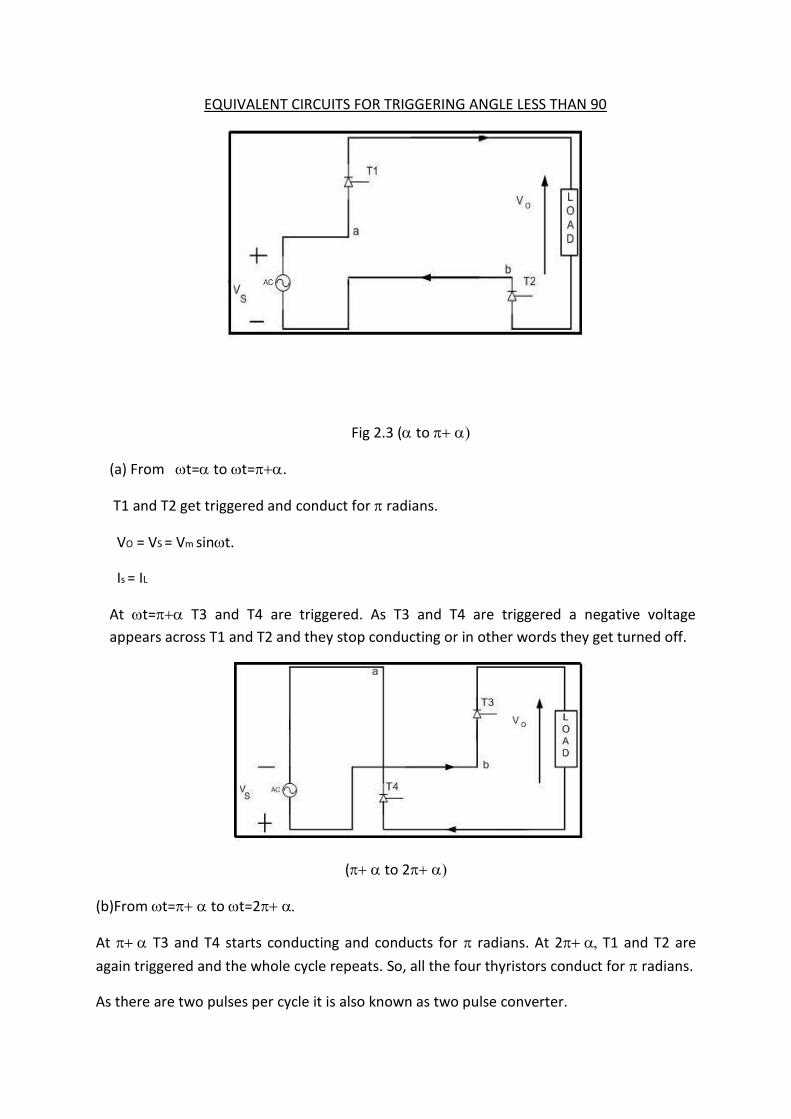
EQUIVALENT CIRCUITS FOR TRIGGERING ANGLE LESS THAN 90
Fig 2.3 (to
(a) From t=to t=.
T1 and T2 get triggered and conduct for radians.
VO = VS = Vm sint.
Is = IL
At t= T3 and T4 are triggered. As T3 and T4 are triggered a negative voltage
appears across T1 and T2 and they stop conducting or in other words they get turned off.
( to 2
(b)From t= to t=2
At T3 and T4 starts conducting and conducts for radians. At 2T1 and T2 are
again triggered and the whole cycle repeats. So, all the four thyristors conduct for radians.
As there are two pulses per cycle it is also known as two pulse converter.

AVERAGE VALUE OF OUTPUT VOLTAGE
π + α π + α
VO = π ∫Vm sinωt d (ωt) =Vm/π (-cosα) l = (2Vm/π) cosα.
α α
----------------------------------(1)
The rms value of the output voltage is found to be
TWO QUARANT OPERATIONS.
Vo = + ve FOR 0<α<π/2
= - ve FOR π/2<α<π figure 2.4
Note that the expression for average value of output voltage is valid only if the load
current is continuous. If the load current is discontinuous then this expression cannot
be used to find the average value of the output voltage. For α varying from 0 to π/2
the average value of output voltage is positive and for α varying from π/2 to π, the
average value of output voltage is negative. The load current is unidirectional.
V0 = 2Vm/π cos (α)
Vor = Vm / 2 =Vs

CASE 2 : WHEN THE TRIGGERING ANGLE IS GREATER THEN 90(
Fig 2.5
Till we trigger T1 and T2, T3 and T4 are conducting. Output voltage is Vba which is
negative in the positive half so we get a negative voltage till α .At α we have triggered T1
and T2, now output voltage jumps to Vab and it continues till until you have
triggered T3 and T4. At when we trigger T3 and T4 the output voltage jumps to Vba

which is positive in the negative half and it continues till T1 and T2 are triggered at 2
Hence in this way the cycle continues. We can see from figure 11 that the average value
of the output voltage across the load is negative that is the area under the curve from 0 to
α is much higher than area under the curve from α to The source current waveform is
same as that of for α<90.The only difference is that it just shifts a bit more to the right as
the triggering angle has been increased. But note that the average value of the output
voltage is negative only when the load current is continuous what we have assumed in the
beginning.
EQUIVALENT CIRCUITS FOR TRIGGERING ANGLE GREATER THAN 90
In 0 < ωt < Fig 2.6
From o< ωt < α:
Potential of point b is greater than that of point a, so voltage across load is negative.
Vo = Vba (- VE).
At ωt = α (Immediately after T1 and T2 are triggered)
=>T1 and T2 are ON and T3 and T4 are OFF.
The turn ON and turn OFF are assumed to be instantaneous.
Vo =Vab = +VE till α < ωt < π.
Vo = -VE from π < ωt < π+α.
As π+α > π-α, the average value of the output voltage is negative when the triggering angle
of the SCR’S are greater than 90 degrees.

Chapter 3
Expression for power factor for a fully controlled rectifier
bridge

EXPRESSION FOR POWER FACTOR FOR A FULLY CONTROLLED BRIDGE
Source current is a square wave. The magnitude of the source current is Io from α to π+ α
and it is –Io from π+ α to 2π+ α. So if we write the Fourier series,
X (ωt) = Is = Io α < ωt < π+α
=> = -Io π+ α <ωt< 2π+α
Fig 3.1
2π+α
Average component => ao =1/2π ∫ x (ωt) d (ωt) = 0
α
as the given square function is an odd function =0.
So all the cosine terms are zero.
π/2
= 4/T ∫x (ωt) sin (nωt) d (ωt) = 4Io/2π *1-cos (nπ/2)]
0
Putting these values in the Fourier series, we get
x (ωt) =4Io/π (sinωt + sin3ωt + sin5ωt +----------------)
( ) ∑(
)

so the peak value of the fundamental component sinωt is 4Io/π where Io is the magnitude of
the square wave.
Rms value of the fundamental component sinωt:
Irms of Is1 = (1/√2)4Io/π = 2√2Io/π.
Rms value of the source current Is:
Irms of Is = Io.
Displacement factor:
cos θ1 = cos (-α)(lagging)
Power factor =Vs1 Is1 cos (-α)/Vrms Irms = mean input power / input volt amperes.
Only fundamental component of voltage and current wave is responsible for current
transfer. Also we have assumed that input voltage is a sinusoid. So the rms value of the
fundamental component of the input voltage is equal to Vrms itself. The rms value of the
fundamental component of the load current is 2√2Io/π and the rms value of the input source
current is I0. Cosα is the displacement factor. That is the fundamental component of the
input source current lags the source input voltage by an angle α.
SO,
Power factor = Vrms * (2√2I0/π)*cos (α).
Vrms * I0
Note that he the power factor obtained is a lagging one.
P.F = (2√2/π) Cosα

Chapter 4
Firing angle control circuit

FIRING ANGLE CONTROL CIRCUIT
Fig 4.1 COMPLETE LAYOUT OF A FIRING CONTROL CIRCUIT
The entire firing angles are with reference to our mains circuit. Mains is 230V. So for control
level we have to step down the mains voltage. So, we will use a step down center tap
transformer for stepping down the voltage to 10V. We have a control level of +10 or -10.
This we give to a zero crossing detector. We can design a positive or negative zero crossing
detector with the help of the operational amplifiers. The output of a positive zero crossing
detector is shown in figure. This output we give to a ramp generator. The output we will
feed to a comparator circuit. Comparator voltage is controlled with the help of a control
voltage Ec. The comparator output is given to a monoshot. In this way we can generate the
desired gate pulse for the thyristor.

Fig 4.2 OUTPUTS OF THE FIRING ANGLE CONTROL COMPONENTS
Positive side of the sinusoidal reference voltage after stepping down is for triggering S1 and
S3 whereas the opposite waveform is for triggering S2 and S4 as shown in the figure. Output
of the positive zero crossing detector is shown. Same we can get for negative waveform.
This output is fed to ramp circuit shown. The ramp output is compared with the control
voltage Ec for firing angle variation. In the ramp generator the capacitor slowly charges. As
per the figure at the zero crossing we must discharge the capacitor. So, for that purpose
these zero crossing points we have to detect again with the help of the monoshot as shown
in the figure. We connect a transistor across the capacitor and the monoshot pulses are
given to transistor. Due to this at zero crossing points the capacitor gets discharged. In this a
ramp we can generate.
Here α is varying proportional to the Ec (control voltage) but the output is varying
proportional to cosα. This is not a linear control. For linear control output as well as the
firing angle must vary proportional to cosα.
COSINE COMPARISION METHOD:
We want our control voltage t vary proportional to cosα.
So, Ec = e COSα.
Eo = Emax COSα

COS α = Ec/e.
Our output voltage Eo = Emax cosα.
Eo = Emax (Ec/e) = kEc.
Where, k= (Emax/e) = constant.
So, the output will be proportional to Ec.
Fig 4.3 VARIOUS OUTPUTS FOR COSINE COMPARISION TECHNIQUE
Here the reference waveform is integrated and a cosine waveform is generated. Positive as
well as negative Ec is generated and is compared with the cosine waveform with the help of
the operational amplifiers based comparators. Pulses are generated at each positive going
pulses and pulse obtained due to comparison of +Ec and cosine waveform is send to the
thyristors T1 and T3. Pulses obtained due to comparison of the –Ec and the cosine
waveform are send to the thyristors T2 and T4. So the firing angle is proportional to cosα.
We can see from the following output waveforms that when the firing angle is zero, the
output is maximum that is cosα = cos0 = 1. So the output obtained is maximum. When α=90,
the output is coming to be equal to zero.

Chapter 5
Model of a DC motor

SPEED CONTROL OF THE DC MOTOR
Fig 5.1
The output speed is compared with the reference speed. The error signal is fed into the
speed controller. This controller output will vary whenever there is a mismatch in the
reference speed and the speed feedback. Here we are controlling the dc motor. We are
controlling the speed by controlling the armature voltage. The output of the controller is the
control voltage Ec that controls the firing angle of the phase controlled converter. This
converter output give the required Va required to bring motor back to the rated speed.
Motor will have the tacho generator. Tacho voltage will not be perfectly dc and it will have
ripple. So, we require to filter it out. So we need a filter. Also a gain is required to bring
tacho output back to the controller level.
MODEL OF A DC MOTOR
Va = armature voltage (volts)
Eb = motor back emf (volts)
Ia = armature current (ampere)
Va = IaRa + La (dIa/dt) +Eb

Ra = armature resistance (ohms)
La = armature inductance (Henry)
Md = Jdω/dt +ML ----------- (1)
ML = load torque (Nm); J = moment of inertia (kg/m²); ω = angular velocity (rad/sec)
now, Eb = K Φ ω --------- (2)
also, Md = K Φ Ia --------- (3)
also, Ia(S) = (Va – Eb)/(Ra + LaS)
=> Ia(s) = (Va – KΦω)
=> Ra(1+ LaS/Ra )
ω(s) = Md - ML = (KΦIa - ML )
Also, Js Js
La/Ra = Ta (Armature time constant)
ω (s) = *kΦ/Ra]/Js(1+TaS)
Now, Va(s) 1 +(k²Φ²/Ra)/JS(1+TaS)
On simplifying the above transfer function we get,
ω (s) = (1/kΦ) --------------------------------------- (4)
Now, Va(s) 1 +(k²Φ²/Ra)/JS(1+TaS)
ω (s) = (1/kΦ) -------------------------------- (5)
Now, Va(s) STm (1+STa)+1
Tm = JRa / (kΦ) ² = electromechanical time constant
Now we have to introduce Electromechanical Time Constant in transfer function
Let us assume load torque ML = 0 and applying full voltage Va

Now Va = KΦω(t) + IaRa (Assuming armature inductance = 0)
=> Md = Jdω/dt = kΦIa----------------------------------(6)
Va = KΦω(t) + (Jdω/dt) Ra
=> KΦ
Va = ω(t) + JRa (dω/dt) ---------------------------(7)
=> KΦ (KΦ) ²
At no load , when the machine reaches full speed
ω (no load) = Va/KΦ
putting this value in eq. (7)
ω (no load) = ω(t) + JRa (dω/dt) = ω (t) + Tm (dω/dt)
=> (KΦ) ²
KΦ = Km
Tm = JRa/ (KΦ) ² = JRa/ (Km) ²
=> J = Tm (Km) ² / Ra ----------------------- (8)
ω (s) = Km Ia(s) - ML ---------------------------(9)
=> Js Js
putting the value of J in eq. (9)
Fig 5.2
Further simplifying eq. (5) we get
ω (s) = (1/Km)-----------------------------(10)
=> Va (s) (1+STm+S²TaTm)
But, the armature time constant Ta is much less than the electromechanical time constant
Tm, Ta << Tm
ω (s) = *(Ra / Km) Ia(s) - ML Ra / (Km) ² ] (1/Tm(s))

Now, 1 + STm + S²TaTm ≈ 1 + S (Ta+Tm) + S²TaTm = (1 + STm)(1 + STa)
Whole this exercise is to represent the transfer function in the time constant form. If we
get the transfer function in time constant form, we know the largest time constant that will
delay the system. So if we use the PI controller, zero of the PI controller can be chosen so
that this large delay can be cancelled. Delay means a lag and zero means a lead, so this will
try to compensate the whole system.
ω (s) = (1/Km)---------------------------(11)
=> Va (s) (1 + STm)(1 + STa)
This Tm and Ta determine the response of the system. These are the time constants of the
system.
PROBLEM:
Let the machine is at standstill. It has not started. Suppose the operator give a high speed
command. Let us say motor has to go to full speed. Because of electromechanical time
constant it will take its own time to speed up. But the controller is very fast. Speed feedback
is zero initially. So this will result in full controller output Ec. Converter gives the maximum
voltage. But during starting back emf Eb is zero. So very large current flows which sometime
exceed the motor rated current limit and it can damage the machine.
So, here the problem is current is not controlled. We are only looking at the speed and the
voltage. For a machine there is not only the voltage rating but the current rating is also
there. So any speed control must have a current control. So, before going to the machine one
current control loop is there. That is, the applied voltage Va is now not dependent on the
speed error but is on the current error. We must ensure that Va is applied in such a way that
machine during positive and negative torque should not draw more than the rated current.
So, an inner current loop is required.

Fig 5.3 COMPLETE LAYOUT OF THE DC DRIVE MECHANISM FOR CONTROLLING SPEED

Chapter 6
Representation of converter

REPRESENTATION OF THE CONVERTER:
Let the converter is a 3 phase fully controlled converter for a typical firing angle α = 60.
Fig 6.1 RIPPLES WITH 60 DEGREE DURATION FOR 50 HZ WAVEFORM
Ripple will be six times the fundamental frequency. So the duration of each ripple will be 60
degree.
For 50 Hz supply
for 360 degrees, Time period T = (1/50) = 0.02 s.
For 60 degree, t = (0.02 * 60)/360 = 3.3 ms.
A change in converter firing angle occurs after every 60 degree. It’s not instantaneous. That
means a delay of 3.3 ms. It can have a maximum delay of 3.3 ms or a minimum of zero.
So, let us take an average Tr = (3.3 ms + 0)/2 = 1.7 ms.
So, converter can be represented as a first order delay with a gain. Suppose a +10v
reference is coming from current controller. So if we are using a cosine firing with linear
control, maximum output voltage should be obtained.
For a 3 phase converter, output voltage = 2 * 1.17 * Erms *cosα
Maximum voltage obtained when α = 0.
Max. Voltage = 2 * 1.17 * Erms.
Control voltage is 10V.
=> So, gain is:
Kt = (2 * 1.17 * Erms)/10

So, converter can be represented as first order lag with some gain Kt.
Fig 6.2 COMPLETE LAYOUT OF THE DC DRIVE SYSTEM
Kt / (1 + STr)

Chapter 7
Designing of current controller

DESIGNING OF THE CURRENT CONTROLLER
We will design the controller for the worst case. That is during starting when Eb = 0 and a
large current flows through the machine.
Fig 7.1
Transfer function:
Ia(S) (f) = [Kc (1 + TcS)/TcS] (Kt/1+STt)[(1/Ra)/(1+STa)----------(12)
=> Ia(S) (ref) 1 + [Kc (1 + TcS)/TcS] (Kt/1+STt)[(1/Ra)/(1+STa)(K2/1+ST2)
Tc is in our control. We choose Tc such that it can cancel one of the largest time constant in
the transfer function . So, the order of the system will be reduced. Now, the response will
be much faster. Converter delay Tr must be much less than armature time constant Ta.
So, let us make
Putting this value in equation (12)
Ia(S) (f) = Kc (Kt/TaRa) (1+T2S) --------------------- (13)
Ia(S) (ref) S (1+TtS) (1+T2S) + (KcKtK2)/TaRa
let Ko = (KcKt/TaRa)
Ia(S) (f) = Ko (1+T2S) ---------------------------------- (14)
Ia(S) (ref) S³TtT2 + s² (Tt +T2) +S+ KoK2
Tt and T2 are the converter lag and filter lag respectively. These are the smaller time
constants. So, their product can be approximated to zero.
TtT2≈0, Tt +T2 =
Ia(S) (f) = Ko (1+T2S) ----------------- (15)
Ia(S) (ref) S²S + KoK2
Tc = Ta

Ia(S) (f)/Ia(s) (ref) = (Ko/T2S / [S² + (S/) + (KoK2/)]
S² + (S/) + (KoK2/) ≈ S² + 2ω + ω²
=> ω = √ (KoK2)/1/ (2ω1/ (2√ (K2Ko)
this is a second order system. So, to get a proper response 0.707
1/√ (2) = 1/2√ (K2Ko) => Ko = 1/ (2K2 = KcKt / (RaTa)
Ko = Kc Kt / (RaTa) = 1/2K2 (Tt + T2)
Ia(S) (f) = (1/K2) (1+T2S) ----------------- (16)
Ia(S) (ref) 2S²²S + 1
thus on using a filter a zero is introduced in the transfer function. This zero may result in an
overshoot. So we will use a filter with same time lag between the Ia (ref) and controller to
cancel the effect of the current filter. Current loop time constant is much higher than the
filter time constant. So a slight delay at Ia (ref) will not affect much. So we put a filter here.
Ia(S) (f) = (1/K2) (1+T2S) ----------------- (17)
Ia(S) (ref)(1+ST2) 2S²²S + 1
Kc = (RaTa)/ (2KtK2)
Ia(S) (f) / Ia(S) (ref) = (1/K2)/ (2S²²S + 1)

Chapter 8
Designing of speed controller

DESIGINING OF THE SPEED CONTROLLER
POLE ZERO CANCELLATION
Fig 8.1
ω (s) = (Kn/K2)(Ra/KmTmTn)(1+TnS/(1+2σS)S²)----------------------------(18)
=> ωs(ref.) 1 + (KnRa/K2KmTmTn)(1+TnS/(1+2σS)S²)(K1/1+T1S)
We can control Tn. We set Tn such that it cancels one of the largest time constant of the
transfer function. So,
Let us take a case
ω (s) = (KnRa/K2KmTmTn)(1+T1S)
=> ωs(ref) K2KmTmTnS²(1+T1S)+KnRaK1
=> ω(s) = 1/ S(S²+αs)
we are not getting the S term coefficients in the denominator. Hence the damping constant
is zero. So the system become little oscillatory and unstable.
OPTIMIZATION TECHNIQUE
The dynamic performance of a control system is good if the controlled variable rapidly
reaches the reference limit. For any frequency variation (between the bandwidth) of the
input variable, the output should track the input variable instantaneously. For any frequency
of input, output follows input as closely as possible.
Tn = 2σ

Optimization technique aims at bringing the input/output gain as close to 1 over a wide
frequency range (modulus hugging).
=> G (jω) ≈ 1
GENERAL CONSIDERATION FOR OPTIMIZATION
Simplifying eqt. (18) further we get,
ω (s) = (KnRa/K2Km)(1 + TnS) (1 + T1S)----------------------------(19)
=> ωs(ref.) S²TmTn(1 + 2S) (1 + T1S) + (KnRaK1/K2Km)(1 + TnS)
But, (1+2S)(1+T1S) = 1 + T1S + 2S + 2T1S² ≈ 1 + S(2T1) + 2T1S² ≈ 1 + S(2T1)
Both T1 and are smaller time constants. So their product can be approximated to zero.
1 + S (2+T1) = 1+ S. Where = (2+T1).
ω (s) = (KnRa/K2Km)(1 + TnS) (1 + T1S)----------------------------(20)
=> ωs(ref.) S²TmTn(1 + S)+ (KnRaK1/K2Km)(1 + TnS)
ω (s) = (KnRa/K2Km)(1 + TnS) (1 + T1S)----------------------------(21)
=> ωs(ref.) S³TmTn+ S²TmTn + (KoK1Tn)S + KoK1
The terms (1 + TnS) and (1 + T1S) in the denominator will be cancelled by using filters.
For a third order system:
F (jω) = bo + jωb1 / [ao + jωa1 + (jω) ²a2 + (jω) ³ a3]
for low frequency bo = ao and b1 = a1
lF(jω)l = (ao² +ωa1²/ao² + ω²(a1²- 2aoa2) + ω´(a2²- 2a1a3) +ω⁶(a3²) )⅟2
For making this mod equivalent to 1; coefficients of ω² and ω´ are made equal to zero
Using filters at the ωs (ref) side:
a1²=2aoa2
a2²= 2a1a3

ω (s) = (KnRa/K2Km)(1 + TnS) (1 + T1S)--------------(22)
ω(s)(ref) )(1/1 + TnS) (1/1 + T1S) S³TmTn+ S²TmTn + (KoK1Tn)S + KoK1
ω (s) = Ko-----------------------------------(22)
=> ω(s)(ref) ) S³TmTn+ S²TmTn + (KoK1Tn)S + KoK1
where Ko = (KnRa/K2Km)
(KoK1Tn) ² = 2 * KoK1 * TmTn
(TmTn) ² = 2 * KoK1Tn * TmTn
=> Tm = 2 * KoK1 * 2 * (KnRa/K2Km) * K1*
Putting the values of kn and km in the main transfer function, we get
Tn = 4 (2+T1) = 4(2Tt+2T2+T1)
Kn = TmKmK2/(2K1Ra)
ω(s)(f) / ω(s)(ref) = 1/(1 +4ss²²8s³³

Chapter 9
Designing of speed and current controller for a DC drive
with the given specifications

DESIGNING OF SPEED AND CURRENT CONTROLLER FOR A DC DRIVE WITH THE
FOLLOWING SPECIFICATION
1. RATED POWER = 300 KW
2. MAXIMUM RATED VOLTAGE = 460V D.C.
3. MAXIMUM RATED CURRENT = 690 Amps.
4. BASE SPEED = 500 RPM = 52.3 rad/s
5. MOMENT OF INERTIA (J) = 84 Kg-m2
6. BACK EMF CONSTANT (Km) = 8.5 Volt-sec. /Rad.
7. ARMATURE RESISTANCE (Ra) = 0.02342 Ohms.
8. ARMATURE INDUCTANCE (La) = 0.7026 mH.
9. CONVERTER = 3-Ph Fully Controlled bridge converter
10. SPEED FEEDDBACK FILTER TIME CONSTANT (T1) = 25msec.
11. CURRENT FILTER TIME CONSTANT (T2) = 3.5msec.
12. MAXIMUM CURRENT LIMIT = 1200 Amps.
VARIOUS PARAMETERS FOR DESIGNING THE CURRENT CONTROLLER
Kc = (TaRa)/2KtK2 (Tt+T2);
But, Tc = Ta;
Ta = La/Ra = 30ms.
Kt = 460/10 = 46
K2 = 10/1200 = 1/120
Tt = 1.7 msec.
T2 = 3.5 msec.
So Now,
Kc = 30×0.02342/(2×46×42(1.7+3.5)) = 0.1762
Tc = Ta = 30 msec.

VARIOUS PARAMETERS FOR DESIGINING THE SPEED CONTROLLER
Tn = 4δ = 4(2σ+T1) =4(2(T1+ T2) + T1) = 4(3.4+7+25)ms = 141.6 ms.
Kn = TmKmK2/(2K1Ra(2Tt+2T2+ T1)
Tt = 1.7msec.
T1 = 25msec.
T2 = 3.5msec.
Km = 8.5 Volt-sec. / rad.
Ra = 0.02342
K2 = 1/120 = 0.0083
SPEED = 500 rpm = (52.3 rad/sec.)
FILTER GAIN K1 = 10/52.3 = 0.19
Tm = J×Ra/ (Km) = 84×0.02342/ (8.5) = 27.2msec.
Kn = 27.2×8.5×0.0083 / 2×0.019×0.0234×35.4 = 6.12

UNIT STEP RESPONSE FOR CURRENT LOOP
MATLAB PROGRAM
>> s=tf('s');
>> g=2218934/(s^2+192.30*s+18491);
>> d=0.1762+5.87/s;
>> m=feedback(d*g,1);
>> step(m);
.

UNIT STEP RESPONSE FOR SPEED LOOP
MATLAB PROGRAM
>> s=tf('s');
>> g=99.74/(s^2+14.12*s+99.74);
>> d=6.2+43.71/s;
>> m=feedback(d*g,1);
>> step(m);

Chapter 10
Simulation of DC motor drive model
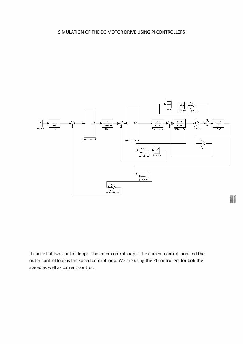
SIMULATION OF THE DC MOTOR DRIVE USING PI CONTROLLERS
It consist of two control loops. The inner control loop is the current control loop and the
outer control loop is the speed control loop. We are using the PI controllers for boh the
speed as well as current control.

Chapter 11
results

(i) AT FULL LOAD
GRAPH FOR THE DC MOTOR SPEED RESPONSE
GRAPH FOR THE ARMATURE CURRENT RESPONSE

GRAPH FOR THE SPEED ERRROR

(ii) AT LOAD LESS THAN FULL LOAD
GRAPH FOR THE DC MOTOR SPEED RESPONSE
GRAPH FOR THE ARMATURE CURRENT RESPONSE

GRAPH FOR THE SPEED ERRROR

(iii) AT LOAD MORE THAN FULL LOAD
GRAPH FOR THE DC MOTOR SPEED RESPONSE
GRAPH FOR THE ARMATURE CURRENT RESPONSE

GRAPH FOR THE SPEED ERRROR

REFERENCES
DC MOTOR DRIVES: P.C.SEN
P.K. NANDAM and P.C. SEN, 1985, A comparative study of proportional-
integral (P-I) and integral-proportional (I-P) controller for dc motor drives.
SIMULINK, Model-based and system-based design, using Simulink,
Math Works Inc., Natick, MA, 2000.
POWER ELECTRONICS: P.S.BIMBHRA
Mohan, Ned, “Electric Drives – An Integrative Approach,” MNPERE,
2003.
Control of electrical drives: WERNER LEONHARD
The Math Works Inc, MATLAB Control System Toolbox ver. 3.0b, 1993
PROF. K.GOPAKUMAR,’POWER ELECTRONICS’, lecture notes,
INDIAN INSTITUTE OF SCIENCE, BANGALORE.
Related Documents