Basic Electronics for Model Railroaders By Gene Jameson NMRA Convention, Portland OR., August 23 - 30, 2015

Welcome message from author
This document is posted to help you gain knowledge. Please leave a comment to let me know what you think about it! Share it to your friends and learn new things together.
Transcript

Basic Electronics for Model Railroaders By
Gene Jameson NMRA Convention, Portland OR., August 23 - 30, 2015

Please turn off your cell phones. If it rings I will ask you to leave the room and I will NOT be too nice about it.
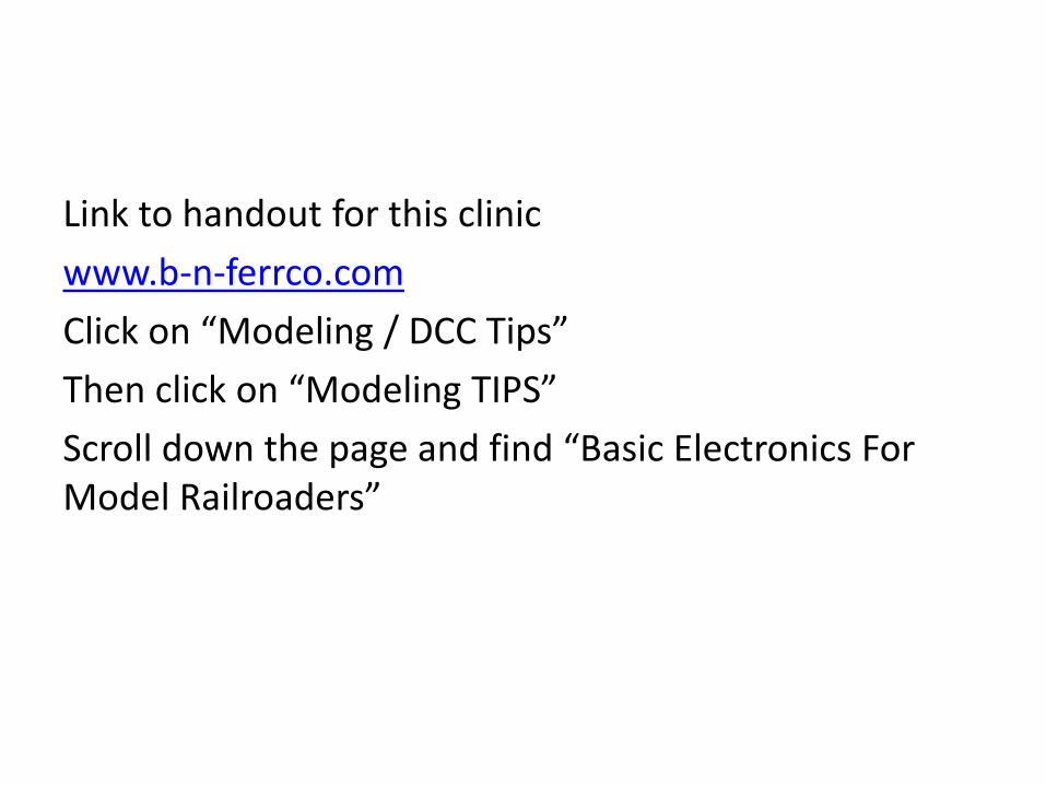
Link to handout for this clinic
www.b-n-ferrco.com
Click on “Modeling / DCC Tips”
Then click on “Modeling TIPS”
Scroll down the page and find “Basic Electronics For Model Railroaders”
Some back ground about me
• I have been in the electronics field since 1975
• I have worked on everything from radios to radar to weather equipment to closed circuit TV
• At the present time I work for Rockwell Collins in the engineering department.
• Some of the recent projects that I have worked on are the HF radio for the Boeing 787, and HF radio for the AirBus A350 which was a totally new design.
• Instrument rated pilot and ground school instructor
• Was the National Coordinator, HO standards for the NMRA for 8 years
• I’m the Eastern Division Superintendent of the Sunshine Region
Agenda
• Terms and definitions
• Schematic symbols and their meanings
• Drawing the schematic
• Electrical components and their markings
• Surface mount vs. leaded components
• LED’s vs. incandescent bulbs
• Reading resistor color codes on carbon composite resistors
• Reading resistor size on metal foil resistors
• Wiring the layout
• Ohms Law and other formulas that you will need
Agenda (Continued)
• How to use Ohms Law – Half Wave • How to use Ohms Law – Full wave • How to use Ohms Law to find resistor size – Full
Wave • How to use Ohms Law to find resistor size – Half
Wave • Resistors in series vs parallel • Wire size vs. current capability • Nice things to have – tools and stuff • Questions – Pass out handouts
Terms and Definitions
• Ohms Law – one volt into one ohm of resistance equals one amp of current
• Voltage – The force applied to the circuit (think of water pressure applied to a hose). Measured in Volts
• Current – The amount of electrons that flow through the circuit. Measured in Amps
• Watts – The heat generated by the resistance to the voltage applied. Measured in Watts
• Working voltage – the highest voltage the part was designed to work under. Normally for capacitors and diodes. ALWAYS select a part the is rated at least 25% higher than the applied voltage of the circuit
Terms and Definitions (Continued)
• Resistor – a device that resists current flow. Measured in “Ohms” Values are shown as ohms, K ohms, M ohms
• Capacitor – a device that resists a change in voltage (stores voltage) Measured in “farads” Values are shown as uf, pf
• Inductor – a device that resists changes in current (produces voltage as fields collapse) Measured in “henrys” Values are shown as mh, uh, nh
• Diode – a device with one PN junction that only allows current to flow in one direction (used for rectification)
• Transistor – A device that has two PN junctions that allow current to be amplified, phase shifted, or buffered

Terms and Definitions (Continued)
• IC - Integrated circuit i.e.; can be an amplifier, buffer, or oscillator
• Transformer – Changes voltage to a higher or lower level than what was applied. If voltage goes up, current goes down. If voltage goes down, current goes up
• LED – A device with one PN junction that only allows current to flow in one direction and produces light of various colors (not used for rectification)
• Cathode – The end of the diode that has the “bar” on it (ground side). It is the negative side of the diode
• Anode – The positive end of the diode • Emitter – The part of the transistor that goes to the
ground side of the circuit. It “emits” electrons
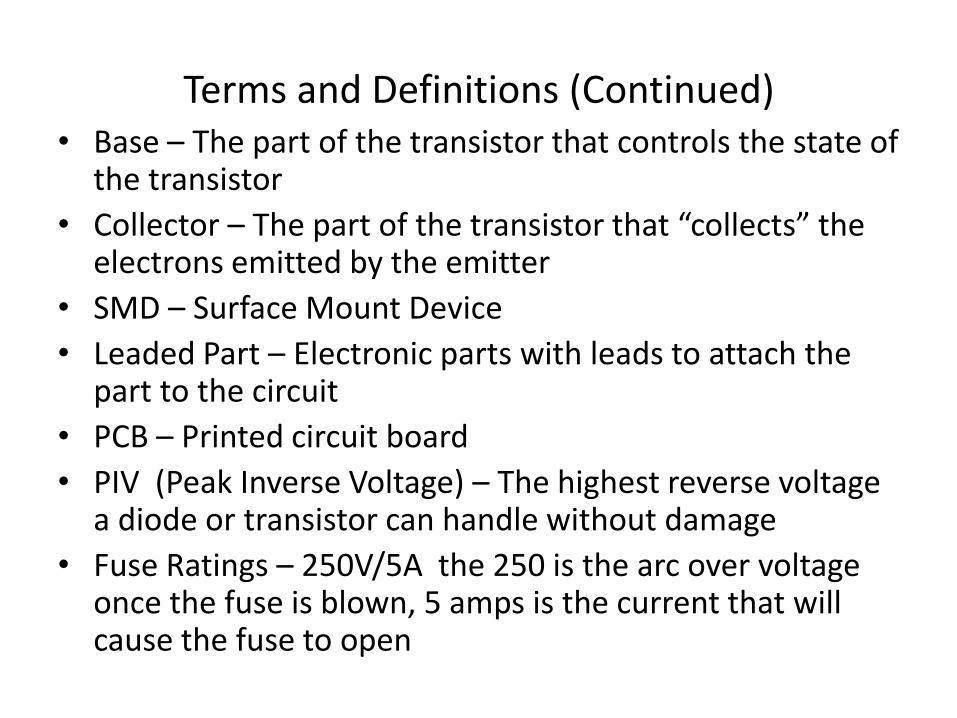
Terms and Definitions (Continued) • Base – The part of the transistor that controls the state of
the transistor
• Collector – The part of the transistor that “collects” the electrons emitted by the emitter
• SMD – Surface Mount Device
• Leaded Part – Electronic parts with leads to attach the part to the circuit
• PCB – Printed circuit board
• PIV (Peak Inverse Voltage) – The highest reverse voltage a diode or transistor can handle without damage
• Fuse Ratings – 250V/5A the 250 is the arc over voltage once the fuse is blown, 5 amps is the current that will cause the fuse to open
Terms and Definitions (Continued)
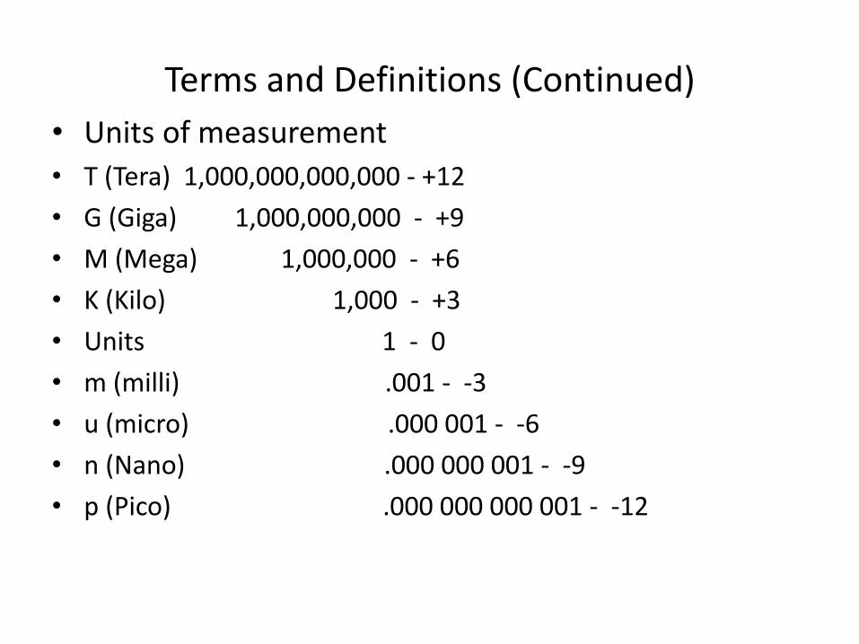
• Units of measurement
• T (Tera) 1,000,000,000,000 - +12
• G (Giga) 1,000,000,000 - +9
• M (Mega) 1,000,000 - +6
• K (Kilo) 1,000 - +3
• Units 1 - 0
• m (milli) .001 - -3
• u (micro) .000 001 - -6
• n (Nano) .000 000 001 - -9
• p (Pico) .000 000 000 001 - -12
Terms and Definitions (Continued)
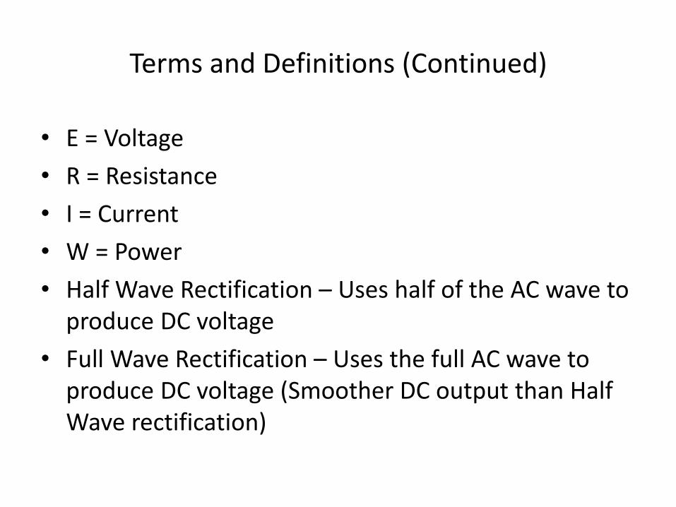
• E = Voltage
• R = Resistance
• I = Current
• W = Power
• Half Wave Rectification – Uses half of the AC wave to produce DC voltage
• Full Wave Rectification – Uses the full AC wave to produce DC voltage (Smoother DC output than Half Wave rectification)


Drawing the Schematic
• Start on the upper left, work to the right and then down
• Number your pages
• Name all bus lines, and keep them constant throughout the schematic
• Show the page number for all bus lines, showing all pages that line is located on
• Number all components R1, R2, C1, C2, etc.
• Use arrows to show data/current flow on and off the pages
• Keep it neat!

Mark your inputs and outputs
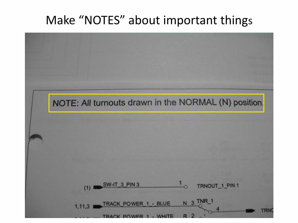
Make “NOTES” about important things

Show page numbers for all inputs and outputs
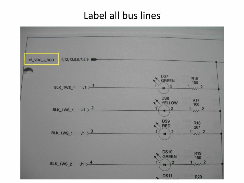
Label all bus lines
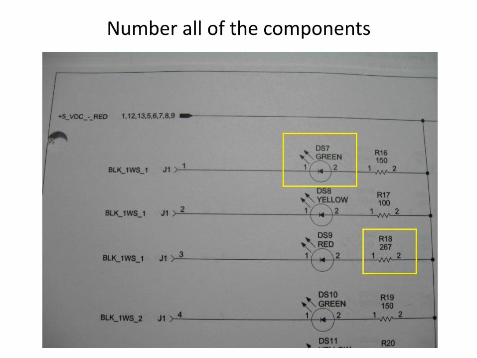
Number all of the components

Label all signal lines
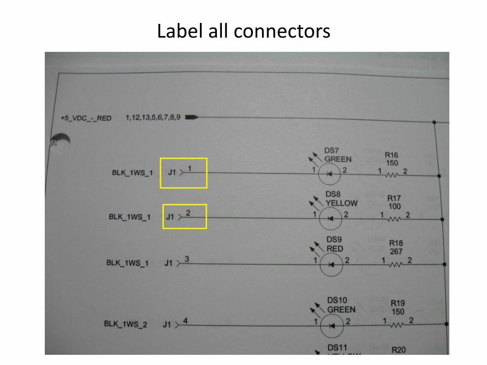
Label all connectors
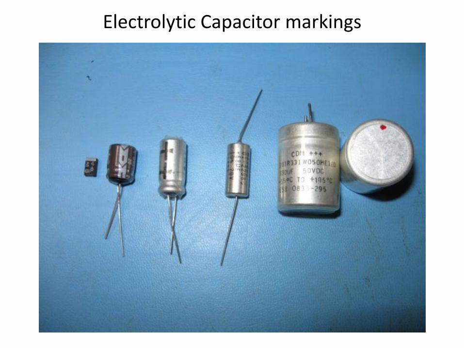
Electrolytic Capacitor markings
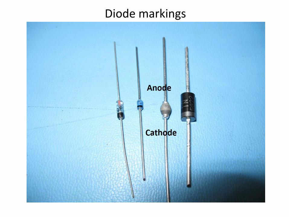
Diode markings
Surface Mount vs. Leaded parts
• Surface mount parts are smaller than the same part with leads
• Surface mount parts have the same values as the leaded parts
• Surface mount parts are readily available, and cheap
• Surface mount parts were meant to be on a circuit board, therefore can be hard to work with
• Leaded parts were meant to be used for “point to point” wiring

LED’s

LEDs vs. Incandescent bulbs
• Lower current
• Operate cooler
• Can give the look of fluorescent lighting (using white LEDs)
• Can give the look of incandescent lighting (using Golden LEDs)
• Easier to hide a Surface Mount Device (SMD) LED in a building than an incandescent bulb
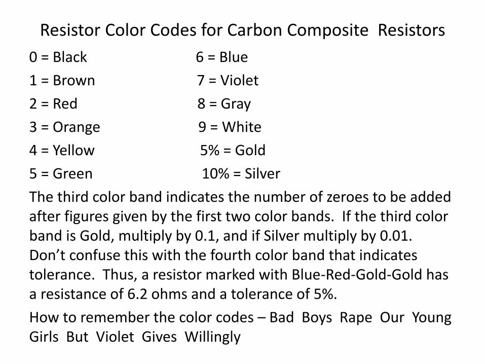
Resistor Color Codes for Carbon Composite Resistors
0 = Black 6 = Blue
1 = Brown 7 = Violet
2 = Red 8 = Gray
3 = Orange 9 = White
4 = Yellow 5% = Gold
5 = Green 10% = Silver
The third color band indicates the number of zeroes to be added after figures given by the first two color bands. If the third color band is Gold, multiply by 0.1, and if Silver multiply by 0.01. Don’t confuse this with the fourth color band that indicates tolerance. Thus, a resistor marked with Blue-Red-Gold-Gold has a resistance of 6.2 ohms and a tolerance of 5%.
How to remember the color codes – Bad Boys Rape Our Young Girls But Violet Gives Willingly

Carbon Composite Resistors
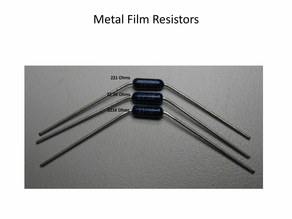
Metal Film Resistors
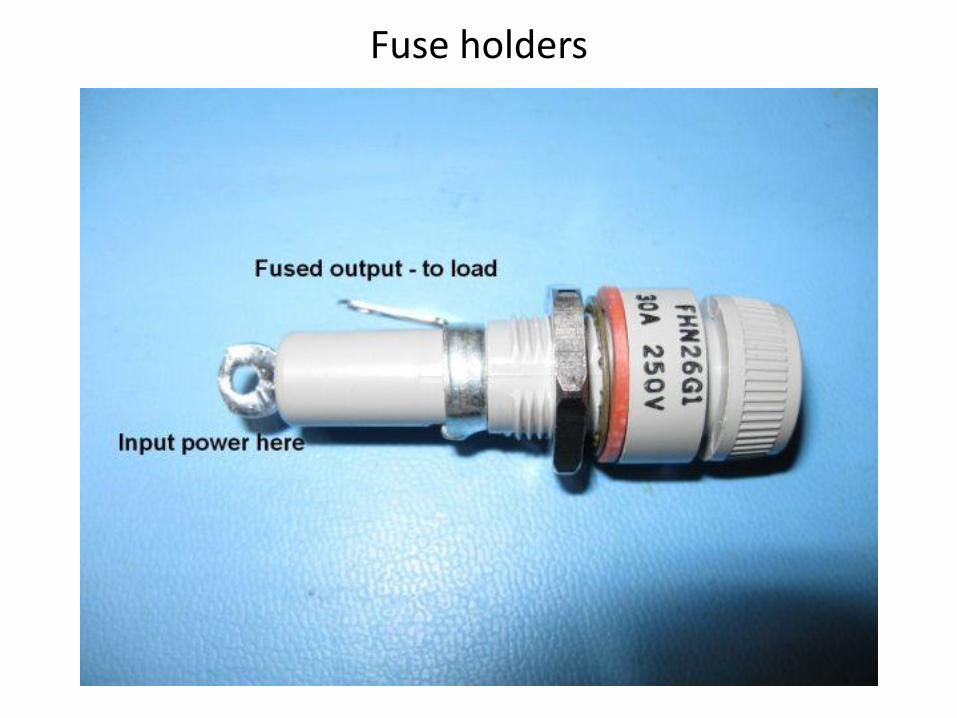
Fuse holders
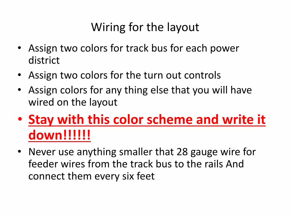
Wiring for the layout
• Assign two colors for track bus for each power district
• Assign two colors for the turn out controls
• Assign colors for any thing else that you will have wired on the layout
• Stay with this color scheme and write it down!!!!!!
• Never use anything smaller that 28 gauge wire for feeder wires from the track bus to the rails And connect them every six feet

Wiring for the layout (Continued)
• Make your wiring neat. You will have to troubleshoot it sometime in the future (Use cheap metal shower hooks to run the wiring through)
• Draw a schematic of the railroad for when you have to troubleshoot it in the future
• Keep the cab bus and track bus as far as possible for each other. If they have to cross each other, do it at a 90 degree angle
• Mark your power district wiring at both ends
• For long track bus runs (over 20 feet) twist the wire three turns per foot and install a “snubber” (47 to 100 ohm resistor and a capacitor that is 0.1 uf 50 V)

Ohms Law for DC Circuits
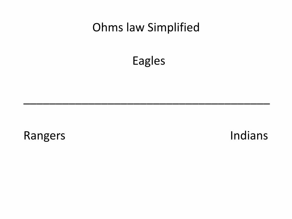
Ohms law Simplified
Eagles
______________________________________
Rangers Indians
Before we get started with Ohm’s Law
• Measure your track voltage and document it – my track voltage is 14.2 volts AC
• Measure the “light common” for the decoder – I measured “light common” to one of the function outputs on a Sound Traxx Tsunami and got 13.4 volts DC
• If you are going to use the half wave method, measure the function out put to one of the rail to the decoder – on the Tsunami I got 6.5 volts DC
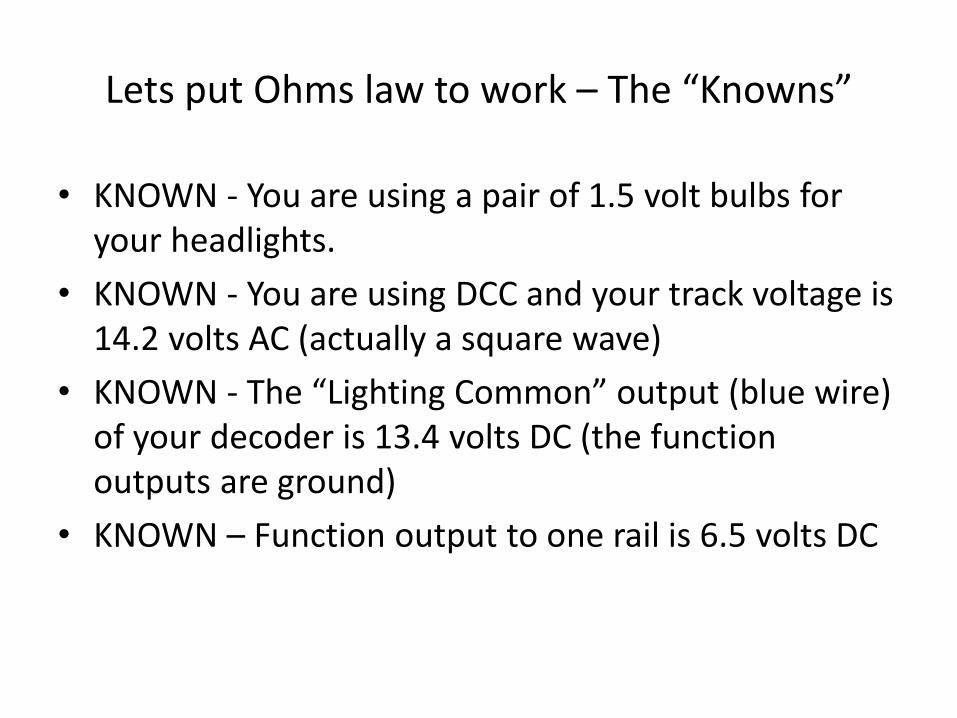
Lets put Ohms law to work – The “Knowns”
• KNOWN - You are using a pair of 1.5 volt bulbs for your headlights.
• KNOWN - You are using DCC and your track voltage is 14.2 volts AC (actually a square wave)
• KNOWN - The “Lighting Common” output (blue wire) of your decoder is 13.4 volts DC (the function outputs are ground)
• KNOWN – Function output to one rail is 6.5 volts DC

Lets put Ohms law to work – The “Unknowns”
• UNKNOWN - What is the current of the bulb
• UNKNOWN - What value resistor do you need
• UNKNOWN – What wattage resistor do you need

Some things to think about before you start
• Am I going to use “full wave” rectification or “half wave” rectification, and what is the difference?
• Using the “full wave” method, you have to drop all the voltage out of the “lighting common” output
• Using the “half wave” method, you only have to drop about half the voltage of “lightning common”(go to one side of track power)
• Am I going to wire the bulbs in series or parallel and what is the difference?
• In series you drop voltage across both bulb (3V) and the current through both bulbs are the same as one bulb
• In parallel you drop voltage across each bulb (1.5V) and the current is now the combination of both bulbs
• How much space do I have in the locomotive?
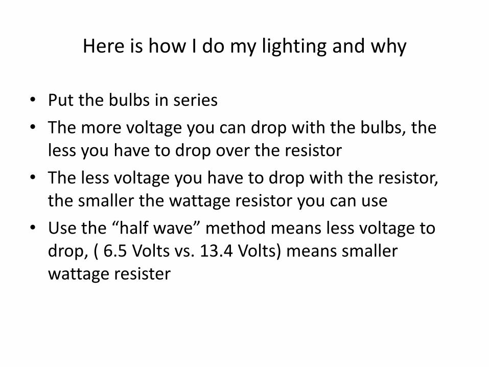
Here is how I do my lighting and why
• Put the bulbs in series
• The more voltage you can drop with the bulbs, the less you have to drop over the resistor
• The less voltage you have to drop with the resistor, the smaller the wattage resistor you can use
• Use the “half wave” method means less voltage to drop, ( 6.5 Volts vs. 13.4 Volts) means smaller wattage resister
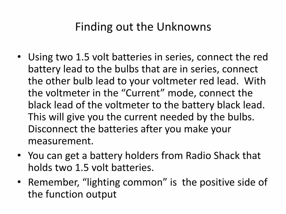
Finding out the Unknowns
• Using two 1.5 volt batteries in series, connect the red battery lead to the bulbs that are in series, connect the other bulb lead to your voltmeter red lead. With the voltmeter in the “Current” mode, connect the black lead of the voltmeter to the battery black lead. This will give you the current needed by the bulbs. Disconnect the batteries after you make your measurement.
• You can get a battery holders from Radio Shack that holds two 1.5 volt batteries.
• Remember, “lighting common” is the positive side of the function output
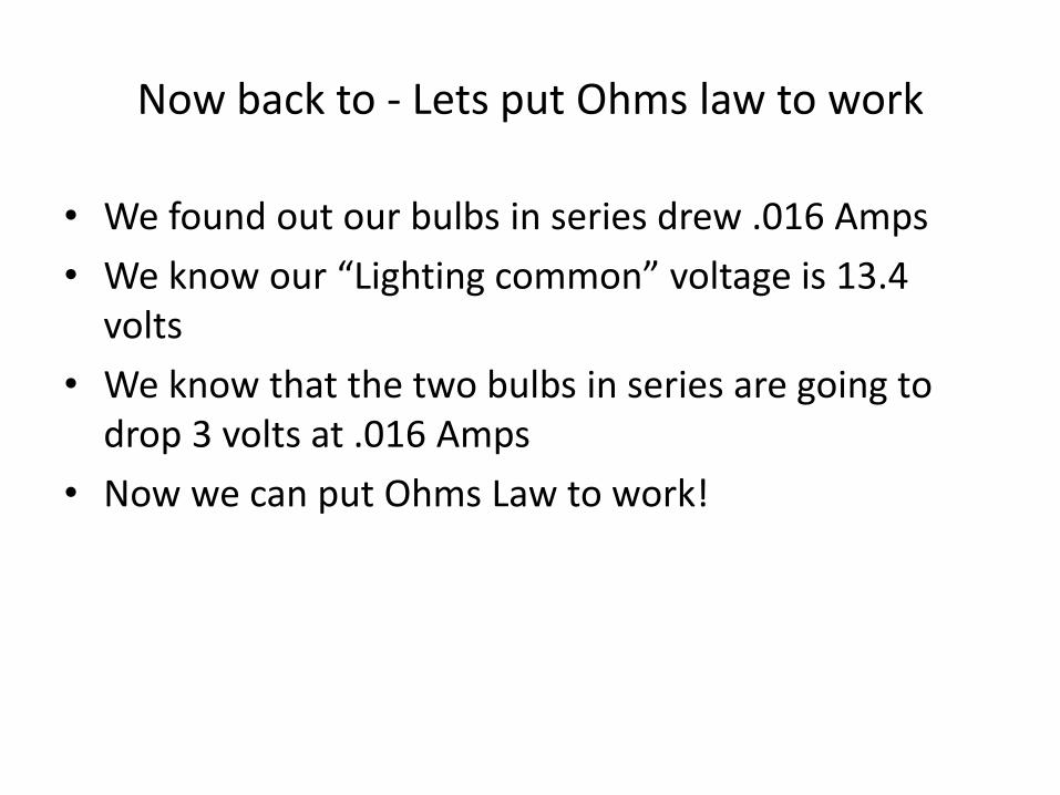
Now back to - Lets put Ohms law to work
• We found out our bulbs in series drew .016 Amps
• We know our “Lighting common” voltage is 13.4 volts
• We know that the two bulbs in series are going to drop 3 volts at .016 Amps
• Now we can put Ohms Law to work!

Putting Ohms law to work – Full Wave
• Bulb voltage = 3 volts (Two 1.5 volt bulbs in series) • Full Wave voltage is 13.4 volts (function output to
lighting common) • That means we have to drop 10.4 volts across the resistor • Here we go – E = Voltage, I = Current, R = resistance • E / I = R • E = 10.4 V, I = .016, R = ? • 10.4 V/.016 I = 637.5 Ohms - Standard value resistor will
be 681 Ohms. You could use two 1.30 K ohm, 1/8 W resistors in parallel to get 650 ohms
• Never go a smaller value resistor or you will be replacing the bulbs
Putting Ohms law to work – Full Wave
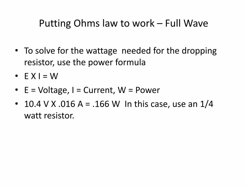
• To solve for the wattage needed for the dropping resistor, use the power formula
• E X I = W
• E = Voltage, I = Current, W = Power
• 10.4 V X .016 A = .166 W In this case, use an 1/4 watt resistor.
Putting Ohms law to work – Half Wave
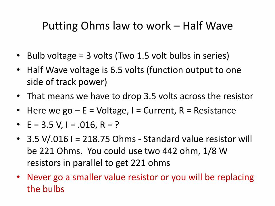
• Bulb voltage = 3 volts (Two 1.5 volt bulbs in series)
• Half Wave voltage is 6.5 volts (function output to one side of track power)
• That means we have to drop 3.5 volts across the resistor
• Here we go – E = Voltage, I = Current, R = Resistance
• E = 3.5 V, I = .016, R = ?
• 3.5 V/.016 I = 218.75 Ohms - Standard value resistor will be 221 Ohms. You could use two 442 ohm, 1/8 W resistors in parallel to get 221 ohms
• Never go a smaller value resistor or you will be replacing the bulbs

Putting Ohms law to work – Half Wave
• To solve for the wattage needed for the dropping resistor, use the power formula
• E X I = W
• E = Voltage, I = Current, W = Power
• 3.5 V X .016 A = .056 W In this case, use an 1/8 watt resistor. I use 1/4 watt resistors in all my installations unless it requires a larger wattage resistor
Resistors in series vs. parallel
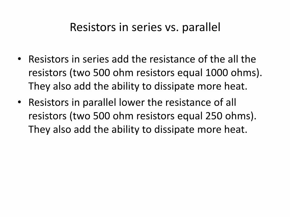
• Resistors in series add the resistance of the all the resistors (two 500 ohm resistors equal 1000 ohms). They also add the ability to dissipate more heat.
• Resistors in parallel lower the resistance of all resistors (two 500 ohm resistors equal 250 ohms). They also add the ability to dissipate more heat.
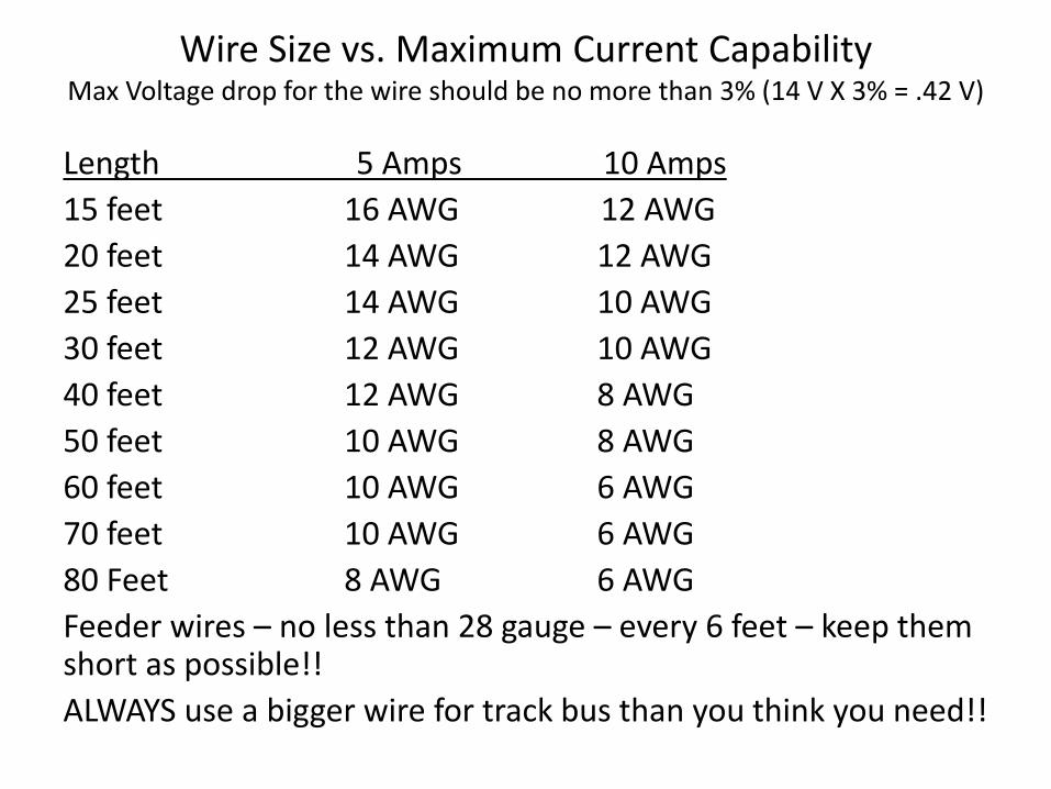
Wire Size vs. Maximum Current Capability Max Voltage drop for the wire should be no more than 3% (14 V X 3% = .42 V)
Length 5 Amps 10 Amps
15 feet 16 AWG 12 AWG
20 feet 14 AWG 12 AWG
25 feet 14 AWG 10 AWG
30 feet 12 AWG 10 AWG
40 feet 12 AWG 8 AWG
50 feet 10 AWG 8 AWG
60 feet 10 AWG 6 AWG
70 feet 10 AWG 6 AWG
80 Feet 8 AWG 6 AWG
Feeder wires – no less than 28 gauge – every 6 feet – keep them short as possible!!
ALWAYS use a bigger wire for track bus than you think you need!!
Nice things to have – Tools and stuff
• A good digital volt meter – with current and diode test function
• 25 watt soldering iron
• Sponge – for cleaning the solder iron tip
• Rosin core solder – NEVER use acid core solder
• Flux
• Wire strippers – 30 to 22 gauge and 22 to 10 gauge
• Side cutters
• Round nose pliers
• Needle nose pliers
• Heat shrink insulation – various sizes
• Alcohol – Rubbing not drinking!!!

Questions?
Thanks for attending my workshop on Basic Electronics for Model Railroaders. If you have questions after you leave the convention, please feel free to contact me.
This Power Point Presentation is on my web site under “Modeling /DCC Tips” then “Modeling Tips”
Cell: 321-432-5483 – if I don’t answer, leave a message and I will call you back.
E-mail: [email protected]
Web Site: b-n-ferrco.com
Related Documents