Welcome message from author
This document is posted to help you gain knowledge. Please leave a comment to let me know what you think about it! Share it to your friends and learn new things together.
Transcript


6 7
E KXLINE
L3L2L1N
PEL3L2L1N
In A 630
06
800
08
1000
10
1250
12
1350
14
1600
17
2000
20
25002500 3200
33
3000
32
4000
40
5000
50
L
S I
�U
L
IR
X
� �U= 3.L. .(RI .Cos +X .Sin ) 10� �-3
V
S
Voltage Drop Calculation
Generally Voltage drop of a busbar system can be
calculated with the following formula.
= Voltage Drop (V)
= Line Length (m)
= Line Current or Load (A)
= Resistance (m /m)
= Reactance (m /m)
�
�
= Supply Point
Aluminium Conductor (Al)
Technical Characteristics
Busbar Code
Rated Current
Standards
PE (4 ½ Conductors)
Busbar Weight (4 Conductors)
Reactance (Independent from temperature)
Reactance (Independent from temperature)
Reactance (Independent from temperature)
Busbar Weight (5 Conductors)
PE (5 Conductors)
Rated Isolation Voltage
Max. Rated Operational Voltage
Rated Impulse Withstand Voltage
Rated Frequency
Pollution Degree
Protection Degree
Protection for Safety
External Mechanical Impacts (IK Code)*
Rated Short-time Withstand Current (1s)
Rated Short-time Withstand Current for Neutral Conductor (1s)
Rated Short-time Withstand Current for PE Conductor (1s)
Rated Peak Withstand Current
Rated Peak Withstand Current for Neutral Conductor
Rated Peak Withstand Current for PE Conductor
Zero-sequence Impedance
Icw
Icw
Icw
Ipk
Ipk
Ipk
Ue
Uimp
Ui
f
IP55
R20
Z
Z20
R
X
Rphdc
RNdc
RPEdc
Z(0)b20phN
Rb20phph
Rbphph
Xbphph
Rb20phN
RbphN
XbphN
Rb20phPE
RbphPE
XbphPE
Z(0)bphN
Z(0)b20phPE
Z(0)bphPE
Vac
kV
V
Hz
kA
kA
kA
kA
kA
kA
m /m�
m /m�
m /m�
m /m�
m /m�
m /m�
m /m�
m /m�
m /m�
m /m�
m /m�
m /m�
m /m�
m /m�
m /m�
m /m�
m /m�
m /m�
m /m�
m /m�
m /m�
W/m
mmxmm
kg/m
kg/m
mm²
mm²
mm²
mm²
Resistance at a conductor temperature of 20 °C
Reactance (Independent from Temperature)
Rated Power Loss at 35 °C
L1,L2,L3,N
Aluminium Housing Section
Conductor Dimensions
DC Resistance at a conductor temperature of 20 °C for Phases
DC Resistance at a conductor temperature of 20 °C for Neutral
DC Resistance at a conductor temperature of 20 °C for PE
Zero-sequence impedance at a conductor temperature of 20 °C
Resistance at a conductor temperature of 20 °C
Resistance at a conductor temperature of 20 °C
Resistance at a conductor temperature of 20 °C
Resistance at an ambient air temperature of 35 °C
Resistance at an ambient air temperature of 35 °C
Resistance at an ambient air temperature of 35 °C
Zero-sequence impedance at a conductor temperature of 20 °C
Zero-sequence impedance at an ambient temperature of 35 °C
Zero-sequence impedance at an ambient temperature of 35 °C
Resistance at an ambient air temperature of 35 °C
Positive and negative sequence impedances at an ambient air temperature of 35 °C
Positive and negative sequence impedances at a conductor temperature of 20 °C
IEC 61439-6:2012 Ed.1 ; IEC 61439-1 Ed.2:2011, TS EN 61439-1: 2011
Bolt-on Busbar 50J, Plug-in Busbar IK08
Basic Protection (HD 60364-4-41, Clause A1)
All phase conductor characteristics had been determined
according to Annex BB of IEC 61439-6.
Fault-loop zero-sequences impedances had been determined
according to Annex CC of IEC 61439-6.
Fault-loop resistances and impedances had been determined
according to Annex DD of IEC 61439-6.
IK10 corresponds to impact energy of 20J according to
IEC 62262.
25
0,121
15
15
30
30
52,5
35
0,088
21
21
44,1
44,1
73,5
50
0,061
30
30
63
63
105
60
0,044
36
36
75,6
75,6
132
60
0,040
36
36
75,6
75,6
132
80
0,031
48
48
100,8
100,8
176
80
0,026
48
48
100,8
100,8
176
100
0,018
60
60
132
132
220
120
0,015
72
72
158,4
158,4
264
120
0,012
72
72
158,4
158,4
264
120
0,008
0,159 0,116 0,080 0,058 0,052 0,041 0,034 0,024 0,020 0,016 0,010
0,027 0,021 0,015 0,013 0,013 0,010 0,008 0,005 0,005 0,004 0,003
0,162 0,118 0,082 0,060 0,053 0,042 0,035 0,024 0,020 0,017 0,011
0,124 0,091 0,063 0,046 0,042 0,033 0,027 0,018 0,016 0,013 0,009
189,3
240
120
7,9
8,6 10,2 12,8
240
1686
6x40 6x55 6x80 6x110 6x125 6x160 6x200 2(6x140) 2(6x160) 2(6x200) 3(6x200)
222,7
330
165
9,2
330
1788
240,6
480
240
11,3
480
1894
271,9
660
330
13,9
15,9
660
2050
282,7
750
375
15,2
17,5
750
2128
315,6
960
480
18,3
21,1
960
2314
412,8
1200
600
21,7
25,3
1200
2518
37,5
708,5
1680
840
32,5
1680
4224
599
1920
960
35,9
41,6
1920
4411
787,2
2400
1200
42,9
50
2400
4848
772,5
3600
1800
63,9
74,6
3600
7128
0,124 0,087 0,060 0,043 0,039 0,030 0,024 0,018 0,015 0,012 0,009
0,126 0,090 0,061 0,044 0,039 0,031 0,025 0,018 0,017 0,013 0,008
0,028
0,572
0,326
0,742
0,406
0,249
0,255
0,175
0,328
0,336
0,231
0,043
0,075
0,069
0,024
0,419
0,268
0,540
0,331
0,184
0,192
0,137
0,241
0,252
0,180
0,042
0,058
0,061
0,028
0,291
0,245
0,371
0,303
0,125
0,131
0,112
0,164
0,171
0,146
0,032
0,045
0,050
0,024
0,214
0,208
0,274
0,260
0,092
0,096
0,093
0,120
0,126
0,122
0,024
0,034
0,041
0,026
0,194
0,199
0,245
0,245
0,083
0,087
0,086
0,107
0,113
0,112
0,023
0,032
0,039
0,033
0,153
0,161
0,195
0,199
0,065
0,069
0,068
0,086
0,090
0,089
0,018
0,026
0,032
0,035
0,130
0,158
0,167
0,199
0,054
0,057
0,065
0,072
0,076
0,086
0,017
0,023
0,030
25
100
0,022
60
60
132
132
220
0,029
0,007
0,030
0,023
2(6x110)
547,5
1320
660
27,3
31,2
1320
3912
0,022
0,023
0,018
0,108
0,101
0,140
0,126
0,046
0,049
0,053
0,059
0,062
0,067
0,012
0,018
0,024
27
80
0,021
48
48
100,8
100,8
176
0,028
0,007
0,029
0,022
6x250
517,5
1500
750
28,5
34,2
1500
2764
0,019
0,020
0,020
0,103
0,131
0,135
0,168
0,042
0,044
0,050
0,057
0,060
0,068
0,013
0,020
0,023
0,026
0,086
0,092
0,113
0,119
0,036
0,038
0,039
0,049
0,052
0,052
0,010
0,014
0,017
0,023
0,074
0,101
0,094
0,127
0,031
0,033
0,049
0,040
0,043
0,064
0,009
0,013
0,019
0,018
0,060
0,084
0,078
0,108
0,025
0,027
0,035
0,033
0,035
0,046
0,008
0,012
0,015*
0,015
0,040
0,061
0,050
0,074
0,017
0,018
0,024
0,021
0,022
0,030
0,004
0,008
0,011
72
72
158,4
158,4
264
1000
1000
12
50
MEAN PHASE CONDUCTOR CHARACTERISTICS AT RATED CURRENT In
SECTIONS
MEAN FAULT-LOOP CHARACTERISTICS
Resistances and Reactances
at Cat IV

8 9
E KXLINE
In A 800 1000 1250 1350 1600 2000 2250 2500 2000 2500 3300 3600 4000 4250 5000 6300
L3L2L1N
PEL3L2L1N
L
S I
�U
L
IR
X
� �U= 3.L. .(RI .Cos +X .Sin ) 10� �-3
V
S
Copper CuConductor ( )
Rated Current
Voltage Drop Calculation
= Voltage Drop (V)
= Line Length (m)
= Line Current or Load (A)
= Resistance (m /m)
= Reactance (m /m)
�
�
= Supply Point
Generally Voltage drop of a busbar system can be
calculated with the following formula.
Busbar Code
Icw
Icw
Icw
Ipk
Ipk
Ipk
Ue
Uimp
Ui
f
IP55
R20
Z
Z20
R
X
Rphdc
RNdc
RPEdc
Z(0)b20phN
Rb20phph
Rbphph
Xbphph
Rb20phN
RbphN
XbphN
Rb20phPE
RbphPE
XbphPE
Z(0)bphN
Z(0)b20phPE
Z(0)bphPE
kV
V 1000
1000
12
50Hz
kA
kA
kA
kA
kA
kA
m /m�
m /m�
m /m�
m /m�
m /m�
m /m�
m /m�
m /m�
m /m�
m /m�
m /m�
m /m�
m /m�
m /m�
m /m�
m /m�
m /m�
m /m�
m /m�
m /m�
m /m�
W/m
mmxmm
kg/m
kg/m
mm²
mm²
mm²
mm²
mm²Aluminium Housing Section (Cu Equivalent)
0,074
5050
0,055
3030
3030
6363
6363
105105
60
0,044
36
36
75,6
75,6
132
60
0,038
36
36
75,6
75,6
132
80
0,029
48
48
100,8
100,8
176
80
0,022 0,016
48
48
100,8
100,8
176
80 80
0,019
48 48
48 48
100,8 100,8
100,8 100,8
176 176
100
0,0140,0190,028
60
60
132
132
220
0,012 0,011
120120 120 120
0,009
7272 72 72
7272 72 72
158,4158,4 158,4 158,4
158,4158,4 158,4 158,4
264264 264 264
120
0,008
72
72
158,4
158,4
264
120
0,005
0,097 0,071 0,057 0,050 0,038 0,029 0,0210,026 0,0190,0250,036 0,016 0,015 0,012 0,010 0,006
0,028 0,023 0,019 0,016 0,016 0,011 0,0080,010 0,0070,0090,012 0,006 0,005 0,005 0,004 0,003
0,101 0,075 0,060 0,053 0,041 0,031 0,0220,028 0,0200,0260,038 0,017 0,016 0,013 0,011 0,007
0,079 0,060 0,047 0,041 0,034 0,025 0,0180,022 0,0160,0210,030 0,014 0,012 0,011 0,009 0,006
185,5
240
120
14,4
16,8 21,5 26,1
240
1686
1058 1122 1155 1188 1286 1384 1579
6x40 6x55 6x70 6x80 6x110 6x140 6x2006,1x160 2(6x110)2(6x80)2(6x55) 2(6x140) 2(6,1x160)2(6x125) 2(6x200) 3(6x200)
213,6
330
165
18,3
330
1788
264,8
420
210
22
420
1842
274,5
480
240
24,5
29,2
480
1894
291,8
660
330
32,1
38,5
660
2050
349,2 384,4
840 1200
420 600
39,6 54,7
47,9 66,5
840 1200
2206 2518
388,8
976
488
44,6
54,1
976
2314
1452
604,4461,3436,8
1320960660
660480330
63,548,535,9
76,557,942,4
1320960660
39123600
24542258
3340
2095
633,7
1500
750
71,1
85,8 95,2
1500
4068
2552
705,6
1680
840
78,6
1680
4224
2650
666,5
1952
976
88,6
107,5
1952
4411
2767
772,5
2400
1200
108,8
132,4
2400
4848
3041
750,1
3600
1800
162,8
198,2
3600
7128
4471
0,072 0,053 0,041 0,036 0,026 0,020 0,0140,017 0,0130,0180,025 0,012 0,010 0,009 0,007 0,005
0,074 0,054 0,042 0,036 0,027 0,020 0,0140,018 0,0150,0180,026 0,012 0,009 0,009 0,008 0,005
0,027
0,393
0,268
0,499
0,324
0,159
0,167
0,123
0,209
0,219
0,161
0,052
0,071
0,070
0,029
0,295
0,281
0,371
0,345
0,119
0,126
0,112
0,154
0,163
0,145
0,043
0,059
0,061
0,024
0,250
0,229
0,309
0,286
0,091
0,097
0,137
0,118
0,126
0,178
0,036
0,050
0,054
0,028
0,198
0,209
0,251
0,259
0,077
0,083
0,083
0,103
0,110
0,111
0,032
0,045
0,050
0,026
0,150
0,174
0,187
0,212
0,058
0,062
0,067
0,075
0,080
0,087
0,023
0,035
0,040
0,024 0,031
0,120 0,086
0,166 0,146
0,152 0,107
0,206 0,181
0,045 0,033
0,049 0,035
0,061 0,053
0,061 0,043
0,066 0,046
0,081 0,070
0,021 0,014
0,030 0,022
0,036 0,028
0,034
0,109
0,170
0,138
0,213
0,040
0,043
0,068
0,053
0,057
0,091
0,018
0,028
0,036
0,0180,0220,019
0,0730,1010,148
0,0910,1390,144
0,0920,1270,189
0,1130,1720,176
0,0290,0400,059
0,0310,0440,063
0,0350,0530,061
0,0380,0520,077
0,0410,0570,083
0,0470,0690,080
0,0120,0150,022
0,0180,0220,029
0,0200,0280,033
0,023
0,067
0,090
0,084
0,112
0,025
0,027
0,034
0,033
0,036
0,044
0,011
0,015
0,018
0,021
0,060
0,100
0,077
0,128
0,023
0,025
0,044
0,030
0,033
0,059
0,010
0,014
0,018
0,021
0,051
0,094
0,064
0,121
0,020
0,021
0,039
0,026
0,028
0,052
0,008
0,013
0,015
0,021
0,038
0,086
0,046
0,106
0,016
0,017
0,032
0,020
0,022
0,041
0,008
0,011
0,014
0,011
0,029
0,061
0,034
0,075
0,011
0,012
0,023
0,013
0,015
0,028
0,005
0,008
0,010
72
72
158,4
158,4
264
Basic Protection (HD 60364-4-41, Clause A1)
IEC 61439-6:2012 Ed.1 ; IEC 61439-1 Ed.2:2011, TS EN 61439-1: 2011
Bolt-on Busbar IK09, Plug-in Busbar IK08
All phase conductor characteristics had been
determined according to Annex BB of IEC 61439-6.
Fault-loop zero-sequences impedances had been
determined according to Annex CC of IEC 61439-6.
Fault-loop resistances and reactances had been
determined according to Annex DD of IEC 61439-6.
IK10 corresponds to impact energy of 20J according
to IEC 62262.
*
08 10 12 14 16 20 21 25 22 26 32 36 40 43 50 63
Standards
PE (4 ½ Conductors)
Busbar Weight (4 Conductors)
Reactance (Independent from temperature)
Reactance (Independent from temperature)
Reactance (Independent from temperature)
Busbar Weight (5 Conductors)
PE (5 Conductors)
Rated Isolation Voltage
Rated Impulse Withstand Voltage
Rated Frequency
Pollution Degree
Protection Degree
Protection for Safety
External Mechanical Impacts (IK Code)*
Rated Short-time Withstand Current (1s)
Rated Short-time Withstand Current for Neutral Conductor (1s)
Rated Short-time Withstand Current for PE Conductor (1s)
Rated Peak Withstand Current
Rated Peak Withstand Current for Neutral Conductor
Rated Peak Withstand Current for PE Conductor
Zero-sequence Impedance
Resistance at a conductor temperature of 20 °C
Reactance (Independent from Temperature)
Rated Power Loss at 35 °C
L1,L2,L3,N
Aluminium Housing Section
Conductor Dimensions
DC Resistance at a conductor temperature of 20 °C for Phases
DC Resistance at a conductor temperature of 20 °C for Neutral
DC Resistance at a conductor temperature of 20 °C for PE
Zero-sequence impedance at a conductor temperature of 20 °C
Resistance at a conductor temperature of 20 °C
Resistance at a conductor temperature of 20 °C
Resistance at a conductor temperature of 20 °C
Resistance at an ambient air temperature of 35 °C
Resistance at an ambient air temperature of 35 °C
Resistance at an ambient air temperature of 35 °C
Zero-sequence impedance at a conductor temperature of 20 °C
Zero-sequence impedance at an ambient temperature of 35 °C
Zero-sequence impedance at an ambient temperature of 35 °C
Resistance at an ambient air temperature of 35 °C
Positive and negative sequence impedances at an ambient air temperature of 35 °C
Positive and negative sequence impedances at a conductor temperature of 20 °C
MEAN PHASE CONDUCTOR CHARACTERISTICS AT RATED CURRENT In
SECTIONS
MEAN FAULT-LOOP CHARACTERISTICS
Resistances and Reactances
Technical Characteristics
at Cat IV
70
42
42
88,2
88,2
154
Max. Rated Operational Voltage Vac


E KXLINE
29
Distance between conductors can vary in 5 mm.±
Sample Connection
Transformer Connection
Transformer Connection Units
Transformer Connection Units (TR11,TU21,TD21,TL31,TR31,TR41,TR51,TL51,TR61)
Note:
No flange supplied with transformer connection units.
The dimensions given above are minumum values.Please call us for non-standard components.
Ø14
KXC 12
20
0±
3
70
30
30
40
1540
KXA 10
KXC 14
30
30
40
20
0±
3
80
2040
Ø14
KXA 12
KXC 16
30
4020
0±
3
110
30
154040
Ø14
KXA 20
KXC 25
20
0±
3
200
30
2040404040
Ø14 Ø14
30
40
KXA 14
30
4020
0±
3
125
30
22,54040
Ø14
KXA 17
KXC 21
20
0±
3
160
30
20404040
Ø14
30
40
KXC 20
20
4020
0±
3
140
30
304040
Ø14
20
0±
3
KXA 08KXA 06
KXC 10
55
30
40
30
27,5
Ø14
KXC 08
20
0±
3
40
30
40
30
20
Ø14
KXA 25
KXC 32
20
0±
3
260
30
30
1515 40404040
Ø14
40
KXA 33KXA 32
KXC 43
20
0±
3
360
30
2020 404040 4040 40
Ø14
30
40
KXA 40
KXC 50
20
0±
3
440
30
30
2020 40 4040 4040 4040 40
Ø14
40
40
KXA 50
KXC 63
20
0±
3
680
30
30
2020 40 404040 404040 404040 4040
Ø14
KXC 36
20
0±
3
290
30
30
22,522,5 40404040
Ø14
40
KXC 40
20
0±
3
320
30
30
3030 40404040
Ø14
40
KXC 22
20
0±
3
150
30
27,527,5
Ø14
30
40
KXC 26
20
0±
3
200
30
30
2020 4040
Ø14
40
20
0±
3
30
KXA 27
20
0±
3
250
2540 40 40 40 40
30
40


B10
B11
- B 1 0
E KXLINE
1
2
2
3
L3
L3
L2
L2
L1
L1
N
N
PE
PE
4
38
- B 1 1
- B 1 0
The dimensions given
above are minumum values
KXA 32504 - B - B10
KXC 36504 - B - B11
Cable Gland Plates
Busbar
Housing Type
Cable
Gland PlateType
Feeder Box B11
Feeder Box B10
Feeder Boxes
(B10,B11)
Sample Order:
3200 A, Aluminium, Bolt-on
4 conductors
Sample Order:
3600 A, Copper, Bolt-on, 4 conductors
Ampere Ratings
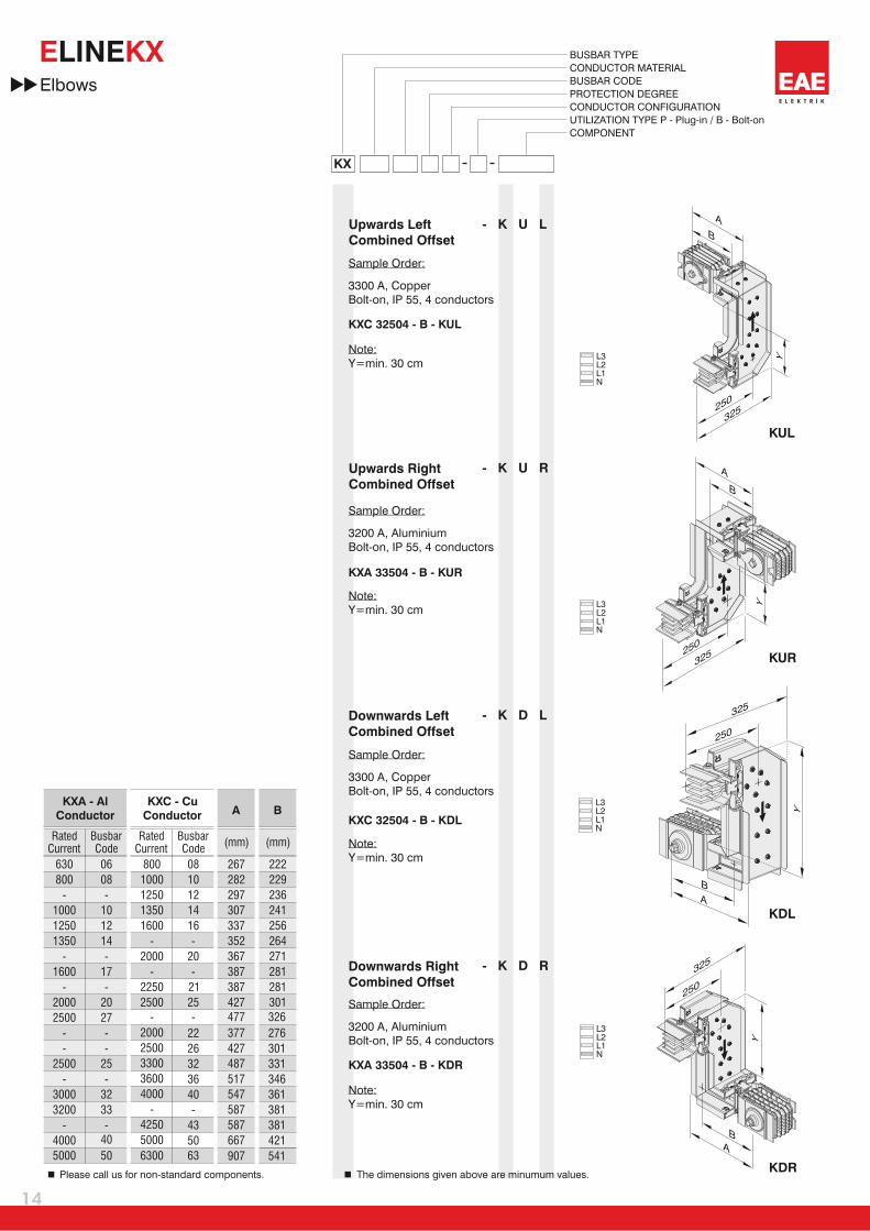
KX
BUSBAR TYPE
CONDUCTOR MATERIAL
BUSBAR CODE
PROTECTION DEGREE
CONDUCTOR CONFIGURATION
UTIZILATION TYPE P - Plug-in / B - Bolt-on
COMPONENT
Please call us for special
applications or for applications
with MCCB's.
500
500
500
500
500
500
500
500
500
500
500
500
500
500
700
700
700
700
KXA - Al
Conductor
KXC - Cu
Conductor
630
800
-
1000
1250
1350
-
1600
-
2000
2500
-
-
2500
-
3000
3200
-
4000
5000
06
08
-
10
12
14
-
17
-
20
27
-
-
25
-
32
33
-
40
50
800
1000
1250
1350
1600
-
2000
-
2250
2500
-
2000
2500
3300
3600
4000
-
4250
5000
6300
08
10
12
14
16
-
20
21
25
-
22
26
32
36
40
-
43
50
RatedCurrent
RatedCurrent
BusbarCode
BusbarCode
-
520
520
520
520
520
520
520
520
520
520
520
520
520
520
520
520
520
520
355
355
355
355
355
555
555
555
555
555
555
555
555
555
770
770
770
770
350
350
350
350
350
350
350
350
350
350
350
350
350
350
550
550
550
550
1
1
1
1
1
2
2
2
2
2
2
2
3
3
3
3
3
3
70063 520 950 550 4
A B C D
(mm) (mm) (mm) (mm)
500 520 555 350 3
Gland
Type
C
C
40
40
40
40
4 conductors
5 conductors
225
225
B
B
D
D
A
A
150
150


E KXLINE
Akcaburgaz Mahallesi, 119. Sokak, No:10 34510 Esenyurt-Istanbul
Tel: +90 (212) 866 20 00 Fax: +90 (212) 886 24 20 http://www.eae.com.tr
EAE Elektrik Asansor End. Insaat San. ve Tic. A.S.
E-Line KX Busbar Energy Distribution System
Declaration
CE DECLARATION OF CONFORMITY
Product Group
Standard :
Manufacturer EAE Elektrik Asansor End. Insaat San. ve Tic. A.S.
Date
30.08.2013
Akcaburgaz Mahallesi, 119. Sokak,
No:10 34510 Esenyurt-Istanbul
51
EAE Elektrik A.S.
TS EN 61439-6Low-voltage switchgear and controlgear assemblies - Part 6: Busbar trunking
systems
IEC 61439-6Low-voltage switchgear and controlgear assemblies - Part 6: Busbar trunking
systems (busways)
CE - Directive
2006/95/EC “Electrical equipment designed for use within certain voltage limits”
This is to attest, under our sole responsibility, that the aforementioned products conforms withthe determined regulations,guidelines and the below standards.


E KXLINE
53
Electrical Characteristics
- Busbar systems nominal insulation voltage shall be 1000 V.
- As per ampere rates, minimum short circuit values shall be as given below;
Product Overview
630A ... 6300A
(E-LINE KX)
COMPACT BUSBAR
PRODUCT OVERVIEW
Standards & Certification:-Busbar system shall be designed and manufactured as per IEC 61439-6 standard, which requires below listed tests. Each busbar rating shall have a separate type test certificate from an independentinternationally accredited laboratory including below tests:
- , - , - , - , -, - , - , - , -
, - , - , - , -
.- Busbar system shall have CE marking.-The manufacturer of busbar system shall have ISO 9001 and ISO 14001 certification.-Each product shall have a “Type Label” including coding system, which identifies the brand, type of the unit, number of conductors and electrical details. The same coding shall be on the related certificate andcatalogue.
10.2 Strength of material and parts 10.2.2 Resistance to corrosion 10.2.3 Properties of insulating materials 10.2.3.1 Verification of thermal stability of enclosures 10.2.3.2 Verification of resistance ofinsulating materials to abnormal heat and fire due to internal electric effects 10.2.6 Mechanical impact 10.2.7 Marking 10.2.101 Ability to withstand mechanical loads 10.2.101.1 Test procedure for astraight busbar trunking unit 10.2.101.2 Test procedure for a joint 10.2.101.3 Resistance of the enclosure to crushing 10.3 Degree of protection of assembly 10.4 Clearances and creepage distances,10.5-Protection against electric shock and integrity of protective circuits, 10.5.2- Effective earth continuity between the exposed conductive parts of the assembly and the protective circuit, 10.5.3- Short-circuitwithstand strength of the protective circuit, 10.9- Dielectric properties, 10.9.2- Power-frequency withstand voltage, 10.9.3- Impulse withstand voltage, 10.10- Verification of temperature rise, 10.11- Short-circuit withstand strength, 10.101- Resistance to flame propagation, 10.102- Fire resistance in building penetrations, Annex BB Phase conductor characteristics, Annex CC Fault-loop zero-sequencesimpedances,Annex DD Fault-loop resistances and reactances
1-
2-
2.1-
2.2-
2.3-
2.4-
2.6-
2.5-
3-
4-
Housing-Busbar system shall have “Sandwich-Compact” structure. Conductors shall be packed and placed into the housing without leaving air gap in order to provide low reactance.-Housing shall be made of thermal processed, extruded aluminium, RAL7038-Electrostatic painted.-Compact structure of the housing shall be provided by M6 screws applied at every 19cm along the entire length.-The sandwich-compact structure shall continue at the plug-in points too. There shall not be air gap between conductors at the plug-in points.
For Aluminium Conductors;
For Copper Conductors;
630A800A
1000A1250-1350A1600-2000A
2500A3200A and above
800A1000A
1250-1350A1600-2000-2250-2500A
2000A2500A
3300A and above
:1 sec/rms 25kA, Peak kA:
52,51 sec/rms 35kA, Peak 73,5kA
:1 sec/rms 50kA, Peak 105kA:1 sec/rms 60kA, Peak 132kA:1 sec/rms 80kA, Peak 176kA:1 sec/rms 100kA,Peak 220kA:1 sec/rms 120kA,Peak 264kA
:1 50kA, 105kA:
sec/rms Peak1 sec/rms 50kA, Peak 105kA
:1 sec/rms 60kA, Peak 132kA:1 sec/rms 80kA, Peak 176kA:1 sec/rms 70kA, Peak 154kA:1 sec/rms 100kA,Peak 220kA:1 sec/rms 120kA,Peak 264kA
ConductorsAluminium or Copper conductors shall be epoxy coated and tin plated at the joints upon the wire configuration and required numbers, which are described below.-Compact busbar system shall have aluminium conductors between 630A – 5000A.- Compact busbar system shall have copper conductors between 800A – 6300A.- Compact busbar system shall have the following number of conductors and wire configuration;a) 4 Conductors: (4 full size conductors + PE (housing)).b) 4 ½ Conductors: (4 full size conductors + PE (50% earth conductor + housing)),c) 5 Conductors: (5 full size conductors + PE (100% earth conductor + housing)),-Phase conductors and neutral conductor shall have the same cross-section and they shall be insulated.
- Aluminium conductors shall be of EC grade aluminium. Minimum conductivity shall be 34m/mm². .
-Copper conductors shall be minimum 99,95% electrolytic copper. Minimum conductivity shall be 56m/mm². .
��
Insulation- Insulation system shall be suitable for 1.000V continuous operation. Conductors shall be minimum thermo-set epoxy coated. Conductor size shall be designed so that temperature rise on the conductors shallnot exceed 100C degree at nominal current, which helps to global heating problem. With this reason, insulation class shall be “B class”.
Protection
- Protection degree of the housing and joints shall be IP55/IP65.
Tap Off Boxes-Both, Feeder and Plug-in busbar systems shall be suitable for bolt-on type tap off box connections at the joints up to 1.000A.-Bolt-on tap off boxes shall be installed to the joints without changing or adding any piece. Bolt-on tap off boxes shall be able to be moved between different rated busbars.-Plug-In busbars shall have minimum 2 plug-in points on each 300cm length. Plug-in tap off box sizes shall be up to 630A. Unused plug-in points shall have covers, which can provide IP55 protection degree.-Plug-in tap off boxes shall be suitable to install or removed from busbars without switching off the power on the busbar.-Contacts of plug-in tap off box shall be plated by silver.-Tap off boxes shall be manufactured of sheet steel and epoxy painted RAL3020 colour.-Plug-in tap off boxes shall have electromechanical safety interlock system. Which means;a-) Electromechanical interlock mechanism shall ensure that the tap off box cannot be removed mechanically from the busbar, when the switch is at “ON” position.b-) Electromechanical interlock mechanism shall ensure that, cover of the box can be opened only, when the switch is at “OFF” position.c-)When the cover is opened, inside protection degree shall be minimum IP2X against accessing to live conductors.d-) While inserting the contacts of plug-in tap off box, earth contact shall make the first touch. While removing, it shall be disconnected last.-Tap off boxes shall be suitable for any brand of MCCBs. Electromechanical interlock mechanism shall be suitable for all these MCCBs too.
Installation and Commisioning-Busbar systems shall be installed as per Single-Line drawings respect to required ampere rates and manufacturer installation guide (torque values, lockers, etc.). Electrical installator shall run an insulationtest after installation according to manufacturers test procedures. The results of the test shall be reported to the manufacturer. Minimum insulation value shall be 1 Mohm.
Joint Structure- Electrical and mechanical connection shall be made by placing conductor joints into the joint blocks of the connected conductors and followed by tightening and fastening of the joint bolts.
Acessories- Busbar system shall have all necessary accessories (elbows, offsets, panel-transformer connections, reductions, etc.) Manufacturer shall supply special dimensioned units in short time, if the projectconditions requires.-For horizontal runs, a horizontal expansion unit shall be used at every 40m and expansion points of the building.-For vertical applications, a vertical expansion unit shall be used at every floor. Busbar system shall be rigidly fixed by supports at every floor.


Related Documents