Welcome message from author
This document is posted to help you gain knowledge. Please leave a comment to let me know what you think about it! Share it to your friends and learn new things together.
Transcript


Technical Characteristics
5
E L E K T R İ K
E MKLINE
L1,L2,L3,N
In A
Copper Conductor (MKC)
160100
10 1016 16 22
100 160 225
Ui
Ue
f
3
IP
V
V
Hz
55
690
690
50
Icw
Ipk
Icw
Ipk
Icw
Ipk
Icw
Ipk
kA(rms)
kA
kA
kA
kA
kA
kA
kA
6
10,2
3,6
5,4
3,6
5,4
3,6
5,4
3,5
5,25
2,1
3,15
2,1
3,15
2,1
3,15
3,5
5,25
2,1
3,15
2,1
3,15
2,1
3,15
6
10,2
3,6
5,4
3,6
5,4
3,6
5,4
12,5
25
7,5
12,75
7,5
12,75
7,5
12,75
R20
R
X
Z
Z20
m /m�
m /m�
m /m�
m /m�
m /m�
0,391
0,506
0,138
0,525
0,415
37,6
0,378
0,377
0,885
0,378
0,640
0,787
0,154
0,802
0,658
23,4
0,608
0,603
0,885
0,609
0,747
0,942
0,191
0,961
0,771
27,7
0,699
0,702
0,885
0,702
0,405
0,535
0,158
0,558
0,435
40,3
0,389
0,386
0,885
0,385
0,251
0,341
0,135
0,367
0,284
49,7
0,242
0,241
0,885
0,242
R/ortPh
RN
RPE
CPER
W/m
m /m�
m /m�
m /m�
m /m�
mm²
²mm
²mm
mmxmm
kg/m
kg/m
47,25
47,25
198
4,5x10,5
2,35
2,50
47,25
47,25
198
4,5x10,5
3,30
3,70
27
27
198
4,5x6
2,75
3,00
76,50
76,50
198
4,5x17
2,70
2,90
76,50
76,50
198
4,5x17
4,50
5,20
Z(0) b20phN
Z(0) b20phPE
(0) b20phCPEZ
Z(0) bphN
Z(0) bphPE
(0) bphCPEZ
m /m�
m /m�
m /m�
m /m�
m /m�
m /m�
2,801
3,781
2,774
3,386
4,570
3,350
1,866
3,284
1,878
2,357
4,235
2,374
3,227
3,811
3,244
3,918
4,620
3,942
1,984
3,186
1,967
2,474
4,052
2,453
1,409
3,050
1,406
1,765
4,040
1,759
Rb20phph
b20phNR
Rb20phPE
b20phCPER
bphphR
RbphN
RbphPE
bphCPER
Xbphph
XbphN
XbphPE
bphCPEX
m /m�
m /m�
m /m�
m /m�
m /m�
m /m�
m /m�
m /m�
m /m�
m /m�
m /m�
m /m�
0,780
0,792
1,384
0,794
1,030
1,045
1,827
1,048
0,261
0,374
0,491
0,367
1,265
1,278
1,587
1,280
1,557
1,573
1,954
1,575
0,302
0,392
0,446
0,379
1,486
1,502
1,668
1,494
1,836
1,856
2,061
1,846
0,352
0,453
0,483
0,461
0,819
0,831
1,436
0,830
1,072
1,087
1,879
1,085
0,311
0,420
0,633
0,424
0,523
0,533
1,152
0,533
0,708
0,722
1,560
0,722
0,268
0,380
0,558
0,376
IEC 61439-6, TS EN 61439-6, IEC 61439-1, TS EN 61439-1
Plug-in Busbar IK07
Aluminium Conductor (MKA)
Standards
Busbar Weight (4 Conductors)
Reactance (Independent from temperature)
Busbar Weight (5 Conductors)
PE (5 Conductors)
Rated Isolation Voltage
Max. Rated Operational Voltage
Rated Frequency
Pollution Degree
Protection Degree
External Mechanical Impacts (IK Code)*
Rated Short-time Withstand Current (1s)
Rated Short-time Withstand Current for Neutral Conductor (1s)
Rated Short-time Withstand Current for PE Conductor (1s)
Rated Peak Withstand Current
Rated Peak Withstand Current for Neutral Conductor
Rated Peak Withstand Current for PE Conductor
Zero-sequence Impedance
Resistance at a conductor temperature of 20 °C
Reactance (Independent from Temperature)
Rated Power Loss at 35 °C
Conductor Dimensions
DC Resistance at a conductor temperature of 20 °C for Phases
DC Resistance at a conductor temperature of 20 °C for Neutral
DC Resistance at a conductor temperature of 20 °C for PE
Zero-sequence impedance at a conductor temperature of 20 °C
Resistance at a conductor temperature of 20 °C
Resistance at a conductor temperature of 20 °C
Resistance at a conductor temperature of 20 °C
Resistance at an ambient air temperature of 35 °C
Zero-sequence impedance at a conductor temperature of 20 °C
Zero-sequence impedance at an ambient temperature of 35 °C
Zero-sequence impedance at an ambient temperature of 35 °C
Resistance at an ambient air temperature of 35 °C
Positive and negative sequence impedances at an ambient air temperature of 35 °C
Positive and negative sequence impedances at a conductor temperature of 20 °C
Busbar Code
Rated Current
SECTIONS
MEAN FAULT-LOOP CHARACTERISTICS
Resistances and Reactances
MEAN PHASE CONDUCTOR CHARACTERISTICS AT RATED CURRENT In
PE (Sheet Metal)
Rated Short-time Withstand Current for CPE Conductor (1s)
Rated Peak Withstand Current for CPE Conductor
Reactance (Independent from temperature)
Reactance (Independent from temperature)
Reactance (Independent from temperature)
DC Resistance at a conductor temperature of 20 °C for CPE
Zero-sequence impedance at a conductor temperature of 20 °C
Zero-sequence impedance at an ambient temperature of 35 °C
Resistance at a conductor temperature of 20 °C
Resistance at an ambient air temperature of 35 °C
Resistance at an ambient air temperature of 35 °C
Resistance at an ambient air temperature of 35 °C


E-Line MK Busbar Energy Distribution System
Declaration
EAE Elektrik A. .S
CE DECLARATION OF CONFORMITY
EAE Elektrik A. .Asansor End. Insaat San. ve Tic. S
Date
23.02.2015
Akcaburgaz Mahallesi, 119. Sokak, No:10 34510 Esenyurt-Istanbul
Tel: +90 (212) 866 20 00 Fax: +90 (212) 886 24 20 www.eae.com.tr
22
E L E K T R İ K
E MKLINE
Product Group
Manufacturer EAE Elektrik Asansor End. Insaat San. ve Tic. A.S.
Akcaburgaz Mahallesi, 119. Sokak,
No:10 34510 Esenyurt-Istanbul
This is to attest, under our sole responsibility, that the aforementioned products conforms with
the determined regulations,guidelines and the below standards.
Standard :
EN 61439-6
Low-voltage switchgear and controlgear assemblies - Part 6: Busbar trunking
systems
IEC 61439-6
Low-voltage switchgear and controlgear assemblies - Part 6: Busbar trunking
systems (busways)
CE - Directive
2006/95/EC “Electrical equipment designed for use within certain voltage limits”

(100...225A MK)
PRODUCT OVERVIEW
Product Overview
E L E K T R İ K
E L E K T R İ K
23
E MKLINE
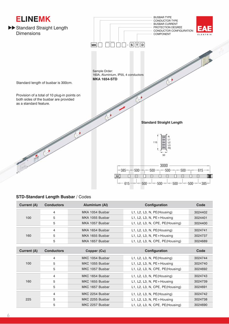
The busbar system have Al conductors for 100A and 160A orshall
Cu conductors for 100A, 160A and 225A.
The busbar system conform to the following phase configuration.shall
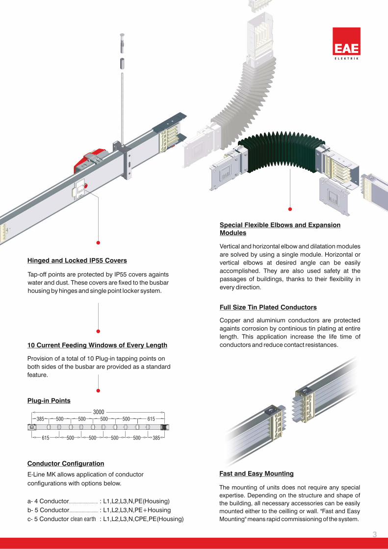
a- 4 conductors
b- 5 conductors
c- 5 conductors (with clean earth)
The insulation voltage of the busbar be 690V.shall
The busbar housing be of 0,60mm thick epoxy painted galvanized sheet metal. (RAL 7038)shall
The Al conductors be plated with nickel and then with tin, the Cu conductorsshall
be plated only with tin. The plating be continuous along the conductor.shall shall
The busbar joint have a single bolt construction andshall
the nut of main joint bolt be a double headed nut, tightened at 20Nm.shall
The busbar housing be continuously clamped together by roll forming method.shall
10 plug-in windows be located on a standard 3m length.shall
Busbar and tap off boxes be IP55 protection class under normal operation conditions.shall
IP protection covers of plug-in points be hinged and lockable from single point.shall
Tap off boxes up to 16A be removed from the busbar before opening their lids.shall
The tap off boxes above 16A, have the following mechanical and electrical safety features.shall
a- The box only be plugged in and removed from the busbar at “OFF” position.shall
b- The energy on the connected load be automatically cut, when the box lid is open.shall
c- The tap off box comply IP2X requirements, while it is plugged into the busbar and the lid is open.shall
All tap off box contacts be silver plated.shall
Jawed tap off box contacts be reinforced by steel springs.shall
Busbar systems be tested and certified according to IEC 61439-6 by international laboratories.shall
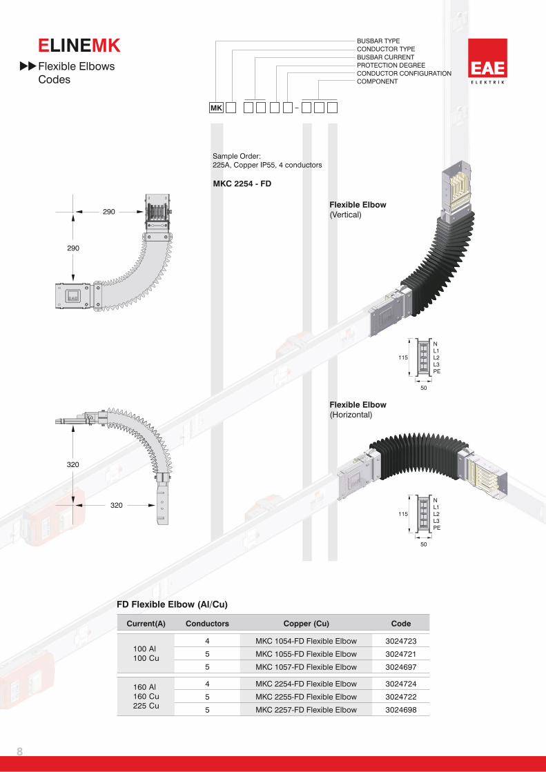
Busbar system shall have flexible elbows and expansion units.
Manufacturing facility of busbar systems shall have ISO 9001 and ISO 14001 certification.
1-
2-
3-
4-
5-
6-
7-
8-
9-
10-
11-
12-
13-
14-
15-
16-
17-
L1 / L2 / L3 / N / PE(Housing)
L1 / L2 / L3 / N / PE+Housing
L1 / L2 / L3 / N / CPE / PE(Housing)

Certificate
24
E L E K T R İ K
E MKLINE


www.eae.com.tr
EAE Elektrik A.Ş.
Akcaburgaz Mahallesi,
119. Sokak, No:10 34510
Esenyurt-Istanbul-TURKEY
Tel: +90 (212) 866 20 00
Fax: +90 (212) 886 24 20
T E
ME 04
IEC 61439-6 sISO9001
14001
QUALIT
YA
ND
ENVI
RONMENTAL MANAGEM
EN
TS
YSTEM
S
Catalogue 05-Eng. / Rev 07 1.000 Pcs. 25/02/2015
atamatbaawww. .net / A.C.E./ 612 40 66EAE has full right to make any revisions or changes on this catalogue without any prior notice.
Related Documents