Bus-clamped PWM Techniques for AC Drives - Application Considerations G.Narayanan V.T.Ranganthan [email protected] [email protected] Department of Electrical Engineering, Indian Institute of Science, Bangalore, INDIA, 560 012. ABSTRACT : Different PWM techniques are used in Voltage Source Inverter fed induction motor drives for the generation of Variable Voltage Variable Frequency 3-phase AC. There is a class of PWM techniques where every phase remains clamped for a duration of 60 o in every half cycle with only the other two phases switching during the said duration. The 60 o clamping duration can be anywhere within the middle 120 o of the given half cycle. The clamping duration can be divided over smaller intervals also. Such techniques are called 'bus-clamped PWM techniques'. This paper shows that these PWM techniques can be used to reduce one or more of the following : 1. Switching frequency and switching losses 2. Total Harmonic Distortion (THD) of the motor current 3. Computational burden. Different issues dominate depending on the power rating of the drive. This paper shows that a judicious use of bus-clamping leads to the mitigation of the problem that is dominant. This means an improvement in the drive performance, efficiency, or size, or a combination thereof. 1. Introduction : Voltage Source Inverter fed induction motor drives are widely used as variable speed drives. Different PWM techniques can be employed in such drives [1-12]. Sine-triangle PWM (SPWM) is a well-known and widely used PWM technique [1]. Conventional space vector PWM (CSVPWM) is another popular technique [2]. This technique has a higher DC bus utilisation and results in lesser harmonic distortion than sine-triangle PWM especially at higher modulation indices. In both these conventional techniques, every phase switches once in every half carrier cycle or sampling period. However, there are numerous PWM techniques, where every phase remains clamped for a duration of 60 o in every half cycle. These are called "bus-clamped PWM techniques" [3-12].

Welcome message from author
This document is posted to help you gain knowledge. Please leave a comment to let me know what you think about it! Share it to your friends and learn new things together.
Transcript

Bus-clamped PWM Techniques for AC Drives - Application Considerations
G.Narayanan V.T.Ranganthan [email protected] [email protected]
Department of Electrical Engineering, Indian Institute of Science, Bangalore, INDIA, 560 012.
ABSTRACT :
Different PWM techniques are used in Voltage Source Inverter fed induction motor drives for the
generation of Variable Voltage Variable Frequency 3-phase AC. There is a class of PWM techniques
where every phase remains clamped for a duration of 60o in every half cycle with only the other two phases
switching during the said duration. The 60o clamping duration can be anywhere within the middle 120o of
the given half cycle. The clamping duration can be divided over smaller intervals also. Such techniques are
called 'bus-clamped PWM techniques'. This paper shows that these PWM techniques can be used to
reduce one or more of the following :
1. Switching frequency and switching losses
2. Total Harmonic Distortion (THD) of the motor current
3. Computational burden.
Different issues dominate depending on the power rating of the drive. This paper shows that a
judicious use of bus-clamping leads to the mitigation of the problem that is dominant. This means an
improvement in the drive performance, efficiency, or size, or a combination thereof.
1. Introduction :
Voltage Source Inverter fed induction motor drives are widely used as variable speed drives.
Different PWM techniques can be employed in such drives [1-12]. Sine-triangle PWM (SPWM) is a
well-known and widely used PWM technique [1]. Conventional space vector PWM (CSVPWM) is another
popular technique [2]. This technique has a higher DC bus utilisation and results in lesser harmonic
distortion than sine-triangle PWM especially at higher modulation indices. In both these conventional
techniques, every phase switches once in every half carrier cycle or sampling period. However, there are
numerous PWM techniques, where every phase remains clamped for a duration of 60o in every half cycle.
These are called "bus-clamped PWM techniques" [3-12].

The choice of the PWM technique has a direct bearing on the distortion in the motor current,
torque pulsation, inverter losses, efficiency of the drive etc. Depending on the power level, device
technology and the specific application, the dominant issue is different. This paper studies the use of
bus-clamped PWM techniques instead of or in conjunction with the conventional techniques to handle the
issue that is dominant in the given case.
The ratio of the switching frequency to the fundamental frequency is a major constraint in the
design or selection of PWM techniques. Depending on the power level and the device used, the switching
frequency can be as low as 5 times the fundamental frequency or as high as several 100 times the
fundamental frequency. The study on bus-clamped techniques is carried out over this wide range of
switching frequencies. One can consider switching frequencies greater than or equal to 21 times the
fundamental frequency as high switching frequencies, and those less than 21 times the fundamental
frequency as low switching frequencies. The advantages of the bus-clamped PWM techniques at both high
as well as low switching frequencies are brought out in this paper.
R Y BO
+
-
+
-
+
-
-0.5VDC
+0.5VDC
Fig.1a Voltage Source Inverter
REF
+-- (1)
++- (2)(3) -+-
(4) -++
(5) --+ +-+ (6)
(0) ---(7) +++
III
III
IV
V
VI
V
1.0
oR = 0
(R-phase axis)
Fig.1b Voltage vectors produced by inverter
R = Angle of R-phase fundamental voltage
I, II, III, IV, V and VI : Sectors
2. Bus-clamped PWM :
There are two popular approaches to real-time PWM, namely the triangle-comparison approach
and space vector approach. In the triangle-comparison approach, the 3-phase PWM waveforms are
generated by comparing suitable 3-phase modulating waves against triangular carriers as in sine-triangle
PWM. A voltage source inverter and the voltage vectors produced by it are shown in Figs.1a and 1b

respectively. In the space vector approach, the reference is provided as a revolving space vector as shown
in Fig.1b. The reference is sampled once in every subcycle (TS), and an average vector equal to the sampled
reference vector is generated over the given subcycle by time-averaging of the different vectors produced by
the inverter. Bus-clamped PWM generation is possible with both the approaches.
Fig.2 Modulating waves corresponding to different types of clamping
While using the triangle-comparison approach, the modulating waves corresponding to four types
of clamping are as shown in Figs.1a - 1d respectively. In Type-I clamping, every phase remains clamped
during the middle 60o duration of every half cycle, i.e. between 60o and 120o in the positive half cycle, and
between 240o and 300o in the negative half cycle as shown in Fig.2a. In Type-II, the clamping is between
30o and 90o in the positive half cycle, and between 210o and 270o in the negative half cycle as shown in
Fig.2b. In Type-III, the clamping is done between 90o and 150o in the positive half cycle, and between 270o
and 330o in the negative half cycle as in Fig.2c. In Type-IV, every phase is clamped during the middle 30o

of every quarter cycle of its fundamental voltage as shown in Fig.2d. These modulating waves can be
generated by adding suitable zero-sequence triplen frequency components to the 3-phase sinusoidal waves.
The zero-sequence component required can be obtained from the 3-phase sinusoids themselves as can be
seen from Fig.1. Comparison of such 3-phase modulating waves against a common triangular carrier gives
the PWM patterns required.
R+
B-
Y+
R-
B+
Y-
+--
++--+-
-++
+-+--+
30oB-
Y-
R+
Y+B-
R-
Y+
B+
R-Y- B+
R+
+--
++--+-
-++
--+ +-+
30o
60o R+
R+
B-
B-Y+
Y+
R-
R-
B+B+ Y-
Y-
+--
++--+-
-++
+-+--+
R+
B-
Y+
R-
B+
Y-
+--
++--+-
-++
+-+--+
Fig.3 Different types of clamping in the space vector domain
a. Type-I clamping b. Type-II clamping
c. Type-III clamping d. Type-IV clamping
In space vector approach, given a sample of the reference vector of magnitude VREF and angle in
sector I as shown in Fig.1b, the durations for which the different states must be applied are calculated as in
Eq.(1).
T1 = VREFsin(60o- )/sin(60o), T2 = VREFsin( )/sin(60o), TZ = TS - T1 - T2 ... (1)
In conventional space vector modulation, the duration TZ is equally divided between the two zero states and
both of them are used. For a sample in sector I, sequence 0127 or 7210 is used. With such a sequence
every phase switches once in every subcycle. Such sequences are termed as 'conventional sequences'.
Alternatively, switching sequence 012, 210, 721 or 127 may also be used. In these sequences, only two

phases switch within the given subcycle and the third remains clamped to one of the DC buses. If the zero
state --- (0) is avoided, then R-phase remains clamped to the positive bus. If the zero state +++ (7) is
avoided, then the B-phase remains clamped to the negative bus. Such sequences can be termed as 'clamping
sequences'.
In bus-clamped PWM techniques, clamping sequences using only one zero state are used to
generate the samples. The zero state used is changed once in every sector as shown in Fig.3. It is changed
in the middle of the sector in Type-I and Type-IV schemes. The zero state used between the centre of sector
VI and that of sector I is +++ (7) in Type-I, while it is --- (0) in Type-IV. The zero state is changed at the
sector boundaries in Type-II and Type-III.
3. High switching frequency :
The usefulness of bus-clamped PWM techniques at high switching frequencies is studied in this
section.
3.1 Switching frequency and switching losses :
For a given carrier frequency or sampling frequency, reduction in switching frequency is the most
obvious of the benefits of using bus-clamped PWM techniques. As shown in Figs.2 and 3, every phase
remains clamped for 120o in every fundamental cycle. Hence, the average switching frequency reduces to
two thirds the carrier frequency with any such technique at fairly high switching frequencies. This implies a
reduction of 33% approximately in the switching losses as well.
The energy loss per switching cycle is the highest around the peak of the fundamental motor
current. If every phase remains clamped around the peak of its fundamental current, then the savings in
switching losses is still higher. In case of motor drives, the fundamental current normally lags behind the
fundamental voltage. In such cases clamping between 90o and 150o, i.e. Type-III, would be beneficial.
Approximately 50% reduction in the switching losses is achieved by this [8]. Further reduction in switching
losses is possible if the clamping duration can be positioned exactly around the peak of the fundamental
current by sensing the fundamental power factor angle. However, this is possible only if the fundamental
power factor angle is less than 30o. Otherwise clamping from 90o to 150o works best [9].
Thus, at a given carrier frequency or sampling frequency, the bus-clamped techniques lead to
significant reduction in the switching frequency and losses. However, this gain is accompanied by an
increase in the distortion over the conventional techniques. The relative values of THD due to the four type
of clamping schemes, conventional space vector PWM and sine-triangle PWM are shown in Fig.4a [5-7].

Fig.4 Harmonic Distortion Factor vs. modulation index(a) Switching frequency of bus-clamped techniques equal to (2/3) times that of SPWM and CSVPWM and
(b) Switching frequency of bus-clamped techniques equal to that of SPWM and CSVPWMA : SPWM, B: CSVPWM, C : Type-I, D: Type-II & III, E : Type-IV
3.2 Reduction in harmonic distortion :
At a given switching frequency, bus-clamped PWM techniques lead to a significant reduction in the
harmonic distortion over the conventional techniques at higher modulation indices as shown in Fig.4b. The
harmonic distortion of any given type of clamping in this case (Fig.4b) is 4/9 times of that in the earlier
case (Fig.4a). Among the bus-clamped techniques, Type-IV clamping results in the lowest harmonic
distortion, and Type-I results in the highest. At any given modulation index, Type-II and Type-III clamping
schemes result in the same harmonic distortion, which is equal to the average of the distortions due to
Type-I and Type-IV clamping schemes [5-7].
Thus, using bus-clamping, the harmonic distortion can be reduced subject to a given switching
frequency at higher modulation indices as shown in Fig.4b.
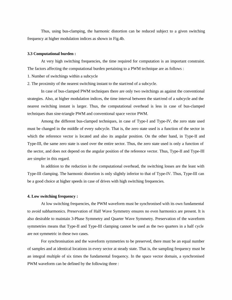
3.3 Computational burden :
At very high switching frequencies, the time required for computation is an important constraint.
The factors affecting the computational burden pertaining to a PWM technique are as follows :
1. Number of switchings within a subcycle
2. The proximity of the nearest switching instant to the start/end of a subcycle.
In case of bus-clamped PWM techniques there are only two switchings as against the conventional
strategies. Also, at higher modulation indices, the time interval between the start/end of a subcycle and the
nearest switching instant is larger. Thus, the computational overhead is less in case of bus-clamped
techniques than sine-triangle PWM and conventional space vector PWM.
Among the different bus-clamped techniques, in case of Type-I and Type-IV, the zero state used
must be changed in the middle of every subcycle. That is, the zero state used is a function of the sector in
which the reference vector is located and also its angular position. On the other hand, in Type-II and
Type-III, the same zero state is used over the entire sector. Thus, the zero state used is only a function of
the sector, and does not depend on the angular position of the reference vector. Thus, Type-II and Type-III
are simpler in this regard.
In addition to the reduction in the computational overhead, the switching losses are the least with
Type-III clamping. The harmonic distortion is only slightly inferior to that of Type-IV. Thus, Type-III can
be a good choice at higher speeds in case of drives with high switching frequencies.
4. Low switching frequency :
At low switching frequencies, the PWM waveform must be synchronised with its own fundamental
to avoid subharmonics. Preservation of Half Wave Symmetry ensures no even harmonics are present. It is
also desirable to maintain 3-Phase Symmetry and Quarter Wave Symmetry. Preservation of the waveform
symmetries means that Type-II and Type-III clamping cannot be used as the two quarters in a half cycle
are not symmetric in these two cases.
For synchronisation and the waveform symmetries to be preserved, there must be an equal number
of samples and at identical locations in every sector at steady state. That is, the sampling frequency must be
an integral multiple of six times the fundamental frequency. In the space vector domain, a synchronised
PWM waveform can be defined by the following three :

1. Number of samples per sector (N)
2. Positions of the samples in a sector
3. Switching sequences corresponding to each of the samples.
Apart from the conventional and clamping sequences mentioned in section 2, switching sequences
0121, 1210, 7212 or 2127 can also be used, with either T1 or T2 divided into two equal halves, to generate
an arbitrary sample in sector I. Given a sample on the boundary between sector I and sector VI, it can be
generated using sequence 010 or 101 with either T1 or T0 divided into two equal halves. Such a sample is
termed as 'boundary sample'. Thus, the space vector approach to PWM offers more flexibilities than the
triangle-comparison approach like double-switching of a phase within a subcycle etc [10,12].
Fig.5 Typical pole voltage waveforms

Three synchronised bus-clamped PWM strategies based the space vector approach have been
proposed recently - Basic Bus Clamping Strategy (BBCS), Asymmetric Zero-Changing Strategy (AZCS)
and Boundary Sampling Strategy (BSS) [10-12]. Typical pole voltage waveforms corresponding to these
strategies besides the synchronised Conventional Space Vector Strategy (CSVS) are presented in Fig.5.
The line voltage spectra and the experimental no-load current waveforms, corresponding to these pole
voltage waveforms, are shown in Figs.6 and 7 respectively.
At low switching frequencies,computation time is not a major constraint. The thrust is on reduction
of switching losses and/or harmonic distortion. The harmonic distortion tends to be especially high.
Fig.6 Line voltage spectraWTHD for (a), (c), (e) and (g) are 0.0438, 0.0463, 0.0327 and 0.0297 respectively
WTHD for (b), (d), (f) and (h) are 0.0259, 0.0259, 0.0212 and 0.0191 respectively
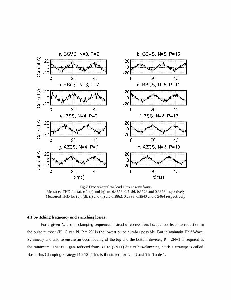
Fig.7 Experimental no-load current waveformsMeasured THD for (a), (c), (e) and (g) are 0.4858, 0.5186, 0.3628 and 0.3369 respectivelyMeasured THD for (b), (d), (f) and (h) are 0.2862, 0.2936, 0.2540 and 0.2464 respectively
4.1 Switching frequency and switching losses :
For a given N, use of clamping sequences instead of conventional sequences leads to reduction in
the pulse number (P). Given N, P = 2N is the lowest pulse number possible. But to maintain Half Wave
Symmetry and also to ensure an even loading of the top and the bottom devices, P = 2N+1 is required as
the minimum. That is P gets reduced from 3N to (2N+1) due to bus-clamping. Such a strategy is called
Basic Bus Clamping Strategy [10-12]. This is illustrated for N = 3 and 5 in Table 1.

Table 1. Reduction in pulse number P for given number of samples per sector N
Strategy N Positions of samples Switching sequences Pulse numberP
Type ofclamping
CSVS 3 10o, 30o, 50o 0127, 7210, 0127 9 -
CSVS 3 10o, 30o, 50o 7210, 0127, 7210 9 -
BBCS 3 10o, 30o, 50o 127, 7210, 012 7 Type-I
CSVS 5 6o, 18o, 30o, 42o, 54o 7210, 0127, 7210, 0127, 7210 15 -
CSVS 5 6o, 18o, 30o, 42o, 54o 0127, 7210, 0127, 7210, 0127 15 -
BBCS 5 6o, 18o, 30o, 42o, 54o 721, 127, 7210, 012, 210 11 Type-I
BBCS 5 6o, 18o, 30o, 42o, 54o 012, 210, 0127, 721, 127 11 Type-IV
Fig.8 Comparison WTHD vs. modulation index characteristicsSolid line : CSVS, dashed line : BBCS, dashed and dotted line : AZCS, dotted line : BSS
Experimental no-load current waveforms pertaining to CSVS with P=9 and P=15 are shown in
Figs.7a and 7b respectively. The current waveforms produced by BBCS with P=7 and P=11 are shown in
Figs.7c and 7d respectively. The switching frequency decreases in both the case. However, it can be seen
that there is a slight increase in THD. The Weighted Total Harmonic Distortion factor (WTHD) of the
voltage waveform against modulation index is plotted for different strategies and different pulse numbers in
Fig.8. It can be seen from Figs.8a and 8b that for a given value of N, BBCS results in lesser P but higher
WTHD.
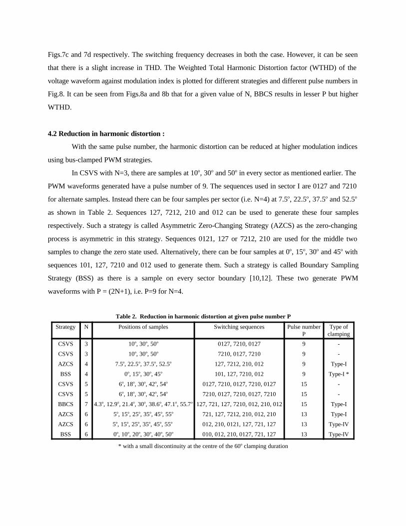
4.2 Reduction in harmonic distortion :
With the same pulse number, the harmonic distortion can be reduced at higher modulation indices
using bus-clamped PWM strategies.
In CSVS with N=3, there are samples at 10o, 30o and 50o in every sector as mentioned earlier. The
PWM waveforms generated have a pulse number of 9. The sequences used in sector I are 0127 and 7210
for alternate samples. Instead there can be four samples per sector (i.e. N=4) at 7.5o, 22.5o, 37.5o and 52.5o
as shown in Table 2. Sequences 127, 7212, 210 and 012 can be used to generate these four samples
respectively. Such a strategy is called Asymmetric Zero-Changing Strategy (AZCS) as the zero-changing
process is asymmetric in this strategy. Sequences 0121, 127 or 7212, 210 are used for the middle two
samples to change the zero state used. Alternatively, there can be four samples at 0o, 15o, 30o and 45o with
sequences 101, 127, 7210 and 012 used to generate them. Such a strategy is called Boundary Sampling
Strategy (BSS) as there is a sample on every sector boundary [10,12]. These two generate PWM
waveforms with P = (2N+1), i.e. P=9 for N=4.
Table 2. Reduction in harmonic distortion at given pulse number P
Strategy N Positions of samples Switching sequences Pulse numberP
Type ofclamping
CSVS 3 10o, 30o, 50o 0127, 7210, 0127 9 -
CSVS 3 10o, 30o, 50o 7210, 0127, 7210 9 -
AZCS 4 7.5o, 22.5o, 37.5o, 52.5o 127, 7212, 210, 012 9 Type-I
BSS 4 0o, 15o, 30o, 45o 101, 127, 7210, 012 9 Type-I *
CSVS 5 6o, 18o, 30o, 42o, 54o 0127, 7210, 0127, 7210, 0127 15 -
CSVS 5 6o, 18o, 30o, 42o, 54o 7210, 0127, 7210, 0127, 7210 15 -
BBCS 7 4.3o, 12.9o, 21.4o, 30o, 38.6o, 47.1o, 55.7o 127, 721, 127, 7210, 012, 210, 012 15 Type-I
AZCS 6 5o, 15o, 25o, 35o, 45o, 55o 721, 127, 7212, 210, 012, 210 13 Type-I
AZCS 6 5o, 15o, 25o, 35o, 45o, 55o 012, 210, 0121, 127, 721, 127 13 Type-IV
BSS 6 0o, 10o, 20o, 30o, 40o, 50o 010, 012, 210, 0127, 721, 127 13 Type-IV
* with a small discontinuity at the centre of the 60o clamping duration

CSVS with N=5 generates PWM patterns with P=15. BBCS generates PWM waveforms with
P=15 for N=5. Similarly with AZCS and BSS, PWM waveforms with P=13 can be generated with N=6 as
shown in Table 2.
The pole voltage waveforms corresponding to CSVS, AZCS and BSS, all with P=9, are shown in
Figs.5a, 5e and 5g respectively. The corresponding line voltage spectra are shown in Figs.6a, 6e and 6g
respectively, and the experimental no-load current waveforms are presented in Figs.7a, 7e and 7g
respectively. It can be seen that BSS with P=9 results in lesser harmonic distortion than CSVS with P=9.
AZCS with P=9 leads to still lesser distortion. Thus, harmonic distortion can be reduced subject to a given
switching frequency or pulse number.
Similarly, pole voltage waveforms corresponding to CSVS with P=15, BSS with P=13 and AZCS
with P=13 are shown in Figs.5b, 5f and 5h respectively. The corresponding line voltage spectra are
presented in Figs.6b, 6f and 6h respectively, and the experimental no-load current waveforms in Figs.7b, 7f
and 7h respectively. Here again, the harmonic distortion is lesser in case of the bus-clamped strategies.
Also, the pulse number is lesser with these strategies. A comparison of WTHD characteristics of CSVS
against those of the bus-clamped PWM strategies in the whole range of modulation is presented in Figs.8c
and 8d. It can be seen that both switching frequency and harmonic distortion can be reduced by suitable
design of PWM strategies.
5. Conclusion :
Depending on the application, power level, device technology etc., different issues dominate in
different cases. If switching frequency and switching losses are dominant, bus-clamped PWM techniques
can be used to reduce them. If the harmonic distortion is to be reduced subject to a given switching
frequency or pulse number, as the case may be, such techniques can once again be used to reduce the
distortion. At very high switching frequencies where the time available for computation is very low,
bus-clamped techniques result in a reduction of the computational burden as well.
References :
1. A.Schonung and H.Stemmler, "Static frequency changers with subharmonic control in conjunction with
reversible variable-speed AC drives", Brown Bov. Rev., Vol. 51, Aug./Sept. 1964, pp. 555-577.
2. H.W.van der Broeck, H.C.Skudelny and G.V.Stanke, "Analysis and realisation of a pulsewidth
modulator based on voltage space vectors", IEEE Trans. IA, Vol. IA-24(1), 1988, pp. 142-150.

3. J.Holtz, "Pulsewidth modulation for electronic power conversion", Proc. IEEE, Vol. 82(8), 1994, pp.
1194-1214.
4. J.W.Kolar, H.Ertl and F.C.Zach, "Influence of the modulation method on conduction and switching
losses of a PWM converter system", IEEE Trans. IA, Vol. IA-27(6), 1991, pp. 1063-1075.
5. H.W.van der Broeck, "Analysis of the harmonics in voltage fed inverter drives caused by PWM schemes
with discontinuous switching operation", 4th European Conference on Power Electronics and Applications,
EPE '91, Firenze, Italy, 1991, pp. 261-266.
6. S.Fukuda and K.Suzuki, "Harmonic evaluation of two-level carrier-based PWM methods", 7th European
Conference on Power Electronics and Applications, EPE '97, Trondheim, 1997, pp. 331-336.
7. A.M.Hava, R.J.Kerkman and T.A.Lipo, "Simple analytical and graphical methods for carrier-based
PWM-VSI drives", IEEE Trans. PE, Vol. PE-14(1), 1999, pp. 49-61.
8. A.M.Trzynadlowski and S.Legowski, "Minimum-loss vector PWM strategy for three-phase inverters",
IEEE Trans. PE, Vol. PE-9(1), 1994, pp. 26-34.
9. A.M.Hava, R.J.Kerkman and T.A.Lipo, "A high performance generalised discontinuous PWM
algorithm", IEEE Trans. IA, Vol. IA-34(5), 1998, pp. 1059-1071.
10. G.Narayanan and V.T.Ranganathan, "Synchronised PWM strategies based on space vector approach.
Part 1 : Principles of waveform generation", IEE Proc.B, Vol. 146(3), 1999, pp. 267-275.
11. __ , "Synchronised PWM strategies based on space vector approach. Part 2 : Performance assessment
and application to V/f drives", IEE Proc.B, Vol. 146(3), 1999, pp. 276-281.
12. G.Narayanan, "Synchronised Pulsewidth Modulation Strategies based on Space Vector Approach for
Induction Motor Drives", Ph.D. Thesis, Indian Institute of Science, Bangalore, India, August 1999.
Related Documents


![Three Level Diode Clamped Inverter for Field Oriented ... ELECTRONIC/E58/E58.pdf · induction motor drives [10]. Three level diode clamped inverter [9] is used for fixed Dc supply](https://static.cupdf.com/doc/110x72/60071394264c7d7cc865d1d2/three-level-diode-clamped-inverter-for-field-oriented-electronice58e58pdf.jpg)

