6 Edition 11.12 Product brochure · GB Burner control units BCU 480 • For pilot and main burners in intermittent or continuous operation • Replace the local control cabinet • Flame control by UV, ionization or a further option of using the furnace chamber temperature • Display of the program status, unit parameters and flame signal; Manual mode for burner adjustment and for diagnostic purposes • Visualization and adaptation to the specific application via the PC programming and diagnostic software BCSoft to simplify logistics management • Air valve control relieves the furnace control • Optional PROFIBUS DP interface • EC type-tested and certified • Certified for systems up to SIL 3 and compliant with PL e

Welcome message from author
This document is posted to help you gain knowledge. Please leave a comment to let me know what you think about it! Share it to your friends and learn new things together.
Transcript

6 Edition 11.12Product brochure · GB
Burner control units BCU 480
• For pilot and main burners in intermittent or continuous operation• Replace the local control cabinet • Flame control by UV, ionization or a further option of using the furnace
chamber temperature• Display of the program status, unit parameters and flame signal;
Manual mode for burner adjustment and for diagnostic purposes• Visualization and adaptation to the specific application via the PC
programming and diagnostic software BCSoft to simplify logistics management
• Air valve control relieves the furnace control• Optional PROFIBUS DP interface• EC type-tested and certified• Certified for systems up to SIL 3 and compliant with PL e
2 · BCU 480 · Edition 11.12
The burner control units BCU 480 control, ig-nite and monitor gas burners for intermittent or continuous operation. As a result of their fully electronic design, they react quickly to various process requirements and are there-fore suitable for frequent cycling operation.
They can be used for industrial burners of unlimited capacity which are ignited by pi-lot burners. Pilot and main burners may be modulating or stage-controlled. The BCU 480 monitors pilot and main burners indepen-dently. The pilot burner can burn permanently or be switched off. The BCU is installed near the burner to be monitored.
On industrial furnaces, the BCU reduces the load on the central furnace control by taking over tasks that only relate to the burner, for example it ensures that the burner always ignites in a safe condition when it is restarted.
The air valve control assists the furnace con-trol for cooling, purging and capacity control tasks.
The program status, the unit parameters and the level of the flame signal can be read directly from the unit. The burner can be controlled manually for commissioning and diagnostic purposes.
If the local requirements on the burner control unit change, the PC software “BCSoft” can be adjusted to the unit parameters of the ap-plication by using the optical interface.
The service personnel is supported by a con-venient visualization system of the input and output signals and the error history.
The new power management scheme reduc-es installation and wiring costs. The power for the valves and ignition transformer is supplied via the power supply of the BCU, protected by a replaceable fine-wire fuse.
The conventional wide-spread systems used in industrial furnace and kiln construction require bridging of large distances for signal processing. The optionally available BCU..B1 for connection to the PROFIBUS DP fieldbus is equipped for this purpose.
As a standardized fieldbus system, the PROFI-BUS DP considerably reduces development, installation and commissioning costs com-pared to conventional wiring.
The use of a standard bus system offers massive benefits compared to manufacturer-specific bespoke solutions. Time-tested hard-ware components, standardized connection methods and a series of tools of bus diag-nostics and optimization are available on the market from a whole range of manufacturers. The widespread use of the system ensures that the planning and service personnel are very familiar with how the system operates and how to handle it and can therefore oper-ate the system efficiently.
The BCU unites the functionally inter-related components of automatic burner control unit, ignition transformer, Manual/Automatic mode and display of operating and fault statuses in a compact metal housing.
Application

BCU 480 · Edition 11.12 · 3
Bogie hearth forging furnace in the metal-
lurgical industry
Intermittent shuttle kiln in the ceramics
industry
Walking beam fur-nace with overhead
firing
4 · BCU 480 · Edition 11.12
BCU 480
14 12
23
26
SPS PLC API
DI
L1, N, PE
P 22 4 21
18 19
16 17
28 29
24 2
1
t
1
2
A
P
5 3
DI
6
02–04 02–04 06–08 06–08
ϑ2 ϑ1
ϑ1
ϑ2
µC
VR..L
VAG
UV
VBY
2 1
t
1
2
BCU 480
14 12
23
26
SPS PLC API
DI
L1, N, PE
P 22 4 21
18 19
16 17
28 29
24 2
1
A
P
5 3
DI
6
04 02–04 06–08 06–08 04
µC
ϑ1 ϑ2
ϑ1
ϑ2 VR..R
VAG
VBY
2 1
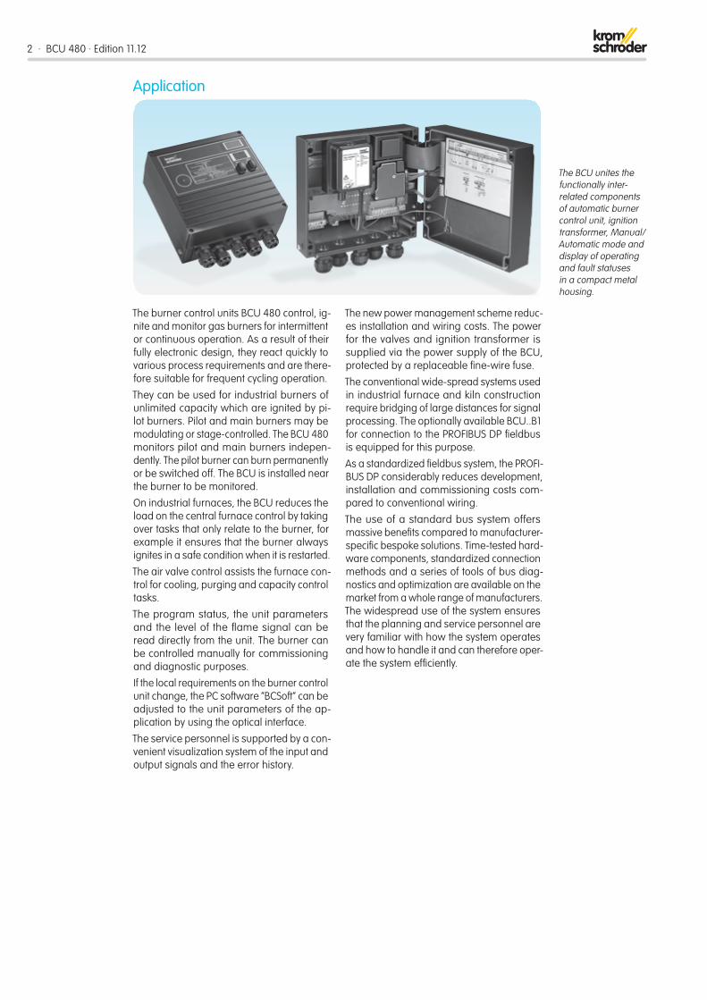
Stage-controlled main burner with alternating pilot burnerControl: Main burner ON/OFF.
The main burner can be started with reduced capacity after the operating signal from the pilot burner has been detected. The pilot burner is switched off automatically after the main burner has started up. When the main burner is switched off, the pilot burner au-tomatically switches on again. This reduces the main burner start-up time.
A UV sensor monitors the flame signal from pilot and main burners. UV sensor UVD 1 is used for continuous operation, UV sensor UVS for intermittent operation.
The BCU provides the cooling and purging processes.
Stage-controlled main burner with permanent pilot burnerControl: Main burner ON/OFF.
The main burner can be started with reduced capacity after the operating signal from the pilot burner has been detected. Pilot and main burners can be operated simultane-ously. This reduces the time required by the main burner for starting up.
The BCU provides the cooling and purging processes.
Examples of application
BCU 480 · Edition 11.12 · 5
BCU 480
12
23
SPS PLC API
DI
L1, N, PE
P 22 4 21
18 19
16 17
28 29
24 2
1
A
P
5 3
DI
6
VBY
µC
ϑ1 ϑ2
t
1
2
04 02–04 06–08 06–08 04 ϑ1
ϑ2
2 1
BV
IC 40
4
7 M
14 26 50 51
VAG
VAS
BCU 480
14 12
SPS PLC API
DI
L1, N, PE
4 21 18 19
16 17
28 29 24
2
1
P
5 3
DI
6
mA
µC
ϑ1 ϑ2
VAG
VBY
BV+IC
M
2 1
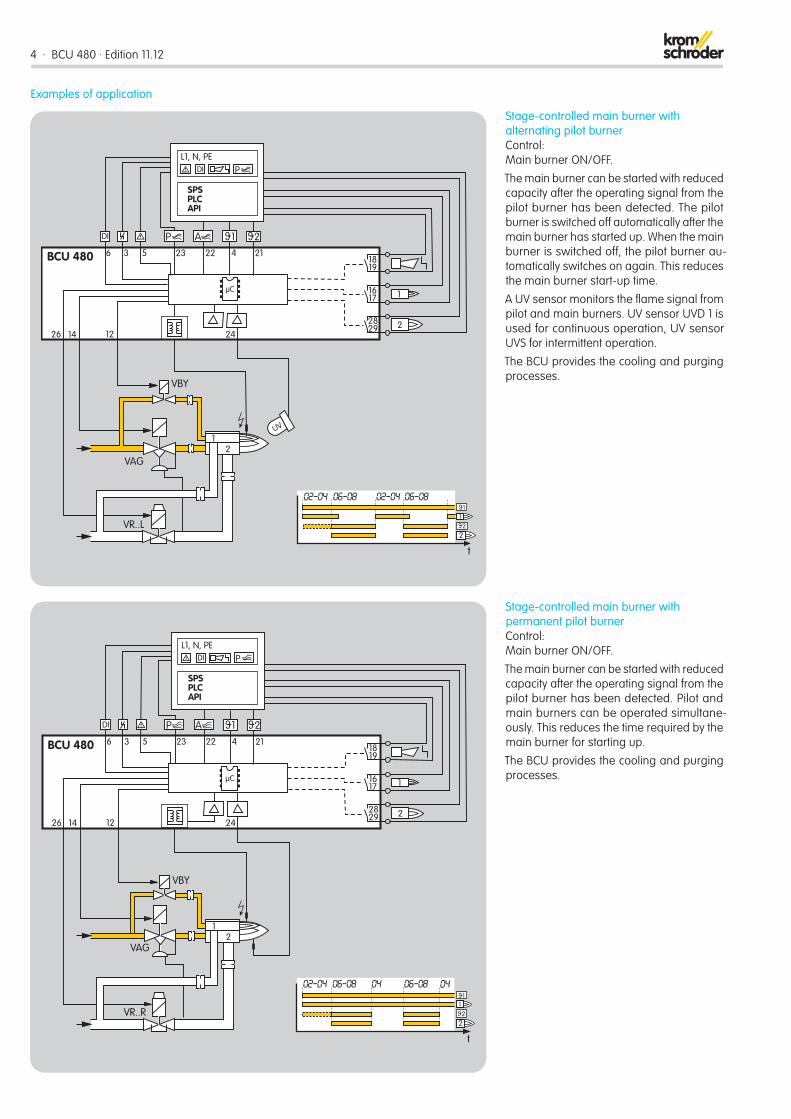
Two-stage-controlled main burner with permanent pilot burnerControl: Main burner ON/OFF with ignition via bypass.
The main burner can be started at low-fire rate after the operating signal from the pilot burner has been detected. When the oper-ating state is reached, the BCU issues the Enable signal for the maximum burner ca-pacity. Pilot and main burners can be oper-ated simultaneously. This reduces the time required by the main burner for starting up.
The BCU provides the cooling and purging processes.
Modulating-controlled burnerControl: Main burner continuous.
The butterfly valve for air is moved to igni-tion position in order to start the main burner. The main burner can be started at low-fire rate after the operating signal from the pi-lot burner has been detected. The control system controls the burner capacity via the butterfly valve for air after the operating state has been signalled. Pilot and main burn-ers can be operated simultaneously. This reduces the time required by the main burner for starting up.

6 · BCU 480 · Edition 11.12
PROFIBUS-DP
BCU 480..B
BUS1–6
BCU 480..B
BUS
BCU 480..B
BUS1–6 1–6
SPSPLCAPI
DI
L1, N, PEP
BUS
L1
DI
BCU 480..D
DI 6 9 24
BCU 480..D
6 9 24
µC µC
STM > 750 °C
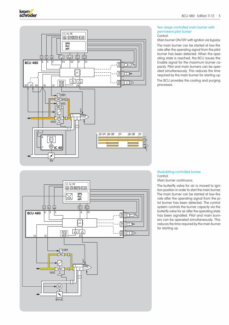
BCU 480..B1 for PROFIBUS DPThe bus system transfers the control sig-nals for starting, resetting and for control-ling the air valve from the control system to the BCU 480..B1. In the opposite direction, it sends operating status, the level of the flame signals and the current program status.
Control signals that are relevant for safety, such as the safety interlocks, purge (optional) and digital input, are transferred indepen-dently of the bus communication by separate cables.
BCU 480..D: High temperature equipmentIndirect flame control using the temperature. During the start-up process, as long as the wall temperature is below auto ignition tem-perature, the flame must be controlled by conventional methods. When the working temperature has exceeded 750°C, the safety temperature monitor (STM) takes over the indirect flame control.
SelectionT -3 -5 -10 /3 /5 /1 /2 L 5 15 25 W R 1 2 3 8 GB1) P2) D2 D3 S2 S3 /2 /3 U C B1 /1 E1
BCU 480 � � � � � � � � � � � � � � � � � � � � � � � � � � � � � � �
� = standard, � = available. 1) Not available for BCU..T. 2) Not in conjunction with PROFIBUS DP (BCU..B1).
Order exampleBCU 480-5/3/1LW3GBCE1

BCU 480 · Edition 11.12 · 7
Technical dataMains voltage: 230 V AC, -15/+10%, 50/60 Hz, 115 V AC, -15/+10%, 50/60 Hz, for grounded and ungrounded mains.
Inherent consumption: approx. 9 VA plus inherent consumption of the integrated ignition transformer [50/60 Hz].
Voltage to inputs and valves = mains voltage.
Signal and control line: max. 2.5 mm2 (AWG 14).
Cable for burner ground/PE wire: 4 mm2 (AWG 12).
Cable gland: 5 cable glands with multiple seal inserts for cable diameters of up to 7 mm, BCU..P: with 2 cable glands and an indus-trial chassis plug. Each BCU is supplied for two cable glands with one seal insert each for cable diameters between 7 – 12 mm.
Input voltage of signal inputs:
Rated value 115 V AC 230 V ACSignal “1” 80 – 126.5 160 – 253Signal “0” 0 – 20 0 – 40Frequency 50/60 Hz 50/60 Hz
Input current of signal inputs: Signal “1”: typ. 2 mA
Output current: max. 1 A, cos ϕ = 1, for the valve outputs (or SRC outputs), but total current for valves and ignition transformer: max. 2.5 A
Fail-safe inputs and outputs: All the inputs and outputs marked “ ” (see connection diagrams) may be used for safety tasks.
Flame control with UV sensor or ionization sensor.
Flame signal for ionization control: 1 – 28 μA, UV control: 1 – 35 μA.
For intermittent or continuous operation.
Maximum length of ignition cable with in-tegrated electronic ignition: 5 m (16.4 ft). Maximum length of ionization/UV cable: 50 m (164 ft).
Fuses in unit: F1: 3.15 A, slow-acting, H, pursuant to IEC 127-2/5. Fuse for protecting the safety-relevant igni-tion, valve 1, valve 2 and air valve outputs (terminals 7, 12, 14 and 26): 5 A, slow-acting, not replaceable. F3 (only for BCU.. A, BCU..C and BCU..U): 3.15 A, slow-acting, H, pursuant to IEC 127-2/5.
Operation and fault signalling contacts: Signalling contact for mains voltage, max. 2 A, 253 V, not internally fused.
Number of operating cycles: Relay outputs: 250,000 pursuant to EN 298, Mains switch: 1,000, Reset/Information button: 1,000.
Ambient temperature: -20 to +60°C (-4 to +140°F), climate: no condensation permitted.
Enclosure: IP 54 pursuant to IEC 529.
Weight: approx. 5 kg (11 lb) depending on version.
Ignition transformer
Input OutputV AC Hz* A* V mA*
TZI 5-15/100W 230 50 (60) 0.45 (0.35) 5000 15 (11)TZI 7-25/20W 230 50 (60) 1.1 (0.8) 7000 25 (18)TZI 7,5-12/100W 230 50 (60) 0.6 (0.45) 7500 12 (9)TZI 7,5-20/33W 230 50 (60) 0.9 (0.7) 7500 20 (15)TZI 5-15/100R 115 50 (60) 0.9 (0.7) 5000 15 (11)TZI 7-25/20R 115 50 (60) 2.2 (1.6) 7000 25 (18)TZI 7,5-12/100R 115 50 (60) 1.2 (0.9) 7500 12 (9)TZI 7,5-20/33R 115 50 (60) 1.8 (1.35) 7500 20 (15)
* Values in ( ) apply to 60 Hz.
BCU..B1External fuse: 12 A per zone.
PROFIBUS DPManufacturer ID: 0x05DB.
ASIC type: SPC3.
SYNC- and FREEZE-capable.
Baud rate detection: automatic.
Min. cycle time: 0.1 ms.
Diagnostic bytes: 6 (DP Standard).
Parameter bytes: 7 (DP Standard).

8 · BCU 480 · Edition 11.12
Detailed information on this product
Contactwww.kromschroeder.com ➔ Sales
Elster GmbH Postfach 2809 · 49018 Osnabrück Strotheweg 1 · 49504 Lotte (Büren) GermanyT +49 541 1214-0 F +49 541 1214-370 [email protected]
We reserve the right to make technical modifications in the interests of progress.Copyright © 2013 Elster GmbH All rights reserved.
http://docuthek.kromschroeder.com/doclib/main.php?language=1&folderid=206080&by_class=6 0325
0579
Safety-specific characteristic valuesIn the case of ionization control, suitable for Safety Integrity Level
SIL 3
Diagnostic coverage DC 92.7%Type of subsystem Type B to EN 61508-2, 7.4.3.1.4
Mode of operationHigh demand mode pursuant to EN 61508-4, 3.5.12
Mean probability of dangerous failure PFHD
1.92 x 10⁻⁸ 1/h
Mean time to dangerous f ailure MTTFd
MTTFd = 1 / PFHD
Safe failure fraction SFF 98.8%
The specified values apply for the combina-tion with ionization electrode (sensor) and a unit of the BCU 400 series. No characteristic values are available for flame control with UV sensor.
Relationship between the Performance Level (PL) and the Safety Integrity Level (SIL)
PL SILa –b 1c 1d 2e 3
Pursuant to EN ISO 13849-1:2006, Table 4, the BCU can be used up to PL e.
Max. service life under operating conditions: 20 years after date of production.
Related Documents