3 BURNDY ® EC&M Mechanical 2 Mechanical BURNDY ® EC&M TYPE KVS OKLIP™ Mechanical Connector for Copper and Copperweld. Compact, two-piece, high strength, high copper alloy BURNDY ® OKLIP™ recommended for heavy duty connections. Neoprene rings hold DURIUM™ bolts in place during installation. Installed with ordinary wrench. Catalog Copper Recommended Number Run Tap Tightening Torque in-lb KVS26 2 - 2/0 str. 6 sol. - 2/0 str. 180 KVS28 1/0 - 4/0 str. 10 - 4/0 str. 250 KVS31 250 - 350 kcmil 10 str. - 350 kcmil 325 KVS34 400 - 500 kcmil 10 str. - 500 kcmil 375 KVS40 400 - 800 kcmil 3/0 str. - 800 kcmil KVS44 500 - 1000 kcmil 3/0 str. - 1000 kcmil 500 TYPE KVSU Universal OKLIP™ Mechanical Connector for all combinations of Copper, Aluminum, ACSR, AAAC and 5005. Compact, high strength, tin plated copper alloy two-piece connector with spacer and tin-plated silicon bronze DURIUM™ hardware. Recommended for heavy duty connections. Spacer separates dissimilar con- ductors and provides long contact length. Neoprene ring prevents loss of shorter bolt during installation. Longer peened bolt permits swivel action for easier installation. Run Tap ACSR, ACSR, Recommended Catalog Copper & AAAC, & Copper & AAAC, & Tightening Number Aluminum 5005 Aluminum 5005 Torque in-lb KVSU26 2 - 2/0 str. 3 - 2/0 6 - 2/0 str. 6 - 2/0 180 KVSU28 1/0 - 4/0 str. 1/0 - 4/0 6 - 4/0 str. 6 - 4/0 250 250 - 350 6 str. - 350 KVSU31 kcmil 4/0 - 300 kcmil 6 - 300 325 400 - 500 336.4- 4 str. - 500 KVSU34 kcmil 397.5 kcmil 5 - 397.5 375 400 - 800 4/0 str. - 800 KVSU40 kcmil 4/0 - 800 kcmil 3/0 - 715.5 500 -1000 4/0 str. -1000 500 KVSU44 kcmil 4/0 -1000 kcmil 4/0 - 900 TYPE KSA TRITAP™ SERVIT ® Tap Connector An aluminum tin-plated universal tap connector for all combinations of alu- minum to aluminum, aluminum to copper and copper to copper applications. UL486B Listed. 90° C rated. 486B Recommended Catalog Run Run Tap Tap Tightening Number Min. Max. Min. Max. Torque in-lb ▲ KSA6 10 sol. 6 str. 10 sol. 6 str. KSA4 8 sol. 4 str. 10 sol. 4 str. 165 KSA2 6 sol. 2 str. 8 str. 2 str. 275 KSA1/0 2 compact 1/0 str. 8 sol. 1/0 str. KSA2/0 2 compact 2/0 str. 8 str. 2/0 str. 385 KSA4/0 2 compact 4/0 str. 6 str. 4/0 str. 500 KSA350* 1/0 compact 350 kcmil 4 str. 350 kcmil 650 KSA500* 400 compact 500 kcmil 2 compact 500 kcmil 825 *Not CSA Listed. ▲ Listed torque values are for maximum conductor combinations accommodated. TYPE SC SERVIT ® Cover Range-taking, insulating cover for SERVIT® and equivalent split-bolt connectors. Catalog Number For Use With SC4 KS17, KS17-3, KS20, KSU17, KSU20 SC2 KS22, KS20-3, KS23, KS22-3, KSA6, KSA4, KSU22, KSU23 SC2/0 KS25, KS26, KSA2, KSA 1/0, KSU25, KSU26 TYPE QPX VERSITAP™ Parallel Clamp Parallel clamp for wide range of copper cable. Makes parallel tap, tees, crosses and end-to-end connections. Rounded edges for easy taping. Cable Range Recommended Catalog Run Run Tap Tap Tightening Number Min. Max. Min. Max. Torque in-lb QPX2C2C 6 str. 2 str. 6 str. 2 str. 150 QPX282C 1 str. 4/0 str. 6 str. 2 str. QPX2828 1 str. 4/0 str. 1 str. 4/0 str. 250 QPX342C 250 kcmil 500 kcmil 6 str. 2 str. QPX3428 250 kcmil 500 kcmil 1 str. 4/0 str. 375 QPX3434 250 kcmil 500 kcmil 250 kcmil 500 kcmil QPX442C 500 kcmil 1000 kcmil 6 str. 2 str. QPX4428 500 kcmil 1000 kcmil 1 str. 4/0 str. QPX4434 500 kcmil 1000 kcmil 250 kcmil 500 kcmil 500 QPX4444 500 kcmil 1000 kcmil 500 kcmil 1000 kcmil

Welcome message from author
This document is posted to help you gain knowledge. Please leave a comment to let me know what you think about it! Share it to your friends and learn new things together.
Transcript

3
BURNDY® EC&M Mechanical
2
Mechanical BURNDY® EC&M
TYPE KVSOKLIP™
Mechanical Connector for Copper and Copperweld. Compact, two-piece,high strength, high copper alloy BURNDY® OKLIP™ recommended for heavyduty connections. Neoprene rings hold DURIUM™ bolts in place during installation. Installed with ordinary wrench.
Catalog Copper RecommendedNumber Run Tap Tightening Torque in-lbKVS26 2 - 2/0 str. 6 sol. - 2/0 str. 180KVS28 1/0 - 4/0 str. 10 - 4/0 str. 250KVS31 250 - 350 kcmil 10 str. - 350 kcmil 325KVS34 400 - 500 kcmil 10 str. - 500 kcmil 375KVS40 400 - 800 kcmil 3/0 str. - 800 kcmilKVS44 500 - 1000 kcmil 3/0 str. - 1000 kcmil
500
TYPE KVSUUniversal OKLIP™
Mechanical Connector for all combinations of Copper, Aluminum, ACSR,AAAC and 5005. Compact, high strength, tin plated copper alloy two-piececonnector with spacer and tin-plated silicon bronze DURIUM™ hardware.Recommended for heavy duty connections. Spacer separates dissimilar con-ductors and provides long contact length. Neoprene ring prevents loss ofshorter bolt during installation. Longer peened bolt permits swivel action foreasier installation.
Run TapACSR, ACSR, Recommended
Catalog Copper & AAAC, & Copper & AAAC, & TighteningNumber Aluminum 5005 Aluminum 5005 Torque in-lbKVSU26 2 - 2/0 str. 3 - 2/0 6 - 2/0 str. 6 - 2/0 180KVSU28 1/0 - 4/0 str. 1/0 - 4/0 6 - 4/0 str. 6 - 4/0 250
250 - 350 6 str. - 350KVSU31
kcmil4/0 - 300
kcmil6 - 300 325
400 - 500 336.4- 4 str. - 500KVSU34
kcmil 397.5 kcmil5 - 397.5 375
400 - 800 4/0 str. - 800KVSU40
kcmil4/0 - 800
kcmil3/0 - 715.5
500 -1000 4/0 str. -1000500
KVSU44kcmil
4/0 -1000kcmil
4/0 - 900
TYPE KSATRITAP™ SERVIT® Tap Connector
An aluminum tin-plated universal tap connector for all combinations of alu-minum to aluminum, aluminum to copper and copper to copper applications.UL486B Listed. 90° C rated.
486B
RecommendedCatalog Run Run Tap Tap TighteningNumber Min. Max. Min. Max. Torque in-lb ▲KSA6 10 sol. 6 str. 10 sol. 6 str.KSA4 8 sol. 4 str. 10 sol. 4 str.
165
KSA2 6 sol. 2 str. 8 str. 2 str. 275KSA1/0 2 compact 1/0 str. 8 sol. 1/0 str.KSA2/0 2 compact 2/0 str. 8 str. 2/0 str.
385
KSA4/0 2 compact 4/0 str. 6 str. 4/0 str. 500KSA350* 1/0 compact 350 kcmil 4 str. 350 kcmil 650KSA500* 400 compact 500 kcmil 2 compact 500 kcmil 825
*Not CSA Listed.▲ Listed torque values are for maximum conductor combinations accommodated.
TYPE SCSERVIT® Cover
Range-taking, insulating cover for SERVIT® and equivalent split-bolt connectors.
CatalogNumber For Use WithSC4 KS17, KS17-3, KS20, KSU17, KSU20SC2 KS22, KS20-3, KS23, KS22-3, KSA6, KSA4, KSU22, KSU23SC2/0 KS25, KS26, KSA2, KSA 1/0, KSU25, KSU26
TYPE QPXVERSITAP™ Parallel Clamp
Parallel clamp for wide range of copper cable. Makes parallel tap, tees,crosses and end-to-end connections. Rounded edges for easy taping.
Cable Range RecommendedCatalog Run Run Tap Tap TighteningNumber Min. Max. Min. Max. Torque in-lbQPX2C2C 6 str. 2 str. 6 str. 2 str. 150QPX282C 1 str. 4/0 str. 6 str. 2 str.QPX2828 1 str. 4/0 str. 1 str. 4/0 str.
250
QPX342C 250 kcmil 500 kcmil 6 str. 2 str.QPX3428 250 kcmil 500 kcmil 1 str. 4/0 str. 375QPX3434 250 kcmil 500 kcmil 250 kcmil 500 kcmilQPX442C 500 kcmil 1000 kcmil 6 str. 2 str.QPX4428 500 kcmil 1000 kcmil 1 str. 4/0 str.QPX4434 500 kcmil 1000 kcmil 250 kcmil 500 kcmil
500
QPX4444 500 kcmil 1000 kcmil 500 kcmil 1000 kcmil

5
BURNDY® EC&M Mechanical
4
Mechanical BURNDY® EC&M
TYPE QPX-YUniversal VERSITAP™ Parallel Clamp
Universal parallel clamp for copper and aluminum. Tin-plated. Makes paral-lel taps, tees, crosses or end-to-end connections.
Conductor RangeCatalog Aluminum or CopperNumber Run TapQPX2C2C-Y 6 - 2 str. 6 - 2 str.QPX282C-Y 1 - 4/0 str. 6 - 2 str.QPX2828-Y 1/0 - 4/0 str. 1/0 - 4/0 str.QPX342C-Y 250 - 500 kcmil 6 - 2 str.QPX3428-Y 250 - 500 kcmil 1/0 - 4/0 str.QPX3434-Y 250 - 500 kcmil 250 - 500 kcmilQPX4444-Y 750 - 1000 kcmil 750 - 1000 kcmil
TYPES KPA, KPA-UPSCRULUG™ TerminalFor Copper Cable
High copper alloy terminal for joining a wide range of cable to equipmentpads or terminal blocks. Plain copper finish.
Catalog CatalogNumber Number ConductorFig. 1 Fig. 2 RangeKPA8C KPA8CUP* 14 sol. - 6 str.KPA4C KPA4CUP* 14 sol. - 4 str.KPA25 — 6 - 1/0 str.KPA28 — 6 - 4/0 str.KPA34 — 2/0 str. - 500 kcmil
Figure 1Figure 2
TYPE KLUSCRULUG™ TerminalFor Copper CableOffset Tongue Non-plated
High copper alloy terminal with offset tongue for joining a wide range of cableto equipment pads or bar. Easy to install with screwdriver or wrench. Con-nector is reusable. Plain copper finish.
* For tin plating drop “UP” suffix and add “TP” suffix.
Catalog ConductorNumber Range
KLU25 14 - 10 sol.KLU35 14 sol. - 6 str.KLU70 8 sol. - 2 str.KLU125 2 - 1/0 str.KLU175 4 - 3/0 str.KLU225 2 - 4/0 str.KLU300 1/0 str. - 350 kcmilKLU400 1/0 str. - 500 kcmil
TYPE KAKA-LUG™ TerminalFor Copper Cable
Compact, economical, high copper alloy terminal for joining a wide range ofcable to equipment pads or terminal blocks.
Catalog ConductorNumber Range
KA8C 14 sol. - 8 str.KA4C 14sol. - 4 str.KA25 4 - 1/0 str.
KA25-2TC38 4 - 1/0 str.KA28 1 - 4/0 str.KA34 4/0 str. - 500 kcmil
TYPE QAQIKLUG™ Terminal
Heavy-duty terminal for a wide range of copper cables. One-hole tongue.
Catalog Conductor StudNumber Range SizeQA8C-B 14 sol. - 8 str. 10QA4C-B 8 - 4 str. 1/4QA1C-B 4 - 1 str. 1/4QA26-B 1/0 - 2/0 str. 3/8QA28-B 3/0 - 4/0 str. 3/8QA31-B 250 - 350 kcmil 1/2QA34-B 400 - 500 kcmil 1/2QA40-B 600 - 800 kcmil 5/8QA44-B 850 - 1000 kcmil 5/8QA46-B 1100 - 1500 kcmil 3/4
TYPES QA-2, QA-4QIKLUG™ Terminal
Heavy-duty terminal for a wide range of copper cables. Two-hole and four-hole tongues.
Catalog Conductor Stud StudNumber Range Hole Size Hole CentersQA8C-2B 14 sol. - 8 str. 10 5/8QA4C-2B 8 - 4 str. 1/4 5/8QA1C-2B 4 - 1 str. 5/16 7/8QA26-2B 1/0 - 2/0 str. 3/8 1QA28-2B 3/0 - 4/0 str. 3/8 1QA31-2B 250 - 350 kcmil 3/8 1QA26-2N 1/0 - 2/0 str. 1/2 1-3/4QA28-2N 3/0 - 4/0 str. 1/2 1 -3/4QA31-2N 250 - 350 kcmil 1/2 1-3/4QA34-2B 400 - 500 kcmil 3/8 1QA34-2N 400 - 500 kcmil 1/2 1-3/4QA34-4B 400 - 500 kcmil 3/8 1QA40-2N 600 - 800 kcmilQA44-2N 850 - 1000 kcmilQA44-4N 850 - 1000 kcmil
1/2 1-3/4
QA46-2N 1100 - 1500 kcmil
7
BURNDY® EC&M Mechanical
6
Mechanical BURNDY® EC&M
TYPE QDAQIKLUG™ Terminal
Heavy-duty terminal for a wide range of cable to equipment studs. One-holetongue finished on both sides.
Catalog Conductor StudNumber Range SizeQDA8C 14 sol. - 8 str. 3/8QDA4C 8 - 4 str. 3/8QDA1C 4 - 1 str. 3/8QDA26 1/0 - 2/0 str. 1/2QDA28 3/0 - 4/0 str. 1/2QDA31 250 - 500 kcmil 5/8QDA34 400 - 500 kcmil 3/4QDA40 600 - 800 kcmil 1
TYPES Q2A-2, Q2A-2N, Q2A-4NQIKLUG™ Terminal
Heavy-duty terminal for a wide range of copper cable. Joins two cables toequipment pads or bars. Two hole and four hole tongue.
Catalog Conductor Stud StudNumber Range Hole Size Hole CentersQ2A1C-2 4 - 1 str. 3/8 1Q2A26-2N 1/0 - 2/0 str.Q2A28-2N 3/0 - 4/0 str.Q2A31-2N 250 - 350 kcmilQ2A34-2N 400 - 500 kcmilQ2A40-2N 600 - 800 kcmilQ2A28-4N 3/0 - 4/0 str. 1/2 1-3/4Q2A31-4N 250 - 350 kcmilQ2A34-4N 400 - 500 kcmilQ2A40-4N 600 - 800 kcmilQ2A44-4N 850 - 1000 kcmilQ2A46-4N 1100 - 1500 kcmil
TYPES Q3A-2N, Q3A-4NQIKLUG™ Terminal
Heavy-duty terminal for a wide range of copper cable. Joins three cables toequipment pads or bars.
Catalog Conductor Stud StudNumber Range Hole Size Hole CentersQ3A28-2N 3/0 - 4/0 str.Q3A31-2N 250 - 350 kcmilQ3A34-2N 400 - 500 kcmilQ3A28-4N 3/0 - 4/0 str.Q3A31-4N 250 - 350 kcmilQ3A34-4N 400 - 500 kcmil
1/2 1-3/4
Q3A40-4N 600 - 800 kcmilQ3A44-4N 850 - 1000 kcmilQ3A46-4N 1100 - 1500 kcmilQ3A48-4N 1600 - 2000 kcmil
TYPE KA-UUniversal Terminal(1 Conductor)For Aluminum and Copper Conductors
These dual-rated one conductor lugs are constructed from high strength alu-minum alloy and electro tin-plated to provide low contact resistance.
Catalog Figure Recommended TighteningNumber Conductor Range Number Torque (in-lb) ▲
KA6U 14 - 6 str. 1 45KA2U 14 - 2 str. 1 50KA25U 14 - 1/0 str. 1 50KA26U 6 - 2/0 str. 1 120KA29U 6 str. - 250 kcmil 2 275KA30U 6 str. - 300 kcmil 2 275KA31U 6 str. - 350 kcmil 2 275KA34U 4 str. - 500 kcmil 2 500KA36U 2 str. - 600 kcmil 2 500KA40U 300 - 800 kcmil 2 550KA44U 500 - 1000 kcmil 2 550
Fig. 1
Fig. 2
TYPE K2A-UUniversal Terminal(2 Conductors)For Aluminum and Copper Conductors
Compact, wide-range, tin-plated aluminum terminal for use with two copperor aluminum cables.
Fig. 1
Fig. 2Fig. 3
Stud Stud RecommendedCatalog Conductor Hole Hole Fig. TighteningNumber Range Size Spacing No. Torque (in-lb) ▲K2A25U Two: 14 - 1/0 str. 1/4 — 1 50K2A26U Two: 14 - 2/0 str. 1/4 — 1 120K2A29U Two: 6 str. - 250 kcmil 3/8 — 2 275K2A31U Two: 4 str. - 350 kcmil 1/2 — 2 275K2A36U Two: 2 str. - 600 kcmil 1/2 — 2 375K2A40U Two: 300 - 800 kcmil 5/8 — 2 550K2A44U Two: 500 - 1000 kcmil 5/8 — 2 550K2A31U-2N* Two: 6 str. - 350 kcmil 1/2 1-3/4 3 275K2A36U-2N* Two: 2 str. - 600 kcmil 1/2 1-3/4 3 375K2A40U-2N* Two: 300 - 800 kcmil 1/2 1-3/4 3 375K2A44U-2N* Two: 500 - 1000 kcmil 1/2 1-3/4 3 375
* Tongue holes drilled per NEMA standards.▲ Listed torque values are for maximum conductor size accommodated.
▲ Listed torque values are for maximum conductor size accommodated.

9
BURNDY® EC&M Mechanical
8
Mechanical BURNDY® EC&M
TYPES K3A-U, KK3A-UUniversal Terminal(3 Conductor)For Aluminum & Copper Conductors
Dual-rated three conductor lugs are constructed from high strength aluminumalloy and electro tin-plated to provide low contact resistance.
Catalog Conductor Stud Fig. Recommended Tight-Number Range Hole Size No. ening Torque (in-lb) ▲K3A2U-2* Three: 14 - 2 str. 5/16 1 50K3A25U-2* Three: 14 - 1/0 str. 3/8 1 50K3A26U-2N Three: 14 - 2/0 str. 1/2 1 50K3A27U-2N Three: 6 - 3/0 str. 1/2 1 275K3A29U-2N Three: 6 str. - 250 kcmil 1/2 1 275K3A31U-2N Three: 6 str. - 350 kcmil 1/2 1 275K3A36U-2N Three: 2 str. - 600 kcmil 1/2 1 375KK3A36U-2N Three: 2 str. - 600 kcmil 1/2 2 375KK3A40U-2N Three: 300 - 800 kcmil 1/2 2 375KK3A44U-2N Three: 500 - 1000 kcmil 1/2 2 375
* Slotted screw.“N” indicates NEMA Standard holes.▲ Listed torque values are for maximum conductor size accommodated.
Fig. 1
Fig. 2
TYPE K4A-UUniversal Terminal(4 Conductor)For Aluminum and Copper Conductors
These dual-rated four conductor lugs are constructed from high strength aluminum alloy and electro tin-plated to provide low contact resistance.
Fig. 1
Fig. 2
Catalog Conductor Stud Fig. Recommended Tight-Number Range Hole Size No. ening Torque (in-lb) ▲K4A29U-4N Four: 6 str. - 250 kcmil 1/2 1 275K4A31U-4N Four: 6 str. - 350 kcmil 1/2 1 275KK4A36U-4N Four: 2 str. - 600 kcmil 1/2 2 375KK4A40U-4N Four: 300 - 800 kcmil 1/2 2 375
“N” indicates NEMA Standard holes.▲ Listed torque values are for maximum conductor size accommodated.
TYPE BGBLLay-In QIKLUG™*UL Listed 90°C, 600 V
The Lay-In QIKLUG™, type BGBL is manufactured from high strength 6061-T6 aluminum, and is ideally suited for grounding and bonding applicationsaccommodating both copper and aluminum conductor sizes 14 AWG to 250kcmil.
Catalog Number Conductor Range Hex SizeBGBL-4 14 - 4 str. SlotBGBL-1/0 14 - 1/0 str. SlotBGBL-250 6 str. - 250 kcmil 7/32
TYPE CL50-1Copper Lay-In QIKLUG™For Copper
The Lay-In QIKLUG™ is manufactured from high strength pure electrolyticcopper to ensure maximum strength and conductivity. UL467 Listed for DirectBurial in earth or concrete. The open-faced design allows for fast lay-in ofthe conductor without the need for cutting or breaking.
Catalog Number Conductor Range Copper Stud HoleCL50-1 14 - 4 AWG 10
NOTE: Stainless Steel Screws.
TYPE KPBFor Copper
UL467 Listed for direct burial application in earth or concrete.
Catalog Number Cable Range Stud HoleKPB4CG1 10 - 4 str. 10*
* To be assembled with TMH322 stainless steel hardware kit, ordered separately.
TYPE K11A-UUniversal TerminalFor Aluminum and Copper Conductors
Dual-rated panelboard lugs are constructed from high strength extruded alu-minum alloy and electro tin-plated to provide low contact resistance.
Catalog Conductor Stud Fig. Recommended Tight-Number Range Hole Size No. ening Torque (in-lb) ▲K11A30U* Two: 6 str. - 300 kcmil 5/16 1 275K11A34U-2 Two: 4/0 str. - 500 kcmil 1/4 2K11A36U-2 Two: 2 str. - 600 kcmil 3/8 3K21A36U-2 Three: 2 str. - 600 kcmil 3/8 4K22A36U-2 Four: 2 str. - 600 kcmil 3/8 5
375
K11A39U-2 Two: 1/0 str. - 750 kcmil 3/8 3K22A39U-2 Four: 1/0 str. - 750 kcmil 3/8 5
* Not CSA listed.▲ Listed torque values are for maximum conductor size accommodated.
Fig. 1
Fig. 2 Fig. 3
Fig. 4 Fig. 5

11
BURNDY® EC&M Mechanical
10
Mechanical BURNDY® EC&M
TYPE KAU-KITTransformer Lug Kit
Each kit contains the UL Listed and CSA certified AL/CU rated aluminum setscrew connectors and tongue mounting hardware needed to terminate alu-minum or copper cables in “dry type” transformers. The KVA rating gives anapproximate cross reference to the appropriate kit.
TerminalsCatalog Transformer CatalogNumber KVA Rating Qty Number Conductor Range
15-37.5 1Ø 8 KA2U 14 - 2 str.KAU-KIT1
15-45 3Ø 4 KA29U 6 str. - 250 kcmil50-75 1Ø
KAU-KIT275-112.5 3Ø
12 KA29U 6 str. - 250 kcmil
100-167 1Ø 6 K2A31U 6 str. - 350 kcmilKAU-KIT3
150-300 3Ø 7 K2A40U 300 - 800 kcmilKAU-KIT4 400-500 3Ø 15 K2A40U 300 - 800 kcmil
Catalog HardwareNumber Qty. Bolt Size Qty. Nut Qty. Washer
CaptiveKAU-KIT1 8 1/4-20 x 3/4 HH 8 1/4 x 20 HN —
To Nut8 1/4-20 X 3/4 HH Captive
KAU-KIT28 1/4-20 x 2 HH
16 1/4 x 20 HN —To Nut
5 1/2-13 x 2 HH 22 1/2 FWKAU-KIT3
6 1/2-13 x 2-1/2 HH11 1/2-13 HN
11 1/2 Belleville7 1/-13 x 2 22 1/2 FW
KAU-KIT44 1/2-13 x 2-1/2
11 1/2-13 HN11 1/2 Belleville
TYPE AMSDual Rated Splicer/ReducerFor Copper and Aluminum Cable
All splicer/reducers are dual rated for use with aluminum and copper conductors and are constructed from high strength, tin-plated aluminum.PENETROX™ oxide inhibiting joint compounds are recommended for all alu-minum applications.
Catalog Wire RangeNumber Min. Max.AMS-2* 14 AWG 2 AWGAMS-0* 8 AWG 1/0 AWGAMS-4/0 6 AWG 4/0 AWGAMS-250 6 AWG 250 kcmilAMS-350 6 AWG 350 kcmilAMS-500 3/0 AWG 500 kcmilAMS-750 250 kcmil 750 kcmilAMS-1000 500 kcmil 1000 kcmil
* Slotted Screws
TYPE UGSKITWatertight/Underground Splice KitFor all Aluminum or Copper/Aluminum Combinations
Type UGS Watertight Underground Splice Kit consists of a standard AMSsplicer/reducer and two heavy wall heat-shrink sleeves.
Catalog Figure Conductor RangeNumber Number Minimum MaximumUGSKIT2* 1 8 AWG 2 AWGUGSKIT250* 2 1 AWG 250 kcmil
* UL486D Listed for Direct Burial.
Fig. 1 Fig. 2
TYPE UGSKIT8UF Direct Burial Splice KitFor All Aluminum or Copper/Aluminum Combinations
Type UGS UF Splice Kit consists of a UF splice connector and a heavy wallheatshrink sleeve.
Catalog Number Conductor Range CopperUGSKIT8* 14 - 8 AWG
* UL486D Listed for Direct Burial.

13
BURNDY® EC&M Mechanical
12
Mechanical BURNDY® EC&M
U-BLOK™ POWER DISTRIBUTION BLOCKSFor Junction Box Applications
The U-BLOK™ system is a modern, state-of-the-art approach to multi-load power distribution applications. Among typical uses are multi-story ormulti-unit buildings, HVAC, refrigeration, control panels, motor control, switch gear, elevator systemsand materials-handling equipment. U-BLOK™ is ULListed for Copper or Aluminum conductors and ratedfor 600-volt applications. U-BLOK™ can bemounted on bases for use in troughs or bolted directly to junction boxes. AL9CU rated.
PENETROX™ inhibitor is recommended for all aluminum wire connections.For two wire tap range is 8 through 1/0.
* Aluminum and copper conductors cannot be assembled under the same pressure plate or t-bar.
FT4B500
3S
3S 3U
FT3B4/0
3 WIRE POWER DISTRIBUTION BLOCKS
4 WIRE POWER DISTRIBUTION BLOCKS
MaximumNumber of Al or Cu Allen Tor-
Catalog Wires per Wire Range * Weight Wrench que StripNumber Phase Run Tap W L H Each Size (in-lb) LengthFT3B4/0 3/0 - 4/0 6 - 4/0 1-1/4 lbs. 1/4� 200 1-1/2�
FT3B5002
400 - 500 6 - 5003-7/8� 5-7/8� 4-1/8�
2-1/8 lbs. 3/8� 375 2-5/16�
3S 2 250-350 6 - 350 3-5/8� 9-3/4� 4-7/8� 3 lbs. 1/4� 200 1-3/4�
Run Tap Run Tap3U 1 8 3/0-500 6 - 1/0 4-3/4� 9-3/4� 5-1/2� 3 lbs. 5/32� 110 2-5/16�1-5/32�
MaximumNumber of Al or Cu Allen Tor-
Catalog Wires per Wire Range * Weight Wrench que StripNumber Phase Run Tap W L H Each Size (in-lb) LengthFT4B4/0 3/0 - 4/0 6 - 4/0 2 lbs. 1/4� 200 1-1/2�
FT4B5002
400 - 500 6 - 5003-7/8� 7-7/8� 4-1/8�
2-3/4 lbs. 3/8� 375 2-5/16�
4S 2 250-350 6 - 350 3-5/8� 11-3/4� 4-7/8� 3-1/2 lbs. 1/4� 200 1-3/4�
Run Tap Run Tap4U 1 8 3/0-500 6 - 1/0 4-3/4� 11-3/4� 5-1/2� 3-1/2 lbs. 5/32� 110 2-5/16�1-5/32�
U-BLOK™ MOUNTING PLATFORMSFor Trough Applications
Hole pattern shown is for reference only.* Supercedes TBPT4/0-6 and TBPT350/500-6.
Catalog Gutter WeightNumber W L H Size EachTBPT-6* 4-1/4� 5-7/8� 1-1/2� 6� 3/4 lb.TBPT-8 4-1/4� 7-7/8� 3-1/2� 8� 1-1/4 lb.TBPT-10 4-1/4� 9-7/8� 4� 10� 1-1/2 lb.TBPT-12 4-1/4� 11-7/8� 4� 12� 1-3/4 lb.
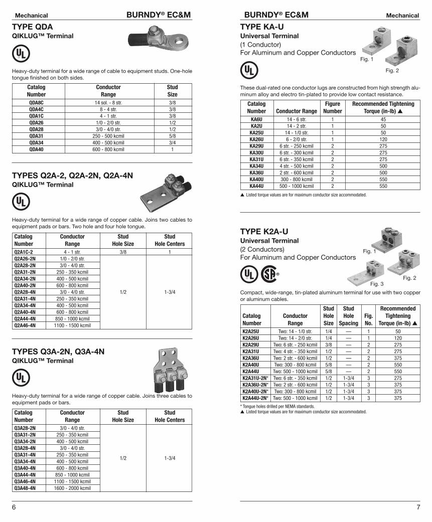
SPEC-BLOK™ POWER DISTRIBUTION CONNECTORSUnique, modular, made-to-order, power- distributionassemblies accommodate any number of supplyand load conductors in any number of poles. Capacity matches the conductors accommodatedand SPEC-BLOK™ assures uniform loading.
Adjacent poles are separated by easy-to- handle,wrap-around insulating covers which eliminatetaping and reduce heat build-up by allowing air toflow freely around connectors. SPEC-BLOK™ isUL Listed for copper or aluminum conductors for600 volts (AL9CU). Assemblies are mounted onplatforms suitable for easy installation in wirewayor junction box.
Features and Benefits• Accommodate unlimited conductors.
�Fits wide range of applications.• Connector elements tin-plated.
�Provides high reliability, low-resistance connections.• User friendly, space-saving design.
�Easy to install. Saves labor.• 94-VO rated insulation folds into place insulating the components.
�Saves time and material. Allows easy installation.• Connector caps removable for easy cable lay-in.
�Saves labor. Makes installation easier. Allows installation or straight-through conductors. Eases retrofit.
• Belleville washers built-in on pressure screw assemblies, except in assemblies installed with a 5/32� Allen wrench.�Provides high-integrity connections.
• Conductors can be cut or fed straight through.�Straight through installation ideal for riser applications.
* SPEC-BLOK™ catalog assembly not UL Listed, individual SPEC-BLOK™ connectors are UL Listed.See next page.
*
Contact BURNDY® Technical Services: 1-800-451-4956,or BURNDY® Customer Service: 1-800-346-4175
15
BURNDY® EC&M Mechanical
14
Mechanical BURNDY® EC&M
SPEC-BLOK™ POWER DISTRIBUTION CONNECTORS
Features and Benefits• The SPEC-BLOK™ system includes 12 connector elements
�A wide variety of conductor sizes can be accommodated• Each element can be bolted together in parallel
�Provides an efficient flow of current from one element to another• AL9CU rated for Copper or Aluminum conductors
�Dual-rated system, with UL486B’s highest temperature rating• 2 Wire (series), 4 (parallel), and Multi-Tap versions available
�Nearly any conductor combination can be terminated• High-strength, corrosion-resistant connector elements• All SPEC-BLOKs™ are custom made for nearly any Power Distribution
system requirement�Time savings — pre-assembled in our factory for immediate
installation!
* SPEC-BLOK™ catalog assembly not UL Listed, individual SPEC-BLOK™ connectors are UL Listed.See next page.
SPEC-BLOK™ CONNECTORSE W
C
B
RS A
D
Q
T
U
P
*
Catalog Designation Number of Al or Cu(Maximum Conductors Wire Range UnderConductor) Accommodated Each Cap
Second DimensionsConductor Length
First (if Height On Without Insulator Allen4 2 4 2 Conductors required) Max. 4 2 Wrench
Conductor Conductor Conductor Conductor MUST Be May Be Conductors Width Conductor Conductor SizeA Q
(2/0)1/0/- 2/0 #12 - 2/0 2-9/16� 1-1/2� 2-1/8� 7/8� 5/32�
B R(250)
3/0 - 250 #6 - 250 3-1/8� 1-11/16� 4-1/4� 1-3/8�
C S1 to 4
1 or 21/4�
(350)(0, 1, or 2
per cap250 - 350 #6 - 350 3-5/16� 1-13/16� 4-5/8� 1-1/2�
D Tper cap)
(500)400 - 500 #6 - 500 4-1/16� 2� 5-5/8� 1-3/4�
E W3/8�
(750)600 - 750 3/0 - 750 4-7/8� 2-1/4� 7-1/4� 2-5/8�
** This range may be expanded to include #8 provided two conductors are being installed in that particular element.
Catalog Designation Number of Height on Length Allen(Maximum Conductors Large Small Maximum Without WrenchConductor) Accommodated Groove Grooves** Conductors Width Insulator Size
1 to 8 (0, 1 or 2P (1/0)under each screw)
— 6-1/10 3-1/2� 2�
2 to 9 (0, 1 or 2 under 1-3/4� 5/32�
U (1/0 & 500) each screw plus one 3/0 - 500 6-1/10 4-1/8� 2�
large conductor)
SPEC-BLOK™Mounting Platforms
SPEC-BLOK™ Mounting Platforms are rigid steel construction with a blackfinish. They can be supplied for junction box mounting or wireway construc-tion allowing trough conductors to pass underneath the assemblies.
(CPB-) (CPT-)
Catalog L L WNumber (Nominal) (Overall) (Overall)CPB6 6� 7-3/4� 2-1/2�
CPB8 8� 9-3/4� 2-1/2�
CPB10 10� 11-3/4� 2-1/2�
CPB12 12� 13-3/4� 3-1/2�
CPB14 14� 15-3/4� 3-1/2�
CPB16-5/8 16-5/8� 18-3/8� 3-1/2�
CPB21-1/4 21-1/4� 23� 3-1/2�
CatalogNumber L W HCPT6 5-7/8� 2-1/2� 2-1/4�
CPT8 7-7/8� 3-1/2� 3�
CPT10 9-7/8� 3-1/2� 3-1/2�
CPT12 11-7/8� 3-1/2� 4�
CPT16 15-7/8� 3-1/2� 4�

17
BURNDY® EC&M Mechanical
16
Mechanical BURNDY® EC&M
TYPE KPU-ACPOLYTAP™Insulated Gutter Tap for All Copper and Aluminum Combinations
Wide range-taking tin-plated aluminum parallel clamp and insulating coverassembly for industrial and multiple story structure applications. Only six connectors cover the entire 14 sol. - 750 kcmil range. Covers having flexiblefingers that conform to conductor, fully insulating the connection. UL486BListed for 600 volts maximum 90° C service. Cover and connector are pack-aged together. No taping required.
600 Volt Max. 90° C
RecommendedCatalog Conductor Copper or Aluminum TighteningNumber Run Tap W H L Torque in-lbKPU29A26AC 1/0 str. - 250 kcmil 14 sol. - 2/0 str.KPU29A29AC 1/0 str. - 250 kcmil 6 str. - 250 kcmil
3-1/8 3-3/8 4-1/4 375
KPU34A26AC 4/0 str. - 500 kcmil 14 sol. - 2/0 str.KPU34A34AC 4/0 str. - 500 kcmil 6 str. - 500 kcmil
3-1/2 3-1/2 4-5/8 450
KPU39A26AC 500 - 750 kcmil 14 sol. - 2/0 str.KPU39A39AC 500 - 750 kcmil 1/0 str. - 750 kcmil
3-1/2 3-7/8 5-1/16 600
TYPE UCU-ACRiser Tap
Parallel-groove riser tap and insulation cover for copper and aluminum. Widerange-taking assembly for apartment house and light industrial applications.Cover and connector are packaged together. Covers having insulating fin-gers that conform to conductors, fully insulating the connection. UL486BListed for 600 volts max. 90° C service.
600 Volt Max. 90° C
▲ RecommendedCatalog Conductor TighteningNumber Run Tap W H L Torque In-lbUCU28AC 2 str. - 4/0 str. 10 sol. - 2 str. 2-1/4 1-13/16 2-5/8 120
▲ Listed torque values are for maximum conductor combinations accommodated. Consult UL486 Tables 7-4, 7-5, and 7-6 for smaller combinations.
TYPE BIPCINSULTAP™ Insulated Piercing ConnectorsUL Listed 90°C, *600 V
The INSULTAP™, Type BIPC, BURNDY® Insulation Piercing Connector is ide-ally suited for splicing and tapping aluminum and copper conductor wiresizes: 10 AWG to 500 kcmil.
Catalog Conductor Range Bolt Socket Recom. Max. VoltNumber Run Tap Size Size Torque RatingBIPC1/0-2 8 - 1/0 AWG 8 - 2 AWG 5/16-18 1/2 180 in-lb 600VBIPC4/0-6 1/0 - 4/0 AWG 6 - 1/0 AWG 5/16-18 1/2 250 in-lb 300VBIPC4/0-1/0 1/0 - 4/0 AWG 1/0 - 4/0 AWG 5/16-18 1/2 250 in-lb 300VBIPC350-4/0 4/0 - 350 AWG 1/0 - 4/0 AWG 3/8-16 9/16 375 in-lb 300VBIPC350-350 4/0 - 350 AWG 4/0 - 350 AWG 3/8-16 9/16 300 in-lb 300VBIPC500-4/0 350 - 500 kcmil 4 - 4/0 AWG 3/8-16 9/16 400 in-lb 600V
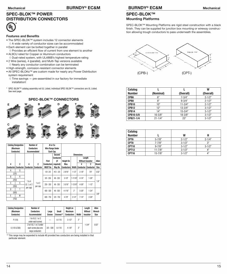
VERSIPOLE™Power Distribution Blocks
VERSIPOLE™ Power Distribution Blocks are designed to provide modularsolutions to power distribution applications. Each connector element is madefrom a high conductivity aluminum alloy which is insulated with a highstrength polymer housing. One, two, and three pole versions available. “Adda pole” (snap-together) blocks are also available for wire sizes up to 500kcmil. For use with Cu or Al 600 V, AL9CU rated.
Conductor AmpereCatalog Connector Range Al/Cu Rating NumberNumber Run Tap Run Tap Per Pole of PolesBDA-112-350 1 12 6 - 350 kcmil 14 - 4 AWG 350 AdderBDA-16-350 1 6 6 - 350 kcmil 14 - 2/0 AWG 350 AdderBDA-16-500 1 6 4 - 500 kcmil 14 - 2/0 AWG 430 AdderBDA-26-350 2 6 6 - 350 kcmil 14 - 2/0 AWG 700 AdderBDA-212-500 2 12 4 - 500 kcmil 14 - 4 AWG 860 AdderBDA-26-500 2 6 4 - 500 kcmil 14 - 2/0 AWG 860 AdderBDA-24-500 2 4 4 - 500 kcmil 6 - 4/0 AWG 860 AdderBDA-11-500 1 1 4 - 500 kcmil 4 - 500 kcmil 430 AdderBDA-22-350 2 2 6 - 350 kcmil 6 - 350 kcmil 700 AdderBDA-22-500 2 2 4 - 500 kcmil 4 - 500 kcmil 760 Adder
SNAP TOGETHER SPLICER/REDUCER BLOCKS
AmpereCatalog Connector Wire Range Al/Cu Rating Number OptionalNumber Run Tap Run Tap Per Pole of Poles CoverBDC-14-2/0-1 1 4 14 - 2/0 AWG 14 - 4 AWG 195 1 BDBCOVER3BDA-14-2/0-1 1 4 14 - 2/0 AWG 14 - 4 AWG 195 Adder BDBCOVER3BDC-11-2/0-1 1 4 14 - 2/0 AWG 14 - 2/0 AWG 195 1 BDBCOVER3BDA-11-2/0-1 1 4 14 - 2/0 AWG 14 - 2/0 AWG 195 Adder BDBCOVER3
19
BURNDY® EC&M Mechanical
18
Mechanical BURNDY® EC&M
VERSIPOLE™1, 2, 3 Pole Distribution Blocks
AmpereCatalog Connector Wire Range Al/Cu Rating Number OptionalNumber Run Tap Run Tap Per Pole of Poles CoverBDB-16-2/0-1 1BDB-16-2/0-2 1 6 12 - 2/0 AWG 14 - 4 AWG 195 2 BDBCOVER2BDB-16-2/0-3 3BDB-26-2/0-1 1BDB-26-2/0-2 2 6 14 - 2/0 AWG 14 - 2 AWG 390 2 BDBCOVER2BDB-26-2/0-3 3BDB-112-350-1 1BDB-112-350-2 1 12 6 - 350 kcmil 14 - 4 AWG 350 2 BDBCOVER1BDB-112-350-3 3BDB-16-350-1 1BDB-16-350-2 1 6 6 - 350 kcmil 14 - 2/0 AWG 350 2 BDBCOVER1BDB-16-350-3 3BDB-14-500-1 1BDB-14-500-2 1 4 4 - 500 kcmil 14 - 2/0 AWG 430 2 BDBCOVER2BDB-14-500-3 3BDB-16-500-1 1BDB-16-500-2 1 6 4 - 500 kcmil 14 - 2/0 AWG 430 2 BDBCOVER1BDB-16-500-3 3BDB-162-500-1 1BDB-162-500-2 1 6 4 - 500 kcmil 14 - 2 AWG 430 2 BDBCOVER2BDB-162-500-3 3BDB-26-350-1 1BDB-26-350-2 2 6 6 - 350 kcmil 14 - 2/0 AWG 700 2 BDBCOVER1BDB-26-350-3 3BDB-212-500-1 1BDB-212-500-2 2 12 4 - 500 kcmil 14 - 4 AWG 760 2 BDBCOVER1BDB-212-500-3 3BDB-26-500-1 1BDB-26-500-2 2 6 4 - 500 kcmil 14 - 2/0 AWG 760 2 BDBCOVER1BDB-26-500-3 3BDB-24-500-1 1BDB-24-500-2 2 4 4 - 500 kcmil 6 - 4/0 AWG 760 2 BDBCOVER1BDB-24-500-3 3
VERSIPOLE™1, 2, 3 Pole Splicer/Reducer Blocks
AmpereCatalog Connector Wire Range Al/Cu Rating Number OptionalNumber Run Tap Run Tap Per Pole of Poles CoverBDB-11-2/0-1 1BDB-11-2/0-2 1 1 14 - 2/0 AWG 14 - 2/0 AWG 195 2 BDBCOVER2BDB-11-2/0-3 3BDB-11-350-1 1BDB-11-350-2 1 1 6 - 350 kcmil 6 - 350 kcmil 350 2 BDBCOVER2BDB-11-350-3 3BDB-11-500-1 1BDB-11-500-2 1 1 6 - 500 kcmil 6 - 500 kcmil 430 2 BDBCOVER1BDB-11-500-3 3BDB-22-2/0-1 1BDB-22-2/0-2 2 2 14 - 2/0 AWG 14 - 2/0 AWG 390 2 BDBCOVER2BDB-22-2/0-3 3BDB-22-350-1 1BDB-22-350-2 2 2 6 - 350 kcmil 6 - 350 kcmil 700 2 BDBCOVER2BDB-22-350-3 3BDB-22-500-1 1BDB-22-500-2 2 2 4 - 500 kcmil 4 - 500 kcmil 760 2 BDBCOVER1BDB-22-500-3 3
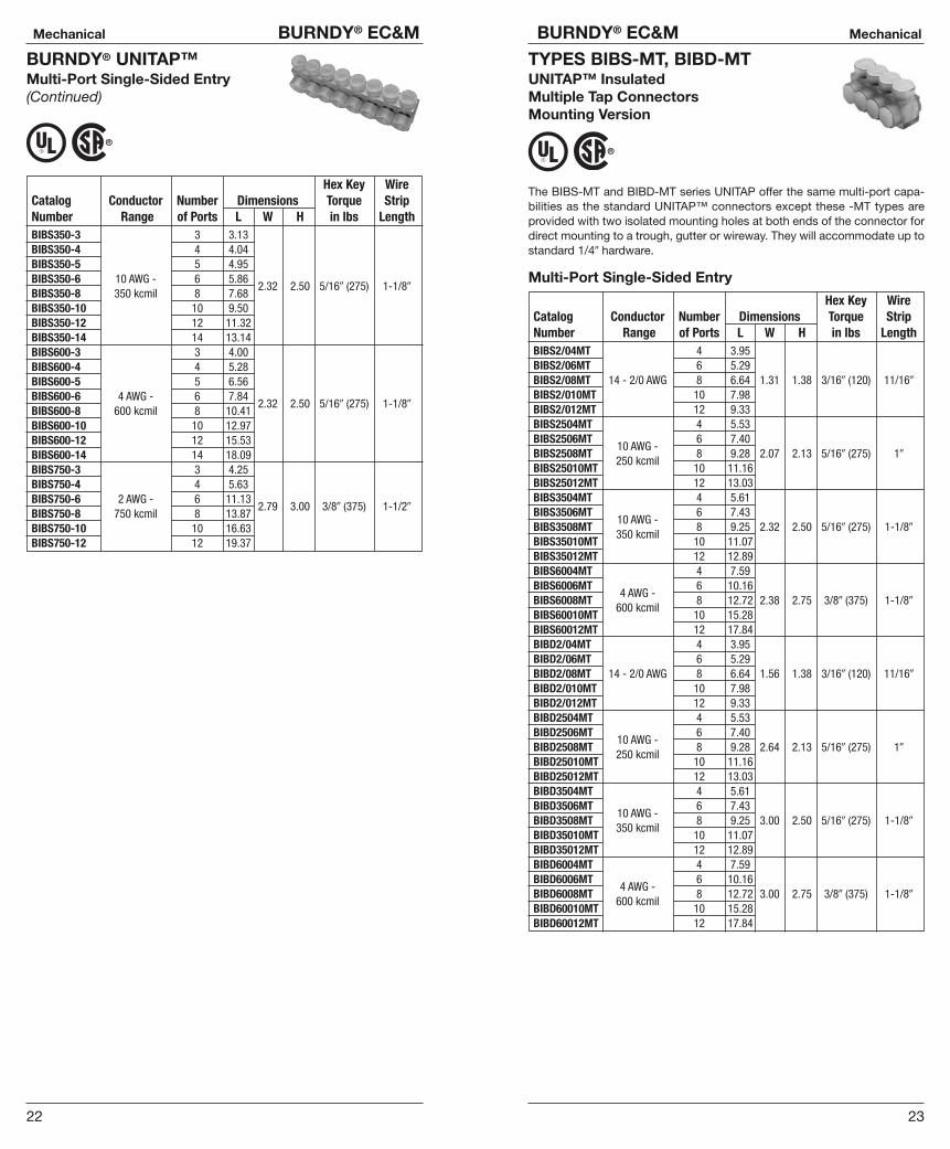
UNITAP™Insulated Multiple Tap Connectors
Tap connections and in-line splice/reductions are made quickly and easilywith the UNITAP™ line of connectors. UL486B Listed. Dual-rated AL9CU forany stranded copper or stranded aluminum applications. 600 V, 90°C.
2 Port 1 or 2 Sided EntryHex Key Wire
Catalog Conductor Number Dimensions Torque StripNumber Range of Ports L W H in lbs LengthBIT4 14 - 4 AWG 1.16 1.16BITO-4 14 - 4 AWG 1.16 1.50
1.25 1/8� (45) 5/8�
BIT2/0 14 - 2/0 AWG 1.52 1.40BITO2/0 14 - 2/0 AWG 1.52 1.56
1.38 3/16� (120) 11 /16�
BIT250 10 AWG-250 kcmil 2.03 2.07BITO250 10 AWG-250 kcmil 2.03 2.64
2.13 5/16� (275) 1�
BIT350 10 AWG-350 kcmil2
2.22 2.32BITO350 10 AWG-350 kcmil 2.22 3.00
2.50 5/16� (275)
BIT600 4 AWG - 600 kcmil 2.72 2.381-1/8�
BITO600 4 AWG - 600 kcmil 2.72 3.002.75 3/8� (375)
BIT750 2 AWG - 750 kcmil 2.87 2.70BITO750 2 AWG - 750 kcmil 2.87 3.38
3.00 3/8� (375) 1-1/2�

21
BURNDY® EC&M Mechanical
20
Mechanical BURNDY® EC&M
BURNDY® UNITAP™In-line Splicer/Reducer
Hex Key WireCatalog Conductor Number Dimensions Torque StripNumber Range of Ports L W H in lbs LengthBISR2 14 - 2 AWG 2.38 0.75 1.22 1/8� (45) 3/4�
BISR-1/0 14 -1/0 AWG 2.91 0.91 1.38 1�
BISR250 10 AWG - 250 kcmil 2 4.01 1.19 2.103/16� (120)
1-3/16�
BISR350 10 AWG - 350 kcmil 4.63 1.34 2.35 5/16� (275) 1-3/8�
BISR500 6 AWG - 500 kcmil 5.00 1.62 2.62 3/8� (375) 1-1/2�
Hex Key WireCatalog Conductor Number Dimensions Torque StripNumber Range of Ports L W H in lbs LengthBIBD4-2 2 1.16BIBD4-3 3 1.59BIBD4-4 4 2.03BIBD4-5
14 - 4 AWG5 2.47
1.50 1.25 1/8� (45) 5/8�
BIBD4-6 6 2.91BIBD4-8 8 3.78BIBD2/0-2 2 1.52BIBD2/0-3 3 2.19BIBD2/0-4 4 2.86BIBD2/0-5 5 3.53BIBD2/0-6 14 - 2/0 AWG 6 4.20 1.56 1.25 3/16� (120) 11 /16�
BIBD2/0-8 8 5.55BIBD2/0-10 10 6.89BIBD2/0-12 12 8.24BIBD2/0-14 14 9.58BIBD250-2 2 2.03BIBD250-3 3 2.97BIBD250-4 4 3.91BIBD250-5 5 4.84BIBD250-6
10 AWG -6 5.78 2.64 2.13 5/16� (275) 1�
BIBD250-8250 kcmil
8 7.66BIBD250-10 10 9.53BIBD250-12 12 11.32BIBD250-14 14 13.29BIBD350-2 2 2.22BIBD350-3 3 3.13BIBD350-4 4 4.04BIBD350-5 5 4.95BIBD350-6
10 AWG -6 5.86 3.00 2.50 5/16� (275) 1-1/8�
BIBD350-8350 kcmil
8 7.68BIBD350-10 10 9.50BIBD350-12 12 11.32BIBD350-14 14 13.14
BURNDY® UNITAP™Multi-Port Double-Sided Entry
(Multi-Port Double-Sided Entry continued on next page)
Hex Key WireCatalog Conductor Number Dimensions Torque StripNumber Range of Ports L W H in lbs LengthBIBD600-2 2 2.56BIBD600-3 3 3.77BIBD600-4 4 4.97BIBD600-5 5 6.17BIBD600-6
4 AWG -6 7.37 3.00 2.75 3/8� (375) 1-1/8�
BIBD600-8600 kcmil
8 9.78BIBD600-10 10 12.97BIBD600-12 12 15.53BIBD600-14 14 18.09BIBD750-2* 2 2.87BIBD750-3* 3 4.25BIBD750-4* 4 5.63BIBD750-6* 6 8.37BIBD750-8*
#2 - 7508 11.13
3.38 3.00 3/8� (375) 1-1/2�
BIBD750-10* 10 13.87BIBD750-12* 12 16.63BIBD750-14* 14 19.37
BURNDY® UNITAP™Multi-Port Double-Sided Entry(Continued)
*Not UL Listed.
BURNDY® UNITAP™Multi-Port Single-Sided Entry
Hex Key WireCatalog Conductor Number Dimensions Torque StripNumber Range of Ports L W H in lbs LengthBIBS4-3 3 1.59BIBS4-4 4 2.03BIBS4-5 14 - 4 AWG 5 2.47 1.25 1.25 1/8� (45) 5/8�
BIBS4-6 6 2.91BIBS4-8 8 3.78BIBS2/0-3 3 2.19BIBS2/0-4 4 2.86BIBS2/0-5 5 3.53BIBS2/0-6 6 4.20BIBS2/0-8
14 -2/0 AWG8 5.55
1.31 1.38 3/16� (120) 11/16�
BIBS2/0-10 10 6.80BIBS2/0-12 12 8.24BIBS2/0-14 14 9.58BIBS250-3 3 2.97BIBS250-4 4 3.91BIBS250-5 5 4.84BIBS250-6 10 AWG - 6 5.78BIBS250-8 250 kcmil 8 7.66
2.07 2.13 5/16� (275) 1�
BIBS250-10 10 9.53BIBS250-12 12 11.41BIBS250-14 14 13.29
(Multi-Port Single-Sided Entry continued on next page)
23
BURNDY® EC&M Mechanical
22
Mechanical BURNDY® EC&M
BURNDY® UNITAP™Multi-Port Single-Sided Entry(Continued)
Hex Key WireCatalog Conductor Number Dimensions Torque StripNumber Range of Ports L W H in lbs LengthBIBS350-3 3 3.13BIBS350-4 4 4.04BIBS350-5 5 4.95BIBS350-6 10 AWG - 6 5.86BIBS350-8 350 kcmil 8 7.68
2.32 2.50 5/16� (275) 1-1/8�
BIBS350-10 10 9.50BIBS350-12 12 11.32BIBS350-14 14 13.14BIBS600-3 3 4.00BIBS600-4 4 5.28BIBS600-5 5 6.56BIBS600-6 4 AWG - 6 7.84BIBS600-8 600 kcmil 8 10.41
2.32 2.50 5/16� (275) 1-1/8�
BIBS600-10 10 12.97BIBS600-12 12 15.53BIBS600-14 14 18.09BIBS750-3 3 4.25BIBS750-4 4 5.63BIBS750-6 2 AWG - 6 11.13BIBS750-8 750 kcmil 8 13.87
2.79 3.00 3/8� (375) 1-1/2�
BIBS750-10 10 16.63BIBS750-12 12 19.37
TYPES BIBS-MT, BIBD-MTUNITAP™ Insulated Multiple Tap Connectors Mounting Version
The BIBS-MT and BIBD-MT series UNITAP offer the same multi-port capa-bilities as the standard UNITAP™ connectors except these -MT types areprovided with two isolated mounting holes at both ends of the connector fordirect mounting to a trough, gutter or wireway. They will accommodate up tostandard 1/4� hardware.
Multi-Port Single-Sided Entry
Hex Key WireCatalog Conductor Number Dimensions Torque StripNumber Range of Ports L W H in lbs LengthBIBS2/04MT 4 3.95BIBS2/06MT 6 5.29BIBS2/08MT 14 - 2/0 AWG 8 6.64 1.31 1.38 3/16� (120) 11/16�
BIBS2/010MT 10 7.98BIBS2/012MT 12 9.33BIBS2504MT 4 5.53BIBS2506MT 6 7.40BIBS2508MT
10 AWG -8 9.28 2.07 2.13 5/16� (275) 1�
BIBS25010MT250 kcmil
10 11.16BIBS25012MT 12 13.03BIBS3504MT 4 5.61BIBS3506MT 6 7.43BIBS3508MT
10 AWG -8 9.25 2.32 2.50 5/16� (275) 1-1/8�
BIBS35010MT350 kcmil
10 11.07BIBS35012MT 12 12.89BIBS6004MT 4 7.59BIBS6006MT 6 10.16BIBS6008MT
4 AWG -8 12.72 2.38 2.75 3/8� (375) 1-1/8�
BIBS60010MT600 kcmil
10 15.28BIBS60012MT 12 17.84BIBD2/04MT 4 3.95BIBD2/06MT 6 5.29BIBD2/08MT 14 - 2/0 AWG 8 6.64 1.56 1.38 3/16� (120) 11/16�
BIBD2/010MT 10 7.98BIBD2/012MT 12 9.33BIBD2504MT 4 5.53BIBD2506MT 6 7.40BIBD2508MT
10 AWG -8 9.28 2.64 2.13 5/16� (275) 1�
BIBD25010MT250 kcmil
10 11.16BIBD25012MT 12 13.03BIBD3504MT 4 5.61BIBD3506MT 6 7.43BIBD3508MT
10 AWG -8 9.25 3.00 2.50 5/16� (275) 1-1/8�
BIBD35010MT350 kcmil
10 11.07BIBD35012MT 12 12.89BIBD6004MT 4 7.59BIBD6006MT 6 10.16BIBD6008MT
4 AWG -8 12.72 3.00 2.75 3/8� (375) 1-1/8�
BIBD60010MT600 kcmil
10 15.28BIBD60012MT 12 17.84

25
BURNDY® EC&M Mechanical
24
Mechanical BURNDY® EC&M
UV RATED BLACK UNITAP™
Features and Benefits• UV Rated Plastisol covered AL6061-T6 aluminum body saves time by
eliminating the need for taping.• Oxide inhibitor pre-installed inhibits moisture and contaminants from
entering the contact area.• Range-taking capability reduces the number of connectors carried in
inventory.• UL486B Listed, AL9CU, 600V 90°C.
PL=2 Port Single Sided Entry (Fig. 3), 1PLO=2 Port Offset Entry (Fig. 4)Wire Hex Key
Catalog Figure Number Range TorqueNumber Number of Ports (AWG/kcmil) (in lbs)1PL42 3 14 - 4 1/8 (45)1PLO42 4 14 - 4 1/8 (45)1PL2/02 3 14 - 2/0 3/16 (120)1PLO2/02 4 14 - 2/0 3/16 (120)1PL2502 3 2 10 - 250 5/16 (275)1PLO2502 4 10 - 250 5/16 (275)1PL3502 3 10 - 350 5/16 (275)1PL6002 3 4 - 600 3/8 (375)1PLO6002 4 4 - 600 3/8 (375)
1PBS=In-line Splicer/Reducer (Fig. 1)
1PBS2 14 - 2 5/32 (45)1PBS1/0 14 - 1/0 3/16 (120)1PBS250 1 2 10 - 250 5/16 (120)1PBS350 10 - 350 5/16 (275)1PBS500 6 - 500 3/8 (375)
1PL= Multi-Port Single Sided Entry (Fig. 5)
1PL43 3 14 - 4 1/8 (45)1PL44 4 14 - 4 1/8 (45)1PL2/03
53 14 - 2/0 3/16 (120)
1PL2503 3 10 - 250 5/16 (275)
1PLD=Multi-Port Double Sided Entry (Fig. 2)
1PLD43 3 1/8 (45)1PLD44 4
14 - 41/8 (45)
1PLD2/02 2 3/16 (120)1PLD2/03 2 3/16 (120)1PLD2/04 4
14 - 2/03/16 (120)
1PLD2/062
6 3/16 (120)1PLD2502 2 5/16 (275)1PLD2503 3 5/16 (275)1PLD2504 4
10 - 2505/16 (275)
1PLD2506 6 5/16 (275)
(Multi-Port Double-Sided Entry — Fig. 2 continued on next page)
Fig. 1 Fig. 2 Fig. 3 Fig. 4 Fig. 5
UV RATED BLACK UNITAP™(Continued)
Fig. 1 Fig. 2 Fig. 3 Fig. 4 Fig. 5
1PLD=Multi-Port Double Sided Entry (Fig. 2)Wire Hex Key
Catalog Figure Number Range TorqueNumber Number of Ports (AWG/kcmil) (in lbs)1PLD3502 21PLD3503 31PLD3504 4 10 - 350 5/16 (375)1PLD3506 61PLD3508 81PLD6002 2 21PLD6003 31PLD6004 41PLD6005 5
4 - 600 3/8 (375)
1PLD6006 61PLD6008 8
BURNDY® UNITAP™THE MOLE™In-Line Splicer/ReducerFor Direct Burial
Designed specifically for direct burial applications, the MOLE™ is made witha specialized plastisol material that forms a watertight connection and isrugged enough to withstand abrasions that may occur in direct burial appli-cations. Dual-rated AL9CU for stranded copper and aluminum applicatons. 600V, 90°C.
Catalog WireNumber Range L W H Hex KeyBISR4-DB 6 - 4 4.25 0.68 1.43� 1/8�
BISR1-DB 2 - 1 6.25 0.89 1.70� 5/32�
BISR3/0-DB 1/0 - 3/0 6.25 0.99 1.90� 3/16�
BISR250-DB 4/0 - 250 6.70 1.18 2.15� 5/16�
TYPE UGS350ULDBIn-Line Splicer/ReducerFor Direct Burial
Features and Benefits• EPDM rubber covered 6061-T6 aluminum connector.• Dual rated AL9CU for copper or aluminum conductor.• UL Listed and CSA Certified for Direct Burial.• Broad range-taking capability.• Low installation cost.
Catalog Wire Length Height Hex TorqueNumber Range In. (mm) In. (mm) Size (lbs.)
8.50 2.81UGS350ULDB 12 AWG - 350 kcmil
(216) (71.4)5/16� 350

27
BURNDY® EC&M Oxide Inhibitor
26
Oxide Inhibitor BURNDY® EC&M
TYPES PENETROX™ A, A-13 and EOxide-Inhibiting Joint Compounds
PENETROX™ oxide-inhibiting compounds produce low initial contact resist-ance, seal out air and moisture, prevent oxidation or corrosion, exhibit supe-rior weathering characteristics, are usable over wide temperature ranges andprovide a high conductivity “gas-tight” joint. All PENETROX™ compoundscontain homogeneously suspended metal particles. The suspended metalparticles assist in penetrating thin oxide film, act as electrical “bridges” between conductor strands, aid in gripping the conductor, improve electricalconductivity and enhance the integrity of the connection.
The specially formulated PENETROX™ compounds are for use with com-pression and bolted connectors providing an improved service life for bothcopper and aluminum connections. Additionally, the non-toxic compoundsare an excellent lubricant for threaded applications reducing galling and seizing.
PENETROX™ A-13PENETROX™ A-13 is a synthetic basecompound with evenly suspended zincparticles. It is recommended for aluminumto aluminum, aluminum to copper connec-tions plus aluminum conduit threads. It iscompatible with rubber, polyethylene andother insulating materials. UL Listed for allvoltages.
PENETROX™ APENETROX™ A is a natural (petroleum)base compound with evenly suspendedzinc particles. It is recommended for alu-minum to aluminum, aluminum to copperconnections and aluminum conduitthreads. It is not recommended for usewith rubber or polyethylene insulated con-ductors. UL Listed to 600V.
PENETROX™ EPENETROX™ E is a synthetic base com-pound with evenly suspended copper particles. It is recommended for copper tocopper, copper threads and all groundingapplications. UL Listed.
PENETROX™ A, A-13 and E
TECHNICAL INFORMATION
Easy to apply:1. Scratch brush the conductor surfaces until bright and clean.2. Immediately apply PENETROX™ to the conductive surfaces.3. For EHV applications, remove all excess PENETROX™ after installation
is complete.
Shelf Life:When stored in its original container in cool (under 100° F) dry environment,PENETROX™ oxide inhibiting compound will remain workable and func-tional for five (5) years from the date marked on the container provided it ismixed per instructions prior to use.
ValuePENETROX™ PENETROX
Property Definition E & A13 AThe value in accordance to ASTM D217 indicates
Penetrationthe consistency of a grease. The higher the 250 230
(Unworked)number, the softer the grease.The temperature at which the grease passes
Droppingfrom the semi-solid to a liquid state under test 500°F 230°F
Point (Min.)conditions.The lowest temperature at which the compound
Pour Pointwill flow. Pour point is the lubricant’s ability to -10°F -15°F
(Max.)perform in cold conditions.
Properties of PENETROX™
*MSDS sheets available through Customer Service.
Ordering Information:Catalog Number Container
PENETROX A PENETROX A-13 PENETROX E Type SizePENA1/2 — — Tube 1/2 Oz.PENA-4 PENA13-4 PENE-4 Squeeze Bottle 4 Oz.
P8A PENA13-8 PENE-8 Squeeze Bottle 8 Oz.PENACARTRIDGE PENA13CARTRIDGE — Cartridge 1 Lb.*
PENA-QT PENA13QT PENE-QT Plastic Tube 1 Qt.PENA-GAL PENA13-GAL PENE-GAL Can 1 Gal.PENA-5GAL PENA13-5GAL PENE-5GAL Pail 5 Gal.PENA-55GAL PENA13-55GAL PENE-55GAL Drum 55 Gal.
* 1 Lb. Cartridge will fit standard caulking guns.

29
BURNDY® EC&M Mechanical
28
Mechanical BURNDY® EC&M
TYPE BDTBONDIT™ Intersystem Bonding ConnectorHouse Mounted or Meter Socket Mounted
Designed to meet the requirements of 2008 NEC Article 250.94 “Bonding forOther Systems.” Corrosion-resistant stainless steel set screws. Accepts mainground wire (#2-#8) and up to 4 intersystem wires (#6-#14). Same design canbe mounted directly to the meter socket or mounted to the house. Innovativedesign does not damage meter socket and will not void warranty.
Catalog Number: BDT1
Features & Benefits• Made in the USA!• Meets Intersystem Bonding Requirements: NEC2008 250.94.• One connector does it all.• House mount or meter socket mount.• Incorporates proven BURNDY® SERVIT POST™ design.• Stainless steel set screws.• Accepts main ground wire (#2-#8), up to 4 intersystem wires (#6-#14).• Easily mounts to meter box during new installation or can be wall
mounted.• Easy to follow instructions included.• Does not damage meter socket; no worries about damaging the paint or
voiding warranties.• Easily installed with a wrench and screwdriver.• Open design prevents buildup of hornets, bees, spiders.
CONFIGURATION 1 — MOUNTED TO ENCLOSURE1. Punch out a 1/2� or 3/4� knock out on the electrical enclosure.2. Begin assembly by installing the ground electrode conductor in the
SERVIT POST™ inside the electrical enclosure. Torque on SERVIT® nut:275 in-lb max.
3. Install the rest of the connector as shown in figure 1 below, it is not nec-essary for the bus bar to be aligned parallel with the enclosure. (Note: thesplit washer is not used in this configuration.)
4. Tighten the intersystem ground wires with set screws in the bus bar to amaximum torque of 35 in-lb.
5. Adhere the BONDIT™ location sticker to the front of the electrical enclo-sure.
Flatwasher
Plasticdisk
Set screw
Bus bar
SERVITPOST™
Electricalenclosure(cut away)
BONDIT™locatonsticker
Groundelectrodeconductor
Intersystemground wire
TYPE BDTBONDIT™ Intersystem Bonding Connector(Continued)
CONFIGURATION 2 — MOUNTED TO EXTERIOR WALL1. Begin by assembling the connector as shown in figure 2 below. Be sure
SERVIT POST™ is as tight as it can be while its groove is aligned with theground electrode conductor. (Note: the flat washer is not used in this configuration.)
2. Use two mounting screws (not included) to secure the connector to theexterior wall so that the set screws in the bus bar face downward.
3. Install the ground electrode conductor into the SERVIT POST™ while turn-ing the nut/pressure bar assembly to a maximum torque of 275 in-lb. (use2 wrenches if necessary).
4. Tighting the intersystem ground wires with the set screws in the bus barto a maximum torque of 35 in-lb.
5. If hidden from view, use the BONDIT™ location sticker to indicate the location.
Split lock-washer
Nut & PressureBar Assembly
SERVITPOST™
Set screw
Exteriorwall
Mountingscrews (notincluded)
Intersystemground wire
Ground electrodeconductor

31
BURNDY® EC&M Mechanical
30
Mechanical BURNDY® EC&M
BWB680 SERIESBURNDY® Pool Water Bonding Kit
NEC 2008 680.26(C) states: “An intentional bond of a minimum conductive surface area of 9� shall be installed in contact with the pool water. This bond shall be permitted to consist of parts that are required to be bonded in 680.26(B).”
In order to comply with this requirement BURNDY® ispleased to introduce the BWB680 Series. Made of non-corrosive stainlesssteel, the BURNDY® water bonding kit maintains constant contact with poolwater to ensure that the pool is effectively bonded at all times.
BURNDY® BWB680 Series is one of the few and the most user friendly, prod-ucts on the market that complies with this code. Other products that are currently available are placed in the plumbing, which is not always in contactwith the water and therefore does not meet the code. Since the BWB680 isplaced in the skimmer, it is always in contact with the water.
Some of the features of this product include:• Easy installation• Mounting hardware included• UL Listed• Placed out of the way on the side wall of the skimmer, below the basket
Catalog Number Pool TypeBWB680IG In-GroundBWB860AG Above Ground
Included in the BURNDY® BWB680 SeriesBonding Kit: One bonding plate, (1) rubbersealing washer, (2) flat washers, (2) lock wash-ers, (2) nuts and (1) BURNDY® CL501-TN
Skimmer
Bonding wiregoes here
A pool skimmer acts as a water filter at the top of apool. Because pool water is continuously flowingthrough the skimmer drain, installing the BURNDY®
Pool Water Bonding Kit inside the skimmer is idealfor complying with NEC 2008 680.26(C).
TYPE GRLGround Rod Clamp
UL467 Listed. Acceptable for direct burial.
Catalog Conductor RangeNumber Rod Size Min. Max.
GRL3* 3/8 10 AWG 4 AWGGRL4 1/2 10 AWG 2 AWGGRL5 5/8 10 AWG 2 AWGGRL6 3/4 10 AWG 2 AWG
* Item not UL Listed.
TYPE GRCBronze Ground Rod Clamps
High copper alloy ground connector for joining a range of cable to rod. UL467Listed. Acceptable for direct burial.
CatalogNumber Ground Rod Conductor RangeGRC12 1/2 10 sol.-2 str.GRC58 5/8 10 sol.-1 str.GRC34 3/4 8 sol.-1/0 str.
TYPES KC, K2CSERVIT® POST™For Copper Cable to Flat
SERVIT® POST™ used to ground one or two cables to steel structures, fenceposts, and transformers. Also used to tap one or two cables from bus bar.One-wrench installation.
* = 1 conductor † = 2 conductors
Catalog Number Conductor StudType KC* Type K2C† Stranded Solid Dia. B CFx CFy D H HH
KC15 K2C15 3/8� 1/2�
KC15B1 K2C15B112 - 9 12 - 8 1/4-20�
7/8�1/2� 3/8�
1�5/8� 7/8�
KC17 K2C17 3/8� 1/2�
KC17B1 K2C17B110 - 7 10 - 6 1/4-20�
7/8�5/8� 7/16�
1�7/8� 1�
KC20 K2C20 13/32� 5/8�
KC20B1 K2C20B110 - 5 10 - 4 5/16-18�
27/32�11/16� 1/2�
1�7/8� 1�
KC22 K2C22 15/32� 5/8�
KC22B1 K2C22B110 - 3 10 - 2 3/8-16�
31/32�3/4� 5/8�
1-1/8�1� 1-1/4�
KC23 K2C23 15/32� 5/8�
KC23B1 K2C23B18 - 2 10 - 1 3/8-16�
31/32�13/16� 5/8�
1-1/8�1� 1-3/8�
KC25 K2C25 9/16� 3/4�
KC25B1 K2C25B12 - 1/0 2 - 2/0 1/2-13�
1-1/16�15/16� 3/4�
1-1/4�1-1/8� 1-5/8�
KC26 K2C26 17/32� 3/4�
KC26B1 K2C26B12 - 1/0 2 - 3/0 1/2�-13�
1-1/16�1� 7/8�
1-1/4�1-3/8� 1-7/8�
KC28 K2C28 3/4� 1�
KC28B1 K2C28B11 - 4/0 1 - 4/0 5/8�-11�
1-1/4�1-1/2� 1-3/16�
1-1/2�1-3/4� 2-1/4�
KC31 K2C31 3/4� 1�
KC31B1 K2C31B11 - 350 — 5/8�-11�
1-1/4�1-11 /16� 1-3/8�
1-1/2�2-1/4� 2-7/8�
KC34 K2C34 1� 1-1/4�
KC34B1 K2C34B13/0 - 500 — 3/4-10
1-1/2�2� 1-5/8�
1-3/4�2-3/8� 3-1/4�

33
BURNDY® EC&M Grounding
32
Grounding BURNDY® EC&M
CAST BRONZE CLAMPSFor Conduit
Pressure bar type conduit hub adjusts for 1/2", 3/4" EMT or 1/2" rigid con-duit. Hub swings 360° for easy alignment. Zinc plated hardware.
Conductor Range Recommended Screw TorqueCatalog Water Hub Pipe WireNumber Pipe Ground Size Clamp ClampC-11JPT 1/2-1C-22JPT 1-1/4-2 10 - 6 sol. 1/2 50 in-lb 50 in-lbC-4JPT 2-1/2-4
CAST BRONZE GROUND CLAMPS
For connecting grounding conductor to water pipe or copper tube. "D" indi-cates UL467 Listed for direct burial in earth and concrete and are suppliedwith silicon bronze hardware. "B" indicates brass hardware.
Conductor Range Recommended Screw TorqueCatalog Water Pipe WireNumber Pipe Rebar Ground Clamp ClampC-11N 1/2 - 1 —C-11D 1/2 - 1 4 - 6C-11B 1/2 - 1C-22 1-1/4 - 2C-22D 1-1/4 - 2
10 - 2 str. 50 in-lb 50 in-lb
C-4 2-1/2 - 4—
C-8 4-1/2 - 6C-5 1/2 - 1
DIE CAST CLAMPS
Die cast zinc with zinc plated screws.
Catalog Conductor Range Recommended Screw TorqueNumber Water Pipe Ground Pipe Clamp Wire ClampCZ-11 1/2 - 1 10 - 2 str. 50 in-lb 50 in-lb
CAST BRONZE CLAMPS
To connect armored cable to water pipe. Zinc plated screws. Pressure bargrips armor or outer cable insulation. 360° swing hub for easy alignment.
Catalog Conductor Range Recommended Screw TorqueNumber Water Pipe Conductor Pipe Clamp Wire ClampC-11JA 1/2 - 1 10 - 6 sol.C-22JA 1-1/4 - 2 10 - 6 sol. 50 in-lb 50 in-lbC-4JA 2-1/2 - 2 10 - 2 sol.
CAST BRONZE CLAMPS
For connecting armored cable to water pipe. Zinc plated screws. "D" indi-cates UL467 for direct burial in earth and concrete, supplied with siliconbronze hardware.
Conductor Range Recommended Screw TorqueCatalog Water Ground Pipe WireNumber Pipe Conductor Clamp Clamp Clamp
Bare ArmoredC-6 1/2 - 1 10 - 2 str.
UnarmoredC-6D 1-1/4 - 2 10 - 2 str. Wire Cables
50 in-lb 50 in-lb
C-7 1-1/4 - 2 10 - 2 str. or Cords
CAST BRONZE CLAMPSFor Rigid Conduit
For grounding rigid conduit systems. Zinc plated screws.
CAST BRONZE GROUND CLAMPS
For connecting grounding conductor, EMT or rigid conduit to water pipe, cop-per tube, ground rod or rebar. Hub swings 360° for easy alignment. Simply re-verse bottom clamp for smaller size rebar or rod. Connectors are providedwith silicon bronze hardware.
Conductor Range Recommended Screw TorqueCatalog Water Hub Pipe WireNumber Pipe Ground Size Clamp ClampC-61 1/2 - 1C-66 1-1/4 - 2
6 sol. Max 1/2 50 in-lb 50 in-lb
Conductor RangeMain Tap Reference
Catalog Water Ground Dimensions RecommendedNumber Pipe Rebar Rod Ground H L W Screw Torque
1/2�- 4 - 6C11HD4/0DB
1� AWG3/8� - 1�
8 - 4/02.25 2.65 1.65
1-1/4�- AWG50 in-lb
C22HD4/0DB2�
— — 2.70 3.60 1.56

35
BURNDY® EC&M Grounding
34
Grounding BURNDY® EC&M
CAST BRONZE GROUND CLAMPSWith Lay-In Feature
For connecting grounding conductor to water pipe, copper tube, ground rodor rebar. The open face design allows for fast lay-in of the tap conductor with-out the need for cutting. Simply reverse bottom clamp for smaller size rebaror rod. Connectors are provided with silicon bronze hardware.
Conductor RangeMain Tap Reference Recommended
Catalog Fig. Water Ground Dimensions ScrewNumber No. Pipe Rebar Rod Ground H L W TorqueC11K16D 1C11K17D 2
1/2� - 1� 4 - 6 3/8� - 1� 10 - 2 str. 1.64 2.28 0.66 50 in-lb
Fig. 1 Fig. 2
CAST BRONZE CLAMPSFor Conduit
For grounding rigid conduit systems. Continuity from rigid conduit systems toground provided by cast bronze threaded conduit hub. Zinc plated screws.
Conductor Range Recommended Screw TorqueCatalog Water Hub Pipe WireNumber Pipe Ground Size Clamp ClampC-11LH-1 1/2 - 1C-22LH-1 1-1/4 - 2 10 str. - 6 sol. 1/2�
C-4LH-1 2-1/2 - 4C-11LH-2 1/2 - 1C-22LH-2 1-1/4 - 2 10 - 2/0 str. 3/4� 50 in-lb 50 in-lbC-4LH-2 2-1/2 - 4C-11LH-3 1/2 - 1C-22LH-3 1-1/4 - 2 10 - 3/0 str. 1�
C-4LH-3 2-1/2 - 4
TYPE GC-ADual Rated Ground Clamp
Ground clamps are UL Listed for use with either copper or aluminum con-ductors to copper water pipe, galvanized pipe or steel conduit. All clampsare constructed from tin-plated high strength extruded aluminum alloy. PENE TROX™ oxide inhibiting compounds are recommended for all aluminum.
Catalog Conduit, Pipe or Ground Wire ScrewNumber Water Tube Size Range TypeGC15A 1/2� – 3/4� – 1� 14 - 1/0 AWG SlottedGC18A 1-1/4� – 1-1/2 �– 2�
GC22A 2-1/2� – 3� – 3-1/2� – 4�6 str. - 250 kcmil Hex Socket
TYPE GARGround ConnectorFor Copper Cable to Rod
High copper alloy connector for joining a range of cable, parallel or at right angles, to rod or tube. UL467 Listed. Acceptable for direct burial.
Conductor RangeCatalog Number IPS Rod Cable RangeGAR114C 1/4 1/2 8 sol. - 4 str.GAR1126 1/4 1/2 4 sol. - 2/0 str.GAR1129 1/4 1/2 2/0 sol. - 250 kcmilGAR644C 3/8 5/8 - 3/4 8 sol. - 4 str.GAR6426 3/8 5/8 - 3/4 4 sol. - 2/0 str.GAR6429 3/8 5/8-3/4 2/0 sol. - 250 kcmilGAR6434 3/8 5/8 - 3/4 300 - 500 kcmilGAR144C 1/2 - 3/4 7/8 - 1 8 sol. - 4 str.GAR1426 1/2 - 3/4 7/8 - 1 4 sol. - 2/0 str.GAR1429 1/2 - 3/4 7/8 - 1 2/0 sol. - 250 kcmilGAR1434 1/2 - 3/4 7/8 - 1 300 - 500 kcmilGAR154C 1 1-1/8 - 1-1/4 8 sol. - 4 str.GAR1526 1 1-1/8 - 1-1/4 4 sol. - 2/0 str.GAR1529 1 1-1/8 - 1-1/4 2/0 sol. - 250 kcmilGAR1534 1 1-1/8 - 1-1/4 300 - 500 kcmilGAR164C 1-1/4 1-3/8 - 1-1/2 8 sol. - 4 str.GAR1626 1-1/4 1-3/8 - 1-1/2 4 sol. - 2/0 str.GAR1629 1-1/4 1-3/8 - 1-1/2 2/0 sol. - 250 kcmilGAR1634 1-1/4 1-3/8 - 1-1/2 300 - 500 kcmilGAR174C 1-1/2 1-5/8 - 1-7/8 8 sol. - 4 str.GAR1726 1-1/2 1-5/8 - 1-7/8 4 sol. - 2/0 str.GAR1729 1-1/2 1-5/8 - 1-7/8 2/0 sol. - 250 kcmilGAR1734 1-1/2 1-5/8 - 1-7/8 300 - 500 kcmilGAR184C 2 2 - 2-3/8 8 sol. - 4 str.GAR1826 2 2 - 2-3/8 4 sol. - 2/0 str.GAR1829 2 2 - 2-3/8 2/0 sol. - 250 kcmilGAR1834 2 2-1/2 - 2-7/8 300 - 500 kcmilGAR194C 2-1/2 2-1/2 - 2-7/8 8 sol. - 4 str.GAR1926 2-1/2 2-1/2 - 2-7/8 4 sol. - 2/0 str.GAR1929 2-1/2 2-1/2 - 2-7/8 2/0 sol. - 250 kcmilGAR1934 2-1/2 2-1/2 - 2-7/8 300 - 500 kcmilGAR204C 3 3 - 3-1/2 8 sol. - 4 str.GAR2026 3 3 - 3-1/2 4 sol. - 2/0 str.GAR2029 3 3 - 3-1/2 2/0 sol. - 250 kcmilGAR2034 3 3 - 3-1/2 300 - 500 kcmilGAR214C 3-1/2 3-1/2 - 4 8 sol. - 4 str.GAR2126 3-1/2 3-1/2 - 4 4 sol. - 2/0 str.GAR2129 3-1/2 3-1/2 - 4 2/0 sol. - 250 kcmilGAR2134 3-1/2 3-1/2 - 4 300 - 500 kcmilGAR224C 4 4 - 4-1/2 8 sol. - 4 str.GAR2226 4 4 - 4-1/2 4 sol. - 2/0 str.GAR2229 4 4 - 4-1/2 2/0 sol. - 250 kcmil

37
BURNDY® EC&M Grounding
36
Grounding BURNDY® EC&M
TYPES GAR-BU AND GAR3902 SERIESGround Connectors
Type GAR-BU is a high-conductivity copper ground connector for connect-ing a small to medium range copper ground conductor to water pipe as wellas structural and reinforcing rod shapes. Universal acceptance of severalsizes of cylindrical shapes makes this suitable for industrial construction andmaintenance work as well as cathodic protection. Cable clamp swivels topermit parallel ground of one pipe or 90° cable run for grounding several par-allel pipes. Single wrench installation. UL467 Listed and CSA Certified.
RecommendedCatalog Cable TighteningNumber* Range IPS Size O.D. Range H J W TorqueGAR3902-BU 1/2� - 1� .840-1.32 3.50 3.25GAR3903-BU 1-1/4� - 2� 1.66-2.38 4.00 4.25GAR3904-BU 2-1/2� - 3-1/2� 2.88-4.00 6.50 6.00GAR3905-BU 4� - 5� 4.50-5.56 7.50 7.50GAR3906-BU 6� 6.62 8.50 8.62GAR3907-BU 8� 8.62 10.00 10.62GAR3908-BU 10� 10.75 12.00 12.75GAR3909-BU 4 - 4/0 12� 12.75 14.00 3/8�- 14.75GAR3902 AWG 1/2 �- 1� .840-1.32 3.50 16 3.25
240 in-lb
GAR3903 1-1/4� - 2� 1.66-2.38 4.00 4.25GAR3904 2-1/2� - 3-1/2� 2.88-4.00 6.50 6.00GAR3905 4� - 5� 4.50-5.56 7.50 7.50GAR3906 6� 6.62 8.50 8.62GAR3907 8� 8.62 10.00 10.62GAR3908 10� 10.75 12.00 12.75GAR3909 12� 12.75 14.00 14.75
*Type GAR-BU is supplied with DURIUM™ silicon bronze hardware and is listed for direct burial.
TYPE GAR-RBReinforcement Bar
Catalog IPS O.D. Copper ConductorNumber Rebar Size Range Rod Min. Max.
3 - 6 AWGGAR644C-RB
(.375 - .750)3/8� .625 - .75 5/8 - 3/4 8 sol. 4 str.
TYPES GB, GBMGround ConnectorFor Copper Cable to Bar
High copper alloy ground connectors for joining a range of cable to 1/4� thickbar.
*GBL30 is not UL Listed. Add "GS" suffix for galvanized steel hardware.
Catalog Number H Type H Type W Type W TypeType GB Type GBM Conductor GB/GBL GBM J GB/GBL GBMGB4C GBM4C 8 sol. - 4 str. 1-1/2� 1-1/2� 3/8� 1-1/4� 1-1/4�
GB26 GBM26 4 sol. - 2/0 str. 2� 1-1/2� 3/8� 1-1/2� 1-1/2�
GBL30 * — 4 sol. - 300 kcmil 2� — 1/2� 7/8� 0�
GB29 GBM29 2/0 sol. - 250 kcmil 2� 2� 1/2� 2� 2�
GB34 GBM34 300 - 500 kcmil 3� 2-1/4� 1/2� 2-3/8� 2-3/8�
Type GB Type GBM
TYPES GC, GCMGround ConnectorFor Two Copper Cables to Bar
High copper alloy ground connectors for joining a range of two parallel cablesto 1/4� thick bar.
Catalog Number H Type H Type W Type W TypeType GC Type GCM Conductor GC/GCL GCM J GC/GCL GCMGC4C4C GCM4C 8 sol. - 4 str. 1-1/2� 1-1/2� 3/8� 1-3/8� 1�
GC2626 GCM26 4 sol. - 2/0 str. 2� 1-1/2� 3/8� 1-3/4� 1-3/8�
GCL30 — 4 sol. - 300 2� — — 1� —GC2929 GCM29 2/0 sol. - 250 2-1/4� 2� — 2-1/4� 2�
GC3434 GCM34 300 - 500 2-7/8� 2-1/4� 1/2� 2-7/8� 2-5/8�
Add "GS" suffix for galvanized steel hardware.
Type GC Type GCM
TYPE GLGround ConnectorFor Two Copper Cables to Bar
High copper alloy ground connectors for joining a wide range of two parallelcables to 1/4� thick bar.
CatalogNumber Conductor H J WGL4C4C 8 sol. - 4 str. 1-1/2� 3/8� 1-3/8�
GL2626 4 sol. - 2/0 str. 2� 3/8� 1-3/4�
GL2929 2/0 sol. - 250 2-1/4� 1/2� 2-1/4�
GL3434 300 - 500 kcmil 2-7/8� 1/2� 2-7/8�
TYPE GZGround ConnectorFor Copper Cable to Bar
High copper alloy ground connectors for joining a wide range of cable to 1/4�
thick bar.
CatalogNumber Conductor H J WGZ4C-38 8 - 4 str. 1-1/2� 3/8� 1-1/8�
GZ4C-12 8 - 4 str. 1-7/8� 1/2� 1-3/4�
GZ4C-58 8 - 4 str. 2� 5/8� 1-3/4�
GZ26-38 3 - 2/0 str. 2� 3/8� 1-5/8�
GZ26-12 3 - 2/0 str. 2-1/8� 1/2� 1-3/4�
GZ26-58 3 - 2/0 str. 2-1/4� 5/8� 1-3/4�
GZ29-38 3/0 str. - 250 kcmil 2-1/4� 3/8� 2-1/4�
GZ29-12 3/0 str. - 250 kcmil 2-3/8� 1/2� 2-1/4�
GZ29-58 3/0 str. - 250 kcmil 2-1/2� 5/8� 2-1/4�
39
BURNDY® EC&M Grounding
38
Grounding BURNDY® EC&M
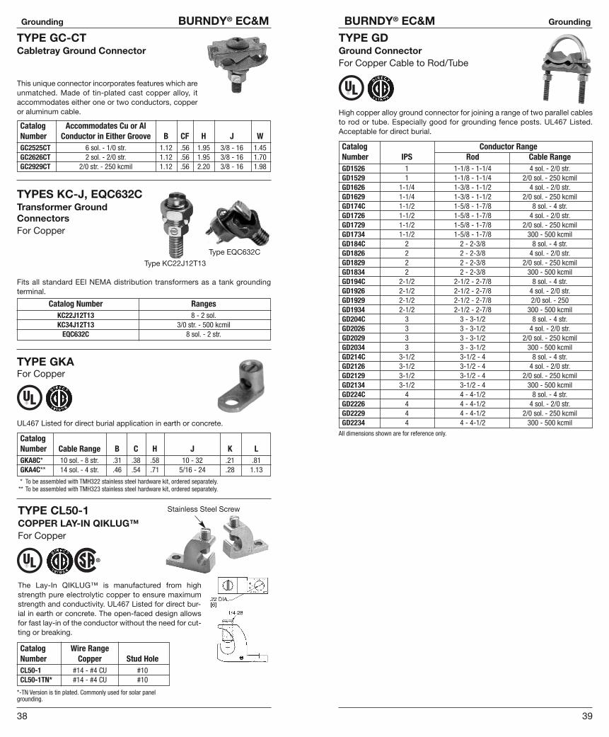
TYPE GC-CTCabletray Ground Connector
This unique connector incorporates features which areunmatched. Made of tin-plated cast copper alloy, it accommodates either one or two conductors, copperor aluminum cable.
Catalog Accommodates Cu or AlNumber Conductor in Either Groove B CF H J WGC2525CT 6 sol. - 1/0 str. 1.12 .56 1.95 3/8 - 16 1.45GC2626CT 2 sol. - 2/0 str. 1.12 .56 1.95 3/8 - 16 1.70GC2929CT 2/0 str. - 250 kcmil 1.12 .56 2.20 3/8 - 16 1.98
TYPES KC-J, EQC632CTransformer Ground ConnectorsFor Copper
Fits all standard EEI NEMA distribution transformers as a tank grounding terminal.
Catalog Number RangesKC22J12T13 8 - 2 sol.KC34J12T13 3/0 str. - 500 kcmil
EQC632C 8 sol. - 2 str.
Type KC22J12T13
Type EQC632C
TYPE GKAFor Copper
UL467 Listed for direct burial application in earth or concrete.
CatalogNumber Cable Range B C H J K LGKA8C* 10 sol. - 8 str. .31 .38 .58 10 - 32 .21 .81GKA4C** 14 sol. - 4 str. .46 .54 .71 5/16 - 24 .28 1.13
* To be assembled with TMH322 stainless steel hardware kit, ordered separately.** To be assembled with TMH323 stainless steel hardware kit, ordered separately.
TYPE CL50-1COPPER LAY-IN QIKLUG™For Copper
The Lay-In QIKLUG™ is manufactured from highstrength pure electrolytic copper to ensure maximumstrength and conductivity. UL467 Listed for direct bur-ial in earth or concrete. The open-faced design allowsfor fast lay-in of the conductor without the need for cut-ting or breaking.
Stainless Steel Screw
Catalog Wire RangeNumber Copper Stud HoleCL50-1 #14 - #4 CU #10CL50-1TN* #14 - #4 CU #10
*-TN Version is tin plated. Commonly used for solar panelgrounding.
TYPE GDGround ConnectorFor Copper Cable to Rod/Tube
High copper alloy ground connector for joining a range of two parallel cablesto rod or tube. Especially good for grounding fence posts. UL467 Listed. Acceptable for direct burial.
Catalog Conductor RangeNumber IPS Rod Cable RangeGD1526 1 1-1/8 - 1-1/4 4 sol. - 2/0 str.GD1529 1 1-1/8 - 1-1/4 2/0 sol. - 250 kcmilGD1626 1-1/4 1-3/8 - 1-1/2 4 sol. - 2/0 str.GD1629 1-1/4 1-3/8 - 1-1/2 2/0 sol. - 250 kcmilGD174C 1-1/2 1-5/8 - 1-7/8 8 sol. - 4 str.GD1726 1-1/2 1-5/8 - 1-7/8 4 sol. - 2/0 str.GD1729 1-1/2 1-5/8 - 1-7/8 2/0 sol. - 250 kcmilGD1734 1-1/2 1-5/8 - 1-7/8 300 - 500 kcmilGD184C 2 2 - 2-3/8 8 sol. - 4 str.GD1826 2 2 - 2-3/8 4 sol. - 2/0 str.GD1829 2 2 - 2-3/8 2/0 sol. - 250 kcmilGD1834 2 2 - 2-3/8 300 - 500 kcmilGD194C 2-1/2 2-1/2 - 2-7/8 8 sol. - 4 str.GD1926 2-1/2 2-1/2 - 2-7/8 4 sol. - 2/0 str.GD1929 2-1/2 2-1/2 - 2-7/8 2/0 sol. - 250GD1934 2-1/2 2-1/2 - 2-7/8 300 - 500 kcmilGD204C 3 3 - 3-1/2 8 sol. - 4 str.GD2026 3 3 - 3-1/2 4 sol. - 2/0 str.GD2029 3 3 - 3-1/2 2/0 sol. - 250 kcmilGD2034 3 3 - 3-1/2 300 - 500 kcmilGD214C 3-1/2 3-1/2 - 4 8 sol. - 4 str.GD2126 3-1/2 3-1/2 - 4 4 sol. - 2/0 str.GD2129 3-1/2 3-1/2 - 4 2/0 sol. - 250 kcmilGD2134 3-1/2 3-1/2 - 4 300 - 500 kcmilGD224C 4 4 - 4-1/2 8 sol. - 4 str.GD2226 4 4 - 4-1/2 4 sol. - 2/0 str.GD2229 4 4 - 4-1/2 2/0 sol. - 250 kcmilGD2234 4 4 - 4-1/2 300 - 500 kcmil
All dimensions shown are for reference only.
41
BURNDY® EC&M Grounding
40
Grounding BURNDY® EC&M
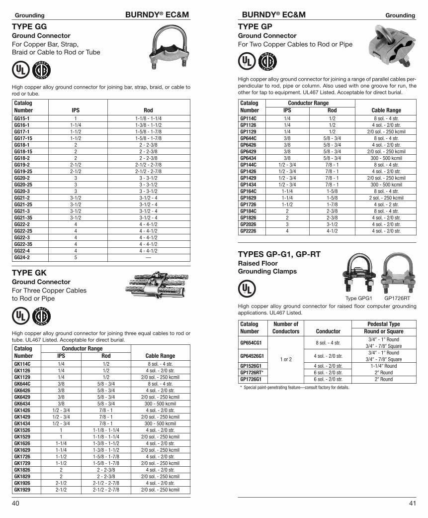
TYPE GGGround ConnectorFor Copper Bar, Strap, Braid or Cable to Rod or Tube
High copper alloy ground connector for joining bar, strap, braid, or cable torod or tube.
CatalogNumber IPS RodGG15-1 1 1-1/8 - 1-1/4GG16-1 1-1/4 1-3/8 - 1-1/2GG17-1 1-1/2 1-5/8 - 1-7/8GG17-15 1-1/2 1-5/8 - 1-7/8GG18-1 2 2 - 2-3/8GG18-15 2 2 - 2-3/8GG18-2 2 2 - 2-3/8GG19-2 2-1/2 2-1/2 - 2-7/8GG19-25 2-1/2 2-1/2 - 2-7/8GG20-2 3 3 - 3-1/2GG20-25 3 3 - 3-1/2GG20-3 3 3 - 3-1/2GG21-2 3-1/2 3-1/2 - 4GG21-25 3-1/2 3-1/2 - 4GG21-3 3-1/2 3-1/2 - 4GG21-35 3-1/2 3-1/2 - 4GG22-2 4 4 - 4-1/2GG22-25 4 4 - 4-1/2GG22-3 4 4 - 4-1/2GG22-35 4 4 - 4-1/2GG22-4 4 4 - 4-1/2GG24-2 5 —
TYPE GKGround ConnectorFor Three Copper Cables to Rod or Pipe
High copper alloy ground connector for joining three equal cables to rod ortube. UL467 Listed. Acceptable for direct burial.
Catalog Conductor RangeNumber IPS Rod Cable RangeGK114C 1/4 1/2 8 sol. - 4 str.GK1126 1/4 1/2 4 sol. - 2/0 str.GK1129 1/4 1/2 2/0 sol. - 250 kcmilGK644C 3/8 5/8 - 3/4 8 sol. - 4 str.GK6426 3/8 5/8 - 3/4 4 sol. - 2/0 str.GK6429 3/8 5/8 - 3/4 2/0 sol. - 250 kcmilGK6434 3/8 5/8 - 3/4 300 - 500 kcmilGK1426 1/2 - 3/4 7/8 - 1 4 sol. - 2/0 str.GK1429 1/2 - 3/4 7/8 - 1 2/0 sol. - 250 kcmilGK1434 1/2 - 3/4 7/8 - 1 300 - 500 kcmilGK1526 1 1-1/8 - 1-1/4 4 sol. - 2/0 str.GK1529 1 1-1/8 - 1-1/4 2/0 sol. - 250 kcmilGK1626 1-1/4 1-3/8 - 1-1/2 4 sol. - 2/0 str.GK1629 1-1/4 1-3/8 - 1-1/2 2/0 sol. - 250 kcmilGK1726 1-1/2 1-5/8 - 1-7/8 4 sol. - 2/0 str.GK1729 1-1/2 1-5/8 - 1-7/8 2/0 sol. - 250 kcmilGK1826 2 2 - 2-3/8 4 sol. - 2/0 str.GK1829 2 2 - 2-3/8 2/0 sol. - 250 kcmilGK1926 2-1/2 2-1/2 - 2-7/8 4 sol. - 2/0 str.GK1929 2-1/2 2-1/2 - 2-7/8 2/0 sol. - 250 kcmil
TYPE GPGround ConnectorFor Two Copper Cables to Rod or Pipe
High copper alloy ground connector for joining a range of parallel cables per-pendicular to rod, pipe or column. Also used with one groove for run, theother for tap to equipment. UL467 Listed. Acceptable for direct burial.
Catalog Conductor RangeNumber IPS Rod Cable RangeGP114C 1/4 1/2 8 sol. - 4 str.GP1126 1/4 1/2 4 sol. - 2/0 str.GP1129 1/4 1/2 2/0 sol. - 250 kcmilGP644C 3/8 5/8 - 3/4 8 sol. - 4 str.GP6426 3/8 5/8 - 3/4 4 sol. - 2/0 str.GP6429 3/8 5/8 - 3/4 2/0 sol. - 250 kcmilGP6434 3/8 5/8 - 3/4 300 - 500 kcmilGP144C 1/2 - 3/4 7/8 - 1 8 sol. - 4 str.GP1426 1/2 - 3/4 7/8 - 1 4 sol. - 2/0 str.GP1429 1/2 - 3/4 7/8 - 1 2/0 sol. - 250 kcmilGP1434 1/2 - 3/4 7/8 - 1 300 - 500 kcmilGP164C 1-1/4 1-5/8 8 sol. - 4 str.GP1629 1-1/4 1-5/8 2 sol. - 250 kcmilGP1726 1-1/2 1-7/8 4 sol. - 2 str.GP184C 2 2-3/8 8 sol. - 4 str.GP1826 2 2-3/8 4 sol. - 2/0 str.GP2026 3 3-1/2 4 sol. - 2/0 str.GP2226 4 4-1/2 4 sol. - 2/0 str.
TYPES GP-G1, GP-RTRaised Floor Grounding Clamps
High copper alloy ground connector for raised floor computer grounding applications. UL467 Listed.
Type GPG1 GP1726RT
Catalog Number of Pedestal TypeNumber Conductors Conductor Round or Square
3/4� - 1� RoundGP654CG1 8 sol. - 4 str.
3/4� - 7/8� Square3/4� - 1� Round
GP64526G11 or 2
4 sol. - 2/0 str.3/4� - 7/8� Square
GP1526G1 4 sol. - 2/0 str. 1-1/4� RoundGP1726RT* 6 sol. - 2/0 str. 2� RoundGP1726G1 6 sol. - 2/0 str. 2� Round
* Special paint-penetrating feature—consult factory for details.

43
BURNDY® EC&M Grounding
42
Grounding BURNDY® EC&M
TYPE GRFUNIGROUND™ Raised Floor Grounding Connector
The BURNDY® UNIGROUND™ is a universal grounding clamp, specificallydesigned for all raised flooring systems. It can be installed on round or squarepedestals and can accommodate one or two grounding wires to make an ef-ficient grid. The underfloor signal reference grid provides the low impedanceground path that attenuates high frequency static and 60 Hz transient noisefor cleaner data output. UL467 Listed.
Catalog Number of Pedestal TypeNumber Conductors Conductor Round or SquareGRF4C-3 Up to 1� Up to 7/8�
GRF4C-41 or 2 8 - 2 AWG
Up to 3/4� Up to 5/8�
TYPE GXGround Connector for Copper Cables
High copper alloy ground connector for cross connecting a wide range ofcable. UL467 Listed. Acceptable for direct burial.
ConductorCatalog Number Groove A Groove BGX4C4C 8 sol. - 4 str. 8 sol. - 4 str.GX264C 8 sol. - 4str.GX2626
4 sol. - 2/0 str.4 sol. - 2/0 str.
GX294C 8 sol. - 4 str.GX2926 2/0 sol. - 250 kcmil 4 sol. - 2/0 str.GX2929 2/0 sol. - 250GX344C 8 sol. - 4 str.GX3426 4 sol. - 2/0 str.GX3429
300 - 500 kcmil2/0 sol. - 250
GX3434 300-500 kcmil
* Not UL Listed.
“W”2.00[51]
Ø.44[11]
“E1”.63[16]
4.00[102]
“F”1.00[25]
(7 Plcs)
“K”Ø.28[7]
(16 Plcs)
8.50[216]
“L”10.00[254]
“W”2.00[51]
“E2”.75[19]
“K”Ø.28[7]
(36 Plcs)
“E1”.625[15.9]
Ø.44[11]
4.00[102]
“L”24.00[610]
22.00[559]
“F1”1.00[25]
(8 Plcs)
“F2”1.00[25]
(8 Plcs)
Figure 1
Figure 2
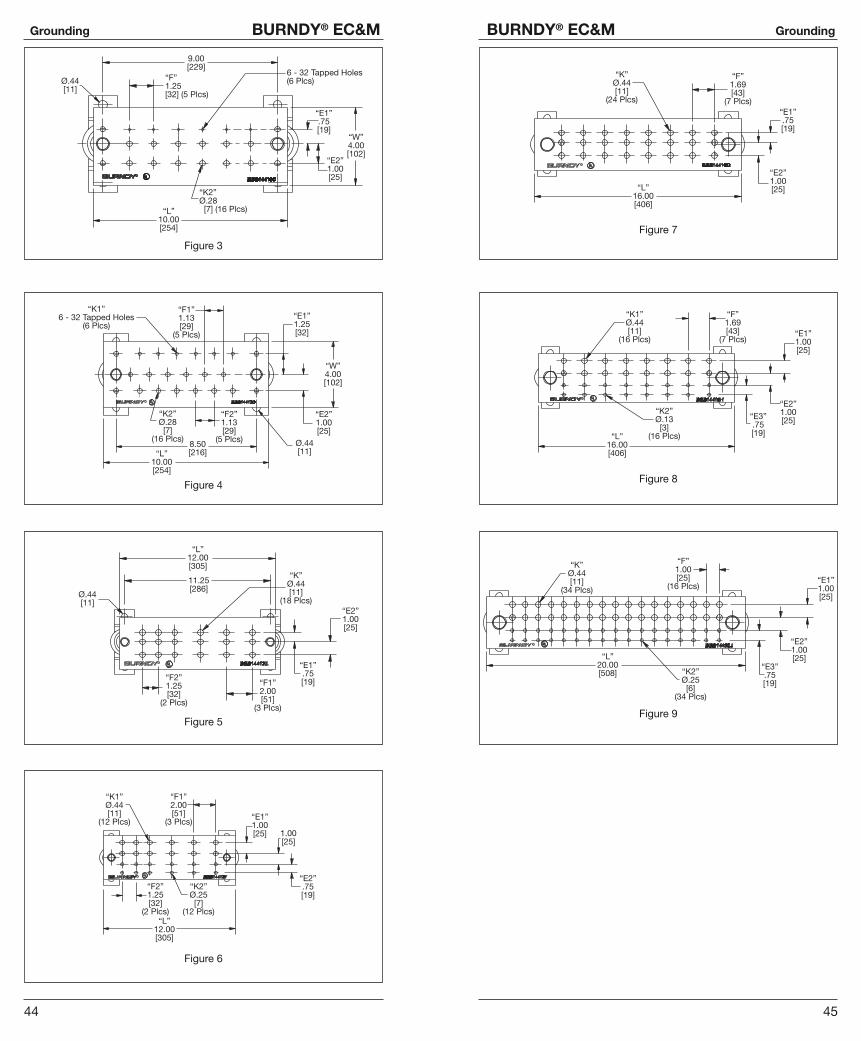
TYPE BBBBURNDY® BusBarCopper BusBar
Bare copper BusBar, UL Listed forgrounding. Available in many sizes andhole patterns. Brackets and insulators in-cluded with most styles. Also available inundrilled, horizontal and vertical versions.
BusBar is used in a variety of applica-tions. Can be used as a common groundpoint and “power” applications as well.
Catalog Fig. Insulator T - Bar W - Bar L - Bar No. ofNumber No. & Bracket Thickness Width Length E1 E2 E3 F1 F2 Holes KBBB14210A 1 A 1/4� 2� 10� .63 — — 1.00 — 16 .28BBB14224B 2 A 1/4� 2� 24� .625 .75 — 1.00 1.00 36 .28
6 6-32BBB14410C 3 A 1/4� 4� 10� .75 1.00 — 1.25 —
16 .286 6-32
BBB14410D 4 A 1/4� 4� 10� 1.25 1.00 — 1.13 1.1316 .28
BBB14412E 5 A 1/4� 4� 12� .75 — — 2.00 1.25 18 .4412 .44
BBB14412F 6 A 1/4� 4� 12� 1.00 .75 — 2.00 1.2512 .28
BBB14416G 7 B 1/4� 4� 16� .75 1.00 — 1.69 — 24 .4416 .44
BBB14416H 8 B 1/4� 4� 16� 1.00 1.00 .75 1.69 —16 .2534 .44
BBB14420J 9 B 1/4� 4� 20� 1.00 1.00 .75 1.00 —34 .25
BBB412UD N/A A 1/4� 4� 12� N/A N/A N/A N/A N/A N/A N/ABBB424UD N/A B 1/4� 4� 24� N/A N/A N/A N/A N/A N/A N/ABBBHR19* N/A N/A 3/16� 3/4� 19� .38BBBVR36* N/A N/A 1/4� 5/8� 36� .32
Contact Factory for Dimensions
3.75[95]
“T”.25[6]
“T”.25[6]
3.75[95]
Bracket/Insulator A
Bracket/Insulator B
(Figures continued on next 2 pages)
45
BURNDY® EC&M Grounding
44
Grounding BURNDY® EC&M
Ø.44[11]
9.00[229]
6 - 32 Tapped Holes(6 Plcs)“F”
1.25[32] (5 Plcs)
“L”10.00[254]
“K2”Ø.28 [7] (16 Plcs)
“W”4.00[102]
“E2”1.00[25]
“E1”.75[19]
Figure 3
“K1”6 - 32 Tapped Holes
(6 Plcs)
“F1”1.13[29]
(5 Plcs)
“E1”1.25[32]
“W”4.00[102]
“E2”1.00[25]
Ø.44[11]“L”
10.00[254]
“F2”1.13[29]
(5 Plcs)
“K2”Ø.28[7]
(16 Plcs)8.50[216]
Figure 4
“L”12.00[305]
11.25[286]
Ø.44[11]
“K”Ø.44[11]
(18 Plcs)
“F2”1.25[32]
(2 Plcs)
“F1”2.00[51]
(3 Plcs)
“E1”.75[19]
“E2”1.00[25]
Figure 5
“K1”Ø.44[11]
(12 Plcs)
“F1”2.00[51]
(3 Plcs)“E1”1.00[25] 1.00
[25]
“E2”.75[19]
“L”12.00[305]
“F2”1.25[32]
(2 Plcs)
“K2”Ø.25[7]
(12 Plcs)
Figure 6
“K”Ø.44[11]
(24 Plcs)
“L”16.00[406]
“F”1.69[43]
(7 Plcs)
“E2”1.00[25]
“E1”.75[19]
Figure 7
“L”16.00[406]
“K2”Ø.13[3]
(16 Plcs)
“K1”Ø.44[11]
(16 Plcs)
“F”1.69[43]
(7 Plcs)“E1”1.00[25]
“E2”1.00[25]“E3”
.75[19]
Figure 8
“L”20.00[508]
“K”Ø.44[11]
(34 Plcs)
“K2”Ø.25[6]
(34 Plcs)
“E3”.75[19]
“E2”1.00[25]
“E1”1.00[25]
“F”1.00[25]
(16 Plcs)
Figure 9

47
BURNDY® EC&M Grounding
46
Grounding BURNDY® EC&M
TYPE BFlexible Copper Braid
Extra-flexible tinned copper braid used on disconnects and switch handlegrounds. Also used to ground fence posts and gates.
Catalog No. of Braids in Ampere RatingNumber Ferrule Indoors
BD12* 1 190BD12N* 1 190BD18* 1 190
BD18N* 1 190BD24* 1 190
BD24N* 1 190B2D12* 2 380
B2D12N* 2 380B3D12* 3 470
B3D12N* 3 470B4D12 4 600
B4D12N 4 600BE12* 1 340
BE12N* 1 340BE18* 1 340
BE18N* 1 340BE24* 1 340
BE24N* 1 340B2E12 2 530
B2E12N 2 530B3E12 3 700
B3E12N 3 700B4E12 4 850
B4E12N 4 850BF12* 1 360
BF12N* 1 360B2F12 2 600BF24* 1 360
BF24N* 1 360B2F12 2 600
B2F12N 2 600B3F12 3 820
B3F12N 3 820B4F12 4 1000
B4F12N 4 1000BG12 1 415
BG12N 1 415BG18 1 415
BG18N 1 415BG24 1 415
BG24N 1 415B2G12 2 700
B2G12N 2 700B3G12 3 960
B3G12N 3 960B4G12 4 1200
B4G12N 4 1200
NOTE: All sizes are listed to UL467 and specific sizes ( * ) are certified to CSA C22.2, No. 41 Groundingand Bonding Equipment Standards. Equivalent sizes may be designated by suffix letters representingvariations in length, mounting configurations, pad size and finish. Contact factory for details.
“N” indicates 2-hole NEMA standard.
THE HYGROUND® IRREVERSIBLECOMPRESSION SYSTEM
BURNDY® has developed an Irreversible Compression Ground System whichmeets the most stringent safety and performance requirements, includingthose of OSHA and nuclear power plant design. Performance excellence andlong life expectancy are the system’s basic design guidelines. It is a com-plete system which consists of connectors for grid cross connections, taps,splices, cable to ground rod, ground plates and terminations.
Our Irreversible Compression Ground Connectors employ well-proven de-sign principles and technology that have been in existence for over 40 years.Connectors are just one component of our Irreversible Compression GroundSystem. Installation tooling is also an integral part of this system. BURNDY®
pioneered the compression connector principle and continues today to bethe leader in compression technology. Our tooling package is the most extensive in the industry and affords the user many options.
49
BURNDY® EC&M Grounding
48
Grounding BURNDY® EC&M
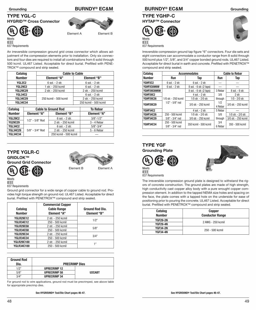
TYPE YGL-CHYGRID™ Cross Connector
An irreversible compression ground grid cross connector which allows ad-justment of the compression elements prior to installation. Only six connec-tors and four dies are required to install all combinations from 6 solid through500 kcmil. UL467 Listed. Acceptable for direct burial. Prefilled with PENE -TROX™ compound and strip sealed.
MeetsIEEE837 Requirements
Catalog Cable to CableNumber Element “A” Element “B”YGL2C2 6 sol. - 2 str. 6 sol. - 2 str.YGL29C2 1 str. - 250 kcmil 6 sol. - 2 str.YGL29C29 2 str. - 250 kcmil 2 str. - 250 kcmilYGL34C2 6 sol. - 2 str.YGL34C29 250 kcmil - 500 kcmil 2 str. - 250 kcmilYGL34C34 250 kcmil - 500 kcmil
Catalog Cable to Ground Rod To RebarNumber Element “A” Element “B” Element “A”YGL29C2 6 sol. - 2 str. 3/8�-1/2�
YG29C291/2� - 5/8� Rod
2 str. - 250 kcmil 3 - 4 RebarYGL34C2 6 sol. - 2 str. 5/8�-3/4�
YGL34C29 5/8� - 3/4� Rod 2 str. - 250 kcmil 5 - 6 RebarYGL34C34 250 kcmil - 500 kcmil —
TYPE YGLR-CGRIDLOK™ Ground Grid Connector
Ground grid connector for a wide range of copper cable to ground rod. Pro-vides high torque strength on ground rod. UL467 Listed. Acceptable for directburial. Prefilled with PENETROX™ compound and strip sealed.
MeetsIEEE837 Requirements
Commercial CopperCatalog Cable Range Ground Rod Dia.Number Element “A” Element “B”
YGLR29C12 2 str. - 250 kcmilYGLR34C12 250 - 500 kcmil
1/2�
YGLR29C58 2 str. - 250 kcmilYGLR34C58 250 - 500 kcmil
5/8�
YGLR29C34 2 str. - 250 kcmilYGLR34C34 250 - 500 kcmil
3/4�
YGLR29C100 2 str. - 250 kcmilYGLR34C100 250 - 500 kcmil
1�
Element A Element B
Element AElement B
See HYGROUND® Tool/Die Chart pages 46-47.
Ground RodDia. PRECRIMP Dies1/2� UPRECRIMP 125/8� UPRECRIMP 58 U2CABT3/4� UPRECRIMP 34
For ground rod to wire applications, ground rod must be precrimped, see above tablefor appropriate precrimp dies.
See HYGROUND® Tool/Die Chart pages 46-47.
TYPE YGHP-CHYTAP™ Connector
Irreversible compression ground tap figure “6” connectors. Four die sets andeight connectors can accommodate a conductor range from 8 solid through500 kcmil plus 1/2�, 5/8�, and 3/4� copper bonded ground rods. UL467 Listed.Acceptable for direct burial in earth and concrete. Prefilled with PENETROX™compound and strip sealed.
MeetsIEEE837 Requirements
Catalog Accommodates Cable to RebarNumber Run Tap Run TapYGHP2C2 6 sol. - 2 str. 6 sol. - 2 str. — —YGHP2C6W6W 6 sol. - 2 str. 8 sol. - 6 str. (2 taps) — —YGHP29C6W6W 8 sol. - 6 str. (2 taps) 3 Rebar 8 sol. - 6 str.YGHP29C2 4 sol. - 2 str. 3/8 2 str.YGHP29C26 1/0 str. - 250 kcmil 1/0 str. - 2/0 str. through 1/0 - 2/0 str.
1/2� - 5/8� rod 1/2YGHP29C29 3/0 str. - 250 kcmil
4 Rebar3/0 str. - 250 kcmil
YGHP34C2 4 sol. - 2 str. 5 Rebar —YGHP34C26 250 - 500 kcmil 1/0 str. - 2/0 str. 5/8 1/0 str. - 2/0 str.YGHP34C29 5/8� - 3/4� rod 3/0 str. - 250 kcmil through 3/0 str. - 250 kcmil
250 - 500 kcmil 3/4YGHP34C34
5/8� - 3/4� rod350 kcmil - 500 kcmil
6 Rebar350 - 500 kcmil
TYPE YGFGrounding Plate
The irreversible compression ground plate is designed to withstand the rig-ors of concrete construction. The ground plates are made of high strength,high conductivity cast copper alloy body with a pure wrought copper com-pression element. In addition to the tapped NEMA size holes and spacing onthe face, the plate comes with a tapped hole on the underside for ease ofpositioning prior to pouring the concrete. UL467 Listed. Acceptable for directburial. Prefilled with PENETROX™ compound and strip sealed.
MeetsIEEE837 Requirements
Catalog CopperNumber Conductor RangeYGF29-2NYGF29-4N
2 AWG - 250 kcmil
YGF34-2NYGF34-4N
250 - 500 kcmil

51
BURNDY® EC&M Grounding
50
Grounding BURNDY® EC&M
TYPE YGHR-CHYTAIL™ Ground Rod Connectors
TYPE YGHC-CHYTAP™ Connector
Irreversible compression ground tap figure “C” connectors. Accommodatesall cable combinations from 6 solid through 500 kcmil. “C” - shaped openingpermits placing two continuous parallel cables into conductor groove. UL467Listed. Acceptable for direct burial. Prefilled with PENETROX™ compoundand strip sealed.
See HYGROUND® Tool/Die Chart pages 46-47.
MeetsIEEE837 Requirements
MeetsIEEE837 Requirements
Catalog Commercial Copper Cable RangeNumber Run Tap
6 sol. 6 sol.YGHC2C2
2 str. 2 str.1 str. 6 sol.
YGHC26C22/0 str. 2 str.1 str. 1 str.
YGHC26C262/0 str. 2/0 str.3/0 str. 6 sol.
YGHC29C26250 kcmil 2/0 str.
3/0 str. 3/0 str.YGHC29C29
250 kcmil 250 kcmil300 kcmil 6 sol.
YGHC34C26500 kcmil 2/0 str.300 kcmil 3/0 str.
YGHC34C29500 kcmil 250 kcmil300 kcmil 300 kcmil
YGHC34C34500 kcmil 500 kcmil
New!
Ground Rod to W
ire
UL467 Listed and
CSA Certified
for Dire
ct Buria
l
Catalog Commercial Copper Nominal GroundNumber Cable Range Rod Dia.
YGHR26C12 1/2�
YGHR26C58 5/8�
YGHR26C342 - 2/0 str.
3/4�
YGHR26C100 1�
YGHR29C12 1/2�
YGHR29C58 5/8�
YGHR29C344/0 str. - 250 kcmil
3/4�
YGHR29C100 1�
YGHR34C58 5/8�
YGHR34C34 300 - 500 kcmil 3/4�
YGHR34C100 1�
See HYGROUND® Tool/Die Chart pages 46-47.
TYPE YGHR-CHYTAIL™ Connectors
High strength copper irreversible compression ground rod tap connector.
Catalog Ground RodNumber Diameter Tap ConductorYGHR58C2W-3 5/8� 2 sol. Copper 1, 2, or 3 may be connected.
TYPE YSHGHigh Strength Copper Irreversible Compression Double H-Tap Connector
Type YSHG Double H-Tap grounding series is comprised of five connectorsdesigned to accommodate wire range sizes 14 AWG through 500 kcmil, including ground rod sizes: 3/4�, 1� and Rebar sizes: 6, 8 and 9. Prefilled withPENETROX™ E2 and strip sealed.
*Note: Not for use on 1� steel ground rod.
Catalog Conductor SizesNumber Main Tap 1 Tap 2 Tap 3
9 & 8 Rebar, 2 AWG - 250YSHG4429
1� (25) Ground Rod kcmil— —
1� (25) Cu Clad Ground Rod 350 - 500YSHG3939*
500 kcmil Copper kcmil— —
6 Rebar, 1� (25) Cu CladYSHG3931* Ground Rod, 3/4� Ground Rod 1/0 - 4/0 AWG 6 - 1 AWG
14 - 2
350 - 500 kcmil CopperAWG
6 Rebar, 3/4� (19) Ground Rod 4/0 AWG -YSHG3434
250 - 400 kcmil Copper 400 kcmil6 Rebar, 3/4� (19) Ground Rod 4/0 AWG - 14 - 8
YSHG34294/0 - 400 kcmil Copper
1/0 - 3/0 AWG400 kcmil AWG
TYPE YGHP-CHYTAP™ Connector
Type YGHP-C irreversible compression ground tap figure 6 can be used as aground rod tap connector for both continuous run and tapping applications.An open groove allows ground rod to be connected to a continuous run ortap. The second groove is for a tap only. Prefilled with PENETROX™ E andstrip sealed. UL467 Listed for direct burial.
Catalog Ground RodNumber Diameter Tap Conductor
2 sol. CopperYGHP58C2W-2 1/2� - 5/8� (1) Continuous run and (1) Tap or
up to (2) taps may be connected.

53
BURNDY® EC&M Grounding
52
Grounding BURNDY® EC&M
See HYGROUND® Tool/Die Chart pages 46-47.
TYPE YGHAHYLUG™ Terminals
Heavy duty HYLUG™ irreversible compression terminals designed not onlyto carry short circuit load but to also withstand high mechanical stress. Eachconductor element has an inspection probe hole to ensure proper cable insertion. UL467 Listed. Acceptable for direct burial. UL486A Listed. Prefilledwith PENETROX™ compound and strip sealed.
MeetsIEEE837 Requirements
Catalog Number Copper Conductor SizeYGHA2C-2N 2 str.YGHA25-2N 1/0 str.YGHA26-2N 2/0 str.YGHA28-2N 4/0 str.YGHA29-2N 250 kcmilYGHA34-2N 500 kcmil
TYPE YGHSHYLINK™ Ground Splice
Heavy duty HYLINK™ ground splice designed not only to carry short circuitload but to also withstand high mechanical stress. Each conductor elementhas an inspection probe hole and a center stop to ensure proper cable insertion. UL467 Listed. Acceptable for direct burial in earth or concrete.UL486A Listed. Prefilled with PENETROX™ compound and strip sealed.
MeetsIEEE837 Requirements
Catalog Number Copper Conductor SizeYGHS2C 2 str.YGHS25 1/0 str.YGHS26 2/0 str.YGHS28 4/0 str.YGHS29 250 kcmil
TYPE YGSHYLINK™ Ground Splices
Irreversible compression HYLINK™ ground splices are specifically designedfor ground applications. Each conductor element has an inspection probehole and a center stop to ensure proper cable insertion. UL467 Listed. Acceptable for direct burial. UL486A Listed. Prefilled with PENETROX™ com-pound and strip sealed.
Catalog Number Copper Conductor SizeYGS2C 2 str.YGS25 1/0 str.YGS26 2/0 str.YGS28 4/0 str.YGS29 250 kcmilYGS34 500 kcmil
TYPE YGAHYLUG™ Terminals
Irreversible compression HYLUG™ ground terminal specifically designed forground applications. Each connector has an inspection probe hole to ensureproper cable insertion. UL467 Listed. Acceptable for direct burial. UL486AListed. Prefilled with PENETROX™ compound and strip sealed.
Catalog Number Copper Conductor SizeYGA2C-2N 2 str.YGA25-2N 1/0 str.YGA26-2N 2/0 str.YGA28-2N 4/0 str.YGA29-2N 250 kcmilYGA34-2N 500 kcmil
TYPE YGIBGROUNDLINK™ Connector
An irreversible compression ground connection which allows attachment toground structural steel (standard [angled] or wide flange parallel) accom-plished with a required 5-piece die set, Catalog PIBEAMKIT or UIBEAMKIT.Made of high conductivity wrought copper and comes prefilled with PENE -TROX™ compound and strip sealed. Order terminal mounting hardware separately.
MeetsIEEE837 Requirements
Copper BeamConductor Flange
Catalog Number Range Length ThicknessYGIBS28-338-2N 3.00YGIBW28-338-2N 2 - 4/0 AWG 3.00YGIBS34-338-2N 250 - 500 kcmil 6.00
250� - .338�
YGIBW34-338-2N 6.00YGIBS28-400-2N 3.00YGIBW28-400-2N 2 - 4/0 AWG 3.00YGIBS34-400-2N 250 - 500 kcmil 6.00
.338� - .400�
YGIBW34-400-2N 6.00YGIBS28-462-2N 3.00YGIBW28-462-2 2 - 4/0 AWG 3.00YGIBS34-462-2N 250 - 500 kcmil 6.00
.400� - .462�
YGIBW34-462-2N 6.00YGIBS28-550-2N 3.00YGIBW28-502N 2 - 4/0 AWG 3.00YGIBS34-550-2N 250 - 500 kcmil 6.00
.462� - .550�
YGIBW34-550-2N 6.00YGIBS28-613-2N 3.00YGIBW28-613-2N 2 - 4/0 AWG 3.00YGIBS34-613-2N 250 - 500 kcmil 6.00
.550� - .613�
YGIBW34-613-2N 6.00YGIBS28-675-2N 3.00YGIBW28-675-2N 2 - 4/0 AWG 3.00YGIBS34-675-2N 250 - 500 kcmil 6.00
.613� - .695�
YGIBW34-675-2N 6.00
See HYGROUND® Tool/Die Chart pages 46-47.
Standard Beams(Flange Angled)
Wide Flange Beams(Flange Parallel)
2 Hole NEMASpacing

55
BURNDY® EC&M Grounding
54
Grounding BURNDY® EC&M
TYPE GSTUD-HYVERSITAIL™
MeetsIEEE837 Requirements
Nom. Use with Compression GSTUD-HY/YGHPCatalog Rod Connector Catalog No. Assembly ConductorNumber Size (Order Separately) Range
YGHP2C2 6 sol. - 2 str.GSTUD14HY 1/4� YGHP29C2 1/0 str. - 250 kcmil
YGHP34C2 250 - 500 kcmilYGHP29C26 1/0 str. - 250 kcmil
GSTUD38HY 3/8�YGHP34C26 250 - 500 kcmilYGHP29C29 3/0 str. - 250 kcmil
GSTUD916HY 5/8�YGHP34C29 250 - 500 kcmil
GSTUD34HY 3/4� YGHP34C34 250 - 500 kcmil
HYGROUND® Tool/Die ChartCatalog Die No. ofNumber Index Y750/39/35 PAT750 Y46** CrimpsYGA25-2N 12 U25RT U25RT U25RT 2YGA26-2N 13 U26RT U26RT U26RT 2YGA28-2N 15 U28RT U28RT U28RT 2YGA29-2N 16 U29RT U29RT U29RT 2YGA2C-2N 10 U2CRT U2CRT U2CRT 2YGA34-2N 20 U34RT U34RT U34RT 4YGHA25-2N 14 U27RT U27RT U27RT 1YGHA26-2N 15 U28RT U28RT U28RT 1YGHA28-2N 17 U30RT U30RT U30RT 2YGHA29-2N 18 U31RT U31RT U31RT 2YGHA2C-2N 11 U1CRT-1 U1CRT-1 U1CRT-1 1YGHA34-2N 22 U36RT U36RT U36RT 3YGHC26C2 O U-O UOP U-O 1YGHC26C26 O U-O UOP U-O 1YGHC29C26 997 U997 U997P U997 1YGHC29C29 997 U997 U997P U997 1YGHC2C2 C U-C U-C U-C 1YGHC34C26 1011 U1011* U1011* P1011 2YGHC34C29 1011 U1011* U1011* P1011 2YGHC34C34 1011 U1011* U1011* P1011 3YGHP29C2 997 U997 U997P U997 1YGHP29C26 997 U997 U997P U997 1YGHP29C29 997 U997 U997P U997 1YGHP29C6W6W 997 U997 U997P U997 1YGHP2C2 O UO UOP UO 1YGHP2C6W6W O UO UOP UO 1YGHP34C2 998 U998* U998P PU998 1YGHP34C26 998 U998* U998P PU998 1YGHP34C29 998 U998* U998P PU998 1YGHP34C34 1011 U1011* U1011* P1011 3YGHP58C2W2 997 U997 U997P U997 1YGHR26C100 1011 U1011* U1011* P1011 2YGHR26C12 998 PU998 PU998P P1011 2YGHR26C34 998 PU998 PU998P P1011 2YGHR26C58 998 PU998 PU998P P1011 2YGHR29C100 1011 U1011* U1101* P1011 2YGHR29C12 998 PU998 PU998P P1011 2YGHR29C34 998 PU998 PU998P P1011 2YGHR29C58 998 PU998 PU998P P1011 2
(HYGROUND® Tool/Die Chart continued on next page)
* Indicates that connector can only be installed with Y750 or Y46. Cannot be installed with Y35 or Y39.** Where a U-die is recommended with the Y46, a PUADP-1 adaptor must be used.
Catalog Die No. ofNumber Index Y750/39/35 PAT750 Y46** CrimpsYGHR34C100 1011 U1011* U1011* P1011 2YGHR34C34 1011 U1011* U1011* P1011 2YGHR34C58 998 PU998 PU998P P1011 2YGHS25 14 U27RT U27RT U27RT 1YGHS26 15 U28RT U28RT U28RT 1YGHS28 17 U30RT U30RT U30RT 2YGHS29 18 U31RT U31RT U31RT 2YGHS2C 11 U1CRT-1 U1CRT-1 U1CRT-1 1YGHS34 22 U36RT U36RT U36RT 3YGIB (All) 1105 UIBEAMKIT UIBEAMKIT PIBEAMKIT variesYGL29C2 997/O U997/U-O U997P/UOP U997/U-O 1YGL29C29 997 U997 U997P U997 1YGL2C2 O U-O UOP U-O 1YGL34C2 998/O U998/U-O* U998P/UOP PU998/U-C 1YGL34C29 998/O U998/U-O* U998P/UOP PU998/U-C 1YGL34C34 1011 U1011* U1011* P1011 3YGLR29C100 997/1011 U997/U1011 U997P/U1011 U997/U1011 2YGLR29C12 997 U997 U997P U997 1YGLR29C34 997/1011 U997/U1011* U997P/U1011 PU998 1YGLR29C58 997/998 U997/U1011* U997P/U1011 PU998 1YGLR34C100 997/1011 U997/U1011 U997P/U1011 U997/U1011 2YGLR34C12 1011/998 U1011* U1011* PU998 1YGLR34C34 1011 U1011* U1011* U1011 2YGLR34C58 998/1011 U998/U1011* U998P/U1011 PU998 1YGS25 12 U25RT U25RT U25RT 2YGS26 13 U26RT U26RT U26RT 2YGS28 15 U28RT U28RT U28RT 2YGS29 16 U29RT U29RT U29RT 2YGS2C 10 U2CRT U2CRT U2CRT 2YGS34 20 U34RT U34RT U34RT 4
HYGROUND® Tool/Die Chart(Continued)
* Indicates that connector can only be installed with Y750 or Y46. Cannot be installed with Y35 or Y39.** Where a U-die is recommended with the Y46, a PUADP-1 adaptor must be used.

57
BURNDY® EC&M Grounding
56
Grounding BURNDY® EC&M
BURNDYWeld®
The BURNDYWeld® connection processis a simple, efficient method of weldingcopper to copper or copper to steel.One advantage is that NO outsidepower is required when using theBURNDYWeld® exothermic process.The BURNDYWeld® process uses hightemperature reaction of powdered cop-per oxide and aluminum. The reactiontakes place in a semi-permanentgraphite mold. These molds will last for fifty or more welds if proper care isgiven. The reaction takes place very rapidly, therefore the total amount of heatapplied to the conductors or surfaces is considerably less than that of braz-ing or soldering, it is important to remember this when welding to insulatedcable or thin wall pipe.
This system is very field friendly since it is light and portable and requires nooutside power source. It requires very little time or skill to obtain an efficient,maintenance free connection when using the BURNDYWeld® process.
For more information visit our website at: www.burndy.com.
WELD METAL
BURNDYWeld® Weld Metal is packed inmoisture-resistant plastic cartridges thathave tight fitting caps. These cartridges,along with the necessary steel discs, arethen packed in boxes that are hermeti-cally sealed. This ensures the powderarriving in good condition, always dryand ready for fast positive ignition.
BURNDYWeld® Weld Metal comes in several types; one for welding copperto copper, copper to steel, copper to rail, copper to cast iron and one forwelding copper to steel for cathodic protection. The size and weight (ingrams) of the cartridge are marked on each individual cartridge.
CathodicStandard Cast Iron Protection Rail Cartridges
Cartridge Size Cartridge Size Cartridge Size Cartridge Size Per Box15 15CI 15CP 15R 2025 25CI 25CP 25R 2032 32CI 32CP 32R 1045 45CI 45CP 45R 2065 65CI 65CP 65R 2090 90CI — 90R 10115 115CI — 115R 10150 — — 150R 10200 — — 200R 10250 — — 250R 10500 — — 500R 10
BURNDYWeld® Weld Metal is sold in box quantities only.
Catalog PackageNumber Weld Metal Size Quantity
B370320-01* 15 - 65 20B370320-02* 90 - 115 10B370320-03* 150 - 500 10
Steel Discs Sold Separately
*Steel Discs Only
BURNDYWeld® QIKLITE™Battery Ignition System
The self-contained unit offers a built-inbattery life indicator, 6� ignitor cord, andseparate buttons for power and ignition.Also, no starting powder is used with thissystem so emissions are greatly reduced.QIKLITE™ works with “off-the-shelf”molds and weld metal, so contractors andinstallers can continue to use the samequality BURNDYWeld® products.
Since the unit operates with standard weldmetal and molds, installers also have theoption of using a traditional flint ignitor orthe new QIKLITE™ system. Another fea-ture is the speed of ignition, with virtuallyno delay between depressing the “push tooperate” button and ignition of the weldmetal. This instant ignition feature offersquick reassurance to the installer, withoutthe delay.
Features and Benefits• The QIKLITE™ system allows installers to make exothermic connections
remotely• Uses standard exothermic molds and weld metal• Use the new BURNDYWeld® QIKLITE™ System or use a flint ignitor, this
versatility makes this system better than anything available in the industry• Installers have virtually 100% confidence that the connection can be
completed, and no wasted material or weld metal shots• No starting material required—which greatly reduces the amount of
emissions generated• Power is supplied by 4 standard “D” Size batteries• Built-in battery life indicator• There’s virtually no delay in ignition after depressing the “push to operate”
button• Separate ON/OFF and Operate buttons• Comes complete with durable 6� heat resistant cord• Durable, long-lasting design• QIKSTIK ignitor sticks are conveniently packaged and available
separately or available packaged complete with standard weld metal
Catalog Number DescriptionQIKLITE Battery Ignition System
QIKLITE™ Battery Ignition System and 20 QIKSTIK QIKLITEKIT
Ignitor Sticks
Catalog NumberStandard Cartridge Cartridges/IgnitorsSize with Ignitor Per Box
15Q 2025Q 2032Q 1045Q 2065Q 2090Q 10115Q 10150Q 10200Q 10250Q 10500Q 10
QIKSTIK* 10
*Ignitor stick only.
QIKLITE™ with mold.

59
BURNDY® EC&M Grounding
58
Grounding BURNDY® EC&M
TYPE BCC-1 MOLDSHorizontal End to End
Type BCC-1 Molds are used for horizontal end to end cable connections. Sizerange is 6 str. through 1000 kcmil solid or concentric stranded copper con-ductors. Contact BURNDY® for information on molds for conductors notlisted below.
For Sizes Not Listed, Contact Customer Service at 1-800-346-4175.
Cable Mold Price Key Weld Metal Handle Clamps8 str. Use Type BCC-146 str. Use Type BCC-144 str. B-5623 18†* 25 N/A3 str. B-5624 18†* 32 N/A2 str. B-5625 18†* 32 N/A1 str. B-5626 18†* 32 N/A
1/0 str. B-205 4 45 B-1062/0 str. B-206 4 65 B-1063/0 str. B-207 4 90 B-1064/0 str. B-208 4 90 B-106
250 kcmil B-209 4 115 B-106300 kcmil B-210 4 115 B-106350 kcmil B-211 4 150 B-106500 kcmil B-213 4 200 B-107750 kcmil B-214 5 2 - 150 B-1071000 kcmil B-215 5 2 - 200 B-107
• For sizes not listed, contact BURNDY®.• Molds listed are for concentric stranded cable. Add suffix “-S” to mold number for solid conductors.• For heavy duty molds, molds with wear plates or molds for Copperweld® cable, contact BURNDY®.• For expedited service, contact BURNDY®.• Required Tools:
Handle Clamps (see chart for correct handles)† Sold complete with handles* B38-0309-00 Flint Ignitor (included)
• Other recommended accessories:B38-3922-00 Mold Cleaning BrushB38-0135-00 Cable Cleaning BrushB38-0330-00 Cable Clamp
For Sizes Not Listed, Contact Customer Service at 1-800-346-4175.
TYPE BCC-2 MOLDSHorizontal Cable Tap to Horizontal Cable Run
Type BCC-2 Molds are used to join horizontal cable tap to a horizontal runcable. Size range is 6 str. through 750 kcmil solid or concentric stranded cop-per conductors. Contact BURNDY® for information on molds for conductorsnot listed below.
Cable Price Weld HandleRun Tap Mold Key Metal Clamps6 str. 6 str. Use Type BCC-144 str. 4 str. B-221 4 32 B-106
2 str. B-223 4 45 B-1062 str.
4 str. B-224 4 45 B-1061 str. B-225 4 45 B-106
1 str. 2 str. B-226 4 45 B-1064 str. B-227 4 45 B-106
1/0 str. B-228 4 90 B-1061 str. B-229 4 45 B-106
1/0 str.2 str. B-230 4 45 B-1064 str. B-231 4 45 B-106
2/0 str. B-232 4 90 B-1061/0 str. B-233 4 90 B-106
2/0 str. 1 str. B-234 4 45 B-1062 str. B-235 4 45 B-1064 str. B-5475 4 45 B-106
3/0 str. B-236 4 115 B-1062/0 str. B-237 4 90 B-1061/0 str. B-238 4 90 B-106
3/0 str.1 str. B-239 4 45 B-1062 str. B-240 4 45 B-1064 str. B-5574 4 45 B-106
4/0 str. B-241 4 150 B-1063/0 str. B-242 4 115 B-1062/0 str. B-243 4 90 B-106
4/0 str. 1/0 str. B-244 4 90 B-1061 str. B-245 4 90 B-1062 str. B-246 4 90 B-1064 str. B-5021 4 90 B-106
250 kcmil B-247 4 150 B-1064/0 str. B-248 4 150 B-1063/0 str. B-249 4 150 B-106
250 kcmil 2/0 str. B-250 4 90 B-1061/0 str. B-251 4 90 B-1061 str. B-252 4 90 B-1062 str. B-253 4 90 B-106
300 kcmil B-254 4 200 B-106250 kcmil B-255 4 150 B-106
4/0 str. B-256 4 150 B-1063/0 str. B-257 4 150 B-106
300 kcmil2/0 str. B-258 4 90 B-1061/0 str. B-259 4 90 B-1061 str. B-260 4 90 B-1062 str. B-261 4 90 B-106
(Type BCC-2 Molds continued on next page)
• For sizes not listed, contact BURNDY®.• Molds listed are for concentric stranded cable. Add suffix “-S” to mold number for solid conductors.• For heavy duty molds, molds with wear plates or molds for Copperweld® cable, contact BURNDY®.• For expedited service, contact BURNDY®.• Required Tools:
Handle Clamps (see chart for correct handles)B38-0309-00 Flint Ignitor
• Other recommended accessories:B40-0319-01 Mold Cleaner for cartridge sizes 15-65B40-0319-03 Mold Cleaner for cartridge sizes 90-500B38-3922-00 Mold Cleaning BrushB38-0135-00 Cable Cleaning BrushB38-0330-00 Cable Clamp

61
BURNDY® EC&M Grounding
60
Grounding BURNDY® EC&M
Cable Price Weld HandleRun Tap Mold Key Metal Clamps
350 kcmil B-262 4 200 B-106300 kcmil B-263 4 200 B-106250 kcmil B-264 4 200 B-106
4/0 str. B-265 4 150 B-106350 kcmil 3/0 str. B-266 4 150 B-106
2/0 str. B-267 4 90 B-1061/0 str. B-268 4 90 B-1061 str. B-269 4 90 B-1062 str. B-270 4 90 B-106
500 kcmil B-280 4 2-150 B-106350 kcmil B-282 4 200 B-106300 kcmil B-283 4 200 B-106250 kcmil B-284 4 200 B-106
500 kcmil 4/0 str. B-285 4 150 B-1062/0 str. B-286 4 90 B-1061/0 str. B-287 4 90 B-1061 str. B-288 4 90 B-1062 str. B-289 4 90 B-106
750 kcmil B-290 5 500 B-107500 kcmil B-291 5 2-200 B-107350 kcmil B-293 4 250 B-106300 kcmil B-294 4 200 B-106
750 kcmil250 kcmil B-295 4 200 B-106
4/0 str. B-296 4 150 B-1062/0 str. B-297 4 150 B-1061/0 str. B-298 4 150 B-106
For Sizes Not Listed, Contact Customer Service at 1-800-346-4175.
TYPE BCC-2 MOLDS(Continued)
• For sizes not listed, contact BURNDY®.• Molds listed are for concentric stranded cable. Add suffix “-S” to mold number for solid conductors.• For heavy duty molds, molds with wear plates or molds for Copperweld® cable, contact BURNDY®.• For expedited service, contact BURNDY®.• Required Tools:
Handle Clamps (see chart for correct handles)B38-0309-00 Flint Ignitor
• Other recommended accessories:B40-0319-01 Mold Cleaner for cartridge sizes 15-65B40-0319-03 Mold Cleaner for cartridge sizes 90-500B38-3922-00 Mold Cleaning BrushB38-0135-00 Cable Cleaning BrushB38-0330-00 Cable Clamp
For Sizes Not Listed, Contact Customer Service at 1-800-346-4175.
TYPE BCR-1 MOLDSHorizontal Cable Terminal to Ground Rod
Type BCR-1 Molds are used to terminate horizontal copper cable at the topof a vertical ground rod. Size range is 6 str. through 1000 kcmil solid or concentric stranded copper conductors; 1/2� through 1� for the ground rod.Contact BURNDY® for information on molds for conductors not listed below.
Cable Price Weld HandleGround Rod Tap Mold Key Metal Clamps
6 str. B-8402 18†* 25 N/A4 str. B-8403 18†* 25 N/A2 str. B-495 4 65 B-1061 str. B-496 4 65 B-106
1/0 str. B-497 4 90 B-1061/2�
2/0 str. B-498 4 90 B-1063/0 str. B-499 4 90 B-1064/0 str. B-500 4 90 B-106
250 kcmil B-501 4 90 B-106300 kcmil B-502 4 90 B-106
6 str. B-8414 18† 32 N/A4 str. B-8415 18† 32 N/A2 str. B-503 4 65 B-1061 str. B-504 4 65 B-106
1/0 str. B-505 4 90 B-1062/0 str. B-506 4 90 B-106
5/8�3/0 str. B-507 4 90 B-1064/0 str. B-508 4 90 B-106
250 kcmil B-509 4 90 B-106300 kcmil B-510 4 115 B-106350 kcmil B-511 4 115 B-106500 kcmil B-513 4 150 B-106
6 str. B-8422 18†* 32 N/A4 str. B-8426 19†* 45 N/A2 str. B-5781 4 90 B-1061 str. B-514 4 90 B-106
1/0 str. B-515 4 90 B-1062/0 str. B-516 4 90 B-106
3/4� 3/0 str. B-517 4 90 B-1064/0 str. B-518 4 90 B-106
250 kcmil B-519 4 90 B-106300 kcmil B-520 4 115 B-106350 kcmil B-521 4 115 B-106500 kcmil B-523 4 150 B-106750 kcmil B-524 4 250 B-106
1/0 str. B-525 4 150 B-1062/0 str. B-526 4 150 B-1063/0 str. B-527 4 150 B-1064/0 str. B-528 4 150 B-106
250 kcmil B-529 4 150 B-1061�
300 kcmil B-530 4 200 B-106350 kcmil B-531 4 200 B-106500 kcmil B-533 4 200 B-106750 kcmil B-534 4 250 B-1061000 kcmil B-535 5 2-150 B-107
• For sizes not listed, contact BURNDY®.• Molds listed are for concentric stranded cable.
Add suffix “-S” to mold number for solid conductors.
• Molds listed are for copperclad ground rods. Forwelding to steel, stainless steel or galvanizedsteel ground rods add suffix “-N” to mold number.
• For heavy duty molds, molds with wear platesor molds for Copperweld® cable, contactBURNDY®.
• For expedited service, contact BURNDY®.• Required Tools:
Handle Clamps (see chart for correct handles)† Sold complete with handles*B38-0309-00 Flint Ignitor (included)
• Other recommended accessories:B38-3922-00 Mold Cleaning BrushB38-0135-00 Cable Cleaning BrushB38-0304-00 FileB38-0330-00 Cable Clamp

63
BURNDY® EC&M Grounding
62
Grounding BURNDY® EC&M
For Sizes Not Listed, Contact Customer Service at 1-800-346-4175.
SINGLE SHOT MOLDS
BURNDYWeld® Single Shot Moldsare an economical way to makecable connections onto the top of aground rod. The Single Shot is a dis-posable single use ceramic mold thatcomes complete with everything required except the flint ignitor.
Cadweld® is a registered trademark of the Erico International Corporation.
BCR-1 BCR-2
BCR-25BCR-24
Ground Rod Cable Size Cadweld®
Size Solid Stranded Type Mold Part6, 8 8 BCR-1 BS-2009 GR1-141G3, 4 4, 6 BCR-1 BS-2010 GR1-141L1, 2 2, 3 BCR-1 BS-2011 GR1-141V
1/2�6, 8 8 BCR-2 BS-2024 GT1-141G3, 4 4, 6 BCR-2 BS-2025 GT1-141L1, 2 2, 3 BCR-2 BS-2026 GT1-141V6, 8 8 BCR-1 BS-2012 GR1-161G3, 4 4, 6 BCR-1 BS-2013 GR1-141L1, 2 2, 3 BCR-1 BS-2014 GR1-161V
2/0, 1/0 1/0, 1 BCR-1 BS-2015 GR1-162C— 2/0 BCR-1 BS-2016 GR1-162G6, 8 8 BCR-2 BS-2027 GT1-161G3, 4 4, 6 BCR-2 BS-2028 GT1-161L
5/8� 1, 2 2, 3 BCR-2 BS-2029 GT1-161V2/0, 1/0 1/0, 1 BCR-2 BS-2030 GT1-162C
6, 8 8 BCR-24 BS-2105 NX1-161G3, 4 4, 6 BCR-24 BS-2106 NX1-161L1, 2 2, 3 BCR-24 BS-2107 NX1-161V6, 8 8 BCR-25 BS-2006 NT1-161G3, 4 4, 6 BCR-25 BS-2007 NT1-161L1, 2 2, 3 BCR-25 BS-2008 NT1-161V6, 8 8 BCR-1 BS-2017 GR1-181G3, 4 4, 6 BCR-1 BS-2018 GR1-181L1, 2 2, 3 BCR-1 BS-2019 GR1-181V
2/1, 1/0 1/0, 1 BCR-1 BS-2020 GR1-182C— 2/0 BCR-1 BS-2021 GR1-182G6, 8 8 BCR-2 BS-2031 GT1-181G3, 4 4, 6 BCR-2 BS-2032 GT1-181L
3/4� 1, 2 2, 3 BCR-2 BS-2033 GT1-181V2/0, 1/0 1/0, 1 BCR-2 BS-2034 GT1-182C
6, 8 8 BCR-24 BS-2108 NX1-181G3, 4 4, 6 BCR-24 BS-2109 NX1-181L1, 2 2, 3 BCR-24 BS-2110 NX1-181V6, 8 8 BCR-25 BS-2068 NT1-181G3, 4 4, 6 BCR-25 BS-2069 NT1-181L1, 2 2, 3 BCR-25 BS-2070 NT1-181V
TYPE BCS-3 MOLDSAngular Cable Drop to Vertical Steel Surface
Type BCS-3 Molds are used to join the end of a copper cable at a 45° angleto a vertical steel surface. Size range is 6 sol. through 1000 kcmil solid orconcentric stranded copper conductors. Contact BURNDY® for informationon molds for conductors not listed below.
Cable to Flat Steel Cable to Pipe
Weld HandleCable Size Mold Price Key Metal Clamps
6 B-585 4 45 B-1064 B-586 4 45 B-1063 B-587 4 45 B-1062 B-588 4 45 B-1061 B-589 4 65 B-106
1/0 B-590 4 90 B-1062/0 B-591 4 90 B-1063/0 B-592 4 115 B-1064/0 B-593 4 115 B-106
250 kcmil B-594 4 115 B-106300 kcmil B-595 4 150 B-106350 kcmil B-596 4 200 B-106500 kcmil B-598 4 200 B-106750 kcmil B-599 5 2-150 B-1071000 kcmil B-600 5 2-200 B-107
Cable to Flat Steel
Cable to PipeWeld Handle
Cable Size Pipe Size Mold Price Key Metal Clamps1-1/4� to 4� B-2476 4 45 B-106
4� to 6� B-2477 4 45 B-1064 sol.
6� to 10� B-2478 4 45 B-10612� & up B-586 ‡ 4 45 B-106
1-1/4� to 4� B-9233-S 4 45 B-1064� to 6� B-2480-S 4 45 B-106
2 sol.6� to 10� B-2583-S 4 45 B-10612� & up B-588-S ‡ 4 45 B-106
1-1/4� to 4� B-9233 4 45 B-1064� to 6� B-2480 4 45 B-106
2 sol.6� to 10� B-2688 4 45 B-10612� & up B-588 ‡ 4 45 B-106
For Sizes Not Listed, Contact Customer Service at 1-800-346-4175.
(Type BCS-3 Molds continued on next page)
• For sizes not listed, contact BURNDY®.• Molds listed are for concentric stranded cable. Add suffix “-S” to mold number for solid conductors.• For heavy duty molds, molds with wear plates or molds for Copperweld® cable, contact BURNDY®.• For expedited service, contact BURNDY®.• Required Tools:
Handle Clamps (see chart for correct handles)B38-0309-00 Flint Ignitor
• Other recommended accessories:Magnetic Clamps to hold molds against vertical steelB38-3922-00 Mold Cleaning BrushB38-0135-00 Cable Cleaning BrushB38-0101-00 RaspB106-32 Vertical Chain Clamp with B-106 Handles for 4” Pipe and smallerB40-0106-27 20” Chain Extension for 4” to 10” PipeUse (2) 20” Chain Extensions for pipe sizes between 10” and 16”
‡ Flat Surface Mold

65
BURNDY® EC&M Cable Ties
64
Grounding BURNDY® EC&M
For Sizes Not Listed, Contact Customer Service at 1-800-346-4175.
TYPE BCS-3 MOLDSAngular Cable Drop to Vertical Steel Surface(Continued)
Cable to Flat Steel Cable to Pipe
Weld HandleCable Size Pipe Size Mold Price Key Metal Clamps
1-1/4� to 4� B-2482 4 65 B-1064� to 6� B-2483 4 65 B-106
1 sol.6� to 10� B-2484 4 65 B-10612� & up B-589 ‡ 4 65 B-106
1-1/4� to 4� B-2486 4 90 B-1064� to 6� B-2487 4 90 B-106
1/0 sol.6� to 10� B-2488 4 90 B-10612� & up B-590 ‡ 4 90 B-106
1-1/4� to 4� B-8833 4 90 B-1064� to 6� B-2490 4 90 B-106
2/0 sol.6� to 10� B-2491 4 90 B-10612� & up B-591 ‡ 4 90 B-106
1-1/4� to 4� B-2493 4 115 B-1064� to 6� B-2494 4 115 B-106
3/0 sol.6� to 10� B-2495 4 115 B-10612� & up B-592 ‡ 4 115 B-106
1-1/4� to 4� B-9021 4 115 B-1064� to 6� B-2497 4 115 B-106
4/0 sol.6� to 10� B-2498 4 115 B-10612� & up B-593 ‡ 4 115 B-106
Cable to Pipe (Continued)
• For sizes not listed, contact BURNDY®.• Molds listed are for concentric stranded cable. Add suffix “-S” to mold number for solid conductors.• For heavy duty molds, molds with wear plates or molds for Copperweld® cable, contact BURNDY®.• For expedited service, contact BURNDY®.• Required Tools:
Handle Clamps (see chart for correct handles)B38-0309-00 Flint Ignitor
• Other recommended accessories:Magnetic Clamps to hold molds against vertical steelB38-3922-00 Mold Cleaning BrushB38-0135-00 Cable Cleaning BrushB38-0101-00 RaspB106-32 Vertical Chain Clamp with B-106 Handles for 4” Pipe and smallerB40-0106-27 20” Chain Extension for 4” to 10” PipeUse (2) 20” Chain Extensions for pipe sizes between 10” and 16”
‡ Flat Surface Mold
UNIRAP™Nylon Cable Ties
UNIRAP™ cable ties are fabricated of one piece nylon with no metal parts.The straps are tough, resilient, lightweight and abrasion resistant. They offerhigh tensile strength and are chemically resistive to solvents, alkalies, oils,grease and diluted acids. Self-locking, they secure without twisting or leav-ing sharp projections.
Minimum MaximumStd. Pkg. Length Tensile Width Bundle Bulk Pkg.Catalog In. Strength In. Diameter Installation CatalogNumber (mm) lbs. (N) (mm) In. (mm) Tools Number
4.00 18 .10 .75CT18075C
(102) (80) (2.5) (19)CT18075M
5.67 18 .10 1.25CT18125C
(144) (80) (2.5) (32)CT18125M
8.00 18 .10 2.00CT18200C
(203) (80) (2.5) (51)CT18200M
6.00 30 .14 1.25CT30125C
(152) (133) (3.6) (32)CT30125M
8.50 40 .14 2.00CT40200C
(216) (178) (3.6) (51)CT40200M
11.50 40 .15 3.00MK7
CT40300C(292) (178) (3.8) (76)
CT40300M
14.50 40 .15 4.00CT40400C
(368) (178) (3.8) (102)CT40400M
8.00 50 .18 1.75CT50175C
(203) (222) (4.6) (44)CT50175M
11.75 50 .18 3.00CT50300C
(298) (222) (4.6) (76)CT50300M
15.50 50 .18 4.00CT50400C
(394) (222) (4.6) (102)CT50400M
8.87 120 .30 2.00CT120200L
(226) (534) (7.6) (51)CT120200D
11.87 120 .30 3.00CT120300L
(302) (534) (7.6) (76)CT120300D
15.25 120 .30 4.00CT120400L
(387) (534) (7.6) (102)CT120400D
29.75 120 .30 9.00CT120900L
(776) (534) (7.6) (229)—
15.00 175 .35 4.00CT175400Q
(381) (778.35) (8.9) (102)—
21.00 175 .35 6.00CT175600Q
(533) (778.35) (8.9) (152)—
32.00 175 .35 9.00CT175900Q
(813) (778.35) (8.9) (229) MK9—
36.00 175 .35 11.00CT1751100Q
(914) (778.35) (8.9) (279)—
52.00 175 .35 14.00CT1751400Q
(1321) (778.35) (8.9) (356)—
23.00 250 .50 6.00CT250600Q
(584) (1112) (12.7) (152)—
29.00 250 .50 8.00CT250800Q
(737) (1112) (12.7) (203)—
35.00 250 .50 10.00CT2501000Q
(889) (1112) (12.7) (254)—
40.00 250 .50 12.00CT2501200Q
(1016) (1112) (12.7) (305)—
*For weather resistant UV UNIRAP ties add suffix "0" to catalog number (example: CT50175C0).
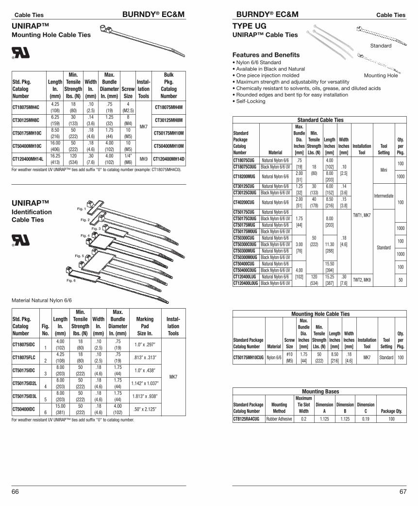
67
BURNDY® EC&M Cable Ties
66
Cable Ties BURNDY® EC&M
UNIRAP™Mounting Hole Cable Ties
Min. Max. BulkStd. Pkg. Length Tensile Width Bundle Instal- Pkg.Catalog In. Strength In. Diameter Screw lation CatalogNumber (mm) lbs. (N) (mm) In. (mm) Size Tools Number
4.25 18 .10 .75 4CT18075MH4C
(108) (80) (2.5) (19) (M2.5)CT18075MH4M
6.25 30 .14 1.25 8CT30125MH8C
(159) (133) (3.6) (32) (M4)CT30125MH8M
8.50 50 .18 1.75 10MK7
CT50175MH10C(216) (222) (4.6) (44) (M5)
CT50175MH10M
16.00 50 .18 4.00 10CT50400MH10C
(406) (222) (4.6) (102) (M5)CT50400MH10M
16.25 120 .30 4.00 1/4�CT120400MH14L
(413) (534) (7.6) (102) (M6)MK9 CT120400MH14D
For weather resistant UV UNIRAP™ ties add suffix "0" to catalog number (example: CT18075MH4C0).
UNIRAP™Identification Cable Ties
Material Natural Nylon 6/6
Min. Max.Std. Pkg. Length Tensile Width Bundle Marking Instal-Catalog Fig. In. Strength In. Diameter Pad lationNumber No. (mm) lbs. (N) (mm) In. (mm) Size In. Tools
4.00 18 .10 .75CT18075IDC
1 (102) (80) (2.5) (19)1.0� x .297�
4.25 18 .10 .75CT18075FLC
2 (108) (80) (2.5) (19).813� x .313�
8.00 50 .18 1.75CT50175IDC
3 (203) (222) (4.6) (44)1.0� x .438�
8.00 50 .18 1.75MK7
CT50175ID2L4 (203) (222) (4.6) (44)
1.142� x 1.037�
8.00 50 .18 1.75CT50175ID3L
5 (203) (222) (4.6) (44)1.813� x .938�
15.00 50 .18 4.00CT50400IDC
6 (381) (222) (4.6) (102).50� x 2.125�
For weather resistant UV UNIRAP™ ties add suffix "0" to catalog number.
TYPE UGUNIRAP™ Cable Ties
Features and Benefits• Nylon 6/6 Standard• Available in Black and Natural• One piece injection molded• Maximum strength and adjustability for versatility• Chemically resistant to solvents, oils, grease, and diluted acids• Rounded edges and bent tip for easy installation• Self-Locking
Standard
Mounting Hole
Standard Cable TiesMax.
Standard Bundle Min.Package Dia. Tensile Length Width Qty.Catalog Inches Strength Inches Inches Installation Tool perNumber Material [mm] Lbs. (N) [mm] [mm] Tool Setting Pkg.
CT18075CUG Natural Nylon 6/6 .75 4.00CT18075C0UG Black Nylon 6/6 UV [19] 18 [102] .10
100
2.00 (80) 8.00 [2.5]Mini
CT18200MUG Natural Nylon 6/6[51] [203]
1000
CT30125CUG Natural Nylon 6/6 1.25 30 6.00 .14CT30125C0UG Black Nylon 6/6 UV [32] (133) [152] [3.6]
2.00 40 8.50 .15Intermediate
CT40200CUG Natural Nylon 6/6[51] (178) [216] [3.8]
100
CT50175CUG Natural Nylon 6/6CT50175C0UG Black Nylon 6/6 UV 1.75 8.00
TWT1, MK7
CT50175MUG Natural Nylon 6/6 [44] [203]CT50175M0UG Black Nylon 6/6 UV
1000
CT50300CUG Natural Nylon 6/6 50 .18CT50300C0UG Black Nylon 6/6 UV 3.00 (222) 11.30 [4.6]
100
CT50300MUG Natural Nylon 6/6 [76] [288]Standard
CT50300M0UG Black Nylon 6/6 UV1000
CT50400CUG Natural Nylon 6/6 15.50CT50400C0UG Black Nylon 6/6 UV 4.00 [394]
100
CT120400LUG Natural Nylon 6/6 [102] 120 15.25 .30CT120400L0UG Black Nylon 6/6 UV (534) [387] [7.6]
TWT2, MK9 50
Mounting Hole Cable TiesMax.
Bundle Min.Dia. Tensile Length Width Qty.
Standard Package Screw Inches Strength Inches Inches Installation Tool perCatalog Number Material Size [mm] Lbs. (N) [mm] [mm] Tool Setting Pkg.
#10 1.75 50 8.50 .18CT50175MH10CUG Nylon 6/6
(M5) [44] (222) [216] [4.6]MK7 Standard 100
Mounting BasesMaximum
Standard Package Mounting Tie Slot Dimension Dimension DimensionCatalog Number Method Width A B C Package Qty.
CTB125RA4CUG Rubber Adhesive 0.2 1.125 1.125 0.19 100

69
BURNDY® EC&M Cable Ties
68
Cable Ties BURNDY® EC&M
UNIRAP™Cable Tie Variety PackUL Listed
Catalog Number: CTASST
ContentsQuantity Length Color Strength
100 40 Natural 18# Strength100 40 Black 18# Strength100 80 Black 50# Strength200 80 Natural 50# Strength50 110 Natural 50# Strength50 110 Black 50# Strength
UNIRAP™Hand Tools
MK7, MK9For Use On:
MK7 Used on all UNIRAP™ ties with body width of .10� to .19�.MK9 Used on all UNIRAP™ ties with body width of .10� to .35�.
MK7, MK9
TWT1, TWT2
TWT1 & TWT2Specifications
Length: 6.68"Width: .81"
Weight: 1.25 oz.
UNIRAP™Mounting Bases
BURNDY® mounting bases are available in adhesive or screw mount forms.The 4-way mounting bases come in 3 sizes to accommodate UNIRAP™ tiesfrom 18 lbs. tensile strength up to 175 lbs. All bases are made of standardnylon and are offered in weather resistant forms.
Std. Pkg. Max. Tie Bulk Pkg.Catalog Slot Width Mounting CatalogNumber Material In. (mm) Technique NumberCTB075S4C .14 4 Screw CTB075S4MCTB075RA4C (3.5) Adhesive CTB075RA4MCTB125S4C .20 8 Screw CTB125S4DCTB125RA4C
Nylon 6/6(5.1) Adhesive CTB125RA4D
CTB150S4C .35 8 Screw CTB150S4BCTB150RA4C (8.9) Adhesive CTB150RA4
*For weather resistant UV UNIRAP™ mounts add suffix “0” to catalog number (example: CTB075S4C0).
4-Way Mounting Bases
2-Way Mounting BasesStd. Pkg. Max. TieCatalog Slot Width MountingNumber Material In. (mm) TechniqueCTB125S2C .18 6 ScrewCTB125RA2C
Nylon 6/6(4.5) Adhesive
*For weather resistant UV UNIRAP™ mounts add suffix “0” to catalog number.
4-Way Mounting Base 2-Way Mounting Base

71
BURNDY® EC&M Small Compression
70
Cable Ties BURNDY® EC&M
UNIRAP™Halar® and Tefzel® Cable Ties
Halar® cable ties meet NEC regulations and can be used in applicationswhere low smoke and low flame are a concern, as in air handling spaces. Theraw material used to manufacture Halar® cable ties is UL 94V-0 rated. Theseties come in a distinct color of red for easy identification.Halar® is a registered trademark of the Allied Chemical Co.
Tefzel® cable ties provide excellent protection against radiation, ultravioletlight, and a wide range of chemicals. Tefzel® cable ties offer temperature sta-bility to 302°F (150°C) and come in a standard color of blue for easy identifi-cation.Tefzel® is a registered trademark of the E.I. DuPont Corporation.
Min.Std. Pkg. Length Tensile Width Max. Instal- Bulk Pkg.Catalog In. Strength In. Bundle lation CatalogNumber Material (mm) lbs. (N) (mm) In. (mm) Tools Number
4.00 18 .10 .75CTH18075C Halar®
(102) (80) (2.5) (19)MK7 CTH18075M
8.00 50 .18 1.75CTH50175C Halar®
(203) (222) (4.6) (44)MK7 CTH50175M
8.00 30 .14 2.00CTH30200C Halar®
(203) (133) (3.6) (51)MK7 CTH30200M
15.25 120 .18 4.00CTH120400L Halar®
(387) (534) (4.6) (102)MK9 CTH120400D
4.00 18 .10 .75CTZ18075C Tefzel®
(102) (80) (2.5) (19)MK7 CTZ18075M
8.00 50 .18 1.75CTZ50175C Tefzel®
(203) (222) (4.6) (44)MK7 CTZ50175M
8.00 30 .14 2.00CTZ30200C Tefzel®
(203) (133) (3.6) (51)MK7 CTZ30200M
5.25 120 .18 4.00CTZ120400L Tefzel®
(387) (534) (4.6) (102)MK9 CTZ120400D
TYPE CHNYLOCLIP™ Cable Hanger
NYLOCLIP™ cable hangers are fabricated one-piece nylon with no metalparts. Tough, resilient, lightweight and abrasion resistant, NYLOCLIP™ cablehangers offer high tensile strength and are resistant to solvents, alkalies, oils,grease and diluted acids. Available in white or black UV/weather resistantmaterial. Meets Mil Spec. M-20693, ASTM STD D4066 Group 1 Class 1.
*For weather resistant UV Nyloclips add suffix "0" to catalog number (example: CH2C0).
Max. BulkCatalog Mounting Bundle CatalogNumber Material Screw In. (mm) NumberCH2C Nylon 6/6 8 (M4) .125 (3.2) CH2MCH3C Nylon 6/6 8 (M4) .187 (4.8) CH3MCH4C Nylon 6/6 8 (M4) .250 (6.4) CH4MCH5C Nylon 6/6 8 (M4) .312 (7.9) CH5MCH6C Nylon 6/6 8 (M4) .375 (9.5) CH6MCH7C Nylon 6/6 8 (M4) .437 (11.1) CH7MCH8C Nylon 6/6 8 (M4) .500 (12.7) CH8MCH9C Nylon 6/6 8 (M4) .563 (14.3) CH9MCH10C Nylon 6/6 8 (M4) .625 (15.9) CH10MCH11C Nylon 6/6 10 (M5) .625 (15.9) CH11MCH12C Nylon 6/6 10 (M5) .750 (15.1) CH12MCH14C Nylon 6/6 10 (M5) .875 (22.2) CH14MCH16C Nylon 6/6 10 (M5) 1.00 (25.4) CH16MCH18C Nylon 6/6 10 (M5) 1.12 (28.5) CH18MCH24L Nylon 6/6 10 (M5) 1.50 (38.1) CH24C
TYPE YFBare Ferrules
For Use On Copper Conductor
Made of electrolytic copper, tin plated with a seamless barrel. Ferrules arealso known as bootlace ferrules or cord end terminals. Ferrules aid in termi-nating extra flexible fine stranded conductor. Provide enhanced flexibility relating to wire termination and management. They provide a positive contactsurface which helps ensure system integrity.
Catalog Wire Size Dimensions in Inches RecommendedNumber AWG mm2 L1 D D1 D2 ToolingYF2807UI 28 .14 .276 .035 .027 .063 YF3206TOOLYF2605UI 26 .25 .196 .043 .031 .059YF2607UI 26 .25 .276 .043 .031 .059 YF3206TOOLYF2405UI 24 .34 .196 .047 .031 .059 YF2610TOOLYF2407UI 24 .34 .276 .047 .031 .059YF2206UI 22 .50 .236 .051 .039 .059YF2208UI 22 .50 .315 .051 .039 .067YF2210UI 22 .50 .394 .051 .039 .067YF2212UI 22 .50 .472 .051 .039 .067YF2006UI 20 .75 .236 .059 .047 .067YF2010UI 20 .75 .394 .059 .047 .075YF2012UI 20 .75 .472 .059 .047 .075YF1806UI 18 1.00 .236 .067 .055 .075YF1808UI 18 1.00 .315 .067 .055 .087YF1810UI 18 1.00 .394 .067 .055 .087
YF3206TOOL
YF1812UI 18 1.00 .472 .067 .055 .087YF2610TOOL
YF1607UI 16 1.50 .276 .079 .067 .087YF2214TOOL
YF1608UI 16 1.50 .315 .079 .067 .098YF2210TOOL
YF1610UI 16 1.50 .394 .079 .067 .098YF1612UI 16 1.50 .472 .079 .067 .098YF1618UI 16 1.50 .709 .079 .067 .098YF1407UI 14 2.50 .276 .102 .091 .130YF1408UI 14 2.50 .315 .102 .091 .130YF1410UI 14 2.50 .394 .102 .091 .130YF1412UI 14 2.50 .472 .102 .091 .130YF1418UI 14 2.50 .709 .102 .091 .130YF1209UI 12 4.00 .354 .126 .110 .154YF1212UI 12 4.00 .472 .126 .110 .154
YF3206TOOL
YF1215UI 12 4.00 .591 .126 .110 .154YF2610TOOL
YF1218UI 12 4.00 .709 .126 .110 .154YF2210TOOL
YF1010UI 10 6.00 .394 .154 .138 .185 YF3206TOOLYF1012UI 10 6.00 .472 .154 .138 .185 YF2610TOOLYF1015UI 10 6.00 .591 .154 .138 .185 YF2210TOOLYF1018UI 10 6.00 .709 .154 .138 .185 YF1006TOOLYF0812UI 8 10.00 .472 .193 .177 .228YF0815UI 8 10.00 .591 .193 .177 .228YF0818UI 8 10.00 .709 .193 .177 .228 YF3206TOOLYF0612UI 6 16.00 .472 .244 .228 .283 YF1006TOOLYF0615UI 6 16.00 .591 .244 .228 .283 YF0801TOOLYF0618UI 6 16.00 .709 .244 .228 .283YF0625UI 6 16.00 .984 .244 .228 .283YF0412UI 4 25.00 .472 .311 .295 .358YF0415UI 4 25.00 .591 .311 .295 .358YF0418UI 4 25.00 .709 .311 .295 .358YF0420UI 4 25.00 .787 .311 .295 .358YF0425UI 4 25.00 .984 .311 .295 .358YF0432UI 4 25.00 1.260 .311 .295 .358 YF0801TOOLYF0215UI 2 35.00 .591 .343 .327 .402 YF0401TOOLYF0220UI 2 35.00 .787 .343 .327 .402YF0225UI 2 35.00 .984 .343 .327 .402YF0232UI 2 35.00 1.260 .343 .327 .402YF0122UI 1 50.00 .866 .429 .406 .500YF0125UI 1 50.00 .984 .429 .406 .500
(Type YF Bare Ferrules continued on next page)

73
BURNDY® EC&M Small Compression
72
Small Compression BURNDY® EC&M
TYPE YFBare Ferrules (Continued)
For Use On Copper Conductor
Catalog Wire Size Dimensions in Inches RecommendedNumber AWG mm2 L1 D D1 D2 ToolingYF0132UI 1 50.00 1.260 .429 .406 .500YF2/022UI 2/0 70.00 .866 .563 .531 .622
YF0801TOOL
YF2/025UI 2/0 70.00 .984 .563 .531 .622YF0401TOOL
YF2/032UI 2/0 70.00 1.260 .563 .531 .622YF3/025UI 3/0 95.00 .984 .614 .583 .681YF3/030UI 3/0 95.00 1.180 .614 .583 .681YF3/032UI 3/0 95.00 1.260 .614 .583 .681
YF1/03/0TOOL
YF4/032UI 4/0 120.00 1.260 .697 .657 .795YF4/034UI 4/0 120.00 1.390 .697 .657 .795YF4/040UI 4/0 120.00 1.570 .697 .657 .795YF25032UI 250 150.00 1.260 .811 .722 .906 YF4/0250TOOLYF25040UI 250 150.00 1.570 .811 .722 .906YF35032UI 350 185.00 1.260 .843 .795 .941YF35040UI 350 185.00 1.570 .843 .795 .941
Y644HSXT
TYPE YF-I FERRULESInsulated Ferrules
For Use on Copper Conductor
Offered in Series D, T and W
Made of electrolytic copper, tin plated with a seamless barrel. Ferrules arealso known as bootlace ferrules or cord end terminals. Ferrules aid in termi-nating extra flexible fine stranded conductor. Provide enhanced flexibility relating to wire termination and management. They provide a positive contactsurface which helps ensure system integrity.
Catalog Number/Color Wire SizeW Series D Series T Series AWG mm2
YF2806IWGray
— — 28 0.14
YF2808IWGray
— — 28 0.14
YF2606IW YF2606ID YF2606ITLight Blue Purple Yellow
26 0.25
YF2608IW YF2608ID YF2608ITLight Blue Purple Yellow
26 0.25
YF2406IWTurquoise
— — 24 0.34
YF2408IWTurquoise
— — 24 0.34
YF2205IW YF2205ID YF2205ITOrange White White
22 0.50
YF2206IW YF2206ID YF2206ITOrange White White
22 0.50
YF2208IW YF2208ID YF2208ITOrange White White
22 0.50
YF2210IW YF2210ID YF2210ITOrange White White
22 0.50
YF2212IW YF2212ID YF2212ITOrange White White
22 0.50
Single Insulated Ferrules
73
D2D1D
L2
L1
Dimensions in InchesL1 Dim. L2 Dim. D Dim. D1 Dim. D2 Dim. Tooling
0.409 0.236 0.037 0.031 0.043YF3206TOOL
0.488 0.315 0.037 0.031 0.043
0.409 0.236 0.043 0.031 0.075
0.488 0.315 0.043 0.031 0.075YF2610TOOLYF3206TOOL
0.409 0.236 0.043 0.031 0.075
0.488 0.315 0.043 0.031 0.075
0.433 0.197 0.051 0.039 0.102
0.472 0.236 0.051 0.039 0.102YF3206TOOLYF2610TOOL
0.551 0.315 0.051 0.039 0.102YF2214TOOLYF2210TOOL
0.630 0.394 0.051 0.039 0.102
0.709 0.472 0.051 0.039 0.102
(Type YF-I Insulated Series W, D, T Ferrules continued on next 6 pages)

75
BURNDY® EC&M Small Compression
74
Small Compression BURNDY® EC&M
TYPE YF-I FERRULESInsulated Ferrules(Continued)
For Use on Copper Conductor
Offered in Series W, D, T
Catalog Number/Color Wire SizeW Series D Series T Series AWG mm2
YF2006IW YF2006ID YF2006ITWhite Gray Light Blue
20 0.75
YF2008IW YF2008ID YF2008ITWhite Gray Light Blue
20 0.75
YF2010IW YF2010ID YF2010ITWhite Gray Light Blue
20 0.75
YF2012IW YF2012ID YF2012ITWhite Gray Light Blue
20 0.75
YF2018IW YF2018ID YF2018ITWhite Gray Light Blue
20 0.75
YF1806IW YF1806ID YF1806ITYellow Red Red
18 1.00
YF1808IW YF1808ID YF1808ITYellow Red Red
18 1.00
YF1810IW YF1810ID YF1810ITYellow Red Red
18 1.00
YF1812IW YF1812ID YF1812ITYellow Red Red
18 1.00
YF1818IW YF1818ID YF1818ITYellow Red Red
18 1.00
YF1606IW YF1606ID YF1606ITRed Black Black
16 1.50
YF1608IW YF1608ID YF1608ITRed Black Black
16 1.50
YF1610IW YF1610ID YF1610ITRed Black Black
16 1.50
YF1612IW YF1612ID YF1612ITRed Black Black
16 1.50
YF1615IW YF1615ID YF1615ITRed Black Black
16 1.50
YF1618IW YF1618ID YF1618ITRed Black Black
16 1.50
YF1408IW YF1408ID YF1408ITBlue Blue Gray
14 2.50
YF1410IW YF1410ID YF1410ITBlue Blue Gray
14 2.50
YF1412IW YF1412ID YF1412ITBlue Blue Gray
14 2.50
YF1418IW YF1418ID YF1418ITBlue Blue Gray
14 2.50
YF1209IW YF1209ID YF1209ITGray Gray Orange
12 4.00
YF1210IW YF1210ID YF1210ITGray Gray Orange
12 4.00
YF1212IW YF1212ID YF1212ITGray Gray Orange
12 4.00
YF1218IW YF1218ID YF1218ITGray Gray Orange
12 4.00
YF1010IW YF1010ID YF1010ITBlack Yellow Green
10 6.00
YF1012IW YF1012ID YF1012ITBlack Yellow Green
10 6.00
YF1018IW YF1018ID YF1018ITBlack Yellow Green
10 6.00
Single Insulated Ferrules
D2D1D
L2
L1
(Type YF-I Insulated Series W, D, T Ferrules continued on next 4 pages)
Dimensions in InchesL1 Dim. L2 Dim. D Dim. D1 Dim. D2 Dim. Tooling
0.472 0.236 0.059 0.047 0.110
0.551 0.315 0.059 0.047 0.110
0.630 0.394 0.059 0.047 0.110
0.709 0.472 0.059 0.047 0.110
0.957 0.709 0.059 0.047 0.110
0.472 0.236 0.067 0.055 0.118
0.551 0.315 0.067 0.055 0.118
0.630 0.394 0.067 0.055 0.118
0.709 0.472 0.067 0.055 0.118
YF3206TOOL0.957 0.709 0.067 0.055 0.118
YF2610TOOLYF2214TOOL
0.484 0.236 0.079 0.067 0.138YF2210TOOL
0.551 0.315 0.079 0.067 0.138
0.630 0.394 0.079 0.067 0.138
0.709 0.472 0.079 0.067 0.138
0.839 0.591 0.079 0.067 0.138
0.945 0.709 0.079 0.067 0.138
0.591 0.315 0.098 0.087 0.165
0.685 0.394 0.098 0.087 0.165
0.709 0.472 0.098 0.087 0.165
0.945 0.709 0.098 0.087 0.165
0.646 0.315 0.126 0.110 0.189
0.699 0.394 0.126 0.110 0.189 YF3206TOOLYF2610TOOL
0.787 0.472 0.126 0.110 0.189 YF2210TOOL
1.020 0.709 0.126 0.110 0.189
0.728 0.394 0.154 0.138 0.248YF3206TOOLYF2610TOOL
0.787 0.472 0.154 0.138 0.248YF2210TOOLYF1006TOOL
1.020 0.709 0.154 0.138 0.138
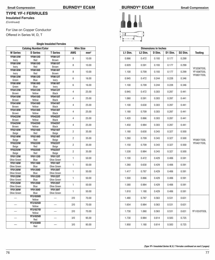
77
BURNDY® EC&M Small Compression
76
Small Compression BURNDY® EC&M
TYPE YF-I FERRULESInsulated Ferrules(Continued)
For Use on Copper Conductor
Offered in Series W, D, T
Catalog Number/Color Wire SizeW Series D Series T Series AWG mm2
YF0812IW YF0812ID YF0812ITIvory Red Brown
8 10.00
YF0815IW YF0815ID YF0815ITIvory Red Brown
8 10.00
YF0818IW YF0818ID YF0818ITIvory Red Brown
8 10.00
YF0612IW YF0612ID YF0612ITGreen Blue Ivory
6 16.00
YF0618IW YF0618ID YF0618ITGreen Blue Ivory
6 16.00
YF0412IW YF0412ID YF0412ITBrown Yellow Black
4 25.00
YF0415IW YF0415ID YF0415ITBrown Yellow Black
4 25.00
YF0416IW YF0416ID YF0416ITBrown Yellow Black
4 25.00
YF0418IW YF0418ID YF0418ITBrown Yellow Black
4 25.00
YF0422IW YF0422ID YF0422ITBrown Yellow Black
4 25.00
YF0425IW YF0425ID YF0425ITBrown Yellow Black
4 25.00
YF0216IW YF0216ID YF0216ITBeige Red Beige
2 35.00
YF0218IW YF0218ID YF0218ITBeige Red Beige
2 35.00
YF0222IW YF0222ID YF0222ITBeige Red Beige
2 35.00
YF0225IW YF0225ID YF0225ITBeige Red Beige
2 35.00
YF0112IW YF0112ID YF0112ITOlive Green Blue Olive Green
1 50.00
YF0116IW YF0116ID YF0116ITOlive Green Blue Olive Green
1 50.00
YF0120IW YF0120ID YF0120ITOlive Green Blue Olive Green
1 50.00
YF0122IW YF0122ID YF0122ITOlive Green Blue Olive Green
1 50.00
YF0125IW YF0125ID YF0125ITOlive Green Blue Olive Green
1 50.00
YF0130IW YF0130ID YF0130ITOlive Green Blue Olive Green
1 50.00
YF2/020ID—
Yellow— 2/0 70.00
YF2/025ID—
Yellow— 2/0 70.00
YF2/027ID—
Yellow— 2/0 70.00
YF3/025ID—
Red— 3/0 95.00
YF3/030ID—
Red— 3/0 95.00
Single Insulated Ferrules
(Type YF-I Insulated Series W, D, T Ferrules continued on next 2 pages)
Dimensions in InchesL1 Dim. L2 Dim. D Dim. D1 Dim. D2 Dim. Tooling
0.866 0.472 0.193 0.177 0.299
0.929 0.591 0.193 0.177 0.299YF3206TOOL
1.100 0.709 0.193 0.177 0.299 YF1006TOOLYF0801TOOL
0.945 0.472 0.244 0.228 0.346
1.100 0.709 0.244 0.228 0.346
0.945 0.472 0.303 0.287 0.441
1.060 0.591 0.303 0.287 0.441
1.100 0.630 0.303 0.287 0.441
1.180 0.709 0.303 0.287 0.441
1.420 0.866 0.303 0.287 0.441
1.450 0.984 0.303 0.287 0.441
1.180 0.630 0.343 0.327 0.500
1.260 0.709 0.343 0.327 0.500YF0801TOOLYF0401TOOL
1.150 0.709 0.343 0.327 0.500
1.530 0.984 0.343 0.327 0.500
1.100 0.472 0.429 0.406 0.591
1.260 0.630 0.429 0.406 0.591
1.417 0.787 0.429 0.406 0.591
1.500 0.866 0.429 0.406 0.591
1.580 0.984 0.429 0.406 0.591
1.810 1.180 0.429 0.406 0.591
1.480 0.787 0.563 0.531 0.631
1.654 0.984 0.563 0.531 0.631
1.730 1.060 0.563 0.531 0.631 YF1/03/0TOOL
1.730 0.984 0.614 0.583 0.725
1.950 1.180 0.614 0.583 0.725
D2D1D
L2
L1

79
BURNDY® EC&M Small Compression
78
Small Compression BURNDY® EC&M
TYPE YF-I FERRULESInsulated Ferrules(Continued)
For Use on Copper Conductor
Offered in Series W, D, T
Catalog Number/Color Wire SizeW Series D Series T Series AWG mm2
YF4/027ID—
Blue— 4/0 120.00
YF4/030ID—
Blue— 4/0 120.00
YF4/032ID—
Blue— 4/0 120.00
YF4/034ID—
Blue— 4/0 120.00
YF25025ID—
Yellow— 250 150.00
YF25027ID—
Yellow— 250 150.00
YF25032ID—
Yellow— 250 150.00
YF25038ID—
Yellow— 250 150.00
Single Insulated Ferrules
Dimensions in InchesL1 Dim. L2 Dim. D Dim. D1 Dim. D2 Dim. Tooling
1.870 1.060 0.697 0.657 0.799
2.090 1.180 0.697 0.657 0.799
2.070 1.260 0.697 0.657 0.799
2.150 1.340 0.697 0.657 0.799YF4/0250TOOL
1.990 0.984 0.811 0.772 0.921
2.070 1.060 0.811 0.772 0.921
2.270 1.260 0.811 0.772 0.921
2.500 1.500 0.811 0.772 0.921
D2D1D
L2
L1
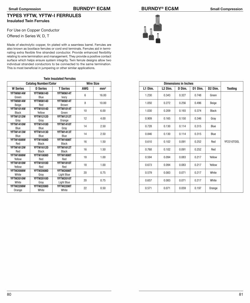
81
BURNDY® EC&M Small Compression
80
Small Compression BURNDY® EC&M
TYPES YFTW, YFTW-I FERRULESInsulated Twin Ferrules
For Use on Copper Conductor
Offered in Series W, D, T
Made of electrolytic copper, tin plated with a seamless barrel. Ferrules arealso known as bootlace ferrules or cord end terminals. Ferrules aid in termi-nating extra flexible fine stranded conductor. Provide enhanced flexibility relating to wire termination and management. They provide a positive contactsurface which helps ensure system integrity. Twin ferrule designs allow two individual stranded conductors to be connected to the same termination.This is most beneficial in jumpering or other similar applications.
Catalog Number/Color Wire SizeW Series D Series T Series AWG mm2
YFTW0614W YFTW0614D YFTW0614TGreen Blue Ivory
6 16.00
YFTW0814W YFTW0814D YFTW0814TBeige Red Brown
8 10.00
YFTW1014W YFTW1014D YFTW1014TBlack Yellow Green
10 6.00
YFTW1212W YFTW1212D YFTW1212TGray Gray Orange
12 4.00
YFTW1410W YFTW1410D YFTW1410TBlue Blue Gray
14 2.50
YFTW1413W YFTW1413D YFTW1413TBlue Blue Blue
14 2.50
YFTW1608W YFTW1608D YFTW1608TRed Black Black
16 1.50
YFTW1612W YFTW1612D YFTW1612TRed Black Black
16 1.50
YFTW1808W YFTW1808D YFTW1808TYellow Red Red
18 1.00
YFTW1810W YFTW1810D YFTW1810TYellow Red Red
18 1.00
YFTW2008W YFTW2008D YFTW2008TWhite Gray Light Blue
20 0.75
YFTW2010W YFTW2010D YFTW2010TWhite Gray Light Blue
20 0.75
YFTW2208W YFTW2208D YFTW2208TOrange White White
22 0.50
Twin Insulated FerrulesDimensions in Inches
L1 Dim. L2 Dim. D Dim. D1 Dim. D2 Dim. Tooling
1.230 0.343 0.327 0.748 Green
1.050 0.272 0.256 0.496 Beige
1.030 0.209 0.193 0.374 Black
0.909 0.165 0.150 0.346 Gray
0.728 0.130 0.114 0.315 Blue
0.846 0.130 0.114 0.315 Blue
0.610 0.102 0.091 0.252 Red YF2210TOOL
0.768 0.102 0.091 0.252 Red
0.594 0.094 0.083 0.217 Yellow
0.673 0.094 0.083 0.217 Yellow
0.579 0.083 0.071 0.217 White
0.657 0.083 0.071 0.217 White
0.571 0.071 0.059 0.197 Orange

83
BURNDY® EC&M Grounding
82
Small Compression BURNDY® EC&M
TYPES T, YADHYLUG™ Terminals
The Type T uninsulated terminals are constructed of pure electrolytic copper.Designed with a long brazed seam barrel, standard neck, deep V groove innerserrations and electro-tin plated. The terminals are ideal for control wiring andother standard duty applications.
BulkCatalog Wire Stud Catalog InstallationNumber Range Size Number ToolingT18-4 3,4 YAD18-4T18-6 4-6 YAD18-6T18-8 6-8 YAD18-8T18-10 22 - 18 8-10 YAD18-10T18-14 1/4 YAD18-14T18-516 5/16 YAD18-516T18-38 3/8 YAD18-38 Non-Ratchet:T14-4 3,4 YAD14-4 Y10D,T14-6 4-6 YAD14-6 Y10-22T14-8 6-8 YAD14-8T14-10 20 - 14 8-10 YAD14-10 Ratchet:T14-14 1/4 YAD14-14 MR8G98,T14-516 5/16 YAD14-516 Y8MRB-1,T14-38 3/8 YAD14-38 MR20T10-6 4-6 YAD10-6T10-8 6-8 YAD10-8T10-10 8-10 YAD10-10T10-14
12 - 10*1/4 YAD10-14
T10-516 5/16 YAD10-516T10-38 3/8 YAD10-38
*NOTE: UL Listed for 14-10 when installed with MR8G98 and Y8MRB-1 tools only.
TYPES TP, BAVINYLUG™
VINYLUG™ Type TP is designed for commercial and light duty industrial control and power circuit applications. Supplied with an expanded polyvinylchloride (PVC) insulation shroud, many tongue variations and rated 600V,makes TP terminals versatile and economical.
BulkCatalog Wire Stud Catalog InstallationNumber Range Size Number ToolingTP16-4 22 - 16 3 - 4 BA16E4TP16-6 Max. Insul. 4 - 6 BA16E6TP16-8 Dia. Accom.: 6 - 8 BA16E8TP16-10 .145 8 - 10 BA16E10 Non-Ratchet:TP16-14 Color Code: 12,1/4 BA16E14 Y10-22, Y10DTP16-38 Red 3/8 BA16E38TP14-4 3 - 4 BA14E4TP14-6
16-144 - 6 BA14E6 Ratchet:
TP14-8Max. Insul.
6 - 8 BA14E8 MR8-89-1,TP14-10
Dia. Accom.:8 - 10 BA14E10 MR8-G96, MR15
TP14-14.180
12, 1/4 BA14E14TP14-516
Color Code:5/16 BA14E516
TP14-38Blue
3/8 BA14E3812-10 Plier Type:
TP10-6Max. Insul.
4 - 6 BA10E6Y10D, Y10-22,
TP10-8 Dia. Accom.: 6 - 8 BA10E8 Ratchet:TP10-10 .260 8 - 10 BA10E10 MR8-89-1, MR8-G96,TP10-14 Color Code: 12,1/4 BA10E14 MR15,TP10-38 Yellow 3/8 BA10E38 M8ND w/N10HET-23
TYPES TN, YAE, YAESINSULUG™ Terminals
INSULUG™ Type TN Nylon-insulated terminals are designed for heavy dutyindustrial, utility and military power and control-circuit applications for wiresizes 22 AWG through 10 AWG. They offer high dielectric strength and sta-bility in oily conditions and meet military CLASS 1 and CLASS 2 requirementsper AS25036 and the requirements of military specifications SAE-AS7928(ASG).
BulkCatalog Wire Stud Catalog InstallationNumber Range Size Number ToolingTN18-4 3 - 4 YAES18N48TN18-6
22-184 - 6 YAES18N1
TN18-8Max. Insul.
6 - 8 YAES18N49TN18-10
Dia. Accom.:8 - 10 YAES18N3
TN18-14.120
12, 1/4 YAES18N50TN18-516
Color Code:5/16 YAES18N4
TN18-38Red
3/8 —TN14-4 3 - 4 YAE14N52 Non-Ratchet:TN14-6
16-144 - 6 YAES14N6 Y10D,
TN14-8Max. Insul.
6 - 8 YAES14N53 Y1022TN14-10
Dia. Accom.:8 - 10 YAES14N8 Ratchet:
TN14-14.153
12, 1/4 YAES14N54 MR8-83,TN14-516
Color Code:5/16 YAES14N9 MR18
TN14-38Blue
3/8 —TN10-6 12-10 4 - 6 YAES10N11TN10-8 Max. Insul. 6 - 8 YAES10N56TN10-10 Dia. Accom.: 8 - 10 YAES10N12TN10-14 .210 12, 1/4 YAES10N57TN10-516 Color Code: 5/16 YAES10N13TN10-38 Yellow 3/8 —
TYPES T-F, YAD-FHYLUG™ Terminals
Type T-F is constructed in the same manner as the Type “T” and employs afork tongue.
BulkCatalog Wire Stud Catalog InstallationNumber Range Size Number ToolingT18-6F 4 - 6 YAD18-6FT18-8F 6 - 8 YAD18-8FT18-10F 22 - 18 8 - 10 YAD18-10F Non-Ratchet:T18-14F 1/4 YAD18-14F Y10D, Y10-22T14-6F 4 - 6 YAD14-6FT14-8F 6 - 8 YAD14-8FT14-10F 20 - 14 8 - 10 YAD14-10F Ratchet:T14-14F 1/4 YAD14-14F MR8G98,T10-6F 4 - 6 YAD10-6F Y8MRB-1,T10-8F 6 - 8 YAD10-8F MR20T10-10F 12 - 10 8 - 10 YAD10-10FT10-14F 1/4 YAD10-14F
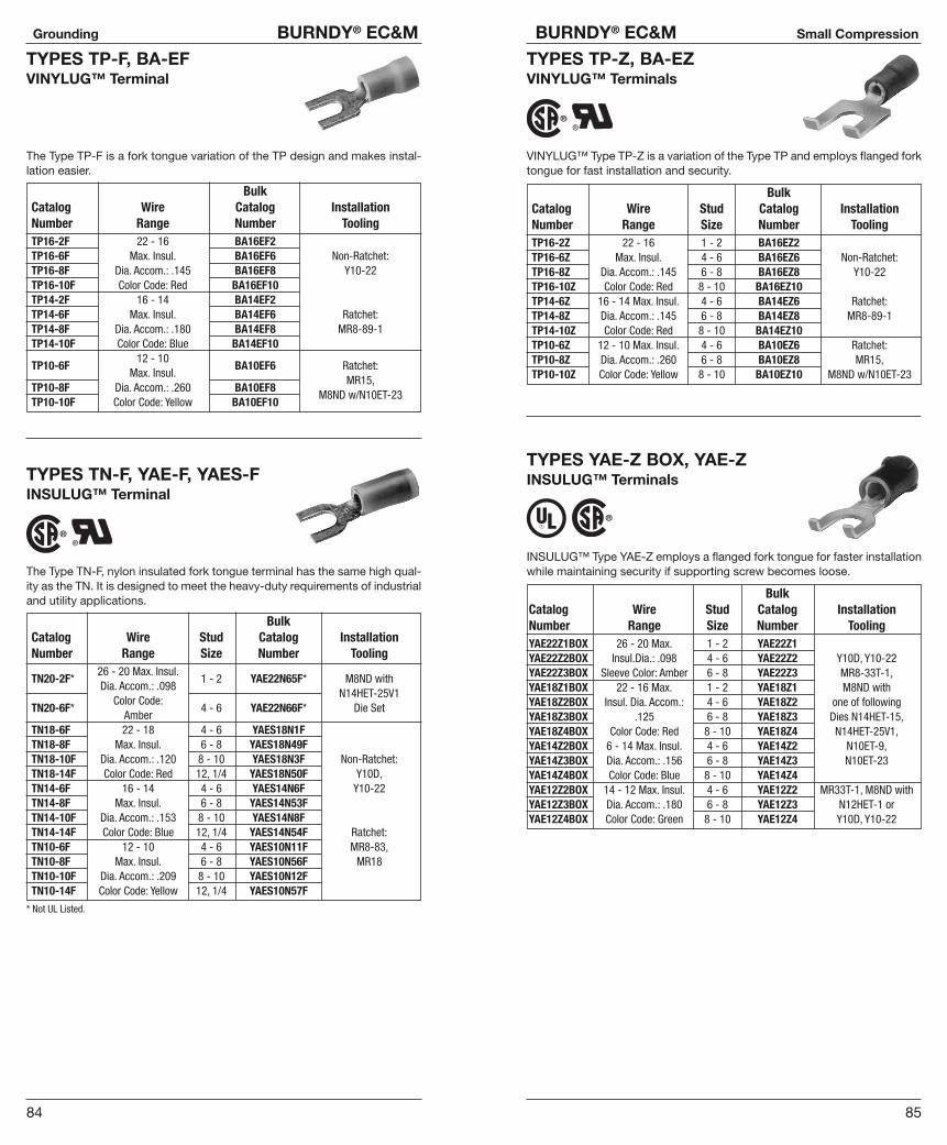
85
BURNDY® EC&M Small Compression
84
Grounding BURNDY® EC&M
TYPES TP-F, BA-EFVINYLUG™ Terminal
The Type TP-F is a fork tongue variation of the TP design and makes instal-lation easier.
BulkCatalog Wire Catalog InstallationNumber Range Number ToolingTP16-2F 22 - 16 BA16EF2TP16-6F Max. Insul. BA16EF6 Non-Ratchet:TP16-8F Dia. Accom.: .145 BA16EF8 Y10-22TP16-10F Color Code: Red BA16EF10TP14-2F 16 - 14 BA14EF2TP14-6F Max. Insul. BA14EF6 Ratchet:TP14-8F Dia. Accom.: .180 BA14EF8 MR8-89-1TP14-10F Color Code: Blue BA14EF10
12 - 10TP10-6F
Max. Insul.BA10EF6 Ratchet:
TP10-8F Dia. Accom.: .260 BA10EF8MR15,
TP10-10F Color Code: Yellow BA10EF10M8ND w/N10ET-23
TYPES TN-F, YAE-F, YAES-FINSULUG™ Terminal
The Type TN-F, nylon insulated fork tongue terminal has the same high qual-ity as the TN. It is designed to meet the heavy-duty requirements of industrialand utility applications.
BulkCatalog Wire Stud Catalog InstallationNumber Range Size Number Tooling
26 - 20 Max. Insul.TN20-2F*
Dia. Accom.: .0981 - 2 YAE22N65F* M8ND with
Color Code:N14HET-25V1
TN20-6F*Amber
4 - 6 YAE22N66F* Die Set
TN18-6F 22 - 18 4 - 6 YAES18N1FTN18-8F Max. Insul. 6 - 8 YAES18N49FTN18-10F Dia. Accom.: .120 8 - 10 YAES18N3F Non-Ratchet:TN18-14F Color Code: Red 12, 1/4 YAES18N50F Y10D,TN14-6F 16 - 14 4 - 6 YAES14N6F Y10-22TN14-8F Max. Insul. 6 - 8 YAES14N53FTN14-10F Dia. Accom.: .153 8 - 10 YAES14N8FTN14-14F Color Code: Blue 12, 1/4 YAES14N54F Ratchet:TN10-6F 12 - 10 4 - 6 YAES10N11F MR8-83,TN10-8F Max. Insul. 6 - 8 YAES10N56F MR18TN10-10F Dia. Accom.: .209 8 - 10 YAES10N12FTN10-14F Color Code: Yellow 12, 1/4 YAES10N57F
* Not UL Listed.
TYPES TP-Z, BA-EZVINYLUG™ Terminals
VINYLUG™ Type TP-Z is a variation of the Type TP and employs flanged forktongue for fast installation and security.
BulkCatalog Wire Stud Catalog InstallationNumber Range Size Number ToolingTP16-2Z 22 - 16 1 - 2 BA16EZ2TP16-6Z Max. Insul. 4 - 6 BA16EZ6 Non-Ratchet:TP16-8Z Dia. Accom.: .145 6 - 8 BA16EZ8 Y10-22TP16-10Z Color Code: Red 8 - 10 BA16EZ10TP14-6Z 16 - 14 Max. Insul. 4 - 6 BA14EZ6 Ratchet:TP14-8Z Dia. Accom.: .145 6 - 8 BA14EZ8 MR8-89-1TP14-10Z Color Code: Red 8 - 10 BA14EZ10TP10-6Z 12 - 10 Max. Insul. 4 - 6 BA10EZ6 Ratchet:TP10-8Z Dia. Accom.: .260 6 - 8 BA10EZ8 MR15,TP10-10Z Color Code: Yellow 8 - 10 BA10EZ10 M8ND w/N10ET-23
TYPES YAE-Z BOX, YAE-ZINSULUG™ Terminals
INSULUG™ Type YAE-Z employs a flanged fork tongue for faster installationwhile maintaining security if supporting screw becomes loose.
BulkCatalog Wire Stud Catalog InstallationNumber Range Size Number ToolingYAE22Z1BOX 26 - 20 Max. 1 - 2 YAE22Z1YAE22Z2BOX Insul.Dia.: .098 4 - 6 YAE22Z2 Y10D, Y10-22YAE22Z3BOX Sleeve Color: Amber 6 - 8 YAE22Z3 MR8-33T-1,YAE18Z1BOX 22 - 16 Max. 1 - 2 YAE18Z1 M8ND withYAE18Z2BOX Insul. Dia. Accom.: 4 - 6 YAE18Z2 one of followingYAE18Z3BOX .125 6 - 8 YAE18Z3 Dies N14HET-15,YAE18Z4BOX Color Code: Red 8 - 10 YAE18Z4 N14HET-25V1,YAE14Z2BOX 6 - 14 Max. Insul. 4 - 6 YAE14Z2 N10ET-9,YAE14Z3BOX Dia. Accom.: .156 6 - 8 YAE14Z3 N10ET-23YAE14Z4BOX Color Code: Blue 8 - 10 YAE14Z4YAE12Z2BOX 14 - 12 Max. Insul. 4 - 6 YAE12Z2 MR33T-1, M8ND withYAE12Z3BOX Dia. Accom.: .180 6 - 8 YAE12Z3 N12HET-1 orYAE12Z4BOX Color Code: Green 8 - 10 YAE12Z4 Y10D, Y10-22

87
BURNDY® EC&M Small Compression
86
Small Compression BURNDY® EC&M
TYPES YAV-L BOX, YAV-LHYLUG™ TerminalsLarge Size Uninsulated Compression Terminals, Seamless Uninsulated Compression Ring Tongue Terminal
8-4/0 Str. Copper
HYLUG™ Type YAV is a seamless, heavy duty uninsulated compression ter-minal manufactured from electrolytic copper and is for use on Type AN aircraftcable, extra flexible conductors and commercial (code) conductors. Theseamless tubing produces a double-thick tongue and seamless barrel designprovides a strong connector for demanding applications requiring high relia-bility.
Applications include aircraft, industrials, hospitals, electric utilities, marine,computers, and other equipment subject to vibration or requiring depend-able electrical performance.
The YAV HYLUG™ terminals meet the requirements of ASE-AS7928 and arelisted per AS20659 for use with copper aircraft cable per MIL-W-5086.
The benefits of YAV-L connectors are the same as YAV connectors forstranded conductors.
BulkCatalog Wire Stud Catalog Installation ToolingNumber Size Size Number HYTOOL™
Non-Ratchet: MY29-11;YAV8C-L1BOX 8 AWG 1/4 YAV8C-L1*
Ratchet: MR4C, MR8-9Q,Y8MRB-1,
YAV8C-L4BOX 8 AWG 1/2 YAV8C-L4*M8ND with N8CT Die Set
YAV6C-L1BOX 6 AWG 8 - 10 YAV6C-L1* Non-Ratchet: MY28, MY29-11;YAV6C-L10BOX 6 AWG 1/2 YAV6C-L10 Ratchet: MR4CYAV2C-L1BOX 2 AWG 1/4 YAV2C-L1 *YAV2C-L4BOX 2 AWG 1/2 YAV2C-L4YAV1C-L1BOX 1 AWG 1/4 YAV1C-L1*YAV1C-L3BOX 1 AWG 1/2 YAV1C-L3YAV25-L1BOX 1/0 1/4 YAV25-L1YAV25-L3BOX 1/0 1/2 YAV25-L3*
Non-Ratchet: MY28,
YAV26-L1BOX 2/0 1/4 YAV26-L1MY29-11
YAV26-L2BOX 2/0 5/16 YAV26-L2YAV26-L3BOX 2/0 1/2 YAV26-L3*YAV26-L12BOX 2/0 5/8 YAV26-L12YAV28-L12BOX 4/0 1/2 YAV28-L12
* Available in (90°) right angle design. Suffix “RS” replaces suffix “L”Add “NK” suffix for nickel plated HYLUGs for high temperature applications up to 650°F continuousservice and 750°F intermittent service.
All dimensions shown are for reference only.
TYPE Q-FFINGRIP™ TerminalUninsulated Female Quick Disconnect Terminal
Chamfered barrel opening assures quick and easy wire insertion. Dimpled female socket and male tab detent ensure firm grip.
Catalog Wire NEMA Hand Wire StripNumber Range Tab Size Tool LengthQ18F18X02D .187 � .020Q18F25X03D
22 - 18.250 � .032
9/32�
Q14F18X02D .187 � .020Y10D,
Q14F25X03D16 - 14
.250 � .032MR20 9/32�
Q10F25X03D 12 - 10 .250 � .032 3/8�
TYPE QP-FFINGRIP™ TerminalVinyl Insulated Female Quick Disconnect Terminal
Easy entry shroud has smooth funnel which assures no hang up wire inser-tion. Color coded for quick and easy identification. Two piece construction.
Catalog Wire NEMA Hand Sleeve Wire StripNumber Range Tab Size Tool Color LengthQP18F110X02D .110 � .020QP18F18X02D 22 - 18 .187 � .020 Red 3/8�
QP18F25X03D .250 � .032QP14F110X02D .110 � .020 Y10DQP14F18X02D 16 - 14 .187 � .020 Blue 3/8�
QP14F25X03D .250 � .032QP10F25X03D 12 - 10 .250 � .032 Yellow 15/32�
TYPE QN-FFINGRIP™ TerminalNylon Insulated Female Quick Disconnect Terminal
Smooth copper funnel wire entry greatly reduces the possibility of wire stub-bing and provides maximum wire support.
Catalog Wire NEMA Hand Sleeve Wire StripNumber Range Tab Size Tool Color LengthQN18F18X02D .187 � .020QN18F25X03D
22 - 18.250 � .032
Red 3/8�
QN14F18X02D .187 � .020 Y10DQN14F25X03D
16 - 14.250 � .032
Blue 3/8�
QN10F25X03D 12 - 10 .250 � .032 Yellow 15/32�
Related Documents