arofiiirastamma=m-amannitm.r..r:2====lriatzszzzitIm..,lanalrrxx,txrinr:-... , . . 7""".. ",1"." Bunya Street Eagle Farm SPS SP010 Pump Instrumentation OM Manual Volume 6B Q-Pulse Id TMS641 Active 29/01/2014 Page 1 of 376

Welcome message from author
This document is posted to help you gain knowledge. Please leave a comment to let me know what you think about it! Share it to your friends and learn new things together.
Transcript

arofiiirastamm
a=m
-amannitm
.r..r:2==
==
lriatzszzzitIm..,lanalrrxx,txrinr:-...
, .
.
7"""..
",1"."
Bunya Street Eagle Farm SPS SP010 Pump Instrumentation OM Manual Volume 6B
Q-Pulse Id TMS641 Active 29/01/2014 Page 1 of 376

BRISBANE CITY COUNCIL
DEPARTMENT OF WATER SUPPLY AND SEWAGE
PUMPWELL NO. 1
EAGLE FARM PUMP STATION
OPERATION AND MAINTENANCE INSTRUCTION MANUAL
WEIR ENGINEERING JOB NO. 15140 BCC CONTRACT NO. S.20/95/963
WEIR ENGINEERING prf A.C.N. 000 37
NVIVE Envirotech weir
MANUAL PREPARED BY
WEIR ENGINEERING PTY LTD
15 GINDURRA ROAD SOMERSBY NSW 2250
TELEPHONE: (02) 4349 2999 FACSIMILE: (02) 4349 2801
Bunya Street Eagle Farm SPS SP010 Pump Instrumentation OM Manual Volume 6B
Q-Pulse Id TMS641 Active 29/01/2014 Page 2 of 376
BRISBANE CITY COUNCIL Dept. Water Supply and Sewage Pumpwell No 1, Eagle Farm Pump Station
BCC Contract No S20/95/96 System Instrumentation
Operation and Maintenance Manual
Section 4 Installation and Pre-Commissioning
4.1 Installation
The installation procedures for specific transducers and Bent ly Nevada modules are generally covered in the relevant part of Section 2 of this manual.
4.2 3300 System Installation
The following publication entitled 3300 System Installation Instructions (Part No 80172-01 Rev L) has been prepared by Bent ly Nevada for plant personnel who operate and maintain the system. It provides detailed information on the installation of the Bendy Nevada 3300 rack mounted monitoring system.
The following sections are included:
4.2.1 Receiving Inspection
4.2.2 Handling and Storage Considerations
4.2.3 Rack Assembly Options
4.2.4 Rack Installation (Panel Mount)
4.2.5 Rack Installation (19-inch EM)
4.2.6 Panel Cutout Dimensions
4.2.7 Weatherproof Housing Installation
4.2.8 Power Supply Installation
4.2.9 System Monitor Installation
4.2.10 Monitor Installation (Typical)
4.2.11 Power Input Module
4.2.12 Signal Input Relay Module
4.2.13 Alert Relay Actuation Circuits
15140/Inst Man/BRH Issue 1 29-Apr-98 Page 4-1
Bunya Street Eagle Farm SPS SP010 Pump Instrumentation OM Manual Volume 6B
Q-Pulse Id TMS641 Active 29/01/2014 Page 3 of 376
BRISBANE CITY COUNCIL Dept. Water Supply and Sewage Pumpwell No 1, Eagle Farm Pump Station
BCC Contract No S20/95/96 System Instrumentation
Operation and Maintenance Manual
4.2.14 Danger Relay Actuation Circuits
4.2.15 Field Grounding Technique
4.2.16 Index
4.2. 1 7 Appendix
15140/Inst Man/BRH Issue 1 29-Apr-98 Page 4-2
Bunya Street Eagle Farm SPS SP010 Pump Instrumentation OM Manual Volume 6B
Q-Pulse Id TMS641 Active 29/01/2014 Page 4 of 376

3300 SYSTEM INSTALLATION INSTRUCTIONS
BENTLY NEVADA
MAD1HUSA.
PART NO. 80172-01 REVISION L
FEBURARY 1994
so . . e a
e e .
Bunya Street Eagle Farm SPS SP010 Pump Instrumentation OM Manual Volume 6B
Q-Pulse Id TMS641 Active 29/01/2014 Page 5 of 376

80172-01 Installation Instructions
NOTICE
READ THE FOLLOWING BEFORE INSTALLING OR OPERATING EQUIPMENT Bent ly Nevada Corporation has attempted to identify areas of risk created by improper installation and/or operation of this product. These areas of information are noted as WARNING or CAUTION for your protection and for the safe and effective operation of this equipment. Read all instructions before installing or operating this product. Pay particular attention to those areas designated by the following symbols.
WARNING
High voltage present could cause shock burns or death.
Do not touch exposed wires or terminals.
Keyphasoe is a registered trademark of Bent ly Nevada Corporation
Proximitor' is a registered trademark of Bent ly Nevada Corporation
CAUTION
Machine protection will be lost during calibration.
First Printing: January 1987 Copyright © Bent ly Nevada Corporation 1987,1988,1989,1990,1991,1992,1993,1994
All Rights Reserved
No part of this publication may be reproduced, transmitted, stored in a retrieval system nor translated into any human or computer language, in any form or by any means, electronic, mechanical, magnetic,optical, chemical, manual, or otherwise, without the prior written permission of the copyright owner,
Bent ly Nevada Corporation P.O.Box 157
Minden, Nevada 89423 USA Telephone 800-227-5514 702-782-3611
Telex 354437 Telemail 7400983 BNC UC
Fax 702-782-9253
Copyright infrigement is a serious matter under United States of America and foreign copyright laws.
Bunya Street Eagle Farm SPS SP010 Pump Instrumentation OM Manual Volume 6B
Q-Pulse Id TMS641 Active 29/01/2014 Page 6 of 376
Installation Instructions 80172-01
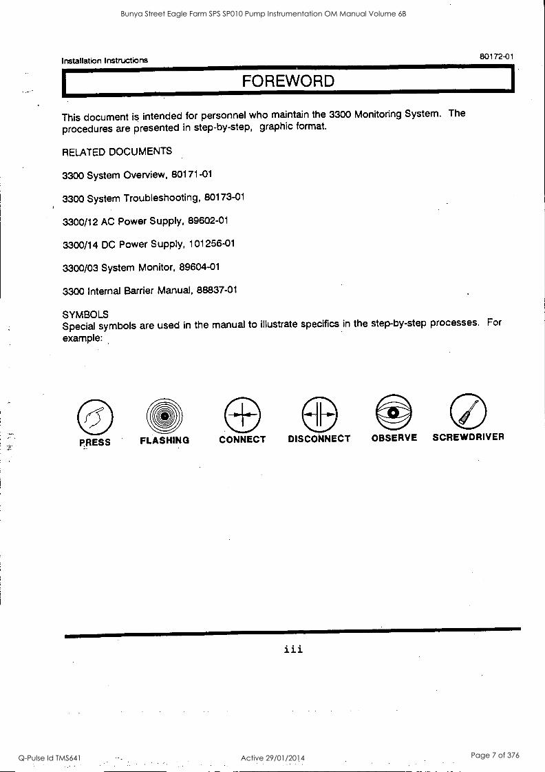
FOREWORD
This document is intended for personnel who maintain the 3300 Monitoring System. The
procedures are presented in step-by-step, graphic format.
RELATED DOCUMENTS
3300 System Overview, 80171-01
3300 System Troubleshooting, 80173-01
3300/12 AC Power Supply, 89602-01
3300/14 DC Power Supply, 101256-01
3300/03 System Monitor, 89604-01
3300 Internal Barrier Manual, 88837-01
SYMBOLS Special symbols are used in the manual to illustrate specifics in the step-by-step processes. For
example:
PRESS FLASHING CONNECT DISCONNECT OBSERVE SCREWDRIVER
iii
Bunya Street Eagle Farm SPS SP010 Pump Instrumentation OM Manual Volume 6B
Q-Pulse Id TMS641 Active 29/01/2014 Page 7 of 376

80172-01 Installation Instructions
iv
Bunya Street Eagle Farm SPS SP010 Pump Instrumentation OM Manual Volume 6B
Q-Pulse Id TMS641 Active 29/01/2014 Page 8 of 376

Installation Instructions 80172-01
CONTENTS
SECTION TITLE PAGE
1 Receiving Inspection 1
2 Handling & Storing Considerations 2
3 Rack Assembly Options 3
4 Rack Installation (Panel Mount) 4
Rack Installation (19-inch EIA) 5
6 Panel Cutout Dimensions 6
7 Weatherproof Housing Installation 7
8 Power Supply Installation 13
9 System Monitor Installation 15
10 Monitor Installation (Typical) 16
11 Power Input Module 17
12 Signal Input Relay Modules 18
13 Alert Relay Actuation Circuits 21
14 Danger Relay Actuation Circuits 23
15 Field Grounding Technique 25
16 Index 26
17 Appendix 27
V
Bunya Street Eagle Farm SPS SP010 Pump Instrumentation OM Manual Volume 6B
Q-Pulse Id TMS641 Active 29/01/2014 Page 9 of 376

80172-01 Installation Instructions
vi
Bunya Street Eagle Farm SPS SP010 Pump Instrumentation OM Manual Volume 6B
Q-Pulse Id TMS641 Active 29/01/2014 Page 10 of 376
Installation Instructions 80172-01
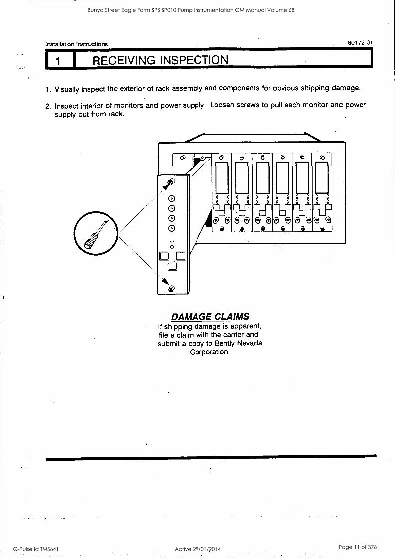
I RECEIVING INSPECTION
1. Visually inspect the exterior of rack assembly and components for obvious shipping damage.
2. Inspect interior of monitors and power supply. Loosen screws to pull each monitor and power supply out from rack.
cDr 0 O 0 0 0 0
LI
ti) I
6 WOINIMM
0
O 0 O 0 O 0
IIMMEMMINIr
.1111= O 0 O 0 O 0
e
.11
11111. O 0 O 0
11,
411 0 0
0 0 0
O 0 O 0 O 0
ae 3
DAMAGE CLAIMS If shipping damage is apparent, file a claim with the carrier and submit a copy to Bent ly Nevada
Corporation.
1
Bunya Street Eagle Farm SPS SP010 Pump Instrumentation OM Manual Volume 6B
Q-Pulse Id TMS641 Active 29/01/2014 Page 11 of 376

80172-01 Installation Instructions
HANDLING & STORING CONSIDERATIONS
Handling and storing of printed circuit boards is extremely critical. Circuit boards contain devices that are susceptible to damage when exposed to electrostatic charges. Damage caused by obvious mishandling of the board will void the warranty. To avoid damage, observe the following precautions in the order given.
*CAUTION Machinery protection will be lost when power is removed from the instrument.
Prior to servicing, remove all power to the instrument.
Do not discharge static electricity onto the circuit board. Avoid tools or procedures that would subject the circuit board to static damage.' Some of the possible causes include ungrounded soldering irons, nonconductive plastics, and similar materials.
Personnel must be grounded with a suitable grounding strap (such as 3M Velostat No.2060) prior to handling or performing maintenance on a printed circuit board.
Transport and store circuit boards in electrically conductive bags or foil.
Use extra caution during dry weather. Relative humidity less than 30% tends to multiply the accumulation of static charges on any surface.
2
Bunya Street Eagle Farm SPS SP010 Pump Instrumentation OM Manual Volume 6B
Q-Pulse Id TMS641 Active 29/01/2014 Page 12 of 376
Installation Instructions 80172-01
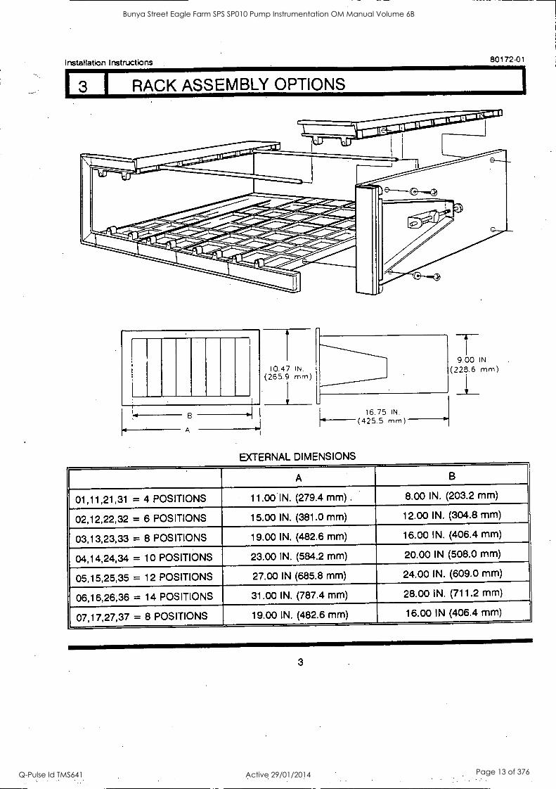
3 I RACK ASSEMBLY OPTIONS
10.47 IN. (265.9 mm
B
A
EXTERNAL DIMENSIONS
16.75 IN. (425.5 mm)
9.00 IN
(228.6 mm)
A B
01,11,21,31 = 4 POSITIONS 11.00 IN. (279.4 mm) . 8.00 IN. (203.2 mm)
02,12,22,32 = 6 POSITIONS 15.00 IN. (381.0 mm) 12.00 IN. (304.8 mm)
03,13,23,33 = 8 POSITIONS 19.00 IN. (482.6 mm) 16.00 IN. (406.4 mm)
04,14,24,34 = 10 POSITIONS 23.00 IN. (584.2 mm) 20.00 IN (508.0 mm)
05,15,25,35 = 12 POSITIONS 27.00 IN (685.8 mm) 24.00 IN. (609.0 mm)
06,16,26,36 = 14 POSITIONS 31.00 IN. (787.4 mm) 28.00 IN. (711.2 mm)
07,17,27,37 = 8 POSITIONS 19.00 IN. (482.6 mm) 16.00 IN (406.4 mm)
3
Bunya Street Eagle Farm SPS SP010 Pump Instrumentation OM Manual Volume 6B
Q-Pulse Id TMS641 Active 29/01/2014 Page 13 of 376
80172-01 Installation Instructions
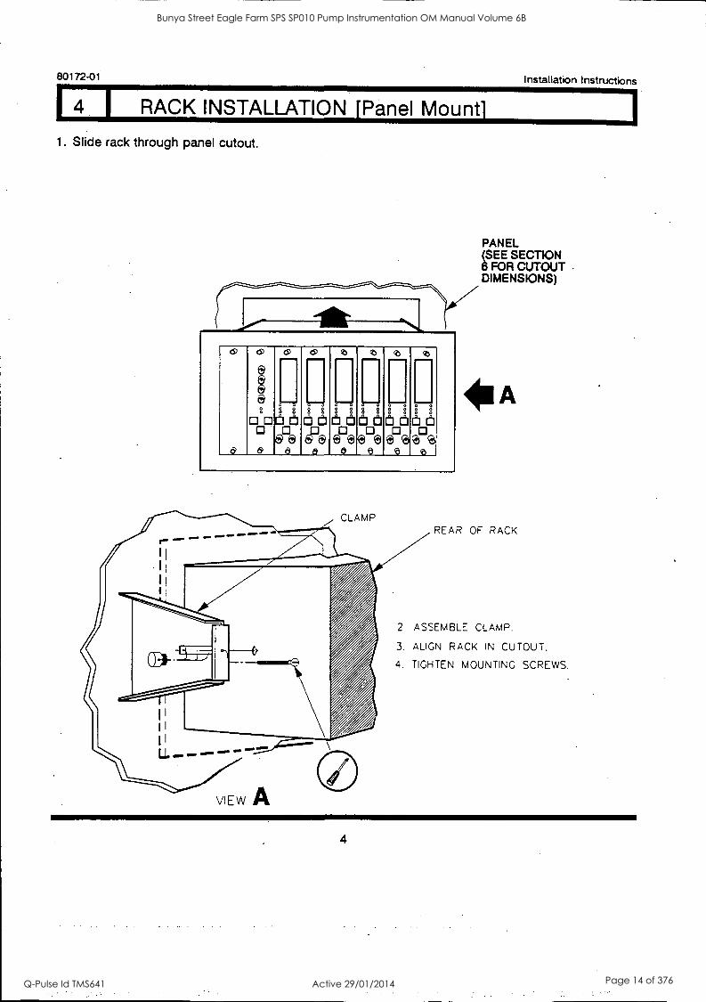
I RACK INSTALLATION [Panel Mount]
1. Slide rack through panel cutout.
CD
6
6)
a g
080 0 ada058e
6) ---
fth I:11
4999
6, ---
8 O
61:ia
0 ---
(1_3 El
ER3
0
6 di
D®
0 ---
8--a
6 8 P,a
0 ---
6 th
ctiFe.
PANEL (SEE SECTION 6 FOR CUTOUT DIMENSIONS)
REAR OF RACK
2 ASSEMBLE CLAMP.
3. ALIGN RACK IN CUTOUT.
4. TIGHTEN MOUNTING SCREWS.
4
Bunya Street Eagle Farm SPS SP010 Pump Instrumentation OM Manual Volume 6B
Q-Pulse Id TMS641 Active 29/01/2014 Page 14 of 376

1
Installation Instructions 80172-01
I RACK INSTALLATION 119-INCH EIA]
19-INCH EIA RACK
0 0 0 0 0 a
0 0
0
CD m
& 0 8
II Illtit ....... 61 CD
t [fit 0 ®e _a
0 0 0
Ott 0 09
b 0
sb
888888883888 a&
15
Obrit 09
8 0
43
0
0 0
NO. 10 FLAT WASHER
(4 PLACES)
PART NO. 3300/05- AA
0 7
0 0 0 0 0 "".
10-32 SCREW (4 PLACES)
3300/05-07 RACK ASSEMBLY
RACK SIZE
07 = 8 Position 19-Inch EIA Rock
ALSO APPLICABLE TO AA OPTION 17.27N ANO 37
5
Bunya Street Eagle Farm SPS SP010 Pump Instrumentation OM Manual Volume 6B
Q-Pulse Id TMS641 Active 29/01/2014 Page 15 of 376
80172-01 Installation Instructions
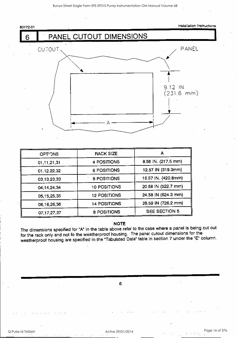
PANEL CUTOUT DIMENSIONS
CUTOUT \ PANEL
9.12 IN
(231.6 mrn)
OPT!ONS RACK SIZE A
01,11,21,31 4 POSITIONS 8.56 IN. (217.5 mm)
01.12.22.32 6 POSITIONS 12.57 IN (319.3mm)
03,13,23,33 8 POSITIONS 16.57 IN. (420.8mm)
04,14,24,34 10 POSITIONS 20.58 IN (522.7 mm)
05,15,25,35 12 POSITIONS 24.58 IN (624.3 mm)
06,16,26,36 14 POSITIONS 28.59 IN (726.2 mm)
07,17,27,37 8 POSITIONS SEE SECTION 5
NOTE
The dimensions specified for "A" in the table above refer to the case where a panel is being cut out
for the rack only and not fo the weatherproof housing. The panel cutout dimensions for the
weatherproof housing are specified in the "Tabulated Data" table in section 7 under the "E" column.
6
Bunya Street Eagle Farm SPS SP010 Pump Instrumentation OM Manual Volume 6B
Q-Pulse Id TMS641 Active 29/01/2014 Page 16 of 376

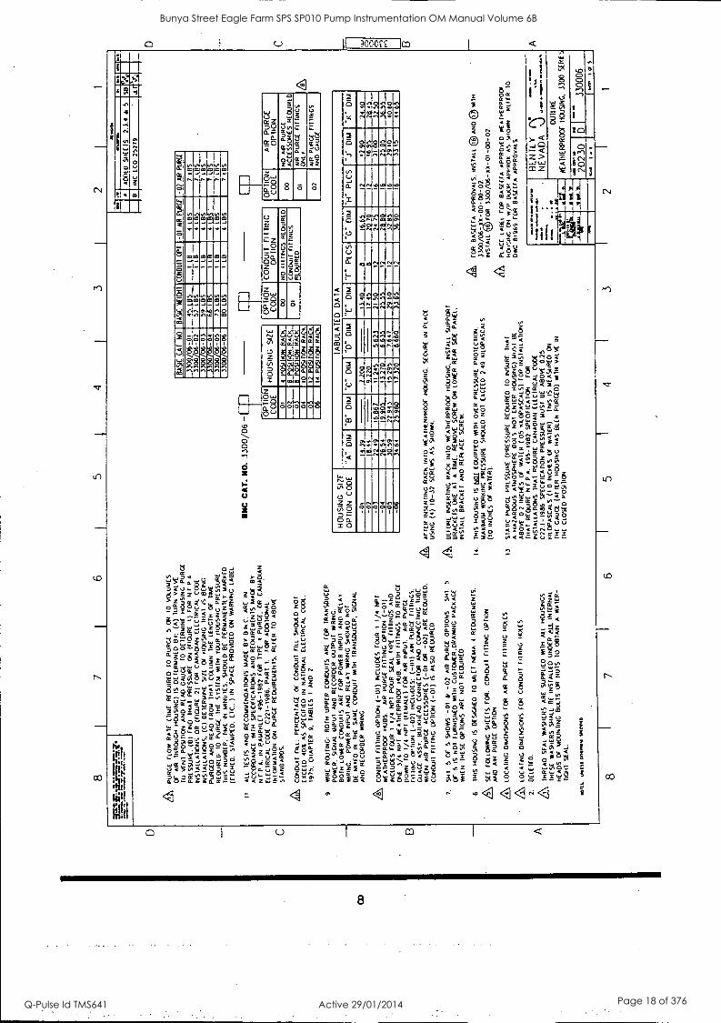
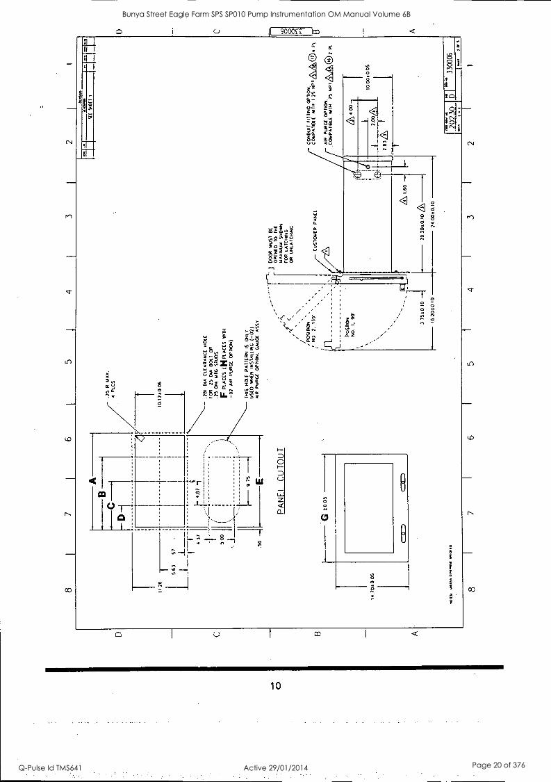
17 I WEATHERPROOF HOUSING INSTALLATION
Installation Instructions 80172-01
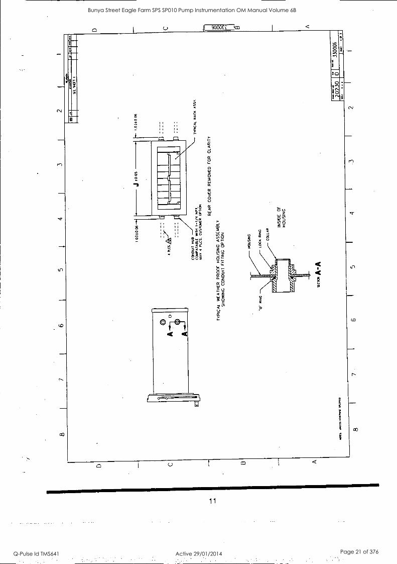
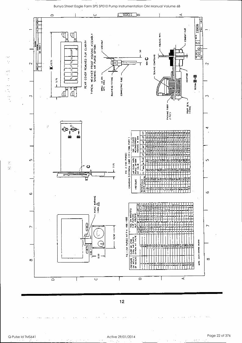
The next 5 pages contain the weatherproof housing installation drawing, 330006.
7
Bunya Street Eagle Farm SPS SP010 Pump Instrumentation OM Manual Volume 6B
Q-Pulse Id TMS641 Active 29/01/2014 Page 17 of 376
8
AP
UR
GE
F
LOW
R
AT
E
(TIM
E
RE
QU
IRE
D
TO
P
UR
GE
5
OR
T
O
VO
LUM
ES
Or
AIR
T
HR
OU
GH
H
OU
SIN
G)
IS
DE
TE
RM
INE
D
7;
(A)
TU
RN
V
ALV
E
TO
V
EN
T
PO
SIT
ION
A
ND
R
EA
D
CA
UC
E
TO
D
ET
ER
MIN
E
HO
US
ING
P
UR
GE
PR
ES
SU
RE
. (B
) F
IND
T
HA
T
PR
ES
SU
RE
O
N
(FIG
UR
E
I) F
OR
N
EP
A
INS
TA
LLA
TIO
NS
OR
(F
IGU
RE
2)
F
OR
C
AN
AD
IAN
ELE
CT
RIC
AL
CO
DE
INS
TA
LLA
TIO
NS
, (C
) D
ET
ER
MIN
E
SIZ
E
Of
HO
US
ING
T
HA
T
IS
BE
ING
PU
RG
ED
A
ND
R
EA
D
FR
OM
T
HA
T
CO
LUM
N
TH
E
LEN
GT
H
OF
T
IME
RE
QU
IRE
D
TO
P
UR
GE
T
HE
S
YS
TE
M
WIT
H
YO
UR
H
OU
SIN
G P
RE
SS
UR
E
DN
S
NU
MB
ER
. T
IME
IN
M
INU
TE
S.
SH
OU
LD
BE
P
ER
MA
NE
NT
LY
MA
RK
ED
(ET
CH
ED
. S
TA
MP
ED
. E
TC
.. )
IN
SP
AC
E
PR
OV
IDE
D
ON
W
AR
NIN
G
LAB
EL
It A
LL
TE
ST
S
AN
D
RE
CO
MM
EN
DA
TIO
NS
M
AD
E
BY
E
l N
.C.
AR
E
IN
AC
CO
RD
AN
CE
W
ITH
S
PE
CIF
ICA
TIO
NS
A
ND
R
EQ
UIR
EM
EN
TS
MA
DE
B
Y
N F
.P.A
. IN
P
AM
PH
LET
49
6-19
82
FO
R
TY
PE
T
P
UR
GE
. O
R
CA
NA
DIA
N
ELE
CT
RIC
AL
CO
DE
C
221-
1986
. P
AR
T
1.
FO
R
AD
DIT
ION
AL
INF
OR
MA
TIO
N
ON
P
UR
GE
R
EQ
UIR
EM
EN
TS
. R
EF
ER
T
O
AB
OV
E
ST
AN
DA
RD
S.
CO
ND
UIT
F
ILL:
P
ER
CE
NT
AG
E
OF
C
ON
DU
IT
FIL
L S
HO
ULD
N
OT
EX
CE
ED
40
5 A
S
SP
EC
IFIE
D
IN
NA
TIO
NA
L E
LEC
TR
ICA
L C
OO
S.
1975
. C
HA
PT
ER
9.
TA
BLE
S
1 A
ND
2
9.
WIR
E
RO
UT
ING
: B
OT
H
UP
PE
R
CO
ND
UIT
S
AR
E
FO
R
TR
AN
SD
UC
ER
PO
WE
R.
SIG
NA
L IN
PU
T
AN
D
RE
CO
RD
ER
O
UT
PU
T
WR
ING
.
BO
TH
LO
WE
R
CO
ND
UIT
S
AR
E
FO
R
PO
WE
R
INP
UT
A
ND
R
ELA
Y
PO
WE
R I
NP
UT
A
ND
R
ELA
Y
WR
ING
S
HO
ULO
N
OT
BE
M
IXE
D
IN
TH
E
SA
ME
C
ON
DU
IT
WIT
H
TR
AN
SD
UC
ER
, S
IGN
AL
AN
D
RE
CO
RD
ER
W
RIN
G.
A CO
ND
UIT
F
ITT
ING
O
PT
ION
(-
01)
INC
LUD
ES
F
OU
R
1 1/
4 N
PT
WE
AT
HE
RP
RO
OF
HU
BS
. A
IR
PU
RG
E
FIT
TIN
G
OP
TIO
N
(-01
) IN
CLU
DE
S
FO
UR
1
1/4
NP
T
PO
UR
S
EA
L T
YP
E
FIT
TIN
GS
A
ND
ON
E
3/4
NP
I W
EA
TH
ER
PR
OO
F
HU
B,
WIT
H
FIT
TIN
GS
10
R
ED
UC
E
DO
WN
T
O
1/4
NP
T
(FE
MA
LE)
FO
R
AIR
IN
PU
T.
AIR
P
UR
GE
FIT
TIN
G
OP
TIO
N
( -0
7) I
NC
LUD
ES
: ( -
OT
) A
IR
PU
RG
E
f I 1 T
ING
S.
GO
RG
E
AS
SY
. B
ULK
HE
AD
C
ON
NE
CT
OR
AN
D
CO
NN
EC
TIN
G
TU
BE
.
WH
EN
A
IR
PU
RG
E
AC
CE
SS
OR
IES
(-
01
OR
-0
2) A
RE
R
EQ
UIR
ED
.
CO
ND
UIT
F
ITT
ING
O
PT
ION
(-
01)
IS
ALS
O
RE
QU
IRE
D
7.
SH
E.
5 O
F
5 S
HO
WS
-0
1 &
-0
2 A
IR
PU
RG
E
OP
TIO
NS
S
HE
5
Or
5 IS
N
OT
F
UR
NIS
HE
D
WIT
H
CU
ST
OM
ER
- D
RA
WIN
G
PA
CK
AG
E
WH
EN
T
HE
SE
O
PT
ION
S
AR
E
NO
T
RE
QU
IRE
D
6 T
HIS
H
OU
SIN
G
IS
DE
SIG
NE
D
10 M
EE
T
NE
MA
4
RE
QU
IRE
ME
NT
S.
A SE
E
FO
LLO
WIN
G
SH
EE
TS
F
OR
. C
ON
DU
IT
FIT
TIN
G
OP
TIO
N
AN
D
AIR
P
UR
GE
O
PT
ION
A LO
CA
TIN
G
DIM
EN
SIO
NS
FO
R
AIR
P
UR
GE
F
ITT
ING
H
OLE
S
LOC
AT
ING
D
IME
NS
ION
S
FO
R
CO
ND
UIT
F
iTIIN
G
HO
LES
2.
DE
LET
ED
.
Z\
TH
RE
AD
S
EA
L W
AS
HE
RS
A
RE
S
UP
PLI
ED
W
ITH
A
LL
HO
US
ING
S
TH
ES
E
WA
SH
ER
S
SH
ALL
B
E
INS
TA
LLE
D
UN
DE
R el
k IN
TE
RN
AL
HE
AD
S
OF
M
OU
NT
ING
B
OLT
S
OR
N
UT
S
TO
O
BT
AIN
A
W
AT
ER
-
TIG
HT
S
EA
L.
won
t. w
its o
mftw
il Lo
uvre
BN
C C
AT
. N
O.
3300
/06
- OP
TIO
N
CO
DE
rev
INC
E
CO
25
279
AD
OE
D
sHE
CIS
. 2.
1.4
&
5
B
011.
77.
ON
O D
o
513
.11
',1*,
BA
SIC
C
AT
N
O
BA
SIC
W
EIC
ill
CO
ND
UIT
O
PT
-0
1 A
IR
PU
NS
-0
1 A
l P
UR
GE
3300
06
-01
45
LBS
LB
4
LEIS
7
LEIS
IFI7
06-0
2 52
LB
S
LB
4 LB
S
7 LB
S
INE
:7 06
-03
11
.114
.U06
- 59
LB
S
LB
4 LB
S
7 LB
S
.6 L
ai
T.1
5' --
--M
7 1.
1-
11
06 -0
5 73
LE
TS
LB
4
LBS
7
LBS
33
00 06
-06
BO
LB
S
LB
4 LB
S
7 LE
TS
HO
US
ING
S
IZE
1111
7111
11M
g177
1010
E
INE
NM
ICIZ
ISIT
CA
DV
ICII
ME
= 11
P
e iT
ION
R
A
OP
IO
N
CO
DE
C
ON
DU
IT
FIT
TIN
G
OP
TIO
N
00
NO
F
AM
INE
S
TIN
GS
R
EQ
UIR
ED
01
CO
ND
UIT
F
ITT
ING
S
RE
QU
IRE
D
=7.
I
I R
11:1
71,5
VM
EN
3
OP
IO
N
CO
DE
A
IR
PU
RG
E
OP
TIO
N
NO
A
IR
PuR
CE
°C
I A
CC
ES
SO
RIE
S
RE
QU
IRE
D
01
AIR
P
UR
GE
F
ITT
ING
S
ON
LT
02
AIR
P
UR
GE
F
ITT
ING
S
AN
D
GA
UG
E
HO
US
ING
S
IZE
O
PT
ION
C
OD
E
TA
BU
LAT
ED
D
AT
A
"A"
DIM
"B
" D
IM
"C"
DIM
"D
" D
IM
"E"
DIM
"F
- P
EC
S
"G"
DIM
"H
" P
EC
S
"J"
DIM
"K
. D
IM
-01
MII=
11
I. 9
220
MIN
ITIM
' 20
70
2___
___
12__
____
. 16
1690
24
.10
-02
16 9
S
2..1
2.__
-0
3 M
TS
INIM
I 11
,o
I 71
N
EN
11
1114
' Im
o IM
INN
E11
1111
TIV
IN
4 7
21.0
0 32
XL_
_1
6..5
5._
40.6
0 -0
4 16
25
05
-05
30 5
9 29
.60
IIER
AB
INIM
I IIN
E
32 8
5 16
29
.10
-06
4.64
.
1,
33 1
5 44
65
A A
FT
ER
IN
SE
RT
ING
R
AC
K
INT
O
WE
AT
HE
RP
RO
OF
H
OU
SIN
G.
SE
CU
RE
IN
P
LAC
E
US
ING
(4
) 10
-32
SC
RE
WS
A
S
SH
OW
N.
A B
EF
OR
E
INS
ER
TIN
G
RA
CK
IN
TO
W
EA
TH
ER
PR
OO
F
HO
US
ING
. IN
ST
ALL
S
UP
PO
RT
BR
AC
KE
TS
ON
E
AT
A
T
IME
. R
EM
OV
E
SC
RE
W
ON
LO
NE
R
RE
AR
S
IDE
P
AN
EL.
INS
TA
LL
BR
AC
KE
T
AN
D
RE
PLA
CE
S
CR
EW
.
14
TH
IS
HO
US
ING
IS
U
M E
QU
IPP
ED
W
ITH
O
VE
R
PR
ES
SU
RE
P
RO
TE
CT
ION
.
MA
XIM
UM
W
OR
KIN
G P
RE
SS
UR
E
SH
OU
LD
NO
1 E
XC
EE
D
2.49
K
x.O
PA
SC
ALS
(10
INC
HE
S
Of
WA
TE
R).
13
ST
AT
IC
PU
RG
E
PR
ES
SU
RE
(P
RE
SS
UR
E
RE
QU
IRE
D
TO
IN
SU
RE
T
HA
T
A
HA
ZA
RD
OU
S
AT
MO
SP
HE
RE
D
OE
S
NO
1 E
NT
ER
H
OU
SIN
G)
MU
ST
B
E
AB
OV
E 02
IN
CH
ES
O
F
WA
TE
R
(OS
K
ILO
PA
SC
ALS
) F
OR
IN
ST
ALL
AT
ION
S
TH
AT
R
EQ
UIR
E N
EP
A.
49S
-198
2 S
PE
CIF
ICA
TIO
N
FO
R
INS
TA
LLA
TIO
NS
T
HA
T
RE
QU
IRE
C
AN
AD
IAN
E
LEC
TR
ICA
L C
OD
E
C22
.1-1
986
SP
EC
IFIC
AT
ION
P
RE
SS
UR
E
MU
ST
B
C
AB
OV
E
0.25
K
ITO
PA
SC
ALS
(1
0 IN
CH
ES
O
F
WA
TE
R)
TH
IS
IS
ME
AS
IIRE
D
ON
TH
E
GA
UG
E
(AF
TE
R
HO
US
ING
H
AS
B
EE
N P
UR
GE
D)
WIT
H
VA
LVE
IN
TH
E
CLO
SE
D P
OS
ITIO
N
A F
OR
B
AS
EE
FA
A
PP
RO
VA
LS,
INS
TA
LL 0
AND
W
ITH
3300
/063
X -
00 -
00- 0
2.
INS
TA
LL
FO
R
3300
/06-
AT
-01-
00-
02.
A)5
P
LAC
E
LAB
EL
FO
R
BA
SE
EF
A
AP
PR
OV
ED
W
EA
TH
ER
PR
OO
F
HO
US
ING
O
N
vf/P
D
OO
R
AP
PR
OX
A
S
SH
OW
N
RLI
ER
T
O
DW
C
8196
9 F
OR
B
AS
EE
FA
A
PP
RO
VA
LS
8 7
6 5
I 4
3
*JO
1
ram
me*
aw
l..
a..
w
11..
i- ta
_
reLa
rd
_
BE
N T
L Y
-
NE
VA
DA
J J
OU
TLI
NE
WE
AT
HE
RP
RO
OF
H
OU
SIN
G.
3300
S
ER
IES
la"-
202
30
3300
06
I
2 1
D
C
Bunya Street Eagle Farm SPS SP010 Pump Instrumentation OM Manual Volume 6B
Q-Pulse Id TMS641 Active 29/01/2014 Page 18 of 376

8 7
5 4
3
5500
WE
AT
HE
RP
RO
OF
tiO
uSeT
C
\1_
5300
SE
RIE
S
RA
CK
O-3
2 16
ME
WS
P
AN
4C
AD
SC
RE
w.
4 R
CS
L.._
FR
ON
T
VIE
W
(VP
MR
NO
T
SH
OW
N
FO
R W
PM
)
WW
1 W
M%
OIN
eo51
11
0/11
:1
1011
ER
R
EA
R
SIX
P
AN
ES
S
CR
EW
SU
PP
OR
T
BR
AC
KE
T
Rtr
to.
1410
111.
Sit
94E
1 1
1014
8 R
EA
R S
et
Pout
( SC
AL
vi
SuP
PO
RI
BR
AIX
T R
EF
SE
E w
i A
85
702-
01
SU
PP
OR
T
BR
AC
KE
T _
PE
CS
A
R
EA
R
VIE
W
NM
Oft,
le
2023
0 33
0006
8 7
I 6
I 5
I 4
I 3
2 I
1
Bunya Street Eagle Farm SPS SP010 Pump Instrumentation OM Manual Volume 6B
Q-Pulse Id TMS641 Active 29/01/2014 Page 19 of 376
rrl
L
(.0
c0
tl
0
8 cs.
0 0
tO
O 0 0,1
Itcn
0 I cs, IO
10
Bunya Street Eagle Farm SPS SP010 Pump Instrumentation OM Manual Volume 6B
Q-Pulse Id TMS641 Active 29/01/2014 Page 20 of 376
8 I
7 I
6 I
5 I
4 I
3 I
2 I
1
Wt.
ollti
vent
I 03
t0 0
6
4 R
CS
CO
ND
UIT
H
UB
C
OM
PA
IAB
LE
WIT
H
1-1/
4 N
PI.
MA
X
4 P
LCS
. C
US
TO
ME
R
OP
TIO
N
TY
PIC
AL
WE
AT
HE
R
PR
OO
F
HO
US
ING
A
SS
EM
BLY
S
HO
WIN
G
CO
ND
UIT
F
IT T
ING
O
PT
ION
0 R
ING
%eh
°. A
-A
RE
AR
C
OV
ER
R
EM
OV
ED
F
OR
C
LAR
ITY
INS
IDE
O
F
HO
US
ING
YE
9111
211.
4
([1
I
1.05
40 0
6
lYP
ICA
L R
AC
K
AS
sv.
CIM
O
M,*
2 02
30
I
3300
06 do
!
8 7
6 5
4 3
2
A
Bunya Street Eagle Farm SPS SP010 Pump Instrumentation OM Manual Volume 6B
Q-Pulse Id TMS641 Active 29/01/2014 Page 21 of 376
8 7
I 6
5 4
2 1
1_ 10
5.
FIG
1
OK
P
UR
GE
) N
F
P
A.
496-
1982
PU
RG
E
WA
RN
ING
LAB
EL a,
PR
ES
SU
RE
(I
N
INC
HE
S
OF
W
AT
ER
)
FLO
W (
IN
GE
M)
DIR
U
AIR
P
UR
GE
O
PT
ION
K
11
VA
LVE
TIM
E
(IN
M
INU
TE
S)
FO
R
PU
RG
ING
W/P
HO
US
ING
4P
WE
I :
IFIM
H
M
UN
19
TOP
®
IEFR
EE
NE
711
12P
31
min
a E
wa
TIP
UN
FM
33
.6
7 6
.8
8 1.
00
16
18
1.0:
11
M.6
1141
1U
Km
17
Imo-
E
l I
,ml
ME
M
I1.
I 2 00
?
4 11
S
E
ll U
sE n
12
11 II
5 0
5.5
10
6 5
Num
mum
a or
mw
mai
rli...
nual
laub
d E
LEE
INIIM
IkE
illE
EE
ICIIE
IMIll
5
19.0
IME
EM
INN
I113
1161
3111
113.
1 .
L.
Enn
lilliE
. Ell
5111
MII
EM
1121
1111
11E
11
MI
ic: I
h.
9 -3
-bo
Ken
t *H
s. 0
11*
FIG
, 2
(10X
P
UR
GE
)
CA
NA
DIA
N
ELE
CT
RIC
AL
CO
DE
C
22
1-19
86 P
AR
T
1
PR
ES
SU
RE
A
IR
RO
W
INR
U
PU
RG
E
()P
ION
K
IT
VA
LVE
TIM
E
10
PU
RG
E
WE
AT
HE
RP
RO
OF
H
OU
SIN
G
IN
LAN
INC
HE
S
KIL
O
WA
TE
R
PA
SC
AL
Elta
llIE
WE
NIII
TT
INIII
IMM
I M
IEM
EK
E21
1111
1M11
111
IEK
EIE
CIA
ININ
IMII
IIIH
IME
:Mia
El:1
MM
II
IEI
Man
M
eal
mom
=
MIK
EZ
IIIM
.
" 3 in
,,,
1.57
M3 /
HR
ItE
tAII
MM
IFE
HIM
IKIE
1 M
AI
WW
II 4p
:
8P
,op
12p
TIP
MN
, R
IM
Fa O
EM
76
M 28
NM
I 72
1 2.
00
212 2
ItE
rl
IMIA
ll il
. 1
ME
M
r101
11:1
IM
Inri
n 11
1.3
411
ma=
4.4
;
Min
0101
10_1
11
Di
El
El um
.
MIK
E=
m
illili
n IE
SIN
SPA
IMM
II
74
2 so
Irap
Ipm
lys
4
ND
3.
10
IMM
IIK
EE
ME
EM
I
PA
CK
ING
F
IBE
R
2 P
tC S
PO
UR
S
EA
L F
ININ
G
/PO
PI
vuo
.
SE
E
901
I
ww
w
RE
AR
C
OV
ER
R
EM
OV
ED
F
OR
C
LAR
ITY
TY
PIC
AL
WE
AT
HE
R
PR
OO
F
HO
US
ING
A
SSE
MB
LY
S
HO
WIN
G
AIR
P
UR
GE
O
PT
ION
DR
ILL
.43
DIA
M
TG
. H
OLE
BU
LKH
EA
D
FIT
TIN
G
CO
NN
EC
TIN
G
TU
BE
r11.
1011
1111
171
1111
1111
16.°
a.
-111
'tzat
ualle
m
SE
ALI
NG
C
OM
PO
UN
D
LOC
K N
UT
AD
AP
TO
R
SE
CT
ION
B-B
HO
US
ING
W
ALL
CO
ND
UIT
H
UB
2 0
2 30
I.
D
3300
06
OW
1O
5
8 6
5 .
4 3
2
Bunya Street Eagle Farm SPS SP010 Pump Instrumentation OM Manual Volume 6B
Q-Pulse Id TMS641 Active 29/01/2014 Page 22 of 376
Installation Instructions
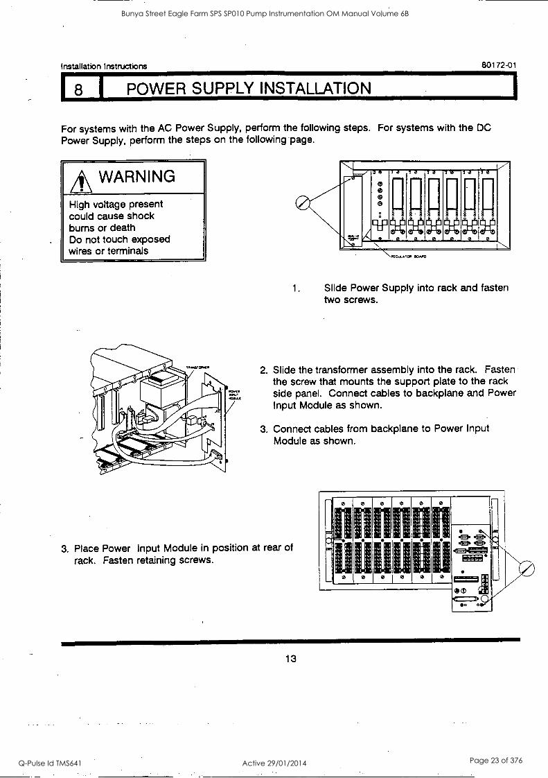
8 1 POWER SUPPLY INSTALLATION
80172-01
For systems with the AC Power Supply, perform the following steps. For systems with the DC Power Supply, perform the steps on the following page.
AN WARNING
High voltage present could cause shock bums or death Do not touch exposed wires or terminals
ptcuLAIcw oak.°
7
1. Slide Power Supply into rack and fasten two screws.
2. Slide the transformer assembly into the rack. Fasten the screw that mounts the support plate to the rack side panel. Connect cables to backplane and Power Input Module as shown.
3. Connect cables from backplane to Power Input Module as shown.
3. Place Power Input Module in position at rear of rack. Fasten retaining screws.
1
r
1 1
1, 1
1, ,1
r,1
1 i 1
1 1
1 1 1
1 1
1,1
1
(a. Al Er I 4E.
MEE'
1==1 0m
I ra
011;
:11. 00
13
Bunya Street Eagle Farm SPS SP010 Pump Instrumentation OM Manual Volume 6B
Q-Pulse Id TMS641 Active 29/01/2014 Page 23 of 376

18 I POWER SUPPLY INSTALLATION ICONT.1
80172-01 Installation Instructions
For systems with the DC Power Supply, perform the following steps.
WARNING
High voltage present could cause shock bums or death Do not touch exposed wires or terminals
f IL TER BOAR 0
POWER INPUT MODULE
NNII--r/ 1,--A
NJ
A r'''
\t".1 ,e
(7 \,01k
36
0 Oa
Ill il il
: a
Ill $4 a
3a
11111
U 0
-7a
1111
il ii
7d
fill
il
7a
ill ii 9:1:1
N
a
V
0
SPECOLATCP BOAPD
1. Slide Power Supply into rack and fasten two screws.
2. Insert filter board. Fasten screw that secures the filter board to the rack side panel. Connect cable from filter board to Power Input Module as shown.
3. Connect cables from backplane to Power Input Module as shown.
4. Place Power Input Module in position at rear of rack. Fasten retaining screws.
I I l
1 1..1
I 1 I
1 1
1:1 I, 1111 0
Z Z.
/
1,1
, 1,1
I, , :I I, 1,
I 1
11:111.,
1
IZIEZ
I 1 1
1 1
, 1,1
1,1
1,1
1,1 1,1
0 II
Ira
14
Bunya Street Eagle Farm SPS SP010 Pump Instrumentation OM Manual Volume 6B
Q-Pulse Id TMS641 Active 29/01/2014 Page 24 of 376

Installation Instructions 80172-01
I SYSTEM MONITOR INSTALLATION
1. Slide System Monitor panel to the right before inserting monitor. Slide System Monitor board into rack to engage connector on backplane.
2. Slide front panel to the left and fasten two screws.
SYSTEM MONITOR BOARD
15
Bunya Street Eagle Farm SPS SP010 Pump Instrumentation OM Manual Volume 6B
Q-Pulse Id TMS641 Active 29/01/2014 Page 25 of 376
80172-01 Installation Instructions
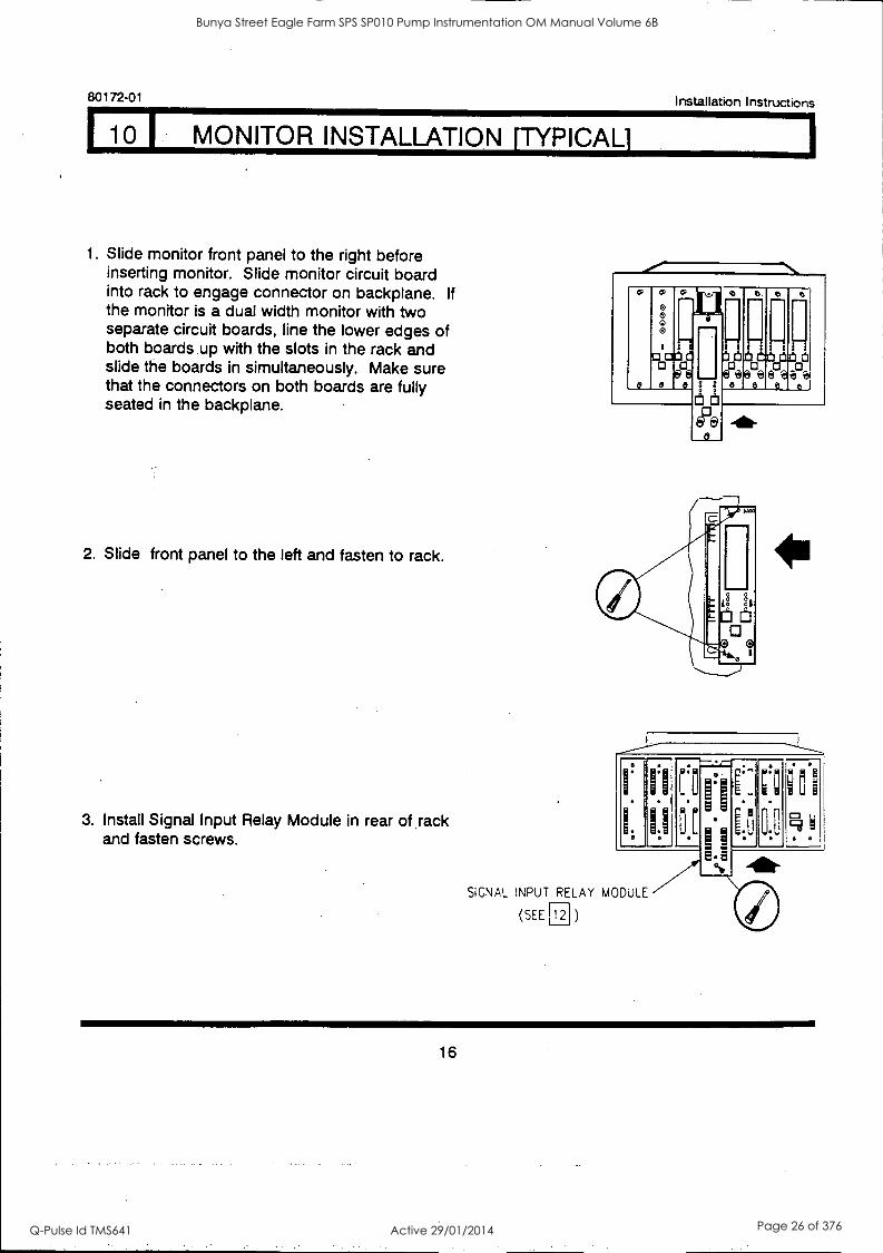
10 I MONITOR INSTALLATION [TYPICAL]
1 Slide monitor front panel to the right before inserting monitor. Slide monitor circuit board into rack to engage connector on backplane. If the monitor is a dual width monitor with two separate circuit boards, line the lower edges of both boards .up with the slots in the rack and slide the boards in simultaneously. Make sure that the connectors on both boards are fully seated in the backplane.
2. Slide front panel to the left and fasten to rack.
3. Install Signal Input Relay Module in rear of sack and fasten screws.
CP CO CP
0 0 0
0 01:1 0
& 8 e e e
r- (:itlEtele11:10
bee eeeA 81 O e e e
SIGNAL INPUT RELAY MODULE
(SEE 12 )
16
Bunya Street Eagle Farm SPS SP010 Pump Instrumentation OM Manual Volume 6B
Q-Pulse Id TMS641 Active 29/01/2014 Page 26 of 376
Installation Instructions 80172-01
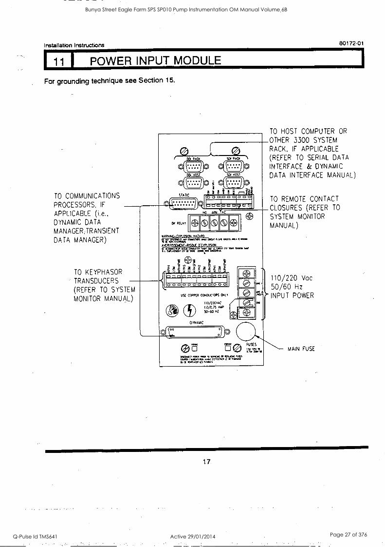
11 I POWER INPUT MODULE
For grounding technique see Section 15.
TO COMMUNICATIONS
PROCESSORS, IF
APPLICABLE (i.e., DYNAMIC DATA
MANAGER,TRANSIENT
DATA MANAGER)
TO KEYPHASOR
TRANSDUCERS
(REFER TO SYSTEM
MONITOR MANUAL)
DOI RACX SDI RACX
wARNINc-ExPLosicN HAZARD CO .0, OiCONLV CIWOCPS oll OICAt OR MISS Ma IS Maw
IC .0.....a1MCOA A VtR1 T1SEVENT -RTSOIA %PLOSION rgeArtjren.r: ., cs, IDA MOM 1"/ 4,ar
1=0 0 ==C=4=1Q0 LQ
0 0 0100 C::)!O 0 01000
USE COPPER CONDUCTORS GILT
I 10/220VAC
1.0/0.75 AMP
50-60 HZ
DYNAMIC
cO:
0
0 0 (+)
INCCMIrtt .0.0 WINO 11)+04 Or WIJUOK WKS (MU l'aILNIIK HO? OtIRCTAO IX 111PanA1
01 .C..t.41. IRS MILES
1.
FU %S SO it. 9
I MA rirf SS
TO HOST COMPUTER OR
OTHER 3300 SYSTEM
RACK, IF APPLICABLE (REFER TO SERIAL DATA
INTERFACE & DYNAMIC
DATA INTERFACE MANUAL)
TO REMOTE CONTACT
CLOSURES (REFER TO
SYSTEM MONITOR
MANUAL)
110/220 Vac
50/60 Hz
INPUT POWER
MAIN FUSE
17
Bunya Street Eagle Farm SPS SP010 Pump Instrumentation OM Manual Volume 6B
Q-Pulse Id TMS641 Active 29/01/2014 Page 27 of 376

80172-01 Installation Instructions
12 I SIGNAL INPUT RELAY MODULES
,A WARNING
High voltage present could cause shock burns or death Do not touch exposed wires or terminals
INVU I I-q..LA'r MULJULL
0,0
BOO
zt, CAUTION
The following information is not applicable to the Velomitor. Refer to the 3300/55 Maintenance Manual for jumper configuration of the Velomitor Relay Module.
JUMPERS wl - W8
FOR FIELD WIRING REFER. TO MONITOR MANUAL
wipiscamVMS
aA 0 0 ON
EU
RIC
043
COI yb
DIA
k C31)
0 0 P. coo 11011
RUM
Of
Ile: I
1
114111
III 1N11
Rol PC, 1
11::11
11:11
110
110 I
11011
1411 Ii::11
ICI
101
101
I?/1
11.111
11011
I
I GI GII
1
1
0 rar Oral
0
Id! un !MU
11011
101
ra
11011
*11 EG1 GU O U 0 I I:11
0 0 uIr RIUY CURIIS
WITH DUAL RELAYS
rn
W6
1114
*3 W2
0
0
0
RELAYS
WITHOUT RELAYS
0
x 00 00
0 0 0 0 x 0 0 0 0
00 00
0
EH
3
CIRCUIT BOARD DUAL RELAYS
JUMPERS
w11,W12
ALERT RELAY JUMPER *
IN OUT
NORMALLY ENERGIZED W3 W4,w1 I
NORMALLY DEENERGIZED W4,w11 W3
DANGER RELAY JUMPER`
IN OUT
NORMALLY ENERGIZED W2 .W1,W12
NORMALLY DEENERGIZED W1,W12 W2
FOR MORE INFORMATION ON RI- CONFIGURATION REFER TO
SECTIONS 13 AND 14.
18
Bunya Street Eagle Farm SPS SP010 Pump Instrumentation OM Manual Volume 6B
Q-Pulse Id TMS641 Active 29/01/2014 Page 28 of 376
Installation Instructions 80172-01
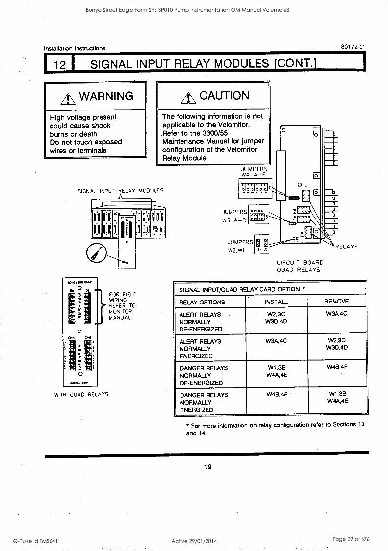
SIGNAL INPUT RELAY MODULES [CONT.]
A\ WARNING
High voltage present could cause shock bums or death Do not touch exposed wires or terminals
CAUTION
The following information is not applicable to the Velomitor. Refer to the 3300/55 Maintenance Manual for jumper configuration of the Velomitor Relay Module.
SIGNAL INPUT RELAY MODULES
moo.g..muis 0
04
1::li u111
h11 1111
eat
O .11
0
O O
1:111 111.11
11,111
"II 11111
1111 r::11
FOR FIELD WIRING REFER TO MONITOR MANUAL
CPO CM13
1::11 usn 110 t 1011
Iron ioII
I :A
11:31
11!.:1 stm
11.611
II11
11::11
ma EU OAS
WITH QUAD RELAYS
JUMPERS W4 A-F
HHHHHEI
JUMPERS
W3 A-D
01117,111.
JUMPERS
W2, W1
CIRCUIT BOARD QUAD RELAYS
SIGNAL INPUT/QUAD RELAY CARD OPTION *
RELAY OPTIONS INSTALL REMOVE
ALERT RELAYS NORMALLY DE-ENERGIZED
W2,3C W3D,4D
W3A,4C
ALERT RELAYS NORMALLY ENERGIZED
W3A,4C W2,3C W3D,4D
DANGER RELAYS NORMALLY DE-ENERGIZED
W1 ,3B W4A4E
W4B,4F
DANGER RELAYS NORMALLY ENERGIZED
W4B,4F W1,38 W4A,4E
* For more information on relay configuration refer to Sections 13
and 14.
19
Bunya Street Eagle Farm SPS SP010 Pump Instrumentation OM Manual Volume 6B
Q-Pulse Id TMS641 Active 29/01/2014 Page 29 of 376
80172-01 Installation Instructions
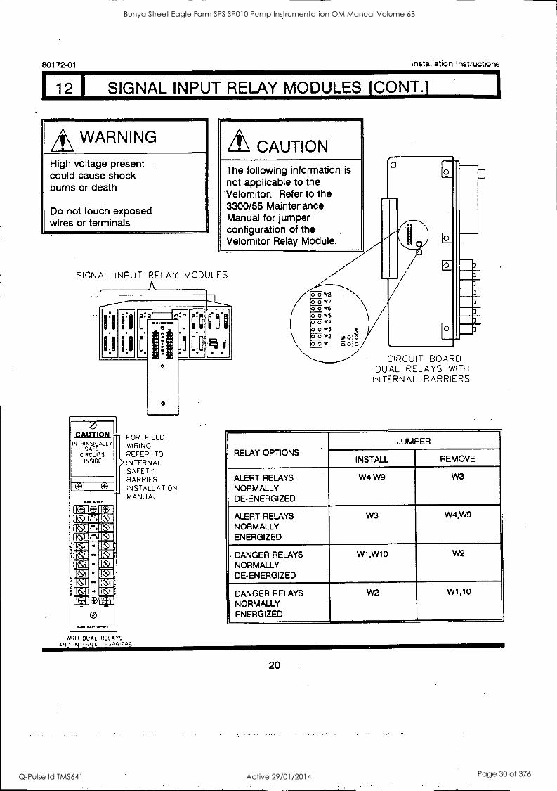
SIGNAL INPUT RELAY MODULES [CONT.]
WARNING
High voltage present .
could cause shock burns or death
Do not touch exposed wires or terminals
A\ CAUTION The following information is
not applicable to the Velomitor. Refer to the 3300/55 Maintenance Manual for jumper configuration of the Velomitor Relay Module.
SIGNAL INPUT RELAY MODULES
1,1
0 CAUTION
INTRINSICALLY SAFE
CIRCUITS INSIDE
1.04 40.1%
Ka O IVA !MEM 115:gliditeg WARM IIM1
- 1 -
K 1 - Keg
=I ES
OrMon
1:11
1,1
FOR FIELD WIRING.
REFER TO INTERNAL SAFETY BARRIER INSTALLATION MANUAL
WITH DUAL RELAYS ANn INTraki el 0,1ZpICQS
0:0 4 CIRCUIT BOARD
DUAL RELAYS WITH
INTERNAL BARRIERS
RELAY OPTIONS
JUMPER
INSTALL REMOVE
ALERT RELAYS NORMALLY DE-ENERGIZED
W4,W9 W3
ALERT RELAYS NORMALLY ENERGIZED
W3 W4,W9
DANGER RELAYS NORMALLY DE-ENERGIZED
W1,W10 W2
DANGER RELAYS NORMALLY ENERGIZED
W2 W1,10
20
Bunya Street Eagle Farm SPS SP010 Pump Instrumentation OM Manual Volume 6B
Q-Pulse Id TMS641 Active 29/01/2014 Page 30 of 376
Installation Instructions 80172.01
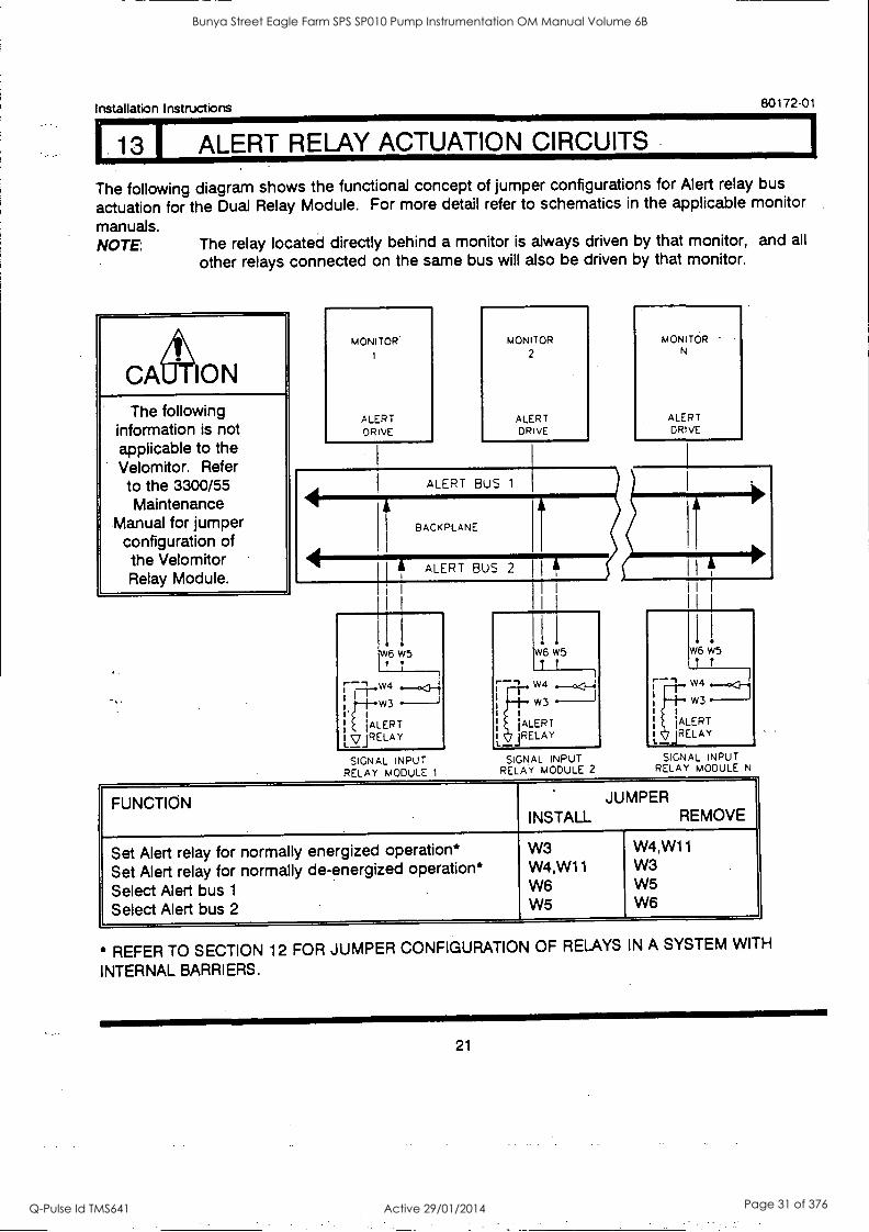
13 I ALERT RELAY ACTUATION CIRCUITS
The following diagram shows the functional concept of jumper configurations for Alert relay bus
actuation for the Dual Relay Module. For more detail refer to schematics in the applicable monitor
manuals. NOTE: The relay located directly behind a monitor is always driven by that monitor, and all
other relays connected on the same bus will also be driven by that monitor.
ON The following
information is not applicable to the Velomitor. Refer to the 3300/55 Maintenance
Manual for jumper configuration of the Velomitor Relay Module.
MONITOR
ALERT DRIVE
MONITOR 2
ALERT DRIVE
ALERT BUS 1
BACKPLANE
41 ALERT BUS 2
SIGNAL INPUT RELAY MODULE 1
II
W6 W5
1 t
W4
w3
jALERT JRELAY
SIGNAL INPUT RELAY MODULE 2
MONITOR N
ALERT DRIVE
I I
! W6 w5
-- I
7......:311 , W4
w3 1
1 'ALERT
L1
(RELAY __
SIGNAL INPUT RELAY MODULE N
FUNCTION JUMPER INSTALL REMOVE
Set Alert relay for normally energized operation* Set Alert relay for normally de-energized operation* Select Alert bus 1
Select Alert bus 2
W3 W4,W11 W6 W5
W4,W11 W3 W5 W6
* REFER TO SECTION 12 FOR JUMPER CONFIGURATION OF RELAYS IN A SYSTEM WITH
INTERNAL BARRIERS.
21
Bunya Street Eagle Farm SPS SP010 Pump Instrumentation OM Manual Volume 6B
Q-Pulse Id TMS641 Active 29/01/2014 Page 31 of 376
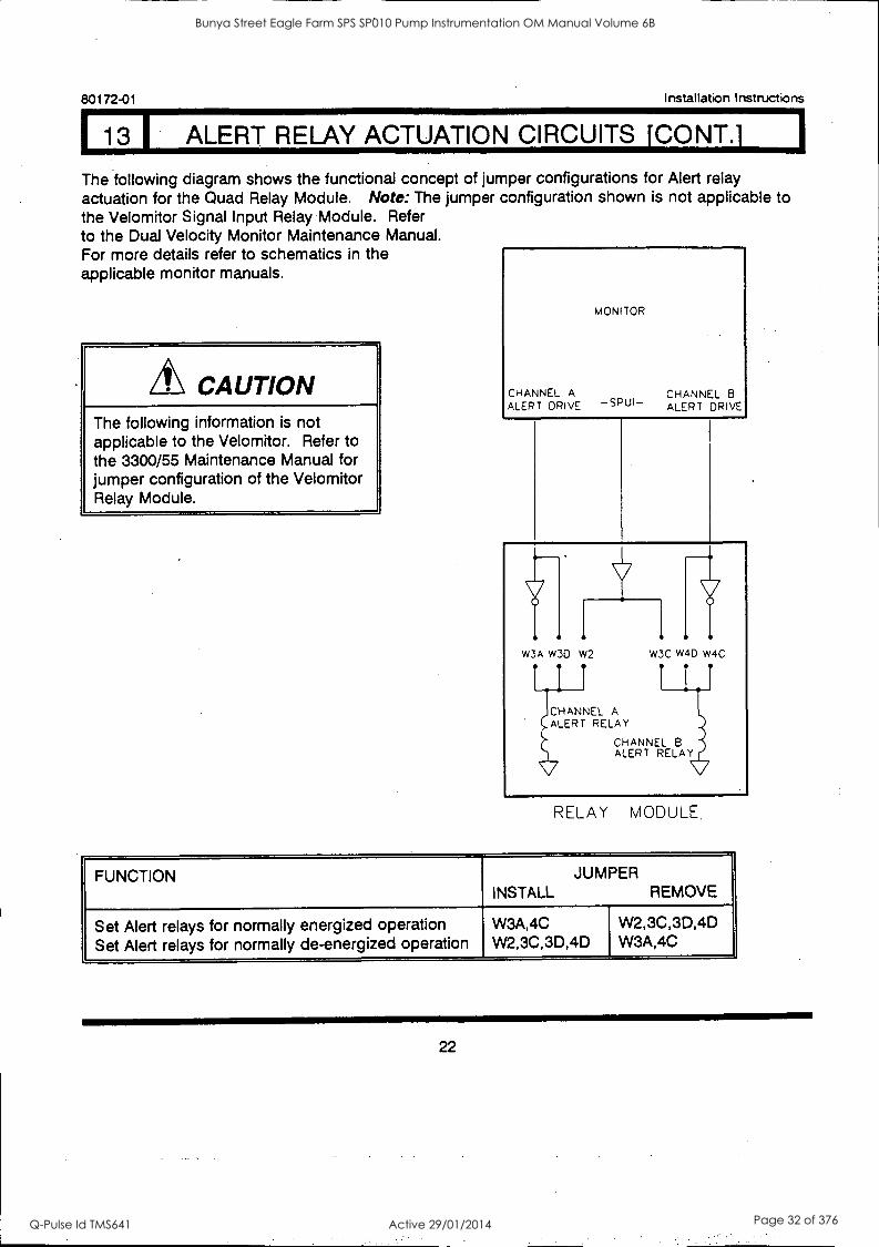
13 ALERT RELAY ACTUATION CIRCUITS [CONT.] I 80172-01 Installation Instructions
The following diagram shows the functional concept of jumper configurations for Alert relay actuation for the Quad Relay Module. Note: The jumper configuration shown is not applicable to the Velomitor Signal Input Relay Module. Refer to the Dual Velocity Monitor Maintenance Manual. For more details refer to schematics in the applicable monitor manuals.
CAUTION The following information is not applicable to the Velomitor. Refer to the 3300/55 Maintenance Manual for jumper configuration of the Velomitor Relay Module.
MONITOR
CHANNEL A ALERT DRIVE -SPUI-
,
CHANNEL 8 ALERT DRIVE
w3A W3D W2 W3C W4D W4C
CHANNEL A ALERT RELAY
CHANNEL B ALERT RELAY
RELAY MODULE.
FUNCTION JUMPER INSTALL REMOVE
Set Alert relays for normally energized operation Set Alert relays for normally de-energized operation
W3A,4C W2,3C,3D,4D
W2,3C,3D,4D W3A,4C
22
Bunya Street Eagle Farm SPS SP010 Pump Instrumentation OM Manual Volume 6B
Q-Pulse Id TMS641 Active 29/01/2014 Page 32 of 376
Installation Instructions 80172-01
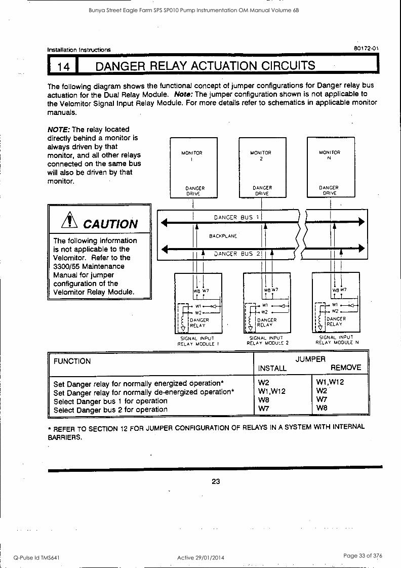
14 DANGER RELAY ACTUATION CIRCUITS
The following diagram shows the functional concept of jumper configurations for Danger relay bus
actuation for the Dual Relay Module. Note: The jumper configuration shown is not applicable to the Velomitor Signal Input Relay Module. For more details refer to schematics in applicable monitor manuals.
NOTE: The relay located directly behind a monitor is always driven by that monitor, and all other relays connected on the same bus will also be driven by that monitor.
CAUTION The following information is not applicable to the Velomitor. Refer to the 3300/55 Maintenance Manual for jumper configuration of the Velomitor Relay Module.
MONITOR
DANGER DRIVE
MONITOR
2
DANGER DRIVE
DANGER BUS I
BACKPLANE
DANGER BUS 2
SIGNAL INPUT RELAY MODULE 1
MONITOR N
DANGER DRIVE
W8 W7
W1
W2
DANGER I RELAY
L_J SIGNAL INPUT
RELAY MODULE 2 SIGNAL INPUT
RELAY MODULE N
FUNCTION JUMPER INSTALL REMOVE
Set Danger relay for normally energized operation* Set Danger relay for normally de-energized operation* Select Danger bus 1 for operation Select Danger bus 2 for operation
W2 W1,W12 W8 W7
W1,W12 W2 W7 W8
* REFER TO SECTION 12 FOR JUMPER CONFIGURATION OF RELAYS IN A SYSTEM WITH INTERNAL
BARRIERS.
23
Bunya Street Eagle Farm SPS SP010 Pump Instrumentation OM Manual Volume 6B
Q-Pulse Id TMS641 Active 29/01/2014 Page 33 of 376
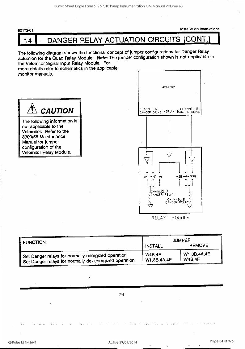
DANGER RELAY ACTUATION CIRCUITS [CONT.] I 80172-01 Installation Instructions
The following diagram shows the functional concept of jumper configurations for Danger Relay
actuation for the Quad Relay Module. Note: The jumper configuration shown is not applicable to
the Velomitor Signal Input Relay Module. For more details refer to schematics in the applicable monitor manuals.
A\ CAUTION The following information is
not applicable to the Velomitor. Refer to the 3300/55 Maintenance Manual for jumper configuration of the Velomitor Relay Module.
MONITOR
CHANNEL A CHANNEL B
DANGER DRIVE DANGER DRIVE
W4F W4E W1
I I I
CHANNEL A DANGER RELAY
CHANNEL B DANGER RELAY
\,:tf
w38 W4A W4B
1 1 1
RELAY MODULE
FUNCTION JUMPER INSTALL REMOVE
Set Danger relays for normally energized operation Set Danger relays for normally de- energized operation
W4B,4F W1,3B,4A,4E
W1,3B,4A,4E W4B,4F
24
Bunya Street Eagle Farm SPS SP010 Pump Instrumentation OM Manual Volume 6B
Q-Pulse Id TMS641 Active 29/01/2014 Page 34 of 376
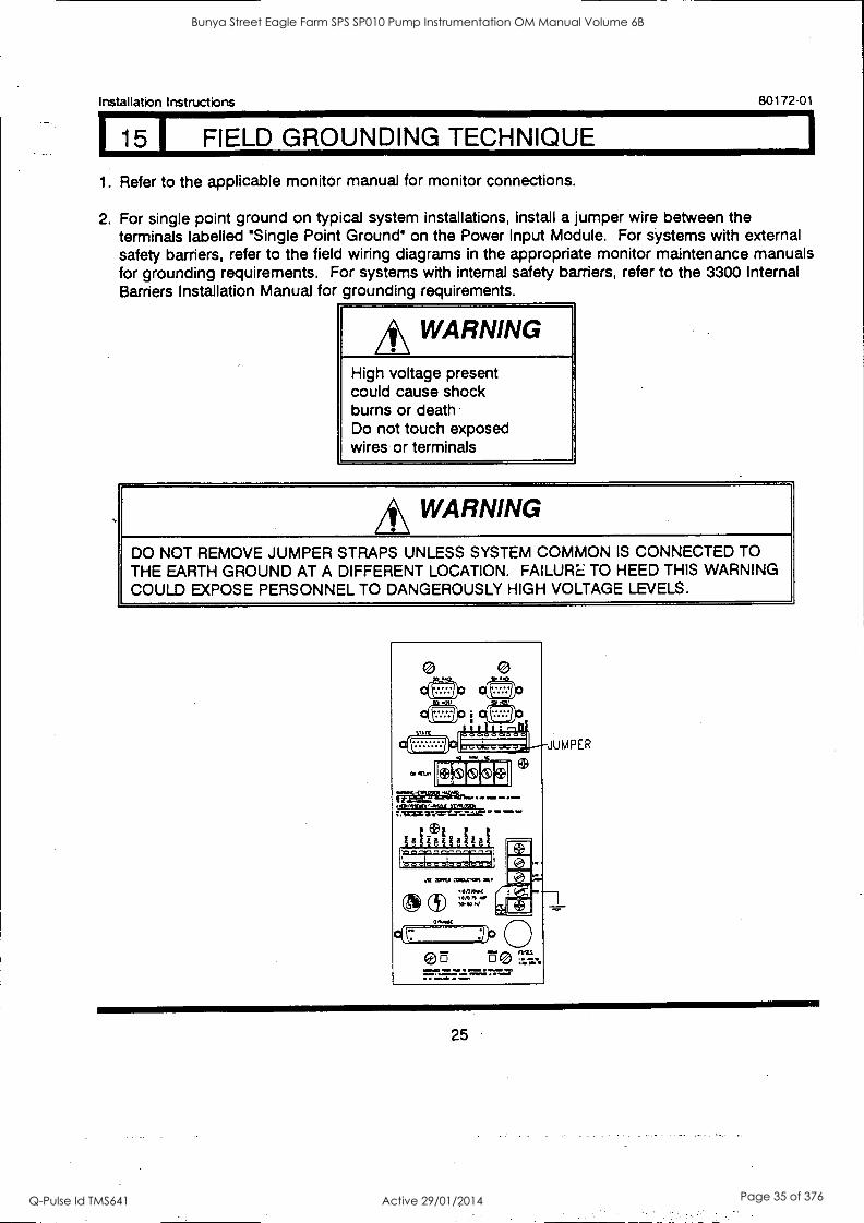
115 I FIELD GROUNDING TECHNIQUE
Installation Instructions 80172-01
1. Refer to the applicable monitor manual for monitor connections.
2. For single point ground on typical system installations, install a jumper wire between the terminals labelled 'Single Point Ground' on the Power Input Module. For systems with external safety barriers, refer to the field wiring diagrams in the appropriate monitor maintenance manuals for grounding requirements. For systems with internal safety barriers, refer to the 3300 Internal Barriers Installation Manual for grounding requirements.
*WARNING High voltage present could cause shock burns or death Do not touch exposed wires or terminals
*WARNING DO NOT REMOVE JUMPER STRAPS UNLESS SYSTEM COMMON IS CONNECTED TO THE EARTH GROUND AT A DIFFERENT LOCATION. FAILURE TO HEED THIS WARNING COULD EXPOSE PERSONNEL TO DANGEROUSLY HIGH VOLTAGE LEVELS.
25
Bunya Street Eagle Farm SPS SP010 Pump Instrumentation OM Manual Volume 6B
Q-Pulse Id TMS641 Active 29/01/2014 Page 35 of 376

80172-01 Installation Instructions
16 1 INDEX 1
PAGE
Alert Relay Actuation Circuits 21,22
Danger Relay Actuation Circuits 23,24
A
F Field Grounding Technique 25
H Handling & Storage Considerations 2
M Monitor Installation (Typical) 16
0 Options
Rack Assembly Options 3
P Panel Cutout Dimensions 6
Power Input Module 17
Power Supply Installation 13,14
R Rack Assembly Options 3
Rack Installation (19-inch EIA) 5
Rack Installation (Panel Mount) 4
Receiving Inspection 1
S Signal Input Relay Module 18,19,20
System Monitor Installation 15
Weatherproof Housing & Rack Assembly 7-12
26
Bunya Street Eagle Farm SPS SP010 Pump Instrumentation OM Manual Volume 6B
Q-Pulse Id TMS641 Active 29/01/2014 Page 36 of 376

Installation Instructions 80172-01
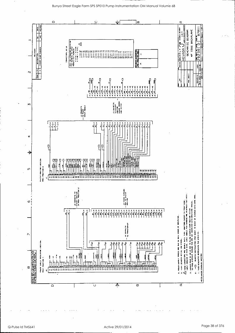
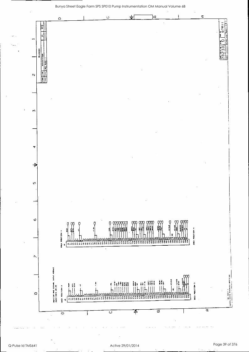
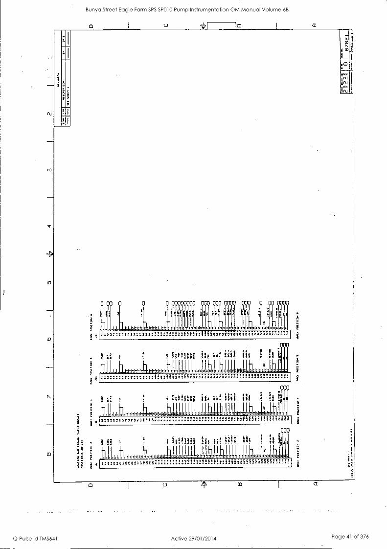
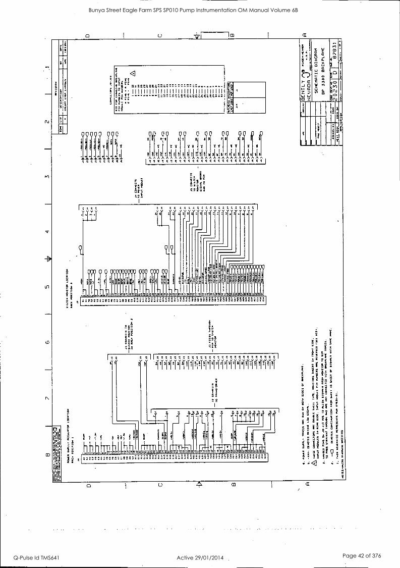
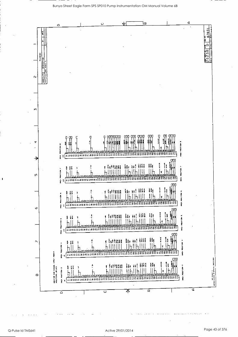
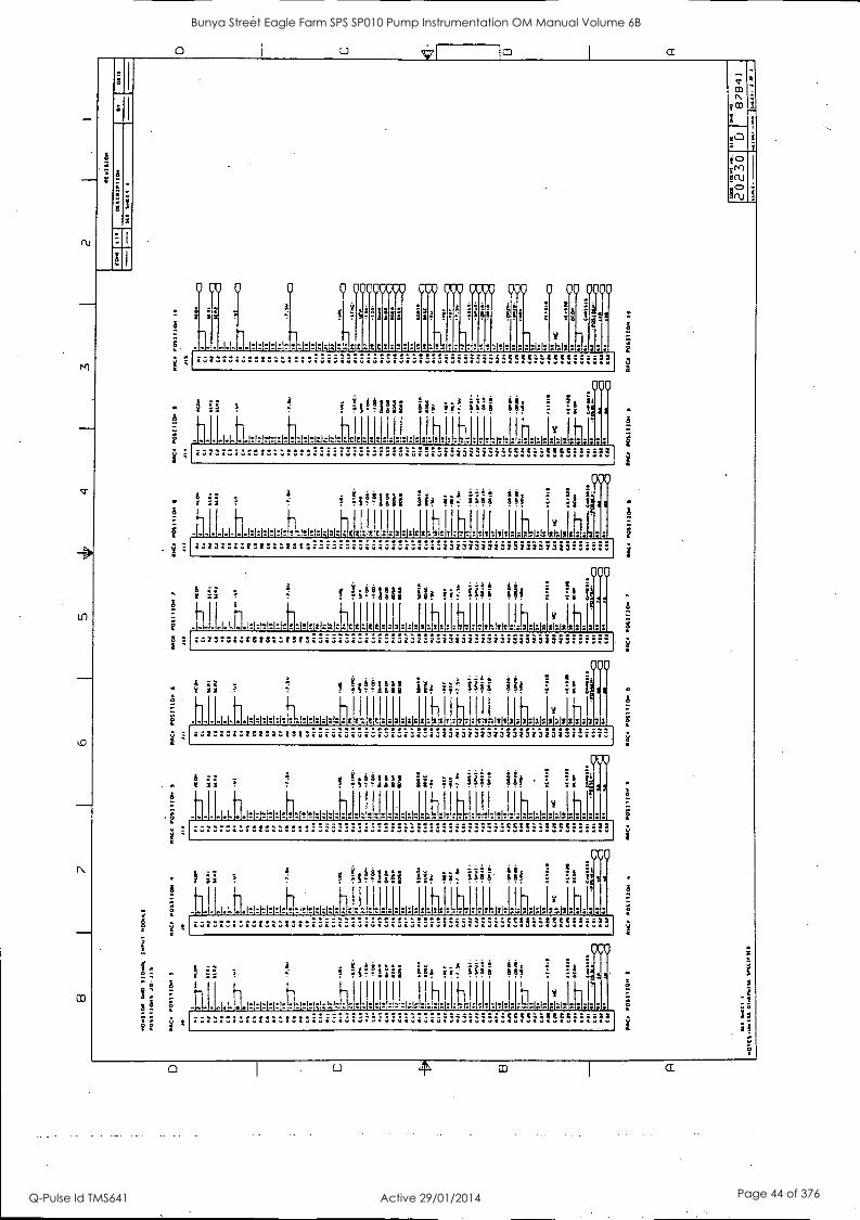
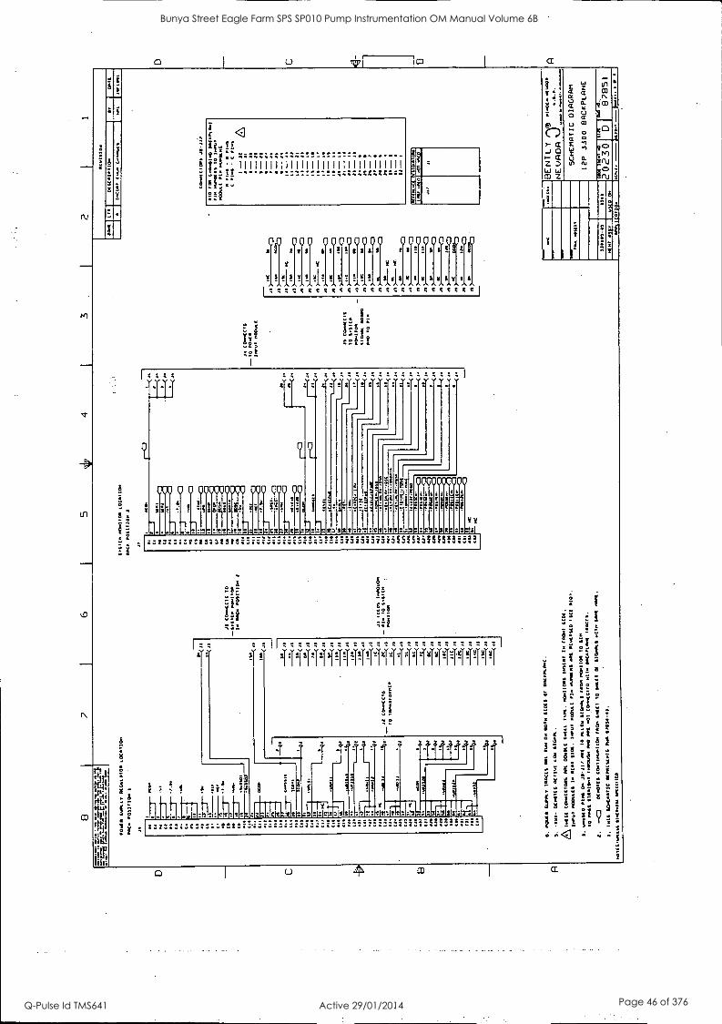
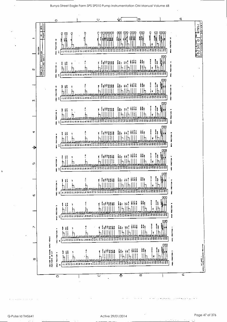
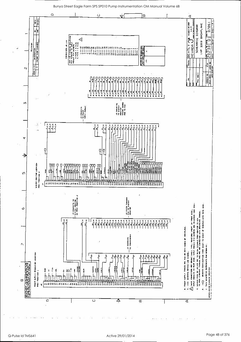
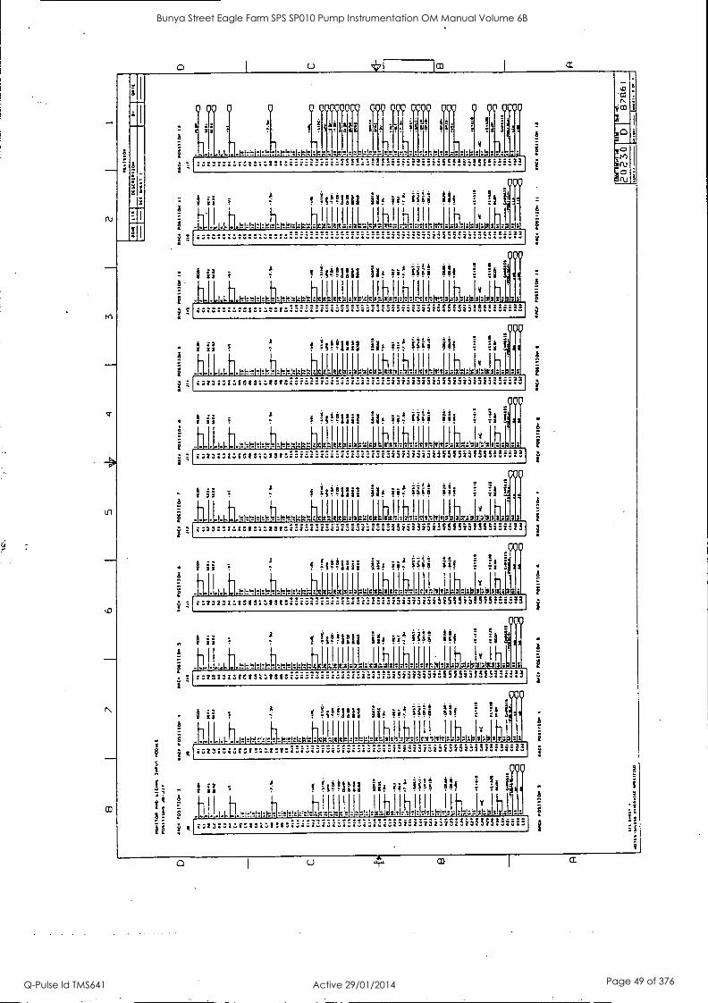
117 I APPENDIX
DRAWING TITLE
3300 4 Position Back Plane Schematic
3300 6 Position Back Plane Schematic
3300 8 Position Back Plane Schematic
3300 10 Position Back Plane Schematic
3300 12 Position Back Plane Schematic
3300 14 Position Back Plane Schematic
DRAWING NO. NO. OF SHEETS
87811 2
87821 2
87831 2
87841 2
87851
87861 3
27
Bunya Street Eagle Farm SPS SP010 Pump Instrumentation OM Manual Volume 6B
Q-Pulse Id TMS641 Active 29/01/2014 Page 37 of 376
<1
?!.177 ti ti III' II
s.,
;:i
.;.°1 Al
v v ywv;
!!!1!1!!140,.,1144..44.1144111.1Ab
a ; !
"y
000 o00
I..
V
6
tTef
0000 000 000 00
gi
cc%
2'12
-12
12:3221222:2221st '
0
.
-!f Ai!i?
Ittittl..I2:4:244122kLal.21.2 -771)--71- F-17.1.44:1;IL .......
i;
-.2 ;21
2!
Ti
2
. E .
8
I
0 U ti co CC
Bunya Street Eagle Farm SPS SP010 Pump Instrumentation OM Manual Volume 6B
Q-Pulse Id TMS641 Active 29/01/2014 Page 38 of 376
cr) 0
a
as
t1 t:::::astvsa)s
4 ' ..11111411111"liliT '19119I'I991111" Lill 1111 Hill
: a. : a? / ,2 a! -
000
.r.2:3212:t2223 :::::
A
,29 qy
MOO 00 0 060 0060 cY 000
00606000 0
cnt 0
Bunya Street Eagle Farm SPS SP010 Pump Instrumentation OM Manual Volume 6B
Q-Pulse Id TMS641 Active 29/01/2014 Page 39 of 376

U 1©
N1
03
8
.
;/ of
0 00 0 00 1 II I A 3
1 1,1!ly !144.A014!,,,,,I.likdAyA, ,1.,,
,, wwWw VVV WV W V
nsssstggsesssc sgsssIsssss r. I
k LiE12 1217.!
COO 0 0
RI C
000 000 000 000
fi=t
glzcs-le -121:4
0000
88888888 t :;7 .1:.2:412f3F;W41
:=237:.:t:132.133 ' :::azr:735515i51555"--33
2!: i ;
E .. ..
1i.i
i
:1e! .r. .: lil ;a
1
=?
i7!! 4W IL 1 2
h
........... .
11M
...... 000.wa
S
n<1 . ft
Bunya Street Eagle Farm SPS SP010 Pump Instrumentation OM Manual Volume 6B
Q-Pulse Id TMS641 Active 29/01/2014 Page 40 of 376
1
I
1
a
YP
400 0
Y 7y
-
Si
I. I-I- 1^
o oyoycio? o coo coo moo oyo 0 00 0000
i
cc:21221:122: 27 72211122 8:13012,0
2:232327.28282:1232 . 03232323232823232323
h h h 2
Of= h.: 5.12 /
:8 28
000
.............. .M. CC222.22222:2--22
.yoo ;a: :
/ f W Ili a i
. 1.144.1.1.1.1.thieW:17.#:1:,44121:.12 . :1110:J: II , ! 1-1
z
ii! iii; 1:s :1
40
.1t1:1"-t-17.12;!: :1 .. :17111 .. . I . 1:11::1 :: 11; ::::: 1-111111 1 I I I
A
1 N .
-
4 CD
1
5O i
c)
0 4 a
Bunya Street Eagle Farm SPS SP010 Pump Instrumentation OM Manual Volume 6B
Q-Pulse Id TMS641 Active 29/01/2014 Page 41 of 376
kiD
co
I co
I
/111,
1 -If
110
!!!il
A
A a
a
<3
21
at
99 0
09 90 90 19
1 : I 1 r W Y Y w V V v W V
44i 5 11! 515 w I it c 114 I II w sff:..:teS ccsee CC
...
000 0 0 000 00
w.
C %ft
-;-
00000000000
:;2; IS i;13:SIZI;f32;13: 23,333233345f3:51 13:-"32
I . '
A
i
.7; 5 o!
--4 ------ ----
Wc. SI41 21(1.1
ei -
Bunya Street Eagle Farm SPS SP010 Pump Instrumentation OM Manual Volume 6B
Q-Pulse Id TMS641 Active 29/01/2014 Page 42 of 376
i71
a
0 00 0 0 0 00010 000 000 0000 000 0 00 0000
i T f ; saq il ii g ief 11 '
- a
,-. .... .-
.4.1...14:11*WrItit121.1tX gtA 21:111= L 4 11*...-01:41:4124::: ::. i m3g323g3f5 5i5fli '52:33]
000
! ii T ''.
i N!!iiii 'if ii:? 10; !!! Is 4 g
-11:111A-1-1-11-414zw:ticallaitzigalgl * l_h."1 ' 1.1,017.1,40,1:04.61:66. I k I.
25232515SC232:232 r3l3:32323i5f5i3llf5::::
:clot:a:sots:alto: '
..,000
0 ii 1 NMIll lif W iiii 1;1 i i fil IL,
J1111.11Litititt:WIOLL11112:14112141-1111121$31:42121::12: azza::::totsa:tat r3:323:3z3fSinif3f5""' 1
g f ii? it if
h I fi
1,14I .14.1.1.1.1-1-tt1-41^N-1:141:111/Lit{ta:1:1:12LF121 ''
2323:::52:132:232
0
ill h l 11,1:01: :111:14, Lillis
2323232323ISLII51545iiii!3
000
i ii : 1 httina 9l4 MI III i .*
1 JalL4t1.1,11,t6,4,0:*tIcLL111-11-41-14 Ilh 1 41,01.4.614.,1:11::.
1 1 1 ' in
0 i g .52 2.23:3232' 23232323232323232323
s 04 Ili
s
1[1111'I 11.-11h1 ' h. '''' 1.1 ' 1.1.1:1:H-21:111-11e1t1:1:121:141:7.1t1r.,--"IzI" '' ' '' rl
'''''' ."'""
S
Bunya Street Eagle Farm SPS SP010 Pump Instrumentation OM Manual Volume 6B
Q-Pulse Id TMS641 Active 29/01/2014 Page 43 of 376
U
i^
ab
4000
1.1-1"1"I1^
y ocuoymo 000 000 0000 000 0 00 00T
211ii a4 3 3 f 3
'11-1-1- . ... .... ......1.1. .... 1-1^1 ..... '""CC4C43XXRC::::2
f 1:16 iif
-I .. .. . .1. 000
. . 00 .00mo
000
f66s` . 5
6 " rs
. .. h. .. Y. . . f.1 .... 6:34:11XICR;;;;3
- lotilli ill iii; ;:i a k
. U .. .1.111.1:1=1*J1.121:14Jlaz 1=121:1:01 1-4'LLIT:1146
A
000
A
31617t111136 3:33::.:631'"I'l 23737373333323732323
6111 iN87 !
# i,iilasa v2
IY 31.
00
3:
73732.33332323237323
000
: :4t,taaaa 124 irri 1.4f ffi !:
! ;"; .7
4 l'
d i.iilbS3 ' ." [ii: Vd S; 11
_h- LI ..... ti . fr.,,.,,,,,:,...t.L.,,,,.,:,:..1.ckz.t._.1...1,,..,___,...,,,,,.; a :I:I: s1:11 s : :Is :I: I
k I r
........, . "- ......... .- "i5iii5i5iSiSi5i323:5 .. ---
6 :2 win: 304 ii!
h h . . ......... .................
1
0 .. 3
lit : :1
"'CCitZZLCC366-;62 as
000
A
A .1.1.
I "!"11ii th ?it "Bi
-1 h . J . .. b .
661 it,
IY
*CtI433tatt:::.33
000
?
6 5 .00,111 Alb ii:' iii; Vi
: X
.. nieLN.,17.11t4.7.1111LLILL I. 11.....11 . ..
A
G,
Mry
g° ru
a m I a
Bunya Street Eagle Farm SPS SP010 Pump Instrumentation OM Manual Volume 6B
Q-Pulse Id TMS641 Active 29/01/2014 Page 44 of 376

ru
r.n
1
In
kr)
ai
'!1i
t
rtlz.
141,1
4f
f;!i: 11111111111111111111111111111111
!!-:!
i
000 0000 000 po 00 cat al! VW, el s
V V Y V Y V V V
V V VII ! ! I! V ! ! ! VI ! 1.14, 1.. 1.,....,1 v f. -- 8;q2 .0A-4
oyo y 0 °Too 000 000 000 00
! A
' . w ;is 1 Till
:2, i
si
lc JecOctAp:12
:::-:Iststscatat '
t t .
a 3
if 00000 0
If
VYYV 7..so Its :4M:I
1313 733 :S SSSi343SSi3i5i3
2!:
L3";:a
:f
r!
..... .0?-1%
I
U 4
Bunya Street Eagle Farm SPS SP010 Pump Instrumentation OM Manual Volume 6B
Q-Pulse Id TMS641 Active 29/01/2014 Page 45 of 376
1
U VI
A
3
3
n
N
I;!
a )
A
A
Yi
.
-
5 <1 ri:!! f"11::
.83
000 00 00000 0000000 0 sos ss!lesss rs!!ss!
WY
4! Y f 4!!!!!!!W4 l4iwell ^OS eN.
Cg t ;CC; t t C t t C t 4 I
f. p.s; 1Ef2
000 0 0 000000000 000
f :ii°1111
o A
4 Ettti . .
0 OP 0000000000
g ! :
icc0 IC12 T1 :VI :.:=1;1:11 ;3111sl
33 373732355f573I5152":221
A
if '4 2
4 4=;44=4 J L 1
T11111 !*
if 5 3 r.
-
771=1 tr:: 1 I 14.11 ---- -cItzlx04:24Wg=1,1 ---- OOOOOOOOOOO:OOOOO . ftd..V..00100.. OOOOOOOO ft
U, CD
403 1
en
:
2
U 4 a
Bunya Street Eagle Farm SPS SP010 Pump Instrumentation OM Manual Volume 6B
Q-Pulse Id TMS641 Active 29/01/2014 Page 46 of 376
0 0 0 0 OOOQ 00 0 OPO 40 0
2
00 0000
f i 1! g. A ', ;
: .---'.. ....... -.."-2222:22222.22.21
000
1 g > f =WM! pie W 011 i !!
I.-, I I
-1-1-1.1.1A-1.1.1.:1:1,4,1;:frt*Itisfr.ls zs 1, JILLIAL b.! . 1 .. LI:I . 1311.1.::111:1,
.
.. ...,..,:, .. ..................... -i1355i:2222:-22$26.- 2:
000
i ii 54
1 Nffini its W Si1i 11f A 1104
i . 222:222226-:2
2
000
- f fi!!1111 ii; ii= 01i 10
-'11111 11 III Ilk 11-11.LHItt4M.-121212k12k4-1.61:12.1461.144-1.12612.61.112121:1224466662 2321237:13,222232 51 i5i515i5f5i5iii55542
000
!win' 11 ii= ia; 11! it
ilt.7.x111/1-1-2L111-21 I- 11 I 11211111111:1111:-.111;I2L3
:13::;:stesraztst . 2a2o23:azsf5i5i5!5f5"- -33
000
Y 11 22 24* .2 222.2
:X ii; I; ! I
-k 4 1111,1.= h 114k 1.1 6U. -1 1:,6.;
- ;z22::1:St2111;:1122 . l3231.111:f5f5i5 5f4"7":
_000
i is > g foliiii pt 8! 111
-1111.1ab.1=1:M==12"11.21:F21 . . 12,- 2112111:2[411-.1.1.
1:23;34Z2222;:i9t ' 2 :2222222255,51iI5P77"
000
1 ii I =WIN! iif 111
Ll.
3313::.:scfsa:113 232323232:SSM515$5:517:33
S Ii!iigii iif W 1111 111
2L1:111-111-1.
7323732223723232513
000
- @ ii h!iini 113; 1:f 1 4
h r
- . . . .... .
3
CD
0
Bunya Street Eagle Farm SPS SP010 Pump Instrumentation OM Manual Volume 6B
Q-Pulse Id TMS641 Active 29/01/2014 Page 47 of 376
O I u lap
oI
A
as
;1 Y.
X
N-1
3
ui
i2 .. /;==7 :f;ZZ
Hi
71111111i(11111111111111.11111111
00000000000 00 000000P is! sss!ss!!:66s!!ss!IstSss
S1451416w2,44=Igs sssx!..sss:sss I .. ____....._ ... - - -
C4444444Ct4C4Z4444444ZeaRta I
L
;°$$
RI Cr
000 0 0 0070000 000 00 00
zz13-2IZECI3Ztt3t
4 'A
Z2 222 Z!ZZ
1
...V :
e2
a
00 00000000
fis ref
it
CZZLZ0z2ZZCZZZ ....... 0 .... 274.22Z22:ZZZZ .......... ...... 0000. ........... 13232313232323232323
6
4 f
h h h Z2 ... tOt3ZA32
1-
;!!
,IL
t's -
It?
14 4J 4- t
.. 171 .. .... .. " ....... .
a.
-;"
Bunya Street Eagle Farm SPS SP010 Pump Instrumentation OM Manual Volume 6B
Q-Pulse Id TMS641 Active 29/01/2014 Page 48 of 376
rU
CO
U
3
5
yo o 000
1-H7.1b1:kw::*,3 -------
iiif
yy oy o 000 0 yo 0000
1 " !
z 5 1:
V
7-222211222222.2-.2
000
; ii 1 i!t!Ii lif W Wi Oi !I 1:11
111b.1-1r-- r4 WlaLLIILLX31-it- hl q41.1.4.1111 i :3
i: 000
1 11 3 Nonli lif W Ill h ff
a
1-
1 ;
111111. -h--
f !Sb M! iff iit 00 lif
::::m1I3tatrazirsta 2383232323532323:323
1,11
1.1.1.1.4.1-1.1-- 1--
i.123:31.11.1/32:A3t
00
I t'iqf!Illi ilf iif ?:
111LILILLI-h 111: ly
000
f iff1Iii 1 Ili ' 1.1 1
. .A
ti.111 1.°I.IMOZ4C46:23WZIC4W=L;M:IleaL01,6476: -11 11 I II I.,
-:73::zzrstall3tst 237323:373551525I5S5 --*3
yoo
!: 1: 3 f ilf iit 814
-111A.1-ht-1-1-41-1-1:11.1L11112L-.111Fill Ilhl J,,,,,1313,3031.3131313L:3 23232373135515i5M5224-33 :323:31.11CIVA3WAV
CPO
1 ii!!!!!! iif iit ill; :1
kk -1"1"141*I'll;H-htltiltt[111:111:121 Ih 01,1111,3,33Y,,,3b1.3 AZ23:313OLI3A3fSt 2.732373235555555555222
.000
1
iy f ft1111 iit 00 184 :1 tit
I 11 I
v
Lii.1421:11.1117.itttei.21.tw*:.L.13i36.111:12: 11 h . -- VIZOILOVI:
23a3122 - 2.22232222232222232"2"33
000
1 h1#1'11 iit 00 ! !!
I I 1:411-1:1-111LALLIAA17.1141: '''''
A
a
a
sS
U m Q
Bunya Street Eagle Farm SPS SP010 Pump Instrumentation OM Manual Volume 6B
Q-Pulse Id TMS641 Active 29/01/2014 Page 49 of 376

000 o o 00000000 900 000 oyoo 000
I!
V
2:14300 3
o 0000
:11
.7:73231323133313: 2323zanzafSf!iif5f5-;13
i
: ii 5
4 1 101111 il W. ii0 elf
I
IL F A
$2 11-11.1-..itthltft*.JILLIILILt1444144-tk. '441. i I i
ii i 1 44.zo::::s.113;rAst 252.1i3ini:Sinif315:2"321 z; .. ................ .
:
000
a
:
I
co I a
Bunya Street Eagle Farm SPS SP010 Pump Instrumentation OM Manual Volume 6B
Q-Pulse Id TMS641 Active 29/01/2014 Page 50 of 376

BRISBANE CITY COUNCIL Dept. Water Supply and Sewage Pumpwell No 1, Eagle Farm Pump Station
BCC Contract No S20/95/96 System Instrumentation
Operation and Maintenance Manual
4.3 Pre-Commissioning
A detailed Inspection and Test Plan (ITP) has been prepared for the on site pre- commissioning and commissioning of the pump system. The ITP together with all of the relevant testing data has been included in Volume 3.
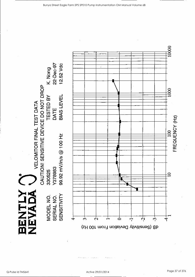
The following factory test data is enclosed:
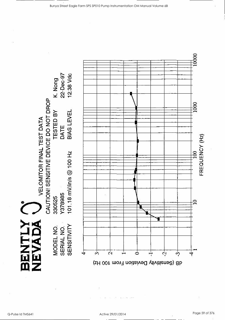
4.3.1 Velometer Final Test Data
4.3.2 Inspection and Test Plan for Local Instrumentation Panel
15140/Inst Man/BRH Issue 1 29-Apr-98 Page 4-3
Bunya Street Eagle Farm SPS SP010 Pump Instrumentation OM Manual Volume 6B
Q-Pulse Id TMS641 Active 29/01/2014 Page 51 of 376

BE
NT
LY
N
EV
AD
A
VE
LOM
ITO
R F
INA
L T
ES
T D
AT
A
CA
UT
ION
! S
EN
SIT
IVE
DE
VIC
E D
O N
OT
DR
OP
M
OD
EL
NO
. 33
0525
T
ES
TE
D B
Y
A.
Grim
m
SE
RIA
L N
O.
Y37
8455
D
AT
E
03-D
ec-9
7 S
EN
SIT
IVIT
Y
104.
66 m
V/in
/s @
100
Hz
BIA
S L
EV
EL
12.5
5 V
dc
4 3 2 1 0 -1
-2
-3
-4 1
10
100
FR
EQ
UE
NC
Y (
Hz)
1000
10
000
Bunya Street Eagle Farm SPS SP010 Pump Instrumentation OM Manual Volume 6B
Q-Pulse Id TMS641 Active 29/01/2014 Page 52 of 376

00001 0001
(zH) A
ON
13110313J
001 O
I
.111116-me
fi-
0
opA O
t7"Z L
13/01 WE
I zH
00 I. c
siuMw
9E' LO
L
AllA
llISN
3S
L6-08C1-£0
diva 99t8LC
A
'ON
1VIE
I3S
ww
PO
'V
18 C131831
SZ
SO
CC
O
N 13001A
1
dOE
ICIIO
N
OC
1 301A313 3/111IS
NI2S
iNainvo
viva 1S31. 1V
NId
011lA1013/1
VC
IVA
H
KL
IN3E
1
Bunya Street Eagle Farm SPS SP010 Pump Instrumentation OM Manual Volume 6B
Q-Pulse Id TMS641 Active 29/01/2014 Page 53 of 376

BE
NT
LY
N
EV
AD
A \
J
0
0
E 0
VE
LOM
ITO
R F
INA
L T
ES
T D
AT
A
CA
UT
ION
! S
EN
SIT
IVE
DE
VIC
E D
O N
OT
DR
OP
MO
DE
L N
O.
3305
25
TE
ST
ED
BY
K
. N
ong
SE
RIA
L N
O.
Y37
4672
D
AT
E
22-D
ec-9
7
SE
NS
ITIV
ITY
99
.85
mV
/in/s
@ 1
00
BIA
S L
EV
EL
12.0
9 V
dc
4
u_
1
0
0 '5
c -2
a)
-4- 1
10
100
1000
10
000
FR
EQ
UE
NC
Y (
Hz)
Bunya Street Eagle Farm SPS SP010 Pump Instrumentation OM Manual Volume 6B
Q-Pulse Id TMS641 Active 29/01/2014 Page 54 of 376

BE
NT
LY
N
EV
AD
A
VE
LOM
ITO
R F
INA
L T
ES
T D
AT
A
CA
UT
ION
! S
EN
SIT
IVE
DE
VIC
E D
O N
OT
DR
OP
MO
DE
L N
O.
3305
25
TE
ST
ED
BY
K
. N
ong
SE
RIA
L N
O.
Y37
4677
D
AT
E
22-D
ec-9
7 S
EN
SIT
IVIT
Y
95.1
7 m
V/in
/s @
100
Hz
BIA
S L
EV
EL
12.3
1 V
dc
4
N
'2
0
0
2 E
O
1
.5
-2
a)
co
-3
-4 1
10
100
FR
EQ
UE
NC
Y (
Hz)
1000
10
000
Bunya Street Eagle Farm SPS SP010 Pump Instrumentation OM Manual Volume 6B
Q-Pulse Id TMS641 Active 29/01/2014 Page 55 of 376

BE
NT
LY
Oas
N
EV
AD
A
VE
LOM
ITO
R F
INA
L T
ES
T D
AT
A
CA
UT
ION
! S
EN
SIT
IVE
DE
VIC
E D
O N
OT
DR
OP
M
OD
EL
NO
. 33
0525
T
ES
TE
D B
Y
K.
Non
g S
ER
IAL
NO
. Y
3789
82
DA
TE
22
-Dec
-97
SE
NS
ITIV
ITY
10
2.10
mV
/in/s
@ 1
00 H
z B
IAS
LE
VE
L 12
.84
Vdc
N
4 3 2 E 0
1 0 a.
)
-1
cc)
_3
-4 1
10
100
100
FR
EQ
UE
NC
Y (
Hz)
1000
10
000
Bunya Street Eagle Farm SPS SP010 Pump Instrumentation OM Manual Volume 6B
Q-Pulse Id TMS641 Active 29/01/2014 Page 56 of 376
BE
NT
LY
N
EV
AD
A
VE
LOM
ITO
R F
INA
L T
ES
T D
AT
A
CA
UT
ION
! S
EN
SIT
IVE
DE
VIC
E D
O N
OT
DR
OP
M
OD
EL
NO
. 33
0525
T
ES
TE
D B
Y
K.
Non
g S
ER
IAL
NO
. Y
3789
83
DA
TE
22
-Dec
-97
SE
NS
ITIV
ITY
99
.92
mV
/in/s
@ 1
00 H
z B
IAS
LE
VE
L 12
.52
Vdc
4 3 2 1 0 -1
-2
-3
-4 1
10
100
FR
EQ
UE
NC
Y (
Hz)
1000
10
000
Bunya Street Eagle Farm SPS SP010 Pump Instrumentation OM Manual Volume 6B
Q-Pulse Id TMS641 Active 29/01/2014 Page 57 of 376

BE
NT
LY
N
EV
AD
A
VE
LOM
ITO
R F
INA
L T
ES
T D
AT
A
CA
UT
ION
! S
EN
SIT
IVE
DE
VIC
E D
O N
OT
DR
OP
M
OD
EL
NO
. 33
0525
T
ES
TE
D B
Y
A.
Grim
m
SE
RIA
L N
O.
Y37
8984
D
AT
E
22-D
ec-9
7 S
EN
SIT
IVIT
Y
100.
01
mV
/in/s
@ 1
00 H
z B
IAS
LE
VE
L 12
.33
Vdc
4
N
a 0 0
2 E 2 u_
1
0
0 a)
0 - 1
c -2
a)
-4 1
10
100
FR
EQ
UE
NC
Y (
Hz)
1000
10
000
Bunya Street Eagle Farm SPS SP010 Pump Instrumentation OM Manual Volume 6B
Q-Pulse Id TMS641 Active 29/01/2014 Page 58 of 376
BE
NT
LY
N
EV
AD
A
VE
LOM
ITO
R F
INA
L T
ES
T D
AT
A
CA
UT
ION
! S
EN
SIT
IVE
DE
VIC
E D
O N
OT
DR
OP
MO
DE
L N
O.
3305
25
TE
ST
ED
BY
K
. N
ong
SE
RIA
L N
O.
Y37
8985
D
AT
E
22-D
ec-9
7 S
EN
SIT
IVIT
Y
101.
18 m
V/in
/s @
100
Hz
BIA
S L
EV
EL
12.3
8 V
dc
4 3 2 1 0 -1
-2
-3
-4 1
10
100
1000
10
000
FR
EQ
UE
NC
Y (
Hz)
Bunya Street Eagle Farm SPS SP010 Pump Instrumentation OM Manual Volume 6B
Q-Pulse Id TMS641 Active 29/01/2014 Page 59 of 376

BE
NT
LY
N
EV
AD
A
VE
LOM
ITO
R F
INA
L T
ES
T D
AT
A
CA
UT
ION
! S
EN
SIT
IVE
DE
VIC
E D
O N
OT
DR
OP
MO
DE
L N
O.
3305
25
TE
ST
ED
BY
K
. N
ong
SE
RIA
L N
O.
Y37
8986
D
AT
E
22-D
ec-9
7 S
EN
SIT
IVIT
Y
101.
77 m
V/in
/s @
100
Hz
BIA
S L
EV
EL
11.7
3 V
dc
4
N
" 0 0
2 E
1
51
0
0 -1
5 F-1
-2
a)
-4 1
10
100
FR
EQ
UE
NC
Y (
Hz)
1000
10
000
Bunya Street Eagle Farm SPS SP010 Pump Instrumentation OM Manual Volume 6B
Q-Pulse Id TMS641 Active 29/01/2014 Page 60 of 376

BE
NT
LY
N
EV
AD
A
VE
LOM
ITO
R F
INA
L T
ES
T D
AT
A
CA
UT
ION
! S
EN
SIT
IVE
DE
VIC
E D
O N
OT
DR
OP
MO
DE
L N
O.
3305
25
TE
ST
ED
BY
K
. N
ong
SE
RIA
L N
O.
Y37
8987
D
AT
E
22-D
ec-9
7
SE
NS
ITIV
ITY
10
1.22
mV
/in/s
@ 1
00 H
z B
IAS
LE
VE
L 11
.77
Vdc
4 3 2 1 0 -1
-2
-3
-4 1
10
100
FR
EQ
UE
NC
Y (
Hz)
1000
10
000
Bunya Street Eagle Farm SPS SP010 Pump Instrumentation OM Manual Volume 6B
Q-Pulse Id TMS641 Active 29/01/2014 Page 61 of 376
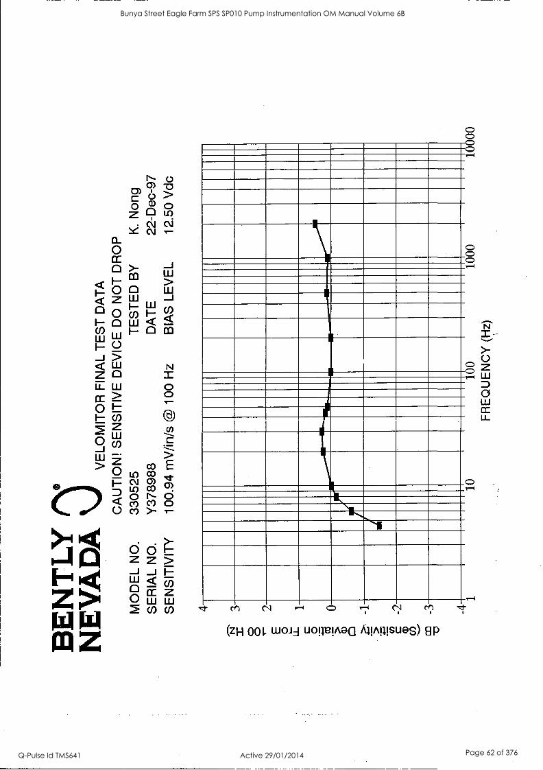
BE
NT
LY
N
EV
AD
A
VE
LOM
ITO
R F
INA
L T
ES
T D
AT
A
CA
UT
ION
! S
EN
SIT
IVE
DE
VIC
E D
O N
OT
DR
OP
MO
DE
L N
O.
3305
25
TE
ST
ED
BY
K
. N
ong
SE
RIA
L N
O.
Y37
8988
D
AT
E
22-D
ec-9
7
SE
NS
ITIV
ITY
10
0.94
mV
/in/s
@ 1
00 H
z B
IAS
LE
VE
L 12
.50
Vdc
4 3 2 1 0 -1
-2
-3
-4 1
10
100
1000
10
000
FR
EQ
UE
NC
Y (H
z)
Bunya Street Eagle Farm SPS SP010 Pump Instrumentation OM Manual Volume 6B
Q-Pulse Id TMS641 Active 29/01/2014 Page 62 of 376

0 CC 0 I-- 0 0 1- 0 w
0 5-
W 0 0
_0 Lo O E
c\I cyci Lo C°
co o ci , o
Li co >-
8
O 1-4
N N-4 O 174 c`,'
(zH 001. wau uownea AimsueS) EIP
N
>- 0
D a CC LL
Bunya Street Eagle Farm SPS SP010 Pump Instrumentation OM Manual Volume 6B
Q-Pulse Id TMS641 Active 29/01/2014 Page 63 of 376
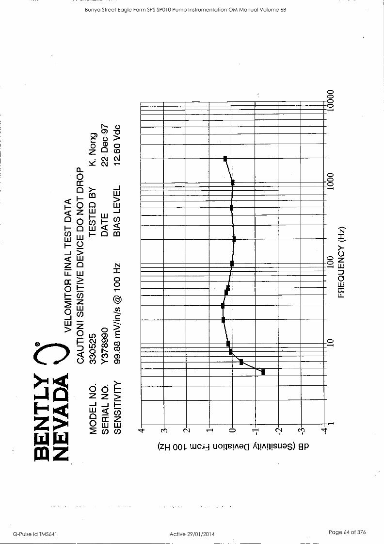
BE
NT
LY
N
EV
AD
A
VE
LOM
ITO
R F
INA
L T
ES
T D
AT
A
CA
UT
ION
! S
EN
SIT
IVE
DE
VIC
E D
O N
OT
DR
OP
MO
DE
L N
O.
3305
25
TE
ST
ED
BY
K
. N
ong
SE
RIA
L N
O.
Y37
8990
D
AT
E
22-D
ec-9
7
SE
NS
ITIV
ITY
99
.88
mV
/in/s
@ 1
00 H
z B
IAS
LE
VE
L 12
.60
Vdc
4 3 2 1 0 -1
-2
-3
-4 1
10
100
1000
10
000
FR
EQ
UE
NC
Y (
Hz)
Bunya Street Eagle Farm SPS SP010 Pump Instrumentation OM Manual Volume 6B
Q-Pulse Id TMS641 Active 29/01/2014 Page 64 of 376

BE
NT
LY
N
EV
AD
A
VE
LOM
ITO
R F
INA
L T
ES
T D
AT
A
CA
UT
ION
! S
EN
SIT
IVE
DE
VIC
E D
O N
OT
DR
OP
M
OD
EL
NO
. 33
0525
T
ES
TE
D B
Y
K.
Non
g S
ER
IAL
NO
. Y
3789
92
DA
TE
22
-Dec
-97
SE
NS
ITIV
ITY
10
1.66
mV
/in/s
@ 1
00 H
z B
IAS
LE
VE
L 12
.02
Vdc
4
N
.0--
I 3
0 2
E 2 LL
1
0 .+
CT
1
0
0 -1
5 :4=
c cr)
-2
co
_3
-a
41
10
100
FR
EQ
UE
NC
Y (
Hz)
1000
10
000
Bunya Street Eagle Farm SPS SP010 Pump Instrumentation OM Manual Volume 6B
Q-Pulse Id TMS641 Active 29/01/2014 Page 65 of 376

BE
NT
LY
N
EV
AD
A
VE
LOM
ITO
R F
INA
L T
ES
T D
AT
A
CA
UT
ION
! S
EN
SIT
IVE
DE
VIC
E D
O N
OT
DR
OP
MO
DE
L N
O.
3305
25
TE
ST
ED
BY
K
. N
ong
SE
RIA
L N
O.
Y37
8993
D
AT
E
22-D
ec-9
7 S
EN
SIT
IVIT
Y
102.
19 m
V/in
/s @
100
Hz
BIA
S L
EV
EL
12.1
9 V
dc
4
N
3 0 0 -
2 E 2 u_
1
.(4-
fs
0 a)
Z
-1
. 5 c CI)
-2
a)
.
co
_3
-4 1
..112
0...1
01°°
°°°.
.)11
111
10
100
FR
EQ
UE
NC
Y (
Hz)
1000
10
000
Bunya Street Eagle Farm SPS SP010 Pump Instrumentation OM Manual Volume 6B
Q-Pulse Id TMS641 Active 29/01/2014 Page 66 of 376
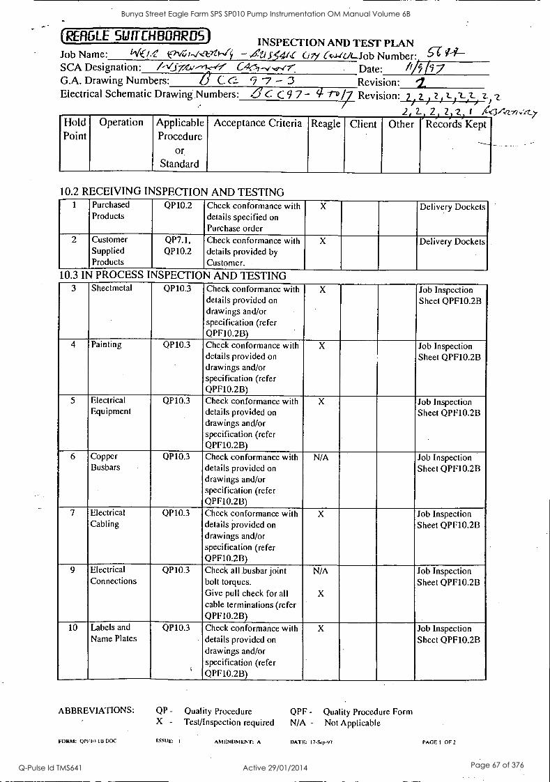
(RERGLE SWITCHBOARDS) INSPECTION AND TEST PLAN Job Name: il( -0! el,/e;r4,crt*--6 - Al 5.41.0 ci 7y Ctu-it.R-Job Number 6-6- 94- SCA Designation: /-16-777..."--)-k--/---7 C4(3,-../..2.(r: Date: A/5 /97 G.A. Drawing Numbers: 6 C c... 9 -7 - 3 Revision: / Electrical Schematic Drawing. Numbers: ..616. C 9 7 - 4 1--D /7 Revision: 2) 2i z) 1-1.2--,2) 2-) z
2 L,2 2 2 I /tg342--7/ ,/zz._
Hold Operation Applicable Acceptance Criteria Reagle Client Other 'Records Kept Point Procedure
or.
Standard
10.2 RECEIVING INSPECTION AND TESTING 1 Purchased
Products QP10.2 Check conformance with
details specified on
X Delivery Dockets
Purchase order 2 Customer
Supplied QP7.1, QP10.2
Check conformance with details provided by
X Delivery Dockets
Products Customer.
10.3 IN PROCESS INSPECTION AND TESTING 3 Sheetmetal QP10.3
4 Painting QP10.3
5 Electrical QP10.3 Equipment
6 Copper QP10.3 Busbars
7 Electrical QP10.3 Cabling
9 Electrical QP10.3 Connections
10 Labels and QP10.3 Name Plates
Check conformance with details provided on
drawings and/or specification (refer QPF10.2B)
X Job Inspection Sheet QPF10.2B
Check conformance with details provided on drawings and/or specification (refer QPF10.2B)
X Job Inspection Sheet QPF10.2B
Check conformance with details provided on
drawings and/or specification (refer QPF10.2B)
X Job Inspection Sheet QPF10.2B
Check conformance with details provided on drawings and/or specification (refer QPF10.2B)
N/A Job Inspection Sheet QPF10.2B
Check conformance with details provided on
drawings and/or specification (refer QPF10.2B)
X Job Inspection Sheet QPF10.2B
Check all busbar joint bolt torques. Give pull check for all cable terminations (refer QPF10.2B)
N/A
X
Job Inspection Sheet QPF10.2B
Check conformance with details provided on
drawings and/or specification (refer QPF10.2B)
X Job Inspection Sheet QPF10.2B
ABBREVIATIONS: QP - Quality Procedure QPF - Quality Procedure Form X - Test/Inspection required N/A - Not Applicable
FORM: OPE III- 113.00C ISSUE: I ANIENI )M11 ENT: A DATE: 17-Sep-97 PAGE I OF?
Bunya Street Eagle Farm SPS SP010 Pump Instrumentation OM Manual Volume 6B
Q-Pulse Id TMS641 Active 29/01/2014 Page 67 of 376
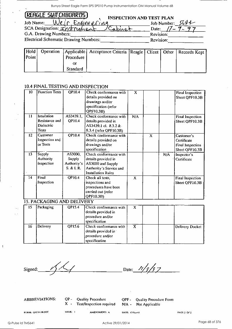
(REFIGLE fr CHBORR DS) INSPECTION AND TEST PLAN Job Name: We,fr Cft ''tie .1 I Job Number: ,5162-1-- SCA Designation: =- licht. . . ._. Date: /7- 7- 7 7 G.A. Drawing Numbers: Revision: Electrical Schematic Drawing Numbers: Revision:
Hold Operation Applicable Acceptance Criteria Reagle Client Other Records Kept Point Procedure
Or
Standard -
10.4 FINAL TESTING AND INSPECTION 10 Function Tests QP10.4 Check conformance with
details provided on drawings and/or specification (refer QPF10.3B)
X Final Inspection Sheet QPF10.3B
11 Insulation Resistance and Dielectric Tests
AS3439.1, QP10.4
Check conformance with details provided in
AS3439.1 cl. 8.3.2 & 8.3.4 (refer QPF10.3B)
N/A Final Inspection Sheet QPF10.3B
12 Customer Inspection and or Tests
QP10.4 Check conformance with details provided on drawings and/or specification
X Customer's Certificate Final Inspection Sheet QPF10.3B
13 Supply Authority Inspection
AS3000, Supply
Authority's S. & I. R.
Check conformance with details provided in
AS3000 and Supply Authority's Service and Installation Rules
N/A Inspector's Certificate
14 Final Inspection
QP10.4 Check all tests, inspections and procedures have been carried out (refer QPF10.3B)
X Final Inspection Sheet QPF10.3B
15. PACKAGING AND DELIVERY 15 Packaging QP15.4 Check conformance with
details provided in
procedure and/or specification
X
16 Delivery QP15.6 Check conformance with details provided in
procedure and/or specification
X Delivery Docket
Signed: Date: ///57/7
ABBREVIATIONS: QP - Quality Procedure QPF - Quality Procedure Form X - Test/Inspection required N/A - Not Applicable
FORM: OP110- I B.DOC ISSUE: I AM EN DM ENT: A DATE: I 7-Scp-97 PAGE 2 OF 2
Bunya Street Eagle Farm SPS SP010 Pump Instrumentation OM Manual Volume 6B
Q-Pulse Id TMS641 Active 29/01/2014 Page 68 of 376
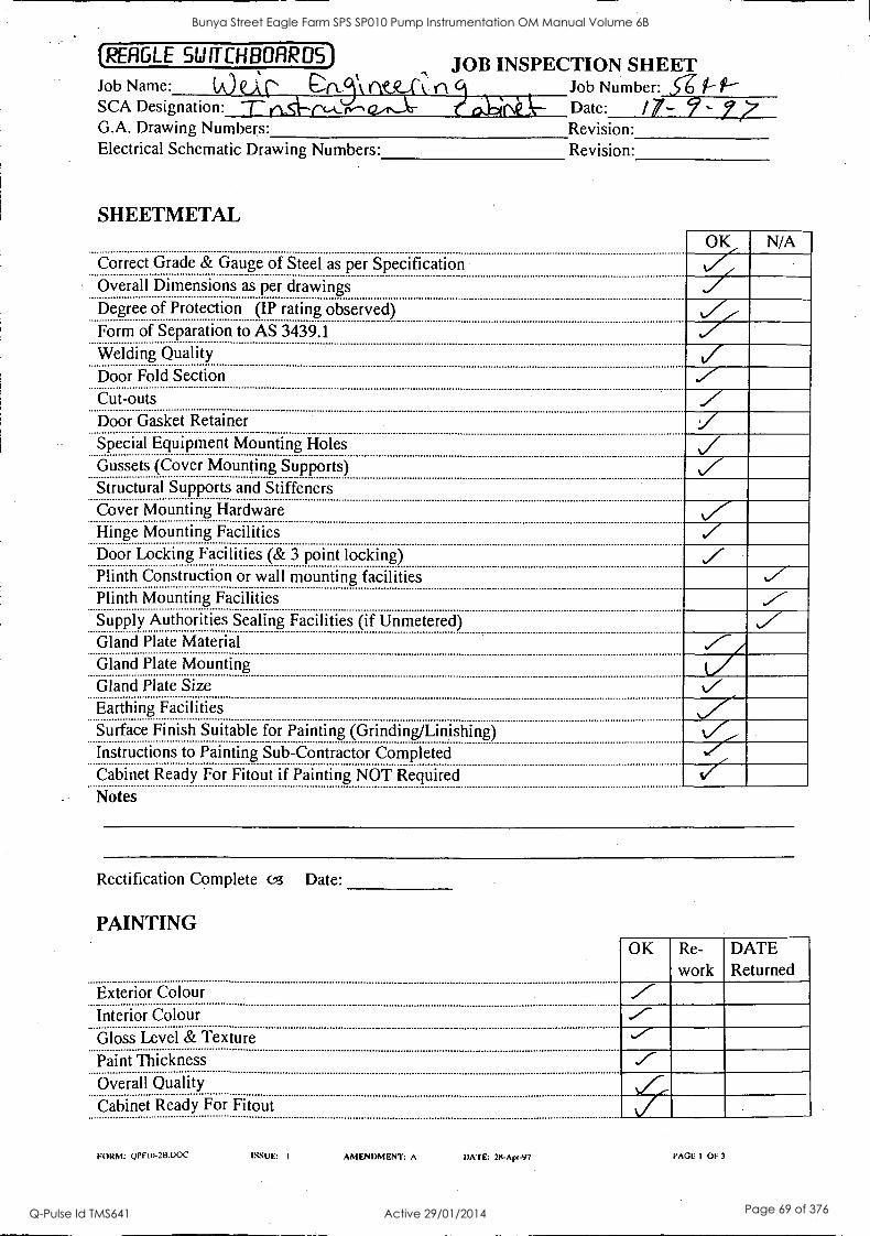
(RERGLE SWffCHBIJRRDS)
Job Name: SCA Designation: G.A. Drawing Numbers: Electrical Schematic Drawing Numbers:
JOB INSPECTION SHEET a.L5 k Job Number: 5-6
re-1 a Date: /7- 77
SHEETMETAL
Revision: Revision:
Correct Grade & Gauge of Steel as per Specification Overall Dimensions as per drawings
OK
rz N/A
Degree of Protection (IP rating observed) Form of Separation to AS 3439.1 Welding Quality Door Fold Section Cut-outs Door Gasket Retainer Special Equipment Mounting Holes Gussets (Cover Mounting Supports) Structural Supports and Stiffeners Cover Mounting Hardware Hinge Mounting Facilities Door Locking Facilities (& 3 point locking) Plinth Construction or wall mounting facilities Plinth Mounting Facilities Supply Authorities Sealing Facilities (if Unmetered) Gland Plate Material Gland Plate Mounting Gland Plate Size Earthing Facilities Surface Finish Suitable for Painting (Grinding/Linishing) Instructions to Painting Sub-Contractor Completed Cabinet Ready For Fitout if Painting NOT Required V Notes
Rectification Complete 03 Date:
PAINTING OK Re-
work DATE Returned
Exterior Colour
Interior Colour Gloss Level & Texture Paint Thickness Overall Quality
Cabinet Ready For Fitout
FORM: ()PFIX-2BDOC ISSUE: I AMENDMENT: A DATE: 25-Apr-97 PAGE I 0E3
Bunya Street Eagle Farm SPS SP010 Pump Instrumentation OM Manual Volume 6B
Q-Pulse Id TMS641 Active 29/01/2014 Page 69 of 376
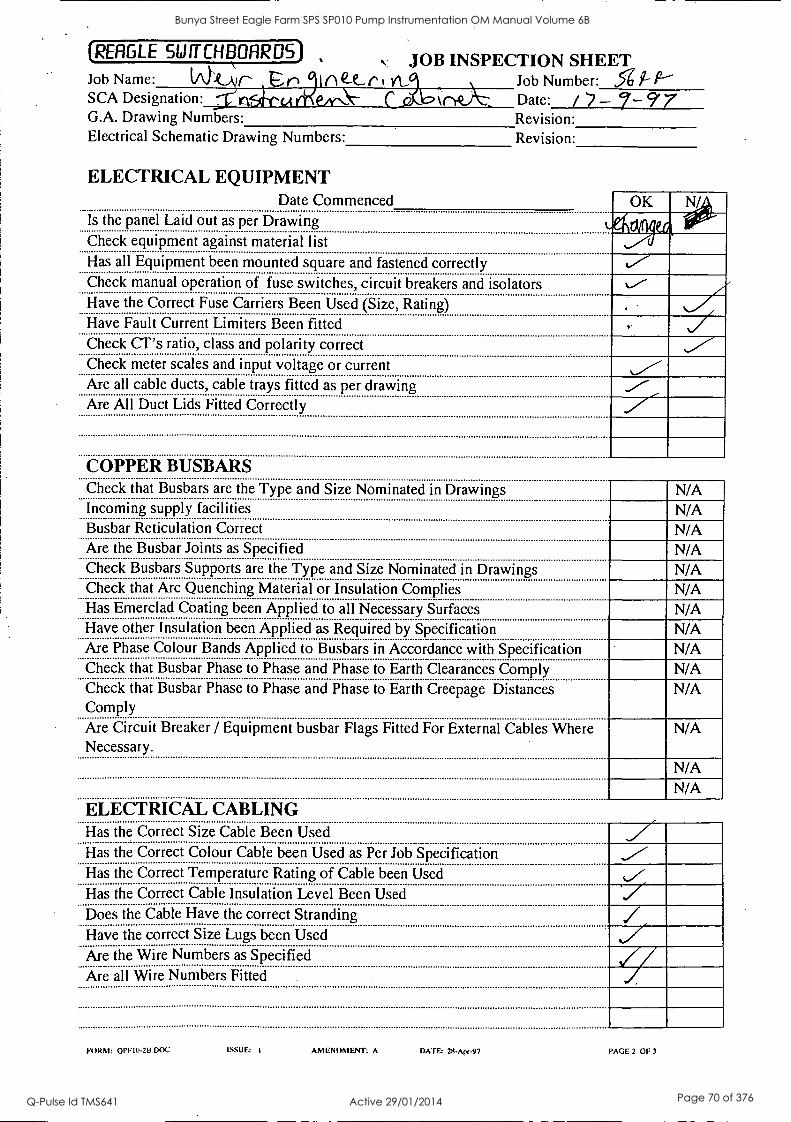
(RERGLE SWITCHBOARDS)
kkAlr- SCA Designation: G.A. Drawing Numbers: Electrical Schematic Drawing Numbers:
Job Name: JOB INSPECTION SHEET
Job Number: 5g 51- P bane Date: / - 7- 9' 7
Revision: Revision:
In et. r Vt
ELECTRICAL EQUIPMENT Date Commenced
Is the panel Laid out as per Drawing Check equipment against material list
OK 4 ex(
Has all Equipment been mounted square and fastened correctly Check manual operation of fuse switches, circuit breakers and isolators Have the Correct Fuse Carriers Been Used (Size, Rating) Have Fault Current Limiters Been fitted Check CT's ratio, class and polarity correct Check meter scales and input voltage or current Are all cable ducts, cable trays fitted as per drawing Are All Duct Lids Fitted Correctly
COPPER BUSBARS Check that Busbars are the Type and Size Nominated in Drawings N/A Incoming supply facilities N/A Busbar Reticulation Correct N/A Are the Busbar Joints as Specified N/A Check Busbars Supports are the Type and Size Nominated in Drawings Check that Arc Quenching Material or Insulation Complies
N/A N/A
Has Emerclad Coating been Applied to all Necessary Surfaces N/A Have other Insulation been Applied as Required by Specification N/A Are Phase Colour Bands Applied to Busbars in Accordance with Specification N/A Check that Busbar Phase to Phase and Phase to Earth Clearances Comply N/A Check that Busbar Phase to Phase and Phase to Earth Creepage Distances Comply
N/A
Are Circuit Breaker / Equipment busbar Flags Fitted For External Cables Where Necessary.
N/A
N/A N/A
ELECTRICAL CABLING Has the Correct Size Cable Been Used Has the Correct Colour Cable been Used as Per Job Specification Has the Correct Temperature Rating of Cable been Used Has. the Correct Cable Insulation Level Been Used
Does the Cable Have the correct Stranding Have the correct Size Lugs been Used Are the Wire Numbers as Specified Are all Wire Numbers Fitted
FORM: OPF10-2B.DOC ISSUE: 1 AMENDMENT: A DATE: 28-Apr-97 PAGE 2 OF 3
Bunya Street Eagle Farm SPS SP010 Pump Instrumentation OM Manual Volume 6B
Q-Pulse Id TMS641 Active 29/01/2014 Page 70 of 376

(REFIGLE SW ff CHBOFIRDS)
Job Name: V\ Wr ri SCA Designation: G.A. Drawing Numbers: Electrical Schematic Drawing Numbers:
I cw.9..,r (1,
JOB INSPECTION SHEET Job Number: ce Date: /7- 9'-- Revision: Revision:
ELECTRICAL CONNECTIONS OK
Check that all Nut and Bolts have been Crossed with Permanent Marking Pen to Signify Torque Wrench Tightening
N/A N/A
Have all Cable terminations been given the pull check for Bonding Is the relevant equipment bonded to the Earth Bar Earth continuity z LABELS AND NAMEPLATES Check labels against label list (wording, letter height, label colour, fixing) Have all Labels been Attached , mounted square and Screwed where Necessary.
I-
Arrange Supply Authority INSPECTION (E.A., I.E., etc) N/A Arrange Customer INSPECTION
Date Complete Notes
Rectification Complete c,3 Date:
Person Testing f-Nt(
FORM: OPF10-2B.DOC ISSUE: I
Signature
AMENDMENT: A DATE: 25- Apr -97 PAGE 3 OF 3
Bunya Street Eagle Farm SPS SP010 Pump Instrumentation OM Manual Volume 6B
Q-Pulse Id TMS641 Active 29/01/2014 Page 71 of 376

(REFIGLE SWITCHBOARDS) N FINAL INSPECTION REPORT
Job Name: IMP V\ e0.1(n4_42.1 )1\ 1 \ 1 Job Number: ,c4 PI-
SCA Designation: fre-)Ce`Ciet r).-----' C aolDinQA-- Date: / 7- 7- 7 7 G.A. Drawing Numbers: Revision: Electrical Schematic Drawing Numbers: Revision:
ROUTINE FUNCTION TESTS
Continuity of power circuits with all switches closed from incoming to outgoing Continuity of control circuits to drawings All control circuits operational All protection circuits operational All metering circuits operational
The Following Equipment was not tested
N/A
Test conducted by:
Signed:
de/ Fir cicmA,-.1 Witnessed by:
Signed:
ROUTINE ELECTRICAL TESTS Main Circuit Rated Insulation Voltage I11: 300 < U; 5 690 V
Phase Measured Insulation Resistance @ 1000V
MQ
Leakage Current @ Dielectric test vol
mA
nsulation Resistance @ 1000V
MQ E - R, W, B, N mA @
V 50Hz for 1 min R - W, B, N, E mA@
2.5kV 50Hz for 1 min ' W - R, B, N, E mA@
2.5kV 50Hz for 1
B - R, W, N, E
li mA@
2.5kV 50. for 1 min N - R, W, B, E ,
1 .1
rn A @ . kV 50Hz for 1 min
Auxiliar ircuit1\
E U; 5 611)i
,. i 111
11111 I
mA @ 1.0kV 50Hz for 1 min
. . iliary circuitili 60 < U1s 31AL
ill mA @ 2.0kV 50Hz for 1 min
Auxiliary circuit: E 300 <11; 5 6/1
mA @ 2.5kV 50Hz for 1 min
Pass Criteria: I lation Resistance - a1M5Z
FORM: OPF10-313.DOC ISSUE: I
Dielectric - No puncture or flashover
AMENDMENT: A DATE: 28-Apr-97 PAGE I OF 2
Bunya Street Eagle Farm SPS SP010 Pump Instrumentation OM Manual Volume 6B
Q-Pulse Id TMS641 Active 29/01/2014 Page 72 of 376
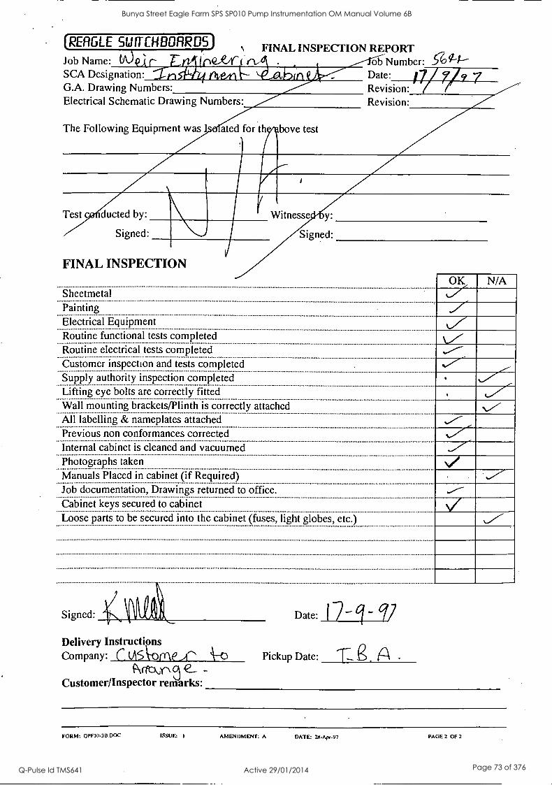
(RERGLE SWITCHBORRDS) 1 FINAL INSPECTION REPORT
Job Name: t./061- #2'Y ob Number: SCA Designation: A ii. L 'ig AP Date: G.A. Drawing Numbers: Revision: Electrical Schematic Drawing Numbers: Revision:
The Following Equipment was ated for th bove test
Test c ducted by:
Signed:
FINAL INSPECTION
Witnesse D y:
Signed:
Sheetmetal OK 1/47
Painting
N/A
Electrical Equipment Routine functional tests completed Routine electrical tests completed Customer inspection and tests completed Supply authority inspection completed Lifting eye bolts are correctly fitted Wall mounting brackets/Plinth is correctly attached All labelling & nameplates attached Previous non conformances corrected Internal cabinet is cleaned and vacuumed Photographs taken Manuals Placed in cabinet (if Required) Job documentation, Drawings returned to office. Cabinet keys secured to cabinet Loose parts to be secured into the cabinet (fuses, light globes, etc.)
Signed:
Delivery Instructions Company: c visk-ome.i" t\--o
fveckn e- - Customer/Inspector remarks:
Date: I 7-
Pickup Date: ri e. A .
FORM: OPF10-3B.DOC ISSUE: I AMENDMENT: A DATE: 214-A4w-97 PAGE 2 OF 2
Bunya Street Eagle Farm SPS SP010 Pump Instrumentation OM Manual Volume 6B
Q-Pulse Id TMS641 Active 29/01/2014 Page 73 of 376

BRISBANE CITY COUNCIL Dept. Water Supply and Sewage Pumpwell No 1, Eagle Farm Pump Station
BCC Contract No S20/95/96 System Instrumentation
Operation and Maintenance Manual
Section 5 Start-Up and Shut-Down Procedures
This Section is not applicable to the System Instrumentation. The start up and shutdown procedures for the pumping system are included in Volume 2.
15140/Inst Man/BRH Issue 1 29-Apr-98 Page 5-1
Bunya Street Eagle Farm SPS SP010 Pump Instrumentation OM Manual Volume 6B
Q-Pulse Id TMS641 Active 29/01/2014 Page 74 of 376
BRISBANE CITY COUNCIL Dept. Water Supply and Sewage Pumpwell No 1, Eagle Farm Pump Station
BCC Contract No S20/95/96 System Instrumentation
Operation and Maintenance Manual
Section 6 Commissioning
A detailed Inspection and Test Plan (ITP) has been prepared for the on site pre- commissioning and commissioning of the pump system. The ITP together with all of the relevant testing data has been included in Volume 3.
15140/Inst Man/BRH Issue 1 29- Apr -98 Page 6-1
Bunya Street Eagle Farm SPS SP010 Pump Instrumentation OM Manual Volume 6B
Q-Pulse Id TMS641 Active 29/01/2014 Page 75 of 376
BRISBANE CITY COUNCIL Dept. Water Supply and Sewage Pumpwell No 1, Eagle Farm Pump Station
BCC Contract No S20/95/96 System Instrumentation
Operation and Maintenance Manual
Section 7 Operations
This Section is not applicable to the Pump Instrumentation. The operational procedures for the pumping system are included in other volumes.
The operational procedures for specific items of equipment supplied under this contract are generally covered in other sections of this manual.
15140/Inst Man/BRH Issue 1 29-Apr-98 Page 7-1
Bunya Street Eagle Farm SPS SP010 Pump Instrumentation OM Manual Volume 6B
Q-Pulse Id TMS641 Active 29/01/2014 Page 76 of 376

BRISBANE CITY COUNCIL Dept. Water Supply and Sewage Pumpwell No 1, Eagle Farm Pump Station
BCC Contract No S20/95/96 System Instrumentation
Operation and Maintenance Manual
Section 8 Maintenance
Maintenance of the field sensors generally involves replacement on failure. The Bently Nevada 3300 System Monitor may require maintenance or adjustment. This can be carried with reference to the following Bently Nevada Publications. It should be noted that the procedures described in this section should only be carried out by a qualified Electronics Technician.
8.1 Temperature Monitor
The following publication entitled 3300 Six Channel Temperature Monitor Maintenance Manual (Part No 80183-01 Rev L) is prepared by Bently Nevada for plant personnel who install and maintain the system. It provides a detailed description of the maintenance and adjustment procedures for the Temperature Monitor.
The following sections are included:
8.1.1 Six Channel Temperature Monitor System
8.1.2 Monitor Functions
8.1.3 Monitor Options
8.1.4 Programmable Options
8.1.5 OK
8.1.6 Bypass
8.1.7 Alarm 1
8.1.8 Alarm 2
8.1.9 Read Channel Temperature
8.1.10 Read Alarm 1 Setpoint Levels
8.1.11 Read Alarm 2 Setpoint Levels
8. 1. 12 Self Test
8.1.13 Error Codes
15140/Inst Man/BRH Issue 1 29-Apr-98 Page 8-1
Bunya Street Eagle Farm SPS SP010 Pump Instrumentation OM Manual Volume 6B
Q-Pulse Id TMS641 Active 29/01/2014 Page 77 of 376
BRISBANE CITY COUNCIL Dept. Water Supply and Sewage Pumpwell No 1, Eagle Farm Pump Station
BCC Contract No S20/95/96 System Instrumentation
Operation and Maintenance Manual
8.1.14 Disassembly Procedure
8.1.15 Recorder/Relay Module
8.1.16 Temperature Input Module
8.1.17 Installed Program Options
8.1.18 RTD Analogue Board Options
8.1.19 First Out, Alarm Delays, Alarm 2 Options
8.1.20 Transducer Type, OK Options
8.1.21 Full Scale, Recorder Options
8.1.22 Alarm Setpoint Adjustment
8.1.23 Channel Bypass
8.1.24 Alarm 2 Bypass
8.1.25 Test Channel Alarms - TC
8.1.26 Test Channel Alarms - RTD
8.1.27 Test OK Limits - TC
8.1.28 Test OK Limits - RTD
8.1.29 Test OK Limits - TC
8.1.30 Test OK Limits - RTD
8.1.31 Test/Calibration - TC
8.1.32 Test/Calibration - RTD
8.1.33 Field Wiring Diagrams
8.1.34 Recommended Spare Parts -TC Monitor
8.1.35 Recommended Spare Parts - RTD Monitor
8.1.36 Specifications
15140/Inst Man/BRH Issue 1 29-Apr-98 Page 8-2
Bunya Street Eagle Farm SPS SP010 Pump Instrumentation OM Manual Volume 6B
Q-Pulse Id TMS641 Active 29/01/2014 Page 78 of 376
PART NO. 80183-01 REVISION L,
NOVEMBER 1996
3300 SIX CHANNEL TEMPERATURE MONITOR
3300/30 - THERMOCOUPLE 3300/35 - RTD
MAINTENANCE MANUAL
BENTLY NEVADA
Bunya Street Eagle Farm SPS SP010 Pump Instrumentation OM Manual Volume 6B
Q-Pulse Id TMS641 Active 29/01/2014 Page 79 of 376
80183-01 Six Channel Temperature Monitor Maintenance
NOTICE READ THE FOLLOWING BEFORE INSTALLING OR OPERATING EQUIPMENT
Bent ly Nevada Corporation has attempted to identify areas of risk created by improper installation and/or operation of this product. These areas of information are noted as WARNING or CAUTION for your protection and for the safe and effective operation of this equipment. Read all instructions before installing or operating this product. Pay particular attention to those areas designated by the following symbols.
WARNING High voltage present . Contact could cause shock, burns or death.
Do not touch exposed wires or terminals.
*, CAUTION Machine protection will be lost during calibration.
First Printing: May 1988
Copyright© 1989,1993,1994, 1996 Bently Nevada Corporation
All Rights Reserved No part of this publication may be reproduced, transmitted, stored in a retrieval system nor translated into any human or computer language, in any form or by any means, electronic, mechanical, magnetic; optical, chemical, manual, or otherwise, without the prior written permission of the copyright owner,
Bently Nevada Corporation P.O. Box 157
Minden, Nevada 89423 USA Telephone 800-227-5514 702-782-3611
Telex 7400983 BNC UC Fax 702-782-9253
Copyright infringement is a serious matter under United States of America and Foreign Copyright Laws
ii
Bunya Street Eagle Farm SPS SP010 Pump Instrumentation OM Manual Volume 6B
Q-Pulse Id TMS641 Active 29/01/2014 Page 80 of 376

Six Channel Temperature Monitor Maintenance 80183-01
FOREWORD
This document is intended for personnel who install and maintain the 3300 Monitoring System. The procedures are presented in step-by-step graphic format.
RELATED DOCUMENTS
3300 System Overview, 80171-01
3300 System Installation Instructions, 80172-01
3300 System Troubleshooting, 80173-01
3300/12 AC Power Supply, 89602-01
3300/14 DC Power Supply, 101256-01
3300/03 System Monitor, 89604-01
3300/30 and 3300/35 Six Channel Temperature Monitor Operation, 80182-01
3300 Internal Barrier Installation, 88837-01
Keyphasor® and Proximitor are registered trademarks of Bent ly Nevada Corporation
SYMBOLS Special symbols are used in the manual to illustrate specifics in the step-by-step process. For example:
PRESS FLASHING CONNECT
TEST EQUIPMENT (Recommended) Digital Wattmeter Decade Resistance
GC
4 1/2-D.g.t D:sPloY 0 to 1000 Vac/Vdc
0 to 10 negohms
O 0 0 0 0 0 0 O
Range 0.01 ohn to 11.1111 Kohn
,n f.ve decodes t 0.01% 2.5
DISCONNECT
Monitor Weeder Board
7 GENTLY NEVADA
CORPORATION P/N 78894-01
OBSERVE SCREWDRIVER
Millivolt Source
Range 0 to i 20V Resolution
(± 10mV with 100:1 divider)
Bunya Street Eagle Farm SPS SP010 Pump Instrumentation OM Manual Volume 6B
Q-Pulse Id TMS641 Active 29/01/2014 Page 81 of 376

80183-01 Six Channel Temperature Monitor Maintenance
iv
Bunya Street Eagle Farm SPS SP010 Pump Instrumentation OM Manual Volume 6B
Q-Pulse Id TMS641 Active 29/01/2014 Page 82 of 376
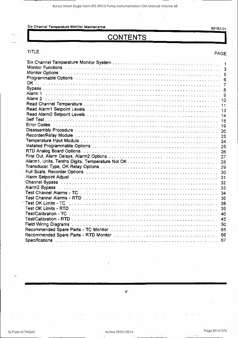
Six Channel Temperature Monitor Maintenance 80183-01
CONTENTS
TITLE PAG E
Six Channel Temperature Monitor System 1
Monitor Functions 3
Monitor Options 5 Programmable Options 6 OK
7 Bypass 8 Alarm 1 9 Alarm 2 10 Read Channel Temperature 11 Read Alarm1 Setpoint Levels 13 Read Alarm2 Setpoint Levels 14 Self Test 15 Error Codes 19 Disassembly Procedure 20 Recorder/Relay Module 23 Temperature Input Module 24 Installed Programmable Options 25 RTD Analog Board Options 26 First Out, Alarm Delays, Alarm2 Options 27 Alarm1, Units, Tenths Digits, Temperature Not OK 28 Transducer Type, OK Relay Options 29 Full Scale, Recorder Options 30 Alarm Setpoint Adjust 31 Channel Bypass 32 Alarm2 Bypass 33 Test Channel Alarms - TC 34 Test Channel Alarms - RTD 36 Test OK Limits - TC 38 Test OK Limits - RTD 39 Test/Calibration - TC 40 Test/Calibration - RTD 45 Field Wiring Diagrams 50 Recommended Spare Parts - TC Monitor 65 Recommended Spare Parts - RTD Monitor 66 Specifications 67
V
Bunya Street Eagle Farm SPS SP010 Pump Instrumentation OM Manual Volume 6B
Q-Pulse Id TMS641 Active 29/01/2014 Page 83 of 376

80183-01 Sbc Channel Temperature Monitor Maintenance
vi
Bunya Street Eagle Farm SPS SP010 Pump Instrumentation OM Manual Volume 6B
Q-Pulse Id TMS641 Active 29/01/2014 Page 84 of 376
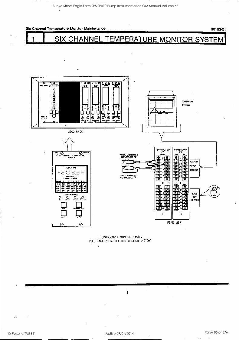
1 I SIX CHANNEL TEMPERATURE MONITOR SYSTEM I
Six Channel Temperature Monitor Maintenance 80183-01
V 0 ...
..0 ..,
...7
fii 1... .....:=.
6 6 6 6
.1101r
" 3
b (;)(?(-)c)o
a AL ,
0
WI 3 e
0 0
LAS'
0
Li2.7
o o
A 3300 RACK
/ 54 0400E1 lthiPCKATIACuceli* Woo TOR
i I
04~1. pug 2
VARR6ruat
I 111. .wid grAti
3
1 f Rre
4
_i 1
5 6
OK 492 kW 8,0
OK Ain Ault 89
OK N.112 AUll 81'0
OK ALM2 kill 134,
OK Alia kW 8YR
OK Alla 4191
8,0
c9.
r0e106
-9,
MX(
.4.0.17
0
VANS
r 0
OYMICL
. R.0ta
%TIE I,
...111
0
t9iziO1/4 UM:ROMEO KRUOCCUFt1 Ti
itlfiERAIWE
RICOIDElt
110aZILI4 my 0
0.04
O
El I(.11 Gll lull
El 11%11
0
THERMOCOUPLE MONITOR SYSTEM
(SEE PACE 2 FOR THE RTD MONITOR SYSTEM)
0:11M DAY" 0 0 El
KsIl Itsal
ral IV:)1 rai
0
REAR vlEw
1
Bunya Street Eagle Farm SPS SP010 Pump Instrumentation OM Manual Volume 6B
Q-Pulse Id TMS641 Active 29/01/2014 Page 85 of 376
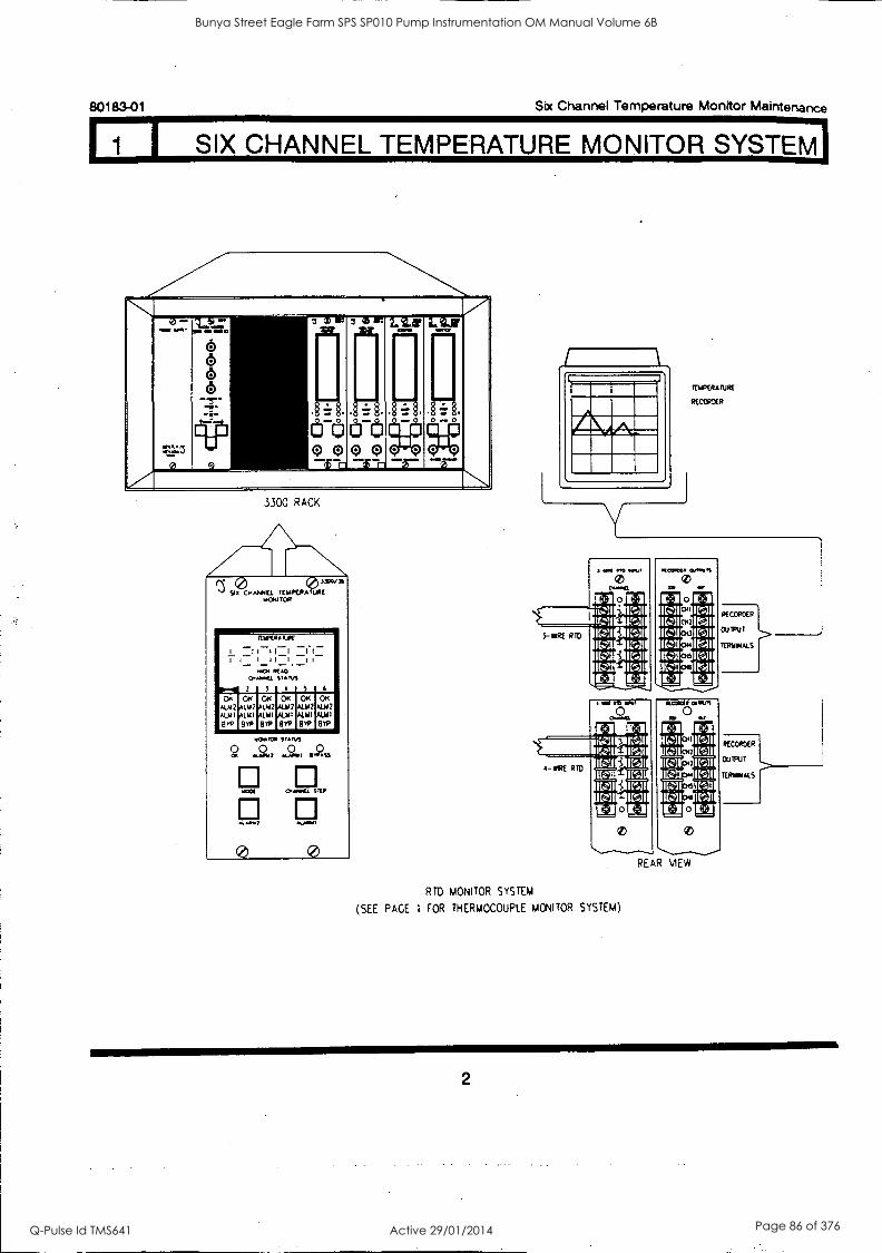
II 1 I SIX CHANNEL TEMPERATURE MONITOR SYSTEM
80183-01 Six Channel Temperature Monitor Maintenance
.. ' 43 .......
.r.=
1....S.: 3 .......-F.T.
15
so 8 (5
-6- -75 r+3-ii
lir CC)C,)(;)o
3)
-.: 0...0 0
21 3
.. Q
0
i. 0-. 0 CI
w i 13.11'
. 0-0 0
LitiLtV
0.-0
o 0
3300 RACK
t). SI 6 C4.64444EL YE IAPE.0,6 31/176 135 606I TOR
-- _
- 1 I
7 1
_
CrwaftEL
2
rt1p(66
1 111 I 1 1 - r(1.
3
UK - 1
. 1- _ 1 -11- I i -
RAO VANS
4 5
___
6
14.160. 2 LW ALM 1 1.141
VP Wm
CRC
ila 4141
Bev
482 41111
1 ay
64646)14
...,
an?
0
5466.4
044.461
o VIP
4.001
0
TEWERATURE
RECORDER
KF1 041E21
KSMN PH MN Ra MN ita MN MI MN LI
RTD MONITOR SYSTEM
(SEE PAGE 1 FOR THERMOCOUPLE MONITOR SYSTEM)
2
Bunya Street Eagle Farm SPS SP010 Pump Instrumentation OM Manual Volume 6B
Q-Pulse Id TMS641 Active 29/01/2014 Page 86 of 376
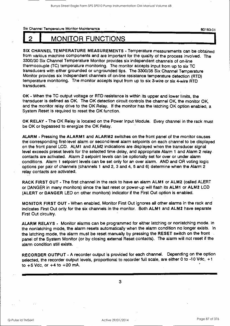
Six Channel Temperature Monitor Maintenance 80183-01
I MONITOR FUNCTIONS
SIX CHANNEL TEMPERATURE MEASUREMENTS - Temperature measurements can be obtained from various machine components and are important for the quality of the process involved. The 3300/30 Six Channel Temperature Monitor provides six independent channels of on-line thermocouple (TC) temperature monitoring. The monitor accepts input from up to six TC transducers with either grounded or ungrounded tips. The 3300/35 Six Channel Temperature Monitor provides six independent channels of on-line resistance temperature detection (RID) temperature monitoring. The monitor accepts input from up to six 3-wire or six 4-wire RTD transducers.
OK - When the TC output voltage or RTD resistance is within its upper and lower limits, the transducer is defined as OK. The OK detection circuit controls the channel OK, the monitor OK, and the monitor relay drive to the OK Relay. If the monitor has the latching OK option enabled, a System Reset is required to reset the OK function.
OK RELAY - The OK Relay is located on the Power Input Module. Every channel in the rack must be OK or bypassed to energize the OK Relay.
ALARM - Pressing the ALARMI and ALARM2 switches on the front panel of the monitor causes the corresponding first-level alarm or second-level alarm setpoints on each channel to be displayed on the front panel LCD. ALM1 and ALM2 indications are displayed when the transducer signal level exceeds preset levels for the selected time delay, and appropriate Alarm 1 and Alarm 2 relay contacts are activated. Alarm 2 setpoint levels can be optionally set for over or under alarm conditions. Alarm 1 setpoint levels can be set only for an over alarm. AND and OR voting logic options per pair of channels (channels 1 and 2, 3 and 4, 5 and 6) determine when the Alarm 2
relay contacts are activated.
RACK FIRST OUT - The first channel in the rack to have an alarm ALM1 or ALM2 (called ALERT or DANGER in many monitors) since the last reset or power-up will flash its ALM1 or ALM2 LCD
(ALERT or DANGER LED on other monitors) indicator if the First Out option is enabled.
MONITOR FIRST OUT - When enabled, Monitor First Out ignores all other alarms in the rack and
indicates First Out only for the six channels in the monitor. Both ALM1 and ALM2 have separate First Out circuitry.
ALARM RELAYS - Monitor alarms can be programmed for either latching or nonlatching mode. In
the nonlatching mode, the alarm resets automatically when the alarm condition no longer exists. In
the latching mode, the alarm must be reset manually by pressing the RESET switch on the front panel of the System Monitor (or by closing external Reset contacts). The alarm will not reset if the
alarm condition still exists.
RECORDER OUTPUT - A recorder output is provided for each channel. Depending on the option
selected, the recorder output levels, proportional to recorder full scale, are either 0 to -10 Vdc, +1
to +5 Vdc, or +4 to +20 mA.
3
Bunya Street Eagle Farm SPS SP010 Pump Instrumentation OM Manual Volume 6B
Q-Pulse Id TMS641 Active 29/01/2014 Page 87 of 376
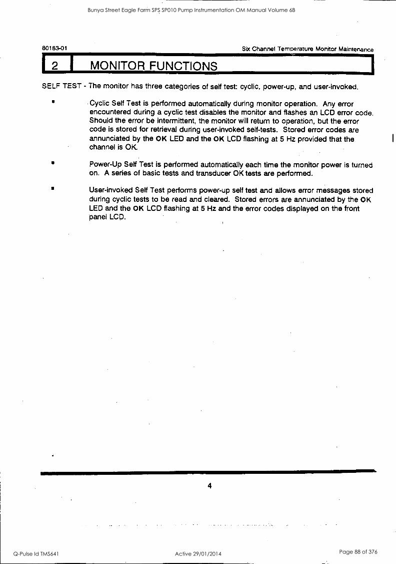
80183-01 Six Channel Temperature Monitor Maintenance
17-1 MONITOR FUNCTIONS
SELF TEST - The monitor has three categories of self test: cyclic, power-up, and user-invoked.
Cyclic Self Test is performed automatically during monitor operation. Any error encountered during a cyclic test disables the monitor and flashes an LCD error code. Should the error be intermittent, the monitor will return to operation, but the error code is stored for retrieval during user-invoked self-tests. Stored error codes are annunciated by the OK LED and the OK LCD flashing at 5 Hz provided that the channel is OK.
Power-Up Self Test is performed automatically each time the monitor power is turned on. A series of basic tests and transducer OK tests are performed.
User-invoked Self Test performs power-up self test and allows error messages stored during cyclic tests to be read and cleared. Stored errors are annunciated by the OK LED and the OK LCD flashing at 5 Hz and the error codes displayed on the front panel LCD.
4
Bunya Street Eagle Farm SPS SP010 Pump Instrumentation OM Manual Volume 6B
Q-Pulse Id TMS641 Active 29/01/2014 Page 88 of 376
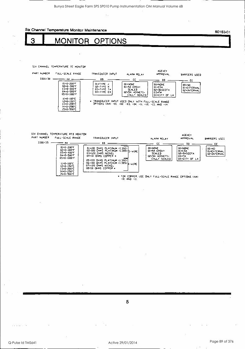
Six Channel Temperature Monitor Maintenance
3 1 MONITOR OPTIONS
SIX CHANNEL TEMPERATURE TC MONITOR
PART NUMBER FULL-SCALE RANGE
3300/30 AA
01=0-200T 02=0-300F 03=0-400F 04=0-500F 05=0-1000F
ii=0-100-C 12=0-150.0 13=0-200C 14=0-250C 15=0-500C
SIX CHANNEL TEMPERATURE RTD MONITOR PART NUMBER
3300/35
FULL-SCALE RANGE
AA
01=0-200F 02=0-300"F 03=0-400F 04=0-500F 05=0-1000'F
11=0-100C 12=0-150*C 13=0-200C 14=0-250-C 15=0-500C
TRANSDUCER INPUT
BB
01=TYPE 02=TypE 03=TypE 04TypE
80183-01
ALARM RELAY
CC
AGENCY APPROVAL BARRIERS USED
DO EE
00=NONE 00.NONE 00=NO 01=5A EPDXY 01.CSA 01 =Ex TERNAL
T. SEALED 02=BASEEFA 02=INTERNAL Em 02=5A HERMETI- 03=rm
CALLY SEALED 04=c1TY OF LA
. TRANSDUCER INPUT USED ONLY viTH FULL-SCALE RANGE OPTIONS (AA) -01. -02. -03. -04. -IL -12. -13. AND -14
AGENCY TRANSDUCER INPUT ALARM RELAY BARRIERS USED
BB CC DO EE
01=100 OHMS PLATINUM (1.392) 00.NONE 00=NONE 00=NO 02=100 OHMS PLATINUM (131215) 3 -v IRE 01=5A EPDXY 01=CSA 01=EXTERNAL 03.120 OHMS NICKEL SEALED 02=BASEEFA 02=INTERNAL 04=10 OHMS COPPER 02=5A HERMETI- 03=Fm
CALLY SEALED 04 =CITy OF LA 05=100 OHMS PLATINUM <1.392) 06=100 OHMS PLATINUM (1385) 07=120 OHMS NICKEL
A-vIRE
013=10 OHMS COPPER
FOR COPPER. USE ONLY FULL-SCALE RANGE OPTIONS (AA) -01 AND -II.
5
Bunya Street Eagle Farm SPS SP010 Pump Instrumentation OM Manual Volume 6B
Q-Pulse Id TMS641 Active 29/01/2014 Page 89 of 376

80183-01 Sbc Channel Temperature Monitor Maintenance
1 4 I PROGRAMMABLE OPTIONS
RACK FIRST OUT
ENABLED DISABLED
MONITOR FIRST OUT
ENABLED DISABLED
ALARM DELAYS ' 1 SECOND 3 SECONDS
' 6 SECONDS
ALARMI MODE LATCHING NONLATCHING
ALARM2 MODE ' LATCHING NONLATCHING OVER ALARm UNDER ALARM
STANDARD CONFIGURATION
RECORDER OUTPUTS #4 TO 20 nA' 1 TO 5 Vdc 0 TO -10 Vdc
ALARM2 VOTING OR VOTING FOR RELAY DRIVE AND VEIT . iG FOR RELAY DRIVE
OK MODE NONLATCHING ' LATCHING
TEMPERATURE NOT -OK
UPSCALE DOVNSCALE'
TENTH (0.1) DIGIT
' ENABLED DISABLED'
ALARM2 RELAY BYPASS
ENABLED DISABLE D
6
Bunya Street Eagle Farm SPS SP010 Pump Instrumentation OM Manual Volume 6B
Q-Pulse Id TMS641 Active 29/01/2014 Page 90 of 376
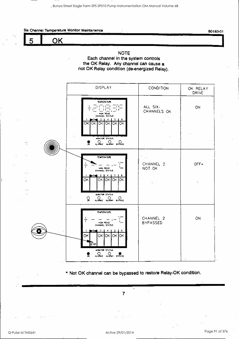
Six Channel Temperature Monitor Maintenance
NOTE Each channel in the system controls
the OK Relay. Any channel can cause a not OK Relay condition (de-energized Relay).
80183-01
DISPLAY CONDITION OK RELAY DRIVE
ALL SIX, CHANNELS OK
ON
TEMPERATURE
1
_ II _ II
= _1 MICH
CHANNEL
3
__ I
-1. READ
STATUS
4
_ . 1 i
=1
5
- 1-
6
OK FICK OK 0 OK
uckolOR STATUS
0 0 0 OK ALARIA2 ALARM' BYPASS
CHANNEL 2 NOT OK
OFF«
TEMPERATURE
WEN
CHANNEL
I 3
READ STATUS
4 5
. 1 '
_ I_
6
OK OK OK OK OK
HoNcrop STATUS
0 0 0 0 OK ALAR12 ALAMO BYPASS
BYPASSED ON
TEMPERATURE
HIGH
CHANNEL CHANNEL
1 11111 3
READ STATUS
4 5
1
-1
- 6
OK OK OK
--------rtYP OK OK
ucoaloa STATUS
0 0 0A ALARU2 ALARIA1 BYPASS
* Not OK channel can be bypassed to restore Relay-OK condition.
7
Bunya Street Eagle Farm SPS SP010 Pump Instrumentation OM Manual Volume 6B
Q-Pulse Id TMS641 Active 29/01/2014 Page 91 of 376
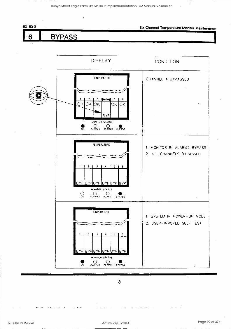
80183-01 Six Channel Temperature Monitor Maintenance
I BYPASS
DISPLAY CONDITION
CHANNEL 4 BYPASSED
5 6 I
-......--------------/ 2
OK OK OK OK
BYP
OK
MONITOR STATUS
0 0 OK ALARM2 ALARMI BYPASS
1. MONITOR IN ALARM2 BYPASS
2. ALL CHANNELS BYPASSED
I 2
TEMPERATURE
3 4 5 6
BYP BYP BYP BYP BYP BYP
MONITOR STATUS
0 0 0 OK ALARM2 ALARMI BYPASS
1. SYSTEM IN POWER-UP MODE
2. USER-INVOKED SELF TEST
1 2
TEMPERATURE
3 6 4 5
BYP I BYP BYP BYP BYP BYP
MONITOR STATUS
0 0 OK ALARM2 ALARMI BYPASS
8
Bunya Street Eagle Farm SPS SP010 Pump Instrumentation OM Manual Volume 6B
Q-Pulse Id TMS641 Active 29/01/2014 Page 92 of 376

Six Channel Temperature Monitor Maintenance 80183-01
DISPLAY CONDITION ALARM 1
RELAY DRIVE
CHANNEL 2 HAS EXCEEDED ALARM 1 LEVEL.
. ON TEMPERATURE
I 2 3
-7- 4 pp5.4 6
OK OK OK OK OK OK
L.,
.0.4.7ce STATUS
0 0 c,,, ALARs42 ALARMI BYPASS
CHANNELS 2 AND 4 HAVE ON ThIPERA TURE
EXCEEDED ALARM 1 LEVEL. FIRST OUT CONDITION FOR CHANNEL 2.
2 3 4 5 1 OK OK OK OK OK OK
Al.41 ALIV
IA OR STATUS
O 0 Ul ALARM2 ALARRI BYPASS
* If two alarms occur within 50 milliseconds, both LEDs could flash.
9
Bunya Street Eagle Farm SPS SP010 Pump Instrumentation OM Manual Volume 6B
Q-Pulse Id TMS641 Active 29/01/2014 Page 93 of 376

80183-01
8 I ALARM 2
Six Channel Temperature Monitor Maintenance
DISPLAY CONDITION ALARM 2 RELAY DRIVE
OR VOTING*
AND VOTINC TEMPERATURE
CHANNEL 3 HAS EXCEEDED ON OFF ALARM 2 LEVEL.
' 2 4 5 6 OK OK 0K 0 1;}310K AL,.
10K
MONITOR STATUS
0 0 CIK ALARM2 ALARMI BYPASS
CHANNELS 3 AND 5 HAVE ON OFF TEMPERATURE
EXCEEDED ALARM 2 LEVEL. FIRST OUT CONDITION FOR CHANNEL 3. ..,* IMIlli
OK OK OK ALM2
NITOR ST TUS t 0 ox R42 ALARM BYPASS
* * *
***
Any channel that exceeds alarm level will activate Alarm 2 relay drive. AND voting is accomplished between channels in the following pairs: Channels 1
and 2, Channels 3 and 4, Channels 5 and 6. The output of these three channel pairs is an OR function. If either channel in a pair is bypassed, an alarm relay is activated when the nonbypassed channel is in alarm. If two alarms occur within 50 milliseconds, both LEDs could flash.
10
Bunya Street Eagle Farm SPS SP010 Pump Instrumentation OM Manual Volume 6B
Q-Pulse Id TMS641 Active 29/01/2014 Page 94 of 376
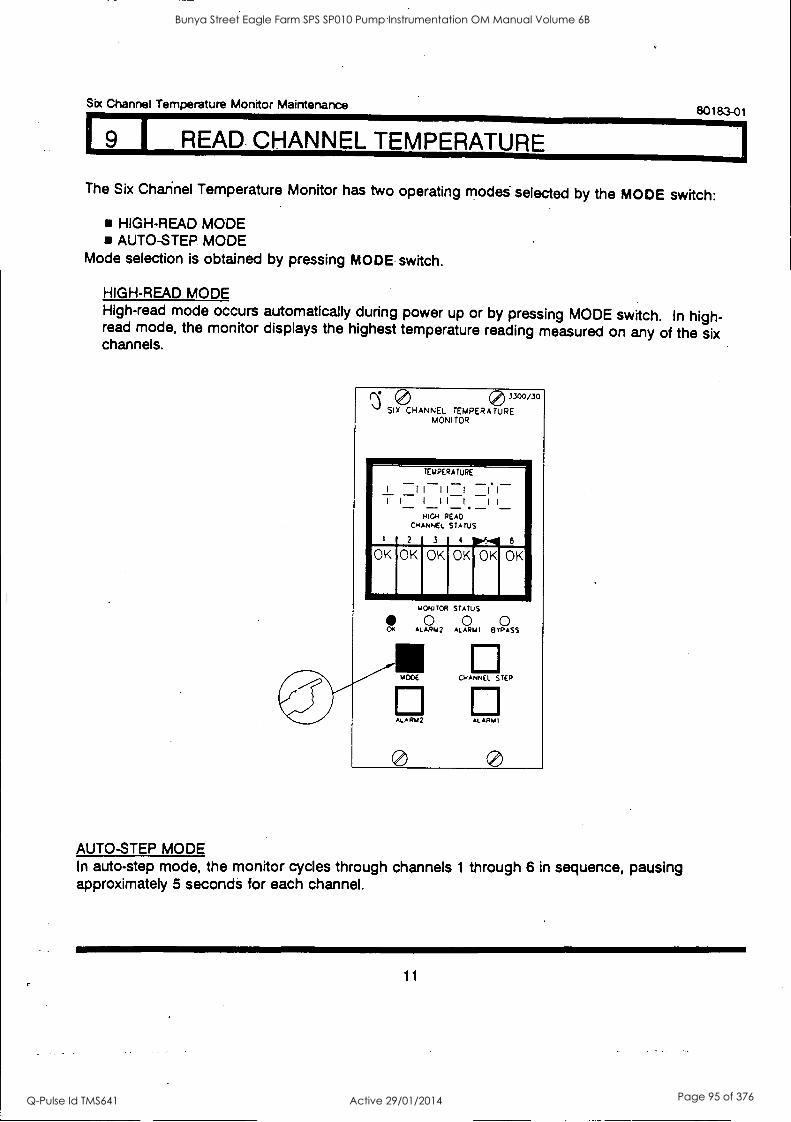
Six Channel Temperature Monitor Maintenance 80183-01
1 9 I READ CHANNEL TEMPERATURE
The Six Channel Temperature Monitor has two operating modes selected by the MODE switch:
HIGH-READ MODE AUTO-STEP MODE
Mode selection is obtained by pressing MODE switch.
HIGH -READ MODE High-read mode occurs automatically during power up or by pressing MODE switch. In high- read mode, the monitor displays the highest temperature reading measured on any of the six channels.
13. SIX CHANNEL TEMPERATURE 0 3300/30
MONI TOR
TEMPERATURE
I II II I _ICI I I I II I II -
HIGH READ CHANNEL STATUS
1 2 3 4 10.6.4 6
OK OK OK OK OK OK
MONITOR STATUS
AL AR 2 AL ARIJ1 BYPASS
'AWE CHANNEL STEP
ALA RIA2 ALARM I
AUTO-STEP MODE In auto-step mode, the monitor cycles through channels 1 through 6 in sequence, pausing approximately 5 seconds for each channel.
11
Bunya Street Eagle Farm SPS SP010 Pump Instrumentation OM Manual Volume 6B
Q-Pulse Id TMS641 Active 29/01/2014 Page 95 of 376

80183-01 Six Channel Temperature Monitor Maintenance
9 I READ CHANNEL TEMPERATURE
CHANNEL-SELECT MODE "
Channel-Select mode is selected by pressing CHANNEL STEP to cycle through channels 1
through 6 in sequence.
0 3300/30
SIX CHANNEL TEMPERATURE MONITOR
TEMPERATURE
1 I I I I I 1 1
T 1- I I I-1 -1 I
CHANNEL STATUS
2 3 4 5 6
OK OK OK l.0 11 OK OK
MONITOR STATUS
0 0 0 OK ALARM2 ALARM1 BYPASS
MOD CHANNEL STEP
ALARM2 ALARM1
CHANNEL INDICATOR
12
Bunya Street Eagle Farm SPS SP010 Pump Instrumentation OM Manual Volume 6B
Q-Pulse Id TMS641 Active 29/01/2014 Page 96 of 376

Six Channel Temperature Monitor Maintenance
10 I READ ALARM 1 SETPOINT LEVELS
80183-01
Press CHANNEL STEP switch to select channel, and press ALARM1 switch to read alarm 1
setpoints. Repeat process for each succeeding channel.
0 3300/30
SIX CHANNEL TEMPERATURE. MONI TOR
TEUPERATUPE
I I I I II II I I I I I I I
OVER ALARM CHANNEL STATUS
P 11 2 3 4 5
OK 1OK OK OK OK OK
MONITOR STATUS
0 0 0 0 OK ALARm2 ALARM; BYPASS
MODE CHANNEL STEP
ALARM2 ALARM1
13
Bunya Street Eagle Farm SPS SP010 Pump Instrumentation OM Manual Volume 6B
Q-Pulse Id TMS641 Active 29/01/2014 Page 97 of 376

80183-01 Six Channel Temperature Monitor Maintenance
11 I READ ALARM 2 SETPOINT LEVELS
Press CHANNEL STEP switch to select channel, and press ALARM2 switch to read alarm 2 setpoints. Repeat process for each succeeding channel.
0 3300/25
SIX CHANNEL TEMPERATURE MONITOR
TEMPERATURE
I II I I I I
. I
1 1 1 I I. I II OVER ALARM
CHANNEL STATUS
P-1 2 3 4
OK IOK OK OK 5 6
OK OK
OK
MONITOR STATUS
0 0 0 ALARM? AL ARMI BYPASS
MODE
ALARM2
0
CHANNEL STEP
AL ARM I
OR
TEMPERATURE
I I I I I I. I
1 I I 1 1 1 1
14
Bunya Street Eagle Farm SPS SP010 Pump Instrumentation OM Manual Volume 6B
Q-Pulse Id TMS641 Active 29/01/2014 Page 98 of 376
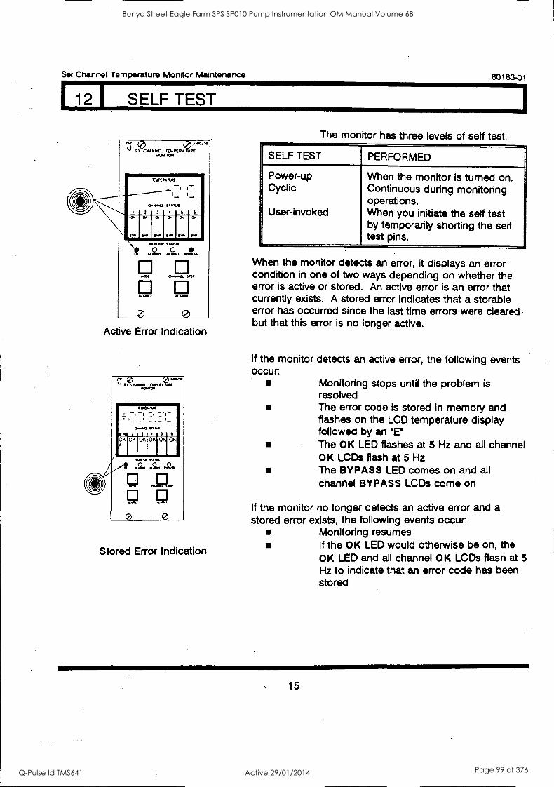
Six Channel Temperature Monitor Maintenance
1.0 SELF TEST
SI?c..,04EL rtypeRZEs"*"° %Kw ma
\
MIK RANK
C.00(1. STARA
- -
C. I.
,..1
... 4 r OVOR
40
WOE
Yn.111
0
SUM 0
°"""u.
.
A.01
(a
Active Error Indication
Stored Error Indication
80183-01
The monitor has three levels of self test:
SELF TEST PERFORMED
Power-up Cyclic
User-invoked
When the monitor is turned on. Continuous during monitoring operations. When you initiate the self test by temporarily shorting the self test pins.
When the monitor detects an error, it displays an error condition in one of two ways depending on whether the error is active or stored. An active error is an error that currently exists. A stored error indicates that a storable error has occurred since the last time errors were cleared but that this error is no longer active.
If the monitor detects an active error, the following events occur:
Monitoring stops until the problem is resolved The error code is stored in memory and flashes on the LCD temperature display followed by an °E"
The OK LED flashes at 5 Hz and all channel OK LCDs flash at 5 Hz The BYPASS LED comes on and all channel BYPASS LCDs come on
If the monitor no longer detects an active error and a stored error exists, the following events occur:
Monitoring resumes If the OK LED would otherwise be on, the OK LED and all channel OK LCDs flash at 5
Hz to indicate that an error code has been stored
15
Bunya Street Eagle Farm SPS SP010 Pump Instrumentation OM Manual Volume 6B
Q-Pulse Id TMS641 Active 29/01/2014 Page 99 of 376
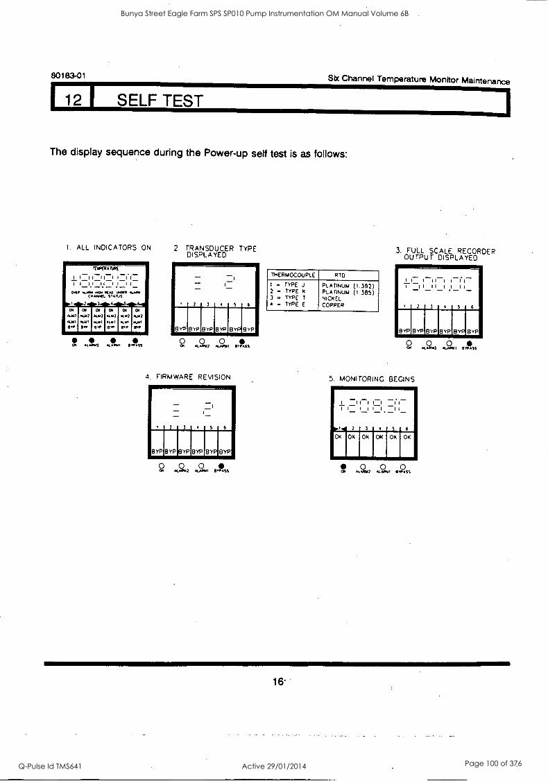
80183-01 Six Channel Temperature Monitor Maintenance
12 I SELF TEST
The display sequence during the Power-up self test is as follows:
1. ALL INDICATORS ON
OK .10.1 kt Aildi 0,0ASS
2. TRANSDUCER TYPE DISPLAYED
2 3 5 6
8 YP BYP GYP B YP GYP GYP
0 0 0 *4.* 42 ft!~ BYPASS
4. FIRMWARE REVISION
BYRIBYPIBYPIBYP B YP B YP
2 3 5 6
Om.a2 I BYPASS
THERMOCOUPLE R TO
I = 2 .A
3 . 4 =
TYPE TYPE TYPE TYPE
J K
I E
PLATINUM PLATINUM NICKEL COPPER
(1.392) (1.385)
3. FULL SCALE RECORDER OUTPUT DISPLAYED
0 0 0 CO, AlARW2 ALAAVI avp.ss
5. MONITORING BEGINS
I II 1 I I II TI I II I II
5 6
OK
16
Bunya Street Eagle Farm SPS SP010 Pump Instrumentation OM Manual Volume 6B
Q-Pulse Id TMS641 Active 29/01/2014 Page 100 of 376

Six Channel Temperature Monitor Maintenance 80183-01
12 1 SELF TEST
Recall stored error codes by using the User-invoked self test. Use the following steps to run the User-invoked self test, read error codes, and clear stored error codes:
4\ CAUTION
Machine protection provided by this monitor will be lost for the duration of the self test.
NOTE: User-invoked self test cannot be initiated if any error is active. Refer to the Error Codes section for more information on the error codes.
1. Initiate the User-invoked self test by shorting the two self test pins (ST) with a screwdriver. All the LEDs and LCD elements will come on for 5 seconds.
If an active or stored error is present, the BYPASS LED and all channel BYPASS LCDs remain on, the OK LED and all channel OK LCDs flash at 5 Hz, and the first error code flashes on the LCD temperature display at 2
Hz. The error code is followed by an °E'.
For example, the monitor to the right is
indicating error code number 2.
?) 33:0160
64 86444LNIkr-A
aura 7
111.6166
7
WM
6,4 Nos
4
- I
S
-
6
Ca' O.
*
06
rm.
C.
II.
tr,
PO
cp
OW
.004
wet
0
RN VANS
04.4464a US,
ft...I
/2)
17
Bunya Street Eagle Farm SPS SP010 Pump Instrumentation OM Manual Volume 6B
Q-Pulse Id TMS641 Active 29/01/2014 Page 101 of 376

80183-01 Six Channel Temperature Monitor Maintenance
12 1 SELF TEST
2. Read any other stored error codes by pressing and holding the ALARMI switch for approximately one second.
For example, the monitor to the right contains a second stored error code - number 5.
When you reach the end of the error code list,
the LCD temperature display will show 613888E*
and the OK LED and all channel OK LCDs turn off.
You may read through the list again by continuing to press the ALARM1 switch.
3. When you have reached the end of the error code list (as described above), clear error codes from memory by pressing and holding the ALARM2 switch for approximately one second. The monitor will go through the power up display sequence, beginning with display number two (transducer type), before it resumes monitoring.
r5 5J X CHANNEL TEMPERATURE 1" NON, TOR
:
Cr.
ItIPERAIURE
mok4.
I
STATUS
I
I I
: a
en.
. ,
8 TP STIP
01
13T,
c .4
PIP STP
CN
POP
KASH
ATOM
ALATNIZ
0
TOP STATUS
0 0 2 AL APIA
00#010.
I ..PASS
STEP
KANN I
0
IP CH EL TEIOERATURE j"*")- NOM TOP
ftlIPOTAILK
I I I I -I CI I_ I C 7 17to...) 11.11 I
0.141 STOMA
VP 1. Iry r. ffv v..,
VCNIMP
WOE
ALTATTI
0
STOMA
CAomu STEP
.1...00
0
Bunya Street Eagle Farm SPS SP010 Pump Instrumentation OM Manual Volume 6B
Q-Pulse Id TMS641 Active 29/01/2014 Page 102 of 376
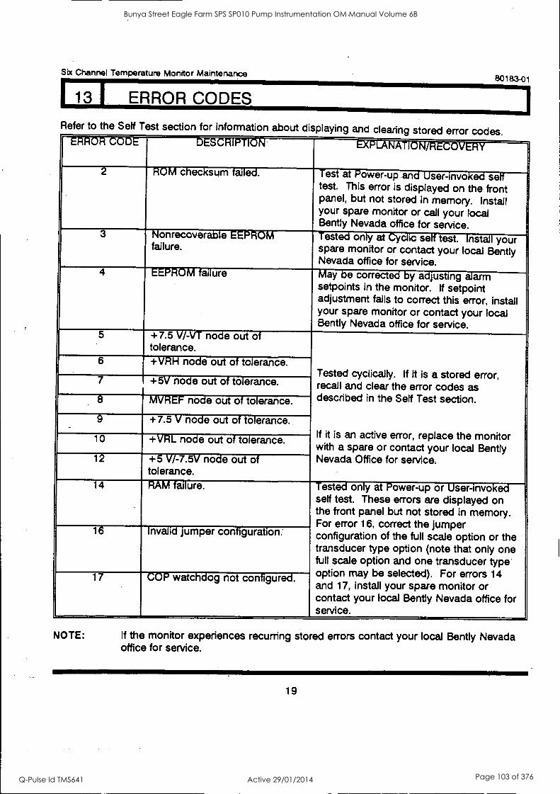
Six Channel Temperature Monitor Maintenance 80183-01
113 I ERROR CODES
Refer to the Self Test section for information about displaying and clearing stored error codes. " ' - - * " - I I . - v -
ID' c ec sum ai. est at -ower-up an g ser-invo . se' test. This error is displayed on the front panel, but not stored in memory. Install your spare monitor or call your local Bently Nevada office for service.
3 lonrecover- e - v
failure. est. on y at is se' test. nst- your
spare monitor or contact your local Bently Nevada office for service.
4 EEPROM failure May be corrected by adjusting alarm setpoints in the monitor. If setpoint adjustment fails to correct this error, install your spare monitor or contact your local Bently Nevada office for service.
5 +7.5 V/-VT node out of tolerance.
_
Tested cyclically. If it is a stored error, recall and clear the error codes as described in the Self Test section.
If it is an active error, replace the monitor with a spare or contact your local Bently Nevada Office for service.
6 +VRH node out of tolerance.
7 . +5V node out of tolerance.
8 MVREF node out of tolerance.
9 +7.5 V node out of tolerance.
10 +VRL node out of tolerance.
12 +5 V/-7.5V node out of tolerance.
14 RAM failure. Tested only at Power-up or User-invoked self test. These errors are displayed on the front panel but not stored in memory. For error 16, correct the jumper configuration of the full scale option or the transducer type option (note that only one full scale option and one transducer type option may be selected). For errors 14 and 17, install your spare monitor or contact your local Gently Nevada office for service.
16 Invalid jumper configuration:
17 COP watchdog not configured.
NOTE: If the monitor experiences recurring stored errors contact your local Bently Nevada office for service.
19
Bunya Street Eagle Farm SPS SP010 Pump Instrumentation OM Manual Volume 6B
Q-Pulse Id TMS641 Active 29/01/2014 Page 103 of 376

80183-01 Six Channel Temperature Monitor Maintenance
14 1 DISASSEMBLY PROCEDURE
1. Loosen screws. Remove front panel by sliding panel to the right, up, and then toward you.
2. Disconnect front panel cable from digital board.
I I.
(2)1Zo/lo 51. R. EL TEMPERA
boODK TOR
OK ALM? ALYI
BYP
ITUKRAnAll
I i-11i t.i II II
OK N.312 ALIAI
ero
40. MI K1 SPANS
3
OK
ALYI
ew
OK ALTO Al111
(01,
OK ALId ALYI
8/1,
OK 1.112
ALAI 819
3. Disconnect cable between digital board and analog board.
DOTAL BOARD
111
ANALOG BOARD
O
A
"mow iiimmor iip
0 0 Li 0 § 0
§ 0
§ 0
§ 0
0 0 0 0 0 0 0 0 0 0
20
Bunya Street Eagle Farm SPS SP010 Pump Instrumentation OM Manual Volume 6B
Q-Pulse Id TMS641 Active 29/01/2014 Page 104 of 376
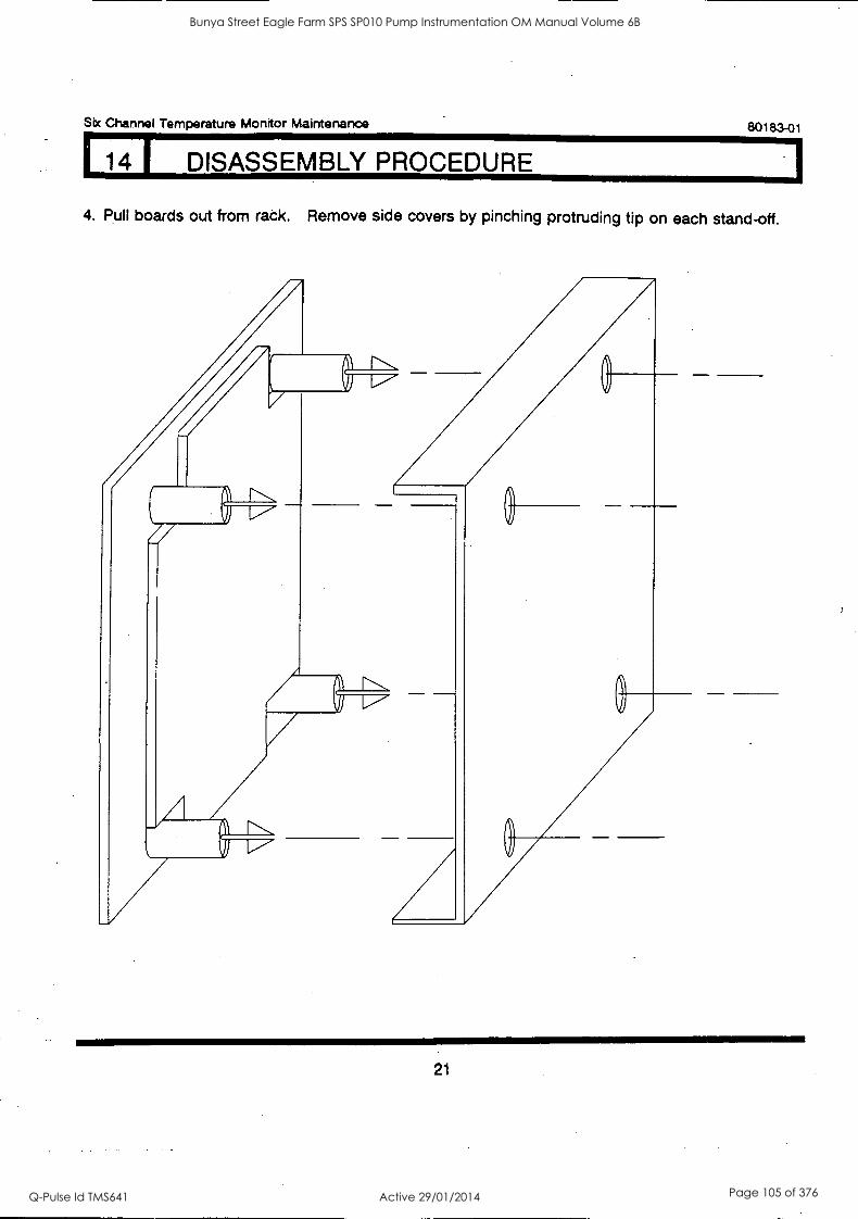
Six Channel Temperature Monitor Maintenance 80183-01
14 I DISASSEMBLY PROCEDURE
4. Pull boards out from rack. Remove side covers by pinching protruding tip on each stand-off.
21
Bunya Street Eagle Farm SPS SP010 Pump Instrumentation OM Manual Volume 6B
Q-Pulse Id TMS641 Active 29/01/2014 Page 105 of 376
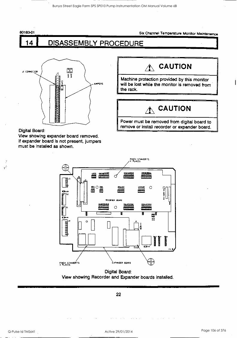
80183-01 Six Channel Temperature Monitor Maintenance
DISASSEMBLY PROCEDURE
JUMPERS
Digital Board: View showing expander board removed. If expander board is not present, jumpers must be installed as shown.
A\ CAUTION
Machine protection provided by this monitor will be lost while the monitor is removed from the rack.
A CAUTION
Power must be removed from digital board to remove or install recorder or expander board.
PINCH STANDOFFS PLACES
PINCH srmocrrs 3 PLACES
Digital Board: View showing Recorder and Expander boards installed.
22
Bunya Street Eagle Farm SPS SP010 Pump Instrumentation OM Manual Volume 6B
Q-Pulse Id TMS641 Active 29/01/2014 Page 106 of 376
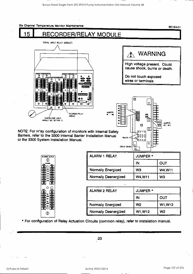
Six Channel Temperature Monitor Maintenance
15 I RECORDER/RELAY MODULE
80183-01
SIGNAL INPUT RELAY MODULES
a)
El El
TEMPERATURE INGUI 1/000LE SEE SECTION IS
RECORCER/RELAY MODULE
fl
JAPERS -
4\ WARNING
High voltage present. Could cause shock, bums or death.
Do not touch exposed wires or terminals
NOTE: For Way configuration of monitors with Internal Safety Barriers, refer to the 3300 Internal Barrier Installation Manual or the 3300 System Installation Manual.
RECOUP OuIRIPS
(D cot
0 Da
ai CtI/
0 min
0 ? cI ID all
IP 6I 150 It:31 1611
AAI
IC Ar
8 (3),
JAPERS WII. WI2
ALARM 1 RELAY JUMPER *
IN OUT
Normally Energized W3 W4,W11
Normally Deenergized W4,W11 W3
ALARM 2 RELAY JUMPER *
IN OUT
Normally Energized W2 W1,W12
Normally Deenergized W1,W12 W2
* For configuration of Relay Actuation Circuits (common relay), refer to installation manual.
23
Bunya Street Eagle Farm SPS SP010 Pump Instrumentation OM Manual Volume 6B
Q-Pulse Id TMS641 Active 29/01/2014 Page 107 of 376
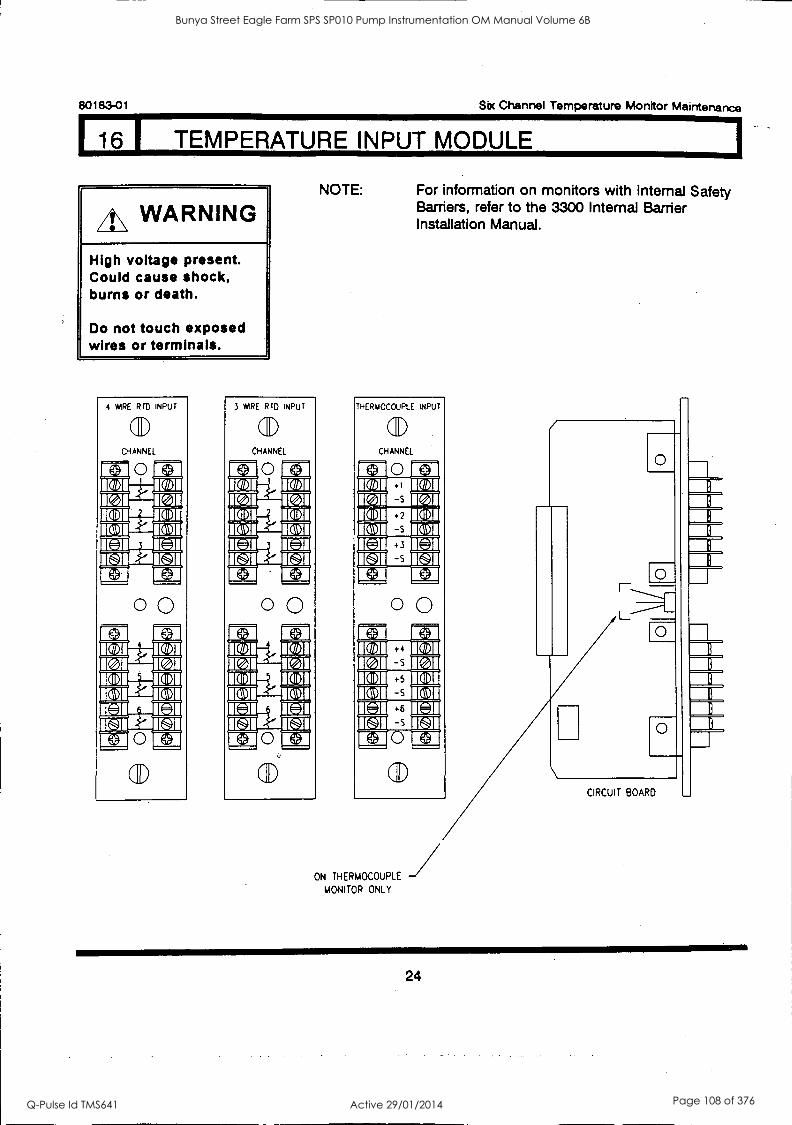
80183-01 Sbc Channel Temperature Monitor Maintenance
16 1 TEMPERATURE INPUT MODULE
it\ WARNING
High voltage present. Could cause shock, burns or death.
Do not touch exposed wires or terminals.
4 WIRE RID INPUT
aD CHANNEL
00
aD
3 WIRE RTD INPUT
(ID CHANNEL
0 Him RAI
C171. HI BMW MI MI MR NIB NI
0 0
Eza KZ I 1031,
NOTE: For information on monitors with internal Safety Barriers, refer to the 3300 Internal Barrier Installation Manual.
THERIAOCOUPLE INPUT
sal) CHANNEL
La 0 UI IE IBIJIMIC171 1(011 ICe ]I IC ]I IM 1141 IE Ea Ea
0 0
lel -s IQDI +5
IQDI -s +6
-s
101
CD
ON THERMOCOUPLE
MONITOR ONLY
O
Fo-
CIRCUIT BOARD
13 ll 0
13
0
B B
13
13
24
Bunya Street Eagle Farm SPS SP010 Pump Instrumentation OM Manual Volume 6B
Q-Pulse Id TMS641 Active 29/01/2014 Page 108 of 376
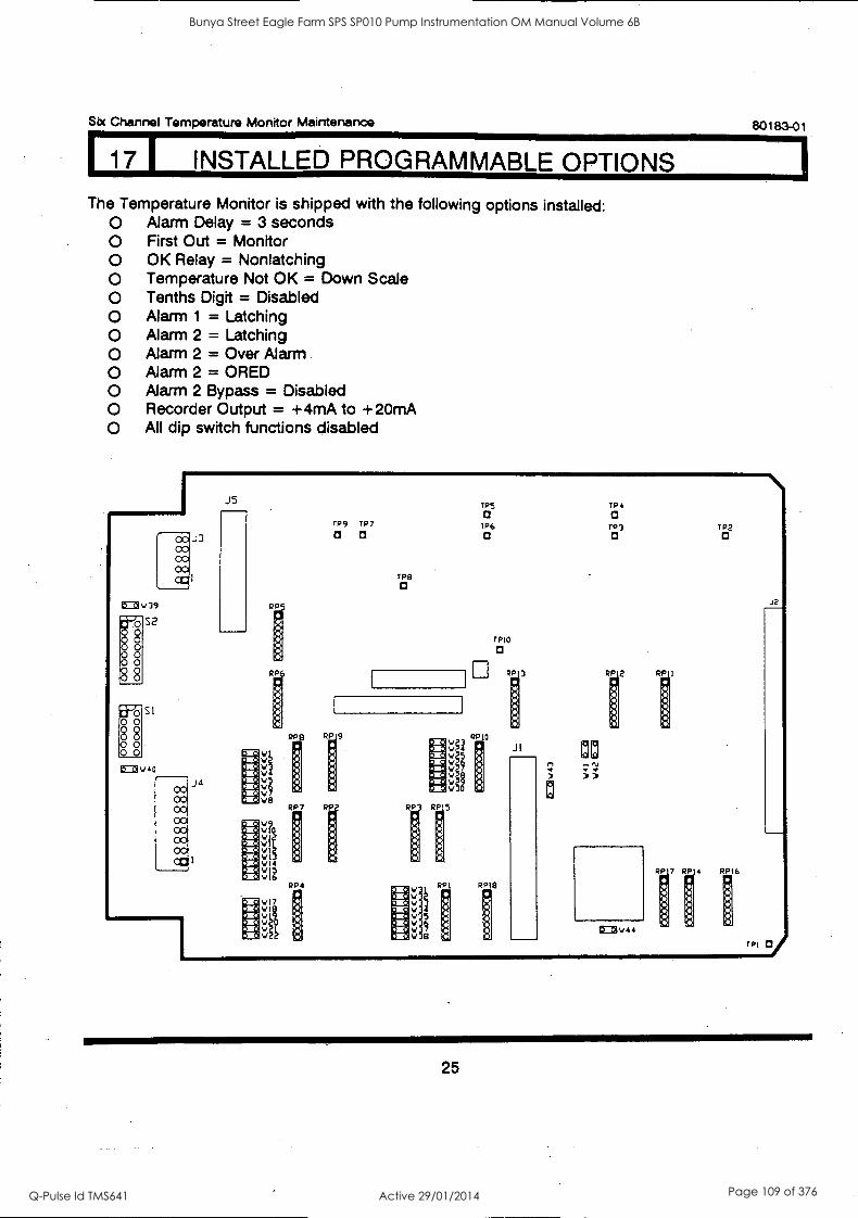
Sbc Channel Temperature Monitor Maintenance 80183-01
17 I INSTALLED PROGRAMMABLE OPTIONS
The Temperature Monitor is shipped with the following options installed: O Alarm Delay = 3 seconds O First Out = Monitor O OK Relay = Non latching O Temperature Not OK = Down Scale O Tenths Digit = Disabled O Alarm 1 = Latching O Alarm 2 = Latching O Alarm 2 = Over Alarm O Alarm 2 = ORED O Alarm 2 Bypass = Disabled O Recorder Output = +4mA to +20mA O All dip switch functions disabled
CO CO CO 00 ca
CO3v39
O 0 O 0 O 0
§§
#8 88 O 0
S2
Si
V 4 0
CO 00 CO CO 00 CO CO Oc
J3
J4
J5
RP
RP
RIDS
,1 .8
VI
Vl VI4
V17
V YO V
V
TP5 TP4 a
TP9 TP7 TP6 TP3 TP2 a O O O 0
TP9 O
TPIO
a
RP 9
V
V RPIO
V g9
RP7 RP RP
RP4 V RPI RPI8
V V
V 67
JI
RP 2
N ; ;
CC3V44 p
1R7 Rpi4 RPI6
TPI
J2
25
Bunya Street Eagle Farm SPS SP010 Pump Instrumentation OM Manual Volume 6B
Q-Pulse Id TMS641 Active 29/01/2014 Page 109 of 376
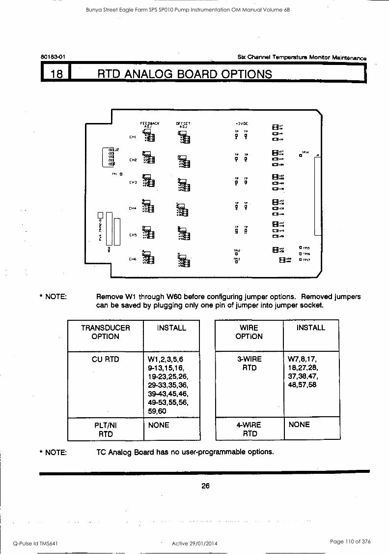
80183-01 Six Channel Temperature Monitor Maintenance
18 I RTD ANALOG BOARD OPTIONS
PI 0
CHl
CH2
CH3
CH4
CHS
CH6
FEADj EDBACK arrsur A DJ
ve
3VDC
TP TP
9 9
TP TP
TP TP
TP TP
TP TP
Till a
Till O
El=
=fry,
Yy
TPIi
a
0 rpm
0 TFIC
0 Till
* NOTE: Remove W1 through W60 before configuring jumper options. Removed jumpers can be saved by plugging only one pin of jumper into jumper socket.
TRANSDUCER OPTION
INSTALL
CU RTD W1,2,3,5,6 9-13,15,16, 19-23,25,26, 29-33,35,36, 39-43,45,46, 49-53,55,56, 59,60
PLT/NI NONE RTD
WIRE OPTION
INSTALL
3-WIRE W7,8,17, RTD 18,27,28,
37,38,47, 48,57,58
4-WIRE NONE RTD
* NOTE: TC Analog Board has no user-programmable options.
26
Bunya Street Eagle Farm SPS SP010 Pump Instrumentation OM Manual Volume 6B
Q-Pulse Id TMS641 Active 29/01/2014 Page 110 of 376
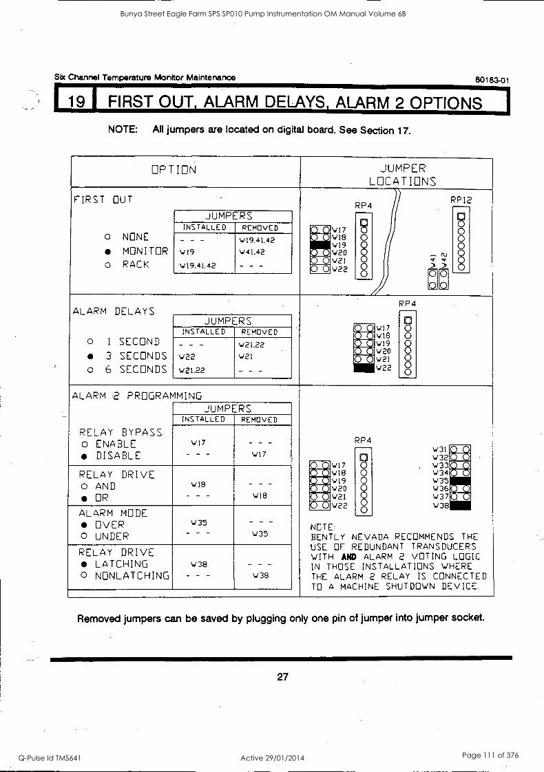
Six Channel Temperature Monitor Maintenance 80183-01
19 FIRST OUT ALARM DELAYS, ALARM 2 OPTIONS
NOTE: All jumpers are located on digital board. See Section 17.
OP T ION JUMPER LOCATIONS
FIRST OUT _
RP4 RP12
9 0 0 0 8
o NONE
MONITOR o RACK
JUMPERS
cj
INSTALLED REMOVED mr-c.47 AXION18
:0140 wi9 v20 W21 w22
9 0
L) 0
- - - W19
v19,41,42
W19,41.42
w11.42
- -- mi ;" cdo rol > 00
.C2.Q.
) 0
ALARM DELAYS RP4
0 0 0 0
0 `.-1 8
o 1 SECOND
3 SECONDS o 6 SECONDS
JUMPERS RiM W17 W18 W19 W20 W21 W22
INSTALLED REMOVED N I Kt
- - - W22
\121.22
W21.22
W21
- - -
Mt COM COO
ALARM .2 PROGRAMMING
RP4
JUMPERS INSTALLED REMOVED
RELAY BYPASS o ENABLE
DISABLE W17
- - -
- - - W17 a
w31 w 32
M AM
-oXD W17 vla
0 , W 33M-10 RELAY DRIVE o AND
OR
w18
- - - - - - W18
0 0 8
w 3 4 W35 W36[011.]
MI g AX \ . /19 Q \in r 0 w21 0
0 w 37 w38
(41 MI 0 w22
ALARM MODE OVER
O UNDER
w35 - - - w35
NOTE BENTL Y NEVADA RECOMMENDS THE USE OF REDUNDANT TRANSDUCERS WITH AND ALARM 2 VOTING LOGIC IN THOSE INSTALLATIONS WHERE THE ALARM 2 RELAY IS CONNECTED TO A MACHINE SHUTDOWN DEVICE.
RELAY DRIVE LATCHING
o NONLATCHING w38
- - -
_ _ _
W38
Removed jumpers can be saved by plugging only one pin of jumper into jumper socket.
27
Bunya Street Eagle Farm SPS SP010 Pump Instrumentation OM Manual Volume 6B
Q-Pulse Id TMS641 Active 29/01/2014 Page 111 of 376

80183-01 Six Channel Temperature Monitor Maintenance
20 1 ALARM 1,_ UNITS, TENTHS DIGIT, TEMPERATURE NOT OK
NOTE: All jumpers are located on digital board. See Section 17.
OPTION JUMPER LOCATIONS
ALARM 1
LATCHING
0 NONLATCHING
w31 w32 w33 ,./ 3 4 \435 w36 w37 w38
RPI
JUMPERS 971, A I MB DJ
0 n 0 0 0 0
INSTALLED REMOVED AriZig
w36
- - -
_ _ _
w36
rg mic II AIN mu
UNITS
0 ° F
0 ° C
w3I v 32 w33 v 34 v 3 5 W36 w37 \./38
RP1
JUMPERS :10 EC 4W1 0 n 0 0 0 0
INSTALLED REMOVED AlrMig MN AWN w31
- -- - --
w3I
Q r411 0
0
TENTHS
DIGIT WHOLE
0 TENTHS
W3I w32 W33 w34 v35 ../ 3 6
V37 W38
RP1
JUMPERS Arzio
56X41-e
. 11. 0 n 6 0 0 0 0
INSTALLED REMOVED
w32
- - -
_ _ _
w32
Am NM MN :QC VAD
TEMPERATURE NOT OK
DOWN SCALE
0 UP SCALE
W3I 1./32 \,./33 W 3 4
v35 W 3 6 W37 W38
RP1
Mg ()- ?.---)
-6 0 0 0 0
JUMPERS MN INSTALLED REMOVED ;z]
AX a 1:01 13
mu W37
_ _ _
_ - -
w37
Removed jumpers can be saved by plugging only one pin of jumper into jumper socket.
28
Bunya Street Eagle Farm SPS SP010 Pump Instrumentation OM Manual Volume 6B
Q-Pulse Id TMS641 Active 29/01/2014 Page 112 of 376
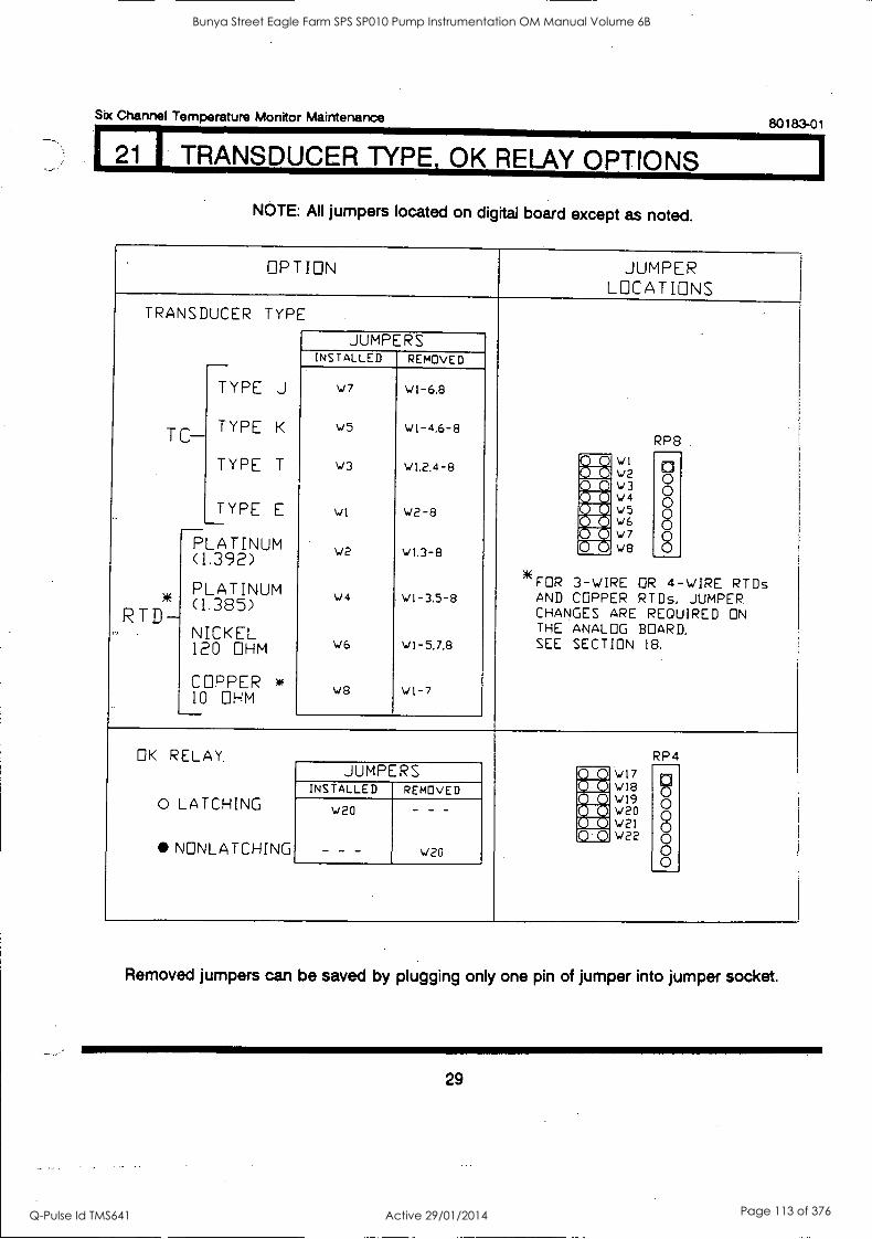
Six Channel Temperature Monitor Maintenance 80183-01
1 I TRANSDUCER TYPE, OK RELAY OPTIONS
NOTE: All jumpers located on digital board except as noted.
OPTION JUMPER LOCATIONS
TRANSDUCER TYPE
RP8
_ JUMPERS INSTALLED REMOVED
TC-
RTD-
PLATINUM (1.392)
PLATINUM (1.385)
NICKEL 120
COPPER 10
TYPE J
TYPE K
TYPE T
TYPE E
OHM
w
OHM
w7
w5
w3
WI
w2
W4
N./6
w8
w1-6,8
wt -4.6 -8
wt,2.4-8
W2-8
wi.3-8
wI-3.5-8
w1-5,7,8
WI-7
@DIN WI w2 w3 V4
' 5 w6 W7 W8
0" 0 0 0 0 0 0
raw IS I 0 (
r 0 0
*FR 3-WIRE OR 4-WIRE RTDs AND COPPER RTDs, JUMPER CHANGES ARE REQUIRED ON THE ANALOG BOARD, SEE SECTION 18.
OK RELAY. RP4 JUMPERS W17
NIXqg w18 n
INSTALLED REMOVED .01 51 AM wi9 w20 0 0 0 LATCHING
NNLATCHING
w20
- - -
- - -
wa
NM w21 0 0 0 W22 0
0 0
Removed jumpers can be saved by plugging only one pin of jumper into jumper socket.
29
Bunya Street Eagle Farm SPS SP010 Pump Instrumentation OM Manual Volume 6B
Q-Pulse Id TMS641 Active 29/01/2014 Page 113 of 376
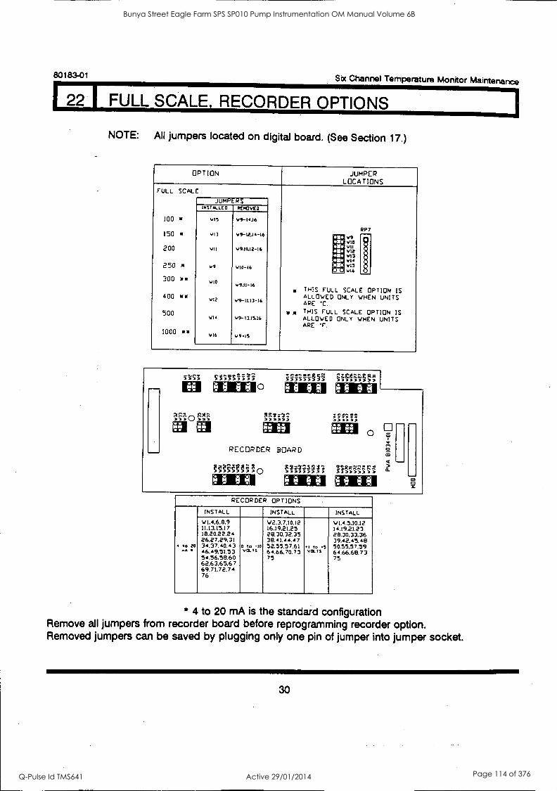
80183-01 Six Channel Temperature Monitor Maintenance
I FULL SCALE, RECORDER OPTIONS
NOTE: All jumpers located on digital board. (See Section 17.)
OPTION JUMPER LOCATIONS
FULL SCALE
JUMPERS INSTALLED RcoovED
100 v15 v9-14.16
RP 7 150 * vI3 V1-12.16-16 I
011 v9 vtO
200 vil v9.10.12-I6 sW i VII VI2 62
16 V13 v14
250 v9 vt0-16 ge vI5 Mgt vI6
300 a* VIO v9.II-16 * THIS FULL SCALE OPTION IS 400 or* ALLOWED ONLY WHEN UNITS Vle V9-11.13-16
ARE *C
500 v, it THIS FULL SCALE OPTION IS vlo V9-13.15.16 ALLOWED ONLY WHEN UNITS
ARE F. 1000 a 'I VI6 v9-15
N7:17,-,
ee ee
O SSSSSSiii
ee ee
RECORDER BOARD
9.. Ne e
2,1,Ct"t§1
ee ee
3.1zgnx
ei RECORDER OPTIONS
INSTALL INSTALL INSTALL
W1.4.6,8.9 W2.3.7.10.12 W1.4.5.10.12 11.13.15.17 16.19.2125 14.19.21.23 18.20.22.24 28.30.32.35 28.30.33.36 26.27.29.31 3E041.44.47 39,42.45.49
to ea 34.37.40.43 0 to -10 52.55.57.61 1 to 5 50.55.57.59 .. 46.49.51.53 va's 64.66.70.73 VC" 64.66.68.73 54,56.58.60 75 75 62.63,65,67 69.71,72.74 76
* 4 to 20 mA is the standard configuration Remove all jumpers from recorder board before reprogramming recorder option. Removed jumpers can be saved by plugging only one pin of jumper into jumper socket.
30
Bunya Street Eagle Farm SPS SP010 Pump Instrumentation OM Manual Volume 6B
Q-Pulse Id TMS641 Active 29/01/2014 Page 114 of 376
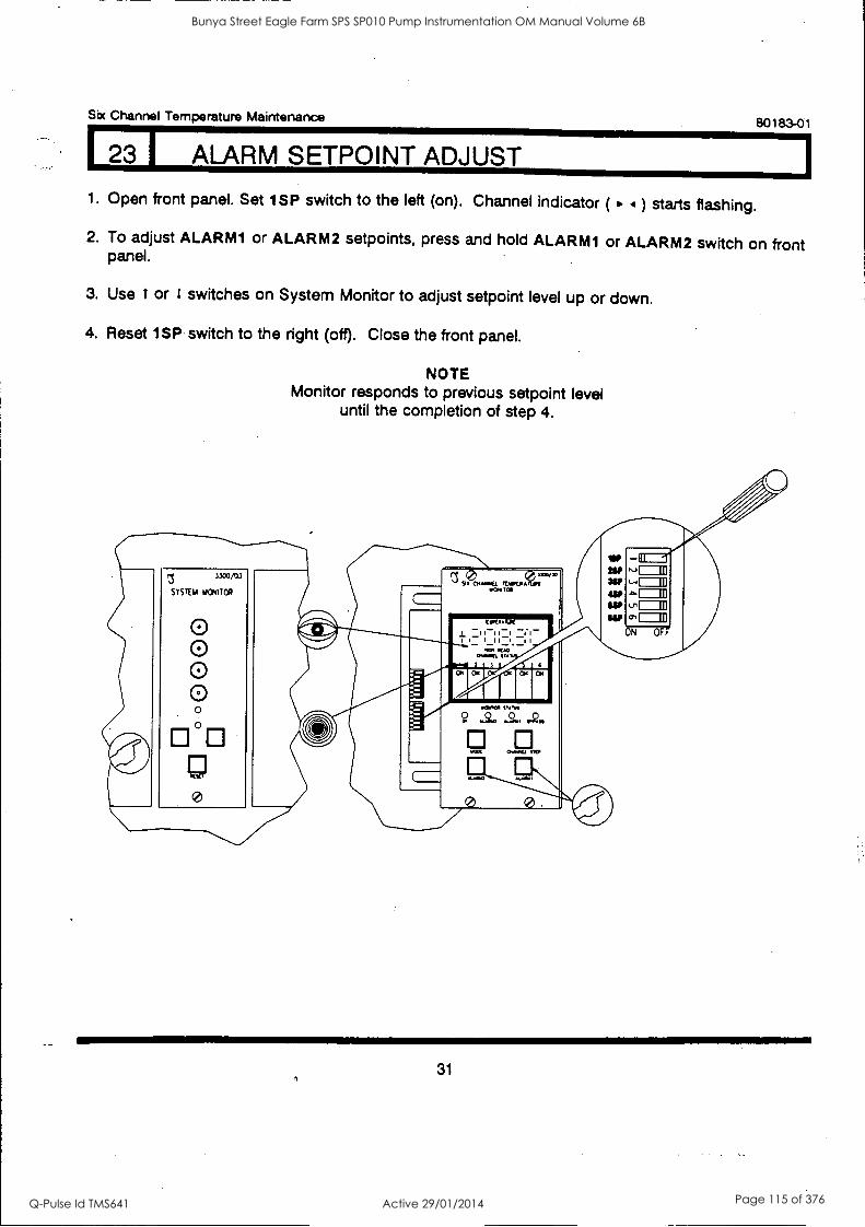
Six Channel Temperature Maintenance 80183-01
23 I ALARM SETPOINT ADJUST
1. Open front panel. Set 1SP switch to the left (on). Channel indicator ( ) starts flashing.
2. To adjust ALARM1 or ALARM2 setpoints, press and hold ALARM1 or ALARM2 switch on front panel.
3. Use t or 1 switches on System Monitor to adjust setpoint level up or down.
4. Reset 1SP switch to the right (off). Close the front panel.
NOTE Monitor responds to previous setpoint level
until the completion of step 4.
31
Bunya Street Eagle Farm SPS SP010 Pump Instrumentation OM Manual Volume 6B
Q-Pulse Id TMS641 Active 29/01/2014 Page 115 of 376
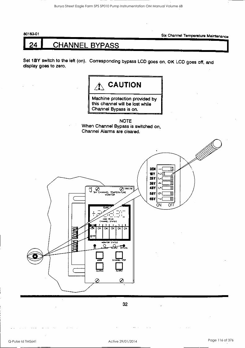
80183-01 Six Channel Temperature Maintenance
4 1 CHANNEL BYPASS
Set 1BY switch to the left (on). Corresponding bypass LCD goes on, OK LCD goes off, and display goes to zero.
A\ CAUTION
Machine protection provided by this channel will be lost while Channel Bypass is on.
NOTE When Channel Bypass is switched on, Channel Alarms are cleared.
(2: -18Y N3111
0 3300/30
SIX CHANNEL TEMPERA TORE MONITOR
28Y c.
98Y IBY
5BY cn
SBY
ON OFF
I I
I I I I - . 14104 RE AO
C.ANN/Lt. STATUS
2
OK
BYP
3 1 4 5 1 6
OK
/A0,48 TOR
OK OK I OK
STATUS
11,P.SS
El El M006 CHMIK1 STEP
El ALARM 2 M.ARY I
II
32
Bunya Street Eagle Farm SPS SP010 Pump Instrumentation OM Manual Volume 6B
Q-Pulse Id TMS641 Active 29/01/2014 Page 116 of 376
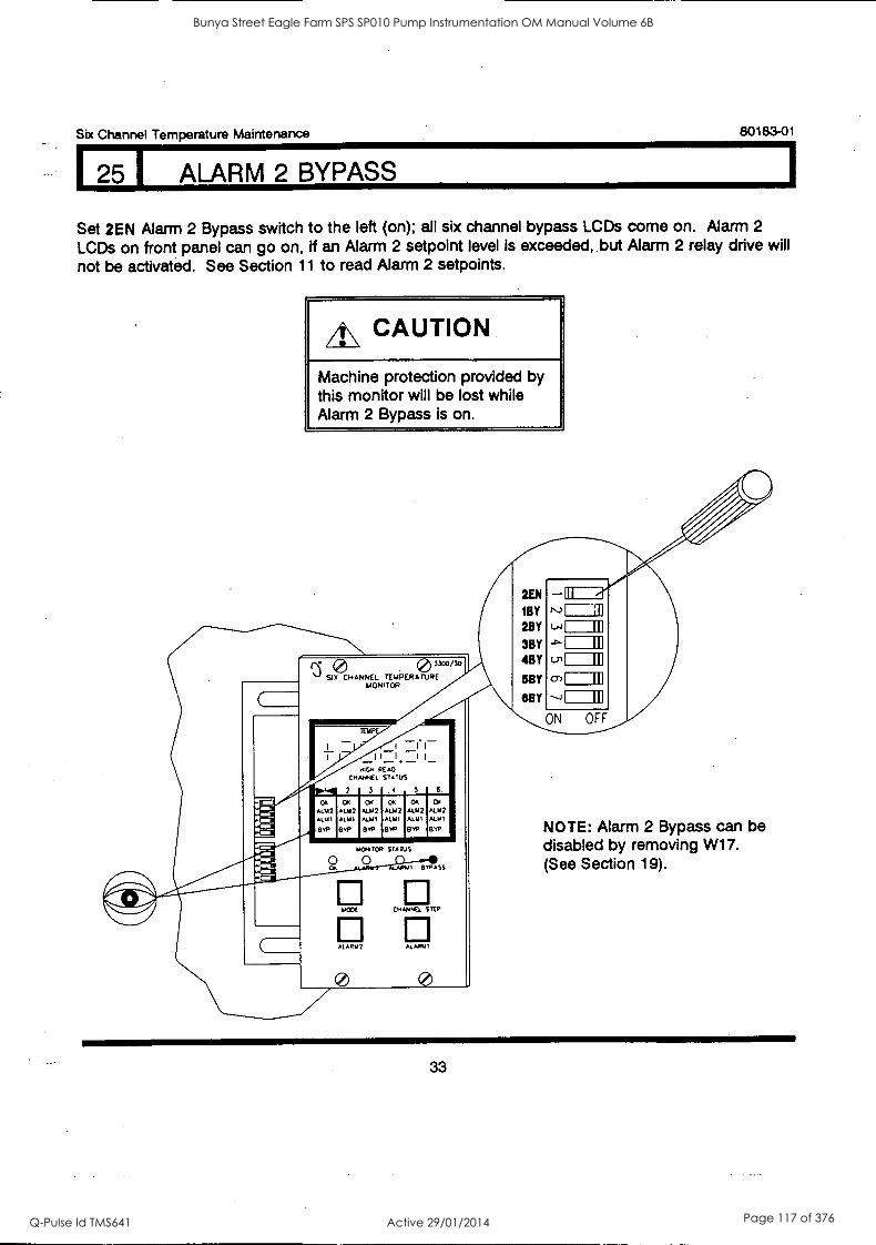
Six Channel Temperature Maintenance 80183-01
25 I ALARM 2 BYPASS
Set 2EN Alarm 2 Bypass switch to the left (on); all six channel bypass LCDs come on. Alarm 2
LCDs on front panel can go on, if an Alarm 2 setpoint level is exceeded, but Alarm 2 relay drive will not be activated. See Section 11 to read Alarm 2 setpoints.
A\ CAUTION
Machine protection provided by this monitor will be lost while Alarm 2 Bypass is on.
0 33°3134) SIX CHANNEL TEMPERATURE
MONITOR
(.----- 2EN -III 'BY r-)=2 2BY (-1
3BY -0'
4BY LT1
EBY o 6BY ---4
ON OFF
It I II - HIGH READ
CHANNEL STATUS
wig 2
OK ALM2 ALU1
GYP
3 4 5 6
OK CH Cr ALM2 ALU2 ALM2 ALM' ALIO ALMI
EOP 010 BVP
OK
ALM%
BvP
MON TOR STATUS
OH
ALU2 ALIN
etyP
LAMA I B V9A SS
0 El MOOS CM WC. STEP
AL APIA 2 ALM,/ I
I III I III
II
I III
I III
NOTE: Alarm 2 Bypass can be disabled by removing W17. (See Section 19).
33
Bunya Street Eagle Farm SPS SP010 Pump Instrumentation OM Manual Volume 6B
Q-Pulse Id TMS641 Active 29/01/2014 Page 117 of 376
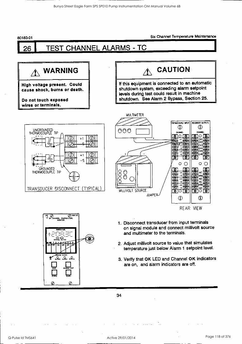
80183-01 Six Channel Temperature Maintenance
26 I TEST CHANNEL ALARMS - TC
A WARNING
High voltage present. Could cause shock, burns or death.
Do not touch exposed wires or terminals.
UNGROUNDED THERMOCOUPLE TIP
GROUNDED. THERMOCOUPLE TIP
TRANSDUCER DISCONNECT (TYPICAL)
,?....t....?)1"'"e 14014110R
A./0112
c,._ SRP
0
A\ CAUTION
If this equipment is connected to an automatic shutdown system, exceeding alarm setpoint levels during test could result in machine shutdown. See Alarm 2 Bypass, Section 25.
MULTIMETER
TIETTwOCO-IPLE
(11)
0
Int RECCROCR OUTPUTS
DIANK1 000 Ea I r:+11 Ir 0 3 K41101[441 I[141
I V.] CHI
I CH2
NOMIDICI %]I
10101 CH3 I ICON CH4 1[011
1[41 CH5 IC-41 WIMI116:11 CH6
IC 4 3 1E+1
00 0 IC-11
RAMP 41 IL I
NC 1[141
00 0 0 IC41 ARM
NO
IRVIE3151 NC
11:11 ARM I(:11
MILLIVOLT SOURCE. Ir:11 NO ICZ/ I
El I ta 0 Ir JUMPE
CD
REAR VIEW
1. Disconnect transducer from input terminals on signal module and connect millivolt source and multimeter to the terminals.
2. Adjust millivolt source to value that simulates temperature just below Alarm 1 setpoint level.
3. Verify that OK LED and Channel OK indicators are on, and alarm indicators are off.
34
Bunya Street Eagle Farm SPS SP010 Pump Instrumentation OM Manual Volume 6B
Q-Pulse Id TMS641 Active 29/01/2014 Page 118 of 376
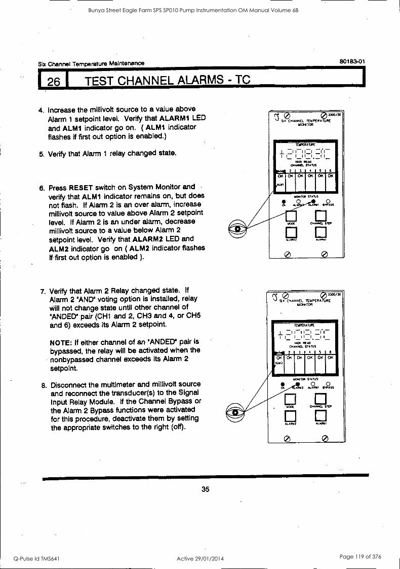
Six Channel Temperature Maintenance 80183 -01
26 1 TEST CHANNEL ALARMS - TC
4. Increase the millivolt source to a value above
Alarm 1 setpoint level. Verify that ALARMI LED
and ALMI indicator go on. ( ALMI indicator flashes if first out option is enabled.)
5. Verify that Alarm 1 relay changed state.
6. Press RESET switch on System Monitor and
verify that ALMI indicator remains on, but does not flash. If Alarm 2 is an over alarm, increase millivolt source to value above Alarm 2 setpoint level. If Alarm 2 is an under alarm, decrease millivolt source to a value below Alarm 2
setpoint level. Verify that ALARM2 LED and
ALM2 indicator go on ( ALM2 indicator flashes if first out option is enabled ).
7. Verify that Alarm 2 Relay changed state. If
Alarm 2 'AND' voting option is installed, relay will not change state until other channel of 'ANDED' pair (CH1 and 2, CH3 and 4, or CH5 and 6) exceeds its Alarm 2 setpoint.
NOTE: If either channel of an 'ANDED' pair is
bypassed, the relay will be activated when the nonbypassed channel exceeds its Alarm 2
setpoint.
8. Disconnect the muttimeter and millivolt source and reconnect the transducer(s) to the Signal Input Relay Module. If the Channel Bypass or the Alarm 2 Bypass functions were activated for this procedure, deactivate them by setting the appropriate switches to the right (off).
0 0,o SIX CHANNEL TEMPERATURE
MONITOR
rEiffRA
'I -1 1i I-_1 -II-
f I I I I . 1M ICAO
O441. STARK
1 3 1 4 1 5 1 6
OK OK
"1111
OK OK
ALAPY 2 MA/111
0
0 3300/30
SIX CHANNEL TEMPERATURE MONITOR
itlf4RATLRE
I =III 1:1 I_ I II I _I1_
HR]I READ CHANNEL STATUS
7 3 101 S 6
OK OK OK OK OK OK M2
STATUS
OR 4R142 AL APLI BYPASS
04.41.44 STEP
A1411112 ALARM!
0 0
35
Bunya Street Eagle Farm SPS SP010 Pump Instrumentation OM Manual Volume 6B
Q-Pulse Id TMS641 Active 29/01/2014 Page 119 of 376

80183-01 Six Channel Temperature Maintenance
1.27 TEST CHANNEL ALARMS-RTD
ath WARNING
High voltage present. Could cause shock, burns or death.
Do not touch exposed wires or terminals.
A\ CAUTION
If this equipment is connected to an automatic shutdown system, exceeding alarm setpoints during test could result in machine shutdown. See Alarm 2 Bypass, Section 25.
1. Disconnect transducer from input terminals on Signal Module and connect decade resistance to the terminals.
sf
3-WIRE RID _ _
J1
4 -MARE RTD
IPA E. 11
!Ell
TRANSDUCER DISCONNECT (TYPICAL)
3300/35
SIX CHANNEL TEMPERATURE MONITOR
TEMPERATURE
I --(I- I I 1111. II
OK
Al"4111*
raMtli PIP
°K ONI TOR
o 0 0 *LAW? MARIA; BWASS
El MODE CHANNEL STEP
ALARM? ALARM?
0000 0 0 0 DECADE RESISTANCE
,UPPER
0 0 0
0 0 0 0 0
DECADE RESISTANCE
JUMPER
3 MIRE RTE HPUT
(ID CHANNEL
0
RECORDER OUTPUTS
COY
(I) OUT
1+3
0 CHI
CH2
CH3
CH4
CH5
CH6
C+31
4 YORE RID INPUT
(ID CHANNEL
VII 0 Ia: X71
1E
o. - J 12 /Kitit15101
1511 IBM
mu -0- Ira LAI 1E+3
COY cui
16-11 UI
CHI
CH2
CH3
CH4
CH5
CH6
0 CID
IE-61 I5/!]I IC II IBM 15\01 ICc11 I[]1 IC+:1
REAR VIEW
2. Adjust decade resistance to value that simulates temperature just below Alarm 1
setpoint level.
3. Verify that OK LED and Channel OK Indicator are on, and Alarm Indicators are off.
36
Bunya Street Eagle Farm SPS SP010 Pump Instrumentation OM Manual Volume 6B
Q-Pulse Id TMS641 Active 29/01/2014 Page 120 of 376
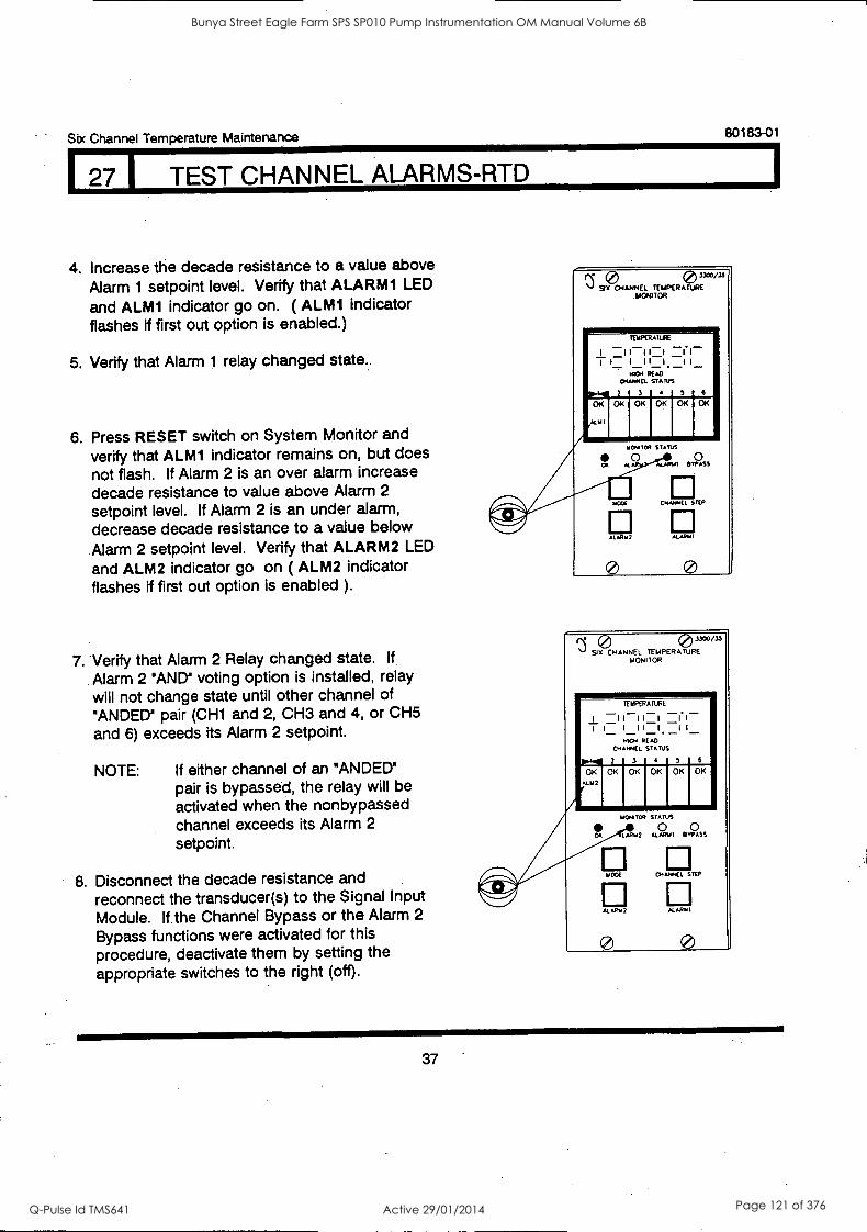
Six Channel Temperature Maintenance 80183-01
I TEST CHANNEL ALARMS-RTD
4. Increase the decade resistance to a value above Alarm 1 setpoint level. Verify that ALARMI LED
and ALM1 indicator go on. ( ALM1 indicator flashes if first out option is enabled.)
5. Verify that Alarm 1 relay changed state.,
6. Press RESET switch on System Monitor and verify that ALM1 indicator remains on, but does not flash. If Alarm 2 is an over alarm increase decade resistance to value above Alarm 2
setpoint level. If Alarm 2 is an under alarm, decrease decade resistance to a value below Alarm 2 setpoint level. Verify that ALARM2 LED
and ALM2 indicator go on ( ALM2 indicator flashes if first out option is enabled ).
7. Verify that Alarm 2 Relay changed state. If
Alarm 2 'AND' voting option is installed, relay will not change state until other channel of NANDED" pair (CH1 and 2, CH3 and 4, or CH5 and 6) exceeds its Alarm 2 setpoint.
NOTE: If either channel of an "ANDED° pair is bypassed, the relay will be activated when the nonbypassed channel exceeds its Alarm 2
setpoint.
8. Disconnect the decade resistance and reconnect the transducer(s) to the Signal Input Module. If the Channel Bypass or the Alarm 2
Bypass functions were activated for this procedure, deactivate them by setting the appropriate switches to the right (off).
9PCH EL TEMPERATURE °3"13' .MONITOR
TERPERATURE
I II II-I L.-CI-- I I I I I I I I_
14104 READ
CHANACL STATUS
2 3 4 S 6 07.0,,.,1 OK OK
/ILAN
0
03300/33 SIX CHANNEL TEMPERATURE
LION/TOR
TERPERAIURE
I -1 11 -1 -1'1- 1 1_ I 11 1_1 1
1.0CAI EN) CHANNEL STATUS
p.4 2 3 4 5 6
0/< OK
OR
OK 0I< OKI OK
INYATOP STATUS
0 0 LAPH2 ALARUI RAPASS
uCOE CHANNEL STEP
ALARM2 NAM
0 0
37
Bunya Street Eagle Farm SPS SP010 Pump Instrumentation OM Manual Volume 6B
Q-Pulse Id TMS641 Active 29/01/2014 Page 121 of 376
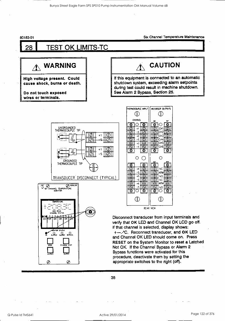
128 1 TEST OK LIMITS-TC
80183-01 Six Channel Temperature Maintenance
A\ WARNING
High voltage present. Could cause shock, burns or death.
Do not touch exposed wires or terminals.
4.\ CAUTION
If this equipment is connected to an automatic shutdown system, exceeding alarm setpoints during test could result in machine shutdown. See Alarm 2 Bypass, Section 25.
UNGROUNDED THERMOCOUPLE TIP
_ 79-
e !
GROUNDED THERMOCOUPLE TIP
TRANSDUCER DISCONNECT (TYPICAL)
3300/30
SIX CHANNEL TEMPERATURE MONITOR
TEMPERATURE
I =I I-I I-I 11- I I I I I I I I
HICA/
CHANNEL STATUS 4C-) 1 3
FinOK
TM STATUS
0 Al U2 ALA S11 BOSS
IAXE CHAIWCI. 55tH
Aft, ALAHYI
THERMOCOUPLE INPUT
(ID CHANNEL
Ea Ea
0 0
RECORDER OUTPUTS
rN
CD
0 CHI
CH2
CH3
CH4
CH5
CH6
O
NC
ARM
NO
NC
ARM
NO
0
1141
IC 11 ICI lI
ILA I I
REAR VIEW
Disconnect transducer from input terminals and verify that OK LED and Channel OK LCD go off. If that channel is selected, display shows: +-.-°C. Reconnect transducer, and OK LED
and Channel OK LED should come on. Press RESET on the System Monitor to reset a Latched Not OK If the Channel Bypass or Alarm 2 Bypass functions were activated for this procedure, deactivate them by setting the appropriate switches to the right (off).
38
Bunya Street Eagle Farm SPS SP010 Pump Instrumentation OM Manual Volume 6B
Q-Pulse Id TMS641 Active 29/01/2014 Page 122 of 376
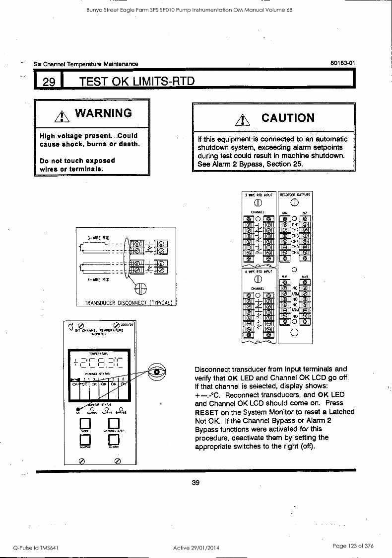
Six Channel Temperature Maintenance 80183-01
129 I TEST OK LIMITS-RTD
A\ WARNING
High voltage present. Could cause shock, burns or death.
Do not touch exposed wires or terminals.
3-1MRE RTD
'CT
4-WE RTD
1: 1
TRANSDUCER DISCONNECT (TYPICAL)
13" 3 Six CHANNEL TEMPERATURE TURE3CW3' MONITOR
TEMPERA MBE
I 1 1111 I.
1 I I 11 1 11 - - - -
Opt
OR STA NS
0 0 0 kLARW2 ALARAH BYPASS
AWE CHANNEL STEP
ALAP.2 NARY'
4\ CAUTION
If this equipment is connected to-an automatic shutdown system, exceeding alarm setpoints during test could result in machine shutdown. See Alarm 2 Bypass, Section 25.
3 IRE RID INPUT
CID
CHANNEL
0
DOI
IL 11 Kull INI DIU 1[0]1 KZ 1
I C:11
t.+11
4 WIRE RID INPUT
CHANNEL
0 M 1
Kam 1611
I MI 1[011 IClil
IC -)1 I[:11
RECORDER WRITS
COY
(ID OJT
0 CHI CH2
CH3
CH4 CH5
CH6
1C+1
0 ALYI ALIO
It+11
NC
ARM
NO
NC
ARM
NO
O
CID
IC DIU
Disconnect transducer from input terminals and verify that OK LED and Channel OK LCD go off. If that channel is selected, display shows: +-.-°C. Reconnect transducers, and OK LED and Channel OK LCD should come on. Press
RESET on the System Monitor to reset a Latched Not OK If the Channel Bypass or Alarm 2
Bypass functions were activated for this procedure, deactivate them by setting the appropriate switches to the right (off).
39
Bunya Street Eagle Farm SPS SP010 Pump Instrumentation OM Manual Volume 6B
Q-Pulse Id TMS641 Active 29/01/2014 Page 123 of 376

80183-01 Six Channel Temperature Maintenance
I 30 1 TEST/CALIBRATION-TC
A\ WARNING
High voltage present. Gould cause shock, burns or death.
Do not touch exposed wires or terminals.
1. Disconnect transducer from input terminals on Signal Module and connect a millivolt source and multimeter to the terminals as shown.
UNDERGROUND THERMOCOUPLE TIP
GROUNDED THERMOCOUPLE TIP
410
TRANSDUCER DISCONNECT (TYPICAL)
A\ CAUTION
-If this equipment is -connected to an automatic shutdown system, exceeding alarm setpoints during test could result in machine shutdown. See Alarm 2 Bypass, Section 25.
MULTIMETER
000
AW11--0 L
o0 00 0 MILLIVOLT SOURCE
JUMPE
11411VOCCIAL SePu7
01
Rf CCROEP
r.
(1) OWIPICL
°1 1
WINS
1501 L10[.7 .!.501=15 : :.]: 15 01/M15
.71: !IQ al
1
15 01
012 043 15 el
150I=15 01 1501 044 1501 map= tvamir:11
015 cH6
1E:11
00 1-3
01W15_01 1501 NC 1501 Ce0 1 1V01 ARM
15 01M1591 15 01 NO 15 01
1501=1501 1501 NC 1501
MI= Irz.11 IrJI ARM IC=l1
lr:11 E3 E3 0 -1
40
Bunya Street Eagle Farm SPS SP010 Pump Instrumentation OM Manual Volume 6B
Q-Pulse Id TMS641 Active 29/01/2014 Page 124 of 376
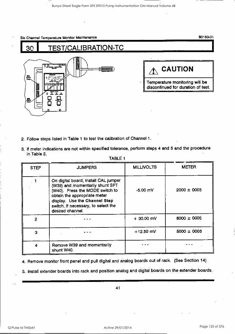
Six Channel Temperature Monitor Maintenance 80183-01
30 1 TEST/CALIBRATION-TC
IA\ CAUTION
Temperature monitoring will be discontinued for duration of test.
2. Follow steps listed in Table 1 to test the calibration of Channel 1.
3. If meter indications are not within specified tolerance, perform steps 4 and 5 and the procedure in Table 2.
TABLE 1
STEP JUMPERS MILLIVOLTS METER
1 On digital board, install CAL jumper (W39) and momentarily shunt SFT (W40). Press the MODE switch to obtain the appropriate meter display. Use the Channel Step switch, if necessary, to select the desired channel.
-5.00 mV 2000 ± 0005
2 - - - + 30.00 mV 8000 ± 0005
3 - - - +12.50 mV 5000 ± 0005
4 Remove W39 and momentarily shunt W40.
- - - - - -
4. Remove monitor front panel and pull digital and analog boards out of rack. (See Section 14)
5. Install extender boards into rack and position analog and digital boards on the extender boards.
41
Bunya Street Eagle Farm SPS SP010 Pump Instrumentation OM Manual Volume 6B
Q-Pulse Id TMS641 Active 29/01/2014 Page 125 of 376

80183-01 Six Channel Temperature Monitor Maintenance
I 30 1 TEST/CALIBRATION-TC TABLE 2
STEP JUMPERS * MILLIVOLTS POTENTIOMETER* METER
1 On digital board, install CAL jumper (W39) momentarily shunt SFT (W40). Press the MODE switch to obtain the appropriate meter display. Use the Channel Step switch, if necessary, to select the desired channel.
--- - - -
2 - - - -5.00 mV Adjust offset R19 2000 ± 0001
3 - - - +30.00 mV Adjust feedback R2 8000 ± 0001
4 - - - -5.00 mV Check 2000 ± 0003
5 ' - - - +30.00 mV Check 8000 ± 0003
6 +12.50 mV Check 5000 ± 0003 **
7 Remove W39 and momentarily shunt W40
- - - - - - - - -
**
Jumpers and Potentiometers are located on Analog Board except as noted.
Components are listed only for Channel 1, corresponding components for each channel are listed in Table 3.
Repeat steps 2 through 6 until meter indication is adjusted within tolerance.
TABLE 3
CHANNEL FEEDBACK POTENTIOMETER
OFFSET POTENTIOMETER
1 R2 R19
2 R21 R42
3 R44 R65
4 R68 R87
5 R93 R110 6 R114 R133
42
Bunya Street Eagle Farm SPS SP010 Pump Instrumentation OM Manual Volume 6B
Q-Pulse Id TMS641 Active 29/01/2014 Page 126 of 376

Six Channel Temperature Monitor Maintenance 80183-01
I 30 I TEST/CALIBRATION-TO
The monitor is calibrated upon completion of the procedure in Table 2 (or if it meets the tolerances specified in Table 1). The following two procedures are optional. The first allows you to verify the calibration at a temperature of your choice. The second allows you to verify the recorder output.
If you do NOT wish to perform the following procedures, disconnect the muttimeter and millivolt source and reconnect the transducer(s) to the Signal Input Module. If the Channel Bypass or the Alarm 2 Bypass functions were activated for this procedure, deactivate them by setting the appropriate switches to the right (off).
I. Verify calibration at a specific temperature
1. Read the Cold Junction Compensation (CJC) temperature. To do this, choose any channel and disconnect that channel's transducer from the input terminals on the Signal Input
Module. Install jumper wires between the + and - terminals and the - and S terminals of this channel. Read the front panel meter temperature displayed for this channel. This is the CJC
temperature.
2. Using a Thermocouple Table, convert the CJC temperature measured in step one to the CJC
voltage. (Vcjc).
NOTE: In converting thermocouple temperatures to voltages, be sure to use the specific Thermocouple Table corresponding to the thermocouple type the monitor is optioned for. If you are unsure of the thermocouple type, perform the User-invoked self test and note the transducer type displayed in the power-up display sequence (see Self Test section).
3. Choose a temperature within the full scale range of the monitor as your desired test temperature. Convert it to your test voltage (Vtest) using the Thermocouple Table.
4. Calculate the appropriate input voltage (Vin) by subtracting the CJC voltage from the test voltage.
EXAMPLE: Assume that the CJC temperature measured in step one is 28.7°C, that the monitor is set up for Type J thermocouples, and that you wish to test the monitor at 100°C.
Round the CJC temperature to the nearest degree, 29°C. From the Thermocouple Table, this corresponds to a CJC voltage (Vcjc) of 1.484 mV.
From the same table, a test temperature of 100°C corresponds to a test voltage (Vtest) of 5.268 mV.
Vin = Vtest - Vcjc = 5.268 - 1.484 mV = 3.784 mV
43
Bunya Street Eagle Farm SPS SP010 Pump Instrumentation OM Manual Volume 6B
Q-Pulse Id TMS641 Active 29/01/2014 Page 127 of 376
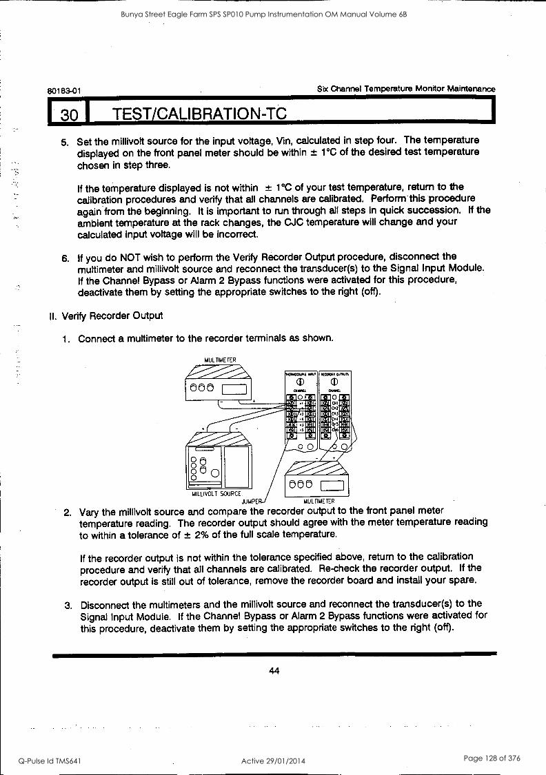
80183-01 Six Channel Temperature Monitor Maintenance
I TEST/CALIBRATION-TC
5. Set the millivolt source for the input voltage, Vin, calculated in step four. The temperature displayed on the front panel meter should be within ± 1°C of the desired test temperature chosen in step three.
If the temperature displayed is not within ± 1°C of your test temperature, return to the calibration procedures and verify that all channels are calibrated. Perform-this procedure again from the beginning. It is important to run through all steps in quick succession. If the ambient temperature at the rack changes, the CJC temperature will change and your calculated input voltage will be incorrect.
6. If you do NOT wish to perform the Verify Recorder Output procedure, disconnect the muttimeter and millivolt source and reconnect the transducer(s) to the Signal Input Module. If the Channel Bypass or Alarm 2 Bypass functions were activated for this procedure, deactivate them by setting the appropriate switches to the right (off).
II. Verify Recorder Output
1. Connect a multimeter to the recorder terminals as shown.
MUL TIME TER
MILLIVOLT SOURCE.
IMRE MUL NETER
2. Vary the millivolt source and compare the recorder output to the front panel meter temperature reading. The recorder output should agree with the meter temperature reading
to within a tolerance of ± 2% of the full scale temperature.
888
If the recorder output is not within the tolerance specified above, return to the calibration procedure and verify that all channels are calibrated. Re-check the recorder output. If the recorder output is still out of tolerance, remove the recorder board and install your spare.
3. Disconnect the multimeters and the millivolt source and reconnect the transducer(s) to the Signal Input Module. If the Channel Bypass or Alarm 2 Bypass functions were activated for this procedure, deactivate them by setting the appropriate switches to the right (off).
44
Bunya Street Eagle Farm SPS SP010 Pump Instrumentation OM Manual Volume 6B
Q-Pulse Id TMS641 Active 29/01/2014 Page 128 of 376

Six Channel Temperature Monitor Maintenance 80183-01
31 I TEST CALIBRATION-RTD
As WARNING
High voltage present. Could cause shock, burns or death.
Do not touch exposed wires or terminals.
1. Disconnect transducer from input terminals on Signal Module and connect decade resistance to the terminals as shown.
A\ CAUTION
If this equipment is connected to an automatic shutdown system, exceeding alarm setpoint levels could cause machine shutdown. See Alarm 2 Bypass, Section 25.
TRANSDUCER DISCONNECT (TYPICAL)
3 WIRE RTD INPUT
CHANNEL
0 l'A. EMI
1 ICU -°P. - IVAI r 1 0 00 C 0 0 O
DECADE RESISTANCE
JUMPER
ISE
RECORDER OUTPUTS
CO OUT
I CID
I`
CH2
CH3
CH4
CH5
CH6
ICo
E
UI 4 WIRE RED INPUT
CHANNEL
0 00 0 0 0 0 0 DECADE RESiSTANCE
JUMPERS
NOTE Refer to field wiring diagrams when using 4-wire RTD setup with internal barriers.
ICp
1=1
co OUT
CH11 011 CH2
CH3
CCCHHH645 6,1
REAR VIEW
45
Bunya Street Eagle Farm SPS SP010 Pump Instrumentation OM Manual Volume 6B
Q-Pulse Id TMS641 Active 29/01/2014 Page 129 of 376
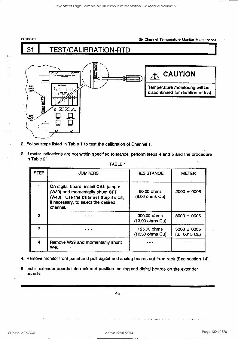
80183-01 Sbc Channel Temperature Monitor Maintenance
31 I TEST/CALIBRATION-RTD
A\ CAUTION
Temperature monitoring will be discontinued for duration of test.
2. Follow steps listed in Table 1 to test the calibration of Channel 1.
3. If meter indications are not within specified tolerance, perform steps 4 and 5 and the procedure in Table 2:
TABLE 1
STEP JUMPERS RESISTANCE METER
1 On digital board, install CAL jumper (W39) and momentarily shunt SFT (W40). Use the Channel Step switch, if necessary, to select the desired channel.
90.00 ohms (8.00 ohms Cu)
2000 ± 0005
2 - - - 300.00 ohms (13.00 ohms Cu)
8000 ± 0005
3 - - - 195.00 ohms (10.50 ohms Cu)
5000 ± 0005 (± 0015 Cu)
4 Remove W39 and momentarily shunt W40.
- - - - - -
4. Remove monitor front panel and pull digital and analog boards out from rack (See section 14).
5. Install extender boards into rack and position analog and digital boards on the extender boards.
46
Bunya Street Eagle Farm SPS SP010 Pump Instrumentation OM Manual Volume 6B
Q-Pulse Id TMS641 Active 29/01/2014 Page 130 of 376
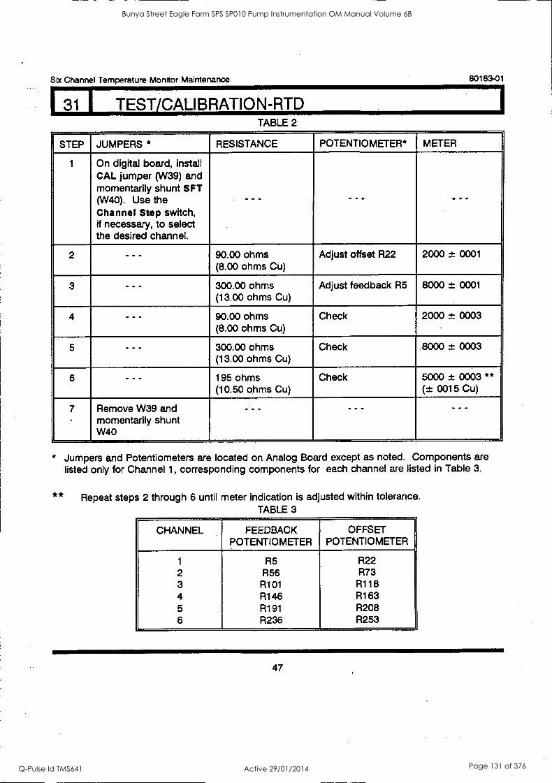
Six Channel Temperature Monitor Maintenance 80183-01
(31 I TEST/CALIBRATION-RTD TABLE 2
STEP JUMPERS * RESISTANCE POTENTIOMETER* METER
1 On digital board, install CAL jumper (W39) and momentarily shunt SFT (W40). Use the Channel Step switch, if necessary, to select the desired channel.
--- - - - - - -
2 - - - 90.00 ohms (8.00 ohms Cu)
Adjust offset R22 2000 ± 0001
3 - - - 300.00 ohms (13.00 ohms Cu)
Adjust feedback R5 8000 ± 0001
4 - - - 90.00 ohms (8.00 ohms Cu)
Check 2000 ± 0003
5 - - - 300.00 ohms (13.00 ohms Cu)
Check 8000 ± 0003
6 - - - 195 ohms (10.50 ohms Cu)
Check 5000 ± 0003 ** (± 0015 Cu)
7 Remove W39 and momentarily shunt W40
- -- - - -
* Jumpers and Potentiometers are located on Analog Board except as noted. Components are listed only for Channel 1, corresponding components for each channel are listed in Table 3.
** Repeat steps 2 through 6 until meter indication is adjusted within tolerance. TABLE 3
CHANNEL FEEDBACK POTENTIOMETER
OFFSET POTENTIOMETER
1 R5 R22 2 R56 R73 3 R101 R118 4 R146 R163 5 R191 R208 6 R236 R253
47
Bunya Street Eagle Farm SPS SP010 Pump Instrumentation OM Manual Volume 6B
Q-Pulse Id TMS641 Active 29/01/2014 Page 131 of 376
l31 1 TEST/CALIBRATION-RID
80183-01 Six Channel Temperature. Monitor Maintenance
The monitor is calibrated upon completion of the procedure in Table 2 (or if it meets the tolerances specified in Table 1). The following two procedures are optional. The first allows you to verify the calibration at a temperature of your choice. The second allows you to verify the recorder output.
If you do NOT .wish to perform the following procedures, disconnect the decade resistance and reconnect the transducer(s) to the Signal Input Module. If the Channel Bypass or the Alarm 2
Bypass functions were activated for this procedure, deactivate them by setting the appropriate switches to the right (off).
I. Verify calibration at a specific temperature
1. Choose a temperature within the full scale range of the monitor as your desired test temperature. Convert it to your test resistance (Rtest) using an RTD Table.
NOTE: In converting RTD temperatures to resistances, be sure to use the specific RTD Table corresponding to the RTD type the monitor is optioned for. If you are unsure of the RTD type, perform the User-invoked self test and note the transducer type displayed in the Power-up display sequence (see Self Test section).
EXAMPLE: Assume that the monitor is set up for platinum (1.385) RTDs and that you wish to test the monitor at 100°C.
From the RTD Table, this corresponds to a test resistance (Rtest) of 138.5 ohms.
2. Set the decade resistance for the test resistance, Rtest, found in step one. The temperature displayed on the front panel meter should be within ± 1°C of the desired test temperature chosen in step one.
If the temperature displayed is not within ± 1°C of your test temperature, return to the calibration procedure and verify that all channels are calibrated. Perform this procedure again from the beginning.
3. If you do NOT wish to perform the Verify Recorder Output procedure, disconnect the decade resistance and reconnect the transducer(s) to the Signal Input Module. If the Channel Bypass or the Alarm 2 Bypass functions were activated for this procedure, deactivate them by setting the appropriate switches to the right (off).
48
Bunya Street Eagle Farm SPS SP010 Pump Instrumentation OM Manual Volume 6B
Q-Pulse Id TMS641 Active 29/01/2014 Page 132 of 376
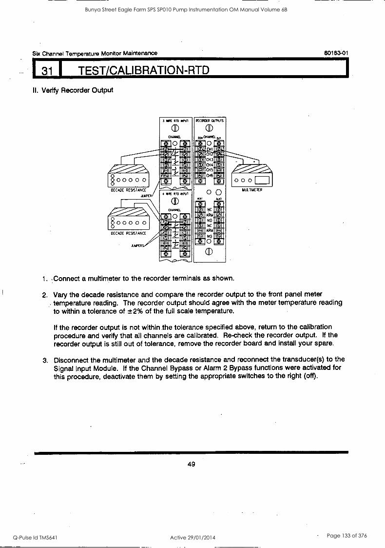
Six Channel Temperature Monitor Maintenance 80183-01
(31 I TEST/CALI BRATION-RTD
II. Verify Recorder Output
:4111.1%111111P-,01_
§ 0 0 0 0 0
DECADE RESISTANCE
&NKR
0 0 0 0 0
DECADE RESISTANCE
JAPER
3 VIRE RID RePUI
(I)
0 r
4 SIRE RID IMPU1
ulec
0
RFCCRIXII oulputs
01414410.
t+1 0 ta via HI WO Mil CH
15I01 CH3 OM 15VI CH4 11[41
1[CAI 045 114I CH6 'MI
r+3 0 0 0
00 min ALIO
NC
ARM
NO
NC
ARM
NO
0
(1)
1. :Connect a multimeter to the recorder terminals as shown.
MIATIMETER
2. Vary the decade resistance and compare the recorder output to the front panel meter temperature reading. The recorder output should agree with the meter temperature reading to within a tolerance of ±2% of the full scale temperature.
If the recorder output is not within the tolerance specified above, return to the calibration procedure and verify that all channels are calibrated. Re-check the recorder output. If the recorder output is still out of tolerance, remove the recorder board and install your spare.
3. Disconnect the multimeter and the decade resistance and reconnect the transducer(s) to the Signal Input Module. If the Channel Bypass or Alarm 2 Bypass functions were activated for this procedure, deactivate them by setting the appropriate switches to the right (off).
49
Bunya Street Eagle Farm SPS SP010 Pump Instrumentation OM Manual Volume 6B
Q-Pulse Id TMS641 Active 29/01/2014 Page 133 of 376

80183-01 Sbc Channel Temperature Monitor Mainterance
321 FIELD WIRING DIAGRAMS
DRAWING TITLE DRAWING NUMBER NUMBER OF SHEETS
Thermocouple Without Barriers 100332 2
Thermocouple With External Barriers . 100333 2
Thermocouple With Internal Barriers . . 100334 2
RTD Without Barriers 100335 2
RTD With External Barriers 100336 3
RTD With Internal Barriers 100337 2
50
Bunya Street Eagle Farm SPS SP010 Pump Instrumentation OM Manual Volume 6B
Q-Pulse Id TMS641 Active 29/01/2014 Page 134 of 376
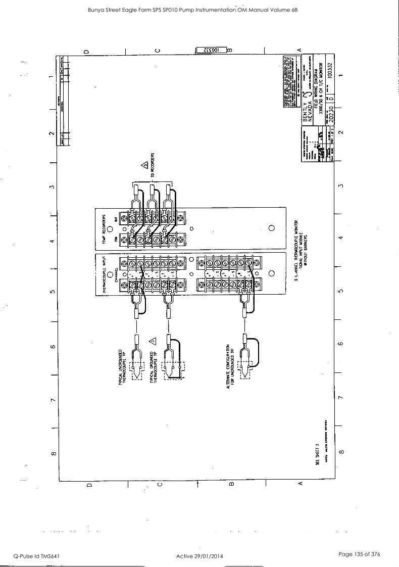
D C B
A
8
SE
E
SH
EE
T
7
mol
ts
...K
is O
HM
.. T
IME
D
6 5
4 3
2 J
1
TY
PIC
AL
UN
GR
OU
ND
ED
T
HE
RM
OC
OU
PLE
T
IP
TY
PIC
AL
GR
OU
ND
ED
T
HE
RM
OC
OU
PLE
T
IP
1- - J
ALT
ER
NA
TE
C
ON
FIC
UR
AIT
CN
FO
R
UN
GR
OU
ND
ED
T
IP
TH
ER
MO
CO
UP
LE
INP
UT
0 C
HA
NN
EL
TE
MP
R
EC
OR
DE
RS
O
CtI
N
aT
I71
IC 7
1
S
IC 7
1 IC
JI
IC11
s O
6 C
AN
NE
L T
HE
RM
OC
OU
PLE
M
ON
ITO
R
SIG
NA
L IN
PU
T
MO
DU
LE
WIT
HO
UT
BA
RR
IER
S
TO
R
EC
OR
DE
RS
1.H
N W
ar
NI I
Oa
MY
. 11
0 IN
11,1
01
1 41
1 I1
N
07/la
10.
. ...
.."""
:.:".
......
."7.
.4=
1".."
4";
* ro
sy a
wl.
my
MIN
S 61
11 IM
61
1 M
OM
. 3
BE
NT
LY
N
NE
VA
DA
\J
0111
110
P F
IELD
M
IRIN
G
DIA
GR
AM
3300
/30
6 C
H
T/C
M
ON
ITO
R
D C
CV
O
O
Bunya Street Eagle Farm SPS SP010 Pump Instrumentation OM Manual Volume 6B
Q-Pulse Id TMS641 Active 29/01/2014 Page 135 of 376
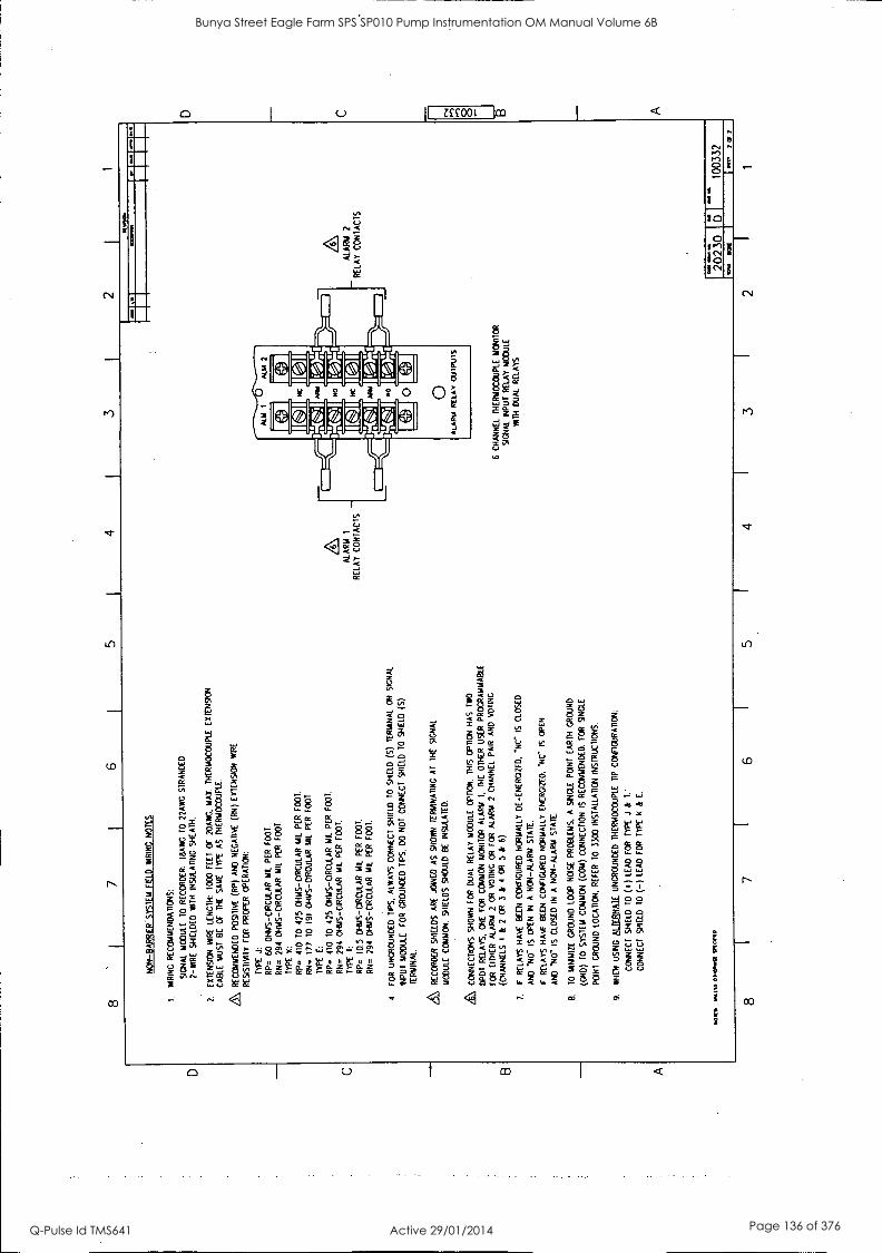
D C
B
A
8 I
7 6
5 1
4 1
3 2
NO
N-B
AR
RIE
R.S
YS
TE
M F
IELD
W
RIN
G
NO
TE
S
I. W
RIN
G
RE
CO
MM
EN
DA
TIO
NS
:
SIG
NA
L M
OD
ULE
T
O
RE
CO
RD
ER
: 11
3AW
G
TO
22
AW
G
ST
RA
ND
ED
2 -W
IRE
S
HIE
LDE
D W
IN
INS
ULA
TIN
G S
HE
AT
H.
2.
EX
TE
NS
ION
W
IRE
LE
NG
TH
: 10
00
FE
ET
O
F
20A
IVG
. M
AX
. T
HE
RM
OC
OU
PLE
E
XT
EN
SIO
N
CA
BLE
M
US
T
BE
O
F
TH
E
SA
ME
T
YP
E
AS
T
HE
RM
OC
OU
PLE
.
RE
CO
MM
EN
DE
D
PO
SIT
IVE
(R
P)
AN
D
NE
GA
TIV
E
(RN
) E
XT
EN
SIO
N
WIR
E
RE
SIS
TIV
ITY
F
OR
P
RO
PE
R
OP
ER
AT
ION
:
TY
PE
J:
RP
=
60
OH
MS
-CIR
CU
LAR
MIL
P
ER
F
OO
T.
RN
=
294
OH
MS
- CIR
CU
LAR
M
IL
PE
R
FO
OT
.
TY
PE
K
:
RP
=
410
TO
42
5 O
HM
S - C
IRC
ULA
R M
IL
PE
R
FO
OT
.
RN
=
177
TO
19
1 O
HM
S-C
IRC
ULA
R
MIL
P
ER
F
OO
T
TY
PE
E
:
RP
=
410
10
425
OH
MS
-OR
CU
LAR
MIL
P
ER
F00
1.
RN
=
294
OH
MS
-CIR
CU
LAR
MIL
P
ER
F
OO
T,
TY
PE
T
:
RP
=
10.5
O
HM
S- C
IRC
ULA
R
MIL
P
ER
F
OO
T.
RN
=
294
OH
MS
-CIR
CU
LAR
M
IL
PE
R
FO
OT
.
4 F
OR
U
NG
RO
UN
DE
D
TIP
S,
ALW
AY
S
CO
NN
EC
T S
HIE
LD
TO
S
HIE
LD (
5)
TE
RM
INA
L O
N
SIG
NA
L
INP
UT
MO
DU
LE
FO
R
GR
OU
ND
ED
T
IPS
, D
O
NO
T
CO
NN
EC
T
SH
IELD
10
SH
IELD
(5
) T
ER
MIN
AL.
RE
CO
RD
ER
S
HIE
LDS
A
RE
JO
INE
D
AS
S
HO
WN
IE
RIA
NA
PN
C A
T
TH
E
SIG
NA
L
MO
DU
LE
CO
MM
ON
. S
HIE
LDS
S
HO
ULD
B
E
INS
ULA
TE
D.
& CO
NN
EC
TIO
NS
SH
OW
N
FO
R
DU
AL
RE
LAY
M
OD
ULE
O
PT
ION
. T
HIS
O
PT
ION
H
AS
T
WO
DP
DT
R
ELA
YS
. M
E F
OR
C
OM
MO
N
MO
NIT
OR
A
LAR
M
I, M
E O
TH
ER
U
SE
R
PR
OG
RA
MM
AB
LE
FO
R
EIT
HE
R
ALA
RM
2
OR
V
OT
ING
O
R
FO
R
ALA
RM
2
CH
AN
NE
L P
AIR
A
ND
VO
TIN
G
(CH
AN
NE
LS
1 &
2
OR
3
&
4 O
R
5 &
6)
.
7.
IF
RE
LAY
S H
AV
E
BE
EN
C
ON
FIG
UR
ED
N
OR
MA
LLY
D
E-E
NE
RG
IZE
D,
-NC
IS
C
LOS
ED
AN
D
'NO
- IS
O
PE
N
IN
A
NM
-ALA
RM
ST
AT
E.
IF
RE
LAY
S
HA
VE
B
EE
N C
ON
FIG
UR
ED
N
OR
MA
LLY
E
NE
RG
IZE
D.
'NC
IS
O
PE
N
AN
D
NO
IS
C
LOS
ED
IN
A
N
ON
-ALA
RM
ST
AT
E
8.
TO
M
INIM
IZE
G
RO
UN
D L
OO
P
NO
ISE
PR
OB
LEM
S,
A
SIN
GLE
P
OIN
T
EA
RT
H
GR
OU
ND
(CN
D)
TO
S
YS
TE
M
CO
MM
ON
(C
OM
) C
ON
NE
CT
ION
IS
R
EC
OM
ME
ND
ED
. F
OR
S
ING
LE
PO
NT
GR
OU
ND
LO
CA
TIO
N.
RE
FE
R
10
3300
IN
ST
ALL
AT
ION
IN
ST
RU
CT
ION
S.
9.
WH
EN
U
SIN
G
ALT
ER
NA
TE
U
NG
RO
UN
DE
D
TH
ER
MO
CO
UP
LE
TIP
C
ON
FIG
UR
AT
ION
:
CO
NN
EC
T
SH
IELD
T
O (a
) LE
AD
F
OR
T
YP
E
J &
T
.'
CO
NN
EC
T
SH
IELD
T
O (-
) LE
AD
F
OR
T
YP
E
II &
E
.
MO
SS
W
AS
S O
NLI
MM
I
AL
AR
M
1
RE
LAY
C
ON
TA
CT
S -
6 C
HA
NN
EL
TH
ER
MO
CO
UP
LE
MO
NIT
OR
S
IGN
AL
INP
UT
R
ELA
Y
MO
DU
LE
WIT
H
DU
AL
RE
LAY
S
ALA
RM
2
RE
LAY
C
ON
TA
CT
S
5 72
0
6 - 10
0332
IO
U
NO
W
94.1
, R
7
8 7
6 5
4 3
2 1
D
C
7,7 8 B A
Bunya Street Eagle Farm SPS SP010 Pump Instrumentation OM Manual Volume 6B
Q-Pulse Id TMS641 Active 29/01/2014 Page 136 of 376
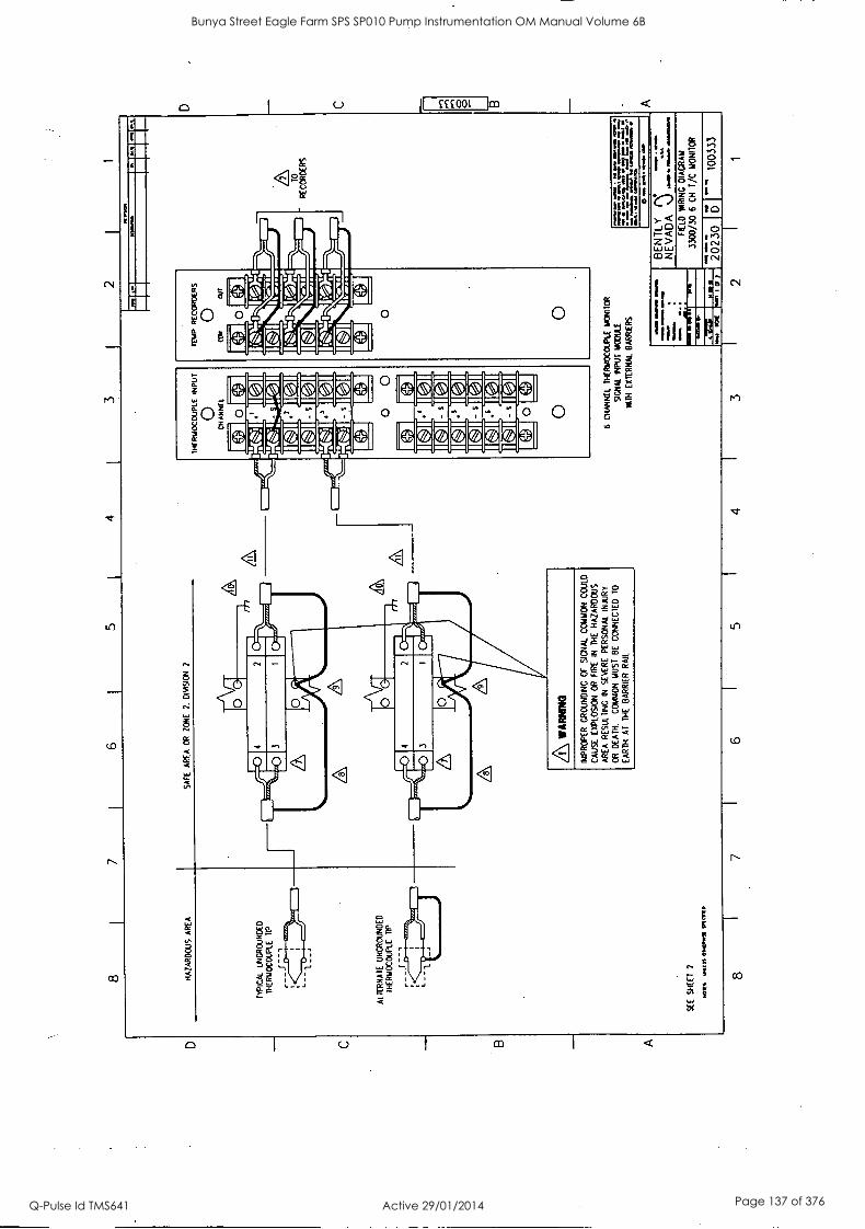
7 4
HA
ZA
RD
OU
S
AR
EA
TY
PIC
AL
UN
GR
OU
ND
ED
TH
ER
MO
CO
UP
LE
RP
ALT
ER
NA
TE
U
NG
RO
UN
DE
D
TH
ER
MO
CO
UP
LE
TIP
SE
E
SH
EE
T
2
.01[
It 01
.CM
1/
SA
FE
A
RE
A
OR
Z
ON
E
2.
DIV
ISIO
N
2
0
0
2
PIM
WA
RN
IWO
IMP
RO
PE
R
GR
OU
ND
ING
O
F
SIG
NA
L C
OM
MO
N
CO
ULD
CA
US
E
EX
PLO
SIO
N
OR
F
IRE
IN
T
HE
H
AZ
AR
DO
US
AR
EA
R
ES
ULT
ING
IN
S
EV
ER
E
PE
RS
ON
AL
INJU
RY
OR
D
EA
TH
. C
OM
MO
N
MU
ST
B
E
CO
NN
EC
TE
D
TO
EA
RT
H
AT
T
HE
B
AR
RIE
R
RA
IL
6 C
HA
NN
EL
TH
ER
MO
CO
UP
LE M
ON
ITO
R
SIG
NA
L IN
PU
T
NO
DU
LE
MT
H
EX
TE
RN
AL
BA
RR
IER
S
NM
0
0.4.
0.0
In V
101
0.
1.1
. pg.
. .4
. ...
, ...
... ..
.. ...
... .
.... .
W
M.,.
. le CO
MM
0
=
ii7
0 m
a sm
.... a
s.
1111
111 61
11
OM
= =
MN
. 71
01
GE
NT
LY
NE
VA
DA
%
.)
WP
M f
t m
oon
mom
mm
oom
s
au
we
FIE
LD
WR
ING
D
IAG
RA
M
3300/30 6 CH T/C MONITOR
2023
0 D
1003
33
8 7
6 5
4 3
2 1
D C B A
Bunya Street Eagle Farm SPS SP010 Pump Instrumentation OM Manual Volume 6B
Q-Pulse Id TMS641 Active 29/01/2014 Page 137 of 376

C
B
A
8 7
6 5
4 3
2
XI',
;
:I"
1 I
, ,
1.
WIR
ING
R
EC
OM
ME
ND
AT
ION
S:
9GN
AL
MO
DU
LE
TO
R
EC
OR
DE
RS
: I8
AW
C
TO
22
AW
G
ST
RA
ND
ED
2-W
IRE
S
HIE
LDE
D
WIT
H
INS
ULA
TIN
G
SH
EA
TH
.
AT
ER
MIN
AT
E T
HE
R
EC
OR
DE
R
SH
IELD
S
AT
T
HE
S
IGN
AL
MO
DU
LE
CO
MM
ON
. S
HIE
LDS
SH
OU
LD
BE
IN
SU
LAT
ED
3.
GR
OU
ND
ED
T
IP
TH
ER
MO
CO
UP
LES
A
RE
N
OT
F
OR
U
SE
W
ITH
B
AR
RIE
RS
.
4.
MIE
N
US
ING
A
LTE
RN
AT
E
UN
GR
OU
ND
ED
T
HE
RM
OC
OU
PLE
T
IP
CO
NF
IGU
RA
TIO
N:
CO
NN
EC
T S
HIE
LD
TO
(4
) LE
AD
FO
R
TY
PE
J
&
1.
CO
NN
EC
T
SH
IELD
T
O (-
) LE
AD
F
OR
T
YP
E
K
&
E.
5.
TH
ER
MO
CO
UP
LES
M
US
T B
E
ISO
LAT
ED
F
RO
M G
RO
UN
D
10 5
00
VA
C
RM
S.
/6,
CO
NN
EC
TIO
NS
SH
OW
F
OR
D
UA
L R
ELA
Y
MO
DU
LE
OP
TIO
N.
1141
5 O
PT
ION
H
AS
T
WO
DP
D1
RE
LAY
S,
ON
E
FO
R
CO
MM
ON
M
ON
ITO
R
ALA
RM
1,
T
HE
O
TH
ER
U
SE
R
PR
OG
RA
MM
AB
LE
FO
R
EIT
HE
R
ALA
RM
2
OR
V
OT
ING
O
R
FO
R
ALA
RM
2
CH
AN
NE
L P
AIR
A
ND
V
OT
ING
(CH
AN
NE
LS I&
2
OR
3
&
4 O
R
5 k
6).
AC
ON
NE
CT
ION
S
FO
R
A
TY
PIC
AL
BA
RR
IER
A
RE
S
HO
WN
. R
EF
ER
T
O
DR
AW
ING
S
BA
2200
0 A
ND
C
A22
000
FO
R M
OR
E
INF
OR
MA
TIO
N.
8.
SH
IELD
S
AR
E
JOIN
ED
A
S
SH
OW
N
TE
RM
INA
TIN
G
AT
B
AR
RIE
R
GR
OU
ND
.
SH
IELD
S
SH
OU
LD
BE
IN
SU
LAT
ED
.
AB
AR
RIE
RS
AR
E
MO
UN
TE
D
10 B
AR
RIE
R
RA
L W
HIC
H
IS
TH
E
PO
TE
NT
IAL
EQ
UA
LIZ
AT
ION
BU
S B
ET
WE
EN
S
YS
TE
M
GR
OU
ND
A
ND
E
AR
TH
G
RO
UN
D.
TO
M
INIM
IZE
G
RO
UN
D
LOO
P
PR
OB
LEM
S.
A
SIN
GLE
P
OIN
T
EA
RT
H
GR
OU
ND
(C
ND
) T
O
SY
ST
EM
CO
MM
ON
(C
OM
) C
ON
NE
CT
ION
IS
R
EC
OM
ME
ND
ED
AT
T
HE
B
AR
RIE
R
RA
IL.
TO
TA
L E
AR
TH
LO
OP
IM
PE
DA
NC
E
MU
ST
N
OT
E
XC
EE
D
I O
HM
. R
EM
OV
E
SIN
GLE
P
OIN
T
EA
RT
H
GR
OU
ND
CO
NN
EC
TIO
N
AT
C
HA
SS
IS
C,R
OU
ND
O
N
TH
E
3300
P
OW
ER
IN
PU
T
MO
DU
LE.
/10\
IND
EP
EN
DE
NT
C
ON
NE
CT
ION
TO
S
YS
TE
M
EA
RT
H.
A RE
CO
MM
EN
DE
D P
OS
ITIV
E (R
P)
AN
D
NE
GA
TIV
E
(RN
) E
XT
EN
SIO
N
WIR
E
RE
SIS
TIV
ITY
F
OR
P
RO
PE
R O
PE
RA
TIO
N:
TY
PE
J:
RP
- 60
C
441.
15-C
IRC
ULA
R
MIL
P
ER
F
001.
R
N-
294
OH
MS
-CIR
CU
LAR
MIL
P
ER
F
OO
T.
TY
PE
K
: R
P=
41
0 T
O
425
OH
MS
-CIR
CU
LAR
M
IL
PE
R
FO
OT
.
RN
=
177
TO
19
1 O
HM
S-C
IRC
ULA
R
MIL
P
ER
FOOT.
TY
PE
E
:
RP
=
410
10 42
5 O
HM
5-C
1RC
ULA
R
MIL
P
ER
F
OO
T.
RN
=
294
OH
MS
-CIR
CU
LAR
M
IL
PE
R
FO
OT
.
TY
PE
1:
RP
=
10.5
O
HM
S-C
IRC
ULA
R M
IL
PE
R
FO
OT
.
RN
=
294
OH
MS
-CIR
CU
LAR
MIL
P
ER
F
OO
T.
12
EX
TE
NS
ION
W
IRE
LE
NG
TH
: 10
00
FE
ET
O
F
20A
WG
, M
AX
. T
HE
RM
OC
OU
PLE
E
XT
EN
SIO
N
CA
BLE
14
1.15
1 B
E
OF
T
HE
S
AM
E
TY
PE
A
S
TH
ER
MO
CO
UP
LE.
13.
IF
RE
LAY
S
HA
VE
BE
EN
C
ON
FIG
UR
ED
NO
RM
ALL
Y
DE
-EN
ER
GIZ
ED
. N
C-
IS
CLO
SE
D
MD
N
O-
IS
OP
EN
IN
A
N
ON
-ALA
RM
S
TA
TE
IF R
ELA
YS
H
AV
E B
EE
N C
ON
FIG
UR
ED
N
OR
MA
LLY
E
NE
RG
IZE
D.
'NC
IS
OP
EN
MD
-N
C).
IS
C
LOS
ED
IN
A
N
ON
-ALA
RM
ST
AT
E.
.011
4 M
ISS
ON
NI
ALA
RM
1
RE
LAY
CO
NT
AC
TS
KA
.
ALA
RM
2
RE
LAY
C
ON
TA
CT
S r
6 C
HA
NN
EL
TH
ER
MO
CO
UP
LE
MO
NIT
OR
SIG
NA
L IN
PU
T
RE
LAY
MO
Dul
l W
ITH
D
UA
L R
ELA
YS
2023
0 6
I 10
0333
8 7
1 6
5 4
3
^._t
OW
2 1
D C 8 B A
Bunya Street Eagle Farm SPS SP010 Pump Instrumentation OM Manual Volume 6B
Q-Pulse Id TMS641 Active 29/01/2014 Page 138 of 376

4
HA
ZA
RD
OU
S
AR
EA
S
AF
E
AR
EA
O
R
ZO
NE
2.
0I
VI9
ON
2
A
TY
PIC
AL
UN
GR
OU
ND
ED
TH
ER
MO
CO
UP
LE
RP
mr.
zi
ALT
ER
NA
TE
C
ON
FIG
UR
AT
ION
FO
R
UN
GR
OU
ND
ED
T
IP
CO
NN
EC
TIO
NS
FO
R
CH
AN
NE
LS
2 T
HE
N 6
NO
T
SH
OW
N
FO
R
CLA
RIT
Y
CO
VE
R
NO
T
SH
OW
N
FO
R
CLA
RIT
Y
MU
ST
B
E
CLO
SE
D D
UR
ING
O
PE
RA
TIO
N
WA
RN
ING
MIS
CO
NN
EC
IING
O
R
INT
ER
MIT
TE
NT
C
ON
TA
CT
O
F
TH
E
FIE
LD W
IRIN
G
TO
R
AC
K
TE
RM
INA
LS
WIT
H
HIG
H
VO
LTA
GE
PO
TE
NT
IALS
C
OU
LD C
AU
SE
A
N
EX
PLO
SIO
N
OR
F
IRE
IN
TH
E
HA
ZA
RD
OU
S
AR
EA
RE
SU
LTIN
G
IN
SE
VE
RE
PE
RS
ON
AL
INJU
RY
O
R
DE
AT
H.
RE
MO
VE
A
LL
VO
LTA
GE
PO
TE
NT
IALS
F
RO
M
RE
AR
O
F
RA
CK
.
SE
E
SH
EE
T
2
W19
_S
S no
n vi
artD
tit
WO
K 0
51 `
SKIM
5101
E
MI
C11
7 9.
0
® IT
10/
tiO
1./1
./ 50
1E
9a
MJ
044
CZ
>
GiD
NM
I i
MS
C
H
nl
4-
9,(9
100C
0LIK
E
Npu
l
6 C
HA
NN
EL
TH
ER
MO
CO
UP
LE M
ON
ITO
R
SIG
NA
L IN
PU
T
MO
DU
LE
WIT
H
INT
ER
NA
L B
AR
RIE
RS
11/3
0.41
1.
A
INC
P
CR
12
4297
X
1:
FL
- T
O R
EC
OR
DE
RS
=1=
4 .7
4ras
%
IMO
MP
e8,
0 01
010.
OM
. .4
M 6
0 ow
..
0 nO
L
01.1
1M16
IM
MO
ca
Mal
i IP
oors
em
u/
BE
NT
LY
-";;,
N
EV
AD
A
\.!
"1N
.521
11ri'
PR
I
-741
111 M
4171
=
ME
I 8
7 6
5 4
3
FIE
LD
WIR
ING
W
RIN
G
DIA
GR
AM
3300
/30
6 cm
T
/C M
ON
ITO
R
2023
0 D
1003
34
D C 0
Bunya Street Eagle Farm SPS SP010 Pump Instrumentation OM Manual Volume 6B
Q-Pulse Id TMS641 Active 29/01/2014 Page 139 of 376
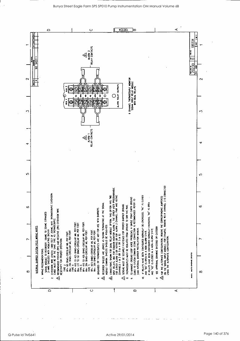
D
C
B
A
8 7
6 5
4 3
I 2
I 1
INT
ER
NA
L B
AR
RIE
R
SY
ST
EM
FIE
LD
WIR
ING
NO
TE
S
I. W
RIN
G R
EC
OM
ME
ND
AT
ION
S:
SIG
NA
L M
OD
ULE
T
O
RE
CO
RD
ER
: 18
AW
G 10
22
AW
G
ST
RA
ND
ED
2-M
IRE
S
HIE
LDE
D
WIT
H
INS
ULA
TIN
G
SH
EA
TH
Z
EX
TE
NS
ION
W
IRE
LE
NG
TH
: 10
00 F
EE
T
OF
20
AW
G
MA
X.
TH
ER
MO
CO
UP
LE
EX
TE
NS
ION
CA
BLE
M
US
T
BE
O
f T
HE
S
AM
E
TY
PE
A
S
TH
ER
MO
CO
UP
LE.
Zt
RE
CO
MM
EN
DE
D
PO
SIT
IVE
(R
P)
AN
D
NE
GA
TIV
E
(RN
) E
XT
EN
SIO
N '
YO
RE
RE
SIS
TIV
ITY
FO
R
PR
OP
ER
GP
ER
AT
ICN
:
TY
PE
J:
RP
=
60
OH
MS
-CIR
CU
LAR
M
IL
PE
R
FO
OT
.
RN
=
294
OH
MS
- CIR
CU
LAR
M
IL
PE
R
FO
OT
.
TY
PE
K
:
RP
- 41
0 T
O 42
5 O
HM
S-C
IRC
ULA
R M
IL
PE
R
FO
OT
.
RN
- 17
7 T
O
191
OH
MS
- CIR
CU
LAR
M
IL
PE
R
FO
OT
.
TY
PE
E
:
TIP
=
410
TO
42
5 C
HM
S-C
IRC
ULA
R
MIL
P
ER
F
OO
T.
RN
=
294
OH
MS
- CIR
CU
LAR
M
k P
ER
F
OO
T.
TY
PE
1:
RP
=
10.5
O
HM
S- C
IRC
ULA
R
MIL
P
ER
F
OO
T.
RN
=
294
OH
MS
-CIR
CU
LAR
MIL
P
ER
F
OO
T
4.
(RO
UN
DE
D
DP
T
HE
RM
OC
OU
PLE
S
AR
E
NO
T
FO
R
US
E
NT
H B
AR
RIE
RS
.
a, R
EC
OR
DE
R
SH
IELD
S
AR
E
JOIN
ED
A
S
SH
OW
N
TE
RM
INA
TIN
G
Al
TH
E
SIG
NA
L
MO
DU
LE C
OM
MO
N.
SH
IELD
S
SH
OU
LD
BE
IN
SU
LAT
ED
.
a, C
ON
NE
CT
ION
S
SH
OW
N F
OR
D
UA
L R
ELA
Y
MO
DU
LE
OP
TIO
N.
TH
IS
OP
PO
N
HA
S
TW
O
DP
DT
R
ELA
YS
. O
NE
F
OR
C
OM
MO
N
MO
NIT
OR
A
LAR
M
I. T
HE
O
TH
ER
U
SE
R
PR
OG
RA
MM
AB
LE
FO
R
EIT
HE
R
ALA
RM
2
OR
V
OT
ING
O
R
FO
R
ALA
RM
2
CH
AN
NE
L P
AIR
A
ND
V
OT
ING
(CH
AN
NE
LS
I &
2
OR
3
& 4
O
R
5 &
6).
& SC
RE
WS
M
US
T
BE
S
EC
UR
ELY
F
AS
TE
NE
D
FO
R
PR
OP
ER
B
AR
RIE
R
GR
OU
ND
.
8.
TH
ER
MO
CO
UP
LES
M
US
T
BE
IS
OLA
TE
D
FR
OM
G
RO
UN
D
TO
50
0 V
AC
R
MS
.
9.
TO
M
INIM
IZE
G
RO
UN
D
LOO
P
NO
ISE
P
RO
BLE
MS
. A
S
ING
LE
PO
INT
E
AR
TH
G
RO
UN
D
(CN
D)
10
SY
ST
EM
C
OM
MO
N (
CC
M)
CO
NN
EC
TIO
N
IS
RE
CO
MM
EN
DE
D.
RE
FE
R
TO
3300
IN
TE
RN
AL
BA
RR
IER
IN
ST
ALL
AT
ION
M
AN
UA
L
10.
IF
RE
LAY
S
HA
VE
B
EE
N
CO
NF
IGU
RE
D N
OR
MA
LLY
D
E-E
NE
RG
IZE
D.
.NC
- IS
C
LOS
ED
AN
D
"NO
" IS
O
PE
N
IN
A
NO
N-A
LAR
M
ST
AR
.
IF
RE
LAY
S
HA
VE
B
EE
N
CO
NF
IGU
RE
D N
OR
MA
LLY
E
NE
RG
IZE
D.
'NC
IS
O
PE
N
AN
D
*N0-
IS
C
LOS
ED
IN
A
N
ON
-ALA
RM
S
TA
TE
.
11
SE
E
AP
PR
OV
AL
DR
AW
ING
B
A22
000
OR
C
A22
000
FO
R
TH
E
ALT
ER
NA
TE
CO
NF
IGU
RA
TIO
N.
RE
MO
VE
T
HE
C
OR
RE
SP
ON
DIN
G
JUM
PE
R(S
)
ON
T
HE
S
IGN
AL
INP
UT
MO
DU
LE:
FO
R
EX
AM
PLE
. R
EM
OV
E
W3
IF
CH
AN
NE
L 3
IS
CO
NN
EC
TE
D
US
ING
T
HE
A
LTE
RN
AT
E C
ON
FIG
UR
AT
ION
.
1011
1,
YltI
S 0
10.0
11I w
mn
8 7
6 5
ALA
RM
1
RE
LAY
C
ON
TA
CT
S -
M.0
1
...I 7
1 S
EE
S
HE
ET
I
4
6 C
HA
NN
EL
TH
ER
MO
CO
UP
LE
MO
NIT
OR
SIG
NA
L IN
PU
T
RE
LAY
M
IME
W
ITH
D
UA
L R
ELA
YS
3
ALA
RM
2
RE
LAY
C
ON
TA
CT
S
I
-1..
0.
20230
I
- 10
0334
IO
C
I.^
Tar
2 I
1
D
C
B A
Bunya Street Eagle Farm SPS SP010 Pump Instrumentation OM Manual Volume 6B
Q-Pulse Id TMS641 Active 29/01/2014 Page 140 of 376

D
B
A
8 I
7 I
6 3
2
SE
E
SH
EE
T
2
son
wits
eso
nrst
sw
am
8
6 C
HA
NN
EL
IUD
M
ON
ITO
R
SIG
NA
L IN
PU
T
MO
DU
LE
MA
TT
IOU
T
BA
RR
IER
S
4 W
IRE
C
ON
FIG
UR
AT
ION
7 6
b C
HA
NN
EL
RT
D
MO
NIT
OR
SIG
NA
L IN
PU
T M
OD
ULE
W
ITH
OU
T
BA
RR
IER
S
3 W
IRE
C
ON
FIG
UR
AT
ION
TO
R
EC
OR
DE
RS
ow-
NN
W
4
lele
l
O&
M 0
0 .
Ma.
./
Ng.
4. WM
I. M
X O
M
Mil
wee
Mao
a ma
ow. o
w
Il =
NN
E
111
min
a am
mo.
m
i
SWAMI
1111
Mr-.4
=NMI
BE
NT
LY
":,;,
" N
EV
AD
A J
FIE
LD
MIR
ING
D
IAG
RA
M
3300
/35
6 C
H
RT
O
MO
NIT
OR
0111
aft,
le
CI
I 20
230
D -
1003
35
3 2
1
D C
Bunya Street Eagle Farm SPS SP010 Pump Instrumentation OM Manual Volume 6B
Q-Pulse Id TMS641 Active 29/01/2014 Page 141 of 376
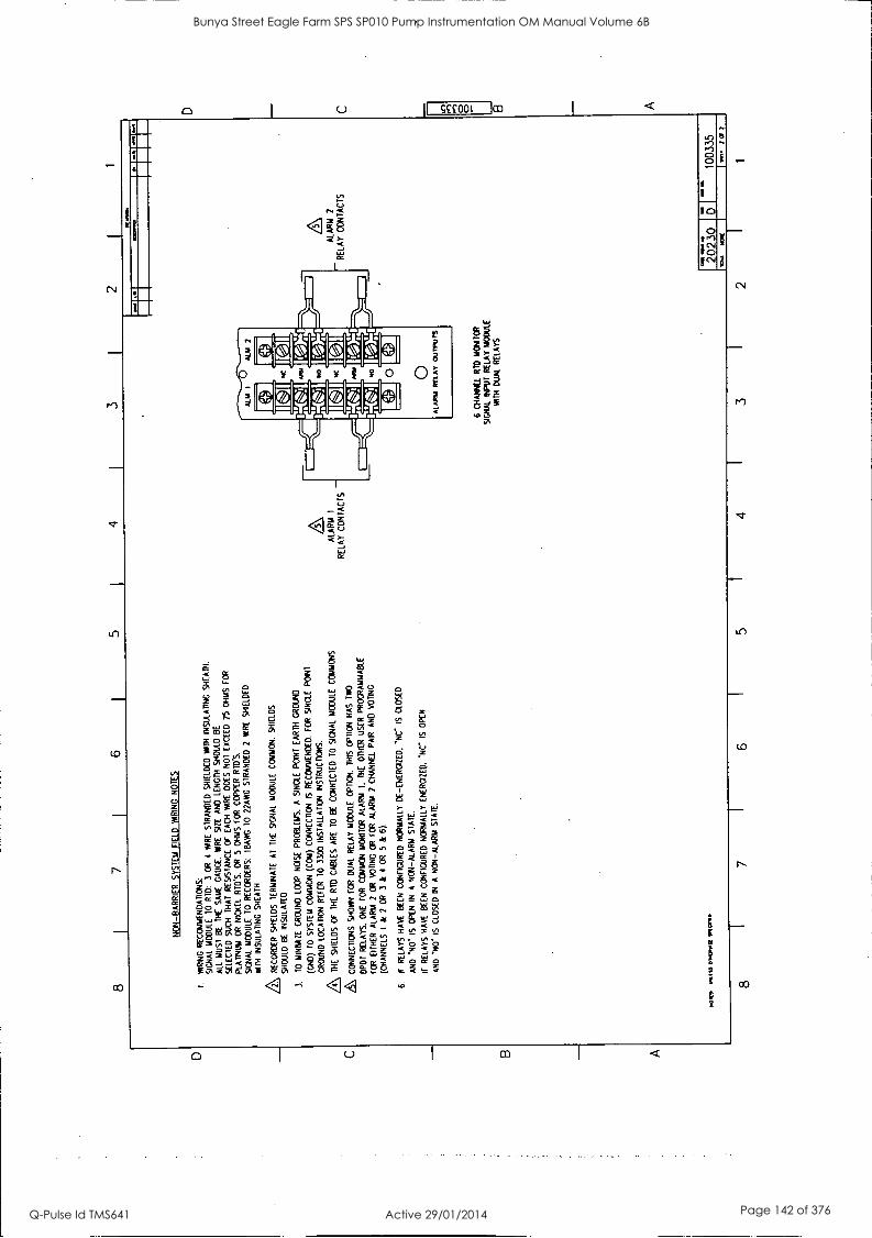
D C
B A
8 7
6 5
I. 4
3 2
1
NO
N-B
AR
RIE
R S
YS
TE
M
FIE
LD
HIR
ING
N
OT
ES
I. W
RIN
G
RE
CO
MM
EN
DA
TIO
NS
: S
IGN
AL
MO
DU
LE
TO
R
ID:
3 O
R
4 IM
RE
S
TR
AN
DE
D
SH
IELD
ED
W
ITH
IN
SU
LAT
ING
S
HE
AT
H.
ALL
M
US
T
BE
T
HE
S
AM
E
GA
UG
E.
WIR
E
SIZ
E
AN
D
LEN
GT
H
SH
OU
LD
BE
SE
LEC
TE
D
SU
CH
T
HA
T
RE
SIS
TA
NC
E
(W
EA
CH
A
IRE
D
OE
S N
OT
E
XC
EE
D
25
OH
MS
FO
R
PLA
TIN
UM
OR
N
ICK
EL
RID
'S.
OR
5
OH
MS
F
OR
C
OP
PE
R R
ID'S
.
SIG
NA
L M
OD
ULE
T
O
RE
CO
RD
ER
S:
I8A
WG
T
O
22A
WG
ST
RA
ND
ED
2
WIR
E
SH
IELD
ED
LMT
H
INS
ULA
TIN
G
SH
EA
TH
.
RE
CO
RD
ER
S
HIE
LDS
T
ER
MIN
AT
E
AT
T
HE
S
IGN
AL
MO
DU
LE
CO
MM
ON
. S
HIE
LDS
SH
OU
LD
BE
IN
SU
LAT
ED
3.
to M
INIM
IZE
G
RO
UN
D
LOO
P
NO
ISE
P
RO
BLE
MS
. A
S
ING
LE
PO
INT
E
AR
TH
G
RO
UN
D
(GN
D)
TO
S
YS
TE
M
CO
MM
ON
(C
OM
) C
ON
NE
CT
ION
IS
R
EC
OM
ME
ND
ED
. F
OR
S
ING
LE
PO
INT
GR
OU
ND
LO
CA
TIO
N
RE
FE
R
10
3300
IN
ST
ALL
AT
ION
IN
ST
RU
CT
ION
S.
TH
E
SH
IELD
S
OF
T
HE
R
ID
CA
BLE
S
AR
E
TO
BE
C
ON
NE
CT
ED
T
O
SIG
NA
L M
OD
ULE
C
OM
MO
NS
.
CO
NN
EC
TIO
NS
SH
OW
N
FO
R
DU
AL
RE
LAY
MO
DU
LE
OP
TIO
N.
TH
IS
OP
TIO
N
HA
S
TW
O
DP
DT
R
ELA
YS
. O
NE
F
OR
C
OM
MO
N
MO
NIT
OR
A
LAR
M
I. T
HE
O
TH
ER
U
SE
R
PR
OG
RA
MM
AB
LE
FO
R
EIT
HE
R
ALA
RM
2
OR
V
OT
ING
C
R
FO
R
ALA
RM
2
CH
AN
NE
L P
AIR
A
ND
V
OT
ING
(CH
AN
NE
LS
I &
2
OR
3
&
4 O
R
5 &
6)
.
6.
IF
RE
LAY
S H
AW
B
EE
N
CO
NF
IGU
RE
D N
OR
MA
LLY
D
E-E
NE
RG
IZE
D.
-NC
" IS
C
LOS
ED
AN
D
NO
IS
O
PE
N
IN
A
NO
N-A
LAR
M S
TA
TE
.
IF
RE
LAY
S H
AV
E
BE
EN
CO
NF
IGU
RE
D
NO
RM
ALL
Y
EN
ER
GIZ
ED
, 'N
C I
S
OP
EN
AN
D 'H
O'
IS
CLO
SE
D
IN
A
NO
N-A
LAR
M
ST
AT
E.
1.0M
1 W
AS
S 0
1.0.
111
9101
/11D
ALA
RM
I
- R
ELA
Y C
ON
TA
CT
S
1111
.14.
&
NI
LIP
I I
11 N
A 1
."
6 C
HA
NN
EL
RID
M
ON
ITO
R
SIG
NA
L IN
PU
T
RE
LAY
MO
DU
LE
WIT
H
DU
AL
RE
LAY
S
ALA
RM
2
RE
LAY
C
ON
TA
CT
S
2023
0 10
0335
8 I
7 I
6
111.
1 K
m(
ff, 7
0
7
5 I
4 I
3 I
2 I
1
D C
rn
.per
B A
Bunya Street Eagle Farm SPS SP010 Pump Instrumentation OM Manual Volume 6B
Q-Pulse Id TMS641 Active 29/01/2014 Page 142 of 376

D
8 7
6 5
4 3
I 2
1
HA
ZA
RD
OU
S
AR
EA
S
AF
E
AR
EA
O
R
ZO
NE
2.
D
IVIS
ION
SE
E
SH
EE
T
3
DIE
S
wus
f 01
01W
Irt
eIID
A\ W
AR
NIN
G
IMP
RO
PE
R
GR
OU
ND
ING
or
SIG
NA
L C
OM
MO
N C
OU
LD
CA
US
E
EX
PLO
SIO
N
OR
F
IRE
IN
T
HE
H
AZ
AR
DO
US
AR
EA
R
ES
ULT
ING
IN
SE
VE
RE
P
ER
SO
NA
L IN
JUR
Y
OR
DE
AT
H.
CO
MM
ON
MU
ST
B
E
CO
NN
EC
TE
D
70
EA
RT
H
AT
T
HE
B
AR
RIE
R
RA
IL.
8 7
6
Off
DID
VT
0
CH
AN
NE
L
r-44
0)
/ R
e)
I IC1
113
0 0
CSO
.
I I
UM
W&
O 6
CH
AN
NE
L R
ID
MO
NIT
OR
S
IGN
AL
INP
UT
M
OD
ULE
W
ITH
E
XT
ER
NA
L B
AR
RIE
RS
3
WIR
E
CO
NF
IGU
RA
TIO
N
FO
R
EC
OR
DE
RS
..w%
jr.r
a=tp
r..:
o M
ale
ow
.0 MO
.1
0 0.
01. Y
. 00
01 0
00
0.0
01/
.0.1
[10
/000
/0/0
* ar
m w
oo a
m
IP.%
wow
. M
on
NM
. 11.
1.0M
, 00
1,00
B
EN
TLY
N
EV
AD
A
NJ
FIE
LD
MA
RIN
O D
IAG
RA
M
3300
/3S
6 C
H
RT
D
MO
NIT
OR
M
t 600
NI
OF
3
2023
0 O
D.
1003
36
4 3
2 1
D C 0 C,
C3 B
A
Bunya Street Eagle Farm SPS SP010 Pump Instrumentation OM Manual Volume 6B
Q-Pulse Id TMS641 Active 29/01/2014 Page 143 of 376
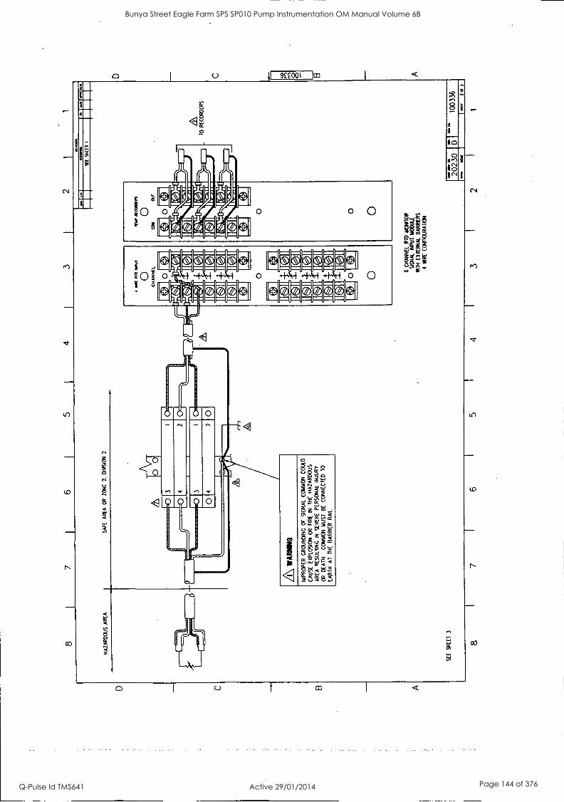
D
C
B
A
8 7
6 4
3 2
1
HA
ZA
RD
OU
S A
RE
A
SA
FE
A
RE
A
OR
Z
ON
E
2.
DIV
ISIO
N
2
5:4
SE
E
SH
EE
T
3
0 0
0 3
0 04
2
0
013
014
A WA
RN
RIG
IMP
RO
PE
R
GR
OU
ND
ING
O
F
SIG
NA
L C
OM
MO
N
CO
ULD
CA
US
E
EX
PLO
SIO
N
OR
F
IRE
IN
T
HE
H
AZ
AR
DO
US
AR
EA
R
ES
UL1
1NG
IN
S
EV
ER
E
PE
RS
ON
AL
INJU
RY
OR
D
EA
TH
. C
OM
MO
N
MU
ST
B
E
CO
NN
EC
TE
D
10
EA
RT
H
AT
T
HE
B
AR
RIE
R
RA
IL.
4 M
R O
M N
OW
0 CHANNEL
SE
E W
EI
I
0 O 6
CH
AN
NE
L R
ID
MO
NIT
OR
S
IGN
AL
INP
UT
M
OD
ULE
M
TH
EX
TE
RN
AL
BA
RR
IER
S
4 M
IRE
C
ON
FIG
UR
AT
ION
I 11
1010
TO
R
EC
OR
DE
RS
FR
2023
0 S
R
I
FR
SR
1003
36
AN,
Of 3
8 I
7 I
6 I
5 4
I 3
2 1
C
O
O
B A
Bunya Street Eagle Farm SPS SP010 Pump Instrumentation OM Manual Volume 6B
Q-Pulse Id TMS641 Active 29/01/2014 Page 144 of 376

C B A
8 7
6 5
4 3
2 I
1
EX
TE
RN
AL
BA
RR
IER
S
YS
TE
M F
IELD
W
RIN
G
NO
TE
S
I. M
IRIN
G
RE
CO
MM
EN
DA
TIO
NS
:
SIG
NA
L M
OD
ULE
T
O B
AR
RIE
R-B
AR
RIE
R T
O R
ID:
3 O
R
4 M
RE
S
TR
AN
DE
D
SH
IELD
ED
WIT
H
INS
ULA
TIN
G
SH
EA
TH
. A
LL
MU
ST
B
E
TH
E
SA
ME
G
AU
GE
. IM
RE
S
IZE
A
ND
LEN
GT
H
SH
OU
LD B
E
SE
LEC
TE
D
SU
CH
T
HA
T
RE
SIS
TA
NC
E
OF
E
AC
H
WIR
E
DO
ES
N
OT
EX
CE
ED
25
O
HM
S
FO
R
PLA
TIN
UM
O
R
NIC
KE
L R
IDS
. O
R
5 O
HM
S F
OR
C
OP
PE
R R
IDS
.
SIG
NA
L M
OD
ULE
T
O
RE
CO
RD
ER
S:
I8A
WG
10
22
AW
G
ST
RA
ND
ED
2
WIR
E
SH
IELD
ED
WIT
H I
NS
ULA
TIN
G
SH
EA
TH
.
RE
CO
RD
ER
S
HIE
LDS
T
ER
MIN
AT
E
AT
T
HE
S
IGN
AL
MO
DU
LE
CO
MM
ON
. S
HIE
LDS
SH
OU
LD
BE
IN
SU
LAT
ED
.
3.
IF
RE
LAY
S H
AV
E
BE
EN
C
ON
FIG
UR
ED
N
OR
MA
LLY
D
E-E
NE
RG
IZE
D,
*NC
' IS
C
LOS
ED
AN
D
'140
- IS
O
PE
N I
N
A N
ON
-ALA
RM
S
TA
TE
.
IF
RE
LAY
S H
AV
E
BE
EN
C
ON
FIG
UR
ED
N
OR
MA
LLY
E
NE
RG
IZE
D.
'NC
IS
O
PE
N
AN
D
NO
IS
C
LOS
ED
IN
A
N
ON
-ALA
RM
ST
AT
E.
CO
NN
EC
TIO
NS
S
HO
W F
OR
D
UA
L R
ELA
Y M
OD
ULE
O
PT
ION
. T
HIS
O
PT
ION
H
AS
T
WO
DP
DT
R
ELA
YS
, O
NE
F
OR
C
OM
MO
N
MO
NIT
OR
A
LAR
M
I, T
HE
O
TH
ER
U
SE
R
PR
OG
RA
MM
AB
LE
FO
R
EIT
HE
R
ALA
RM
2
OR
V
OT
ING
O
R
FO
R
ALA
RM
2
CH
AN
NE
L P
AIR
A
ND
V
OT
ING
(CH
AN
NE
LS
I &
2
OR
3
&
4 O
R
5 &
6)
.
5.
WH
EN
U
SIN
G
BA
RR
IER
S,
SIN
GLE
P
OIN
T
GR
OU
ND
ST
RA
P
MU
ST
BE
R
EM
OV
ED
. S
EE
3300
IN
ST
ALL
AT
ION
IN
ST
RU
CT
ION
S F
OR
S
ING
LE
PO
NT
G
RO
UN
D
ST
RA
P
LOC
AT
ION
. B
AR
RIE
R
EA
RT
H
MU
ST
B
E
CO
NN
EC
TE
D
TO
C
CM
T
ER
MIN
AL
ON
P
OW
ER
IN
PU
T
MO
DU
LE
6.
MA
XIM
UM
P
RIM
AR
Y
CIR
CU
IT
PO
TE
NT
IAL
MU
ST
NO
T
EX
CE
ED
25
0 V
AC
.
A CO
NN
EC
TIO
NS
F
OR
A
T
YP
ICA
L B
AR
RIE
R
AR
E
SH
OW
N.
RE
FE
R
TO
DR
AW
ING
S
BA
2200
0
AN
D C
A22
000
FO
R
MO
RE
IN
FO
RM
AT
ION
.
BA
RR
IER
S
AR
E
MO
UN
TE
D
TO
B
AR
RIE
R R
AIL
W
HIC
H
IS
TH
E
PO
TE
NT
IAL
EO
UA
LIZ
AT
ION
B
US
BE
TW
EE
N
SY
ST
EM
G
RO
UN
D
AN
D
EA
RT
H
GR
OU
ND
. T
O
MIN
IMIZ
E
GR
OU
ND
LO
OP
P
RO
BLE
MS
. A
SIN
GLE
P
OIN
T
EA
RT
H
GR
OU
ND
(G
ND
) T
O. S
YS
TE
M
CO
MM
ON
(C
OM
) C
ON
NE
CT
ION
IS
RE
CO
MM
EN
DE
D
AT
T
HE
B
AR
RIE
R
RA
IL.
TO
TA
L E
AR
TH
LO
OP
IM
PE
DA
NC
E
MU
ST
N
OT
E
XC
EE
D
I O
HM
. R
EM
OV
E
SIN
GLE
P
ON
T
EA
RT
H
GR
OU
ND
CO
NN
EC
TIO
N
AT
C
HA
SS
IS
GR
OU
ND
O
N
TH
E
3300
P
OW
ER
IN
PU
T
MO
DU
LE.
&T
HE
RID
T
HIR
D
OR
F
OU
RT
H
IMR
E
CO
MP
EN
SA
TIO
N I
S
AC
CO
MP
LIS
HE
D
TH
RO
UG
H
US
E
OF
BA
RR
IER
E
AR
TH
T
O
CO
MM
ON
C
ON
NE
CT
ION
. S
EE
N
OT
E
5.
A IN
DE
PE
ND
EN
T
CO
NN
EC
TIO
N
TO
S
YS
TE
M
EA
RT
H.
MO
WS
ME
SS 0
1.00
111
.0/1
0
A
ALA
RM
1
RE
LAY
CO
NT
AC
TS
1111
441
6 C
HA
NN
EL
RID
MO
NIT
OR
SIG
NA
L IN
PU
T
RE
LAY
M
OD
ULE
W
ITH
DU
AL
RE
LAY
S
A
ALA
RM
2
RE
LAY
C
ON
TA
CT
S r rrr
2023
0 IM
I
Me
1003
36
MIK
30
,1
8 I
7 I
6 5
I 4
I 3
I 2
I 1
D C
r^o 8 B A
Bunya Street Eagle Farm SPS SP010 Pump Instrumentation OM Manual Volume 6B
Q-Pulse Id TMS641 Active 29/01/2014 Page 145 of 376

D C B
A
8 1
7 6
5 4
3 I
2
HA
ZA
RD
OU
S
AR
EA
S
AF
E
AR
EA
C
R
ZO
NE
2.
D
IVIS
ION
2
SH
IELD
MW
9S0
A
w.w
ww
INC
P
CR
12
3429
7
- 10
RE
CO
RD
ER
S
CO
NN
EC
TIO
NS
F
OR
C
HA
NN
ELS
2
TH
RU
6
NO
T
SH
OW
N
FC
R
CLA
RIT
Y
A WA
RN
ING
MIS
CO
NN
EC
TIN
G
OR
IN
TE
RM
ITT
EN
T
CO
NT
AC
T
OF
T
HE
FIE
LD
WIR
ING
TO
R
AC
K
TE
RM
INA
LS
WIT
H
HIG
H
VO
LTA
GE
PO
TE
NT
IALS
C
OU
LD
CA
US
E
AN
E
XP
LOS
ION
O
R
FIR
E
IN
TH
E
HA
ZA
RD
OU
S
AR
EA
R
ES
ULT
ING
IN
S
EV
ER
E
PE
RS
ON
AL
INJU
RY
O
R
DE
AT
H.
RE
MO
VE
A
LL
VO
LTA
GE
PO
TE
NT
IALS
F
RO
M
RE
AR
O
F
RA
CK
.
SE
E
SH
EE
T 2
Wtta
U
MIS
S m
aws
MO
RD
CO
VE
R
NO
T
SH
OW
N
FO
R
CLA
RIT
Y
MU
ST
B
E
CLO
SE
D
WR
ING
O
PE
RA
TIO
N
6 C
HA
NN
EL
R
D M
ON
ITO
R
SIG
NA
L IN
PU
T
MO
DU
LE
WIT
H
INT
ER
NA
L B
AR
RIE
RS
1 6
1 5
1 4
1
010
oral
s A
MY
O
M
way
Ol 8
NW
IM
O
l 1.
. OW
N.
le
NII
MIN
IM N
I M
OO
R%
11
10 M
t*. M
el O
R dr
OOP.
wen
t 11
MO
O.
MN
. to
kall
apP
4e.
BE
NT
LY
NE
VA
DA
%
.)
FIE
LD
WIR
ING
D
IAG
RA
M
3300
/35
6 C
H
RT
D
MO
NIT
OR
Id M
. 21
WU
IO
C
lmt O
r 2
8 7
3 1
2
1 7 3 0
I 6'
I_
1003
37
1
C
M 8 B A
Bunya Street Eagle Farm SPS SP010 Pump Instrumentation OM Manual Volume 6B
Q-Pulse Id TMS641 Active 29/01/2014 Page 146 of 376
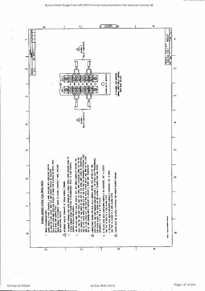
D C
B A
8 3
2
INT
ER
NA
L B
AR
RIE
R S
YS
TE
M
FIE
LD
WR
ING
NO
TE
S
1 W
RIN
G
RE
CO
MM
EN
DA
TIO
NS
:
SIG
NA
L M
OD
ULE
10
R
ID:
ST
RA
ND
ED
. 3
MIR
E
SH
IELD
ED
N
TH
IN
SU
LAT
ING
S
HE
AT
H.
ALL
MU
ST
B
E
SA
ME
G
AU
GE
. W
IRE
S
IZE
A
ND
LE
NG
TH
S
HO
ULD
BE
S
ELE
CT
ED
SU
CH
T
HA
T
EA
CH
W
IRE
D
OE
S
NO
T
EX
CE
ED
25
OH
MS
F
OR
P
LAT
INU
M
OR
N
ICK
EL
RID
'S
OR
5
OH
MS
FO
R
CO
PP
ER
F
UD
.S.
SIG
NA
L M
OD
ULE
10
RE
CO
RD
ER
: IR
AN
; T
O
22A
WC
, S
TR
AN
DE
D
2 W
IRE
, S
HIE
LDE
D
NTH I
NS
ULA
TIN
G
SH
EA
TH
,
& RE
CO
RD
ER
S
HIE
LDS
T
ER
MIN
AT
E
AF
S
IGN
AL
1400
ULE
C
OM
MO
N.
3.
TO
M
INIM
IZE
G
RO
UN
D
LOO
P
NO
SE
P
RO
BLE
MS
, A
S
ING
LE
PO
INT
E
AR
TH
G
RO
UN
D (
CN
D)
TO
SY
ST
EM
C
CM
MO
N
(CO
M)
CO
NN
EC
TIO
N
IS
RE
CO
MM
EN
DE
D.
RE
FE
R
TO
33
00
INT
ER
NA
L
BA
RR
IER
IN
ST
ALL
AT
ION
M
AN
UA
L.
4.
IWO
O
R
FO
UR
W
IRE
R
ID'S
CA
N
BE
U
SE
D
IF
TH
EY
A
RE
W
IRE
D
CO
RR
EC
TLY
O
UT
SID
E
TH
E
RA
CK
. F
OR
T
HE
T
M)
WIR
E R
ID'S
. T
AK
E
TH
E
TH
RE
E
WA
RE
E
XT
EN
SIO
N
CA
BLE
O
UT
T
O
TH
E
RT
D.
CO
NN
EC
T
TH
E
TW
O
WIR
ES
O
F
TH
E
RT
D
TO
T
HE
T
HR
EE
W
AR
E
CA
BLE
B
Y
CO
NN
EC
TIN
G
NO
OF
T
HE
T
HR
EE
W
IRE
S
TO
O
NE
LE
G
OF
T
HE
R
TD
A
ND
T
HE
R
EM
AIN
ING
E
XT
EN
SIO
N
CA
BLE
WIR
E
10
TH
E
OT
HE
R
LEG
. F
OR
FO
UR
W
IRE
R
IO'S
, E
ITH
ER
D
ELE
TE
O
NE
W
IRE
O
F
TH
E
FO
UR
OR
T
IE
TW
O
CO
MM
ON
W
IRE
S
TO
GE
TH
ER
T
O
CR
EA
TE
A
T
HR
EE
W
AR
E
TR
AN
SD
UC
ER
.
CO
NN
EC
TIO
NS
S
HO
WN
F
OR
D
UA
L R
ELA
Y
MO
DU
LE
OP
TIO
N.
TH
IS
OP
TIO
N
HA
S
TW
O
°PD
T R
ELA
YS
. O
NE
F
OR
C
OM
MO
N
MO
NIT
OR
A
LAR
M
I. T
HE
O
TH
ER
U
SE
R
PR
OG
RA
MM
AB
LE
FO
R
EIT
HE
R
ALA
RM
2
OR
V
OT
ING
O
R
FO
R
ALA
RM
2
CH
AN
NE
L P
AIR
A
ND
(CH
AN
NE
LS
I &
2
OR
3
&
4 O
R
5 &
6)
.
6.
IF
RE
LAY
S
HA
VE
B
EE
N
CO
NF
IGU
RE
D N
OR
MA
LLY
D
E-E
NE
RG
IZE
D,
NC
" IS
C
LOS
ED
AN
D N
O-
IS O
PE
N
IN
A
NO
N-A
LAR
M
ST
AT
E
IF
RE
LAY
S
HA
VE
B
EE
N C
ON
FIG
UR
ED
N
OR
MA
LLY
E
NE
RG
IZE
D.
NC
" IS
O
PE
N
AN
D N
O
IS C
LOS
ED
IN
A
N
ON
-ALA
RM
S
TA
TE
.
SC
RE
WS
MU
ST
BE
S
EC
UR
ELY
F
AS
TE
NE
D
FO
R
PR
OP
ER
BA
RR
IER
GR
OU
ND
.
NO
l%
ioaE
SS
01.
0M11
11
1tV
tD
ALA
RM
I
RE
LAY
CO
NT
AC
TS
/4.0
4 01
,0
A
SE
E
SH
EE
T
1
6 C
HA
NN
EL
RID
M
ON
ITO
R
SIG
NA
L N
PU
T
RE
LAY
M
OD
ULE
W
ITH
D
UA
L R
ELA
YS
ALA
RM
2
RE
LAY
C
ON
TA
CT
S
2023
0 5 - 10
0337
8 7
6 4
3 2
V.(
IO
C
D C 4:
O
B A
Bunya Street Eagle Farm SPS SP010 Pump Instrumentation OM Manual Volume 6B
Q-Pulse Id TMS641 Active 29/01/2014 Page 147 of 376

80183-01 Sbc Channel Temperature Monitor Mainterance
64
Bunya Street Eagle Farm SPS SP010 Pump Instrumentation OM Manual Volume 6B
Q-Pulse Id TMS641 Active 29/01/2014 Page 148 of 376
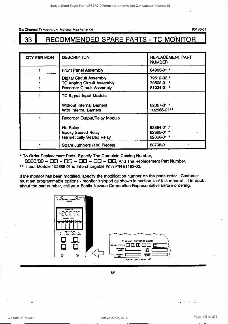
133 I RECOMMENDED. SPARE PARTS - TC MONITOR I
Six Channel Temperature Monitor Maintenance 80183-01
QTY PER MON DESCRIPTION REPLACEMENT PART NUMBER
1 Front Panel Assembly 84933-01 *
1 Digital Circuit Assembly 79512-02 * 1 TC Analog Circuit Assembly 79502-01 * 1 Recorder Circuit Assembly. 81034-01 *
1 TC Signal Input Module
Without Internal Barriers 82367-01 * With Internal Barriers 102566-01**
1 Recorder Output/Relay Module
No Relay 82364-01 * Epoxy Sealed Relay 82365-01 * Hermetically Sealed Relay 82366-01 *
1 Spare Jumpers (100 Pieces) 88706-01
* To Order Replacement Parts, Specify The Complete Catalog Number,
3300/30 - 00 - DO - DO - DO - DO, And The Replacement Part Number. ** Input Module 102566-01 Is Interchangable Wrth P/N 81192-03.
If the monitor has been modified, specify the modification number on the parts order. Customer must set programmable options - monitor shipped as shown in section 4 of this manual. If in doubt about the part number, call your Bent ly Nevada Corporation Representative before ordering.
1/014TOR CENTIFICATION LABEL
65
Bunya Street Eagle Farm SPS SP010 Pump Instrumentation OM Manual Volume 6B
Q-Pulse Id TMS641 Active 29/01/2014 Page 149 of 376
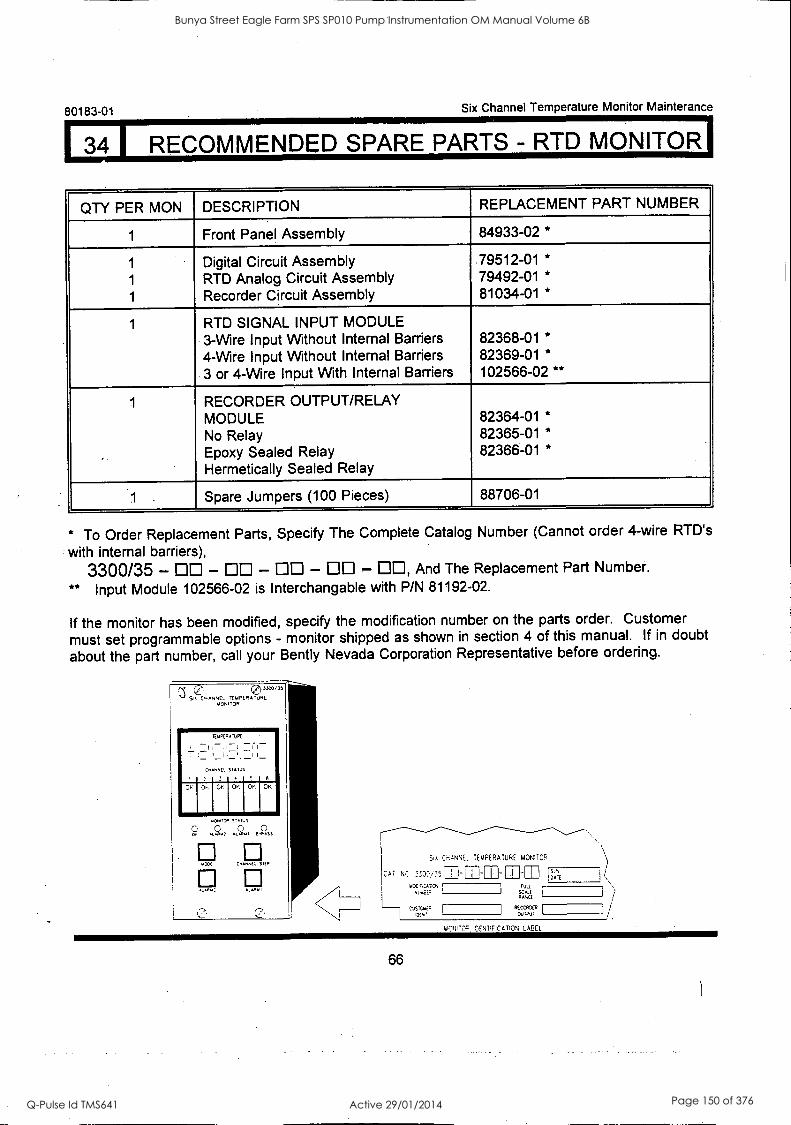
L, I RECOMMENDED SPARE PARTS - RTD MONITOR) 80183-01 Six Channel Temperature Monitor Mainterance
QTY PER MON DESCRIPTION REPLACEMENT PART NUMBER
1 Front Panel Assembly 84933-02 *
1 - Digital Circuit Assembly 79512-01 *
1 RTD Analog Circuit Assembly 79492-01 *
1 Recorder Circuit Assembly 81034-01 *
1 RTD SIGNAL INPUT MODULE 3-Wire Input Without Internal Barriers 82368-01 *
4-Wire Input Without Internal Barriers 82369-01 *
3 or 4-Wire Input With Internal Barriers 102566-02 **
1 RECORDER OUTPUT/RELAY MODULE 82364-01 *
No Relay 82365-01 *
Epoxy Sealed Relay 82366-01 *
Hermetically Sealed Relay
Spare Jumpers (100 Pieces) 88706-01
* To Order Replacement Parts, Specify The Complete Catalog Number (Cannot order 4-wire RTD's
with internal barriers),
3300/35 - CIO - CIO - DO - OO - DO, And The Replacement Part Number.
** Input Module 102566-02 is Interchangable with P/N 81192-02.
If the monitor has been modified, specify the modification number on the parts order. Customer
must set programmable options - monitor shipped as shown in section 4 of this manual. If in doubt
about the part number, call your Bently Nevada Corporation Representative before ordering.
Six OH.tNNEL TEMPERATURE MONITOR
CAT NC 2200,35 1-51-M-7-71 E.E.AAA=
EULJ.
SCALE RANCE
1 CLISriSA4!:, I
I RECORDER ouiPul
iOENTtFiCATION LABEL
66
Bunya Street Eagle Farm SPS SP010 Pump Instrumentation OM Manual Volume 6B
Q-Pulse Id TMS641 Active 29/01/2014 Page 150 of 376

Six Channel Temperature Monitor Maintenance
I 35I SPECIFICATIONS
80183-01
INPUT Signal Input
3300/30 Thermocouple Monitor Accepts signals from up to six grounded or etc ungrounded thermocouple tips of the following ANSI types:
Type J - 1000°F, 500C, max Type K - 1000°F, 500°C, max Type T - 500°F, 250°C, max Type E - 500°F, 250°C, max
3300/35 RTD Monitor Accepts up to six RTD signals from the following RTD detectors:
3-wire 100 platinum (= 0.00385) - 1000°F, 500°C, max 3-wire 100 platinum (= 0.00392) - 1000°F, 500°C, max 3-wire 120 nickel - 300°F, 150°C, max 3-wire 10 copper - 200°F, 100°C, max 4-wire 100 platinum (= 0.00385) - 1000°F, 500°C, max 4-wire 100 platinum (= 0.00392) - 1000°F, 500°C, max 4-wire 120 nickel - 300°F, 150°C, max 4-wire 10 copper - 200°F, 100°C, max
SIGNAL CONDITIONING TC or RTD Input Accuracy (Includes transducer non-linearity)
±0.5°C error typical at 77F(25°C) ±1°C error maximum at 77°F(25°C) ±3°C error typical from 0°C to 65°C NOTE: Add ±0.9°F(0.5°C) error to accuracy if Tenths Digit is not displayed.
Common Mode Input Range
ALARMS Alarm Setpoints Alarm Delay
DISPLAYS Meter
LEDs
CONTROLS Front Panel
Internal External
±250 Vac
Alarm 1 and Alarm 2 alarm levels adjustable from 0°F to 1000°F (0°C to 500°C)
Alarm delay times are user-programmable per options
LCD 7-segment,numerical, 4 digit. Annunciates HIGH READ, and OVER/UNDER alarm, and status
per channel (OK, ALARM 1, ALARM 2, and BYPASS).
Green LEDs annunciate transducer OK condition, red LEDs annunciate ALARM 2, ALARM 1, and
BYPASS conditions
Front panel switches (4) for reading ALARM 1 and ALARM 2 set point levels, and for reading CHANNEL SELECT and MODE.
Switches on circuitboard for setpoint adjustment, Alarm 2 Bypass, and Channel Bypass
External remote controls: Reset, Inhibit, and setpoint adjust (1 and I)
67
Bunya Street Eagle Farm SPS SP010 Pump Instrumentation OM Manual Volume 6B
Q-Pulse Id TMS641 Active 29/01/2014 Page 151 of 376
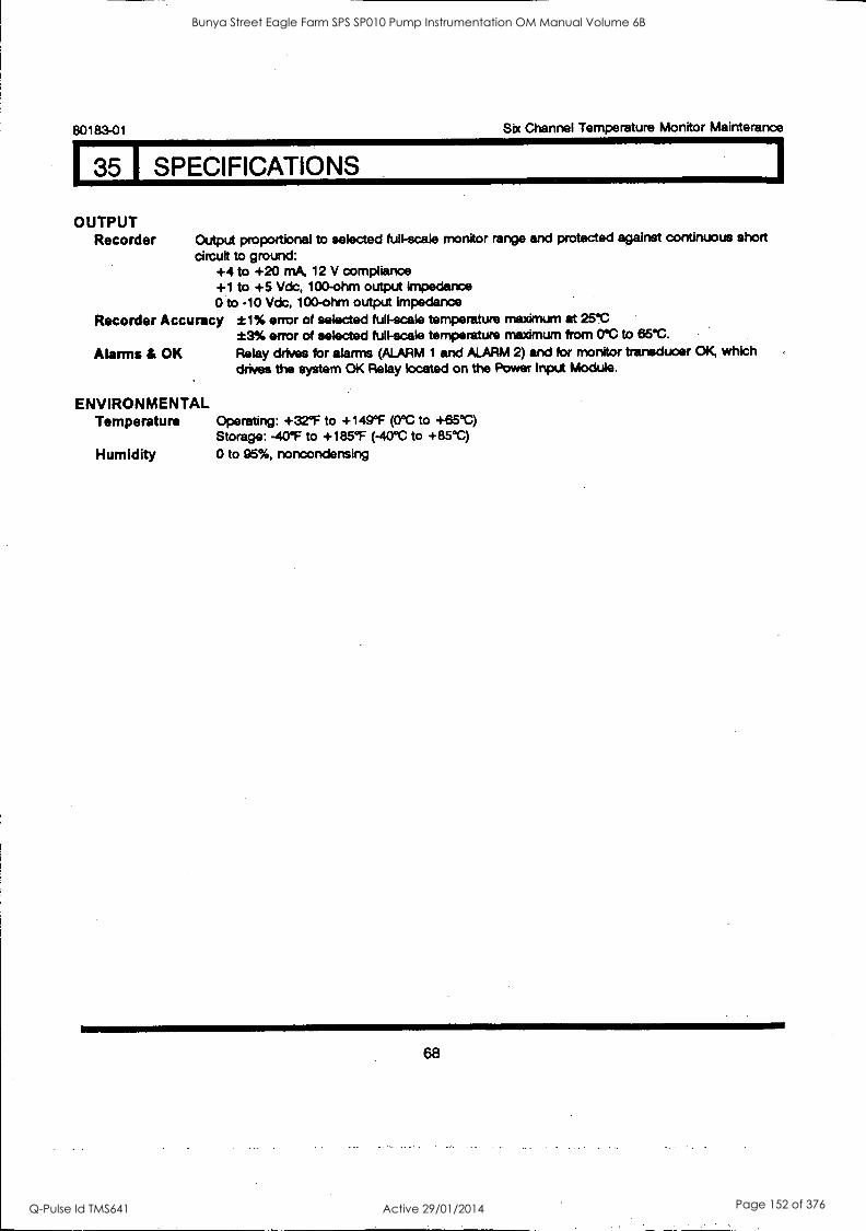
80183-01 Sbc Channel Temperature Monitor Mainterance
35 I SPECIFICATIONS.
OUTPUT Recorder Output proportional to selected full-scale monitor range and protected against continuous short
circuit to ground: +4 to +20 mA, 12 V compliance +1 to +5 Vdc, 100-ohm output impedance 0 to -10 Vdc, 100-ohm output impedance
Recorder Accuracy ±1% error of selected full-scale temperature maximum at 25`C *3% error of selected full-scale temperature maximum from 0°C to 65°C.
Alarms & OK Relay drives for alarms (ALARM 1 and ALARM 2) and for monitor transducer OK, which drives the system OK Relay located on the Power Input Module.
ENVIRONMENTAL Temperature Operating: +32°F to +149°F (0°C to +65°C)
Storage: -40°F to +185°F (-40°C to +85°C)
Humidity 0 to 95%, noncondensing
68
Bunya Street Eagle Farm SPS SP010 Pump Instrumentation OM Manual Volume 6B
Q-Pulse Id TMS641 Active 29/01/2014 Page 152 of 376

BRISBANE CITY COUNCIL Dept. Water Supply and Sewage Pumpwell No 1, Eagle Farm Pump Station
BCC Contract No S20195196 System Instrumentation
Operation and Maintenance Manual
8.2 Tachometer
The following publication entitled 3300/50 Tachometer Maintenance Manual (Part No 83871-01 Rev F) is prepared by Bent ly Nevada for plant personnel who operate and maintain the system. It provides a detailed description of the maintenance and adjustment procedures for the Tachometer module.
The following sections are included:
8.2.1 System Overview Zero Speed Tachometer
8.2.2 System Overview Rotor Acceleration Tachometer
8.2.3 Front Panel Features - Dual Setpoint Tachometer
8.2.4 Front Panel Features - Zero Speed Tachometer
8.2.5 Front Panel Features - Rotor Acceleration Tachometer
8.2.6 Monitor Removal
8.2.7 Monitor Disassembly
8.2.8 Signal Input Relay Module
8.2.9 Monitor Options
8.2.10 Monitor Full Scale Range Adjustment
8.2.11 Events per Revolution Adjustment
8.2.12 Threshold and Hysteresis Adjustment
8.2.13 Alert Hysteresis
8.2.14 Adjust Alert Setpoints Dual Setpoint Tachometer
8.2.15 Adjust Alert Setpoints Zero Speed Tachometer
8.2.16 Adjust Alert Setpoints Rotor Acceleration Tachometer
8.2.17 Bypass Dual Setpoint Tachometer
8.2.18 Bypass Zero. Speed Tachometer
8.2.19 Bypass Rotor Acceleration Tachometer
8.2.20 Monitor Bypass Dual Setpoint Tachometer
8.2.21 Monitor Bypass Zero Speed Tachometer
8.2.22 Monitor Bypass Rotor Acceleration Tachometer
8.2.23 Test Alert Dual Setpoint Tachometer
8.2.24 Test Alert Zero Speed Tachometer
15140/Inst Man/BRH Issue 1 29-Apr-98 Page 8-3
Bunya Street Eagle Farm SPS SP010 Pump Instrumentation OM Manual Volume 6B
Q-Pulse Id TMS641 Active 29/01/2014 Page 153 of 376

BRISBANE CITY COUNCIL Dept. Water Supply and Sewage Pumpwell No 1, Eagle Farm Pump Station
BCC Contract No S20/95/96 System Instrumentation
Operation and Maintenance Manual
8.2.25 Test Alert Rotor Acceleration Tachometer
8.2.26 Test Trigger OK's
8.2.27 Self Test
8.2.28 Wiring Diag - Dual Setpoint Tachometer
8.2.29 Wiring Diag - Zero Speed Tachometer
8.2.30 Wiring Diag - Rotor Acceleration Tachometer
8.2.31 Recommended Spare Parts
8.2.32 Specifications
8.2.33 Index
8.2.34 Schematics and Technical Drawings
15140/Inst Man/BRH Issue 1 29-Apr-98 Page 8-4
Bunya Street Eagle Farm SPS SP010 Pump Instrumentation OM Manual Volume 6B
Q-Pulse Id TMS641 Active 29/01/2014 Page 154 of 376

3300/50 TACHOMETER
INCLUDES DUAL SETPOINT, ZERO SPEED, AND ROTOR ACCELERATION TACHOMETERS.
MAINTENANCE MANUAL
NEVADA rn
PART NO. 83871-01 REVISION F,
JANUARY 1995
Bunya Street Eagle Farm SPS SP010 Pump Instrumentation OM Manual Volume 6B
Q-Pulse Id TMS641 Active 29/01/2014 Page 155 of 376
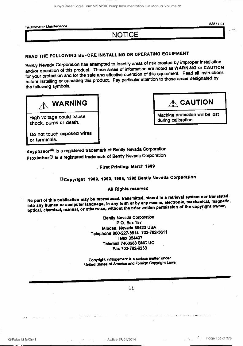
Tachometer Maintenance
READ THE FOLLOWING BEFORE INSTALLING OR OPERATING EQUIPMENT
83871-01
Bent ly Nevada Corporation has attempted to identify areas of risk created by improper installation
and/or operation of this product. These areas of information are noted as WARNING or CAUTION
for your protection and for the safe and effective operation of this equipment. Read all instructions
before installing or operating this product. Pay particular attention to those areas designated by
the following symbols.
4\ WARNING
High voltage could cause shock, burns or death.
Do not touch exposed wires or terminals.
A\ CAUTION
Machine protection will be lost during calibration.
Keyphasore is a registered trademark of Bent ly Nevada Corporation
Proxlmitore is a registered trademark of Bent ly Nevada Corporation
First Printing: March 1989
©Copyright 1989, 1993, 1994, 1995 Bently Nevada Corporation
All Rights reserved
No part of this publication may be reproduced, transmitted, stored in a retrieval system nor translated
into any human or computer language, in any form or by any means, electronic, mechanical, magnetic,
optical, chemical, manual, or otherwise, without the prior written permission of the copyright owner,
Bent ly Nevada Corporation P.O. Box 157
Minden, Nevada 89423 USA
Telephone 800-227-5514 702-782-3811 Telex 354437
Telemail 7400983 BNC UC
Fax 702-782-9253
Copyright infringement is a serious matter under
United States of America and Foreign Copyright Laws
ii
Bunya Street Eagle Farm SPS SP010 Pump Instrumentation OM Manual Volume 6B
Q-Pulse Id TMS641 Active 29/01/2014 Page 156 of 376

Tachometer Maintenance 83871-01
WARNING !
Bently Nevada Tachometers are not designed for use independently as, or a component of, a speed control or overspeed protection system.
Bently Nevada Tachometers do not provide protective redundancy and the response speed needed for reliable operation as a speed control or overspeed protection system.
Where provided, the analog proportional output is suitable for data logging or chart recording purposes only. Also, where provided, speed Alert setpoints are suitable for annunciation purposes only.
Failure to take the above warnings into account constitutes a misuse of the product and may result in property damage and/or bodily injury.
iii
Bunya Street Eagle Farm SPS SP010 Pump Instrumentation OM Manual Volume 6B
Q-Pulse Id TMS641 Active 29/01/2014 Page 157 of 376

Tachometer Maintenance 83871-01
iv
Bunya Street Eagle Farm SPS SP010 Pump Instrumentation OM Manual Volume 6B
Q-Pulse Id TMS641 Active 29/01/2014 Page 158 of 376

Tachometer Maintenance 83871-01
FOREWORD
This document is intended for personnel who maintain the 3300 Monitoring System. The
procedures are presented in step-by-step, graphic format.
RELATED DOCUMENTS
3300 System Overview, 80171-01
3300 System Installation Instructions, 80172-01
3300 System Troubleshooting, 80173-01
3300/12 AC Power Supply, 89602-01
3300/14 DC Power Supply, 101256-01
3300/03 System Monitor, 89604-01
3300/50 Tachometer Operation, 83870-01
SYMBOLS Special symbols are used in the manual to illustrate specifics in the step-by-step processes. For
example:
PRESS FLASHING CONNECT DISCONNECT OBSERVE SCREWDRIVER
V
Bunya Street Eagle Farm SPS SP010 Pump Instrumentation OM Manual Volume 6B
Q-Pulse Id TMS641 Active 29/01/2014 Page 159 of 376

Tachometer. Maintenance 83871-01
vi
Bunya Street Eagle Farm SPS SP010 Pump Instrumentation OM Manual Volume 6B
Q-Pulse Id TMS641 Active 29/01/2014 Page 160 of 376
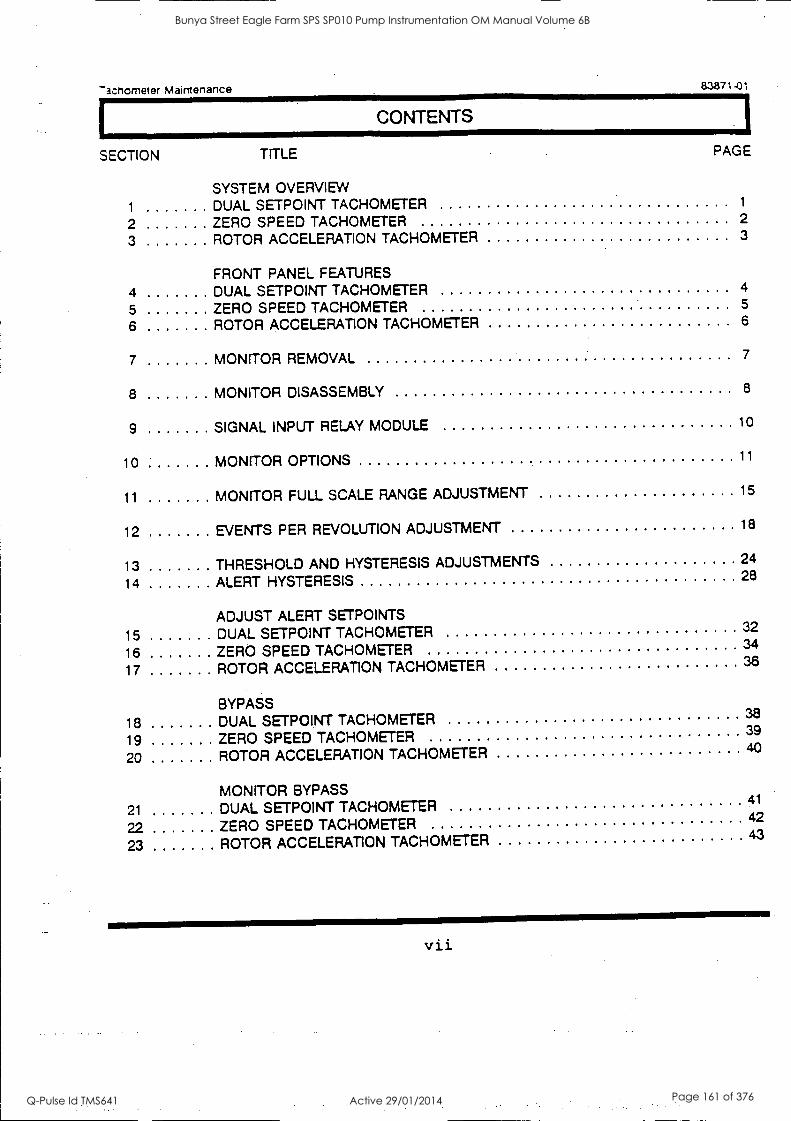
Thchometer Mairttenance 83871-01
CONTENTS
SECTION
1
2
3
TITLE PAGE
SYSTEM OVERVIEW DUAL SETPOINT TACHOMETER 1
ZERO SPEED TACHOMETER 2
ROTOR ACCELERATION TACHOMETER 3
FRONT PANEL FEATURES
4 DUAL SETPOINT TACHOMETER 4
5 ZERO SPEED TACHOMETER 5
6 ROTOR ACCELERATION TACHOMETER 6
7 MONITOR REMOVAL 7
8 MONITOR DISASSEMBLY 8
9 SIGNAL INPUT RELAY MODULE 10
10 MONITOR OPTIONS 11
11 MONITOR FULL SCALE RANGE ADJUSTMENT 15
12 EVENTS PER REVOLUTION ADJUSTMENT 18
13 THRESHOLD AND HYSTERESIS ADJUSTMENTS 24
14 ALERT HYSTERESIS 28
ADJUST ALERT SETPOINTS
15 DUAL SETPOINT TACHOMETER 32
16 ZERO SPEED TACHOMETER 34
17 ROTOR ACCELERATION TACHOMETER 36
BYPASS 18 DUAL SETPOINT TACHOMETER 38
19 ZERO SPEED TACHOMETER 39
20 ROTOR ACCELERATION TACHOMETER 40
MONITOR BYPASS
21 DUAL SETPOINT TACHOMETER 41
22 ZERO SPEED TACHOMETER 42
23 ROTOR ACCELERATION TACHOMETER 43
vii
Bunya Street Eagle Farm SPS SP010 Pump Instrumentation OM Manual Volume 6B
Q-Pulse Id TMS641 Active 29/01/2014 Page 161 of 376

Tachometer Maintenance 83871-01
CONTENTS
SECTION TITLE PAGE
TEST ALERTS 24 DUAL SETPOINT TACHOMETER 44 25 ZERO SPEED TACHOMETER 46
26 ROTOR ACCELERATION TACHOMETER 48
27 TEST TRIGGER OKs 50
28 SELF TEST 52
29 FIELD WIRING DIAGRAMS 56
DUAL SETPOINT TACHOMETER 57
ZERO SPEED TACHOMETER 61
ROTOR ACCELERATION TACHOMETER 65
30 RECOMMENDED SPARE PARTS 69
31 SPECIFICATIONS 70
32 INDEX
33 SCHEMATICS AND TECHNICAL DRAWINGS 74
viii
Bunya Street Eagle Farm SPS SP010 Pump Instrumentation OM Manual Volume 6B
Q-Pulse Id TMS641 Active 29/01/2014 Page 162 of 376
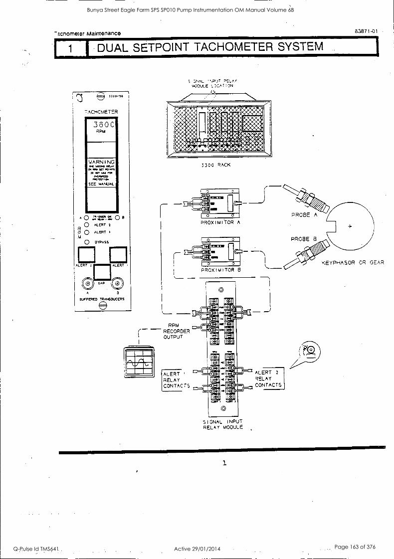
1
Mcnorneter Maintenance 83871-01
1 I DUAL SETPOINT TACHOMETER SYSTEM
1700.!0
TACHCMETER 11I 3 6 0 C RPM
WARNING 0.4 111100 MAY
GI ems siR otwaS 00 DOT USA AM
0.0-010211 MOM, I 04
SEE MANUAL
A0 000t C.( On, MO*
0 ALERT 2
R p O ALERT M
0 BYPASS
0B
SUFFERED TRANSDUCERS
.:;NAL `PUT mODUL E L :CA T
3300 RACK
PROXIMITOR A
PROXIMITOR 8
RPM - RECORDER
OUTPUT
ALERT I
RELAY CONTACTS
OO
SIGNAL INPUT RELAY MODULE
ALERT 2
RELAY CONTACTS
KEYPHASOR OR GEAR
Bunya Street Eagle Farm SPS SP010 Pump Instrumentation OM Manual Volume 6B
Q-Pulse Id TMS641 Active 29/01/2014 Page 163 of 376

Tachometer Maintenance
I 2 ZERO SPEED TACHOMETER SYSTEM
83871-01
= 3300,10
TACHOMETER ..............
3600 ,7ipm
ZERO SPEED ENABLED
WARNING .01 w MLA,
01 WIG %ET 00.n 00 .01' tie MI
0.19.11.61D mcnyei
SEE VANJAL
1O
O
TRIGGER CK
CPT IIPLO I aftl
ALERT Q R srpAss Q M
ALERT
vAP
A
BuFFERED TRANSCucERs
Ppm
S GNAL NPUr =E- A
+100U LE LcCAr .:?1
3300 RACK
PROX I M I TOR A
KEYPHASOR CR GEAR
RPM RECORDER OUTPUT
ALERT RPM -7.R0 SPEED
RELAY CONTACTS
-'LAY :CNTACTS
To EXTERNAL ZERO SPEED
ENABLE CONTACTS _sER SuPPLIED1
SIGNAL RELA r
_ERT
2
Bunya Street Eagle Farm SPS SP010 Pump Instrumentation OM Manual Volume 6B
Q-Pulse Id TMS641 Active 29/01/2014 Page 164 of 376

-acnometer Maintenance 8.3871-01
I 3 1 ROTOR ACCELERATION TACHOMETER SYSTEM
= 1300,50
TACHOMETER ......... 3 6 0 0
RPM
WARNING GC WOO OCIAr
4 OW SR Kowa CO CT tAt sow
CACMPINO m10,1C, ICH
SEE MANUAL
-600 RPM/MIN
AMIIMMIIIMMEM
7 TRIGGER 0 BMW
R M Q ALERT 0 R P/
M \10 BYPASS 0 M
PJA4,14114
ALERT
GAP
Rem
A B
9UFFERED TAANSCIJCERS
,NAL I ',RUT Q EL AY
vOCULE LOCATION
3300 RACK
PROXIMITOR A
PROXIMITOR 8
RPM RECORDER OUTPUT
SIGNAL i%PUT RELAY YOOLLE
RPM /MINUTE RECORDER OUTPUT
RPM /MINUTE ALERT RELAY CONTACTS
PROBE A
PROBE B
KEYPHASOR OR GEAR
3
Bunya Street Eagle Farm SPS SP010 Pump Instrumentation OM Manual Volume 6B
Q-Pulse Id TMS641 Active 29/01/2014 Page 165 of 376
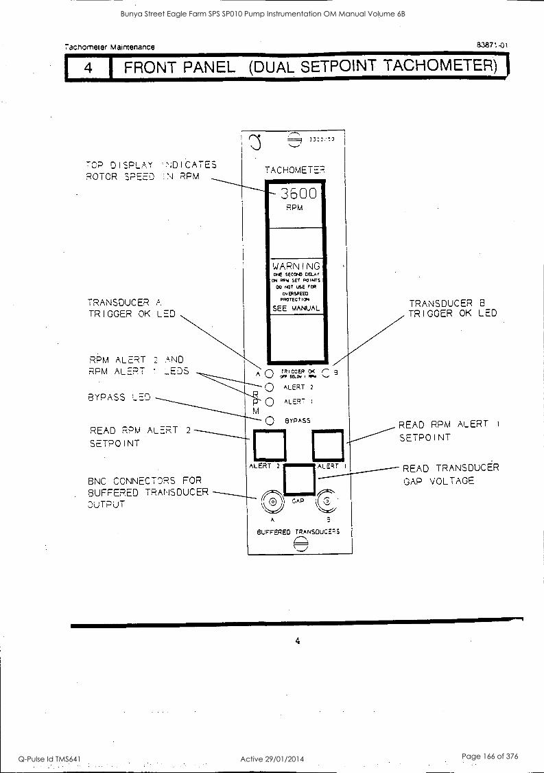
Tacnometer Maintenance 83871-01
FRONT PANEL (DUAL SETPOINT TACHOMETER)
TCP DISPLAY INDICATES ROTOR SPEED :N RPM
TRANSDUCER A TRIGGER OK LED
RPM ALERT 2 AND RPM ALERT ! LEDS
BYPASS LED
READ RPM ALERT 2
SETPOINT
===9 33:::!0
TACHOMETER 11111111111I
3600 RPM
WARNING ONE SECOND Cam ON A91.1 SET POINTS
CO NOT USE FOR
OVERSPEEC PROTECTION
SEE MANUAL
A n TRIGGER OK r- 3 OFT
0 ALERT 2
0 ALERT :
() BYPASS
ALERT 2
GAP
A
BNC CONNECTORS FOR BUFFERED TRANSDUCER OUTPUT
M
ALERT
BUFFERED TRANSOUCFRS
C:11
TRANSDUCER 8
TRIGGER OK LED
READ RPM ALERT
SETPOINT
READ TRANSDUCER GAP VOLTAGE
4
Bunya Street Eagle Farm SPS SP010 Pump Instrumentation OM Manual Volume 6B
Q-Pulse Id TMS641 Active 29/01/2014 Page 166 of 376
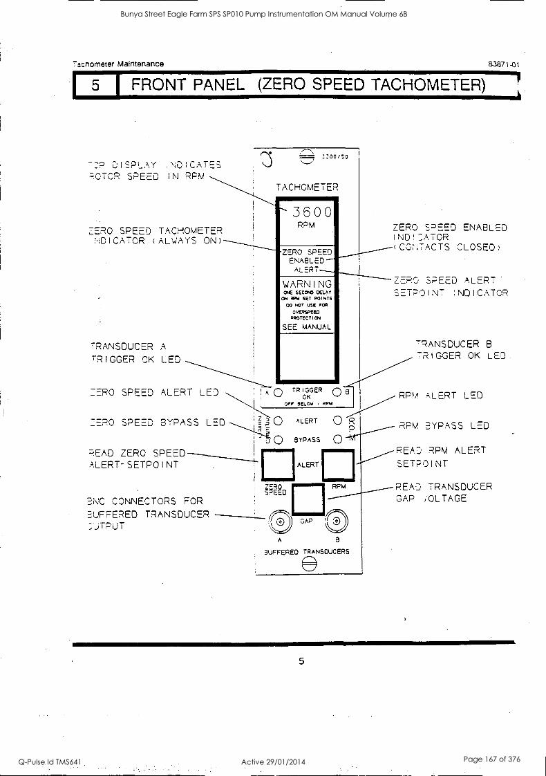
Tacnometer Maintenance 83871-01
I 5 I FRONT PANEL (ZERO SPEED TACHOMETER)
D I cPi Ay I CATES P.OTOR SPEED IN RPM
TACHOMETER
EERO SPEED TACHOMETER NDICATOR (ALWAYS ON)
TRANSDUCER A
TRIGGER OK LED
3600 RPM
ZERO SPEED ENABLED
ALERT
WARNING cte SECOND OELAY ON RPN SET POINTS
C.2 NOT USE FOR
ovERsPEED PROTECTION
SEE MANUAL
SPEED ALERT LED A 0
:ERO SPEED BYPASS LED .1.D
DO READ ZERO SPEED ALERT- SETPO I NT
NC CONNECTORS FOR SUFFERED TRANSDUCER ;:ji-PUT
TRIGGER O B OK
OFF SELOW i RIAd
ALERT
BYPASS
ALERT
ZERO SPEED ENABLED INDI:ATOR (COTACTS CLOSED)
ZERO SPEED ALERT SETPOINT :NDICATOR
0 R
0
A
GAP
RPM
BUFFERED TRANSDUCERS
TRANSDUCER B
TRIGGER OK LED.
RPM ALERT LED
RPM BYPASS LED
READ RPM ALERT SETPOINT
READ TRANSDUCER GAP ;OLTAGE
5
Bunya Street Eagle Farm SPS SP010 Pump Instrumentation OM Manual Volume 6B
Q-Pulse Id TMS641 Active 29/01/2014 Page 167 of 376

Tachometer Maintenance 33371 -01
6 I FRONT PANEL (ROTOR ACCEL. TACHOMETER)
TOP DISPIAY INDICATES ROTOR SPEED IN RPM
BOTTOM DISPLAY INDICATES ROTOR ACCEL=RATION IN
RPM/MIN
TRANSDUCER TRIGGER OK _ED
RPM/MIN ALERT LED
RPM/MIN BY P4SS LED
READ RPM/MIN ALERT SETPOINT
:300/50
TACHOMETER
3600 RPM
WARNING ONE SECCh0 DELAY
CN RPm SET POINTS
00 NOT USE FOR
oveRseeen PROTECTION
SEE MANUAL
-600 RPM/MIN
411111111M111111111 TRIGGER 0
OPP BELOW I .Pm OK
BNC CONNECTORS FOR BUFFERED TRANSDUCER OUTPUT
ALERT
BYPASS
ALERT
RPM/MIN
0 R
O P
GAP
RPM
A 3
BUFFERED TRANSDUCERS
9
TRANSDUCER B
TRIGGER OK LED
RPM ALERT LED
RPM BYPASS LED
READ RPM ALERT SETPOINT
READ TRANSDUCER GAP VOLTAGE
6
Bunya Street Eagle Farm SPS SP010 Pump Instrumentation OM Manual Volume 6B
Q-Pulse Id TMS641 Active 29/01/2014 Page 168 of 376
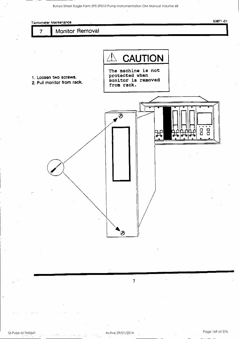
Tacnometer Maintenance 83871 -01
7 I Monitor Removal
1. Loosen two screws. 2. Pull monitor from rack.
/! CAUTION The machine is not protected when monitor is removed from rack.
Bunya Street Eagle Farm SPS SP010 Pump Instrumentation OM Manual Volume 6B
Q-Pulse Id TMS641 Active 29/01/2014 Page 169 of 376
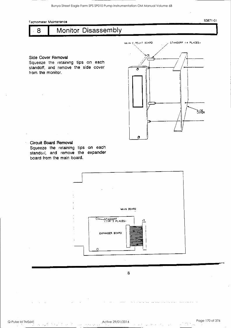
111M111MM/
/11111
Tachometer Maintenance 8.3871-01
I Monitor Disassembly
Side Cover Removal Squeeze the retaining tips on each standoff, and remove the side cover from the monitor.
Circuit Board Removal Squeeze the retaining tips on each standoti, and remove the expander board from the main board.
MAIN c.q4::.-NT 3CARO STANDOFF 14 PLACES)
MAIN BOARD
C'" _STANDOFF (TYP 3 PLACES
EXPANDER BOARD
0
.:3
I
4===axma
8
Bunya Street Eagle Farm SPS SP010 Pump Instrumentation OM Manual Volume 6B
Q-Pulse Id TMS641 Active 29/01/2014 Page 170 of 376
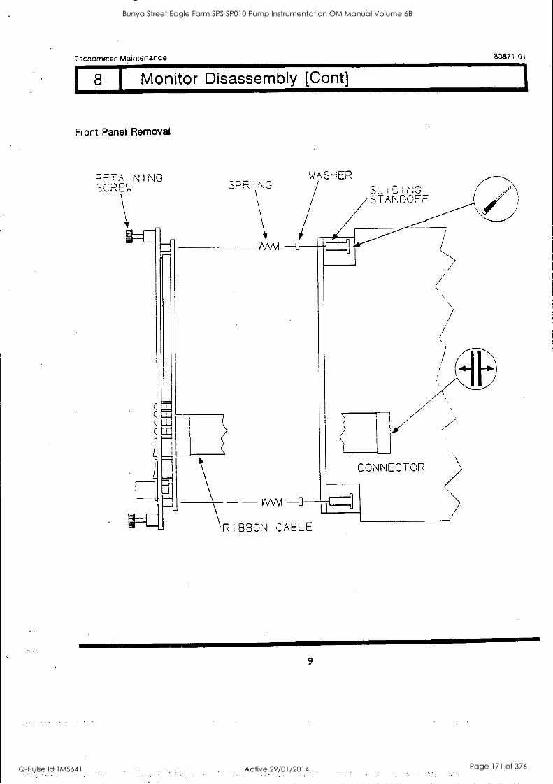
7acnometer Maintenance 23871-01
I. Monitor Disassembly [Cont]
Front Panel Removal
7,7=7AINING WASHER SLi-DINO STANDOFF /
CONNECTOR
RIBBON CABLE
9
Bunya Street Eagle Farm SPS SP010 Pump Instrumentation OM Manual Volume 6B
Q-Pulse Id TMS641 Active 29/01/2014 Page 171 of 376

Tachometer Maintenance 83871-01
9 1 Signal Input Relay Module
4\ WARNING High Voltage present Could cause shock, bums or death. Do Not touch exposed wires or terminals.
The Signal Input Relay Module is on the back of the rack. For relay configuration, see Installation Manual. For field wiring, see Section 29 (Field Wiring Diagrams).
Module Removal Loosen two screws and remove the module.
Module Options
Alert 1 Relay Jumper In Out
Normally Energized Normally De-energized
W3 W4,W1 1
W4,W11 W3
Alert 2 Relay Jumper In Out
Normally Energized Normally De-energized
W2 W1,W12 W1,W12 W2
Alert Relays
Alert 1 Relay Alert 2 Relay
Tc.1
in O
Tachometer Type Dual Set oint Zero Speed Rotor Accel
RPM Alert 1 RPM Alert RPM Alert
RPM Alert 2 Zero Speed RPM/MIN Alert Alert
10
Bunya Street Eagle Farm SPS SP010 Pump Instrumentation OM Manual Volume 6B
Q-Pulse Id TMS641 Active 29/01/2014 Page 172 of 376

Tachometer Maintenance 83871-01
110 I Monitor Options
TACHOMETER PART NUMBER
TACHOMETER TYPE
3300/50 AA
ALERT RELAYS
BB
AGENCY APPROVAL BARRIERS
CC DD
01 = DUAL SETPOINT 00 = NONE 00 = NOT REQ'D 00 = NO BARRIERS
TACHOMETER 01 = 5 AMP EPDXY 01 = CSA 01 = EXTERNAL
SEALED BARRIERS
02 = ZERO SPEED 02 = BASEEFA 02 = INTERNAL BARRIERS
TACHOMETER 02 = 5 AMP 03 = FACTORY
03 = ROTOR HERMETICALLY MUTUAL
ACCELERATION SEALED .TACHOMETER
The Tachometer has several user-programmable options. The options can be changed by removing
and installing jumpers.
W16 uoi S J
Y
WI 7
J4
518
JI
ta
Jumper Locations On Main Circuit Board
11
Bunya Street Eagle Farm SPS SP010 Pump Instrumentation OM Manual Volume 6B
Q-Pulse Id TMS641 Active 29/01/2014 Page 173 of 376
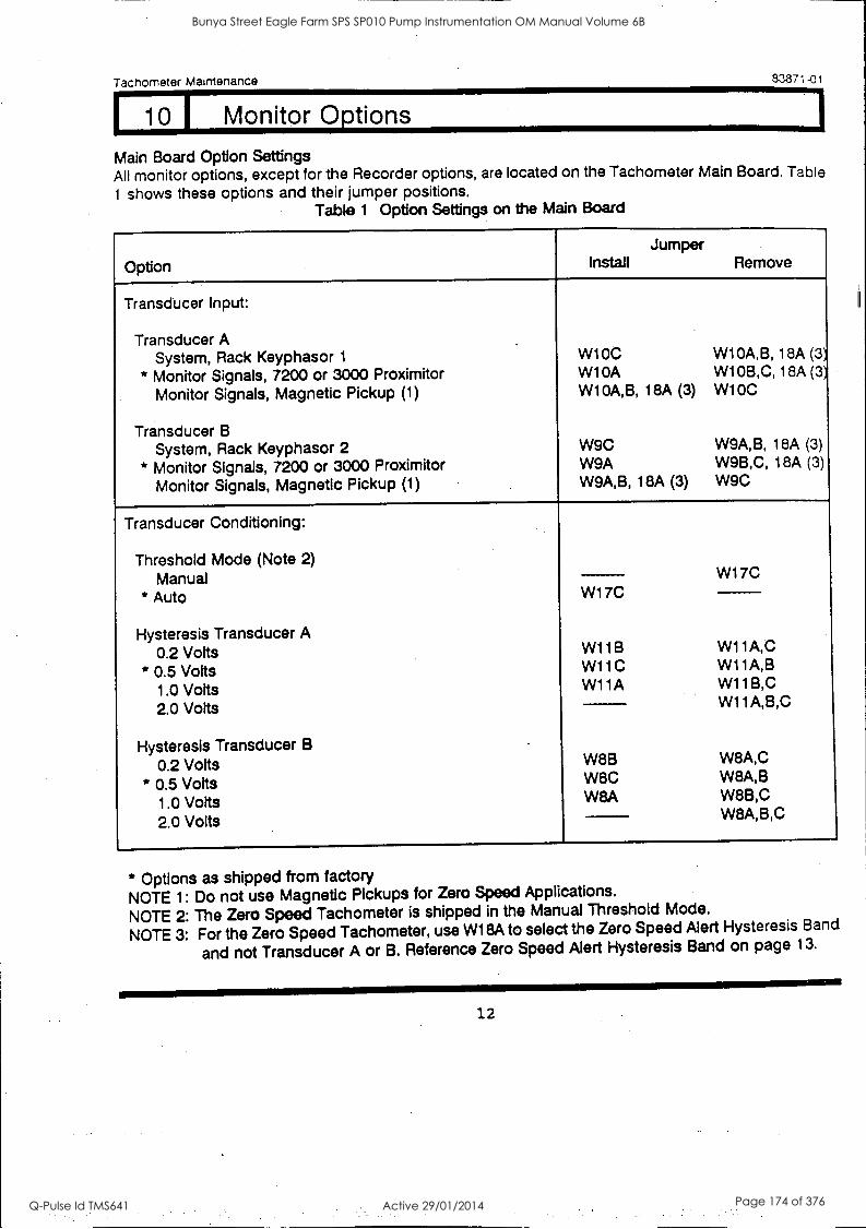
Tachometer Maintenance 83871-01
10 j Monitor Options
Main Board Option Settings All monitor options, except for the Recorder options, are located on the Tachometer Main Board. Table
I shows these options and their jumper positions. Table 1 Option Settings on the Main Board
Option
Jumper Install Remove
Transducer Input:
Transducer A System, Rack Keyphasor 1 W1 0C W10A,B, 18A (3)
* Monitor Signals, 7200 or 3000 Proximitor Monitor Signals, Magnetic Pickup (1)
W10A W10A,B, 18A (3)
W10B,C, 18A (3',
W10C
Transducer B System, Rack Keyphasor 2 W9C W9A,B, 18A (3)
* Monitor Signals, 7200 or 3000 Proximitor W9A W9B,C, 18A (3)
Monitor Signals, Magnetic Pickup (1) W9A,B, 18A (3) W9C
Transducer Conditioning:
Threshold Mode (Note 2)
Manual W17C
* Auto W17C
Hysteresis Transducer A 0.2 Volts W118 W11A,C
* 0.5 Volts W11C W11A,B
1.0 Volts W11A W11B,C
2.0 Volts W11A,B,C
Hysteresis Transducer B
0.2 Volts W8B W8A,C
* 0.5 Volts W8C W8A,B
1.0 Volts W8A W8B,C
2.0 Volts W8A,B,C
* Options as shipped from factory NOTE 1: Do not use Magnetic Pickups for Zero Speed Applications.
NOTE 2: The Zero Speed Tachometer is shipped in the Manual Threshold Mode.
NOTE 3: For the Zero Speed Tachometer, use W18A to select the Zero Speed Alert Hysteresis Band
and not Transducer A or B. Reference Zero Speed Alert Hysteresis Band on page 13.
12
Bunya Street Eagle Farm SPS SP010 Pump Instrumentation OM Manual Volume 6B
Q-Pulse Id TMS641 Active 29/01/2014 Page 174 of 376
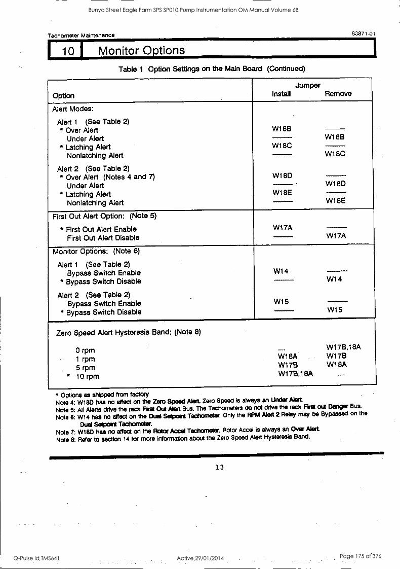
Tachometer Maintenance
10 j Monitor Options
a3871-01
Table 1 Option Settings on the Main Board (Continued)
Option
Jumper Install Remove
Alert Modes:
Alert 1 (See Table 2)
* Over Alert Under Alert
* Latching Alert Nonlatching Alert
Alert 2 (See Table 2) * Over Alert (Notes 4 and 7)
Under Alert * Latching Alert
Nonlatching Alert
W188 W1 8B
W1 8C W1 8C
W1 8D W1 8D
WISE W1 8E
First Out Alert Option: (Note 5)
* First Out Alert Enable First Out Alert Disable
W17A W1 7A
Monitor Options: (Note 6)
Alert 1 (See Table 2) Bypass Switch Enable
* Bypass Switch Disable
Alert 2 (See Table 2) .
Bypass Switch Enable * Bypass Switch Disable
W14 W14
W15 W15
Zero Speed Alert Hysteresis Band: (Note 8)
0 rpm 1 rpm W1 8A
5 rpm W1 7B
* 10 rpm W178,1 8A
W17B,18A W178 W1 8A
* Options as shipped from factory Note 4: W180 has no affect on the Zero Speed Alert. Zero Speed is always an Under Alert
Note 5: All Alerts drive the rack Fist Out Alert Bus. The Tachometers do not drive the rack First out Danger Bus.
Note 6: W14 has no affect on the Duel Setpoint Tachometer. Only the RP1A Alert 2 Relay may be Bypassed on the
Dual Setpoint Tachometer. Note 7: W180 has no affect on the Rotor Accel Tachometer. Rotor Accel is always an Over Alert
Note 8: Refer to section 14 for more information about the Zero Speed Alert Hysteresis Band.
13
Bunya Street Eagle Farm SPS SP010 Pump Instrumentation OM Manual Volume 6B
Q-Pulse Id TMS641 Active 29/01/2014 Page 175 of 376
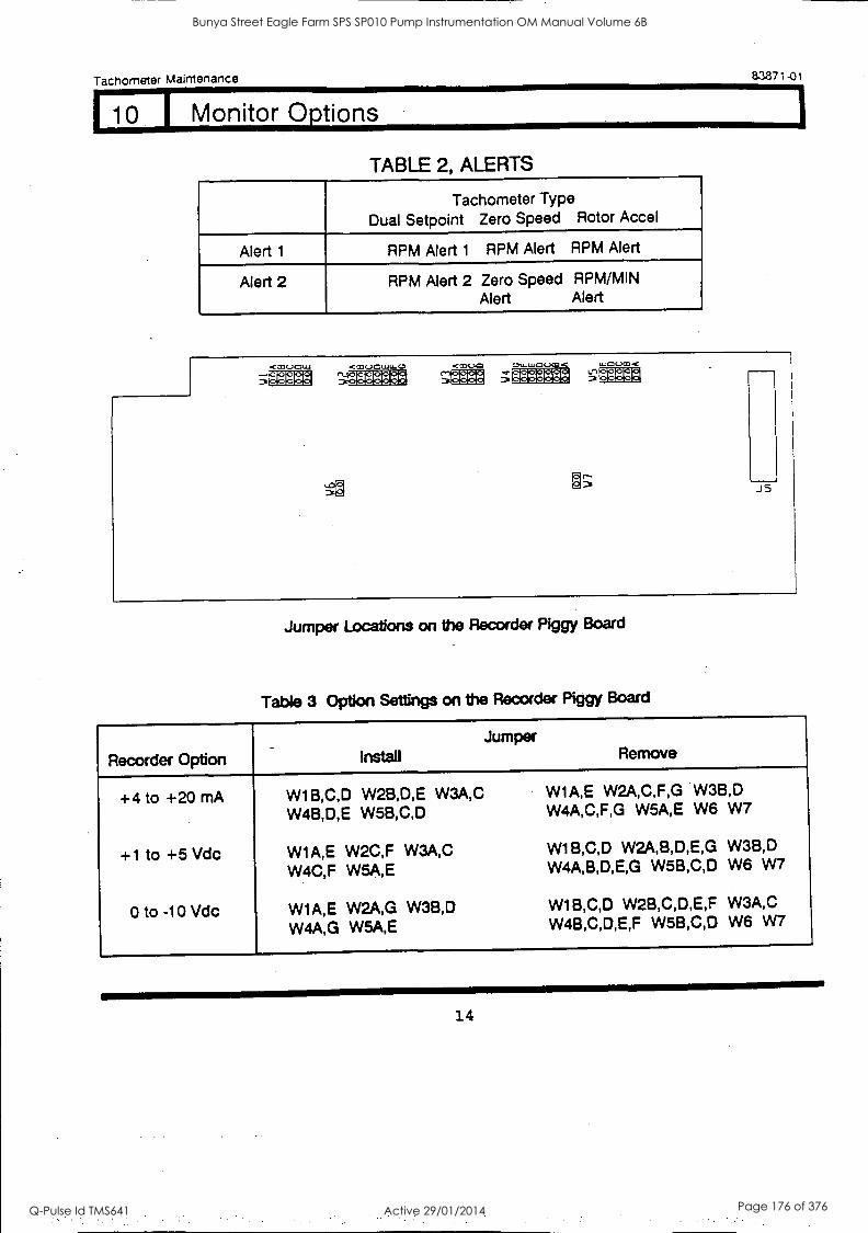
Tachometer Maintenance 83871-01
1 10 1 Monitor Options
TABLE 2, ALERTS
Tachometer Type Dual Setpoint Zero Speed Rotor Accel
Alert 1 RPM Alert 1 RPM Alert RPM Alert
Alert 2 RPM Alert 2 Zero Speed RPM/MIN Alert Alert
IC 3ffia ;ff2M &-'12ffl
Jumper Locations on the Recorder Piggy Board
Table 3 Option Settings on the Recorder Piggy Board
Recorder Option Install Jumper
Remove
+4 to +20 mA
+1 to +5 Vdc
0 to -10 Vdc
W1B,C,D W2B,D,E W3A,C W4B,D,E W5B,C,D
W1A,E W2C,F W3A,C W4C,F W5A,E
W1A,E W2A,G W3B,D W4A,G W5A,E
W1A,E W2A,C,F,G W3B,D W4A,C,F,G W5A,E W6 W7
W1B,C,D W2A,B,D,E,G W3B,D W4A,B,D,E,G W5B,C,D W6 W7
W1B,C,D W2B,C,D,E,F W3A,C W4B,C,D,E,F W5B,C,D W6 W7
14
Bunya Street Eagle Farm SPS SP010 Pump Instrumentation OM Manual Volume 6B
Q-Pulse Id TMS641 Active 29/01/2014 Page 176 of 376
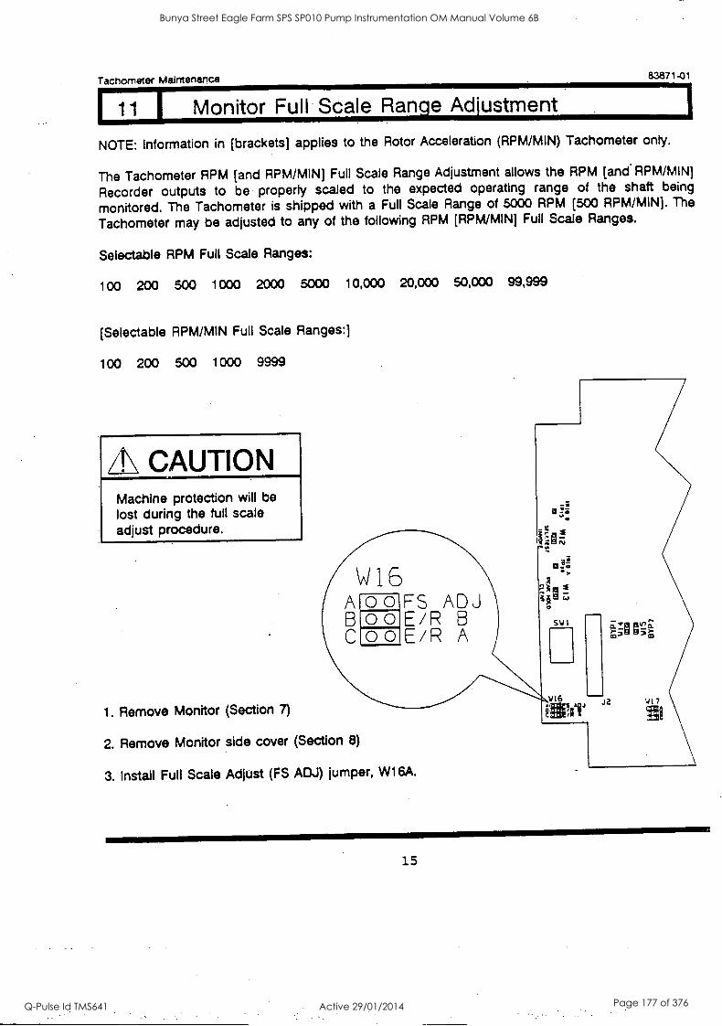
Tachometer Maintenance 83871-01
11 1 Monitor Full Scale Range Adjustment
NOTE: Information in [brackets] applies to the Rotor Acceleration (RPM/MIN) Tachometer only.
The Tachometer RPM [and RPM/MIN) Full Scale Range Adjustment allows the RPM [and RPM/MIN)
Recorder outputs to be properly scaled to the expected operating range of the shaft being
monitored. The Tachometer is shipped with a Full Scale Range of 5000 RPM [500 RPM /MIN). The
Tachometer may be adjusted to any of the following RPM [RPM/MIN) Full Scale Ranges.
Selectable RPM Full Scale Ranges:
100 200 500 1000 2000 5000 10,000 20,000 50,000 99,999
[Selectable RPM/MIN Full Scale Ranges:)
100 200 500 1000 9999
ZE CAUTION Machine protection will be lost during the full scale adjust procedure.
W15 A o o FS ADJ B o o E/R B C,o o E/R A
1. Remove Monitor (Section 7)
2. Remove Monitor side cover (Section 8)
3. Install Full Scale Adjust (FS ADJ) jumper, W16A.
V16 J2 \J I 7
15
Bunya Street Eagle Farm SPS SP010 Pump Instrumentation OM Manual Volume 6B
Q-Pulse Id TMS641 Active 29/01/2014 Page 177 of 376

Tachometer Maintenance 83871-01
11 1 Monitor Full Scale Range Adjustment (Cont)
4. Install Monitor in Rack. The RPM (and RPM/MIN] display will show the current RPM [and RPM/MIN) Full Scale Range.
5. Set Switch 6 (ER) to the "ON" position. The RPM [and RPM/MIN] display flash the current RPM [and RPM/MIN] Full Scale Range.
6. To adjust the RPM Full Scale Range, press and hold the right Alert switch on the front panel. The RPM Full Scale Range will remain flashing.
7. Use the (t) or (I) switches on the System Monitor to adjust the RPM Full Scale Range.
%MON
T A CHCMET ER
/1 5000
A
2: Co4
IA 01
ON OFF
SYSTEM hICN I TOR
O
O
e
16
Bunya Street Eagle Farm SPS SP010 Pump Instrumentation OM Manual Volume 6B
Q-Pulse Id TMS641 Active 29/01/2014 Page 178 of 376

Tachometer Maintenance 83871-01
11 I Monitor Full. Scale Range Adjustment Cont)
[81 To adjust the RPM/MIN Full Scale Range, press and hold the left Alert switch on the front panel. The RPM/MIN Full Scale Range ' will remain flashing.
[9.1 Use the (t) or (I) switches on the System Monitor to adjust the RPM/MIN Full Scale Range.
S/STEU UCNI TCR
O .11YLTIPLT
t27 POOR *01157 4,
10. When the correct Full Scale Range has been selected, reset Switch 6 (ER) to the OFF position. This will lock the Full Scale Range into permanent memory.
5000 .p.,
500 RPM/PIN
11. Remove Monitor from Rack.
12. Remove the Full Scale Adjust Jumper, W16A. L_
13. Install Monitor side cover.
14. Install Monitor in Rack.
4=IMMINIIMM
17
Bunya Street Eagle Farm SPS SP010 Pump Instrumentation OM Manual Volume 6B
Q-Pulse Id TMS641 Active 29/01/2014 Page 179 of 376
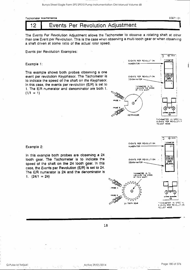
Tacnometer Martenance 83871 -01
12 I Events Per Revolution Adjustment
The Events Per Revolution Adjustment allows the Tachometer to observe a rotating shaft at other than one Event per Revolution. This is the case when observing a multi-tooth gear or when observing a shaft driven at some ratio of the actual rotor speed.
Events per Revolution Examples:
Example 1:
This example shows both probes observing a one event per revolution Keyphasor. The Tachometer is
to indicate the speed of the shaft on the Keyphasor. In this case, the events per revolution (E/R) is set to 1. The E/R numerator and denominator are both 1.
(1/1 = 1)
Example 2:
In this example both probes are observing a 24
tooth gear. The Tachometer is to indicate the
speed of the shaft on the 24 tooth gear. In this
case, the Events per Revolution (E/R) is set to 24.
The E/R numerator is 24 and the denominator is
1. (24/1 = 24)
EVENTS PER PEVOLUT'r:"N
NUMERATOR OW
EVENTS PER REVOLUTION
CENOmiNATOR
TACHOMETER IS TO INDICATE THE SPEED OF THIS SHAFT
11=11NI
TACHOMETER IN SPEC :AL EVENTS PER REVOLUTP,, ADJUST MODE
EVENTS PER REVOLUTION NUMERATOR 411.
EVENTS PER REVOLUTION
DENOMINATOR
TACHOMETER IS TO INDICATE THE SPEED OF THIS SHAFT
"Aci.oyETER
24
I.EN. M.110/3111111
-4CHCvETER IN SPEC; AL
',ENTS PER REVOLUTION AO.,LST mOOE
18
Bunya Street Eagle Farm SPS SP010 Pump Instrumentation OM Manual Volume 6B
Q-Pulse Id TMS641 Active 29/01/2014 Page 180 of 376

Tachometer Maintenance 2.3871 -01
12 I Events Per Revolution Adjustment (Cont)
Example 3:
In this example, both probes are observing an eleven tooth gear being driven from a 24 tooth gear. The Tachometer is to indicate the speed of the shaft on the 24 tooth gear. In
this case, the Events per Revolution (E/R) is
set to 24. Although the probes are observing the eleven tooth gear, they still detect 24 events per one turn of the indicated shaft. The E/R numerator is set to 24 and the denominator is set to 1. (24/1 = 24)
Example 4:
In this example, both probes are observing a one event per revolution Keyphasor on the same shaft with an eleven tooth gear. The eleven tooth gear is driven from a 24 tooth gear. The Tachometer is to indicate the speed of the shaft on the 24 tooth gear. In this case, the Events per Revolution (E/R) is 24/11. For each revolution of the indicated shaft, the Keyphasor will rotate 24/11 revolutions. The E/R numerator is set to 24 and the denominator is set to 11.
EVENTS PER REVOLUTION
%L.NERATOR
EVENTS PER REVOLUTION
ZENOMINATOR
II TOOTH CEA*
TACWAIETEP I IM
24
VINING
TACHOMETER IN SPECIAL EVENTS PER REVOLUTION ADJUST MOPE
EVENTS PER REVOLUTION
'AJAERATOR
EVENTS PER REVOLUTION
ZENOmiNATOR
TmoCmETER I S TO
,NOICATE THE SPEED. OF THIS SHAFT
> s
2' TOOTH GEAR
KETI.I4S011
BOTH POOBES OBSUN polo
VPHAS041
- T40.4414'12,
24
VA/041.3
TAorOmETER IN SPECIAL
EVENTS PER REVOLUTION ADJUST 'Axe
19
Bunya Street Eagle Farm SPS SP010 Pump Instrumentation OM Manual Volume 6B
Q-Pulse Id TMS641 Active 29/01/2014 Page 181 of 376
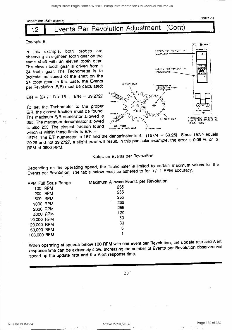
Tachometer Maintenance. 83871-01
12 1 Events Per Revolution Adjustment (Cont)
Example 5:
In this example, both probes are
observing an eighteen tooth gear on the
same shaft with an eleven tooth gear.
The eleven tooth gear is driven from a
24 tooth gear. The Tachometer is to
indicate the speed of the shaft on the
24 tooth gear. In this case, the Events
per Revolution (E/R) must be calculated:
E/R = (24 / 11) x 18 ; E/R = 39.2727
To set the Tachometer to the proper E/R, the closest fraction must be found.
.4c6E
I 11,11= ..M1111
The maximum E/R numerator allowed is
255. The maximum denominator allowed a4 TOOTH GEAR
is also 255. The closest fraction found 90TH PPlees GEM le room ;e roon4 m Gem
which is within these limits is E/R = cesERvimo
157/4. The E/R numerator is 157 and the denominator is 4. (157/4 = 39.25) Since 157/4 equals
39.25 and not 39.2727, a slight error will result. In this particular example, the error is 0.06 %, or 2
RPM at 3600 RPM.
TOON GEAR TAo.owETER ,S TO
,ho,cAre The SPEED OF rm.e SHAFT
E'lENTS DER DE',C1..;7.)N NLUERArCR OW
EVENTS REP PEVOLUT!:N
C.ENOMINATCR
57
7ACHOmerER IN SPECIAL
E'iENTS PER REVGLuT:oN ADJUST 1.00E
Notes on Events per Revolution
Depending on the operating speed, the Tachometer is limited to certain
Events per Revolution. The table below must be adhered to for +/- 1 RPM
RPM Full Scale Range Maximum Allowed Events per Revolution
100 RPM 255
200 RPM 255
500 RPM 255
1000 RPM 255
2000 RPM 255
5000 RPM 120
10,000 RPM 60
20,000 RPM 30
50,000 RPM 6
100,000 RPM 1
maximum values for the
accuracy.
When operating at speeds below 100 RPM with one Event per Revolution, the update rate and Alert
response time can be extremely slow. Increasing the number of Events per Revolution observed will
speed up the update rate and the Alert response time.
20'
Bunya Street Eagle Farm SPS SP010 Pump Instrumentation OM Manual Volume 6B
Q-Pulse Id TMS641 Active 29/01/2014 Page 182 of 376
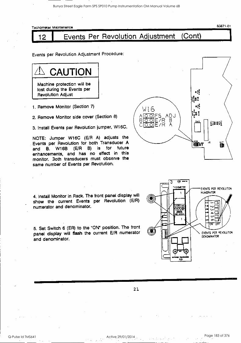
Tachometer Maintenance 83871-01
12 I Events Per Revolution Adjustment (Cont)
Events per Revolution Adjustment Procedure:
CAUTION Machine protection will be lost during the Events per Revolution Adjust
1. Remove Monitor (Section 7) A/ 16
2. Remove Monitor side cover (Section 8) A o 0 FS ADJ B 00 EiR B
3. Install Events per Revolution jumper, W16C. C oo EiR A
NOTE: Jumper W16C (E/R A) adjusts the
Events per Revolution for both Transducer A
and B. W168 (E/R B) is for future enhancements, and has no effect in this monitor. 3oth transducers must observe the
same number of Events per Revolution.
4. Install Monitor in Rack. The front panel display will
show the current Events per Revolution (E/R)
numerator and denominator.
5. Set Switch 6 (ER) to the "ON" position. The front
panel display will flash the current E/R numerator
and denominator.
ACMOIE TER EVENTS PM REVOLUTION
NUMERATOR
..AEI I NIG
enrarAr
SMI
AI" EVENTS PER REVOLUTION
DENONINATOR
21
Bunya Street Eagle Farm SPS SP010 Pump Instrumentation OM Manual Volume 6B
Q-Pulse Id TMS641 Active 29/01/2014 Page 183 of 376
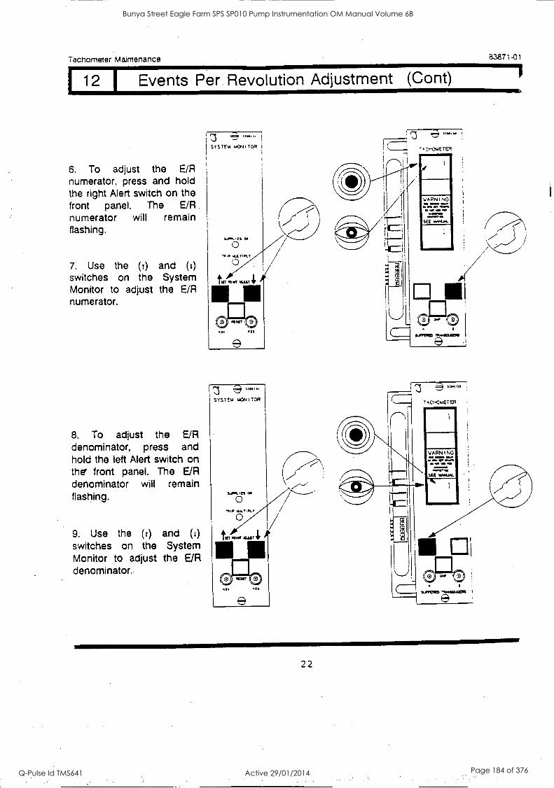
Tachometer Maintenance
12 I Events Per. Revolution Adjustment
6. To adjust the E/R numerator, press and hold the right Alert switch on the front panel. The E/R numerator will remain flashing.
7. Use the (t) and (1)
switches on the System Monitor to adjust the E/R numerator.
8. To adjust the E/R denominator, press and hold the left Alert switch on the' front panel. The E/R denominator will remain flashing.
9. Use the (r) and (L)
switches on the System Monitor to adjust the E/R denominator.
U./. SYSTEM mCN;TOR I
SYSTEM MCNITOR
CO
Mt* WILT Ilk/ O
II 3
83871-01
Cont)
22
Bunya Street Eagle Farm SPS SP010 Pump Instrumentation OM Manual Volume 6B
Q-Pulse Id TMS641 Active 29/01/2014 Page 184 of 376

Tachometer Maintenance 8387' -3
12 Events Per Revolution Adjustment (Cont)
10. When the correct Events per Revolution numerator and denominator have been selected, reset Switch 6
(ER) to the OFF position. This will lock the E/R into permanent memory.
11. Remove Monitor from Rack.
12. Remove the E/R Jumper, W16C.
13. Install Monitor side cover.
14. install Monitor in Rack.
A
77,1 2 LA 1-71 Ne 171 .
m ul
CN OFF
23
Bunya Street Eagle Farm SPS SP010 Pump Instrumentation OM Manual Volume 6B
Q-Pulse Id TMS641 Active 29/01/2014 Page 185 of 376
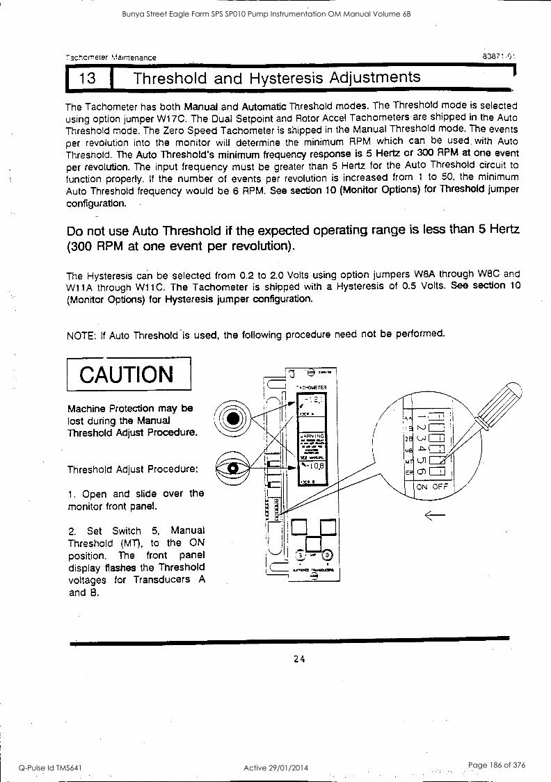
73cnorreter Maintenance 83871-01
13 1 Threshold and Hysteresis Adjustments
The Tachometer has both Manual and Automatic Threshold modes. The Threshold mode is selected using option jumper W1 7C. The Dual Setpoint and Rotor Accei Tachometers are shipped in the Auto
Threshold mode. The Zero Speed Tachometer is shipped in the Manual Threshold mode. The events
per revolution into the monitor will determine the minimum RPM which can be used with Auto
Threshold. The Auto Threshold's minimum frequency response is 5 Hertz or 300 RPM at one event
per revolution. The input frequency must be greater than 5 Hertz for the Auto Threshold circuit to
function properly. If the number of events per revolution is increased from 1 to 50, the minimum
Auto Threshold frequency would be 6 RPM. See section 10 (Monitor Options) for Threshold jumper
configuration.
Do not use Auto Threshold if the expected operating range is less than 5 Hertz
(300 RPM at one event per revolution).
The Hysteresis can be selected from 0.2 to 2.0 Volts using option jumpers W8A through W8C and
Wi 1 A through W11C. The Tachometer is shipped with a Hysteresis of 0.5 Volts. See section 10
(Monitor Options) for Hysteresis jumper configuration.
NOTE: If Auto Threshold is used, the following procedure need not be performed.
CAUTION Machine Protection may be lost during the Manual Threshold Adjust Procedure.
Threshold Adjust Procedure:
1. Open and slide over the monitor front panel.
2. Set Switch 5, Manual Threshold (MT), to the ON position. The front panel display flashes the Threshold voltages for Transducers A and B.
24
Bunya Street Eagle Farm SPS SP010 Pump Instrumentation OM Manual Volume 6B
Q-Pulse Id TMS641 Active 29/01/2014 Page 186 of 376
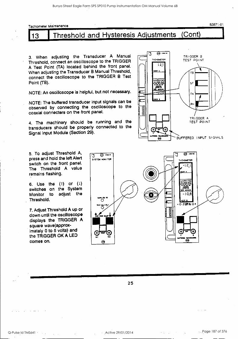
Tachometer Maintenance 83871-01
113 I Threshold and Hysteresis Adjustments (Cont)
3. When adjusting the Transducer A Manual
Threshold, connect an oscilloscope to the TRIGGER
A Test Point (TA) located behind the front panel.
When adjusting the Transducer B Manual Threshold,
connect the oscilloscope to the TRIGGER B Test
Point (TB).
NOTE: An oscilloscope is helpful, but not necessary.
NOTE: The buffered transducer input signals can be
observed by connecting the oscilloscope to the
coaxial connecters on the front panel.
4. The machinery should be running and the
transducers should be property connected to the
Signal Input Module (Section 29).
5. To adjust Threshold A,
press and hold the left Alert switch on the front panel. The Threshold A value remains flashing.
6. Use the (t) or (1)
switches on the System Monitor to adjust the Threshold.
7. Adjust Threshold A up or down until the oscilloscope displays the TRIGGER A
square wave(approx- imately 0 to 5 volts) and the TRIGGER OK A LED
comes on.
e SYSTEM MONITOR
AP-OdETER
12.1
WARN I NO
www .4111111
TRIGGER B TEST POINT
1 0 II TRIGGER A
II TEST POINT
.,:.......... e BUFFERED INPUT SIGNALS
25
Bunya Street Eagle Farm SPS SP010 Pump Instrumentation OM Manual Volume 6B
Q-Pulse Id TMS641 Active 29/01/2014 Page 187 of 376
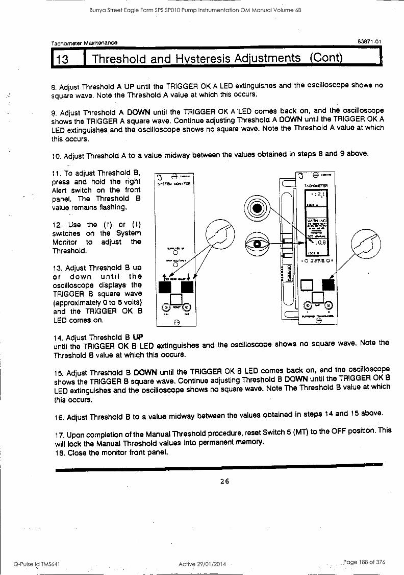
Tachometer Maintenance 83871-01
113 I Threshold and Hysteresis Adjustments (Cont)
8. Adjust Threshold A UP until the TRIGGER OK A LED extinguishes and the oscilloscope shows no
square wave. Note the Threshold A value at which this occurs.
9. Adjust Threshold A DOWN until the TRIGGER OK A LED comes back on, and the oscilloscope
shows the TRIGGER A square wave. Continue adjusting Threshold A DOWN until the TRIGGER OK A
LED extinguishes and the oscilloscope shows no square wave. Note the Threshold A value at which
this occurs.
10. Adjust Threshold A to a value midway between the values obtained in steps 8 and 9 above.
11. To adjust Threshold B,
press and hold the right Alert switch on the front panel. The Threshold B
value remains flashing.
12. Use the ( t) or (1)
switches on the System Monitor to adjust the Threshold.
13. Adjust Threshold B up or down until the oscilloscope displays the TRIGGER B square wave (approximately 0 to 5 volts) and the TRIGGER OK B
LED comes on.
14. Adjust Threshold B UP until the TRIGGER OK B LED extinguishes Threshold B value at which this occurs.
and the oscilloscope shows no square wave. Note the
15. Adjust Threshold B DOWN until the TRIGGER OK B LED comes back on, and the oscilloscope
shows the TRIGGER B square wave. Continue adjusting Threshold B DOWN until the TRIGGER OK B
LED extinguishes and the oscilloscope shows no square wave. Note The Threshold B value at which
this occurs.
16. Adjust Threshold B to a value midway between the values obtained in steps 14 and 15 above.
17. Upon completion of the Manual Threshold procedure, reset Switch 5 (MT) to the OFF position. This
will lock the Manual Threshold values into permanent memory.
18. Close the monitor front panel.
26
Bunya Street Eagle Farm SPS SP010 Pump Instrumentation OM Manual Volume 6B
Q-Pulse Id TMS641 Active 29/01/2014 Page 188 of 376
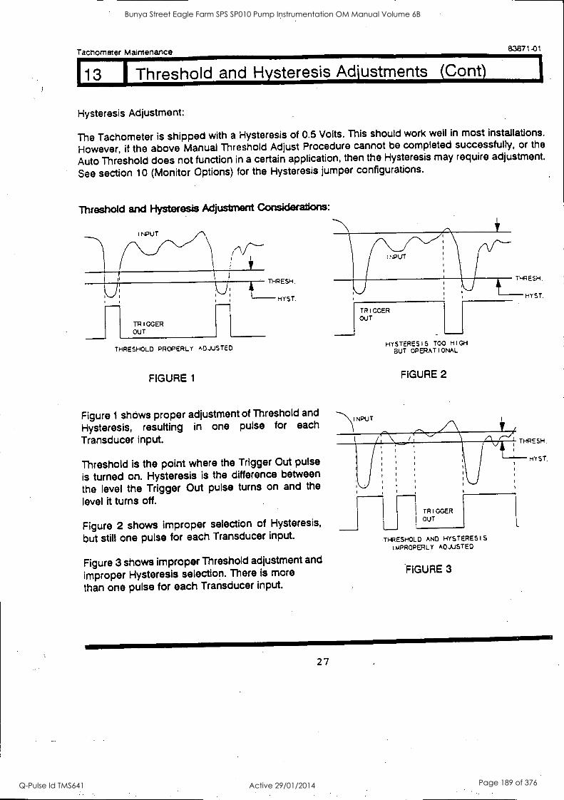
Tachometer Maintenance 83871-01
113 1 Threshold and Hysteresis Adjustments (Cant)
Hysteresis Adjustment:
The Tachometer is shipped with a Hysteresis of 0.5 Volts. This should work well in most installations.
However, if the above Manual Threshold Adjust Procedure cannot be completed successfully, or the
Auto Threshold does not function in a certain application, then the Hysteresis may require adjustment.
See section 10 (Monitor Options) for the Hysteresis jumper configurations.
Threshold and Hysteresis Adjustment Considerations:
INPUT
TRIGGER OUT
THRESH.
THRESHOLD PROPERLY ADJUSTED
FIGURE 1
Figure 1 shows proper adjustment of Threshold and
Hysteresis, resulting in one pulse for each
Transducer input.
Threshold is the point where the Trigger Out pulse
is turned on. Hysteresis is the difference between
the level the Trigger Out pulse turns on and the
level it turns off.
Figure 2 shows improper selection of Hysteresis,
but still one pulse for each Transducer input.
Figure 3 shows improper Threshold adjustment and
improper Hysteresis selection. There is more
than one pulse for each Transducer input.
INPUT
TRIGGER OUT
THRESH.
HYSTERESIS TOO HIGH BUT OPERATIONAL
FIGURE 2
MYST
TRIGGER OUT
THRESHOLD AND HYSTERESIS IMPROPERLY ADJUSTED
FIGURE 3
27
Bunya Street Eagle Farm SPS SP010 Pump Instrumentation OM Manual Volume 6B
Q-Pulse Id TMS641 Active 29/01/2014 Page 189 of 376
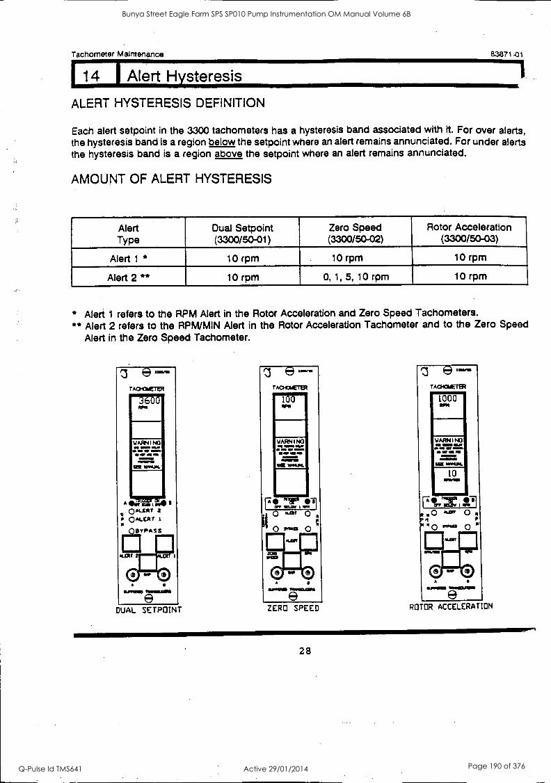
Tachometer Maintenance 8.3871-01
14 1 Alert Hysteresis
ALERT HYSTERESIS DEFINITION
Each alert setpoint in the 3300 tachometers has a hysteresis band associated with it. For over alerts, the hysteresis band is a region below the setpoint where an alert remains annunciated. For under alerts the hysteresis band is a region above the setpoint where an alert remains annunciated.
AMOUNT OF ALERT HYSTERESIS
Alert Dual Setpoint Zero Speed Rotor Acceleration Type (3300/50-01) (3300/50-02) (3300/50-03)
Alert 1 * 10 rpm . 10 rpm ..-
10 rpm
Alert 2 ** 10 rpm 0, 1, 5, 10 rpm 10 rpm
* Alert 1 refers to the RPM Alert in the Rotor Acceleration and Zero Speed Tachometers. ** Alert 2 refers to the RPM/MIN Alert in the Rotor Acceleration Tachometer and to the Zero Speed
Alert in the Zero Speed Tachometer.
DUAL SETPOINT ZERO SPEED ROTOR ACCELERATION
28
Bunya Street Eagle Farm SPS SP010 Pump Instrumentation OM Manual Volume 6B
Q-Pulse Id TMS641 Active 29/01/2014 Page 190 of 376
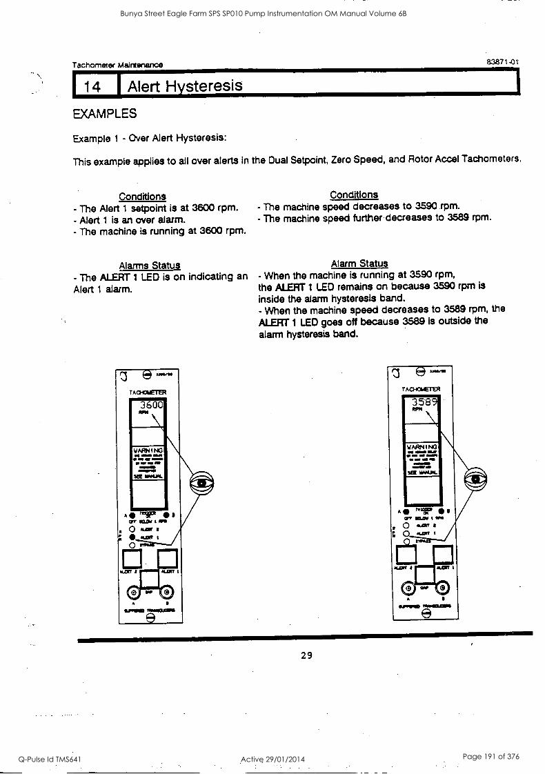
Tachometer Maintenance 83871-01
114 I Alert Hysteresis
EXAMPLES
Example 1 - Over Alert Hysteresis:
This example applies to all over alerts in the Dual Setpoint, Zero Speed, and Rotor Accel Tachometers.
Conditions - The Alert 1 setpoint is at 3600 rpm. - Alert 1 is an over alarm. - The machine is running at 3600 rpm.
Alarms Status - The ALERT 1 LED is on indicating an
Alert 1 alarm.
esawn ACHCSETER
PFMMI
Conditions - The machine speed decreases to 3590 rpm. - The machine speed further decreases to 3589 rpm.
Alarm Status - When the machine is running at 3590 rpm, the ALERT 1 LED remains on because 3590 rpm is
inside the alarm hysteresis band. - When the machine speed decreases to 3589 rpm, the
ALERT 1 LED goes off because 3589 is outside the
alarm hysteresis band.
e ACHOMETER
OPPIPID
29
Bunya Street Eagle Farm SPS SP010 Pump Instrumentation OM Manual Volume 6B
Q-Pulse Id TMS641 Active 29/01/2014 Page 191 of 376

Tachometer Maintenance 83871-01
14 [ Alert Hysteresis
Example 2 - Under Alert Hysteresis:
This example applies to all over alerts in the Dual Setpoint, Zero Speed, and Rotor Acceleration Tachometers with the exception of the Zero Speed Alert in the Zero Speed Tachometer.
CONDMONS CONDITIONS
- The RPM Alert setpoint is at 1000 rpm. - The RPM Alert is under alarm. - The machine is running at 1000 rpm.
Alarms Status
- The RPM ALERT LED is on indicating an RPM alert.
eurnam TRANCLOPII
- The machine speed increases to 1010 rpm. - The machine speed further increases to 1011 rpm.
Alarm Status
- When the machine is running at 1010 rpm, the monitor remains in an RPM Alert because 1010 rpm is inside the hysteresis band. - When the machine speed increases to 1011 rpm,the RPM ALERT LED goes oft because 1011 is outside the hysteresis band.
30
Bunya Street Eagle Farm SPS SP010 Pump Instrumentation OM Manual Volume 6B
Q-Pulse Id TMS641 Active 29/01/2014 Page 192 of 376

Tachometer Maintenance 83871-01
14 I Alert Hysteresis
Example 3 - The Zero Speed Alert Hysteresis (1rpm):
You can set the Zero Speed Alert Hysteresis at 0, 1, 5, or 10 rpm. Section 10 (Monitor Options)
describes how to select the Zero Speed Alert Hysteresis.
Conditions
- The Zero Speed Alert setpoint is at 100 rpm - The machine is running at 100 rpm. - The Zero speed Alert Hysteresis is at 1
rpm.
Alarms status
- The Zero Speed Alert LED is on indicating a Zero Speed Alert.
e TA0-04ETER
100
MCI In't I OWILLO
WARNING
In MP a an 11Mb =IMMO
Sel **SAL
,111 /fly 41171 Crr WIN 1!M
11/1.1111110 110MIll
Conditions
- The machine speed increases to 101 rpm. - The machine speed further increases to 102 rpm.
Alarm status
- When the machine is running at 101 rpm,
the Zero Speed Alert LED remains on because 101
rpm is in the Zero Speed Alert hysteresis band. - When the machine speed increases to 102 rpm, the Zero Speed Alert LED goes off because 102 is outside
the Zero Speed Alert hysteresis band.
TACHOMETER
102
111
NOTE: The RPM Alert in the Zero Speed Tachometer always has a hysteresis band of 10 rpm.
31
Bunya Street Eagle Farm SPS SP010 Pump Instrumentation OM Manual Volume 6B
Q-Pulse Id TMS641 Active 29/01/2014 Page 193 of 376
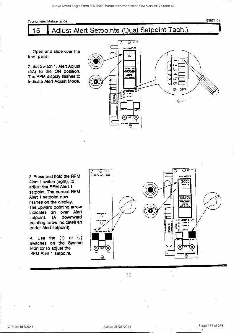
Tachometer Maintenance 83871-01
115 1 Adjust Alert Setpoints (Dual Setpoint Tach.)
1. Open and slide over the front panel.
2. Set Switch 1, Alert Adjust (AA) to the ON position. The RPM display flashes to indicate Alert Adjust Mode.
3. Press and hold the RPM Alert 1 switch (right), to adjust the RPM Alert 1
setpoint. The current RPM Alert 1 setpoint now flashes on the display. The upward pointing arrow indicates an over Alert setpoint. (A downward pointing arrow indicates an
under Alert setpoint).
4. Use the (1) or (t) switches on the System Monitor to adjust the RPM Alert 1 setpoint.
A0-0.4Erut
3500 qP11
YARNING
11004JM.
:A A
9 NJ 11.
. 2 9 (...4 I I
i,491
%ft Ul L_L;
ON OFF
J IIVANCLCOIS
5000 RPM
4=1MNINE
32
Bunya Street Eagle Farm SPS SP010 Pump Instrumentation OM Manual Volume 6B
Q-Pulse Id TMS641 Active 29/01/2014 Page 194 of 376
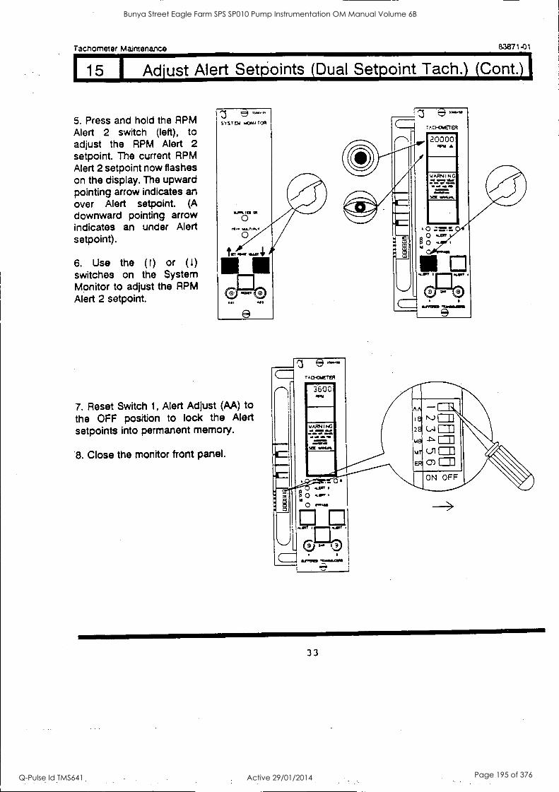
Tachometer Maintenance 83871-01
15 Adjust Alert Seti3oints (Dual Setpoint Tach.) (Cont.)
5. Press and hold the RPM Alert 2 switch (left), to adjust the RPM Alert 2 setpoint. The current RPM Alert 2 setpoint now flashes on the display. The upward pointing arrow indicates an over Alert setpoint. (A downward pointing arrow indicates an under Alert setpoint).
6. Use the (1) or (1) switches on the System Monitor to adjust the RPM Alert 2 setpoint.
20000
WARNING mme wry a
maw..
7. Reset Switch 1, Alert Adjust (AA) to the OFF position to lock the Alert setpoints into permanent memory.
8. Close the monitor front panel.
a/RIND
L.* i3
110.1911110 MINNALCIPS
lame
33
Bunya Street Eagle Farm SPS SP010 Pump Instrumentation OM Manual Volume 6B
Q-Pulse Id TMS641 Active 29/01/2014 Page 195 of 376

Tachometer Maintenance 83871-01
1 16 1 Adjust Alert Setpoints (Zero Speed Tach.)
1. Open and slide over the front panel.
2. Set Switch 1, Alert Adjust (AA) to the ON position. The RPM display flashes to indicate Alert Adjust Mode.
3. Press and hold the RPM Alert switch (right), to adjust the RPM Alert setpoint. The current RPM Alert setpoint now flashes on the display. The upward pointing arrow indicates an over Alert setpoint. (A downward pointing arrow indicates an under Alert setpoint).
4. Use the (1) or (t) switches on the System Monitor to adjust the RPM Alert setpoint.
34
Bunya Street Eagle Farm SPS SP010 Pump Instrumentation OM Manual Volume 6B
Q-Pulse Id TMS641 Active 29/01/2014 Page 196 of 376

Tachometer Maintenance 83871 -01
116 I Adjust Alert Setpoints (Zero Speed Tach.) (Cont.)
5. Press and hold the Zero Speed Alert switch (left), to adjust the Zero Speed Alert setpoint. The current Zero Speed Alert setpoint now flashes on the display. The downward pointing arrow indicates an under Alert setpoint. (Zero Speed is always an under Alert setpoint).
6. Use the (t) or (1) switches on the System Monitor to adjust the Zero Speed Alert setpoint.
7. Reset Switch 1, Alert Adjust (AA) to the OFF position to lock the Alert setpoints into permanent memory.
8. Close the monitor front panel.
35
Bunya Street Eagle Farm SPS SP010 Pump Instrumentation OM Manual Volume 6B
Q-Pulse Id TMS641 Active 29/01/2014 Page 197 of 376

Tachometer Maintenance 83871-01
117 Adjust Alert Setpoints (Rotor Accel Tach)
1. Open and slide over the front panel.
2. Set Switch 1, Alert Adjust (AA) to the ON position. The RPM and RPM/MIN display flashes to indicate Alert Adjust Mode.
3. Press and hold the RPM Alert switch (right), to adjust the RPM Alert setpoint. The current RPM Alert setpoint now flashes on the display. The upward pointing arrow indicates an over Alert setpoint. (A downward pointing arrow indicates an under Alert setpoint).
4. Use the (t) or (1) switches on the System Monitor to adjust the RPM Alert setpoint.
C- TAa-cureR
3600 RPM
500 QPIO/141
11. or 0.
"PRIED
A
ER cn= C.N OFF
5000 WY
WARNING
36
Bunya Street Eagle Farm SPS SP010 Pump Instrumentation OM Manual Volume 6B
Q-Pulse Id TMS641 Active 29/01/2014 Page 198 of 376
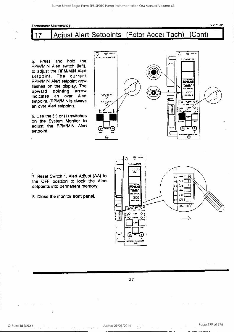
117 'Adjust Alert Setpoints (Rotor Accel Tach) (Cant) I
Tachometer Maintenance 83871-01
5. Press and hold the RPM/MIN Alert switch (left), to adjust the RPM/MIN Alert setpoint. The current RPM/MIN Alert setpoint now flashes on the display. The upward pointing arrow indicates an over Alert setpoint. (RPM/MIN is always an over Alert setpoint).
6. Use the (1) or (1) switches on the System Monitor to adjust the RPM/MIN Alert setpoint.
e=1 no....
SYSTEM 14NI tOR
600
'7. Reset Switch 1, Alert Adjust (AA) to the OFF position to lock the Alert setpoints into permanent memory.
8. Close the monitor front panel.
37
Bunya Street Eagle Farm SPS SP010 Pump Instrumentation OM Manual Volume 6B
Q-Pulse Id TMS641 Active 29/01/2014 Page 199 of 376

Tachometer Maintenance 83871-01
18 1 Bypass (Dual Setpoint Tach.)
T.\ CAUTION
as.
Machine protection will be lost while Bypass is on.
Set the 28 (Bypass Alert 2 Relay) Switch to the ON position to bypass the Alert 2 relay. The Bypass
LED will turn on. The monitor will otherwise function normally.
The RPM Alert 1 relay cannot be Bypassed. Switch (1B) has no affect in the Dual Setpoint Tach.
O 3400/SO
Burro=
38
Bunya Street Eagle Farm SPS SP010 Pump Instrumentation OM Manual Volume 6B
Q-Pulse Id TMS641 Active 29/01/2014 Page 200 of 376
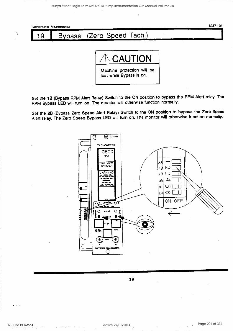
Tachometer Maintenance 83871 -01
19 1 Bypass (Zero Speed Tach.)
CAUTION Machine protection will be lost while Bypass is on.
Set the 1B (Bypass RPM Alert Relay) Switch to the ON position to bypass the RPM Alert relay. The
RPM Bypass LED will turn on. The monitor will otherwise function normally.
Set the 28 (Bypass Zero Speed Alert Relay) Switch to the ON position to bypass the Zero Speed
Alert relay. The Zero Speed Bypass LED will turn on. The monitor will otherwise function normally.
33 sssss
TACHOMETER
3600 RPM
ZERO SPEED ENABLED
YARNING OW MOO IOW a NM WV Alfmn a .111/ PM
poreAMMIO AAVICT te.
SEE MANUAL
A
O 0 04.eur 0 R
ss
ALERT
A
eurveres
39
Bunya Street Eagle Farm SPS SP010 Pump Instrumentation OM Manual Volume 6B
Q-Pulse Id TMS641 Active 29/01/2014 Page 201 of 376
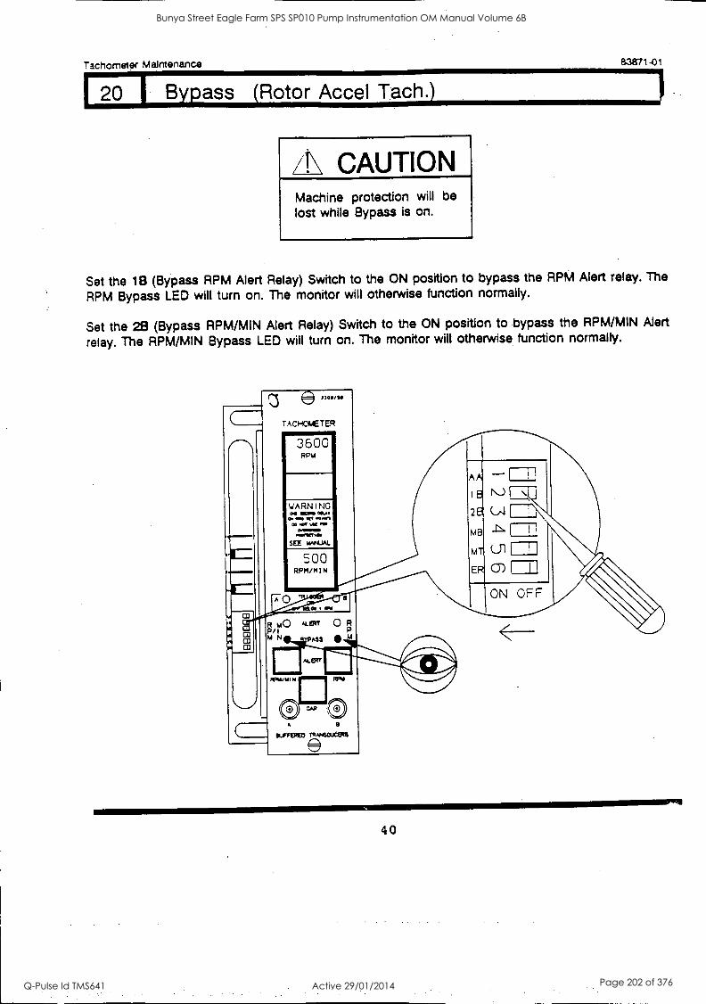
Tachometer Maintenance 83871-01
20 Bypass (Rotor Accel Tach.)
/I\ CAUTION Machine protection will be lost while Bypass is on.
Set the 1B (Bypass RPM Alert Relay) Switch to the ON position to bypass the RPM Alert relay. The
RPM Bypass LED will turn on. The monitor will otherwise function normally.
Set the 2B (Bypass RPM/MIN Alert Relay) Switch to the ON position to bypass the RPM/MIN Alert
relay. The RPM/MIN Bypass LED will turn on. The monitor will otherwise function normally.
3300/Se
TAcHomETER
3600 RPM
YARNING Se Mel
Om 31% W3 00 eel 00 tel
0.001m 000310101
SEE kMAJAL
500 RPM/MIN
R A40 NART 0 R P/1
N ASS
KEW
9
EIUFSEMED rRANsouctms
2e /s11 !\ MB
MT
ER C)
ON OFF
40
Bunya Street Eagle Farm SPS SP010 Pump Instrumentation OM Manual Volume 6B
Q-Pulse Id TMS641 Active 29/01/2014 Page 202 of 376
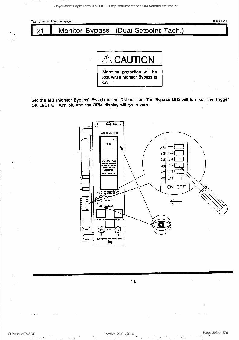
Tachometer Maintenance 83871-01
121 I Monitor Bypass (Dual Setpoint Tach.)
CAUTION Machine protection will be lost while Monitor Bypass is on.
Set the MB (Monitor Bypass) Switch to the ON position. The Bypass LED will turn on, the Trigger
OK LEDs will turn off, and the RPM display will go to zero.
)700/10
TACI-10METER
0
Co A
ELIFFERED
41
Bunya Street Eagle Farm SPS SP010 Pump Instrumentation OM Manual Volume 6B
Q-Pulse Id TMS641 Active 29/01/2014 Page 203 of 376

Tachometer Maintenance
122 Monitor Bypass (Zero Speed Tach.)
CAUTION Machine protection will be lost while Monitor Bypass is on.
E13871-01
Set the MB (Monitor Bypass) Switch to the ON position. The Bypass LEDs will turn on, the Trigger OK LEDs will turn off, and the RPM display will go to zero.
TACT-t0L4ETER
0
A
ornate:1 mmaacens
42
Bunya Street Eagle Farm SPS SP010 Pump Instrumentation OM Manual Volume 6B
Q-Pulse Id TMS641 Active 29/01/2014 Page 204 of 376

Tachometer Maintenance 83871-01
23 1 Monitor Bypass (Rotor Accel Tech.)
/!\ CAUTION Machine protection will be
lost while Monitor Bypass is on.
Set the MB (Monitor Bypass) Switch to the ON position. The Bypass LEDs will turn on, the Trigger OK LEDs will turn off, and the RPM and RPM/MIN displays will go to zero.
e33011/511
TACHOMETER imomor
RPM
0
43
Bunya Street Eagle Farm SPS SP010 Pump Instrumentation OM Manual Volume 6B
Q-Pulse Id TMS641 Active 29/01/2014 Page 205 of 376
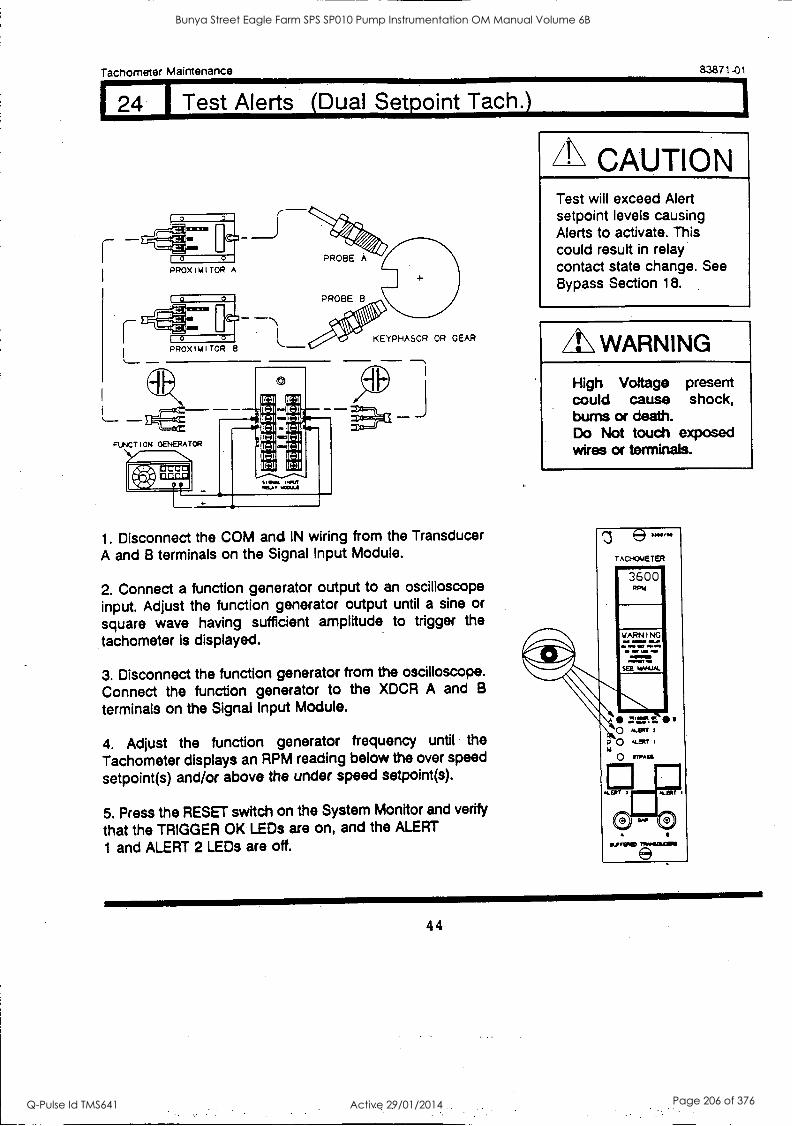
Tachometer Maintenance
[ 24 i Test Alerts
PROX I M I TOR A
2.3871-01
Dual Setpoint Tach.)
KEYPHASOR OR GEAR
1. Disconnect the COM and IN wiring from the Transducer A and B terminals on the Signal Input Module.
2. Connect a function generator output to an oscilloscope input. Adjust the function generator output until a sine or square wave having sufficient amplitude to trigger the
tachometer is displayed.
3. Disconnect the function generator from the oscilloscope. Connect the function generator to the XDCR A and B
terminals on the Signal Input Module.
4. Adjust the function generator frequency until the
Tachometer displays an RPM reading below the over speed
setpoint(s) and/or above the under speed setpoint(s).
5. Press the RESET switch on the System Monitor and verify
that the TRIGGER OK LEDs are on, and the ALERT
1 and ALERT 2 LEDs are off.
/1\ CAUTION Test will exceed Alert setpoint levels causing Alerts to activate. This could result in relay contact state change. See Bypass Section 18.
/I\ WARNING
High Voltage present could cause shock, burns or death. Do Not touch exposed wires or terminals.
e - rAcHomerER
3600
SEE WNW&
: . s ' o N. r 3
a0 ALarr U
O ormass
44
Bunya Street Eagle Farm SPS SP010 Pump Instrumentation OM Manual Volume 6B
Q-Pulse Id TMS641 Active 29/01/2014 Page 206 of 376

Tachometer Maintenance 83871-01
24 1 Test Alerts (Dual Setpoint Tach.) (Cont.)
6. Adjust the function generator frequency until the Tachometer displays an RPM reading above the ALERT 1 over speed setpoint or below the ALERT 1 under speed setpoint.
7. Verify that the ALERT 1 LED turns on (Flashing if the first out option is selected).
8. Verify that the ALERT 1 relay has changed state.
9. Press the RESET switch on the System Monitor and verify that the ALERT 1 LED remains on steady.
10. Adjust the function generator frequency until the Tachometer displays an RPM reading above the ALERT 2 over speed setpoint or below the ALERT 2 under speed setpoint.
11. Verify that the ALERT 2 LED turns on (Flashing if the first out option is selected).
12. Verify that the ALERT 2 relay has changed state. (The Relay will not change state if the Alert 2 Relay has been Bypassed. See section 18)
13. Press the RESET switch on the System Monitor and verify that the ALERT 2 LED remains on steady.
14. Adjust the function generator frequency until the Tachometer displays an RPM reading below the Alert 1 and 2
over speed setpoints or above the Alert 1 and 2 under speed setpoints.
15. Press the Reset switch on the System Monitor and verify
that the Alert 1 and 2 LEDs go off.
16. Connect all field wiring.
45
Bunya Street Eagle Farm SPS SP010 Pump Instrumentation OM Manual Volume 6B
Q-Pulse Id TMS641 Active 29/01/2014 Page 207 of 376
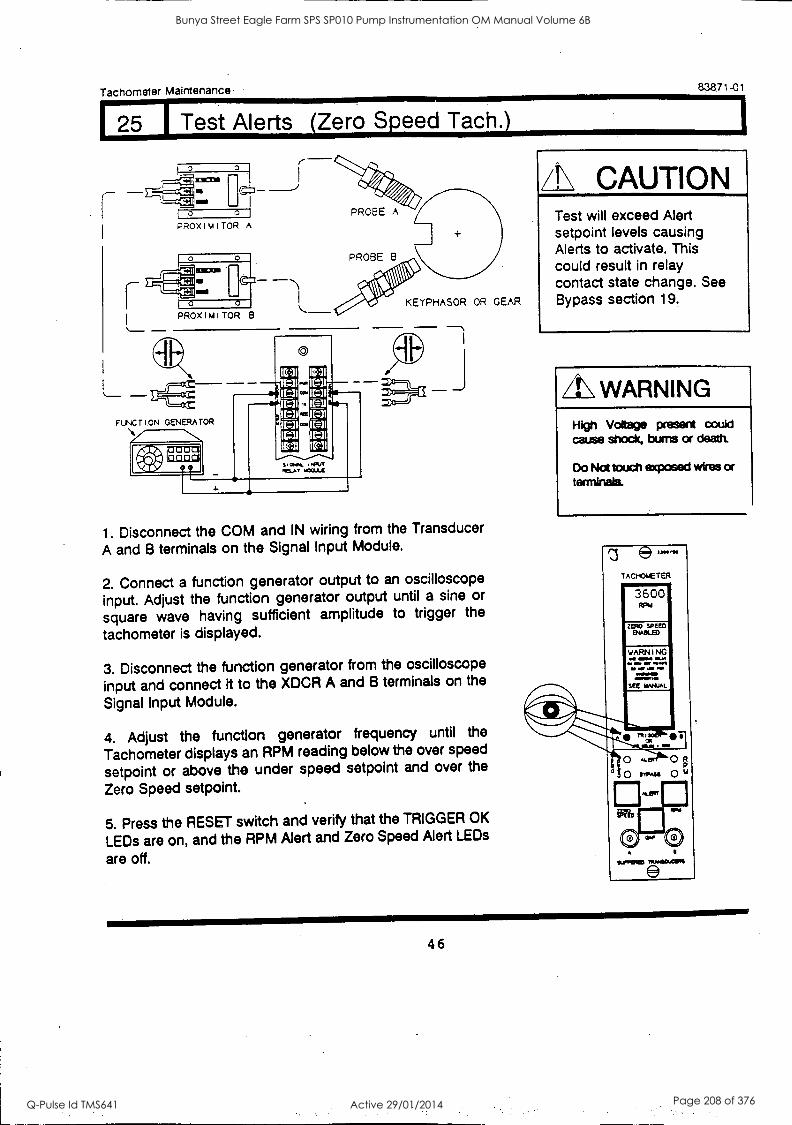
Tachometer Maintenance 83871-01
25 Test Alerts (Zero Speed Tach.)
KEYPHASOR OR GEAR PROX I M I TOR B
1. Disconnect the COM and IN wiring from the Transducer
A and B terminals on the Signal Input Module.
2. Connect a function generator output to an oscilloscope
input. Adjust the function generator output until a sine or
square wave having sufficient amplitude to trigger the
tachometer is displayed.
3. Disconnect the function generator from the oscilloscope
input and connect it to the XDCR A and B terminals on the
Signal Input Module.
4. Adjust the function generator frequency until the
Tachometer displays an RPM reading below the over speed
setpoint or above the under speed setpoint and over the
Zero Speed setpoint.
5. Press the RESET switch and verify that the TRIGGER OK
LEDs are on, and the RPM Alert and Zero Speed Alert LEDs
are off.
A\ CAUTION Test will exceed Alert setpoint levels causing Alerts to activate. This could result in relay contact state change. See Bypass section 19.
O WARNING High Voltage present could cause shock, bums or death.
Do Not touch exposed wires or terminals
z e TAchomETER
3600 ppm
ZEMSPEEM MMWM
SEE 11MIJAL
114.711,E0
46
Bunya Street Eagle Farm SPS SP010 Pump Instrumentation OM Manual Volume 6B
Q-Pulse Id TMS641 Active 29/01/2014 Page 208 of 376
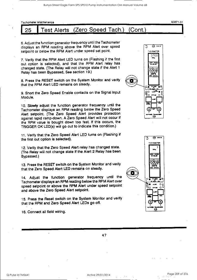
1
Tachometer Maintenance 83871-01
12 I Test Alerts (Zero Speed Tach.) Cont.)
6. Adjust the function generator frequency until the Tachometer displays an RPM reading above the RPM Alert over speed setpoint or below the RPM Alert under speed set point.
7. Verify that the RPM Alert LED turns on (Flashing if the first
out option is selected), and that the RPM Alert relay has changed state. (The Relay will not change state if the Alert 1
Relay has been Bypassed, See section 19.)
8. Press the RESET switch on the System Monitor and verify that the RPM Alert LED remains on steady.
9. Short the Zero Speed Enable contacts on the Signal Input Module.
10. Slowly adjust the function generator frequency until the
Tachometer displays an RPM reading below the Zero Speed Alert setpoint. (The Zero Speed Alert provides protection against rapid ramp-down. A Zero Speed Alert will not occur if
the RPM value is bought down too fast. If this occurs, the TRIGGER OK LED(s) will go out to indicate this condition.)
11. Verify that the Zero Speed Alert LED turns on (Flashing if the first out option is selected).
12. Verify that the Zero Speed Alert relay has changed state.
(The Relay will not change state if the Alert 2 Relay has been
Bypassed.)
13. Press the RESET switch on the System Monitor and verify
that the Zero Speed Alert LED remains on steady.
14. Adjust the function generator frequency until the
Tachometer displays an RPM reading below the RPM Alert over
speed setpoint or above the RPM Alert under speed setpoint
and above the Zero Speed Alert setpoint.
15. Press the Reset switch on the System Monitor and verify
that the RPM and Zero Speed Alert LEDs go off.
16. Connect all field wiring.
3760 PPM
:1110 WEED EPPEL ED
WARNING M.N.%
0.111.11= Mi
SEE **PUN.
e TACHCNIET ER
7 PPM
ZERO SPEED CNN"- ED
SCE MANUAL
0./P0113)
47
Bunya Street Eagle Farm SPS SP010 Pump Instrumentation OM Manual Volume 6B
Q-Pulse Id TMS641 Active 29/01/2014 Page 209 of 376
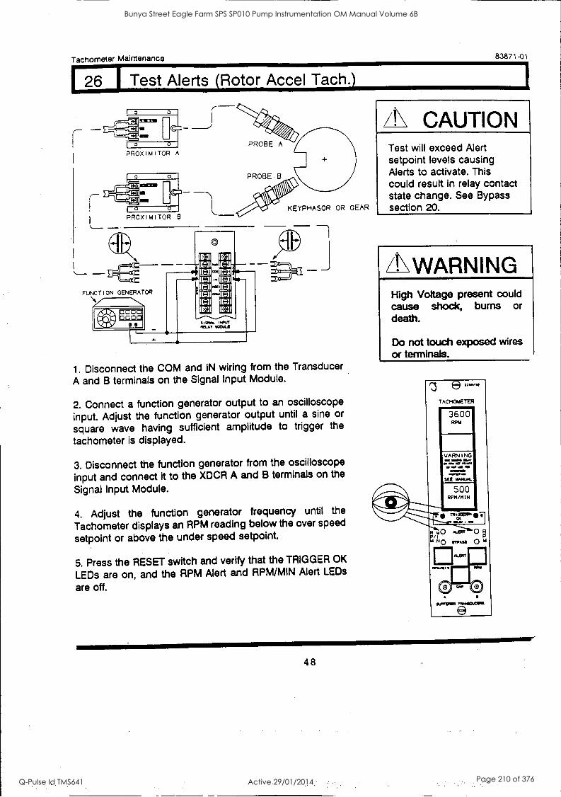
Tachometer Maintenance a3871-01
1 26 Test Alerts (Rotor Accel Tach.)
KEYPHASOR OR GEAR
1. Disconnect the COM and IN wiring from the Transducer
A and B terminals on the Signal Input Module.
2. Connect a function generator output to an oscilloscope
input. Adjust the function generator output until a sine or
square wave having sufficient amplitude to trigger the
tachometer is displayed.
3. Disconnect the function generator from the oscilloscope
input and connect it to the XDCR A and B terminals on the
Signal Input Module.
4. Adjust the function generator frequency until the
Tachometer displays an RPM reading below the over speed
setpoint or above the under speed setpoint.
5. Press the RESET switch and verify that the TRIGGER OK
LEDs are on, and the RPM Alert and RPM/MIN Alert LEDs
are off.
/N CAUTION Test will exceed Alert setpoint levels causing Alerts to activate. This could result in relay contact state change. See Bypass section 20.
LL WARNING High Voltage present could cause shock, bums or death.
Do not touch exposed wires or terminals.
3 e- TACHOMETER
3600 RPM
500 RPM/MIN
A
num0.01111
e
48
Bunya Street Eagle Farm SPS SP010 Pump Instrumentation OM Manual Volume 6B
Q-Pulse Id TMS641 Active 29/01/2014 Page 210 of 376

Tachometer Maintenance 83871 -01
26 I Test Alerts (Rotor AccelTach.) (Cont.)
6. Adjust the function generator frequency until the Tachometer
displays an RPM reading above the RPM Alert over speed setpoint or
below the RPM Alert under speed setpoint.
7. Verify that the RPM Alert LED turns on (Flashing if the first out option is selected), and that the RPM Alert relay has changed state.(The Relay will not change state if the Alert 1 Relay has been
Bypassed. See section 19.)
8. Press the RESET switch on the System Monitor and verify that the RPM Alert LED remains on steady.
9. Adjust the function generator frequency until the Tachometer
displays an RPM /MIN reading above the RPM/MIN Alert setpoint.
NOTE: Rotor Acceleration (RPM/MIN) is the rate of change of Rotor Speed (RPM). Therefore, the RPM/MIN display increases as
the function generator frequency is increased. The RPM/MIN
display returns to Zero if the function generator frequency
remains constant.
10. Verify that the RPM/MIN Alert LED turns on (Flashing if the
first out option is selected).
11. Verify that the RPM/MIN Alert relay has changed state.(The
Relay will not change state if the Alert 2 Relay has been
Bypassed. See section 19.)
12. Adjust the function generator until the Tachometer displays
an RPM reading below the RPM Alert over speed setpoint or
above the RPM Alert under speed setpoint. Leave the generator
at this frequency long enough for the RPM/MIN display to settle
back to zero. 13. Press the Reset switch on the System Monitor and Verify that
the RPM and RPM/MIN LEDs go out.
14. Connect all field wiring.
1.0 la
7.Ct..CMETER
3600 ap.
WAPN1 NC a ea
QIIP
SaIMICIED
SEE urn M.M.
800 RpmmiN
JWIN=1 ,.':"
I
1.10 N. V.' P/I 4 NO 0 V
EISTE .101"111119
Oa gueruato Tokmicaxt.s
11/0CPCD rP.I/CUCIPM
49
Bunya Street Eagle Farm SPS SP010 Pump Instrumentation OM Manual Volume 6B
Q-Pulse Id TMS641 Active 29/01/2014 Page 211 of 376
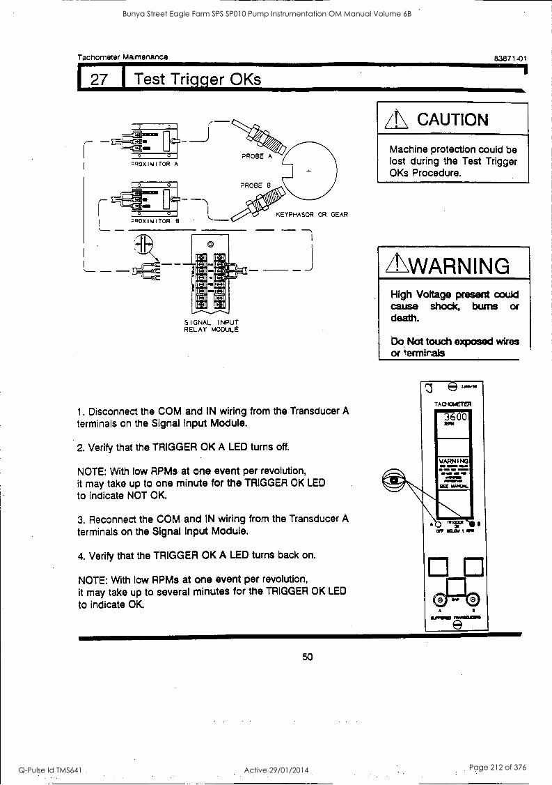
Tachometer Maintenance
27 1 Test Trigger OKs
83871-01
a C:11
1=31 11=irriu AMM
(=al C'tilf-
=31 1=31
11=11 11=21
IC 31 IC 31
SIGNAL I NPUT RELAY MODULE
KEYPHASOR OR GEAR
J
1. Disconnect the COM and IN wiring from the Transducer A terminals on the Signal Input Module.
2. Verify that the TRIGGER OK A LED turns off.
NOTE: With low RPMs at one event per revolution, it may take up to one minute for the TRIGGER OK LED
to indicate NOT OK.
3. Reconnect the COM and IN wiring from the Transducer A terminals on the Signal Input Module.
4. Verify that the TRIGGER OK A LED turns back on.
NOTE: With low RPMs at one event per revolution, it may take up to several minutes for the TRIGGER OK LED
to indicate OK
/N CAUTION
Machine protection could be lost during the Test Trigger OKs Procedure.
ZLWARNING High Voltage present could cause shock, bums or death.
Do Not touch exposed wires or termirals
z e- TAcrowerEpe
3600
WARNING
50
Bunya Street Eagle Farm SPS SP010 Pump Instrumentation OM Manual Volume 6B
Q-Pulse Id TMS641 Active 29/01/2014 Page 212 of 376
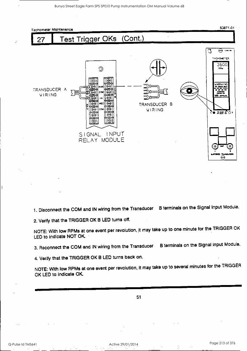
Tachometer Maintenance 83871-01
27 Test Trigger OKs (Cont.)
TRANSDUCER A
WIRING
SIGNAL I NPUT RELAY MODULE
TRANSDUCER B
WIRING
e
3600 RPM
YARNING as mos ona
OWWIM
1. Disconnect the COM and IN wiring from the Transducer B terminals on the Signal Input Module.
2. Verify that the TRIGGER OK B LED turns off.
NOTE: With low RPMs at one event per revolution, it may take up to one minute for the TRIGGER OK
LED to indicate NOT OK
3. Reconnect the COM and IN wiring from the Transducer B terminals on the Signal Input Module.
4. Verify that the TRIGGER OK B LED turns back on.
NOTE: With low RPMs at one event per revolution, it may take up to several minutes for the TRIGGER
OK LED to indicate OK
51
Bunya Street Eagle Farm SPS SP010 Pump Instrumentation OM Manual Volume 6B
Q-Pulse Id TMS641 Active 29/01/2014 Page 213 of 376

Tachometer Maintenance 83871-01
128 1 SELF TEST
/N CAUTION Machine protection will be lost for duration of test.
The monitor has three levels of self tests:
SELF TEST PERFORMED
Power-up
Cyclic
User-Invoked
When the monitor is turned on.
Continuously during normal operation.
When shorting the self test contacts.
SP.11.
If the monitor detects an error during a Cyclic self test, the following events occur:
Monitoring stops until the problem is resolved. The error code is stored in memory and flashes on the LCD display. The BYPASS LED comes on. The OK LEDs flash at 5 Hz.
If the error is intermittent and goes away, the following events occur:
Monitoring resumes. The OK LEDs flash at 5 Hz to indicate that an
error code has been stored.
If the monitor detects an error during the Power-up or
User-invoked self test monitoring stops until the problem
is resolved.
52
Bunya Street Eagle Farm SPS SP010 Pump Instrumentation OM Manual Volume 6B
Q-Pulse Id TMS641 Active 29/01/2014 Page 214 of 376
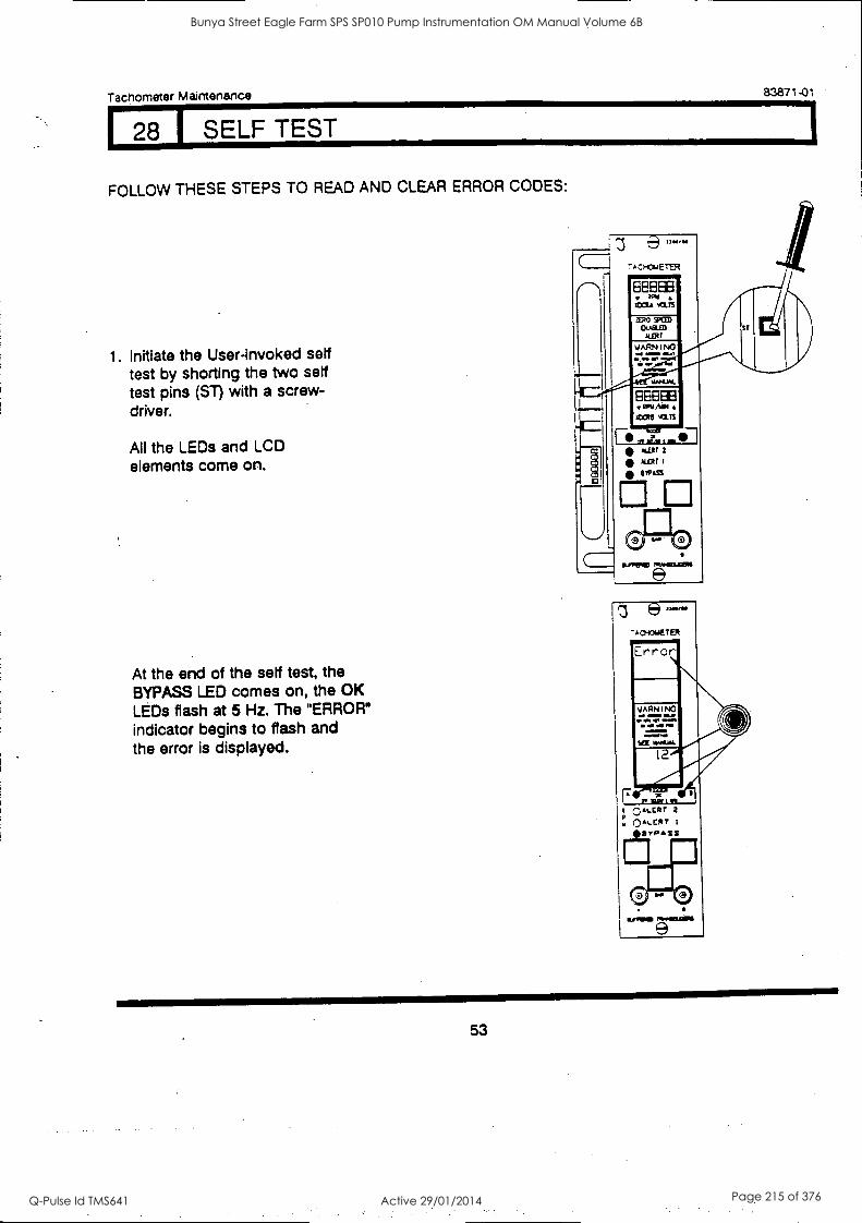
Tachometer Maintenance 83871-01
128 SELF TEST
FOLLOW THESE STEPS TO READ AND CLEAR ERROR CODES:
1. Initiate the User-invoked self test by shorting the two self test pins (ST) with a screw- driver.
All the LEDs and LCD elements come on.
At the end of the self test, the BYPASS LED comes on, the OK LEDs flash at 5 Hz. The "ERROR*
indicator begins to flash and the error is displayed.
'AO-1016E1ER
TWOUI:11111
9
53
Bunya Street Eagle Farm SPS SP010 Pump Instrumentation OM Manual Volume 6B
Q-Pulse Id TMS641 Active 29/01/2014 Page 215 of 376
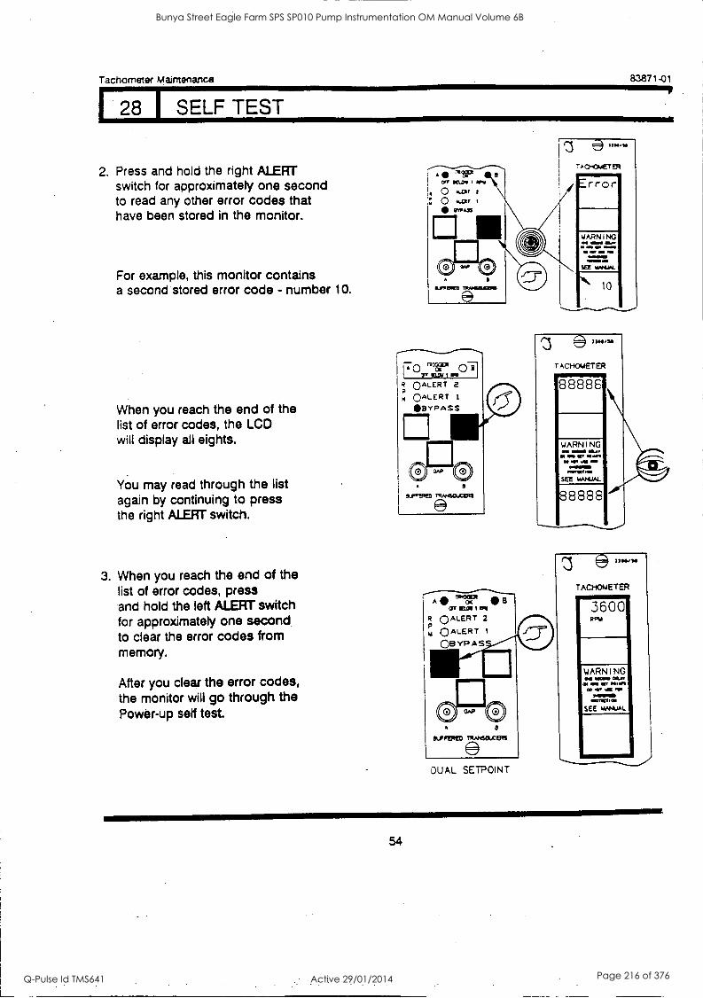
Tachometer Maintenance
1.2.2 j SELF TEST
83871-01
2. Press and hold the right ALERT switch for approximately one second to read any other error codes that have been stored in the monitor.
For example, this monitor contains a second stored error code - number 10.
When you reach the end of the list of error codes, the LCD will display all eights.
You may read through the list again by continuing to press the right ALERT switch.
3. When you reach the end of the list of error codes, press and hold the left ALERT switch for approximately one second to clear the error codes from memory.
After you clear the error codes, the monitor will go through the Power-up self test.
WARNING ON 4E00 Whow in MID ablen
IN MI, MI NM w.
31011/SO
TACHOMETER
88888
WARNING ea WOO Sat co MO or coon
CO NO 000momo ~Wm.
see WAP1JAL
8 8888
DU AL SETPOIN T
(ii) 7304,20
TACHOMETER
3600 RPV
WARNING aw MOM
CO or WO RN TOWED
-11111/01
SEE MMAJAL.
54
Bunya Street Eagle Farm SPS SP010 Pump Instrumentation OM Manual Volume 6B
Q-Pulse Id TMS641 Active 29/01/2014 Page 216 of 376
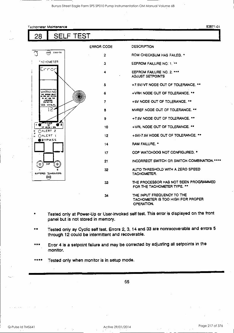
Tachometer Maintenance 83871-01
28 I SELF TEST
A
1300,10
TAC-,CmETER
WARNING Of UM00 MAT sftun WPW11 W PM *WIWI= monwrow
SEE VANUAL
°ALERT 2
m C)ALERT t
BYPASS
E OAP 0
8
BUFFERED TRANSDUCERS
ERROR CODE
2
3
4
5
6
8
9
10
12
14
17
21
32
33
DESCRIPTION
ROM CHECKSUM HAS FAILED.
EEPROM FAILURE NO. 1.
EEPROM FAILURE NO. 2 ADJUST SETPOINTS
+7.5V/-VT NODE OUT OF TOLERANCE. * +VRH NODE OUT OF TOLERANCE * +5V NODE OUT OF TOLERANCE.
MVREF NODE OUT OF TOLERANCE. * +7.5V NODE OUT OF TOLERANCE. * +VRL NODE OUT OF TOLERANCE. **
+5V/-7.5V NODE OUT OF TOLERANCE. * RAM FAILURE. *
COP WATCHDOG NOT CONFIGURED.
INCORRECT SWITCH OR SWITCH COMBINATION. * * **
AUTO THRESHOLD WITH A ZERO SPEED TACHOMETER.
THE PROCESSOR HAS NOT BEEN PROGRAMMED FOR THE TACHOMETER TYPE. *
34 THE INPUT FREQUENCY TO THE TACHOMETER IS TOO HIGH FOR PROPER
OPERATION.
Tested only at Power-Up or User-Invoked self test. This error is displayed on the front
panel but is not stored in memory.
**
***
****
Tested only ay Cyclic self test. Errors 2, 3, 14 and 33 are nonrecoverable and errors 5
through 12 could be intermittent and recoverable.
Error 4 is a setpoint failure and may be corrected by adjusting all setpoints in the
monitor.
Tested only when monitor is in setup mode.
55
Bunya Street Eagle Farm SPS SP010 Pump Instrumentation OM Manual Volume 6B
Q-Pulse Id TMS641 Active 29/01/2014 Page 217 of 376

Tachometer Maintenance 83871-01
29 1 Field Wiring Diagram
The next 18 pages contain the following Field Wiring Diagrams:
DRAWING NAME DRAWING NUMBER
Dual Setpoint Tachometer without External Barriers 100338
Dual Setpoint Tachometer with External Barriers 100339
Dual Setpoint Tachometer with Internal Barriers 125593
Zero Speed Tachometer without External Barriers 100341.
Zero Speed Tachometer with External Barriers 100342
Zero Speed Tachometer with Internal Barriers 125595
Rotor Acceleration Tachometer without External Barriers 100344
Rotor Acceleration Tachometer with External Barriers 100345
Rotor Acceleration Tachometer with Internal Barriers 125594
56
Bunya Street Eagle Farm SPS SP010 Pump Instrumentation OM Manual Volume 6B
Q-Pulse Id TMS641 Active 29/01/2014 Page 218 of 376
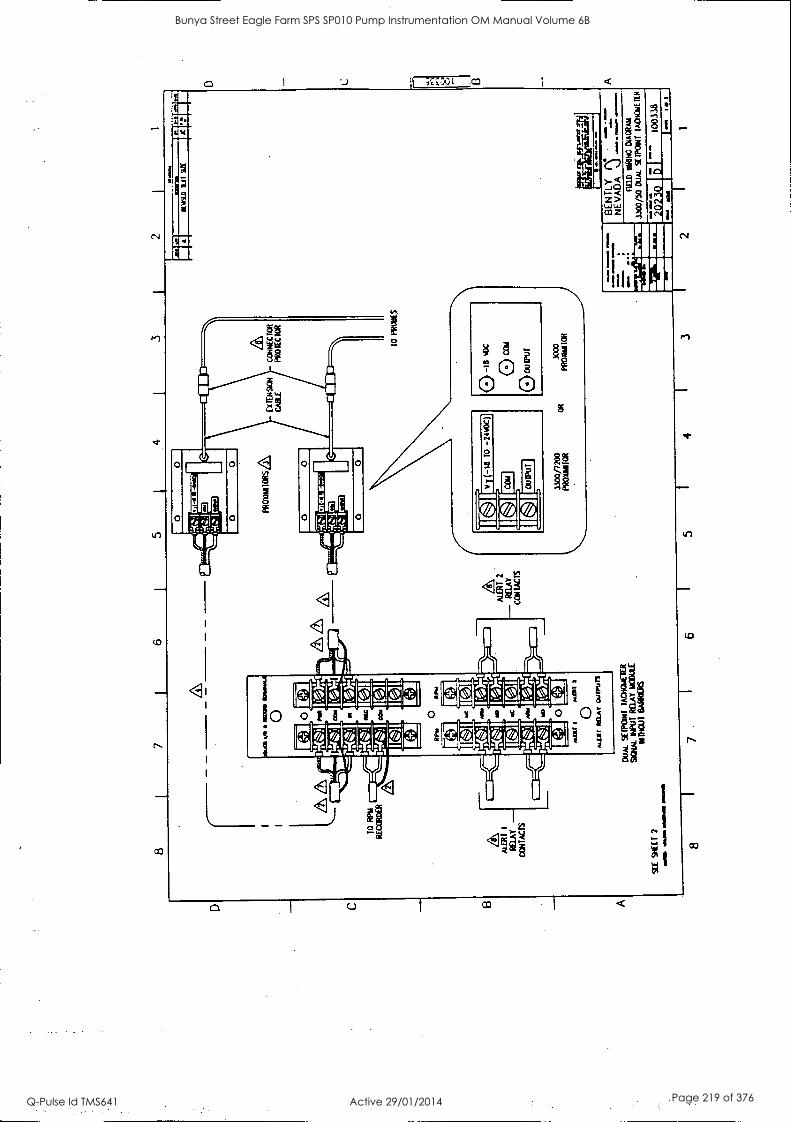
01.4
11 V
G
NC
O*
0
ZIA
TO
R
PM
RE
CO
RD
ER
ALE
RT
I
RE
LAY
-
CO
NT
AC
TS
RP
M
pPY
MO
MC
Mao
0 0 o.
1311
I
oal1
11 1
0 M
LII
RU
A,
Oul
Purl
DU
AL
%W
ON
T 1
1110
1011
CIE
R
SIG
NA
L IN
PU
T R
ELA
Y
MO
DU
LE
MR
IOU
T
BA
RR
IER
S
SE
E S
HE
ET
2
a ...
am a
rom
a w
arm
pRox
iuno
8s/\,
C
ON
NE
CT
OR
P
RO
TE
CT
OR
ALE
RT
2
- RE
LAY
CO
NT
AC
TS
V
T (
-18
TO
-2
0.0C
)
[ ] C
OM
1
[ ] O
UT
PU
T
TO
PR
OB
ES
8 1
7 I
6 I
5 4
1
A I
ICW
AD
11
11 9
2 I
C "1
-`r r
sal
!NN
W
In
Mam
a
01
D L ri
8
GE
NT
LY (
A
NE
VA
DA
--
----
----
- na
z w
aNG
DIA
GR
AM
3300
/50
DU
AL
%P
ON
T
'AM
ME
TE
R
'. 20
230
D
1003
38
MO
W
Iid
Ma
I- se
. It
3 2
Bunya Street Eagle Farm SPS SP010 Pump Instrumentation OM Manual Volume 6B
Q-Pulse Id TMS641 Active 29/01/2014 Page 219 of 376
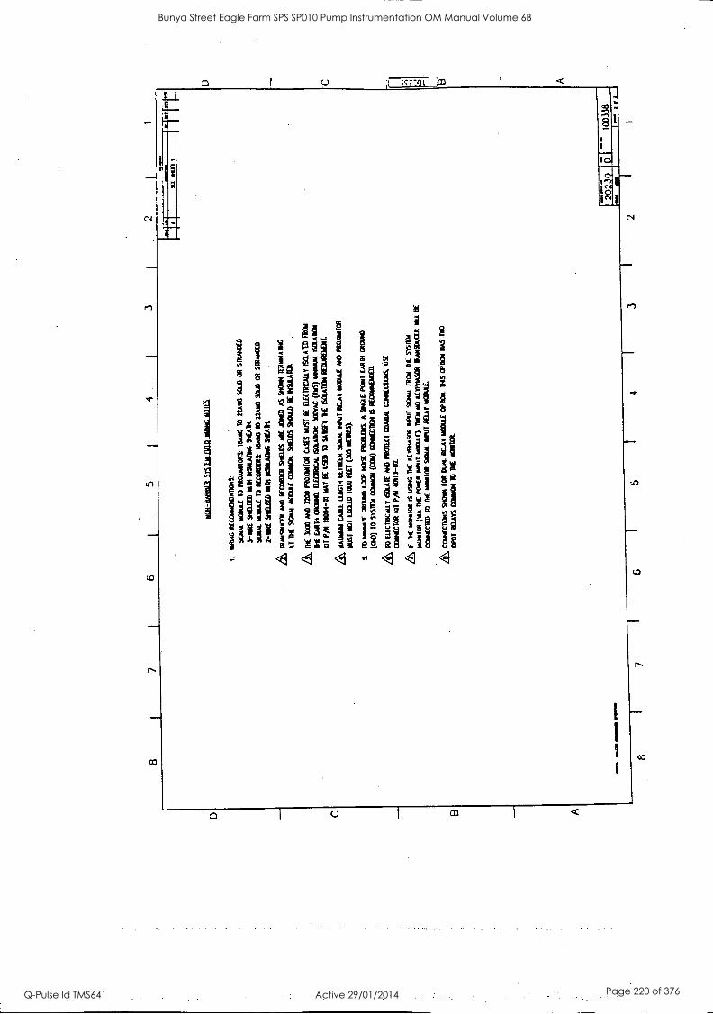
8 I
3 2
S - -
- 8
7 6
ge1-
lieB
BIL
L11
1121
1111
1111
1110
16.1
1111
11
1.
ININ
G R
EC
CIM
MA
DO
NS:
SI
GN
AL
W
elt/
TO
PR
OM
IOR
S:
16A
ING
10
22A
RG
SC
UD
O
R
STR
AN
DE
D
3-11
P1 S
HE
LD
ED
MM
ors
uLA
nwo sc
at
scam
Nom
a to
RE
CO
RD
ER
S(
MA
NG
T
O
22A
NG
SO
LO
O
R s
ntA
tioro
2-11
RE
ST
IEU
TE
D
MN
INSU
LA
TIN
G S
tAil
roA
msa
ucot
AN
D
ouco
toot
%A
m A
RE
JA
ILE
D
AS
SHO
RN
TE
RN
NIA
114
AT
T
HE
SI
ON
AL
MO
UE
CO
MM
ST
EW
S %
MO
BE
/WA
ND
.
ME
300
0 N
O 7
200
PRO
XIN
TO
R
CA
SES
MST
BE
E
LE
CT
RIC
AL
LY
IS
OL
AT
ED
FR
OM
TH
E
EA
RN
CliZ
TA
D.
EL
EC
TR
ICA
L e
SOL
AB
Ott
500v
AC
(R
IS)
ININ
AN
A I
SO
LAT
ION
IOT
P/1
1 11
1094
-01
MA
Y B
E U
SED
T
O
SA
It ISC
UD
ON
RE
CT
AR
DIE
NE
A\
MA
TR
ON
C
AB
LE
LE
NG
TH
MIE
N W
m B
AIT
R
EL
AY
MO
W A
M P
RO
NN
ITC
R
1105
i N
OT
E
XC
EE
D 1
000
FEE
T (
305
NE
WS)
.
S.
TO
m
om&
WO
RM
TE
MP
Nom
PR
OR
OP
S.
A
5/N
aL
PO
NT
TA
M M
AO
(G
144
10
SY
ST
EM
WA
IN (
CO
N)
03N
NE
CIC
R 6
RE
CC
AR
AE
ME
D.
to E
LOG
INC
ALL
Y
ISO
LAT
E P
AID
PR
OT
EC
T C
OA
XA
L
CO
mE
CT
EN
S U
SE
CO
NN
EC
TO
R K
IT
P/14
40
1I3-
02
ZS
I T
HE
W
HO
A I
S uS
ING
M
E
AV
OW
-SO
D /
VW
SC
UM
IR
ON
D
E W
SW
/
liON
ION
(M
A
DE
PO
NE
R R
IM m
OD
AE
).
ME
N
NO
AT
IPN
AS
OR
D
UM
DU
M
NIL
LIE
CE
NN
EC
TE
D 1
0 T
HE
N
OR
TO
N W
AX
NM
MA
T W
AA
L
CO
NE
CD
ON
S SR
ON
N
FOR
DU
AL
MA
T N
OM
E
MO
N.
MS
OPT
ION
HA
S T
a0
OPO
T 1
111A
TS
MA
MM
ON
T
O M
E W
M&
MR
M
.
L
4 3
2 1
Bunya Street Eagle Farm SPS SP010 Pump Instrumentation OM Manual Volume 6B
Q-Pulse Id TMS641 Active 29/01/2014 Page 220 of 376

5 4
3
SA
FE
A
RE
A
OR
Z
ON
E
2 01
1190
/1 2
H
AZ
AR
DO
US
AR
EA
1
Ell CA
M
6\
CO
NN
EC
TO
R
PR
OT
EC
TO
R
EL
I 3=--
-%
10
RP
M
RE
CO
RD
ER
A
10
PR
OB
ES
ALE
RT
1
RE
LAY
CO
NT
AC
TS
Ath
M
II ".
131f
I
0 M
OH
N
IAV
cui
run
DU
AL
SM
IRK
TA
CH
OM
ET
ER
SC
NA
L M
UT
RE
LAY
11C
OU
LE -
UR
I B
AR
RIE
RS
SE
E
SH
EE
T
2
8 7
1 6
5 I
4 I
3
"--
BE
N T
LY
NE
VA
DA
=
11
E1D
N
IR1N
G
CIA
GR
AR
3300
/50
DU
AL
SE
IPO
NT
TA
CItu
milE
it
26.2
10 I
1003
39
2
r) 8
Bunya Street Eagle Farm SPS SP010 Pump Instrumentation OM Manual Volume 6B
Q-Pulse Id TMS641 Active 29/01/2014 Page 221 of 376
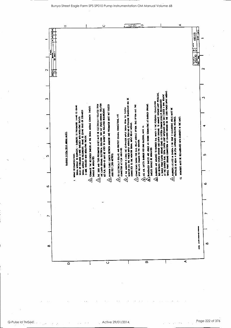
8 7
5 4
3 2
MA
O O
ME
N./
11/1
1110
1/.
DA
BID
EIL
S111
111.
1111
1111
11G
.110
.111
I. "Y
AN
G
RE
com
etiA
ncoi
s:
SIG
NA
L N
OD
ULE
10
BA
RR
IER
S -
BA
RR
IER
S
TO
P
R0M
1011
H
AN
G 1
0 M
AN
G
SC
UD
CH
S
TR
AN
DE
D 3
-WIT
E S
itlE
IDE
D N
TH
IN
SU
LAIN
G %
CA
M
90A
AL
NO
DU
LE
TO
R
EC
OR
IXA
S:
HIA
.0 I
D 2
2AD
0 S
OLD
O
t S
IRA
HO
E0
2-uR
E
9111
IED
NT
H I
IST
ILA
ING
SH
EA
lt
IER
AD
NA
lE E
NE
R
EC
OR
DE
R 9t
lDS
Al
EN
E
SC
AM
MC
OuT
E M
HO
& S
IID0S
910U
10 B
E D
IMM
ED
.
Dt
3000
AN
D 72
00 P
RO
0110
0 C
AS
ES
MIS
T
BE
O
ICIR
CA
LLY
ISM
AIL
I) I
RO
N
BE
E
AR
TH
G
RO
UN
D.
ELE
CIR
ICA
t 60
.A10
11:
300
VA
C (
MS
) IIH
11M
. IS
OLA
DO
N
of P
/N H
I094
-01
HA
Y B
E u
SE
D
TO
SA
ISF
Y 1
HE
IS
CA
AD
OH
R
EC
HR
EM
EN
T.
imam
CA
BLE
LIA
M B
ET
IED
I 11
0110
8 A
ND
PR
OM
TO
R N
MI
NO
T
EX
CE
ED
1000
FE
ET
006
NO
TE
S}
Z\ T
O
ELE
CIR
ICA
U.Y
iS
OLA
IL
AN
O P
RO
11C
1 C
OA
VA
L C
Om
EC
IDIN
S
US
E
CO
NN
EC
TO
R
RH
P/N
401
13-0
2.
1 lit
MO
NO
= I
S U
NIG
DIE
K
EW
NA
SO
R *
Put
S1G
NA
L 11
101
Di
SK
IER
110N
10R
CA
A D
IE
PO
SE
R R
IME
M
OD
ULE
).
RE
M
MO
R
EV
IVIA
SO
R IR
/AR
V=
NIL
R
E
CO
AN
EC
TE
D
10
DE
DO
DIO
R S
OW
. P
OV
I R
ELA
Y
CO
/[CO
ON
S W
on 1
1011
OuN
. R
ELA
Y M
OD
ULE
C
RO
ON
. IN
S O
MR
INS
OP
Or
RE
LAY
S C
OM
MO
N
10 T
HE
/4\ U
SE
H
D.
SA
FE
TY
B
MW
PE
R M
C I
tA22
004
NO
TE
It
kIR
AN
SO
UC
ER
SK
IDS
AR
E A
HE
D A
S
SH
OW
TE
IHN
HA
DH
C A
l B
AR
KA
MO
M.
Stil
lDS
SH
OU
LD D
E M
UM
A
BA
RR
IER
S A
RE
MO
AN
ED
10
WIR
ER
RA
IL
11/2
01 IS
TH
E
PO
MP
ON
. (C
ON
JUR
OR
Bus
@
Ew
a M
EM
Mul
e A
iS D
AM
GR
OU
ND
. 10
Now
a G
RO
UN
D L
OO
P
PR
OB
LEM
S,
A S
ofa/
PC
11 M
IN M
OO
D (
0E1)
10
Mild
Car
go (0
01)
IS R
EM
IND
/00
AT
M
E
BA
RR
IER
RM
. M
EA
L (A
RM
LO
W I
MP
ED
AN
CE
MU
SE
NO
T
EX
CE
ED
1
011.
RE
HM
So=
pad
Maa
s al
atcl
ICH
AT
CH
AS
SIS
G
NO
imi0
O
N lit
1300
PE
NE
R N
NE
HO
PA
L
ksw
arm
s ID
EA
TE
D II
MO
N 2
O
R
20H
E
2 H
AIA
RD
OH
S
AR
EA
S
MU
ST
OE
WA
LLE
D D
i 4
OR
11
1 A
MM
O P
RO
W.C
IVE
H
OU
SIN
GS
IDO
NIT
OR
S m
uS1
fE R
EC
AuB
RA
ND
HU
H O
AR
S 11
1 1E
LIE
S
NI
dm..
..7-7
1. 1-
- 10
0339
7 6
5 4
3 2
1
Bunya Street Eagle Farm SPS SP010 Pump Instrumentation OM Manual Volume 6B
Q-Pulse Id TMS641 Active 29/01/2014 Page 222 of 376

SA
WS
A
AA
OR
20
mE
2.
D
eA90
rE
2 D
A/M
OO
DS
AR
EA
D
C01
LIC
IOR
P
RO
1LC
IOR
C
9CA
LAL
OuI
PU
TS
10
PR
OO
FS
10 M
a R
EC
OR
DE
R
ALA
RM
R
ELA
Y O
uIP
UIS
SE
E
SnE
E1
2
wA
TH
i. .a
lft 0
04,4
11 M
ale>
DU
AL
SE
IPO
IN1
LAC
IICIV
ER
SA
NA
A M
U!
BC
Out
f
YIN
IM
IER
NA
L B
AR
RIE
RS
A WA
RN
ING
MIS
CO
NN
EC
TIN
G
OR
IN
1CR
UT
TE
NI
CO
NT
AC
T
OF
1H
E
FIE
LD
WR
ING
10
RA
CK
S
ER
MIN
ALS
N
MI
HIG
H
VO
LTA
GE
PO
TE
NT
IALS
CO
ULD
C
AU
SE
A
N
EX
PLO
SIO
N
OR
F
IRE
IN
TH
E
HA
ZA
RD
OU
S
AR
EA
R
ES
ULT
ING
IN
S
EV
ER
E
PE
RS
ON
AL
INJU
RY
O
R
DC
A1H
. R
EM
OV
E
ALL
V
OL1
AC
E
PO
TE
NT
IALS
FR
OM
R
EA
R
OF
R
AC
K
wia
no
mag
a :r
am
FIE
LD
MM
HG
DIA
GR
AM
3300
/50
DU
AL
SC
WO
N]
IAC
HO
ME
If I
t
--
2023
0 D
12
5593
BE
N R
A
NE
VA
DA
..0
4/10
11.
At
1E1.
4.11
11
8 7
6 5
4 3
2 1
A
Bunya Street Eagle Farm SPS SP010 Pump Instrumentation OM Manual Volume 6B
Q-Pulse Id TMS641 Active 29/01/2014 Page 223 of 376

D C A
8 6
5 4
3
INT
ER
NA
L B
AR
RIE
R
SY
ST
EM
MO
WR
ING
N
OT
ES
I. W
IRIN
G
RE
CO
mm
EN
DA
TiO
NS
:
SIG
NA
L M
OD
ULE
T
O
PR
OX
IAR
TO
R:
16A
WG
T
O
18A
14C
ST
RA
ND
ED
3
-WIR
E
SH
IELD
ED
W
ITH
IN
SU
LAT
ING
S
HE
AT
H
SIG
NA
L m
oouL
E
TO
R
EC
OR
DE
R/R
EA
DO
UT
: IE
SA
WG
10
22A
WG
S
OLI
D
CR
S
TR
AN
DE
D
2 -W
IRE
S
HIE
LDE
D
WIT
H I
NS
ULA
TIN
G
SH
EA
TH
.
ME
30
00
AN
D
7200
PR
OX
IMIT
OR
C
AS
ES
M
US
T
BE
E
LEC
TR
ICA
LLY
IS
OLA
TE
D
/RC
N
TH
E
EA
RT
H
GR
OU
ND
. E
LEC
TR
ICA
L IS
OLA
TIO
N:
500
VA
C (R
NS
) M
INIM
UM
. IS
OLA
TIC
11
Ka
P/N
190
94-0
1 M
AY
BE
U
SE
D
10 S
AT
ISF
Y
TH
E
ISO
LAT
ION
RE
QU
IRE
ME
NT
3300
P
RO
XIU
ITO
RS
HA
W
BU
ILT
IN
C
AS
E
ISO
LAT
ION
. T
HE
33
00
PR
OX
IMIO
R
HA
S
BU
ILT
-I
N
ISO
LAT
ION
AM
AX
IMU
M C
AB
LE
LEN
GT
H B
ON
IER
MO
NIT
OR
A
ND
P
RO
MO
TE
:1R
M
US
T
NO
T
EX
CE
ED
1000
FE
ET
(30
5 METRES),
/I\ S
CR
EW
S
MU
ST
B
E
SE
CU
RE
LY
FA
ST
EN
ED
F
OR
P
RO
PE
R
BA
RR
IER
GR
OU
ND
CO
NN
EC
TIO
N.
A10
E
LEC
TR
ICA
LLY
IS
OLA
TE
A
ND
P
RO
ICC
1 C
OA
XIA
L C
CN
NE
CT
ION
S.
US
E
CO
NN
EC
TO
R A
ll P
/N
4011
3-02
A,
if T
HE
m
UN
HO
R
IS
US
ING
IH
E
ktyP
HA
SO
R
INP
UT
S
IGN
AL
FR
OM
T
HE
S
YS
TE
M
mO
NT
IOR
(N
A
TH
E
PO
TT
ER
IN
PU
T
mO
DuL
E).
IN
N
NO
K
EY
PH
AS
CR
T
RA
NS
DU
CE
R
HIL
L B
C
CO
NN
EC
TE
D
TO
R
d M
ON
ITO
R
SIG
NA
L IN
PU
T
RE
LAY
M
OD
ULE
.
/7\ C
CN
NE
CIT
uNS
S
HO
WN
T
OR
D
UA
L R
ELA
Y
MO
DU
LE
OP
TIO
N
TM
OP
TIO
N
HA
S
HM
O
DP
OI
RE
LAY
S
com
mon
10
TH
E m
ane.
AE
MA
NA
TE
IH
E
RE
CO
RD
ER
S
HIE
LDS
A
l T
HE
S
IGN
AL
MO
DU
LE
CO
MM
ON
A
S
SH
OR
N.
SH
IELD
S
SH
OU
LD
BE
IN
SU
LAT
ED
A\S
EE
AP
PR
OV
AL
DW
G B
A22
000
OR
CA22000,
NO
1 ai
ls °N
UN
. le
t(14
0
ALE
RT
I
RE
LAY
C
ON
TA
CT
S
SIG
NA
L O
ulP
uIS
10)I
NC
AIIA
I
NO
WR
Y
NO
Vor
i- 1(
A
W-m
A
UN
T
I M
INI
2
AL
AR
IA
RE
LAY
CA
I T
RU
IS
OU
1 sL
ITio
Ni
IAC
HO
W.II
R
SIG
NA
L N
PU
I R
ELA
Y
MO
DU
LE
BA
RR
ILK
S
8 I
7 6
5 4
2 1
ALE
RI
2
KE
AY
CO
NIA
CIS
in-5
3-0-
.1
"1-0
3.
--T
.1..!
..!:..
!;!
3 1
1
----
---
-
1
Bunya Street Eagle Farm SPS SP010 Pump Instrumentation OM Manual Volume 6B
Q-Pulse Id TMS641 Active 29/01/2014 Page 224 of 376
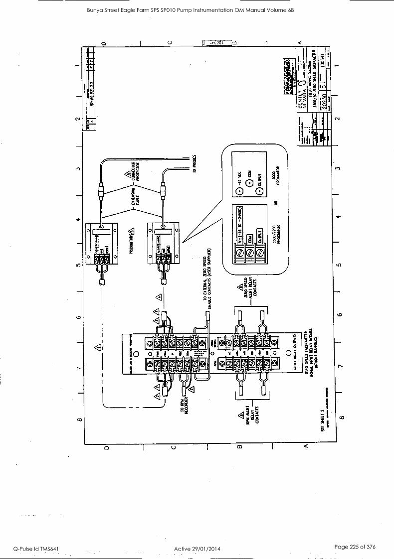
4 I
3 I
2 I
1
PRO
XM
I00
CO
NN
EC
TO
R
PR
OT
EC
TO
R
TO
R
PW
RE
CO
RD
ER
TO
E
XT
ER
NA
L Z
ER
O S
PE
ED
EN
AB
LE
CO
NT
AC
TS
(U
SE
R
SuP
PuE
D)
RP
M A
LER
T
RE
LAY
CO
NT
AC
TS
ZE
RO
SP
ED
-A
TE
RT
RE
LAT
CO
NT
AC
TS
3300
/720
0 P
RO
MIT
OR
O
R
TO
P
RO
BE
S
O-il
l vO
C
OC
OA
OU
TP
UT
MO
O
PR
Om
atO
R
SE
E W
ET
2
MO
M
IMM
O O
NO
.= M
OM
.
ER
O W
EE
D
TA
CK
ITT
EIR
SIG
NA
L IN
PU
T R
ELA
Y N
OM
E
INT
HO
ul B
AN
NE
RS
8 1
7 I
6
1110
11.1
1
AtW
D
mI9
a t
anoN
. 61
1Nw
il 11
1141
1111
.
=
BE
N T
LY
NE
VA
DA
ea
M
ID R
OW
OuG
Rud
Mgt
,A
7M7-
13
00/5
0 Z
ER
O S
PU
D
TA
CT
iON
ET
UT
"1:1
1111
52
305
ON
O
1003
41
5 4
2
Bunya Street Eagle Farm SPS SP010 Pump Instrumentation OM Manual Volume 6B
Q-Pulse Id TMS641 Active 29/01/2014 Page 225 of 376
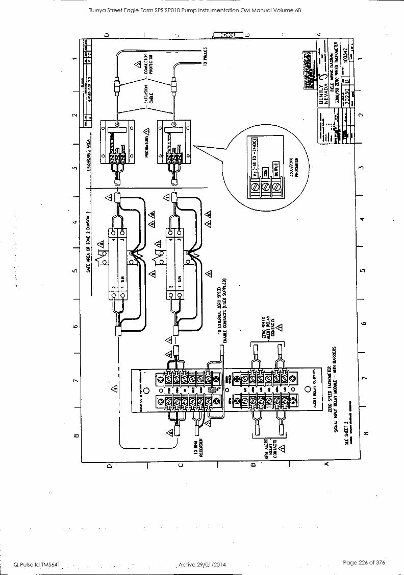
8 7
6 .5
4
3 2
L
IIN
SED
nY
r ST
I 7C
ET
F-"
;
CO
ME
CIC
il P
RO
TE
CT
OR
A&
TO
R
NA
R
EC
OR
DE
R
&A
T
O
EX
TE
RN
AL
ZE
RO
S
PE
ED
MA
KE
CO
NT
AC
TS
(U
SE
R
SU
PP
UE
D)
1[0]
mir -4
1 el
403
RP
M A
LER
T
RE
LAY
C
ON
TA
CT
S
ith
1 Z
ER
O
SP
EE
D
ME
AT
RE
LAY
CO
NT
AC
TS
ZE
RO
SP
EE
D
TA
CH
OM
ET
ER
SO
UL
NP
UT
RE
LAY
M
OD
ULE
- N
TH
B
AR
RE
RS
SE
E
SH
EE
T
2 N
OM
IM
/118
M
EM
8 1
7 6
5 4
3
10 P
RT
IIES
NE
VA
DA
""
B
EN
TLY
MO
'AM
C D
AC
RA
N
IMO
/SO
ZE
RO
SP
UD
TA
CH
OM
ET
ER
1721
13 15
1--
1003
42
1 tf
2 m
il 1
A
Bunya Street Eagle Farm SPS SP010 Pump Instrumentation OM Manual Volume 6B
Q-Pulse Id TMS641 Active 29/01/2014 Page 226 of 376
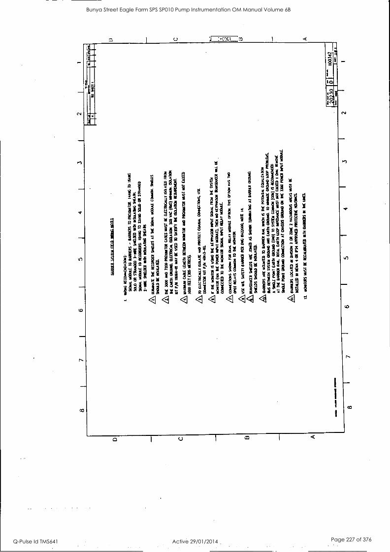
8
5 J
4 3
2
MO
MA
IM O
WN
. IM
O.
8
BA
BB
I1 2
1111
1L11
E10
11
21.2
1011
2
1.
isla
wG
RE
CO
ratm
AT
ION
s
SIG
NA
L W
WII
TO
B
AR
KE
RS
B
AR
RE
RS
10
PR
OX
IMIO
R:
14A
V1G
10
M
AR
C
SW
) O
R
=A
WE
D 3
-11f
tE
At P
ILE
D M
TH
11
152t
Abi
G S
TE
AM
.
Dic
aut
ii0D
4E T
O M
OW
ER
S
TO
RA
D
TO
22
A00
S
EW
OR
S
TR
AM
ED
2-1R
E S
IGM
A P
ITH
W
AR
RIIK
SW
AN
.
IEJO
INA
IE
DE
RE
CC
RO
CR
S
HIE
LDS
A
T A
t 931
4. N
004F
C0i
004.
SuP
2.05
9102
11)
BE
AT
HE
30
00 N
C 7
200
PR
OA
NT
OR
CA
SE
S A
uST
It
ILE
CIR
WA
ILT
IS
OLA
TE
D T
RW
If E
MIR
GU
M.
111.
L1R
iCrt
60
1AR
01t
300
VA
C (I
NS
) w
ow. P
SC
LAT
IOR
101
PA
190
04-0
1 M
AY
BE
U
SE
D
10 S
AIS
FT
lt ISO
LAT
ION
ft
WIR
DE
NT
.
A MU
NN
CA
BLE
IIN
GT
H B
ET
RE
D11
1011
TO
R
AM
O 11
10=
1OR
lis
ST
NO
T M
EM
10
00 F
IEr
(305
IM
ES
).
A10
DE
CIR
ICA
LLY
IS
OLA
TE
w
e P
RO
MO
CO
WL
oxtC
1336
, US
E
CO
optC
TO
R K
IT P
IN 4
0111
-02.
AIT
D
E W
INT
ON
IS
U
SW
DIE
A
retta
Sor
t *P
UT
DO
TA
L F
RO
M
1TE
M
IL
Wea
l CP
A
TH
E
PO
KE
R B
rut
AM
IE),
ME
N
NO
P
EU
NIA
SO
R
TR
AR
SO
uCIA
ON
1(C
1ED
10
At
IMA
I1O
R S
p3u4
.11e
uf R
ELA
Y M
OD
AL
com
unas
s W
m F
OR
D
UA
L M
IA,
1100
.0 O
PT
ION
. 01
5 O
PO
ON
HA
S
NO
oPor
Aru
n C
atuO
m T
O T
it W
HIM
.
A USE
M
IL S
WE
TT
IA
MB
HA
fo
G 1
A22
000.
NO
M I1
kit A
',Mue
r D
rEID
S P
it A
RE
A A
S W
ei ID
IAM
AIIN
G A
T
BA
RR
ER
C
RO
WD
.
SA
GA
S S
taab
BE
M
AM
E&
AR
E
YO
WLE
D
10 B
AR
RIE
R
RA
IL W
ILL
IS
DC
P
OT
EN
TIA
L E
0uA
LIZ
AB
ON
BE
T.1
114
ME
AL
GR
OuN
O A
ID C
AR
DS
O
RO
RE
I. T
O W
OR
N G
RO
UN
D
LOO
P N
OW
A
A S
olt
PO
W E
AR
TH
CR
OW
D (
ON
O)
TO
51
1100
C
Ouu
Oti
(CO
) 6
PE
CO
1uf1
0ED
Al
DE
BA
RB
ER
R
m.
TO
TA
L E
AR
TH
LO
OP
BIP
ED
NE
E M
US
T s
at E
x= I
clim
. cl
me4
SN
aE P
OIN
T G
RO
uND
C
Ort
glai
AT
01A
59S
Mud
ON
it
Iwo
P00
1 B
AIT
NO
ME
.
kBA
RR
ET
T'S
LO
CA
TE
D N
moa
t 2
OR
M
t 2
KA
TA
ND
CW
A
RE
AS
NuS
T
BE
US
TA
ILD
N
MIA
4
OR
154
AM
MO
PR
OT
TC
1* M
AK
I
11
NO
MT
CR
S h
ug B
E R
EC
AU
BR
AT
ID
N 1
NE
O
ILS
Aul
A
24/1
al
usrr
2023
0 ,"
7 6
1 5
I 4
1 3
1 2
1 1
1003
42
Bunya Street Eagle Farm SPS SP010 Pump Instrumentation OM Manual Volume 6B
Q-Pulse Id TMS641 Active 29/01/2014 Page 227 of 376

8 7
4
L
W(
AM
A O
R
NN
E
2.
Oia
SIO
N
2
10
El I
I 1M
A
RO
SP
EE
D
(NN
BE
CC
NIA
CIS
(uS
ER
SU
PIN
AID
10 K
W
RE
CO
RD
ER
SE
E W
EI
2
Km
%
goal
. olm
u sm
IaD
SCA
M.
OU
TPU
TS
RIC
CO
D
ALA
RM
P
ILA
1r O
UT
PUT
S
AR
O S
PE
ED
1A
0401
1EIR
slam
IN
PU
1 K
EW
1R
DI
INIII
DIA
t B
AR
RIE
RS
8 7
SN
UG
&
MA
ZA
RO
CIU
S A
RE
A
PR
OK
BA
ITO
RS
C
ON
K C
TO
R
PR
OIlC
IOR
10
PR
OO
FS
A WA
RN
ING
:Z
NY
IVZ
VLI
TA
Lre=
O
P..
6.m
M...
ft
MIS
CC
NN
EC
TIN
G O
R
INT
ER
Mill
EN
I C
ON
IAC
I C
E
1HE
FE
LD
WR
ING
10
RA
CK
IE
RM
NA
LS
IAT
H H
IGH
V
OLT
AG
E
PO
ICN
1IA
LS
CO
ULD
C
AU
SE
A
N
EX
PLO
SIO
N
OR
F
IRE
IN
TH
E
HA
ZA
RD
OU
S A
RE
A
RE
SU
L1IN
G
IN
SE
VE
RE
PE
RS
ON
AL
INJU
RY
O
R
DE
AT
H
RE
MO
VE
A
LL
VO
LTA
GE
PO
TE
NT
IALS
F
RO
M
RE
AR
a
RA
CK
.
1114
1.41
111
saw
* 0
BE
N IL
N
EV
AD
A
Y
""":
.:"' -.
FIE
LD
MIR
ING
DIA
GR
AM
3300
/50
ZE
RO
S
PE
ED
T
AC
HO
WIE
R
aim
- a-
Ear
r'^ii
2023
0 D
12
5595
m
r.ra
6
5 4
3 2
1
D . rn uI
Bunya Street Eagle Farm SPS SP010 Pump Instrumentation OM Manual Volume 6B
Q-Pulse Id TMS641 Active 29/01/2014 Page 228 of 376
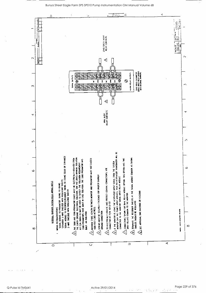
2
INT
ER
NA
L_ B
AR
RIE
R 5
1511
11
FIE
LD
WIR
ING
NOTES
1 W
IRIN
G
RE
CO
MM
EN
DA
TIO
NS
:
SIG
NA
L M
OD
ULE
10
PR
OW
YR
IOR
: 16
AV
EG
T
O
MA
NG
ST
RA
ND
ED
3
-WIR
E
SH
IELD
ED
W
ITH
IN
SU
LAT
ING
S
HE
AT
H.
SIG
NA
L M
OD
ULE
10
RE
CO
RD
ER
/RE
AD
OU
T:
TB
AV
IG
10
22A
MC
SO
LO O
R
ST
RA
ND
ED
2-W
IRE
S
HIE
LDE
D
WI1
H
INS
ULA
TIN
G
SH
EA
TH
.
AD
iE
3000
A
ND
72
00 P
RO
x0R
ICR
C
AS
ES
M
US
T
BE
E
LEC
TR
ICA
LLY
IS
OLA
TE
D
FR
CW
TH
E
EA
RT
H
GR
OU
ND
. E
LEC
TR
ICA
L IS
OLA
TIO
N:
500
VA
C
(RIO
S)
MIN
IMU
M.
ISO
LAT
ION
K11
P
/N
1909
4-01
M
AY
B
E
US
ED
10
S
AT
ISF
Y
TH
E
ISO
LAT
ION
RE
CuI
RE
LTE
NT
.
3303
P
R0x
am10
R5
HA
YS
13
011
IN C
AS
E
ISO
LAT
ION
. T
HE
33
00
PR
O1I
M10
R H
AS
MI
ISO
LAT
ION
.
/3\ M
AX
IMU
M
CA
BLE
LE
NG
TH
BE
TW
EE
N
MO
NIT
OR
AN
D
PR
OX
IMIT
OR
LO
ST
N
OT
E
XC
EE
D
1000
FE
ET
(3
05 M
ET
RE
S).
AS
CR
EW
S M
US
T
BE
S
EC
UR
ELY
F
AS
TE
NE
D
FO
R P
RO
PE
R
BA
RR
IER
CR
OA
T)
CO
NN
EC
TIO
N
A\ 1
0 E
LEC
TR
ICA
LLY
IS
OLA
TE
A
ND
P
RO
TE
CT
C
OA
XIA
L C
ON
NE
CT
ION
S.
US
E
CO
NN
EC
TO
R K
O
P/N
401
13-0
2
/6\ if
T
HE
M
ON
ITO
R
IS us
INC
1H
E
KE
YP
HA
SO
R
INP
UT
S
ICN
AL
FR
OM
T
HE
S
YS
TE
M
MO
NIT
OR
(N
A
TH
E
R01
01
INP
UT
m
0001
).
TH
EN
N
O
RE
YP
HA
SO
R
TR
AN
SD
UC
ER
W
ILL
BE
CO
NN
EC
TE
D
10
DLL
m
OrR
IOR
S10
.4/9
. IN
PU
I R
ELA
Y
MO
DU
LE
A.4
chi,.
SK
EA
N
FU
R
DU
AL
RU
N 1
100u
LE
OP
TIO
N
DR
S O
PT
ION
HA
S
TW
O
DP
OT
R
ELA
YS
C
OM
MO
N
10
TH
E
MO
NIT
OR
.
78\
TE
RM
INA
TE
T
HE
R
EC
OR
DE
R
SH
IELD
S A
l T
HE
S
IGN
AL
MO
DU
LE
CO
MM
ON
A
S
SH
OW
N.
SH
IELD
S
SN
OW
) B
E
INS
ULA
TE
D
AS
EE
A
PP
RO
VA
L O
voG
B
A12
000
OR
CA22000.
.01
laal
11 0
411I
l M
UM
>
RP
M
ALE
RT
RE
LAY
C
ON
TA
CT
S
PI W
an
law
."
1
SC
NA
l O
UIP
uIS
ALM
. R
ELA
Y
7111
0 S
PU
D T
ALI
ON
IIR
9010
1. H
UT
RE
LAY
PLP
$JL(
MIN
IN
IIR/IN
. B
AIM
ITA
S
4 1
3
OR
O
SP
UD
A
llit1
R
ELA
Y
CO
NT
AC
TS
?.02
30
i)
11 ,
-))J
2 1 i..
1
1)
1 i A
Bunya Street Eagle Farm SPS SP010 Pump Instrumentation OM Manual Volume 6B
Q-Pulse Id TMS641 Active 29/01/2014 Page 229 of 376
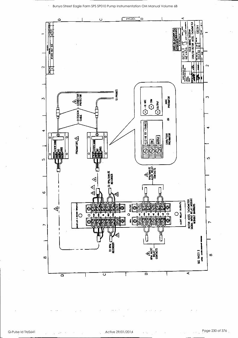
TO
R
PM
RE
CO
RO
ER
RP
M
ALE
RT
R
ELA
Y -
CO
NT
AC
TS
F
&
RP
M/I/
MU
LE
MIR
Y R
ELA
Y
CO
NT
AC
TS
RO
TO
R A
CC
II. T
AC
HO
ME
TE
R
SO
UL
MU
T R
ELA
Y M
CC
UE
M
IMI
BA
RR
IER
S
SE
E S
KE
ET
2
ainm
w
ow e
mew
s w
asp
3300
/720
0 P
RO
XIM
ITO
R
OR
TO
P
RO
BE
S
0 -t
8 O
C
(-) C
ON
C>
OU
TP
UT
3000
P
RO
WIT
OR
MIN
N=
O
IND
ICA
O M
a S
IZE
NO
= M
OW
N.
IIMIN
NO
om
il.
1111
.111
.
F--
w4s
e-w
"'l
NE
V T
LY
NE
VA
DA
..)
FIE
LO
WR
ING
D
IAG
RA
M
3300
/50
RO
TO
R
AC
C&
T
AC
HO
mE
ltit
202.
30
1003
44
1-
jai
7 6
5 4
3 2
1
D
C
Bunya Street Eagle Farm SPS SP010 Pump Instrumentation OM Manual Volume 6B
Q-Pulse Id TMS641 Active 29/01/2014 Page 230 of 376
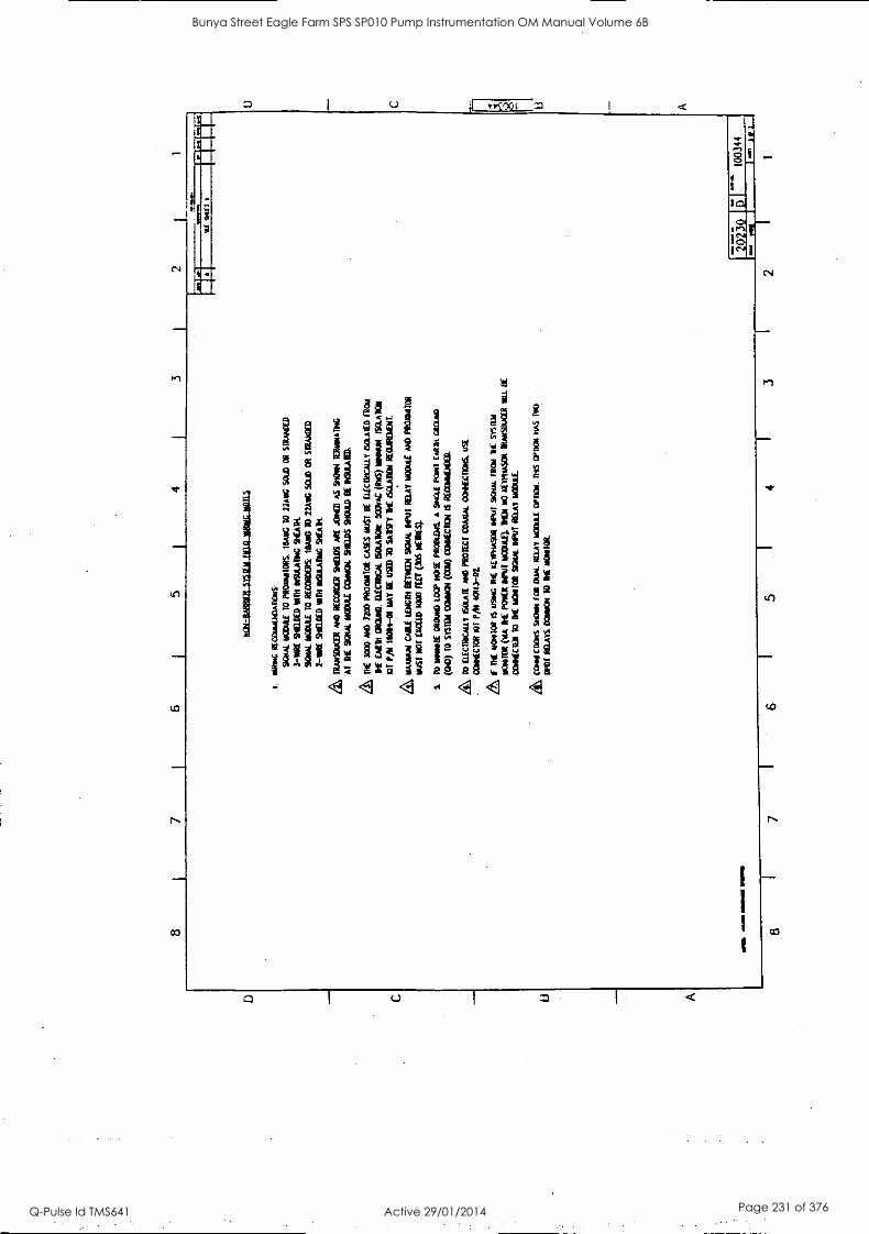
8 7
6 5
4 3
glili
tiltE
L11
1111
.111
11.1
011k
1101
1.5
1.
NR
ING
RE
cmat
hOA
DoR
S:
SCR
AL
HO
OL
AF
TO
PR
Om
itOR
S:
MA
RC
TO
22
AN
G S
OW
O
R
STR
AN
DE
D
3-T
IRE
SH
IEL
DE
D V
IM I
NSU
LA
NG
SN
EA
K
SOU
L 1
1001
11
TO
R
EC
OR
DE
RS:
II
LA
M
TO
22
Ave
SO
LD
OR
M
UM
2 -
NN
E M
EL
DE
D 1
101
INSU
LA
TM
C S
HE
AR
TR
AN
SIK
ER
AN
D
RE
CO
RD
ER
M
EL
DS
AM
AIL
ED
AS
StIO
YN
T
ER
NN
IAT
RIG
AT
T
HE
sc
am.
IIC
OU
LE
WO
W S
TE
WS
STO
LID
EE
M
SUL
AU
D.
th M
E
3000
/M
D
7200
PR
OD
INT
OR
C
ASE
S M
UST
B
E E
LE
CT
RIC
AL
LY
ISC
LA
TE
D F
RO
M
H E
AR
TH
mos
. &
MIC
A 6
0LA
DO
ID
DO
NA
C (
RiS
) R
esul
t IS
OL
AT
ION
Fa P
/11
1908
4 -0
1 M
AY
B
E
USE
D
TO
SA
W(
TH
E
60L
A1I
0N R
EC
uRE
ME
RL
MA
XX
AM
C
AB
LE
to
ronr
Krim
sax
MT
MA
Y W
OR
E A
ND
PR
OD
ILIT
OR
RU
ST
NO
T E
XC
EE
D
1000
nir
(305
ME
WS)
.
S
to m
emst
f M
OR
RO
Loo
P to
sE P
RO
OL
EK
, A
9N
CL
E P
ON
T
FAR
M M
OM
(G
O)
TO
SY
S101
CO
INC
tl (0
20 C
EN
NE
CT
ICt4
6 R
EC
OIN
IDO
EL
L
TO
D
.EC
IIN
CK
LY
60L
A1E
A
ND
PR
OT
EC
T
DU
RA
L c
omcn
cers
. us
r C
ON
NE
CT
CR
RL
T
P/14
40
113-
02.
if'
DIE
W
INK
* IS
U
SW !
If I
LE
YM
ASO
R p
etit
gam
FR
OM
R
E S
YST
EM
MO
NIT
OR
CA
A
DE
P01
ER
WH
Y W
OR
E).
D10
1 N
O
KE
ITII
ASO
R
itoet
soua
rt a
u B
E
CO
NE
CID
10
DE
LIC
M10
R
SOU
L W
O M
AY
laT
uE.
cotH
EM
NS
mom
IO
N a
pt R
am m
Ocu
f aq
ui
nis
woa
d oA
s IM
O
OW
RE
LA
YS
MIN
CH
TO
M
E
MO
NIT
OR
.
2 1
Bunya Street Eagle Farm SPS SP010 Pump Instrumentation OM Manual Volume 6B
Q-Pulse Id TMS641 Active 29/01/2014 Page 231 of 376
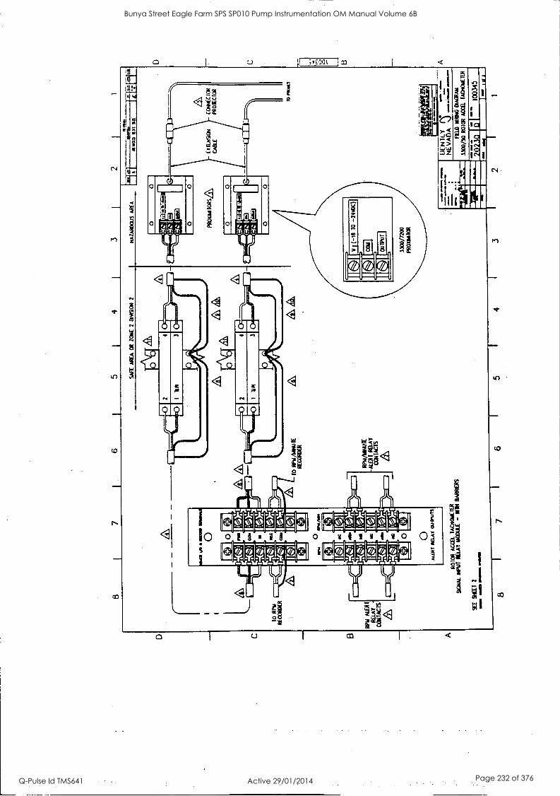
801331084 31F
1X1
80103NX
403 N
06NI1 X
3
Bunya Street Eagle Farm SPS SP010 Pump Instrumentation OM Manual Volume 6B
Q-Pulse Id TMS641 Active 29/01/2014 Page 232 of 376
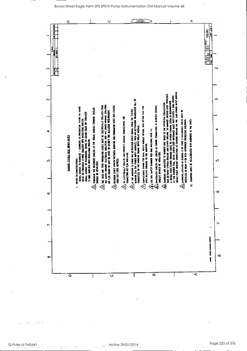
_la otioz
I I 111/6 /6
M
16,1ur M
Y
1
9 L
9
S3W1 31
11 %M
f8 WIN
1111A111,731 33
15(14 S11010101
TO
WN
NO
TIO
N M
OR
I Kd
BO
W
131 PM
1111341011
311 ISAN
svoit snot:Dram
t 3N
O2 1A
t 009110
M C
r11v531 survive
7TIO
ns zwe
1D11pI llO
rt rill N
O
O W
IC
=A
SO r
ICIL
TIN
ICO
MO
D L
ed 719115 310430 7610
1 0330X3 JO
N ISM
3111vWJ1 40301 PO
W) W
101 'To m
om oil Iv
0301011003e (1w
) wow
Finis 01 (cno) com
er 1ailY
3 DO
M 3046
v
'mam
a don moo ingespi in m
oo vire cm w
oo MO
OD
IUM
sro N
Orarr10)
WIN
310,1 31 SI
KIN
N W
/I 131111141 ci
(13MO
R lir R
OH
M
rOivroe
3B ante SIM
MS
mim
e nom iv m
oment 11186 sr O
mer ow
Sams vm
movonV
304 tw
irl mo 83d m
um inns
7154 isnV
1000111 341 al 104403 SAY
1010
oil S'64 MU
D
SIM M
UD
TO
MO
WU
lrt10 1101 M
IMS 5606364103 W
-7/1C
OPI
INN
W
4 N
OU
POI Ill 01 U
MW
=
itIonecova vosvmaiD
Or 1011 IntoO
n 113004 311 w
ig 1031114311
*31515 Itt N
OW
mos inn ictsvtilui X
I 'EA
st ottm
311
10-ttio 1141 oi 1101.10M0
SIC1173011:0 -w
w410 132101d O
MV
wrog K
T/rill/W
O 01 W
153110
0001
033333 ion 15(31 V3I0101 il
Wool'
KIN
U.113 M
VP M
r) norm
1100010111 MO
MS 31 ',M
IN5 Q
033113111471 10-40061 M
id 111
=m
ost Irma, O
M N
A Q
C
14415(1011 713W3713 w
oo rum m
m
osj 031,11)51 A
lW31/113313
31 rzm S3SY
3 10310130511 0011 O
N O
a 314
38 OE
M
501316 'NO
M Prom
rnita 34I 1V
9333111 x4]0:031 311 31Wo0E
W
MV
Os tvIN
VISII
CO
OT
OO
Ml -1
coMtviS v0 431X
Or=
01 91v11 Z
ol000311 C
IL non
WIR
NS
1115(3113 9otiv11511 N
IP. 03013/5 310-t 0313111115
543 IDS
011WI 01
011v11 =im
am 01 900R
IV2 -
SNIN
WO
01 MO
OS 10:36
'910aV(N
11610336 MO
HR
'I
SII133131Mr1M
3WIM
IST1011W
g
111 1111M
1011 MU
% =
IN
9 1
L i
g
Bunya Street Eagle Farm SPS SP010 Pump Instrumentation OM Manual Volume 6B
Q-Pulse Id TMS641 Active 29/01/2014 Page 233 of 376
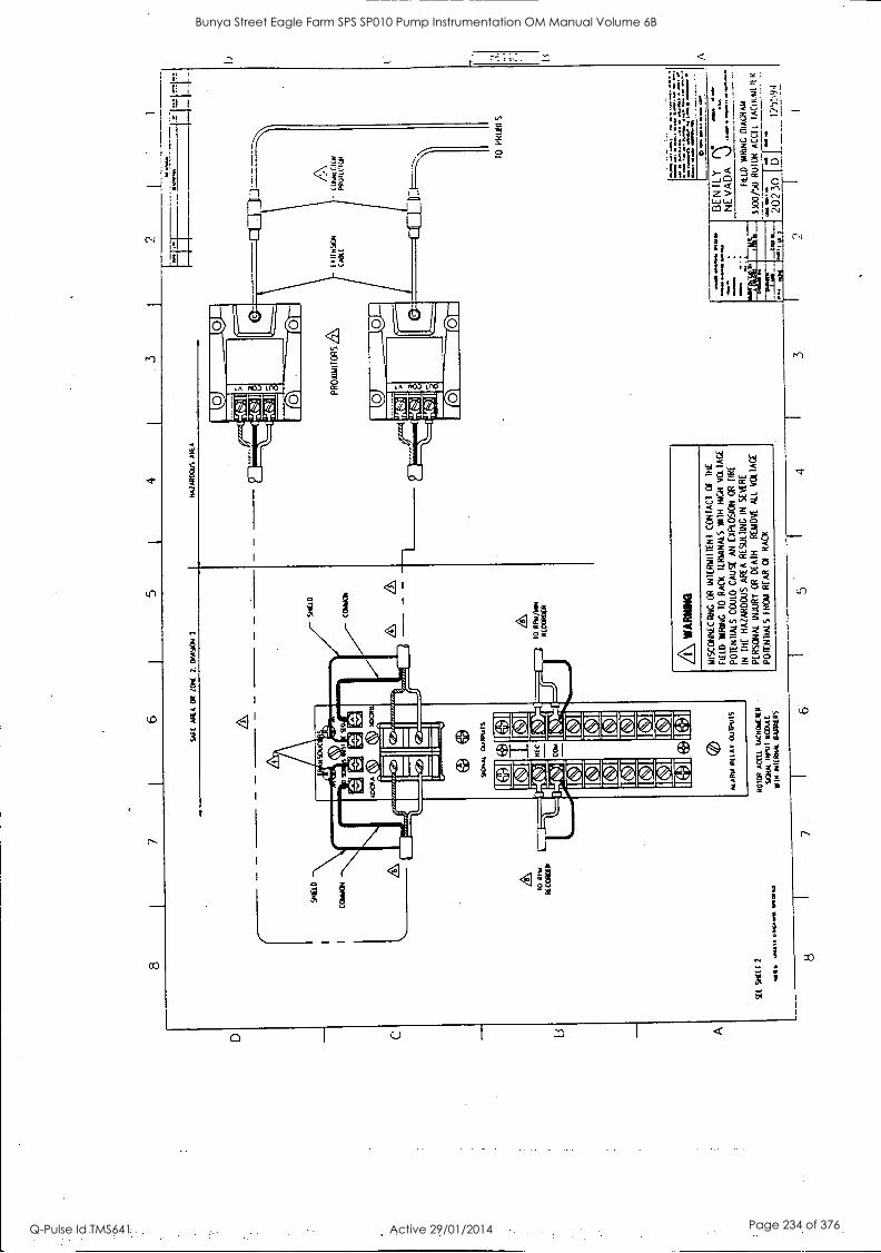
8
SA
ES
A
RE
A
OR
Z
ON
E
2,
DIV
ISIO
N
2
4
HA
ZA
RD
OU
S
AR
EA
PR
OA
TIN
TO
RS
ZL
SE
E
SN
EE
I 2
WK
S
0.04
. 0.
1.41
11 N
CO
.
RO
TO
R
AC
CLL
IA
CH
CA
ILIE
R
%H
AL
INP
UI
RO
DU
LL
VO
IR
OIH
RH
AL
BA
RR
IER
S
A WA
RN
ING
Tei
SC
ON
NE
CT
ING
OR
iN
TE
RN
ITT
EN
I C
ON
TA
CT
O
f T
HE
FIE
LD
VA
RT
NG
10
RA
CK
T
ER
MN
ALS
V
A1H
H
IGH
VO
LIA
GE
PO
TE
NT
IALS
CO
ULD
C
AU
SE
A
N
EX
PLO
SIO
N
OR
F
IRE
IN
TH
E
HA
ZA
RD
OU
S
AR
EA
RE
SU
LTIN
G I
N
SE
VE
RE
PE
RS
ON
AL
INJU
RY
OR
D
EA
TH
R
EM
OV
E A
LL
VO
LTA
GE
PO
TE
NT
IALS
TR
W
RE
AR
O
f R
AC
K
10 P
HU
:4.S
.7.7
......
..1..:
::.r.
r....
...
ID
*ow
ao
. -
-
8 7
6 4
3
DE
N T
L Y
r°
N
EV
AD
A
g:rL
ia.1
-'-47
47"
FIE
LD
W33
00/5
0 R
OT
OR
A
CM
. IA
Ctio
uL
It R
ELD
R
ING
D
IAG
NA
N
-ear
=
Mx
8-'.-
20
230
D
I I2
5:19
4
Bunya Street Eagle Farm SPS SP010 Pump Instrumentation OM Manual Volume 6B
Q-Pulse Id TMS641 Active 29/01/2014 Page 234 of 376
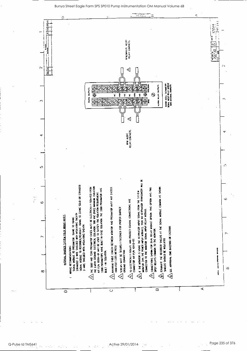
D C B A
8 I
7 I
6 1
5 4
1 3
INIL
RN
AL
BA
RR
IER
SY
ST
EM
F
IELD
W
IRIN
G N
OT
ES
I W
RIN
G
RE
CO
MM
EN
DA
TIO
NS
:
SIG
NA
L M
OD
ULE
10
PR
OX
IMIT
OR
: 16
AW
C T
O
MA
C
ST
RA
ND
ED
3
-WA
RE
S
HIE
LDE
D W
ITH
IN
SU
LAT
ING
%
CA
M
SIG
NA
L M
OD
ULE
10
RE
CO
RD
ER
/RE
AD
OU
T:
1BA
WG
10
22A
WC
S
OLI
D O
R
ST
RA
ND
ED
2 -R
AR
E
SH
IELD
ED
Y
AM
IN
SU
LAT
ING
S
HE
AT
H
/2\ M
E
3000
A
ND
72
00
PR
OX
IVIT
OR
C
AS
ES
T
RU
ST
B
E
ELE
CT
RIC
ALL
Y I
SO
LAT
ED
F
RC
A4
TH
E
EA
RT
H G
RO
UN
D
ELE
CT
RIC
AL
ISO
LAT
ION
: 50
0 V
AC
(R
MS
) M
INIM
UM
. IS
OLA
TIO
N
Klf
P/N
190
94-0
1 M
AY
B
E
US
ED
10
S
AT
ISF
Y
TH
E
ISO
LAT
ION
RE
CoR
Em
EN
I
3300
PR
OX
IMIT
OR
S
HA
VE
B
U41
IN
C
AS
E *C
LAIM
. T
HE
33
00
PR
OX
ILU
TO
R H
AS
BU
ILT
-I
N
ISC
I.AT
ICN
.
3 \ MA
XIM
UM
C
AB
LE
LEN
GT
H B
ET
WE
EN
MO
NIT
OR
AN
D
PR
Oxi
milO
R M
US
1 N
OT
E
XC
EE
D
1000
FE
ET
(3
05 (
AIR
ES
)
/4\ S
CR
EW
S
MU
ST
B
C
SE
CU
RE
LY
FA
ST
EN
ED
F
OR
P
RO
PE
R
BA
RR
IER
GR
OU
ND
C
ON
NE
CT
ION
/5\ 1
0 E
LEC
TR
ICA
LLY
IS
OLA
TE
AN
D
PR
OT
EC
T C
OA
XIA
L C
ON
NE
CT
ION
S.
US
E
CO
NN
EC
TO
R
101
P/N
40
113 -
02.
/6\ IF
T
HE
M
ON
ITO
R
IS
US
ING
M
E
KE
YP
HA
SO
R
INP
UT
S
IGN
AL
RD
A T
HE
S
YS
TE
M
MO
NIT
OR
(M
A
TH
E
PO
WE
R
INP
UT
M
OD
ULE
),
TH
EN
NO
X
EY
PH
AS
OR
T
RA
NS
DU
CE
R W
EL
BE
CO
NN
EC
TE
D
TO
T
HE
M
ON
ITO
R
SIG
NA
L IN
PU
T
RE
LAY
M
OD
ULE
.
AC
ON
NE
CT
ION
S
SH
OW
N
FO
R
CA
ME
R
ELA
Y
MO
DU
LE
OP
TIO
N
MIS
O
PT
ION
H
AS
IW
O
DP
OT
R
ELA
YS
C
OM
MO
N T
O
DIE
M
ON
ITO
R.
Z\ T
ER
MIN
AT
E
TH
E
RE
CO
RD
ER
S
HIE
LDS
A
l T
HE
si
crat
wow
CO
MM
ON
A
S
SH
OW
N.
SH
IELD
S
SH
OU
LD B
E
INS
MA
IED
AS
EE
A
PP
RO
VA
L D
WC
B
A22
000
OR
C
A22
000
RP
M *U
RI
RE
LAY
C
CN
IAC
TS
SIG
NA
L O
MIT
Su
AR
M
NO
NC
AR
IA
NO
4+:
RP
M/W
M
AL M
N R
ELA
I1
PU
IS
1101
01 A
MU
IA
DLO
YIE
IER
900,
1 f.U
1 R
ELA
Y
NO
UN
(
win
INT
ER
NA
L B
AR
RIE
RS
2
-art
-
RT
,u/k
liNtil
i A
UN
T
RE
LAY
cu
NlA
cis
8 1
7 I
6 1
5 4
_ !L
.! I n.
59:1
. 20
') S
O
. __
. %
oaf
...E
SL c
oma.
, IN
CA
.
Bunya Street Eagle Farm SPS SP010 Pump Instrumentation OM Manual Volume 6B
Q-Pulse Id TMS641 Active 29/01/2014 Page 235 of 376

Tachometer Maintenance 83871-01
32 1 Recommended Spare Parts
OTY DESCRIPTION PART NUMBER
TACHOMETER 3300/50
1 FRONT PANEL ASSEMBLY 84133-01 Dual Setpoint Tach 84950-01 Zero Speed Tach 84951-01 Rotor Accel. Tach
MONITOR CIRCUIT ASSEMBLY 82962-01
1 EXPANDER BOARD PWA 81410-01
SIGNAL INPUT RELAY MODULE
Dual Setpoint Tach: No Relays 84689-01 No Relays W/Intemal Barriers 88843-07 Epoxy Sealed Relays 84140-01 Epoxy Relays W/Intemal Barriers 88843-04 Hermetically Sealed Relays 84148-01 Hermetic Relays W/Intemal Barriers 88843-01
Zero Speed Tach: No Relays 84690-01
No Relays W/Intemal Barriers 88843 -08 Epoxy Sealed Relays 84141-01
Epoxy Relays W/Intemal Barriers 88843-05
Hermetically Sealed Relays 84147-01
Hermetic Relays W/Intemal Barriers 88843-02
Rotor Accel. Tach: No Relays 84691 -01
No Relays W/Intemal Barriers 88843-09
Epoxy Sealed Relays 84142-01 Epoxy Relays W/Intemal Barriers 88843-06
Hermetically Sealed Relays 84148-01
Hermetic Relays W/Intemal Barriers 88843-03
1 Spare Jumpers (100 pieces) 88706-01
TO ORDER REPLACEMENT PARTS, SPECIFY THE COMPLETE PART NUMBER, 3300/50 -00-00-00-00, AND THE REPLACEMENT PART NUMBER. If the monitor has been modified, specify the modification number
on the parts order. User must set programmable options (reference section 10 of this manual). If in doubt about
the part number, call your BENTLY NEVADA CORPORATION representative before ordering.
PART NO
TACHOMETER
,300'50 - - - CO - CID 10:01FICATIO.
NAIRN
CIA1104 PINT
S.N DATE
ACCCAOL Cl/TIAIT
75
Bunya Street Eagle Farm SPS SP010 Pump Instrumentation OM Manual Volume 6B
Q-Pulse Id TMS641 Active 29/01/2014 Page 236 of 376
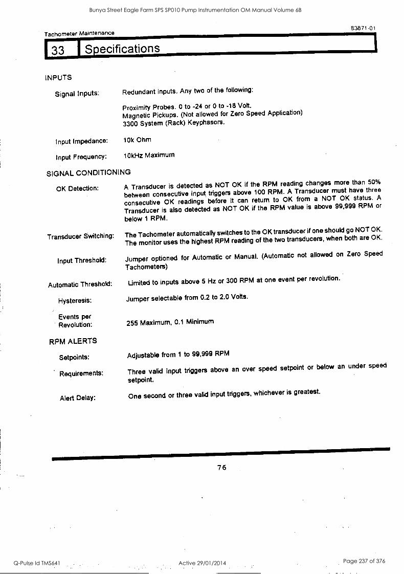
Tachometer Maintenance 83871-01
33 1 Specifications
INPUTS
Signal Inputs: Redundant inputs. Any two of the following:
Proximity Probes. 0 to -24 or 0 to -18 Volt.
Magnetic Pickups. (Not allowed for Zero Speed Application)
3300 System (Rack) Keyphasors.
Input Impedance: 10k Ohm
Input Frequency: 10k Hz Maximum
SIGNAL CONDITIONING
OK Detection: A Transducer is detected as NOT OK if the RPM reading changes more than 50%
between consecutive input triggers above 100 RPM. A Transducer must have three
consecutive OK readings before it can return to OK from a NOT OK status. A
Transducer is also detected as NOT OK if the RPM value is above 99,999 RPM or
below 1 RPM.
Transducer Switching: The Tachometer automatically switches to the OK transducer if one should go NOT OK.
The monitor uses the highest RPM reading of the two transducers, when both are OK.
Input Threshold: Jumper optioned for Automatic or Manual. (Automatic not allowed on Zero Speed
Tachometers)
Automatic Threshold: Limited to inputs above 5 Hz or 300 RPM at one event per revolution.
Hysteresis: Jumper selectable from 0.2 to 2.0 Volts.
Events per Revolution: 255 Maximum, 0.1 Minimum
RPM ALERTS
Setpoints: Adjustable from 1 to 99,999 RPM
Requirements: Three valid input triggers above an over speed setpoint or below an under speed
setpoint.
Alert Delay: One second or three valid input triggers, whichever is greatest.
76
Bunya Street Eagle Farm SPS SP010 Pump Instrumentation OM Manual Volume 6B
Q-Pulse Id TMS641 Active 29/01/2014 Page 237 of 376
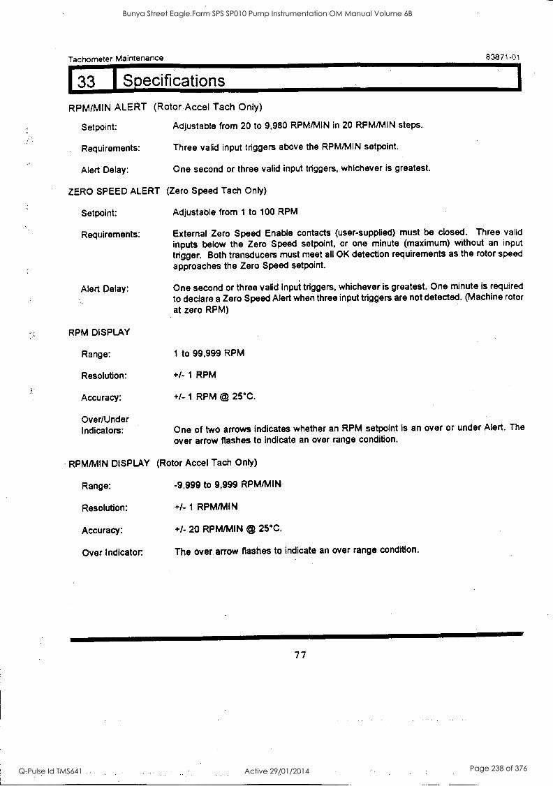
Tachometer Maintenance
RPM/MIN ALERT (Rotor Accel Tach Only)
Setpoint: Adjustable from 20 to 9,980 RPM/MIN in 20 RPM/MIN steps.
Requirements: Three valid input triggers above the RPM/MIN setpoint.
Alert Delay: One second or three valid input triggers, whichever is greatest.
ZERO SPEED ALERT (Zero Speed Tach Only)
Setpoint: Adjustable from 1 to 100 RPM
83871-01
Requirements: External Zero Speed Enable contacts (user-supplied) must be closed. Three valid inputs below the Zero Speed setpoint, or one minute (maximum) without an input
trigger. Both transducers must meet all OK detection requirements as the rotor speed
approaches the Zero Speed setpoint.
Alert Delay: One second or three valid input triggers, whichever is greatest. One minute is required
to declare a Zero Speed Alert when three input triggers are not detected. (Machine rotor
at zero RPM)
RPM DISPLAY
Range: 1 to 99,999 RPM
Resolution: +/- 1 RPM
Accuracy: +/- 1 RPM @ 25°C.
Over/Under Indicators: One of two arrows indicates whether an RPM setpoint is an over or under Alert. The
over arrow flashes to indicate an over range condition.
RPM/MIN DISPLAY (Rotor Accel Tach Only)
Range: -9,999 to 9,999 RPM/MIN
Resolution: +/- 1 RPM/MIN
Accuracy: +/- 20 RPM/MIN 25°C.
Over Indicator. The over arrow flashes to indicate an over range condition.
77
Bunya Street Eagle Farm SPS SP010 Pump Instrumentation OM Manual Volume 6B
Q-Pulse Id TMS641 Active 29/01/2014 Page 238 of 376
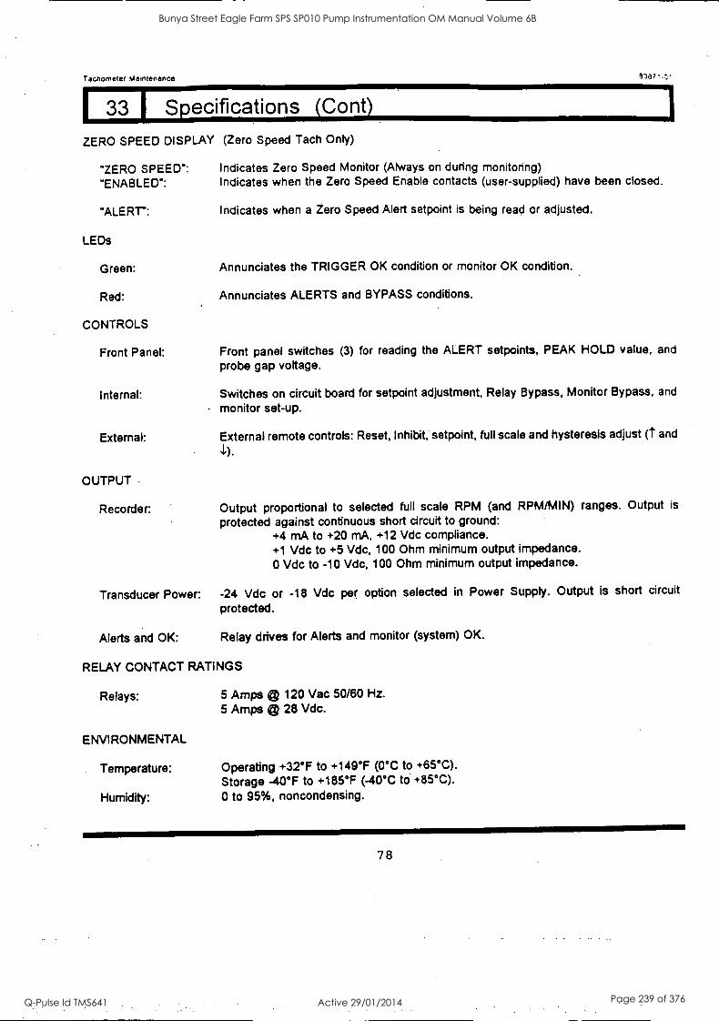
Tachometer Maintenance 3387..t.;
33 1 Specifications (Cont)
ZERO SPEED DISPLAY (Zero Speed Tach Only)
"ZERO SPEED": Indicates Zero Speed Monitor (Always on during monitoring)
"ENABLED": Indicates when the Zero Speed Enable contacts (user-supplied) have been closed.
"ALERT":
LEDs
Green:
Red:
CONTROLS
Front Panel:
Internal:
External:
OUTPUT
Recorder:
Indicates when a Zero Speed Alert setpoint is being read or adjusted.
Annunciates the TRIGGER OK condition or monitor OK condition.
Annunciates ALERTS and BYPASS conditions.
Front panel switches (3) for reading the ALERT setpoints, PEAK HOLD value, and
probe gap voltage.
Switches on circuit board for setpoint adjustment, Relay Bypass, Monitor Bypass, and
monitor set-up.
External remote controls: Reset, Inhibit, setpoint, full scale and hysteresis adjust (t and
Output proportional to selected full scale RPM (and RPM/MIN) ranges. Output is
protected against continuous short circuit to ground: +4 mA to +20 mA, +12 Vdc compliance. +1 Vdc to +5 Vdc, 100 Ohm minimum output impedance. 0 Vdc to -10 Vdc, 100 Ohm minimum output impedance.
Transducer Power: -24 Vdc or -18 Vdc per option selected in Power Supply. Output is short circuit
protected.
Alerts and OK: Relay drives for Alerts and monitor (system) OK.
RELAY CONTACT RATINGS
Relays: 5 Amps t 120 Vac 50/60 Hz. 5 Amps © 28 Vdc.
ENVIRONMENTAL
Temperature: Operating +32°F to +149°F (0°C to +65°C).
Storage -40°F to +185°F (-40°C to +85°C).
Humidity: 0 to 95%, noncondensing.
78
Bunya Street Eagle Farm SPS SP010 Pump Instrumentation OM Manual Volume 6B
Q-Pulse Id TMS641 Active 29/01/2014 Page 239 of 376
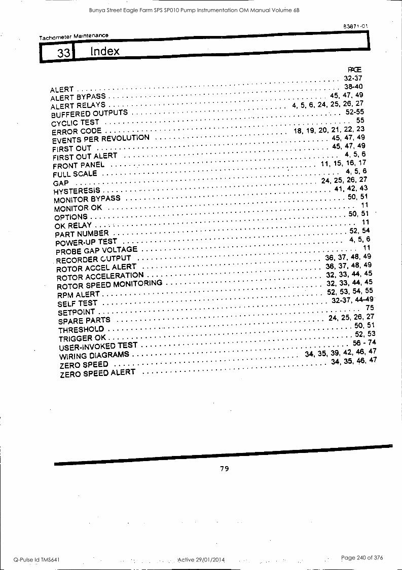
Tachometer Maintenance
3387101
3 Index
ALERT ALERT BYPASS
RCE 32-37 38-40
ALERT RELAYS 45, 47, 49
BUFFERED OUTPUTS 4, 5, 6, 24, 25, 26, 27
CYCLIC TEST
52-55
ERROR CODE
55
EVENTS PER REVOLUTION 18, 19, 20, 21, 22, 23
FIRST OUT 45, 47, 49
FIRST OUT ALERT 45, 47, 49
FRONT PANEL
4, 5, 6
FULL SCALE
11, 15, 16, 17
GAP
4, 5, 6
HYSTERESIS
24, 25, 26, 27
MONITOR BYPASS
41, 42, 43
MONITOR OK 50, 51
OPTIONS
11
OK RELAY
50, 51
PART NUMBER
11
POWER-UP TEST
52, 54
PROBE GAP VOLTAGE 4, 5, 6
RECORDER CUTPUT
11
ROTOR ACCEL ALERT 36, 37, 48, 49
ROTOR ACCELERATION 36, 37, 48, 49
ROTOR SPEED MONITORING 32, 33, 44, 45
RPM ALERT
32, 33, 44, .45
SELF TEST
52, 53, 54, 55
SETPOI NT
32-37, 44-49
SPARE PARTS
75
THRESHOLD
24, 25, 26, 27
TRIGGER OK
50, 51
USER-INVOKED TEST 52, 53
WIRING DIAGRAMS
56 - 74
ZERO SPEED
34, 35, 39, 42, 46, 47
ZERO SPEED ALERT
34, 35, 46, 47
79
Bunya Street Eagle Farm SPS SP010 Pump Instrumentation OM Manual Volume 6B
Q-Pulse Id TMS641 Active 29/01/2014 Page 240 of 376

BRISBANE CITY COUNCIL Dept. Water Supply and Sewage Pumpwell No 1, Eagle Farm Pump Station
BCC Contract No S20/95/96 System Instrumentation
Operation and Maintenance Manual
8.3 Vibration Monitor
The following publication entitled 3300/55 Dual Velocity Monitor Maintenance Manual (Part No 130748-01 Rev C) is prepared by Bendy Nevada for plant personnel who install and maintain the system. It provides a detailed description of the maintenance and adjustment procedures for the of the Dual Velocity module.
The following sections are included:
8.3.1 Dual Velocity Monitor System
8.3.2 Front Panel Features
8.3.3 Monitor Removal
8.3.4 Monitor Disassembly
8.3.5 Signal Input Relay Module
8.3.6 Monitor Options
8.3.7 Main Board Jumper Locations
8.3.8 PK-PK Filter Board Jumper Locations
8.3.9 RMS Filter Jumper Locations
8.3.10 First Out, Alarm Delays
8.3.11 Alert Mode, Danger Mode
8.3.12 Danger Relay Voting
8.3.13 Buffered Transducer Output Option
8.3.14 Transducer Channel Units Input Option
8.3.15 Transducer Type Option
8.3.16 Channel A Full Scale Range Option
8.3.17 Channel B Full Scale Range Option
8.3.18 Barriers, Trip Multiply Options
8.3.19 Alarm Setpoint Adjustment
8.3.20 Bypass Monitor Channel
8.3.21 Danger Bypass
15140/Inst Man/BRH Issue 1 29-App:98 Page 8-5
Bunya Street Eagle Farm SPS SP010 Pump Instrumentation OM Manual Volume 6B
Q-Pulse Id TMS641 Active 29/01/2014 Page 241 of 376

BRISBANE CITY COUNCIL Dept. Water Supply and Sewage Pumpwell No 1, Eagle Farm Pump Station
BCC Contract No S20/95/96 System Instrumentation
Operation and Maintenance Manual
8.3.22 Test Channel Alarms
8.3.23 Test OK Limits
8.3.24 Calibrate Channels
8.3.25 Filter Programming
8.3.26 Self Test
8.3.27 Field Wiring Diagram
8.3.28 Recommended Spare Parts
8.3.29 Specifications
8.3.30 Index
15140/Inst Man/BRH Issue 1 29-Apr-98 Page 8-6
Bunya Street Eagle Farm SPS SP010 Pump Instrumentation OM Manual Volume 6B
Q-Pulse Id TMS641 Active 29/01/2014 Page 242 of 376
3300/55 DUAL VELOCITY MONITOR
MAINTENANCE MANUAL
BENTLY(N NEVADA J
PART NO. 130748-01 REVISION, C
APRIL 1997
....., ...."
......
_
ir
[I .
rn rleffle
.
I
. . . .
E E
-.....
Bunya Street Eagle Farm SPS SP010 Pump Instrumentation OM Manual Volume 6B
Q-Pulse Id TMS641 Active 29/01/2014 Page 243 of 376

130748-01 Dual Velocity Monitor Maintenance
READ THE FOLLOWING BEFORE INSTALLING OR OPERATING EQUIPMENT
Bently Nevada Corporation has attempted to identify areas of risk created by improper installation and /or operation of this product:: These ereas of information are noted as WARNING: or_ CAUTION for your protection andfor the safe and effective operation of this eqUipment instructions before installing (*operating this product pay:-particular attention to -those areas the Tollowing symwbols,.
igh Voltage. present : - Orttact ctiukcicaqse cidlc,:blierts0,r-death.,
411L-V '1' i 0 ('-riff.itkittA,Fi.t- qi,t.i;rm-1,414.rti frp Irk. ti_''-'-iti.-\'Llt":-1.irtt.,0.111-11t--it-...1 .A.a.,24 '- - - - -a.....,_ -rr,--..,-.-,.
111(E74:_l Iirg. 1 i II ±7a)-24. '1_1, nil), C(4.-.40-421_q12L L2111.4AN*04g070 v_i.111:2,-;1114417,111-i-F*'17 i =I -.:
LL _---+. 114 IVItil - . _ S 1. a l 1:--1
ex 74
irifringemen is a Seri OUs tro% e UNtetl,,Atates of America. and ForeigrYCopyright
ii
Bunya Street Eagle Farm SPS SP010 Pump Instrumentation OM Manual Volume 6B
Q-Pulse Id TMS641 Active 29/01/2014 Page 244 of 376
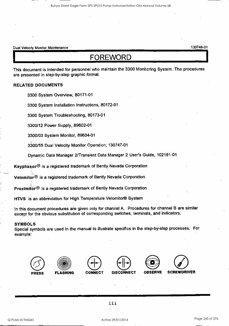
Dual Velocity Monitor Maintenance 130748-01
FOREWORD
This document is intended for personnel who maintain the 3300 Monitoring System. The procedures are presented in step-by-step graphic format.
RELATED DOCUMENTS
3300 System Overview, 80171-01
3300 System Installation Instructions, 80172-01
3300 System Troubleshooting, 80173-01
3300/12 Power Supply, 89602-01
3300/03 System Monitor, 89604-01
3300/55 Dual Velocity Monitor Operation, 130747-01
Dynamic Data Manager 2/Transient Data Manager 2 User's Guide, 102191-01
Keyphasor® is a registered trademark of Bent ly Nevada Corporation
Velomitor® is a registered trademark of Bent ly Nevada Corporation
Proxim kora is a registered trademark of Bent ly Nevada Corporation
HTVS is an abbreviation for High Temperature Velomitor® System
In this document procedures are given only for channel A. Procedures for channel B are similar except for the obvious substitution of corresponding switches, terminals, and indicators.
SYMBOLS Special symbols are used in the manual to illustrate specifics in the step-by-step processes. For
example:
PRESS FLASHING CONNECT DISCONNECT OBSERVE SCREWDRIVER
iii
Bunya Street Eagle Farm SPS SP010 Pump Instrumentation OM Manual Volume 6B
Q-Pulse Id TMS641 Active 29/01/2014 Page 245 of 376
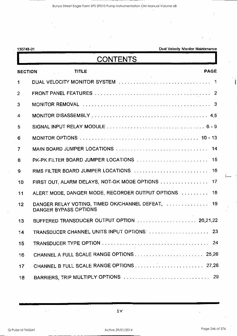
130748-01 Dual Velocity Monitor Maintenance
CONTENTS
SECTION TITLE
1 DUAL VELOCITY MONITOR SYSTEM
2 FRONT PANEL FEATURES
3 MONITOR REMOVAL
4 MONITOR DISASSEMBLY
5 SIGNAL INPUT RELAY MODULE
PAGE
1
2
3
4,5
6 - 9
6 MONITOR OPTIONS 10 - 13
7 MAIN BOARD JUMPER LOCATIONS 14
8 PK-PK FILTER BOARD JUMPER LOCATIONS 15
9 RMS FILTER BOARD JUMPER LOCATIONS 16
10 FIRST OUT, ALARM DELAYS, NOT-OK MODE OPTIONS 17
11 ALERT MODE, DANGER MODE, RECORDER OUTPUT OPTIONS 18
12 DANGER RELAY VOTING, TIMED OK/CHANNEL DEFEAT, DANGER BYPASS OPTIONS
19
13 BUFFERED TRANSDUCER OUTPUT OPTION 20,21,22
14 TRANSDUCER CHANNEL UNITS INPUT OPTIONS 23
15 TRANSDUCER TYPE OPTION 24
16 CHANNEL A FULL SCALE RANGE OPTIONS 25,26
17 CHANNEL B FULL SCALE RANGE OPTIONS 27,28
18 BARRIERS, TRIP MULTIPLY OPTIONS 29
iv
Bunya Street Eagle Farm SPS SP010 Pump Instrumentation OM Manual Volume 6B
Q-Pulse Id TMS641 Active 29/01/2014 Page 246 of 376
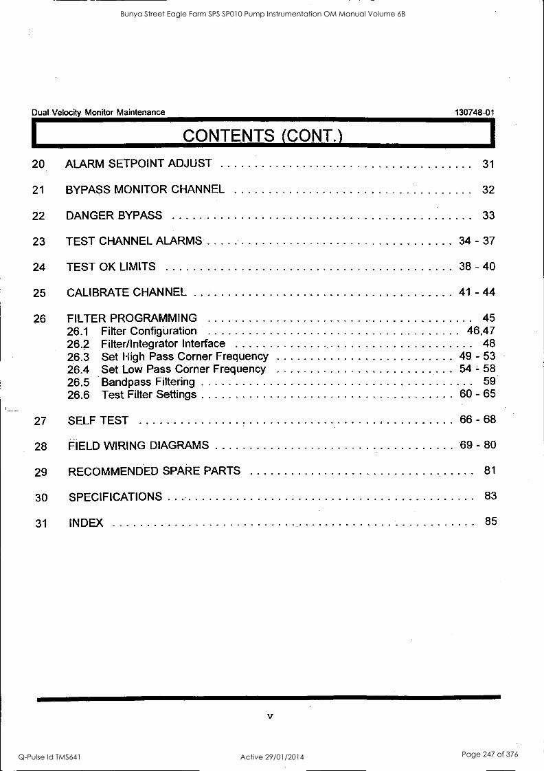
Dual Velocity Monitor Maintenance 130748-01
CONTENTS (CONT.) 1
20 ALARM SETPOINT ADJUST 31
21 BYPASS MONITOR CHANNEL
22 DANGER BYPASS 33
23 TEST CHANNEL ALARMS 34 - 37
24 TEST OK LIMITS 38 - 40
25 CALIBRATE CHANNEL 41 - 44
26 FILTER PROGRAMMING 45 26.1 Filter Configuration 46,47 26.2 Filter/Integrator Interface 48 26.3 Set High Pass Corner Frequency 49 - 53 26.4 Set Low Pass Corner Frequency 54 - 58 26.5 Bandpass. Filtering 59 26.6 Test Filter Settings 60 - 65
27 SELF TEST 66 - 68
28 FIELD WIRING DIAGRAMS 69 - 80
29 RECOMMENDED SPARE PARTS 81
30 SPECIFICATIONS 83
31 INDEX 85
32
Bunya Street Eagle Farm SPS SP010 Pump Instrumentation OM Manual Volume 6B
Q-Pulse Id TMS641 Active 29/01/2014 Page 247 of 376

130748-01 Dual Velocity Monitor Maintenance
THIS PAGE INTENTIONALLY LEFT BLANK
vi
Bunya Street Eagle Farm SPS SP010 Pump Instrumentation OM Manual Volume 6B
Q-Pulse Id TMS641 Active 29/01/2014 Page 248 of 376
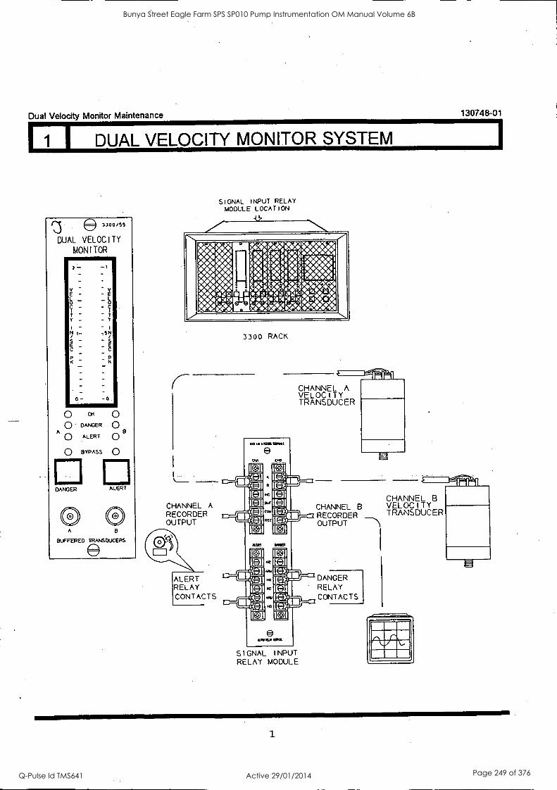
Dual Velocity Monitor Maintenance 130748-01
1 I DUAL VELOCITY MONITOR SYSTEM
SIGNAL INPUT RELAY MODULE LOCATION
fiARV-493+:4, I 0404 4 44,44 I 4044) 44401. . *4. 4-010 .4.4141-4.-/4--..1 I-..-4. 44 t WA,* We4 (>4,444- idib e. .A444 1,4J. .-1,1u 02104 ' Ae. ..4.414
V44 t4r4'4kr?44'...4440 L.. 41A -.4A &.. 1-4
3300 RACK
CHANNEL A VELOCITY TRANSDUCER
CHANNEL A RECORDER OUTPUT
ALERT RELAY CONTACTS
SIGNAL INPUT RELAY MODULE
CHANNEL B CHANNEL B VELOCITY RECORDER TRANSDUCER OUTPUT
DANGER RELAY CONTACTS
1
Bunya Street Eagle Farm SPS SP010 Pump Instrumentation OM Manual Volume 6B
Q-Pulse Id TMS641 Active 29/01/2014 Page 249 of 376

130748-01 Dual Velocity Monitor Maintenance
2 I FRONT PANEL FEATURES
Bar graph - indicates velocity or displacement value
Transducer OK LED
DANGER LED
ALERT LED
3300/55
DUAL
VELOCITY TY MON I TOR
1.07
V E
e I 8E
C
t .6
Channel BYPASS LED
Read Monitor Danger Setpoints
Reod Monitor Alert Setpoints
Coaxial Connector for Buffered Transducer Output
-1 0
-V e
$ 0 c
7 i
t y
n
=s
OK 0 DANGER 0
O ALERT Q B BYPASS 0
ANGER ALERT
A
BUFFERED TRANSDUCERS
2
Bunya Street Eagle Farm SPS SP010 Pump Instrumentation OM Manual Volume 6B
Q-Pulse Id TMS641 Active 29/01/2014 Page 250 of 376

Dual Velocity Monitor Maintenance 130748-01
3 I MONITOR REMOVAL
1. Loosen two screws. 2. Pull monitor from rack.
4\ CAUTION
The machine is not protected when the monitor is removed from the rack
3
Bunya Street Eagle Farm SPS SP010 Pump Instrumentation OM Manual Volume 6B
Q-Pulse Id TMS641 Active 29/01/2014 Page 251 of 376
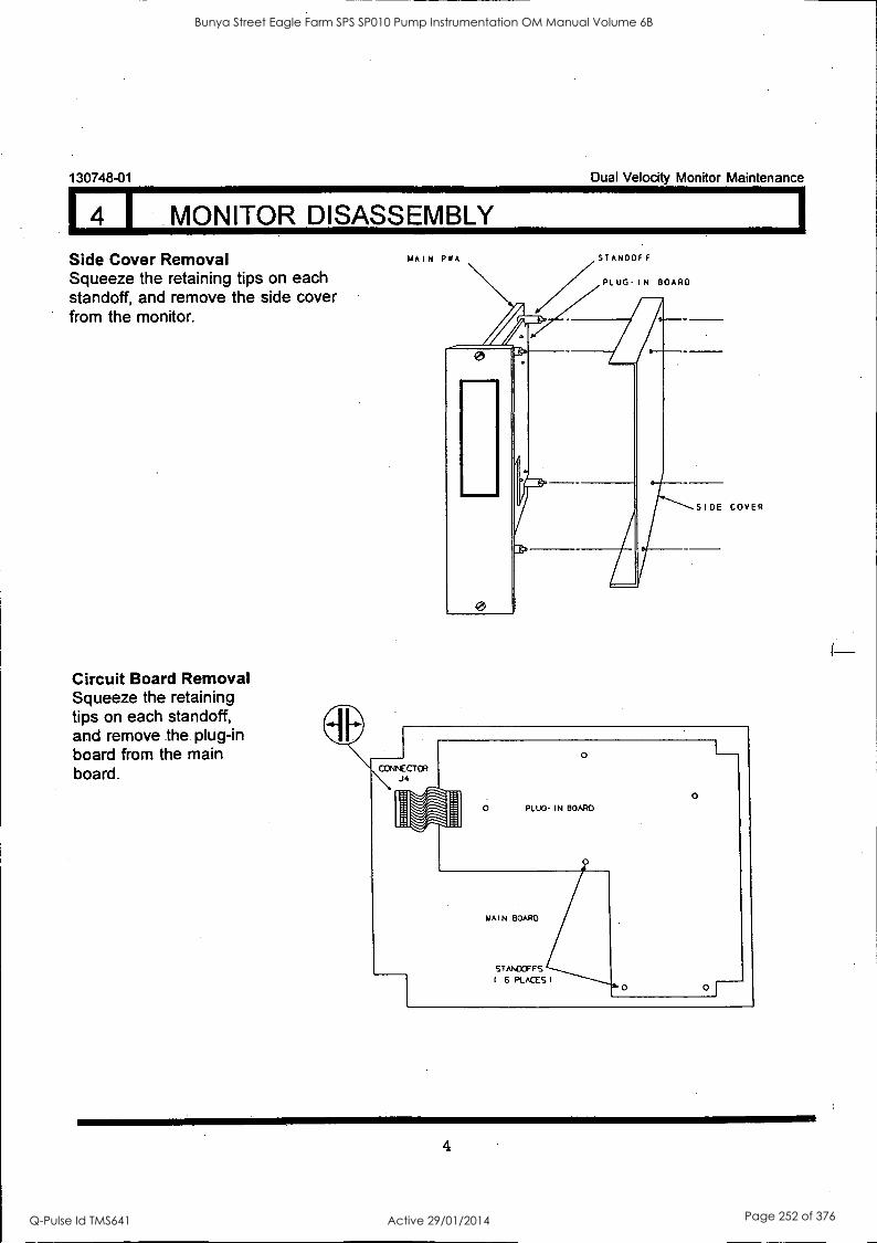
130748-01 Dual Velocity Monitor Maintenance
4 I MONITOR DISASSEMBLY
Side Cover Removal Squeeze the retaining tips on each standoff, and remove the side cover
' from the monitor.
Circuit Board Removal Squeeze the retaining tips on each standoff, and remove the plug-in board from the main board.
MAIN PWA STANDOFF
PLUG-IN BOARD
SIDE COVER
4
Bunya Street Eagle Farm SPS SP010 Pump Instrumentation OM Manual Volume 6B
Q-Pulse Id TMS641 Active 29/01/2014 Page 252 of 376
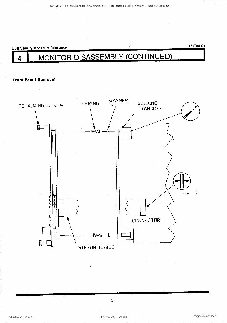
Dual Velocity Monitor Maintenance 130748-01
4 1 MONITOR DISASSEMBLY (CONTINUED)
Front Panel Removal
RETAINING SCREW SPRING
VVVV1
WASHER SLIDING STANDOFF
CONNECTOR
1NVM 0
RIBBON CABLE
5
Bunya Street Eagle Farm SPS SP010 Pump Instrumentation OM Manual Volume 6B
Q-Pulse Id TMS641 Active 29/01/2014 Page 253 of 376
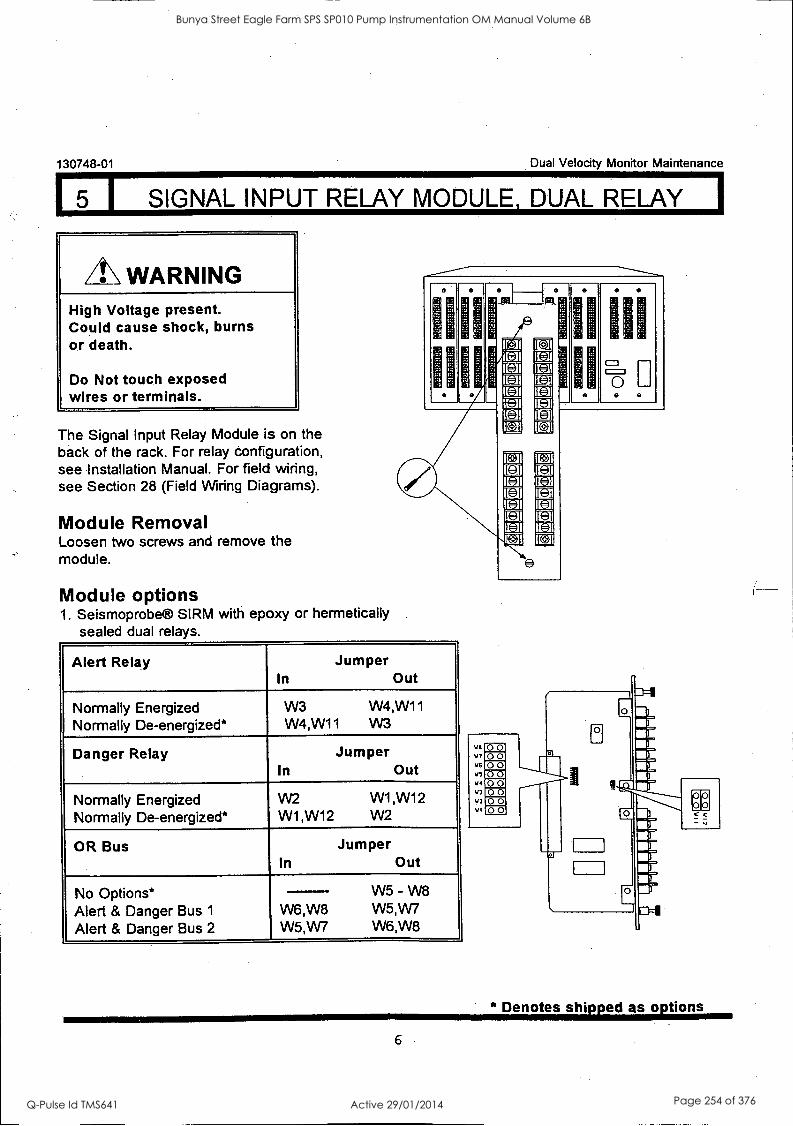
5 I SIGNAL INPUT RELAY MODULE, DUAL RELAY I
130748-01 Dual Velocity Monitor Maintenance
WARNING High Voltage present. Could cause shock, burns or death.
Do Not touch exposed wires or terminals.
The Signal Input Relay Module is on the back of the rack. For relay configuration, see Installation Manual. For field wiring, see Section 28 (Field Wiring Diagrams).
Module Removal Loosen two screws and remove the module.
Module options 1. Seismoprobe® SIRM with epoxy or hermetically
sealed dual relays.
Alert Relay Jumper In Out
Normally Energized Normally De-energized*
W3 W4,W1 1
W4,W11 W3
Danger Relay Jumper In Out
Normally Energized Normally De-energized*
W2 W1,W12 W1 ,W12 W2
OR Bus Jumper In Out
No Options* Alert & Danger Bus 1
Alert & Danger Bus 2
W5 W8 - W6,W8 W5,W7 W5,W7 W6,W8
oa
iii 0
a
V6
V7
V6
VS 114
V3 %.13
VI
00 00 00 00 00 00 00 00
0
Denotes shipped as options
6
Bunya Street Eagle Farm SPS SP010 Pump Instrumentation OM Manual Volume 6B
Q-Pulse Id TMS641 Active 29/01/2014 Page 254 of 376
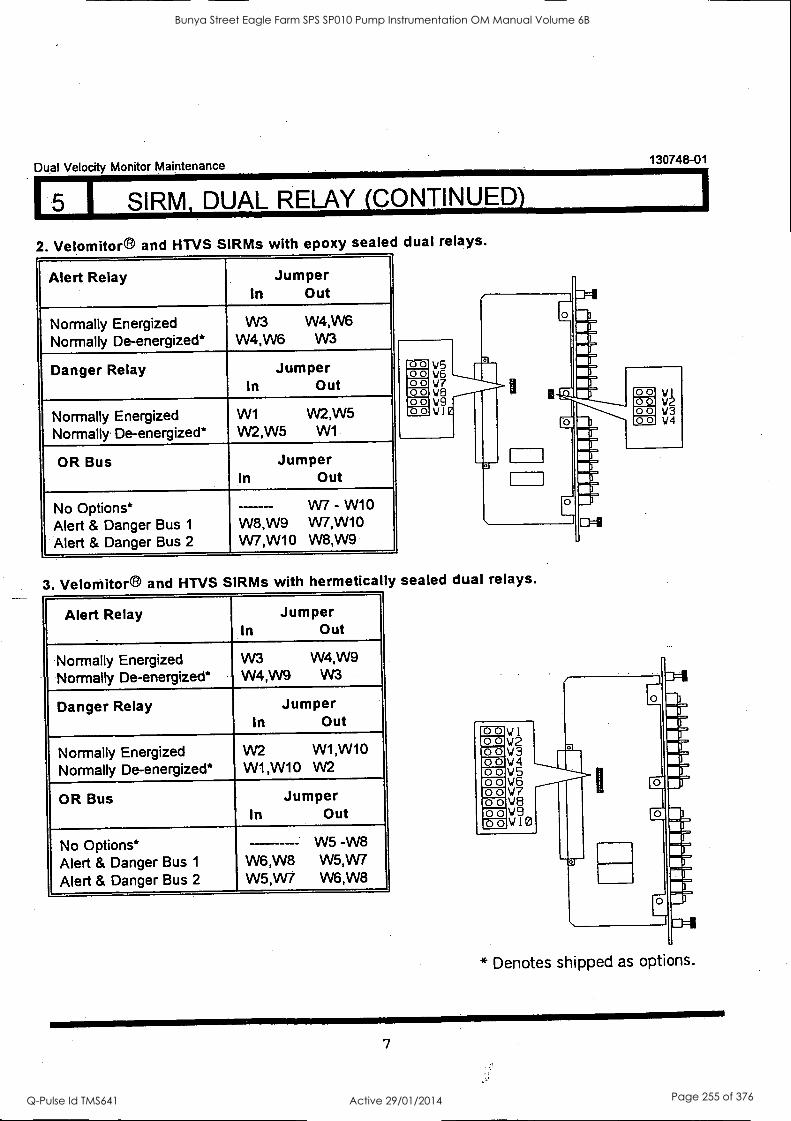
Dual Velocity Monitor Maintenance 130748-01
5 I SIRM, DUAL RELAY (CONTINUED)
2. Velomitor® and HTVS SIRMs with epoxy sealed dual relays.
Alert Relay Jumper In Out
Normally Energized Normally De-energized*
W3 W4,W6 W4,W6 W3
Danger Relay Jumper In Out
Normally Energized Normally. De-energized*
W1 VV2,W5 W2,W5 W1
OR Bus Jumper In Out
No Options* Alert & Danger Bus 1
Alert & Danger Bus 2
W7 W10 - -
W8,W9 VV7,W10 VV7,W10 W8,W9
oo 00 00 00 00 00
\15 %/6
7 W
1./8
VI
I
3. Velomitor® and HTVS SIRMs with hermetically sealed dual relays.
Alert Relay Jumper In Out
Normally Energized Normally De-energized*
W3 W4,W9 W4,W9 W3
Danger Relay Jumper In Out
Normally Energized Normally De-energized*
W2 W1,W10 W1,W10 W2
OR Bus Jumper In Out.
No Options* Alert & Danger Bus 1
Alert & Danger Bus 2
W5 -W8 W6,W8 W5,W7 W5,VV7 W6,W8
00 00 00 00
W
V2 3 W
1/4
* Denotes shipped as options.
7
Bunya Street Eagle Farm SPS SP010 Pump Instrumentation OM Manual Volume 6B
Q-Pulse Id TMS641 Active 29/01/2014 Page 255 of 376
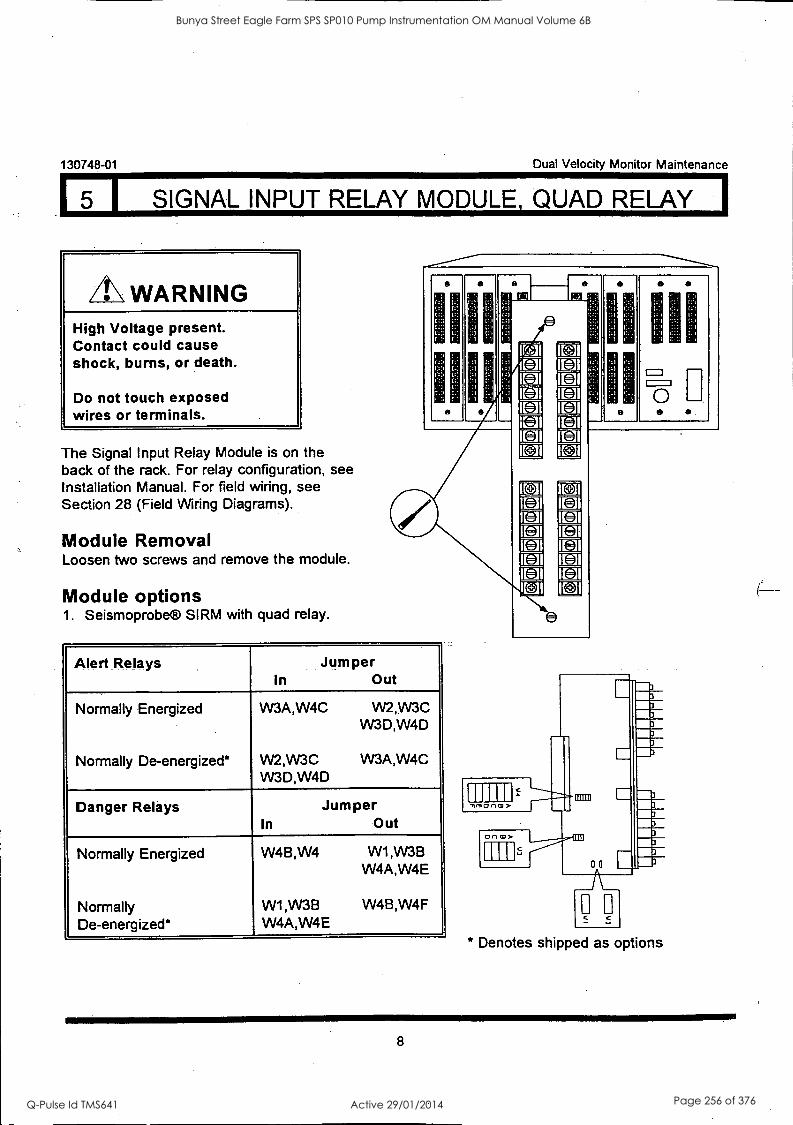
130748-01 Dual Velocity Monitor Maintenance
5 I SIGNAL INPUT RELAY MODULE, QUAD RELAY
WARNING High Voltage present. Contact could cause shock, burns, or death.
Do not touch exposed wires or terminals.
The Signal Input Relay Module is on the back of the rack. For relay configuration, see Installation Manual. For field wiring, see Section 28 (Field Wiring Diagrams).
Module Removal Loosen two screws and remove the module.
Module options 1. Seismoprobe® SIRM with quad relay.
fi li fl
0
Alert Relays Jumper In Out
Normally Energized
Normally De-energized*
W3A,W4C VV2,VV3C W3D,W4D
W2,W3C VV3A,W4C VV3D,W4D
Danger Relays Jumper In Out
Normally Energized
Normally De-energized*
W4B,W4 W1 ,VV3B
W4A,W4E
W1 ,VV3B W4B,W4F W4A,W4E
1E11
I -2 I
I I
Co] 3
r.z.
C7 U U tJ E-=-]
z
I DJI
IC=-]I
IVO I
I CU I !MI
HI
00 CO >
0a * Denotes shipped as options
8
Bunya Street Eagle Farm SPS SP010 Pump Instrumentation OM Manual Volume 6B
Q-Pulse Id TMS641 Active 29/01/2014 Page 256 of 376
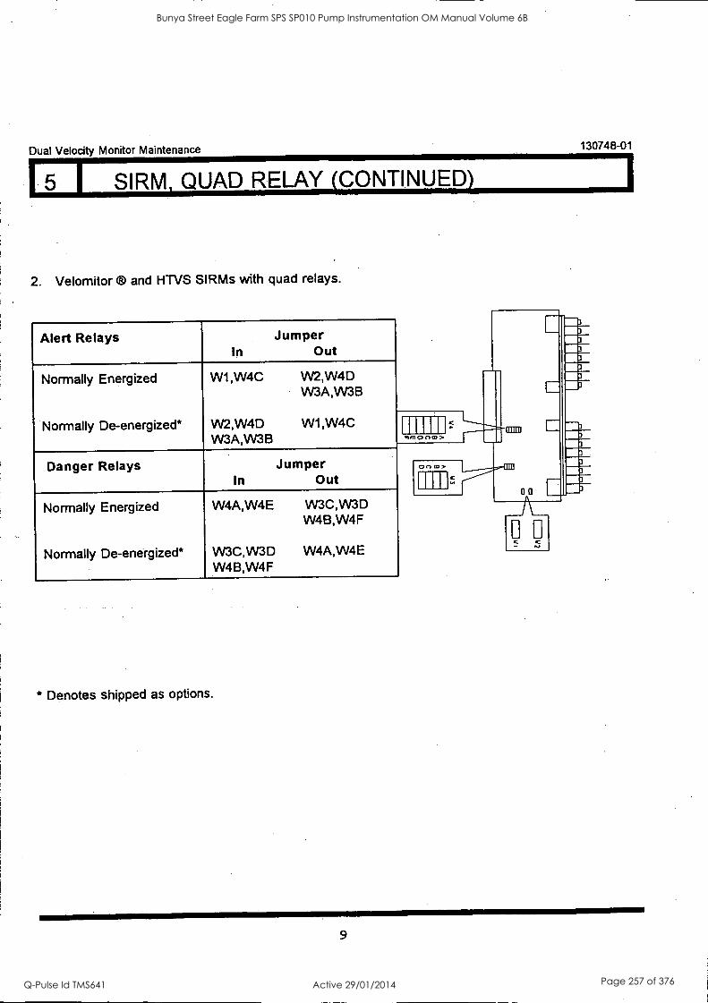
Dual Velocity Monitor Maintenance 130748-01
I SIRM, QUAD RELAY (CONTINUED)
2. Velomitor and HTVS SIRMs with quad relays.
Alert Relays In
Jumper Out
Normally Energized W1,W4C W2,W4D W3A,VV3B
Normally De-energized* W2,W4D W3A,W3B
W1,W4C
Danger Relays In
Jumper Out
Normally Energized
Normally De-energized*
W4A,W4E
W3C,W3D W4B,W4F
W3C,W3D W4B,W4F
W4A,W4E
* Denotes shipped as options.
m co >
CIO CO>
9
Bunya Street Eagle Farm SPS SP010 Pump Instrumentation OM Manual Volume 6B
Q-Pulse Id TMS641 Active 29/01/2014 Page 257 of 376
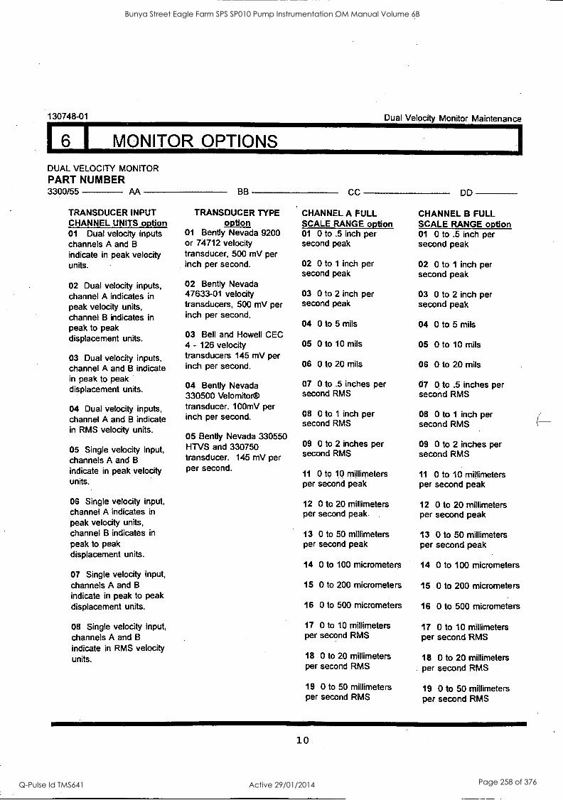
16 I MONITOR OPTIONS
130748-01 Dual Velocity Monitor Maintenance
DUAL VELOCITY MONITOR PART NUMBER 3300/55 AA
TRANSDUCER INPUT CHANNEL UNITS option 01 Dual velocity inputs channels A and B
indicate in peak velocity units.
02 Dual velocity inputs, channel A indicates in peak velocity units, channel B indicates in peak to peak displacement units.
03 Dual velocity inputs, channel A and B indicate in peak to peak displacement units.
04 Dual velocity inputs, channel A and B indicate in RMS velocity units.
05 Single velocity input, channels A and B
indicate in peak velocity units.
06 Single velocity input, channel A indicates in
peak velocity units, channel B indicates in
peak to peak displacement units.
07 Single velocity input, channels A and B
indicate in peak to peak displacement units.
08 Single velocity input, channels A and B
indicate in RMS velocity units.
BB
TRANSDUCER TYPE option
01 Bent ly Nevada 9200 or 74712 velocity transducer, 500 mV per inch per second.
02 Bent ly Nevada 47633-01 velocity transducers, 500 mV per inch per second.
03 Bell and Howell CEC 4 - 126 velocity transducers 145 mV per inch per second.
04 Bent ly Nevada 330500 Velomitoi transducer. 100mV per inch per second.
05 Bent ly Nevada 330550 HTVS and 330750 transducer. 145 mV per per second.
CC
CHANNEL A FULL SCALE RANGE option 01 0 to .5 inch per second peak
02 0 to 1 inch per second peak
03 0 to 2 inch per second peak
04 0 to 5 mils
05 0 to 10 mils
06 0 to 20 mils
07 0 to .5 inches per second RMS
08 0 to 1 inch per second RMS
09 0 to 2 inches per second RMS
11 0 to 10 millimeters per second peak
12 0 to 20 millimeters per second peak
13 0 to 50 millimeters per second peak
14 0 to 100 micrometers
15 0 to 200 micrometers
16 0 to 500 micrometers
17 0 to 10 millimeters per second RMS
18 0 to 20 millimeters per second RMS
19 0 to 50 millimeters per second RMS
DD
CHANNEL B FULL SCALE RANGE option 01 0 to .5 inch per second peak
02 0 to 1 inch per second peak
03 0 to 2 inch per second peak
04 0 to 5 mils
05 0 to 10 mils
06 0 to 20 mils
07 0 to .5 inches per second RMS
08 0 to 1 inch per second RMS
09 0 to 2 inches per second RMS
11 0 to 10 millimeters per second peak
12 0 to 20 millimeters per second peak
13 0 to 50 millimeters per second peak
14 0 to 100 micrometers
15 0 to 200 micrometers
16 0 to 500 micrometers
17 0 to 10 millimeters per second RMS
18 0 to 20 millimeters . per second RMS
19 0 to 50 millimeters per second RMS
10.
Bunya Street Eagle Farm SPS SP010 Pump Instrumentation OM Manual Volume 6B
Q-Pulse Id TMS641 Active 29/01/2014 Page 258 of 376
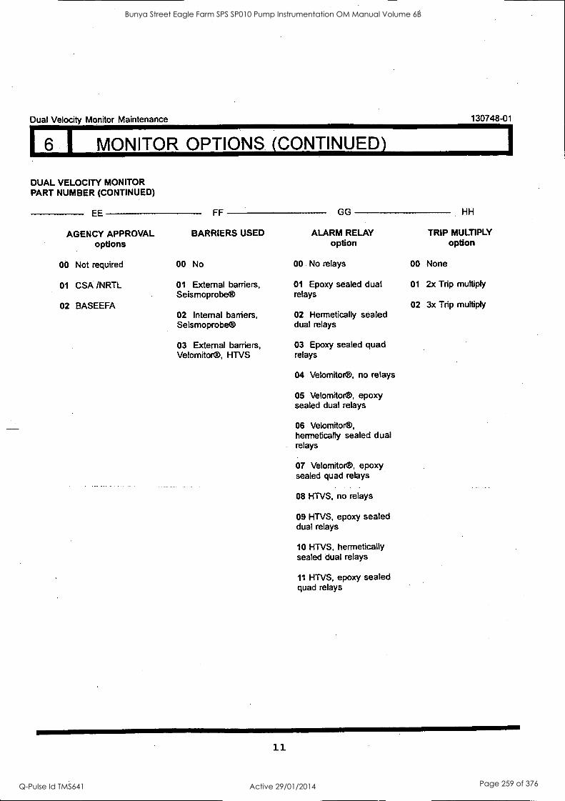
Dual Velocity Monitor Maintenance 130748-01
6 1 MONITOR OPTIONS. (CONTINUED)
DUAL VELOCITY MONITOR PART NUMBER (CONTINUED)
EE
AGENCY APPROVAL options
00 Not required
01 CSA /NRTL
02 BASEEFA
FF
BARRIERS USED
00 No
01 External barriers, Seismoprobe®
02 Internal barriers, Seismoprobe®
03 External barriers, Velomitor®, HTVS
GG HH
ALARM RELAY TRIP MULTIPLY option option
00 No relays
01 Epoxy sealed dual relays
02 Hermetically sealed dual relays
03 Epoxy sealed quad relays
04 Velomitor®, no relays
05 Velomitor®, epoxy sealed dual relays
06 Velomitor®, hermetically sealed dual relays
07 Velomitor®, epoxy sealed quad relays
08 HTVS, no relays
09 HTVS, epoxy sealed dual relays
10 HTVS, hermetically sealed dual relays
11 HTVS, epoxy sealed quad relays
00 None
01 2x Trip multiply
02 3x Trip multiply
11
Bunya Street Eagle Farm SPS SP010 Pump Instrumentation OM Manual Volume 6B
Q-Pulse Id TMS641 Active 29/01/2014 Page 259 of 376
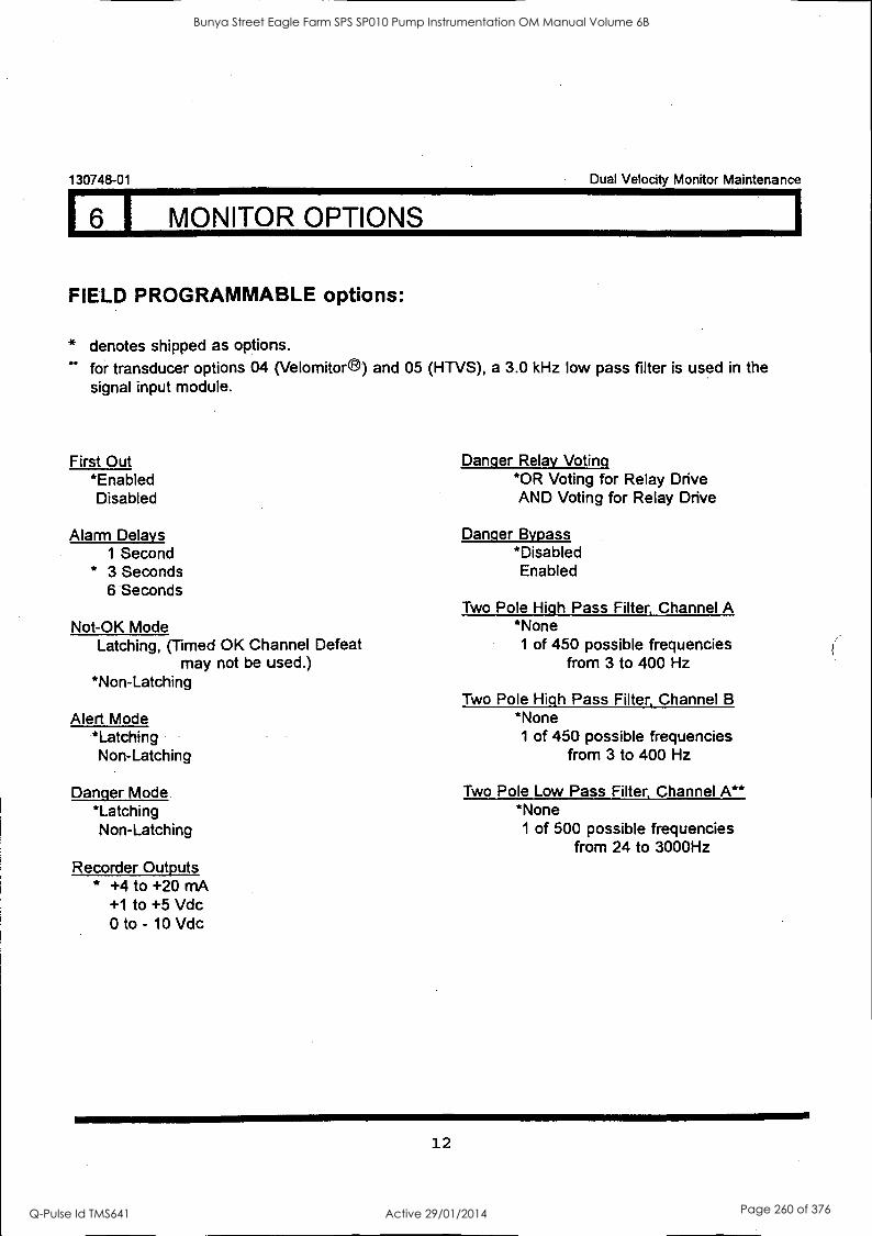
130748-01 Dual Velocity Monitor Maintenance
6 I MONITOR OPTIONS
FIELD PROGRAMMABLE options:
* denotes shipped as options.
for transducer options 04 (Velomitor ®) and 05 (HTVS), a 3.0 kHz low pass filter is used in the signal input module.
First Out *Enabled Disabled
Alarm Delays 1 Second
* 3 Seconds 6 Seconds
Not-OK Mode Latching, (Timed OK Channel Defeat
may not be used.) *Non-Latching
Alert Mode *Latching Non-Latching
Danger Mode *Latching Non-Latching
Recorder Outputs * +4 to +20 mA
+1 to +5 Vdc 0 to - 10 Vdc
Danger Relay Voting *OR Voting for Relay Drive AND Voting for Relay Drive
Danger Bypass *Disabled Enabled
Two Pole High Pass Filter, Channel A *None
1 of 450 possible frequencies from 3 to 400 Hz
Two Pole High Pass Filter, Channel B *None
1 of 450 possible frequencies from 3 to 400 Hz
Two Pole Low Pass Filter, Channel A** *None
1 of 500 possible frequencies from 24 to 3000Hz
12
Bunya Street Eagle Farm SPS SP010 Pump Instrumentation OM Manual Volume 6B
Q-Pulse Id TMS641 Active 29/01/2014 Page 260 of 376

Dual Velocity Monitor Maintenance 130748.01
6 I MONITOR OPTIONS (CONTINUED)
Two Pole Low Pass Filter, Channel B** *None
1 of 500 possible frequencies from 24 to 3000 Hz
Timed OK Channel Defeat *Enabled, (Must have Non-Latching
Not-OK Mode Selected.) Disabled
Integrator / Filter Positioning Channel A Integrator After Filtering Integrator Before Filtering
Integrator / Filter Positioning Channel B Integrator After Filtering Integrator Before Filtering
Buffered Transducer Filterinq,Channel A *No Filtering Filtered
Buffered Transducer Filterinq,Channel B
*No Filtering Filtered
The Dual Velocity Monitor has a number of ordered options and a variety of field (user) programmable options. The ordered and field programmable options are presented on the preceding two pages and are further described on the following pages. In general the ordered options affect the hardware configuration of the monitor whereas the field programmable options do not. For example, if Transducer Input Channel Units option (option AA) 01, 02, 03, 05, 06, or 07 is ordered then the plug-in board will be the Peak-Peak Filter Board. If Transducer Input Channel Units option 04 or 08 is ordered then the plug-in board will be the RMS Filter Board.
Ordered options can be changed, providing the correct hardware is installed, by removing and installing jumpers on the main circuit board and/or the plug-in circuit board. The field programmable options can be changed simply by installing or removing jumpers on the main circuit board and/or the plug-in circuit board.
The location of the option jumpers on the circuit boards and a jumper configuration guide for the monitor options is shown in the following sections. Note that many monitor options require installation or removal of jumpers on both the main board and the plug-in board.
13
Bunya Street Eagle Farm SPS SP010 Pump Instrumentation OM Manual Volume 6B
Q-Pulse Id TMS641 Active 29/01/2014 Page 261 of 376
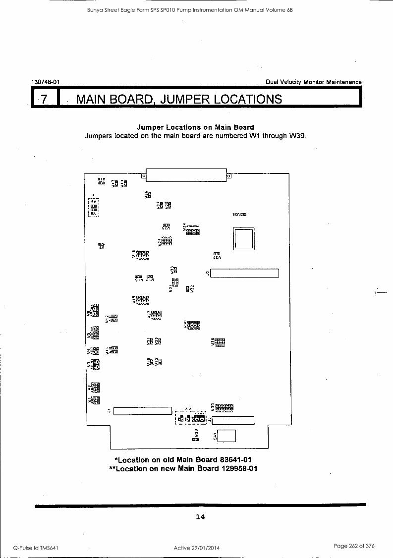
130748-01 Dual Velocity Monitor Maintenance
7 I MAIN BOARD, JUMPER LOCATIONS
Jumper Locations on Main Board Jumpers located on the main board are numbered W1 through W39.
OIA
"3.'n
; 6 M ;
1223:6
6:1253
.10
.gro
-¢GE1:6 <gal
- alleg 431:19
LLA .01f.-,04.1 OSINSO
o
9 CA MID
`i®
Jn
k k - - CCWOLLI.60
!:0;0:CEM;
6E9 5
*Location on old Main Board 83641-01 **Location on new Main Board 129958-01
14
Bunya Street Eagle Farm SPS SP010 Pump Instrumentation OM Manual Volume 6B
Q-Pulse Id TMS641 Active 29/01/2014 Page 262 of 376

8 1 PEAK-PEAK FILTER BOARD, JUMPER LOCATIONS) Dual Velocity Monitor Maintenance
130748-01
Jumper Locations on Peak-Peak Filter Board
Jumpers located on the Peak-Peak Filter Board are numbered from W39 - W55.
139 to 01
J4
1140
o 001
141 A 10 0 B o 0
140 O 0 O 0 O 0 O 0
A
9
C
B
A
147 O
O o 8
O 0 C
O o D
O o E
1112 A
143 A
B
C
E
6 H
C
6 H
1144
1145
lo o 0 0 io o 0 0
0 0 0 0 123 f° of
0 0
1149
0 0 0 0 0 0 0 0
0 6' o A
o 0 0 8 o 0 0 0 C
0 0 0 0 0 0 0 0 0 0 0 0 0 0 0 0 6 0 0
1150
A
8
C
6
H
F
O 0 O 0 O 0 O 0 0.0 O 0 O 0 O 0 M53 O 0 O 0 0 0 O 0 O 0 O 0 O 0 O 0 0 -0 O 0
A
8
E
F
6 H
O 0 O 0
A
B
C
6
1152 O 0 O 0 O 0
154 O 0 O 0 O 0
A
8
C
A
B
C
PEAK - PEAK FILTER BOARD (83657-01)
NOTE: The Peak-Peak Filter board must be installed for Transducer Input Channel Units_options
(option AA) 01, 02, 03, 05, 06, and 07.
The filters are located on the plug-in boards for both the peak-peak and rms plug-in
boards.
15
Bunya Street Eagle Farm SPS SP010 Pump Instrumentation OM Manual Volume 6B
Q-Pulse Id TMS641 Active 29/01/2014 Page 263 of 376
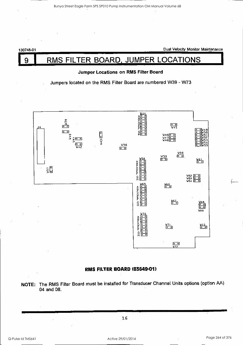
130748-01 Dual Velocity Monitor Maintenance
9 I RMS FILTER BOARD, JUMPER LOCATIONS
Jumper Locations on RMS Filter Board
Jumpers located on the RMS Filter Board are numbered W39 - W73
J4
W56 CD
A B
0 E F
H
A B r
0 E F 0 H
A B
0 E F
0 H.
A B
F
H
,144 O 0 O 0 O 0 O 0 O 0 O 0
O 0
58 O 0 O 0 O 0 O 0 O 0 O 0
O 0
4165 O 0 O 0 O 0 O 0 O 0 O 0 O 0 O 0
W70 O 0 O o O 0 O 0 O 0 O 0 O 0 O 0
C=1 W45
W46 W4 7 W48
O 0 O 0 O 0
W60 W59
W66 to of
rol
1471
==
1477
W62 W63 W64
O oW
O 0 o o\I O o\,/
W61 to of
O 0 O 0 O 0
4 5 5 5 53 54 55
W68 o o o -o
1469
W73 to o
RMS FILTER BOARD (83649-01)
NOTE: The RMS Filter Board must be installed for Transducer Channel Units options (option AA)
04 and 08.
16
Bunya Street Eagle Farm SPS SP010 Pump Instrumentation OM Manual Volume 6B
Q-Pulse Id TMS641 Active 29/01/2014 Page 264 of 376
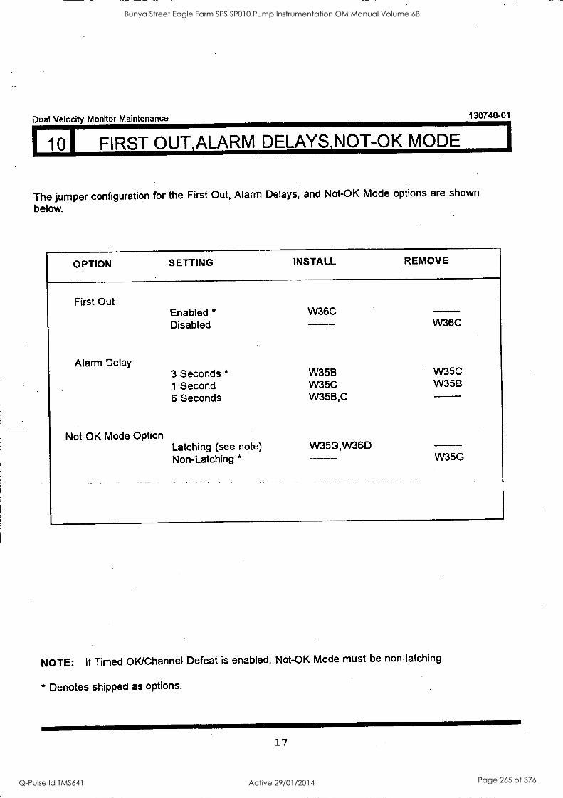
101 FIRST OUT,ALARM DELAYS,NOT-OK MODE 1
Dual Velocity Monitor Maintenance 130748-01
The jumper configuration for the First Out, Alarm Delays, and Not-OK Mode options are shown
below.
OPTION SETTING INSTALL REMOVE
First Out Enabled * W36C Disabled W36C
Alarm Delay 3 Seconds * W35B W35C 1 Second W35C W35B 6 Seconds W35B,C
Not-OK Mode Option Latching (see note) VV35G,IN36D Non-Latching * W35G
NOTE: If Timed OK/Channel Defeat is enabled, Not-OK Mode must be non-latching.
* Denotes shipped as options.
17
Bunya Street Eagle Farm SPS SP010 Pump Instrumentation OM Manual Volume 6B
Q-Pulse Id TMS641 Active 29/01/2014 Page 265 of 376
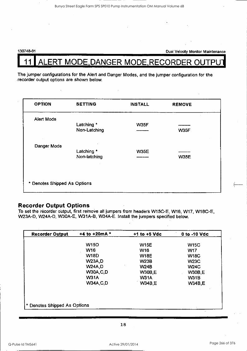
130748-01 Dual Velocity Monitor Maintenance
11 I ALERT MODE,DANGER MODE,RECORDER OUTPUT The jumper configurations for the Alert and Danger Modes, and the jumper configuration for the recorder output options are shown below.
OPTION SETTING INSTALL REMOVE
Alert Mode
Danger Mode
Latching *
Non-Latching
Latching * Non-latching
* Denotes Shipped As Options
W35F
W35E
W35F
W35E
Recorder Output Options To set the recorder output, first remove all jumpers from headers W15C-E, W16, W17, W18C-E, W23A -D, W24A -D, VV30A-E, W31A -B, W34A -E. Install the jumpers specified below.
Recorder Output +4 to +20mA * +1 to +5 Vdc 0 to -10 Vdc
W15D W15E W15C W16 W16 W17 W18D W18E W18C W23A,D W23B W23C W24A,D W24B W24C W30A,C,D VV30B,E VV30B,E W31A W31A W31B W34A,C,D VV34B,E W34B,E
* Denotes Shipped As Options
18
Bunya Street Eagle Farm SPS SP010 Pump Instrumentation OM Manual Volume 6B
Q-Pulse Id TMS641 Active 29/01/2014 Page 266 of 376

Dual. Velocity Monitor Maintenance 130748-01
121 DANGER VOTING, TIMED OK/CHANNEL DEFEAT, DANGER BYPASS
The jumper configuration for the Danger Relay Voting, Timed OK/Channel Defeat, and Danger
Bypass options is shown below.
OPTION SETTING INSTALL REMOVE
Danger Voting OR* AND W36B
Timed OK/Channel Defeat Enabled * (see note) Disabled VV36D
Danger Bypass Enabled W35D Disabled *
* Denotes Shipped As Options
W36B
W36D,W35G
W35D
NOTE: When Timed OK/Channel Defeat is enabled the Not-OK Mode must be non-latching.
19
Bunya Street Eagle Farm SPS SP010 Pump Instrumentation OM Manual Volume 6B
Q-Pulse Id TMS641 Active 29/01/2014 Page 267 of 376
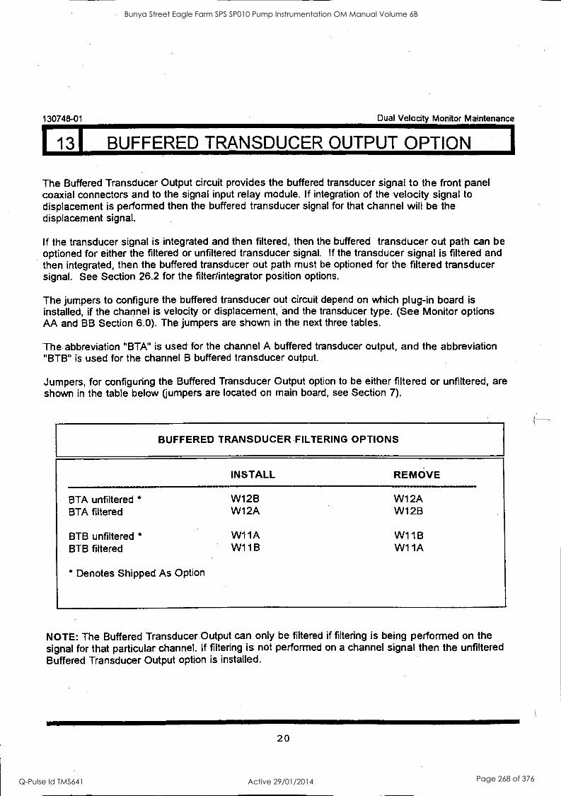
130748-01 Dual Velocity Monitor Maintenance
131 BUFFERED TRANSDUCER OUTPUT OPTION
The Buffered Transducer Output circuit provides the buffered transducer signal to the front panel coaxial connectors and to the signal input relay module. If integration of the velocity signal to displacement is performed then the buffered transducer signal for that channel will be the displacement signal.
If the transducer signal is integrated and then filtered, then the buffered transducer out path can be optioned for either the filtered or unfiltered transducer signal. If the transducer signal is filtered and then integrated, then the buffered transducer out path must be optioned for the filtered transducer signal. See Section 26.2 for the filter/integrator position options.
The jumpers to configure the buffered transducer out circuit depend on which plug-in board is installed, if the channel is velocity or displacement, and the transducer type. (See Monitor options AA and BB Section 6.0). The jumpers are shown in the next three tables.
The abbreviation "BTA" is used for the channel A buffered transducer output, and the abbreviation "BTB" is used for the channel B buffered transducer output.
Jumpers, for configuring the Buffered Transducer Output option to be either filtered or unfiltered, are shown in the table below (jumpers are located on main board, see Section 7).
BUFFERED TRANSDUCER FILTERING OPTIONS
INSTALL
BTA unfiltered *
BTA filtered
BTB unfiltered * BTB filtered
* Denotes Shipped As Option
W12B W12A
W11A W11B
REMOVE
W12A W1 2B
W1 1B W11A
NOTE: The Buffered Transducer. Output can only be filtered if filtering is being performed on the signal for that particular channel. If filtering is not performed on a channel signal then the unfiltered Buffered Transducer Output option is installed.
20
Bunya Street Eagle Farm SPS SP010 Pump Instrumentation OM Manual Volume 6B
Q-Pulse Id TMS641 Active 29/01/2014 Page 268 of 376
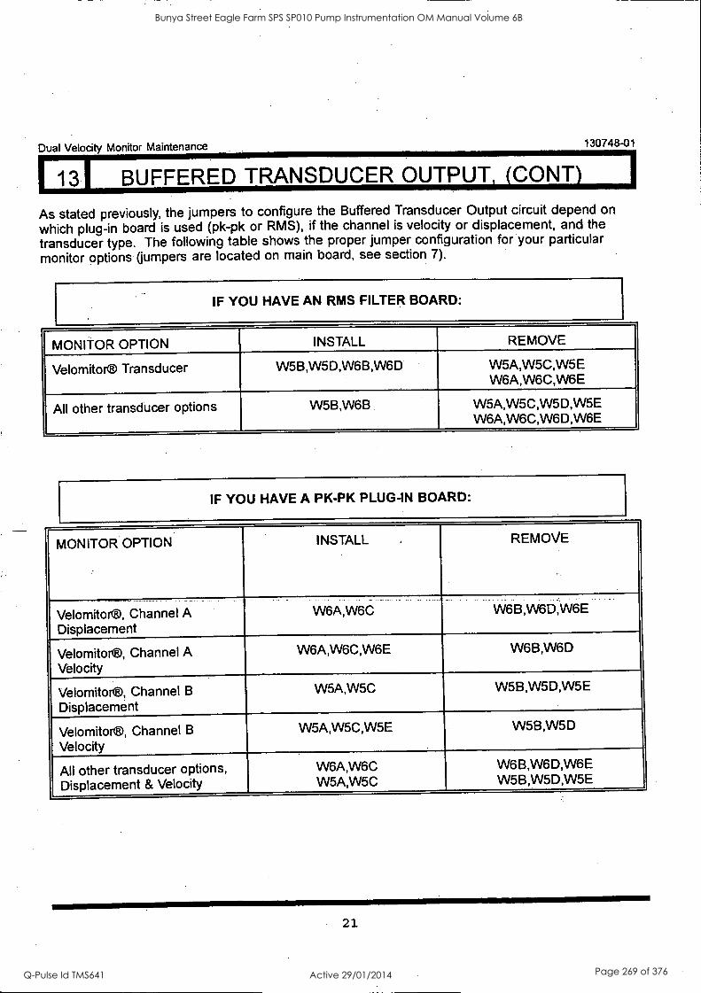
Dual Velocity Monitor Maintenance 130748-01
1 13I BUFFERED TRANSDUCER OUTPUT, (CONY)
As stated previously, the jumpers to configure the Buffered Transducer Output circuit depend on
which plug-in board is used (pk-pk or RMS), if the channel is velocity or displacement, and the
transducer type. The following table shows the proper jumper configuration for your particular
monitor options (jumpers are located on main board, see section 7).
IF YOU HAVE AN RMS FILTER BOARD:
MONITOR OPTION INSTALL REMOVE
Velomitor® Transducer W5B,W5D,W6B,W6D W5A,W5C,W5E W6A,W6C,VV6E
All other transducer options W5B,W6B W5A,W5C,W5D,W5E W6A,W6C,W6D,W6E
IF YOU HAVE A PK-PK PLUG-IN BOARD:
MONITOR OPTION INSTALL REMOVE
Velomitor®, Channel A Displacement
W6A,W6C W6B,W6D,W6E
Velomitor®, Channel A Velocity
W6A,W6C,W6E W6B,W6D
Velomitor®, Channel B
Displacement
W5A,W5C W5B,W5D,W5E
Velomitor®, Channel B
Velocity
W5A,W5C,W5E W5B,W5D
All other transducer options, Displacement & Velocity
W6A,W6C W5A,W5C
W6B,W6D,W6E W5B,W5D,W5E
21
Bunya Street Eagle Farm SPS SP010 Pump Instrumentation OM Manual Volume 6B
Q-Pulse Id TMS641 Active 29/01/2014 Page 269 of 376

113I BUFFERED TRANSDUCER OUTPUT OPTION
130748-01 Dual Velocity Monitor Maintenance
The Scale Factor of the Buffered Transducer Output for different transducer options is shown below:
TRANSDUCER INPUT BUFFERED OUTPUT SCALE FACTOR Velocity Seismoprobe® 500 mV/in/sec
9200 Velocity Seismoprobe® 500 mV/in/sec
47633 and 86205
VELOCITY DISPLACEMENT 500 mWin/sec
(19.685 mV/mm/sec) 200 mV/mil
(7.874 mV/mm)
Velomitor® 100 mV/in/sec 100mV/in/sec 200mV/mil
Velocity (non-standard) 145 mV/in/sec HTVS 145 mV/in/sec
145 mV/in/sec (5.709 mV/mm/sec)
200 mV/mil (7.874 mV/mm)
Note 1: Revisions B, A & NC of the 3300/55 Main Board (BNC P/N 129958-01) yield 500mV/in/sec for the Buffered Transducer Output (velocity) when used with the Velomitor® Transducer (BBoption 04). To be consistent with earlier versions, revisions C and later of the Main Board when used with Velomitor® Transducer can be configured to yield 500 mV/in/sec at the Buffered Transducer Output. This can be accomplished by selecting the jumper settings for "all other transducer options" from the tables on page 21.
Note 2: The dynamic signal present at the Buffered Transducer Outputs will swing around signal ground except in the case of an unfiltered configuration on the RMS/Filter Board. In this case, the Buffered Transducer Outputs will be biased at -1.4 Vdc (-7.0 Vdc if the Main Board revision is NC, A, or B).
22
Bunya Street Eagle Farm SPS SP010 Pump Instrumentation OM Manual Volume 6B
Q-Pulse Id TMS641 Active 29/01/2014 Page 270 of 376
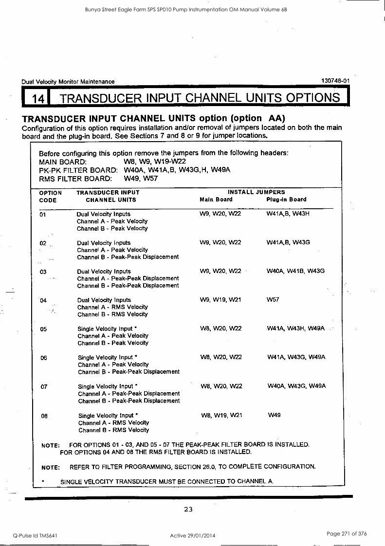
141 TRANSDUCER INPUT CHANNEL UNITS OPTIONS I
Dual Velocity Monitor Maintenance 130748-01
TRANSDUCER INPUT CHANNEL UNITS option (option AA) Configuration of this option requires installation and/or removal of jumpers located on both the main board and the plug-in board. See Sections 7 and 8 or 9 for jumper locations.
Before configuring this option remove the jumpers from the following headers: MAIN BOARD: W8, W9, W19-W22 PK-PK FILTER BOARD: W40A, W41A,B, W43G,H, W49A RMS FILTER BOARD: W49, W57
OPTION TRANSDUCER INPUT INSTALL JUMPERS CODE CHANNEL UNITS Main Board Plug-in Board
01 Dual Velocity Inputs W9, W20, W22 W41A,B, W43H Channel A - Peak Velocity Channel B - Peak Velocity
02 Dual Velocity Inputs W9, W20, W22 W41A,B, W43G Channel A - Peak Velocity Channel B - Peak-Peak Displacement
03 Dual Velocity Inputs W9, W20, W22 W40A, W41B, W43G Channel A - Peak-Peak Displacement Channel B - Peak-Peak Displacement
04 Dual Velocity Inputs W9, W19, W21 W57 Channel A - RMS Velocity Channel B - RMS Velocity
05 Single Velocity Input W8, W20, W22 W41A, W43H, W49A Channel A - Peak Velocity Channel B - Peak Velocity
06 Single Velocity Input " W8, W20, W22 W41A, W43G, W49A Channel A - Peak Velocity Channel B - Peak-Peak Displacement
07 Single Velocity Input W8, W20, W22 W40A, W43G, W49A Channel A - Peak-Peak Displacement Channel B - Peak-Peak Displacement
08 Single Velocity Input W8, W19, W21 W49 Channel A - RMS Velocity Channel B - RMS Velocity
NOTE: FOR OPTIONS 01 - 03, AND 05 - 07 THE PEAK-PEAK FILTER BOARD IS INSTALLED. FOR OPTIONS 04 AND 08 THE RMS FILTER BOARD IS INSTALLED.
NOTE: REFER TO FILTER PROGRAMMING, SECTION 26.0, TO COMPLETE CONFIGURATION.
SINGLE VELOCITY TRANSDUCER MUST BE CONNECTED TO CHANNEL A.
23
Bunya Street Eagle Farm SPS SP010 Pump Instrumentation OM Manual Volume 6B
Q-Pulse Id TMS641 Active 29/01/2014 Page 271 of 376
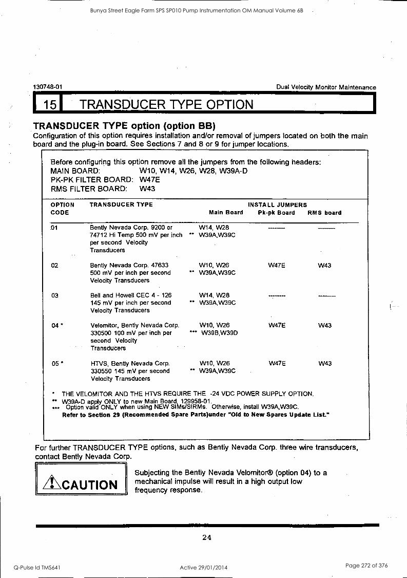
130748-01 Dual Velocity Monitor Maintenance
15I TRANSDUCER TYPE OPTION
TRANSDUCER TYPE option (option BB) Configuration of this option requires installation and/or removal of jumpers located on both the main board and the plug-in board. See Sections 7 and 8 or 9 for jumper locations.
Before configuring this option remove all the jumpers from the following headers: MAIN BOARD: W10, W14, W26, W28, W39A-D PK-PK FILTER BOARD: W47E RMS FILTER BOARD: W43
OPTION TRANSDUCER TYPE CODE
INSTALL JUMPERS Main Board Pk-pk Board RMS board
01 Bently Nevada Corp. 9200 or 74712 Hi Temp 500 mV per inch per second Velocity Transducers
02 Bently Nevada Corp. 47633 500 mV per inch per second Velocity Transducers
03 Bell and Howell CEC 4 - 126 145 mV per inch per second Velocity Transducers
04 * Velomitor, Bently Nevada Corp. 330500 100 mV per inch per second Velocity Transducers
05 * HTVS, Gently Nevada Corp. 330550 145 mV per second Velocity Transducers
W14, W28 ** W39A,W39C
W10, W26 W47E W43 ** W39A,W39C
W14, VV28 **
- - -- W39A,W39C
W10, W26 W47E W43 *** W39B,W39D
W10, W26 W47E W43 ** W39A,W39C
" THE VELOMITOR AND THE HTVS REQUIRE THE -24 VDC POWER SUPPLY OPTION. W39A -D apply ONLY to new Main Board, 129958-01.
Option valid ONLY when using NEW SIMs/SIRMs. Otherwise, install W39A,W39C. Refer to Section 29 (Recommended Spare Parts)under "Old to New Spares Update List."
For further TRANSDUCER TYPE options, such as Bently Nevada Corp. three wire transducers, contact Bently Nevada Corp.
CAUTION Subjecting the Bently Nevada Velomitor® (option 04) to a mechanical impulse will result in a high output low frequency response.
24
Bunya Street Eagle Farm SPS SP010 Pump Instrumentation OM Manual Volume 6B
Q-Pulse Id TMS641 Active 29/01/2014 Page 272 of 376
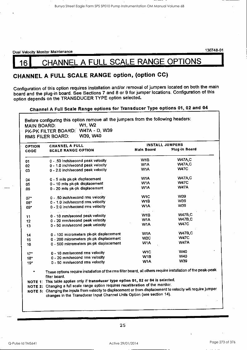
116I CHANNEL A FULL SCALE RANGE OPTIONS I Dual Velocity Monitor Maintenance 130748-01
CHANNEL A FULL SCALE RANGE option, (option CC)
Configuration of this option requires installation and/or removal of jumpers located on both the main
board and the plug-in board. See Sections 7 and 8 or 9 for jumper locations. Configuration of this
option depends on the TRANSDUCER TYPE option selected.
Channel A Full Scale Range options for Transducer Type options 01, 02 and 04
Before configuring this option remove all the jumpers from the following headers:
MAIN BOARD: W1, VV2
PK-PK FILTER BOARD: W47A - D, W39 RMS FILER BOARD: W39, W40
OPTION CODE
01
02 03
04 05 06
07* 08* 09*
11
12 13
14 15 16
17* 18* 19*
CHANNEL A FULL SCALE RANGE OPTION
INSTALL JUMPERS Main Board Plug-in Board
0 - .50 inch/second peak velocity W1B W47A,C
0 - 1.0 inch/second peak velocity W1A W47A,C
0 - 2.0 inch/second peak velocity W1A W47C
0 - 5 mils pk-pk displacement W1A W47A,C
0 - 10 mils pk-pk displacement W1A W47C
0 - 20 mils pk-pk displacement W1A W47A
0 - .50 inch/second rms velocity WIC W39.
0 - 1.0 inch/second rms velocity W1B W39
0 - 2.0 inch/second rms velocity W1A W39
0 - 10 mm/second peak velocity W1B W47B,C
0 - 20 mm/second peak velocity W1A W47B,C
0 - 50 mm/second peak velocity W1A W47C
0 - 100 micrometers pk-pk displacement W1A W47B,C
0 - 200 micrometers pk-pk displacement W2C W47C
0 - 500 micrometers pk-pk displacement W1A W47A
0 - 10 mm/second rms velocity WIC W40
0 - 20 mm/second rms velocity VV1B W40
0 - 50 mm/second rms velocity W1A W39
These options require installation of the rms filter board, all others require installation of the peak-peak
filter board.
NOTE 1: This table applies only if transducer type option 01, 02 or 04 is selected.
NOTE 2: Changing a full scale range option requires recalibration of the monitor.
NOTE 3: Changing the inputs from velocity to displacement or from displacement to velocity will require jumper
changes in the Transducer Input Channel Units Option (see section 14).
25
Bunya Street Eagle Farm SPS SP010 Pump Instrumentation OM Manual Volume 6B
Q-Pulse Id TMS641 Active 29/01/2014 Page 273 of 376

161 CHANNEL A FULL SCALE RANGE OPTIONS (CONTI
130748-01 Dual Velocity Monitor Maintenance
The Channel A Full Scale Range options for Transducer Type options 03, Bell and Howell GEC 4 - 126 145 mV per inch per second velocity transducer, and 05 HTVS 145 mV per inch per second velocity transducer, are shown below.
Channel A Full Scale Range options for Transducer Type options 03 and 05
Before configuring this option remove all the jumpers from the following headers: MAIN BOARD: W1, W2 PK-PK FILTER BOARD: W47A - D, W39 RMS FILTER BOARD: W39,W40
OPTION CHANNEL A FULL INSTALL JUMPERS CODE SCALE RANGE OPTION Main Board PIug-in Board
01 0 - .50 inch/second peak velocity W2A W47A,C 02 0 - 1.0 inch/second peak velocity W2A W47C 03 0 - 2.0 inch/second peak velocity W2A W47A
04 0 - 5 mils pk-pk displacement W1A W47A,C,W39 05 0 - 10 mils pk-pk displacement W1A W47C,W39 06 0 - 20 mils pk-pk displacement W1A W47A,W39
07* 0 - .50 inch/second rms velocity W2A - -- 08* 0 - 1.0 inch/second rms velocity W2A W39 09* 0 - 2.0 inch/second rms velocity W2B W39
11 0 - 10 mm/second peak velocity W2D W47A,C 12 0 - 20 mm/second peak velocity W2D W47C 13 0 - 50 mm/second peak velocity W2D
14 0 - 100 micrometers pk-pk displacement W1A W47B,C,W39 15 0 - 200 micrometers pk-pk displacement W2C W47C,W39 16 0 - 500 micrometers pk-pk displacement W1A W47A,W39
17' 0 - 10 mm/second rms velocity W2D 18' 0 - 20 mm/second rms velocity W2D W39 19' 0 - 50 mm/second rms velocity W2B W39
These options require installation of the rms filter board, all others require installation of the peak-peak filter board.
NOTE 1: This table applies only if transducer type option 03 or 05 is selected. NOTE 2: Changing a full scale range option requires recalibration of the monitor. NOTE 3: Changing the inputs from velocity to displacement or from displacement to velocity will require jumper
changes in the Transducer Input Channel Units Option (see section 14).
26
Bunya Street Eagle Farm SPS SP010 Pump Instrumentation OM Manual Volume 6B
Q-Pulse Id TMS641 Active 29/01/2014 Page 274 of 376
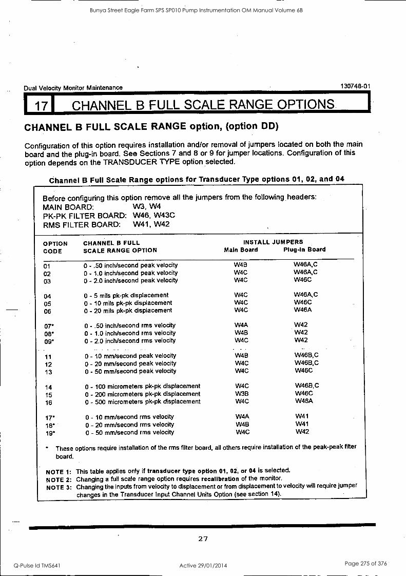
Dual Velocity Monitor Maintenance 130748-01
171 CHANNEL B FULL SCALE RANGE. OPTIONS. I
CHANNEL B FULL SCALE RANGE option, (option DD)
Configuration of this option requires installation and/or removal of jumpers located on both the main board and the plug-in board. See Sections 7 and 8 or 9 for jumper locations. Configuration of this option depends on the TRANSDUCER TYPE option selected.
Channel B Full Scale Range options for Transducer Type options 01, 02, and 04
Before configuring this option remove all the jumpers from the following headers: MAIN BOARD: VV3, W4 PK-PK FILTER BOARD: W46, W43C RMS FILTER BOARD: W41, W42
OPTION CODE
CHANNEL B FULL SCALE RANGE OPTION
INSTALL JUMPERS Main Board Plug-In Board
01 0 - .50 inch/second peak velocity W4B W46A,C
02 0 - 1.0 inch/second peak velocity W4C W46A,C 03 0 - 2.0 inch/second peak velocity W4C W46C
04 0 - 5 mils pk-pk displacement W4C W46A,C
05 0 - 10 mils pk-pk displacement W4C W46C 06 0 - 20 mils pk-pk displacement W4C W46A
07* 0 - .50 inch/second rms velocity W4A W42
08* 0 - 1.0 inch/second rms velocity W4B W42 09* 0 - 2.0 inch/second rms velocity W4C W42
11 0 - 10 mm/second peak velocity W4B W46B,C
12 0 - 20 mm/second peak velocity W4C W46B,C 13 0 - 50 mm/second peak velocity W4C W46C
14 0 - 100 micrometers pk-pk displacement W4C W46B,C
15 0 - 200 micrometers pk-pk displacement W3B W46C 16 0 - 500 micrometers pk-pk displacement W4C W46A
17* 0 - 10 mm/second rms velocity W4A W41
18 0 - 20 mm/second rms velocity W4B W41
19' 0 - 50 mm/second rms velocity W4C W42
These options require installation of the rms filter board, all others require installation of the peak-peak fitter
board.
NOTE 1: This table applies only if transducer type option 01, 02, or 04 is selected.
NOTE 2: Changing a full scale range option requires recallbration of the monitor.
NOTE 3: Changing the inputs from velocity to displacement or from displacement to velocity will require jumper
changes in the Transducer Input Channel Units Option (see section 14).
27
Bunya Street Eagle Farm SPS SP010 Pump Instrumentation OM Manual Volume 6B
Q-Pulse Id TMS641 Active 29/01/2014 Page 275 of 376
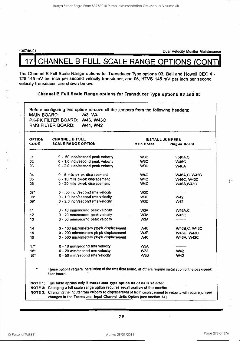
130748-01 Dual Velocity Monitor Maintenance
17 CHANNEL B FULL SCALE RANGE OPTIONS (CONT)I The Channel B Full Scale Range options for Transducer Type options 03, Bell and Howell CEC 4 - 126 145 mV per inch per second velocity transducer, and 05, HTVS 145 mV per inch per second velocity transducer, are shown below.
Channel B Full Scale Range options for Transducer Type options 03 and 05
Before configuring this option remove all the jumpers from the following headers: MAIN BOARD: W3, W4 PK-PK FILTER BOARD: W46, W43C RMS FILTER BOARD: W41, W42
OPTION CHANNEL B FULL INSTALL JUMPERS CODE SCALE RANGE OPTION Main Board Plug-in Board
01 0 - .50 inch/second peak velocity W3C % '46A,C 02 0 - 1.0 inch/second peak velocity W3C W46C 03 0 - 2.0 inch/second peak velocity W3C W46A
04 0 - 5 mils pk-pk displacement W4C W46A,C, W43C 05 0 - 10 mils pk-pk displacement W4C W46C, W43C 06 0 - 20 mils pk-pk displacement W4C W46A,W43C
07* 0 - .50 inch/second rms velocity W3C - - -- 08' 0 - 1.0 inch/second rms velocity W3C W42 09* 0 - 2.0 inch/second rms velocity W3D W42
11 0 - 10 mm/second peak velocity W3A W46A,C 12 0 - 20 mm/second peak velocity W3A W46C 13 0 - 50 mm/second peak velocity W3A
14 0 - 100 micrometers pk-pk displacement W4C W46B,C, W43C 15 0 - 200 micrometers pk-pk displacement W3B W46C, W43C 16 0 - 500 micrometers pk-pk displacement W4C W46A, W43C
17* 0 - 10 mm/second rms velocity W3A 18* 0 - 20 mm/second rms velocity W3A W42 19* 0 - 50 mm/second rms velocity W3D W42
These options require installation of the rms filter board, all others require installation of the peak-peak filter board.
NOTE 1: This table applies only if transducer type option 03 or 05 is selected. NOTE 2: Changing a full scale range option requires recalibration of the monitor. NOTE 3: Changing the inputs from velocity to displacement or from displacement to velocity will require jumper
changes in the Transducer Input Channel Units Option (see section 14).
28
Bunya Street Eagle Farm SPS SP010 Pump Instrumentation OM Manual Volume 6B
Q-Pulse Id TMS641 Active 29/01/2014 Page 276 of 376
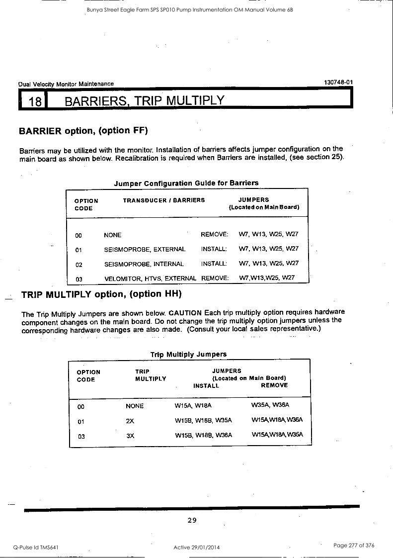
Dual Velocity Monitor Maintenance 130748-01
181 BARRIERS, TRIP MULTIPLY
BARRIER option, (option FF)
Barriers may be utilized with the monitor. Installation of barriers affects jumper configuration on the
main board as shown below. Recalibration is required when Barriers are installed, (see section 25).
Jumper Configuration Guide for Barriers
OPTION CODE
TRANSDUCER / BARRIERS JUMPERS (Located on Main Board)
00 NONE REMOVE: W7, W13, W25, W27
01 SEISMOPROBE, EXTERNAL INSTALL: W7, W13, W25, W27
02 SEISMOPROBE, INTERNAL INSTALL: W7, W13, W25, W27
03 VELOMITOR, HTVS, EXTERNAL REMOVE: W7,W13,W25, W27
TRIP MULTIPLY option, (option HH)
The Trip Multiply Jumpers are shown below. CAUTION Each trip multiply option requires hardware
component changes on the main board. Do not change the trip multiply option jumpers unless the
corresponding hardware changes are also made. (Consult your local sales representative.)
Trip Multiply Jumpers
OPTION TRIP JUMPERS
CODE MULTIPLY (Located on Main Board) INSTALL REMOVE
00 NONE W15A, W18A W35A, W36A
01 2X W15B, W18B, W35A W15A,W18A,W36A
03 3X W15B, W18B, W36A W15A,W18A,W35A
29
Bunya Street Eagle Farm SPS SP010 Pump Instrumentation OM Manual Volume 6B
Q-Pulse Id TMS641 Active 29/01/2014 Page 277 of 376
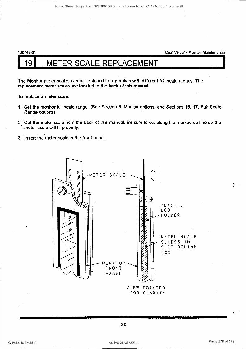
I191 METER SCALE REPLACEMENT 1
130748-01 Dual Velocity Monitor Maintenance
The Monitor meter scales can be replaced for operation with different full scale ranges. The replacement meter scales are located in the back of this manual.
To replace a meter scale:
1. Set the monitor full scale range. (See Section 6, Monitor options, and Sections 16, 17, Full Scale Range options)
2. Cut the meter scale from the back of this manual. Be sure to cut along the marked outline so the meter scale will fit properly.
3. Insert the meter scale in the front panel.
METER SCALE
MONITOR FRONT PANEL
PLASTIC LCD HOLDER
METER SCALE SLIDES I N
SLOT BEHIND LCD
VIEW ROTATED FOR CLARITY
30
Bunya Street Eagle Farm SPS SP010 Pump Instrumentation OM Manual Volume 6B
Q-Pulse Id TMS641 Active 29/01/2014 Page 278 of 376

120I ALARM SETPOINT ADJUST
Dual Velocity Monitor Maintenance 130748-01
1. Open front panel.
2. Set switch AA (Adjust channel A) or AB (Adjust channel B) to the left (ON).
3. To adjust ALERT or DANGER setpoints, press and hold ALERT or DANGER switch on the front panel.
4. Use the (up arrow) or (down arrow) switches on the System Monitor to adjust the setpoint level up or down.
5. Reset AA ( or AB) to the right (OFF); close front panel.
31
Bunya Street Eagle Farm SPS SP010 Pump Instrumentation OM Manual Volume 6B
Q-Pulse Id TMS641 Active 29/01/2014 Page 279 of 376
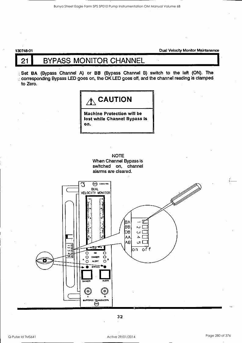
130748-01 Dual Velocity Monitor Maintenance
1 1 BYPASS MONITOR CHANNEL
Set BA (Bypass Channel A) or BB (Bypass Channel B) switch to the left (ON). The corresponding Bypass LED goes on, the OK LED goes off, and the channel reading is clamped to Zero.
A\ CAUTION
Machine Protection will be lost while Channel Bypass is on.
NOTE When Channel Bypass is switched on, channel alarms are cleared.
DUAL
VELOCITY MONITOR
,
32
Bunya Street Eagle Farm SPS SP010 Pump Instrumentation OM Manual Volume 6B
Q-Pulse Id TMS641 Active 29/01/2014 Page 280 of 376
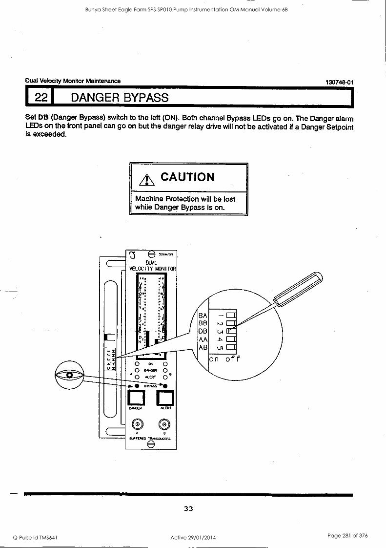
Dual Velocity Monitor Maintenance 130748-01
22 1 DANGER BYPASS
Set DB (Danger Bypass) switch to the left (ON). Both channel Bypass LEDs go on. The Danger alarm LEDs on the front panel can go on but the danger relay drive will not be activated if a Danger Setpoint is exceeded.
A\ CAUTION
Machine Protection will be lost while Danger Bypass is on.
3100,55
DUAL VELOCITY MONITOR
10
V f- O$
t Y yY
Is
Els
DANGER ALERT
BA BB 1--r DB M CE AB us Cr
on off
33
Bunya Street Eagle Farm SPS SP010 Pump Instrumentation OM Manual Volume 6B
Q-Pulse Id TMS641 Active 29/01/2014 Page 281 of 376
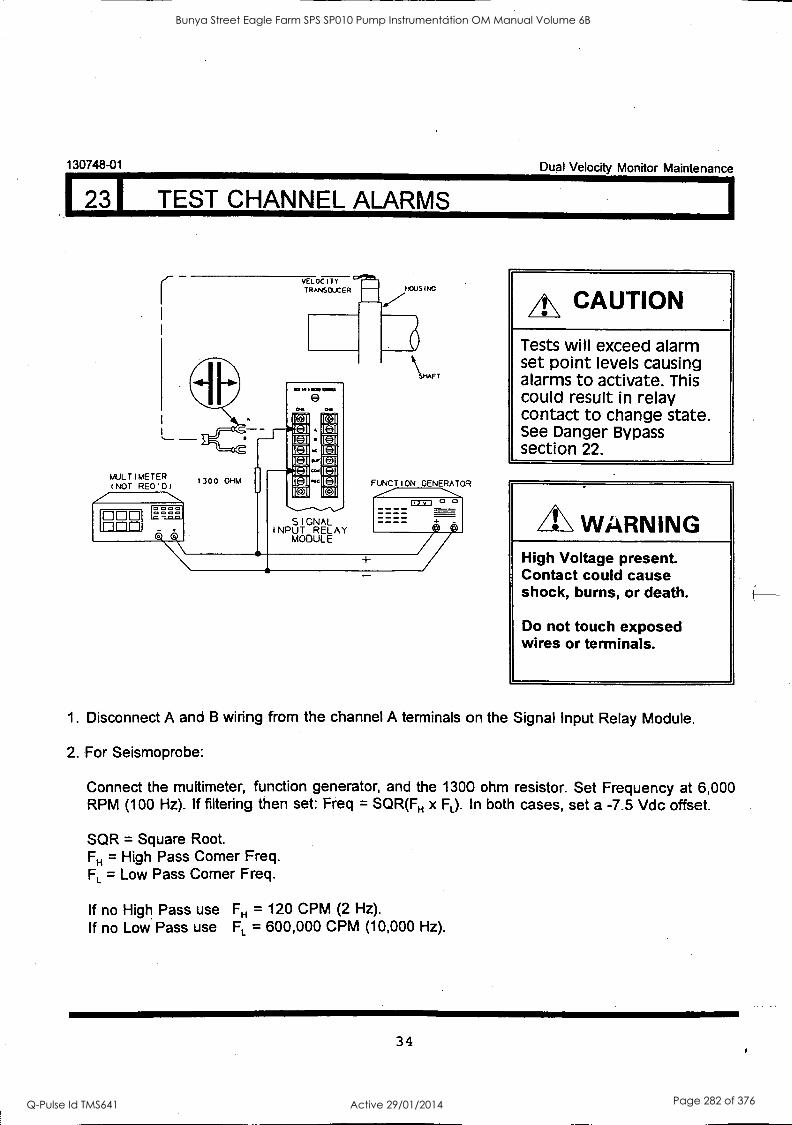
130748-01
123r TEST CHANNEL ALARMS
muLTIMETER INOT REo.o,
DOD =La
vELOC I TT
TRANSDUCER
1101 MSUS 1101M1
9
1300 OHM
SIGNAL INPUT RELAY
MODULE
MOUS INC
SHAFT
Dual Velocity Monitor Maintenance
FUNCTION
IL=
CAUTION
Tests will exceed alarm set point levels causing alarms to activate. This could result in relay contact to change state. See Danger Bypass section 22.
WARNING High Voltage present Contact could cause shock, burns, or death.
Do not touch exposed wires or terminals.
1. Disconnect A and B wiring from the channel A terminals on the Signal Input Relay Module.
2. For Seismoprobe:
Connect the multimeter, function generator, and the 1300 ohm resistor. Set Frequency at 6,000 RPM (100 Hz). If filtering then set: Freq = SQR(FH x FL). In both cases, set a -7.5 Vdc offset.
SQR = Square Root. FH = High Pass Corner Freq. FL = Low Pass Corner Freq.
If no High Pass use FH = 120 CPM (2 Hz). If no Low Pass use FL = 600,000 CPM (10,000 Hz).
34
Bunya Street Eagle Farm SPS SP010 Pump Instrumentation OM Manual Volume 6B
Q-Pulse Id TMS641 Active 29/01/2014 Page 282 of 376
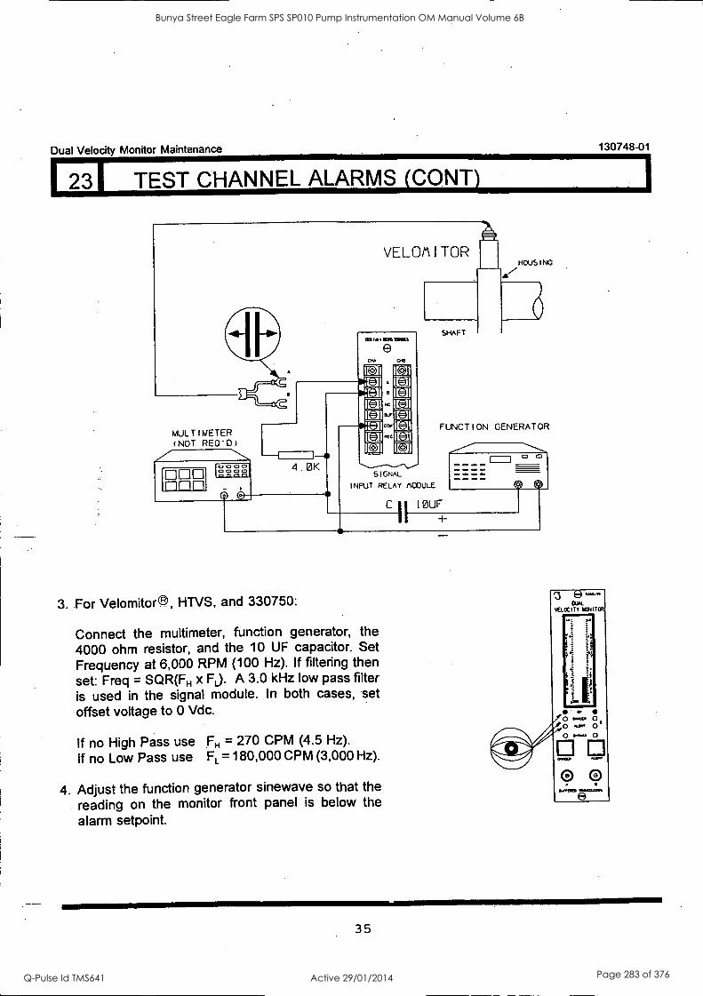
Dual Velocity Monitor Maintenance 130748-01
1 231 TEST CHANNEL ALARMS (CONTI
VELMA I TOR 110US I NG
WI 14 11111111111
MULTIMETER (NOT REO'D)
DOD n
1- 4. 0K
SIGNAL
INPUT RELAY ACC ULE
3. For Velomitor ®, HTVS, and 330750:
Connect the multimeter, function generator, the 4000 ohm resistor, and the 10 OF capacitor. Set Frequency at 6,000 RPM (100 Hz). if filtering then set: Freq = SQR(FH x FL). A 3.0 kHz low pass filter is used in the signal module. In both cases, set offset voltage to 0 Vdc.
If no High Pass use FH = 270 CPM (4.5 Hz).
If no Low Pass use FL = 180,000 CPM (3,000 Hz).
4. Adjust the function generator sinewave so that the
reading on the monitor front panel is below the alarm setpoint.
SHAFT
FUNCTION GENERATOR
C II 10UF
e VELOCITY ICNITOR
r
it
ij
o o o
0 0 &Pram
35
Bunya Street Eagle Farm SPS SP010 Pump Instrumentation OM Manual Volume 6B
Q-Pulse Id TMS641 Active 29/01/2014 Page 283 of 376

130748-01
I 231 TEST CHANNEL ALARMS (CONT)
5. Wait for the Timed OK/Channel defeat delay to elapse then press the RESET switch and verify the OK LEDs are on, and the ALERT and DANGER LEDs are off.
6. Adjust the function generator amplitude past the alert setpoint level and verify that the ALERT LED comes on (Flashing if the first out option is selected).
7. Verify that the ALERT RELAY changed state.
8. Press the RESET switch on the system monitor and verify that the ALERT LED remains on steady.
9. Adjust the function generator amplitude past the DANGER setpoint level and verify that the DANGER LED goes on (Flashing if first out option is selected).
10. Verify that the DANGER Relay changed state. If DANGER 'AND' voting logic is selected, the relay will not change states until both channels exceed their DANGER setpoints. 'AND' voting is not active if either channel is bypassed; Also, the Relay will not change states if the Danger Bypass is on.
Dual Velocity Monitor Maintenance
36
Bunya Street Eagle Farm SPS SP010 Pump Instrumentation OM Manual Volume 6B
Q-Pulse Id TMS641 Active 29/01/2014 Page 284 of 376
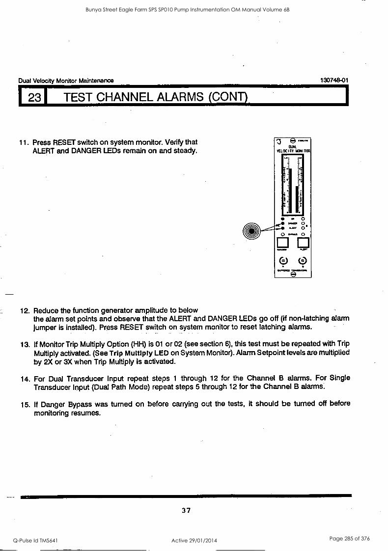
Dual Velocity Monitor Maintenance 130748-01
231 TEST CHANNEL ALARMS (CONT)
11. Press RESET switch on system monitor. Verify that ALERT and DANGER LEDs remain on and steady.
12. Reduce the function generator amplitude to below the alarm set points and observe that the ALERT and DANGER LEDs go off (if non-latching alarm jumper is installed). Press RESET switch on system monitor to reset latching alarms.
13. If Monitor Trip Multiply Option (HH) is 01 or 02 (see section 6), this test must be repeated with Trip Multiply activated. (See Trip Multiply LED on System Monitor). Alarm Setpoint levels are multiplied by 2X or 3X when Trip Multiply is activated.
14. For Dual Transducer Input repeat steps 1 through 12 for the Channel B alarms. For Single Transducer Input (Dual Path Mode) repeat steps 5 through 12 for the Channel B alarms.
15. If Danger Bypass was turned on before carrying out the tests, it should be turned off before monitoring resumes.
37
Bunya Street Eagle Farm SPS SP010 Pump Instrumentation OM Manual Volume 6B
Q-Pulse Id TMS641 Active 29/01/2014 Page 285 of 376
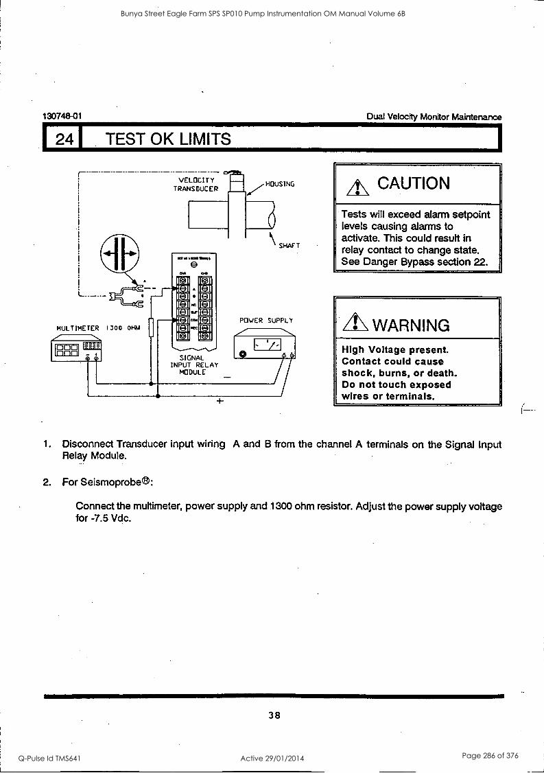
130748-01 Dual Velocity Monitor Maintenance
1 241 TEST OK LIMITS
--------------- - - - - -- VELOCITY
TRANSDUCER 71
la 1/1.4%
MUL T IME TER 1300 01-64
SIGNAL INPUT RELAY
MODULE
HOUSING
SHAFT
POWER SUPPLY
0
1/
A\ CAUTION
Tests will exceed alarm setpoint levels causing alarms to activate. This could result in relay contact to change state. See Danger Bypass section 22.
A\ WARNING High Voltage present. Contact could cause shock, burns, or death. Do not touch exposed wires or terminals.
1. Disconnect Transducer input wiring A and B from the channel A terminals on the. Signal Input Relay Module.
2. For Seismoprobe ®:
Connect the multimeter, power supply and 1300 ohm resistor. Adjust the power supply voltage for -7.5 Vdc.
38
Bunya Street Eagle Farm SPS SP010 Pump Instrumentation OM Manual Volume 6B
Q-Pulse Id TMS641 Active 29/01/2014 Page 286 of 376
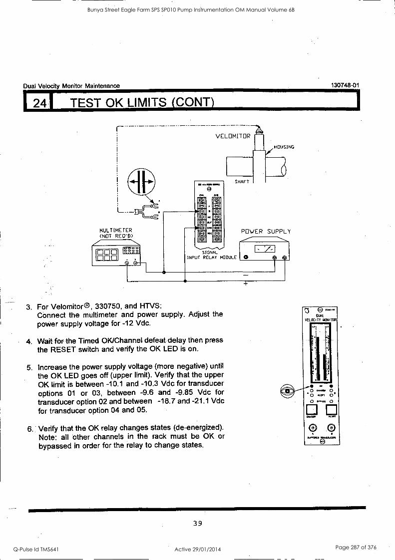
130748-01
1
Dual Velocity Monitor Maintenance
124I TEST OK LIMITS (CONY)
MULTIMETER (NOT REO'D) z
DOD FlElEt
SIGNAL INPUT RELAY MODULE
POWER SUPPLY
J
O
3. For Velomitor 330750, and HTVS: Connect the multimeter and power supply. Adjust the power supply voltage for -12 Vdc.
4. Wait for the Timed OK/Channel defeat delay then press the RESET switch and verify the OK LED is on.
5. Increase the power supply voltage (more negative) until
the OK LED goes off (upper limit). Verify that the upper OK limit is between -10.1 and -10.3 Vdc for transducer options 01 or 03, between -9.6 and -9.85 Vdc for transducer option 02 and between -18.7 and -21.1 Vdc for transducer option 04 and 05.
6. Verify that the OK relay changes states (de-energized). Note: all other channels in the rack must be OK or bypassed in order for the relay to change states.
39
Bunya Street Eagle Farm SPS SP010 Pump Instrumentation OM Manual Volume 6B
Q-Pulse Id TMS641 Active 29/01/2014 Page 287 of 376
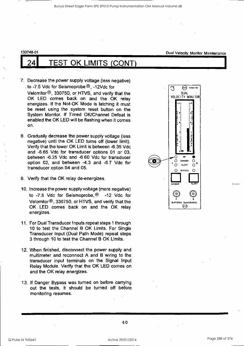
130748-01
24I TEST OK LIMITS (CONY)
7. Decrease the power supply voltage (less negative) to -7.5 Vdc for Seismoprobe a, -12Vdc for Velomitor®, 330750, or HTVS, and verify that the OK LED comes back on and the OK relay energizes. If the Not-OK Mode is latching it must be reset using the system reset button on the System Monitor. If Timed OK/Channel Defeat is enabled the OK LED will be flashing when it comes on.
8. Gradually decrease the power supply voltage (less negative) until the OK LED turns off (lower limit). Verify that the lower OK Limit is between -6.35 Vdc and -6.65 Vdc for transducer options 01 or 03, between -6.25 Vdc and -6.60 Vdc for transducer option 02, and between -4.3 and -6.7 Vdc for transducer option 04 and 05.
9. Verify that the OK relay de-energizes.
10. Increase the power supply voltage (more negative) to -7.5 Vdc for Seismoprobe, -12 Vdc for Velomitor®, 330750, or HTVS, and verify that the OK LED comes back on and the OK relay. energizes.
11. For Dual Transducer Inputs repeat steps 1 through 10 to test the Channel B OK Limits. For Single Transducer Input (Dual Path Mode) repeat steps 3 through 10 to test the Channel B OK Limits.
12. When finished, disconnect the power supply and multimeter and reconnect A and B wiring to the transducer input terminals on the Signal Input Relay Module. Verify that the OK LED comes on and the OK relay energizes.
13. If Danger. Bypass was turned on before carrying out the tests, it should be turned off before monitoring resumes.
Dual Velocity Monitor Maintenance
40
Bunya Street Eagle Farm SPS SP010 Pump Instrumentation OM Manual Volume 6B
Q-Pulse Id TMS641 Active 29/01/2014 Page 288 of 376
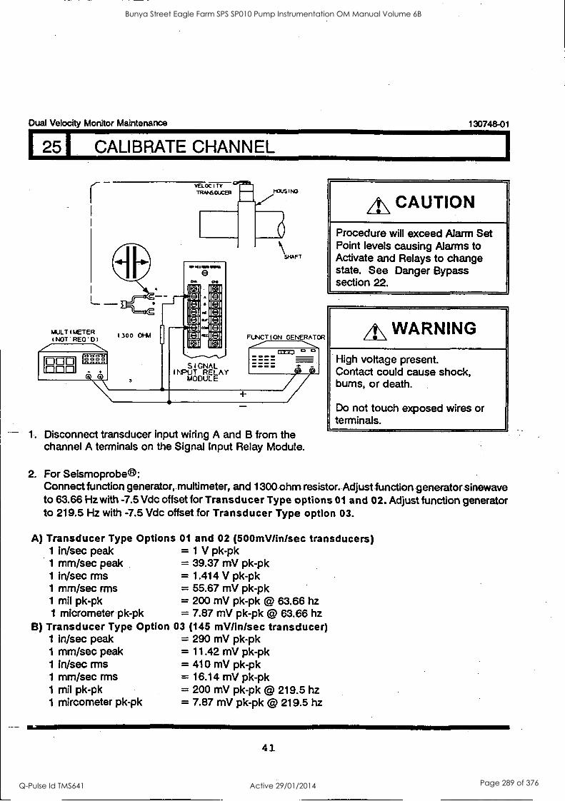
Dual Velocity Monitor Maintenance
VELOCITY TRANSDUCER MOUSING
MULT1METER tNOT REO'D)
1300 011A
SHAFT
FuNCTION GENERATOR
cr 0000
cagl
1. Disconnect transducer input wiring A and B from the channel A terminals on the Signal Input Relay Module.
130748-01
4\ CAUTION
Procedure will exceed Alarm Set Point levels causing Alarms to Activate and Relays to change state. See Danger Bypass section 22.
A\ WARNING
High voltage present. Contact could cause shock, bums, or death.
Do not touch exposed wires or terminals.
2. For Seismoprobee: Connect function generator, muftimeter, and 1300 ohm resistor. Adjust function generator sinewave to 63.66 Hz with -7.5 Vdc offset for Transducer Type options 01 and 02. Adjust function generator to 219.5 Hz with -7.5 Vdc offset for Transducer Type option 03.
A) Transducer Type Options 01 and 02 (500mV/Inisec transducers) 1 in/sec peak = 1 V pk-pk 1 mm/sec peak = 39.37 mV pk-pk 1 in/sec mis = 1.414 V pk-pk 1 mm/sec mis = 55.67 mV pk-pk 1 mil pk-pk = 200 mV pk-pk @ 63.66 hz 1 micrometer pk-pk = 7.87 mV pk-pk @ 63.66 hz
B) Transducer Type Option 03 (145 mV/in/sec transducer) 1 in/sec peak 1 mm/sec peak 1 in/sec rms 1 mm/sec rms 1 mil pk-pk 1 mircometer pk-pk
= 290 mV pk-pk = 11.42 mV pk-pk = 410 mV pk-pk = 16.14 mV pk-pk = 200 mV pk-pk @ 219.5 hz = 7.87 mV pk-pk @ 219.5 hz
41
Bunya Street Eagle Farm SPS SP010 Pump Instrumentation OM Manual Volume 6B
Q-Pulse Id TMS641 Active 29/01/2014 Page 289 of 376
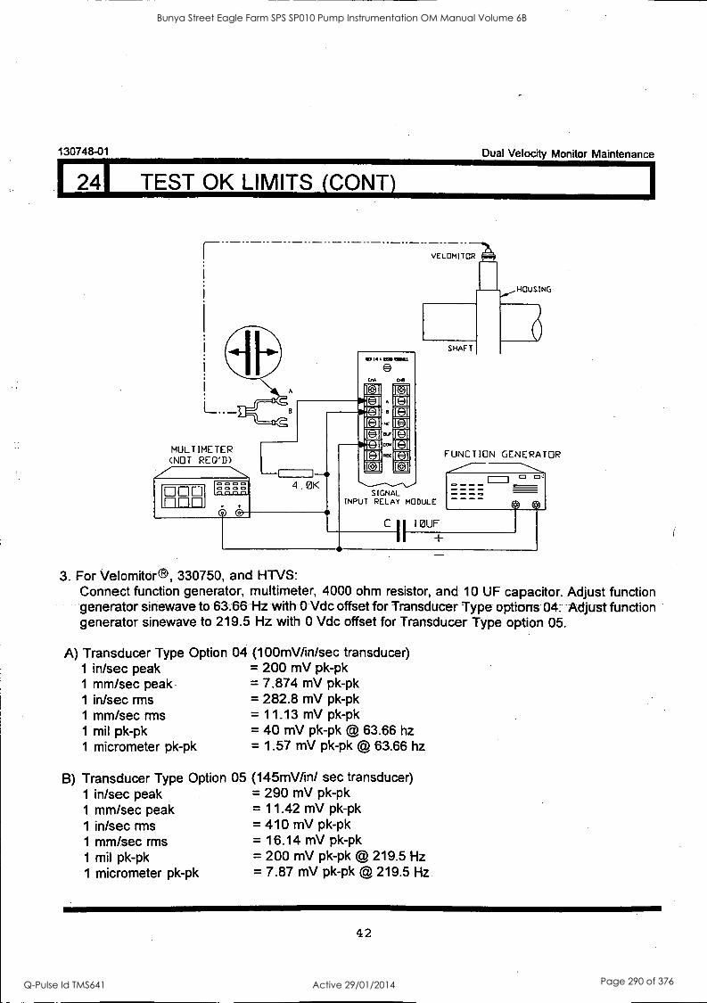
124I TEST OK LIMITS (CONY)
130748-01 Dual Velocity Monitor Maintenance
MULTIMETER (NOT REQ'D)
O DE 1-11-11-1
0 0 0 0 0 0 0 0 13 I-I 1-1
A
la 14 Oil OWLS
4 .0K
CJ [1.
SIGNAL INPUT RELAY MODULE
C 10LIF
I
FUNCTI N GENERATOR
3. For Velomitor ®, 330750, and HTVS: Connect function generator, multimeter, 4000 ohm resistor, and 10 OF capacitor. Adjust function generator sinewave to 63-.66 Hz with 0 Vdc offset for Transducer Type options 04. Adjust function generator sinewave to 219.5 Hz with 0 Vdc offset for Transducer Type option 05.
A) Transducer Type Option 1 in/sec peak 1 mm/sec peak 1 in/sec rms 1 mm/sec rms 1 mil pk-pk 1 micrometer pk-pk
B) Transducer Type Option 1 in/sec peak 1 mm/sec peak 1 in/sec rms 1 mm/sec rms 1 mil pk-pk 1 micrometer pk-pk
04 (100mV/in/sec transducer) = 200 mV pk-pk = 7.874 mV pk-pk = 282.8 mV pk-pk = 11.13 mV pk-pk = 40 mV pk-pk @ 63.66 hz = 1.57 mV pk-pk @ 63.66 hz
05 (145mV/in/ sec transducer) = 290 mV pk-pk = 11.42 mV pk-pk = 410 mV pk-pk = 16.14 mV pk-pk = 200 mV pk-pk @ 219.5 Hz = 7.87 mV pk-pk @ 219.5 Hz
42
Bunya Street Eagle Farm SPS SP010 Pump Instrumentation OM Manual Volume 6B
Q-Pulse Id TMS641 Active 29/01/2014 Page 290 of 376

Dual Velocity Monitor Maintenance 130748-01
251 CALIBRATE CHANNEL (CONS
Example
Given: Transducer Type Option is 01. Full scale range is 2 in/sec pk.
From 2A above: 1 in/sec peak = 1 Vpk-pk, therefore the full scale peak to peak input voltage amplitude is 2 V pk-pk.
The Multimeter reads an AC voltage as an rms voltage, Vrms, where:
Vrms = (.707/2) x( V pk-pk), for a sinewave input
When the full scale signal, (2 V pk-pk), is applied, the Multimeter will read:
Vrms = (.707/2) x ( 2 V pk-pk) = .707 Vrms
4. Open front panel. Slide front panel to right and measure proportional signal output at appropriate signal output testpoints, TP 22 (BPPLA) for Channel A and TP 21 (BPPLB) for Channel B.
PROPORTIONAL OUTPUT =
NO TRIP MULTIPLY +5.00 Vdc
2X TRIP MULTIPLY +2.50 Vdc
3x TRIP MULTIPLY +1.67 Vdc
43
Bunya Street Eagle Farm SPS SP010 Pump Instrumentation OM Manual Volume 6B
Q-Pulse Id TMS641 Active 29/01/2014 Page 291 of 376

130748-01 Dual Velocity Monitor Maintenance
25 I CALIBRATE CHANNEL (CONT)
5. Adjust potentiometer (GA (gain adjust A) for channel A, and GB for channel B) for 100% of full scale voltage.
GAIN A ADJUST
CHANNEL A TP
CHANNEL B ADJUST
CHANNEL B TP
DUAL VELOCITY MONITOR
LO rL
S 1
FD -aL
ER
wow 0 A ALERT 0 e
o rmAss 0
El El hunFR ALERT
A
OurrEPEo tomesoLcuts
MULTIMETER
ED Finn 0 0 0 0 0 ire o
6. Close front panel. Disconnect test equipment and reconnect the transducer wiring A and B to Channel A terminals. Verify that the Alert and Danger LED's go out if Alarms are non-latching. Use system reset on System Monitor if Alarms are latching. Verify the OK LED is on. If Timed OK/Channel Defeat is enabled the Not-OK Mode must be non-latching, in this case the OK LED will come on and flash. Pressing the system reset (on the System Monitor) will cause the OK LED to stop flashing and remain on. If the Not-OK Mode is latching, the OK LED will remain off until the system reset is pressed.
7. If Danger Bypass was turned on before carrying out the tests, it should be turned off before monitoring resumes.
44
Bunya Street Eagle Farm SPS SP010 Pump Instrumentation OM Manual Volume 6B
Q-Pulse Id TMS641 Active 29/01/2014 Page 292 of 376
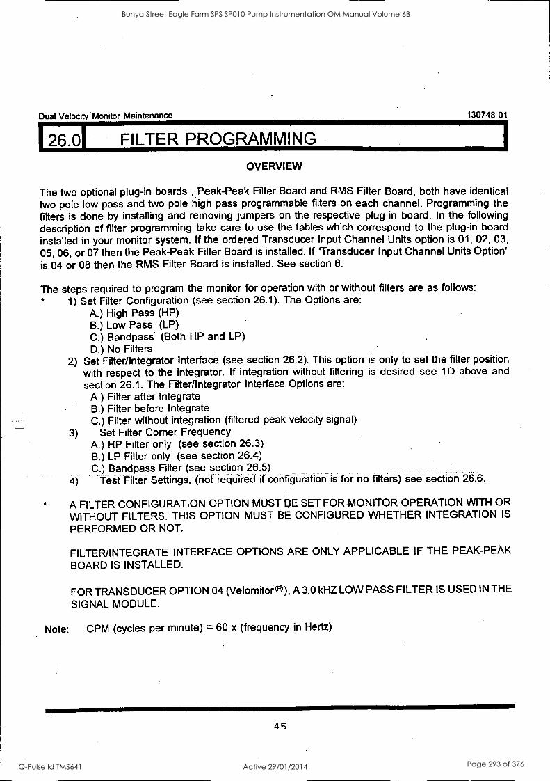
I26.OI FILTER PROGRAMMING
Dual Velocity Monitor Maintenance 130748-01
OVERVIEW
The two optional plug-in boards , Peak-Peak Filter Board and RMS Filter Board, both have identical two pole low pass and two pole high pass programmable filters on each channel, Programming the filters is done by installing and removing jumpers on the respective plug-in board. In the following description of filter programming take care to use the tables which correspond to the plug-in board installed in your monitor system. If the ordered Transducer Input Channel Units option is 01, 02, 03,
05, 06, or 07 then the Peak-Peak Filter Board is installed. If 'Transducer Input Channel Units Option" is 04 or 08 then the RMS Filter Board is installed. See section 6.
The steps required to program the monitor for operation with or without filters are as follows: * 1) Set Filter Configuration (see section 26.1). The Options are:
A.) High Pass (HP) B.) Low Pass (LP) C.) Bandpass (Both HP and LP) D.) No Filters
2) Set Filter/Integrator Interface (see section 26.2). This option is only to set the filter position with respect to the integrator. If integration without filtering is desired see 1D above and section 26.1. The Filter/Integrator Interface Options are:
A.) Filter after Integrate B.) Filter before Integrate C.) Filter without integration (filtered peak velocity signal)
Set Filter Corner Frequency A.) HP Filter only (see section 26.3) B.) LP Filter only (see section 26.4) C.) Bandpass Filter (see section 26.5)
4) Test Filter Settings, (not required if configuration is for no filters) see section 26.6.
A FILTER CONFIGURATION OPTION MUST BE SET FOR MONITOR OPERATION WITH OR
WITHOUT FILTERS. THIS OPTION MUST BE CONFIGURED WHETHER INTEGRATION IS
PERFORMED OR NOT.
FILTER/INTEGRATE INTERFACE OPTIONS ARE ONLY APPLICABLE IF THE PEAK-PEAK BOARD IS INSTALLED.
FOR TRANSDUCER OPTION 04 (Velomitor 6), A 3.0 kHZ LOW PASS FILTER IS USED IN THE
SIGNAL MODULE.
Note: CPM (cycles per minute) = 60 x (frequency in Hertz)
45
Bunya Street Eagle Farm SPS SP010 Pump Instrumentation OM Manual Volume 6B
Q-Pulse Id TMS641 Active 29/01/2014 Page 293 of 376
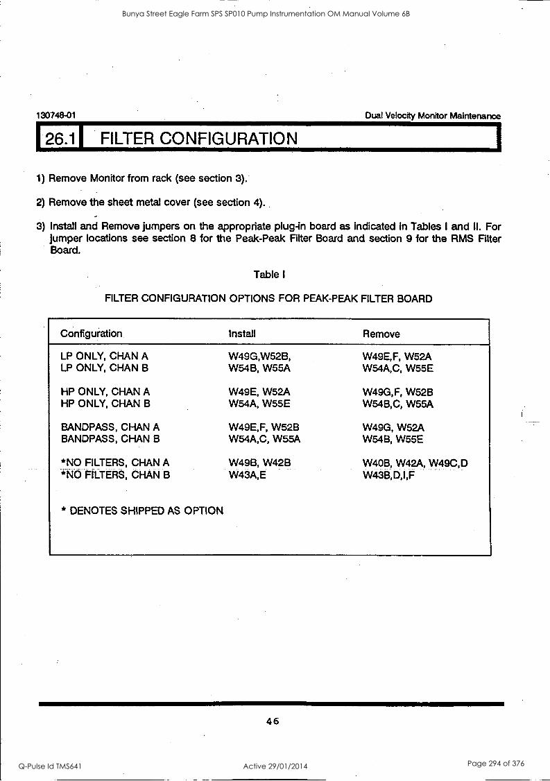
130748-01 Dual Velocity Monitor Maintenance
26.11 FILTER CONFIGURATION
1) Remove Monitor from rack (see section 3).
2) Remove the sheet metal cover (see section 4).
3) Install and Remove jumpers on the appropriate plug-in board as indicated in Tables I and II. For jumper locations see section 8 for the Peak-Peak Fitter Board and section 9 for the RMS Filter Board.
Table I
FILTER CONFIGURATION OPTIONS FOR PEAK-PEAK FILTER BOARD
Configuration Install Remove
LP ONLY, CHAN A LP ONLY, CHAN B
HP ONLY, CHAN A HP ONLY, CHAN B
BANDPASS, CHAN A BANDPASS, CHAN B
*NO FILTERS, CHAN A *NO FILTERS, CHAN B
* DENOTES SHIPPED AS OPTION
W49G,W52B, W54B, W55A
W49E, W52A W54A, W55E
W49E,F, W52B W54A,C, W55A
W49B, W42B W43A,E
W49E,F, W52A W54A,C, W55E
W49G,F, W52B W54B,C, W55A
W49G, W52A W54B, W55E
W40B, W42A, W49C,D W43B,D,I,F
46
Bunya Street Eagle Farm SPS SP010 Pump Instrumentation OM Manual Volume 6B
Q-Pulse Id TMS641 Active 29/01/2014 Page 294 of 376

Dual Velocity Monitor Maintenance 130748-01
126.1 FILTER CONFIGURATION (CONT)
4) (Cont) Table II shows the jumpers to be installed or removed to set the filter configuration option
on the RMS Filter Board, (see section 9 for board jumper locations).
Table II
FILTER CONFIGURATION OPTIONS FOR RMS FILTER BOARD
Configuration Install Remove
LP ONLY, CHAN A LP ONLY, CHAN B
HP ONLY, CHAN A HP ONLY, CHAN B
BANDPASS, CHAN A BANDPASS, CHAN B
*NO FILTERS, CHAN A *NO FILTERS, CHAN B
* DENOTES SHIPPED AS OPTION
W50,W52,W54,W55 W56,W62,W64,W69
W47,W48,W50,W52 W56,W62,W63,W73
W46,W48,W50,W52,W55 W56,W62,W64,W68,W73
W51 W61
W46,W47,W48,W51 W61,W63,W68,W73
W46,W51,W54,W55 W61,W64,W68,W69
W47,W51,W54 W61,W63,W69
W50,W52 W56,W62
5) If the monitor was configured for no filters then re-assemble the monitor and install in the rack. If
the monitor was configured with filters then continue to section 26.2 to set filter/integrator interface or continue to section 26.3 to set corner frequency option.
47
Bunya Street Eagle Farm SPS SP010 Pump Instrumentation OM Manual Volume 6B
Q-Pulse Id TMS641 Active 29/01/2014 Page 295 of 376
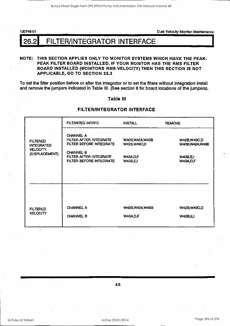
130748-01 Dual Velocity Monitor Maintenance
26.2 FILTER/INTEGRATOR INTERFACE
NOTE: THIS SECTION APPLIES ONLY TO MONITOR SYSTEMS WHICH HAVE THE PEAK- PEAK FILTER BOARD INSTALLED. IF YOUR MONITOR HAS THE RMS FILTER BOARD INSTALLED (MONITORS RMS VELOCITY) THEN THIS SECTION IS NOT APPLICABLE, GO TO SECTION 26.3
To set the filter position before or after the integrator or to set the filters without integration install and remove the jumpers indicated in Table III. (See section 8 for board locations of the jumpers).
Table III
FILTER/INTEGRATOR INTERFACE
FILTERED INTEGRATED VELOCITY. (DISPLACEMENT)
FILT/INTEG INTRFC INSTALL REMOVE
CHANNEL A FILTER AFTER INTEGRATE FILTER BEFORE INTEGRATE
CHANNEL B FILTER AFTER INTEGRATE FILTER BEFORE INTEGRATE
W40B,W42A,W49B W42B,W49C,D
W43A,D,F W43B,E,I
W42B,W49C,D W40B,W42A,W498
W43B,E,1 W43A,D,F
FILTERED VELOCITY
CHANNEL A
CHANNEL B
W40B,W42AW49B
W43A,D,F
W42B,W49C,D
W43B,E,1
48
Bunya Street Eagle Farm SPS SP010 Pump Instrumentation OM Manual Volume 6B
Q-Pulse Id TMS641 Active 29/01/2014 Page 296 of 376
Dual Velocity Monitor Maintenance 130748-01
126.31 SET HP CORNER FREQUENCY
1. Determine whether the Peak-Peak Filter Board or the RMS Filter Board is installed. See section 6
and check your ordered options. If Transducer Input Channel Units Option is 01, 02, 03, 05, 06, or
07 then the Peak-Peak Filter Board is installed. If the Transducer Input Channel Units Option is 04
or 08 then the RMS Filter Board is installed.
2. Verify the Filter Configuration (see section 26.1).
3. If the Peak-Peak Filter Board is installed then verify the filter/integrator interface (see section
26.2).
4. On the respective plug-in board install and remove jumpers according to the selected HP corner
frequencies shown in Tables IV and V. Board locations of the jumpers are shown in sections 8
and 9. For special applications, jumper settings not listed in Tables IV or V can be determined
using the procedure described at the end of this section.
} 5. Test Filters. (See section 26.6.)
49
Bunya Street Eagle Farm SPS SP010 Pump Instrumentation OM Manual Volume 6B
Q-Pulse Id TMS641 Active 29/01/2014 Page 297 of 376
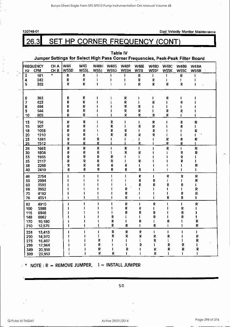
1
130748-01 Dual Velocity Monitor Maintenance
126.31 SET HP CORNER FREQUENCY (CONY)
Table IV Jumper Settings for Select High Pass Corner Frequencies, Peak-Peak Filter Board
FREQUENCY CH A Hz CPM CH B
W44 W55D
W45 W55L
W48H W55J
W48G W55G
W48F W55H
W48E W55I
W48D W55F
W48C W55K
W48B W55C
W48A W55B
3
4 5
181 * 242 302
R
R
R
R
R
R
I
I
I
I
I
I
I
I
I
R
R
R
I
R
R
I
I
R
R
I
R
I
I
I
6 363 R R I I R I I R I I
7 423 R R I I R I R I R I
8 484 R R I I R R I I I I
9 544 R R I I R R I R R I
10 605 R R I I R R R R I I
13 756 R R I R I I R I R R 15 907 R R I R I R R I R
18 1058 R R I R R I R I I R
20 1210 R R I R R R R I I I ' 23 1361 R R R I I I I R R R
25 1512 R R R I I R I R R I
28 1663 R R R I R I I R I R
30 1804 R R R I R R I I R R
33 1955 R R R R I I I I R I
35 2117 R R R R I R I I R I
38 2268 R R R R R I I I I R
40 2419 R R R R R R I I I I
46 2754 I I I I I R I R R R
50 2994 I I I I I R R I I R
60 3593 I I I I I R R R R I
66 3952 I I I I R I I I I R
70 4192 I I I I R I I I R R
76 4551. I I I I R I I R R I
82 4910 I I I I R I R I I R
100 5988 I I I I R R I I R I
116 6946 I I I I R R R I R I
148 8862 I I I R I I R I R I
170 10,180 I I I R I R I R I R
210 12,575 I I I R R I R I I R
224 13,413 I I I R R R I I I I
250 14,970 I I I R R R R R I R
273 16,407 I I R I I I R I I R
299 17,964 I I R I I R I R R I
349 20,958 I I R I R I R R R R
399 23,952 I I R R I I R I I I
* NOTE : R = REMOVE JUMPER, I = INSTALL JUMPER
50
Bunya Street Eagle Farm SPS SP010 Pump Instrumentation OM Manual Volume 6B
Q-Pulse Id TMS641 Active 29/01/2014 Page 298 of 376

Dual Velocity Monitor Maintenance
26.31 SET HP CORNER FREQUENCY (CONT)
130748-01
Table V Jumper Settings for Select High Pass Corner Frequencies, RMS Filter Board
FREQUENCY HZ CPM
CH A CH B
W59 W71
W60 W72
W58H W7OH
W58G W7OG
W58F W7OF
.W58E VV70E
W58D W7OD
W58C W70C
W58B W7OB
W58A VV70A
3 181 * R R I I I R I I R I
4 242 R R I I I R R I I I
6 363 R R 1 I R I 1 R 1 1
7 423 R R I I R I R I R I
8 484 R R 1 I R R I I I 1
9 544 R R I I R R I R R 1
10 605 R R I I R R R R I 1
..
13 756 R R I R I I R I R R
15 907 R R I R I R R I R 1
18 1058 R R I R R I R I I R
20 1210 R R I R R R R I I 1
23 1361 R R R 1 I 1 I R R R
25 1512 R R R I I R I R R 1
28 1663 R R R I R I I '12 I R
30 1801 R R R I R R I I R R
33 1955 R R R R I I I I R I
35 2117 R R R R I R I 1 R 1
38 2268 R R R R R I I I I R
40 2419 R R R R R R I I I I
46 2754 1 I 1 I I R I R R R
50 2994 I I I 1 1 R R I 1 R
60 3593 I I I 1 I R R R R I
66 3952 I I I 1 R I 1 1 1 R
70 4192 1 I I I R I I I R R
76 4551 I 1 1 1 R 1 1 R R 1
82 4910 I I 1 I R I R I I R
100 5988 1 1 I 1 R R I 1 R I
116 6946 I I I I R R R I R 1
148 8862 I I I R I 1 R I R 1
170 10,180 1 I I R I R I R I R
210 12,575 I I I R R I R I I R
224 13,413 I I I R R R I I I 1
250 14,970 I I I R R R R R I R
273 16,407 I I R I I I R I I R
299 17,964 I I R I I R I R R 1
349 20,958 I I R 1 R I R R R R
399 23,952 I I R R I 1 R I I 1
* NOTE : R = REMOVE JUMPER, I = INSTALL JUMPER
51
Bunya Street Eagle Farm SPS SP010 Pump Instrumentation OM Manual Volume 6B
Q-Pulse Id TMS641 Active 29/01/2014 Page 299 of 376
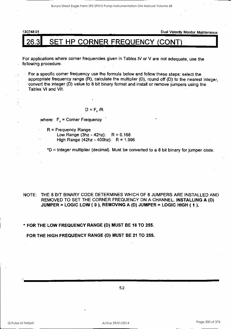
130748-01 Dual Velocity Monitor Maintenance
26.31 SET HP CORNER FREQUENCY (CONT)
For applications where corner frequencies given in Tables IV or V are not adequate, use the following procedure.
For a specific corner frequency use the formula below and follow these steps: select the appropriate frequency range (R), calculate the multiplier (D), round off (D) to the nearest integer, convert the integer (D) value to 8 bit binary format and install or remove jumpers using the Tables VI and VII.
D = Fc /R
where: Fc = Corner Frequency
R = Frequency Range Low Range (3hz - 42hz): R = 0.168 High Range (42hz - 400hz): R = 1.996
*D = Integer multiplier (decimal). Must be converted to a 8 bit binary for jumper code.
NOTE: THE 8 BIT BINARY CODE DETERMINES WHICH OF 8 JUMPERS ARE INSTALLED AND REMOVED TO SET THE CORNER FREQUENCY ON A CHANNEL. INSTALLING A (D) JUMPER = LOGIC LOW ( 0 ), REMOVING A (D) JUMPER = LOGIC HIGH ( 1 ).
* FOR THE LOW FREQUENCY RANGE (D) MUST BE 18 TO 255.
FOR THE HIGH FREQUENCY RANGE (D) MUST BE 21 TO 255.
52
Bunya Street Eagle Farm SPS SP010 Pump Instrumentation OM Manual Volume 6B
Q-Pulse Id TMS641 Active 29/01/2014 Page 300 of 376
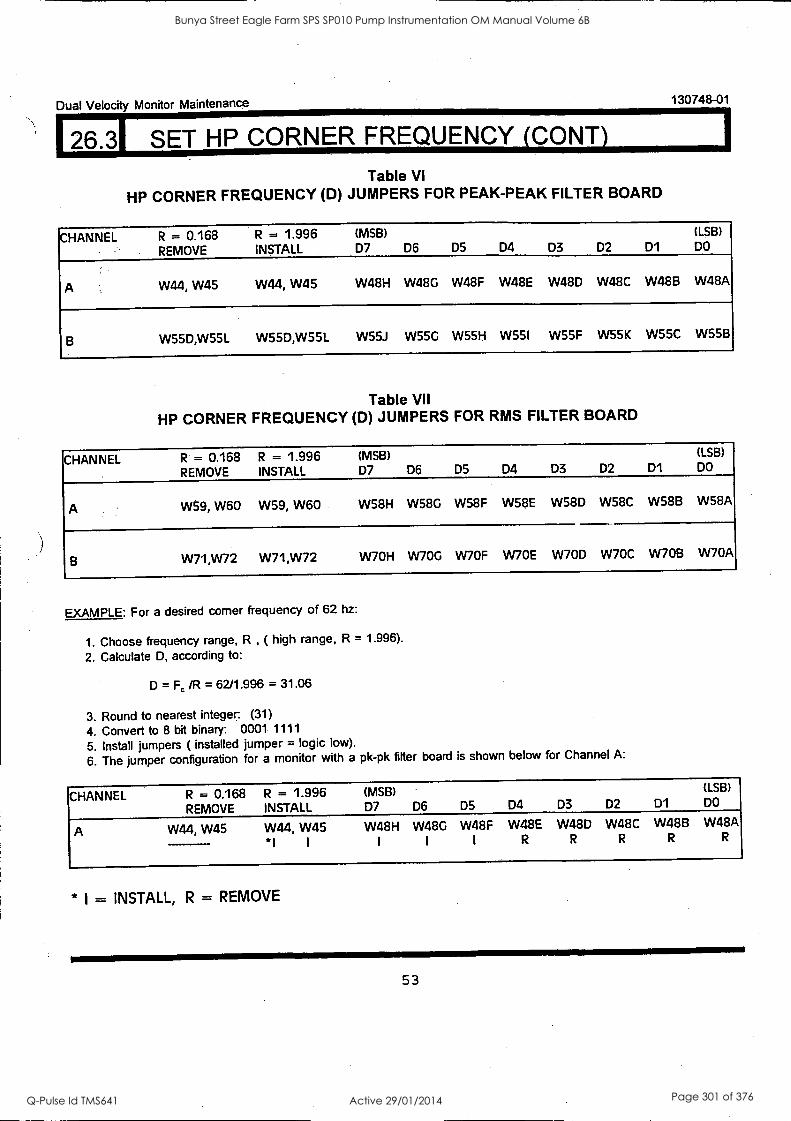
Dual Velocity Monitor Maintenance 130748-01
126.31 SET HP CORNER FREQUENCY (CONY)
Table VI
HP CORNER FREQUENCY (D) JUMPERS FOR PEAK-PEAK FILTER BOARD
CHANNEL R = 0.168 R = 1.996 (MSB) (LSB)
REMOVE INSTALL D7 D6 D5 D4 D3 D2 D1 DO
A W44, W45 W44, W45 W48H W48G W48F W48E W48D W48C W48B W48A
B W55D,W55L W55D,W55L W55J W55G W55H W55I W55F W55K W55C W55B
Table VII
HP CORNER FREQUENCY (D) JUMPERS FOR RMS FILTER BOARD
CHANNEL R = 0.168 R = 1.996 (MSB) (LSB)
REMOVE INSTALL D7 D6 D5 D4 D3 D2 D1 DO
A W59, W60 W59, W60 W58H W58G W58F W58E WS8D W58C W58B W58A
B W71,W72 W71,W72 W7OH W7OG W7OF W70E W7OD W70C W7OB W70A
EXAMPLE: For a desired corner frequency of 62 hz:
1. Choose frequency range, R , ( high range, R = 1.996).
2. Calculate D, according to:
D = F, /R = 62/1.996 = 31.06
3. Round to nearest integer: (31)
4. Convert to 8 bit binary: 0001 1111
5. Install jumpers ( installed jumper = logic low).
6. The jumper configuration for a monitor with a pk-pk filter board is shown below for Channel A:
CHANNEL R = 0.168 R = 1.996 (MSB) (LSB)
REMOVE INSTALL D7 D6 D5 D4 D3 D2 D1 DO
A W44, W45 W44, W45 W48H W48G W48F W48E W48D W48C W48B W48A
*I I
* I = INSTALL, R = REMOVE
53
Bunya Street Eagle Farm SPS SP010 Pump Instrumentation OM Manual Volume 6B
Q-Pulse Id TMS641 Active 29/01/2014 Page 301 of 376
130748-01
126.41 SET LP CORNER FREQUENCY
Dual Velocity Monitor Maintenance
1*. Determine whether the Peak-Peak Filter Board or the RMS Filter Board is installed. See section 6 and check your ordered options. If Transducer Input Channel Units Option is 01, 02, 03, 05, 06, or 07 then the Peak-Peak Filter Board is installed. If the Transducer Input Channel Units Option is 04 or 08 then the RMS Filter Board is installed.
2. Verify the Filter Configuration (see section 26.1).
3. If the Peak-Peak Filter Board is installed then verify the filter/integrator interface (see section 26.2).
4. On the respective plug-in board install and remove jumpers according to the selected LP corner frequencies shown in Tables VIII and IX. Board locations of the jumpers are shown in sections 8 and 9. For special applications, jumper settings not listed in Tables VIII or IX can be determined using the procedure described at the end of this section.
5. Test Filters. (See section 26.6.)
FOR TRANSDUCER OPTIONS 04 ( VELOMITOR ®) AND 05 (HTVS and 330750 ), A 3.0 kHz LOW PASS FILTER IS USED IN THE SIGNAL INPUT MODULE.
54
Bunya Street Eagle Farm SPS SP010 Pump Instrumentation OM Manual Volume 6B
Q-Pulse Id TMS641 Active 29/01/2014 Page 302 of 376
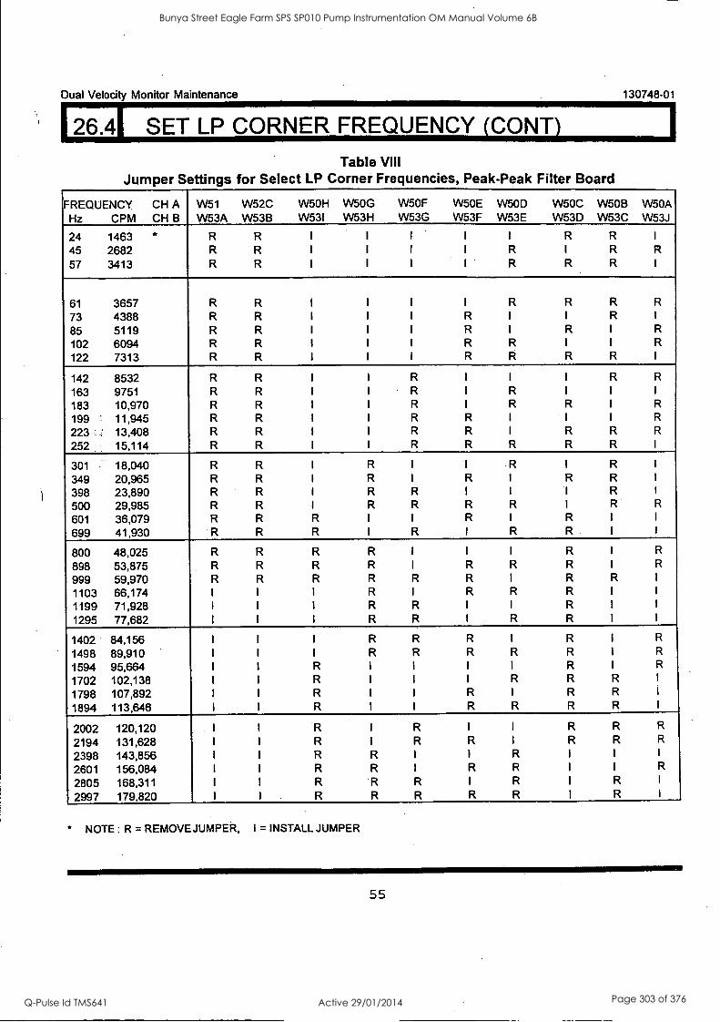
Dual Velocity Monitor Maintenance 130748-01
26.4 SET LP CORNER FREQUENCY (CONY)
Table VIII Jumper Settings for Select LP Corner Frequencies, Peak-Peak Filter Board
FREQUENCY CH A Hz CPM CH B
W51 W53A
W52C W53B
W5OH W53I
W5OG W53H
W5OF W53G
W50E W53F
W5OD W53E
W50C W53D
W5OB W53C
W50A W53J
24 1463 * R R I I I I I R R 45 2682 R R I I I I R I R R
57 3413 R R I I I I R R R
61 3657 R R I I I I R R R R
73 4388 R R I I I R I I R
85 5119 R R I I I R I R I R
102 6094 R R I I I R R I I R
122 7313 R R I I I R R R R
142 8532 R R I I R I I I R R
163 9751 R R I I R I R 183 10,970 R R 1 I R I R R I R
199 ' 11,945 R R I I R R I 1 I R
223 _. 13,408 R R I I R R I R R R
252 15,114 R R I I R R R R R
301 18,040 R R I R R I R
349 20,965 R R I R I R I R R
398 23,890 R R I R R I I I R
500 29,985 R R I R R R R I R R
601 36,079 R R R I I R I R
699 41,930 R R R I R I R R
800 48,025 R R R R I I I R I R
898 53,875 R R R R I R R R I R
999 59,970 R R R R R R I R R
1103 66,174 I I I R I R R R
1199 71,928 I I I R R I I R
1295 77,682 I I I R R I R R
1402 84,156 I I I R R R I R I R
1498 89,910 I I I R R R R R I R
1594 95,664 I 1 R I I I I R I R
1702 102,138 I I R I I I R R R I
1798 107,892 I I R I I R I R R I
1894 113,646 I I R I I R R R R I
2002 120,120 I I R I R I I R R R
2194 131,628 I I R I R R I R R R
2398 143,856 I I R R I I R I I I
2601 156,084 I I R R I R R I I R
2805 168,311 I I R R R I R I R I
2997 179,820 I I R R R R R I R I
* NOTE : R = REMOVE JUMPER, I = INSTALL JUMPER
55
Bunya Street Eagle Farm SPS SP010 Pump Instrumentation OM Manual Volume 6B
Q-Pulse Id TMS641 Active 29/01/2014 Page 303 of 376
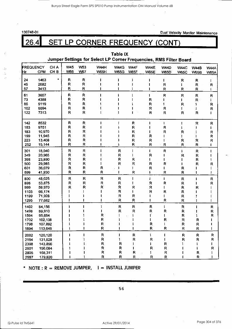
130748-01 Dual Velocity Monitor Maintenance
26.41 SET LP CORNER FREQUENCY (CONT)
Table IX Jumper Settings for Select LP Corner Frequencies, RMS Filter Board
FREQUENCY CH A 1z CPM CH B
W45 W66
W53 VV67
W44H VV65H
W44G VV65G
W44F VV65F
W44E VV65E
W44D VV65D
W44C W65C
W44B VV65B
W4-4A W65A
24 1463 R R I I I I I R R 45 2682 R R I I I I R I R R 57 3413 R R I I I I R R R
61 3657 R R I I I I R R R R 73 4388 R R I I I R I I R 85 5119 R R 1 I I R I R I R 102 6094 R R I I 1 R R I I R 122 7313 R R I I I R R R R
142 8532 R R I I R I I I R R 163 9751 R R I I R I R I I
183 10,970 R R I I R I R R I R 199 11,945 R R 1 I R R I I I R 223 13,408 R R I I R R I R R R 252 15,144 R R I I R R R R R
301 18,040 R R I R I I R I R 349 20,965 R R I R I R I R R 398 23,890 R R I R R I I I R 500 29,985 R R I R R R R R R 601 36,079 R R R I I R I R 699 41,930 R R R I R I R R
800 48,025 R R R R I 1 I R I R
898 53,875 R R R R I R R R I R 999 59,970 R R R R R R I R R 1103 66,174 I I I R I R R R 1199 71,928 I I I R R I I R 1295 77,682 I I I R R I R R
1402 84,156 I I I R R R I R I R
1498 89,910 I I I R R R R R I R
1594 95,664 I I R I I I I R I R
1702 102,138 I I R I I I, R R R I
1798 107,892 1 I R I I R I R R I
1894 113,646 I I R I I R R R R I
2002 120,120 I I R I R I I R R R
2194 131,628 I I R I R R I R R R
2398 143,856 I I R R I I R I I I
2601 156,084 I I R R I R R I I R
2805 168,311 I I R R R I R I R I
2997 179,820 R R R R R I R I
* NOTE : R = REMOVE JUMPER, I = INSTALL JUMPER
56
Bunya Street Eagle Farm SPS SP010 Pump Instrumentation OM Manual Volume 6B
Q-Pulse Id TMS641 Active 29/01/2014 Page 304 of 376

Dual Velocity Monitor Maintenance 130748-01
26.41 SET LP CORNER. FREQUENCY (CONY)
For applications where corner frequencies given in Tables VIII or IX are not adequate, use the
following procedure.
For a specific corner frequency use the formula below and follow these steps: select the
appropriate frequency range (R), calculate the multiplier (D), round off (D) to the nearest integer,
convert the integer (D) value to 8 bit binary format and install or remove jumpers using Tables X
and Xl.
D = Fc /R
where: Fc = Corner Frequency
R = Frequency Range Low Range (24hz - 1000hz): R = 4.063 High Range (1000hz -3000hz): R = 11.988
*D = Integer multiplier (decimal). Must be converted to a 8 bit binary number for jumper code.
NOTE: THE 8 BIT BINARY CODE DETERMINES WHICH OF 8 JUMPERS ARE INSTALLED AND
REMOVED TO SET THE CORNER FREQUENCY ON A CHANNEL. INSTALLING A (D)
JUMPER = LOGIC LOW ( 0 ), REMOVING A (0) JUMPER = LOGIC HIGH ( 1 ).
* FOR THE LOW FREQUENCY RANGE (D) MUST BE 6 TO 255.
FOR THE HIGH FREQUENCY RANGE (D) MUST BE 83 TO 255.
57
Bunya Street Eagle Farm SPS SP010 Pump Instrumentation OM Manual Volume 6B
Q-Pulse Id TMS641 Active 29/01/2014 Page 305 of 376

130748-01 Dual Velocity Monitor Maintenance
26.41 SET LP CORNER FREQUENCY (CONY)
Table X LP CORNER FREQUENCY (D) JUMPERS FOR PEAK-PEAK FILTER BOARD
CHANNEL R =4.063 R = 11.988 (MSB) (LSB) REMOVE INSTALL D7 D6 D5 D4 D3 D2 D1 DO
W51, W52C W51, W52C W5OH W5OG W5OF W50E W5OD W50C W5OB W50A
B W53A,W53B W53AW5313 W531 W53H W53G W53F W53E W53D W530 W53J
Table XI LP CORNER FREQUENCY (D) JUMPERS FOR RMS FILTER BOARD
CHANNEL R =4.063 R = 11.988 (MSB) REMOVE INSTALL D7
(LSB) D5 D3 D2 D1 DO
W45, W53 W45, W53 W44H W44G W44F W44E W44D W44C W44B W44A
W66,W67 W66,W67 W65H W65G W65F W65E W65D W65C W658 W65A
EXAMPLE: For a desired corner frequency of 562 hz:
1. Choose frequency range, R , ( Low range, R = 4.063). 2. Calculate D, according to:
D = FdR = 562/4.063 = 138.32
3. Round to nearest integer. (138) 4. Convert to 8 bit binary: 1000 1010 5. Install jumpers ( installed jumper = logic low). 6. The jumper configuration for a monitor with a pk-pk fitter board is shown below for Channel A:
CHANNEL R =4.063 R = 11.988 (MSB) (LSB) REMOVE INSTALL D7 D6 D5 D4 D3 D2 D1 DO
A W51, W52C W51, W52C W44H W44G W44F W44E W44D W44C W44B W44A *R R
I = INSTALL, R = REMOVE
58
Bunya Street Eagle Farm SPS SP010 Pump Instrumentation OM Manual Volume 6B
Q-Pulse Id TMS641 Active 29/01/2014 Page 306 of 376

Dual Velocity Monitor Maintenance
26.5 BAND PASS FILTERS
130748-01
Bandpass filtering is implemented by cascading the High Pass and Low Pass filters. To set up the
monitor for Bandpass filtering follow the procedure below.
1. Determine whether the Peak-Peak Filter Board or the RMS Filter Board is installed. See section 6
and check your ordered options. If Transducer Input Channel Units Option is 01, 02, 03, 05, 06,
or 07 then the Peak-Peak Filter Board is installed. If the Transducer Input Channel Units Option
is 04 or 08 then the RMS Fitter Board is installed.
2. Verify the Filter Configuration (see section 26.1).
3. If the Peak-Peak Filter Board is installed then verify the filter /integrator interface (see section
26.2).
4. Select the High and Low Pass corner frequencies, and calculate the center frequency of the
pass band according to the following: (an example is given at the end of section' 26.6)
A.) The High and Low pass corner frequencies must be at least one decade apart, i.e. the
LP corner should be at least 10X the HP corner.
B.) The center frequency of the pass band is given by:
Fbp = SQR(Fhp x Flp)
where: Fbp = Center frequency of pass band Fhp = High pass corner frequency Flp = Low pass corner frequency SQR = Square Root function
4. On the respective plug-in board install and remove jumpers according to the selected LP corner
frequencies shown in Tables VIII or IX. Install and remove jumpers according to the selected HP
corner frequencies shown in Tables IV or V. Board locations of the jumpers are shown in
sections 8 and 9. For special applications Low Pass jumper settings not listed in Tables VIII or
IX can be determined using the procedure described at the end of section 26.4, and High Pass
jumper settings not listed in Tables IV or V can be determined by the method described at the
end of section 26.3.
5. Test Fitters. (See section 26.6.)
59
Bunya Street Eagle Farm SPS SP010 Pump Instrumentation OM Manual Volume 6B
Q-Pulse Id TMS641 Active 29/01/2014 Page 307 of 376
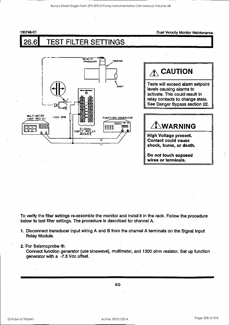
130748-01 Dual Velocity Monitor Maintenance
126.61 TEST FILTER SETTINGS
VELOCITY TRANSDUCER 1.03US INO
111110.11111114
L
NULTIUETER (NOT RE0'0)
t300 01-IM
ca L=3
L:1 L:3
FUNCTION GENERATOR
OW.. 00420
A\ CAUTION
Tests will exceed alarm setpoint levels causing alarms to activate. This could result in relay contacts to change state. See Danger Bypass section 22.
LLWARNING High Voltage present. Contact could cause shock, burns, or death.
Do not touch exposed wires or terminals.
To verify the filter settings re-assemble the monitor and install it in the rack. Follow the procedure below to test filter settings. The procedure is described for channel A.
1. Disconnect transducer input wiring A and B from the channel A terminals on the Signal Input Relay Module.
2. For Seismoprobe ®: Connect function generator (use sinewave), multimeter, and 1300 ohm resistor. Set up function generator with a -7.5 Vdc offset.
60
Bunya Street Eagle Farm SPS SP010 Pump Instrumentation OM Manual Volume 6B
Q-Pulse Id TMS641 Active 29/01/2014 Page 308 of 376

Dual Velocity Monitor Maintenance 130748-01
126.61 TEST FILTER SETTINGS (CONY)
HODS I NO
MULTIMETER (NOT RE0'0) 0 nnn
4 . OK SIGNAL
INPUT RELAY AOOULE
FUNCTION GENERATOR
o = = =
C II 10UF
3. *For Velomitor ®, HTVS, and 330750: Connect function generator (use sinewave), multimeter, 4000 ohm resistor and 10 OF capacitor. Set up function generator with a 0 Vdc offset.
4. To test the filter settings the input frequency must be adjusted to the corner frequency (or frequencies if bandpass filtering). With the input frequency set at a corner frequency and a full
scale input signal the front panel meter scale should be between 60% and 70% of full scale
(providing the monitor is calibrated, see section 25). To set the full scale amplitude for a peak
velocity or rms velocity go to step 5. To set the full scale amplitude for mils peak-peak or
micrometers peak-peak skip step 5 and go to step 6.
* FOR TRANSDUCER OPTIONS 04 (Velomitor ®) AND 05 (HTVS and 330750), A 3.0 kHz LOW
PASS FILTER IS USED IN THE SIGNAL INPUT MODULE.
61
Bunya Street Eagle Farm SPS SP010 Pump Instrumentation OM Manual Volume 6B
Q-Pulse Id TMS641 Active 29/01/2014 Page 309 of 376

130748-01 Dual Velocity Monitor Maintenance
26.61 TEST FILTER SETTINGS (CONT)
5. Calculate full scale amplitude for peak velocity or rms velocity meter full scale using the following scale factors.
A.) Transducer Options 01 and 02 (500mV/in/sec transducers) 1 in/sec peak = 1 V pk-pk 1 mm/sec peak = 39.37 mV pk-pk 1 in/sec rms = 1.414 V pk-pk 1 mm/sec rms = 55.67 mV pk-pk
B.) Transducer Options 03 and 05 (145 mV/in/sec transducer) 1 in/sec peak = 290 mV pk-pk 1 mm/sec peak = 11.42 mV pk-pk 1 in/sec rms = 410 mV pk-pk 1 mm/sec rms = 16.14 mV pk-pk
C.) Transducer Options 04 (100mV/in/sec transducer) 1 in/sec peak = 200 mV pk-pk 1 mm/sec peak = 7.87 mV pk-pk 1 in/sec rms = 282.8 mV pk-pk 1 mm/sec rms = 11.13 mV pk-pk
6. The amplitude of the integrated velocity signal (displacement) is a function of both the amplitude and frequency of the velocity signal. To calculate the full meter scale signal for mils peak-peak or micrometers peak-peak at a specific frequency use the formula shown below to find the equivalent velocity and then use the conversion factors in step 5 to determine the peak-peak input voltage.
Velocity in/sec peak = (mils peak-peak full scale)(.003142)(Frequency in Hz)
Velocity mm/sec peak = (micrometers pk-pk full scale)(.003142)(Frequency in Hz)
62
Bunya Street Eagle Farm SPS SP010 Pump Instrumentation OM Manual Volume 6B
Q-Pulse Id TMS641 Active 29/01/2014 Page 310 of 376

1 26.6 TEST FILTER SETTINGS (CONT) Dual Velocity Monitor Maintenance 130748-01
7. Input the full scale signal at the corner frequency.
8. Read meter, the value should be 60% to 70% of full scale.
9. If Danger Bypass was turned on before carrying out the tests, it should be turned off before
monitoring resumes.
z 3300/55
DUAL VELOCITY MONITOR
11IMININNIM11111,
1.0- :1.0
. 6
4
k
OK
A 0 DANGER 0
ALERT 0 8 0 BYPASS 0
DANGER ALERT
0 0 A
BUFFERED TRANSDUCERS
63
Bunya Street Eagle Farm SPS SP010 Pump Instrumentation OM Manual Volume 6B
Q-Pulse Id TMS641 Active 29/01/2014 Page 311 of 376
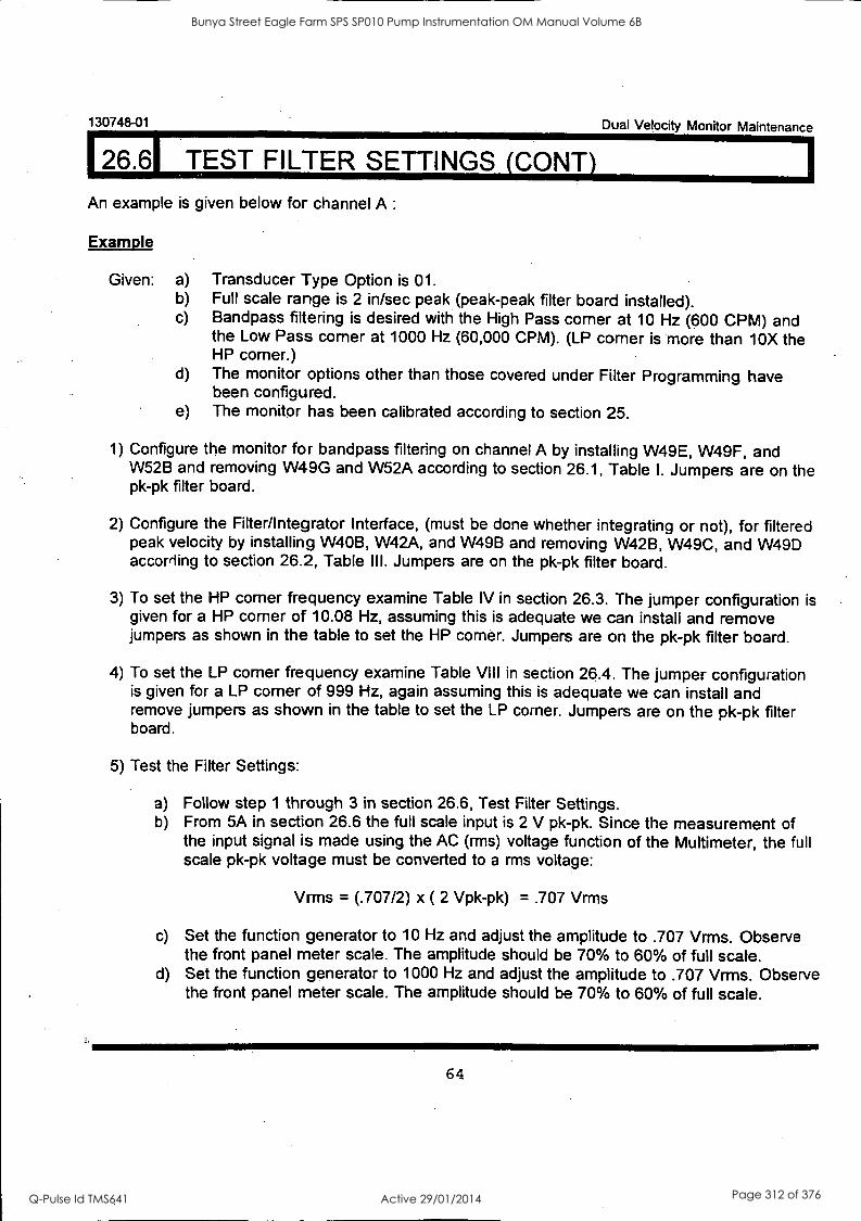
130748-01
126.61 TEST FILTER SETTINGS (CONY)
An example is given below for channel A :
Example
Given: a) b) c)
Dual Velocity Monitor Maintenance
Transducer Type Option is 01. Full scale range is 2 in/sec peak (peak-peak filter board installed). Bandpass filtering is desired with the High Pass corner at 10 Hz (600 CPM) and the Low Pass corner at 1000 Hz (60,000 CPM). (LP corner is more than 10X the HP corner.)
d) The monitor options other than those covered under Filter Programming have been configured.
e) The monitor has been calibrated according to section 25.
1) Configure the monitor for bandpass filtering on channel A by installing W49E, W49F, and W52B and removing W49G and W52A according to section 26.1, Table 1. Jumpers are on the pk-pk filter board.
2) Configure the Filter/Integrator Interface, (must be done whether integrating or not), for filtered peak velocity by installing W40B, W42A, and W49B and removing W42B, W49C, and W49D according to section 26.2, Table III. Jumpers are on the pk-pk filter board.
3) To set the HP corner frequency examine Table IV in section 26.3. The jumper configuration is given for a HP corner of 10.08 Hz, assuming this is adequate we can install and remove jumpers as shown in the table to set the HP corner. Jumpers are on the pk-pk filter board.
4) To set the LP corner frequency examine Table VIII in section 26.4. The jumper configuration is given for a LP corner of 999 Hz, again assuming this is adequate we can install and remove jumpers as shown in the table to set the LP corner. Jumpers are on the pk-pk filter board.
5) Test the Filter Settings:
a) Follow step 1 through 3 in section 26.6, Test Filter Settings. b) From 5A in section 26.6 the full scale input is 2 V pk-pk. Since the measurement of
the input signal is made using the AC (mis) voltage function of the Multimeter, the full scale pk-pk voltage must be converted to a mis voltage:
Vrms = (.707/2) x ( 2 Vpk-pk) = .707 Vrms
c) Set the function generator to 10 Hz and adjust the amplitude to .707 Vrms. Observe the front panel meter scale. The amplitude should be 70% to 60% of full scale.
d) Set the function generator to 1000 Hz and adjust the amplitude to .707 Vrms. Observe the front panel meter scale. The amplitude should be 70% to 60% of full scale.
64
Bunya Street Eagle Farm SPS SP010 Pump Instrumentation OM Manual Volume 6B
Q-Pulse Id TMS641 Active 29/01/2014 Page 312 of 376

Dual Velocity Monitor Maintenance 130748-01
26.61 TEST FILTER SETTINGS (CONY)
The frequency response curve is shown below:
1 0
2,0 707
4c 0.5 --I -3 db 0' -3 db at
CD 10 Hz £600 CPM1 1000 Hz (60000 CPM:
100 200 300 400 500 600 700 600 900 1000 1100 1200
FREQUENCY n HERTZ (CPM = 60 x(Fr eq in Hz)
65
Bunya Street Eagle Farm SPS SP010 Pump Instrumentation OM Manual Volume 6B
Q-Pulse Id TMS641 Active 29/01/2014 Page 313 of 376
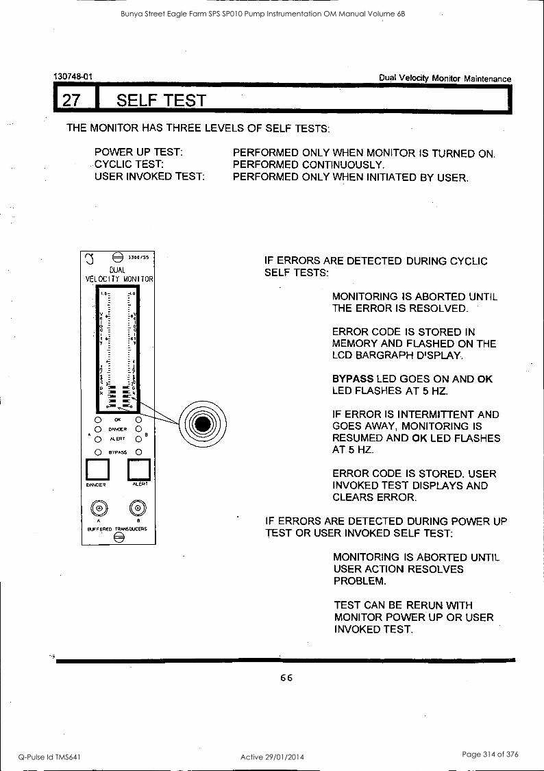
130748-01
127 I SELF TEST
Dual Velocity Monitor Maintenance
THE MONITOR HAS THREE LEVELS OF SELF TESTS:
POWER UP TEST: CYCLIC TEST: USER INVOKED TEST:
e3300/55
DUAL
VELOCITY MONITOR
O OK
O DANDER
A 0 ALERT
Q BYPASS
DANGER
B
ALERT
A e
BUFFERED TRANSDUCERS
PERFORMED ONLY WHEN MONITOR IS TURNED ON. PERFORMED CONTINUOUSLY. PERFORMED ONLY WHEN INITIATED BY USER.
IF ERRORS ARE DETECTED DURING CYCLIC SELF TESTS:
MONITORING IS ABORTED UNTIL THE ERROR IS RESOLVED.
ERROR CODE IS STORED IN MEMORY AND FLASHED ON THE LCD BARGRAPH D'SPLAY.
BYPASS LED GOES ON AND OK LED FLASHES AT 5 HZ.
IF ERROR IS INTERMITTENT AND GOES AWAY, MONITORING IS RESUMED AND OK LED FLASHES AT 5 HZ.
ERROR CODE IS STORED. USER INVOKED TEST DISPLAYS AND CLEARS ERROR.
IF ERRORS ARE DETECTED DURING POWER UP TEST OR USER INVOKED SELF TEST:
MONITORING IS ABORTED UNTIL USER ACTION RESOLVES PROBLEM.
TEST CAN BE RERUN WITH MONITOR POWER UP OR USER INVOKED TEST.
66
Bunya Street Eagle Farm SPS SP010 Pump Instrumentation OM Manual Volume 6B
Q-Pulse Id TMS641 Active 29/01/2014 Page 314 of 376
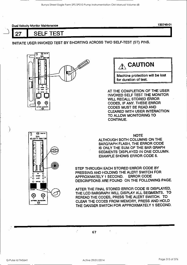
127 SELF TEST
Dual Velocity Monitor Maintenance 130748-01
INITIATE USER INVOKED TEST BY SHORTING ACROSS TWO SELF-TEST (ST) PINS.
elaw 1St
%AOC CNITCR
O . 0 0. 0 0-
ITO
e
e3 744
CUAL VELOCITY MOTOR 4111M/
.8.
0 C.
0 0'40 o 'Cr"
A\ CAUTION
Machine protection will be lost for duration of test.
AT THE COMPLETION OF THE USER INVOKED SELF TEST THE MONITOR WILL RECALL STORED ERROR CODES, IF ANY. THESE ERROR CODES MUST BE READ AND CLEARED WITH USER INTERACTION TO ALLOW MONITORING TO CONTINUE.
NOTE ALTHOUGH BOTH COLUMNS ON THE BARGRAPH FLASH, THE ERROR CODE IS ONLY THE SUM OF THE BAR GRAPH SEGMENTS DISPLAYED IN ONE COLUMN. EXAMPLE SHOWS ERROR CODE 5.
STEP THROUGH EACH STORED ERROR CODE BY
PRESSING AND HOLDING THE ALERT SWITCH FOR APPROXIMATELY 1 SECOND. ERROR CODE DESCRIPTIONS ARE FOUND ON THE FOLLOWING PAGE.
AFTER THE FINAL STORED ERROR CODE IS DISPLAYED, THE LCD BARGRAPH WILL DISPLAY ALL SEGMENTS. TO
REREAD THE CODES, PRESS THE ALERT SWITCH. TO CLEAR THE CODES FROM MEMORY, PRESS AND HOLD THE DANGER SWITCH FOR APPROXIMATELY 1 SECOND.
67
Bunya Street Eagle Farm SPS SP010 Pump Instrumentation OM Manual Volume 6B
Q-Pulse Id TMS641 Active 29/01/2014 Page 315 of 376

130748-01 Dual Velocity Monitor Maintenance
127 I SELF TEST
e3300,55
DUAL
VELOCITY MONITOR 1MENNIMINV
le= E E
'I
Wry
o CW 0 o D'4.3CR 0
A 0 At Eal 0 e
O enPAss Q
El m C %HOER KERT
0 BLPTERED ntAISOUCERS
ERROR CODE DESCRIPTION
2 ROM CHECKSUM HAS FAILED. *
3 EEPROM FAILURE NO. 1. **
4 EEPROM FAILURE NO. 2. * ADJUST S ETPOINTS
5 +7.5V/-VT NODE OUT OF TOLERANCE. **
6 +VRH NODE OUT OF TOLERANCE. **
7 +5V NODE OUT OF TOLERANCE. **
8 MVREF NODE OUT OF TOLERANCE. **
9 +7.5V NODE OUT OF TOLERANCE. **
10 +VRL NODE OUT OF TOLERANCE. **
11 MVREF/-6.0V NODE OUT OF TOLERANCE.**
12 +5V/-7.5V NODE OUT OF TOLERANCE **
13 THE CLOCK OK VOLTAGE IS OUT OF TOLERANCE.**
14 RAM FAILURE. *
17 COP WATCHDOG NOT CONFIGURED.*
**
Tested only at Power Up or User Invoked self test. This error is displayed but is not stored in memory.
Tested only at Cyclic sell test. Errors 2,3 and 14 are non-recoverable and could be intermittent and recoverable.
on the front panel
errors 5 through 13
Error 4 is a Set Point Failure and may be corrected by adjusting all set points in the monitor.
68
Bunya Street Eagle Farm SPS SP010 Pump Instrumentation OM Manual Volume 6B
Q-Pulse Id TMS641 Active 29/01/2014 Page 316 of 376

Dual Velocity Monitor Maintenance
28 I FIELD WIRING DIAGRAMS
130748-01
Drawing Number No. of Sheets
103627 2
103628 2
103633 2
103634 2
129422 2
The 330550 HTVS and 330750 transducers are wired in the same manner as the Velomitor transducers. For more details refer to your Operation Manual (104143-01) for the 330500, or (135090-01) for the 330750.
69
Bunya Street Eagle Farm SPS SP010 Pump Instrumentation OM Manual Volume 6B
Q-Pulse Id TMS641 Active 29/01/2014 Page 317 of 376
130748-01 Dual Velocity Monitor Maintenance
70
Bunya Street Eagle Farm SPS SP010 Pump Instrumentation OM Manual Volume 6B
Q-Pulse Id TMS641 Active 29/01/2014 Page 318 of 376
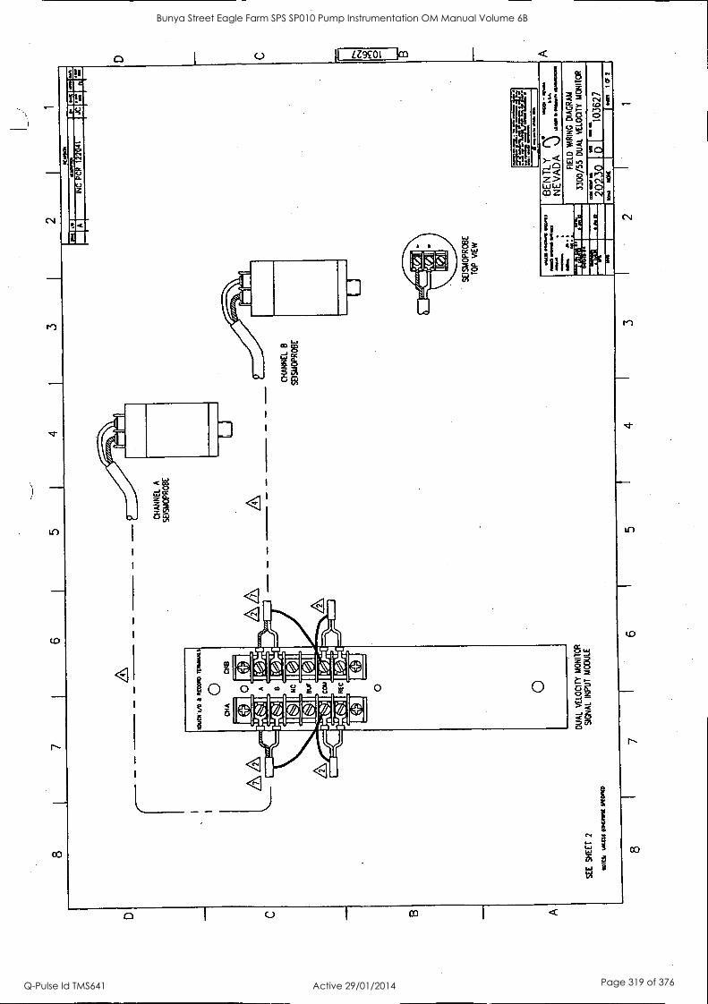
1
SE
E
SH
EE
T
2
In
OIK
Ral
g M
AID
DU
AL
VE
LOC
ITY
MO
NIT
OR
SIG
NA
L IN
PU
T
MO
DU
LE
8 7
CH
AN
NE
L A
SE
ISM
OP
RO
BE
6 5
4
CH
AN
NE
L B
SE
ISM
OP
RO
BE
Le
10.0
on
I ...
I we
eat
INC
PC
R
1220
41
SE
ISM
OP
RO
BE
TO
P
ME
W
MO
S O
M..
MO
OM
, Mm
M
AI
CM
a
titiA
4,',A
ii
lair
;611
11
MO
M
Ma=
GE
NT
LY
s;:"
. N
EV
AD
A
FIE
LD
WIR
ING
D
IAG
RA
M
3300
/55
DU
AL
VE
LOC
ITY
MO
NIT
OR
*227
210
D
rA
I ""
a103
627
I C
F
3 2
1
Bunya Street Eagle Farm SPS SP010 Pump Instrumentation OM Manual Volume 6B
Q-Pulse Id TMS641 Active 29/01/2014 Page 319 of 376
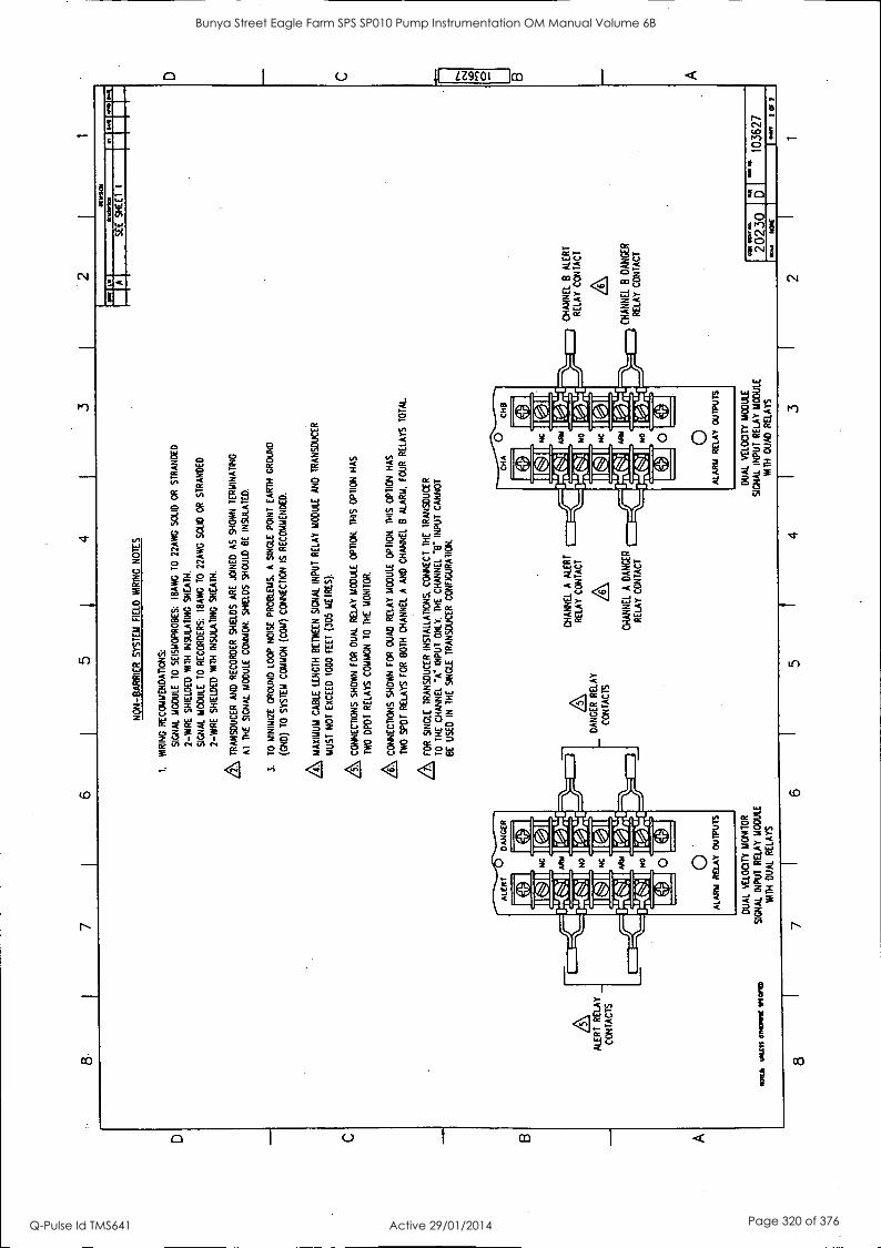
D C
8 7
6 5
4 2
1
ALE
RT
RE
LAY
CO
NT
AC
TS
NO
N-B
AR
RIE
R
SY
ST
EM
F
IELD
W
IRIN
G N
OT
ES
1.
WIR
ING
R
EC
OM
ME
ND
AT
ION
S:
SIG
NA
L M
OD
ULE
T
O
SE
ISM
OP
RO
BE
S:
113A
WG
T
O
22A
WG
S
OLI
D
OR
S
TR
AN
DE
D
2-W
IRE
S
HIE
LDE
D
WIT
H
INS
ULA
TIN
G
SH
EA
TH
.
SIG
NA
L M
OD
ULE
T
O
RE
CO
RD
ER
S:
113A
WG
TO
22
AW
G
SO
LID
O
R
ST
RA
ND
ED
2-W
IRE
S
HIE
LDE
D
WIT
H
INS
ULA
TIN
G
SH
EA
TH
.
& TRA
NS
DU
CE
R
AN
D R
EC
OR
DE
R
SH
IELD
S A
RE
JO
INE
D
AS
S
HO
WN
T
ER
MIN
AT
ING
AT
T
HE
S
IGN
AL
MO
DU
LE
CO
MM
ON
, S
HIE
LDS
S
HO
ULD
B
E
INS
ULA
TE
D.
3.
TO
MIN
IMIZ
E
GR
OU
ND
LO
OP
N
OIS
E
PR
OB
LEM
S.
A
SIN
GLE
P
OIN
T
EA
RT
H
GR
OU
ND
(GN
D)
TO
S
YS
TE
M
CO
MM
ON
(C
OM
) C
ON
NE
CT
ION
IS
R
EC
OM
ME
ND
ED
.
& MA
XIM
UM
CA
BLE
LE
NG
TH
BE
TW
EE
N
SIG
NA
L IN
PU
T
RE
LAY
M
OD
ULE
AN
D
TR
AN
SD
UC
ER
MU
ST
N
OT
E
XC
EE
D
1000
FE
ET
(3
05
ME
TR
ES
).
& CO
NN
EC
TIO
NS
SH
OW
N
FO
R
DU
AL
RE
LAY
MO
DU
LE
OP
TIO
N.
TH
IS
OP
TIO
N
HA
S
TW
O D
PW
R
ELA
YS
CO
MM
ON
T
O T
HE
M
ON
ITO
R.
& CO
NN
EC
TIO
NS
SH
OW
N
FO
R
OU
AD
R
ELA
Y M
OD
ULE
O
PT
ION
. T
HIS
O
PT
ION
H
AS
TW
O
SP
OT
R
ELA
YS
FO
R
BO
TH
C
HA
NN
EL
A
AN
D
CH
AN
NE
L B
A
LAR
M.
FO
UR
R
ELA
YS
T
OT
AL
46S
, F
OR
S
ING
LE
TR
AN
SD
UC
ER
IN
ST
ALL
AT
ION
S.
CO
NN
EC
T T
HE
T
RA
NS
DU
CE
R
TO
TH
E
CH
AN
NE
L "A
" IN
PU
T
ON
LY.
TH
E
CH
AN
NE
L '6
' IN
PU
T
CA
NN
OT
BE
U
SE
D
IN
TH
E
SIN
GLE
T
RA
NS
DU
CE
R
CO
NF
IGU
RA
TIO
N.
DA
NG
ER
R
ELA
Y
CO
NT
AC
TS
WIL
L W
att M
IMI w
ane)
D
UA
L V
ELO
CIT
Y M
ON
ITO
R
SIG
NA
L IN
PU
T
RE
LAY
M
OD
ULE
1411
11
DU
AL
RE
LAY
S
CH
AN
NE
L A
A
LER
T
CO
NT
AC
T
CH
AN
NE
L A
D
AN
GE
R
RE
LAY
C
ON
TA
CT
8 7
6 5
DU
AL
VE
LOC
ITY
MO
DU
LE
SIG
NA
L IN
PU
T
RE
LAY
M
OD
ULE
WIT
H
OU
AD
R
ELA
YS
4
IRW
2CM
M
it A
CH
AN
NE
L B
A
LER
T
RE
LAY
C
ON
TA
CT
CH
AN
NE
L B
D
AN
GE
R
RE
LAY
C
ON
TA
CT
1110
106
rr
SE
E
SH
EE
T
I
20230
ba
".
1036
27
OW
2
02
2
2 1
Bunya Street Eagle Farm SPS SP010 Pump Instrumentation OM Manual Volume 6B
Q-Pulse Id TMS641 Active 29/01/2014 Page 320 of 376

2
SA
FE
A
RE
A O
R
ZO
NE
2,
D
IVIS
ION
2
HA
ZA
RD
OU
S
AR
EA
PO
MO
%
11.1
0/10
%
INC
CC
OS
26
290.
262
91
8 D
ELE
TE
D
WA
RN
ING
LA
BE
L
0I
us
D.
INC
P
CR
12
2041
CH
AN
NE
L A
SE
ISM
OP
RO
BE
0)
II[
1111
T
O
CH
AN
NE
L 14
0)
RE
CO
RD
ER
CH
AN
NE
L B
SE
ISM
OP
RO
BE
11:0
)."1
"-Ilk
ik
11.0
1:1-
/-
TO
C
HA
NN
EL
B
RE
CO
RD
ER
SE
ISM
OP
RO
BE
TO
P
VIE
W
SE
E
SH
EE
T
2
DU
AL
VE
LOC
ITY
MO
NIT
OR
S
IGN
AL
INP
UT
M
OD
ULE
WIT
H
EX
TE
RN
AL
BA
RR
IER
S
. W
OO
MO
WN
M
OM
1
lIl
*MIS
IN
IMI1
M
i. N
I
o IO
U 1
. a..
sw
BE
NT
LY
NE
VA
DA
"r
n"m
s F
IELD
M
AR
INO
D
IAG
RA
M
3300
/55
DU
AL
VE
LOC
ITY
M
ON
ITO
R
.011
18
1,14
11S
S O
TC
.111
11 li
lt0,1
0 10
3628
8 7
6 5
4 3
2
C
ao
es1
tD O
B A
Bunya Street Eagle Farm SPS SP010 Pump Instrumentation OM Manual Volume 6B
Q-Pulse Id TMS641 Active 29/01/2014 Page 321 of 376

8 7
6 5
4 3
2
0581
11E
8511
1BLI
IELD
WIR
IMIIM
I. W
IRIN
G
RE
CO
MM
EN
DA
TIO
NS
:
SIG
NA
L M
OD
ULE
T
O
BA
RR
IER
S -
BA
RR
IER
S
70
SE
ISM
OP
RO
BE
: I4
AW
G
TO
t8
AW
G
SO
LID
O
R
ST
RA
ND
ED
2-
WIR
E S
HIE
LDE
D
WIT
H
INS
ULA
TIN
G
SH
EA
TH
.
SIG
NA
L M
OD
ULE
T
O
RE
CO
RD
ER
S:
I8A
WG
70
22
AW
G
SO
UD
O
R
ST
RA
ND
ED
2-Y
AR
E
SH
IELD
ED
W
ITH
IN
SU
LAT
ING
S
HE
AT
H.
AT
ER
MIN
AT
E
TH
E
RE
CO
RD
ER
SH
IELD
S
AT
T
HE
SIG
NA
L M
OD
ULE
CO
MM
ON
. S
HIE
LDS
SH
OU
LD
BE
IN
SU
LAT
ED
.
MA
XIM
UM
C
AB
LE
LEN
GT
H
BE
TW
EE
N M
ON
ITO
R A
ND
S
EIS
MO
PR
OB
E M
US
T N
OT
E
XC
EE
D
1000
F
EE
T
(305
M
ET
RE
S).
,A CO
NN
EC
TIO
NS
S
HO
WN
F
OR
D
UA
L R
ELA
Y
MO
DU
LE
OP
TIO
N.
TH
IS
OP
TIO
N
HA
S
TW
O
DP
DT
R
ELA
YS
C
OM
MO
N
TO
T
HE
M
ON
ITO
R.
SQ
CO
NN
EC
TIO
NS
S
HO
WN
F
OR
O
UA
D
RE
LAY
M
OD
ULE
OP
TIO
N.
TH
IS
OP
TIO
N H
AS
IW
O
SP
OT
RE
LAY
S
FO
R
BO
TH
C
HA
NN
EL
A
AN
D
CH
AN
NE
L 8
ALA
RM
, F
OU
R
RE
LAY
S T
OT
AL.
BA
RR
IER
S
AR
E
MO
UN
TE
D
TO
B
AR
RIE
R
RA
IL
WH
ICH
IS
T
HE
P
OT
EN
TIA
L E
OU
AU
ZA
DO
N
BU
S
BE
TW
EE
N
SY
ST
EM
G
RO
UN
D
AN
D
EA
RT
H
GR
OU
ND
. T
O
MIN
IMIZ
E
GR
OU
ND
LO
OP
PR
OB
LEM
S.
A S
ING
LE
PO
INT
E
AR
TH
G
RO
UN
D
(CN
D)
TO
S
YS
TE
M
CO
MM
ON
(C
OM
) 15
R
EC
OM
ME
ND
ED
AT
T
HE
B
AR
RIE
R R
AIL
. T
OT
AL
EA
RT
H
LOO
P I
MP
ED
AN
CE
M
US
T
NO
T
EX
CE
ED
I
OH
M.
RE
MO
VE
A
SIN
GLE
P
OIN
T
GR
OU
ND
C
ON
NE
CT
ION
A
T
CH
AS
SIS
G
RO
UN
D
ON
T
HE
33
00
PO
WE
R
INP
UT
M
OD
ULE
.
\ US
E
AIX
SA
FE
TY
B
AR
RIE
R
PE
R
DW
G 8A
2200
0.
/TR
AN
SD
UC
ER
SH
IELD
S
AR
E
JOIN
ED
A
S
SH
OW
N
TE
RM
INA
TIN
G A
T
BA
RR
IER
G
RO
UN
D.
/BA
RR
IER
S S
HO
ULD
B
E
INS
ULA
TE
D.
\BA
RF
HE
RS
LO
CA
TE
D
IN
DP
AS
ION
2
OR
Z
ON
E
2 H
AZ
AR
DO
US
A
RE
AS
MU
ST
B
E
INS
TA
LLE
D
IN
NE
MA
4
OR
IP
54
AP
PR
OV
ED
P
RO
TE
CT
IVE
HO
US
ING
S.
10.
MO
NIT
OR
S
MU
ST
B
E
RE
CA
IJB
RA
TE
D
WIT
H
BA
RR
IER
S
IN
TH
E
LIN
ES
.
A FO
R
SIN
GLE
T
RA
NS
DU
CE
R
INS
TA
LLA
TIO
NS
. C
ON
NE
CT
T
HE
T
RA
NS
DU
CE
R
TO
T
HE
C
HA
NN
EL
"e IN
PU
T
ON
LY.
TH
E C
HA
NN
EL
"8"
INP
UT
C
AN
NO
T
BE
U
SE
D
IN
TH
E
SIN
GLE
T
RA
NS
DU
CE
R
CO
NF
IGU
RA
TIO
N.
MO
ILS
1.01
1118
01
KR
IM S
PIE
CC
ID
111[
1.20
1
Le
ALE
RT
RE
LAY
_
CO
NT
AC
TS
CH
AN
NE
L A
A
LER
T
RE
LAY
C
ON
TA
CT
A
CH
AN
NE
L A
D
AN
GE
R
RE
LAY
C
ON
TA
CT
6 5
4
SIG
NA
L IN
PU
T
RE
LAY
MO
DU
LE
WIT
H
DU
AL
RE
LAY
S
SIG
NA
L IN
PU
T
RE
LAY
MO
DU
LE
MA
TH
O
UA
D
RE
LAY
S
3
SE
E
SH
EE
T
I
1101
/10.
DA
NG
ER
R
ELA
Y
CO
NT
AC
TS
CH
AN
NE
L 8
ALE
RT
RE
LAY
C
ON
TA
CT
A
CH
AN
NE
L B
D
AN
CE
R
RE
LAY
C
ON
TA
CT
OA
S */
10
202
30
5'
~a
1036
28
2 1
D 0 B A
Bunya Street Eagle Farm SPS SP010 Pump Instrumentation OM Manual Volume 6B
Q-Pulse Id TMS641 Active 29/01/2014 Page 322 of 376
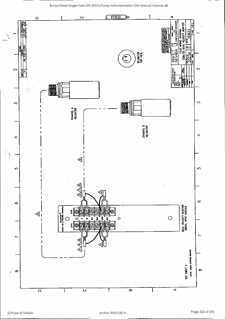
8 7
6 I
5 1
4 I
3 I
2
SE
E
SH
EE
T
2
CH
AN
NE
L B
VE
LOM
ITO
R
CH
AN
NE
L A
VE
LOM
ITO
R
NO
N&
U
NLI
SS
0)
1111
1,1 M
VO
DU
AL
VE
LOC
ITY
M
ON
ITO
R
SIG
NA
L IN
PU
T
MO
DU
LE
a O
P
OtIP
OW
o a.
4.0
PM
INC
P
CR
12
2041
JC
0.13
. 10
0 Se
e -
embu
s of
tem
as
NO
M
JO
VE
LOM
ITO
R
TO
P
VIE
W Fa
riv-
--
O.O
.190
!OM
BE
NT
LY
NE
VA
DA
..1
da
m,
FIE
LD W
IRIN
G
DIA
GR
AM
3300
/55
DU
AL
VE
LOC
ITY
MO
NIT
OR
0 I
1036
33
gen
1 O
f
8 7
6 5
4 2
1
D C 0
Bunya Street Eagle Farm SPS SP010 Pump Instrumentation OM Manual Volume 6B
Q-Pulse Id TMS641 Active 29/01/2014 Page 323 of 376

D C
B
8 7
6 I
5 4
3 2
1
NO
N-B
AR
RIE
R
SY
ST
EM
F
IELD
W
RIN
G
NO
TE
S
I. W
IRIN
G
RE
CO
MM
EN
DA
TIO
NS
:
SIG
NA
L M
OD
ULE
T
O
VE
LOM
ITO
RS
: 18
AW
G
TO
22A
WG
S
OLI
D
OR
S
TR
AN
DE
D
2-W
IRE
SH
IELD
ED
N
M I
NS
ULA
TIN
G S
HE
AT
H.
SIG
NA
L M
OD
ULE
T
O
RE
CO
RD
ER
S:
lent
TO
22
AW
G
SO
LID
O
R
ST
RA
ND
ED
2-W
IRE
SH
IELD
ED
W
ITH
IN
SU
LAT
ING
S
HE
AT
H.
A TR
AN
SD
UC
ER
A
ND
RE
CO
RD
ER
S
HIE
LDS
A
RE
JO
INE
D
AS
S
HO
WN
T
ER
MIN
AT
ING
AT
T
HE
S
IGN
AL
MO
DU
LE C
OM
MO
N.
SH
IELD
S
SH
OU
LD B
E
INS
ULA
TE
D.
3.
TO
MIN
IMIZ
E
GR
OU
ND
LO
OP
N
OIS
E
PR
OB
LEM
S.
A
SIN
GLE
P
OIN
T
EA
RT
H
GR
OU
ND
(GN
D)
TO
S
YS
TE
M
CO
MM
ON
(C
OM
) C
ON
NE
CT
ION
IS
R
EC
OM
ME
ND
ED
.
MA
XIM
UM
C
AB
LE
LEN
GT
H
BE
TW
EE
N
SIG
NA
L IN
PU
T
RE
LAY
MO
DU
LE
AN
D
TR
AN
SD
UC
ER
MU
ST
N
OT
EX
CE
ED
10
00
FE
ET
(3
05
ME
TR
ES
).
SQ
CO
NN
EC
TIO
NS
SH
OW
N
FO
R
DU
AL
RE
LAY
MO
DU
LE
OP
TIO
N.
TH
IS
OP
TIO
N
HA
S
TW
O
DP
DT
R
ELA
YS
C
OM
MO
N
TO
T
HE
M
ON
ITO
R.
CO
NN
EC
TIO
NS
S
HO
WN
F
OR
O
UA
D
RE
LAY
M
OD
ULE
O
PT
ION
. T
HIS
O
PT
ION
H
AS
TW
O
SP
OT
R
ELA
YS
F
OR
B
OT
H
CH
AN
NE
L A
A
ND
CH
AN
NE
L B
A
LAR
M,
FO
UR
R
ELA
YS
T
OT
AL.
FO
R
VE
LOM
ITO
R,
US
E
CA
BLE
S
9571
, 84
661
OR
89
477.
T
HE
W
HIT
E
WIR
E
CO
NN
EC
TS
TO
A
. T
HE
B
LAC
K
WIR
E
CO
NN
EC
TS
T
O "
Er.
AN
D
TH
E
GR
EE
N W
IRE
C
ON
NE
CT
S
TO
'CO
M'
AT
T
HE
S
IGN
AL
MO
DU
LE.
A,
FO
R
SIN
GLE
T
RA
NS
DU
CE
R
INS
TA
LLA
TIO
NS
, C
ON
NE
CT
T
HE
T
RA
NS
DU
CE
R
TO
T
HE
C
HA
NN
EL
"A"
INP
UT
O
NLY
. T
HE
C
HA
NN
EL
INP
UT
C
AN
NO
T
BE
U
SE
D
IN
TH
E
SIN
GLE
T
RA
NS
DU
CE
R
CO
NF
IGU
RA
TIO
N.
ALE
RT
RE
LAY
_
CO
NT
AC
TS
ZS
, C
HA
NN
EL
A
ALE
RT
R
ELA
Y
CO
NT
AC
T
DA
NG
ER
R
ELA
Y
CO
NT
AC
TS
1101
Irk
Wat
t 01
0111
1/ M
ON
D
DU
AL
VE
LOC
ITY
MO
NIT
OR
SIG
NA
L IN
PU
T R
ELA
Y
MO
DU
LE
WIT
H
DU
AL
RE
LAY
S
CH
AN
NE
L A
D
AN
GE
R
RE
LAY
CO
NT
AC
T
8 7
6 5
DU
AL
VE
LOC
ITY
M
OD
ULE
SIG
NA
L IN
PU
T
RE
LAY
M
OD
ULE
W
ITH
O
UA
D
RE
LAY
S
4
Wal
e.
CH
AN
NE
L 8
ALE
RT
R
ELA
Y C
ON
TA
CT
zs,
CH
AN
NE
L B
D
AN
GE
R
RE
LAY
C
ON
TA
CT
SE
E 11
1111
.4
I
V
SH
EE
T
I
ma
Dag
Yi
5' I
N. .
6 10
3633
IO
C
2 1
Bunya Street Eagle Farm SPS SP010 Pump Instrumentation OM Manual Volume 6B
Q-Pulse Id TMS641 Active 29/01/2014 Page 324 of 376
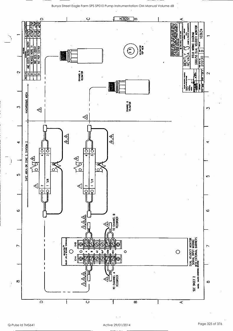
C
B
8 7
6 5
4 3
2 1
AR
EA
O
R
ZO
NE
2
DIM
SIO
N
2 H
AZ
AR
D
AR
EA
TO
C
HA
NN
EL A
LA
R
EC
OR
DE
R
SE
E
SH
EE
T 2
w11
1
KO
PI \I _
II _f
t
TO
C
HA
NN
EL
8 R
EC
OR
DE
R
DU
AL
VE
LOC
ITY
MO
NIT
OR
S
IGN
AL
INP
UT
MO
DU
LE
WIT
H
EX
TE
RN
AL
BA
RR
IER
S
MIS
S 01
101.
11 im
am
AA
A
CH
AN
CE
8
VE
LCU
TO
R
Raf
al
0/1
0.0.
20
M.
IMO
A
INC
C
CO
'S
2629
0,
2629
1 S
e ja
8
RE
VIS
ED
N
OT
E
11
JC
04.0
JT
aw
l
C
INC
C
CO
12
2041
JC
L
L
11:
D
INC
P
CR
12
3769
JE
.4
1 nu
'
CH
AN
NE
L A
VE
LCN
ITO
R
Wag
Mam
a M
ann
mom
a
mam
a le
a a
8 7
5 4
3
1.C
LON
TIO
R
TO
P
NE
W
=gr
og,:
an .=
gr.::
at
laka
ll WO
0 M
IAM
I tr
..,=
=tn
el..4
714:
4.10
1.
WM
aw
e& =
amai
n
C
UD
O B
A
GE
NT
LY
'".";
r N
EV
AD
A
,)
FIE
LD
`AIR
ING
D
IAG
RA
M
3300
/55
DU
AL
VE
LOC
ITY
M
ON
ITO
R
7725
0 5'
10
3634
o an
Ma.
, ay
. MR
2 1
Bunya Street Eagle Farm SPS SP010 Pump Instrumentation OM Manual Volume 6B
Q-Pulse Id TMS641 Active 29/01/2014 Page 325 of 376
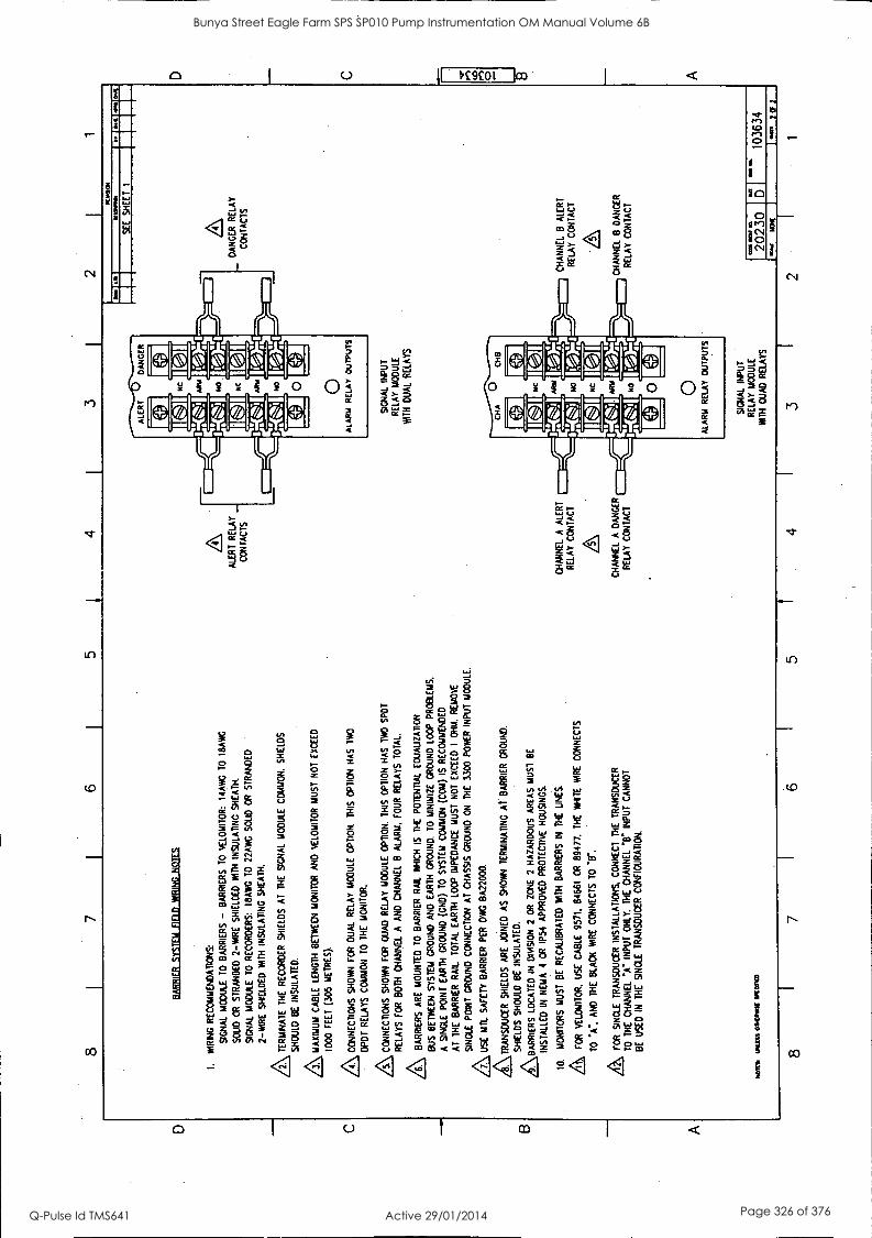
8 7
6 5
4 3
2
BA
BB
ILIL
ITIT
ET
LIIE
LELM
BIN
CO
IDIF
I
I. W
IRIN
G
RE
CO
MM
EN
DA
TIO
NS
:
SIG
NA
L M
OD
ULE
T
O
BA
RR
IER
S -
BA
RR
IER
S
TO
V
ELO
MIT
OR
: 14
AK
TO
I8
AW
G
SO
LID
O
R
ST
RA
ND
ED
2-
WIR
E
SH
IELD
ED
W
ITH
IN
SU
LAT
ING
S
HE
AT
H.
SIG
NA
L M
OD
ULE
T
O
RE
CO
RD
ER
S:
18A
WG
T
O
22A
WG
S
OLI
D
OR
S
TR
AN
DE
D
2-W
IRE
SH
IELD
ED
W
ITH
IN
SU
LAT
ING
SH
EA
TH
.
ZS
TE
RM
INA
TE
T
HE
R
EC
OR
DE
R
SH
IELD
S
AT
T
HE
S
IGN
AL
MO
DU
LE
CO
MM
ON
. S
HIE
LDS
SH
OU
LD
BE
IN
SU
LAT
ED
.
ZS
,
MA
XIM
UM
C
AB
LE
LEN
GT
H
BE
TW
EE
N
MO
NIT
OR
A
ND
V
ELO
MIT
OR
M
US
T
NO
T
EX
CE
ED
1000
F
EE
T
(305
M
ET
RE
S).
CO
NN
EC
TIO
NS
S
HO
WN
FO
R D
UA
L R
ELA
Y
MO
DU
LE
OP
TIO
N.
TH
IS
OP
TIO
N
HA
S
IWO
DP
DT
R
ELA
YS
C
OM
MO
N
TO
T
HE
M
ON
ITO
R.
&C
ON
NE
CT
ION
S S
HO
WN
F
OR
Q
UA
D
RE
LAY
M
OD
ULE
O
PT
ION
. T
HIS
O
PT
ION
H
AS
T
WO
S
PO
T
RE
LAY
S
FO
R
BO
TH
C
HA
NN
EL
A
AN
D C
HA
NN
EL
B
ALA
RM
. F
OU
R
RE
LAY
S
TO
TA
L
AB
AR
RIE
RS
AR
E
MO
UN
TE
D
TO
BA
RR
IER
R
AIL
W
HIC
H
IS
TH
E
PO
TE
NT
IAL
EO
UA
UZ
AT
ION
BU
S
BE
TW
EE
N
SY
ST
EM
G
RO
UN
D
AN
D
EA
RT
H
GR
OU
ND
. T
O
MIN
IMIZ
E
GR
OU
ND
LO
OP
PR
OB
LEM
S.
A
SIN
GLE
P
OIN
T
EA
RT
H
GR
OU
ND
(C
ND
) T
O
SY
ST
EM
C
OM
MO
N (
CO
M)
IS R
EC
OM
ME
ND
ED
AT
T
HE
B
AR
RIE
R
RA
IL
TO
TA
L E
AR
TH
LO
OP
IM
PE
DA
NC
E
MU
ST
N
OT
E
XC
EE
D
I O
HM
. R
EM
OV
E
A
SIN
GLE
P
OIN
T
GR
OU
ND
C
ON
NE
CT
ION
A
T
CH
AS
SIS
GR
OU
ND
O
N
TH
E
3300
P
OW
ER
IN
PU
T
MO
DU
LE.
\ US
E
MU
. S
AF
ET
Y
BA
RR
IER
P
ER
D
WG
BA
2200
0.
/TR
AN
SD
UC
ER
SH
IELD
S
AR
E
JOIN
ED
A
S
SH
OW
N
1ER
MIN
AT
INC
A
l B
AR
RIE
R
GR
OU
ND
.
/BA
RR
IER
S S
HO
ULD
B
E
INS
ULA
TE
D.
AA
BA
RR
IER
S LO
CA
TE
D
IN
DP
AS
ION
2
OR
Z
ON
E
2 H
AZ
AR
DO
US
A
RE
AS
MU
ST
B
E
INS
TA
LLE
D
IN N
M 4
O
R
IP54
A
PP
RO
VE
D
PR
OT
EC
TIV
E H
OU
SIN
GS
.
10.
MO
NIT
OR
S
MU
ST
B
E
RE
CA
LIB
RA
TE
D
WIT
H
BA
RR
IER
S
IN
TH
E
UN
ES
.
A FO
R
VE
LOM
ITO
R.
US
E
CA
BLE
95
71.
8466
1 O
R
8947
7.
TH
E
VO
CE
W
IRE
C
ON
NE
CT
S
TO
'A
", A
ND
T
HE
B
LAC
K T
IRE
C
ON
NE
CT
S
TO
T
.
A FOR
S
ING
LE
TR
AN
SD
UC
ER
IN
ST
ALL
AT
ION
S,
CO
NN
EC
T
TH
E
TR
AN
SD
UC
ER
TO
T
HE
C
HA
NN
EL
"A-
INP
UT
O
NLY
. T
HE
C
HA
NN
EL
INP
UT
C
AN
NO
T
BE
U
SE
D
IN
TH
E
SIN
GLE
T
RA
NS
DU
CE
R C
ON
FIG
UR
AT
ION
.
NO
R%
w
as
IPIO
ND
ALE
RT
RE
LAY
CO
NT
AC
TS
Kea
1
1m1
SE
E
SH
EE
T
I 1
I. 1"
4174
CH
AN
NE
L A
A
LER
T
RE
LAY
C
ON
TA
CT
CH
AN
NE
L A
DA
NG
ER
RE
LAY
C
ON
TA
CT
8 7
6 5
4
SIG
NA
L IN
PU
T
RE
LAY
M
OD
ULE
WIT
H
DU
AL
RE
LAY
S
SIG
NA
L IN
PU
T
RE
LAY
MO
DU
LE
ICH
Q
UA
D
RE
LAY
S
3
_ D
AN
GE
R
RE
LAY
CO
NT
AC
TS
CH
AN
NE
L 8
ALE
RT
RE
LAY
C
ON
TA
CT
CH
AN
NE
L B
D
AN
GE
R
RE
LAY
C
ON
TA
CT
2023
0 10
3634
2 1
Bunya Street Eagle Farm SPS SP010 Pump Instrumentation OM Manual Volume 6B
Q-Pulse Id TMS641 Active 29/01/2014 Page 326 of 376
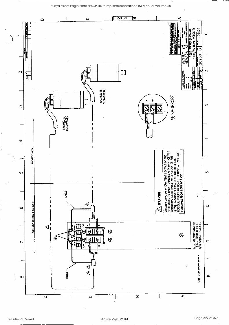
2
WE
AR
EA
O
R
ZO
NE
2.
W
AS
ION
2
HA
LAD
OU
S A
RE
A
Z\ W
AR
NIN
G
MIS
CO
NN
EC
TIN
G
OR
IN
TE
RM
ITT
EN
T
CO
NT
AC
T
OF
T
HE
FIE
LD
WR
ING
T
O
RA
CK
T
ER
MIN
ALS
W
TH
H
IGH
V
OLT
AG
E
PO
TE
NT
IALS
C
OU
LD
CA
US
E
AN
EX
PLO
SIO
N
OR
F
IRE
IN
TH
E
HA
ZA
RD
OU
S A
RE
A
RE
SU
LTIN
G
IN
SE
VE
RE
PE
RS
ON
AL
INJU
RY
O
R
DE
AT
H.
RE
MO
VE
A
LL
VO
LTA
GE
PO
TE
NT
IALS
F
RO
M
RE
AR
O
F
RA
CK
.
1.
Val
lr
CH
AN
NE
L A
SE
ISM
OP
RO
BE
CH
AN
NE
L B
SE
ISM
OP
RO
BE
SE
ISM
OP
RO
BE
was
flO
wS
WO
RD
m
oo o
n1 01
010,
11
mom
a
MY
%
AM
10.7
= le
balt.
ocar
czo4
: Ir
jrine
mbo
Arr
inam
ala
a ea
u a&
way
... m
amas
. se
ow. a
m
BE
NT
LY
NE
VA
DA
%
1
1110
01
iMa
ILLA
WO
O
MO
M, 1
0011
1
1101
13.
WIL
LIS
°N
UM
"IW
O
DU
AL
VE
LOC
ITY
MO
NIT
OR
SIG
NA
L IN
PU
T
MO
DU
LE
WT
H
INT
ER
NA
L B
AR
RIE
RS
FIE
LD
WIR
ING
D
IAG
RA
M
3300
/55
DU
AL
VE
LOC
ITY
7721
0 12
9422
8 7
6 5
4 3
2 1
D C 8 A
Bunya Street Eagle Farm SPS SP010 Pump Instrumentation OM Manual Volume 6B
Q-Pulse Id TMS641 Active 29/01/2014 Page 327 of 376

D
C
B
A
5 4
3 I
2 1
INT
ER
NA
L B
AR
RIE
R
SY
ST
EM
F
IELD
W
RIN
G
NO
TE
S
1.
WR
ING
R
EC
OM
ME
ND
AT
ION
S:
SIG
NA
L M
OD
ULE
10
S
EIS
1AO
PR
OB
ES
: I4
AW
G T
O
18A
WG
S
OLI
D
OR
S
TR
AN
DE
D
2-W
IRE
S
HIE
LDE
D
WIT
H
INS
ULA
TIN
G
SH
EA
TH
.
SIG
NA
L M
OD
ULE
10
R
EC
OR
DE
R/R
EA
DO
UT
: 18
AW
G
TO
22
AW
G
ST
RA
ND
ED
2-W
IRE
S
HIE
LDE
D
WIT
H
INS
ULA
TIN
G
SH
EA
TH
.
AM
AX
IMU
M
CA
BLE
LE
NG
TH
B
ET
WE
EN
M
ON
ITO
R
AN
D
SE
ISLI
OP
RO
BE
M
US
T
NO
T
EX
CE
ED
1000
F
EE
T (3
05 M
ET
RE
S).
3.
TO
M
INIM
IZE
GR
OU
ND
LO
OP
N
OIS
E
PR
OB
LEM
S.
A
SIN
GLE
P
OIN
T
EA
RT
H
GR
OU
ND
(CN
D)
TO
S
YS
TE
M
CO
MM
ON
(C
OM
) C
ON
NE
CT
ION
IS
R
EC
OM
ME
ND
ED
.
AC
ON
NE
CT
ION
S
SH
OW
N
FO
R
DU
AL
RE
LAY
M
OD
ULE
O
PT
ION
. T
HIS
O
PT
ION
H
AS
T
WO
DP
DT
R
ELA
YS
C
OM
MO
N
TO
B
OT
H
CH
AN
NE
LS,
ON
E
FO
R
ALE
RT
A
ND
O
NE
F
OR
D
AN
GE
R.
SQ S
CR
EW
S
MU
ST
B
E
SE
CU
RE
LY
FA
ST
EN
ED
F
OR
P
RO
PE
R
GR
OU
ND
. B
AR
RIE
RS
AR
E
CO
NN
EC
TE
D
TO
TH
E
INT
ER
NA
L B
AR
RIE
R
GR
OU
ND
R
AIL
A
T
TH
IS
PO
NT
. S
EE
P
OW
ER
S
UP
PLY
MA
NU
AL
FO
R
PR
OP
ER
SIN
GLE
P
OIN
T G
RO
UN
D C
ON
NE
CT
ION
B
ET
WE
EN
BA
RR
IER
GR
OU
ND
A
ND
E
AR
TH
G
RO
UN
D
AT
T
HE
PO
WE
R
INP
UT
MO
DU
LE.
6.
IF
RE
LAY
S
HA
VE
B
EE
N
CO
NF
IGU
RE
D
NO
RM
ALL
Y
DE
-EN
ER
GIZ
ED
, 'N
C'
IS
CLO
SE
D
AN
D N
o'
IS
OP
EN
IN
A
N
ON
-ALA
RM
S
TA
TE
. IF
RE
LAY
S
HA
VE
B
EE
N C
ON
FIG
UR
ED
N
OR
MA
LLY
E
NE
RG
IZE
D,
'NC
'
IS
OP
EN
A
ND
"N
O'
IS
CLO
SE
D
IN
A
NO
N-A
LAR
M
ST
AT
E.
/C\ T
ER
MIN
AT
E
TH
E
RE
CO
RD
ER
S
HIE
LDS
AT
T
HE
SIG
NA
L M
OD
ULE
C
OM
MO
N
AS
S
HO
WN
. S
HIE
LDS
SH
OU
LD
BE
IN
SU
LAT
ED
.
&
SE
E
AP
PR
OV
AL
DR
AW
ING
B
A22
000
OR
C
A22
000.
FO
R
SIN
GLE
T
RA
NS
DU
CE
R I
NS
TA
LLA
TIO
NS
, C
ON
NE
CT
T
HE
T
RA
NS
DU
CE
R
TO
T
HE
C
HA
NN
EL
"A"
INP
UT
O
NLY
. T
HE
CH
AN
NE
L V
' IN
PU
T
CA
NN
OT
BE
U
SE
D
IN
TH
E
SIN
GLE
T
RA
NS
DU
CE
R
CO
NF
IGU
RA
TIO
N,
MO
TE
L JM
ILIS
CO
MF
Y 7
P10
11C
D
TO
C
HA
NN
EL
A
RE
CO
RD
ER
ALL
RT
R
ELA
Y C
ON
TA
CT
S
RE
C
Ai_
A
s B
UT
CO
! A
9
NC
is I
ALE
RT
ALA
RM
R
ELA
Y
OU
TP
UT
S
DU
AL
IKLO
CT
IT
1101
8TO
R
SIG
NA
L IN
PU
T
RE
LAY
M
OD
ULE
NT
H
DU
AL
RE
LAY
S
MO
N
MI!
10
CH
AN
NE
L 8
RE
CO
RD
ER
amm
o S
EE
S
HE
ET
1
DA
NG
ER
RE
LAY
C
ON
TA
CT
S
Ml
0771
RO
O N
I
2023
0 1;
1 "'e
l 12
9422
8 I
7 I
6 5
I 4
3 I
2
v.
NO
NE
1
Iar7
Bunya Street Eagle Farm SPS SP010 Pump Instrumentation OM Manual Volume 6B
Q-Pulse Id TMS641 Active 29/01/2014 Page 328 of 376
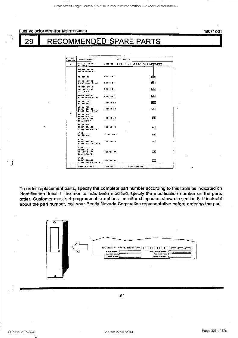
Dual Velocity Monitor Maintenance 130748-01
9 1 RECOMMENDED SPARE PARTS
OTT PER MONITOR DESCRIPTION PART NUMIEO
DUAL VELOCITY MONITOR
7700113 co_pri.m_co030a=10D SIGNAL INPUT RELAY MODULE:
NO RELAYS 84177-01 (= EPDXY SEALED 7 AMP OVAL REALY 114147.01 CD HERMETICALLY SEALED 3 AMP -01 Ei Ill DUAL RELAY
EPDXY SEALED 1 AMP QUAD RELAY
84134.01 DE VELOMITOR NO RELAYS 170731.01 CEI
VELOMITOR EPDXY SEALED 130770-01 tail $ AMP DUAL RELAY
1 VELOMITOR HERMETICALLY SEALED 3 AMP 130733-01 Gal DUAL MEALY
VELOMITOR EPDXY SEALED 130732-01 ED I AMP QUAD RELAY
HrE S NO RELAYS 170733.01 ED HUES EPDXY SEALED 130171.01 ED 3 AMP DUAL RELAYS
HTVS HERMETICALLY SEALED S AMP 130737.01 EIZI DUAL RELAYS
WINS EPDXY SEALED 130738-01 GO 1 AMP QUAD RELAYS
1 JUMPER WIRES 88700-01 (100 PIECES)
To order replacement parts, specify the complete part number according to this table as indicated on identification decal. If the monitor has been modified, specify the modification number on the parts order. Customer must set programmable options - monitor shipped as shown in section 6. If in doubt about the part number, call your Bent ly Nevada Corporation representative before ordering the part.
81
Bunya Street Eagle Farm SPS SP010 Pump Instrumentation OM Manual Volume 6B
Q-Pulse Id TMS641 Active 29/01/2014 Page 329 of 376

Dual Velocity Monitor Maintenance
129 I RECOMMENDED SPARE. PARTS (CON'T)
OLD TO NEW SPARES UPDATE LIST
Definition of terms: SIM - Signal Input Module. SIRM - Signal Input Relay Module.
130748-01
Old and new SIM/SIRM part numbers, associated with 3300/55 monitor are listed below. Part number changes only involve the 3300/55 main board, HTVS and Velomitor SIMs/SIRMs. From the Recommended Spare Parts Table, 3300/55 filter boards, front panel assembly, and Seismoprobe SIMs/SIRMs are not involved with this change.
DESCRIPTION OLD PART# NEW PART#
Main Board 83641-01 129958-01
EPDXY SPAREs
Velomitor S IRA 89590-01 130730-01
Velomitor SIM 89589-01 130731-01
HTVS SIRM 109759-01 130734-01
HTVS SIM 109758-01 130735-01
QUAD SPAREs
Velomitor SIRM 89592-01 130732-01
HTVS SIRM 109761-01 130736-01
HERMETIC SPAREs
Velomitor SIRM 89588-01 130733-01
HTVS SIRM 109760-01 130737-01
NOTE: Using an old main board (83641-01) with a new SIM/SIRM is not a problem; however, if a
new main board (129958-01) is used with an old SIM/SIRM, the main board must be configured to use the old OK circuitry.
82
Bunya Street Eagle Farm SPS SP010 Pump Instrumentation OM Manual Volume 6B
Q-Pulse Id TMS641 Active 29/01/2014 Page 330 of 376
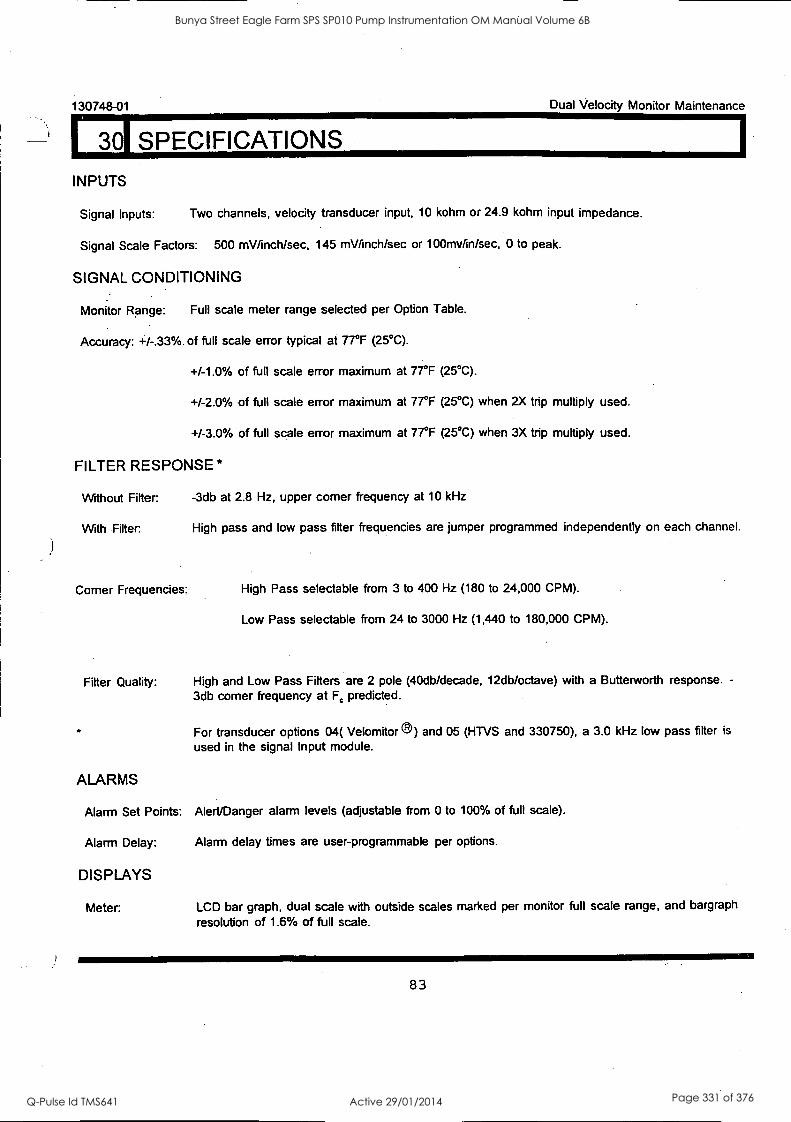
130748-01 Dual Velocity Monitor Maintenance
301 SPECIFICATIONS
INPUTS
Signal Inputs: Two channels, velocity transducer input, 10 kohm or 24.9 kohm input impedance.
Signal Scale Factors: 500 mV/inch/sec, 145 mWinch/sec or 100mv/in/sec, 0 to peak.
SIGNAL CONDITIONING
Monitor Range: Full scale meter range selected per Option Table.
Accuracy: +/-.33% of full scale error typical at 77°F (25°C).
+/-1.0% of full scale error maximum at 77°F (25°C).
+/-2.0% of full scale error maximum at 77°F (25°C) when 2X trip multiply used.
+/-3.0% of full scale error maximum at 77°F (25°C) when 3X trip multiply used.
FILTER RESPONSE*
Without Fitter: -3db at 2.8 Hz, upper corner frequency at 10 kHz
With Filter. High pass and low pass filter frequencies are jumper programmed independently on each channel.
Corner Frequencies: High Pass selectable from 3 to 400 Hz (180 to 24,000 CPM).
Low Pass selectable from 24 to 3000 Hz (1,440 to 180,000 CPM).
Filter Quality: High and Low Pass Fitters are 2 pole (40db/decade, 12db/octave) with a Butterworth response. -
3db corner frequency at F, predicted.
For transducer options 04( Velomitor ) and 05 (HTVS and 330750), a 3.0 kHz low pass filter is
used in the signal Input module.
ALARMS
Alarm Set Points: Alert/Danger alarm levels (adjustable from 0 to 100% of full scale).
Alarm Delay:
DISPLAYS
Meter:
Alarm delay times are user-programmable per options.
LCD bar graph, dual scale with outside scales marked per monitor full scale range, and bargraph resolution of 1.6% of full scale.
83
Bunya Street Eagle Farm SPS SP010 Pump Instrumentation OM Manual Volume 6B
Q-Pulse Id TMS641 Active 29/01/2014 Page 331 of 376

130748-01 Dual Velocity Monitor Maintenance
30 I SPECIFICATIONS (CON'T)
LED's: Green LEDs annunciate transducer OK condition, red LEDs annunciate DANGER alarm, ALERT alarm, and BYPASS conditions.
CONTROLS
Front Panel: Front panel switches (2) for reading ALERT and DANGER set point levels.
Internal: Switches on circuit board for set point adjustment, Danger Bypass, Channel Bypass.
External: External remote controls: Reset, Inhibit, Trip Multiply and Set Point adjust (up arrow and down arrow).
OUTPUT
Recorder. Output proportional to selected full scale monitor range and protected against continuous short circuit to ground:
+4 mA to +20 mA, +12 Vdc compliance.
+1 Vdc to +5 Vdc, 100 Ohm maximum output impedance.
0 Vdc to -10 Vdc, 100 Ohm maximum output impedance.
Alarms and OK: Relay drives for ALERT, DANGER, and System OK.
RELAY CONTACT RATINGS
Dual Relays: 5 A @ 120 Vac 50/60 Hz.
5 A @ 28 Vdc.
Quad Relays: 0.6 A @ 120 Vac 50/60 Hz.
2 A @ 30 Vdc.
ENVIRONMENTAL
Temperature: Operating +32°F to +149°F (0°C to +65°C).
Storage -40°F to +185°F (-40°C to +85°C).
Humidity: 0 to 95%, non-condensing.
84
Bunya Street Eagle Farm SPS SP010 Pump Instrumentation OM Manual Volume 6B
Q-Pulse Id TMS641 Active 29/01/2014 Page 332 of 376

130748-01
311 INDEX
Dual Velocity Monitor Maintenance
Alarm Delay
Alarm Setpoint Test
Alert M6de
Alert Relay
Alert Setpoint
Barrier
Buffered Transducer Output
Bypass Channel
Channel A Full Scale Range
Channel B Full Scale Range
Circuit Board Removal
Cyclic Test
Danger Bypass
Danger Mode
Danger Relay
Danger Relay Voting
Danger Setpoint
Dual Relay Module
Error Code
Filters
Bandpass Filtering
Fitter Configuration
Filter /integrator Interface
6,
6,
7,
7,
8,
8,
Page
17
34
18
9, 37
31
29,71
20
32
25,26
27,28
4
66
19,33
18
9, 36
19
31
70
66,67
45
59
46,47
48
85
Bunya Street Eagle Farm SPS SP010 Pump Instrumentation OM Manual Volume 6B
Q-Pulse Id TMS641 Active 29/01/2014 Page 333 of 376
130748-01
31 1 INDEX (CON'T)
Dual Velocity Monitor Maintenance
Set High Pass Corner Frequency 49
Set Low Pass Corner Frequency 54
First Out 17
Front Panel Removal
Jumper Locations 14-16
Main Board 14
Meter Scales 30
Not-OK Mode 17
OK Circuit 38,70
OK Relay 38
Options 10-12
10,73
Peak-Peak Filter Board 15
Power Up Test 66
Quad Relay Module 7,70
Recorder Outputs 18
Replacement Parts 77
RMS Filter Board 16
Self Test 65
Shipped as Options 12
Side Cover Removal 4
Signal Input Relay Module 6
Specifications 83
Timed OK Channel Defeat 19
Transducer Input Channel Units Option 22
5
Part Number
86
Bunya Street Eagle Farm SPS SP010 Pump Instrumentation OM Manual Volume 6B
Q-Pulse Id TMS641 Active 29/01/2014 Page 334 of 376
Dual Velocity Monitor Maintenance
31 1 INDEX (CON'T)
130748-01
Page
Transducer Type Option 24
Trip Multiply. 29,37
User Invoked Test 65,66
Wring 68
Velomitor ® 24,69,71
87
Bunya Street Eagle Farm SPS SP010 Pump Instrumentation OM Manual Volume 6B
Q-Pulse Id TMS641 Active 29/01/2014 Page 335 of 376

Dual Velocity Maintenance Manual 130748-01
88
Bunya Street Eagle Farm SPS SP010 Pump Instrumentation OM Manual Volume 6B
Q-Pulse Id TMS641 Active 29/01/2014 Page 336 of 376

BRISBANE CITY COUNCIL Dept. Water Supply and Sewage Pumpwell No 1, Eagle Farm Pump Station
BCC Contract No S20/95/96 System Instrumentation
Operation and Maintenance Manual
Section 9 Fault Protection and Rectification
9.1 Alarm Protection and Safety Devices
Alarm and trip setpoints are provided for the temperature, speed and vibration monitors in the form of voltage free contacts to the BCC control system. A summary of the setpoints is shown in drawing WD4358.
9.2 Trouble Shooting
The field sensors do not require any specialised procedures other than normal electrical checks.
The Bently Nevada 3300 Monitoring System does require a systematic approach to identify potential problems. The following publication entitled 3300 System Trouble Shooting (Part No 80173-01 Rev C) has been prepared by Bently Nevada for plant personnel who operate and maintain the system. It provides a detailed description of the basic trouble shooting procedure in case of system malfunction.
15140/Inst Man/BRH Issue 1 29-Apr-98 Page 9-1
Bunya Street Eagle Farm SPS SP010 Pump Instrumentation OM Manual Volume 6B
Q-Pulse Id TMS641 Active 29/01/2014 Page 337 of 376
3300 SYSTEM TROUBLESHOOTING
BENTLY(N NEVADA \,J
PART NO. 80173-01 REVISION C,
NOVEMBER 1993
Bunya Street Eagle Farm SPS SP010 Pump Instrumentation OM Manual Volume 6B
Q-Pulse Id TMS641 Active 29/01/2014 Page 338 of 376
80173 System Troubleshooting
NOTICE
Read the following before installing or operating equipment
Bent ly Nevada Corporation has attempted to identify areas of risk created by improper installation and/or operation of this product. These areas of information are noted as WARNING or CAUTION for your protection and for the safe and effective operation of this equipment. Read all instructions before installing or operating this product. Pay particular attention to those areas designated by the following symbols.
WARNING
High voltage present could cause shock bums or death
Do not touch exposed wires or terminals
Keyphasor® is a registered trademark of Bent ly Nevada Corporation
Proximitor® is a registered trademark of Bent ly Nevada Corporation
*CAUTION
Machine protection will be lost during calibration.
@ Copyright Bent ly Nevada Corporation 1987,1988,1989,1990,1991,1992, 1993 All Rights Reserved
No part of this publication may be reproduced, transmitted, stored in a retrieval system or translated into any human or computer language, in any form or by any means, electronic, mechanical, magnetic, optical, chemical, manual, or otherwise, without the prior written permission of the copyright owner,
Bent ly Nevada Corporation P.O. Box 157
Minden, Nevada 89423 USA Telephone 800-227-5514 702-782-3611
Telex 354437 Telemail 7400983 BNC UC
Fax 702-782-9253
Copyright infringement is a serious matter under United States of America and foreign copyright laws.
ii
Bunya Street Eagle Farm SPS SP010 Pump Instrumentation OM Manual Volume 6B
Q-Pulse Id TMS641 Active 29/01/2014 Page 339 of 376
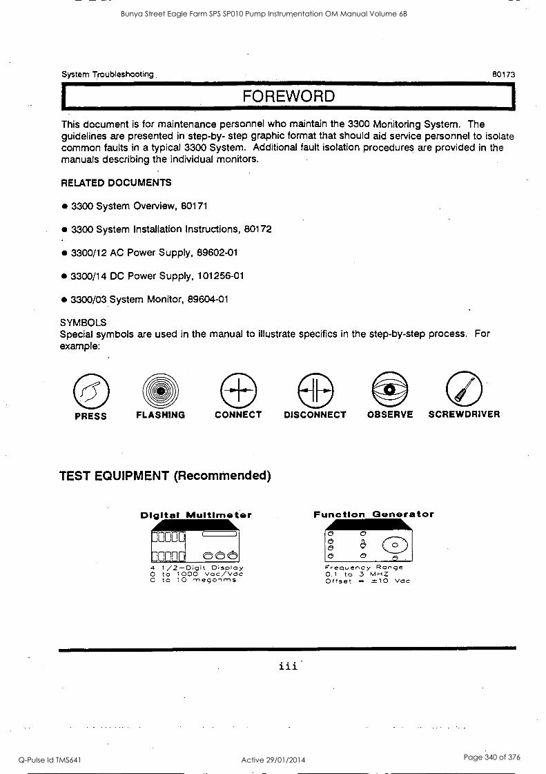
System Troubleshooting 80173
I FOREWORD 1
This document is for maintenance personnel who maintain the 3300 Monitoring System. The guidelines are presented in step-by- step graphic format that should aid service personnel to isolate common faults in a typical 3300 System. Additional fault isolation procedures are provided in the manuals describing the individual monitors.
RELATED DOCUMENTS
3300 System Overview, 80171
3300 System Installation Instructions, 80172
3300/12 AC Power Supply, 89602-01
3300/14 DC Power Supply, 101256-01
3300/03 System Monitor, 89604-01
SYMBOLS Special symbols are used in the manual to illustrate specifics in the step-by-step process. For example:
PRESS FLASHING CONNECT
TEST EQUIPMENT (Recommended)
Digital Multimeter
4 1 /2 -Digit Display O to 1000 voc/Vdc O to 10 rnegonrns
DISCONNECT OBSERVE SCREWDRIVER
Function Generator
Frequency Range 0.1 to 3 MHZ Offset = ±10 Vdc
Bunya Street Eagle Farm SPS SP010 Pump Instrumentation OM Manual Volume 6B
Q-Pulse Id TMS641 Active 29/01/2014 Page 340 of 376

80173 System Troubleshooting
iv
Bunya Street Eagle Farm SPS SP010 Pump Instrumentation OM Manual Volume 6B
Q-Pulse Id TMS641 Active 29/01/2014 Page 341 of 376
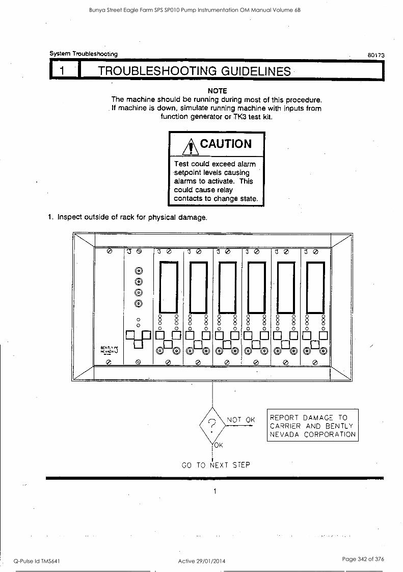
System Troubleshooting 80173
I TROUBLESHOOTING GUIDELINES
N OTE The machine should be running during most of this procedure. If machine is down, simulate running machine with inputs from
function generator or TK3 test kit.
*CAUTION Test could exceed alarm setpoint levels causing alarms to activate. This could cause relay contacts to change state.
1. Inspect outside of rack for physical damage.
0
5.'.1 0
Z5
0 9 0 0
00 10 00 00 00 00 ....... v...,.. IIIMIIV 41I NMEMI 11/
o 0 0 0
0 e 99
§ 00
00
0
e
0 00
00
0
e
0 00
00
§
e
§ 0
09 e
§ 0
9 - § e
NOT OK
OK OK
GO TO NEXT STEP
REPORT DAMAGE TO
CARRIER AND BENTLY NEVADA CORPORATION
1
Bunya Street Eagle Farm SPS SP010 Pump Instrumentation OM Manual Volume 6B
Q-Pulse Id TMS641 Active 29/01/2014 Page 342 of 376
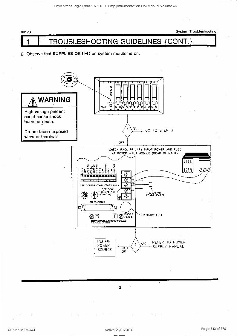
80173 System Troubleshooting
I 1 1 TROUBLESHOOTING GUIDELINES {CONT.}
. 2. Observe that SUPPLIES OK LED on system monitor is on.
*WARNING High voltage present could cause shock burns or death.
Do not touch exposed wires or terminals
r..."
'N..",.
e O O
H 20 7
...-a,..3
, H 0 :2
111111-1
10 00 5 a
. 0
32 10
0 0. 2
e. 0.00 00 0
GO TO STEP 3
CHECK RACK PRIMARY INPUT POWER AND FUSE AT POWER INPUT MODULE (REAR OF RACK)
* 0. a IbSSOSOOS
Lar..171;1.1;14;LGC4QCLC.
000 000 o o otTo 0 o
USE COPPER CONDUCTORS ONLY
110/220VAC 1.0/0.75 AMP 50-60 NZ
TDI/DYNAMiC
00
IMPANKT.MVPOODMWW.SOMPLAC.M.1. 011.1A,WIMOWWW.U111.40m. MM.
C
110/220 vac POWER SOURCE
PRIMARY FUSE
REPAIR POWER SOURCE NOT
OK
OK REFER TO POWER SUPPLY MANUAL
2
Bunya Street Eagle Farm SPS SP010 Pump Instrumentation OM Manual Volume 6B
Q-Pulse Id TMS641 Active 29/01/2014 Page 343 of 376

System Troubleshooting 80173
I TROUBLESHOOTING GUIDELINES {CONT.} 3. Actuate RESET switch and observe monitor ALARM LEDs. Latched monitor ALARM LEDs
should go off if their inputs are not currently exceeding the alarm level.
v7- o
t:: 11 1
a
6
0 0 0 0
10 30 30 10 30 3 e
0
111/ IImp 1111P
0 0 0 a 0 0 0 s 0 0 0 lOoo
e
0 0
cPto eee cP e 0000 e_e 0 Z. '.. NOTE
To gather troubleshooting information continue to next test even if alarm LEDs fail to go out.
4. Observe that OK and ALARM LEDs go on in accordance with current input and setpoint levels.
NOTE
To gather troubleshooting ,
information continue to next test even if alarm LEDs do not agree with input and setpoint levels.
V. 0
:t11:1
UCEP
0 0 0 0
30 30 I 30 30 30 10
1161611111°111i
imir worn,
°
eL\ CCO 9'0 0°e ocio
e cPe
e cPe
e
CO TO NEXT STEP
3
Bunya Street Eagle Farm SPS SP010 Pump Instrumentation OM Manual Volume 6B
Q-Pulse Id TMS641 Active 29/01/2014 Page 344 of 376

80173 System Troubleshooting Li TROUBLESHOOTING GUIDELINES {CONY.} I
5. Check Alarm setpoint levels on all monitors.
0
? . . . . . v . 1
US
0 0 0 0 0
IW
§ 0
§ § 0
70
0
30
§ 0 0
§
10
§ 0 0
§
10
§ 0
§ 0
10
§ 0
§ 0
§ 0
0 0 0 0 0 0 0 0 0 0 0 0
K
NOT OK REFER TO APPLICABLE MONITOR MANUAL AND THE TEST ALARMS SEC TiON.
6. Observe monitor OK LEDs and monitor front panel display while actuating GAP switch on each monitor. Refer to applicable monitor manual for gap OK limits.
0
LI C!)
OS
0 CI
0 0 :
cup
9
30
§ ... Oho 0
30
§
Um. §
30
§ §
imi
TO
§ § ...
30
§ §
..i.
30
§ § §
..i. oho 0
oho 0
Oho 04
0 0
0 oho 0
7
MONITOR OK
REFER TO APPLICABLE mONI TOR
MANUAL AND THE TEST OK LIMITS SECTION
4
Bunya Street Eagle Farm SPS SP010 Pump Instrumentation OM Manual Volume 6B
Q-Pulse Id TMS641 Active 29/01/2014 Page 345 of 376

I TROUBLESHOOTING GUIDELINES {CONT.1
System Troubleshooting 80173
7. Measure voltage at applicable monitor front panel BUFFERED TRANSDUCER coaxial cable connector. Monitor front panel gap display reading should agree with multimeter reading (set multimeter to DC volts).
All"1111001
,1001d
N 0
=3 a
OS
0
0!
o
10
11 . 70
ril
TB
il ............ o co e_az
ze,
[I
.0
3.3
ii
ila
ii o 0
a o c
J a o
CO TO NEXT STEP
REFER TO APPLICABLE tacNtTOR MANUAL AND THE CALIBRATE CHANNEL SECTION
5
Bunya Street Eagle Farm SPS SP010 Pump Instrumentation OM Manual Volume 6B
Q-Pulse Id TMS641 Active 29/01/2014 Page 346 of 376

80173 System Troubleshooting
I TROUBLESHOOTING GUIDELINES { CO N T. }
8. Measure Proximitor/Accelerometer Interface Module power at signal module PWR terminal. The acceptable voltage range depends on what transducer voltage the supply is configured for. If
the supply is configured for -24V, the acceptable range is -23.28 to -24.40 VDC. If the supply is configured for -18V, the acceptable range is -17.48 to -18.40 VDC.
xDDCR /0 & RECORD TERIAN ALS
CHA CHB
'''....,. 7 0 7'7 30 10 10
-
0 0 0
I I [I
i 1 i I I i 0 0 0 0 . c c 0 0 0 0 0
VOLTAGE
IN TOLERANCE GO TO STEP 10
VOLTAGE
OUT OF
TOLERANCE
9... Disconnect Proximitor/Accelerometer Interface Module power field wire at signal module PWR terminal and remeasure voltage at signal module PWR terminal.
rouck ./0 k nag° ,[ANNALS
0 CHA CHB
VOLTAGE
IN TOLERANCE
RECONNECT EB---4r-PWR
VOLTAGE OUT OF.
TOLERANCE
GO TO NEXT STEP
PROBLEM IS WITH MONITOR OR SIGNAL MODULE. REPLACE MONITOR AND REMEASURE VOLTAGE AT PWR TERMINAL. IF VOLTAGE IS STILL OUT OF
TOLERANCE, REPLACE SIGNAL MODULE.
6
Bunya Street Eagle Farm SPS SP010 Pump Instrumentation OM Manual Volume 6B
Q-Pulse Id TMS641 Active 29/01/2014 Page 347 of 376
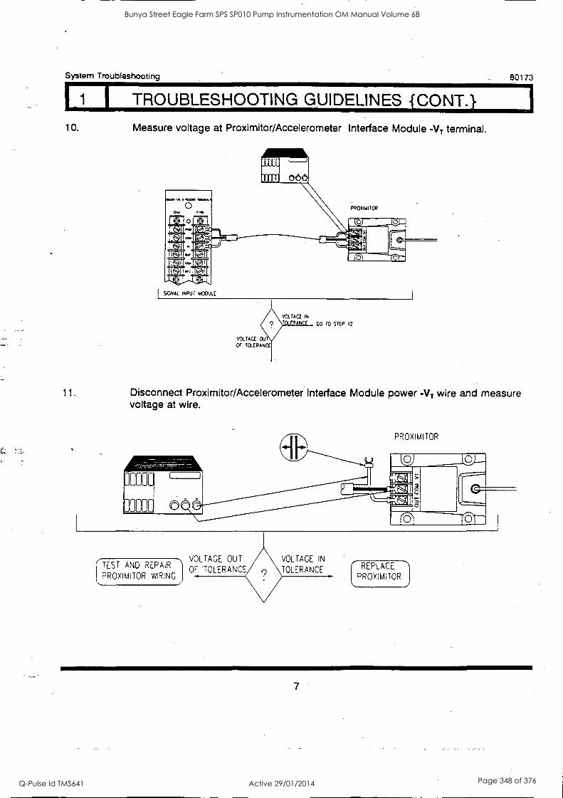
System Troubleshooting 80173
I TROUBLESHOOTING GUIDELINES {CONT.} 10. Measure voltage at Proximitor/Accelerometer Interface Module -VT terminal.
SIGNAL NPUT MODULE
CO TO STEP 12
11. Disconnect Proximitor/Accelerometer Interface Module power -VT wire and measure voltage at wire.
PROXIMITOR
TEST AND REPAIR
PROXIMITOR WIRING
VOLTAGE OUT
OF TOLERANCE
VOLTAGE IN
TOLERANCE REPLACE -\
PROXIMITOR
Bunya Street Eagle Farm SPS SP010 Pump Instrumentation OM Manual Volume 6B
Q-Pulse Id TMS641 Active 29/01/2014 Page 348 of 376

80173 System Troubleshooting
1 TROUBLESHOOTING GUIDELINES CONT.
12. Disconnect wire from Proximitor/Accelerometer Interface Module OUTPUT terminal and measure voltage at terminal.
PROXIMITOR
GAP VOLTAGE
INCORRECT
GAP
VOLTAGE
CORRECT
GO TO NEXT STEP
REFER TO APPLICABLE
TRANSDUCER MANUAL
AND CHECK:
o GAP VOLTAGE
o PROXIMITOR
o PROBE
o EXTENSION CABLE
13. Reconnect wire to Proximitor/Accelerometer Interface Module OUTPUT terminal. Disconnect wire at signal module IN terminal and measure voltage at wire.
./o Kam Tam.,
0 CMS CH8
0 010
COY
Sur
Cam
RC
48
SIGNAL NPUT MODULE
(TROUBLESHOOT
AND REPAIR I INCORREC
WIRING BETWEEN
PROXIMITOR AND j \MONITOR
CORRECT REPLACE
MONITOR
8
Bunya Street Eagle Farm SPS SP010 Pump Instrumentation OM Manual Volume 6B
Q-Pulse Id TMS641 Active 29/01/2014 Page 349 of 376

BRISBANE CITY COUNCIL Dept. Water Supply and Sewage Pumpwell No 1, Eagle Farm Pump Station
BCC Contract No S20/95/96 System Instrumentation
Operation and Maintenance Manual
Section 10 Isolation and Restoration Procedures
This Section is not applicable to the System Instrumentation. The Isolation and Restoration procedures for the pumping system are included in other volumes.
The Local Instrumentation Panel can be isolated by the two moulded case circuit breakers in the back of the panel. Each MCCB will isolate an entire rack.
15140/Inst Man/BRH Issue 1 29-Apr-98 Page 10-1
Bunya Street Eagle Farm SPS SP010 Pump Instrumentation OM Manual Volume 6B
Q-Pulse Id TMS641 Active 29/01/2014 Page 350 of 376

BRISBANE CITY COUNCIL Dept. Water Supply and Sewage Pumpwell No 1, Eagle Farm Pump Station
BCC Contract No S20/95/96 System Instrumentation
Operation and Maintenance Manual
Section 11 List of Sub-Contractors and Proprietary Equipment
Sub-contract suppliers of proprietary equipment include:
Vibration and Seed Monitoring - Bently Nevada 20 Healey Circuit Huntingwood NSW 2148
RTD Temperature Sensors -
Pump Junction Box -
15140/Inst Man/BRH Issue 1
Ph 02 9672 7447
Temperature Controls Pty Ltd 55 Henry Street Leichhardt NSW 2040
Ph 02 9560 0644
J & P Richardson Industries Pty Ltd Campbell Avenue Walcol QLD 4076
Ph 07 3271 2911
29-Apr-98 Page 11-1
Bunya Street Eagle Farm SPS SP010 Pump Instrumentation OM Manual Volume 6B
Q-Pulse Id TMS641 Active 29/01/2014 Page 351 of 376

BRISBANE CITY COUNCIL Dept. Water Supply and Sewage Pumpwell No 1, Eagle Farm Pump Station
BCC Contract No S20/95/96 System Instrumentation
Operation and Maintenance Manual
Section 12 Recommended Spares and Special Tools
Some of the equipment used on this project, in particular the Bently Nevada modules, can take up to 6 weeks to obtain. In order to keep the three pumps fully operational with minimal down time, one of each item of equipment that is not available ex stock from suppliers is recommended to be held in stock by the Brisbane City Council.
The following list includes the equipment items that we recommend one spare is held by BCC in order to avoid potential downtime:
1. Bently Nevada 3300/03 System Monitor
2. Bently Nevada 3300/012 Power Supply
3. Bently Nevada 3300 Six Channel Temperature Monitor
4. Bently Nevada 3300/50 Tachometer
5. Bently Nevada 3300/52 Reverse Rotation Monitor
6. Bently Nevada 330525 Velometer XA Piezo - Velocity Sensor
7. Bently Nevada 3300 - 8mm Proximity Transducer
8. Temperature Controls RTD Assembly to Dwg No 3015
9. Temperature Controls RTD Assembly to Dwg No 3016
10. Temperature Controls RTD Assembly to Dwg No 3017
11. Temperature Controls RTD Assembly to Dwg No 3018
12. Capacitive Proximity Probe - Schmersal IFC 15-30-10yTPD
All of the above items can be purchased through:
15140/Inst Man/BRH Issue 1
Weir Engineering Pty Ltd 15 Gindurra Road Somersby NSW 2250
Ph 02 4349 2999
29-Apr-98 Page 12-1
Bunya Street Eagle Farm SPS SP010 Pump Instrumentation OM Manual Volume 6B
Q-Pulse Id TMS641 Active 29/01/2014 Page 352 of 376
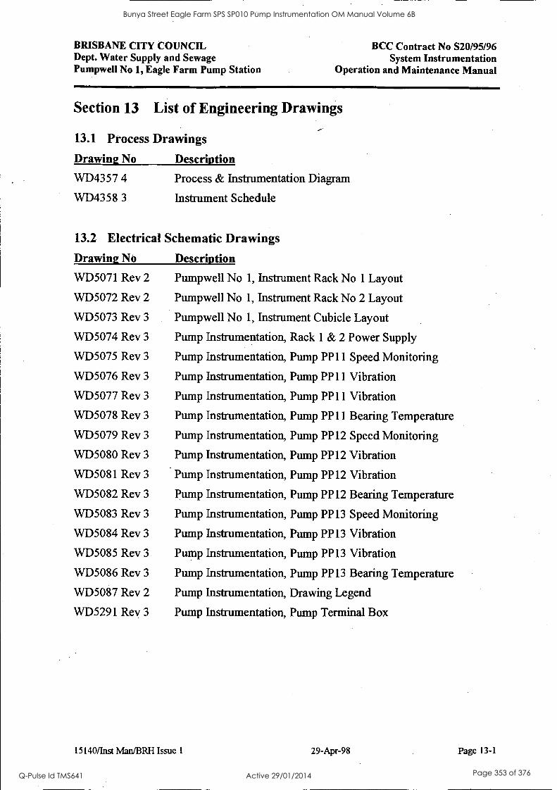
BRISBANE CITY COUNCIL Dept. Water Supply and Sewage Pumpwell No 1, Eagle Farm Pump Station
BCC Contract No S20/95/96 System Instrumentation
Operation and Maintenance Manual
Section 13 List of Engineering Drawings
13.1 Process Drawings
Drawing No Description
WD4357 4 Process & Instrumentation Diagram
WD4358 3 Instrument Schedule
13.2 Electrical Schematic Drawings
Drawing No Description
WD5071 Rev 2 Pumpwell No 1, Instrument Rack No 1 Layout
WD5072 Rev 2 Pumpwell No 1, Instrument Rack No 2 Layout
WD5073 Rev 3 Pumpwell No 1, Instrument Cubicle Layout
WD5074 Rev 3 Pump Instrumentation, Rack 1 & 2 Power Supply
WD5075 Rev 3 Pump Instrumentation, Pump PP11 Speed Monitoring
WD5076 Rev 3 Pump Instrumentation, Pump PP11 Vibration
WD5077 Rev 3 Pump Instrumentation, Pump PP11 Vibration
WD5078 Rev 3 Pump Instrumentation, Pump PP11 Bearing Temperature
WD5079 Rev 3 Pump Instrumentation, Pump. PP12 Speed Monitoring
WD5080 Rev 3 Pump Instrumentation, Pump PP12 Vibration
WD5081 Rev 3 Pump Instrumentation, Pump PP12 Vibration
WD5082 Rev 3 Pump Instrumentation, Pump PP12 Bearing Temperature
WD5083 Rev 3 Pump Instrumentation, Pump PP13 Speed Monitoring
WD5084 Rev 3 Pump Instrumentation, Pump PP13 Vibration
WD5085 Rev 3 Pump Instrumentation, Pump PP13 Vibration
WD5086 Rev 3 Pump Instrumentation, Pump PP13 Bearing Temperature
WD5087 Rev 2 Pump Instrumentation, Drawing Legend
WD5291 Rev 3 Pump Instrumentation, Pump Terminal Box
15140/Inst Man/BRH Issue 1 29-Apr-98 Page 13-1
Bunya Street Eagle Farm SPS SP010 Pump Instrumentation OM Manual Volume 6B
Q-Pulse Id TMS641 Active 29/01/2014 Page 353 of 376
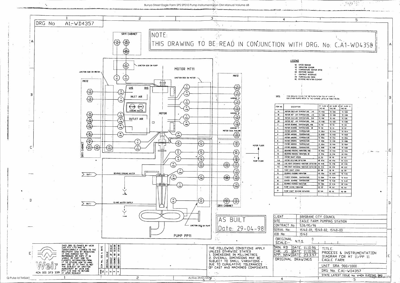
B
C
D
1 2 4 5 DRG No Al7V/D4357
SR11 CABINET
r -
JUNCTION BOX ON 140100
L
MK12
w AL w
IOW
1:!L
L
NOTE:
THIS DRAWING TO BE. REAn IN CON*JUNCTION WITH DRG. N C.A1- WD435&
N JUNCTION BOX ON PUMP
MOTOR MT11
JUNCTION BOX ON MOTOR
- - ------
MK12
AL w AL w
WINDING 'A'
AL
WINDING
WINDING 'C.
MOTOR SEAL FAILURE
BEARING COOLING WATER L 4
> 1347 I GLAND WATER SUPPLY
Affl
,SR11 CABINET
JUNCTION 134 ON PUMP
I
PUMP PP11
MOTOR FLOOR
fir
PUMP FLOOR
AS BUILT
Date: 29-04-98
LEGEND
SE
VE
TE
ME
CI
MK
RE
SPEED SENSOR
VIBRATION SENSOR
TEMPERATURE SENSOR (RTD) MOISTURE SENSOR
CONTRACT INTERFACE
MARSHALLING KIOSK
REVERSE ROTATION ELEMENT
tHLTE, THIS DRAWING SM.:WS THE-NS-Q.,,mEs'A,ICN HT I./RP ,11.
FOR OTHER PumPS,REFER TO 'AG 41.1.3ERS *-5"E) IN TABLE 9ELoW.
ITEM NO OESCRPTION IT 1/op 11
'AG No
MT 12/pp 12
TAG NO
MT 13/pp 13
TAG NO
IA ,MOTOR COLD AIR TEMPERATURE, LHS TE 103A TE 113A TE 123A
18 MOTOR HOT AIR TEMPERATURE, LHS TE 1018 TE 1135 TB 1238
2A MOTOR COLD AIR TEMPERATURE, RHS TE 103C TE 113E TE 123C
2B MOTOR HOT AIR TEMPERATURE, RHS TB 1030 TE 1130 TE 1230
3 MOTOR BEARING TEMPERATURE, NOE TE 102 TB Ill TB 122
MOTOR BEARING TEMPERATURE, DE TE 101 TE 111 TE 121
5 MOTOR MINDING TEMPERATURE TE 1046 TB II46 TE 124A
6 MOTOR WINDING TEMPERATURE TE 1048 TE 11413 TE 1248
7 MOTOR WINDING TEMPERATURE TE 100A TE 1156 TE 1256
a MOTOR WINDING TEMPERATURE TB 1058 TE 1158 TE 1258
9 MOTOR WINDING TEMPERATURE TO 1066 TE 1166 TE 7166
10 MOTOR WINDING TEMPERATURE TE 1068 TE I168 TE 1268
11 BEARING HOUSING VIBRATION, NOE VE IO2A VE 112A VE 1226
12 BEARING HOUSING VIBRATION, OE vE I016 VE 111A vE 121A
13 MOTOR SHAFT SPEED SE IOU SE 112 SE 122
14A MOTOR MOISTURE DETECTOR ME 107A ME 117A ME 127A
118 LHS HEAT EXCHANGE MOISTURE DETECTOR ME 1078 ME 1178 ME 1279
I4C RHS HEAT EXCHANGE MOISTURE DETECTOR ME 1070 ME 1I7C ME 127E
IS PUMP SHAFT SPEED SE 708 SE 119 SE 128
16 BEARING HOUSING VIBRATION VE 1356 VE 139A vE 143A
17 THURST BEARING TEMPERATURE TE 136A TE 140A TE 144A
18 LOWER BEARING TEMPERATURE TE 1368 TE 1408 TE 1449
19 BEARING HOUSING VIBRATION VE 138A vE 1416 VE 11.06
20 PUMP CASING VIBRATION vE 137 vE 142 VE 146
21 PUMP SHAFT REVERSE ROTATION RE 140 RE 119 RE 128
CLIENT BRISBANE CITY COUNCIL
SITE EAGLE FARM PUMPING STATION CONTRACT No: S20/95/96 SERIAL No: 15140-01, 15140-02, 15140-03 JOB No: 15140
ORIGINAL SCALE:- N.T.S.
I I I
ACM 000 373 339
THIS DRG IS OWNED BY WEIR ENG PTY LTD AND IS CONDITIONALLY LOANED TO THE RECIPIENT WHO BY RECEIVING IT HAS AGREED NOT TO REPRODUCE CR COPY IT IN WHOLE OR PART NOR TO FURNIFH INFORMATION FROM IT TO OTHERS NOR TO MAKE ANY USE OF IT THAT IS NOT THE SUBJECT OF WRITTEN AGREEMENT BY WEIR ENG PTY LTD AND TO RETURN IT UPON REQUEST
0 S
O eN1
5 S
1
el
THE FOLLOWING CONDITIONS APPLY UNLESS THRWISE STATED 1. DIMENSIONS IN MILLIMETRES, 2. OVERALL DIMENSIONS MAY BE SUBJECT TO SMALL VARIATIONS DUE TO CUMULATIVE TOLERANCES Or' CAST AND MACHINE-D COMPONENTS,
bRN. RD CHK, JG
DATE. 11.10.96 I TITLE. PROCESS & INSTRUMENTATION DIAGRAM FOR MT 11/PP 11
EAGLE FARM
DATE. 11.10.96 APP, NAW DATE. 23.3.97 ORIGINAL DRAWINGS
UNIT SRA 900/1000. DRG No. C.Ai- WD4357 STATE LATEST ISSUE No. WHEN QUOTING DRG
5
Bunya Street Eagle Farm SPS SP010 Pump Instrumentation OM Manual Volume 6B
Q-Pulse Id TMS641 Active 29/01/2014 Page 354 of 376
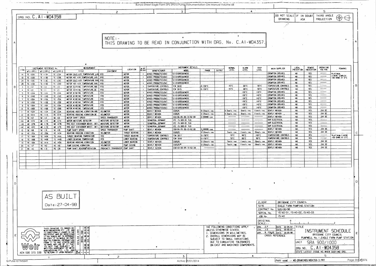
2
DRG NO. C.A14D4358 4 5
NOTE:- THIS DRAWING TO BE READ IN CONJUNCTION WITH DRG. No. C.AI- WD4357.
DO NOT SCALE
DRAWING IF IN DOUBT
ASK
THIRD ANGLE
PROJECTION
ITEM INSTRUMENT REFERENCE No. MEASUREMENT
LOCATION P4, UT RR
INSTRUMENT DETAILS NORMAL LEVEL
ALARM LEVEL
TRIP LEVEL
MAIN SUPPLIER LOCAL
INDICATION REMOTE
INDICATION OPERATING VOLTAGE .
REMARKS
1011/PPii AITZ/PP12 MT13/PPI3 TITLE EQUIPMENT MANUFACTURER MCCEL RANGE OUTPUT
IA TE I034 TE 1134 TE I234 MOTOR COLD AIR TEMPERATURE LHS RTD MOTOR I MINCO PRODUCTS(USA) 511016POIMINCO) CROMPTON GREAVES NO YES PLATINUM, 3 WIRE SIMPLEX 100 AT O'C OHMS 1B YE 1035 TE 1138 TE 1238 MOTOR HOT AIR TEMPERATURE LHS RID MOTOR I MINCO PROCUCTS(USA) 511016P0(MINCO) CROMPTON GREAVES NO YES
2A TE 103C TE 111C TE I23C MOTOR COLD AIR TEMPERATURE RHS RID MOTOR MINCO PRODUCTS(USA) 511016POIMINCOI CROMPTON GREAVES YES
28 TE !030 TE 1110 TE 1230 MOTOR HOT AIR TEMPERATURE RHS RTD MOTOR I MINED PRODUCTSIUSAI 511016P0(MINCO) CROMPTON GREAVES NO YES
3 1E :02 TE 112 TE 122 MOTOR SEARING TEMPERATURE NOE RID MOTOR I TEMPERATURE CONTROLS TOW 3018 0 -150'C 70'C 80'C 90'C TEMPERATURE CONTROLS NO YES
4 TE 101 TE III II 121 MOTOR SEARING "EMPERATURE,DE RTD MOTOR I TEMPERATURE CONTROLS TCW 3015 0 -150'C 70T 80'C 90T TEMPERATURE CONTROLS NO YES
5 TE I044 TE II44 TE 1244 MOTOR WINDING -EMPERATURE RID MOTOR I MINCO PRODUCTS(USA) 511016PO(MINCO) 130'C 140'C CROMPTON GREAVES NO YES
6 TE 1048 TE 114E1 TE 124B MOTOR WINDING "EMPERATURE RIO MOTOR I MINCO PRODUCTS(USA) 511016POIMINCOI 130"C 140'C CROMPTON GREAVES NO YES
7 TE I054 TE 1154 TE 125A MOTOR WINDING TEMPERATURE RID MOTOR I MINCO PRODUCTS(USA) 511016POIMINCOI 130"C 140T CROMPTON GREAVES NO YES
8 TE 1056 TE 1158 TE 125B MOTOR WINDING "EMPERATURE RIO MOTOR I MINCO PRODUCTS(USA) 511016PO(MINCO) 130"C 140T CROMPTON GREAVES NO YES
9 TE 106A TE II64 TE I264 MOTOR WINDING TEMPERATURE RTD MOTOR I MINED PROCUCTS(USA) S11016POIMINCOI 130'C 140'C CROMPTON GREAVES NO YES
10 TE 1068 TE 1168 TE 1268 MOTOR WINDING TEMPERATURE RID MOTOR I MINCO PRODUCTS(USA) S11016P0(MINCO) 130T 140T CROMPTON GREAVES NO YES
II VE 102A VE 112A VE 122A BEARING HDJSING VieRATION,NDE VELOMETER MOTOR I BENTLY NEVADA 330525 0-20mm/s rms 4.5mm/s rms 8mm/s rms 11mm/s rms BENTLY NEVADA NO YES 24V DC
12 VE 10IA VE IIIA VE 12IA BEARING HOUSING VIBRATION,OE VELOMETER MOTOR I BENTLY NEVADA 330525 0-20mm/s rms 4.5mm/s rms 8mm/s rms Ilmm/s rms BENTLY NEVADA YES 24V DC
13 SE 102 SE 112 SE 122 MOTOR SHAFT SPEED SPEED TRANSDUCER MOTOR I BENTLY NEVADA 330106-05 30-10 02 00 0-99999 rpm BENTLY NEVADA NO YES 24V DC
14A ME 107A ME 117A ME I274 MOTOR MOISTURE DETECTOR MOISTURE DETECTOR MOTOR I SCHMERSAL,GERMANY IFC 15- 300 -01 YLG NFP ELECTRICAL NO YES
145 ME 1078 ME 1178 ME I278 RHS HEAT EXCHANGER MOIST. PET. MOISTURE DETECTOR MOTOR I SCHMERSAL,GERMANY IFC 15-300-01 YLG NIP ELECTRICAL NO YES
14C ME 107C ME 117C ME I27C RHS HEAT EXCHANGER MOIST. CET. MOISTURE DETECTOR MOTOR I SCHMERSAL,GERMANY IFC 15-300-01 YLG NIP ELECTRICAL NO YES
15 SE 108 SE 119 SE 128 PUMP SHAFT SPEED SPEED TRANSDUCER PUMP SHAFT I BENTLY NEVADA 330106-05-30-10-02-00 0 -99999 rpm BENTLY NEVADA NO YES 24V DC
16 VE I354 VE 139A VE I43A BEARING HOUSING VIBRATION VELOMETER THRUST BEARING I BENTLY NEVADA 330525 0-20mm/s rms 7mm/s rms Ilmm/s rms 18mm/s rms BENTLY NEVADA NO YES 24V DC
17 TE 136A TE 140A TE I44A THRUST BEARING TEMPERATURE RIO THRUST BEARING I TEMPERATURE CONTROLS TOW 3017 0-150'C 70*C 90T 100'C TEMPERATURE CONTROLS NO YES PLATINUM,3 WIRE 100 OHMS AT O'C
18 TE 1368 TE 140E1 TE 144B LOWER BEARING TEMPERATURE RID LOWER BEARING I TEMPERATURE CONTROLS TCW 3016 0-150'C 70*C 80'C 90*C TEMPERATURE CONTROLS NO YES
19 VE I384 VE 14I4 VE 145A BEARING HOUSING VIBRATION VELOMETER LOWER BEARING I BENTLY NEVADA 330525 0-20mm/s rms 7mm/s rms Ilmm/s rms 18mm/s rms BENTLY NEVADA NO YES 24V DC
20 VE 137 VE 142 VE 146 PUMP CASING VIBRATION VELOMETER PUMP CASING I BENTLY NEVADA 330525 0-20mm/s rms 7mm/s rms Ilmm/s rms 18mm/s rms BENTLY NEVADA NO YES 24V DC
21 RE 140 RE 119 RE 128 PUMP SHAFT REVERSE* ROTATION PROXIMITY TRANSDUCER PUMP SHAFT I BENTLY NC,VADA 330103 -00 -05-10 -02-00 BENTLY NEVADA NO YES 24V DC
AS BUILT Date:27-04-98
THIS DRAWING IS 0,1,NZD BY WEIR ENGINEERING PTY. LTD. AND
IS CONDITIONALLI LOANED TO THE
RECIPIENT MHO BY RECEIVING IT HAS AGREED NOT TO REPRODUCE
OR COPY IT IN *OLE OR PART PO TO FURNISH INFORMATION FROM IT TO ANY OTHERS NOR TO MAKE ANY USE CF IT THAT
IS NOT TI-E SUBJECT OF WRITTEN AGREEMENT BY WEIR ENGINEERING PTY. LTD. AND TO RETURN IT UPON REQUEST.
66.
ACN 000 373 339 gi
A
CLIENT BRISBANE CITY COUNCIL
SITE EAGLE FARM PUMPING STATION
CONTRACT No. S20/95/96 SERIAL No. 15140-01,15140-02,15140-03
JOB No. 15140
ORIGINAL 0
SCALE:- I , I 1
CC
CO
CC
./1
2C 9
THE FOLLOWING CONDITIONS APPLY
UNLESS OTHERWISE STATED.
I. DIMENSIONS IN MILLIMETRES.
2. OVERALL DIMENSIONS MAY BE
SUBJECT TO SMALL VARIATIONS
DUE TO CUMULATIVE TOLERANCES
ON CAST AND MACHINED COMPONENTS.
DRN. ZP DATE. 02-05-97 TITLE
INSTRUMENT SCHEDULE BRISBANE CITY COUNCIL
PUMPWELL No.I,EAGLE FARM PUMP STATION
CHK, G DATE 05 -05 -97
APP. B. FOX)-EE GATE: 20-05-98
CROSS REFERENCE
UNIT SRA 900/1000 .
ORG NO C Al-WD4358 O.) STATE LATEST ISSUE NG.WHEN DUOTING ORG.
5
PART NAME :-WD-ORAWINGS/WD4358-3.PRT 0
Bunya Street Eagle Farm SPS SP010 Pump Instrumentation OM Manual Volume 6B
Q-Pulse Id TMS641 Active 29/01/2014 Page 355 of 376
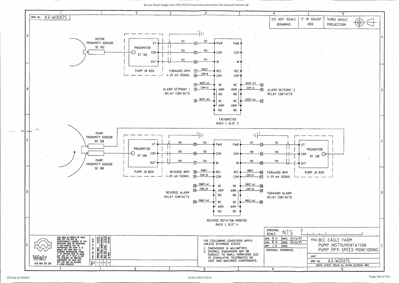
1 I 2
I 3 4
1 5
-
B
C
D
E
DRG No A3-WD5075 DO NOT SCALE
DRAWING
IF IN DOUBT
ASK
THIRD ANGLE il
B
0
E
PROJECTION wily
I
11
MOTOR
VT
PROXIMITOR
0 COM ST 102
OUT
,I. 151 1S1 PWR PWR
COM. COM
IN IN
REC REC
COM COM
NC NC
ARM
PROXIMITY SENSOR
SE 102 I
13
III 152 1S2
5
_
.--PROXIMITY PUMP
SENSOR
RE 108
1S3 153
I
I
FORWARD RPM
4-20 mA SIGNAL
ALARM SETPIONT 1
RELAY CONTACTS
6
PUMP JN BOX L__ - ___ - ___ ___I
10 25T El
COM-8 8
102ST-A1 102ST-A3 El
14
El COM-11 COM-14
m
1025T-A2
ARM
NO NO
NC NC
5- ARM ARM
NO NO
102ST-A4
ALARM SETPOINT 2
RELAY CONTACTS
El -
TACHOMETER
RACK 1, SLOT 3
r- - ____ I
I I I I I I
eis is4 VT
1S4 157 PWR
1S7 I, VT
PROXIMITOR I
PROXIMITOR I
1111
155
PWR
15 8
EC II I
155 1S8 0 ST 108
COM El
156
COM COM
159
EU COM RT 108 0
OUT I
PUMP 156 159 U PROXIMITY SENSOR I
OUT L
REVERSE RPM
MI
10 8ST El
IN IN
108RT REC
Ei
SE 108
JN I BOX PUMP BOX
L__ ___ - - - ___1 4-20 mA SIGNAL
REVERSE ALARM
RELAY CONTACTS
COM-19 REC
COM-27 Er. FORWARD RPM PUMP JN
EE 4-20 mA SIGNAL I-- - - - - --i ii IIE
FORWARD ALARM
RELAY CONTACTS
IN
108RT-A1
COM COM
108ST-A1 EC
COM-22 NC NC
COM-30
108RT-A2 Oil
ARM ARM
NO NO
NC
'
108ST-A2
- NC
ARM ARM
NO NO
-5
REVERSE ROTATION MONITOR
RACK 1, SLOT 4
ORIGINAL l I i I SCALE: N T S °
THIS ORG IS OWNED BY WEIR
114-12,AVID TO THE RECIPIENT WHO BY RECENG
HAS AGREED NOT TO IVI
REPRODUCE OR COPY IT IN WHOLE OR PART NOR TO FURNISH INFORMATION FROM IT TO OTHERS NOR TO MAKE n/}(]^ ANY USE OF IT THAT IS NOT THE SUBJECT OF WRITTEN AGREEMENT BY WEIR ENG PTY LTD AND TO RETURN
ACN 000 373 339 IT UPON REQUEST
5 .1
LI in
ci z Z u L.,
2
7; . i M ''S f3
Z s rNI
g M
P
..!,
.
t.
THE FOLLOWING CONDITIONS APPLY UNLESS OTHRWISE STATED
1. DIMENSIONS IN MILLIMETRES. 2. OVERALL DIMENSIONS MAY BE
SUBJECT TO SMALL VARIATIONS DUE TO CUMULATIVE TOLERANCES ON
CAST AND MACHINED COMPONENTS.
ow R H um 24/6/97 TITLE. BCC EAGLE FARM
PUMP INSTRUMENTATION PUMP PP11 SPEED MONITORING
CHK. B H DATE. 25/6/97 APP. J 0 DATE.
ORIGINAL DRAWINGS
UNIT
DRG No. A3-WD5075 1 ".''' STATE LATEST ISSUE No. WHEN QUOTING DRG
1 2 3 I 4 5
Bunya Street Eagle Farm SPS SP010 Pump Instrumentation OM Manual Volume 6B
Q-Pulse Id TMS641 Active 29/01/2014 Page 356 of 376

1 I 2 ' I
- 4 I 5
A
B
...
C
_
D
E
DRG No A3-WD5074 I
DO NOT SCALE
DRAWING
IF IN DOUBT
ASK
THIRD ANGLE
A
__
B
C
0
--,
E
PROJECTION Air
240V POWER
SUPPLY I I
A E N
CB2-10A
Ll
NO
OK ARM
RELAY
NC
LINE 1
LINE 2
GND
COM-3
RACK 1
W1 INST PWR1 ALARM
'
N1 . .-
El -- --
CB3-10A
POWER SUPPLY MODULE
RACK 1, SLOT 1/2
NO
OK ARM
RELAY
W1 INST PWR2 2 RACK 2
L2
NC ALARM
OX LINE 1
N2
LINE 2
E2
GND
POWER SUPPLY MODULE
RACK 2, SLOT 1/2
I I I , I_ I SCALE: ORIGINAL
NTS ° THIS DRG IS OWNED BY WEIR
Nal' LTDYM"ED TO THE RECIPIENT WHO EY RECEMNG IT HAS AGRUD NOT TO REPRODUCE OR COPY IT IN WHOLE OR PART NOR TO FURNISH %ISM INFORMAT1011 FROM
MAKE OTHERS NOR ANY USE OF IT THAT IS NOT WS 11T THE SUBJECT OF WRITTEN AGREEMENT BY WEIR ENG
ACN 000 373 339 ipirYja ARNELTEDSTRETURN
5,:..39,,-z 41
LI m I z 8
S;
1
15
g
i;
a 5 0 *I
a g
gl 5
2
THE FOLLOWING CONDITIONS APPLY UNLESS OTHRWISE STATED
1 . DIMENSIONS IN MILLIMETRES. 2. OVERALL DIMENSIONS MAY BE
SUBJECT TO SMALL VARIATIONS DUE TO CUMULATIVE TOLERANCES ON CAST AND MACHINED COMPONENTS.
OW R H DATE. 24/6/97 TIRE BCC EAGLE FARM
PUMP INSTRUMENTATION RACK 1 & 2 POWER SUPPLY
CHK. B H DATE. 25/6/97 APP. J 0 DATE.
ORIGINAL DRAWINGS
.
UNIT
DRG No. A3-WDS074 i I - ... n ....
STATE LATEST ISSUE No. WHEN QUOTING DRG 1 2 3 4 5 -
Bunya Street Eagle Farm SPS SP010 Pump Instrumentation OM Manual Volume 6B
Q-Pulse Id TMS641 Active 29/01/2014 Page 357 of 376

1 I 2 ---- 3.
I el- I 5
A
_
B
- --i
C
_
D
-
E
DRG No A3-WD5073 DO NOT SCALE
DRAWIN G
IF IN DOUBT
SK
THIRD ANGLE
A
B
_
c
-I
D
-- _
E
PROJECTION lir 0 1 1
. Il I
PLAN VIEW
0 ITEM No DESCRIPTION
1 - CABLE DUC TING-40mmx5Omm
2 1 PANEL LABEL
3 2 INSTRUMENATION RACK A
CD
iin n
CLEAR PERSPEX
VIEWING PANEL
700
4 330 4mm DIN RAIL TERMINALS
5 4 4mm DIN RAIL TERMINALS 0
0
6 1 REAR ENCLOSURE 800Wx1000Hx300D 7 1 FRONT ENCLOSURE 800Wx1000Hx300D 8 1 INSTRUMENT EARTH LINK - INSULATED 9 1 CABLE GLAND PLATE
10 2 240V, 10A CIRCUIT BREAKER
I
FRONT DOOR 0 800
0 H
320 320
0 0
PT4 E/UNK N/UNK INST EARTH
FRONT VIEW (door removed)
o
I
I
I
0 cp c) ,._
0
Ci a..
z 0
n_ z n_
r ,
L.: a_
z 0
n_
= 0_
r n ci = a_
z 0
m n_
c, r-- C 1
c=, L.r,
RACK 1
0 1
cn c-- (NI 0
RACK 2
0
400
U
720 - - -
9-1
GEAR TRAY LAYOUT - _J
TYPICAL SECTION ORIGINAL
° SCALE: N TS I I L I I THIS DRS IS OWNED BY WEIR
g'IPMW.LYAN"ED TO THE RECIPIENT WHO BY RECEMNG IT HAS AGREED NOT TO REPRODUCE OR COPY 170 IN
FURNISH INFORMATION FROM rr TO OTHERS NOR TO MAKE
W.Gn'Er ANY USE OF IT THAT IS NOT THE SUBJECT OF WRITTEN AGREEMENT BY WEIR ENG PTY LTD AND TO RETURN ACN 000 373 339 IT UPON REQUEST
5 41
tg.
4 - z 8
°-*
:._ -,
., 2 13 E
--z m
g
..
.1 < m
B
" W
Z Z . m
m,
g
THE FOLLOWING CONDITIONS APPLY UNLESS OTHRWISE STATED
1. DIMENSIONS IN MILLIMETRES. 2. OVERALL DIMENSIONS MAY BE
SUBJECT TO SMALL VARIATIONS DUE TO CUMULATIVE TOLERANCES ON CAST AND MACHINED COMPONENTS.
DRN. R H DATE. 24/6/97 TITLE. BCC EAGLE FARM
PUMPWELL No 1 INSTRUMENT CUBICLE LAYOUT
CHK. B H DATE. 25/6/97 APP. J 0 DATE.
ORIGINAL DRAWINGS
UNIT
DRG No. A3-WD5073 4 '
g 1 - ,-, " - -,
STATE LATEST ISSUE No. WHEN QUOTING DRG 1 2 3 4 5
Bunya Street Eagle Farm SPS SP010 Pump Instrumentation OM Manual Volume 6B
Q-Pulse Id TMS641 Active 29/01/2014 Page 358 of 376
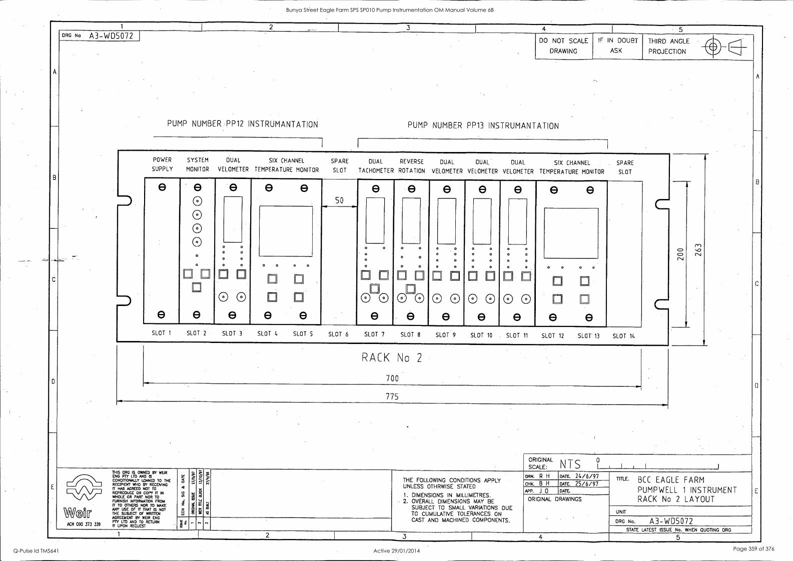
1 2 3 I
4 I
A
r--
B
___
0
E
DRG No A3-W05072 DO NOT SCALE
DRAWING __,
IF IN DOUBT
ASK
THIRD ANGLE gi
A
B
C
_
D
E
PROJECTION i)
'
PUMP NUMBER PP12 INSTRUMANTATION PUMP NUMBER PP13 INSTRUMANTATION
I
POWER SYSTEM DUAL SIX CHANNEL SPARE DUAL REVERSE DUAL DUAL DUAL SIX CHANNEL SPARE SUPPLY MONITOR VELOMETER TEMPERATURE MONITOR SLOT TACHOMETER ROTATION VELOMETER VELOMETER VELOMETER TEMPERATURE MONITOR SLOT
-
i
e
e
e 0 0 0 0
o
e e e 50
e e e e e e e 1
in '.0 CV
I
.
C= CD CV
0 0 o 0
0 0
0 0 0 0
0 0 0 0 0 0
0 0 0 o
0
0
0
00
0
0 0
n
0 0
E 0
0
0
0 ri 0
0
0
0
o
0
0
0
0
0
0
0
0
0
0 _
0
0
0
0
0
0
0
0
0
0
0 0 0
1 n
0
e e e e e e e e e e e SLOT 1 SLOT 2 SLOT 3 SLOT 4 SLOT 5 SLOT 6 SLOT 7 SLOT 8 SLOT 9 SLOT 10 SLOT 11 SLOT 12 SLOT' 13 SLOT 14
RACK No 2
700 ....
-.
-...
775 .
SCALE:
ORIGINAL NTS ? , I , I
1
THIS DRG IS OWNED BY WEIR ENG FTC LTD AND IS CONDMONAU_Y LOANED TO THE RECIPIENT WHO BY RECEMNG FT HAS AGREED NOT TO REPRODUCE OR COPY (I" IN WHOLE OR PART NOR TO FURNISH INFORMATION FROM IT TO OTHERS NOR TO MANE
W®tr ANY USE OF IT THAT IS NOT THE SUBJECT OF WRITTEN AGREEMENT BY WEIR ENG PTY LM AND TO RETURN
ACN 000 373 339 R UPON REQUEST
W g 41
g 6 z z u ta
't ii-
g
2 13
1 -,-
g
RE
t -, ... 4- -.
" - M
THE FOLLOWING CONDITIONS APPLY UNLESS OTHRWISE STATED
1. DIMENSIONS IN MILLIMETRES. 2. OVERALL DIMENSIONS MAY BE
SUBJECT TO SMALL VARIATIONS DUE TO CUMULATIVE TOLERANCES ON
ORN. R H DATE. 24/6/97 TITLE' BCC EAGLE FARM
PUMPWELL 1 INSTRUMENT RACK No 2 LAYOUT
CHK. B H DATE. 25/6/97 APP. J 0 DATE.
ORIGINAL DRAWINGS
UNIT
DRG No. A3-WD5072 . a
I ' , CAST AND MACHINED COMPONENTS.
STATE LATEST ISSUE No WHEN QUOTING DRG 1
I 2 3 4 5 -
Bunya Street Eagle Farm SPS SP010 Pump Instrumentation OM Manual Volume 6B
Q-Pulse Id TMS641 Active 29/01/2014 Page 359 of 376

1 2 I 3 I
4 I_
5
A
-
B
_
,.-
C
D
E
DRG No A3-WD5071 DO NOT SCALE
DRAWING
IF IN DOUBT
ASK
THIRD ANGLE il
A
B
c
D
E
_
PROJECTION %l
PUMP NUMBER PP11 INSTRUMANTATION PUMP NUMBER PP12 INSTRUMANTATION
I I
POWER SYSTEM DUAL REVERSE DUAL DUAL DUAL SIX CHANNEL SPARE DUAL REVERSE DUAL DUAL
SUPPLY MONITOR TACHOMETER ROTATION VELOMETER VELOMETER VELOMETER TEMPERATURE MONITOR SLOT TACHOMETER ROTATION VELOMETER VELOMETER
I
e
e
e 0 0 0 0
e e e e. e e e e e e e
M VD CV
50
CD CD CNJ
0 0
o
. 0 . . 0 0
. . 0 0
. 0 0
0 0
0 . . 0 0
. . 0 0
. 0
0 o 0
0
E E.
o
0
0 00000000 0 0 0 0 0
I-1
0
I::
0
F-1
0
ri
0 0
I-1
0
0
0
E E
0 .00000 0 0 0
ni
0
e 0 0
e 0 0
e 0 0
e 0
e 0 0
e e e 00000000
e e e e SLOT 1 SLOT 2 SLOT 3 SLOT If SLOT 5 SLOT 6 SLOT 7 SLOT 8 SLOT 9 SLOT 10 SLOT 11 SLOT 12. SLOT 13 SLOT 14
RACK No 1
700 .....
775
ORIGINA
SCALE:
L
NTS l0 1 I 1 I I
_
THIS DRG IS OWNED BY WEIR ENG Prf LTD MD S CONDMONALLY LOANED TO THE RECIPIENT WHO BY RECEMNG IT HAS AGREED NOT TO REPRODUCE OR COPY TT IN
WHOLE OR PART NOR TO
I.UFgS1-01.441;s3RINtTRIOIFROME
ANY USE OF TT THAT IS NOT
We@iclIT THE SUBJECT OF WRITTEN
W
g Al
g.
i z La
, . ;7.--. LY
a
--- ,-.' A- .-
B
.. RUg
m m
`,,...
7---.. C.1
. V
THE FOLLOWING CONDITIONS APPLY UNLESS OTHRWISE STATED
1. DIMENSIONS IN MILLIMETRES. 2. OVERALL DIMENSIONS MAY BE
SUBJECT TO SMALL VARIATIONS DUE TO CUMULATIVE TOLERANCES ON CAST AND MACHINED COMPONENTS.
DRN. R H DATE. 24/6/97 TITLE. BCC EAGLE FARM
PUMPWELL 1 INSTRUMENT RACK No 1 LAYOUT
CHIC B H DATE. 25/6/97 APP. J 0 DATE.
ORIGINAL DRAWINGS
UNIT
DRG No. A3-WD5071 AGREEMENT BY WEIR ENG PTY LTD AND TO RETURN
ACN 000 373 339 if UPON REQUEST ''';'-e'''' 0 ' STATE LATEST ISSUE No. WHEN QUOTING DRG
1 2 3 4 5
Bunya Street Eagle Farm SPS SP010 Pump Instrumentation OM Manual Volume 6B
Q-Pulse Id TMS641 Active 29/01/2014 Page 360 of 376
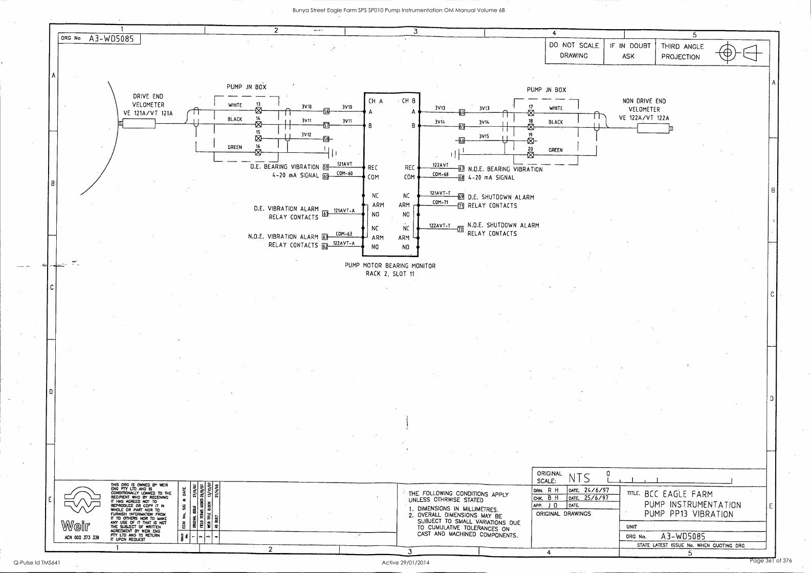
1 -- 4 1
5
A
B
-
C
D
ORG No A3-WD5085 DO NOT SCALE
DRAWING
IF IN DOUBT
ASK
THIRD ANGLE
PROJECTION wr
A
8
C
D
E
PUMP JN BOX PUMP JN BOX DRIVE END
VELOMETER
_ _ WHITE 13 -
ei 3\110 3V10 CH A CH B
A A
B B
REC REC
COM COM
NC NC - ARM ARM
3V13 3V13
_ - - - 17 WHITE
0 NON DRIVE END
VELOMETER VE 121A/VT 121A f n 1
1 BLACK 14
56
3V11 3V11
IT I
1 BLACK VE 122A/VT 122A
I E i U 3V14 3V14 ...18
M 1
1 ls gil
gG
[X iN I j 3V12 3V15 19
0 I
I GREEN T6 It ill
122AVT
En
I
I 20 GREEN
r I 0 II'
121AVT 1 - - - _..1 D.E. BEARING VIBRATION
4-20 mA SIGNAL
D.E. VIBRATION ALARM
RELAY CONTACTS
N.D.E. VIBRATION ALARM
RELAY CONTACTS
E] COM-60 COM-68
EE N.D.E. BEARING VIBRATION
4-20 SIGNAL IEE
121AVT-A 131
13 mA
121AVT-T
COM-71 Di D.E. SHUTDOWN ALARM
0 RELAY CONTACTS
j N.D.E. SHUTDOWN ALARM
RELAY CONTACTS
NO NO
NC NC 122AVT-T
COM-63 11
122AVT-A ARM ARM -- NO NO EE
__ - - PUMP MOTOR BEARING MONITOR
RACK 2, SLOT 11
.
SCALE:
ORIGINAL N T S 1 I I I
THIS DRC IS OWNED 8Y WEIR
grNDPRPO' LTBYAND is ED TO THE RECIPIENT WHO BY RECEMNG if HAS AGREED NOT TO 1--:: REPRODUCE OR COPY IT IN
WHOLE OR PART NOR TO FURNISH INFORMATION FROIA fT TO OTHERS NOR TO MAKE
WMIT ANY USE OF ri THAT IS NOT THE SUBJECT OF WRITTEN AGREEMENT BY WEIR ENG PTY LTD AND TO RETURN
ACN 000 373 339 if UPON REQUEST
<
4 _
z
^ S. ;*--
1
......
7.1' . Z o 4*: -
w
. . THE FOLLOWING CONDITIONS APPLY UNLESS OTHRWISE STATED
1 . DIMENSIONS IN MILLIMETRES. 2. OVERALL DIMENSIONS MAY BE
SUBJECT TO SMALL VARIATIONS DUE TO CUMULATIVE TOLERANCES ON CAST AND MACHINED COMPONENTS.
ORN. R H DATE. 24/6/97 TIME' BCC EAGLE FARM
PUMP INSTRUMENTATION PUMP PP13 VIBRATION
CHK. B H DATE. 25/6/97 APP. J 0 DATE.
ORIGINAL DRAWINGS
UNIT
DRG No. A3-WDSO8S - . n .r
STATE LATEST ISSUE No. WHEN QUOTING DRG 1 2 3
1 4 5
Bunya Street Eagle Farm SPS SP010 Pump Instrumentation OM Manual Volume 6B
Q-Pulse Id TMS641 Active 29/01/2014 Page 361 of 376
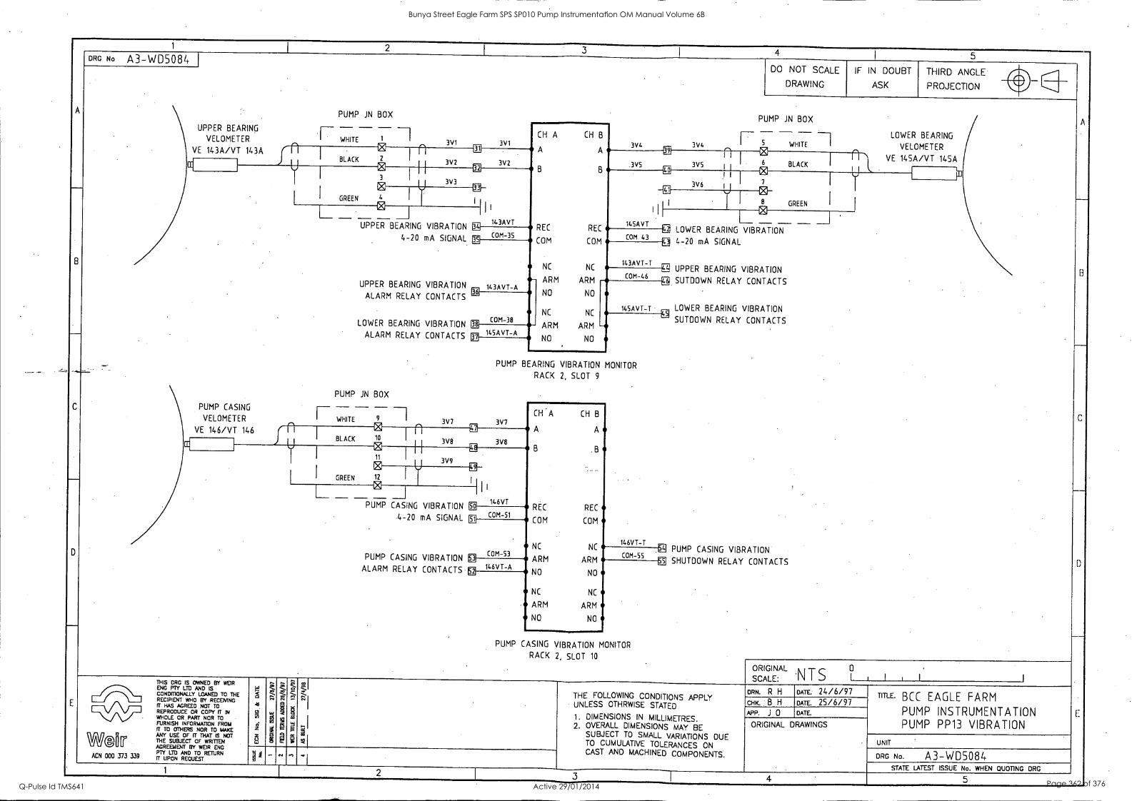
1
4 5 DRG No A3-WD5084
UPPER BEARING
VELOMETER
VE 143A/VT 143A
CC
PUMP CASING
VELOMETER
VE 146/VT 146
CC
PUMP IN BOX
WHITE 3V1
UPPER BEARING VIBRATION E 143AVT REC
COM -3S 4.-20 mA SIGNAL COM- COM
CH A CH B
A A
B
UPPER BEARING VIBRATION
ALARM RELAY CONTACTS
LOWER BEARING VIBRATION
ALARM RELAY CONTACTS
PUMP IN BOX
F-- WHITE z 1 n BLACK 10
21 H I
11
3V8
I 3V9
GREEN
N 12 I y
I.
3V7
NC - ARM 143AVT-A
COM-38
145AVT-A
B
REC
COM
NC
ARM
NO NO
NC NC
ARM ARM
NO NO
3V4
3V5
DO NOT SCALE
DRAWING
IF IN DOUBT
ASK
THIRD ANGLE
PROJECTION
PUMP IN BOX
LOWER BEARING / 3V4 WHITE VELOMETER
VE 145A /V T 145A 3V5 6 BLACK
U n 3V6 7
8 GREEN
I 145AVT frz, LOWER BEARING VIBRATION
COM 43 g 4-20 mA SIGNAL
143AVT-T
COM-46 g UPPER BEARING VIBRATION
SUTDOWN RELAY CONTACTS
145AVT-T LOWER BEARING VIBRATION
PUMP BEARING VIBRATION MONITOR
RACK 2, SLOT 9
3V7
146VT - El
PUMP CA- S- ING VIBRATION 52
3V8
4-20 mA SIGNAL
PUMP CASING VIBRATION
ALARM RELAY CONTACTS
COM-51
COM-53
146VT-A
CH A CH B
A
B
A
B
REC REC
COM COM
NC NC
ARM ARM
NO NO
NC NC
ARM ARM
NO NO
146VT-T
COM-55
PUMP CASING VIBRATION MONITOR
RACK 2, SLOT 10
!It
SUTDOWN RELAY CONTACTS
PUMP CASING VIBRATION
SHUTDOWN RELAY CONTACTS
ORIGINAL S SCALE: T I I I
War ACN 000 373 339
THIS CRC IS OWNED BY WEIR ENG MY LTD AND IS CONDMONALLY LOANED TO THE RECIPIENT WHO BY RECEMNG
HAS AGREED NOT TO
REPRODUCE OR COPY FT IN WHOLE OR. PART NOR TO FURNISH INFORMATION FROM (I* TO OTHERS NOR TO MAKE ANY USE OF IT THAT IS NOT THE SUBJECT OF WRITTEN AGREEMENT BY WEIR ENG PTY LTD AND TO RETURN IT UPON RECUEST
z 3
.1,7t
CO
O
1 Co3
THE FOLLOWING CONDITIONS APPLY UNLESS OTHRWISE STATED
1. DIMENSIONS IN MILLIMETRES. 2. OVERALL DIMENSIONS MAY BE
SUBJECT TO SMALL VARIATIONS DUE TO CUMULATIVE TOLERANCES ON CAST AND MACHINED COMPONENTS.
DRN. R H DATE. 24/6/97 cHK. I B H DATE. 25/6/97 APP. J 0 DATE.
ORIGINAL DRAWINGS
TIME. BCC EAGLE FARM
PUMP INSTRUMENTATION PUMP PP13 VIBRATION
UNIT
ORG No. A3-WDS084 STATE LATEST ISSUE No. WHEN QUOTING ORG
1 2 5
Bunya Street Eagle Farm SPS SP010 Pump Instrumentation OM Manual Volume 6B
Q-Pulse Id TMS641 Active 29/01/2014 Page 362 of 376
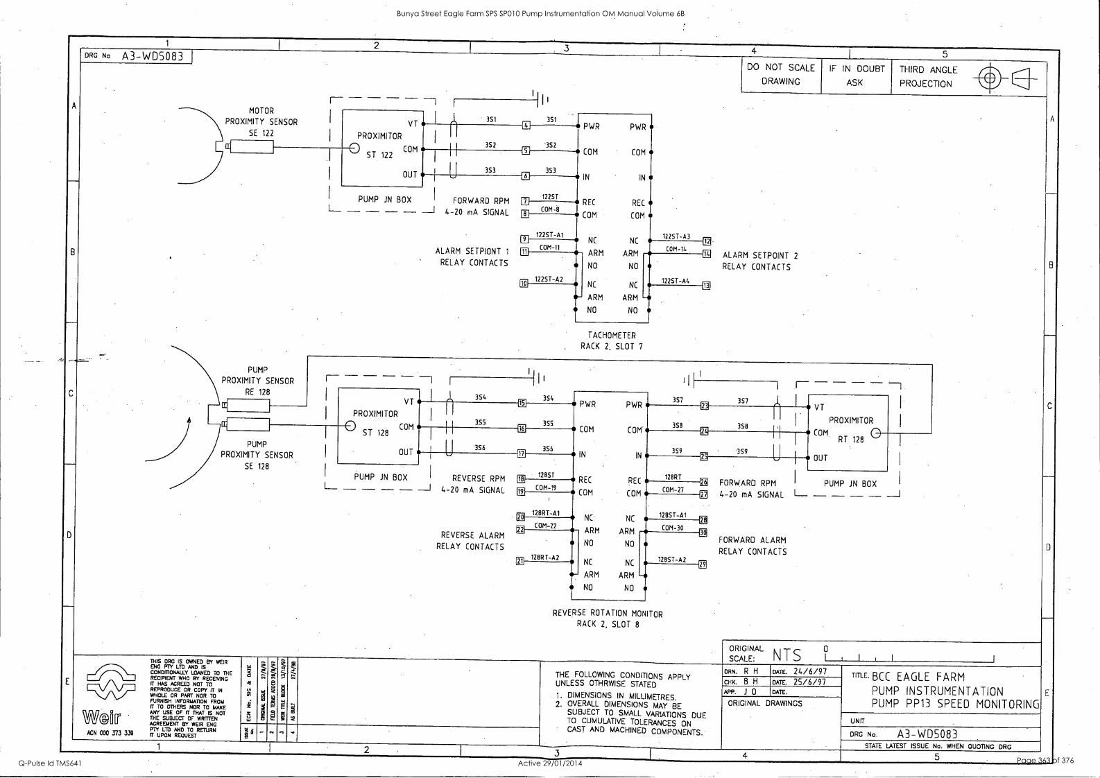
1 [ 2 H
. 4 I 5
A
B
___
_
C
-
D
-
E
DRG No A3-WD5083 DO NOT SCALE
DRAWING
IF IN DOUBT
ASK
THIRD ANGLE
A
B
C
-
0
PROJECTION it - - - - II, i-- --1 1
MOTOR
PROXIMITY SENSOR I VT
PROXIMITOR
0 ST 122 COM
OUT
- 351 351 PWR PWR
COM COM
IN IN
REC REC
COM COM
NC NC 12251-A3
12
SE 122
352 '352 CE
I I
353 3S3
PUMP
SENSOR
RE 128
4-20
ALARM
RELAY
6
.
-....PROXIMITY
PUMP JN BOX
L-- - - - - --I FORWARD RPM
mA SIGNAL
SETPIONT 1
CONTACTS
12251 p COM-8
1225T-Al LI
COM-11 COM-14 ill m
12251-A2 10
ARM ARM
NO NO
NC NC
ARM ARM
NO NO
ALARM SETPOINT 2
RELAY CONTACTS
12251-A4 LE
TACHOMETER
RACK 2, SLOT 7
- - -1 I
I I _ _ -7 I
els 354
____ 354
PWR 357 357 et VT
VT 121
355
PWR
358
EE 1 CC
I
I [ 355
3S8 COM ST 128
OUT
16
n 355
COM COM.
IN 359
ET
comPROXIMITOR
RT 128
OUT
PUMP
PROXIMITY SENSOR U 356
3S9 U I IN
REC 128RT
EE
SE 128
PUMP I RPM 18 12851
I PUMP JN BOX JN BOX REVERSE
L__ ___ - - - ___I 4-20 mA SIGNAL
REVERSE ALARM
RELAY CONTACTS
19 COM -19
REC
COM (UM -27 FORWARD RPM
,, 4 -20 mA SIGNAL L-- - - - - ---1
128RT-Al EC
COM
NC NC 128ST-A1
COM-22 ARM COM-30 ,1 ---
128RT-A2
ARM
NO NO
NC NC
FORWARD ALARM
RELAY CONTACTS 1285T-A2 FE
it. ARM ARM
NO NO
Ell -
REVERSE ROTATION MONITOR
RACK 2, SLOT 8
ORIGIN
SCALE:
AL 0 NTS I I , I THIS DRG IS OWNED BY WEIR
ENG FT?' LTD AND IS CONDMONALLY LOANED TO THE RECIPIENT WHO BY RECEIVING IT HAS AGREED NOT TO REPRODUCE OR COPY IT IN Vv WHOLE OR PART NOR TO FURNISH INFORMATION FROM IT TO OTHERS NOR TO MAKE
WG1ITI ANY USE OF IT THAT IS NOT THE SUBJECT OF WRITTEN AGREEMENT BY WEIR ENG
339 MY OD AND TO RETURN
ACN 000 373 3JV FT UPON REQUEST
g Al
2 vi
ei
z 5 t.,
2
- -, ,
, i _, 2 g
M
- - -. ... § Q
g 0
p
Z ---, -
m ;
2 - -,... .
., M
THE FOLLOWING CONDITIONS APPLY UNLESS OTHRWISE STATED
1. DIMENSIONS IN MILLIMETRES. 2. OVERALL DIMENSIONS MAY BE
SUBJECT TO SMALL VARIATIONS DUE TO CUMULATIVE TOLERANCES ON
- CAST AND MACHINED COMPONENTS. .
om R H DATE. 24/6/97 TITLE. BCC EAGLE FARM PUMP INSTRUMENTATION PUMP PP13 SPEED MONITORING
K. B H DATE. 25/6/97 APP. i 0 DATE.
ORIGINAL DRAWINGS
UNIT
DRG No. A3-WDS083 '' 4 g
... ..,
STATE LATEST ISSUE No. WHEN QUOTING DRG 1 I 2 3 4 5
Bunya Street Eagle Farm SPS SP010 Pump Instrumentation OM Manual Volume 6B
Q-Pulse Id TMS641 Active 29/01/2014 Page 363 of 376
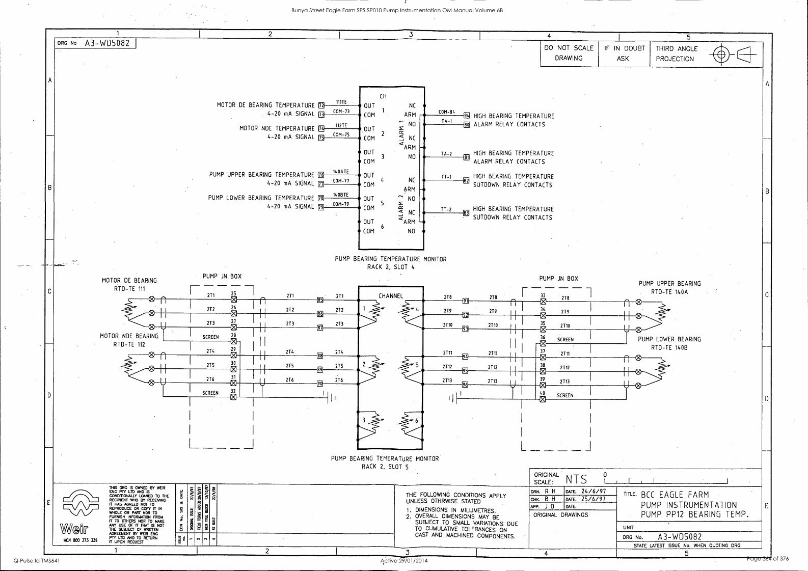
1 1 2
I 3 _
4 I
5
A
-
8
C
-
D
E
DRG No A3-WD5082 DO NOT SCALE
DRAWING
IF IN DOUBT
ASK
THIRD ANGLE ol
A
.--
B
C
--
U
-
E
PROJECTION yr
111TE MOTOR DE BEARING TEMPERATURE
CH
OUT NC 1
COM ARM 4-20 mA SIGNAL
MOTOR NDE TEMPERATURE
4-20 mA SIGNAL
PUMP UPPER BEARING TEMPERATURE
4-20 mA SIGNAL
PUMP LOWER BEARING TEMPERATURE
4-20 mA SIGNAL
- PUMP JN BOX
MOTOR DE BEARING
n 73 COM- COM-84
B HIGH BEARING TEMPERATURE
ALARM RELAY CONTACTS
12
'-- NO OUT x COM 2 < NC --I <
A R M OUT
3 NO COM
OUT
COM 4- NC
ARM
OUT ' NO
COM S
OUT
< NC _J <ARM
COM 6
NO
TA-1 112TE
- TA-2
t5 FE
Ei COM-75
140ATE
HIGH BEARING TEMPERATURE a ALARM RELAY CONTACTS
T7-1 ilJ COM- 77
HIGH BEARING TEMPERATURE
- TT-2
82 SUTOOWN RELAY CONTACTS EE
14087E
HIGH BEARING TEMPERATURE CE
SUTDOWN RELAY CONTACTS
PUMP JN BOX PUMP UPPER BEARING r -- - RTD-TE 140A
278 278
FE COM-79 El
PUMP BEARING TEMPERATURE MONITOR
RACK 2, SLOT 4
RTD -TE 111
271 25 271 2T1 CHANNEL 218 0 n 272 26
n LR
2T2 2T2
al 2T9 2T9 34
2T9
n
U
0 2T3 27
02
2T3 213
92
2110 2710
0 35
2110
Co
0 MOTOR NDE BEARING SCREEN 28
214 2T4 2T11
36 SCREEN PUMP LOWER BEARING
RTD-TE 112
214
cl 29
kT,
30
2111
L. 37
2711
RTD-TE 1408
:-s) n 275
CE
275 275
CB
2712 2112
0 38
0 39
2112
n 0-
0 U 276
0 31
0 32
m
2T6 2T6
95
2713 2713 2713
SCREEN
DI
I
rr., EY 40
SCREEN V 0 III 0
L _ _ L i _ _I _ _ _ _ PUMP BEARING TEMERATURE MONITOR
RACK 2, SLOT 5
SCALE
ORIGINAL 0
: N T S 1 I . 1
THIS (AG IS OWNED BY WEIR
EZDM L','"' ID TO THE RECIPIENT WHO BY RECEMNG IT HAS AGREED NOT TO REPRODUCE OR COPY if IN WHOLE OR PART NOR TO FnUIZISH INFORMATION FROM FROME
ANY USE OF R THAT IS NOT THE SUBJECT OF WRITTEN WeGkr AGREEMENT BY WEIR ENG PTY LTD AND TO RETURN
ACN 000 373 339 if UPON RECUEST
5 41
iin2 i = 8
6-
',.. c....
i
' I <,4
§
g m
g
;-;
g p . W
Z ,S C.
,,,
2
THE FOLLOWING CONDITIONS APPLY UNLESS OTHRWISE STATED
1. DIMENSIONS IN MILLIMETRES. 2. OVERALL DIMENSIONS MAY BE
SUBJECT TO SMALL VARIATIONS DUE TO CUMULATIVE TOLERANCES ON CAST AND MACHINED COMPONENTS.
DRN. R H DATE. 24/6/97 TITLE. BCC EAGLE FARM
PUMP INSTRUMENTATION PUMP PP12 BEARING TEMP.
CHK. B H DATE. 25/6/97 APP. J Q DATE.
ORIGINAL DRAWINGS
UNIT
DRG No. A3-WD5082 g 1 2
- .., n
STATE LATEST ISSUE No. WHEN QUOTING DRG 1
I 2 3 4 5 ,_
Bunya Street Eagle Farm SPS SP010 Pump Instrumentation OM Manual Volume 6B
Q-Pulse Id TMS641 Active 29/01/2014 Page 364 of 376

L 2 3 I 5
A
-
B
-
C
D
E
DRG No A3-WD5081 DO NOT SCALE
DRAWING
IF IN DOUBT
ASK
THIRD ANGLE
A
1-
B
C
D
E
PROJECTION low
PUMP JN BOX PUMP JN BOX
DRIVE END - - VELOMETER r WHITE 13
IS) I
2V10 2V10 CH A CH B
A A
B B
REC REC
COM COM
NC NC
ARM ARM
2V13 2V13
- 1 WHITE I
NON DRIVE END
- VELOMETER VE 111A/VT 111A
I BLACK 14
WV
2V11
@
1° VE 112A/VT 112A
CC 2V11 2V14 2V14 BLACK
I
0 15
gfi H i6I 2V12 2V15 1
19
[ I GREEN 16 r gfi En 0
20 GREEN -4 L___
-D.E. BEARING VIBRATION
I
111AVT
1111 1
I12AVT
1
I__
4-20 mA SIGNAL
D.E. VIBRATION ALARM
RELAY CONTACTS
N.D.E. VIBRATION ALARM
RELAY CONTACTS
14]
COM-60 tE
COM-68 N.D.E. BEARING VIBRATION
4-20 mA SIGNAL
D.E. SHUTDOWN ALARM
RELAY CONTACTS
N.D.E. SHUTDOWN ALARM
II
4,-. 111AVT-A
Cr
69
111AVT-T 69
COM-71
NO NO
NC NC
po
m 112AVT-T
1 COM-63 - RELAY CONTACTS
ty 112AVT-A ARM ARM
NO NO
PUMP MOTOR BEARING MONITOR
RACK 2, SLOT 3
.
SCALE:
ORIGINAL NTS 1
0 ,1,1 THIS CMG IS OWNED BY WEIR
CgoPrg LIDYANIANIsED TO THE RECIPIENT WHO BY RECEMNG TT HAS AGREED NOT TO REPRODUCE OR COPY IT IN WHOLE OR PART NOR TO FURNISH INFORMATION FROM FROM
MAKE
WI2 kr ANY USE OF IT THAT IS NOT THE SUBJECT OF WRITTEN AGREEMENT BY WEIR ENG PTY LTD AND TO RETURN
ACN 000 373 33u R UPON REQUEST
w g ict,
,71
IT
3 Li
2 , -::
g
2 ,.. ,S g
0 Z -
g g
;
S ... $ THE FOLLOWING CONDITIONS APPLY
UNLESS OTHRWISE STATED
1. DIMENSIONS IN MILLIMETRES. 2. OVERALL DIMENSIONS MAY BE
SUBJECT TO SMALL VARIATIONS DUE TO CUMULATIVE TOLERANCES ON CAST AND MACHINED COMPONENTS.
DRN. R H DATE. 24/6/97 TITLE. BCC EAGLE FARM
PUMP INSTRUMENTATION PUMP PP12 VIBRATION
CHK. B H DATE. 25/6/97 APP. J 0 DATE.
ORIGINAL DRAWINGS
UNIT
DRG No. A3-WD5081 '' 4 2
_ N. , ....
STATE LATEST ISSUE No. WHEN QUOTING DRG 1 2 3 4 5
Bunya Street Eagle Farm SPS SP010 Pump Instrumentation OM Manual Volume 6B
Q-Pulse Id TMS641 Active 29/01/2014 Page 365 of 376
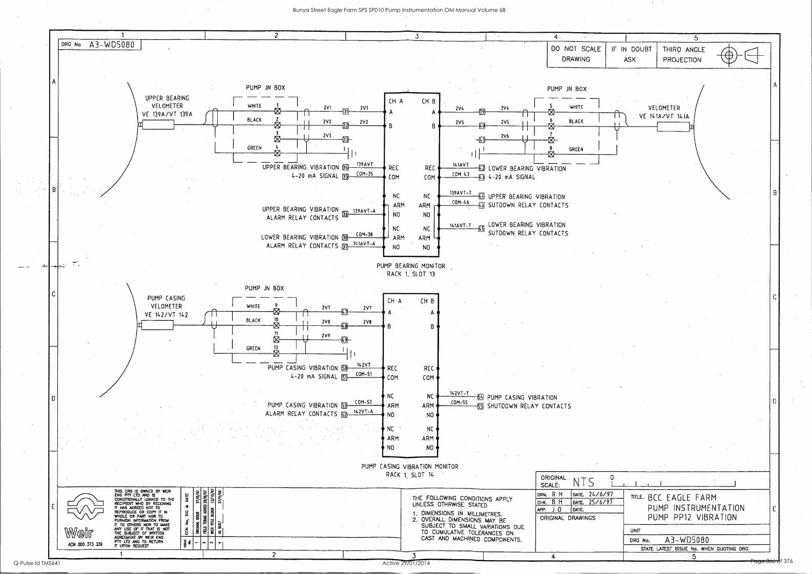
1 I
2 I
3 4. ,
I 5
A
__.
C
___
D
E
DRG No A3-WD5080 DO NOT SCALE
DRAWING
IF IN DOUBT
ASK
THIRD ANGLE le,
PROJECTION le,
A
C
----1
D
E
.
PUMP JN BOX .
PUMP JN BOX
UPPER BEARING
VELOMETER
- - ---1
-- WHITE 1
0 I
2V1 2V1 al
CH A CH B
A A
B B
REC REC
COM COM
NC NC
2V4 2V4 Ug
I 5 WHITE VELOMETER VE 139A/VT 139A
BLACK 2
n 2V2 I BLACK
VE 141A/VT 141A 1 '
1 1 2V2 2V5 2V5 0 1 I
ffi
2V3
e 7
w [1:1
I
I GREEN
3 2V6 0
4 I I
C L.
8 GREEN I
L____ -"J UPPER
UPPER
ALARM
LOWER
ALARM
_- ..
PUMP JN
BEARING VIBRATION
4-20 mA SIGNAL
BEARING VIBRATION
RELAY CONTACTS
BEARING VIBRATION
RELAY CONTACTS
BOX - 7 9 2V7 0
I II 139AVT
M
III 141AVT
L- -- _ E
I
COM 35 COM 43 LOWER BEARING VIBRATION
0 4-20 mA SIGNAL
=I EEI UPPER BEARING VIBRATION
ff3 SUTDOWN RELAY CONTACTS'
LOWER BEARING VIBRATION N
SUTDOWN RELAY CONTACTS
PE PUMP CASING VIBRATION
SHUTDOWN RELAY CONTACTS
139AVT-A Virl
139AVT-T
COM-46 - ARM ARM
NO NO
NC NC 141AVT-T
COM-38 fiE
141AVT-A ARM ARM - NO NO g h
PUMP BEARING MONITOR.
RACK 1, SLOT 13
PUMP CASING
VELOMETER
i- - - I WHITE 2V7
CH A CH B
VE 142/VT 142 BLACK 10
n Et
2V8
A A A. M 0
11
°
LE B B
1 1 2V9
I GREEN 12 I U N I
L._ ____I
PUMP CASING
1 I
142VT VIBRATION
4-20 mA SIGNAL
PUMP CASING VIBRATION
ALARM RELAY CONTACTS
So
COM -51 REC REC
COM COM a
NC NC 142VT-T
COM-53 ARM ARM
COM-55 gE
142VT -A NO ai NO
NC ' NC
ARM ARM
NO NO
PUMP CASING VIBRATION MONITOR
RACK 1, SLOT 14 .
ORIGINAL 0
SCALE: NTS 1 1 , 1 1
THIS DRC IS OWNED BY WEIR
'Zgorio 'yAND IS ED TO THE RECIPIENT WHO BY RECEIVING ET HAS AGREED NOT TO REPRODUCE
PART O OR COPY ITO IN
FURNISH INFORMATION FROM IT TO OTHERS NOR TO MAKE
W6Mirr ANY USE OF IT THAT IS NOT THE SUBJECT OF WRITTEN AGREEMENT BY WEIR ENG
339 PTY LTD AND TO RETURN
ACN 000 373 3N IT UPON REQUEST
5
:,,i,
eT
z 6 LJ
kl ..
, 2 g a
: 0
t -
g ;
1 1 THE FOLLOWING CONDITIONS APPLY
UNLESS OTHRWISE STATED
1. DIMENSIONS IN MILLIMETRES. 2: OVERALL DIMENSIONS MAY BE
SUBJECT TO SMALL VARIATIONS DUE TO CUMULATIVE TOLERANCES ON CAST AND MACHINED COMPONENTS.
DRN. R H DATE. 24/6/97 TITLE' BCC EAGLE FARM
PUMP INSTRUMENTATION PUMP PP12 VIBRATION
CHK. B H DATE. 25/6/97 APP. J 0 DATE.
.... 1
ORIGINAL DRAWINGS .
S" ; UNIT
DRG No. A3-WD5080 ., ., - .. I
STATE LATEST ISSUE No. WHEN QUOTING DRG
1 2 I 3 4 5 _
Bunya Street Eagle Farm SPS SP010 Pump Instrumentation OM Manual Volume 6B
Q-Pulse Id TMS641 Active 29/01/2014 Page 366 of 376

1 1 2 3 4 I 5
B
D
DRG No A3-WD5079 DO NOT SCALE
DRAWING
IF IN DOUBT
ASK
THIRD ANGLE
A
B
C
D
E
PROJECTION le,
- - I
III
- --, I
MOTOR
PROXIMITY SENSOR
SE 112 I
VT
PROXIMITOR
° ST 112 COM
OUT
,1. 251 251 PWR PWR
COM COM
IN IN
REC REC
COM COM
NC NC 112S7 -A3
4
252 2S2 Et
PROXIMITY
PUMP
SENSOR
RE 119
U 253 253
I
FORWARD RPM
-20 mA SIGNAL
SETPIONT 1
CONTACTS
a
PUMP JN BOX
I---- - - - - ----I
I
4
ALARM
RELAY
11251 7
a COM-8
1125T-A1 9
COM -11 El
COM-14 ii
11257-A2 ill
ARM ARM
NO NO
NC NC
ARM ARM
NO NO
CM ALARM SETPOINT .2
RELAY CONTACTS
11251-A4 El
TACHOMETER
RACK 1, SLOT 11
_ ____ _ IIII - - - ----I ,i, 254.
IIII i n- - 254
® 257 257 ri., VT
PROXIMITOR I
VT
PROXIMITOR 255
PWR PWR
258
® '
I
255 258 COM ° ST 119
16
2S6 17
COM COM
259
IT COM RT 119 G
OUT I
PUMP 256 U 259
U PROXIMITY SENSOR I OUT
I RPM 18 119ST
IN IN
119RT REC
Or- SE 119
PUMP JN BOX I JN BOX REVERSE
L_- - - - - --I 4 -20 mA SIGNAL
REVERSE ALARM
RELAY CONTACTS
COM -19 REC
COM-27 EE FORWARD RPM PUMP
EE 4 -20 mA SIGNAL I--- - - - - -I 11
11:1
FORWARD ALARM
RELAY CONTACTS
11
El
119RT-A1 El
COM COM
1195T-A1
COM -22 NC
COM -30 El
119RT-A2
ARM ARM
NO NO
--
11951-A2 NC NC
ARM ARM
NO NO
--
REVERSE ROTATION MONITOR
RACK 1, SLOT 12
ORIGIN
SCALE: AL
NTS 10 I , I 1
THIS DRG IS OWNED BY WEIR
goil-Z "),,AND SED TO THE RECIPIENT WHO BY RECEMNG IT HAS AGREED NOT TO REPRODUCE OR COPY IT IN
WHOLE OR PART NOR TO FURNISH INFORMATION FROM IT TO OTHERS NOR TO MAKE
WM Fr
ANY USE OF TT THAT IS NOT THE SUBJECT OF WRITTEN AGREEMENT BY WEIR ENG PTY LTD AND TO RETURN
ACN 000 373 339 rr UPON REQUEST
4 41
S-2
z
,...
,..
1
i!' ,...
.., s
1 P
Z-; -
g ;
;".
'
THE FOLLOWING CONDITIONS APPLY UNLESS OTHRWISE STATED
1. . DIMENSIONS IN MILLIMETRES. 2. OVERALL DIMENSIONS MAY BE
SUBJECT TO SMALL VARIATIONS DUE TO CUMULATIVE TOLERANCES ON CAST AND MACHINED COMPONENTS.
DRN. R H DATE. 24/6/97 TITLE. BCC EAGLE FARM
PUMP INSTRUMENTATION PUMP PP12 SPEED MONITORING
CHK. B H DATE. 25/6/9 7
APP. J 0 DATE.
ORIGINAL DRAWINGS
UNIT
DRG No. A3-WD5079 S' 4 _
- ti ., ....
STATE LATEST ISSUE No. WHEN QUOTING DRG
1 5
Bunya Street Eagle Farm SPS SP010 Pump Instrumentation OM Manual Volume 6B
Q-Pulse Id TMS641 Active 29/01/2014 Page 367 of 376
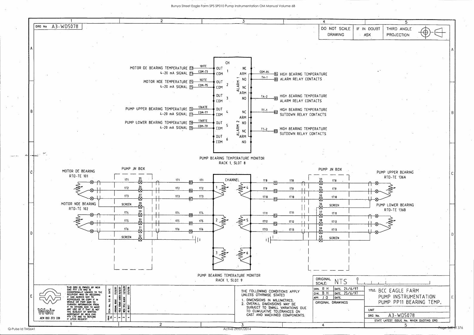
1 1
2 1_
3. I: 4 I
5 -
A
-
B
-
C
-'
D
____
E
DRG No A3-WD5078 DO NOT SCALE
DRAWING
IF IN DOUBT
ASK
THIRD ANGLE
A
__
B
-
(.:
--
I)
E
gig
PROJECTION le,
DE BEARING TEMPERATURE 1 101TE
CH
OUT NC 1
ARM
-
COM-84
MOTOR COM-73 4-20 mA SIGNAL n 102TE
MOTOR NDE TEMPERATURE
COM
- NO OUT m
COM 2 35 NC
OUT 3
<ARM
NO COM
OUT 4 NC
COM ARM
OUT 'N' NO
COM 5 Z
cr < NC _i
OUT <ARM
COM 6
NO
E2 HIGH BEARING TEMPERATURE TA-1
ALARM RELAY CONTACTS [1]
TA-2 HIGH BEARING TEMPERATURE
n COM-75 4-20 mA SIGNAL n
136ATE PUMP UPPER BEARING TEMPERATURE m
Cil ,
ALARM RELAY CONTACTS
TT-1 HIGH BEARING TEMPERATURE CE COM-77 4-20 mA SIGNAL SUTDOWN RELAY CONTACTS -
TT-2 HIGH BEARING TEMPERATURE
ft 1368TE
PUMP LOWER BEARING TEMPERATURE n COM -79 4-20 mA SIGNAL a i
EE SUTDOWN RELAY CONTACTS -
PUMP BEARING TEMPERATURE MONITOR
RACK 1, SLOT 8
PUMP JN BOX PUMP JN BOX MOTOR DE BEARING PUMP UPPER BEARING - - - -33- RTD-TE 101
- III 25
@ 111 111 CHANNEL 118 118
r -118 0,
RTD-TE 136A
C4
10 0
CR a!
119 n I 34 1T9
n ®
113 27
LE
113 113
11 I
1110 I 35 1T10 U®
MOTOR NDE BEARING
0 SCREEN 28
0 CB
H IT4 1T4
93 I
IT11 1111
I CI 36
SCREEN PUMP LOWER BEARING RTD-TE 102
114 29 I I
37 1111
RTD-TE 136B
0 0 115 30
CI
1 1
115 175 89
2 5
ZE
1112 1712 I 38
1112 e n ®
C4
116 31 176 116
ER
I713 1113 u 39 1113 e SCREEN 32
e EE ER
I
0 40
SCREEN 0
L _I
I
I
L J _ _ _ _ PUMP BEARING TEMERATURE MONITOR
RACK 1, SLOT 9 ORIGIN AL 0
N T S 1 I i SCALE: THIS DRC IS OWNED BY WEIR
COGKIPmra LTUYIANSED TO THE RECIPIENT WHO BY RECEMNG IT HAS AGREED NOT TO REPRODUCE OR COPY fr IN
WHOLE OR PART NOR TO FURNISH INFORMATION FROM IT TO OTHERS NOR TO MAKE
Wal[r THE USE
rrOFTUTENNOT AGREEMENT BY WEIR ENG
ACN 000 373 339 rPTIYug TELTEOSTRETURN
5 ie
g 0
4.
A
7.
: ,..
I 1
7.
r; ....
e Q , 6
t1
. -,, - g . g I
ti ,z: "
I
THE FOLLOWING CONDITIONS APPLY UNLESS OTHRWISE STATED
1. DIMENSIONS IN MILLIMETRES. 2. OVERALL DIMENSIONS MAY BE
SUBJECT TO SMALL VARIATIONS DUE TO CUMULATIVE TOLERANCES ON CAST AND MACHINED COMPONENTS.
DRN. R H DATE. 24/6/97 TITLE. BCC EAGLE FARM
PUMP INSTRUMENTATION PUMP PP11 BEARING TEMP.
CHK B H DATE. 25/6/97 APP. J 0 DATE.
ORIGINAL DRAWINGS
UNIT
DRG No. A3-WD5078 2
_ -, STATE LATEST ISSUE No. WHEN QUOTING DRG
1 2 1 3
I 4 5 -
Bunya Street Eagle Farm SPS SP010 Pump Instrumentation OM Manual Volume 6B
Q-Pulse Id TMS641 Active 29/01/2014 Page 368 of 376
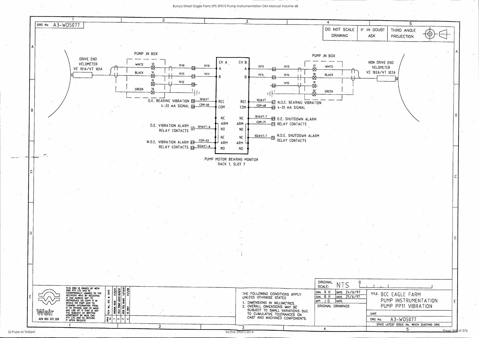
1
4 I 5
A
B
-
C
D
DRG No A3-WD5077 DO NOT SCALE
DRAWING
IF IN DOUBT
ASK
THIRD ANGLE
A
-
B
--
C
D
E
PROJECTION Nor
PUMP JN BOX .
PUMP JN BOX DRIVE END
VELOMETER F WHITE- 13 1V10 1V10
CH A CH B
A
B
A
B
REC REC
(OM COM
NC NC -
1V13 1V13 F 17 WHITE .. -4
NON DRIVE END
VELOMETER 101A/VT 101A
I BLACK 21----n54 18 BLACK
VE 102A/VT 102A 1V11 1V11 1V14 1V14
1 gfi 0
I I GREEN
1V12 a 1V15 19
0 16 I
gfi
I
I
102AVT
IV .. I
20 GREEN
I ____ ____ 5 D.E. BEARING
I
VIBRATION
I I 1
a 101AVT
II - - 4-20 mA SIGNAL
.
D.E. VIBRATION ALARM
RELAY CONTACTS
N.D.E. VIBRATION ALARM
RELAY CONTACTS
l
EE COM-60
Ei COM-68
N.D.E. BEARING VIBRA-TION- 4-20 mA SIGNAL
D.E. SHUTDOWN ALARM
RELAY CONTACTS 101AVT-A II
68
101AVT-T 1 COM-71 ARM ARM
NO NO
NC NC
Eit
102AVT-T N.D.E. SHUTDOWN ALARM COM-63 E
70 RELAY CONTACTS
102AVT-A ARM ARM -- NO NO EE
PUMP MOTOR BEARING MONITOR
RACK 1, SLOT 7
,
SCALE
ORIGINAL N T S 1 I , 1
THIS ORG IS OWNED BY WEIR Fctorm LTD
YA" ISED TO THE RECIPIENT WHO BY RECEIVING IT HAS AGREED NOT TO REPRODUCE OR COPY FT W WHOLE OR PART NOR TO FURNISH INFORMATION FROM IT TO OTHERS NOR TO MAKE
WO [le ANY USE OF fT THAT IS NOT THE SUBJECT OF WRITTEN AGREEMENT BY WEIR ENG PTY LTD AND TO RETURN ACN 000 J73 339 R UPON REQUEST
41
rn
z ,
,..
,- aN
1
.' m a
g M
P
.ii .-
;
. : CV
. -
THE FOLLOWING CONDITIONS APPLY UNLESS OTHRWISE STATED
1 . DIMENSIONS IN MILLIMETRES. 2. OVERALL DIMENSIONS MAY BE
SUBJECT TO SMALL VARIATIONS DUE TO CUMULATIVE TOLERANCES ON CAST AND MACHINED COMPONENTS.
:
DRN. R H DATE. 24/6/97 TITLE. BCC EAGLE FARM
PUMP INSTRUMENTATION PUMP PP11 VIBRATION
CHK. B H DATE. 25/6/97 APP. J 0 DATE.
ORIGINAL DRAWINGS
UNIT
DRG No. A3-WD5077 = ..,
STATE LATEST ISSUE No. WHEN QUOTING DRG 1
3 4 5 _
Bunya Street Eagle Farm SPS SP010 Pump Instrumentation OM Manual Volume 6B
Q-Pulse Id TMS641 Active 29/01/2014 Page 369 of 376
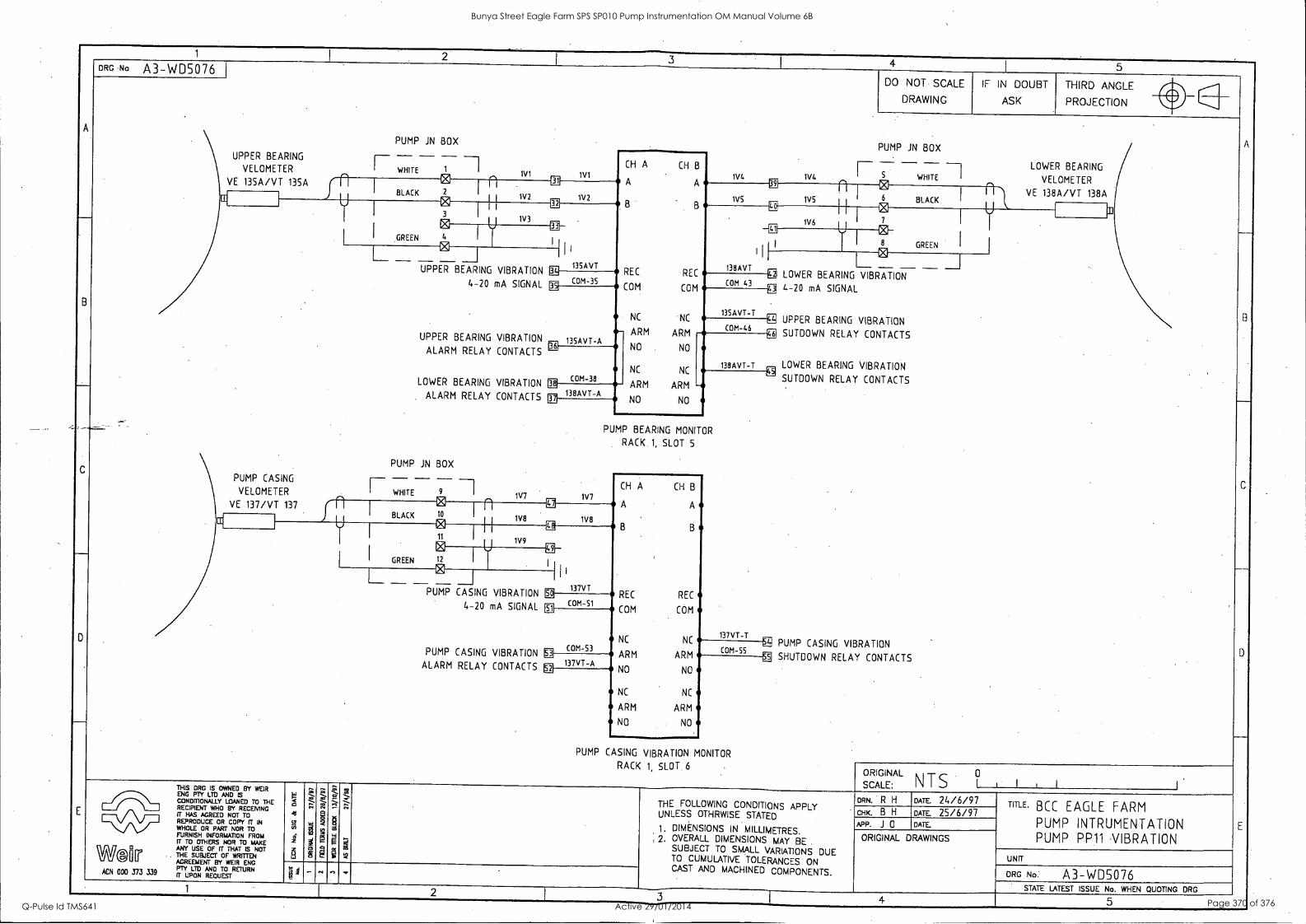
1 I 2
1 3
I 4 1 5
A
8
C
___
D
E
DRG No A3-WD5076 DO NOT SCALE
DRAWING
IF IN DOUBT
ASK
THIRD ANGLE
A
8
C
_
D
E
PROJECTION v.
PUMP JN BOX PUMP JN BOX
UPPER BEARING
VELOMETER
____ ___ _ WHITE - 1V1 1V1
CH A CH B
A A
B B
REC REC
COM COM
NC NC
f- - - - 1V4 1W, 5 WHITE
LOWER BEARING I VELOMETER VE 135A /VT 135A e 31
1V2 1V2
n n I
1VS 1V5
0 I n I VE 138A/VT 138A BLACK EL
BLACK
{
1
V Ci 32 g 1V6 1 1
I
1 -1 I GREEN
3 W3
° I
4 I
I I e GREEN I I
.
PUMP CASING
VELOMETER
I ° UPPER BEARING
I I I
135AVT
lid L ' 138AVT g BEARING VIBRATION _J
VIBRATION
4-20 mA SIGNAL
UPPER BEARING VIBRATION
ALARM RELAY CONTACTS
LOWER BEARING VIBRATION
ALARM RELAY CONTACTS
PUMP ill BOX
F WHITE- 9 -1 1V7 0
MI COM-35
LOWER COM 43 g 4-20 mA SIGNAL
135AVT-A .
135AVT-T 'ffl. UPPER BEARING VIBRATION
XI SUTDOWN RELAY CONTACTS
, LOWER BEARING VIBRATION
SUTOOWN RELAY CONTACTS
PUMP CASING VIBRATION
SHUTDOWN RELAY CONTACTS
COM -46 -- ARM ARM
NO NO
NC NC 138AVT-T
gr21
COM-38 gi- 138AVT-A
ARM ARM -- NO NO 12
PUMP BEARING MONITOR
RACK 1, SLOT 5
1V7 VE
CH A CH B
A A VE 137/VT 137 rl BLACK 10
n 1V13
B B iro
WE CC
11
LE
1V9
I I GREEN
e 12 I
L - - 0 I
137VT PUMP CASING VIBRATION
4-20 mA SIGNAL
PUMP CASING VIBRATION ALARM RELAY CONTACTS
so COM- 51
REC REC
COM COM 51
NC 137VT-T
COM-53 -- NC
ARM ARM COM-55 11
137VT-A N
.11 NO NO
NC NC
ARM ARM
NO NO
PUMP CASING VIBRATION MONITOR
RACK 1, SLOT 6 ORIGINAL s CALE: I I 1 I N T S
0
THIS DRG IS OWNED BY WEIR
liNOGNOFMrY0 1-113YANIANSED TO THE RECIPIENT WHO BY RECEMNG IT HAS AGREED NOT TO REPRODUCE OR COPY IT IN vv WHOLE OR PART NOR TO IFURNISH INFORMATION FRO ME
ANY USE OF IT THAT IS NOT 11
THE SUBJECT OF WRITTEN a AGREEMENT BY WEIR ENG PTY LTD AND TO RETURN ACN 000 373 339 if UPON REQUEST
t a
111 i 3 La
ZZ .:.-1-. .
i 2. a
-7:- . ,c,i
: 0
5,- -
1
'
-Z-- -
,,,
g
THE FOLLOWING CONDITIONS APPLY UNLESS OTHRWISE STATED
1. DIMENSIONS IN MILLIMETRES, 2. OVERALL DIMENSIONS MAY BE
SUBJECT TO SMALL VARIATIONS DUE TO CUMULATIVE TOLERANCES ON CAST AND MACHINED COMPONENTS.
DRN. R H DATE. 24/6/97 TITLE. BCC EAGLE FARM
PUMP INTRUMENTATION PUMP PP11 VIBRATION
CHK. B H DATE. 25/6/97 APP. J 0 DATE.
ORIGINAL DRAWINGS
UNIT
DRG No. A3-WD5076 4 - . , *
STATE LATEST ISSUE No. WHEN QUOTING DRG 1 2 3 1 4 5
Bunya Street Eagle Farm SPS SP010 Pump Instrumentation OM Manual Volume 6B
Q-Pulse Id TMS641 Active 29/01/2014 Page 370 of 376

1 i 2 - 3 I
4 1 5
A
_
B
-
D
E
DRG 110 A3-WD5(387 DO NOT SCALE
DRAWING
IF IN DOUBT
ASK
THIRD ANGLE 411
_
C
D
E
PROJECTION li1
, ITEM No DESCRIPTION
1 2 CABLE DUCTING-40mmx5Omm 400
I 2 50. TERMINALS -. TELEMECHANIQUE WK4 /U 3 3 PROXIMITOR LABELS .
4 3 PROXIMITOR TRANSDUCERS
0
0
0
cz, . .....
5 1 DIN RAIL / 1111./11#11?° ...
1111
6 1 STAINLESS STEEL ENCLOSURE
0
° 0 PROXIMITOR
SENSOR
0
Notes
0 0
PROXIMITOR
SENSOR l.!..)
1. CABLE ENTRY FROM BOTTOM OF PANEL
2.
TO PROVIDE EASIER ACCESS
10 TERMINALS PER
JUNCTION BOX ARE REQUIRED TO PROVIDE 20% SPARE CAPACITY
O 0
, PROXIMITOR (Th SENSOR Q° ..)
......A
FRONT VIEW WITH COVER REMOVED
ORIGIN 1 I , SCALE:
AL NTS °
THIS DRG IS OWNED BY WEIR gg3G4DITZ LTDyAND IS
LOANED THE RECIPIENT WHO BY RECENING IT HAS AGREED NOT TO
DUCE 0 C IN El REPRODUCE OR PART
COPY TO
FURNISH INFORMATION FROM IT M OTHERS NOR TO MAKE
W®l[ri ANY USE OF IT THAT IS NOT THE SUBJECT OF WRITTEN AGREEMENT BY WEIR ENG
,n PT( LM AND TO RETURN ACN 000 373 339 IT UPON REQUEST
W < 41
(3 w
d z z 8
'"*. . i 2 §
0 '". e
as
LI '''-' f 4
-.1
THE FOLLOWING CONDITIONS APPLY UNLESS OTHRWISE STATED
1 . DIMENSIONS IN MILLIMETRES. 2. OVERALL DIMENSIONS MAY BE
SUBJECT TO SMALL VARIATIONS DUE TO CUMULATIVE TOLERANCES ON CAST AND MACHINED COMPONENTS.
DRN. R H WE 24/6/97 TITLE. BCC EAGLE FARM
PUMP INSTRUMENTATION PUMP TERMINAL BOX
CHK. B H DATE. 25/6/97 APP. J 0 DATE.
ORIGINAL DRAWINGS
UNIT
DRG No. A3-WDS291 1 1 - ". " STATE LATEST ISSUE No. WHEN QUOTING DRG
1 2 3 4 5
Bunya Street Eagle Farm SPS SP010 Pump Instrumentation OM Manual Volume 6B
Q-Pulse Id TMS641 Active 29/01/2014 Page 371 of 376
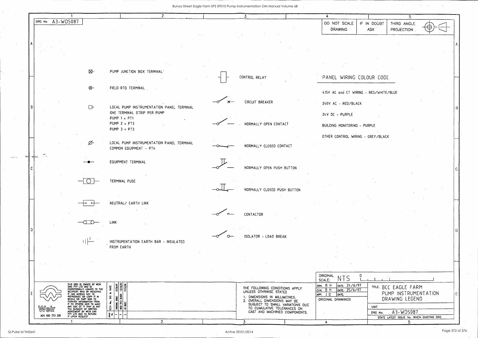
A
-
B
___.
D
E
1 1
2 .._ I
3 I
4 5 _-
A
_
8
____
C
0
E
DRG No A3-WD5087
PUMP JUNCTION BOX TERMINAL'
FIELD RTD TERMINAL
LOCAL PUMP INSTRUMENTATION PANEL TERMINAL
ONE TERMINAL STRIP PER PUMP
PUMP 1 = PT1
PUMP 2 = PT2
PUMP 3 = PT3
LOCAL PUMP INSTRUMENTATION PANEL TERMINAL
COMMON EQUIPMENT - PT4
EQUIPMENT TERMINAL TERMINAL
TERMINAL FUSE
NEUTRAL/ EARTH LINK
LINK
INSTRUMENTATION EARTH BAR - INSULATED
FROM EARTH
-
-CfX--
---Cl
-0---.-F-
-- -C.7°--
-OCI--
- CONTROL RELAY
CIRCUIT BREAKER
, NORMALLY OPEN CONTACT
NORMALLY CLOSED CONTACT
NORMALLY NORMALLY OPEN PUSH BUTTON
NORMALLY CLOSED PUSH BUTTON
CONTACTOR
ISOLATOR - LOAD BREAK
DO NOT SCALE
DRAWING
IF IN DOUBT
ASK
THIRD ANGLE A lik
IZ-
(8)-
El-
PROJECTION IRV
PANEL WIRING COLOUR CODE
415V AC and CT WIRING - RED/WHITE/BLUE
240V AC - RED/BLACK
24V DC - PURPLE
BUILDING MONITORING - PURPLE
OTHER CONTROL WIRING - GREY/BLACK
-41- -41-
-[ 0 H
-CED--
I I
FI__
0 ORIGINAL N T S SCALE: I 1 , 1 1
THIS OR IS OWNED BY WEIR
FOINDIP111.0( LTDYAND SED TO THE RECIPIENT WHO BY RECEMNG IT HAS AGREED NOT TO REPRODUCE OR COPY IT IN
WHOLE OR PART NOR TO fFillTSH INFORMATION I; IigTRiorrtmomE
ANY USE OF IT THAT IS NOT THE SUBJECT OF WRITTEN AGREEMENT BY WEIR ENG PlY LTD rr UPCN REQUEST
AND To RETURN
1
5 41
g i z el
G;
. g
621
5
t ..-; -
g ...1
N
III
,-- ....
.
THE FOLLOWING CONDITIONS APPLY UNLESS OTHRWISE STATED
1. DIMENSIONS IN MILLIMETRES. 2. OVERALL DIMENSIONS MAY BE
SUBJECT TO SMALL VARIATIONS DUE TO CUMULATIVE TOLERANCES ON CAST AND MACHINED COMPONENTS.
DRN. R H DATE. 24/6/97 TITLE. BCC EAGLE FARM
PUMP INSTRUMENTATION DRAWING LEGEND
CHIC B H DATE. 25/6/97 APP. J 0 DATE.
WG[irr ACN 000 373 339
ORIGINAL DRAWINGS
UNIT
DRG N.. A3-WD5087 1 - .. "
2 STATE LATEST ISSUE No. WHEN QUOTING DRG
3 4 5 ___
Bunya Street Eagle Farm SPS SP010 Pump Instrumentation OM Manual Volume 6B
Q-Pulse Id TMS641 Active 29/01/2014 Page 372 of 376
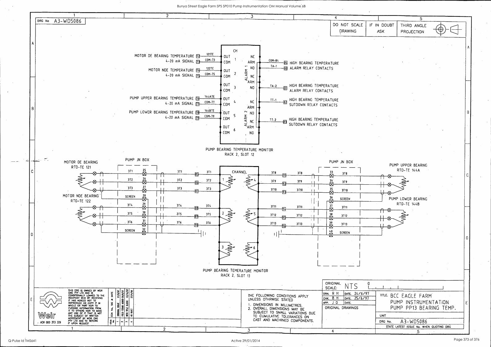
1 I 2
. 3 4 I 5
A
_
B
C
D
_
E
DRG No A3-WD5086 DO NOT SCALE
DRAWING
IF IN DOUBT
ASK
THIRD ANGLE
A
_
C
13
___
E
PROJECTION v.
1217E BEARING TEMPERATURE
CH
OUT NC
1 ARM COM -84 ,
MOTOR DE n 4-20 SIGNAL COM-73 mA
122TE MOTOR NDE TEMPERATURE
<-. NO
OUT
COM 2 ! NC <ARM
OUT 3 NO
COM
OUT
COM 4 NC
ARM -OUT
cs' NO S r
NC COM a
< OUT <ARM
COM 6
NO
TA -1 TS HIGH BEARING TEMPERATURE
CE ALARM RELAY CONTACTS
TA-2
2 COM-75 4-20 mA SIGNAL
HIGH BEARING TEMPERATURE ED
ALARM RELAY CONTACTS
HIGH BEARING TEMPERATURE [Ft
SUTDOWN RELAY CONTACTS
, HIGH BEARING TEMPERATURE
a
PUMP UPPER BEARING TEMPERATURE it 144ATE TT-1
4-20 mA SIGNAL
PUMP LOWER BEARING TEMPERATURE
4-20 mA SIGNAL
PUMP JN BOX MOTOR DE BEARING
COM-77
-11
TT-2
bi
144BTE ifi 79
COM-79
-- M
SUTDOWN RELAY CONTACTS
,
PUMP JN BOX PUMP UPPER BEARING
PUMP BEARING TEMPERATURE MONITOR
RACK 2, SLOT 12
RTD-TE 121 I 3T1 25
3T1 3T1 CHANNEL 3T8 r -33- -1 RTD-TE 144A 3T8 3T8 0 n 2)
3T2 26 n CR
312 372 1 4
a 379 379 I
e 34 379
n® 0 I
U 373 27 373 313
EE
3710 3110 1
@ 35
3710
MOTOR NDE BEARING SCREEN
ei 28 I
I I
1 I
374
LE a it
i
3111 3111
r 36
SCREEN PUMP LOWER BEARING RTD-TE 122
314
El 29
El 30
31
0 32
374
@
37 3T11
RTD-TE 144B
® n 315 -
I I 88
315 315 2 5
Ee
3T12 3112
- 38 3112 0 I I
U
"Cg
3T6 I
89 1 I
316 316 U
C@ i
3T13 3713 J El 39
3713 r ® SCREEN
CE
.
96
,40, SCREEN Ci
t&
__I L _ i _ _ _ _ PUMP BEARING TEMERATURE MONITOR
RACK 2, SLOT 13
ORIGIN
SCALE:
AL 0 N T S 1 1 , 1 1
THIS CRC IS OWNED BY WEIR ENG PTY LTD AND IS CONDITIONALLY LOANED TO THE RECIPIENT WHO BY RECEMNG IT HAS AGREED NOT TO REPRODUCE OR COPY IT IN WHOLE OR PART NOR TO trTUFZISH INFORINglt0.1rio FROM
WallT ANY USE OF IT THAT IS NOT THE SUBJECT OF WRITTEN AGREEMENT BY WEIR ENG PTY LTD AND TO RETURN
ACN 000 373 339 TT UPON REQUEST
,, F g 4
M i 3 u,
'a Zos 7:: .
Z co
7.4-
§
Q g 0
k. z , - 9 g
;
S --- 7:: ..,
:
THE FOLLOWING CONDITIONS APPLY UNLESS OTHRWISE STATED
1. DIMENSIONS IN MILLIMETRES. 2. OVERALL DIMENSIONS MAY BE
SUBJECT TO SMALL VARIATIONS DUE TO CUMULATIVE TOLERANCES ON CAST AND MACHINED COMPONENTS.
DRN. R H DATE. 24/6/97 TITLE. BCC EAGLE FARM PUMP INSTRUMENTATION PUMP PP13 BEARING TEMP.
CHK. B H DATE. 25/6/97 APP. J 0 DATE.
ORIGINAL DRAWINGS
UNIT
DRG No. A3-WD5086 1 4 - N n .,
STATE LATEST ISSUE No. WHEN QUOTING DRG 1 2 3 F 4 5
Bunya Street Eagle Farm SPS SP010 Pump Instrumentation OM Manual Volume 6B
Q-Pulse Id TMS641 Active 29/01/2014 Page 373 of 376
BRISBANE CITY COUNCIL Dept. Water Supply and Sewage Pumpwell No 1, Eagle Farm Pump Station
BCC Contract No S20/95/96 System Instrumentation
Operation and Maintenance Manual
Section 14 Training
Please consult Weir Engineering for Operator and Staff training on 02 4349 2999.
15140/Inst Man/BRH Issue 1 29-Apr-98 Page 14-1
Bunya Street Eagle Farm SPS SP010 Pump Instrumentation OM Manual Volume 6B
Q-Pulse Id TMS641 Active 29/01/2014 Page 374 of 376
BRISBANE CITY COUNCIL Dept. Water Supply and Sewage Pumpwell No 1, Eagle Farm Pump Station
BCC Contract No S20/95/96 System Instrumentation
Operation and Maintenance Manual
Section 15 List of Contract Variations and Plant Modifications
The following plant modifications were made:
1. Accelerometers replaced with Velometers to measure machine vibration.
2. Original pump junction boxes were increased in size to provide better maintenance access.
15140/Inst Man/BRH Issue 1 29-Apr-98 Page 15-1
Bunya Street Eagle Farm SPS SP010 Pump Instrumentation OM Manual Volume 6B
Q-Pulse Id TMS641 Active 29/01/2014 Page 375 of 376

BRISBANE CITY COUNCIL Dept. Water Supply and Sewage Pumpwell No 1, Eagle Farm Pump Station
BCC Contract No S20/95/96 System Instrumentation
Operation and Maintenance Manual
Section 16 Commissioning and Test Reports
A detailed Inspection and Test Plan (ITP) has been prepared for the on site pre- commissioning and commissioning of the pump system. The ITP together with all of the relevant testing data has been included in Volume 3.
15140/Inst Man/BRH Issue 1 29-Apr-98 Page 16-1
Bunya Street Eagle Farm SPS SP010 Pump Instrumentation OM Manual Volume 6B
Q-Pulse Id TMS641 Active 29/01/2014 Page 376 of 376
Related Documents