Bulk Current Injection Testing of Cable Noise Reduction Techniques, 50 kHz to 400 MHz Arthur T. Bradley #1 , Richard J. Hare #2 , Manisha Singh #3 NASA Langley Research Center 5 North Dryden, MS488, Hampton, VA 23681 USA 1arthur.t.bradley®nasa.gov 2richard.j.hare®nasa.gov 3manisha.singh-1®nasa.gov Abstract— This paper presents empirical results of cable noise reduction techniques as demonstrated using bulk current injection (BCI) techniques with radiated fields from 50 kHz - 400 MHz. It is a follow up to the two-part paper series presented at the Asia Pacific EMC Conference that focused on TEM cell signal injection. This paper discusses the effects of cable types, shield connections, and chassis connections on cable noise. For each topic, well established theories are compared with data from a real-world physical system. Keywords-bulk current injection; cable noise reduction I. INTRODUCTION Cable noise reduction techniques were investigated across a relatively broad frequency range (50 kHz – 400 MHz). The effectiveness of various noise reduction techniques were examined including the use of dedicated return wires, twisted wiring, cable shielding, shield connections, and implementing single-reference grounding. The experimental setup emulates a real-world electrical system, while still allowing us to independently vary a set of operating parameters. The data presented in this paper using bulk current injection (BCI) is complimentary to the data taken from similar testing using a transverse electromagnetic (TEM) cell [1], [2]. Data from both methods are briefly compared for similarities and differences. Other researchers have shown that both methods are valid cable testing methods for low to moderate frequencies [6]. For completeness, theory for the measurements is repeated in this paper. II. EXPERIMENT SETUP The electronic system shown in Fig. 1 consisted of two Hammond shielded electrical enclosures, one containing the source resistance, and the other containing the load resistance. The boxes were mounted on a large aluminium plate acting as the system chassis. Cables connecting the two boxes measured 50 cm in length and were attached to the boxes using BNC or D38999 military-style connectors. The full test setup is shown in Fig. 2. Electromagnetic fields were created using an HP8657B signal generator, AR 50WD1000 broadband amplifier, and ETS95236-1/95242-1 BCI probes. Measurements were taken using an Agilent E4401B spectrum analyzer and HP41800 probe. III. CABLE TYPES Common-mode and differential-mode currents can cause cables to act as unintentional radiators/receptors in electrical systems. Each is dependent on different properties of the cable and interference signal. Common-mode radiation has been shown to be proportional to cable length and signal frequency, whereas differential-mode radiation is proportional to the area enclosed by the differential mode current and the square of the signal frequency [3]. Reduction of common-mode radiation generally requires minimizing the common-mode current or common-mode signal frequency. As far as cabling, the only significant adjustments that can be made to reduce radiation and reception are to shield the cable, shorten the cable, or to isolate the offending cable with distance. Fig. 1 Electronic system Fig. 2 Experiment test setup https://ntrs.nasa.gov/search.jsp?R=20090030527 2018-06-17T23:42:42+00:00Z

Welcome message from author
This document is posted to help you gain knowledge. Please leave a comment to let me know what you think about it! Share it to your friends and learn new things together.
Transcript
Bulk Current Injection Testing of Cable NoiseReduction Techniques, 50 kHz to 400 MHz
Arthur T. Bradley#1 , Richard J. Hare#2 , Manisha Singh#3
NASA Langley Research Center5 North Dryden, MS488, Hampton, VA 23681 USA
1arthur.t.bradley®nasa.gov
2richard.j.hare®nasa.gov
3manisha.singh-1®nasa.gov
Abstract— This paper presents empirical results of cable noisereduction techniques as demonstrated using bulk currentinjection (BCI) techniques with radiated fields from 50 kHz - 400MHz. It is a follow up to the two-part paper series presented atthe Asia Pacific EMC Conference that focused on TEM cellsignal injection. This paper discusses the effects of cable types,shield connections, and chassis connections on cable noise. Foreach topic, well established theories are compared with datafrom a real-world physical system.
Keywords-bulk current injection; cable noise reduction
I. INTRODUCTION
Cable noise reduction techniques were investigated across arelatively broad frequency range (50 kHz – 400 MHz). Theeffectiveness of various noise reduction techniques wereexamined including the use of dedicated return wires, twistedwiring, cable shielding, shield connections, and implementingsingle-reference grounding. The experimental setup emulatesa real-world electrical system, while still allowing us toindependently vary a set of operating parameters.
The data presented in this paper using bulk currentinjection (BCI) is complimentary to the data taken fromsimilar testing using a transverse electromagnetic (TEM) cell[1], [2]. Data from both methods are briefly compared forsimilarities and differences. Other researchers have shownthat both methods are valid cable testing methods for low tomoderate frequencies [6]. For completeness, theory for themeasurements is repeated in this paper.
II. EXPERIMENT SETUP
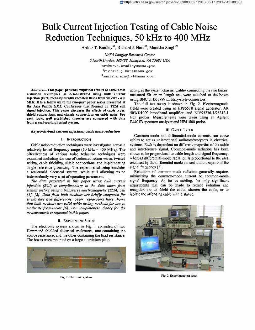
The electronic system shown in Fig. 1 consisted of twoHammond shielded electrical enclosures, one containing thesource resistance, and the other containing the load resistance.The boxes were mounted on a large aluminium plate
acting as the system chassis. Cables connecting the two boxesmeasured 50 cm in length and were attached to the boxesusing BNC or D38999 military-style connectors.
The full test setup is shown in Fig. 2. Electromagneticfields were created using an HP8657B signal generator, AR50WD1000 broadband amplifier, and ETS95236-1/95242-1BCI probes. Measurements were taken using an AgilentE4401B spectrum analyzer and HP41800 probe.
III. CABLE TYPES
Common-mode and differential-mode currents can causecables to act as unintentional radiators/receptors in electricalsystems. Each is dependent on different properties of the cableand interference signal. Common-mode radiation has beenshown to be proportional to cable length and signal frequency,whereas differential-mode radiation is proportional to the areaenclosed by the differential mode current and the square of thesignal frequency [3].
Reduction of common-mode radiation generally requiresminimizing the common-mode current or common-modesignal frequency. As far as cabling, the only significantadjustments that can be made to reduce radiation andreception are to shield the cable, shorten the cable, or toisolate the offending cable with distance.
Fig. 1 Electronic system Fig. 2 Experiment test setup
https://ntrs.nasa.gov/search.jsp?R=20090030527 2018-06-17T23:42:42+00:00Z
f__11RSR
"L
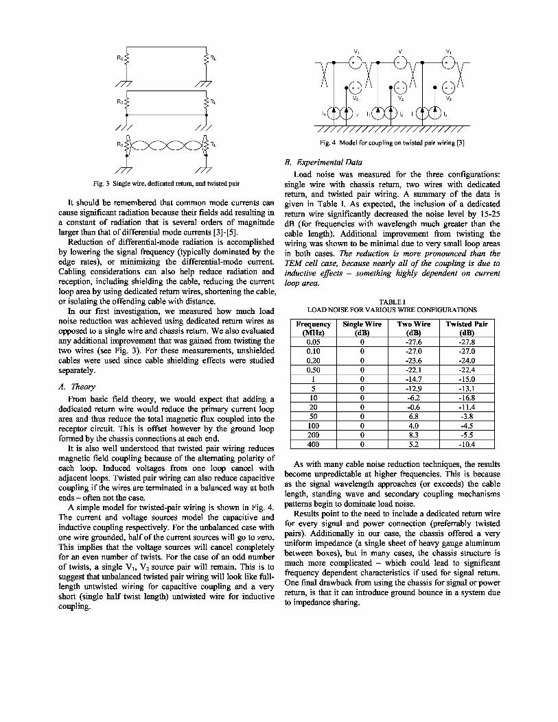
Fig. 3 Single wire, dedicated return, and twisted pair
It should be remembered that common mode currents cancause significant radiation because their fields add resulting ina constant of radiation that is several orders of magnitudelarger than that of differential mode currents [3]-[5].
Reduction of differential-mode radiation is accomplishedby lowering the signal frequency (typically dominated by theedge rates), or minimizing the differential-mode current.Cabling considerations can also help reduce radiation andreception, including shielding the cable, reducing the currentloop area by using dedicated return wires, shortening the cable,or isolating the offending cable with distance.
In our first investigation, we measured how much loadnoise reduction was achieved using dedicated return wires asopposed to a single wire and chassis return. We also evaluatedany additional improvement that was gained from twisting thetwo wires (see Fig. 3). For these measurements, unshieldedcables were used since cable shielding effects were studiedseparately.
A. Theory
From basic field theory, we would expect that adding adedicated return wire would reduce the primary current looparea and thus reduce the total magnetic flux coupled into thereceptor circuit. This is offset however by the ground loopformed by the chassis connections at each end.
It is also well understood that twisted pair wiring reducesmagnetic field coupling because of the alternating polarity ofeach loop. Induced voltages from one loop cancel withadjacent loops. Twisted pair wiring can also reduce capacitivecoupling if the wires are terminated in a balanced way at bothends – often not the case.
A simple model for twisted-pair wiring is shown in Fig. 4.The current and voltage sources model the capacitive andinductive coupling respectively. For the unbalanced case withone wire grounded, half of the current sources will go to zero.This implies that the voltage sources will cancel completelyfor an even number of twists. For the case of an odd numberof twists, a single V 1 , V2 source pair will remain. This is tosuggest that unbalanced twisted pair wiring will look like full-length untwisted wiring for capacitive coupling and a veryshort (single half twist length) untwisted wire for inductivecoupling.
Fig. 4 Model for coupling on twisted pair wiring [3]
B. Experimental DataLoad noise was measured for the three configurations:
single wire with chassis return, two wires with dedicatedreturn, and twisted pair wiring. A summary of the data isgiven in Table I. As expected, the inclusion of a dedicatedreturn wire significantly decreased the noise level by 15-25dB (for frequencies with wavelength much greater than thecable length). Additional improvement from twisting thewiring was shown to be minimal due to very small loop areasin both cases. The reduction is more pronounced than theTEM cell case, because nearly all of the coupling is due toinductive effects – something highly dependent on currentloop area.
TABLE ILOAD NOISE FOR VARIOUS WIRE CONFIGURATIONS
Frequency(MHz)
Single Wire(dB)
Two Wire(dB)
Twisted Pair(dB)
0.05 0 -27.6 -27.80.10 0 -27.0 -27.00.20 0 -23.6 -24.00.50 0 -22.1 -22.4
1 0 -14.7 -15.05 0 -12.9 -13.110 0 -6.2 -16.820 0 -0.6 -11.450 0 6.8 -3.8100 0 4.0 -4.5200 0 8.3 -5.5400 0 5.2 -10.4
As with many cable noise reduction techniques, the resultsbecome unpredictable at higher frequencies. This is becauseas the signal wavelength approaches (or exceeds) the cablelength, standing wave and secondary coupling mechanismspatterns begin to dominate load noise.
Results point to the need to include a dedicated return wirefor every signal and power connection (preferrably twistedpairs). Additionally in our case, the chassis offered a veryuniform impedance (a single sheet of heavy gauge aluminumbetween boxes), but in many cases, the chassis structure ismuch more complicated – which could lead to significantfrequency dependent characteristics if used for signal return.One final drawback from using the chassis for signal or powerreturn, is that it can introduce ground bounce in a system dueto impedance sharing.

IV. SHIELD CONNECTIONS
One of the most pervasive questions that integrators wrestlewith is how to effectively connect the cable shield. Manyoptions exist, including tying the shield to:
the chassis at the source and/or load using aconventional connector and pigtail connection,the chassis at the source and/or load using an EMIbackshell with 360 degree coverage,a “quiet ground” in the system by routing it through apin on the connector.
It is well understood that a shield can be an effective tool toreduce capacitive and inductive coupling. Numerous sourceshave shown that grounding the shield at one end will eliminatemuch of the capacitive coupling, but grounding it at both endsis required to reduce inductive coupling [1]-[5].
Unlike data taken with a TEM cell [1], [2], the BCI methodof signal injection is dominated by inductive coupling.Therefore, little if any reduction of induced noise is expectedfrom tying the shield to the chassis at one end when using BCIinjection. It should be made clear that this is not an indicationthat single-ended shielding is not useful, but rather is only acharacteristic of BCI testing. For that reason, capacitivecoupling is not discussed in this paper, rather the reader isreferred to [1] for additional information.
A. Inductive CouplingThe noise voltage at the source and load ends due to
inductive coupling can be approximated by
YSIND _ RS RSH (1)
RS +RLj(-)MNRlN
RSH +j(-)ܮSH
L RL + RS j c
VI _ _ RL RSHVoMNR IN
RSH + j(-)(
LSH
2)
where RS, RL, and RSH are the source, load, and shieldresistances, and MNR is the mutual inductance from the circuitwith noise current IN [3].
The effect of a shield is seen only in the last term of eachequation. If the shield is not connected at both ends, the shieldinductance will go to zero, driving the last term in theequations to unity – the shield thus offering no inductive noisereduction.
However, if the shield is grounded at both ends, themagnetic flux generated in the shield-to-ground plane circuitwill generate a corresponding voltage in the shield thatproduces a current that counteracts the induced noise current.
B. Pigtails and 360-degree EMI ConnectorsThe term “pigtail” is used to denote the break in the shield
required to tie it to ground – often at the backshell of theconnector. The effect of the exposed signal wire and pigtailextension of the shield is to allow noise coupling to both thesignal and shield. It is generally understood that the longer the
pigtail, the worse the effect. Experiments in a TEM cellshowed that minimizing the pigtail length/area can improvethe load noise by up to 5 dB [1].
Some connectors avoid the pigtail problem with backshellsspecifically designed to offer full coverage of the signal wires,(i.e. 360-degree shield connection). The performance of “EMI”connectors of this sort were compared to standard backshellsthat used pigtail connections. Fig. 5 shows the two connectortypes.
Fig. 5 EMI and standard pigtail connectors
C. Experimental DataIn our experiment, we measured the induced noise voltage
at the load while varying the shield connection. Table IIpresents a summary of the test results. The headings OO, SO,OS, SS, and SS-EMI denote the particular shield connection,where O stands for open and S stands for short. So forexample, OS indicates that the shield was left disconnected atthe source side and connected at the load side. For all cases,the same shielded twisted pair wire was used. The SS-EMIcase denotes a 360-degree connector versus the other standardconnector with pigtail. The SS-PIN case denotes routing theshield through a connector pin to a quiet ground inside the box.
TABLE IILOAD NOISE WITH VARIOUS SHIELD CONNECTIONS
Frequency(MHz)
OO(dB)
SO(dB)
OS(dB)
SS(dB)
SS-PIN(dB)
SS-EMI(dB)
0.05 0 -0.2 0.2 -3.3 -1.0 -12.40.10 0 -0.3 0.0 -4.9 -1.6 -14.40.20 0 -0.5 0.1 -6.7 -2.8 -17.90.50 0 -0.3 0.1 -10.2 -5.0 -23.4
1 0 -0.3 0.0 -12.2 -5.9 -27.65 0 0.7 0.8 -11.0 -5.0 -36.710 0 0.3 -0.1 -14.9 -6.5 -38.320 0 3.4 -0.1 -13.4 -6.1 -22.150 0 1.0 4.8 -6.7 0.1 -15.9100 0 -5.2 0.4 -13.7 -3.6 -25.8200 0 1.5 -6.2 -15.5 -3.0 -31.7400 0 -7.1 6.4 7.0 -7.7 -20.9
As expected, there was little noise reduction seen fromtying the shield to one side (either source or load). This isdifferent than TEM cell testing, because the dominantcoupling in BCI is magnetic and will not be reduced by single-ended shield connections.

SO
OS
—dr- SS`•^ fit— SS ‐ Pi n. 9 SS ‐EMIFrequency (MHz)
For shields tied to both ends, the reduction ranges from 3-7dB for very low frequencies – believed due to a tradeoffbetween shielding benefits and the ground loop and shieldcutoff characteristics. As frequency increases (but still belowX/20), effectiveness improves to 10-15 dB. The shielding isshown to be less effective by about 5-8 dB if routed through apin to an internal ground. Finally, the EMI backshell showedan improvement of 11-32 dB over other shieldingconfigurations.
As frequencies increased and the cable began to exceed theshort-cable approximation of X/20, the results becamedominated by standing wave patterns and secondary couplingpaths. Any potential benefit of shielding became unpredictable.Fig. 6 shows the actual measured load noise with the variousshield connections.
Fig. 6 Load noise with different shield connections
V. CHASSIS CONNECTIONS
It has been demonstrated by numerous researchers thatsignificant noise reduction can be achieved through single-reference ground strategies [3], [10]. Reductions are a resultof eliminating “ground loops” – noise introduced by grounddifferences, and by establishing smaller current loop areas –thus reducing electromagnetic susceptibility. However, thereremains some question as to the effectiveness of suchstrategies when applied to higher-frequency systems. Parasiticcapacitance and inductance allow for high-frequency signalsto return on uncontrolled paths. Furthermore, as wire lengthsbegin to approach the interference signal wavelength, standingwave patterns can degrade any potential improvement. In ourexperiment we are able to measure the benefits of single-reference versus multi-reference grounding up to 400 MHz fora very simple two-box system connected by a low-impedancechassis.
To examine the effects of single-reference grounding forhigher frequencies, we compared the load noise for twoconfigurations as shown in Fig. 7. The load noise measuredacross frequency is given in Fig. 8 and Fig. 9, with the secondplot focusing in on the low frequencies. Once again, thesinusoidal pattern in the first figure is due to the standingwave patterns for the cable.
Fig. 7 Single- and multi-point grounding connections (RS=100 n, RL=1 MΩ)
‐30 z,
‐40 0100 200 ', 300 400‐50‐60 ......... ......... •...... %...
‐70 r
‐80O
..^
0 ‐90 ': --s- Referenced at both sides
‐100‐110 ..... Single referenced
Frequency (MHz)
Fig. 8 Load noise for source, load, or grounds referenced to both sides
‐30‐40 0 ;? 2 +? 4 :: 6 :: 8 10
‐50‐60 ... .... . r
_ ‐70..Z -80 ...... .........-o . .. .. . . . .
‐90M .
IO .. . r-
--4- Referenced at both sides‐100 ^
^; I I f Single referenced‐110
Frequency (MHz)
Fig. 9 Load noise for source, load, or grounds referenced to both sides
Table III presents the data with noise levels normalized tothe multi-point ground (MPG) case. This is done todemonstrate the effect of establishing a single-point ground(SPG) connection without allowing other frequency-dependent factors to obfuscate the findings (e.g. parasiticcoupling, wavelength). For signals with wavelengths muchlonger than the cable length, the single-referenced connectiondemonstrated significantly reduced load noise (25-40 dB).
20
10
0
dc ‐ 10ZM ‐20J
‐30
‐40
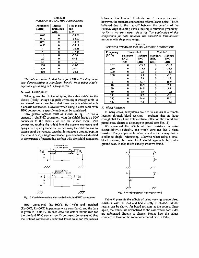
TABLE IIINOISE FOR SPG AND MPG CONNECTIONS
Frequency(MIIz)
Tied atboth ends(dB)
Tied at oneend(dB)
0.05 0 -39.610.10 0 -34.020.20 0 -30.760.50 0 -24.19
1 0 -25.485 0 -12.4810 0 -2.9820 0 6.4350 0 -1.41100 0 -3.02200 0 2.49400 0 -2.64
The data is similar to that taken for TEM cell testing, bothsets demonstrating a significant benefit from using single-reference grounding at low frequencies.
D. BNC ConnectionsWhen given the choice of tying the cable shield to the
chassis (likely through a pigtail) or routing it through a pin toan internal ground, we found that lower noise is achieved witha chassis connection. However when using a coax cable withBNC connection, a specific trade must be considered.
Two general options exist as shown in Fig. 10: use astandard 1-pin BNC connector, tying the shield through a 360°connector to the chassis, or use an isolated 2-pin BNCconnector, routing the shield into the system enclosure andtying it to a quiet ground. In the first case, the cable acts as anextension of the Faraday cage but introduces a ground loop. Inthe second case, a single-referenced ground can be establishedat the expense of penetrating the box with the shield conductor.
Fig. 10 Coaxial connections with standard or isolated BNC connections
Both unmatched (RS=100Ω, RL=1M52) and matched(RS=50Ω, RL=5052) impedances were considered, and the datais given in Table IV. In each case, the data is normalized forthe standard BNC connection. Experiments demonstrated thatthe isolated connections exhibited lower noise for frequencies
below a few hundred kilohertz. As frequency increasedhowever, the standard connections offered lower noise. This isbelieved due to the tradeoff between the benefits of theFaraday cage shielding versus the single-reference grounding.As far as we are aware, this is the first publication of thiscomparison for both matched and unmatched terminationsacross a wide frequency range.
TABLE IVNOISE FOR STANDARD AND ISOLATED BNC CONNECTIONS
Frequency(MIIz)
Unmatched MatchedStandardBNC(dB)
IsolatedBNC(dB)
StandardBNC(dB)
IsolatedBNC(dB)
0.05 0 -25.2 0 -31.30.10 0 -15.7 0 -22.10.20 0 -7.8 0 -13.80.50 0 5.8 0 -0.3
1 0 7.9 0 1.65 0 32.7 0 18.910 0 18.9 0 2.320 0 14.8 0 3.350 0 4.9 0 -10.1100 0 8.7 0 -6.9200 0 24.4 0 10.1400 0 7.6 0 -18.9
E. Bleed ResistorsIn many cases, subsystems are tied to chassis at a remote
location through bleed resistors – resistors that are largeenough that they have little electrical effect on the circuit, butpermit stray charge to discharge to ground (see Fig. 11).
We examined the effects of bleed resistors on noisesusceptibility. Logically, one would conclude that a bleedresistor of any appreciable value would act in a way that issimilar to single- referencing. Likewise when using a smallbleed resistor, the noise level should approach the multi-ground case. In fact, this is exactly what we found.
Fig. 11 Bleed resistors at load or source end
Table V presents the effects of using varying source bleedresistors, with the load end tied directly to chassis. Similarresults can be shown for bleed resistors at the source. Onceagain, the results are normalized to the case where both sidesare referenced directly to chassis. Notice how the valuescompare to those of the source-referenced case in Table III.

TABLE VLOAD NOISE FOR BLEED RESISTOR CONNECTIONS
Frequency(HHz)
Tied atbothends(dB)
BleedR=200(dB)
BleedR=10052(dB)
BleedR=1KΩ(dB)
0.05 0 -18.3 -29.7 -38.80.10 0 -14.5 -24.8 -33.30.20 0 -12.6 -21.9 -29.80.50 0 -8.6 -16.4 -23.2
1 0 -9.6 -17.8 -24.55 0 -1.4 -6.7 -11.810 0 0.8 0.8 -2.720 0 0.9 2.4 2.250 0 0.1 0.2 -2.2100 0 -3.3 -3.0 6.6200 0 2.1 2.7 12.3400 0 5.5 5.6 12.5
For any reasonably large bleed resistors (>1kΩ), the noiseapproaches that of single-point referencing, and as the bleedresistor decreases in value, the load noise approaches that ofthe multi-point ground. Once again this data is in generalagreement with that taken using a TEM cell.
VI. CONCLUSIONS
This paper focused on the effectiveness of cable noisereduction techniques with the system stimulated using bulk-current injection. The investigation is analogous to, andlargely in agreement with, measurements taken using a TEMcell [1], [2]. The fundamental conclusions are the same forboth experiments. First and foremost is the reductiontechniques only work reliably for electrically short cables. Inour case that related to a maximum frequency of about 10MHz. This reinforces the need to keep cable lengths shortwith respect to the interference signal wavelength.
The use of dedicated return was shown to reduce themagnetic coupling by about 15-27 dB. For additional noiseimmunity, the return can be twisted with the power or signalline. However twisting of cables does not reduce capacitivecoupling for unbalanced applications, and in ourmeasurements was shown to offer only minimal additionalimprovement in susceptibility.
Given that BCI couples energy into the cable usingmagnetic fields, this experiment did not allow the benefits ofsingle connection shielding to be measured. It did howeverconfirm that shielding connected at both sides can reduce theinductively coupled noise. Pigtail connections outperformedrouting the shield through a pin to an internal ground by about5-8 dB. EMI backshells were shown to offer an additional 11-32 dB of noise rejection over pigtails.
Results demonstrated the advantage of single-referencingthe electronic system to chassis. A noise reduction of up to 40dB was measured. A specific case with coax cable and BNCconnections was examined. Data suggests that at lowfrequencies, an isolated BNC connection with the shieldrouted to a ground inside the enclosure offered lower noisethan conventional connections. As frequency increasedhowever, the conventional case demonstrated lower noise dueto the improved shielding.
VII. REFERENCES[1] A..T. Bradley, TEM Cell Testing of Cable Noise Reduction Techniques
from 2 MHz to 200 MHz – Part 1, 2008 Asia Pacific EMC Symposium,Singapore, 2008.
[2] A..T. Bradley, TEM Cell Testing of Cable Noise Reduction Techniquesfrom 2 MHz to 200 MHz – Part 2, 2008 Asia Pacific EMC Symposium,Singapore, 2008.
[3] C.R. Paul, Introduction to Electromagnetic Compatibility, 2nd ed.,Wiley Interscience, New Jersey, 2006.
[4] H.W. Ott, Noise Reduction Techniques in Electronic Systems, 2nd ed.,Wiley Interscience, New York, 1988.
[5] D.A. Weston, Electromagnetic Compatibility Principles andApplications, 2nd ed., Marcel Dekker, New York, 2001.
[6] D.H. Trout, N.F. Audeh, Evaluation of Electromagnetic RadiatedSusceptibility Testing using Induced Currents, Aerospace Conference,1997.
[7] M. Mardiguian, Handbook Series on Electromagnetic Interference andCompatibility: Volume 2 – Grounding and Bonding, InterferenceControl Technologies, Virginia, 1988.
[8] R.B. Schulz, V.C. Plantz, and D.R. Brush, Shielding Theory andPractice, IEEE Transactions on Electromagnetic Compatibility, Vol. 30,No. 3, August 1988.
[9] K.L. Kaiser, Electromagnetic Compatibility Handbook, CRC Press,2005.
[10] H.W. Ott, Ground-a Path for Current Flow, IEEE Proceedings Int.Symposium Electromagnetic Compatibility, San Diego, CA 1979.
Related Documents