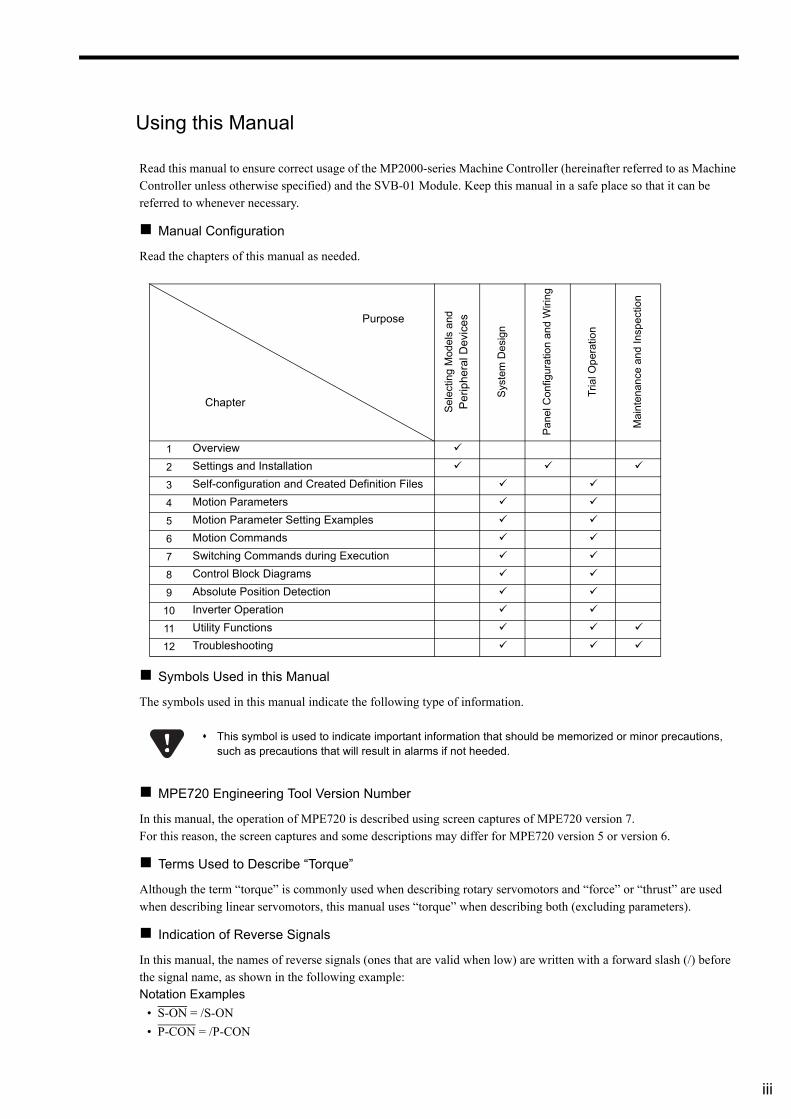
USER’S MANUAL MANUAL NO. SIEP C880700 33I Model: JAPMC-MC2100(-E), JEPMC-MP2400-E JAPMC-MC2102-E, JAPMC-MC2140(-E), JAPMC-MC2142-E, JEPMC-MP2300(-E), JEPMC-MP2300S-E, JAPMC-MC2310(-E) JEPMC-MP2310-E Built-in SVB/SVB-01 Motion Module Machine Controller MP2000 Series Overview Settings and Installation Self-configuration and Created Definition Files Motion Parameters Motion Parameter Setting Examples Motion Commands Switching Commands during Execution Control Block Diagrams Absolute Position Detection Inverter Operation Utility Functions Troubleshooting Appendices 1 2 3 4 5 6 7 8 9 10 11 12 App SVB-01 TX ERR RUN SPD SIZE M/S ON OFF × 10 × 1 M-I/II CN1 CN2

Welcome message from author
This document is posted to help you gain knowledge. Please leave a comment to let me know what you think about it! Share it to your friends and learn new things together.
Transcript
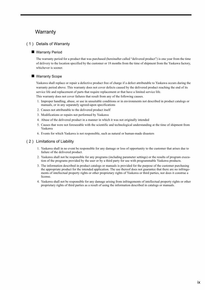
USER’S MANUAL
MANUAL NO. SIEP C880700 33I
Model: JAPMC-MC2100(-E), JEPMC-MP2400-EJAPMC-MC2102-E, JAPMC-MC2140(-E), JAPMC-MC2142-E, JEPMC-MP2300(-E), JEPMC-MP2300S-E, JAPMC-MC2310(-E)JEPMC-MP2310-E
Built-in SVB/SVB-01Motion Module
Machine Controller MP2000 Series
Overview
Settings and Installation
Self-configuration and Created Definition Files
Motion Parameters
Motion Parameter Setting Examples
Motion Commands
Switching Commands during Execution
Control Block Diagrams
Absolute Position Detection
Inverter Operation
Utility Functions
Troubleshooting
Appendices
1
2
3
4
5
6
7
8
9
10
11
12
App
SVB-01
TX
ERRRUN
SPDSIZEM/S
ONOFF
×10
×1
M-I/II
CN1
CN2

Copyright © 2007 YASKAWA ELECTRIC CORPORATION
All rights reserved. No part of this publication may be reproduced, stored in a retrieval system, or transmitted, in any form, or by any means, mechanical, electronic, photocopying, recording, or other-wise, without the prior written permission of Yaskawa. No patent liability is assumed with respect to the use of the information contained herein. Moreover, because Yaskawa is constantly striving to improve its high-quality products, the information contained in this manual is subject to change without notice. Every precaution has been taken in the preparation of this manual. Nevertheless, Yaskawa assumes no responsibility for errors or omissions. Neither is any liability assumed for damages result-ing from the use of the information contained in this publication.
iii
Using this Manual
Read this manual to ensure correct usage of the MP2000-series Machine Controller (hereinafter referred to as Machine Controller unless otherwise specified) and the SVB-01 Module. Keep this manual in a safe place so that it can be referred to whenever necessary.
Manual Configuration
Read the chapters of this manual as needed.
Symbols Used in this Manual
The symbols used in this manual indicate the following type of information.
MPE720 Engineering Tool Version Number
In this manual, the operation of MPE720 is described using screen captures of MPE720 version 7. For this reason, the screen captures and some descriptions may differ for MPE720 version 5 or version 6.
Terms Used to Describe “Torque”
Although the term “torque” is commonly used when describing rotary servomotors and “force” or “thrust” are used when describing linear servomotors, this manual uses “torque” when describing both (excluding parameters).
Indication of Reverse Signals
In this manual, the names of reverse signals (ones that are valid when low) are written with a forward slash (/) before the signal name, as shown in the following example: Notation Examples
• S-ON = /S-ON
• P-CON = /P-CON
Purpose
Chapter
Sel
ectin
g M
odel
s a
nd
Pe
riph
era
l Dev
ice
s
Sys
tem
Des
ign
Pa
nel C
onfig
urat
ion
and
Wiri
ng
Tria
l Op
erat
ion
Mai
nten
ance
an
d In
spec
tion
1 Overview
2 Settings and Installation
3 Self-configuration and Created Definition Files
4 Motion Parameters
5 Motion Parameter Setting Examples
6 Motion Commands
7 Switching Commands during Execution
8 Control Block Diagrams
9 Absolute Position Detection
10 Inverter Operation
11 Utility Functions
12 Troubleshooting
This symbol is used to indicate important information that should be memorized or minor precautions, such as precautions that will result in alarms if not heeded.
iv
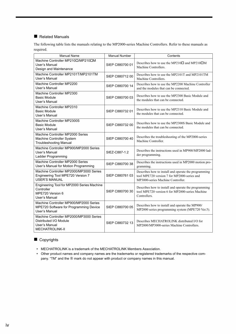
Related Manuals
The following table lists the manuals relating to the MP2000-series Machine Controllers. Refer to these manuals as required.
Copyrights
Manual Name Manual Number Contents
Machine Controller MP210/MP210MUser’s Manual Design and Maintenance
SIEP C880700 01 Describes how to use the MP210 and MP210M Machine Controllers.
Machine Controller MP2101T/MP2101TM User’s Manual
SIEP C880712 00 Describes how to use the MP2101T and MP2101TM Machine Controllers.
Machine Controller MP2200 User’s Manual
SIEP C880700 14 Describes how to use the MP2200 Machine Controller and the modules that can be connected.
Machine Controller MP2300 Basic Module User’s Manual
SIEP C880700 03 Describes how to use the MP2300 Basic Module and the modules that can be connected.
Machine Controller MP2310Basic ModuleUser’s Manual
SIEP C880732 01 Describes how to use the MP2310 Basic Module and the modules that can be connected.
Machine Controller MP2300SBasic ModuleUser’s Manual
SIEP C880732 00 Describes how to use the MP2300S Basic Module and the modules that can be connected.
Machine Controller MP2000 SeriesMachine Controller SystemTroubleshooting Manual
SIEP C880700 40 Describes the troubleshooting of the MP2000-series Machine Controller.
Machine Controller MP900/MP2000 SeriesUser’s Manual Ladder Programming
SIEZ-C887-1.2 Describes the instructions used in MP900/MP2000 lad-der programming.
Machine Controller MP2000 SeriesUser’s Manual for Motion Programming
SIEP C880700 38 Describes the instructions used in MP2000 motion pro-gramming.
Machine Controller MP2000/MP3000 Series Engineering Tool MPE720 Version 7USER’S MANUAL
SIEP C880761 03Describes how to install and operate the programming tool MPE720 version 7 for MP2000-series and MP3000-series Machine Controller.
Engineering Tool for MP2000 Series Machine ControllerMPE720 Version 6 User’s Manual
SIEP C880700 30Describes how to install and operate the programming tool MPE720 version 6 for MP2000-series Machine Controllers.
Machine Controller MP900/MP2000 SeriesMPE720 Software for Programming DeviceUser’s Manual
SIEP C880700 05 Describes how to install and operate the MP900/MP2000 series programming system (MPE720 Ver.5).
Machine Controller MP2000/MP3000 Series Distributed I/O Module User’s Manual MECHATROLINK-II
SIEP C880732 13 Describes MECHATROLINK distributed I/O for MP2000/MP3000-series Machine Controllers.
MECHATROLINK is a trademark of the MECHATROLINK Members Association.
Other product names and company names are the trademarks or registered trademarks of the respective com-
pany. “TM” and the ® mark do not appear with product or company names in this manual.
v
Safety Information
The following conventions are used to indicate precautions in this manual. These precautions are provided to ensure the safe operation of the MP2000-series Machine Controller and connected devices. Information marked as shown below is important for the safety of the user. Always read this information and heed the precautions that are provided.The conventions are as follows:
Indicates precautions that, if not heeded, could possibly result in loss of life, serious inju-ry, or property damage.
Indicates precautions that, if not heeded, could result in relatively serious or minor injury, or property damage.
If not heeded, even precautions classified under can lead to serious re-sults depending on circumstances.
Indicates prohibited actions. Specific prohibitions are indicated inside .
For example, indicates prohibition of open flame.
Indicates mandatory actions. Specific actions are indicated inside .
For example, indicates mandatory grounding.
WARNING
CAUTIONCAUTION
PROHIBITED
MANDATORY
vi
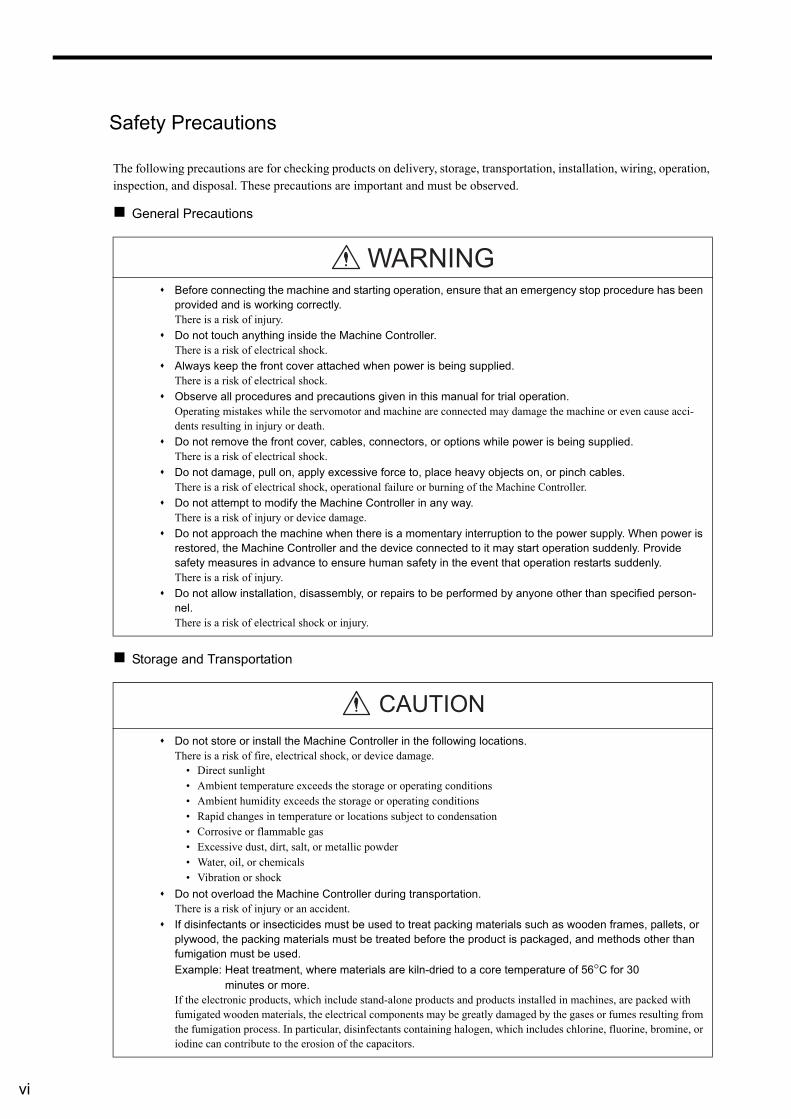
Safety Precautions
The following precautions are for checking products on delivery, storage, transportation, installation, wiring, operation, inspection, and disposal. These precautions are important and must be observed.
General Precautions
Storage and Transportation
Before connecting the machine and starting operation, ensure that an emergency stop procedure has been provided and is working correctly. There is a risk of injury.
Do not touch anything inside the Machine Controller.There is a risk of electrical shock.
Always keep the front cover attached when power is being supplied. There is a risk of electrical shock.
Observe all procedures and precautions given in this manual for trial operation. Operating mistakes while the servomotor and machine are connected may damage the machine or even cause acci-dents resulting in injury or death.
Do not remove the front cover, cables, connectors, or options while power is being supplied. There is a risk of electrical shock.
Do not damage, pull on, apply excessive force to, place heavy objects on, or pinch cables. There is a risk of electrical shock, operational failure or burning of the Machine Controller.
Do not attempt to modify the Machine Controller in any way.There is a risk of injury or device damage.
Do not approach the machine when there is a momentary interruption to the power supply. When power is restored, the Machine Controller and the device connected to it may start operation suddenly. Provide safety measures in advance to ensure human safety in the event that operation restarts suddenly. There is a risk of injury.
Do not allow installation, disassembly, or repairs to be performed by anyone other than specified person-nel. There is a risk of electrical shock or injury.
Do not store or install the Machine Controller in the following locations.There is a risk of fire, electrical shock, or device damage.
• Direct sunlight• Ambient temperature exceeds the storage or operating conditions• Ambient humidity exceeds the storage or operating conditions• Rapid changes in temperature or locations subject to condensation• Corrosive or flammable gas• Excessive dust, dirt, salt, or metallic powder• Water, oil, or chemicals• Vibration or shock
Do not overload the Machine Controller during transportation.There is a risk of injury or an accident.
If disinfectants or insecticides must be used to treat packing materials such as wooden frames, pallets, or plywood, the packing materials must be treated before the product is packaged, and methods other than fumigation must be used.
Example: Heat treatment, where materials are kiln-dried to a core temperature of 56°C for 30 minutes or more.If the electronic products, which include stand-alone products and products installed in machines, are packed with fumigated wooden materials, the electrical components may be greatly damaged by the gases or fumes resulting from the fumigation process. In particular, disinfectants containing halogen, which includes chlorine, fluorine, bromine, or iodine can contribute to the erosion of the capacitors.
WARNING
CAUTION
vii
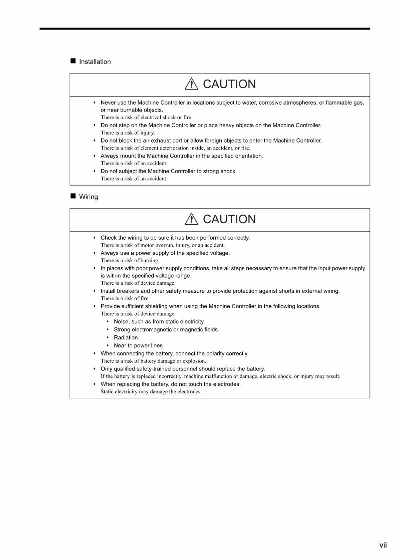
Installation
Wiring
Never use the Machine Controller in locations subject to water, corrosive atmospheres, or flammable gas, or near burnable objects. There is a risk of electrical shock or fire.
Do not step on the Machine Controller or place heavy objects on the Machine Controller. There is a risk of injury.
Do not block the air exhaust port or allow foreign objects to enter the Machine Controller. There is a risk of element deterioration inside, an accident, or fire.
Always mount the Machine Controller in the specified orientation.There is a risk of an accident.
Do not subject the Machine Controller to strong shock.There is a risk of an accident.
Check the wiring to be sure it has been performed correctly.There is a risk of motor overrun, injury, or an accident.
Always use a power supply of the specified voltage.There is a risk of burning.
In places with poor power supply conditions, take all steps necessary to ensure that the input power supply is within the specified voltage range. There is a risk of device damage.
Install breakers and other safety measure to provide protection against shorts in external wiring. There is a risk of fire.
Provide sufficient shielding when using the Machine Controller in the following locations. There is a risk of device damage.
Noise, such as from static electricity
Strong electromagnetic or magnetic fields
Radiation
Near to power lines
When connecting the battery, connect the polarity correctly. There is a risk of battery damage or explosion.
Only qualified safety-trained personnel should replace the battery.If the battery is replaced incorrectly, machine malfunction or damage, electric shock, or injury may result.
When replacing the battery, do not touch the electrodes.Static electricity may damage the electrodes.
CAUTION
CAUTION
viii
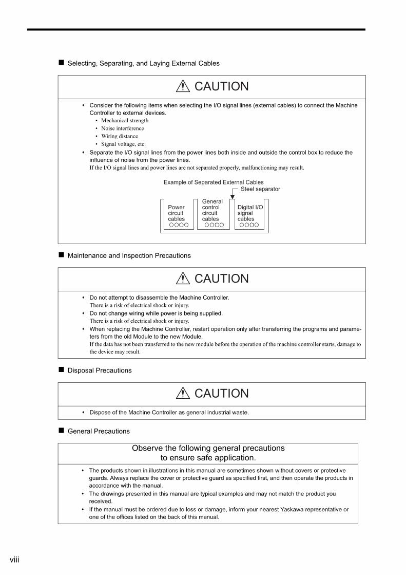
Selecting, Separating, and Laying External Cables
Maintenance and Inspection Precautions
Disposal Precautions
General Precautions
Consider the following items when selecting the I/O signal lines (external cables) to connect the Machine Controller to external devices.
• Mechanical strength• Noise interference• Wiring distance• Signal voltage, etc.
Separate the I/O signal lines from the power lines both inside and outside the control box to reduce the influence of noise from the power lines.If the I/O signal lines and power lines are not separated properly, malfunctioning may result.
Do not attempt to disassemble the Machine Controller.There is a risk of electrical shock or injury.
Do not change wiring while power is being supplied.There is a risk of electrical shock or injury.
When replacing the Machine Controller, restart operation only after transferring the programs and parame-ters from the old Module to the new Module.If the data has not been transferred to the new module before the operation of the machine controller starts, damage to the device may result.
Dispose of the Machine Controller as general industrial waste.
Observe the following general precautions to ensure safe application.
The products shown in illustrations in this manual are sometimes shown without covers or protective guards. Always replace the cover or protective guard as specified first, and then operate the products in accordance with the manual.
The drawings presented in this manual are typical examples and may not match the product you received.
If the manual must be ordered due to loss or damage, inform your nearest Yaskawa representative or one of the offices listed on the back of this manual.
CAUTION
Steel separator
Digital I/O signal cables
General control circuit cables
Power circuit cables
Example of Separated External Cables
CAUTION
CAUTION
ix
Warranty
( 1 ) Details of Warranty
Warranty Period
The warranty period for a product that was purchased (hereinafter called “delivered product”) is one year from the time of delivery to the location specified by the customer or 18 months from the time of shipment from the Yaskawa factory, whichever is sooner.
Warranty Scope
Yaskawa shall replace or repair a defective product free of charge if a defect attributable to Yaskawa occurs during the warranty period above. This warranty does not cover defects caused by the delivered product reaching the end of its service life and replacement of parts that require replacement or that have a limited service life.This warranty does not cover failures that result from any of the following causes.
1. Improper handling, abuse, or use in unsuitable conditions or in environments not described in product catalogs or manuals, or in any separately agreed-upon specifications
2. Causes not attributable to the delivered product itself
3. Modifications or repairs not performed by Yaskawa
4. Abuse of the delivered product in a manner in which it was not originally intended
5. Causes that were not foreseeable with the scientific and technological understanding at the time of shipment from Yaskawa
6. Events for which Yaskawa is not responsible, such as natural or human-made disasters
( 2 ) Limitations of Liability
1. Yaskawa shall in no event be responsible for any damage or loss of opportunity to the customer that arises due to failure of the delivered product.
2. Yaskawa shall not be responsible for any programs (including parameter settings) or the results of program execu-tion of the programs provided by the user or by a third party for use with programmable Yaskawa products.
3. The information described in product catalogs or manuals is provided for the purpose of the customer purchasing the appropriate product for the intended application. The use thereof does not guarantee that there are no infringe-ments of intellectual property rights or other proprietary rights of Yaskawa or third parties, nor does it construe a license.
4. Yaskawa shall not be responsible for any damage arising from infringements of intellectual property rights or other proprietary rights of third parties as a result of using the information described in catalogs or manuals.
x
( 3 ) Suitability for Use
1. It is the customer’s responsibility to confirm conformity with any standards, codes, or regulations that apply if the Yaskawa product is used in combination with any other products.
2. The customer must confirm that the Yaskawa product is suitable for the systems, machines, and equipment used by the customer.
3. Consult with Yaskawa to determine whether use in the following applications is acceptable. If use in the application is acceptable, use the product with extra allowance in ratings and specifications, and provide safety measures to minimize hazards in the event of failure.
• Outdoor use, use involving potential chemical contamination or electrical interference, or use in conditions or environments not described in product catalogs or manuals
• Nuclear energy control systems, combustion systems, railroad systems, aviation systems, vehicle systems, medical equipment, amusement machines, and installations subject to separate industry or government regula-tions
• Systems, machines, and equipment that may present a risk to life or property• Systems that require a high degree of reliability, such as systems that supply gas, water, or electricity, or sys-
tems that operate continuously 24 hours a day• Other systems that require a similar high degree of safety
4. Never use the product for an application involving serious risk to life or property without first ensuring that the sys-tem is designed to secure the required level of safety with risk warnings and redundancy, and that the Yaskawa product is properly rated and installed.
5. The circuit examples and other application examples described in product catalogs and manuals are for reference. Check the functionality and safety of the actual devices and equipment to be used before using the product.
6. Read and understand all use prohibitions and precautions, and operate the Yaskawa product correctly to prevent accidental harm to third parties.
( 4 ) Specifications Change
The names, specifications, appearance, and accessories of products in product catalogs and manuals may be changed at any time based on improvements and other reasons. The next editions of the revised catalogs or manuals will be pub-lished with updated code numbers. Consult with your Yaskawa representative to confirm the actual specifications before purchasing a product.
xi
Contents
Using this Manual - - - - - - - - - - - - - - - - - - - - - - - - - - - - - - - - - - - - - - - - - - - - - - - - - - - - - - - iii
Safety Information - - - - - - - - - - - - - - - - - - - - - - - - - - - - - - - - - - - - - - - - - - - - - - - - - - - - - - - v
Safety Precautions - - - - - - - - - - - - - - - - - - - - - - - - - - - - - - - - - - - - - - - - - - - - - - - - - - - - - - vi
Warranty - - - - - - - - - - - - - - - - - - - - - - - - - - - - - - - - - - - - - - - - - - - - - - - - - - - - - - - - - - - - - ix
1 Overview- - - - - - - - - - - - - - - - - - - - - - - - - - - - - - - - - - - - - - - - - - - - - - - - - - 1-1
1.1 SVB Module Overview and Features - - - - - - - - - - - - - - - - - - - - - - - - - - - - - - 1-21.1.1 SVB Modules - - - - - - - - - - - - - - - - - - - - - - - - - - - - - - - - - - - - - - - - - - - - - - - - - - - - - - - - - 1-21.1.2 Built-in SVB and Slot-mounting Optional SVB - - - - - - - - - - - - - - - - - - - - - - - - - - - - - - - - - - 1-21.1.3 Features- - - - - - - - - - - - - - - - - - - - - - - - - - - - - - - - - - - - - - - - - - - - - - - - - - - - - - - - - - - - - 1-21.1.4 System Configuration Example- - - - - - - - - - - - - - - - - - - - - - - - - - - - - - - - - - - - - - - - - - - - - 1-31.1.5 Devices and Cables Connectable to MECHATROLINK - - - - - - - - - - - - - - - - - - - - - - - - - - - - 1-41.1.6 Synchronization between Modules - - - - - - - - - - - - - - - - - - - - - - - - - - - - - - - - - - - - - - - - - - 1-7
1.2 Specifications - - - - - - - - - - - - - - - - - - - - - - - - - - - - - - - - - - - - - - - - - - - - - - - 1-91.2.1 SVB-01 Module Hardware Specifications- - - - - - - - - - - - - - - - - - - - - - - - - - - - - - - - - - - - - - 1-91.2.2 Specifications of SVB Module - - - - - - - - - - - - - - - - - - - - - - - - - - - - - - - - - - - - - - - - - - - - - 1-10
1.3 SVR Virtual Motion Module - - - - - - - - - - - - - - - - - - - - - - - - - - - - - - - - - - - - - 1-131.3.1 Overview - - - - - - - - - - - - - - - - - - - - - - - - - - - - - - - - - - - - - - - - - - - - - - - - - - - - - - - - - - - 1-131.3.2 Example of SVR Usage - - - - - - - - - - - - - - - - - - - - - - - - - - - - - - - - - - - - - - - - - - - - - - - - - 1-141.3.3 System Configuration Example- - - - - - - - - - - - - - - - - - - - - - - - - - - - - - - - - - - - - - - - - - - - 1-141.3.4 SVR Operation - - - - - - - - - - - - - - - - - - - - - - - - - - - - - - - - - - - - - - - - - - - - - - - - - - - - - - - 1-15
2 Settings and Installation - - - - - - - - - - - - - - - - - - - - - - - - - - - - - - - - - - - - - - - 2-1
2.1 LED Indicators and Switch Settings - - - - - - - - - - - - - - - - - - - - - - - - - - - - - - - 2-22.1.1 External Appearance - - - - - - - - - - - - - - - - - - - - - - - - - - - - - - - - - - - - - - - - - - - - - - - - - - - - 2-22.1.2 Indicators - - - - - - - - - - - - - - - - - - - - - - - - - - - - - - - - - - - - - - - - - - - - - - - - - - - - - - - - - - - - 2-22.1.3 SVB-01 Module Status Indication - - - - - - - - - - - - - - - - - - - - - - - - - - - - - - - - - - - - - - - - - - - 2-22.1.4 Switch Settings - - - - - - - - - - - - - - - - - - - - - - - - - - - - - - - - - - - - - - - - - - - - - - - - - - - - - - - - 2-4
2.2 Applicable Machine Controllers for SVB-01 Modules - - - - - - - - - - - - - - - - - - - 2-62.2.1 MP2000 Series - - - - - - - - - - - - - - - - - - - - - - - - - - - - - - - - - - - - - - - - - - - - - - - - - - - - - - - - 2-6
2.2.2 MP3000 Series - - - - - - - - - - - - - - - - - - - - - - - - - - - - - - - - - - - - - - - - - - - - - - - - - - - - - - - - 2-6
2.3 Mounting/Removing SVB-01 Modules - - - - - - - - - - - - - - - - - - - - - - - - - - - - - 2-82.3.1 Mounting an SVB-01 Module - - - - - - - - - - - - - - - - - - - - - - - - - - - - - - - - - - - - - - - - - - - - - - 2-82.3.2 Replacing and Adding an SVB-01 Module - - - - - - - - - - - - - - - - - - - - - - - - - - - - - - - - - - - - - 2-9
3 Self-configuration and Created Definition Files - - - - - - - - - - - - - - - - - - - - - - - 3-1
3.1 Self-configuration Overview - - - - - - - - - - - - - - - - - - - - - - - - - - - - - - - - - - - - - 3-2
3.2 Executing Self-configuration - - - - - - - - - - - - - - - - - - - - - - - - - - - - - - - - - - - - 3-4
3.3 System Startup Using Self-Configuration - - - - - - - - - - - - - - - - - - - - - - - - - - - 3-53.3.1 Starting the System for First Time - - - - - - - - - - - - - - - - - - - - - - - - - - - - - - - - - - - - - - - - - - - 3-53.3.2 System Startup when Adding Electronic Devices - - - - - - - - - - - - - - - - - - - - - - - - - - - - - - - - 3-83.3.3 System Startup when Replacing Electronic Devices - - - - - - - - - - - - - - - - - - - - - - - - - - - - - 3-10
xii
3.4 Self-configuration and Each Window - - - - - - - - - - - - - - - - - - - - - - - - - - - - - - 3-123.4.1 Module Configuration Definition Window- - - - - - - - - - - - - - - - - - - - - - - - - - - - - - - - - - - - - 3-133.4.2 MECHATROLINK Transmission Definition Window - - - - - - - - - - - - - - - - - - - - - - - - - - - - - 3-163.4.3 Motion Parameter Window - - - - - - - - - - - - - - - - - - - - - - - - - - - - - - - - - - - - - - - - - - - - - - 3-223.4.4 SERVOPACK Parameter Window - - - - - - - - - - - - - - - - - - - - - - - - - - - - - - - - - - - - - - - - - 3-31
4 Motion Parameters - - - - - - - - - - - - - - - - - - - - - - - - - - - - - - - - - - - - - - - - - - 4-1
4.1 Motion Parameters Register Numbers - - - - - - - - - - - - - - - - - - - - - - - - - - - - - - 4-24.1.1 Motion Parameter Register Numbers for MP2000 Series Machine Controllers - - - - - - - - - - - 4-2
4.2 Motion Parameters Setting Window - - - - - - - - - - - - - - - - - - - - - - - - - - - - - - - - 4-44.2.1 Opening the Motion Parameter Setting Windows - - - - - - - - - - - - - - - - - - - - - - - - - - - - - - - - 4-54.2.2 Motor Type and Related Alarms - - - - - - - - - - - - - - - - - - - - - - - - - - - - - - - - - - - - - - - - - - - - 4-6
4.3 Motion Parameter Lists - - - - - - - - - - - - - - - - - - - - - - - - - - - - - - - - - - - - - - - - - 4-74.3.1 Fixed Parameter List- - - - - - - - - - - - - - - - - - - - - - - - - - - - - - - - - - - - - - - - - - - - - - - - - - - - 4-74.3.2 Setting Parameter List- - - - - - - - - - - - - - - - - - - - - - - - - - - - - - - - - - - - - - - - - - - - - - - - - - - 4-94.3.3 Monitoring Parameter List - - - - - - - - - - - - - - - - - - - - - - - - - - - - - - - - - - - - - - - - - - - - - - - 4-15
4.4 MP2000 Series Machine Controller Parameter Details - - - - - - - - - - - - - - - - - - 4-194.4.1 Motion Fixed Parameter Details - - - - - - - - - - - - - - - - - - - - - - - - - - - - - - - - - - - - - - - - - - - 4-194.4.2 Motion Setting Parameter Details - - - - - - - - - - - - - - - - - - - - - - - - - - - - - - - - - - - - - - - - - - 4-264.4.3 Motion Monitoring Parameter Details - - - - - - - - - - - - - - - - - - - - - - - - - - - - - - - - - - - - - - - 4-58
5 Motion Parameter Setting Examples - - - - - - - - - - - - - - - - - - - - - - - - - - - - - - 5-1
5.1 Example Setting of Motion Parameters for the Machine - - - - - - - - - - - - - - - - - - 5-25.1.1 Reference Unit - - - - - - - - - - - - - - - - - - - - - - - - - - - - - - - - - - - - - - - - - - - - - - - - - - - - - - - - 5-25.1.2 Electronic Gear - - - - - - - - - - - - - - - - - - - - - - - - - - - - - - - - - - - - - - - - - - - - - - - - - - - - - - - 5-25.1.3 Axis Type Selection - - - - - - - - - - - - - - - - - - - - - - - - - - - - - - - - - - - - - - - - - - - - - - - - - - - - 5-45.1.4 Position Reference - - - - - - - - - - - - - - - - - - - - - - - - - - - - - - - - - - - - - - - - - - - - - - - - - - - - - 5-55.1.5 Speed Reference - - - - - - - - - - - - - - - - - - - - - - - - - - - - - - - - - - - - - - - - - - - - - - - - - - - - - - 5-95.1.6 Acceleration/Deceleration Settings - - - - - - - - - - - - - - - - - - - - - - - - - - - - - - - - - - - - - - - - - 5-115.1.7 Acceleration/Deceleration Filter Settings- - - - - - - - - - - - - - - - - - - - - - - - - - - - - - - - - - - - - 5-135.1.8 Linear Scale Pitch and Rated Speed - - - - - - - - - - - - - - - - - - - - - - - - - - - - - - - - - - - - - - - 5-14
6 Motion Commands - - - - - - - - - - - - - - - - - - - - - - - - - - - - - - - - - - - - - - - - - - 6-1
6.1 Motion Commands - - - - - - - - - - - - - - - - - - - - - - - - - - - - - - - - - - - - - - - - - - - - 6-36.1.1 Motion Command Table - - - - - - - - - - - - - - - - - - - - - - - - - - - - - - - - - - - - - - - - - - - - - - - - - 6-36.1.2 Motion Commands Supported by SERVOPACK Models- - - - - - - - - - - - - - - - - - - - - - - - - - - 6-4
6.2 Motion Command Details - - - - - - - - - - - - - - - - - - - - - - - - - - - - - - - - - - - - - - - 6-56.2.1 Position Mode (POSING) (Positioning) - - - - - - - - - - - - - - - - - - - - - - - - - - - - - - - - - - - - - - - 6-56.2.2 Latch Target Positioning (EX_POSING) (External Positioning) - - - - - - - - - - - - - - - - - - - - - 6-106.2.3 Zero Point Return (ZRET) - - - - - - - - - - - - - - - - - - - - - - - - - - - - - - - - - - - - - - - - - - - - - - - 6-156.2.4 Interpolation (INTERPOLATE) - - - - - - - - - - - - - - - - - - - - - - - - - - - - - - - - - - - - - - - - - - - - 6-356.2.5 Interpolation Mode with Latch Input (LATCH) - - - - - - - - - - - - - - - - - - - - - - - - - - - - - - - - - 6-396.2.6 Jog Mode (FEED)- - - - - - - - - - - - - - - - - - - - - - - - - - - - - - - - - - - - - - - - - - - - - - - - - - - - - 6-436.2.7 Relative Position Mode (STEP) (Step Mode) - - - - - - - - - - - - - - - - - - - - - - - - - - - - - - - - - - 6-476.2.8 Set Zero Point (ZSET)- - - - - - - - - - - - - - - - - - - - - - - - - - - - - - - - - - - - - - - - - - - - - - - - - - 6-516.2.9 Change Acceleration Time (ACC)- - - - - - - - - - - - - - - - - - - - - - - - - - - - - - - - - - - - - - - - - - 6-536.2.10 Change Deceleration Time (DCC) - - - - - - - - - - - - - - - - - - - - - - - - - - - - - - - - - - - - - - - - 6-556.2.11 Change Filter Time Constant (SCC) - - - - - - - - - - - - - - - - - - - - - - - - - - - - - - - - - - - - - - - 6-576.2.12 Change Filter Type (CHG_FILTER) - - - - - - - - - - - - - - - - - - - - - - - - - - - - - - - - - - - - - - - 6-596.2.13 Change Speed Loop Gain (KVS) - - - - - - - - - - - - - - - - - - - - - - - - - - - - - - - - - - - - - - - - - 6-616.2.14 Change Position Loop Gain (KPS) - - - - - - - - - - - - - - - - - - - - - - - - - - - - - - - - - - - - - - - - 6-636.2.15 Change Feed Forward (KFS) - - - - - - - - - - - - - - - - - - - - - - - - - - - - - - - - - - - - - - - - - - - - 6-656.2.16 Read User Constant (PRM_RD)- - - - - - - - - - - - - - - - - - - - - - - - - - - - - - - - - - - - - - - - - - 6-67
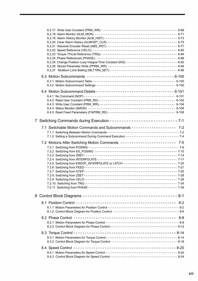
xiii
6.2.17 Write User Constant (PRM_WR) - - - - - - - - - - - - - - - - - - - - - - - - - - - - - - - - - - - - - - - - - - 6-696.2.18 Alarm Monitor (ALM_MON) - - - - - - - - - - - - - - - - - - - - - - - - - - - - - - - - - - - - - - - - - - - - - 6-716.2.19 Alarm History Monitor (ALM_HIST) - - - - - - - - - - - - - - - - - - - - - - - - - - - - - - - - - - - - - - - - 6-736.2.20 Clear Alarm History (ALMHIST_CLR) - - - - - - - - - - - - - - - - - - - - - - - - - - - - - - - - - - - - - - 6-756.2.21 Absolute Encoder Reset (ABS_RST)- - - - - - - - - - - - - - - - - - - - - - - - - - - - - - - - - - - - - - - 6-776.2.22 Speed Reference (VELO)- - - - - - - - - - - - - - - - - - - - - - - - - - - - - - - - - - - - - - - - - - - - - - - 6-806.2.23 Torque /Thrust Reference (TRQ)- - - - - - - - - - - - - - - - - - - - - - - - - - - - - - - - - - - - - - - - - - 6-846.2.24 Phase References (PHASE)- - - - - - - - - - - - - - - - - - - - - - - - - - - - - - - - - - - - - - - - - - - - - 6-886.2.25 Change Position Loop Integral Time Constant (KIS) - - - - - - - - - - - - - - - - - - - - - - - - - - - - 6-926.2.26 Stored Parameter Write (PPRM_WR) - - - - - - - - - - - - - - - - - - - - - - - - - - - - - - - - - - - - - - 6-946.2.27 Multiturn Limit Setting (MLTTRN_SET) - - - - - - - - - - - - - - - - - - - - - - - - - - - - - - - - - - - - - 6-96
6.3 Motion Subcommands - - - - - - - - - - - - - - - - - - - - - - - - - - - - - - - - - - - - - - - 6-1006.3.1 Motion Subcommand Table - - - - - - - - - - - - - - - - - - - - - - - - - - - - - - - - - - - - - - - - - - - - - 6-1006.3.2 Motion Subcommand Settings - - - - - - - - - - - - - - - - - - - - - - - - - - - - - - - - - - - - - - - - - - - 6-100
6.4 Motion Subcommand Details - - - - - - - - - - - - - - - - - - - - - - - - - - - - - - - - - - - 6-1016.4.1 No Command (NOP) - - - - - - - - - - - - - - - - - - - - - - - - - - - - - - - - - - - - - - - - - - - - - - - - - - 6-1016.4.2 Read User Constant (PRM_RD) - - - - - - - - - - - - - - - - - - - - - - - - - - - - - - - - - - - - - - - - - - 6-1026.4.3 Write User Constant (PRM_WR)- - - - - - - - - - - - - - - - - - - - - - - - - - - - - - - - - - - - - - - - - - 6-1046.4.4 Status Monitor (SMON) - - - - - - - - - - - - - - - - - - - - - - - - - - - - - - - - - - - - - - - - - - - - - - - - 6-1066.4.5 Read Fixed Parameters (FIXPRM_RD) - - - - - - - - - - - - - - - - - - - - - - - - - - - - - - - - - - - - - 6-108
7 Switching Commands during Execution - - - - - - - - - - - - - - - - - - - - - - - - - - - - 7-1
7.1 Switchable Motion Commands and Subcommands - - - - - - - - - - - - - - - - - - - - 7-27.1.1 Switching Between Motion Commands - - - - - - - - - - - - - - - - - - - - - - - - - - - - - - - - - - - - - - - 7-27.1.2 Setting a Subcommand During Command Execution - - - - - - - - - - - - - - - - - - - - - - - - - - - - - 7-4
7.2 Motions After Switching Motion Commands - - - - - - - - - - - - - - - - - - - - - - - - - 7-57.2.1 Switching from POSING- - - - - - - - - - - - - - - - - - - - - - - - - - - - - - - - - - - - - - - - - - - - - - - - - - 7-67.2.2 Switching from EX_POSING - - - - - - - - - - - - - - - - - - - - - - - - - - - - - - - - - - - - - - - - - - - - - 7-107.2.3 Switching from ZRET- - - - - - - - - - - - - - - - - - - - - - - - - - - - - - - - - - - - - - - - - - - - - - - - - - - 7-147.2.4 Switching from INTERPOLATE- - - - - - - - - - - - - - - - - - - - - - - - - - - - - - - - - - - - - - - - - - - - 7-177.2.5 Switching from ENDOF_INTERPOLATE or LATCH - - - - - - - - - - - - - - - - - - - - - - - - - - - - - 7-207.2.6 Switching from FEED- - - - - - - - - - - - - - - - - - - - - - - - - - - - - - - - - - - - - - - - - - - - - - - - - - - 7-217.2.7 Switching from STEP- - - - - - - - - - - - - - - - - - - - - - - - - - - - - - - - - - - - - - - - - - - - - - - - - - - 7-257.2.8 Switching from ZSET - - - - - - - - - - - - - - - - - - - - - - - - - - - - - - - - - - - - - - - - - - - - - - - - - - - 7-287.2.9 Switching from VELO- - - - - - - - - - - - - - - - - - - - - - - - - - - - - - - - - - - - - - - - - - - - - - - - - - - 7-297.2.10 Switching from TRQ- - - - - - - - - - - - - - - - - - - - - - - - - - - - - - - - - - - - - - - - - - - - - - - - - - - 7-347.2.11 Switching from PHASE- - - - - - - - - - - - - - - - - - - - - - - - - - - - - - - - - - - - - - - - - - - - - - - - - 7-39
8 Control Block Diagrams - - - - - - - - - - - - - - - - - - - - - - - - - - - - - - - - - - - - - - - 8-1
8.1 Position Control - - - - - - - - - - - - - - - - - - - - - - - - - - - - - - - - - - - - - - - - - - - - - 8-28.1.1 Motion Parameters for Position Control - - - - - - - - - - - - - - - - - - - - - - - - - - - - - - - - - - - - - - - 8-28.1.2 Control Block Diagram for Position Control - - - - - - - - - - - - - - - - - - - - - - - - - - - - - - - - - - - - 8-6
8.2 Phase Control - - - - - - - - - - - - - - - - - - - - - - - - - - - - - - - - - - - - - - - - - - - - - - 8-88.2.1 Motion Parameters for Phase Control - - - - - - - - - - - - - - - - - - - - - - - - - - - - - - - - - - - - - - - - 8-88.2.2 Control Block Diagram for Phase Control- - - - - - - - - - - - - - - - - - - - - - - - - - - - - - - - - - - - - 8-12
8.3 Torque Control - - - - - - - - - - - - - - - - - - - - - - - - - - - - - - - - - - - - - - - - - - - - - - 8-148.3.1 Motion Parameters for Torque Control - - - - - - - - - - - - - - - - - - - - - - - - - - - - - - - - - - - - - - - 8-148.3.2 Control Block Diagram for Torque Control - - - - - - - - - - - - - - - - - - - - - - - - - - - - - - - - - - - - 8-18
8.4 Speed Control - - - - - - - - - - - - - - - - - - - - - - - - - - - - - - - - - - - - - - - - - - - - - - 8-208.4.1 Motion Parameters for Speed Control - - - - - - - - - - - - - - - - - - - - - - - - - - - - - - - - - - - - - - - 8-208.4.2 Control Block Diagram for Speed Control- - - - - - - - - - - - - - - - - - - - - - - - - - - - - - - - - - - - - 8-24
xiv
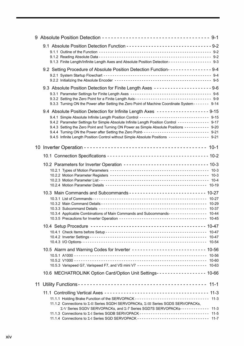
9 Absolute Position Detection - - - - - - - - - - - - - - - - - - - - - - - - - - - - - - - - - - - - 9-1
9.1 Absolute Position Detection Function - - - - - - - - - - - - - - - - - - - - - - - - - - - - - - - 9-29.1.1 Outline of the Function - - - - - - - - - - - - - - - - - - - - - - - - - - - - - - - - - - - - - - - - - - - - - - - - - - 9-29.1.2 Reading Absolute Data - - - - - - - - - - - - - - - - - - - - - - - - - - - - - - - - - - - - - - - - - - - - - - - - - - 9-29.1.3 Finite Length/Infinite Length Axes and Absolute Position Detection - - - - - - - - - - - - - - - - - - - 9-3
9.2 Setting Procedure of Absolute Position Detection Function- - - - - - - - - - - - - - - - 9-49.2.1 System Startup Flowchart - - - - - - - - - - - - - - - - - - - - - - - - - - - - - - - - - - - - - - - - - - - - - - - - 9-49.2.2 Initializing the Absolute Encoder - - - - - - - - - - - - - - - - - - - - - - - - - - - - - - - - - - - - - - - - - - - 9-5
9.3 Absolute Position Detection for Finite Length Axes - - - - - - - - - - - - - - - - - - - - - 9-69.3.1 Parameter Settings for Finite Length Axes - - - - - - - - - - - - - - - - - - - - - - - - - - - - - - - - - - - - 9-69.3.2 Setting the Zero Point for a Finite Length Axis - - - - - - - - - - - - - - - - - - - - - - - - - - - - - - - - - - 9-99.3.3 Turning ON the Power after Setting the Zero Point of Machine Coordinate System- - - - - - - 9-14
9.4 Absolute Position Detection for Infinite Length Axes - - - - - - - - - - - - - - - - - - - 9-159.4.1 Simple Absolute Infinite Length Position Control - - - - - - - - - - - - - - - - - - - - - - - - - - - - - - - 9-159.4.2 Parameter Settings for Simple Absolute Infinite Length Position Control - - - - - - - - - - - - - - 9-179.4.3 Setting the Zero Point and Turning ON Power as Simple Absolute Positions - - - - - - - - - - - 9-209.4.4 Turning ON the Power after Setting the Zero Point- - - - - - - - - - - - - - - - - - - - - - - - - - - - - - 9-219.4.5 Infinite Length Position Control without Simple Absolute Positions - - - - - - - - - - - - - - - - - - 9-21
10 Inverter Operation - - - - - - - - - - - - - - - - - - - - - - - - - - - - - - - - - - - - - - - - - 10-1
10.1 Connection Specifications - - - - - - - - - - - - - - - - - - - - - - - - - - - - - - - - - - - - - 10-2
10.2 Parameters for Inverter Operation - - - - - - - - - - - - - - - - - - - - - - - - - - - - - - - 10-310.2.1 Types of Motion Parameters - - - - - - - - - - - - - - - - - - - - - - - - - - - - - - - - - - - - - - - - - - - - 10-310.2.2 Motion Parameter Registers - - - - - - - - - - - - - - - - - - - - - - - - - - - - - - - - - - - - - - - - - - - - 10-310.2.3 Motion Parameter List - - - - - - - - - - - - - - - - - - - - - - - - - - - - - - - - - - - - - - - - - - - - - - - - - 10-410.2.4 Motion Parameter Details - - - - - - - - - - - - - - - - - - - - - - - - - - - - - - - - - - - - - - - - - - - - - 10-19
10.3 Main Commands and Subcommands - - - - - - - - - - - - - - - - - - - - - - - - - - - - 10-2710.3.1 List of Commands- - - - - - - - - - - - - - - - - - - - - - - - - - - - - - - - - - - - - - - - - - - - - - - - - - - 10-2710.3.2 Main Command Details - - - - - - - - - - - - - - - - - - - - - - - - - - - - - - - - - - - - - - - - - - - - - - - 10-2910.3.3 Subcommand Details - - - - - - - - - - - - - - - - - - - - - - - - - - - - - - - - - - - - - - - - - - - - - - - - 10-3710.3.4 Applicable Combinations of Main Commands and Subcommands- - - - - - - - - - - - - - - - - 10-4410.3.5 Precautions for Inverter Operation - - - - - - - - - - - - - - - - - - - - - - - - - - - - - - - - - - - - - - - 10-45
10.4 Setup Procedure - - - - - - - - - - - - - - - - - - - - - - - - - - - - - - - - - - - - - - - - - - 10-4710.4.1 Check Items before Setup - - - - - - - - - - - - - - - - - - - - - - - - - - - - - - - - - - - - - - - - - - - - - 10-4710.4.2 Inverter Settings - - - - - - - - - - - - - - - - - - - - - - - - - - - - - - - - - - - - - - - - - - - - - - - - - - - - 10-4710.4.3 I/O Options- - - - - - - - - - - - - - - - - - - - - - - - - - - - - - - - - - - - - - - - - - - - - - - - - - - - - - - - 10-54
10.5 Alarm and Warning Codes for Inverter - - - - - - - - - - - - - - - - - - - - - - - - - - - 10-5610.5.1 A1000 - - - - - - - - - - - - - - - - - - - - - - - - - - - - - - - - - - - - - - - - - - - - - - - - - - - - - - - - - - - 10-5610.5.2 V1000 - - - - - - - - - - - - - - - - - - - - - - - - - - - - - - - - - - - - - - - - - - - - - - - - - - - - - - - - - - - 10-6010.5.3 Varispeed G7, Varispeed F7, and VS mini V7 - - - - - - - - - - - - - - - - - - - - - - - - - - - - - - - 10-63
10.6 MECHATROLINK Option Card/Option Unit Settings- - - - - - - - - - - - - - - - - - 10-66
11 Utility Functions - - - - - - - - - - - - - - - - - - - - - - - - - - - - - - - - - - - - - - - - - - - 11-1
11.1 Controlling Vertical Axes - - - - - - - - - - - - - - - - - - - - - - - - - - - - - - - - - - - - - - 11-311.1.1 Holding Brake Function of the SERVOPACK - - - - - - - - - - - - - - - - - - - - - - - - - - - - - - - - - 11-311.1.2 Connections to Σ-II Series SGDH SERVOPACKs, Σ-III Series SGDS SERVOPACKs,
Σ-V Series SGDV SERVOPACKs, and Σ-7 Series SGD7S SERVOPACKs- - - - - - - - - - - - - 11-311.1.3 Connections to Σ-I Series SGDB SERVOPACK - - - - - - - - - - - - - - - - - - - - - - - - - - - - - - - 11-511.1.4 Connections to Σ-I Series SGD SERVOPACK - - - - - - - - - - - - - - - - - - - - - - - - - - - - - - - - 11-7
xv
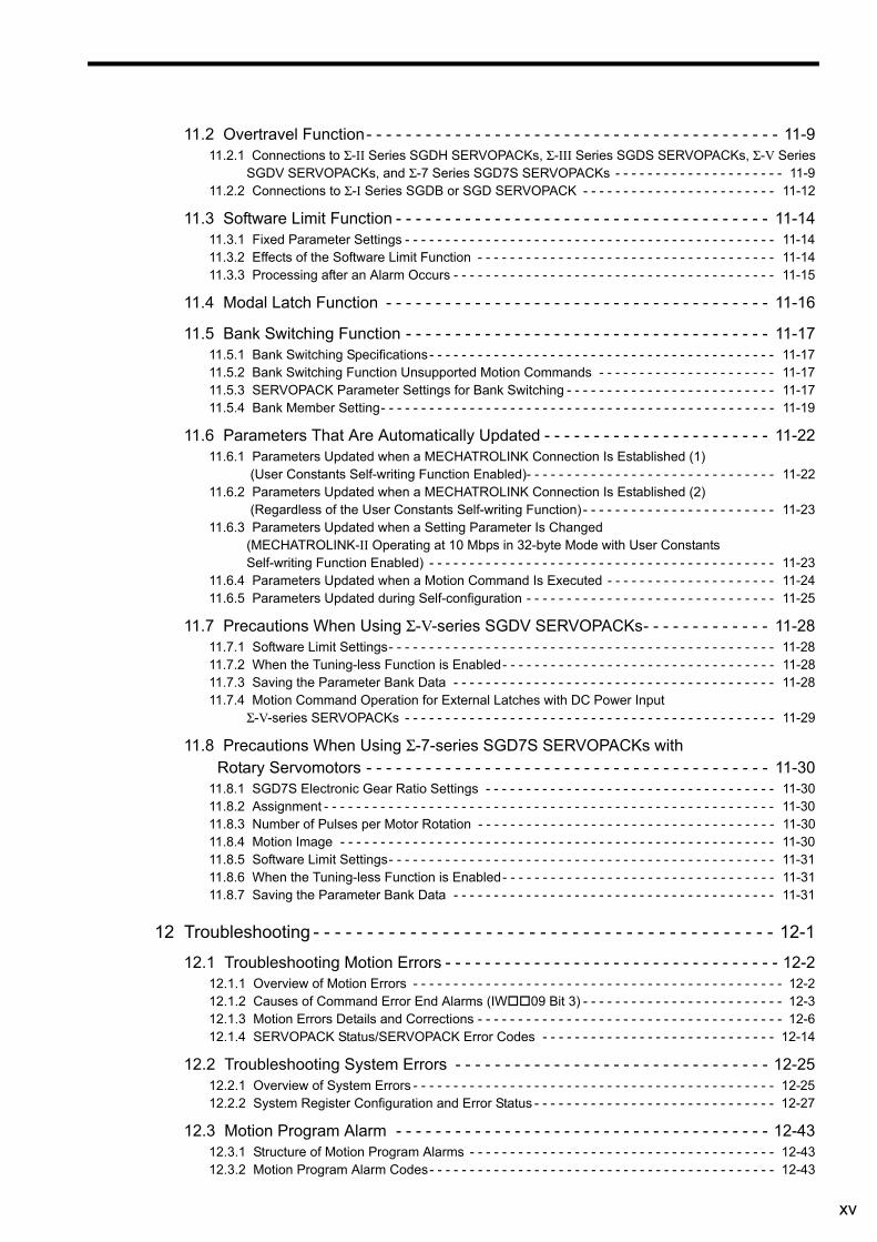
11.2 Overtravel Function- - - - - - - - - - - - - - - - - - - - - - - - - - - - - - - - - - - - - - - - - - 11-911.2.1 Connections to Σ-II Series SGDH SERVOPACKs, Σ-III Series SGDS SERVOPACKs, Σ-V Series
SGDV SERVOPACKs, and Σ-7 Series SGD7S SERVOPACKs - - - - - - - - - - - - - - - - - - - - - 11-911.2.2 Connections to Σ-I Series SGDB or SGD SERVOPACK - - - - - - - - - - - - - - - - - - - - - - - - 11-12
11.3 Software Limit Function - - - - - - - - - - - - - - - - - - - - - - - - - - - - - - - - - - - - - - 11-1411.3.1 Fixed Parameter Settings - - - - - - - - - - - - - - - - - - - - - - - - - - - - - - - - - - - - - - - - - - - - - - 11-1411.3.2 Effects of the Software Limit Function - - - - - - - - - - - - - - - - - - - - - - - - - - - - - - - - - - - - - 11-1411.3.3 Processing after an Alarm Occurs - - - - - - - - - - - - - - - - - - - - - - - - - - - - - - - - - - - - - - - - 11-15
11.4 Modal Latch Function - - - - - - - - - - - - - - - - - - - - - - - - - - - - - - - - - - - - - - - 11-16
11.5 Bank Switching Function - - - - - - - - - - - - - - - - - - - - - - - - - - - - - - - - - - - - - 11-1711.5.1 Bank Switching Specifications- - - - - - - - - - - - - - - - - - - - - - - - - - - - - - - - - - - - - - - - - - - 11-1711.5.2 Bank Switching Function Unsupported Motion Commands - - - - - - - - - - - - - - - - - - - - - - 11-1711.5.3 SERVOPACK Parameter Settings for Bank Switching - - - - - - - - - - - - - - - - - - - - - - - - - - 11-1711.5.4 Bank Member Setting- - - - - - - - - - - - - - - - - - - - - - - - - - - - - - - - - - - - - - - - - - - - - - - - - 11-19
11.6 Parameters That Are Automatically Updated - - - - - - - - - - - - - - - - - - - - - - - 11-2211.6.1 Parameters Updated when a MECHATROLINK Connection Is Established (1)
(User Constants Self-writing Function Enabled)- - - - - - - - - - - - - - - - - - - - - - - - - - - - - - - 11-2211.6.2 Parameters Updated when a MECHATROLINK Connection Is Established (2)
(Regardless of the User Constants Self-writing Function) - - - - - - - - - - - - - - - - - - - - - - - - 11-2311.6.3 Parameters Updated when a Setting Parameter Is Changed
(MECHATROLINK-II Operating at 10 Mbps in 32-byte Mode with User Constants Self-writing Function Enabled) - - - - - - - - - - - - - - - - - - - - - - - - - - - - - - - - - - - - - - - - - - - 11-23
11.6.4 Parameters Updated when a Motion Command Is Executed - - - - - - - - - - - - - - - - - - - - - 11-2411.6.5 Parameters Updated during Self-configuration - - - - - - - - - - - - - - - - - - - - - - - - - - - - - - - 11-25
11.7 Precautions When Using Σ-V-series SGDV SERVOPACKs- - - - - - - - - - - - - 11-2811.7.1 Software Limit Settings- - - - - - - - - - - - - - - - - - - - - - - - - - - - - - - - - - - - - - - - - - - - - - - - 11-2811.7.2 When the Tuning-less Function is Enabled- - - - - - - - - - - - - - - - - - - - - - - - - - - - - - - - - - 11-2811.7.3 Saving the Parameter Bank Data - - - - - - - - - - - - - - - - - - - - - - - - - - - - - - - - - - - - - - - - 11-2811.7.4 Motion Command Operation for External Latches with DC Power Input
Σ-V-series SERVOPACKs - - - - - - - - - - - - - - - - - - - - - - - - - - - - - - - - - - - - - - - - - - - - - - 11-29
11.8 Precautions When Using Σ-7-series SGD7S SERVOPACKs with Rotary Servomotors - - - - - - - - - - - - - - - - - - - - - - - - - - - - - - - - - - - - - - - - - 11-30
11.8.1 SGD7S Electronic Gear Ratio Settings - - - - - - - - - - - - - - - - - - - - - - - - - - - - - - - - - - - - 11-3011.8.2 Assignment - - - - - - - - - - - - - - - - - - - - - - - - - - - - - - - - - - - - - - - - - - - - - - - - - - - - - - - - 11-3011.8.3 Number of Pulses per Motor Rotation - - - - - - - - - - - - - - - - - - - - - - - - - - - - - - - - - - - - - 11-3011.8.4 Motion Image - - - - - - - - - - - - - - - - - - - - - - - - - - - - - - - - - - - - - - - - - - - - - - - - - - - - - - 11-3011.8.5 Software Limit Settings- - - - - - - - - - - - - - - - - - - - - - - - - - - - - - - - - - - - - - - - - - - - - - - - 11-3111.8.6 When the Tuning-less Function is Enabled- - - - - - - - - - - - - - - - - - - - - - - - - - - - - - - - - - 11-3111.8.7 Saving the Parameter Bank Data - - - - - - - - - - - - - - - - - - - - - - - - - - - - - - - - - - - - - - - - 11-31
12 Troubleshooting - - - - - - - - - - - - - - - - - - - - - - - - - - - - - - - - - - - - - - - - - - - 12-1
12.1 Troubleshooting Motion Errors - - - - - - - - - - - - - - - - - - - - - - - - - - - - - - - - - - 12-212.1.1 Overview of Motion Errors - - - - - - - - - - - - - - - - - - - - - - - - - - - - - - - - - - - - - - - - - - - - - - 12-212.1.2 Causes of Command Error End Alarms (IW09 Bit 3) - - - - - - - - - - - - - - - - - - - - - - - - - 12-312.1.3 Motion Errors Details and Corrections - - - - - - - - - - - - - - - - - - - - - - - - - - - - - - - - - - - - - - 12-612.1.4 SERVOPACK Status/SERVOPACK Error Codes - - - - - - - - - - - - - - - - - - - - - - - - - - - - - 12-14
12.2 Troubleshooting System Errors - - - - - - - - - - - - - - - - - - - - - - - - - - - - - - - - 12-2512.2.1 Overview of System Errors - - - - - - - - - - - - - - - - - - - - - - - - - - - - - - - - - - - - - - - - - - - - - 12-2512.2.2 System Register Configuration and Error Status - - - - - - - - - - - - - - - - - - - - - - - - - - - - - - 12-27
12.3 Motion Program Alarm - - - - - - - - - - - - - - - - - - - - - - - - - - - - - - - - - - - - - - 12-4312.3.1 Structure of Motion Program Alarms - - - - - - - - - - - - - - - - - - - - - - - - - - - - - - - - - - - - - - 12-4312.3.2 Motion Program Alarm Codes- - - - - - - - - - - - - - - - - - - - - - - - - - - - - - - - - - - - - - - - - - - 12-43
xvi
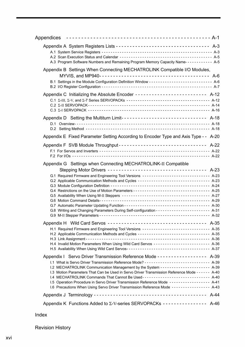
Appendices - - - - - - - - - - - - - - - - - - - - - - - - - - - - - - - - - - - - - - - - - - - - - - - - A-1
Appendix A System Registers Lists - - - - - - - - - - - - - - - - - - - - - - - - - - - - - - - - - - A-3A.1 System Service Registers - - - - - - - - - - - - - - - - - - - - - - - - - - - - - - - - - - - - - - - - - - - - - - - - - A-3A.2 Scan Execution Status and Calendar - - - - - - - - - - - - - - - - - - - - - - - - - - - - - - - - - - - - - - - - - A-5A.3 Program Software Numbers and Remaining Program Memory Capacity Name- - - - - - - - - - - - A-5
Appendix B Settings When Connecting MECHATROLINK Compatible I/O Modules, MYVIS, and MP940- - - - - - - - - - - - - - - - - - - - - - - - - - - - - - - - - - - - - - - - A-6
B.1 Settings in the Module Configuration Definition Window - - - - - - - - - - - - - - - - - - - - - - - - - - - - A-6B.2 I/O Register Configuration - - - - - - - - - - - - - - - - - - - - - - - - - - - - - - - - - - - - - - - - - - - - - - - - - A-7
Appendix C Initializing the Absolute Encoder - - - - - - - - - - - - - - - - - - - - - - - - - - A-12C.1 Σ-III, Σ-V, and Σ-7 Series SERVOPACKs - - - - - - - - - - - - - - - - - - - - - - - - - - - - - - - - - - - - - A-12C.2 Σ-II SERVOPACK - - - - - - - - - - - - - - - - - - - - - - - - - - - - - - - - - - - - - - - - - - - - - - - - - - - - - - A-14C.3 Σ-I SERVOPACK - - - - - - - - - - - - - - - - - - - - - - - - - - - - - - - - - - - - - - - - - - - - - - - - - - - - - - A-16
Appendix D Setting the Multiturn Limit- - - - - - - - - - - - - - - - - - - - - - - - - - - - - - - A-18D.1 Overview- - - - - - - - - - - - - - - - - - - - - - - - - - - - - - - - - - - - - - - - - - - - - - - - - - - - - - - - - - - - A-18D.2 Setting Method - - - - - - - - - - - - - - - - - - - - - - - - - - - - - - - - - - - - - - - - - - - - - - - - - - - - - - - A-18
Appendix E Fixed Parameter Setting According to Encoder Type and Axis Type - - A-20
Appendix F SVB Module Throughput - - - - - - - - - - - - - - - - - - - - - - - - - - - - - - - - A-22F.1 For Servos and Inverters - - - - - - - - - - - - - - - - - - - - - - - - - - - - - - - - - - - - - - - - - - - - - - - - - A-22F.2 For I/Os - - - - - - - - - - - - - - - - - - - - - - - - - - - - - - - - - - - - - - - - - - - - - - - - - - - - - - - - - - - - - A-22
Appendix G Settings when Connecting MECHATROLINK-II Compatible Stepping Motor Drivers - - - - - - - - - - - - - - - - - - - - - - - - - - - - - - - - - - - - A-23
G.1 Required Firmware and Engineering Tool Versions - - - - - - - - - - - - - - - - - - - - - - - - - - - - - - A-23G.2 Applicable Communication Methods and Cycles - - - - - - - - - - - - - - - - - - - - - - - - - - - - - - - - A-23G.3 Module Configuration Definition - - - - - - - - - - - - - - - - - - - - - - - - - - - - - - - - - - - - - - - - - - - - A-24G.4 Restrictions on the Use of Motion Parameters - - - - - - - - - - - - - - - - - - - - - - - - - - - - - - - - - - A-25G.5 Availability When Using M-II Steppers - - - - - - - - - - - - - - - - - - - - - - - - - - - - - - - - - - - - - - - A-27G.6 Motion Command Details- - - - - - - - - - - - - - - - - - - - - - - - - - - - - - - - - - - - - - - - - - - - - - - - - A-29G.7 Automatic Parameter Updating Function - - - - - - - - - - - - - - - - - - - - - - - - - - - - - - - - - - - - - - A-30G.8 Writing and Changing Parameters During Self-configuration - - - - - - - - - - - - - - - - - - - - - - - - A-31G.9 M-II Stepper Parameters - - - - - - - - - - - - - - - - - - - - - - - - - - - - - - - - - - - - - - - - - - - - - - - - - A-32
Appendix H Wild Card Servos - - - - - - - - - - - - - - - - - - - - - - - - - - - - - - - - - - - - A-35H.1 Required Firmware and Engineering Tool Versions - - - - - - - - - - - - - - - - - - - - - - - - - - - - - - A-35H.2 Applicable Communication Methods and Cycles - - - - - - - - - - - - - - - - - - - - - - - - - - - - - - - - A-35H.3 Link Assignment - - - - - - - - - - - - - - - - - - - - - - - - - - - - - - - - - - - - - - - - - - - - - - - - - - - - - - - A-36H.4 Invalid Motion Parameters When Using Wild Card Servos - - - - - - - - - - - - - - - - - - - - - - - - - A-36H.5 Availability When Using Wild Card Servos- - - - - - - - - - - - - - - - - - - - - - - - - - - - - - - - - - - - - A-37
Appendix I Servo Driver Transmission Reference Mode - - - - - - - - - - - - - - - - - - A-39I.1 What is Servo Driver Transmission Reference Mode? - - - - - - - - - - - - - - - - - - - - - - - - - - - - - A-39I.2 MECHATROLINK Communication Management by the System - - - - - - - - - - - - - - - - - - - - - - A-39I.3 Motion Parameters That Can be Used in Servo Driver Transmission Reference Mode - - - - - - A-40I.4 MECHATROLINK Commands That Cannot Be Used- - - - - - - - - - - - - - - - - - - - - - - - - - - - - - A-40I.5 Operation Procedure in Servo Driver Transmission Reference Mode - - - - - - - - - - - - - - - - - - A-41I.6 Precautions When Using Servo Driver Transmission Reference Mode - - - - - - - - - - - - - - - - - A-43
Appendix J Terminology - - - - - - - - - - - - - - - - - - - - - - - - - - - - - - - - - - - - - - - - - A-44
Appendix K Functions Added to Σ-V-series SERVOPACKs - - - - - - - - - - - - - - - - A-46
Index
Revision History
1-1
Ove
rvie
w
1
Overview
This chapter provides an overview and the features of the SVB Module.
1.1 SVB Module Overview and Features - - - - - - - - - - - - - - - - - - - - - - - - - - -1-2
1.1.1 SVB Modules - - - - - - - - - - - - - - - - - - - - - - - - - - - - - - - - - - - - - - - - - - - - - - - - - - - - 1-2
1.1.2 Built-in SVB and Slot-mounting Optional SVB - - - - - - - - - - - - - - - - - - - - - - - - - - - - - 1-2
1.1.3 Features - - - - - - - - - - - - - - - - - - - - - - - - - - - - - - - - - - - - - - - - - - - - - - - - - - - - - - - - 1-2
1.1.4 System Configuration Example - - - - - - - - - - - - - - - - - - - - - - - - - - - - - - - - - - - - - - - - 1-3
1.1.5 Devices and Cables Connectable to MECHATROLINK - - - - - - - - - - - - - - - - - - - - - - - 1-4
1.1.6 Synchronization between Modules - - - - - - - - - - - - - - - - - - - - - - - - - - - - - - - - - - - - - 1-7
1.2 Specifications - - - - - - - - - - - - - - - - - - - - - - - - - - - - - - - - - - - - - - - - - - - -1-9
1.2.1 SVB-01 Module Hardware Specifications - - - - - - - - - - - - - - - - - - - - - - - - - - - - - - - - - 1-9
1.2.2 Specifications of SVB Module - - - - - - - - - - - - - - - - - - - - - - - - - - - - - - - - - - - - - - - - 1-10
1.3 SVR Virtual Motion Module - - - - - - - - - - - - - - - - - - - - - - - - - - - - - - - - - 1-13
1.3.1 Overview - - - - - - - - - - - - - - - - - - - - - - - - - - - - - - - - - - - - - - - - - - - - - - - - - - - - - - 1-13
1.3.2 Example of SVR Usage - - - - - - - - - - - - - - - - - - - - - - - - - - - - - - - - - - - - - - - - - - - - 1-14
1.3.3 System Configuration Example - - - - - - - - - - - - - - - - - - - - - - - - - - - - - - - - - - - - - - - 1-14
1.3.4 SVR Operation - - - - - - - - - - - - - - - - - - - - - - - - - - - - - - - - - - - - - - - - - - - - - - - - - - 1-15
1.1 SVB Module Overview and Features
1.1.1 SVB Modules
1-2
1.1 SVB Module Overview and Features
1.1.1 SVB Modules
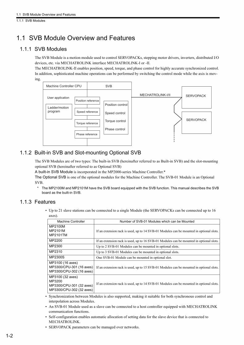
The SVB Module is a motion module used to control SERVOPACKs, stepping motor drivers, inverters, distributed I/O devices, etc. via MECHATROLINK interface MECHATROLINK-I or -II.The MECHATROLINK-II enables position, speed, torque, and phase control for highly accurate synchronized control. In addition, sophisticated machine operations can be performed by switching the control mode while the axis is mov-ing.
1.1.2 Built-in SVB and Slot-mounting Optional SVB
The SVB Modules are of two types: The built-in SVB (hereinafter referred to as Built-in SVB) and the slot-mounting optional SVB (hereinafter referred to as Optional SVB)A built-in SVB Module is incorporated in the MP2000-series Machine Controller.*The Optional SVB is one of the optional modules for the Machine Controller. The SVB-01 Module is an Optional SVB.
* The MP2100M and MP2101M have the SVB board equipped with the SVB function. This manual describes the SVB board as the built-in SVB.
1.1.3 Features
• Up to 21 slave stations can be connected to a single Module (the SERVOPACKs can be connected up to 16 axes).
• Synchronization between Modules is also supported, making it suitable for both synchronous control and interpolation across Modules.
• An SVB-01 Module used as a slave can be connected to a host controller equipped with MECHATROLINK communication functions.
• Self-configuration enables automatic allocation of setting data for the slave device that is connected to MECHATROLINK.
• SERVOPACK parameters can be managed over networks.
Machine Controller CPU SVB
MECHATROLINK-I/II
Ladder/motion program Speed control
Position control
Phase control
SERVOPACK
Torque control
Position reference
Speed reference
Phase reference
Torque reference SERVOPACK
User application
Machine Controller Number of SVB-01 Modules which can be Mounted
MP2100MMP2101MMP2101TM
If an extension rack is used, up to 14 SVB-01 Modules can be mounted in optional slots.
MP2200 If an extension rack is used, up to 16 SVB-01 Modules can be mounted in optional slots.
MP2300 Up to 2 SVB-01 Modules can be mounted in optional slots.
MP2310 Up to 3 SVB-01 Modules can be mounted in optional slots.
MP2300S One SVB-01 Module can be mounted in optional slot.
MP3100 (16 axes)MP3300/CPU-301 (16 axes)MP3300/CPU-302 (16 axes)
If an extension rack is used, up to 15 SVB-01 Modules can be mounted in optional slots.
MP3100 (32 axes)MP3200MP3300/CPU-301 (32 axes)MP3300/CPU-302 (32 axes)
If an extension rack is used, up to 14 SVB-01 Modules can be mounted in optional slots.
1.1 SVB Module Overview and Features
1.1.4 System Configuration Example
1-3
Ove
rvie
w
1.1.4 System Configuration Example
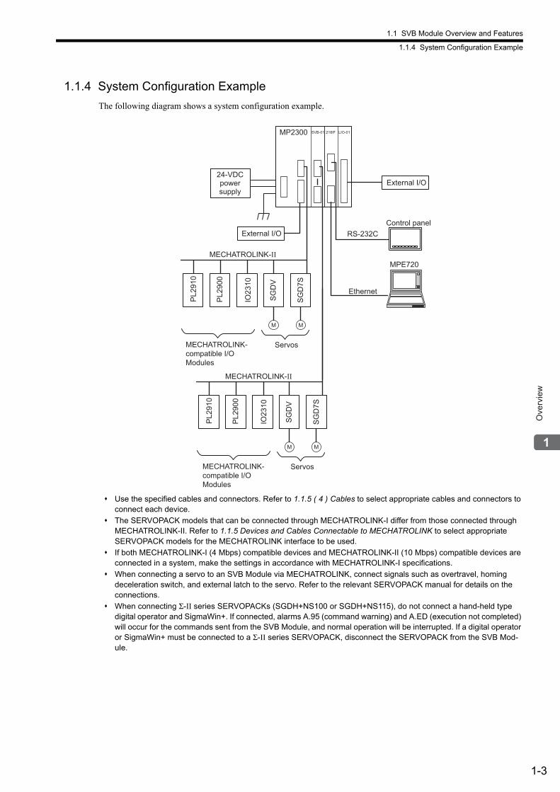
The following diagram shows a system configuration example.
Use the specified cables and connectors. Refer to 1.1.5 ( 4 ) Cables to select appropriate cables and connectors to connect each device.
The SERVOPACK models that can be connected through MECHATROLINK-I differ from those connected through MECHATROLINK-II. Refer to 1.1.5 Devices and Cables Connectable to MECHATROLINK to select appropriate SERVOPACK models for the MECHATROLINK interface to be used.
If both MECHATROLINK-I (4 Mbps) compatible devices and MECHATROLINK-II (10 Mbps) compatible devices are connected in a system, make the settings in accordance with MECHATROLINK-I specifications.
When connecting a servo to an SVB Module via MECHATROLINK, connect signals such as overtravel, homing deceleration switch, and external latch to the servo. Refer to the relevant SERVOPACK manual for details on the connections.
When connecting Σ-II series SERVOPACKs (SGDH+NS100 or SGDH+NS115), do not connect a hand-held type digital operator and SigmaWin+. If connected, alarms A.95 (command warning) and A.ED (execution not completed) will occur for the commands sent from the SVB Module, and normal operation will be interrupted. If a digital operator or SigmaWin+ must be connected to a Σ-II series SERVOPACK, disconnect the SERVOPACK from the SVB Mod-ule.
MP2300
MECHATROLINK-II
SG
D7S
M
IO23
10
PL2
900
PL2
910
SG
DV
M
MECHATROLINK-II
SG
D7S
M
IO23
10
PL2
900
PL2
910
SG
DV
M
Ethernet
RS-232C
218IF LIO-01SVB-01
MPE720
External I/O
24-VDC power supply
MECHATROLINK-compatible I/O Modules
Servos
MECHATROLINK-compatible I/O Modules
Servos
External I/O
Control panel
1.1 SVB Module Overview and Features
1.1.5 Devices and Cables Connectable to MECHATROLINK
1-4
1.1.5 Devices and Cables Connectable to MECHATROLINK
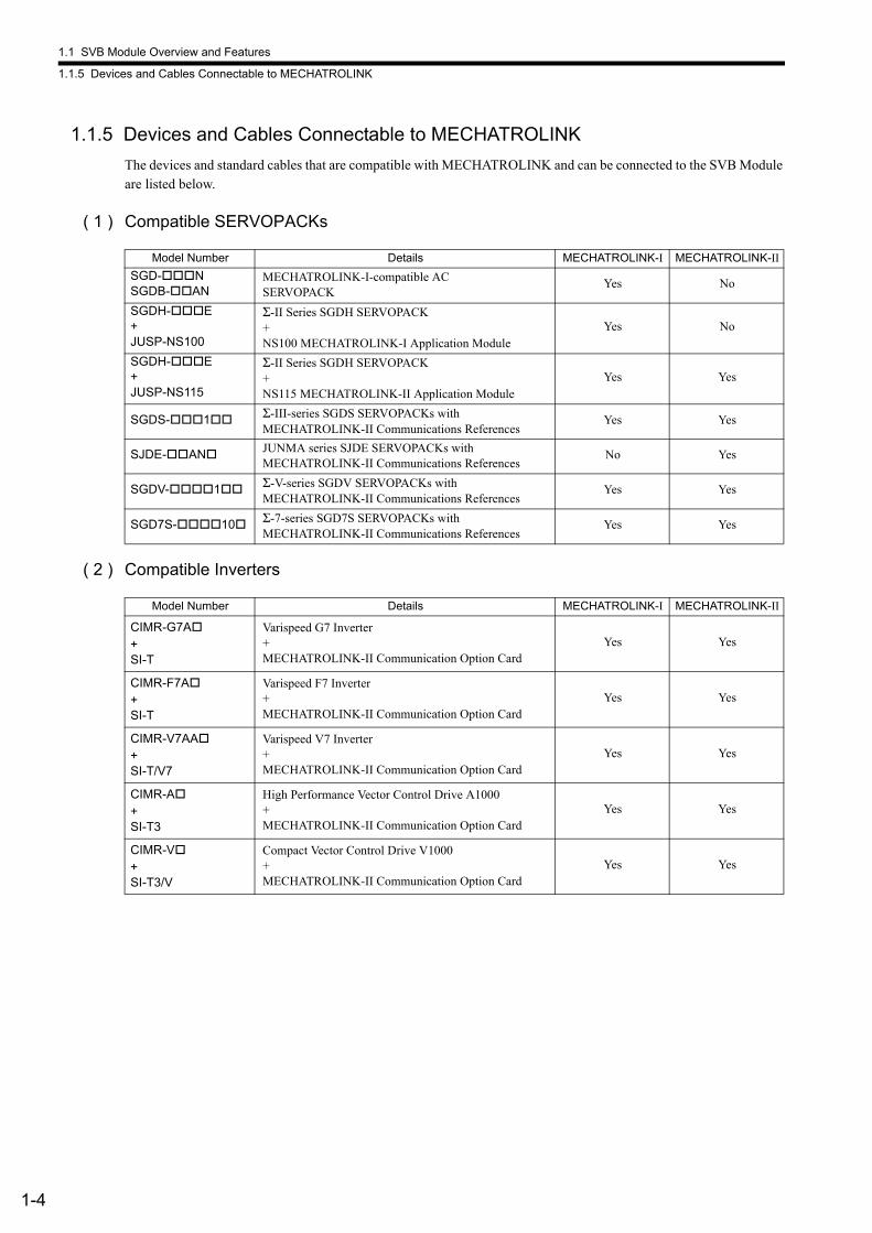
The devices and standard cables that are compatible with MECHATROLINK and can be connected to the SVB Module are listed below.
( 1 ) Compatible SERVOPACKs
( 2 ) Compatible Inverters
Model Number Details MECHATROLINK-I MECHATROLINK-II
SGD-NSGDB-AN
MECHATROLINK-I-compatible ACSERVOPACK
Yes No
SGDH-E+JUSP-NS100
Σ-II Series SGDH SERVOPACK+NS100 MECHATROLINK-I Application Module
Yes No
SGDH-E+JUSP-NS115
Σ-II Series SGDH SERVOPACK+NS115 MECHATROLINK-II Application Module
Yes Yes
SGDS-1 Σ-III-series SGDS SERVOPACKs with MECHATROLINK-II Communications References
Yes Yes
SJDE-AN JUNMA series SJDE SERVOPACKs with MECHATROLINK-II Communications References
No Yes
SGDV-1 Σ-V-series SGDV SERVOPACKs with MECHATROLINK-II Communications References
Yes Yes
SGD7S-10 Σ-7-series SGD7S SERVOPACKs with MECHATROLINK-II Communications References
Yes Yes
Model Number Details MECHATROLINK-I MECHATROLINK-II
CIMR-G7A+SI-T
Varispeed G7 Inverter+MECHATROLINK-II Communication Option Card
Yes Yes
CIMR-F7A+SI-T
Varispeed F7 Inverter+MECHATROLINK-II Communication Option Card
Yes Yes
CIMR-V7AA+SI-T/V7
Varispeed V7 Inverter+MECHATROLINK-II Communication Option Card
Yes Yes
CIMR-A+SI-T3
High Performance Vector Control Drive A1000+MECHATROLINK-II Communication Option Card
Yes Yes
CIMR-V+SI-T3/V
Compact Vector Control Drive V1000+MECHATROLINK-II Communication Option Card
Yes Yes
1.1 SVB Module Overview and Features
1.1.5 Devices and Cables Connectable to MECHATROLINK
1-5
Ove
rvie
w
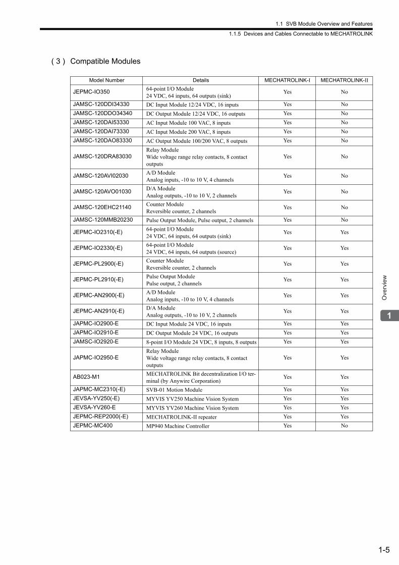
( 3 ) Compatible Modules
Model Number Details MECHATROLINK-I MECHATROLINK-II
JEPMC-IO350 64-point I/O Module 24 VDC, 64 inputs, 64 outputs (sink)
Yes No
JAMSC-120DDI34330 DC Input Module 12/24 VDC, 16 inputs Yes No
JAMSC-120DDO34340 DC Output Module 12/24 VDC, 16 outputs Yes No
JAMSC-120DAI53330 AC Input Module 100 VAC, 8 inputs Yes No
JAMSC-120DAI73330 AC Input Module 200 VAC, 8 inputs Yes No
JAMSC-120DAO83330 AC Output Module 100/200 VAC, 8 outputs Yes No
JAMSC-120DRA83030Relay ModuleWide voltage range relay contacts, 8 contact outputs
Yes No
JAMSC-120AVI02030 A/D ModuleAnalog inputs, -10 to 10 V, 4 channels
Yes No
JAMSC-120AVO01030 D/A ModuleAnalog outputs, -10 to 10 V, 2 channels
Yes No
JAMSC-120EHC21140 Counter ModuleReversible counter, 2 channels
Yes No
JAMSC-120MMB20230 Pulse Output Module, Pulse output, 2 channels Yes No
JEPMC-IO2310(-E) 64-point I/O Module 24 VDC, 64 inputs, 64 outputs (sink)
Yes Yes
JEPMC-IO2330(-E) 64-point I/O Module 24 VDC, 64 inputs, 64 outputs (source)
Yes Yes
JEPMC-PL2900(-E) Counter ModuleReversible counter, 2 channels
Yes Yes
JEPMC-PL2910(-E) Pulse Output ModulePulse output, 2 channels
Yes Yes
JEPMC-AN2900(-E) A/D ModuleAnalog inputs, -10 to 10 V, 4 channels
Yes Yes
JEPMC-AN2910(-E) D/A ModuleAnalog outputs, -10 to 10 V, 2 channels
Yes Yes
JAPMC-IO2900-E DC Input Module 24 VDC, 16 inputs Yes Yes
JAPMC-IO2910-E DC Output Module 24 VDC, 16 outputs Yes Yes
JAMSC-IO2920-E 8-point I/O Module 24 VDC, 8 inputs, 8 outputs Yes Yes
JAPMC-IO2950-ERelay Module Wide voltage range relay contacts, 8 contact outputs
Yes Yes
AB023-M1 MECHATROLINK Bit decentralization I/O ter-minal (by Anywire Corporation)
Yes Yes
JAPMC-MC2310(-E) SVB-01 Motion Module Yes Yes
JEVSA-YV250(-E) MYVIS YV250 Machine Vision System Yes Yes
JEVSA-YV260-E MYVIS YV260 Machine Vision System Yes Yes
JEPMC-REP2000(-E) MECHATROLINK-II repeater Yes Yes
JEPMC-MC400 MP940 Machine Controller Yes No
1.1 SVB Module Overview and Features
1.1.5 Devices and Cables Connectable to MECHATROLINK
1-6
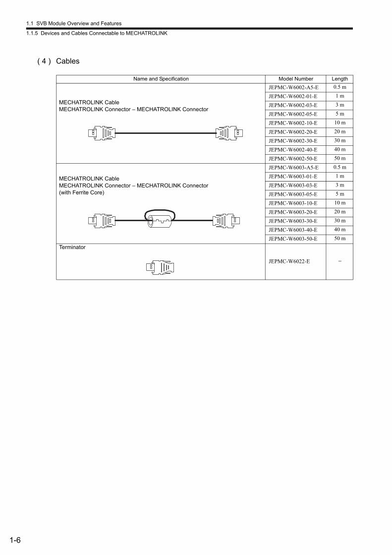
( 4 ) Cables
Name and Specification Model Number Length
MECHATROLINK CableMECHATROLINK Connector – MECHATROLINK Connector
JEPMC-W6002-A5-E 0.5 m
JEPMC-W6002-01-E 1 m
JEPMC-W6002-03-E 3 m
JEPMC-W6002-05-E 5 m
JEPMC-W6002-10-E 10 m
JEPMC-W6002-20-E 20 m
JEPMC-W6002-30-E 30 m
JEPMC-W6002-40-E 40 m
JEPMC-W6002-50-E 50 m
MECHATROLINK CableMECHATROLINK Connector – MECHATROLINK Connector (with Ferrite Core)
JEPMC-W6003-A5-E 0.5 m
JEPMC-W6003-01-E 1 m
JEPMC-W6003-03-E 3 m
JEPMC-W6003-05-E 5 m
JEPMC-W6003-10-E 10 m
JEPMC-W6003-20-E 20 m
JEPMC-W6003-30-E 30 m
JEPMC-W6003-40-E 40 m
JEPMC-W6003-50-E 50 m
Terminator
JEPMC-W6022-E −
1.1 SVB Module Overview and Features
1.1.6 Synchronization between Modules
1-7
Ove
rvie
w
1.1.6 Synchronization between Modules
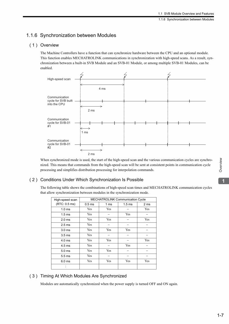
( 1 ) Overview
The Machine Controllers have a function that can synchronize hardware between the CPU and an optional module. This function enables MECHATROLINK communications in synchronization with high-speed scans. As a result, syn-chronization between a built-in SVB Module and an SVB-01 Module, or among multiple SVB-01 Modules, can be enabled.
When synchronized mode is used, the start of the high-speed scan and the various communication cycles are synchro-nized. This means that commands from the high-speed scan will be sent at consistent points in communication cycle processing and simplifies distribution processing for interpolation commands.
( 2 ) Conditions Under Which Synchronization Is Possible
The following table shows the combinations of high-speed scan times and MECHATROLINK communication cycles that allow synchronization between modules in the synchronization mode.
( 3 ) Timing At Which Modules Are Synchronized
Modules are automatically synchronized when the power supply is turned OFF and ON again.
High-speed scan
4 ms
2 ms
1 ms
2 ms
Communication
cycle for SVB built
into the CPU
Communication
cycle for SVB-01
#1
Communication
cycle for SVB-01
#2
High-speed scan(RTC: 0.5 ms)
MECHATROLINK Communication Cycle
0.5 ms 1 ms 1.5 ms 2 ms
1.0 ms Yes Yes − Yes
1.5 ms Yes − Yes −
2.0 ms Yes Yes − Yes
2.5 ms Yes − − −
3.0 ms Yes Yes Yes −
3.5 ms Yes − − −
4.0 ms Yes Yes − Yes
4.5 ms Yes − Yes −
5.0 ms Yes Yes − −
5.5 ms Yes − − −
6.0 ms Yes Yes Yes Yes
:
1.1 SVB Module Overview and Features
1.1.6 Synchronization between Modules
1-8
( 4 ) Operation when High-speed Scan Cycle Is Changed
MECHATROLINK communication with SVB Modules will continue even if the high-speed scan cycle is changed. However, the speed waveform at execution of interpolation command will be disordered. When changing the high-speed scan cycle, do so either with the CPU stopped or when motion command are not being executed. Change the high-speed scan setting and then save the settings to flash memory and turn the power supply OFF and ON when operation changes from synchronized to asynchronized or from asynchronized to synchronized.
( 5 ) Operation When the MECHATROLINK Communication Cycle Is Changed
Changing the MECHATROLINK Communication Cycle of the SVB in the CPU
Synchronization may be lost when a change is made even if synchronization is possible for the high-speed scan and communication cycle combination. When a change is made, save the settings to flash memory and then turn the power supply OFF and ON.
Changing the MECHATROLINK Communication Cycle of the SVB-01 Module
Operation will be automatically synchronized when a change is made if synchronization is possible for the high-speed scan and communication cycle combination. It is not necessary to turn the power supply OFF and ON.
( 6 ) Conditions when the Power Supply Must Be Turned OFF and ON
When any of the following operations is performed, save the settings to flash memory and then turn the power supply OFF and ON.
• After executing a self-configuration command from the MPE720 after turning ON the power supply
• After loading a Module definition after turning ON the power supply
• After changing the SVB communication cycle in the CPU after turning ON the power supply
• After operation changes from synchronized to asynchronized or from asynchronized to synchronized when the high-speed scan setting is changed
( 7 ) Precaution
Observe the following precautions when the scan time over counter error occurs.
When an H Scan Time Over Counter error or L Scan Time Over Counter error occurs, the MECHATROLINK commu-nication cycle is disturbed and a communication error may occur. These scan time errors can be checked in the SW00044 and SW00046 registers.
1.2 Specifications
1.2.1 SVB-01 Module Hardware Specifications
1-9
Ove
rvie
w
1.2 Specifications
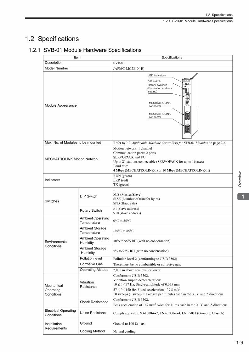
1.2.1 SVB-01 Module Hardware SpecificationsItem Specifications
Description SVB-01
Model Number JAPMC-MC2310(-E)
Module Appearance
Max. No. of Modules to be mounted Refer to 2.2 Applicable Machine Controllers for SVB-01 Modules on page 2-6.
MECHATROLINK Motion Network
Motion network: 1 channelCommunication ports: 2 portsSERVOPACK and I/O:Up to 21 stations connectable (SERVOPACK for up to 16 axes)Baud rate: 4 Mbps (MECHATROLINK-I) or 10 Mbps (MECHATROLINK-II)
IndicatorsRUN (green)ERR (red)TX (green)
SwitchesDIP Switch
−M/S (Master/Slave)SIZE (Number of transfer bytes)SPD (Baud rate)
Rotary Switch ×1 (slave address) ×10 (slave address)
Environmental Conditions
Ambient Operating Temperature 0°C to 55°C
Ambient Storage Temperature -25°C to 85°C
Ambient Operating Humidity 30% to 95% RH (with no condensation)
Ambient Storage Humidity 5% to 95% RH (with no condensation)
Pollution level Pollution level 2 (conforming to JIS B 3502)
Corrosive Gas There must be no combustible or corrosive gas.
Operating Altitude 2,000 m above sea level or lower
Mechanical Operating Conditions
Vibration Resistance
Conforms to JIS B 3502.Vibration amplitude/acceleration:10 ≤ f < 57 Hz, Single-amplitude of 0.075 mm
57 ≤ f ≤ 150 Hz, Fixed acceleration of 9.8 m/s2
10 sweeps (1 sweep = 1 octave per minute) each in the X, Y, and Z directions
Shock ResistanceConforms to JIS B 3502.
Peak acceleration of 147 m/s2 twice for 11 ms each in the X, Y, and Z directions
Electrical Operating Conditions
Noise Resistance Complying with EN 61000-6-2, EN 61000-6-4, EN 55011 (Group 1, Class A)
Installation Requirements
Ground Ground to 100 Ω max.
Cooling Method Natural cooling
SVB-01
TX
ERRRUN
SPDSIZEM/S
ONOFF
10
1
M-I/II
CN1
CN2
LED indicators
Rotary switches (For station address setting)
DIP switch
MECHATROLINKconnector
MECHATROLINKconnector
1.2 Specifications
1.2.2 Specifications of SVB Module
1-10
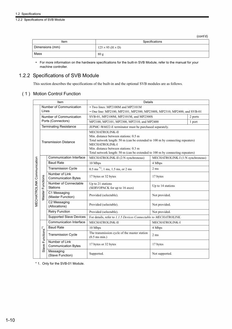
For more information on the hardware specifications for the built-in SVB Module, refer to the manual for your machine controller.
1.2.2 Specifications of SVB Module
This section describes the specifications of the built-in and the optional SVB modules are as follows.
( 1 ) Motion Control Function
* 1. Only for the SVB-01 Module.
Dimensions (mm) 125 × 95 (H × D)
Mass 80 g
(cont’d)
Item Specifications
Item Details
ME
CH
AT
RO
LIN
K C
omm
un
ica
tion
Number of Communication Lines
• Two lines: MP2100M and MP2101M• One line: MP2100, MP2101, MP2300, MP2300S, MP2310, MP2400, and SVB-01
Number of Communication Ports (Connectors)
SVB-01, MP2100M, MP2101M, and MP2300S 2 ports
MP2100, MP2101, MP2300, MP2310, and MP2400 1 port
Terminating Resistance JEPMC-W6022-E terminator must be purchased separately.
Transmission Distance
MECHATROLINK-IIMin. distance between stations: 0.5 mTotal network length: 50 m (can be extended to 100 m by connecting repeaters)MECHATROLINK-IMin. distance between stations: 0.3 mTotal network length: 50 m (can be extended to 100 m by connecting repeaters)
Mas
ter
Fu
nct
ion
s
Communication Interface MECHATROLINK-II (2:N synchronous) MECHATROLINK-I (1:N synchronous)
Baud Rate 10 Mbps 4 Mbps
Transmission Cycle 0.5 ms *1, 1 ms, 1.5 ms, or 2 ms 2 ms
Number of Link Communication Bytes 17 bytes or 32 bytes 17 bytes
Number of Connectable Stations
Up to 21 stations (SERVOPACK for up to 16 axes)
Up to 14 stations
C1 Messaging (Master Function) Provided (selectable). Not provided.
C2 Messaging (Allocations) Provided (selectable). Not provided.
Retry Function Provided (selectable). Not provided.
Supported Slave Devices For details, refer to 1.1.5 Devices Connectable to MECHATROLINK.
Sla
ve F
un
ctio
ns*1
Communication Interface MECHATROLINK-II MECHATROLINK-I
Baud Rate 10 Mbps 4 Mbps
Transmission Cycle The transmission cycle of the master station(0.5 ms min.)
2 ms
Number of Link Communication Bytes 17 bytes or 32 bytes 17 bytes
Messaging (Slave Function) Supported. Not supported.
1.2 Specifications
1.2.2 Specifications of SVB Module
1-11
Ove
rvie
w
* 2. Only with MECHATROLINK-II
(cont'd)
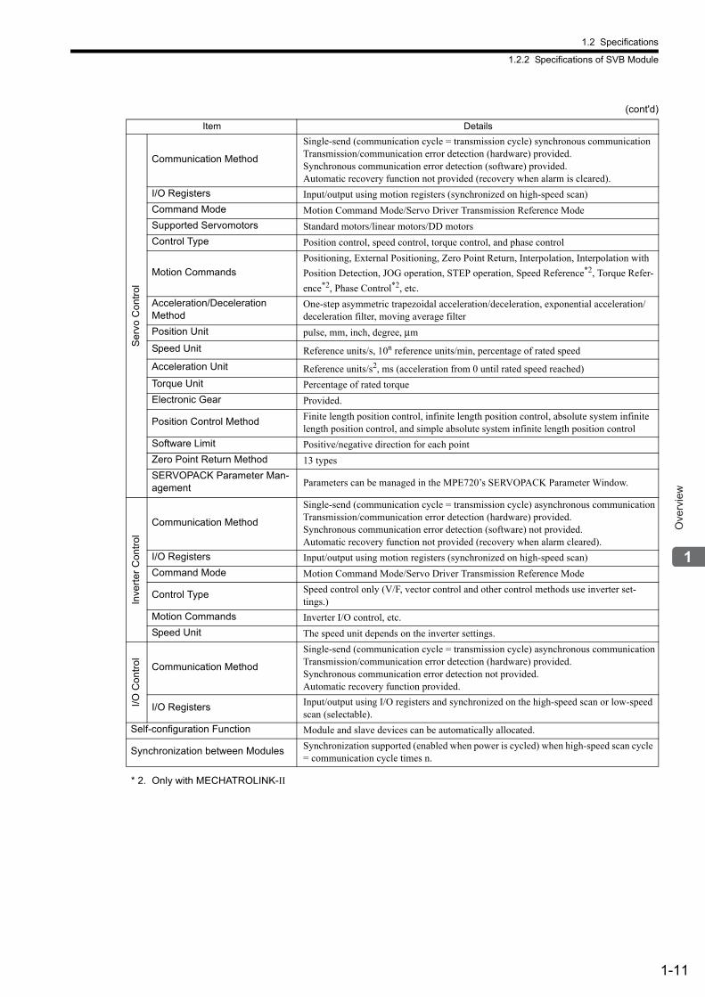
Item DetailsS
erv
o C
on
trol
Communication Method
Single-send (communication cycle = transmission cycle) synchronous communicationTransmission/communication error detection (hardware) provided. Synchronous communication error detection (software) provided. Automatic recovery function not provided (recovery when alarm is cleared).
I/O Registers Input/output using motion registers (synchronized on high-speed scan)
Command Mode Motion Command Mode/Servo Driver Transmission Reference Mode
Supported Servomotors Standard motors/linear motors/DD motors
Control Type Position control, speed control, torque control, and phase control
Motion Commands
Positioning, External Positioning, Zero Point Return, Interpolation, Interpolation with
Position Detection, JOG operation, STEP operation, Speed Reference*2, Torque Refer-
ence*2, Phase Control*2, etc.
Acceleration/Deceleration Method
One-step asymmetric trapezoidal acceleration/deceleration, exponential acceleration/deceleration filter, moving average filter
Position Unit pulse, mm, inch, degree, μm
Speed Unit Reference units/s, 10n reference units/min, percentage of rated speed
Acceleration Unit Reference units/s2, ms (acceleration from 0 until rated speed reached)
Torque Unit Percentage of rated torque
Electronic Gear Provided.
Position Control Method Finite length position control, infinite length position control, absolute system infinite length position control, and simple absolute system infinite length position control
Software Limit Positive/negative direction for each point
Zero Point Return Method 13 types
SERVOPACK Parameter Man-agement Parameters can be managed in the MPE720’s SERVOPACK Parameter Window.
Inve
rte
r C
on
tro
l
Communication Method
Single-send (communication cycle = transmission cycle) asynchronous communicationTransmission/communication error detection (hardware) provided. Synchronous communication error detection (software) not provided. Automatic recovery function not provided (recovery when alarm cleared).
I/O Registers Input/output using motion registers (synchronized on high-speed scan)
Command Mode Motion Command Mode/Servo Driver Transmission Reference Mode
Control Type Speed control only (V/F, vector control and other control methods use inverter set-tings.)
Motion Commands Inverter I/O control, etc.
Speed Unit The speed unit depends on the inverter settings.
I/O
Co
ntr
ol
Communication Method
Single-send (communication cycle = transmission cycle) asynchronous communicationTransmission/communication error detection (hardware) provided. Synchronous communication error detection not provided. Automatic recovery function provided.
I/O Registers Input/output using I/O registers and synchronized on the high-speed scan or low-speed scan (selectable).
Self-configuration Function Module and slave devices can be automatically allocated.
Synchronization between Modules Synchronization supported (enabled when power is cycled) when high-speed scan cycle = communication cycle times n.
1.2 Specifications
1.2.2 Specifications of SVB Module
1-12
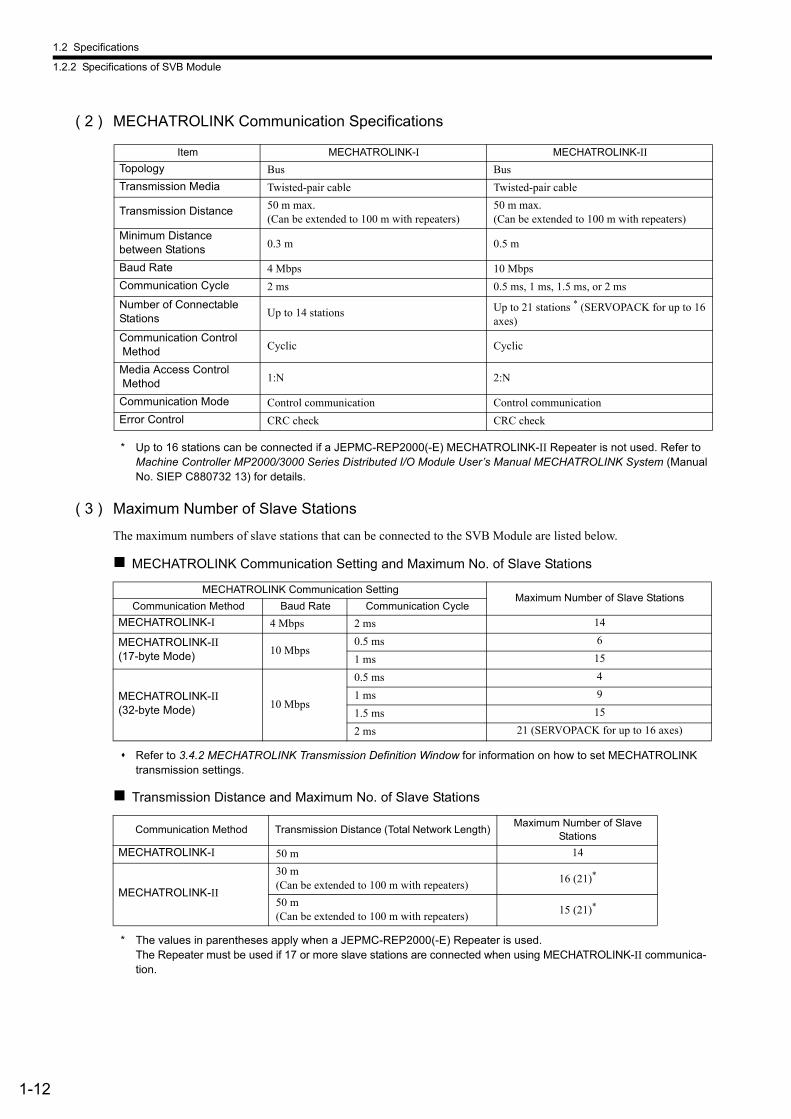
( 2 ) MECHATROLINK Communication Specifications
* Up to 16 stations can be connected if a JEPMC-REP2000(-E) MECHATROLINK-II Repeater is not used. Refer to Machine Controller MP2000/3000 Series Distributed I/O Module User’s Manual MECHATROLINK System (Manual No. SIEP C880732 13) for details.
( 3 ) Maximum Number of Slave Stations
The maximum numbers of slave stations that can be connected to the SVB Module are listed below.
MECHATROLINK Communication Setting and Maximum No. of Slave Stations
Refer to 3.4.2 MECHATROLINK Transmission Definition Window for information on how to set MECHATROLINK transmission settings.
Transmission Distance and Maximum No. of Slave Stations
* The values in parentheses apply when a JEPMC-REP2000(-E) Repeater is used. The Repeater must be used if 17 or more slave stations are connected when using MECHATROLINK-II communica-tion.
Item MECHATROLINK-I MECHATROLINK-II
Topology Bus Bus
Transmission Media Twisted-pair cable Twisted-pair cable
Transmission Distance 50 m max.(Can be extended to 100 m with repeaters)
50 m max.(Can be extended to 100 m with repeaters)
Minimum Distancebetween Stations 0.3 m 0.5 m
Baud Rate 4 Mbps 10 Mbps
Communication Cycle 2 ms 0.5 ms, 1 ms, 1.5 ms, or 2 ms
Number of ConnectableStations Up to 14 stations Up to 21 stations * (SERVOPACK for up to 16
axes)
Communication Control Method Cyclic Cyclic
Media Access Control Method 1:N 2:N
Communication Mode Control communication Control communication
Error Control CRC check CRC check
MECHATROLINK Communication SettingMaximum Number of Slave Stations
Communication Method Baud Rate Communication Cycle
MECHATROLINK-I 4 Mbps 2 ms 14
MECHATROLINK-II (17-byte Mode) 10 Mbps
0.5 ms 6
1 ms 15
MECHATROLINK-II (32-byte Mode) 10 Mbps
0.5 ms 4
1 ms 9
1.5 ms 15
2 ms 21 (SERVOPACK for up to 16 axes)
Communication Method Transmission Distance (Total Network Length) Maximum Number of Slave
Stations
MECHATROLINK-I 50 m 14
MECHATROLINK-II
30 m(Can be extended to 100 m with repeaters)
16 (21)*
50 m(Can be extended to 100 m with repeaters)
15 (21)*
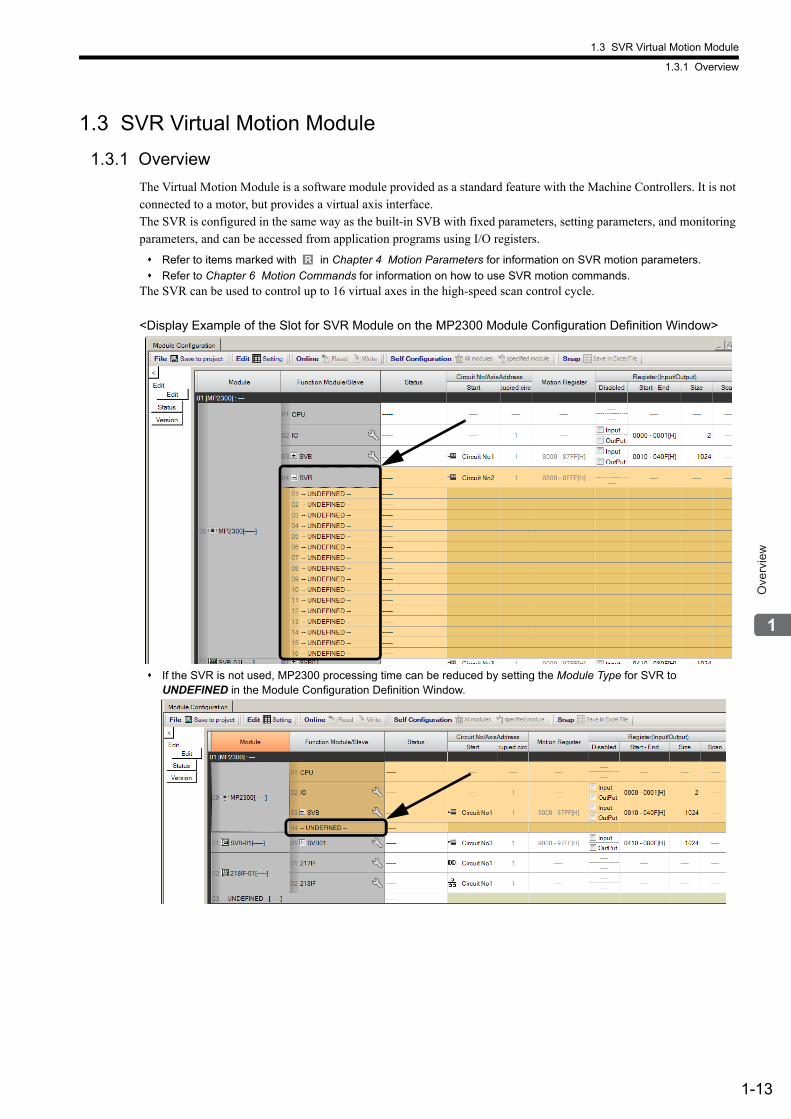
1.3 SVR Virtual Motion Module
1.3.1 Overview
1-13
Ove
rvie
w
1.3 SVR Virtual Motion Module
1.3.1 Overview
The Virtual Motion Module is a software module provided as a standard feature with the Machine Controllers. It is not connected to a motor, but provides a virtual axis interface. The SVR is configured in the same way as the built-in SVB with fixed parameters, setting parameters, and monitoring parameters, and can be accessed from application programs using I/O registers.
Refer to items marked with in Chapter 4 Motion Parameters for information on SVR motion parameters.
Refer to Chapter 6 Motion Commands for information on how to use SVR motion commands.The SVR can be used to control up to 16 virtual axes in the high-speed scan control cycle.
<Display Example of the Slot for SVR Module on the MP2300 Module Configuration Definition Window>
If the SVR is not used, MP2300 processing time can be reduced by setting the Module Type for SVR toUNDEFINED in the Module Configuration Definition Window.
R
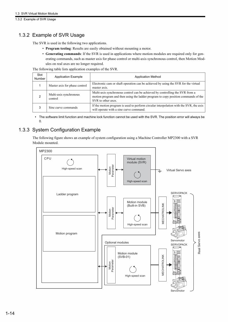
1.3 SVR Virtual Motion Module
1.3.2 Example of SVR Usage
1-14
1.3.2 Example of SVR Usage
The SVR is used in the following two applications.
• Program testing: Results are easily obtained without mounting a motor.
• Generating commands: If the SVR is used in applications where motion modules are required only for gen-erating commands, such as master axis for phase control or multi-axis synchronous control, then Motion Mod-ules on real axes are no longer required.
The following table lists application examples of the SVR.
The software limit function and machine lock function cannot be used with the SVR. The position error will always be 0.
1.3.3 System Configuration Example
The following figure shows an example of system configuration using a Machine Controller MP2300 with a SVR Module mounted.
Slot Number
Application Example Application Method
1 Master axis for phase controlElectronic cam or shaft operation can be achieved by using the SVR for the virtual master axis.
2Multi-axis synchronouscontrol
Multi-axis synchronous control can be achieved by controlling the SVR from a motion program and then using the ladder program to copy position commands of the SVR to other axes.
3 Sine curve commandsIf the motion program is used to perform circular interpolation with the SVR, the axis will operate with a sine curve command.
Mot
ion
Par
amet
er
Virtual Servo axes
MP2300
Mot
ion
Par
amet
erM
otio
nP
aram
eter
Optional modules
Ladder program
Motion program
High-speed scan
High-speed scan
ME
CH
ATR
OLI
NK
ME
CH
ATR
OLI
NK
SERVOPACKYASKAWA SERVOPACK 200V
SGDS-01A12A
SW1
CHARGE
CN3
A/B
CN1
CN2
CN4
L1L2
L2C
L1C
B1/B2
U
V
W
CN6
ServomotorSERVOPACK
YASKAWA SERVOPACK 200V
SGDS-01A12A
SW1
CHARGE
CN3
A/B
CN1
CN2
CN4
L1L2
L2C
L1C
B1/B2
U
V
W
CN6
Servomotor
Rea
l Ser
vo a
xes
Virtual motionmodule (SVR)
High-speed scan
Motion module(Built-in SVB)
High-speed scan
Motion module(SVB-01)
CPU
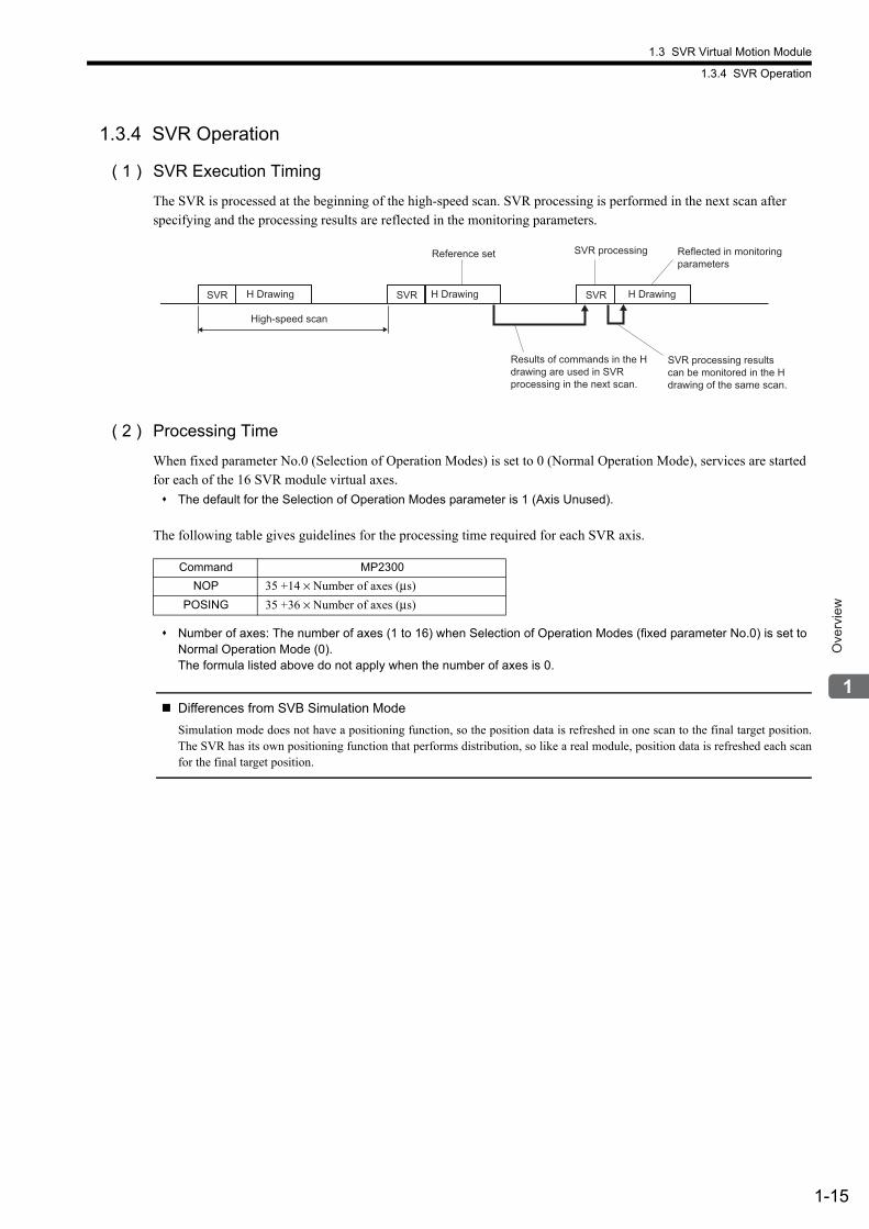
1.3 SVR Virtual Motion Module
1.3.4 SVR Operation
1-15
Ove
rvie
w
1.3.4 SVR Operation
( 1 ) SVR Execution Timing
The SVR is processed at the beginning of the high-speed scan. SVR processing is performed in the next scan after specifying and the processing results are reflected in the monitoring parameters.
( 2 ) Processing Time
When fixed parameter No.0 (Selection of Operation Modes) is set to 0 (Normal Operation Mode), services are started for each of the 16 SVR module virtual axes.
The default for the Selection of Operation Modes parameter is 1 (Axis Unused).
The following table gives guidelines for the processing time required for each SVR axis.
Number of axes: The number of axes (1 to 16) when Selection of Operation Modes (fixed parameter No.0) is set to Normal Operation Mode (0).The formula listed above do not apply when the number of axes is 0.
Differences from SVB Simulation Mode
Simulation mode does not have a positioning function, so the position data is refreshed in one scan to the final target position.The SVR has its own positioning function that performs distribution, so like a real module, position data is refreshed each scanfor the final target position.
SVR SVR SVR
High-speed scan
H Drawing
Results of commands in the H
drawing are used in SVR
processing in the next scan.
H DrawingH Drawing
SVR processing results
can be monitored in the H
drawing of the same scan.
Reflected in monitoring
parameters
Reference set SVR processing
Command MP2300
NOP 35 +14 × Number of axes (μs)
POSING 35 +36 × Number of axes (μs)
2-1
Set
tings
and
Inst
alla
tion
2
Settings and Installation
This chapter explains the LED indicators and switch settings of the SVB-01 Module and how to install or remove it.
2.1 LED Indicators and Switch Settings - - - - - - - - - - - - - - - - - - - - - - - - - - - -2-2
2.1.1 External Appearance - - - - - - - - - - - - - - - - - - - - - - - - - - - - - - - - - - - - - - - - - - - - - - - 2-2
2.1.2 Indicators - - - - - - - - - - - - - - - - - - - - - - - - - - - - - - - - - - - - - - - - - - - - - - - - - - - - - - - 2-2
2.1.3 SVB-01 Module Status Indication - - - - - - - - - - - - - - - - - - - - - - - - - - - - - - - - - - - - - - 2-2
2.1.4 Switch Settings - - - - - - - - - - - - - - - - - - - - - - - - - - - - - - - - - - - - - - - - - - - - - - - - - - - 2-4
2.2 Applicable Machine Controllers for SVB-01 Modules - - - - - - - - - - - - - - - -2-6
2.2.1 MP2000 Series - - - - - - - - - - - - - - - - - - - - - - - - - - - - - - - - - - - - - - - - - - - - - - - - - - - 2-6
2.2.2 MP3000 Series - - - - - - - - - - - - - - - - - - - - - - - - - - - - - - - - - - - - - - - - - - - - - - - - - - - 2-6
2.3 Mounting/Removing SVB-01 Modules - - - - - - - - - - - - - - - - - - - - - - - - - -2-8
2.3.1 Mounting an SVB-01 Module - - - - - - - - - - - - - - - - - - - - - - - - - - - - - - - - - - - - - - - - - 2-8
2.3.2 Replacing and Adding an SVB-01 Module - - - - - - - - - - - - - - - - - - - - - - - - - - - - - - - - 2-9
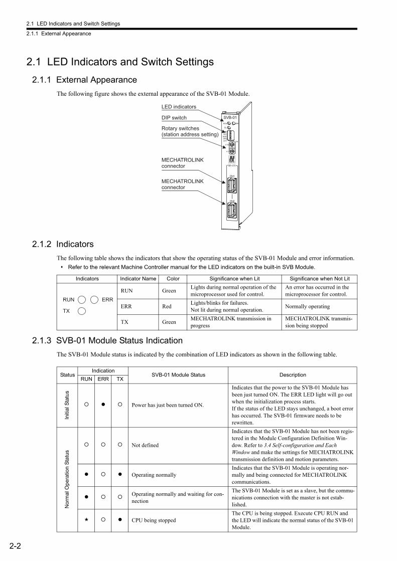
2.1 LED Indicators and Switch Settings
2.1.1 External Appearance
2-2
2.1 LED Indicators and Switch Settings
2.1.1 External Appearance
The following figure shows the external appearance of the SVB-01 Module.
2.1.2 Indicators
The following table shows the indicators that show the operating status of the SVB-01 Module and error information.
Refer to the relevant Machine Controller manual for the LED indicators on the built-in SVB Module.
2.1.3 SVB-01 Module Status Indication
The SVB-01 Module status is indicated by the combination of LED indicators as shown in the following table.
SVB-01
TX
ERRRUN
SPDSIZEM/S
ONOFF
10
1
M-I/II
CN1
CN2
LED indicators
Rotary switches (station address setting)
DIP switch
MECHATROLINK connector
MECHATROLINK connector
Indicators Indicator Name Color Significance when Lit Significance when Not Lit
RUN GreenLights during normal operation of the microprocessor used for control.
An error has occurred in the microprocessor for control.
ERR RedLights/blinks for failures. Not lit during normal operation.
Normally operating
TX GreenMECHATROLINK transmission in progress
MECHATROLINK transmis-sion being stopped
RUN
TX
ERR
StatusIndication
SVB-01 Module Status DescriptionRUN ERR TX
Initi
al S
tatu
s
Power has just been turned ON.
Indicates that the power to the SVB-01 Module has been just turned ON. The ERR LED light will go out when the initialization process starts.If the status of the LED stays unchanged, a boot error has occurred. The SVB-01 firmware needs to be rewritten.
Nor
mal
Ope
ratio
n S
tatu
s
Not defined
Indicates that the SVB-01 Module has not been regis-tered in the Module Configuration Definition Win-dow. Refer to 3.4 Self-configuration and Each Window and make the settings for MECHATROLINK transmission definition and motion parameters.
Operating normallyIndicates that the SVB-01 Module is operating nor-mally and being connected for MECHATROLINK communications.
Operating normally and waiting for con-nection
The SVB-01 Module is set as a slave, but the commu-nications connection with the master is not estab-lished.
CPU being stoppedThe CPU is being stopped. Execute CPU RUN and the LED will indicate the normal status of the SVB-01 Module.
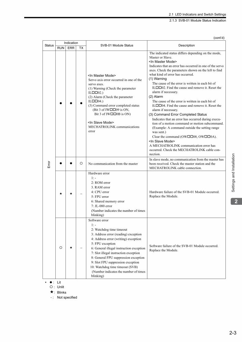
2.1 LED Indicators and Switch Settings
2.1.3 SVB-01 Module Status Indication
2-3
Set
tings
and
Inst
alla
tion
: Lit : Unlit
: Blinks
- : Not specified
Err
or
<In Master Mode>Servo axis error occurred in one of the servo axes.(1) Warning (Check the parameter IL02.)(2) Alarm (Check the parameter IL04.)(3) Command error completed status (Bit 3 of IW09 is ON, Bit 3 of IW0B is ON)
<In Slave Mode>MECHATROLINK communications error
The indicated status differs depending on the mode, Master or Slave.<In Master Mode>Indicates that an error has occurred in one of the servo axes. Check the parameters shown on the left to find what kind of error has occurred.(1) Warning
The cause of the error is written in each bit of IL02. Find the cause and remove it. Reset the alarm if necessary.
(2) AlarmThe cause of the error is written in each bit of IL04. Find the cause and remove it. Reset the alarm if necessary.
(3) Command Error Completed StatusIndicates that an error has occurred during execu-tion of a motion command or motion subcommand. (Example: A command outside the setting range was sent.)Clear the command (OW08, OW0A).
<In Slave Mode>A MECHATROLINK communication error has occurred. Check the MECHATROLINK cable con-nection.
No communication from the masterIn slave mode, no communication from the master has been received. Check the master station and the MECHATROLINK cable connection.
−
Hardware error1: -2: ROM error3. RAM error4: CPU error5: FPU error6: Shared memory error7: JL-080 error(Number indicates the number of times blinking)
Hardware failure of the SVB-01 Module occurred. Replace the Module.
−
Software error1: -2: Watchdog time timeout3: Address error (reading) exception4: Address error (writing) exception5: FPU exception6: General illegal instruction exception7: Slot illegal instruction exception8: General FPU suppression exception9: Slot FPU suppression exception
10: Watchdog time timeout (SVB) (Number indicates the number of times blinking)
Software failure of the SVB-01 Module occurred. Replace the Module.
(cont’d)
StatusIndication
SVB-01 Module Status DescriptionRUN ERR TX
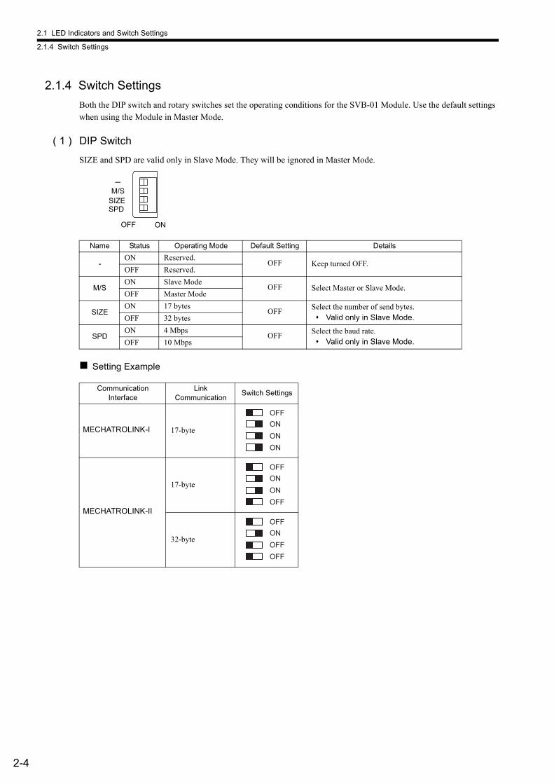
2.1 LED Indicators and Switch Settings
2.1.4 Switch Settings
2-4
2.1.4 Switch Settings
Both the DIP switch and rotary switches set the operating conditions for the SVB-01 Module. Use the default settings when using the Module in Master Mode.
( 1 ) DIP Switch
SIZE and SPD are valid only in Slave Mode. They will be ignored in Master Mode.
Setting Example
Name Status Operating Mode Default Setting Details
-ON Reserved.
OFF Keep turned OFF.OFF Reserved.
M/SON Slave Mode
OFF Select Master or Slave Mode.OFF Master Mode
SIZEON 17 bytes
OFFSelect the number of send bytes. Valid only in Slave Mode.OFF 32 bytes
SPDON 4 Mbps
OFFSelect the baud rate. Valid only in Slave Mode.OFF 10 Mbps
CommunicationInterface
LinkCommunication
Switch Settings
MECHATROLINK-I 17-byte
MECHATROLINK-II
17-byte
32-byte
OFF ON
SPDSIZEM/S
OFF
ON
ON
ON
OFF
OFF
ON
ON
OFF
OFF
ON
OFF
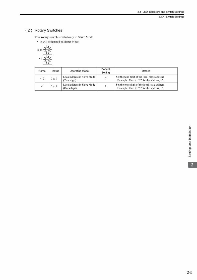
2.1 LED Indicators and Switch Settings
2.1.4 Switch Settings
2-5
Set
tings
and
Inst
alla
tion
( 2 ) Rotary Switches
This rotary switch is valid only in Slave Mode.
It will be ignored in Master Mode.
Name Status Operating ModeDefaultSetting
Details
×10 0 to 9Local address in Slave Mode (Tens digit)
0 Set the tens digit of the local slave address. Example: Turn to “1” for the address, 15.
×1 0 to 9Local address in Slave Mode (Ones digit)
1 Set the ones digit of the local slave address. Example: Turn to “5” for the address, 15.
10
1
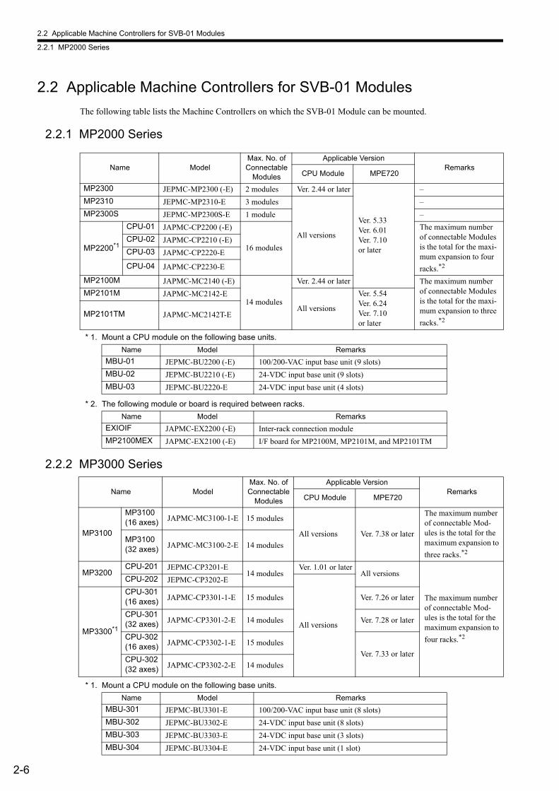
2.2 Applicable Machine Controllers for SVB-01 Modules
2.2.1 MP2000 Series
2-6
2.2 Applicable Machine Controllers for SVB-01 Modules
The following table lists the Machine Controllers on which the SVB-01 Module can be mounted.
2.2.1 MP2000 Series
* 1. Mount a CPU module on the following base units.
* 2. The following module or board is required between racks.
2.2.2 MP3000 Series
* 1. Mount a CPU module on the following base units.
Name ModelMax. No. of Connectable
Modules
Applicable VersionRemarks
CPU Module MPE720
MP2300 JEPMC-MP2300 (-E) 2 modules Ver. 2.44 or later
Ver. 5.33Ver. 6.01Ver. 7.10or later
–
MP2310 JEPMC-MP2310-E 3 modules
All versions
–
MP2300S JEPMC-MP2300S-E 1 module –
MP2200*1
CPU-01 JAPMC-CP2200 (-E)
16 modules
The maximum number of connectable Modules is the total for the maxi-mum expansion to four
racks.*2
CPU-02 JAPMC-CP2210 (-E)
CPU-03 JAPMC-CP2220-E
CPU-04 JAPMC-CP2230-E
MP2100M JAPMC-MC2140 (-E)
14 modules
Ver. 2.44 or later The maximum number of connectable Modules is the total for the maxi-mum expansion to three
racks.*2
MP2101M JAPMC-MC2142-E
All versions
Ver. 5.54Ver. 6.24Ver. 7.10or later
MP2101TM JAPMC-MC2142T-E
Name Model Remarks
MBU-01 JEPMC-BU2200 (-E) 100/200-VAC input base unit (9 slots)
MBU-02 JEPMC-BU2210 (-E) 24-VDC input base unit (9 slots)
MBU-03 JEPMC-BU2220-E 24-VDC input base unit (4 slots)
Name Model Remarks
EXIOIF JAPMC-EX2200 (-E) Inter-rack connection module
MP2100MEX JAPMC-EX2100 (-E) I/F board for MP2100M, MP2101M, and MP2101TM
Name ModelMax. No. of Connectable
Modules
Applicable VersionRemarks
CPU Module MPE720
MP3100
MP3100 (16 axes) JAPMC-MC3100-1-E 15 modules
All versions Ver. 7.38 or later
The maximum number of connectable Mod-ules is the total for the maximum expansion to
three racks.*2
MP3100 (32 axes) JAPMC-MC3100-2-E 14 modules
MP3200CPU-201 JEPMC-CP3201-E
14 modulesVer. 1.01 or later
All versions
The maximum number of connectable Mod-ules is the total for the maximum expansion to
four racks.*2
CPU-202 JEPMC-CP3202-E
All versionsMP3300*1
CPU-301 (16 axes) JAPMC-CP3301-1-E 15 modules Ver. 7.26 or later
CPU-301 (32 axes) JAPMC-CP3301-2-E 14 modules Ver. 7.28 or later
CPU-302 (16 axes) JAPMC-CP3302-1-E 15 modules
Ver. 7.33 or laterCPU-302 (32 axes) JAPMC-CP3302-2-E 14 modules
Name Model Remarks
MBU-301 JEPMC-BU3301-E 100/200-VAC input base unit (8 slots)
MBU-302 JEPMC-BU3302-E 24-VDC input base unit (8 slots)
MBU-303 JEPMC-BU3303-E 24-VDC input base unit (3 slots)
MBU-304 JEPMC-BU3304-E 24-VDC input base unit (1 slot)
2.2 Applicable Machine Controllers for SVB-01 Modules
2.2.2 MP3000 Series
2-7
Set
tings
and
Inst
alla
tion
* 2. The following module or board is required between racks.
Name Model Remarks
EXIOIF JAPMC-EX2200 (-E) Inter-rack connection module
MP3100EX JAPMC-EX3100-ECan be connected to the Expansion Interface Module and the EXIOIF Module.
MP3101EX JAPMC-EX3101-E Can be connected to the EXIOIF Module.
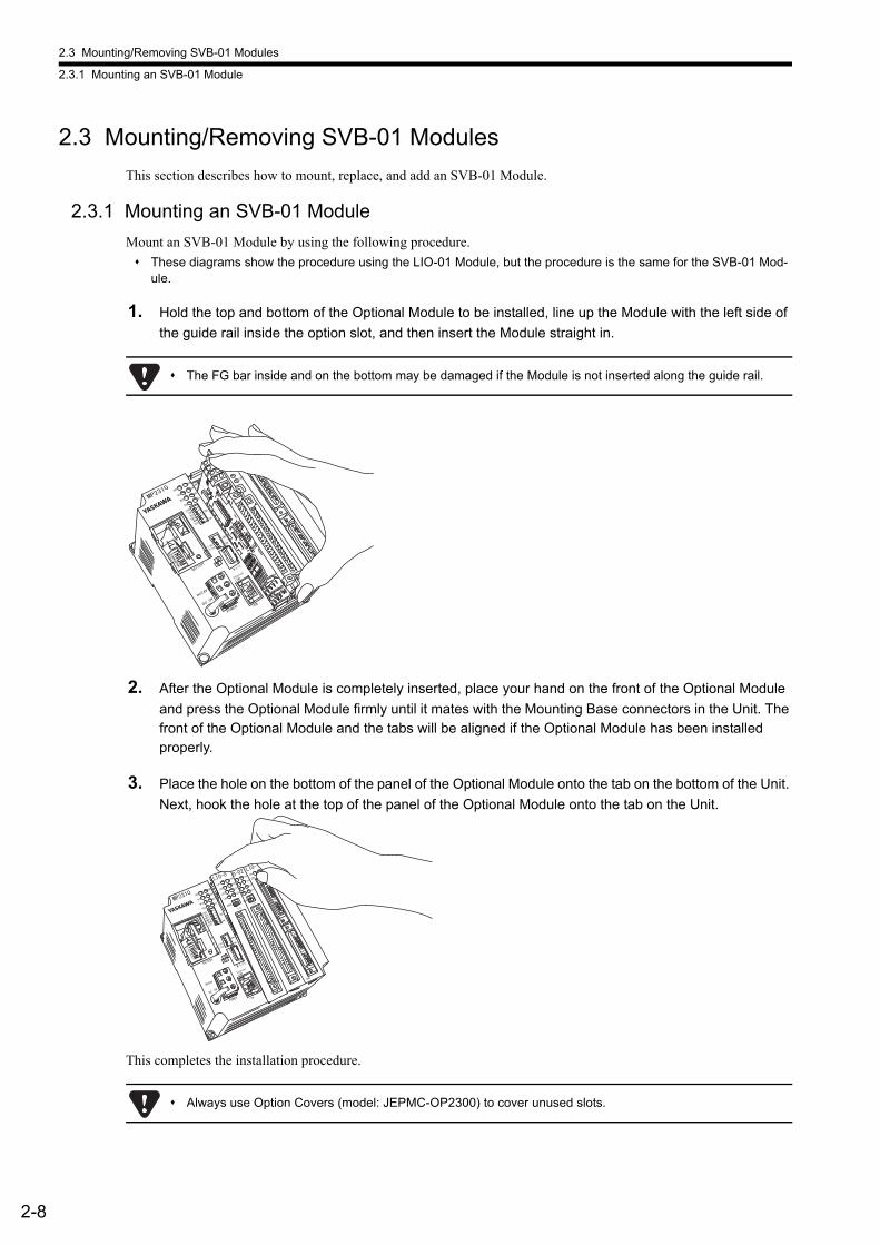
2.3 Mounting/Removing SVB-01 Modules
2.3.1 Mounting an SVB-01 Module
2-8
2.3 Mounting/Removing SVB-01 Modules
This section describes how to mount, replace, and add an SVB-01 Module.
2.3.1 Mounting an SVB-01 Module
Mount an SVB-01 Module by using the following procedure.
These diagrams show the procedure using the LIO-01 Module, but the procedure is the same for the SVB-01 Mod-ule.
1. Hold the top and bottom of the Optional Module to be installed, line up the Module with the left side of
the guide rail inside the option slot, and then insert the Module straight in.
2. After the Optional Module is completely inserted, place your hand on the front of the Optional Module
and press the Optional Module firmly until it mates with the Mounting Base connectors in the Unit. The front of the Optional Module and the tabs will be aligned if the Optional Module has been installed properly.
3. Place the hole on the bottom of the panel of the Optional Module onto the tab on the bottom of the Unit.
Next, hook the hole at the top of the panel of the Optional Module onto the tab on the Unit.
This completes the installation procedure.
The FG bar inside and on the bottom may be damaged if the Module is not inserted along the guide rail.
Always use Option Covers (model: JEPMC-OP2300) to cover unused slots.

2.3 Mounting/Removing SVB-01 Modules
2.3.2 Replacing and Adding an SVB-01 Module
2-9
Set
tings
and
Inst
alla
tion
2.3.2 Replacing and Adding an SVB-01 Module
Replace or add an SVB-01 Module by using the following procedure.
These diagrams show the procedure using the LIO-01 Module, but the procedure is the same for the SVB-01 Mod-ule.
1. Turn OFF the power supply and disconnect all cables from the Machine Controller.
2. Pull the notch on the side toward you to remove the battery cover.
3. Insert the protruding part of the battery cover into the slot on top of the Optional Module panel to
unhook the tab. Face the front of the battery cover toward you for this operation.
Unhook the bottom tab in the same way.
Always create a backup before replacing or adding Optional Modules.
Back up the program from the Machine Controller to the PC using the MPE720.
<MP2200/MP2300> <MP2310/MP2300S>
12345
6
SW1
IP
STOP
MODE
LD4
CN1
LD3 LD8
LD7
SUP
INIT
CNFG
MON
TEST
ON
I/O
MODE
LD4
LD3 LD8
LD7LD2
LD6
LD5
FU
RUN
I/O
1234
SW2
ONE-IN
IT
E-TEST
BATTER
Y
DC24V
Ethern
et
LINK
M-I/II
DCOV
Use the same method to remove the Option Cover from an unused slot before adding an Optional Module.
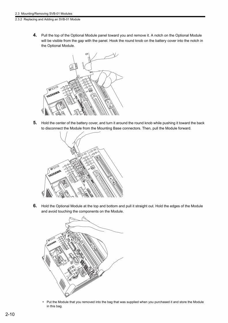
2.3 Mounting/Removing SVB-01 Modules
2.3.2 Replacing and Adding an SVB-01 Module
2-10
4. Pull the top of the Optional Module panel toward you and remove it. A notch on the Optional Module
will be visible from the gap with the panel. Hook the round knob on the battery cover into the notch in the Optional Module.
5. Hold the center of the battery cover, and turn it around the round knob while pushing it toward the back
to disconnect the Module from the Mounting Base connectors. Then, pull the Module forward.
6. Hold the Optional Module at the top and bottom and pull it straight out. Hold the edges of the Module
and avoid touching the components on the Module.
Put the Module that you removed into the bag that was supplied when you purchased it and store the Module in this bag.
3-1
Sel
f-con
figur
atio
n an
d C
reat
ed D
efin
ition
File
s
3
Self-configuration and Created Definition Files
This chapter describes the procedures for self-configuration and the definition files that will be cre-ated by self-configuration.
3.1 Self-configuration Overview - - - - - - - - - - - - - - - - - - - - - - - - - - - - - - - - - -3-2
3.2 Executing Self-configuration - - - - - - - - - - - - - - - - - - - - - - - - - - - - - - - - -3-4
3.3 System Startup Using Self-Configuration - - - - - - - - - - - - - - - - - - - - - - - -3-5
3.3.1 Starting the System for First Time - - - - - - - - - - - - - - - - - - - - - - - - - - - - - - - - - - - - - - 3-5
3.3.2 System Startup when Adding Electronic Devices - - - - - - - - - - - - - - - - - - - - - - - - - - - 3-8
3.3.3 System Startup when Replacing Electronic Devices - - - - - - - - - - - - - - - - - - - - - - - - 3-10
3.4 Self-configuration and Each Window - - - - - - - - - - - - - - - - - - - - - - - - - - 3-12
3.4.1 Module Configuration Definition Window - - - - - - - - - - - - - - - - - - - - - - - - - - - - - - - - 3-13
3.4.2 MECHATROLINK Transmission Definition Window - - - - - - - - - - - - - - - - - - - - - - - - - 3-16
3.4.3 Motion Parameter Window - - - - - - - - - - - - - - - - - - - - - - - - - - - - - - - - - - - - - - - - - - 3-22
3.4.4 SERVOPACK Parameter Window - - - - - - - - - - - - - - - - - - - - - - - - - - - - - - - - - - - - - 3-31
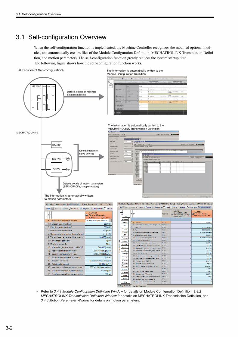
3.1 Self-configuration Overview
3-2
3.1 Self-configuration Overview
When the self-configuration function is implemented, the Machine Controller recognizes the mounted optional mod-ules, and automatically creates files of the Module Configuration Definition, MECHATROLINK Transmission Defini-tion, and motion parameters. The self-configuration function greatly reduces the system startup time.The following figure shows how the self-configuration function works.
Refer to 3.4.1 Module Configuration Definition Window for details on Module Configuration Definition, 3.4.2 MECHATROLINK Transmission Definition Window for details on MECHATROLINK Transmission Definition, and 3.4.3 Motion Parameter Window for details on motion parameters.
The information is automatically written to the Module Configuration Definition.
The information is automatically written to theMECHATROLINK Transmission Definition.
MP2300
MECHATROLINK-II
218IF LIO-02SVB-01
<Execution of Self-configuration>
Detects details of mountedoptional modules
Detects details ofslave devices
SGD7S
MSGDV
M
IO2310
The information is automatically written to motion parameters.
Detects details of motion parameters(SERVOPACKs, stepper motors)
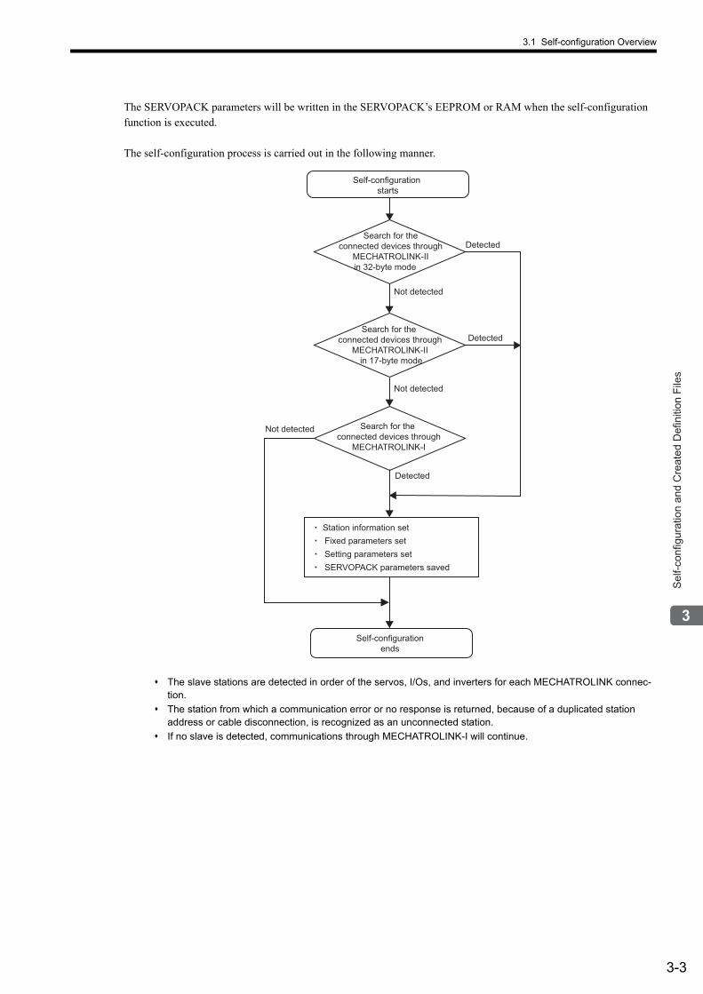
3.1 Self-configuration Overview
3-3
Sel
f-con
figur
atio
n an
d C
reat
ed D
efin
ition
File
s
The SERVOPACK parameters will be written in the SERVOPACK’s EEPROM or RAM when the self-configuration function is executed.
The self-configuration process is carried out in the following manner.
The slave stations are detected in order of the servos, I/Os, and inverters for each MECHATROLINK connec-tion.
The station from which a communication error or no response is returned, because of a duplicated station address or cable disconnection, is recognized as an unconnected station.
If no slave is detected, communications through MECHATROLINK-I will continue.
Self-configuration
starts
Self-configuration
ends
Station information set
Fixed parameters set
Setting parameters set
Detected
Detected
Detected
Not detected
Not detected
Not detected
Search for the
connected devices through
MECHATROLINK-II
in 32-byte mode
Search for the
connected devices through
MECHATROLINK-I
Search for the
connected devices through
MECHATROLINK-II
in 17-byte mode
SERVOPACK parameters saved
3.2 Executing Self-configuration
3-4
3.2 Executing Self-configuration
There are two ways to execute self-configuration.
Turning ON the Power After Setting the DIP switch “CNFG”
Set the DIP switch “CNFG” on the Machine Controller to ON, and then turn ON the power to execute self-configura-tion. The setting of the DIP switch “INIT” causes some differences in the results of self-configuration.
After execution of self-configuration, be sure to execute Save to Flash to save the results of self-configuration in the Machine Controller.
For MP2100, MP2100M, MP2101T, and MP2101TM Machine Controllers, the DIP switch is not commonly used for self-configuration. Use an MPE720 as described below to execute self-configuration.
For details on the parameters that are written in motion parameters when executing self-configuration, refer to 11.6.5 Parameters Updated during Self-configuration.
Using an MPE720
Start the MPE720 and open the Module Configuration Definition Window. Click All modules of the Module Configu-ration Definition Window, or select a module for which self-configuration is to be executed in the Module Configura-tion Definition Window and then click specified module.
Refer to 3.4.1 ( 1 ) Opening the Module Configuration Definition Window for information on how to open the Module Configuration Definition Window.
The results of configuration will be as follows.
For details on the parameters that are written in motion parameters when executing self-configuration, refer to 11.6.5 Parameters Updated during Self-configuration.
CNFG INIT Result
ON ON
• Module Configuration Definition will be updated.• All the detected axes (slave devices) will be allocated to the MECHATROLINK Transmission
Definition.• Some of the SERVOPACK parameters will be written in the motion parameters.
ON OFF
• Module Configuration Definition will be updated.• The axes that have already been allocated to the MECHATROLINK Transmission Definition
will stay unchanged. Only the axes that are newly detected by self-configuration will be newly allocated.
• The column showing the deleted axis will appear blank in the MECHATROLINK Transmission Definition Window.
• Some SERVOPACK parameters will be written to motion parameters for only the axes that are newly detected. The motion parameters for the axes that have already been allocated to the MECHATROLINK Transmission Definition Window will not be updated.
Button Name of MPE720 Result
All modules(Self-configuration for all modules)
• Module Configuration Definitions will be updated.• The axes that have already been allocated to the MECHATROLINK Transmission Definition will
remain unchanged. Only the axes that are newly detected by self-configuration will be newly allo-cated.
• The column showing the deleted axis will appear blank in the MECHATROLINK Transmission Definition Window.
• Some SERVOPACK parameters will be written to motion parameters for only the axes that are newly detected. The motion parameters for the axes that have already been allocated to the MECHATROLINK Transmission Definition Window will not be updated.
specified module(Self-configuration for individual module)
• The slave devices (slave axes) of the selected module will be detected.• The axes that have already been allocated to the MECHATROLINK Transmission Definition will
stay unchanged. Only the axes that are newly detected by self-configuration will be newly allocated.• The column showing the deleted axis will appear blank in the MECHATROLINK Transmission
Definition Window.• Some SERVOPACK parameters will be written to motion parameters for only the axes that are
newly detected. The motion parameters for the axes that have already been allocated to the MECHATROLINK Transmission Definition Window will not be updated.
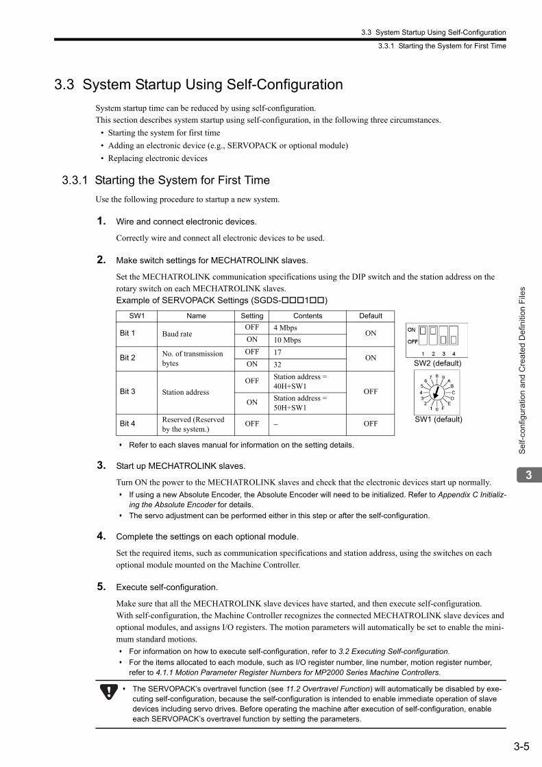
3.3 System Startup Using Self-Configuration
3.3.1 Starting the System for First Time
3-5
Sel
f-con
figur
atio
n an
d C
reat
ed D
efin
ition
File
s
3.3 System Startup Using Self-Configuration
System startup time can be reduced by using self-configuration. This section describes system startup using self-configuration, in the following three circumstances.
• Starting the system for first time
• Adding an electronic device (e.g., SERVOPACK or optional module)
• Replacing electronic devices
3.3.1 Starting the System for First Time
Use the following procedure to startup a new system.
1. Wire and connect electronic devices.
Correctly wire and connect all electronic devices to be used.
2. Make switch settings for MECHATROLINK slaves.
Set the MECHATROLINK communication specifications using the DIP switch and the station address on the rotary switch on each MECHATROLINK slaves.Example of SERVOPACK Settings (SGDS-1)
Refer to each slaves manual for information on the setting details.
3. Start up MECHATROLINK slaves.
Turn ON the power to the MECHATROLINK slaves and check that the electronic devices start up normally.
If using a new Absolute Encoder, the Absolute Encoder will need to be initialized. Refer to Appendix C Initializ-ing the Absolute Encoder for details.
The servo adjustment can be performed either in this step or after the self-configuration.
4. Complete the settings on each optional module.
Set the required items, such as communication specifications and station address, using the switches on each optional module mounted on the Machine Controller.
5. Execute self-configuration.
Make sure that all the MECHATROLINK slave devices have started, and then execute self-configuration.With self-configuration, the Machine Controller recognizes the connected MECHATROLINK slave devices and optional modules, and assigns I/O registers. The motion parameters will automatically be set to enable the mini-mum standard motions.
For information on how to execute self-configuration, refer to 3.2 Executing Self-configuration.
For the items allocated to each module, such as I/O register number, line number, motion register number, refer to 4.1.1 Motion Parameter Register Numbers for MP2000 Series Machine Controllers.
SW1 Name Setting Contents Default
Bit 1 Baud rateOFF 4 Mbps
ONON 10 Mbps
Bit 2 No. of transmission bytes
OFF 17ON
ON 32
Bit 3 Station address
OFF Station address =40H+SW1
OFF
ON Station address =50H+SW1
Bit 4 Reserved (Reserved by the system.)
OFF − OFF
SW2 (default)
SW1 (default)
The SERVOPACK’s overtravel function (see 11.2 Overtravel Function) will automatically be disabled by exe-cuting self-configuration, because the self-configuration is intended to enable immediate operation of slave devices including servo drives. Before operating the machine after execution of self-configuration, enable each SERVOPACK’s overtravel function by setting the parameters.
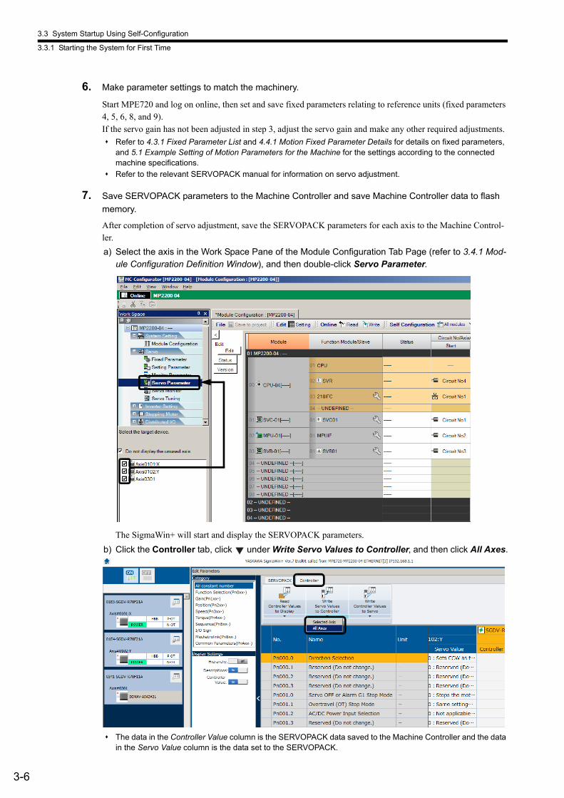
3.3 System Startup Using Self-Configuration
3.3.1 Starting the System for First Time
3-6
6. Make parameter settings to match the machinery.
Start MPE720 and log on online, then set and save fixed parameters relating to reference units (fixed parameters 4, 5, 6, 8, and 9).If the servo gain has not been adjusted in step 3, adjust the servo gain and make any other required adjustments.
Refer to 4.3.1 Fixed Parameter List and 4.4.1 Motion Fixed Parameter Details for details on fixed parameters, and 5.1 Example Setting of Motion Parameters for the Machine for the settings according to the connected machine specifications.
Refer to the relevant SERVOPACK manual for information on servo adjustment.
7. Save SERVOPACK parameters to the Machine Controller and save Machine Controller data to flash
memory.
After completion of servo adjustment, save the SERVOPACK parameters for each axis to the Machine Control-ler.
a) Select the axis in the Work Space Pane of the Module Configuration Tab Page (refer to 3.4.1 Mod-ule Configuration Definition Window), and then double-click Servo Parameter.
The SigmaWin+ will start and display the SERVOPACK parameters.
b) Click the Controller tab, click under Write Servo Values to Controller, and then click All Axes.
The data in the Controller Value column is the SERVOPACK data saved to the Machine Controller and the data in the Servo Value column is the data set to the SERVOPACK.
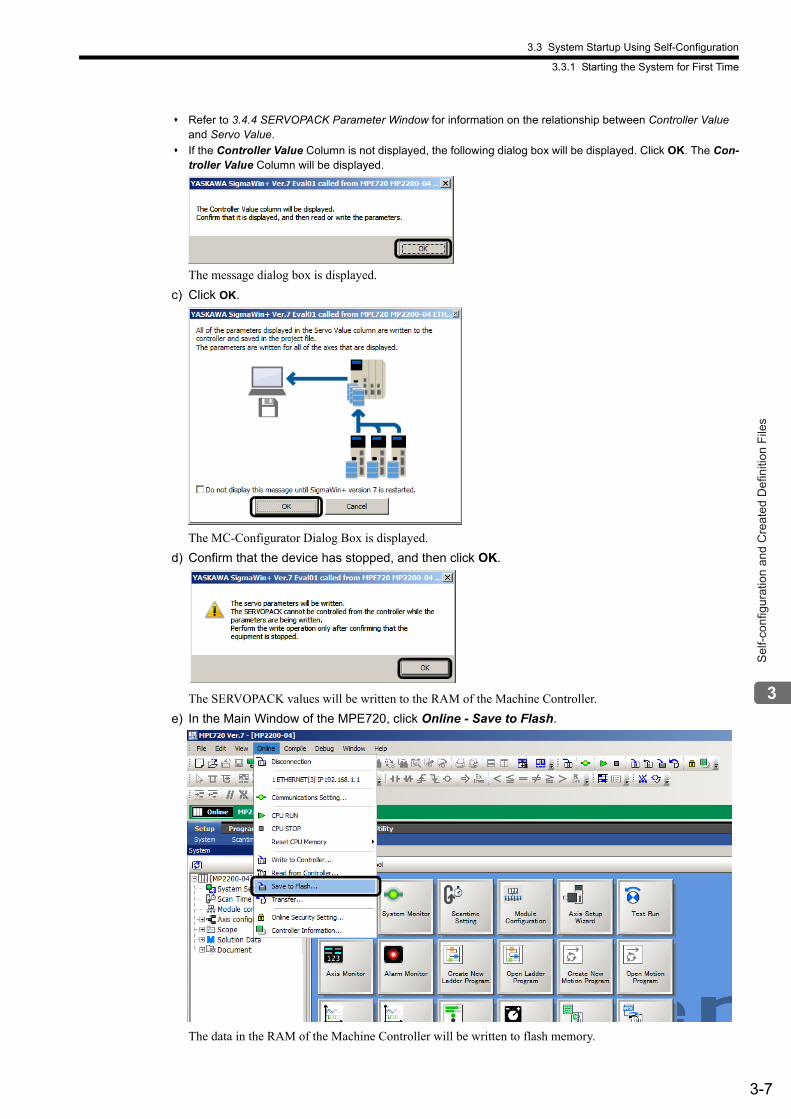
3.3 System Startup Using Self-Configuration
3.3.1 Starting the System for First Time
3-7
Sel
f-con
figur
atio
n an
d C
reat
ed D
efin
ition
File
s
Refer to 3.4.4 SERVOPACK Parameter Window for information on the relationship between Controller Value and Servo Value.
If the Controller Value Column is not displayed, the following dialog box will be displayed. Click OK. The Con-troller Value Column will be displayed.
The message dialog box is displayed.
c) Click OK.
The MC-Configurator Dialog Box is displayed.
d) Confirm that the device has stopped, and then click OK.
The SERVOPACK values will be written to the RAM of the Machine Controller.
e) In the Main Window of the MPE720, click Online - Save to Flash.
The data in the RAM of the Machine Controller will be written to flash memory.
3.3 System Startup Using Self-Configuration
3.3.2 System Startup when Adding Electronic Devices
3-8
8. Save ladder programs, and reboot the Machine Controller.
a) In the Main Window of the MPE720, click Online - Transfer - Write to Controller, and then follow the instructions to transfer the ladder program to the Machine Controller.
b) In the Main Window of the MPE720, click Online - Save to Flash.
The ladder program that was transferred and saved in the RAM of the Machine Controller will be written toflash memory.
c) Turn OFF all pins on the DIP switches of the Machine Controller and turn the power supply OFF and ON again.
This completes the system startup procedure.
3.3.2 System Startup when Adding Electronic Devices
Use the following procedure to start the system when adding SERVOPACKs, Optional Modules, and other electronic devices.
1. Back up applications.
Before adding the electronic devices, log on to the Machine Controller online using MPE720 and select Online - Transfer - Read from Controller to create a backup of the application.
2. Turn OFF the power to the Machine Controller.
After disconnecting MPE720 from the Machine Controller, turn OFF the Machine Controller power.
3. Start the electronic device to be added.
Make the DIP and rotary switch settings for the device to be added. For MECHATROLINK slaves, make the switch settings, and turn ON the power to the slave. Confirm that the device starts correctly and then turn OFF the power.
4. Connect the electronic device.
Connect the electronic device to the Machine Controller and turn ON the power to all the MECHATROLINK slaves.
5. Turn ON the Machine Controller power.
Turn ON the power of the Machine Controller.
After changing the application by editing ladder programs or changing parameter settings, always save the changes to the flash memory. If the Machine Controller’s power is turned OFF without having saved the changes in the application to the flash memory, the changed data will be lost from inside the Machine Con-troller. If this happens, load the application saved in the personal computer to the Machine Controller and save it to the flash memory.
You are recommended to back up the application whenever convenient. The procedure is given below.
MPE720: Log on online to the Machine Controller, then select Online - Transfer - Read from Controller.
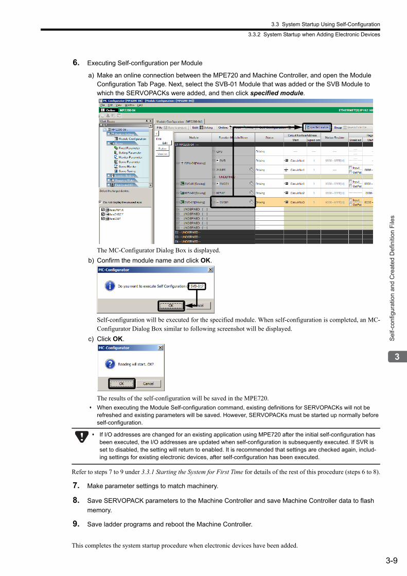
3.3 System Startup Using Self-Configuration
3.3.2 System Startup when Adding Electronic Devices
3-9
Sel
f-con
figur
atio
n an
d C
reat
ed D
efin
ition
File
s
6. Executing Self-configuration per Module
a) Make an online connection between the MPE720 and Machine Controller, and open the Module Configuration Tab Page. Next, select the SVB-01 Module that was added or the SVB Module to which the SERVOPACKs were added, and then click specified module.
The MC-Configurator Dialog Box is displayed.
b) Confirm the module name and click OK.
Self-configuration will be executed for the specified module. When self-configuration is completed, an MC-Configurator Dialog Box similar to following screenshot will be displayed.
c) Click OK.
The results of the self-configuration will be saved in the MPE720.
When executing the Module Self-configuration command, existing definitions for SERVOPACKs will not be refreshed and existing parameters will be saved. However, SERVOPACKs must be started up normally before self-configuration.
Refer to steps 7 to 9 under 3.3.1 Starting the System for First Time for details of the rest of this procedure (steps 6 to 8).
7. Make parameter settings to match machinery.
8. Save SERVOPACK parameters to the Machine Controller and save Machine Controller data to flash
memory.
9. Save ladder programs and reboot the Machine Controller.
This completes the system startup procedure when electronic devices have been added.
If I/O addresses are changed for an existing application using MPE720 after the initial self-configuration has been executed, the I/O addresses are updated when self-configuration is subsequently executed. If SVR is set to disabled, the setting will return to enabled. It is recommended that settings are checked again, includ-ing settings for existing electronic devices, after self-configuration has been executed.
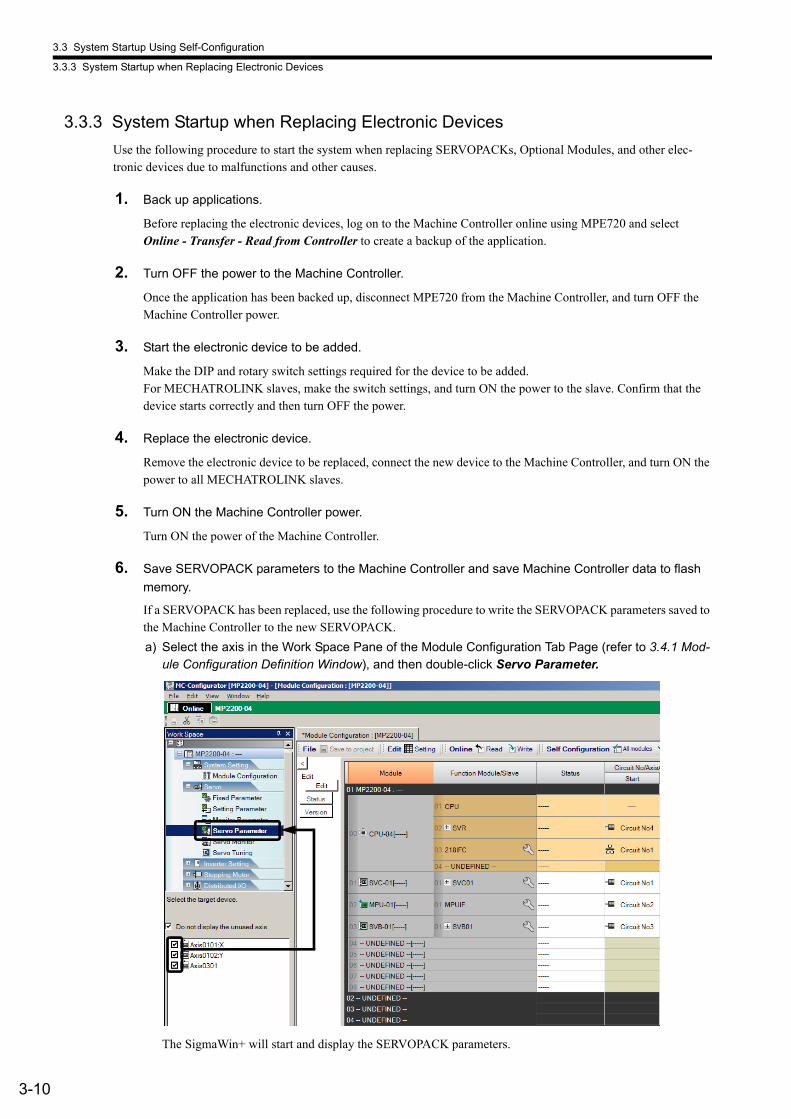
3.3 System Startup Using Self-Configuration
3.3.3 System Startup when Replacing Electronic Devices
3-10
3.3.3 System Startup when Replacing Electronic Devices
Use the following procedure to start the system when replacing SERVOPACKs, Optional Modules, and other elec-tronic devices due to malfunctions and other causes.
1. Back up applications.
Before replacing the electronic devices, log on to the Machine Controller online using MPE720 and select Online - Transfer - Read from Controller to create a backup of the application.
2. Turn OFF the power to the Machine Controller.
Once the application has been backed up, disconnect MPE720 from the Machine Controller, and turn OFF the Machine Controller power.
3. Start the electronic device to be added.
Make the DIP and rotary switch settings required for the device to be added. For MECHATROLINK slaves, make the switch settings, and turn ON the power to the slave. Confirm that the device starts correctly and then turn OFF the power.
4. Replace the electronic device.
Remove the electronic device to be replaced, connect the new device to the Machine Controller, and turn ON the power to all MECHATROLINK slaves.
5. Turn ON the Machine Controller power.
Turn ON the power of the Machine Controller.
6. Save SERVOPACK parameters to the Machine Controller and save Machine Controller data to flash
memory.
If a SERVOPACK has been replaced, use the following procedure to write the SERVOPACK parameters saved to the Machine Controller to the new SERVOPACK.
a) Select the axis in the Work Space Pane of the Module Configuration Tab Page (refer to 3.4.1 Mod-ule Configuration Definition Window), and then double-click Servo Parameter.
The SigmaWin+ will start and display the SERVOPACK parameters.
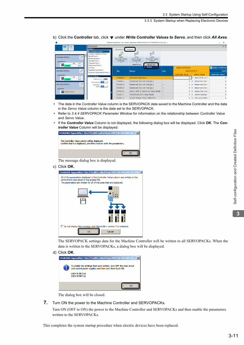
3.3 System Startup Using Self-Configuration
3.3.3 System Startup when Replacing Electronic Devices
3-11
Sel
f-con
figur
atio
n an
d C
reat
ed D
efin
ition
File
s
b) Click the Controller tab, click under Write Controller Values to Servo, and then click All Axes.
The data in the Controller Value column is the SERVOPACK data saved to the Machine Controller and the data in the Servo Value column is the data set to the SERVOPACK.
Refer to 3.4.4 SERVOPACK Parameter Window for information on the relationship between Controller Value and Servo Value.
If the Controller Value Column is not displayed, the following dialog box will be displayed. Click OK. The Con-troller Value Column will be displayed.
The message dialog box is displayed.
c) Click OK.
The SERVOPACK settings data for the Machine Controller will be written to all SERVOPACKs. When thedata is written to the SERVOPACKs, a dialog box will be displayed.
d) Click OK.
The dialog box will be closed.
7. Turn ON the power to the Machine Controller and SERVOPACKs.
Turn ON (OFF to ON) the power to the Machine Controller and SERVOPACKs and then enable the parameters written to the SERVOPACKs.
This completes the system startup procedure when electric devices have been replaced.
3.4 Self-configuration and Each Window
3-12
3.4 Self-configuration and Each Window
When executing self-configuration, the Machine Controller automatically recognizes all the connected optional mod-ules, and the files of the Module Configuration Definition, MECHATROLINK Transmission Definition, and motion parameters will accordingly be automatically created.Each file contains the following information.
Module Configuration Definition
Information on all the optional modules connected to the Machine ControllerRefer to 3.4.1 Module Configuration Definition Window for details.
MECHATROLINK Transmission Definition
Information of allocations related to MECHATROLINK transmission (master and slaves)Refer to 3.4.2 MECHATROLINK Transmission Definition Window for details.
Motion Parameters
Information on motion parameters to control axes such as SERVOPACKs, linear servomotors, inverters, and distrib-uted I/Os that are connected to the SVB ModuleRefer to 3.4.3 Motion Parameter Window for details.
This section describes the setting window for each file.
Refer to Chapter 10 Inverter Operation for information on the inverter settings.
Refer to Appendix B Settings When Connecting MECHATROLINK Compatible I/O Modules, MYVIS, and MP940 for information on MECHATROLINK slave module settings.
Refer to Appendix G Settings when Connecting MECHATROLINK-II Compatible Stepping Motor Drivers for informa-tion on MECHATROLINK-II stepper motor settings.
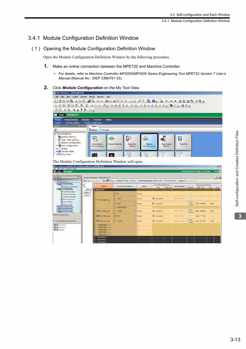
3.4 Self-configuration and Each Window
3.4.1 Module Configuration Definition Window
3-13
Sel
f-con
figur
atio
n an
d C
reat
ed D
efin
ition
File
s
3.4.1 Module Configuration Definition Window
( 1 ) Opening the Module Configuration Definition Window
Open the Module Configuration Definition Window by the following procedure.
1. Make an online connection between the MPE720 and Machine Controller.
For details, refer to Machine Controller MP2000/MP3000 Series Engineering Tool MPE720 Version 7 User’s Manual (Manual No.: SIEP C880761 03).
2. Click Module Configuration on the My Tool View.
The Module Configuration Definition Window will open.
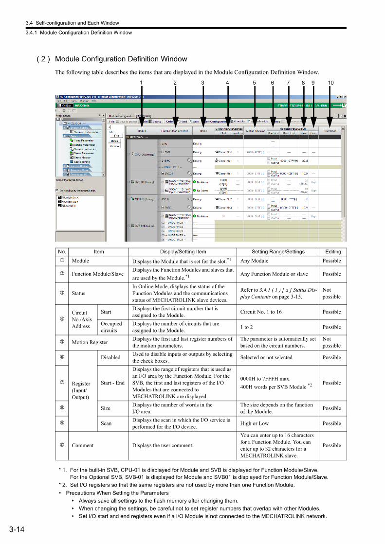
3.4 Self-configuration and Each Window
3.4.1 Module Configuration Definition Window
3-14
( 2 ) Module Configuration Definition Window
The following table describes the items that are displayed in the Module Configuration Definition Window.
* 1. For the built-in SVB, CPU-01 is displayed for Module and SVB is displayed for Function Module/Slave. For the Optional SVB, SVB-01 is displayed for Module and SVB01 is displayed for Function Module/Slave.
* 2. Set I/O registers so that the same registers are not used by more than one Function Module.
Precautions When Setting the Parameters
Always save all settings to the flash memory after changing them.
When changing the settings, be careful not to set register numbers that overlap with other Modules.
Set I/O start and end registers even if a I/O Module is not connected to the MECHATROLINK network.
No. Item Display/Setting Item Setting Range/Settings Editing
Module Displays the Module that is set for the slot.*1 Any Module Possible
Function Module/SlaveDisplays the Function Modules and slaves that
are used by the Module.*1 Any Function Module or slave Possible
StatusIn Online Mode, displays the status of the Function Modules and the communications status of MECHATROLINK slave devices.
Refer to 3.4.1 ( 1 ) [ a ] Status Dis-play Contents on page 3-15.
Not possible
Circuit No./Axis Address
StartDisplays the first circuit number that is assigned to the Module.
Circuit No. 1 to 16 Possible
Occupied circuits
Displays the number of circuits that are assigned to the Module.
1 to 2 Possible
Motion RegisterDisplays the first and last register numbers of the motion parameters.
The parameter is automatically set based on the circuit numbers.
Not possible
Register (Input/Output)
DisabledUsed to disable inputs or outputs by selecting the check boxes.
Selected or not selected Possible
Start - End
Displays the range of registers that is used as an I/O area by the Function Module. For the SVB, the first and last registers of the I/O Modules that are connected to MECHATROLINK are displayed.
0000H to 7FFFH max.
400H words per SVB Module *2 Possible
SizeDisplays the number of words in the I/O area.
The size depends on the function of the Module.
Possible
ScanDisplays the scan in which the I/O service is performed for the I/O device.
High or Low Possible
Comment Displays the user comment.
You can enter up to 16 characters for a Function Module. You can enter up to 32 characters for a MECHATROLINK slave.
Possible
1 2 3 4 5 6 7 8 9 10

3.4 Self-configuration and Each Window
3.4.1 Module Configuration Definition Window
3-15
Sel
f-con
figur
atio
n an
d C
reat
ed D
efin
ition
File
s
*****I/O and *****SERVO in Function Module/Slave column The following slave devices (I/O Modules) do not have model codes. Therefore, “*****I/O”(wild card I/O) will be dis-played in Function Module/Slave column for these devices after execution of self-configuration.
JEPMC-IO350
JAMSC-120DAI53330
JAMSC-120DAI73330
JAMSC-120DAO83330
JAMSC-120DRA83030For a servo with customized specifications that could not be recognized by self-configuration, “*****SERVO”(wild card servo) will be displayed in Function Module/Slave column.For a device displayed as “***** I/O” or “***** SERVO”, right-click the Function Module/Slave Cell and clickSelect Device. The Slaves Dialog Box will be displayed. Reassign the correct device.
[ a ] Status Display Contents
The following status is displayed for Function Modules.
Display Description
---- The Function Module is not defined.
Empty The Function Module is defined, but it is not mounted.
Driving The Function Module is operating normally.
Failure An error was detected in the Function Module.
× A Function Module is operating, but it is not the Function Module that was defined.
Initializing The Function Module is defined, but there is no Detailed Function Module Definition.
Driving Stop The CPU Module is stopped (The user programs are stopped).

3.4 Self-configuration and Each Window
3.4.2 MECHATROLINK Transmission Definition Window
3-16
3.4.2 MECHATROLINK Transmission Definition Window
( 1 ) Opening the MECHATROLINK Transmission Definition Window
In the Module Configuration Definition Window, double-click the SVB or SVB01 cell in the Function Module/Slave field. The MECHATROLINK Transmission Definition Window will open.
If several SVB Modules are mounted, select the SVB Module to be checked.
For the built-in SVB, CPU-01 is displayed for Module and SVB is displayed for Function Module/Slave. For the Optional SVB, SVB-01 is displayed for Module and SVB01 is displayed for Function Module/Slave.
Clicking Icon displays the MECHATROLINK Transmission Definition Window too.
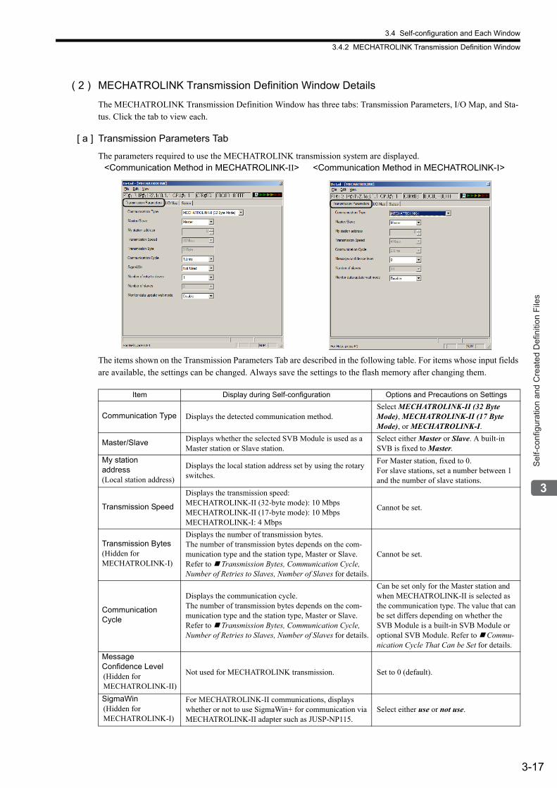
3.4 Self-configuration and Each Window
3.4.2 MECHATROLINK Transmission Definition Window
3-17
Sel
f-con
figur
atio
n an
d C
reat
ed D
efin
ition
File
s
( 2 ) MECHATROLINK Transmission Definition Window Details
The MECHATROLINK Transmission Definition Window has three tabs: Transmission Parameters, I/O Map, and Sta-tus. Click the tab to view each.
[ a ] Transmission Parameters Tab
The parameters required to use the MECHATROLINK transmission system are displayed.
The items shown on the Transmission Parameters Tab are described in the following table. For items whose input fields are available, the settings can be changed. Always save the settings to the flash memory after changing them.
<Communication Method in MECHATROLINK-II> <Communication Method in MECHATROLINK-I>
Item Display during Self-configuration Options and Precautions on Settings
Communication Type Displays the detected communication method.Select MECHATROLINK-II (32 Byte Mode), MECHATROLINK-II (17 Byte Mode), or MECHATROLINK-I.
Master/Slave Displays whether the selected SVB Module is used as a Master station or Slave station.
Select either Master or Slave. A built-in SVB is fixed to Master.
My stationaddress(Local station address)
Displays the local station address set by using the rotary switches.
For Master station, fixed to 0.For slave stations, set a number between 1 and the number of slave stations.
Transmission Speed
Displays the transmission speed:MECHATROLINK-II (32-byte mode): 10 MbpsMECHATROLINK-II (17-byte mode): 10 MbpsMECHATROLINK-I: 4 Mbps
Cannot be set.
Transmission Bytes(Hidden for MECHATROLINK-I)
Displays the number of transmission bytes.The number of transmission bytes depends on the com-munication type and the station type, Master or Slave. Refer to Transmission Bytes, Communication Cycle, Number of Retries to Slaves, Number of Slaves for details.
Cannot be set.
Communication Cycle
Displays the communication cycle.The number of transmission bytes depends on the com-munication type and the station type, Master or Slave. Refer to Transmission Bytes, Communication Cycle, Number of Retries to Slaves, Number of Slaves for details.
Can be set only for the Master station and when MECHATROLINK-II is selected as the communication type. The value that can be set differs depending on whether the SVB Module is a built-in SVB Module or optional SVB Module. Refer to Commu-nication Cycle That Can be Set for details.
Message Confidence Level(Hidden for MECHATROLINK-II)
Not used for MECHATROLINK transmission. Set to 0 (default).
SigmaWin(Hidden for MECHATROLINK-I)
For MECHATROLINK-II communications, displays whether or not to use SigmaWin+ for communication via MECHATROLINK-II adapter such as JUSP-NP115.
Select either use or not use.
3.4 Self-configuration and Each Window
3.4.2 MECHATROLINK Transmission Definition Window
3-18
Transmission Bytes, Communication Cycle, Number of Retries to Slaves, Number of Slaves
Transmission bytes, communication cycle, number of retries to slaves, and number of slaves at execution of self-con-figuration will be automatically set according to conditions including communication type, station type (Master or Slave), and the largest slave station number (the largest number among the detected slave station numbers).
<For Master Station>
<For Slave Stations>
Number of Retries Slaves(Hidden for MECHATROLINK-I)
Displays the maximum number of slave stations to which the Master can retry transmission in one transmission cycle when the Master has not received a normal response from a slave.
Only for Master station. Set a number between 0 and 7. Cannot set for Slaves.
Number of Slaves
Displays the number of slave stations that can be con-nected.Determined by communication type, communication cycle, use of SigmaWin+, and number of attempts to retry transmission to slaves.
Cannot be set.
Wait for Monitor Data Update(Hidden for built-in SVB Modules)
Displays whether or not to suspend CPU processing for the scan delay time of monitoring parameters of an optional SVB Module. Suspended when enabled, not sus-pended when disabled.
Select either Enable or Disable.Refer to Wait for Monitor Data Update for details on this function.
(cont’d)
Item Display during Self-configuration Options and Precautions on Settings
For items whose input fields are available, the settings can be changed. Always save the settings to the flash memory after changing them.
ItemMECHATROLINK-II
(32-byte mode)
MECHATROLINK-II(17-byte mode) MECHATRO-
LINK-ILargest Slave Station Number 1 to 8 9 10 to 16 17 to 21 1 to 14 15
Transmission Bytes
31 bytes 16 bytes −
Communication Cycle 1 ms 1 ms 2 ms 2 ms 1 ms 1 ms 2 ms
Number ofRetries to Slaves 1 0 5
21−The largest slave station number
1 0 14
Number of Slaves 8 9 16
The largest slave station number
14 15 14
ItemMECHATROLINK-II
(32-byte mode)
MECHATROLINK-II(17-byte mode)
MECHATROLINK-I
Transmission Bytes
− − −
Communication Cycle 1 ms 1 ms 2 ms
Number of Slaves 30 30 15
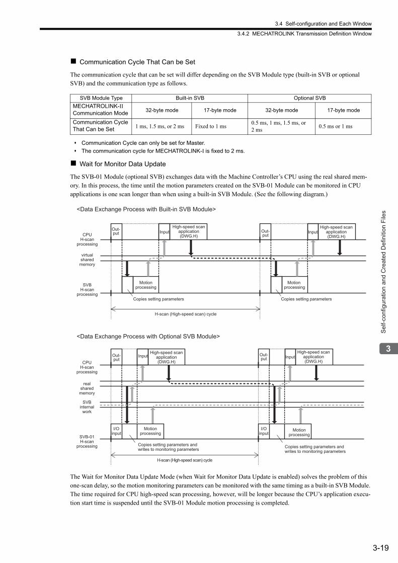
3.4 Self-configuration and Each Window
3.4.2 MECHATROLINK Transmission Definition Window
3-19
Sel
f-con
figur
atio
n an
d C
reat
ed D
efin
ition
File
s
Communication Cycle That Can be Set
The communication cycle that can be set will differ depending on the SVB Module type (built-in SVB or optional SVB) and the communication type as follows.
Communication Cycle can only be set for Master.
The communication cycle for MECHATROLINK-I is fixed to 2 ms.
Wait for Monitor Data Update
The SVB-01 Module (optional SVB) exchanges data with the Machine Controller’s CPU using the real shared mem-ory. In this process, the time until the motion parameters created on the SVB-01 Module can be monitored in CPU applications is one scan longer than when using a built-in SVB Module. (See the following diagram.)
The Wait for Monitor Data Update Mode (when Wait for Monitor Data Update is enabled) solves the problem of this one-scan delay, so the motion monitoring parameters can be monitored with the same timing as a built-in SVB Module. The time required for CPU high-speed scan processing, however, will be longer because the CPU’s application execu-tion start time is suspended until the SVB-01 Module motion processing is completed.
SVB Module Type Built-in SVB Optional SVB
MECHATROLINK-II Communication Mode 32-byte mode 17-byte mode 32-byte mode 17-byte mode
Communication Cycle That Can be Set 1 ms, 1.5 ms, or 2 ms Fixed to 1 ms
0.5 ms, 1 ms, 1.5 ms, or 2 ms
0.5 ms or 1 ms
<Data Exchange Process with Built-in SVB Module>
<Data Exchange Process with Optional SVB Module>
CPUH-scan
processing
SVBH-scan
processing
virtualsharedmemory
Out-put Input
High-speed scanapplication(DWG.H)
Out-put
InputHigh-speed scan
application(DWG.H)
Motionprocessing
Motion processing
Copies setting parameters Copies setting parameters
H-scan (High-speed scan) cycle
CPUH-scan
processing
SVB-01H-scan
processing
SVBinternal
work
realsharedmemory
Out-put
InputHigh-speed scan
application(DWG.H)
Motionprocessing
I/Oinput
H-scan (High-speed scan) cycle
Out-put Input
High-speed scanapplication(DWG.H)
Motionprocessing
I/Oinput
Copies setting parameters andwrites to monitoring parameters
Copies setting parameters andwrites to monitoring parameters
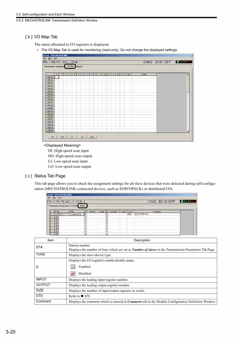
3.4 Self-configuration and Each Window
3.4.2 MECHATROLINK Transmission Definition Window
3-20
[ b ] I/O Map Tab
The status allocated to I/O registers is displayed.
The I/O Map Tab is used for monitoring (read-only). Do not change the displayed settings.
<Displayed Meaning>HI: High-speed scan inputHO: High-speed scan outputLI: Low-speed scan inputLO: Low-speed scan output
[ c ] Status Tab Page
This tab page allows you to check the assignment settings for all slave devices that were detected during self-configu-ration (MECHATROLINK-connected devices, such as SERVOPACKs or distributed I/O).
Item Description
ST# Station numberDisplays the number of lines which are set as Number of slaves in the Transmission Parameters Tab Page.
TYPE Displays the slave device type.
D
Displays the I/O register's enable/disable status.
: Enabled
: Disabled
INPUT Displays the leading input register number.
OUTPUT Displays the leading output register number.
SIZE Displays the number of input/output registers in words.
STS Refer to STS.
Comment Displays the comment which is entered in Comment cell in the Module Configuration Definition Window.
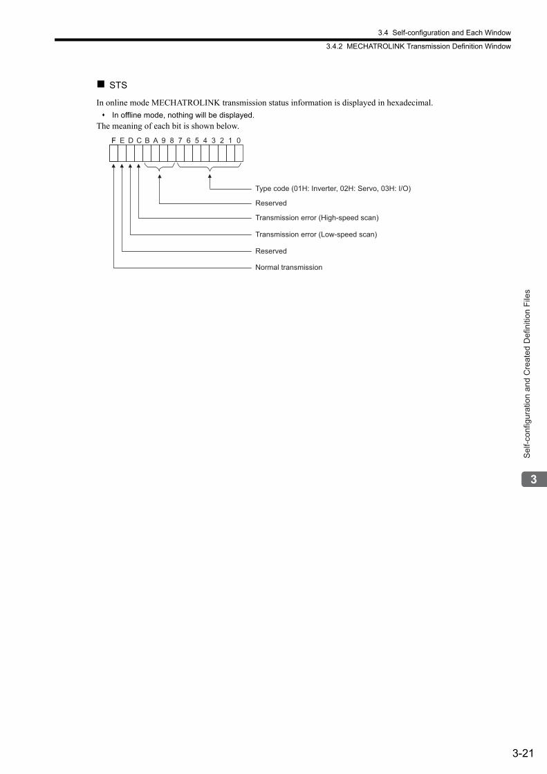
3.4 Self-configuration and Each Window
3.4.2 MECHATROLINK Transmission Definition Window
3-21
Sel
f-con
figur
atio
n an
d C
reat
ed D
efin
ition
File
s
STS
In online mode MECHATROLINK transmission status information is displayed in hexadecimal.
In offline mode, nothing will be displayed.
The meaning of each bit is shown below.
Type code (01H: Inverter, 02H: Servo, 03H: I/O)
Reserved
F E D C B A 9 8 7 6 5 4 3 2 1 0F
Transmission error (High-speed scan)
Transmission error (Low-speed scan)
Reserved
Normal transmission
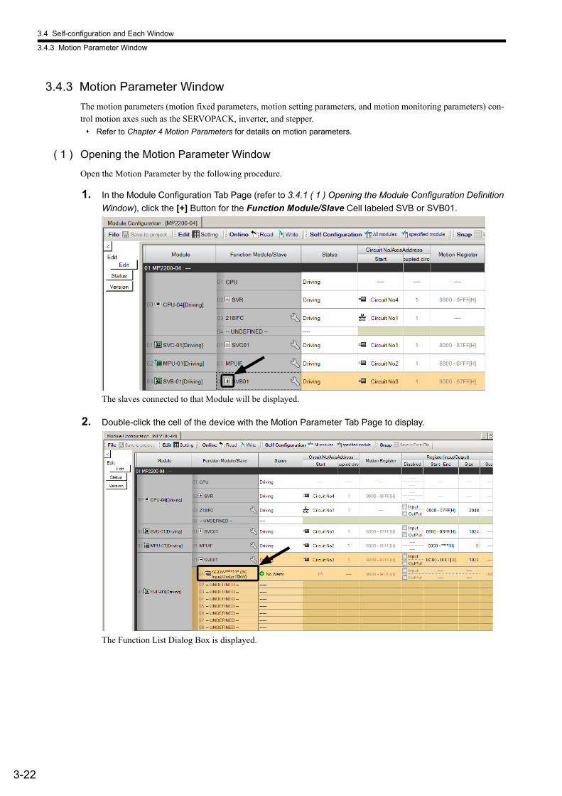
3.4 Self-configuration and Each Window
3.4.3 Motion Parameter Window
3-22
3.4.3 Motion Parameter Window
The motion parameters (motion fixed parameters, motion setting parameters, and motion monitoring parameters) con-trol motion axes such as the SERVOPACK, inverter, and stepper.
Refer to Chapter 4 Motion Parameters for details on motion parameters.
( 1 ) Opening the Motion Parameter Window
Open the Motion Parameter by the following procedure.
1. In the Module Configuration Tab Page (refer to 3.4.1 ( 1 ) Opening the Module Configuration Definition
Window), click the [+] Button for the Function Module/Slave Cell labeled SVB or SVB01.
The slaves connected to that Module will be displayed.
2. Double-click the cell of the device with the Motion Parameter Tab Page to display.
The Function List Dialog Box is displayed.
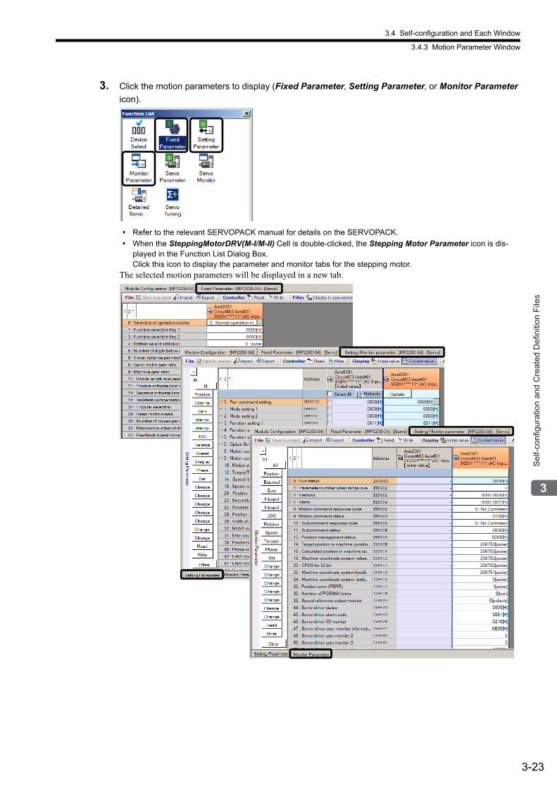
3.4 Self-configuration and Each Window
3.4.3 Motion Parameter Window
3-23
Sel
f-con
figur
atio
n an
d C
reat
ed D
efin
ition
File
s
3. Click the motion parameters to display (Fixed Parameter, Setting Parameter, or Monitor Parameter
icon).
Refer to the relevant SERVOPACK manual for details on the SERVOPACK.
When the SteppingMotorDRV(M-I/M-II) Cell is double-clicked, the Stepping Motor Parameter icon is dis-played in the Function List Dialog Box. Click this icon to display the parameter and monitor tabs for the stepping motor.
The selected motion parameters will be displayed in a new tab.
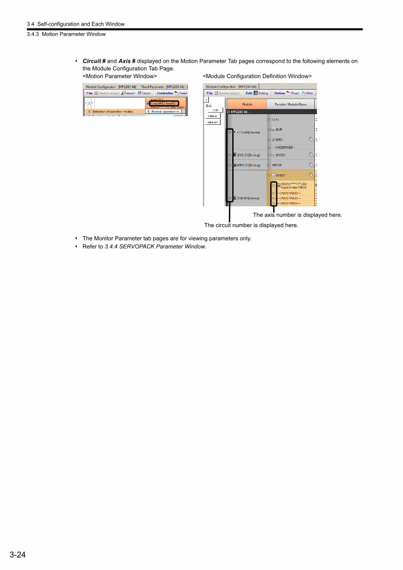
3.4 Self-configuration and Each Window
3.4.3 Motion Parameter Window
3-24
Circuit # and Axis # displayed on the Motion Parameter Tab pages correspond to the following elements on the Module Configuration Tab Page.
The Monitor Parameter tab pages are for viewing parameters only.
Refer to 3.4.4 SERVOPACK Parameter Window.
The circuit number is displayed here.
The axis number is displayed here.
<Motion Parameter Window> <Module Configuration Definition Window>
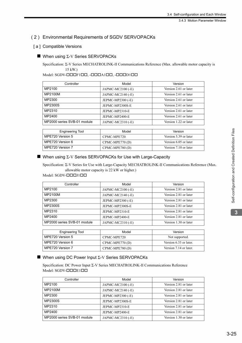
3.4 Self-configuration and Each Window
3.4.3 Motion Parameter Window
3-25
Sel
f-con
figur
atio
n an
d C
reat
ed D
efin
ition
File
s
( 2 ) Environmental Requirements of SGDV SERVOPACKs
[ a ] Compatible Versions
When using Σ-V Series SERVOPACKs
Specification: Σ-V Series MECHATROLINK-II Communications Reference (Max. allowable motor capacity is 15 kW.)
Model: SGDV-F1, -A1, -D1
When using Σ-V Series SERVOPACKs for Use with Large-Capacity
Specification: Σ-V Series for Use with Large-Capacity MECHATROLINK-II Communications Reference (Max. allowable motor capacity is 22 kW or higher.)
Model: SGDV-J1
When using DC Power Input Σ-V Series SERVOPACKs
Specification: DC Power Input Σ-V Series MECHATROLINK-II Communications ReferenceModel: SGDV-E1
Controller Model Version
MP2100 JAPMC-MC2100 (-E) Version 2.61 or later
MP2100M JAPMC-MC2140 (-E) Version 2.61 or later
MP2300 JEPMC-MP2300 (-E) Version 2.61 or later
MP2300S JEPMC-MP2300S-E Version 2.61 or later
MP2310 JEPMC-MP2310-E Version 2.61 or later
MP2400 JEPMC-MP2400-E Version 2.61 or later
MP2000 series SVB-01 module JAPMC-MC2310 (-E) Version 1.22 or later
Engineering Tool Model Version
MPE720 Version 5 CPMC-MPE720 Version 5.39 or later
MPE720 Version 6 CPMC-MPE770 (D) Version 6.05 or later
MPE720 Version 7 CPMC-MPE780 (D) Version 7.10 or later
Controller Model Version
MP2100 JAPMC-MC2100 (-E) Version 2.81 or later
MP2100M JAPMC-MC2140 (-E) Version 2.81 or later
MP2300 JEPMC-MP2300 (-E) Version 2.81 or later
MP2300S JEPMC-MP2300S-E Version 2.81 or later
MP2310 JEPMC-MP2310-E Version 2.81 or later
MP2400 JEPMC-MP2400-E Version 2.81 or later
MP2000 series SVB-01 module JAPMC-MC2310 (-E) Version 1.30 or later
Engineering Tool Model Version
MPE720 Version 5 CPMC-MPE720 Not supported.
MPE720 Version 6 CPMC-MPE770 (D) Version 6.33 or later.
MPE720 Version 7 CPMC-MPE780 (D) Version 7.14 or later.
Controller Model Version
MP2100 JAPMC-MC2100 (-E) Version 2.81 or later
MP2100M JAPMC-MC2140 (-E) Version 2.81 or later
MP2300 JEPMC-MP2300 (-E) Version 2.81 or later
MP2300S JEPMC-MP2300S-E Version 2.81 or later
MP2310 JEPMC-MP2310-E Version 2.81 or later
MP2400 JEPMC-MP2400-E Version 2.81 or later
MP2000 series SVB-01 module JAPMC-MC2310 (-E) Version 1.30 or later
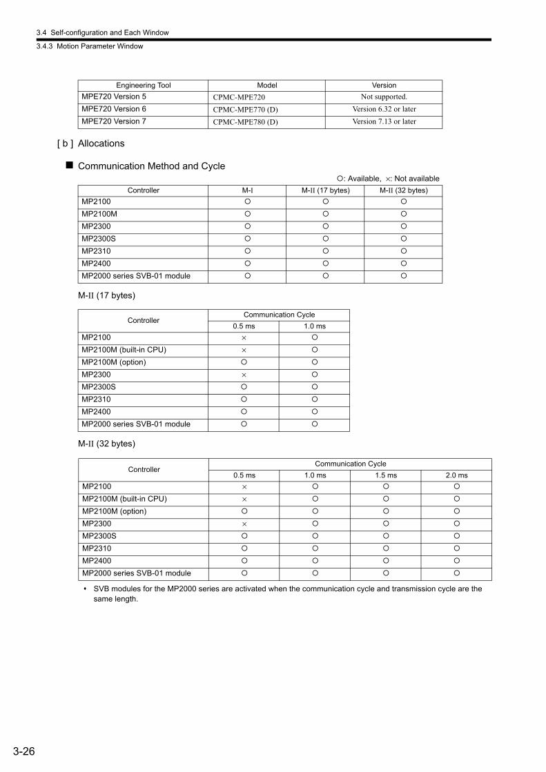
3.4 Self-configuration and Each Window
3.4.3 Motion Parameter Window
3-26
[ b ] Allocations
Communication Method and Cycle
M-II (17 bytes)
M-II (32 bytes)
SVB modules for the MP2000 series are activated when the communication cycle and transmission cycle are the same length.
Engineering Tool Model Version
MPE720 Version 5 CPMC-MPE720 Not supported.
MPE720 Version 6 CPMC-MPE770 (D) Version 6.32 or later
MPE720 Version 7 CPMC-MPE780 (D) Version 7.13 or later
: Available, ×: Not available
Controller M-I M-II (17 bytes) M-II (32 bytes)
MP2100
MP2100M
MP2300
MP2300S
MP2310
MP2400
MP2000 series SVB-01 module
ControllerCommunication Cycle
0.5 ms 1.0 ms
MP2100 ×
MP2100M (built-in CPU) ×
MP2100M (option)
MP2300 ×
MP2300S
MP2310
MP2400
MP2000 series SVB-01 module
ControllerCommunication Cycle
0.5 ms 1.0 ms 1.5 ms 2.0 ms
MP2100 ×
MP2100M (built-in CPU) ×
MP2100M (option)
MP2300 ×
MP2300S
MP2310
MP2400
MP2000 series SVB-01 module
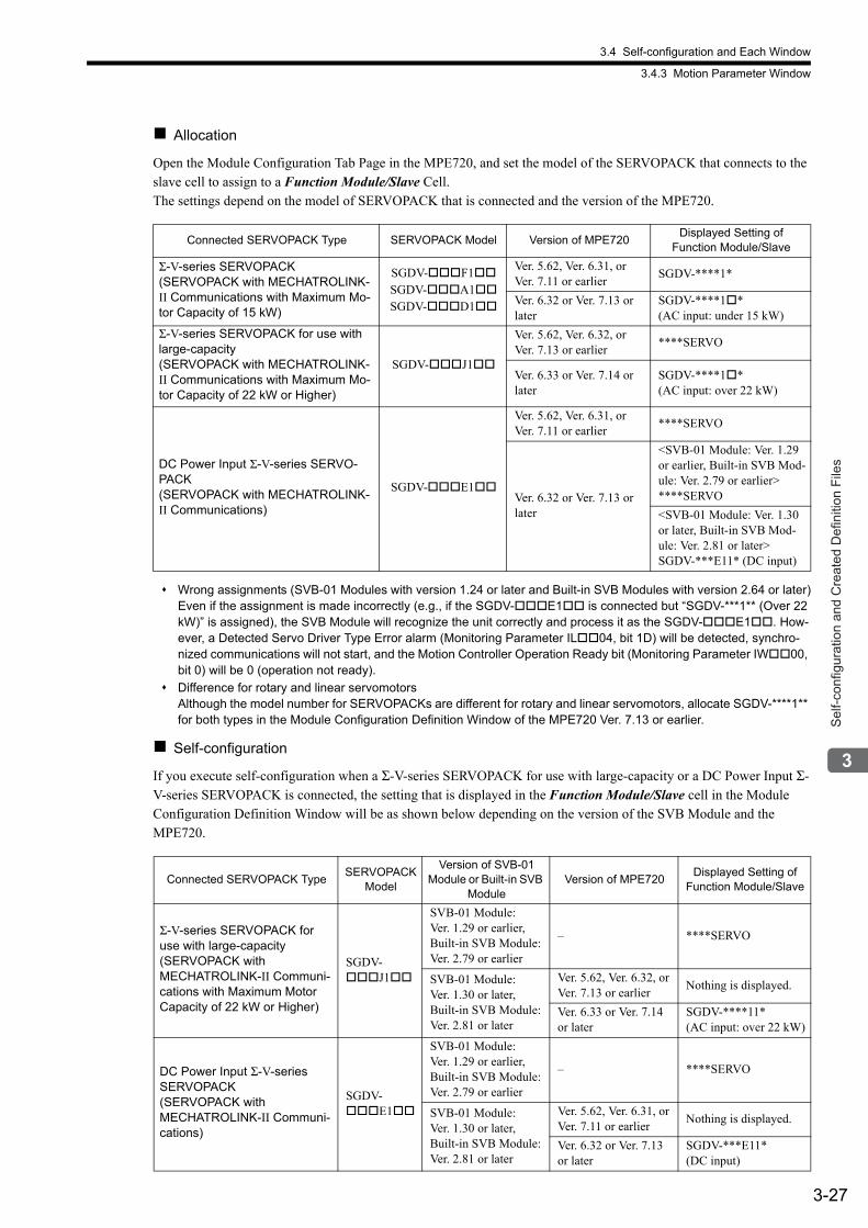
3.4 Self-configuration and Each Window
3.4.3 Motion Parameter Window
3-27
Sel
f-con
figur
atio
n an
d C
reat
ed D
efin
ition
File
s
Allocation
Open the Module Configuration Tab Page in the MPE720, and set the model of the SERVOPACK that connects to the slave cell to assign to a Function Module/Slave Cell.The settings depend on the model of SERVOPACK that is connected and the version of the MPE720.
Wrong assignments (SVB-01 Modules with version 1.24 or later and Built-in SVB Modules with version 2.64 or later)Even if the assignment is made incorrectly (e.g., if the SGDV-E1 is connected but “SGDV-***1** (Over 22 kW)” is assigned), the SVB Module will recognize the unit correctly and process it as the SGDV-E1. How-ever, a Detected Servo Driver Type Error alarm (Monitoring Parameter IL04, bit 1D) will be detected, synchro-nized communications will not start, and the Motion Controller Operation Ready bit (Monitoring Parameter IW00, bit 0) will be 0 (operation not ready).
Difference for rotary and linear servomotors Although the model number for SERVOPACKs are different for rotary and linear servomotors, allocate SGDV-****1** for both types in the Module Configuration Definition Window of the MPE720 Ver. 7.13 or earlier.
Self-configuration
If you execute self-configuration when a Σ-V-series SERVOPACK for use with large-capacity or a DC Power Input Σ-V-series SERVOPACK is connected, the setting that is displayed in the Function Module/Slave cell in the Module Configuration Definition Window will be as shown below depending on the version of the SVB Module and the MPE720.
Connected SERVOPACK Type SERVOPACK Model Version of MPE720Displayed Setting of
Function Module/Slave
Σ-V-series SERVOPACK (SERVOPACK with MECHATROLINK-II Communications with Maximum Mo-tor Capacity of 15 kW)
SGDV-F1SGDV-A1SGDV-D1
Ver. 5.62, Ver. 6.31, or Ver. 7.11 or earlier
SGDV-****1*
Ver. 6.32 or Ver. 7.13 or later
SGDV-****1* (AC input: under 15 kW)
Σ-V-series SERVOPACK for use with large-capacity (SERVOPACK with MECHATROLINK-II Communications with Maximum Mo-tor Capacity of 22 kW or Higher)
SGDV-J1
Ver. 5.62, Ver. 6.32, or Ver. 7.13 or earlier
****SERVO
Ver. 6.33 or Ver. 7.14 or later
SGDV-****1* (AC input: over 22 kW)
DC Power Input Σ-V-series SERVO-PACK (SERVOPACK with MECHATROLINK-II Communications)
SGDV-E1
Ver. 5.62, Ver. 6.31, or Ver. 7.11 or earlier
****SERVO
Ver. 6.32 or Ver. 7.13 or later
<SVB-01 Module: Ver. 1.29 or earlier, Built-in SVB Mod-ule: Ver. 2.79 or earlier>****SERVO
<SVB-01 Module: Ver. 1.30 or later, Built-in SVB Mod-ule: Ver. 2.81 or later>SGDV-***E11* (DC input)
Connected SERVOPACK TypeSERVOPACK
Model
Version of SVB-01 Module or Built-in SVB
ModuleVersion of MPE720
Displayed Setting of Function Module/Slave
Σ-V-series SERVOPACK for use with large-capacity (SERVOPACK with MECHATROLINK-II Communi-cations with Maximum Motor Capacity of 22 kW or Higher)
SGDV-J1
SVB-01 Module: Ver. 1.29 or earlier, Built-in SVB Module: Ver. 2.79 or earlier
– ****SERVO
SVB-01 Module: Ver. 1.30 or later, Built-in SVB Module: Ver. 2.81 or later
Ver. 5.62, Ver. 6.32, or Ver. 7.13 or earlier
Nothing is displayed.
Ver. 6.33 or Ver. 7.14 or later
SGDV-****11* (AC input: over 22 kW)
DC Power Input Σ-V-series SERVOPACK(SERVOPACK with MECHATROLINK-II Communi-cations)
SGDV-E1
SVB-01 Module: Ver. 1.29 or earlier, Built-in SVB Module: Ver. 2.79 or earlier
– ****SERVO
SVB-01 Module: Ver. 1.30 or later, Built-in SVB Module: Ver. 2.81 or later
Ver. 5.62, Ver. 6.31, or Ver. 7.11 or earlier
Nothing is displayed.
Ver. 6.32 or Ver. 7.13 or later
SGDV-***E11* (DC input)

3.4 Self-configuration and Each Window
3.4.3 Motion Parameter Window
3-28
[ c ] Restrictions
The following functions cannot be used with SGDV SERVOPACKs.
• Gain switching*1
• Backlash compensation*2
• Saving parameter bank data in the nonvolatile memory
* 1. Gain switching is different between SGDS and SGDV SERVOPACKs.SGDS SERVOPACKs: 2 bits (4 points) SGDV SERVOPACKs: 1 bit (2 points)
* 2. However, if you use an SGDV-****1** with software version 0023 or later, you can use the backlash compen-sation function in the SERVOPACK.
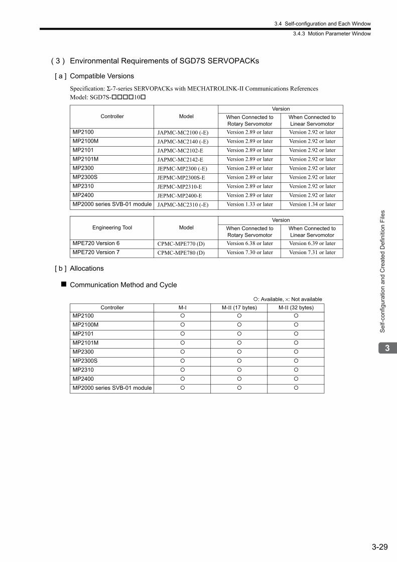
3.4 Self-configuration and Each Window
3.4.3 Motion Parameter Window
3-29
Sel
f-con
figur
atio
n an
d C
reat
ed D
efin
ition
File
s
( 3 ) Environmental Requirements of SGD7S SERVOPACKs
[ a ] Compatible Versions
Specification: Σ-7-series SERVOPACKs with MECHATROLINK-II Communications ReferencesModel: SGD7S-10
[ b ] Allocations
Communication Method and Cycle
Controller Model
Version
When Connected to Rotary Servomotor
When Connected to Linear Servomotor
MP2100 JAPMC-MC2100 (-E) Version 2.89 or later Version 2.92 or later
MP2100M JAPMC-MC2140 (-E) Version 2.89 or later Version 2.92 or later
MP2101 JAPMC-MC2102-E Version 2.89 or later Version 2.92 or later
MP2101M JAPMC-MC2142-E Version 2.89 or later Version 2.92 or later
MP2300 JEPMC-MP2300 (-E) Version 2.89 or later Version 2.92 or later
MP2300S JEPMC-MP2300S-E Version 2.89 or later Version 2.92 or later
MP2310 JEPMC-MP2310-E Version 2.89 or later Version 2.92 or later
MP2400 JEPMC-MP2400-E Version 2.89 or later Version 2.92 or later
MP2000 series SVB-01 module JAPMC-MC2310 (-E) Version 1.33 or later Version 1.34 or later
Engineering Tool Model
Version
When Connected to Rotary Servomotor
When Connected to Linear Servomotor
MPE720 Version 6 CPMC-MPE770 (D) Version 6.38 or later Version 6.39 or later
MPE720 Version 7 CPMC-MPE780 (D) Version 7.30 or later Version 7.31 or later
: Available, ×: Not available
Controller M-I M-II (17 bytes) M-II (32 bytes)
MP2100
MP2100M
MP2101
MP2101M
MP2300
MP2300S
MP2310
MP2400
MP2000 series SVB-01 module
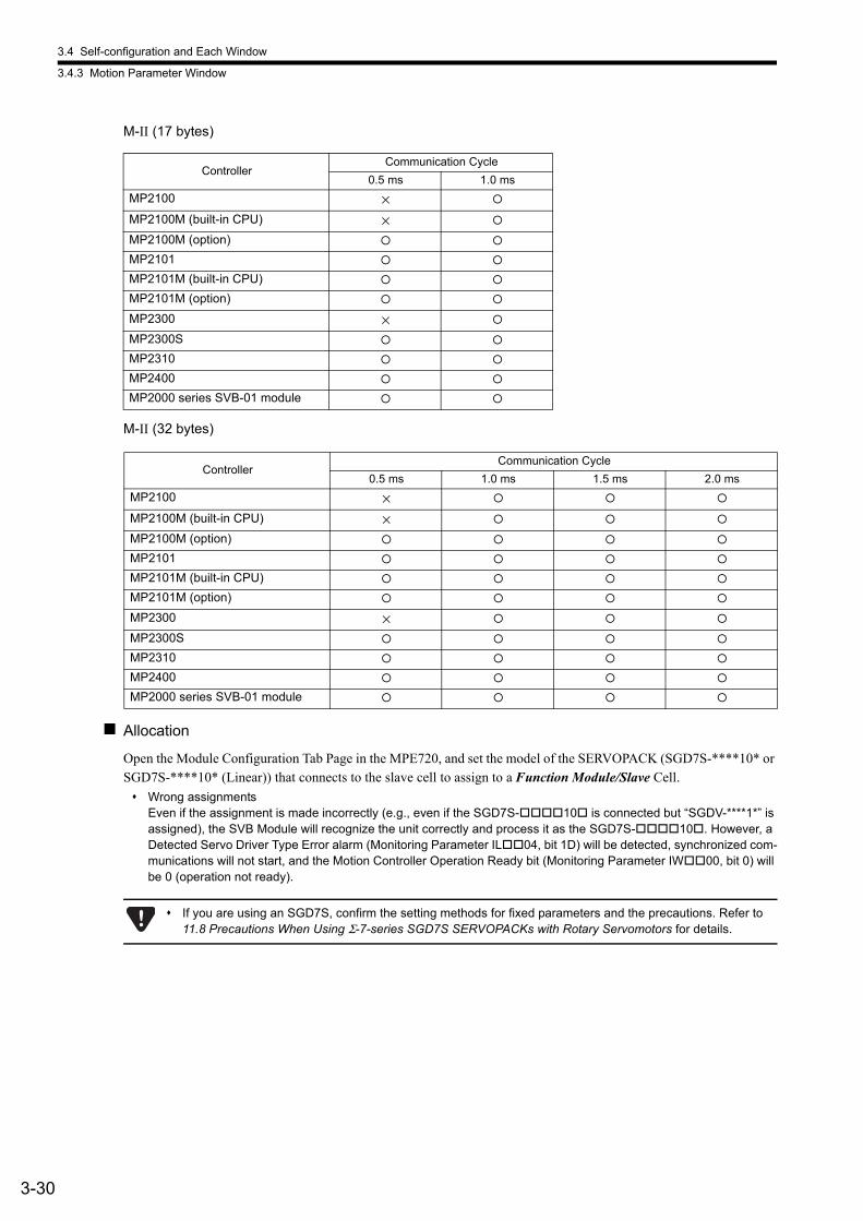
3.4 Self-configuration and Each Window
3.4.3 Motion Parameter Window
3-30
M-II (17 bytes)
M-II (32 bytes)
Allocation
Open the Module Configuration Tab Page in the MPE720, and set the model of the SERVOPACK (SGD7S-****10* or SGD7S-****10* (Linear)) that connects to the slave cell to assign to a Function Module/Slave Cell.
Wrong assignments Even if the assignment is made incorrectly (e.g., even if the SGD7S-10 is connected but “SGDV-****1*” is assigned), the SVB Module will recognize the unit correctly and process it as the SGD7S-10. However, a Detected Servo Driver Type Error alarm (Monitoring Parameter IL04, bit 1D) will be detected, synchronized com-munications will not start, and the Motion Controller Operation Ready bit (Monitoring Parameter IW00, bit 0) will be 0 (operation not ready).
ControllerCommunication Cycle
0.5 ms 1.0 ms
MP2100 ×
MP2100M (built-in CPU) ×
MP2100M (option)
MP2101
MP2101M (built-in CPU)
MP2101M (option)
MP2300 ×
MP2300S
MP2310
MP2400
MP2000 series SVB-01 module
ControllerCommunication Cycle
0.5 ms 1.0 ms 1.5 ms 2.0 ms
MP2100 ×
MP2100M (built-in CPU) ×
MP2100M (option)
MP2101
MP2101M (built-in CPU)
MP2101M (option)
MP2300 ×
MP2300S
MP2310
MP2400
MP2000 series SVB-01 module
If you are using an SGD7S, confirm the setting methods for fixed parameters and the precautions. Refer to 11.8 Precautions When Using Σ-7-series SGD7S SERVOPACKs with Rotary Servomotors for details.

3.4 Self-configuration and Each Window
3.4.4 SERVOPACK Parameter Window
3-31
Sel
f-con
figur
atio
n an
d C
reat
ed D
efin
ition
File
s
3.4.4 SERVOPACK Parameter Window
In systems connected to MECHATROLINK, SERVOPACK parameters can be read or written directly from the Machine Controller. (Refer to 11.6 Parameters That Are Automatically Updated.) This means that parameters are saved in the memory areas of both the Machine Controller and the SERVOPACK. It is thus necessary to consider the relation-ship between the settings in both memory areas.The following steps show how to display the Servo Parameters Window and the flow of SERVOPACK parameter data under various conditions.
( 1 ) Opening the SERVOPACK Parameter Window
Open the SERVOPACK Parameter Window by the following procedure.
1. In the Module Configuration Tab Page (refer to 3.4.1 ( 1 ) Opening the Module Configuration Definition
Window), click the [+] Button for the Function Module/Slave Cell labeled SVB or SVB01.
The slaves connected to that Module will be displayed.
2. Double-click the cell of the device with the Servo Parameter Tab Page to display.
The Function List Dialog Box is displayed.
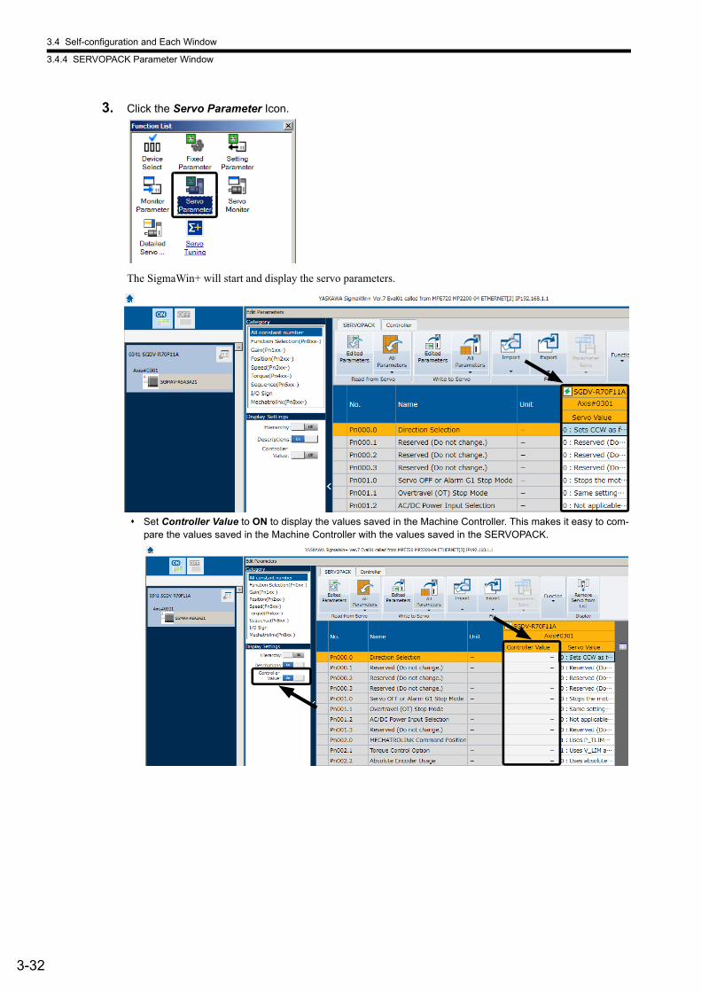
3.4 Self-configuration and Each Window
3.4.4 SERVOPACK Parameter Window
3-32
3. Click the Servo Parameter Icon.
The SigmaWin+ will start and display the servo parameters.
Set Controller Value to ON to display the values saved in the Machine Controller. This makes it easy to com-pare the values saved in the Machine Controller with the values saved in the SERVOPACK.
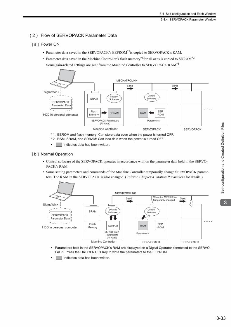
3.4 Self-configuration and Each Window
3.4.4 SERVOPACK Parameter Window
3-33
Sel
f-con
figur
atio
n an
d C
reat
ed D
efin
ition
File
s
( 2 ) Flow of SERVOPACK Parameter Data
[ a ] Power ON
• Parameter data saved in the SERVOPACK’s EEPROM*1is copied to SERVOPACK’s RAM.
• Parameter data saved in the Machine Controller’s flash memory*1for all axes is copied to SDRAM*2.
Some gain-related settings are sent from the Machine Controller to SERVOPACK RAM*1.
* 1. EEROM and flash memory: Can store data even when the power is turned OFF. * 2. RAM, SRAM, and SDRAM: Can lose data when the power is turned OFF.
indicates data has been written.
[ b ] Normal Operation
• Control software of the SERVOPACK operates in accordance with on the parameter data held in the SERVO-PACK’s RAM.
• Some setting parameters and commands of the Machine Controller temporarily change SERVOPACK parame-ters. The RAM in the SERVOPACK is also changed. (Refer to Chapter 4 Motion Parameters for details.)
Parameters held in the SERVOPACK’s RAM are displayed on a Digital Operator connected to the SERVO-PACK. Press the DATE/ENTER Key to write the parameters to the EEPROM.
indicates data has been written.
RAM EEP-ROMSDRAM
MECHATROLINK
SRAMSERVOPACK
Parameter Data
SigmaWin+
HDD in personal computerFlash
Memory
SERVOPACK Parameters (All Axes)
Parameters
System Software
Control Software
Machine Controller SERVOPACK SERVOPACK
Send Send
MECHATROLINK
RAM EEP-ROM
SRAM
SDRAM
SERVOPACK Parameter Data
SigmaWin+
HDD in personal computerFlash
Memory
SERVOPACK Parameters (All Axes)
Parameters
System Software
Control Software
SERVOPACK SERVOPACK
Send Send When the MP2300 has temporarily changed
Machine Controller
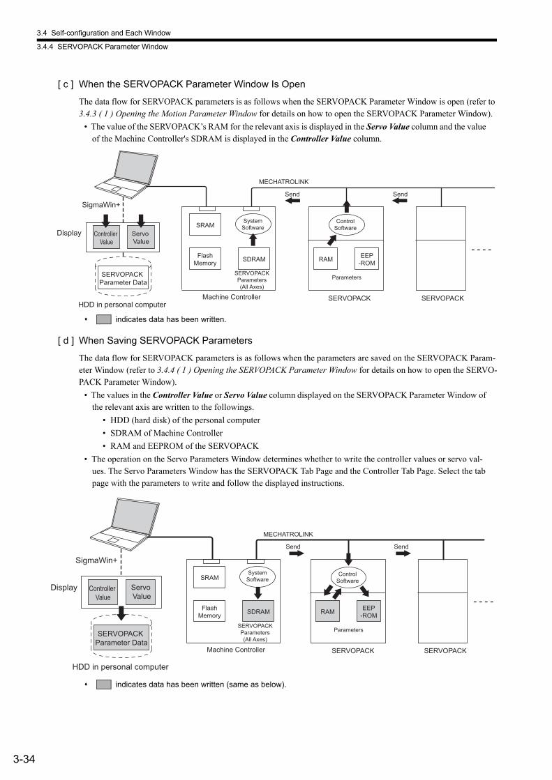
3.4 Self-configuration and Each Window
3.4.4 SERVOPACK Parameter Window
3-34
[ c ] When the SERVOPACK Parameter Window Is Open
The data flow for SERVOPACK parameters is as follows when the SERVOPACK Parameter Window is open (refer to 3.4.3 ( 1 ) Opening the Motion Parameter Window for details on how to open the SERVOPACK Parameter Window).
• The value of the SERVOPACK’s RAM for the relevant axis is displayed in the Servo Value column and the value of the Machine Controller's SDRAM is displayed in the Controller Value column.
indicates data has been written.
[ d ] When Saving SERVOPACK Parameters
The data flow for SERVOPACK parameters is as follows when the parameters are saved on the SERVOPACK Param-eter Window (refer to 3.4.4 ( 1 ) Opening the SERVOPACK Parameter Window for details on how to open the SERVO-PACK Parameter Window).
• The values in the Controller Value or Servo Value column displayed on the SERVOPACK Parameter Window of the relevant axis are written to the followings.
• HDD (hard disk) of the personal computer
• SDRAM of Machine Controller
• RAM and EEPROM of the SERVOPACK
• The operation on the Servo Parameters Window determines whether to write the controller values or servo val-ues. The Servo Parameters Window has the SERVOPACK Tab Page and the Controller Tab Page. Select the tab page with the parameters to write and follow the displayed instructions.
indicates data has been written (same as below).
SDRAM
SRAM
EEP-ROMRAM
MECHATROLINK
SERVOPACK Parameter Data
SigmaWin+
HDD in personal computer
Display Servo Value
Controller Value
Machine Controller
Send Send
SERVOPACKSERVOPACK
Control Software
System Software
Parameters SERVOPACK Parameters (All Axes)
Flash Memory
MECHATROLINK
RAM EEP-ROM
SRAM
SDRAM
SERVOPACK Parameter Data
SigmaWin+
HDD in personal computer
Display Servo Value
Controller Value
Flash Memory
SERVOPACK Parameters (All Axes)
Parameters
System Software
Control Software
SERVOPACK SERVOPACK
Send Send
Machine Controller
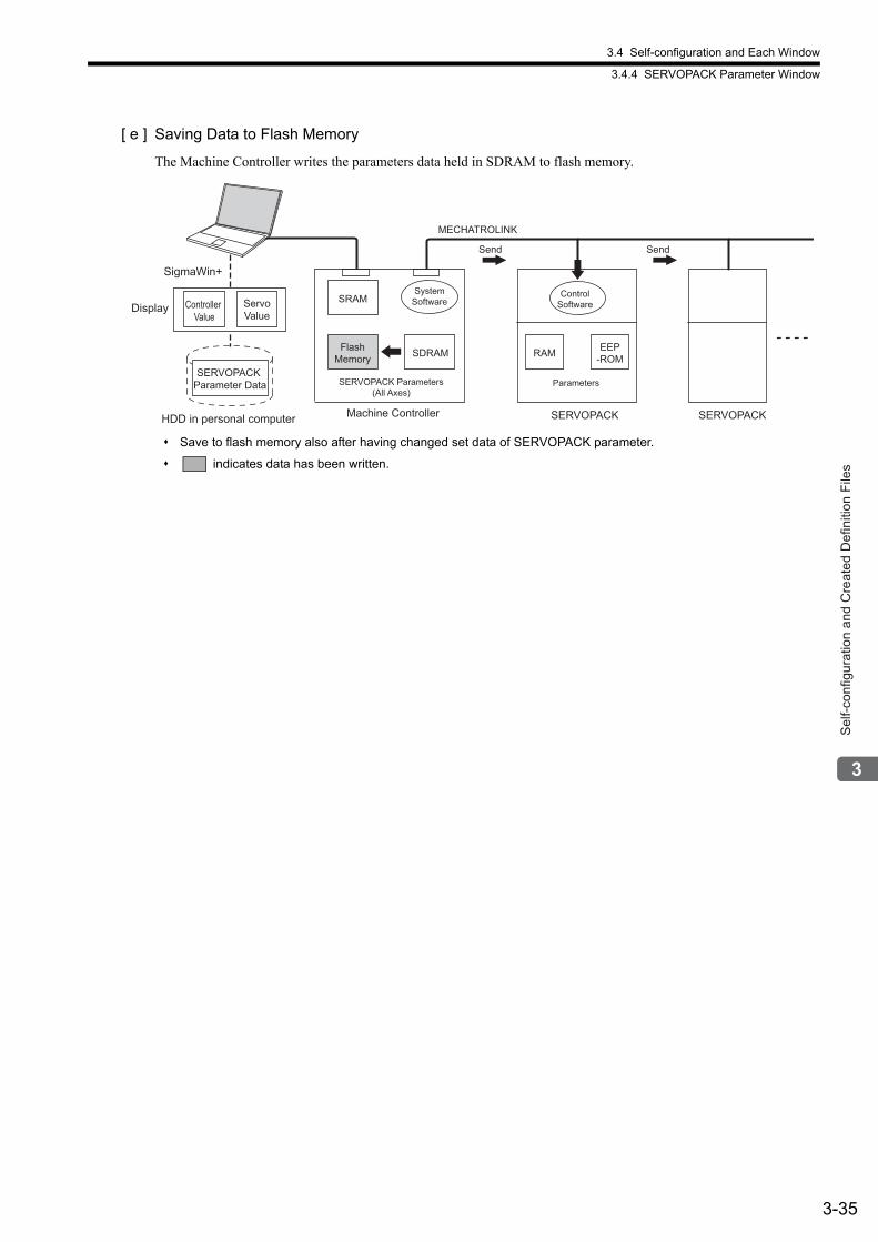
3.4 Self-configuration and Each Window
3.4.4 SERVOPACK Parameter Window
3-35
Sel
f-con
figur
atio
n an
d C
reat
ed D
efin
ition
File
s
[ e ] Saving Data to Flash Memory
The Machine Controller writes the parameters data held in SDRAM to flash memory.
Save to flash memory also after having changed set data of SERVOPACK parameter.
indicates data has been written.
MECHATROLINK
RAM EEP-ROM
SRAM
SDRAM
SERVOPACK Parameter Data
SigmaWin+
HDD in personal computer
Display ServoValue
Controller Value
Flash Memory
System Software
Control Software
SERVOPACK Parameters (All Axes)
Parameters
SERVOPACK SERVOPACK
Send Send
Machine Controller
4-1
Mot
ion
Par
amet
ers
4
Motion Parameters
This chapter explains each of the motion parameters.
4.1 Motion Parameters Register Numbers - - - - - - - - - - - - - - - - - - - - - - - - - -4-2
4.1.1 Motion Parameter Register Numbers for MP2000 Series Machine Controllers - - - - - - 4-2
4.2 Motion Parameters Setting Window - - - - - - - - - - - - - - - - - - - - - - - - - - - -4-4
4.2.1 Opening the Motion Parameter Setting Windows - - - - - - - - - - - - - - - - - - - - - - - - - - - 4-5
4.2.2 Motor Type and Related Alarms - - - - - - - - - - - - - - - - - - - - - - - - - - - - - - - - - - - - - - - 4-6
4.3 Motion Parameter Lists - - - - - - - - - - - - - - - - - - - - - - - - - - - - - - - - - - - - -4-7
4.3.1 Fixed Parameter List - - - - - - - - - - - - - - - - - - - - - - - - - - - - - - - - - - - - - - - - - - - - - - - 4-7
4.3.2 Setting Parameter List - - - - - - - - - - - - - - - - - - - - - - - - - - - - - - - - - - - - - - - - - - - - - - 4-9
4.3.3 Monitoring Parameter List - - - - - - - - - - - - - - - - - - - - - - - - - - - - - - - - - - - - - - - - - - 4-15
4.4 MP2000 Series Machine Controller Parameter Details - - - - - - - - - - - - - - 4-19
4.4.1 Motion Fixed Parameter Details - - - - - - - - - - - - - - - - - - - - - - - - - - - - - - - - - - - - - - 4-19
4.4.2 Motion Setting Parameter Details - - - - - - - - - - - - - - - - - - - - - - - - - - - - - - - - - - - - - 4-26
4.4.3 Motion Monitoring Parameter Details - - - - - - - - - - - - - - - - - - - - - - - - - - - - - - - - - - - 4-58
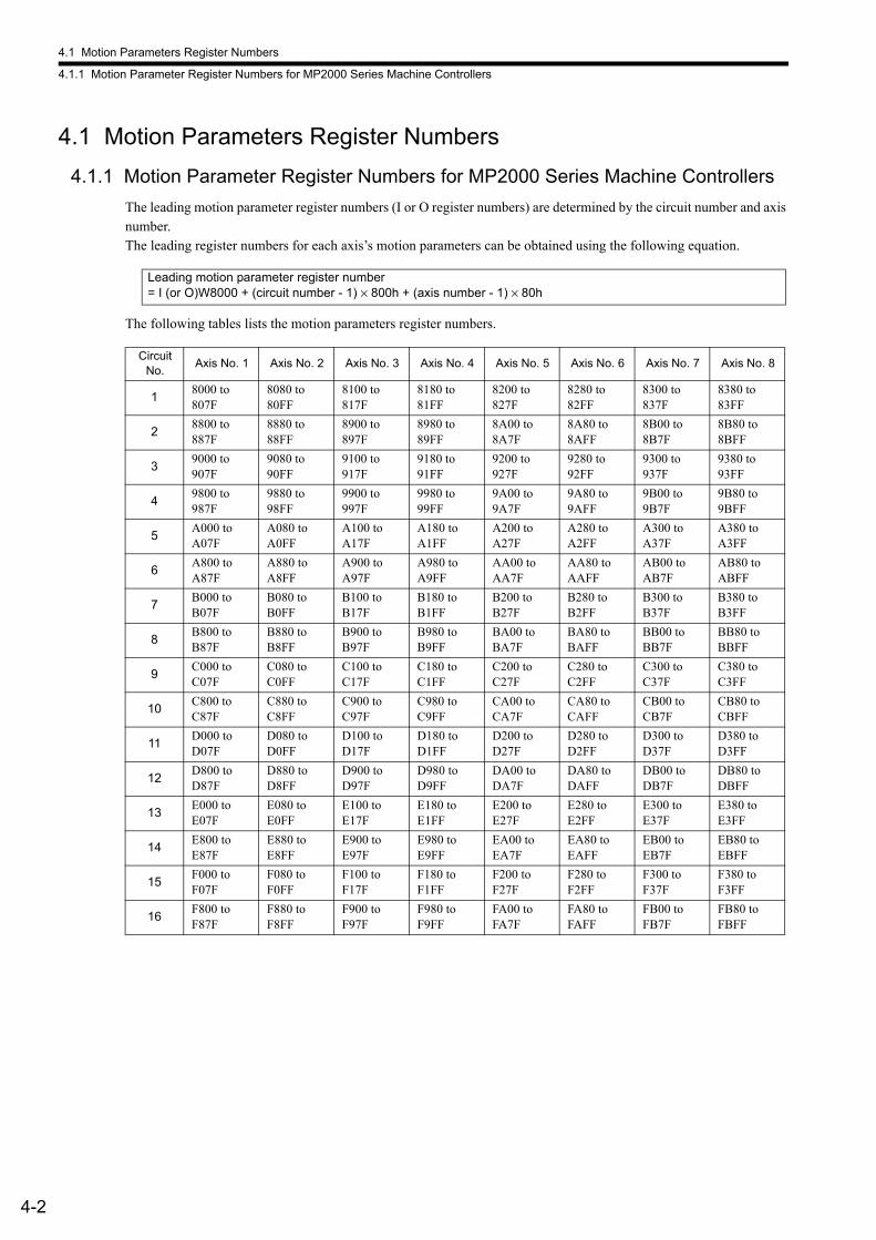
4.1 Motion Parameters Register Numbers
4.1.1 Motion Parameter Register Numbers for MP2000 Series Machine Controllers
4-2
4.1 Motion Parameters Register Numbers
4.1.1 Motion Parameter Register Numbers for MP2000 Series Machine Controllers
The leading motion parameter register numbers (I or O register numbers) are determined by the circuit number and axis number.The leading register numbers for each axis’s motion parameters can be obtained using the following equation.
The following tables lists the motion parameters register numbers.
Leading motion parameter register number= I (or O)W8000 + (circuit number - 1) × 800h + (axis number - 1) × 80h
Circuit No.
Axis No. 1 Axis No. 2 Axis No. 3 Axis No. 4 Axis No. 5 Axis No. 6 Axis No. 7 Axis No. 8
18000 to 807F
8080 to 80FF
8100 to 817F
8180 to 81FF
8200 to 827F
8280 to 82FF
8300 to 837F
8380 to 83FF
28800 to 887F
8880 to 88FF
8900 to 897F
8980 to 89FF
8A00 to 8A7F
8A80 to 8AFF
8B00 to 8B7F
8B80 to 8BFF
39000 to 907F
9080 to 90FF
9100 to 917F
9180 to 91FF
9200 to 927F
9280 to 92FF
9300 to 937F
9380 to 93FF
49800 to 987F
9880 to 98FF
9900 to 997F
9980 to 99FF
9A00 to 9A7F
9A80 to 9AFF
9B00 to 9B7F
9B80 to 9BFF
5A000 to A07F
A080 to A0FF
A100 to A17F
A180 to A1FF
A200 to A27F
A280 to A2FF
A300 to A37F
A380 to A3FF
6A800 to A87F
A880 to A8FF
A900 to A97F
A980 to A9FF
AA00 to AA7F
AA80 to AAFF
AB00 to AB7F
AB80 to ABFF
7B000 to B07F
B080 to B0FF
B100 to B17F
B180 to B1FF
B200 to B27F
B280 to B2FF
B300 to B37F
B380 to B3FF
8B800 to B87F
B880 to B8FF
B900 to B97F
B980 to B9FF
BA00 to BA7F
BA80 to BAFF
BB00 to BB7F
BB80 to BBFF
9C000 to C07F
C080 to C0FF
C100 to C17F
C180 to C1FF
C200 to C27F
C280 to C2FF
C300 to C37F
C380 to C3FF
10C800 to C87F
C880 to C8FF
C900 to C97F
C980 to C9FF
CA00 to CA7F
CA80 to CAFF
CB00 to CB7F
CB80 to CBFF
11D000 to D07F
D080 to D0FF
D100 to D17F
D180 to D1FF
D200 to D27F
D280 to D2FF
D300 to D37F
D380 to D3FF
12D800 to D87F
D880 to D8FF
D900 to D97F
D980 to D9FF
DA00 to DA7F
DA80 to DAFF
DB00 to DB7F
DB80 to DBFF
13E000 to E07F
E080 to E0FF
E100 to E17F
E180 to E1FF
E200 to E27F
E280 to E2FF
E300 to E37F
E380 to E3FF
14E800 to E87F
E880 to E8FF
E900 to E97F
E980 to E9FF
EA00 to EA7F
EA80 to EAFF
EB00 to EB7F
EB80 to EBFF
15F000 to F07F
F080 to F0FF
F100 to F17F
F180 to F1FF
F200 to F27F
F280 to F2FF
F300 to F37F
F380 to F3FF
16F800 to F87F
F880 to F8FF
F900 to F97F
F980 to F9FF
FA00 to FA7F
FA80 to FAFF
FB00 to FB7F
FB80 to FBFF
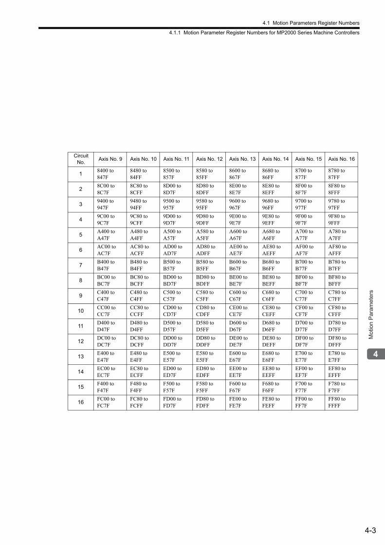
4.1 Motion Parameters Register Numbers
4.1.1 Motion Parameter Register Numbers for MP2000 Series Machine Controllers
4-3
Mot
ion
Par
amet
ers
Circuit No.
Axis No. 9 Axis No. 10 Axis No. 11 Axis No. 12 Axis No. 13 Axis No. 14 Axis No. 15 Axis No. 16
18400 to 847F
8480 to 84FF
8500 to 857F
8580 to 85FF
8600 to 867F
8680 to 86FF
8700 to 877F
8780 to 87FF
28C00 to 8C7F
8C80 to 8CFF
8D00 to 8D7F
8D80 to 8DFF
8E00 to 8E7F
8E80 to 8EFF
8F00 to 8F7F
8F80 to 8FFF
39400 to 947F
9480 to 94FF
9500 to 957F
9580 to 95FF
9600 to 967F
9680 to 96FF
9700 to 977F
9780 to 97FF
49C00 to 9C7F
9C80 to 9CFF
9D00 to 9D7F
9D80 to 9DFF
9E00 to 9E7F
9E80 to 9EFF
9F00 to 9F7F
9F80 to 9FFF
5A400 to A47F
A480 to A4FF
A500 to A57F
A580 to A5FF
A600 to A67F
A680 to A6FF
A700 to A77F
A780 to A7FF
6AC00 to AC7F
AC80 to ACFF
AD00 to AD7F
AD80 to ADFF
AE00 to AE7F
AE80 to AEFF
AF00 to AF7F
AF80 to AFFF
7B400 to B47F
B480 to B4FF
B500 to B57F
B580 to B5FF
B600 to B67F
B680 to B6FF
B700 to B77F
B780 to B7FF
8BC00 to BC7F
BC80 to BCFF
BD00 to BD7F
BD80 to BDFF
BE00 to BE7F
BE80 to BEFF
BF00 to BF7F
BF80 to BFFF
9C400 to C47F
C480 to C4FF
C500 to C57F
C580 to C5FF
C600 to C67F
C680 to C6FF
C700 to C77F
C780 to C7FF
10CC00 to CC7F
CC80 to CCFF
CD00 to CD7F
CD80 to CDFF
CE00 to CE7F
CE80 to CEFF
CF00 to CF7F
CF80 to CFFF
11D400 to D47F
D480 to D4FF
D500 to D57F
D580 to D5FF
D600 to D67F
D680 to D6FF
D700 to D77F
D780 to D7FF
12DC00 to DC7F
DC80 to DCFF
DD00 to DD7F
DD80 to DDFF
DE00 to DE7F
DE80 to DEFF
DF00 to DF7F
DF80 to DFFF
13E400 to E47F
E480 to E4FF
E500 to E57F
E580 to E5FF
E600 to E67F
E680 to E6FF
E700 to E77F
E780 to E7FF
14EC00 to EC7F
EC80 to ECFF
ED00 to ED7F
ED80 to EDFF
EE00 to EE7F
EE80 to EEFF
EF00 to EF7F
EF80 to EFFF
15F400 to F47F
F480 to F4FF
F500 to F57F
F580 to F5FF
F600 to F67F
F680 to F6FF
F700 to F77F
F780 to F7FF
16FC00 to FC7F
FC80 to FCFF
FD00 to FD7F
FD80 to FDFF
FE00 to FE7F
FE80 to FEFF
FF00 to FF7F
FF80 to FFFF
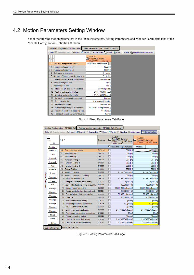
4.2 Motion Parameters Setting Window
4-4
4.2 Motion Parameters Setting Window
Set or monitor the motion parameters in the Fixed Parameters, Setting Parameters, and Monitor Parameters tabs of the Module Configuration Definition Window.
Fig. 4.1 Fixed Parameters Tab Page
Fig. 4.2 Setting Parameters Tab Page
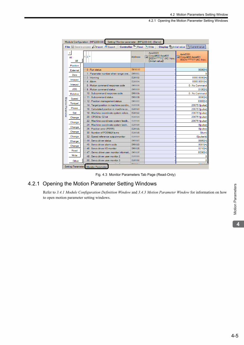
4.2 Motion Parameters Setting Window
4.2.1 Opening the Motion Parameter Setting Windows
4-5
Mot
ion
Par
amet
ers
Fig. 4.3 Monitor Parameters Tab Page (Read-Only)
4.2.1 Opening the Motion Parameter Setting Windows
Refer to 3.4.1 Module Configuration Definition Window and 3.4.3 Motion Parameter Window for information on how to open motion parameter setting windows.
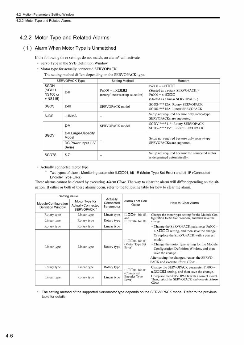
4.2 Motion Parameters Setting Window
4.2.2 Motor Type and Related Alarms
4-6
4.2.2 Motor Type and Related Alarms
( 1 ) Alarm When Motor Type is Unmatched
If the following three settings do not match, an alarm* will activate.
• Servo Type in the SVB Definition Window
• Motor type for actually connected SERVOPACK
The setting method differs depending on the SERVOPACK type.
• Actually connected motor type
* Two types of alarm: Monitoring parameter IL04, bit 1E (Motor Type Set Error) and bit 1F (Connected Encoder Type Error)
These alarms cannot be cleared by executing Alarm Clear. The way to clear the alarm will differ depending on the sit-uation. If either or both of these alarms occur, refer to the following table for how to clear the alarm.
* The setting method of the supported Servomotor type depends on the SERVOPACK model. Refer to the previous table for details.
SERVOPACK Type Setting Method Remark
SGDH (SGDH + NS100 or + NS115)
Σ-II Pn000 = n.X(rotary/linear startup selection)
Pn000 = n.0(Started as a rotary SERVOPACK.)Pn000 = n.1(Started as a linear SERVOPACK.)
SGDS Σ-III SERVOPACK modelSGDS-***12A: Rotary SERVOPACKSGDS-***15A: Linear SERVOPACK
SJDE JUNMA –Setup not required because only rotary-type SERVOPACKs are supported.
SGDV
Σ-V SERVOPACK modelSGDV-****11*: Rotary SERVOPACKSGDV-****15*: Linear SERVOPACK
Σ-V Large-Capacity Model
–Setup not required because only rotary-type SERVOPACKs are supported.DC Power Input Σ-V
Series
SGD7S Σ-7 –Setup not required because the connected motor is determined automatically.
Setting ValueActually
Connected Servomotor
Alarm That Can Occur
How to Clear AlarmModule Configuration Definition Window
Motor Type for Actually Connected
SERVOPACK *
Rotary type Linear type Linear type IL04, bit 1E andIL04, bit 1F
Change the motor type setting for the Module Con-figuration Definition Window, and then save the change.Linear type Rotary type Rotary type
Rotary type Rotary type Linear type
IL04, bit 1E(Motor Type Set Error)
• Change the SERVOPACK parameter Pn000 = n.X setting, and then save the change. Or replace the SERVOPACK with a correct model.
• Change the motor type setting for the Module Configuration Definition Window, and then save the change.
After saving the changes, restart the SERVO-PACK and execute Alarm Clear.
Linear type Linear type Rotary type
Rotary type Linear type Rotary typeIL04, bit 1F(Connected Encoder Type Error)
Change the SERVOPACK parameter Pn000 = n.X setting, and then save the change.Or replace the SERVOPACK with a correct model. Then, restart the SERVOPACK and execute Alarm Clear.
Linear type Rotary type Linear type
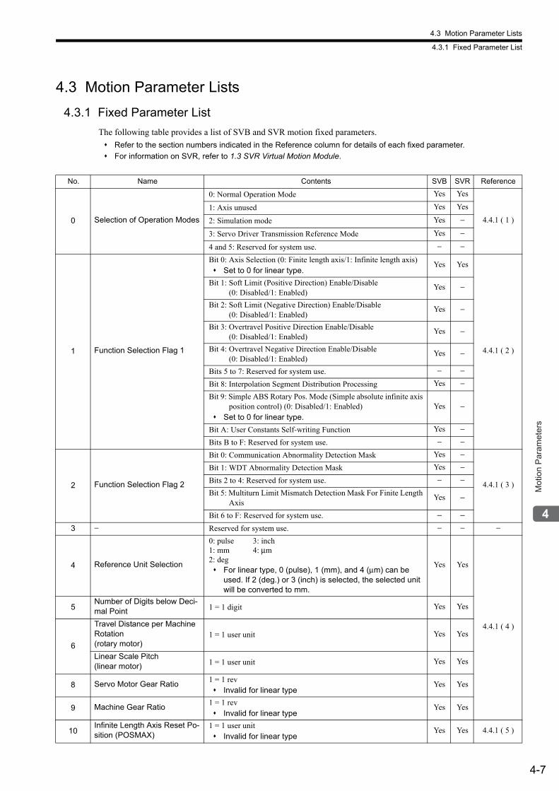
4.3 Motion Parameter Lists
4.3.1 Fixed Parameter List
4-7
Mot
ion
Par
amet
ers
4.3 Motion Parameter Lists
4.3.1 Fixed Parameter List
The following table provides a list of SVB and SVR motion fixed parameters.
Refer to the section numbers indicated in the Reference column for details of each fixed parameter.
For information on SVR, refer to 1.3 SVR Virtual Motion Module.
No. Name Contents SVB SVR Reference
0 Selection of Operation Modes
0: Normal Operation Mode Yes Yes
4.4.1 ( 1 )
1: Axis unused Yes Yes
2: Simulation mode Yes −
3: Servo Driver Transmission Reference Mode Yes −
4 and 5: Reserved for system use. − −
1 Function Selection Flag 1
Bit 0: Axis Selection (0: Finite length axis/1: Infinite length axis) Set to 0 for linear type.
Yes Yes
4.4.1 ( 2 )
Bit 1: Soft Limit (Positive Direction) Enable/Disable(0: Disabled/1: Enabled)
Yes −
Bit 2: Soft Limit (Negative Direction) Enable/Disable(0: Disabled/1: Enabled)
Yes −
Bit 3: Overtravel Positive Direction Enable/Disable(0: Disabled/1: Enabled)
Yes −
Bit 4: Overtravel Negative Direction Enable/Disable(0: Disabled/1: Enabled)
Yes −
Bits 5 to 7: Reserved for system use. − −
Bit 8: Interpolation Segment Distribution Processing Yes −
Bit 9: Simple ABS Rotary Pos. Mode (Simple absolute infinite axis position control) (0: Disabled/1: Enabled)
Set to 0 for linear type.Yes −
Bit A: User Constants Self-writing Function Yes −
Bits B to F: Reserved for system use. − −
2 Function Selection Flag 2
Bit 0: Communication Abnormality Detection Mask Yes −
4.4.1 ( 3 )
Bit 1: WDT Abnormality Detection Mask Yes −
Bits 2 to 4: Reserved for system use. − −
Bit 5: Multiturn Limit Mismatch Detection Mask For Finite Length Axis
Yes –
Bit 6 to F: Reserved for system use. – –
3 − Reserved for system use. − − −
4 Reference Unit Selection
0: pulse 3: inch1: mm 4: μm2: deg For linear type, 0 (pulse), 1 (mm), and 4 (μm) can be
used. If 2 (deg.) or 3 (inch) is selected, the selected unit will be converted to mm.
Yes Yes
4.4.1 ( 4 )
5Number of Digits below Deci-mal Point 1 = 1 digit Yes Yes
6
Travel Distance per Machine Rotation(rotary motor)
1 = 1 user unit Yes Yes
Linear Scale Pitch(linear motor) 1 = 1 user unit Yes Yes
8 Servo Motor Gear Ratio1 = 1 rev Invalid for linear type
Yes Yes
9 Machine Gear Ratio1 = 1 rev Invalid for linear type
Yes Yes
10Infinite Length Axis Reset Po-sition (POSMAX)
1 = 1 user unit Invalid for linear type
Yes Yes 4.4.1 ( 5 )
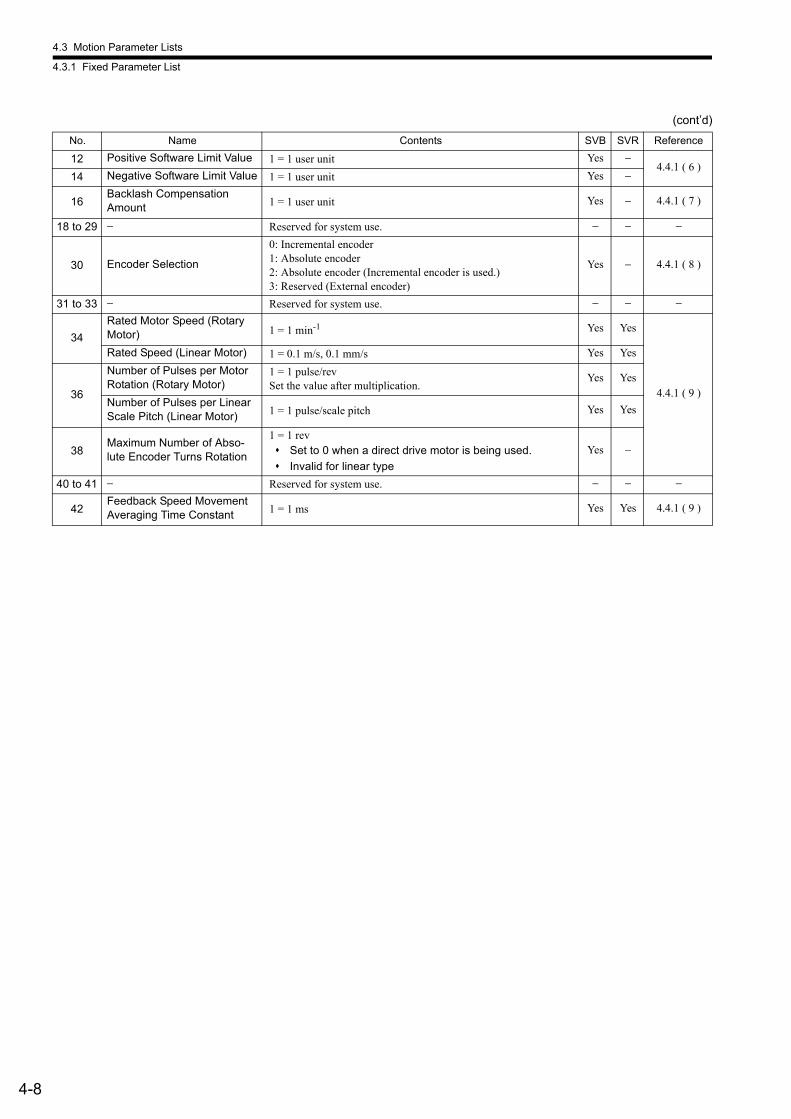
4.3 Motion Parameter Lists
4.3.1 Fixed Parameter List
4-8
12 Positive Software Limit Value 1 = 1 user unit Yes −4.4.1 ( 6 )
14 Negative Software Limit Value 1 = 1 user unit Yes −
16Backlash Compensation Amount 1 = 1 user unit Yes − 4.4.1 ( 7 )
18 to 29 − Reserved for system use. − − −
30 Encoder Selection
0: Incremental encoder1: Absolute encoder2: Absolute encoder (Incremental encoder is used.)3: Reserved (External encoder)
Yes − 4.4.1 ( 8 )
31 to 33 − Reserved for system use. − − −
34
Rated Motor Speed (Rotary Motor) 1 = 1 min-1 Yes Yes
4.4.1 ( 9 )
Rated Speed (Linear Motor) 1 = 0.1 m/s, 0.1 mm/s Yes Yes
36
Number of Pulses per Motor Rotation (Rotary Motor)
1 = 1 pulse/revSet the value after multiplication.
Yes Yes
Number of Pulses per Linear Scale Pitch (Linear Motor) 1 = 1 pulse/scale pitch Yes Yes
38Maximum Number of Abso-lute Encoder Turns Rotation
1 = 1 rev Set to 0 when a direct drive motor is being used.
Invalid for linear type
Yes −
40 to 41 − Reserved for system use. − − −
42Feedback Speed Movement Averaging Time Constant 1 = 1 ms Yes Yes 4.4.1 ( 9 )
(cont’d)
No. Name Contents SVB SVR Reference
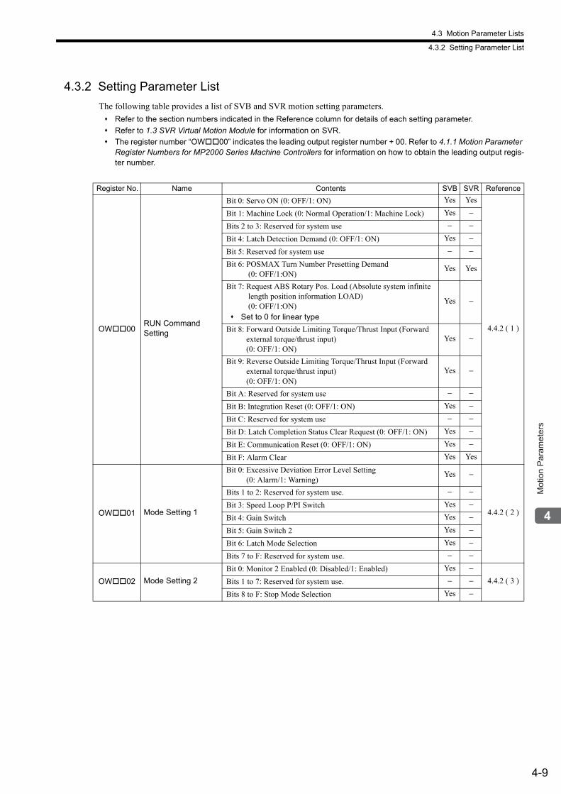
4.3 Motion Parameter Lists
4.3.2 Setting Parameter List
4-9
Mot
ion
Par
amet
ers
4.3.2 Setting Parameter List
The following table provides a list of SVB and SVR motion setting parameters.
Refer to the section numbers indicated in the Reference column for details of each setting parameter.
Refer to 1.3 SVR Virtual Motion Module for information on SVR.
The register number “OW00” indicates the leading output register number + 00. Refer to 4.1.1 Motion Parameter Register Numbers for MP2000 Series Machine Controllers for information on how to obtain the leading output regis-ter number.
Register No. Name Contents SVB SVR Reference
OW00RUN CommandSetting
Bit 0: Servo ON (0: OFF/1: ON) Yes Yes
4.4.2 ( 1 )
Bit 1: Machine Lock (0: Normal Operation/1: Machine Lock) Yes −
Bits 2 to 3: Reserved for system use − −
Bit 4: Latch Detection Demand (0: OFF/1: ON) Yes −
Bit 5: Reserved for system use − −
Bit 6: POSMAX Turn Number Presetting Demand (0: OFF/1:ON)
Yes Yes
Bit 7: Request ABS Rotary Pos. Load (Absolute system infinite length position information LOAD) (0: OFF/1:ON) Set to 0 for linear type
Yes −
Bit 8: Forward Outside Limiting Torque/Thrust Input (Forward external torque/thrust input) (0: OFF/1: ON)
Yes −
Bit 9: Reverse Outside Limiting Torque/Thrust Input (Forward external torque/thrust input) (0: OFF/1: ON)
Yes −
Bit A: Reserved for system use − −
Bit B: Integration Reset (0: OFF/1: ON) Yes −
Bit C: Reserved for system use − −
Bit D: Latch Completion Status Clear Request (0: OFF/1: ON) Yes −
Bit E: Communication Reset (0: OFF/1: ON) Yes −
Bit F: Alarm Clear Yes Yes
OW01 Mode Setting 1
Bit 0: Excessive Deviation Error Level Setting(0: Alarm/1: Warning)
Yes −
4.4.2 ( 2 )
Bits 1 to 2: Reserved for system use. − −
Bit 3: Speed Loop P/PI Switch Yes −
Bit 4: Gain Switch Yes −
Bit 5: Gain Switch 2 Yes −
Bit 6: Latch Mode Selection Yes −
Bits 7 to F: Reserved for system use. − −
OW02 Mode Setting 2
Bit 0: Monitor 2 Enabled (0: Disabled/1: Enabled) Yes −4.4.2 ( 3 )Bits 1 to 7: Reserved for system use. − −
Bits 8 to F: Stop Mode Selection Yes −
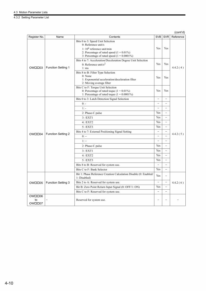
4.3 Motion Parameter Lists
4.3.2 Setting Parameter List
4-10
OW03 Function Setting 1
Bits 0 to 3: Speed Unit Selection 0: Reference unit/s
1: 10n reference unit/min 2: Percentage of rated speed (1 = 0.01%) 3: Percentage of rated speed (1 = 0.0001%)
Yes Yes
4.4.2 ( 4 )
Bits 4 to 7: Acceleration/Deceleration Degree Unit Selection
0: Reference unit/s2
1: ms
Yes Yes
Bits 8 to B: Filter Type Selection 0: None 1: Exponential acceleration/deceleration filter 2: Moving average filter
Yes Yes
Bits C to F: Torque Unit Selection 0: Percentage of rated toque (1 = 0.01%) 1: Percentage of rated toque (1 = 0.0001%)
Yes Yes
OW04 Function Setting 2
Bits 0 to 3: Latch Detection Signal Selection − −
4.4.2 ( 5 )
0: - − −
1: - − −
2: Phase-C pulse Yes −
3: /EXT1 Yes −
4: /EXT2 Yes −
5: /EXT3 Yes −
Bits 4 to 7: External Positioning Signal Setting − −
0: − − −
1: − − −
2: Phase-C pulse Yes −
3: /EXT1 Yes −
4: /EXT2 Yes −
5: /EXT3 Yes −
Bits 8 to B: Reserved for system use. − −
Bits C to F: Bank Selector Yes −
OW05 Function Setting 3
Bit 1: Phase Reference Creation Calculation Disable (0: Enabled/1: Disabled)
Yes −
4.4.2 ( 6 )Bits 2 to A: Reserved for system use. − −
Bit B: Zero Point Return Input Signal (0: OFF/1: ON) Yes −
Bits C to F: Reserved for system use. − −
OW06 to
OW07− Reserved for system use. − − −
(cont’d)
Register No. Name Contents SVB SVR Reference
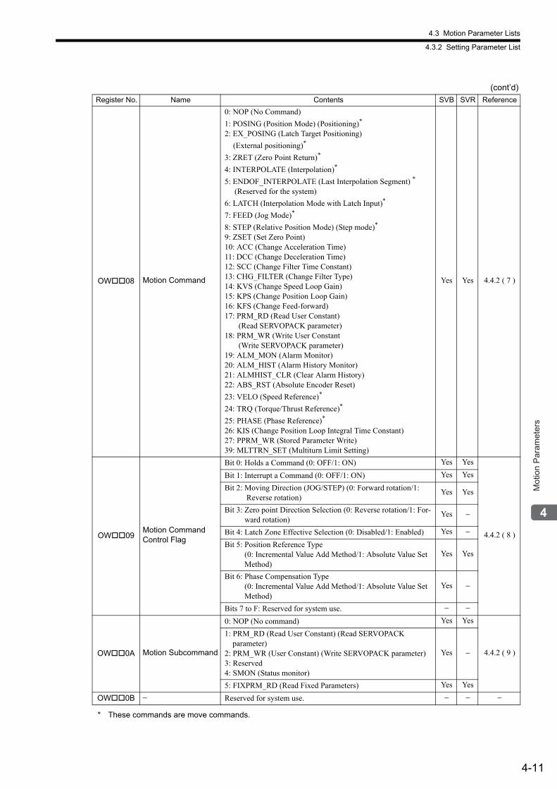
4.3 Motion Parameter Lists
4.3.2 Setting Parameter List
4-11
Mot
ion
Par
amet
ers
OW08 Motion Command
0: NOP (No Command)
1: POSING (Position Mode) (Positioning)*
2: EX_POSING (Latch Target Positioning)
(External positioning)*
3: ZRET (Zero Point Return)*
4: INTERPOLATE (Interpolation)*
5: ENDOF_INTERPOLATE (Last Interpolation Segment) *
(Reserved for the system)
6: LATCH (Interpolation Mode with Latch Input)*
7: FEED (Jog Mode)*
8: STEP (Relative Position Mode) (Step mode)*
9: ZSET (Set Zero Point)10: ACC (Change Acceleration Time)11: DCC (Change Deceleration Time)12: SCC (Change Filter Time Constant)13: CHG_FILTER (Change Filter Type)14: KVS (Change Speed Loop Gain)15: KPS (Change Position Loop Gain)16: KFS (Change Feed-forward)17: PRM_RD (Read User Constant) (Read SERVOPACK parameter)18: PRM_WR (Write User Constant (Write SERVOPACK parameter)19: ALM_MON (Alarm Monitor)20: ALM_HIST (Alarm History Monitor)21: ALMHIST_CLR (Clear Alarm History)22: ABS_RST (Absolute Encoder Reset)
23: VELO (Speed Reference)*
24: TRQ (Torque/Thrust Reference)*
25: PHASE (Phase Reference)*
26: KIS (Change Position Loop Integral Time Constant)27: PPRM_WR (Stored Parameter Write)39: MLTTRN_SET (Multiturn Limit Setting)
Yes Yes 4.4.2 ( 7 )
OW09Motion Command Control Flag
Bit 0: Holds a Command (0: OFF/1: ON) Yes Yes
4.4.2 ( 8 )
Bit 1: Interrupt a Command (0: OFF/1: ON) Yes Yes
Bit 2: Moving Direction (JOG/STEP) (0: Forward rotation/1: Reverse rotation)
Yes Yes
Bit 3: Zero point Direction Selection (0: Reverse rotation/1: For-ward rotation)
Yes −
Bit 4: Latch Zone Effective Selection (0: Disabled/1: Enabled) Yes −
Bit 5: Position Reference Type(0: Incremental Value Add Method/1: Absolute Value Set Method)
Yes Yes
Bit 6: Phase Compensation Type(0: Incremental Value Add Method/1: Absolute Value Set Method)
Yes −
Bits 7 to F: Reserved for system use. − −
OW0A Motion Subcommand
0: NOP (No command) Yes Yes
4.4.2 ( 9 )
1: PRM_RD (Read User Constant) (Read SERVOPACK parameter)2: PRM_WR (User Constant) (Write SERVOPACK parameter)3: Reserved4: SMON (Status monitor)
Yes −
5: FIXPRM_RD (Read Fixed Parameters) Yes Yes
OW0B − Reserved for system use. − − −
* These commands are move commands.
(cont’d)
Register No. Name Contents SVB SVR Reference
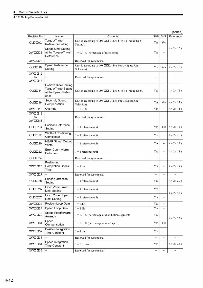
4.3 Motion Parameter Lists
4.3.2 Setting Parameter List
4-12
OL0CTorque/ThrustReference Setting
Unit is according to OW03, bits C to F (Torque UnitSetting).
Yes Yes
4.4.2 ( 10 )
OW0ESpeed Limit Setting at the Torque/Thrust Reference
1 = 0.01% (percentage of rated speed) Yes −
OW0F − Reserved for system use. − − −
OL10Speed Reference Setting
Unit is according to OW03, bits 0 to 3 (Speed UnitSelection).
Yes Yes 4.4.2 ( 11 )
OW12 to
OW13− Reserved for system use. − − −
OL14
Positive Side Limiting Torque/Thrust Setting at the Speed Refer-ence
Unit is according to OW03, bits C to F (Torque Unit). Yes − 4.4.2 ( 12 )
OL16Secondly Speed Compensation
Unit is according to OW03, bits 0 to 3 (Speed UnitSelection).
Yes Yes 4.4.2 ( 13 )
OW18 Override 1 = 0.01% Yes − 4.4.2 ( 14 )
OW19 to
OW1B− Reserved for system use. − − −
OL1CPosition Reference Setting 1 = 1 reference unit Yes Yes 4.4.2 ( 15 )
OL1EWidth of Positioning Completion 1 = 1 reference unit Yes − 4.4.2 ( 16 )
OL20NEAR Signal Output Width 1 = 1 reference unit Yes − 4.4.2 ( 17 )
OL22Error Count Alarm Detection 1 = 1 reference unit Yes − 4.4.2 ( 18 )
OL24 − Reserved for system use. − − −
OW26PositioningCompletion Check Time
1 = 1 ms Yes − 4.4.2 ( 19 )
OW27 − Reserved for system use. − − −
OL28Phase CorrectionSetting 1 = 1 reference unit Yes − 4.4.2 ( 20 )
OL2ALatch Zone Lower Limit Setting 1 = 1 reference unit Yes −
4.4.2 ( 21 )
OL2CLatch Zone Upper Limit Setting 1 = 1 reference unit Yes −
OW2E Position Loop Gain 1 = 0.1/s Yes −
4.4.2 ( 22 )
OW2F Speed Loop Gain 1 = 1 Hz Yes −
OW30Speed Feedforward Amends 1 = 0.01% (percentage of distribution segment) Yes −
OW31SpeedCompensation 1 = 0.01% (percentage of rated speed) Yes Yes
OW32Position Integration Time Constant 1 = 1 ms Yes −
OW33 − Reserved for system use. − − −
OW34Speed Integration Time Constant 1 = 0.01 ms Yes − 4.4.2 ( 22 )
OW35 − Reserved for system use. − − −
(cont’d)
Register No. Name Contents SVB SVR Reference
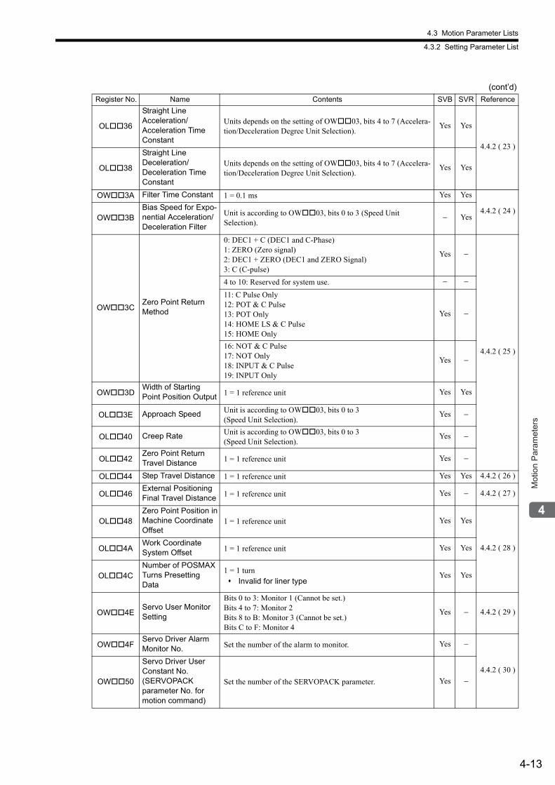
4.3 Motion Parameter Lists
4.3.2 Setting Parameter List
4-13
Mot
ion
Par
amet
ers
OL36
Straight LineAcceleration/Acceleration Time Constant
Units depends on the setting of OW03, bits 4 to 7 (Accelera-tion/Deceleration Degree Unit Selection).
Yes Yes
4.4.2 ( 23 )
OL38
Straight LineDeceleration/Deceleration TimeConstant
Units depends on the setting of OW03, bits 4 to 7 (Accelera-tion/Deceleration Degree Unit Selection).
Yes Yes
OW3A Filter Time Constant 1 = 0.1 ms Yes Yes
4.4.2 ( 24 )OW3B
Bias Speed for Expo-nential Acceleration/Deceleration Filter
Unit is according to OW03, bits 0 to 3 (Speed UnitSelection).
− Yes
OW3CZero Point Return Method
0: DEC1 + C (DEC1 and C-Phase)1: ZERO (Zero signal)2: DEC1 + ZERO (DEC1 and ZERO Signal)3: C (C-pulse)
Yes −
4.4.2 ( 25 )
4 to 10: Reserved for system use. − −
11: C Pulse Only12: POT & C Pulse13: POT Only14: HOME LS & C Pulse15: HOME Only
Yes −
16: NOT & C Pulse17: NOT Only18: INPUT & C Pulse19: INPUT Only
Yes −
OW3DWidth of StartingPoint Position Output 1 = 1 reference unit Yes Yes
OL3E Approach Speed Unit is according to OW03, bits 0 to 3(Speed Unit Selection).
Yes −
OL40 Creep Rate Unit is according to OW03, bits 0 to 3(Speed Unit Selection).
Yes −
OL42Zero Point ReturnTravel Distance 1 = 1 reference unit Yes −
OL44 Step Travel Distance 1 = 1 reference unit Yes Yes 4.4.2 ( 26 )
OL46External Positioning Final Travel Distance 1 = 1 reference unit Yes − 4.4.2 ( 27 )
OL48Zero Point Position inMachine CoordinateOffset
1 = 1 reference unit Yes Yes
4.4.2 ( 28 )OL4AWork Coordinate System Offset 1 = 1 reference unit Yes Yes
OL4CNumber of POSMAX Turns Presetting Data
1 = 1 turn Invalid for liner type
Yes Yes
OW4EServo User MonitorSetting
Bits 0 to 3: Monitor 1 (Cannot be set.)Bits 4 to 7: Monitor 2Bits 8 to B: Monitor 3 (Cannot be set.)Bits C to F: Monitor 4
Yes − 4.4.2 ( 29 )
OW4FServo Driver Alarm Monitor No. Set the number of the alarm to monitor. Yes −
4.4.2 ( 30 )
OW50
Servo Driver User Constant No.(SERVOPACKparameter No. for motion command)
Set the number of the SERVOPACK parameter. Yes −
(cont’d)
Register No. Name Contents SVB SVR Reference
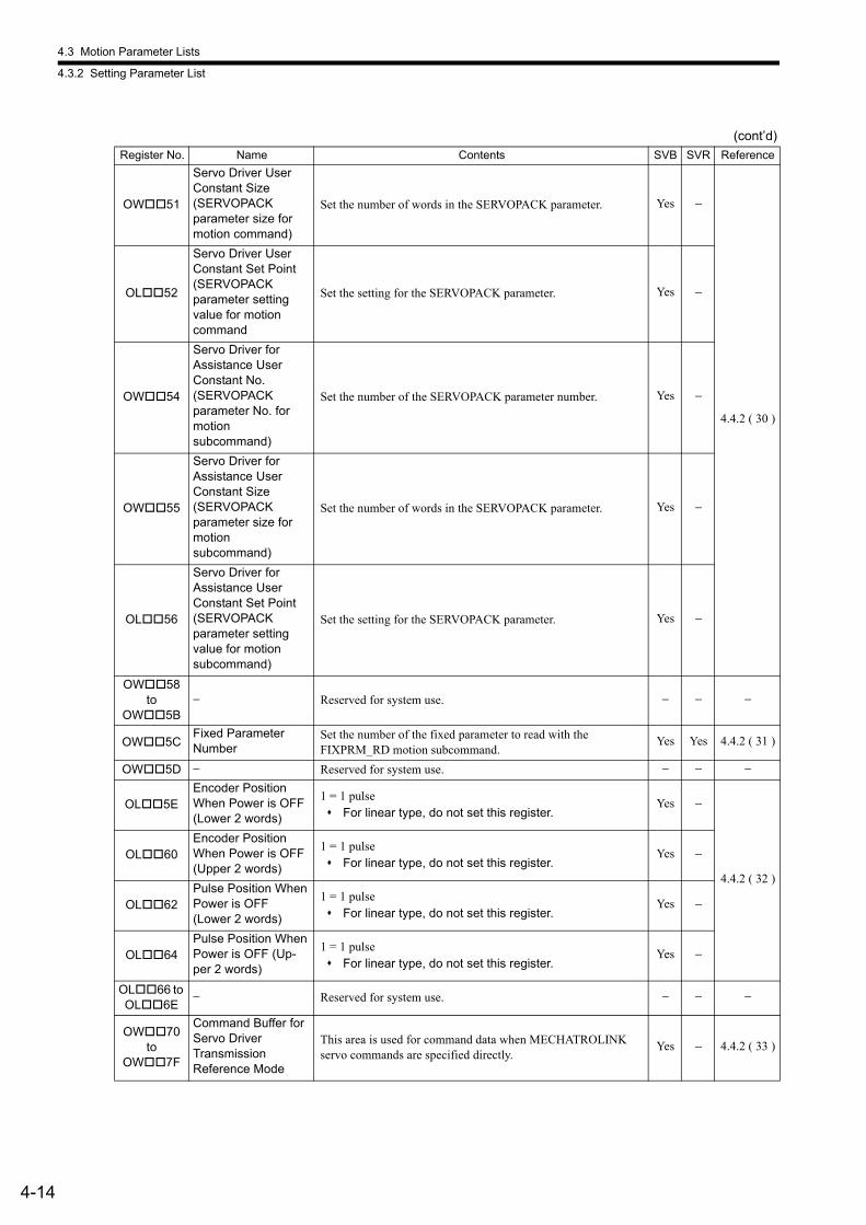
4.3 Motion Parameter Lists
4.3.2 Setting Parameter List
4-14
OW51
Servo Driver User Constant Size(SERVOPACKparameter size for motion command)
Set the number of words in the SERVOPACK parameter. Yes −
4.4.2 ( 30 )
OL52
Servo Driver User Constant Set Point(SERVOPACKparameter setting value for motioncommand
Set the setting for the SERVOPACK parameter. Yes −
OW54
Servo Driver forAssistance User Constant No.(SERVOPACKparameter No. formotionsubcommand)
Set the number of the SERVOPACK parameter number. Yes −
OW55
Servo Driver forAssistance User Constant Size(SERVOPACKparameter size for motionsubcommand)
Set the number of words in the SERVOPACK parameter. Yes −
OL56
Servo Driver forAssistance User Constant Set Point(SERVOPACKparameter setting value for motionsubcommand)
Set the setting for the SERVOPACK parameter. Yes −
OW58to
OW5B− Reserved for system use. − − −
OW5CFixed Parameter Number
Set the number of the fixed parameter to read with the FIXPRM_RD motion subcommand.
Yes Yes 4.4.2 ( 31 )
OW5D − Reserved for system use. − − −
OL5EEncoder PositionWhen Power is OFF(Lower 2 words)
1 = 1 pulse For linear type, do not set this register.
Yes −
4.4.2 ( 32 )
OL60Encoder PositionWhen Power is OFF(Upper 2 words)
1 = 1 pulse For linear type, do not set this register.
Yes −
OL62Pulse Position WhenPower is OFF(Lower 2 words)
1 = 1 pulse For linear type, do not set this register.
Yes −
OL64Pulse Position WhenPower is OFF (Up-per 2 words)
1 = 1 pulse For linear type, do not set this register.
Yes −
OL66 to OL6E
− Reserved for system use. − − −
OW70 to
OW7F
Command Buffer for Servo DriverTransmissionReference Mode
This area is used for command data when MECHATROLINK servo commands are specified directly.
Yes − 4.4.2 ( 33 )
(cont’d)
Register No. Name Contents SVB SVR Reference
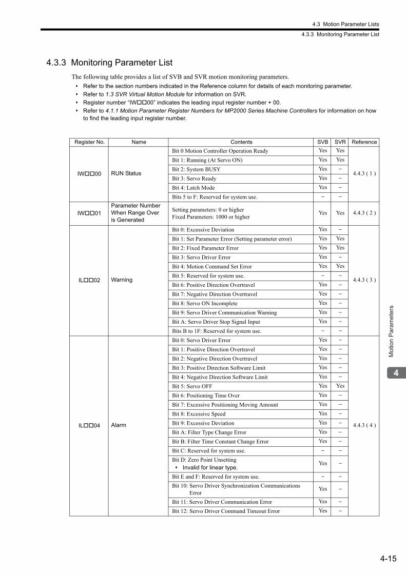
4.3 Motion Parameter Lists
4.3.3 Monitoring Parameter List
4-15
Mot
ion
Par
amet
ers
4.3.3 Monitoring Parameter List
The following table provides a list of SVB and SVR motion monitoring parameters.
Refer to the section numbers indicated in the Reference column for details of each monitoring parameter.
Refer to 1.3 SVR Virtual Motion Module for information on SVR.
Register number “IW00” indicates the leading input register number + 00.
Refer to 4.1.1 Motion Parameter Register Numbers for MP2000 Series Machine Controllers for information on how to find the leading input register number.
Register No. Name Contents SVB SVR Reference
IW00 RUN Status
Bit 0 Motion Controller Operation Ready Yes Yes
4.4.3 ( 1 )
Bit 1: Running (At Servo ON) Yes Yes
Bit 2: System BUSY Yes −
Bit 3: Servo Ready Yes −
Bit 4: Latch Mode Yes −
Bits 5 to F: Reserved for system use. − −
IW01Parameter NumberWhen Range Overis Generated
Setting parameters: 0 or higher Fixed Parameters: 1000 or higher
Yes Yes 4.4.3 ( 2 )
IL02 Warning
Bit 0: Excessive Deviation Yes −
4.4.3 ( 3 )
Bit 1: Set Parameter Error (Setting parameter error) Yes Yes
Bit 2: Fixed Parameter Error Yes Yes
Bit 3: Servo Driver Error Yes −
Bit 4: Motion Command Set Error Yes Yes
Bit 5: Reserved for system use. − −
Bit 6: Positive Direction Overtravel Yes −
Bit 7: Negative Direction Overtravel Yes −
Bit 8: Servo ON Incomplete Yes −
Bit 9: Servo Driver Communication Warning Yes −
Bit A: Servo Driver Stop Signal Input Yes −
Bits B to 1F: Reserved for system use. − −
IL04 Alarm
Bit 0: Servo Driver Error Yes −
4.4.3 ( 4 )
Bit 1: Positive Direction Overtravel Yes −
Bit 2: Negative Direction Overtravel Yes −
Bit 3: Positive Direction Software Limit Yes −
Bit 4: Negative Direction Software Limit Yes −
Bit 5: Servo OFF Yes Yes
Bit 6: Positioning Time Over Yes −
Bit 7: Excessive Positioning Moving Amount Yes −
Bit 8: Excessive Speed Yes −
Bit 9: Excessive Deviation Yes −
Bit A: Filter Type Change Error Yes −
Bit B: Filter Time Constant Change Error Yes −
Bit C: Reserved for system use. − −
Bit D: Zero Point Unsetting Invalid for linear type.
Yes −
Bit E and F: Reserved for system use. − −
Bit 10: Servo Driver Synchronization Communications Error
Yes −
Bit 11: Servo Driver Communication Error Yes −
Bit 12: Servo Driver Command Timeout Error Yes −
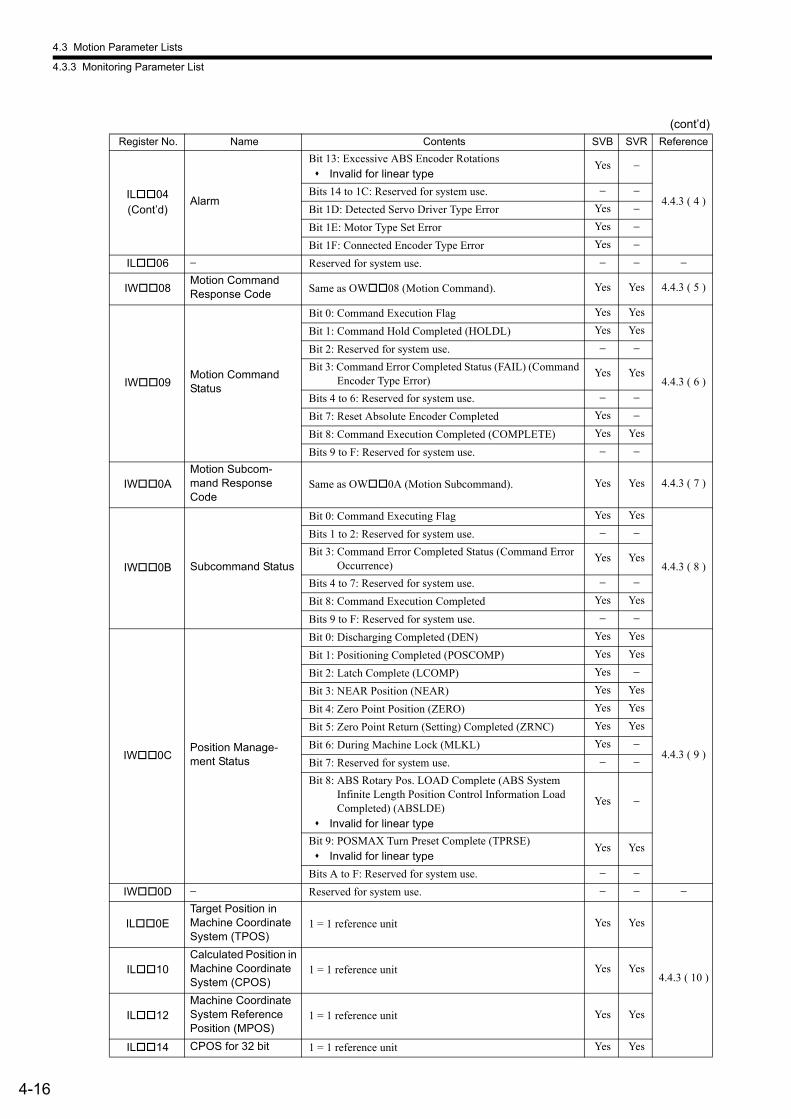
4.3 Motion Parameter Lists
4.3.3 Monitoring Parameter List
4-16
IL04(Cont’d)
Alarm
Bit 13: Excessive ABS Encoder Rotations Invalid for linear type
Yes −
4.4.3 ( 4 )Bits 14 to 1C: Reserved for system use. − −
Bit 1D: Detected Servo Driver Type Error Yes −
Bit 1E: Motor Type Set Error Yes −
Bit 1F: Connected Encoder Type Error Yes −
IL06 − Reserved for system use. − − −
IW08Motion CommandResponse Code Same as OW08 (Motion Command). Yes Yes 4.4.3 ( 5 )
IW09Motion Command Status
Bit 0: Command Execution Flag Yes Yes
4.4.3 ( 6 )
Bit 1: Command Hold Completed (HOLDL) Yes Yes
Bit 2: Reserved for system use. − −
Bit 3: Command Error Completed Status (FAIL) (Command Encoder Type Error)
Yes Yes
Bits 4 to 6: Reserved for system use. − −
Bit 7: Reset Absolute Encoder Completed Yes −
Bit 8: Command Execution Completed (COMPLETE) Yes Yes
Bits 9 to F: Reserved for system use. − −
IW0AMotion Subcom-mand Response Code
Same as OW0A (Motion Subcommand). Yes Yes 4.4.3 ( 7 )
IW0B Subcommand Status
Bit 0: Command Executing Flag Yes Yes
4.4.3 ( 8 )
Bits 1 to 2: Reserved for system use. − −
Bit 3: Command Error Completed Status (Command Error Occurrence)
Yes Yes
Bits 4 to 7: Reserved for system use. − −
Bit 8: Command Execution Completed Yes Yes
Bits 9 to F: Reserved for system use. − −
IW0CPosition Manage-ment Status
Bit 0: Discharging Completed (DEN) Yes Yes
4.4.3 ( 9 )
Bit 1: Positioning Completed (POSCOMP) Yes Yes
Bit 2: Latch Complete (LCOMP) Yes −
Bit 3: NEAR Position (NEAR) Yes Yes
Bit 4: Zero Point Position (ZERO) Yes Yes
Bit 5: Zero Point Return (Setting) Completed (ZRNC) Yes Yes
Bit 6: During Machine Lock (MLKL) Yes −
Bit 7: Reserved for system use. − −
Bit 8: ABS Rotary Pos. LOAD Complete (ABS SystemInfinite Length Position Control Information Load Completed) (ABSLDE)
Invalid for linear type
Yes −
Bit 9: POSMAX Turn Preset Complete (TPRSE) Invalid for linear type
Yes Yes
Bits A to F: Reserved for system use. − −
IW0D − Reserved for system use. − − −
IL0ETarget Position inMachine Coordinate System (TPOS)
1 = 1 reference unit Yes Yes
4.4.3 ( 10 )IL10
Calculated Position in Machine CoordinateSystem (CPOS)
1 = 1 reference unit Yes Yes
IL12Machine Coordinate System Reference Position (MPOS)
1 = 1 reference unit Yes Yes
IL14 CPOS for 32 bit 1 = 1 reference unit Yes Yes
(cont’d)
Register No. Name Contents SVB SVR Reference
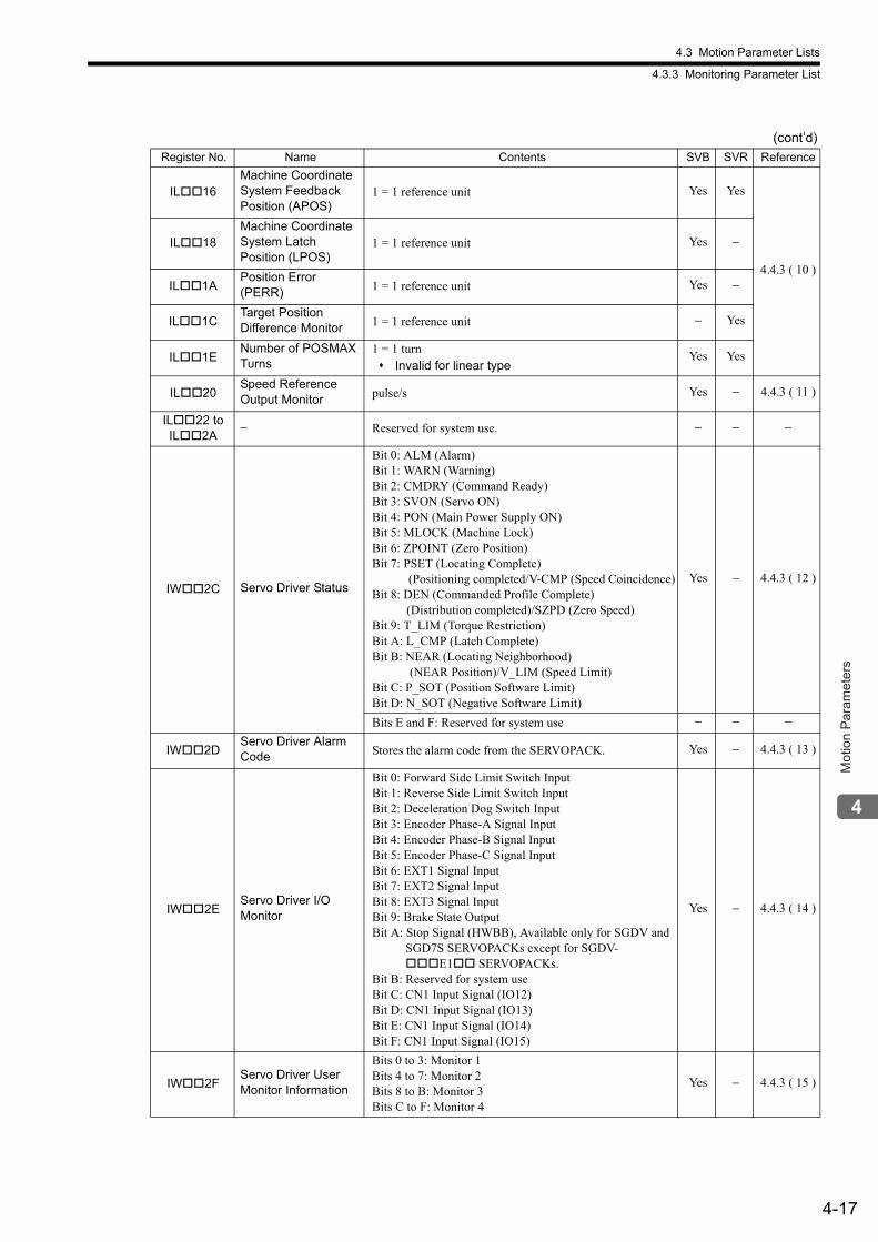
4.3 Motion Parameter Lists
4.3.3 Monitoring Parameter List
4-17
Mot
ion
Par
amet
ers
IL16Machine Coordinate System Feedback Position (APOS)
1 = 1 reference unit Yes Yes
4.4.3 ( 10 )
IL18Machine Coordinate System LatchPosition (LPOS)
1 = 1 reference unit Yes −
IL1APosition Error (PERR) 1 = 1 reference unit Yes −
IL1CTarget Position Difference Monitor 1 = 1 reference unit − Yes
IL1ENumber of POSMAXTurns
1 = 1 turn Invalid for linear type
Yes Yes
IL20Speed Reference Output Monitor pulse/s Yes − 4.4.3 ( 11 )
IL22 to IL2A
− Reserved for system use. − − −
IW2C Servo Driver Status
Bit 0: ALM (Alarm)Bit 1: WARN (Warning)Bit 2: CMDRY (Command Ready)Bit 3: SVON (Servo ON)Bit 4: PON (Main Power Supply ON)Bit 5: MLOCK (Machine Lock)Bit 6: ZPOINT (Zero Position)Bit 7: PSET (Locating Complete) (Positioning completed/V-CMP (Speed Coincidence)Bit 8: DEN (Commanded Profile Complete) (Distribution completed)/SZPD (Zero Speed)Bit 9: T_LIM (Torque Restriction)Bit A: L_CMP (Latch Complete)Bit B: NEAR (Locating Neighborhood) (NEAR Position)/V_LIM (Speed Limit)Bit C: P_SOT (Position Software Limit)Bit D: N_SOT (Negative Software Limit)
Yes − 4.4.3 ( 12 )
Bits E and F: Reserved for system use − − −
IW2DServo Driver Alarm Code Stores the alarm code from the SERVOPACK. Yes − 4.4.3 ( 13 )
IW2EServo Driver I/O Monitor
Bit 0: Forward Side Limit Switch InputBit 1: Reverse Side Limit Switch InputBit 2: Deceleration Dog Switch InputBit 3: Encoder Phase-A Signal InputBit 4: Encoder Phase-B Signal InputBit 5: Encoder Phase-C Signal InputBit 6: EXT1 Signal InputBit 7: EXT2 Signal InputBit 8: EXT3 Signal InputBit 9: Brake State OutputBit A: Stop Signal (HWBB), Available only for SGDV and
SGD7S SERVOPACKs except for SGDV-E1 SERVOPACKs.
Bit B: Reserved for system useBit C: CN1 Input Signal (IO12)Bit D: CN1 Input Signal (IO13)Bit E: CN1 Input Signal (IO14)Bit F: CN1 Input Signal (IO15)
Yes − 4.4.3 ( 14 )
IW2FServo Driver User Monitor Information
Bits 0 to 3: Monitor 1Bits 4 to 7: Monitor 2Bits 8 to B: Monitor 3Bits C to F: Monitor 4
Yes − 4.4.3 ( 15 )
(cont’d)
Register No. Name Contents SVB SVR Reference
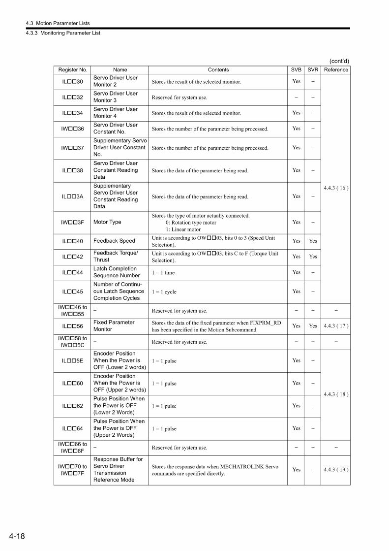
4.3 Motion Parameter Lists
4.3.3 Monitoring Parameter List
4-18
IL30Servo Driver User Monitor 2 Stores the result of the selected monitor. Yes −
4.4.3 ( 16 )
IL32Servo Driver User Monitor 3 Reserved for system use. − −
IL34Servo Driver User Monitor 4 Stores the result of the selected monitor. Yes −
IW36Servo Driver UserConstant No. Stores the number of the parameter being processed. Yes −
IW37Supplementary ServoDriver User ConstantNo.
Stores the number of the parameter being processed. Yes −
IL38Servo Driver UserConstant Reading Data
Stores the data of the parameter being read. Yes −
IL3A
SupplementaryServo Driver User Constant Reading Data
Stores the data of the parameter being read. Yes −
IW3F Motor TypeStores the type of motor actually connected. 0: Rotation type motor 1: Linear motor
Yes −
IL40 Feedback Speed Unit is according to OW03, bits 0 to 3 (Speed UnitSelection).
Yes Yes
IL42Feedback Torque/Thrust
Unit is according to OW03, bits C to F (Torque UnitSelection).
Yes Yes
IL44Latch CompletionSequence Number 1 = 1 time Yes −
IL45Number of Continu-ous Latch SequenceCompletion Cycles
1 = 1 cycle Yes −
IW46 to IW55
− Reserved for system use. − − −
IL56Fixed Parameter Monitor
Stores the data of the fixed parameter when FIXPRM_RD has been specified in the Motion Subcommand.
Yes Yes 4.4.3 ( 17 )
IW58 to IW5C
− Reserved for system use. − − −
IL5EEncoder PositionWhen the Power isOFF (Lower 2 words)
1 = 1 pulse Yes −
4.4.3 ( 18 )
IL60Encoder PositionWhen the Power isOFF (Upper 2 words)
1 = 1 pulse Yes −
IL62Pulse Position Whenthe Power is OFF(Lower 2 Words)
1 = 1 pulse Yes −
IL64Pulse Position Whenthe Power is OFF(Upper 2 Words)
1 = 1 pulse Yes −
IW66 to IW6F
− Reserved for system use. − − −
IW70 to IW7F
Response Buffer for Servo DriverTransmissionReference Mode
Stores the response data when MECHATROLINK Servo commands are specified directly.
Yes − 4.4.3 ( 19 )
(cont’d)
Register No. Name Contents SVB SVR Reference
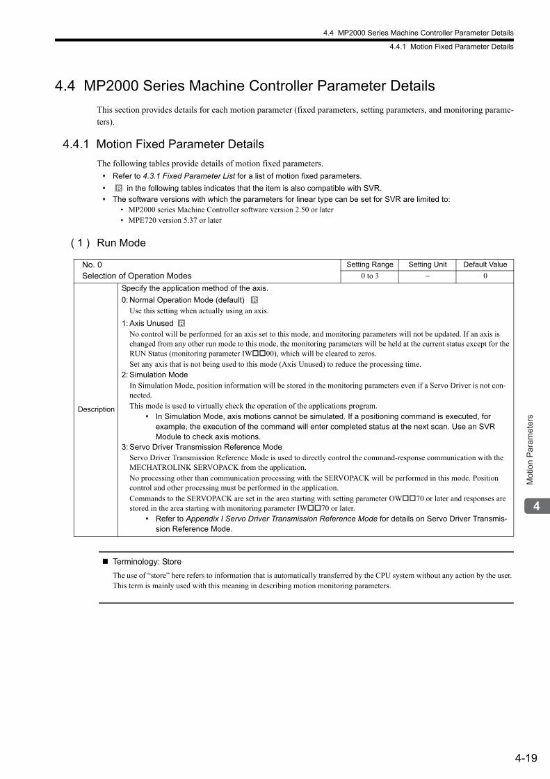
4.4 MP2000 Series Machine Controller Parameter Details
4.4.1 Motion Fixed Parameter Details
4-19
Mot
ion
Par
amet
ers
4.4 MP2000 Series Machine Controller Parameter Details
This section provides details for each motion parameter (fixed parameters, setting parameters, and monitoring parame-ters).
4.4.1 Motion Fixed Parameter Details
The following tables provide details of motion fixed parameters.
Refer to 4.3.1 Fixed Parameter List for a list of motion fixed parameters.
in the following tables indicates that the item is also compatible with SVR.
The software versions with which the parameters for linear type can be set for SVR are limited to:• MP2000 series Machine Controller software version 2.50 or later• MPE720 version 5.37 or later
( 1 ) Run Mode
Terminology: Store
The use of “store” here refers to information that is automatically transferred by the CPU system without any action by the user. This term is mainly used with this meaning in describing motion monitoring parameters.
R
No. 0Selection of Operation Modes
Setting Range Setting Unit Default Value
0 to 3 − 0
Description
Specify the application method of the axis.
0: Normal Operation Mode (default) Use this setting when actually using an axis.
1: Axis UnusedNo control will be performed for an axis set to this mode, and monitoring parameters will not be updated. If an axis is changed from any other run mode to this mode, the monitoring parameters will be held at the current status except for the RUN Status (monitoring parameter IW00), which will be cleared to zeros.Set any axis that is not being used to this mode (Axis Unused) to reduce the processing time.
2: Simulation ModeIn Simulation Mode, position information will be stored in the monitoring parameters even if a Servo Driver is not con-nected.This mode is used to virtually check the operation of the applications program.
In Simulation Mode, axis motions cannot be simulated. If a positioning command is executed, for example, the execution of the command will enter completed status at the next scan. Use an SVR Module to check axis motions.
3: Servo Driver Transmission Reference ModeServo Driver Transmission Reference Mode is used to directly control the command-response communication with the MECHATROLINK SERVOPACK from the application.No processing other than communication processing with the SERVOPACK will be performed in this mode. Position control and other processing must be performed in the application.Commands to the SERVOPACK are set in the area starting with setting parameter OW70 or later and responses are stored in the area starting with monitoring parameter IW70 or later.
Refer to Appendix I Servo Driver Transmission Reference Mode for details on Servo Driver Transmis-sion Reference Mode.
R
R
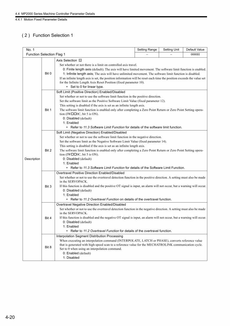
4.4 MP2000 Series Machine Controller Parameter Details
4.4.1 Motion Fixed Parameter Details
4-20
( 2 ) Function Selection 1
No. 1Function Selection Flag 1
Setting Range Setting Unit Default Value
− − 0000H
Description
Bit 0
Axis SelectionSet whether or not there is a limit on controlled axis travel.
0: Finite length axis (default); The axis will have limited movement. The software limit function is enabled.1: Infinite length axis; The axis will have unlimited movement. The software limit function is disabled.
If an infinite length axis is set, the position information will be reset each time the position exceeds the value set for the Infinite Length Axis Reset Position (fixed parameter 10).
Set to 0 for linear type.
Bit 1
Soft Limit (Positive Direction) Enabled/DisabledSet whether or not to use the software limit function in the positive direction.Set the software limit as the Positive Software Limit Value (fixed parameter 12).This setting is disabled if the axis is set as an infinite length axis.The software limit function is enabled only after completing a Zero Point Return or Zero Point Setting opera-tion (IW0C, bit 5 is ON).
0: Disabled (default)1: Enabled Refer to 11.3 Software Limit Function for details of the software limit function.
Bit 2
Soft Limit (Negative Direction) Enabled/DisabledSet whether or not to use the software limit function in the negative direction.Set the software limit as the Negative Software Limit Value (fixed parameter 14).This setting is disabled if the axis is set as an infinite length axis.The software limit function is enabled only after completing a Zero Point Return or Zero Point Setting opera-tion (IW0C, bit 5 is ON).
0: Disabled (default)1: Enabled Refer to 11.3 Software Limit Function for details of the Software Limit Function.
Bit 3
Overtravel Positive Direction Enabled/DisabledSet whether or not to use the overtravel detection function in the positive direction. A setting must also be made in the SERVOPACK.If this function is disabled and the positive OT signal is input, an alarm will not occur, but a warning will occur.
0: Disabled (default)1: Enabled Refer to 11.2 Overtravel Function on details of the overtravel function.
Bit 4
Overtravel Negative Direction Enabled/DisabledSet whether or not to use the overtravel detection function in the negative direction. A setting must also be made in the SERVOPACK.If this function is disabled and the negative OT signal is input, an alarm will not occur, but a warning will occur.
0: Disabled (default)1: Enabled Refer to 11.2 Overtravel Function for details of the overtravel function.
Bit 8
Interpolation Segment Distribution ProcessingWhen executing an interpolation command (INTERPOLATE, LATCH or PHASE), converts reference value that is generated with high-speed scan to a reference value for the MECHATROLINK communication cycle.Set to 0 when using an interpolation command.
0: Enabled (default)1: Disabled
R

4.4 MP2000 Series Machine Controller Parameter Details
4.4.1 Motion Fixed Parameter Details
4-21
Mot
ion
Par
amet
ers
( 3 ) Function Selection Flag 2
Description
Bit 9
Simple ABS Rotary Pos. ModeSet whether or not the infinite length position control function is used, on the condition that the number of turns that the encoder can count is a multiple of the number of turns corresponding to the reference unit reset fre-quency.With this function, it is not necessary to save and load absolute infinite axis information, eliminating the need for a ladder program and thus simplifying handling. It is recommended that the Simple ABS Rotary Pos. Mode is set to Enabled for ABS infinite length axes.
0: Disabled (default)1: Enabled Refer to 9.4.2 ( 2 ) Machine Controller Fixed Parameters for Absolute Position Detection and
9.4.1 ( 2 ) Conditions to Enable the Simple Absolute Infinite Axis Position Control for details.
Set to 0 for linear type.
Bit A
User Constants Self-Writing FunctionSet whether or not to use the function that automatically writes Machine Controller setting parameters to the SERVOPACK parameters when a MECHATROLINK communication connection is established. Also, the auto-matic writing is triggered by changing the setting parameters or starting execution of a motion command.
0: Enabled (default)1: Disabled Refer to 11.6 Parameters That Are Automatically Updated for details.
No. 2Function Selection Flag 2
Setting Range Setting Unit Default Value
− − 0000H
Description
Bit 0
Communication Abnormality Detection MaskMasks MECHATROLINK communication errors detected at the Machine Controller.
0: Disabled (default)1: Enabled
Bit 1
WDT Abnormality Detection MaskMasks MECHATROLINK watchdog timeout errors detected at the Machine Controller.
0: Disabled (default)1: Enabled
Bit 5
Multiturn Limit Mismatch Detection Mask For Finite Length Axis(Valid for SVB-01 module version 1.33 or later and built-in SVB version 2.89 or later)
When using the axis as a finite length axis, set whether or not to detect a multiturn limit mismatch alarm.0: Not detected (default)1: Detected
(cont’d)
No. 1Function Selection Flag 1 (cont’d)
Setting Range Setting Unit Default Value
− − 0000H
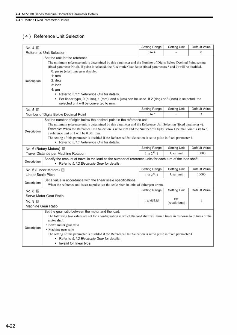
4.4 MP2000 Series Machine Controller Parameter Details
4.4.1 Motion Fixed Parameter Details
4-22
( 4 ) Reference Unit Selection
No. 4Reference Unit Selection
Setting Range Setting Unit Default Value
0 to 4 − 0
Description
Set the unit for the reference. The minimum reference unit is determined by this parameter and the Number of Digits Below Decimal Point setting (fixed parameter No.5). If pulse is selected, the Electronic Gear Ratio (fixed parameters 8 and 9) will be disabled.
0: pulse (electronic gear disabled)1: mm2: deg3: inch4: μm Refer to 5.1.1 Reference Unit for details.
For linear type, 0 (pulse), 1 (mm), and 4 (μm) can be used. If 2 (deg) or 3 (inch) is selected, the selected unit will be converted to mm.
No. 5Number of Digits Below Decimal Point
Setting Range Setting Unit Default Value
0 to 5 − 3
Description
Set the number of digits below the decimal point in the reference unit.The minimum reference unit is determined by this parameter and the Reference Unit Selection (fixed parameter 4).Example: When the Reference Unit Selection is set to mm and the Number of Digits Below Decimal Point is set to 3,a reference unit of 1 will be 0.001 mm.The setting of this parameter is disabled if the Reference Unit Selection is set to pulse in fixed parameter 4.
Refer to 5.1.1 Reference Unit for details.
No. 6 (Rotary Motors)Travel Distance per Machine Rotation
Setting Range Setting Unit Default Value
1 to 231-1 User unit 10000
DescriptionSpecify the amount of travel in the load as the number of reference units for each turn of the load shaft.
Refer to 5.1.2 Electronic Gear for details.
No. 6 (Linear Motors) Linear Scale Pitch
Setting Range Setting Unit Default Value
1 to 231-1 User unit 10000
DescriptionSet a value in accordance with the linear scale specifications.
When the reference unit is set to pulse, set the scale pitch in units of either μm or nm.
No. 8Servo Motor Gear Ratio
No. 9Machine Gear Ratio
Setting Range Setting Unit Default Value
1 to 65535rev
(revolutions)1
Description
Set the gear ratio between the motor and the load.The following two values are set for a configuration in which the load shaft will turn n times in response to m turns of the motor shaft.
• Servo motor gear ratio• Machine gear ratio
The setting of this parameter is disabled if the Reference Unit Selection is set to pulse in fixed parameter 4. Refer to 5.1.2 Electronic Gear for details.
Invalid for linear type.
R
R
R
R
R
R
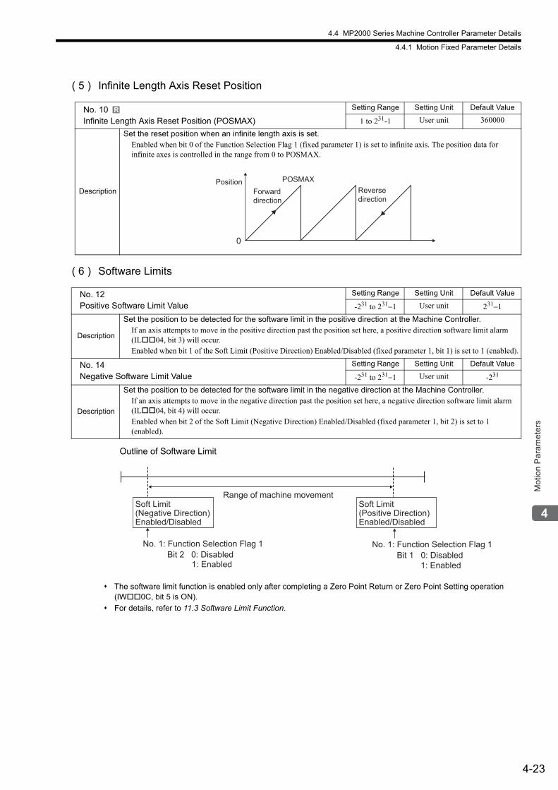
4.4 MP2000 Series Machine Controller Parameter Details
4.4.1 Motion Fixed Parameter Details
4-23
Mot
ion
Par
amet
ers
( 5 ) Infinite Length Axis Reset Position
( 6 ) Software Limits
Outline of Software Limit
The software limit function is enabled only after completing a Zero Point Return or Zero Point Setting operation (IW0C, bit 5 is ON).
For details, refer to 11.3 Software Limit Function.
No. 10Infinite Length Axis Reset Position (POSMAX)
Setting Range Setting Unit Default Value
1 to 231-1 User unit 360000
Description
Set the reset position when an infinite length axis is set.Enabled when bit 0 of the Function Selection Flag 1 (fixed parameter 1) is set to infinite axis. The position data for infinite axes is controlled in the range from 0 to POSMAX.
No. 12Positive Software Limit Value
Setting Range Setting Unit Default Value
-231 to 231−1 User unit 231−1
Description
Set the position to be detected for the software limit in the positive direction at the Machine Controller.If an axis attempts to move in the positive direction past the position set here, a positive direction software limit alarm (IL04, bit 3) will occur.Enabled when bit 1 of the Soft Limit (Positive Direction) Enabled/Disabled (fixed parameter 1, bit 1) is set to 1 (enabled).
No. 14Negative Software Limit Value
Setting Range Setting Unit Default Value
-231 to 231−1 User unit -231
Description
Set the position to be detected for the software limit in the negative direction at the Machine Controller.If an axis attempts to move in the negative direction past the position set here, a negative direction software limit alarm (IL04, bit 4) will occur.Enabled when bit 2 of the Soft Limit (Negative Direction) Enabled/Disabled (fixed parameter 1, bit 2) is set to 1 (enabled).
R
0
POSMAXForward direction
Reverse direction
Position
Bit 1 0: Disabled 1: Enabled
Soft Limit(Negative Direction)Enabled/Disabled
Soft Limit(Positive Direction)Enabled/Disabled
Range of machine movement
No. 1: Function Selection Flag 1Bit 2 0: Disabled
1: Enabled
No. 1: Function Selection Flag 1
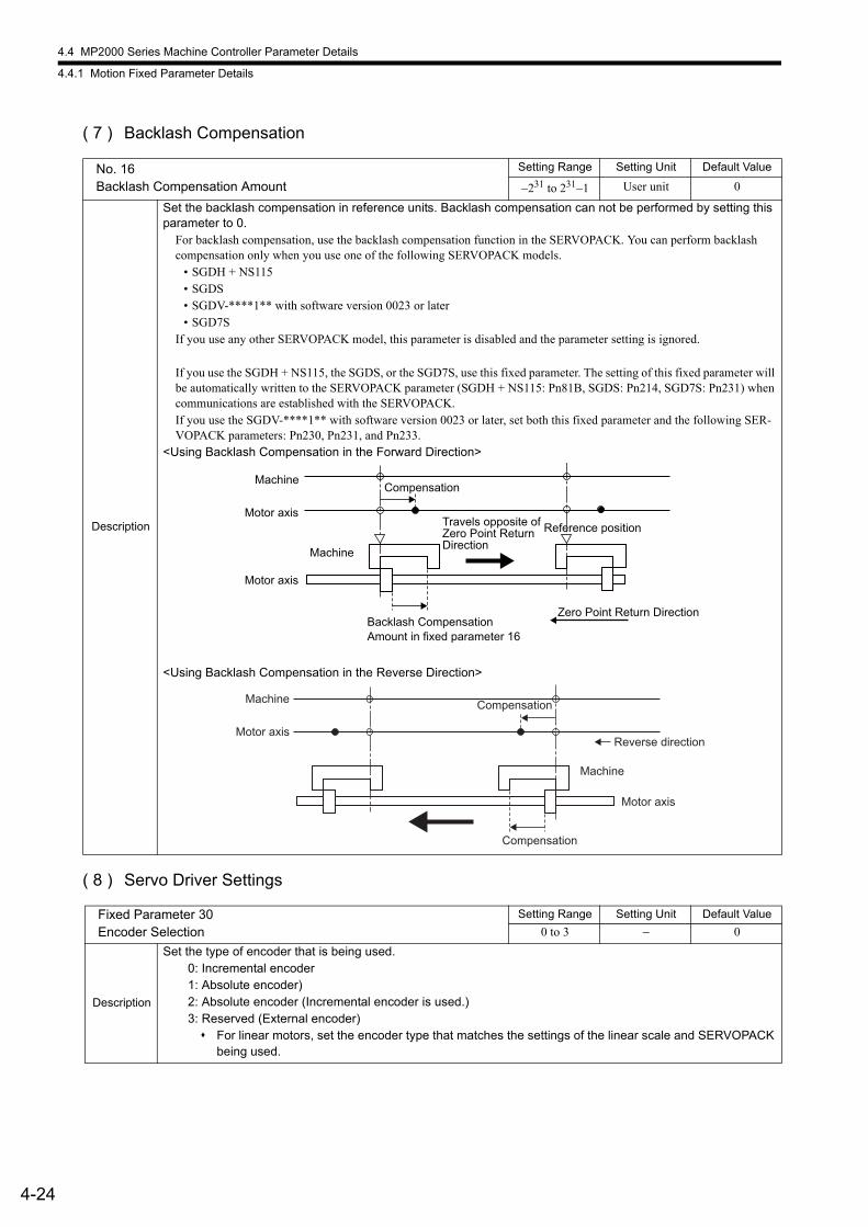
4.4 MP2000 Series Machine Controller Parameter Details
4.4.1 Motion Fixed Parameter Details
4-24
( 7 ) Backlash Compensation
( 8 ) Servo Driver Settings
No. 16Backlash Compensation Amount
Setting Range Setting Unit Default Value
−231 to 231−1 User unit 0
Description
Set the backlash compensation in reference units. Backlash compensation can not be performed by setting this parameter to 0.
For backlash compensation, use the backlash compensation function in the SERVOPACK. You can perform backlash compensation only when you use one of the following SERVOPACK models.
• SGDH + NS115• SGDS• SGDV-****1** with software version 0023 or later• SGD7S
If you use any other SERVOPACK model, this parameter is disabled and the parameter setting is ignored.
If you use the SGDH + NS115, the SGDS, or the SGD7S, use this fixed parameter. The setting of this fixed parameter will be automatically written to the SERVOPACK parameter (SGDH + NS115: Pn81B, SGDS: Pn214, SGD7S: Pn231) when communications are established with the SERVOPACK.If you use the SGDV-****1** with software version 0023 or later, set both this fixed parameter and the following SER-VOPACK parameters: Pn230, Pn231, and Pn233.
<Using Backlash Compensation in the Forward Direction>
<Using Backlash Compensation in the Reverse Direction>
Fixed Parameter 30Encoder Selection
Setting Range Setting Unit Default Value
0 to 3 − 0
Description
Set the type of encoder that is being used.0: Incremental encoder1: Absolute encoder)2: Absolute encoder (Incremental encoder is used.)3: Reserved (External encoder) For linear motors, set the encoder type that matches the settings of the linear scale and SERVOPACK
being used.
Compensation
Backlash Compensation Amount in fixed parameter 16
Travels opposite ofZero Point Return Direction
Machine
Machine
Motor axis
Motor axis
Reference position
Zero Point Return Direction
Compensation
CompensationMachine
Machine
Motor axis
Motor axis
Reverse direction
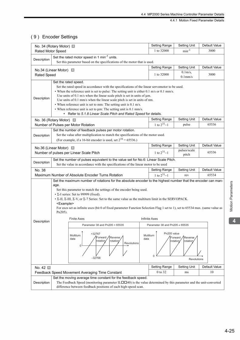
4.4 MP2000 Series Machine Controller Parameter Details
4.4.1 Motion Fixed Parameter Details
4-25
Mot
ion
Par
amet
ers
( 9 ) Encoder Settings
No. 34 (Rotary Motor)Rated Motor Speed
Setting Range Setting Unit Default Value
1 to 32000 min-1 3000
DescriptionSet the rated motor speed in 1 min-1 units.
Set this parameter based on the specifications of the motor that is used.
No.34 (Linear Motor) Rated Speed
Setting Range Setting Unit Default Value
1 to 320000.1m/s,
0.1mm/s3000
Description
Set the rated speed.Set the rated speed in accordance with the specifications of the linear servomotor to be used.
• When the reference unit is set to pulse: The setting unit is either 0.1 m/s or 0.1 mm/s.Use units of 0.1 m/s when the linear scale pitch is set in units of μm.Use units of 0.1 mm/s when the linear scale pitch is set in units of nm.
• When reference unit is set to mm: The setting unit is 0.1 m/s.• When reference unit is set to μm: The setting unit is 0.1 mm/s.
Refer to 5.1.8 Linear Scale Pitch and Rated Speed for details.
No. 36 (Rotary Motor) Number of Pulses per Motor Rotation
Setting Range Setting Unit Default Value
1 to 231−1 pulse 65536
Description
Set the number of feedback pulses per motor rotation.Set the value after multiplication to match the specifications of the motor used.
(For example, if a 16-bit encoder is used, set 216 = 65536.)
No.36 (Linear Motor) Number of pulses per Linear Scale Pitch
Setting Range Setting Unit Default Value
1 to 231−1pulses/scale
pitch65536
DescriptionSet the number of pulses equivalent to the value set for No.6: Linear Scale Pitch.
Set the value in accordance with the specifications of the linear motor to be used
No. 38Maximum Number of Absolute Encoder Turns Rotation
Setting Range Setting Unit Default Value
1 to 231−1 rev 65534
Description
Set the maximum number of rotations for the absolute encoder to the highest number that the encoder can man-age.
Set this parameter to match the settings of the encoder being used.• Σ-I series: Set to 99999 (fixed).• Σ-II, Σ-III, Σ-V, or Σ-7 Series: Set to the same value as the multiturn limit in the SERVOPACK.<Example>For axes set as infinite axes (bit 0 of fixed parameter Function Selection Flag 1 set to 1), set to 65534 max. (same value as Pn205).
No. 42Feedback Speed Movement Averaging Time Constant
Setting Range Setting Unit Default Value
0 to 32 ms 10
Description
Set the moving average time constant for the feedback speed.The Feedback Speed (monitoring parameter IL40) is the value determined by this parameter and the unit-converted difference between feedback positions of each high-speed scan.
R
R
R
R
0
0−32768
+32767 Pn205 value
Forward
rotation
Revolutions
Reverse
rotation
Multiturn
dataForward
rotationRevolutions
Reverse
rotation
Multiturn
data
Parameter 38 and Pn205 = 65535 Parameter 38 and Pn205 ≠ 65535
Finite Axes Infinite Axes
R
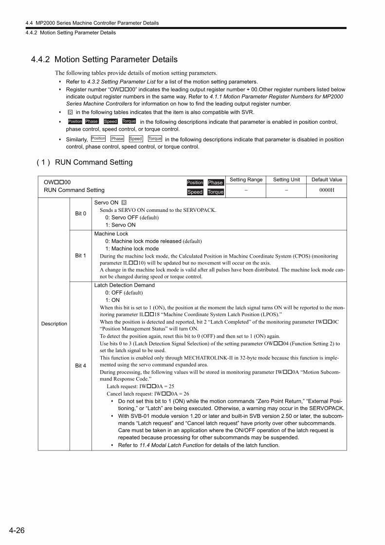
4.4 MP2000 Series Machine Controller Parameter Details
4.4.2 Motion Setting Parameter Details
4-26
4.4.2 Motion Setting Parameter Details
The following tables provide details of motion setting parameters.
Refer to 4.3.2 Setting Parameter List for a list of the motion setting parameters.
Register number “OW00” indicates the leading output register number + 00.Other register numbers listed below indicate output register numbers in the same way. Refer to 4.1.1 Motion Parameter Register Numbers for MP2000 Series Machine Controllers for information on how to find the leading output register number.
in the following tables indicates that the item is also compatible with SVR.
in the following descriptions indicate that parameter is enabled in position control, phase control, speed control, or torque control.
Similarly, in the following descriptions indicate that parameter is disabled in position control, phase control, speed control, or torque control.
( 1 ) RUN Command Setting
R
Position Phase Speed Torque
Speed TorquePosition Phase
OW00RUN Command Setting
Setting Range Setting Unit Default Value
− − 0000H
Description
Bit 0
Servo ONSends a SERVO ON command to the SERVOPACK.
0: Servo OFF (default)1: Servo ON
Bit 1
Machine Lock0: Machine lock mode released (default)1: Machine lock mode
During the machine lock mode, the Calculated Position in Machine Coordinate System (CPOS) (monitoring parameter IL10) will be updated but no movement will occur on the axis.A change in the machine lock mode is valid after all pulses have been distributed. The machine lock mode can-not be changed during speed or torque control.
Bit 4
Latch Detection Demand0: OFF (default)1: ON
When this bit is set to 1 (ON), the position at the moment the latch signal turns ON will be reported to the mon-itoring parameter IL18 “Machine Coordinate System Latch Position (LPOS).”When the position is detected and reported, bit 2 “Latch Completed” of the monitoring parameter IW0C “Position Management Status” will turn ON.To detect the position again, reset this bit to 0 (OFF) and then set to 1 (ON) again.Use bits 0 to 3 (Latch Detection Signal Selection) of the setting parameter OW04 (Function Setting 2) to set the latch signal to be used.This function is enabled only through MECHATROLINK-II in 32-byte mode because this function is imple-mented using the servo command expanded area.During processing, the following values will be stored in monitoring parameter IW0A “Motion Subcom-mand Response Code.”
Latch request: IW0A = 25 Cancel latch request: IW0A = 26 Do not set this bit to 1 (ON) while the motion commands “Zero Point Return,” “External Posi-
tioning,” or “Latch” are being executed. Otherwise, a warning may occur in the SERVOPACK.
With SVB-01 module version 1.20 or later and built-in SVB version 2.50 or later, the subcom-mands “Latch request” and “Cancel latch request” have priority over other subcommands. Care must be taken in an application where the ON/OFF operation of the latch request is repeated because processing for other subcommands may be suspended.
Refer to 11.4 Modal Latch Function for details of the latch function.
Position Phase
Speed Torque
R
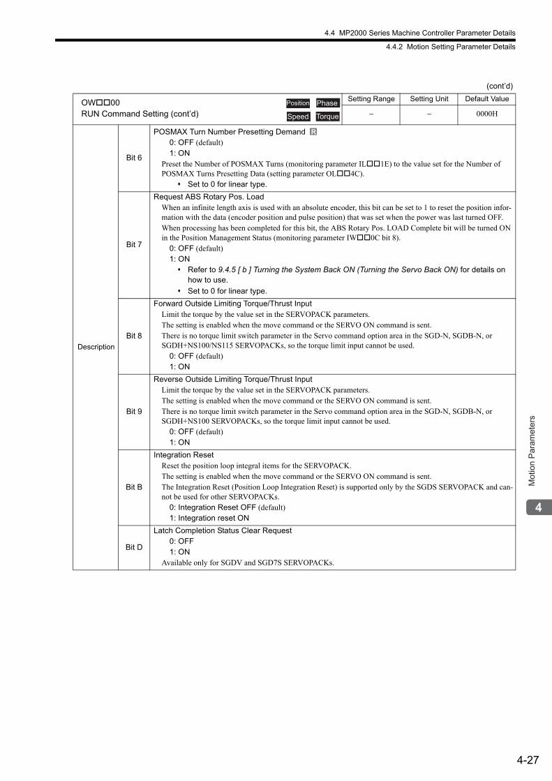
4.4 MP2000 Series Machine Controller Parameter Details
4.4.2 Motion Setting Parameter Details
4-27
Mot
ion
Par
amet
ers
Description
Bit 6
POSMAX Turn Number Presetting Demand0: OFF (default)1: ON
Preset the Number of POSMAX Turns (monitoring parameter IL1E) to the value set for the Number of POSMAX Turns Presetting Data (setting parameter OL4C).
Set to 0 for linear type.
Bit 7
Request ABS Rotary Pos. LoadWhen an infinite length axis is used with an absolute encoder, this bit can be set to 1 to reset the position infor-mation with the data (encoder position and pulse position) that was set when the power was last turned OFF.When processing has been completed for this bit, the ABS Rotary Pos. LOAD Complete bit will be turned ON in the Position Management Status (monitoring parameter IW0C bit 8).
0: OFF (default)1: ON Refer to 9.4.5 [ b ] Turning the System Back ON (Turning the Servo Back ON) for details on
how to use.
Set to 0 for linear type.
Bit 8
Forward Outside Limiting Torque/Thrust InputLimit the torque by the value set in the SERVOPACK parameters.The setting is enabled when the move command or the SERVO ON command is sent.There is no torque limit switch parameter in the Servo command option area in the SGD-N, SGDB-N, or SGDH+NS100/NS115 SERVOPACKs, so the torque limit input cannot be used.
0: OFF (default)1: ON
Bit 9
Reverse Outside Limiting Torque/Thrust InputLimit the torque by the value set in the SERVOPACK parameters.The setting is enabled when the move command or the SERVO ON command is sent.There is no torque limit switch parameter in the Servo command option area in the SGD-N, SGDB-N, or SGDH+NS100 SERVOPACKs, so the torque limit input cannot be used.
0: OFF (default)1: ON
Bit B
Integration ResetReset the position loop integral items for the SERVOPACK.The setting is enabled when the move command or the SERVO ON command is sent.The Integration Reset (Position Loop Integration Reset) is supported only by the SGDS SERVOPACK and can-not be used for other SERVOPACKs.
0: Integration Reset OFF (default)1: Integration reset ON
Bit D
Latch Completion Status Clear Request 0: OFF1: ON
Available only for SGDV and SGD7S SERVOPACKs.
(cont’d)
OW00RUN Command Setting (cont’d)
Setting Range Setting Unit Default Value
− − 0000H
Position Phase
Speed Torque
R
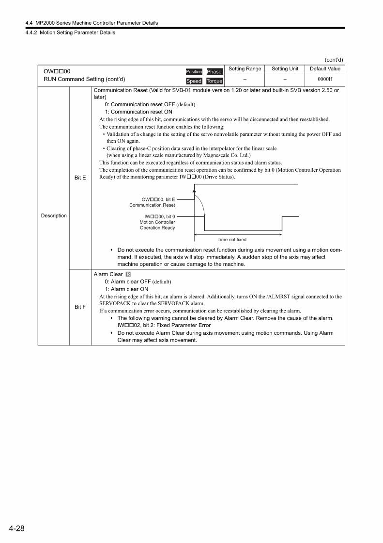
4.4 MP2000 Series Machine Controller Parameter Details
4.4.2 Motion Setting Parameter Details
4-28
Description
Bit E
Communication Reset (Valid for SVB-01 module version 1.20 or later and built-in SVB version 2.50 or later)
0: Communication reset OFF (default)1: Communication reset ON
At the rising edge of this bit, communications with the servo will be disconnected and then reestablished.The communication reset function enables the following:
• Validation of a change in the setting of the servo nonvolatile parameter without turning the power OFF and then ON again.
• Clearing of phase-C position data saved in the interpolator for the linear scale (when using a linear scale manufactured by Magnescale Co. Ltd.)
This function can be executed regardless of communication status and alarm status.The completion of the communication reset operation can be confirmed by bit 0 (Motion Controller Operation Ready) of the monitoring parameter IW00 (Drive Status).
Do not execute the communication reset function during axis movement using a motion com-mand. If executed, the axis will stop immediately. A sudden stop of the axis may affect machine operation or cause damage to the machine.
Bit F
Alarm Clear0: Alarm clear OFF (default)1: Alarm clear ON
At the rising edge of this bit, an alarm is cleared. Additionally, turns ON the /ALMRST signal connected to the SERVOPACK to clear the SERVOPACK alarm.If a communication error occurs, communication can be reestablished by clearing the alarm.
The following warning cannot be cleared by Alarm Clear. Remove the cause of the alarm.IW02, bit 2: Fixed Parameter Error
Do not execute Alarm Clear during axis movement using motion commands. Using Alarm Clear may affect axis movement.
(cont’d)
OW00RUN Command Setting (cont’d)
Setting Range Setting Unit Default Value
− − 0000H
Position Phase
Speed Torque
OW��00, bit ECommunication Reset
IW��00, bit 0Motion ControllerOperation Ready
Time not fixed
R
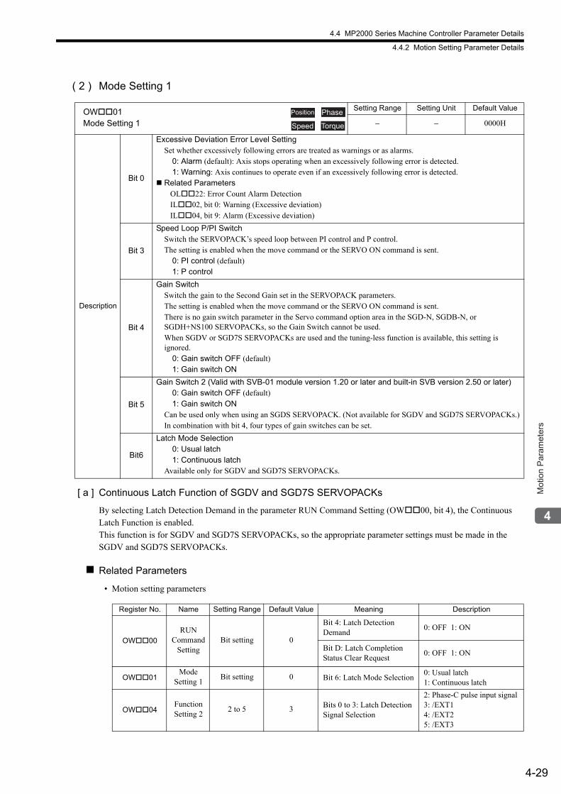
4.4 MP2000 Series Machine Controller Parameter Details
4.4.2 Motion Setting Parameter Details
4-29
Mot
ion
Par
amet
ers
( 2 ) Mode Setting 1
[ a ] Continuous Latch Function of SGDV and SGD7S SERVOPACKs
By selecting Latch Detection Demand in the parameter RUN Command Setting (OW00, bit 4), the Continuous Latch Function is enabled.This function is for SGDV and SGD7S SERVOPACKs, so the appropriate parameter settings must be made in the SGDV and SGD7S SERVOPACKs.
Related Parameters
• Motion setting parameters
OW01Mode Setting 1
Setting Range Setting Unit Default Value
− − 0000H
Description
Bit 0
Excessive Deviation Error Level SettingSet whether excessively following errors are treated as warnings or as alarms.
0: Alarm (default): Axis stops operating when an excessively following error is detected.1: Warning: Axis continues to operate even if an excessively following error is detected.
Related Parameters OL22: Error Count Alarm Detection IL02, bit 0: Warning (Excessive deviation) IL04, bit 9: Alarm (Excessive deviation)
Bit 3
Speed Loop P/PI SwitchSwitch the SERVOPACK’s speed loop between PI control and P control.The setting is enabled when the move command or the SERVO ON command is sent.
0: PI control (default)1: P control
Bit 4
Gain SwitchSwitch the gain to the Second Gain set in the SERVOPACK parameters.The setting is enabled when the move command or the SERVO ON command is sent.There is no gain switch parameter in the Servo command option area in the SGD-N, SGDB-N, or SGDH+NS100 SERVOPACKs, so the Gain Switch cannot be used.When SGDV or SGD7S SERVOPACKs are used and the tuning-less function is available, this setting is ignored.
0: Gain switch OFF (default)1: Gain switch ON
Bit 5
Gain Switch 2 (Valid with SVB-01 module version 1.20 or later and built-in SVB version 2.50 or later)0: Gain switch OFF (default)1: Gain switch ON
Can be used only when using an SGDS SERVOPACK. (Not available for SGDV and SGD7S SERVOPACKs.)In combination with bit 4, four types of gain switches can be set.
Bit6
Latch Mode Selection0: Usual latch1: Continuous latch
Available only for SGDV and SGD7S SERVOPACKs.
Position Phase
Speed Torque
Register No. Name Setting Range Default Value Meaning Description
OW00
RUN Command
SettingBit setting 0
Bit 4: Latch Detection Demand
0: OFF 1: ON
Bit D: Latch Completion Status Clear Request
0: OFF 1: ON
OW01Mode
Setting 1Bit setting 0 Bit 6: Latch Mode Selection
0: Usual latch1: Continuous latch
OW04Function Setting 2
2 to 5 3 Bits 0 to 3: Latch Detection Signal Selection
2: Phase-C pulse input signal3: /EXT14: /EXT25: /EXT3
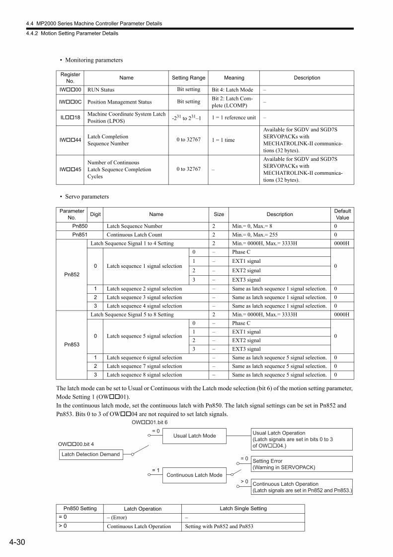
4.4 MP2000 Series Machine Controller Parameter Details
4.4.2 Motion Setting Parameter Details
4-30
• Monitoring parameters
• Servo parameters
The latch mode can be set to Usual or Continuous with the Latch mode selection (bit 6) of the motion setting parameter, Mode Setting 1 (OW01).In the continuous latch mode, set the continuous latch with Pn850. The latch signal settings can be set in Pn852 and Pn853. Bits 0 to 3 of OW04 are not required to set latch signals.
Register No.
Name Setting Range Meaning Description
IW00 RUN Status Bit setting Bit 4: Latch Mode –
IW0C Position Management Status Bit setting Bit 2: Latch Com-plete (LCOMP)
–
IL18Machine Coordinate System LatchPosition (LPOS) -231 to 231–1 1 = 1 reference unit –
IW44Latch CompletionSequence Number
0 to 32767 1 = 1 time
Available for SGDV and SGD7S SERVOPACKs with MECHATROLINK-II communica-tions (32 bytes).
IW45Number of ContinuousLatch Sequence Completion Cycles
0 to 32767 –
Available for SGDV and SGD7S SERVOPACKs with MECHATROLINK-II communica-tions (32 bytes).
Parameter No.
Digit Name Size DescriptionDefault Value
Pn850 Latch Sequence Number 2 Min.= 0, Max.= 8 0
Pn851 Continuous Latch Count 2 Min.= 0, Max.= 255 0
Pn852
Latch Sequence Signal 1 to 4 Setting 2 Min.= 0000H, Max.= 3333H 0000H
0 Latch sequence 1 signal selection
0 – Phase C
01 – EXT1 signal
2 – EXT2 signal
3 – EXT3 signal
1 Latch sequence 2 signal selection – Same as latch sequence 1 signal selection. 0
2 Latch sequence 3 signal selection – Same as latch sequence 1 signal selection. 0
3 Latch sequence 4 signal selection – Same as latch sequence 1 signal selection. 0
Pn853
Latch Sequence Signal 5 to 8 Setting 2 Min.= 0000H, Max.= 3333H 0000H
0 Latch sequence 5 signal selection
0 – Phase C
01 – EXT1 signal
2 – EXT2 signal
3 – EXT3 signal
1 Latch sequence 6 signal selection – Same as latch sequence 5 signal selection. 0
2 Latch sequence 7 signal selection – Same as latch sequence 5 signal selection. 0
3 Latch sequence 8 signal selection – Same as latch sequence 5 signal selection. 0
Pn850 Setting Latch Operation Latch Single Setting
= 0 – (Error) –
> 0 Continuous Latch Operation Setting with Pn852 and Pn853
Latch Detection Demand
OW��00.bit 4
Continuous Latch Mode= 1
Continuous Latch Operation (Latch signals are set in Pn852 and Pn853.)
Setting Error (Warning in SERVOPACK)
Usual Latch Operation (Latch signals are set in bits 0 to 3 of OW��04.)
Usual Latch Mode
OW��01.bit 6= 0
> 0
= 0
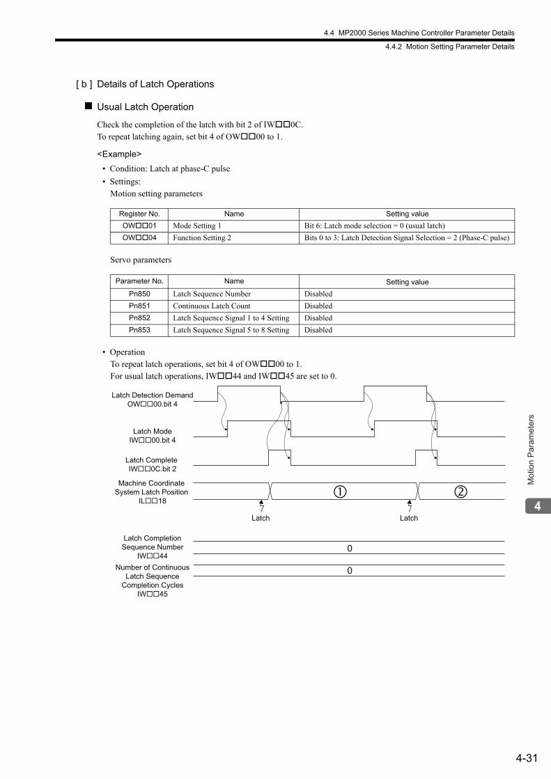
4.4 MP2000 Series Machine Controller Parameter Details
4.4.2 Motion Setting Parameter Details
4-31
Mot
ion
Par
amet
ers
[ b ] Details of Latch Operations
Usual Latch Operation
Check the completion of the latch with bit 2 of IW0C.To repeat latching again, set bit 4 of OW00 to 1.
<Example>
• Condition: Latch at phase-C pulse
• Settings: Motion setting parameters
Servo parameters
• Operation To repeat latch operations, set bit 4 of OW00 to 1.For usual latch operations, IW44 and IW45 are set to 0.
Register No. Name Setting value
OW01 Mode Setting 1 Bit 6: Latch mode selection = 0 (usual latch)
OW04 Function Setting 2 Bits 0 to 3: Latch Detection Signal Selection = 2 (Phase-C pulse)
Parameter No. Name Setting value
Pn850 Latch Sequence Number Disabled
Pn851 Continuous Latch Count Disabled
Pn852 Latch Sequence Signal 1 to 4 Setting Disabled
Pn853 Latch Sequence Signal 5 to 8 Setting Disabled
Machine Coordinate System Latch Position
IL��18
Number of ContinuousLatch Sequence
Completion CyclesIW��45
Latch CompletionSequence Number
IW��44
Latch Complete IW��0C.bit 2
Latch ModeIW��00.bit 4
Latch Detection DemandOW��00.bit 4
0
0
�LatchLatch
�
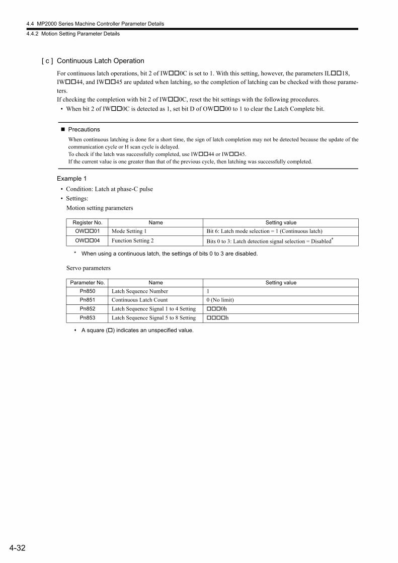
4.4 MP2000 Series Machine Controller Parameter Details
4.4.2 Motion Setting Parameter Details
4-32
[ c ] Continuous Latch Operation
For continuous latch operations, bit 2 of IW0C is set to 1. With this setting, however, the parameters IL18, IW44, and IW45 are updated when latching, so the completion of latching can be checked with those parame-ters.If checking the completion with bit 2 of IW0C, reset the bit settings with the following procedures.
• When bit 2 of IW0C is detected as 1, set bit D of OW00 to 1 to clear the Latch Complete bit.
Precautions
When continuous latching is done for a short time, the sign of latch completion may not be detected because the update of thecommunication cycle or H scan cycle is delayed.To check if the latch was successfully completed, use IW44 or IW45.If the current value is one greater than that of the previous cycle, then latching was successfully completed.
Example 1
• Condition: Latch at phase-C pulse
• Settings:
Motion setting parameters
* When using a continuous latch, the settings of bits 0 to 3 are disabled.
Servo parameters
A square () indicates an unspecified value.
Register No. Name Setting value
OW01 Mode Setting 1 Bit 6: Latch mode selection = 1 (Continuous latch)
OW04 Function Setting 2 Bits 0 to 3: Latch detection signal selection = Disabled*
Parameter No. Name Setting value
Pn850 Latch Sequence Number 1
Pn851 Continuous Latch Count 0 (No limit)
Pn852 Latch Sequence Signal 1 to 4 Setting 0h
Pn853 Latch Sequence Signal 5 to 8 Setting h
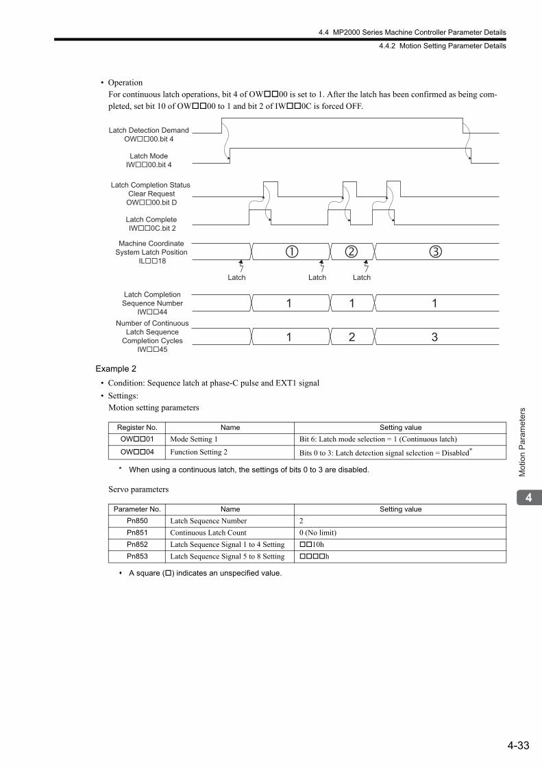
4.4 MP2000 Series Machine Controller Parameter Details
4.4.2 Motion Setting Parameter Details
4-33
Mot
ion
Par
amet
ers
• Operation For continuous latch operations, bit 4 of OW00 is set to 1. After the latch has been confirmed as being com-pleted, set bit 10 of OW00 to 1 and bit 2 of IW0C is forced OFF.
Example 2
• Condition: Sequence latch at phase-C pulse and EXT1 signal
• Settings: Motion setting parameters
* When using a continuous latch, the settings of bits 0 to 3 are disabled.
Servo parameters
A square () indicates an unspecified value.
Register No. Name Setting value
OW01 Mode Setting 1 Bit 6: Latch mode selection = 1 (Continuous latch)
OW04 Function Setting 2 Bits 0 to 3: Latch detection signal selection = Disabled*
Parameter No. Name Setting value
Pn850 Latch Sequence Number 2
Pn851 Continuous Latch Count 0 (No limit)
Pn852 Latch Sequence Signal 1 to 4 Setting 10h
Pn853 Latch Sequence Signal 5 to 8 Setting h
� �Machine Coordinate
System Latch Position IL��18
Number of ContinuousLatch Sequence
Completion CyclesIW��45
Latch CompletionSequence Number
IW��44
Latch Complete IW��0C.bit 2
Latch ModeIW��00.bit 4
Latch Detection DemandOW��00.bit 4
�
1 1 1
1 2
Latch LatchLatch
Latch Completion Status Clear Request
OW��00.bit D
3
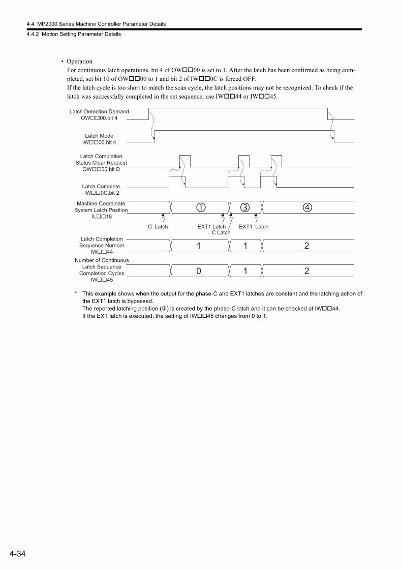
4.4 MP2000 Series Machine Controller Parameter Details
4.4.2 Motion Setting Parameter Details
4-34
• OperationFor continuous latch operations, bit 4 of OW00 is set to 1. After the latch has been confirmed as being com-pleted, set bit 10 of OW00 to 1 and bit 2 of IW0C is forced OFF.If the latch cycle is too short to match the scan cycle, the latch positions may not be recognized. To check if the latch was successfully completed in the set sequence, use IW44 or IW45.
* This example shows when the output for the phase-C and EXT1 latches are constant and the latching action ofthe EXT1 latch is bypassed.The reported latching position () is created by the phase-C latch and it can be checked at IW44.If the EXT latch is executed, the setting of IW45 changes from 0 to 1.
� �
Latch CompletionStatus Clear Request
OW��00.bit D
Machine Coordinate System Latch Position
IL��18
Number of ContinuousLatch Sequence
Completion CyclesIW��45
Latch CompletionSequence Number
IW��44
Latch Complete IW��0C.bit 2
Latch ModeIW��00.bit 4
Latch Detection DemandOW��00.bit 4
�
1 1 2
0 1 2
EXT1 LatchC Latch
EXT1 LatchC Latch

4.4 MP2000 Series Machine Controller Parameter Details
4.4.2 Motion Setting Parameter Details
4-35
Mot
ion
Par
amet
ers
( 3 ) Mode Setting 2
OW02Mode Setting 2
Setting Range Setting Unit Default Value
− − 0000H
Description
Bit 0
Monitor 2 EnabledDisable/enable Monitor 2 in the Servo User Monitor Setting (setting parameter OW4E, bits 4 to 7).
0: Disabled (default)1: Enabled
This bit is valid only when the communication mode is MECHATROLINK-I or MECHATROLINK-II 17-byte Mode. This bit is ignored for MECHATROLINK-II 32-byte Mode.
Bit 8 to Bit F
Stop Mode SelectionSVB-01 modules: Available for SVB module version 1.21 or laterBuilt-in SVB modules: Available for SVB module version 2.60 or later
Selects the stopping method for the axes controlled by move commands.This function is only available for MECHATROLINK compatible SERVOPACKs.For details on functions that can be used with the SERVOPACK, refer to the section on the HOLD command in the manual of the SERVOPACK being used.• When using the speed reference (VELO) (OW08 = 23)
0: Decelerate to a stop according to the linear deceleration time constant (default)1: Stop immediately When using the speed reference and this setting is set to a value other than 0 or 1, the motor
will stop in accordance with the action specified for the 0 setting.• When using any move commands other than the speed reference (VELO)
0: Decelerate to a stop according to the linear deceleration time constant (default)1: Stop immediately2: Stop in accordance with the value of Linear Deceleration Constant 1 for Stopping*
* The relevant servo parameter (Pn827 when Pn883.0 = 0 and Pn840 when Pn883.0 = 1) must be set beforehand.
Position Phase
Speed Torque
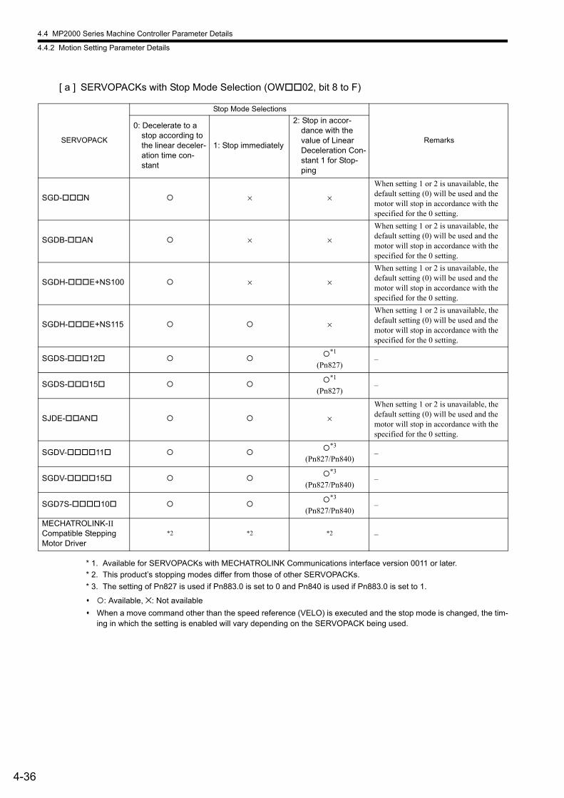
4.4 MP2000 Series Machine Controller Parameter Details
4.4.2 Motion Setting Parameter Details
4-36
[ a ] SERVOPACKs with Stop Mode Selection (OW02, bit 8 to F)
* 1. Available for SERVOPACKs with MECHATROLINK Communications interface version 0011 or later.
* 2. This product’s stopping modes differ from those of other SERVOPACKs.
* 3. The setting of Pn827 is used if Pn883.0 is set to 0 and Pn840 is used if Pn883.0 is set to 1.
: Available, ×: Not available
When a move command other than the speed reference (VELO) is executed and the stop mode is changed, the tim-ing in which the setting is enabled will vary depending on the SERVOPACK being used.
SERVOPACK
Stop Mode Selections
Remarks
0: Decelerate to a stop according to the linear deceler-ation time con-stant
1: Stop immediately
2: Stop in accor-dance with the value of Linear Deceleration Con-stant 1 for Stop-ping
SGD-N × ×
When setting 1 or 2 is unavailable, the default setting (0) will be used and the motor will stop in accordance with the specified for the 0 setting.
SGDB-AN × ×
When setting 1 or 2 is unavailable, the default setting (0) will be used and the motor will stop in accordance with the specified for the 0 setting.
SGDH-E+NS100 × ×
When setting 1 or 2 is unavailable, the default setting (0) will be used and the motor will stop in accordance with the specified for the 0 setting.
SGDH-E+NS115 ×
When setting 1 or 2 is unavailable, the default setting (0) will be used and the motor will stop in accordance with the specified for the 0 setting.
SGDS-12 *1
(Pn827)–
SGDS-15 *1
(Pn827)–
SJDE-AN ×
When setting 1 or 2 is unavailable, the default setting (0) will be used and the motor will stop in accordance with the specified for the 0 setting.
SGDV-11 *3
(Pn827/Pn840)–
SGDV-15 *3
(Pn827/Pn840)–
SGD7S-10 *3
(Pn827/Pn840)–
MECHATROLINK-II Compatible Stepping Motor Driver
*2 *2 *2 –
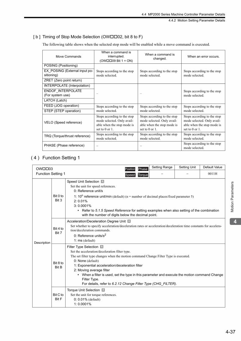
4.4 MP2000 Series Machine Controller Parameter Details
4.4.2 Motion Setting Parameter Details
4-37
Mot
ion
Par
amet
ers
[ b ] Timing of Stop Mode Selection (OW02, bit 8 to F)
The following table shows when the selected stop mode will be enabled while a move command is executed.
( 4 ) Function Setting 1
Move CommandsWhen a command is
interrupted.(OW09 Bit 1 = ON)
When a command is changed.
When an error occurs.
POSING (Positioning)
Stops according to the stop mode selected.
Stops according to the stop mode selected.
Stops according to the stop mode selected.
EX_POSING (External input po-sitioning)
ZRET (Zero point return)
INTERPOLATE (Interpolation)
– –Stops according to the stop mode selected.
ENDOF_INTERPOLATE (For system use)
LATCH (Latch)
FEED (JOG operation) Stops according to the stop mode selected.
Stops according to the stop mode selected.
Stops according to the stop mode selected.STEP (STEP operation)
VELO (Speed reference)
Stops according to the stop mode selected. Only avail-able when the stop mode is set to 0 or 1.
Stops according to the stop mode selected. Only avail-able when the stop mode is set to 0 or 1.
Stops according to the stop mode selected. Only avail-able when the stop mode is set to 0 or 1.
TRQ (Torque/thrust reference) Stops according to the stop mode selected.
Stops according to the stop mode selected.
Stops according to the stop mode selected.
PHASE (Phase reference) – –Stops according to the stop mode selected.
OW03Function Setting 1
Setting Range Setting Unit Default Value
− − 0011H
Description
Bit 0 to Bit 3
Speed Unit SelectionSet the unit for speed references.
0: Reference unit/s
1: 10n reference unit/min (default) (n = number of decimal places/fixed parameter 5)2: 0.01%3: 0.0001% Refer to 5.1.5 Speed Reference for setting examples when also setting of the combination
with the number of digits below the decimal point.
Bit 4 to Bit 7
Acceleration/Deceleration Degree UnitSet whether to specify acceleration/deceleration rates or acceleration/deceleration time constants for accelera-tion/deceleration commands.
0: Reference units/s2
1: ms (default)
Bit 8 to Bit B
Filter Type SelectionSet the acceleration/deceleration filter type.The set filter type changes when the motion command Change Filter Type is executed.
0: None (default)1: Exponential acceleration/deceleration filter2: Moving average filter When a filter is used, set the type in this parameter and execute the motion command Change
Filter Type. For details, refer to 6.2.12 Change Filter Type (CHG_FILTER).
Bit C to Bit F
Torque Unit SelectionSet the unit for torque references.
0: 0.01% (default)1: 0.0001%
Position Phase
Speed Torque
R
R
R
R
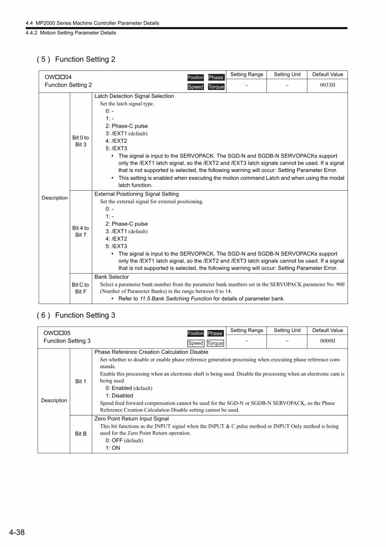
4.4 MP2000 Series Machine Controller Parameter Details
4.4.2 Motion Setting Parameter Details
4-38
( 5 ) Function Setting 2
( 6 ) Function Setting 3
OW04Function Setting 2
Setting Range Setting Unit Default Value
− − 0033H
Description
Bit 0 to Bit 3
Latch Detection Signal SelectionSet the latch signal type.
0: -1: -2: Phase-C pulse3: /EXT1 (default)4: /EXT25: /EXT3 The signal is input to the SERVOPACK. The SGD-N and SGDB-N SERVOPACKs support
only the /EXT1 latch signal, so the /EXT2 and /EXT3 latch signals cannot be used. If a signal that is not supported is selected, the following warning will occur: Setting Parameter Error.
This setting is enabled when executing the motion command Latch and when using the modal latch function.
Bit 4 to Bit 7
External Positioning Signal SettingSet the external signal for external positioning.
0: -1: -2: Phase-C pulse3: /EXT1 (default)4: /EXT25: /EXT3 The signal is input to the SERVOPACK. The SGD-N and SGDB-N SERVOPACKs support
only the /EXT1 latch signal, so the /EXT2 and /EXT3 latch signals cannot be used. If a signal that is not supported is selected, the following warning will occur: Setting Parameter Error.
Bit C to Bit F
Bank SelectorSelect a parameter bank number from the parameter bank numbers set in the SERVOPACK parameter No. 900 (Number of Parameter Banks) in the range between 0 to 14.
Refer to 11.5 Bank Switching Function for details of parameter bank.
OW05Function Setting 3
Setting Range Setting Unit Default Value
− − 0000H
Description
Bit 1
Phase Reference Creation Calculation DisableSet whether to disable or enable phase reference generation processing when executing phase reference com-mands.Enable this processing when an electronic shaft is being used. Disable the processing when an electronic cam is being used.
0: Enabled (default)1: Disabled
Speed feed forward compensation cannot be used for the SGD-N or SGDB-N SERVOPACK, so the Phase Reference Creation Calculation Disable setting cannot be used.
Bit B
Zero Point Return Input SignalThis bit functions as the INPUT signal when the INPUT & C pulse method or INPUT Only method is being used for the Zero Point Return operation.
0: OFF (default)1: ON
Position Phase
Speed Torque
Position Phase
Speed Torque
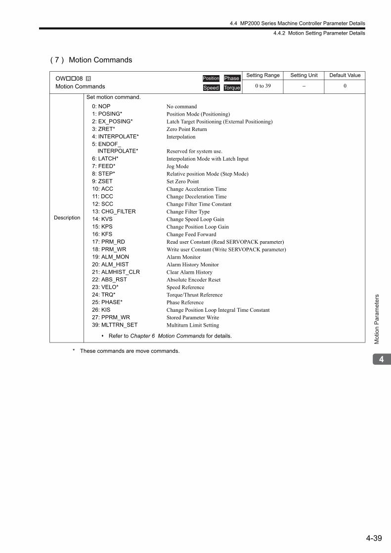
4.4 MP2000 Series Machine Controller Parameter Details
4.4.2 Motion Setting Parameter Details
4-39
Mot
ion
Par
amet
ers
( 7 ) Motion Commands
* These commands are move commands.
OW08Motion Commands
Setting Range Setting Unit Default Value
0 to 39 − 0
Description
Set motion command.
0: NOP1: POSING*2: EX_POSING*3: ZRET*4: INTERPOLATE*5: ENDOF_
INTERPOLATE*6: LATCH*7: FEED*8: STEP*9: ZSET10: ACC11: DCC12: SCC13: CHG_FILTER14: KVS15: KPS16: KFS17: PRM_RD18: PRM_WR19: ALM_MON20: ALM_HIST21: ALMHIST_CLR22: ABS_RST23: VELO*24: TRQ*25: PHASE*26: KIS27: PPRM_WR39: MLTTRN_SET
No commandPosition Mode (Positioning)Latch Target Positioning (External Positioning)Zero Point ReturnInterpolation
Reserved for system use.Interpolation Mode with Latch InputJog ModeRelative position Mode (Step Mode)Set Zero PointChange Acceleration TimeChange Deceleration TimeChange Filter Time ConstantChange Filter TypeChange Speed Loop GainChange Position Loop GainChange Feed ForwardRead user Constant (Read SERVOPACK parameter)Write user Constant (Write SERVOPACK parameter)Alarm MonitorAlarm History MonitorClear Alarm HistoryAbsolute Encoder ResetSpeed ReferenceTorque/Thrust ReferencePhase ReferenceChange Position Loop Integral Time ConstantStored Parameter WriteMultiturn Limit Setting
Refer to Chapter 6 Motion Commands for details.
R Position Phase
Speed Torque
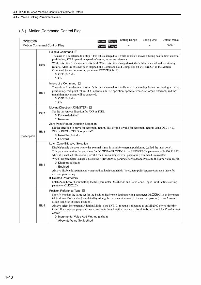
4.4 MP2000 Series Machine Controller Parameter Details
4.4.2 Motion Setting Parameter Details
4-40
( 8 ) Motion Command Control Flag
OW09Motion Command Control Flag
Setting Range Setting Unit Default Value
− − 0000H
Description
Bit 0
Holds a CommandThe axis will decelerate to a stop if this bit is changed to 1 while an axis is moving during positioning, external positioning, STEP operation, speed reference, or torque reference. While this bit is 1, the command is held. When this bit is changed to 0, the hold is canceled and positioning restarts. After the axis has been stopped, the Command Hold Completed bit will turn ON in the MotionCommand Status (monitoring parameter IW09, bit 1).
0: OFF (default)1: ON
Bit 1
Interrupt a CommandThe axis will decelerate to a stop if this bit is changed to 1 while an axis is moving during positioning, external positioning, zero point return, JOG operation, STEP operation, speed reference, or torque reference, and the remaining movement will be canceled.
0: OFF (default)1: ON
Bit 2
Moving Direction (JOG/STEP)Set the movement direction for JOG or STEP.
0: Forward (default)1: Reverse
Bit 3
Zero Point Return Direction SelectionSet the direction to move for zero point return. This setting is valid for zero point returns using DEC1 + C, ZERO, DEC1 + ZERO, or phase-C.
0: Reverse (default)1: Forward
Bit 4
Latch Zone Effective SelectionDisable/enable the area where the external signal is valid for external positioning (called the latch zone).This parameter writes the set values for OL2A/OL2C in the SERVOPACK parameters (Pn820, Pn822) when it is enabled. This setting is valid each time a new external positioning command is executed.When this parameter is disabled, sets the SERVOPACK parameters Pn820 and Pn822 to the same value (zero).
0: Disabled (default)1: Enabled
Always disable this parameter when sending latch commands (latch, zero point return) other than those for external positioning.
Related ParametersLatch Zone Lower Limit Setting (setting parameter OL2A) and Latch Zone Upper Limit Setting (setting parameter OL2C)
Bit 5
Position Reference TypeSpecify whether the value set for the Position Reference Setting (setting parameter OL1C) is an Incremen-tal Addition Mode value (calculated by adding the movement amount to the current position) or an Absolute Mode value (an absolute position).Always select Incremental Addition Mode if the SVB-01 module is mounted to an MP2000-series Machine Controller, a motion program is used, and an infinite length axis is used. For details, refer to 5.1.4 Position Ref-erence.
0: Incremental Value Add Method (default)1: Absolute Value Set Method
Position Phase
Speed Torque
R
R
R
R
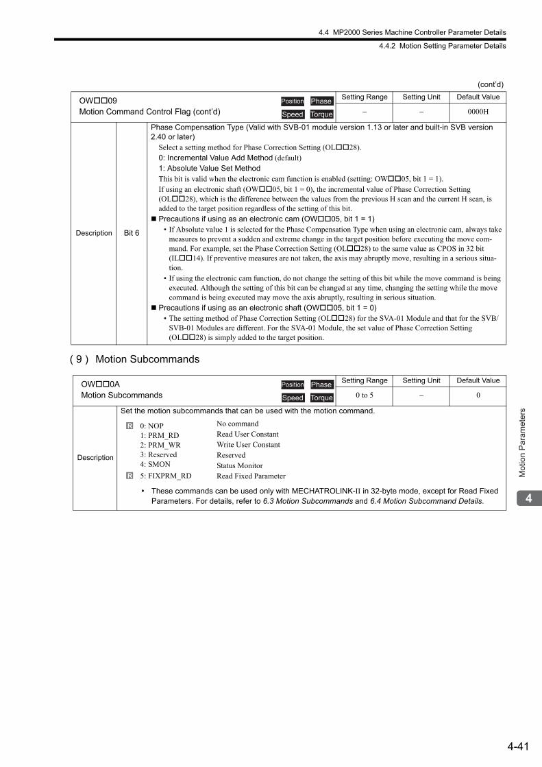
4.4 MP2000 Series Machine Controller Parameter Details
4.4.2 Motion Setting Parameter Details
4-41
Mot
ion
Par
amet
ers
( 9 ) Motion Subcommands
Description Bit 6
Phase Compensation Type (Valid with SVB-01 module version 1.13 or later and built-in SVB version 2.40 or later)
Select a setting method for Phase Correction Setting (OL28).0: Incremental Value Add Method (default)1: Absolute Value Set MethodThis bit is valid when the electronic cam function is enabled (setting: OW05, bit 1 = 1).If using an electronic shaft (OW05, bit 1 = 0), the incremental value of Phase Correction Setting (OL28), which is the difference between the values from the previous H scan and the current H scan, is added to the target position regardless of the setting of this bit.
Precautions if using as an electronic cam (OW05, bit 1 = 1)• If Absolute value 1 is selected for the Phase Compensation Type when using an electronic cam, always take
measures to prevent a sudden and extreme change in the target position before executing the move com-mand. For example, set the Phase Correction Setting (OL28) to the same value as CPOS in 32 bit (IL14). If preventive measures are not taken, the axis may abruptly move, resulting in a serious situa-tion.
• If using the electronic cam function, do not change the setting of this bit while the move command is being executed. Although the setting of this bit can be changed at any time, changing the setting while the move command is being executed may move the axis abruptly, resulting in serious situation.
Precautions if using as an electronic shaft (OW05, bit 1 = 0)• The setting method of Phase Correction Setting (OL28) for the SVA-01 Module and that for the SVB/
SVB-01 Modules are different. For the SVA-01 Module, the set value of Phase Correction Setting (OL28) is simply added to the target position.
OW0AMotion Subcommands
Setting Range Setting Unit Default Value
0 to 5 − 0
Description
Set the motion subcommands that can be used with the motion command.
0: NOP1: PRM_RD2: PRM_WR3: Reserved4: SMON
5: FIXPRM_RD
No commandRead User ConstantWrite User ConstantReservedStatus MonitorRead Fixed Parameter
These commands can be used only with MECHATROLINK-II in 32-byte mode, except for Read Fixed Parameters. For details, refer to 6.3 Motion Subcommands and 6.4 Motion Subcommand Details.
(cont’d)
OW09Motion Command Control Flag (cont’d)
Setting Range Setting Unit Default Value
− − 0000H
Position Phase
Speed Torque
Position Phase
Speed Torque
R
R
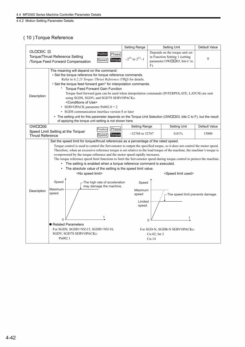
4.4 MP2000 Series Machine Controller Parameter Details
4.4.2 Motion Setting Parameter Details
4-42
( 10 )Torque Reference
OL0CTorque/Thrust Reference Setting/Torque Feed Forward Compensation
Setting Range Setting Unit Default Value
−231 to 231−1
Depends on the torque unit set in Function Setting 1 (setting parameter OW03, bits C to F).
0
Description
The meaning will depend on the command. • Set the torque reference for torque reference commands.
Refer to 6.2.23 Torque /Thrust Reference (TRQ) for details.• Set the torque feed forward gain* for interpolation commands.
* Torque Feed Forward Gain FunctionTorque feed forward gain can be used when interpolation commands (INTERPOLATE, LATCH) are sent using SGDS, SGDV, and SGD7S SERVOPACKs.<Conditions of Use>
• SERVOPACK parameter Pn002.0 = 2• SGDS communication interface version 8 or later
The setting unit for this parameter depends on the Torque Unit Selection (OW03, bits C to F), but the result of applying the torque unit setting is not shown here.
OW0ESpeed Limit Setting at the Torque/Thrust Reference
Setting Range Setting Unit Default Value
−32768 to 32767 0.01% 15000
Description
Set the speed limit for torque/thrust references as a percentage of the rated speed.Torque control is used to control the Servomotor to output the specified torque, so it does not control the motor speed. Therefore, when an excessive reference torque is set relative to the load torque of the machine, the machine’s torque is overpowered by the torque reference and the motor speed rapidly increases.The torque reference speed limit functions to limit the Servomotor speed during torque control to protect the machine.
The setting is enabled when a torque reference command is executed.
The absolute value of the setting is the speed limit value.
<No speed limit> <Speed limit used>
RPhase
Speed Torque
Position
Position Phase
Speed Torque
0t
Speed The high rate of acceleration
may damage the machine.
Maximum
speed
0t
Speed
Limited speed
The speed limit prevents damage.Maximum speed
Related ParametersFor SGDS, SGDH+NS115, SGDH+NS110, SGDV, SGD7S SERVOPACKs: Pn002.1
For SGD-N, SGDB-N SERVOPACKs: Cn-02, bit 2 Cn-14
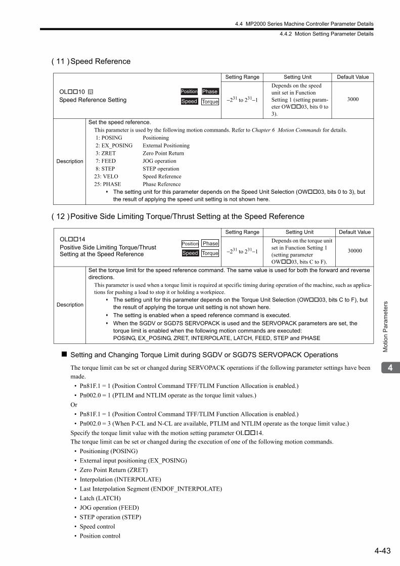
4.4 MP2000 Series Machine Controller Parameter Details
4.4.2 Motion Setting Parameter Details
4-43
Mot
ion
Par
amet
ers
( 11 )Speed Reference
( 12 )Positive Side Limiting Torque/Thrust Setting at the Speed Reference
Setting and Changing Torque Limit during SGDV or SGD7S SERVOPACK Operations
The torque limit can be set or changed during SERVOPACK operations if the following parameter settings have been made.
• Pn81F.1 = 1 (Position Control Command TFF/TLIM Function Allocation is enabled.)
• Pn002.0 = 1 (PTLIM and NTLIM operate as the torque limit values.)
Or
• Pn81F.1 = 1 (Position Control Command TFF/TLIM Function Allocation is enabled.)
• Pn002.0 = 3 (When P-CL and N-CL are available, PTLIM and NTLIM operate as the torque limit value.)
Specify the torque limit value with the motion setting parameter OL14.The torque limit can be set or changed during the execution of one of the following motion commands.
• Positioning (POSING)
• External input positioning (EX_POSING)
• Zero Point Return (ZRET)
• Interpolation (INTERPOLATE)
• Last Interpolation Segment (ENDOF_INTERPOLATE)
• Latch (LATCH)
• JOG operation (FEED)
• STEP operation (STEP)
• Speed control
• Position control
OL10Speed Reference Setting
Setting Range Setting Unit Default Value
−231 to 231−1
Depends on the speed unit set in FunctionSetting 1 (setting param-eter OW03, bits 0 to 3).
3000
Description
Set the speed reference.This parameter is used by the following motion commands. Refer to Chapter 6 Motion Commands for details. 1: POSING Positioning 2: EX_POSING External Positioning 3: ZRET Zero Point Return 7: FEED JOG operation 8: STEP STEP operation23: VELO Speed Reference25: PHASE Phase Reference
The setting unit for this parameter depends on the Speed Unit Selection (OW03, bits 0 to 3), but the result of applying the speed unit setting is not shown here.
OL14Positive Side Limiting Torque/ThrustSetting at the Speed Reference
Setting Range Setting Unit Default Value
−231 to 231−1
Depends on the torque unit set in Function Setting 1 (setting parameter OW03, bits C to F).
30000
Description
Set the torque limit for the speed reference command. The same value is used for both the forward and reverse directions.
This parameter is used when a torque limit is required at specific timing during operation of the machine, such as applica-tions for pushing a load to stop it or holding a workpiece.
The setting unit for this parameter depends on the Torque Unit Selection (OW03, bits C to F), but the result of applying the torque unit setting is not shown here.
The setting is enabled when a speed reference command is executed.
When the SGDV or SGD7S SERVOPACK is used and the SERVOPACK parameters are set, the torque limit is enabled when the following motion commands are executed:POSING, EX_POSING, ZRET, INTERPOLATE, LATCH, FEED, STEP and PHASE
R Position Phase
Speed Torque
Position Phase
Speed Torque
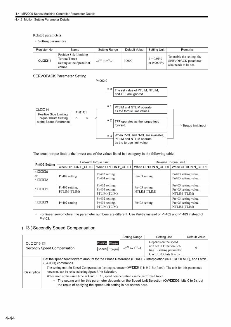
4.4 MP2000 Series Machine Controller Parameter Details
4.4.2 Motion Setting Parameter Details
4-44
Related parameters
• Setting parameters
SERVOPACK Parameter Setting
The actual torque limit is the lowest one of the values listed in a category in the following table.
For linear servomotors, the parameter numbers are different. Use Pn482 instead of Pn402 and Pn483 instead of Pn403.
( 13 )Secondly Speed Compensation
Register No. Name Setting Range Default Value Setting Unit Remarks
OL14
Positive Side Limiting Torque/ThrustSetting at the Speed Ref-erence
–231 to 231–1 300001 = 0.01% or 0.0001%
To enable the setting, the SERVOPACK parameter also needs to be set.
Pn002 SettingForward Torque Limit Reverse Torque Limit
When OPTION.P_CL = 0 When OPTION.P_CL = 1 When OPTION.N_CL = 0 When OPTION.N_CL = 1
n.0orn.2
Pn402 settingPn402 setting,Pn404 setting
Pn403 settingPn403 setting value,Pn405 setting value,
n.1 Pn402 setting,PTLIM (TLIM)
Pn402 setting,Pn404 setting,PTLIM (TLIM)
Pn403 setting,NTLIM (TLIM)
Pn403 setting value,Pn405 setting value,NTLIM (TLIM)
n.3 Pn402 settingPn402 setting,Pn404 setting,PTLIM (TLIM)
Pn403 settingPn403 setting value,Pn405 setting value,NTLIM (TLIM)
Positive Side Limiting Torque/Thrust Setting
at the Speed Reference
OL��14
Torque limit input
Pn81F.1
= 2
The set value of PTLIM, NTLIM, and TFF are ignored.
= 0
Pn002.0
= 3
= 1 PTLIM and NTLIM operate as the torque limit values.
TFF operates as the torque feed forward.
When P-CL and N-CL are available, PTLIM and NTLIM operate as the torque limit value.
OL16Secondly Speed Compensation
Setting Range Setting Unit Default Value
−231 to 231−1
Depends on the speed unit set in Function Set-ting 1 (setting parameter OW03, bits 0 to 3).
0
Description
Set the speed feed forward amount for the Phase Reference (PHASE), Interpolation (INTERPOLATE), and Latch (LATCH) commands.
The setting unit for Speed Compensation (setting parameter OW31) is 0.01% (fixed). The unit for this parameter, however, can be selected using Speed Unit Selection.When used at the same time as OW31, speed compensation can be performed twice.
The setting unit for this parameter depends on the Speed Unit Selection (OW03, bits 0 to 3), but the result of applying the speed unit setting is not shown here.
R Phase
Speed Torque
Position
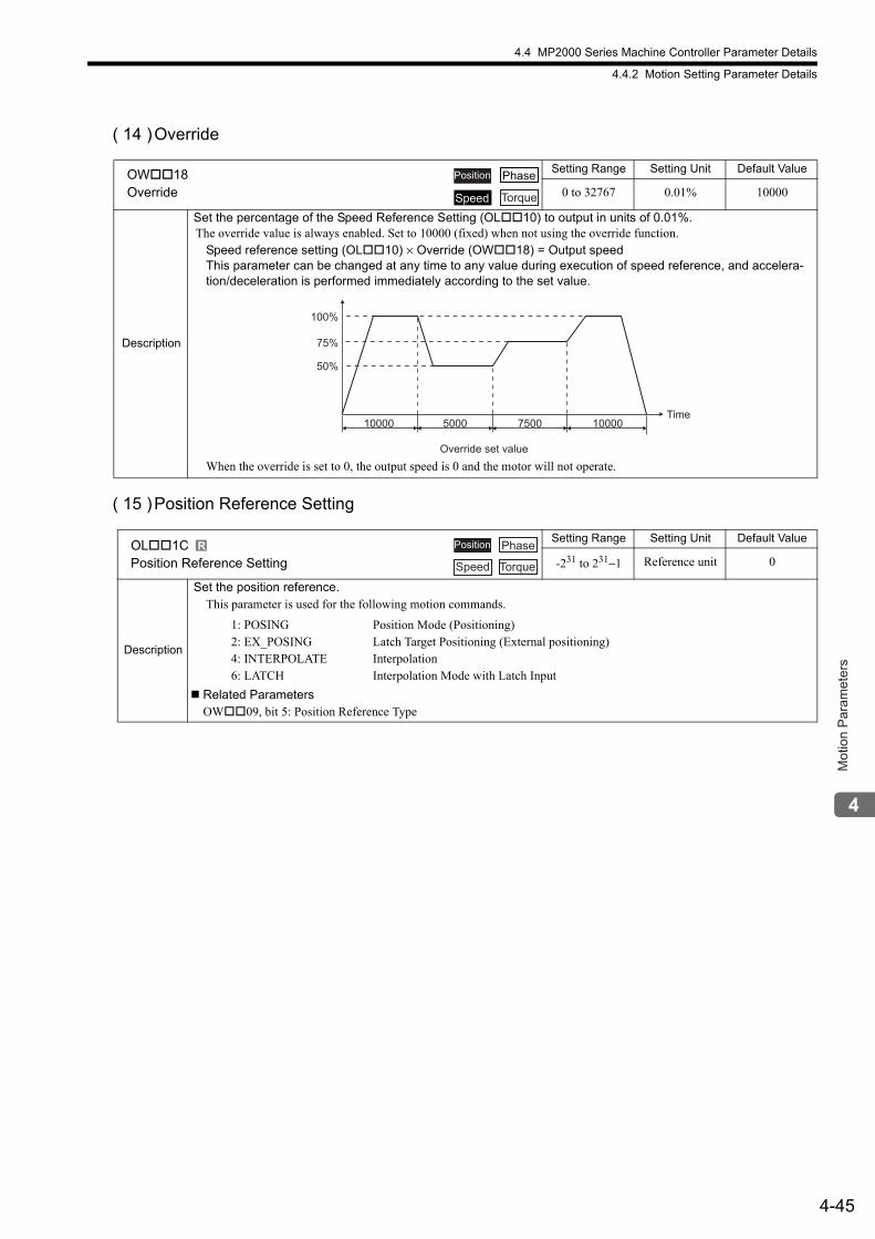
4.4 MP2000 Series Machine Controller Parameter Details
4.4.2 Motion Setting Parameter Details
4-45
Mot
ion
Par
amet
ers
( 14 )Override
( 15 )Position Reference Setting
OW18Override
Setting Range Setting Unit Default Value
0 to 32767 0.01% 10000
Description
Set the percentage of the Speed Reference Setting (OL10) to output in units of 0.01%.The override value is always enabled. Set to 10000 (fixed) when not using the override function.
Speed reference setting (OL10) × Override (OW18) = Output speedThis parameter can be changed at any time to any value during execution of speed reference, and accelera-tion/deceleration is performed immediately according to the set value.
When the override is set to 0, the output speed is 0 and the motor will not operate.
OL1CPosition Reference Setting
Setting Range Setting Unit Default Value
-231 to 231−1 Reference unit 0
Description
Set the position reference.This parameter is used for the following motion commands.
1: POSING 2: EX_POSING 4: INTERPOLATE 6: LATCH
Position Mode (Positioning)Latch Target Positioning (External positioning)InterpolationInterpolation Mode with Latch Input
Related ParametersOW09, bit 5: Position Reference Type
Position Phase
Speed Torque
50%
75%
100%
5000 7500 1000010000
Override set value
Time
R Position Phase
Speed Torque
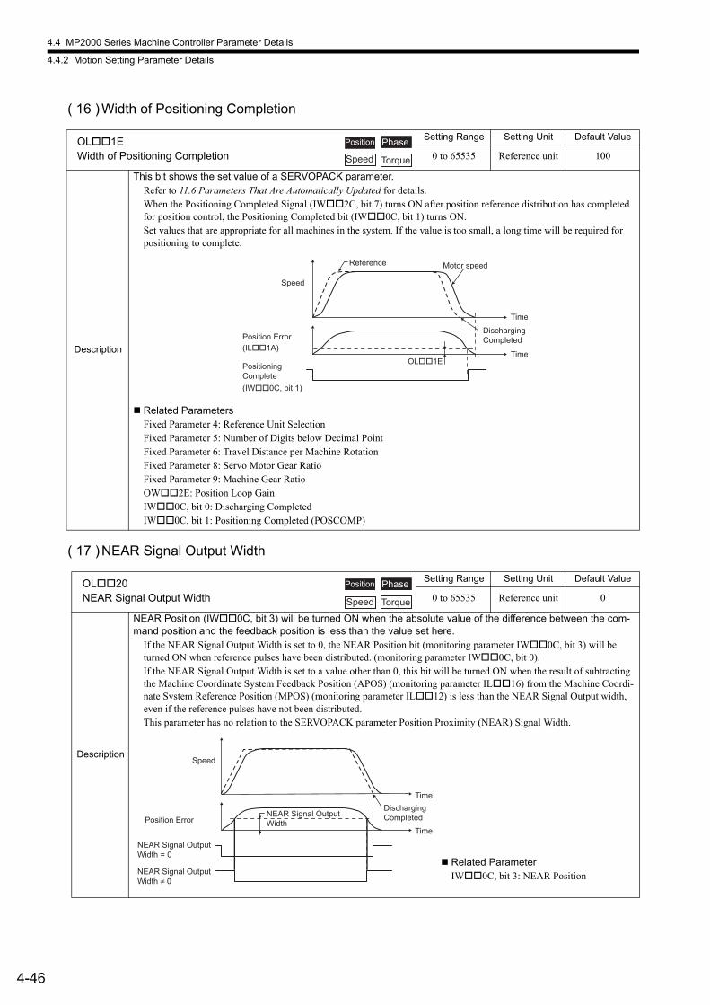
4.4 MP2000 Series Machine Controller Parameter Details
4.4.2 Motion Setting Parameter Details
4-46
( 16 )Width of Positioning Completion
( 17 )NEAR Signal Output Width
OL1EWidth of Positioning Completion
Setting Range Setting Unit Default Value
0 to 65535 Reference unit 100
Description
This bit shows the set value of a SERVOPACK parameter.Refer to 11.6 Parameters That Are Automatically Updated for details.When the Positioning Completed Signal (IW2C, bit 7) turns ON after position reference distribution has completed for position control, the Positioning Completed bit (IW0C, bit 1) turns ON.Set values that are appropriate for all machines in the system. If the value is too small, a long time will be required for positioning to complete.
Related ParametersFixed Parameter 4: Reference Unit SelectionFixed Parameter 5: Number of Digits below Decimal PointFixed Parameter 6: Travel Distance per Machine RotationFixed Parameter 8: Servo Motor Gear RatioFixed Parameter 9: Machine Gear RatioOW2E: Position Loop GainIW0C, bit 0: Discharging CompletedIW0C, bit 1: Positioning Completed (POSCOMP)
OL20NEAR Signal Output Width
Setting Range Setting Unit Default Value
0 to 65535 Reference unit 0
Description
NEAR Position (IW0C, bit 3) will be turned ON when the absolute value of the difference between the com-mand position and the feedback position is less than the value set here.
If the NEAR Signal Output Width is set to 0, the NEAR Position bit (monitoring parameter IW0C, bit 3) will be turned ON when reference pulses have been distributed. (monitoring parameter IW0C, bit 0).If the NEAR Signal Output Width is set to a value other than 0, this bit will be turned ON when the result of subtracting the Machine Coordinate System Feedback Position (APOS) (monitoring parameter IL16) from the Machine Coordi-nate System Reference Position (MPOS) (monitoring parameter IL12) is less than the NEAR Signal Output width, even if the reference pulses have not been distributed.This parameter has no relation to the SERVOPACK parameter Position Proximity (NEAR) Signal Width.
Position Phase
Speed Torque
OL��1ETime
Time
(IW��0C, bit 1)
(IL��1A)
Speed
Position Error
Reference Motor speed
PositioningComplete
DischargingCompleted
Position Phase
Speed Torque
Speed
Time
Time
Position ErrorNEAR Signal OutputWidth
Discharging Completed
NEAR Signal OutputWidth = 0
NEAR Signal OutputWidth ≠ 0
Related ParameterIW0C, bit 3: NEAR Position
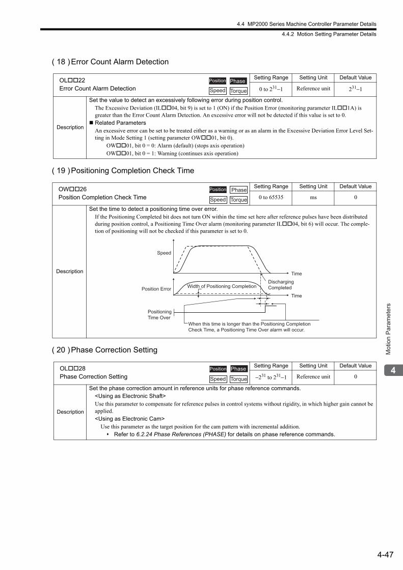
4.4 MP2000 Series Machine Controller Parameter Details
4.4.2 Motion Setting Parameter Details
4-47
Mot
ion
Par
amet
ers
( 18 )Error Count Alarm Detection
( 19 )Positioning Completion Check Time
( 20 )Phase Correction Setting
OL22Error Count Alarm Detection
Setting Range Setting Unit Default Value
0 to 231−1 Reference unit 231−1
Description
Set the value to detect an excessively following error during position control.The Excessive Deviation (IL04, bit 9) is set to 1 (ON) if the Position Error (monitoring parameter IL1A) is greater than the Error Count Alarm Detection. An excessive error will not be detected if this value is set to 0.
Related ParametersAn excessive error can be set to be treated either as a warning or as an alarm in the Excessive Deviation Error Level Set-ting in Mode Setting 1 (setting parameter OW01, bit 0). OW01, bit 0 = 0: Alarm (default) (stops axis operation) OW01, bit 0 = 1: Warning (continues axis operation)
OW26Position Completion Check Time
Setting Range Setting Unit Default Value
0 to 65535 ms 0
Description
Set the time to detect a positioning time over error.If the Positioning Completed bit does not turn ON within the time set here after reference pulses have been distributed during position control, a Positioning Time Over alarm (monitoring parameter IL04, bit 6) will occur. The comple-tion of positioning will not be checked if this parameter is set to 0.
OL28Phase Correction Setting
Setting Range Setting Unit Default Value
−231 to 231−1 Reference unit 0
Description
Set the phase correction amount in reference units for phase reference commands.<Using as Electronic Shaft>Use this parameter to compensate for reference pulses in control systems without rigidity, in which higher gain cannot be applied.<Using as Electronic Cam>
Use this parameter as the target position for the cam pattern with incremental addition. Refer to 6.2.24 Phase References (PHASE) for details on phase reference commands.
Position
Speed Torque
Phase
Position Phase
Speed Torque
Speed
Time
TimePosition Error Width of Positioning Completion
When this time is longer than the Positioning CompletionCheck Time, a Positioning Time Over alarm will occur.
Discharging Completed
PositioningTime Over
Phase
Speed Torque
Position
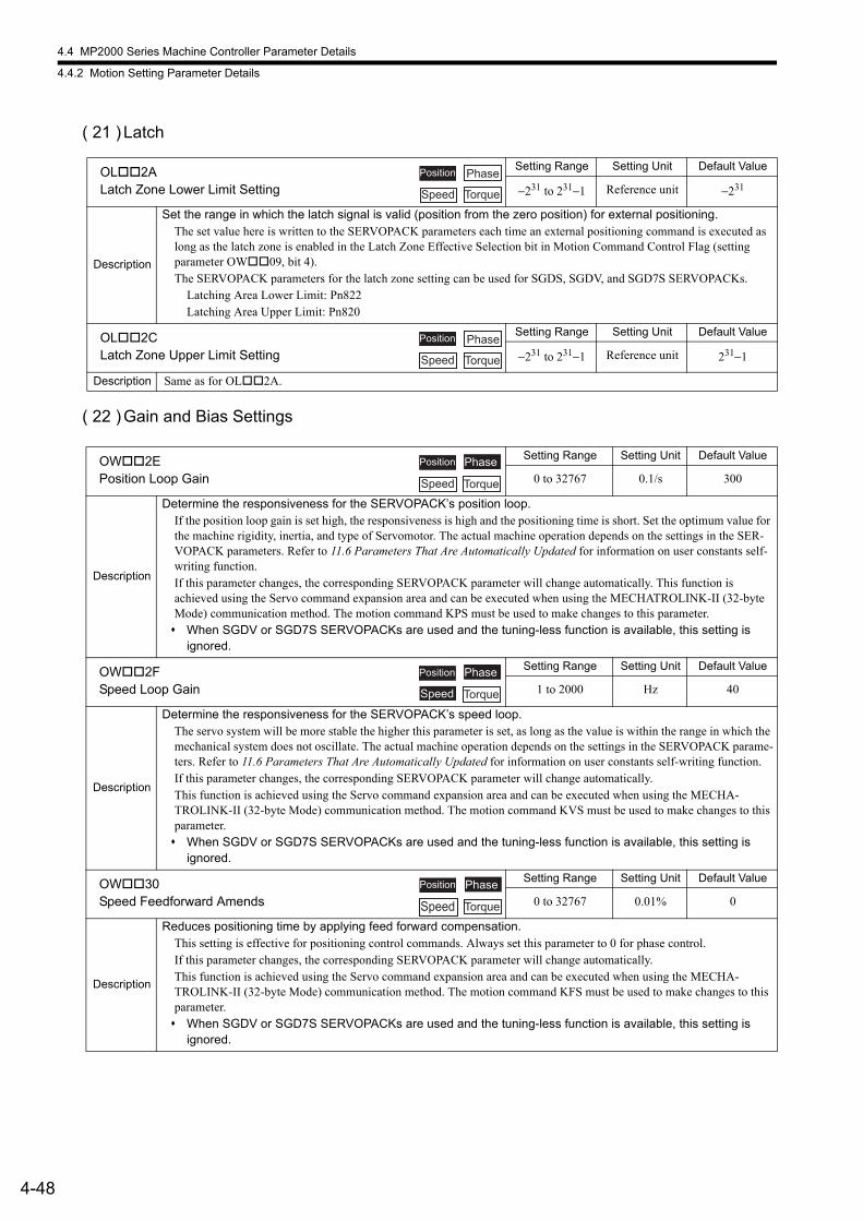
4.4 MP2000 Series Machine Controller Parameter Details
4.4.2 Motion Setting Parameter Details
4-48
( 21 ) Latch
( 22 )Gain and Bias Settings
OL2ALatch Zone Lower Limit Setting
Setting Range Setting Unit Default Value
−231 to 231−1 Reference unit −231
Description
Set the range in which the latch signal is valid (position from the zero position) for external positioning.The set value here is written to the SERVOPACK parameters each time an external positioning command is executed as long as the latch zone is enabled in the Latch Zone Effective Selection bit in Motion Command Control Flag (setting parameter OW09, bit 4).The SERVOPACK parameters for the latch zone setting can be used for SGDS, SGDV, and SGD7S SERVOPACKs.
Latching Area Lower Limit: Pn822Latching Area Upper Limit: Pn820
OL2CLatch Zone Upper Limit Setting
Setting Range Setting Unit Default Value
−231 to 231−1 Reference unit 231−1
Description Same as for OL2A.
OW2EPosition Loop Gain
Setting Range Setting Unit Default Value
0 to 32767 0.1/s 300
Description
Determine the responsiveness for the SERVOPACK’s position loop.If the position loop gain is set high, the responsiveness is high and the positioning time is short. Set the optimum value for the machine rigidity, inertia, and type of Servomotor. The actual machine operation depends on the settings in the SER-VOPACK parameters. Refer to 11.6 Parameters That Are Automatically Updated for information on user constants self-writing function.If this parameter changes, the corresponding SERVOPACK parameter will change automatically. This function is achieved using the Servo command expansion area and can be executed when using the MECHATROLINK-II (32-byte Mode) communication method. The motion command KPS must be used to make changes to this parameter. When SGDV or SGD7S SERVOPACKs are used and the tuning-less function is available, this setting is
ignored.
OW2FSpeed Loop Gain
Setting Range Setting Unit Default Value
1 to 2000 Hz 40
Description
Determine the responsiveness for the SERVOPACK’s speed loop.The servo system will be more stable the higher this parameter is set, as long as the value is within the range in which the mechanical system does not oscillate. The actual machine operation depends on the settings in the SERVOPACK parame-ters. Refer to 11.6 Parameters That Are Automatically Updated for information on user constants self-writing function.If this parameter changes, the corresponding SERVOPACK parameter will change automatically. This function is achieved using the Servo command expansion area and can be executed when using the MECHA-TROLINK-II (32-byte Mode) communication method. The motion command KVS must be used to make changes to this parameter. When SGDV or SGD7S SERVOPACKs are used and the tuning-less function is available, this setting is
ignored.
OW30Speed Feedforward Amends
Setting Range Setting Unit Default Value
0 to 32767 0.01% 0
Description
Reduces positioning time by applying feed forward compensation.This setting is effective for positioning control commands. Always set this parameter to 0 for phase control.If this parameter changes, the corresponding SERVOPACK parameter will change automatically. This function is achieved using the Servo command expansion area and can be executed when using the MECHA-TROLINK-II (32-byte Mode) communication method. The motion command KFS must be used to make changes to this parameter. When SGDV or SGD7S SERVOPACKs are used and the tuning-less function is available, this setting is
ignored.
Position Phase
Speed Torque
Position Phase
Speed Torque
Position Phase
TorqueSpeed
Position Phase
Speed Torque
Position Phase
TorqueSpeed
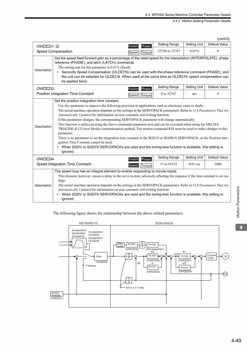
4.4 MP2000 Series Machine Controller Parameter Details
4.4.2 Motion Setting Parameter Details
4-49
Mot
ion
Par
amet
ers
The following figure shows the relationship between the above related parameters.
OW31Speed Compensation
Setting Range Setting Unit Default Value
-32768 to 32767 0.01% 0
Description
Set the speed feed forward gain as a percentage of the rated speed for the interpolation (INTERPOLATE), phase reference (PHASE), and latch (LATCH) commands.
The setting unit for this parameter is 0.01% (fixed). Secondly Speed Compensation (OL16) can be used with the phase reference command (PHASE), and
the unit can be selected for OL16. When used at the same time as OL16, speed compensation can be applied twice.
OW32Position Integration Time Constant
Setting Range Setting Unit Default Value
0 to 32767 ms 0
Description
Set the position integration time constant.Use this parameter to improve the following precision in applications such as electronic cams or shafts.The actual machine operation depends on the settings in the SERVOPACK parameters. Refer to 11.6 Parameters That Are Automatically Updated for information on user constants self-writing function.If this parameter changes, the corresponding SERVOPACK parameter will change automatically. This function is achieved using the Servo command expansion area and can be executed when using the MECHA-TROLINK-II (32-byte Mode) communication method. The motion command KIS must be used to make changes to this parameter.There is no parameter to set the integration time constant in the SGD-N or SGDB-N SERVOPACK, so the Position Inte-gration Time Constant cannot be used. When SGDV or SGD7S SERVOPACKs are used and the tuning-less function is available, this setting is
ignored.
OW34Speed Integration Time Constant
Setting Range Setting Unit Default Value
15 to 65535 0.01 ms 2000
Description
The speed loop has an integral element to enable responding to minute inputs.This element, however, causes a delay in the servo system, adversely affecting the response if the time constant is set too large.The actual machine operation depends on the settings in the SERVOPACK parameters. Refer to 11.6 Parameters That Are Automatically Updated for information on user constants self-writing function. When SGDV or SGD7S SERVOPACKs are used and the tuning-less function is available, this setting is
ignored.
(cont’d)
R Position Phase
TorqueSpeed
Position Phase
Speed Torque
Position Phase
Speed Torque
NS100/NS115
FB
BA
(OW30)
BA
Pn109
BA
TiPn11F
(OW2E)
(OW32)
Pn102
Pn10A
Vref
NTi
Kv
(OW34)
(OW2F)
Pn100
Pn101
Kp
OW3A
(OW31)
PG
MFilter
Differ-ential
CurrentLoop
Speed Amends
Acceleration/ deceleration processing
Acceleration: OL36Deceleration: OL38
Followup
(Not supported.)
SERVOPACK
Set in a 1:1 ratio.
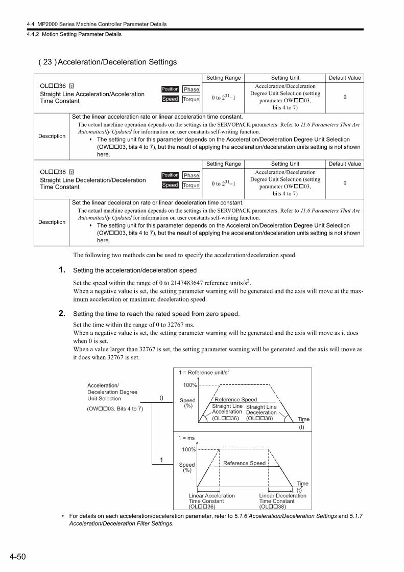
4.4 MP2000 Series Machine Controller Parameter Details
4.4.2 Motion Setting Parameter Details
4-50
( 23 )Acceleration/Deceleration Settings
The following two methods can be used to specify the acceleration/deceleration speed.
1. Setting the acceleration/deceleration speed
Set the speed within the range of 0 to 2147483647 reference units/s2.When a negative value is set, the setting parameter warning will be generated and the axis will move at the max-imum acceleration or maximum deceleration speed.
2. Setting the time to reach the rated speed from zero speed.
Set the time within the range of 0 to 32767 ms.When a negative value is set, the setting parameter warning will be generated and the axis will move as it does when 0 is set.When a value larger than 32767 is set, the setting parameter warning will be generated and the axis will move as it does when 32767 is set.
For details on each acceleration/deceleration parameter, refer to 5.1.6 Acceleration/Deceleration Settings and 5.1.7 Acceleration/Deceleration Filter Settings.
OL36Straight Line Acceleration/Acceleration Time Constant
Setting Range Setting Unit Default Value
0 to 231−1
Acceleration/Deceleration Degree Unit Selection (setting
parameter OW03, bits 4 to 7)
0
Description
Set the linear acceleration rate or linear acceleration time constant.The actual machine operation depends on the settings in the SERVOPACK parameters. Refer to 11.6 Parameters That Are Automatically Updated for information on user constants self-writing function.
The setting unit for this parameter depends on the Acceleration/Deceleration Degree Unit Selection (OW03, bits 4 to 7), but the result of applying the acceleration/deceleration units setting is not shown here.
OL38Straight Line Deceleration/Deceleration Time Constant
Setting Range Setting Unit Default Value
0 to 231−1
Acceleration/Deceleration Degree Unit Selection (setting
parameter OW03, bits 4 to 7)
0
Description
Set the linear deceleration rate or linear deceleration time constant.The actual machine operation depends on the settings in the SERVOPACK parameters. Refer to 11.6 Parameters That Are Automatically Updated for information on user constants self-writing function.
The setting unit for this parameter depends on the Acceleration/Deceleration Degree Unit Selection (OW03, bits 4 to 7), but the result of applying the acceleration/deceleration units setting is not shown here.
R Position Phase
Speed Torque
R Position Phase
Speed Torque
1
0
100%
1 = ms
100%
(%)
(%)
(t)
(t)
(OL��38)(OL��36)
(OW��03. Bits 4 to 7)
Acceleration/Deceleration Degree Unit Selection
Speed Reference Speed
Time
Linear Acceleration Time Constant (OL��36)
Linear Deceleration Time Constant (OL��38)
Reference SpeedStraight Line Acceleration
Straight Line Deceleration
Speed
Time
1 = Reference unit/s2
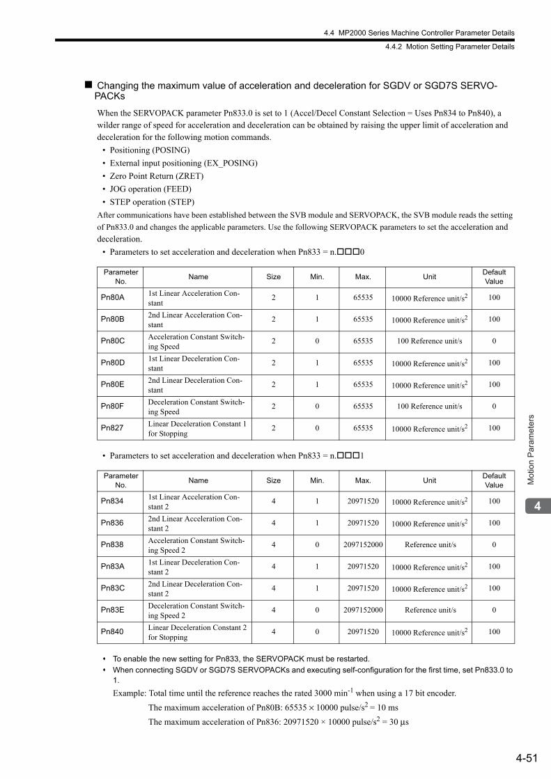
4.4 MP2000 Series Machine Controller Parameter Details
4.4.2 Motion Setting Parameter Details
4-51
Mot
ion
Par
amet
ers
Changing the maximum value of acceleration and deceleration for SGDV or SGD7S SERVO-PACKs
When the SERVOPACK parameter Pn833.0 is set to 1 (Accel/Decel Constant Selection = Uses Pn834 to Pn840), a wilder range of speed for acceleration and deceleration can be obtained by raising the upper limit of acceleration and deceleration for the following motion commands.
• Positioning (POSING)
• External input positioning (EX_POSING)
• Zero Point Return (ZRET)
• JOG operation (FEED)
• STEP operation (STEP)
After communications have been established between the SVB module and SERVOPACK, the SVB module reads the setting
of Pn833.0 and changes the applicable parameters. Use the following SERVOPACK parameters to set the acceleration and deceleration.
• Parameters to set acceleration and deceleration when Pn833 = n.0
• Parameters to set acceleration and deceleration when Pn833 = n.1
To enable the new setting for Pn833, the SERVOPACK must be restarted.
When connecting SGDV or SGD7S SERVOPACKs and executing self-configuration for the first time, set Pn833.0 to 1.
Example: Total time until the reference reaches the rated 3000 min-1 when using a 17 bit encoder.
The maximum acceleration of Pn80B: 65535 × 10000 pulse/s2 = 10 ms
The maximum acceleration of Pn836: 20971520 × 10000 pulse/s2 = 30 μs
Parameter No.
Name Size Min. Max. UnitDefault Value
Pn80A 1st Linear Acceleration Con-stant
2 1 65535 10000 Reference unit/s2 100
Pn80B 2nd Linear Acceleration Con-stant
2 1 65535 10000 Reference unit/s2 100
Pn80C Acceleration Constant Switch-ing Speed
2 0 65535 100 Reference unit/s 0
Pn80D 1st Linear Deceleration Con-stant
2 1 65535 10000 Reference unit/s2 100
Pn80E 2nd Linear Deceleration Con-stant
2 1 65535 10000 Reference unit/s2 100
Pn80F Deceleration Constant Switch-ing Speed
2 0 65535 100 Reference unit/s 0
Pn827 Linear Deceleration Constant 1 for Stopping
2 0 65535 10000 Reference unit/s2 100
Parameter No.
Name Size Min. Max. UnitDefault Value
Pn834 1st Linear Acceleration Con-stant 2
4 1 20971520 10000 Reference unit/s2 100
Pn836 2nd Linear Acceleration Con-stant 2
4 1 20971520 10000 Reference unit/s2 100
Pn838 Acceleration Constant Switch-ing Speed 2
4 0 2097152000 Reference unit/s 0
Pn83A 1st Linear Deceleration Con-stant 2
4 1 20971520 10000 Reference unit/s2 100
Pn83C 2nd Linear Deceleration Con-stant 2
4 1 20971520 10000 Reference unit/s2 100
Pn83E Deceleration Constant Switch-ing Speed 2
4 0 2097152000 Reference unit/s 0
Pn840 Linear Deceleration Constant 2 for Stopping
4 0 20971520 10000 Reference unit/s2 100
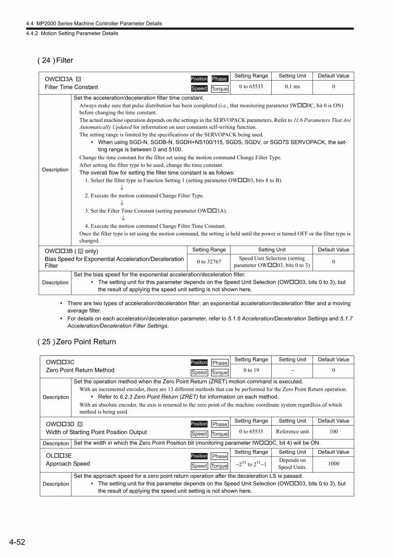
4.4 MP2000 Series Machine Controller Parameter Details
4.4.2 Motion Setting Parameter Details
4-52
( 24 )Filter
There are two types of acceleration/deceleration filter: an exponential acceleration/deceleration filter and a moving average filter.
For details on each acceleration/deceleration parameter, refer to 5.1.6 Acceleration/Deceleration Settings and 5.1.7 Acceleration/Deceleration Filter Settings.
( 25 )Zero Point Return
OW3AFilter Time Constant
Setting Range Setting Unit Default Value
0 to 65535 0.1 ms 0
Description
Set the acceleration/deceleration filter time constant.Always make sure that pulse distribution has been completed (i.e., that monitoring parameter IW0C, bit 0 is ON) before changing the time constant.The actual machine operation depends on the settings in the SERVOPACK parameters. Refer to 11.6 Parameters That Are Automatically Updated for information on user constants self-writing function.The setting range is limited by the specifications of the SERVOPACK being used.
When using SGD-N, SGDB-N, SGDH+NS100/115, SGDS, SGDV, or SGD7S SERVOPACK, the set-ting range is between 0 and 5100.
Change the time constant for the filter set using the motion command Change Filter Type. After setting the filter type to be used, change the time constant.The overall flow for setting the filter time constant is as follows:
1. Select the filter type in Function Setting 1 (setting parameter OW03, bits 8 to B). ↓2. Execute the motion command Change Filter Type. ↓3. Set the Filter Time Constant (setting parameter OW3A). ↓4. Execute the motion command Change Filter Time Constant.
Once the filter type is set using the motion command, the setting is held until the power is turned OFF or the filter type is changed.
OW3B ( only)Bias Speed for Exponential Acceleration/Deceleration Filter
Setting Range Setting Unit Default Value
0 to 32767Speed Unit Selection (setting
parameter OW03, bits 0 to 3)0
Description
Set the bias speed for the exponential acceleration/deceleration filter. The setting unit for this parameter depends on the Speed Unit Selection (OW03, bits 0 to 3), but
the result of applying the speed unit setting is not shown here.
R Position Phase
Speed Torque
R
OW3CZero Point Return Method
Setting Range Setting Unit Default Value
0 to 19 − 0
Description
Set the operation method when the Zero Point Return (ZRET) motion command is executed.With an incremental encoder, there are 13 different methods that can be performed for the Zero Point Return operation.
Refer to 6.2.3 Zero Point Return (ZRET) for information on each method.
With an absolute encoder, the axis is returned to the zero point of the machine coordinate system regardless of which method is being used.
OW3DWidth of Starting Point Position Output
Setting Range Setting Unit Default Value
0 to 65535 Reference unit 100
Description Set the width in which the Zero Point Position bit (monitoring parameter IW0C, bit 4) will be ON.
OL3EApproach Speed
Setting Range Setting Unit Default Value
−231 to 231−1Depends on Speed Units.
1000
Description
Set the approach speed for a zero point return operation after the deceleration LS is passed. The setting unit for this parameter depends on the Speed Unit Selection (OW03, bits 0 to 3), but
the result of applying the speed unit setting is not shown here.
Position Phase
Speed Torque
R Position Phase
Speed Torque
Position Phase
Speed Torque
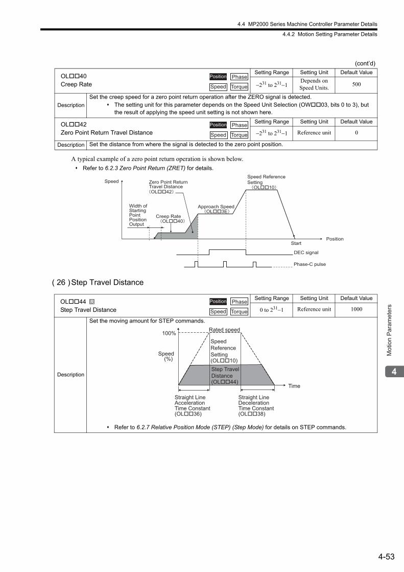
4.4 MP2000 Series Machine Controller Parameter Details
4.4.2 Motion Setting Parameter Details
4-53
Mot
ion
Par
amet
ers
A typical example of a zero point return operation is shown below.
Refer to 6.2.3 Zero Point Return (ZRET) for details.
( 26 )Step Travel Distance
OL40Creep Rate
Setting Range Setting Unit Default Value
−231 to 231−1Depends on Speed Units.
500
Description
Set the creep speed for a zero point return operation after the ZERO signal is detected. The setting unit for this parameter depends on the Speed Unit Selection (OW03, bits 0 to 3), but
the result of applying the speed unit setting is not shown here.
OL42Zero Point Return Travel Distance
Setting Range Setting Unit Default Value
−231 to 231−1 Reference unit 0
Description Set the distance from where the signal is detected to the zero point position.
(cont’d)
Position Phase
Speed Torque
Position Phase
Speed Torque
Speed
Start
OL��40
OL��42
DEC signal
Phase-C pulse
Creep Rate
Zero Point ReturnTravel Distance
Width ofStartingPointPositionOutput
OL��3EApproach Speed
OL��10
Speed ReferenceSetting
Position
OL44Step Travel Distance
Setting Range Setting Unit Default Value
0 to 231−1 Reference unit 1000
Description
Set the moving amount for STEP commands.
Refer to 6.2.7 Relative Position Mode (STEP) (Step Mode) for details on STEP commands.
R Position Phase
Speed Torque
(%) (OL��10)
(OL��44)
100%
Speed
Time
Straight Line Acceleration Time Constant (OL��36)
Straight Line DecelerationTime Constant (OL��38)
Rated speed
Speed ReferenceSetting
Step Travel Distance
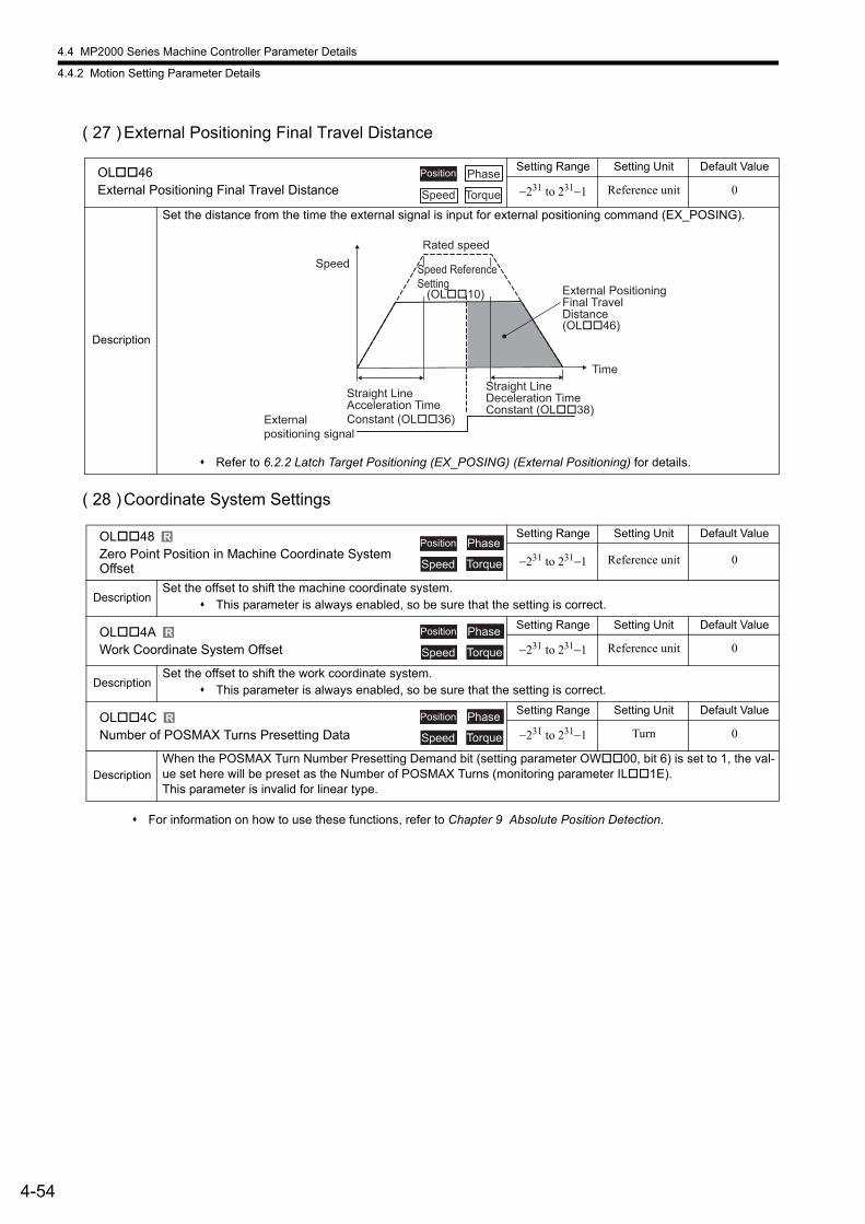
4.4 MP2000 Series Machine Controller Parameter Details
4.4.2 Motion Setting Parameter Details
4-54
( 27 )External Positioning Final Travel Distance
( 28 )Coordinate System Settings
For information on how to use these functions, refer to Chapter 9 Absolute Position Detection.
OL46External Positioning Final Travel Distance
Setting Range Setting Unit Default Value
−231 to 231−1 Reference unit 0
Description
Set the distance from the time the external signal is input for external positioning command (EX_POSING).
Refer to 6.2.2 Latch Target Positioning (EX_POSING) (External Positioning) for details.
OL48Zero Point Position in Machine Coordinate System Offset
Setting Range Setting Unit Default Value
−231 to 231−1 Reference unit 0
DescriptionSet the offset to shift the machine coordinate system.
This parameter is always enabled, so be sure that the setting is correct.
OL4AWork Coordinate System Offset
Setting Range Setting Unit Default Value
−231 to 231−1 Reference unit 0
DescriptionSet the offset to shift the work coordinate system.
This parameter is always enabled, so be sure that the setting is correct.
OL4CNumber of POSMAX Turns Presetting Data
Setting Range Setting Unit Default Value
−231 to 231−1 Turn 0
Description
When the POSMAX Turn Number Presetting Demand bit (setting parameter OW00, bit 6) is set to 1, the val-ue set here will be preset as the Number of POSMAX Turns (monitoring parameter IL1E).This parameter is invalid for linear type.
Position Phase
Speed Torque
(OL��46)
(OL��10)
Speed
Time
Straight Line Acceleration TimeConstant (OL��36)
Straight Line Deceleration Time Constant (OL��38)
External positioning signal
External PositioningFinal Travel Distance
Rated speed
Speed ReferenceSetting
R Position Phase
Speed Torque
R Position Phase
Speed Torque
R Position Phase
Speed Torque
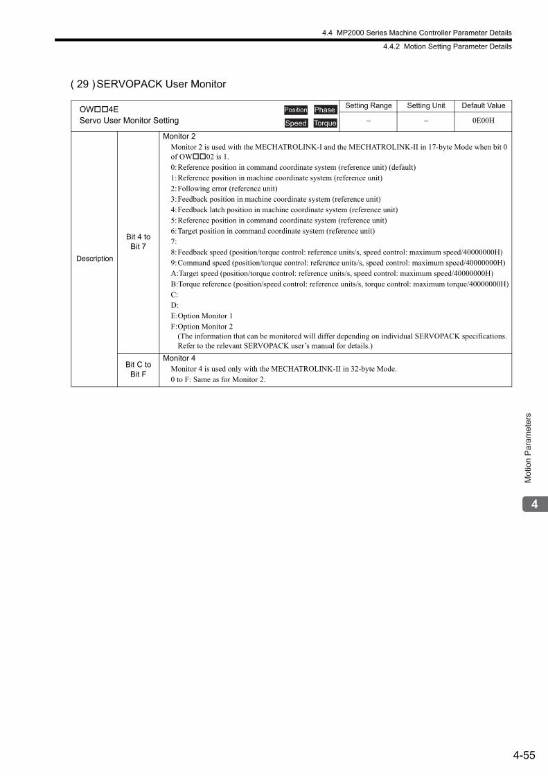
4.4 MP2000 Series Machine Controller Parameter Details
4.4.2 Motion Setting Parameter Details
4-55
Mot
ion
Par
amet
ers
( 29 )SERVOPACK User Monitor
OW4EServo User Monitor Setting
Setting Range Setting Unit Default Value
− − 0E00H
Description
Bit 4 to Bit 7
Monitor 2Monitor 2 is used with the MECHATROLINK-I and the MECHATROLINK-II in 17-byte Mode when bit 0 of OW02 is 1.0:Reference position in command coordinate system (reference unit) (default)1:Reference position in machine coordinate system (reference unit)2:Following error (reference unit)3:Feedback position in machine coordinate system (reference unit)4:Feedback latch position in machine coordinate system (reference unit)5:Reference position in command coordinate system (reference unit)6:Target position in command coordinate system (reference unit)7:8:Feedback speed (position/torque control: reference units/s, speed control: maximum speed/40000000H)9:Command speed (position/torque control: reference units/s, speed control: maximum speed/40000000H)A:Target speed (position/torque control: reference units/s, speed control: maximum speed/40000000H)B:Torque reference (position/speed control: reference units/s, torque control: maximum torque/40000000H)C: D: E:Option Monitor 1F:Option Monitor 2
(The information that can be monitored will differ depending on individual SERVOPACK specifications.Refer to the relevant SERVOPACK user’s manual for details.)
Bit C to Bit F
Monitor 4Monitor 4 is used only with the MECHATROLINK-II in 32-byte Mode.0 to F: Same as for Monitor 2.
Position Phase
Speed Torque
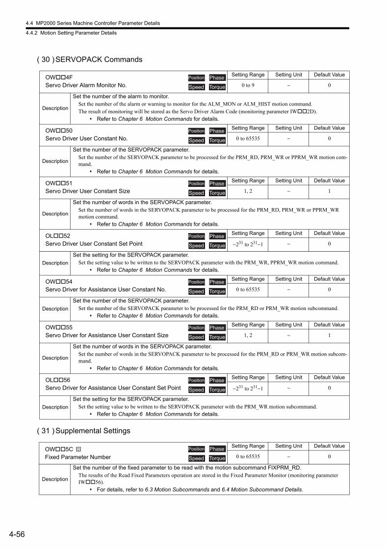
4.4 MP2000 Series Machine Controller Parameter Details
4.4.2 Motion Setting Parameter Details
4-56
( 30 )SERVOPACK Commands
( 31 )Supplemental Settings
OW4FServo Driver Alarm Monitor No.
Setting Range Setting Unit Default Value
0 to 9 − 0
Description
Set the number of the alarm to monitor.Set the number of the alarm or warning to monitor for the ALM_MON or ALM_HIST motion command.The result of monitoring will be stored as the Servo Driver Alarm Code (monitoring parameter IW2D).
Refer to Chapter 6 Motion Commands for details.
OW50Servo Driver User Constant No.
Setting Range Setting Unit Default Value
0 to 65535 − 0
Description
Set the number of the SERVOPACK parameter.Set the number of the SERVOPACK parameter to be processed for the PRM_RD, PRM_WR or PPRM_WR motion com-mand.
Refer to Chapter 6 Motion Commands for details.
OW51Servo Driver User Constant Size
Setting Range Setting Unit Default Value
1, 2 − 1
Description
Set the number of words in the SERVOPACK parameter.Set the number of words in the SERVOPACK parameter to be processed for the PRM_RD, PRM_WR or PPRM_WR motion command.
Refer to Chapter 6 Motion Commands for details.
OL52Servo Driver User Constant Set Point
Setting Range Setting Unit Default Value
−231 to 231−1 − 0
Description
Set the setting for the SERVOPACK parameter.Set the setting value to be written to the SERVOPACK parameter with the PRM_WR, PPRM_WR motion command.
Refer to Chapter 6 Motion Commands for details.
OW54Servo Driver for Assistance User Constant No.
Setting Range Setting Unit Default Value
0 to 65535 − 0
Description
Set the number of the SERVOPACK parameter.Set the number of the SERVOPACK parameter to be processed for the PRM_RD or PRM_WR motion subcommand.
Refer to Chapter 6 Motion Commands for details.
OW55Servo Driver for Assistance User Constant Size
Setting Range Setting Unit Default Value
1, 2 − 1
Description
Set the number of words in the SERVOPACK parameter.Set the number of words in the SERVOPACK parameter to be processed for the PRM_RD or PRM_WR motion subcom-mand.
Refer to Chapter 6 Motion Commands for details.
OL56Servo Driver for Assistance User Constant Set Point
Setting Range Setting Unit Default Value
−231 to 231−1 − 0
Description
Set the setting for the SERVOPACK parameter.Set the setting value to be written to the SERVOPACK parameter with the PRM_WR motion subcommand.
Refer to Chapter 6 Motion Commands for details.
OW5CFixed Parameter Number
Setting Range Setting Unit Default Value
0 to 65535 − 0
Description
Set the number of the fixed parameter to be read with the motion subcommand FIXPRM_RD.The results of the Read Fixed Parameters operation are stored in the Fixed Parameter Monitor (monitoring parameter IW56).
For details, refer to 6.3 Motion Subcommands and 6.4 Motion Subcommand Details.
Position Phase
Speed Torque
Position Phase
Speed Torque
Position Phase
Speed Torque
Position Phase
Speed Torque
Position Phase
Speed Torque
Position Phase
Speed Torque
Position Phase
Speed Torque
R Position Phase
Speed Torque
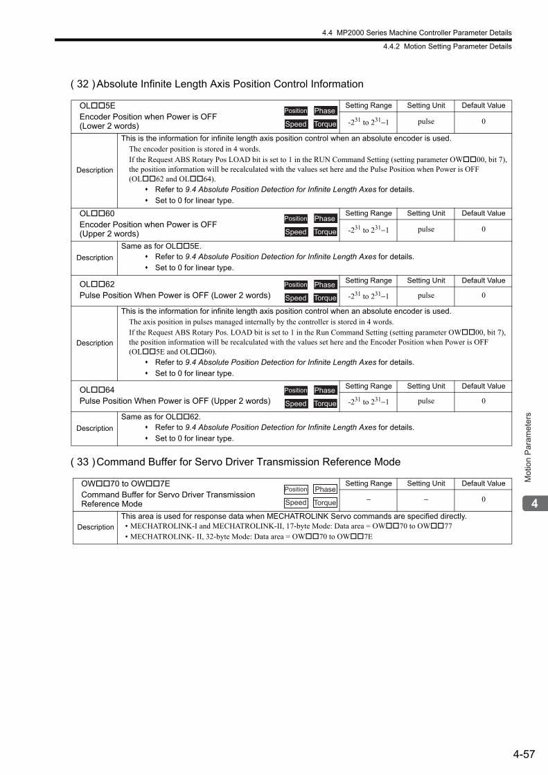
4.4 MP2000 Series Machine Controller Parameter Details
4.4.2 Motion Setting Parameter Details
4-57
Mot
ion
Par
amet
ers
( 32 )Absolute Infinite Length Axis Position Control Information
( 33 )Command Buffer for Servo Driver Transmission Reference Mode
OL5EEncoder Position when Power is OFF (Lower 2 words)
Setting Range Setting Unit Default Value
-231 to 231−1 pulse 0
Description
This is the information for infinite length axis position control when an absolute encoder is used.The encoder position is stored in 4 words.If the Request ABS Rotary Pos LOAD bit is set to 1 in the RUN Command Setting (setting parameter OW00, bit 7), the position information will be recalculated with the values set here and the Pulse Position when Power is OFF (OL62 and OL64).
Refer to 9.4 Absolute Position Detection for Infinite Length Axes for details.
Set to 0 for linear type.
OL60Encoder Position when Power is OFF (Upper 2 words)
Setting Range Setting Unit Default Value
-231 to 231−1 pulse 0
Description
Same as for OL5E. Refer to 9.4 Absolute Position Detection for Infinite Length Axes for details.
Set to 0 for linear type.
OL62Pulse Position When Power is OFF (Lower 2 words)
Setting Range Setting Unit Default Value
-231 to 231−1 pulse 0
Description
This is the information for infinite length axis position control when an absolute encoder is used.The axis position in pulses managed internally by the controller is stored in 4 words.If the Request ABS Rotary Pos. LOAD bit is set to 1 in the Run Command Setting (setting parameter OW00, bit 7), the position information will be recalculated with the values set here and the Encoder Position when Power is OFF (OL5E and OL60).
Refer to 9.4 Absolute Position Detection for Infinite Length Axes for details.
Set to 0 for linear type.
OL64Pulse Position When Power is OFF (Upper 2 words)
Setting Range Setting Unit Default Value
-231 to 231−1 pulse 0
Description
Same as for OL62. Refer to 9.4 Absolute Position Detection for Infinite Length Axes for details.
Set to 0 for linear type.
OW70 to OW7ECommand Buffer for Servo Driver Transmission Reference Mode
Setting Range Setting Unit Default Value
− − 0
Description
This area is used for response data when MECHATROLINK Servo commands are specified directly.• MECHATROLINK-I and MECHATROLINK-II, 17-byte Mode: Data area = OW70 to OW77• MECHATROLINK- II, 32-byte Mode: Data area = OW70 to OW7E
Position Phase
Speed Torque
Position Phase
Speed Torque
Position Phase
Speed Torque
Position Phase
Speed Torque
Position Phase
Speed Torque
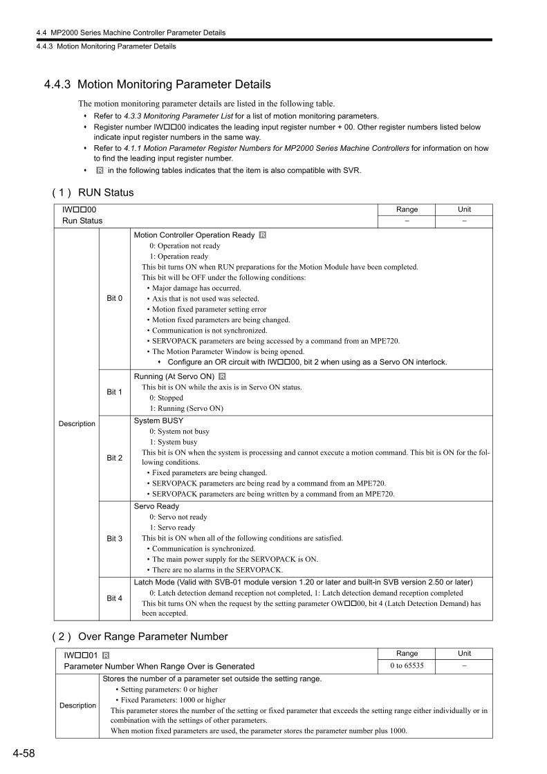
4.4 MP2000 Series Machine Controller Parameter Details
4.4.3 Motion Monitoring Parameter Details
4-58
4.4.3 Motion Monitoring Parameter Details
The motion monitoring parameter details are listed in the following table.
Refer to 4.3.3 Monitoring Parameter List for a list of motion monitoring parameters.
Register number IW00 indicates the leading input register number + 00. Other register numbers listed below indicate input register numbers in the same way.
Refer to 4.1.1 Motion Parameter Register Numbers for MP2000 Series Machine Controllers for information on how to find the leading input register number.
in the following tables indicates that the item is also compatible with SVR.
( 1 ) RUN Status
( 2 ) Over Range Parameter Number
R
IW00Run Status
Range Unit
− −
Description
Bit 0
Motion Controller Operation Ready0: Operation not ready1: Operation ready
This bit turns ON when RUN preparations for the Motion Module have been completed.This bit will be OFF under the following conditions:
• Major damage has occurred.• Axis that is not used was selected.• Motion fixed parameter setting error• Motion fixed parameters are being changed.• Communication is not synchronized.• SERVOPACK parameters are being accessed by a command from an MPE720.• The Motion Parameter Window is being opened. Configure an OR circuit with IW00, bit 2 when using as a Servo ON interlock.
Bit 1
Running (At Servo ON)This bit is ON while the axis is in Servo ON status.
0: Stopped1: Running (Servo ON)
Bit 2
System BUSY0: System not busy1: System busy
This bit is ON when the system is processing and cannot execute a motion command. This bit is ON for the fol-lowing conditions.
• Fixed parameters are being changed.• SERVOPACK parameters are being read by a command from an MPE720.• SERVOPACK parameters are being written by a command from an MPE720.
Bit 3
Servo Ready0: Servo not ready1: Servo ready
This bit is ON when all of the following conditions are satisfied.• Communication is synchronized.• The main power supply for the SERVOPACK is ON.• There are no alarms in the SERVOPACK.
Bit 4
Latch Mode (Valid with SVB-01 module version 1.20 or later and built-in SVB version 2.50 or later)0: Latch detection demand reception not completed, 1: Latch detection demand reception completed
This bit turns ON when the request by the setting parameter OW00, bit 4 (Latch Detection Demand) has been accepted.
IW01Parameter Number When Range Over is Generated
Range Unit
0 to 65535 −
Description
Stores the number of a parameter set outside the setting range.• Setting parameters: 0 or higher • Fixed Parameters: 1000 or higher
This parameter stores the number of the setting or fixed parameter that exceeds the setting range either individually or in combination with the settings of other parameters.When motion fixed parameters are used, the parameter stores the parameter number plus 1000.
R
R
R
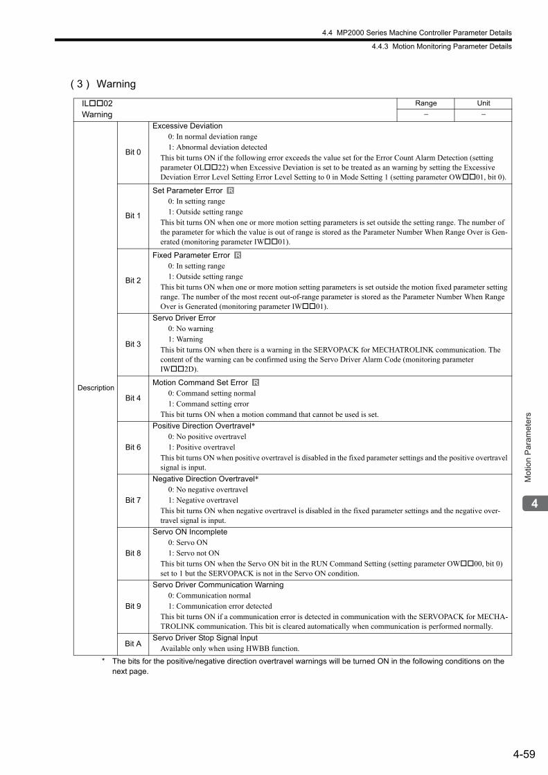
4.4 MP2000 Series Machine Controller Parameter Details
4.4.3 Motion Monitoring Parameter Details
4-59
Mot
ion
Par
amet
ers
( 3 ) Warning
* The bits for the positive/negative direction overtravel warnings will be turned ON in the following conditions on the next page.
IL02Warning
Range Unit
− −
Description
Bit 0
Excessive Deviation0: In normal deviation range1: Abnormal deviation detected
This bit turns ON if the following error exceeds the value set for the Error Count Alarm Detection (setting parameter OL22) when Excessive Deviation is set to be treated as an warning by setting the Excessive Deviation Error Level Setting Error Level Setting to 0 in Mode Setting 1 (setting parameter OW01, bit 0).
Bit 1
Set Parameter Error0: In setting range1: Outside setting range
This bit turns ON when one or more motion setting parameters is set outside the setting range. The number of the parameter for which the value is out of range is stored as the Parameter Number When Range Over is Gen-erated (monitoring parameter IW01).
Bit 2
Fixed Parameter Error0: In setting range1: Outside setting range
This bit turns ON when one or more motion setting parameters is set outside the motion fixed parameter setting range. The number of the most recent out-of-range parameter is stored as the Parameter Number When Range Over is Generated (monitoring parameter IW01).
Bit 3
Servo Driver Error0: No warning1: Warning
This bit turns ON when there is a warning in the SERVOPACK for MECHATROLINK communication. The content of the warning can be confirmed using the Servo Driver Alarm Code (monitoring parameter IW2D).
Bit 4
Motion Command Set Error0: Command setting normal1: Command setting error
This bit turns ON when a motion command that cannot be used is set.
Bit 6
Positive Direction Overtravel*0: No positive overtravel1: Positive overtravel
This bit turns ON when positive overtravel is disabled in the fixed parameter settings and the positive overtravel signal is input.
Bit 7
Negative Direction Overtravel*0: No negative overtravel1: Negative overtravel
This bit turns ON when negative overtravel is disabled in the fixed parameter settings and the negative over-travel signal is input.
Bit 8
Servo ON Incomplete0: Servo ON1: Servo not ON
This bit turns ON when the Servo ON bit in the RUN Command Setting (setting parameter OW00, bit 0) set to 1 but the SERVOPACK is not in the Servo ON condition.
Bit 9
Servo Driver Communication Warning0: Communication normal1: Communication error detected
This bit turns ON if a communication error is detected in communication with the SERVOPACK for MECHA-TROLINK communication. This bit is cleared automatically when communication is performed normally.
Bit AServo Driver Stop Signal Input
Available only when using HWBB function.
R
R
R
4.4 MP2000 Series Machine Controller Parameter Details
4.4.3 Motion Monitoring Parameter Details
4-60
• For an SGDV or SGD7S SERVOPACK, the following servo parameter settings must be used.The setting of Pn50A is equal to that of H2881 (A P-OT warning is activated when Cn1-8 is low).The setting of Pn50B is equal to that of H8881 (A N-OT warning is activated when Cn1-7 is low).
• The fixed parameters of the MP2300 machine controller use the following settings.Fixed parameter No.1: Bit 3 is set to 0 (disabled).
Bit 4 is set to 0 (disabled).
The bits for the positive/negative direction overtravel warnings will be turned ON in the following order.
1. The servomotor power is ON.
2. A motion command, such as one for positioning or constant feed, is executed.
3. The servomotor moves in the forward (P-OT) or reverse (N-OT) direction.
4. A SERVOPACK P-OT or N-OT signal is input.
Stop Signal Input Warning for SGDV and SGD7S SERVOPACKs
When an HWBB signal (stop signal) is input, bit A of IL02 is turned ON, and a warning is issued.The warning (Servo Driver Stop Signal Input) indicates that the SERVOPACK is being stopped forcibly.This warning is cleared automatically when the HWBB signal turns OFF.The status of the HWBB signal can be checked with the stop signal (HWBB) of the Servo Driver I/O Monitor.
• Monitoring Parameters
When an HWBB signal (stop signal) is sent, the SERVOPACK cannot be ON. Also, if an HWBB signal is sent when the SERVOPACK is running, the SERVOPACK is turned OFF.
• Servo ON and NOP mid-operation
When the SERVOPACK is ON and a No Operation (NOP) motion command is issued during operations, a warning is issued (IL02, bit 8 = 1). To clear the warning, turn the HWBB signal OFF, and set bit 0 of OW00 to 1.
• Axis Movement by the Motion Command
When axis movement results from a motion command being issued, and the following warnings or alarms will occur.
• Servo Driver Error (IL02, bit 3)
• Servo ON Incomplete (IL02, bit 8)
• Servo OFF (IL04, bit 5)
And then the following motion command will be executed: Command Error Completed Status (IW09, bit 3). To clear the error, turn the HWBB signal OFF and do the following procedures.
1. Change the motion command to NOP (OW08 = 0)
2. Servo OFF (OW00, bit 0 to 0)
3. Clear the alarm (OW00, bit F = 0 → 1 → 0)
4. Servo ON (OW00, bit 0 to 1)
Register No. Name Meaning
IL02 Warning Bit A: Servo Driver Stop Signal Input
IW2E Servo Driver I/O Monitor Bit A: Stop signal (HWBB)
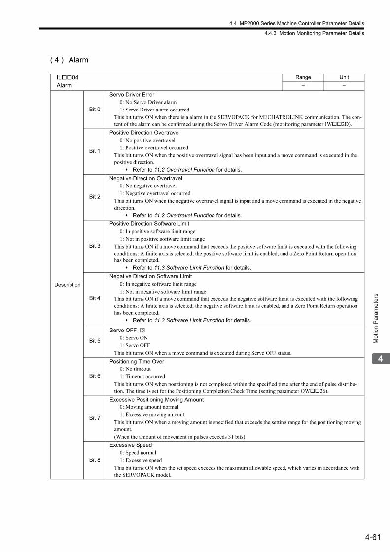
4.4 MP2000 Series Machine Controller Parameter Details
4.4.3 Motion Monitoring Parameter Details
4-61
Mot
ion
Par
amet
ers
( 4 ) Alarm
IL04Alarm
Range Unit
− −
Description
Bit 0
Servo Driver Error0: No Servo Driver alarm1: Servo Driver alarm occurred
This bit turns ON when there is a alarm in the SERVOPACK for MECHATROLINK communication. The con-tent of the alarm can be confirmed using the Servo Driver Alarm Code (monitoring parameter IW2D).
Bit 1
Positive Direction Overtravel0: No positive overtravel1: Positive overtravel occurred
This bit turns ON when the positive overtravel signal has been input and a move command is executed in the positive direction.
Refer to 11.2 Overtravel Function for details.
Bit 2
Negative Direction Overtravel0: No negative overtravel1: Negative overtravel occurred
This bit turns ON when the negative overtravel signal is input and a move command is executed in the negative direction.
Refer to 11.2 Overtravel Function for details.
Bit 3
Positive Direction Software Limit0: In positive software limit range1: Not in positive software limit range
This bit turns ON if a move command that exceeds the positive software limit is executed with the following conditions: A finite axis is selected, the positive software limit is enabled, and a Zero Point Return operation has been completed.
Refer to 11.3 Software Limit Function for details.
Bit 4
Negative Direction Software Limit0: In negative software limit range1: Not in negative software limit range
This bit turns ON if a move command that exceeds the negative software limit is executed with the following conditions: A finite axis is selected, the negative software limit is enabled, and a Zero Point Return operation has been completed.
Refer to 11.3 Software Limit Function for details.
Bit 5
Servo OFF0: Servo ON1: Servo OFF
This bit turns ON when a move command is executed during Servo OFF status.
Bit 6
Positioning Time Over0: No timeout1: Timeout occurred
This bit turns ON when positioning is not completed within the specified time after the end of pulse distribu-tion. The time is set for the Positioning Completion Check Time (setting parameter OW26).
Bit 7
Excessive Positioning Moving Amount0: Moving amount normal1: Excessive moving amount
This bit turns ON when a moving amount is specified that exceeds the setting range for the positioning moving amount. (When the amount of movement in pulses exceeds 31 bits)
Bit 8
Excessive Speed0: Speed normal1: Excessive speed
This bit turns ON when the set speed exceeds the maximum allowable speed, which varies in accordance with the SERVOPACK model.
R
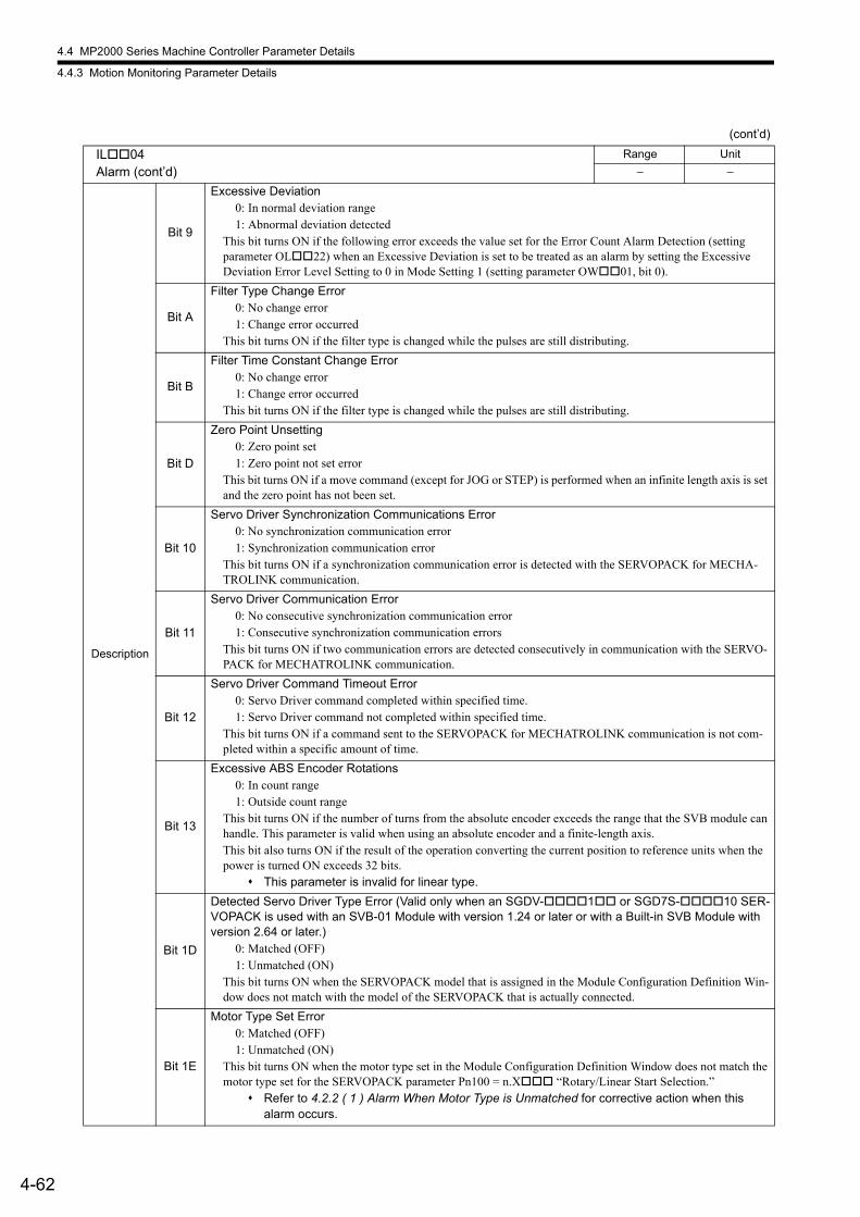
4.4 MP2000 Series Machine Controller Parameter Details
4.4.3 Motion Monitoring Parameter Details
4-62
Description
Bit 9
Excessive Deviation0: In normal deviation range1: Abnormal deviation detected
This bit turns ON if the following error exceeds the value set for the Error Count Alarm Detection (setting parameter OL22) when an Excessive Deviation is set to be treated as an alarm by setting the Excessive Deviation Error Level Setting to 0 in Mode Setting 1 (setting parameter OW01, bit 0).
Bit A
Filter Type Change Error0: No change error1: Change error occurred
This bit turns ON if the filter type is changed while the pulses are still distributing.
Bit B
Filter Time Constant Change Error0: No change error1: Change error occurred
This bit turns ON if the filter type is changed while the pulses are still distributing.
Bit D
Zero Point Unsetting0: Zero point set1: Zero point not set error
This bit turns ON if a move command (except for JOG or STEP) is performed when an infinite length axis is set and the zero point has not been set.
Bit 10
Servo Driver Synchronization Communications Error0: No synchronization communication error1: Synchronization communication error
This bit turns ON if a synchronization communication error is detected with the SERVOPACK for MECHA-TROLINK communication.
Bit 11
Servo Driver Communication Error0: No consecutive synchronization communication error1: Consecutive synchronization communication errors
This bit turns ON if two communication errors are detected consecutively in communication with the SERVO-PACK for MECHATROLINK communication.
Bit 12
Servo Driver Command Timeout Error0: Servo Driver command completed within specified time.1: Servo Driver command not completed within specified time.
This bit turns ON if a command sent to the SERVOPACK for MECHATROLINK communication is not com-pleted within a specific amount of time.
Bit 13
Excessive ABS Encoder Rotations0: In count range1: Outside count range
This bit turns ON if the number of turns from the absolute encoder exceeds the range that the SVB module can handle. This parameter is valid when using an absolute encoder and a finite-length axis.This bit also turns ON if the result of the operation converting the current position to reference units when the power is turned ON exceeds 32 bits.
This parameter is invalid for linear type.
Bit 1D
Detected Servo Driver Type Error (Valid only when an SGDV-1 or SGD7S-10 SER-VOPACK is used with an SVB-01 Module with version 1.24 or later or with a Built-in SVB Module with version 2.64 or later.)
0: Matched (OFF)1: Unmatched (ON)
This bit turns ON when the SERVOPACK model that is assigned in the Module Configuration Definition Win-dow does not match with the model of the SERVOPACK that is actually connected.
Bit 1E
Motor Type Set Error0: Matched (OFF)1: Unmatched (ON)
This bit turns ON when the motor type set in the Module Configuration Definition Window does not match the motor type set for the SERVOPACK parameter Pn100 = n.X “Rotary/Linear Start Selection.”
Refer to 4.2.2 ( 1 ) Alarm When Motor Type is Unmatched for corrective action when this alarm occurs.
(cont’d)
IL04Alarm (cont’d)
Range Unit
− −
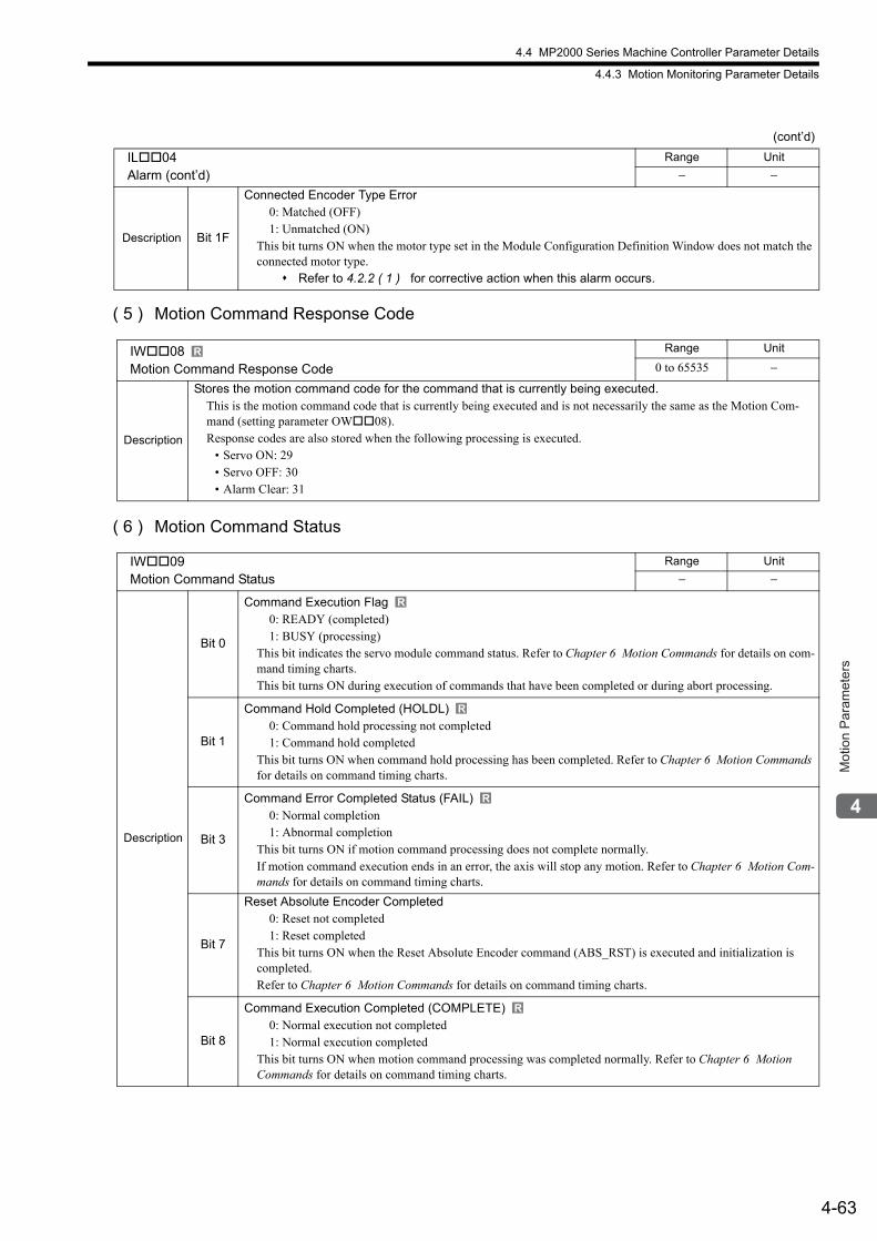
4.4 MP2000 Series Machine Controller Parameter Details
4.4.3 Motion Monitoring Parameter Details
4-63
Mot
ion
Par
amet
ers
( 5 ) Motion Command Response Code
( 6 ) Motion Command Status
Description Bit 1F
Connected Encoder Type Error0: Matched (OFF)1: Unmatched (ON)
This bit turns ON when the motor type set in the Module Configuration Definition Window does not match the connected motor type.
Refer to 4.2.2 ( 1 ) for corrective action when this alarm occurs.
IW08Motion Command Response Code
Range Unit
0 to 65535 −
Description
Stores the motion command code for the command that is currently being executed.This is the motion command code that is currently being executed and is not necessarily the same as the Motion Com-mand (setting parameter OW08).Response codes are also stored when the following processing is executed.
• Servo ON: 29• Servo OFF: 30• Alarm Clear: 31
IW09Motion Command Status
Range Unit
− −
Description
Bit 0
Command Execution Flag0: READY (completed)1: BUSY (processing)
This bit indicates the servo module command status. Refer to Chapter 6 Motion Commands for details on com-mand timing charts.This bit turns ON during execution of commands that have been completed or during abort processing.
Bit 1
Command Hold Completed (HOLDL)0: Command hold processing not completed1: Command hold completed
This bit turns ON when command hold processing has been completed. Refer to Chapter 6 Motion Commands for details on command timing charts.
Bit 3
Command Error Completed Status (FAIL)0: Normal completion1: Abnormal completion
This bit turns ON if motion command processing does not complete normally.If motion command execution ends in an error, the axis will stop any motion. Refer to Chapter 6 Motion Com-mands for details on command timing charts.
Bit 7
Reset Absolute Encoder Completed0: Reset not completed1: Reset completed
This bit turns ON when the Reset Absolute Encoder command (ABS_RST) is executed and initialization is completed.Refer to Chapter 6 Motion Commands for details on command timing charts.
Bit 8
Command Execution Completed (COMPLETE)0: Normal execution not completed1: Normal execution completed
This bit turns ON when motion command processing was completed normally. Refer to Chapter 6 Motion Commands for details on command timing charts.
(cont’d)
IL04Alarm (cont’d)
Range Unit
− −
R
R
R
R
R
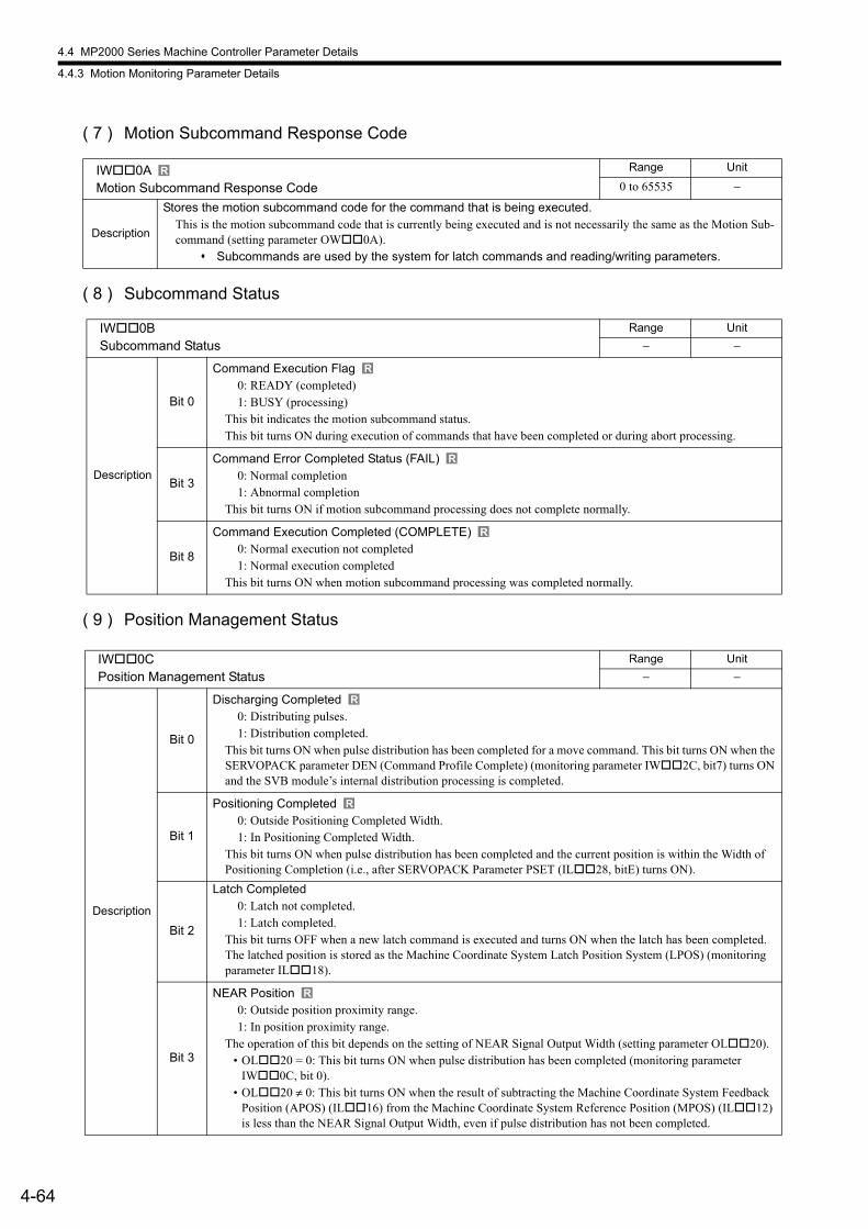
4.4 MP2000 Series Machine Controller Parameter Details
4.4.3 Motion Monitoring Parameter Details
4-64
( 7 ) Motion Subcommand Response Code
( 8 ) Subcommand Status
( 9 ) Position Management Status
IW0AMotion Subcommand Response Code
Range Unit
0 to 65535 −
Description
Stores the motion subcommand code for the command that is being executed.This is the motion subcommand code that is currently being executed and is not necessarily the same as the Motion Sub-command (setting parameter OW0A).
Subcommands are used by the system for latch commands and reading/writing parameters.
IW0BSubcommand Status
Range Unit
− −
Description
Bit 0
Command Execution Flag0: READY (completed)1: BUSY (processing)
This bit indicates the motion subcommand status.This bit turns ON during execution of commands that have been completed or during abort processing.
Bit 3
Command Error Completed Status (FAIL)0: Normal completion1: Abnormal completion
This bit turns ON if motion subcommand processing does not complete normally.
Bit 8
Command Execution Completed (COMPLETE)0: Normal execution not completed1: Normal execution completed
This bit turns ON when motion subcommand processing was completed normally.
IW0CPosition Management Status
Range Unit
− −
Description
Bit 0
Discharging Completed0: Distributing pulses.1: Distribution completed.
This bit turns ON when pulse distribution has been completed for a move command. This bit turns ON when the SERVOPACK parameter DEN (Command Profile Complete) (monitoring parameter IW2C, bit7) turns ON and the SVB module’s internal distribution processing is completed.
Bit 1
Positioning Completed0: Outside Positioning Completed Width.1: In Positioning Completed Width.
This bit turns ON when pulse distribution has been completed and the current position is within the Width of Positioning Completion (i.e., after SERVOPACK Parameter PSET (IL28, bitE) turns ON).
Bit 2
Latch Completed0: Latch not completed.1: Latch completed.
This bit turns OFF when a new latch command is executed and turns ON when the latch has been completed. The latched position is stored as the Machine Coordinate System Latch Position System (LPOS) (monitoring parameter IL18).
Bit 3
NEAR Position0: Outside position proximity range.1: In position proximity range.
The operation of this bit depends on the setting of NEAR Signal Output Width (setting parameter OL20).• OL20 = 0: This bit turns ON when pulse distribution has been completed (monitoring parameter
IW0C, bit 0).• OL20 ≠ 0: This bit turns ON when the result of subtracting the Machine Coordinate System Feedback
Position (APOS) (IL16) from the Machine Coordinate System Reference Position (MPOS) (IL12) is less than the NEAR Signal Output Width, even if pulse distribution has not been completed.
R
R
R
R
R
R
R
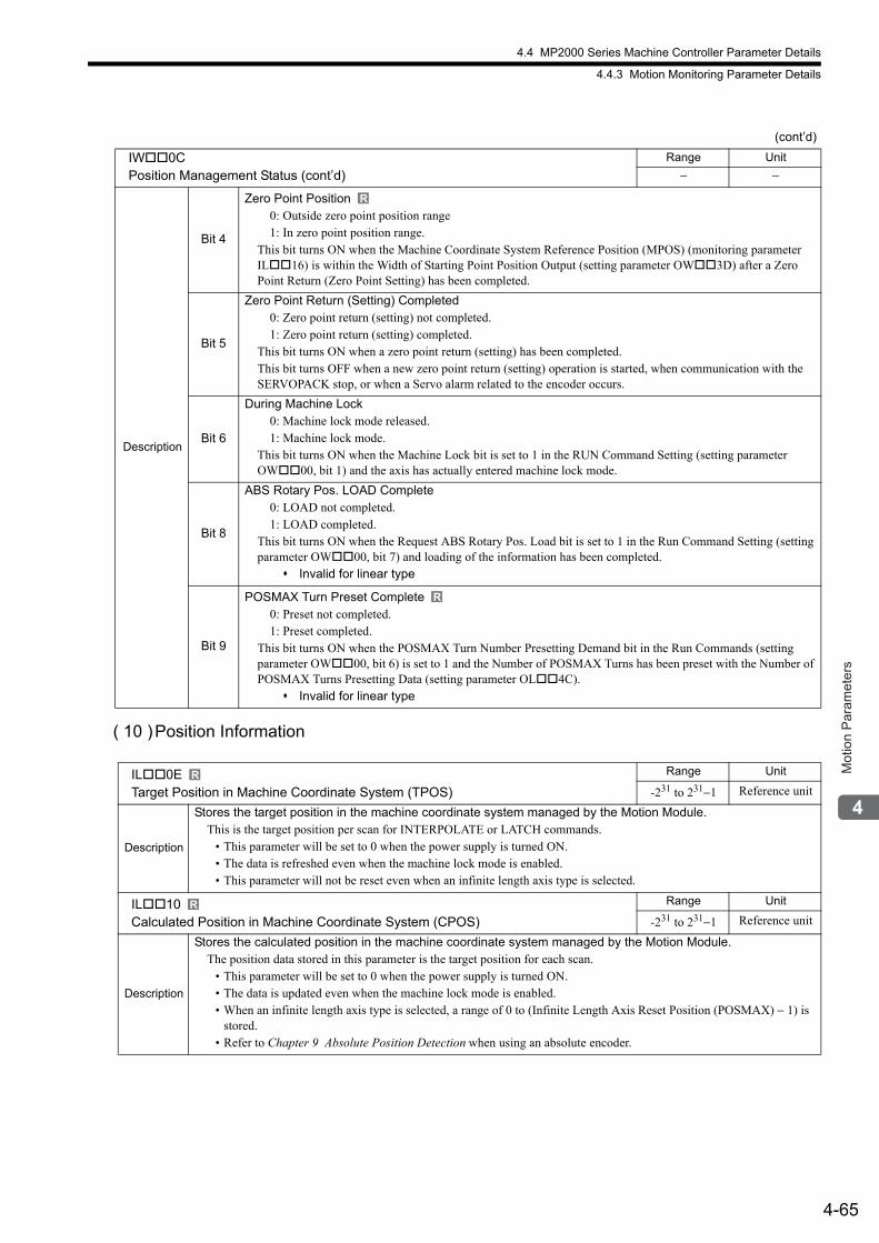
4.4 MP2000 Series Machine Controller Parameter Details
4.4.3 Motion Monitoring Parameter Details
4-65
Mot
ion
Par
amet
ers
( 10 )Position Information
Description
Bit 4
Zero Point Position0: Outside zero point position range1: In zero point position range.
This bit turns ON when the Machine Coordinate System Reference Position (MPOS) (monitoring parameter IL16) is within the Width of Starting Point Position Output (setting parameter OW3D) after a Zero Point Return (Zero Point Setting) has been completed.
Bit 5
Zero Point Return (Setting) Completed0: Zero point return (setting) not completed.1: Zero point return (setting) completed.
This bit turns ON when a zero point return (setting) has been completed.This bit turns OFF when a new zero point return (setting) operation is started, when communication with the SERVOPACK stop, or when a Servo alarm related to the encoder occurs.
Bit 6
During Machine Lock0: Machine lock mode released.1: Machine lock mode.
This bit turns ON when the Machine Lock bit is set to 1 in the RUN Command Setting (setting parameter OW00, bit 1) and the axis has actually entered machine lock mode.
Bit 8
ABS Rotary Pos. LOAD Complete0: LOAD not completed.1: LOAD completed.
This bit turns ON when the Request ABS Rotary Pos. Load bit is set to 1 in the Run Command Setting (setting parameter OW00, bit 7) and loading of the information has been completed.
Invalid for linear type
Bit 9
POSMAX Turn Preset Complete0: Preset not completed.1: Preset completed.
This bit turns ON when the POSMAX Turn Number Presetting Demand bit in the Run Commands (setting parameter OW00, bit 6) is set to 1 and the Number of POSMAX Turns has been preset with the Number of POSMAX Turns Presetting Data (setting parameter OL4C).
Invalid for linear type
IL0ETarget Position in Machine Coordinate System (TPOS)
Range Unit
-231 to 231−1 Reference unit
Description
Stores the target position in the machine coordinate system managed by the Motion Module.This is the target position per scan for INTERPOLATE or LATCH commands.
• This parameter will be set to 0 when the power supply is turned ON.• The data is refreshed even when the machine lock mode is enabled.• This parameter will not be reset even when an infinite length axis type is selected.
IL10Calculated Position in Machine Coordinate System (CPOS)
Range Unit
-231 to 231−1 Reference unit
Description
Stores the calculated position in the machine coordinate system managed by the Motion Module.The position data stored in this parameter is the target position for each scan.
• This parameter will be set to 0 when the power supply is turned ON.• The data is updated even when the machine lock mode is enabled.• When an infinite length axis type is selected, a range of 0 to (Infinite Length Axis Reset Position (POSMAX) − 1) is
stored.• Refer to Chapter 9 Absolute Position Detection when using an absolute encoder.
(cont’d)
IW0CPosition Management Status (cont’d)
Range Unit
− −
R
R
R
R
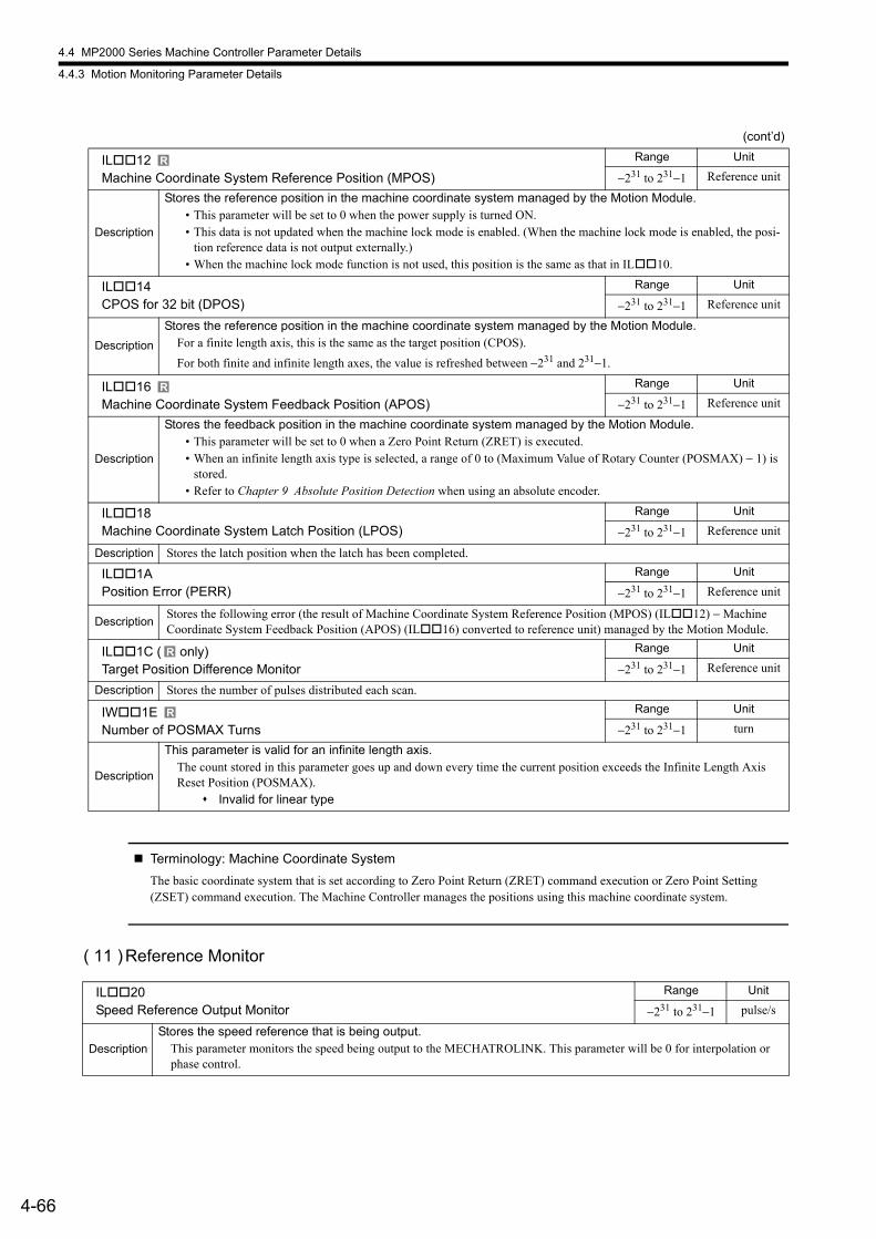
4.4 MP2000 Series Machine Controller Parameter Details
4.4.3 Motion Monitoring Parameter Details
4-66
Terminology: Machine Coordinate System
The basic coordinate system that is set according to Zero Point Return (ZRET) command execution or Zero Point Setting (ZSET) command execution. The Machine Controller manages the positions using this machine coordinate system.
( 11 )Reference Monitor
IL12Machine Coordinate System Reference Position (MPOS)
Range Unit
−231 to 231−1 Reference unit
Description
Stores the reference position in the machine coordinate system managed by the Motion Module.• This parameter will be set to 0 when the power supply is turned ON.• This data is not updated when the machine lock mode is enabled. (When the machine lock mode is enabled, the posi-
tion reference data is not output externally.)• When the machine lock mode function is not used, this position is the same as that in IL10.
IL14CPOS for 32 bit (DPOS)
Range Unit
−231 to 231−1 Reference unit
Description
Stores the reference position in the machine coordinate system managed by the Motion Module.For a finite length axis, this is the same as the target position (CPOS).
For both finite and infinite length axes, the value is refreshed between −231 and 231−1.
IL16Machine Coordinate System Feedback Position (APOS)
Range Unit
−231 to 231−1 Reference unit
Description
Stores the feedback position in the machine coordinate system managed by the Motion Module.• This parameter will be set to 0 when a Zero Point Return (ZRET) is executed.• When an infinite length axis type is selected, a range of 0 to (Maximum Value of Rotary Counter (POSMAX) − 1) is
stored.• Refer to Chapter 9 Absolute Position Detection when using an absolute encoder.
IL18Machine Coordinate System Latch Position (LPOS)
Range Unit
−231 to 231−1 Reference unit
Description Stores the latch position when the latch has been completed.
IL1APosition Error (PERR)
Range Unit
−231 to 231−1 Reference unit
DescriptionStores the following error (the result of Machine Coordinate System Reference Position (MPOS) (IL12) − Machine Coordinate System Feedback Position (APOS) (IL16) converted to reference unit) managed by the Motion Module.
IL1C ( only)Target Position Difference Monitor
Range Unit
−231 to 231−1 Reference unit
Description Stores the number of pulses distributed each scan.
IW1ENumber of POSMAX Turns
Range Unit
−231 to 231−1 turn
Description
This parameter is valid for an infinite length axis.The count stored in this parameter goes up and down every time the current position exceeds the Infinite Length Axis Reset Position (POSMAX).
Invalid for linear type
(cont’d)
R
R
R
R
IL20Speed Reference Output Monitor
Range Unit
−231 to 231−1 pulse/s
Description
Stores the speed reference that is being output.This parameter monitors the speed being output to the MECHATROLINK. This parameter will be 0 for interpolation or phase control.
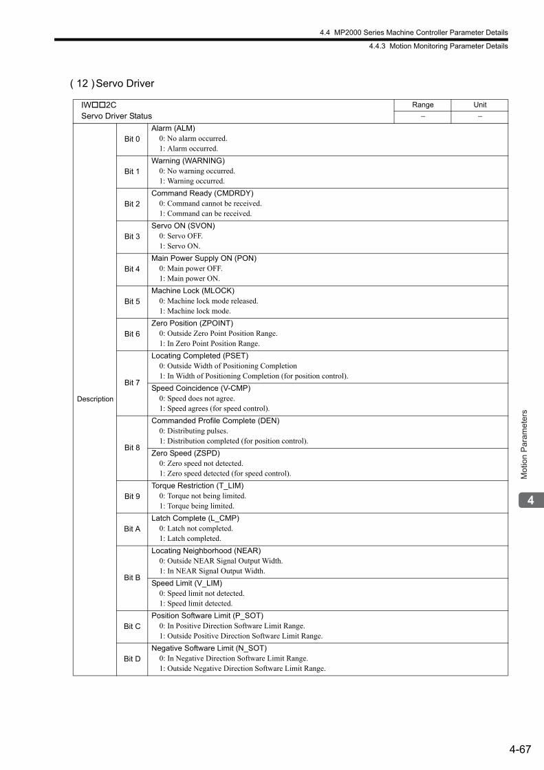
4.4 MP2000 Series Machine Controller Parameter Details
4.4.3 Motion Monitoring Parameter Details
4-67
Mot
ion
Par
amet
ers
( 12 )Servo Driver
IW2CServo Driver Status
Range Unit
− −
Description
Bit 0Alarm (ALM)
0: No alarm occurred.1: Alarm occurred.
Bit 1Warning (WARNING)
0: No warning occurred.1: Warning occurred.
Bit 2Command Ready (CMDRDY)
0: Command cannot be received.1: Command can be received.
Bit 3Servo ON (SVON)
0: Servo OFF.1: Servo ON.
Bit 4Main Power Supply ON (PON)
0: Main power OFF.1: Main power ON.
Bit 5Machine Lock (MLOCK)
0: Machine lock mode released.1: Machine lock mode.
Bit 6Zero Position (ZPOINT)
0: Outside Zero Point Position Range.1: In Zero Point Position Range.
Bit 7
Locating Completed (PSET)0: Outside Width of Positioning Completion1: In Width of Positioning Completion (for position control).
Speed Coincidence (V-CMP)0: Speed does not agree.1: Speed agrees (for speed control).
Bit 8
Commanded Profile Complete (DEN)0: Distributing pulses.1: Distribution completed (for position control).
Zero Speed (ZSPD)0: Zero speed not detected.1: Zero speed detected (for speed control).
Bit 9Torque Restriction (T_LIM)
0: Torque not being limited.1: Torque being limited.
Bit ALatch Complete (L_CMP)
0: Latch not completed.1: Latch completed.
Bit B
Locating Neighborhood (NEAR)0: Outside NEAR Signal Output Width.1: In NEAR Signal Output Width.
Speed Limit (V_LIM)0: Speed limit not detected.1: Speed limit detected.
Bit CPosition Software Limit (P_SOT)
0: In Positive Direction Software Limit Range.1: Outside Positive Direction Software Limit Range.
Bit DNegative Software Limit (N_SOT)
0: In Negative Direction Software Limit Range.1: Outside Negative Direction Software Limit Range.
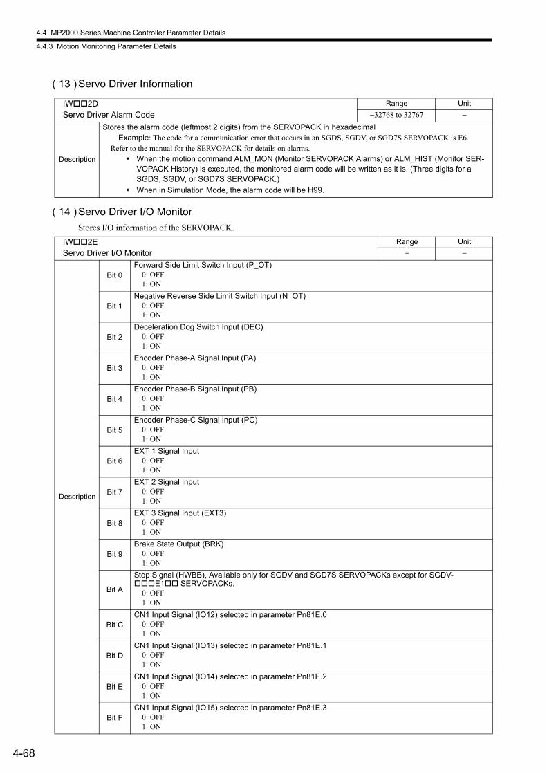
4.4 MP2000 Series Machine Controller Parameter Details
4.4.3 Motion Monitoring Parameter Details
4-68
( 13 )Servo Driver Information
( 14 )Servo Driver I/O Monitor
Stores I/O information of the SERVOPACK.
IW2DServo Driver Alarm Code
Range Unit
−32768 to 32767 −
Description
Stores the alarm code (leftmost 2 digits) from the SERVOPACK in hexadecimalExample: The code for a communication error that occurs in an SGDS, SGDV, or SGD7S SERVOPACK is E6.
Refer to the manual for the SERVOPACK for details on alarms. When the motion command ALM_MON (Monitor SERVOPACK Alarms) or ALM_HIST (Monitor SER-
VOPACK History) is executed, the monitored alarm code will be written as it is. (Three digits for a SGDS, SGDV, or SGD7S SERVOPACK.)
When in Simulation Mode, the alarm code will be H99.
IW2EServo Driver I/O Monitor
Range Unit
− −
Description
Bit 0Forward Side Limit Switch Input (P_OT)
0: OFF1: ON
Bit 1Negative Reverse Side Limit Switch Input (N_OT)
0: OFF1: ON
Bit 2Deceleration Dog Switch Input (DEC)
0: OFF1: ON
Bit 3Encoder Phase-A Signal Input (PA)
0: OFF1: ON
Bit 4Encoder Phase-B Signal Input (PB)
0: OFF1: ON
Bit 5Encoder Phase-C Signal Input (PC)
0: OFF1: ON
Bit 6EXT 1 Signal Input
0: OFF1: ON
Bit 7EXT 2 Signal Input
0: OFF1: ON
Bit 8EXT 3 Signal Input (EXT3)
0: OFF1: ON
Bit 9Brake State Output (BRK)
0: OFF1: ON
Bit A
Stop Signal (HWBB), Available only for SGDV and SGD7S SERVOPACKs except for SGDV-E1 SERVOPACKs.
0: OFF1: ON
Bit CCN1 Input Signal (IO12) selected in parameter Pn81E.0
0: OFF1: ON
Bit DCN1 Input Signal (IO13) selected in parameter Pn81E.1
0: OFF1: ON
Bit ECN1 Input Signal (IO14) selected in parameter Pn81E.2
0: OFF1: ON
Bit FCN1 Input Signal (IO15) selected in parameter Pn81E.3
0: OFF1: ON
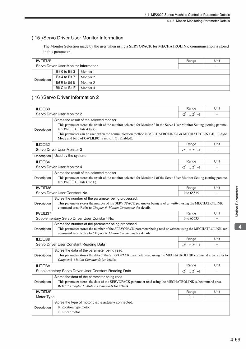
4.4 MP2000 Series Machine Controller Parameter Details
4.4.3 Motion Monitoring Parameter Details
4-69
Mot
ion
Par
amet
ers
( 15 )Servo Driver User Monitor Information
The Monitor Selection made by the user when using a SERVOPACK for MECHATROLINK communication is stored in this parameter.
( 16 )Servo Driver Information 2
IW2FServo Driver User Monitor Information
Range Unit
− −
Description
Bit 0 to Bit 3 Monitor 1
Bit 4 to Bit 7 Monitor 2
Bit 8 to Bit B Monitor 3
Bit C to Bit F Monitor 4
IL30Servo Driver User Monitor 2
Range Unit
-231 to 231−1 −
Description
Stores the result of the selected monitor.This parameter stores the result of the monitor selected for Monitor 2 in the Servo User Monitor Setting (setting parame-ter OW4E, bits 4 to 7).This parameter can be used when the communication method is MECHATROLINK-I or MECHATROLINK-II, 17-byte Mode and bit 0 of OW02 is set to 1 (1: Enabled).
IL32Servo Driver User Monitor 3
Range Unit
-231 to 231−1 −
Description Used by the system.
IL34Servo Driver User Monitor 4
Range Unit
-231 to 231−1 −
Description
Stores the result of the selected monitor.This parameter stores the result of the monitor selected for Monitor 4 of the Servo User Monitor Setting (setting parame-ter OW4E, bits C to F).
IW36Servo Driver User Constant No.
Range Unit
0 to 65535 −
Description
Stores the number of the parameter being processed.This parameter stores the number of the SERVOPACK parameter being read or written using the MECHATROLINK command area. Refer to Chapter 6 Motion Commands for details.
IW37Supplementary Servo Driver User Constant No.
Range Unit
0 to 65535 −
Description
Stores the number of the parameter being processed.This parameter stores the number of the SERVOPACK parameter being read or written using the MECHATROLINK sub-command area. Refer to Chapter 6 Motion Commands for details.
IL38Servo Driver User Constant Reading Data
Range Unit
-231 to 231−1 −
Description
Stores the data of the parameter being read.This parameter stores the data of the SERVOPACK parameter read using the MECHATROLINK command area. Refer to Chapter 6 Motion Commands for details.
IL3ASupplementary Servo Driver User Constant Reading Data
Range Unit
-231 to 231−1 −
Description
Stores the data of the parameter being read.This parameter stores the data of the SERVOPACK parameter read using the MECHATROLINK subcommand area. Refer to Chapter 6 Motion Commands for details.
IW3FMotor Type
Range Unit
0, 1 −
Description
Stores the type of motor that is actually connected.0: Rotation type motor1: Linear motor
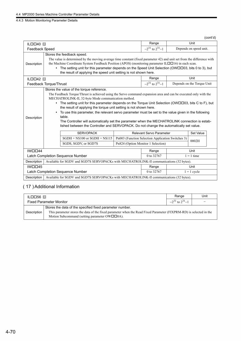
4.4 MP2000 Series Machine Controller Parameter Details
4.4.3 Motion Monitoring Parameter Details
4-70
( 17 )Additional Information
IL40Feedback Speed
Range Unit
−231 to 231−1 Depends on speed unit.
Description
Stores the feedback speed.The value is determined by the moving average time constant (fixed parameter 42) and unit set from the difference with the Machine Coordinate System Feedback Position (APOS) (monitoring parameter IL16) in each scan.
The setting unit for this parameter depends on the Speed Unit Selection (OW03, bits 0 to 3), but the result of applying the speed unit setting is not shown here.
IL42Feedback Torque/Thrust
Range Unit
−231 to 231−1 Depends on the Torque Unit
Description
Stores the value of the torque reference.The Feedback Torque/Thrust is achieved using the Servo command expansion area and can be executed only with the MECHATROLINK-II, 32-byte Mode communication method.
The setting unit for this parameter depends on the Torque Unit Selection (OW03, bits C to F), but the result of applying the torque unit setting is not shown here.
To use this parameter, the relevant servo parameter must be set to the value given in the following table.The Controller will automatically set the parameter when the MECHATROLINK connection is estab-lished between the Controller and SERVOPACK. Do not change the automatically set value.
IW44Latch Completion Sequence Number
Range Unit
0 to 32767 1 = 1 time
Description Available for SGDV and SGD7S SERVOPACKs with MECHATROLINK-II communications (32 bytes).
IW45Latch Completion Sequence Number
Range Unit
0 to 32767 1 = 1 cycle
Description Available for SGDV and SGD7S SERVOPACKs with MECHATROLINK-II communications (32 bytes).
IL56Fixed Parameter Monitor
Range Unit
−231 to 231−1 −
Description
Stores the data of the specified fixed parameter number.This parameter stores the data of the fixed parameter when the Read Fixed Parameter (FIXPRM-RD) is selected in the Motion Subcommand (setting parameter OW0A).
(cont’d)
R
R
SERVOPACK Relevant Servo Parameter Set Value
SGDH + NS100 or SGDH + NS115 Pn003 (Function Selection Application Switches 3)0002H
SGDS, SGDV, or SGD7S Pn824 (Option Monitor 1 Selection)
R
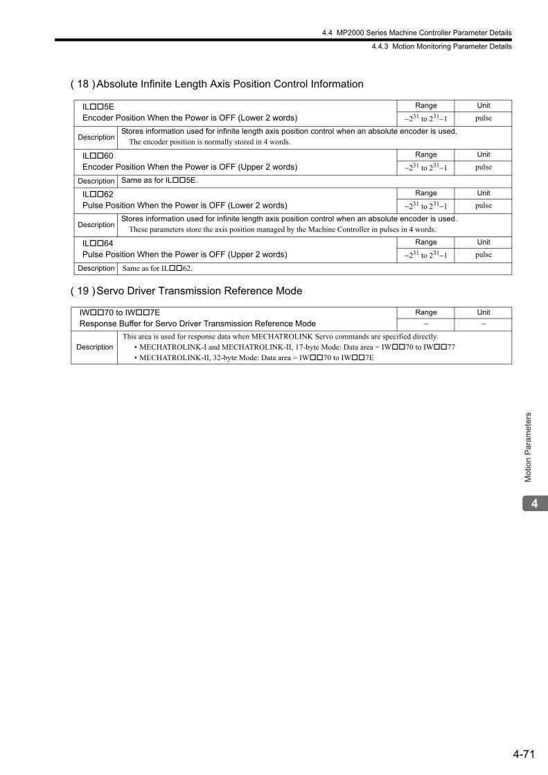
4.4 MP2000 Series Machine Controller Parameter Details
4.4.3 Motion Monitoring Parameter Details
4-71
Mot
ion
Par
amet
ers
( 18 )Absolute Infinite Length Axis Position Control Information
( 19 )Servo Driver Transmission Reference Mode
IL5EEncoder Position When the Power is OFF (Lower 2 words)
Range Unit
−231 to 231−1 pulse
DescriptionStores information used for infinite length axis position control when an absolute encoder is used.
The encoder position is normally stored in 4 words.
IL60Encoder Position When the Power is OFF (Upper 2 words)
Range Unit
−231 to 231−1 pulse
Description Same as for IL5E.
IL62Pulse Position When the Power is OFF (Lower 2 words)
Range Unit
−231 to 231−1 pulse
DescriptionStores information used for infinite length axis position control when an absolute encoder is used.
These parameters store the axis position managed by the Machine Controller in pulses in 4 words.
IL64Pulse Position When the Power is OFF (Upper 2 words)
Range Unit
−231 to 231−1 pulse
Description Same as for IL62.
IW70 to IW7EResponse Buffer for Servo Driver Transmission Reference Mode
Range Unit
− −
Description
This area is used for response data when MECHATROLINK Servo commands are specified directly.• MECHATROLINK-I and MECHATROLINK-II, 17-byte Mode: Data area = IW70 to IW77• MECHATROLINK-II, 32-byte Mode: Data area = IW70 to IW7E
5-1
Mot
ion
Par
amet
er S
ettin
g E
xam
ples
5
Motion Parameter Setting Examples
This chapter gives setting examples of the motion parameters for each machine.
5.1 Example Setting of Motion Parameters for the Machine - - - - - - - - - - - - - -5-2
5.1.1 Reference Unit - - - - - - - - - - - - - - - - - - - - - - - - - - - - - - - - - - - - - - - - - - - - - - - - - - - 5-2
5.1.2 Electronic Gear - - - - - - - - - - - - - - - - - - - - - - - - - - - - - - - - - - - - - - - - - - - - - - - - - - - 5-2
5.1.3 Axis Type Selection - - - - - - - - - - - - - - - - - - - - - - - - - - - - - - - - - - - - - - - - - - - - - - - - 5-4
5.1.4 Position Reference - - - - - - - - - - - - - - - - - - - - - - - - - - - - - - - - - - - - - - - - - - - - - - - - 5-5
5.1.5 Speed Reference - - - - - - - - - - - - - - - - - - - - - - - - - - - - - - - - - - - - - - - - - - - - - - - - - 5-9
5.1.6 Acceleration/Deceleration Settings - - - - - - - - - - - - - - - - - - - - - - - - - - - - - - - - - - - - 5-11
5.1.7 Acceleration/Deceleration Filter Settings - - - - - - - - - - - - - - - - - - - - - - - - - - - - - - - - 5-13
5.1.8 Linear Scale Pitch and Rated Speed - - - - - - - - - - - - - - - - - - - - - - - - - - - - - - - - - - - 5-14
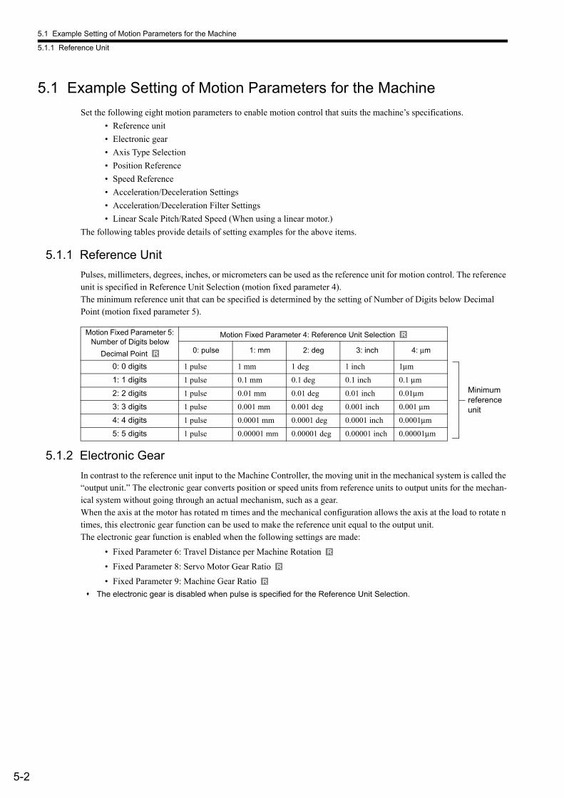
5.1 Example Setting of Motion Parameters for the Machine
5.1.1 Reference Unit
5-2
5.1 Example Setting of Motion Parameters for the Machine
Set the following eight motion parameters to enable motion control that suits the machine’s specifications.
• Reference unit
• Electronic gear
• Axis Type Selection
• Position Reference
• Speed Reference
• Acceleration/Deceleration Settings
• Acceleration/Deceleration Filter Settings
• Linear Scale Pitch/Rated Speed (When using a linear motor.)
The following tables provide details of setting examples for the above items.
5.1.1 Reference Unit
Pulses, millimeters, degrees, inches, or micrometers can be used as the reference unit for motion control. The reference unit is specified in Reference Unit Selection (motion fixed parameter 4).The minimum reference unit that can be specified is determined by the setting of Number of Digits below Decimal Point (motion fixed parameter 5).
5.1.2 Electronic Gear
In contrast to the reference unit input to the Machine Controller, the moving unit in the mechanical system is called the “output unit.” The electronic gear converts position or speed units from reference units to output units for the mechan-ical system without going through an actual mechanism, such as a gear.When the axis at the motor has rotated m times and the mechanical configuration allows the axis at the load to rotate n times, this electronic gear function can be used to make the reference unit equal to the output unit.The electronic gear function is enabled when the following settings are made:
• Fixed Parameter 6: Travel Distance per Machine Rotation
• Fixed Parameter 8: Servo Motor Gear Ratio
• Fixed Parameter 9: Machine Gear Ratio
The electronic gear is disabled when pulse is specified for the Reference Unit Selection.
Motion Fixed Parameter 5: Number of Digits below
Decimal Point
Motion Fixed Parameter 4: Reference Unit Selection
0: pulse 1: mm 2: deg 3: inch 4: μm
0: 0 digits 1 pulse 1 mm 1 deg 1 inch 1μm
1: 1 digits 1 pulse 0.1 mm 0.1 deg 0.1 inch 0.1 μm
2: 2 digits 1 pulse 0.01 mm 0.01 deg 0.01 inch 0.01μm
3: 3 digits 1 pulse 0.001 mm 0.001 deg 0.001 inch 0.001 μm
4: 4 digits 1 pulse 0.0001 mm 0.0001 deg 0.0001 inch 0.0001μm
5: 5 digits 1 pulse 0.00001 mm 0.00001 deg 0.00001 inch 0.00001μm
R
R
Minimum reference unit
R
R
R
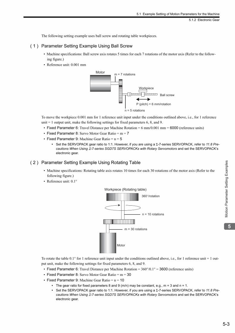
5.1 Example Setting of Motion Parameters for the Machine
5.1.2 Electronic Gear
5-3
Mot
ion
Par
amet
er S
ettin
g E
xam
ples
The following setting example uses ball screw and rotating table workpieces.
( 1 ) Parameter Setting Example Using Ball Screw
• Machine specifications: Ball screw axis rotates 5 times for each 7 rotations of the motor axis (Refer to the follow-ing figure.)
• Reference unit: 0.001 mm
To move the workpiece 0.001 mm for 1 reference unit input under the conditions outlined above, i.e., for 1 reference unit = 1 output unit, make the following settings for fixed parameters 6, 8, and 9.
• Fixed Parameter 6: Travel Distance per Machine Rotation = 6 mm/0.001 mm = 6000 (reference units)
• Fixed Parameter 8: Servo Motor Gear Ratio = m = 7
• Fixed Parameter 9: Machine Gear Ratio = n = 5
Set the SERVOPACK gear ratio to 1:1. However, if you are using a Σ-7-series SERVOPACK, refer to 11.8 Pre-cautions When Using Σ-7-series SGD7S SERVOPACKs with Rotary Servomotors and set the SERVOPACK’s electronic gear.
( 2 ) Parameter Setting Example Using Rotating Table
• Machine specifications: Rotating table axis rotates 10 times for each 30 rotations of the motor axis (Refer to the following figure.)
• Reference unit: 0.1°
To rotate the table 0.1° for 1 reference unit input under the conditions outlined above, i.e., for 1 reference unit = 1 out-put unit, make the following settings for fixed parameters 6, 8, and 9.
• Fixed Parameter 6: Travel Distance per Machine Rotation = 360°/0.1° = 3600 (reference units)
• Fixed Parameter 8: Servo Motor Gear Ratio = m = 30
• Fixed Parameter 9: Machine Gear Ratio = n = 10
The gear ratio for fixed parameters 8 and 9 (m/n) may be constant, e.g., m = 3 and n = 1.
Set the SERVOPACK gear ratio to 1:1. However, if you are using a Σ-7-series SERVOPACK, refer to 11.8 Pre-cautions When Using Σ-7-series SGD7S SERVOPACKs with Rotary Servomotors and set the SERVOPACK’s electronic gear.
Ball screw
Workpiece
P (pitch) = 6 mm/rotation
m = 7 rotations
n = 5 rotations
Motor
Workpiece (Rotating table)
360°/rotation
n = 10 rotations
Motor
m = 30 rotations
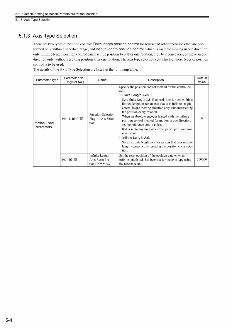
5.1 Example Setting of Motion Parameters for the Machine
5.1.3 Axis Type Selection
5-4
5.1.3 Axis Type Selection
There are two types of position control: Finite length position control for return and other operations that are per-formed only within a specified range, and infinite length position control, which is used for moving in one direction only. Infinite length position control can reset the position to 0 after one rotation, e.g., belt conveyors, or move in one direction only, without resetting position after one rotation. The axis type selection sets which of these types of position control is to be used.The details of the Axis Type Selection are listed in the following table.
Parameter TypeParameter No. (Register No.)
Name DescriptionDefault Value
Motion Fixed Parameters
No. 1, bit 0Function Selection Flag 1, Axis Selec-tion
Specify the position control method for the controlled axis.0: Finite Length Axis
Set a finite length axis if control is performed within a limited length or for an axis that uses infinite length control in one moving direction only without resetting the position every rotation.When an absolute encoder is used with the infinite position control method for motion in one direction, set the reference unit to pulse.If it is set to anything other than pulse, position error may occur.
1: Infinite Length AxisSet an infinite length axis for an axis that uses infinite length control while resetting the position every rota-tion.
0
No. 10Infinite Length Axis Reset Posi-tion (POSMAX)
Set the reset position of the position data when an infinite length axis has been set for the axis type using the reference unit.
360000
R
R
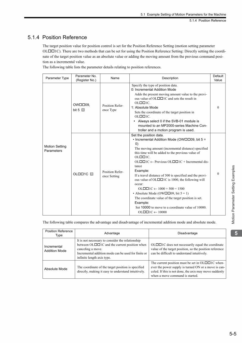
5.1 Example Setting of Motion Parameters for the Machine
5.1.4 Position Reference
5-5
Mot
ion
Par
amet
er S
ettin
g E
xam
ples
5.1.4 Position Reference
The target position value for position control is set for the Position Reference Setting (motion setting parameter OL1C). There are two methods that can be set for using the Position Reference Setting: Directly setting the coordi-nate of the target position value as an absolute value or adding the moving amount from the previous command posi-tion as a incremental value.The following table lists the parameter details relating to position references.
The following table compares the advantage and disadvantage of incremental addition mode and absolute mode.
Parameter TypeParameter No. (Register No.)
Name DescriptionDefault Value
Motion Setting Parameters
OW09,
bit 5Position Refer-ence Type
Specify the type of position data.0: Incremental Addition Mode
Adds the present moving amount value to the previ-ous value of OL1C and sets the result in OL1C.
1: Absolute ModeSets the coordinate of the target position in OL1C. Always select 0 if the SVB-01 module is
mounted to an MP2000-series Machine Con-troller and a motion program is used.
0
OL1CPosition Refer-ence Setting
Set the position data.• Incremental Addition Mode (OW09, bit 5 =
0)The moving amount (incremental distance) specified this time will be added to the previous value of OL1C.OL1C ← Previous OL1C + Incremental dis-tanceExample:If a travel distance of 500 is specified and the previ-ous value of OL1C is 1000, the following will occur: OL1C ← 1000 + 500 = 1500
• Absolute Mode (OW09, bit 5 = 1)The coordinate value of the target position is set.Example: Set 10000 to move to a coordinate value of 10000. OL1C ← 10000
0
Position Reference Type
Advantage Disadvantage
Incremental Addition Mode
It is not necessary to consider the relationship between OL1C and the current position when canceling a move.Incremental addition mode can be used for finite or infinite length axis type.
OL1C does not necessarily equal the coordinate value of the target position, so the position reference can be difficult to understand intuitively.
Absolute Mode The coordinate of the target position is specified directly, making it easy to understand intuitively.
The current position must be set in OL1C when-ever the power supply is turned ON or a move is can-celed. If this is not done, the axis may move suddenly when a move command is started.
R
R
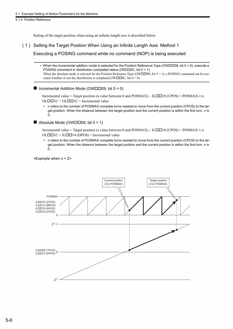
5.1 Example Setting of Motion Parameters for the Machine
5.1.4 Position Reference
5-6
Setting of the target position when using an infinite length axis is described below.
( 1 ) Setting the Target Position When Using an Infinite Length Axis: Method 1
Executing a POSING command while no command (NOP) is being executed
• When the incremental addition mode is selected for the Position Reference Type (OW09, bit 5 = 0), execute a POSING command in distribution completed status (IW0C, bit 0 = 1).When the absolute mode is selected for the Position Reference Type (OW09, bit 5 = 1), a POSING command can be exe-cuted whether or not the distribution is completed (IW0C, bit 0 = 0).
Incremental Addition Mode (OW09, bit 5 = 0)
Incremental value = Target position (a value between 0 and POSMAX) − IL10 (CPOS) + POSMAX × n OL1C = OL1C + Incremental value
n refers to the number of POSMAX complete turns needed to move from the current position (CPOS) to the tar-get position. When the distance between the target position and the current position is within the first turn, n is 0.
Absolute Mode (OW09, bit 5 = 1)
Incremental value = Target position (a value between 0 and POSMAX) − IL10 (CPOS) + POSMAX × nOL1C = IL14 (DPOS) + Incremental value
n refers to the number of POSMAX complete turns needed to move from the current position (CPOS) to the tar-get position. When the distance between the target position and the current position is within the first turn, n is 0.
<Example when n = 2>
POSMAX
0
231
-1
0
-231
IL��10 (CPOS)
IL��12 (MPOS)
IL��16 (APOS)
IL��18 (LPOS)
IL��0E (TPOS)
IL��14 (DPOS)
Current position
(0 to POSMAX)
Target position
(0 to POSMAX)
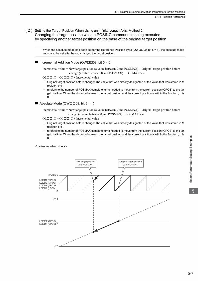
5.1 Example Setting of Motion Parameters for the Machine
5.1.4 Position Reference
5-7
Mot
ion
Par
amet
er S
ettin
g E
xam
ples
( 2 ) Setting the Target Position When Using an Infinite Length Axis: Method 2Changing the target position while a POSING command is being executed by specifying another target position on the base of the original target position
• When the absolute mode has been set for the Reference Position Type (OW09, bit 5 = 1), the absolute mode must also be set after having changed the target position.
Incremental Addition Mode (OW09, bit 5 = 0)
Incremental value = New target position (a value between 0 and POSMAX) − Original target position before change (a value between 0 and POSMAX) + POSMAX × n
OL1C = OL1C + Incremental value
Original target position before change: The value that was directly designated or the value that was stored in M register, etc.
n refers to the number of POSMAX complete turns needed to move from the current position (CPOS) to the tar-get position. When the distance between the target position and the current position is within the first turn, n is 0.
Absolute Mode (OW09, bit 5 = 1)
Incremental value = New target position (a value between 0 and POSMAX) − Original target position before change (a value between 0 and POSMAX) + POSMAX × n
OL1C = OL1C + Incremental value
Original target position before change: The value that was directly designated or the value that was stored in M register, etc.
n refers to the number of POSMAX complete turns needed to move from the current position (CPOS) to the tar-get position. When the distance between the target position and the current position is within the first turn, n is 0.
<Example when n = 2>
POSMAX
0
231
-1
0
-231
IL��10 (CPOS)
IL��12 (MPOS)
IL��16 (APOS)
IL��18 (LPOS)
IL��0E (TPOS)
IL��14 (DPOS)
New target position
(0 to POSMAX)
Original target position
(0 to POSMAX)
5.1 Example Setting of Motion Parameters for the Machine
5.1.4 Position Reference
5-8
( 3 ) Setting the Target Position When Using an Infinite Length Axis: Method 3Changing the target position while a POSING command is being executedby specifying another target position on the base of the current position
• When the incremental addition mode is selected for Position Reference Type (OW09, bit 5 = 0), execute a POSING command in distribution completed status (IW0C, bit 0 = 1).When the absolute mode is selected for Position Reference Type (OW09, bit 5 = 1), a POSING command can be exe-cuted if the distribution is not completed (IW0C, bit 0 = 0).
The method is the same as for ( 1 ) Setting the Target Position When Using an Infinite Length Axis: Method 1.
( 4 ) Setting the Target Position When Using an Infinite Length Axis: Method 4Switching a command that is being executed to a POSING command
• When the incremental addition mode is selected for Position Reference Type (OW09, bit 5 = 0), execute a POS-ING command in distribution completed status (IW0C, bit 0 = 1).When the absolute mode is selected for Position Reference Type (OW09, bit 5 = 1), a POSING command can be exe-cuted if the distribution is not completed (IW0C, bit 0 = 0).
The method is the same as for ( 1 ) Setting the Target Position When Using an Infinite Length Axis: Method 1.
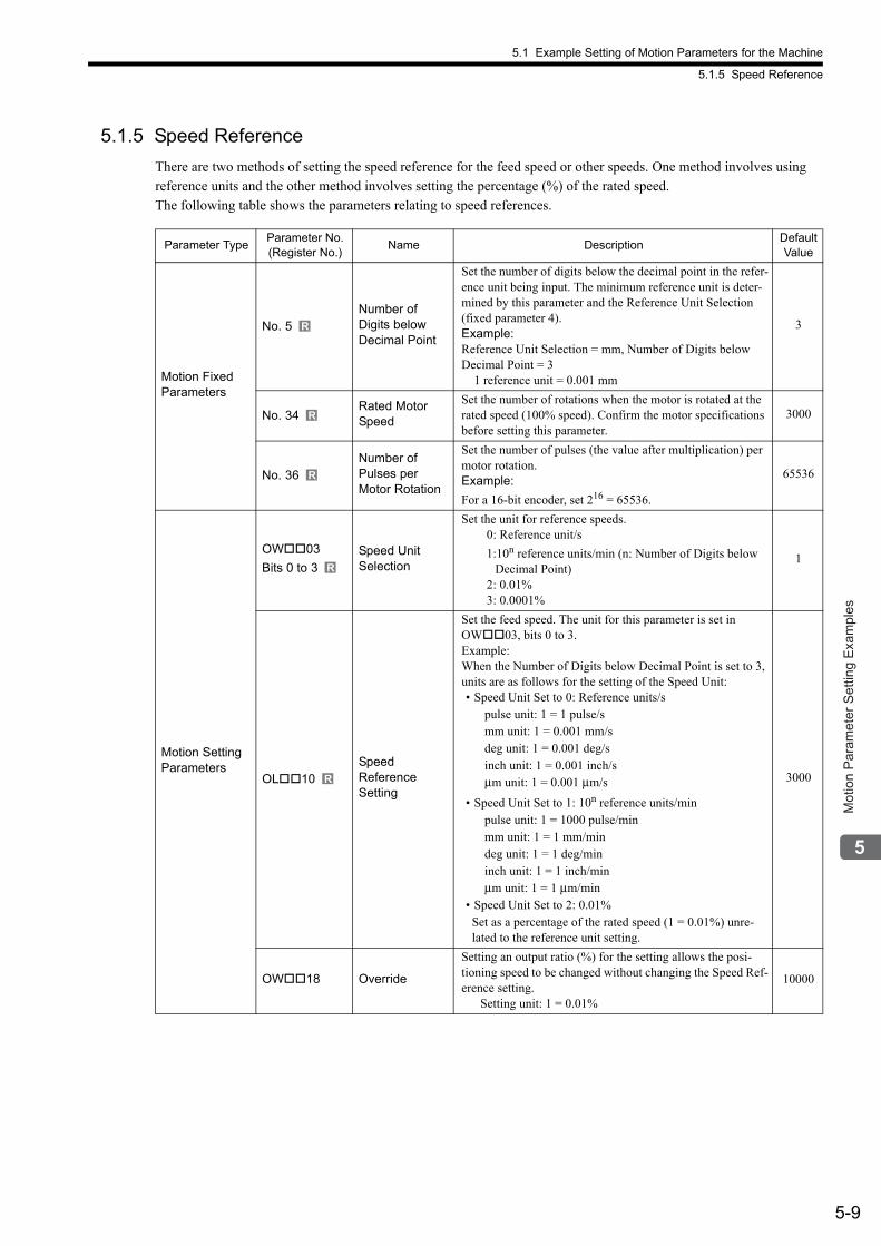
5.1 Example Setting of Motion Parameters for the Machine
5.1.5 Speed Reference
5-9
Mot
ion
Par
amet
er S
ettin
g E
xam
ples
5.1.5 Speed Reference
There are two methods of setting the speed reference for the feed speed or other speeds. One method involves using reference units and the other method involves setting the percentage (%) of the rated speed.The following table shows the parameters relating to speed references.
Parameter TypeParameter No. (Register No.)
Name DescriptionDefault Value
Motion Fixed Parameters
No. 5Number of Digits below Decimal Point
Set the number of digits below the decimal point in the refer-ence unit being input. The minimum reference unit is deter-mined by this parameter and the Reference Unit Selection (fixed parameter 4).Example:Reference Unit Selection = mm, Number of Digits below Decimal Point = 3 1 reference unit = 0.001 mm
3
No. 34Rated Motor Speed
Set the number of rotations when the motor is rotated at the rated speed (100% speed). Confirm the motor specifications before setting this parameter.
3000
No. 36Number ofPulses perMotor Rotation
Set the number of pulses (the value after multiplication) per motor rotation.Example:
For a 16-bit encoder, set 216 = 65536.
65536
Motion Setting Parameters
OW03
Bits 0 to 3Speed Unit Selection
Set the unit for reference speeds. 0: Reference unit/s
1:10n reference units/min (n: Number of Digits below Decimal Point)
2: 0.01% 3: 0.0001%
1
OL10Speed Reference Setting
Set the feed speed. The unit for this parameter is set in OW03, bits 0 to 3.Example:When the Number of Digits below Decimal Point is set to 3, units are as follows for the setting of the Speed Unit:• Speed Unit Set to 0: Reference units/s
pulse unit: 1 = 1 pulse/s mm unit: 1 = 0.001 mm/s deg unit: 1 = 0.001 deg/s inch unit: 1 = 0.001 inch/s μm unit: 1 = 0.001 μm/s
• Speed Unit Set to 1: 10n reference units/min pulse unit: 1 = 1000 pulse/min mm unit: 1 = 1 mm/min deg unit: 1 = 1 deg/min inch unit: 1 = 1 inch/min μm unit: 1 = 1 μm/min
• Speed Unit Set to 2: 0.01%Set as a percentage of the rated speed (1 = 0.01%) unre-lated to the reference unit setting.
3000
OW18 Override
Setting an output ratio (%) for the setting allows the posi-tioning speed to be changed without changing the Speed Ref-erence setting. Setting unit: 1 = 0.01%
10000
R
R
R
R
R
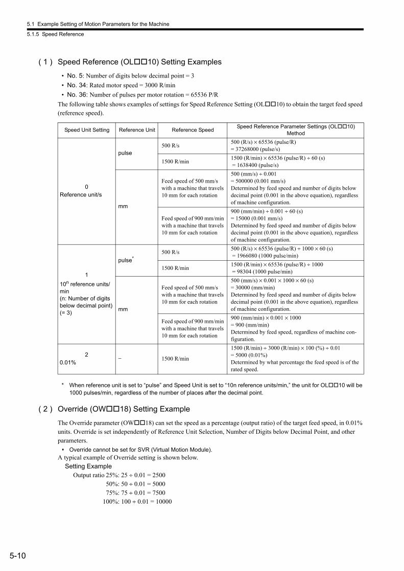
5.1 Example Setting of Motion Parameters for the Machine
5.1.5 Speed Reference
5-10
( 1 ) Speed Reference (OL10) Setting Examples
• No. 5: Number of digits below decimal point = 3
• No. 34: Rated motor speed = 3000 R/min
• No. 36: Number of pulses per motor rotation = 65536 P/R
The following table shows examples of settings for Speed Reference Setting (OL10) to obtain the target feed speed (reference speed).
* When reference unit is set to “pulse” and Speed Unit is set to “10n reference units/min,” the unit for OL10 will be 1000 pulses/min, regardless of the number of places after the decimal point.
( 2 ) Override (OW18) Setting Example
The Override parameter (OW18) can set the speed as a percentage (output ratio) of the target feed speed, in 0.01% units. Override is set independently of Reference Unit Selection, Number of Digits below Decimal Point, and other parameters.
Override cannot be set for SVR (Virtual Motion Module).A typical example of Override setting is shown below. Setting Example
Output ratio 25%: 25 ÷ 0.01 = 250050%: 50 ÷ 0.01 = 500075%: 75 ÷ 0.01 = 7500
100%: 100 ÷ 0.01 = 10000
Speed Unit Setting Reference Unit Reference SpeedSpeed Reference Parameter Settings (OL10)
Method
0Reference unit/s
pulse500 R/s
500 (R/s) × 65536 (pulse/R)= 37268000 (pulse/s)
1500 R/min1500 (R/min) × 65536 (pulse/R) ÷ 60 (s) = 1638400 (pulse/s)
mm
Feed speed of 500 mm/s with a machine that travels 10 mm for each rotation
500 (mm/s) ÷ 0.001= 500000 (0.001 mm/s)Determined by feed speed and number of digits below decimal point (0.001 in the above equation), regardless of machine configuration.
Feed speed of 900 mm/min with a machine that travels 10 mm for each rotation
900 (mm/min) ÷ 0.001 ÷ 60 (s)= 15000 (0.001 mm/s)Determined by feed speed and number of digits below decimal point (0.001 in the above equation), regardless of machine configuration.
1
10n reference units/min(n: Number of digits below decimal point)(= 3)
pulse*500 R/s
500 (R/s) × 65536 (pulse/R) ÷ 1000 × 60 (s) = 1966080 (1000 pulse/min)
1500 R/min1500 (R/min) × 65536 (pulse/R) ÷ 1000 = 98304 (1000 pulse/min)
mm
Feed speed of 500 mm/s with a machine that travels 10 mm for each rotation
500 (mm/s) × 0.001 × 1000 × 60 (s)= 30000 (mm/min)Determined by feed speed and number of digits below decimal point (0.001 in the above equation), regardless of machine configuration.
Feed speed of 900 mm/min with a machine that travels 10 mm for each rotation
900 (mm/min) × 0.001 × 1000= 900 (mm/min)Determined by feed speed, regardless of machine con-figuration.
20.01%
− 1500 R/min
1500 (R/min) ÷ 3000 (R/min) × 100 (%) ÷ 0.01= 5000 (0.01%)Determined by what percentage the feed speed is of the rated speed.
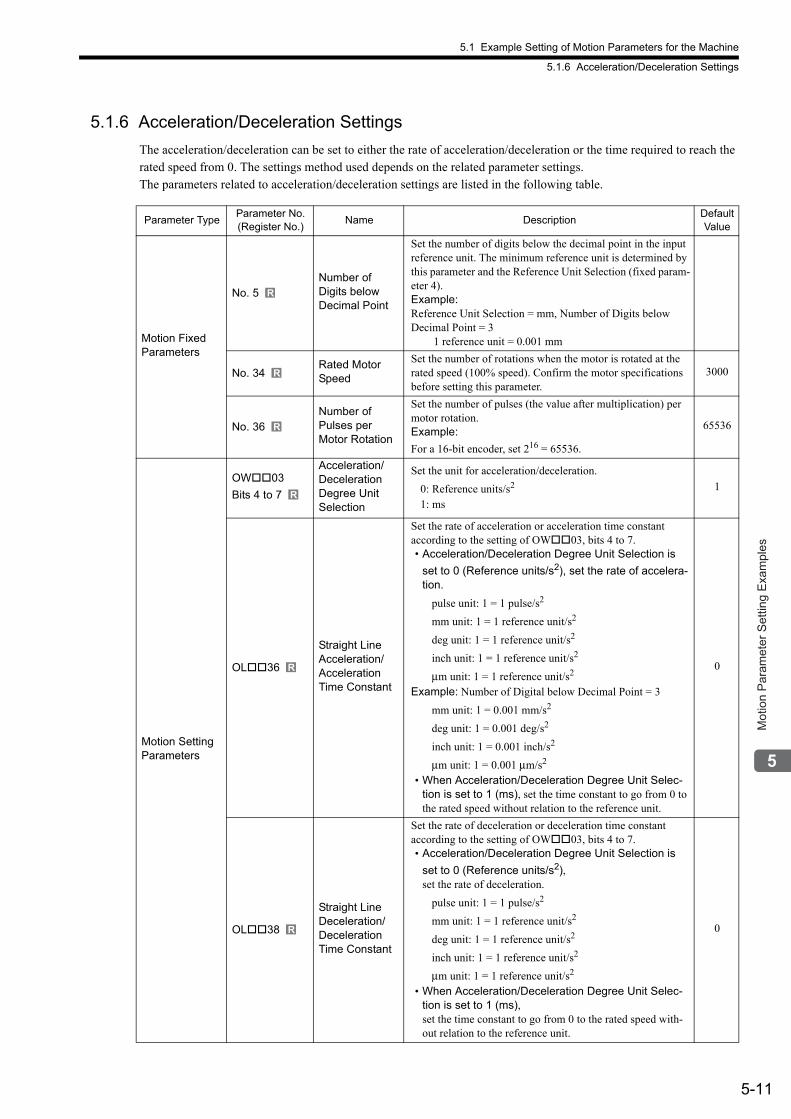
5.1 Example Setting of Motion Parameters for the Machine
5.1.6 Acceleration/Deceleration Settings
5-11
Mot
ion
Par
amet
er S
ettin
g E
xam
ples
5.1.6 Acceleration/Deceleration Settings
The acceleration/deceleration can be set to either the rate of acceleration/deceleration or the time required to reach the rated speed from 0. The settings method used depends on the related parameter settings.The parameters related to acceleration/deceleration settings are listed in the following table.
Parameter TypeParameter No. (Register No.)
Name DescriptionDefault Value
Motion Fixed Parameters
No. 5Number ofDigits below Decimal Point
Set the number of digits below the decimal point in the input reference unit. The minimum reference unit is determined by this parameter and the Reference Unit Selection (fixed param-eter 4).Example:Reference Unit Selection = mm, Number of Digits below Decimal Point = 3 1 reference unit = 0.001 mm
No. 34Rated Motor Speed
Set the number of rotations when the motor is rotated at the rated speed (100% speed). Confirm the motor specifications before setting this parameter.
3000
No. 36Number ofPulses perMotor Rotation
Set the number of pulses (the value after multiplication) per motor rotation.Example:
For a 16-bit encoder, set 216 = 65536.
65536
Motion Setting Parameters
OW03
Bits 4 to 7
Acceleration/Deceleration Degree UnitSelection
Set the unit for acceleration/deceleration.
0: Reference units/s2
1: ms
1
OL36
Straight Line Acceleration/ Acceleration Time Constant
Set the rate of acceleration or acceleration time constant according to the setting of OW03, bits 4 to 7.• Acceleration/Deceleration Degree Unit Selection is
set to 0 (Reference units/s2), set the rate of accelera-tion.
pulse unit: 1 = 1 pulse/s2
mm unit: 1 = 1 reference unit/s2
deg unit: 1 = 1 reference unit/s2
inch unit: 1 = 1 reference unit/s2
μm unit: 1 = 1 reference unit/s2
Example: Number of Digital below Decimal Point = 3
mm unit: 1 = 0.001 mm/s2
deg unit: 1 = 0.001 deg/s2
inch unit: 1 = 0.001 inch/s2
μm unit: 1 = 0.001 μm/s2
• When Acceleration/Deceleration Degree Unit Selec-tion is set to 1 (ms), set the time constant to go from 0 to the rated speed without relation to the reference unit.
0
OL38
Straight Line Deceleration/ Deceleration Time Constant
Set the rate of deceleration or deceleration time constant according to the setting of OW03, bits 4 to 7.• Acceleration/Deceleration Degree Unit Selection is
set to 0 (Reference units/s2), set the rate of deceleration.
pulse unit: 1 = 1 pulse/s2
mm unit: 1 = 1 reference unit/s2
deg unit: 1 = 1 reference unit/s2
inch unit: 1 = 1 reference unit/s2
μm unit: 1 = 1 reference unit/s2
• When Acceleration/Deceleration Degree Unit Selec-tion is set to 1 (ms), set the time constant to go from 0 to the rated speed with-out relation to the reference unit.
0
R
R
R
R
R
R
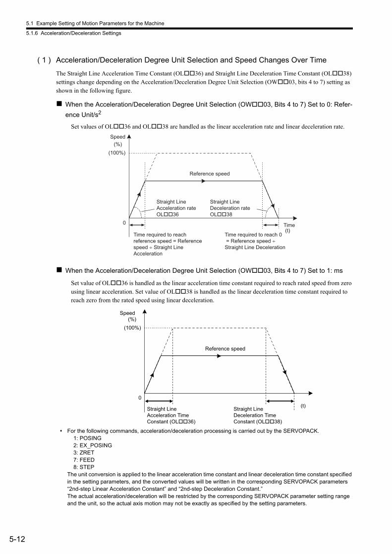
5.1 Example Setting of Motion Parameters for the Machine
5.1.6 Acceleration/Deceleration Settings
5-12
( 1 ) Acceleration/Deceleration Degree Unit Selection and Speed Changes Over Time
The Straight Line Acceleration Time Constant (OL36) and Straight Line Deceleration Time Constant (OL38) settings change depending on the Acceleration/Deceleration Degree Unit Selection (OW03, bits 4 to 7) setting as shown in the following figure.
When the Acceleration/Deceleration Degree Unit Selection (OW03, Bits 4 to 7) Set to 0: Refer-
ence Unit/s2
Set values of OL36 and OL38 are handled as the linear acceleration rate and linear deceleration rate.
When the Acceleration/Deceleration Degree Unit Selection (OW03, Bits 4 to 7) Set to 1: ms
Set value of OL36 is handled as the linear acceleration time constant required to reach rated speed from zero using linear acceleration. Set value of OL38 is handled as the linear deceleration time constant required to reach zero from the rated speed using linear deceleration.
For the following commands, acceleration/deceleration processing is carried out by the SERVOPACK. 1: POSING 2: EX_POSING 3: ZRET 7: FEED 8: STEPThe unit conversion is applied to the linear acceleration time constant and linear deceleration time constant specified in the setting parameters, and the converted values will be written in the corresponding SERVOPACK parameters “2nd-step Linear Acceleration Constant” and “2nd-step Deceleration Constant.”The actual acceleration/deceleration will be restricted by the corresponding SERVOPACK parameter setting range and the unit, so the actual axis motion may not be exactly as specified by the setting parameters.
0(t)
(100%)(%)
Speed
Time
Reference speed
Straight Line Acceleration rate OL��36
Straight Line Deceleration rate OL��38
Time required to reach reference speed = Reference speed ÷ Straight Line Acceleration
Time required to reach 0 = Reference speed ÷ Straight Line Deceleration
0(t)
(100%)(%)
Speed
Reference speed
Straight Line Acceleration Time Constant (OL��36)
Straight Line Deceleration Time Constant (OL��38)
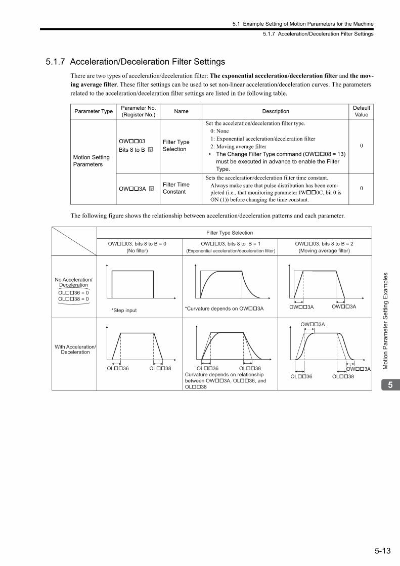
5.1 Example Setting of Motion Parameters for the Machine
5.1.7 Acceleration/Deceleration Filter Settings
5-13
Mot
ion
Par
amet
er S
ettin
g E
xam
ples
5.1.7 Acceleration/Deceleration Filter Settings
There are two types of acceleration/deceleration filter: The exponential acceleration/deceleration filter and the mov-ing average filter. These filter settings can be used to set non-linear acceleration/deceleration curves. The parameters related to the acceleration/deceleration filter settings are listed in the following table.
The following figure shows the relationship between acceleration/deceleration patterns and each parameter.
Parameter TypeParameter No. (Register No.)
Name DescriptionDefault Value
Motion Setting Parameters
OW03
Bits 8 to BFilter TypeSelection
Set the acceleration/deceleration filter type.0: None1: Exponential acceleration/deceleration filter2: Moving average filter The Change Filter Type command (OW08 = 13)
must be executed in advance to enable the Filter Type.
0
OW3AFilter Time Constant
Sets the acceleration/deceleration filter time constant.Always make sure that pulse distribution has been com-pleted (i.e., that monitoring parameter IW0C, bit 0 is ON (1)) before changing the time constant.
0
R
R
OL��36 = 0OL��38 = 0
OW��3A
OW��3AOW��3A
OL��38OW��3A
OL��36OL��38OL��36OL��38OL��36
*Curvature depends on OW��3A
Curvature depends on relationship between OW��3A, OL��36, and OL��38
*Step input
With Acceleration/Deceleration
OW��03, bits 8 to B = 0(No filter)
Filter Type Selection
OW��03, bits 8 to B = 1(Exponential acceleration/deceleration filter)
OW��03, bits 8 to B = 2(Moving average filter)
No Acceleration/Deceleration
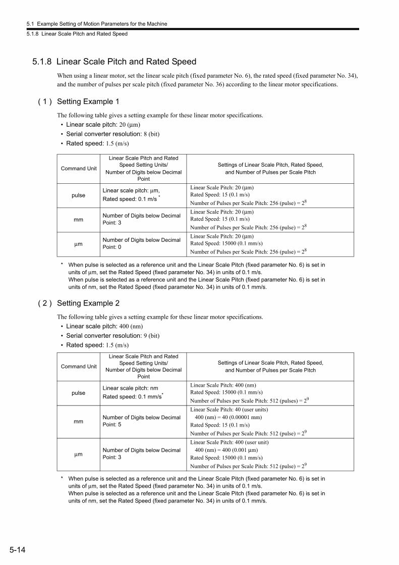
5.1 Example Setting of Motion Parameters for the Machine
5.1.8 Linear Scale Pitch and Rated Speed
5-14
5.1.8 Linear Scale Pitch and Rated Speed
When using a linear motor, set the linear scale pitch (fixed parameter No. 6), the rated speed (fixed parameter No. 34), and the number of pulses per scale pitch (fixed parameter No. 36) according to the linear motor specifications.
( 1 ) Setting Example 1
The following table gives a setting example for these linear motor specifications.
• Linear scale pitch: 20 (μm)
• Serial converter resolution: 8 (bit)
• Rated speed: 1.5 (m/s)
* When pulse is selected as a reference unit and the Linear Scale Pitch (fixed parameter No. 6) is set in units of μm, set the Rated Speed (fixed parameter No. 34) in units of 0.1 m/s. When pulse is selected as a reference unit and the Linear Scale Pitch (fixed parameter No. 6) is set in units of nm, set the Rated Speed (fixed parameter No. 34) in units of 0.1 mm/s.
( 2 ) Setting Example 2
The following table gives a setting example for these linear motor specifications.
• Linear scale pitch: 400 (nm)
• Serial converter resolution: 9 (bit)
• Rated speed: 1.5 (m/s)
* When pulse is selected as a reference unit and the Linear Scale Pitch (fixed parameter No. 6) is set in units of μm, set the Rated Speed (fixed parameter No. 34) in units of 0.1 m/s. When pulse is selected as a reference unit and the Linear Scale Pitch (fixed parameter No. 6) is set in units of nm, set the Rated Speed (fixed parameter No. 34) in units of 0.1 mm/s.
Command Unit
Linear Scale Pitch and Rated Speed Setting Units/
Number of Digits below Decimal Point
Settings of Linear Scale Pitch, Rated Speed, and Number of Pulses per Scale Pitch
pulseLinear scale pitch: μm,
Rated speed: 0.1 m/s *
Linear Scale Pitch: 20 (μm)Rated Speed: 15 (0.1 m/s)
Number of Pulses per Scale Pitch: 256 (pulse) = 28
mmNumber of Digits below Decimal Point: 3
Linear Scale Pitch: 20 (μm)Rated Speed: 15 (0.1 m/s)
Number of Pulses per Scale Pitch: 256 (pulse) = 28
μmNumber of Digits below Decimal Point: 0
Linear Scale Pitch: 20 (μm)Rated Speed: 15000 (0.1 mm/s)
Number of Pulses per Scale Pitch: 256 (pulse) = 28
Command Unit
Linear Scale Pitch and Rated Speed Setting Units/
Number of Digits below Decimal Point
Settings of Linear Scale Pitch, Rated Speed,and Number of Pulses per Scale Pitch
pulseLinear scale pitch: nm
Rated speed: 0.1 mm/s*
Linear Scale Pitch: 400 (nm)Rated Speed: 15000 (0.1 mm/s)
Number of Pulses per Scale Pitch: 512 (pulses) = 29
mmNumber of Digits below Decimal Point: 5
Linear Scale Pitch: 40 (user units)400 (nm) = 40 (0.00001 mm)
Rated Speed: 15 (0.1 m/s)
Number of Pulses per Scale Pitch: 512 (pulse) = 29
μmNumber of Digits below Decimal Point: 3
Linear Scale Pitch: 400 (user unit)400 (nm) = 400 (0.001 μm)
Rated Speed: 15000 (0.1 mm/s)
Number of Pulses per Scale Pitch: 512 (pulse) = 29
6-1
Mot
ion
Com
man
ds
6
Motion Commands
This chapter explains each motion command's operation, related parameters, and timing charts.
6.1 Motion Commands - - - - - - - - - - - - - - - - - - - - - - - - - - - - - - - - - - - - - - - -6-3
6.1.1 Motion Command Table - - - - - - - - - - - - - - - - - - - - - - - - - - - - - - - - - - - - - - - - - - - - - 6-3
6.1.2 Motion Commands Supported by SERVOPACK Models - - - - - - - - - - - - - - - - - - - - - - 6-4
6.2 Motion Command Details - - - - - - - - - - - - - - - - - - - - - - - - - - - - - - - - - - -6-5
6.2.1 Position Mode (POSING) (Positioning) - - - - - - - - - - - - - - - - - - - - - - - - - - - - - - - - - - 6-5
6.2.2 Latch Target Positioning (EX_POSING) (External Positioning) - - - - - - - - - - - - - - - - - 6-10
6.2.3 Zero Point Return (ZRET) - - - - - - - - - - - - - - - - - - - - - - - - - - - - - - - - - - - - - - - - - - 6-15
6.2.4 Interpolation (INTERPOLATE) - - - - - - - - - - - - - - - - - - - - - - - - - - - - - - - - - - - - - - - 6-35
6.2.5 Interpolation Mode with Latch Input (LATCH) - - - - - - - - - - - - - - - - - - - - - - - - - - - - - 6-39
6.2.6 Jog Mode (FEED) - - - - - - - - - - - - - - - - - - - - - - - - - - - - - - - - - - - - - - - - - - - - - - - - 6-43
6.2.7 Relative Position Mode (STEP) (Step Mode) - - - - - - - - - - - - - - - - - - - - - - - - - - - - - 6-47
6.2.8 Set Zero Point (ZSET) - - - - - - - - - - - - - - - - - - - - - - - - - - - - - - - - - - - - - - - - - - - - - 6-51
6.2.9 Change Acceleration Time (ACC) - - - - - - - - - - - - - - - - - - - - - - - - - - - - - - - - - - - - - 6-53
6.2.10 Change Deceleration Time (DCC) - - - - - - - - - - - - - - - - - - - - - - - - - - - - - - - - - - - - 6-55
6.2.11 Change Filter Time Constant (SCC) - - - - - - - - - - - - - - - - - - - - - - - - - - - - - - - - - - - 6-57
6.2.12 Change Filter Type (CHG_FILTER) - - - - - - - - - - - - - - - - - - - - - - - - - - - - - - - - - - - 6-59
6.2.13 Change Speed Loop Gain (KVS) - - - - - - - - - - - - - - - - - - - - - - - - - - - - - - - - - - - - - 6-61
6.2.14 Change Position Loop Gain (KPS) - - - - - - - - - - - - - - - - - - - - - - - - - - - - - - - - - - - 6-63
6.2.15 Change Feed Forward (KFS) - - - - - - - - - - - - - - - - - - - - - - - - - - - - - - - - - - - - - - - 6-65
6.2.16 Read User Constant (PRM_RD) - - - - - - - - - - - - - - - - - - - - - - - - - - - - - - - - - - - - - 6-67
6.2.17 Write User Constant (PRM_WR) - - - - - - - - - - - - - - - - - - - - - - - - - - - - - - - - - - - - - 6-69
6.2.18 Alarm Monitor (ALM_MON) - - - - - - - - - - - - - - - - - - - - - - - - - - - - - - - - - - - - - - - - 6-71
6.2.19 Alarm History Monitor (ALM_HIST) - - - - - - - - - - - - - - - - - - - - - - - - - - - - - - - - - - - 6-73
6.2.20 Clear Alarm History (ALMHIST_CLR) - - - - - - - - - - - - - - - - - - - - - - - - - - - - - - - - - 6-75
6.2.21 Absolute Encoder Reset (ABS_RST) - - - - - - - - - - - - - - - - - - - - - - - - - - - - - - - - - - 6-77
6.2.22 Speed Reference (VELO) - - - - - - - - - - - - - - - - - - - - - - - - - - - - - - - - - - - - - - - - - - 6-80
6.2.23 Torque /Thrust Reference (TRQ) - - - - - - - - - - - - - - - - - - - - - - - - - - - - - - - - - - - - - 6-84
6.2.24 Phase References (PHASE) - - - - - - - - - - - - - - - - - - - - - - - - - - - - - - - - - - - - - - - - 6-88
6.2.25 Change Position Loop Integral Time Constant (KIS) - - - - - - - - - - - - - - - - - - - - - - - 6-92
6.2.26 Stored Parameter Write (PPRM_WR) - - - - - - - - - - - - - - - - - - - - - - - - - - - - - - - - - 6-94
6.2.27 Multiturn Limit Setting (MLTTRN_SET) - - - - - - - - - - - - - - - - - - - - - - - - - - - - - - - - 6-96

6-2
6.3 Motion Subcommands - - - - - - - - - - - - - - - - - - - - - - - - - - - - - - - - - - - 6-100
6.3.1 Motion Subcommand Table - - - - - - - - - - - - - - - - - - - - - - - - - - - - - - - - - - - - - - - - -6-100
6.3.2 Motion Subcommand Settings - - - - - - - - - - - - - - - - - - - - - - - - - - - - - - - - - - - - - - -6-100
6.4 Motion Subcommand Details - - - - - - - - - - - - - - - - - - - - - - - - - - - - - - - 6-101
6.4.1 No Command (NOP) - - - - - - - - - - - - - - - - - - - - - - - - - - - - - - - - - - - - - - - - - - - - - -6-101
6.4.2 Read User Constant (PRM_RD) - - - - - - - - - - - - - - - - - - - - - - - - - - - - - - - - - - - - -6-102
6.4.3 Write User Constant (PRM_WR) - - - - - - - - - - - - - - - - - - - - - - - - - - - - - - - - - - - - -6-104
6.4.4 Status Monitor (SMON) - - - - - - - - - - - - - - - - - - - - - - - - - - - - - - - - - - - - - - - - - - - -6-106
6.4.5 Read Fixed Parameters (FIXPRM_RD) - - - - - - - - - - - - - - - - - - - - - - - - - - - - - - - -6-108
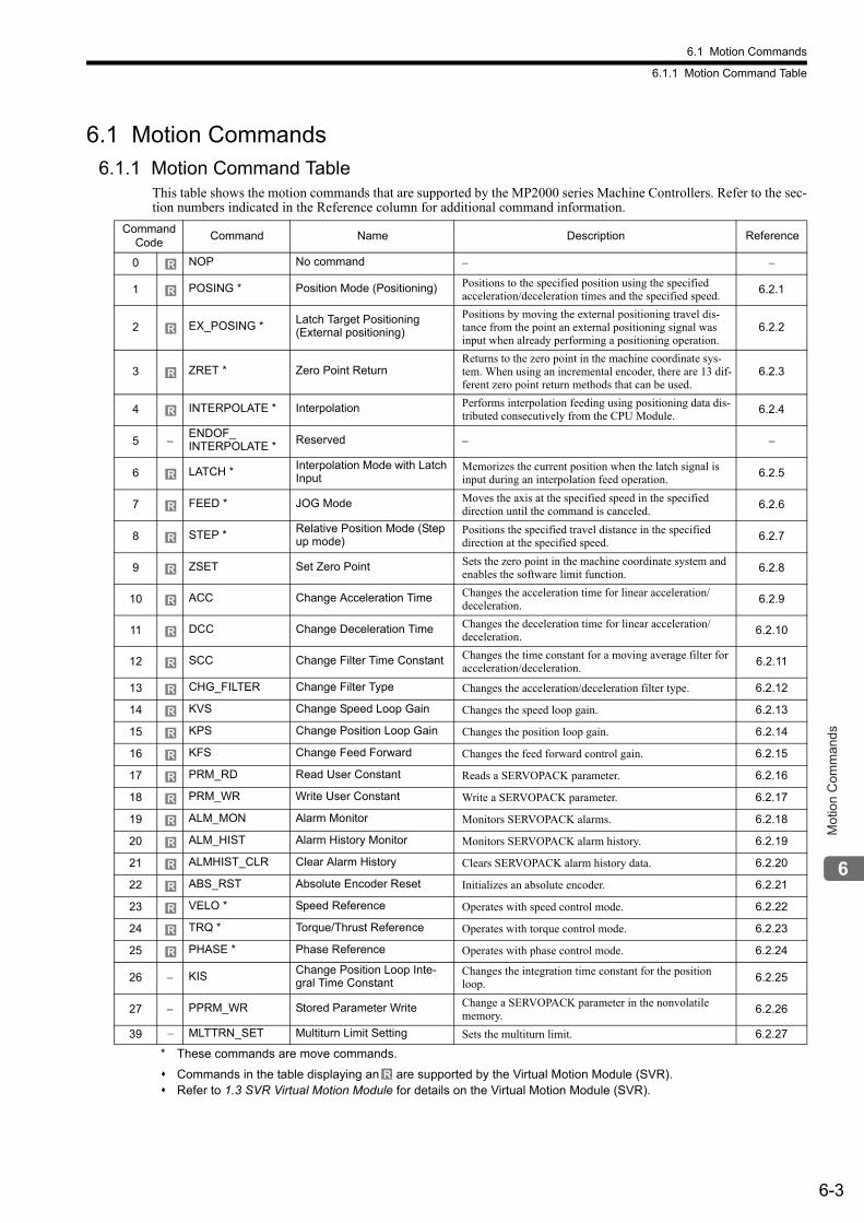
6.1 Motion Commands
6.1.1 Motion Command Table
6-3
Mot
ion
Com
man
ds
6.1 Motion Commands6.1.1 Motion Command Table
This table shows the motion commands that are supported by the MP2000 series Machine Controllers. Refer to the sec-tion numbers indicated in the Reference column for additional command information.
* These commands are move commands.
Commands in the table displaying an are supported by the Virtual Motion Module (SVR). Refer to 1.3 SVR Virtual Motion Module for details on the Virtual Motion Module (SVR).
Command Code
Command Name Description Reference
0 NOP No command − −
1 POSING * Position Mode (Positioning) Positions to the specified position using the specified acceleration/deceleration times and the specified speed.
6.2.1
2 EX_POSING *Latch Target Positioning(External positioning)
Positions by moving the external positioning travel dis-tance from the point an external positioning signal was input when already performing a positioning operation.
6.2.2
3 ZRET * Zero Point ReturnReturns to the zero point in the machine coordinate sys-tem. When using an incremental encoder, there are 13 dif-ferent zero point return methods that can be used.
6.2.3
4 INTERPOLATE * Interpolation Performs interpolation feeding using positioning data dis-tributed consecutively from the CPU Module.
6.2.4
5 −ENDOF_INTERPOLATE *
Reserved − −
6 LATCH *Interpolation Mode with Latch Input
Memorizes the current position when the latch signal is input during an interpolation feed operation.
6.2.5
7 FEED * JOG Mode Moves the axis at the specified speed in the specified direction until the command is canceled.
6.2.6
8 STEP *Relative Position Mode (Step up mode)
Positions the specified travel distance in the specified direction at the specified speed.
6.2.7
9 ZSET Set Zero Point Sets the zero point in the machine coordinate system and enables the software limit function.
6.2.8
10 ACC Change Acceleration Time Changes the acceleration time for linear acceleration/deceleration.
6.2.9
11 DCC Change Deceleration Time Changes the deceleration time for linear acceleration/deceleration.
6.2.10
12 SCC Change Filter Time Constant Changes the time constant for a moving average filter for acceleration/deceleration.
6.2.11
13 CHG_FILTER Change Filter Type Changes the acceleration/deceleration filter type. 6.2.12
14 KVS Change Speed Loop Gain Changes the speed loop gain. 6.2.13
15 KPS Change Position Loop Gain Changes the position loop gain. 6.2.14
16 KFS Change Feed Forward Changes the feed forward control gain. 6.2.15
17 PRM_RD Read User Constant Reads a SERVOPACK parameter. 6.2.16
18 PRM_WR Write User Constant Write a SERVOPACK parameter. 6.2.17
19 ALM_MON Alarm Monitor Monitors SERVOPACK alarms. 6.2.18
20 ALM_HIST Alarm History Monitor Monitors SERVOPACK alarm history. 6.2.19
21 ALMHIST_CLR Clear Alarm History Clears SERVOPACK alarm history data. 6.2.20
22 ABS_RST Absolute Encoder Reset Initializes an absolute encoder. 6.2.21
23 VELO * Speed Reference Operates with speed control mode. 6.2.22
24 TRQ * Torque/Thrust Reference Operates with torque control mode. 6.2.23
25 PHASE * Phase Reference Operates with phase control mode. 6.2.24
26 − KISChange Position Loop Inte-gral Time Constant
Changes the integration time constant for the position loop.
6.2.25
27 − PPRM_WR Stored Parameter Write Change a SERVOPACK parameter in the nonvolatile memory.
6.2.26
39 – MLTTRN_SET Multiturn Limit Setting Sets the multiturn limit. 6.2.27
R
R
R
R
R
R
R
R
R
R
R
R
R
R
R
R
R
R
R
R
R
R
R
R
R
R
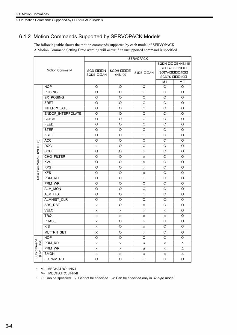
6.1 Motion Commands
6.1.2 Motion Commands Supported by SERVOPACK Models
6-4
6.1.2 Motion Commands Supported by SERVOPACK Models
The following table shows the motion commands supported by each model of SERVOPACK. A Motion Command Setting Error warning will occur if an unsupported command is specified.
M-I: MECHATROLINK-IM-II: MECHATROLINK-II
: Can be specified. ×: Cannot be specified. Δ: Can be specified only in 32-byte mode.
Motion Command
SERVOPACK
SGD-NSGDB-AN
SGDH-E+NS100
SJDE-AN
SGDH-E+NS115SGDS-1
SGDV-1SGD7S-10
M-I M-II
Mai
n C
omm
and
(OW
08)
NOP
POSING
EX_POSING
ZRET
INTERPOLATE
ENDOF_INTERPOLATE
LATCH
FEED
STEP
ZSET
ACC
DCC ×
SCC ×
CHG_FILTER ×
KVS ×
KPS ×
KFS ×
PRM_RD
PRM_WR
ALM_MON
ALM_HIST
ALMHIST_CLR
ABS_RST × ×
VELO × × × ×
TRQ × × × ×
PHASE × ×
KIS × ×
MLTTRN_SET × ×
Sub
com
ma
nd (
OW
0A)
NOP
PRM_RD × × Δ × ΔPRM_WR × × Δ × ΔSMON × × Δ × ΔFIXPRM_RD
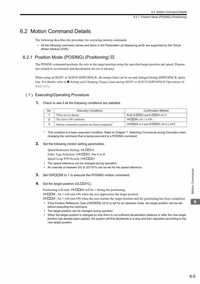
6.2 Motion Command Details
6.2.1 Position Mode (POSING) (Positioning)
6-5
Mot
ion
Com
man
ds
6.2 Motion Command Details
The following describes the procedure for executing motion commands.
All the following command names and items in the Parameter List displaying an are supported by the Virtual Motion Module (SVR).
6.2.1 Position Mode (POSING) (Positioning)
The POSING command positions the axis to the target position using the specified target position and speed. Parame-ters related to acceleration and deceleration are set in advance.
When using an SGDV or SGD7S SERVOPACK, the torque limit can be set and changed during SERVOPACK opera-tion. For details, refer to Setting and Changing Torque Limit during SGDV or SGD7S SERVOPACK Operations of 4.4.2 ( 12 ).
( 1 ) Executing/Operating Procedure
1. Check to see if all the following conditions are satisfied.
* This condition is a basic execution condition. Refer to Chapter 7 Switching Commands during Execution when changing the command that is being executed to a POSING command.
2. Set the following motion setting parameters.
Speed Reference Setting: OL10Filter Type Selection: OW03, bits 8 to BSpeed Loop P/PI Switch: OW01
The speed reference can be changed during operation.
An override of between 0% to 327.67% can be set for the speed reference.
3. Set OW08 to 1 to execute the POSING motion command.
4. Set the target position (OL1C).
Positioning will start. IW08 will be 1 during the positioning.IW0C, bit 3 will turn ON when the axis approaches the target position.IW0C, bit 1 will turn ON when the axis reaches the target position and the positioning has been completed.
If the Position Reference Type (OW09, bit 5) is set for an absolute mode, the target position can be set before executing the command.
The target position can be changed during operation.
When the target position is changed so that there is not sufficient deceleration distance or after the new target position has already been passed, the system will first decelerate to a stop and then reposition according to the new target position.
R
R
No. Execution Conditions Confirmation Method
1 There are no alarms. Both IL02 and IL04 are 0.
2 The Servo ON condition. IW00, bit 1 is ON.
3 Motion command execution has been completed.* IW08 is 0 and IW09, bit 0 is OFF.
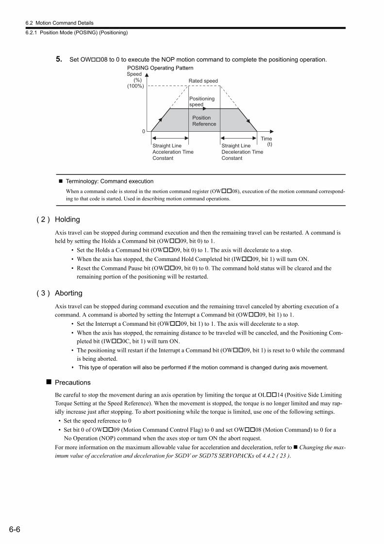
6.2 Motion Command Details
6.2.1 Position Mode (POSING) (Positioning)
6-6
5. Set OW08 to 0 to execute the NOP motion command to complete the positioning operation.
Terminology: Command execution
When a command code is stored in the motion command register (OW08), execution of the motion command correspond-ing to that code is started. Used in describing motion command operations.
( 2 ) Holding
Axis travel can be stopped during command execution and then the remaining travel can be restarted. A command is held by setting the Holds a Command bit (OW09, bit 0) to 1.
• Set the Holds a Command bit (OW09, bit 0) to 1. The axis will decelerate to a stop.
• When the axis has stopped, the Command Hold Completed bit (IW09, bit 1) will turn ON.
• Reset the Command Pause bit (OW09, bit 0) to 0. The command hold status will be cleared and the remaining portion of the positioning will be restarted.
( 3 ) Aborting
Axis travel can be stopped during command execution and the remaining travel canceled by aborting execution of a command. A command is aborted by setting the Interrupt a Command bit (OW09, bit 1) to 1.
• Set the Interrupt a Command bit (OW09, bit 1) to 1. The axis will decelerate to a stop.
• When the axis has stopped, the remaining distance to be traveled will be canceled, and the Positioning Com-pleted bit (IW0C, bit 1) will turn ON.
• The positioning will restart if the Interrupt a Command bit (OW09, bit 1) is reset to 0 while the command is being aborted.
This type of operation will also be performed if the motion command is changed during axis movement.
Precautions
Be careful to stop the movement during an axis operation by limiting the torque at OL14 (Positive Side Limiting Torque Setting at the Speed Reference). When the movement is stopped, the torque is no longer limited and may rap-idly increase just after stopping. To abort positioning while the torque is limited, use one of the following settings.
• Set the speed reference to 0
• Set bit 0 of OW09 (Motion Command Control Flag) to 0 and set OW08 (Motion Command) to 0 for a No Operation (NOP) command when the axes stop or turn ON the abort request.
For more information on the maximum allowable value for acceleration and deceleration, refer to Changing the max-imum value of acceleration and deceleration for SGDV or SGD7S SERVOPACKs of 4.4.2 ( 23 ).
Speed
(100%)
0
Positioningspeed
Rated speed (%)
Position Reference
Straight Line Acceleration Time Constant
(t)Time
Straight Line Deceleration Time Constant
POSING Operating Pattern
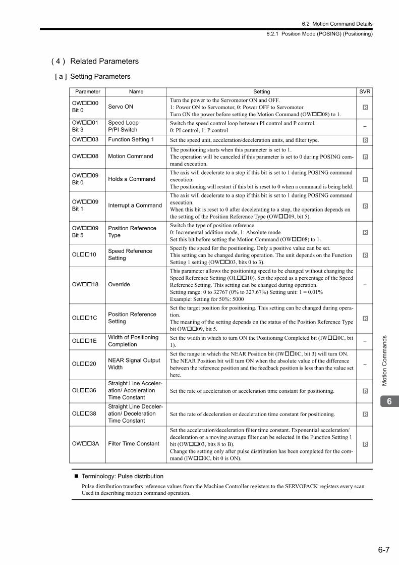
6.2 Motion Command Details
6.2.1 Position Mode (POSING) (Positioning)
6-7
Mot
ion
Com
man
ds
( 4 ) Related Parameters
[ a ] Setting Parameters
Terminology: Pulse distribution
Pulse distribution transfers reference values from the Machine Controller registers to the SERVOPACK registers every scan.Used in describing motion command operation.
Parameter Name Setting SVR
OW00 Bit 0
Servo ONTurn the power to the Servomotor ON and OFF. 1: Power ON to Servomotor, 0: Power OFF to ServomotorTurn ON the power before setting the Motion Command (OW08) to 1.
OW01 Bit 3
Speed Loop P/PI Switch
Switch the speed control loop between PI control and P control. 0: PI control, 1: P control
−
OW03 Function Setting 1 Set the speed unit, acceleration/deceleration units, and filter type.
OW08 Motion CommandThe positioning starts when this parameter is set to 1. The operation will be canceled if this parameter is set to 0 during POSING com-mand execution.
OW09Bit 0
Holds a CommandThe axis will decelerate to a stop if this bit is set to 1 during POSING command execution. The positioning will restart if this bit is reset to 0 when a command is being held.
OW09 Bit 1
Interrupt a Command
The axis will decelerate to a stop if this bit is set to 1 during POSING command execution. When this bit is reset to 0 after decelerating to a stop, the operation depends on the setting of the Position Reference Type (OW09, bit 5).
OW09 Bit 5
Position Reference Type
Switch the type of position reference.0: Incremental addition mode, 1: Absolute mode Set this bit before setting the Motion Command (OW08) to 1.
OL10Speed ReferenceSetting
Specify the speed for the positioning. Only a positive value can be set.This setting can be changed during operation. The unit depends on the Function Setting 1 setting (OW03, bits 0 to 3).
OW18 Override
This parameter allows the positioning speed to be changed without changing the Speed Reference Setting (OL10). Set the speed as a percentage of the Speed Reference Setting. This setting can be changed during operation. Setting range: 0 to 32767 (0% to 327.67%) Setting unit: 1 = 0.01%Example: Setting for 50%: 5000
−
OL1CPosition Reference Setting
Set the target position for positioning. This setting can be changed during opera-tion.The meaning of the setting depends on the status of the Position Reference Type bit OW09, bit 5.
OL1EWidth of Positioning Completion
Set the width in which to turn ON the Positioning Completed bit (IW0C, bit 1).
−
OL20NEAR Signal Output Width
Set the range in which the NEAR Position bit (IW0C, bit 3) will turn ON. The NEAR Position bit will turn ON when the absolute value of the difference between the reference position and the feedback position is less than the value set here.
−
OL36Straight Line Acceler-ation/ Acceleration Time Constant
Set the rate of acceleration or acceleration time constant for positioning.
OL38Straight Line Deceler-ation/ Deceleration Time Constant
Set the rate of deceleration or deceleration time constant for positioning.
OW3A Filter Time Constant
Set the acceleration/deceleration filter time constant. Exponential acceleration/deceleration or a moving average filter can be selected in the Function Setting 1 bit (OW03, bits 8 to B). Change the setting only after pulse distribution has been completed for the com-mand (IW0C, bit 0 is ON).
R
R
R
R
R
R
R
R
R
R
R
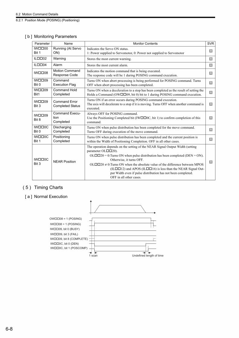
6.2 Motion Command Details
6.2.1 Position Mode (POSING) (Positioning)
6-8
[ b ] Monitoring Parameters
( 5 ) Timing Charts
[ a ] Normal Execution
Parameter Name Monitor Contents SVR
IW00 Bit 1
Running (At Servo ON)
Indicates the Servo ON status. 1: Power supplied to Servomotor, 0: Power not supplied to Servomotor
IL02 Warning Stores the most current warning.
IL04 Alarm Stores the most current alarm.
IW08Motion Command Response Code
Indicates the motion command that is being executed. The response code will be 1 during POSING command execution.
IW09 Bit 0
Command Execution Flag
Turns ON when abort processing is being performed for POSING command. Turns OFF when abort processing has been completed.
IW09 Bit1
Command Hold Completed
Turns ON when a deceleration to a stop has been completed as the result of setting the Holds a Command (OW09, bit 0) bit to 1 during POSING command execution.
IW09 Bit 3
Command Error Completed Status
Turns ON if an error occurs during POSING command execution. The axis will decelerate to a stop if it is moving. Turns OFF when another command is executed.
IW09 Bit 8
Command Execu-tion Completed
Always OFF for POSING command. Use the Positioning Completed bit (IW0C, bit 1) to confirm completion of this command.
IW0C Bit 0
Discharging Completed
Turns ON when pulse distribution has been completed for the move command. Turns OFF during execution of the move command.
IW0C Bit 1
Positioning Completed
Turns ON when pulse distribution has been completed and the current position is within the Width of Positioning Completion. OFF in all other cases.
IW0C Bit 3
NEAR Position
The operation depends on the setting of the NEAR Signal Output Width (setting parameter OL20).
OL20 = 0:Turns ON when pulse distribution has been completed (DEN = ON). Otherwise, it turns OFF.
OL20 ≠ 0:Turns ON when the absolute value of the difference between MPOS (IL12) and APOS (IL16) is less than the NEAR Signal Out-put Width even if pulse distribution has not been completed.OFF in all other cases.
R
R
R
R
R
R
R
R
R
R
R
OW��08 = 1 (POSING)
IW��08 = 1 (POSING)
IW��09, bit 0 (BUSY)
Undefined length of time
IW��09, bit 8 (COMPLETE)
IW��09, bit 3 (FAIL)
IW��0C, bit 0 (DEN)
IW��0C, bit 1 (POSCOMP)
1 scan
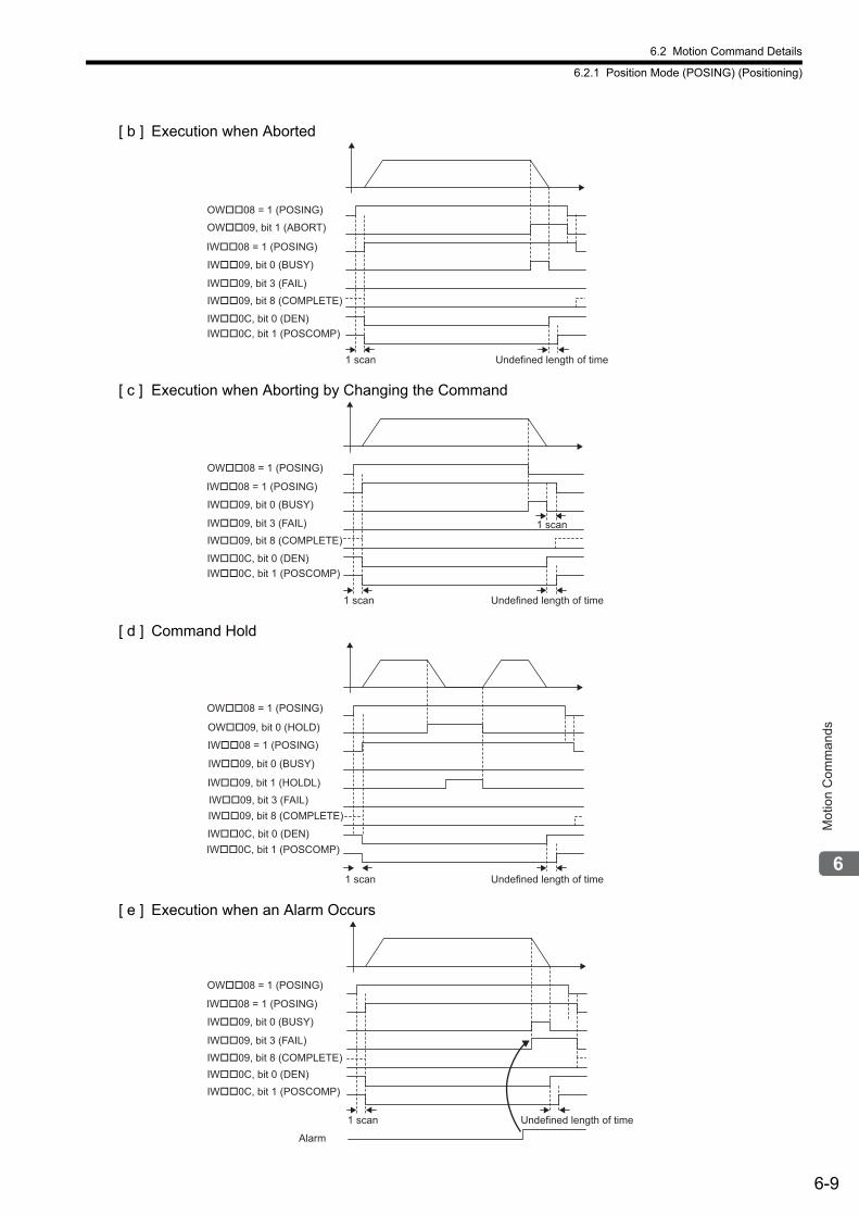
6.2 Motion Command Details
6.2.1 Position Mode (POSING) (Positioning)
6-9
Mot
ion
Com
man
ds
[ b ] Execution when Aborted
[ c ] Execution when Aborting by Changing the Command
[ d ] Command Hold
[ e ] Execution when an Alarm Occurs
Undefined length of time1 scan
OW��09, bit 1 (ABORT)
OW��08 = 1 (POSING)
IW��08 = 1 (POSING)
IW��09, bit 0 (BUSY)
IW��09, bit 8 (COMPLETE)
IW��09, bit 3 (FAIL)
IW��0C, bit 0 (DEN)
IW��0C, bit 1 (POSCOMP)
Undefined length of time1 scan
1 scan
OW��08 = 1 (POSING)
IW��08 = 1 (POSING)
IW��09, bit 0 (BUSY)
IW��09, bit 8 (COMPLETE)
IW��09, bit 3 (FAIL)
IW��0C, bit 0 (DEN)
IW��0C, bit 1 (POSCOMP)
Undefined length of time1 scan
OW��09, bit 0 (HOLD)
IW��09, bit 1 (HOLDL)
OW��08 = 1 (POSING)
IW��08 = 1 (POSING)
IW��09, bit 0 (BUSY)
IW��09, bit 8 (COMPLETE)
IW��09, bit 3 (FAIL)
IW��0C, bit 0 (DEN)
IW��0C, bit 1 (POSCOMP)
Undefined length of time
Alarm
1 scan
OW��08 = 1 (POSING)
IW��08 = 1 (POSING)
IW��09, bit 0 (BUSY)
IW��09, bit 8 (COMPLETE)
IW��09, bit 3 (FAIL)
IW��0C, bit 0 (DEN)
IW��0C, bit 1 (POSCOMP)
6.2 Motion Command Details
6.2.2 Latch Target Positioning (EX_POSING) (External Positioning)
6-10
6.2.2 Latch Target Positioning (EX_POSING) (External Positioning)
The EX_POSING command positions the axis to the target position using the specified target position and speed. Parameters related to acceleration and deceleration are set in advance. If the external positioning signal turns ON during axis movement, the axis will move the distance specified for the External Positioning Final Travel Distance from the point at which the external positioning signal turned ON, and then stop. If the external positioning signal does not turn ON, positioning will be completed to the original target position.
When using an SGDV or SGD7S SERVOPACK, the torque limit can be set and changed during SERVOPACK opera-tion. For details, refer to Setting and Changing Torque Limit during SGDV or SGD7S SERVOPACK Operations of 4.4.2 ( 12 ). Also, refer to Precautions of 6.2.1 ( 3 ). When using a DC Power Input Σ-V Series SERVOPACK (Model: SGDV-E1), refer to 11.7.4 Motion Com-mand Operation for External Latches with DC Power Input Σ-V-series SERVOPACKs.For more information on the maximum allowable value for acceleration and deceleration, refer to Changing the max-imum value of acceleration and deceleration for SGDV or SGD7S SERVOPACKs of 4.4.2 ( 23 ).
( 1 ) Executing/Operating Procedure
1. Check to see if all the following conditions are satisfied.
* This condition is a basic execution condition. Refer to Chapter 7 Switching Commands during Execution when changing the command that is being executed to an EX_POSING command.
2. Set the following motion setting parameters.
External Positioning Final Travel Distance: OL46External Positioning Signal Setting: OW04Speed Reference Setting: OL10Filter Type Selection: OW03, bits 8 to BSpeed Loop P/PI Switch: OW01Position Reference Setting: OL1C
The Speed Reference Setting can be changed during operation.
An override of between 0% to 327.67% can be set for the speed reference.
A latch zone can be set as long as it is supported by the SERVOPACK being used.
3. Set OW08 to 2 to execute the EX_POSING motion command to use the preceding settings in the
same scan.
4. Turn ON the external positioning signal.
The axis will be moved the External Positioning Final Travel Move Distance and decelerate to a stop.IW09, bit 8 will turn ON when the axis stops and external positioning has been completed.
R
No. Execution Conditions Confirmation Method
1 There are no alarms. Both IL02 and IL04 are 0.
2 The Servo ON condition. IW00, bit 1 is ON.
3 Motion command execution has been completed.* IW08 is 0 and IW09, bit 0 is OFF.
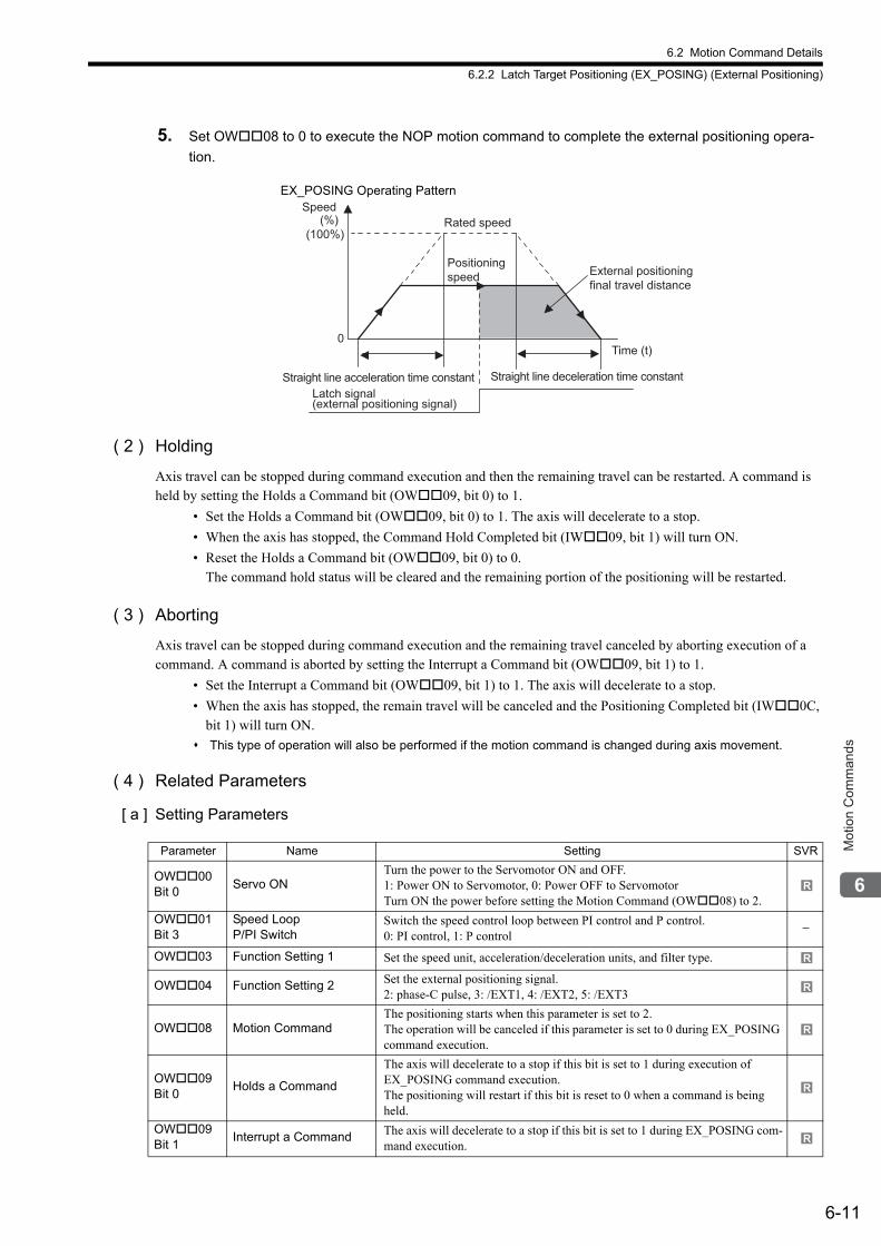
6.2 Motion Command Details
6.2.2 Latch Target Positioning (EX_POSING) (External Positioning)
6-11
Mot
ion
Com
man
ds
5. Set OW08 to 0 to execute the NOP motion command to complete the external positioning opera-
tion.
( 2 ) Holding
Axis travel can be stopped during command execution and then the remaining travel can be restarted. A command is held by setting the Holds a Command bit (OW09, bit 0) to 1.
• Set the Holds a Command bit (OW09, bit 0) to 1. The axis will decelerate to a stop.
• When the axis has stopped, the Command Hold Completed bit (IW09, bit 1) will turn ON.
• Reset the Holds a Command bit (OW09, bit 0) to 0.The command hold status will be cleared and the remaining portion of the positioning will be restarted.
( 3 ) Aborting
Axis travel can be stopped during command execution and the remaining travel canceled by aborting execution of a command. A command is aborted by setting the Interrupt a Command bit (OW09, bit 1) to 1.
• Set the Interrupt a Command bit (OW09, bit 1) to 1. The axis will decelerate to a stop.
• When the axis has stopped, the remain travel will be canceled and the Positioning Completed bit (IW0C, bit 1) will turn ON.
This type of operation will also be performed if the motion command is changed during axis movement.
( 4 ) Related Parameters
[ a ] Setting Parameters
Speed(%)
(100%)
0Time (t)
Straight line deceleration time constant
Rated speed
Latch signal (external positioning signal)
Positioning speed External positioning
final travel distance
Straight line acceleration time constant
EX_POSING Operating Pattern
Parameter Name Setting SVR
OW00 Bit 0
Servo ONTurn the power to the Servomotor ON and OFF. 1: Power ON to Servomotor, 0: Power OFF to ServomotorTurn ON the power before setting the Motion Command (OW08) to 2.
OW01 Bit 3
Speed Loop P/PI Switch
Switch the speed control loop between PI control and P control. 0: PI control, 1: P control
−
OW03 Function Setting 1 Set the speed unit, acceleration/deceleration units, and filter type.
OW04 Function Setting 2 Set the external positioning signal.2: phase-C pulse, 3: /EXT1, 4: /EXT2, 5: /EXT3
OW08 Motion CommandThe positioning starts when this parameter is set to 2. The operation will be canceled if this parameter is set to 0 during EX_POSING command execution.
OW09 Bit 0
Holds a Command
The axis will decelerate to a stop if this bit is set to 1 during execution of EX_POSING command execution. The positioning will restart if this bit is reset to 0 when a command is being held.
OW09 Bit 1
Interrupt a Command The axis will decelerate to a stop if this bit is set to 1 during EX_POSING com-mand execution.
R
R
R
R
R
R
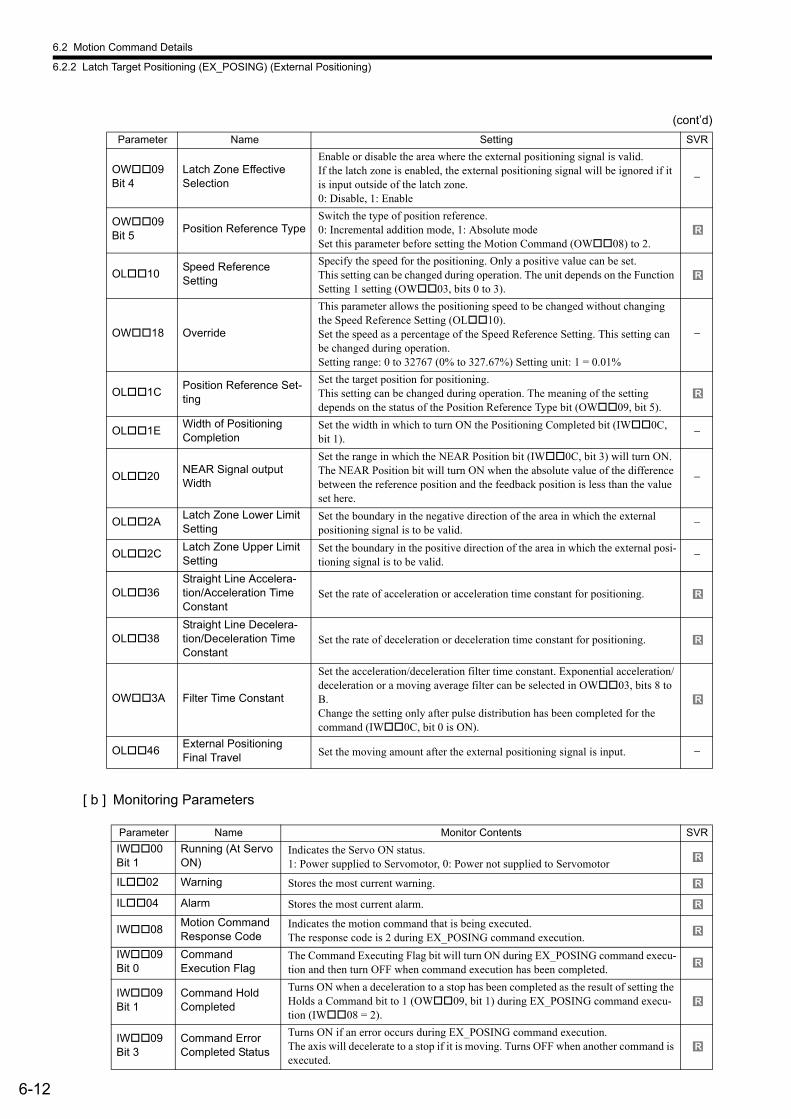
6.2 Motion Command Details
6.2.2 Latch Target Positioning (EX_POSING) (External Positioning)
6-12
[ b ] Monitoring Parameters
OW09 Bit 4
Latch Zone EffectiveSelection
Enable or disable the area where the external positioning signal is valid. If the latch zone is enabled, the external positioning signal will be ignored if it is input outside of the latch zone. 0: Disable, 1: Enable
−
OW09 Bit 5
Position Reference TypeSwitch the type of position reference.0: Incremental addition mode, 1: Absolute mode Set this parameter before setting the Motion Command (OW08) to 2.
OL10Speed ReferenceSetting
Specify the speed for the positioning. Only a positive value can be set.This setting can be changed during operation. The unit depends on the Function Setting 1 setting (OW03, bits 0 to 3).
OW18 Override
This parameter allows the positioning speed to be changed without changing the Speed Reference Setting (OL10). Set the speed as a percentage of the Speed Reference Setting. This setting can be changed during operation. Setting range: 0 to 32767 (0% to 327.67%) Setting unit: 1 = 0.01%
−
OL1CPosition Reference Set-ting
Set the target position for positioning. This setting can be changed during operation. The meaning of the setting depends on the status of the Position Reference Type bit (OW09, bit 5).
OL1EWidth of Positioning Completion
Set the width in which to turn ON the Positioning Completed bit (IW0C, bit 1).
−
OL20NEAR Signal output Width
Set the range in which the NEAR Position bit (IW0C, bit 3) will turn ON. The NEAR Position bit will turn ON when the absolute value of the difference between the reference position and the feedback position is less than the value set here.
−
OL2ALatch Zone Lower LimitSetting
Set the boundary in the negative direction of the area in which the external positioning signal is to be valid.
−
OL2CLatch Zone Upper LimitSetting
Set the boundary in the positive direction of the area in which the external posi-tioning signal is to be valid.
−
OL36Straight Line Accelera-tion/Acceleration Time Constant
Set the rate of acceleration or acceleration time constant for positioning.
OL38Straight Line Decelera-tion/Deceleration Time Constant
Set the rate of deceleration or deceleration time constant for positioning.
OW3A Filter Time Constant
Set the acceleration/deceleration filter time constant. Exponential acceleration/deceleration or a moving average filter can be selected in OW03, bits 8 to B.Change the setting only after pulse distribution has been completed for the command (IW0C, bit 0 is ON).
OL46External Positioning Final Travel Set the moving amount after the external positioning signal is input. −
Parameter Name Monitor Contents SVR
IW00 Bit 1
Running (At Servo ON)
Indicates the Servo ON status. 1: Power supplied to Servomotor, 0: Power not supplied to Servomotor
IL02 Warning Stores the most current warning.
IL04 Alarm Stores the most current alarm.
IW08Motion Command Response Code
Indicates the motion command that is being executed. The response code is 2 during EX_POSING command execution.
IW09 Bit 0
Command Execution Flag
The Command Executing Flag bit will turn ON during EX_POSING command execu-tion and then turn OFF when command execution has been completed.
IW09 Bit 1
Command Hold Completed
Turns ON when a deceleration to a stop has been completed as the result of setting the Holds a Command bit to 1 (OW09, bit 1) during EX_POSING command execu-tion (IW08 = 2).
IW09 Bit 3
Command Error Completed Status
Turns ON if an error occurs during EX_POSING command execution. The axis will decelerate to a stop if it is moving. Turns OFF when another command is executed.
(cont’d)
Parameter Name Setting SVR
R
R
R
R
R
R
R
R
R
R
R
R
R
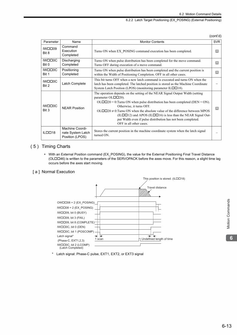
6.2 Motion Command Details
6.2.2 Latch Target Positioning (EX_POSING) (External Positioning)
6-13
Mot
ion
Com
man
ds
( 5 ) Timing Charts
With an External Position command (EX_POSING), the value for the External Positioning Final Travel Distance (OL46) is written to the parameters of the SERVOPACK before the axes move. For this reason, a slight time lag occurs before the axes start moving.
[ a ] Normal Execution
* Latch signal: Phase-C pulse, EXT1, EXT2, or EXT3 signal
IW09 Bit 8
Command Execution Completed
Turns ON when EX_POSING command execution has been completed.
IW0C Bit 0
DischargingCompleted
Turns ON when pulse distribution has been completed for the move command. Turns OFF during execution of a move command.
IW0C Bit 1
Positioning Completed
Turns ON when pulse distribution has been completed and the current position is within the Width of Positioning Completion. OFF in all other cases.
IW0C Bit 2
Latch CompleteThis bit turns OFF when a new latch command is executed and turns ON when the latch has been completed. The latched position is stored as the Machine Coordinate System Latch Position (LPOS) (monitoring parameter IL18).
−
IW0C Bit 3
NEAR Position
The operation depends on the setting of the NEAR Signal Output Width (setting parameter OL20).
OL20 = 0:Turns ON when pulse distribution has been completed (DEN = ON). Otherwise, it turns OFF.
OL20 ≠ 0:Turns ON when the absolute value of the difference between MPOS (IL12) and APOS (IL16) is less than the NEAR Signal Out-put Width even if pulse distribution has not been completed.OFF in all other cases.
IL18Machine Coordi-nate System Latch Position (LPOS)
Stores the current position in the machine coordinate system when the latch signal turned ON.
−
(cont’d)
Parameter Name Monitor Contents SVR
R
R
R
R
OW��08 = 2 (EX_POSING)
IW��08 = 2 (EX_POSING)
IW��09, bit 0 (BUSY)
Undefined length of time
IW��09, bit 8 (COMPLETE)
IW��09, bit 3 (FAIL)
IW��0C, bit 0 (DEN)
(Phase-C, EXT1,2,3)
IW��0C, bit 1 (POSCOMP)
Latch signal*
IW��0C, bit 2 (LCOMP)
(Latch Completed)
1 scan
Travel distance
This position is stored. (IL��18)
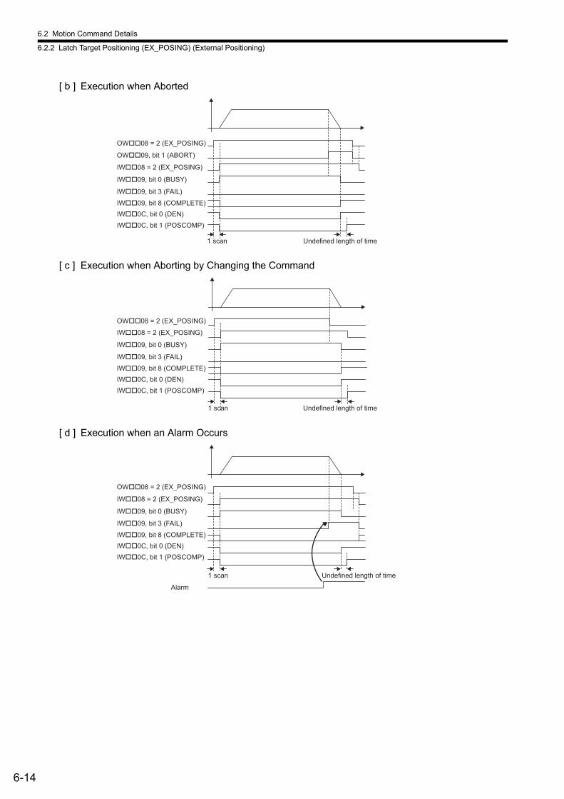
6.2 Motion Command Details
6.2.2 Latch Target Positioning (EX_POSING) (External Positioning)
6-14
[ b ] Execution when Aborted
[ c ] Execution when Aborting by Changing the Command
[ d ] Execution when an Alarm Occurs
OW��08 = 2 (EX_POSING)
IW��08 = 2 (EX_POSING)
IW��09, bit 0 (BUSY)
Undefined length of time
IW��09, bit 8 (COMPLETE)
IW��09, bit 3 (FAIL)
IW��0C, bit 0 (DEN)
IW��0C, bit 1 (POSCOMP)
1 scan
OW��09, bit 1 (ABORT)
Undefined length of time1 scan
OW��08 = 2 (EX_POSING)
IW��08 = 2 (EX_POSING)
IW��09, bit 0 (BUSY)
IW��09, bit 8 (COMPLETE)
IW��09, bit 3 (FAIL)
IW��0C, bit 0 (DEN)
IW��0C, bit 1 (POSCOMP)
Undefined length of time
Alarm
1 scan
OW��08 = 2 (EX_POSING)
IW��08 = 2 (EX_POSING)
IW��09, bit 0 (BUSY)
IW��09, bit 8 (COMPLETE)
IW��09, bit 3 (FAIL)
IW��0C, bit 0 (DEN)
IW��0C, bit 1 (POSCOMP)
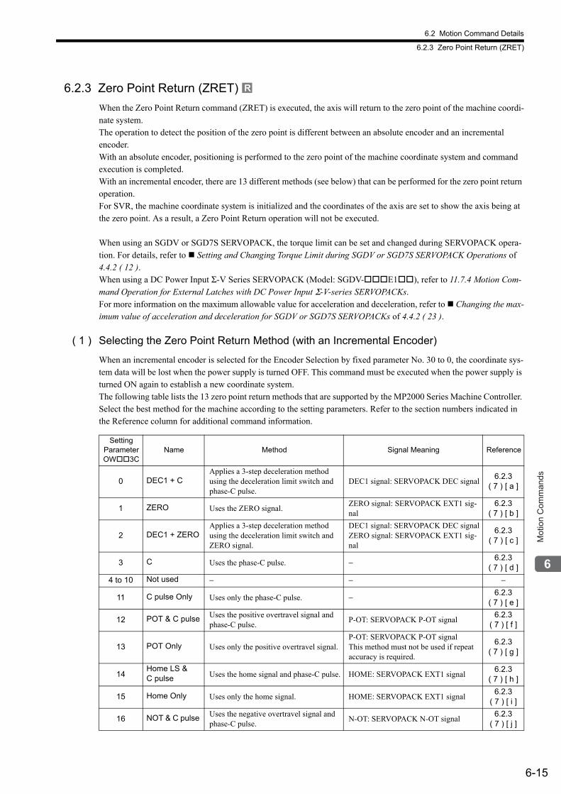
6.2 Motion Command Details
6.2.3 Zero Point Return (ZRET)
6-15
Mot
ion
Com
man
ds
6.2.3 Zero Point Return (ZRET)
When the Zero Point Return command (ZRET) is executed, the axis will return to the zero point of the machine coordi-nate system. The operation to detect the position of the zero point is different between an absolute encoder and an incremental encoder.With an absolute encoder, positioning is performed to the zero point of the machine coordinate system and command execution is completed.With an incremental encoder, there are 13 different methods (see below) that can be performed for the zero point return operation. For SVR, the machine coordinate system is initialized and the coordinates of the axis are set to show the axis being at the zero point. As a result, a Zero Point Return operation will not be executed.
When using an SGDV or SGD7S SERVOPACK, the torque limit can be set and changed during SERVOPACK opera-tion. For details, refer to Setting and Changing Torque Limit during SGDV or SGD7S SERVOPACK Operations of 4.4.2 ( 12 ).When using a DC Power Input Σ-V Series SERVOPACK (Model: SGDV-E1), refer to 11.7.4 Motion Com-mand Operation for External Latches with DC Power Input Σ-V-series SERVOPACKs.For more information on the maximum allowable value for acceleration and deceleration, refer to Changing the max-imum value of acceleration and deceleration for SGDV or SGD7S SERVOPACKs of 4.4.2 ( 23 ).
( 1 ) Selecting the Zero Point Return Method (with an Incremental Encoder)
When an incremental encoder is selected for the Encoder Selection by fixed parameter No. 30 to 0, the coordinate sys-tem data will be lost when the power supply is turned OFF. This command must be executed when the power supply is turned ON again to establish a new coordinate system. The following table lists the 13 zero point return methods that are supported by the MP2000 Series Machine Controller. Select the best method for the machine according to the setting parameters. Refer to the section numbers indicated in the Reference column for additional command information.
R
Setting Parameter OW3C
Name Method Signal Meaning Reference
0 DEC1 + CApplies a 3-step deceleration method using the deceleration limit switch and phase-C pulse.
DEC1 signal: SERVOPACK DEC signal6.2.3
( 7 ) [ a ]
1 ZERO Uses the ZERO signal.ZERO signal: SERVOPACK EXT1 sig-nal
6.2.3( 7 ) [ b ]
2 DEC1 + ZEROApplies a 3-step deceleration method using the deceleration limit switch and ZERO signal.
DEC1 signal: SERVOPACK DEC signalZERO signal: SERVOPACK EXT1 sig-nal
6.2.3( 7 ) [ c ]
3 C Uses the phase-C pulse. − 6.2.3( 7 ) [ d ]
4 to 10 Not used − − −
11 C pulse Only Uses only the phase-C pulse. − 6.2.3( 7 ) [ e ]
12 POT & C pulse Uses the positive overtravel signal and phase-C pulse.
P-OT: SERVOPACK P-OT signal6.2.3
( 7 ) [ f ]
13 POT Only Uses only the positive overtravel signal.P-OT: SERVOPACK P-OT signalThis method must not be used if repeat accuracy is required.
6.2.3( 7 ) [ g ]
14Home LS & C pulse Uses the home signal and phase-C pulse. HOME: SERVOPACK EXT1 signal
6.2.3( 7 ) [ h ]
15 Home Only Uses only the home signal. HOME: SERVOPACK EXT1 signal6.2.3
( 7 ) [ i ]
16 NOT & C pulse Uses the negative overtravel signal and phase-C pulse.
N-OT: SERVOPACK N-OT signal6.2.3
( 7 ) [ j ]

6.2 Motion Command Details
6.2.3 Zero Point Return (ZRET)
6-16
( 2 ) Executing/Operating Procedure
1. Check to see if all the following conditions are satisfied.
* This condition is a basic execution condition. Refer to Chapter 7 Switching Commands during Execution when changing the command that is being executed to a ZRET command.
2. When an incremental encoder is selected for the Encoder Selection Type by setting fixed parameter
No. 30 to 0, set the zero point return method that will be used in the Zero Point Return Method Home (motion setting parameter OW3C) as described on the previous page.
The software limit function will be enabled after the zero point return operation has been completed.
3. Refer to 6.2.3 ( 7 ) Zero Point Return Operation and Parameters and set the required parameters.
4. Set OW08 to 3 to execute the ZRET motion command.
The zero point return operation will start. IW08 will be 3 during the operation. IB0C, bit5 will turn ON when the axis reaches the zero point and zero point return has been completed.
5. Set OW08 to 0 to execute the NOP motion command and then complete the zero point return
operation.
( 3 ) Holding
Holding execution is not possible during zero point return operation. The Holds a Command bit (OW09, bit 0) is ignored.
( 4 ) Aborting
The zero point return can be canceled by aborting execution of a command. A command is aborted by setting the Inter-rupt a Command bit (OW09, bit 1) to 1.
• Set the Interrupt a Command bit (OW09, bit 1) to 1. The axis will decelerate to a stop.
• When the axis has decelerated to a stop the remain travel will be canceled and the Positioning Completed bit (IW0C, bit 1) will turn ON.
This type of operation will also be performed if the motion command is changed during axis movement.
17 NOT Only Uses only the negative overtravel signal.N-OT: SERVOPACK N-OT signalThis method must not be used if repeat accuracy is required.
6.2.3( 7 ) [ k ]
18INPUT & C pulse
Uses the INPUT signal and phase-C pulse.
INPUT: Setting parameter OW05, bit B
6.2.3( 7 ) [ l ]
19 INPUT Only Uses only the INPUT signal.
With this method, a zero point return can be performed without connecting an external signal using setting parameter OW05, bit B. This method must not be used if repeat accuracy is required.
6.2.3( 7 ) [ m ]
(cont’d)
Setting Parameter OW3C
Name Method Signal Meaning Reference
No. Execution Conditions Confirmation Method
1 There are no alarms. Both IL02 and IL04 are 0.
2 The Servo ON condition. IW00, bit 1 is ON.
3 Motion command execution has been completed.* IW08 is 0 and IW09, bit 0 is OFF.
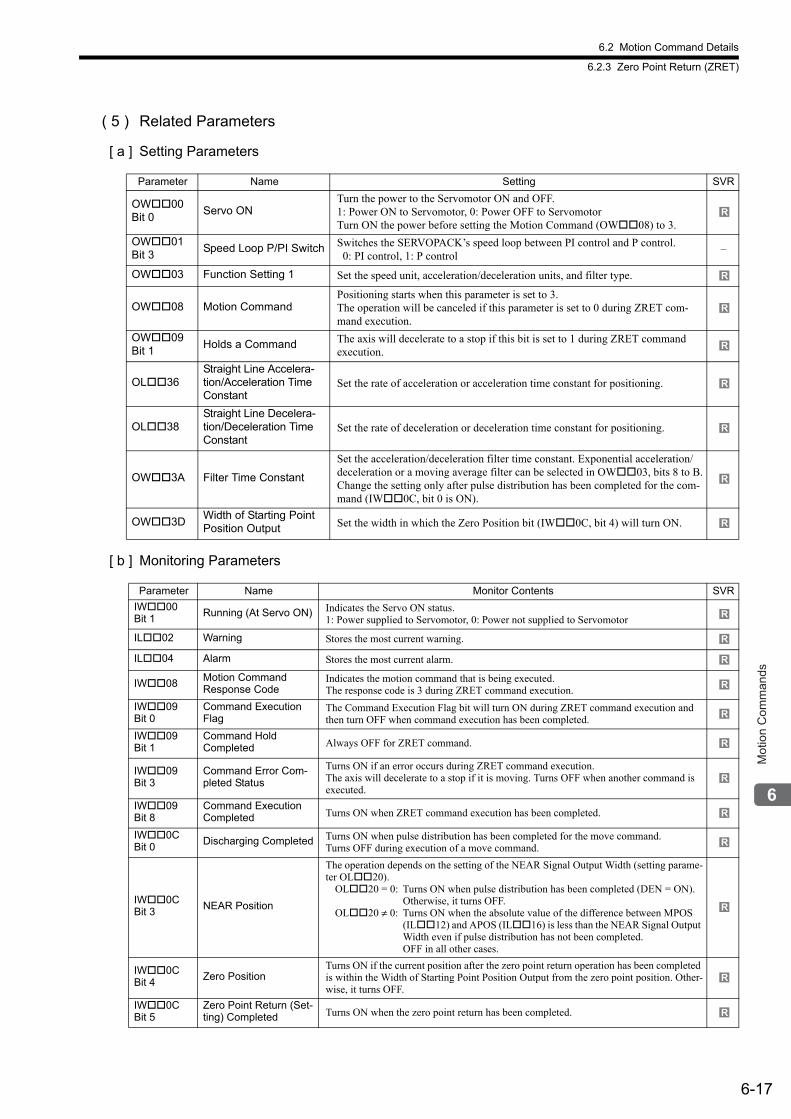
6.2 Motion Command Details
6.2.3 Zero Point Return (ZRET)
6-17
Mot
ion
Com
man
ds
( 5 ) Related Parameters
[ a ] Setting Parameters
[ b ] Monitoring Parameters
Parameter Name Setting SVR
OW00 Bit 0
Servo ONTurn the power to the Servomotor ON and OFF. 1: Power ON to Servomotor, 0: Power OFF to ServomotorTurn ON the power before setting the Motion Command (OW08) to 3.
OW01 Bit 3
Speed Loop P/PI Switch Switches the SERVOPACK’s speed loop between PI control and P control. 0: PI control, 1: P control
–
OW03 Function Setting 1 Set the speed unit, acceleration/deceleration units, and filter type.
OW08 Motion CommandPositioning starts when this parameter is set to 3.The operation will be canceled if this parameter is set to 0 during ZRET com-mand execution.
OW09 Bit 1
Holds a Command The axis will decelerate to a stop if this bit is set to 1 during ZRET command execution.
OL36Straight Line Accelera-tion/Acceleration Time Constant
Set the rate of acceleration or acceleration time constant for positioning.
OL38Straight Line Decelera-tion/Deceleration Time Constant
Set the rate of deceleration or deceleration time constant for positioning.
OW3A Filter Time Constant
Set the acceleration/deceleration filter time constant. Exponential acceleration/deceleration or a moving average filter can be selected in OW03, bits 8 to B.Change the setting only after pulse distribution has been completed for the com-mand (IW0C, bit 0 is ON).
OW3DWidth of Starting Point Position Output Set the width in which the Zero Position bit (IW0C, bit 4) will turn ON.
Parameter Name Monitor Contents SVR
IW00 Bit 1
Running (At Servo ON) Indicates the Servo ON status. 1: Power supplied to Servomotor, 0: Power not supplied to Servomotor
IL02 Warning Stores the most current warning.
IL04 Alarm Stores the most current alarm.
IW08Motion CommandResponse Code
Indicates the motion command that is being executed. The response code is 3 during ZRET command execution.
IW09 Bit 0
Command Execution Flag
The Command Execution Flag bit will turn ON during ZRET command execution and then turn OFF when command execution has been completed.
IW09 Bit 1
Command Hold Completed Always OFF for ZRET command.
IW09 Bit 3
Command Error Com-pleted Status
Turns ON if an error occurs during ZRET command execution. The axis will decelerate to a stop if it is moving. Turns OFF when another command is executed.
IW09 Bit 8
Command Execution Completed Turns ON when ZRET command execution has been completed.
IW0C Bit 0
Discharging Completed Turns ON when pulse distribution has been completed for the move command. Turns OFF during execution of a move command.
IW0C Bit 3
NEAR Position
The operation depends on the setting of the NEAR Signal Output Width (setting parame-ter OL20).
OL20 = 0: Turns ON when pulse distribution has been completed (DEN = ON). Otherwise, it turns OFF.
OL20 ≠ 0: Turns ON when the absolute value of the difference between MPOS (IL12) and APOS (IL16) is less than the NEAR Signal Output Width even if pulse distribution has not been completed.OFF in all other cases.
IW0C Bit 4
Zero PositionTurns ON if the current position after the zero point return operation has been completed is within the Width of Starting Point Position Output from the zero point position. Other-wise, it turns OFF.
IW0C Bit 5
Zero Point Return (Set-ting) Completed Turns ON when the zero point return has been completed.
R
R
R
R
R
R
R
R
R
R
R
R
R
R
R
R
R
R
R
R
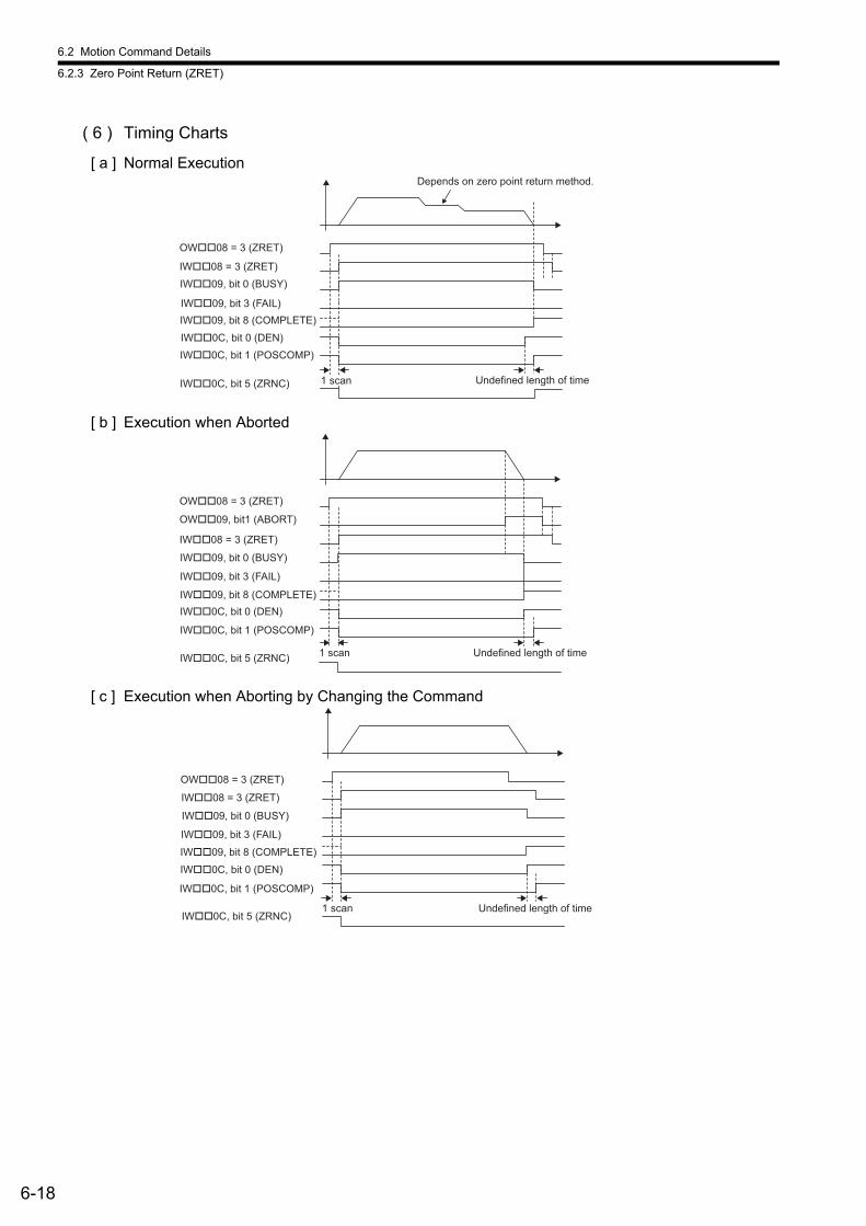
6.2 Motion Command Details
6.2.3 Zero Point Return (ZRET)
6-18
( 6 ) Timing Charts
[ a ] Normal Execution
[ b ] Execution when Aborted
[ c ] Execution when Aborting by Changing the Command
OW��08 = 3 (ZRET)
IW��08 = 3 (ZRET)
IW��09, bit 0 (BUSY)
Undefined length of time
IW��09, bit 8 (COMPLETE)
IW��09, bit 3 (FAIL)
IW��0C, bit 0 (DEN)
IW��0C, bit 1 (POSCOMP)
IW��0C, bit 5 (ZRNC)
Depends on zero point return method.
1 scan
Undefined length of time1 scan
OW��09, bit1 (ABORT)
OW��08 = 3 (ZRET)
IW��08 = 3 (ZRET)
IW��09, bit 0 (BUSY)
IW��09, bit 8 (COMPLETE)
IW��09, bit 3 (FAIL)
IW��0C, bit 0 (DEN)
IW��0C, bit 1 (POSCOMP)
IW��0C, bit 5 (ZRNC)
Undefined length of time1 scan
OW��08 = 3 (ZRET)
IW��08 = 3 (ZRET)
IW��09, bit 0 (BUSY)
IW��09, bit 8 (COMPLETE)
IW��09, bit 3 (FAIL)
IW��0C, bit 0 (DEN)
IW��0C, bit 1 (POSCOMP)
IW��0C, bit 5 (ZRNC)
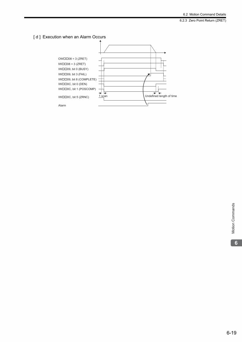
6.2 Motion Command Details
6.2.3 Zero Point Return (ZRET)
6-19
Mot
ion
Com
man
ds
[ d ] Execution when an Alarm Occurs
Undefined length of time
Alarm
1 scan
OW��08 = 3 (ZRET)
IW��08 = 3 (ZRET)
IW��09, bit 0 (BUSY)
IW��09, bit 8 (COMPLETE)
IW��09, bit 3 (FAIL)
IW��0C, bit 0 (DEN)
IW��0C, bit 1 (POSCOMP)
IW��0C, bit 5 (ZRNC)
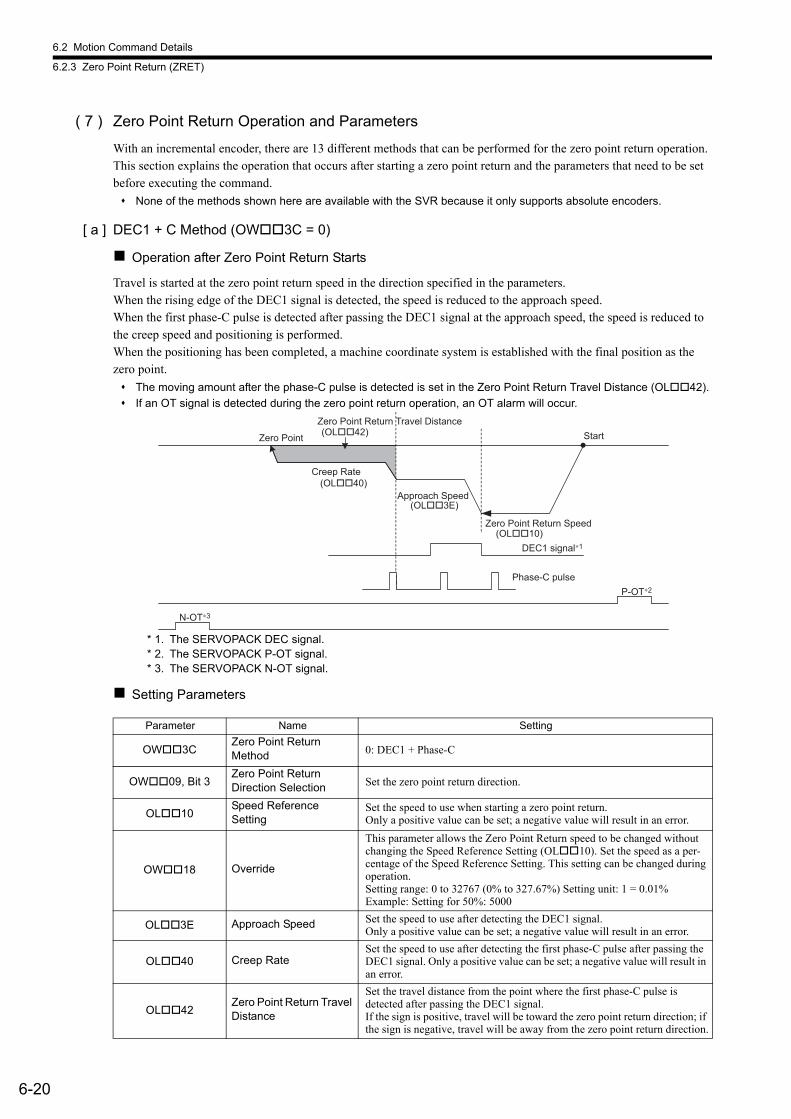
6.2 Motion Command Details
6.2.3 Zero Point Return (ZRET)
6-20
( 7 ) Zero Point Return Operation and Parameters
With an incremental encoder, there are 13 different methods that can be performed for the zero point return operation. This section explains the operation that occurs after starting a zero point return and the parameters that need to be set before executing the command.
None of the methods shown here are available with the SVR because it only supports absolute encoders.
[ a ] DEC1 + C Method (OW3C = 0)
Operation after Zero Point Return Starts
Travel is started at the zero point return speed in the direction specified in the parameters.When the rising edge of the DEC1 signal is detected, the speed is reduced to the approach speed. When the first phase-C pulse is detected after passing the DEC1 signal at the approach speed, the speed is reduced to the creep speed and positioning is performed.When the positioning has been completed, a machine coordinate system is established with the final position as the zero point.
The moving amount after the phase-C pulse is detected is set in the Zero Point Return Travel Distance (OL42).
If an OT signal is detected during the zero point return operation, an OT alarm will occur.
* 1. The SERVOPACK DEC signal. * 2. The SERVOPACK P-OT signal. * 3. The SERVOPACK N-OT signal.
Setting Parameters
Parameter Name Setting
OW3CZero Point ReturnMethod 0: DEC1 + Phase-C
OW09, Bit 3Zero Point ReturnDirection Selection Set the zero point return direction.
OL10Speed ReferenceSetting
Set the speed to use when starting a zero point return. Only a positive value can be set; a negative value will result in an error.
OW18 Override
This parameter allows the Zero Point Return speed to be changed without changing the Speed Reference Setting (OL10). Set the speed as a per-centage of the Speed Reference Setting. This setting can be changed during operation. Setting range: 0 to 32767 (0% to 327.67%) Setting unit: 1 = 0.01%Example: Setting for 50%: 5000
OL3E Approach Speed Set the speed to use after detecting the DEC1 signal. Only a positive value can be set; a negative value will result in an error.
OL40 Creep RateSet the speed to use after detecting the first phase-C pulse after passing the DEC1 signal. Only a positive value can be set; a negative value will result in an error.
OL42Zero Point Return Travel Distance
Set the travel distance from the point where the first phase-C pulse is detected after passing the DEC1 signal. If the sign is positive, travel will be toward the zero point return direction; if the sign is negative, travel will be away from the zero point return direction.
DEC1 signal∗1
N-OT∗3
P-OT∗2
StartZero Point
Phase-C pulse
Zero Point Return Travel Distance(OL��42)
Creep Rate(OL��40)
Approach Speed(OL��3E)
Zero Point Return Speed(OL��10)
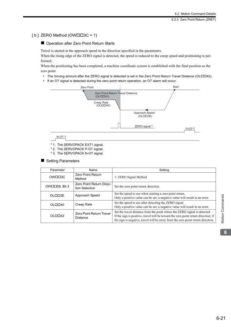
6.2 Motion Command Details
6.2.3 Zero Point Return (ZRET)
6-21
Mot
ion
Com
man
ds
[ b ] ZERO Method (OW3C = 1)
Operation after Zero Point Return Starts
Travel is started at the approach speed in the direction specified in the parameters.When the rising edge of the ZERO signal is detected, the speed is reduced to the creep speed and positioning is per-formed.When the positioning has been completed, a machine coordinate system is established with the final position as the zero point.
The moving amount after the ZERO signal is detected is set in the Zero Point Return Travel Distance (OL42).
If an OT signal is detected during the zero point return operation, an OT alarm will occur.
* 1. The SERVOPACK EXT1 signal. * 2. The SERVOPACK P-OT signal. * 3. The SERVOPACK N-OT signal.
Setting Parameters
Parameter Name Setting
OW3CZero Point ReturnMethod 1: ZERO Signal Method
OW09, Bit 3Zero Point Return Direc-tion Selection Set the zero point return direction.
OL3E Approach Speed Set the speed to use when starting a zero point return.Only a positive value can be set; a negative value will result in an error.
OL40 Creep Rate Set the speed to use after detecting the ZERO signal.Only a positive value can be set; a negative value will result in an error.
OL42Zero Point Return Travel Distance
Set the travel distance from the point where the ZERO signal is detected.If the sign is positive, travel will be toward the zero point return direction; if the sign is negative, travel will be away from the zero point return direction.
N-OT∗3
P-OT∗2
StartZero Point
ZERO signal∗1
Zero Point Return Travel Distance(OL��42)
Creep Rate(OL��40)
Approach Speed(OL��3E)
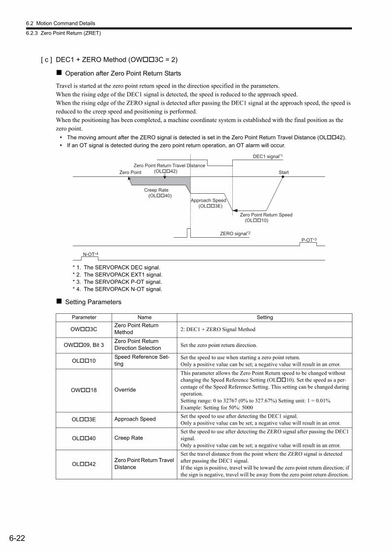
6.2 Motion Command Details
6.2.3 Zero Point Return (ZRET)
6-22
[ c ] DEC1 + ZERO Method (OW3C = 2)
Operation after Zero Point Return Starts
Travel is started at the zero point return speed in the direction specified in the parameters.When the rising edge of the DEC1 signal is detected, the speed is reduced to the approach speed.When the rising edge of the ZERO signal is detected after passing the DEC1 signal at the approach speed, the speed is reduced to the creep speed and positioning is performed.When the positioning has been completed, a machine coordinate system is established with the final position as the zero point.
The moving amount after the ZERO signal is detected is set in the Zero Point Return Travel Distance (OL42).
If an OT signal is detected during the zero point return operation, an OT alarm will occur.
* 1. The SERVOPACK DEC signal. * 2. The SERVOPACK EXT1 signal. * 3. The SERVOPACK P-OT signal. * 4. The SERVOPACK N-OT signal.
Setting Parameters
Parameter Name Setting
OW3CZero Point ReturnMethod 2: DEC1 + ZERO Signal Method
OW09, Bit 3Zero Point ReturnDirection Selection Set the zero point return direction.
OL10Speed Reference Set-ting
Set the speed to use when starting a zero point return. Only a positive value can be set; a negative value will result in an error.
OW18 Override
This parameter allows the Zero Point Return speed to be changed without changing the Speed Reference Setting (OL10). Set the speed as a per-centage of the Speed Reference Setting. This setting can be changed during operation. Setting range: 0 to 32767 (0% to 327.67%) Setting unit: 1 = 0.01%Example: Setting for 50%: 5000
OL3E Approach Speed Set the speed to use after detecting the DEC1 signal.Only a positive value can be set; a negative value will result in an error.
OL40 Creep RateSet the speed to use after detecting the ZERO signal after passing the DEC1 signal.Only a positive value can be set; a negative value will result in an error.
OL42Zero Point Return Travel Distance
Set the travel distance from the point where the ZERO signal is detected after passing the DEC1 signal.If the sign is positive, travel will be toward the zero point return direction; if the sign is negative, travel will be away from the zero point return direction.
DEC1 signal*1
N-OT∗4
P-OT∗3
StartZero Point
ZERO signal*2
Zero Point Return Travel Distance(OL��42)
Creep Rate(OL��40)
Approach Speed(OL��3E)
Zero Point Return Speed(OL��10)
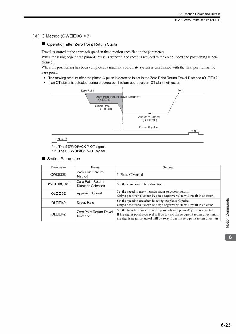
6.2 Motion Command Details
6.2.3 Zero Point Return (ZRET)
6-23
Mot
ion
Com
man
ds
[ d ] C Method (OW3C = 3)
Operation after Zero Point Return Starts
Travel is started at the approach speed in the direction specified in the parameters.When the rising edge of the phase-C pulse is detected, the speed is reduced to the creep speed and positioning is per-formed.When the positioning has been completed, a machine coordinate system is established with the final position as the zero point.
The moving amount after the phase-C pulse is detected is set in the Zero Point Return Travel Distance (OL42).
If an OT signal is detected during the zero point return operation, an OT alarm will occur.
* 1. The SERVOPACK P-OT signal. * 2. The SERVOPACK N-OT signal.
Setting Parameters
Parameter Name Setting
OW3CZero Point ReturnMethod 3: Phase-C Method
OW09, Bit 3Zero Point ReturnDirection Selection Set the zero point return direction.
OL3E Approach Speed Set the speed to use when starting a zero point return. Only a positive value can be set; a negative value will result in an error.
OL40 Creep Rate Set the speed to use after detecting the phase-C pulse.Only a positive value can be set; a negative value will result in an error.
OL42Zero Point Return Travel Distance
Set the travel distance from the point where a phase-C pulse is detected.If the sign is positive, travel will be toward the zero point return direction; if the sign is negative, travel will be away from the zero point return direction.
N-OT*2
P-OT*1
StartZero Point
Phase-C pulse
Zero Point Return Travel Distance(OL��42)
Creep Rate(OL��40)
Approach Speed(OL��3E)

6.2 Motion Command Details
6.2.3 Zero Point Return (ZRET)
6-24
[ e ] C Pulse Only Method (OW3C = 11)
Operation after Zero Point Return Starts
Travel is started at the creep speed in the direction specified by the sign of the creep speed. When the rising edge of the phase-C pulse is detected, positioning is performed at the positioning speed.When the positioning has been completed, a machine coordinate system is established with the final position as the zero point.
The moving amount after the phase-C pulse is detected is set in the Zero Point Return Travel Distance. The posi-tioning speed is set in the Speed Reference.
If an OT signal is detected during creep speed operation, an OT alarm will not occur, the direction will be reversed, and a search will be made for the phase-C pulse.
If an OT signal is detected during positioning speed operation, an OT alarm will occur.
<OT Signal Detected during Creep Speed Operation>
* 1. The SERVOPACK P-OT signal.* 2. The SERVOPACK N-OT signal.
The stopping method when the OT signal is detected depends on the setting of SERVOPACK parameters.
Setting Parameters
Parameter Name Setting
OW3CZero Point ReturnMethod 11: C Pulse Only Method
OL10Speed ReferenceSetting
Set the positioning speed to use after detecting the phase-C pulse. The sign is ignored.The travel direction will depend on the sign of the Home Offset.
OL40 Creep Rate Set the speed and travel direction (sign) to use when starting a zero point return.
OL42Zero Point ReturnMethod
Set the travel distance from the point where a phase-C pulse is detected. The travel direction will depend on the sign.
Phase-C pulse
N-OT*2
P-OT*1
Start Zero Point
Creep Rate(OL��40)
Positioning Speed(OL��10)
Zero Point Return Travel Distance(OL��42)
Phase-C pulse
N-OT*2
P-OT*1
StartZero Point
Positioning Speed(OL��10)
Home Offset(OL��42)
Creep Rate(OL��40)
Creep Rate(OL��40)
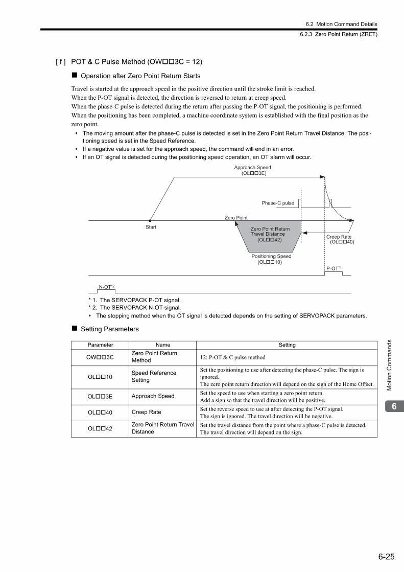
6.2 Motion Command Details
6.2.3 Zero Point Return (ZRET)
6-25
Mot
ion
Com
man
ds
[ f ] POT & C Pulse Method (OW3C = 12)
Operation after Zero Point Return Starts
Travel is started at the approach speed in the positive direction until the stroke limit is reached.When the P-OT signal is detected, the direction is reversed to return at creep speed.When the phase-C pulse is detected during the return after passing the P-OT signal, the positioning is performed.When the positioning has been completed, a machine coordinate system is established with the final position as the zero point.
The moving amount after the phase-C pulse is detected is set in the Zero Point Return Travel Distance. The posi-tioning speed is set in the Speed Reference.
If a negative value is set for the approach speed, the command will end in an error.
If an OT signal is detected during the positioning speed operation, an OT alarm will occur.
* 1. The SERVOPACK P-OT signal. * 2. The SERVOPACK N-OT signal.
The stopping method when the OT signal is detected depends on the setting of SERVOPACK parameters.
Setting Parameters
Parameter Name Setting
OW3CZero Point ReturnMethod 12: P-OT & C pulse method
OL10Speed ReferenceSetting
Set the positioning to use after detecting the phase-C pulse. The sign is ignored.The zero point return direction will depend on the sign of the Home Offset.
OL3E Approach Speed Set the speed to use when starting a zero point return.Add a sign so that the travel direction will be positive.
OL40 Creep Rate Set the reverse speed to use at after detecting the P-OT signal.The sign is ignored. The travel direction will be negative.
OL42Zero Point Return TravelDistance
Set the travel distance from the point where a phase-C pulse is detected.The travel direction will depend on the sign.
Phase-C pulse
N-OT*2
P-OT*1
Start
Zero Point
Approach Speed(OL��3E)
Zero Point Return Travel Distance
(OL��42)
Positioning Speed(OL��10)
Creep Rate(OL��40)
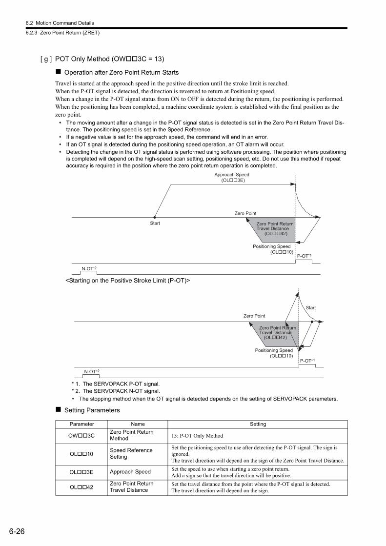
6.2 Motion Command Details
6.2.3 Zero Point Return (ZRET)
6-26
[ g ] POT Only Method (OW3C = 13)
Operation after Zero Point Return Starts
Travel is started at the approach speed in the positive direction until the stroke limit is reached.When the P-OT signal is detected, the direction is reversed to return at Positioning speed.When a change in the P-OT signal status from ON to OFF is detected during the return, the positioning is performed.When the positioning has been completed, a machine coordinate system is established with the final position as the zero point. The moving amount after a change in the P-OT signal status is detected is set in the Zero Point Return Travel Dis-
tance. The positioning speed is set in the Speed Reference. If a negative value is set for the approach speed, the command will end in an error. If an OT signal is detected during the positioning speed operation, an OT alarm will occur. Detecting the change in the OT signal status is performed using software processing. The position where positioning
is completed will depend on the high-speed scan setting, positioning speed, etc. Do not use this method if repeat accuracy is required in the position where the zero point return operation is completed.
<Starting on the Positive Stroke Limit (P-OT)>
* 1. The SERVOPACK P-OT signal. * 2. The SERVOPACK N-OT signal.
The stopping method when the OT signal is detected depends on the setting of SERVOPACK parameters.
Setting Parameters
Parameter Name Setting
OW3CZero Point Return Method 13: P-OT Only Method
OL10Speed ReferenceSetting
Set the positioning speed to use after detecting the P-OT signal. The sign is ignored.The travel direction will depend on the sign of the Zero Point Travel Distance.
OL3E Approach Speed Set the speed to use when starting a zero point return.Add a sign so that the travel direction will be positive.
OL42Zero Point Return Travel Distance
Set the travel distance from the point where the P-OT signal is detected.The travel direction will depend on the sign.
N-OT*2
P-OT*1
Start
Zero Point
Approach Speed(OL��3E)
Zero Point Return Travel Distance
(OL��42)
Positioning Speed(OL��10)
P-OT∗1
Start
Zero Point
N-OT∗2
Zero Point Return Travel Distance
(OL��42)
Positioning Speed(OL��10)
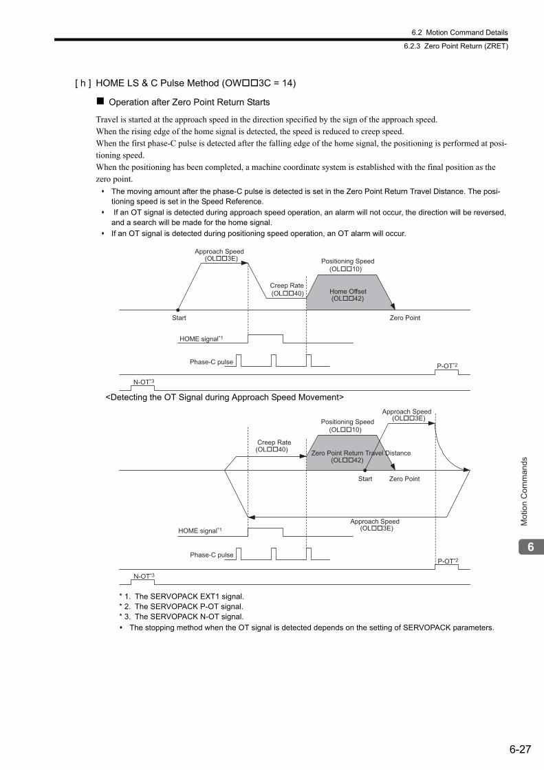
6.2 Motion Command Details
6.2.3 Zero Point Return (ZRET)
6-27
Mot
ion
Com
man
ds
[ h ] HOME LS & C Pulse Method (OW3C = 14)
Operation after Zero Point Return Starts
Travel is started at the approach speed in the direction specified by the sign of the approach speed.When the rising edge of the home signal is detected, the speed is reduced to creep speed.When the first phase-C pulse is detected after the falling edge of the home signal, the positioning is performed at posi-tioning speed.When the positioning has been completed, a machine coordinate system is established with the final position as the zero point.
The moving amount after the phase-C pulse is detected is set in the Zero Point Return Travel Distance. The posi-tioning speed is set in the Speed Reference.
If an OT signal is detected during approach speed operation, an alarm will not occur, the direction will be reversed, and a search will be made for the home signal.
If an OT signal is detected during positioning speed operation, an OT alarm will occur.
<Detecting the OT Signal during Approach Speed Movement>
* 1. The SERVOPACK EXT1 signal. * 2. The SERVOPACK P-OT signal. * 3. The SERVOPACK N-OT signal.
The stopping method when the OT signal is detected depends on the setting of SERVOPACK parameters.
HOME signal*1
N-OT*3
P-OT*2
Start Zero Point
Phase-C pulse
Approach Speed(OL��3E)
Creep Rate(OL��40)
Positioning Speed(OL��10)
Home Offset(OL��42)
HOME signal*1
N-OT*3
P-OT*2
Start Zero Point
Phase-C pulse
Creep Rate(OL��40)
Positioning Speed(OL��10)
Zero Point Return Travel Distance(OL��42)
Approach Speed(OL��3E)
Approach Speed(OL��3E)
6.2 Motion Command Details
6.2.3 Zero Point Return (ZRET)
6-28
Setting Parameters
Parameter Name Setting
OW3CZero Point Return Method 14: HOME LS & C pulse method
OL10Speed ReferenceSetting
Set the positioning speed to use after detecting the phase-C pulse. The sign is ignored.The travel direction depends on the sign of the Zero Point Return Travel Distance.
OL3E Approach Speed Set the speed to use when starting a zero point return.The travel direction will depend on the sign of the approach speed.
OL40 Creep Rate Set the speed to use after detecting the home signal and the travel direction (sign).
OL42Zero Point Return Travel Distance
Set the travel distance from the point where a phase-C pulse is detected.The travel direction will depend on the sign.
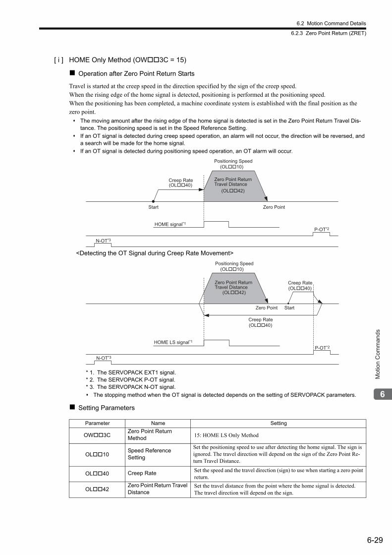
6.2 Motion Command Details
6.2.3 Zero Point Return (ZRET)
6-29
Mot
ion
Com
man
ds
[ i ] HOME Only Method (OW3C = 15)
Operation after Zero Point Return Starts
Travel is started at the creep speed in the direction specified by the sign of the creep speed.When the rising edge of the home signal is detected, positioning is performed at the positioning speed.When the positioning has been completed, a machine coordinate system is established with the final position as the zero point.
The moving amount after the rising edge of the home signal is detected is set in the Zero Point Return Travel Dis-tance. The positioning speed is set in the Speed Reference Setting.
If an OT signal is detected during creep speed operation, an alarm will not occur, the direction will be reversed, and a search will be made for the home signal.
If an OT signal is detected during positioning speed operation, an OT alarm will occur.
<Detecting the OT Signal during Creep Rate Movement>
* 1. The SERVOPACK EXT1 signal.* 2. The SERVOPACK P-OT signal.* 3. The SERVOPACK N-OT signal.
The stopping method when the OT signal is detected depends on the setting of SERVOPACK parameters.
Setting Parameters
Parameter Name Setting
OW3CZero Point Return Method 15: HOME LS Only Method
OL10Speed ReferenceSetting
Set the positioning speed to use after detecting the home signal. The sign is ignored. The travel direction will depend on the sign of the Zero Point Re-turn Travel Distance.
OL40 Creep Rate Set the speed and the travel direction (sign) to use when starting a zero point return.
OL42Zero Point Return Travel Distance
Set the travel distance from the point where the home signal is detected.The travel direction will depend on the sign.
HOME signal*1
N-OT*3
P-OT*2
Start Zero Point
Creep Rate(OL��40)
Positioning Speed(OL��10)
Zero Point Return Travel Distance
(OL��42)
HOME LS signal*1
N-OT*3
P-OT*2
StartZero Point
Positioning Speed(OL��10)
Zero Point Return Travel Distance
(OL��42)
Creep Rate(OL��40)
Creep Rate(OL��40)
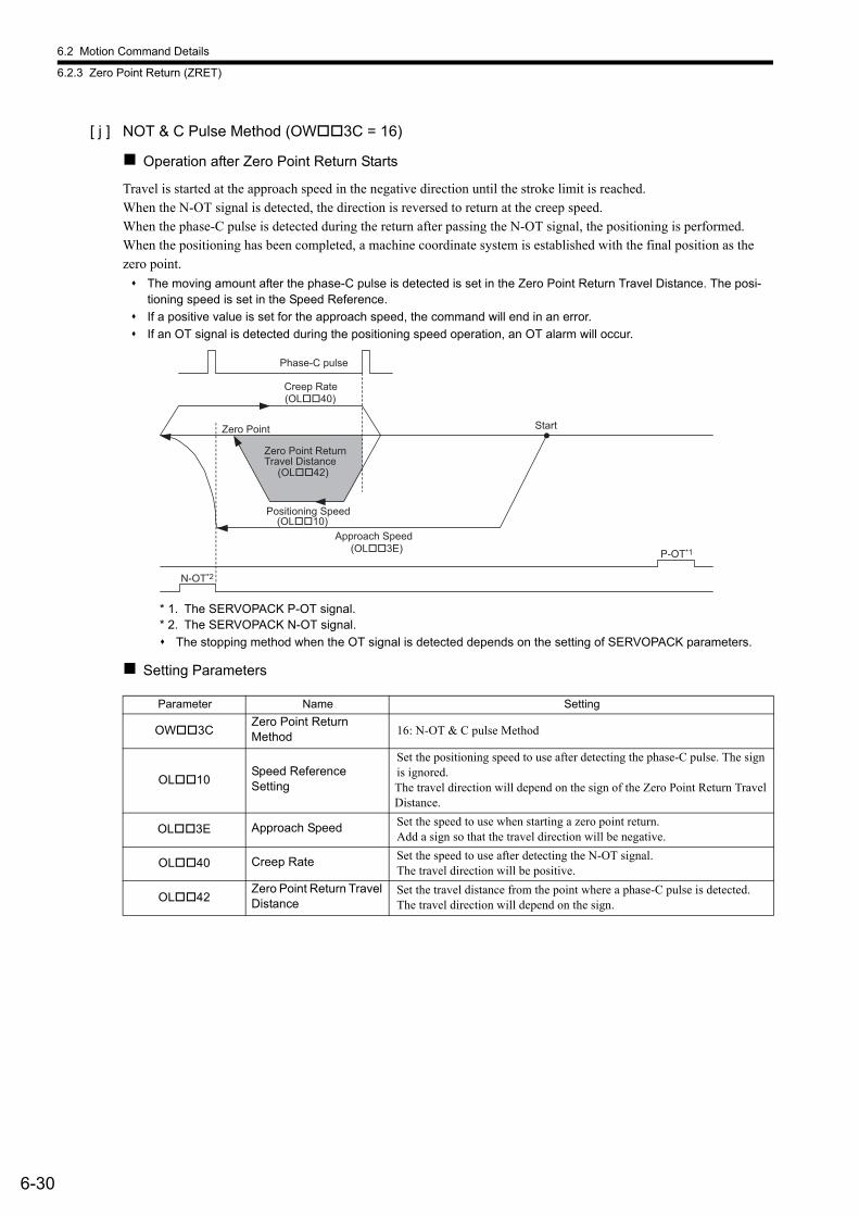
6.2 Motion Command Details
6.2.3 Zero Point Return (ZRET)
6-30
[ j ] NOT & C Pulse Method (OW3C = 16)
Operation after Zero Point Return Starts
Travel is started at the approach speed in the negative direction until the stroke limit is reached.When the N-OT signal is detected, the direction is reversed to return at the creep speed.When the phase-C pulse is detected during the return after passing the N-OT signal, the positioning is performed.When the positioning has been completed, a machine coordinate system is established with the final position as the zero point.
The moving amount after the phase-C pulse is detected is set in the Zero Point Return Travel Distance. The posi-tioning speed is set in the Speed Reference.
If a positive value is set for the approach speed, the command will end in an error.
If an OT signal is detected during the positioning speed operation, an OT alarm will occur.
* 1. The SERVOPACK P-OT signal.* 2. The SERVOPACK N-OT signal.
The stopping method when the OT signal is detected depends on the setting of SERVOPACK parameters.
Setting Parameters
Parameter Name Setting
OW3CZero Point Return Method 16: N-OT & C pulse Method
OL10Speed ReferenceSetting
Set the positioning speed to use after detecting the phase-C pulse. The sign is ignored.The travel direction will depend on the sign of the Zero Point Return Travel Distance.
OL3E Approach Speed Set the speed to use when starting a zero point return.Add a sign so that the travel direction will be negative.
OL40 Creep Rate Set the speed to use after detecting the N-OT signal.The travel direction will be positive.
OL42Zero Point Return Travel Distance
Set the travel distance from the point where a phase-C pulse is detected.The travel direction will depend on the sign.
Phase-C pulse
N-OT*2
P-OT*1
StartZero Point
Creep Rate(OL��40)
Zero Point Return Travel Distance
(OL��42)
Positioning Speed(OL��10)
Approach Speed(OL��3E)
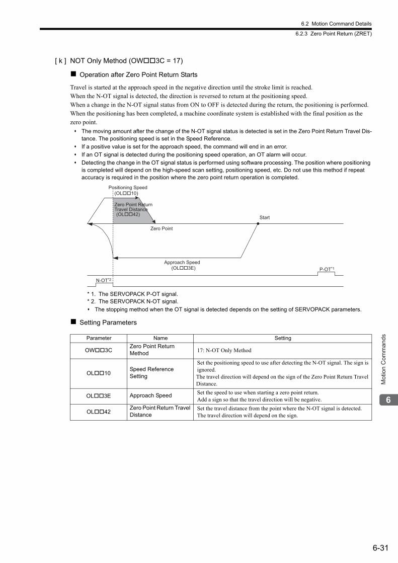
6.2 Motion Command Details
6.2.3 Zero Point Return (ZRET)
6-31
Mot
ion
Com
man
ds
[ k ] NOT Only Method (OW3C = 17)
Operation after Zero Point Return Starts
Travel is started at the approach speed in the negative direction until the stroke limit is reached.When the N-OT signal is detected, the direction is reversed to return at the positioning speed.When a change in the N-OT signal status from ON to OFF is detected during the return, the positioning is performed.When the positioning has been completed, a machine coordinate system is established with the final position as the zero point.
The moving amount after the change of the N-OT signal status is detected is set in the Zero Point Return Travel Dis-tance. The positioning speed is set in the Speed Reference.
If a positive value is set for the approach speed, the command will end in an error.
If an OT signal is detected during the positioning speed operation, an OT alarm will occur.
Detecting the change in the OT signal status is performed using software processing. The position where positioning is completed will depend on the high-speed scan setting, positioning speed, etc. Do not use this method if repeat accuracy is required in the position where the zero point return operation is completed.
* 1. The SERVOPACK P-OT signal.* 2. The SERVOPACK N-OT signal.
The stopping method when the OT signal is detected depends on the setting of SERVOPACK parameters.
Setting Parameters
Parameter Name Setting
OW3CZero Point Return Method 17: N-OT Only Method
OL10Speed ReferenceSetting
Set the positioning speed to use after detecting the N-OT signal. The sign is ignored.The travel direction will depend on the sign of the Zero Point Return Travel Distance.
OL3E Approach Speed Set the speed to use when starting a zero point return.Add a sign so that the travel direction will be negative.
OL42Zero Point Return Travel Distance
Set the travel distance from the point where the N-OT signal is detected.The travel direction will depend on the sign.
N-OT*2
P-OT*1
Zero Point
Start
Positioning Speed(OL��10)
Zero Point Return Travel Distance(OL��42)
Approach Speed(OL��3E)
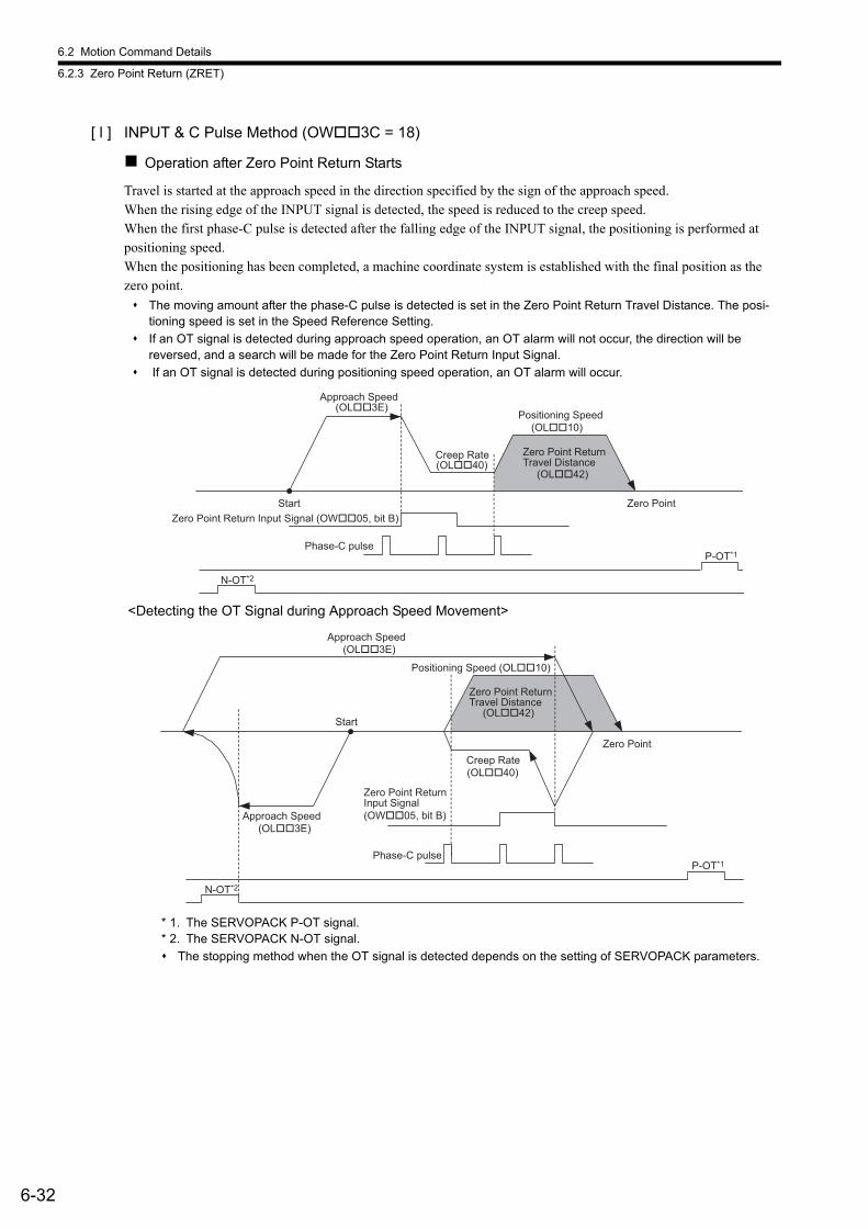
6.2 Motion Command Details
6.2.3 Zero Point Return (ZRET)
6-32
[ l ] INPUT & C Pulse Method (OW3C = 18)
Operation after Zero Point Return Starts
Travel is started at the approach speed in the direction specified by the sign of the approach speed.When the rising edge of the INPUT signal is detected, the speed is reduced to the creep speed.When the first phase-C pulse is detected after the falling edge of the INPUT signal, the positioning is performed at positioning speed.When the positioning has been completed, a machine coordinate system is established with the final position as the zero point.
The moving amount after the phase-C pulse is detected is set in the Zero Point Return Travel Distance. The posi-tioning speed is set in the Speed Reference Setting.
If an OT signal is detected during approach speed operation, an OT alarm will not occur, the direction will be reversed, and a search will be made for the Zero Point Return Input Signal.
If an OT signal is detected during positioning speed operation, an OT alarm will occur.
<Detecting the OT Signal during Approach Speed Movement>
* 1. The SERVOPACK P-OT signal.* 2. The SERVOPACK N-OT signal.
The stopping method when the OT signal is detected depends on the setting of SERVOPACK parameters.
Zero Point Return Input Signal (OW��05, bit B)Start Zero Point
Phase-C pulse
N-OT*2
P-OT*1
Approach Speed(OL��3E)
Creep Rate(OL��40)
Positioning Speed(OL��10)
Zero Point Return Travel Distance
(OL��42)
Start
Zero Point
Positioning Speed (OL��10)
Phase-C pulse
N-OT*2
P-OT*1
Approach Speed(OL��3E)
Zero Point ReturnTravel Distance
(OL��42)
Approach Speed(OL��3E)
Creep Rate(OL��40)
Zero Point Return Input Signal (OW��05, bit B)
6.2 Motion Command Details
6.2.3 Zero Point Return (ZRET)
6-33
Mot
ion
Com
man
ds
Setting Parameters
Parameter Name Setting
OW3CZero Point ReturnMethod 18: INPUT & C pulse Method
OL10Speed ReferenceSetting
Set the positioning speed to use after detecting the phase-C pulse. The sign is ignored.The travel direction will depend on the sign of the Zero Point Return Travel Distance
OL3E Approach Speed Set the speed to use when starting a zero point return.The travel direction will depend on the sign of the approach speed.
OL40 Creep RateSet the speed and the travel direction (sign) to use after detecting the Zero Point Return Input Signal.
OL42Zero Point Return Travel Distance
Set the travel distance from the point where a phase-C pulse is detected.The travel direction will depend on the sign.
OW05, Bit B
Zero Point Return Input Signal This signal must be turned ON from the ladder program.
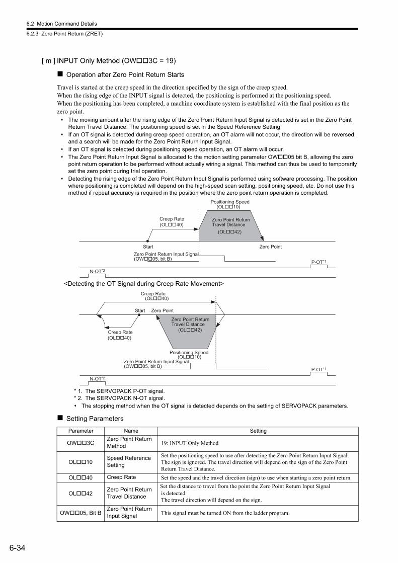
6.2 Motion Command Details
6.2.3 Zero Point Return (ZRET)
6-34
[ m ] INPUT Only Method (OW3C = 19)
Operation after Zero Point Return Starts
Travel is started at the creep speed in the direction specified by the sign of the creep speed.When the rising edge of the INPUT signal is detected, the positioning is performed at the positioning speed.When the positioning has been completed, a machine coordinate system is established with the final position as the zero point. The moving amount after the rising edge of the Zero Point Return Input Signal is detected is set in the Zero Point
Return Travel Distance. The positioning speed is set in the Speed Reference Setting. If an OT signal is detected during creep speed operation, an OT alarm will not occur, the direction will be reversed,
and a search will be made for the Zero Point Return Input Signal. If an OT signal is detected during positioning speed operation, an OT alarm will occur. The Zero Point Return Input Signal is allocated to the motion setting parameter OW05 bit B, allowing the zero
point return operation to be performed without actually wiring a signal. This method can thus be used to temporarily set the zero point during trial operation.
Detecting the rising edge of the Zero Point Return Input Signal is performed using software processing. The position where positioning is completed will depend on the high-speed scan setting, positioning speed, etc. Do not use this method if repeat accuracy is required in the position where the zero point return operation is completed.
<Detecting the OT Signal during Creep Rate Movement>
* 1. The SERVOPACK P-OT signal.* 2. The SERVOPACK N-OT signal. The stopping method when the OT signal is detected depends on the setting of SERVOPACK parameters.
Setting Parameters
Parameter Name Setting
OW3CZero Point Return Method 19: INPUT Only Method
OL10Speed ReferenceSetting
Set the positioning speed to use after detecting the Zero Point Return Input Signal. The sign is ignored. The travel direction will depend on the sign of the Zero Point Return Travel Distance.
OL40 Creep Rate Set the speed and the travel direction (sign) to use when starting a zero point return.
OL42Zero Point Return Travel Distance
Set the distance to travel from the point the Zero Point Return Input Signalis detected.The travel direction will depend on the sign.
OW05, Bit BZero Point Return Input Signal This signal must be turned ON from the ladder program.
Zero Point Return Input Signal(OW��05, bit B)
Start Zero Point
N-OT*2
P-OT*1
Positioning Speed(OL��10)
Creep Rate(OL��40)
Zero Point Return Travel Distance
(OL��42)
Zero Point Return Input Signal(OW��05, bit B)
Start Zero Point
N-OT*2
P-OT*1
Creep Rate(OL��40)
Creep Rate(OL��40)
Zero Point Return Travel Distance
(OL��42)
Positioning Speed(OL��10)
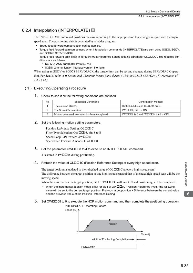
6.2 Motion Command Details
6.2.4 Interpolation (INTERPOLATE)
6-35
Mot
ion
Com
man
ds
6.2.4 Interpolation (INTERPOLATE)
The INTERPOLATE command positions the axis according to the target position that changes in sync with the high-speed scan. The positioning data is generated by a ladder program.
Speed feed forward compensation can be applied.
Torque feed forward gain can be used when interpolation commands (INTERPOLATE) are sent using SGDS, SGDV, and SGD7S SERVOPACKs. Torque feed forward gain is set in Torque/Thrust Reference Setting (setting parameter OL0C). The required con-ditions are as follows:
• SERVOPACK parameter Pn002.0 = 2• SGDS communication interface version 8 or later
When using an SGDV or SGD7S SERVOPACK, the torque limit can be set and changed during SERVOPACK opera-tion. For details, refer to Setting and Changing Torque Limit during SGDV or SGD7S SERVOPACK Operations of 4.4.2 ( 12 ).
( 1 ) Executing/Operating Procedure
1. Check to see if all the following conditions are satisfied.
2. Set the following motion setting parameters.
Position Reference Setting: OL1CFilter Type Selection: OW03, bits 8 to BSpeed Loop P/PI Switch: OW01Speed Feed Forward Amends: OW30
3. Set the parameter OW08 to 4 to execute an INTERPOLATE command.
4 is stored in IW08 during positioning.
4. Refresh the value of OL1C (Position Reference Setting) at every high-speed scan.
The target position is updated to the refreshed value of OL1C at every high-speed scan.*
The difference between the target position of one high-speed scan and that of the next high-speed scan will be the moving speed.When the axis reaches the target position, bit 1 of IW0C will turn ON and positioning will be completed.
* When the incremental addition mode is set for bit 5 of OW09 “Position Reference Type,” the following value will be set to the current target position: Previous target position + Difference between the current value and the previous value of the Position Reference Setting
5. Set OW08 to 0 to execute the NOP motion command and then complete the positioning operation.
R
No. Execution Conditions Confirmation Method
1 There are no alarms. Both IL02 and IL04 are 0.
2 The Servo ON condition. IW00, bit 1 is ON.
3 Motion command execution has been completed. IW08 is 0 and IW09, bit 0 is OFF.
Position
0
Width of Positioning Completion
POSCOMP
Speed (%)
Time (t)
INTERPOLATE Operating Pattern
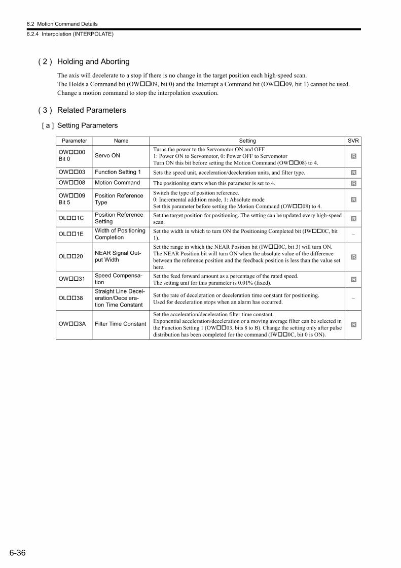
6.2 Motion Command Details
6.2.4 Interpolation (INTERPOLATE)
6-36
( 2 ) Holding and Aborting
The axis will decelerate to a stop if there is no change in the target position each high-speed scan.The Holds a Command bit (OW09, bit 0) and the Interrupt a Command bit (OW09, bit 1) cannot be used. Change a motion command to stop the interpolation execution.
( 3 ) Related Parameters
[ a ] Setting Parameters
Parameter Name Setting SVR
OW00 Bit 0
Servo ONTurns the power to the Servomotor ON and OFF. 1: Power ON to Servomotor, 0: Power OFF to ServomotorTurn ON this bit before setting the Motion Command (OW08) to 4.
OW03 Function Setting 1 Sets the speed unit, acceleration/deceleration units, and filter type.
OW08 Motion Command The positioning starts when this parameter is set to 4.
OW09 Bit 5
Position Reference Type
Switch the type of position reference. 0: Incremental addition mode, 1: Absolute mode Set this parameter before setting the Motion Command (OW08) to 4.
OL1CPosition Reference Setting
Set the target position for positioning. The setting can be updated every high-speed scan.
OL1EWidth of Positioning Completion
Set the width in which to turn ON the Positioning Completed bit (IW0C, bit 1).
–
OL20NEAR Signal Out-put Width
Set the range in which the NEAR Position bit (IW0C, bit 3) will turn ON. The NEAR Position bit will turn ON when the absolute value of the difference between the reference position and the feedback position is less than the value set here.
OW31Speed Compensa-tion
Set the feed forward amount as a percentage of the rated speed. The setting unit for this parameter is 0.01% (fixed).
OL38Straight Line Decel-eration/Decelera-tion Time Constant
Set the rate of deceleration or deceleration time constant for positioning. Used for deceleration stops when an alarm has occurred.
–
OW3A Filter Time Constant
Set the acceleration/deceleration filter time constant.Exponential acceleration/deceleration or a moving average filter can be selected in the Function Setting 1 (OW03, bits 8 to B). Change the setting only after pulse distribution has been completed for the command (IW0C, bit 0 is ON).
R
R
R
R
R
R
R
R
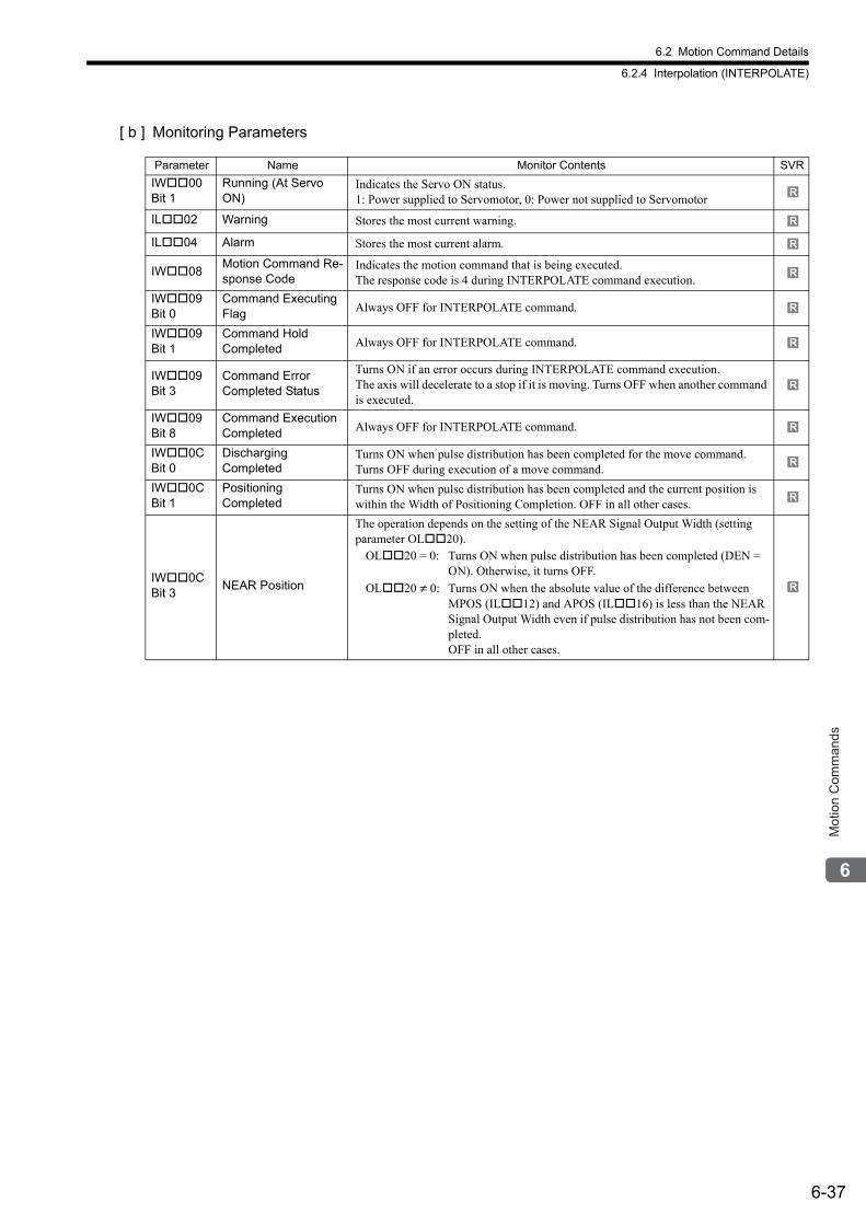
6.2 Motion Command Details
6.2.4 Interpolation (INTERPOLATE)
6-37
Mot
ion
Com
man
ds
[ b ] Monitoring Parameters
Parameter Name Monitor Contents SVR
IW00 Bit 1
Running (At Servo ON)
Indicates the Servo ON status. 1: Power supplied to Servomotor, 0: Power not supplied to Servomotor
IL02 Warning Stores the most current warning.
IL04 Alarm Stores the most current alarm.
IW08Motion Command Re-sponse Code
Indicates the motion command that is being executed. The response code is 4 during INTERPOLATE command execution.
IW09 Bit 0
Command ExecutingFlag Always OFF for INTERPOLATE command.
IW09 Bit 1
Command Hold Completed Always OFF for INTERPOLATE command.
IW09 Bit 3
Command ErrorCompleted Status
Turns ON if an error occurs during INTERPOLATE command execution.The axis will decelerate to a stop if it is moving. Turns OFF when another command is executed.
IW09 Bit 8
Command Execution Completed Always OFF for INTERPOLATE command.
IW0C Bit 0
Discharging Completed
Turns ON when pulse distribution has been completed for the move command. Turns OFF during execution of a move command.
IW0C Bit 1
Positioning Completed
Turns ON when pulse distribution has been completed and the current position is within the Width of Positioning Completion. OFF in all other cases.
IW0C Bit 3
NEAR Position
The operation depends on the setting of the NEAR Signal Output Width (setting parameter OL20).
OL20 = 0: Turns ON when pulse distribution has been completed (DEN = ON). Otherwise, it turns OFF.
OL20 ≠ 0: Turns ON when the absolute value of the difference between MPOS (IL12) and APOS (IL16) is less than the NEAR Signal Output Width even if pulse distribution has not been com-pleted.OFF in all other cases.
R
R
R
R
R
R
R
R
R
R
R
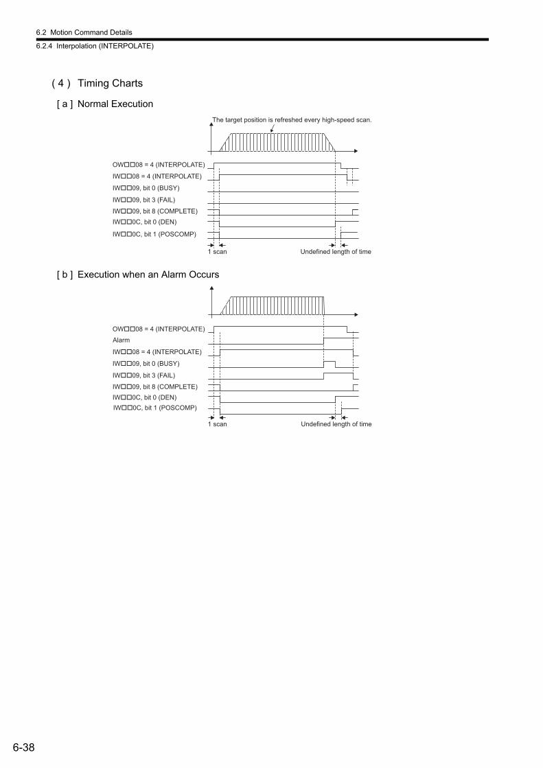
6.2 Motion Command Details
6.2.4 Interpolation (INTERPOLATE)
6-38
( 4 ) Timing Charts
[ a ] Normal Execution
[ b ] Execution when an Alarm Occurs
OW��08 = 4 (INTERPOLATE)
IW��08 = 4 (INTERPOLATE)
IW��09, bit 0 (BUSY)
IW��09, bit 8 (COMPLETE)
IW��09, bit 3 (FAIL)
IW��0C, bit 0 (DEN)
IW��0C, bit 1 (POSCOMP)
Undefined length of time1 scan
The target position is refreshed every high-speed scan.
Undefined length of time
IW��0C, bit 1 (POSCOMP)
1 scan
Alarm
OW��08 = 4 (INTERPOLATE)
IW��08 = 4 (INTERPOLATE)
IW��09, bit 0 (BUSY)
IW��09, bit 8 (COMPLETE)
IW��09, bit 3 (FAIL)
IW��0C, bit 0 (DEN)
6.2 Motion Command Details
6.2.5 Interpolation Mode with Latch Input (LATCH)
6-39
Mot
ion
Com
man
ds
6.2.5 Interpolation Mode with Latch Input (LATCH)
The LATCH command saves in a register the current position when the latch signal is detected during interpolation positioning. The latch signal type is set in setting register OW04 and can be set to the phase-C pulse, /EXT1 signal, /EXT2 sig-nal, or /EXT3 signal.
Speed feed forward compensation can be applied.
When executing the LATCH command more than once after latching the current position by the LATCH command, change the Motion Command to NOP for at least one scan before executing LATCH again.
Torque feed forward gain can be used when LATCH commands are sent using SGDS, SGDV, and SGD7S SERVO-PACKs. Torque feed forward gain is set in Torque/Thrust Reference Setting (setting parameter OL0C). The required con-ditions are as follows:
• SERVOPACK parameter Pn002.0 = 2
• SGDS communication interface version 8 or later
When using an SGDV or SGD7S SERVOPACK, the torque limit can be set and changed during SERVOPACK opera-tion. For details, refer to Setting and Changing Torque Limit during SGDV or SGD7S SERVOPACK Operations of 4.4.2 ( 12 ).When using a DC Power Input Σ-V Series SERVOPACK (Model: SGDV-E1), refer to 11.7.4 Motion Com-mand Operation for External Latches with DC Power Input Σ-V-series SERVOPACKs.
( 1 ) Executing/Operating Procedure
1. Check to see if all the following conditions are satisfied.
2. Set the following motion setting parameters.
Position Reference Setting: OL1CFilter Type Selection: OW03, bits 8 to BSpeed Loop P/PI Switch: OW01Speed Feed Forward Amends: OW30Function Setting 2: OW04
3. Set OW08 to 6 (Latch) to execute a LATCH motion command.
6 is stored in IW08 during positioning.
4. Refresh the value of OL1C “Position Reference Setting.”
The target position is updated to the refreshed value of OL1C at every high-speed scan.*
The difference between the target position of one high-speed scan and that of the next high-speed scan will be the moving speed.When the axis reaches the target position, bit 1 of IW0C will turn ON and positioning will be completed.
* When the incremental addition mode is set for bit 5 of OW09 “Position Reference Type,” the following value will be set to the current target position: Previous target position + Difference between the current value and the previous value of the Position Reference Setting
Execute a LATCH command considering the latch process time obtained by the following equation.Latch process time = 2 scans + MECHATROLINK communication cycle + SERVOPACK’s processing time (4 ms max.)
R
No. Execution Conditions Confirmation Method
1 There are no alarms. Both IL02 and IL04 are 0.
2 The Servo ON condition. IW00, bit 1 is ON.
3 Motion command execution has been completed. IW08 is 0 and IW09, bit 0 is OFF.
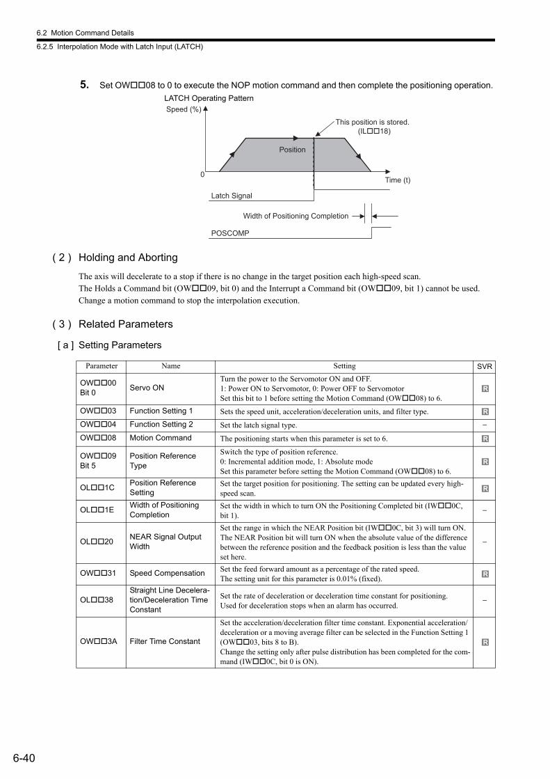
6.2 Motion Command Details
6.2.5 Interpolation Mode with Latch Input (LATCH)
6-40
5. Set OW08 to 0 to execute the NOP motion command and then complete the positioning operation.
( 2 ) Holding and Aborting
The axis will decelerate to a stop if there is no change in the target position each high-speed scan. The Holds a Command bit (OW09, bit 0) and the Interrupt a Command bit (OW09, bit 1) cannot be used. Change a motion command to stop the interpolation execution.
( 3 ) Related Parameters
[ a ] Setting Parameters
Position
0
Width of Positioning Completion
POSCOMP
Speed (%)
Time (t)
Latch Signal
This position is stored.(IL��18)
LATCH Operating Pattern
Parameter Name Setting SVR
OW00Bit 0
Servo ONTurn the power to the Servomotor ON and OFF. 1: Power ON to Servomotor, 0: Power OFF to ServomotorSet this bit to 1 before setting the Motion Command (OW08) to 6.
OW03 Function Setting 1 Sets the speed unit, acceleration/deceleration units, and filter type.
OW04 Function Setting 2 Set the latch signal type. −
OW08 Motion Command The positioning starts when this parameter is set to 6.
OW09Bit 5
Position Reference Type
Switch the type of position reference. 0: Incremental addition mode, 1: Absolute mode Set this parameter before setting the Motion Command (OW08) to 6.
OL1CPosition ReferenceSetting
Set the target position for positioning. The setting can be updated every high-speed scan.
OL1EWidth of Positioning Completion
Set the width in which to turn ON the Positioning Completed bit (IW0C, bit 1).
−
OL20NEAR Signal Output Width
Set the range in which the NEAR Position bit (IW0C, bit 3) will turn ON.The NEAR Position bit will turn ON when the absolute value of the difference between the reference position and the feedback position is less than the value set here.
−
OW31 Speed Compensation Set the feed forward amount as a percentage of the rated speed. The setting unit for this parameter is 0.01% (fixed).
OL38Straight Line Decelera-tion/Deceleration TimeConstant
Set the rate of deceleration or deceleration time constant for positioning. Used for deceleration stops when an alarm has occurred.
−
OW3A Filter Time Constant
Set the acceleration/deceleration filter time constant. Exponential acceleration/deceleration or a moving average filter can be selected in the Function Setting 1 (OW03, bits 8 to B).Change the setting only after pulse distribution has been completed for the com-mand (IW0C, bit 0 is ON).
R
R
R
R
R
R
R
6.2 Motion Command Details
6.2.5 Interpolation Mode with Latch Input (LATCH)
6-41
Mot
ion
Com
man
ds
[ b ] Monitoring Parameters
Parameter Name Monitor Contents SVR
IW00 Bit 1
Running (At Servo ON)
Indicates the Servo ON status. 1: Power supplied to Servomotor, 0: Power not supplied to Servomotor
IL02 Warning Stores the most current warning.
IL04 Alarm Stores the most current alarm.
IW08Motion CommandResponse Code
Indicates any alarms that have occurred during execution. The response code is 6 during LATCH operation.
IW09 Bit 0
Command Execution Flag Always OFF for LATCH operation.
IW09 Bit 1
Command Hold Completed Always OFF for LATCH operation.
IW09 Bit 3
Command Error Completed Status
Turns ON if an error occurs during LATCH operation. The axis will decelerate to a stop if it is moving. Turns OFF when another command is executed.
IW09 Bit 8
Command Execution Completed
Always OFF for LATCH operation.
IW0C Bit 0
Discharging Completed
Turns ON when distribution has been completed for the move command. Turns OFF during execution of a move command.
IW0C Bit 1
Positioning Completed
Turns ON when distribution has been completed and the current position is within the Width of Positioning Completion. OFF in all other cases.
IW0C Bit 2
Latch CompleteThis bit turns OFF when a new latch command is executed and turns ON when the latch has been completed. The latched position is stored as the Machine Coordinate System Latch Position (LPOS) (monitoring parameter IL18).
−
IW0C Bit3
NEAR Position
The operation depends on the setting of the NEAR Signal Output Width (setting parameter OL20).
OL20 = 0:Turns ON when pulse distribution has been completed (DEN = ON). Otherwise, it turns OFF.
OL20 ≠ 0:Turns ON when the absolute value of the difference between MPOS (IL12) and APOS (IL16) is less than the NEAR Signal Out-put Width even if pulse distribution has not been completed.OFF in all other cases.
IL18Machine Coordi-nate System Latch Position (LPOS)
Stores the current position in the machine coordinate system when the latch signal turned ON.
−
R
R
R
R
R
R
R
R
R
R
R
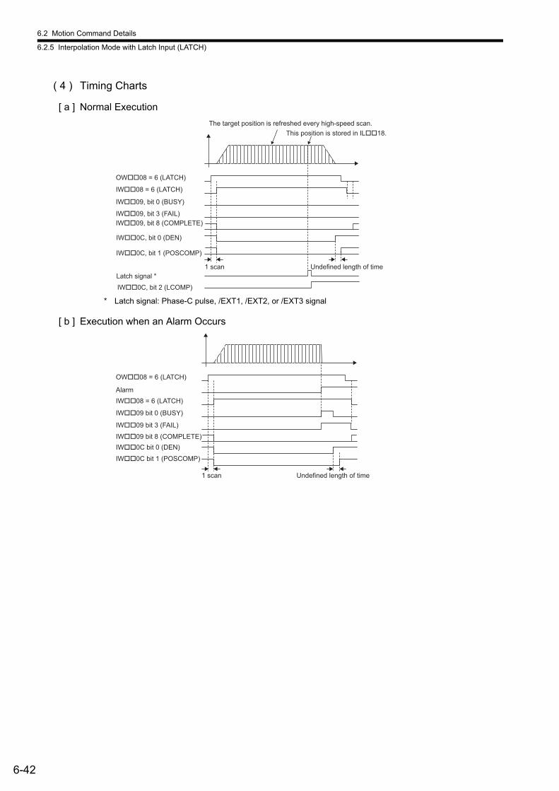
6.2 Motion Command Details
6.2.5 Interpolation Mode with Latch Input (LATCH)
6-42
( 4 ) Timing Charts
[ a ] Normal Execution
* Latch signal: Phase-C pulse, /EXT1, /EXT2, or /EXT3 signal
[ b ] Execution when an Alarm Occurs
OW��08 = 6 (LATCH)
IW��08 = 6 (LATCH)
IW��09, bit 0 (BUSY)
Undefined length of time
IW��09, bit 3 (FAIL)
IW��0C, bit 0 (DEN)
1 scan
Latch signal *
IW��0C, bit 2 (LCOMP)
The target position is refreshed every high-speed scan.
This position is stored in IL��18.
IW��09, bit 8 (COMPLETE)
IW��0C, bit 1 (POSCOMP)
Alarm
Undefined length of time
IW��0C bit 1 (POSCOMP)
1 scan
OW��08 = 6 (LATCH)
IW��08 = 6 (LATCH)
IW��09 bit 0 (BUSY)
IW��09 bit 8 (COMPLETE)
IW��09 bit 3 (FAIL)
IW��0C bit 0 (DEN)
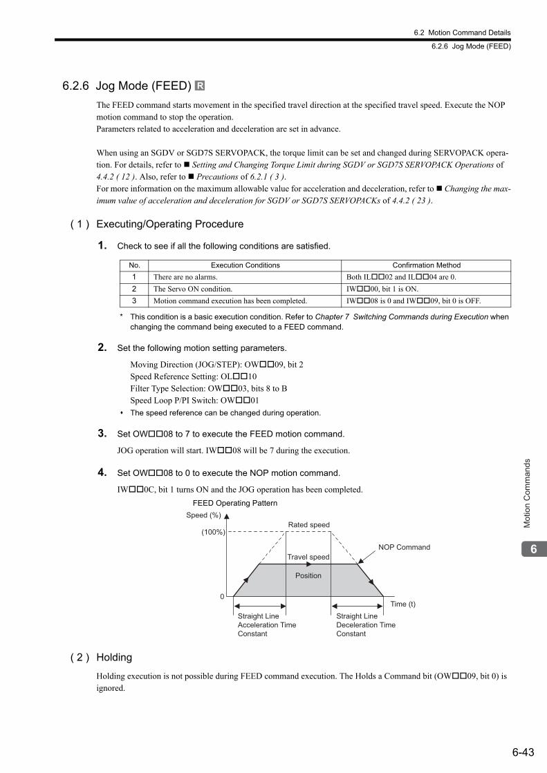
6.2 Motion Command Details
6.2.6 Jog Mode (FEED)
6-43
Mot
ion
Com
man
ds
6.2.6 Jog Mode (FEED)
The FEED command starts movement in the specified travel direction at the specified travel speed. Execute the NOP motion command to stop the operation.Parameters related to acceleration and deceleration are set in advance.
When using an SGDV or SGD7S SERVOPACK, the torque limit can be set and changed during SERVOPACK opera-tion. For details, refer to Setting and Changing Torque Limit during SGDV or SGD7S SERVOPACK Operations of 4.4.2 ( 12 ). Also, refer to Precautions of 6.2.1 ( 3 ).For more information on the maximum allowable value for acceleration and deceleration, refer to Changing the max-imum value of acceleration and deceleration for SGDV or SGD7S SERVOPACKs of 4.4.2 ( 23 ).
( 1 ) Executing/Operating Procedure
1. Check to see if all the following conditions are satisfied.
* This condition is a basic execution condition. Refer to Chapter 7 Switching Commands during Execution when changing the command being executed to a FEED command.
2. Set the following motion setting parameters.
Moving Direction (JOG/STEP): OW09, bit 2Speed Reference Setting: OL10Filter Type Selection: OW03, bits 8 to BSpeed Loop P/PI Switch: OW01
The speed reference can be changed during operation.
3. Set OW08 to 7 to execute the FEED motion command.
JOG operation will start. IW08 will be 7 during the execution.
4. Set OW08 to 0 to execute the NOP motion command.
IW0C, bit 1 turns ON and the JOG operation has been completed.
( 2 ) Holding
Holding execution is not possible during FEED command execution. The Holds a Command bit (OW09, bit 0) is ignored.
R
No. Execution Conditions Confirmation Method
1 There are no alarms. Both IL02 and IL04 are 0.
2 The Servo ON condition. IW00, bit 1 is ON.
3 Motion command execution has been completed. IW08 is 0 and IW09, bit 0 is OFF.
Position
Speed (%)
(100%)
0Time (t)
Travel speed
Rated speed
NOP Command
Straight Line Acceleration TimeConstant
Straight Line Deceleration TimeConstant
FEED Operating Pattern
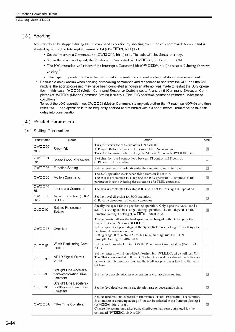
6.2 Motion Command Details
6.2.6 Jog Mode (FEED)
6-44
( 3 ) Aborting
Axis travel can be stopped during FEED command execution by aborting execution of a command. A command is aborted by setting the Interrupt a Command bit (OW09, bit 1) to 1.
• Set the Interrupt a Command bit (OW09, bit 1) to 1. The axis will decelerate to a stop.
• When the axis has stopped, the Positioning Completed bit (IW0C, bit 1) will turn ON.
• The JOG operation will restart if the Interrupt a Command bit (OW09, bit 1) is reset to 0 during abort pro-
cessing.*
This type of operation will also be performed if the motion command is changed during axis movement.
* Because a delay occurs when sending or receiving commands and responses to and from the CPU and the SVB module, the abort processing may have been completed although an attempt was made to restart the JOG opera-tion. In this case, IW08 (Motion Command Response Code) is set to 7, and bit 8 (Command Execution Com-pleted) of IW09 (Motion Command Status) is set to 1. The JOG operation cannot be restarted under these conditions.To reset the JOG operation, set OW08 (Motion Command) to any value other than 7 (such as NOP=0) and then reset it to 7. If an operation is to be frequently aborted and restarted within a short interval, remember to take this delay into consideration.
( 4 ) Related Parameters
[ a ] Setting Parameters
Parameter Name Setting SVR
OW00 Bit 0
Servo ONTurn the power to the Servomotor ON and OFF. 1: Power ON to Servomotor, 0: Power OFF to ServomotorTurn ON the power before setting the Motion Command (OW08) to 7.
OW01 Bit 3
Speed Loop P/PI Switch Switches the speed control loop between PI control and P control. 0: PI control, 1: P control
−
OW03 Function Setting 1 Set the speed unit, acceleration/deceleration units, and filter type.
OW08 Motion CommandThe JOG operation starts when this parameter is set to 7.The axis is decelerated to a stop and the JOG operation is completed if this parameter is set to 0 during the execution of a FEED command.
OW09 Bit 1
Interrupt a Command The axis is decelerated to a stop if this bit is set to 1 during JOG operation.
OW09 Bit 2
Moving Direction (JOG/STEP)
Set the travel direction for JOG operation. 0: Positive direction, 1: Negative direction
OL10Setting ReferenceSetting
Specify the speed for the positioning operation. Only a positive value can be set. This setting can be changed during operation. The unit depends on the Function Setting 1 setting (OW03, bits 0 to 3).
OW18 Override
This parameter allows the feed speed to be changed without changing the Speed Reference Setting (OL10).Set the speed as a percentage of the Speed Reference Setting. This setting can be changed during operation. Setting range: 0 to 32767 (0% to 327.67%) Setting unit: 1 = 0.01%Example: Setting for 50%: 5000
−
OL1EWidth Positioning Com-pletion
Set the width in which to turn ON the Positioning Completed bit (IW0C, bit 1).
−
OL20NEAR Signal Output Width
Set the range in which the NEAR Position bit (IW0C, bit 3) will turn ON.The NEAR Position bit will turn ON when the absolute value of the difference between the reference position and the feedback position is less than the value set here.
−
OL36Straight Line Accelera-tion/Acceleration TimeConstant
Set the feed acceleration in acceleration rate or acceleration time.
OL38Straight Line Decelera-tion/Deceleration TimeConstant
Set the feed deceleration in deceleration rate or deceleration time.
OW3A Filter Time Constant
Set the acceleration/deceleration filter time constant. Exponential acceleration/deceleration or a moving average filter can be selected in the Function Setting 1 (OW03, bits 8 to B). Change the setting only after pulse distribution has been completed for the command (IW0C, bit 0 is ON).
R
R
R
R
R
R
R
R
R
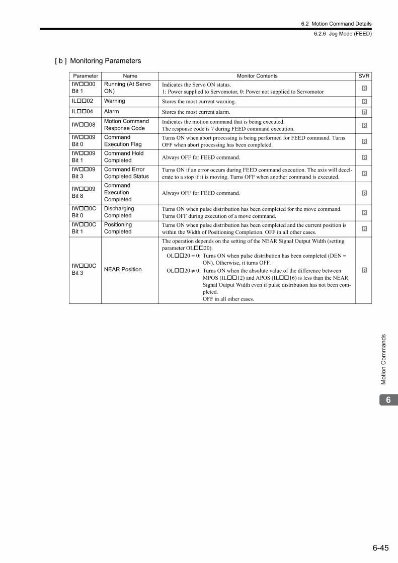
6.2 Motion Command Details
6.2.6 Jog Mode (FEED)
6-45
Mot
ion
Com
man
ds
[ b ] Monitoring Parameters
Parameter Name Monitor Contents SVR
IW00 Bit 1
Running (At Servo ON)
Indicates the Servo ON status. 1: Power supplied to Servomotor, 0: Power not supplied to Servomotor
IL02 Warning Stores the most current warning.
IL04 Alarm Stores the most current alarm.
IW08Motion CommandResponse Code
Indicates the motion command that is being executed. The response code is 7 during FEED command execution.
IW09 Bit 0
Command Execution Flag
Turns ON when abort processing is being performed for FEED command. Turns OFF when abort processing has been completed.
IW09 Bit 1
Command Hold Completed Always OFF for FEED command.
IW09 Bit 3
Command ErrorCompleted Status
Turns ON if an error occurs during FEED command execution. The axis will decel-erate to a stop if it is moving. Turns OFF when another command is executed.
IW09 Bit 8
Command Execution Completed
Always OFF for FEED command.
IW0C Bit 0
Discharging Completed
Turns ON when pulse distribution has been completed for the move command. Turns OFF during execution of a move command.
IW0C Bit 1
Positioning Completed
Turns ON when pulse distribution has been completed and the current position is within the Width of Positioning Completion. OFF in all other cases.
IW0C Bit 3
NEAR Position
The operation depends on the setting of the NEAR Signal Output Width (setting parameter OL20).
OL20 = 0: Turns ON when pulse distribution has been completed (DEN = ON). Otherwise, it turns OFF.
OL20 ≠ 0: Turns ON when the absolute value of the difference between MPOS (IL12) and APOS (IL16) is less than the NEAR Signal Output Width even if pulse distribution has not been com-pleted.OFF in all other cases.
R
R
R
R
R
R
R
R
R
R
R
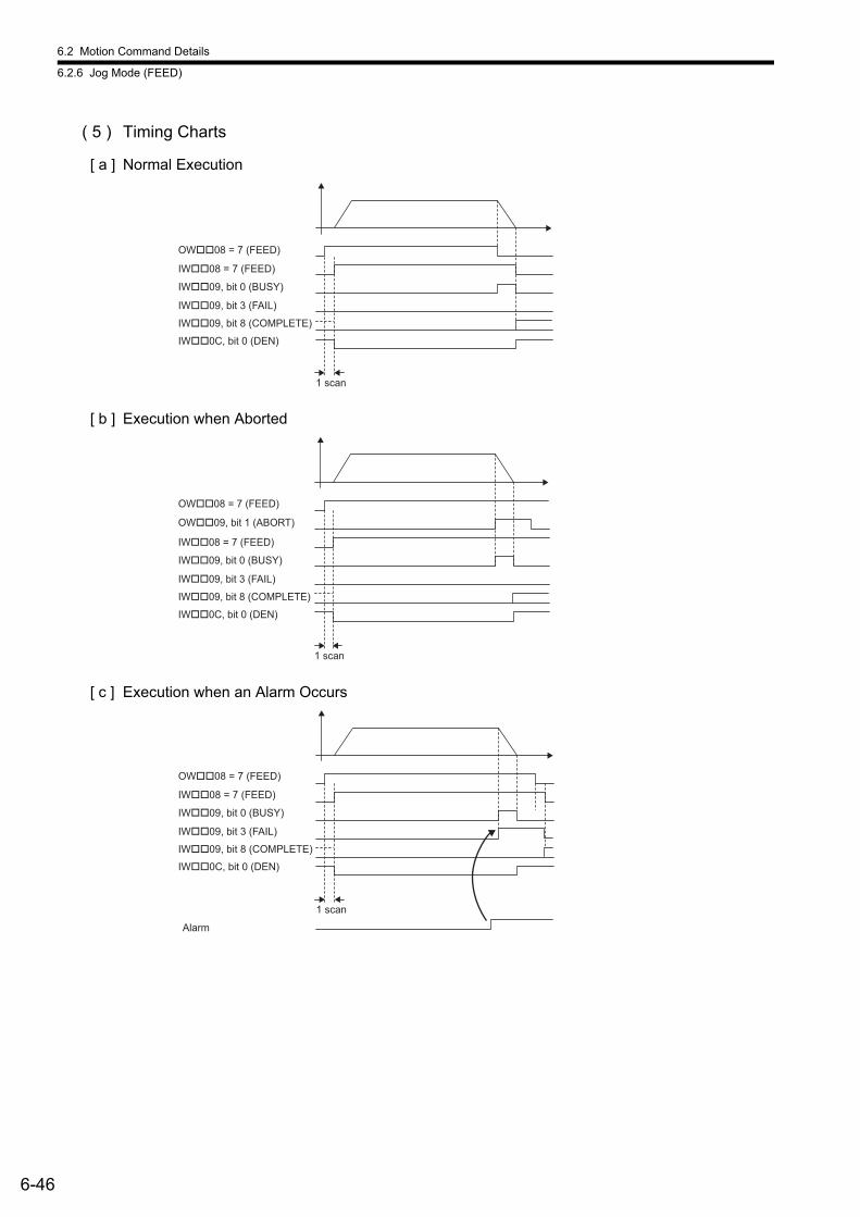
6.2 Motion Command Details
6.2.6 Jog Mode (FEED)
6-46
( 5 ) Timing Charts
[ a ] Normal Execution
[ b ] Execution when Aborted
[ c ] Execution when an Alarm Occurs
OW��08 = 7 (FEED)
IW��08 = 7 (FEED)
IW��09, bit 0 (BUSY)
IW��09, bit 8 (COMPLETE)
IW��09, bit 3 (FAIL)
IW��0C, bit 0 (DEN)
1 scan
1 scan
OW��09, bit 1 (ABORT)
OW��08 = 7 (FEED)
IW��08 = 7 (FEED)
IW��09, bit 0 (BUSY)
IW��09, bit 8 (COMPLETE)
IW��09, bit 3 (FAIL)
IW��0C, bit 0 (DEN)
Alarm
1 scan
OW��08 = 7 (FEED)
IW��08 = 7 (FEED)
IW��09, bit 0 (BUSY)
IW��09, bit 8 (COMPLETE)
IW��09, bit 3 (FAIL)
IW��0C, bit 0 (DEN)
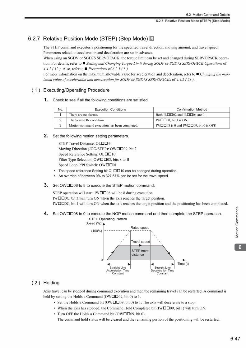
6.2 Motion Command Details
6.2.7 Relative Position Mode (STEP) (Step Mode)
6-47
Mot
ion
Com
man
ds
6.2.7 Relative Position Mode (STEP) (Step Mode)
The STEP command executes a positioning for the specified travel direction, moving amount, and travel speed. Parameters related to acceleration and deceleration are set in advance.When using an SGDV or SGD7S SERVOPACK, the torque limit can be set and changed during SERVOPACK opera-tion. For details, refer to Setting and Changing Torque Limit during SGDV or SGD7S SERVOPACK Operations of 4.4.2 ( 12 ). Also, refer to Precautions of 6.2.1 ( 3 ).For more information on the maximum allowable value for acceleration and deceleration, refer to Changing the max-imum value of acceleration and deceleration for SGDV or SGD7S SERVOPACKs of 4.4.2 ( 23 ).
( 1 ) Executing/Operating Procedure
1. Check to see if all the following conditions are satisfied.
2. Set the following motion setting parameters.
STEP Travel Distance: OL44Moving Direction (JOG/STEP): OW09, bit 2Speed Reference Setting: OL10Filter Type Selection: OW03, bits 8 to BSpeed Loop P/PI Switch: OW01
The speed reference Setting bit OL10 can be changed during operation.
An override of between 0% to 327.67% can be set for the travel speed.
3. Set OW08 to 8 to execute the STEP motion command.
STEP operation will start. IW08 will be 8 during execution. IW0C, bit 3 will turn ON when the axis reaches the target position. IW0C, bit 1 will turn ON when the axis reaches the target position and the positioning has been completed.
4. Set OW08 to 0 to execute the NOP motion command and then complete the STEP operation.
( 2 ) Holding
Axis travel can be stopped during command execution and then the remaining travel can be restarted. A command is held by setting the Holds a Command (OW09, bit 0) to 1.
• Set the Holds a Command bit (OW09, bit 0) to 1. The axis will decelerate to a stop.
• When the axis has stopped, the Command Hold Completed bit (IW09, bit 1) will turn ON.
• Turn OFF the Holds a Command bit (OW09, bit 0).The command hold status will be cleared and the remaining portion of the positioning will be restarted.
R
No. Execution Conditions Confirmation Method
1 There are no alarms. Both IL02 and IL04 are 0.
2 The Servo ON condition. IW00, bit 1 is ON.
3 Motion command execution has been completed. IW08 is 0 and IW09, bit 0 is OFF.
Speed (%)
(100%)
0Time (t)
Travel speed
Rated speed
STEP travel distance
Straight LineAcceleration Time
Constant
Straight LineDeceleration Time
Constant
STEP Operating Pattern
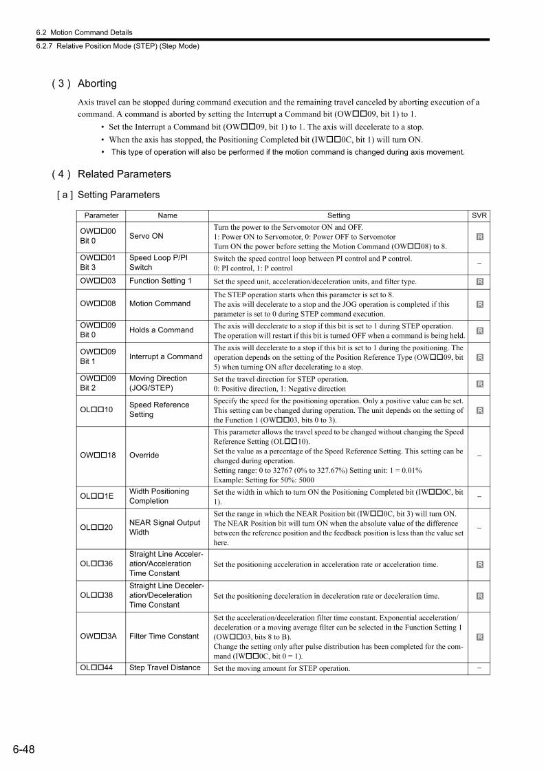
6.2 Motion Command Details
6.2.7 Relative Position Mode (STEP) (Step Mode)
6-48
( 3 ) Aborting
Axis travel can be stopped during command execution and the remaining travel canceled by aborting execution of a command. A command is aborted by setting the Interrupt a Command bit (OW09, bit 1) to 1.
• Set the Interrupt a Command bit (OW09, bit 1) to 1. The axis will decelerate to a stop.
• When the axis has stopped, the Positioning Completed bit (IW0C, bit 1) will turn ON.
This type of operation will also be performed if the motion command is changed during axis movement.
( 4 ) Related Parameters
[ a ] Setting Parameters
Parameter Name Setting SVR
OW00 Bit 0
Servo ONTurn the power to the Servomotor ON and OFF. 1: Power ON to Servomotor, 0: Power OFF to ServomotorTurn ON the power before setting the Motion Command (OW08) to 8.
OW01 Bit 3
Speed Loop P/PI Switch
Switch the speed control loop between PI control and P control. 0: PI control, 1: P control
−
OW03 Function Setting 1 Set the speed unit, acceleration/deceleration units, and filter type.
OW08 Motion Command The STEP operation starts when this parameter is set to 8.The axis will decelerate to a stop and the JOG operation is completed if this parameter is set to 0 during STEP command execution.
OW09 Bit 0
Holds a Command The axis will decelerate to a stop if this bit is set to 1 during STEP operation. The operation will restart if this bit is turned OFF when a command is being held.
OW09 Bit 1
Interrupt a Command The axis will decelerate to a stop if this bit is set to 1 during the positioning. The operation depends on the setting of the Position Reference Type (OW09, bit 5) when turning ON after decelerating to a stop.
OW09 Bit 2
Moving Direction (JOG/STEP)
Set the travel direction for STEP operation. 0: Positive direction, 1: Negative direction
OL10Speed ReferenceSetting
Specify the speed for the positioning operation. Only a positive value can be set. This setting can be changed during operation. The unit depends on the setting of the Function 1 (OW03, bits 0 to 3).
OW18 Override
This parameter allows the travel speed to be changed without changing the Speed Reference Setting (OL10). Set the value as a percentage of the Speed Reference Setting. This setting can be changed during operation.Setting range: 0 to 32767 (0% to 327.67%) Setting unit: 1 = 0.01%Example: Setting for 50%: 5000
−
OL1EWidth Positioning Completion
Set the width in which to turn ON the Positioning Completed bit (IW0C, bit 1).
−
OL20NEAR Signal Output Width
Set the range in which the NEAR Position bit (IW0C, bit 3) will turn ON. The NEAR Position bit will turn ON when the absolute value of the difference between the reference position and the feedback position is less than the value set here.
−
OL36Straight Line Acceler-ation/Acceleration Time Constant
Set the positioning acceleration in acceleration rate or acceleration time.
OL38Straight Line Deceler-ation/Deceleration Time Constant
Set the positioning deceleration in deceleration rate or deceleration time.
OW3A Filter Time Constant
Set the acceleration/deceleration filter time constant. Exponential acceleration/deceleration or a moving average filter can be selected in the Function Setting 1 (OW03, bits 8 to B). Change the setting only after pulse distribution has been completed for the com-mand (IW0C, bit 0 = 1).
OL44 Step Travel Distance Set the moving amount for STEP operation. −
R
R
R
R
R
R
R
R
R
R
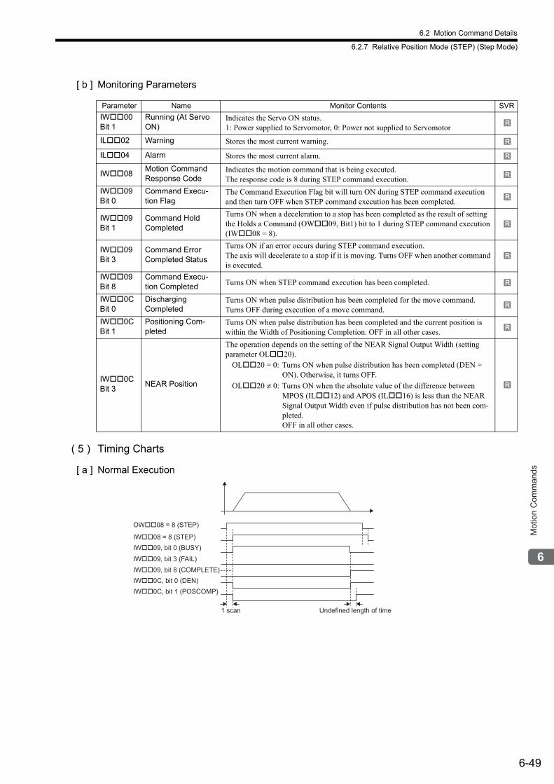
6.2 Motion Command Details
6.2.7 Relative Position Mode (STEP) (Step Mode)
6-49
Mot
ion
Com
man
ds
[ b ] Monitoring Parameters
( 5 ) Timing Charts
[ a ] Normal Execution
Parameter Name Monitor Contents SVR
IW00 Bit 1
Running (At Servo ON)
Indicates the Servo ON status. 1: Power supplied to Servomotor, 0: Power not supplied to Servomotor
IL02 Warning Stores the most current warning.
IL04 Alarm Stores the most current alarm.
IW08Motion CommandResponse Code
Indicates the motion command that is being executed. The response code is 8 during STEP command execution.
IW09 Bit 0
Command Execu-tion Flag
The Command Execution Flag bit will turn ON during STEP command execution and then turn OFF when STEP command execution has been completed.
IW09 Bit 1
Command Hold Completed
Turns ON when a deceleration to a stop has been completed as the result of setting the Holds a Command (OW09, Bit1) bit to 1 during STEP command execution (IW08 = 8).
IW09 Bit 3
Command ErrorCompleted Status
Turns ON if an error occurs during STEP command execution.The axis will decelerate to a stop if it is moving. Turns OFF when another command is executed.
IW09 Bit 8
Command Execu-tion Completed Turns ON when STEP command execution has been completed.
IW0C Bit 0
Discharging Completed
Turns ON when pulse distribution has been completed for the move command. Turns OFF during execution of a move command.
IW0C Bit 1
Positioning Com-pleted
Turns ON when pulse distribution has been completed and the current position is within the Width of Positioning Completion. OFF in all other cases.
IW0C Bit 3
NEAR Position
The operation depends on the setting of the NEAR Signal Output Width (setting parameter OL20).
OL20 = 0: Turns ON when pulse distribution has been completed (DEN = ON). Otherwise, it turns OFF.
OL20 ≠ 0: Turns ON when the absolute value of the difference between MPOS (IL12) and APOS (IL16) is less than the NEAR Signal Output Width even if pulse distribution has not been com-pleted.OFF in all other cases.
R
R
R
R
R
R
R
R
R
R
R
OW��08 = 8 (STEP)
IW��08 = 8 (STEP)
IW��09, bit 0 (BUSY)
Undefined length of time
IW��09, bit 8 (COMPLETE)
IW��09, bit 3 (FAIL)
IW��0C, bit 0 (DEN)
IW��0C, bit 1 (POSCOMP)
1 scan
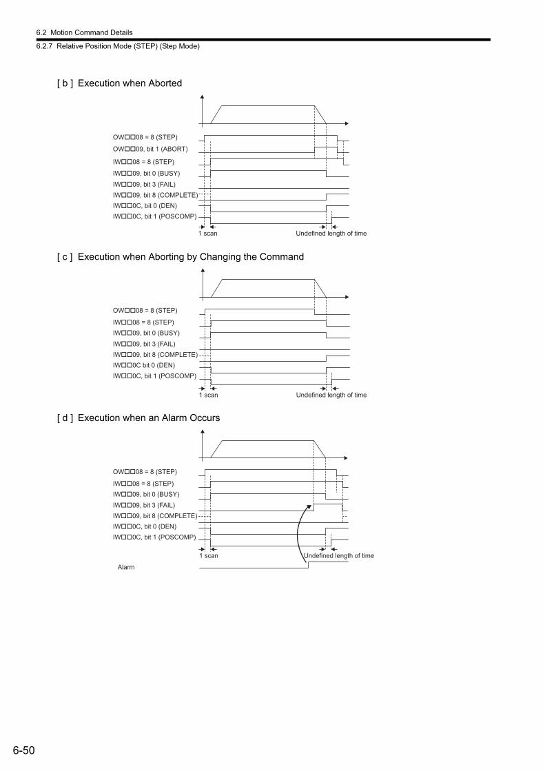
6.2 Motion Command Details
6.2.7 Relative Position Mode (STEP) (Step Mode)
6-50
[ b ] Execution when Aborted
[ c ] Execution when Aborting by Changing the Command
[ d ] Execution when an Alarm Occurs
Undefined length of time1 scan
OW��09, bit 1 (ABORT)
OW��08 = 8 (STEP)
IW��08 = 8 (STEP)
IW��09, bit 0 (BUSY)
IW��09, bit 8 (COMPLETE)
IW��09, bit 3 (FAIL)
IW��0C, bit 0 (DEN)
IW��0C, bit 1 (POSCOMP)
Undefined length of time1 scan
OW��08 = 8 (STEP)
IW��08 = 8 (STEP)
IW��09, bit 0 (BUSY)
IW��09, bit 8 (COMPLETE)
IW��09, bit 3 (FAIL)
IW��0C bit 0 (DEN)
IW��0C, bit 1 (POSCOMP)
Undefined length of time
Alarm
1 scan
OW��08 = 8 (STEP)
IW��08 = 8 (STEP)
IW��09, bit 0 (BUSY)
IW��09, bit 8 (COMPLETE)
IW��09, bit 3 (FAIL)
IW��0C, bit 0 (DEN)
IW��0C, bit 1 (POSCOMP)
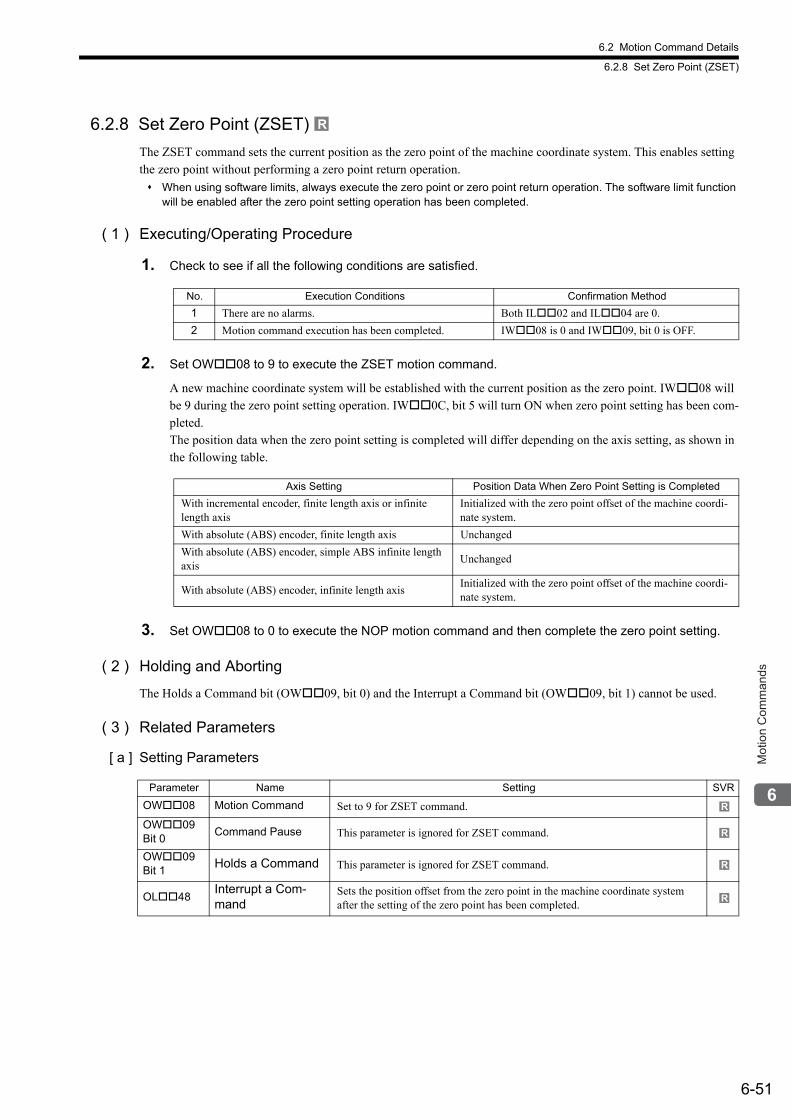
6.2 Motion Command Details
6.2.8 Set Zero Point (ZSET)
6-51
Mot
ion
Com
man
ds
6.2.8 Set Zero Point (ZSET)
The ZSET command sets the current position as the zero point of the machine coordinate system. This enables setting the zero point without performing a zero point return operation.
When using software limits, always execute the zero point or zero point return operation. The software limit function will be enabled after the zero point setting operation has been completed.
( 1 ) Executing/Operating Procedure
1. Check to see if all the following conditions are satisfied.
2. Set OW08 to 9 to execute the ZSET motion command.
A new machine coordinate system will be established with the current position as the zero point. IW08 will be 9 during the zero point setting operation. IW0C, bit 5 will turn ON when zero point setting has been com-pleted.The position data when the zero point setting is completed will differ depending on the axis setting, as shown in the following table.
3. Set OW08 to 0 to execute the NOP motion command and then complete the zero point setting.
( 2 ) Holding and Aborting
The Holds a Command bit (OW09, bit 0) and the Interrupt a Command bit (OW09, bit 1) cannot be used.
( 3 ) Related Parameters
[ a ] Setting Parameters
R
No. Execution Conditions Confirmation Method
1 There are no alarms. Both IL02 and IL04 are 0.
2 Motion command execution has been completed. IW08 is 0 and IW09, bit 0 is OFF.
Axis Setting Position Data When Zero Point Setting is Completed
With incremental encoder, finite length axis or infinite length axis
Initialized with the zero point offset of the machine coordi-nate system.
With absolute (ABS) encoder, finite length axis Unchanged
With absolute (ABS) encoder, simple ABS infinite length axis
Unchanged
With absolute (ABS) encoder, infinite length axisInitialized with the zero point offset of the machine coordi-nate system.
Parameter Name Setting SVR
OW08 Motion Command Set to 9 for ZSET command.
OW09 Bit 0
Command Pause This parameter is ignored for ZSET command.
OW09 Bit 1
Holds a Command This parameter is ignored for ZSET command.
OL48Interrupt a Com-mand
Sets the position offset from the zero point in the machine coordinate system after the setting of the zero point has been completed.
R
R
R
R
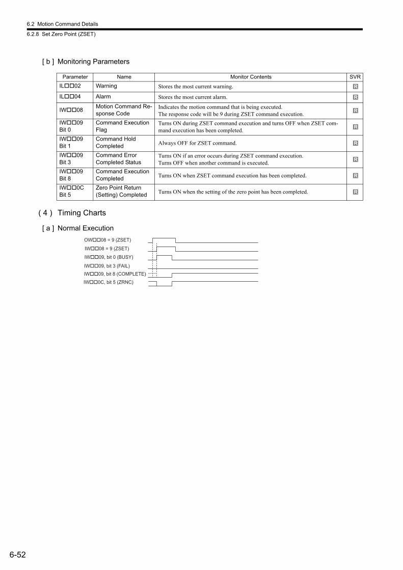
6.2 Motion Command Details
6.2.8 Set Zero Point (ZSET)
6-52
[ b ] Monitoring Parameters
( 4 ) Timing Charts
[ a ] Normal Execution
Parameter Name Monitor Contents SVR
IL02 Warning Stores the most current warning.
IL04 Alarm Stores the most current alarm.
IW08Motion Command Re-sponse Code
Indicates the motion command that is being executed.The response code will be 9 during ZSET command execution.
IW09 Bit 0
Command Execution Flag
Turns ON during ZSET command execution and turns OFF when ZSET com-mand execution has been completed.
IW09 Bit 1
Command Hold Completed Always OFF for ZSET command.
IW09 Bit 3
Command ErrorCompleted Status
Turns ON if an error occurs during ZSET command execution.Turns OFF when another command is executed.
IW09 Bit 8
Command Execution Completed Turns ON when ZSET command execution has been completed.
IW0C Bit 5
Zero Point Return (Setting) Completed Turns ON when the setting of the zero point has been completed.
R
R
R
R
R
R
R
R
OW��08 = 9 (ZSET)
IW��08 = 9 (ZSET)
IW��09, bit 0 (BUSY)
IW��09, bit 8 (COMPLETE)
IW��0C, bit 5 (ZRNC)
IW��09, bit 3 (FAIL)
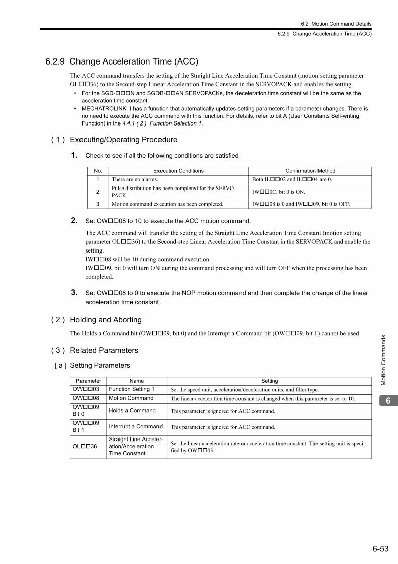
6.2 Motion Command Details
6.2.9 Change Acceleration Time (ACC)
6-53
Mot
ion
Com
man
ds
6.2.9 Change Acceleration Time (ACC)
The ACC command transfers the setting of the Straight Line Acceleration Time Constant (motion setting parameter OL36) to the Second-step Linear Acceleration Time Constant in the SERVOPACK and enables the setting.
For the SGD-N and SGDB-AN SERVOPACKs, the deceleration time constant will be the same as the acceleration time constant.
MECHATROLINK-II has a function that automatically updates setting parameters if a parameter changes. There is no need to execute the ACC command with this function. For details, refer to bit A (User Constants Self-writing Function) in the 4.4.1 ( 2 ) Function Selection 1.
( 1 ) Executing/Operating Procedure
1. Check to see if all the following conditions are satisfied.
2. Set OW08 to 10 to execute the ACC motion command.
The ACC command will transfer the setting of the Straight Line Acceleration Time Constant (motion setting parameter OL36) to the Second-step Linear Acceleration Time Constant in the SERVOPACK and enable the setting.IW08 will be 10 during command execution.IW09, bit 0 will turn ON during the command processing and will turn OFF when the processing has been completed.
3. Set OW08 to 0 to execute the NOP motion command and then complete the change of the linear
acceleration time constant.
( 2 ) Holding and Aborting
The Holds a Command bit (OW09, bit 0) and the Interrupt a Command bit (OW09, bit 1) cannot be used.
( 3 ) Related Parameters
[ a ] Setting Parameters
No. Execution Conditions Confirmation Method
1 There are no alarms. Both IL02 and IL04 are 0.
2Pulse distribution has been completed for the SERVO-PACK.
IW0C, bit 0 is ON.
3 Motion command execution has been completed. IW08 is 0 and IW09, bit 0 is OFF.
Parameter Name Setting
OW03 Function Setting 1 Set the speed unit, acceleration/deceleration units, and filter type.
OW08 Motion Command The linear acceleration time constant is changed when this parameter is set to 10.
OW09 Bit 0
Holds a Command This parameter is ignored for ACC command.
OW09 Bit 1
Interrupt a Command This parameter is ignored for ACC command.
OL36Straight Line Acceler-ation/Acceleration Time Constant
Set the linear acceleration rate or acceleration time constant. The setting unit is speci-fied by OW03.
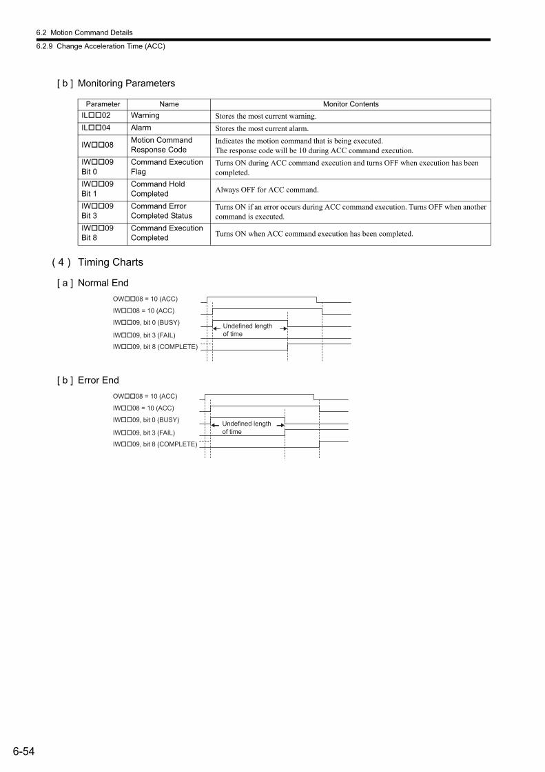
6.2 Motion Command Details
6.2.9 Change Acceleration Time (ACC)
6-54
[ b ] Monitoring Parameters
( 4 ) Timing Charts
[ a ] Normal End
[ b ] Error End
Parameter Name Monitor Contents
IL02 Warning Stores the most current warning.
IL04 Alarm Stores the most current alarm.
IW08Motion CommandResponse Code
Indicates the motion command that is being executed. The response code will be 10 during ACC command execution.
IW09 Bit 0
Command Execution Flag
Turns ON during ACC command execution and turns OFF when execution has been completed.
IW09 Bit 1
Command Hold Completed Always OFF for ACC command.
IW09 Bit 3
Command ErrorCompleted Status
Turns ON if an error occurs during ACC command execution. Turns OFF when another command is executed.
IW09 Bit 8
Command Execution Completed Turns ON when ACC command execution has been completed.
OW��08 = 10 (ACC)
IW��08 = 10 (ACC)
IW��09, bit 0 (BUSY)
IW��09, bit 8 (COMPLETE)
IW��09, bit 3 (FAIL)
Undefined length
of time
OW��08 = 10 (ACC)
IW��08 = 10 (ACC)
IW��09, bit 0 (BUSY)
IW��09, bit 8 (COMPLETE)
IW��09, bit 3 (FAIL)
Undefined length
of time
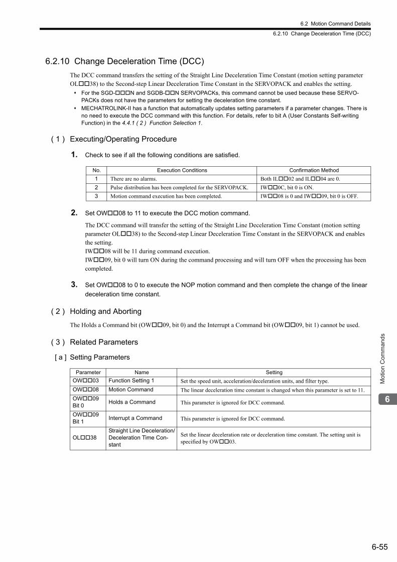
6.2 Motion Command Details
6.2.10 Change Deceleration Time (DCC)
6-55
Mot
ion
Com
man
ds
6.2.10 Change Deceleration Time (DCC)
The DCC command transfers the setting of the Straight Line Deceleration Time Constant (motion setting parameter OL38) to the Second-step Linear Deceleration Time Constant in the SERVOPACK and enables the setting.
For the SGD-N and SGDB-N SERVOPACKs, this command cannot be used because these SERVO-PACKs does not have the parameters for setting the deceleration time constant.
MECHATROLINK-II has a function that automatically updates setting parameters if a parameter changes. There is no need to execute the DCC command with this function. For details, refer to bit A (User Constants Self-writing Function) in the 4.4.1 ( 2 ) Function Selection 1.
( 1 ) Executing/Operating Procedure
1. Check to see if all the following conditions are satisfied.
2. Set OW08 to 11 to execute the DCC motion command.
The DCC command will transfer the setting of the Straight Line Deceleration Time Constant (motion setting parameter OL38) to the Second-step Linear Deceleration Time Constant in the SERVOPACK and enables the setting. IW08 will be 11 during command execution. IW09, bit 0 will turn ON during the command processing and will turn OFF when the processing has been completed.
3. Set OW08 to 0 to execute the NOP motion command and then complete the change of the linear
deceleration time constant.
( 2 ) Holding and Aborting
The Holds a Command bit (OW09, bit 0) and the Interrupt a Command bit (OW09, bit 1) cannot be used.
( 3 ) Related Parameters
[ a ] Setting Parameters
No. Execution Conditions Confirmation Method
1 There are no alarms. Both IL02 and IL04 are 0.
2 Pulse distribution has been completed for the SERVOPACK. IW0C, bit 0 is ON.
3 Motion command execution has been completed. IW08 is 0 and IW09, bit 0 is OFF.
Parameter Name Setting
OW03 Function Setting 1 Set the speed unit, acceleration/deceleration units, and filter type.
OW08 Motion Command The linear deceleration time constant is changed when this parameter is set to 11.
OW09 Bit 0
Holds a Command This parameter is ignored for DCC command.
OW09 Bit 1
Interrupt a Command This parameter is ignored for DCC command.
OL38Straight Line Deceleration/Deceleration Time Con-stant
Set the linear deceleration rate or deceleration time constant. The setting unit is specified by OW03.
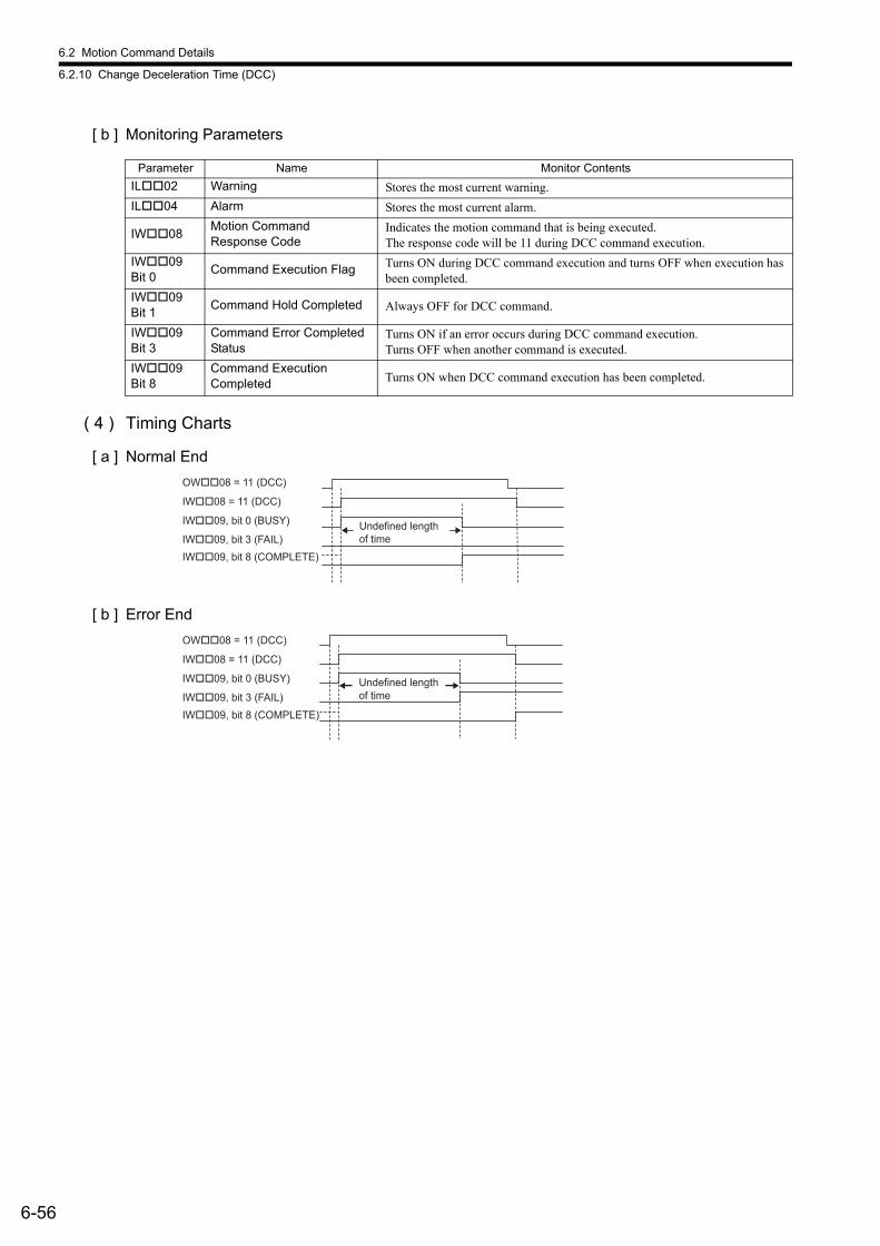
6.2 Motion Command Details
6.2.10 Change Deceleration Time (DCC)
6-56
[ b ] Monitoring Parameters
( 4 ) Timing Charts
[ a ] Normal End
[ b ] Error End
Parameter Name Monitor Contents
IL02 Warning Stores the most current warning.
IL04 Alarm Stores the most current alarm.
IW08Motion CommandResponse Code
Indicates the motion command that is being executed. The response code will be 11 during DCC command execution.
IW09 Bit 0
Command Execution Flag Turns ON during DCC command execution and turns OFF when execution has been completed.
IW09 Bit 1
Command Hold Completed Always OFF for DCC command.
IW09 Bit 3
Command Error Completed Status
Turns ON if an error occurs during DCC command execution.Turns OFF when another command is executed.
IW09 Bit 8
Command Execution Completed Turns ON when DCC command execution has been completed.
OW��08 = 11 (DCC)
IW��08 = 11 (DCC)
IW��09, bit 0 (BUSY)
IW��09, bit 8 (COMPLETE)
IW��09, bit 3 (FAIL)
Undefined length
of time
OW��08 = 11 (DCC)
IW��08 = 11 (DCC)
IW��09, bit 0 (BUSY)
IW��09, bit 8 (COMPLETE)
IW��09, bit 3 (FAIL)
Undefined length
of time
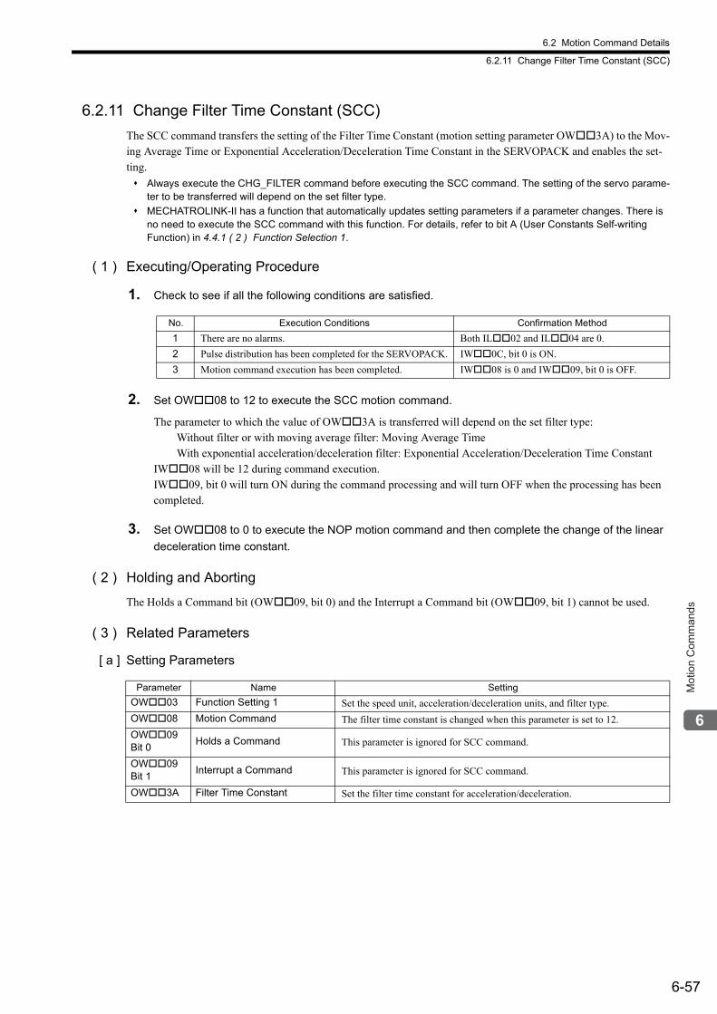
6.2 Motion Command Details
6.2.11 Change Filter Time Constant (SCC)
6-57
Mot
ion
Com
man
ds
6.2.11 Change Filter Time Constant (SCC)
The SCC command transfers the setting of the Filter Time Constant (motion setting parameter OW3A) to the Mov-ing Average Time or Exponential Acceleration/Deceleration Time Constant in the SERVOPACK and enables the set-ting.
Always execute the CHG_FILTER command before executing the SCC command. The setting of the servo parame-ter to be transferred will depend on the set filter type.
MECHATROLINK-II has a function that automatically updates setting parameters if a parameter changes. There is no need to execute the SCC command with this function. For details, refer to bit A (User Constants Self-writing Function) in 4.4.1 ( 2 ) Function Selection 1.
( 1 ) Executing/Operating Procedure
1. Check to see if all the following conditions are satisfied.
2. Set OW08 to 12 to execute the SCC motion command.
The parameter to which the value of OW3A is transferred will depend on the set filter type: Without filter or with moving average filter: Moving Average Time With exponential acceleration/deceleration filter: Exponential Acceleration/Deceleration Time ConstantIW08 will be 12 during command execution.IW09, bit 0 will turn ON during the command processing and will turn OFF when the processing has been completed.
3. Set OW08 to 0 to execute the NOP motion command and then complete the change of the linear
deceleration time constant.
( 2 ) Holding and Aborting
The Holds a Command bit (OW09, bit 0) and the Interrupt a Command bit (OW09, bit 1) cannot be used.
( 3 ) Related Parameters
[ a ] Setting Parameters
No. Execution Conditions Confirmation Method
1 There are no alarms. Both IL02 and IL04 are 0.
2 Pulse distribution has been completed for the SERVOPACK. IW0C, bit 0 is ON.
3 Motion command execution has been completed. IW08 is 0 and IW09, bit 0 is OFF.
Parameter Name Setting
OW03 Function Setting 1 Set the speed unit, acceleration/deceleration units, and filter type.
OW08 Motion Command The filter time constant is changed when this parameter is set to 12.
OW09 Bit 0
Holds a Command This parameter is ignored for SCC command.
OW09 Bit 1
Interrupt a Command This parameter is ignored for SCC command.
OW3A Filter Time Constant Set the filter time constant for acceleration/deceleration.

6.2 Motion Command Details
6.2.11 Change Filter Time Constant (SCC)
6-58
[ b ] Monitoring Parameters
( 4 ) Timing Charts
[ a ] Normal End
[ b ] Error End
Parameter Name Monitor Contents
IL02 Warning Stores the most current warning.
IL04 Alarm Stores the most current alarm.
IW08Motion CommandResponse Code
Indicates the motion command that is being executed. The response code is 12 during SCC command execution.
IW09 Bit 0
Command Execution Flag Turns ON during SCC command execution and turns OFF when execution has been completed.
IW09 Bit 1
Command Hold Completed Always OFF for SCC command.
IW09 Bit 3
Command Error Completed Status
Turns ON if an error occurs during SCC command execution.Turns OFF when another command is executed.
IW09 Bit 8
Command Execution Completed Turns ON when SCC command execution has been completed.
OW��08 = 12 (SCC)
IW��08 = 12 (SCC)
IW��09, bit 0 (BUSY)
IW��09, bit 8 (COMPLETE)
IW��09, bit 3 (FAIL)
Undefined length
of time
OW��08 = 12 (SCC)
IW��08 = 12 (SCC)
IW��09, bit 0 (BUSY)
IW��09, bit 8 (COMPLETE)
IW��09, bit 3 (FAIL)
Undefined length
of time
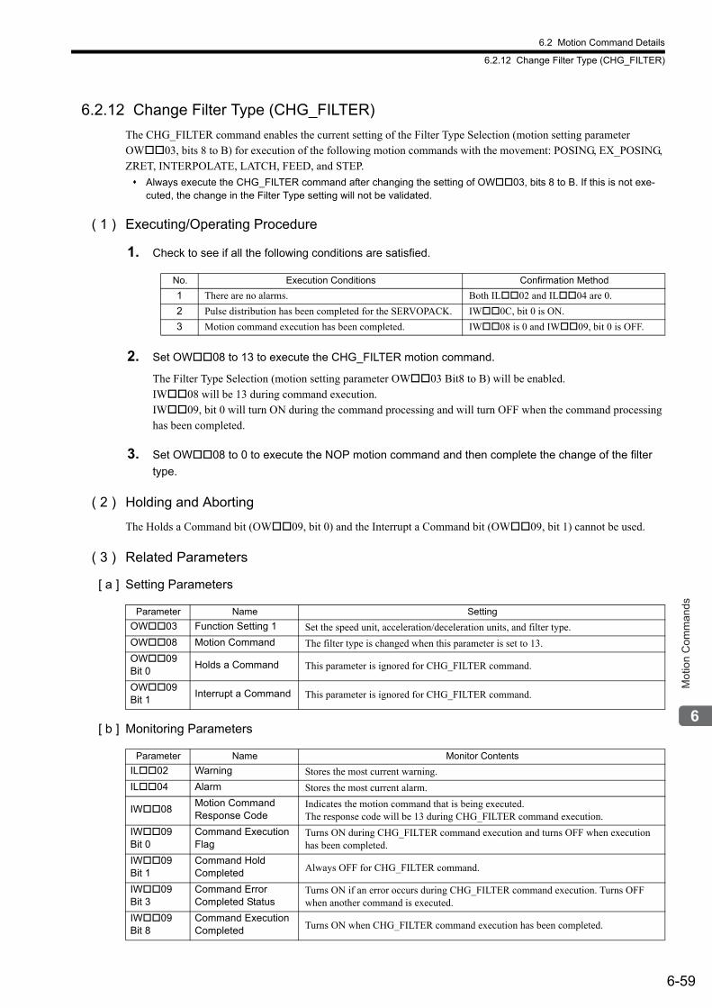
6.2 Motion Command Details
6.2.12 Change Filter Type (CHG_FILTER)
6-59
Mot
ion
Com
man
ds
6.2.12 Change Filter Type (CHG_FILTER)
The CHG_FILTER command enables the current setting of the Filter Type Selection (motion setting parameter OW03, bits 8 to B) for execution of the following motion commands with the movement: POSING, EX_POSING, ZRET, INTERPOLATE, LATCH, FEED, and STEP.
Always execute the CHG_FILTER command after changing the setting of OW03, bits 8 to B. If this is not exe-cuted, the change in the Filter Type setting will not be validated.
( 1 ) Executing/Operating Procedure
1. Check to see if all the following conditions are satisfied.
2. Set OW08 to 13 to execute the CHG_FILTER motion command.
The Filter Type Selection (motion setting parameter OW03 Bit8 to B) will be enabled.IW08 will be 13 during command execution.IW09, bit 0 will turn ON during the command processing and will turn OFF when the command processing has been completed.
3. Set OW08 to 0 to execute the NOP motion command and then complete the change of the filter
type.
( 2 ) Holding and Aborting
The Holds a Command bit (OW09, bit 0) and the Interrupt a Command bit (OW09, bit 1) cannot be used.
( 3 ) Related Parameters
[ a ] Setting Parameters
[ b ] Monitoring Parameters
No. Execution Conditions Confirmation Method
1 There are no alarms. Both IL02 and IL04 are 0.
2 Pulse distribution has been completed for the SERVOPACK. IW0C, bit 0 is ON.
3 Motion command execution has been completed. IW08 is 0 and IW09, bit 0 is OFF.
Parameter Name Setting
OW03 Function Setting 1 Set the speed unit, acceleration/deceleration units, and filter type.
OW08 Motion Command The filter type is changed when this parameter is set to 13.
OW09 Bit 0
Holds a Command This parameter is ignored for CHG_FILTER command.
OW09 Bit 1
Interrupt a Command This parameter is ignored for CHG_FILTER command.
Parameter Name Monitor Contents
IL02 Warning Stores the most current warning.
IL04 Alarm Stores the most current alarm.
IW08Motion CommandResponse Code
Indicates the motion command that is being executed. The response code will be 13 during CHG_FILTER command execution.
IW09 Bit 0
Command Execution Flag
Turns ON during CHG_FILTER command execution and turns OFF when execution has been completed.
IW09 Bit 1
Command Hold Completed Always OFF for CHG_FILTER command.
IW09 Bit 3
Command ErrorCompleted Status
Turns ON if an error occurs during CHG_FILTER command execution. Turns OFF when another command is executed.
IW09 Bit 8
Command Execution Completed Turns ON when CHG_FILTER command execution has been completed.

6.2 Motion Command Details
6.2.12 Change Filter Type (CHG_FILTER)
6-60
( 4 ) Timing Charts
[ a ] Normal End
[ b ] Error End
OW��08 = 13 (CHG-FILTER)
IW��08 = 13 (CHG-FILTER)
IW��09, bit 0 (BUSY)
IW��09, bit 8 (COMPLETE)
IW��09, bit 3 (FAIL)
1 scan
OW��08 = 13 (CHG-FILTER)
IW��08 = 13 (CHG-FILTER)
IW��09, bit 0 (BUSY)
IW��09, bit 8 (COMPLETE)
IW��09, bit 3 (FAIL)
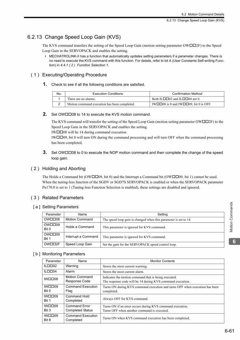
6.2 Motion Command Details
6.2.13 Change Speed Loop Gain (KVS)
6-61
Mot
ion
Com
man
ds
6.2.13 Change Speed Loop Gain (KVS)
The KVS command transfers the setting of the Speed Loop Gain (motion setting parameter OW2F) to the Speed Loop Gain in the SERVOPACK and enables the setting.
MECHATROLINK-II has a function that automatically updates setting parameters if a parameter changes. There is no need to execute the KVS command with this function. For details, refer to bit A (User Constants Self-writing Func-tion) in 4.4.1 ( 2 ) Function Selection 1.
( 1 ) Executing/Operating Procedure
1. Check to see if all the following conditions are satisfied.
2. Set OW08 to 14 to execute the KVS motion command.
The KVS command will transfer the setting of the Speed Loop Gain (motion setting parameter OW2F) to the Speed Loop Gain in the SERVOPACK and enables the setting. IW08 will be 14 during command execution.IW09, bit 0 will turn ON during the command processing and will turn OFF when the command processing has been completed.
3. Set OW08 to 0 to execute the NOP motion command and then complete the change of the speed
loop gain.
( 2 ) Holding and Aborting
The Holds a Command bit (OW09, bit 0) and the Interrupt a Command bit (OW09, bit 1) cannot be used.When the tuning-less function of the SGDV or SGD7S SERVOPACK is enabled or when the SERVOPACK parameter Pn170.0 is set to 1 (Tuning-less Function Selection is enabled), these settings are disabled and ignored.
( 3 ) Related Parameters
[ a ] Setting Parameters
[ b ] Monitoring Parameters
No. Execution Conditions Confirmation Method
1 There are no alarms. Both IL02 and IL04 are 0.
2 Motion command execution has been completed. IW08 is 0 and IW09, bit 0 is OFF.
Parameter Name Setting
OW08 Motion Command The speed loop gain is changed when this parameter is set to 14.
OW09 Bit 0
Holds a Command This parameter is ignored for KVS command.
OW09 Bit 1
Interrupt a Command This parameter is ignored for KVS command.
OW2F Speed Loop Gain Set the gain for the SERVOPACK speed control loop.
Parameter Name Monitor Contents
IL02 Warning Stores the most current warning.
IL04 Alarm Stores the most current alarm.
IW08Motion CommandResponse Code
Indicates the motion command that is being executed. The response code will be 14 during KVS command execution.
IW09 Bit 0
Command Execution Flag
Turns ON during KVS command execution and turns OFF when execution has been completed.
IW09 Bit 1
Command Hold Completed Always OFF for KVS command.
IW09 Bit 3
Command ErrorCompleted Status
Turns ON if an error occurs during KVS command execution. Turns OFF when another command is executed.
IW09 Bit 8
Command Execution Completed Turns ON when KVS command execution has been completed.

6.2 Motion Command Details
6.2.13 Change Speed Loop Gain (KVS)
6-62
( 4 ) Timing Charts
[ a ] Normal End
[ b ] Error End
OW��08 = 14 (KVS)
IW��08 = 14 (KVS)
IW��09, bit 0 (BUSY)
IW��09, bit 8 (COMPLETE)
IW��09, bit 3 (FAIL)
Undefined length
of time
OW��08 = 14 (KVS)
IW��08 = 14 (KVS)
IW��09, bit 0 (BUSY)
IW��09, bit 8 (COMPLETE)
IW��09, bit 3 (FAIL)
Undefined length
of time
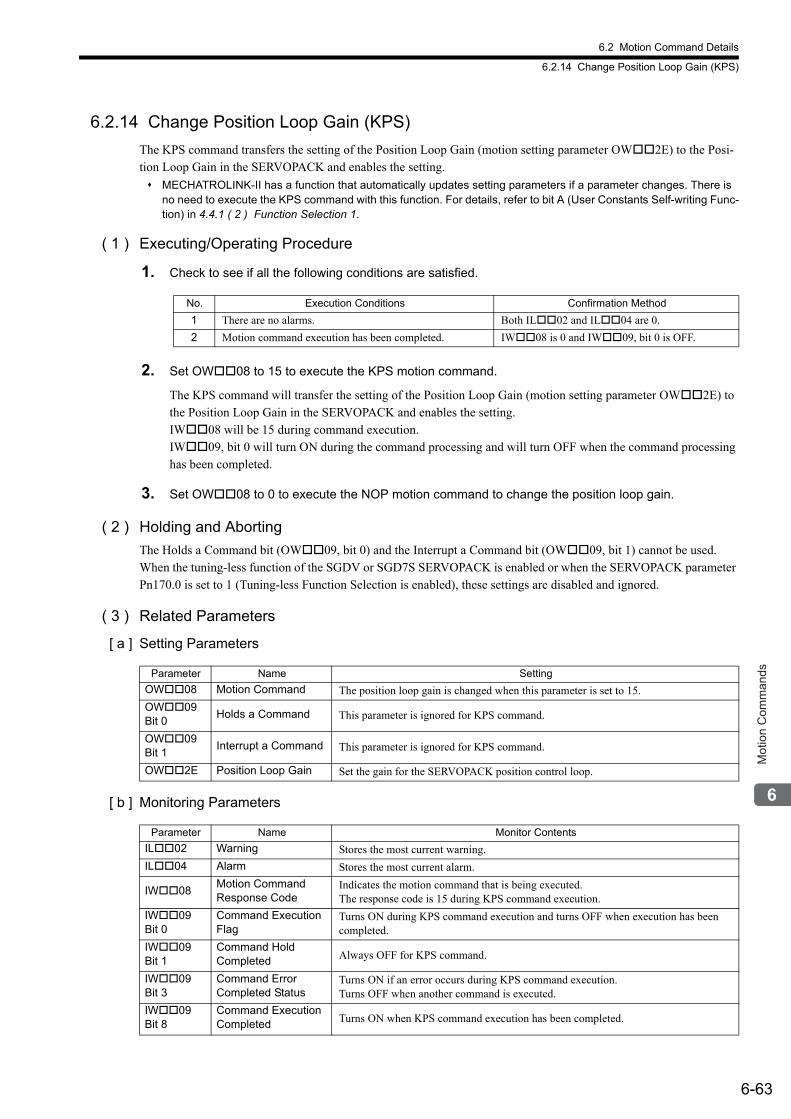
6.2 Motion Command Details
6.2.14 Change Position Loop Gain (KPS)
6-63
Mot
ion
Com
man
ds
6.2.14 Change Position Loop Gain (KPS)
The KPS command transfers the setting of the Position Loop Gain (motion setting parameter OW2E) to the Posi-tion Loop Gain in the SERVOPACK and enables the setting.
MECHATROLINK-II has a function that automatically updates setting parameters if a parameter changes. There is no need to execute the KPS command with this function. For details, refer to bit A (User Constants Self-writing Func-tion) in 4.4.1 ( 2 ) Function Selection 1.
( 1 ) Executing/Operating Procedure
1. Check to see if all the following conditions are satisfied.
2. Set OW08 to 15 to execute the KPS motion command.
The KPS command will transfer the setting of the Position Loop Gain (motion setting parameter OW2E) to the Position Loop Gain in the SERVOPACK and enables the setting. IW08 will be 15 during command execution.IW09, bit 0 will turn ON during the command processing and will turn OFF when the command processing has been completed.
3. Set OW08 to 0 to execute the NOP motion command to change the position loop gain.
( 2 ) Holding and Aborting
The Holds a Command bit (OW09, bit 0) and the Interrupt a Command bit (OW09, bit 1) cannot be used. When the tuning-less function of the SGDV or SGD7S SERVOPACK is enabled or when the SERVOPACK parameter Pn170.0 is set to 1 (Tuning-less Function Selection is enabled), these settings are disabled and ignored.
( 3 ) Related Parameters
[ a ] Setting Parameters
[ b ] Monitoring Parameters
No. Execution Conditions Confirmation Method
1 There are no alarms. Both IL02 and IL04 are 0.
2 Motion command execution has been completed. IW08 is 0 and IW09, bit 0 is OFF.
Parameter Name Setting
OW08 Motion Command The position loop gain is changed when this parameter is set to 15.
OW09 Bit 0
Holds a Command This parameter is ignored for KPS command.
OW09 Bit 1
Interrupt a Command This parameter is ignored for KPS command.
OW2E Position Loop Gain Set the gain for the SERVOPACK position control loop.
Parameter Name Monitor Contents
IL02 Warning Stores the most current warning.
IL04 Alarm Stores the most current alarm.
IW08Motion CommandResponse Code
Indicates the motion command that is being executed. The response code is 15 during KPS command execution.
IW09 Bit 0
Command Execution Flag
Turns ON during KPS command execution and turns OFF when execution has been completed.
IW09 Bit 1
Command Hold Completed Always OFF for KPS command.
IW09 Bit 3
Command ErrorCompleted Status
Turns ON if an error occurs during KPS command execution.Turns OFF when another command is executed.
IW09 Bit 8
Command Execution Completed Turns ON when KPS command execution has been completed.

6.2 Motion Command Details
6.2.14 Change Position Loop Gain (KPS)
6-64
( 4 ) Timing Charts
[ a ] Normal End
[ b ] Error End
OW��08 = 15 (KPS)
IW��08 = 15 (KPS)
IW��09, bit 0 (BUSY)
IW��09, bit 8 (COMPLETE)
IW��09, bit 3 (FAIL)
Undefined length
of time
OW��08 = 15 (KPS)
IW��08 = 15 (KPS)
IW��09, bit 0 (BUSY)
IW��09, bit 8 (COMPLETE)
IW��09, bit 3 (FAIL)
Undefined length
of time
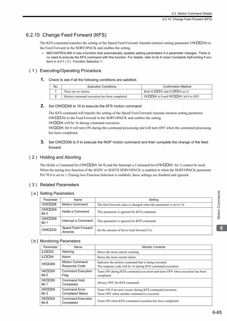
6.2 Motion Command Details
6.2.15 Change Feed Forward (KFS)
6-65
Mot
ion
Com
man
ds
6.2.15 Change Feed Forward (KFS)
The KFS command transfers the setting of the Speed Feed Forward Amends (motion setting parameter OW30) to the Feed Forward in the SERVOPACK and enables the setting.
MECHATROLINK-II has a function that automatically updates setting parameters if a parameter changes. There is no need to execute the KFS command with this function. For details, refer to bit A (User Constants Self-writing Func-tion) in 4.4.1 ( 2 ) Function Selection 1.
( 1 ) Executing/Operating Procedure
1. Check to see if all the following conditions are satisfied.
2. Set OW08 to 16 to execute the KFS motion command.
The KFS command will transfer the setting of the Speed Feed Forward Amends (motion setting parameter OW30) to the Feed Forward in the SERVOPACK and enables the setting. IW08 will be 16 during command execution.IW09, bit 0 will turn ON during the command processing and will turn OFF when the command processing has been completed.
3. Set OW08 to 0 to execute the NOP motion command and then complete the change of the feed
forward.
( 2 ) Holding and Aborting
The Holds a Command bit (OW09, bit 0) and the Interrupt a Command bit (OW09, bit 1) cannot be used. When the tuning-less function of the SGDV or SGD7S SERVOPACK is enabled or when the SERVOPACK parameter Pn170.0 is set to 1 (Tuning-less Function Selection is enabled), these settings are disabled and ignored.
( 3 ) Related Parameters
[ a ] Setting Parameters
[ b ] Monitoring Parameters
No. Execution Conditions Confirmation Method
1 There are no alarms. Both IL02 and IL04 are 0.
2 Motion command execution has been completed. IW08 is 0 and IW09, bit 0 is OFF.
Parameter Name Setting
OW08 Motion Command The feed forward value is changed when this parameter is set to 16.
OW09 Bit 0
Holds a Command This parameter is ignored for KFS command.
OW09 Bit 1
Interrupt a Command This parameter is ignored for KFS command.
OW30Speed Feed Forward Amends Set the amount of Servo feed forward (%).
Parameter Name Monitor Contents
IL02 Warning Stores the most current warning.
IL04 Alarm Stores the most current alarm.
IW08Motion CommandResponse Code
Indicates the motion command that is being executed. The response code will be 16 during KFS command execution.
IW09 Bit 0
Command Execution Flag
Turns ON during KFS command execution and turns OFF when execution has been completed.
IW09 Bit 1
Command Hold Completed Always OFF for KFS command.
IW09 Bit 3
Command ErrorCompleted Status
Turns ON if an error occurs during KFS command execution.Turns OFF when another command is executed.
IW09 Bit 8
Command Execution Completed Turns ON when KFS command execution has been completed.

6.2 Motion Command Details
6.2.15 Change Feed Forward (KFS)
6-66
( 4 ) Timing Charts
[ a ] Normal End
[ b ] Error End
OW��08 = 16 (KFS)
IW��08 = 16 (KFS)
IW��09, bit 0 (BUSY)
IW��09, bit 8 (COMPLETE)
IW��09, bit 3 (FAIL)
Undefined length
of time
OW��08 = 16 (KFS)
IW��08 = 16 (KFS)
IW��09, bit 0 (BUSY)
IW��09, bit 8 (COMPLETE)
IW��09, bit 3 (FAIL)
Undefined length
of time
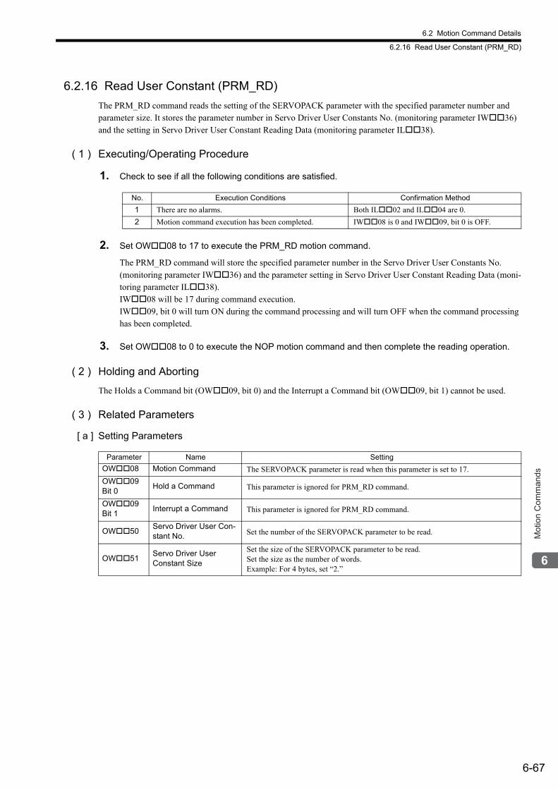
6.2 Motion Command Details
6.2.16 Read User Constant (PRM_RD)
6-67
Mot
ion
Com
man
ds
6.2.16 Read User Constant (PRM_RD)
The PRM_RD command reads the setting of the SERVOPACK parameter with the specified parameter number and parameter size. It stores the parameter number in Servo Driver User Constants No. (monitoring parameter IW36) and the setting in Servo Driver User Constant Reading Data (monitoring parameter IL38).
( 1 ) Executing/Operating Procedure
1. Check to see if all the following conditions are satisfied.
2. Set OW08 to 17 to execute the PRM_RD motion command.
The PRM_RD command will store the specified parameter number in the Servo Driver User Constants No. (monitoring parameter IW36) and the parameter setting in Servo Driver User Constant Reading Data (moni-toring parameter IL38). IW08 will be 17 during command execution.IW09, bit 0 will turn ON during the command processing and will turn OFF when the command processing has been completed.
3. Set OW08 to 0 to execute the NOP motion command and then complete the reading operation.
( 2 ) Holding and Aborting
The Holds a Command bit (OW09, bit 0) and the Interrupt a Command bit (OW09, bit 1) cannot be used.
( 3 ) Related Parameters
[ a ] Setting Parameters
No. Execution Conditions Confirmation Method
1 There are no alarms. Both IL02 and IL04 are 0.
2 Motion command execution has been completed. IW08 is 0 and IW09, bit 0 is OFF.
Parameter Name Setting
OW08 Motion Command The SERVOPACK parameter is read when this parameter is set to 17.
OW09 Bit 0
Hold a Command This parameter is ignored for PRM_RD command.
OW09 Bit 1
Interrupt a Command This parameter is ignored for PRM_RD command.
OW50Servo Driver User Con-stant No. Set the number of the SERVOPACK parameter to be read.
OW51Servo Driver UserConstant Size
Set the size of the SERVOPACK parameter to be read.Set the size as the number of words. Example: For 4 bytes, set “2.”
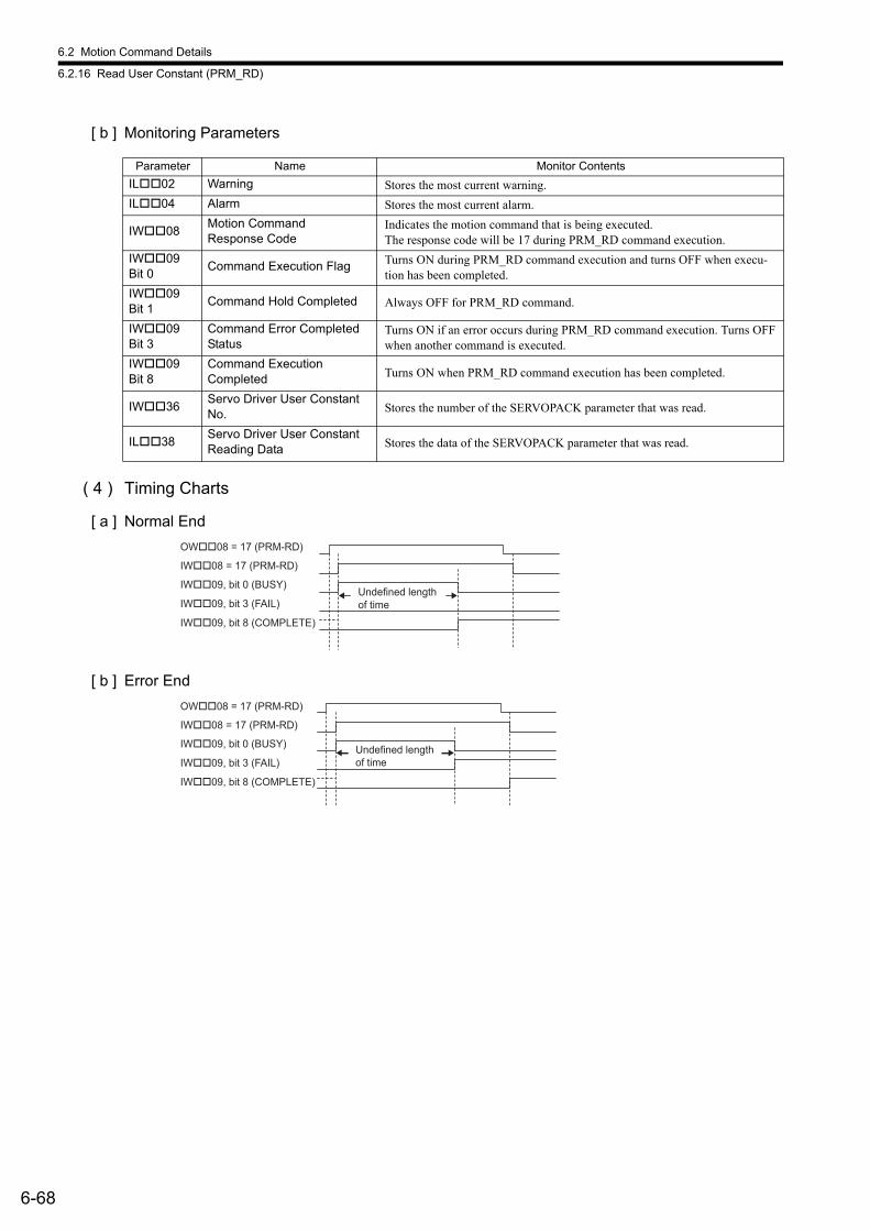
6.2 Motion Command Details
6.2.16 Read User Constant (PRM_RD)
6-68
[ b ] Monitoring Parameters
( 4 ) Timing Charts
[ a ] Normal End
[ b ] Error End
Parameter Name Monitor Contents
IL02 Warning Stores the most current warning.
IL04 Alarm Stores the most current alarm.
IW08Motion CommandResponse Code
Indicates the motion command that is being executed. The response code will be 17 during PRM_RD command execution.
IW09 Bit 0
Command Execution Flag Turns ON during PRM_RD command execution and turns OFF when execu-tion has been completed.
IW09 Bit 1
Command Hold Completed Always OFF for PRM_RD command.
IW09 Bit 3
Command Error Completed Status
Turns ON if an error occurs during PRM_RD command execution. Turns OFF when another command is executed.
IW09 Bit 8
Command Execution Completed Turns ON when PRM_RD command execution has been completed.
IW36Servo Driver User Constant No. Stores the number of the SERVOPACK parameter that was read.
IL38Servo Driver User Constant Reading Data Stores the data of the SERVOPACK parameter that was read.
OW��08 = 17 (PRM-RD)
IW��08 = 17 (PRM-RD)
IW��09, bit 0 (BUSY)
IW��09, bit 8 (COMPLETE)
IW��09, bit 3 (FAIL)
Undefined length
of time
OW��08 = 17 (PRM-RD)
IW��08 = 17 (PRM-RD)
IW��09, bit 0 (BUSY)
IW��09, bit 8 (COMPLETE)
IW��09, bit 3 (FAIL)
Undefined length
of time
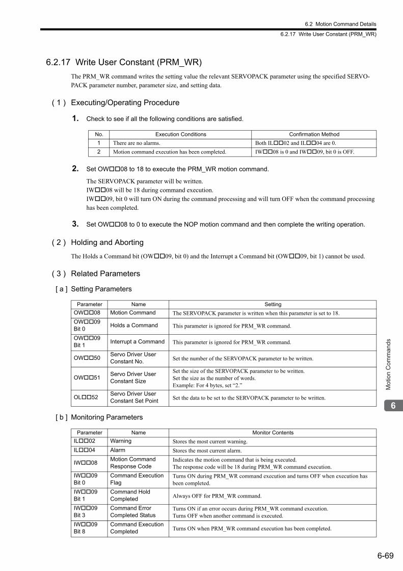
6.2 Motion Command Details
6.2.17 Write User Constant (PRM_WR)
6-69
Mot
ion
Com
man
ds
6.2.17 Write User Constant (PRM_WR)
The PRM_WR command writes the setting value the relevant SERVOPACK parameter using the specified SERVO-PACK parameter number, parameter size, and setting data.
( 1 ) Executing/Operating Procedure
1. Check to see if all the following conditions are satisfied.
2. Set OW08 to 18 to execute the PRM_WR motion command.
The SERVOPACK parameter will be written.IW08 will be 18 during command execution.IW09, bit 0 will turn ON during the command processing and will turn OFF when the command processing has been completed.
3. Set OW08 to 0 to execute the NOP motion command and then complete the writing operation.
( 2 ) Holding and Aborting
The Holds a Command bit (OW09, bit 0) and the Interrupt a Command bit (OW09, bit 1) cannot be used.
( 3 ) Related Parameters
[ a ] Setting Parameters
[ b ] Monitoring Parameters
No. Execution Conditions Confirmation Method
1 There are no alarms. Both IL02 and IL04 are 0.
2 Motion command execution has been completed. IW08 is 0 and IW09, bit 0 is OFF.
Parameter Name Setting
OW08 Motion Command The SERVOPACK parameter is written when this parameter is set to 18.
OW09 Bit 0
Holds a Command This parameter is ignored for PRM_WR command.
OW09 Bit 1
Interrupt a Command This parameter is ignored for PRM_WR command.
OW50Servo Driver User Constant No. Set the number of the SERVOPACK parameter to be written.
OW51Servo Driver User Constant Size
Set the size of the SERVOPACK parameter to be written.Set the size as the number of words. Example: For 4 bytes, set “2.”
OL52Servo Driver User Constant Set Point Set the data to be set to the SERVOPACK parameter to be written.
Parameter Name Monitor Contents
IL02 Warning Stores the most current warning.
IL04 Alarm Stores the most current alarm.
IW08Motion CommandResponse Code
Indicates the motion command that is being executed. The response code will be 18 during PRM_WR command execution.
IW09Bit 0
Command Execution Flag
Turns ON during PRM_WR command execution and turns OFF when execution has been completed.
IW09Bit 1
Command Hold Completed Always OFF for PRM_WR command.
IW09Bit 3
Command Error Completed Status
Turns ON if an error occurs during PRM_WR command execution.Turns OFF when another command is executed.
IW09Bit 8
Command Execution Completed Turns ON when PRM_WR command execution has been completed.
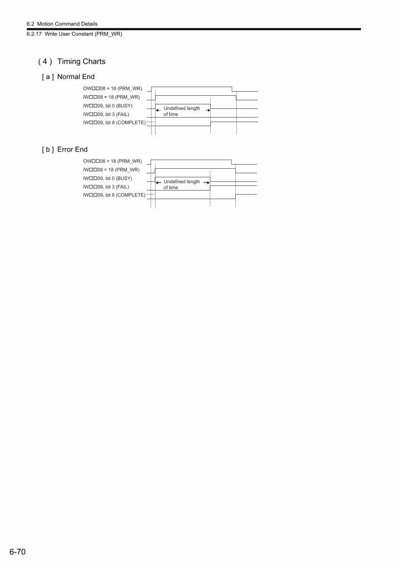
6.2 Motion Command Details
6.2.17 Write User Constant (PRM_WR)
6-70
( 4 ) Timing Charts
[ a ] Normal End
[ b ] Error End
OW��08 = 18 (PRM_WR)
IW��08 = 18 (PRM_WR)
IW��09, bit 0 (BUSY)
IW��09, bit 8 (COMPLETE)
IW��09, bit 3 (FAIL)
Undefined length
of time
OW��08 = 18 (PRM_WR)
IW��08 = 18 (PRM_WR)
IW��09, bit 0 (BUSY)
IW��09, bit 8 (COMPLETE)
IW��09, bit 3 (FAIL)
Undefined length
of time

6.2 Motion Command Details
6.2.18 Alarm Monitor (ALM_MON)
6-71
Mot
ion
Com
man
ds
6.2.18 Alarm Monitor (ALM_MON)
The ALM_MON command reads the alarm or warning that has occurred in the SERVOPACK and stores it in Servo Driver Alarm Code (monitoring parameter IW2D). Three-digit alarm codes, such as SGDS, SGDV, or SGD7S SERVOPACK alarm codes, can also be read out by using this command.
( 1 ) Executing/Operating Procedure
1. Check to see if all the following conditions are satisfied.
2. Set OW08 to 19 to execute the ALM_MON motion command.
The ALM_MON command will read the alarm or warning that has occurred in the SERVOPACK and store it in Servo Driver Alarm Code (monitoring parameter IW2D). IW08 will be 19 during command execution.IW09, bit 0 will turn ON during the command processing and will turn OFF when the command processing has been completed.
3. Set OW08 to 0 to execute the NOP motion command and then complete the monitoring operation.
( 2 ) Holding and Aborting
The Holds a Command bit (OW09, bit 0) and the Interrupt a Command bit (OW09, bit 1) cannot be used.
( 3 ) Related Parameters
[ a ] Setting Parameters
[ b ] Monitoring Parameters
No. Execution Conditions Confirmation Method
1 Motion command execution has been completed. IW08 is 0 and IW09, bit 0 is OFF.
Parameter Name Setting
OW08 Motion Command Alarms are monitored when this parameter is set to 19.
OW09 Bit 0
Holds a Command This parameter is ignored for ALM_MON command.
OW09 Bit 1
Interrupt a Command This parameter is ignored for ALM_MON command.
OW4FServo Driver Alarm Monitor No.
When several alarms and warnings occur at the same time, set the number of the alarm or warning to be monitored.
Parameter Name Monitor Contents
IL02 Warning Stores the most current warning.
IL04 Alarm Stores the most current alarm.
IW08Motion CommandResponse Code
Indicates the motion command that is being executed. The response code will be 19 during ALM_MON command execution.
IW09 Bit 0
Command Execution Flag
Turns ON during ALM_MON command execution and turns OFF when execution has been completed.
IW09 Bit 1
Command Hold Completed Always OFF for ALM_MON command.
IW09 Bit 3
Command ErrorCompleted Status
Turns ON if an error occurs during ALM_MON command execution. Turns OFF when another command is executed.
IW09 Bit 8
Command Execution Completed Turns ON when ALM_MON command execution has been completed.
IW2DServo Driver Alarm Code Stores the SERVOPACK alarm or warning code that was read.
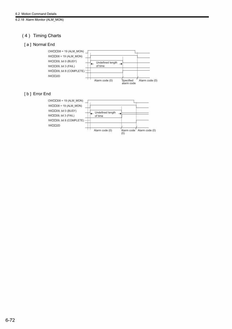
6.2 Motion Command Details
6.2.18 Alarm Monitor (ALM_MON)
6-72
( 4 ) Timing Charts
[ a ] Normal End
[ b ] Error End
OW��08 = 19 (ALM_MON)
IW��08 = 19 (ALM_MON)
IW��09, bit 0 (BUSY)
IW��2D
Alarm code (0) Alarm code (0)
IW��09, bit 8 (COMPLETE)
IW��09, bit 3 (FAIL)
Undefined length
of time
Specified
alarm code
Alarm code (0) Alarm code (0)
OW��08 = 19 (ALM_MON)
IW��08 = 19 (ALM_MON)
IW��09, bit 0 (BUSY)
IW��2D
IW��09, bit 8 (COMPLETE)
IW��09, bit 3 (FAIL)
Undefined length
of time
Alarm code
(0)
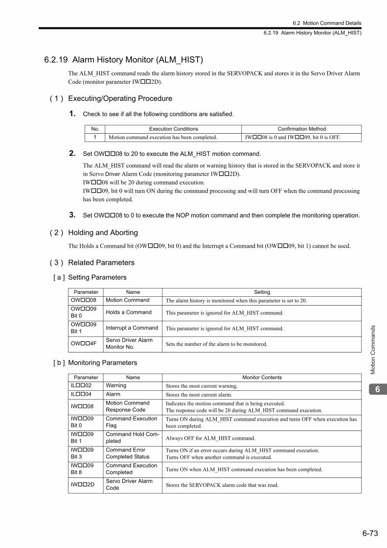
6.2 Motion Command Details
6.2.19 Alarm History Monitor (ALM_HIST)
6-73
Mot
ion
Com
man
ds
6.2.19 Alarm History Monitor (ALM_HIST)
The ALM_HIST command reads the alarm history stored in the SERVOPACK and stores it in the Servo Driver Alarm Code (monitor parameter IW2D).
( 1 ) Executing/Operating Procedure
1. Check to see if all the following conditions are satisfied.
2. Set OW08 to 20 to execute the ALM_HIST motion command.
The ALM_HIST command will read the alarm or warning history that is stored in the SERVOPACK and store it in Servo Driver Alarm Code (monitoring parameter IW2D). IW08 will be 20 during command execution.IW09, bit 0 will turn ON during the command processing and will turn OFF when the command processing has been completed.
3. Set OW08 to 0 to execute the NOP motion command and then complete the monitoring operation.
( 2 ) Holding and Aborting
The Holds a Command bit (OW09, bit 0) and the Interrupt a Command bit (OW09, bit 1) cannot be used.
( 3 ) Related Parameters
[ a ] Setting Parameters
[ b ] Monitoring Parameters
No. Execution Conditions Confirmation Method
1 Motion command execution has been completed. IW08 is 0 and IW09, bit 0 is OFF.
Parameter Name Setting
OW08 Motion Command The alarm history is monitored when this parameter is set to 20.
OW09 Bit 0
Holds a Command This parameter is ignored for ALM_HIST command.
OW09 Bit 1
Interrupt a Command This parameter is ignored for ALM_HIST command.
OW4FServo Driver Alarm Monitor No. Sets the number of the alarm to be monitored.
Parameter Name Monitor Contents
IL02 Warning Stores the most current warning.
IL04 Alarm Stores the most current alarm.
IW08Motion CommandResponse Code
Indicates the motion command that is being executed. The response code will be 20 during ALM_HIST command execution.
IW09 Bit 0
Command Execution Flag
Turns ON during ALM_HIST command execution and turns OFF when execution has been completed.
IW09 Bit 1
Command Hold Com-pleted Always OFF for ALM_HIST command.
IW09 Bit 3
Command ErrorCompleted Status
Turns ON if an error occurs during ALM_HIST command execution.Turns OFF when another command is executed.
IW09 Bit 8
Command Execution Completed Turns ON when ALM_HIST command execution has been completed.
IW2DServo Driver Alarm Code Stores the SERVOPACK alarm code that was read.
6.2 Motion Command Details
6.2.19 Alarm History Monitor (ALM_HIST)
6-74
( 4 ) Timing Charts
[ a ] Normal End
[ b ] Error End
OW��08 = 20 (ALM_HIST)
IW��08 = 20 (ALM_HIST)
IW��09, bit 0 (BUSY)
IW��2D
Alarm code (0) Alarm code (0)
IW��09, bit 8 (COMPLETE)
IW��09, bit 3 (FAIL)
Undefined length
of time
Specified
alarm code
Alarm code (0) Alarm code (0)
OW��08 = 20 (ALM_HIST)
IW��08 = 20 (ALM_HIST)
IW��09, bit 0 (BUSY)
IW��2D
IW��09, bit 8 (COMPLETE)
IW��09, bit 3 (FAIL)
Undefined length
of time
Alarm
code (0)
6.2 Motion Command Details
6.2.20 Clear Alarm History (ALMHIST_CLR)
6-75
Mot
ion
Com
man
ds
6.2.20 Clear Alarm History (ALMHIST_CLR)
The ALMHIST_CLR command clears the alarm history in the SERVOPACK.
( 1 ) Executing/Operating Procedure
1. Check to see if all the following conditions are satisfied.
2. Set OW08 to 21 to execute the ALMHIST_CLR motion command.
The ALMHIST_CLR command will clear the alarm history stored in the SERVOPACK. IW08 will be 21 during command execution.IW09, bit 0 will turn ON during the command processing and will turn OFF when the command processing has been completed.
3. Set OW08 to 0 to execute the NOP motion command and then clear the alarm history.
( 2 ) Holding and Aborting
The Holds a Command bit (OW09, bit 0) and the Interrupt a Command bit (OW09, bit 1) cannot be used.
( 3 ) Related Parameters
[ a ] Setting Parameters
[ b ] Monitoring Parameters
No. Execution Conditions Confirmation Method
1 Motion command execution has been completed. IW08 is 0 and IW09, bit 0 is OFF.
Parameter Name Setting
OW08 Motion Command The alarm history is cleared when this parameter is set to 21.
OW09 Bit 0
Holds a Command This parameter is ignored for ALMHIST_CLR command.
OW09 Bit 1
Interrupt a Command This parameter is ignored for ALMHIST_CLR command.
Parameter Name Monitor Contents
IL02 Warning Stores the most current warning.
IL04 Alarm Stores the most current alarm.
IW08Motion CommandResponse Code
Indicates the motion command that is being executed. The response code will be 21 during ALMHIST_CLR command execution.
IW09 Bit 0
Command Execution Flag
Turns ON during ALMHIST_CLR command execution and turns OFF when execution has been completed.
IW09 Bit 1
Command Hold Completed Always OFF for ALMHIST_CLR command.
IW09 Bit 3
Command ErrorCompleted Status
Turns ON if an error occurs during ALMHIST_CLR command execution. Turns OFF when another command is executed.
IW09 Bit 8
Command Execution Completed Turns ON when ALMHIST_CLR command execution has been completed.

6.2 Motion Command Details
6.2.20 Clear Alarm History (ALMHIST_CLR)
6-76
( 4 ) Timing Charts
[ a ] Normal End
[ b ] Error End
OW��08 = 21 (ALMHIST_CLR)
IW��08 = 21 (ALMHIST_CLR)
IW��09, bit 0 (BUSY)
IW��2D
Alarm code (0) Alarm code (0)
IW��09, bit 8 (COMPLETE)
IW��09, bit 3 (FAIL)
Undefined length
of time
Specified
alarm code
Alarm code (0) Alarm code (0)
OW��08 = 21 (ALMHIST_CLR)
IW��08 = 21 (ALMHIST_CLR)
IW��09, bit 0 (BUSY)
IW��2D
IW��09, bit 8 (COMPLETE)
IW��09, bit 3 (FAIL)
Undefined length
of time
Alarm
code (0)
6.2 Motion Command Details
6.2.21 Absolute Encoder Reset (ABS_RST)
6-77
Mot
ion
Com
man
ds
6.2.21 Absolute Encoder Reset (ABS_RST)
The ABS_RST command initializes the absolute encoder via MECHATROLINK.Initialization of the absolute encoder is required in the following cases.
• Before initial operation of a machine
• When the alarm A.81 “Encoder Backup Alarm” has occurred.
• When the alarm A.82 “Encoder Checksum Error” has occurred.
The ABS_RST command is valid for Σ-II, Σ-III, Σ-V, and Σ-7 Series SERVOPACKs with absolute encoders. A com-mand error will occur if the ABS_RST command is executed for a Σ-I Series SERVOPACK. A command error will occur if the ABS_RST command is executed for a Σ-I Series SERVOPACK. A command error will also occur if the ABS_RST command is executed when an incremental encoder is being used with a Σ-II, Σ-III, Σ-V, or Σ-7 Series SERVOPACK (even if it is being used as an absolute encoder).
( 1 ) Executing/Operating Procedure
1. Check to see if all the following conditions are satisfied.
If there is an Encoder Backup Alarm or Encoder Checksum Alarm in the SERVOPACK, communications can-not be synchronized just by turning ON the power supply to the controller. Use the Alarm Clear bit (OW00, bit F) to synchronize communications.
2. Set OW08 to 22 to execute the ABS_RST motion command.
The ABS_RST command will clear any alarms that have occurred and resets the multiturn data in the absolute encoder to 0. IW08 will be 22 and IW09 Bit0 will turn ON during command processing. IW09 bit 0, IW09 bit 3, and IW00 bit 0 will turn OFF and IW09 bit 7 will turn ON when the command processing has been completed.
3. Set OW08 to 0 to execute the NOP motion command to initialize the absolute encoder.
When using an SGD7S, SGDV, or SGDH+NS115 SERVOPACK:Always turn OFF the power to the SERVOPACK and then turn it ON again after executing the ABS_RST command.
When using an SGDS SERVOPACK:It is not necessary to turn OFF the power to the SERVOPACK and then turn it ON again after executing the ABS_RST command. Just use the Alarm Clear bit (OW00, bit F) to synchronize communications. If the ABS_RST command is executed while there is an Encoder Backup Alarm (A.81), the alarm clear operation will have to be performed twice before communications can be synchronized again.
( 2 ) Holding and Aborting
The Holds a Command bit (OW09, bit 0) and the Interrupt a Command bit (OW09, bit 1) cannot be used. Processing will be canceled if a communication error occurs while the command is being executed and a command error will occur.
SGDV and SGDH+ NS115 SERVOPACKs need to be restarted after this function is executed.
SGDS SERVOPACKs, however, can be used after resetting the absolute encoder and clearing the alarm.
No. Execution Conditions Confirmation Method
1Communication with the SERVOPACK must be synchro-nized.
IW00, bit 0 is ON.
2 The Servo OFF condition. IW00, bit 1 is OFF.
3 Motion command execution has been completed. IW08 is 0, and IW09, bit 0 is OFF.
When the absolute encoder has been reset, communication will be disconnected between the MachineController and the SERVOPACK. The zero point setting completed and zero point return completed statuswill thus be cleared. Use the Alarm Clear bit (OW00, bit F) after executing the ABS_RST command, re-establish communications, and then execute the ZRET or ZSET command.
6.2 Motion Command Details
6.2.21 Absolute Encoder Reset (ABS_RST)
6-78
( 3 ) Related Parameters
[ a ] Setting Parameters
[ b ] Monitoring Parameters
Parameter Name Setting
OW00 Bit 0
Servo ONTurn the power to the Servomotor ON and OFF.1: Power ON to Servomotor; 0: Power OFF to ServomotorTurn OFF the power before setting the Motion Command (OW08) to 22.
OW08 Motion CommandStarts resetting the absolute encoder when this parameter is set to 22.Even if this parameter is set to 0 during command processing, it will be ignored and execution will be continued.
OW09 Bit 0
Holds a Command This parameter is ignored for the ABS_RST command.
OW09 Bit 1
Interrupt a Command This parameter is ignored for the ABS_RST command.
Parameter Name Monitor Contents
IW00 Bit 0
Motion Controller Operation Ready
Indicates the communication status between the Machine Controller and SERVOPACK.1: Communication synchronized, 0: Communication disconnected
IW00 Bit 1
Servo ON Indicates the Servo ON status.1: Power supplied to Servomotor, 0: Power not supplied to Servomotor
IL02 Warning Stores the most current warning.
IL04 Alarm Stores the most current alarm.
IW08Motion CommandResponse Code
Indicates the motion command that is being executed. The response code will be 22 during ABS_RST command execution.
IW09 Bit 0
Command Execution Flag
Turns ON during ABS_RST command execution and turns OFF when execution has been completed.
IW09 Bit 1
Command Hold Completed Always OFF for the ABS_RST command.
IW09 Bit 3
Command Error Completed Status
Turns ON if an error, such as a communication error, occurs during ABS_RST com-mand execution. Command execution will be canceled.
IW09 Bit 7
Absolute Encoder Reset Completed Turns ON when resetting the absolute encoder has been completed.
IW09 Bit 8
Command Execution Completed Turns ON when ABS_RST command execution has been completed.
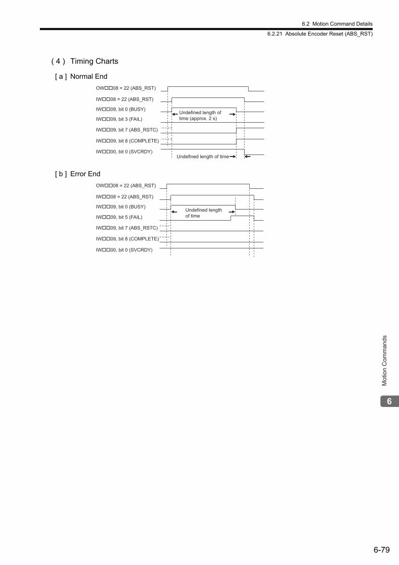
6.2 Motion Command Details
6.2.21 Absolute Encoder Reset (ABS_RST)
6-79
Mot
ion
Com
man
ds
( 4 ) Timing Charts
[ a ] Normal End
[ b ] Error End
OW��08 = 22 (ABS_RST)
IW��08 = 22 (ABS_RST)
IW��09, bit 0 (BUSY)
IW��09, bit 3 (FAIL)
IW��09, bit 7 (ABS_RSTC)
IW��09, bit 8 (COMPLETE)
IW��00, bit 0 (SVCRDY)
Undefined length of time
Undefined length of
time (approx. 2 s)
OW��08 = 22 (ABS_RST)
IW��08 = 22 (ABS_RST)
IW��09, bit 0 (BUSY)
IW��09, bit 5 (FAIL)
IW��09, bit 7 (ABS_RSTC)
IW��09, bit 8 (COMPLETE)
IW��00, bit 0 (SVCRDY)
Undefined length
of time
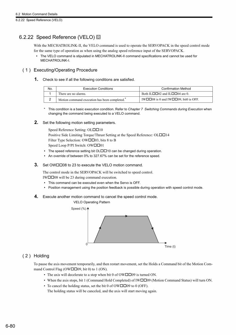
6.2 Motion Command Details
6.2.22 Speed Reference (VELO)
6-80
6.2.22 Speed Reference (VELO)
With the MECHATROLINK-II, the VELO command is used to operate the SERVOPACK in the speed control mode for the same type of operation as when using the analog speed reference input of the SERVOPACK.
The VELO command is stipulated in MECHATROLINK-II command specifications and cannot be used for MECHATROLINK-I.
( 1 ) Executing/Operating Procedure
1. Check to see if all the following conditions are satisfied.
* This condition is a basic execution condition. Refer to Chapter 7 Switching Commands during Execution when changing the command being executed to a VELO command.
2. Set the following motion setting parameters.
Speed Reference Setting: OL10Positive Side Limiting Torque/Thrust Setting at the Speed Reference: OL14Filter Type Selection: OW03, bits 8 to BSpeed Loop P/PI Switch: OW01
The speed reference setting bit OL10 can be changed during operation.
An override of between 0% to 327.67% can be set for the reference speed.
3. Set OW08 to 23 to execute the VELO motion command.
The control mode in the SERVOPACK will be switched to speed control.IW08 will be 23 during command execution.
This command can be executed even when the Servo is OFF.
Position management using the position feedback is possible during operation with speed control mode.
4. Execute another motion command to cancel the speed control mode.
( 2 ) Holding
To pause the axis movement temporarily, and then restart movement, set the Holds a Command bit of the Motion Com-mand Control Flag (OW09, bit 0) to 1 (ON).
• The axis will decelerate to a stop when bit 0 of OW09 is turned ON.
• When the axis stops, bit 1 (Command Hold Completed) of IW09 (Motion Command Status) will turn ON.
• To cancel the holding status, set the bit 0 of OW09 to 0 (OFF).The holding status will be canceled, and the axis will start moving again.
R
No. Execution Conditions Confirmation Method
1 There are no alarms. Both IL02 and IL04 are 0.
2 Motion command execution has been completed.* IW08 is 0 and IW09, bit0 is OFF.
0
Speed (%)
Time (t)
VELO Operating Pattern
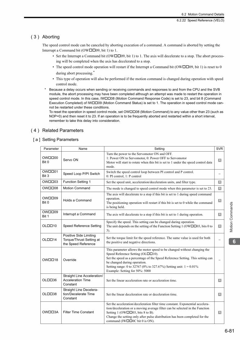
6.2 Motion Command Details
6.2.22 Speed Reference (VELO)
6-81
Mot
ion
Com
man
ds
( 3 ) Aborting
The speed control mode can be canceled by aborting execution of a command. A command is aborted by setting the Interrupt a Command bit (OW09, bit 1) to 1.
• Set the Interrupt a Command bit (OW09, bit 1) to 1. The axis will decelerate to a stop. The abort process-ing will be completed when the axis has decelerated to a stop.
• The speed control mode operation will restart if the Interrupt a Command bit (OW09, bit 1) is reset to 0
during abort processing.*
• This type of operation will also be performed if the motion command is changed during operation with speed control mode.
* Because a delay occurs when sending or receiving commands and responses to and from the CPU and the SVB module, the abort processing may have been completed although an attempt was made to restart the operation in speed control mode. In this case, IW08 (Motion Command Response Code) is set to 23, and bit 8 (Command Execution Completed) of IW09 (Motion Command Status) is set to 1. The operation in speed control mode can-not be restarted under these conditions.To reset the operation in speed control mode, set OW08 (Motion Command) to any value other than 23 (such as NOP=0) and then reset it to 23. If an operation is to be frequently aborted and restarted within a short interval, remember to take this delay into consideration.
( 4 ) Related Parameters
[ a ] Setting Parameters
Parameter Name Setting SVR
OW00 Bit 0
Servo ON
Turn the power to the Servomotor ON and OFF.1: Power ON to Servomotor, 0: Power OFF to ServomotorMotor will start to rotate when this bit is set to 1 under the speed control data mode.
OW01 Bit 3
Speed Loop P/PI Switch Switch the speed control loop between PI control and P control. 0: PI control, 1: P control
−
OW03 Function Setting 1 Set the speed unit, acceleration/deceleration units, and filter type.
OW08 Motion Command The mode is changed to speed control mode when this parameter is set to 23.
OW09 Bit 0
Holds a Command
The axis will decelerate to a stop if this bit is set to 1 during speed command operation. The positioning operation will restart if this bit is set to 0 while the command is being held.
OW09 Bit 1
Interrupt a Command The axis will decelerate to a stop if this bit is set to 1 during operation.
OL10 Speed Reference SettingSpecify the speed. This setting can be changed during operation.The unit depends on the setting of the Function Setting 1 (OW03, bits 0 to 3).
OL14Positive Side Limiting Torque/Thrust Setting at the Speed Reference
Set the torque limit for the speed reference. The same value is used for both the positive and negative directions.
−
OW18 Override
This parameter allows the motor speed to be changed without changing the Speed Reference Setting (OL10).Set the speed as a percentage of the Speed Reference Setting. This setting can be changed during operation.Setting range: 0 to 32767 (0% to 327.67%) Setting unit: 1 = 0.01%Example: Setting for 50%: 5000
−
OL36Straight Line Acceleration/Acceleration Time Constant
Set the linear acceleration rate or acceleration time.
OL38Straight Line Decelera-tion/Decelerate Time Constant
Set the linear deceleration rate or deceleration time.
OW3A Filter Time Constant
Set the acceleration/deceleration filter time constant. Exponential accelera-tion/deceleration or a moving average filter can be selected in the Function Setting 1 (OW03, bits 8 to B). Change the setting only after pulse distribution has been completed for the command (IW0C bit 0 is ON).
R
R
R
R
R
R
R
R
R
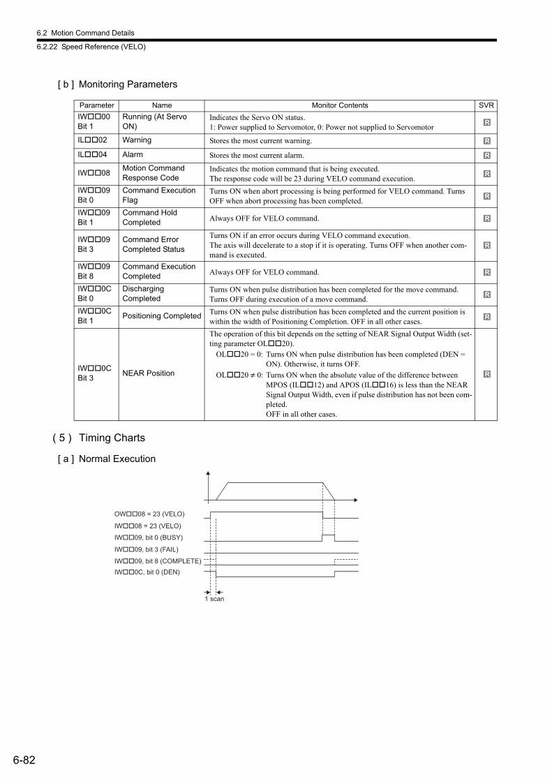
6.2 Motion Command Details
6.2.22 Speed Reference (VELO)
6-82
[ b ] Monitoring Parameters
( 5 ) Timing Charts
[ a ] Normal Execution
Parameter Name Monitor Contents SVR
IW00 Bit 1
Running (At Servo ON)
Indicates the Servo ON status. 1: Power supplied to Servomotor, 0: Power not supplied to Servomotor
IL02 Warning Stores the most current warning.
IL04 Alarm Stores the most current alarm.
IW08Motion CommandResponse Code
Indicates the motion command that is being executed.The response code will be 23 during VELO command execution.
IW09 Bit 0
Command Execution Flag
Turns ON when abort processing is being performed for VELO command. Turns OFF when abort processing has been completed.
IW09 Bit 1
Command Hold Completed Always OFF for VELO command.
IW09 Bit 3
Command ErrorCompleted Status
Turns ON if an error occurs during VELO command execution. The axis will decelerate to a stop if it is operating. Turns OFF when another com-mand is executed.
IW09 Bit 8
Command Execution Completed Always OFF for VELO command.
IW0C Bit 0
DischargingCompleted
Turns ON when pulse distribution has been completed for the move command. Turns OFF during execution of a move command.
IW0C Bit 1
Positioning Completed Turns ON when pulse distribution has been completed and the current position is within the width of Positioning Completion. OFF in all other cases.
IW0C Bit 3
NEAR Position
The operation of this bit depends on the setting of NEAR Signal Output Width (set-ting parameter OL20).
OL20 = 0: Turns ON when pulse distribution has been completed (DEN = ON). Otherwise, it turns OFF.
OL20 ≠ 0: Turns ON when the absolute value of the difference between MPOS (IL12) and APOS (IL16) is less than the NEAR Signal Output Width, even if pulse distribution has not been com-pleted. OFF in all other cases.
R
R
R
R
R
R
R
R
R
R
R
OW��08 = 23 (VELO)
IW��08 = 23 (VELO)
IW��09, bit 0 (BUSY)
IW��09, bit 8 (COMPLETE)
IW��09, bit 3 (FAIL)
IW��0C, bit 0 (DEN)
1 scan
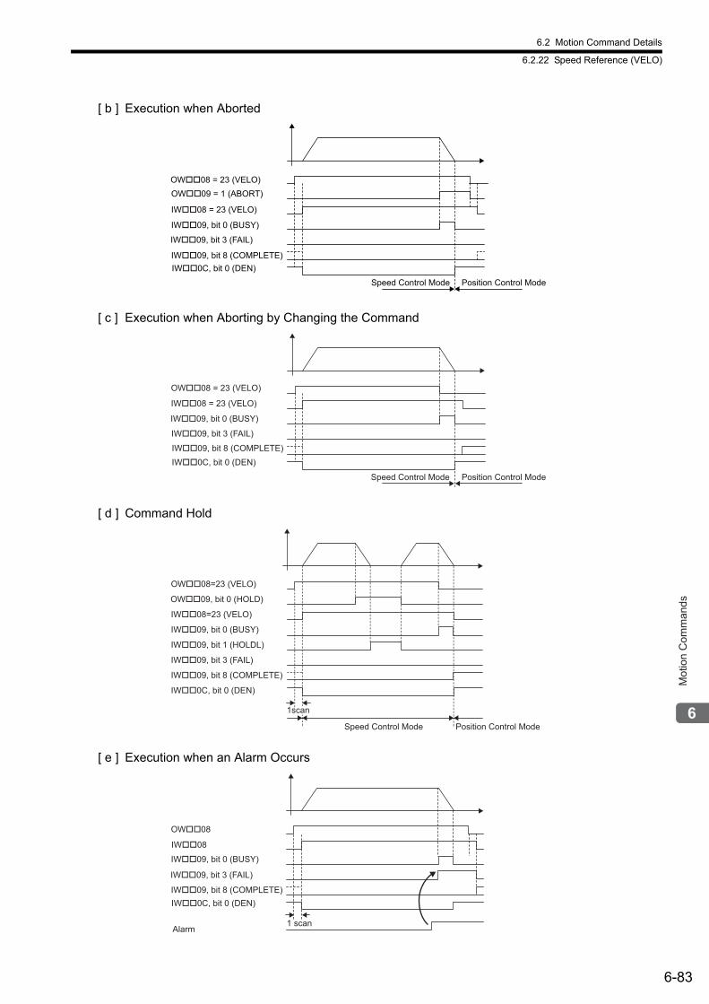
6.2 Motion Command Details
6.2.22 Speed Reference (VELO)
6-83
Mot
ion
Com
man
ds
[ b ] Execution when Aborted
[ c ] Execution when Aborting by Changing the Command
[ d ] Command Hold
[ e ] Execution when an Alarm Occurs
OW��09 = 1 (ABORT)
Speed Control Mode Position Control Mode
OW��08 = 23 (VELO)
IW��08 = 23 (VELO)
IW��09, bit 0 (BUSY)
IW��09, bit 8 (COMPLETE)
IW��09, bit 3 (FAIL)
IW��0C, bit 0 (DEN)
Speed Control Mode Position Control Mode
OW��08 = 23 (VELO)
IW��08 = 23 (VELO)
IW��09, bit 0 (BUSY)
IW��09, bit 8 (COMPLETE)
IW��09, bit 3 (FAIL)
IW��0C, bit 0 (DEN)
OW��08=23 (VELO)
OW��09, bit 0 (HOLD)
IW��08=23 (VELO)
IW��09, bit 1 (HOLDL)
IW��09, bit 0 (BUSY)
IW��09, bit 3 (FAIL)
IW��09, bit 8 (COMPLETE)
IW��0C, bit 0 (DEN)
Speed Control Mode Position Control Mode
1scan
Alarm1 scan
OW��08
IW��08
IW��09, bit 0 (BUSY)
IW��09, bit 8 (COMPLETE)
IW��09, bit 3 (FAIL)
IW��0C, bit 0 (DEN)
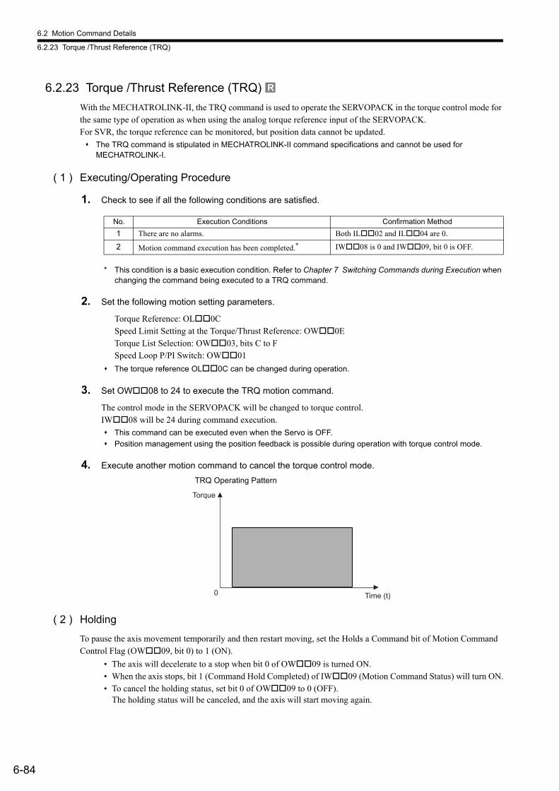
6.2 Motion Command Details
6.2.23 Torque /Thrust Reference (TRQ)
6-84
6.2.23 Torque /Thrust Reference (TRQ)
With the MECHATROLINK-II, the TRQ command is used to operate the SERVOPACK in the torque control mode for the same type of operation as when using the analog torque reference input of the SERVOPACK.For SVR, the torque reference can be monitored, but position data cannot be updated.
The TRQ command is stipulated in MECHATROLINK-II command specifications and cannot be used for MECHATROLINK-I.
( 1 ) Executing/Operating Procedure
1. Check to see if all the following conditions are satisfied.
* This condition is a basic execution condition. Refer to Chapter 7 Switching Commands during Execution when changing the command being executed to a TRQ command.
2. Set the following motion setting parameters.
Torque Reference: OL0CSpeed Limit Setting at the Torque/Thrust Reference: OW0ETorque List Selection: OW03, bits C to FSpeed Loop P/PI Switch: OW01
The torque reference OL0C can be changed during operation.
3. Set OW08 to 24 to execute the TRQ motion command.
The control mode in the SERVOPACK will be changed to torque control.IW08 will be 24 during command execution.
This command can be executed even when the Servo is OFF.
Position management using the position feedback is possible during operation with torque control mode.
4. Execute another motion command to cancel the torque control mode.
( 2 ) Holding
To pause the axis movement temporarily and then restart moving, set the Holds a Command bit of Motion Command Control Flag (OW09, bit 0) to 1 (ON).
• The axis will decelerate to a stop when bit 0 of OW09 is turned ON.• When the axis stops, bit 1 (Command Hold Completed) of IW09 (Motion Command Status) will turn ON.• To cancel the holding status, set bit 0 of OW09 to 0 (OFF).
The holding status will be canceled, and the axis will start moving again.
R
No. Execution Conditions Confirmation Method
1 There are no alarms. Both IL02 and IL04 are 0.
2 Motion command execution has been completed.* IW08 is 0 and IW09, bit 0 is OFF.
TRQ Operating Pattern
Torque
Time (t)0
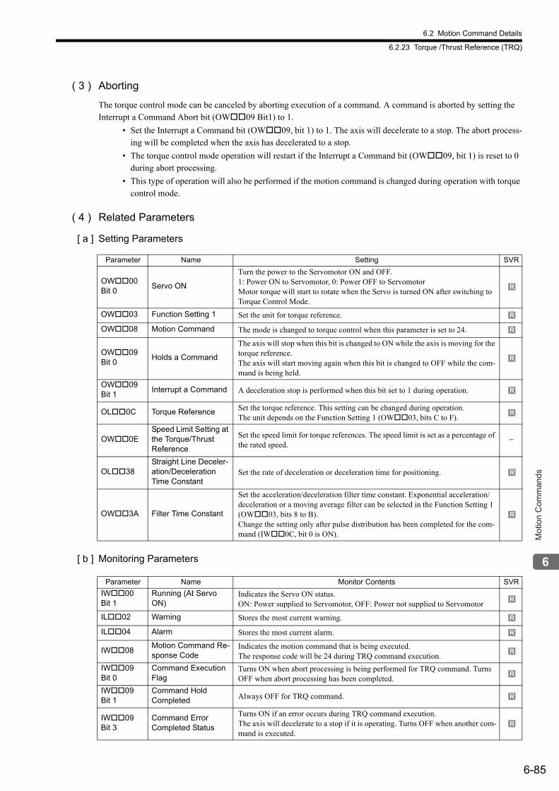
6.2 Motion Command Details
6.2.23 Torque /Thrust Reference (TRQ)
6-85
Mot
ion
Com
man
ds
( 3 ) Aborting
The torque control mode can be canceled by aborting execution of a command. A command is aborted by setting the Interrupt a Command Abort bit (OW09 Bit1) to 1.
• Set the Interrupt a Command bit (OW09, bit 1) to 1. The axis will decelerate to a stop. The abort process-ing will be completed when the axis has decelerated to a stop.
• The torque control mode operation will restart if the Interrupt a Command bit (OW09, bit 1) is reset to 0 during abort processing.
• This type of operation will also be performed if the motion command is changed during operation with torque control mode.
( 4 ) Related Parameters
[ a ] Setting Parameters
[ b ] Monitoring Parameters
Parameter Name Setting SVR
OW00 Bit 0
Servo ON
Turn the power to the Servomotor ON and OFF. 1: Power ON to Servomotor, 0: Power OFF to ServomotorMotor torque will start to rotate when the Servo is turned ON after switching to Torque Control Mode.
OW03 Function Setting 1 Set the unit for torque reference.
OW08 Motion Command The mode is changed to torque control when this parameter is set to 24.
OW09 Bit 0
Holds a Command
The axis will stop when this bit is changed to ON while the axis is moving for the torque reference.The axis will start moving again when this bit is changed to OFF while the com-mand is being held.
OW09 Bit 1
Interrupt a Command A deceleration stop is performed when this bit set to 1 during operation.
OL0C Torque Reference Set the torque reference. This setting can be changed during operation. The unit depends on the Function Setting 1 (OW03, bits C to F).
OW0ESpeed Limit Setting at the Torque/ThrustReference
Set the speed limit for torque references. The speed limit is set as a percentage of the rated speed.
−
OL38Straight Line Deceler-ation/Deceleration Time Constant
Set the rate of deceleration or deceleration time for positioning.
OW3A Filter Time Constant
Set the acceleration/deceleration filter time constant. Exponential acceleration/deceleration or a moving average filter can be selected in the Function Setting 1 (OW03, bits 8 to B). Change the setting only after pulse distribution has been completed for the com-mand (IW0C, bit 0 is ON).
Parameter Name Monitor Contents SVR
IW00 Bit 1
Running (At Servo ON)
Indicates the Servo ON status. ON: Power supplied to Servomotor, OFF: Power not supplied to Servomotor
IL02 Warning Stores the most current warning.
IL04 Alarm Stores the most current alarm.
IW08Motion Command Re-sponse Code
Indicates the motion command that is being executed. The response code will be 24 during TRQ command execution.
IW09 Bit 0
Command Execution Flag
Turns ON when abort processing is being performed for TRQ command. Turns OFF when abort processing has been completed.
IW09 Bit 1
Command HoldCompleted Always OFF for TRQ command.
IW09 Bit 3
Command ErrorCompleted Status
Turns ON if an error occurs during TRQ command execution. The axis will decelerate to a stop if it is operating. Turns OFF when another com-mand is executed.
R
R
R
R
R
R
R
R
R
R
R
R
R
R
R

6.2 Motion Command Details
6.2.23 Torque /Thrust Reference (TRQ)
6-86
( 5 ) Timing Charts
[ a ] Normal Execution
[ b ] Executed when Aborted
IW09 Bit 8
Command Execution Completed Always OFF for TRQ command.
IW0C Bit 0
Discharging Complet-ed
Turns ON when pulse distribution has been completed for the move command.Turns OFF during execution of a move command.
IW0C Bit 1
Positioning Completed
Turns ON when pulse distribution has been completed and the current position is within the width of Positioning Completion. OFF in all other cases.
IW0C Bit 3
NEAR Position
The operation of this bit depends on the setting NEAR Signal Output Width (set-ting parameter OL20).
OL20 = 0: Turns ON when pulse distribution has been completed (DEN = ON). Otherwise, it turns OFF.
OL20 ≠ 0: Turns ON when the absolute value of the difference between MPOS (IL12) and APOS (IL16) is less than the NEAR Signal Output Width, even if pulse distribution has not been completed. OFF in all other cases.
(cont’d)
Parameter Name Monitor Contents SVR
R
R
R
R
OW��08 = 24 (TRQ)
IW��08 = 24 (TRQ)
IW��09, bit 0 (BUSY)
IW��09, bit 8 (COMPLETE)
IW��09, bit 3 (FAIL)
IW��0C, bit 0 (DEN)
1 scan
IW��0C, bit 1 (POSCOMP)
1 scan
OW��09, bit 1 (ABORT)
Torque Control Mode Position Control Mode
OW��08 = 24 (TRQ)
IW��08 = 24 (TRQ)
IW��09, bit 0 (BUSY)
IW��09, bit 8 (COMPLETE)
IW��09, bit 3 (FAIL)
IW��0C, bit 0 (DEN)
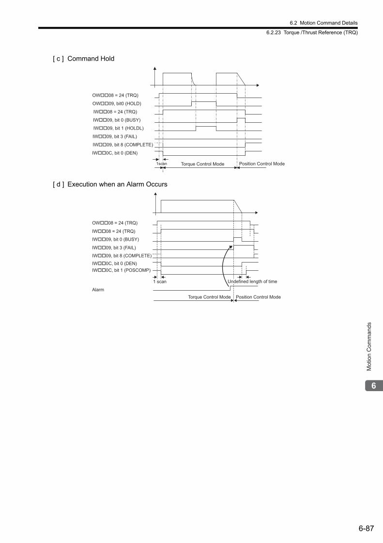
6.2 Motion Command Details
6.2.23 Torque /Thrust Reference (TRQ)
6-87
Mot
ion
Com
man
ds
[ c ] Command Hold
[ d ] Execution when an Alarm Occurs
OW��08 = 24 (TRQ)
IW��08 = 24 (TRQ)
IW��09, bit 0 (BUSY)
IW��09, bit 8 (COMPLETE)
IW��09, bit 3 (FAIL)
IW��0C, bit 0 (DEN)
1scan
OW��09, bit0 (HOLD)
IW��09, bit 1 (HOLDL)
Torque Control Mode Position Control Mode
Alarm
IW��0C, bit 1 (POSCOMP)
1 scan
Torque Control Mode Position Control Mode
Undefined length of time
OW��08 = 24 (TRQ)
IW��08 = 24 (TRQ)
IW��09, bit 0 (BUSY)
IW��09, bit 8 (COMPLETE)
IW��09, bit 3 (FAIL)
IW��0C, bit 0 (DEN)
6.2 Motion Command Details
6.2.24 Phase References (PHASE)
6-88
6.2.24 Phase References (PHASE)
The PHASE command is used for the synchronized operation of multiple axes under phase control mode, using the specified speed, phase bias, and speed compensation value.For SVR, the position data and the feedback speed can be monitored.
Speed feed forward compensation cannot be used for the SGD-N or SGDB-N SERVOPACK, so the PHASE com-mand cannot be used.
When using an SGDV or SGD7S SERVOPACK, the torque limit can be set and changed during SERVOPACK opera-tion. For details, refer to Setting and Changing Torque Limit during SGDV or SGD7S SERVOPACK Operations of 4.4.2 ( 12 ).
Precautions When Using Σ-V or Σ-7 Series SERVOPACKs
( 1 ) Executing/Operating Procedure
1. Check to see if all the following conditions are satisfied.
2. Set the following motion setting parameters.
Speed Reference Setting: OL10Filter Type Selection: OW03, bits 8 to BSpeed Loop P/PI Switch: OW01Phase Correction Setting: OL28Speed Compensation: OW31
3. Set OW08 to 25 to execute the PHASE motion command.
Synchronized operation using phase control will start.IW08 will be 25 during the execution.
R
If you use the SVB Module to synchronously operate more than one axis as electronic shafts, make sure that the command resolution is the same for all of the axes.Example:If you use a SERVOPACK with a 17-bit encoder together with a SERVOPACK with a 20-bit encoder to con-trol more than one axis, change the electronic gear ratio of the SERVOPACK with the 20-bit encoder so that it operates as a 17-bit encoder.
When the tuning or vibration suppression functions are used to perform Servo adjustments and model fol-lowing control is enabled (i.e., when Pn140.0 = 1), the SERVOPACK cannot be properly controlled by phase references. When using phase references, change the settings to the following values.
• Set the model-following control to disabled (Pn140.0=0).• When using the utility functions for adjustment, select the following modes.
• Advanced Autotuning and Advanced Autotuning by References: Mode=1• One-parameter Tuning: Tuning mode=0 or 1
CAUTION
No. Execution Conditions Confirmation Method
1 There are no alarms. Both IL02 and IL04 are 0.
2 The Servo ON condition. IW00, bit 1 is ON.
3 Motion command execution has been completed. IW08 is 0 and IW09, bit 0 is OFF.
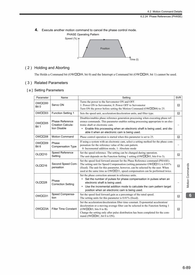
6.2 Motion Command Details
6.2.24 Phase References (PHASE)
6-89
Mot
ion
Com
man
ds
4. Execute another motion command to cancel the phase control mode.
( 2 ) Holding and Aborting
The Holds a Command bit (OW09, bit 0) and the Interrupt a Command bit (OW09, bit 1) cannot be used.
( 3 ) Related Parameters
[ a ] Setting Parameters
PHASE Operating Pattern
0
Speed (%)
Time (t)
Position
Parameter Name Setting SVR
OW00 Bit 0
Servo ONTurns the power to the Servomotor ON and OFF. 1: Power ON to Servomotor, 0: Power OFF to ServomotorTurn ON the power before setting the Motion Command (OW08) to 25.
OW03 Function Setting 1 Sets the speed unit, acceleration/deceleration units, and filter type.
OW05 Bit 1
Phase Reference Creation Calcula-tion Disable
Disables/enables phase reference generation processing when executing phase ref-erence commands. This parameter enables setting processing appropriate to an elec-tronic shaft or electronic cam. Enable this processing when an electronic shaft is being used, and dis-
able it when an electronic cam is being used.
−
OW08 Motion Command Phase control operation is started when this parameter is set to 25.
OW09 Bit 6
Phase Compensation Type
If using a system with an electronic cam, select a setting method for the phase com-pensation for the reference value of the cam pattern. 0: Incremental addition mode, 1: Absolute mode
−
OL10Speed Reference Setting
Set the speed reference. The setting can be changed during operation. The unit depends on the Function Setting 1 setting (OW03, bits 0 to 3).
OL16Second Speed Com-pensation
Set the speed feed forward amount for the Phase Reference command (PHASE). The setting unit for Speed Compensation (setting parameter OW31) is 0.01% (fixed). The unit for this parameter, however, can be selected by the user. When used at the same time as OW31, speed compensation can be performed twice.
OL28Phase Correction Setting
Set the phase correction amount in reference units. Set the number of pulses for phase compensation in pulses when an
electronic shaft is being used.
Use the incremental addition mode to calculate the cam pattern target position when an electronic cam is being used.
−
OW31Speed Compensa-tion
Set the speed feed forward gain as a percentage of the rated speed.The setting units for this parameter is 0.01% (fixed).
OW3A Filter Time Constant
Set the acceleration/deceleration filter time constant. Exponential acceleration/deceleration or a moving average filter can be selected in the Function Setting 1 (OW03, bits 8 to B).Change the setting only after pulse distribution has been completed for the com-mand (IW0C, bit 0 is ON).
R
R
R
R
R
R
R
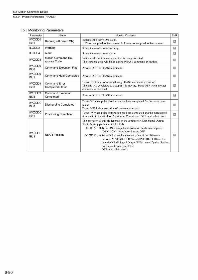
6.2 Motion Command Details
6.2.24 Phase References (PHASE)
6-90
[ b ] Monitoring Parameters
Parameter Name Monitor Contents SVR
IW00 Bit 1
Running (At Servo ON) Indicates the Servo ON status. 1: Power supplied to Servomotor, 0: Power not supplied to Servomotor
IL02 Warning Stores the most current warning.
IL04 Alarm Stores the most current alarm.
IW08Motion Command Re-sponse Code
Indicates the motion command that is being executed. The response code will be 25 during PHASE command execution.
IW09 Bit 0
Command Execution Flag Always OFF for PHASE command.
IW09 Bit 1
Command Hold Completed Always OFF for PHASE command.
IW09 Bit 3
Command ErrorCompleted Status
Turns ON if an error occurs during PHASE command execution. The axis will decelerate to a stop if it is moving. Turns OFF when another command is executed.
IW09 Bit 8
Command Execution Completed Always OFF for PHASE command.
IW0C Bit 0
Discharging CompletedTurns ON when pulse distribution has been completed for the move com-mand. Turns OFF during execution of a move command.
IW0C Bit 1
Positioning Completed Turns ON when pulse distribution has been completed and the current posi-tion is within the width of Positioning Completion. OFF in all other cases.
IW0C Bit 3
NEAR Position
The operation of this bit depends on the setting of NEAR Signal Output Width (setting parameter OL20).
OL20 = 0:Turns ON when pulse distribution has been completed (DEN = ON). Otherwise, it turns OFF.
OL20 ≠ 0:Turns ON when the absolute value of the difference between MPOS (IL12) and APOS (IL16) is less than the NEAR Signal Output Width, even if pulse distribu-tion has not been completed.OFF in all other cases.
R
R
R
R
R
R
R
R
R
R
R
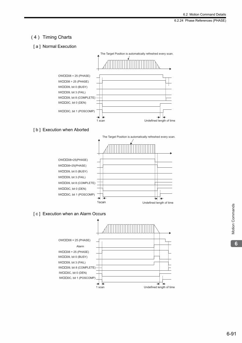
6.2 Motion Command Details
6.2.24 Phase References (PHASE)
6-91
Mot
ion
Com
man
ds
( 4 ) Timing Charts
[ a ] Normal Execution
[ b ] Execution when Aborted
[ c ] Execution when an Alarm Occurs
OW��08 = 25 (PHASE)
IW��08 = 25 (PHASE)
IW��09, bit 0 (BUSY)
IW��09, bit 8 (COMPLETE)
IW��09, bit 3 (FAIL)
IW��0C, bit 0 (DEN)
IW��0C, bit 1 (POSCOMP)
Undefined length of time1 scan
The Target Position is automatically refreshed every scan.
Undefined length of time
IW��0C, bit 1 (POSCOMP)
1scan
OW��08=25(PHASE)
IW��09, bit 0 (BUSY)
IW��08=25(PHASE)
IW��09, bit 3 (FAIL)
IW��0C, bit 0 (DEN)
IW��09, bit 8 (COMPLETE)
The Target Position is automatically refreshed every scan.
Undefined length of time
IW��0C, bit 1 (POSCOMP)
1 scan
Alarm
OW��08 = 25 (PHASE)
IW��08 = 25 (PHASE)
IW��09, bit 0 (BUSY)
IW��09, bit 8 (COMPLETE)
IW��09, bit 3 (FAIL)
IW��0C, bit 0 (DEN)
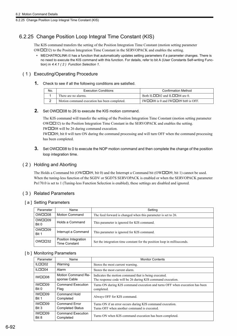
6.2 Motion Command Details
6.2.25 Change Position Loop Integral Time Constant (KIS)
6-92
6.2.25 Change Position Loop Integral Time Constant (KIS)
The KIS command transfers the setting of the Position Integration Time Constant (motion setting parameter OW32) to the Position Integration Time Constant in the SERVOPACK and enables the setting.
MECHATROLINK-II has a function that automatically updates setting parameters if a parameter changes. There is no need to execute the KIS command with this function. For details, refer to bit A (User Constants Self-writing Func-tion) in 4.4.1 ( 2 ) Function Selection 1.
( 1 ) Executing/Operating Procedure
1. Check to see if all the following conditions are satisfied.
2. Set OW08 to 26 to execute the KIS motion command.
The KIS command will transfer the setting of the Position Integration Time Constant (motion setting parameter OW32) to the Position Integration Time Constant in the SERVOPACK and enables the setting. IW08 will be 26 during command execution. IW09, bit 0 will turn ON during the command processing and will turn OFF when the command processing has been completed.
3. Set OW08 to 0 to execute the NOP motion command and then complete the change of the position
loop integration time.
( 2 ) Holding and Aborting
The Holds a Command bit (OW09, bit 0) and the Interrupt a Command bit (OW09, bit 1) cannot be used. When the tuning-less function of the SGDV or SGD7S SERVOPACK is enabled or when the SERVOPACK parameter Pn170.0 is set to 1 (Tuning-less Function Selection is enabled), these settings are disabled and ignored.
( 3 ) Related Parameters
[ a ] Setting Parameters
[ b ] Monitoring Parameters
No. Execution Conditions Confirmation Method
1 There are no alarms. Both IL02 and IL04 are 0.
2 Motion command execution has been completed. IW08 is 0 and IW09 bit0 is OFF.
Parameter Name Setting
OW08 Motion Command The feed forward is changed when this parameter is set to 26.
OW09 Bit 0
Holds a Command This parameter is ignored for KIS command.
OW09 Bit 1
Interrupt a Command This parameter is ignored for KIS command.
OW32Position Integration Time Constant Set the integration time constant for the position loop in milliseconds.
Parameter Name Monitor Contents
IL02 Warning Stores the most current warning.
IL04 Alarm Stores the most current alarm.
IW08Motion Command Re-sponse Cable
Indicates the motion command that is being executed. The response code will be 26 during KIS command execution.
IW09 Bit 0
Command Execution Flag
Turns ON during KIS command execution and turns OFF when execution has been completed.
IW09 Bit 1
Command Hold Completed Always OFF for KIS command.
IW09 Bit 3
Command ErrorCompleted Status
Turns ON if an error occurs during KIS command execution.Turns OFF when another command is executed.
IW09 Bit 8
Command Execution Completed Turns ON when KIS command execution has been completed.
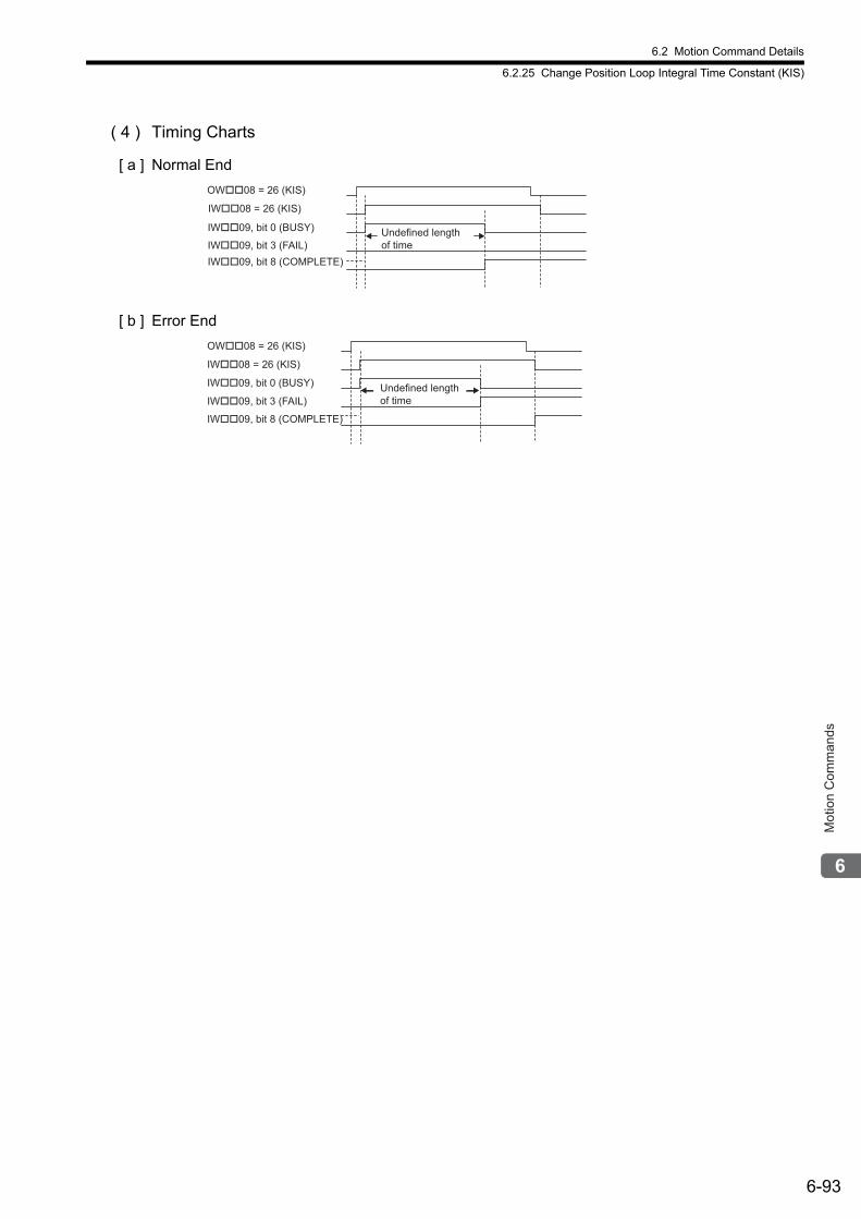
6.2 Motion Command Details
6.2.25 Change Position Loop Integral Time Constant (KIS)
6-93
Mot
ion
Com
man
ds
( 4 ) Timing Charts
[ a ] Normal End
[ b ] Error End
OW��08 = 26 (KIS)
IW��08 = 26 (KIS)
IW��09, bit 0 (BUSY)
IW��09, bit 8 (COMPLETE)
IW��09, bit 3 (FAIL)
Undefined length
of time
OW��08 = 26 (KIS)
IW��08 = 26 (KIS)
IW��09, bit 0 (BUSY)
IW��09, bit 8 (COMPLETE)
IW��09, bit 3 (FAIL)
Undefined length
of time
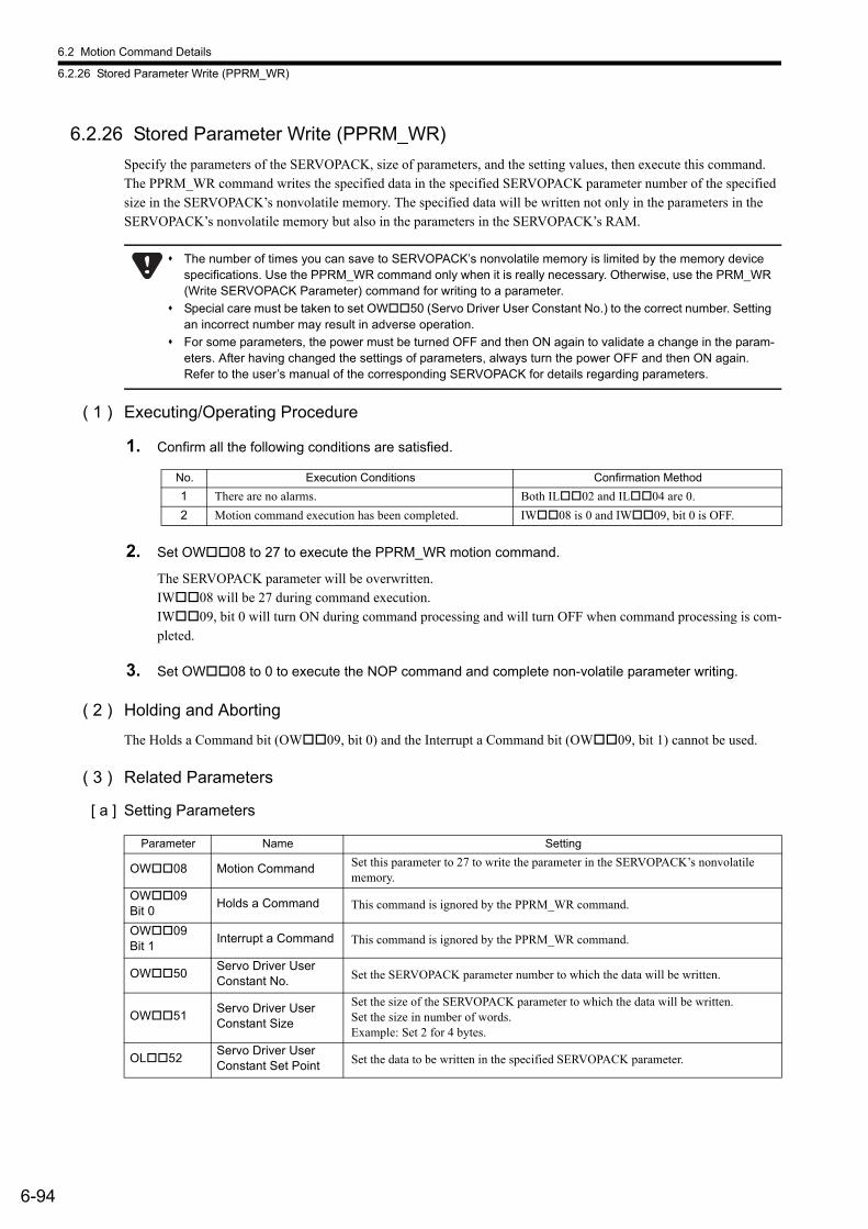
6.2 Motion Command Details
6.2.26 Stored Parameter Write (PPRM_WR)
6-94
6.2.26 Stored Parameter Write (PPRM_WR)
Specify the parameters of the SERVOPACK, size of parameters, and the setting values, then execute this command.The PPRM_WR command writes the specified data in the specified SERVOPACK parameter number of the specified size in the SERVOPACK’s nonvolatile memory. The specified data will be written not only in the parameters in the SERVOPACK’s nonvolatile memory but also in the parameters in the SERVOPACK’s RAM.
( 1 ) Executing/Operating Procedure
1. Confirm all the following conditions are satisfied.
2. Set OW08 to 27 to execute the PPRM_WR motion command.
The SERVOPACK parameter will be overwritten.IW08 will be 27 during command execution.IW09, bit 0 will turn ON during command processing and will turn OFF when command processing is com-pleted.
3. Set OW08 to 0 to execute the NOP command and complete non-volatile parameter writing.
( 2 ) Holding and Aborting
The Holds a Command bit (OW09, bit 0) and the Interrupt a Command bit (OW09, bit 1) cannot be used.
( 3 ) Related Parameters
[ a ] Setting Parameters
The number of times you can save to SERVOPACK’s nonvolatile memory is limited by the memory device specifications. Use the PPRM_WR command only when it is really necessary. Otherwise, use the PRM_WR (Write SERVOPACK Parameter) command for writing to a parameter.
Special care must be taken to set OW50 (Servo Driver User Constant No.) to the correct number. Setting an incorrect number may result in adverse operation.
For some parameters, the power must be turned OFF and then ON again to validate a change in the param-eters. After having changed the settings of parameters, always turn the power OFF and then ON again. Refer to the user’s manual of the corresponding SERVOPACK for details regarding parameters.
No. Execution Conditions Confirmation Method
1 There are no alarms. Both IL02 and IL04 are 0.
2 Motion command execution has been completed. IW08 is 0 and IW09, bit 0 is OFF.
Parameter Name Setting
OW08 Motion Command Set this parameter to 27 to write the parameter in the SERVOPACK’s nonvolatile memory.
OW09Bit 0
Holds a Command This command is ignored by the PPRM_WR command.
OW09Bit 1
Interrupt a Command This command is ignored by the PPRM_WR command.
OW50Servo Driver User Constant No. Set the SERVOPACK parameter number to which the data will be written.
OW51Servo Driver User Constant Size
Set the size of the SERVOPACK parameter to which the data will be written.Set the size in number of words.Example: Set 2 for 4 bytes.
OL52Servo Driver User Constant Set Point Set the data to be written in the specified SERVOPACK parameter.
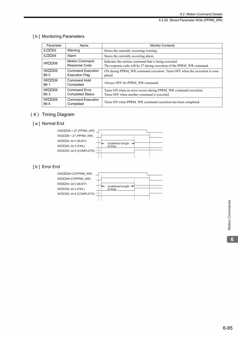
6.2 Motion Command Details
6.2.26 Stored Parameter Write (PPRM_WR)
6-95
Mot
ion
Com
man
ds
[ b ] Monitoring Parameters
( 4 ) Timing Diagram
[ a ] Normal End
[ b ] Error End
Parameter Name Monitor Contents
IL02 Warning Stores the currently occurring warning.
IL04 Alarm Stores the currently occurring alarm.
IW08Motion Command Response Code
Indicates the motion command that is being executed.The response code will be 27 during execution of the PPRM_WR command.
IW09Bit 0
Command Execution Execution Flag
ON during PPRM_WR command execution. Turns OFF when the execution is com-pleted.
IW09 Bit 1
Command Hold Completed Always OFF for PPRM_WR command.
IW09 Bit 3
Command Error Completed Status
Turns ON when an error occurs during PPRM_WR command execution.Turns OFF when another command is executed.
IW09Bit 8
Command Execution Completed Turns ON when PPRM_WR command execution has been completed.
OW��08 = 27 (PPRM_WR)
IW��08 = 27 (PPRM_WR)
IW��09, bit 0 (BUSY)Undefined length
of time
IW��09. bit 8 (COMPLETE)
IW��09, bit 3 (FAIL)
Undefined length
of time
OW��08=27(PPRM_WR)
IW��08=27(PPRM_WR)
IW��09, bit 0 (BUSY)
IW��09, bit 8 (COMPLETE)
IW��09, bit 3 (FAIL)
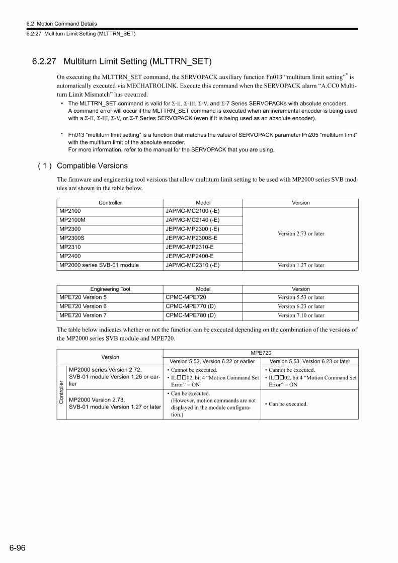
6.2 Motion Command Details
6.2.27 Multiturn Limit Setting (MLTTRN_SET)
6-96
6.2.27 Multiturn Limit Setting (MLTTRN_SET)
On executing the MLTTRN_SET command, the SERVOPACK auxiliary function Fn013 “multiturn limit setting”* is automatically executed via MECHATROLINK. Execute this command when the SERVOPACK alarm “A.CC0 Multi-turn Limit Mismatch” has occurred.
The MLTTRN_SET command is valid for Σ-II, Σ-III, Σ-V, and Σ-7 Series SERVOPACKs with absolute encoders.A command error will occur if the MLTTRN_SET command is executed when an incremental encoder is being used with a Σ-II, Σ-III, Σ-V, or Σ-7 Series SERVOPACK (even if it is being used as an absolute encoder).
* Fn013 “multiturn limit setting” is a function that matches the value of SERVOPACK parameter Pn205 “multiturn limit” with the multiturn limit of the absolute encoder.For more information, refer to the manual for the SERVOPACK that you are using.
( 1 ) Compatible Versions
The firmware and engineering tool versions that allow multiturn limit setting to be used with MP2000 series SVB mod-ules are shown in the table below.
The table below indicates whether or not the function can be executed depending on the combination of the versions of the MP2000 series SVB module and MPE720.
Controller Model Version
MP2100 JAPMC-MC2100 (-E)
Version 2.73 or later
MP2100M JAPMC-MC2140 (-E)
MP2300 JEPMC-MP2300 (-E)
MP2300S JEPMC-MP2300S-E
MP2310 JEPMC-MP2310-E
MP2400 JEPMC-MP2400-E
MP2000 series SVB-01 module JAPMC-MC2310 (-E) Version 1.27 or later
Engineering Tool Model Version
MPE720 Version 5 CPMC-MPE720 Version 5.53 or later
MPE720 Version 6 CPMC-MPE770 (D) Version 6.23 or later
MPE720 Version 7 CPMC-MPE780 (D) Version 7.10 or later
VersionMPE720
Version 5.52, Version 6.22 or earlier Version 5.53, Version 6.23 or later
Con
trol
ler
MP2000 series Version 2.72, SVB-01 module Version 1.26 or ear-lier
• Cannot be executed.• IL02, bit 4 “Motion Command Set
Error” = ON
• Cannot be executed.• IL02, bit 4 “Motion Command Set
Error” = ON
MP2000 Version 2.73, SVB-01 module Version 1.27 or later
• Can be executed.(However, motion commands are not displayed in the module configura-tion.)
• Can be executed.
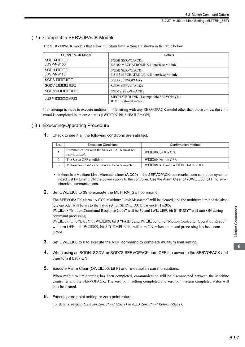
6.2 Motion Command Details
6.2.27 Multiturn Limit Setting (MLTTRN_SET)
6-97
Mot
ion
Com
man
ds
( 2 ) Compatible SERVOPACK Models
The SERVOPACK models that allow multiturn limit setting are shown in the table below.
If an attempt is made to execute multiturn limit setting with any SERVOPACK model other than those above, the com-mand is completed in an error status (IW09, bit 3 “FAIL” = ON).
( 3 ) Executing/Operating Procedure
1. Check to see if all the following conditions are satisfied.
If there is a Multiturn Limit Mismatch alarm (A.CC0) in the SERVOPACK, communications cannot be synchro-nized just by turning ON the power supply to the controller. Use the Alarm Clear bit (OW00, bit F) to syn-chronize communications.
2. Set OW08 to 39 to execute the MLTTRN_SET command.
The SERVOPACK alarm “A.CC0 Multiturn Limit Mismatch” will be cleared, and the multiturn limit of the abso-lute encoder will be set to the value set for SERVOPACK parameter Pn205.IW08 “Motion Command Response Code” will be 39 and IW09, bit 0 “BUSY” will turn ON during command processing.IW09, bit 0 “BUSY”, IW09, bit 3 “FAIL”, and IW00, bit 0 “Motion Controller Operation Ready” will turn OFF, and IW09, bit 8 “COMPLETE” will turn ON, when command processing has been com-pleted.
3. Set OW08 to 0 to execute the NOP command to complete multiturn limit setting.
4. When using an SGDH, SGDV, or SGD7S SERVOPACK, turn OFF the power to the SERVOPACK and
then turn it back ON.
5. Execute Alarm Clear (OW00, bit F) and re-establish communications.
When multiturn limit setting has been completed, communication will be disconnected between the MachineController and the SERVOPACK. The zero point setting completed and zero point return completed status willthus be cleared.
6. Execute zero point setting or zero point return.
For details, refer to 6.2.8 Set Zero Point (ZSET) or 6.2.3 Zero Point Return (ZRET).
SERVOPACK Model Details
SGDH-EJUSP-NS100
SGDH SERVOPACKsNS100 MECHATROLINK-I Interface Module
SGDH-EJUSP-NS115
SGDH SERVOPACKsNS115 MECHATROLINK-II Interface Module
SGDS-1 SGDS SERVOPACKs
SGDV-1 SGDV SERVOPACKs
SGD7S-10 SGD7S SERVOPACKs
JUSP-IMR MECHATROLINK-II-compatible SERVOPACKsIDM (rotational motor)
No. Execution Conditions Confirmation Method
1Communication with the SERVOPACK must be synchronized.
IW00, bit 0 is ON.
2 The Servo OFF condition. IW00, bit 1 is OFF.
3 Motion command execution has been completed. IW08 is 0, and IW09, bit 0 is OFF.
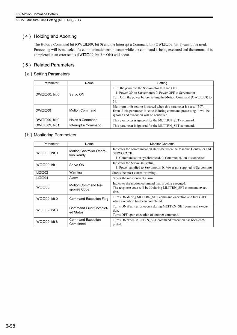
6.2 Motion Command Details
6.2.27 Multiturn Limit Setting (MLTTRN_SET)
6-98
( 4 ) Holding and Aborting
The Holds a Command bit (OW09, bit 0) and the Interrupt a Command bit (OW09, bit 1) cannot be used.Processing will be canceled if a communication error occurs while the command is being executed and the command is completed in an error status (IW09, bit 3 = ON) will occur.
( 5 ) Related Parameters
[ a ] Setting Parameters
[ b ] Monitoring Parameters
Parameter Name Setting
OW00, bit 0 Servo ON
Turn the power to the Servomotor ON and OFF.1: Power ON to Servomotor; 0: Power OFF to Servomotor
Turn OFF the power before setting the Motion Command (OW08) to 39.
OW08 Motion CommandMultiturn limit setting is started when this parameter is set to “39”.Even if this parameter is set to 0 during command processing, it will be ignored and execution will be continued.
OW09, bit 0 Holds a Command This parameter is ignored for the MLTTRN_SET command.
OW09, bit 1 Interrupt a Command This parameter is ignored for the MLTTRN_SET command.
Parameter Name Monitor Contents
IW00, bit 0Motion Controller Opera-tion Ready
Indicates the communication status between the Machine Controller and SERVOPACK.
1: Communication synchronized, 0: Communication disconnected
IW00, bit 1 Servo ONIndicates the Servo ON status.
1: Power supplied to Servomotor, 0: Power not supplied to Servomotor
IL02 Warning Stores the most current warning.
IL04 Alarm Stores the most current alarm.
IW08Motion Command Re-sponse Code
Indicates the motion command that is being executed.The response code will be 39 during MLTTRN_SET command execu-tion.
IW09, bit 0 Command Execution Flag Turns ON during MLTTRN_SET command execution and turns OFF when execution has been completed.
IW09, bit 3Command Error Complet-ed Status
Turns ON if any error occurs during MLTTRN_SET command execu-tion.Turns OFF upon execution of another command.
IW09, bit 8Command Execution Completed
Turns ON when MLTTRN_SET command execution has been com-pleted.
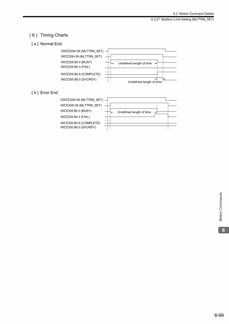
6.2 Motion Command Details
6.2.27 Multiturn Limit Setting (MLTTRN_SET)
6-99
Mot
ion
Com
man
ds
( 6 ) Timing Charts
[ a ] Normal End
[ b ] Error End
OW��08=39 (MLTTRN_SET)
IW��08=39 (MLTTRN_SET)
IW��09 Bit 0 (BUSY) Undefined length of timeIW��09 Bit 3 (FAIL)
IW��00 Bit 0 (SVCRDY)
IW��09 Bit 8 (COMPLETE)
Undefined length of time
Undefined length of time
OW��08=39 (MLTTRN_SET)
IW��08=39 (MLTTRN_SET)
IW��09 Bit 0 (BUSY)
IW��09 Bit 3 (FAIL)
IW��00 Bit 0 (SVCRDY)IW��09 Bit 8 (COMPLETE)
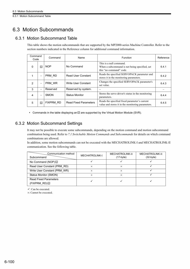
6.3 Motion Subcommands
6.3.1 Motion Subcommand Table
6-100
6.3 Motion Subcommands
6.3.1 Motion Subcommand Table
This table shows the motion subcommands that are supported by the MP2000-series Machine Controller. Refer to the section numbers indicated in the Reference column for additional command information.
Commands in the table displaying an are supported by the Virtual Motion Module (SVR).
6.3.2 Motion Subcommand Settings
It may not be possible to execute some subcommands, depending on the motion command and motion subcommand combination being used. Refer to 7.1 Switchable Motion Commands and Subcommands for details on which command combinations are allowed. In addition, some motion subcommands can not be executed with the MECHATROLINK-I and MECHATROLINK-II communication. See the following table.
: Can be executed.×: Cannot be executed.
Command Code
Command Name Function Reference
0 NOP No CommandThis is a null command. When a subcommand is not being specified, set this “no command” code.
6.4.1
1 − PRM_RD Read User Constant Reads the specified SERVOPACK parameter and stores it in the monitoring parameters.
6.4.2
2 − PRM_WR Write User Constant Changes the specified SERVOPACK parameter's set value.
6.4.3
3 − Reserved Reserved by system. − −
4 − SMON Status Monitor Stores the servo driver's status in the monitoring parameters.
6.4.4
5 FIXPRM_RD Read Fixed Parameters Reads the specified fixed parameter’s current value and stores it in the monitoring parameters.
6.4.5
R
R
R
Communication method
SubcommandMECHATROLINK-I
MECHATROLINK-II (17-byte)
MECHATROLINK-II (32-byte)
No Command (NOP)
Read User Constant (PRM_RD) × ×
Write User Constant (PRM_WR) × ×
Status Monitor (SMON) × ×
Read Fixed Parameters
(FIXPRM_RD)
R
R
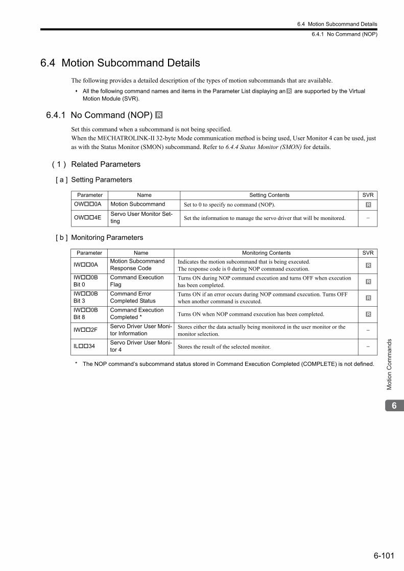
6.4 Motion Subcommand Details
6.4.1 No Command (NOP)
6-101
Mot
ion
Com
man
ds
6.4 Motion Subcommand Details
The following provides a detailed description of the types of motion subcommands that are available.
All the following command names and items in the Parameter List displaying an are supported by the Virtual Motion Module (SVR).
6.4.1 No Command (NOP)
Set this command when a subcommand is not being specified. When the MECHATROLINK-II 32-byte Mode communication method is being used, User Monitor 4 can be used, just as with the Status Monitor (SMON) subcommand. Refer to 6.4.4 Status Monitor (SMON) for details.
( 1 ) Related Parameters
[ a ] Setting Parameters
[ b ] Monitoring Parameters
* The NOP command’s subcommand status stored in Command Execution Completed (COMPLETE) is not defined.
R
R
Parameter Name Setting Contents SVR
OW0A Motion Subcommand Set to 0 to specify no command (NOP).
OW4EServo User Monitor Set-ting Set the information to manage the servo driver that will be monitored. −
Parameter Name Monitoring Contents SVR
IW0AMotion Subcommand Response Code
Indicates the motion subcommand that is being executed. The response code is 0 during NOP command execution.
IW0B Bit 0
Command Execution Flag
Turns ON during NOP command execution and turns OFF when execution has been completed.
IW0B Bit 3
Command ErrorCompleted Status
Turns ON if an error occurs during NOP command execution. Turns OFF when another command is executed.
IW0B Bit 8
Command Execution Completed * Turns ON when NOP command execution has been completed.
IW2FServo Driver User Moni-tor Information
Stores either the data actually being monitored in the user monitor or the monitor selection.
−
IL34Servo Driver User Moni-tor 4 Stores the result of the selected monitor. −
R
R
R
R
R
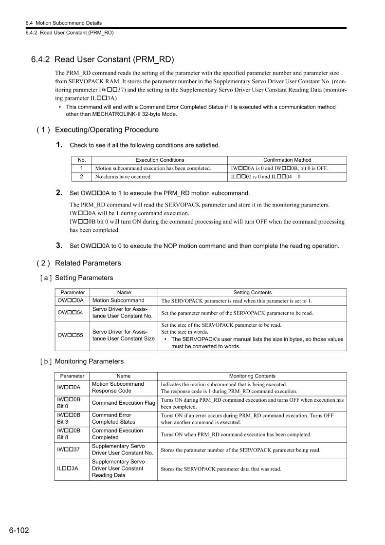
6.4 Motion Subcommand Details
6.4.2 Read User Constant (PRM_RD)
6-102
6.4.2 Read User Constant (PRM_RD)
The PRM_RD command reads the setting of the parameter with the specified parameter number and parameter size from SERVOPACK RAM. It stores the parameter number in the Supplementary Servo Driver User Constant No. (mon-itoring parameter IW37) and the setting in the Supplementary Servo Driver User Constant Reading Data (monitor-ing parameter IL3A)
This command will end with a Command Error Completed Status if it is executed with a communication method other than MECHATROLINK-II 32-byte Mode.
( 1 ) Executing/Operating Procedure
1. Check to see if all the following conditions are satisfied.
2. Set OW0A to 1 to execute the PRM_RD motion subcommand.
The PRM_RD command will read the SERVOPACK parameter and store it in the monitoring parameters. IW0A will be 1 during command execution. IW0B bit 0 will turn ON during the command processing and will turn OFF when the command processing has been completed.
3. Set OW0A to 0 to execute the NOP motion command and then complete the reading operation.
( 2 ) Related Parameters
[ a ] Setting Parameters
[ b ] Monitoring Parameters
No. Execution Conditions Confirmation Method
1 Motion subcommand execution has been completed. IW0A is 0 and IW0B, bit 0 is OFF.
2 No alarms have occurred. IL02 is 0 and IL04 = 0
Parameter Name Setting Contents
OW0A Motion Subcommand The SERVOPACK parameter is read when this parameter is set to 1.
OW54Servo Driver for Assis-tance User Constant No. Set the parameter number of the SERVOPACK parameter to be read.
OW55Servo Driver for Assis-tance User Constant Size
Set the size of the SERVOPACK parameter to be read. Set the size in words. The SERVOPACK’s user manual lists the size in bytes, so those values
must be converted to words.
Parameter Name Monitoring Contents
IW0AMotion SubcommandResponse Code
Indicates the motion subcommand that is being executed. The response code is 1 during PRM_RD command execution.
IW0B Bit 0
Command Execution Flag Turns ON during PRM_RD command execution and turns OFF when execution has been completed.
IW0B Bit 3
Command ErrorCompleted Status
Turns ON if an error occurs during PRM_RD command execution. Turns OFF when another command is executed.
IW0B Bit 8
Command Execution Completed Turns ON when PRM_RD command execution has been completed.
IW37Supplementary Servo Driver User Constant No. Stores the parameter number of the SERVOPACK parameter being read.
IL3ASupplementary Servo Driver User Constant Reading Data
Stores the SERVOPACK parameter data that was read.
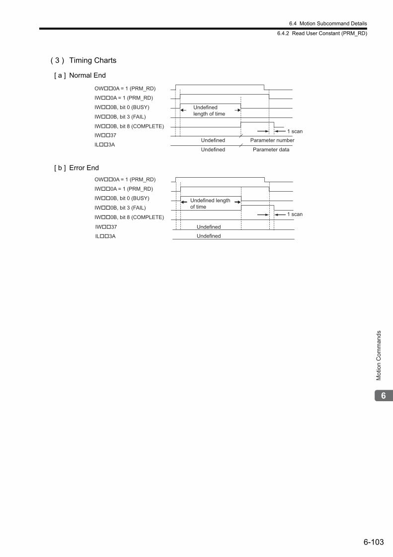
6.4 Motion Subcommand Details
6.4.2 Read User Constant (PRM_RD)
6-103
Mot
ion
Com
man
ds
( 3 ) Timing Charts
[ a ] Normal End
[ b ] Error End
Undefined length of time
OW��0A = 1 (PRM_RD)
IW��0A = 1 (PRM_RD)
IW��0B, bit 0 (BUSY)
Parameter number
IW��0B, bit 8 (COMPLETE)
IW��0B, bit 3 (FAIL)
Parameter data
UndefinedIW��37
UndefinedIL��3A
1 scan
Undefined
Undefined
Undefined length of time
OW��0A = 1 (PRM_RD)
IW��0A = 1 (PRM_RD)
IW��0B, bit 0 (BUSY)
IW��0B, bit 8 (COMPLETE)
IW��0B, bit 3 (FAIL)
IW��37
IL��3A
1 scan
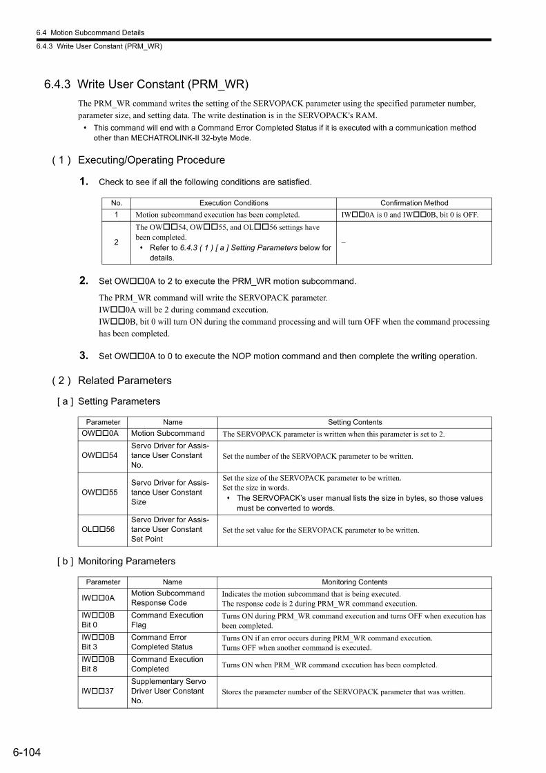
6.4 Motion Subcommand Details
6.4.3 Write User Constant (PRM_WR)
6-104
6.4.3 Write User Constant (PRM_WR)
The PRM_WR command writes the setting of the SERVOPACK parameter using the specified parameter number, parameter size, and setting data. The write destination is in the SERVOPACK's RAM.
This command will end with a Command Error Completed Status if it is executed with a communication method other than MECHATROLINK-II 32-byte Mode.
( 1 ) Executing/Operating Procedure
1. Check to see if all the following conditions are satisfied.
2. Set OW0A to 2 to execute the PRM_WR motion subcommand.
The PRM_WR command will write the SERVOPACK parameter.IW0A will be 2 during command execution. IW0B, bit 0 will turn ON during the command processing and will turn OFF when the command processing has been completed.
3. Set OW0A to 0 to execute the NOP motion command and then complete the writing operation.
( 2 ) Related Parameters
[ a ] Setting Parameters
[ b ] Monitoring Parameters
No. Execution Conditions Confirmation Method
1 Motion subcommand execution has been completed. IW0A is 0 and IW0B, bit 0 is OFF.
2
The OW54, OW55, and OL56 settings have been completed. Refer to 6.4.3 ( 1 ) [ a ] Setting Parameters below for
details.
−
Parameter Name Setting Contents
OW0A Motion Subcommand The SERVOPACK parameter is written when this parameter is set to 2.
OW54Servo Driver for Assis-tance User Constant No.
Set the number of the SERVOPACK parameter to be written.
OW55Servo Driver for Assis-tance User Constant Size
Set the size of the SERVOPACK parameter to be written. Set the size in words. The SERVOPACK’s user manual lists the size in bytes, so those values
must be converted to words.
OL56Servo Driver for Assis-tance User Constant Set Point
Set the set value for the SERVOPACK parameter to be written.
Parameter Name Monitoring Contents
IW0AMotion Subcommand Response Code
Indicates the motion subcommand that is being executed. The response code is 2 during PRM_WR command execution.
IW0B Bit 0
Command Execution Flag
Turns ON during PRM_WR command execution and turns OFF when execution has been completed.
IW0B Bit 3
Command ErrorCompleted Status
Turns ON if an error occurs during PRM_WR command execution. Turns OFF when another command is executed.
IW0B Bit 8
Command Execution Completed Turns ON when PRM_WR command execution has been completed.
IW37Supplementary Servo Driver User Constant No.
Stores the parameter number of the SERVOPACK parameter that was written.
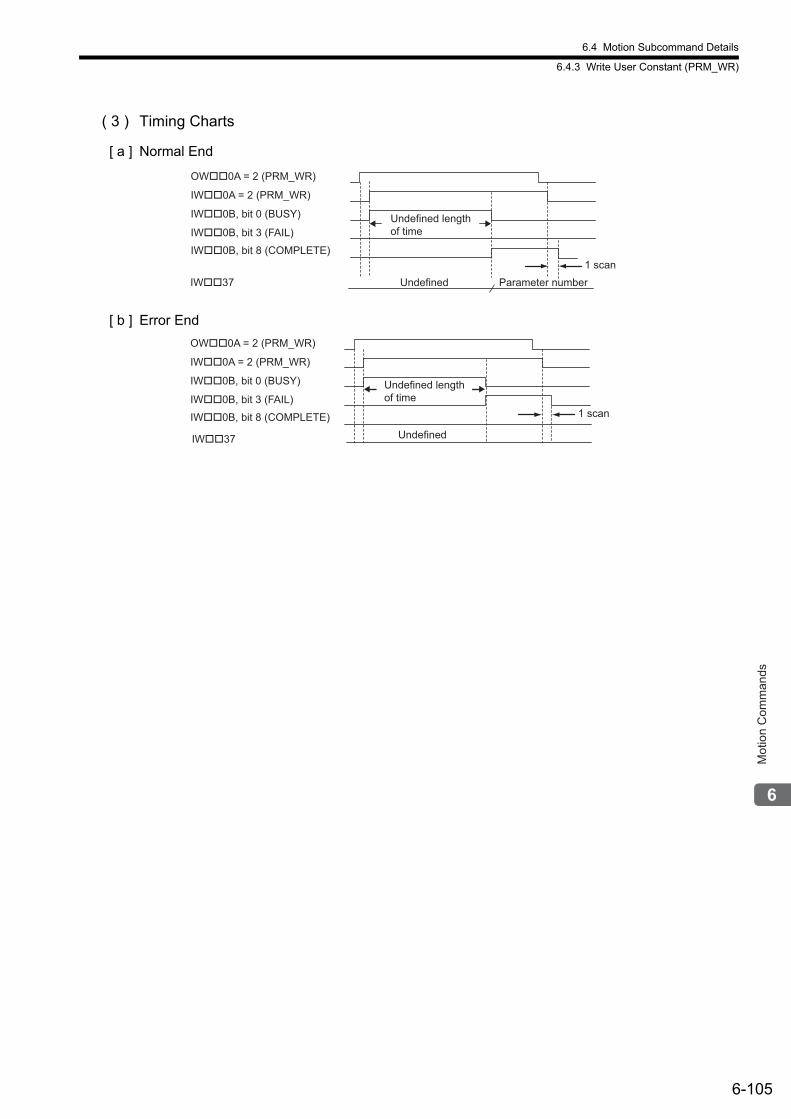
6.4 Motion Subcommand Details
6.4.3 Write User Constant (PRM_WR)
6-105
Mot
ion
Com
man
ds
( 3 ) Timing Charts
[ a ] Normal End
[ b ] Error End
Parameter numberUndefined
Undefined length of time
OW��0A = 2 (PRM_WR)
IW��0A = 2 (PRM_WR)
IW��0B, bit 0 (BUSY)
IW��0B, bit 8 (COMPLETE)
IW��0B, bit 3 (FAIL)
IW��371 scan
Undefined
Undefined length of time
OW��0A = 2 (PRM_WR)
IW��0A = 2 (PRM_WR)
IW��0B, bit 0 (BUSY)
IW��0B, bit 8 (COMPLETE)
IW��0B, bit 3 (FAIL)
IW��37
1 scan
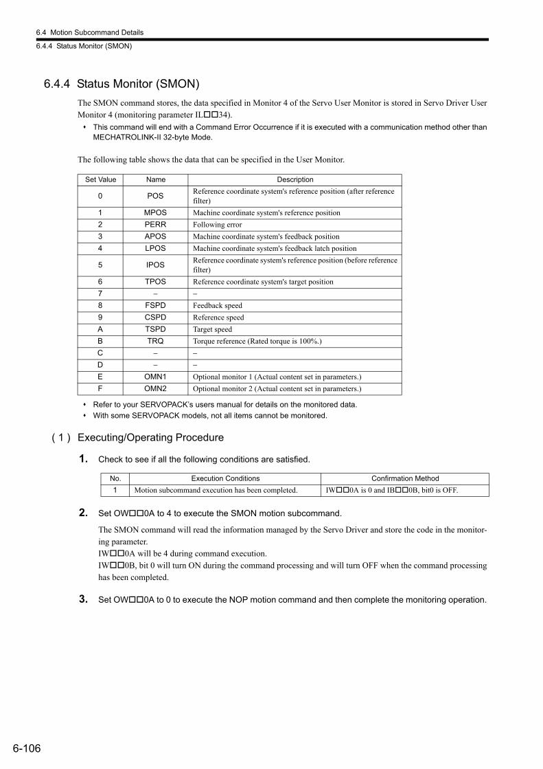
6.4 Motion Subcommand Details
6.4.4 Status Monitor (SMON)
6-106
6.4.4 Status Monitor (SMON)
The SMON command stores, the data specified in Monitor 4 of the Servo User Monitor is stored in Servo Driver User Monitor 4 (monitoring parameter IL34).
This command will end with a Command Error Occurrence if it is executed with a communication method other than MECHATROLINK-II 32-byte Mode.
The following table shows the data that can be specified in the User Monitor.
Refer to your SERVOPACK’s users manual for details on the monitored data.
With some SERVOPACK models, not all items cannot be monitored.
( 1 ) Executing/Operating Procedure
1. Check to see if all the following conditions are satisfied.
2. Set OW0A to 4 to execute the SMON motion subcommand.
The SMON command will read the information managed by the Servo Driver and store the code in the monitor-ing parameter.IW0A will be 4 during command execution. IW0B, bit 0 will turn ON during the command processing and will turn OFF when the command processing has been completed.
3. Set OW0A to 0 to execute the NOP motion command and then complete the monitoring operation.
Set Value Name Description
0 POSReference coordinate system's reference position (after reference filter)
1 MPOS Machine coordinate system's reference position
2 PERR Following error
3 APOS Machine coordinate system's feedback position
4 LPOS Machine coordinate system's feedback latch position
5 IPOSReference coordinate system's reference position (before reference filter)
6 TPOS Reference coordinate system's target position
7 − −8 FSPD Feedback speed
9 CSPD Reference speed
A TSPD Target speed
B TRQ Torque reference (Rated torque is 100%.)
C − −D − −E OMN1 Optional monitor 1 (Actual content set in parameters.)
F OMN2 Optional monitor 2 (Actual content set in parameters.)
No. Execution Conditions Confirmation Method
1 Motion subcommand execution has been completed. IW0A is 0 and IB0B, bit0 is OFF.
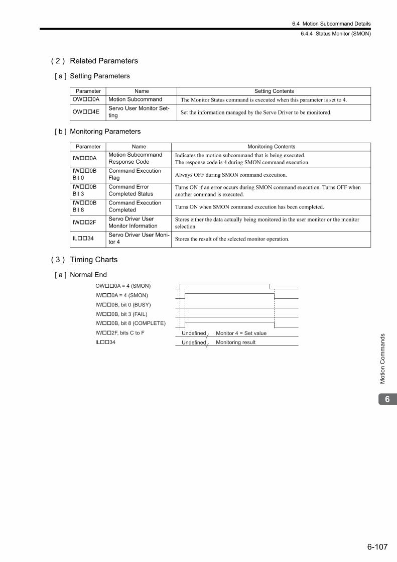
6.4 Motion Subcommand Details
6.4.4 Status Monitor (SMON)
6-107
Mot
ion
Com
man
ds
( 2 ) Related Parameters
[ a ] Setting Parameters
[ b ] Monitoring Parameters
( 3 ) Timing Charts
[ a ] Normal End
Parameter Name Setting Contents
OW0A Motion Subcommand The Monitor Status command is executed when this parameter is set to 4.
OW4EServo User Monitor Set-ting Set the information managed by the Servo Driver to be monitored.
Parameter Name Monitoring Contents
IW0AMotion Subcommand Response Code
Indicates the motion subcommand that is being executed. The response code is 4 during SMON command execution.
IW0B Bit 0
Command Execution Flag Always OFF during SMON command execution.
IW0B Bit 3
Command ErrorCompleted Status
Turns ON if an error occurs during SMON command execution. Turns OFF when another command is executed.
IW0B Bit 8
Command Execution Completed Turns ON when SMON command execution has been completed.
IW2FServo Driver UserMonitor Information
Stores either the data actually being monitored in the user monitor or the monitor selection.
IL34Servo Driver User Moni-tor 4 Stores the result of the selected monitor operation.
Monitor 4 = Set value
Monitoring result
OW��0A = 4 (SMON)
IW��0A = 4 (SMON)
IW��0B, bit 0 (BUSY)
IW��2F, bits C to F Undefined
IW��0B, bit 8 (COMPLETE)
IW��0B, bit 3 (FAIL)
IL��34 Undefined
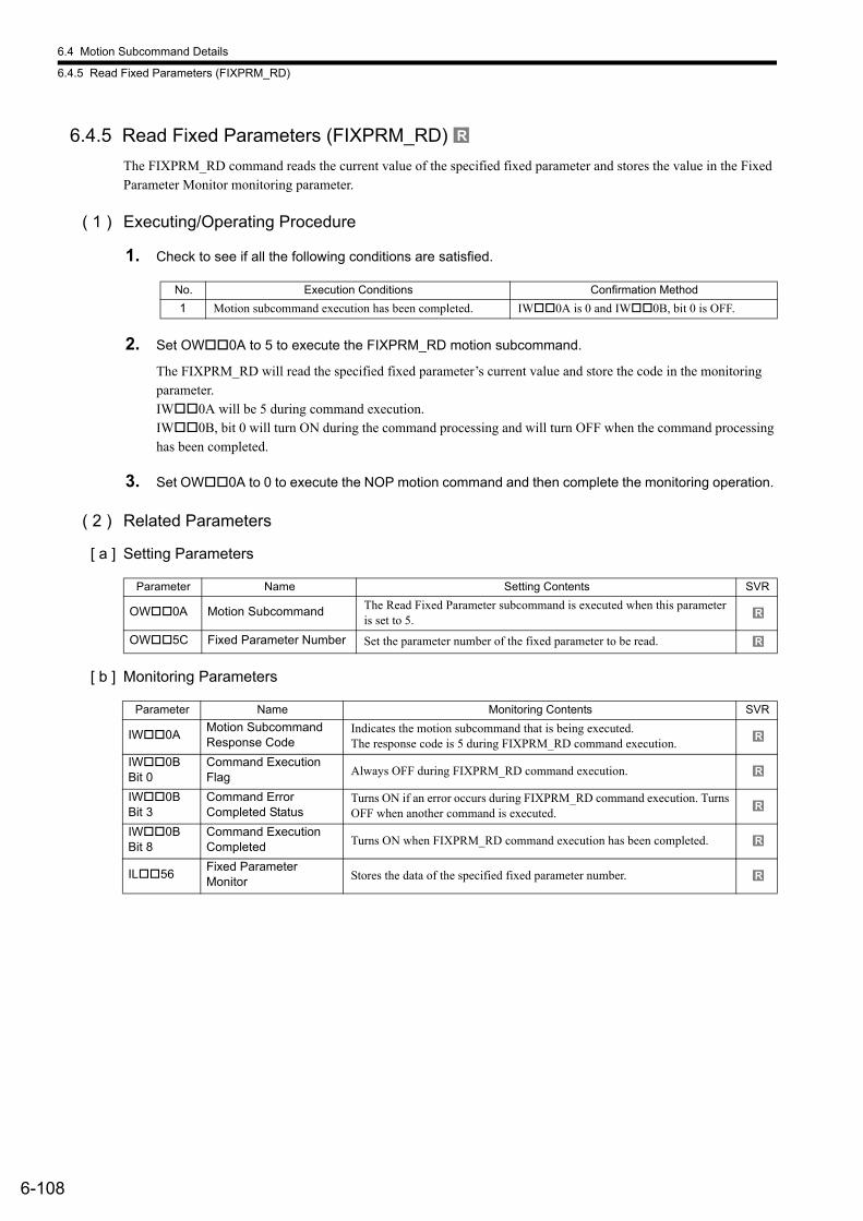
6.4 Motion Subcommand Details
6.4.5 Read Fixed Parameters (FIXPRM_RD)
6-108
6.4.5 Read Fixed Parameters (FIXPRM_RD)
The FIXPRM_RD command reads the current value of the specified fixed parameter and stores the value in the Fixed Parameter Monitor monitoring parameter.
( 1 ) Executing/Operating Procedure
1. Check to see if all the following conditions are satisfied.
2. Set OW0A to 5 to execute the FIXPRM_RD motion subcommand.
The FIXPRM_RD will read the specified fixed parameter’s current value and store the code in the monitoring parameter. IW0A will be 5 during command execution.IW0B, bit 0 will turn ON during the command processing and will turn OFF when the command processing has been completed.
3. Set OW0A to 0 to execute the NOP motion command and then complete the monitoring operation.
( 2 ) Related Parameters
[ a ] Setting Parameters
[ b ] Monitoring Parameters
R
No. Execution Conditions Confirmation Method
1 Motion subcommand execution has been completed. IW0A is 0 and IW0B, bit 0 is OFF.
Parameter Name Setting Contents SVR
OW0A Motion Subcommand The Read Fixed Parameter subcommand is executed when this parameter is set to 5.
OW5C Fixed Parameter Number Set the parameter number of the fixed parameter to be read.
Parameter Name Monitoring Contents SVR
IW0AMotion Subcommand Response Code
Indicates the motion subcommand that is being executed. The response code is 5 during FIXPRM_RD command execution.
IW0B Bit 0
Command Execution Flag Always OFF during FIXPRM_RD command execution.
IW0B Bit 3
Command ErrorCompleted Status
Turns ON if an error occurs during FIXPRM_RD command execution. Turns OFF when another command is executed.
IW0B Bit 8
Command Execution Completed Turns ON when FIXPRM_RD command execution has been completed.
IL56Fixed Parameter Monitor Stores the data of the specified fixed parameter number.
R
R
R
R
R
R
R
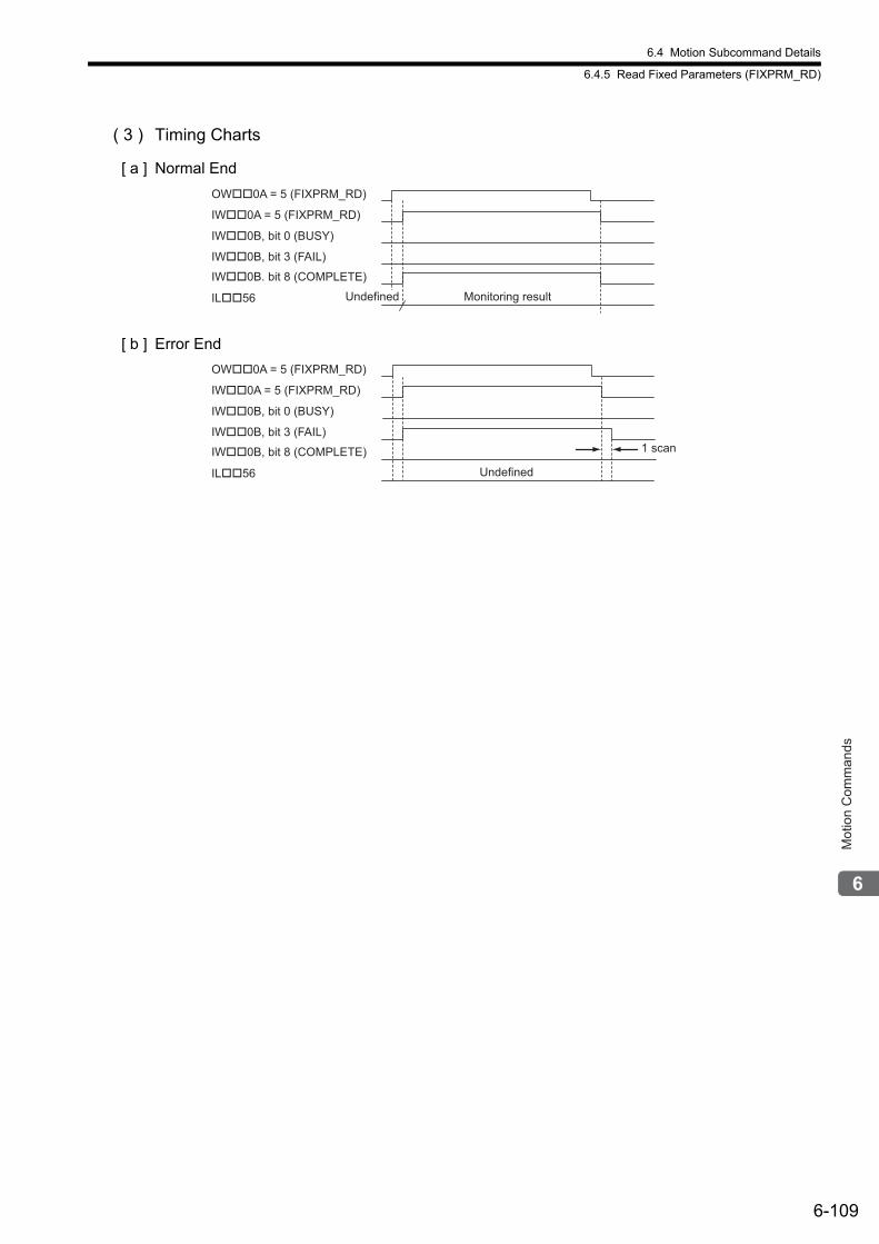
6.4 Motion Subcommand Details
6.4.5 Read Fixed Parameters (FIXPRM_RD)
6-109
Mot
ion
Com
man
ds
( 3 ) Timing Charts
[ a ] Normal End
[ b ] Error End
Undefined
OW��0A = 5 (FIXPRM_RD)
IW��0A = 5 (FIXPRM_RD)
IW��0B, bit 0 (BUSY)
IL��56 Monitoring result
IW��0B. bit 8 (COMPLETE)
IW��0B, bit 3 (FAIL)
Undefined
OW��0A = 5 (FIXPRM_RD)
IW��0A = 5 (FIXPRM_RD)
IW��0B, bit 0 (BUSY)
IL��56
IW��0B, bit 8 (COMPLETE)
IW��0B, bit 3 (FAIL)1 scan
7-1
Sw
itchi
ng C
omm
ands
dur
ing
Exe
cutio
n
7
Switching Commands during Execution
This chapter describes commands and subcommands that can be switched during execution and how the axis will move when they are switched.
7.1 Switchable Motion Commands and Subcommands - - - - - - - - - - - - - - - - -7-2
7.1.1 Switching Between Motion Commands - - - - - - - - - - - - - - - - - - - - - - - - - - - - - - - - - - 7-2
7.1.2 Setting a Subcommand During Command Execution - - - - - - - - - - - - - - - - - - - - - - - - 7-4
7.2 Motions After Switching Motion Commands - - - - - - - - - - - - - - - - - - - - - -7-5
7.2.1 Switching from POSING - - - - - - - - - - - - - - - - - - - - - - - - - - - - - - - - - - - - - - - - - - - - - 7-6
7.2.2 Switching from EX_POSING - - - - - - - - - - - - - - - - - - - - - - - - - - - - - - - - - - - - - - - - 7-10
7.2.3 Switching from ZRET - - - - - - - - - - - - - - - - - - - - - - - - - - - - - - - - - - - - - - - - - - - - - - 7-14
7.2.4 Switching from INTERPOLATE - - - - - - - - - - - - - - - - - - - - - - - - - - - - - - - - - - - - - - - 7-17
7.2.5 Switching from ENDOF_INTERPOLATE or LATCH - - - - - - - - - - - - - - - - - - - - - - - - 7-20
7.2.6 Switching from FEED - - - - - - - - - - - - - - - - - - - - - - - - - - - - - - - - - - - - - - - - - - - - - - 7-21
7.2.7 Switching from STEP - - - - - - - - - - - - - - - - - - - - - - - - - - - - - - - - - - - - - - - - - - - - - - 7-25
7.2.8 Switching from ZSET - - - - - - - - - - - - - - - - - - - - - - - - - - - - - - - - - - - - - - - - - - - - - - 7-28
7.2.9 Switching from VELO - - - - - - - - - - - - - - - - - - - - - - - - - - - - - - - - - - - - - - - - - - - - - - 7-29
7.2.10 Switching from TRQ - - - - - - - - - - - - - - - - - - - - - - - - - - - - - - - - - - - - - - - - - - - - - - 7-34
7.2.11 Switching from PHASE - - - - - - - - - - - - - - - - - - - - - - - - - - - - - - - - - - - - - - - - - - - - 7-39
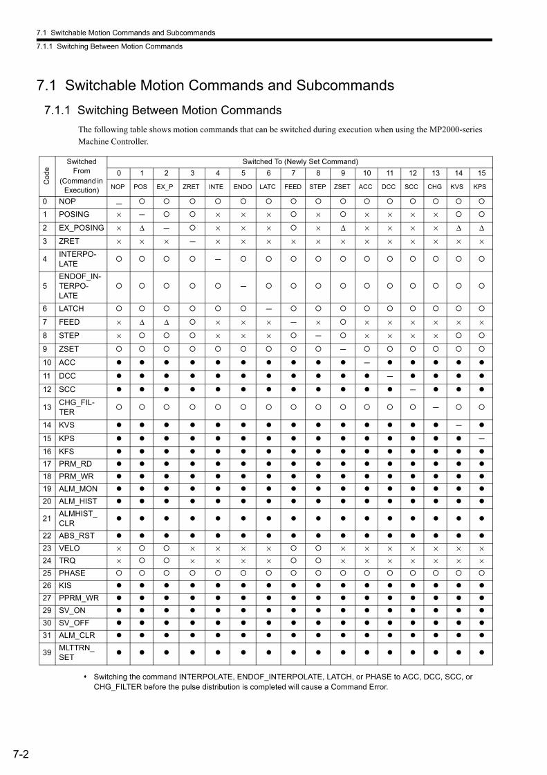
7.1 Switchable Motion Commands and Subcommands
7.1.1 Switching Between Motion Commands
7-2
7.1 Switchable Motion Commands and Subcommands
7.1.1 Switching Between Motion Commands
The following table shows motion commands that can be switched during execution when using the MP2000-series Machine Controller.
Switching the command INTERPOLATE, ENDOF_INTERPOLATE, LATCH, or PHASE to ACC, DCC, SCC, or CHG_FILTER before the pulse distribution is completed will cause a Command Error.
Cod
e
Switched From
(Command in Execution)
Switched To (Newly Set Command)
0 1 2 3 4 5 6 7 8 9 10 11 12 13 14 15
NOP POS EX_P ZRET INTE ENDO LATC FEED STEP ZSET ACC DCC SCC CHG KVS KPS
0 NOP -
1 POSING × - × × × × × × × ×
2 EX_POSING × Δ - × × × × Δ × × × × Δ Δ
3 ZRET × × × - × × × × × × × × × × × ×
4INTERPO-LATE
-
5ENDOF_IN-TERPO-LATE
-
6 LATCH -
7 FEED × Δ Δ × × × - × × × × × × ×
8 STEP × × × × - × × × ×
9 ZSET -
10 ACC -
11 DCC -
12 SCC -
13CHG_FIL-TER
-
14 KVS -
15 KPS -
16 KFS
17 PRM_RD
18 PRM_WR
19 ALM_MON
20 ALM_HIST
21ALMHIST_CLR
22 ABS_RST
23 VELO × × × × × × × × × × × ×24 TRQ × × × × × × × × × × × ×25 PHASE
26 KIS
27 PPRM_WR
29 SV_ON
30 SV_OFF
31 ALM_CLR
39MLTTRN_SET
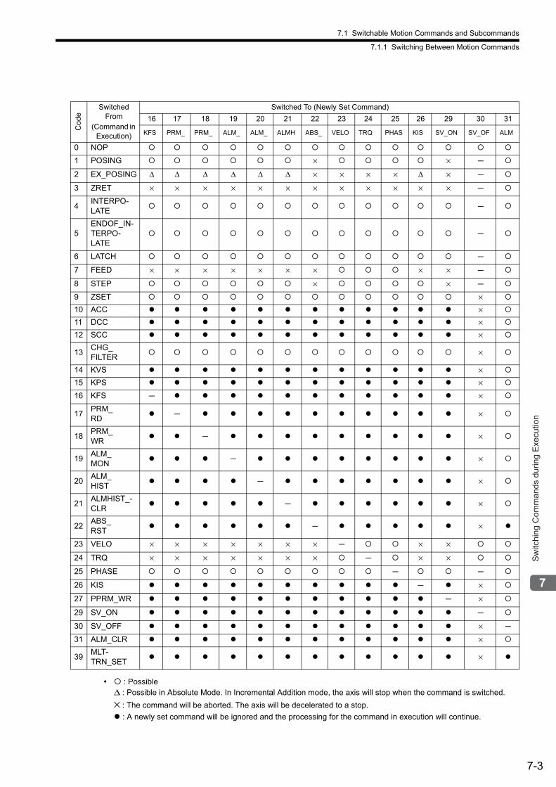
7.1 Switchable Motion Commands and Subcommands
7.1.1 Switching Between Motion Commands
7-3
Sw
itchi
ng C
omm
ands
dur
ing
Exe
cutio
n
: PossibleΔ : Possible in Absolute Mode. In Incremental Addition mode, the axis will stop when the command is switched.
× : The command will be aborted. The axis will be decelerated to a stop.
: A newly set command will be ignored and the processing for the command in execution will continue.
Cod
e
Switched From
(Command in Execution)
Switched To (Newly Set Command)
16 17 18 19 20 21 22 23 24 25 26 29 30 31
KFS PRM_ PRM_ ALM_ ALM_ ALMH ABS_ VELO TRQ PHAS KIS SV_ON SV_OF ALM
0 NOP
1 POSING × × -
2 EX_POSING Δ Δ Δ Δ Δ Δ × × × × Δ × -
3 ZRET × × × × × × × × × × × × -
4INTERPO-LATE
-
5ENDOF_IN-TERPO-LATE
-
6 LATCH -
7 FEED × × × × × × × × × -
8 STEP × × -
9 ZSET ×
10 ACC ×
11 DCC ×
12 SCC ×
13CHG_FILTER
×
14 KVS ×
15 KPS ×
16 KFS - ×
17PRM_RD
- ×
18PRM_WR
- ×
19ALM_MON
- ×
20ALM_HIST
- ×
21ALMHIST_-CLR
- ×
22ABS_RST
- ×
23 VELO × × × × × × × - × ×
24 TRQ × × × × × × × - × ×
25 PHASE - -
26 KIS - ×
27 PPRM_WR - ×
29 SV_ON -
30 SV_OFF × -
31 ALM_CLR ×
39MLT-TRN_SET
×
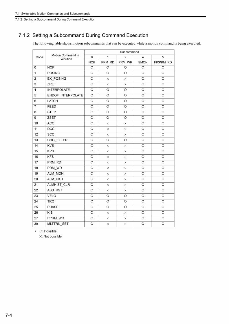
7.1 Switchable Motion Commands and Subcommands
7.1.2 Setting a Subcommand During Command Execution
7-4
7.1.2 Setting a Subcommand During Command Execution
The following table shows motion subcommands that can be executed while a motion command is being executed.
: Possible
×: Not possible
CodeMotion Command in
Execution
Subcommand
0 1 2 4 5
NOP PRM_RD PRM_WR SMON FIXPRM_RD
0 NOP
1 POSING
2 EX_POSING × ×
3 ZRET × ×
4 INTERPOLATE
5 ENDOF_INTERPOLATE
6 LATCH
7 FEED
8 STEP
9 ZSET
10 ACC × ×
11 DCC × ×
12 SCC × ×
13 CHG_FILTER
14 KVS × ×
15 KPS × ×
16 KFS × ×
17 PRM_RD × ×
18 PRM_WR × ×
19 ALM_MON × ×
20 ALM_HIST × ×
21 ALMHIST_CLR × ×
22 ABS_RST × ×
23 VELO
24 TRQ
25 PHASE
26 KIS × ×
27 PPRM_WR × ×
39 MLTTRN_SET × ×
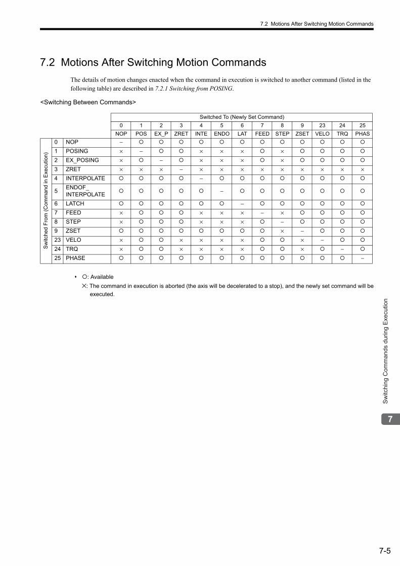
7.2 Motions After Switching Motion Commands
7-5
Sw
itchi
ng C
omm
ands
dur
ing
Exe
cutio
n
7.2 Motions After Switching Motion Commands
The details of motion changes enacted when the command in execution is switched to another command (listed in the following table) are described in 7.2.1 Switching from POSING.
: Available
×: The command in execution is aborted (the axis will be decelerated to a stop), and the newly set command will be
executed.
<Switching Between Commands>
Switched To (Newly Set Command)
0 1 2 3 4 5 6 7 8 9 23 24 25
NOP POS EX_P ZRET INTE ENDO LAT FEED STEP ZSET VELO TRQ PHAS
Sw
itche
d F
rom
(C
omm
and
in E
xecu
tion)
0 NOP −
1 POSING × − × × × ×
2 EX_POSING × − × × × ×
3 ZRET × × × − × × × × × × × × ×4 INTERPOLATE −
5ENDOF_INTERPOLATE
−
6 LATCH −
7 FEED × × × × − ×
8 STEP × × × × −
9 ZSET × −
23 VELO × × × × × × −
24 TRQ × × × × × × −
25 PHASE −

7.2 Motions After Switching Motion Commands
7.2.1 Switching from POSING
7-6
7.2.1 Switching from POSING
Switched From Switched To Operation
POSING
NOP
POSING will switch to NOP when the axis stops after deceleration.
POSING POSING operation continue.
EX_POSING
POSING will immediately switch to EX_POSING. When this happens, the amount of motion stored in the acceleration/deceleration filter will be output. When execution of EX_POSING is started, values are written to the related servo parameters and then the positioning operation starts.
<Change in Position Reference Setting (OL1C) during Deceleration>• In Incremental Addition Mode (OW09, bit 5 = 0)
Any change in the Position Reference Setting (OL1C) will be ignored.• In Absolute Mode (OW09 Bit5 = 1) the value of the Position Reference Setting
(OL1C) when EX_POSING execution starts will be the target position. Do not change the Position Reference Setting during deceleration unless it is
absolutely necessary.Values are written to the related parameters when execution of EX_POSING starts, so the speed may drop.
ZRET
POSING will immediately switch to ZRET. When this happens, the amount of motion stored in the acceleration/deceleration filter will be output. When execution of ZRET is started, values are written to the related servo parameters and then the zero point return operation starts.
POSING
CanceledPOSING operation
POSINGMotion command
Motion commandresponse
NOP
POSING NOP
POSING
CanceledPOSING operation
POSING EX_POSING
POSING EX_POSING
The speed will smoothly change.(The speed at the time the motion com-mand is switched will increase/decreaseuntil it reaches the target speed of EX_POSING.)
The acceleration/deceleration filter will be kept valid.
EX_POSING
Motion command
Motion commandresponse
POSING
CanceledPOSING operation
POSING ZRET
POSING ZRET
The speed will smoothly change.(The speed at the time the motion com-mand is switched will increase/decreaseuntil it reaches the target speed of ZRET.)
The acceleration/deceleration filter will bekept valid.
ZRET
Motion command
Motion commandresponse
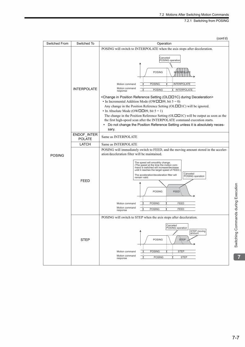
7.2 Motions After Switching Motion Commands
7.2.1 Switching from POSING
7-7
Sw
itchi
ng C
omm
ands
dur
ing
Exe
cutio
n
POSING
INTERPOLATE
POSING will switch to INTERPOLATE when the axis stops after deceleration.
<Change in Position Reference Setting (OL1C) during Deceleration>• In Incremental Addition Mode (OW09, bit 5 = 0)Any change in the Position Reference Setting (OL1C) will be ignored.
• In Absolute Mode (OW09, bit 5 = 1)The change in the Position Reference Setting (OL1C) will be output as soon as the the first high-speed scan after the INTERPOLATE command execution starts. Do not change the Position Reference Setting unless it is absolutely neces-
sary.
ENDOF_INTERPOLATE
Same as INTERPOLATE
LATCH Same as INTERPOLATE
FEED
POSING will immediately switch to FEED, and the moving amount stored in the acceler-ation/deceleration filter will be maintained.
STEP
POSING will switch to STEP when the axis stops after deceleration.
(cont’d)
Switched From Switched To Operation
POSING
CanceledPOSING operation
POSING INTERPOLATE
POSING INTERPOLATE
INTERPOLATE
Motion command
Motion commandresponse
CanceledPOSING operation
POSING
POSING FEED
POSING FEED
FEED
The speed will smoothly change.(The speed at the time the motion com-mand is switched will increase/decreaseuntil it reaches the target speed of FEED.)
The acceleration/deceleration filter will remain valid.
Motion command
Motion commandresponse
CanceledPOSING operation
POSING
POSING STEP
POSING STEP
STEP
STEP movingamount
Motion command
Motion commandresponse
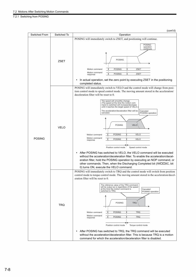
7.2 Motions After Switching Motion Commands
7.2.1 Switching from POSING
7-8
POSING
ZSET
POSING will immediately switch to ZSET, and positioning will continue.
In actual operation, set the zero point by executing ZSET in the positioning completed status.
VELO
POSING will immediately switch to VELO and the control mode will change from posi-tion control mode to speed control mode. The moving amount stored in the acceleration/deceleration filter will be reset to 0.
After POSING has switched to VELO, the VELO command will be executed without the acceleration/deceleration filter. To enable the acceleration/decel-eration filter, hold the POSING operation by executing an NOP command, or other commands. Then, when the Discharging Completed bit (IW0C, bit 0) turns ON, execute the VELO command.
TRQ
POSING will immediately switch to TRQ and the control mode will switch from position control mode to torque control mode. The moving amount stored in the acceleration/decel-eration filter will be reset to 0.
After POSING has switched to TRQ, the TRQ command will be executed without the acceleration/deceleration filter. This is because TRQ is a motion command for which the acceleration/deceleration filter is disabled.
(cont’d)
Switched From Switched To Operation
POSINGoperation continues
POSING
POSING ZSET
POSING ZSET
Motion command
Motion commandresponse
POSING
POSING VELO
POSING VELO
CanceledPOSING operation
VELO
Position control mode Speed control mode
The speed will smoothly change.(The speed at the time the motion com-mand is switched will increase/decreaseuntil it reaches the target speed of VELO.)
The acceleration/deceleration filter will becanceled.
Motion command
Motion commandresponse
POSING
POSING TRQ
POSING TRQ
CanceledPOSING operation
TRQ
Position control mode Torque control mode
The reference value of the TRQ command will be output as is regardless of the speed at the time the motion command is switched to TRQ.
Motion command
Motion commandresponse
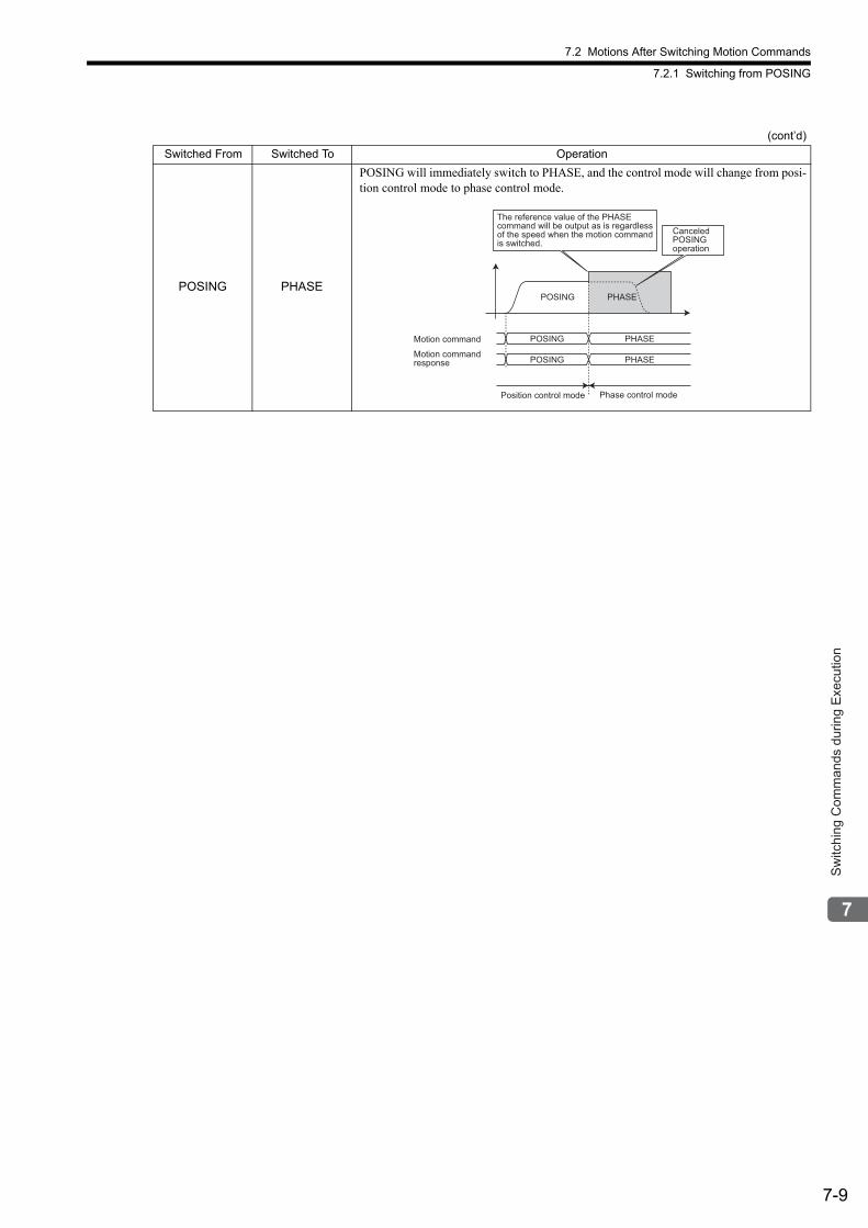
7.2 Motions After Switching Motion Commands
7.2.1 Switching from POSING
7-9
Sw
itchi
ng C
omm
ands
dur
ing
Exe
cutio
n
POSING PHASE
POSING will immediately switch to PHASE, and the control mode will change from posi-tion control mode to phase control mode.
(cont’d)
Switched From Switched To Operation
Canceled POSINGoperation
The reference value of the PHASEcommand will be output as is regardlessof the speed when the motion commandis switched.
POSING PHASE
POSING PHASE
POSING PHASE
Position control mode Phase control mode
Motion command
Motion commandresponse
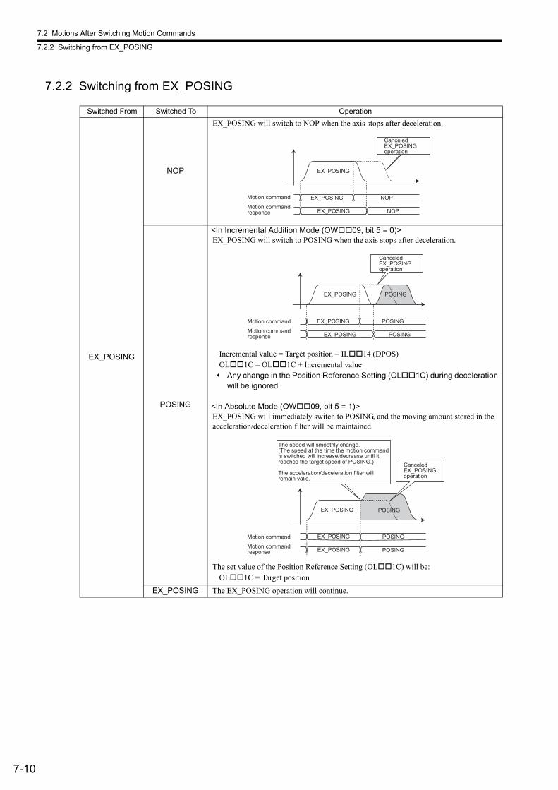
7.2 Motions After Switching Motion Commands
7.2.2 Switching from EX_POSING
7-10
7.2.2 Switching from EX_POSING
Switched From Switched To Operation
EX_POSING
NOP
EX_POSING will switch to NOP when the axis stops after deceleration.
POSING
<In Incremental Addition Mode (OW09, bit 5 = 0)>EX_POSING will switch to POSING when the axis stops after deceleration.
Incremental value = Target position − IL14 (DPOS)OL1C = OL1C + Incremental value Any change in the Position Reference Setting (OL1C) during deceleration
will be ignored.
<In Absolute Mode (OW09, bit 5 = 1)>EX_POSING will immediately switch to POSING, and the moving amount stored in the acceleration/deceleration filter will be maintained.
The set value of the Position Reference Setting (OL1C) will be:OL1C = Target position
EX_POSING The EX_POSING operation will continue.
EX_POSING
CanceledEX_POSING operation
EX_POSING NOP
EX_POSING NOP
Motion command
Motion commandresponse
CanceledEX_POSINGoperation
EX_POSING
EX_POSING POSING
EX_POSING POSING
POSING
Motion command
Motion commandresponse
EX_POSING
CanceledEX_POSINGoperation
EX_POSING POSING
EX_POSING POSING
The speed will smoothly change.(The speed at the time the motion command is switched will increase/decrease until it reaches the target speed of POSING.)
The acceleration/deceleration filter will remain valid.
POSING
Motion command
Motion commandresponse
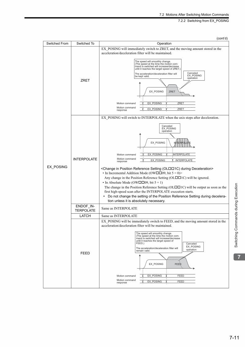
7.2 Motions After Switching Motion Commands
7.2.2 Switching from EX_POSING
7-11
Sw
itchi
ng C
omm
ands
dur
ing
Exe
cutio
n
EX_POSING
ZRET
EX_POSING will immediately switch to ZRET, and the moving amount stored in the acceleration/deceleration filter will be maintained.
INTERPOLATE
EX_POSING will switch to INTERPOLATE when the axis stops after deceleration.
<Change in Position Reference Setting (OL1C) during Deceleration>• In Incremental Addition Mode (OW09, bit 5 = 0)>Any change in the Position Reference Setting (OL1C) will be ignored.
• In Absolute Mode (OW09, bit 5 = 1)The change in the Position Reference Setting (OL1C) will be output as soon as the first high-speed scan after the INTERPOLATE execution starts. Do not change the setting of the Position Reference Setting during decelera-
tion unless it is absolutely necessary.
ENDOF_IN-TERPOLATE
Same as INTERPOLATE
LATCH Same as INTERPOLATE
FEED
EX_POSING will be immediately switch to FEED, and the moving amount stored in the acceleration/deceleration filter will be maintained.
(cont’d)
Switched From Switched To Operation
EX_POSING
EX_POSING ZRET
EX_POSING ZRET
ZRET
CanceledEX_POSINGoperation
The speed will smoothly change.(The speed at the time the motion com-mand is switched will increase/decreaseuntil it reaches the target speed of ZRET.)
The acceleration/deceleration filter will be kept valid.
Motion command
Motion commandresponse
EX_POSING
EX_POSING INTERPOLATE
EX_POSING INTERPOLATE
INTERPOLATE
CanceledEX_POSINGoperation
Motion command
Motion commandresponse
EX_POSING
CanceledEX_POSINGoperation
EX_POSING FEED
EX_POSING FEED
The speed will smoothly change.(The speed at the time the motion com-mand is switched will increase/decreaseuntil it reaches the target speed ofFEED.)
The acceleration/deceleration filter will remain valid.
FEED
Motion command
Motion commandresponse
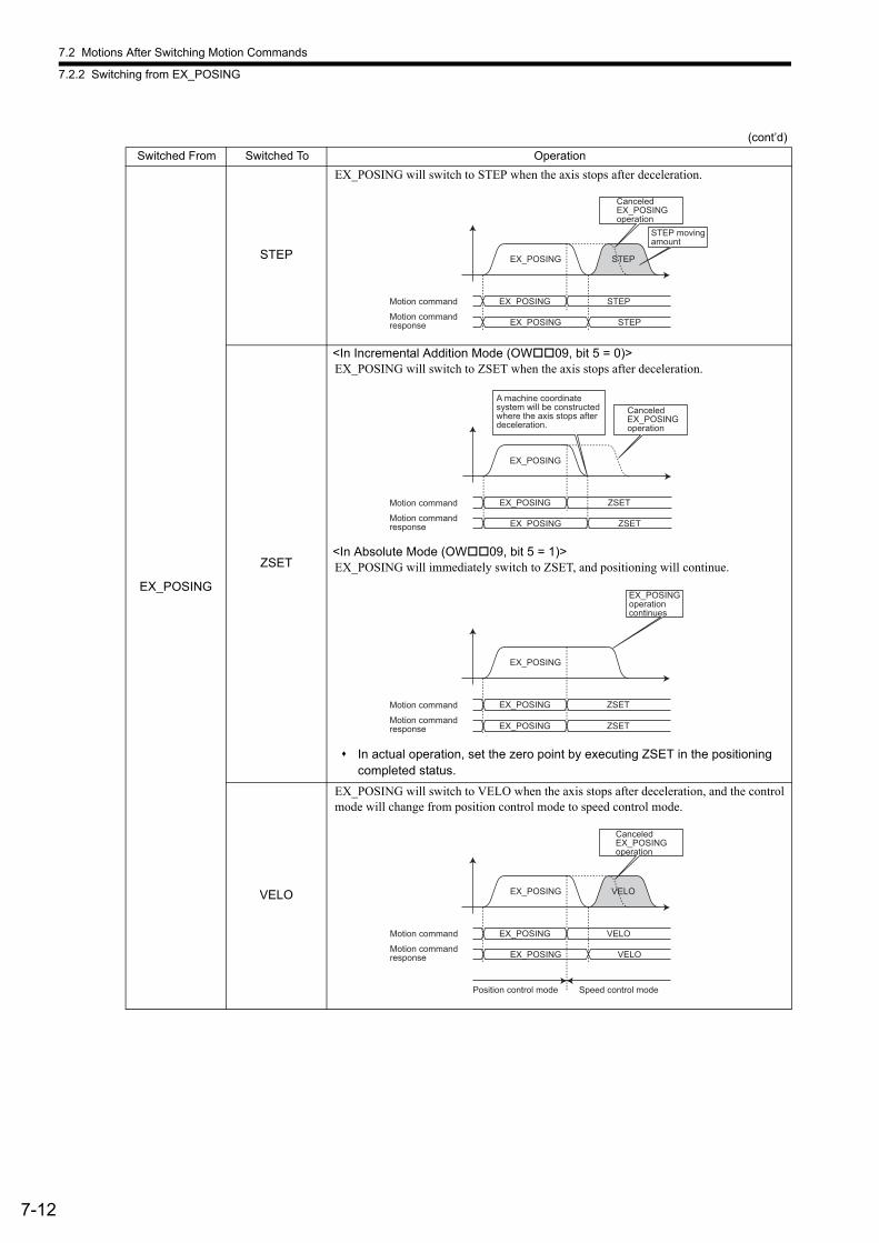
7.2 Motions After Switching Motion Commands
7.2.2 Switching from EX_POSING
7-12
EX_POSING
STEP
EX_POSING will switch to STEP when the axis stops after deceleration.
ZSET
<In Incremental Addition Mode (OW09, bit 5 = 0)>EX_POSING will switch to ZSET when the axis stops after deceleration.
<In Absolute Mode (OW09, bit 5 = 1)>EX_POSING will immediately switch to ZSET, and positioning will continue.
In actual operation, set the zero point by executing ZSET in the positioning completed status.
VELO
EX_POSING will switch to VELO when the axis stops after deceleration, and the control mode will change from position control mode to speed control mode.
(cont’d)
Switched From Switched To Operation
CanceledEX_POSING operation
EX_POSING
EX_POSING STEP
EX_POSING STEP
STEP
STEP movingamount
Motion command
Motion commandresponse
EX_POSING
CanceledEX_POSINGoperation
EX_POSING ZSET
EX_POSING ZSET
A machine coordinatesystem will be constructedwhere the axis stops afterdeceleration.
Motion command
Motion commandresponse
EX_POSINGoperationcontinues
EX_POSING
EX_POSING ZSET
EX_POSING ZSET
Motion command
Motion commandresponse
Position control mode Speed control mode
CanceledEX_POSINGoperation
EX_POSING
EX_POSING VELO
EX_POSING VELO
VELO
Motion command
Motion commandresponse
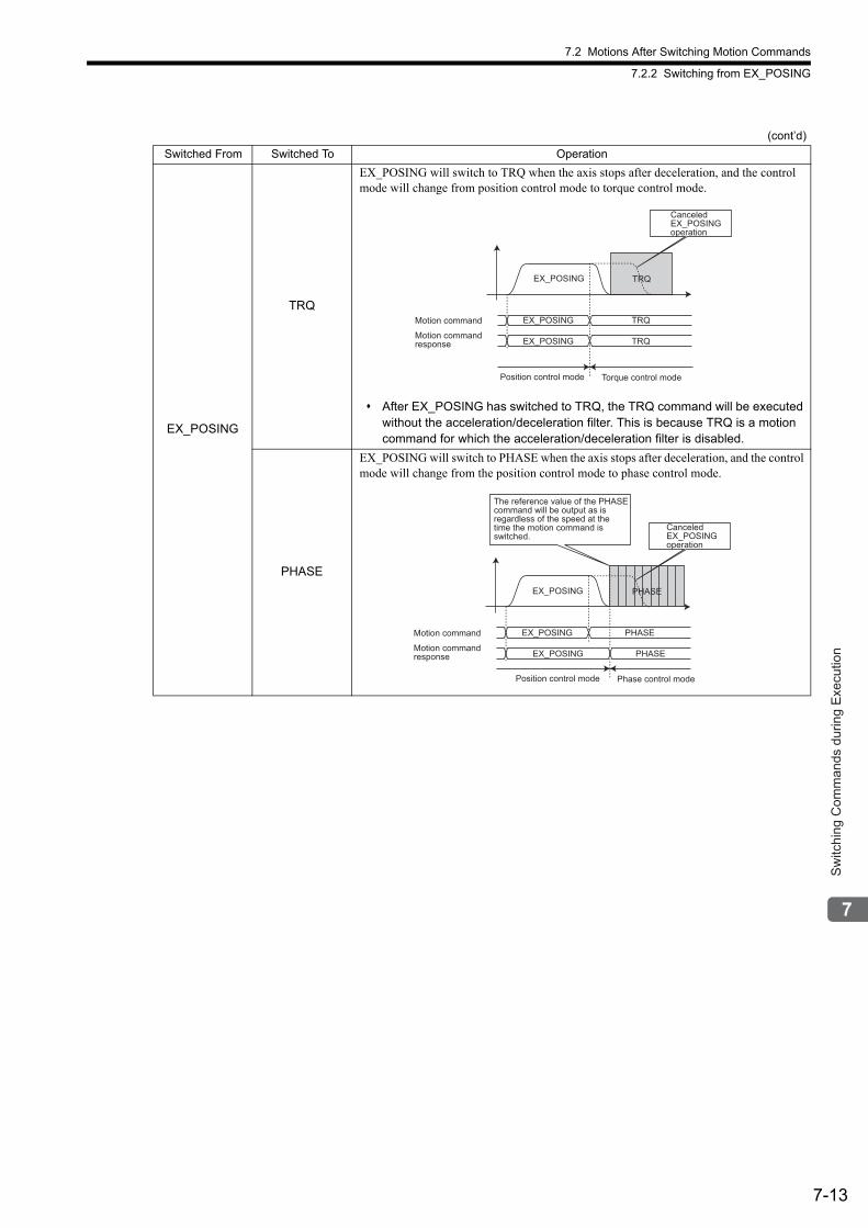
7.2 Motions After Switching Motion Commands
7.2.2 Switching from EX_POSING
7-13
Sw
itchi
ng C
omm
ands
dur
ing
Exe
cutio
n
EX_POSING
TRQ
EX_POSING will switch to TRQ when the axis stops after deceleration, and the control mode will change from position control mode to torque control mode.
After EX_POSING has switched to TRQ, the TRQ command will be executed without the acceleration/deceleration filter. This is because TRQ is a motion command for which the acceleration/deceleration filter is disabled.
PHASE
EX_POSING will switch to PHASE when the axis stops after deceleration, and the control mode will change from the position control mode to phase control mode.
(cont’d)
Switched From Switched To Operation
CanceledEX_POSING operation
EX_POSING TRQ
EX_POSING TRQ
EX_POSING TRQ
Position control mode Torque control mode
Motion command
Motion commandresponse
CanceledEX_POSINGoperation
The reference value of the PHASEcommand will be output as isregardless of the speed at thetime the motion command isswitched.
EX_POSING PHASE
EX_POSING PHASE
EX_POSING PHASE
Position control mode Phase control mode
Motion command
Motion commandresponse
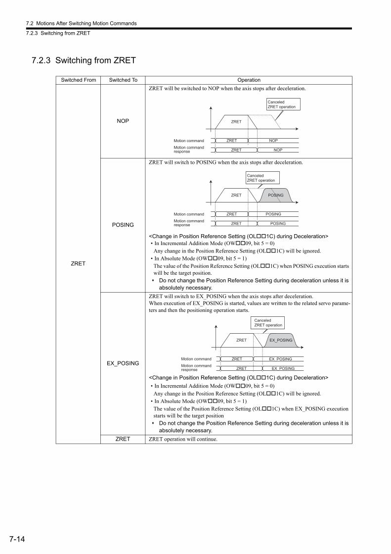
7.2 Motions After Switching Motion Commands
7.2.3 Switching from ZRET
7-14
7.2.3 Switching from ZRET
Switched From Switched To Operation
ZRET
NOP
ZRET will be switched to NOP when the axis stops after deceleration.
POSING
ZRET will switch to POSING when the axis stops after deceleration.
<Change in Position Reference Setting (OL1C) during Deceleration>• In Incremental Addition Mode (OW09, bit 5 = 0)
Any change in the Position Reference Setting (OL1C) will be ignored.• In Absolute Mode (OW09, bit 5 = 1)
The value of the Position Reference Setting (OL1C) when POSING execution starts will be the target position. Do not change the Position Reference Setting during deceleration unless it is
absolutely necessary.
EX_POSING
ZRET will switch to EX_POSING when the axis stops after deceleration.When execution of EX_POSING is started, values are written to the related servo parame-ters and then the positioning operation starts.
<Change in Position Reference Setting (OL1C) during Deceleration>
• In Incremental Addition Mode (OW09, bit 5 = 0)Any change in the Position Reference Setting (OL1C) will be ignored.
• In Absolute Mode (OW09, bit 5 = 1)The value of the Position Reference Setting (OL1C) when EX_POSING execution starts will be the target position Do not change the Position Reference Setting during deceleration unless it is
absolutely necessary.
ZRET ZRET operation will continue.
ZRET
ZRET NOP
ZRET NOP
CanceledZRET operation
Motion command
Motion commandresponse
ZRET
ZRET POSING
ZRET POSING
CanceledZRET operation
POSING
Motion command
Motion commandresponse
ZRET
ZRET EX_POSING
ZRET EX_POSING
CanceledZRET operation
EX_POSING
Motion command
Motion commandresponse
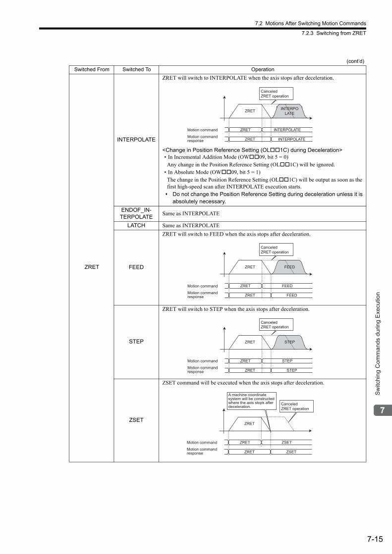
7.2 Motions After Switching Motion Commands
7.2.3 Switching from ZRET
7-15
Sw
itchi
ng C
omm
ands
dur
ing
Exe
cutio
n
ZRET
INTERPOLATE
ZRET will switch to INTERPOLATE when the axis stops after deceleration.
<Change in Position Reference Setting (OL1C) during Deceleration>• In Incremental Addition Mode (OW09, bit 5 = 0)Any change in the Position Reference Setting (OL1C) will be ignored.
• In Absolute Mode (OW09, bit 5 = 1)The change in the Position Reference Setting (OL1C) will be output as soon as the first high-speed scan after INTERPOLATE execution starts. Do not change the Position Reference Setting during deceleration unless it is
absolutely necessary.
ENDOF_IN-TERPOLATE
Same as INTERPOLATE
LATCH Same as INTERPOLATE
FEED
ZRET will switch to FEED when the axis stops after deceleration.
STEP
ZRET will switch to STEP when the axis stops after deceleration.
ZSET
ZSET command will be executed when the axis stops after deceleration.
(cont’d)
Switched From Switched To Operation
ZRET
ZRET INTERPOLATE
ZRET INTERPOLATE
CanceledZRET operation
INTERPOLATE
Motion command
Motion commandresponse
ZRET
ZRET FEED
ZRET FEED
CanceledZRET operation
FEED
Motion command
Motion commandresponse
ZRET
ZRET STEP
ZRET STEP
CanceledZRET operation
STEP
Motion command
Motion commandresponse
ZRET
ZRET ZSET
ZRET ZSET
CanceledZRET operation
A machine coordinatesystem will be constructedwhere the axis stops after deceleration.
Motion command
Motion commandresponse
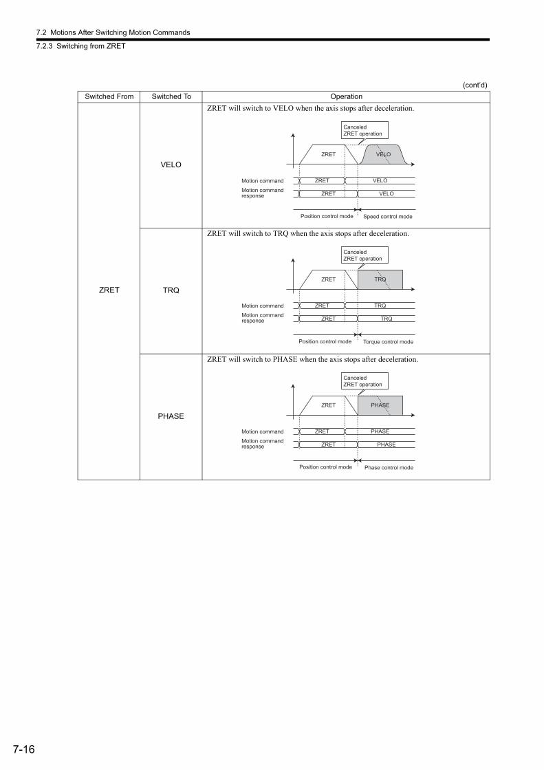
7.2 Motions After Switching Motion Commands
7.2.3 Switching from ZRET
7-16
ZRET
VELO
ZRET will switch to VELO when the axis stops after deceleration.
TRQ
ZRET will switch to TRQ when the axis stops after deceleration.
PHASE
ZRET will switch to PHASE when the axis stops after deceleration.
(cont’d)
Switched From Switched To Operation
Motion command
Motion commandresponse
ZRET
ZRET VELO
ZRET VELO
CanceledZRET operation
VELO
Position control mode Speed control mode
Motion command
Motion commandresponse
ZRET
ZRET TRQ
ZRET TRQ
CanceledZRET operation
TRQ
Position control mode Torque control mode
Motion command
Motion commandresponse
ZRET
ZRET PHASE
ZRET PHASE
CanceledZRET operation
PHASE
Position control mode Phase control mode
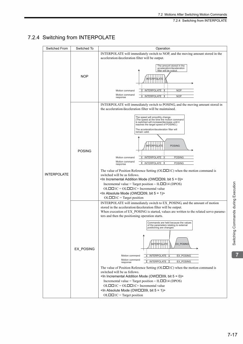
7.2 Motions After Switching Motion Commands
7.2.4 Switching from INTERPOLATE
7-17
Sw
itchi
ng C
omm
ands
dur
ing
Exe
cutio
n
7.2.4 Switching from INTERPOLATE
Switched From Switched To Operation
INTERPOLATE
NOP
INTERPOLATE will immediately switch to NOP, and the moving amount stored in the acceleration/deceleration filter will be output.
POSING
INTERPOLATE will immediately switch to POSING, and the moving amount stored in the acceleration/deceleration filter will be maintained.
The value of Position Reference Setting (OL1C) when the motion command is switched will be as follows.<In Incremental Addition Mode (OW09, bit 5 = 0)>
Incremental value = Target position − IL14 (DPOS)OL1C = OL1C+ Incremental value
<In Absolute Mode (OW09, bit 5 = 1)> OL1C = Target position
EX_POSING
INTERPOLATE will immediately switch to EX_POSING, and the amount of motion stored in the acceleration/deceleration filter will be output.When execution of EX_POSING is started, values are written to the related servo parame-ters and then the positioning operation starts.
The value of Position Reference Setting (OL1C) when the motion command is switched will be as follows.<In Incremental Addition Mode (OW09, bit 5 = 0)>
Incremental value = Target position − IL14 (DPOS)OL1C = OL1C+ Incremental value
<In Absolute Mode (OW09, bit 5 = 1)>OL1C = Target position
INTERPOLATE
The amount stored in the
acceleration/deceleration
filter will be output.
INTERPOLATE NOP
INTERPOLATE NOP
Motion command
Motion command
response
INTERPOLATE
INTERPOLATE POSING
INTERPOLATE POSING
POSING
The speed will smoothly change.
(The speed at the time the motion command
is switched will increase/decrease until it
reaches the target speed of POSING.)
The acceleration/deceleration filter will
remain valid.
Motion command
Motion command
response
INTERPOLATE
Commands are held because the values of the parameters relating to external positioning are changed.
INTERPOLATE EX_POSING
INTERPOLATE EX_POSING
EX_POSING
Motion command
Motion commandresponse
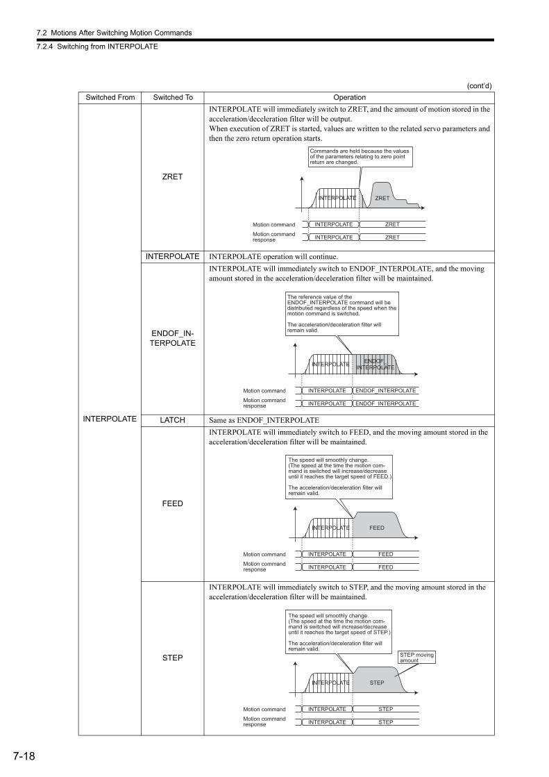
7.2 Motions After Switching Motion Commands
7.2.4 Switching from INTERPOLATE
7-18
INTERPOLATE
ZRET
INTERPOLATE will immediately switch to ZRET, and the amount of motion stored in the acceleration/deceleration filter will be output.When execution of ZRET is started, values are written to the related servo parameters and then the zero return operation starts.
INTERPOLATE INTERPOLATE operation will continue.
ENDOF_IN-TERPOLATE
INTERPOLATE will immediately switch to ENDOF_INTERPOLATE, and the moving amount stored in the acceleration/deceleration filter will be maintained.
LATCH Same as ENDOF_INTERPOLATE
FEED
INTERPOLATE will immediately switch to FEED, and the moving amount stored in the acceleration/deceleration filter will be maintained.
STEP
INTERPOLATE will immediately switch to STEP, and the moving amount stored in the acceleration/deceleration filter will be maintained.
(cont’d)
Switched From Switched To Operation
INTERPOLATE
Commands are held because the values of the parameters relating to zero point return are changed.
INTERPOLATE ZRET
INTERPOLATE ZRET
ZRET
Motion command
Motion commandresponse
INTERPOLATE
INTERPOLATE ENDOF_INTERPOLATE
INTERPOLATE ENDOF_INTERPOLATE
ENDOF_
INTERPOLATE
The reference value of the
ENDOF_INTERPOLATE command will be
distributed regardless of the speed when the
motion command is switched.
The acceleration/deceleration filter will
remain valid.
Motion command
Motion command
response
INTERPOLATE
INTERPOLATE FEED
INTERPOLATE FEED
FEED
The speed will smoothly change.
(The speed at the time the motion com-
mand is switched will increase/decrease
until it reaches the target speed of FEED.)
The acceleration/deceleration filter will
remain valid.
Motion command
Motion command
response
INTERPOLATE
INTERPOLATE STEP
INTERPOLATE STEP
STEP
The speed will smoothly change.
(The speed at the time the motion com-
mand is switched will increase/decrease
until it reaches the target speed of STEP.)
The acceleration/deceleration filter will
remain valid.
STEP moving
amount
Motion command
Motion command
response
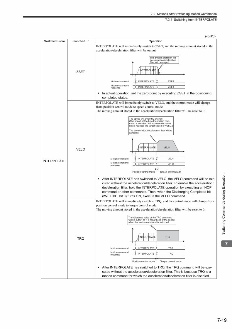
7.2 Motions After Switching Motion Commands
7.2.4 Switching from INTERPOLATE
7-19
Sw
itchi
ng C
omm
ands
dur
ing
Exe
cutio
n
INTERPOLATE
ZSET
INTERPOLATE will immediately switch to ZSET, and the moving amount stored in the acceleration/deceleration filter will be output.
In actual operation, set the zero point by executing ZSET in the positioning completed status.
VELO
INTERPOLATE will immediately switch to VELO, and the control mode will change from position control mode to speed control mode.The moving amount stored in the acceleration/deceleration filter will be reset to 0.
After INTERPOLATE has switched to VELO, the VELO command will be exe-cuted without the acceleration/deceleration filter. To enable the acceleration/deceleration filter, hold the INTERPOLATE operation by executing an NOP command or other commands. Then, when the Discharging Completed bit (IW0C, bit 0) turns ON, execute the VELO command.
TRQ
INTERPOLATE will immediately switch to TRQ, and the control mode will change from position control mode to torque control mode.The moving amount stored in the acceleration/deceleration filter will be reset to 0.
After INTERPOLATE has switched to TRQ, the TRQ command will be exe-cuted without the acceleration/deceleration filter. This is because TRQ is a motion command for which the acceleration/deceleration filter is disabled.
(cont’d)
Switched From Switched To Operation
INTERPOLATE
The amount stored in theacceleration/decelerationfilter will be output.
INTERPOLATE ZSET
INTERPOLATE ZSET
Motion command
Motion commandresponse
INTERPOLATE
INTERPOLATE VELO
INTERPOLATE VELO
Position control mode Speed control mode
VELO
The speed will smoothly change.(The speed at the time the motion com-mand is switched will increase/decreaseuntil it reaches the target speed of VELO.)
The acceleration/deceleration filter will be canceled.
Motion command
Motion commandresponse
INTERPOLATE
INTERPOLATE TRQ
INTERPOLATE TRQ
Position control mode Torque control mode
TRQ
The reference value of the TRQ command
will be output as it is regardless of the speed
when the motion command is switched.
Motion command
Motion command
response
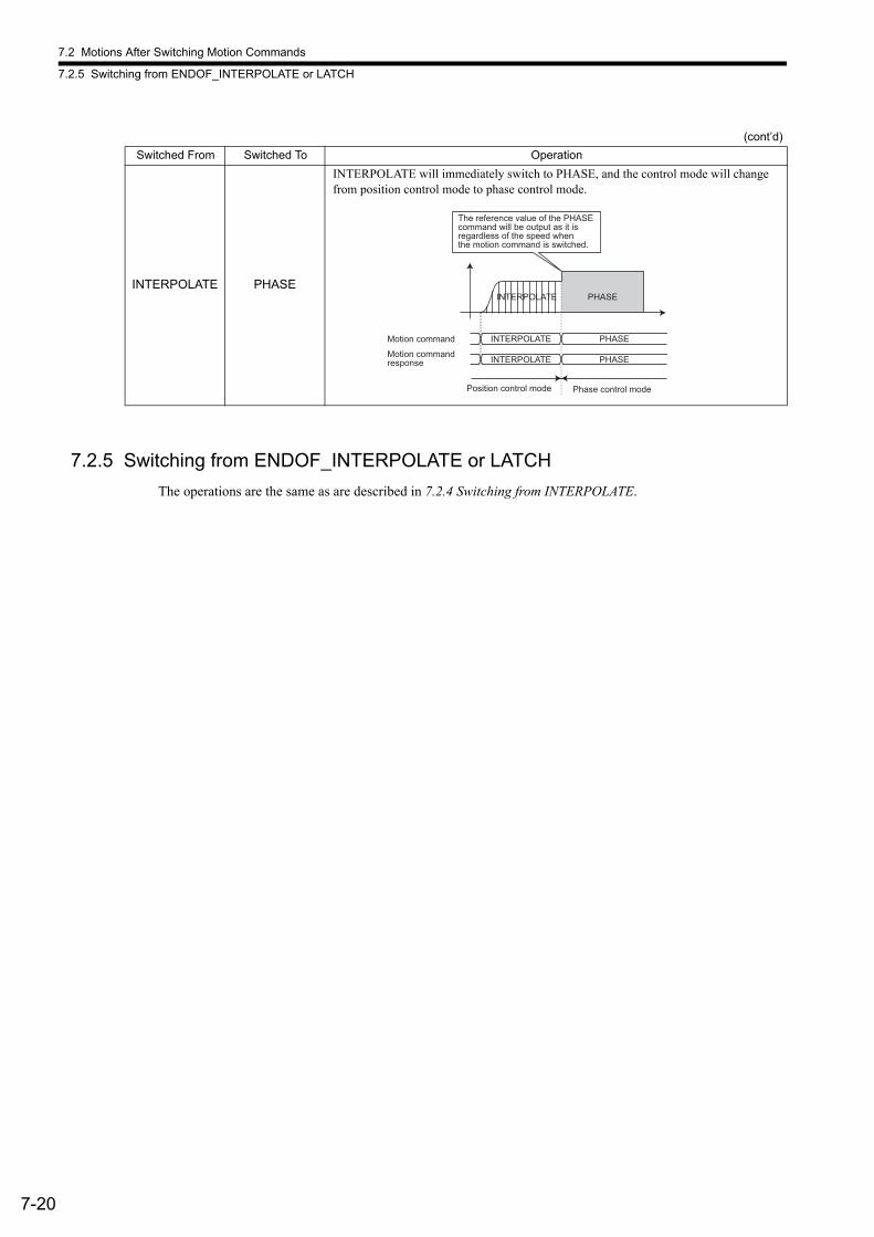
7.2 Motions After Switching Motion Commands
7.2.5 Switching from ENDOF_INTERPOLATE or LATCH
7-20
7.2.5 Switching from ENDOF_INTERPOLATE or LATCH
The operations are the same as are described in 7.2.4 Switching from INTERPOLATE.
INTERPOLATE PHASE
INTERPOLATE will immediately switch to PHASE, and the control mode will change from position control mode to phase control mode.
(cont’d)
Switched From Switched To Operation
INTERPOLATE
INTERPOLATE PHASE
INTERPOLATE PHASE
Position control mode Phase control mode
PHASE
The reference value of the PHASE
command will be output as it is
regardless of the speed when
the motion command is switched.
Motion command
Motion command
response
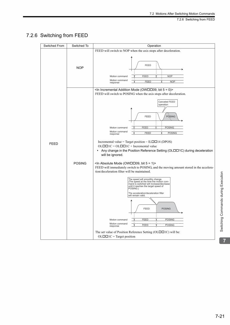
7.2 Motions After Switching Motion Commands
7.2.6 Switching from FEED
7-21
Sw
itchi
ng C
omm
ands
dur
ing
Exe
cutio
n
7.2.6 Switching from FEED
Switched From Switched To Operation
FEED
NOP
FEED will switch to NOP when the axis stops after deceleration.
POSING
<In Incremental Addition Mode (OW09, bit 5 = 0)>FEED will switch to POSING when the axis stops after deceleration.
Incremental value = Target position − IL14 (DPOS)OL1C = OL1C + Incremental value Any change in the Position Reference Setting (OL1C) during deceleration
will be ignored.
<In Absolute Mode (OW09, bit 5 = 1)>FEED will immediately switch to POSING, and the moving amount stored in the accelera-tion/deceleration filter will be maintained.
The set value of Position Reference Setting (OL1C) will be:OL1C = Target position
FEED
FEED NOP
FEED NOP
Motion command
Motion commandresponse
Canceled FEEDoperation
FEED
FEED POSING
FEED POSING
POSING
Motion command
Motion commandresponse
FEED
FEED POSING
FEED POSING
The speed will smoothly change.
(The speed at the time the motion com-
mand is switched will increase/decrease
until it reaches the target speed of
POSING.)
The acceleration/deceleration filter
will remain valid.
POSING
Motion command
Motion command
response
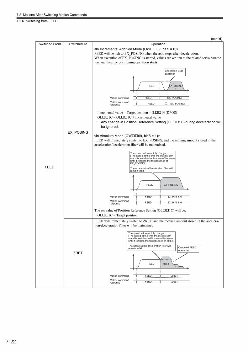
7.2 Motions After Switching Motion Commands
7.2.6 Switching from FEED
7-22
FEED
EX_POSING
<In Incremental Addition Mode (OW09, bit 5 = 0)>FEED will switch to EX_POSING when the axis stops after deceleration.When execution of EX_POSING is started, values are written to the related servo parame-ters and then the positioning operation starts.
Incremental value = Target position − IL14 (DPOS)OL1C = OL1C + Incremental value Any change in Position Reference Setting (OL1C) during deceleration will
be ignored.
<In Absolute Mode (OW09, bit 5 = 1)>FEED will immediately switch to EX_POSING, and the moving amount stored in the acceleration/deceleration filter will be maintained.
The set value of Position Reference Setting (OL1C) will be:OL1C = Target position
ZRET
FEED will immediately switch to ZRET, and the moving amount stored in the accelera-tion/deceleration filter will be maintained.
(cont’d)
Switched From Switched To Operation
Canceled FEEDoperation
FEED
FEED EX_POSING
FEED EX_POSING
EX_POSING
Motion command
Motion commandresponse
FEED
FEED EX_POSING
FEED EX_POSING
The speed will smoothly change.
(The speed at the time the motion com-
mand is switched will increase/decrease
until it reaches the target speed of
EX_POSING.)
The acceleration/deceleration filter will
remain valid.
EX_POSING
Motion command
Motion command
response
FEED
Canceled FEEDoperation
FEED ZRET
FEED ZRET
The speed will smoothly change.(The speed at the time the motion com-mand is switched will increase/decreaseuntil it reaches the target speed of ZRET.)
The acceleration/deceleration filter will remain valid.
ZRET
Motion command
Motion commandresponse

7.2 Motions After Switching Motion Commands
7.2.6 Switching from FEED
7-23
Sw
itchi
ng C
omm
ands
dur
ing
Exe
cutio
n
FEED
INTERPOLATE
FEED will switch to INTERPOLATE when the axis stops after deceleration.
<Change in Position Reference Setting (OL1C) during Deceleration>• In Incremental Addition Mode (OW09, bit 5 = 0)Any change in the Position Reference Setting (OL1C) will be ignored.
• In Absolute Mode (OW09, bit 5 = 1)The change in the Position Reference Setting (OL1C) will be output at as soon as at the timing of the first high-speed scan after INTERPOLATE execution starts. Do not change the Position Reference Setting during deceleration unless it is
absolutely necessary.
ENDOF_IN-TERPOLATE
Same as INTERPOLATE
LATCH Same as INTERPOLATE
FEED FEED operation will continue.
STEP
FEED will switch to STEP when the axis stops after deceleration.
ZSET
FEED will immediately switch to ZSET, and the FEED operation will continue.
In actual operation, set the zero point by executing ZSET in the positioning completed status.
(cont’d)
Switched From Switched To Operation
FEED
Canceled FEEDoperation
FEED INTERPOLATE
FEED INTERPOLATE
INTERPOLATE
Motion command
Motion commandresponse
Canceled FEEDoperation
FEED
FEED STEP
FEED STEP
STEP
Motion command
Motion commandresponse
FEED
FEED operation will
continue.
FEED ZSET
FEED ZSET
Motion command
Motion command
response

7.2 Motions After Switching Motion Commands
7.2.6 Switching from FEED
7-24
FEED
VELO
FEED will immediately switch to VELO, and the control mode will change from position control mode to speed control mode. The moving amount stored in the acceleration/decel-eration filter will be reset to 0.
After FEED has switched to VELO, the VELO command will be executed with-out the acceleration/deceleration filter. To enable the acceleration/decelera-tion filter, hold the FEED operation by executing an NOP command or other commands. Then, when the Discharging Completed bit (IW0C, bit 0) turns ON, execute the VELO command.
TRQ
FEED will immediately switch to TRQ, and the control mode will change from position control mode to torque control mode.The moving amount stored in the acceleration/deceleration filter will be reset to 0.
After FEED has switched to TRQ, the TRQ command will be executed without the acceleration/deceleration filter. This is because TRQ is a motion com-mand for which the acceleration/deceleration filter is disabled.
PHASE
FEED will immediately switch to PHASE, and the control mode will change from posi-tion control mode to phase control mode.
(cont’d)
Switched From Switched To Operation
FEED
FEED VELO
FEED VELO
VELO
Position control mode Speed control mode
The speed will smoothly change.(The speed at the time the motion com-mand is switched will increase/decreaseuntil it reaches the target speed of VELO.)
The acceleration/deceleration filter will be canceled.
Motion command
Motion commandresponse
FEED
FEED TRQ
FEED TRQ
Position control mode Torque control mode
TRQ
The reference value of the TRQ command will be output as is regardless of the speed when the motion command is switched.
Motion command
Motion commandresponse
FEED
FEED PHASE
FEED PHASE
Position control mode Phase control mode
PHASE
The reference value of the PHASE command will be output as it is regardless of the speed when the motion command is switched.
Motion command
Motion commandresponse
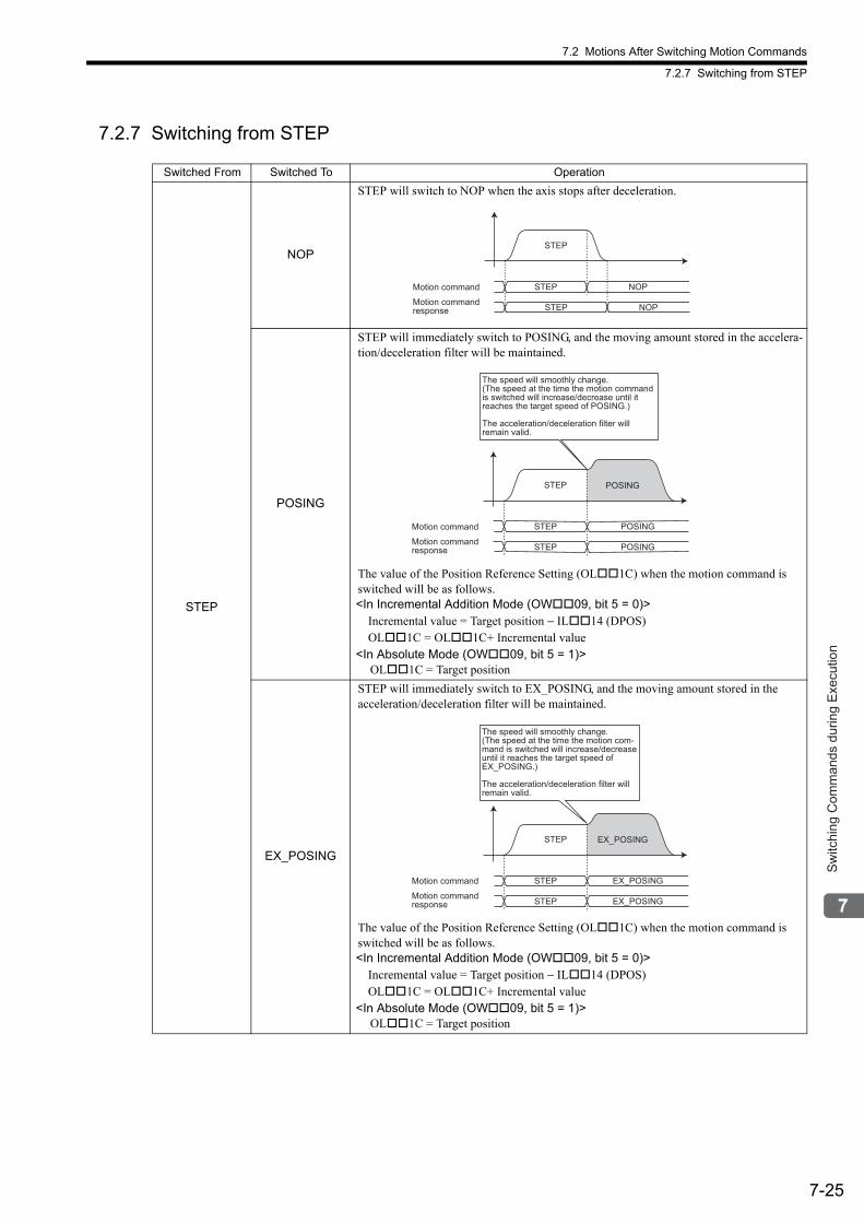
7.2 Motions After Switching Motion Commands
7.2.7 Switching from STEP
7-25
Sw
itchi
ng C
omm
ands
dur
ing
Exe
cutio
n
7.2.7 Switching from STEP
Switched From Switched To Operation
STEP
NOP
STEP will switch to NOP when the axis stops after deceleration.
POSING
STEP will immediately switch to POSING, and the moving amount stored in the accelera-tion/deceleration filter will be maintained.
The value of the Position Reference Setting (OL1C) when the motion command is switched will be as follows.<In Incremental Addition Mode (OW09, bit 5 = 0)>
Incremental value = Target position − IL14 (DPOS)OL1C = OL1C+ Incremental value
<In Absolute Mode (OW09, bit 5 = 1)> OL1C = Target position
EX_POSING
STEP will immediately switch to EX_POSING, and the moving amount stored in the acceleration/deceleration filter will be maintained.
The value of the Position Reference Setting (OL1C) when the motion command is switched will be as follows.<In Incremental Addition Mode (OW09, bit 5 = 0)>
Incremental value = Target position − IL14 (DPOS)OL1C = OL1C+ Incremental value
<In Absolute Mode (OW09, bit 5 = 1)> OL1C = Target position
STEP
STEP NOP
STEP NOP
Motion command
Motion commandresponse
STEP
STEP POSING
STEP POSING
The speed will smoothly change.
(The speed at the time the motion command
is switched will increase/decrease until it
reaches the target speed of POSING.)
The acceleration/deceleration filter will
remain valid.
POSING
Motion command
Motion command
response
STEP
STEP EX_POSING
STEP EX_POSING
The speed will smoothly change.
(The speed at the time the motion com-
mand is switched will increase/decrease
until it reaches the target speed of
EX_POSING.)
The acceleration/deceleration filter will
remain valid.
EX_POSING
Motion command
Motion command
response
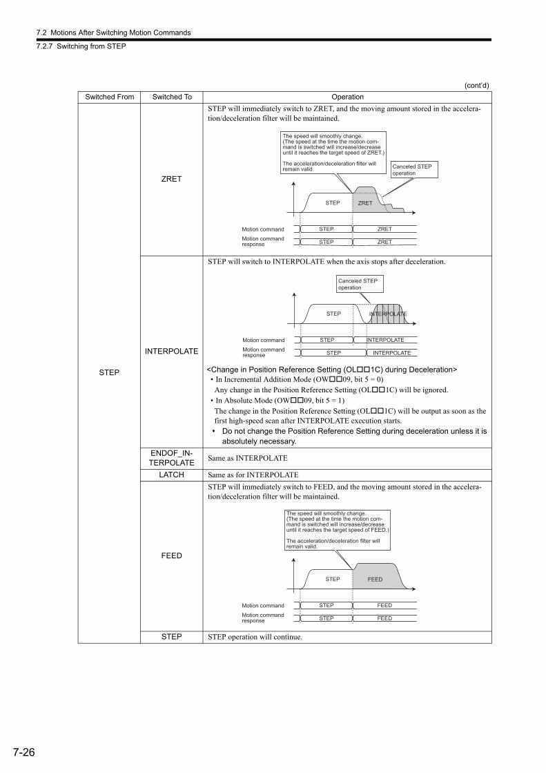
7.2 Motions After Switching Motion Commands
7.2.7 Switching from STEP
7-26
STEP
ZRET
STEP will immediately switch to ZRET, and the moving amount stored in the accelera-tion/deceleration filter will be maintained.
INTERPOLATE
STEP will switch to INTERPOLATE when the axis stops after deceleration.
<Change in Position Reference Setting (OL1C) during Deceleration>• In Incremental Addition Mode (OW09, bit 5 = 0)
Any change in the Position Reference Setting (OL1C) will be ignored.• In Absolute Mode (OW09, bit 5 = 1)
The change in the Position Reference Setting (OL1C) will be output as soon as the first high-speed scan after INTERPOLATE execution starts. Do not change the Position Reference Setting during deceleration unless it is
absolutely necessary.
ENDOF_IN-TERPOLATE
Same as INTERPOLATE
LATCH Same as for INTERPOLATE
FEED
STEP will immediately switch to FEED, and the moving amount stored in the accelera-tion/deceleration filter will be maintained.
STEP STEP operation will continue.
(cont’d)
Switched From Switched To Operation
STEP
Canceled STEPoperation
STEP ZRET
STEP ZRET
The speed will smoothly change.(The speed at the time the motion com-mand is switched will increase/decreaseuntil it reaches the target speed of ZRET.)
The acceleration/deceleration filter will remain valid.
ZRET
Motion command
Motion commandresponse
STEP
Canceled STEPoperation
STEP INTERPOLATE
STEP INTERPOLATE
INTERPOLATE
Motion command
Motion commandresponse
STEP
STEP FEED
STEP FEED
The speed will smoothly change.
(The speed at the time the motion com-
mand is switched will increase/decrease
until it reaches the target speed of FEED.)
The acceleration/deceleration filter will
remain valid.
FEED
Motion command
Motion command
response

7.2 Motions After Switching Motion Commands
7.2.7 Switching from STEP
7-27
Sw
itchi
ng C
omm
ands
dur
ing
Exe
cutio
n
STEP
ZSET
STEP will immediately switch to ZSET, and positioning will continue.
In actual operation, set the zero point by executing ZSET in the positioning completed status.
VELO
STEP will immediately switch to VELO, and the control mode will change from position control mode to speed control mode. The moving amount stored in the acceleration/decel-eration filter will be reset to 0.
After STEP has switched to VELO, the VELO command will be executed with-out the acceleration/deceleration filter. To enable the acceleration/decelera-tion filter, hold the STEP operation by executing an NOP command or other commands. Then, when the Discharging Completed bit (IW0C, bit 0) turns ON, execute the VELO command.
TRQ
STEP will immediately switch to TRQ, and the control mode will change from position control mode to torque control mode. The moving amount stored in the acceleration/decel-eration filter will be reset to 0.
After STEP has switched to TRQ, the TRQ command will be executed without the acceleration/deceleration filter. This is because TRQ is a motion com-mand for which the acceleration/deceleration filter is disabled.
(cont’d)
Switched From Switched To Operation
STEP operationwill continue.
STEP
STEP ZSET
STEP ZSET
Motion command
Motion command
response
STEP
STEP VELO
STEP VELO
VELO
Position control mode Speed control mode
The speed will smoothly change.(The speed at the time the motion com-mand is switched will increase/decreaseuntil it reaches the target speed of VELO.)
The acceleration/deceleration filter will be canceled.
Motion command
Motion commandresponse
STEP
STEP TRQ
STEP TRQ
Position control mode Torque control mode
TRQ
The reference value of the TRQ command
will be output as is regardless of the
speed the motion command is switched.
Motion command
Motion command
response

7.2 Motions After Switching Motion Commands
7.2.8 Switching from ZSET
7-28
7.2.8 Switching from ZSET
The execution of the ZSET command is completed in one scan if neither Absolute Mode nor infinite length axis are selected. So, a motion command that is set to run while the ZSET command is being carried out as soon as it is issued.
STEP PHASE
STEP will immediately switch to PHASE, and the control mode will change from position control mode to phase control mode.
(cont’d)
Switched From Switched To Operation
STEP
STEP PHASE
STEP PHASE
Position control mode Phase control mode
PHASE
The reference value of the PHASE command
will be output as is regardless of the speed
when the motion command is switched.
Motion command
Motion command
response
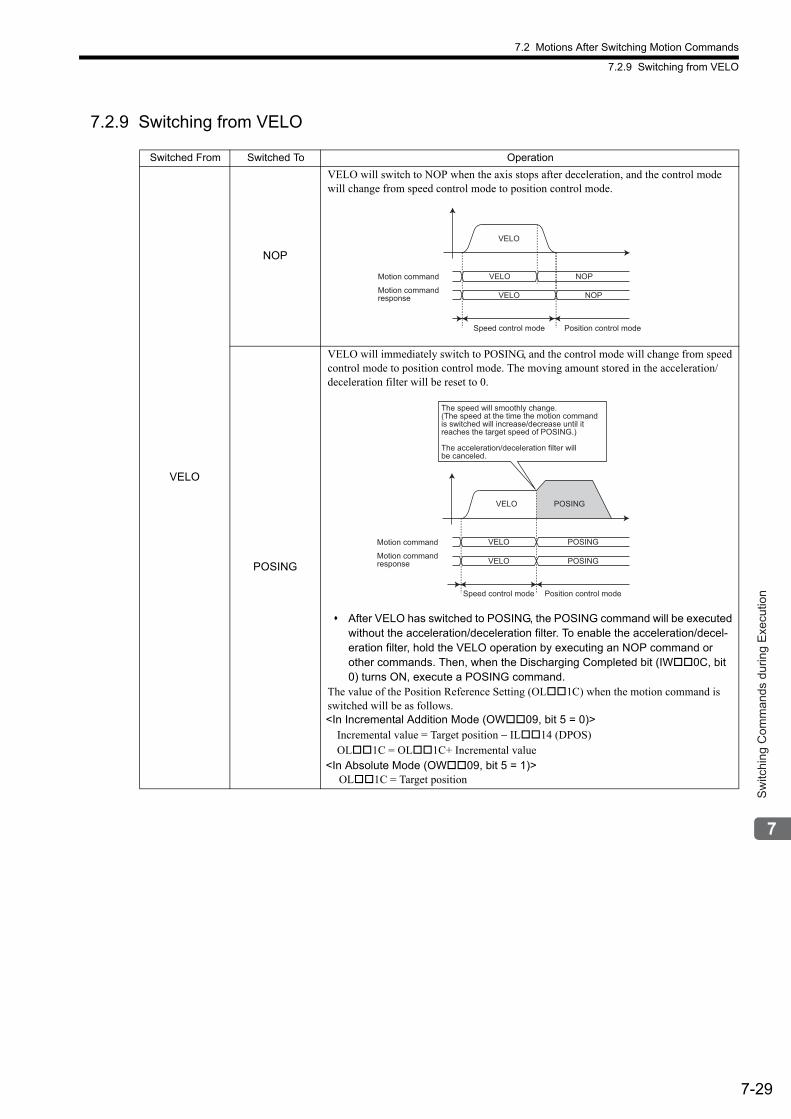
7.2 Motions After Switching Motion Commands
7.2.9 Switching from VELO
7-29
Sw
itchi
ng C
omm
ands
dur
ing
Exe
cutio
n
7.2.9 Switching from VELO
Switched From Switched To Operation
VELO
NOP
VELO will switch to NOP when the axis stops after deceleration, and the control mode will change from speed control mode to position control mode.
POSING
VELO will immediately switch to POSING, and the control mode will change from speed control mode to position control mode. The moving amount stored in the acceleration/deceleration filter will be reset to 0.
After VELO has switched to POSING, the POSING command will be executed without the acceleration/deceleration filter. To enable the acceleration/decel-eration filter, hold the VELO operation by executing an NOP command or other commands. Then, when the Discharging Completed bit (IW0C, bit 0) turns ON, execute a POSING command.
The value of the Position Reference Setting (OL1C) when the motion command is switched will be as follows.<In Incremental Addition Mode (OW09, bit 5 = 0)>
Incremental value = Target position − IL14 (DPOS)OL1C = OL1C+ Incremental value
<In Absolute Mode (OW09, bit 5 = 1)> OL1C = Target position
VELO
VELO NOP
VELO NOP
Motion command
Motion commandresponse
Speed control mode Position control mode
VELO
VELO POSING
VELO POSING
POSING
The speed will smoothly change.(The speed at the time the motion command is switched will increase/decrease until it reaches the target speed of POSING.)
The acceleration/deceleration filter will be canceled.
Motion command
Motion commandresponse
Speed control mode Position control mode
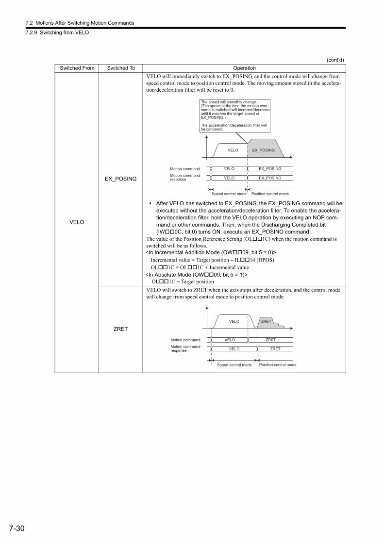
7.2 Motions After Switching Motion Commands
7.2.9 Switching from VELO
7-30
VELO
EX_POSING
VELO will immediately switch to EX_POSING, and the control mode will change from speed control mode to position control mode. The moving amount stored in the accelera-tion/deceleration filter will be reset to 0.
After VELO has switched to EX_POSING, the EX_POSING command will be executed without the acceleration/deceleration filter. To enable the accelera-tion/deceleration filter, hold the VELO operation by executing an NOP com-mand or other commands. Then, when the Discharging Completed bit (IW0C, bit 0) turns ON, execute an EX_POSING command.
The value of the Position Reference Setting (OL1C) when the motion command is switched will be as follows.<In Incremental Addition Mode (OW09, bit 5 = 0)>
Incremental value = Target position − IL14 (DPOS)OL1C = OL1C + Incremental value
<In Absolute Mode (OW09, bit 5 = 1)> OL1C = Target position
ZRET
VELO will switch to ZRET when the axis stops after deceleration, and the control mode will change from speed control mode to position control mode.
(cont’d)
Switched From Switched To Operation
VELO
VELO EX_POSING
VELO EX_POSING
EX_POSING
The speed will smoothly change.(The speed at the time the motion com-mand is switched will increase/decreaseuntil it reaches the target speed of EX_POSING.)
The acceleration/deceleration filter willbe canceled.
Speed control mode Position control mode
Motion command
Motion commandresponse
VELO
VELO ZRET
VELO ZRET
Speed control mode Position control mode
ZRET
Motion command
Motion commandresponse
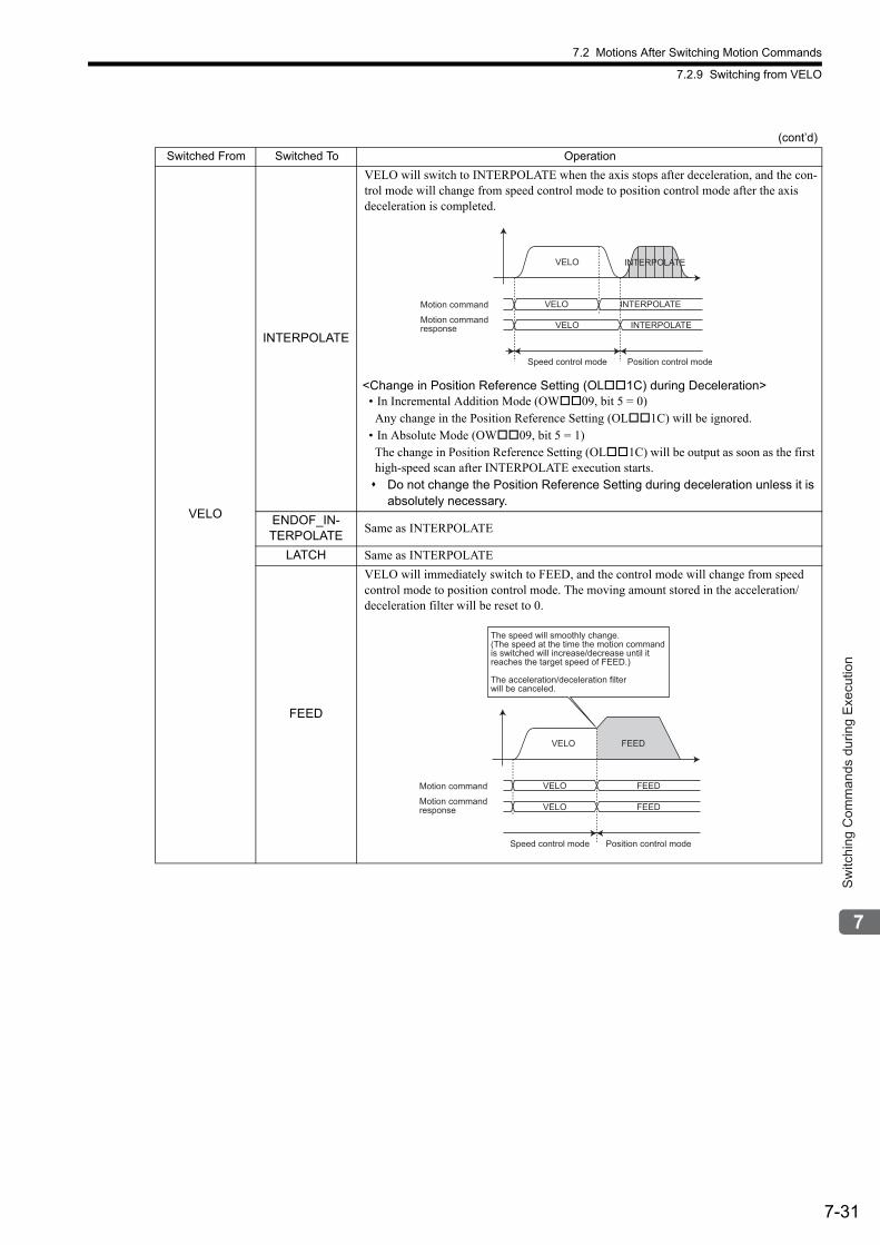
7.2 Motions After Switching Motion Commands
7.2.9 Switching from VELO
7-31
Sw
itchi
ng C
omm
ands
dur
ing
Exe
cutio
n
VELO
INTERPOLATE
VELO will switch to INTERPOLATE when the axis stops after deceleration, and the con-trol mode will change from speed control mode to position control mode after the axis deceleration is completed.
<Change in Position Reference Setting (OL1C) during Deceleration>• In Incremental Addition Mode (OW09, bit 5 = 0)Any change in the Position Reference Setting (OL1C) will be ignored.
• In Absolute Mode (OW09, bit 5 = 1)The change in Position Reference Setting (OL1C) will be output as soon as the first high-speed scan after INTERPOLATE execution starts. Do not change the Position Reference Setting during deceleration unless it is
absolutely necessary.
ENDOF_IN-TERPOLATE
Same as INTERPOLATE
LATCH Same as INTERPOLATE
FEED
VELO will immediately switch to FEED, and the control mode will change from speed control mode to position control mode. The moving amount stored in the acceleration/deceleration filter will be reset to 0.
(cont’d)
Switched From Switched To Operation
VELO
VELO INTERPOLATE
VELO INTERPOLATE
INTERPOLATE
Motion command
Motion commandresponse
Speed control mode Position control mode
VELO
VELO FEED
VELO FEED
FEED
Speed control mode Position control mode
The speed will smoothly change.(The speed at the time the motion command is switched will increase/decrease until it reaches the target speed of FEED.)
The acceleration/deceleration filterwill be canceled.
Motion command
Motion commandresponse
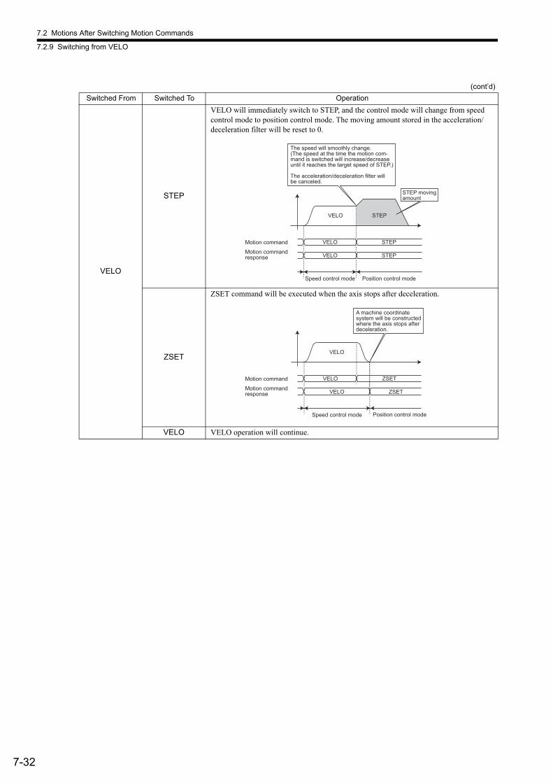
7.2 Motions After Switching Motion Commands
7.2.9 Switching from VELO
7-32
VELO
STEP
VELO will immediately switch to STEP, and the control mode will change from speed control mode to position control mode. The moving amount stored in the acceleration/deceleration filter will be reset to 0.
ZSET
ZSET command will be executed when the axis stops after deceleration.
VELO VELO operation will continue.
(cont’d)
Switched From Switched To Operation
VELO
VELO STEP
VELO STEP
STEP
Speed control mode Position control mode
The speed will smoothly change.(The speed at the time the motion com-mand is switched will increase/decreaseuntil it reaches the target speed of STEP.)
The acceleration/deceleration filter will be canceled.
STEP movingamount
Motion command
Motion commandresponse
VELO
VELO ZSET
VELO ZSET
Motion command
Motion command
response
Speed control mode Position control mode
A machine coordinate
system will be constructed
where the axis stops after
deceleration.
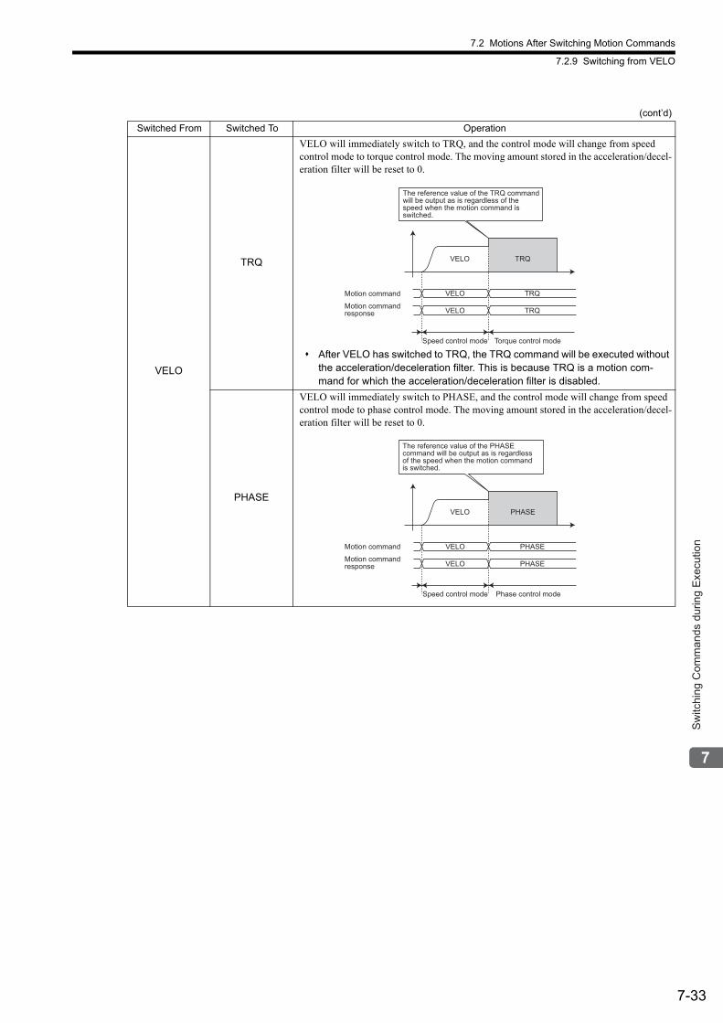
7.2 Motions After Switching Motion Commands
7.2.9 Switching from VELO
7-33
Sw
itchi
ng C
omm
ands
dur
ing
Exe
cutio
n
VELO
TRQ
VELO will immediately switch to TRQ, and the control mode will change from speed control mode to torque control mode. The moving amount stored in the acceleration/decel-eration filter will be reset to 0.
After VELO has switched to TRQ, the TRQ command will be executed without the acceleration/deceleration filter. This is because TRQ is a motion com-mand for which the acceleration/deceleration filter is disabled.
PHASE
VELO will immediately switch to PHASE, and the control mode will change from speed control mode to phase control mode. The moving amount stored in the acceleration/decel-eration filter will be reset to 0.
(cont’d)
Switched From Switched To Operation
VELO
VELO TRQ
VELO TRQ
Speed control mode Torque control mode
TRQ
The reference value of the TRQ command
will be output as is regardless of the
speed when the motion command is
switched.
Motion command
Motion command
response
VELO
VELO PHASE
VELO PHASE
Speed control mode Phase control mode
PHASE
The reference value of the PHASE
command will be output as is regardless
of the speed when the motion command
is switched.
Motion command
Motion command
response
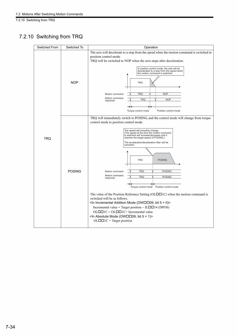
7.2 Motions After Switching Motion Commands
7.2.10 Switching from TRQ
7-34
7.2.10 Switching from TRQ
Switched From Switched To Operation
TRQ
NOP
The axis will decelerate to a stop from the speed when the motion command is switched in position control mode.TRQ will be switched to NOP when the axis stops after deceleration.
POSING
TRQ will immediately switch to POSING, and the control mode will change from torque control mode to position control mode.
The value of the Position Reference Setting (OL1C) when the motion command is switched will be as follows.<In Incremental Addition Mode (OW09, bit 5 = 0)>
Incremental value = Target position − IL14 (DPOS)OL1C = OL1C+ Incremental value
<In Absolute Mode (OW09, bit 5 = 1)> OL1C = Target position
TRQ NOP
TRQ NOP
Torque control mode Position control mode
TRQ
In position control mode, the axis will be
decelerated to a stop from the speed when
the motion command is switched.
Motion command
Motion command
response
TRQ POSING
TRQ POSING
Torque control mode Position control mode
TRQ POSING
The speed will smoothly change.(The speed at the time the motion command is switched will increase/decrease until itreaches the target speed of POSING.)
The acceleration/deceleration filter will be canceled.
Motion command
Motion commandresponse
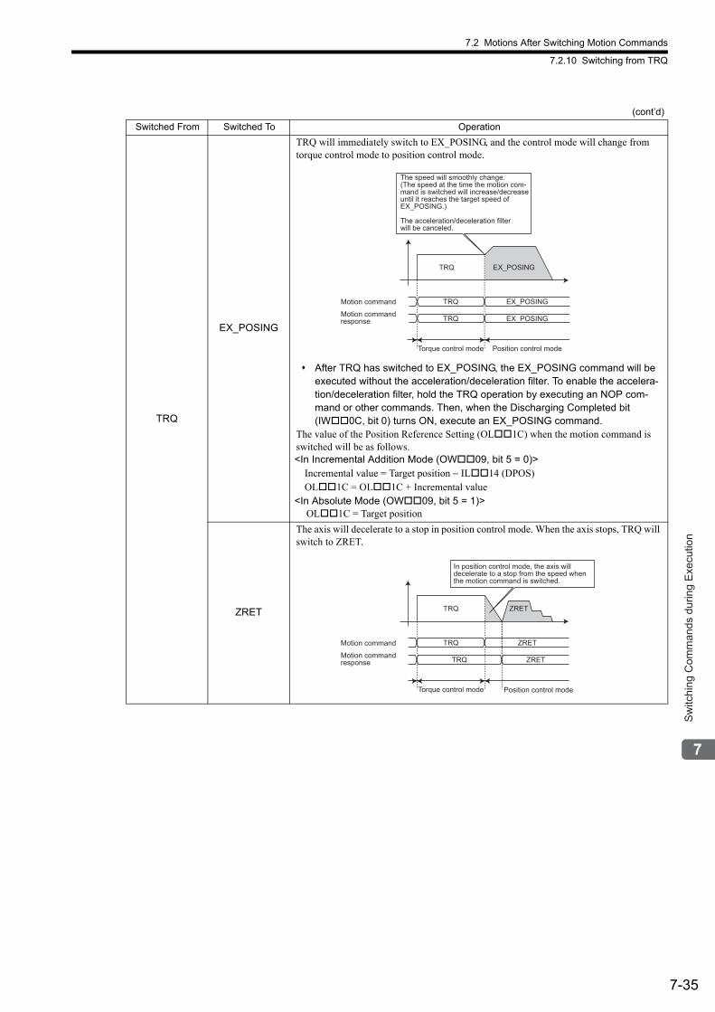
7.2 Motions After Switching Motion Commands
7.2.10 Switching from TRQ
7-35
Sw
itchi
ng C
omm
ands
dur
ing
Exe
cutio
n
TRQ
EX_POSING
TRQ will immediately switch to EX_POSING, and the control mode will change from torque control mode to position control mode.
After TRQ has switched to EX_POSING, the EX_POSING command will be executed without the acceleration/deceleration filter. To enable the accelera-tion/deceleration filter, hold the TRQ operation by executing an NOP com-mand or other commands. Then, when the Discharging Completed bit (IW0C, bit 0) turns ON, execute an EX_POSING command.
The value of the Position Reference Setting (OL1C) when the motion command is switched will be as follows.<In Incremental Addition Mode (OW09, bit 5 = 0)>
Incremental value = Target position − IL14 (DPOS)OL1C = OL1C + Incremental value
<In Absolute Mode (OW09, bit 5 = 1)> OL1C = Target position
ZRET
The axis will decelerate to a stop in position control mode. When the axis stops, TRQ will switch to ZRET.
(cont’d)
Switched From Switched To Operation
TRQ EX_POSING
TRQ EX_POSING
Torque control mode Position control mode
TRQ EX_POSING
The speed will smoothly change.(The speed at the time the motion com-mand is switched will increase/decreaseuntil it reaches the target speed ofEX_POSING.)
The acceleration/deceleration filterwill be canceled.
Motion command
Motion commandresponse
TRQ
TRQ ZRET
TRQ ZRET
Torque control mode Position control mode
ZRET
In position control mode, the axis will
decelerate to a stop from the speed when
the motion command is switched.
Motion command
Motion command
response
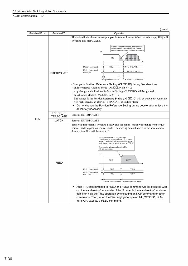
7.2 Motions After Switching Motion Commands
7.2.10 Switching from TRQ
7-36
TRQ
INTERPOLATE
The axis will decelerate to a stop in position control mode. When the axis stops, TRQ will switch to INTERPOLATE.
<Change in Position Reference Setting (OL1C) during Deceleration>• In Incremental Addition Mode (OW09, bit 5 = 0)
Any change in the Position Reference Setting (OL1C) will be ignored.• In Absolute Mode (OW09, bit 5 = 1)
The change in the Position Reference Setting (OL1C) will be output as soon as the first high-speed scan after INTERPOLATE execution starts. Do not change the Position Reference Setting during deceleration unless it is
absolutely necessary.
ENDOF_IN-TERPOLATE
Same as INTERPOLATE
LATCH Same as INTERPOLATE
FEED
TRQ will immediately switch to FEED, and the control mode will change from torque control mode to position control mode. The moving amount stored in the acceleration/deceleration filter will be reset to 0.
After TRQ has switched to FEED, the FEED command will be executed with-out the acceleration/deceleration filter. To enable the acceleration/decelera-tion filter, hold the TRQ operation by executing an NOP command or other commands. Then, when the Discharging Completed bit (IW0C, bit 0) turns ON, execute a FEED command.
(cont’d)
Switched From Switched To Operation
TRQ
TRQ INTERPOLATE
TRQ INTERPOLATE
Torque control mode Position control mode
In position control mode, the axis will
decelerate to a stop from the speed
when the motion command is switched.
INTERPOLATE
Motion command
Motion command
response
TRQ FEED
TRQ FEED
Torque control mode Position control mode
TRQ FEED
The speed will smoothly change.(The speed at the time the motion com-mand is switched will increase/decreaseuntil it reaches the target speed of FEED.)
The acceleration/deceleration filterwill be canceled.
Motion command
Motion commandresponse
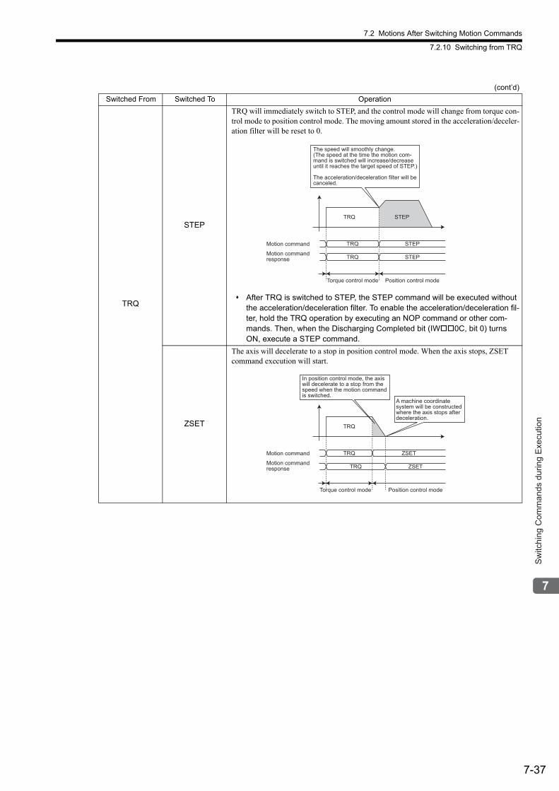
7.2 Motions After Switching Motion Commands
7.2.10 Switching from TRQ
7-37
Sw
itchi
ng C
omm
ands
dur
ing
Exe
cutio
n
TRQ
STEP
TRQ will immediately switch to STEP, and the control mode will change from torque con-trol mode to position control mode. The moving amount stored in the acceleration/deceler-ation filter will be reset to 0.
After TRQ is switched to STEP, the STEP command will be executed without the acceleration/deceleration filter. To enable the acceleration/deceleration fil-ter, hold the TRQ operation by executing an NOP command or other com-mands. Then, when the Discharging Completed bit (IW0C, bit 0) turns ON, execute a STEP command.
ZSET
The axis will decelerate to a stop in position control mode. When the axis stops, ZSET command execution will start.
(cont’d)
Switched From Switched To Operation
TRQ STEP
TRQ STEP
Torque control mode Position control mode
TRQ STEP
The speed will smoothly change.(The speed at the time the motion com-mand is switched will increase/decreaseuntil it reaches the target speed of STEP.)
The acceleration/deceleration filter will be canceled.
Motion command
Motion commandresponse
TRQ ZSET
TRQ ZSET
Torque control mode Position control mode
TRQ
In position control mode, the axis
will decelerate to a stop from the
speed when the motion command
is switched.
A machine coordinate
system will be constructed
where the axis stops after
deceleration.
Motion command
Motion command
response
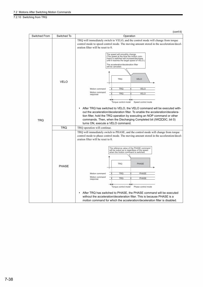
7.2 Motions After Switching Motion Commands
7.2.10 Switching from TRQ
7-38
TRQ
VELO
TRQ will immediately switch to VELO, and the control mode will change from torque control mode to speed control mode. The moving amount stored in the acceleration/decel-eration filter will be reset to 0.
After TRQ has switched to VELO, the VELO command will be executed with-out the acceleration/deceleration filter. To enable the acceleration/decelera-tion filter, hold the TRQ operation by executing an NOP command or other commands. Then, when the Discharging Completed bit (IW0C, bit 0) turns ON, execute a VELO command.
TRQ TRQ operation will continue.
PHASE
TRQ will immediately switch to PHASE, and the control mode will change from torque control mode to phase control mode. The moving amount stored in the acceleration/decel-eration filter will be reset to 0.
After TRQ has switched to PHASE, the PHASE command will be executed without the acceleration/deceleration filter. This is because PHASE is a motion command for which the acceleration/deceleration filter is disabled.
(cont’d)
Switched From Switched To Operation
TRQ VELO
TRQ VELO
Torque control mode Speed control mode
TRQ VELO
The speed will smoothly change.(The speed at the time the motion com-mand is switched will increase/decreaseuntil it reaches the target speed of VELO.)
The acceleration/deceleration filterwill be canceled.
Motion command
Motion commandresponse
TRQ PHASE
TRQ PHASE
Torque control mode Phase control mode
TRQ PHASE
The reference value of the PHASE commandwill be output as is regardless of the speed when the motion command is switched.
Motion command
Motion commandresponse
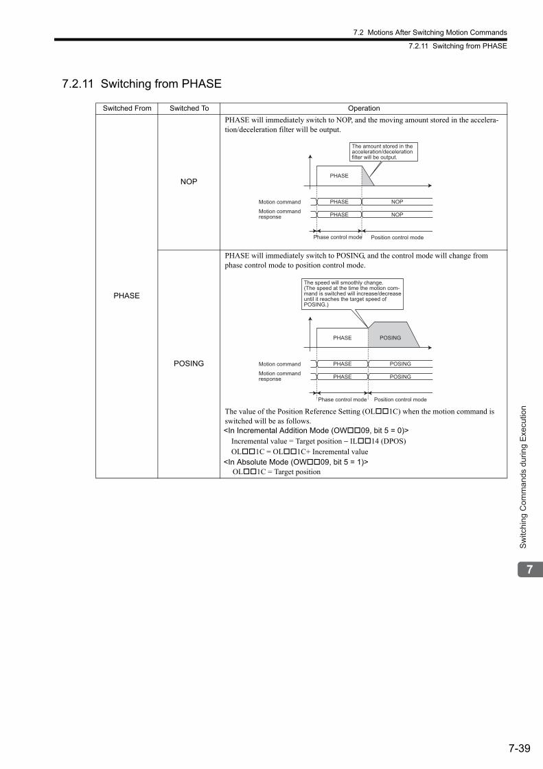
7.2 Motions After Switching Motion Commands
7.2.11 Switching from PHASE
7-39
Sw
itchi
ng C
omm
ands
dur
ing
Exe
cutio
n
7.2.11 Switching from PHASE
Switched From Switched To Operation
PHASE
NOP
PHASE will immediately switch to NOP, and the moving amount stored in the accelera-tion/deceleration filter will be output.
POSING
PHASE will immediately switch to POSING, and the control mode will change from phase control mode to position control mode.
The value of the Position Reference Setting (OL1C) when the motion command is switched will be as follows.<In Incremental Addition Mode (OW09, bit 5 = 0)>
Incremental value = Target position − IL14 (DPOS)OL1C = OL1C+ Incremental value
<In Absolute Mode (OW09, bit 5 = 1)> OL1C = Target position
PHASE NOP
PHASE NOP
Phase control mode Position control mode
PHASE
The amount stored in the
acceleration/deceleration
filter will be output.
Motion command
Motion command
response
PHASE POSING
PHASE POSING
Phase control mode Position control mode
PHASE POSING
The speed will smoothly change.
(The speed at the time the motion com-
mand is switched will increase/decrease
until it reaches the target speed of
POSING.)
Motion command
Motion command
response
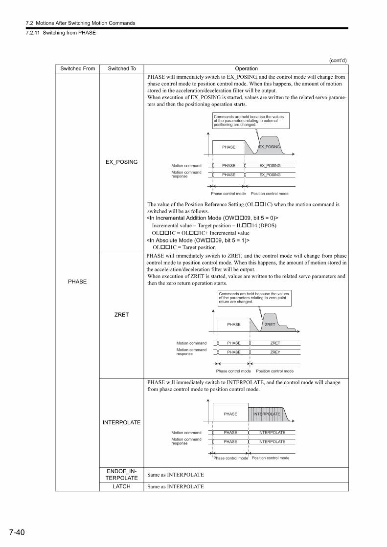
7.2 Motions After Switching Motion Commands
7.2.11 Switching from PHASE
7-40
PHASE
EX_POSING
PHASE will immediately switch to EX_POSING, and the control mode will change from phase control mode to position control mode. When this happens, the amount of motion stored in the acceleration/deceleration filter will be output.When execution of EX_POSING is started, values are written to the related servo parame-ters and then the positioning operation starts.
The value of the Position Reference Setting (OL1C) when the motion command is switched will be as follows.<In Incremental Addition Mode (OW09, bit 5 = 0)>
Incremental value = Target position − IL14 (DPOS)OL1C = OL1C+ Incremental value
<In Absolute Mode (OW09, bit 5 = 1)> OL1C = Target position
ZRET
PHASE will immediately switch to ZRET, and the control mode will change from phasecontrol mode to position control mode. When this happens, the amount of motion stored inthe acceleration/deceleration filter will be output.When execution of ZRET is started, values are written to the related servo parameters and then the zero return operation starts.
INTERPOLATE
PHASE will immediately switch to INTERPOLATE, and the control mode will change from phase control mode to position control mode.
ENDOF_IN-TERPOLATE
Same as INTERPOLATE
LATCH Same as INTERPOLATE
(cont’d)
Switched From Switched To Operation
PHASE EX_POSING
PHASE EX_POSING
PHASE
Commands are held because the values of the parameters relating to external positioning are changed.
EX_POSING
Phase control mode Position control mode
Motion command
Motion commandresponse
PHASE ZRET
PHASE ZREY
PHASE
Commands are held because the values of the parameters relating to zero point return are changed.
ZRET
Phase control mode Position control mode
Motion command
Motion commandresponse
PHASE
PHASE INTERPOLATE
PHASE INTERPOLATE
Phase control mode Position control mode
INTERPOLATE
Motion command
Motion commandresponse
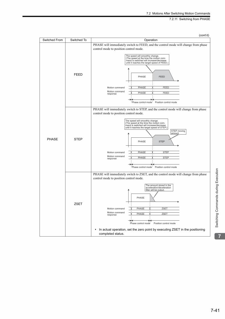
7.2 Motions After Switching Motion Commands
7.2.11 Switching from PHASE
7-41
Sw
itchi
ng C
omm
ands
dur
ing
Exe
cutio
n
PHASE
FEED
PHASE will immediately switch to FEED, and the control mode will change from phase control mode to position control mode.
STEP
PHASE will immediately switch to STEP, and the control mode will change from phase control mode to position control mode.
ZSET
PHASE will immediately switch to ZSET, and the control mode will change from phase control mode to position control mode.
In actual operation, set the zero point by executing ZSET in the positioning completed status.
(cont’d)
Switched From Switched To Operation
PHASE FEED
PHASE FEED
Phase control mode Position control mode
PHASE FEED
The speed will smoothly change.
(The speed at the time the motion com-
mand is switched will increase/decrease
until it reaches the target speed of FEED.)
Motion command
Motion command
response
PHASE STEP
PHASE STEP
Phase control mode Position control mode
PHASE STEP
The speed will smoothly change.
(The speed at the time the motion com-
mand is switched will increase/decrease
until it reaches the target speed of STEP.)
STEP moving
amount
Motion command
Motion command
response
PHASE ZSET
PHASE ZSET
Phase control mode Position control mode
PHASE
The amount stored in the
acceleration/deceleration
filter will be output.
Motion command
Motion command
response
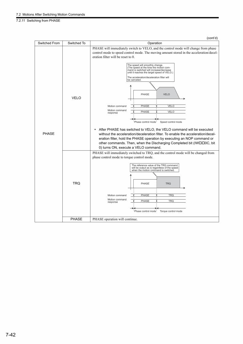
7.2 Motions After Switching Motion Commands
7.2.11 Switching from PHASE
7-42
PHASE
VELO
PHASE will immediately switch to VELO, and the control mode will change from phase control mode to speed control mode. The moving amount stored in the acceleration/decel-eration filter will be reset to 0.
After PHASE has switched to VELO, the VELO command will be executed without the acceleration/deceleration filter. To enable the acceleration/decel-eration filter, hold the PHASE operation by executing an NOP command or other commands. Then, when the Discharging Completed bit (IW0C, bit 0) turns ON, execute a VELO command.
TRQ
PHASE will immediately switched to TRQ, and the control mode will be changed from phase control mode to torque control mode.
PHASE PHASE operation will continue.
(cont’d)
Switched From Switched To Operation
PHASE VELO
PHASE VELO
Phase control mode Speed control mode
PHASE VELO
The speed will smoothly change.(The speed at the time the motion com-mand is switched will increase/decreaseuntil it reaches the target speed of VELO.)
The acceleration/deceleration filter will be canceled.
Motion command
Motion commandresponse
PHASE TRQ
PHASE TRQ
Phase control mode Torque control mode
PHASE TRQ
The reference value of the TRQ command
will be output as is regardless of the speed
when the motion command is switched.
Motion command
Motion command
response
8-1
Con
trol B
lock
Dia
gram
s
8
Control Block Diagrams
This chapter explains the control block diagrams.
8.1 Position Control - - - - - - - - - - - - - - - - - - - - - - - - - - - - - - - - - - - - - - - - - -8-2
8.1.1 Motion Parameters for Position Control - - - - - - - - - - - - - - - - - - - - - - - - - - - - - - - - - - 8-2
8.1.2 Control Block Diagram for Position Control - - - - - - - - - - - - - - - - - - - - - - - - - - - - - - - 8-6
8.2 Phase Control - - - - - - - - - - - - - - - - - - - - - - - - - - - - - - - - - - - - - - - - - - -8-8
8.2.1 Motion Parameters for Phase Control - - - - - - - - - - - - - - - - - - - - - - - - - - - - - - - - - - - 8-8
8.2.2 Control Block Diagram for Phase Control - - - - - - - - - - - - - - - - - - - - - - - - - - - - - - - - 8-12
8.3 Torque Control - - - - - - - - - - - - - - - - - - - - - - - - - - - - - - - - - - - - - - - - - - 8-14
8.3.1 Motion Parameters for Torque Control - - - - - - - - - - - - - - - - - - - - - - - - - - - - - - - - - - 8-14
8.3.2 Control Block Diagram for Torque Control - - - - - - - - - - - - - - - - - - - - - - - - - - - - - - - 8-18
8.4 Speed Control - - - - - - - - - - - - - - - - - - - - - - - - - - - - - - - - - - - - - - - - - - 8-20
8.4.1 Motion Parameters for Speed Control - - - - - - - - - - - - - - - - - - - - - - - - - - - - - - - - - - 8-20
8.4.2 Control Block Diagram for Speed Control - - - - - - - - - - - - - - - - - - - - - - - - - - - - - - - - 8-24
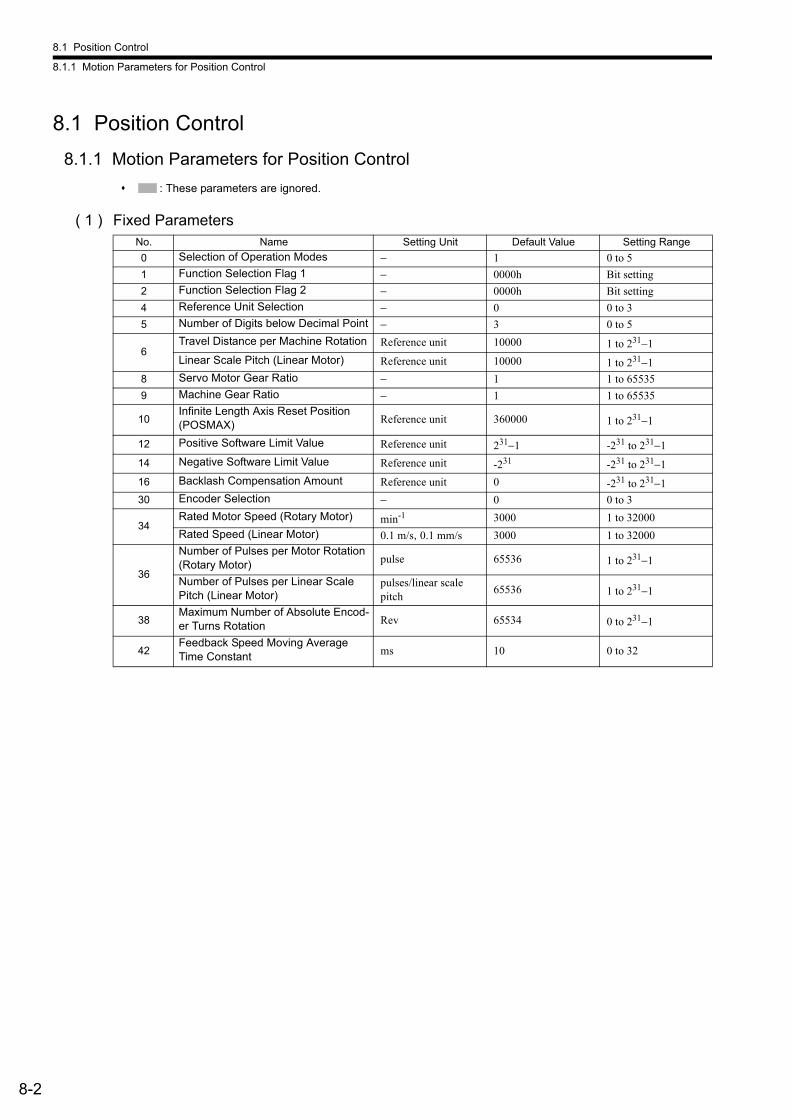
8.1 Position Control
8.1.1 Motion Parameters for Position Control
8-2
8.1 Position Control
8.1.1 Motion Parameters for Position Control
: These parameters are ignored.
( 1 ) Fixed ParametersNo. Name Setting Unit Default Value Setting Range
0 Selection of Operation Modes − 1 0 to 5
1 Function Selection Flag 1 − 0000h Bit setting
2 Function Selection Flag 2 − 0000h Bit setting
4 Reference Unit Selection − 0 0 to 3
5 Number of Digits below Decimal Point − 3 0 to 5
6Travel Distance per Machine Rotation Reference unit 10000 1 to 231−1
Linear Scale Pitch (Linear Motor) Reference unit 10000 1 to 231−1
8 Servo Motor Gear Ratio − 1 1 to 65535
9 Machine Gear Ratio − 1 1 to 65535
10Infinite Length Axis Reset Position (POSMAX) Reference unit 360000 1 to 231−1
12 Positive Software Limit Value Reference unit 231−1 -231 to 231−1
14 Negative Software Limit Value Reference unit -231 -231 to 231−1
16 Backlash Compensation Amount Reference unit 0 -231 to 231−1
30 Encoder Selection − 0 0 to 3
34Rated Motor Speed (Rotary Motor) min-1 3000 1 to 32000
Rated Speed (Linear Motor) 0.1 m/s, 0.1 mm/s 3000 1 to 32000
36
Number of Pulses per Motor Rotation (Rotary Motor) pulse 65536 1 to 231−1
Number of Pulses per Linear Scale Pitch (Linear Motor)
pulses/linear scale pitch
65536 1 to 231−1
38Maximum Number of Absolute Encod-er Turns Rotation Rev 65534 0 to 231−1
42Feedback Speed Moving Average Time Constant ms 10 0 to 32
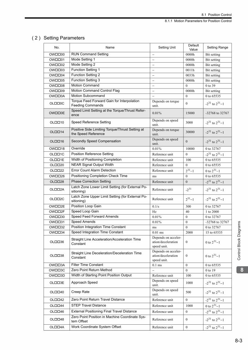
8.1 Position Control
8.1.1 Motion Parameters for Position Control
8-3
Con
trol B
lock
Dia
gram
s
( 2 ) Setting Parameters
No. Name Setting UnitDefault Value
Setting Range
OW00 RUN Command Setting − 0000h Bit setting
OW01 Mode Setting 1 − 0000h Bit setting
OW02 Mode Setting 2 − 0000h Bit setting
OW03 Function Setting 1 − 0011h Bit setting
OW04 Function Setting 2 − 0033h Bit setting
OW05 Function Setting 3 − 0000h Bit setting
OW08 Motion Command − 0 0 to 39
OW09 Motion Command Control Flag − 0000h Bit setting
OW0A Motion Subcommand − 0 0 to 65535
OL0CTorque Feed Forward Gain for Interpolation Feeding Commands
Depends on torque unit.
0 -231 to 231−1
OW0ESpeed Limit Setting at the Torque/Thrust Refer-ence 0.01% 15000 -32768 to 32767
OL10 Speed Reference Setting Depends on speed unit.
3000 -231 to 231−1
OL14Positive Side Limiting Torque/Thrust Setting at the Speed Reference
Depends on torque unit.
30000 -231 to 231−1
OL16 Secondly Speed Compensation Depends on speed unit.
0 -231 to 231−1
OW18 Override 0.01% 10000 0 to 32767
OL1C Position Reference Setting Reference unit 0 -231 to 231−1
OL1E Width of Positioning Completion Reference unit 100 0 to 65535
OL20 NEAR Signal Output Width Reference unit 0 0 to 65535
OL22 Error Count Alarm Detection Reference unit 231−1 0 to 231−1
OW26 Positioning Completion Check Time ms 0 0 to 65535
OL28 Phase Correction Setting Reference unit 0 -231 to 231−1
OL2ALatch Zone Lower Limit Setting (for External Po-sitioning) Reference unit -231 -231 to 231−1
OL2CLatch Zone Upper Limit Setting (for External Po-sitioning) Reference unit 231−1 -231 to 231−1
OW2E Position Loop Gain 0.1/s 300 0 to 32767
OW2F Speed Loop Gain Hz 40 1 to 2000
OW30 Speed Feed Forward Amends 0.01% 0 0 to 32767
OW31 Speed Amends 0.01% 0 -32768 to 32767
OW32 Position Integration Time Constant ms 0 0 to 32767
OW34 Speed Integration Time Constant 0.01 ms 2000 15 to 65535
OL36Straight Line Acceleration/Acceleration Time Constant
Depends on acceler-ation/deceleration speed unit.
0 0 to 231−1
OL38Straight Line Deceleration/Deceleration Time Constant
Depends on acceler-ation/deceleration speed unit.
0 0 to 231−1
OW3A Filter Time Constant 0.1 ms 0 0 to 65535
OW3C Zero Point Return Method − 0 0 to 19
OW3D Width of Starting Point Position Output Reference unit 100 0 to 65535
OL3E Approach Speed Depends on speed unit.
1000 -231 to 231−1
OL40 Creep Rate Depends on speed unit.
500 -231 to 231−1
OL42 Zero Point Return Travel Distance Reference unit 0 -231 to 231−1
OL44 STEP Travel Distance Reference unit 1000 0 to 231−1
OL46 External Positioning Final Travel Distance Reference unit 0 -231 to 231−1
OL48Zero Point Position in Machine Coordinate Sys-tem Offset Reference unit 0 -231 to 231−1
OL4A Work Coordinate System Offset Reference unit 0 -231 to 231−1

8.1 Position Control
8.1.1 Motion Parameters for Position Control
8-4
OL4C Number of POSMAX Turns Presetting Data Rev 0 -231 to 231−1
OW4E Servo User Monitor Setting − 0E00H Bit setting
OW4F Servo Driver Alarm Monitor No. − 0 0 to 9
OW50 Servo Driver User Constant No. − 0 0 to 65535
OW51 Servo Driver User Constant Size − 1 1, 2
OL52 Servo Driver User Constant Set Point − 0 -231 to 231−1
OW54 Servo Driver for Assistance User Constant No. − 0 0 to 65535
OW55 Servo Driver for Assistance User Constant Size − 1 1, 2
OL56Servo Driver for Assistance User Constant Set Point − 0 -231 to 231−1
OW5C Fixed Parameter Number − 0 0 to 65535
OL5EEncoder Position When Power is OFF (Lower 2 words) pulse 0 -231 to 231−1
OL60Encoder Position When Power is OFF (Upper 2 words) pulse 0 -231 to 231−1
OL62Pulse Position When Power is OFF (Lower 2 words) pulse 0 -231 to 231−1
OL64Pulse Position When Power is OFF (Upper 2 words) pulse 0 -231 to 231−1
(cont’d)
No. Name Setting UnitDefault Value
Setting Range
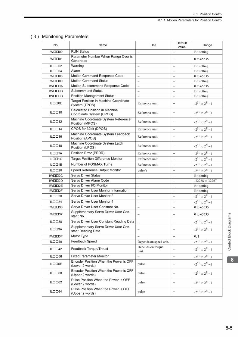
8.1 Position Control
8.1.1 Motion Parameters for Position Control
8-5
Con
trol B
lock
Dia
gram
s
( 3 ) Monitoring Parameters
No. Name UnitDefault Value
Range
IW00 RUN Status − − Bit setting
IW01Parameter Number When Range Over is Generated − − 0 to 65535
IL02 Warning − − Bit setting
IL04 Alarm − − Bit setting
IW08 Motion Command Response Code − − 0 to 65535
IW09 Motion Command Status − − Bit setting
IW0A Motion Subcommand Response Code − − 0 to 65535
IW0B Subcommand Status − − Bit setting
IW0C Position Management Status − − Bit setting
IL0ETarget Position in Machine Coordinate System (TPOS) Reference unit − -231 to 231−1
IL10Calculated Position in Machine Coordinate System (CPOS) Reference unit − -231 to 231−1
IL12Machine Coordinate System Reference Position (MPOS) Reference unit − -231 to 231−1
IL14 CPOS for 32bit (DPOS) Reference unit − -231 to 231−1
IL16Machine Coordinate System Feedback Position (APOS) Reference unit − -231 to 231−1
IL18Machine Coordinate System Latch Position (LPOS) Reference unit − -231 to 231−1
IL1A Position Error (PERR) Reference unit − -231 to 231−1
IL1C Target Position Difference Monitor Reference unit − -231 to 231−1
IL1E Number of POSMAX Turns Reference unit − -231 to 231−1
IL20 Speed Reference Output Monitor pulse/s − -231 to 231−1
IW2C Servo Driver Status − − Bit setting
IW2D Servo Driver Alarm Code − − -32768 to 32767
IW2E Servo Driver I/O Monitor − − Bit setting
IW2F Servo Driver User Monitor Information − − Bit setting
IL30 Servo Driver User Monitor 2 − − -231 to 231−1
IL34 Servo Driver User Monitor 4 − − -231 to 231−1
IW36 Servo Driver User Constant No. − − 0 to 65535
IW37Supplementary Servo Driver User Con-stant No. − − 0 to 65535
IL38 Servo Driver User Constant Reading Data − − -231 to 231−1
IL3ASupplementary Servo Driver User Con-stant Reading Data − − -231 to 231−1
IW3F Motor Type − − 0, 1
IL40 Feedback Speed Depends on speed unit. − -231 to 231−1
IL42 Feedback Torque/Thrust Depends on torque unit.
− -231 to 231−1
IL56 Fixed Parameter Monitor − − -231 to 231−1
IL5EEncoder Position When the Power is OFF (Lower 2 words) pulse − -231 to 231−1
IL60Encoder Position When the Power is OFF (Upper 2 words) pulse − -231 to 231−1
IL62Pulse Position When the Power is OFF (Lower 2 words) pulse − -231 to 231−1
IL64Pulse Position When the Power is OFF (Upper 2 words) pulse − -231 to 231−1
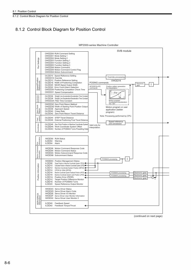
8.1 Position Control
8.1.2 Control Block Diagram for Position Control
8-6
8.1.2 Control Block Diagram for Position Control
p
t
p
ts
Override processing
OW��18POSING commands
MP2000-series Machine Controller
SVB moduleOW��00 RUN Command Setting OW��01 Mode Setting 1OW��02 Mode Setting 2OW��03 Function Setting 1 OW��04 Function Setting 2OW��05 Function Setting 3OW��08 Motion Command OW��09 Motion Command Control Flag OW��0A Motion Subcommand
OL��10 Speed Reference SettingOW��18 Override OL��1C Position Reference SettingOL��1E Width of Positioning Completion OL��20 NEAR Signal Output WidthOL��22 Error Count Alarm Detection OW��26 Positioning Completion Check Time OW��31 Speed Compensation
OL��36 Straight Line Acceleration/Acceleration Time ConstantOL��38 Straight Line Deceleration/Deceleration Time ConstantOW��3A Filter Time Constant
OW��3C Zero Point Return MethodOW��3D Width of Starting Point Position OutputOL��3E Approach Speed OL��40 Creep Rate OL��42 Zero Point Return Travel Distance
OL��44 STEP Travel Distance OL��46 External Positioning Final Travel Distance
OL��48 Zero Point Position in Machine Coordinate System OL��4A Work Coordinate System Offset OL��4C Number of POSMAX Turns Presetting Data
IW��00 RUN Status IL��02 Warning IL��04 Alarm
IW��08 Motion Command Response CodeIW��09 Motion Command StatusIW��0A Motion Subcommand Response Code IW��0B Subcommand Status
IW��0C Position Management Status IL��0E Target Position in Machine Coordinate System (TPOS) IL��10 Calculated Position in Machine Coordinate System (CPOS) IL��12 Machine Coordinate System Position (MPOS) IL��14 CPOS for 32bit (DPOS) IL��16 Machine Coordinate System Feedback Position (APOS) IL��18 Machine Coordinate System Latch Position (LPOS) IL��1A Position Error (PERR) IL��1C Target Position Difference Monitor IL��1E Number of POSMAX Turns IL��20 Speed Reference Output Monitor
IW��2C Servo Driver StatusIW��2D Servo Driver Alarm Code IW��2E Servo Driver I/O Monitor IW��2F Servo Driver User Monitor InformationIW��30 Servo Driver User Monitor 2
IL��40 Feedback Speed IL��42 Feedback Torque/Thrust
+
Note: Processing performed by CPU.
Run
Set
tings
S
peed
/Pos
ition
R
efer
ence
s A
ccel
erat
ion/
Dec
eler
atio
n Ze
ro P
oint
R
etur
n Fe
ed
spee
dsC
oord
inat
es
Run
In
form
atio
n M
otio
n C
omm
and
Info
rmat
ion
Pos
ition
Info
rmat
ion
SE
RV
OPA
CK
In
form
atio
n
INTERPOLATE commands
Position pattern generation for interpolation
Electronic gear
Motion program Acceleration/deceleration: IAC, IDC
Motion program or user application (ladder program)
Valid only for interpolation.
Speed reference unit conversion
POSMAX processing
POSMAX processing
POSMAX processing
Electronic gear Electronic gear Electronic gear
(continued on next page)
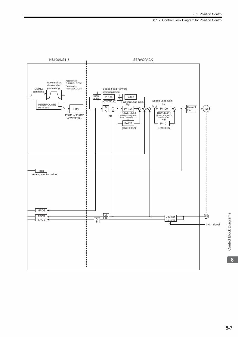
8.1 Position Control
8.1.2 Control Block Diagram for Position Control
8-7
Con
trol B
lock
Dia
gram
s
Filter
Analog monitor value
Pn109 Pn10A
Pn102
Pn101
AB Pn100
AB
M
PG
Pn11F
AB
Speed Loop GainPosition Loop Gain
Pn811 or Pn812(OW��3A)
(OW��32)
(OW��30)
(OW��2F)
S
Kp
Ti
(OW��2E)
(OW��34)
Kv
NTiFB
Vref
SERVOPACKNS100/NS115
MPOS
APOSLPOS
TRQ
BA Counter
Latch signal
Counter
POSING command
Acceleration/deceleration processing
Acceleration: Pn80B (OL��36)Deceleration: Pn80E (OL��38)
INTERPOLATE command
Differ-ential
Speed Feed Forward Compensation
Position Integration Time Constant
Speed Integration Time Constant
Current loop
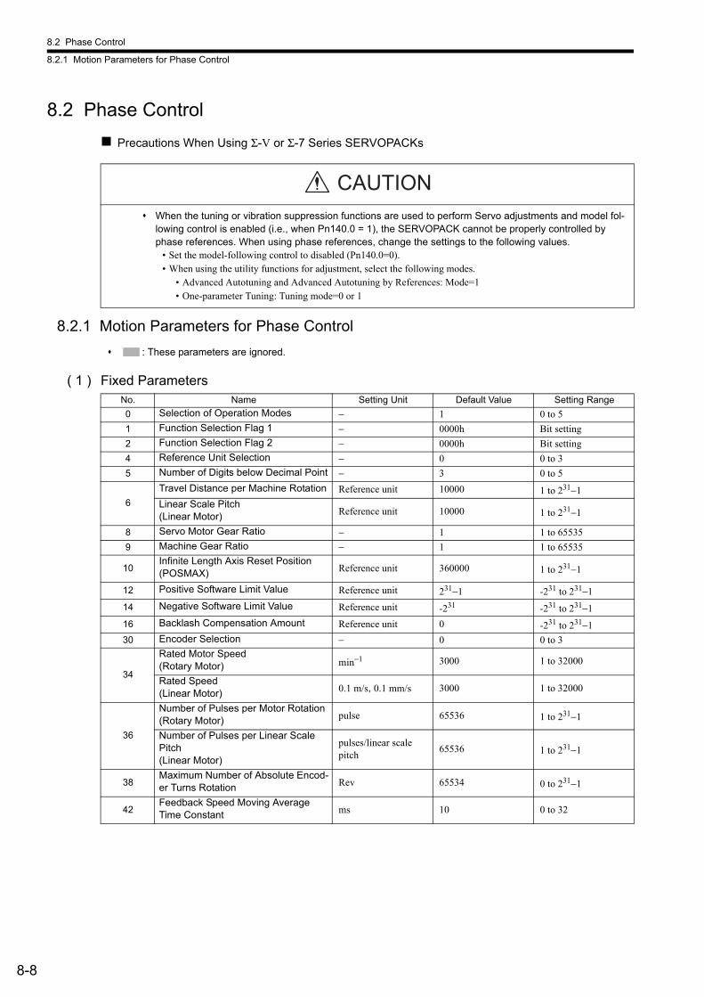
8.2 Phase Control
8.2.1 Motion Parameters for Phase Control
8-8
8.2 Phase Control
Precautions When Using Σ-V or Σ-7 Series SERVOPACKs
8.2.1 Motion Parameters for Phase Control
: These parameters are ignored.
( 1 ) Fixed Parameters
When the tuning or vibration suppression functions are used to perform Servo adjustments and model fol-lowing control is enabled (i.e., when Pn140.0 = 1), the SERVOPACK cannot be properly controlled by phase references. When using phase references, change the settings to the following values.
• Set the model-following control to disabled (Pn140.0=0).• When using the utility functions for adjustment, select the following modes.
• Advanced Autotuning and Advanced Autotuning by References: Mode=1• One-parameter Tuning: Tuning mode=0 or 1
CAUTION
No. Name Setting Unit Default Value Setting Range
0 Selection of Operation Modes − 1 0 to 5
1 Function Selection Flag 1 − 0000h Bit setting
2 Function Selection Flag 2 − 0000h Bit setting
4 Reference Unit Selection − 0 0 to 3
5 Number of Digits below Decimal Point − 3 0 to 5
6
Travel Distance per Machine Rotation Reference unit 10000 1 to 231−1Linear Scale Pitch (Linear Motor) Reference unit 10000 1 to 231−1
8 Servo Motor Gear Ratio − 1 1 to 65535
9 Machine Gear Ratio − 1 1 to 65535
10Infinite Length Axis Reset Position (POSMAX) Reference unit 360000 1 to 231−1
12 Positive Software Limit Value Reference unit 231−1 -231 to 231−1
14 Negative Software Limit Value Reference unit -231 -231 to 231−1
16 Backlash Compensation Amount Reference unit 0 -231 to 231−1
30 Encoder Selection − 0 0 to 3
34
Rated Motor Speed(Rotary Motor) min−1 3000 1 to 32000
Rated Speed(Linear Motor) 0.1 m/s, 0.1 mm/s 3000 1 to 32000
36
Number of Pulses per Motor Rotation(Rotary Motor) pulse 65536 1 to 231−1
Number of Pulses per Linear Scale Pitch(Linear Motor)
pulses/linear scale pitch
65536 1 to 231−1
38Maximum Number of Absolute Encod-er Turns Rotation Rev 65534 0 to 231−1
42Feedback Speed Moving Average Time Constant ms 10 0 to 32
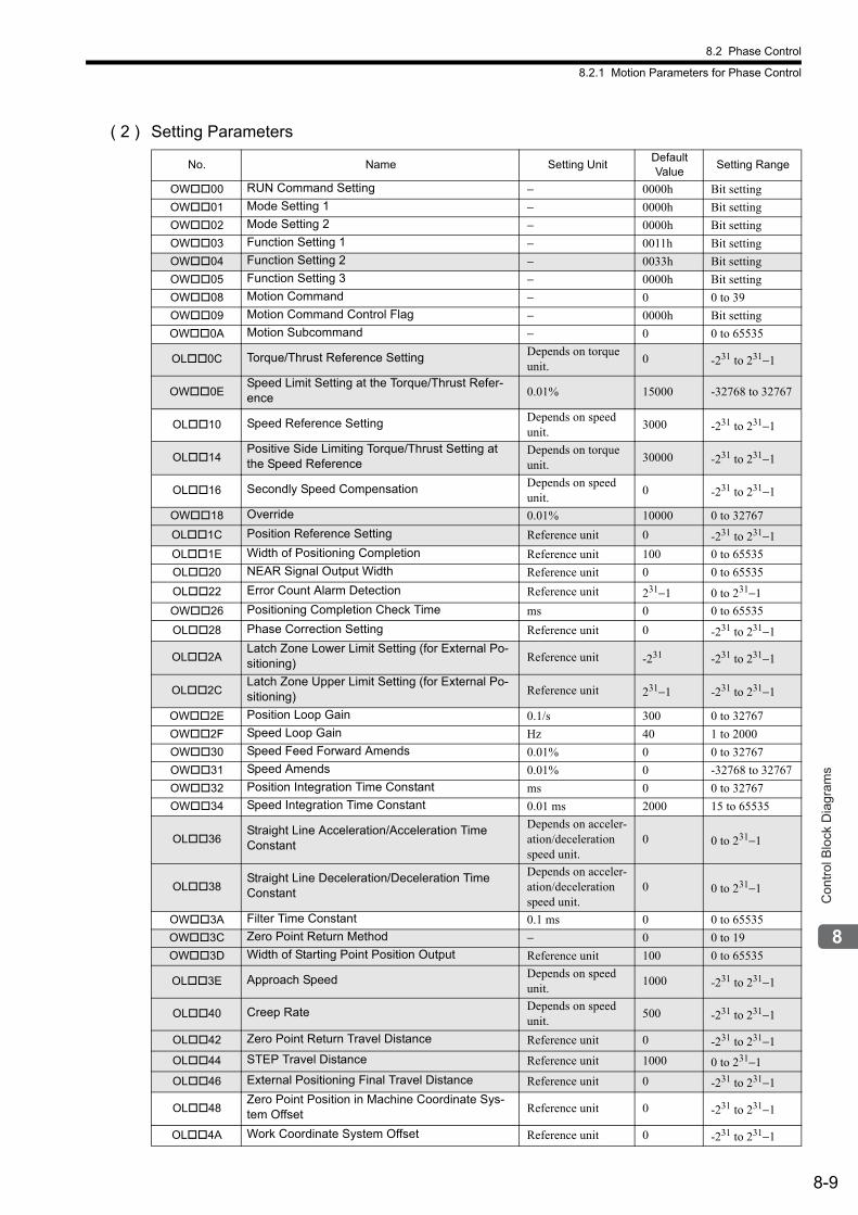
8.2 Phase Control
8.2.1 Motion Parameters for Phase Control
8-9
Con
trol B
lock
Dia
gram
s
( 2 ) Setting Parameters
No. Name Setting UnitDefault Value
Setting Range
OW00 RUN Command Setting − 0000h Bit setting
OW01 Mode Setting 1 − 0000h Bit setting
OW02 Mode Setting 2 − 0000h Bit setting
OW03 Function Setting 1 − 0011h Bit setting
OW04 Function Setting 2 − 0033h Bit setting
OW05 Function Setting 3 − 0000h Bit setting
OW08 Motion Command − 0 0 to 39
OW09 Motion Command Control Flag − 0000h Bit setting
OW0A Motion Subcommand − 0 0 to 65535
OL0C Torque/Thrust Reference Setting Depends on torque unit.
0 -231 to 231−1
OW0ESpeed Limit Setting at the Torque/Thrust Refer-ence 0.01% 15000 -32768 to 32767
OL10 Speed Reference Setting Depends on speed unit.
3000 -231 to 231−1
OL14Positive Side Limiting Torque/Thrust Setting at the Speed Reference
Depends on torque unit.
30000 -231 to 231−1
OL16 Secondly Speed Compensation Depends on speed unit.
0 -231 to 231−1
OW18 Override 0.01% 10000 0 to 32767
OL1C Position Reference Setting Reference unit 0 -231 to 231−1
OL1E Width of Positioning Completion Reference unit 100 0 to 65535
OL20 NEAR Signal Output Width Reference unit 0 0 to 65535
OL22 Error Count Alarm Detection Reference unit 231−1 0 to 231−1
OW26 Positioning Completion Check Time ms 0 0 to 65535
OL28 Phase Correction Setting Reference unit 0 -231 to 231−1
OL2ALatch Zone Lower Limit Setting (for External Po-sitioning) Reference unit -231 -231 to 231−1
OL2CLatch Zone Upper Limit Setting (for External Po-sitioning) Reference unit 231−1 -231 to 231−1
OW2E Position Loop Gain 0.1/s 300 0 to 32767
OW2F Speed Loop Gain Hz 40 1 to 2000
OW30 Speed Feed Forward Amends 0.01% 0 0 to 32767
OW31 Speed Amends 0.01% 0 -32768 to 32767
OW32 Position Integration Time Constant ms 0 0 to 32767
OW34 Speed Integration Time Constant 0.01 ms 2000 15 to 65535
OL36Straight Line Acceleration/Acceleration Time Constant
Depends on acceler-ation/deceleration speed unit.
0 0 to 231−1
OL38Straight Line Deceleration/Deceleration Time Constant
Depends on acceler-ation/deceleration speed unit.
0 0 to 231−1
OW3A Filter Time Constant 0.1 ms 0 0 to 65535
OW3C Zero Point Return Method − 0 0 to 19
OW3D Width of Starting Point Position Output Reference unit 100 0 to 65535
OL3E Approach Speed Depends on speed unit.
1000 -231 to 231−1
OL40 Creep Rate Depends on speed unit.
500 -231 to 231−1
OL42 Zero Point Return Travel Distance Reference unit 0 -231 to 231−1
OL44 STEP Travel Distance Reference unit 1000 0 to 231−1
OL46 External Positioning Final Travel Distance Reference unit 0 -231 to 231−1
OL48Zero Point Position in Machine Coordinate Sys-tem Offset Reference unit 0 -231 to 231−1
OL4A Work Coordinate System Offset Reference unit 0 -231 to 231−1

8.2 Phase Control
8.2.1 Motion Parameters for Phase Control
8-10
OL4C Number of POSMAX Turns Presetting Data Rev 0 -231 to 231−1
OW4E Servo User Monitor Setting − 0E00H Bit setting
OW4F Servo Driver Alarm Monitor No. − 0 0 to 9
OW50 Servo Driver User Constant No. − 0 0 to 65535
OW51 Servo Driver User Constant Size − 1 1, 2
OL52 Servo Driver User Constant Set Point − 0 -231 to 231−1
OW54 Servo Driver for Assistance User Constant No. − 0 0 to 65535
OW55 Servo Driver for Assistance User Constant Size − 1 1, 2
OL56Servo Driver for Assistance User Constant Set Point − 0 -231 to 231−1
OW5C Fixed Parameter Number − 0 0 to 65535
OL5EEncoder Position When Power is OFF (Lower 2 words) pulse 0 -231 to 231−1
OL60Encoder Position When Power is OFF (Upper 2 words) pulse 0 -231 to 231−1
OL62Pulse Position When Power is OFF (Lower 2 words) pulse 0 -231 to 231−1
OL64Pulse Position When Power is OFF (Upper 2 words) pulse 0 -231 to 231−1
(cont’d)
No. Name Setting UnitDefault Value
Setting Range

8.2 Phase Control
8.2.1 Motion Parameters for Phase Control
8-11
Con
trol B
lock
Dia
gram
s
( 3 ) Monitoring Parameters
No. Name UnitDefault Value
Range
IW00 RUN Status − − Bit setting
IW01Parameter Number When Range Over is Generated − − 0 to 65535
IL02 Warning − − Bit setting
IL04 Alarm − − Bit setting
IW08 Motion Command Response Code − − 0 to 65535
IW09 Motion Command Status − − Bit setting
IW0A Motion Subcommand Response Code − − 0 to 65535
IW0B Subcommand Status − − Bit setting
IW0C Position Management Status − − Bit setting
IL0ETarget Position in Machine Coordinate System (TPOS) Reference unit − -231 to 231−1
IL10Calculated Position in Machine Coordinate System (CPOS) Reference unit − -231 to 231−1
IL12Machine Coordinate System Reference Position (MPOS) Reference unit − -231 to 231−1
IL14 CPOS for 32bit (DPOS) Reference unit − -231 to 231−1
IL16Machine Coordinate System Feedback Position (APOS) Reference unit − -231 to 231−1
IL18Machine Coordinate System Latch Position (LPOS) Reference unit − -231 to 231−1
IL1A Position Error (PERR) Reference unit − -231 to 231−1
IL1C Target Position Difference Monitor Reference unit − -231 to 231−1
IL1E Number of POSMAX Turns Reference unit − -231 to 231−1
IL20 Speed Reference Output Monitor pulse/s − -231 to 231−1
IW2C Servo Driver Status − − Bit setting
IW2D Servo Driver Alarm Code − − -32768 to 32767
IW2E Servo Driver I/O Monitor − − Bit setting
IW2F Servo Driver User Monitor Information − − Bit setting
IL30 Servo Driver User Monitor 2 − − -231 to 231−1
IL34 Servo Driver User Monitor 4 − − -231 to 231−1
IW36 Servo Driver User Constant No. − − 0 to 65535
IW37Supplementary Servo Driver User Con-stant No. − − 0 to 65535
IL38 Servo Driver User Constant Reading Data − − -231 to 231−1
IL3ASupplementary Servo Driver User Con-stant Reading Data − − -231 to 231−1
IW3F Motor Type − − 0, 1
IL40 Feedback Speed Depends on speed unit. − -231 to 231−1
IL42 Feedback Torque/Thrust Depends on torque unit.
− -231 to 231−1
IL56 Fixed Parameter Monitor − − -231 to 231−1
IL5EEncoder Position When the Power is OFF (Lower 2 words) pulse − -231 to 231−1
IL60Encoder Position When the Power is OFF (Upper 2 words) pulse − -231 to 231−1
IL62Pulse Position When the Power is OFF (Lower 2 words) pulse − -231 to 231−1
IL64Pulse Position When the Power is OFF (Upper 2 words) pulse − -231 to 231−1
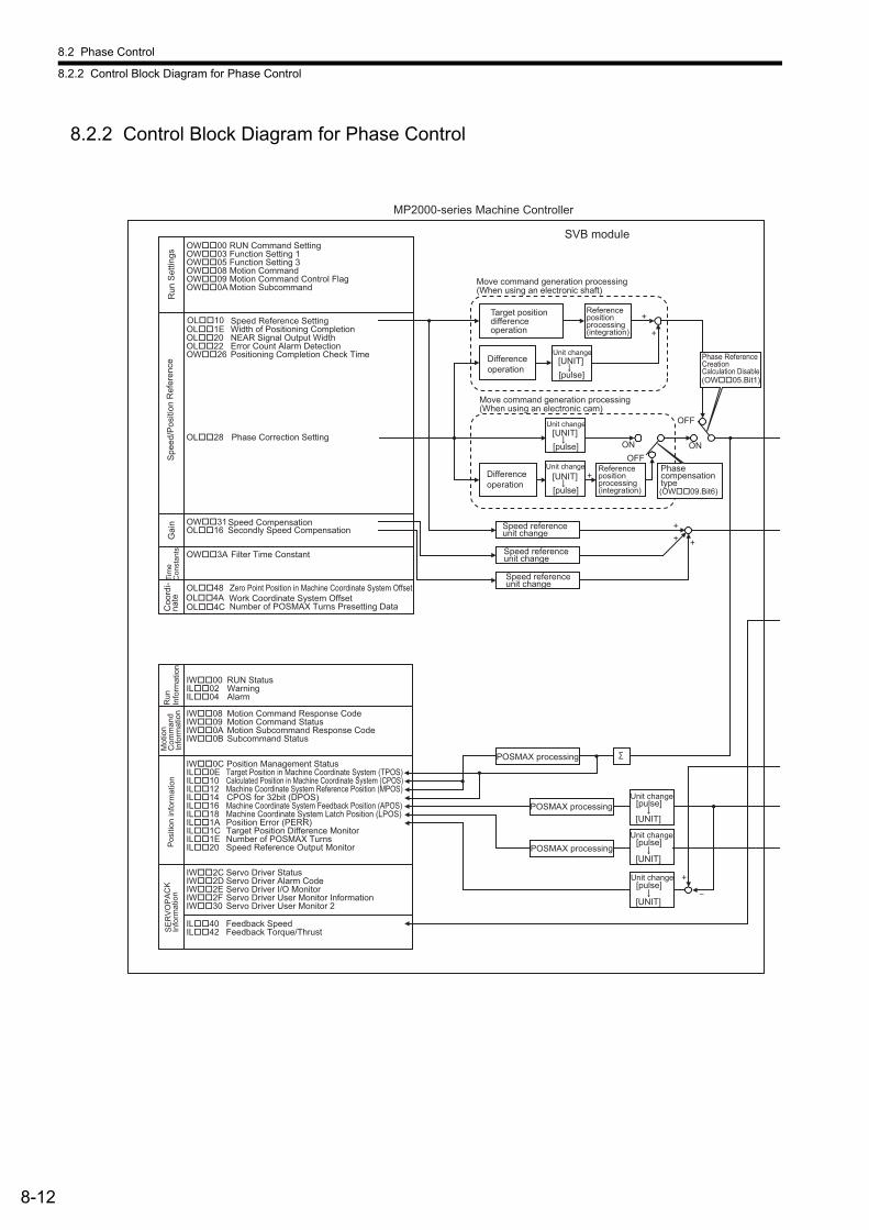
8.2 Phase Control
8.2.2 Control Block Diagram for Phase Control
8-12
8.2.2 Control Block Diagram for Phase Control
MP2000-series Machine Controller
SVB module
Move command generation processing (When using an electronic shaft)
Target positiondifferenceoperation
+
+
Referencepositionprocessing (integration)
Referenceposition processing (integration)
+
Move command generation processing (When using an electronic cam)
Differenceoperation
Phase ReferenceCreationCalculation Disable(OW��05.Bit1)
ONONOFF
OFF
Differenceoperation
[UNIT][pulse]
[UNIT][pulse]
[UNIT][pulse]
Speed referenceunit change
OL��10 Speed Reference Setting
OL��28 Phase Correction Setting
OW��31 Speed CompensationOL��16 Secondly Speed Compensation
OW��3A Filter Time Constant
OL��48 Zero Point Position in Machine Coordinate System OffsetOL��4A Work Coordinate System Offset
OL��1E Width of Positioning CompletionOL��20 NEAR Signal Output WidthOL��22 Error Count Alarm DetectionOW��26 Positioning Completion Check Time
OW��00 RUN Command SettingOW��03 Function Setting 1OW��05 Function Setting 3OW��08 Motion CommandOW��09 Motion Command Control FlagOW��0A Motion Subcommand
OL��4C Number of POSMAX Turns Presetting Data
IW��00 RUN StatusIL��02 WarningIL��04 Alarm
IW��08 Motion Command Response CodeIW��09 Motion Command StatusIW��0A Motion Subcommand Response Code
Position Management StatusTarget Position in Machine Coordinate System (TPOS)
IW��0B Subcommand Status
IW��0CIL��0EIL��10IL��12IL��14IL��16IL��18IL��1AIL��1CIL��1EIL��20
IW��2C Servo Driver StatusIW��2DIW��2EIW��2FIW��30
IL��40 Feedback SpeedIL��42 Feedback Torque/Thrust
Target Position Difference MonitorNumber of POSMAX TurnsSpeed Reference Output Monitor
Calculated Position in Machine Coordinate System (CPOS)Machine Coordinate System Reference Position (MPOS)CPOS for 32bit (DPOS)Machine Coordinate System Feedback Position (APOS)Machine Coordinate System Latch Position (LPOS)Position Error (PERR)
Servo Driver Alarm CodeServo Driver I/O MonitorServo Driver User Monitor InformationServo Driver User Monitor 2
POSMAX processing
Unit change[pulse]
[UNIT]
[pulse]
[UNIT]
[pulse]
[UNIT]
POSMAX processing
POSMAX processing
+
++ +
Run
Set
tings
Spe
ed/P
ositi
on R
efer
ence
Gai
nTi
me
Con
stan
tsC
oord
i-na
teR
unIn
form
atio
nM
otio
n C
omm
and
Info
rmat
ion
SE
RV
OP
AC
KIn
form
atio
n
Phasecompensationtype(OW��09.Bit6)
Pos
ition
info
rmat
ion
Unit change
Unit change
Unit change
Unit change
Unit change
Speed referenceunit change
Speed referenceunit change
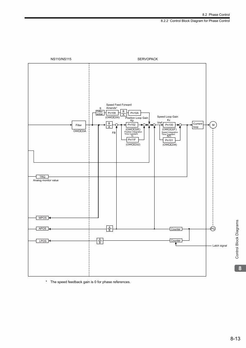
8.2 Phase Control
8.2.2 Control Block Diagram for Phase Control
8-13
Con
trol B
lock
Dia
gram
s
* The speed feedback gain is 0 for phase references.
Filter
Analog monitor value
Pn109 Pn10A
Pn102
Pn101
AB Pn100
AB
M
PG
Pn11F
AB
Speed Loop GainPosition Loop Gain
OW��3A
(OW��32)
(OW��30)
(OW��2F)
S
Kp
Ti
(OW��2E)
(OW��34)
Kv
NTiFB
Vref
SERVOPACK NS110/NS115
MPOS
APOS
LPOS
TRQ
BA Counter
Latch signal
Counter
Differ-ential
Speed Feed Forward Amends*
Position Integration Time Constant
Speed Integration Time Constant
Current loop
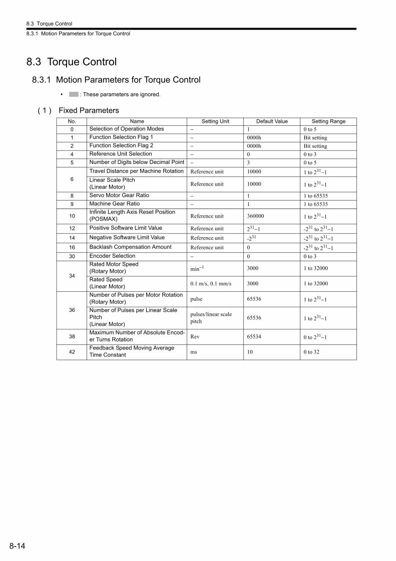
8.3 Torque Control
8.3.1 Motion Parameters for Torque Control
8-14
8.3 Torque Control
8.3.1 Motion Parameters for Torque Control
: These parameters are ignored.
( 1 ) Fixed ParametersNo. Name Setting Unit Default Value Setting Range
0 Selection of Operation Modes − 1 0 to 5
1 Function Selection Flag 1 − 0000h Bit setting
2 Function Selection Flag 2 − 0000h Bit setting
4 Reference Unit Selection − 0 0 to 3
5 Number of Digits below Decimal Point − 3 0 to 5
6
Travel Distance per Machine Rotation Reference unit 10000 1 to 231−1Linear Scale Pitch (Linear Motor) Reference unit 10000 1 to 231−1
8 Servo Motor Gear Ratio − 1 1 to 65535
9 Machine Gear Ratio − 1 1 to 65535
10Infinite Length Axis Reset Position (POSMAX) Reference unit 360000 1 to 231−1
12 Positive Software Limit Value Reference unit 231−1 -231 to 231−1
14 Negative Software Limit Value Reference unit -231 -231 to 231−1
16 Backlash Compensation Amount Reference unit 0 -231 to 231−1
30 Encoder Selection − 0 0 to 3
34
Rated Motor Speed(Rotary Motor) min−1 3000 1 to 32000
Rated Speed(Linear Motor) 0.1 m/s, 0.1 mm/s 3000 1 to 32000
36
Number of Pulses per Motor Rotation(Rotary Motor) pulse 65536 1 to 231−1
Number of Pulses per Linear Scale Pitch(Linear Motor)
pulses/linear scale pitch
65536 1 to 231−1
38Maximum Number of Absolute Encod-er Turns Rotation Rev 65534 0 to 231−1
42Feedback Speed Moving Average Time Constant ms 10 0 to 32
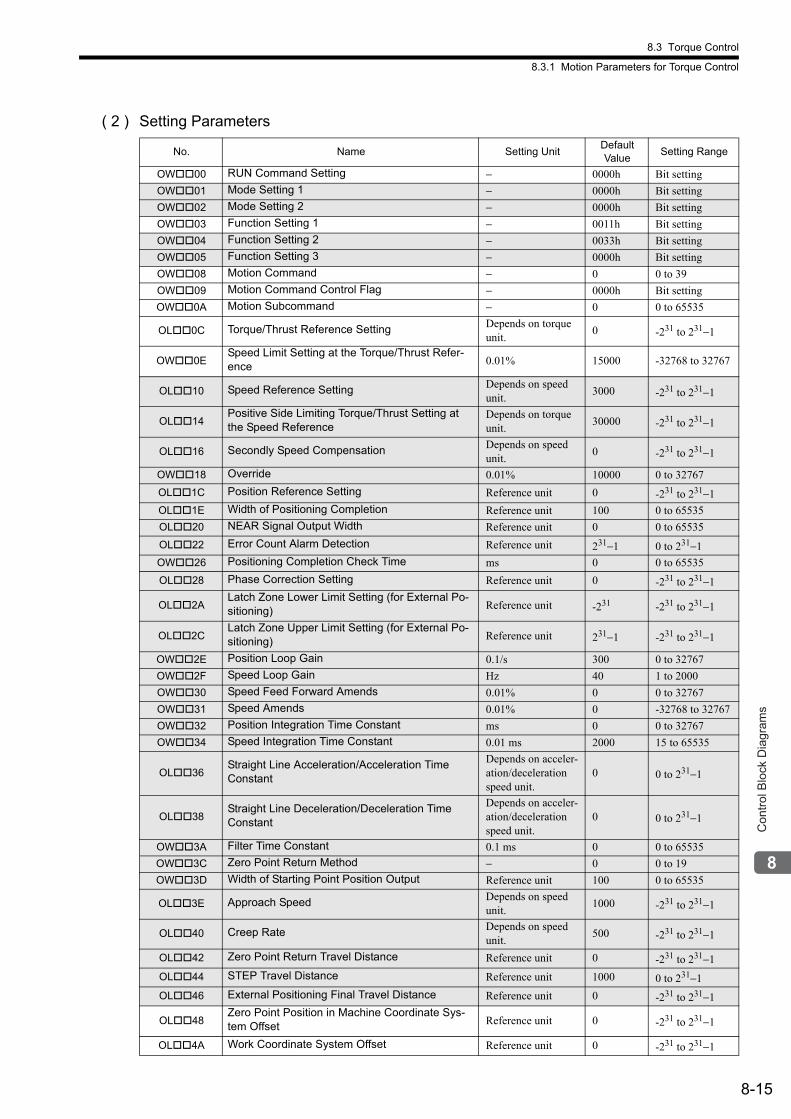
8.3 Torque Control
8.3.1 Motion Parameters for Torque Control
8-15
Con
trol B
lock
Dia
gram
s
( 2 ) Setting Parameters
No. Name Setting UnitDefault Value
Setting Range
OW00 RUN Command Setting − 0000h Bit setting
OW01 Mode Setting 1 − 0000h Bit setting
OW02 Mode Setting 2 − 0000h Bit setting
OW03 Function Setting 1 − 0011h Bit setting
OW04 Function Setting 2 − 0033h Bit setting
OW05 Function Setting 3 − 0000h Bit setting
OW08 Motion Command − 0 0 to 39
OW09 Motion Command Control Flag − 0000h Bit setting
OW0A Motion Subcommand − 0 0 to 65535
OL0C Torque/Thrust Reference Setting Depends on torque unit.
0 -231 to 231−1
OW0ESpeed Limit Setting at the Torque/Thrust Refer-ence 0.01% 15000 -32768 to 32767
OL10 Speed Reference Setting Depends on speed unit.
3000 -231 to 231−1
OL14Positive Side Limiting Torque/Thrust Setting at the Speed Reference
Depends on torque unit.
30000 -231 to 231−1
OL16 Secondly Speed Compensation Depends on speed unit.
0 -231 to 231−1
OW18 Override 0.01% 10000 0 to 32767
OL1C Position Reference Setting Reference unit 0 -231 to 231−1
OL1E Width of Positioning Completion Reference unit 100 0 to 65535
OL20 NEAR Signal Output Width Reference unit 0 0 to 65535
OL22 Error Count Alarm Detection Reference unit 231−1 0 to 231−1
OW26 Positioning Completion Check Time ms 0 0 to 65535
OL28 Phase Correction Setting Reference unit 0 -231 to 231−1
OL2ALatch Zone Lower Limit Setting (for External Po-sitioning) Reference unit -231 -231 to 231−1
OL2CLatch Zone Upper Limit Setting (for External Po-sitioning) Reference unit 231−1 -231 to 231−1
OW2E Position Loop Gain 0.1/s 300 0 to 32767
OW2F Speed Loop Gain Hz 40 1 to 2000
OW30 Speed Feed Forward Amends 0.01% 0 0 to 32767
OW31 Speed Amends 0.01% 0 -32768 to 32767
OW32 Position Integration Time Constant ms 0 0 to 32767
OW34 Speed Integration Time Constant 0.01 ms 2000 15 to 65535
OL36Straight Line Acceleration/Acceleration Time Constant
Depends on acceler-ation/deceleration speed unit.
0 0 to 231−1
OL38Straight Line Deceleration/Deceleration Time Constant
Depends on acceler-ation/deceleration speed unit.
0 0 to 231−1
OW3A Filter Time Constant 0.1 ms 0 0 to 65535
OW3C Zero Point Return Method − 0 0 to 19
OW3D Width of Starting Point Position Output Reference unit 100 0 to 65535
OL3E Approach Speed Depends on speed unit.
1000 -231 to 231−1
OL40 Creep Rate Depends on speed unit.
500 -231 to 231−1
OL42 Zero Point Return Travel Distance Reference unit 0 -231 to 231−1
OL44 STEP Travel Distance Reference unit 1000 0 to 231−1
OL46 External Positioning Final Travel Distance Reference unit 0 -231 to 231−1
OL48Zero Point Position in Machine Coordinate Sys-tem Offset Reference unit 0 -231 to 231−1
OL4A Work Coordinate System Offset Reference unit 0 -231 to 231−1

8.3 Torque Control
8.3.1 Motion Parameters for Torque Control
8-16
OL4C Number of POSMAX Turns Presetting Data Rev 0 -231 to 231−1
OW4E Servo User Monitor Setting − 0E00H Bit setting
OW4F Servo Driver Alarm Monitor No. − 0 0 to 9
OW50 Servo Driver User Constant No. − 0 0 to 65535
OW51 Servo Driver User Constant Size − 1 1, 2
OL52 Servo Driver User Constant Set Point − 0 -231 to 231−1
OW54 Servo Driver for Assistance User Constant No. − 0 0 to 65535
OW55 Servo Driver for Assistance User Constant Size − 1 1, 2
OL56Servo Driver for Assistance User Constant Set Point − 0 -231 to 231−1
OW5C Fixed Parameter Number − 0 0 to 65535
OL5EEncoder Position When Power is OFF (Lower 2 words) pulse 0 -231 to 231−1
OL60Encoder Position When Power is OFF (Upper 2 words) pulse 0 -231 to 231−1
OL62Pulse Position When Power is OFF (Lower 2 words) pulse 0 -231 to 231−1
OL64Pulse Position When Power is OFF (Upper 2 words) pulse 0 -231 to 231−1
(cont’d)
No. Name Setting UnitDefault Value
Setting Range

8.3 Torque Control
8.3.1 Motion Parameters for Torque Control
8-17
Con
trol B
lock
Dia
gram
s
( 3 ) Monitoring Parameters
No. Name UnitDefault Value
Range
IW00 RUN Status − − Bit setting
IW01Parameter Number When Range Over is Generated − − 0 to 65535
IL02 Warning − − Bit setting
IL04 Alarm − − Bit setting
IW08 Motion Command Response Code − − 0 to 65535
IW09 Motion Command Status − − Bit setting
IW0A Motion Subcommand Response Code − − 0 to 65535
IW0B Subcommand Status − − Bit setting
IW0C Position Management Status − − Bit setting
IL0ETarget Position in Machine Coordinate System (TPOS) Reference unit − -231 to 231−1
IL10Calculated Position in Machine Coordinate System (CPOS) Reference unit − -231 to 231−1
IL12Machine Coordinate System Reference Position (MPOS) Reference unit − -231 to 231−1
IL14 CPOS for 32bit (DPOS) Reference unit − -231 to 231−1
IL16Machine Coordinate System Feedback Position (APOS) Reference unit − -231 to 231−1
IL18Machine Coordinate System Latch Position (LPOS) Reference unit − -231 to 231−1
IL1A Position Error (PERR) Reference unit − -231 to 231−1
IL1C Target Position Difference Monitor Reference unit − -231 to 231−1
IL1E Number of POSMAX Turns Reference unit − -231 to 231−1
IL20 Speed Reference Output Monitor pulse/s − -231 to 231−1
IW2C Servo Driver Status − − Bit setting
IW2D Servo Driver Alarm Code − − -32768 to 32767
IW2E Servo Driver I/O Monitor − − Bit setting
IW2F Servo Driver User Monitor Information − − Bit setting
IL30 Servo Driver User Monitor 2 − − -231 to 231−1
IL34 Servo Driver User Monitor 4 − − -231 to 231−1
IW36 Servo Driver User Constant No. − − 0 to 65535
IW37Supplementary Servo Driver User Con-stant No. − − 0 to 65535
IL38 Servo Driver User Constant Reading Data − − -231 to 231−1
IL3ASupplementary Servo Driver User Con-stant Reading Data − − -231 to 231−1
IW3F Motor Type − − 0, 1
IL40 Feedback Speed Depends on speed unit. − -231 to 231−1
IL42 Feedback Torque/Thrust Depends on torque unit.
− -231 to 231−1
IL56 Fixed Parameter Monitor − − -231 to 231−1
IL5EEncoder Position When the Power is OFF (Lower 2 words) pulse − -231 to 231−1
IL60Encoder Position When the Power is OFF (Upper 2 words) pulse − -231 to 231−1
IL62Pulse Position When the Power is OFF (Lower 2 words) pulse − -231 to 231−1
IL64Pulse Position When the Power is OFF (Upper 2 words) pulse − -231 to 231−1
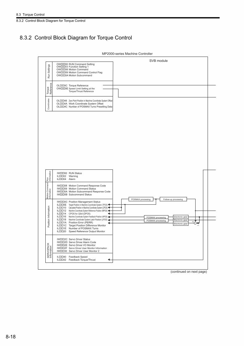
8.3 Torque Control
8.3.2 Control Block Diagram for Torque Control
8-18
8.3.2 Control Block Diagram for Torque Control
MP2000-series Machine Controller
OW��00 RUN Command Setting OW��03 Function Setting 1 OW��08 Motion CommandOW��09 Motion Command Control Flag OW��0A Motion Subcommand
OL��0C Torque Reference OW��0E Speed Limit Setting at the
Torque/Thrust Reference
OL��48 Zero Point Position in Machine Coordinate System Offset OL��4A Work Coordinate System Offset OL��4C Number of POSMAX Turns Presetting Data
IW��00 RUN Status IL��02 WarningIL��04 Alarm
IW��08 Motion Command Response CodeIW��09 Motion Command StatusIW��0A Motion Subcommand Response Code IW��0B Subcommand Status
IW��0C Position Management Status IL��0E Target Position in Machine Coordinate System (TPOS) IL��10 Calculated Position in Machine Coordinate System (CPOS) IL��12 Machine Coordinate System Reference Position (MPOS) IL��14 CPOS for 32bit (DPOS) IL��16 Machine Coordinate System Feedback Position (APOS) IL��18 Machine Coordinate System Latch Position (LPOS) IL��1A Position Error (PERR)IL��1C Target Position Difference Monitor IL��1E Number of POSMAX Turns IL��20 Speed Reference Output Monitor
IW��2C Servo Driver Status IW��2D Servo Driver Alarm CodeIW��2E Servo Driver I/O Monitor IW��2F Servo Driver User Monitor InformationIW��30 Servo Driver User Monitor 2
IL��40 Feedback Speed IL��42 Feedback Torque/Thrust
POSMAX processing Follow-up processing
Electronic gear POSMAX processing Electronic gear POSMAX processing Electronic gear
+
Run
Set
tings
To
rque
R
efer
ence
C
oord
inat
es
Run
In
form
atio
n M
otio
n C
omm
and
Info
rmat
ion
Pos
ition
Info
rmat
ion
SE
RV
OPA
CK
In
form
atio
n
(continued on next page)
SVB module
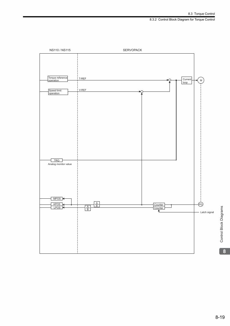
8.3 Torque Control
8.3.2 Control Block Diagram for Torque Control
8-19
Con
trol B
lock
Dia
gram
s
Analog monitor value
Current
loopM
PGA
B
SERVOPACKNS110 / NS115
APOS
LPOSB
ACounter
Latch signal
Counter
TRQ
T-REF
V-REFSpeed limit
operation
Torque reference
operation
MPOS

8.4 Speed Control
8.4.1 Motion Parameters for Speed Control
8-20
8.4 Speed Control
8.4.1 Motion Parameters for Speed Control
: These parameters are ignored.
( 1 ) Fixed ParametersNo. Name Setting Unit Default Value Setting Range
0 Selection of Operation Modes − 1 0 to 5
1 Function Selection Flag 1 − 0000h Bit setting
2 Function Selection Flag 2 − 0000h Bit setting
4 Reference Unit Selection − 0 0 to 3
5 Number of Digits below Decimal Point − 3 0 to 5
6
Travel Distance per Machine Rotation Reference unit 10000 1 to 231−1Linear Scale Pitch (Linear Motor) Reference unit 10000 1 to 231−1
8 Servo Motor Gear Ratio − 1 1 to 65535
9 Machine Gear Ratio − 1 1 to 65535
10Infinite Length Axis Reset Position (POSMAX) Reference unit 360000 1 to 231−1
12 Positive Software Limit Value Reference unit 231−1 -231 to 231−1
14 Negative Software Limit Value Reference unit -231 -231 to 231−1
16 Backlash Compensation Amount Reference unit 0 -231 to 231−1
30 Encoder Selection − 0 0 to 3
34
Rated Motor Speed(Rotary Motor) min−1 3000 1 to 32000
Rated Speed(Linear Motor) 0.1 m/s, 0.1 mm/s 3000 1 to 32000
36
Number of Pulses per Motor Rotation(Rotary Motor) pulse 65536 1 to 231−1
Number of Pulses per Linear Scale Pitch(Linear Motor)
pulses/linear scale pitch
65536 1 to 231−1
38Maximum Number of Absolute Encod-er Turns Rotation Rev 65534 0 to 231−1
42Feedback Speed Moving Average Time Constant ms 10 0 to 32
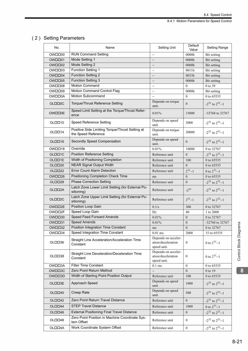
8.4 Speed Control
8.4.1 Motion Parameters for Speed Control
8-21
Con
trol B
lock
Dia
gram
s
( 2 ) Setting Parameters
No. Name Setting UnitDefault Value
Setting Range
OW00 RUN Command Setting − 0000h Bit setting
OW01 Mode Setting 1 − 0000h Bit setting
OW02 Mode Setting 2 − 0000h Bit setting
OW03 Function Setting 1 − 0011h Bit setting
OW04 Function Setting 2 − 0033h Bit setting
OW05 Function Setting 3 − 0000h Bit setting
OW08 Motion Command − 0 0 to 39
OW09 Motion Command Control Flag − 0000h Bit setting
OW0A Motion Subcommand − 0 0 to 65535
OL0C Torque/Thrust Reference Setting Depends on torque unit.
0 -231 to 231−1
OW0ESpeed Limit Setting at the Torque/Thrust Refer-ence 0.01% 15000 -32768 to 32767
OL10 Speed Reference Setting Depends on speed unit.
3000 -231 to 231−1
OL14Positive Side Limiting Torque/Thrust Setting at the Speed Reference
Depends on torque unit.
30000 -231 to 231−1
OL16 Secondly Speed Compensation Depends on speed unit.
0 -231 to 231−1
OW18 Override 0.01% 10000 0 to 32767
OL1C Position Reference Setting Reference unit 0 -231 to 231−1
OL1E Width of Positioning Completion Reference unit 100 0 to 65535
OL20 NEAR Signal Output Width Reference unit 0 0 to 65535
OL22 Error Count Alarm Detection Reference unit 231−1 0 to 231−1
OW26 Positioning Completion Check Time ms 0 0 to 65535
OL28 Phase Correction Setting Reference unit 0 -231 to 231−1
OL2ALatch Zone Lower Limit Setting (for External Po-sitioning) Reference unit -231 -231 to 231−1
OL2CLatch Zone Upper Limit Setting (for External Po-sitioning) Reference unit 231−1 -231 to 231−1
OW2E Position Loop Gain 0.1/s 300 0 to 32767
OW2F Speed Loop Gain Hz 40 1 to 2000
OW30 Speed Feed Forward Amends 0.01% 0 0 to 32767
OW31 Speed Amends 0.01% 0 -32768 to 32767
OW32 Position Integration Time Constant ms 0 0 to 32767
OW34 Speed Integration Time Constant 0.01 ms 2000 15 to 65535
OL36Straight Line Acceleration/Acceleration Time Constant
Depends on acceler-ation/deceleration speed unit.
0 0 to 231−1
OL38Straight Line Deceleration/Deceleration Time Constant
Depends on acceler-ation/deceleration speed unit.
0 0 to 231−1
OW3A Filter Time Constant 0.1 ms 0 0 to 65535
OW3C Zero Point Return Method − 0 0 to 19
OW3D Width of Starting Point Position Output Reference unit 100 0 to 65535
OL3E Approach Speed Depends on speed unit.
1000 -231 to 231−1
OL40 Creep Rate Depends on speed unit.
500 -231 to 231−1
OL42 Zero Point Return Travel Distance Reference unit 0 -231 to 231−1
OL44 STEP Travel Distance Reference unit 1000 0 to 231−1
OL46 External Positioning Final Travel Distance Reference unit 0 -231 to 231−1
OL48Zero Point Position in Machine Coordinate Sys-tem Offset Reference unit 0 -231 to 231−1
OL4A Work Coordinate System Offset Reference unit 0 -231 to 231−1
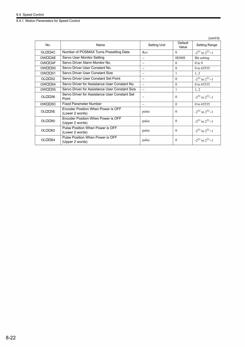
8.4 Speed Control
8.4.1 Motion Parameters for Speed Control
8-22
OL4C Number of POSMAX Turns Presetting Data Rev 0 -231 to 231−1
OW4E Servo User Monitor Setting − 0E00H Bit setting
OW4F Servo Driver Alarm Monitor No. − 0 0 to 9
OW50 Servo Driver User Constant No. − 0 0 to 65535
OW51 Servo Driver User Constant Size − 1 1, 2
OL52 Servo Driver User Constant Set Point − 0 -231 to 231−1
OW54 Servo Driver for Assistance User Constant No. − 0 0 to 65535
OW55 Servo Driver for Assistance User Constant Size − 1 1, 2
OL56Servo Driver for Assistance User Constant Set Point − 0 -231 to 231−1
OW5C Fixed Parameter Number − 0 0 to 65535
OL5EEncoder Position When Power is OFF (Lower 2 words) pulse 0 -231 to 231−1
OL60Encoder Position When Power is OFF (Upper 2 words) pulse 0 -231 to 231−1
OL62Pulse Position When Power is OFF (Lower 2 words) pulse 0 -231 to 231−1
OL64Pulse Position When Power is OFF (Upper 2 words) pulse 0 -231 to 231−1
(cont’d)
No. Name Setting UnitDefault Value
Setting Range

8.4 Speed Control
8.4.1 Motion Parameters for Speed Control
8-23
Con
trol B
lock
Dia
gram
s
( 3 ) Monitoring Parameters
No. Name UnitDefault Value
Range
IW00 RUN Status − − Bit setting
IW01Parameter Number When Range Over is Generated − − 0 to 65535
IL02 Warning − − Bit setting
IL04 Alarm − − Bit setting
IW08 Motion Command Response Code − − 0 to 65535
IW09 Motion Command Status − − Bit setting
IW0A Motion Subcommand Response Code − − 0 to 65535
IW0B Subcommand Status − − Bit setting
IW0C Position Management Status − − Bit setting
IL0ETarget Position in Machine Coordinate System (TPOS) Reference unit − -231 to 231−1
IL10Calculated Position in Machine Coordinate System (CPOS) Reference unit − -231 to 231−1
IL12Machine Coordinate System Reference Position (MPOS) Reference unit − -231 to 231−1
IL14 CPOS for 32bit (DPOS) Reference unit − -231 to 231−1
IL16Machine Coordinate System Feedback Position (APOS) Reference unit − -231 to 231−1
IL18Machine Coordinate System Latch Position (LPOS) Reference unit − -231 to 231−1
IL1A Position Error (PERR) Reference unit − -231 to 231−1
IL1C Target Position Difference Monitor Reference unit − -231 to 231−1
IL1E Number of POSMAX Turns Reference unit − -231 to 231−1
IL20 Speed Reference Output Monitor pulse/s − -231 to 231−1
IW2C Servo Driver Status − − Bit setting
IW2D Servo Driver Alarm Code − − -32768 to 32767
IW2E Servo Driver I/O Monitor − − Bit setting
IW2F Servo Driver User Monitor Information − − Bit setting
IL30 Servo Driver User Monitor 2 − − -231 to 231−1
IL34 Servo Driver User Monitor 4 − − -231 to 231−1
IW36 Servo Driver User Constant No. − − 0 to 65535
IW37Supplementary Servo Driver User Con-stant No. − − 0 to 65535
IL38 Servo Driver User Constant Reading Data − − -231 to 231−1
IL3ASupplementary Servo Driver User Con-stant Reading Data − − -231 to 231−1
IW3F Motor Type − − 0, 1
IL40 Feedback Speed Depends on speed unit. − -231 to 231−1
IL42 Feedback Torque/Thrust Depends on torque unit.
− -231 to 231−1
IL56 Fixed Parameter Monitor − − -231 to 231−1
IL5EEncoder Position When the Power is OFF (Lower 2 words) pulse − -231 to 231−1
IL60Encoder Position When the Power is OFF (Upper 2 words) pulse − -231 to 231−1
IL62Pulse Position When the Power is OFF (Lower 2 words) pulse − -231 to 231−1
IL64Pulse Position When the Power is OFF (Upper 2 words) pulse − -231 to 231−1
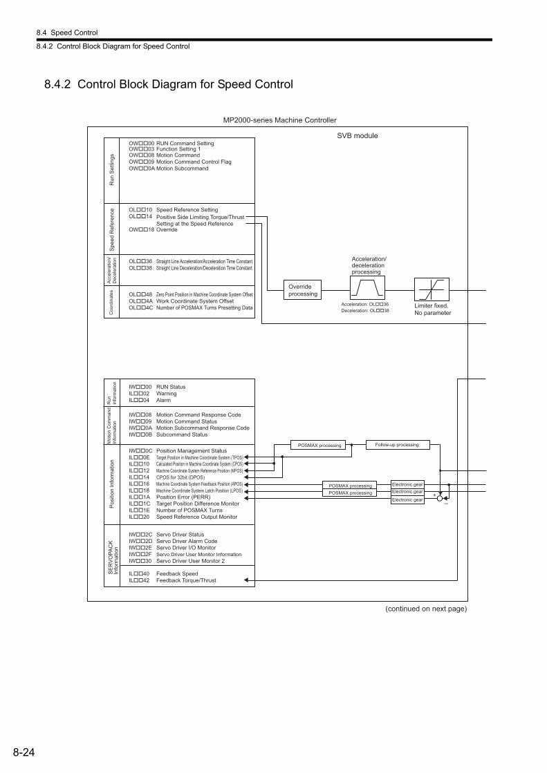
8.4 Speed Control
8.4.2 Control Block Diagram for Speed Control
8-24
8.4.2 Control Block Diagram for Speed Control
MP2000-series Machine Controller
SVB moduleRUN Command Setting OW��00
OW��03 Function Setting 1OW��08 Motion CommandOW��09 Motion Command Control Flag OW��0A Motion Subcommand
OL��10 Speed Reference Setting OL��14
OW��18 Override
OL��36 Straight Line Acceleration/Acceleration Time Constant OL��38 Straight Line Deceleration/Deceleration Time Constant
OL��48 Zero Point Position in Machine Coordinate System Offset OL��4A Work Coordinate System OffsetOL��4C Number of POSMAX Turns Presetting Data
IW��00 RUN Status IL��02 WarningIL��04 Alarm
IW��08 Motion Command Response CodeIW��09 Motion Command StatusIW��0A Motion Subcommand Response CodeIW��0B Subcommand Status
IW��0C Position Management Status IL��0E Target Position in Machine Coordinate System (TPOS) IL��10 Calculated Position in Machine Coordinate System (CPOS)IL��12 Machine Coordinate System Reference Position (MPOS) IL��14 CPOS for 32bit (DPOS) IL��16 Machine Coordinate System Feedback Position (APOS) IL��18 Machine Coordinate System Latch Position (LPOS) IL��1A Position Error (PERR)IL��1C Target Position Difference MonitorIL��1E Number of POSMAX TurnsIL��20 Speed Reference Output Monitor
IW��2C Servo Driver Status IW��2D Servo Driver Alarm CodeIW��2E Servo Driver I/O Monitor IW��2F Servo Driver User Monitor InformationIW��30 Servo Driver User Monitor 2
IL��40 Feedback Speed IL��42 Feedback Torque/Thrust
POSMAX processing Follow-up processing
Electronic gear POSMAX processing Electronic gear POSMAX processing Electronic gear
+
Run
Set
tings
S
peed
Ref
eren
ce
Positive Side Limiting Torque/Thrust Setting at the Speed Reference
Acc
eler
atio
n/D
ecel
erat
ion
Coo
rdin
ates
R
un
Info
rmat
ion
Mot
ion
Com
man
d In
form
atio
n P
ositi
on In
form
atio
n S
ER
VO
PAC
K
Info
rmat
ion
Acceleration/deceleration processing
Override processing
Acceleration: OL��36 Deceleration: OL��38
Limiter fixed. No parameter
(continued on next page)
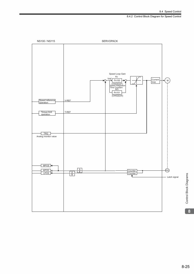
8.4 Speed Control
8.4.2 Control Block Diagram for Speed Control
8-25
Con
trol B
lock
Dia
gram
s
Analog monitor value
Pn101
Pn100 Currentloop M
PGAB
Speed Loop Gain
Speed IntegrationTime Constant
NS100 / NS115
(OW��2F)
(OW��34)
Kv
NTi
Vref
SERVOPACK
APOSLPOS
BA Counter
Latch signal
Counter
TRQ
V-REF
T-REFTorque limitoperation
MPOS
Speed referenceoperation
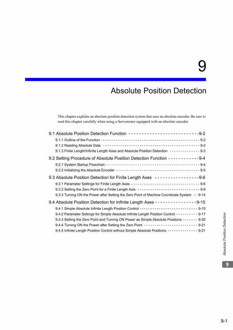
9-1
Abs
olut
e P
ositi
on D
etec
tion
9
Absolute Position Detection
This chapter explains an absolute position detection system that uses an absolute encoder. Be sure to read this chapter carefully when using a Servomotor equipped with an absolute encoder.
9.1 Absolute Position Detection Function - - - - - - - - - - - - - - - - - - - - - - - - - - -9-2
9.1.1 Outline of the Function - - - - - - - - - - - - - - - - - - - - - - - - - - - - - - - - - - - - - - - - - - - - - - 9-2
9.1.2 Reading Absolute Data - - - - - - - - - - - - - - - - - - - - - - - - - - - - - - - - - - - - - - - - - - - - - 9-2
9.1.3 Finite Length/Infinite Length Axes and Absolute Position Detection - - - - - - - - - - - - - - 9-3
9.2 Setting Procedure of Absolute Position Detection Function - - - - - - - - - - - -9-4
9.2.1 System Startup Flowchart - - - - - - - - - - - - - - - - - - - - - - - - - - - - - - - - - - - - - - - - - - - - 9-4
9.2.2 Initializing the Absolute Encoder - - - - - - - - - - - - - - - - - - - - - - - - - - - - - - - - - - - - - - - 9-5
9.3 Absolute Position Detection for Finite Length Axes - - - - - - - - - - - - - - - - -9-6
9.3.1 Parameter Settings for Finite Length Axes - - - - - - - - - - - - - - - - - - - - - - - - - - - - - - - - 9-6
9.3.2 Setting the Zero Point for a Finite Length Axis - - - - - - - - - - - - - - - - - - - - - - - - - - - - - 9-9
9.3.3 Turning ON the Power after Setting the Zero Point of Machine Coordinate System - - 9-14
9.4 Absolute Position Detection for Infinite Length Axes - - - - - - - - - - - - - - - - 9-15
9.4.1 Simple Absolute Infinite Length Position Control - - - - - - - - - - - - - - - - - - - - - - - - - - - 9-15
9.4.2 Parameter Settings for Simple Absolute Infinite Length Position Control - - - - - - - - - - 9-17
9.4.3 Setting the Zero Point and Turning ON Power as Simple Absolute Positions - - - - - - - 9-20
9.4.4 Turning ON the Power after Setting the Zero Point - - - - - - - - - - - - - - - - - - - - - - - - - 9-21
9.4.5 Infinite Length Position Control without Simple Absolute Positions - - - - - - - - - - - - - - 9-21
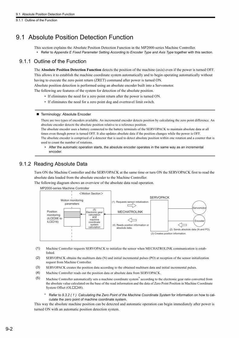
9.1 Absolute Position Detection Function
9.1.1 Outline of the Function
9-2
9.1 Absolute Position Detection Function
This section explains the Absolute Position Detection Function in the MP2000-series Machine Controller. Refer to Appendix E Fixed Parameter Setting According to Encoder Type and Axis Type together with this section.
9.1.1 Outline of the Function
The Absolute Position Detection Function detects the position of the machine (axis) even if the power is turned OFF. This allows it to establish the machine coordinate system automatically and to begin operating automatically without having to execute the zero point return (ZRET) command after power is turned ON. Absolute position detection is performed using an absolute encoder built into a Servomotor. The following are features of the system for detection of the absolute position.
• If eliminates the need for a zero point return after the power is turned ON.
• If eliminates the need for a zero point dog and overtravel limit switch.
Terminology: Absolute Encoder
There are two types of encoders available. An incremental encoder detects position by calculating the zero point difference. An absolute encoder detects the absolute position relative to a reference position. The absolute encoder uses a battery connected to the battery terminals of the SERVOPACK to maintain absolute data at all times even though power is turned OFF. It also updates absolute data if the position changes while the power is OFF. The absolute encoder is comprised of a detector that is used to detect absolute position within one rotation and a counter that is used to count the number of rotations.
After the automatic operation starts, the absolute encoder operates in the same way as an incremental encoder.
9.1.2 Reading Absolute Data
Turn ON the Machine Controller and the SERVOPACK at the same time or turn ON the SERVOPACK first to read the absolute data loaded from the absolute encoder to the Machine Controller. The following diagram shows an overview of the absolute data read operation.
* Refer to 9.3.2 ( 1 ) Calculating the Zero Point of the Machine Coordinate System for information on how to cal-culate the zero point of machine coordinate system.
This way the absolute machine position can be detected and automatic operation can begin immediately after power is turned ON with an automatic position detection system.
(1) Machine Controller requests SERVOPACK to initialize the sensor when MECHATROLINK communication is estab-lished.
(2) SERVOPACK obtains the multiturn data (N) and initial incremental pulses (PO) at reception of the sensor initialization request from Machine Controller.
(3) SERVOPACK creates the position data according to the obtained multiturn data and initial incremental pulses.
(4) Machine Controller reads out the position data or absolute data from SERVOPACK.
(5) Machine Controller automatically sets a machine coordinate system* according to the electronic gear ratio converted from the absolute value calculated on the base of the read information and the data of Zero Point Position in Machine Coordinate System Offset (OL48).
Positionmonitoring(IL��0E to IL��16)
Motion monitoringparameters
(5)Electronic gear
calculation
machinecoordinate
systemcalculation
MP2000-series Machine Controller
SERVOPACK
MECHATROLINKServomotor
Encoder(4) Reads position information or absolute data.
(3) Creates position information.(2) Sends absolute data (N and PO).
(1) Requests sensor initialization.
Motion Section
9.1 Absolute Position Detection Function
9.1.3 Finite Length/Infinite Length Axes and Absolute Position Detection
9-3
Abs
olut
e P
ositi
on D
etec
tion
Terminology: Absolute Data
Absolute data that is stored in an absolute encoder has two types of data: the absolute reference position (initial incremental pulses; PO) and the number of rotations (multi-turn data; N) from the absolute reference position.The absolute reference position is the phase-C position when the absolute encoder is initialized and is the reference position for absolute-position detection.Only the number of rotations (N) can be cleared when the absolute encoder is initialized, and the initial incremental pulses will not change.
Information: Calculation of Absolute Position
We can determine the absolute position (P) using the following data. Data stored in an absolute encoder
• Absolute reference position (initial incremental pulses): PO• Number of rotations from the absolute reference position (multi-turn data): N
Parameter determined according to the number of bits of servomotor• Feedback pulses per motor rotation: RP
Equation to calculate the absolute position• Absolute position (P) = N × RP + PO
9.1.3 Finite Length/Infinite Length Axes and Absolute Position Detection
There are two types of axes. An infinite length axis resets the current position to a specified value every rotation, and the finite length axis does not. Set a finite length axis if return and other operations are performed only within a specified range or for an axis that moves in one direction only without resetting the position every rotation. Set an infinite length axis for conveyor belts and other operations that require the position to be reset every rotation.There are two types of position control available with an infinite length axis. Simple Absolute Infinite Length position control and Infinite Length position control are available if Simple Absolute Infinite Length position control is not used. An absolute encoder performs absolute position detection with a finite or infinite length axis depending on the Axis Selection setting (fixed parameter 1, bit 0) of the Machine ControllerSet the Machine Controller fixed parameters and SERVOPACK parameters to select the absolute position detection function with an absolute encoder. The setting procedures are different for finite and infinite length axes. Refer to 9.2.1 System Startup Flowchart for details.
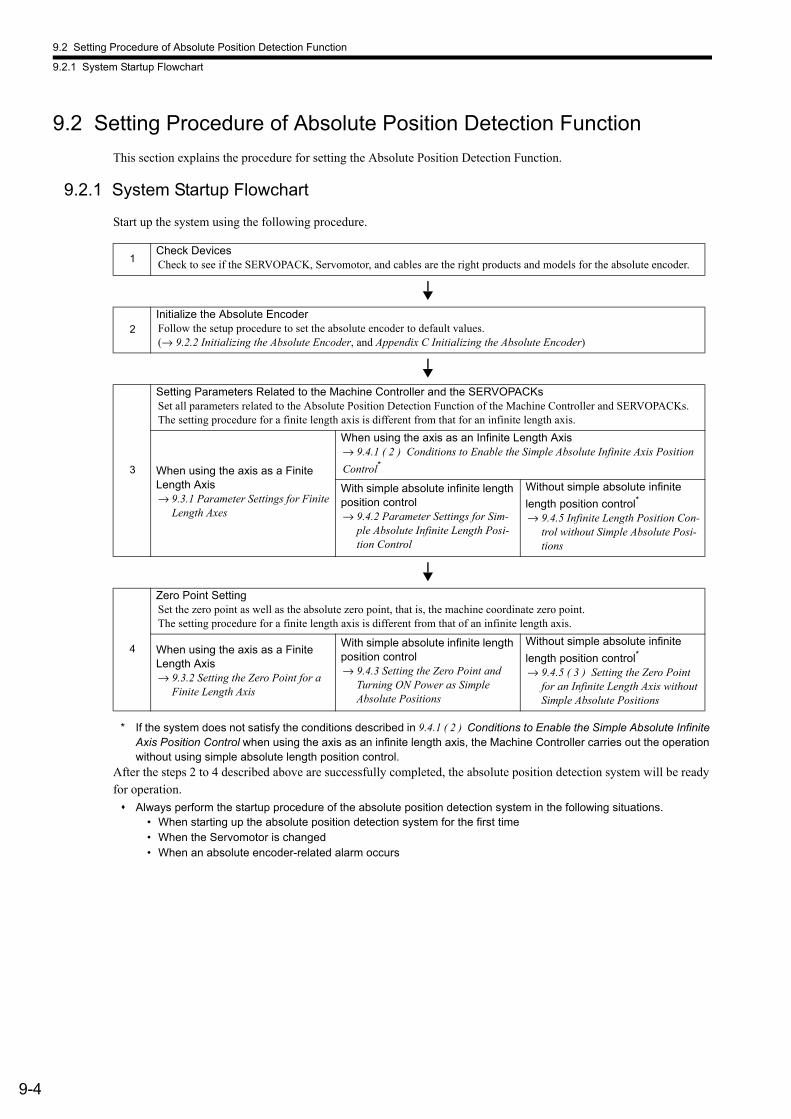
9.2 Setting Procedure of Absolute Position Detection Function
9.2.1 System Startup Flowchart
9-4
9.2 Setting Procedure of Absolute Position Detection Function
This section explains the procedure for setting the Absolute Position Detection Function.
9.2.1 System Startup Flowchart
Start up the system using the following procedure.
* If the system does not satisfy the conditions described in 9.4.1 ( 2 ) Conditions to Enable the Simple Absolute Infinite Axis Position Control when using the axis as an infinite length axis, the Machine Controller carries out the operation without using simple absolute length position control.
After the steps 2 to 4 described above are successfully completed, the absolute position detection system will be ready for operation.
Always perform the startup procedure of the absolute position detection system in the following situations.• When starting up the absolute position detection system for the first time• When the Servomotor is changed• When an absolute encoder-related alarm occurs
1Check DevicesCheck to see if the SERVOPACK, Servomotor, and cables are the right products and models for the absolute encoder.
2
Initialize the Absolute EncoderFollow the setup procedure to set the absolute encoder to default values.(→ 9.2.2 Initializing the Absolute Encoder, and Appendix C Initializing the Absolute Encoder)
3
Setting Parameters Related to the Machine Controller and the SERVOPACKsSet all parameters related to the Absolute Position Detection Function of the Machine Controller and SERVOPACKs.The setting procedure for a finite length axis is different from that for an infinite length axis.
When using the axis as a Finite Length Axis→ 9.3.1 Parameter Settings for Finite
Length Axes
When using the axis as an Infinite Length Axis→ 9.4.1 ( 2 ) Conditions to Enable the Simple Absolute Infinite Axis Position
Control*
With simple absolute infinite length position control→ 9.4.2 Parameter Settings for Sim-
ple Absolute Infinite Length Posi-tion Control
Without simple absolute infinite
length position control*
→ 9.4.5 Infinite Length Position Con-trol without Simple Absolute Posi-tions
4
Zero Point SettingSet the zero point as well as the absolute zero point, that is, the machine coordinate zero point.The setting procedure for a finite length axis is different from that of an infinite length axis.
When using the axis as a Finite Length Axis→ 9.3.2 Setting the Zero Point for a
Finite Length Axis
With simple absolute infinite length position control→ 9.4.3 Setting the Zero Point and
Turning ON Power as Simple Absolute Positions
Without simple absolute infinite
length position control*
→ 9.4.5 ( 3 ) Setting the Zero Point for an Infinite Length Axis without Simple Absolute Positions
9.2 Setting Procedure of Absolute Position Detection Function
9.2.2 Initializing the Absolute Encoder
9-5
Abs
olut
e P
ositi
on D
etec
tion
9.2.2 Initializing the Absolute Encoder
Absolute encoders can be initialized as follows:
• SERVOPACK Procedure
Refer to the manual for the SERVOPACK for details.
• Panel Operator or Digital Operator Procedure
Refer to the manual for the SERVOPACK for details.
• ABS_RST Command Procedure
Refer to 6.2.21 Absolute Encoder Reset (ABS_RST) for details.
For details on the procedure for initializing SERVOPACKS, refer to Appendix C Initializing the Absolute Encoder.
Initialize the absolute encoder in the following situations.• When the absolute position detection system is started up for the first time• When number of rotations from the absolute reference position needs to be initialized to 0• When a Servomotor has been left with no battery connected to the absolute encoder• When an alarm which is related the absolute position detection system occurs
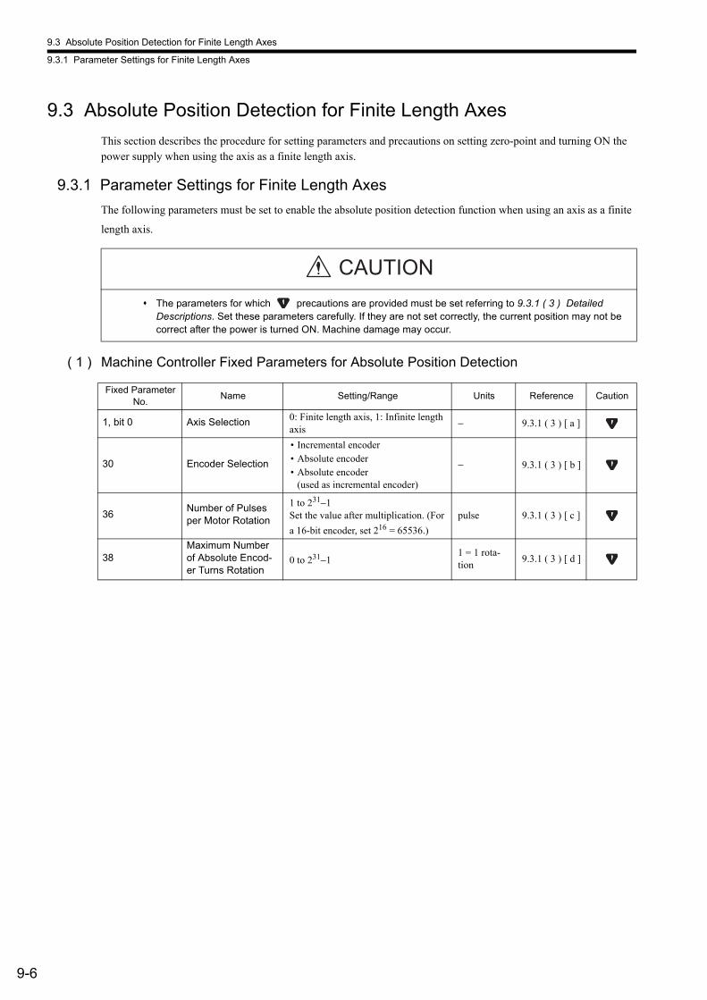
9.3 Absolute Position Detection for Finite Length Axes
9.3.1 Parameter Settings for Finite Length Axes
9-6
9.3 Absolute Position Detection for Finite Length Axes
This section describes the procedure for setting parameters and precautions on setting zero-point and turning ON the power supply when using the axis as a finite length axis.
9.3.1 Parameter Settings for Finite Length Axes
The following parameters must be set to enable the absolute position detection function when using an axis as a finite
length axis.
( 1 ) Machine Controller Fixed Parameters for Absolute Position Detection
The parameters for which precautions are provided must be set referring to 9.3.1 ( 3 ) Detailed Descriptions. Set these parameters carefully. If they are not set correctly, the current position may not be correct after the power is turned ON. Machine damage may occur.
CAUTION
Fixed Parameter No.
Name Setting/Range Units Reference Caution
1, bit 0 Axis Selection 0: Finite length axis, 1: Infinite length axis
− 9.3.1 ( 3 ) [ a ]
30 Encoder Selection
• Incremental encoder• Absolute encoder• Absolute encoder
(used as incremental encoder)
− 9.3.1 ( 3 ) [ b ]
36Number of Pulses per Motor Rotation
1 to 231−1Set the value after multiplication. (For
a 16-bit encoder, set 216 = 65536.)
pulse 9.3.1 ( 3 ) [ c ]
38Maximum Number of Absolute Encod-er Turns Rotation
0 to 231−11 = 1 rota-tion
9.3.1 ( 3 ) [ d ]
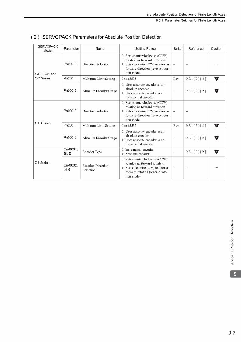
9.3 Absolute Position Detection for Finite Length Axes
9.3.1 Parameter Settings for Finite Length Axes
9-7
Abs
olut
e P
ositi
on D
etec
tion
( 2 ) SERVOPACK Parameters for Absolute Position Detection
SERVOPACK Model
Parameter Name Setting Range Units Reference Caution
Σ-III, Σ-V, and Σ-7 Series
Pn000.0 Direction Selection
0: Sets counterclockwise (CCW) rotation as forward direction.
1: Sets clockwise (CW) rotation as forward direction (reverse rota-tion mode).
− − −
Pn205 Multiturn Limit Setting 0 to 65535 Rev 9.3.1 ( 3 ) [ d ]
Pn002.2 Absolute Encoder Usage
0: Uses absolute encoder as an absolute encoder.
1: Uses absolute encoder as an incremental encoder.
− 9.3.1 ( 3 ) [ b ]
Σ-II Series
Pn000.0 Direction Selection
0: Sets counterclockwise (CCW) rotation as forward direction.
1: Sets clockwise (CW) rotation as forward direction (reverse rota-tion mode).
− − −
Pn205 Multiturn Limit Setting 0 to 65535 Rev 9.3.1 ( 3 ) [ d ]
Pn002.2 Absolute Encoder Usage
0: Uses absolute encoder as an absolute encoder.
1: Uses absolute encoder as an incremental encoder.
− 9.3.1 ( 3 ) [ b ]
Σ-I Series
Cn-0001, Bit E Encoder Type
0: Incremental encoder1: Absolute encoder
− 9.3.1 ( 3 ) [ b ]
Cn-0002,bit 0
Rotation Direction Selection
0: Sets counterclockwise (CCW) rotation as forward rotation.
1: Sets clockwise (CW) rotation as forward rotation (reverse rota-tion mode).
− − −
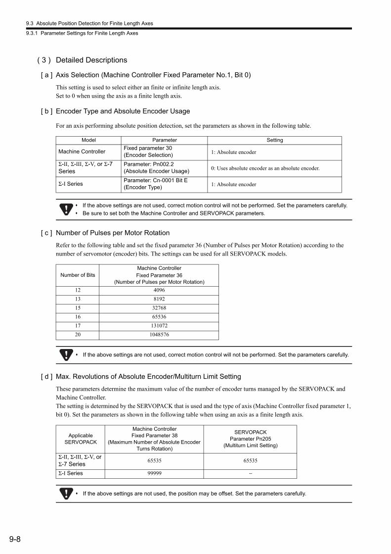
9.3 Absolute Position Detection for Finite Length Axes
9.3.1 Parameter Settings for Finite Length Axes
9-8
( 3 ) Detailed Descriptions
[ a ] Axis Selection (Machine Controller Fixed Parameter No.1, Bit 0)
This setting is used to select either an finite or infinite length axis.Set to 0 when using the axis as a finite length axis.
[ b ] Encoder Type and Absolute Encoder Usage
For an axis performing absolute position detection, set the parameters as shown in the following table.
[ c ] Number of Pulses per Motor Rotation
Refer to the following table and set the fixed parameter 36 (Number of Pulses per Motor Rotation) according to the number of servomotor (encoder) bits. The settings can be used for all SERVOPACK models.
[ d ] Max. Revolutions of Absolute Encoder/Multiturn Limit Setting
These parameters determine the maximum value of the number of encoder turns managed by the SERVOPACK and Machine Controller.The setting is determined by the SERVOPACK that is used and the type of axis (Machine Controller fixed parameter 1, bit 0). Set the parameters as shown in the following table when using an axis as a finite length axis.
Model Parameter Setting
Machine ControllerFixed parameter 30(Encoder Selection) 1: Absolute encoder
Σ-II, Σ-III, Σ-V, or Σ-7 Series
Parameter: Pn002.2(Absolute Encoder Usage) 0: Uses absolute encoder as an absolute encoder.
Σ-I SeriesParameter: Cn-0001 Bit E(Encoder Type) 1: Absolute encoder
If the above settings are not used, correct motion control will not be performed. Set the parameters carefully.
Be sure to set both the Machine Controller and SERVOPACK parameters.
Number of BitsMachine ControllerFixed Parameter 36
(Number of Pulses per Motor Rotation)
12 4096
13 8192
15 32768
16 65536
17 131072
20 1048576
If the above settings are not used, correct motion control will not be performed. Set the parameters carefully.
ApplicableSERVOPACK
Machine ControllerFixed Parameter 38
(Maximum Number of Absolute Encoder Turns Rotation)
SERVOPACK Parameter Pn205
(Multiturn Limit Setting)
Σ-II, Σ-III, Σ-V, or Σ-7 Series
65535 65535
Σ-I Series 99999 −
If the above settings are not used, the position may be offset. Set the parameters carefully.
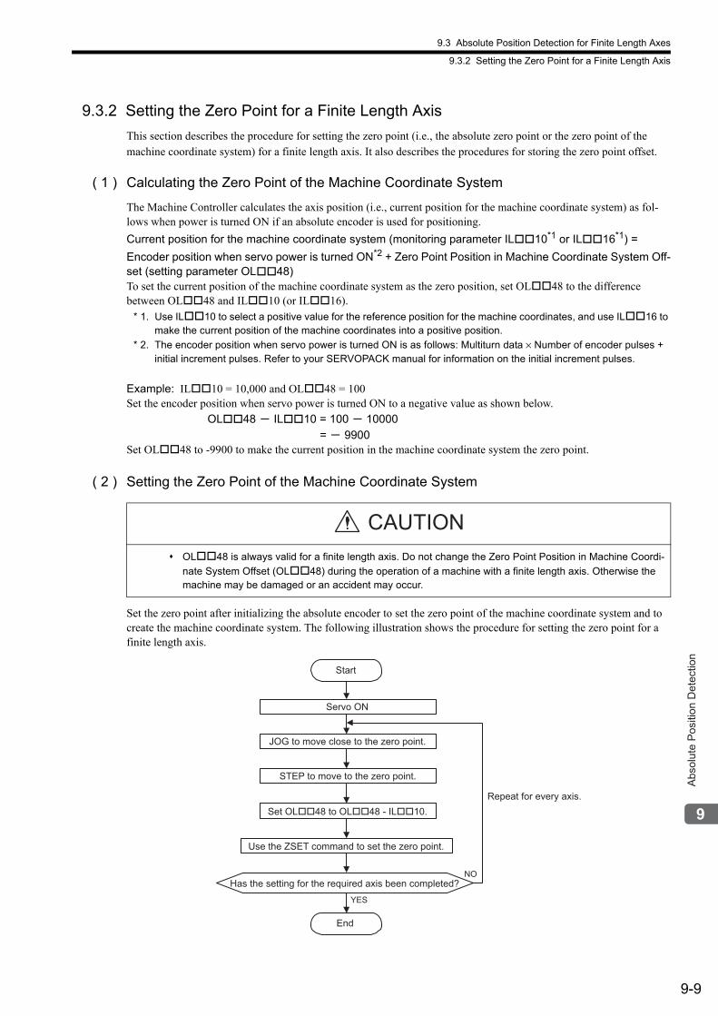
9.3 Absolute Position Detection for Finite Length Axes
9.3.2 Setting the Zero Point for a Finite Length Axis
9-9
Abs
olut
e P
ositi
on D
etec
tion
9.3.2 Setting the Zero Point for a Finite Length Axis
This section describes the procedure for setting the zero point (i.e., the absolute zero point or the zero point of the machine coordinate system) for a finite length axis. It also describes the procedures for storing the zero point offset.
( 1 ) Calculating the Zero Point of the Machine Coordinate System
The Machine Controller calculates the axis position (i.e., current position for the machine coordinate system) as fol-lows when power is turned ON if an absolute encoder is used for positioning.
Current position for the machine coordinate system (monitoring parameter IL10*1 or IL16*1) =
Encoder position when servo power is turned ON*2 + Zero Point Position in Machine Coordinate System Off-set (setting parameter OL48)To set the current position of the machine coordinate system as the zero position, set OL48 to the difference between OL48 and IL10 (or IL16).
* 1. Use IL10 to select a positive value for the reference position for the machine coordinates, and use IL16 to make the current position of the machine coordinates into a positive position.
* 2. The encoder position when servo power is turned ON is as follows: Multiturn data × Number of encoder pulses + initial increment pulses. Refer to your SERVOPACK manual for information on the initial increment pulses.
Example: IL10 = 10,000 and OL48 = 100Set the encoder position when servo power is turned ON to a negative value as shown below.
OL48 - IL10 = 100 - 10000
= - 9900Set OL48 to -9900 to make the current position in the machine coordinate system the zero point.
( 2 ) Setting the Zero Point of the Machine Coordinate System
Set the zero point after initializing the absolute encoder to set the zero point of the machine coordinate system and to create the machine coordinate system. The following illustration shows the procedure for setting the zero point for a finite length axis.
OL48 is always valid for a finite length axis. Do not change the Zero Point Position in Machine Coordi-
nate System Offset (OL48) during the operation of a machine with a finite length axis. Otherwise the machine may be damaged or an accident may occur.
CAUTION
Repeat for every axis.
Start
End
YES
NO
Servo ON
JOG to move close to the zero point.
STEP to move to the zero point.
Set OL��48 to OL��48 - IL��10.
Use the ZSET command to set the zero point.
Has the setting for the required axis been completed?
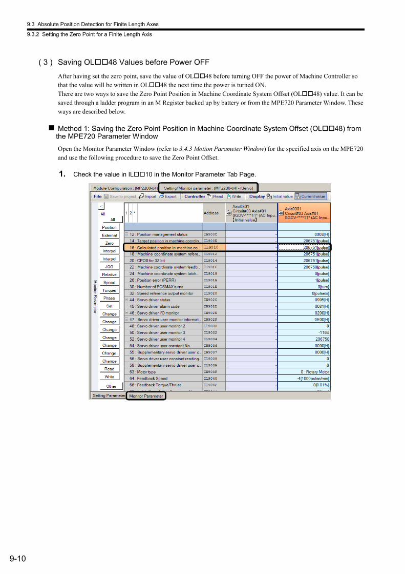
9.3 Absolute Position Detection for Finite Length Axes
9.3.2 Setting the Zero Point for a Finite Length Axis
9-10
( 3 ) Saving OL48 Values before Power OFF
After having set the zero point, save the value of OL48 before turning OFF the power of Machine Controller so that the value will be written in OL48 the next time the power is turned ON.There are two ways to save the Zero Point Position in Machine Coordinate System Offset (OL48) value. It can be saved through a ladder program in an M Register backed up by battery or from the MPE720 Parameter Window. These ways are described below.
Method 1: Saving the Zero Point Position in Machine Coordinate System Offset (OL48) from the MPE720 Parameter Window
Open the Monitor Parameter Window (refer to 3.4.3 Motion Parameter Window) for the specified axis on the MPE720 and use the following procedure to save the Zero Point Offset.
1. Check the value in IL10 in the Monitor Parameter Tab Page.
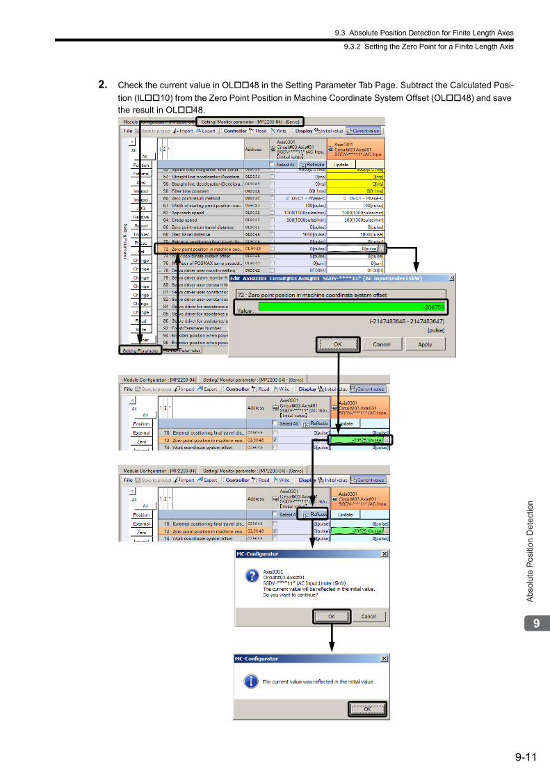
9.3 Absolute Position Detection for Finite Length Axes
9.3.2 Setting the Zero Point for a Finite Length Axis
9-11
Abs
olut
e P
ositi
on D
etec
tion
2. Check the current value in OL48 in the Setting Parameter Tab Page. Subtract the Calculated Posi-
tion (IL10) from the Zero Point Position in Machine Coordinate System Offset (OL48) and save the result in OL48.
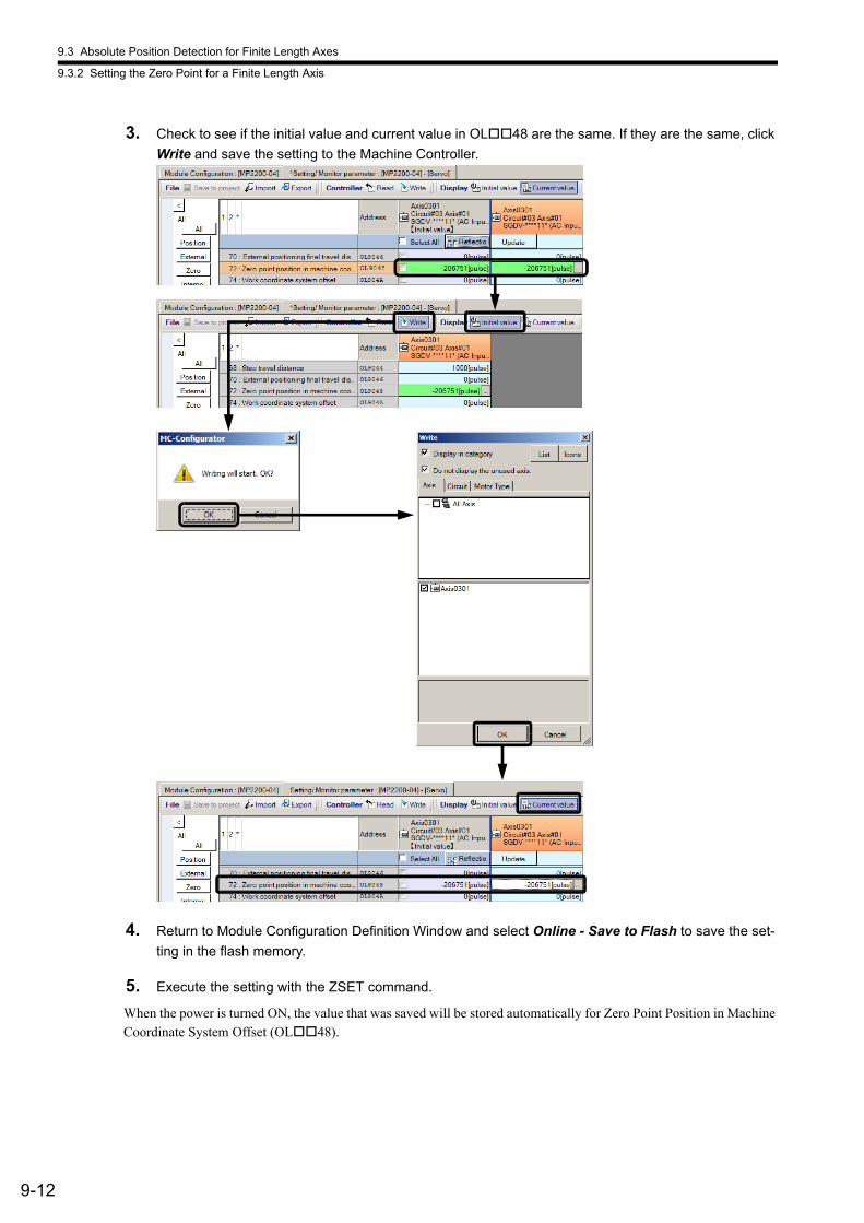
9.3 Absolute Position Detection for Finite Length Axes
9.3.2 Setting the Zero Point for a Finite Length Axis
9-12
3. Check to see if the initial value and current value in OL48 are the same. If they are the same, click
Write and save the setting to the Machine Controller.
4. Return to Module Configuration Definition Window and select Online - Save to Flash to save the set-
ting in the flash memory.
5. Execute the setting with the ZSET command.
When the power is turned ON, the value that was saved will be stored automatically for Zero Point Position in Machine Coordinate System Offset (OL48).
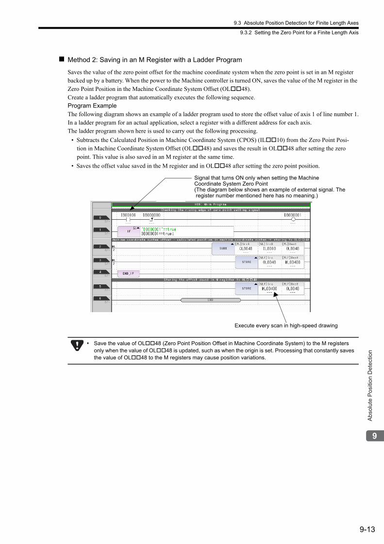
9.3 Absolute Position Detection for Finite Length Axes
9.3.2 Setting the Zero Point for a Finite Length Axis
9-13
Abs
olut
e P
ositi
on D
etec
tion
Method 2: Saving in an M Register with a Ladder Program
Saves the value of the zero point offset for the machine coordinate system when the zero point is set in an M register backed up by a battery. When the power to the Machine controller is turned ON, saves the value of the M register in the Zero Point Position in the Machine Coordinate System Offset (OL48).Create a ladder program that automatically executes the following sequence.Program ExampleThe following diagram shows an example of a ladder program used to store the offset value of axis 1 of line number 1.In a ladder program for an actual application, select a register with a different address for each axis.The ladder program shown here is used to carry out the following processing.
• Subtracts the Calculated Position in Machine Coordinate System (CPOS) (IL10) from the Zero Point Posi-tion in Machine Coordinate System Offset (OL48) and saves the result in OL48 after setting the zero point. This value is also saved in an M register at the same time.
• Saves the offset value saved in the M register and in OL48 after setting the zero point position.
Signal that turns ON only when setting the MachineCoordinate System Zero Point(The diagram below shows an example of external signal. The register number mentioned here has no meaning.)
Execute every scan in high-speed drawing
Save the value of OL48 (Zero Point Position Offset in Machine Coordinate System) to the M registers only when the value of OL48 is updated, such as when the origin is set. Processing that constantly saves the value of OL48 to the M registers may cause position variations.
9.3 Absolute Position Detection for Finite Length Axes
9.3.3 Turning ON the Power after Setting the Zero Point of Machine Coordinate System
9-14
9.3.3 Turning ON the Power after Setting the Zero Point of Machine Coordinate System
Bit 5 (Zero Point Return/Setting Completed) in the IW0C monitor parameter changes to 0 (Zero point return/set-ting not completed) when the power supply to the Machine Controller is turned OFF and ON again or communications are restarted by turning the power supply to the SERVOPACK OFF and ON again after the zero point has been set. The Zero Point Return (Setting) Completed bit must therefore be turned ON when the power supply is restored. Use the following procedure.
1. Turn ON the power supply to the Machine Controller. Or, clear alarms to restart communication.
The offset saved in the M register is stored to OL48.
2. Check to see if communication has been synchronized.
Check to make sure that bit 0 (Motion Operation Ready) in the IW00 monitor parameter is 0 (Motion opera-tion not ready) at this time.
3. Set the OW08 setting parameter (Motion Commands) to 9 to execute the ZSET motion command.
Use this procedure only to set bit 5 in IW0C to 1 (Zero point return/setting completed). It cannot be used to set the zero point of the machine coordinate system (OL48).
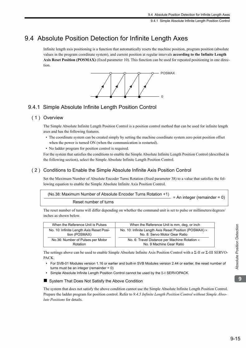
9.4 Absolute Position Detection for Infinite Length Axes
9.4.1 Simple Absolute Infinite Length Position Control
9-15
Abs
olut
e P
ositi
on D
etec
tion
9.4 Absolute Position Detection for Infinite Length Axes
Infinite length axis positioning is a function that automatically resets the machine position, program position (absolute values in the program coordinate system), and current position at regular intervals according to the Infinite Length Axis Reset Position (POSMAX) (fixed parameter 10). This function can be used for repeated positioning in one direc-tion.
9.4.1 Simple Absolute Infinite Length Position Control
( 1 ) Overview
The Simple Absolute Infinite Length Position Control is a position control method that can be used for infinite length axes and has the following features.
• The coordinate system can be created simply by setting the machine coordinate system zero point position offset when the power is turned ON (when the communication is restarted).
• No ladder program for position control is required.
For the system that satisfies the conditions to enable the Simple Absolute Infinite Length Position Control (described in the following section), select the Simple Absolute Infinite Length Position Control.
( 2 ) Conditions to Enable the Simple Absolute Infinite Axis Position Control
Set the Maximum Number of Absolute Encoder Turns Rotation (fixed parameter 38) to a value that satisfies the fol-lowing equation to enable the Simple Absolute Infinite Axis Position Control.
The reset number of turns will differ depending on whether the command unit is set to pulse or millimeters/degrees/inches as shown below.
The settings above can be used to enable Simple Absolute Infinite Axis Position Control with a Σ-II or Σ-III SERVO-PACK.
For SVB-01 Modules version 1.16 or earlier and built-in SVB Modules version 2.44 or earlier, the reset number of turns must be an integer (remainder = 0)
Simple Absolute Infinite Length Position Control cannot be used by the Σ-I SERVOPACK.
System That Does Not Satisfy the Above Condition
The system that does not satisfy the above condition cannot use the Simple Absolute Infinite Length Position Control. Prepare the ladder program for position control. Refer to 9.4.5 Infinite Length Position Control without Simple Abso-lute Positions for details.
POSMAX
0
(No.38: Maximum Number of Absolute Encoder Turns Rotation +1)
Reset number of turns= An integer (remainder = 0)
When the Reference Unit is Pulses When the Reference Unit is mm, deg, or inch
No. 10: Infinite Length Axis Reset Posi-tion (POSMAX)
No. 10: Infinite Length Axis Reset Position (POSMAX) ×No. 8: Servo Motor Gear Ratio
No.36: Number of Pulses per Motor Rotation
No. 6: Travel Distance per Machine Rotation ×No. 9 Machine Gear Ratio
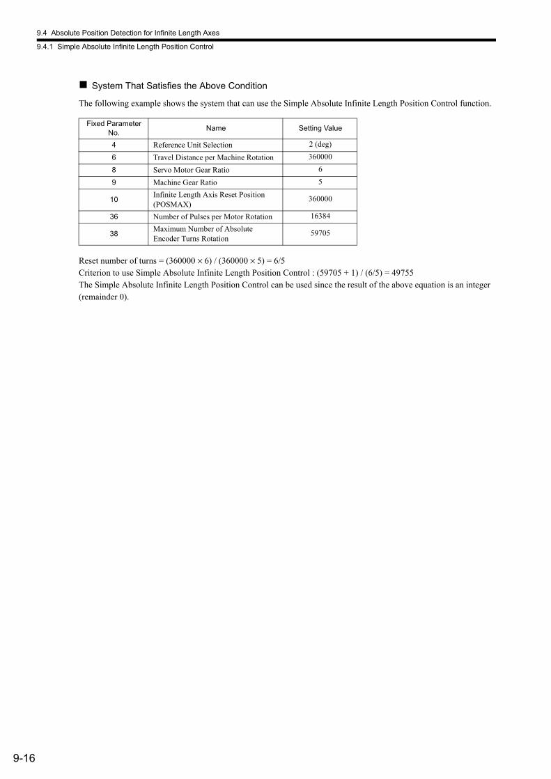
9.4 Absolute Position Detection for Infinite Length Axes
9.4.1 Simple Absolute Infinite Length Position Control
9-16
System That Satisfies the Above Condition
The following example shows the system that can use the Simple Absolute Infinite Length Position Control function.
Reset number of turns = (360000 × 6) / (360000 × 5) = 6/5Criterion to use Simple Absolute Infinite Length Position Control : (59705 + 1) / (6/5) = 49755The Simple Absolute Infinite Length Position Control can be used since the result of the above equation is an integer (remainder 0).
Fixed ParameterNo.
Name Setting Value
4 Reference Unit Selection 2 (deg)
6 Travel Distance per Machine Rotation 360000
8 Servo Motor Gear Ratio 6
9 Machine Gear Ratio 5
10Infinite Length Axis Reset Position (POSMAX)
360000
36 Number of Pulses per Motor Rotation 16384
38Maximum Number of Absolute Encoder Turns Rotation
59705
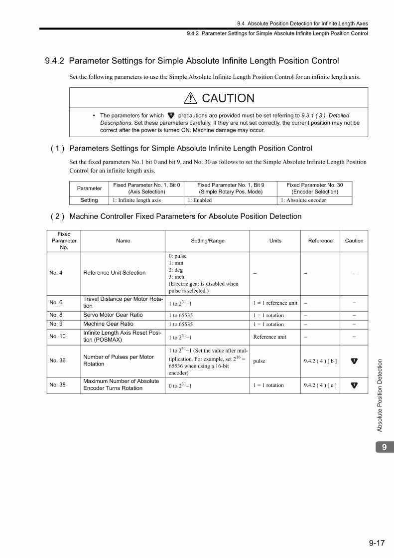
9.4 Absolute Position Detection for Infinite Length Axes
9.4.2 Parameter Settings for Simple Absolute Infinite Length Position Control
9-17
Abs
olut
e P
ositi
on D
etec
tion
9.4.2 Parameter Settings for Simple Absolute Infinite Length Position Control
Set the following parameters to use the Simple Absolute Infinite Length Position Control for an infinite length axis.
( 1 ) Parameters Settings for Simple Absolute Infinite Length Position Control
Set the fixed parameters No.1 bit 0 and bit 9, and No. 30 as follows to set the Simple Absolute Infinite Length Position Control for an infinite length axis.
( 2 ) Machine Controller Fixed Parameters for Absolute Position Detection
The parameters for which precautions are provided must be set referring to 9.3.1 ( 3 ) Detailed Descriptions. Set these parameters carefully. If they are not set correctly, the current position may not be correct after the power is turned ON. Machine damage may occur.
CAUTION
ParameterFixed Parameter No. 1, Bit 0
(Axis Selection)Fixed Parameter No. 1, Bit 9(Simple Rotary Pos. Mode)
Fixed Parameter No. 30(Encoder Selection)
Setting 1: Infinite length axis 1: Enabled 1: Absolute encoder
Fixed Parameter
No.Name Setting/Range Units Reference Caution
No. 4 Reference Unit Selection
0: pulse1: mm2: deg3: inch(Electric gear is disabled when pulse is selected.)
− − −
No. 6Travel Distance per Motor Rota-tion 1 to 231−1 1 = 1 reference unit − −
No. 8 Servo Motor Gear Ratio 1 to 65535 1 = 1 rotation − −No. 9 Machine Gear Ratio 1 to 65535 1 = 1 rotation − −
No. 10Infinite Length Axis Reset Posi-tion (POSMAX) 1 to 231−1 Reference unit − −
No. 36Number of Pulses per Motor Rotation
1 to 231−1 (Set the value after mul-
tiplication. For example, set 216 = 65536 when using a 16-bit encoder)
pulse 9.4.2 ( 4 ) [ b ]
No. 38Maximum Number of Absolute Encoder Turns Rotation 0 to 231−1 1 = 1 rotation 9.4.2 ( 4 ) [ c ]
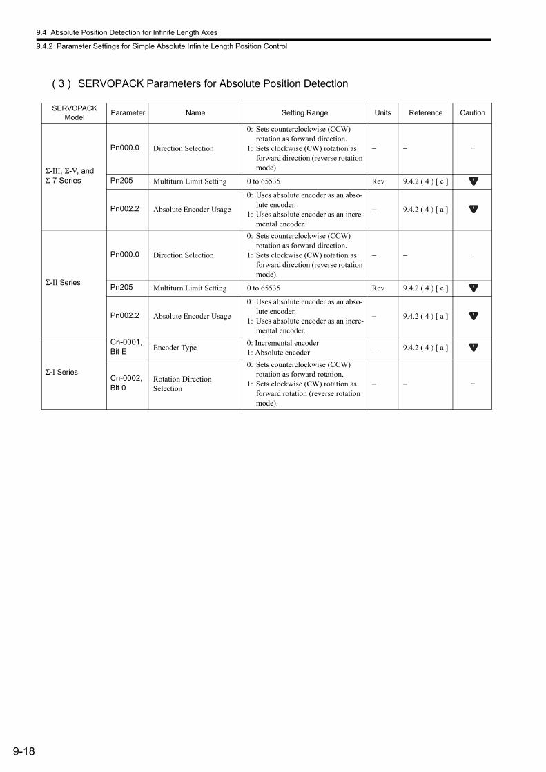
9.4 Absolute Position Detection for Infinite Length Axes
9.4.2 Parameter Settings for Simple Absolute Infinite Length Position Control
9-18
( 3 ) SERVOPACK Parameters for Absolute Position Detection
SERVOPACK Model
Parameter Name Setting Range Units Reference Caution
Σ-III, Σ-V, and Σ-7 Series
Pn000.0 Direction Selection
0: Sets counterclockwise (CCW) rotation as forward direction.
1: Sets clockwise (CW) rotation as forward direction (reverse rotation mode).
− − −
Pn205 Multiturn Limit Setting 0 to 65535 Rev 9.4.2 ( 4 ) [ c ]
Pn002.2 Absolute Encoder Usage
0: Uses absolute encoder as an abso-lute encoder.
1: Uses absolute encoder as an incre-mental encoder.
− 9.4.2 ( 4 ) [ a ]
Σ-II Series
Pn000.0 Direction Selection
0: Sets counterclockwise (CCW) rotation as forward direction.
1: Sets clockwise (CW) rotation as forward direction (reverse rotation mode).
− − −
Pn205 Multiturn Limit Setting 0 to 65535 Rev 9.4.2 ( 4 ) [ c ]
Pn002.2 Absolute Encoder Usage
0: Uses absolute encoder as an abso-lute encoder.
1: Uses absolute encoder as an incre-mental encoder.
− 9.4.2 ( 4 ) [ a ]
Σ-I Series
Cn-0001, Bit E Encoder Type
0: Incremental encoder1: Absolute encoder
− 9.4.2 ( 4 ) [ a ]
Cn-0002,Bit 0
Rotation DirectionSelection
0: Sets counterclockwise (CCW) rotation as forward rotation.
1: Sets clockwise (CW) rotation as forward rotation (reverse rotation mode).
− − −
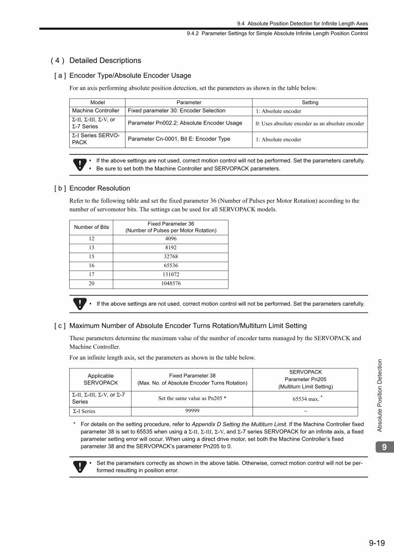
9.4 Absolute Position Detection for Infinite Length Axes
9.4.2 Parameter Settings for Simple Absolute Infinite Length Position Control
9-19
Abs
olut
e P
ositi
on D
etec
tion
( 4 ) Detailed Descriptions
[ a ] Encoder Type/Absolute Encoder Usage
For an axis performing absolute position detection, set the parameters as shown in the table below.
[ b ] Encoder Resolution
Refer to the following table and set the fixed parameter 36 (Number of Pulses per Motor Rotation) according to the number of servomotor bits. The settings can be used for all SERVOPACK models.
[ c ] Maximum Number of Absolute Encoder Turns Rotation/Multiturn Limit Setting
These parameters determine the maximum value of the number of encoder turns managed by the SERVOPACK and Machine Controller.
For an infinite length axis, set the parameters as shown in the table below.
* For details on the setting procedure, refer to Appendix D Setting the Multiturn Limit. If the Machine Controller fixed parameter 38 is set to 65535 when using a Σ-II, Σ-III, Σ-V, and Σ-7 series SERVOPACK for an infinite axis, a fixed parameter setting error will occur. When using a direct drive motor, set both the Machine Controller’s fixed parameter 38 and the SERVOPACK’s parameter Pn205 to 0.
Model Parameter Setting
Machine Controller Fixed parameter 30: Encoder Selection 1: Absolute encoder
Σ-II, Σ-III, Σ-V, or Σ-7 Series
Parameter Pn002.2: Absolute Encoder Usage 0: Uses absolute encoder as an absolute encoder
Σ-I Series SERVO-PACK
Parameter Cn-0001, Bit E: Encoder Type 1: Absolute encoder
If the above settings are not used, correct motion control will not be performed. Set the parameters carefully.
Be sure to set both the Machine Controller and SERVOPACK parameters.
Number of BitsFixed Parameter 36
(Number of Pulses per Motor Rotation)
12 4096
13 8192
15 32768
16 65536
17 131072
20 1048576
If the above settings are not used, correct motion control will not be performed. Set the parameters carefully.
Applicable SERVOPACK
Fixed Parameter 38(Max. No. of Absolute Encoder Turns Rotation)
SERVOPACKParameter Pn205
(Multiturn Limit Setting)
Σ-II, Σ-III, Σ-V, or Σ-7 Series
Set the same value as Pn205 * 65534 max. *
Σ-I Series 99999 −
Set the parameters correctly as shown in the above table. Otherwise, correct motion control will not be per-formed resulting in position error.
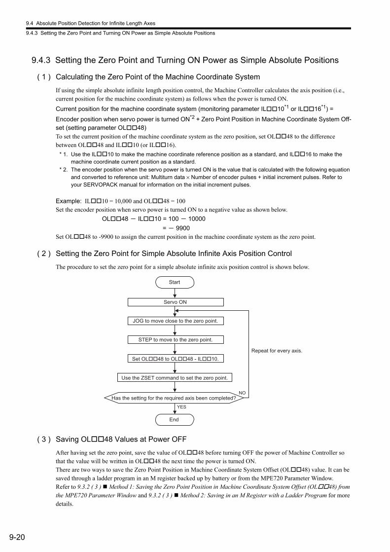
9.4 Absolute Position Detection for Infinite Length Axes
9.4.3 Setting the Zero Point and Turning ON Power as Simple Absolute Positions
9-20
9.4.3 Setting the Zero Point and Turning ON Power as Simple Absolute Positions
( 1 ) Calculating the Zero Point of the Machine Coordinate System
If using the simple absolute infinite length position control, the Machine Controller calculates the axis position (i.e., current position for the machine coordinate system) as follows when the power is turned ON.
Current position for the machine coordinate system (monitoring parameter IL10*1 or IL16*1) =
Encoder position when servo power is turned ON*2 + Zero Point Position in Machine Coordinate System Off-set (setting parameter OL48)To set the current position of the machine coordinate system as the zero position, set OL48 to the difference between OL48 and IL10 (or IL16).
* 1. Use the IL10 to make the machine coordinate reference position as a standard, and IL16 to make the machine coordinate current position as a standard.
* 2. The encoder position when the servo power is turned ON is the value that is calculated with the following equation and converted to reference unit: Multiturn data × Number of encoder pulses + initial increment pulses. Refer to your SERVOPACK manual for information on the initial increment pulses.
Example: IL10 = 10,000 and OL48 = 100Set the encoder position when servo power is turned ON to a negative value as shown below.
OL48 - IL10 = 100 - 10000
= - 9900Set OL48 to -9900 to assign the current position in the machine coordinate system as the zero point.
( 2 ) Setting the Zero Point for Simple Absolute Infinite Axis Position Control
The procedure to set the zero point for a simple absolute infinite axis position control is shown below.
( 3 ) Saving OL48 Values at Power OFF
After having set the zero point, save the value of OL48 before turning OFF the power of Machine Controller so that the value will be written in OL48 the next time the power is turned ON.There are two ways to save the Zero Point Position in Machine Coordinate System Offset (OL48) value. It can be saved through a ladder program in an M register backed up by battery or from the MPE720 Parameter Window.Refer to 9.3.2 ( 3 ) Method 1: Saving the Zero Point Position in Machine Coordinate System Offset (OL48) from the MPE720 Parameter Window and 9.3.2 ( 3 ) Method 2: Saving in an M Register with a Ladder Program for more details.
Repeat for every axis.
Start
End
YES
NO
Servo ON
JOG to move close to the zero point.
STEP to move to the zero point.
Set OL��48 to OL��48 - IL��10.
Use the ZSET command to set the zero point.
Has the setting for the required axis been completed?
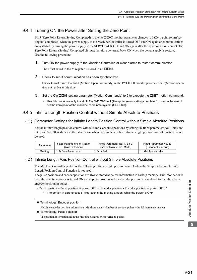
9.4 Absolute Position Detection for Infinite Length Axes
9.4.4 Turning ON the Power after Setting the Zero Point
9-21
Abs
olut
e P
ositi
on D
etec
tion
9.4.4 Turning ON the Power after Setting the Zero Point
Bit 5 (Zero Point Return/Setting Completed) in the IW0C monitor parameter changes to 0 (Zero point return/set-ting not completed) when the power supply to the Machine Controller is turned OFF and ON again or communications are restarted by turning the power supply to the SERVOPACK OFF and ON again after the zero point has been set. The Zero Point Return (Setting) Completed bit must therefore be turned back ON when the power supply is restored. Use the following procedure.
1. Turn ON the power supply to the Machine Controller, or clear alarms to restart communication.
The offset saved in the M register is stored in OL48.
2. Check to see if communication has been synchronized.
Check to make sure that bit 0 (Motion Operation Ready) in the IW00 monitor parameter is 0 (Motion opera-tion not ready) at this time.
3. Set the OW08 setting parameter (Motion Commands) to 9 to execute the ZSET motion command.
Use this procedure only to set bit 5 in IW0C to 1 (Zero point return/setting completed). It cannot be used to set the zero point of the machine coordinate system (OL48).
9.4.5 Infinite Length Position Control without Simple Absolute Positions
( 1 ) Parameter Settings for Infinite Length Position Control without Simple Absolute Positions
Set the infinite length position control without simple absolute positions by setting the fixed parameters No. 1 bit 0 and bit 9, and No. 30 as shown in the table below when the simple absolute infinite length position control function cannot be used.
( 2 ) Infinite Length Axis Position Control without Simple Absolute Positions
The Machine Controller performs the following infinite length position control when the Simple Absolute Infinite Length Position Control Function is not used.The pulse position and encoder position are always stored as paired information in backup memory. This information is used the next time power is turned ON as the pulse position and the encoder position at shutdown to find the relative encoder position in pulses.
• Pulse position = Pulse position at power OFF + (Encoder position - Encoder position at power OFF)*
* The portion in parentheses ( ) represents the moving amount while the power is OFF.
Terminology: Encoder position
Absolute encoder position information (Multiturn data × Number of encoder pulses + Initial increment pulses)
Terminology: Pulse Position
The position information from the Machine Controller converted to pulses
ParameterFixed Parameter No.1, Bit 0
(Axis Selection)Fixed Parameter No. 1, Bit 9(Simple Rotary Pos. Mode)
Fixed Parameter No. 30(Encoder Selection)
Setting 1: Infinite length axis 0: Disabled 1: Absolute encoder
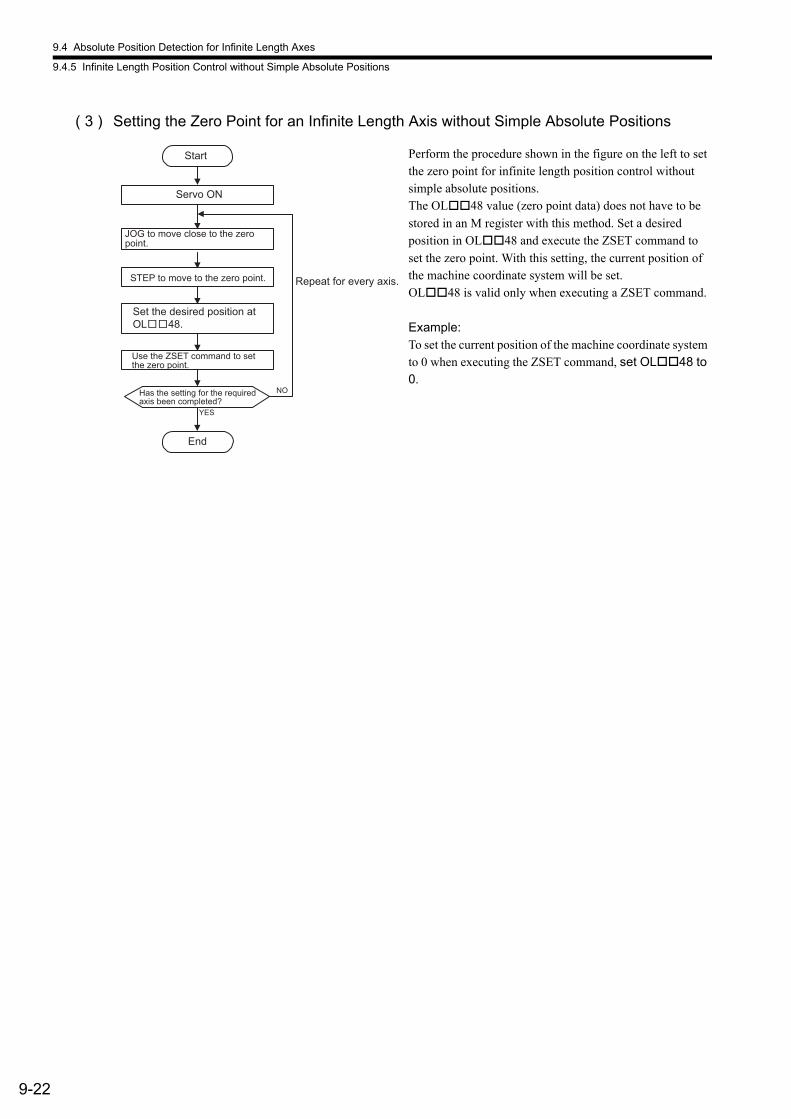
9.4 Absolute Position Detection for Infinite Length Axes
9.4.5 Infinite Length Position Control without Simple Absolute Positions
9-22
( 3 ) Setting the Zero Point for an Infinite Length Axis without Simple Absolute Positions
Repeat for every axis.
Start
Servo ON
STEP to move to the zero point.
End
YES
NO
JOG to move close to the zero point.
Set the desired position at
OL 48.
Has the setting for the required axis been completed?
Use the ZSET command to set the zero point.
Perform the procedure shown in the figure on the left to set the zero point for infinite length position control without simple absolute positions.The OL48 value (zero point data) does not have to be
stored in an M register with this method. Set a desired position in OL48 and execute the ZSET command to
set the zero point. With this setting, the current position of the machine coordinate system will be set.OL48 is valid only when executing a ZSET command.
Example:To set the current position of the machine coordinate system to 0 when executing the ZSET command, set OL48 to 0.
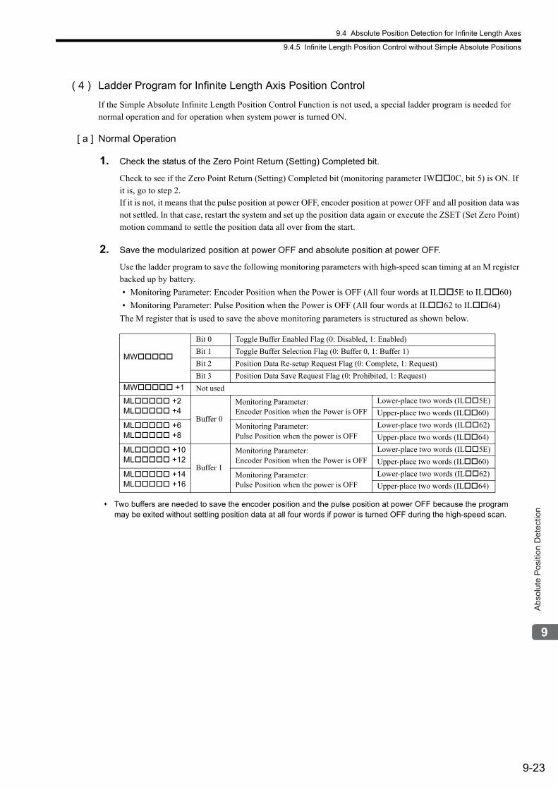
9.4 Absolute Position Detection for Infinite Length Axes
9.4.5 Infinite Length Position Control without Simple Absolute Positions
9-23
Abs
olut
e P
ositi
on D
etec
tion
( 4 ) Ladder Program for Infinite Length Axis Position Control
If the Simple Absolute Infinite Length Position Control Function is not used, a special ladder program is needed for normal operation and for operation when system power is turned ON.
[ a ] Normal Operation
1. Check the status of the Zero Point Return (Setting) Completed bit.
Check to see if the Zero Point Return (Setting) Completed bit (monitoring parameter IW0C, bit 5) is ON. If it is, go to step 2.If it is not, it means that the pulse position at power OFF, encoder position at power OFF and all position data was not settled. In that case, restart the system and set up the position data again or execute the ZSET (Set Zero Point) motion command to settle the position data all over from the start.
2. Save the modularized position at power OFF and absolute position at power OFF.
Use the ladder program to save the following monitoring parameters with high-speed scan timing at an M register backed up by battery.
• Monitoring Parameter: Encoder Position when the Power is OFF (All four words at IL5E to IL60)
• Monitoring Parameter: Pulse Position when the Power is OFF (All four words at IL62 to IL64)
The M register that is used to save the above monitoring parameters is structured as shown below.
Two buffers are needed to save the encoder position and the pulse position at power OFF because the program may be exited without settling position data at all four words if power is turned OFF during the high-speed scan.
MW
Bit 0 Toggle Buffer Enabled Flag (0: Disabled, 1: Enabled)
Bit 1 Toggle Buffer Selection Flag (0: Buffer 0, 1: Buffer 1)
Bit 2 Position Data Re-setup Request Flag (0: Complete, 1: Request)
Bit 3 Position Data Save Request Flag (0: Prohibited, 1: Request)
MW +1 Not used
ML +2ML +4
Buffer 0
Monitoring Parameter: Encoder Position when the Power is OFF
Lower-place two words (IL5E)
Upper-place two words (IL60)
ML +6ML +8
Monitoring Parameter: Pulse Position when the power is OFF
Lower-place two words (IL62)
Upper-place two words (IL64)
ML +10ML +12
Buffer 1
Monitoring Parameter: Encoder Position when the Power is OFF
Lower-place two words (IL5E)
Upper-place two words (IL60)
ML +14ML +16
Monitoring Parameter: Pulse Position when the power is OFF
Lower-place two words (IL62)
Upper-place two words (IL64)
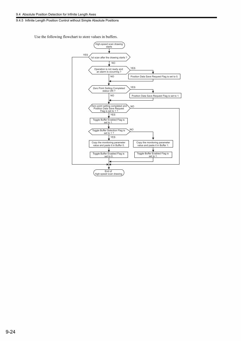
9.4 Absolute Position Detection for Infinite Length Axes
9.4.5 Infinite Length Position Control without Simple Absolute Positions
9-24
Use the following flowchart to store values in buffers.
High-speed scan drawingstarts
Toggle Buffer Enabled Flag isset to 1.
Toggle Buffer Enabled Flag is set to 0.
Copy the monitoring parameter value and paste it in Buffer 0.
Toggle Buffer Enabled Flag is set to 1.
Copy the monitoring parametervalue and paste it in Buffer 1.
End of high-speed scan drawing
YES
NO
YES
NO
YES
NO
1st scan after the drawing starts ?
Operation is not ready and an alarm is occurring ?
Toggle Buffer Selection Flag is set to 1 ?
Position Data Save Request Flag is set to 0.
NO
YESZero Point Setting Completedstatus ON ?
Position Data Save Request Flag is set to 1.
YES
NOZero point setting completed andPosition Data Save Request
Flag is set to 1 ?
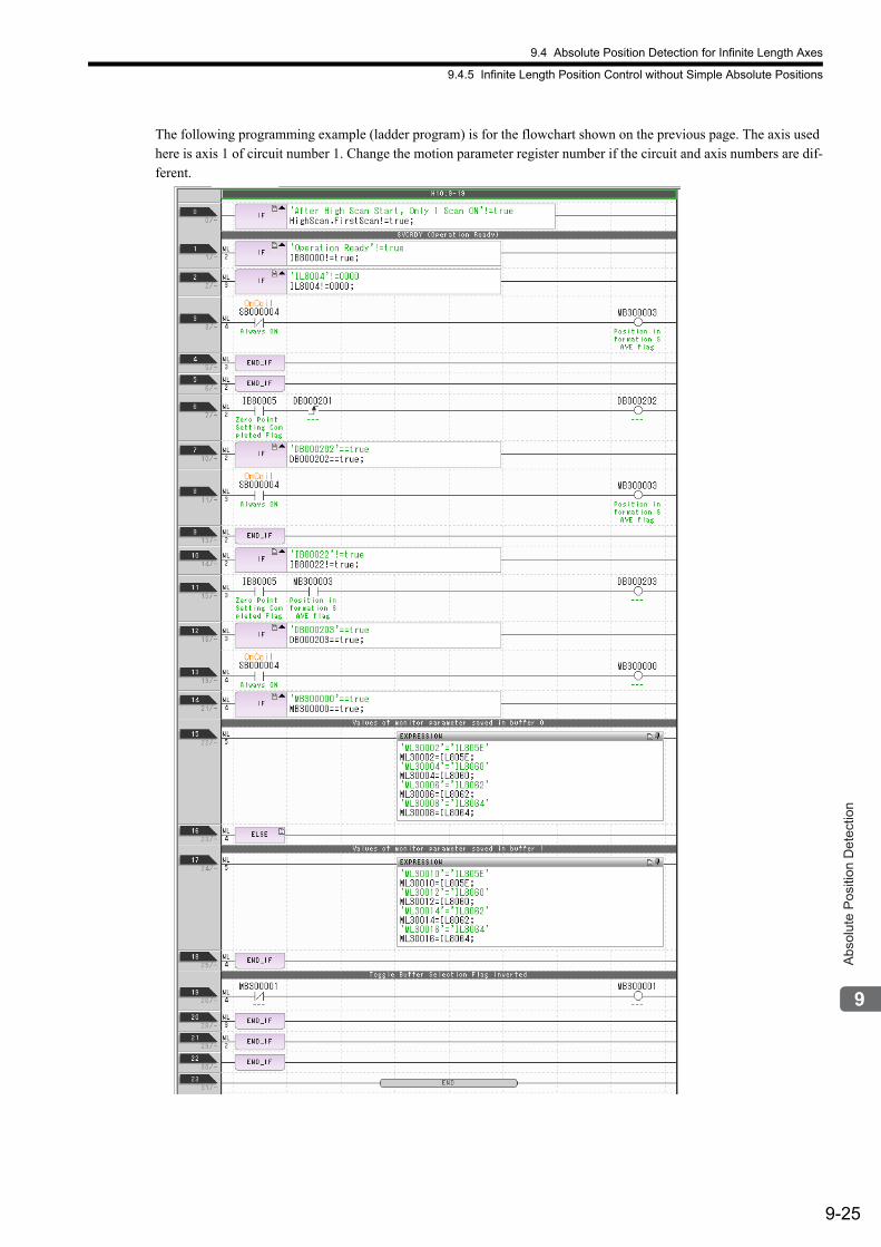
9.4 Absolute Position Detection for Infinite Length Axes
9.4.5 Infinite Length Position Control without Simple Absolute Positions
9-25
Abs
olut
e P
ositi
on D
etec
tion
The following programming example (ladder program) is for the flowchart shown on the previous page. The axis used here is axis 1 of circuit number 1. Change the motion parameter register number if the circuit and axis numbers are dif-ferent.

9.4 Absolute Position Detection for Infinite Length Axes
9.4.5 Infinite Length Position Control without Simple Absolute Positions
9-26
[ b ] Turning the System Back ON (Turning the Servo Back ON)
Set up position data again from the ladder program using high-speed scan timing as shown below. This is done when MP2300 power or power of the SERVOPACK is turned OFF and ON.
1. Store Pulse Position at Power OFF and Encoder Position at Power OFF to setting parameters.
Store the Pulse Position at Power OFF and Encoder Position at Power OFF values saved in M register to the fol-lowing setting parameters.
• Setting parameter: Encoder Position when the Power is OFF (All four words, form OL5E to OL60.)
• Setting parameter: Pulse Position When the Power is OFF (All four words, from OL62 to OL64.)
Store the contents of the buffer selected by the Toggle Buffer Selection Flag.
2. Infinite Length Axis Position Information LOAD
Set bit 7 (Absolute Infinite-length Position Information Load Request) in the OW00 setting parameter to 0 (OFF), 1 (ON), and then 0 (OFF) again. This will allow all position data to be settled. Bit 5 (Zero Point Return/Setting Completed) in the IW0C monitor parameter changes to 1 (Zero point return/setting completed) and the following monitor parameters are enabled.
• Monitoring Parameter: Encoder Position when the Power is OFF (All four words, from IL5E to IL60.)
• Monitoring Parameter: Pulse Position When the Power is OFF (All four words, from IL62 to IL64.)
The system will create position data using the following equation when the Request ABS Rotary Pos. Load bit turns ON.
• Pulse position = Pulse position at power OFF + (Encoder position − Encoder position at power OFF)*
* The portion in parentheses ( ) represents the moving amount while power is OFF. Use the following flowchart for storing the position data in the setting parameters and for requesting to load the infinite length axis position information.
High-speed scan drawingstarts
1st scan after the drawing starts ? Or,Servo power reset signal is set to 1?
Position Data Re-setup Request Flag is set to 1
Operation ready and Position DataRe-setup Request Flag is set to 1 ?
ABS System Infinite Length Position Control Data Initialization Completed
Flag is set to 0 ?
Toggle Buffer Enabled Flag is set to 1 ?
Toggle Buffer Selection Flag is set to 1 ?
Copy the value of Buffer 1 and paste it in the setting parameter.
ABS System Infinite LengthPosition Control Data Initialization
Request Flag is set to 1
Position Data Save Request Flag isset to 1
Copy the value of Buffer 0 andpaste it in the settingparameter.
End ofhigh-speed scan drawing
ABS System Infinite Length Position Control Data Initialization
Request Flag is set to 0
Position Data Re-setup Request Flag is set to 0
NO
YES
NO
YES
NO
YES
NO
YES
NO
YES
Position Data Re-setup Enabled Flag isset to 0
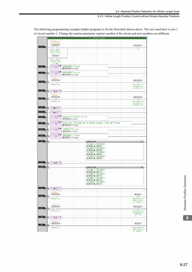
9.4 Absolute Position Detection for Infinite Length Axes
9.4.5 Infinite Length Position Control without Simple Absolute Positions
9-27
Abs
olut
e P
ositi
on D
etec
tion
The following programming example (ladder program) is for the flowchart shown above. The axis used here is axis 1 of circuit number 1. Change the motion parameter register number if the circuit and axis numbers are different.

9.4 Absolute Position Detection for Infinite Length Axes
9.4.5 Infinite Length Position Control without Simple Absolute Positions
9-28
There are no restrictions in the executing order for ladder programs H10 and H11 when an absolute encoder is used for a finite length axis.
10-1
Inve
rter O
pera
tion
10
Inverter Operation
Motion control with an Inverter is possible using the SVB Module. This chapter describes the parameters and commands required for motion control with an Inverter.
10.1 Connection Specifications - - - - - - - - - - - - - - - - - - - - - - - - - - - - - - - - - 10-2
10.2 Parameters for Inverter Operation - - - - - - - - - - - - - - - - - - - - - - - - - - - 10-3
10.2.1 Types of Motion Parameters - - - - - - - - - - - - - - - - - - - - - - - - - - - - - - - - - - - - - - - - 10-3
10.2.2 Motion Parameter Registers - - - - - - - - - - - - - - - - - - - - - - - - - - - - - - - - - - - - - - - - 10-3
10.2.3 Motion Parameter List - - - - - - - - - - - - - - - - - - - - - - - - - - - - - - - - - - - - - - - - - - - - 10-4
10.2.4 Motion Parameter Details - - - - - - - - - - - - - - - - - - - - - - - - - - - - - - - - - - - - - - - - - 10-19
10.3 Main Commands and Subcommands - - - - - - - - - - - - - - - - - - - - - - - - 10-27
10.3.1 List of Commands - - - - - - - - - - - - - - - - - - - - - - - - - - - - - - - - - - - - - - - - - - - - - - 10-27
10.3.2 Main Command Details - - - - - - - - - - - - - - - - - - - - - - - - - - - - - - - - - - - - - - - - - - 10-29
10.3.3 Subcommand Details - - - - - - - - - - - - - - - - - - - - - - - - - - - - - - - - - - - - - - - - - - - - 10-37
10.3.4 Applicable Combinations of Main Commands and Subcommands - - - - - - - - - - - - 10-44
10.3.5 Precautions for Inverter Operation - - - - - - - - - - - - - - - - - - - - - - - - - - - - - - - - - - - 10-45
10.4 Setup Procedure - - - - - - - - - - - - - - - - - - - - - - - - - - - - - - - - - - - - - - - 10-47
10.4.1 Check Items before Setup - - - - - - - - - - - - - - - - - - - - - - - - - - - - - - - - - - - - - - - - 10-47
10.4.2 Inverter Settings - - - - - - - - - - - - - - - - - - - - - - - - - - - - - - - - - - - - - - - - - - - - - - - 10-47
10.4.3 I/O Options - - - - - - - - - - - - - - - - - - - - - - - - - - - - - - - - - - - - - - - - - - - - - - - - - - - 10-54
10.5 Alarm and Warning Codes for Inverter - - - - - - - - - - - - - - - - - - - - - - - 10-56
10.5.1 A1000 - - - - - - - - - - - - - - - - - - - - - - - - - - - - - - - - - - - - - - - - - - - - - - - - - - - - - - 10-56
10.5.2 V1000 - - - - - - - - - - - - - - - - - - - - - - - - - - - - - - - - - - - - - - - - - - - - - - - - - - - - - - 10-60
10.5.3 Varispeed G7, Varispeed F7, and VS mini V7 - - - - - - - - - - - - - - - - - - - - - - - - - - - 10-63
10.6 MECHATROLINK Option Card/Option Unit Settings - - - - - - - - - - - - - - 10-66
10.1 Connection Specifications
10-2
10.1 Connection Specifications
The connection specifications when controlling an Inverter using MECHATROLINK-II communications from the Machine Controller are given in the following table.
* 1. The maximum number of connectable Inverters in MECHATROLINK-II 32-byte mode can be obtained by the fol-lowing equation.Transmission cycle 2 ms: 21 − C2 Message (with: 1, none: 0) − Number of retries to slavesTransmission cycle 1 ms: 9 − C2 Message (with: 1, none: 0) − Number of retries to slaves • Setting range of number of retry to slaves is 0 to 7. • If the result of the above equation is 16 or greater, the maximum number of connectable Inverters is 16.
* 2. The maximum number of connectable Inverters in MECHATROLINK-II 17-byte mode can be obtained by the fol-lowing equation.Transmission cycle 1 ms: 15 − C2 Message (with: 1, none: 0) − Number of retries to slaves • Setting range of number of retry to slaves is 0 to 7.
Item
Description
MECHATROLINK-II(32-byte mode)
MECHATROLINK-II(17-byte mode)
MECHATROLINK-I
Supported Models
SVB Module Built-in SVB: CPU version 2.20 or laterSVB-01 Module: Version 1.10 or later
EngineeringTool MPE720 version 5.12 or later
Inverter
A1000, using the SI-T3 Communications Option CardV1000, using the SI-T3/V Communications Option UnitVarispeed G7, using the SI-T Communications Option CardVarispeed F7, using the SI-T Communications Option CardVS mini V7, using the SI-T/V7 Communications Option Unit
Number of Connectable Inverters
16 max.(at transmission cycle 2 ms) Differs depending on
whether messages are used and the number of retries to
slaves. *1
15 max. Differs depending on
whether messages are used and the number of retries to
slaves. *2
14 max.
Transmission Cycle 1 ms, 2 ms 1 ms 2 ms
InterfaceFixed parameters (To set application conditions)Setting parameters (To update references and output data)Monitor parameters (To update monitored or input data)
Self-configuration Function Available
Others Conforms to MECHATROLINK-I and II specifications
10.2 Parameters for Inverter Operation
10.2.1 Types of Motion Parameters
10-3
Inve
rter O
pera
tion
10.2 Parameters for Inverter Operation
This section describes the motion parameters required for Inverter operation.
10.2.1 Types of Motion Parameters
The motion parameters for operating an Inverter are fixed parameters, setting parameters, and monitor parameters.
10.2.2 Motion Parameter Registers
Motion parameter registers are used to store setting parameters and monitor parameters.Specific motion parameter register addresses are determined by the circuit number that is used for each motion control function and the axis number that is assigned. Motion parameter registers are the same as for SERVOPACKs. Refer to 4.1 Motion Parameters Register Numbers for details on motion parameter registers.However, the station address of the Inverter is used for motion parameter registers instead of the axis number on the SERVOPACK.
Parameter Description
Fixed Parameters These parameters are used to configure basic system settings for Inverter operation.
Setting Parameters These parameters are used to configure Inverter operation references and details of func-tions.
Monitor Parameters These parameters are used to monitor detailed information, such as the operating status of the Inverter.
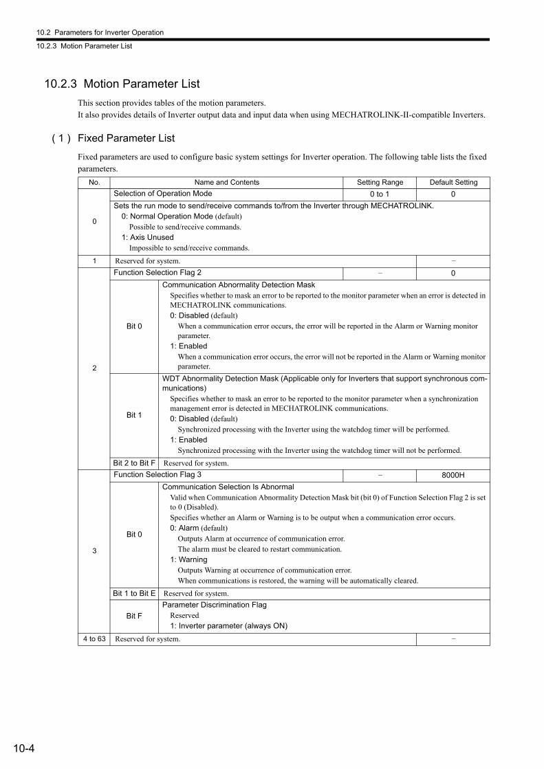
10.2 Parameters for Inverter Operation
10.2.3 Motion Parameter List
10-4
10.2.3 Motion Parameter List
This section provides tables of the motion parameters.It also provides details of Inverter output data and input data when using MECHATROLINK-II-compatible Inverters.
( 1 ) Fixed Parameter List
Fixed parameters are used to configure basic system settings for Inverter operation. The following table lists the fixed parameters.
No. Name and Contents Setting Range Default Setting
0
Selection of Operation Mode 0 to 1 0
Sets the run mode to send/receive commands to/from the Inverter through MECHATROLINK.0: Normal Operation Mode (default)
Possible to send/receive commands.1: Axis Unused
Impossible to send/receive commands.
1 Reserved for system. –
2
Function Selection Flag 2 – 0
Bit 0
Communication Abnormality Detection MaskSpecifies whether to mask an error to be reported to the monitor parameter when an error is detected in MECHATROLINK communications.0: Disabled (default)
When a communication error occurs, the error will be reported in the Alarm or Warning monitor parameter.
1: EnabledWhen a communication error occurs, the error will not be reported in the Alarm or Warning monitor parameter.
Bit 1
WDT Abnormality Detection Mask (Applicable only for Inverters that support synchronous com-munications)
Specifies whether to mask an error to be reported to the monitor parameter when a synchronization management error is detected in MECHATROLINK communications.0: Disabled (default)
Synchronized processing with the Inverter using the watchdog timer will be performed.1: Enabled
Synchronized processing with the Inverter using the watchdog timer will not be performed.
Bit 2 to Bit F Reserved for system.
3
Function Selection Flag 3 – 8000H
Bit 0
Communication Selection Is AbnormalValid when Communication Abnormality Detection Mask bit (bit 0) of Function Selection Flag 2 is set to 0 (Disabled).Specifies whether an Alarm or Warning is to be output when a communication error occurs.0: Alarm (default)
Outputs Alarm at occurrence of communication error.The alarm must be cleared to restart communication.
1: WarningOutputs Warning at occurrence of communication error.When communications is restored, the warning will be automatically cleared.
Bit 1 to Bit E Reserved for system.
Bit F
Parameter Discrimination FlagReserved1: Inverter parameter (always ON)
4 to 63 Reserved for system. –
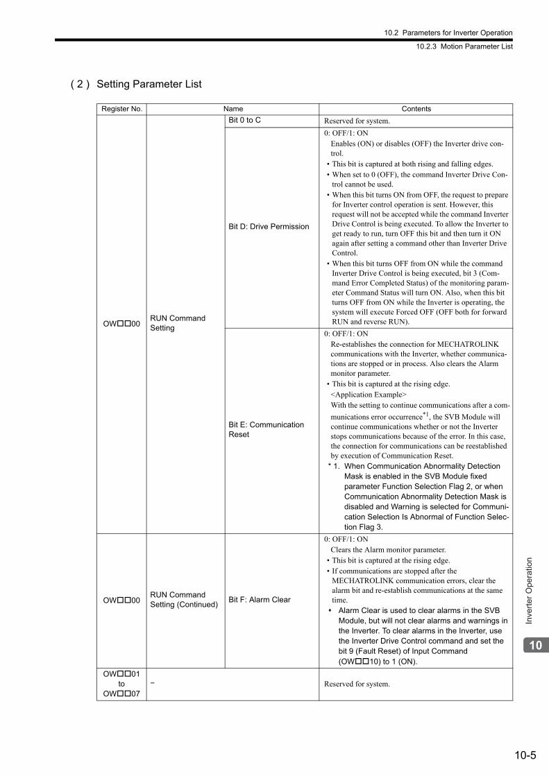
10.2 Parameters for Inverter Operation
10.2.3 Motion Parameter List
10-5
Inve
rter O
pera
tion
( 2 ) Setting Parameter List
Register No. Name Contents
OW00RUN Command Setting
Bit 0 to C Reserved for system.
Bit D: Drive Permission
0: OFF/1: ONEnables (ON) or disables (OFF) the Inverter drive con-trol.
• This bit is captured at both rising and falling edges.• When set to 0 (OFF), the command Inverter Drive Con-
trol cannot be used.• When this bit turns ON from OFF, the request to prepare
for Inverter control operation is sent. However, this request will not be accepted while the command Inverter Drive Control is being executed. To allow the Inverter to get ready to run, turn OFF this bit and then turn it ON again after setting a command other than Inverter Drive Control.
• When this bit turns OFF from ON while the command Inverter Drive Control is being executed, bit 3 (Com-mand Error Completed Status) of the monitoring param-eter Command Status will turn ON. Also, when this bit turns OFF from ON while the Inverter is operating, the system will execute Forced OFF (OFF both for forward RUN and reverse RUN).
Bit E: Communication Reset
0: OFF/1: ONRe-establishes the connection for MECHATROLINK communications with the Inverter, whether communica-tions are stopped or in process. Also clears the Alarm monitor parameter.
• This bit is captured at the rising edge.<Application Example>With the setting to continue communications after a com-
munications error occurrence*1, the SVB Module will continue communications whether or not the Inverter stops communications because of the error. In this case, the connection for communications can be reestablished by execution of Communication Reset.
* 1. When Communication Abnormality Detection Mask is enabled in the SVB Module fixed parameter Function Selection Flag 2, or when Communication Abnormality Detection Mask is disabled and Warning is selected for Communi-cation Selection Is Abnormal of Function Selec-tion Flag 3.
OW00RUN Command Setting (Continued)
Bit F: Alarm Clear
0: OFF/1: ONClears the Alarm monitor parameter.
• This bit is captured at the rising edge.• If communications are stopped after the
MECHATROLINK communication errors, clear the alarm bit and re-establish communications at the same time. Alarm Clear is used to clear alarms in the SVB
Module, but will not clear alarms and warnings in the Inverter. To clear alarms in the Inverter, use the Inverter Drive Control command and set the bit 9 (Fault Reset) of Input Command (OW10) to 1 (ON).
OW01to
OW07− Reserved for system.
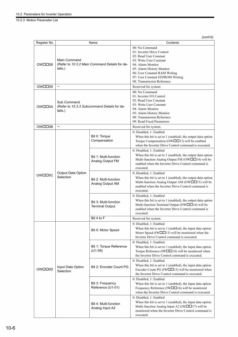
10.2 Parameters for Inverter Operation
10.2.3 Motion Parameter List
10-6
OW08Main Command(Refer to 10.3.2 Main Command Details for de-tails.)
00: No Command01: Inverter Drive Control02: Read User Constant03: Write User Constant04: Alarm Monitor05: Alarm History Monitor06: User Constant RAM Writing07: User Constant EEPROM Writing08: Transmission Reference
OW09 ─ Reserved for system.
OW0ASub Command(Refer to 10.3.3 Subcommand Details for de-tails.)
00: No Command01: Inverter I/O Control02: Read User Constant03: Write User Constant04: Alarm Monitor05: Alarm History Monitor08: Transmission Reference09: Read Fixed Parameters
OW0B ─ Reserved for system.
OW0COutput Data Option Selection
Bit 0: Torque Compensation
0: Disabled, 1: EnabledWhen this bit is set to 1 (enabled), the output data option Torque Compensation (OW13) will be enabled when the Inverter Drive Control command is executed.
Bit 1: Multi-function Analog Output FM
0: Disabled, 1: EnabledWhen this bit is set to 1 (enabled), the output data option Multi-function Analog Output FM (OW14) will be enabled when the Inverter Drive Control command is executed.
Bit 2: Multi-function Analog Output AM
0: Disabled, 1: EnabledWhen this bit is set to 1 (enabled), the output data option Multi-function Analog Output AM (OW15) will be enabled when the Inverter Drive Control command is executed.
Bit 3: Multi-function Terminal Output
0: Disabled, 1: EnabledWhen this bit is set to 1 (enabled), the output data option Multi-function Terminal Output (OW16) will be enabled when the Inverter Drive Control command is executed.
Bit 4 to F Reserved for system.
OW0DInput Data Option Selection
Bit 0: Motor Speed
0: Disabled, 1: EnabledWhen this bit is set to 1 (enabled), the input data option Motor Speed (IW13) will be monitored when the Inverter Drive Control command is executed.
Bit 1: Torque Reference (U1-09)
0: Disabled, 1: EnabledWhen this bit is set to 1 (enabled), the input data option Torque Reference (IW14) will be monitored when the Inverter Drive Control command is executed.
Bit 2: Encoder Count PG
0: Disabled, 1: EnabledWhen this bit is set to 1 (enabled), the input data option Encoder Count PG (IW15) will be monitored when the Inverter Drive Control command is executed.
Bit 3: Frequency Reference (U1-01)
0: Disabled, 1: EnabledWhen this bit is set to 1 (enabled), the input data option Frequency Reference (IW16) will be monitored when the Inverter Drive Control command is executed.
Bit 4: Multi-function Analog Input A2
0: Disabled, 1: EnabledWhen this bit is set to 1 (enabled), the input data option Multi-function Analog Input A2 (IW17) will be monitored when the Inverter Drive Control command is executed.
(cont’d)
Register No. Name Contents
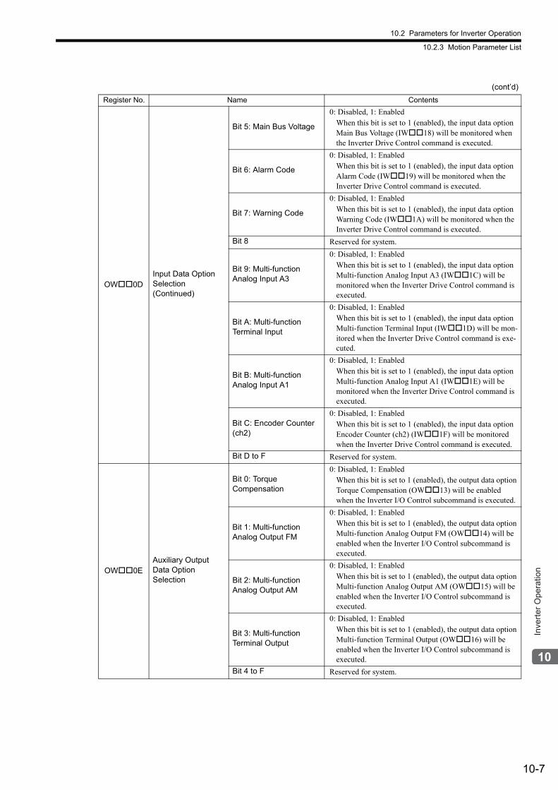
10.2 Parameters for Inverter Operation
10.2.3 Motion Parameter List
10-7
Inve
rter O
pera
tion
OW0DInput Data Option Selection(Continued)
Bit 5: Main Bus Voltage
0: Disabled, 1: EnabledWhen this bit is set to 1 (enabled), the input data option Main Bus Voltage (IW18) will be monitored when the Inverter Drive Control command is executed.
Bit 6: Alarm Code
0: Disabled, 1: EnabledWhen this bit is set to 1 (enabled), the input data option Alarm Code (IW19) will be monitored when the Inverter Drive Control command is executed.
Bit 7: Warning Code
0: Disabled, 1: EnabledWhen this bit is set to 1 (enabled), the input data option Warning Code (IW1A) will be monitored when the Inverter Drive Control command is executed.
Bit 8 Reserved for system.
Bit 9: Multi-function Analog Input A3
0: Disabled, 1: EnabledWhen this bit is set to 1 (enabled), the input data option Multi-function Analog Input A3 (IW1C) will be monitored when the Inverter Drive Control command is executed.
Bit A: Multi-function Terminal Input
0: Disabled, 1: EnabledWhen this bit is set to 1 (enabled), the input data option Multi-function Terminal Input (IW1D) will be mon-itored when the Inverter Drive Control command is exe-cuted.
Bit B: Multi-function Analog Input A1
0: Disabled, 1: EnabledWhen this bit is set to 1 (enabled), the input data option Multi-function Analog Input A1 (IW1E) will be monitored when the Inverter Drive Control command is executed.
Bit C: Encoder Counter (ch2)
0: Disabled, 1: EnabledWhen this bit is set to 1 (enabled), the input data option Encoder Counter (ch2) (IW1F) will be monitored when the Inverter Drive Control command is executed.
Bit D to F Reserved for system.
OW0EAuxiliary Output Data Option Selection
Bit 0: Torque Compensation
0: Disabled, 1: EnabledWhen this bit is set to 1 (enabled), the output data option Torque Compensation (OW13) will be enabled when the Inverter I/O Control subcommand is executed.
Bit 1: Multi-function Analog Output FM
0: Disabled, 1: EnabledWhen this bit is set to 1 (enabled), the output data option Multi-function Analog Output FM (OW14) will be enabled when the Inverter I/O Control subcommand is executed.
Bit 2: Multi-function Analog Output AM
0: Disabled, 1: EnabledWhen this bit is set to 1 (enabled), the output data option Multi-function Analog Output AM (OW15) will be enabled when the Inverter I/O Control subcommand is executed.
Bit 3: Multi-function Terminal Output
0: Disabled, 1: EnabledWhen this bit is set to 1 (enabled), the output data option Multi-function Terminal Output (OW16) will be enabled when the Inverter I/O Control subcommand is executed.
Bit 4 to F Reserved for system.
(cont’d)
Register No. Name Contents
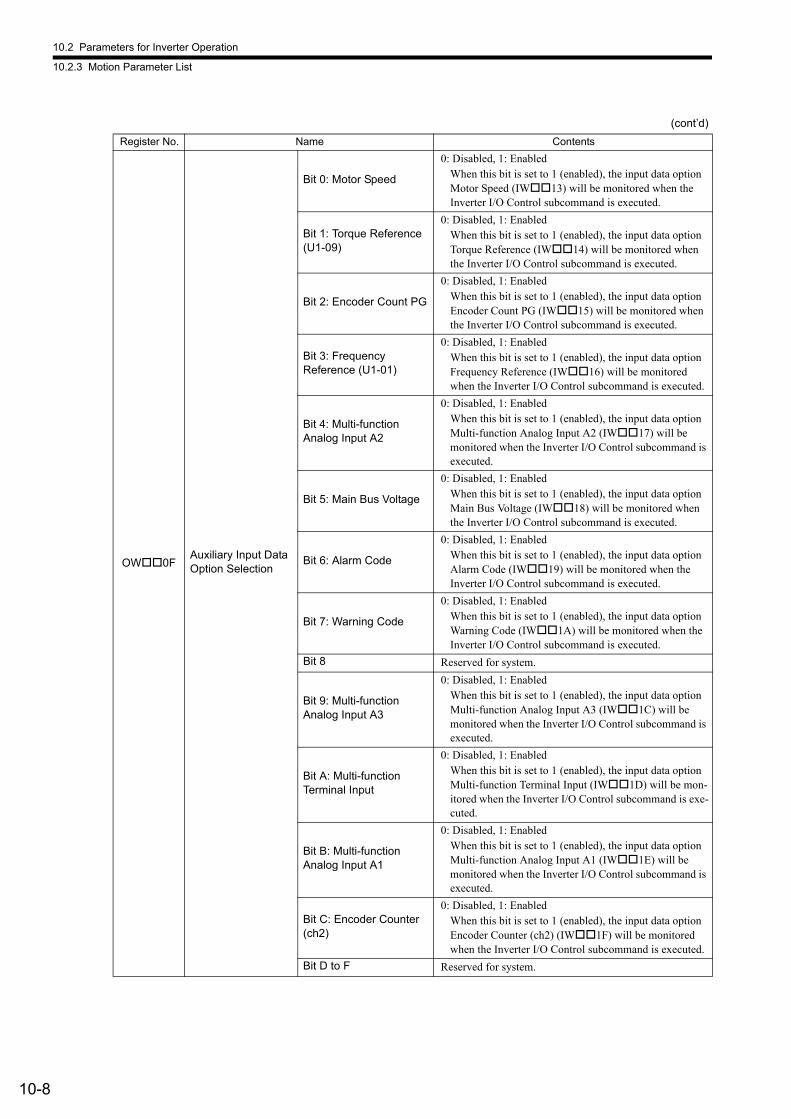
10.2 Parameters for Inverter Operation
10.2.3 Motion Parameter List
10-8
OW0FAuxiliary Input Data Option Selection
Bit 0: Motor Speed
0: Disabled, 1: EnabledWhen this bit is set to 1 (enabled), the input data option Motor Speed (IW13) will be monitored when the Inverter I/O Control subcommand is executed.
Bit 1: Torque Reference (U1-09)
0: Disabled, 1: EnabledWhen this bit is set to 1 (enabled), the input data option Torque Reference (IW14) will be monitored when the Inverter I/O Control subcommand is executed.
Bit 2: Encoder Count PG
0: Disabled, 1: EnabledWhen this bit is set to 1 (enabled), the input data option Encoder Count PG (IW15) will be monitored when the Inverter I/O Control subcommand is executed.
Bit 3: Frequency Reference (U1-01)
0: Disabled, 1: EnabledWhen this bit is set to 1 (enabled), the input data option Frequency Reference (IW16) will be monitored when the Inverter I/O Control subcommand is executed.
Bit 4: Multi-function Analog Input A2
0: Disabled, 1: EnabledWhen this bit is set to 1 (enabled), the input data option Multi-function Analog Input A2 (IW17) will be monitored when the Inverter I/O Control subcommand is executed.
Bit 5: Main Bus Voltage
0: Disabled, 1: EnabledWhen this bit is set to 1 (enabled), the input data option Main Bus Voltage (IW18) will be monitored when the Inverter I/O Control subcommand is executed.
Bit 6: Alarm Code
0: Disabled, 1: EnabledWhen this bit is set to 1 (enabled), the input data option Alarm Code (IW19) will be monitored when the Inverter I/O Control subcommand is executed.
Bit 7: Warning Code
0: Disabled, 1: EnabledWhen this bit is set to 1 (enabled), the input data option Warning Code (IW1A) will be monitored when the Inverter I/O Control subcommand is executed.
Bit 8 Reserved for system.
Bit 9: Multi-function Analog Input A3
0: Disabled, 1: EnabledWhen this bit is set to 1 (enabled), the input data option Multi-function Analog Input A3 (IW1C) will be monitored when the Inverter I/O Control subcommand is executed.
Bit A: Multi-function Terminal Input
0: Disabled, 1: EnabledWhen this bit is set to 1 (enabled), the input data option Multi-function Terminal Input (IW1D) will be mon-itored when the Inverter I/O Control subcommand is exe-cuted.
Bit B: Multi-function Analog Input A1
0: Disabled, 1: EnabledWhen this bit is set to 1 (enabled), the input data option Multi-function Analog Input A1 (IW1E) will be monitored when the Inverter I/O Control subcommand is executed.
Bit C: Encoder Counter (ch2)
0: Disabled, 1: EnabledWhen this bit is set to 1 (enabled), the input data option Encoder Counter (ch2) (IW1F) will be monitored when the Inverter I/O Control subcommand is executed.
Bit D to F Reserved for system.
(cont’d)
Register No. Name Contents
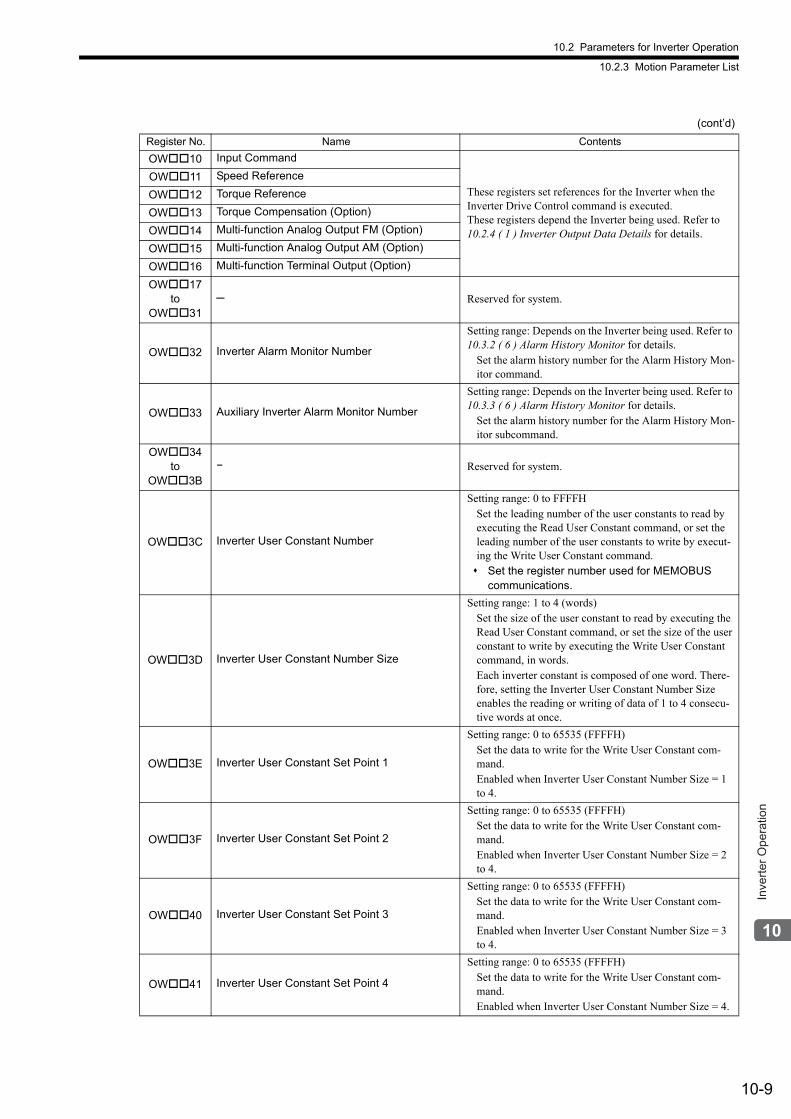
10.2 Parameters for Inverter Operation
10.2.3 Motion Parameter List
10-9
Inve
rter O
pera
tion
OW10 Input Command
These registers set references for the Inverter when the Inverter Drive Control command is executed.These registers depend the Inverter being used. Refer to 10.2.4 ( 1 ) Inverter Output Data Details for details.
OW11 Speed Reference
OW12 Torque Reference
OW13 Torque Compensation (Option)
OW14 Multi-function Analog Output FM (Option)
OW15 Multi-function Analog Output AM (Option)
OW16 Multi-function Terminal Output (Option)
OW17to
OW31─ Reserved for system.
OW32 Inverter Alarm Monitor Number
Setting range: Depends on the Inverter being used. Refer to 10.3.2 ( 6 ) Alarm History Monitor for details.
Set the alarm history number for the Alarm History Mon-itor command.
OW33 Auxiliary Inverter Alarm Monitor Number
Setting range: Depends on the Inverter being used. Refer to 10.3.3 ( 6 ) Alarm History Monitor for details.
Set the alarm history number for the Alarm History Mon-itor subcommand.
OW34to
OW3B− Reserved for system.
OW3C Inverter User Constant Number
Setting range: 0 to FFFFHSet the leading number of the user constants to read by executing the Read User Constant command, or set the leading number of the user constants to write by execut-ing the Write User Constant command. Set the register number used for MEMOBUS
communications.
OW3D Inverter User Constant Number Size
Setting range: 1 to 4 (words)Set the size of the user constant to read by executing the Read User Constant command, or set the size of the user constant to write by executing the Write User Constant command, in words.Each inverter constant is composed of one word. There-fore, setting the Inverter User Constant Number Size enables the reading or writing of data of 1 to 4 consecu-tive words at once.
OW3E Inverter User Constant Set Point 1
Setting range: 0 to 65535 (FFFFH)Set the data to write for the Write User Constant com-mand.Enabled when Inverter User Constant Number Size = 1 to 4.
OW3F Inverter User Constant Set Point 2
Setting range: 0 to 65535 (FFFFH)Set the data to write for the Write User Constant com-mand.Enabled when Inverter User Constant Number Size = 2 to 4.
OW40 Inverter User Constant Set Point 3
Setting range: 0 to 65535 (FFFFH)Set the data to write for the Write User Constant com-mand.Enabled when Inverter User Constant Number Size = 3 to 4.
OW41 Inverter User Constant Set Point 4
Setting range: 0 to 65535 (FFFFH)Set the data to write for the Write User Constant com-mand.Enabled when Inverter User Constant Number Size = 4.
(cont’d)
Register No. Name Contents
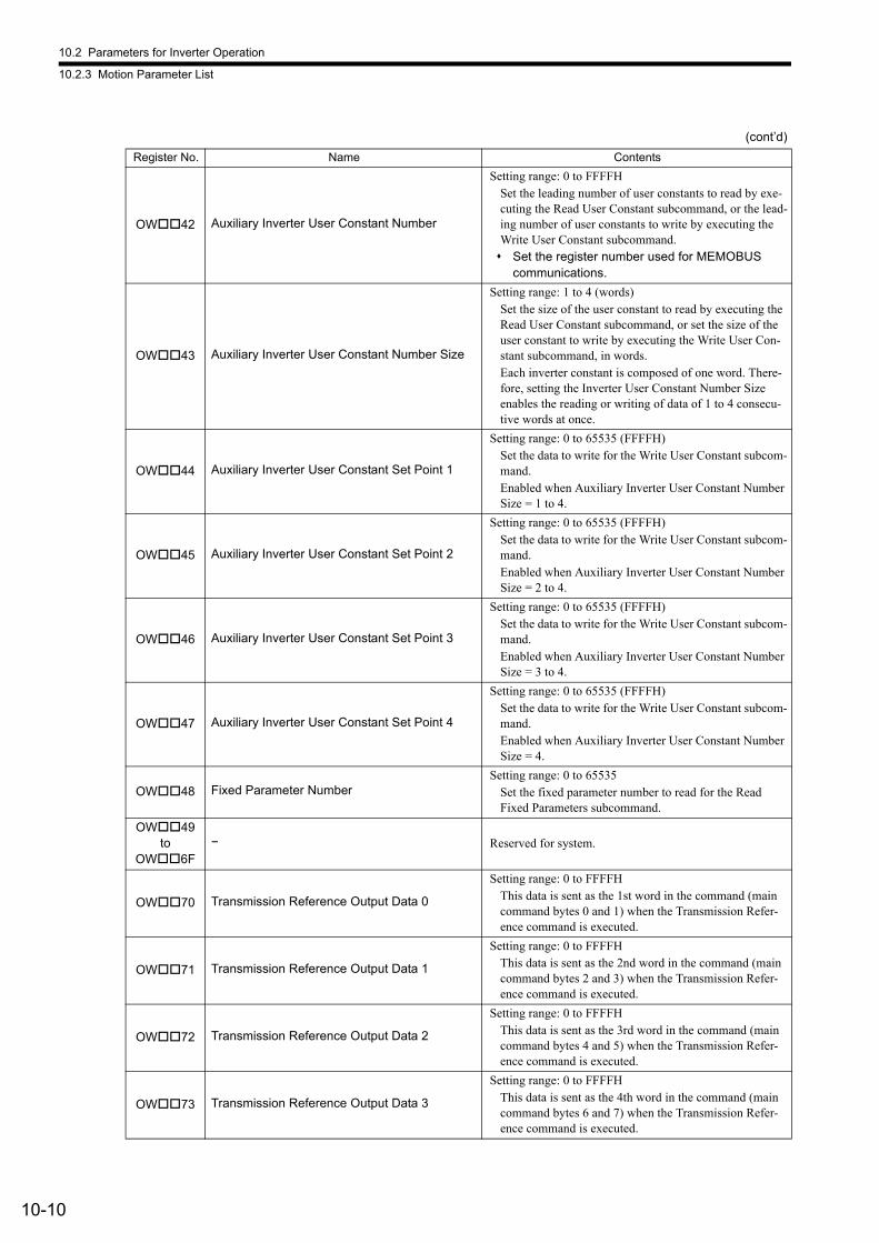
10.2 Parameters for Inverter Operation
10.2.3 Motion Parameter List
10-10
OW42 Auxiliary Inverter User Constant Number
Setting range: 0 to FFFFHSet the leading number of user constants to read by exe-cuting the Read User Constant subcommand, or the lead-ing number of user constants to write by executing the Write User Constant subcommand. Set the register number used for MEMOBUS
communications.
OW43 Auxiliary Inverter User Constant Number Size
Setting range: 1 to 4 (words)Set the size of the user constant to read by executing the Read User Constant subcommand, or set the size of the user constant to write by executing the Write User Con-stant subcommand, in words.Each inverter constant is composed of one word. There-fore, setting the Inverter User Constant Number Size enables the reading or writing of data of 1 to 4 consecu-tive words at once.
OW44 Auxiliary Inverter User Constant Set Point 1
Setting range: 0 to 65535 (FFFFH)Set the data to write for the Write User Constant subcom-mand.Enabled when Auxiliary Inverter User Constant Number Size = 1 to 4.
OW45 Auxiliary Inverter User Constant Set Point 2
Setting range: 0 to 65535 (FFFFH)Set the data to write for the Write User Constant subcom-mand.Enabled when Auxiliary Inverter User Constant Number Size = 2 to 4.
OW46 Auxiliary Inverter User Constant Set Point 3
Setting range: 0 to 65535 (FFFFH)Set the data to write for the Write User Constant subcom-mand.Enabled when Auxiliary Inverter User Constant Number Size = 3 to 4.
OW47 Auxiliary Inverter User Constant Set Point 4
Setting range: 0 to 65535 (FFFFH)Set the data to write for the Write User Constant subcom-mand.Enabled when Auxiliary Inverter User Constant Number Size = 4.
OW48 Fixed Parameter NumberSetting range: 0 to 65535
Set the fixed parameter number to read for the Read Fixed Parameters subcommand.
OW49to
OW6F− Reserved for system.
OW70 Transmission Reference Output Data 0
Setting range: 0 to FFFFHThis data is sent as the 1st word in the command (main command bytes 0 and 1) when the Transmission Refer-ence command is executed.
OW71 Transmission Reference Output Data 1
Setting range: 0 to FFFFHThis data is sent as the 2nd word in the command (main command bytes 2 and 3) when the Transmission Refer-ence command is executed.
OW72 Transmission Reference Output Data 2
Setting range: 0 to FFFFHThis data is sent as the 3rd word in the command (main command bytes 4 and 5) when the Transmission Refer-ence command is executed.
OW73 Transmission Reference Output Data 3
Setting range: 0 to FFFFHThis data is sent as the 4th word in the command (main command bytes 6 and 7) when the Transmission Refer-ence command is executed.
(cont’d)
Register No. Name Contents
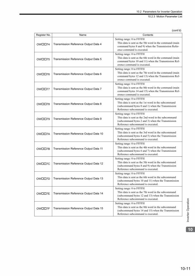
10.2 Parameters for Inverter Operation
10.2.3 Motion Parameter List
10-11
Inve
rter O
pera
tion
OW74 Transmission Reference Output Data 4
Setting range: 0 to FFFFHThis data is sent as the 5th word in the command (main command bytes 8 and 9) when the Transmission Refer-ence command is executed.
OW75 Transmission Reference Output Data 5
Setting range: 0 to FFFFHThis data is sent as the 6th word in the command (main command bytes 10 and 11) when the Transmission Ref-erence command is executed.
OW76 Transmission Reference Output Data 6
Setting range: 0 to FFFFHThis data is sent as the 7th word in the command (main command bytes 12 and 13) when the Transmission Ref-erence command is executed.
OW77 Transmission Reference Output Data 7
Setting range: 0 to FFFFHThis data is sent as the 8th word in the command (main command bytes 14 and 15) when the Transmission Ref-erence command is executed.
OW78 Transmission Reference Output Data 8
Setting range: 0 to FFFFHThis data is sent as the 1st word in the subcommand (subcommand bytes 0 and 1) when the Transmission Reference subcommand is executed.
OW79 Transmission Reference Output Data 9
Setting range: 0 to FFFFHThis data is sent as the 2nd word in the subcommand (subcommand bytes 2 and 3) when the Transmission Reference subcommand is executed.
OW7A Transmission Reference Output Data 10
Setting range: 0 to FFFFHThis data is sent as the 3rd word in the subcommand (subcommand bytes 4 and 5) when the Transmission Reference subcommand is executed.
OW7B Transmission Reference Output Data 11
Setting range: 0 to FFFFHThis data is sent as the 4th word in the subcommand (subcommand bytes 6 and 7) when the Transmission Reference subcommand is executed.
OW7C Transmission Reference Output Data 12
Setting range: 0 to FFFFHThis data is sent as the 5th word in the subcommand (subcommand bytes 8 and 9) when the Transmission Reference subcommand is executed.
OW7D Transmission Reference Output Data 13
Setting range: 0 to FFFFHThis data is sent as the 6th word in the subcommand (subcommand bytes 10 and 11) when the Transmission Reference subcommand is executed.
OW7E Transmission Reference Output Data 14
Setting range: 0 to FFFFHThis data is sent as the 7th word in the subcommand (subcommand bytes 12 and 13) when the Transmission Reference subcommand is executed.
OW7F Transmission Reference Output Data 15
Setting range: 0 to FFFFHThis data is sent as the 8th word in the subcommand (subcommand bytes 14 and 15) when the Transmission Reference subcommand is executed.
(cont’d)
Register No. Name Contents
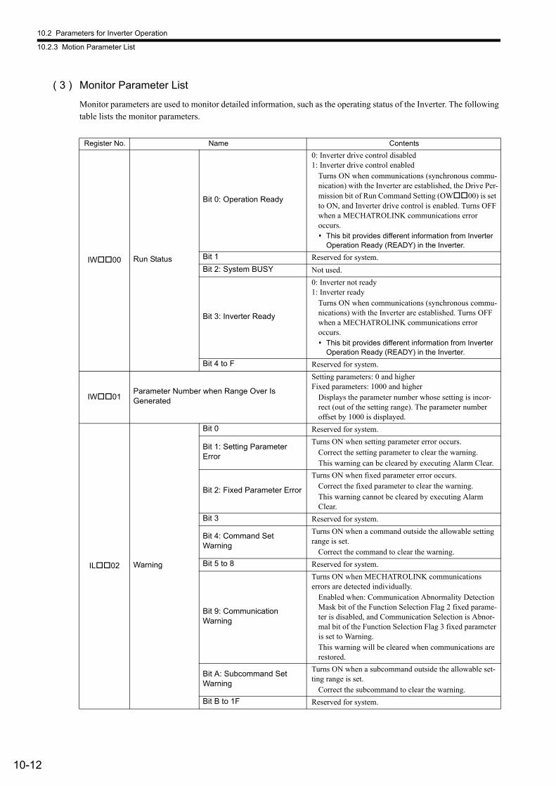
10.2 Parameters for Inverter Operation
10.2.3 Motion Parameter List
10-12
( 3 ) Monitor Parameter List
Monitor parameters are used to monitor detailed information, such as the operating status of the Inverter. The following table lists the monitor parameters.
Register No. Name Contents
IW00 Run Status
Bit 0: Operation Ready
0: Inverter drive control disabled1: Inverter drive control enabled
Turns ON when communications (synchronous commu-nication) with the Inverter are established, the Drive Per-mission bit of Run Command Setting (OW00) is set to ON, and Inverter drive control is enabled. Turns OFF when a MECHATROLINK communications error occurs. This bit provides different information from Inverter
Operation Ready (READY) in the Inverter.
Bit 1 Reserved for system.
Bit 2: System BUSY Not used.
Bit 3: Inverter Ready
0: Inverter not ready1: Inverter ready
Turns ON when communications (synchronous commu-nications) with the Inverter are established. Turns OFF when a MECHATROLINK communications error occurs. This bit provides different information from Inverter
Operation Ready (READY) in the Inverter.
Bit 4 to F Reserved for system.
IW01Parameter Number when Range Over Is Generated
Setting parameters: 0 and higherFixed parameters: 1000 and higher
Displays the parameter number whose setting is incor-rect (out of the setting range). The parameter number offset by 1000 is displayed.
IL02 Warning
Bit 0 Reserved for system.
Bit 1: Setting Parameter Error
Turns ON when setting parameter error occurs.Correct the setting parameter to clear the warning.This warning can be cleared by executing Alarm Clear.
Bit 2: Fixed Parameter Error
Turns ON when fixed parameter error occurs.Correct the fixed parameter to clear the warning.This warning cannot be cleared by executing Alarm Clear.
Bit 3 Reserved for system.
Bit 4: Command Set Warning
Turns ON when a command outside the allowable setting range is set.
Correct the command to clear the warning.
Bit 5 to 8 Reserved for system.
Bit 9: Communication Warning
Turns ON when MECHATROLINK communications errors are detected individually.
Enabled when: Communication Abnormality Detection Mask bit of the Function Selection Flag 2 fixed parame-ter is disabled, and Communication Selection is Abnor-mal bit of the Function Selection Flag 3 fixed parameter is set to Warning.This warning will be cleared when communications are restored.
Bit A: Subcommand Set Warning
Turns ON when a subcommand outside the allowable set-ting range is set.
Correct the subcommand to clear the warning.
Bit B to 1F Reserved for system.
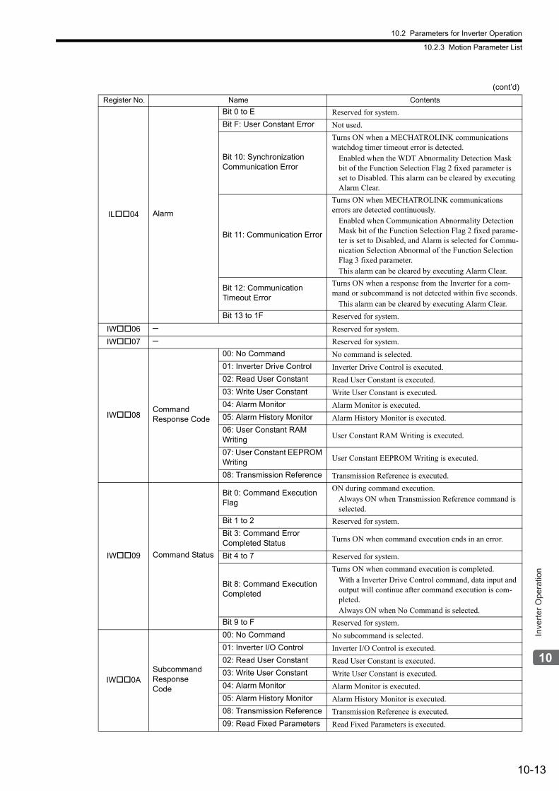
10.2 Parameters for Inverter Operation
10.2.3 Motion Parameter List
10-13
Inve
rter O
pera
tion
IL04 Alarm
Bit 0 to E Reserved for system.
Bit F: User Constant Error Not used.
Bit 10: Synchronization Communication Error
Turns ON when a MECHATROLINK communications watchdog timer timeout error is detected.
Enabled when the WDT Abnormality Detection Mask bit of the Function Selection Flag 2 fixed parameter is set to Disabled. This alarm can be cleared by executing Alarm Clear.
Bit 11: Communication Error
Turns ON when MECHATROLINK communications errors are detected continuously.
Enabled when Communication Abnormality Detection Mask bit of the Function Selection Flag 2 fixed parame-ter is set to Disabled, and Alarm is selected for Commu-nication Selection Abnormal of the Function Selection Flag 3 fixed parameter.This alarm can be cleared by executing Alarm Clear.
Bit 12: Communication Timeout Error
Turns ON when a response from the Inverter for a com-mand or subcommand is not detected within five seconds.
This alarm can be cleared by executing Alarm Clear.
Bit 13 to 1F Reserved for system.
IW06 ─ Reserved for system.
IW07 ─ Reserved for system.
IW08Command Response Code
00: No Command No command is selected.
01: Inverter Drive Control Inverter Drive Control is executed.
02: Read User Constant Read User Constant is executed.
03: Write User Constant Write User Constant is executed.
04: Alarm Monitor Alarm Monitor is executed.
05: Alarm History Monitor Alarm History Monitor is executed.
06: User Constant RAM Writing User Constant RAM Writing is executed.
07: User Constant EEPROM Writing User Constant EEPROM Writing is executed.
08: Transmission Reference Transmission Reference is executed.
IW09 Command Status
Bit 0: Command Execution Flag
ON during command execution.Always ON when Transmission Reference command is selected.
Bit 1 to 2 Reserved for system.
Bit 3: Command Error Completed Status Turns ON when command execution ends in an error.
Bit 4 to 7 Reserved for system.
Bit 8: Command Execution Completed
Turns ON when command execution is completed.With a Inverter Drive Control command, data input and output will continue after command execution is com-pleted.Always ON when No Command is selected.
Bit 9 to F Reserved for system.
IW0ASubcommand Response Code
00: No Command No subcommand is selected.
01: Inverter I/O Control Inverter I/O Control is executed.
02: Read User Constant Read User Constant is executed.
03: Write User Constant Write User Constant is executed.
04: Alarm Monitor Alarm Monitor is executed.
05: Alarm History Monitor Alarm History Monitor is executed.
08: Transmission Reference Transmission Reference is executed.
09: Read Fixed Parameters Read Fixed Parameters is executed.
(cont’d)
Register No. Name Contents
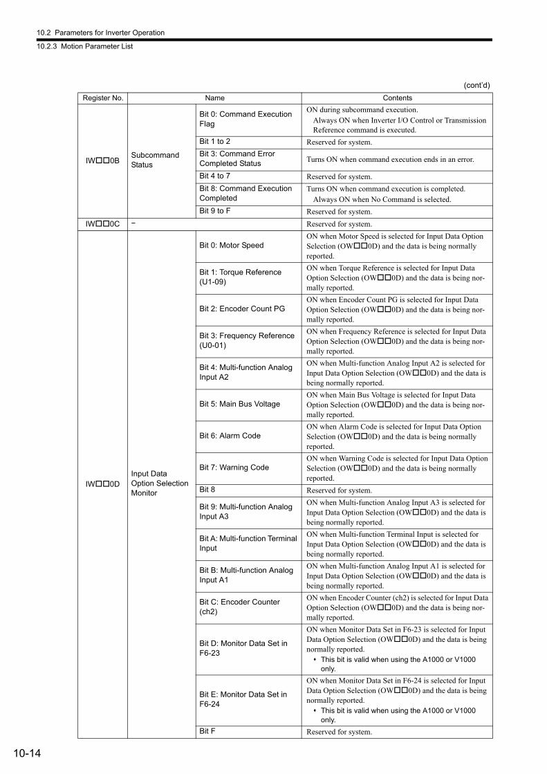
10.2 Parameters for Inverter Operation
10.2.3 Motion Parameter List
10-14
IW0BSubcommand Status
Bit 0: Command Execution Flag
ON during subcommand execution.Always ON when Inverter I/O Control or Transmission Reference command is executed.
Bit 1 to 2 Reserved for system.
Bit 3: Command Error Completed Status Turns ON when command execution ends in an error.
Bit 4 to 7 Reserved for system.
Bit 8: Command Execution Completed
Turns ON when command execution is completed.Always ON when No Command is selected.
Bit 9 to F Reserved for system.
IW0C − Reserved for system.
IW0DInput Data Option Selection Monitor
Bit 0: Motor SpeedON when Motor Speed is selected for Input Data Option Selection (OW0D) and the data is being normally reported.
Bit 1: Torque Reference (U1-09)
ON when Torque Reference is selected for Input Data Option Selection (OW0D) and the data is being nor-mally reported.
Bit 2: Encoder Count PGON when Encoder Count PG is selected for Input Data Option Selection (OW0D) and the data is being nor-mally reported.
Bit 3: Frequency Reference (U0-01)
ON when Frequency Reference is selected for Input Data Option Selection (OW0D) and the data is being nor-mally reported.
Bit 4: Multi-function Analog Input A2
ON when Multi-function Analog Input A2 is selected for Input Data Option Selection (OW0D) and the data is being normally reported.
Bit 5: Main Bus VoltageON when Main Bus Voltage is selected for Input Data Option Selection (OW0D) and the data is being nor-mally reported.
Bit 6: Alarm CodeON when Alarm Code is selected for Input Data Option Selection (OW0D) and the data is being normally reported.
Bit 7: Warning CodeON when Warning Code is selected for Input Data Option Selection (OW0D) and the data is being normally reported.
Bit 8 Reserved for system.
Bit 9: Multi-function Analog Input A3
ON when Multi-function Analog Input A3 is selected for Input Data Option Selection (OW0D) and the data is being normally reported.
Bit A: Multi-function Terminal Input
ON when Multi-function Terminal Input is selected for Input Data Option Selection (OW0D) and the data is being normally reported.
Bit B: Multi-function Analog Input A1
ON when Multi-function Analog Input A1 is selected for Input Data Option Selection (OW0D) and the data is being normally reported.
Bit C: Encoder Counter (ch2)
ON when Encoder Counter (ch2) is selected for Input Data Option Selection (OW0D) and the data is being nor-mally reported.
Bit D: Monitor Data Set in F6-23
ON when Monitor Data Set in F6-23 is selected for Input Data Option Selection (OW0D) and the data is being normally reported. This bit is valid when using the A1000 or V1000
only.
Bit E: Monitor Data Set in F6-24
ON when Monitor Data Set in F6-24 is selected for Input Data Option Selection (OW0D) and the data is being normally reported. This bit is valid when using the A1000 or V1000
only.
Bit F Reserved for system.
(cont’d)
Register No. Name Contents
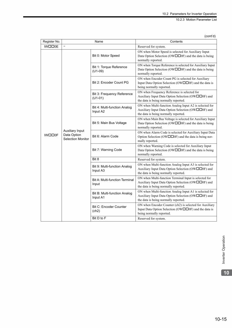
10.2 Parameters for Inverter Operation
10.2.3 Motion Parameter List
10-15
Inve
rter O
pera
tion
IW0E − Reserved for system.
IW0FAuxiliary Input Data Option Selection Monitor
Bit 0: Motor SpeedON when Motor Speed is selected for Auxiliary Input Data Option Selection (OW0F) and the data is being normally reported.
Bit 1: Torque Reference (U1-09)
ON when Torque Reference is selected for Auxiliary Input Data Option Selection (OW0F) and the data is being normally reported.
Bit 2: Encoder Count PGON when Encoder Count PG is selected for Auxiliary Input Data Option Selection (OW0F) and the data is being normally reported.
Bit 3: Frequency Reference (U1-01)
ON when Frequency Reference is selected forAuxiliary Input Data Option Selection (OW0F) and the data is being normally reported.
Bit 4: Multi-function Analog Input A2
ON when Multi-function Analog Input A2 is selected for Auxiliary Input Data Option Selection (OW0F) and the data is being normally reported.
Bit 5: Main Bus VoltageON when Main Bus Voltage is selected for Auxiliary Input Data Option Selection (OW0F) and the data is being normally reported.
Bit 6: Alarm CodeON when Alarm Code is selected for Auxiliary Input Data Option Selection (OW0F) and the data is being nor-mally reported.
Bit 7: Warning CodeON when Warning Code is selected for Auxiliary Input Data Option Selection (OW0F) and the data is being normally reported.
Bit 8 Reserved for system.
Bit 9: Multi-function Analog Input A3
ON when Multi-function Analog Input A3 is selected for Auxiliary Input Data Option Selection (OW0F) and the data is being normally reported.
Bit A: Multi-function Terminal Input
ON when Multi-function Terminal Input is selected for Auxiliary Input Data Option Selection (OW0F) and the data is being normally reported.
Bit B: Multi-function Analog Input A1
ON when Multi-function Analog Input A1 is selected for Auxiliary Input Data Option Selection (OW0F) and the data is being normally reported.
Bit C: Encoder Counter (ch2)
ON when Encoder Counter (ch2) is selected for Auxiliary Input Data Option Selection (OW0F) and the data is being normally reported.
Bit D to F Reserved for system.
(cont’d)
Register No. Name Contents
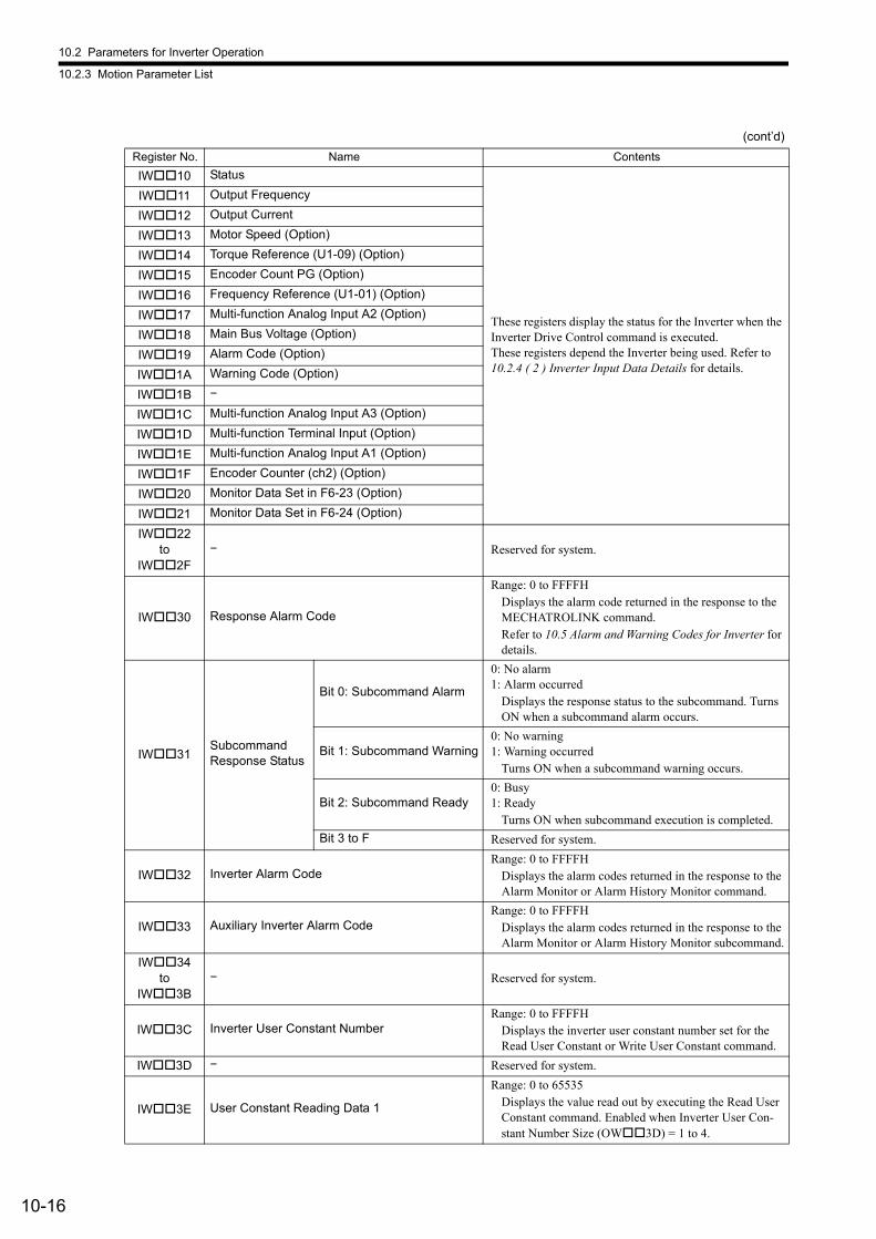
10.2 Parameters for Inverter Operation
10.2.3 Motion Parameter List
10-16
IW10 Status
These registers display the status for the Inverter when the Inverter Drive Control command is executed.These registers depend the Inverter being used. Refer to 10.2.4 ( 2 ) Inverter Input Data Details for details.
IW11 Output Frequency
IW12 Output Current
IW13 Motor Speed (Option)
IW14 Torque Reference (U1-09) (Option)
IW15 Encoder Count PG (Option)
IW16 Frequency Reference (U1-01) (Option)
IW17 Multi-function Analog Input A2 (Option)
IW18 Main Bus Voltage (Option)
IW19 Alarm Code (Option)
IW1A Warning Code (Option)
IW1B −
IW1C Multi-function Analog Input A3 (Option)
IW1D Multi-function Terminal Input (Option)
IW1E Multi-function Analog Input A1 (Option)
IW1F Encoder Counter (ch2) (Option)
IW20 Monitor Data Set in F6-23 (Option)
IW21 Monitor Data Set in F6-24 (Option)
IW22to
IW2F− Reserved for system.
IW30 Response Alarm Code
Range: 0 to FFFFHDisplays the alarm code returned in the response to the MECHATROLINK command.Refer to 10.5 Alarm and Warning Codes for Inverter for details.
IW31Subcommand Response Status
Bit 0: Subcommand Alarm
0: No alarm1: Alarm occurred
Displays the response status to the subcommand. Turns ON when a subcommand alarm occurs.
Bit 1: Subcommand Warning0: No warning1: Warning occurred
Turns ON when a subcommand warning occurs.
Bit 2: Subcommand Ready0: Busy1: Ready
Turns ON when subcommand execution is completed.
Bit 3 to F Reserved for system.
IW32 Inverter Alarm CodeRange: 0 to FFFFH
Displays the alarm codes returned in the response to the Alarm Monitor or Alarm History Monitor command.
IW33 Auxiliary Inverter Alarm CodeRange: 0 to FFFFH
Displays the alarm codes returned in the response to the Alarm Monitor or Alarm History Monitor subcommand.
IW34to
IW3B− Reserved for system.
IW3C Inverter User Constant NumberRange: 0 to FFFFH
Displays the inverter user constant number set for the Read User Constant or Write User Constant command.
IW3D − Reserved for system.
IW3E User Constant Reading Data 1
Range: 0 to 65535Displays the value read out by executing the Read User Constant command. Enabled when Inverter User Con-stant Number Size (OW3D) = 1 to 4.
(cont’d)
Register No. Name Contents
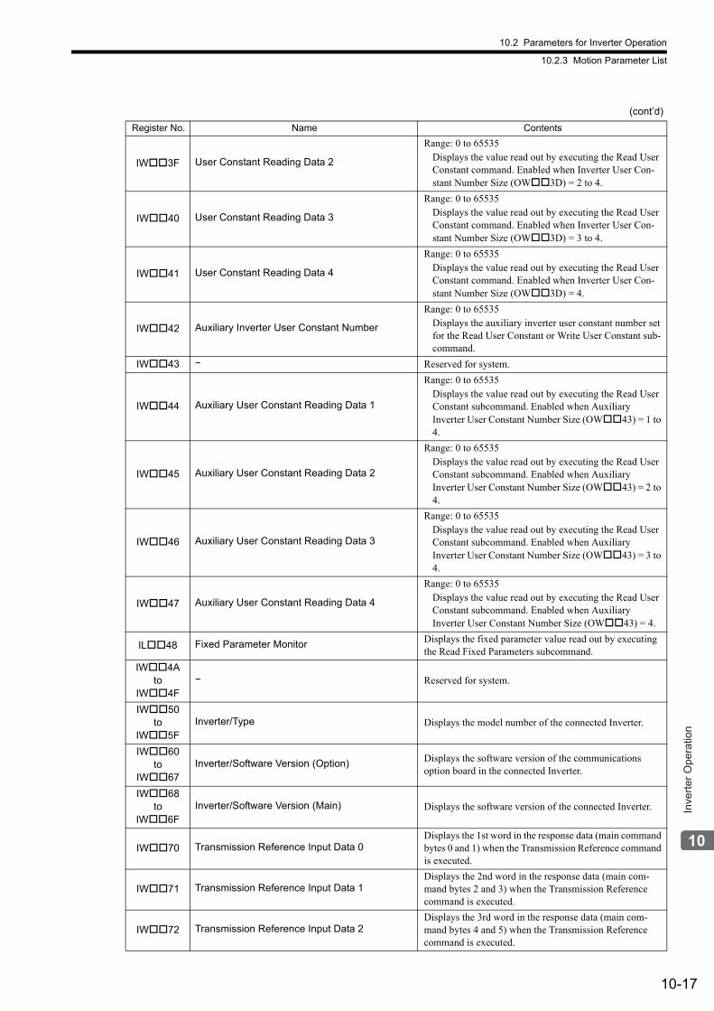
10.2 Parameters for Inverter Operation
10.2.3 Motion Parameter List
10-17
Inve
rter O
pera
tion
IW3F User Constant Reading Data 2
Range: 0 to 65535Displays the value read out by executing the Read User Constant command. Enabled when Inverter User Con-stant Number Size (OW3D) = 2 to 4.
IW40 User Constant Reading Data 3
Range: 0 to 65535Displays the value read out by executing the Read User Constant command. Enabled when Inverter User Con-stant Number Size (OW3D) = 3 to 4.
IW41 User Constant Reading Data 4
Range: 0 to 65535Displays the value read out by executing the Read User Constant command. Enabled when Inverter User Con-stant Number Size (OW3D) = 4.
IW42 Auxiliary Inverter User Constant Number
Range: 0 to 65535Displays the auxiliary inverter user constant number set for the Read User Constant or Write User Constant sub-command.
IW43 − Reserved for system.
IW44 Auxiliary User Constant Reading Data 1
Range: 0 to 65535Displays the value read out by executing the Read User Constant subcommand. Enabled when Auxiliary Inverter User Constant Number Size (OW43) = 1 to 4.
IW45 Auxiliary User Constant Reading Data 2
Range: 0 to 65535Displays the value read out by executing the Read User Constant subcommand. Enabled when Auxiliary Inverter User Constant Number Size (OW43) = 2 to 4.
IW46 Auxiliary User Constant Reading Data 3
Range: 0 to 65535Displays the value read out by executing the Read User Constant subcommand. Enabled when Auxiliary Inverter User Constant Number Size (OW43) = 3 to 4.
IW47 Auxiliary User Constant Reading Data 4
Range: 0 to 65535Displays the value read out by executing the Read User Constant subcommand. Enabled when Auxiliary Inverter User Constant Number Size (OW43) = 4.
IL48 Fixed Parameter Monitor Displays the fixed parameter value read out by executing the Read Fixed Parameters subcommand.
IW4A to
IW4F− Reserved for system.
IW50 to
IW5FInverter/Type Displays the model number of the connected Inverter.
IW60 to
IW67Inverter/Software Version (Option) Displays the software version of the communications
option board in the connected Inverter.
IW68 to
IW6FInverter/Software Version (Main) Displays the software version of the connected Inverter.
IW70 Transmission Reference Input Data 0Displays the 1st word in the response data (main command bytes 0 and 1) when the Transmission Reference command is executed.
IW71 Transmission Reference Input Data 1Displays the 2nd word in the response data (main com-mand bytes 2 and 3) when the Transmission Reference command is executed.
IW72 Transmission Reference Input Data 2Displays the 3rd word in the response data (main com-mand bytes 4 and 5) when the Transmission Reference command is executed.
(cont’d)
Register No. Name Contents
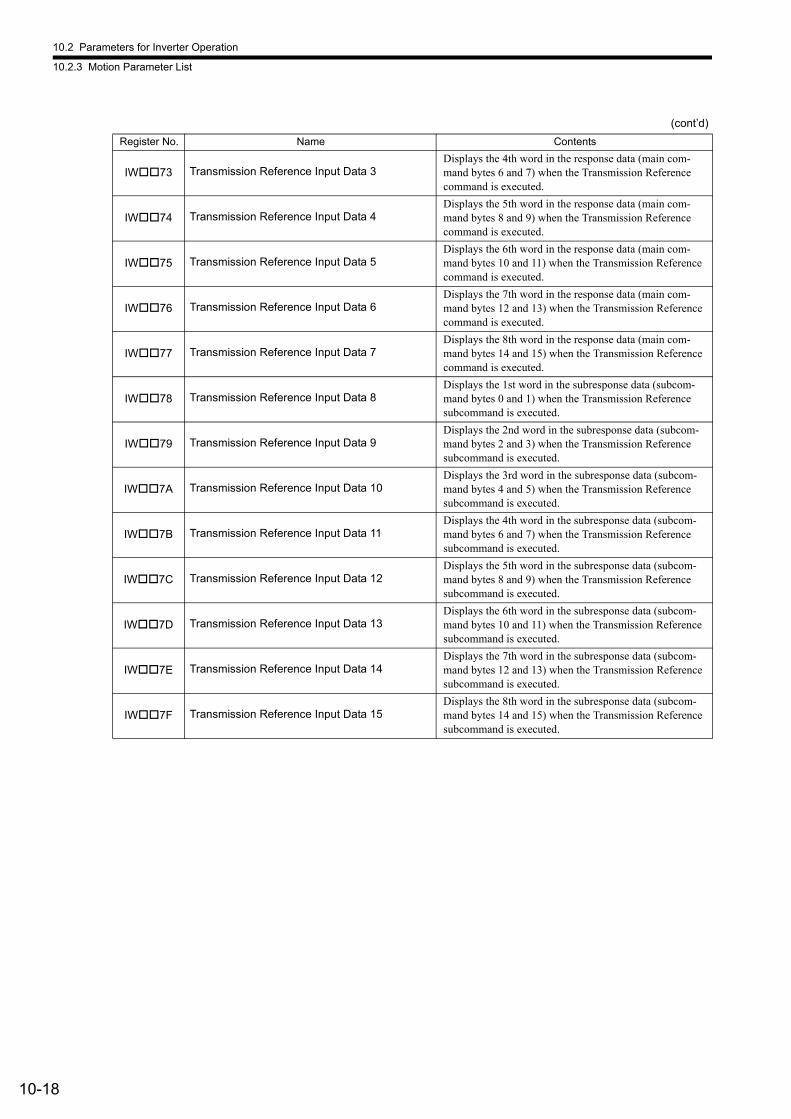
10.2 Parameters for Inverter Operation
10.2.3 Motion Parameter List
10-18
IW73 Transmission Reference Input Data 3Displays the 4th word in the response data (main com-mand bytes 6 and 7) when the Transmission Reference command is executed.
IW74 Transmission Reference Input Data 4Displays the 5th word in the response data (main com-mand bytes 8 and 9) when the Transmission Reference command is executed.
IW75 Transmission Reference Input Data 5Displays the 6th word in the response data (main com-mand bytes 10 and 11) when the Transmission Reference command is executed.
IW76 Transmission Reference Input Data 6Displays the 7th word in the response data (main com-mand bytes 12 and 13) when the Transmission Reference command is executed.
IW77 Transmission Reference Input Data 7Displays the 8th word in the response data (main com-mand bytes 14 and 15) when the Transmission Reference command is executed.
IW78 Transmission Reference Input Data 8Displays the 1st word in the subresponse data (subcom-mand bytes 0 and 1) when the Transmission Reference subcommand is executed.
IW79 Transmission Reference Input Data 9Displays the 2nd word in the subresponse data (subcom-mand bytes 2 and 3) when the Transmission Reference subcommand is executed.
IW7A Transmission Reference Input Data 10Displays the 3rd word in the subresponse data (subcom-mand bytes 4 and 5) when the Transmission Reference subcommand is executed.
IW7B Transmission Reference Input Data 11Displays the 4th word in the subresponse data (subcom-mand bytes 6 and 7) when the Transmission Reference subcommand is executed.
IW7C Transmission Reference Input Data 12Displays the 5th word in the subresponse data (subcom-mand bytes 8 and 9) when the Transmission Reference subcommand is executed.
IW7D Transmission Reference Input Data 13Displays the 6th word in the subresponse data (subcom-mand bytes 10 and 11) when the Transmission Reference subcommand is executed.
IW7E Transmission Reference Input Data 14Displays the 7th word in the subresponse data (subcom-mand bytes 12 and 13) when the Transmission Reference subcommand is executed.
IW7F Transmission Reference Input Data 15Displays the 8th word in the subresponse data (subcom-mand bytes 14 and 15) when the Transmission Reference subcommand is executed.
(cont’d)
Register No. Name Contents
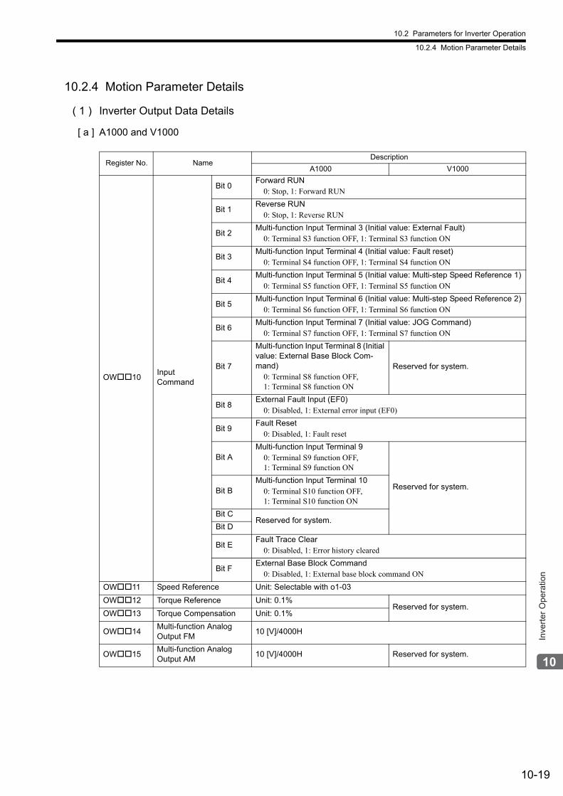
10.2 Parameters for Inverter Operation
10.2.4 Motion Parameter Details
10-19
Inve
rter O
pera
tion
10.2.4 Motion Parameter Details
( 1 ) Inverter Output Data Details
[ a ] A1000 and V1000
Register No. NameDescription
A1000 V1000
OW10Input Command
Bit 0Forward RUN
0: Stop, 1: Forward RUN
Bit 1Reverse RUN
0: Stop, 1: Reverse RUN
Bit 2Multi-function Input Terminal 3 (Initial value: External Fault)
0: Terminal S3 function OFF, 1: Terminal S3 function ON
Bit 3Multi-function Input Terminal 4 (Initial value: Fault reset)
0: Terminal S4 function OFF, 1: Terminal S4 function ON
Bit 4Multi-function Input Terminal 5 (Initial value: Multi-step Speed Reference 1)
0: Terminal S5 function OFF, 1: Terminal S5 function ON
Bit 5Multi-function Input Terminal 6 (Initial value: Multi-step Speed Reference 2)
0: Terminal S6 function OFF, 1: Terminal S6 function ON
Bit 6Multi-function Input Terminal 7 (Initial value: JOG Command)
0: Terminal S7 function OFF, 1: Terminal S7 function ON
Bit 7
Multi-function Input Terminal 8 (Initial value: External Base Block Com-mand)
0: Terminal S8 function OFF, 1: Terminal S8 function ON
Reserved for system.
Bit 8External Fault Input (EF0)
0: Disabled, 1: External error input (EF0)
Bit 9Fault Reset
0: Disabled, 1: Fault reset
Bit AMulti-function Input Terminal 9
0: Terminal S9 function OFF, 1: Terminal S9 function ON
Reserved for system.Bit BMulti-function Input Terminal 10
0: Terminal S10 function OFF, 1: Terminal S10 function ON
Bit CReserved for system.
Bit D
Bit EFault Trace Clear
0: Disabled, 1: Error history cleared
Bit FExternal Base Block Command
0: Disabled, 1: External base block command ON
OW11 Speed Reference Unit: Selectable with o1-03
OW12 Torque Reference Unit: 0.1%Reserved for system.
OW13 Torque Compensation Unit: 0.1%
OW14Multi-function Analog Output FM
10 [V]/4000H
OW15Multi-function Analog Output AM
10 [V]/4000H Reserved for system.

10.2 Parameters for Inverter Operation
10.2.4 Motion Parameter Details
10-20
OW16Multi-function Terminal Output
Bit 0Terminals M1-M2
0: OFF, 1: ON (Enabled when H2-01 = F)
Terminals MA-MC0: OFF, 1: ON (Enabled when H2-01 = F)
Bit 1Terminals P1-PC
0: OFF, 1: ON (Enabled when H2-02 = F)
Terminal P10: OFF, 1: ON (Enabled when H2-02 = F)
Bit 2Terminals P2-PC
0: OFF, 1: ON (Enabled when H2-03 = F)
Terminal P20: OFF, 1: ON (Enabled when H2-03 = F)
Bit 3 to F Reserved for system.
(cont’d)
Register No. NameDescription
A1000 V1000
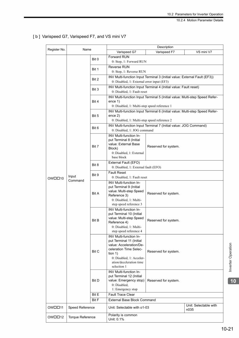
10.2 Parameters for Inverter Operation
10.2.4 Motion Parameter Details
10-21
Inve
rter O
pera
tion
[ b ] Varispeed G7, Varispeed F7, and VS mini V7
Register No. NameDescription
Varispeed G7 Varispeed F7 VS mini V7
OW10Input Command
Bit 0Forward RUN
0: Stop, 1: Forward RUN
Bit 1Reverse RUN
0: Stop, 1: Reverse RUN
Bit 2INV Multi-function Input Terminal 3 (Initial value: External Fault (EF3))
0: Disabled, 1: External error input (EF3)
Bit 3INV Multi-function Input Terminal 4 (Initial value: Fault reset)
0: Disabled, 1: Fault reset
Bit 4INV Multi-function Input Terminal 5 (Initial value: Multi-step Speed Refer-ence 1)
0: Disabled, 1: Multi-step speed reference 1
Bit 5INV Multi-function Input Terminal 6 (Initial value: Multi-step Speed Refer-ence 2)
0: Disabled, 1: Multi-step speed reference 2
Bit 6INV Multi-function Input Terminal 7 (Initial value: JOG Command)
0: Disabled, 1: JOG command
Bit 7
INV Multi-function In-put Terminal 8 (Initial value: External Base Block)
0: Disabled, 1: External base block
Reserved for system.
Bit 8External Fault (EFO)
0: Disabled, 1: External fault (EFO)
Bit 9Fault Reset
0: Disabled, 1: Fault reset
Bit A
INV Multi-function In-put Terminal 9 (Initial value: Multi-step Speed Reference 3)
0: Disabled, 1: Multi-step speed reference 3
Reserved for system.
Bit B
INV Multi-function In-put Terminal 10 (Initial value: Multi-step Speed Reference 4)
0: Disabled, 1: Multi-step speed reference 4
Reserved for system.
Bit C
INV Multi-function In-put Terminal 11 (Initial value: Acceleration/De-celeration Time Selec-tion 1)
0: Disabled, 1: Acceler-ation/deceleration time selection 1
Reserved for system.
Bit D
INV Multi-function In-put Terminal 12 (Initial value: Emergency stop)
0: Disabled, 1: Emergency stop
Reserved for system.
Bit E Fault Trace Clear
Bit F External Base Block Command
OW11 Speed Reference Unit: Selectable with o1-03Unit: Selectable with n035
OW12 Torque ReferencePolarity is commonUnit: 0.1%
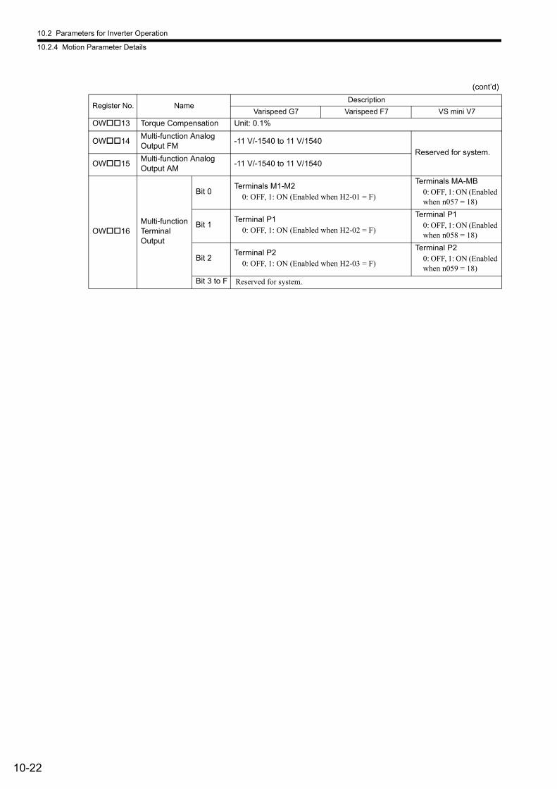
10.2 Parameters for Inverter Operation
10.2.4 Motion Parameter Details
10-22
OW13 Torque Compensation Unit: 0.1%
OW14Multi-function Analog Output FM
-11 V/-1540 to 11 V/1540
Reserved for system.
OW15Multi-function Analog Output AM
-11 V/-1540 to 11 V/1540
OW16Multi-function Terminal Output
Bit 0Terminals M1-M2
0: OFF, 1: ON (Enabled when H2-01 = F)
Terminals MA-MB0: OFF, 1: ON (Enabled when n057 = 18)
Bit 1Terminal P1
0: OFF, 1: ON (Enabled when H2-02 = F)
Terminal P10: OFF, 1: ON (Enabled when n058 = 18)
Bit 2Terminal P2
0: OFF, 1: ON (Enabled when H2-03 = F)
Terminal P20: OFF, 1: ON (Enabled when n059 = 18)
Bit 3 to F Reserved for system.
(cont’d)
Register No. NameDescription
Varispeed G7 Varispeed F7 VS mini V7
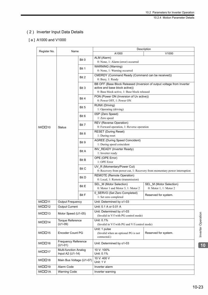
10.2 Parameters for Inverter Operation
10.2.4 Motion Parameter Details
10-23
Inve
rter O
pera
tion
( 2 ) Inverter Input Data Details
[ a ] A1000 and V1000
Register No. NameDescription
A1000 V1000
IW10 Status
Bit 0ALM (Alarm)
0: None, 1: Alarm (error) occurred
Bit 1WARNING (Warning)
0: None, 1: Warning occurred
Bit 2CMDRDY (Command Ready (Command can be received))
0: Busy, 1: Ready
Bit 3BB OFF (Base Block Released (Inversion of output voltage from Inverter active and base block active))
0: Base block active, 1: Base block released
Bit 4PON (Power ON (Inversion of Uv active))
0: Power OFF, 1: Power ON
Bit 5RUNX (Driving)
1: Operating (driving)
Bit 60SP (Zero Speed)
1: Zero speed
Bit 7REV (Reverse Operation)
0: Forward operation, 1: Reverse operation
Bit 8RESET (During Reset)
1: During reset
Bit 9AGREE (During Speed Coincident)
1: During speed coincident
Bit AINV_READY (Inverter Ready)
1: Inverter ready
Bit BOPE (OPE Error)
1: OPE Error
Bit CUV_R (Momentary/Power Cut)
0: Recovery from power cut, 1: Recovery from momentary power interruption
Bit DREMOTE (Remote Operation)
0: Local, 1: Remote (transmission)
Bit ESEL_M (Motor Selection)
0: Motor 1 and Motor 3, 1: Motor 2SEL_M (Motor Selection)
0: Motor 1, 1: Motor 2
Bit F0_SERVO (Set Zero Completed)
1: Set zero completedReserved for system.
IW11 Output Frequency Unit: Determined by o1-03
IW12 Output Current Unit: 0.1 A or 0.01 A
IW13 Motor Speed (U1-05)Unit: Determined by o1-03
(Invalid in V/f with PG control mode)
IW14Torque Reference (U1-09)
Unit: 0.1%(Invalid in V/f with PG and V/f control mode)
IW15 Encoder Count PGUnit: 1 pulse
(Invalid when an optional PG is not connected.)
Reserved for system.
IW16Frequency Reference (U1-01)
Unit: Determined by o1-03
IW17Multi-function Analog Input A2 (U1-14)
10 V: 100%Unit: 0.1%
IW18 Main Bus Voltage (U1-07)10 V: 400 VUnit: 1 V
IW19 Alarm Code Inverter alarm
IW1A Warning Code Inverter warning
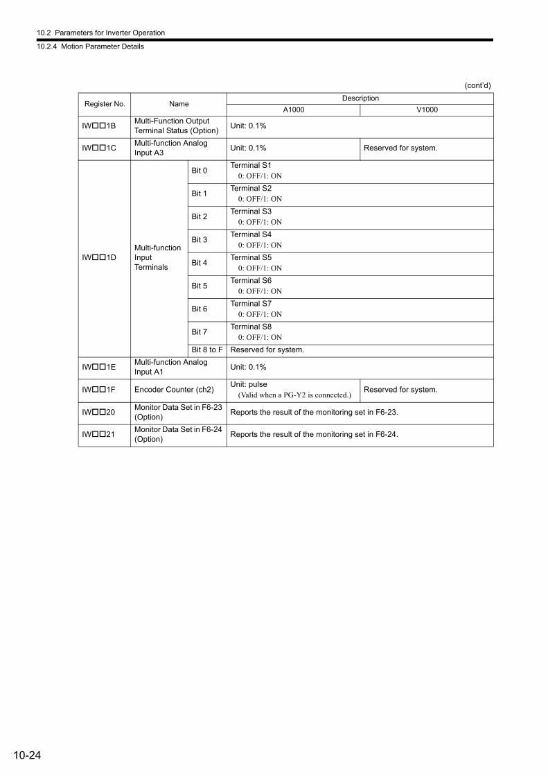
10.2 Parameters for Inverter Operation
10.2.4 Motion Parameter Details
10-24
IW1BMulti-Function Output Terminal Status (Option)
Unit: 0.1%
IW1CMulti-function Analog Input A3
Unit: 0.1% Reserved for system.
IW1DMulti-function Input Terminals
Bit 0Terminal S1
0: OFF/1: ON
Bit 1Terminal S2
0: OFF/1: ON
Bit 2Terminal S3
0: OFF/1: ON
Bit 3Terminal S4
0: OFF/1: ON
Bit 4Terminal S5
0: OFF/1: ON
Bit 5Terminal S6
0: OFF/1: ON
Bit 6Terminal S7
0: OFF/1: ON
Bit 7Terminal S8
0: OFF/1: ON
Bit 8 to F Reserved for system.
IW1EMulti-function Analog Input A1
Unit: 0.1%
IW1F Encoder Counter (ch2)Unit: pulse
(Valid when a PG-Y2 is connected.)Reserved for system.
IW20Monitor Data Set in F6-23 (Option)
Reports the result of the monitoring set in F6-23.
IW21Monitor Data Set in F6-24 (Option)
Reports the result of the monitoring set in F6-24.
(cont’d)
Register No. NameDescription
A1000 V1000
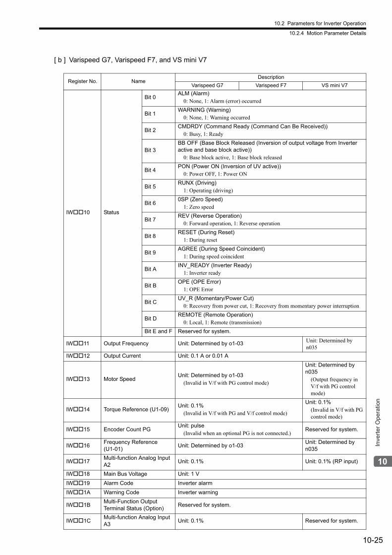
10.2 Parameters for Inverter Operation
10.2.4 Motion Parameter Details
10-25
Inve
rter O
pera
tion
[ b ] Varispeed G7, Varispeed F7, and VS mini V7
Register No. NameDescription
Varispeed G7 Varispeed F7 VS mini V7
IW10 Status
Bit 0ALM (Alarm)
0: None, 1: Alarm (error) occurred
Bit 1WARNING (Warning)
0: None, 1: Warning occurred
Bit 2CMDRDY (Command Ready (Command Can Be Received))
0: Busy, 1: Ready
Bit 3BB OFF (Base Block Released (Inversion of output voltage from Inverter active and base block active))
0: Base block active, 1: Base block released
Bit 4PON (Power ON (Inversion of UV active))
0: Power OFF, 1: Power ON
Bit 5RUNX (Driving)
1: Operating (driving)
Bit 60SP (Zero Speed)
1: Zero speed
Bit 7REV (Reverse Operation)
0: Forward operation, 1: Reverse operation
Bit 8RESET (During Reset)
1: During reset
Bit 9AGREE (During Speed Coincident)
1: During speed coincident
Bit AINV_READY (Inverter Ready)
1: Inverter ready
Bit BOPE (OPE Error)
1: OPE Error
Bit CUV_R (Momentary/Power Cut)
0: Recovery from power cut, 1: Recovery from momentary power interruption
Bit DREMOTE (Remote Operation)
0: Local, 1: Remote (transmission)
Bit E and F Reserved for system.
IW11 Output Frequency Unit: Determined by o1-03 Unit: Determined by n035
IW12 Output Current Unit: 0.1 A or 0.01 A
IW13 Motor SpeedUnit: Determined by o1-03
(Invalid in V/f with PG control mode)
Unit: Determined by n035
(Output frequency in V/f with PG control mode)
IW14 Torque Reference (U1-09)Unit: 0.1%
(Invalid in V/f with PG and V/f control mode)
Unit: 0.1%(Invalid in V/f with PG control mode)
IW15 Encoder Count PGUnit: pulse
(Invalid when an optional PG is not connected.)Reserved for system.
IW16Frequency Reference (U1-01)
Unit: Determined by o1-03Unit: Determined by n035
IW17Multi-function Analog Input A2
Unit: 0.1% Unit: 0.1% (RP input)
IW18 Main Bus Voltage Unit: 1 V
IW19 Alarm Code Inverter alarm
IW1A Warning Code Inverter warning
IW1BMulti-Function Output Terminal Status (Option)
Reserved for system.
IW1CMulti-function Analog Input A3
Unit: 0.1% Reserved for system.
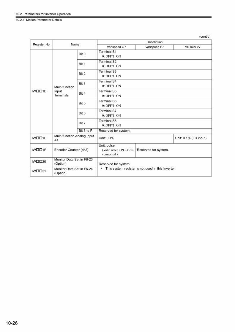
10.2 Parameters for Inverter Operation
10.2.4 Motion Parameter Details
10-26
IW1DMulti-function Input Terminals
Bit 0Terminal S1
0: OFF/1: ON
Bit 1Terminal S2
0: OFF/1: ON
Bit 2Terminal S3
0: OFF/1: ON
Bit 3Terminal S4
0: OFF/1: ON
Bit 4Terminal S5
0: OFF/1: ON
Bit 5Terminal S6
0: OFF/1: ON
Bit 6Terminal S7
0: OFF/1: ON
Bit 7Terminal S8
0: OFF/1: ON
Bit 8 to F Reserved for system.
IW1EMulti-function Analog Input A1
Unit: 0.1% Unit: 0.1% (FR input)
IW1F Encoder Counter (ch2)Unit: pulse
(Valid when a PG-Y2 is connected.)
Reserved for system.
IW20Monitor Data Set in F6-23 (Option) Reserved for system.
This system register is not used in this Inverter.IW21
Monitor Data Set in F6-24 (Option)
(cont’d)
Register No. NameDescription
Varispeed G7 Varispeed F7 VS mini V7
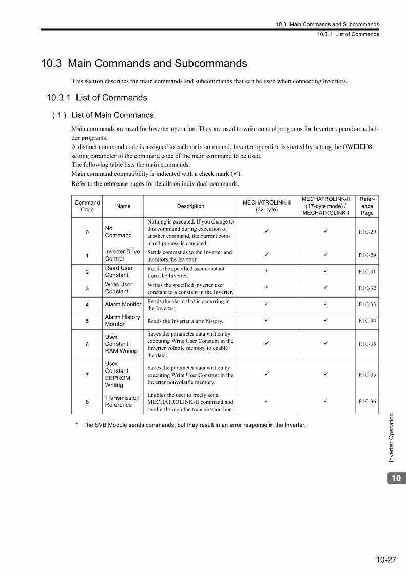
10.3 Main Commands and Subcommands
10.3.1 List of Commands
10-27
Inve
rter O
pera
tion
10.3 Main Commands and Subcommands
This section describes the main commands and subcommands that can be used when connecting Inverters.
10.3.1 List of Commands
( 1 ) List of Main Commands
Main commands are used for Inverter operation. They are used to write control programs for Inverter operation as lad-der programs.
A distinct command code is assigned to each main command. Inverter operation is started by setting the OW08
setting parameter to the command code of the main command to be used.The following table lists the main commands.Main command compatibility is indicated with a check mark ().
Refer to the reference pages for details on individual commands.
* The SVB Module sends commands, but they result in an error response in the Inverter.
CommandCode
Name DescriptionMECHATROLINK-II
(32-byte)
MECHATROLINK-II(17-byte mode) /
MECHATROLINK-I
Refer-encePage
0No Command
Nothing is executed. If you change to this command during execution of another command, the current com-mand process is canceled.
P.10-29
1Inverter Drive Control
Sends commands to the Inverter and monitors the Inverter.
P.10-29
2Read User Constant
Reads the specified user constant from the Inverter.
* P.10-31
3Write User Constant
Writes the specified inverter user constant to a constant in the Inverter.
* P.10-32
4 Alarm Monitor Reads the alarm that is occurring in the Inverter.
P.10-33
5Alarm History Monitor Reads the Inverter alarm history. P.10-34
6
User Constant RAM Writing
Saves the parameter data written by executing Write User Constant in the Inverter volatile memory to enable the data.
P.10-35
7
User Constant EEPROM Writing
Saves the parameter data written by executing Write User Constant in the Inverter nonvolatile memory.
P.10-35
8Transmission Reference
Enables the user to freely set a MECHATROLINK-II command and send it through the transmission line.
P.10-36
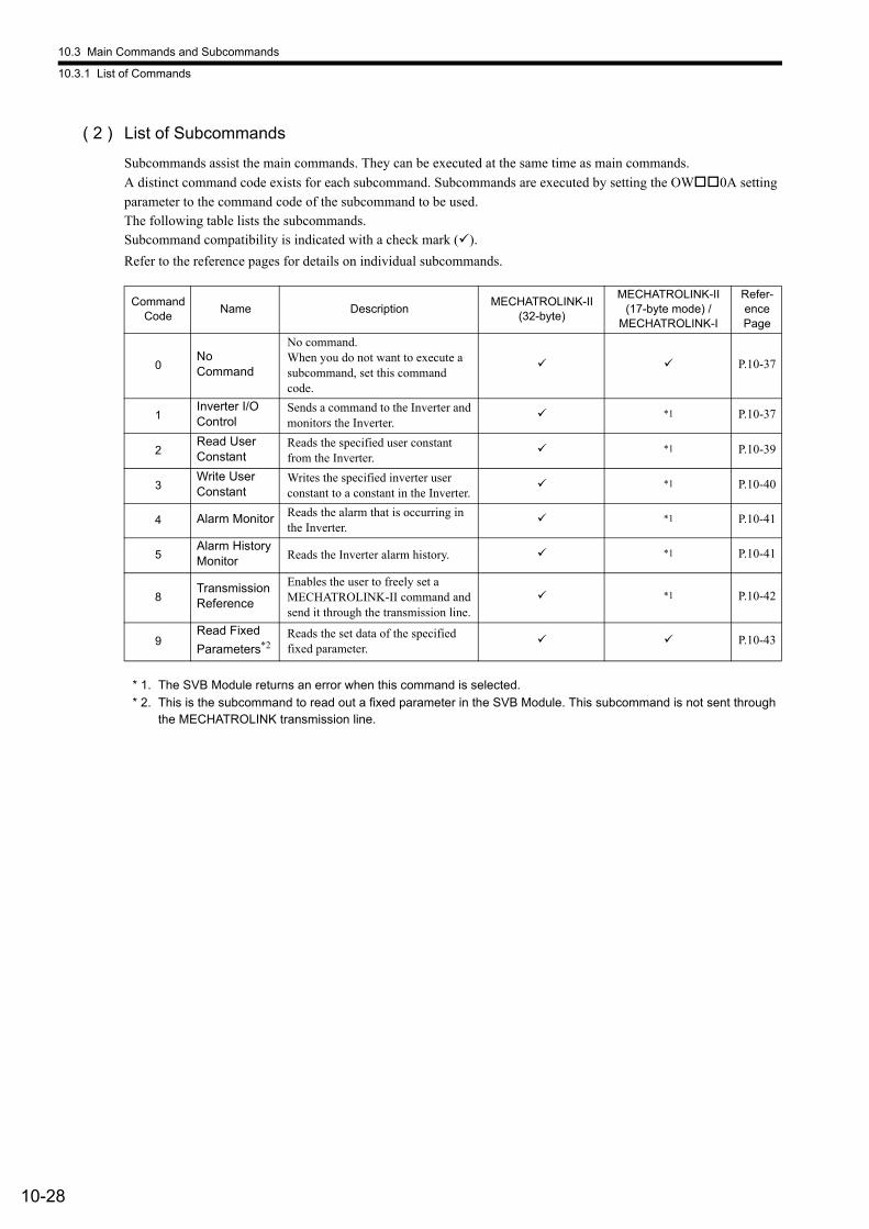
10.3 Main Commands and Subcommands
10.3.1 List of Commands
10-28
( 2 ) List of Subcommands
Subcommands assist the main commands. They can be executed at the same time as main commands.
A distinct command code exists for each subcommand. Subcommands are executed by setting the OW0A setting
parameter to the command code of the subcommand to be used.The following table lists the subcommands.Subcommand compatibility is indicated with a check mark ().
Refer to the reference pages for details on individual subcommands.
* 1. The SVB Module returns an error when this command is selected.
* 2. This is the subcommand to read out a fixed parameter in the SVB Module. This subcommand is not sent through the MECHATROLINK transmission line.
CommandCode
Name DescriptionMECHATROLINK-II
(32-byte)
MECHATROLINK-II(17-byte mode) /
MECHATROLINK-I
Refer-encePage
0No Command
No command.When you do not want to execute a subcommand, set this command code.
P.10-37
1Inverter I/O Control
Sends a command to the Inverter and monitors the Inverter.
*1 P.10-37
2Read User Constant
Reads the specified user constant from the Inverter.
*1 P.10-39
3Write User Constant
Writes the specified inverter user constant to a constant in the Inverter.
*1 P.10-40
4 Alarm Monitor Reads the alarm that is occurring in the Inverter.
*1 P.10-41
5Alarm History Monitor Reads the Inverter alarm history. *1 P.10-41
8Transmission Reference
Enables the user to freely set a MECHATROLINK-II command and send it through the transmission line.
*1 P.10-42
9Read Fixed
Parameters*2Reads the set data of the specified fixed parameter.
P.10-43
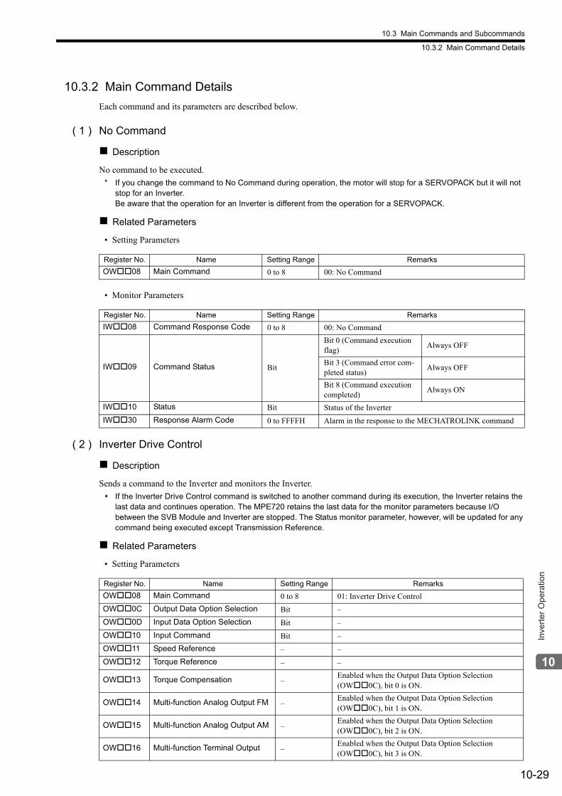
10.3 Main Commands and Subcommands
10.3.2 Main Command Details
10-29
Inve
rter O
pera
tion
10.3.2 Main Command Details
Each command and its parameters are described below.
( 1 ) No Command
Description
No command to be executed.
* If you change the command to No Command during operation, the motor will stop for a SERVOPACK but it will not stop for an Inverter. Be aware that the operation for an Inverter is different from the operation for a SERVOPACK.
Related Parameters
• Setting Parameters
• Monitor Parameters
( 2 ) Inverter Drive Control
Description
Sends a command to the Inverter and monitors the Inverter.
If the Inverter Drive Control command is switched to another command during its execution, the Inverter retains the last data and continues operation. The MPE720 retains the last data for the monitor parameters because I/O between the SVB Module and Inverter are stopped. The Status monitor parameter, however, will be updated for any command being executed except Transmission Reference.
Related Parameters
• Setting Parameters
Register No. Name Setting Range Remarks
OW08 Main Command 0 to 8 00: No Command
Register No. Name Setting Range Remarks
IW08 Command Response Code 0 to 8 00: No Command
IW09 Command Status Bit
Bit 0 (Command execution flag)
Always OFF
Bit 3 (Command error com-pleted status)
Always OFF
Bit 8 (Command execution completed)
Always ON
IW10 Status Bit Status of the Inverter
IW30 Response Alarm Code 0 to FFFFH Alarm in the response to the MECHATROLINK command
Register No. Name Setting Range Remarks
OW08 Main Command 0 to 8 01: Inverter Drive Control
OW0C Output Data Option Selection Bit –
OW0D Input Data Option Selection Bit –
OW10 Input Command Bit –
OW11 Speed Reference – –
OW12 Torque Reference – –
OW13 Torque Compensation –Enabled when the Output Data Option Selection (OW0C), bit 0 is ON.
OW14 Multi-function Analog Output FM –Enabled when the Output Data Option Selection (OW0C), bit 1 is ON.
OW15 Multi-function Analog Output AM –Enabled when the Output Data Option Selection (OW0C), bit 2 is ON.
OW16 Multi-function Terminal Output –Enabled when the Output Data Option Selection (OW0C), bit 3 is ON.
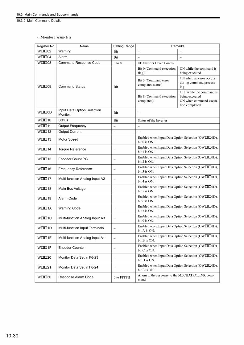
10.3 Main Commands and Subcommands
10.3.2 Main Command Details
10-30
• Monitor Parameters
Register No. Name Setting Range Remarks
IW02 Warning Bit – –
IW04 Alarm Bit – –
IW08 Command Response Code 0 to 8 01: Inverter Drive Control
IW09 Command Status Bit
Bit 0 (Command execution flag)
ON while the command is being executed
Bit 3 (Command error completed status)
ON when an error occurs during command process-ing
Bit 8 (Command execution completed)
OFF while the command is being executedON when command execu-tion completed
IW0DInput Data Option Selection Monitor Bit –
IW10 Status Bit Status of the Inverter
IW11 Output Frequency – –
IW12 Output Current – –
IW13 Motor Speed –Enabled when Input Data Option Selection (OW0D), bit 0 is ON.
IW14 Torque Reference –Enabled when Input Data Option Selection (OW0D), bit 1 is ON.
IW15 Encoder Count PG –Enabled when Input Data Option Selection (OW0D), bit 2 is ON.
IW16 Frequency Reference –Enabled when Input Data Option Selection (OW0D), bit 3 is ON.
IW17 Multi-function Analog Input A2 –Enabled when Input Data Option Selection (OW0D), bit 4 is ON.
IW18 Main Bus Voltage –Enabled when Input Data Option Selection (OW0D), bit 5 is ON.
IW19 Alarm Code –Enabled when Input Data Option Selection (OW0D), bit 6 is ON.
IW1A Warning Code –Enabled when Input Data Option Selection (OW0D), bit 7 is ON.
IW1C Multi-function Analog Input A3 –Enabled when Input Data Option Selection (OW0D), bit 9 is ON.
IW1D Multi-function Input Terminals –Enabled when Input Data Option Selection (OW0D), bit A is ON.
IW1E Multi-function Analog Input A1 –Enabled when Input Data Option Selection (OW0D), bit B is ON.
IW1F Encoder Counter –Enabled when Input Data Option Selection (OW0D), bit C is ON.
IW20 Monitor Data Set in F6-23 –Enabled when Input Data Option Selection (OW0D), bit D is ON.
IW21 Monitor Data Set in F6-24 –Enabled when Input Data Option Selection (OW0D), bit E is ON.
IW30 Response Alarm Code 0 to FFFFHAlarm in the response to the MECHATROLINK com-mand
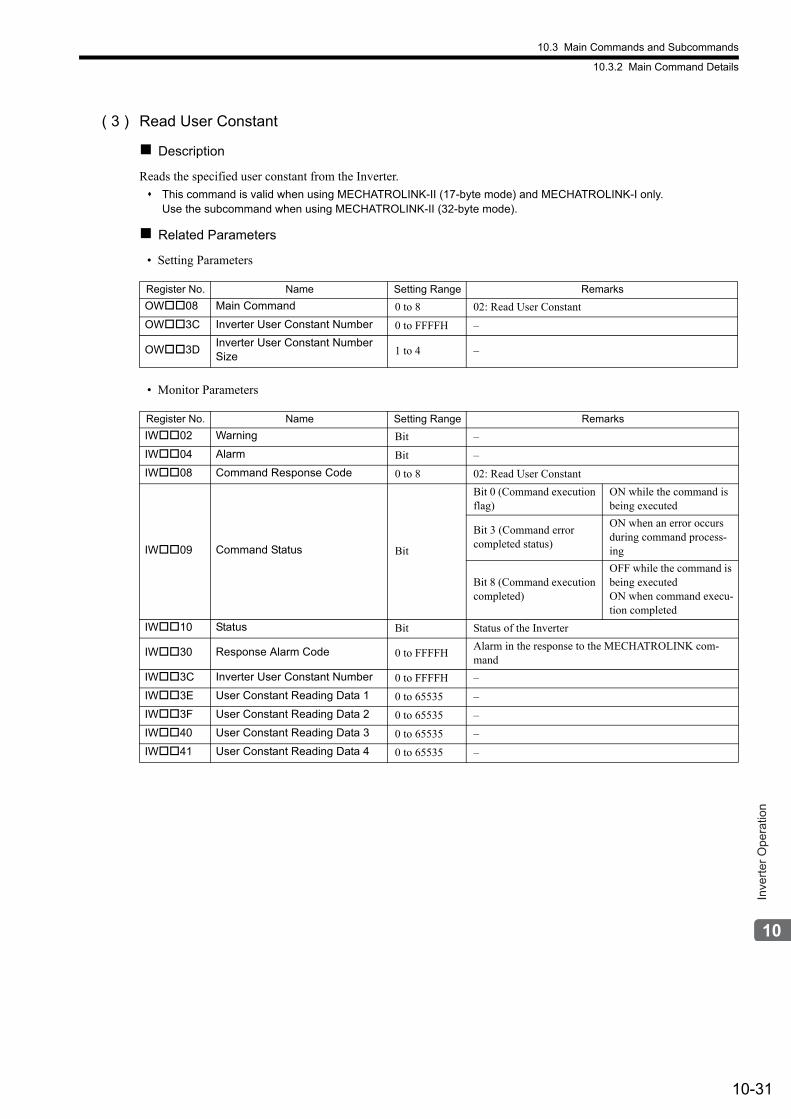
10.3 Main Commands and Subcommands
10.3.2 Main Command Details
10-31
Inve
rter O
pera
tion
( 3 ) Read User Constant
Description
Reads the specified user constant from the Inverter.
This command is valid when using MECHATROLINK-II (17-byte mode) and MECHATROLINK-I only.Use the subcommand when using MECHATROLINK-II (32-byte mode).
Related Parameters
• Setting Parameters
• Monitor Parameters
Register No. Name Setting Range Remarks
OW08 Main Command 0 to 8 02: Read User Constant
OW3C Inverter User Constant Number 0 to FFFFH –
OW3DInverter User Constant Number Size 1 to 4 –
Register No. Name Setting Range Remarks
IW02 Warning Bit –
IW04 Alarm Bit –
IW08 Command Response Code 0 to 8 02: Read User Constant
IW09 Command Status Bit
Bit 0 (Command execution flag)
ON while the command is being executed
Bit 3 (Command error completed status)
ON when an error occurs during command process-ing
Bit 8 (Command execution completed)
OFF while the command is being executedON when command execu-tion completed
IW10 Status Bit Status of the Inverter
IW30 Response Alarm Code 0 to FFFFHAlarm in the response to the MECHATROLINK com-mand
IW3C Inverter User Constant Number 0 to FFFFH –
IW3E User Constant Reading Data 1 0 to 65535 –
IW3F User Constant Reading Data 2 0 to 65535 –
IW40 User Constant Reading Data 3 0 to 65535 –
IW41 User Constant Reading Data 4 0 to 65535 –
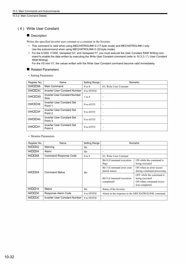
10.3 Main Commands and Subcommands
10.3.2 Main Command Details
10-32
( 4 ) Write User Constant
Description
Writes the specified inverter user constant to a constant in the Inverter.
This command is valid when using MECHATROLINK-II (17-byte mode) and MECHATROLINK-I only.Use the subcommand when using MECHATROLINK-II (32-byte mode).
For the A1000, V1000, Varispeed G7, and Varispeed F7, you must execute the User Constant RAM Writing com-mand to enable the data written by executing the Write User Constant command (refer to 10.3.2 ( 7 ) User Constant RAM Writing).For the VS mini V7, the values written with the Write User Constant command become valid immediately.
Related Parameters
• Setting Parameters
• Monitor Parameters
Register No. Name Setting Range Remarks
OW08 Main Command 0 to 8 03: Write User Constant
OW3C Inverter User Constant Number 0 to FFFFH –
OW3DInverter User Constant Number Size 1 to 4 –
OW3EInverter User Constant Set Point 1 0 to 65535 –
OW3FInverter User Constant Set Point 2 0 to 65535 –
OW40Inverter User Constant Set Point 3 0 to 65535 –
OW41Inverter User Constant Set Point 4 0 to 65535 –
Register No. Name Setting Range Remarks
IW02 Warning Bit –
IW04 Alarm Bit –
IW08 Command Response Code 0 to 8 03: Write User Constant
IW09 Command Status Bit
Bit 0 (Command execution flag)
ON while the command is being executed
Bit 3 (Command error com-pleted status)
ON when an error occurs during command processing
Bit 8 (Command execution completed)
OFF while the command is being executedON when command execu-tion completed
IW10 Status Bit Status of the Inverter
IW30 Response Alarm Code 0 to FFFFH Alarm in the response to the MECHATROLINK command
IW3C Inverter User Constant Number 0 to FFFFH –
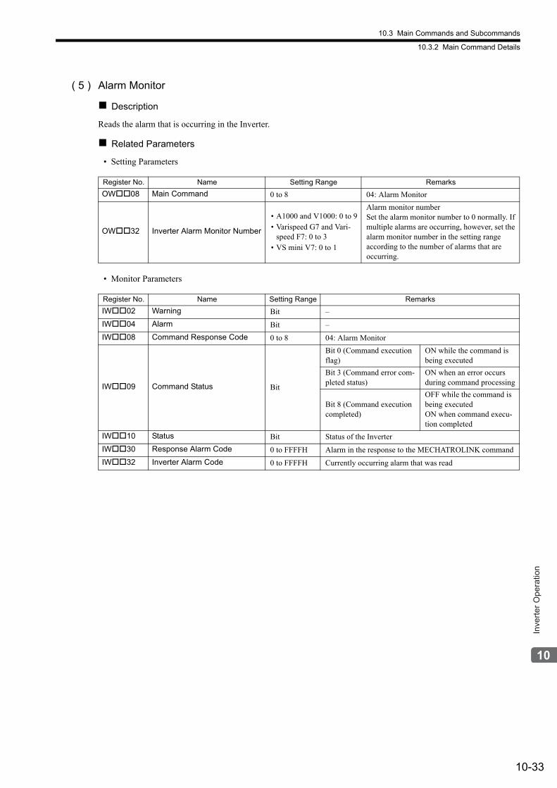
10.3 Main Commands and Subcommands
10.3.2 Main Command Details
10-33
Inve
rter O
pera
tion
( 5 ) Alarm Monitor
Description
Reads the alarm that is occurring in the Inverter.
Related Parameters
• Setting Parameters
• Monitor Parameters
Register No. Name Setting Range Remarks
OW08 Main Command 0 to 8 04: Alarm Monitor
OW32 Inverter Alarm Monitor Number
• A1000 and V1000: 0 to 9• Varispeed G7 and Vari-
speed F7: 0 to 3• VS mini V7: 0 to 1
Alarm monitor numberSet the alarm monitor number to 0 normally. If multiple alarms are occurring, however, set the alarm monitor number in the setting range according to the number of alarms that are occurring.
Register No. Name Setting Range Remarks
IW02 Warning Bit –
IW04 Alarm Bit –
IW08 Command Response Code 0 to 8 04: Alarm Monitor
IW09 Command Status Bit
Bit 0 (Command execution flag)
ON while the command is being executed
Bit 3 (Command error com-pleted status)
ON when an error occurs during command processing
Bit 8 (Command execution completed)
OFF while the command is being executedON when command execu-tion completed
IW10 Status Bit Status of the Inverter
IW30 Response Alarm Code 0 to FFFFH Alarm in the response to the MECHATROLINK command
IW32 Inverter Alarm Code 0 to FFFFH Currently occurring alarm that was read
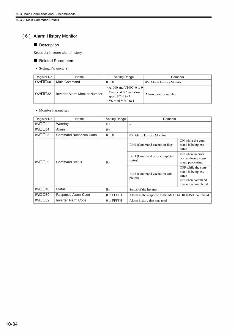
10.3 Main Commands and Subcommands
10.3.2 Main Command Details
10-34
( 6 ) Alarm History Monitor
Description
Reads the Inverter alarm history.
Related Parameters
• Setting Parameters
• Monitor Parameters
Register No. Name Setting Range Remarks
OW08 Main Command 0 to 8 05: Alarm History Monitor
OW32 Inverter Alarm Monitor Number
• A1000 and V1000: 0 to 9• Varispeed G7 and Vari-
speed F7: 0 to 3• VS mini V7: 0 to 1
Alarm monitor number
Register No. Name Setting Range Remarks
IW02 Warning Bit –
IW04 Alarm Bit –
IW08 Command Response Code 0 to 8 05: Alarm History Monitor
IW09 Command Status Bit
Bit 0 (Command execution flag)ON while the com-mand is being exe-cuted
Bit 3 (Command error completed status)
ON when an error occurs during com-mand processing
Bit 8 (Command execution com-pleted)
OFF while the com-mand is being exe-cutedON when command execution completed
IW10 Status Bit Status of the Inverter
IW30 Response Alarm Code 0 to FFFFH Alarm in the response to the MECHATROLINK command
IW32 Inverter Alarm Code 0 to FFFFH Alarm history that was read
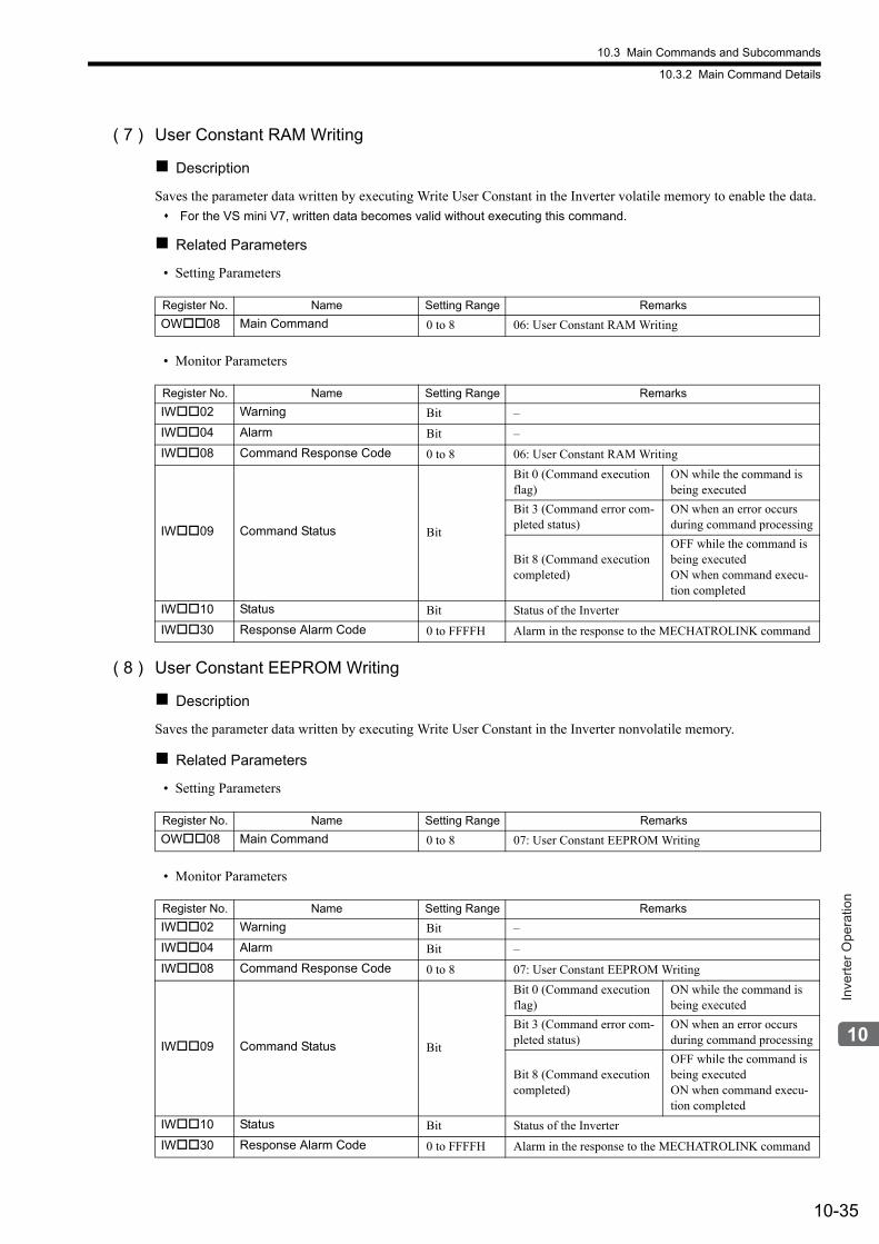
10.3 Main Commands and Subcommands
10.3.2 Main Command Details
10-35
Inve
rter O
pera
tion
( 7 ) User Constant RAM Writing
Description
Saves the parameter data written by executing Write User Constant in the Inverter volatile memory to enable the data.
For the VS mini V7, written data becomes valid without executing this command.
Related Parameters
• Setting Parameters
• Monitor Parameters
( 8 ) User Constant EEPROM Writing
Description
Saves the parameter data written by executing Write User Constant in the Inverter nonvolatile memory.
Related Parameters
• Setting Parameters
• Monitor Parameters
Register No. Name Setting Range Remarks
OW08 Main Command 0 to 8 06: User Constant RAM Writing
Register No. Name Setting Range Remarks
IW02 Warning Bit –
IW04 Alarm Bit –
IW08 Command Response Code 0 to 8 06: User Constant RAM Writing
IW09 Command Status Bit
Bit 0 (Command execution flag)
ON while the command is being executed
Bit 3 (Command error com-pleted status)
ON when an error occurs during command processing
Bit 8 (Command execution completed)
OFF while the command is being executedON when command execu-tion completed
IW10 Status Bit Status of the Inverter
IW30 Response Alarm Code 0 to FFFFH Alarm in the response to the MECHATROLINK command
Register No. Name Setting Range Remarks
OW08 Main Command 0 to 8 07: User Constant EEPROM Writing
Register No. Name Setting Range Remarks
IW02 Warning Bit –
IW04 Alarm Bit –
IW08 Command Response Code 0 to 8 07: User Constant EEPROM Writing
IW09 Command Status Bit
Bit 0 (Command execution flag)
ON while the command is being executed
Bit 3 (Command error com-pleted status)
ON when an error occurs during command processing
Bit 8 (Command execution completed)
OFF while the command is being executedON when command execu-tion completed
IW10 Status Bit Status of the Inverter
IW30 Response Alarm Code 0 to FFFFH Alarm in the response to the MECHATROLINK command
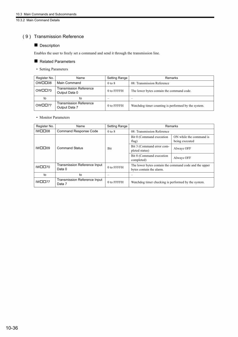
10.3 Main Commands and Subcommands
10.3.2 Main Command Details
10-36
( 9 ) Transmission Reference
Description
Enables the user to freely set a command and send it through the transmission line.
Related Parameters
• Setting Parameters
• Monitor Parameters
Register No. Name Setting Range Remarks
OW08 Main Command 0 to 8 08: Transmission Reference
OW70Transmission Reference Output Data 0 0 to FFFFH The lower bytes contain the command code.
to to – –
OW77Transmission Reference Output Data 7 0 to FFFFH Watchdog timer counting is performed by the system.
Register No. Name Setting Range Remarks
IW08 Command Response Code 0 to 8 08: Transmission Reference
IW09 Command Status Bit
Bit 0 (Command execution flag)
ON while the command is being executed
Bit 3 (Command error com-pleted status)
Always OFF
Bit 8 (Command execution completed)
Always OFF
IW70Transmission Reference Input Data 0 0 to FFFFH
The lower bytes contain the command code and the upper bytes contain the alarm.
to to – –
IW77Transmission Reference Input Data 7 0 to FFFFH Watchdog timer checking is performed by the system.
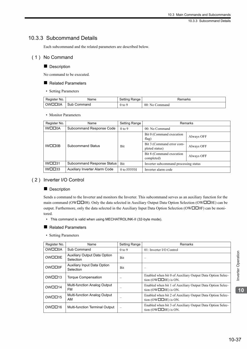
10.3 Main Commands and Subcommands
10.3.3 Subcommand Details
10-37
Inve
rter O
pera
tion
10.3.3 Subcommand Details
Each subcommand and the related parameters are described below.
( 1 ) No Command
Description
No command to be executed.
Related Parameters
• Setting Parameters
• Monitor Parameters
( 2 ) Inverter I/O Control
Description
Sends a command to the Inverter and monitors the Inverter. This subcommand serves as an auxiliary function for the
main command (OW08). Only the data selected in Auxiliary Output Data Option Selection (OW0E) can be
output. Furthermore, only the data selected in the Auxiliary Input Data Option Selection (OW0F) can be moni-
tored.
This command is valid when using MECHATROLINK-II (32-byte mode).
Related Parameters
• Setting Parameters
Register No. Name Setting Range Remarks
OW0A Sub Command 0 to 9 00: No Command
Register No. Name Setting Range Remarks
IW0A Subcommand Response Code 0 to 9 00: No Command
IW0B Subcommand Status Bit
Bit 0 (Command execution flag)
Always OFF
Bit 3 (Command error com-pleted status)
Always OFF
Bit 8 (Command execution completed)
Always OFF
IW31 Subcommand Response Status Bit Inverter subcommand processing status
IW33 Auxiliary Inverter Alarm Code 0 to FFFFH Inverter alarm code
Register No. Name Setting Range Remarks
OW0A Sub Command 0 to 9 01: Inverter I/O Control
OW0EAuxiliary Output Data Option Selection Bit –
OW0FAuxiliary Input Data Option Selection Bit –
OW13 Torque Compensation –Enabled when bit 0 of Auxiliary Output Data Option Selec-tion (OW0E) is ON.
OW14Multi-function Analog Output FM –
Enabled when bit 1 of Auxiliary Output Data Option Selec-tion (OW0E) is ON.
OW15Multi-function Analog Output AM –
Enabled when bit 2 of Auxiliary Output Data Option Selec-tion (OW0E) is ON.
OW16 Multi-function Terminal Output –Enabled when bit 3 of Auxiliary Output Data Option Selec-tion (OW0E) is ON.
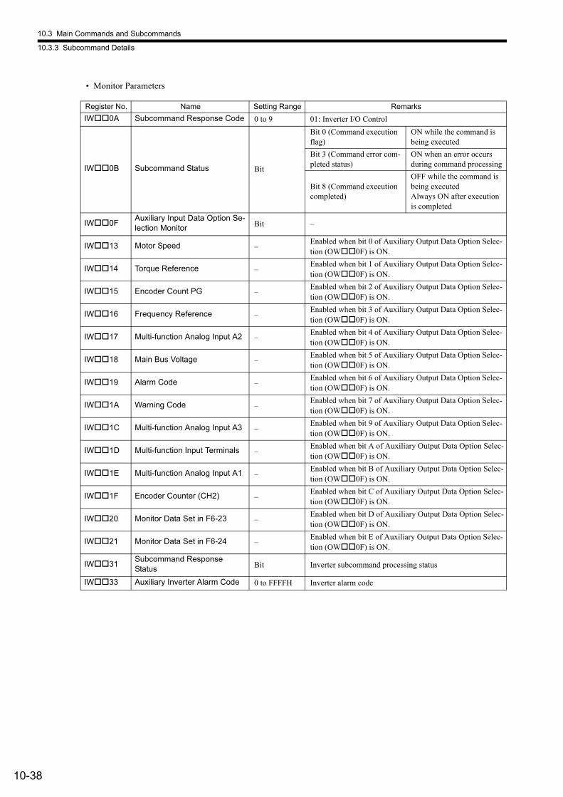
10.3 Main Commands and Subcommands
10.3.3 Subcommand Details
10-38
• Monitor Parameters
Register No. Name Setting Range Remarks
IW0A Subcommand Response Code 0 to 9 01: Inverter I/O Control
IW0B Subcommand Status Bit
Bit 0 (Command execution flag)
ON while the command is being executed
Bit 3 (Command error com-pleted status)
ON when an error occurs during command processing
Bit 8 (Command execution completed)
OFF while the command is being executedAlways ON after execution is completed
IW0FAuxiliary Input Data Option Se-lection Monitor Bit –
IW13 Motor Speed –Enabled when bit 0 of Auxiliary Output Data Option Selec-tion (OW0F) is ON.
IW14 Torque Reference –Enabled when bit 1 of Auxiliary Output Data Option Selec-tion (OW0F) is ON.
IW15 Encoder Count PG –Enabled when bit 2 of Auxiliary Output Data Option Selec-tion (OW0F) is ON.
IW16 Frequency Reference –Enabled when bit 3 of Auxiliary Output Data Option Selec-tion (OW0F) is ON.
IW17 Multi-function Analog Input A2 –Enabled when bit 4 of Auxiliary Output Data Option Selec-tion (OW0F) is ON.
IW18 Main Bus Voltage –Enabled when bit 5 of Auxiliary Output Data Option Selec-tion (OW0F) is ON.
IW19 Alarm Code –Enabled when bit 6 of Auxiliary Output Data Option Selec-tion (OW0F) is ON.
IW1A Warning Code –Enabled when bit 7 of Auxiliary Output Data Option Selec-tion (OW0F) is ON.
IW1C Multi-function Analog Input A3 –Enabled when bit 9 of Auxiliary Output Data Option Selec-tion (OW0F) is ON.
IW1D Multi-function Input Terminals –Enabled when bit A of Auxiliary Output Data Option Selec-tion (OW0F) is ON.
IW1E Multi-function Analog Input A1 –Enabled when bit B of Auxiliary Output Data Option Selec-tion (OW0F) is ON.
IW1F Encoder Counter (CH2) –Enabled when bit C of Auxiliary Output Data Option Selec-tion (OW0F) is ON.
IW20 Monitor Data Set in F6-23 –Enabled when bit D of Auxiliary Output Data Option Selec-tion (OW0F) is ON.
IW21 Monitor Data Set in F6-24 –Enabled when bit E of Auxiliary Output Data Option Selec-tion (OW0F) is ON.
IW31Subcommand Response Status Bit Inverter subcommand processing status
IW33 Auxiliary Inverter Alarm Code 0 to FFFFH Inverter alarm code
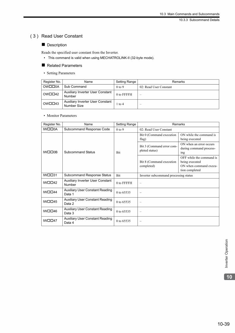
10.3 Main Commands and Subcommands
10.3.3 Subcommand Details
10-39
Inve
rter O
pera
tion
( 3 ) Read User Constant
Description
Reads the specified user constant from the Inverter.
This command is valid when using MECHATROLINK-II (32-byte mode).
Related Parameters
• Setting Parameters
• Monitor Parameters
Register No. Name Setting Range Remarks
OW0A Sub Command 0 to 9 02: Read User Constant
OW42Auxiliary Inverter User Constant Number 0 to FFFFH –
OW43Auxiliary Inverter User Constant Number Size 1 to 4 –
Register No. Name Setting Range Remarks
IW0A Subcommand Response Code 0 to 9 02: Read User Constant
IW0B Subcommand Status Bit
Bit 0 (Command execution flag)
ON while the command is being executed
Bit 3 (Command error com-pleted status)
ON when an error occurs during command process-ing
Bit 8 (Command execution completed)
OFF while the command is being executedON when command execu-tion completed
IW31 Subcommand Response Status Bit Inverter subcommand processing status
IW42Auxiliary Inverter User Constant Number 0 to FFFFH –
IW44Auxiliary User Constant Reading Data 1 0 to 65535 –
IW45Auxiliary User Constant Reading Data 2 0 to 65535 –
IW46Auxiliary User Constant Reading Data 3 0 to 65535 –
IW47Auxiliary User Constant Reading Data 4 0 to 65535 –
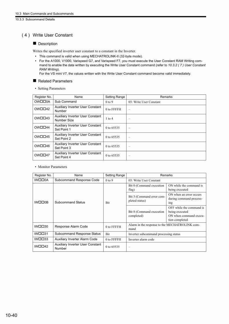
10.3 Main Commands and Subcommands
10.3.3 Subcommand Details
10-40
( 4 ) Write User Constant
Description
Writes the specified inverter user constant to a constant in the Inverter.
This command is valid when using MECHATROLINK-II (32-byte mode).
For the A1000, V1000, Varispeed G7, and Varispeed F7, you must execute the User Constant RAM Writing com-mand to enable the data written by executing the Write User Constant command (refer to 10.3.2 ( 7 ) User Constant RAM Writing).For the VS mini V7, the values written with the Write User Constant command become valid immediately.
Related Parameters
• Setting Parameters
• Monitor Parameters
Register No. Name Setting Range Remarks
OW0A Sub Command 0 to 9 03: Write User Constant
OW42Auxiliary Inverter User Constant Number 0 to FFFFH –
OW43Auxiliary Inverter User Constant Number Size 1 to 4 –
OW44Auxiliary Inverter User Constant Set Point 1 0 to 65535 –
OW45Auxiliary Inverter User Constant Set Point 2 0 to 65535 –
OW46Auxiliary Inverter User Constant Set Point 3 0 to 65535 –
OW47Auxiliary Inverter User Constant Set Point 4 0 to 65535 –
Register No. Name Setting Range Remarks
IW0A Subcommand Response Code 0 to 9 03: Write User Constant
IW0B Subcommand Status Bit
Bit 0 (Command execution flag)
ON while the command is being executed
Bit 3 (Command error com-pleted status)
ON when an error occurs during command process-ing
Bit 8 (Command execution completed)
OFF while the command is being executedON when command execu-tion completed
IW30 Response Alarm Code 0 to FFFFHAlarm in the response to the MECHATROLINK com-mand
IW31 Subcommand Response Status Bit Inverter subcommand processing status
IW33 Auxiliary Inverter Alarm Code 0 to FFFFH Inverter alarm code
IW42Auxiliary Inverter User Constant Number 0 to 65535 –
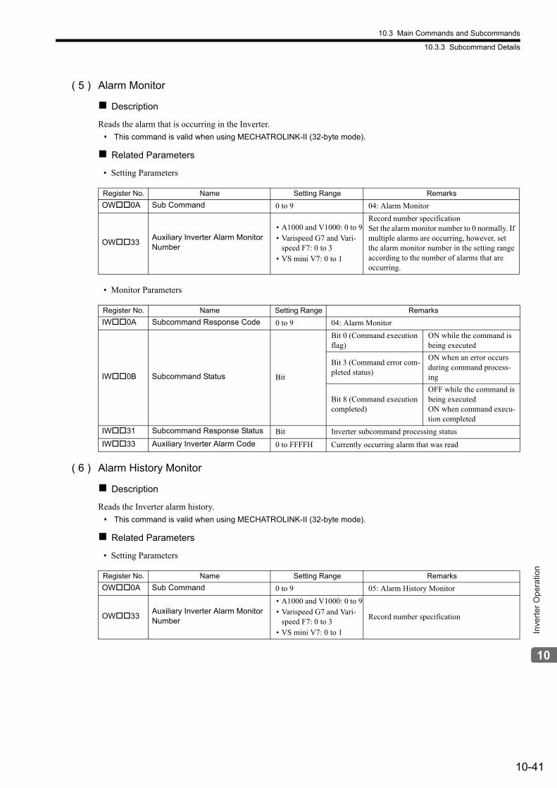
10.3 Main Commands and Subcommands
10.3.3 Subcommand Details
10-41
Inve
rter O
pera
tion
( 5 ) Alarm Monitor
Description
Reads the alarm that is occurring in the Inverter.
This command is valid when using MECHATROLINK-II (32-byte mode).
Related Parameters
• Setting Parameters
• Monitor Parameters
( 6 ) Alarm History Monitor
Description
Reads the Inverter alarm history.
This command is valid when using MECHATROLINK-II (32-byte mode).
Related Parameters
• Setting Parameters
Register No. Name Setting Range Remarks
OW0A Sub Command 0 to 9 04: Alarm Monitor
OW33Auxiliary Inverter Alarm Monitor Number
• A1000 and V1000: 0 to 9• Varispeed G7 and Vari-
speed F7: 0 to 3• VS mini V7: 0 to 1
Record number specificationSet the alarm monitor number to 0 normally. If multiple alarms are occurring, however, set the alarm monitor number in the setting range according to the number of alarms that are occurring.
Register No. Name Setting Range Remarks
IW0A Subcommand Response Code 0 to 9 04: Alarm Monitor
IW0B Subcommand Status Bit
Bit 0 (Command execution flag)
ON while the command is being executed
Bit 3 (Command error com-pleted status)
ON when an error occurs during command process-ing
Bit 8 (Command execution completed)
OFF while the command is being executedON when command execu-tion completed
IW31 Subcommand Response Status Bit Inverter subcommand processing status
IW33 Auxiliary Inverter Alarm Code 0 to FFFFH Currently occurring alarm that was read
Register No. Name Setting Range Remarks
OW0A Sub Command 0 to 9 05: Alarm History Monitor
OW33Auxiliary Inverter Alarm Monitor Number
• A1000 and V1000: 0 to 9• Varispeed G7 and Vari-
speed F7: 0 to 3• VS mini V7: 0 to 1
Record number specification
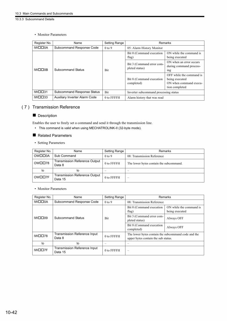
10.3 Main Commands and Subcommands
10.3.3 Subcommand Details
10-42
• Monitor Parameters
( 7 ) Transmission Reference
Description
Enables the user to freely set a command and send it through the transmission line.
This command is valid when using MECHATROLINK-II (32-byte mode).
Related Parameters
• Setting Parameters
• Monitor Parameters
Register No. Name Setting Range Remarks
IW0A Subcommand Response Code 0 to 9 05: Alarm History Monitor
IW0B Subcommand Status Bit
Bit 0 (Command execution flag)
ON while the command is being executed
Bit 3 (Command error com-pleted status)
ON when an error occurs during command process-ing
Bit 8 (Command execution completed)
OFF while the command is being executedON when command execu-tion completed
IW31 Subcommand Response Status Bit Inverter subcommand processing status
IW33 Auxiliary Inverter Alarm Code 0 to FFFFH Alarm history that was read
Register No. Name Setting Range Remarks
OW0A Sub Command 0 to 9 08: Transmission Reference
OW78Transmission Reference Output Data 8 0 to FFFFH The lower bytes contain the subcommand.
to to – –
OW7FTransmission Reference Output Data 15 0 to FFFFH –
Register No. Name Setting Range Remarks
IW0A Subcommand Response Code 0 to 9 08: Transmission Reference
IW09 Subcommand Status Bit
Bit 0 (Command execution flag)
ON while the command is being executed
Bit 3 (Command error com-pleted status)
Always OFF
Bit 8 (Command execution completed)
Always OFF
IW78Transmission Reference Input Data 8 0 to FFFFH
The lower bytes contain the subcommand code and the upper bytes contain the sub status.
to to – –
IW7FTransmission Reference Input Data 15 0 to FFFFH –
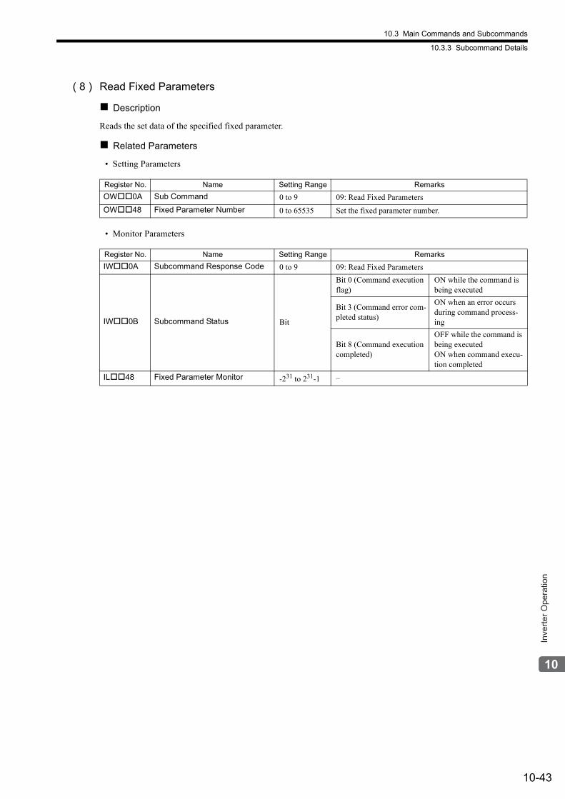
10.3 Main Commands and Subcommands
10.3.3 Subcommand Details
10-43
Inve
rter O
pera
tion
( 8 ) Read Fixed Parameters
Description
Reads the set data of the specified fixed parameter.
Related Parameters
• Setting Parameters
• Monitor Parameters
Register No. Name Setting Range Remarks
OW0A Sub Command 0 to 9 09: Read Fixed Parameters
OW48 Fixed Parameter Number 0 to 65535 Set the fixed parameter number.
Register No. Name Setting Range Remarks
IW0A Subcommand Response Code 0 to 9 09: Read Fixed Parameters
IW0B Subcommand Status Bit
Bit 0 (Command execution flag)
ON while the command is being executed
Bit 3 (Command error com-pleted status)
ON when an error occurs during command process-ing
Bit 8 (Command execution completed)
OFF while the command is being executedON when command execu-tion completed
IL48 Fixed Parameter Monitor -231 to 231-1 –
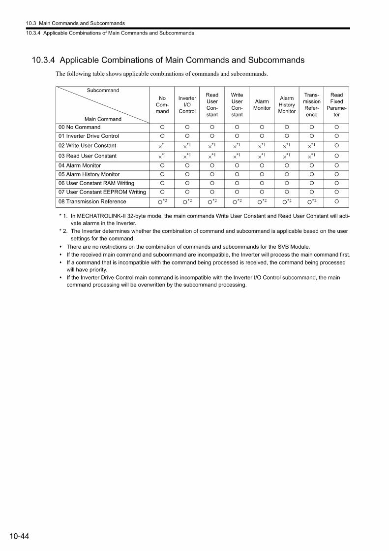
10.3 Main Commands and Subcommands
10.3.4 Applicable Combinations of Main Commands and Subcommands
10-44
10.3.4 Applicable Combinations of Main Commands and Subcommands
The following table shows applicable combinations of commands and subcommands.
* 1. In MECHATROLINK-II 32-byte mode, the main commands Write User Constant and Read User Constant will acti-vate alarms in the Inverter.
* 2. The Inverter determines whether the combination of command and subcommand is applicable based on the user settings for the command.
There are no restrictions on the combination of commands and subcommands for the SVB Module.
If the received main command and subcommand are incompatible, the Inverter will process the main command first.
If a command that is incompatible with the command being processed is received, the command being processed will have priority.
If the Inverter Drive Control main command is incompatible with the Inverter I/O Control subcommand, the main command processing will be overwritten by the subcommand processing.
Subcommand
Main Command
No Com-mand
Inverter I/O
Control
Read User Con-stant
Write User Con-stant
Alarm Monitor
Alarm History Monitor
Trans-mission Refer-ence
Read Fixed
Parame-ter
00 No Command
01 Inverter Drive Control
02 Write User Constant ×*1 ×*1 ×*1 ×*1 ×*1 ×*1 ×*1
03 Read User Constant ×*1 ×*1 ×*1 ×*1 ×*1 ×*1 ×*1
04 Alarm Monitor
05 Alarm History Monitor
06 User Constant RAM Writing
07 User Constant EEPROM Writing
08 Transmission Reference *2 *2 *2 *2 *2 *2 *2
10.3 Main Commands and Subcommands
10.3.5 Precautions for Inverter Operation
10-45
Inve
rter O
pera
tion
10.3.5 Precautions for Inverter Operation
This section provides precautions for Inverter operation.
Inverter operation in progress: Bit 5 (Driving) in the Status (IL10) monitor parameter is 1 (ON).Even if the motor is stopped, Inverter operation is considered to be in progress if this bit is 1 (ON).
Inverter operation stopped: Bit 5 (Driving) in the Status (IL10) monitor parameter is 0 (OFF).
( 1 ) Operation When the CPU Stops
If CPU STOP is executed from the Machine Controller while Inverter operation is in progress, the SVB Module will force the Inverter to stop operation.Even if the Forward RUN or Reverse RUN bit was set to 1 (ON) by the application, the bit will be forced to 0 (OFF).
Bit 0 (Operation Ready) in IW00 (Run Status) will also change to 0 (OFF). To start the CPU when it has stopped,
click the Setting Parameter Tab to change the tab page, set Main Command (OW08) to No Command and then
change bit D (Drive Permission) of Run Command Setting (OW00) to 1 (ON).
( 2 ) Timing of Changes to MECHATROLINK Allocations
Changes to settings made in the Module Configuration Tab Page cannot be saved while Inverter operation is in prog-ress. Save the settings in the Module Configuration Tab Page while the Inverter is stopped.
( 3 ) Timing of Changes to Fixed Parameters
The fixed parameters cannot be saved while Inverter operation is in progress. Save the fixed parameters while the Inverter is stopped.
( 4 ) Switching between Motion Commands While the Command Control Inverter Drive Is Being Executed
If the Inverter Drive Control command in Main Command (OW08) is changed to another command while Inverter
operation is in progress, the Inverter will maintain the last command status of the Inverter Drive Control command and motor operation will continue. Note that switching to the No Command command also will not stop the motor.Refer to 10.3.5 ( 5 ) Motor Stopping and Restarting Methods for the motor stopping methods.Also, if you change the command, I/O between the SVB Module and Inverter will stop. When that occurs, the monitor parameter data on the MPE720 will no longer be the most recent data. If you change to any command other than the Transmission Reference command, the Run status monitor information will be valid.
( 5 ) Motor Stopping and Restarting Methods
There are two ways to stop and restart the motor.
Method 1
To stop the motor, set bit 0 (Forward RUN) and bit 1 (Reserve RUN) of Input Command (OW10) to 0 (OFF) while
the Inverter Drive Control command is being executed in Main Command (OW08).
To restart the motor, set bit 0 or bit 1 of OW10 to 1 (ON).
Method 2
To stop the motor, set bit D (Drive Permission) of Run Command Setting (OW00) to 0 (OFF).
To restart the motor, set parameters using the following procedure.
1. Change Main Command (OW08) to the No Command command.
2. Set bit D (Drive Permission) of Run command setting (OW00) to 1 (ON).
3. Change Main Command (OW08) to the Inverter Drive Control command.
This concludes the procedure to restart the motor.

10.3 Main Commands and Subcommands
10.3.5 Precautions for Inverter Operation
10-46
( 6 ) Saving Fixed Parameters
If you manually allocate the Inverter, always save the fixed parameters. If you do not save the fixed parameters, the current values of the setting parameters will be restored to the default values when you restart the Inverter.
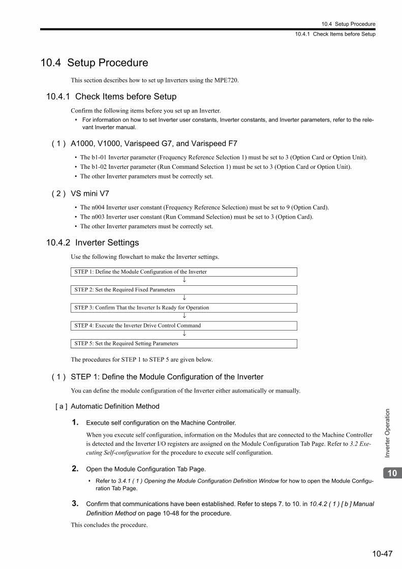
10.4 Setup Procedure
10.4.1 Check Items before Setup
10-47
Inve
rter O
pera
tion
10.4 Setup Procedure
This section describes how to set up Inverters using the MPE720.
10.4.1 Check Items before Setup
Confirm the following items before you set up an Inverter.
For information on how to set Inverter user constants, Inverter constants, and Inverter parameters, refer to the rele-vant Inverter manual.
( 1 ) A1000, V1000, Varispeed G7, and Varispeed F7
• The b1-01 Inverter parameter (Frequency Reference Selection 1) must be set to 3 (Option Card or Option Unit).
• The b1-02 Inverter parameter (Run Command Selection 1) must be set to 3 (Option Card or Option Unit).
• The other Inverter parameters must be correctly set.
( 2 ) VS mini V7
• The n004 Inverter user constant (Frequency Reference Selection) must be set to 9 (Option Card).
• The n003 Inverter user constant (Run Command Selection) must be set to 3 (Option Card).
• The other Inverter parameters must be correctly set.
10.4.2 Inverter Settings
Use the following flowchart to make the Inverter settings.
The procedures for STEP 1 to STEP 5 are given below.
( 1 ) STEP 1: Define the Module Configuration of the Inverter
You can define the module configuration of the Inverter either automatically or manually.
[ a ] Automatic Definition Method
1. Execute self configuration on the Machine Controller.
When you execute self configuration, information on the Modules that are connected to the Machine Controller is detected and the Inverter I/O registers are assigned on the Module Configuration Tab Page. Refer to 3.2 Exe-cuting Self-configuration for the procedure to execute self configuration.
2. Open the Module Configuration Tab Page.
Refer to 3.4.1 ( 1 ) Opening the Module Configuration Definition Window for how to open the Module Configu-ration Tab Page.
3. Confirm that communications have been established. Refer to steps 7. to 10. in 10.4.2 ( 1 ) [ b ] Manual
Definition Method on page 10-48 for the procedure.
This concludes the procedure.
STEP 1: Define the Module Configuration of the Inverter
↓
STEP 2: Set the Required Fixed Parameters
↓
STEP 3: Confirm That the Inverter Is Ready for Operation
↓
STEP 4: Execute the Inverter Drive Control Command
↓
STEP 5: Set the Required Setting Parameters
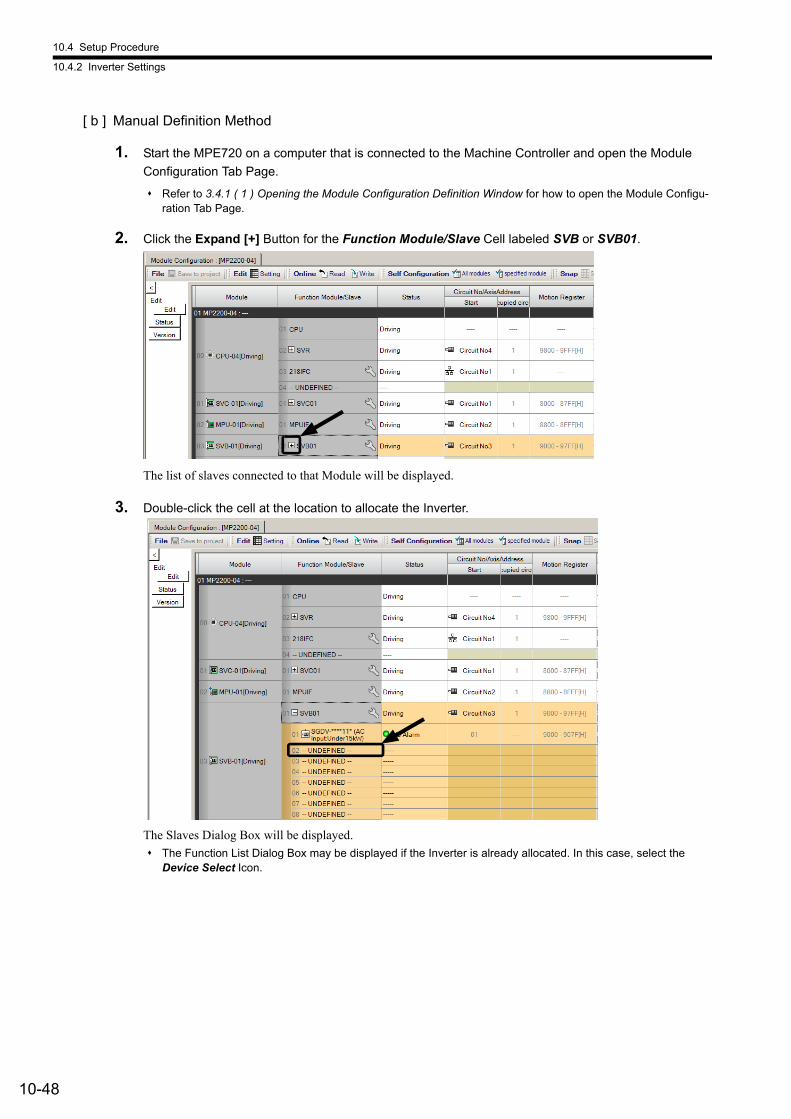
10.4 Setup Procedure
10.4.2 Inverter Settings
10-48
[ b ] Manual Definition Method
1. Start the MPE720 on a computer that is connected to the Machine Controller and open the Module
Configuration Tab Page.
Refer to 3.4.1 ( 1 ) Opening the Module Configuration Definition Window for how to open the Module Configu-ration Tab Page.
2. Click the Expand [+] Button for the Function Module/Slave Cell labeled SVB or SVB01.
The list of slaves connected to that Module will be displayed.
3. Double-click the cell at the location to allocate the Inverter.
The Slaves Dialog Box will be displayed.
The Function List Dialog Box may be displayed if the Inverter is already allocated. In this case, select the Device Select Icon.
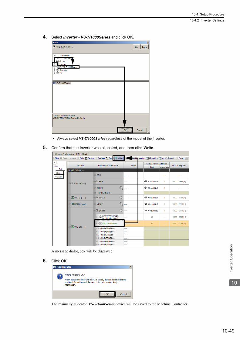
10.4 Setup Procedure
10.4.2 Inverter Settings
10-49
Inve
rter O
pera
tion
4. Select Inverter - VS-7/1000Series and click OK.
Always select VS-7/1000Series regardless of the model of the Inverter.
5. Confirm that the Inverter was allocated, and then click Write.
A message dialog box will be displayed.
6. Click OK.
The manually allocated VS-7/1000Series device will be saved to the Machine Controller.
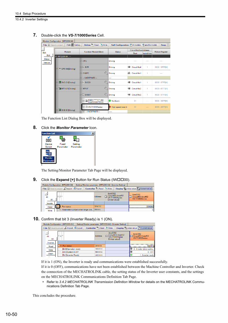
10.4 Setup Procedure
10.4.2 Inverter Settings
10-50
7. Double-click the VS-7/1000Series Cell.
The Function List Dialog Box will be displayed.
8. Click the Monitor Parameter Icon.
The Setting/Monitor Parameter Tab Page will be displayed.
9. Click the Expand [+] Button for Run Status (IW00).
10. Confirm that bit 3 (Inverter Ready) is 1 (ON).
If it is 1 (ON), the Inverter is ready and communications were established successfully.If it is 0 (OFF), communications have not been established between the Machine Controller and Inverter. Check the connection of the MECHATROLINK cable, the setting status of the Inverter user constants, and the settings on the MECHATROLINK Communications Definition Tab Page.
Refer to 3.4.2 MECHATROLINK Transmission Definition Window for details on the MECHATROLINK Commu-nications Definition Tab Page.
This concludes the procedure.
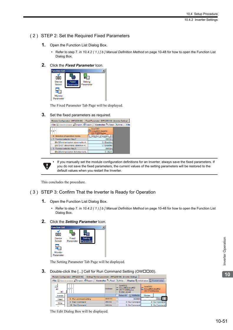
10.4 Setup Procedure
10.4.2 Inverter Settings
10-51
Inve
rter O
pera
tion
( 2 ) STEP 2: Set the Required Fixed Parameters
1. Open the Function List Dialog Box.
Refer to step 7. in 10.4.2 ( 1 ) [ b ] Manual Definition Method on page 10-48 for how to open the Function List Dialog Box.
2. Click the Fixed Parameter Icon.
The Fixed Parameter Tab Page will be displayed.
3. Set the fixed parameters as required.
This concludes the procedure.
( 3 ) STEP 3: Confirm That the Inverter Is Ready for Operation
1. Open the Function List Dialog Box.
Refer to step 7. in 10.4.2 ( 1 ) [ b ] Manual Definition Method on page 10-48 for how to open the Function List Dialog Box.
2. Click the Setting Parameter Icon.
The Setting Parameter Tab Page will be displayed.
3. Double-click the [...] Cell for Run Command Setting (OW00).
The Edit Dialog Box will be displayed.
If you manually set the module configuration definitions for an Inverter, always save the fixed parameters. If you do not save the fixed parameters, the current values of the setting parameters will be restored to the default values when you restart the Inverter.
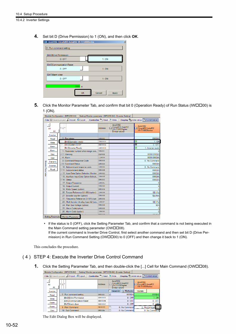
10.4 Setup Procedure
10.4.2 Inverter Settings
10-52
4. Set bit D (Drive Permission) to 1 (ON), and then click OK.
5. Click the Monitor Parameter Tab, and confirm that bit 0 (Operation Ready) of Run Status (IW00) is
1 (ON).
If the status is 0 (OFF), click the Setting Parameter Tab, and confirm that a command is not being executed in the Main Command setting parameter (OW08).If the current command is Inverter Drive Control, first select another command and then set bit D (Drive Per-mission) in Run Command Setting (OW00) to 0 (OFF) and then change it back to 1 (ON).
This concludes the procedure.
( 4 ) STEP 4: Execute the Inverter Drive Control Command
1. Click the Setting Parameter Tab, and then double-click the [...] Cell for Main Command (OW08).
The Edit Dialog Box will be displayed.
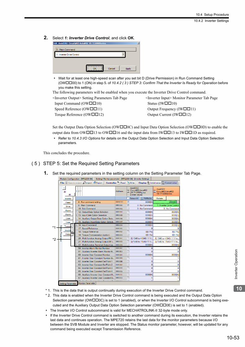
10.4 Setup Procedure
10.4.2 Inverter Settings
10-53
Inve
rter O
pera
tion
2. Select 1: Inverter Drive Control, and click OK.
Wait for at least one high-speed scan after you set bit D (Drive Permission) in Run Command Setting (OW00) to 1 (ON) in step 5. of 10.4.2 ( 3 ) STEP 3: Confirm That the Inverter Is Ready for Operation before you make this setting.
The following parameters will be enabled when you execute the Inverter Drive Control command.
Set the Output Data Option Selection (OW0C) and Input Data Option Selection (OW0D) to enable the
output data from OW13 to OW16 and the input data from IW13 to IW1D as required.
Refer to 10.4.3 I/O Options for details on the Output Data Option Selection and Input Data Option Selection parameters.
This concludes the procedure.
( 5 ) STEP 5: Set the Required Setting Parameters
1. Set the required parameters in the setting column on the Setting Parameter Tab Page.
* 1. This is the data that is output continually during execution of the Inverter Drive Control command.
* 2. This data is enabled when the Inverter Drive Control command is being executed and the Output Data Option
Selection parameter (OW0C) is set to 1 (enabled), or when the Inverter I/O Control subcommand is being exe-
cuted and the Auxiliary Output Data Option Selection parameter (OW0E) is set to 1 (enabled).
The Inverter I/O Control subcommand is valid for MECHATROLINK-II 32-byte mode only.
If the Inverter Drive Control command is switched to another command during its execution, the Inverter retains the last data and continues operation. The MPE720 retains the last data for the monitor parameters because I/O between the SVB Module and Inverter are stopped. The Status monitor parameter, however, will be updated for any command being executed except Transmission Reference.
<Inverter Output> Setting Parameters Tab Page
Input Command (OW10)
Speed Reference (OW11)
Torque Reference (OW12)
<Inverter Input> Monitor Parameter Tab Page
Status (IW10)
Output Frequency (IW11)
Output Current (IW12)
*1
*2
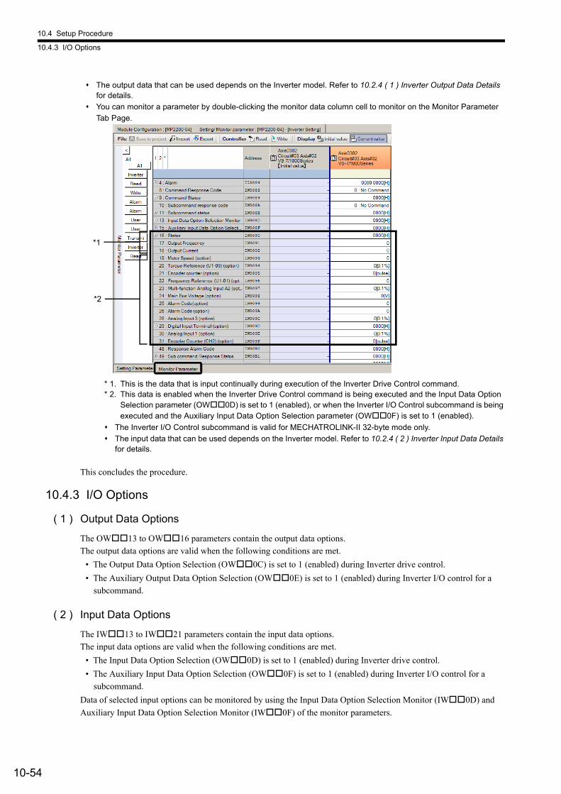
10.4 Setup Procedure
10.4.3 I/O Options
10-54
The output data that can be used depends on the Inverter model. Refer to 10.2.4 ( 1 ) Inverter Output Data Details for details.
You can monitor a parameter by double-clicking the monitor data column cell to monitor on the Monitor Parameter
Tab Page.
* 1. This is the data that is input continually during execution of the Inverter Drive Control command.* 2. This data is enabled when the Inverter Drive Control command is being executed and the Input Data Option
Selection parameter (OW0D) is set to 1 (enabled), or when the Inverter I/O Control subcommand is being executed and the Auxiliary Input Data Option Selection parameter (OW0F) is set to 1 (enabled).
The Inverter I/O Control subcommand is valid for MECHATROLINK-II 32-byte mode only.
The input data that can be used depends on the Inverter model. Refer to 10.2.4 ( 2 ) Inverter Input Data Details for details.
This concludes the procedure.
10.4.3 I/O Options
( 1 ) Output Data Options
The OW13 to OW16 parameters contain the output data options.
The output data options are valid when the following conditions are met.
• The Output Data Option Selection (OW0C) is set to 1 (enabled) during Inverter drive control.
• The Auxiliary Output Data Option Selection (OW0E) is set to 1 (enabled) during Inverter I/O control for a
subcommand.
( 2 ) Input Data Options
The IW13 to IW21 parameters contain the input data options.
The input data options are valid when the following conditions are met.
• The Input Data Option Selection (OW0D) is set to 1 (enabled) during Inverter drive control.
• The Auxiliary Input Data Option Selection (OW0F) is set to 1 (enabled) during Inverter I/O control for a
subcommand.
Data of selected input options can be monitored by using the Input Data Option Selection Monitor (IW0D) and
Auxiliary Input Data Option Selection Monitor (IW0F) of the monitor parameters.
*1
*2
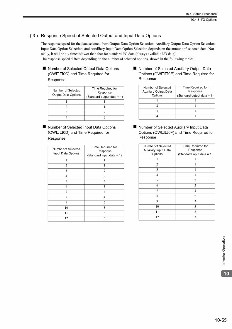
10.4 Setup Procedure
10.4.3 I/O Options
10-55
Inve
rter O
pera
tion
( 3 ) Response Speed of Selected Output and Input Data Options
The response speed for the data selected from Output Data Option Selection, Auxiliary Output Data Option Selection, Input Data Option Selection, and Auxiliary Input Data Option Selection depends on the amount of selected data. Nor-mally, it will be six times slower than that for standard I/O data (always available I/O data).The response speed differs depending on the number of selected options, shown in the following tables.
Number of Selected Output Data Options (OW0C) and Time Required for
Response
Number of Selected Auxiliary Output Data Options (OW0E) and Time Required for Response
Number of SelectedOutput Data Options
Time Required for Response
(Standard output data = 1)
1 1
2 1
3 2
4 2
Number of Selected Auxiliary Output Data
Options
Time Required for Response
(Standard output data = 1)
1 1
2 1
3 1
4 1
Number of Selected Input Data Options (OW0D) and Time Required for
Response
Number of Selected Auxiliary Input Data Options (OW0F) and Time Required for Response
Number of SelectedInput Data Options
Time Required for Response
(Standard input data = 1)
1 1
2 1
3 2
4 2
5 3
6 3
7 4
8 4
9 5
10 5
11 6
12 6
Number of Selected Auxiliary Input Data
Options
Time Required for Response
(Standard input data = 1)
1 1
2 1
3 1
4 1
5 2
6 2
7 2
8 2
9 3
10 3
11 3
12 3
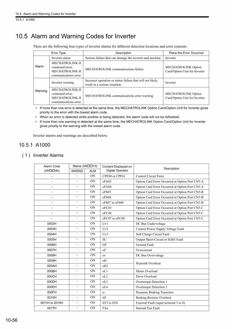
10.5 Alarm and Warning Codes for Inverter
10.5.1 A1000
10-56
10.5 Alarm and Warning Codes for Inverter
There are the following four types of inverter alarms for different detection locations and error contents.
If more than one error is detected at the same time, the MECHATROLINK Option Card/Option Unit for Inverter gives priority to the error with the lowest alarm code.
When an error is detected while another is being detected, the alarm code will not be refreshed.
If more than one warning is detected at the same time, the MECHATROLINK Option Card/Option Unit for Inverter gives priority to the warning with the lowest alarm code.
Inverter alarms and warnings are described below.
10.5.1 A1000
( 1 ) Inverter Alarms
Error Type Description Place the Error Occurred
Alarm
Inverter alarm Serious failure that can damage the inverter and machine Inverter
MECHATROLINK-IIcommand error,MECHATROLINK-IIcommunications error
MECHATROLINK communications failureMECHATROLINK Option Card/Option Unit for Inverter
Warning
Inverter warningIncorrect operation or minor failure that will not likely result in a serious situation.
Inverter
MECHATROLINK-IIcommand error,MECHATROLINK-IIcommunications error
MECHATROLINK communications error warningMECHATROLINK Option Card/Option Unit for Inverter
Alarm Code
(IW30)
Status (IW10) Content Displayed on Digital Operator
DescriptionWARNG ALM
− − ON CPF00 or CPF01 Control Circuit Error
− − ON oFA03 Option Card Error Occurred at Option Port CN5-A
− − ON oFA04 Option Card Error Occurred at Option Port CN5-A
− − ON oFb03 Option Card Error Occurred at Option Port CN5-B
− − ON oFb04 Option Card Error Occurred at Option Port CN5-B
− − ON oFb07 to oFb09 Option Card Error Occurred at Option Port CN5-B
− − ON oFC03 Option Card Error Occurred at Option Port CN5-C
− − ON oFC04 Option Card Error Occurred at Option Port CN5-C
− − ON oFC07 to oFC09 Option Card Error Occurred at Option Port CN5-C
0002H − ON Uv1 DC Bus Undervoltage
0003H − ON Uv2 Control Power Supply Voltage Fault
0004H − ON Uv3 Soft Charge Circuit Fault
0005H − ON SC Output Short-Circuit or IGBT Fault
0006H − ON GF Ground Fault
0007H − ON oC Overcurrent
0008H − ON ov DC Bus Overvoltage
0009H − ON oHHeatsink Overheat
000AH − ON oH1
000BH − ON oL1 Motor Overload
000CH − ON oL2 Drive Overload
000DH − ON oL3 Overtorque Detection 1
000EH − ON oL4 Overtorque Detection 2
000FH − ON rr Dynamic Braking Transistor
0010H − ON rH Braking Resistor Overheat
0011H to 0016H − ON EF3 to EF8 External Fault (input terminal 3 to 8)
0017H − ON FAn Internal Fan Fault
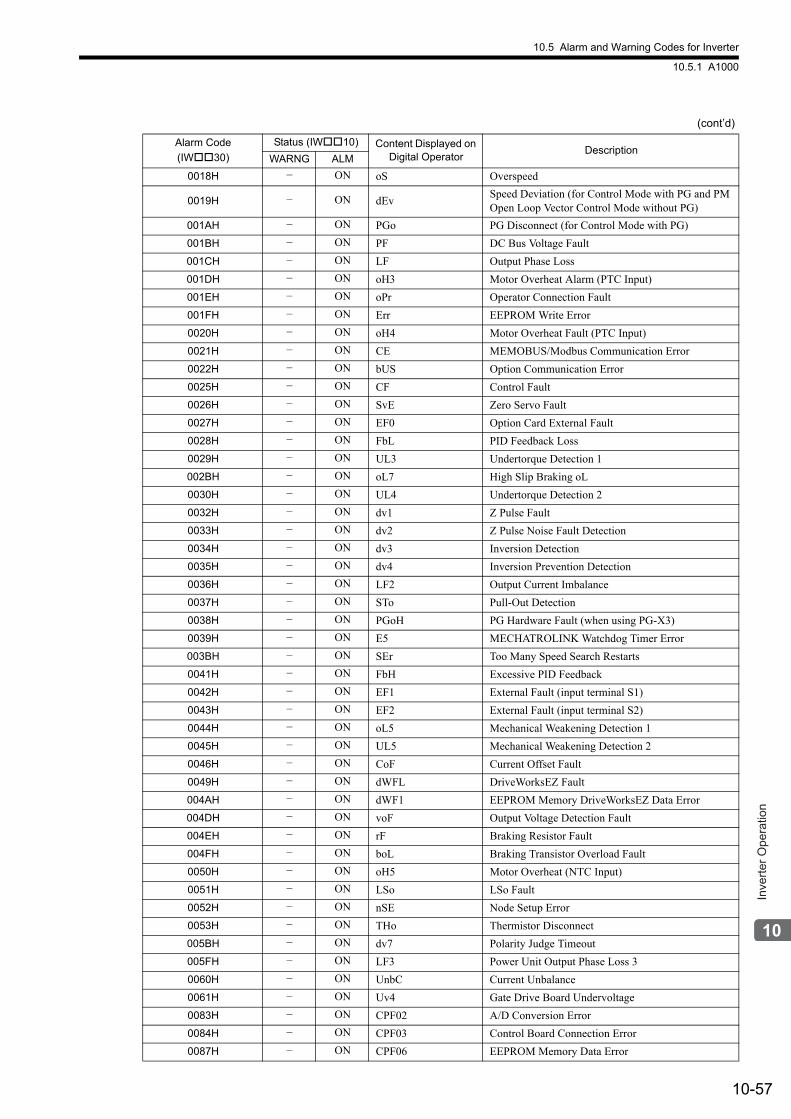
10.5 Alarm and Warning Codes for Inverter
10.5.1 A1000
10-57
Inve
rter O
pera
tion
0018H − ON oS Overspeed
0019H − ON dEvSpeed Deviation (for Control Mode with PG and PM Open Loop Vector Control Mode without PG)
001AH − ON PGo PG Disconnect (for Control Mode with PG)
001BH − ON PF DC Bus Voltage Fault
001CH − ON LF Output Phase Loss
001DH − ON oH3 Motor Overheat Alarm (PTC Input)
001EH − ON oPr Operator Connection Fault
001FH − ON Err EEPROM Write Error
0020H − ON oH4 Motor Overheat Fault (PTC Input)
0021H − ON CE MEMOBUS/Modbus Communication Error
0022H − ON bUS Option Communication Error
0025H − ON CF Control Fault
0026H − ON SvE Zero Servo Fault
0027H − ON EF0 Option Card External Fault
0028H − ON FbL PID Feedback Loss
0029H − ON UL3 Undertorque Detection 1
002BH − ON oL7 High Slip Braking oL
0030H − ON UL4 Undertorque Detection 2
0032H − ON dv1 Z Pulse Fault
0033H − ON dv2 Z Pulse Noise Fault Detection
0034H − ON dv3 Inversion Detection
0035H − ON dv4 Inversion Prevention Detection
0036H − ON LF2 Output Current Imbalance
0037H − ON STo Pull-Out Detection
0038H − ON PGoH PG Hardware Fault (when using PG-X3)
0039H − ON E5 MECHATROLINK Watchdog Timer Error
003BH − ON SEr Too Many Speed Search Restarts
0041H − ON FbH Excessive PID Feedback
0042H − ON EF1 External Fault (input terminal S1)
0043H − ON EF2 External Fault (input terminal S2)
0044H − ON oL5 Mechanical Weakening Detection 1
0045H − ON UL5 Mechanical Weakening Detection 2
0046H − ON CoF Current Offset Fault
0049H − ON dWFL DriveWorksEZ Fault
004AH − ON dWF1 EEPROM Memory DriveWorksEZ Data Error
004DH − ON voF Output Voltage Detection Fault
004EH − ON rF Braking Resistor Fault
004FH − ON boL Braking Transistor Overload Fault
0050H − ON oH5 Motor Overheat (NTC Input)
0051H − ON LSo LSo Fault
0052H − ON nSE Node Setup Error
0053H − ON THo Thermistor Disconnect
005BH − ON dv7 Polarity Judge Timeout
005FH − ON LF3 Power Unit Output Phase Loss 3
0060H − ON UnbC Current Unbalance
0061H − ON Uv4 Gate Drive Board Undervoltage
0083H − ON CPF02 A/D Conversion Error
0084H − ON CPF03 Control Board Connection Error
0087H − ON CPF06 EEPROM Memory Data Error
(cont’d)
Alarm Code
(IW30)
Status (IW10) Content Displayed on Digital Operator
DescriptionWARNG ALM
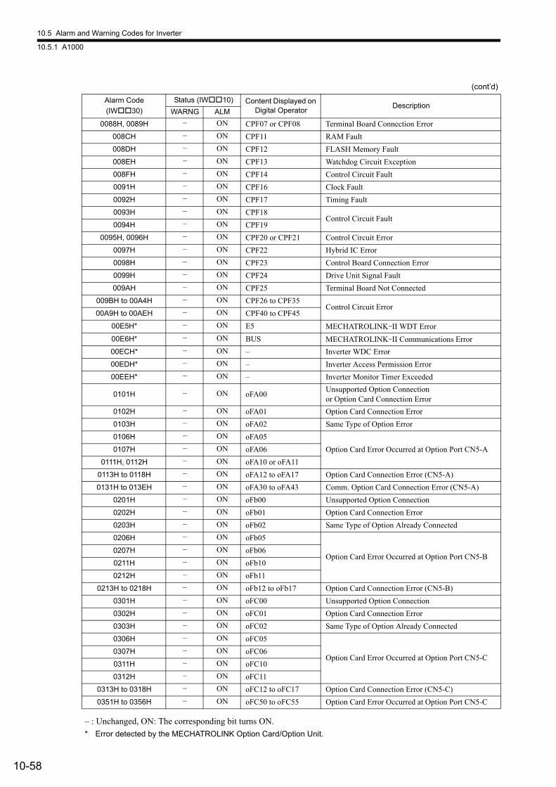
10.5 Alarm and Warning Codes for Inverter
10.5.1 A1000
10-58
– : Unchanged, ON: The corresponding bit turns ON.
* Error detected by the MECHATROLINK Option Card/Option Unit.
0088H, 0089H − ON CPF07 or CPF08 Terminal Board Connection Error
008CH − ON CPF11 RAM Fault
008DH − ON CPF12 FLASH Memory Fault
008EH − ON CPF13 Watchdog Circuit Exception
008FH − ON CPF14 Control Circuit Fault
0091H − ON CPF16 Clock Fault
0092H − ON CPF17 Timing Fault
0093H − ON CPF18Control Circuit Fault
0094H − ON CPF19
0095H, 0096H − ON CPF20 or CPF21 Control Circuit Error
0097H − ON CPF22 Hybrid IC Error
0098H − ON CPF23 Control Board Connection Error
0099H − ON CPF24 Drive Unit Signal Fault
009AH − ON CPF25 Terminal Board Not Connected
009BH to 00A4H − ON CPF26 to CPF35Control Circuit Error
00A9H to 00AEH − ON CPF40 to CPF45
00E5H* − ON E5 MECHATROLINK-II WDT Error
00E6H* − ON BUS MECHATROLINK-II Communications Error
00ECH* − ON – Inverter WDC Error
00EDH* − ON – Inverter Access Permission Error
00EEH* − ON – Inverter Monitor Timer Exceeded
0101H − ON oFA00Unsupported Option Connection or Option Card Connection Error
0102H − ON oFA01 Option Card Connection Error
0103H − ON oFA02 Same Type of Option Error
0106H − ON oFA05
Option Card Error Occurred at Option Port CN5-A0107H − ON oFA06
0111H, 0112H − ON oFA10 or oFA11
0113H to 0118H − ON oFA12 to oFA17 Option Card Connection Error (CN5-A)
0131H to 013EH − ON oFA30 to oFA43 Comm. Option Card Connection Error (CN5-A)
0201H − ON oFb00 Unsupported Option Connection
0202H − ON oFb01 Option Card Connection Error
0203H − ON oFb02 Same Type of Option Already Connected
0206H − ON oFb05
Option Card Error Occurred at Option Port CN5-B0207H − ON oFb06
0211H − ON oFb10
0212H − ON oFb11
0213H to 0218H − ON oFb12 to oFb17 Option Card Connection Error (CN5-B)
0301H − ON oFC00 Unsupported Option Connection
0302H − ON oFC01 Option Card Connection Error
0303H − ON oFC02 Same Type of Option Already Connected
0306H − ON oFC05
Option Card Error Occurred at Option Port CN5-C0307H − ON oFC06
0311H − ON oFC10
0312H − ON oFC11
0313H to 0318H − ON oFC12 to oFC17 Option Card Connection Error (CN5-C)
0351H to 0356H − ON oFC50 to oFC55 Option Card Error Occurred at Option Port CN5-C
(cont’d)
Alarm Code
(IW30)
Status (IW10) Content Displayed on Digital Operator
DescriptionWARNG ALM
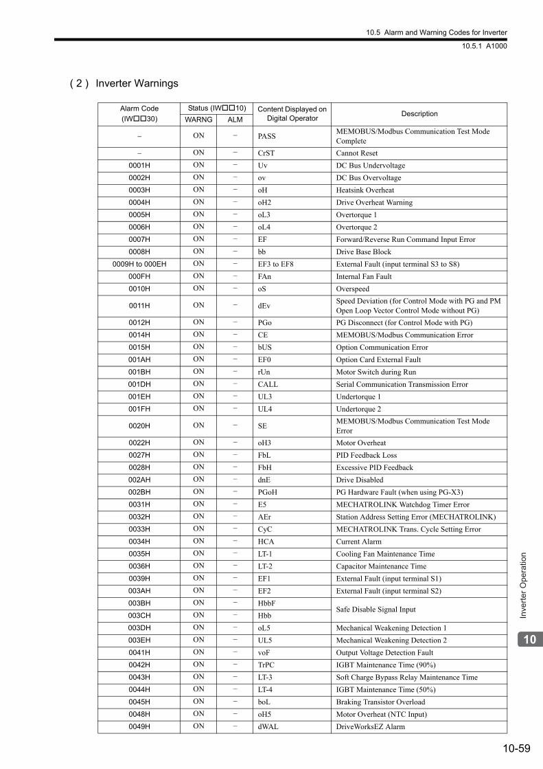
10.5 Alarm and Warning Codes for Inverter
10.5.1 A1000
10-59
Inve
rter O
pera
tion
( 2 ) Inverter Warnings
Alarm Code
(IW30)
Status (IW10) Content Displayed on Digital Operator
DescriptionWARNG ALM
− ON − PASSMEMOBUS/Modbus Communication Test Mode Complete
− ON − CrST Cannot Reset
0001H ON − Uv DC Bus Undervoltage
0002H ON − ov DC Bus Overvoltage
0003H ON − oH Heatsink Overheat
0004H ON − oH2 Drive Overheat Warning
0005H ON − oL3 Overtorque 1
0006H ON − oL4 Overtorque 2
0007H ON − EF Forward/Reverse Run Command Input Error
0008H ON − bb Drive Base Block
0009H to 000EH ON − EF3 to EF8 External Fault (input terminal S3 to S8)
000FH ON − FAn Internal Fan Fault
0010H ON − oS Overspeed
0011H ON − dEvSpeed Deviation (for Control Mode with PG and PM Open Loop Vector Control Mode without PG)
0012H ON − PGo PG Disconnect (for Control Mode with PG)
0014H ON − CE MEMOBUS/Modbus Communication Error
0015H ON − bUS Option Communication Error
001AH ON − EF0 Option Card External Fault
001BH ON − rUn Motor Switch during Run
001DH ON − CALL Serial Communication Transmission Error
001EH ON − UL3 Undertorque 1
001FH ON − UL4 Undertorque 2
0020H ON − SEMEMOBUS/Modbus Communication Test Mode Error
0022H ON − oH3 Motor Overheat
0027H ON − FbL PID Feedback Loss
0028H ON − FbH Excessive PID Feedback
002AH ON − dnE Drive Disabled
002BH ON − PGoH PG Hardware Fault (when using PG-X3)
0031H ON − E5 MECHATROLINK Watchdog Timer Error
0032H ON − AEr Station Address Setting Error (MECHATROLINK)
0033H ON − CyC MECHATROLINK Trans. Cycle Setting Error
0034H ON − HCA Current Alarm
0035H ON − LT-1 Cooling Fan Maintenance Time
0036H ON − LT-2 Capacitor Maintenance Time
0039H ON − EF1 External Fault (input terminal S1)
003AH ON − EF2 External Fault (input terminal S2)
003BH ON − HbbFSafe Disable Signal Input
003CH ON − Hbb
003DH ON − oL5 Mechanical Weakening Detection 1
003EH ON − UL5 Mechanical Weakening Detection 2
0041H ON − voF Output Voltage Detection Fault
0042H ON − TrPC IGBT Maintenance Time (90%)
0043H ON − LT-3 Soft Charge Bypass Relay Maintenance Time
0044H ON − LT-4 IGBT Maintenance Time (50%)
0045H ON − boL Braking Transistor Overload
0048H ON − oH5 Motor Overheat (NTC Input)
0049H ON − dWAL DriveWorksEZ Alarm
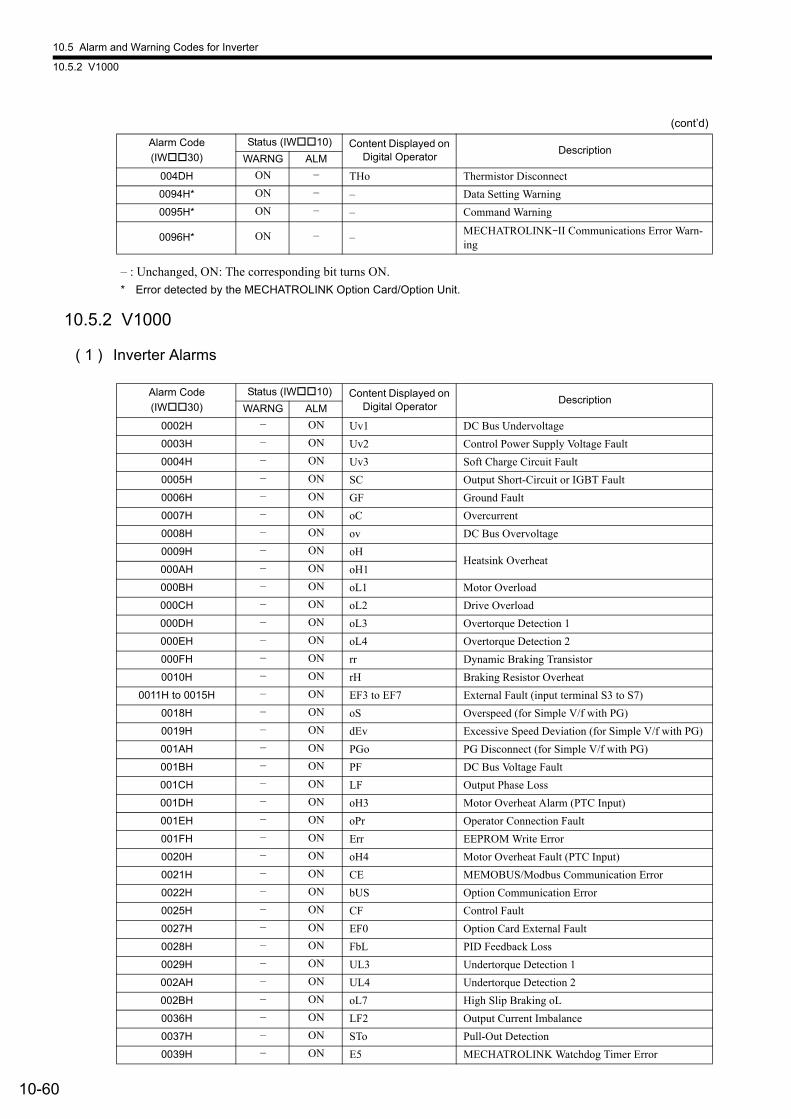
10.5 Alarm and Warning Codes for Inverter
10.5.2 V1000
10-60
– : Unchanged, ON: The corresponding bit turns ON.
* Error detected by the MECHATROLINK Option Card/Option Unit.
10.5.2 V1000
( 1 ) Inverter Alarms
004DH ON − THo Thermistor Disconnect
0094H* ON − – Data Setting Warning
0095H* ON − – Command Warning
0096H* ON − –MECHATROLINK-II Communications Error Warn-ing
(cont’d)
Alarm Code
(IW30)
Status (IW10) Content Displayed on Digital Operator
DescriptionWARNG ALM
Alarm Code
(IW30)
Status (IW10) Content Displayed on Digital Operator
DescriptionWARNG ALM
0002H − ON Uv1 DC Bus Undervoltage
0003H − ON Uv2 Control Power Supply Voltage Fault
0004H − ON Uv3 Soft Charge Circuit Fault
0005H − ON SC Output Short-Circuit or IGBT Fault
0006H − ON GF Ground Fault
0007H − ON oC Overcurrent
0008H − ON ov DC Bus Overvoltage
0009H − ON oHHeatsink Overheat
000AH − ON oH1
000BH − ON oL1 Motor Overload
000CH − ON oL2 Drive Overload
000DH − ON oL3 Overtorque Detection 1
000EH − ON oL4 Overtorque Detection 2
000FH − ON rr Dynamic Braking Transistor
0010H − ON rH Braking Resistor Overheat
0011H to 0015H − ON EF3 to EF7 External Fault (input terminal S3 to S7)
0018H − ON oS Overspeed (for Simple V/f with PG)
0019H − ON dEv Excessive Speed Deviation (for Simple V/f with PG)
001AH − ON PGo PG Disconnect (for Simple V/f with PG)
001BH − ON PF DC Bus Voltage Fault
001CH − ON LF Output Phase Loss
001DH − ON oH3 Motor Overheat Alarm (PTC Input)
001EH − ON oPr Operator Connection Fault
001FH − ON Err EEPROM Write Error
0020H − ON oH4 Motor Overheat Fault (PTC Input)
0021H − ON CE MEMOBUS/Modbus Communication Error
0022H − ON bUS Option Communication Error
0025H − ON CF Control Fault
0027H − ON EF0 Option Card External Fault
0028H − ON FbL PID Feedback Loss
0029H − ON UL3 Undertorque Detection 1
002AH − ON UL4 Undertorque Detection 2
002BH − ON oL7 High Slip Braking oL
0036H − ON LF2 Output Current Imbalance
0037H − ON STo Pull-Out Detection
0039H − ON E5 MECHATROLINK Watchdog Timer Error
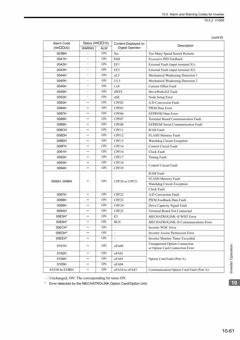
10.5 Alarm and Warning Codes for Inverter
10.5.2 V1000
10-61
Inve
rter O
pera
tion
– : Unchanged, ON: The corresponding bit turns ON.
* Error detected by the MECHATROLINK Option Card/Option Unit.
003BH − ON Ser Too Many Speed Search Restarts
0041H − ON FbH Excessive PID Feedback
0042H − ON EF1 External Fault (input terminal S1)
0043H − ON EF2 External Fault (input terminal S2)
0044H − ON oL5 Mechanical Weakening Detection 1
0045H − ON UL5 Mechanical Weakening Detection 2
0046H − ON CoF Current Offset Fault
0049H − ON dWFL DriveWorksEZ Fault
0052H − ON nSE Node Setup Error
0083H ─ ON CPF02 A/D Conversion Fault
0084H ─ ON CPF03 PWM Data Error
0087H ─ ON CPF06 EEPROM Data Error
0088H ─ ON CPF07 Terminal Board Communication Fault
0089H ─ ON CPF08 EEPROM Serial Communication Fault
008CH ─ ON CPF11 RAM Fault
008DH ─ ON CPF12 FLASH Memory Fault
008EH ─ ON CPF13 Watchdog Circuit Exception
008FH ─ ON CPF14 Control Circuit Fault
0091H ─ ON CPF16 Clock Fault
0092H ─ ON CPF17 Timing Fault
0093H ─ ON CPF18Control Circuit Fault
0094H ─ ON CPF19
0095H, 0096H ─ ON CPF20 or CPF21
RAM Fault
FLASH Memory Fault
Watchdog Circuit Exception
Clock Fault
0097H ─ ON CPF22 A/D Conversion Fault
0098H ─ ON CPF23 PWM Feedback Data Fault
0099H ─ ON CPF24 Drive Capacity Signal Fault
009AH ─ ON CPF25 Terminal Board Not Connected
00E5H* ─ ON E5 MECHATROLINK-II WDT Error
00E6H* ─ ON BUS MECHATROLINK-II Communications Error
00ECH* ─ ON – Inverter WDC Error
00EDH* ─ ON – Inverter Access Permission Error
00EEH* ─ ON – Inverter Monitor Timer Exceeded
0101H ─ ON oFA00Unsupported Option Connectionor Option Card Connection Error
0102H ─ ON oFA01
Option Card Fault (Port A)0104H ─ ON oFA03
0105H ─ ON oFA04
0131H to 013EH ─ ON oFA30 to oFA43 Communication Option Card Fault (Port A)
(cont’d)
Alarm Code
(IW30)
Status (IW10) Content Displayed on Digital Operator
DescriptionWARNG ALM
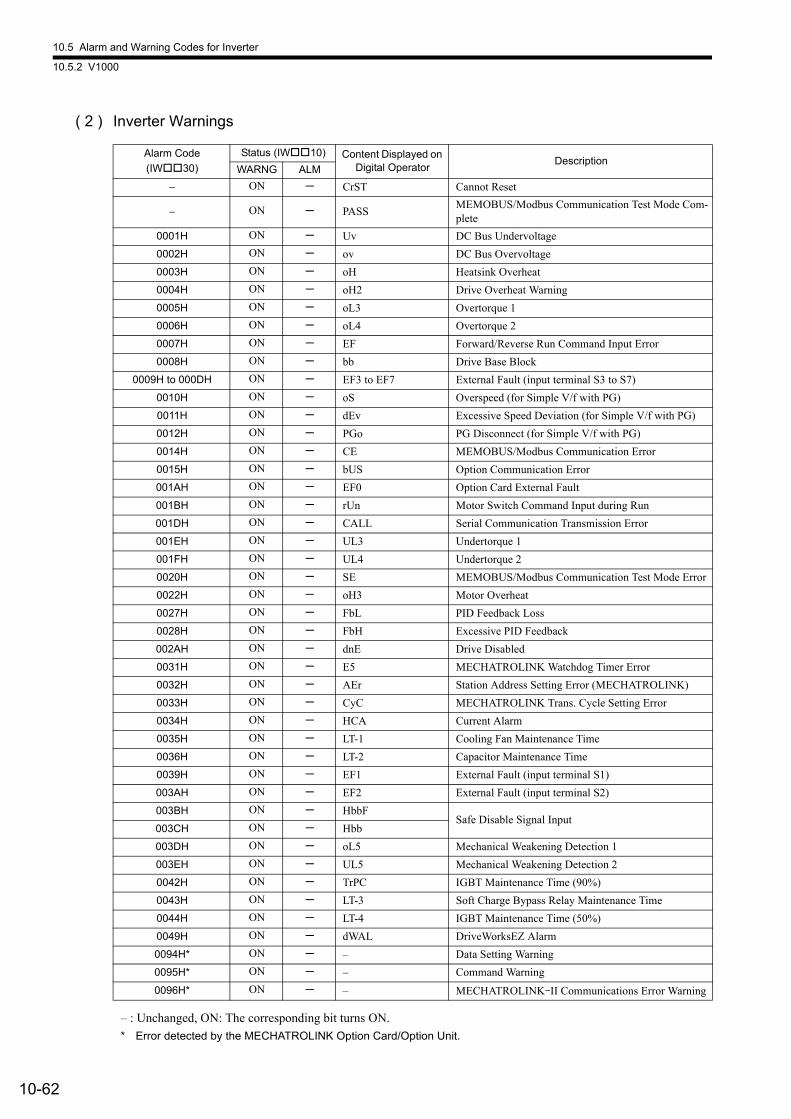
10.5 Alarm and Warning Codes for Inverter
10.5.2 V1000
10-62
( 2 ) Inverter Warnings
– : Unchanged, ON: The corresponding bit turns ON.
* Error detected by the MECHATROLINK Option Card/Option Unit.
Alarm Code
(IW30)
Status (IW10) Content Displayed on Digital Operator
DescriptionWARNG ALM
− ON ─ CrST Cannot Reset
− ON ─ PASSMEMOBUS/Modbus Communication Test Mode Com-plete
0001H ON ─ Uv DC Bus Undervoltage
0002H ON ─ ov DC Bus Overvoltage
0003H ON ─ oH Heatsink Overheat
0004H ON ─ oH2 Drive Overheat Warning
0005H ON ─ oL3 Overtorque 1
0006H ON ─ oL4 Overtorque 2
0007H ON ─ EF Forward/Reverse Run Command Input Error
0008H ON ─ bb Drive Base Block
0009H to 000DH ON ─ EF3 to EF7 External Fault (input terminal S3 to S7)
0010H ON ─ oS Overspeed (for Simple V/f with PG)
0011H ON ─ dEv Excessive Speed Deviation (for Simple V/f with PG)
0012H ON ─ PGo PG Disconnect (for Simple V/f with PG)
0014H ON ─ CE MEMOBUS/Modbus Communication Error
0015H ON ─ bUS Option Communication Error
001AH ON ─ EF0 Option Card External Fault
001BH ON ─ rUn Motor Switch Command Input during Run
001DH ON ─ CALL Serial Communication Transmission Error
001EH ON ─ UL3 Undertorque 1
001FH ON ─ UL4 Undertorque 2
0020H ON ─ SE MEMOBUS/Modbus Communication Test Mode Error
0022H ON ─ oH3 Motor Overheat
0027H ON ─ FbL PID Feedback Loss
0028H ON ─ FbH Excessive PID Feedback
002AH ON ─ dnE Drive Disabled
0031H ON ─ E5 MECHATROLINK Watchdog Timer Error
0032H ON ─ AEr Station Address Setting Error (MECHATROLINK)
0033H ON ─ CyC MECHATROLINK Trans. Cycle Setting Error
0034H ON ─ HCA Current Alarm
0035H ON ─ LT-1 Cooling Fan Maintenance Time
0036H ON ─ LT-2 Capacitor Maintenance Time
0039H ON ─ EF1 External Fault (input terminal S1)
003AH ON ─ EF2 External Fault (input terminal S2)
003BH ON ─ HbbFSafe Disable Signal Input
003CH ON ─ Hbb
003DH ON ─ oL5 Mechanical Weakening Detection 1
003EH ON ─ UL5 Mechanical Weakening Detection 2
0042H ON ─ TrPC IGBT Maintenance Time (90%)
0043H ON ─ LT-3 Soft Charge Bypass Relay Maintenance Time
0044H ON ─ LT-4 IGBT Maintenance Time (50%)
0049H ON ─ dWAL DriveWorksEZ Alarm
0094H* ON ─ – Data Setting Warning
0095H* ON ─ – Command Warning
0096H* ON ─ – MECHATROLINK-II Communications Error Warning
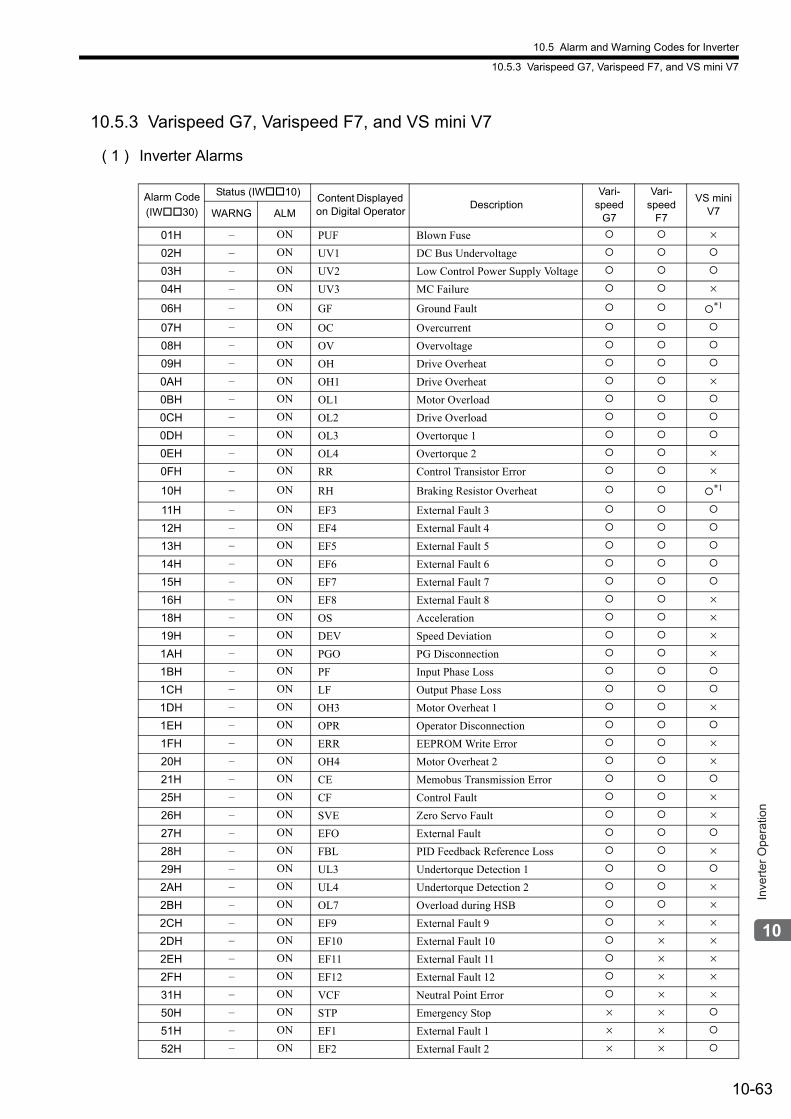
10.5 Alarm and Warning Codes for Inverter
10.5.3 Varispeed G7, Varispeed F7, and VS mini V7
10-63
Inve
rter O
pera
tion
10.5.3 Varispeed G7, Varispeed F7, and VS mini V7
( 1 ) Inverter Alarms
Alarm Code
(IW30)
Status (IW10)Content Displayed on Digital Operator
DescriptionVari-
speed G7
Vari-speed
F7
VS mini V7WARNG ALM
01H – ON PUF Blown Fuse ×
02H – ON UV1 DC Bus Undervoltage
03H – ON UV2 Low Control Power Supply Voltage
04H – ON UV3 MC Failure ×
06H – ON GF Ground Fault *1
07H – ON OC Overcurrent
08H – ON OV Overvoltage
09H – ON OH Drive Overheat
0AH – ON OH1 Drive Overheat ×
0BH – ON OL1 Motor Overload
0CH – ON OL2 Drive Overload
0DH – ON OL3 Overtorque 1
0EH – ON OL4 Overtorque 2 ×
0FH – ON RR Control Transistor Error ×
10H – ON RH Braking Resistor Overheat *1
11H – ON EF3 External Fault 3
12H – ON EF4 External Fault 4
13H – ON EF5 External Fault 5
14H – ON EF6 External Fault 6
15H – ON EF7 External Fault 7
16H – ON EF8 External Fault 8 ×
18H – ON OS Acceleration ×
19H – ON DEV Speed Deviation ×
1AH – ON PGO PG Disconnection ×
1BH – ON PF Input Phase Loss
1CH – ON LF Output Phase Loss
1DH – ON OH3 Motor Overheat 1 ×
1EH – ON OPR Operator Disconnection
1FH – ON ERR EEPROM Write Error ×
20H – ON OH4 Motor Overheat 2 ×
21H – ON CE Memobus Transmission Error
25H – ON CF Control Fault ×
26H – ON SVE Zero Servo Fault ×
27H – ON EFO External Fault
28H – ON FBL PID Feedback Reference Loss ×
29H – ON UL3 Undertorque Detection 1
2AH – ON UL4 Undertorque Detection 2 ×
2BH – ON OL7 Overload during HSB ×
2CH – ON EF9 External Fault 9 × ×
2DH – ON EF10 External Fault 10 × ×
2EH – ON EF11 External Fault 11 × ×
2FH – ON EF12 External Fault 12 × ×
31H – ON VCF Neutral Point Error × ×
50H – ON STP Emergency Stop × ×
51H – ON EF1 External Fault 1 × ×
52H – ON EF2 External Fault 2 × ×
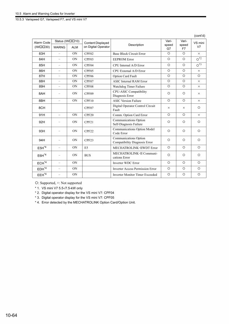
10.5 Alarm and Warning Codes for Inverter
10.5.3 Varispeed G7, Varispeed F7, and VS mini V7
10-64
: Supported, ×: Not supported
* 1. VS mini V7 5.5-/7.5-kW only
* 2. Digital operator display for the VS mini V7: CPF04
* 3. Digital operator display for the VS mini V7: CPF05
* 4. Error detected by the MECHATROLINK Option Card/Option Unit.
83H – ON CPF02 Base Block Circuit Error ×
84H – ON CPF03 EEPROM Error *2
85H – ON CPF04 CPU Internal A/D Error *3
86H – ON CPF05 CPU External A/D Error ×
87H – ON CPF06 Option Card Fault
88H – ON CPF07 ASIC Internal RAM Error ×
89H – ON CPF08 Watchdog Timer Failure ×
8AH – ON CPF09CPU-ASIC Compatibility Diagnosis Error
×
8BH – ON CPF10 ASIC Version Failure ×
8CH CPF07Digital Operator Control Circuit Fault
× ×
91H – ON CPF20 Comm. Option Card Error ×
92H – ON CPF21Communications Option Self-Diagnosis Failure
93H – ON CPF22Communications Option Model Code Error
94H – ON CPF23Communications Option Compatibility Diagnosis Error
E5H*4 – ON E5 MECHATROLINK-IIWDT Error
E6H*4 – ON BUSMECHATROLINK-II Communi-cations Error
ECH*4 – ON Inverter WDC Error
EDH*4 – ON Inverter Access Permission Error
EEH*4 – ON Inverter Monitor Timer Exceeded
(cont’d)
Alarm Code
(IW30)
Status (IW10)Content Displayed on Digital Operator
DescriptionVari-
speed G7
Vari-speed
F7
VS mini V7WARNG ALM
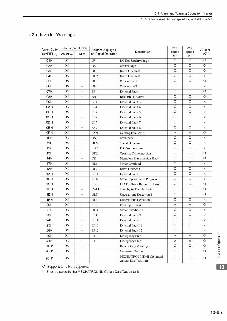
10.5 Alarm and Warning Codes for Inverter
10.5.3 Varispeed G7, Varispeed F7, and VS mini V7
10-65
Inve
rter O
pera
tion
( 2 ) Inverter Warnings
: Supported, ×: Not supported
* Error detected by the MECHATROLINK Option Card/Option Unit.
Alarm Code
(IW30)
Status (IW10)Content Displayed on Digital Operator
DescriptionVari-
speed G7
Vari-speed
F7
VS mini V7WARNG ALM
01H ON – UV DC Bus Undervoltage
02H ON – OV Overvoltage
03H ON – OH Drive Overheat
04H ON – OH2 Drive Overheat ×
05H ON – OL3 Overtorque 1
06H ON – OL4 Overtorque 2 ×
07H ON – EF External Fault
08H ON – BB Base Block Active
09H ON – EF3 External Fault 3 ×
0AH ON – EF4 External Fault 4 ×
0BH ON – EF5 External Fault 5 ×
0CH ON – EF6 External Fault 6 ×
0DH ON – EF7 External Fault 7 ×
0EH ON – EF8 External Fault 8 ×
0FH ON – FAN Cooling Fan Error × ×
10H ON – OS Overspeed ×
11H ON – DEV Speed Deviation ×
12H ON – PGO PG Disconnection ×
13H ON – OPR Operator Disconnection
14H ON – CE Memobus Transmission Error
17H ON – OL1 Motor Overload ×
18H ON – OL2 Drive Overload ×
1AH ON – EFO External Fault ×
1BH ON – RUN Motor Operation in Progress ×
1CH ON – FBL PID Feedback Reference Loss
1DH ON – CALL Standby to Transfer Data
1EH ON – UL3 Undertorque Detection 1
1FH ON – UL4 Undertorque Detection 2 ×
20H ON – SER PLC Input Error × ×
22H ON – OH3 Motor Overheat 1 ×
23H ON – EF9 External Fault 9 ×
24H ON – EF10 External Fault 10 ×
25H ON – EF11 External Fault 11 ×
26H ON – EF12 External Fault 12 ×
40H ON – STP Emergency Stop × ×
41H ON – STP Emergency Stop × ×
94H* ON – Data Setting Warning
95H* ON – Command Warning
96H* ON – MECHATROLINK-II Communi-cations Error Warning
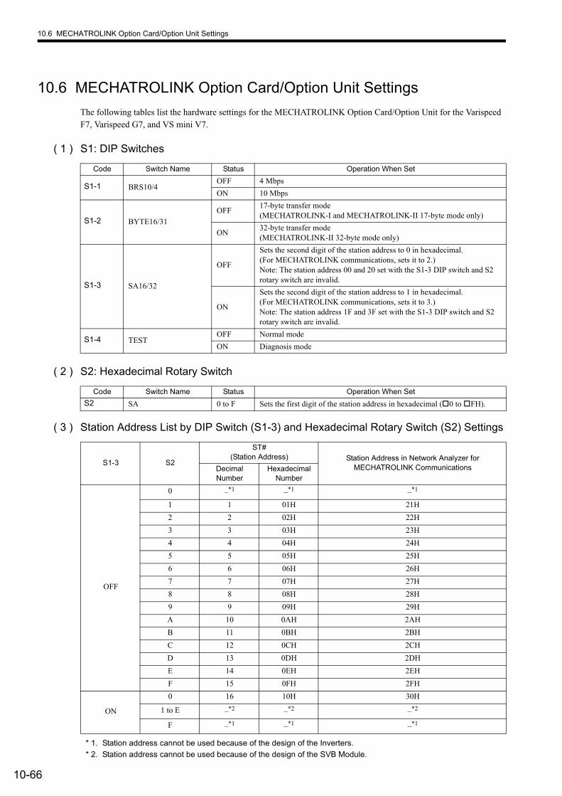
10.6 MECHATROLINK Option Card/Option Unit Settings
10-66
10.6 MECHATROLINK Option Card/Option Unit Settings
The following tables list the hardware settings for the MECHATROLINK Option Card/Option Unit for the Varispeed F7, Varispeed G7, and VS mini V7.
( 1 ) S1: DIP Switches
( 2 ) S2: Hexadecimal Rotary Switch
( 3 ) Station Address List by DIP Switch (S1-3) and Hexadecimal Rotary Switch (S2) Settings
* 1. Station address cannot be used because of the design of the Inverters.
* 2. Station address cannot be used because of the design of the SVB Module.
Code Switch Name Status Operation When Set
S1-1 BRS10/4OFF 4 Mbps
ON 10 Mbps
S1-2 BYTE16/31
OFF17-byte transfer mode(MECHATROLINK-I and MECHATROLINK-II 17-byte mode only)
ON32-byte transfer mode(MECHATROLINK-II 32-byte mode only)
S1-3 SA16/32
OFF
Sets the second digit of the station address to 0 in hexadecimal. (For MECHATROLINK communications, sets it to 2.)Note: The station address 00 and 20 set with the S1-3 DIP switch and S2 rotary switch are invalid.
ON
Sets the second digit of the station address to 1 in hexadecimal. (For MECHATROLINK communications, sets it to 3.)Note: The station address 1F and 3F set with the S1-3 DIP switch and S2 rotary switch are invalid.
S1-4 TESTOFF Normal mode
ON Diagnosis mode
Code Switch Name Status Operation When Set
S2 SA 0 to F Sets the first digit of the station address in hexadecimal (0 to FH).
S1-3 S2
ST#(Station Address) Station Address in Network Analyzer for
MECHATROLINK CommunicationsDecimal Number
Hexadecimal Number
OFF
0 –*1 –*1 –*1
1 1 01H 21H
2 2 02H 22H
3 3 03H 23H
4 4 04H 24H
5 5 05H 25H
6 6 06H 26H
7 7 07H 27H
8 8 08H 28H
9 9 09H 29H
A 10 0AH 2AH
B 11 0BH 2BH
C 12 0CH 2CH
D 13 0DH 2DH
E 14 0EH 2EH
F 15 0FH 2FH
ON
0 16 10H 30H
1 to E –*2 –*2 –*2
F –*1 –*1 –*1
11-1
Util
ity F
unct
ions
11
Utility Functions
This chapter describes MP2000-series Machine Controller and SERVOPACK utility functions such as vertical axis control, overtravel, and software limits, modal latch, and bank switching. Also, the parameters automatically updated under the specified conditions are explained.
11.1 Controlling Vertical Axes - - - - - - - - - - - - - - - - - - - - - - - - - - - - - - - - - - 11-3
11.1.1 Holding Brake Function of the SERVOPACK - - - - - - - - - - - - - - - - - - - - - - - - - - - - 11-3
11.1.2 Connections to Σ-II Series SGDH SERVOPACKs, Σ-III Series SGDS SERVOPACKs, Σ-V Series SGDV SERVOPACKs, and Σ-7 Series SGD7S SERVOPACKs - - - - - - - 11-3
11.1.3 Connections to Σ-I Series SGDB SERVOPACK - - - - - - - - - - - - - - - - - - - - - - - - - - 11-5
11.1.4 Connections to Σ-I Series SGD SERVOPACK - - - - - - - - - - - - - - - - - - - - - - - - - - - 11-7
11.2 Overtravel Function - - - - - - - - - - - - - - - - - - - - - - - - - - - - - - - - - - - - - - 11-9
11.2.1 Connections to Σ-II Series SGDH SERVOPACKs, Σ-III Series SGDS SERVOPACKs, Σ-V Series SGDV SERVOPACKs, and Σ-7 Series SGD7S SERVOPACKs - - - - - - - 11-9
11.2.2 Connections to Σ-I Series SGDB or SGD SERVOPACK - - - - - - - - - - - - - - - - - - - 11-12
11.3 Software Limit Function - - - - - - - - - - - - - - - - - - - - - - - - - - - - - - - - - - 11-14
11.3.1 Fixed Parameter Settings - - - - - - - - - - - - - - - - - - - - - - - - - - - - - - - - - - - - - - - - - 11-14
11.3.2 Effects of the Software Limit Function - - - - - - - - - - - - - - - - - - - - - - - - - - - - - - - - 11-14
11.3.3 Processing after an Alarm Occurs - - - - - - - - - - - - - - - - - - - - - - - - - - - - - - - - - - - 11-15
11.4 Modal Latch Function - - - - - - - - - - - - - - - - - - - - - - - - - - - - - - - - - - - 11-16
11.5 Bank Switching Function - - - - - - - - - - - - - - - - - - - - - - - - - - - - - - - - - 11-17
11.5.1 Bank Switching Specifications - - - - - - - - - - - - - - - - - - - - - - - - - - - - - - - - - - - - - - 11-17
11.5.2 Bank Switching Function Unsupported Motion Commands - - - - - - - - - - - - - - - - - 11-17
11.5.3 SERVOPACK Parameter Settings for Bank Switching - - - - - - - - - - - - - - - - - - - - - 11-17
11.5.4 Bank Member Setting - - - - - - - - - - - - - - - - - - - - - - - - - - - - - - - - - - - - - - - - - - - - 11-19
11.6 Parameters That Are Automatically Updated - - - - - - - - - - - - - - - - - - - 11-22
11.6.1 Parameters Updated when a MECHATROLINK Connection Is Established (1) (User Constants Self-writing Function Enabled) - - - - - - - - - - - - - - - - - - - - - - - - - - 11-22
11.6.2 Parameters Updated when a MECHATROLINK Connection Is Established (2) (Regardless of the User Constants Self-writing Function) - - - - - - - - - - - - - - - - - - - 11-23
11.6.3 Parameters Updated when a Setting Parameter Is Changed (MECHATROLINK-II Operating at 10 Mbps in 32-byte Mode with User Constants Self-writing Function Enabled) - - - - - - - - - - - - - - - - - - - - - - - - - - - - - - - - - - - - - - 11-23
11.6.4 Parameters Updated when a Motion Command Is Executed - - - - - - - - - - - - - - - - 11-24
11.6.5 Parameters Updated during Self-configuration - - - - - - - - - - - - - - - - - - - - - - - - - - 11-25
11-2
11.7 Precautions When Using Σ-V-series SGDV SERVOPACKs - - - - - - - - - 11-28
11.7.1 Software Limit Settings - - - - - - - - - - - - - - - - - - - - - - - - - - - - - - - - - - - - - - - - - - - 11-28
11.7.2 When the Tuning-less Function is Enabled - - - - - - - - - - - - - - - - - - - - - - - - - - - - - 11-28
11.7.3 Saving the Parameter Bank Data - - - - - - - - - - - - - - - - - - - - - - - - - - - - - - - - - - - - 11-28
11.7.4 Motion Command Operation for External Latches with DC Power Input Σ-V-series SERVOPACKs - - - - - - - - - - - - - - - - - - - - - - - - - - - - - - - - - - - - - - - - - - - - - - - - - 11-29
11.8 Precautions When Using Σ-7-series SGD7S SERVOPACKs with Rotary Servomotors - - - - - - - - - - - - - - - - - - - - - - - - - - - - - - - - - 11-30
11.8.1 SGD7S Electronic Gear Ratio Settings - - - - - - - - - - - - - - - - - - - - - - - - - - - - - - - - 11-30
11.8.2 Assignment - - - - - - - - - - - - - - - - - - - - - - - - - - - - - - - - - - - - - - - - - - - - - - - - - - - 11-30
11.8.3 Number of Pulses per Motor Rotation - - - - - - - - - - - - - - - - - - - - - - - - - - - - - - - - - 11-30
11.8.4 Motion Image - - - - - - - - - - - - - - - - - - - - - - - - - - - - - - - - - - - - - - - - - - - - - - - - - - 11-30
11.8.5 Software Limit Settings - - - - - - - - - - - - - - - - - - - - - - - - - - - - - - - - - - - - - - - - - - - 11-31
11.8.6 When the Tuning-less Function is Enabled - - - - - - - - - - - - - - - - - - - - - - - - - - - - - 11-31
11.8.7 Saving the Parameter Bank Data - - - - - - - - - - - - - - - - - - - - - - - - - - - - - - - - - - - - 11-31
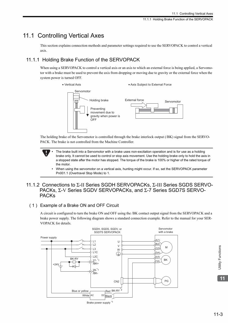
11.1 Controlling Vertical Axes
11.1.1 Holding Brake Function of the SERVOPACK
11-3
Util
ity F
unct
ions
11.1 Controlling Vertical Axes
This section explains connection methods and parameter settings required to use the SERVOPACK to control a vertical axis.
11.1.1 Holding Brake Function of the SERVOPACK
When using a SERVOPACK to control a vertical axis or an axis to which an external force is being applied, a Servomo-tor with a brake must be used to prevent the axis from dropping or moving due to gravity or the external force when the system power is turned OFF.
The holding brake of the Servomotor is controlled through the brake interlock output (/BK) signal from the SERVO-PACK. The brake is not controlled from the Machine Controller.
11.1.2 Connections to Σ-II Series SGDH SERVOPACKs, Σ-III Series SGDS SERVO-PACKs, Σ-V Series SGDV SERVOPACKs, and Σ-7 Series SGD7S SERVO-PACKs
( 1 ) Example of a Brake ON and OFF Circuit
A circuit is configured to turn the brake ON and OFF using the /BK contact output signal from the SERVOPACK and a brake power supply. The following diagram shows a standard connection example. Refer to the manual for your SER-VOPACK for details.
• Vertical Axis • Axis Subject to External Force
Servomotor
Holding brake External force Servomotor
Preventing
movement due to
gravity when power is
OFF
The brake built into a Servomotor with a brake uses non-excitation operation and is for use as a holding brake only. It cannot be used to control or stop axis movement. Use the holding brake only to hold the axis in a stopped state after the motor has stopped. The torque of the brake is 100% or higher of the rated torque of the motor.
When using the servomotor on a vertical axis, hunting might occur. If so, set the SERVOPACK parameter Pn001.1 (Overtravel Stop Mode) to 1.
Red White
Brake power supply *3
SGDH, SGDS, SGDV, or SGD7S SERVOPACK
Power supply
Blue or yellow
Servomotor with a brake
M
BK
PG
UVW
CN2
AC DC
BK-RY
+24V
L1L2L3L1CL2C27-
28-
/BK+
/BK-
A(1)
B(2)
C(3)
D(4)
E(5)
F(6)
BK-RY
*1
*1
*2
Black
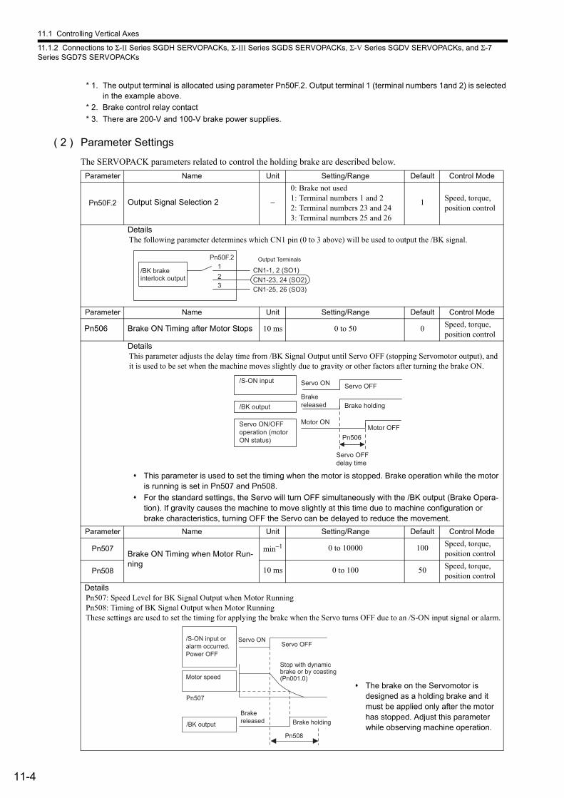
11.1 Controlling Vertical Axes
11.1.2 Connections to Σ-II Series SGDH SERVOPACKs, Σ-III Series SGDS SERVOPACKs, Σ-V Series SGDV SERVOPACKs, and Σ-7 Series SGD7S SERVOPACKs
11-4
* 1. The output terminal is allocated using parameter Pn50F.2. Output terminal 1 (terminal numbers 1and 2) is selected in the example above.
* 2. Brake control relay contact
* 3. There are 200-V and 100-V brake power supplies.
( 2 ) Parameter Settings
The SERVOPACK parameters related to control the holding brake are described below.
Parameter Name Unit Setting/Range Default Control Mode
Pn50F.2 Output Signal Selection 2 −
0: Brake not used1: Terminal numbers 1 and 22: Terminal numbers 23 and 243: Terminal numbers 25 and 26
1 Speed, torque, position control
DetailsThe following parameter determines which CN1 pin (0 to 3 above) will be used to output the /BK signal.
Parameter Name Unit Setting/Range Default Control Mode
Pn506 Brake ON Timing after Motor Stops 10 ms 0 to 50 0 Speed, torque, position control
DetailsThis parameter adjusts the delay time from /BK Signal Output until Servo OFF (stopping Servomotor output), and it is used to be set when the machine moves slightly due to gravity or other factors after turning the brake ON.
This parameter is used to set the timing when the motor is stopped. Brake operation while the motor is running is set in Pn507 and Pn508.
For the standard settings, the Servo will turn OFF simultaneously with the /BK output (Brake Opera-tion). If gravity causes the machine to move slightly at this time due to machine configuration or brake characteristics, turning OFF the Servo can be delayed to reduce the movement.
Parameter Name Unit Setting/Range Default Control Mode
Pn507Brake ON Timing when Motor Run-ning
min−1 0 to 10000 100 Speed, torque, position control
Pn508 10 ms 0 to 100 50 Speed, torque, position control
DetailsPn507: Speed Level for BK Signal Output when Motor RunningPn508: Timing of BK Signal Output when Motor Running These settings are used to set the timing for applying the brake when the Servo turns OFF due to an /S-ON input signal or alarm.
Pn50F.2123
Output Terminals
CN1-1, 2 (SO1)CN1-23, 24 (SO2)CN1-25, 26 (SO3)
/BK brake interlock output
/S-ON input
/BK output
Servo ON
Motor ON
Brake holding
Servo OFF
Motor OFFPn506
Servo ON/OFF operation (motor ON status)
Brake released
Servo OFF delay time
Motor speed
Pn507
/BK output
Servo ON Servo OFF
Pn508
Brake holding
/S-ON input or alarm occurred. Power OFF
Stop with dynamic brake or by coasting (Pn001.0)
Brake released
The brake on the Servomotor is designed as a holding brake and it must be applied only after the motor has stopped. Adjust this parameter while observing machine operation.
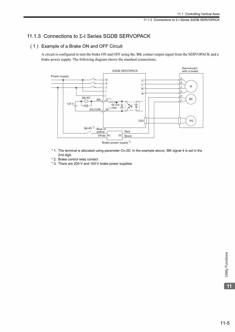
11.1 Controlling Vertical Axes
11.1.3 Connections to Σ-I Series SGDB SERVOPACK
11-5
Util
ity F
unct
ions
11.1.3 Connections to Σ-I Series SGDB SERVOPACK
( 1 ) Example of a Brake ON and OFF Circuit
A circuit is configured to turn the brake ON and OFF using the /BK contact output signal from the SERVOPACK and a brake power supply. The following diagram shows the standard connections.
* 1. The terminal is allocated using parameter Cn-2D. In the example above, /BK signal 4 is set in the 2nd digit.
* 2. Brake control relay contact* 3. There are 200-V and 100-V brake power supplies.
Power supply
M
BK
PG
UVW
CN2
Red BlackWhite AC DC
BK-RY
+24 V
RSTrt
Brake power supply
SGDB SERVOPACK
27
28
A
B
C
D
E
F/BK
SG-COM
*2
*3
BK-RY
*1
*150 mA max.
Blue or yellow
Servomotor with a brake
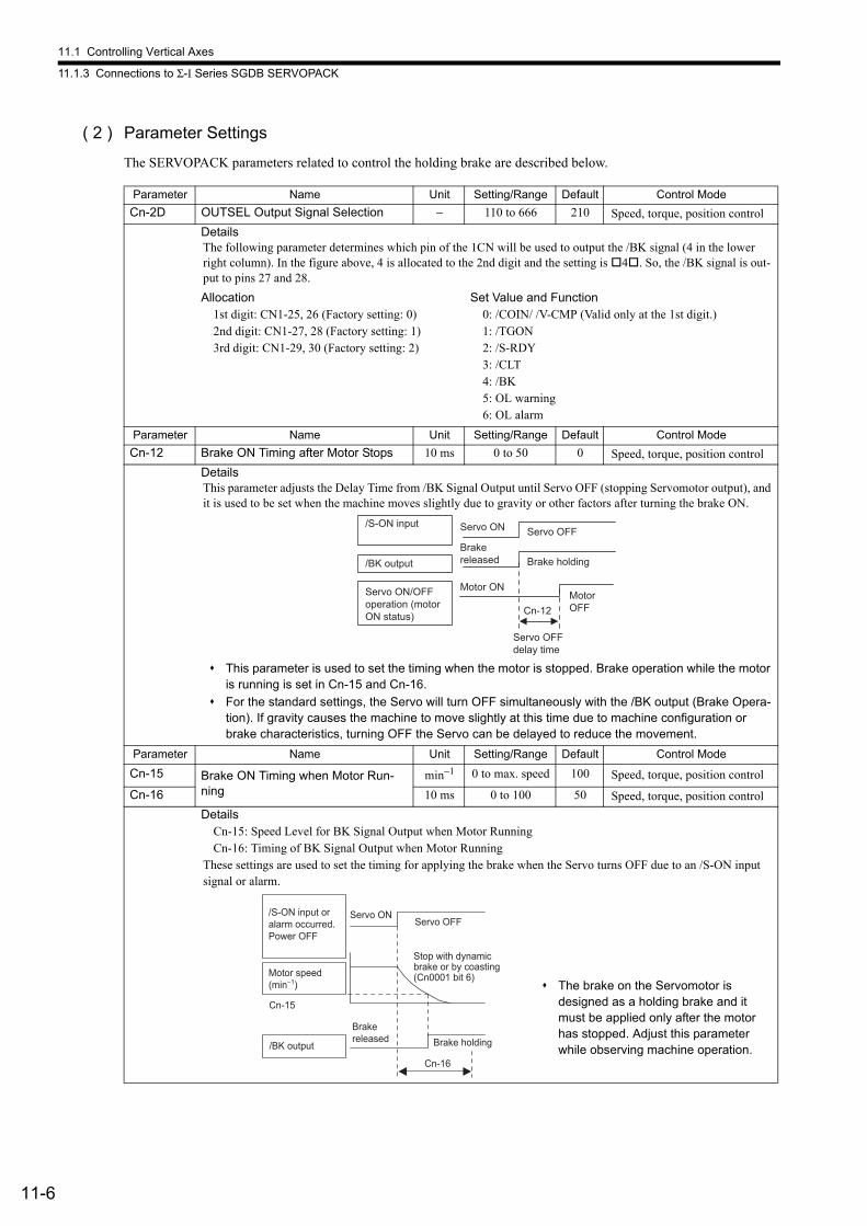
11.1 Controlling Vertical Axes
11.1.3 Connections to Σ-I Series SGDB SERVOPACK
11-6
( 2 ) Parameter Settings
The SERVOPACK parameters related to control the holding brake are described below.
Parameter Name Unit Setting/Range Default Control Mode
Cn-2D OUTSEL Output Signal Selection − 110 to 666 210 Speed, torque, position control
DetailsThe following parameter determines which pin of the 1CN will be used to output the /BK signal (4 in the lower right column). In the figure above, 4 is allocated to the 2nd digit and the setting is 4. So, the /BK signal is out-put to pins 27 and 28.
Allocation1st digit: CN1-25, 26 (Factory setting: 0)2nd digit: CN1-27, 28 (Factory setting: 1)3rd digit: CN1-29, 30 (Factory setting: 2)
Set Value and Function0: /COIN/ /V-CMP (Valid only at the 1st digit.)1: /TGON2: /S-RDY3: /CLT4: /BK5: OL warning6: OL alarm
Parameter Name Unit Setting/Range Default Control Mode
Cn-12 Brake ON Timing after Motor Stops 10 ms 0 to 50 0 Speed, torque, position control
DetailsThis parameter adjusts the Delay Time from /BK Signal Output until Servo OFF (stopping Servomotor output), and it is used to be set when the machine moves slightly due to gravity or other factors after turning the brake ON.
This parameter is used to set the timing when the motor is stopped. Brake operation while the motor is running is set in Cn-15 and Cn-16.
For the standard settings, the Servo will turn OFF simultaneously with the /BK output (Brake Opera-tion). If gravity causes the machine to move slightly at this time due to machine configuration or brake characteristics, turning OFF the Servo can be delayed to reduce the movement.
Parameter Name Unit Setting/Range Default Control Mode
Cn-15 Brake ON Timing when Motor Run-ning
min−1 0 to max. speed 100 Speed, torque, position control
Cn-16 10 ms 0 to 100 50 Speed, torque, position control
DetailsCn-15: Speed Level for BK Signal Output when Motor RunningCn-16: Timing of BK Signal Output when Motor Running
These settings are used to set the timing for applying the brake when the Servo turns OFF due to an /S-ON input signal or alarm.
/S-ON input
/BK output
Servo ON
Motor ON
Brake holding
Servo OFF
Cn-12
Servo ON/OFF operation (motor ON status)
Brake released
Motor OFF
Servo OFF delay time
Cn-15
/BK output
Servo ONServo OFF
Cn-16
Brake holding
/S-ON input or alarm occurred. Power OFF
Motor speed (min−1)
Stop with dynamic brake or by coasting (Cn0001 bit 6)
Brake released
The brake on the Servomotor is designed as a holding brake and it must be applied only after the motor has stopped. Adjust this parameter while observing machine operation.
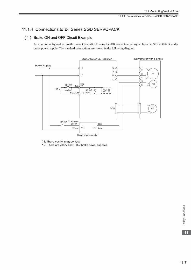
11.1 Controlling Vertical Axes
11.1.4 Connections to Σ-I Series SGD SERVOPACK
11-7
Util
ity F
unct
ions
11.1.4 Connections to Σ-I Series SGD SERVOPACK
( 1 ) Brake ON and OFF Circuit Example
A circuit is configured to turn the brake ON and OFF using the /BK contact output signal from the SERVOPACK and a brake power supply. The standard connections are shown in the following diagram.
* 1. Brake control relay contact* 2. There are 200-V and 100-V brake power supplies.
R
T
U
V
W
2CN
1
2
3
4
5
6
Power supply
BK-RY
White
Red
BlackAC DC
Brake power supply*2
SGD or SGDA SERVOPACK Servomotor with a brake
*1
BK-RY
+24 V-7
-10
/BK
SG-COM
1CN
M
BK
PG
50 mA max.
Blue or yellow
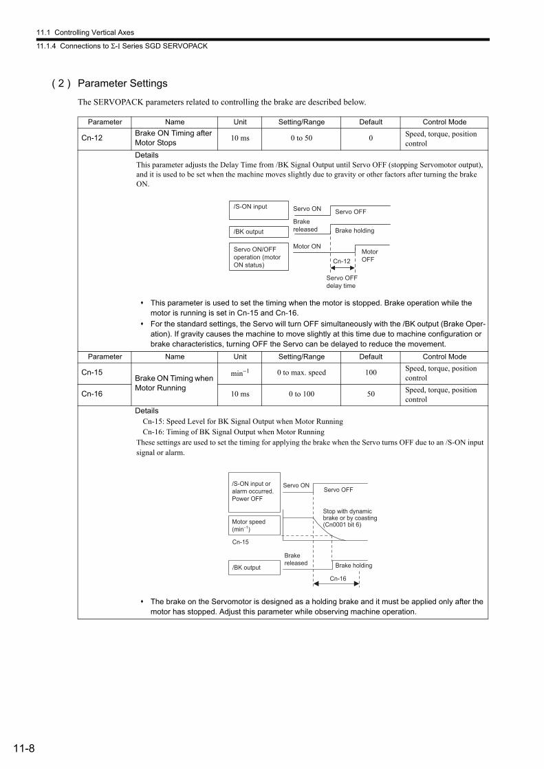
11.1 Controlling Vertical Axes
11.1.4 Connections to Σ-I Series SGD SERVOPACK
11-8
( 2 ) Parameter Settings
The SERVOPACK parameters related to controlling the brake are described below.
Parameter Name Unit Setting/Range Default Control Mode
Cn-12Brake ON Timing after Motor Stops
10 ms 0 to 50 0 Speed, torque, position control
DetailsThis parameter adjusts the Delay Time from /BK Signal Output until Servo OFF (stopping Servomotor output), and it is used to be set when the machine moves slightly due to gravity or other factors after turning the brake ON.
This parameter is used to set the timing when the motor is stopped. Brake operation while the motor is running is set in Cn-15 and Cn-16.
For the standard settings, the Servo will turn OFF simultaneously with the /BK output (Brake Oper-ation). If gravity causes the machine to move slightly at this time due to machine configuration or brake characteristics, turning OFF the Servo can be delayed to reduce the movement.
Parameter Name Unit Setting/Range Default Control Mode
Cn-15Brake ON Timing when Motor Running
min−1 0 to max. speed 100 Speed, torque, position control
Cn-16 10 ms 0 to 100 50 Speed, torque, position control
DetailsCn-15: Speed Level for BK Signal Output when Motor RunningCn-16: Timing of BK Signal Output when Motor Running
These settings are used to set the timing for applying the brake when the Servo turns OFF due to an /S-ON input signal or alarm.
The brake on the Servomotor is designed as a holding brake and it must be applied only after the motor has stopped. Adjust this parameter while observing machine operation.
/S-ON input
/BK output
Servo ON
Motor ON
Brake holding
Servo OFF
Cn-12
Servo ON/OFF operation (motor ON status)
Brake released
Motor OFF
Servo OFF delay time
Cn-15
/BK output
Servo ONServo OFF
Cn-16
Brake holding
/S-ON input or alarm occurred. Power OFF
Motor speed (min−1)
Stop with dynamic brake or by coasting (Cn0001 bit 6)
Brake released
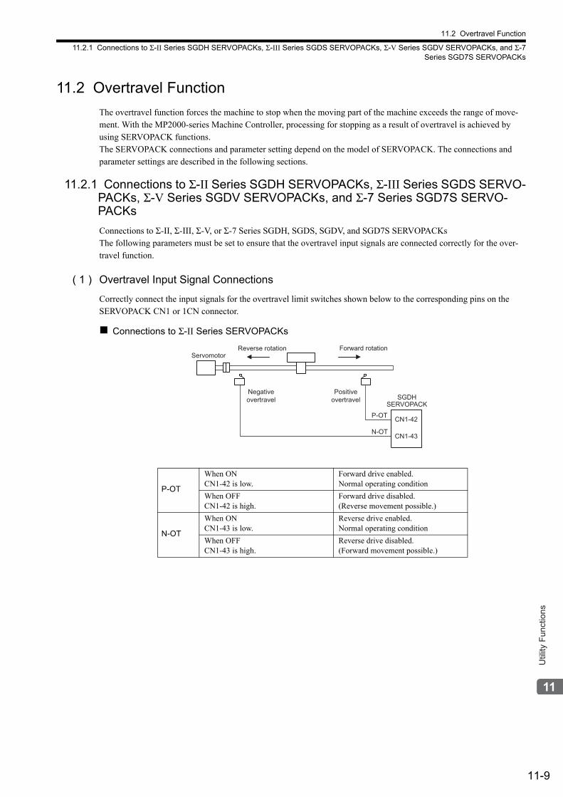
11.2 Overtravel Function
11.2.1 Connections to Σ-II Series SGDH SERVOPACKs, Σ-III Series SGDS SERVOPACKs, Σ-V Series SGDV SERVOPACKs, and Σ-7Series SGD7S SERVOPACKs
11-9
Util
ity F
unct
ions
11.2 Overtravel Function
The overtravel function forces the machine to stop when the moving part of the machine exceeds the range of move-ment. With the MP2000-series Machine Controller, processing for stopping as a result of overtravel is achieved by using SERVOPACK functions. The SERVOPACK connections and parameter setting depend on the model of SERVOPACK. The connections and parameter settings are described in the following sections.
11.2.1 Connections to Σ-II Series SGDH SERVOPACKs, Σ-III Series SGDS SERVO-PACKs, Σ-V Series SGDV SERVOPACKs, and Σ-7 Series SGD7S SERVO-PACKs
Connections to Σ-II, Σ-III, Σ-V, or Σ-7 Series SGDH, SGDS, SGDV, and SGD7S SERVOPACKsThe following parameters must be set to ensure that the overtravel input signals are connected correctly for the over-travel function.
( 1 ) Overtravel Input Signal Connections
Correctly connect the input signals for the overtravel limit switches shown below to the corresponding pins on the SERVOPACK CN1 or 1CN connector.
Connections to Σ-II Series SERVOPACKs
P-OT
When ONCN1-42 is low.
Forward drive enabled.Normal operating condition
When OFFCN1-42 is high.
Forward drive disabled.(Reverse movement possible.)
N-OT
When ONCN1-43 is low.
Reverse drive enabled.Normal operating condition
When OFFCN1-43 is high.
Reverse drive disabled.(Forward movement possible.)
Forward rotationReverse rotation
SERVOPACKSGDH
CN1-42
CN1-43N-OT
P-OT
Servomotor
Negative overtravel
Positive overtravel
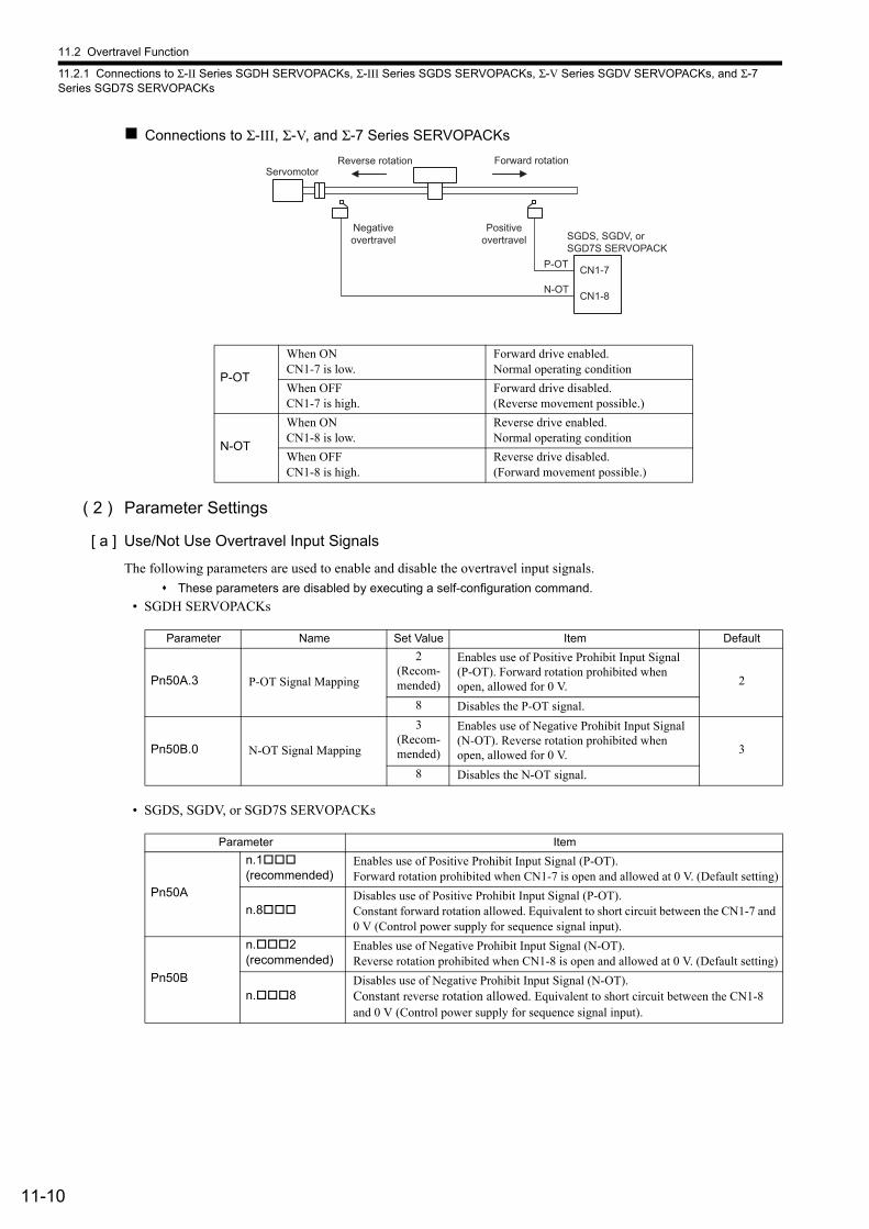
11.2 Overtravel Function
11.2.1 Connections to Σ-II Series SGDH SERVOPACKs, Σ-III Series SGDS SERVOPACKs, Σ-V Series SGDV SERVOPACKs, and Σ-7 Series SGD7S SERVOPACKs
11-10
Connections to Σ-III, Σ-V, and Σ-7 Series SERVOPACKs
( 2 ) Parameter Settings
[ a ] Use/Not Use Overtravel Input Signals
The following parameters are used to enable and disable the overtravel input signals.
These parameters are disabled by executing a self-configuration command.
• SGDH SERVOPACKs
• SGDS, SGDV, or SGD7S SERVOPACKs
P-OT
When ONCN1-7 is low.
Forward drive enabled.Normal operating condition
When OFFCN1-7 is high.
Forward drive disabled.(Reverse movement possible.)
N-OT
When ONCN1-8 is low.
Reverse drive enabled.Normal operating condition
When OFFCN1-8 is high.
Reverse drive disabled.(Forward movement possible.)
Forward rotationReverse rotation
SGDS, SGDV, or SGD7S SERVOPACK
CN1-7
CN1-8N-OT
P-OT
Servomotor
Negative overtravel
Positive overtravel
Parameter Name Set Value Item Default
Pn50A.3 P-OT Signal Mapping
2(Recom-mended)
Enables use of Positive Prohibit Input Signal (P-OT). Forward rotation prohibited when open, allowed for 0 V. 2
8 Disables the P-OT signal.
Pn50B.0 N-OT Signal Mapping
3(Recom-mended)
Enables use of Negative Prohibit Input Signal (N-OT). Reverse rotation prohibited when open, allowed for 0 V. 3
8 Disables the N-OT signal.
Parameter Item
Pn50A
n.1(recommended)
Enables use of Positive Prohibit Input Signal (P-OT). Forward rotation prohibited when CN1-7 is open and allowed at 0 V. (Default setting)
n.8Disables use of Positive Prohibit Input Signal (P-OT). Constant forward rotation allowed. Equivalent to short circuit between the CN1-7 and 0 V (Control power supply for sequence signal input).
Pn50B
n.2(recommended)
Enables use of Negative Prohibit Input Signal (N-OT). Reverse rotation prohibited when CN1-8 is open and allowed at 0 V. (Default setting)
n.8Disables use of Negative Prohibit Input Signal (N-OT).Constant reverse rotation allowed. Equivalent to short circuit between the CN1-8 and 0 V (Control power supply for sequence signal input).
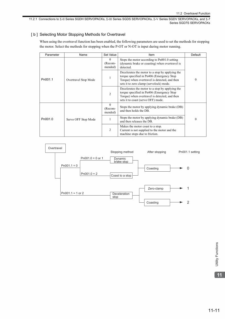
11.2 Overtravel Function
11.2.1 Connections to Σ-II Series SGDH SERVOPACKs, Σ-III Series SGDS SERVOPACKs, Σ-V Series SGDV SERVOPACKs, and Σ-7Series SGD7S SERVOPACKs
11-11
Util
ity F
unct
ions
[ b ] Selecting Motor Stopping Methods for Overtravel
When using the overtravel function has been enabled, the following parameters are used to set the methods for stopping the motor. Select the methods for stopping when the P-OT or N-OT is input during motor running.
Parameter Name Set Value Item Default
Pn001.1 Overtravel Stop Mode
0(Recom-mended)
Stops the motor according to Pn001.0 setting (dynamic brake or coasting) when overtravel is detected.
01
Decelerates the motor to a stop by applying the torque specified in Pn406 (Emergency Stop Torque) when overtravel is detected, and then sets it to zero clamp (servolock) mode.
2
Decelerates the motor to a stop by applying the torque specified in Pn406 (Emergency Stop Torque) when overtravel is detected, and then sets it to coast (servo OFF) mode.
Pn001.0 Servo OFF Stop Mode
0(Recom-mended)
Stops the motor by applying dynamic brake (DB) and then holds the DB.
01 Stops the motor by applying dynamic brake (DB) and then releases the DB.
2Makes the motor coast to a stop. Current is not supplied to the motor and the machine stops due to friction.
Zero-clamp
Coasting
Pn001.1 = 1 or 2
Pn001.1 = 0
Overtravel
Stopping method After stopping Pn001.1 setting
Coast to a stop
Pn001.0 = 0 or 1
Pn001.0 = 2
Coasting
0
1
2
Dynamic
brake stop
Deceleration
stop
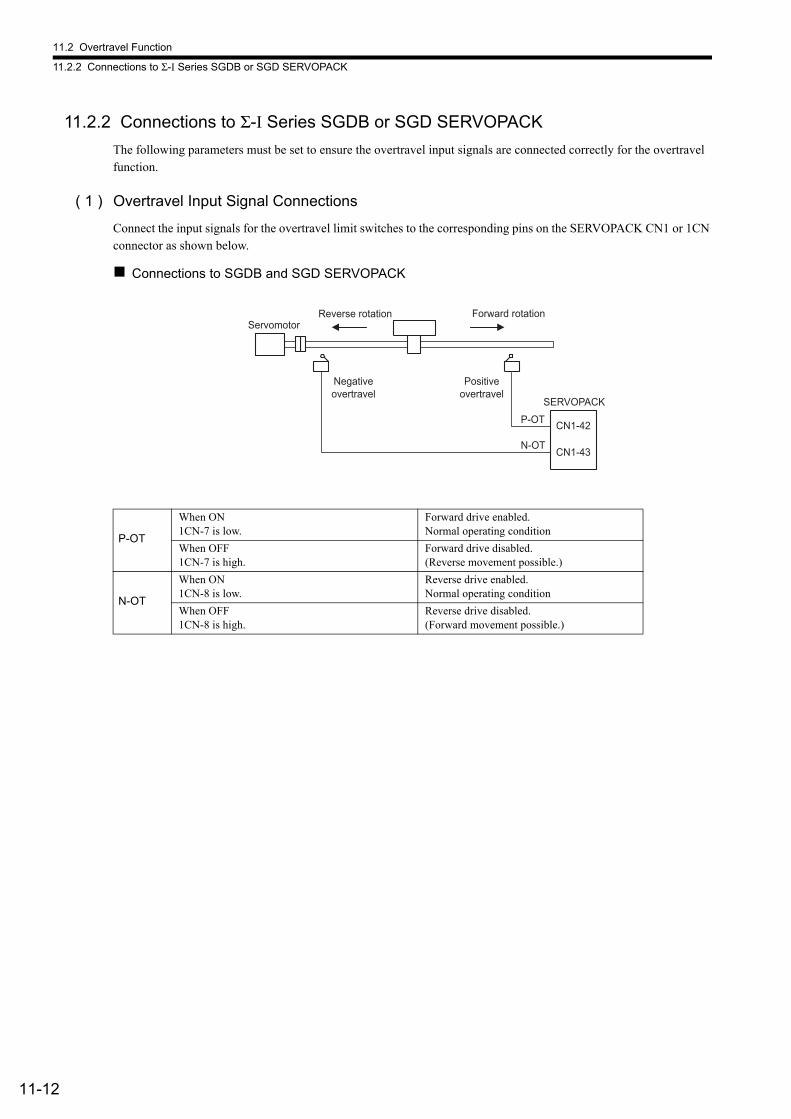
11.2 Overtravel Function
11.2.2 Connections to Σ-I Series SGDB or SGD SERVOPACK
11-12
11.2.2 Connections to Σ-I Series SGDB or SGD SERVOPACK
The following parameters must be set to ensure the overtravel input signals are connected correctly for the overtravel function.
( 1 ) Overtravel Input Signal Connections
Connect the input signals for the overtravel limit switches to the corresponding pins on the SERVOPACK CN1 or 1CN connector as shown below.
Connections to SGDB and SGD SERVOPACK
P-OT
When ON1CN-7 is low.
Forward drive enabled.Normal operating condition
When OFF1CN-7 is high.
Forward drive disabled.(Reverse movement possible.)
N-OT
When ON1CN-8 is low.
Reverse drive enabled.Normal operating condition
When OFF1CN-8 is high.
Reverse drive disabled.(Forward movement possible.)
Forward rotationReverse rotation
SERVOPACK
CN1-42
CN1-43N-OT
P-OT
Servomotor
Negative overtravel
Positive overtravel
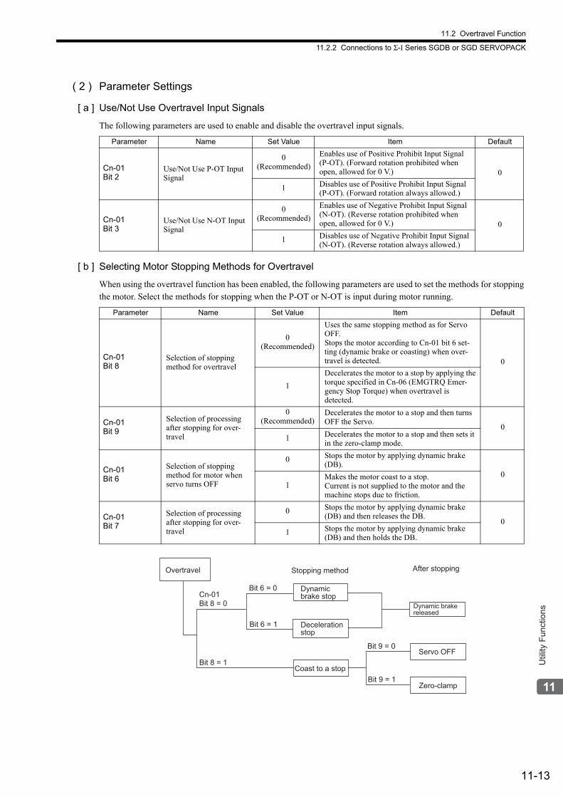
11.2 Overtravel Function
11.2.2 Connections to Σ-I Series SGDB or SGD SERVOPACK
11-13
Util
ity F
unct
ions
( 2 ) Parameter Settings
[ a ] Use/Not Use Overtravel Input Signals
The following parameters are used to enable and disable the overtravel input signals.
[ b ] Selecting Motor Stopping Methods for Overtravel
When using the overtravel function has been enabled, the following parameters are used to set the methods for stopping the motor. Select the methods for stopping when the P-OT or N-OT is input during motor running.
Parameter Name Set Value Item Default
Cn-01Bit 2
Use/Not Use P-OT Input Signal
0(Recommended)
Enables use of Positive Prohibit Input Signal (P-OT). (Forward rotation prohibited when open, allowed for 0 V.) 0
1 Disables use of Positive Prohibit Input Signal (P-OT). (Forward rotation always allowed.)
Cn-01Bit 3
Use/Not Use N-OT Input Signal
0(Recommended)
Enables use of Negative Prohibit Input Signal (N-OT). (Reverse rotation prohibited when open, allowed for 0 V.) 0
1 Disables use of Negative Prohibit Input Signal (N-OT). (Reverse rotation always allowed.)
Parameter Name Set Value Item Default
Cn-01Bit 8
Selection of stopping method for overtravel
0(Recommended)
Uses the same stopping method as for Servo OFF.Stops the motor according to Cn-01 bit 6 set-ting (dynamic brake or coasting) when over-travel is detected. 0
1
Decelerates the motor to a stop by applying the torque specified in Cn-06 (EMGTRQ Emer-gency Stop Torque) when overtravel is detected.
Cn-01Bit 9
Selection of processing after stopping for over-travel
0(Recommended)
Decelerates the motor to a stop and then turns OFF the Servo.
01 Decelerates the motor to a stop and then sets it
in the zero-clamp mode.
Cn-01Bit 6
Selection of stopping method for motor when servo turns OFF
0 Stops the motor by applying dynamic brake (DB).
01
Makes the motor coast to a stop. Current is not supplied to the motor and the machine stops due to friction.
Cn-01Bit 7
Selection of processing after stopping for over-travel
0 Stops the motor by applying dynamic brake (DB) and then releases the DB.
01 Stops the motor by applying dynamic brake
(DB) and then holds the DB.
Coast to a stop
Servo OFF
Zero-clamp
Bit 8 = 1
Cn-01
Bit 8 = 0
Overtravel Stopping method After stopping
Bit 6 = 0
Bit 6 = 1
Bit 9 = 0
Bit 9 = 1
Dynamic
brake stop
Deceleration
stop
Dynamic brake
released
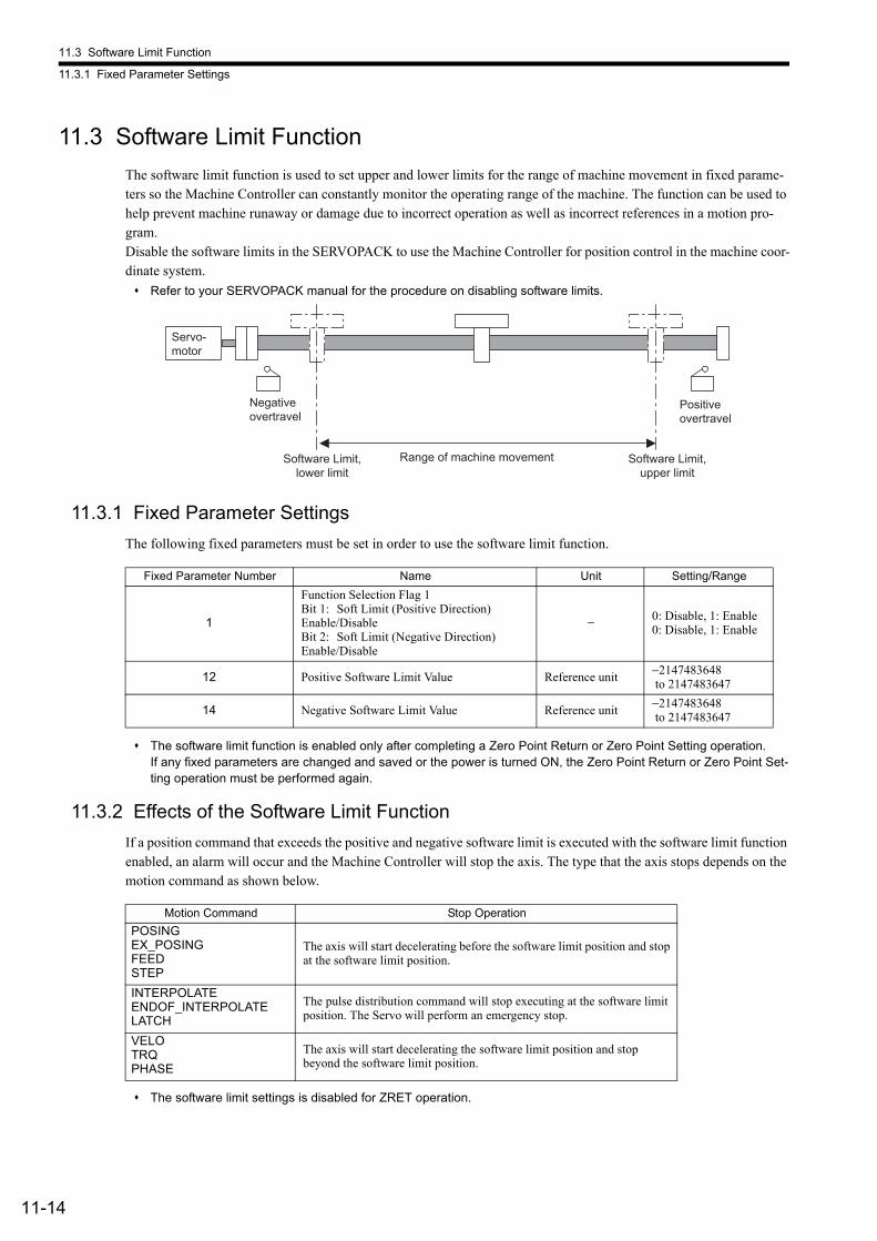
11.3 Software Limit Function
11.3.1 Fixed Parameter Settings
11-14
11.3 Software Limit Function
The software limit function is used to set upper and lower limits for the range of machine movement in fixed parame-ters so the Machine Controller can constantly monitor the operating range of the machine. The function can be used to help prevent machine runaway or damage due to incorrect operation as well as incorrect references in a motion pro-gram.Disable the software limits in the SERVOPACK to use the Machine Controller for position control in the machine coor-dinate system.
Refer to your SERVOPACK manual for the procedure on disabling software limits.
11.3.1 Fixed Parameter Settings
The following fixed parameters must be set in order to use the software limit function.
The software limit function is enabled only after completing a Zero Point Return or Zero Point Setting operation. If any fixed parameters are changed and saved or the power is turned ON, the Zero Point Return or Zero Point Set-ting operation must be performed again.
11.3.2 Effects of the Software Limit Function
If a position command that exceeds the positive and negative software limit is executed with the software limit function enabled, an alarm will occur and the Machine Controller will stop the axis. The type that the axis stops depends on the motion command as shown below.
The software limit settings is disabled for ZRET operation.
Servo-motor
Negative overtravel
Software Limit, lower limit
Range of machine movement
Positive overtravel
Software Limit, upper limit
Fixed Parameter Number Name Unit Setting/Range
1
Function Selection Flag 1Bit 1: Soft Limit (Positive Direction)Enable/DisableBit 2: Soft Limit (Negative Direction)Enable/Disable
− 0: Disable, 1: Enable0: Disable, 1: Enable
12 Positive Software Limit Value Reference unit−2147483648 to 2147483647
14 Negative Software Limit Value Reference unit−2147483648 to 2147483647
Motion Command Stop Operation
POSINGEX_POSINGFEEDSTEP
The axis will start decelerating before the software limit position and stop at the software limit position.
INTERPOLATEENDOF_INTERPOLATELATCH
The pulse distribution command will stop executing at the software limit position. The Servo will perform an emergency stop.
VELOTRQPHASE
The axis will start decelerating the software limit position and stop beyond the software limit position.
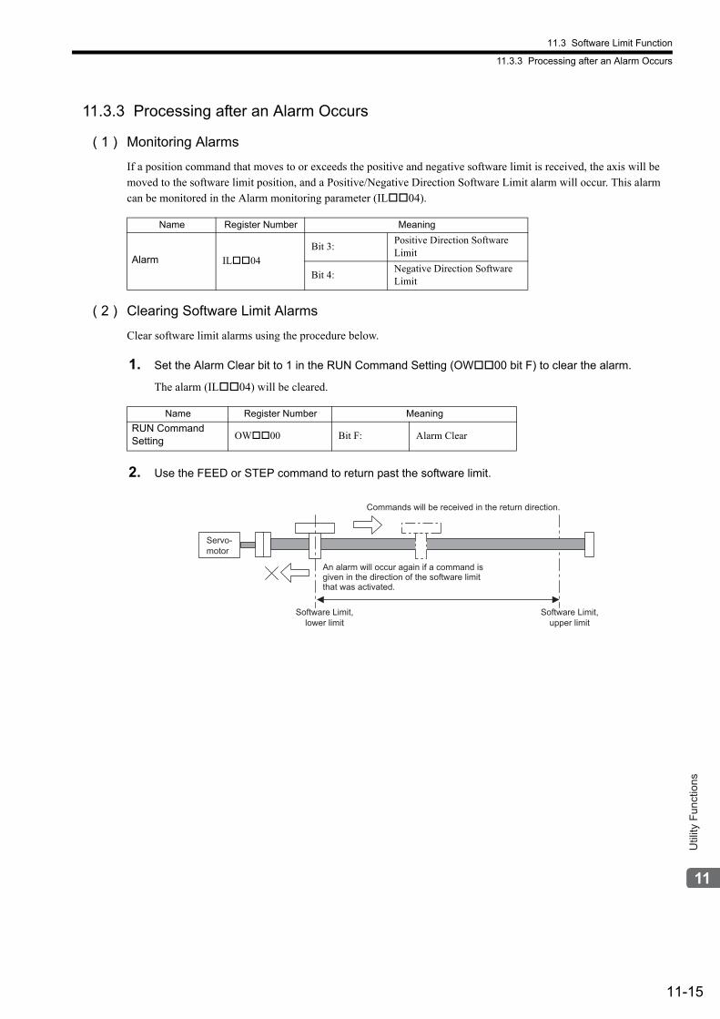
11.3 Software Limit Function
11.3.3 Processing after an Alarm Occurs
11-15
Util
ity F
unct
ions
11.3.3 Processing after an Alarm Occurs
( 1 ) Monitoring Alarms
If a position command that moves to or exceeds the positive and negative software limit is received, the axis will be moved to the software limit position, and a Positive/Negative Direction Software Limit alarm will occur. This alarm can be monitored in the Alarm monitoring parameter (IL04).
( 2 ) Clearing Software Limit Alarms
Clear software limit alarms using the procedure below.
1. Set the Alarm Clear bit to 1 in the RUN Command Setting (OW00 bit F) to clear the alarm.
The alarm (IL04) will be cleared.
2. Use the FEED or STEP command to return past the software limit.
Name Register Number Meaning
Alarm IL04
Bit 3:Positive Direction Software Limit
Bit 4:Negative Direction Software Limit
Name Register Number Meaning
RUN Command Setting OW00 Bit F: Alarm Clear
Commands will be received in the return direction.
Servo-
motor
An alarm will occur again if a command is
given in the direction of the software limit
that was activated.
Software Limit,
lower limit
Software Limit,
upper limit
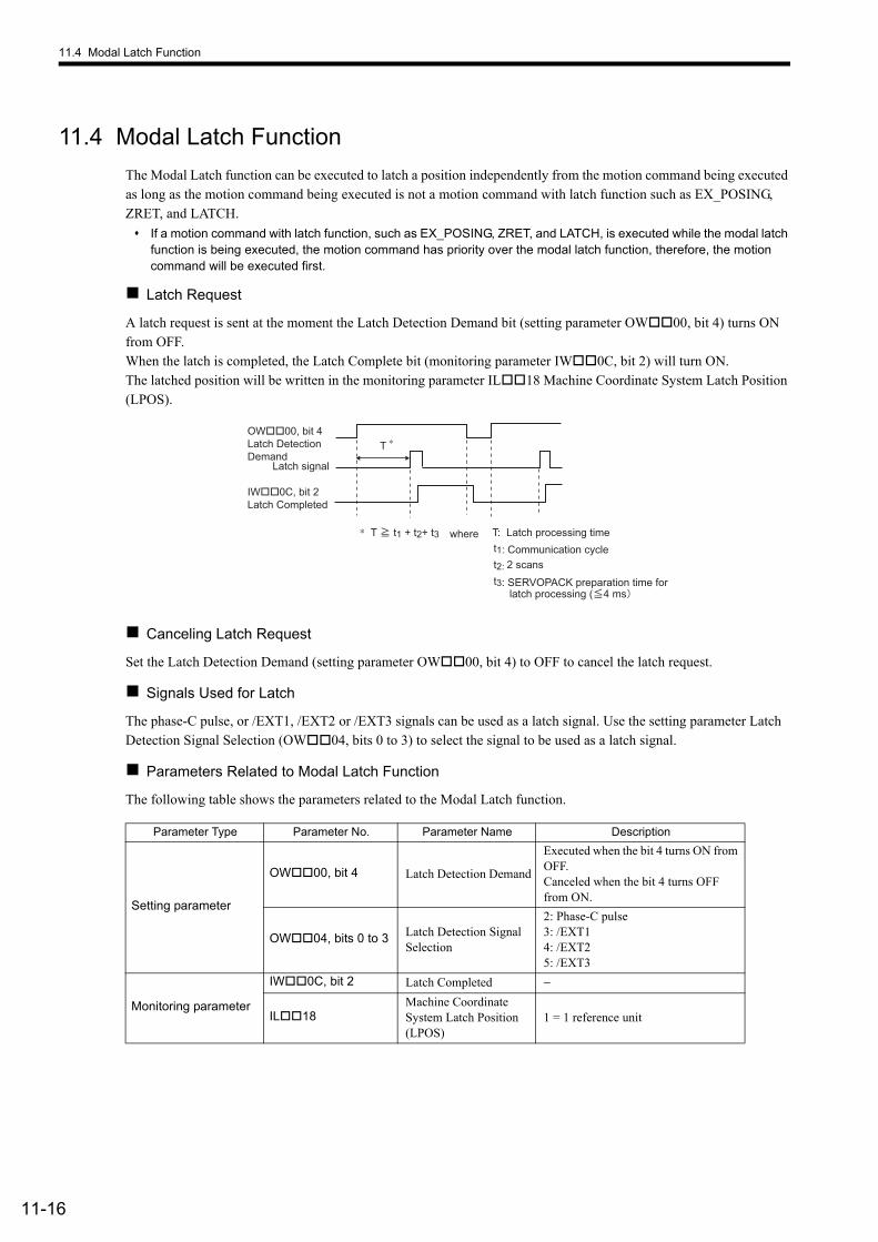
11.4 Modal Latch Function
11-16
11.4 Modal Latch Function
The Modal Latch function can be executed to latch a position independently from the motion command being executed as long as the motion command being executed is not a motion command with latch function such as EX_POSING, ZRET, and LATCH.
If a motion command with latch function, such as EX_POSING, ZRET, and LATCH, is executed while the modal latch function is being executed, the motion command has priority over the modal latch function, therefore, the motion command will be executed first.
Latch Request
A latch request is sent at the moment the Latch Detection Demand bit (setting parameter OW00, bit 4) turns ON from OFF.When the latch is completed, the Latch Complete bit (monitoring parameter IW0C, bit 2) will turn ON.The latched position will be written in the monitoring parameter IL18 Machine Coordinate System Latch Position (LPOS).
Canceling Latch Request
Set the Latch Detection Demand (setting parameter OW00, bit 4) to OFF to cancel the latch request.
Signals Used for Latch
The phase-C pulse, or /EXT1, /EXT2 or /EXT3 signals can be used as a latch signal. Use the setting parameter Latch Detection Signal Selection (OW04, bits 0 to 3) to select the signal to be used as a latch signal.
Parameters Related to Modal Latch Function
The following table shows the parameters related to the Modal Latch function.
Parameter Type Parameter No. Parameter Name Description
Setting parameter
OW00, bit 4 Latch Detection Demand
Executed when the bit 4 turns ON from OFF.Canceled when the bit 4 turns OFF from ON.
OW04, bits 0 to 3 Latch Detection Signal Selection
2: Phase-C pulse3: /EXT14: /EXT25: /EXT3
Monitoring parameter
IW0C, bit 2 Latch Completed −
IL18Machine Coordinate System Latch Position (LPOS)
1 = 1 reference unit
OW��00, bit 4Latch DetectionDemand
t2: 2 scanst1: Communication cycle
Latch signal
t3: SERVOPACK preparation time forlatch processing ( 4 ms
IW��0C, bit 2Latch Completed
∗ T t1 + t2+ t3 where T: Latch processing time
∗T
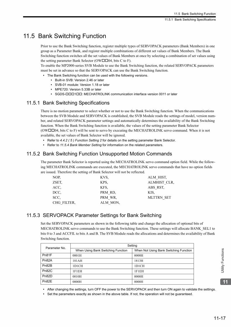
11.5 Bank Switching Function
11.5.1 Bank Switching Specifications
11-17
Util
ity F
unct
ions
11.5 Bank Switching Function
Prior to use the Bank Switching function, register multiple types of SERVOPACK parameters (Bank Members) in one group as a Parameter Bank, and register multiple combinations of different set values of Bank Members. The Bank Switching function switches all the set values of Bank Members at once by selecting a combination of set values using the setting parameter Bank Selector (OW04, bits C to F).To enable the MP2000-series SVB Module to use the Bank Switching function, the related SERVOPACK parameters must be set in advance so that the SERVOPACK can use the Bank Switching function. The Bank Switching function can be used with the following versions.
Built-in SVB: Version 2.46 or later
SVB-01 module: Version 1.18 or later
MPE720: Version 5.33B or later
SGDS-1: MECHATROLINK communication interface version 0011 or later
11.5.1 Bank Switching Specifications
There is no motion parameter to select whether or not to use the Bank Switching function. When the communications between the SVB Module and SERVOPACK is established, the SVB Module reads the settings of model, version num-ber, and related SERVOPACK parameter settings and automatically determines the availability of the Bank Switching function. When the Bank Switching function is available, the values of the setting parameter Bank Selector (OW04, bits C to F) will be sent to servo by executing the MECHATROLINK servo command. When it is not available, the set values of Bank Selector will be ignored. Refer to 4.4.2 ( 5 ) Function Setting 2 for details on the setting parameter Bank Selector.
Refer to 11.5.4 Bank Member Setting for information on the related parameters.
11.5.2 Bank Switching Function Unsupported Motion Commands
The parameter Bank Selector is reported using the MECHATROLINK servo command option field. While the follow-ing MECHATROLINK commands are executed, the MECHATROLINK servo commands that have no option fields are issued. Therefore the setting of Bank Selector will not be reflected.
11.5.3 SERVOPACK Parameter Settings for Bank Switching
Set the SERVOPACK parameters as shown in the following table and change the allocation of optional bits of MECHATROLINK servo commands to use the Bank Switching function. These settings will allocate BANK_SEL1 to bits 0 to 3 and ACCFIL to bits A and B. The SVB Module reads the allocations and determines the availability of Bank Switching function.
After changing the settings, turn OFF the power to the SERVOPACK and then turn ON again to validate the settings.
Set the parameters exactly as shown in the above table. If not, the operation will not be guaranteed.
NOP,ZSET,ACC,DCC,SCC,CHG_FILTER,
KVS,KPS,KFS,PRM_RD,PRM_WR,ALM_MON,
ALM_HIST,ALMHIST_CLR,ABS_RST,KIS,MLTTRN_SET
Parameter No.Setting
When Using Bank Switching Function When Not Using Bank Switching Function
Pn81F 0001H 0000H
Pn82A 181AH 1813H
Pn82B 1D1CH 1D1CH
Pn82C 1F1EH 1F1EH
Pn82D 0010H 0000H
Pn82E 0000H 0000H
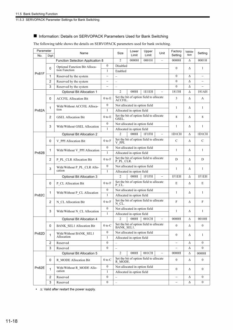
11.5 Bank Switching Function
11.5.3 SERVOPACK Parameter Settings for Bank Switching
11-18
Information: Details on SERVOPACK Parameters Used for Bank Switching
The following table shows the details on SERVOPACK parameters used for bank switching.
Δ: Valid after restart the power supply.
ParameterName Size
Lower Limit
Upper Limit
UnitFactory Setting
Valida-tion Setting
No. Digit
Pn81F
Function Selection Application 8 2 0000H 0001H − 0000H Δ 0001H
0 Optional Function Bit Alloca-tion Function
0 Disabled0 Δ 1
1 Enabled
1 Reserved by the system − – 0 Δ −
2 Reserved by the system − – 0 Δ −
3 Reserved by the system − – 0 Δ −
Pn82A
Optional Bit Allocation 1 2 000H 1E1EH − 1813H Δ 181AH
0 ACCFIL Allocation Bit 0 to E Set the bit of option field to allocate ACCFIL.
3 Δ A
1 With/Without ACCFIL Alloca-tion
0 Not allocated in option field1 Δ 1
1 Allocated in option field
2 GSEL Allocation Bit 0 to E Set the bit of option field to allocate GSEL.
8 Δ 8
3 With/Without GSEL Allocation0 Not allocated in option field
1 Δ 11 Allocated in option field
Pn82B
Optional Bit Allocation 2 2 000H 1F1FH − 1D1CH Δ 1D1CH
0 V_PPI Allocation Bit 0 to F Set the bit of option field to allocate V_PPI.
C Δ C
1 With/Without V_PPI Allocation0 Not allocated in option field
1 Δ 11 Allocated in option field
2 P_PL_CLR Allocation Bit 0 to F Set the bit of option field to allocate P_PL_CLR.
D Δ D
3 With/Without P_PL_CLR Allo-cation
0 Not allocated in option field1 Δ 1
1 Allocated in option field
Pn82C
Optional Bit Allocation 3 2 000H 1F1FH − 1F1EH Δ 1F1EH
0 P_CL Allocation Bit 0 to F Set the bit of option field to allocate P_CL.
E Δ E
1 With/Without P_CL Allocation0 Not allocated in option field
1 Δ 11 Allocated in option field
2 N_CL Allocation Bit 0 to F Set the bit of option field to allocate N_CL.
F Δ F
3 With/Without N_CL Allocation0 Not allocated in option field
1 Δ 11 Allocated in option field
Pn82D
Optional Bit Allocation 4 2 000H 001CH − 0000H Δ 0010H
0 BANK_SEL1 Allocation Bit 0 to C Set the bit of option field to allocate BANK_SEL1.
0 Δ 0
1 With/Without BANK_SEL1 Allocation
0 Not allocated in option field0 Δ 1
1 Allocated in option field
2 Reserved 0 – − Δ 0
3 Reserved 0 – − Δ 0
Pn82E
Optional Bit Allocation 5 2 000H 001CH − 0000H Δ 0000H
0 R_MODE Allocation Bit 0 to C Set the bit of option field to allocate R_MODE.
0 Δ 0
1 With/Without R_MODE Allo-cation
0 Not allocated in option field0 Δ 0
1 Allocated in option field
2 Reserved 0 – − Δ 0
3 Reserved 0 – − Δ 0
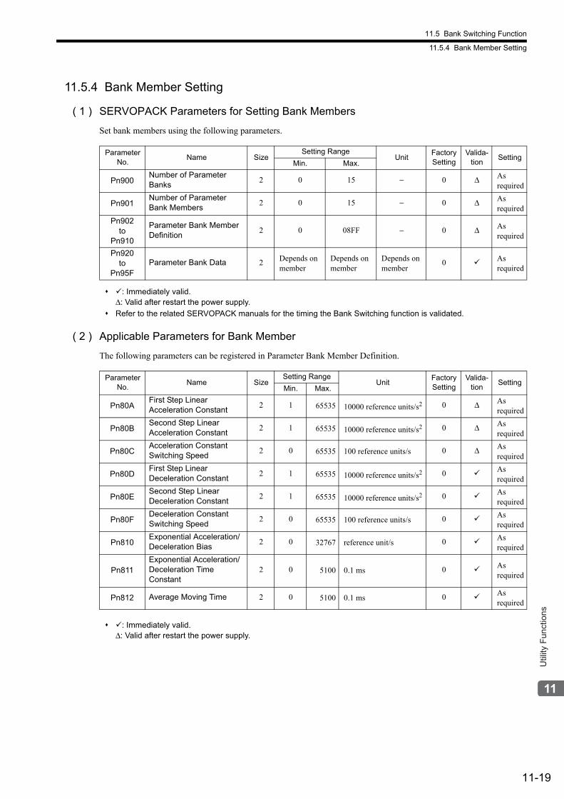
11.5 Bank Switching Function
11.5.4 Bank Member Setting
11-19
Util
ity F
unct
ions
11.5.4 Bank Member Setting
( 1 ) SERVOPACK Parameters for Setting Bank Members
Set bank members using the following parameters.
: Immediately valid.Δ: Valid after restart the power supply.
Refer to the related SERVOPACK manuals for the timing the Bank Switching function is validated.
( 2 ) Applicable Parameters for Bank Member
The following parameters can be registered in Parameter Bank Member Definition.
: Immediately valid.Δ: Valid after restart the power supply.
Parameter No.
Name SizeSetting Range
UnitFactory Setting
Valida-tion
SettingMin. Max.
Pn900Number of Parameter Banks
2 0 15 − 0 Δ As required
Pn901Number of Parameter Bank Members
2 0 15 − 0 Δ As required
Pn902to
Pn910
Parameter Bank Member Definition
2 0 08FF − 0 Δ As required
Pn920to
Pn95FParameter Bank Data 2 Depends on
memberDepends on member
Depends on member
0 As required
Parameter No.
Name SizeSetting Range
UnitFactory Setting
Valida-tion
SettingMin. Max.
Pn80AFirst Step Linear Acceleration Constant
2 1 65535 10000 reference units/s2 0 Δ As required
Pn80BSecond Step Linear Acceleration Constant
2 1 65535 10000 reference units/s2 0 Δ As required
Pn80CAcceleration Constant Switching Speed
2 0 65535 100 reference units/s 0 Δ As required
Pn80DFirst Step Linear Deceleration Constant
2 1 65535 10000 reference units/s2 0 As required
Pn80ESecond Step Linear Deceleration Constant
2 1 65535 10000 reference units/s2 0 As required
Pn80FDeceleration Constant Switching Speed
2 0 65535 100 reference units/s 0 As required
Pn810Exponential Acceleration/Deceleration Bias
2 0 32767 reference unit/s 0 As required
Pn811Exponential Acceleration/Deceleration Time Constant
2 0 5100 0.1 ms 0 As required
Pn812 Average Moving Time 2 0 5100 0.1 ms 0 As required
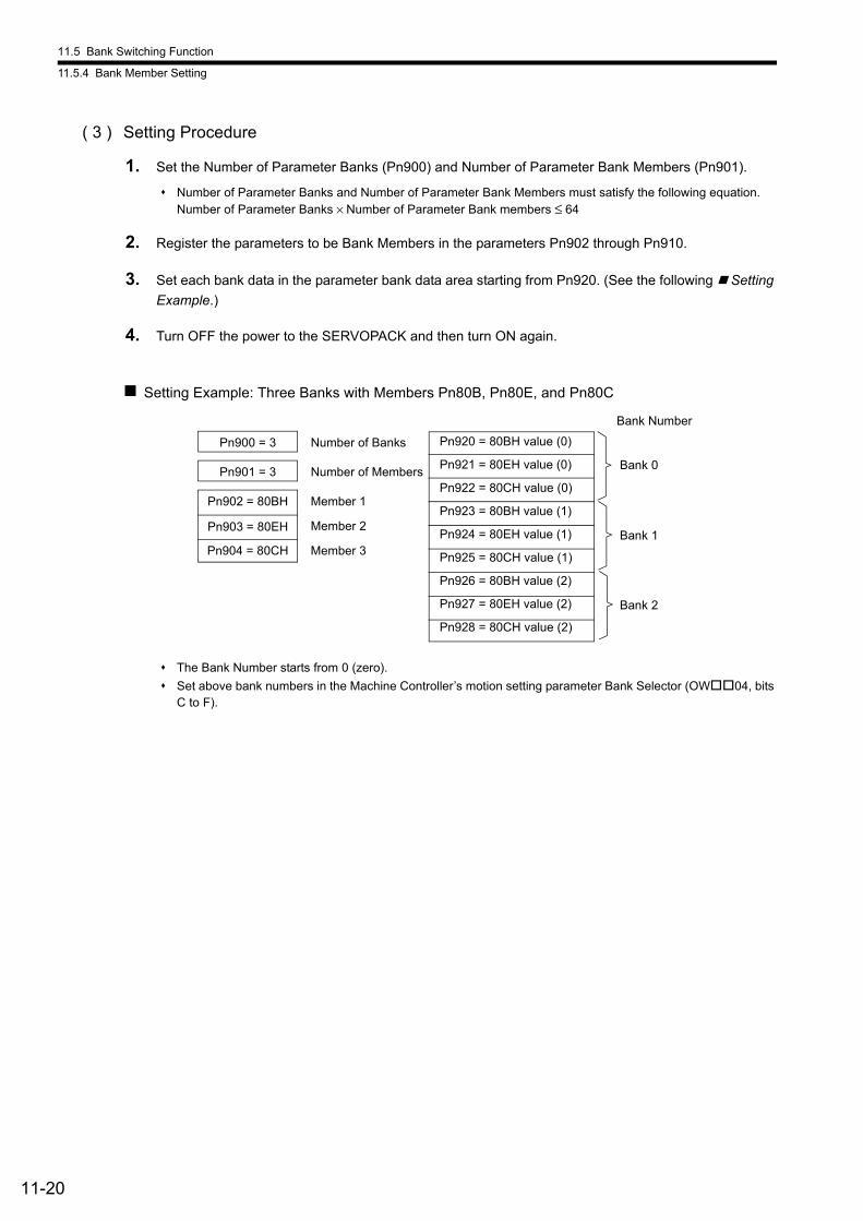
11.5 Bank Switching Function
11.5.4 Bank Member Setting
11-20
( 3 ) Setting Procedure
1. Set the Number of Parameter Banks (Pn900) and Number of Parameter Bank Members (Pn901).
Number of Parameter Banks and Number of Parameter Bank Members must satisfy the following equation.Number of Parameter Banks × Number of Parameter Bank members ≤ 64
2. Register the parameters to be Bank Members in the parameters Pn902 through Pn910.
3. Set each bank data in the parameter bank data area starting from Pn920. (See the following Setting
Example.)
4. Turn OFF the power to the SERVOPACK and then turn ON again.
Setting Example: Three Banks with Members Pn80B, Pn80E, and Pn80C
The Bank Number starts from 0 (zero).
Set above bank numbers in the Machine Controller’s motion setting parameter Bank Selector (OW04, bits C to F).
Pn900 = 3 Number of Banks
Pn901 = 3 Number of Members
Pn902 = 80BH Member 1
Pn903 = 80EH
Pn904 = 80CH Member 3
Member 2
Bank 0
Pn920 = 80BH value (0)
Pn921 = 80EH value (0)
Pn922 = 80CH value (0)
Pn923 = 80BH value (1)
Pn924 = 80EH value (1)
Pn925 = 80CH value (1)
Pn926 = 80BH value (2)
Pn927 = 80EH value (2)
Pn928 = 80CH value (2)
Bank 1
Bank 2
Bank Number
11.5 Bank Switching Function
11.5.4 Bank Member Setting
11-21
Util
ity F
unct
ions
( 4 ) Precautions on Setting
• When the parameter Number of Banks (Pn900) or Number of Members (Pn901) is set to 0, the standard parame-ters will be used so that the Bank Switching function is invalid.
• When the members registered in Parameter Bank Member Definition (Pn902 to Pn910) are overlapped, the bank data of the member with the bigger Parameter Bank Member Definition number will be applied.
• The Number of Parameter Banks (Pn900), Number of Parameter Bank Members (Pn901), and Parameter Bank Member Definition (Pn902 to Pn910) are offline parameters and these settings will be validated after turning OFF the power and turning ON, or by executing CONFIG command.
• When the Machine Controller setting parameter Bank Selector (OW04, bits C to F) is set to 0 (BANK_SEL = 0), the bank data will be used. Set the Bank 0 to the default value.
• The Bank will be switched after pulse distribution is completed (DEN = 1). It will not be switched while pulse is being distributed (DEN = 0).
• If the Parameter Bank Data (Pn920 to Pn95F) of the selected bank is changed while pulse is being distributed (DEN = 0), the SERVOPACK will generate the warning A.95A and ignore the command.
• A.04A (Parameter Error) will occur after turning ON the power and then turning OFF, or after executing CON-FIG command in the following cases.
• A parameter that is not applicable for bank member has been set.
• The bank data is out of the setting range.
• The total number of bank data exceeds 64 (Pn900 × Pn901 > 64)
• When both the Bank Switching function and other torque feed forward compensation function are enabled at the same time, the 14th and 15th bytes are used for TFF field and the parameter bank designation cannot be changed. In this case, the latest bank settings will be maintained.
• If the BANK_SEL is allocated to the option field function bit, the BANK_SEL of the 14th byte will be invalid. Unless the 14th byte is used for interpolation torque feed forward compensation function, set it to 0.
• In the servo parameters, set the Bank Switching function for SGDV or SGD7S SERVOPACKs.The Parameter Bank data (Pn902 to Pn95F) is not saved in the nonvolatile memory. So, always set these param-eters when using MECHATROLINK networks.
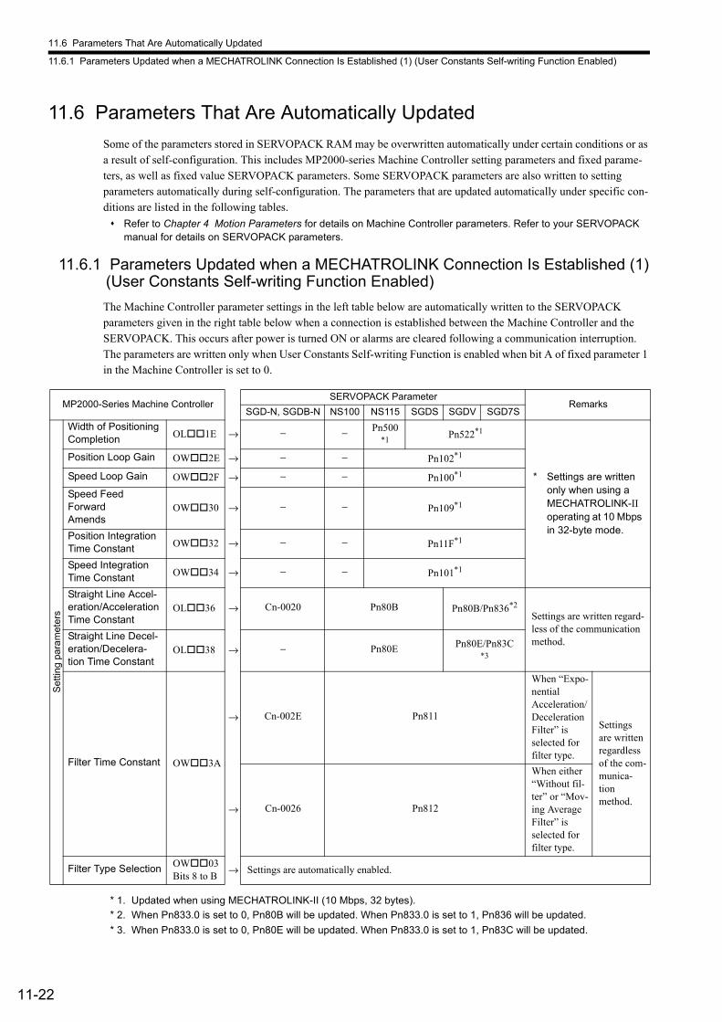
11.6 Parameters That Are Automatically Updated
11.6.1 Parameters Updated when a MECHATROLINK Connection Is Established (1) (User Constants Self-writing Function Enabled)
11-22
11.6 Parameters That Are Automatically Updated
Some of the parameters stored in SERVOPACK RAM may be overwritten automatically under certain conditions or as a result of self-configuration. This includes MP2000-series Machine Controller setting parameters and fixed parame-ters, as well as fixed value SERVOPACK parameters. Some SERVOPACK parameters are also written to setting parameters automatically during self-configuration. The parameters that are updated automatically under specific con-ditions are listed in the following tables.
Refer to Chapter 4 Motion Parameters for details on Machine Controller parameters. Refer to your SERVOPACK manual for details on SERVOPACK parameters.
11.6.1 Parameters Updated when a MECHATROLINK Connection Is Established (1) (User Constants Self-writing Function Enabled)
The Machine Controller parameter settings in the left table below are automatically written to the SERVOPACK parameters given in the right table below when a connection is established between the Machine Controller and the SERVOPACK. This occurs after power is turned ON or alarms are cleared following a communication interruption. The parameters are written only when User Constants Self-writing Function is enabled when bit A of fixed parameter 1 in the Machine Controller is set to 0.
* 1. Updated when using MECHATROLINK-II (10 Mbps, 32 bytes).
* 2. When Pn833.0 is set to 0, Pn80B will be updated. When Pn833.0 is set to 1, Pn836 will be updated.
* 3. When Pn833.0 is set to 0, Pn80E will be updated. When Pn833.0 is set to 1, Pn83C will be updated.
MP2000-Series Machine ControllerSERVOPACK Parameter
RemarksSGD-N, SGDB-N NS100 NS115 SGDS SGDV SGD7S
Set
ting
para
met
ers
Width of Positioning Completion OL1E → − − Pn500
*1Pn522*1
* Settings are written only when using a MECHATROLINK-II operating at 10 Mbps in 32-byte mode.
Position Loop Gain OW2E → − − Pn102*1
Speed Loop Gain OW2F → − − Pn100*1
Speed Feed Forward Amends
OW30 → − − Pn109*1
Position Integration Time Constant OW32 → − − Pn11F*1
Speed Integration Time Constant OW34 → − − Pn101*1
Straight Line Accel-eration/Acceleration Time Constant
OL36 → Cn-0020 Pn80B Pn80B/Pn836*2
Settings are written regard-less of the communication method.Straight Line Decel-
eration/Decelera-tion Time Constant
OL38 → − Pn80E Pn80E/Pn83C*3
Filter Time Constant OW3A
→ Cn-002E Pn811
When “Expo-nential Acceleration/Deceleration Filter” is selected for filter type.
Settings are written regardless of the com-munica-tion method.
→ Cn-0026 Pn812
When either “Without fil-ter” or “Mov-ing Average Filter” is selected for filter type.
Filter Type Selection OW03Bits 8 to B
→ Settings are automatically enabled.
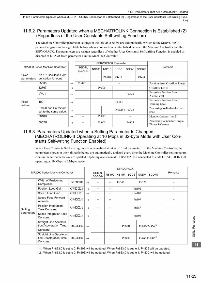
11.6 Parameters That Are Automatically Updated
11.6.2 Parameters Updated when a MECHATROLINK Connection Is Established (2) (Regardless of the User Constants Self-writing Func-tion)
11-23
Util
ity F
unct
ions
11.6.2 Parameters Updated when a MECHATROLINK Connection Is Established (2) (Regardless of the User Constants Self-writing Function)
The Machine Controller parameter settings in the left table below are automatically written to the SERVOPACK parameters given in the right table below when a connection is established between the Machine Controller and the SERVOPACK. The parameters are written regardless of whether User Constants Self-writing Function is enabled or disabled at bit A of fixed parameter 1 in the Machine Controller.
11.6.3 Parameters Updated when a Setting Parameter Is Changed (MECHATROLINK-II Operating at 10 Mbps in 32-byte Mode with User Con-stants Self-writing Function Enabled)
When User Constants Self-writing Function is enabled at bit A of fixed parameter 1 in the Machine Controller, the parameters shown in the right table below are automatically updated every time the Machine Controller setting param-eters in the left table below are updated. Updating occurs on all SERVOPACKs connected to a MECHATROLINK-II operating at 10 Mbps in 32-byte mode.
* 1. When Pn833.0 is set to 0, Pn80B will be updated. When Pn833.0 is set to 1, Pn836 will be updated.
* 2. When Pn833.0 is set to 0, Pn80E will be updated. When Pn833.0 is set to 1, Pn83C will be updated.
MP2000 Series Machine Controller
SERVOPACK Parameter
RemarksSGD-N, SGDB-N
NS100 NS115 SGDS SGDV SGD7S
Fixed parameters
No.16: Backlash Com-pensation Amount
− − Pn81B Pn214 − Pn231 −
Fixed values
65535 → Cn-001E − Position Error Overflow Range
32767 → − Pn505 − Overflow Level
230 -1 → − − Pn520 Excessive Position ErrorAlarm Level
100 → − Pn51E Excessive Position Error Warning Level
Pn820 and Pn822 are set to the same value. → − − Pn820 -> Pn822 Processing to disable the latch
zone
0010H → − Pn813 − Monitor Options 1 or 2
0002H → − Pn003 Pn824 Processing to monitor Torque/Thrust Reference.
MP2000 Series Machine Controller
SERVOPACK
RemarksSGD-N, SGDB-N
NS100 NS115 SGDS SGDV SGD7S
Setting parameters
Width of Positioning Completion
OL1E → − − Pn500 Pn522 −
Position Loop Gain OW2E → − − Pn102 −Speed Loop Gain OW2F → − − Pn100 −Speed Feed Forward Amends
OW30 → − − Pn109 −
Position Integration Time Constant
OW32 → − − Pn11F −
Speed Integration Time Constant
OW34 → − − Pn101 −
Straight Line Accelera-tion/Acceleration Time
Constant OL36 → − − Pn80B Pn80B/Pn836*1
−Straight Line Decelera-tion/Deceleration Time Constant
OL38 → − − Pn80E Pn80E/Pn83C*2
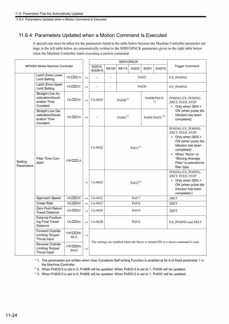
11.6 Parameters That Are Automatically Updated
11.6.4 Parameters Updated when a Motion Command Is Executed
11-24
11.6.4 Parameters Updated when a Motion Command Is Executed
A special care must be taken for the parameters listed in the table below because the Machine Controller parameter set-tings in the left table below are automatically written to the SERVOPACK parameters given in the right table below when the Machine Controller starts executing a motion command.
* 1. The parameters are written when User Constants Self-writing Function is enabled at bit A of fixed parameter 1 in the Machine Controller.
* 2. When Pn833.0 is set to 0, Pn80B will be updated. When Pn833.0 is set to 1, Pn836 will be updated.
* 3. When Pn833.0 is set to 0, Pn80E will be updated. When Pn833.0 is set to 1, Pn83C will be updated.
MP2000 Series Machine Controller
SERVOPACK
Trigger Command SGD-N, SGDB-N
NS100 NS115 SGDS SGDV SGD7S
Setting Parameters
Latch Zone Lower Limit Setting
OL2A → - - Pn822 EX_POSING
Latch Zone Upper Limit Setting
OL2C → - - Pn820 EX_POSING
Straight Line Ac-celeration/Accel-eration Time Constant
OL36 → Cn-0020 Pn80B*1 Pn80B/Pn836*2
POSING, EX_POSING, ZRET, FEED, STEP Only when DEN =
ON (when pulse dis-tribution has been completed)
Straight Line De-celeration/Decel-eration Time Constant
OL38 → - Pn80E*1 Pn80E/Pn83C*3
Filter Time Con-stant
OW3A
Cn-002E Pn811*1
POSING, EX_POSING, ZRET, FEED, STEP Only when DEN =
ON (when pulse dis-tribution has been completed)
When “None” or “Moving Average Filter” is selected for filter type.
→ Cn-0026 Pn812*1
POSING, EX_POSING, ZRET, FEED, STEP Only when DEN =
ON (when pulse dis-tribution has been completed.)
Approach Speed OL3E → Cn-0022 Pn817 ZRET
Creep Rate OL40 → Cn-0023 Pn818 ZRET
Zero Point Return Travel Distance
OL42 → Cn-0028 Pn819 ZRET
External Position-ing Final Travel Distance
OL46 → Cn-002B Pn814 EX_POSING and ZRET
Forward Outside Limiting Torque/Thrust Input
OW00, Bit 8 →
The settings are enabled when the Servo is turned ON or a move command is sent. Reverse Outside Limiting Torque/Thrust Input
OW00, Bits9 →
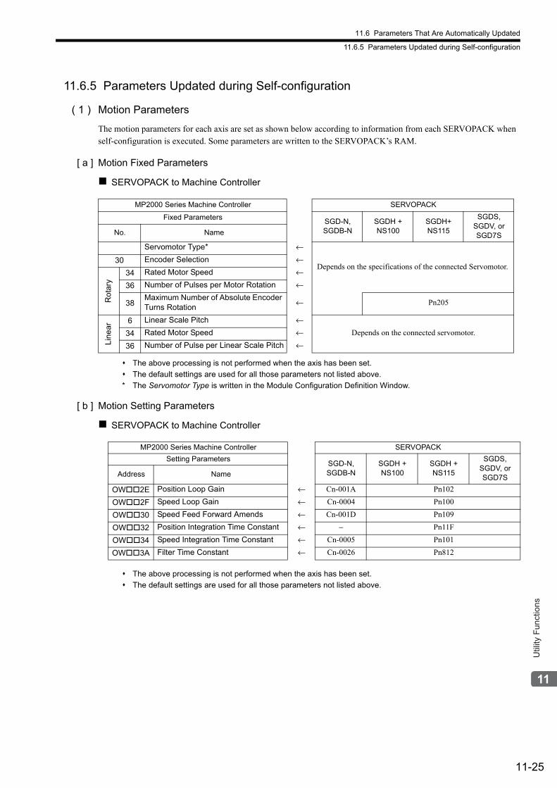
11.6 Parameters That Are Automatically Updated
11.6.5 Parameters Updated during Self-configuration
11-25
Util
ity F
unct
ions
11.6.5 Parameters Updated during Self-configuration
( 1 ) Motion Parameters
The motion parameters for each axis are set as shown below according to information from each SERVOPACK when self-configuration is executed. Some parameters are written to the SERVOPACK’s RAM.
[ a ] Motion Fixed Parameters
SERVOPACK to Machine Controller
The above processing is not performed when the axis has been set.
The default settings are used for all those parameters not listed above.
* The Servomotor Type is written in the Module Configuration Definition Window.
[ b ] Motion Setting Parameters
SERVOPACK to Machine Controller
The above processing is not performed when the axis has been set.
The default settings are used for all those parameters not listed above.
MP2000 Series Machine Controller SERVOPACK
Fixed ParametersSGD-N, SGDB-N
SGDH + NS100
SGDH+NS115
SGDS, SGDV, or SGD7SNo. Name
Servomotor Type* ←
Depends on the specifications of the connected Servomotor.30 Encoder Selection ←
Ro
tary
34 Rated Motor Speed ←
36 Number of Pulses per Motor Rotation ←
38Maximum Number of Absolute Encoder Turns Rotation
← Pn205
Lin
ea
r 6 Linear Scale Pitch ←Depends on the connected servomotor.34 Rated Motor Speed ←
36 Number of Pulse per Linear Scale Pitch ←
MP2000 Series Machine Controller SERVOPACK
Setting Parameters SGD-N, SGDB-N
SGDH + NS100
SGDH + NS115
SGDS, SGDV, or SGD7SAddress Name
OW2E Position Loop Gain ← Cn-001A Pn102
OW2F Speed Loop Gain ← Cn-0004 Pn100
OW30 Speed Feed Forward Amends ← Cn-001D Pn109
OW32 Position Integration Time Constant ← − Pn11F
OW34 Speed Integration Time Constant ← Cn-0005 Pn101
OW3A Filter Time Constant ← Cn-0026 Pn812
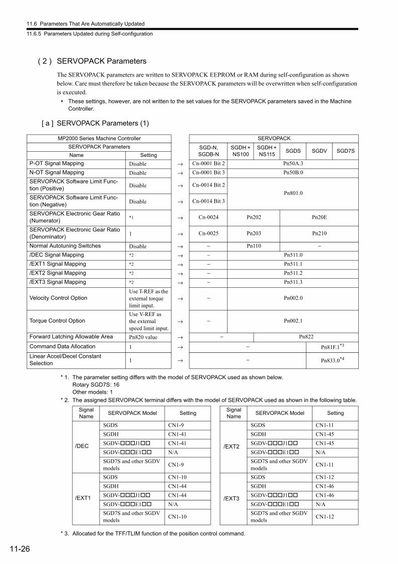
11.6 Parameters That Are Automatically Updated
11.6.5 Parameters Updated during Self-configuration
11-26
( 2 ) SERVOPACK Parameters
The SERVOPACK parameters are written to SERVOPACK EEPROM or RAM during self-configuration as shown below. Care must therefore be taken because the SERVOPACK parameters will be overwritten when self-configuration is executed.
These settings, however, are not written to the set values for the SERVOPACK parameters saved in the Machine Controller.
[ a ] SERVOPACK Parameters (1)
* 1. The parameter setting differs with the model of SERVOPACK used as shown below.Rotary SGD7S: 16Other models: 1
* 2. The assigned SERVOPACK terminal differs with the model of SERVOPACK used as shown in the following table.
* 3. Allocated for the TFF/TLIM function of the position control command.
MP2000 Series Machine Controller SERVOPACK
SERVOPACK Parameters SGD-N, SGDB-N
SGDH + NS100
SGDH + NS115
SGDS SGDV SGD7SName Setting
P-OT Signal Mapping Disable → Cn-0001 Bit 2 Pn50A.3
N-OT Signal Mapping Disable → Cn-0001 Bit 3 Pn50B.0
SERVOPACK Software Limit Func-tion (Positive) Disable → Cn-0014 Bit 2
Pn801.0SERVOPACK Software Limit Func-tion (Negative) Disable → Cn-0014 Bit 3
SERVOPACK Electronic Gear Ratio (Numerator)
*1 → Cn-0024 Pn202 Pn20E
SERVOPACK Electronic Gear Ratio (Denominator) 1 → Cn-0025 Pn203 Pn210
Normal Autotuning Switches Disable → − Pn110 −/DEC Signal Mapping *2 → − Pn511.0
/EXT1 Signal Mapping *2 → − Pn511.1
/EXT2 Signal Mapping *2 → − Pn511.2
/EXT3 Signal Mapping *2 → − Pn511.3
Velocity Control OptionUse T-REF as the external torque limit input.
→ − Pn002.0
Torque Control OptionUse V-REF as the external speed limit input.
→ − Pn002.1
Forward Latching Allowable Area Pn820 value → − Pn822
Command Data Allocation 1 → − Pn81F.1*3
Linear Accel/Decel ConstantSelection 1 → − Pn833.0*4
Signal Name
SERVOPACK Model SettingSignal Name
SERVOPACK Model Setting
/DEC
SGDS CN1-9
/EXT2
SGDS CN1-11
SGDH CN1-41 SGDH CN1-45
SGDV-J1 CN1-41 SGDV-J1 CN1-45
SGDV-E1 N/A SGDV-E1 N/A
SGD7S and other SGDV models
CN1-9SGD7S and other SGDV models
CN1-11
/EXT1
SGDS CN1-10
/EXT3
SGDS CN1-12
SGDH CN1-44 SGDH CN1-46
SGDV-J1 CN1-44 SGDV-J1 CN1-46
SGDV-E1 N/A SGDV-E1 N/A
SGD7S and other SGDV models
CN1-10SGD7S and other SGDV models
CN1-12
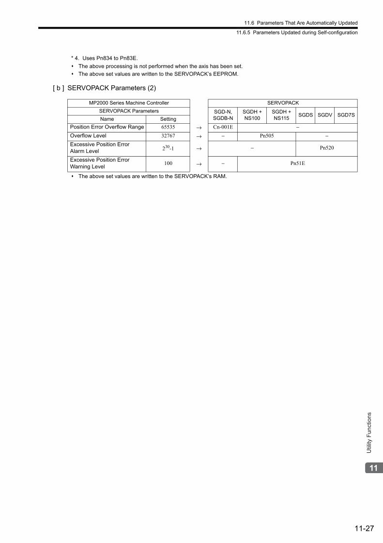
11.6 Parameters That Are Automatically Updated
11.6.5 Parameters Updated during Self-configuration
11-27
Util
ity F
unct
ions
* 4. Uses Pn834 to Pn83E.
The above processing is not performed when the axis has been set.
The above set values are written to the SERVOPACK’s EEPROM.
[ b ] SERVOPACK Parameters (2)
The above set values are written to the SERVOPACK’s RAM.
MP2000 Series Machine Controller SERVOPACK
SERVOPACK Parameters SGD-N, SGDB-N
SGDH + NS100
SGDH + NS115
SGDS SGDV SGD7SName Setting
Position Error Overflow Range 65535 → Cn-001E −Overflow Level 32767 → − Pn505 −Excessive Position Error Alarm Level 230-1 → − Pn520
Excessive Position Error Warning Level
100 → − Pn51E
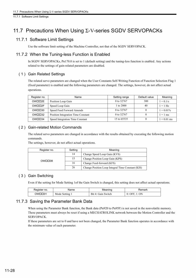
11.7 Precautions When Using Σ-V-series SGDV SERVOPACKs
11.7.1 Software Limit Settings
11-28
11.7 Precautions When Using Σ-V-series SGDV SERVOPACKs
11.7.1 Software Limit Settings
Use the software limit setting of the Machine Controller, not that of the SGDV SERVOPACK.
11.7.2 When the Tuning-less Function is Enabled
In SGDV SERVOPACKs, Pn170.0 is set to 1 (default setting) and the tuning-less function is enabled. Any actions related to the settings of gain-related parameters are disabled.
( 1 ) Gain Related Settings
The related servo parameters are changed when the User Constants Self-Writing Function of Function Selection Flag 1 (fixed parameter) is enabled and the following parameters are changed. The settings, however, do not affect actual
operations.
( 2 ) Gain-related Motion Commands
The related servo parameters are changed in accordance with the results obtained by executing the following motion commands.The settings, however, do not affect actual operations.
( 3 ) Gain Switching
Even if the setting for Mode Setting 1of the Gain Switch is changed, this setting does not affect actual operations.
11.7.3 Saving the Parameter Bank Data
When using the Parameter Bank function, the Bank data (Pn920 to Pn95F) is not saved in the nonvolatile memory. These parameters must always be reset if using a MECHATROLINK network between the Motion Controller and the SERVOPACK.If these parameters are set to 0 and have not been changed, the Parameter Bank function operates in accordance with the minimum value of each parameter.
Register no. Name Setting range Default value Meaning
OW2E Position Loop Gain 0 to 32767 300 1 = 0.1/s
OW2F Speed Loop Gain 1 to 2000 40 1 = 1 Hz
OW30 Speed Feed Forward Amends 0 to 32767 0 1 = 0.01%
OW32 Position Integration Time Constant 0 to 32767 0 1 = 1 ms
OW34 Speed Integration Time Constant 15 to 65535 0 1 = 0.01 ms
Register no. Setting Meaning
OW08
14 Change Speed Loop Gain (KVS)
15 Change Position Loop Gain (KPS)
16 Change Feed-forward (KFS)
26 Change Position Loop Integral Time Constant (KIS)
Register no. Name Meaning Remark
OW01 Mode Setting 1 Bit 4: Gain Switch 0: OFF, 1: ON

11.7 Precautions When Using Σ-V-series SGDV SERVOPACKs
11.7.4 Motion Command Operation for External Latches with DC Power Input Σ-V-series SERVOPACKs
11-29
Util
ity F
unct
ions
11.7.4 Motion Command Operation for External Latches with DC Power Input Σ-V-series SERVOPACKs
If you use an external latch signal (/EXT1) with a DC Power Input Σ-V-series SERVOPACK, always change the setting of the Input Signal Selection 5 in the Pn511 SERVOPACK parameter so that /EXT1 is used. This signal is disabled in the default settings.
If you attempt to execute a motion command*2 using /EXT1*1 when /EXT1 is disabled, a Set Parameter Error warning (Monitoring Parameter IL02, bit 1) will occur and execution of the motion command will end in an error.
* 1. Set bits 0 to 3 (Latch Detection Signal Selection) or bits 4 to 7 (External Positioning Signal Setting) of Setting Parameter OW04 to 3 (/EXT1) or set Setting Parameter OW3C (Zero Point Return Method) to 1 (ZERO), 2 (DEC1 + ZERO), 14 (Home LS & C Pulse), or 15 (Home Only).
* 2. Set Setting Parameter OW08 (Interpolation Mode with Latch Input) to 2 (EX_POSING (External Positioning)), 6 (LATCH), or 9 (ZSET) Set Zero Point)).
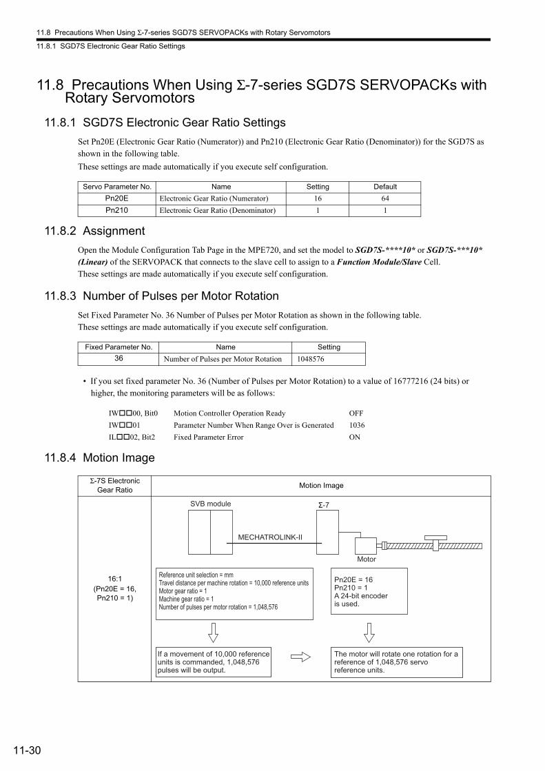
11.8 Precautions When Using Σ-7-series SGD7S SERVOPACKs with Rotary Servomotors
11.8.1 SGD7S Electronic Gear Ratio Settings
11-30
11.8 Precautions When Using Σ-7-series SGD7S SERVOPACKs with Rotary Servomotors
11.8.1 SGD7S Electronic Gear Ratio Settings
Set Pn20E (Electronic Gear Ratio (Numerator)) and Pn210 (Electronic Gear Ratio (Denominator)) for the SGD7S as shown in the following table.
These settings are made automatically if you execute self configuration.
11.8.2 Assignment
Open the Module Configuration Tab Page in the MPE720, and set the model to SGD7S-****10* or SGD7S-***10* (Linear) of the SERVOPACK that connects to the slave cell to assign to a Function Module/Slave Cell.These settings are made automatically if you execute self configuration.
11.8.3 Number of Pulses per Motor Rotation
Set Fixed Parameter No. 36 Number of Pulses per Motor Rotation as shown in the following table.These settings are made automatically if you execute self configuration.
• If you set fixed parameter No. 36 (Number of Pulses per Motor Rotation) to a value of 16777216 (24 bits) or higher, the monitoring parameters will be as follows:
11.8.4 Motion Image
Servo Parameter No. Name Setting Default
Pn20E Electronic Gear Ratio (Numerator) 16 64
Pn210 Electronic Gear Ratio (Denominator) 1 1
Fixed Parameter No. Name Setting
36 Number of Pulses per Motor Rotation 1048576
IW00, Bit0 Motion Controller Operation Ready OFF
IW01 Parameter Number When Range Over is Generated 1036
IL02, Bit2 Fixed Parameter Error ON
Σ-7S Electronic Gear Ratio
Motion Image
16:1(Pn20E = 16, Pn210 = 1)
Reference unit selection = mmTravel distance per machine rotation = 10,000 reference unitsMotor gear ratio = 1Machine gear ratio = 1Number of pulses per motor rotation = 1,048,576
If a movement of 10,000 referenceunits is commanded, 1,048,576pulses will be output.
Pn20E = 16Pn210 = 1A 24-bit encoder is used.
The motor will rotate one rotation for areference of 1,048,576 servoreference units.
SVB module Σ-7
MECHATROLINK-II
Motor

11.8 Precautions When Using Σ-7-series SGD7S SERVOPACKs with Rotary Servomotors
11.8.5 Software Limit Settings
11-31
Util
ity F
unct
ions
11.8.5 Software Limit Settings
Use the software limit setting of the Machine Controller, not that of the SGDV SERVOPACK.
11.8.6 When the Tuning-less Function is Enabled
The default servo parameter setting for the SGD7S is 1 (Tuning-less Function Selection is enabled) for Pn170.0 (Tun-ing-less Selection).For functions that are disabled in this state, refer to 11.7.2 When the Tuning-less Function is Enabled.
11.8.7 Saving the Parameter Bank Data
When using the Parameter Bank function, the Bank data (Pn920 to Pn95F) is not saved in the nonvolatile memory.For details, refer to 11.7.3 Saving the Parameter Bank Data.
12-1
Trou
bles
hoot
ing
12
Troubleshooting
This chapter describes the system registers used for troubleshooting the SVB Module and trouble-shooting related to motion.
12.1 Troubleshooting Motion Errors - - - - - - - - - - - - - - - - - - - - - - - - - - - - - - 12-2
12.1.1 Overview of Motion Errors - - - - - - - - - - - - - - - - - - - - - - - - - - - - - - - - - - - - - - - - - 12-2
12.1.2 Causes of Command Error End Alarms (IW09 Bit 3) - - - - - - - - - - - - - - - - - - - - 12-3
12.1.3 Motion Errors Details and Corrections - - - - - - - - - - - - - - - - - - - - - - - - - - - - - - - - - 12-6
12.1.4 SERVOPACK Status/SERVOPACK Error Codes - - - - - - - - - - - - - - - - - - - - - - - - 12-14
12.2 Troubleshooting System Errors - - - - - - - - - - - - - - - - - - - - - - - - - - - - 12-25
12.2.1 Overview of System Errors - - - - - - - - - - - - - - - - - - - - - - - - - - - - - - - - - - - - - - - - 12-25
12.2.2 System Register Configuration and Error Status - - - - - - - - - - - - - - - - - - - - - - - - - 12-27
12.3 Motion Program Alarm - - - - - - - - - - - - - - - - - - - - - - - - - - - - - - - - - - 12-43
12.3.1 Structure of Motion Program Alarms - - - - - - - - - - - - - - - - - - - - - - - - - - - - - - - - - 12-43
12.3.2 Motion Program Alarm Codes - - - - - - - - - - - - - - - - - - - - - - - - - - - - - - - - - - - - - - 12-43
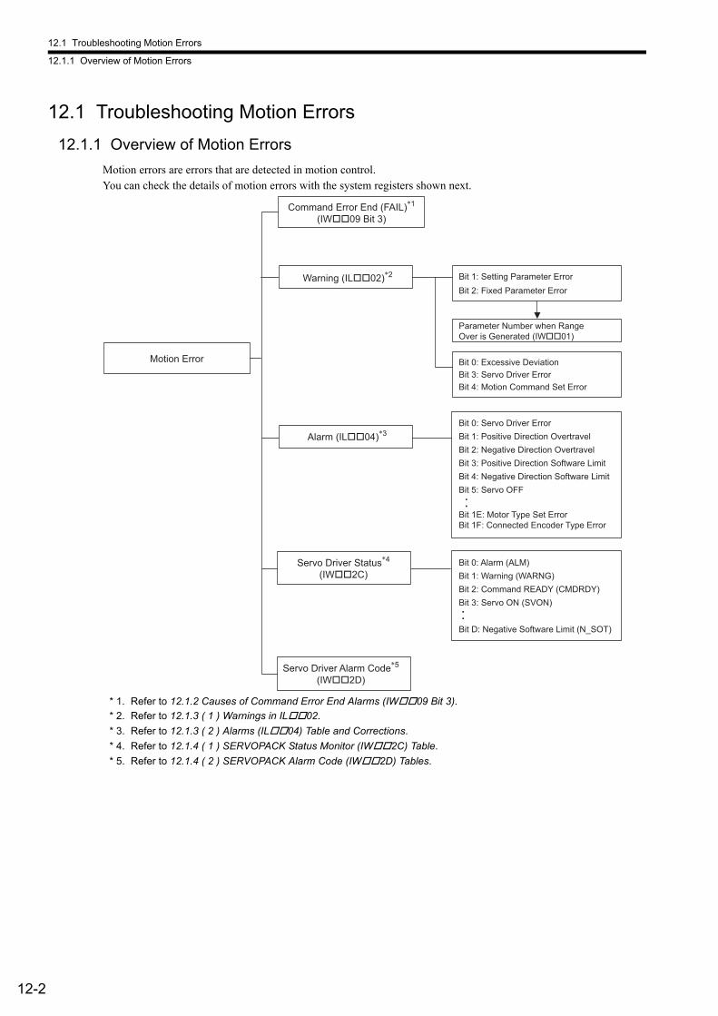
12.1 Troubleshooting Motion Errors
12.1.1 Overview of Motion Errors
12-2
12.1 Troubleshooting Motion Errors
12.1.1 Overview of Motion Errors
Motion errors are errors that are detected in motion control.You can check the details of motion errors with the system registers shown next.
* 1. Refer to 12.1.2 Causes of Command Error End Alarms (IW09 Bit 3).
* 2. Refer to 12.1.3 ( 1 ) Warnings in IL02.
* 3. Refer to 12.1.3 ( 2 ) Alarms (IL04) Table and Corrections.
* 4. Refer to 12.1.4 ( 1 ) SERVOPACK Status Monitor (IW2C) Table.
* 5. Refer to 12.1.4 ( 2 ) SERVOPACK Alarm Code (IW2D) Tables.
Bit 1: Setting Parameter Error Bit 2: Fixed Parameter Error
Bit 0: Excessive Deviation Bit 3: Servo Driver Error Bit 4: Motion Command Set Error
Bit 0: Servo Driver Error Bit 1: Positive Direction Overtravel Bit 2: Negative Direction Overtravel Bit 3: Positive Direction Software LimitBit 4: Negative Direction Software Limit Bit 5: Servo OFF
Servo Driver Alarm Code*5
(IW��2D)
Alarm (IL��04)*3
Servo Driver Status*4
(IW��2C)Bit 0: Alarm (ALM)Bit 1: Warning (WARNG)Bit 2: Command READY (CMDRDY)Bit 3: Servo ON (SVON)
Bit D: Negative Software Limit (N_SOT)
Parameter Number when Range Over is Generated (IW��01)
Bit 1E: Motor Type Set ErrorBit 1F: Connected Encoder Type Error
Motion Error
Command Error End (FAIL)*1
(IW��09 Bit 3)
Warning (IL��02)*2
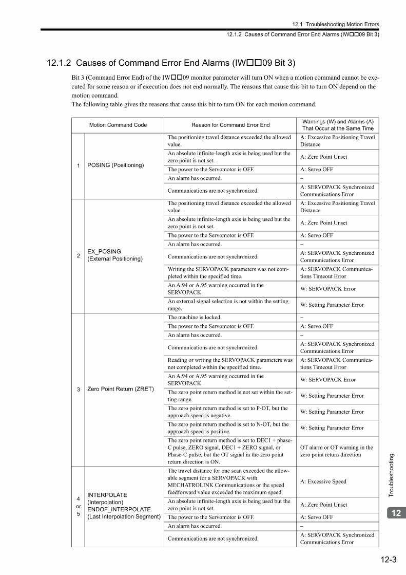
12.1 Troubleshooting Motion Errors
12.1.2 Causes of Command Error End Alarms (IW09 Bit 3)
12-3
Trou
bles
hoot
ing
12.1.2 Causes of Command Error End Alarms (IW09 Bit 3)
Bit 3 (Command Error End) of the IW09 monitor parameter will turn ON when a motion command cannot be exe-
cuted for some reason or if execution does not end normally. The reasons that cause this bit to turn ON depend on the motion command.The following table gives the reasons that cause this bit to turn ON for each motion command.
Motion Command Code Reason for Command Error EndWarnings (W) and Alarms (A) That Occur at the Same Time
1 POSING (Positioning)
The positioning travel distance exceeded the allowed value.
A: Excessive Positioning Travel Distance
An absolute infinite-length axis is being used but the zero point is not set.
A: Zero Point Unset
The power to the Servomotor is OFF. A: Servo OFF
An alarm has occurred. −
Communications are not synchronized.A: SERVOPACK Synchronized Communications Error
2EX_POSING(External Positioning)
The positioning travel distance exceeded the allowed value.
A: Excessive Positioning Travel Distance
An absolute infinite-length axis is being used but the zero point is not set.
A: Zero Point Unset
The power to the Servomotor is OFF. A: Servo OFF
An alarm has occurred. −
Communications are not synchronized.A: SERVOPACK Synchronized Communications Error
Writing the SERVOPACK parameters was not com-pleted within the specified time.
A: SERVOPACK Communica-tions Timeout Error
An A.94 or A.95 warning occurred in the SERVOPACK.
W: SERVOPACK Error
An external signal selection is not within the setting range.
W: Setting Parameter Error
3 Zero Point Return (ZRET)
The machine is locked. −The power to the Servomotor is OFF. A: Servo OFF
An alarm has occurred. −
Communications are not synchronized.A: SERVOPACK Synchronized Communications Error
Reading or writing the SERVOPACK parameters was not completed within the specified time.
A: SERVOPACK Communica-tions Timeout Error
An A.94 or A.95 warning occurred in the SERVOPACK.
W: SERVOPACK Error
The zero point return method is not set within the set-ting range.
W: Setting Parameter Error
The zero point return method is set to P-OT, but the approach speed is negative.
W: Setting Parameter Error
The zero point return method is set to N-OT, but the approach speed is positive.
W: Setting Parameter Error
The zero point return method is set to DEC1 + phase-C pulse, ZERO signal, DEC1 + ZERO signal, or Phase-C pulse, but the OT signal in the zero point return direction is ON.
OT alarm or OT warning in the zero point return direction
4or5
INTERPOLATE (Interpolation)ENDOF_INTERPOLATE(Last Interpolation Segment)
The travel distance for one scan exceeded the allow-able segment for a SERVOPACK with MECHATROLINK Communications or the speed feedforward value exceeded the maximum speed.
A: Excessive Speed
An absolute infinite-length axis is being used but the zero point is not set.
A: Zero Point Unset
The power to the Servomotor is OFF. A: Servo OFF
An alarm has occurred. −
Communications are not synchronized.A: SERVOPACK Synchronized Communications Error
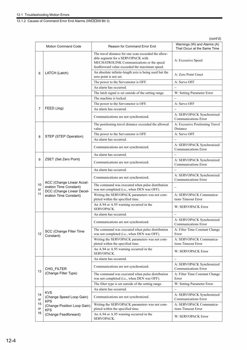
12.1 Troubleshooting Motion Errors
12.1.2 Causes of Command Error End Alarms (IW09 Bit 3)
12-4
6 LATCH (Latch)
The travel distance for one scan exceeded the allow-able segment for a SERVOPACK with MECHATROLINK Communications or the speed feedforward value exceeded the maximum speed.
A: Excessive Speed
An absolute infinite-length axis is being used but the zero point is not set.
A: Zero Point Unset
The power to the Servomotor is OFF. A: Servo OFF
An alarm has occurred. −The latch signal is set outside of the setting range. W: Setting Parameter Error
7 FEED (Jog)
The machine is locked. −The power to the Servomotor is OFF. A: Servo OFF
An alarm has occurred. −
Communications are not synchronized.A: SERVOPACK Synchronized Communications Error
8 STEP (STEP Operation)
The positioning travel distance exceeded the allowed value.
A: Excessive Positioning Travel Distance
The power to the Servomotor is OFF. A: Servo OFF
An alarm has occurred. −
Communications are not synchronized.A: SERVOPACK Synchronized Communications Error
9 ZSET (Set Zero Point)An alarm has occurred. −
Communications are not synchronized.A: SERVOPACK Synchronized Communications Error
10or11
ACC (Change Linear Accel-eration Time Constant)DCC (Change Linear Decel-eration Time Constant)
An alarm has occurred. −
Communications are not synchronized.A: SERVOPACK Synchronized Communications Error
The command was executed when pulse distribution was not completed (i.e., when DEN was OFF).
−
Writing the SERVOPACK parameters was not com-pleted within the specified time.
A: SERVOPACK Communica-tions Timeout Error
An A.94 or A.95 warning occurred in the SERVOPACK.
W: SERVOPACK Error
12SCC (Change Filter Time Constant)
An alarm has occurred. −
Communications are not synchronized.A: SERVOPACK Synchronized Communications Error
The command was executed when pulse distribution was not completed (i.e., when DEN was OFF).
A: Filter Time Constant Change Error
Writing the SERVOPACK parameters was not com-pleted within the specified time.
A: SERVOPACK Communica-tions Timeout Error
An A.94 or A.95 warning occurred in the SERVOPACK.
W: SERVOPACK Error
13CHG_FILTER(Change Filter Type)
An alarm has occurred. −
Communications are not synchronized.A: SERVOPACK Synchronized Communications Error
The command was executed when pulse distribution was not completed (i.e., when DEN was OFF).
A: Filter Time Constant Change Error
The filter type is set outside of the setting range. W: Setting Parameter Error
14or15or16
KVS(Change Speed Loop Gain)KPS(Change Position Loop Gain)KFS(Change Feedforward)
An alarm has occurred. −
Communications are not synchronized.A: SERVOPACK Synchronized Communications Error
Writing the SERVOPACK parameters was not com-pleted within the specified time.
A: SERVOPACK Communica-tions Timeout Error
An A.94 or A.95 warning occurred in the SERVOPACK.
W: SERVOPACK Error
(cont’d)
Motion Command Code Reason for Command Error EndWarnings (W) and Alarms (A) That Occur at the Same Time
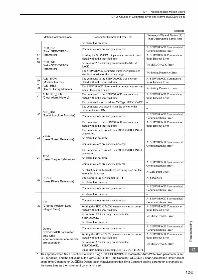
12.1 Troubleshooting Motion Errors
12.1.2 Causes of Command Error End Alarms (IW09 Bit 3)
12-5
Trou
bles
hoot
ing
* This applies when No.1 Function Selection Flag 1 Bit A SERVOPACK Parameter Auto-Write fixed parameter is set to 0 (Enabled) and the set value of the OW3A Filter Time Constant, OL36 Linear Acceleration Rate/Acceler-ation Time Constant, or OL38 Deceleration Rate/Deceleration Time Constant setting parameter is changed at the same time as the movement command is set.
17or18
PRM_RD(Read SERVOPACK Parameter)
PRM_WR(Write SERVOPACK Parameter)
An alarm has occurred. −
Communications are not synchronized.A: SERVOPACK Synchronized Communications Error
Reading the SERVOPACK parameter was not com-pleted within the specified time.
A: SERVOPACK Communica-tions Timeout Error
An A.94 or A.95 warning occurred in the SERVO-PACK.
W: SERVOPACK Error
The SERVOPACK parameter number or parameter size is set outside of the setting range.
W: Setting Parameter Error
19or20
ALM_MON(Monitor Alarms)ALM_HIST(Alarm History Monitor)
The command to the SERVOPACK was not com-pleted within the specified time.
A: SERVOPACK Communica-tions Timeout Error
The SERVOPACK alarm monitor number was set out-side of the setting range.
W: Setting Parameter Error
21ALMHIST_CLR(Clear Alarm History)
The command to the SERVOPACK was not com-pleted within the specified time.
A: SERVOPACK Communica-tions Timeout Error
22ABS_RST (Reset Absolute Encoder)
The command was issued to a Σ-I Type SERVOPACK. −The command was issued when the power to the Servomotor was ON.
−
Communications are not synchronized.A: SERVOPACK Synchronized Communications Error
The command to the SERVOPACK was not com-pleted within the specified time.
A: SERVOPACK Communica-tions Timeout Error
23VELO (Issue Speed Reference)
The command was issued for a MECHATROLINK-I connection.
−
An alarm has occurred. −
Communications are not synchronized.A: SERVOPACK Synchronized Communications Error
24TRQ (Issue Torque Reference)
The command was issued for a MECHATROLINK-I connection.
−
An alarm has occurred. −
Communications are not synchronized.A: SERVOPACK Synchronized Communications Error
25PHASE (Issue Phase Reference)
An absolute infinite-length axis is being used but the zero point is not set.
A: Zero Point Unset
The power to the Servomotor is OFF. A: Servo OFF
An alarm has occurred. −
Communications are not synchronized.A: SERVOPACK Synchronized Communications Error
26
KIS(Change Position Loop Integral Time)
An alarm has occurred. −
Communications are not synchronized.A: SERVOPACK Synchronized Communications Error
Writing the SERVOPACK parameters was not com-pleted within the specified time.
A: SERVOPACK Communica-tions Timeout Error
An A.94 or A.95 warning occurred in the SERVOPACK.
W: SERVOPACK Error
−
OthersSERVOPACK parameter auto-writewhen movement commands are executed*
An alarm has occurred. −
Communications are not synchronized.A: SERVOPACK Synchronized Communications Error
Writing the SERVOPACK parameters was not com-pleted within the specified time.
A: SERVOPACK Communica-tions Timeout Error
An A.94 or A.95 warning occurred in the SERVOPACK.
W: SERVOPACK Error
Pulse distribution is not completed (i.e., DEN is OFF). −
(cont’d)
Motion Command Code Reason for Command Error EndWarnings (W) and Alarms (A) That Occur at the Same Time
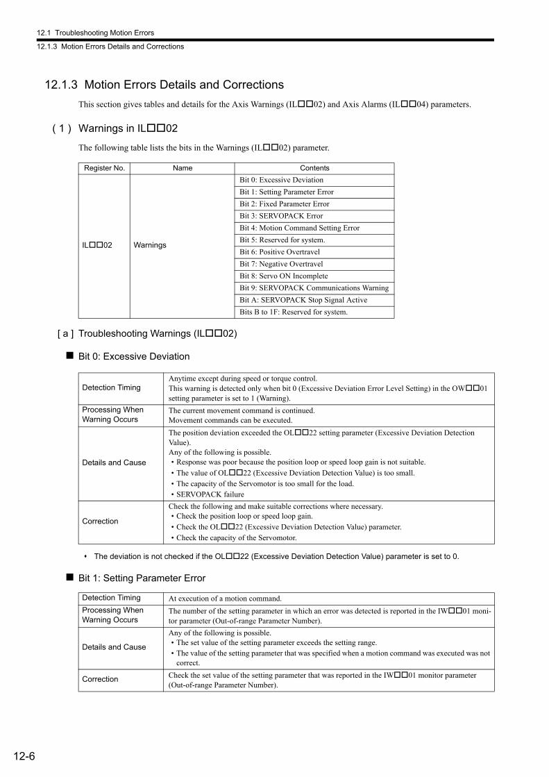
12.1 Troubleshooting Motion Errors
12.1.3 Motion Errors Details and Corrections
12-6
12.1.3 Motion Errors Details and Corrections
This section gives tables and details for the Axis Warnings (IL02) and Axis Alarms (IL04) parameters.
( 1 ) Warnings in IL02
The following table lists the bits in the Warnings (IL02) parameter.
[ a ] Troubleshooting Warnings (IL02)
Bit 0: Excessive Deviation
The deviation is not checked if the OL22 (Excessive Deviation Detection Value) parameter is set to 0.
Bit 1: Setting Parameter Error
Register No. Name Contents
IL02 Warnings
Bit 0: Excessive Deviation
Bit 1: Setting Parameter Error
Bit 2: Fixed Parameter Error
Bit 3: SERVOPACK Error
Bit 4: Motion Command Setting Error
Bit 5: Reserved for system.
Bit 6: Positive Overtravel
Bit 7: Negative Overtravel
Bit 8: Servo ON Incomplete
Bit 9: SERVOPACK Communications Warning
Bit A: SERVOPACK Stop Signal Active
Bits B to 1F: Reserved for system.
Detection TimingAnytime except during speed or torque control.This warning is detected only when bit 0 (Excessive Deviation Error Level Setting) in the OW01 setting parameter is set to 1 (Warning).
Processing When Warning Occurs
The current movement command is continued.Movement commands can be executed.
Details and Cause
The position deviation exceeded the OL22 setting parameter (Excessive Deviation Detection Value).Any of the following is possible.• Response was poor because the position loop or speed loop gain is not suitable.
• The value of OL22 (Excessive Deviation Detection Value) is too small.• The capacity of the Servomotor is too small for the load.• SERVOPACK failure
Correction
Check the following and make suitable corrections where necessary.• Check the position loop or speed loop gain.
• Check the OL22 (Excessive Deviation Detection Value) parameter.• Check the capacity of the Servomotor.
Detection Timing At execution of a motion command.
Processing When Warning Occurs
The number of the setting parameter in which an error was detected is reported in the IW01 moni-tor parameter (Out-of-range Parameter Number).
Details and Cause
Any of the following is possible.• The set value of the setting parameter exceeds the setting range.• The value of the setting parameter that was specified when a motion command was executed was not
correct.
Correction Check the set value of the setting parameter that was reported in the IW01 monitor parameter (Out-of-range Parameter Number).
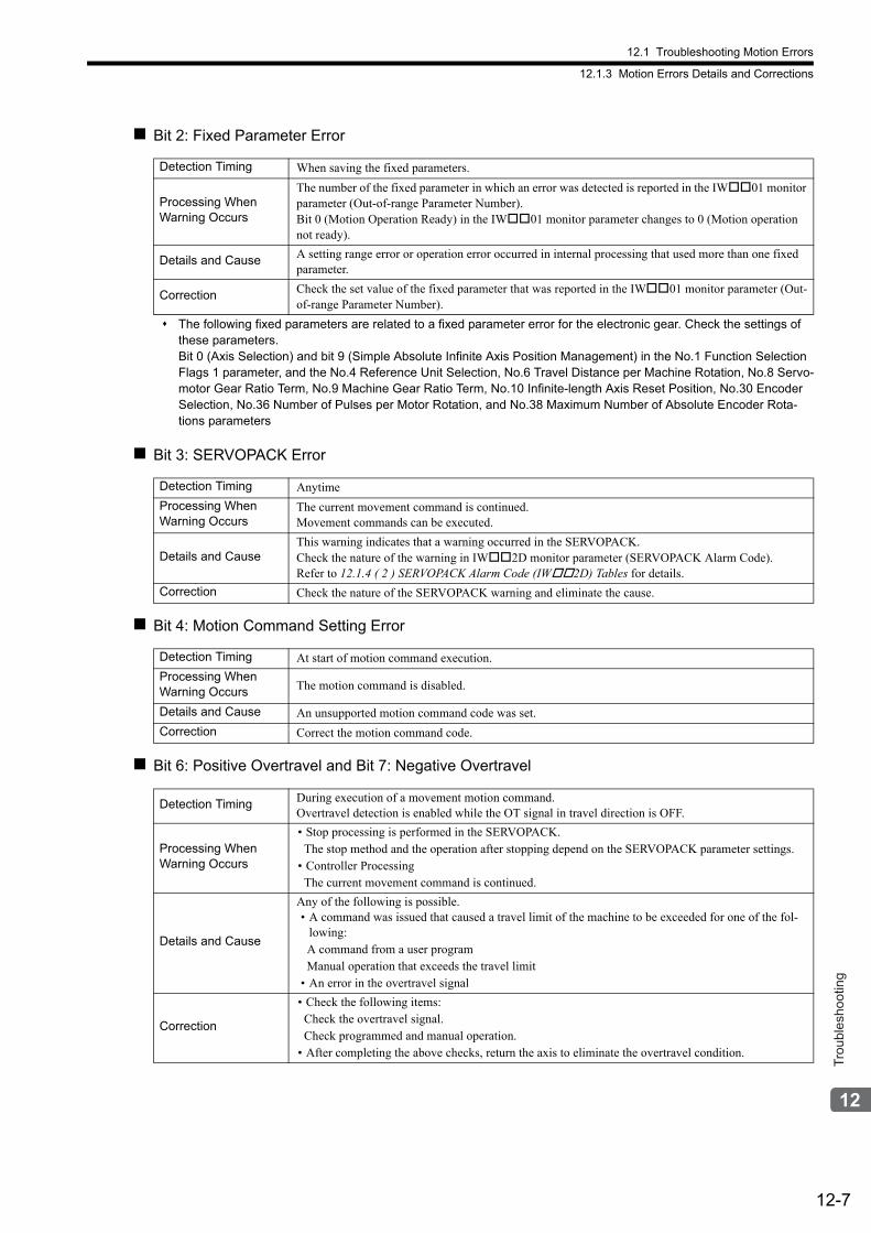
12.1 Troubleshooting Motion Errors
12.1.3 Motion Errors Details and Corrections
12-7
Trou
bles
hoot
ing
Bit 2: Fixed Parameter Error
The following fixed parameters are related to a fixed parameter error for the electronic gear. Check the settings of these parameters. Bit 0 (Axis Selection) and bit 9 (Simple Absolute Infinite Axis Position Management) in the No.1 Function Selection Flags 1 parameter, and the No.4 Reference Unit Selection, No.6 Travel Distance per Machine Rotation, No.8 Servo-motor Gear Ratio Term, No.9 Machine Gear Ratio Term, No.10 Infinite-length Axis Reset Position, No.30 Encoder Selection, No.36 Number of Pulses per Motor Rotation, and No.38 Maximum Number of Absolute Encoder Rota-tions parameters
Bit 3: SERVOPACK Error
Bit 4: Motion Command Setting Error
Bit 6: Positive Overtravel and Bit 7: Negative Overtravel
Detection Timing When saving the fixed parameters.
Processing When Warning Occurs
The number of the fixed parameter in which an error was detected is reported in the IW01 monitor parameter (Out-of-range Parameter Number).Bit 0 (Motion Operation Ready) in the IW01 monitor parameter changes to 0 (Motion operation not ready).
Details and Cause A setting range error or operation error occurred in internal processing that used more than one fixed parameter.
Correction Check the set value of the fixed parameter that was reported in the IW01 monitor parameter (Out-of-range Parameter Number).
Detection Timing Anytime
Processing When Warning Occurs
The current movement command is continued.Movement commands can be executed.
Details and CauseThis warning indicates that a warning occurred in the SERVOPACK.Check the nature of the warning in IW2D monitor parameter (SERVOPACK Alarm Code).Refer to 12.1.4 ( 2 ) SERVOPACK Alarm Code (IW2D) Tables for details.
Correction Check the nature of the SERVOPACK warning and eliminate the cause.
Detection Timing At start of motion command execution.
Processing When Warning Occurs The motion command is disabled.
Details and Cause An unsupported motion command code was set.
Correction Correct the motion command code.
Detection Timing During execution of a movement motion command.Overtravel detection is enabled while the OT signal in travel direction is OFF.
Processing When Warning Occurs
• Stop processing is performed in the SERVOPACK.The stop method and the operation after stopping depend on the SERVOPACK parameter settings.
• Controller ProcessingThe current movement command is continued.
Details and Cause
Any of the following is possible.• A command was issued that caused a travel limit of the machine to be exceeded for one of the fol-
lowing:A command from a user programManual operation that exceeds the travel limit
• An error in the overtravel signal
Correction
• Check the following items:Check the overtravel signal.Check programmed and manual operation.
• After completing the above checks, return the axis to eliminate the overtravel condition.

12.1 Troubleshooting Motion Errors
12.1.3 Motion Errors Details and Corrections
12-8
Bit 8: Servo ON Incomplete
Bit 9: SERVOPACK Communications Warning
If communications errors occur consecutively, an alarm will be shown in IL04 bit 11 (SERVOPACK Communica-tions Error).
Bit A: SERVOPACK Stop Signal Active
( 2 ) Alarms (IL04) Table and Corrections
This section describes the alarms that are given in IL04 and the corrections for them.
[ a ] Alarms in IL04
The following table lists the bits in the Alarms (IL04) parameter.
Detection Timing Anytime
Processing When Warning Occurs Movement commands cannot be executed.
Details and Cause
The power to the Servomotor was not turned ON even though bit 0 (Servo ON) of the OW00 set-ting parameter was turned ON.Any of the following is possible.• The change in the Servo ON command from OFF to ON was not detected.• There is an alarm in the SERVOPACK.• The main circuit power supply to the SERVOPACK is OFF.
Correction Turn ON the Servo ON command again.Check the SERVOPACK for alarms and check the power supply status and stop signal status.
Detection Timing Anytime
Processing When Warning Occurs
The current movement command is continued.Movement commands can be executed.
Details and Cause This bit shows individual errors in MECHATROLINK communications.
CorrectionWhen the communications error stops, normal status is recovered automatically.If warnings occur frequently, reroute the MECHATROLINK cable, change the ground, or implement other noise countermeasures.
Detection Timing Anytime
Processing When Warning Occurs The power supply to the Servomotor is turned OFF and movement commands are not executed.
Details and Cause The stop signal (or an HWBB for Σ-V/Σ-7 SERVOPACKs) was received by the SERVOPACK.
Correction Confirm safety, and then disable the stop signal.
IL04 Alarm IL04 Alarm
Bit 0 SERVOPACK Error Bit 10 SERVOPACK Synchronized Communications Error
Bit 1 Positive Overtravel Bit 11 SERVOPACK Communications Error
Bit 2 Negative Overtravel Bit 12 SERVOPACK Communications Timeout Error
Bit 3 Positive Software Limit Bit 13 Excessive Absolute Encoder Rotations
Bit 4 Negative Software Limit Bit 14 Reserved for system.
Bit 5 Servo OFF Bit 15 Reserved for system.
Bit 6 Positioning Time Exceeded Bit 16 Not used.
Bit 7 Excessive Positioning Travel Distance Bit 17 Not used.
Bit 8 Excessive Speed Bit 18 Not used.
Bit 9 Excessive Deviation Bit 19 Not used.
Bit A Filter Type Change Error Bit 1A Not used.
Bit B Filter Time Constant Change Error Bit 1B Not used.
Bit C Not used. Bit 1C Not used.
Bit D Zero Point Unset Bit 1D Detected SERVOPACK Model Error
Bit E Not used. Bit 1E Motor Type Setting Error
Bit F Not used. Bit 1F Connected Encoder Model Error
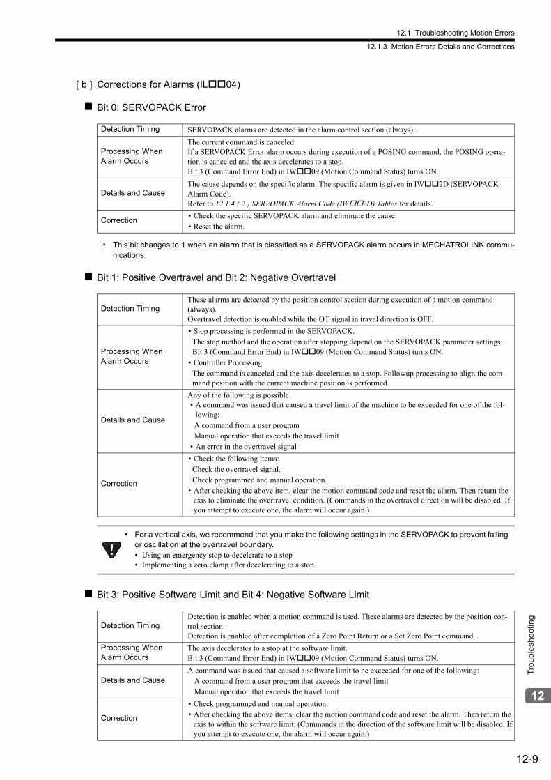
12.1 Troubleshooting Motion Errors
12.1.3 Motion Errors Details and Corrections
12-9
Trou
bles
hoot
ing
[ b ] Corrections for Alarms (IL04)
Bit 0: SERVOPACK Error
This bit changes to 1 when an alarm that is classified as a SERVOPACK alarm occurs in MECHATROLINK commu-nications.
Bit 1: Positive Overtravel and Bit 2: Negative Overtravel
Bit 3: Positive Software Limit and Bit 4: Negative Software Limit
Detection Timing SERVOPACK alarms are detected in the alarm control section (always).
Processing When Alarm Occurs
The current command is canceled. If a SERVOPACK Error alarm occurs during execution of a POSING command, the POSING opera-tion is canceled and the axis decelerates to a stop.Bit 3 (Command Error End) in IW09 (Motion Command Status) turns ON.
Details and CauseThe cause depends on the specific alarm. The specific alarm is given in IW2D (SERVOPACK Alarm Code).Refer to 12.1.4 ( 2 ) SERVOPACK Alarm Code (IW2D) Tables for details.
Correction• Check the specific SERVOPACK alarm and eliminate the cause.• Reset the alarm.
Detection TimingThese alarms are detected by the position control section during execution of a motion command (always).Overtravel detection is enabled while the OT signal in travel direction is OFF.
Processing When Alarm Occurs
• Stop processing is performed in the SERVOPACK.The stop method and the operation after stopping depend on the SERVOPACK parameter settings.Bit 3 (Command Error End) in IW09 (Motion Command Status) turns ON.
• Controller ProcessingThe command is canceled and the axis decelerates to a stop. Followup processing to align the com-mand position with the current machine position is performed.
Details and Cause
Any of the following is possible.• A command was issued that caused a travel limit of the machine to be exceeded for one of the fol-
lowing:A command from a user programManual operation that exceeds the travel limit
• An error in the overtravel signal
Correction
• Check the following items:Check the overtravel signal.Check programmed and manual operation.
• After checking the above item, clear the motion command code and reset the alarm. Then return the axis to eliminate the overtravel condition. (Commands in the overtravel direction will be disabled. If you attempt to execute one, the alarm will occur again.)
For a vertical axis, we recommend that you make the following settings in the SERVOPACK to prevent falling or oscillation at the overtravel boundary.• Using an emergency stop to decelerate to a stop• Implementing a zero clamp after decelerating to a stop
Detection TimingDetection is enabled when a motion command is used. These alarms are detected by the position con-trol section.Detection is enabled after completion of a Zero Point Return or a Set Zero Point command.
Processing When Alarm Occurs
The axis decelerates to a stop at the software limit.Bit 3 (Command Error End) in IW09 (Motion Command Status) turns ON.
Details and CauseA command was issued that caused a software limit to be exceeded for one of the following:
A command from a user program that exceeds the travel limitManual operation that exceeds the travel limit
Correction
• Check programmed and manual operation.• After checking the above items, clear the motion command code and reset the alarm. Then return the
axis to within the software limit. (Commands in the direction of the software limit will be disabled. If you attempt to execute one, the alarm will occur again.)
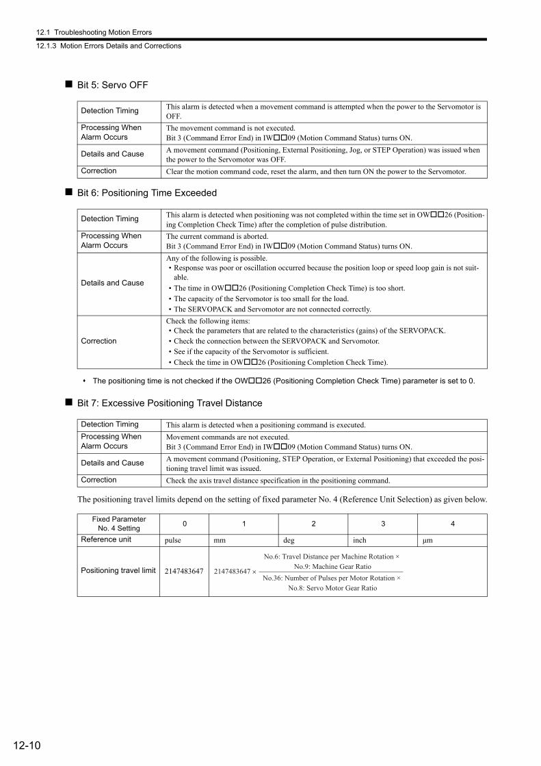
12.1 Troubleshooting Motion Errors
12.1.3 Motion Errors Details and Corrections
12-10
Bit 5: Servo OFF
Bit 6: Positioning Time Exceeded
The positioning time is not checked if the OW26 (Positioning Completion Check Time) parameter is set to 0.
Bit 7: Excessive Positioning Travel Distance
The positioning travel limits depend on the setting of fixed parameter No. 4 (Reference Unit Selection) as given below.
Detection Timing This alarm is detected when a movement command is attempted when the power to the Servomotor is OFF.
Processing When Alarm Occurs
The movement command is not executed.Bit 3 (Command Error End) in IW09 (Motion Command Status) turns ON.
Details and Cause A movement command (Positioning, External Positioning, Jog, or STEP Operation) was issued when the power to the Servomotor was OFF.
Correction Clear the motion command code, reset the alarm, and then turn ON the power to the Servomotor.
Detection Timing This alarm is detected when positioning was not completed within the time set in OW26 (Position-ing Completion Check Time) after the completion of pulse distribution.
Processing When Alarm Occurs
The current command is aborted.Bit 3 (Command Error End) in IW09 (Motion Command Status) turns ON.
Details and Cause
Any of the following is possible.• Response was poor or oscillation occurred because the position loop or speed loop gain is not suit-
able.
• The time in OW26 (Positioning Completion Check Time) is too short.• The capacity of the Servomotor is too small for the load.• The SERVOPACK and Servomotor are not connected correctly.
Correction
Check the following items:• Check the parameters that are related to the characteristics (gains) of the SERVOPACK.• Check the connection between the SERVOPACK and Servomotor.• See if the capacity of the Servomotor is sufficient.
• Check the time in OW26 (Positioning Completion Check Time).
Detection Timing This alarm is detected when a positioning command is executed.
Processing When Alarm Occurs
Movement commands are not executed.Bit 3 (Command Error End) in IW09 (Motion Command Status) turns ON.
Details and Cause A movement command (Positioning, STEP Operation, or External Positioning) that exceeded the posi-tioning travel limit was issued.
Correction Check the axis travel distance specification in the positioning command.
Fixed ParameterNo. 4 Setting
0 1 2 3 4
Reference unit pulse mm deg inch μm
Positioning travel limit 2147483647 2147483647 × No.36: Number of Pulses per Motor Rotation ×
No.8: Servo Motor Gear Ratio
No.6: Travel Distance per Machine Rotation × No.9: Machine Gear Ratio
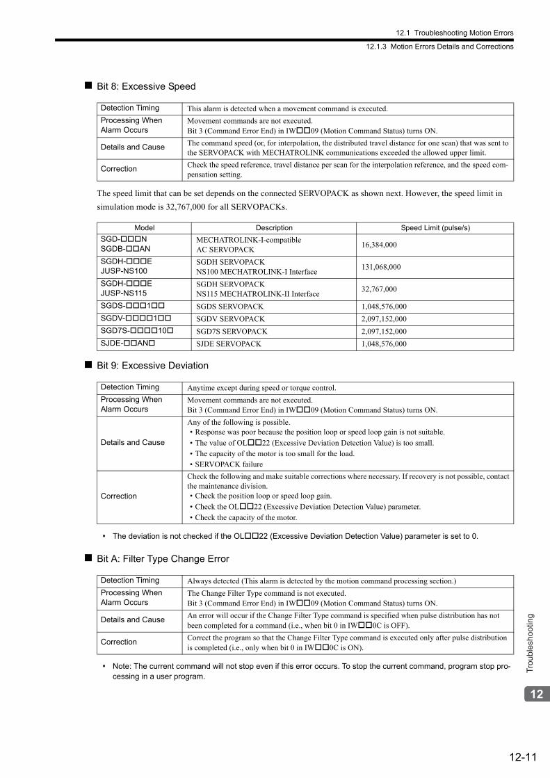
12.1 Troubleshooting Motion Errors
12.1.3 Motion Errors Details and Corrections
12-11
Trou
bles
hoot
ing
Bit 8: Excessive Speed
The speed limit that can be set depends on the connected SERVOPACK as shown next. However, the speed limit in
simulation mode is 32,767,000 for all SERVOPACKs.
Bit 9: Excessive Deviation
The deviation is not checked if the OL22 (Excessive Deviation Detection Value) parameter is set to 0.
Bit A: Filter Type Change Error
Note: The current command will not stop even if this error occurs. To stop the current command, program stop pro-cessing in a user program.
Detection Timing This alarm is detected when a movement command is executed.
Processing When Alarm Occurs
Movement commands are not executed.Bit 3 (Command Error End) in IW09 (Motion Command Status) turns ON.
Details and Cause The command speed (or, for interpolation, the distributed travel distance for one scan) that was sent to the SERVOPACK with MECHATROLINK communications exceeded the allowed upper limit.
Correction Check the speed reference, travel distance per scan for the interpolation reference, and the speed com-pensation setting.
Model Description Speed Limit (pulse/s)
SGD-NSGDB-AN
MECHATROLINK-I-compatibleAC SERVOPACK
16,384,000
SGDH-EJUSP-NS100
SGDH SERVOPACKNS100 MECHATROLINK-I Interface
131,068,000
SGDH-EJUSP-NS115
SGDH SERVOPACKNS115 MECHATROLINK-II Interface
32,767,000
SGDS-1 SGDS SERVOPACK 1,048,576,000
SGDV-1 SGDV SERVOPACK 2,097,152,000
SGD7S-10 SGD7S SERVOPACK 2,097,152,000
SJDE-AN SJDE SERVOPACK 1,048,576,000
Detection Timing Anytime except during speed or torque control.
Processing When Alarm Occurs
Movement commands are not executed.Bit 3 (Command Error End) in IW09 (Motion Command Status) turns ON.
Details and Cause
Any of the following is possible.• Response was poor because the position loop or speed loop gain is not suitable.
• The value of OL22 (Excessive Deviation Detection Value) is too small.• The capacity of the motor is too small for the load.• SERVOPACK failure
Correction
Check the following and make suitable corrections where necessary. If recovery is not possible, contact the maintenance division.• Check the position loop or speed loop gain.
• Check the OL22 (Excessive Deviation Detection Value) parameter.• Check the capacity of the motor.
Detection Timing Always detected (This alarm is detected by the motion command processing section.)
Processing When Alarm Occurs
The Change Filter Type command is not executed.Bit 3 (Command Error End) in IW09 (Motion Command Status) turns ON.
Details and CauseAn error will occur if the Change Filter Type command is specified when pulse distribution has not been completed for a command (i.e., when bit 0 in IW0C is OFF).
CorrectionCorrect the program so that the Change Filter Type command is executed only after pulse distribution is completed (i.e., only when bit 0 in IW0C is ON).
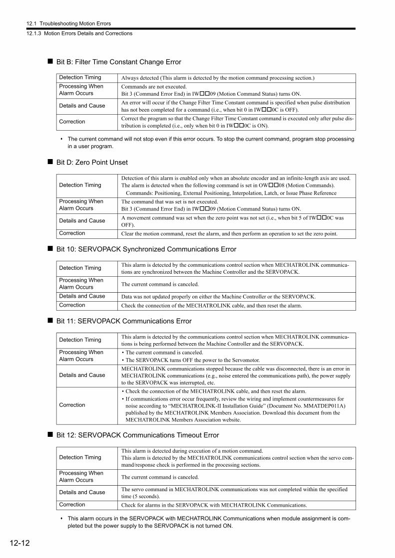
12.1 Troubleshooting Motion Errors
12.1.3 Motion Errors Details and Corrections
12-12
Bit B: Filter Time Constant Change Error
The current command will not stop even if this error occurs. To stop the current command, program stop processing in a user program.
Bit D: Zero Point Unset
Bit 10: SERVOPACK Synchronized Communications Error
Bit 11: SERVOPACK Communications Error
Bit 12: SERVOPACK Communications Timeout Error
This alarm occurs in the SERVOPACK with MECHATROLINK Communications when module assignment is com-pleted but the power supply to the SERVOPACK is not turned ON.
Detection Timing Always detected (This alarm is detected by the motion command processing section.)
Processing When Alarm Occurs
Commands are not executed.Bit 3 (Command Error End) in IW09 (Motion Command Status) turns ON.
Details and CauseAn error will occur if the Change Filter Time Constant command is specified when pulse distribution has not been completed for a command (i.e., when bit 0 in IW0C is OFF).
CorrectionCorrect the program so that the Change Filter Time Constant command is executed only after pulse dis-tribution is completed (i.e., only when bit 0 in IW0C is ON).
Detection TimingDetection of this alarm is enabled only when an absolute encoder and an infinite-length axis are used. The alarm is detected when the following command is set in OW08 (Motion Commands).
Commands: Positioning, External Positioning, Interpolation, Latch, or Issue Phase Reference
Processing When Alarm Occurs
The command that was set is not executed.Bit 3 (Command Error End) in IW09 (Motion Command Status) turns ON.
Details and Cause A movement command was set when the zero point was not set (i.e., when bit 5 of IW0C was OFF).
Correction Clear the motion command, reset the alarm, and then perform an operation to set the zero point.
Detection Timing This alarm is detected by the communications control section when MECHATROLINK communica-tions are synchronized between the Machine Controller and the SERVOPACK.
Processing When Alarm Occurs The current command is canceled.
Details and Cause Data was not updated properly on either the Machine Controller or the SERVOPACK.
Correction Check the connection of the MECHATROLINK cable, and then reset the alarm.
Detection Timing This alarm is detected by the communications control section when MECHATROLINK communica-tions is being performed between the Machine Controller and the SERVOPACK.
Processing When Alarm Occurs
• The current command is canceled.• The SERVOPACK turns OFF the power to the Servomotor.
Details and CauseMECHATROLINK communications stopped because the cable was disconnected, there is an error in MECHATROLINK communications (e.g., noise entered the communications path), the power supply to the SERVOPACK was interrupted, etc.
Correction
• Check the connection of the MECHATROLINK cable, and then reset the alarm.• If communications error occur frequently, review the wiring and implement countermeasures for
noise according to “MECHATROLINK-II Installation Guide” (Document No. MMATDEP011A) published by the MECHATROLINK Members Association. Download this document from the MECHATROLINK Members Association website.
Detection TimingThis alarm is detected during execution of a motion command.This alarm is detected by the MECHATROLINK communications control section when the servo com-mand/response check is performed in the processing sections.
Processing When Alarm Occurs The current command is canceled.
Details and Cause The servo command in MECHATROLINK communications was not completed within the specified time (5 seconds).
Correction Check for alarms in the SERVOPACK with MECHATROLINK Communications.
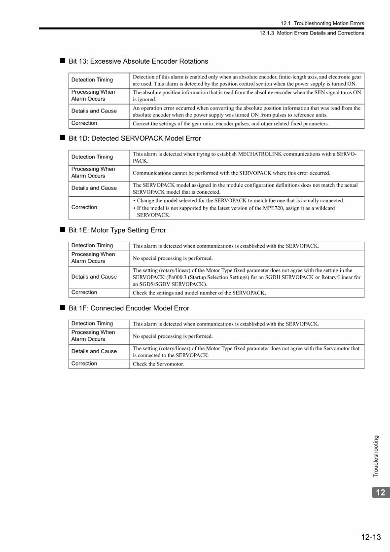
12.1 Troubleshooting Motion Errors
12.1.3 Motion Errors Details and Corrections
12-13
Trou
bles
hoot
ing
Bit 13: Excessive Absolute Encoder Rotations
Bit 1D: Detected SERVOPACK Model Error
Bit 1E: Motor Type Setting Error
Bit 1F: Connected Encoder Model Error
Detection Timing Detection of this alarm is enabled only when an absolute encoder, finite-length axis, and electronic gear are used. This alarm is detected by the position control section when the power supply is turned ON.
Processing When Alarm Occurs
The absolute position information that is read from the absolute encoder when the SEN signal turns ON is ignored.
Details and Cause An operation error occurred when converting the absolute position information that was read from the absolute encoder when the power supply was turned ON from pulses to reference units.
Correction Correct the settings of the gear ratio, encoder pulses, and other related fixed parameters.
Detection Timing This alarm is detected when trying to establish MECHATROLINK communications with a SERVO-PACK.
Processing When Alarm Occurs Communications cannot be performed with the SERVOPACK where this error occurred.
Details and Cause The SERVOPACK model assigned in the module configuration definitions does not match the actual SERVOPACK model that is connected.
Correction• Change the model selected for the SERVOPACK to match the one that is actually connected.• If the model is not supported by the latest version of the MPE720, assign it as a wildcard
SERVOPACK.
Detection Timing This alarm is detected when communications is established with the SERVOPACK.
Processing When Alarm Occurs No special processing is performed.
Details and CauseThe setting (rotary/linear) of the Motor Type fixed parameter does not agree with the setting in the SERVOPACK (Pn000.3 (Startup Selection Settings) for an SGDH SERVOPACK or Rotary/Linear for an SGDS/SGDV SERVOPACK).
Correction Check the settings and model number of the SERVOPACK.
Detection Timing This alarm is detected when communications is established with the SERVOPACK.
Processing When Alarm Occurs No special processing is performed.
Details and Cause The setting (rotary/linear) of the Motor Type fixed parameter does not agree with the Servomotor that is connected to the SERVOPACK.
Correction Check the Servomotor.
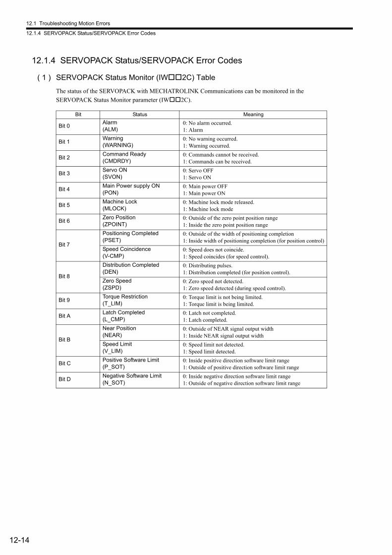
12.1 Troubleshooting Motion Errors
12.1.4 SERVOPACK Status/SERVOPACK Error Codes
12-14
12.1.4 SERVOPACK Status/SERVOPACK Error Codes
( 1 ) SERVOPACK Status Monitor (IW2C) Table
The status of the SERVOPACK with MECHATROLINK Communications can be monitored in the
SERVOPACK Status Monitor parameter (IW2C).
Bit Status Meaning
Bit 0Alarm (ALM)
0: No alarm occurred.1: Alarm
Bit 1Warning (WARNING)
0: No warning occurred.1: Warning occurred.
Bit 2Command Ready (CMDRDY)
0: Commands cannot be received.1: Commands can be received.
Bit 3Servo ON (SVON)
0: Servo OFF1: Servo ON
Bit 4Main Power supply ON (PON)
0: Main power OFF1: Main power ON
Bit 5Machine Lock (MLOCK)
0: Machine lock mode released.1: Machine lock mode
Bit 6Zero Position (ZPOINT)
0: Outside of the zero point position range1: Inside the zero point position range
Bit 7
Positioning Completed (PSET)
0: Outside of the width of positioning completion1: Inside width of positioning completion (for position control)
Speed Coincidence (V-CMP)
0: Speed does not coincide.1: Speed coincides (for speed control).
Bit 8
Distribution Completed (DEN)
0: Distributing pulses.1: Distribution completed (for position control).
Zero Speed (ZSPD)
0: Zero speed not detected.1: Zero speed detected (during speed control).
Bit 9Torque Restriction (T_LIM)
0: Torque limit is not being limited.1: Torque limit is being limited.
Bit ALatch Completed (L_CMP)
0: Latch not completed.1: Latch completed.
Bit B
Near Position (NEAR)
0: Outside of NEAR signal output width1: Inside NEAR signal output width
Speed Limit (V_LIM)
0: Speed limit not detected.1: Speed limit detected.
Bit CPositive Software Limit (P_SOT)
0: Inside positive direction software limit range1: Outside of positive direction software limit range
Bit DNegative Software Limit (N_SOT)
0: Inside negative direction software limit range1: Outside of negative direction software limit range
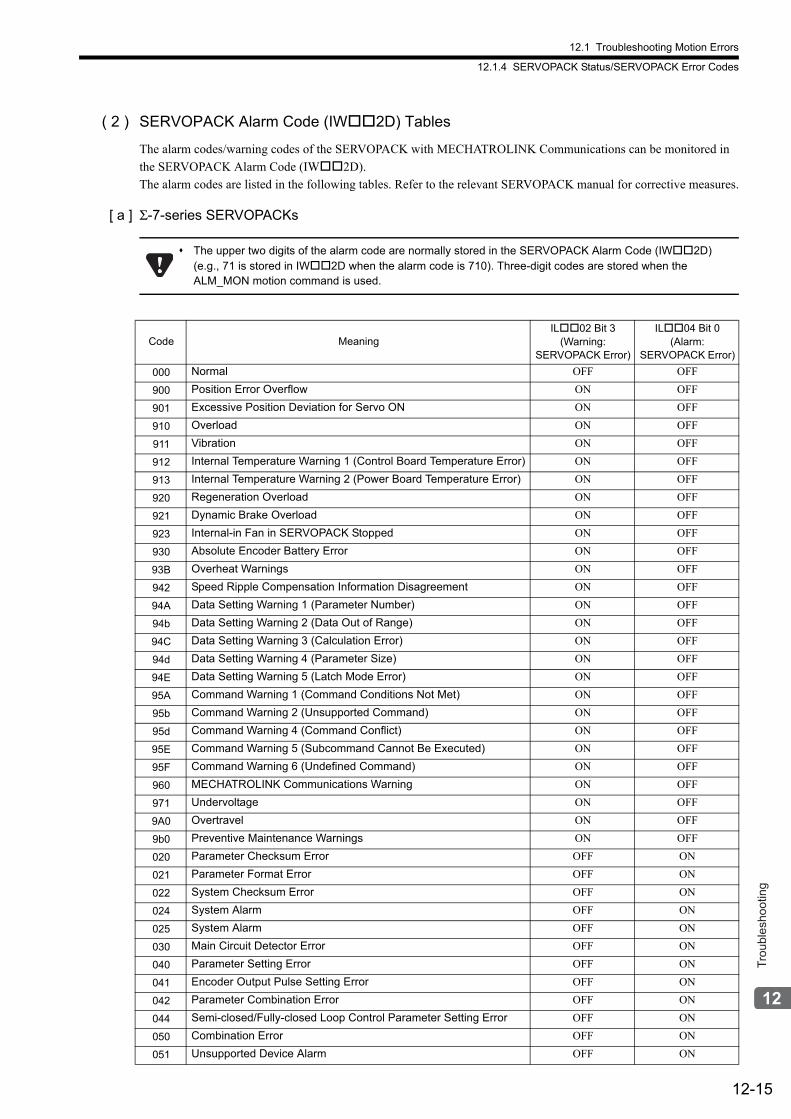
12.1 Troubleshooting Motion Errors
12.1.4 SERVOPACK Status/SERVOPACK Error Codes
12-15
Trou
bles
hoot
ing
( 2 ) SERVOPACK Alarm Code (IW2D) Tables
The alarm codes/warning codes of the SERVOPACK with MECHATROLINK Communications can be monitored in
the SERVOPACK Alarm Code (IW2D).
The alarm codes are listed in the following tables. Refer to the relevant SERVOPACK manual for corrective measures.
[ a ] Σ-7-series SERVOPACKs
The upper two digits of the alarm code are normally stored in the SERVOPACK Alarm Code (IW2D) (e.g., 71 is stored in IW2D when the alarm code is 710). Three-digit codes are stored when the ALM_MON motion command is used.
Code MeaningIL02 Bit 3
(Warning:SERVOPACK Error)
IL04 Bit 0(Alarm:
SERVOPACK Error)
000 Normal OFF OFF
900 Position Error Overflow ON OFF
901 Excessive Position Deviation for Servo ON ON OFF
910 Overload ON OFF
911 Vibration ON OFF
912 Internal Temperature Warning 1 (Control Board Temperature Error) ON OFF
913 Internal Temperature Warning 2 (Power Board Temperature Error) ON OFF
920 Regeneration Overload ON OFF
921 Dynamic Brake Overload ON OFF
923 Internal-in Fan in SERVOPACK Stopped ON OFF
930 Absolute Encoder Battery Error ON OFF
93B Overheat Warnings ON OFF
942 Speed Ripple Compensation Information Disagreement ON OFF
94A Data Setting Warning 1 (Parameter Number) ON OFF
94b Data Setting Warning 2 (Data Out of Range) ON OFF
94C Data Setting Warning 3 (Calculation Error) ON OFF
94d Data Setting Warning 4 (Parameter Size) ON OFF
94E Data Setting Warning 5 (Latch Mode Error) ON OFF
95A Command Warning 1 (Command Conditions Not Met) ON OFF
95b Command Warning 2 (Unsupported Command) ON OFF
95d Command Warning 4 (Command Conflict) ON OFF
95E Command Warning 5 (Subcommand Cannot Be Executed) ON OFF
95F Command Warning 6 (Undefined Command) ON OFF
960 MECHATROLINK Communications Warning ON OFF
971 Undervoltage ON OFF
9A0 Overtravel ON OFF
9b0 Preventive Maintenance Warnings ON OFF
020 Parameter Checksum Error OFF ON
021 Parameter Format Error OFF ON
022 System Checksum Error OFF ON
024 System Alarm OFF ON
025 System Alarm OFF ON
030 Main Circuit Detector Error OFF ON
040 Parameter Setting Error OFF ON
041 Encoder Output Pulse Setting Error OFF ON
042 Parameter Combination Error OFF ON
044 Semi-closed/Fully-closed Loop Control Parameter Setting Error OFF ON
050 Combination Error OFF ON
051 Unsupported Device Alarm OFF ON
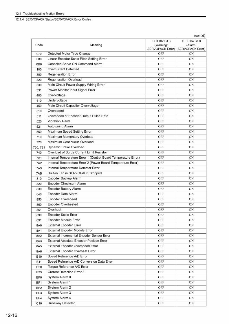
12.1 Troubleshooting Motion Errors
12.1.4 SERVOPACK Status/SERVOPACK Error Codes
12-16
070 Detected Motor Type Change OFF ON
080 Linear Encoder Scale Pitch Setting Error OFF ON
0B0 Canceled Servo ON Command Alarm OFF ON
100 Overcurrent Detected OFF ON
300 Regeneration Error OFF ON
320 Regeneration Overload OFF ON
330 Main Circuit Power Supply Wiring Error OFF ON
331 Power Monitor Input Signal Error OFF ON
400 Overvoltage OFF ON
410 Undervoltage OFF ON
450 Main Circuit Capacitor Overvoltage OFF ON
510 Overspeed OFF ON
511 Overspeed of Encoder Output Pulse Rate OFF ON
520 Vibration Alarm OFF ON
521 Autotuning Alarm OFF ON
550 Maximum Speed Setting Error OFF ON
710 Maximum Momentary Overload OFF ON
720 Maximum Continuous Overload OFF ON
730, 731 Dynamic Brake Overload OFF ON
740 Overload of Surge Current Limit Resistor OFF ON
7A1 Internal Temperature Error 1 (Control Board Temperature Error) OFF ON
7A2 Internal Temperature Error 2 (Power Board Temperature Error) OFF ON
7A3 Internal Temperature Detector Error OFF ON
7AB Built-in Fan in SERVOPACK Stopped OFF ON
810 Encoder Backup Alarm OFF ON
820 Encoder Checksum Alarm OFF ON
830 Encoder Battery Alarm OFF ON
840 Encoder Data Alarm OFF ON
850 Encoder Overspeed OFF ON
860 Encoder Overheated OFF ON
861 Overheat OFF ON
890 Encoder Scale Error OFF ON
891 Encoder Module Error OFF ON
8A0 External Encoder Error OFF ON
8A1 External Encoder Module Error OFF ON
8A2 External Incremental Encoder Sensor Error OFF ON
8A3 External Absolute Encoder Position Error OFF ON
8A5 External Encoder Overspeed Error OFF ON
8A6 External Encoder Overheat Error OFF ON
B10 Speed Reference A/D Error OFF ON
B11 Speed Reference A/D Conversion Data Error OFF ON
B20 Torque Reference A/D Error OFF ON
B33 Current Detection Error 3 OFF ON
BF0 System Alarm 0 OFF ON
BF1 System Alarm 1 OFF ON
BF2 System Alarm 2 OFF ON
BF3 System Alarm 3 OFF ON
BF4 System Alarm 4 OFF ON
C10 Runaway Detected OFF ON
(cont’d)
Code MeaningIL02 Bit 3
(Warning:SERVOPACK Error)
IL04 Bit 0(Alarm:
SERVOPACK Error)
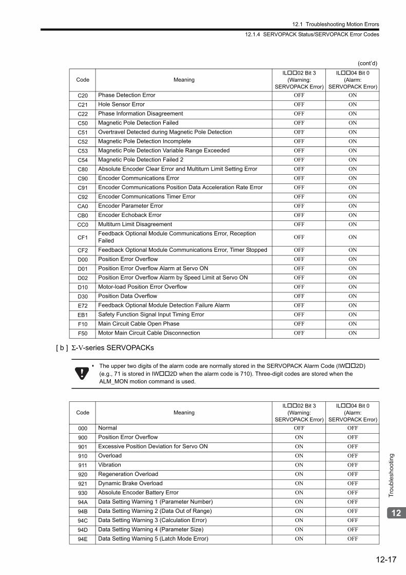
12.1 Troubleshooting Motion Errors
12.1.4 SERVOPACK Status/SERVOPACK Error Codes
12-17
Trou
bles
hoot
ing
[ b ] Σ-V-series SERVOPACKs
C20 Phase Detection Error OFF ON
C21 Hole Sensor Error OFF ON
C22 Phase Information Disagreement OFF ON
C50 Magnetic Pole Detection Failed OFF ON
C51 Overtravel Detected during Magnetic Pole Detection OFF ON
C52 Magnetic Pole Detection Incomplete OFF ON
C53 Magnetic Pole Detection Variable Range Exceeded OFF ON
C54 Magnetic Pole Detection Failed 2 OFF ON
C80 Absolute Encoder Clear Error and Multiturn Limit Setting Error OFF ON
C90 Encoder Communications Error OFF ON
C91 Encoder Communications Position Data Acceleration Rate Error OFF ON
C92 Encoder Communications Timer Error OFF ON
CA0 Encoder Parameter Error OFF ON
CB0 Encoder Echoback Error OFF ON
CC0 Multiturn Limit Disagreement OFF ON
CF1Feedback Optional Module Communications Error, Reception Failed
OFF ON
CF2 Feedback Optional Module Communications Error, Timer Stopped OFF ON
D00 Position Error Overflow OFF ON
D01 Position Error Overflow Alarm at Servo ON OFF ON
D02 Position Error Overflow Alarm by Speed Limit at Servo ON OFF ON
D10 Motor-load Position Error Overflow OFF ON
D30 Position Data Overflow OFF ON
E72 Feedback Optional Module Detection Failure Alarm OFF ON
EB1 Safety Function Signal Input Timing Error OFF ON
F10 Main Circuit Cable Open Phase OFF ON
F50 Motor Main Circuit Cable Disconnection OFF ON
The upper two digits of the alarm code are normally stored in the SERVOPACK Alarm Code (IW2D) (e.g., 71 is stored in IW2D when the alarm code is 710). Three-digit codes are stored when the ALM_MON motion command is used.
Code MeaningIL02 Bit 3
(Warning:SERVOPACK Error)
IL04 Bit 0(Alarm:
SERVOPACK Error)
000 Normal OFF OFF
900 Position Error Overflow ON OFF
901 Excessive Position Deviation for Servo ON ON OFF
910 Overload ON OFF
911 Vibration ON OFF
920 Regeneration Overload ON OFF
921 Dynamic Brake Overload ON OFF
930 Absolute Encoder Battery Error ON OFF
94A Data Setting Warning 1 (Parameter Number) ON OFF
94B Data Setting Warning 2 (Data Out of Range) ON OFF
94C Data Setting Warning 3 (Calculation Error) ON OFF
94D Data Setting Warning 4 (Parameter Size) ON OFF
94E Data Setting Warning 5 (Latch Mode Error) ON OFF
(cont’d)
Code MeaningIL02 Bit 3
(Warning:SERVOPACK Error)
IL04 Bit 0(Alarm:
SERVOPACK Error)
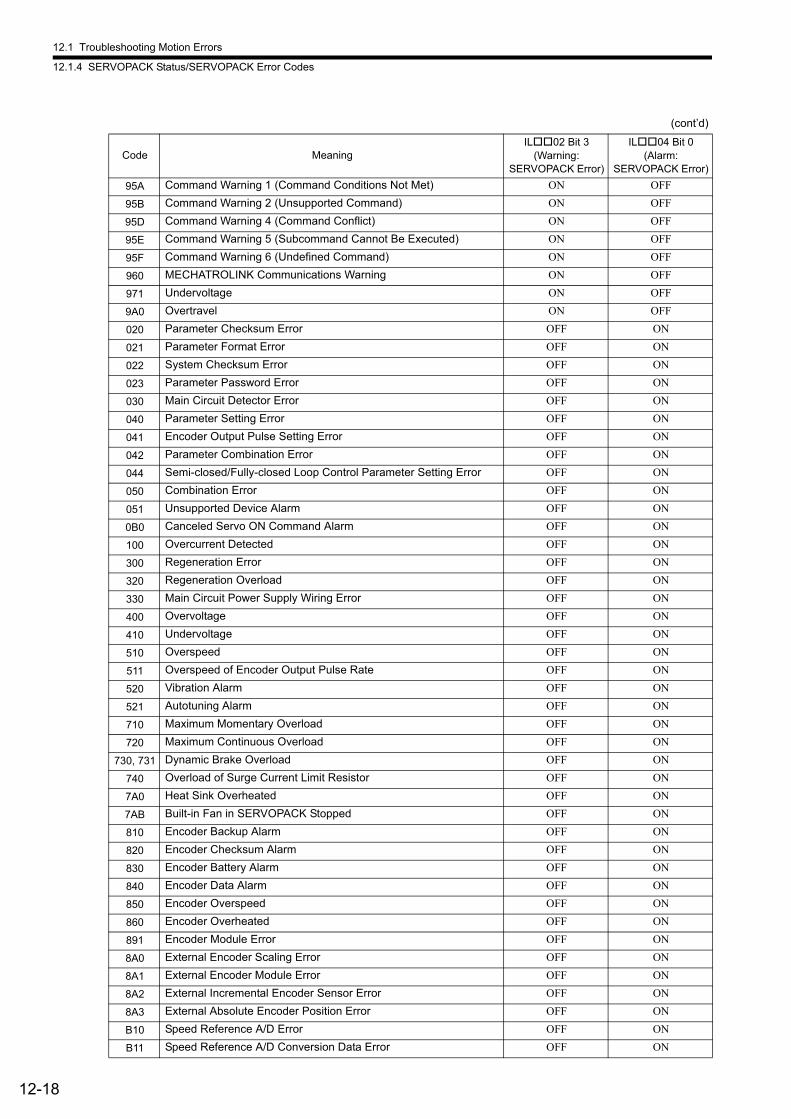
12.1 Troubleshooting Motion Errors
12.1.4 SERVOPACK Status/SERVOPACK Error Codes
12-18
95A Command Warning 1 (Command Conditions Not Met) ON OFF
95B Command Warning 2 (Unsupported Command) ON OFF
95D Command Warning 4 (Command Conflict) ON OFF
95E Command Warning 5 (Subcommand Cannot Be Executed) ON OFF
95F Command Warning 6 (Undefined Command) ON OFF
960 MECHATROLINK Communications Warning ON OFF
971 Undervoltage ON OFF
9A0 Overtravel ON OFF
020 Parameter Checksum Error OFF ON
021 Parameter Format Error OFF ON
022 System Checksum Error OFF ON
023 Parameter Password Error OFF ON
030 Main Circuit Detector Error OFF ON
040 Parameter Setting Error OFF ON
041 Encoder Output Pulse Setting Error OFF ON
042 Parameter Combination Error OFF ON
044 Semi-closed/Fully-closed Loop Control Parameter Setting Error OFF ON
050 Combination Error OFF ON
051 Unsupported Device Alarm OFF ON
0B0 Canceled Servo ON Command Alarm OFF ON
100 Overcurrent Detected OFF ON
300 Regeneration Error OFF ON
320 Regeneration Overload OFF ON
330 Main Circuit Power Supply Wiring Error OFF ON
400 Overvoltage OFF ON
410 Undervoltage OFF ON
510 Overspeed OFF ON
511 Overspeed of Encoder Output Pulse Rate OFF ON
520 Vibration Alarm OFF ON
521 Autotuning Alarm OFF ON
710 Maximum Momentary Overload OFF ON
720 Maximum Continuous Overload OFF ON
730, 731 Dynamic Brake Overload OFF ON
740 Overload of Surge Current Limit Resistor OFF ON
7A0 Heat Sink Overheated OFF ON
7AB Built-in Fan in SERVOPACK Stopped OFF ON
810 Encoder Backup Alarm OFF ON
820 Encoder Checksum Alarm OFF ON
830 Encoder Battery Alarm OFF ON
840 Encoder Data Alarm OFF ON
850 Encoder Overspeed OFF ON
860 Encoder Overheated OFF ON
891 Encoder Module Error OFF ON
8A0 External Encoder Scaling Error OFF ON
8A1 External Encoder Module Error OFF ON
8A2 External Incremental Encoder Sensor Error OFF ON
8A3 External Absolute Encoder Position Error OFF ON
B10 Speed Reference A/D Error OFF ON
B11 Speed Reference A/D Conversion Data Error OFF ON
(cont’d)
Code MeaningIL02 Bit 3
(Warning:SERVOPACK Error)
IL04 Bit 0(Alarm:
SERVOPACK Error)
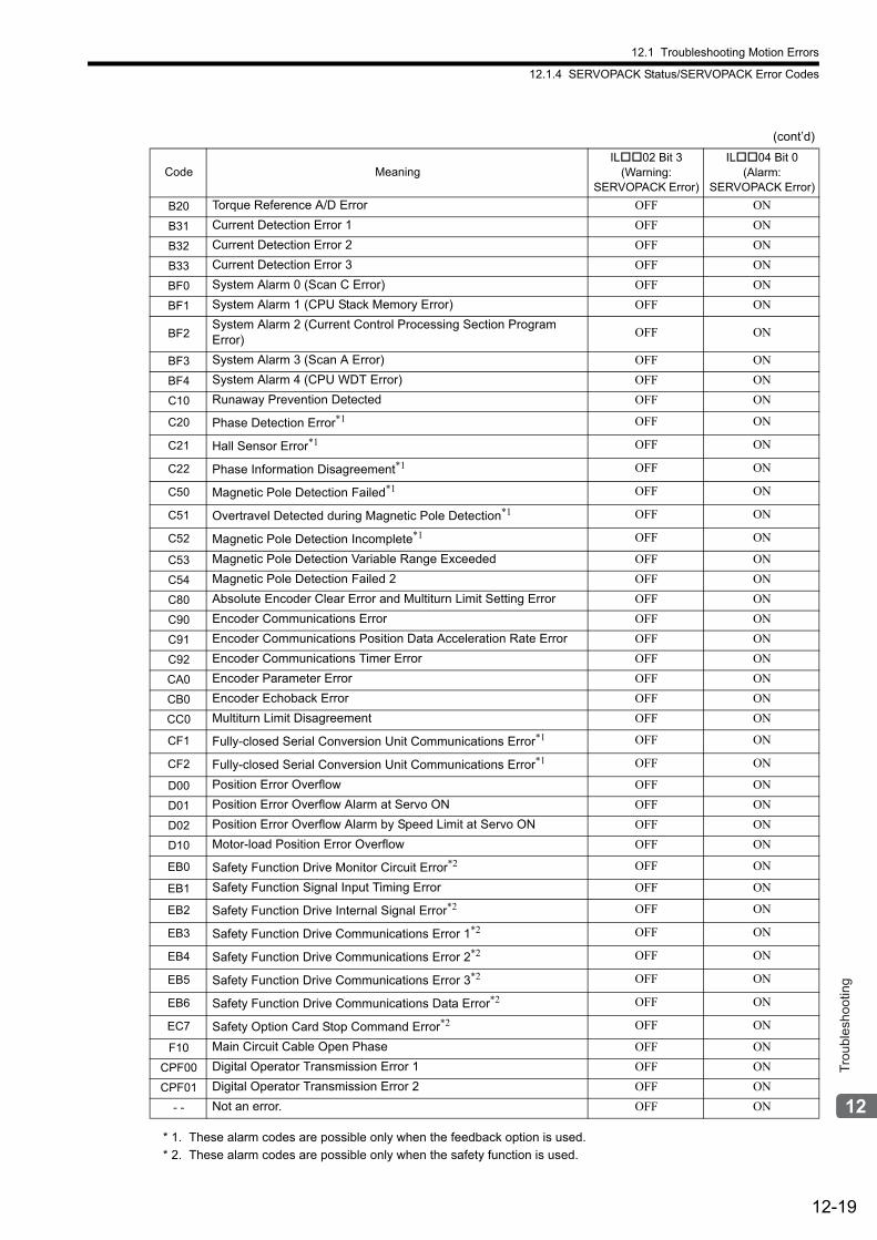
12.1 Troubleshooting Motion Errors
12.1.4 SERVOPACK Status/SERVOPACK Error Codes
12-19
Trou
bles
hoot
ing
* 1. These alarm codes are possible only when the feedback option is used.
* 2. These alarm codes are possible only when the safety function is used.
B20 Torque Reference A/D Error OFF ON
B31 Current Detection Error 1 OFF ON
B32 Current Detection Error 2 OFF ON
B33 Current Detection Error 3 OFF ON
BF0 System Alarm 0 (Scan C Error) OFF ON
BF1 System Alarm 1 (CPU Stack Memory Error) OFF ON
BF2System Alarm 2 (Current Control Processing Section Program Error)
OFF ON
BF3 System Alarm 3 (Scan A Error) OFF ON
BF4 System Alarm 4 (CPU WDT Error) OFF ON
C10 Runaway Prevention Detected OFF ON
C20 Phase Detection Error*1 OFF ON
C21 Hall Sensor Error*1 OFF ON
C22 Phase Information Disagreement*1 OFF ON
C50 Magnetic Pole Detection Failed*1 OFF ON
C51 Overtravel Detected during Magnetic Pole Detection*1 OFF ON
C52 Magnetic Pole Detection Incomplete*1 OFF ON
C53 Magnetic Pole Detection Variable Range Exceeded OFF ON
C54 Magnetic Pole Detection Failed 2 OFF ON
C80 Absolute Encoder Clear Error and Multiturn Limit Setting Error OFF ON
C90 Encoder Communications Error OFF ON
C91 Encoder Communications Position Data Acceleration Rate Error OFF ON
C92 Encoder Communications Timer Error OFF ON
CA0 Encoder Parameter Error OFF ON
CB0 Encoder Echoback Error OFF ON
CC0 Multiturn Limit Disagreement OFF ON
CF1 Fully-closed Serial Conversion Unit Communications Error*1 OFF ON
CF2 Fully-closed Serial Conversion Unit Communications Error*1 OFF ON
D00 Position Error Overflow OFF ON
D01 Position Error Overflow Alarm at Servo ON OFF ON
D02 Position Error Overflow Alarm by Speed Limit at Servo ON OFF ON
D10 Motor-load Position Error Overflow OFF ON
EB0 Safety Function Drive Monitor Circuit Error*2 OFF ON
EB1 Safety Function Signal Input Timing Error OFF ON
EB2 Safety Function Drive Internal Signal Error*2 OFF ON
EB3 Safety Function Drive Communications Error 1*2 OFF ON
EB4 Safety Function Drive Communications Error 2*2 OFF ON
EB5 Safety Function Drive Communications Error 3*2 OFF ON
EB6 Safety Function Drive Communications Data Error*2 OFF ON
EC7 Safety Option Card Stop Command Error*2 OFF ON
F10 Main Circuit Cable Open Phase OFF ON
CPF00 Digital Operator Transmission Error 1 OFF ON
CPF01 Digital Operator Transmission Error 2 OFF ON
- - Not an error. OFF ON
(cont’d)
Code MeaningIL02 Bit 3
(Warning:SERVOPACK Error)
IL04 Bit 0(Alarm:
SERVOPACK Error)
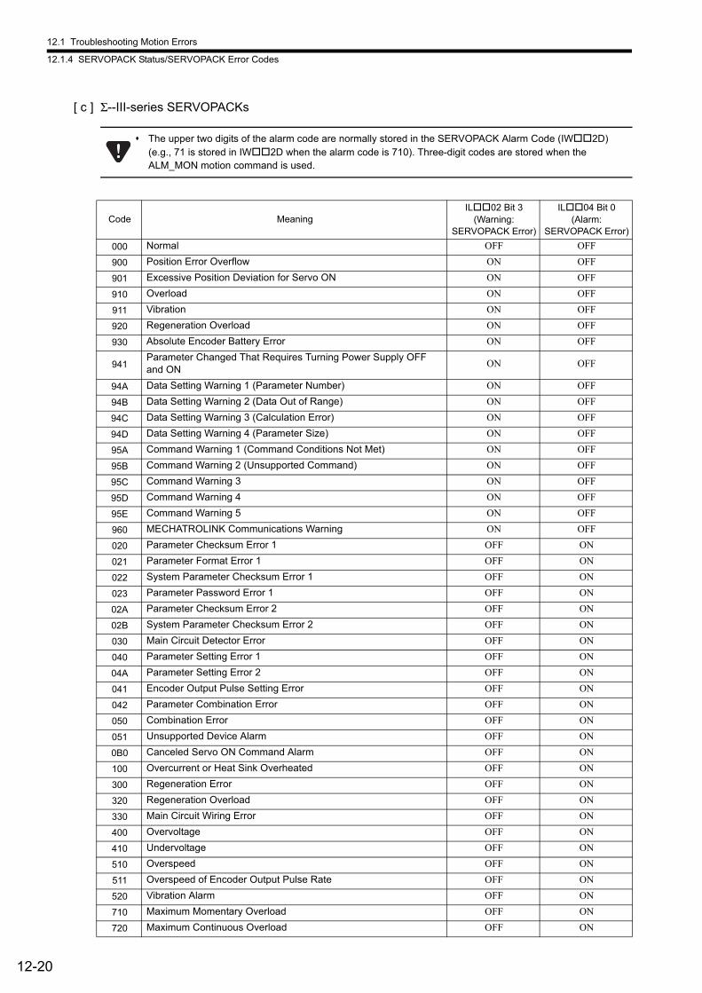
12.1 Troubleshooting Motion Errors
12.1.4 SERVOPACK Status/SERVOPACK Error Codes
12-20
[ c ] Σ--III-series SERVOPACKs
The upper two digits of the alarm code are normally stored in the SERVOPACK Alarm Code (IW2D) (e.g., 71 is stored in IW2D when the alarm code is 710). Three-digit codes are stored when the ALM_MON motion command is used.
Code MeaningIL02 Bit 3
(Warning:SERVOPACK Error)
IL04 Bit 0(Alarm:
SERVOPACK Error)
000 Normal OFF OFF
900 Position Error Overflow ON OFF
901 Excessive Position Deviation for Servo ON ON OFF
910 Overload ON OFF
911 Vibration ON OFF
920 Regeneration Overload ON OFF
930 Absolute Encoder Battery Error ON OFF
941Parameter Changed That Requires Turning Power Supply OFF and ON
ON OFF
94A Data Setting Warning 1 (Parameter Number) ON OFF
94B Data Setting Warning 2 (Data Out of Range) ON OFF
94C Data Setting Warning 3 (Calculation Error) ON OFF
94D Data Setting Warning 4 (Parameter Size) ON OFF
95A Command Warning 1 (Command Conditions Not Met) ON OFF
95B Command Warning 2 (Unsupported Command) ON OFF
95C Command Warning 3 ON OFF
95D Command Warning 4 ON OFF
95E Command Warning 5 ON OFF
960 MECHATROLINK Communications Warning ON OFF
020 Parameter Checksum Error 1 OFF ON
021 Parameter Format Error 1 OFF ON
022 System Parameter Checksum Error 1 OFF ON
023 Parameter Password Error 1 OFF ON
02A Parameter Checksum Error 2 OFF ON
02B System Parameter Checksum Error 2 OFF ON
030 Main Circuit Detector Error OFF ON
040 Parameter Setting Error 1 OFF ON
04A Parameter Setting Error 2 OFF ON
041 Encoder Output Pulse Setting Error OFF ON
042 Parameter Combination Error OFF ON
050 Combination Error OFF ON
051 Unsupported Device Alarm OFF ON
0B0 Canceled Servo ON Command Alarm OFF ON
100 Overcurrent or Heat Sink Overheated OFF ON
300 Regeneration Error OFF ON
320 Regeneration Overload OFF ON
330 Main Circuit Wiring Error OFF ON
400 Overvoltage OFF ON
410 Undervoltage OFF ON
510 Overspeed OFF ON
511 Overspeed of Encoder Output Pulse Rate OFF ON
520 Vibration Alarm OFF ON
710 Maximum Momentary Overload OFF ON
720 Maximum Continuous Overload OFF ON
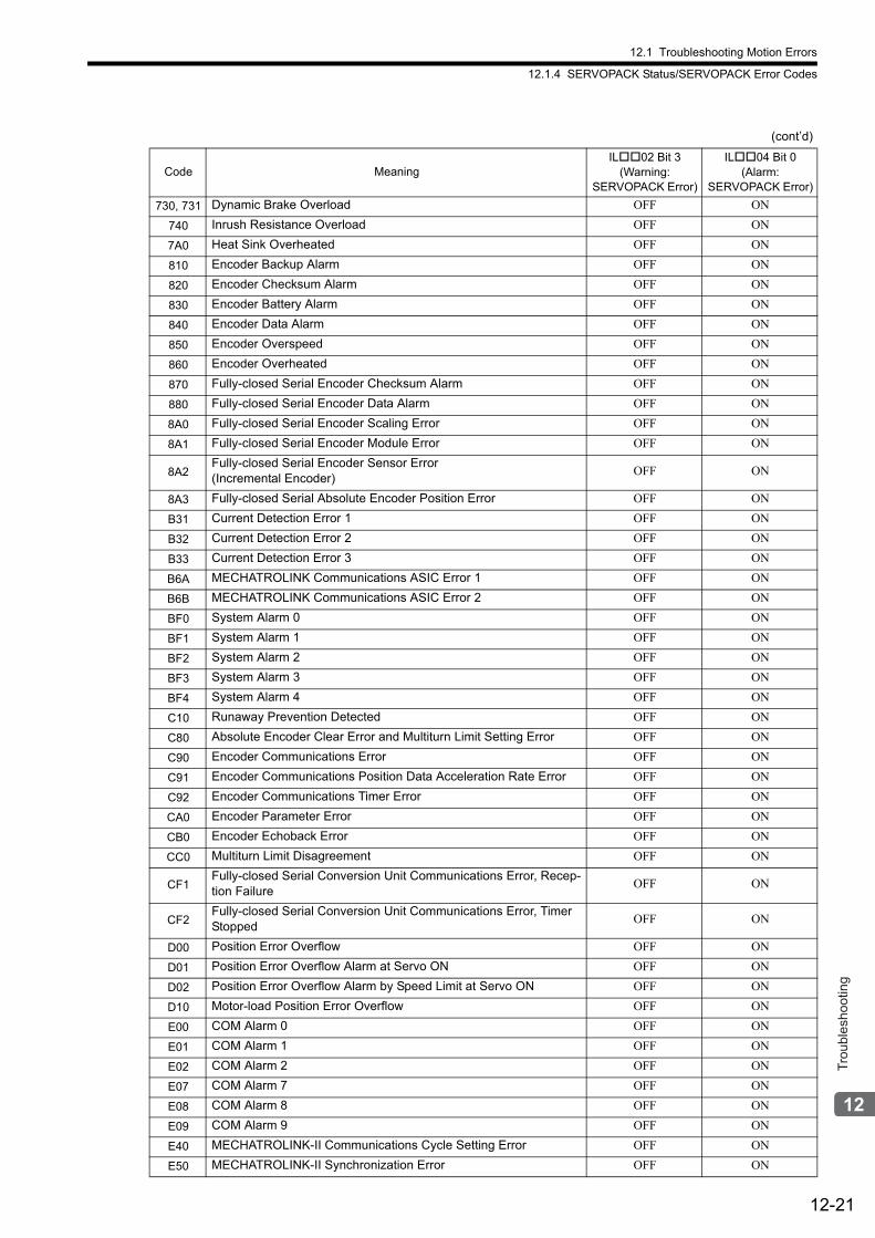
12.1 Troubleshooting Motion Errors
12.1.4 SERVOPACK Status/SERVOPACK Error Codes
12-21
Trou
bles
hoot
ing
730, 731 Dynamic Brake Overload OFF ON
740 Inrush Resistance Overload OFF ON
7A0 Heat Sink Overheated OFF ON
810 Encoder Backup Alarm OFF ON
820 Encoder Checksum Alarm OFF ON
830 Encoder Battery Alarm OFF ON
840 Encoder Data Alarm OFF ON
850 Encoder Overspeed OFF ON
860 Encoder Overheated OFF ON
870 Fully-closed Serial Encoder Checksum Alarm OFF ON
880 Fully-closed Serial Encoder Data Alarm OFF ON
8A0 Fully-closed Serial Encoder Scaling Error OFF ON
8A1 Fully-closed Serial Encoder Module Error OFF ON
8A2Fully-closed Serial Encoder Sensor Error(Incremental Encoder)
OFF ON
8A3 Fully-closed Serial Absolute Encoder Position Error OFF ON
B31 Current Detection Error 1 OFF ON
B32 Current Detection Error 2 OFF ON
B33 Current Detection Error 3 OFF ON
B6A MECHATROLINK Communications ASIC Error 1 OFF ON
B6B MECHATROLINK Communications ASIC Error 2 OFF ON
BF0 System Alarm 0 OFF ON
BF1 System Alarm 1 OFF ON
BF2 System Alarm 2 OFF ON
BF3 System Alarm 3 OFF ON
BF4 System Alarm 4 OFF ON
C10 Runaway Prevention Detected OFF ON
C80 Absolute Encoder Clear Error and Multiturn Limit Setting Error OFF ON
C90 Encoder Communications Error OFF ON
C91 Encoder Communications Position Data Acceleration Rate Error OFF ON
C92 Encoder Communications Timer Error OFF ON
CA0 Encoder Parameter Error OFF ON
CB0 Encoder Echoback Error OFF ON
CC0 Multiturn Limit Disagreement OFF ON
CF1Fully-closed Serial Conversion Unit Communications Error, Recep-tion Failure
OFF ON
CF2Fully-closed Serial Conversion Unit Communications Error, Timer Stopped
OFF ON
D00 Position Error Overflow OFF ON
D01 Position Error Overflow Alarm at Servo ON OFF ON
D02 Position Error Overflow Alarm by Speed Limit at Servo ON OFF ON
D10 Motor-load Position Error Overflow OFF ON
E00 COM Alarm 0 OFF ON
E01 COM Alarm 1 OFF ON
E02 COM Alarm 2 OFF ON
E07 COM Alarm 7 OFF ON
E08 COM Alarm 8 OFF ON
E09 COM Alarm 9 OFF ON
E40 MECHATROLINK-II Communications Cycle Setting Error OFF ON
E50 MECHATROLINK-II Synchronization Error OFF ON
(cont’d)
Code MeaningIL02 Bit 3
(Warning:SERVOPACK Error)
IL04 Bit 0(Alarm:
SERVOPACK Error)
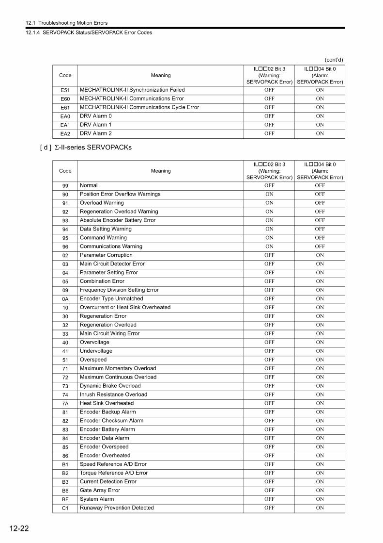
12.1 Troubleshooting Motion Errors
12.1.4 SERVOPACK Status/SERVOPACK Error Codes
12-22
[ d ] Σ-II-series SERVOPACKs
E51 MECHATROLINK-II Synchronization Failed OFF ON
E60 MECHATROLINK-II Communications Error OFF ON
E61 MECHATROLINK-II Communications Cycle Error OFF ON
EA0 DRV Alarm 0 OFF ON
EA1 DRV Alarm 1 OFF ON
EA2 DRV Alarm 2 OFF ON
Code MeaningIL02 Bit 3
(Warning:SERVOPACK Error)
IL04 Bit 0(Alarm:
SERVOPACK Error)
99 Normal OFF OFF
90 Position Error Overflow Warnings ON OFF
91 Overload Warning ON OFF
92 Regeneration Overload Warning ON OFF
93 Absolute Encoder Battery Error ON OFF
94 Data Setting Warning ON OFF
95 Command Warning ON OFF
96 Communications Warning ON OFF
02 Parameter Corruption OFF ON
03 Main Circuit Detector Error OFF ON
04 Parameter Setting Error OFF ON
05 Combination Error OFF ON
09 Frequency Division Setting Error OFF ON
0A Encoder Type Unmatched OFF ON
10 Overcurrent or Heat Sink Overheated OFF ON
30 Regeneration Error OFF ON
32 Regeneration Overload OFF ON
33 Main Circuit Wiring Error OFF ON
40 Overvoltage OFF ON
41 Undervoltage OFF ON
51 Overspeed OFF ON
71 Maximum Momentary Overload OFF ON
72 Maximum Continuous Overload OFF ON
73 Dynamic Brake Overload OFF ON
74 Inrush Resistance Overload OFF ON
7A Heat Sink Overheated OFF ON
81 Encoder Backup Alarm OFF ON
82 Encoder Checksum Alarm OFF ON
83 Encoder Battery Alarm OFF ON
84 Encoder Data Alarm OFF ON
85 Encoder Overspeed OFF ON
86 Encoder Overheated OFF ON
B1 Speed Reference A/D Error OFF ON
B2 Torque Reference A/D Error OFF ON
B3 Current Detection Error OFF ON
B6 Gate Array Error OFF ON
BF System Alarm OFF ON
C1 Runaway Prevention Detected OFF ON
(cont’d)
Code MeaningIL02 Bit 3
(Warning:SERVOPACK Error)
IL04 Bit 0(Alarm:
SERVOPACK Error)
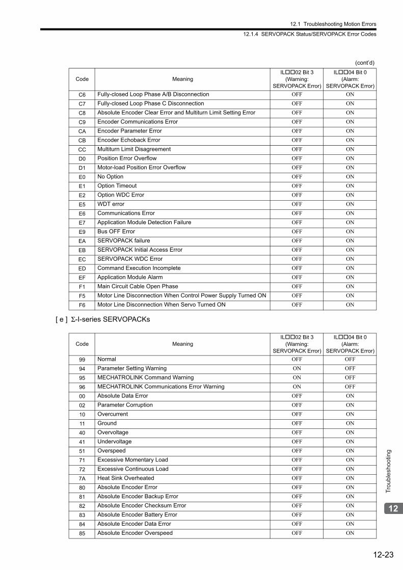
12.1 Troubleshooting Motion Errors
12.1.4 SERVOPACK Status/SERVOPACK Error Codes
12-23
Trou
bles
hoot
ing
[ e ] Σ-I-series SERVOPACKs
C6 Fully-closed Loop Phase A/B Disconnection OFF ON
C7 Fully-closed Loop Phase C Disconnection OFF ON
C8 Absolute Encoder Clear Error and Multiturn Limit Setting Error OFF ON
C9 Encoder Communications Error OFF ON
CA Encoder Parameter Error OFF ON
CB Encoder Echoback Error OFF ON
CC Multiturn Limit Disagreement OFF ON
D0 Position Error Overflow OFF ON
D1 Motor-load Position Error Overflow OFF ON
E0 No Option OFF ON
E1 Option Timeout OFF ON
E2 Option WDC Error OFF ON
E5 WDT error OFF ON
E6 Communications Error OFF ON
E7 Application Module Detection Failure OFF ON
E9 Bus OFF Error OFF ON
EA SERVOPACK failure OFF ON
EB SERVOPACK Initial Access Error OFF ON
EC SERVOPACK WDC Error OFF ON
ED Command Execution Incomplete OFF ON
EF Application Module Alarm OFF ON
F1 Main Circuit Cable Open Phase OFF ON
F5 Motor Line Disconnection When Control Power Supply Turned ON OFF ON
F6 Motor Line Disconnection When Servo Turned ON OFF ON
Code MeaningIL02 Bit 3
(Warning:SERVOPACK Error)
IL04 Bit 0(Alarm:
SERVOPACK Error)
99 Normal OFF OFF
94 Parameter Setting Warning ON OFF
95 MECHATROLINK Command Warning ON OFF
96 MECHATROLINK Communications Error Warning ON OFF
00 Absolute Data Error OFF ON
02 Parameter Corruption OFF ON
10 Overcurrent OFF ON
11 Ground OFF ON
40 Overvoltage OFF ON
41 Undervoltage OFF ON
51 Overspeed OFF ON
71 Excessive Momentary Load OFF ON
72 Excessive Continuous Load OFF ON
7A Heat Sink Overheated OFF ON
80 Absolute Encoder Error OFF ON
81 Absolute Encoder Backup Error OFF ON
82 Absolute Encoder Checksum Error OFF ON
83 Absolute Encoder Battery Error OFF ON
84 Absolute Encoder Data Error OFF ON
85 Absolute Encoder Overspeed OFF ON
(cont’d)
Code MeaningIL02 Bit 3
(Warning:SERVOPACK Error)
IL04 Bit 0(Alarm:
SERVOPACK Error)
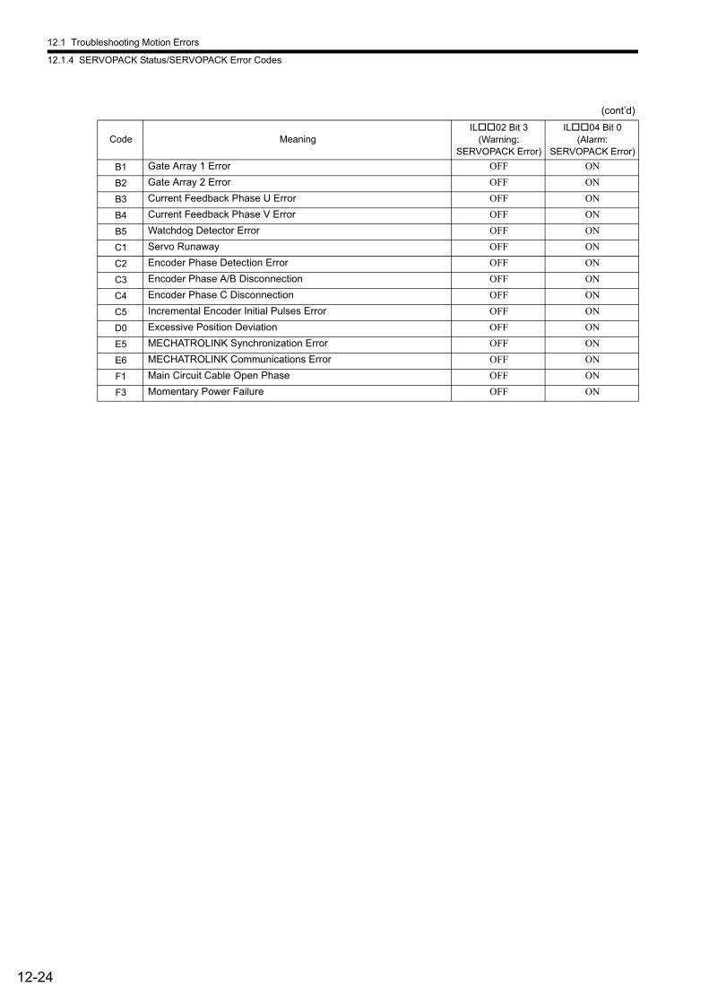
12.1 Troubleshooting Motion Errors
12.1.4 SERVOPACK Status/SERVOPACK Error Codes
12-24
B1 Gate Array 1 Error OFF ON
B2 Gate Array 2 Error OFF ON
B3 Current Feedback Phase U Error OFF ON
B4 Current Feedback Phase V Error OFF ON
B5 Watchdog Detector Error OFF ON
C1 Servo Runaway OFF ON
C2 Encoder Phase Detection Error OFF ON
C3 Encoder Phase A/B Disconnection OFF ON
C4 Encoder Phase C Disconnection OFF ON
C5 Incremental Encoder Initial Pulses Error OFF ON
D0 Excessive Position Deviation OFF ON
E5 MECHATROLINK Synchronization Error OFF ON
E6 MECHATROLINK Communications Error OFF ON
F1 Main Circuit Cable Open Phase OFF ON
F3 Momentary Power Failure OFF ON
(cont’d)
Code MeaningIL02 Bit 3
(Warning:SERVOPACK Error)
IL04 Bit 0(Alarm:
SERVOPACK Error)
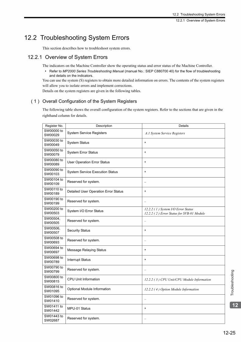
12.2 Troubleshooting System Errors
12.2.1 Overview of System Errors
12-25
Trou
bles
hoot
ing
12.2 Troubleshooting System Errors
This section describes how to troubleshoot system errors.
12.2.1 Overview of System Errors
The indicators on the Machine Controller show the operating status and error status of the Machine Controller.
Refer to MP2000 Series Troubleshooting Manual (manual No.: SIEP C880700 40) for the flow of troubleshooting and details on the indicators.
You can use the system (S) registers to obtain more detailed information on errors. The contents of the system registers will allow you to isolate errors and implement corrections.Details on the system registers are given in the following tables.
( 1 ) Overall Configuration of the System Registers
The following table shows the overall configuration of the system registers. Refer to the sections that are given in the
righthand column for details.
Register No. Description Details
SW00000 toSW00029
System Service Registers A.1 System Service Registers
SW00030 toSW00049
System Status *
SW00050 toSW00079
System Error Status *
SW00080 toSW00089
User Operation Error Status *
SW00090 toSW00103
System Service Execution Status *
SW00104 toSW00109
Reserved for system. –
SW00110 toSW00189
Detailed User Operation Error Status *
SW00190 toSW00199
Reserved for system. –
SW00200 toSW00503
System I/O Error Status 12.2.2 ( 1 ) System I/O Error Status12.2.2 ( 2 ) Error Status for SVB-01 Module
SW00504,SW00505
Reserved for system. –
SW00506,SW00507
Security Status *
SW00508 toSW00693
Reserved for system. –
SW00694 toSW00697
Message Relaying Status *
SW00698 toSW00789
Interrupt Status *
SW00790 toSW00799
Reserved for system. –
SW00800 toSW00815
CPU Unit Information 12.2.2 ( 3 ) CPU Unit/CPU Module Information
SW00816 toSW01095
Optional Module Information 12.2.2 ( 4 ) Option Module Information
SW01096 toSW01410
Reserved for system. –
SW01411 toSW01442
MPU-01 Status *
SW01443 toSW02687
Reserved for system. –
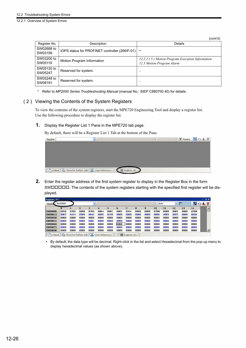
12.2 Troubleshooting System Errors
12.2.1 Overview of System Errors
12-26
* Refer to MP2000 Series Troubleshooting Manual (manual No.: SIEP C880700 40) for details.
( 2 ) Viewing the Contents of the System Registers
To view the contents of the system registers, start the MPE720 Engineering Tool and display a register list.Use the following procedure to display the register list.
1. Display the Register List 1 Pane in the MPE720 tab page.
By default, there will be a Register List 1 Tab at the bottom of the Pane.
2. Enter the register address of the first system register to display in the Register Box in the form
SW. The contents of the system registers starting with the specified first register will be dis-played.
By default, the data type will be decimal. Right-click in the list and select Hexadecimal from the pop-up menu to display hexadecimal values (as shown above).
SW02688 toSW03199
IOPS status for PROFINET controller (266IF-01) *
SW03200 toSW05119
Motion Program Information 12.2.2 ( 5 ) Motion Program Execution Information12.3 Motion Program Alarm
SW05120 toSW05247
Reserved for system. –
SW05248 toSW08191
Reserved for system. –
(cont’d)
Register No. Description Details
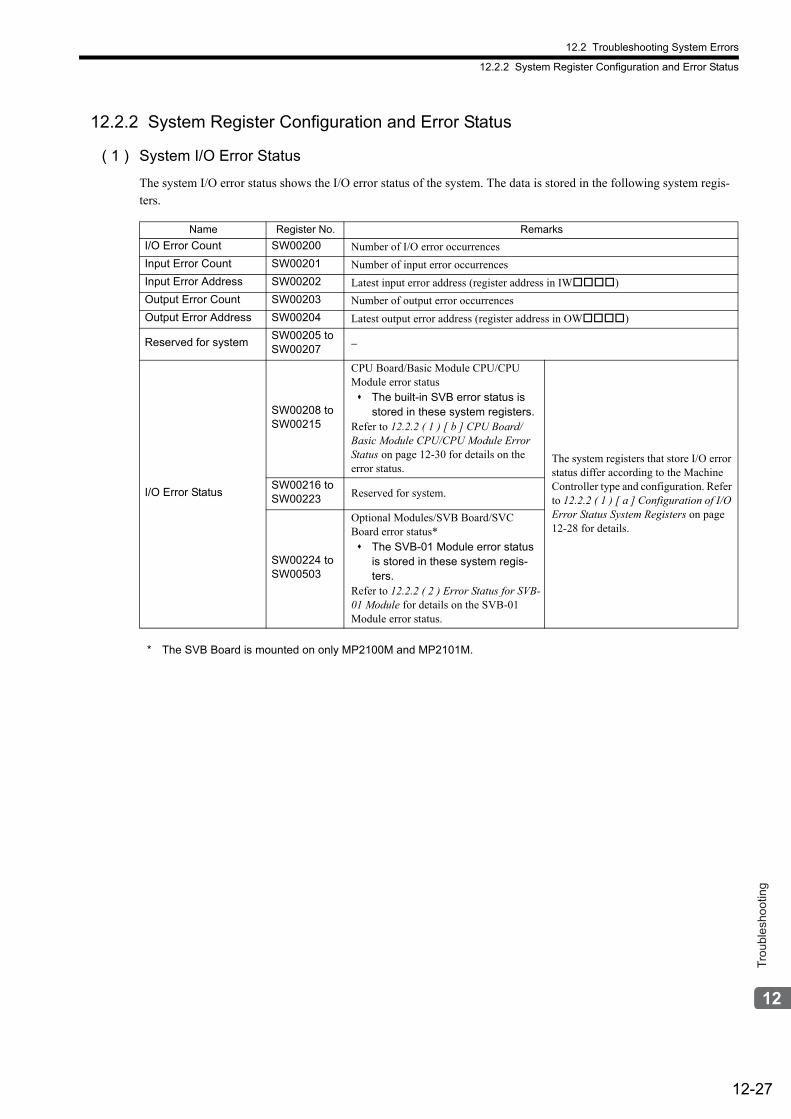
12.2 Troubleshooting System Errors
12.2.2 System Register Configuration and Error Status
12-27
Trou
bles
hoot
ing
12.2.2 System Register Configuration and Error Status
( 1 ) System I/O Error Status
The system I/O error status shows the I/O error status of the system. The data is stored in the following system regis-ters.
* The SVB Board is mounted on only MP2100M and MP2101M.
Name Register No. Remarks
I/O Error Count SW00200 Number of I/O error occurrences
Input Error Count SW00201 Number of input error occurrences
Input Error Address SW00202 Latest input error address (register address in IW)
Output Error Count SW00203 Number of output error occurrences
Output Error Address SW00204 Latest output error address (register address in OW)
Reserved for systemSW00205 toSW00207 −
I/O Error Status
SW00208 toSW00215
CPU Board/Basic Module CPU/CPU Module error status The built-in SVB error status is
stored in these system registers.Refer to 12.2.2 ( 1 ) [ b ] CPU Board/Basic Module CPU/CPU Module Error Status on page 12-30 for details on the error status.
The system registers that store I/O error status differ according to the Machine Controller type and configuration. Refer to 12.2.2 ( 1 ) [ a ] Configuration of I/O Error Status System Registers on page 12-28 for details.
SW00216 toSW00223 Reserved for system.
SW00224 toSW00503
Optional Modules/SVB Board/SVC Board error status* The SVB-01 Module error status
is stored in these system regis-ters.
Refer to 12.2.2 ( 2 ) Error Status for SVB-01 Module for details on the SVB-01 Module error status.
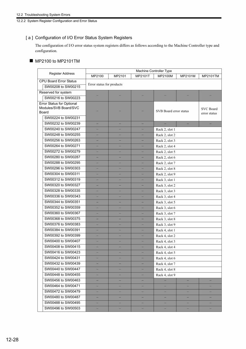
12.2 Troubleshooting System Errors
12.2.2 System Register Configuration and Error Status
12-28
[ a ] Configuration of I/O Error Status System Registers
The configuration of I/O error status system registers differs as follows according to the Machine Controller type and configuration.
MP2100 to MP2101TM
Register AddressMachine Controller Type
MP2100 MP2101 MP2101T MP2100M MP2101M MP2101TM
CPU Board Error StatusError status for products
SW00208 to SW00215
Reserved for system– – – – – –
SW00216 to SW00223
Error Status for Optional Modules/SVB Board/SVC Board – – – SVB Board error status
SVC Board error status
SW00224 to SW00231
SW00232 to SW00239 – – – – – –
SW00240 to SW00247 – – – Rack 2, slot 1
SW00248 to SW00255 – – – Rack 2, slot 2
SW00256 to SW00263 – – – Rack 2, slot 3
SW00264 to SW00271 – – – Rack 2, slot 4
SW00272 to SW00279 – – – Rack 2, slot 5
SW00280 to SW00287 – – – Rack 2, slot 6
SW00288 to SW00295 – – – Rack 2, slot 7
SW00296 to SW00303 – – – Rack 2, slot 8
SW00304 to SW00311 – – – Rack 2, slot 9
SW00312 to SW00319 – – – Rack 3, slot 1
SW00320 to SW00327 – – – Rack 3, slot 2
SW00328 to SW00335 – – – Rack 3, slot 3
SW00336 to SW00343 – – – Rack 3, slot 4
SW00344 to SW00351 – – – Rack 3, slot 5
SW00352 to SW00359 – – – Rack 3, slot 6
SW00360 to SW00367 – – – Rack 3, slot 7
SW00368 to SW00375 – – – Rack 3, slot 8
SW00376 to SW00383 – – – Rack 3, slot 9
SW00384 to SW00391 – – – Rack 4, slot 1
SW00392 to SW00399 – – – Rack 4, slot 2
SW00400 to SW00407 – – – Rack 4, slot 3
SW00408 to SW00415 – – – Rack 4, slot 4
SW00416 to SW00423 – – – Rack 4, slot 5
SW00424 to SW00431 – – – Rack 4, slot 6
SW00432 to SW00439 – – – Rack 4, slot 7
SW00440 to SW00447 – – – Rack 4, slot 8
SW00448 to SW00455 – – – Rack 4, slot 9
SW00456 to SW00463 – – – – – –
SW00464 to SW00471 – – – – – –
SW00472 to SW00479 – – – – – –
SW00480 to SW00487 – – – – – –
SW00488 to SW00495 – – – – – –
SW00496 to SW00503 – – – – – –
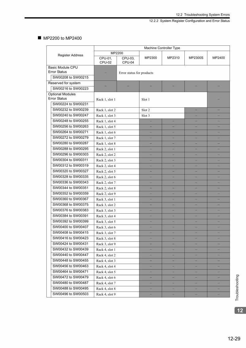
12.2 Troubleshooting System Errors
12.2.2 System Register Configuration and Error Status
12-29
Trou
bles
hoot
ing
MP2200 to MP2400
Register Address
Machine Controller Type
MP2200
MP2300 MP2310 MP2300S MP2400CPU-01, CPU-02
CPU-03, CPU-04
Basic Module CPUError Status – Error status for products
SW00208 to SW00215
Reserved for system– – – – – –
SW00216 to SW00223
Optional Modules Error Status Rack 1, slot 1 Slot 1 –
SW00224 to SW00231
SW00232 to SW00239 Rack 1, slot 2 Slot 2 – –
SW00240 to SW00247 Rack 1, slot 3 Slot 3 – –
SW00248 to SW00255 Rack 1, slot 4 – – – –
SW00256 to SW00263 Rack 1, slot 5 – – – –
SW00264 to SW00271 Rack 1, slot 6 – – – –
SW00272 to SW00279 Rack 1, slot 7 – – – –
SW00280 to SW00287 Rack 1, slot 8 – – – –
SW00288 to SW00295 Rack 2, slot 1 – – – –
SW00296 to SW00303 Rack 2, slot 2 – – – –
SW00304 to SW00311 Rack 2, slot 3 – – – –
SW00312 to SW00319 Rack 2, slot 4 – – – –
SW00320 to SW00327 Rack 2, slot 5 – – – –
SW00328 to SW00335 Rack 2, slot 6 – – – –
SW00336 to SW00343 Rack 2, slot 7 – – – –
SW00344 to SW00351 Rack 2, slot 8 – – – –
SW00352 to SW00359 Rack 2, slot 9 – – – –
SW00360 to SW00367 Rack 3, slot 1 – – – –
SW00368 to SW00375 Rack 3, slot 2 – – – –
SW00376 to SW00383 Rack 3, slot 3 – – – –
SW00384 to SW00391 Rack 3, slot 4 – – – –
SW00392 to SW00399 Rack 3, slot 5 – – – –
SW00400 to SW00407 Rack 3, slot 6 – – – –
SW00408 to SW00415 Rack 3, slot 7 – – – –
SW00416 to SW00423 Rack 3, slot 8 – – – –
SW00424 to SW00431 Rack 3, slot 9 – – – –
SW00432 to SW00439 Rack 4, slot 1 – – – –
SW00440 to SW00447 Rack 4, slot 2 – – – –
SW00448 to SW00455 Rack 4, slot 3 – – – –
SW00456 to SW00463 Rack 4, slot 4 – – – –
SW00464 to SW00471 Rack 4, slot 5 – – – –
SW00472 to SW00479 Rack 4, slot 6 – – – –
SW00480 to SW00487 Rack 4, slot 7 – – – –
SW00488 to SW00495 Rack 4, slot 8 – – – –
SW00496 to SW00503 Rack 4, slot 9 – – – –
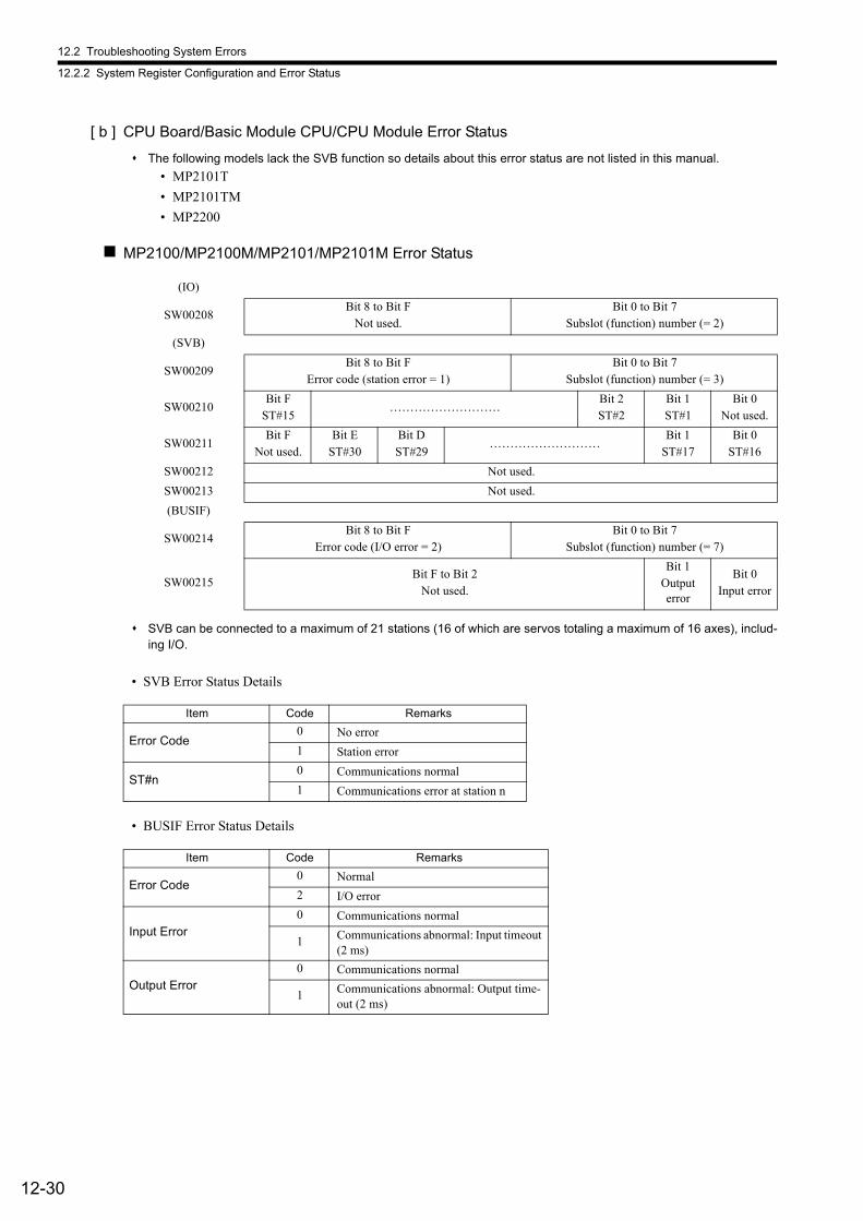
12.2 Troubleshooting System Errors
12.2.2 System Register Configuration and Error Status
12-30
[ b ] CPU Board/Basic Module CPU/CPU Module Error Status
The following models lack the SVB function so details about this error status are not listed in this manual.
• MP2101T
• MP2101TM
• MP2200
MP2100/MP2100M/MP2101/MP2101M Error Status
SVB can be connected to a maximum of 21 stations (16 of which are servos totaling a maximum of 16 axes), includ-ing I/O.
• SVB Error Status Details
• BUSIF Error Status Details
(IO)
SW00208Bit 8 to Bit F
Not used.Bit 0 to Bit 7
Subslot (function) number (= 2)
(SVB)
SW00209Bit 8 to Bit F
Error code (station error = 1)Bit 0 to Bit 7
Subslot (function) number (= 3)
SW00210Bit F
ST#15………………………
Bit 2ST#2
Bit 1ST#1
Bit 0Not used.
SW00211Bit F
Not used.Bit E
ST#30Bit DST#29
………………………Bit 1
ST#17Bit 0
ST#16
SW00212 Not used.
SW00213 Not used.
(BUSIF)
SW00214Bit 8 to Bit F
Error code (I/O error = 2)Bit 0 to Bit 7
Subslot (function) number (= 7)
SW00215Bit F to Bit 2
Not used.
Bit 1Output error
Bit 0Input error
Item Code Remarks
Error Code0 No error
1 Station error
ST#n0 Communications normal
1 Communications error at station n
Item Code Remarks
Error Code0 Normal
2 I/O error
Input Error0 Communications normal
1 Communications abnormal: Input timeout (2 ms)
Output Error0 Communications normal
1 Communications abnormal: Output time-out (2 ms)

12.2 Troubleshooting System Errors
12.2.2 System Register Configuration and Error Status
12-31
Trou
bles
hoot
ing
MP2300 Error Status
SVB can be connected to a maximum of 21 stations (16 of which are servos totaling a maximum of 16 axes), includ-ing I/O.
• SVB Error Status Details
MP2300S/MP2310/MP2400 Error Status
• 218IFA Error Status Details
(IO)
SW00208Bit 8 to Bit F
Not used.Bit 0 to Bit 7
Subslot (function) number (= 2)
(SVB)
SW00209Bit 8 to Bit F
Error code (station error = 1)Bit 0 to Bit 7
Subslot (function) number (= 3)
SW00210Bit F
ST#15………………………
Bit 2ST#2
Bit 1ST#1
Bit 0Not used.
SW00211Bit F
Not used.Bit DST#30
Bit DST#29
………………………Bit 1
ST#17Bit 0
ST#16
SW00212 to SW00215
Not used.
Item Code Remarks
Error Code0 No error
1 Station error
ST#n0 Communications normal
1 Communications error at station n
(218IFA)
SW00208Bit 8 to Bit F
Error code (station error = 1)Bit 0 to Bit 7
Subslot (function) number (= 2)
SW00209Bit 2 to Bit F
Not used.Bit 1Write
Bit 0Read
SW00210Bit C to Bit F
Write transmission STBit 8 to Bit B
Reserved for system.Bit 4 to Bit 7
Read transmission STBit 0 to Bit 3
Reserved for system.
SW00211 to SW00212
Not used.
(SVB)
SW00213Bit 8 to Bit F
Error code (station error = 1)Bit 0 to Bit 7
Subslot (function) number (= 3)
SW00214Bit F
ST#15………………………
Bit 2ST#2
Bit 1ST#1
Bit 0Not used.
SW00215Bit F
Not used.Bit E
ST#30Bit DST#29
………………………Bit 1
ST#17Bit 0
ST#16
Item Code Remarks
Error Code0 Normal
1 Station error
Read/Write0 Communications normal
1 Communications error
Read/WriteTransmission ST
00 No error
04 Parameter formatting error
05 Command sequence error
06 Reset
07 Data reception error
08 Data sending error
0A Connection error
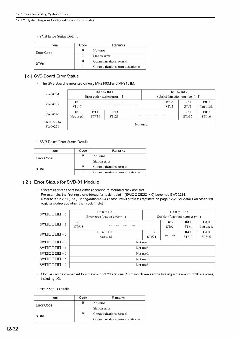
12.2 Troubleshooting System Errors
12.2.2 System Register Configuration and Error Status
12-32
• SVB Error Status Details
[ c ] SVB Board Error Status
The SVB Board is mounted on only MP2100M and MP2101M.
• SVB Board Error Status Details
( 2 ) Error Status for SVB-01 Module
System register addresses differ according to mounted rack and slot.For example, the first register address for rack 1, slot 1 (SW + 0) becomes SW00224.Refer to 12.2.2 ( 1 ) [ a ] Configuration of I/O Error Status System Registers on page 12-28 for details on other first register addresses other than rack 1, slot 1.
Module can be connected to a maximum of 21 stations (16 of which are servos totaling a maximum of 16 stations), including I/O.
• Error Status Details
Item Code Remarks
Error Code0 No error
1 Station error
ST#n0 Communications normal
1 Communications error at station n
SW00224Bit 8 to Bit F
Error code (station error = 1)Bit 0 to Bit 7
Subslot (function) number (= 1)
SW00225Bit F
ST#15………………………
Bit 2ST#2
Bit 1ST#1
Bit 0Not used.
SW00226Bit F
Not used.Bit E
ST#30Bit DST#29
………………………Bit 1
ST#17Bit 0
ST#16
SW00227 toSW00231
Not used.
Item Code Remarks
Error Code0 No error
1 Station error
ST#n0 Communications normal
1 Communications error at station n
SW + 0Bit 8 to Bit F
Error code (station error = 1)Bit 0 to Bit 7
Subslot (function) number (= 1)
SW + 1Bit F
ST#15………………………
Bit 2ST#2
Bit 1ST#1
Bit 0Not used.
SW + 2Bit 6 to Bit F
Not used.Bit 5
ST#21………
Bit 1ST#17
Bit 0ST#16
SW + 3 Not used.
SW + 4 Not used.
SW + 5 Not used.
SW + 6 Not used.
SW + 7 Not used.
Item Code Remarks
Error Code0 No error
1 Station error
ST#n0 Communications normal
1 Communications error at station n
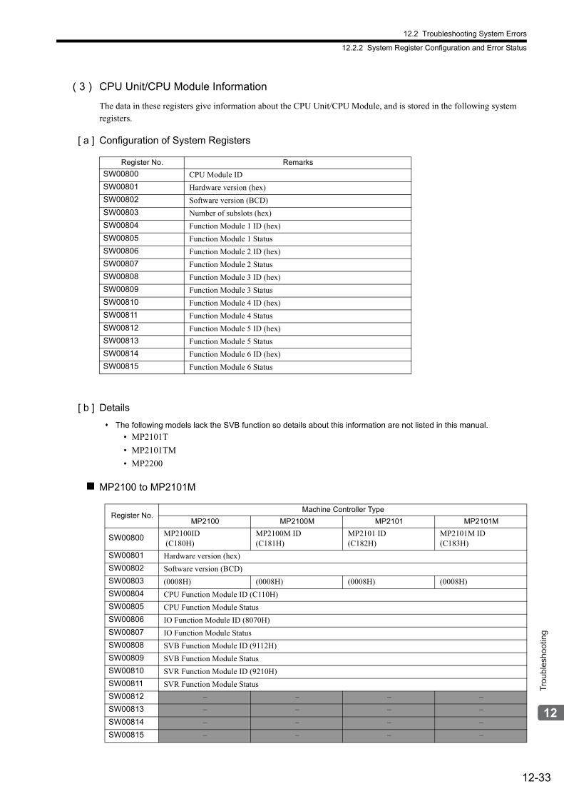
12.2 Troubleshooting System Errors
12.2.2 System Register Configuration and Error Status
12-33
Trou
bles
hoot
ing
( 3 ) CPU Unit/CPU Module Information
The data in these registers give information about the CPU Unit/CPU Module, and is stored in the following system registers.
[ a ] Configuration of System Registers
[ b ] Details
The following models lack the SVB function so details about this information are not listed in this manual.
• MP2101T
• MP2101TM
• MP2200
MP2100 to MP2101M
Register No. Remarks
SW00800 CPU Module ID
SW00801 Hardware version (hex)
SW00802 Software version (BCD)
SW00803 Number of subslots (hex)
SW00804 Function Module 1 ID (hex)
SW00805 Function Module 1 Status
SW00806 Function Module 2 ID (hex)
SW00807 Function Module 2 Status
SW00808 Function Module 3 ID (hex)
SW00809 Function Module 3 Status
SW00810 Function Module 4 ID (hex)
SW00811 Function Module 4 Status
SW00812 Function Module 5 ID (hex)
SW00813 Function Module 5 Status
SW00814 Function Module 6 ID (hex)
SW00815 Function Module 6 Status
Register No.Machine Controller Type
MP2100 MP2100M MP2101 MP2101M
SW00800 MP2100ID (C180H)
MP2100M ID (C181H)
MP2101 ID (C182H)
MP2101M ID (C183H)
SW00801 Hardware version (hex)
SW00802 Software version (BCD)
SW00803 (0008H) (0008H) (0008H) (0008H)
SW00804 CPU Function Module ID (C110H)
SW00805 CPU Function Module Status
SW00806 IO Function Module ID (8070H)
SW00807 IO Function Module Status
SW00808 SVB Function Module ID (9112H)
SW00809 SVB Function Module Status
SW00810 SVR Function Module ID (9210H)
SW00811 SVR Function Module Status
SW00812 – – – –
SW00813 – – – –
SW00814 – – – –
SW00815 – – – –
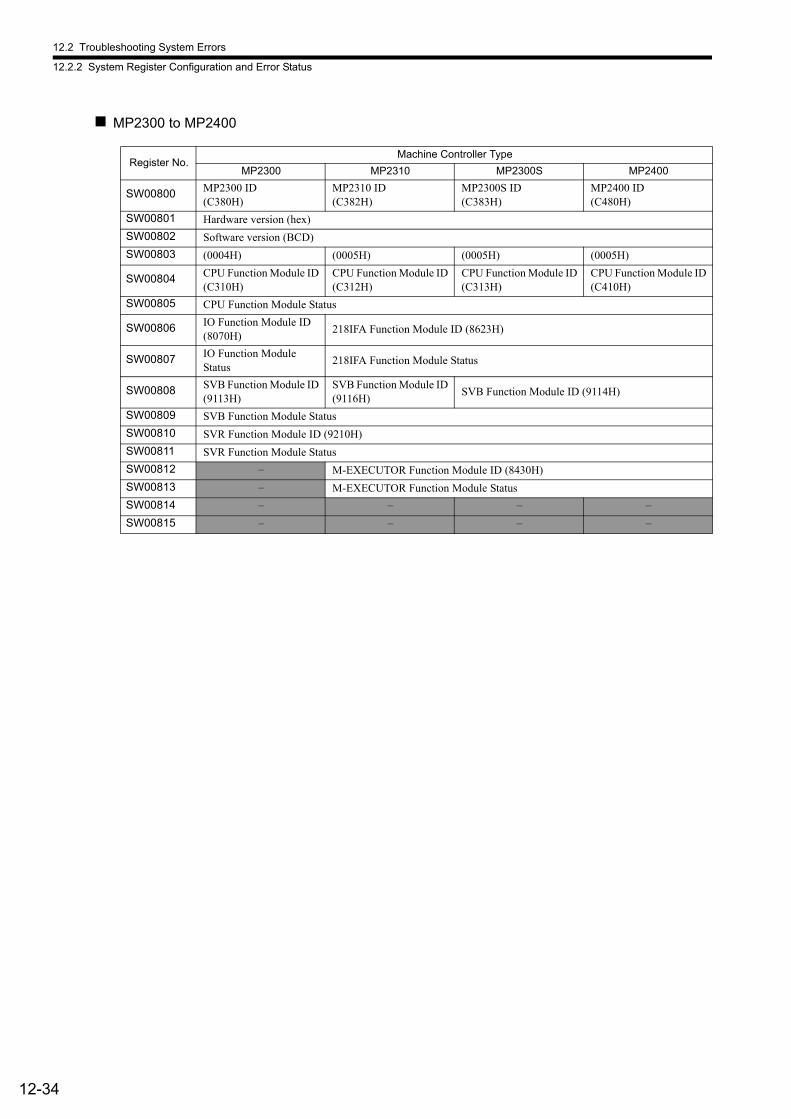
12.2 Troubleshooting System Errors
12.2.2 System Register Configuration and Error Status
12-34
MP2300 to MP2400
Register No.Machine Controller Type
MP2300 MP2310 MP2300S MP2400
SW00800 MP2300 ID (C380H)
MP2310 ID (C382H)
MP2300S ID (C383H)
MP2400 ID (C480H)
SW00801 Hardware version (hex)
SW00802 Software version (BCD)
SW00803 (0004H) (0005H) (0005H) (0005H)
SW00804 CPU Function Module ID (C310H)
CPU Function Module ID (C312H)
CPU Function Module ID (C313H)
CPU Function Module ID (C410H)
SW00805 CPU Function Module Status
SW00806 IO Function Module ID (8070H)
218IFA Function Module ID (8623H)
SW00807 IO Function Module Status
218IFA Function Module Status
SW00808 SVB Function Module ID (9113H)
SVB Function Module ID (9116H)
SVB Function Module ID (9114H)
SW00809 SVB Function Module Status
SW00810 SVR Function Module ID (9210H)
SW00811 SVR Function Module Status
SW00812 – M-EXECUTOR Function Module ID (8430H)
SW00813 – M-EXECUTOR Function Module Status
SW00814 – – – –
SW00815 – – – –
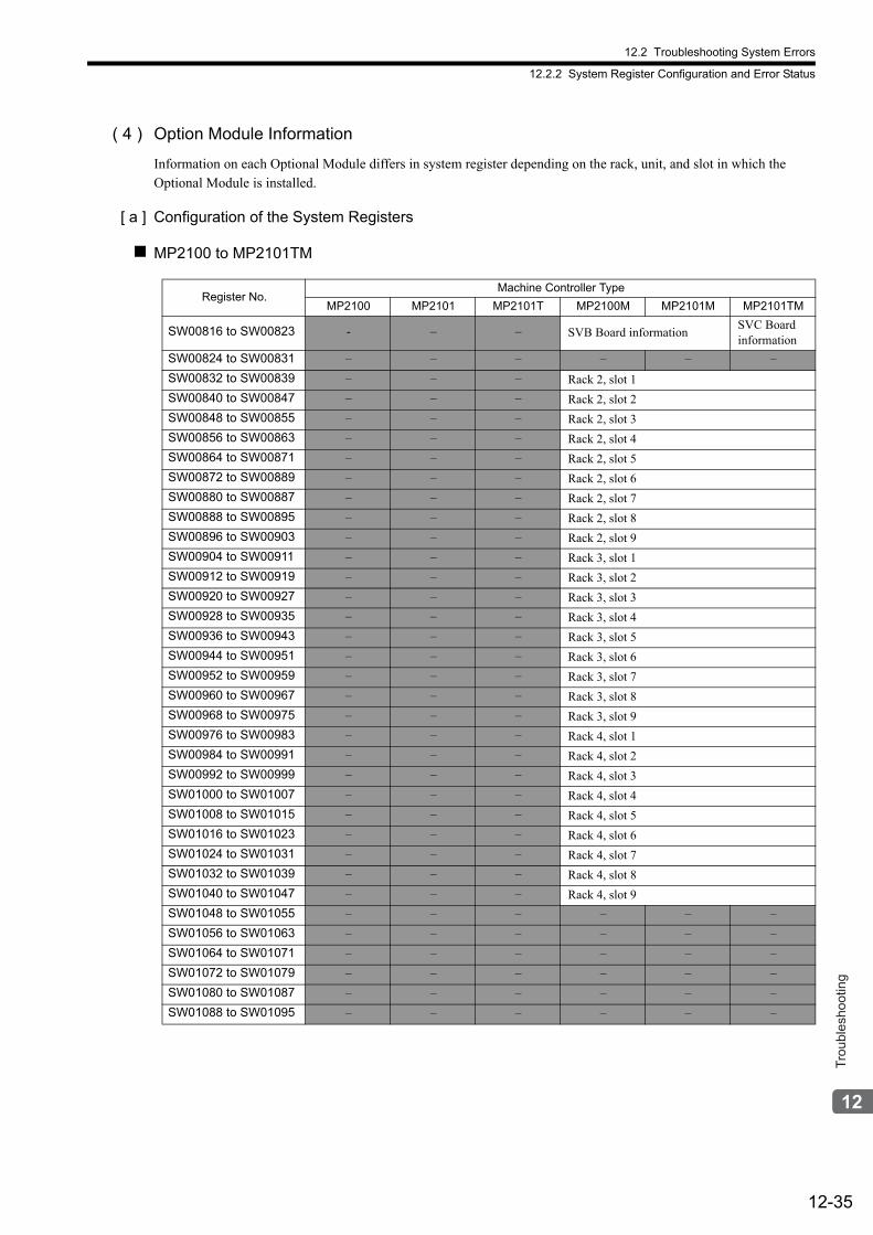
12.2 Troubleshooting System Errors
12.2.2 System Register Configuration and Error Status
12-35
Trou
bles
hoot
ing
( 4 ) Option Module Information
Information on each Optional Module differs in system register depending on the rack, unit, and slot in which the Optional Module is installed.
[ a ] Configuration of the System Registers
MP2100 to MP2101TM
Register No.Machine Controller Type
MP2100 MP2101 MP2101T MP2100M MP2101M MP2101TM
SW00816 to SW00823 - – – SVB Board informationSVC Board information
SW00824 to SW00831 – – – – – –
SW00832 to SW00839 – – – Rack 2, slot 1
SW00840 to SW00847 – – – Rack 2, slot 2
SW00848 to SW00855 – – – Rack 2, slot 3
SW00856 to SW00863 – – – Rack 2, slot 4
SW00864 to SW00871 – – – Rack 2, slot 5
SW00872 to SW00889 – – – Rack 2, slot 6
SW00880 to SW00887 – – – Rack 2, slot 7
SW00888 to SW00895 – – – Rack 2, slot 8
SW00896 to SW00903 – – – Rack 2, slot 9
SW00904 to SW00911 – – – Rack 3, slot 1
SW00912 to SW00919 – – – Rack 3, slot 2
SW00920 to SW00927 – – – Rack 3, slot 3
SW00928 to SW00935 – – – Rack 3, slot 4
SW00936 to SW00943 – – – Rack 3, slot 5
SW00944 to SW00951 – – – Rack 3, slot 6
SW00952 to SW00959 – – – Rack 3, slot 7
SW00960 to SW00967 – – – Rack 3, slot 8
SW00968 to SW00975 – – – Rack 3, slot 9
SW00976 to SW00983 – – – Rack 4, slot 1
SW00984 to SW00991 – – – Rack 4, slot 2
SW00992 to SW00999 – – – Rack 4, slot 3
SW01000 to SW01007 – – – Rack 4, slot 4
SW01008 to SW01015 – – – Rack 4, slot 5
SW01016 to SW01023 – – – Rack 4, slot 6
SW01024 to SW01031 – – – Rack 4, slot 7
SW01032 to SW01039 – – – Rack 4, slot 8
SW01040 to SW01047 – – – Rack 4, slot 9
SW01048 to SW01055 – – – – – –
SW01056 to SW01063 – – – – – –
SW01064 to SW01071 – – – – – –
SW01072 to SW01079 – – – – – –
SW01080 to SW01087 – – – – – –
SW01088 to SW01095 – – – – – –
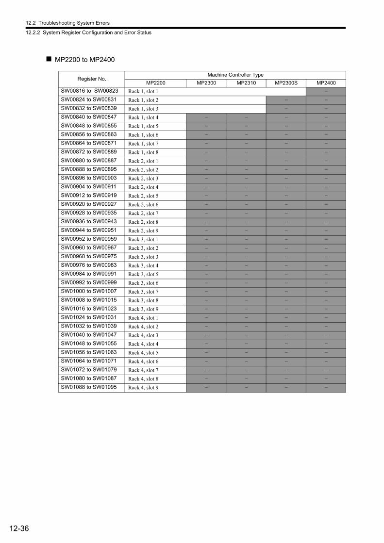
12.2 Troubleshooting System Errors
12.2.2 System Register Configuration and Error Status
12-36
MP2200 to MP2400
Register No.Machine Controller Type
MP2200 MP2300 MP2310 MP2300S MP2400
SW00816 to SW00823 Rack 1, slot 1 –
SW00824 to SW00831 Rack 1, slot 2 – –
SW00832 to SW00839 Rack 1, slot 3 – –
SW00840 to SW00847 Rack 1, slot 4 – – – –
SW00848 to SW00855 Rack 1, slot 5 – – – –
SW00856 to SW00863 Rack 1, slot 6 – – – –
SW00864 to SW00871 Rack 1, slot 7 – – – –
SW00872 to SW00889 Rack 1, slot 8 – – – –
SW00880 to SW00887 Rack 2, slot 1 – – – –
SW00888 to SW00895 Rack 2, slot 2 – – – –
SW00896 to SW00903 Rack 2, slot 3 – – – –
SW00904 to SW00911 Rack 2, slot 4 – – – –
SW00912 to SW00919 Rack 2, slot 5 – – – –
SW00920 to SW00927 Rack 2, slot 6 – – – –
SW00928 to SW00935 Rack 2, slot 7 – – – –
SW00936 to SW00943 Rack 2, slot 8 – – – –
SW00944 to SW00951 Rack 2, slot 9 – – – –
SW00952 to SW00959 Rack 3, slot 1 – – – –
SW00960 to SW00967 Rack 3, slot 2 – – – –
SW00968 to SW00975 Rack 3, slot 3 – – – –
SW00976 to SW00983 Rack 3, slot 4 – – – –
SW00984 to SW00991 Rack 3, slot 5 – – – –
SW00992 to SW00999 Rack 3, slot 6 – – – –
SW01000 to SW01007 Rack 3, slot 7 – – – –
SW01008 to SW01015 Rack 3, slot 8 – – – –
SW01016 to SW01023 Rack 3, slot 9 – – – –
SW01024 to SW01031 Rack 4, slot 1 – – – –
SW01032 to SW01039 Rack 4, slot 2 – – – –
SW01040 to SW01047 Rack 4, slot 3 – – – –
SW01048 to SW01055 Rack 4, slot 4 – – – –
SW01056 to SW01063 Rack 4, slot 5 – – – –
SW01064 to SW01071 Rack 4, slot 6 – – – –
SW01072 to SW01079 Rack 4, slot 7 – – – –
SW01080 to SW01087 Rack 4, slot 8 – – – –
SW01088 to SW01095 Rack 4, slot 9 – – – –
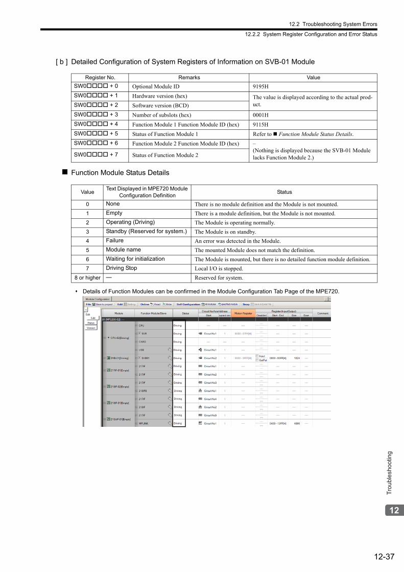
12.2 Troubleshooting System Errors
12.2.2 System Register Configuration and Error Status
12-37
Trou
bles
hoot
ing
[ b ] Detailed Configuration of System Registers of Information on SVB-01 Module
Function Module Status Details
Details of Function Modules can be confirmed in the Module Configuration Tab Page of the MPE720.
Register No. Remarks Value
SW0 + 0 Optional Module ID 9195H
SW0 + 1 Hardware version (hex) The value is displayed according to the actual prod-uct.SW0 + 2 Software version (BCD)
SW0 + 3 Number of subslots (hex) 0001H
SW0 + 4 Function Module 1 Function Module ID (hex) 9115H
SW0 + 5 Status of Function Module 1 Refer to Function Module Status Details.
SW0 + 6 Function Module 2 Function Module ID (hex) –(Nothing is displayed because the SVB-01 Module lacks Function Module 2.)SW0 + 7 Status of Function Module 2
ValueText Displayed in MPE720 Module
Configuration DefinitionStatus
0 None There is no module definition and the Module is not mounted.
1 Empty There is a module definition, but the Module is not mounted.
2 Operating (Driving) The Module is operating normally.
3 Standby (Reserved for system.) The Module is on standby.
4 Failure An error was detected in the Module.
5 Module name The mounted Module does not match the definition.
6 Waiting for initialization The Module is mounted, but there is no detailed function module definition.
7 Driving Stop Local I/O is stopped.
8 or higher — Reserved for system.

12.2 Troubleshooting System Errors
12.2.2 System Register Configuration and Error Status
12-38
( 5 ) Motion Program Execution Information
This section gives the system register configuration of and details on the motion program execution information.
[ a ] Configuration of System Registers
The data in these registers give the execution status of the motion programs, and is stored in the following system reg-isters.
Register No. Name Reference
SW03200 Number of Currently Executing Program for Work 1 −SW03201 Number of Currently Executing Program for Work 2 −SW03202 Number of Currently Executing Program for Work 3 −SW03203 Number of Currently Executing Program for Work 4 −SW03204 Number of Currently Executing Program for Work 5 −SW03205 Number of Currently Executing Program for Work 6 −SW03206 Number of Currently Executing Program for Work 7 −SW03207 Number of Currently Executing Program for Work 8 −SW03208 Number of Currently Executing Program for Work 9 −SW03209 Number of Currently Executing Program for Work 10 −SW03210 Number of Currently Executing Program for Work 11 −SW03211 Number of Currently Executing Program for Work 12 −SW03212 Number of Currently Executing Program for Work 13 −SW03213 Number of Currently Executing Program for Work 14 −SW03214 Number of Currently Executing Program for Work 15 −SW03215 Number of Currently Executing Program for Work 16 −SW03216 to SW03231 Reserved for system. −
SW03232 to SW03263 Program Running Bits 12.2.2 ( 5 ) [ b ] Details
SW03264 to SW03321 Work 1 Program Information
System Work Numbers 1 to 8
SW03322 to SW03379 Work 2 Program Information
SW03380 to SW03437 Work 3 Program Information
SW03438 to SW03495 Work 4 Program Information
SW03496 to SW03553 Work 5 Program Information
SW03554 to SW03611 Work 6 Program Information
SW03612 to SW03669 Work 7 Program Information
SW03670 to SW03727 Work 8 Program Information
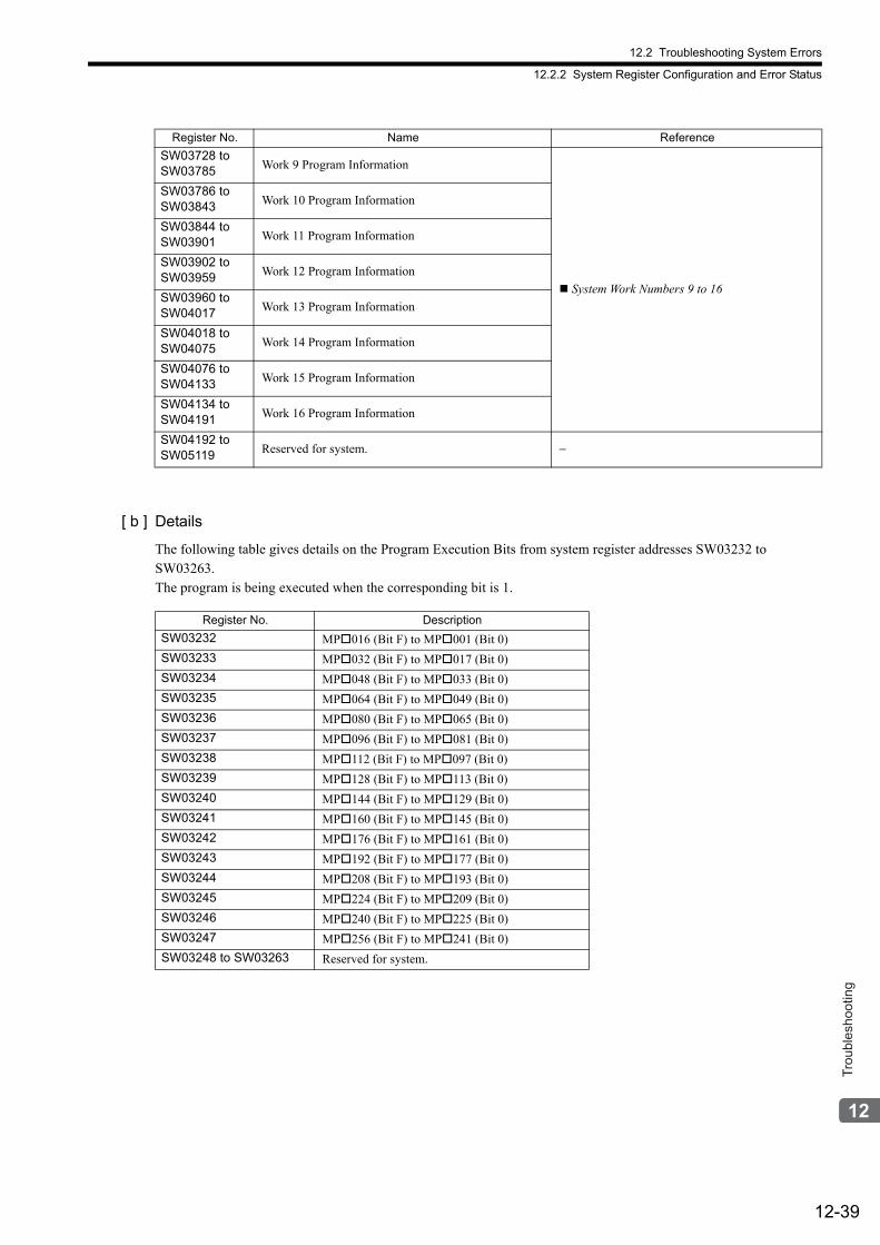
12.2 Troubleshooting System Errors
12.2.2 System Register Configuration and Error Status
12-39
Trou
bles
hoot
ing
[ b ] Details
The following table gives details on the Program Execution Bits from system register addresses SW03232 to SW03263.The program is being executed when the corresponding bit is 1.
SW03728 to SW03785 Work 9 Program Information
System Work Numbers 9 to 16
SW03786 to SW03843 Work 10 Program Information
SW03844 to SW03901 Work 11 Program Information
SW03902 to SW03959 Work 12 Program Information
SW03960 to SW04017 Work 13 Program Information
SW04018 to SW04075 Work 14 Program Information
SW04076 to SW04133 Work 15 Program Information
SW04134 to SW04191 Work 16 Program Information
SW04192 to SW05119 Reserved for system. −
Register No. Name Reference
Register No. Description
SW03232 MP016 (Bit F) to MP001 (Bit 0)
SW03233 MP032 (Bit F) to MP017 (Bit 0)
SW03234 MP048 (Bit F) to MP033 (Bit 0)
SW03235 MP064 (Bit F) to MP049 (Bit 0)
SW03236 MP080 (Bit F) to MP065 (Bit 0)
SW03237 MP096 (Bit F) to MP081 (Bit 0)
SW03238 MP112 (Bit F) to MP097 (Bit 0)
SW03239 MP128 (Bit F) to MP113 (Bit 0)
SW03240 MP144 (Bit F) to MP129 (Bit 0)
SW03241 MP160 (Bit F) to MP145 (Bit 0)
SW03242 MP176 (Bit F) to MP161 (Bit 0)
SW03243 MP192 (Bit F) to MP177 (Bit 0)
SW03244 MP208 (Bit F) to MP193 (Bit 0)
SW03245 MP224 (Bit F) to MP209 (Bit 0)
SW03246 MP240 (Bit F) to MP225 (Bit 0)
SW03247 MP256 (Bit F) to MP241 (Bit 0)
SW03248 to SW03263 Reserved for system.
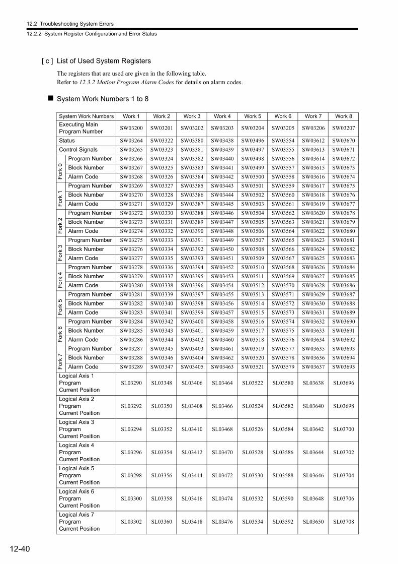
12.2 Troubleshooting System Errors
12.2.2 System Register Configuration and Error Status
12-40
[ c ] List of Used System Registers
The registers that are used are given in the following table.Refer to 12.3.2 Motion Program Alarm Codes for details on alarm codes.
System Work Numbers 1 to 8
System Work Numbers Work 1 Work 2 Work 3 Work 4 Work 5 Work 6 Work 7 Work 8
Executing Main Program Number
SW03200 SW03201 SW03202 SW03203 SW03204 SW03205 SW03206 SW03207
Status SW03264 SW03322 SW03380 SW03438 SW03496 SW03554 SW03612 SW03670
Control Signals SW03265 SW03323 SW03381 SW03439 SW03497 SW03555 SW03613 SW03671
Fo
rk 0
Program Number SW03266 SW03324 SW03382 SW03440 SW03498 SW03556 SW03614 SW03672
Block Number SW03267 SW03325 SW03383 SW03441 SW03499 SW03557 SW03615 SW03673
Alarm Code SW03268 SW03326 SW03384 SW03442 SW03500 SW03558 SW03616 SW03674
Fo
rk 1
Program Number SW03269 SW03327 SW03385 SW03443 SW03501 SW03559 SW03617 SW03675
Block Number SW03270 SW03328 SW03386 SW03444 SW03502 SW03560 SW03618 SW03676
Alarm Code SW03271 SW03329 SW03387 SW03445 SW03503 SW03561 SW03619 SW03677
Fo
rk 2
Program Number SW03272 SW03330 SW03388 SW03446 SW03504 SW03562 SW03620 SW03678
Block Number SW03273 SW03331 SW03389 SW03447 SW03505 SW03563 SW03621 SW03679
Alarm Code SW03274 SW03332 SW03390 SW03448 SW03506 SW03564 SW03622 SW03680
Fo
rk 3
Program Number SW03275 SW03333 SW03391 SW03449 SW03507 SW03565 SW03623 SW03681
Block Number SW03276 SW03334 SW03392 SW03450 SW03508 SW03566 SW03624 SW03682
Alarm Code SW03277 SW03335 SW03393 SW03451 SW03509 SW03567 SW03625 SW03683
Fo
rk 4
Program Number SW03278 SW03336 SW03394 SW03452 SW03510 SW03568 SW03626 SW03684
Block Number SW03279 SW03337 SW03395 SW03453 SW03511 SW03569 SW03627 SW03685
Alarm Code SW03280 SW03338 SW03396 SW03454 SW03512 SW03570 SW03628 SW03686
Fo
rk 5
Program Number SW03281 SW03339 SW03397 SW03455 SW03513 SW03571 SW03629 SW03687
Block Number SW03282 SW03340 SW03398 SW03456 SW03514 SW03572 SW03630 SW03688
Alarm Code SW03283 SW03341 SW03399 SW03457 SW03515 SW03573 SW03631 SW03689
Fo
rk 6
Program Number SW03284 SW03342 SW03400 SW03458 SW03516 SW03574 SW03632 SW03690
Block Number SW03285 SW03343 SW03401 SW03459 SW03517 SW03575 SW03633 SW03691
Alarm Code SW03286 SW03344 SW03402 SW03460 SW03518 SW03576 SW03634 SW03692
Fo
rk 7
Program Number SW03287 SW03345 SW03403 SW03461 SW03519 SW03577 SW03635 SW03693
Block Number SW03288 SW03346 SW03404 SW03462 SW03520 SW03578 SW03636 SW03694
Alarm Code SW03289 SW03347 SW03405 SW03463 SW03521 SW03579 SW03637 SW03695
Logical Axis 1 Program Current Position
SL03290 SL03348 SL03406 SL03464 SL03522 SL03580 SL03638 SL03696
Logical Axis 2 Program Current Position
SL03292 SL03350 SL03408 SL03466 SL03524 SL03582 SL03640 SL03698
Logical Axis 3 Program Current Position
SL03294 SL03352 SL03410 SL03468 SL03526 SL03584 SL03642 SL03700
Logical Axis 4 Program Current Position
SL03296 SL03354 SL03412 SL03470 SL03528 SL03586 SL03644 SL03702
Logical Axis 5 Program Current Position
SL03298 SL03356 SL03414 SL03472 SL03530 SL03588 SL03646 SL03704
Logical Axis 6 Program Current Position
SL03300 SL03358 SL03416 SL03474 SL03532 SL03590 SL03648 SL03706
Logical Axis 7 Program Current Position
SL03302 SL03360 SL03418 SL03476 SL03534 SL03592 SL03650 SL03708
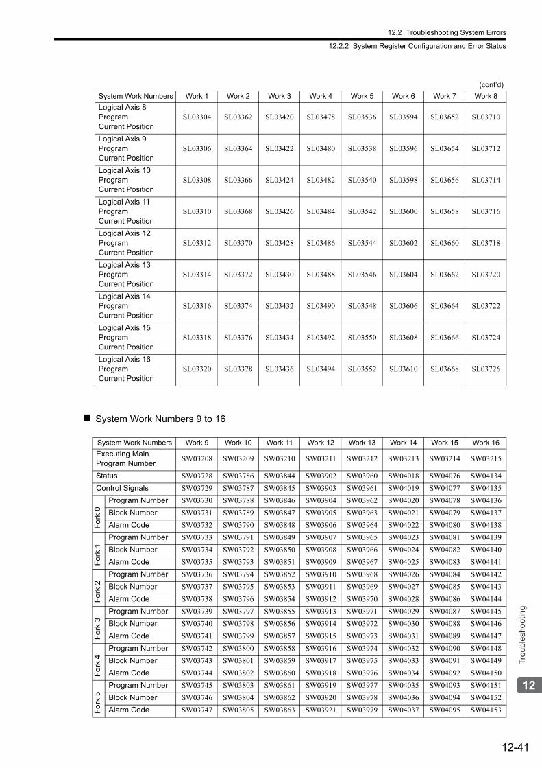
12.2 Troubleshooting System Errors
12.2.2 System Register Configuration and Error Status
12-41
Trou
bles
hoot
ing
System Work Numbers 9 to 16
Logical Axis 8 Program Current Position
SL03304 SL03362 SL03420 SL03478 SL03536 SL03594 SL03652 SL03710
Logical Axis 9 Program Current Position
SL03306 SL03364 SL03422 SL03480 SL03538 SL03596 SL03654 SL03712
Logical Axis 10 Program Current Position
SL03308 SL03366 SL03424 SL03482 SL03540 SL03598 SL03656 SL03714
Logical Axis 11 Program Current Position
SL03310 SL03368 SL03426 SL03484 SL03542 SL03600 SL03658 SL03716
Logical Axis 12 Program Current Position
SL03312 SL03370 SL03428 SL03486 SL03544 SL03602 SL03660 SL03718
Logical Axis 13 Program Current Position
SL03314 SL03372 SL03430 SL03488 SL03546 SL03604 SL03662 SL03720
Logical Axis 14 Program Current Position
SL03316 SL03374 SL03432 SL03490 SL03548 SL03606 SL03664 SL03722
Logical Axis 15 Program Current Position
SL03318 SL03376 SL03434 SL03492 SL03550 SL03608 SL03666 SL03724
Logical Axis 16 Program Current Position
SL03320 SL03378 SL03436 SL03494 SL03552 SL03610 SL03668 SL03726
(cont’d)
System Work Numbers Work 1 Work 2 Work 3 Work 4 Work 5 Work 6 Work 7 Work 8
System Work Numbers Work 9 Work 10 Work 11 Work 12 Work 13 Work 14 Work 15 Work 16
Executing MainProgram Number
SW03208 SW03209 SW03210 SW03211 SW03212 SW03213 SW03214 SW03215
Status SW03728 SW03786 SW03844 SW03902 SW03960 SW04018 SW04076 SW04134
Control Signals SW03729 SW03787 SW03845 SW03903 SW03961 SW04019 SW04077 SW04135
Fo
rk 0
Program Number SW03730 SW03788 SW03846 SW03904 SW03962 SW04020 SW04078 SW04136
Block Number SW03731 SW03789 SW03847 SW03905 SW03963 SW04021 SW04079 SW04137
Alarm Code SW03732 SW03790 SW03848 SW03906 SW03964 SW04022 SW04080 SW04138
Fo
rk 1
Program Number SW03733 SW03791 SW03849 SW03907 SW03965 SW04023 SW04081 SW04139
Block Number SW03734 SW03792 SW03850 SW03908 SW03966 SW04024 SW04082 SW04140
Alarm Code SW03735 SW03793 SW03851 SW03909 SW03967 SW04025 SW04083 SW04141
Fo
rk 2
Program Number SW03736 SW03794 SW03852 SW03910 SW03968 SW04026 SW04084 SW04142
Block Number SW03737 SW03795 SW03853 SW03911 SW03969 SW04027 SW04085 SW04143
Alarm Code SW03738 SW03796 SW03854 SW03912 SW03970 SW04028 SW04086 SW04144
Fo
rk 3
Program Number SW03739 SW03797 SW03855 SW03913 SW03971 SW04029 SW04087 SW04145
Block Number SW03740 SW03798 SW03856 SW03914 SW03972 SW04030 SW04088 SW04146
Alarm Code SW03741 SW03799 SW03857 SW03915 SW03973 SW04031 SW04089 SW04147
Fo
rk 4
Program Number SW03742 SW03800 SW03858 SW03916 SW03974 SW04032 SW04090 SW04148
Block Number SW03743 SW03801 SW03859 SW03917 SW03975 SW04033 SW04091 SW04149
Alarm Code SW03744 SW03802 SW03860 SW03918 SW03976 SW04034 SW04092 SW04150
Fo
rk 5
Program Number SW03745 SW03803 SW03861 SW03919 SW03977 SW04035 SW04093 SW04151
Block Number SW03746 SW03804 SW03862 SW03920 SW03978 SW04036 SW04094 SW04152
Alarm Code SW03747 SW03805 SW03863 SW03921 SW03979 SW04037 SW04095 SW04153
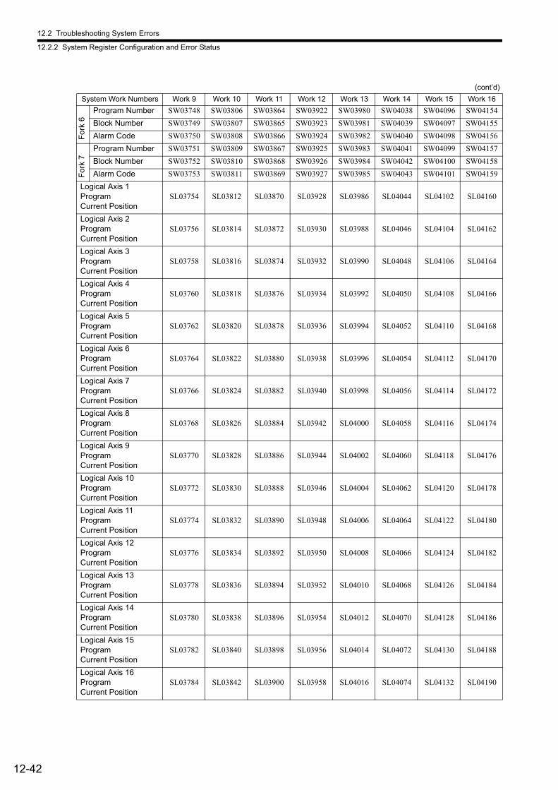
12.2 Troubleshooting System Errors
12.2.2 System Register Configuration and Error Status
12-42
Fo
rk 6
Program Number SW03748 SW03806 SW03864 SW03922 SW03980 SW04038 SW04096 SW04154
Block Number SW03749 SW03807 SW03865 SW03923 SW03981 SW04039 SW04097 SW04155
Alarm Code SW03750 SW03808 SW03866 SW03924 SW03982 SW04040 SW04098 SW04156
Fo
rk 7
Program Number SW03751 SW03809 SW03867 SW03925 SW03983 SW04041 SW04099 SW04157
Block Number SW03752 SW03810 SW03868 SW03926 SW03984 SW04042 SW04100 SW04158
Alarm Code SW03753 SW03811 SW03869 SW03927 SW03985 SW04043 SW04101 SW04159
Logical Axis 1 Program Current Position
SL03754 SL03812 SL03870 SL03928 SL03986 SL04044 SL04102 SL04160
Logical Axis 2 Program Current Position
SL03756 SL03814 SL03872 SL03930 SL03988 SL04046 SL04104 SL04162
Logical Axis 3 Program Current Position
SL03758 SL03816 SL03874 SL03932 SL03990 SL04048 SL04106 SL04164
Logical Axis 4 Program Current Position
SL03760 SL03818 SL03876 SL03934 SL03992 SL04050 SL04108 SL04166
Logical Axis 5 Program Current Position
SL03762 SL03820 SL03878 SL03936 SL03994 SL04052 SL04110 SL04168
Logical Axis 6 Program Current Position
SL03764 SL03822 SL03880 SL03938 SL03996 SL04054 SL04112 SL04170
Logical Axis 7 Program Current Position
SL03766 SL03824 SL03882 SL03940 SL03998 SL04056 SL04114 SL04172
Logical Axis 8 Program Current Position
SL03768 SL03826 SL03884 SL03942 SL04000 SL04058 SL04116 SL04174
Logical Axis 9 Program Current Position
SL03770 SL03828 SL03886 SL03944 SL04002 SL04060 SL04118 SL04176
Logical Axis 10 Program Current Position
SL03772 SL03830 SL03888 SL03946 SL04004 SL04062 SL04120 SL04178
Logical Axis 11 Program Current Position
SL03774 SL03832 SL03890 SL03948 SL04006 SL04064 SL04122 SL04180
Logical Axis 12 Program Current Position
SL03776 SL03834 SL03892 SL03950 SL04008 SL04066 SL04124 SL04182
Logical Axis 13 Program Current Position
SL03778 SL03836 SL03894 SL03952 SL04010 SL04068 SL04126 SL04184
Logical Axis 14 Program Current Position
SL03780 SL03838 SL03896 SL03954 SL04012 SL04070 SL04128 SL04186
Logical Axis 15 Program Current Position
SL03782 SL03840 SL03898 SL03956 SL04014 SL04072 SL04130 SL04188
Logical Axis 16 Program Current Position
SL03784 SL03842 SL03900 SL03958 SL04016 SL04074 SL04132 SL04190
(cont’d)
System Work Numbers Work 9 Work 10 Work 11 Work 12 Work 13 Work 14 Work 15 Work 16
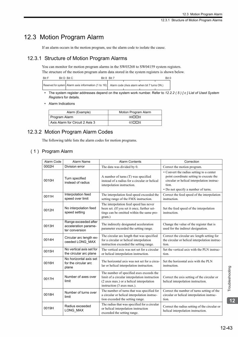
12.3 Motion Program Alarm
12.3.1 Structure of Motion Program Alarms
12-43
Trou
bles
hoot
ing
12.3 Motion Program Alarm
If an alarm occurs in the motion program, use the alarm code to isolate the cause.
12.3.1 Structure of Motion Program Alarms
You can monitor for motion program alarms in the SW03268 to SW04159 system registers.The structure of the motion program alarm data stored in the system registers is shown below.
The system register addresses depend on the system work number. Refer to 12.2.2 ( 5 ) [ c ] List of Used System Registers for details.
Alarm Indications
12.3.2 Motion Program Alarm Codes
The following table lists the alarm codes for motion programs.
( 1 ) Program Alarm
Alarm (Example) Motion Program Alarm
Program Alarm 00H
Axis Alarm for Circuit 2 Axis 3 03H
Alarm axis information (1 to 16)
Bit F Bit C Bit 8 Bit 7 Bit 0
Alarm code (Axis alarm when bit 7 turns ON.)
Bit D
Reserved for system
Alarm Code Alarm Name Alarm Contents Correction
0002H Division error The data was divided by 0. Correct the motion program.
0010HTurn specified instead of radius
A number of turns (T) was specified instead of a radius for a circular or helical interpolation instruction.
• Convert the radius setting to a center point coordinate setting to execute the circular or helical interpolation instruc-tion.
• Do not specify a number of turns.
0011HInterpolation feed speed over limit
The interpolation feed speed exceeded the setting range of the FMX instruction.
Correct the feed speed of the interpolation instruction.
0012HNo interpolation feed speed setting
The interpolation feed speed has never been set. (If you set it once, further set-tings can be omitted within the same pro-gram.)
Set the feed speed of the interpolation instruction.
0013HRange exceeded after acceleration parame-ter conversion
The indirectly designated acceleration parameter exceeded the setting range.
Change the value of the register that is used for the indirect designation.
0014HCircular arc length ex-ceeded LONG_MAX
The circular arc length that was specified for a circular or helical interpolation instruction exceeded the setting range.
Correct the circular arc length setting for the circular or helical interpolation instruc-tion.
0015HNo vertical axis set for the circular arc plane
The vertical axis was not set for a circular or helical interpolation instruction.
Set the vertical axis with the PLN instruc-tion.
0016HNo horizontal axis set for the circular arc plane
The horizontal axis was not set for a circu-lar or helical interpolation instruction.
Set the horizontal axis with the PLN instruction.
0017HNumber of axes over limit
The number of specified axes exceeds the limit of a circular interpolation instruction (2 axes max.) or a helical interpolation instruction (3 axes max.).
Correct the axis setting of the circular or helical interpolation instruction.
0018HNumber of turns over limit
The number of turns that was specified for a circular or helical interpolation instruc-tion exceeded the setting range.
Correct the number of turns setting of the circular or helical interpolation instruc-tion.
0019HRadius exceeded LONG_MAX
The radius that was specified for a circular or helical interpolation instruction exceeded the setting range.
Correct the radius setting of the circular or helical interpolation instruction.
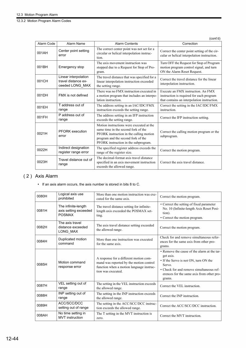
12.3 Motion Program Alarm
12.3.2 Motion Program Alarm Codes
12-44
( 2 ) Axis Alarm
If an axis alarm occurs, the axis number is stored in bits 8 to C.
001AHCenter point setting error
The correct center point was not set for a circular or helical interpolation instruc-tion.
Correct the center point setting of the cir-cular or helical interpolation instruction.
001BH Emergency stopThe axis movement instruction was stopped due to a Request for Stop of Pro-gram.
Turn OFF the Request for Stop of Program motion program control signal, and turn ON the Alarm Reset Request.
001CHLinear interpolation travel distance ex-ceeded LONG_MAX
The travel distance that was specified for a linear interpolation instruction exceeded the setting range.
Correct the travel distance for the linear interpolation instruction.
001DH FMX is not definedThere was no FMX instruction executed in a motion program that includes an interpo-lation instruction.
Execute an FMX instruction. An FMX instruction is required for each program that contains an interpolation instruction.
001EHT address out of range
The address setting in an IAC/IDC/FMX instruction exceeds the setting range.
Correct the setting in the IAC/IDC/FMX instruction.
001FHP address out of range
The address setting in an IFP instruction exceeds the setting range.
Correct the IFP instruction setting.
0021HPFORK execution error
Motion instructions were executed at the same time in the second fork of the PFORK instruction in the calling motion program and the second fork of the PFORK instruction in the subprogram.
Correct the calling motion program or the subprogram.
0022HIndirect designation register range error
The specified register address exceeds the range of the register size.
Correct the motion program.
0023HTravel distance out of range
The decimal-format axis travel distance specified in an axis movement instruction exceeds the allowed range.
Correct the axis travel distance.
(cont’d)
Alarm Code Alarm Name Alarm Contents Correction
0080HLogical axis use prohibited
More than one motion instruction was exe-cuted for the same axis.
Correct the motion program.
0081HThe infinite-length axis setting exceeded POSMAX
The travel distance setting for infinite-length axis exceeded the POSMAX set-ting.
• Correct the setting of fixed parameter No. 10 (Infinite-length Axis Reset Posi-tion).
• Correct the motion program.
0082HThe axis travel distance exceeded LONG_MAX
The axis travel distance setting exceeded the allowed range.
Correct the motion program.
0084HDuplicated motion command
More than one instruction was executed for the same axis.
Check for and remove simultaneous refer-ences for the same axis from other pro-grams.
0085HMotion command response error
A response for a different motion com-mand was reported by the motion control function when a motion language instruc-tion was executed.
• Remove the cause of the alarm at the tar-get axis.
• If the Servo is not ON, turn ON the Servo.
• Check for and remove simultaneous ref-erences for the same axis from other pro-grams.
0087HVEL setting out of range
The setting in the VEL instruction exceeds the allowed range.
Correct the VEL instruction.
0088HINP setting out of range
The setting in the INP instruction exceeds the allowed range.
Correct the INP instruction.
0089HACC/SCC/DCC setting out of range
The setting in the ACC/SCC/DCC instruc-tion exceeds the allowed range.
Correct the ACC/SCC/DCC instruction.
008AHNo time setting in MVT instruction
The T setting in the MVT instruction is zero.
Correct the MVT instruction.
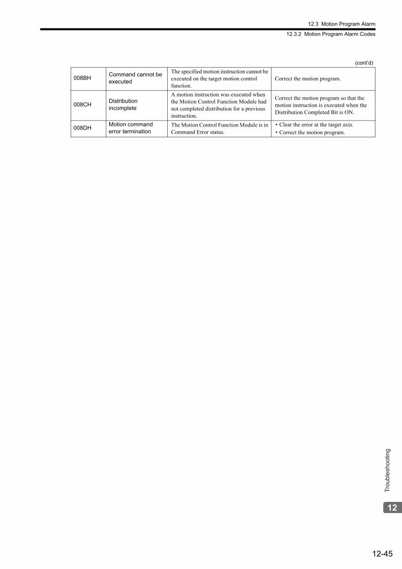
12.3 Motion Program Alarm
12.3.2 Motion Program Alarm Codes
12-45
Trou
bles
hoot
ing
008BHCommand cannot be executed
The specified motion instruction cannot be executed on the target motion control function.
Correct the motion program.
008CHDistribution incomplete
A motion instruction was executed when the Motion Control Function Module had not completed distribution for a previous instruction.
Correct the motion program so that the motion instruction is executed when the Distribution Completed Bit is ON.
008DHMotion command error termination
The Motion Control Function Module is in Command Error status.
• Clear the error at the target axis.• Correct the motion program.
(cont’d)
A-1
App
endi
ces
Appendices
A System Registers Lists - - - - - - - - - - - - - - - - - - - - - - - - - - - - - - - - - - - - - -A-3
A.1 System Service Registers- - - - - - - - - - - - - - - - - - - - - - - - - - - - - - - - - - - - - - - - - - - - - A-3
A.2 Scan Execution Status and Calendar- - - - - - - - - - - - - - - - - - - - - - - - - - - - - - - - - - - - - A-5
A.3 Program Software Numbers and Remaining Program Memory Capacity Name - - - - - - - A-5
B Settings When Connecting MECHATROLINK Compatible I/O Modules, MYVIS, and MP940 - - - - - - - - - - - - - - - - - - - - - - - - - - - - - - - - - - - - - - - -A-6
B.1 Settings in the Module Configuration Definition Window - - - - - - - - - - - - - - - - - - - - - - - A-6
B.2 I/O Register Configuration - - - - - - - - - - - - - - - - - - - - - - - - - - - - - - - - - - - - - - - - - - - - A-7
C Initializing the Absolute Encoder- - - - - - - - - - - - - - - - - - - - - - - - - - - - - - -A-12
C.1 Σ-III, Σ-V, and Σ-7 Series SERVOPACKs- - - - - - - - - - - - - - - - - - - - - - - - - - - - - - - - - A-12
C.2 Σ-II SERVOPACK - - - - - - - - - - - - - - - - - - - - - - - - - - - - - - - - - - - - - - - - - - - - - - - - - A-14
C.3 Σ-I SERVOPACK- - - - - - - - - - - - - - - - - - - - - - - - - - - - - - - - - - - - - - - - - - - - - - - - - - A-16
D Setting the Multiturn Limit - - - - - - - - - - - - - - - - - - - - - - - - - - - - - - - - - - -A-18
D.1 Overview - - - - - - - - - - - - - - - - - - - - - - - - - - - - - - - - - - - - - - - - - - - - - - - - - - - - - - - A-18
D.2 Setting Method - - - - - - - - - - - - - - - - - - - - - - - - - - - - - - - - - - - - - - - - - - - - - - - - - - - A-18
E Fixed Parameter Setting According to Encoder Type and Axis Type - - - - -A-20
F SVB Module Throughput - - - - - - - - - - - - - - - - - - - - - - - - - - - - - - - - - - - -A-22
F.1 For Servos and Inverters- - - - - - - - - - - - - - - - - - - - - - - - - - - - - - - - - - - - - - - - - - - - - A-22
F.2 For I/Os- - - - - - - - - - - - - - - - - - - - - - - - - - - - - - - - - - - - - - - - - - - - - - - - - - - - - - - - - A-22
G Settings when Connecting MECHATROLINK-II Compatible Stepping Motor Drivers - - - - - - - - - - - - - - - - - - - - - - - - - - - - - - - - - - - - - - - - - - - -A-23
G.1 Required Firmware and Engineering Tool Versions - - - - - - - - - - - - - - - - - - - - - - - - - - A-23
G.2 Applicable Communication Methods and Cycles- - - - - - - - - - - - - - - - - - - - - - - - - - - - A-23
G.3 Module Configuration Definition - - - - - - - - - - - - - - - - - - - - - - - - - - - - - - - - - - - - - - - A-24
G.4 Restrictions on the Use of Motion Parameters - - - - - - - - - - - - - - - - - - - - - - - - - - - - - A-25
G.5 Availability When Using M-II Steppers - - - - - - - - - - - - - - - - - - - - - - - - - - - - - - - - - - - A-27
G.6 Motion Command Details - - - - - - - - - - - - - - - - - - - - - - - - - - - - - - - - - - - - - - - - - - - - A-29
G.7 Automatic Parameter Updating Function - - - - - - - - - - - - - - - - - - - - - - - - - - - - - - - - - A-30
G.8 Writing and Changing Parameters During Self-configuration - - - - - - - - - - - - - - - - - - - A-31
G.9 M-II Stepper Parameters - - - - - - - - - - - - - - - - - - - - - - - - - - - - - - - - - - - - - - - - - - - - A-32

A-2
H Wild Card Servos - - - - - - - - - - - - - - - - - - - - - - - - - - - - - - - - - - - - - - - - -A-35
H.1 Required Firmware and Engineering Tool Versions - - - - - - - - - - - - - - - - - - - - - - - - - A-35
H.2 Applicable Communication Methods and Cycles - - - - - - - - - - - - - - - - - - - - - - - - - - - A-35
H.3 Link Assignment - - - - - - - - - - - - - - - - - - - - - - - - - - - - - - - - - - - - - - - - - - - - - - - - - - A-36
H.4 Invalid Motion Parameters When Using Wild Card Servos - - - - - - - - - - - - - - - - - - - - A-36
H.5 Availability When Using Wild Card Servos- - - - - - - - - - - - - - - - - - - - - - - - - - - - - - - - A-37
I Servo Driver Transmission Reference Mode - - - - - - - - - - - - - - - - - - - - - - -A-39
I.1 What is Servo Driver Transmission Reference Mode? - - - - - - - - - - - - - - - - - - - - - - - - A-39
I.2 MECHATROLINK Communication Management by the System - - - - - - - - - - - - - - - - - A-39
I.3 Motion Parameters That Can be Used in Servo Driver Transmission Reference Mode - A-40
I.4 MECHATROLINK Commands That Cannot Be Used- - - - - - - - - - - - - - - - - - - - - - - - - A-40
I.5 Operation Procedure in Servo Driver Transmission Reference Mode - - - - - - - - - - - - - A-41
I.6 Precautions When Using Servo Driver Transmission Reference Mode - - - - - - - - - - - - A-43
J Terminology - - - - - - - - - - - - - - - - - - - - - - - - - - - - - - - - - - - - - - - - - - - - -A-44
K Functions Added to Σ-V-series SERVOPACKs - - - - - - - - - - - - - - - - - - - -A-46
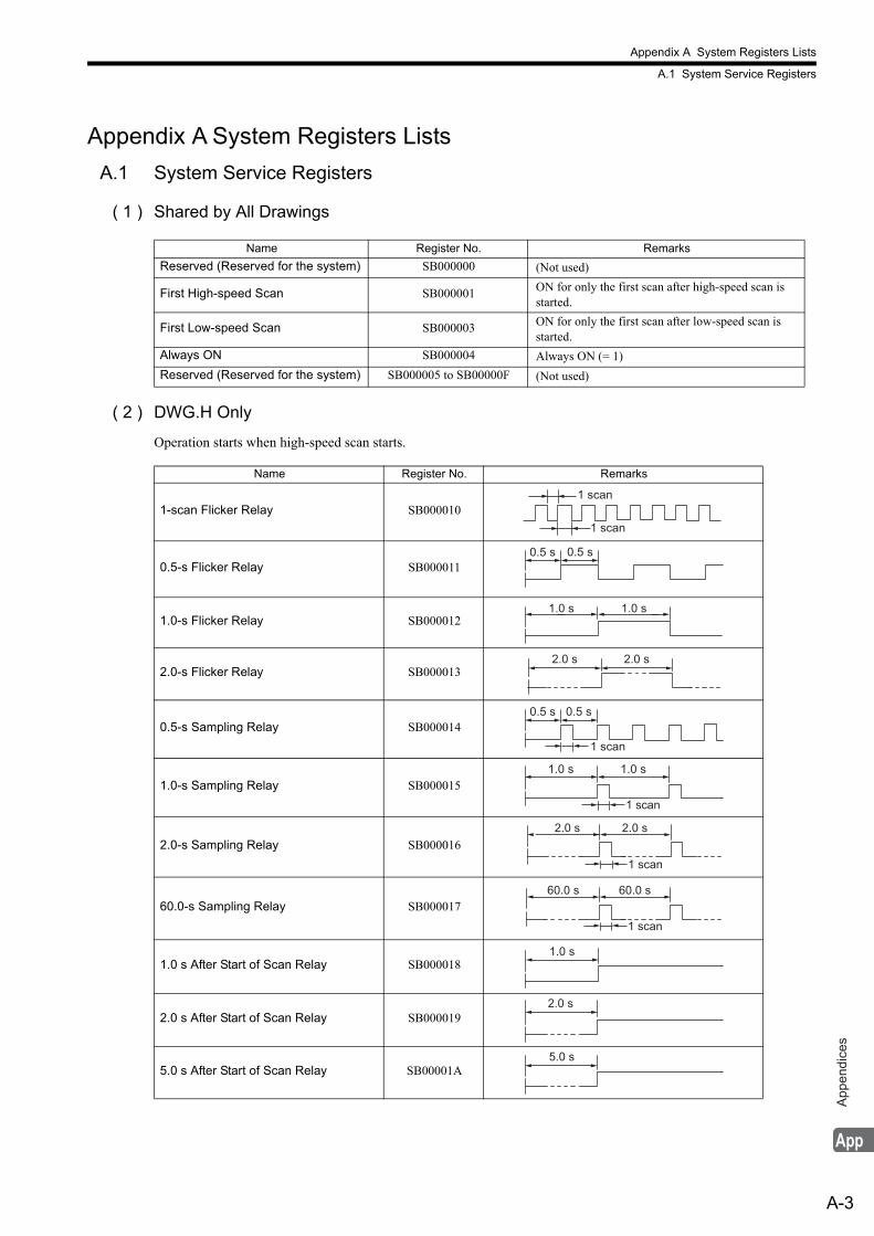
Appendix A System Registers Lists
A.1 System Service Registers
A-3
App
endi
ces
Appendix A System Registers Lists
A.1 System Service Registers
( 1 ) Shared by All Drawings
( 2 ) DWG.H Only
Operation starts when high-speed scan starts.
Name Register No. Remarks
Reserved (Reserved for the system) SB000000 (Not used)
First High-speed Scan SB000001 ON for only the first scan after high-speed scan is started.
First Low-speed Scan SB000003 ON for only the first scan after low-speed scan is started.
Always ON SB000004 Always ON (= 1)
Reserved (Reserved for the system) SB000005 to SB00000F (Not used)
Name Register No. Remarks
1-scan Flicker Relay SB000010
0.5-s Flicker Relay SB000011
1.0-s Flicker Relay SB000012
2.0-s Flicker Relay SB000013
0.5-s Sampling Relay SB000014
1.0-s Sampling Relay SB000015
2.0-s Sampling Relay SB000016
60.0-s Sampling Relay SB000017
1.0 s After Start of Scan Relay SB000018
2.0 s After Start of Scan Relay SB000019
5.0 s After Start of Scan Relay SB00001A
1 scan
1 scan
0.5 s 0.5 s
1.0 s 1.0 s
2.0 s 2.0 s
0.5 s 0.5 s
1 scan
1.0 s 1.0 s
1 scan
2.0 s 2.0 s
1 scan
1 scan
60.0 s 60.0 s
1.0 s
2.0 s
5.0 s
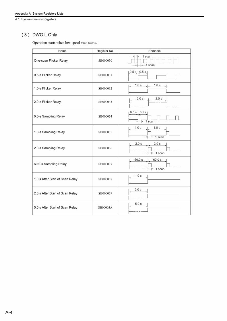
Appendix A System Registers Lists
A.1 System Service Registers
A-4
( 3 ) DWG.L Only
Operation starts when low-speed scan starts.
Name Register No. Remarks
One-scan Flicker Relay SB000030
0.5-s Flicker Relay SB000031
1.0-s Flicker Relay SB000032
2.0-s Flicker Relay SB000033
0.5-s Sampling Relay SB000034
1.0-s Sampling Relay SB000035
2.0-s Sampling Relay SB000036
60.0-s Sampling Relay SB000037
1.0 s After Start of Scan Relay SB000038
2.0 s After Start of Scan Relay SB000039
5.0 s After Start of Scan Relay SB00003A
1 scan
1 scan
0.5 s 0.5 s
1.0 s 1.0 s
2.0 s 2.0 s
0.5 s 0.5 s
1 scan
1.0 s 1.0 s
1 scan
2.0 s 2.0 s
1 scan
1 scan
60.0 s 60.0 s
1.0 s
2.0 s
5.0 s
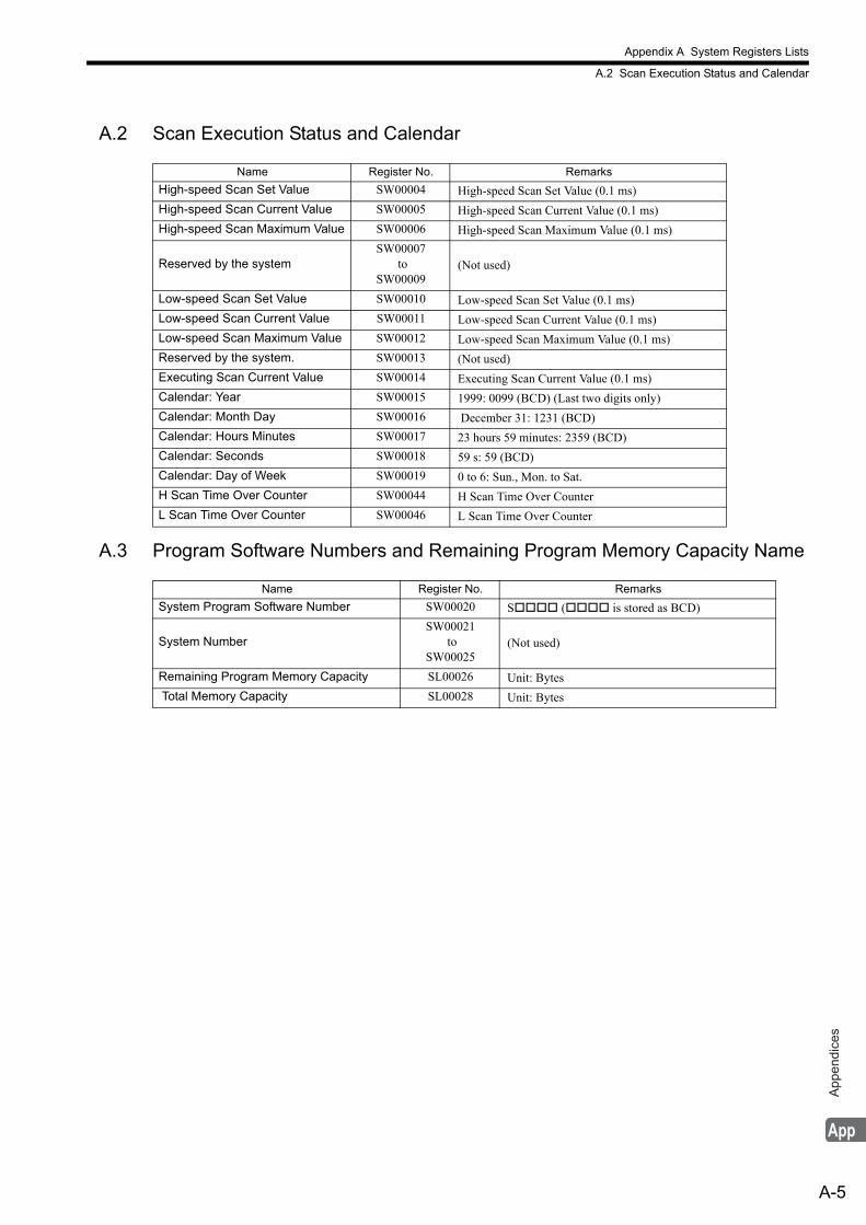
Appendix A System Registers Lists
A.2 Scan Execution Status and Calendar
A-5
App
endi
ces
A.2 Scan Execution Status and Calendar
A.3 Program Software Numbers and Remaining Program Memory Capacity Name
Name Register No. Remarks
High-speed Scan Set Value SW00004 High-speed Scan Set Value (0.1 ms)
High-speed Scan Current Value SW00005 High-speed Scan Current Value (0.1 ms)
High-speed Scan Maximum Value SW00006 High-speed Scan Maximum Value (0.1 ms)
Reserved by the systemSW00007
to SW00009
(Not used)
Low-speed Scan Set Value SW00010 Low-speed Scan Set Value (0.1 ms)
Low-speed Scan Current Value SW00011 Low-speed Scan Current Value (0.1 ms)
Low-speed Scan Maximum Value SW00012 Low-speed Scan Maximum Value (0.1 ms)
Reserved by the system. SW00013 (Not used)
Executing Scan Current Value SW00014 Executing Scan Current Value (0.1 ms)
Calendar: Year SW00015 1999: 0099 (BCD) (Last two digits only)
Calendar: Month Day SW00016 December 31: 1231 (BCD)
Calendar: Hours Minutes SW00017 23 hours 59 minutes: 2359 (BCD)
Calendar: Seconds SW00018 59 s: 59 (BCD)
Calendar: Day of Week SW00019 0 to 6: Sun., Mon. to Sat.
H Scan Time Over Counter SW00044 H Scan Time Over Counter
L Scan Time Over Counter SW00046 L Scan Time Over Counter
Name Register No. Remarks
System Program Software Number SW00020 S ( is stored as BCD)
System NumberSW00021
to SW00025
(Not used)
Remaining Program Memory Capacity SL00026 Unit: Bytes
Total Memory Capacity SL00028 Unit: Bytes
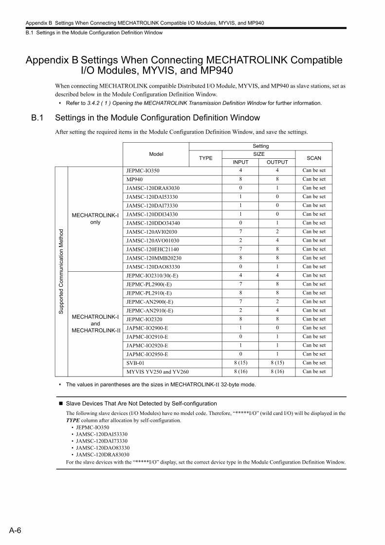
Appendix B Settings When Connecting MECHATROLINK Compatible I/O Modules, MYVIS, and MP940
B.1 Settings in the Module Configuration Definition Window
A-6
Appendix B Settings When Connecting MECHATROLINK Compatible I/O Modules, MYVIS, and MP940
When connecting MECHATROLINK compatible Distributed I/O Module, MYVIS, and MP940 as slave stations, set as described below in the Module Configuration Definition Window.
Refer to 3.4.2 ( 1 ) Opening the MECHATROLINK Transmission Definition Window for further information.
B.1 Settings in the Module Configuration Definition Window
After setting the required items in the Module Configuration Definition Window, and save the settings.
The values in parentheses are the sizes in MECHATROLINK-II 32-byte mode.
Slave Devices That Are Not Detected by Self-configuration
The following slave devices (I/O Modules) have no model code. Therefore, “*****I/O” (wild card I/O) will be displayed in the TYPE column after allocation by self-configuration.
• JEPMC-IO350• JAMSC-120DAI53330• JAMSC-120DAI73330• JAMSC-120DAO83330• JAMSC-120DRA83030
For the slave devices with the “*****I/O” display, set the correct device type in the Module Configuration Definition Window.
Model
Setting
TYPESIZE
SCANINPUT OUTPUT
Su
pp
ort
ed
Co
mm
un
ica
tion
Me
tho
d
MECHATROLINK-I only
JEPMC-IO350 4 4 Can be set
MP940 8 8 Can be set
JAMSC-120DRA83030 0 1 Can be set
JAMSC-120DAI53330 1 0 Can be set
JAMSC-120DAI73330 1 0 Can be set
JAMSC-120DDI34330 1 0 Can be set
JAMSC-120DDO34340 0 1 Can be set
JAMSC-120AVI02030 7 2 Can be set
JAMSC-120AVO01030 2 4 Can be set
JAMSC-120EHC21140 7 8 Can be set
JAMSC-120MMB20230 8 8 Can be set
JAMSC-120DAO83330 0 1 Can be set
MECHATROLINK-I and
MECHATROLINK-II
JEPMC-IO2310/30(-E) 4 4 Can be set
JEPMC-PL2900(-E) 7 8 Can be set
JEPMC-PL2910(-E) 8 8 Can be set
JEPMC-AN2900(-E) 7 2 Can be set
JEPMC-AN2910(-E) 2 4 Can be set
JEPMC-IO2320 8 8 Can be set
JAPMC-IO2900-E 1 0 Can be set
JAPMC-IO2910-E 0 1 Can be set
JAPMC-IO2920-E 1 1 Can be set
JAPMC-IO2950-E 0 1 Can be set
SVB-01 8 (15) 8 (15) Can be set
MYVIS YV250 and YV260 8 (16) 8 (16) Can be set
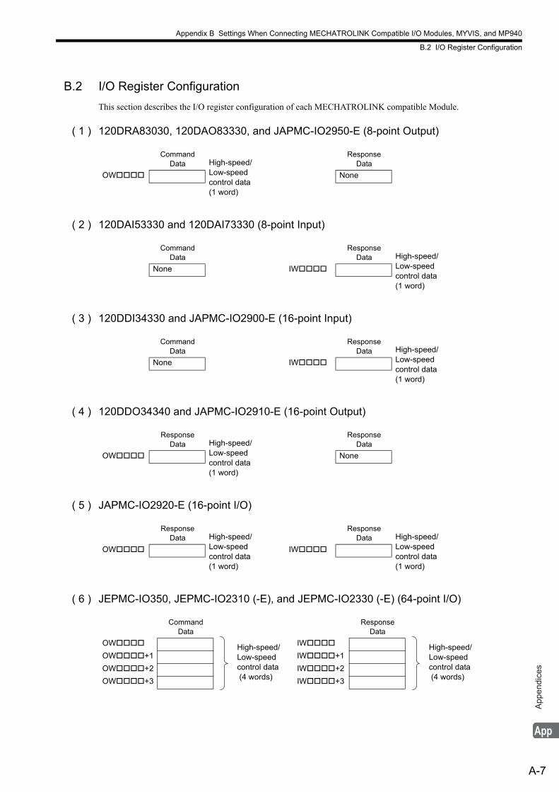
Appendix B Settings When Connecting MECHATROLINK Compatible I/O Modules, MYVIS, and MP940
B.2 I/O Register Configuration
A-7
App
endi
ces
B.2 I/O Register Configuration
This section describes the I/O register configuration of each MECHATROLINK compatible Module.
( 1 ) 120DRA83030, 120DAO83330, and JAPMC-IO2950-E (8-point Output)
( 2 ) 120DAI53330 and 120DAI73330 (8-point Input)
( 3 ) 120DDI34330 and JAPMC-IO2900-E (16-point Input)
( 4 ) 120DDO34340 and JAPMC-IO2910-E (16-point Output)
( 5 ) JAPMC-IO2920-E (16-point I/O)
( 6 ) JEPMC-IO350, JEPMC-IO2310 (-E), and JEPMC-IO2330 (-E) (64-point I/O)
Command Data High-speed/
Low-speed control data(1 word)
Response Data
OW None
Command Data
Response Data High-speed/
Low-speed control data(1 word)
None IW
Command Data
Response Data High-speed/
Low-speed control data(1 word)
None IW
Response Data High-speed/
Low-speed control data(1 word)
Response Data
OW None
Response Data High-speed/
Low-speed control data(1 word)
Response Data High-speed/
Low-speed control data(1 word)
OW IW
Command Data
Response Data
OW High-speed/Low-speed control data (4 words)
IW High-speed/Low-speed control data (4 words)
OW+1 IW+1
OW+2 IW+2
OW+3 IW+3
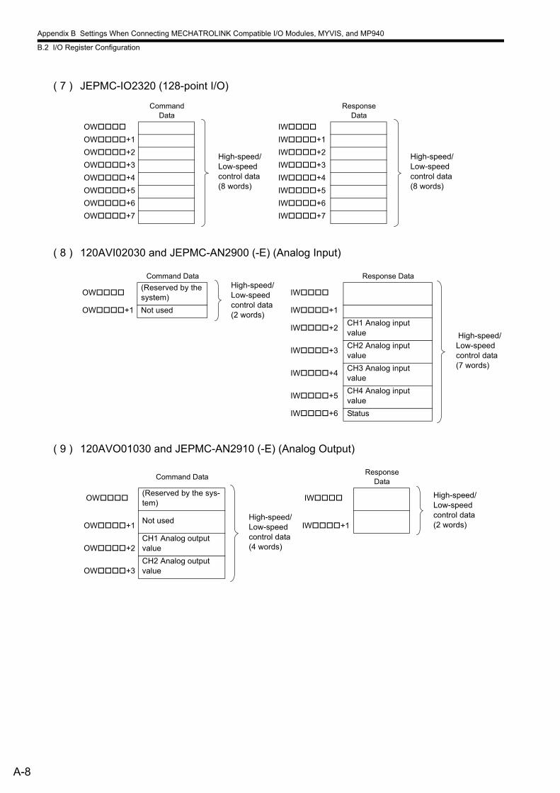
Appendix B Settings When Connecting MECHATROLINK Compatible I/O Modules, MYVIS, and MP940
B.2 I/O Register Configuration
A-8
( 7 ) JEPMC-IO2320 (128-point I/O)
( 8 ) 120AVI02030 and JEPMC-AN2900 (-E) (Analog Input)
( 9 ) 120AVO01030 and JEPMC-AN2910 (-E) (Analog Output)
Command Data
Response Data
OW
High-speed/Low-speed control data(8 words)
IW
High-speed/Low-speed control data(8 words)
OW+1 IW+1
OW+2 IW+2
OW+3 IW+3
OW+4 IW+4
OW+5 IW+5
OW+6 IW+6
OW+7 IW+7
Command DataHigh-speed/Low-speed control data(2 words)
Response Data
OW(Reserved by the system)
IW
High-speed/Low-speed control data(7 words)
OW+1 Not used IW+1
IW+2CH1 Analog input value
IW+3CH2 Analog input value
IW+4CH3 Analog input value
IW+5CH4 Analog input value
IW+6 Status
Command DataResponse
Data
High-speed/Low-speed control data(2 words)
OW(Reserved by the sys-tem)
High-speed/Low-speed control data(4 words)
IW
OW+1
Not used IW+1
OW+2
CH1 Analog output value
OW+3
CH2 Analog output value
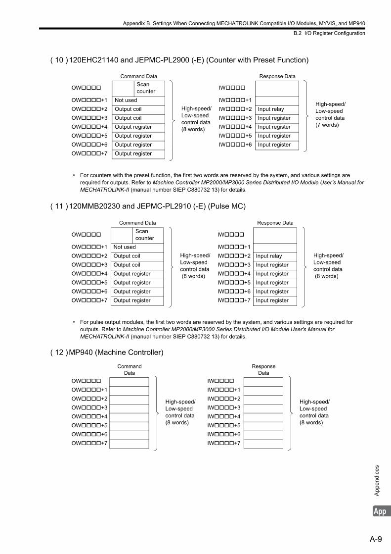
Appendix B Settings When Connecting MECHATROLINK Compatible I/O Modules, MYVIS, and MP940
B.2 I/O Register Configuration
A-9
App
endi
ces
( 10 )120EHC21140 and JEPMC-PL2900 (-E) (Counter with Preset Function)
For counters with the preset function, the first two words are reserved by the system, and various settings are required for outputs. Refer to Machine Controller MP2000/MP3000 Series Distributed I/O Module User’s Manual for MECHATROLINK-II (manual number SIEP C880732 13) for details.
( 11 )120MMB20230 and JEPMC-PL2910 (-E) (Pulse MC)
For pulse output modules, the first two words are reserved by the system, and various settings are required for outputs. Refer to Machine Controller MP2000/MP3000 Series Distributed I/O Module User's Manual for MECHATROLINK-II (manual number SIEP C880732 13) for details.
( 12 )MP940 (Machine Controller)
Command Data Response Data
OWScan counter
High-speed/Low-speed control data(8 words)
IW
High-speed/Low-speed control data(7 words)
OW+1 Not used IW+1
OW+2 Output coil IW+2 Input relay
OW+3 Output coil IW+3 Input register
OW+4 Output register IW+4 Input register
OW+5 Output register IW+5 Input register
OW+6 Output register IW+6 Input register
OW+7 Output register
Command Data Response Data
OWScan counter
High-speed/Low-speed control data (8 words)
IW
High-speed/Low-speed control data (8 words)
OW+1 Not used IW+1
OW+2 Output coil IW+2 Input relay
OW+3 Output coil IW+3 Input register
OW+4 Output register IW+4 Input register
OW+5 Output register IW+5 Input register
OW+6 Output register IW+6 Input register
OW+7 Output register IW+7 Input register
Command Data
Response Data
OW
High-speed/Low-speed control data(8 words)
IW
High-speed/Low-speed control data(8 words)
OW+1 IW+1
OW+2 IW+2
OW+3 IW+3
OW+4 IW+4
OW+5 IW+5
OW+6 IW+6
OW+7 IW+7
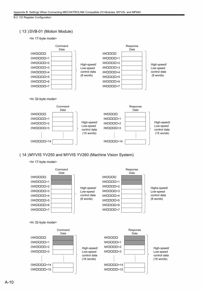
Appendix B Settings When Connecting MECHATROLINK Compatible I/O Modules, MYVIS, and MP940
B.2 I/O Register Configuration
A-10
( 13 )SVB-01 (Motion Module)
<In 17-byte mode>
<In 32-byte mode>
( 14 )MYVIS YV250 and MYVIS YV260 (Machine Vision System)
<In 17-byte mode>
<In 32-byte mode>
Command Data
Response Data
OW
High-speed/Low-speed control data(8 words)
IW
High-speed/Low-speed control data (8 words)
OW+1 IW+1
OW+2 IW+2
OW+3 IW+3
OW+4 IW+4
OW+5 IW+5
OW+6 IW+6
OW+7 IW+7
Command Data
Response Data
OW
High-speed/Low-speed control data (15 words)
IW
High-speed/Low-speed control data (15 words)
OW+1 IW+1
OW+2 IW+2
OW+3 IW+3
.....
...
.....
...
.....
...
......
.
OW+14 IW+14
Command Data
Response Data
OW
High-speed/Low-speed control data(8 words)
IW
Highs-speed/Low-speed control data(8 words)
OW+1 IW+1
OW+2 IW+2
OW+3 IW+3
OW+4 IW+4
OW+5 IW+5
OW+6 IW+6
OW+7 IW+7
Command Data
Response Data
OW
High-speed/Low-speed control data(16 words)
IW
High-speed/Low-speed control data(16 words)
OW+1 IW+1
OW+2 IW+2
OW+3 IW+3
.....
...
.....
...
.....
...
.....
...
OW+14 IW+14
OW+15 IW+15
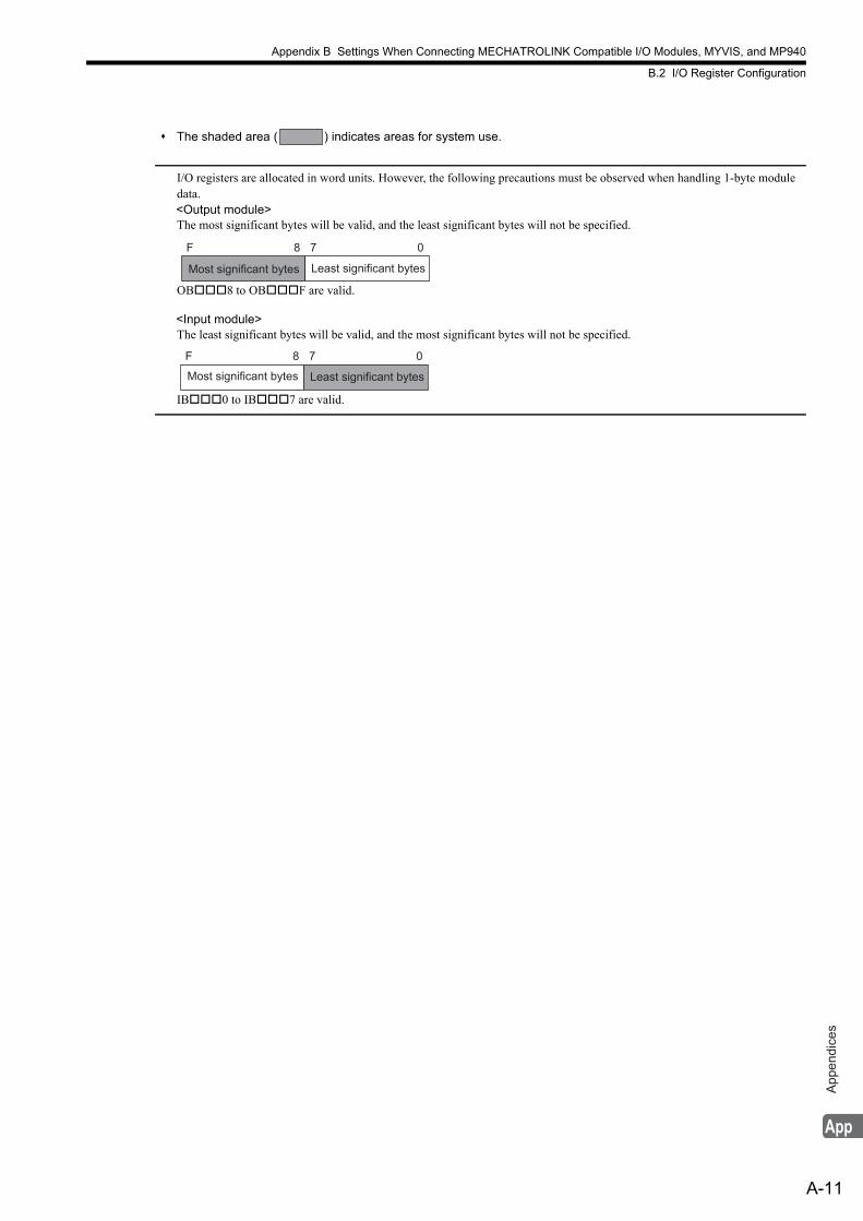
Appendix B Settings When Connecting MECHATROLINK Compatible I/O Modules, MYVIS, and MP940
B.2 I/O Register Configuration
A-11
App
endi
ces
The shaded area ( ) indicates areas for system use.
I/O registers are allocated in word units. However, the following precautions must be observed when handling 1-byte module data.
<Output module>The most significant bytes will be valid, and the least significant bytes will not be specified.
OB8 to OBF are valid.
<Input module>The least significant bytes will be valid, and the most significant bytes will not be specified.
IB0 to IB7 are valid.
Most significant bytes Least significant bytes
F 8 7 0
Most significant bytes Least significant bytes
F 8 7 0
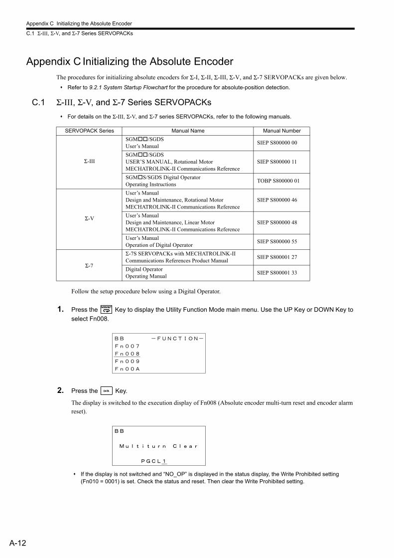
Appendix C Initializing the Absolute Encoder
C.1 Σ-III, Σ-V, and Σ-7 Series SERVOPACKs
A-12
Appendix C Initializing the Absolute EncoderThe procedures for initializing absolute encoders for Σ-I, Σ-II, Σ-III, Σ-V, and Σ-7 SERVOPACKs are given below.
Refer to 9.2.1 System Startup Flowchart for the procedure for absolute-position detection.
C.1 Σ-III, Σ-V, and Σ-7 Series SERVOPACKs
For details on the Σ-III, Σ-V, and Σ-7 series SERVOPACKs, refer to the following manuals.
Follow the setup procedure below using a Digital Operator.
1. Press the Key to display the Utility Function Mode main menu. Use the UP Key or DOWN Key to
select Fn008.
2. Press the Key.
The display is switched to the execution display of Fn008 (Absolute encoder multi-turn reset and encoder alarm reset).
If the display is not switched and “NO_OP” is displayed in the status display, the Write Prohibited setting (Fn010 = 0001) is set. Check the status and reset. Then clear the Write Prohibited setting.
SERVOPACK Series Manual Name Manual Number
Σ-III
SGM/SGDSUser’s Manual
SIEP S800000 00
SGM/SGDSUSER’S MANUAL, Rotational MotorMECHATROLINK-II Communications Reference
SIEP S800000 11
SGMS/SGDS Digital OperatorOperating Instructions
TOBP S800000 01
Σ-V
User’s ManualDesign and Maintenance, Rotational MotorMECHATROLINK-II Communications Reference
SIEP S800000 46
User’s ManualDesign and Maintenance, Linear MotorMECHATROLINK-II Communications Reference
SIEP S800000 48
User’s ManualOperation of Digital Operator
SIEP S800000 55
Σ-7
Σ-7S SERVOPACKs with MECHATROLINK-II Communications References Product Manual
SIEP S800001 27
Digital OperatorOperating Manual
SIEP S800001 33

Appendix C Initializing the Absolute Encoder
C.1 Σ-III, Σ-V, and Σ-7 Series SERVOPACKs
A-13
App
endi
ces
3. Keep pressing the Key until “PGCL1” is changed to “PGCL5.”
4. Press the Key.
“BB” in the status display changes to “Done.”
5. Press the Key. The display returns to the Utility Function Mode main menu.
This completes setting up the absolute encoder. Turn the power supply OFF and then back ON to reset the SERVO-PACK.
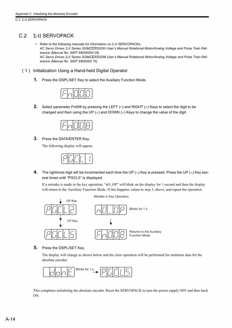
Appendix C Initializing the Absolute Encoder
C.2 Σ-II SERVOPACK
A-14
C.2 Σ-II SERVOPACK
Refer to the following manuals for information on Σ-II SERVOPACKs.AC Servo Drives Σ-II Series SGM/SGDH User’s Manual Rotational Motor/Analog Voltage and Pulse Train Ref-erence (Manual No. SIEP S8000000 05) AC Servo Drives Σ-II Series SGM/SGDM User’s Manual Rotational Motor/Analog Voltage and Pulse Train Ref-erence (Manual No. SIEP S800000 15)
( 1 ) Initialization Using a Hand-held Digital Operator
1. Press the DSPL/SET Key to select the Auxiliary Function Mode.
2. Select parameter Fn008 by pressing the LEFT (<) and RIGHT (>) Keys to select the digit to be
changed and then using the UP (∧) and DOWN (∨) Keys to change the value of the digit.
3. Press the DATA/ENTER Key.
The following display will appear.
4. The rightmost digit will be incremented each time the UP (∧) Key is pressed. Press the UP (∧) Key sev-
eral times until “PGCL5” is displayed.
If a mistake is made in the key operation, “nO_OP” will blink on the display for 1 second and then the display will return to the Auxiliary Function Mode. If this happens, return to step 3, above, and repeat the operation.
5. Press the DSPL/SET Key.
The display will change as shown below and the clear operation will be performed for multiturn data for the absolute encoder.
This completes initializing the absolute encoder. Reset the SERVOPACK to turn the power supply OFF and then back ON.
Returns to the Auxiliary Function Mode.
Blinks for 1 s.
Mistake in Key Operation
UP Key
UP Key
Blinks for 1 s.
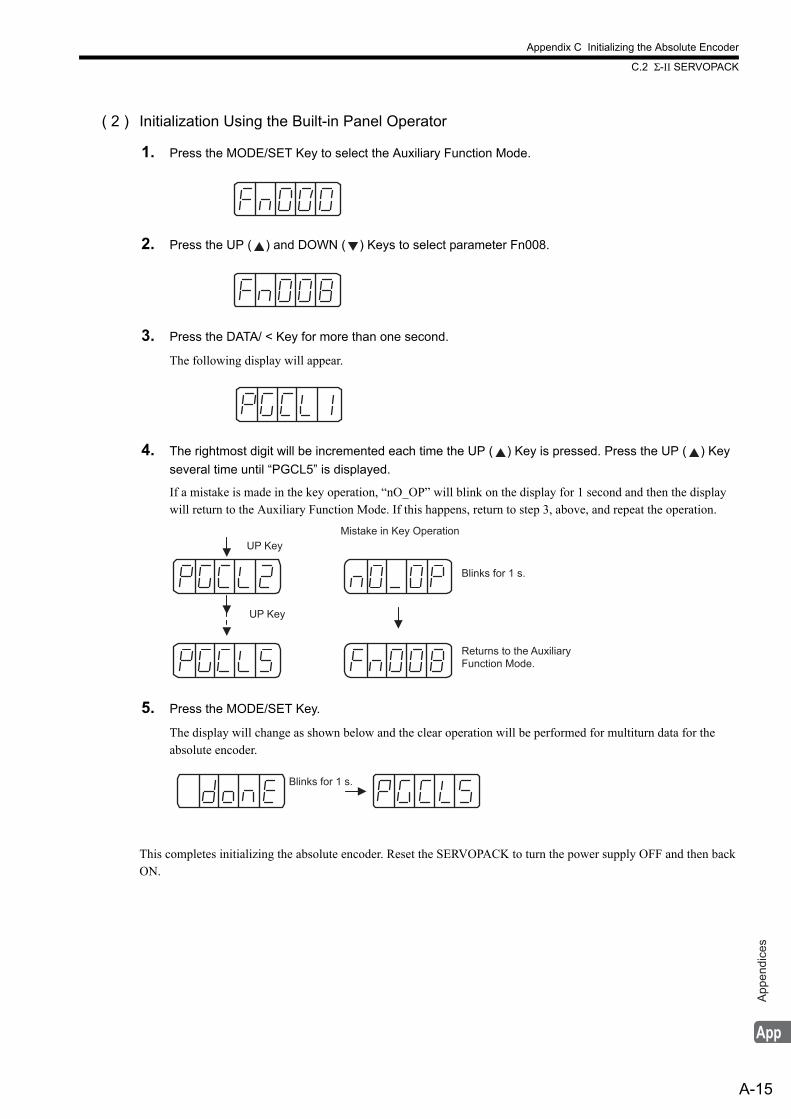
Appendix C Initializing the Absolute Encoder
C.2 Σ-II SERVOPACK
A-15
App
endi
ces
( 2 ) Initialization Using the Built-in Panel Operator
1. Press the MODE/SET Key to select the Auxiliary Function Mode.
2. Press the UP ( ) and DOWN ( ) Keys to select parameter Fn008.
3. Press the DATA/ < Key for more than one second.
The following display will appear.
4. The rightmost digit will be incremented each time the UP ( ) Key is pressed. Press the UP ( ) Key
several time until “PGCL5” is displayed.
If a mistake is made in the key operation, “nO_OP” will blink on the display for 1 second and then the display will return to the Auxiliary Function Mode. If this happens, return to step 3, above, and repeat the operation.
5. Press the MODE/SET Key.
The display will change as shown below and the clear operation will be performed for multiturn data for the absolute encoder.
This completes initializing the absolute encoder. Reset the SERVOPACK to turn the power supply OFF and then back ON.
Returns to the Auxiliary Function Mode.
Blinks for 1 s.
Mistake in Key Operation
UP Key
UP Key
Blinks for 1 s.
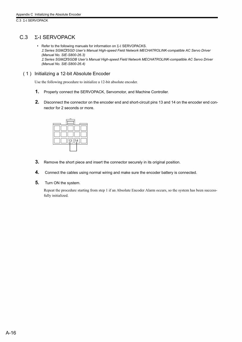
Appendix C Initializing the Absolute Encoder
C.3 Σ-I SERVOPACK
A-16
C.3 Σ-I SERVOPACK
Refer to the following manuals for information on Σ-I SERVOPACKS.Σ Series SGM/SGD User’s Manual High-speed Field Network MECHATROLINK-compatible AC Servo Driver (Manual No. SIE-S800-26.3) Σ Series SGM/SGDB User’s Manual High-speed Field Network MECHATROLINK-compatible AC Servo Driver (Manual No. SIE-S800-26.4)
( 1 ) Initializing a 12-bit Absolute Encoder
Use the following procedure to initialize a 12-bit absolute encoder.
1. Properly connect the SERVOPACK, Servomotor, and Machine Controller.
2. Disconnect the connector on the encoder end and short-circuit pins 13 and 14 on the encoder end con-
nector for 2 seconds or more.
3. Remove the short piece and insert the connector securely in its original position.
4. Connect the cables using normal wiring and make sure the encoder battery is connected.
5. Turn ON the system.
Repeat the procedure starting from step 1 if an Absolute Encoder Alarm occurs, so the system has been success-fully initialized.
13 14
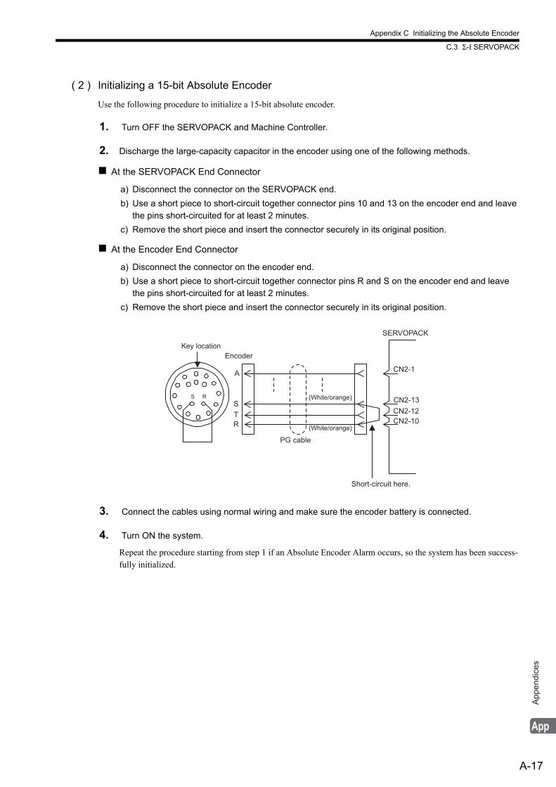
Appendix C Initializing the Absolute Encoder
C.3 Σ-I SERVOPACK
A-17
App
endi
ces
( 2 ) Initializing a 15-bit Absolute Encoder
Use the following procedure to initialize a 15-bit absolute encoder.
1. Turn OFF the SERVOPACK and Machine Controller.
2. Discharge the large-capacity capacitor in the encoder using one of the following methods.
At the SERVOPACK End Connector
a) Disconnect the connector on the SERVOPACK end.
b) Use a short piece to short-circuit together connector pins 10 and 13 on the encoder end and leave the pins short-circuited for at least 2 minutes.
c) Remove the short piece and insert the connector securely in its original position.
At the Encoder End Connector
a) Disconnect the connector on the encoder end.
b) Use a short piece to short-circuit together connector pins R and S on the encoder end and leave the pins short-circuited for at least 2 minutes.
c) Remove the short piece and insert the connector securely in its original position.
3. Connect the cables using normal wiring and make sure the encoder battery is connected.
4. Turn ON the system.
Repeat the procedure starting from step 1 if an Absolute Encoder Alarm occurs, so the system has been success-fully initialized.
A
S
T
R
CN2-1
CN2-13
CN2-10
CN2-12
S R
Key location
SERVOPACK
Encoder
(White/orange)
Short-circuit here.
PG cable
(White/orange)
Appendix D Setting the Multiturn Limit
D.1 Overview
A-18
Appendix D Setting the Multiturn Limit
D.1 Overview
When using the absolute encoder of a Σ-II, Σ-III, Σ-V, or Σ-7 series SERVOPACK for an infinite axis, satisfy the fol-lowing conditions.If these conditions are not satisfied, a “fixed parameter setting error” or “multiturn limit mismatch error” will occur.
• Fixed parameter No. 38 = 65534 or less
• Value set for fixed parameter No. 38 = value set for SERVOPACK user parameter Pn205
D.2 Setting Method
The procedure for using SigmaWin+ is explained here.When using the digital operator or panel operator, refer to the user’s manual for the SERVOPACK being used.
1. Change the multiturn reset value of Pn205.
After setting a value not exceeding 65534 for Pn205 on the [Edit Parameters] screen, click [Write to SERVO-PACK].
2. Turn the power to the SERVOPACK OFF and back ON.
A “multiturn limit mismatch error (A.CC0)” will be displayed.
3. Click [Setup] − [Absolute encoder setting] − [Multiturn limit setting].
4. Click [Continue].
5. After setting the same value as was set for Pn205 for [Multiturn limit value], click [Write to SERVO-
PACK].
6. Turn the power to the SERVOPACK OFF and back ON.

Appendix D Setting the Multiturn Limit
D.2 Setting Method
A-19
App
endi
ces
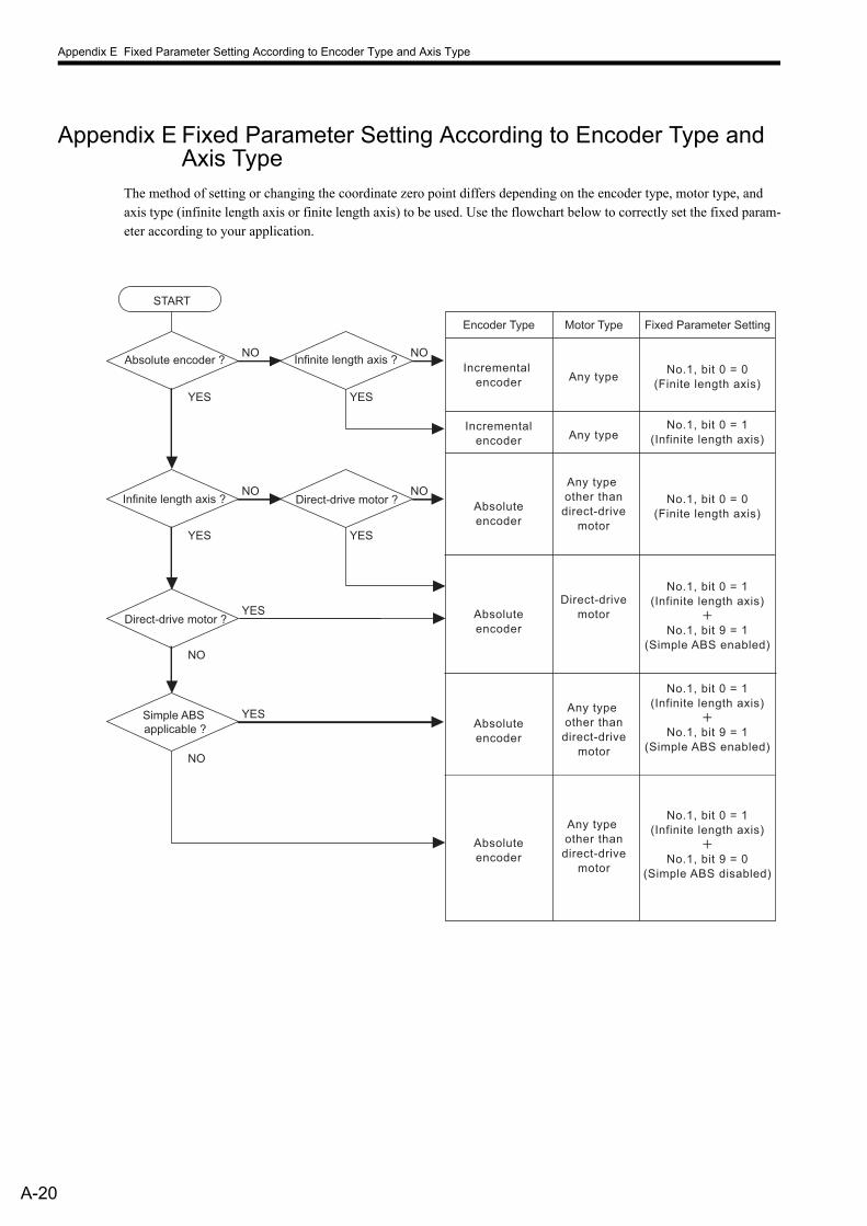
Appendix E Fixed Parameter Setting According to Encoder Type and Axis Type
A-20
Appendix E Fixed Parameter Setting According to Encoder Type and Axis Type
The method of setting or changing the coordinate zero point differs depending on the encoder type, motor type, and axis type (infinite length axis or finite length axis) to be used. Use the flowchart below to correctly set the fixed param-eter according to your application.
Absolute encoder ?NO
YES
Infinite length axis ?NO
YES
Direct-drive motor ?NO
YES
Direct-drive motor ?YES
NO
Infinite length axis ?
START
NO
YES
Simple ABS
applicable ?
YES
NO
Fixed Parameter Setting
No.1, bit 0 = 0
(Finite length axis)
No.1, bit 0 = 0
(Finite length axis)
No.1, bit 0 = 1
(Infinite length axis)
No.1, bit 9 = 1
(Simple ABS enabled)
No.1, bit 0 = 1
(Infinite length axis)
No.1, bit 9 = 1
(Simple ABS enabled)
No.1, bit 0 = 1
(Infinite length axis)
No.1, bit 9 = 0
(Simple ABS disabled)
No.1, bit 0 = 1
(Infinite length axis)
Encoder Type
Incremental
encoder
Absolute
encoder
Absolute
encoder
Absolute
encoder
Absolute
encoder
Motor Type
Any type
Incremental
encoderAny type
Any type
other than
direct-drive
motor
Direct-drive
motor
Any type
other than
direct-drive
motor
Any type
other than
direct-drive
motor
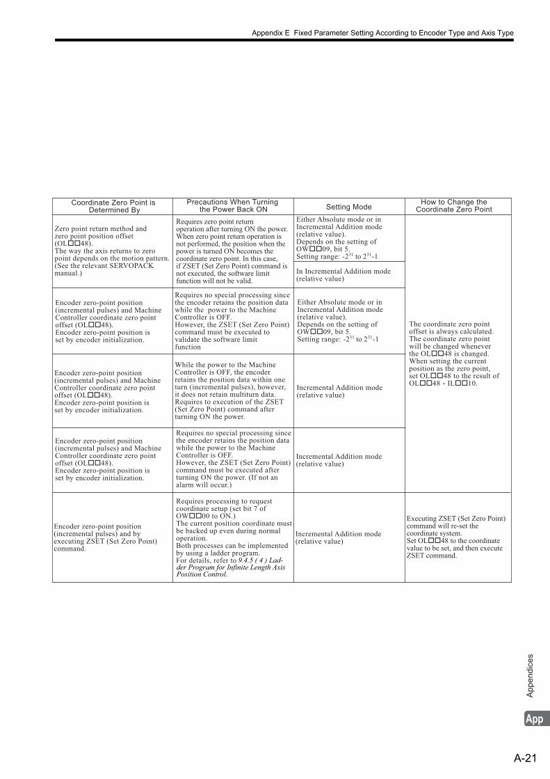
Appendix E Fixed Parameter Setting According to Encoder Type and Axis Type
A-21
App
endi
ces
Coordinate Zero Point is Determined By
Precautions When Turning the Power Back ON Setting Mode
How to Change theCoordinate Zero Point
Zero point return method andzero point position offset(OL��48).The way the axis returns to zeropoint depends on the motion pattern. (See the relevant SERVOPACK manual.)
Encoder zero-point position(incremental pulses) and MachineController coordinate zero pointoffset (OL��48).Encoder zero-point position is set by encoder initialization.
Encoder zero-point position(incremental pulses) and MachineController coordinate zero pointoffset (OL��48).Encoder zero-point position is set by encoder initialization.
Encoder zero-point position(incremental pulses) and MachineController coordinate zero pointoffset (OL��48).Encoder zero-point position is set by encoder initialization.
Encoder zero-point position(incremental pulses) and by executing ZSET (Set Zero Point)command.
Requires zero point return operation after turning ON the power.When zero point return operation is not performed, the position when the power is turned ON becomes the coordinate zero point. In this case, if ZSET (Set Zero Point) command is not executed, the software limitfunction will not be valid.
Requires no special processing sincethe encoder retains the position data while the power to the Machine Controller is OFF.However, the ZSET (Set Zero Point)command must be executed tovalidate the software limitfunction
While the power to the MachineController is OFF, the encoder retains the position data within one turn (incremental pulses), however,it does not retain multiturn data.Requires to execution of the ZSET (Set Zero Point) command afterturning ON the power.
Requires no special processing sincethe encoder retains the position datawhile the power to the Machine Controller is OFF.However, the ZSET (Set Zero Point)command must be executed afterturning ON the power. (If not an alarm will occur.)
Requires processing to requestcoordinate setup (set bit 7 of OW��00 to ON.)The current position coordinate must be backed up even during normal operation.Both processes can be implemented by using a ladder program.For details, refer to
Either Absolute mode or inIncremental Addition mode (relative value).Depends on the setting ofOW��09, bit 5.Setting range: -231 to 231-1
In Incremental Addition mode(relative value)
Either Absolute mode or inIncremental Addition mode (relative value).Depends on the setting ofOW��09, bit 5.Setting range: -231 to 231-1
Incremental Addition mode(relative value)
Incremental Addition mode(relative value)
Incremental Addition mode(relative value)
The coordinate zero pointoffset is always calculated. The coordinate zero point will be changed whenever the OL��48 is changed.When setting the currentposition as the zero point,set OL��48 to the result ofOL��48 - IL��10.
Executing ZSET (Set Zero Point)command will re-set the coordinate system. Set OL��48 to the coordinate value to be set, and then execute ZSET command.
9.4.5 ( 4 ) Lad-der Program for Infinite Length Axis Position Control.
Appendix F SVB Module Throughput
F.1 For Servos and Inverters
A-22
Appendix F SVB Module ThroughputThe maximum time for data to be received via the SVB Module is described below.
F.1 For Servos and Inverters
( 1 ) Time Required to Transmit a Command from an Application to a Servo
<When the high-speed scan setting = Communication cycle × n (n = an integer)> Required time for command = High-speed scan set time × 2 + Communication cycle × 1<When the high-speed scan setting = Communication cycle × n (n = a non-integer)> Required time for command = High-speed scan set time × 2 + Communication cycle × 2 The time from the moment the servo receives a command until it outputs the command is not included.
This also applies to built-in and optional SVB Modules
( 2 ) Time Required to Transmit a Response from a Servo to an Application
Built-in SVB Modules
<When the high-speed scan setting = Communication cycle × n (n = an integer)> Required time for response = High-speed scan set time × 1 + Communication cycle × 1<When the high-speed scan setting = Communication cycle × n (n = a non-integer)> Required time for response = High-speed scan set time × 1 + Communication cycle × 2 The time required for the response from the servo to be written in MECHATROLINK input data is not included.
Optional SVB Modules
<When the high-speed scan setting = Communication cycle × n (n = an integer)> Required time for response = High-speed scan set time × 2 + Communication cycle × 1<When the high-speed scan setting = Communication cycle × n (n = a non-integer)> Required time for response = High-speed scan set time × 2 + Communication cycle × 2 When Wait For Monitor Data Update mode is used, the required time will be same as for built-in SVB Modules.
F.2 For I/Os
( 1 ) Time Required to Transmit an output from the Application to an I/O Module
<When the high-speed scan setting = Communication cycle × n (n = an integer)> Required time for command = High-speed scan set time × 2 + Communication cycle × 1<When the high-speed scan setting = Communication cycle × n (n = a non-integer)> Required time for command = High-speed scan set time × 2 + Communication cycle × 2 The time from the moment the output module receives a command until it outputs a signal is not included.
This also applies to built-in and optional SVB Modules
( 2 ) Time Required to Transmit an I/O Module Input Data to an Application
<When the high-speed scan setting = Communication cycle × n (n = an integer)> Required time for response = High-speed scan set time × 1 + Communication cycle × 1<When the high-speed scan setting = Communication cycle × n (n = a non-integer)> Required time for response = High-speed scan set time × 1 + Communication cycle × 2 The time required for the response from the input module to be written in MECHATROLINK input data is not
included.
This also applies to built-in and optional SVB Modules
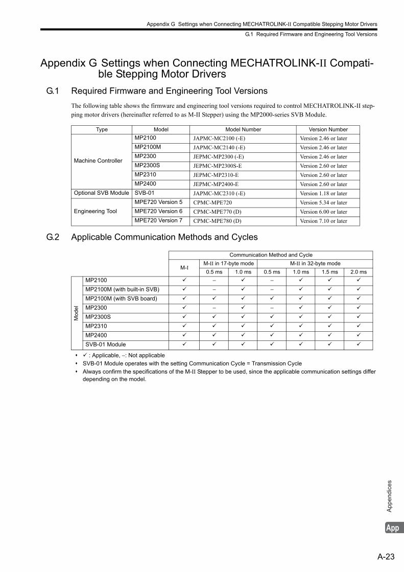
Appendix G Settings when Connecting MECHATROLINK-II Compatible Stepping Motor Drivers
G.1 Required Firmware and Engineering Tool Versions
A-23
App
endi
ces
Appendix G Settings when Connecting MECHATROLINK-II Compati-ble Stepping Motor Drivers
G.1 Required Firmware and Engineering Tool Versions
The following table shows the firmware and engineering tool versions required to control MECHATROLINK-II step-ping motor drivers (hereinafter referred to as M-II Stepper) using the MP2000-series SVB Module.
G.2 Applicable Communication Methods and Cycles
: Applicable, −: Not applicable
SVB-01 Module operates with the setting Communication Cycle = Transmission Cycle
Always confirm the specifications of the M-II Stepper to be used, since the applicable communication settings differ depending on the model.
Type Model Model Number Version Number
Machine Controller
MP2100 JAPMC-MC2100 (-E) Version 2.46 or later
MP2100M JAPMC-MC2140 (-E) Version 2.46 or later
MP2300 JEPMC-MP2300 (-E) Version 2.46 or later
MP2300S JEPMC-MP2300S-E Version 2.60 or later
MP2310 JEPMC-MP2310-E Version 2.60 or later
MP2400 JEPMC-MP2400-E Version 2.60 or later
Optional SVB Module SVB-01 JAPMC-MC2310 (-E) Version 1.18 or later
Engineering Tool
MPE720 Version 5 CPMC-MPE720 Version 5.34 or later
MPE720 Version 6 CPMC-MPE770 (D) Version 6.00 or later
MPE720 Version 7 CPMC-MPE780 (D) Version 7.10 or later
Communication Method and Cycle
M-IM-II in 17-byte mode M-II in 32-byte mode
0.5 ms 1.0 ms 0.5 ms 1.0 ms 1.5 ms 2.0 ms
Mod
el
MP2100 − −
MP2100M (with built-in SVB) − −
MP2100M (with SVB board)
MP2300 − −
MP2300S
MP2310
MP2400
SVB-01 Module
Appendix G Settings when Connecting MECHATROLINK-II Compatible Stepping Motor Drivers
G.3 Module Configuration Definition
A-24
G.3 Module Configuration Definition
To use a M-II Stepper, open the Module Configuration Tab Page in the MPE720, and set SteppingMotorDRV(M-I/M-II) to the slave cell to assign to a Function Module/Slave Cell.
Refer to 3.4.2 ( 1 ) Opening the MECHATROLINK Transmission Definition Window for information on how to open the Module Configuration Definition Window.
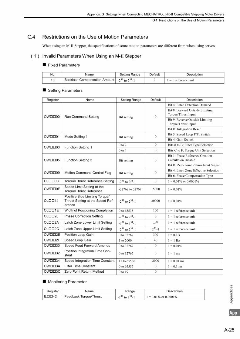
Appendix G Settings when Connecting MECHATROLINK-II Compatible Stepping Motor Drivers
G.4 Restrictions on the Use of Motion Parameters
A-25
App
endi
ces
G.4 Restrictions on the Use of Motion Parameters
When using an M-II Stepper, the specifications of some motion parameters are different from when using servos.
( 1 ) Invalid Parameters When Using an M-II Stepper
Fixed Parameters
Setting Parameters
Monitoring Parameter
No. Name Setting Range Default Description
16 Backlash Compensation Amount -231 to 231-1 0 1 = 1 reference unit
Register Name Setting Range Default Description
OW00 Run Command Setting Bit setting 0
Bit 4: Latch Detection Demand
Bit 8: Forward Outside Limiting Torque/Thrust Input
Bit 9: Reverse Outside Limiting Torque/Thrust Input
Bit B: Integration Reset
OW01 Mode Setting 1 Bit setting 0Bit 3: Speed Loop P/PI Switch
Bit 4: Gain Switch
OW03 Function Setting 10 to 2 0 Bits 8 to B: Filter Type Selection
0 or 1 0 Bits C to F: Torque Unit Selection
OW05 Function Setting 3 Bit setting 0Bit 1: Phase Reference CreationCalculation Disable
Bit B: Zero Point Return Input Signal
OW09 Motion Command Control Flag Bit setting 0Bit 4: Latch Zone Effective Selection
Bit 6: Phase Compensation Type
OL0C Torque/Thrust Reference Setting -231 to 231-1 0 1 = 0.01% or 0.0001%
OW0ESpeed Limit Setting at the Torque/Thrust Reference -32768 to 32767 15000 1 = 0.01%
OL14Positive Side Limiting Torque/Thrust Setting at the Speed Ref-erence
-231 to 231-1 30000 1 = 0.01%
OL1E Width of Positioning Completion 0 to 65535 100 1 = 1 reference unit
OL28 Phase Correction Setting -231 to 231-1 0 1 = 1 reference unit
OL2A Latch Zone Lower Limit Setting -231 to 231-1 -231 1 = 1 reference unit
OL2C Latch Zone Upper Limit Setting -231 to 231-1 231-1 1 = 1 reference unit
OW2E Position Loop Gain 0 to 32767 300 1 = 0.1/s
OW2F Speed Loop Gain 1 to 2000 40 1 = 1 Hz
OW30 Speed Feed Forward Amends 0 to 32767 0 1 = 0.01%
OW32Position Integration Time Con-stant 0 to 32767 0 1 = 1 ms
OW34 Speed Integration Time Constant 15 to 65536 2000 1 = 0.01 ms
OW3A Filter Time Constant 0 to 65535 0 1 = 0.1 ms
OW3C Zero Point Return Method 0 to 19 0 −
Register Name Range Description
IL42 Feedback Torque/Thrust -231 to 231-1 1 = 0.01% or 0.0001%
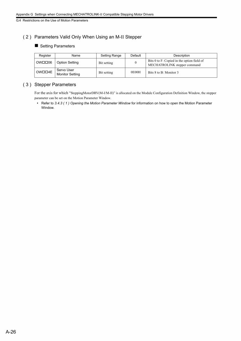
Appendix G Settings when Connecting MECHATROLINK-II Compatible Stepping Motor Drivers
G.4 Restrictions on the Use of Motion Parameters
A-26
( 2 ) Parameters Valid Only When Using an M-II Stepper
Setting Parameters
( 3 ) Stepper Parameters
For the axis for which “SteppingMotorDRV(M-I/M-II)” is allocated on the Module Configuration Definition Window, the stepper
parameter can be set on the Motion Parameter Window.
Refer to 3.4.3 ( 1 ) Opening the Motion Parameter Window for information on how to open the Motion Parameter Window.
Register Name Setting Range Default Description
OW06 Option Setting Bit setting 0 Bits 0 to F: Copied in the option field of MECHATROLINK stepper command
OW4EServo User Monitor Setting Bit setting 0E00H Bits 8 to B: Monitor 3
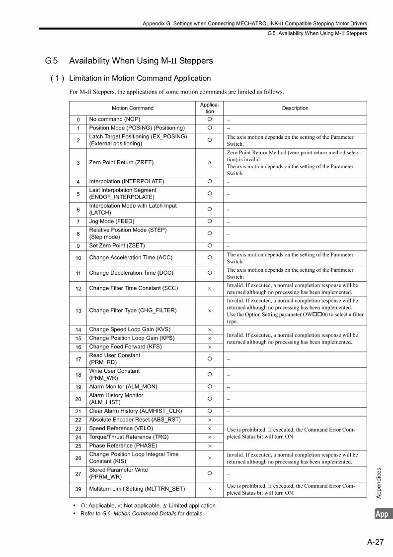
Appendix G Settings when Connecting MECHATROLINK-II Compatible Stepping Motor Drivers
G.5 Availability When Using M-II Steppers
A-27
App
endi
ces
G.5 Availability When Using M-II Steppers
( 1 ) Limitation in Motion Command Application
For M-II Steppers, the applications of some motion commands are limited as follows.
: Applicable, ×: Not applicable, Δ: Limited application
Refer to G.6 Motion Command Details for details.
Motion CommandApplica-
tionDescription
0 No command (NOP) −1 Position Mode (POSING) (Positioning) −
2Latch Target Positioning (EX_POSING)(External positioning)
The axis motion depends on the setting of the Parameter Switch.
3 Zero Point Return (ZRET) Δ
Zero Point Return Method (zero point return method selec-tion) is invalid.The axis motion depends on the setting of the Parameter Switch.
4 Interpolation (INTERPOLATE) −
5Last Interpolation Segment(ENDOF_INTERPOLATE)
−
6Interpolation Mode with Latch Input (LATCH)
−
7 Jog Mode (FEED) −
8Relative Position Mode (STEP)(Step mode)
−
9 Set Zero Point (ZSET) −
10 Change Acceleration Time (ACC) The axis motion depends on the setting of the Parameter Switch.
11 Change Deceleration Time (DCC) The axis motion depends on the setting of the Parameter Switch.
12 Change Filter Time Constant (SCC) × Invalid. If executed, a normal completion response will be returned although no processing has been implemented.
13 Change Filter Type (CHG_FILTER) ×
Invalid. If executed, a normal completion response will be returned although no processing has been implemented.Use the Option Setting parameter OW06 to select a filter type.
14 Change Speed Loop Gain (KVS) ×Invalid. If executed, a normal completion response will be returned although no processing has been implemented.
15 Change Position Loop Gain (KPS) ×
16 Change Feed Forward (KFS) ×
17Read User Constant(PRM_RD)
−
18Write User Constant(PRM_WR)
−
19 Alarm Monitor (ALM_MON) −
20Alarm History Monitor(ALM_HIST)
−
21 Clear Alarm History (ALMHIST_CLR) −22 Absolute Encoder Reset (ABS_RST) ×
Use is prohibited. If executed, the Command Error Com-pleted Status bit will turn ON.
23 Speed Reference (VELO) ×
24 Torque/Thrust Reference (TRQ) ×25 Phase Reference (PHASE) ×
26Change Position Loop Integral TimeConstant (KIS)
× Invalid. If executed, a normal completion response will be returned although no processing has been implemented.
27Stored Parameter Write(PPRM_WR)
−
39 Multiturn Limit Setting (MLTTRN_SET) × Use is prohibited. If executed, the Command Error Com-pleted Status bit will turn ON.

Appendix G Settings when Connecting MECHATROLINK-II Compatible Stepping Motor Drivers
G.5 Availability When Using M-II Steppers
A-28
( 2 ) Absolute Encoder Infinite Length Axis Setting
For M-II Steppers, absolute encoder infinite length axis setting is not supported.
( 3 ) Absolute Encoder Finite Length Axis Setting
For M-II Steppers, absolute encoder finite length axis setting is possible. However, the allowable stroke range will be determined by the M-II Stepper specifications.Check the absolute position data range that the M-II Stepper can store, and determine whether the absolute encoder finite length axis can be used or not.
( 4 ) Instructions That Cannot be Used in Motion Programs
The following instructions cannot be used.
Instruction Description
VCS Speed reference
VCR Cancel speed reference
TCS Torque reference
TCR Cancel torque reference
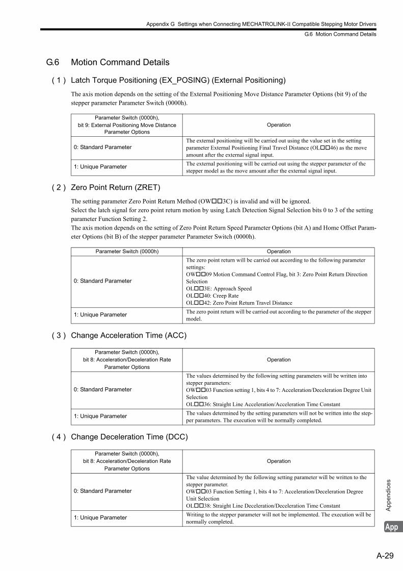
Appendix G Settings when Connecting MECHATROLINK-II Compatible Stepping Motor Drivers
G.6 Motion Command Details
A-29
App
endi
ces
G.6 Motion Command Details
( 1 ) Latch Torque Positioning (EX_POSING) (External Positioning)
The axis motion depends on the setting of the External Positioning Move Distance Parameter Options (bit 9) of the stepper parameter Parameter Switch (0000h).
( 2 ) Zero Point Return (ZRET)
The setting parameter Zero Point Return Method (OW3C) is invalid and will be ignored.Select the latch signal for zero point return motion by using Latch Detection Signal Selection bits 0 to 3 of the setting parameter Function Setting 2.The axis motion depends on the setting of Zero Point Return Speed Parameter Options (bit A) and Home Offset Param-eter Options (bit B) of the stepper parameter Parameter Switch (0000h).
( 3 ) Change Acceleration Time (ACC)
( 4 ) Change Deceleration Time (DCC)
Parameter Switch (0000h), bit 9: External Positioning Move Distance
Parameter OptionsOperation
0: Standard ParameterThe external positioning will be carried out using the value set in the setting parameter External Positioning Final Travel Distance (OL46) as the move amount after the external signal input.
1: Unique Parameter The external positioning will be carried out using the stepper parameter of the stepper model as the move amount after the external signal input.
Parameter Switch (0000h) Operation
0: Standard Parameter
The zero point return will be carried out according to the following parameter settings:OW09 Motion Command Control Flag, bit 3: Zero Point Return Direction SelectionOL3E: Approach SpeedOL40: Creep RateOL42: Zero Point Return Travel Distance
1: Unique Parameter The zero point return will be carried out according to the parameter of the stepper model.
Parameter Switch (0000h), bit 8: Acceleration/Deceleration Rate
Parameter OptionsOperation
0: Standard Parameter
The values determined by the following setting parameters will be written into stepper parameters:OW03 Function setting 1, bits 4 to 7: Acceleration/Deceleration Degree Unit SelectionOL36: Straight Line Acceleration/Acceleration Time Constant
1: Unique Parameter The values determined by the setting parameters will not be written into the step-per parameters. The execution will be normally completed.
Parameter Switch (0000h),bit 8: Acceleration/Deceleration Rate
Parameter OptionsOperation
0: Standard Parameter
The value determined by the following setting parameter will be written to the stepper parameter.OW03 Function Setting 1, bits 4 to 7: Acceleration/Deceleration Degree Unit SelectionOL38: Straight Line Deceleration/Deceleration Time Constant
1: Unique Parameter Writing to the stepper parameter will not be implemented. The execution will be normally completed.
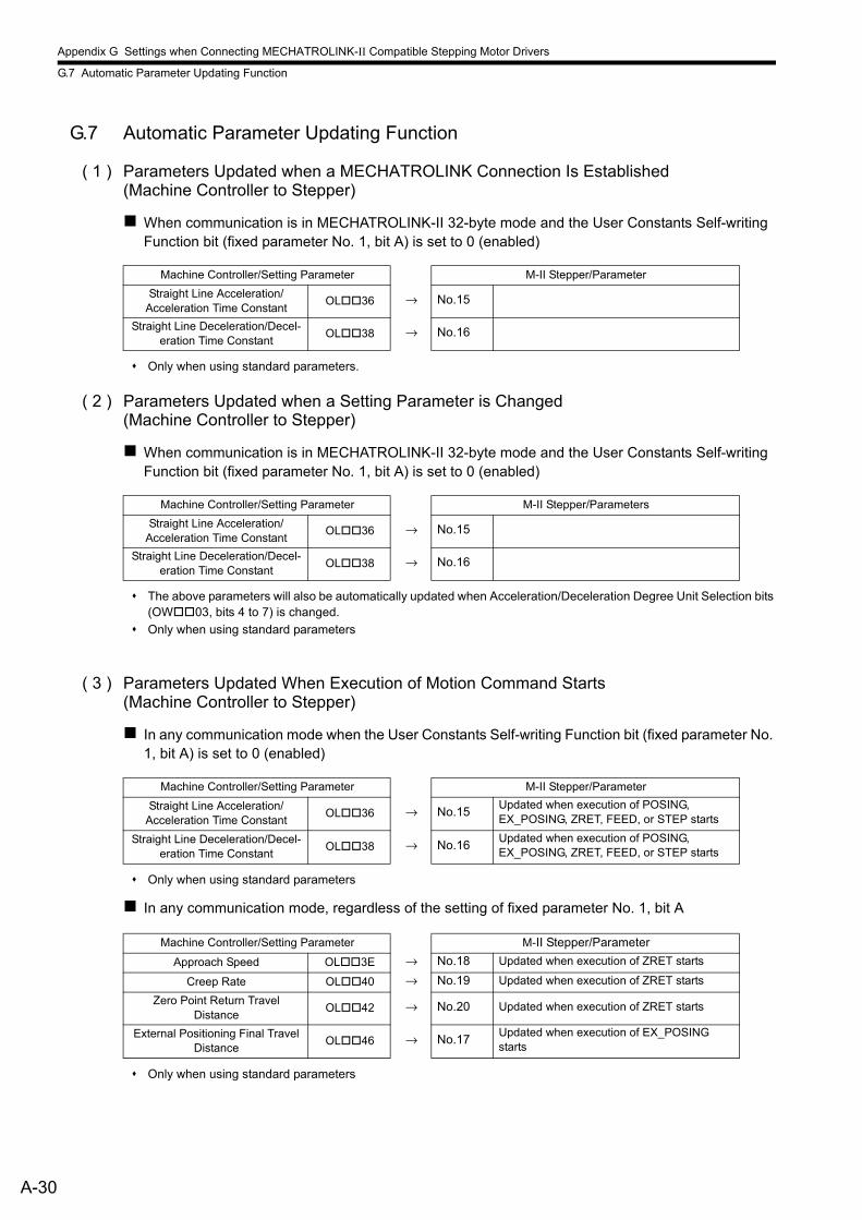
Appendix G Settings when Connecting MECHATROLINK-II Compatible Stepping Motor Drivers
G.7 Automatic Parameter Updating Function
A-30
G.7 Automatic Parameter Updating Function
( 1 ) Parameters Updated when a MECHATROLINK Connection Is Established (Machine Controller to Stepper)
When communication is in MECHATROLINK-II 32-byte mode and the User Constants Self-writing Function bit (fixed parameter No. 1, bit A) is set to 0 (enabled)
Only when using standard parameters.
( 2 ) Parameters Updated when a Setting Parameter is Changed(Machine Controller to Stepper)
When communication is in MECHATROLINK-II 32-byte mode and the User Constants Self-writing Function bit (fixed parameter No. 1, bit A) is set to 0 (enabled)
The above parameters will also be automatically updated when Acceleration/Deceleration Degree Unit Selection bits (OW03, bits 4 to 7) is changed.
Only when using standard parameters
( 3 ) Parameters Updated When Execution of Motion Command Starts(Machine Controller to Stepper)
In any communication mode when the User Constants Self-writing Function bit (fixed parameter No. 1, bit A) is set to 0 (enabled)
Only when using standard parameters
In any communication mode, regardless of the setting of fixed parameter No. 1, bit A
Only when using standard parameters
Machine Controller/Setting Parameter M-II Stepper/Parameter
Straight Line Acceleration/Acceleration Time Constant
OL36 → No.15
Straight Line Deceleration/Decel-eration Time Constant
OL38 → No.16
Machine Controller/Setting Parameter M-II Stepper/Parameters
Straight Line Acceleration/Acceleration Time Constant
OL36 → No.15
Straight Line Deceleration/Decel-eration Time Constant
OL38 → No.16
Machine Controller/Setting Parameter M-II Stepper/Parameter
Straight Line Acceleration/Acceleration Time Constant
OL36 → No.15Updated when execution of POSING, EX_POSING, ZRET, FEED, or STEP starts
Straight Line Deceleration/Decel-eration Time Constant
OL38 → No.16Updated when execution of POSING, EX_POSING, ZRET, FEED, or STEP starts
Machine Controller/Setting Parameter M-II Stepper/Parameter
Approach Speed OL3E → No.18 Updated when execution of ZRET starts
Creep Rate OL40 → No.19 Updated when execution of ZRET starts
Zero Point Return TravelDistance
OL42 → No.20 Updated when execution of ZRET starts
External Positioning Final Travel Distance
OL46 → No.17Updated when execution of EX_POSING starts
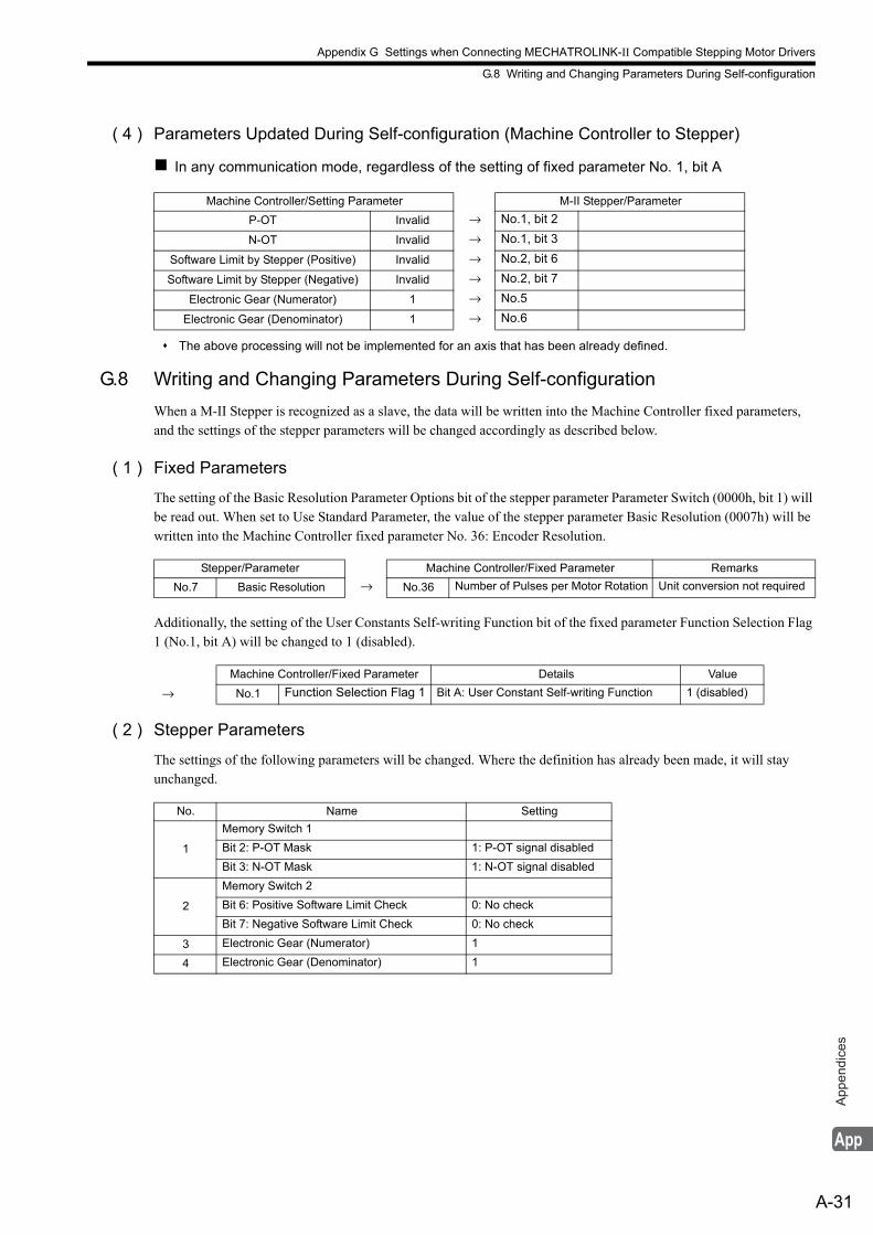
Appendix G Settings when Connecting MECHATROLINK-II Compatible Stepping Motor Drivers
G.8 Writing and Changing Parameters During Self-configuration
A-31
App
endi
ces
( 4 ) Parameters Updated During Self-configuration (Machine Controller to Stepper)
In any communication mode, regardless of the setting of fixed parameter No. 1, bit A
The above processing will not be implemented for an axis that has been already defined.
G.8 Writing and Changing Parameters During Self-configuration
When a M-II Stepper is recognized as a slave, the data will be written into the Machine Controller fixed parameters, and the settings of the stepper parameters will be changed accordingly as described below.
( 1 ) Fixed Parameters
The setting of the Basic Resolution Parameter Options bit of the stepper parameter Parameter Switch (0000h, bit 1) will be read out. When set to Use Standard Parameter, the value of the stepper parameter Basic Resolution (0007h) will be written into the Machine Controller fixed parameter No. 36: Encoder Resolution.
Additionally, the setting of the User Constants Self-writing Function bit of the fixed parameter Function Selection Flag 1 (No.1, bit A) will be changed to 1 (disabled).
( 2 ) Stepper Parameters
The settings of the following parameters will be changed. Where the definition has already been made, it will stay unchanged.
Machine Controller/Setting Parameter M-II Stepper/Parameter
P-OT Invalid → No.1, bit 2
N-OT Invalid → No.1, bit 3
Software Limit by Stepper (Positive) Invalid → No.2, bit 6
Software Limit by Stepper (Negative) Invalid → No.2, bit 7
Electronic Gear (Numerator) 1 → No.5
Electronic Gear (Denominator) 1 → No.6
Stepper/Parameter Machine Controller/Fixed Parameter Remarks
No.7 Basic Resolution → No.36 Number of Pulses per Motor Rotation Unit conversion not required
Machine Controller/Fixed Parameter Details Value
→ No.1 Function Selection Flag 1 Bit A: User Constant Self-writing Function 1 (disabled)
No. Name Setting
1
Memory Switch 1
Bit 2: P-OT Mask 1: P-OT signal disabled
Bit 3: N-OT Mask 1: N-OT signal disabled
2
Memory Switch 2
Bit 6: Positive Software Limit Check 0: No check
Bit 7: Negative Software Limit Check 0: No check
3 Electronic Gear (Numerator) 1
4 Electronic Gear (Denominator) 1
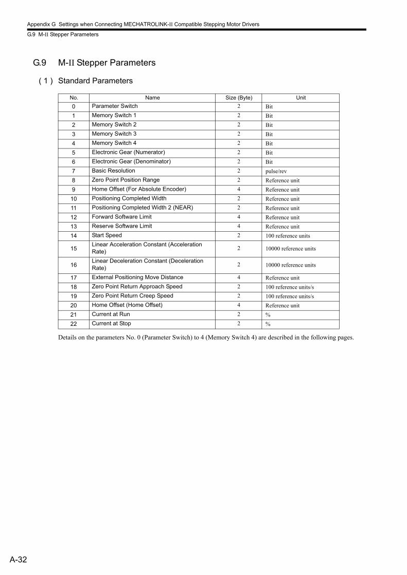
Appendix G Settings when Connecting MECHATROLINK-II Compatible Stepping Motor Drivers
G.9 M-II Stepper Parameters
A-32
G.9 M-II Stepper Parameters
( 1 ) Standard Parameters
Details on the parameters No. 0 (Parameter Switch) to 4 (Memory Switch 4) are described in the following pages.
No. Name Size (Byte) Unit
0 Parameter Switch 2 Bit
1 Memory Switch 1 2 Bit
2 Memory Switch 2 2 Bit
3 Memory Switch 3 2 Bit
4 Memory Switch 4 2 Bit
5 Electronic Gear (Numerator) 2 Bit
6 Electronic Gear (Denominator) 2 Bit
7 Basic Resolution 2 pulse/rev
8 Zero Point Position Range 2 Reference unit
9 Home Offset (For Absolute Encoder) 4 Reference unit
10 Positioning Completed Width 2 Reference unit
11 Positioning Completed Width 2 (NEAR) 2 Reference unit
12 Forward Software Limit 4 Reference unit
13 Reserve Software Limit 4 Reference unit
14 Start Speed 2 100 reference units
15Linear Acceleration Constant (Acceleration Rate)
2 10000 reference units
16Linear Deceleration Constant (Deceleration Rate)
2 10000 reference units
17 External Positioning Move Distance 4 Reference unit
18 Zero Point Return Approach Speed 2 100 reference units/s
19 Zero Point Return Creep Speed 2 100 reference units/s
20 Home Offset (Home Offset) 4 Reference unit
21 Current at Run 2 %
22 Current at Stop 2 %
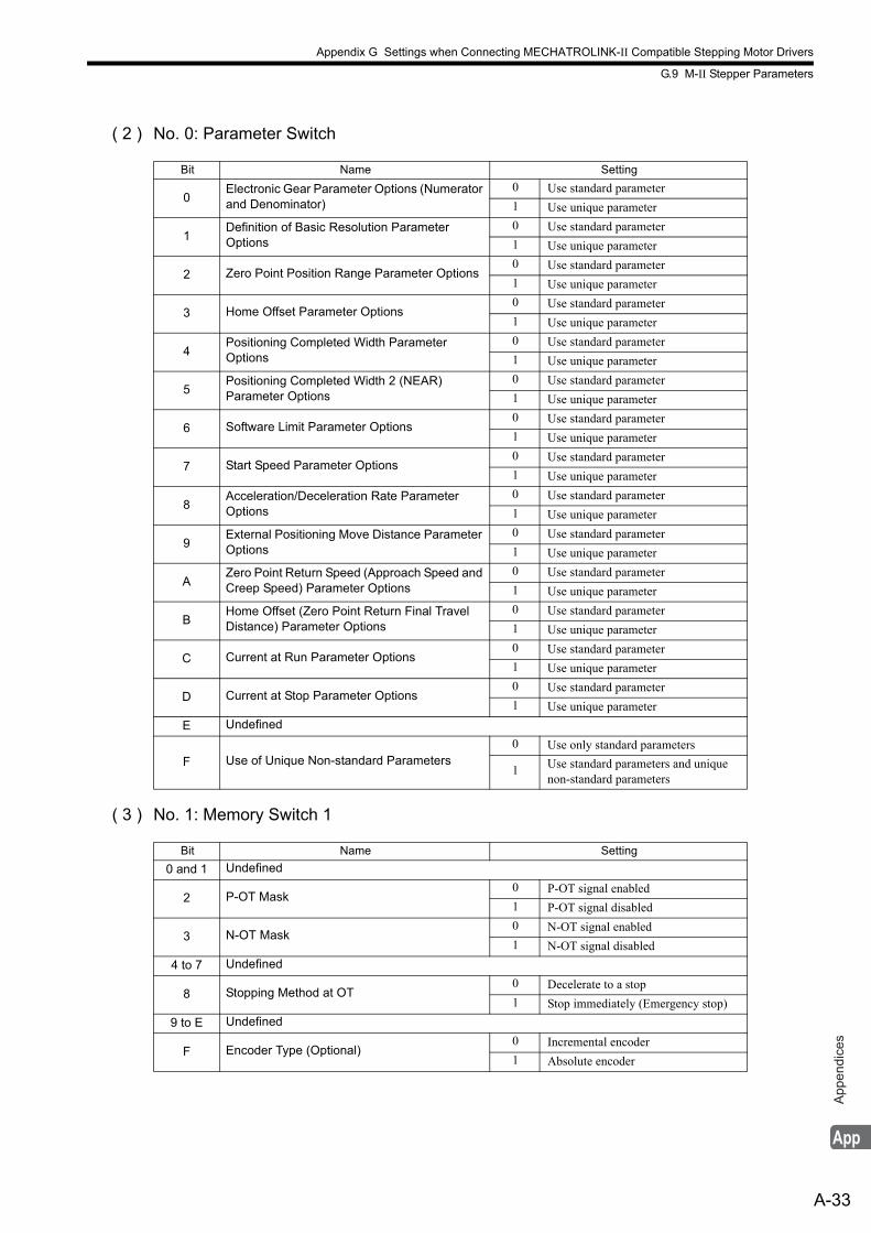
Appendix G Settings when Connecting MECHATROLINK-II Compatible Stepping Motor Drivers
G.9 M-II Stepper Parameters
A-33
App
endi
ces
( 2 ) No. 0: Parameter Switch
( 3 ) No. 1: Memory Switch 1
Bit Name Setting
0Electronic Gear Parameter Options (Numerator and Denominator)
0 Use standard parameter
1 Use unique parameter
1Definition of Basic Resolution Parameter Options
0 Use standard parameter
1 Use unique parameter
2 Zero Point Position Range Parameter Options0 Use standard parameter
1 Use unique parameter
3 Home Offset Parameter Options0 Use standard parameter
1 Use unique parameter
4Positioning Completed Width ParameterOptions
0 Use standard parameter
1 Use unique parameter
5Positioning Completed Width 2 (NEAR) Parameter Options
0 Use standard parameter
1 Use unique parameter
6 Software Limit Parameter Options0 Use standard parameter
1 Use unique parameter
7 Start Speed Parameter Options0 Use standard parameter
1 Use unique parameter
8Acceleration/Deceleration Rate Parameter Options
0 Use standard parameter
1 Use unique parameter
9External Positioning Move Distance Parameter Options
0 Use standard parameter
1 Use unique parameter
AZero Point Return Speed (Approach Speed and Creep Speed) Parameter Options
0 Use standard parameter
1 Use unique parameter
BHome Offset (Zero Point Return Final TravelDistance) Parameter Options
0 Use standard parameter
1 Use unique parameter
C Current at Run Parameter Options0 Use standard parameter
1 Use unique parameter
D Current at Stop Parameter Options0 Use standard parameter
1 Use unique parameter
E Undefined
F Use of Unique Non-standard Parameters0 Use only standard parameters
1 Use standard parameters and unique non-standard parameters
Bit Name Setting
0 and 1 Undefined
2 P-OT Mask0 P-OT signal enabled
1 P-OT signal disabled
3 N-OT Mask0 N-OT signal enabled
1 N-OT signal disabled
4 to 7 Undefined
8 Stopping Method at OT0 Decelerate to a stop
1 Stop immediately (Emergency stop)
9 to E Undefined
F Encoder Type (Optional)0 Incremental encoder
1 Absolute encoder
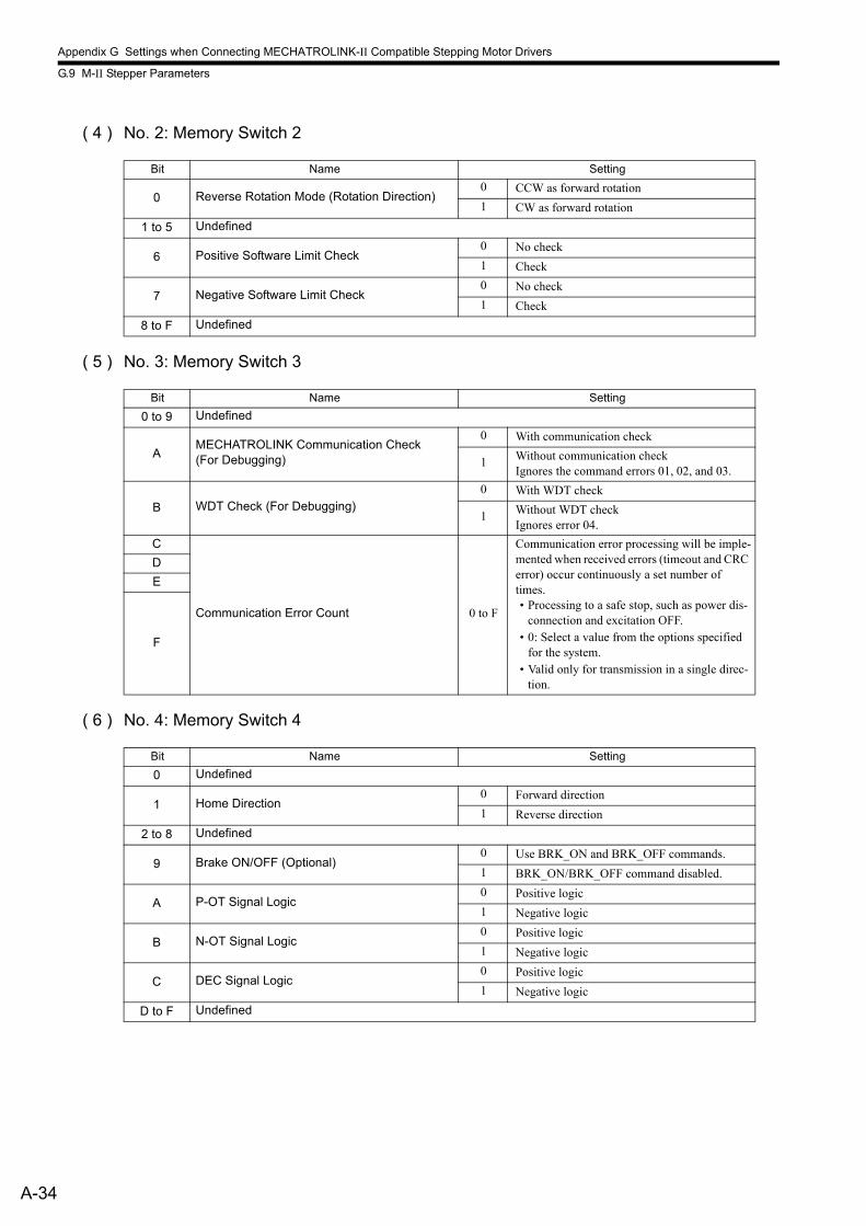
Appendix G Settings when Connecting MECHATROLINK-II Compatible Stepping Motor Drivers
G.9 M-II Stepper Parameters
A-34
( 4 ) No. 2: Memory Switch 2
( 5 ) No. 3: Memory Switch 3
( 6 ) No. 4: Memory Switch 4
Bit Name Setting
0 Reverse Rotation Mode (Rotation Direction)0 CCW as forward rotation
1 CW as forward rotation
1 to 5 Undefined
6 Positive Software Limit Check0 No check
1 Check
7 Negative Software Limit Check0 No check
1 Check
8 to F Undefined
Bit Name Setting
0 to 9 Undefined
AMECHATROLINK Communication Check(For Debugging)
0 With communication check
1 Without communication checkIgnores the command errors 01, 02, and 03.
B WDT Check (For Debugging)0 With WDT check
1 Without WDT checkIgnores error 04.
C
Communication Error Count 0 to F
Communication error processing will be imple-mented when received errors (timeout and CRC error) occur continuously a set number of times.• Processing to a safe stop, such as power dis-
connection and excitation OFF.• 0: Select a value from the options specified
for the system.• Valid only for transmission in a single direc-
tion.
D
E
F
Bit Name Setting
0 Undefined
1 Home Direction0 Forward direction
1 Reverse direction
2 to 8 Undefined
9 Brake ON/OFF (Optional)0 Use BRK_ON and BRK_OFF commands.
1 BRK_ON/BRK_OFF command disabled.
A P-OT Signal Logic0 Positive logic
1 Negative logic
B N-OT Signal Logic0 Positive logic
1 Negative logic
C DEC Signal Logic0 Positive logic
1 Negative logic
D to F Undefined
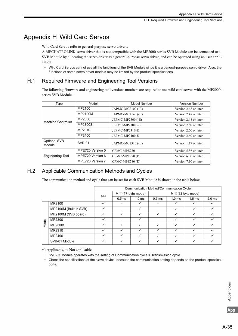
Appendix H Wild Card Servos
H.1 Required Firmware and Engineering Tool Versions
A-35
App
endi
ces
Appendix H Wild Card ServosWild Card Servos refer to general-purpose servo drivers.A MECHATROLINK servo driver that is not compatible with the MP2000-series SVB Module can be connected to a SVB Module by allocating the servo driver as a general-purpose servo driver, and can be operated using an user appli-cation.
Wild Card Servos cannot use all the functions of the SVB Module since it is a general-purpose servo driver. Also, the functions of some servo driver models may be limited by the product specifications.
H.1 Required Firmware and Engineering Tool Versions
The following firmware and engineering tool versions numbers are required to use wild card servos with the MP2000-series SVB Module.
H.2 Applicable Communication Methods and Cycles
The communication method and cycle that can be set for each SVB Module is shown in the table below.
: Applicable, −: Not applicable
SVB-01 Module operates with the setting of Communication cycle = Transmission cycle.
Check the specifications of the slave device, because the communication setting depends on the product specifica-tions.
Type Model Model Number Version Number
Machine Controller
MP2100 JAPMC-MC2100 (-E) Version 2.48 or later
MP2100M JAPMC-MC2140 (-E) Version 2.48 or later
MP2300 JEPMC-MP2300 (-E) Version 2.48 or later
MP2300S JEPMC-MP2300S-E Version 2.60 or later
MP2310 JEPMC-MP2310-E Version 2.60 or later
MP2400 JEPMC-MP2400-E Version 2.60 or later
Optional SVB Module
SVB-01 JAPMC-MC2310 (-E) Version 1.19 or later
Engineering Tool
MPE720 Version 5 CPMC-MPE720 Version 5.36 or later
MPE720 Version 6 CPMC-MPE770 (D) Version 6.00 or later
MPE720 Version 7 CPMC-MPE780 (D) Version 7.10 or later
Communication Method/Communication Cycle
M-IM-II (17-byte mode) M-II (32-byte mode)
0.5ms 1.0 ms 0.5 ms 1.0 ms 1.5 ms 2.0 ms
Mod
el
MP2100 − −
MP2100M (Built-in SVB) − −
MP2100M (SVB board)
MP2300 − −
MP2300S
MP2310
MP2400
SVB-01 Module
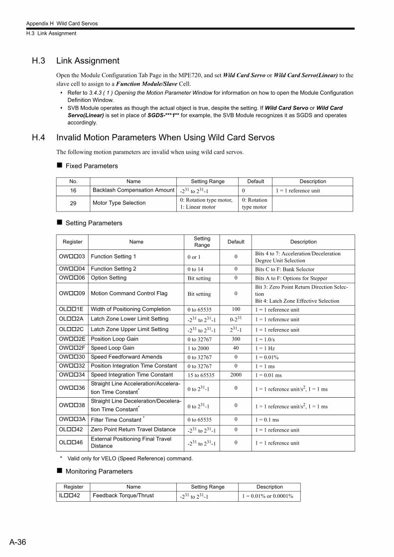
Appendix H Wild Card Servos
H.3 Link Assignment
A-36
H.3 Link Assignment
Open the Module Configuration Tab Page in the MPE720, and set Wild Card Servo or Wild Card Servo(Linear) to the slave cell to assign to a Function Module/Slave Cell.
Refer to 3.4.3 ( 1 ) Opening the Motion Parameter Window for information on how to open the Module Configuration Definition Window.
SVB Module operates as though the actual object is true, despite the setting. If Wild Card Servo or Wild Card Servo(Linear) is set in place of SGDS-***1** for example, the SVB Module recognizes it as SGDS and operates accordingly.
H.4 Invalid Motion Parameters When Using Wild Card Servos
The following motion parameters are invalid when using wild card servos.
Fixed Parameters
Setting Parameters
* Valid only for VELO (Speed Reference) command.
Monitoring Parameters
No. Name Setting Range Default Description
16 Backlash Compensation Amount -231 to 231-1 0 1 = 1 reference unit
29 Motor Type Selection 0: Rotation type motor, 1: Linear motor
0: Rotation type motor
Register NameSetting Range
Default Description
OW03 Function Setting 1 0 or 1 0 Bits 4 to 7: Acceleration/Deceleration Degree Unit Selection
OW04 Function Setting 2 0 to 14 0 Bits C to F: Bank Selector
OW06 Option Setting Bit setting 0 Bits A to F: Options for Stepper
OW09 Motion Command Control Flag Bit setting 0Bit 3: Zero Point Return Direction Selec-tionBit 4: Latch Zone Effective Selection
OL1E Width of Positioning Completion 0 to 65535 100 1 = 1 reference unit
OL2A Latch Zone Lower Limit Setting -231 to 231-1 0-231 1 = 1 reference unit
OL2C Latch Zone Upper Limit Setting -231 to 231-1 231-1 1 = 1 reference unit
OW2E Position Loop Gain 0 to 32767 300 1 = 1.0/s
OW2F Speed Loop Gain 1 to 2000 40 1 = 1 Hz
OW30 Speed Feedforward Amends 0 to 32767 0 1 = 0.01%
OW32 Position Integration Time Constant 0 to 32767 0 1 = 1 ms
OW34 Speed Integration Time Constant 15 to 65535 2000 1 = 0.01 ms
OW36Straight Line Acceleration/Accelera-
tion Time Constant* 0 to 231-1 0 1 = 1 reference unit/s2, 1 = 1 ms
OW38Straight Line Deceleration/Decelera-
tion Time Constant* 0 to 231-1 0 1 = 1 reference unit/s2, 1 = 1 ms
OW3A Filter Time Constant * 0 to 65535 0 1 = 0.1 ms
OL42 Zero Point Return Travel Distance -231 to 231-1 0 1 = 1 reference unit
OL46External Positioning Final Travel Distance -231 to 231-1 0 1 = 1 reference unit
Register Name Setting Range Description
IL42 Feedback Torque/Thrust -231 to 231-1 1 = 0.01% or 0.0001%
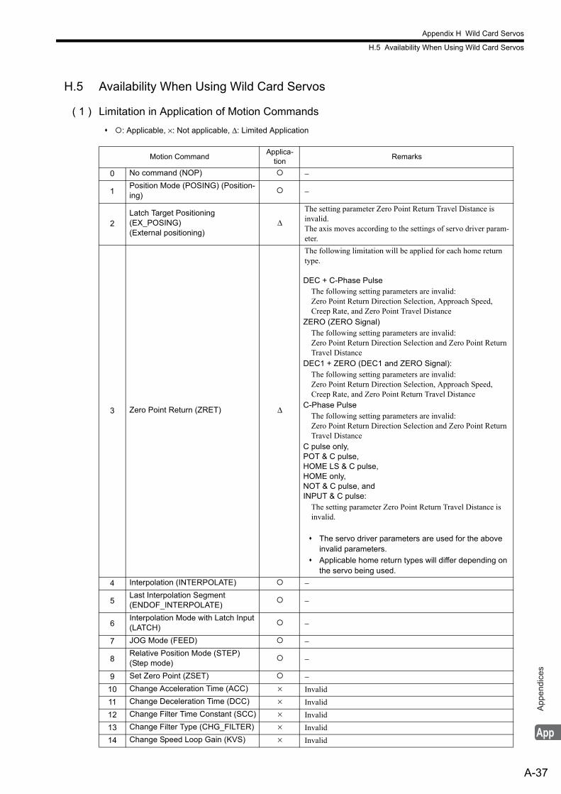
Appendix H Wild Card Servos
H.5 Availability When Using Wild Card Servos
A-37
App
endi
ces
H.5 Availability When Using Wild Card Servos
( 1 ) Limitation in Application of Motion Commands
: Applicable, ×: Not applicable, Δ: Limited Application
Motion CommandApplica-
tionRemarks
0 No command (NOP) −
1Position Mode (POSING) (Position-ing)
−
2Latch Target Positioning(EX_POSING)(External positioning)
Δ
The setting parameter Zero Point Return Travel Distance is invalid.The axis moves according to the settings of servo driver param-eter.
3 Zero Point Return (ZRET) Δ
The following limitation will be applied for each home return type.
DEC + C-Phase PulseThe following setting parameters are invalid:Zero Point Return Direction Selection, Approach Speed, Creep Rate, and Zero Point Travel Distance
ZERO (ZERO Signal)The following setting parameters are invalid:Zero Point Return Direction Selection and Zero Point Return Travel Distance
DEC1 + ZERO (DEC1 and ZERO Signal):The following setting parameters are invalid:Zero Point Return Direction Selection, Approach Speed, Creep Rate, and Zero Point Return Travel Distance
C-Phase PulseThe following setting parameters are invalid:Zero Point Return Direction Selection and Zero Point Return Travel Distance
C pulse only,POT & C pulse,HOME LS & C pulse,HOME only,NOT & C pulse, andINPUT & C pulse:
The setting parameter Zero Point Return Travel Distance is invalid.
The servo driver parameters are used for the above invalid parameters.
Applicable home return types will differ depending on the servo being used.
4 Interpolation (INTERPOLATE) −
5Last Interpolation Segment(ENDOF_INTERPOLATE)
−
6Interpolation Mode with Latch Input (LATCH)
−
7 JOG Mode (FEED) −
8Relative Position Mode (STEP) (Step mode)
−
9 Set Zero Point (ZSET) −10 Change Acceleration Time (ACC) × Invalid
11 Change Deceleration Time (DCC) × Invalid
12 Change Filter Time Constant (SCC) × Invalid
13 Change Filter Type (CHG_FILTER) × Invalid
14 Change Speed Loop Gain (KVS) × Invalid
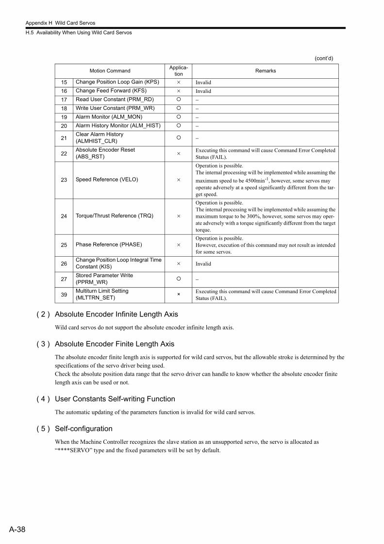
Appendix H Wild Card Servos
H.5 Availability When Using Wild Card Servos
A-38
( 2 ) Absolute Encoder Infinite Length Axis
Wild card servos do not support the absolute encoder infinite length axis.
( 3 ) Absolute Encoder Finite Length Axis
The absolute encoder finite length axis is supported for wild card servos, but the allowable stroke is determined by the specifications of the servo driver being used.Check the absolute position data range that the servo driver can handle to know whether the absolute encoder finite length axis can be used or not.
( 4 ) User Constants Self-writing Function
The automatic updating of the parameters function is invalid for wild card servos.
( 5 ) Self-configuration
When the Machine Controller recognizes the slave station as an unsupported servo, the servo is allocated as “****SERVO” type and the fixed parameters will be set by default.
15 Change Position Loop Gain (KPS) × Invalid
16 Change Feed Forward (KFS) × Invalid
17 Read User Constant (PRM_RD) −18 Write User Constant (PRM_WR) −19 Alarm Monitor (ALM_MON) −20 Alarm History Monitor (ALM_HIST) −
21Clear Alarm History(ALMHIST_CLR)
−
22Absolute Encoder Reset(ABS_RST)
× Executing this command will cause Command Error Completed Status (FAIL).
23 Speed Reference (VELO) ×
Operation is possible.The internal processing will be implemented while assuming the
maximum speed to be 4500min-1, however, some servos may operate adversely at a speed significantly different from the tar-get speed.
24 Torque/Thrust Reference (TRQ) ×
Operation is possible.The internal processing will be implemented while assuming the maximum torque to be 300%, however, some servos may oper-ate adversely with a torque significantly different from the target torque.
25 Phase Reference (PHASE) ×Operation is possible.However, execution of this command may not result as intended for some servos.
26Change Position Loop Integral Time Constant (KIS)
× Invalid
27Stored Parameter Write(PPRM_WR)
−
39Multiturn Limit Setting (MLTTRN_SET)
× Executing this command will cause Command Error CompletedStatus (FAIL).
(cont’d)
Motion CommandApplica-
tionRemarks
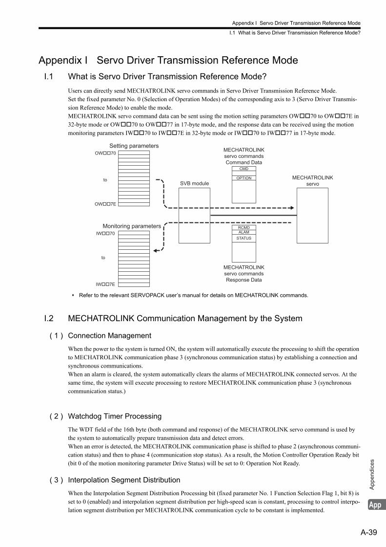
Appendix I Servo Driver Transmission Reference Mode
I.1 What is Servo Driver Transmission Reference Mode?
A-39
App
endi
ces
Appendix I Servo Driver Transmission Reference Mode
I.1 What is Servo Driver Transmission Reference Mode?
Users can directly send MECHATROLINK servo commands in Servo Driver Transmission Reference Mode.Set the fixed parameter No. 0 (Selection of Operation Modes) of the corresponding axis to 3 (Servo Driver Transmis-sion Reference Mode) to enable the mode.MECHATROLINK servo command data can be sent using the motion setting parameters OW70 to OW7E in 32-byte mode or OW70 to OW77 in 17-byte mode, and the response data can be received using the motion monitoring parameters IW70 to IW7E in 32-byte mode or IW70 to IW77 in 17-byte mode.
Refer to the relevant SERVOPACK user’s manual for details on MECHATROLINK commands.
I.2 MECHATROLINK Communication Management by the System
( 1 ) Connection Management
When the power to the system is turned ON, the system will automatically execute the processing to shift the operation to MECHATROLINK communication phase 3 (synchronous communication status) by establishing a connection and synchronous communications.When an alarm is cleared, the system automatically clears the alarms of MECHATROLINK connected servos. At the same time, the system will execute processing to restore MECHATROLINK communication phase 3 (synchronous communication status.)
( 2 ) Watchdog Timer Processing
The WDT field of the 16th byte (both command and response) of the MECHATROLINK servo command is used by the system to automatically prepare transmission data and detect errors.When an error is detected, the MECHATROLINK communication phase is shifted to phase 2 (asynchronous communi-cation status) and then to phase 4 (communication stop status). As a result, the Motion Controller Operation Ready bit (bit 0 of the motion monitoring parameter Drive Status) will be set to 0: Operation Not Ready.
( 3 ) Interpolation Segment Distribution
When the Interpolation Segment Distribution Processing bit (fixed parameter No. 1 Function Selection Flag 1, bit 8) is set to 0 (enabled) and interpolation segment distribution per high-speed scan is constant, processing to control interpo-lation segment distribution per MECHATROLINK communication cycle to be constant is implemented.
Setting parametersOW��70
OW��7E
Monitoring parametersIW��70
IW��7E
CMD
OPTION
RCMDALAM
STATUS
SVB module
MECHATROLINKservo commandsCommand Data
MECHATROLINKservo commandsResponse Data
MECHATROLINKservo
to
to
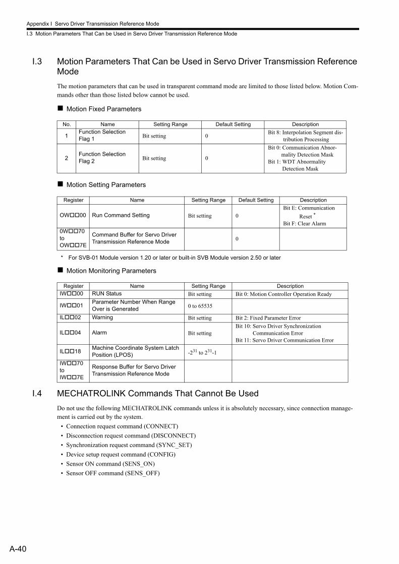
Appendix I Servo Driver Transmission Reference Mode
I.3 Motion Parameters That Can be Used in Servo Driver Transmission Reference Mode
A-40
I.3 Motion Parameters That Can be Used in Servo Driver Transmission Reference Mode
The motion parameters that can be used in transparent command mode are limited to those listed below. Motion Com-mands other than those listed below cannot be used.
Motion Fixed Parameters
Motion Setting Parameters
* For SVB-01 Module version 1.20 or later or built-in SVB Module version 2.50 or later
Motion Monitoring Parameters
I.4 MECHATROLINK Commands That Cannot Be Used
Do not use the following MECHATROLINK commands unless it is absolutely necessary, since connection manage-ment is carried out by the system.
• Connection request command (CONNECT)
• Disconnection request command (DISCONNECT)
• Synchronization request command (SYNC_SET)
• Device setup request command (CONFIG)
• Sensor ON command (SENS_ON)
• Sensor OFF command (SENS_OFF)
No. Name Setting Range Default Setting Description
1Function Selection Flag 1 Bit setting 0
Bit 8: Interpolation Segment dis-tribution Processing
2Function Selection Flag 2 Bit setting 0
Bit 0: Communication Abnor-mality Detection Mask
Bit 1: WDT Abnormality Detection Mask
Register Name Setting Range Default Setting Description
OW00 Run Command Setting Bit setting 0Bit E: Communication
Reset *
Bit F: Clear Alarm0W70toOW7E
Command Buffer for Servo Driver Transmission Reference Mode 0
Register Name Setting Range Description
IW00 RUN Status Bit setting Bit 0: Motion Controller Operation Ready
IW01Parameter Number When Range Over is Generated 0 to 65535
IL02 Warning Bit setting Bit 2: Fixed Parameter Error
IL04 Alarm Bit settingBit 10: Servo Driver Synchronization
Communication ErrorBit 11: Servo Driver Communication Error
IL18Machine Coordinate System Latch Position (LPOS) -231 to 231-1
IW70to IW7E
Response Buffer for Servo Driver Transmission Reference Mode
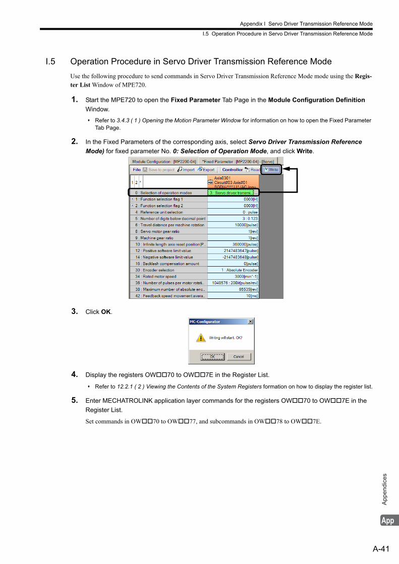
Appendix I Servo Driver Transmission Reference Mode
I.5 Operation Procedure in Servo Driver Transmission Reference Mode
A-41
App
endi
ces
I.5 Operation Procedure in Servo Driver Transmission Reference Mode
Use the following procedure to send commands in Servo Driver Transmission Reference Mode mode using the Regis-ter List Window of MPE720.
1. Start the MPE720 to open the Fixed Parameter Tab Page in the Module Configuration Definition
Window.
Refer to 3.4.3 ( 1 ) Opening the Motion Parameter Window for information on how to open the Fixed Parameter Tab Page.
2. In the Fixed Parameters of the corresponding axis, select Servo Driver Transmission Reference
Mode) for fixed parameter No. 0: Selection of Operation Mode, and click Write.
3. Click OK.
4. Display the registers OW70 to OW7E in the Register List.
Refer to 12.2.1 ( 2 ) Viewing the Contents of the System Registers formation on how to display the register list.
5. Enter MECHATROLINK application layer commands for the registers OW70 to OW7E in the
Register List.
Set commands in OW70 to OW77, and subcommands in OW78 to OW7E.
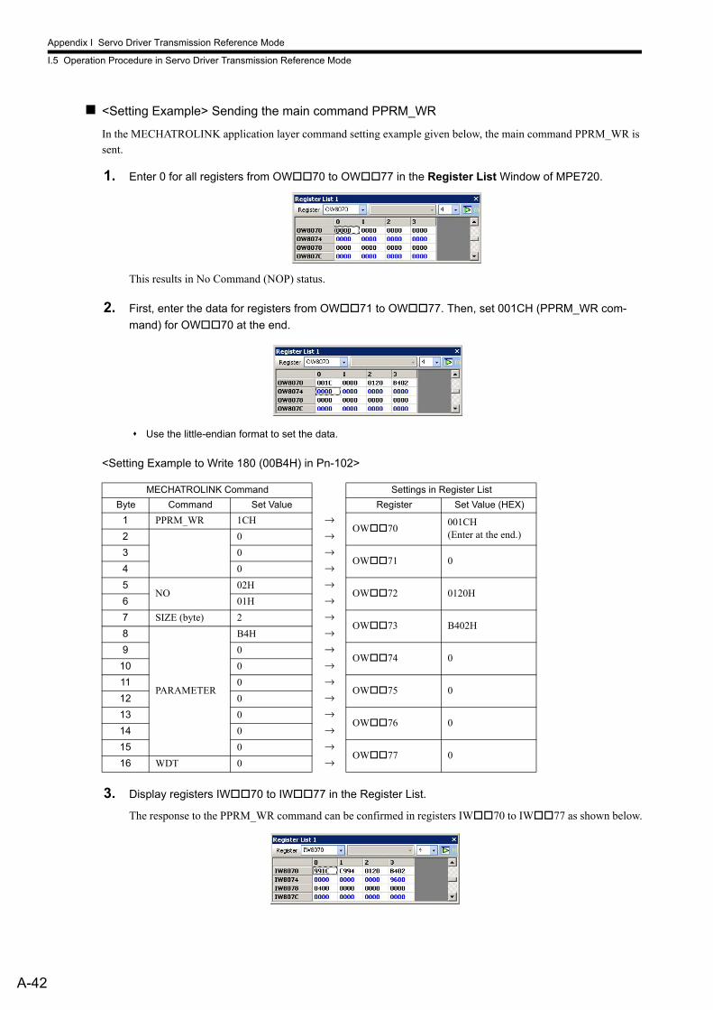
Appendix I Servo Driver Transmission Reference Mode
I.5 Operation Procedure in Servo Driver Transmission Reference Mode
A-42
<Setting Example> Sending the main command PPRM_WR
In the MECHATROLINK application layer command setting example given below, the main command PPRM_WR is sent.
1. Enter 0 for all registers from OW70 to OW77 in the Register List Window of MPE720.
This results in No Command (NOP) status.
2. First, enter the data for registers from OW71 to OW77. Then, set 001CH (PPRM_WR com-
mand) for OW70 at the end.
Use the little-endian format to set the data.
<Setting Example to Write 180 (00B4H) in Pn-102>
3. Display registers IW70 to IW77 in the Register List.
The response to the PPRM_WR command can be confirmed in registers IW70 to IW77 as shown below.
MECHATROLINK Command Settings in Register List
Byte Command Set Value Register Set Value (HEX)
1 PPRM_WR 1CH →OW70
001CH(Enter at the end.)2 0 →
3 0 →OW71 0
4 0 →
5NO
02H →OW72 0120H
6 01H →
7 SIZE (byte) 2 →OW73 B402H
8
PARAMETER
B4H →
9 0 →OW74 0
10 0 →
11 0 →OW75 0
12 0 →
13 0 →OW76 0
14 0 →
15 0 →OW77 0
16 WDT 0 →
Appendix I Servo Driver Transmission Reference Mode
I.6 Precautions When Using Servo Driver Transmission Reference Mode
A-43
App
endi
ces
I.6 Precautions When Using Servo Driver Transmission Reference Mode
• Note that the response to a MECHATROLINK servo command will be delayed because of the delay in the MECHATROLINK communications.For example, when sending a move command such as POSING for the axis being stopped, it will take some time for the Commanded Profile Complete bit to turn OFF. Wait the following number of scans to monitor the response data to the MECHATROLINK servo command.
When High-speed scan set time < MECHATROLINK communication cycle × 3 Number of scans (rounded up to the nearest integer) = MECHATROLINK communication cycle × 7 ÷ High-speed scan set timeWhen MECHATROLINK communication cycle × 3 ≤ High-speed scan set time ≤ MECHATROLINK com-munication cycle × 6 Number of scans (rounded up to the nearest integer) = MECHATROLINK communication cycle × 6 ÷ High-speed scan set time + 1When High-speed scan set time > MECHATROLINK communication cycle × 6 Number of scans = 1
• Always set the Interpolation Segment Distribution Processing bit (fixed parameter No. 1 Function Selection Flag 1, bit 8) to 0 (enabled) when using an interpolation MECHATROLINK servo command, INTERPOLATE or LATCH.If this bit is set to 1 (disabled), interpolation segment distribution per MECHATROLINK communication cycle will not be constant, though that per high-speed scan will be constant. As a result, the speed waveform will be disordered.
• Precaution on operation of MPE720 parameter windows of MECHATROLINK compatible servosCurrent value reading, writing, and saving operations are allowed only when the MECHATROLINK servo com-mand NOP is set. The operations in parameter windows are disabled while any command other than NOP is being executed.
Appendix J Terminology
A-44
Appendix J Terminology
Phase-C Pulse
The encoders mounted on Yaskawa’s servomotors output three types of pulse data, phase-A, -B, and -C. Phase-C pulse is a signal that reverses once per motor rotation and is called Zero-point Pulse.
POSMAX
Reset position of infinite length axisRefer to 4.4.1 Motion Fixed Parameter Details for details.
Override
The original meaning of Override is annulling. In descriptions on Machine Controllers, override means overwriting the setting.
Machine Coordinate System
The basic coordinate system set by executing the motion command ZRET (Zero Point Return) or ZSET (Set Zero Point). The Machine Controller manages positions using the Machine Coordinate System.With a system using an incremental encoder, or absolute encoder as the incremental encoder, the Machine Coordinate System is automatically set by the first zero point return operation after the power turns ON.With the system using an absolute encoder, it is automatically set after the power turns ON.
Deceleration LS
Limit switch for deceleration.For SERVOPACKs, deceleration LS for zero point return is connected to the Zero Point Return Deceleration signal DEC.
Absolute Mode
One of target position (CPOS) coordinate data setting methods for position control. Target position (CPOS) coordinate data is directly set in Absolute Mode.Refer to 5.1.4 Position Reference for details.
Incremental Addition Mode
One of the target position (CPOS) coordinate data setting methods for position control. Target position (CPOS) coordi-nate data is set by adding the movement amount to the previous position reference value in Incremental Addition Mode.Refer to 5.1.4 Position Reference for details.
Infinite Length Axis
An axis that employs the infinite length position control method, which resets the position data after one motor rota-tion.Refer to 5.1.3 Axis Type Selection for details.
Infinite Length Position Control
This control method is used to perform position control without limiting the movement range for movements such as rotation in one direction.Refer to 5.1.3 Axis Type Selection for details.
Finite Length Axis
An axis that employs the finite length position control method or infinite length position control that does not reset the position data after one motor rotation to move in one direction.Refer to 5.1.3 Axis Type Selection for details.
Appendix J Terminology
A-45
App
endi
ces
Finite Length Position Control
This control method is used to perform position control within a specified section for movements such as go-and-return motions.Refer to 5.1.3 Axis Type Selection for details.
Work Coordinate System
The coordinate system used in motion programs. It is called the Work Coordinate System to distinguish it from the Machine Coordinate System. The work coordinate system can be set by executing the Change Current Value (POS) instruction of the motion program.Refer to Machine Controller MP2000 Series User’s Manual Motion Programming (manual number: SIEP C880700 38) for details.
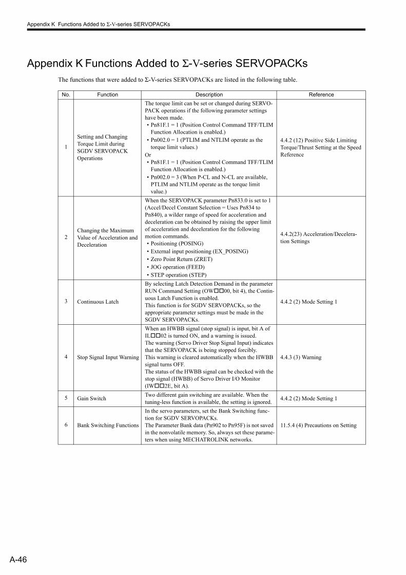
Appendix K Functions Added to Σ-V-series SERVOPACKs
A-46
Appendix K Functions Added to Σ-V-series SERVOPACKsThe functions that were added to Σ-V-series SERVOPACKs are listed in the following table.
No. Function Description Reference
1
Setting and Changing Torque Limit during SGDV SERVOPACK Operations
The torque limit can be set or changed during SERVO-PACK operations if the following parameter settings have been made.• Pn81F.1 = 1 (Position Control Command TFF/TLIM
Function Allocation is enabled.)• Pn002.0 = 1 (PTLIM and NTLIM operate as the
torque limit values.)Or• Pn81F.1 = 1 (Position Control Command TFF/TLIM
Function Allocation is enabled.)• Pn002.0 = 3 (When P-CL and N-CL are available,
PTLIM and NTLIM operate as the torque limit value.)
4.4.2 (12) Positive Side Limiting Torque/Thrust Setting at the Speed Reference
2Changing the Maximum Value of Acceleration and Deceleration
When the SERVOPACK parameter Pn833.0 is set to 1 (Accel/Decel Constant Selection = Uses Pn834 to Pn840), a wilder range of speed for acceleration and deceleration can be obtained by raising the upper limit of acceleration and deceleration for the following motion commands.• Positioning (POSING)• External input positioning (EX_POSING)• Zero Point Return (ZRET)• JOG operation (FEED)• STEP operation (STEP)
4.4.2(23) Acceleration/Decelera-tion Settings
3 Continuous Latch
By selecting Latch Detection Demand in the parameter RUN Command Setting (OW00, bit 4), the Contin-uous Latch Function is enabled.This function is for SGDV SERVOPACKs, so the appropriate parameter settings must be made in the SGDV SERVOPACKs.
4.4.2 (2) Mode Setting 1
4 Stop Signal Input Warning
When an HWBB signal (stop signal) is input, bit A of IL02 is turned ON, and a warning is issued.The warning (Servo Driver Stop Signal Input) indicates that the SERVOPACK is being stopped forcibly.This warning is cleared automatically when the HWBB signal turns OFF.The status of the HWBB signal can be checked with the stop signal (HWBB) of Servo Driver I/O Monitor (IW2E, bit A).
4.4.3 (3) Warning
5 Gain SwitchTwo different gain switching are available. When the tuning-less function is available, the setting is ignored.
4.4.2 (2) Mode Setting 1
6 Bank Switching Functions
In the servo parameters, set the Bank Switching func-tion for SGDV SERVOPACKs.The Parameter Bank data (Pn902 to Pn95F) is not saved in the nonvolatile memory. So, always set these parame-ters when using MECHATROLINK networks.
11.5.4 (4) Precautions on Setting
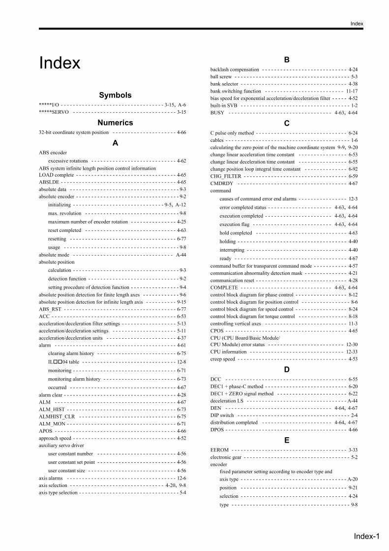
Index
Index-1
Index
Symbols *****I/O - - - - - - - - - - - - - - - - - - - - - - - - - - - - - - - - - - 3-15, A-6 *****SERVO - - - - - - - - - - - - - - - - - - - - - - - - - - - - - - - - - - 3-15
Numerics 32-bit coordinate system position - - - - - - - - - - - - - - - - - - - - - 4-66
A ABS encoder
excessive rotations - - - - - - - - - - - - - - - - - - - - - - - - - - - - 4-62 ABS system infinite length position control informationLOAD complete - - - - - - - - - - - - - - - - - - - - - - - - - - - - - - - - - 4-65 ABSLDE - - - - - - - - - - - - - - - - - - - - - - - - - - - - - - - - - - - - - - 4-65 absolute data - - - - - - - - - - - - - - - - - - - - - - - - - - - - - - - - - - - - 9-3 absolute encoder - - - - - - - - - - - - - - - - - - - - - - - - - - - - - - - - - - 9-2
initializing - - - - - - - - - - - - - - - - - - - - - - - - - - - - - - 9-5, A-12 max. revolution - - - - - - - - - - - - - - - - - - - - - - - - - - - - - - - 9-8 maximum number of encoder rotation - - - - - - - - - - - - - - - 4-25 reset completed - - - - - - - - - - - - - - - - - - - - - - - - - - - - - - 4-63 resetting - - - - - - - - - - - - - - - - - - - - - - - - - - - - - - - - - - - 6-77 usage - - - - - - - - - - - - - - - - - - - - - - - - - - - - - - - - - - - - - - 9-8
absolute mode - - - - - - - - - - - - - - - - - - - - - - - - - - - - - - - - - A-44 absolute position
calculation - - - - - - - - - - - - - - - - - - - - - - - - - - - - - - - - - - - 9-3 detection function - - - - - - - - - - - - - - - - - - - - - - - - - - - - - - 9-2 setting procedure of detection function - - - - - - - - - - - - - - - - 9-4
absolute position detection for finite length axes - - - - - - - - - - - - 9-6 absolute position detection for infinite length axis - - - - - - - - - - 9-15 ABS_RST - - - - - - - - - - - - - - - - - - - - - - - - - - - - - - - - - - - - - 6-77 ACC - - - - - - - - - - - - - - - - - - - - - - - - - - - - - - - - - - - - - - - - - 6-53 acceleration/deceleration filter settings - - - - - - - - - - - - - - - - - - 5-13 acceleration/deceleration settings - - - - - - - - - - - - - - - - - - - - - 5-11 acceleration/deceleration units - - - - - - - - - - - - - - - - - - - - - - - 4-37 alarm - - - - - - - - - - - - - - - - - - - - - - - - - - - - - - - - - - - - - - - - 4-61
clearing alarm history - - - - - - - - - - - - - - - - - - - - - - - - - - 6-75 IL04 table - - - - - - - - - - - - - - - - - - - - - - - - - - - - - - - 12-8 monitoring - - - - - - - - - - - - - - - - - - - - - - - - - - - - - - - - - - 6-71 monitoring alarm history - - - - - - - - - - - - - - - - - - - - - - - - 6-73 occurred - - - - - - - - - - - - - - - - - - - - - - - - - - - - - - - - - - - 4-67
alarm clear - - - - - - - - - - - - - - - - - - - - - - - - - - - - - - - - - - - - - 4-28 ALM - - - - - - - - - - - - - - - - - - - - - - - - - - - - - - - - - - - - - - - - 4-67 ALM_HIST - - - - - - - - - - - - - - - - - - - - - - - - - - - - - - - - - - - - 6-73 ALMHIST_CLR - - - - - - - - - - - - - - - - - - - - - - - - - - - - - - - - 6-75 ALM_MON - - - - - - - - - - - - - - - - - - - - - - - - - - - - - - - - - - - - 6-71 APOS - - - - - - - - - - - - - - - - - - - - - - - - - - - - - - - - - - - - - - - - 4-66 approach speed - - - - - - - - - - - - - - - - - - - - - - - - - - - - - - - - - - 4-52 auxiliary servo driver
user constant number - - - - - - - - - - - - - - - - - - - - - - - - - - 4-56 user constant set point - - - - - - - - - - - - - - - - - - - - - - - - - - 4-56 user constant size - - - - - - - - - - - - - - - - - - - - - - - - - - - - - 4-56
axis alarms - - - - - - - - - - - - - - - - - - - - - - - - - - - - - - - - - - - - 12-6 axis selection - - - - - - - - - - - - - - - - - - - - - - - - - - - - - - - 4-20, 9-8 axis type selection - - - - - - - - - - - - - - - - - - - - - - - - - - - - - - - - - 5-4
B backlash compensation - - - - - - - - - - - - - - - - - - - - - - - - - - - - 4-24 ball screw - - - - - - - - - - - - - - - - - - - - - - - - - - - - - - - - - - - - - - 5-3 bank selector - - - - - - - - - - - - - - - - - - - - - - - - - - - - - - - - - - - 4-38 bank switching function - - - - - - - - - - - - - - - - - - - - - - - - - - 11-17 bias speed for exponential acceleration/deceleration filter - - - - - 4-52 built-in SVB - - - - - - - - - - - - - - - - - - - - - - - - - - - - - - - - - - - - 1-2 BUSY - - - - - - - - - - - - - - - - - - - - - - - - - - - - - - - - - - 4-63, 4-64
C C pulse only method - - - - - - - - - - - - - - - - - - - - - - - - - - - - - - 6-24 cables - - - - - - - - - - - - - - - - - - - - - - - - - - - - - - - - - - - - - - - - - 1-6 calculating the zero point of the machine coordinate system 9-9, 9-20 change linear acceleration time constant - - - - - - - - - - - - - - - - 6-53 change linear deceleration time constant - - - - - - - - - - - - - - - - 6-55 change position loop integral time constant - - - - - - - - - - - - - - 6-92 CHG_FILTER - - - - - - - - - - - - - - - - - - - - - - - - - - - - - - - - - - 6-59 CMDRDY - - - - - - - - - - - - - - - - - - - - - - - - - - - - - - - - - - - - 4-67 command
causes of command error end alarms - - - - - - - - - - - - - - - - 12-3 error completed status - - - - - - - - - - - - - - - - - - - - - 4-63, 4-64 execution completed - - - - - - - - - - - - - - - - - - - - - - 4-63, 4-64 execution flag - - - - - - - - - - - - - - - - - - - - - - - - - - 4-63, 4-64 hold completed - - - - - - - - - - - - - - - - - - - - - - - - - - - - - - 4-63 holding - - - - - - - - - - - - - - - - - - - - - - - - - - - - - - - - - - - - 4-40 interrupting - - - - - - - - - - - - - - - - - - - - - - - - - - - - - - - - - 4-40 ready - - - - - - - - - - - - - - - - - - - - - - - - - - - - - - - - - - - - - 4-67
command buffer for transparent command mode - - - - - - - - - - - 4-57 communication abnormality detection mask - - - - - - - - - - - - - - 4-21 communication reset - - - - - - - - - - - - - - - - - - - - - - - - - - - - - - 4-28 COMPLETE - - - - - - - - - - - - - - - - - - - - - - - - - - - - - - 4-63, 4-64 control block diagram for phase control - - - - - - - - - - - - - - - - - 8-12 control block diagram for position control - - - - - - - - - - - - - - - - 8-6 control block diagram for speed control - - - - - - - - - - - - - - - - - 8-24 control block diagram for torque control - - - - - - - - - - - - - - - - 8-18 controlling vertical axes - - - - - - - - - - - - - - - - - - - - - - - - - - - 11-3 CPOS - - - - - - - - - - - - - - - - - - - - - - - - - - - - - - - - - - - - - - - - 4-65 CPU (CPU Board/Basic Module/CPU Module) error status - - - - - - - - - - - - - - - - - - - - - - - - - 12-30 CPU information - - - - - - - - - - - - - - - - - - - - - - - - - - - - - - - 12-33 creep speed - - - - - - - - - - - - - - - - - - - - - - - - - - - - - - - - - - - - 4-53
D DCC - - - - - - - - - - - - - - - - - - - - - - - - - - - - - - - - - - - - - - - - 6-55 DEC1 + phase-C method - - - - - - - - - - - - - - - - - - - - - - - - - - - 6-20 DEC1 + ZERO signal method - - - - - - - - - - - - - - - - - - - - - - - 6-22 deceleration LS - - - - - - - - - - - - - - - - - - - - - - - - - - - - - - - - - A-44 DEN - - - - - - - - - - - - - - - - - - - - - - - - - - - - - - - - - - - 4-64, 4-67 DIP switch - - - - - - - - - - - - - - - - - - - - - - - - - - - - - - - - - - - - - 2-4 distribution completed - - - - - - - - - - - - - - - - - - - - - - - 4-64, 4-67 DPOS - - - - - - - - - - - - - - - - - - - - - - - - - - - - - - - - - - - - - - - - 4-66
E EEROM - - - - - - - - - - - - - - - - - - - - - - - - - - - - - - - - - - - - - - 3-33 electronic gear - - - - - - - - - - - - - - - - - - - - - - - - - - - - - - - - - - - 5-2 encoder
fixed parameter setting according to encoder type and
axis type - - - - - - - - - - - - - - - - - - - - - - - - - - - - - - - - - - - A-20 position - - - - - - - - - - - - - - - - - - - - - - - - - - - - - - - - - - - 9-21 selection - - - - - - - - - - - - - - - - - - - - - - - - - - - - - - - - - - - 4-24 type - - - - - - - - - - - - - - - - - - - - - - - - - - - - - - - - - - - - - - - 9-8
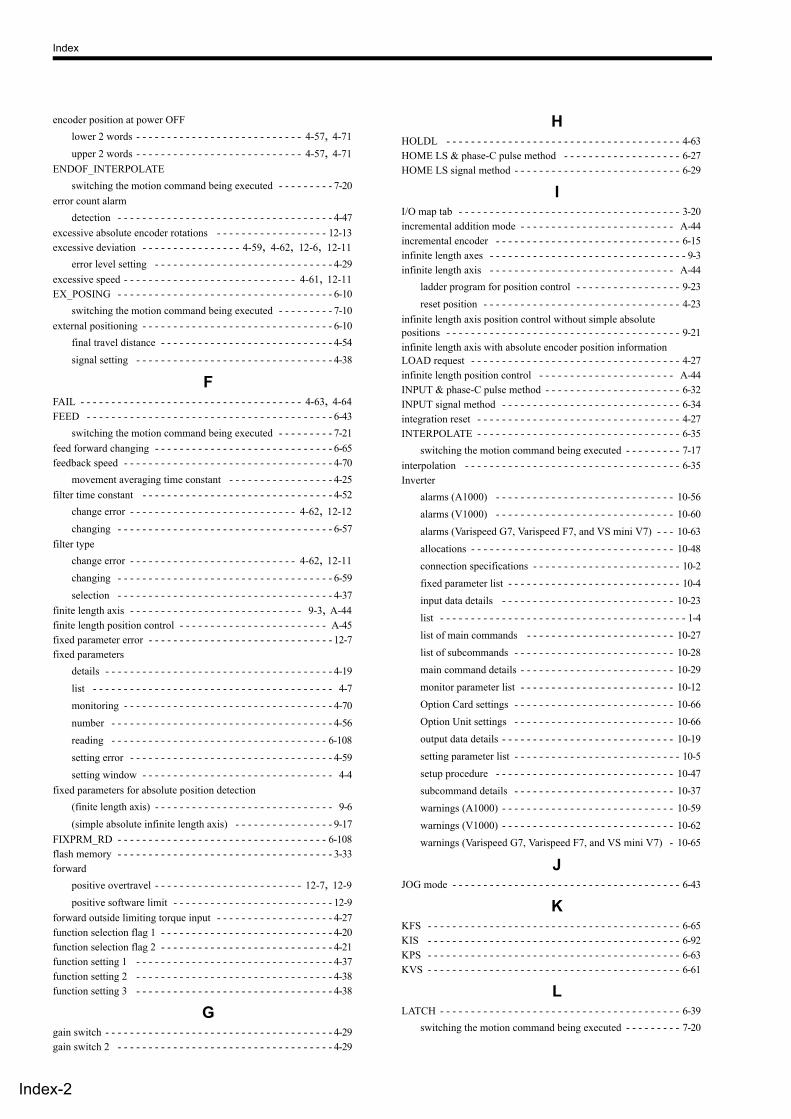
Index
Index-2
encoder position at power OFF lower 2 words - - - - - - - - - - - - - - - - - - - - - - - - - - - 4-57, 4-71 upper 2 words - - - - - - - - - - - - - - - - - - - - - - - - - - - 4-57, 4-71
ENDOF_INTERPOLATE switching the motion command being executed - - - - - - - - - 7-20
error count alarm detection - - - - - - - - - - - - - - - - - - - - - - - - - - - - - - - - - - - 4-47
excessive absolute encoder rotations - - - - - - - - - - - - - - - - - - 12-13 excessive deviation - - - - - - - - - - - - - - - - 4-59, 4-62, 12-6, 12-11
error level setting - - - - - - - - - - - - - - - - - - - - - - - - - - - - - 4-29 excessive speed - - - - - - - - - - - - - - - - - - - - - - - - - - - - 4-61, 12-11 EX_POSING - - - - - - - - - - - - - - - - - - - - - - - - - - - - - - - - - - - 6-10
switching the motion command being executed - - - - - - - - - 7-10 external positioning - - - - - - - - - - - - - - - - - - - - - - - - - - - - - - - 6-10
final travel distance - - - - - - - - - - - - - - - - - - - - - - - - - - - - 4-54 signal setting - - - - - - - - - - - - - - - - - - - - - - - - - - - - - - - - 4-38
F FAIL - - - - - - - - - - - - - - - - - - - - - - - - - - - - - - - - - - - - 4-63, 4-64 FEED - - - - - - - - - - - - - - - - - - - - - - - - - - - - - - - - - - - - - - - - 6-43
switching the motion command being executed - - - - - - - - - 7-21 feed forward changing - - - - - - - - - - - - - - - - - - - - - - - - - - - - - 6-65 feedback speed - - - - - - - - - - - - - - - - - - - - - - - - - - - - - - - - - - 4-70
movement averaging time constant - - - - - - - - - - - - - - - - - 4-25 filter time constant - - - - - - - - - - - - - - - - - - - - - - - - - - - - - - - 4-52
change error - - - - - - - - - - - - - - - - - - - - - - - - - - - 4-62, 12-12 changing - - - - - - - - - - - - - - - - - - - - - - - - - - - - - - - - - - - 6-57
filter type change error - - - - - - - - - - - - - - - - - - - - - - - - - - - 4-62, 12-11 changing - - - - - - - - - - - - - - - - - - - - - - - - - - - - - - - - - - - 6-59 selection - - - - - - - - - - - - - - - - - - - - - - - - - - - - - - - - - - - 4-37
finite length axis - - - - - - - - - - - - - - - - - - - - - - - - - - - - 9-3, A-44 finite length position control - - - - - - - - - - - - - - - - - - - - - - - - A-45 fixed parameter error - - - - - - - - - - - - - - - - - - - - - - - - - - - - - - 12-7 fixed parameters
details - - - - - - - - - - - - - - - - - - - - - - - - - - - - - - - - - - - - - 4-19 list - - - - - - - - - - - - - - - - - - - - - - - - - - - - - - - - - - - - - - - 4-7 monitoring - - - - - - - - - - - - - - - - - - - - - - - - - - - - - - - - - - 4-70 number - - - - - - - - - - - - - - - - - - - - - - - - - - - - - - - - - - - - 4-56 reading - - - - - - - - - - - - - - - - - - - - - - - - - - - - - - - - - - - 6-108 setting error - - - - - - - - - - - - - - - - - - - - - - - - - - - - - - - - - 4-59 setting window - - - - - - - - - - - - - - - - - - - - - - - - - - - - - - - 4-4
fixed parameters for absolute position detection (finite length axis) - - - - - - - - - - - - - - - - - - - - - - - - - - - - - 9-6 (simple absolute infinite length axis) - - - - - - - - - - - - - - - - 9-17
FIXPRM_RD - - - - - - - - - - - - - - - - - - - - - - - - - - - - - - - - - - 6-108 flash memory - - - - - - - - - - - - - - - - - - - - - - - - - - - - - - - - - - - 3-33 forward
positive overtravel - - - - - - - - - - - - - - - - - - - - - - - - 12-7, 12-9 positive software limit - - - - - - - - - - - - - - - - - - - - - - - - - - 12-9
forward outside limiting torque input - - - - - - - - - - - - - - - - - - - 4-27 function selection flag 1 - - - - - - - - - - - - - - - - - - - - - - - - - - - - 4-20 function selection flag 2 - - - - - - - - - - - - - - - - - - - - - - - - - - - - 4-21 function setting 1 - - - - - - - - - - - - - - - - - - - - - - - - - - - - - - - - 4-37 function setting 2 - - - - - - - - - - - - - - - - - - - - - - - - - - - - - - - - 4-38 function setting 3 - - - - - - - - - - - - - - - - - - - - - - - - - - - - - - - - 4-38
G gain switch - - - - - - - - - - - - - - - - - - - - - - - - - - - - - - - - - - - - - 4-29 gain switch 2 - - - - - - - - - - - - - - - - - - - - - - - - - - - - - - - - - - - 4-29
H HOLDL - - - - - - - - - - - - - - - - - - - - - - - - - - - - - - - - - - - - - - 4-63 HOME LS & phase-C pulse method - - - - - - - - - - - - - - - - - - - 6-27 HOME LS signal method - - - - - - - - - - - - - - - - - - - - - - - - - - - 6-29
I I/O map tab - - - - - - - - - - - - - - - - - - - - - - - - - - - - - - - - - - - - 3-20 incremental addition mode - - - - - - - - - - - - - - - - - - - - - - - - - A-44 incremental encoder - - - - - - - - - - - - - - - - - - - - - - - - - - - - - - 6-15 infinite length axes - - - - - - - - - - - - - - - - - - - - - - - - - - - - - - - - 9-3 infinite length axis - - - - - - - - - - - - - - - - - - - - - - - - - - - - - - A-44
ladder program for position control - - - - - - - - - - - - - - - - - 9-23 reset position - - - - - - - - - - - - - - - - - - - - - - - - - - - - - - - - 4-23
infinite length axis position control without simple absolute positions - - - - - - - - - - - - - - - - - - - - - - - - - - - - - - - - - - - - - - 9-21 infinite length axis with absolute encoder position information LOAD request - - - - - - - - - - - - - - - - - - - - - - - - - - - - - - - - - - 4-27 infinite length position control - - - - - - - - - - - - - - - - - - - - - - A-44 INPUT & phase-C pulse method - - - - - - - - - - - - - - - - - - - - - - 6-32 INPUT signal method - - - - - - - - - - - - - - - - - - - - - - - - - - - - - 6-34 integration reset - - - - - - - - - - - - - - - - - - - - - - - - - - - - - - - - - 4-27 INTERPOLATE - - - - - - - - - - - - - - - - - - - - - - - - - - - - - - - - - 6-35
switching the motion command being executed - - - - - - - - - 7-17 interpolation - - - - - - - - - - - - - - - - - - - - - - - - - - - - - - - - - - - 6-35 Inverter
alarms (A1000) - - - - - - - - - - - - - - - - - - - - - - - - - - - - - 10-56 alarms (V1000) - - - - - - - - - - - - - - - - - - - - - - - - - - - - - 10-60 alarms (Varispeed G7, Varispeed F7, and VS mini V7) - - - 10-63 allocations - - - - - - - - - - - - - - - - - - - - - - - - - - - - - - - - - 10-48 connection specifications - - - - - - - - - - - - - - - - - - - - - - - - 10-2 fixed parameter list - - - - - - - - - - - - - - - - - - - - - - - - - - - - 10-4 input data details - - - - - - - - - - - - - - - - - - - - - - - - - - - - 10-23 list - - - - - - - - - - - - - - - - - - - - - - - - - - - - - - - - - - - - - - - - 1-4 list of main commands - - - - - - - - - - - - - - - - - - - - - - - - 10-27 list of subcommands - - - - - - - - - - - - - - - - - - - - - - - - - - 10-28 main command details - - - - - - - - - - - - - - - - - - - - - - - - - 10-29 monitor parameter list - - - - - - - - - - - - - - - - - - - - - - - - - 10-12 Option Card settings - - - - - - - - - - - - - - - - - - - - - - - - - - 10-66 Option Unit settings - - - - - - - - - - - - - - - - - - - - - - - - - - 10-66 output data details - - - - - - - - - - - - - - - - - - - - - - - - - - - - 10-19 setting parameter list - - - - - - - - - - - - - - - - - - - - - - - - - - - 10-5 setup procedure - - - - - - - - - - - - - - - - - - - - - - - - - - - - - 10-47 subcommand details - - - - - - - - - - - - - - - - - - - - - - - - - - 10-37 warnings (A1000) - - - - - - - - - - - - - - - - - - - - - - - - - - - - 10-59 warnings (V1000) - - - - - - - - - - - - - - - - - - - - - - - - - - - - 10-62 warnings (Varispeed G7, Varispeed F7, and VS mini V7) - 10-65
J JOG mode - - - - - - - - - - - - - - - - - - - - - - - - - - - - - - - - - - - - - 6-43
K KFS - - - - - - - - - - - - - - - - - - - - - - - - - - - - - - - - - - - - - - - - - 6-65 KIS - - - - - - - - - - - - - - - - - - - - - - - - - - - - - - - - - - - - - - - - - 6-92 KPS - - - - - - - - - - - - - - - - - - - - - - - - - - - - - - - - - - - - - - - - - 6-63 KVS - - - - - - - - - - - - - - - - - - - - - - - - - - - - - - - - - - - - - - - - - 6-61
L LATCH - - - - - - - - - - - - - - - - - - - - - - - - - - - - - - - - - - - - - - - 6-39
switching the motion command being executed - - - - - - - - - 7-20
Index
Index-3
latch - - - - - - - - - - - - - - - - - - - - - - - - - - - - - - - - - - - - - - - - - 6-39 completed - - - - - - - - - - - - - - - - - - - - - - - - - - - - - 4-64, 4-67 completion status clear request - - - - - - - - - - - - - - - - 4-9, 4-27 detection demand - - - - - - - - - - - - - - - - - - - - - - - - - - - - - 4-26 detection demand completed - - - - - - - - - - - - - - - - - - - - - 4-58 detection signal selection - - - - - - - - - - - - - - - - - - - - - - - - 4-38 mode selection - - - - - - - - - - - - - - - - - - - - - - - - - - - 4-9, 4-29
latch zone effective selection - - - - - - - - - - - - - - - - - - - - - - - - - - - - - 4-40 lower limit setting - - - - - - - - - - - - - - - - - - - - - - - - - - - - - 4-48 upper limit setting - - - - - - - - - - - - - - - - - - - - - - - - - - - - - 4-48
L_CMP - - - - - - - - - - - - - - - - - - - - - - - - - - - - - - - - - - - - - - - 4-67 LCOMP - - - - - - - - - - - - - - - - - - - - - - - - - - - - - - - - - - - - - - 4-64 leading register numbers - - - - - - - - - - - - - - - - - - - - - - - - - - - - 4-2 limiting torque/force setting at the speed reference - - - - - - - - - - 4-43 linear acceleration/acceleration time constant - - - - - - - - - - - - - 4-50 linear deceleration/deceleration time constant - - - - - - - - - - - - - 4-50 linear scale pitch - - - - - - - - - - - - - - - - - - - - - - - - - - - - 4-22, 5-14 LPOS - - - - - - - - - - - - - - - - - - - - - - - - - - - - - - - - - - - - - - - - 4-66
M machine coordinate system - - - - - - - - - - - - - - - - - - - - - 4-66, A-44
calculated position - - - - - - - - - - - - - - - - - - - - - - - - - - - - 4-65 feedback position - - - - - - - - - - - - - - - - - - - - - - - - - - - - - 4-66 latch position - - - - - - - - - - - - - - - - - - - - - - - - - - - - - - - - 4-66 reference position - - - - - - - - - - - - - - - - - - - - - - - - - - - - - 4-66 target position - - - - - - - - - - - - - - - - - - - - - - - - - - - - - - - 4-65 zero point offset - - - - - - - - - - - - - - - - - - - - - - - - - - - - - - 4-54
machine gear ratio - - - - - - - - - - - - - - - - - - - - - - - - - - - - - - - 4-22 machine lock - - - - - - - - - - - - - - - - - - - - - - - - - - - - - - 4-26, 4-67 machine lock ON - - - - - - - - - - - - - - - - - - - - - - - - - - - - - - - - 4-65 main power ON - - - - - - - - - - - - - - - - - - - - - - - - - - - - - - - - - 4-67 maximum number of slave stations - - - - - - - - - - - - - - - - - - - - 1-12 MECHATROLINK
cables - - - - - - - - - - - - - - - - - - - - - - - - - - - - - - - - - - - - - - 1-6 communication specifications - - - - - - - - - - - - - - - - - - - - - 1-12 compatible distributed I/O modules - - - - - - - - - - - - - - - - - A-6 transmission definition - - - - - - - - - - - - - - - - - - - - - - - - - 3-16
MLKL - - - - - - - - - - - - - - - - - - - - - - - - - - - - - - - - - - - - - - - 4-65 MLOCK - - - - - - - - - - - - - - - - - - - - - - - - - - - - - - - - - - - - - - 4-67 modal latch function - - - - - - - - - - - - - - - - - - - - - - - - - - - - - 11-16 mode setting 1 - - - - - - - - - - - - - - - - - - - - - - - - - - - - - - - - - - 4-29 mode setting 2 - - - - - - - - - - - - - - - - - - - - - - - - - - - - - - - - - - 4-35 module configuration definition - - - - - - - - - - - - - - - - - - - - - - 3-13 module list - - - - - - - - - - - - - - - - - - - - - - - - - - - - - - - - - - - - - - 1-5 monitor 2 - - - - - - - - - - - - - - - - - - - - - - - - - - - - - - - - - - - - - 4-55 monitor 2 enabled - - - - - - - - - - - - - - - - - - - - - - - - - - - - - - - - 4-35 monitor 4 - - - - - - - - - - - - - - - - - - - - - - - - - - - - - - - - - - - - - 4-55 monitoring parameters
details - - - - - - - - - - - - - - - - - - - - - - - - - - - - - - - - - - - - - 4-58 list - - - - - - - - - - - - - - - - - - - - - - - - - - - - - - - - - - - - - - - 4-15
motion command response codes - - - - - - - - - - - - - - - - - - - - - - - - - - - - - - - 4-63 setting error - - - - - - - - - - - - - - - - - - - - - - - - - - - - - - - - - 4-59 status - - - - - - - - - - - - - - - - - - - - - - - - - - - - - - - - - - - - - 4-63
motion commands - - - - - - - - - - - - - - - - - - - - - - - - - - - - - - - 4-39 control flags - - - - - - - - - - - - - - - - - - - - - - - - - - - - - - - - 4-40 setting error - - - - - - - - - - - - - - - - - - - - - - - - - - - - - - - - - 12-7 switching between motion commands - - - - - - - - - - - - - - - - 7-2 switching motion commands - - - - - - - - - - - - - - - - - - - - - - 7-5 table - - - - - - - - - - - - - - - - - - - - - - - - - - - - - - - - - - - - - - - 6-3
motion commands supported by SERVOPACK models - - - - - - - 6-4 motion control functions - - - - - - - - - - - - - - - - - - - - - - - - - - - 1-10 motion controller operation ready - - - - - - - - - - - - - - - - - - - - - 4-58 motion errors
details - - - - - - - - - - - - - - - - - - - - - - - - - - - - - - - - - - - - 12-6 overview - - - - - - - - - - - - - - - - - - - - - - - - - - - - - - - - - - - 12-2
motion monitor parameter window - - - - - - - - - - - - - - - - - - - - - 4-4 motion parameter window - - - - - - - - - - - - - - - - - - - - - - - - - - 3-22 motion parameters
example setting - - - - - - - - - - - - - - - - - - - - - - - - - - - - - - - 5-2 register numbers - - - - - - - - - - - - - - - - - - - - - - - - - - - - - - 4-2 setting window - - - - - - - - - - - - - - - - - - - - - - - - - - - - - - - 4-4
motion parameters for phase control - - - - - - - - - - - - - - - - - - - - 8-8 motion parameters for position control - - - - - - - - - - - - - - - - - - 8-2 motion parameters for speed control - - - - - - - - - - - - - - - - - - - 8-20 motion parameters for torque control - - - - - - - - - - - - - - - - - - - 8-14 motion program
alarm codes - - - - - - - - - - - - - - - - - - - - - - - - - - - - - - - - 12-43 execution information - - - - - - - - - - - - - - - - - - - - - - - - - 12-38 structure of alarms - - - - - - - - - - - - - - - - - - - - - - - - - - - 12-43
motion subcommand response code - - - - - - - - - - - - - - - - - - - - - - - - - - - - - - - 4-64 status - - - - - - - - - - - - - - - - - - - - - - - - - - - - - - - - - - - - - 4-64
motion subcommands - - - - - - - - - - - - - - - - - - - - - - - - - - - - - 4-41 setting a subcommand during command execution - - - - - - - 7-4 table - - - - - - - - - - - - - - - - - - - - - - - - - - - - - - - - - - - - - 6-100
motor gear ratio - - - - - - - - - - - - - - - - - - - - - - - - - - - - - - - - - 4-22 motor type - - - - - - - - - - - - - - - - - - - - - - - - - - - - - - - - - - - - 4-69
alarm when motor type is unmatched - - - - - - - - - - - - - - - - 4-6 moving direction - - - - - - - - - - - - - - - - - - - - - - - - - - - - - - - - 4-40 MP940 - - - - - - - - - - - - - - - - - - - - - - - - - - - - - - - - - - - - - - - - A-6 MPOS - - - - - - - - - - - - - - - - - - - - - - - - - - - - - - - - - - - - - - - 4-66 Multiturn limit mismatch detection mask for finite length axis - - - - - - - - - - - - - - - - - - - - - - - - - - - - - - - - - - - - - - - - - 4-21 multiturn limit setting - - - - - - - - - - - - - - - - - - - - - - - - - 6-96, 9-8 MYVIS - - - - - - - - - - - - - - - - - - - - - - - - - - - - - - - - - - - - - - - A-6
N NEAR - - - - - - - - - - - - - - - - - - - - - - - - - - - - - - - - - - 4-64, 4-67 negative direction
overtravel - - - - - - - - - - - - - - - - - - - - - - - - - - - - - 4-59, 4-61 software limit - - - - - - - - - - - - - - - - - - - - - - - - - - 4-23, 4-61
negative direction software limit - - - - - - - - - - - - - - - - - - - - - - 4-67 no command - - - - - - - - - - - - - - - - - - - - - - - - - - - - - - - - - - 6-101 NOP - - - - - - - - - - - - - - - - - - - - - - - - - - - - - - - - - - - - - - - - 6-101 NOT & phase-C pulse method - - - - - - - - - - - - - - - - - - - - - - - 6-30 NOT signal method - - - - - - - - - - - - - - - - - - - - - - - - - - - - - - 6-31 N_SOT - - - - - - - - - - - - - - - - - - - - - - - - - - - - - - - - - - - - - - - 4-67 number of decimal places - - - - - - - - - - - - - - - - - - - - - - - - - - 4-22 number of pulses per linear scale pitch - - - - - - - - - - - - - - - - - 4-25 number of pulses per motor rotation - - - - - - - - - - - - - - - 4-25, 9-8
Index
Index-4
O OL10 - - - - - - - - - - - - - - - - - - - - - - - - - - - - - - - - - - - - - 5-10 Option module information - - - - - - - - - - - - - - - - - - - - - - - - - 12-35 optional SVB - - - - - - - - - - - - - - - - - - - - - - - - - - - - - - - - - - - 1-2 override - - - - - - - - - - - - - - - - - - - - - - - - - - - - - 4-45, 5-10, A-44 overtravel
function - - - - - - - - - - - - - - - - - - - - - - - - - - - - - - - - - - - - 11-9 negative direction enabled - - - - - - - - - - - - - - - - - - - - - - - 4-20 positive direction enabled - - - - - - - - - - - - - - - - - - - - - - - - 4-20
OW18 - - - - - - - - - - - - - - - - - - - - - - - - - - - - - - - - - - - - - 5-10
P parameter settings for simple absolute infinite length positioncontrol - - - - - - - - - - - - - - - - - - - - - - - - - - - - - - - - - - - - - - - - 9-17 parameters that are automatically updated - - - - - - - - - - - - - - - 11-22 parameters updated during self-configuration - - - - - - - - - - - - 11-25 PERR - - - - - - - - - - - - - - - - - - - - - - - - - - - - - - - - - - - - - - - - 4-66 PHASE - - - - - - - - - - - - - - - - - - - - - - - - - - - - - - - - - - - - - - - 6-88
switching the motion command being executed - - - - - - - - - 7-39 phase compensation type with an electronic cam - - - - - - - - - - - 4-41 phase correction setting - - - - - - - - - - - - - - - - - - - - - - - - - - - - 4-47 phase reference - - - - - - - - - - - - - - - - - - - - - - - - - - - - - - - - - - 6-88
creation calculation disabled - - - - - - - - - - - - - - - - - - - - - - 4-38 phase-C method - - - - - - - - - - - - - - - - - - - - - - - - - - - - - - - - - 6-23 phase-C pulse - - - - - - - - - - - - - - - - - - - - - - - - - - - - - - - - - - A-44 PON - - - - - - - - - - - - - - - - - - - - - - - - - - - - - - - - - - - - - - - - - 4-67 POSCOMP - - - - - - - - - - - - - - - - - - - - - - - - - - - - - - - - - - - - 4-64 POSING - - - - - - - - - - - - - - - - - - - - - - - - - - - - - - - - - - - - - - 6-5
switching the motion command being executed - - - - - - - - - 7-6 position error - - - - - - - - - - - - - - - - - - - - - - - - - - - - - - - - - - - 4-66 position integration time constant - - - - - - - - - - - - - - - - - - - - - 4-49 position loop gain - - - - - - - - - - - - - - - - - - - - - - - - - - - - - - - - 4-48
changing - - - - - - - - - - - - - - - - - - - - - - - - - - - - - - - - - - - 6-63 position management status - - - - - - - - - - - - - - - - - - - - - - - - - 4-64 position reference - - - - - - - - - - - - - - - - - - - - - - - - - - - - - - - - 5-5
setting - - - - - - - - - - - - - - - - - - - - - - - - - - - - - - - - - - - - - 4-45 type - - - - - - - - - - - - - - - - - - - - - - - - - - - - - - - - - - - - - - 4-40
positioning - - - - - - - - - - - - - - - - - - - - - - - - - - - - - - - - - - - - - 6-5 completed - - - - - - - - - - - - - - - - - - - - - - - - - - - - - 4-64, 4-67 completion check time - - - - - - - - - - - - - - - - - - - - - - - - - - 4-47 excessive moving amount - - - - - - - - - - - - - - - - - - - - - - - - 4-61 excessive travel distance - - - - - - - - - - - - - - - - - - - - - - - 12-10 near signal output width - - - - - - - - - - - - - - - - - - - - - - - - - 4-46 positioning completed width - - - - - - - - - - - - - - - - - - - - - - 4-46 proximity - - - - - - - - - - - - - - - - - - - - - - - - - - - - - - 4-64, 4-67 time exceeded - - - - - - - - - - - - - - - - - - - - - - - - - - - - - - - 12-10 time over - - - - - - - - - - - - - - - - - - - - - - - - - - - - - - - - - - - 4-61
positive direction overtravel - - - - - - - - - - - - - - - - - - - - - - - - - - - - - 4-59, 4-61 software limit - - - - - - - - - - - - - - - - - - - - - - - - - - - 4-23, 4-61
positive direction software limit - - - - - - - - - - - - - - - - - - - - - - 4-67 POSMAX - - - - - - - - - - - - - - - - - - - - - - - - - - - - - - - 4-23, A-44
number of turns - - - - - - - - - - - - - - - - - - - - - - - - - - - - - - 4-66 number of turns presetting data - - - - - - - - - - - - - - - - - - - - 4-54 turn number presetting demand - - - - - - - - - - - - - - - - - - - - 4-27 turn preset completed - - - - - - - - - - - - - - - - - - - - - - - - - - - 4-65
POT & C pulse method - - - - - - - - - - - - - - - - - - - - - - - - - - - - 6-25 POT signal method - - - - - - - - - - - - - - - - - - - - - - - - - - - - - - - 6-26 PPRM_WR - - - - - - - - - - - - - - - - - - - - - - - - - - - - - - - - - - - - 6-94 PRM_RD - - - - - - - - - - - - - - - - - - - - - - - - - - - - - - - - 6-67, 6-102
PRM_WR - - - - - - - - - - - - - - - - - - - - - - - - - - - - - - - 6-69, 6-104 PSET - - - - - - - - - - - - - - - - - - - - - - - - - - - - - - - - - - - - - - - - 4-67 P_SOT - - - - - - - - - - - - - - - - - - - - - - - - - - - - - - - - - - - - - - - 4-67 pulse position - - - - - - - - - - - - - - - - - - - - - - - - - - - - - - - - - - - 9-21 pulse position at power OFF
lower 2 words - - - - - - - - - - - - - - - - - - - - - - - - - - 4-57, 4-71 upper 2 words - - - - - - - - - - - - - - - - - - - - - - - - - - 4-57, 4-71
R RAM - - - - - - - - - - - - - - - - - - - - - - - - - - - - - - - - - - - - - - - - 3-33 range over parameter number - - - - - - - - - - - - - - - - - - - - - - - - 4-58 rated motor speed - - - - - - - - - - - - - - - - - - - - - - - - - - - - - - - - 4-25 rated speed - - - - - - - - - - - - - - - - - - - - - - - - - - - - - - - 4-25, 5-14 reference unit - - - - - - - - - - - - - - - - - - - - - - - - - - - - - - - - - - - - 5-2
selection - - - - - - - - - - - - - - - - - - - - - - - - - - - - - - - - - - - 4-22 response buffer for transmission reference mode - - - - - - - - - - - 4-71 Reverse
Negative overtravel - - - - - - - - - - - - - - - - - - - - - - - 12-7, 12-9 Negative software limit - - - - - - - - - - - - - - - - - - - - - - - - - 12-9
reverse outside limiting torque input - - - - - - - - - - - - - - - - - - - 4-27 rotary switches - - - - - - - - - - - - - - - - - - - - - - - - - - - - - - - - - - - 2-5 rotating table - - - - - - - - - - - - - - - - - - - - - - - - - - - - - - - - - - - - 5-3 RUN commands - - - - - - - - - - - - - - - - - - - - - - - - - - - - - - - - - 4-26 run status - - - - - - - - - - - - - - - - - - - - - - - - - - - - - - - - - - - - - - 4-58 running (at servo ON) - - - - - - - - - - - - - - - - - - - - - - - - - - - - - 4-58
S saving OL48 values - - - - - - - - - - - - - - - - - - - - - - - - - - - 9-10 SCC - - - - - - - - - - - - - - - - - - - - - - - - - - - - - - - - - - - - - - - - - 6-57 SDRAM - - - - - - - - - - - - - - - - - - - - - - - - - - - - - - - - - - - - - - 3-33 secondary speed compensation - - - - - - - - - - - - - - - - - - - - - - - 4-44 segment distribution processing - - - - - - - - - - - - - - - - - - - - - - 4-20 selection of operation modes - - - - - - - - - - - - - - - - - - - - - - - - 4-19 self-configuration - - - - - - - - - - - - - - - - - - - - - - - - - - - - - - - - - 3-2
how to execute self-configuration - - - - - - - - - - - - - - - - - - - 3-4 servo driver
alarm code - - - - - - - - - - - - - - - - - - - - - - - - - - - - - - - - - - 4-68 alarm monitor number - - - - - - - - - - - - - - - - - - - - - - - - - - 4-56 command timeout error - - - - - - - - - - - - - - - - - - - - - - - - - 4-62 communication error - - - - - - - - - - - - - - - - - - - - - - - - - - - 4-62 communication warning - - - - - - - - - - - - - - - - - - - - - - - - 4-59 error - - - - - - - - - - - - - - - - - - - - - - - - - - - - - - - - - 4-59, 4-61 I/O monitor - - - - - - - - - - - - - - - - - - - - - - - - - - - - - - - - - 4-68 reading user constant - - - - - - - - - - - - - - - - - - - - - 6-67, 6-102 status - - - - - - - - - - - - - - - - - - - - - - - - - - - - - - - - - - - - - 4-67 synchronization communications error - - - - - - - - - - - - - - - 4-62 transmission reference mode - - - - - - - - - - - - - - - - - - - - A-39 user constant number - - - - - - - - - - - - - - - - - - - - - 4-56, 4-69 user constant reading data - - - - - - - - - - - - - - - - - - - - - - - 4-69 user constant set point - - - - - - - - - - - - - - - - - - - - - - - - - - 4-56 user constant size - - - - - - - - - - - - - - - - - - - - - - - - - - - - - 4-56 user monitor 2 - - - - - - - - - - - - - - - - - - - - - - - - - - - - - - - 4-69 user monitor 3 - - - - - - - - - - - - - - - - - - - - - - - - - - - - - - - 4-69 user monitor 4 - - - - - - - - - - - - - - - - - - - - - - - - - - - - - - - 4-69 user monitor information - - - - - - - - - - - - - - - - - - - - - - - - 4-69 user monitor setting - - - - - - - - - - - - - - - - - - - - - - - - - - - 4-55 writing user constant - - - - - - - - - - - - - - - - - - - - - 6-69, 6-104
servo OFF - - - - - - - - - - - - - - - - - - - - - - - - - - - - - - - 4-61, 12-10 servo ON - - - - - - - - - - - - - - - - - - - - - - - - - - - - - - - - - 4-26, 4-67 servo ON incomplete - - - - - - - - - - - - - - - - - - - - - - - - - 4-59, 12-8
Index
Index-5
servo ready - - - - - - - - - - - - - - - - - - - - - - - - - - - - - - - - - - - - 4-58 SERVOPACK
alarm code tables - - - - - - - - - - - - - - - - - - - - - - - - - - - - 12-15 communications error - - - - - - - - - - - - - - - - - - - - - - - - - 12-12 communications timeout error - - - - - - - - - - - - - - - - - - - 12-12 communications warning - - - - - - - - - - - - - - - - - - - - - - - - 12-8 connected encoder model error - - - - - - - - - - - - - - - - - - - 12-13 connected encoder type error - - - - - - - - - - - - - - - - - - - - - 4-63 detected SERVOPACK model error - - - - - - - - - - - - - - - - 12-13 error - - - - - - - - - - - - - - - - - - - - - - - - - - - - - - - - - 12-7, 12-9 list - - - - - - - - - - - - - - - - - - - - - - - - - - - - - - - - - - - - - - - - 1-4 motor type set error - - - - - - - - - - - - - - - - - - - - - - - - - - - - 4-62 motor type setting error - - - - - - - - - - - - - - - - - - - - - - - - 12-13 Status monitor table - - - - - - - - - - - - - - - - - - - - - - - - - - 12-14 Stop signal active - - - - - - - - - - - - - - - - - - - - - - - - - - - - - 12-8 Synchronized communications error - - - - - - - - - - - - - - - 12-12 unmatched - - - - - - - - - - - - - - - - - - - - - - - - - - - - - - - - - - 4-62
SERVOPACK parameter window - - - - - - - - - - - - - - - - - - - - - 3-31 SERVOPACK parameters for absolute position detection
(finite length axis) - - - - - - - - - - - - - - - - - - - - - - - - - - - - - 9-7 (simple absolute infinite length axis) - - - - - - - - - - - - - - - - 9-18
set parameters setting error - - - - - - - - - - - - - - - - - - - - - - - - - - - - - - - - - 4-59
setting parameter error - - - - - - - - - - - - - - - - - - - - - - - - - - - - - 12-6 setting parameters
details - - - - - - - - - - - - - - - - - - - - - - - - - - - - - - - - - - - - - 4-26 list - - - - - - - - - - - - - - - - - - - - - - - - - - - - - - - - - - - - - - - - 4-9
settings when connecting MECHATROLINK-II compatiblestepping motor drivers - - - - - - - - - - - - - - - - - - - - - - - - - - - - A-23 setup parameters
setting window - - - - - - - - - - - - - - - - - - - - - - - - - - - - - - - - 4-4 simple ABS infinite axis infinite length position control
selection - - - - - - - - - - - - - - - - - - - - - - - - - - - - - - - - - - - 4-21 simple absolute infinite length position control - - - - - - - - - - - - 9-15
setting - - - - - - - - - - - - - - - - - - - - - - - - - - - - - - - - - - - - - 9-17 SMON - - - - - - - - - - - - - - - - - - - - - - - - - - - - - - - - - - - - - - 6-106 software limit
function - - - - - - - - - - - - - - - - - - - - - - - - - - - - - - - - - - 11-14 negative direction enabled - - - - - - - - - - - - - - - - - - - - - - - 4-20 positive direction enabled - - - - - - - - - - - - - - - - - - - - - - - 4-20
speed coincidence - - - - - - - - - - - - - - - - - - - - - - - - - - - - - - - - 4-67 speed compensation - - - - - - - - - - - - - - - - - - - - - - - - - - - - - - 4-49 speed feed forward compensation - - - - - - - - - - - - - - - - - - - - - 4-48 speed integration time constant - - - - - - - - - - - - - - - - - - - - - - - 4-49 speed limit - - - - - - - - - - - - - - - - - - - - - - - - - - - - - - - - - - - - - 4-67 speed limit setting at torque/thrust reference - - - - - - - - - - - - - - 4-42 speed loop gain - - - - - - - - - - - - - - - - - - - - - - - - - - - - - - - - - 4-48
changing - - - - - - - - - - - - - - - - - - - - - - - - - - - - - - - - - - - 6-61 speed loop P/PI switch - - - - - - - - - - - - - - - - - - - - - - - - - - - - - 4-29 speed reference - - - - - - - - - - - - - - - - - - - - - - - - - - - - - 5-9, 6-80
output monitor - - - - - - - - - - - - - - - - - - - - - - - - - - - - - - - 4-66 setting - - - - - - - - - - - - - - - - - - - - - - - - - - - - - - - - 4-43, 5-10
speed unit selection - - - - - - - - - - - - - - - - - - - - - - - - - - - - - - - 4-37 SRAM - - - - - - - - - - - - - - - - - - - - - - - - - - - - - - - - - - - - - - - 3-33 status
monitoring - - - - - - - - - - - - - - - - - - - - - - - - - - - - - - - - - 6-106 tab page - - - - - - - - - - - - - - - - - - - - - - - - - - - - - - - - - - - 3-20
STEP - - - - - - - - - - - - - - - - - - - - - - - - - - - - - - - - - - - - - - - - 6-47 switching the motion command being executed - - - - - - - - 7-25 travel distance - - - - - - - - - - - - - - - - - - - - - - - - - - - - - - - 4-53
step mode - - - - - - - - - - - - - - - - - - - - - - - - - - - - - - - - - - - - - 6-47 store - - - - - - - - - - - - - - - - - - - - - - - - - - - - - - - - - - - - - - - - - 4-19 supplementary servo driver
user constant number - - - - - - - - - - - - - - - - - - - - - - - - - - 4-69 user constant reading data - - - - - - - - - - - - - - - - - - - - - - - 4-69
SVB board - - - - - - - - - - - - - - - - - - - - - - - - - - - - - - - - - - - - - 1-2 SVB Board/SVC Board error status - - - - - - - - - - - - - - - - - - 12-32 SVB function - - - - - - - - - - - - - - - - - - - - - - - - - - - - - - - - - - - 1-2 SVB module throughput - - - - - - - - - - - - - - - - - - - - - - - - - - - A-22 SVB-01
adding - - - - - - - - - - - - - - - - - - - - - - - - - - - - - - - - - - - - - 2-9 applicable machine controllers - - - - - - - - - - - - - - - - - - - - - 2-6 hardware specifications - - - - - - - - - - - - - - - - - - - - - - - - - - 1-9 indicators - - - - - - - - - - - - - - - - - - - - - - - - - - - - - - - - - - - 2-2 mounting - - - - - - - - - - - - - - - - - - - - - - - - - - - - - - - - - - - 2-8 removing - - - - - - - - - - - - - - - - - - - - - - - - - - - - - - - - - - - 2-8
SVB-01 Module - - - - - - - - - - - - - - - - - - - - - - - - - - - - - - - - - - 1-2 SVON - - - - - - - - - - - - - - - - - - - - - - - - - - - - - - - - - - - - - - - 4-67 SVR virtual motion module - - - - - - - - - - - - - - - - - - - - - - - - - 1-13 switching motion commands
switching from ENDOF_INTERPOLATE - - - - - - - - - - - - 7-20 switching from EX_POSING - - - - - - - - - - - - - - - - - - - - - 7-10 switching from FEED - - - - - - - - - - - - - - - - - - - - - - - - - - 7-21 switching from INTERPOLATE - - - - - - - - - - - - - - - - - - - 7-17 switching from LATCH - - - - - - - - - - - - - - - - - - - - - - - - - 7-20 switching from PHASE - - - - - - - - - - - - - - - - - - - - - - - - - 7-39 switching from POSING - - - - - - - - - - - - - - - - - - - - - - - - - 7-6 switching from STEP - - - - - - - - - - - - - - - - - - - - - - - - - - 7-25 switching from TRQ - - - - - - - - - - - - - - - - - - - - - - - - - - - 7-34 switching from VELO - - - - - - - - - - - - - - - - - - - - - - - - - 7-29 switching from ZRET - - - - - - - - - - - - - - - - - - - - - - - - - - 7-14 switching from ZSET - - - - - - - - - - - - - - - - - - - - - - - - - - 7-28
synchronization between modules - - - - - - - - - - - - - - - - - - - - - - 1-7 system busy - - - - - - - - - - - - - - - - - - - - - - - - - - - - - - - - - - - - 4-58 system configuration example - - - - - - - - - - - - - - - - - - - - - - - - 1-3 System errors
Troubleshooting - - - - - - - - - - - - - - - - - - - - - - - - - - - - - 12-25 System I/O error status - - - - - - - - - - - - - - - - - - - - - - - - - - - 12-27 System registers
Configuration - - - - - - - - - - - - - - - - - - - - - - - - - - - - - - 12-27 system registers
list - - - - - - - - - - - - - - - - - - - - - - - - - - - - - - - - - - - - - - - - A-3 system startup - - - - - - - - - - - - - - - - - - - - - - - - - - - - - - - - - - - 3-5
T target position difference monitor - - - - - - - - - - - - - - - - - - - - - 4-66 terminator - - - - - - - - - - - - - - - - - - - - - - - - - - - - - - - - - - - - - - 1-6 terminology - - - - - - - - - - - - - - - - - - - - - - - - - - - - - - - - - - - - A-44 T_LIM - - - - - - - - - - - - - - - - - - - - - - - - - - - - - - - - - - - - - - - 4-67 torque (thrust) reference monitor - - - - - - - - - - - - - - - - - - - - - 4-70 torque being limited - - - - - - - - - - - - - - - - - - - - - - - - - - - - - - 4-67 torque feed forward compensation - - - - - - - - - - - - - - - - - - - - 4-42 torque reference - - - - - - - - - - - - - - - - - - - - - - - - - - - - - - - - - 6-84 torque unit selection - - - - - - - - - - - - - - - - - - - - - - - - - - - - - - 4-37 torque/thrust reference setting - - - - - - - - - - - - - - - - - - - - - - - 4-42 TPOS - - - - - - - - - - - - - - - - - - - - - - - - - - - - - - - - - - - - - - - - 4-65 TPRSE - - - - - - - - - - - - - - - - - - - - - - - - - - - - - - - - - - - - - - - 4-65 transmission parameters tab - - - - - - - - - - - - - - - - - - - - - - - - - 3-17
Index
Index-6
travel distance per machine rotation - - - - - - - - - - - - - - - - - - - - 4-22 TRQ - - - - - - - - - - - - - - - - - - - - - - - - - - - - - - - - - - - - - - - - - 6-84
switching the motion command being executed - - - - - - - - - 7-34
U user constants self-writing function - - - - - - - - - - - - - - - - - - - - 4-21 user constants that are automatically updated - - - - - - - - - - - - - 11-22
V V-CMP - - - - - - - - - - - - - - - - - - - - - - - - - - - - - - - - - - - - - - - 4-67 VELO - - - - - - - - - - - - - - - - - - - - - - - - - - - - - - - - - - - - - - - - 6-80
switching the motion command being executed - - - - - - - - - 7-29 virtual motion module - - - - - - - - - - - - - - - - - - - - - - - - - - - - - 1-13 V_LIM - - - - - - - - - - - - - - - - - - - - - - - - - - - - - - - - - - - - - - - 4-67
W wait for monitor data update - - - - - - - - - - - - - - - - - - - - - - - - - 3-19 warning - - - - - - - - - - - - - - - - - - - - - - - - - - - - - - - - - - 4-59, 4-67
IL02 table - - - - - - - - - - - - - - - - - - - - - - - - - - - - - - - 12-6 occurred - - - - - - - - - - - - - - - - - - - - - - - - - - - - - - - - - - - 4-67 troubleshooting IL02 - - - - - - - - - - - - - - - - - - - - - - - - 12-6
WDT abnormality detection mask - - - - - - - - - - - - - - - - - - - - - 4-21 wild card I/O - - - - - - - - - - - - - - - - - - - - - - - - - - - - - - 3-15, A-6 wild card servo - - - - - - - - - - - - - - - - - - - - - - - - - - - - - - - - - - 3-15 wild card servos - - - - - - - - - - - - - - - - - - - - - - - - - - - - - - - - A-35 work coordinate system - - - - - - - - - - - - - - - - - - - - - - - - - - - A-45
offset - - - - - - - - - - - - - - - - - - - - - - - - - - - - - - - - - - - - - - 4-54 writing stored parameter - - - - - - - - - - - - - - - - - - - - - - - - - - - - 6-94
Z ZERO - - - - - - - - - - - - - - - - - - - - - - - - - - - - - - - - - - - - - - - - 4-65 zero point position - - - - - - - - - - - - - - - - - - - - - - - - - - - 4-65, 4-67
output width - - - - - - - - - - - - - - - - - - - - - - - - - - - - - - - - - 4-52 zero point return - - - - - - - - - - - - - - - - - - - - - - - - - - - - - - - - - 6-15
(setting) completed - - - - - - - - - - - - - - - - - - - - - - - - - - - - 4-65 direction selection - - - - - - - - - - - - - - - - - - - - - - - - - - - - - 4-40 final travel distance - - - - - - - - - - - - - - - - - - - - - - - - - - - - 4-53
zero point return input signal - - - - - - - - - - - - - - - - - - - - - - - - - 4-38 zero point return method - - - - - - - - - - - - - - - - - - - - - - - - - - - 4-52
selection - - - - - - - - - - - - - - - - - - - - - - - - - - - - - - - - - - - 6-15 zero point setting - - - - - - - - - - - - - - - - - - - - - - - - - - - - - - - - - 6-51 zero point unsetting - - - - - - - - - - - - - - - - - - - - - - - - - 4-62, 12-12 ZERO signal method - - - - - - - - - - - - - - - - - - - - - - - - - - - - - - 6-21 zero speed - - - - - - - - - - - - - - - - - - - - - - - - - - - - - - - - - - - - - 4-67 ZPOINT - - - - - - - - - - - - - - - - - - - - - - - - - - - - - - - - - - - - - - 4-67 ZRET - - - - - - - - - - - - - - - - - - - - - - - - - - - - - - - - - - - - - - - - 6-15
switching the motion command being executed - - - - - - - - - 7-14 ZRNC - - - - - - - - - - - - - - - - - - - - - - - - - - - - - - - - - - - - - - - - 4-65 ZSET - - - - - - - - - - - - - - - - - - - - - - - - - - - - - - - - - - - - - - - - 6-51
switching the motion command being executed - - - - - - - - - 7-28 ZSPD - - - - - - - - - - - - - - - - - - - - - - - - - - - - - - - - - - - - - - - - 4-67
Revision HistoryThe date of publication, revision number, and web revision number are given at the bottom right of the back cover. Refer to the following example.
Date of Publication Rev. No.
Web Rev. No.
Section Revised Contents
April 2020 <14> 1 1.1.5, 1.2.2 Partly revised.
December 2019 0 All chapters Completely revised
Back cover Revision: Address
March 2019 <13> 1 1.2.1 Revision: Vibration Resistance, Noise Resistance
November 2018 0 Back cover Revision: Address
June 2018 <12> 0 4.3.1, 4.4.1 (3) Addition: Bit 5 of No.2 Function Selection Flag 2
4.4.2 (10) Revision: Description of OL0C Torque/Thrust Reference Setting/Torque Feed Forward Compensation
Revision: Description of OW0E Speed Limit Setting at the Torque/Thrust Refer-ence
4.4.2 (21) Revision: Description of OL2A Latch Zone Lower Limit Setting
4.4.2 (24) Revision: Description of OW3A Filter Time Constant
6.1.2 Addition: SGDV-1, SGD7S-10
6.2.4, 6.2.5 Revision: Notes of Interpolation (INTERPOLATE)
6.4.2 (3) [b], 6.4.3 (3), 6.4.4 (3) [a], 6.4.5 (3)
Revision: Timing charts
February 2018 <11> 0 1.2.1 Revision: Pollution Level, Vibration Resistance
2.2 Revision: Applicable machine controllers for the SVB-01 modules
All chapter Partly revised
August 2017 <10> 0 – Printed version of the manual that is available on the web (web version: SIEP C880700 33G<9>-1)
Back cover Revision: Address
October 2016 <9> 1 3.4.3 (3) [a] Revision: Compatible versions under (3) Environmental Requirements of SGD7S SERVOPACKs
July 2016 0 – Printed version of the user’s manual that is available on the web (web version: SIEP C880700 33G<8>-2)
June 2016 <8> 2 3.4.3 (2) [a], (3) [a], 6.2.27 (1), Appendix G.1, Appendix H.1
Revision: Controller model numbers and version of MPE720
December 2015 1 4.4.3 (16) Addition: Information on servo parameter set value for IL42
8.4.2 Deletion: Filter Time Constant (OW3A)
October 2015 0 Front cover, spine Revision: Format
Preface, 1.1.5 (1), 3.4.3 (3), Chapter 4, 6.2, 8.2, Chapter 9, Chapter 11, 12.5.2 (8)
Addition: Information on Σ-7-series SERVOPACKs
6.2.2 (5) Addition: Precautions on EX_POSING
– Based on Japanese user's manual, SIJP C880700 33J<19>-1, published in June 2014.
Back cover Revision: Address and format
July 2015 <7> 0 Front cover Revision: Format
Back cover Revision: Address and format
September 2013 <6> 0 – SIEP C880700 33E<5>-1, available on the web.
8.2.2 Revision: Diagram of move command generation processing (When using an electronic shaft)
Back cover Revision: Address
MANUAL NO. SIEP C880700 33A <1>-1
Published in Japan August 2009
Date of publication
Revision numberWeb revision number
January 2013 <5> 1 4.4.2 (30), 6.2.18 (3), 6.2.19
Revision: Description of OW4F
4.4.3 (9) Revision: Description of IW0C Bit 1
Back cover Revision: Address
December 2012 0 – Printed version of the user’s manual that is available on the web (web version: SIEP C880700 33C<4>-4)
– Based on Japanese user’s manual, SIEP C880700 33I<18>-1, published in October 2012.
Back cover Revision: Address
May 2012 <4> 4 12.5.2 (14) Revision: Name of reference manual described in Correction
January 2012 3 8.1.1 (2) Revision: OL0C (disable→enable)
Back cover Revision: Address
December 2011 2 2.2 Revision: Description of applicable machine controllers for SVB-01 modules
October 2011 1 6.4.4 Revision: Setting value of “OW0A” (3 → 4)Setting value of “IW0A” (3 → 4)“IW2D” → “IW2F”
September 2011 0 – Based on Japanese user’s manual, SIJP C880700 33F<15>-3, available on the Web in September 2011.
May 2011 <3> 0 – SIEP C880700 33B<2>-4, available on the Web.
April 2011 <2> 4 8.3.1 (2) Revision: Availability of “OL38” and “OW3A” (Available→Unavailable)
1.1.5 (1), 10.1, 10.4.3 Addition: Description of A1000 and V1000
October 2010 3 Front cover,back cover
Revision: Format
10.3.3 (2), 10.3.4 (2)
Addition: Setting range of IW15
September 2010 2 5.1.4 Revision: Description of OW09, bit 5
Back cover Revision: Address
June 2010 1 6.2.1 (4) [a],6.2.2 (4) [a],6.2.6 (4) [a],6.2.7 (4) [a]
Revision: Setting of OL10
June 2010 0 – Based on Japanese user’s manual, SIJP C880700 33D<12>-1, available on the Web in May 2010.
All chapters Completely revised
12.5.3 (2) [d] Revision: Servo driver alarm code
Back cover Revision: Address
December 2009 <1> 5 12.5.3 (2) [c] Deletion: Alarm code 941 for Σ-III series SERVOPACK of Servo Driver Alarm Code (monitoring parameter IW2D)
November 2009 4 5.1.4 Revision: Description of disadvantages for using absolute mode
6.4.2 Addition: Step1 in (1) Executing/Operating Procedure
September 2009 3 4.4.2 (14) Revision: Control mode
September 2009 2 Preface Addition: Warranty
Back cover Revision: Address
August 2009 1 4.4.2 (10) Deletion: Related parameters Pn407, Pn408.1, and Pn300
4.4.2 (18) Slightly revised
4.4.3 (4) Revision: Description of Bit8
4.4.3 (9) Revision: “IL12” → “IL16” in description of Bit4
4.4.3 (13) Addition: Explanation of the alarm code in Simulation Mode
8.3.1 (2) Revision: “OL38” and “OW3A” unshaded in table
11.1.2 (2) Revision: Output terminals for Pn50F.2
Back cover Revision: Address
April 2008 0 All chapters Slightly revised
Back cover Revision: Address
December 2007 – – – First edition
Date of Publication Rev. No.
Web Rev. No.
Section Revised Contents
IRUMA BUSINESS CENTER (SOLUTION CENTER)480, Kamifujisawa, Iruma, Saitama, 358-8555, JapanPhone: +81-4-2962-5151 Fax: +81-4-2962-6138www.yaskawa.co.jp
YASKAWA AMERICA, INC.2121, Norman Drive South, Waukegan, IL 60085, U.S.A.Phone: +1-800-YASKAWA (927-5292) or +1-847-887-7000 Fax: +1-847-887-7310www.yaskawa.com
YASKAWA ELÉTRICO DO BRASIL LTDA.777, Avenida Piraporinha, Diadema, São Paulo, 09950-000, Brasil Phone: +55-11-3585-1100 Fax: +55-11-3585-1187www.yaskawa.com.br
YASKAWA EUROPE GmbHHauptstraβe 185, 65760 Eschborn, GermanyPhone: +49-6196-569-300 Fax: +49-6196-569-398www.yaskawa.eu.com E-mail: [email protected]
YASKAWA ELECTRIC KOREA CORPORATION35F, Three IFC, 10 Gukjegeumyung-ro, Yeongdeungpo-gu, Seoul, 07326, KoreaPhone: +82-2-784-7844 Fax: +82-2-784-8495www.yaskawa.co.kr
YASKAWA ASIA PACIFIC PTE. LTD.30A, Kallang Place, #06-01, 339213, SingaporePhone: +65-6282-3003 Fax: +65-6289-3003www.yaskawa.com.sg
YASKAWA ELECTRIC (THAILAND) CO., LTD.59, 1F-5F, Flourish Building, Soi Ratchadapisek 18, Ratchadapisek Road, Huaykwang, Bangkok, 10310, ThailandPhone: +66-2-017-0099 Fax: +66-2-017-0799www.yaskawa.co.th
YASKAWA ELECTRIC (CHINA) CO., LTD.22F, Link Square 1, No.222, Hubin Road, Shanghai, 200021, ChinaPhone: +86-21-5385-2200 Fax: +86-21-5385-3299www.yaskawa.com.cn
YASKAWA ELECTRIC (CHINA) CO., LTD. BEIJING OFFICERoom 1011, Tower W3 Oriental Plaza, No.1, East Chang An Avenue,Dong Cheng District, Beijing, 100738, ChinaPhone: +86-10-8518-4086 Fax: +86-10-8518-4082
YASKAWA ELECTRIC TAIWAN CORPORATION12F, No. 207, Section 3, Beishin Road, Shindian District, New Taipei City 23143, TaiwanPhone: +886-2-8913-1333 Fax: +886-2-8913-1513 or +886-2-8913-1519www.yaskawa.com.tw
In the event that the end user of this product is to be the military and said product is to be employed in any weapons systems or the manufacture thereof, the export will fall under the relevant regulations as stipulated in the Foreign Exchange and Foreign Trade Regulations. Therefore, be sure to follow all procedures and submit all relevant documentation according to any and all rules, regulations and laws that may apply.
Specifications are subject to change without notice for ongoing product modifications and improvements.
© 2007 YASKAWA ELECTRIC CORPORATION
Published in Japan April 2020
MANUAL NO. SIEP C880700 33I <14>-1
19-10-16Original instructions
USER’S MANUAL
Built-in SVB/SVB-01Motion Module
Machine Controller MP2000 Series
Related Documents