BUILDING WITH THE APEX BLOCK™ INTERLOCKING SYSTEM THE BASICS

Building With Apex Block 113007
Nov 29, 2015
building blocks
Welcome message from author
This document is posted to help you gain knowledge. Please leave a comment to let me know what you think about it! Share it to your friends and learn new things together.
Transcript
BUILDING WITH
THE
APEX BLOCK™
INTERLOCKING SYSTEM
THE BASICS
Copyright and Trademark Notice
© 2007 APEX Construction Systems, Inc. This document is developed by APEX Construction Systems,
Inc. It may not be redistributed or modified without prior consent of APEX Construction Systems, Inc.
APEX Block™ is a trademark of APEX Constructions Systems Inc.
Disclaimer
The figures and photos in this manual are for illustration purposes only and are not intended to reflect
conditions on your construction site, OSHA regulations, or requirements of local jurisdictions.
Change History
Version Date Author Description
1.0 January, 2007 L. LaManna; C. Thoen Original
1.1 August, 2007 C. Thoen Additions, corrections

APEX CONSTRUCTION SYSTEMS, INC.
Building with the APEX Block™ Interlocking System – The Basics Version 1.1
TABLE OF CONTENTS
i
1. WHY BUILD WITH APEX BLOCK™? .............................................................................. 1
1.1. Advantages over Traditional ICF .................................................................................................. 1
1.2. Advantages over Masonry Block ................................................................................................... 1
1.3. Excellent Test Values .................................................................................................................... 2
2. APEX BLOCK™ SPECIFICATIONS .................................................................................. 2
3. BEFORE YOU START ........................................................................................................... 4
3.1. Planning ......................................................................................................................................... 4
3.2. Tools and Supplies......................................................................................................................... 5
4. BUILDING WITH APEX BLOCK™: THE BASICS .......................................................... 7
4.1. Placing The First Course of Blocks ............................................................................................... 7
4.2. Constructing Corners ..................................................................................................................... 9
4.3. Placing Additional Courses of Blocks ......................................................................................... 13
4.4. Creating Openings ....................................................................................................................... 14
4.5. Rebar Placement around Openings .............................................................................................. 14
4.6. Supporting Openings ................................................................................................................... 14
4.7. Creating Reinforced Lintels and Headers .................................................................................... 17
4.8. Bracing the Walls ........................................................................................................................ 19
4.9. Creating Curved Walls ................................................................................................................ 21
4.10. Rebar Specifications .................................................................................................................... 25
4.11. Preparing the Rebar ..................................................................................................................... 25
4.12. Placing the Rebar ......................................................................................................................... 25
4.13. Stabilizing the Blocks Prior to Grouting ...................................................................................... 26
4.14. Adding Ledgers ........................................................................................................................... 27
4.14.1 Ledgers for Floors ......................................................................................................... 29
4.14.2 Installing Wood Flooring .............................................................................................. 31
4.14.3 Ledgers for Flat Roofs ................................................................................................... 31
4.15. Accounting for Plumbing ............................................................................................................ 32
4.16. Insert Vertical Rebar .................................................................................................................... 34
4.17. Preparing to Pour the Grout ......................................................................................................... 34
4.18. Pouring the Grout ........................................................................................................................ 35
4.19. Adding Wall Top Plates .............................................................................................................. 36
4.20. Wrapping Windows ..................................................................................................................... 38
4.21. Installing Electrical ...................................................................................................................... 38
4.22. Removing Bracing ....................................................................................................................... 40
4.23. Exterior Finishes .......................................................................................................................... 41
4.23.1 Stucco ............................................................................................................................ 41
4.23.2 Rock or Brick Veneer .................................................................................................... 42

APEX CONSTRUCTION SYSTEMS, INC.
Building with the APEX Block™ Interlocking System – The Basics Version 1.1
TABLE OF CONTENTS
ii
4.24. Interior Finishes ........................................................................................................................... 42
4.24.1 Dry Wall ........................................................................................................................ 42
4.24.2 Plaster ............................................................................................................................ 42
5. INSTALLING INTERIOR WALLS .................................................................................... 42
5.1. Wood Frame or Metal Stud Interior Walls .................................................................................. 42
5.2. APEX Block™ Interior Walls ................................................................................................... 43
6. ATTACHING CABINETS AND OTHER INTERIOR FIXTURES ................................ 43
APPENDIX A ................................................................................................................................. 1
LIST OF FIGURES
FIGURE 1: APEX BLOCK™ TONGUE-AND-GROOVE SHAPING ........................................................................ 1
FIGURE 2: APEX BLOCK™ ISOMETRIC VIEW ................................................................................................. 3
FIGURE 3: APEX BLOCK™ PLAN VIEW .......................................................................................................... 3
FIGURE 4: APEX BLOCK™ EDGE VIEW ......................................................................................................... 3
FIGURE 5: APEX BLOCK™ SIDE VIEW .......................................................................................................... 3
FIGURE 6: REBAR PLACEMENT IN FOUNDATION ............................................................................................. 5
FIGURE 7: FOAM ADHESIVE LABEL DETAILS ................................................................................................. 7
FIGURE 8: FIRST COURSE OF BLOCKS ............................................................................................................. 8
FIGURE 9: FIRST COURSE OF BLOCKS, VERTICAL AND HORIZONTAL ............................................................... 8
FIGURE 10: REBAR BENT TO MEET GROUT CHANNELS .................................................................................. 8
FIGURE 11: WALL WITH SHIMS IN PLACE ....................................................................................................... 9
FIGURE 12: BLOCKS MODIFIED FOR CORNER ................................................................................................10
FIGURE 13: CORNER BLOCKS TOGETHER .......................................................................................................10
FIGURE 14: DETAILS OF CORNER CAVITY .....................................................................................................10
FIGURE 15: HORIZONTAL REBAR BENT AT CORNER ......................................................................................11
FIGURE 16: CREATING A CORNER ..................................................................................................................11
FIGURE 17: INSTALLING METAL STAPLES .....................................................................................................12
FIGURE 18: CORNER WITH STAPLES ..............................................................................................................12
FIGURE 19: WALL WITH STAGGERED SEAMS.................................................................................................13
FIGURE 20: VERTICAL REBAR PLACEMENT AT OPENING ...............................................................................14
FIGURE 21: WINDOW OPENING UNDER CONSTRUCTION ...............................................................................15
FIGURE 22: CREATING A GROOVE IN THE END OF A BLOCK ..........................................................................15
FIGURE 23: 2X6 LUMBER EMBEDDED AT OPENING .......................................................................................16
FIGURE 24: COUNTERSINKING LAG BOLTS INTO BUCKING............................................................................16
FIGURE 25: SMOOTHING BLOCKS, BOTTOM OF OPENING ...............................................................................17
FIGURE 26: BLOCK MODIFIED FOR LINTELOVER OPENING ............................................................................17
FIGURE 27: BOXED SUPPORT OF BLOCKS OVER LINTELS...............................................................................18
FIGURE 28: ADDITIONAL REBAR OVER OPENING ..........................................................................................18
FIGURE 29: BOND BEAM DETAILS .................................................................................................................19
FIGURE 30: SUPPORTED OPENING ..................................................................................................................19
FIGURE 31: BRACING WALLS – INTERIOR AND EXTERIOR .............................................................................19
FIGURE 32: PREPARING A BRACING BOARD ...................................................................................................20
FIGURE 33: BRACING STRIP GLUED TO WALL ...............................................................................................20
FIGURE 34: CORNER BRACED PRIOR TO POUR...............................................................................................21
FIGURE 35: FOUNDATION FOR CURVED WALL ..............................................................................................21
FIGURE 36: CUTTING A BLOCK FOR A RADIUS ...............................................................................................22

APEX CONSTRUCTION SYSTEMS, INC.
Building with the APEX Block™ Interlocking System – The Basics Version 1.1
TABLE OF CONTENTS
iii
FIGURE 37: BLOCKS CUT FOR CURVED WALL ...............................................................................................23
FIGURE 38: CURVED WALL, FIRST COURSE OF BLOCKS – INSIDE VIEW ........................................................23
FIGURE 39: CURVED WALL, FIRST COURSE OF BLOCKS – OUTSIDE VIEW ....................................................23
FIGURE 40: COMPLETED CURVED WALL .......................................................................................................24
FIGURE 41: INTERSECTION OF CURVED WALL TO STRAIGHT WALL ..............................................................24
FIGURE 42: DETAIL OF REBAR PLACEMENT – INTERSECTION OF CURVED AND STRAIGHT WALLS ...............25
FIGURE 43: PLACING HORIZONTAL REBAR....................................................................................................26
FIGURE 44: REINFORCEMENT OF MODIFIED BLOCKS OVER DOORWAY .........................................................27
FIGURE 45: LEDGER PREP - HOLES FOR “J”BOLTS .........................................................................................27
FIGURE 46: LEDGER PREP – “J” BOLTS WITH PLYWOOD SQUARES IN PLACE ................................................28
FIGURE 47: LEDGER PREP – “J” BOLTS WITH PLYWOOD REMOVED, AFTER GROUT POUR .............................28
FIGURE 48: WOOD LEDGER INSTALLATION ....................................................................................................29
FIGURE 49: LEDGER INSTALLED ....................................................................................................................29
FIGURE 50: JOISTS INSTALLED ON LEDGER ....................................................................................................29
FIGURE 51: EXTERIOR WALL WITH FLOOR JOIST AND LEDGER .....................................................................30
FIGURE 52: INTERIOR WALLS WITH LEDGERS AND FLOOR JOISTS .................................................................31
FIGURE 53: LEDGER FOR FLAT ROOF ............................................................................................................32
FIGURE 54: PREPARING THE BLOCKS FOR PLUMBING ....................................................................................33
FIGURE 55: PLUMBING PIPES INSTALLED IN WALL........................................................................................33
FIGURE 56: EXTERNAL PLUMBING FIXTURE IN WALL ...................................................................................34
FIGURE 57: POURING THE FIRST LIFT OF GROUT ...........................................................................................35
FIGURE 58: WALL PLUG AFTER POURING GROUT..........................................................................................36
FIGURE 59: TOP PLATE INSTALLATION ..........................................................................................................37
FIGURE 60: INSTALLED TOP PLATE ................................................................................................................37
FIGURE 61: GABLE END DETAIL ....................................................................................................................38
FIGURE 62: TRUSS CONNECTION AT WALL ...................................................................................................38
FIGURE 63: PREPARING FOR ELECTRICAL ......................................................................................................39
FIGURE 64: CUTTING GROOVES FOR ELECTRICAL WIRING ............................................................................39
FIGURE 65: WALL WITH GROOVES AND CAVITY FOR ELECTRICAL ...............................................................40
FIGURE 66: ELECTRICAL BOXES AND WIRING IN PLACE ................................................................................40
FIGURE 67: ELECTRICAL UTILITIES INSTALLED .............................................................................................40
FIGURE 68: SMOOTHING THE EXTERIOR SURFACE OF THE WALL ..................................................................41
FIGURE 69: CONNECTING APEX BLOCK™ INTERIOR WALLS .......................................................................43
FIGURE 70: INSTALLING A NAILER FOR INTERIOR FIXTURES .........................................................................44
LIST OF TABLES
TABLE 1 FOUNDATION REQUIREMENTS .......................................................................................................... 4
TABLE 2 TOOLS FOR WORKING WITH APEX BLOCK™ ................................................................................... 5
TABLE 3 STANDARD RADIUS CHART ..............................................................................................................22

APEX CONSTRUCTION SYSTEMS, INC.
Building with the APEX Block™ Interlocking System – The Basics Version 1.1
1
1. WHY BUILD WITH APEX BLOCK™?
The APEX Block™ Interlocking System is a complete low-density concrete forming system, with
significant advantages over construction with other ICF systems or masonry block.
1.1. ADVANTAGES OVER TRADITIONAL ICF
� Ease of construction: The patented tongue-and-groove shaping locks each block onto the others
around it, making it easier to keep walls plumb and level.
Figure 1: APEX Block™ Tongue-and-Groove Shaping
� Easy handling: Improved size and reduced weight ease handling and assembly,
� Less gluing: The APEX Block™ Interlocking System significantly reduces the use of glue to
keep the blocks in place, saving effort, time, and materials.
� Ideal reinforced grid spacing: In APEX Block™, the reinforced, 6-inch diameter concrete grout
channels are placed at 16-inch-on-center intervals, the standard framing spacing in the U.S.
� Optimum use of concrete: Improved design of reinforcement channels eliminates overuse of
concrete while optimizing strength.
� Consistent size, shape, and weight: Advanced production techniques and strict quality control
mean that APEX blocks have a consistent size, shapes, and weight. You can count on APEX
blocks to meet specs and to fit together snugly, for easy stacking.
1.2. ADVANTAGES OVER MASONRY BLOCK
� No clean-outs needed: Most debris created during construction is polystyrene granules or dry
cement, which can mix easily with the poured concrete grout without problems, so there’s no
need to build clean-outs into your wall.
� No vibration needed: The size and placement of the cells in the blocks allow the grout to flow
freely throughout all the channels, without vibration.
� Rebar is not tied: The channels in the blocks keep the rebar in the right position, so you don’t
need to tie the rebar at all.

APEX CONSTRUCTION SYSTEMS, INC. Building with the APEX Block™ Interlocking System – The Basics Version 1.1
Level and plumb before grouting: You’ll keep the walls level and plumb as you stack the blocks, using small amounts of foam glue to help keep them stable and occasionally using shims to ensure the blocks are level and plumb.
1.3. Excellent Test Values In independent testing, APEX Block achieves excellent thermal insulation, acoustical insulation and fire resistance values.
Thermal Value Insulation: Structures built with APEX Block has proven to save owners and occupants up to 50% on their energy bills. Our initial R-Value test results on our block alone were astounding. We are currently awaiting our latest Thermal Value test results for ASTM C1363 which will provide us with an R-Value rating for a finished APEX Block wall assembly. We expect to have these results by January ’08.
Sound Insulation: Our acoustical-insulation test results of -55.5 db, per ASTM E90/C634, is an excellent rating that is praised by our customers and occupants.
Fire Resistance: Per ASTM E84 test results, APEX Block was given a 3-hour fire resistance rating. (The actual results for this test was 3 hours 53 minutes.)
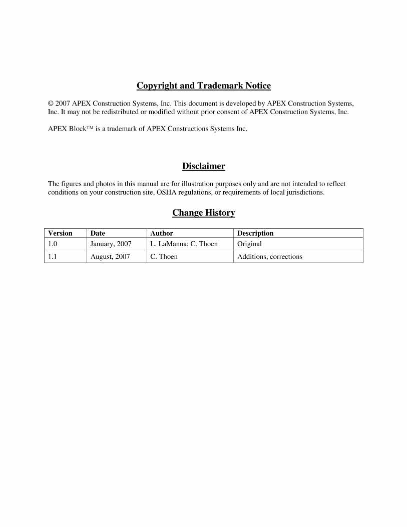
Refer to Appendix A for detailed test results. 2. APEX Block Specifications APEX Blocks are made of a mixture of recycled expanded polystyrene (EPS), cement, water, and bonding agents. As shown in Figures 1, 2, and 3, our blocks have a precision tongue-and-groove design to allow for a more secure placement of the blocks. The 6 inch diameter, round grout channels are placed 16 inches on center (16 OC) and run horizontally and vertically through each block. Each block is one solid piece, the grout channels pass through the middle of the block, not at a seam, creating secure pathways for the grout.
APEX CONSTRUCTION SYSTEMS, INC.
Building with the APEX Block™ Interlocking System Version 1.1
3
Figure 2: APEX Block™ Isometric View
AWS-10
Standard APEX Block™
48" H x 16" W x 10" D , approx. 55 lbs.
Channel spacing for inner reinforced concrete grid is
set on the industry standard of 16 inch OC (vertically
and horizontally).
Red fill shown here represents channel for reinforced
concrete pour.
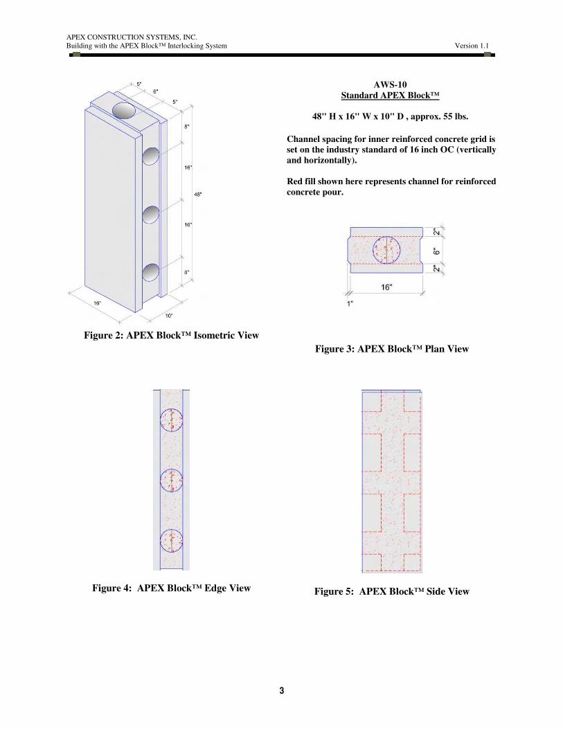
Figure 3: APEX Block™ Plan View
Figure 4: APEX Block™ Edge View
Figure 5: APEX Block™ Side View

APEX CONSTRUCTION SYSTEMS, INC.
Building with the APEX Block™ Interlocking System Version 1.1
4
3. BEFORE YOU START
3.1. PLANNING
It’s easy to prepare for a job using APEX Block™:
� Be sure you have your plans and all engineering specs ready
� Identify a flat location for storing the APEX Block™ after delivery. Storing the blocks on an
uneven surface can cause them to warp or break.
� When the blocks arrive, keep them clean and dry.
� Check the foundation (slab or stem wall) against the requirements in
Table 1.
Table 1
Foundation Requirements
Foundation Requirement Comment
Concrete poured at least 1 week
prior to starting walls
Construct foundations of concrete in accordance with the requirements of IBC
Chapters 18 and 19 or IRC Chapter 4.
Stem walls are wide enough Must be at least 10 inches wide.
Surface is level Mark any uneven or non-level areas prior to setting blocks
Slab is square and true Verify that the corners of the slab are 90º angles. An easy way to confirm this
is to draw out a 3-ftx4-ftx5-ft triangle on the slab.
ASTM A615 Grade 60 deformed
steel reinforcement bars are used
Vertical rebar must be minimum No. 4 and must comply with Section 1907 of
the IBC. If the construction is based on the IRC, reinforcing steel must comply
with IRC Section R611.6.2.
Rebar spaced 16 in. on center, to
match grout channels in blocks
If slightly out of position, bend to re-position per Figure 10.
Openings are specified Be sure that you know where all planned openings are in relation to the
foundation, and mark them on the slab or stem wall as needed.
Two pieces of rebar are placed on
either side of any opening, as
shown in Figure 6.
If rebar is missing, drill through the slab with a roto-hammer and epoxy a piece
of rebar in place
Rebar extends at least 24 inches
above the foundation
Foundation rebar must extend into the wall panel a minimum of 24 inches or a
distance determined in accordance with IBC Section 1901.2 (normally 22 times
the diameter of the rebar as mandated by code) whichever is greater.
If rebar is too short, drill through the slab with a roto-hammer and epoxy a
APEX CONSTRUCTION SYSTEMS, INC.
Building with the APEX Block™ Interlocking System Version 1.1
5
longer piece of rebar in place.
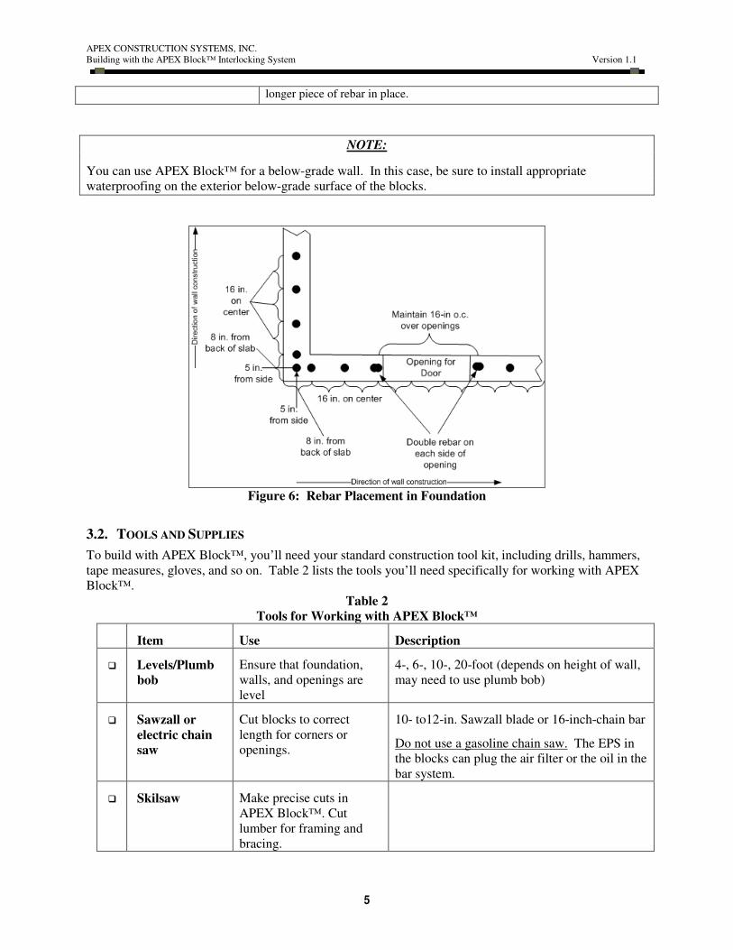
NOTE:
You can use APEX Block™ for a below-grade wall. In this case, be sure to install appropriate
waterproofing on the exterior below-grade surface of the blocks.
Figure 6: Rebar Placement in Foundation
3.2. TOOLS AND SUPPLIES
To build with APEX Block™, you’ll need your standard construction tool kit, including drills, hammers,
tape measures, gloves, and so on. Table 2 lists the tools you’ll need specifically for working with APEX
Block™.
Table 2
Tools for Working with APEX Block™
Item Use Description
� Levels/Plumb
bob
Ensure that foundation,
walls, and openings are
level
4-, 6-, 10-, 20-foot (depends on height of wall,
may need to use plumb bob)
� Sawzall or
electric chain
saw
Cut blocks to correct
length for corners or
openings.
10- to12-in. Sawzall blade or 16-inch-chain bar
Do not use a gasoline chain saw. The EPS in
the blocks can plug the air filter or the oil in the
bar system.
� Skilsaw Make precise cuts in
APEX Block™. Cut
lumber for framing and
bracing.

APEX CONSTRUCTION SYSTEMS, INC.
Building with the APEX Block™ Interlocking System Version 1.1
6
Item Use Description
� Hole saw Cut round holes in blocks 4-in. and 6-in. round hole-saw blades
� Hand saw Cut or shape blocks by
hand
Stiff saw blade, 36 inches long with 3-4 teeth
per inch
� Keyhole saw Make rough cuts in APEX
Block™. Scribe areas
where small openings are
needed, such as holes for
electrical boxes
� Claw hammer Gouge out scribed areas
� Rebar cutter Cut rebar to length Metal wheel on Skilsaw, hack saw, or rebar
cutter
� Rasp Smooth the surface of
blocks
Custom made; weld a 6x8-in piece of open
diamond-grid grating to a frame and handle.
� Staples Tie blocks together at
corners
Custom made; 1/8-in.-thick steel, 1-in.wide;
right-angle bends on each end, points on tips,
as shown in Figure 17.
� Glue gun, glue
canisters, and
gun cleaner
canisters.
See NOTE
below.
Tack blocks to the
foundation and repair
small breaks in the blocks.
Glue gun, low-expansion, high-yield foam
adhesive, and cleaner of the same general type
as shown here.
� Concrete
scraper
Scrape off excess grout,
flatten top surfaces of
wall, clean up slab, scrape
off glue
14-in. blade
� Lumber Bucking and bracing 2x4s, 2x6s, 2x10s
APEX CONSTRUCTION SYSTEMS, INC.
Building with the APEX Block™ Interlocking System Version 1.1
7
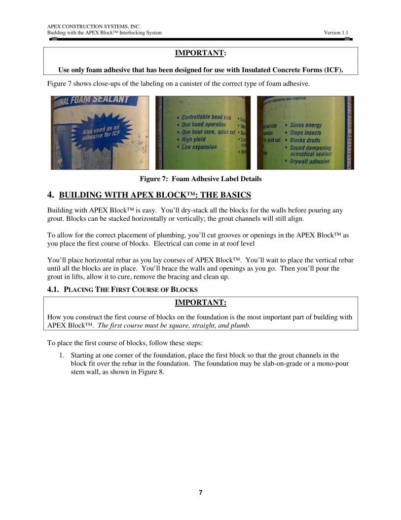
IMPORTANT:
Use only foam adhesive that has been designed for use with Insulated Concrete Forms (ICF).
Figure 7 shows close-ups of the labeling on a canister of the correct type of foam adhesive.
Figure 7: Foam Adhesive Label Details
4. BUILDING WITH APEX BLOCK™: THE BASICS
Building with APEX Block™ is easy. You’ll dry-stack all the blocks for the walls before pouring any
grout. Blocks can be stacked horizontally or vertically; the grout channels will still align.
To allow for the correct placement of plumbing, you’ll cut grooves or openings in the APEX Block™ as
you place the first course of blocks. Electrical can come in at roof level
You’ll place horizontal rebar as you lay courses of APEX Block™. You’ll wait to place the vertical rebar
until all the blocks are in place. You’ll brace the walls and openings as you go. Then you’ll pour the
grout in lifts, allow it to cure, remove the bracing and clean up.
4.1. PLACING THE FIRST COURSE OF BLOCKS
IMPORTANT:
How you construct the first course of blocks on the foundation is the most important part of building with
APEX Block™. The first course must be square, straight, and plumb.
To place the first course of blocks, follow these steps:
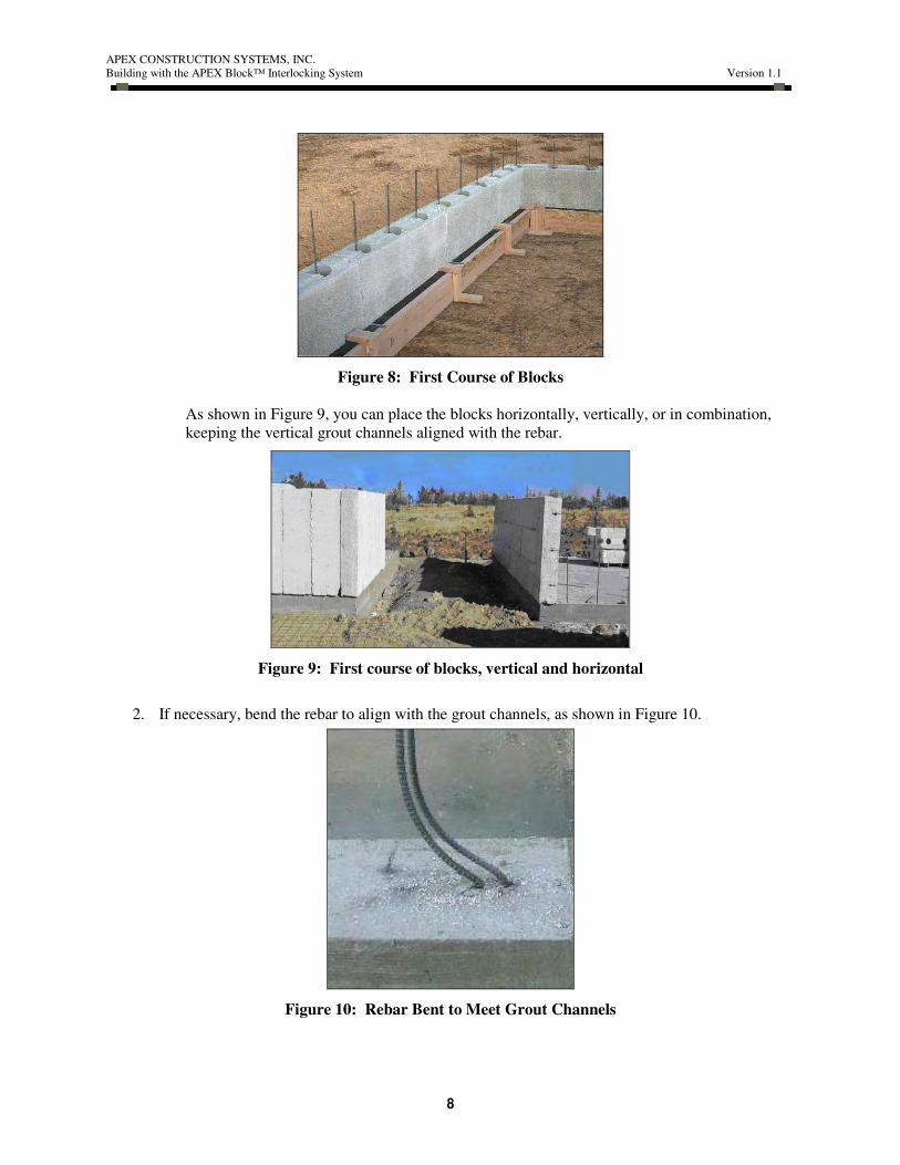
1. Starting at one corner of the foundation, place the first block so that the grout channels in the
block fit over the rebar in the foundation. The foundation may be slab-on-grade or a mono-pour
stem wall, as shown in Figure 8.
APEX CONSTRUCTION SYSTEMS, INC.
Building with the APEX Block™ Interlocking System Version 1.1
8
Figure 8: First Course of Blocks
As shown in Figure 9, you can place the blocks horizontally, vertically, or in combination,
keeping the vertical grout channels aligned with the rebar.
Figure 9: First course of blocks, vertical and horizontal
2. If necessary, bend the rebar to align with the grout channels, as shown in Figure 10.
Figure 10: Rebar Bent to Meet Grout Channels

APEX CONSTRUCTION SYSTEMS, INC.
Building with the APEX Block™ Interlocking System Version 1.1
9
3. Place the next block beside the first, ensuring that the rebar fits into the grout channels and that
the tongue-and-grove shaping on the two blocks is snug.
4. Continue placing blocks along the wall, ensuring that the blocks are square, straight, and plumb.
5. Use wood shims to level or plumb APEX Blocks™, as shown in Figure 11.
Figure 11: Wall with Shims in Place
a. Gently tip up the block and place the shim.
b. Do not drive the shim into the joint; this will only crush the block as opposed to raising
it.
c. Leave the shims in place until 48 hrs after you have poured the grout.
d. Cut off or pull out the shims.
6. Account for any doors or windows as you place the blocks.
a. Build around openings by cutting or shaping the APEX Blocks™ to the right length.
b. Fill any gaps between blocks with low-expansion high-strength foam adhesive, so the
block can’t tip or move.
c. Allow the glue to dry for 30 minutes before stacking another course of blocks on top.
NOTE:
If necessary, you can cut openings out of the APEX Block™ wall after you’ve built the wall (but before
you’ve placed the rebar or poured the grout). This might be necessary, for example, if a window has been
missed during layout or has been moved after the plans were completed. However, try to avoid cutting
parts of a wall away after construction, as this wastes time, materials, and money.
4.2. CONSTRUCTING CORNERS
Construct corners as you work your way around the perimeter of the building, following these steps:
1. Modify the ends of two blocks to make a larger, solid grout channel at the corner as shown in
Figure 12 and Figure 13; this makes a strong corner that is less likely to blow out when you pour
the grout.

APEX CONSTRUCTION SYSTEMS, INC.
Building with the APEX Block™ Interlocking System Version 1.1
10
Figure 12: Blocks Modified for Corner Figure 13: Corner Blocks Together
Figure 14 illustrates the details of corner construction
Figure 14: Details of Corner Cavity
2. Bend a piece of rebar at least 48-inches long at a right angle at the mid-point and place one end in
the horizontal grout channel of the first block.
3. As you place the next block (around the corner) slide the bent rebar into the horizontal grout
channel in that block.
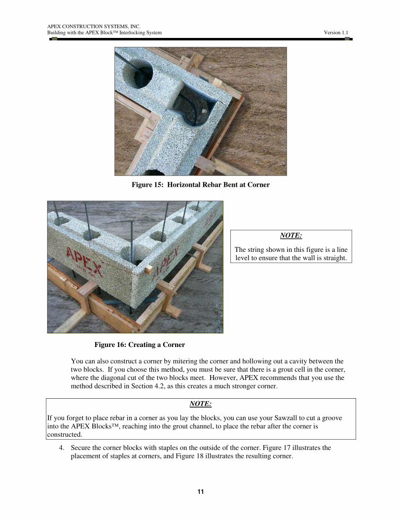
Figure 15 and Figure 16 show the resulting corner.
APEX CONSTRUCTION SYSTEMS, INC.
Building with the APEX Block™ Interlocking System Version 1.1
11
Figure 15: Horizontal Rebar Bent at Corner
NOTE:
The string shown in this figure is a line
level to ensure that the wall is straight.
Figure 16: Creating a Corner
You can also construct a corner by mitering the corner and hollowing out a cavity between the
two blocks. If you choose this method, you must be sure that there is a grout cell in the corner,
where the diagonal cut of the two blocks meet. However, APEX recommends that you use the
method described in Section 4.2, as this creates a much stronger corner.
NOTE:
If you forget to place rebar in a corner as you lay the blocks, you can use your Sawzall to cut a groove
into the APEX Blocks™, reaching into the grout channel, to place the rebar after the corner is
constructed.
4. Secure the corner blocks with staples on the outside of the corner. Figure 17 illustrates the
placement of staples at corners, and Figure 18 illustrates the resulting corner.

APEX CONSTRUCTION SYSTEMS, INC.
Building with the APEX Block™ Interlocking System Version 1.1
12
Figure 17: Installing Metal Staples
Figure 18: Corner with Staples
5. Before pouring the grout, brace the corner as described in Section 4.8, “Bracing the Walls.”
NOTE:
Be sure to place horizontal rebar as you work along the wall, and before you build the next corner.
Otherwise, the next corner will cap off that length of the wall, and you’ll have no easy way to insert the
rebar.
APEX CONSTRUCTION SYSTEMS, INC.
Building with the APEX Block™ Interlocking System Version 1.1
13
4.3. PLACING ADDITIONAL COURSES OF BLOCKS
After you’ve completed one course of blocks completely around the perimeter of the building, you can
place the second and following courses. Follow these guidelines:
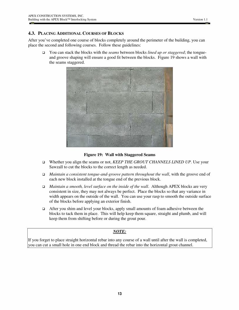
� You can stack the blocks with the seams between blocks lined up or staggered; the tongue-
and groove shaping will ensure a good fit between the blocks. Figure 19 shows a wall with
the seams staggered.
Figure 19: Wall with Staggered Seams
� Whether you align the seams or not, KEEP THE GROUT CHANNELS LINED UP. Use your
Sawzall to cut the blocks to the correct length as needed.
� Maintain a consistent tongue-and-groove pattern throughout the wall, with the groove end of
each new block installed at the tongue end of the previous block.
� Maintain a smooth, level surface on the inside of the wall. Although APEX blocks are very
consistent in size, they may not always be perfect. Place the blocks so that any variance in
width appears on the outside of the wall. You can use your rasp to smooth the outside surface
of the blocks before applying an exterior finish.
� After you shim and level your blocks, apply small amounts of foam adhesive between the
blocks to tack them in place. This will help keep them square, straight and plumb, and will
keep them from shifting before or during the grout pour.
NOTE:
If you forget to place straight horizontal rebar into any course of a wall until after the wall is completed,
you can cut a small hole in one end block and thread the rebar into the horizontal grout channel.
APEX CONSTRUCTION SYSTEMS, INC.
Building with the APEX Block™ Interlocking System Version 1.1
14
4.4. CREATING OPENINGS
Create openings by cutting blocks to length as you place them. Follow these guidelines:
� Add 3 inches to the rough opening (RO) for doors or windows, to allow for bucking and
wrapping of the opening. For example, for a 4-ft. x 6-ft. rough opening, create an opening
measuring 4 ft. 3 in. x 6 ft. 3 in.
� Use staples to secure blocks around openings.
� Use 2x10 lumber to brace any openings more than 6 feet long, such as the garage door. See
Figure 30.
� Create bond beams over all openings. Refer to Section 0, below.
� Install double rebar on either side of all openings.
NOTE:
If you forget to create an opening as you place the blocks, you can use your Sawzall to cut out the
opening after you’ve built the wall (but before you pour the grout).
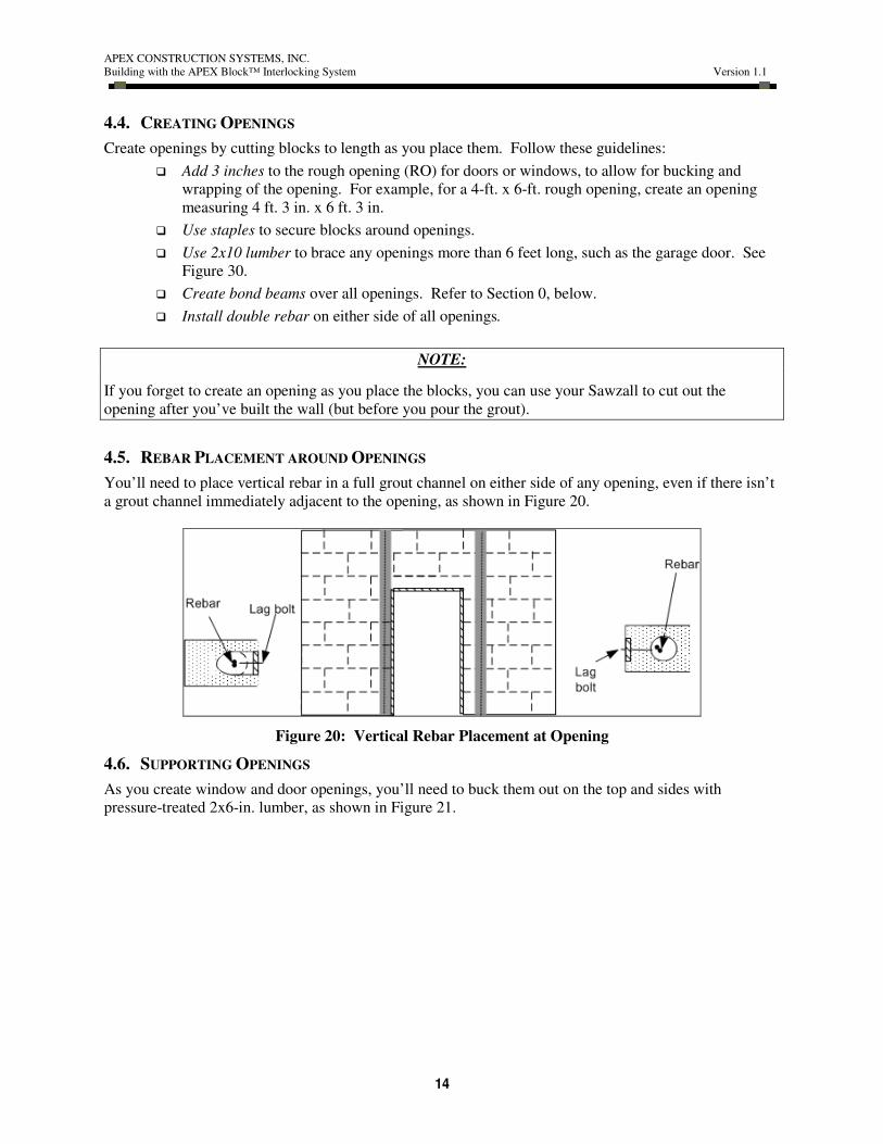
4.5. REBAR PLACEMENT AROUND OPENINGS
You’ll need to place vertical rebar in a full grout channel on either side of any opening, even if there isn’t
a grout channel immediately adjacent to the opening, as shown in Figure 20.
Figure 20: Vertical Rebar Placement at Opening
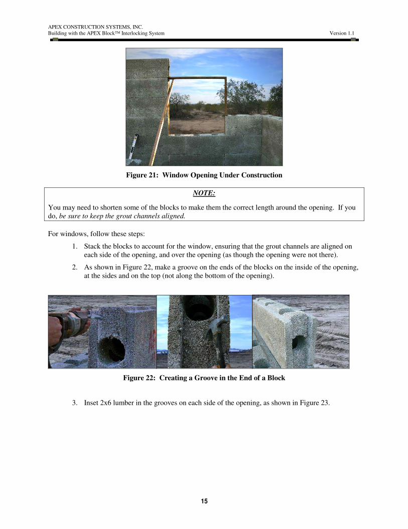
4.6. SUPPORTING OPENINGS
As you create window and door openings, you’ll need to buck them out on the top and sides with
pressure-treated 2x6-in. lumber, as shown in Figure 21.
APEX CONSTRUCTION SYSTEMS, INC.
Building with the APEX Block™ Interlocking System Version 1.1
15
Figure 21: Window Opening Under Construction
NOTE:
You may need to shorten some of the blocks to make them the correct length around the opening. If you
do, be sure to keep the grout channels aligned.
For windows, follow these steps:
1. Stack the blocks to account for the window, ensuring that the grout channels are aligned on
each side of the opening, and over the opening (as though the opening were not there).
2. As shown in Figure 22, make a groove on the ends of the blocks on the inside of the opening,
at the sides and on the top (not along the bottom of the opening).
Figure 22: Creating a Groove in the End of a Block
3. Inset 2x6 lumber in the grooves on each side of the opening, as shown in Figure 23.

APEX CONSTRUCTION SYSTEMS, INC.
Building with the APEX Block™ Interlocking System Version 1.1
16
Figure 23: 2x6 Lumber Embedded at Opening
4. “Lead in” the bucking on the sides of the opening, using 6-inch hardened-steel lag bolts.
a. Drill a pilot hole for each lag bolt
b. Drill a countersink hole, so the lag bolts can be inserted flush with the bucking.
c. Insert the lag bolts.
Figure 24: Countersinking Lag Bolts into Bucking
5. As shown in Figure 25, use your rasp to smooth any rough spots after cutting the tongue off
the blocks at the bottom of the opening. This will provide a flat surface for your window
framing.
APEX CONSTRUCTION SYSTEMS, INC.
Building with the APEX Block™ Interlocking System Version 1.1
17
Figure 25: Smoothing Blocks, Bottom of Opening
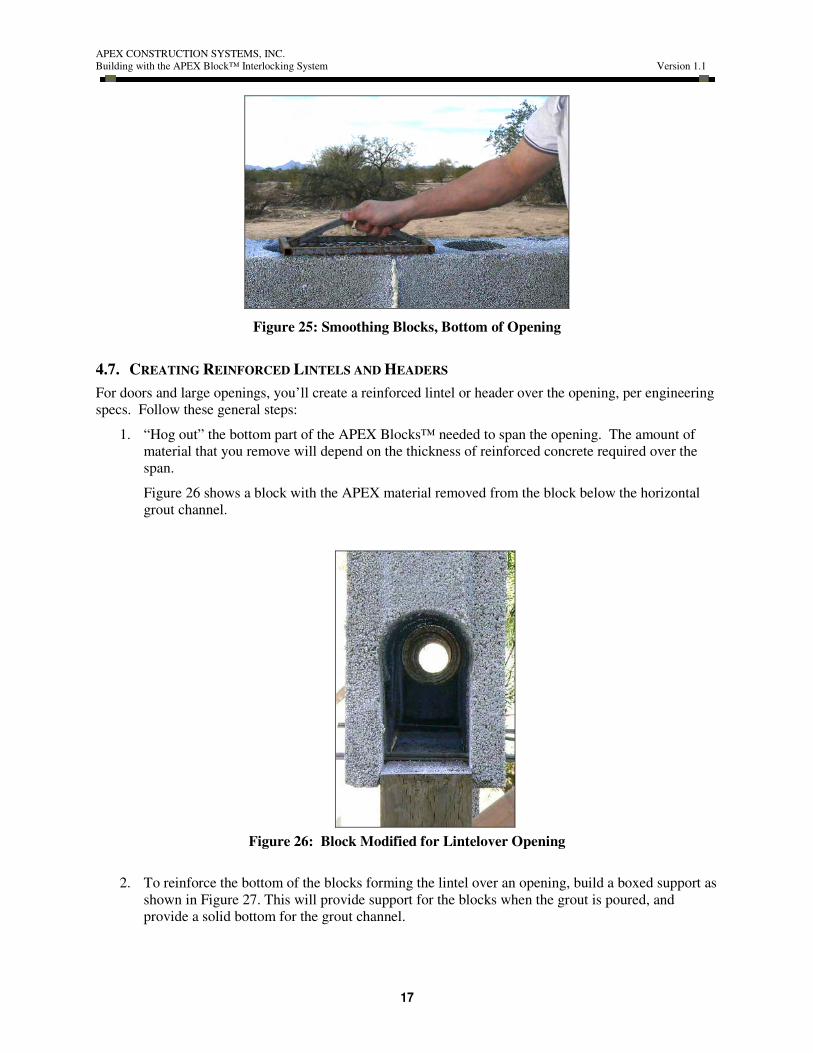
4.7. CREATING REINFORCED LINTELS AND HEADERS
For doors and large openings, you’ll create a reinforced lintel or header over the opening, per engineering
specs. Follow these general steps:
1. “Hog out” the bottom part of the APEX Blocks™ needed to span the opening. The amount of
material that you remove will depend on the thickness of reinforced concrete required over the
span.
Figure 26 shows a block with the APEX material removed from the block below the horizontal
grout channel.
Figure 26: Block Modified for Lintelover Opening
2. To reinforce the bottom of the blocks forming the lintel over an opening, build a boxed support as
shown in Figure 27. This will provide support for the blocks when the grout is poured, and
provide a solid bottom for the grout channel.

APEX CONSTRUCTION SYSTEMS, INC.
Building with the APEX Block™ Interlocking System Version 1.1
18
Figure 27: Boxed Support of Blocks over Lintels
NOTE:
If necessary, you can remove ALL of the APEX material from the center of the blocks
when creating a bond beam, leaving only the two side walls. Make sure that you brace
these portions of the wall using one or more of the methods described in Section 4.8.
3. Place additional rebar in the grout channel for the header, as required by engineering specs.
Figure 28 shows rebar placement in a lintel over a door.
Figure 28: Additional Rebar Over Opening
The photos in Figure 28 show a “skeleton” view of the extra rebar needed in all lintels as it would
be placed through blocks over an opening. One block is missing here, so you can see how you
would overlap the rebar and how you would place multiple pieces of rebar to reinforce the span.
If the height of the opening causes the lintel to fall in the middle of the block, create the opening
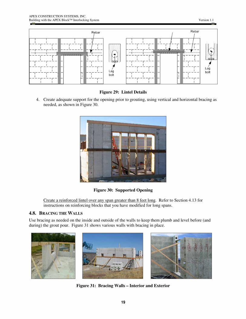
for the additional concrete and rebar in the upper half of the block, as shown in Figure 29.
APEX CONSTRUCTION SYSTEMS, INC.
Building with the APEX Block™ Interlocking System Version 1.1
19
Figure 29: Lintel Details
4. Create adequate support for the opening prior to grouting, using vertical and horizontal bracing as
needed, as shown in Figure 30.
Figure 30: Supported Opening
Create a reinforced lintel over any span greater than 8 feet long. Refer to Section 4.13 for
instructions on reinforcing blocks that you have modified for long spans.
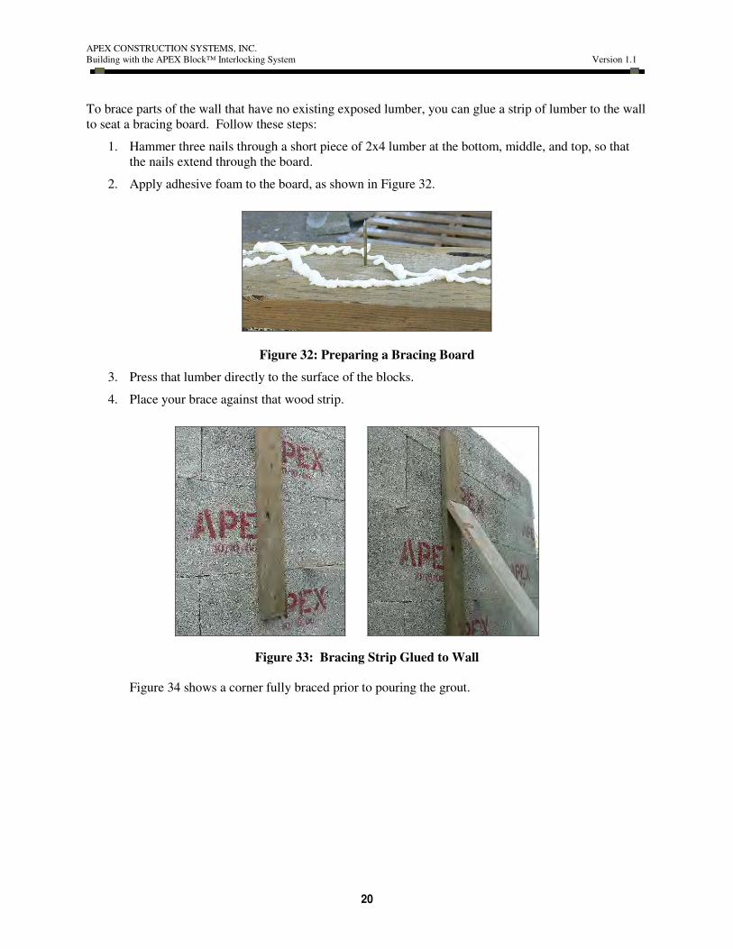
4.8. BRACING THE WALLS
Use bracing as needed on the inside and outside of the walls to keep them plumb and level before (and
during) the grout pour. Figure 31 shows various walls with bracing in place.
Figure 31: Bracing Walls – Interior and Exterior
APEX CONSTRUCTION SYSTEMS, INC.
Building with the APEX Block™ Interlocking System Version 1.1
20
To brace parts of the wall that have no existing exposed lumber, you can glue a strip of lumber to the wall
to seat a bracing board. Follow these steps:
1. Hammer three nails through a short piece of 2x4 lumber at the bottom, middle, and top, so that
the nails extend through the board.
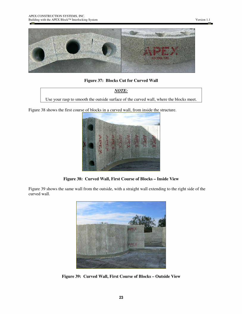
2. Apply adhesive foam to the board, as shown in Figure 32.
Figure 32: Preparing a Bracing Board
3. Press that lumber directly to the surface of the blocks.
4. Place your brace against that wood strip.
Figure 33: Bracing Strip Glued to Wall
Figure 34 shows a corner fully braced prior to pouring the grout.

APEX CONSTRUCTION SYSTEMS, INC.
Building with the APEX Block™ Interlocking System Version 1.1
21
Figure 34: Corner Braced Prior to Pour
4.9. CREATING CURVED WALLS
You’ll create curved walls by cutting angles from the inside edges of APEX Blocks™ using the standard
radius chart in Table 3. Figure 35 shows the foundation for a curved wall.
Figure 35: Foundation for Curved Wall
Follow these steps to create a curved wall:
1. Set the blocks on the vertical.
2. Cut angles from the tongue edges of blocks, per the standard radius chart in Table 3. You’ll
lose most, if not all, of the tongue-and-groove shaping on the inside edges of the block.

APEX CONSTRUCTION SYSTEMS, INC.
Building with the APEX Block™ Interlocking System Version 1.1
22
Table 3
Standard Radius Chart
RADIUS "R" 10-INCH THICK WALL
NOTE: For other radii, calculate X=
0.625 x thickness (inches) / “R” (feet)
3'-0" 2.13
4'-0" 1.68
5'-0" 1.36
6'-0" 1.06
7'-0" 0.95
8'-0" 0.80
9'-0" 0.75
10'-0" 0.62
Figure 36 shows a builder cutting the blocks for a curved wall.
Figure 36: Cutting a Block for a Radius
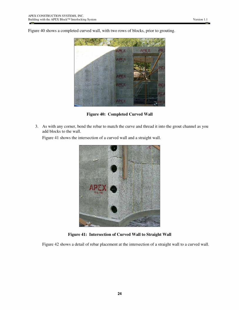
Figure 37 shows block cut and ready for use in a curved wall.
APEX CONSTRUCTION SYSTEMS, INC.
Building with the APEX Block™ Interlocking System Version 1.1
23
Figure 37: Blocks Cut for Curved Wall
NOTE:
Use your rasp to smooth the outside surface of the curved wall, where the blocks meet.
Figure 38 shows the first course of blocks in a curved wall, from inside the structure.
Figure 38: Curved Wall, First Course of Blocks – Inside View
Figure 39 shows the same wall from the outside, with a straight wall extending to the right side of the
curved wall.
Figure 39: Curved Wall, First Course of Blocks – Outside View
APEX CONSTRUCTION SYSTEMS, INC.
Building with the APEX Block™ Interlocking System Version 1.1
24
Figure 40 shows a completed curved wall, with two rows of blocks, prior to grouting.
Figure 40: Completed Curved Wall
3. As with any corner, bend the rebar to match the curve and thread it into the grout channel as you
add blocks to the wall.
Figure 41 shows the intersection of a curved wall and a straight wall.
Figure 41: Intersection of Curved Wall to Straight Wall
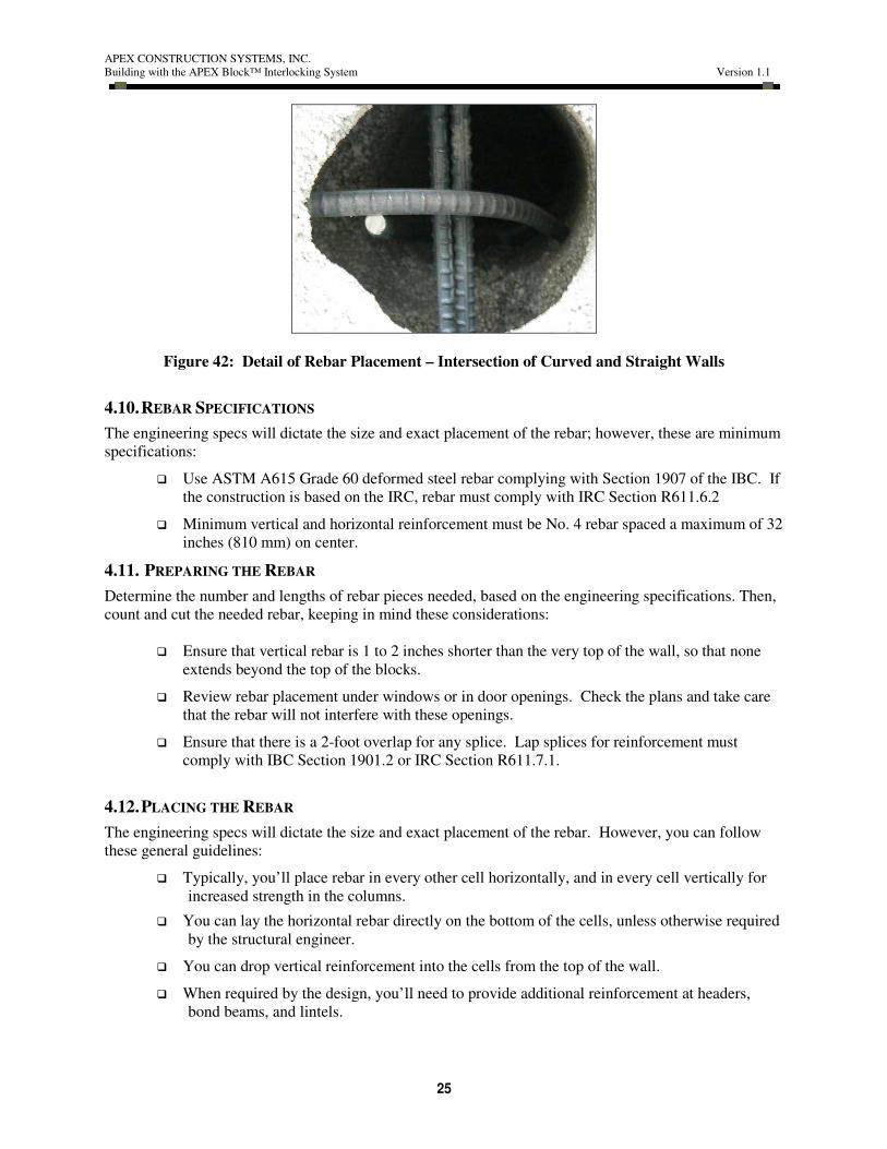
Figure 42 shows a detail of rebar placement at the intersection of a straight wall to a curved wall.
APEX CONSTRUCTION SYSTEMS, INC.
Building with the APEX Block™ Interlocking System Version 1.1
25
Figure 42: Detail of Rebar Placement – Intersection of Curved and Straight Walls
4.10. REBAR SPECIFICATIONS
The engineering specs will dictate the size and exact placement of the rebar; however, these are minimum
specifications:
� Use ASTM A615 Grade 60 deformed steel rebar complying with Section 1907 of the IBC. If
the construction is based on the IRC, rebar must comply with IRC Section R611.6.2
� Minimum vertical and horizontal reinforcement must be No. 4 rebar spaced a maximum of 32
inches (810 mm) on center.
4.11. PREPARING THE REBAR
Determine the number and lengths of rebar pieces needed, based on the engineering specifications. Then,
count and cut the needed rebar, keeping in mind these considerations:
� Ensure that vertical rebar is 1 to 2 inches shorter than the very top of the wall, so that none
extends beyond the top of the blocks.
� Review rebar placement under windows or in door openings. Check the plans and take care
that the rebar will not interfere with these openings.
� Ensure that there is a 2-foot overlap for any splice. Lap splices for reinforcement must
comply with IBC Section 1901.2 or IRC Section R611.7.1.
4.12. PLACING THE REBAR
The engineering specs will dictate the size and exact placement of the rebar. However, you can follow
these general guidelines:
� Typically, you’ll place rebar in every other cell horizontally, and in every cell vertically for
increased strength in the columns.
� You can lay the horizontal rebar directly on the bottom of the cells, unless otherwise required
by the structural engineer.
� You can drop vertical reinforcement into the cells from the top of the wall.
� When required by the design, you’ll need to provide additional reinforcement at headers,
bond beams, and lintels.
APEX CONSTRUCTION SYSTEMS, INC.
Building with the APEX Block™ Interlocking System Version 1.1
26
� There’s usually no need to tie the rebar – the vertical rebar can fall as it does; the horizontal
rebar can rest on the bottom of the horizontal cells. However, if required by code or
engineering specs, you can easily tie the rebar so that it remains in the center of each grout
channel: lay another piece of rebar along the top of the row of blocks prior to pouring the
grout, and use wire to tie the vertical rebar to the rebar along the top.
� Ensure that vertical rebar is 2 inches shorter than the very top of the wall (so that none
extends beyond blocks at the top).
� Ensure that there is a 2-foot overlap for any splice. Lap splices for reinforcement must
comply with IBC Section 1923 or IRC Section R611.7.1.
NOTE:
Remember that if you are placing rebar and you have not reached final wall height, then the rebar must
extend a minimum of 24 inches above the current course of blocks.
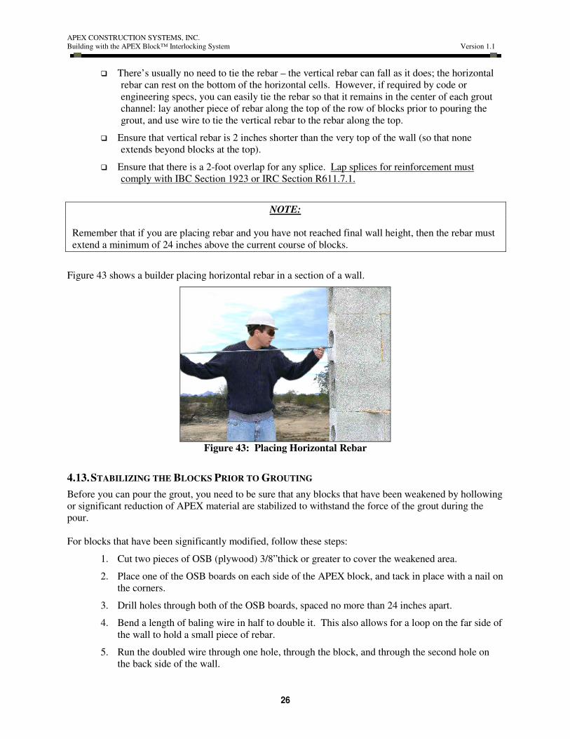
Figure 43 shows a builder placing horizontal rebar in a section of a wall.
Figure 43: Placing Horizontal Rebar
4.13. STABILIZING THE BLOCKS PRIOR TO GROUTING
Before you can pour the grout, you need to be sure that any blocks that have been weakened by hollowing
or significant reduction of APEX material are stabilized to withstand the force of the grout during the
pour.
For blocks that have been significantly modified, follow these steps:
1. Cut two pieces of OSB (plywood) 3/8”thick or greater to cover the weakened area.
2. Place one of the OSB boards on each side of the APEX block, and tack in place with a nail on
the corners.
3. Drill holes through both of the OSB boards, spaced no more than 24 inches apart.
4. Bend a length of baling wire in half to double it. This also allows for a loop on the far side of
the wall to hold a small piece of rebar.
5. Run the doubled wire through one hole, through the block, and through the second hole on
the back side of the wall.

APEX CONSTRUCTION SYSTEMS, INC.
Building with the APEX Block™ Interlocking System Version 1.1
27
6. Use this wire to secure a small piece of rebar on each side of the reinforcement, by twisting
the wire to hold the rebar in place, as shown in Figure 44.
Figure 44: Reinforcement of Modified Blocks over Doorway
4.14. ADDING LEDGERS
Add ledgers for floors and flat roofs at the appropriate height on the wall before you place rebar or pour
grout. Follow these steps to install a ledger:
1. Using your hole saw, cut round 6-in. holes into the APEX Block™ at intervals per engineering
specs, for the length of the ledger, as shown in Figure 45 . Be sure that the holes extend into the
grout channel.
Figure 45: Ledger Prep - Holes for “J”bolts
2. Place “J” bolts (sized per engineering specs) in the holes, extending into the grout channel.
3. Cut multiple 6x6-in squares of plywood.
4. Drill holes (matching the size of the “J” bolts) in the center of each square of plywood.
5. Use nails to tack the squares of plywood onto the wall, with the bolt protruding through the center
hole.
6. Use foam adhesive around all four sides to keep the squares of plywood in place during the pour.

APEX CONSTRUCTION SYSTEMS, INC.
Building with the APEX Block™ Interlocking System Version 1.1
28
7. Place a nut on the bolt to keep it level and ensure that it won’t fall into the grout channel during
the pour.
These secured squares of plywood will seal the hole so that grout does not escape during the pour.
Figure 46 shows the “J” bolts for the ledger, prior to the pour.
Figure 46: Ledger Prep – “J” Bolts with Plywood Squares in Place
8. About 30 minutes after the pour, check the position of the “J” bolts to be sure they are straight
and at the correct depth. Reposition, if needed, before the grout sets completely.
You can remove the plywood after the grout has set up, as shown in Figure 47.
Figure 47: Ledger Prep – “J” Bolts with Plywood Removed, after Grout Pour
9. Drill holes through lengths of lumber, matching the size and locations of the “J” bolts.
10. Install the lumber on the “J” bolts and secure with washers and nuts. Figure 48 illustrates ledger
installation.

APEX CONSTRUCTION SYSTEMS, INC.
Building with the APEX Block™ Interlocking System Version 1.1
29
Figure 48: Wood Ledger Installation
11. Attach hangers for floor joists or trusses, as shown in Figure 49.
Figure 49: Ledger Installed
12. Install the joists or trusses in the hangers, as shown in Figure 50.
Figure 50: Joists Installed on Ledger
4.14.1 LEDGERS FOR FLOORS

APEX CONSTRUCTION SYSTEMS, INC.
Building with the APEX Block™ Interlocking System Version 1.1
30
Add ledgers for floors as you place the first course of APEX Blocks™. Figure 51 illustrates an exterior
wall with a ledger and floor joist.
Figure 51: Exterior Wall with Floor Joist and Ledger
APEX CONSTRUCTION SYSTEMS, INC.
Building with the APEX Block™ Interlocking System Version 1.1
31
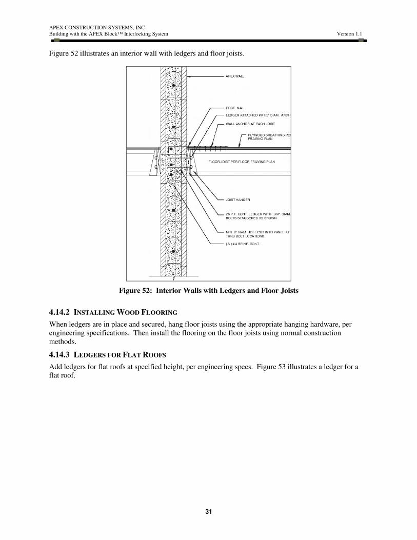
Figure 52 illustrates an interior wall with ledgers and floor joists.
Figure 52: Interior Walls with Ledgers and Floor Joists
4.14.2 INSTALLING WOOD FLOORING
When ledgers are in place and secured, hang floor joists using the appropriate hanging hardware, per
engineering specifications. Then install the flooring on the floor joists using normal construction
methods.
4.14.3 LEDGERS FOR FLAT ROOFS
Add ledgers for flat roofs at specified height, per engineering specs. Figure 53 illustrates a ledger for a
flat roof.

APEX CONSTRUCTION SYSTEMS, INC.
Building with the APEX Block™ Interlocking System Version 1.1
32
Figure 53: Ledger for Flat Roof
4.15. ACCOUNTING FOR PLUMBING
For commercial applications where you have many utilities, potentially passing through multiple floors of
the construction, it makes sense to “fir out” the inside of the wall with steel studs. Then, you’ll manage
the utilities as you ordinarily would in a framed construction.
However, for most residential applications, you can embed the plumbing in the APEX Block™ wall.
Since plumbing stubs are usually in the foundation, most often you’ll account for the plumbing as you lay
the first course of blocks.
Follow these steps to install plumbing on the inside of the APEX Block™ wall:
1. Groove or gouge out the material in the APEX Blocks™ to account for the pipes where they
come out of the slab.
2. Then route out the path that the remaining plumbing will follow, as shown in Figure 54.

APEX CONSTRUCTION SYSTEMS, INC.
Building with the APEX Block™ Interlocking System Version 1.1
33
Figure 54: Preparing the Blocks for Plumbing
3. Install the copper or plastic piping, as shown in Figure 55.
Figure 55: Plumbing Pipes Installed in Wall
4. Depending on the location of the pipe stubs, you may need to drill through the block to place
external plumbing fixtures.
5. Use a wooden or pre-cast concrete block embedded in the wall to stabilize the pipe and reduce the
risk of water penetration at the opening, as shown in Figure 56.

APEX CONSTRUCTION SYSTEMS, INC.
Building with the APEX Block™ Interlocking System Version 1.1
34
Figure 56: External Plumbing Fixture in Wall
4.16. INSERT VERTICAL REBAR
Before you prepare to pour the grout, insert any remaining vertical rebar. As noted earlier, the rebar
should be 2 inches shorter than the finished height of the wall. Any splices must overlap by 24 inches.
4.17. PREPARING TO POUR THE GROUT
Prior to pouring the grout, take these steps:
1. Verify that all rebar is in place, per engineering specifications. As noted earlier, all vertical rebar
should be 1 to 2 inches shorter than the finished height of the wall, and any splices must overlap
by 24 inches.
2. Schedule any building inspections.
3. Verify that all walls are straight and plumb.
4. Be sure that any long, straight runs are adequately braced to maintain the stability of the wall
during grouting. Add extra staples or spot glue with foam adhesive if needed.
5. Smooth the top surface of the blocks. Use your Sawzall to cut the “tongue” off the top course of
blocks. Then use your rasp to smooth any rough spots along the top edge. This will enable you
to place top plates along the top surface of the wall.
6. Order the grout. Now’s the time to line up your concrete truck and grout pump.
GROUT SPECIFICATION
3/8” minus pea gravel, 2500 psi, 8-in. slump
7. If the wall is constructed on an existing slab, place polyfilm under cardboard or kraft paper next
to the wall to ease cleanup after the pour.
8. A few hours before the pour (or the evening before), wet down the inside of the grout channels;
this can help ensure that the grout channels fill completely. This step will also cool the wall in
hot weather and add humidity, which can improve the curing of the concrete. Any water that
APEX CONSTRUCTION SYSTEMS, INC.
Building with the APEX Block™ Interlocking System Version 1.1
35
puddles at the bottom of the wall will be displaced by the grout flowing through the wall
channels.
4.18. POURING THE GROUT
You can pour the grout in single-story lifts. However, APEX suggests that you pour the grout in two lifts
per story.
IMPORTANT:
Before you start filling the wall grout channels, fill all window sills (bottoms of openings). This
is important, since the area under the windows is not easily reached by the grout being poured
from above the window.
Toe in a 2x10 piece of lumber to keep this grout from coming up through the cells when you pour the rest
of the grout.
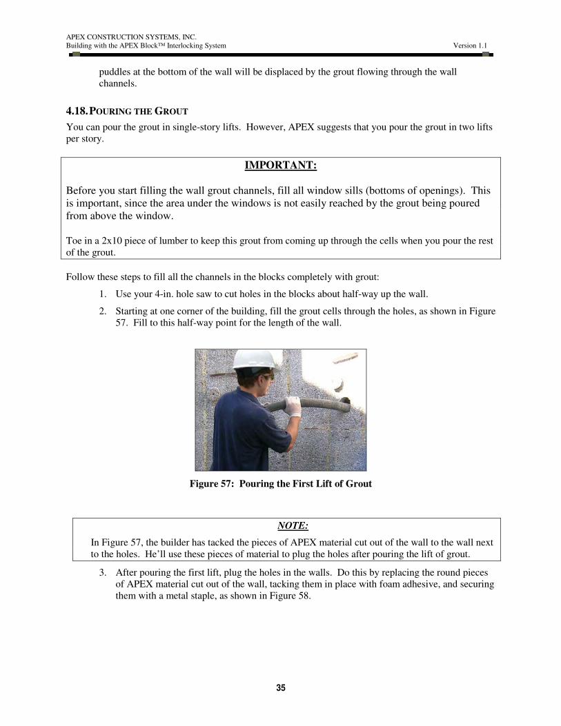
Follow these steps to fill all the channels in the blocks completely with grout:
1. Use your 4-in. hole saw to cut holes in the blocks about half-way up the wall.
2. Starting at one corner of the building, fill the grout cells through the holes, as shown in Figure
57. Fill to this half-way point for the length of the wall.
Figure 57: Pouring the First Lift of Grout
NOTE:
In Figure 57, the builder has tacked the pieces of APEX material cut out of the wall to the wall next
to the holes. He’ll use these pieces of material to plug the holes after pouring the lift of grout.
3. After pouring the first lift, plug the holes in the walls. Do this by replacing the round pieces
of APEX material cut out of the wall, tacking them in place with foam adhesive, and securing
them with a metal staple, as shown in Figure 58.

APEX CONSTRUCTION SYSTEMS, INC.
Building with the APEX Block™ Interlocking System Version 1.1
36
Figure 58: Wall Plug after Pouring Grout
4. Go back to your starting point and finish filling the cells from openings in the top of the
blocks.
5. Scrape off the excess grout along the top of the wall using a 2x4 piece of lumber, or a trowel,
making sure that the excess falls to the outside of the structure as much as possible, to reduce
cleanup later.
6. When you’ve finished pouring the grout, clean any grout off the slab before it sets up.
7. After about 30 minutes, place “J” bolts for roof trusses, per engineering specs.
8. The grout will set up in 48 hours and reach full strength in about 28 days.
IMPORTANT:
Verify that concrete has completely filled all of the block cores. Push a 0.25-in.-diameter, smooth steel
rod (or your key-hole saw) through the APEX Block™ material into the grout channels. Wet concrete on
the rod when you pull it out will confirm that the grout channel has been filled completely.
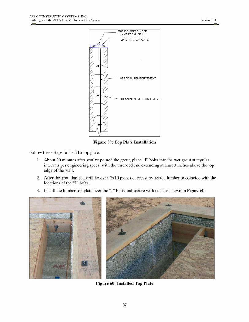
4.19. ADDING WALL TOP PLATES
To seal the open grout channels at the top of the wall, and to provide a secure attachment for nailers on
the interior of the wall, you’ll add top plates of 2x10 pressure-treated lumber after you place the rebar and
pour the grout. Figure 59 illustrates installation of a top plate.
APEX CONSTRUCTION SYSTEMS, INC.
Building with the APEX Block™ Interlocking System Version 1.1
37
Figure 59: Top Plate Installation
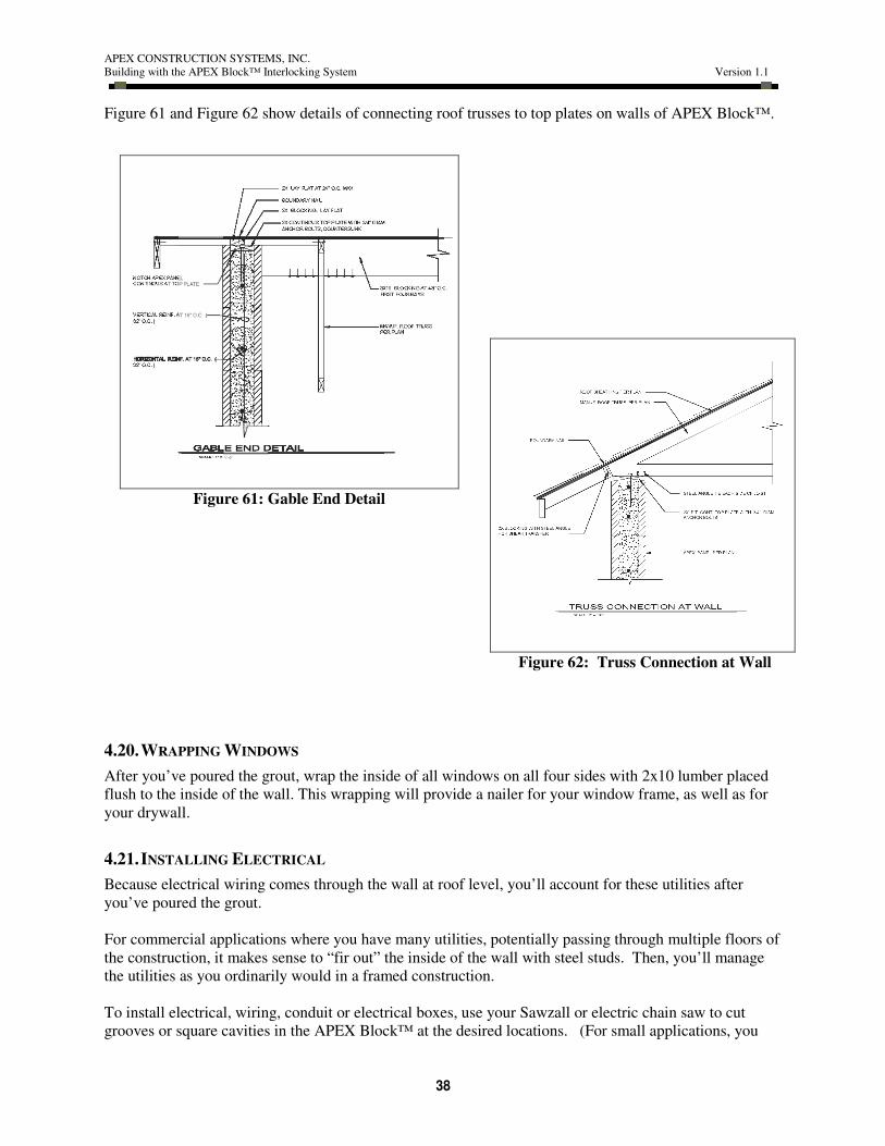
Follow these steps to install a top plate:
1. About 30 minutes after you’ve poured the grout, place “J” bolts into the wet grout at regular
intervals per engineering specs, with the threaded end extending at least 3 inches above the top
edge of the wall.
2. After the grout has set, drill holes in 2x10 pieces of pressure-treated lumber to coincide with the
locations of the “J” bolts.
3. Install the lumber top plate over the “J” bolts and secure with nuts, as shown in Figure 60.
Figure 60: Installed Top Plate
APEX CONSTRUCTION SYSTEMS, INC.
Building with the APEX Block™ Interlocking System Version 1.1
38
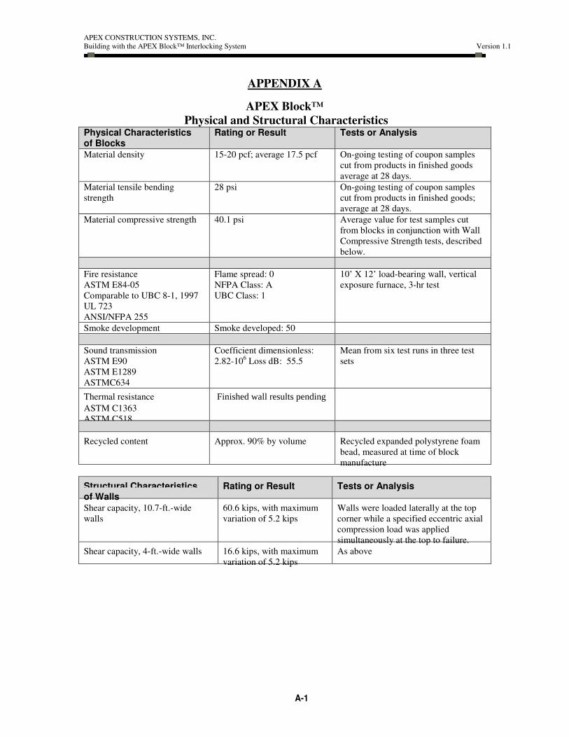
Figure 61 and Figure 62 show details of connecting roof trusses to top plates on walls of APEX Block™.
4.20. WRAPPING WINDOWS
After you’ve poured the grout, wrap the inside of all windows on all four sides with 2x10 lumber placed
flush to the inside of the wall. This wrapping will provide a nailer for your window frame, as well as for
your drywall.
4.21. INSTALLING ELECTRICAL
Because electrical wiring comes through the wall at roof level, you’ll account for these utilities after
you’ve poured the grout.
For commercial applications where you have many utilities, potentially passing through multiple floors of
the construction, it makes sense to “fir out” the inside of the wall with steel studs. Then, you’ll manage
the utilities as you ordinarily would in a framed construction.
To install electrical, wiring, conduit or electrical boxes, use your Sawzall or electric chain saw to cut
grooves or square cavities in the APEX Block™ at the desired locations. (For small applications, you
Figure 61: Gable End Detail
Figure 62: Truss Connection at Wall

APEX CONSTRUCTION SYSTEMS, INC.
Building with the APEX Block™ Interlocking System Version 1.1
39
can use your key hole saw.) Figure 63 illustrates routing or cutting cavities for electrical conduit and
boxes.
Figure 63: Preparing for Electrical
Figure 64 shows a builder preparing a wall for installation of wiring and junction boxes.
Figure 64: Cutting Grooves for Electrical Wiring
Be sure to place your junction boxes in parts of the APEX Block™ that are solid foam. Junction boxes
are more than 2 inches deep, and the APEX Block™ material over a grout channel is just 2 inches deep.
So, if you try to place a “J” box over a grout channel, the grout will keep the box from setting flush with
the surface of the wall.
Some permitting offices may require conduit for electrical wiring. In this case, simply cut the grooves
wide enough to accept the conduit.
Figure 65 shows a wall with grooves and a cavity cut for electrical wiring and a double-gang junction
box.

APEX CONSTRUCTION SYSTEMS, INC.
Building with the APEX Block™ Interlocking System Version 1.1
40
Figure 65: Wall with Grooves and Cavity for Electrical
Figure 66 shows several views of electrical boxes and wiring in place.
Figure 66: Electrical Boxes and Wiring in Place
Figure 67 is a larger view of the same wall with the boxes and wiring in place.
Figure 67: Electrical Utilities Installed
4.22. REMOVING BRACING
You can remove most bracing for walls and small openings one day after you have poured the grout.
Remember that the grout will set up in 48 hours, and will reach its maximum strength in 28 days.

APEX CONSTRUCTION SYSTEMS, INC.
Building with the APEX Block™ Interlocking System Version 1.1
41
For any span 6 feet long or longer, (large windows, garage doors) keep bracing up for a minimum of 4
days.
4.23. EXTERIOR FINISHES
You can always choose to leave the exterior surface of above-grade APEX Block™ unfinished. If you
are using an exterior finish, you must install it according to the requirements of the IBC or a current
evaluation report.
You must protect any exterior wall surfaces below grade using water-proofing solvent, applied in
accordance with IBC Section 1806 or IRC Section R406.
1. Wearing a dust mask and safety goggles, use your rasp to smooth any uneven surfaces on the
exterior walls.
Figure 68: Smoothing the Exterior Surface of the Wall
2. Apply a waterproofing sealant. You must install water-proofing materials in accordance with the
manufacturer’s instructions and per local building codes.
4.23.1 STUCCO
Stucco is a good exterior finish for APEX Block™ construction, because it is much easier to apply to
APEX Block™ than to a wood-framed structure. You’ll apply the stucco directly to the wall, without any
chicken wire, lathing, or other special construction. Your time and costs will be reduced significantly,
because there is much less labor and material involved.
Follow these general steps to apply a stucco exterior finish, ensuring that you comply with the product
manufacturer’s instructions:
1. Wearing a dust mask and safety glasses, use your rasp to smooth any uneven surfaces on the
exterior walls.
2. Apply a waterproofing sealant.
3. Apply a smooth base coat of stucco and allow it to dry.
4. Apply the finish coat of stucco, texturing as desired.

APEX CONSTRUCTION SYSTEMS, INC.
Building with the APEX Block™ Interlocking System Version 1.1
42
4.23.2 ROCK OR BRICK VENEER
Rock or brick veneer is also easy to install with APEX Block™ construction, using the same general
methods that you would use for masonry construction:
1. Be sure that the surface of the wall is smooth, clean, and dry.
2. Apply a scratch coat of mortar ½ to ¾ inch thick.
3. Use a small piece of lath to lightly rake horizontal grooves into the scratch coat.
4. Allow the scratch coat to cure for a minimum of 24 hours.
5. Continue by applying mortar and attaching the stones or bricks, using normal methods.
4.24. INTERIOR FINISHES
Because APEX Block™ acts as an interior thermal barrier, you may leave the constructed wall without an
interior finish. However, you can also using interior finishes such as gypsum drywall or plaster.
4.24.1 DRY WALL
To attach drywall to the APEX block, follow these steps:
1. Spread drywall mud or ICF foam on the back side of a sheet of drywall.
2. Press the sheet of drywall onto the interior of the APEX wall.
3. Tack the drywall sheet to the APEX blocks with a couple of nails.
4. When all drywall sheets are in place, remove the nails, then tape and paint the drywall as usual
4.24.2 PLASTER
Apply plaster directly to the surface of the blocks, in accordance with the manufacturer’s installation
instructions.
5. INSTALLING INTERIOR WALLS
You can easily join interior walls to the exterior APEX Block™ walls, whether the interior walls are
made of APEX Blocks™ or are of wood or metal stud frame construction.
APEX recommends that you install the interior walls and attach them to the exterior walls or to other
interior walls before pouring the grout. However, it is possible to add interior walls built of APEX
Block™ after you’ve poured the grout.
5.1. WOOD FRAME OR METAL STUD INTERIOR WALLS
To attach wood frame interior or metal stud frame walls to exterior APEX Block™ walls, follow these
steps:
1. Use ½-inch or larger threaded “J” bolts.
2. Insert the bolts into the open block cores. Leave enough room on the end of the bolt extending out
of the APEX Block™ exterior wall to go into a hole drilled in the interior wall’s end stud,
including a washer and nut.
3. Bolt the interior wall’s end stud to the inside of the exterior wall.

APEX CONSTRUCTION SYSTEMS, INC.
Building with the APEX Block™ Interlocking System Version 1.1
43
5.2. APEX BLOCK™ INTERIOR WALLS
To attach APEX Block™ interior walls, follow these steps:
1. Mark on the inside of the exterior wall exactly where the new interior APEX Block™ wall
will join to the exterior wall.
2. Using a Sawzall or electric chain saw, cut along the marked lines on the inside of exterior
wall. Cut deeply enough to reach the vertical or horizontal grout channels in the blocks.
3. Be sure that the hollow grout channels inside the exterior wall line up with those in the
interior wall, so the concrete will flow easily into both walls during the grout pour, making a
solid, reinforced connection. Figure 69 shows how to connect interior walls made of APEX
Block™.
Figure 69: Connecting APEX Block™ Interior Walls
6. ATTACHING CABINETS AND OTHER INTERIOR FIXTURES
This section describes one way of preparing for cabinets and other interior fixtures, if you know the
location of interior fixtures prior to wall construction.
If possible, plan for the placement of cabinets and other interior fixtures before you pour the grout. As
you construct the wall, you can “lead in” a 2x4 nailer, following these steps:
1. Route out a groove 1.5 inches deep in the block, for the length of the nailer you’ll need.
2. Cut a piece of lumber for the nailer.
3. Drill a pilot hole in the lumber for each lag bolt you plan to install, ensuring that the position of
the bolts will intersect with grout channels in the wall.
4. Drill a countersink hole, so the lag bolts can be inserted flush with the lumber.
5. Apply foam adhesive to the back of the lumber and the portions of the wall that are solid APEX
material, ensuring that the glue does not expand into the grout channels.
6. Inset the lumber in the prepared groove.
7. Install 6-inch hardened-steel lag bolts in the holes and tighten.

APEX CONSTRUCTION SYSTEMS, INC.
Building with the APEX Block™ Interlocking System Version 1.1
44
8. Secure with metal staples.
Figure 70: Installing a Nailer for Interior Fixtures
APEX CONSTRUCTION SYSTEMS, INC.
Building with the APEX Block™ Interlocking System Version 1.1
A-1
APPENDIX A
APEX Block™
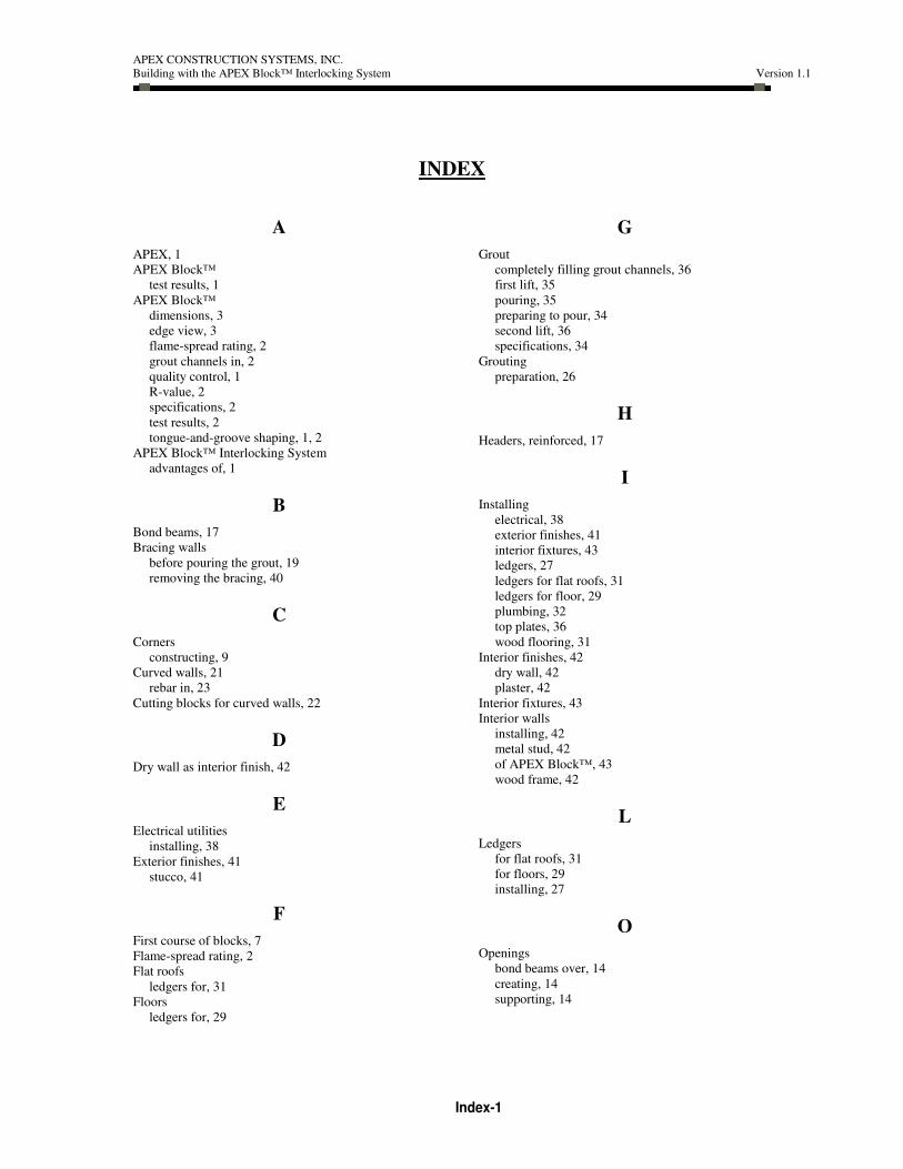
Physical and Structural Characteristics Physical Characteristics of Blocks
Rating or Result Tests or Analysis
Material density 15-20 pcf; average 17.5 pcf On-going testing of coupon samples
cut from products in finished goods
average at 28 days.
Material tensile bending
strength
28 psi On-going testing of coupon samples
cut from products in finished goods;
average at 28 days.
Material compressive strength 40.1 psi Average value for test samples cut
from blocks in conjunction with Wall
Compressive Strength tests, described
below.
Fire resistance
ASTM E84-05
Comparable to UBC 8-1, 1997
UL 723
ANSI/NFPA 255
Flame spread: 0
NFPA Class: A
UBC Class: 1
10’ X 12’ load-bearing wall, vertical
exposure furnace, 3-hr test
Smoke development Smoke developed: 50
Sound transmission
ASTM E90
ASTM E1289
ASTMC634
Coefficient dimensionless:
2.82-106 Loss dB: 55.5
Mean from six test runs in three test
sets
Thermal resistance Finished wall results pendingASTM C1363
ASTM C518
Recycled content Approx. 90% by volume Recycled expanded polystyrene foam
bead, measured at time of block
manufacture
Structural Characteristics of Walls
Rating or Result Tests or Analysis
Shear capacity, 10.7-ft.-wide
walls
60.6 kips, with maximum
variation of 5.2 kips
Walls were loaded laterally at the top
corner while a specified eccentric axial
compression load was applied
simultaneously at the top to failure.
Shear capacity, 4-ft.-wide walls 16.6 kips, with maximum
variation of 5.2 kips
As above
APEX CONSTRUCTION SYSTEMS, INC.
Building with the APEX Block™ Interlocking System Version 1.1
Index-1
INDEX
A
APEX, 1
APEX Block™
test results, 1
APEX Block™
dimensions, 3
edge view, 3
flame-spread rating, 2
grout channels in, 2
quality control, 1
R-value, 2
specifications, 2
test results, 2
tongue-and-groove shaping, 1, 2
APEX Block™ Interlocking System
advantages of, 1
B
Bond beams, 17
Bracing walls
before pouring the grout, 19
removing the bracing, 40
C
Corners
constructing, 9
Curved walls, 21
rebar in, 23
Cutting blocks for curved walls, 22
D
Dry wall as interior finish, 42
E
Electrical utilities
installing, 38
Exterior finishes, 41
stucco, 41
F
First course of blocks, 7
Flame-spread rating, 2
Flat roofs
ledgers for, 31
Floors
ledgers for, 29
G
Grout
completely filling grout channels, 36
first lift, 35
pouring, 35
preparing to pour, 34
second lift, 36
specifications, 34
Grouting
preparation, 26
H
Headers, reinforced, 17
I
Installing
electrical, 38
exterior finishes, 41
interior fixtures, 43
ledgers, 27
ledgers for flat roofs, 31
ledgers for floor, 29
plumbing, 32
top plates, 36
wood flooring, 31
Interior finishes, 42
dry wall, 42
plaster, 42
Interior fixtures, 43
Interior walls
installing, 42
metal stud, 42
of APEX Block™, 43
wood frame, 42
L
Ledgers
for flat roofs, 31
for floors, 29
installing, 27
O
Openings
bond beams over, 14
creating, 14
supporting, 14

APEX CONSTRUCTION SYSTEMS, INC.
Building with the APEX Block™ Interlocking System Version 1.1
Index-2
P
Planning your project, 4
Plaster as interior finish, 42
Plumbing
installing, 32
Pouring the grout, 35
Preparing to pour grout, 34
R
Rebar
at top of wall, 26
height above foundation, 4
in curved walls, 23
in grout channels, 25, 26
marking locations of, 34
placement, 14
placing in grout channels, 25
spacing in foundation, 4
specifications, 4, 25
splicing, 26
tying, 26
Rock veneer as exterior finish, 42
R-value of APEX Block™, 2
S
Second course of blocks, 13
Shims
to level the blocks, 9
Specifications
APEX Block™, 2
grout, 34
Stabilizing the blocks, 26
Stacking the blocks
first course, 7
grout channel alignment, 13
seam alignment, 13
smooth interior surface, 13
Staples, 12
at corners, 12
at openings, 14
Stucco as exterior finish, 41
T
Test results, 2, 1
Tools
concrete scraper, 6
electric chain saw, 5
for working with APEX Block™, 5
glue and glue gun, 6
rasp, 6
Sawzall, 5
staples, 6
Top plates, 36
W
Walls
adding courses of blocks, 13
bracing, 19
curved, 21
first course of blocks, 7
Windows
bucking out, 15
wrapping, 38
Wood flooring
installing, 31
Wrapping windows, 38
Related Documents