BUILDING EVOLVABLE DISTRIBUTED SYSTEMS FOR DYNAMIC DATA CENTER ENVIRONMENTS A Dissertation Presented to the Faculty of the Graduate School of Cornell University in Partial Fulfillment of the Requirements for the Degree of Doctor of Philosophy by Deniz Altınbüken January 2017

Welcome message from author
This document is posted to help you gain knowledge. Please leave a comment to let me know what you think about it! Share it to your friends and learn new things together.
Transcript
BUILDING EVOLVABLE DISTRIBUTED SYSTEMSFOR DYNAMIC DATA CENTER ENVIRONMENTS
A Dissertation
Presented to the Faculty of the Graduate School
of Cornell University
in Partial Fulfillment of the Requirements for the Degree of
Doctor of Philosophy
by
Deniz Altınbüken
January 2017

c○ 2017 Deniz Altınbüken
ALL RIGHTS RESERVED
BUILDING EVOLVABLE DISTRIBUTED SYSTEMS FOR DYNAMIC DATA
CENTER ENVIRONMENTS
Deniz Altınbüken, Ph.D.
Cornell University 2017
Distributed systems that are built to run in data centers should sustain the ex-
pected level of performance and scale to developing workloads, while at the same
time handling evolving infrastructure and tolerating failures. To cope with the per-
formance and scalability demands, systems need to incorporate techniques such as
sharding, replication, and batching. It is also necessary to support online config-
uration changes as hardware is being updated or a new version of the system is
being deployed. All this is sometimes termed “organic growth” of a distributed
system. While there has been much work on how to build large-scale distributed
systems as services that run in dynamic data center environments, there is little
or no support for evolving them organically and understanding how this evolution
changes the system. Moreover, most state-of-the-art distributed systems that un-
dergo evolution and growth become more complex and unmanageable over time,
making maintenance of such systems an increasingly difficult task.
This thesis introduces Ovid, a framework for building large-scale distributed
systems that need to evolve quickly as a result of changes in their functionality
or the assumptions they made for their initial deployment. In practice, organic
growth often makes distributed systems increasingly more complex and unman-
ageable. To counter this, Ovid supports transformations, automated refinements
that allow distributed systems to be developed from simple components. Ovid
models distributed systems as a collection of agents, self-contained state machines
that communicate by exchanging messages. Next, it applies a transformation to a
system, which replaces agents by one or more new agents, in effect creating a new
specification for the system. Transformations can be applied recursively, result-
ing in a tree of transformations. Examples of transformations include replication,
batching, sharding, and encryption. Ovid can automatically replicate for fault-
tolerance, shard for scalable capacity, batch for higher throughput, and encrypt
for better security. Refinement mappings prove that transformed systems imple-
ment the original specification, as shown by the full refinement of a storage system
replicated with the Chain Replication protocol to a centralized storage system.
The result is a software-defined distributed system, in which a logically centralized
controller specifies the components, their interactions, and their transformations.
Such systems can be updated on-the-fly, changing assumptions or providing new
guarantees while keeping the original implementation of the application logic un-
changed.
This thesis also presents the implementation of Ovid, which includes an inter-
active and visual tool for specifying and transforming distributed systems and a
run-time environment that deploys and runs the agents in a data center. The inter-
active designer makes it relatively easy, even for novice users, to construct systems
that are scalable and reliable. The designer can be run from any web browser.
The run-time environment evolves systems deployed in a data center and manages
all execution and communication fully automatically. Finally, the evaluation for a
key-value store built with Ovid shows the benefits of building a system using the
Ovid framework. The performance evaluation underlines that systems that can
evolve and adjust to their environment offer various performance benefits.
BIOGRAPHICAL SKETCH
Deniz Altınbüken grew up in Istanbul in a loving family with her older sister Cansu
and her parents Metin and Güzin. From an early age, she was very interested in
riddles and puzzles much to the dismay of people around her, since she kept asking
questions all the time. Over the years, she focused her curiosity towards math and
computers while she was studying at Deutsche Schule Istanbul and Koç University.
And one day she decided to do a Ph.D. Finally, she thought, I found a career where
I can ask as many questions as I want!
During her Ph.D. she got better at building systems but she really found joy
in understanding how complicated systems work. As a result, she also started
working on distributed systems theory. She really loved understanding systems to
a level that everything just makes sense and enjoyed being able to build systems
that are clean and beautiful as a result. She also spent a lot of time making infa-
mously complicated distributed system principles easier to understand, believing
this further enables researchers to build on each other’s work.
Deniz plans to keep working on distributed systems theory and building dis-
tributed systems, and is very excited to work on many more research problems
that are bound to arise as we keep pushing the boundaries of human knowledge.
iii

To my parents, Metin and Güzin.
iv
ACKNOWLEDGEMENTS
This thesis would not have been possible without the guidance of my amazing
advisor Robbert van Renesse. He taught me how to ask the correct questions, how
to think deeply and clearly, how to be persistent and most importantly how to
really enjoy the process of figuring complicated things out. Thanks to him I am
finishing my Ph.D. with a clear understanding of what it means to be a researcher.
I also want to thank the other members of my committee. I want to thank
Robert D. Kleinberg for strengthening my theoretical knowledge. I want to thank
Emin Gün Sirer for believing in me, teaching me how to be tenacious, and showing
me how to build systems. I want to thank Levent V. Orman for being an integral
part of my life at Cornell and looking out for me; he was a great mentor and he
helped me more than I can ever thank him for. Finally, I also want to thank Fred
B. Schneider for teaching me the importance of being precise and understanding
things to a level that is beyond the level that others do, for that is the point that
you can actually challenge the status quo and expand existing human knowledge.
Throughout my Ph.D. I was also lucky enough to meet and work with many
amazing researchers that are part of the Distributed Systems community. I want
to thank them for inspiring me, and sharing their experiences and expertise with
me. I feel very happy to be part of this community. I hope to be working on many
more exciting projects together and catching up in conferences.
I also want to thank the members of the Cornell Computer Science Department
for making our department feel like home to me. Thank you for every smile, every
"Good morning!" and every little bit of encouragement and warmth you shared
with me, I learned so much from so many of you.
Lastly, a lot of people in my personal life supported me throughout my Ph.D.
and I will always be thankful to every single one of them:
v
To my loving and supportive parents and sister, thank you for always putting
my happiness ahead of everything else, for respecting me and my choices in life.
You taught me to enjoy the wonders of the world and to never stop asking questions.
I could not be writing this thesis if it weren’t for you.
To all my friends, I do not dare to list your names and thank each and every
one of you personally here, as it would require an unacceptable amount of pages
to show my gratitude. You are my anchor, my second family, my safety blanket,
my partner in crime, my rubber duck. Thank you for your constant love, your
constant support, and for appreciating my unusual self. You make my life better.
And to Susan, thank you. You helped me make the most important decisions
when they were the hardest to make, and I will always be thinking of you whenever
I need to tackle things in life.
"The important thing is not to stop questioning. Curiosity has its own reason
for existing. One cannot help but be in awe when he contemplates the mysteries of
eternity, of life, of the marvelous structure of reality. It is enough if one tries merely
to comprehend a little of this mystery every day. Never lose a holy curiosity. Try
not to become a man of success, but rather try to become a man of value. He is
considered successful in our day who gets more out of life than he puts in. But a
man of value will give more than he receives." – Albert Einstein [43]
vi
TABLE OF CONTENTS
Biographical Sketch . . . . . . . . . . . . . . . . . . . . . . . . . . . . . . iiiDedication . . . . . . . . . . . . . . . . . . . . . . . . . . . . . . . . . . . ivAcknowledgements . . . . . . . . . . . . . . . . . . . . . . . . . . . . . . vTable of Contents . . . . . . . . . . . . . . . . . . . . . . . . . . . . . . . viiList of Figures . . . . . . . . . . . . . . . . . . . . . . . . . . . . . . . . . ix
1 Introduction 1
2 Background and Related Work 62.1 Evolving Distributed Systems . . . . . . . . . . . . . . . . . . . . . 62.2 Automated Distributed System Creation and Verification . . . . . . 72.3 Automated Data Center Management . . . . . . . . . . . . . . . . . 9
3 Fault-Tolerance as a Service 113.1 Approach . . . . . . . . . . . . . . . . . . . . . . . . . . . . . . . . 12
3.1.1 Maintaining State . . . . . . . . . . . . . . . . . . . . . . . . 133.1.2 Reacting to State Changes . . . . . . . . . . . . . . . . . . . 15
3.2 Implementation . . . . . . . . . . . . . . . . . . . . . . . . . . . . . 183.2.1 Making It Work: Paxos Replicated State Machines . . . . . 193.2.2 Making it Dynamic . . . . . . . . . . . . . . . . . . . . . . . 223.2.3 Making It Easy to Use . . . . . . . . . . . . . . . . . . . . . 243.2.4 Making it Fast . . . . . . . . . . . . . . . . . . . . . . . . . 28
3.3 Evaluation . . . . . . . . . . . . . . . . . . . . . . . . . . . . . . . . 313.3.1 Latency . . . . . . . . . . . . . . . . . . . . . . . . . . . . . 313.3.2 Scalability . . . . . . . . . . . . . . . . . . . . . . . . . . . . 333.3.3 Throughput . . . . . . . . . . . . . . . . . . . . . . . . . . . 353.3.4 Fault Tolerance . . . . . . . . . . . . . . . . . . . . . . . . . 36
3.4 Discussion . . . . . . . . . . . . . . . . . . . . . . . . . . . . . . . . 37
4 Modeling a Distributed System 394.1 System Model . . . . . . . . . . . . . . . . . . . . . . . . . . . . . . 39
4.1.1 Agents . . . . . . . . . . . . . . . . . . . . . . . . . . . . . . 394.1.2 Transformation . . . . . . . . . . . . . . . . . . . . . . . . . 424.1.3 Agent Identifiers and Transformation Trees . . . . . . . . . . 474.1.4 Ordering . . . . . . . . . . . . . . . . . . . . . . . . . . . . . 49
4.2 Transformation Examples . . . . . . . . . . . . . . . . . . . . . . . 504.2.1 State Machine Replication . . . . . . . . . . . . . . . . . . . 514.2.2 Primary-Backup Replication . . . . . . . . . . . . . . . . . . 524.2.3 Encryption, Compression, and Batching . . . . . . . . . . . 544.2.4 Byzantine Tolerance . . . . . . . . . . . . . . . . . . . . . . 55
4.3 Discussion . . . . . . . . . . . . . . . . . . . . . . . . . . . . . . . . 56
vii
5 Refining a Distributed System 585.1 High-level specification . . . . . . . . . . . . . . . . . . . . . . . . . 585.2 Low-level specification . . . . . . . . . . . . . . . . . . . . . . . . . 61
5.2.1 Refining Chain Replication . . . . . . . . . . . . . . . . . . . 675.3 Refining Consistency Models . . . . . . . . . . . . . . . . . . . . . . 77
5.3.1 Sequential Consistency . . . . . . . . . . . . . . . . . . . . . 775.3.2 Eventual Consistency . . . . . . . . . . . . . . . . . . . . . . 785.3.3 Causal Consistency . . . . . . . . . . . . . . . . . . . . . . . 805.3.4 Read-Your-Writes Consistency . . . . . . . . . . . . . . . . . 805.3.5 Monotonic Read Consistency . . . . . . . . . . . . . . . . . 81
5.4 Discussion . . . . . . . . . . . . . . . . . . . . . . . . . . . . . . . . 81
6 Building and Evolving a Distributed System 836.1 Running Agents . . . . . . . . . . . . . . . . . . . . . . . . . . . . . 83
6.1.1 Boxing . . . . . . . . . . . . . . . . . . . . . . . . . . . . . . 846.1.2 Placement . . . . . . . . . . . . . . . . . . . . . . . . . . . . 856.1.3 Controller Agent . . . . . . . . . . . . . . . . . . . . . . . . 856.1.4 Evolution . . . . . . . . . . . . . . . . . . . . . . . . . . . . 87
6.2 Implementation . . . . . . . . . . . . . . . . . . . . . . . . . . . . . 896.2.1 The Designer . . . . . . . . . . . . . . . . . . . . . . . . . . 906.2.2 Ovid Core . . . . . . . . . . . . . . . . . . . . . . . . . . . . 95
6.3 Discussion . . . . . . . . . . . . . . . . . . . . . . . . . . . . . . . . 96
7 Evaluation 987.1 Key-Value Store Performance . . . . . . . . . . . . . . . . . . . . . 997.2 Sharding . . . . . . . . . . . . . . . . . . . . . . . . . . . . . . . . . 1007.3 Replication . . . . . . . . . . . . . . . . . . . . . . . . . . . . . . . 1027.4 Discussion . . . . . . . . . . . . . . . . . . . . . . . . . . . . . . . . 106
8 Conclusion 1078.1 Summary . . . . . . . . . . . . . . . . . . . . . . . . . . . . . . . . 1078.2 Future Work . . . . . . . . . . . . . . . . . . . . . . . . . . . . . . . 109
Bibliography 111
viii
LIST OF FIGURES
3.1 Using OpenReplica, a distributed queue can be implemented easilyusing built-in Python queue module. . . . . . . . . . . . . . . . . . 15
3.2 OpenReplica Membership Object updates sharding information de-pending on changes in the membership and notifies all nodes. . . . 17
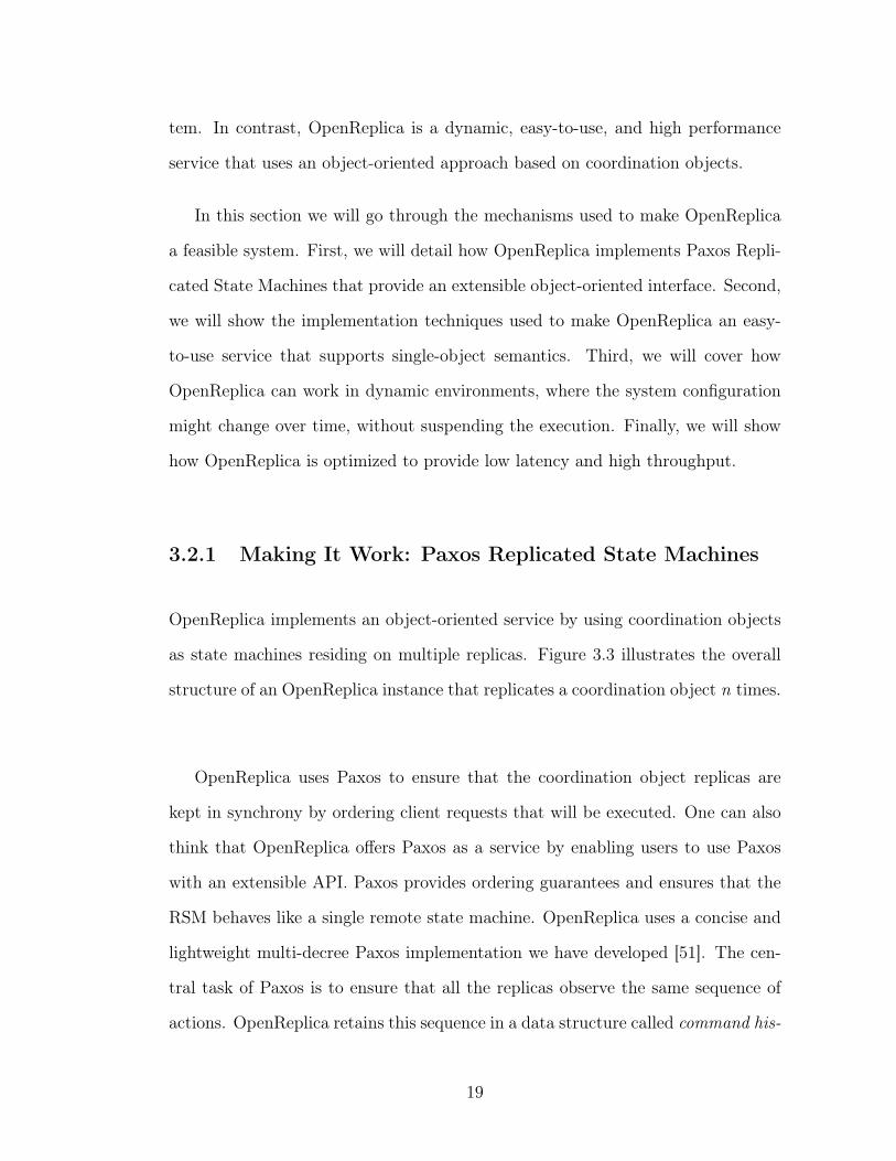
3.3 The structure of an OpenReplica instance. Clients interact witha coordination object transparently through the client proxy. Theconsistency and fault-tolerance of the user-defined coordination ob-ject is maintained by Replica nodes using the Paxos consensus pro-tocol. Dashed arrows represent method invocations, solid arrowsrepresent network messages. . . . . . . . . . . . . . . . . . . . . . . 20
3.4 Command history OpenReplica maintains for a replicated object. . 223.5 Latency as a function of the number of replicas. . . . . . . . . . . . 323.6 CDF of the latency as a function of the number of replicas. . . . . 333.7 Latency as a function of the size of the replicated state. . . . . . . 343.8 Throughput as a function of the number of replicas. . . . . . . . . 353.9 Latency in the presence of leader failures at operations 250 and 500. 36
4.1 Pseudocode for a key-value store agent. The key-value store keepsa mapping from keys to values and maps a new value to a given keywith the PUT operation and returns the value mapped to a givenkey with the GET operation. . . . . . . . . . . . . . . . . . . . . . . 41
4.2 Pseudocode for a client agent that requests a key mapping from thekey-value store agent with a GET operation on the key ‘foo’. . . . . 41
4.3 Pseudocode for a client-side sharding ingress proxy agent for thekey-value store. The ingress proxy agent mimics ‘KVS’ to the clientand forwards client requests to the correct shard depending on thekey. . . . . . . . . . . . . . . . . . . . . . . . . . . . . . . . . . . . 43
4.4 Pseudocode for a server-side sharding egress proxy agent for thekey-value store. The egress proxy agent mimics the client to ashard of the key-value store and simply forwards a received clientrequest. . . . . . . . . . . . . . . . . . . . . . . . . . . . . . . . . . 43
4.5 Configuration for the key-value store that has been transformed tobe sharded two-ways. . . . . . . . . . . . . . . . . . . . . . . . . . 45
4.6 Pseudocode for a determistic key-value store agent that handlesrequests in order using a counter. . . . . . . . . . . . . . . . . . . . 49
4.7 Pseudocode for the numbering agent that numbers every messagebefore it forwards it to its destination. . . . . . . . . . . . . . . . . 49
4.8 KVS transformed with state machine replication. . . . . . . . . . . 514.9 KVS transformed with primary-backup replication. . . . . . . . . . 53
ix
4.10 The key-value store can be transformed to accept encrypted traf-fic from clients by adding an ingress proxy on the client-side thatencrypts client messages before they are sent and an egress proxyon the server-side that decrypt a message using the key shared be-tween proxies. The reverse traffic is encrypted by transforming theclients in the same fashion. . . . . . . . . . . . . . . . . . . . . . . 54
4.11 A crash fault-tolerant key-value store can be made to tolerateByzantine failures by applying the Nysiad transformation, whichreplaces the replicas of the key-value store agent. . . . . . . . . . . 56
5.1 High-level specification SpecH . . . . . . . . . . . . . . . . . . . . . 595.2 Specification for ordering updates in dynamic chains. . . . . . . . . 645.3 Dynamic chain specification for queries. . . . . . . . . . . . . . . . 655.4 Additional transitions for low-level chain specification for configu-
ration updates. . . . . . . . . . . . . . . . . . . . . . . . . . . . . . 655.5 Sequentially consistent service. . . . . . . . . . . . . . . . . . . . . 785.6 Sequentially consistent queries on the chain. . . . . . . . . . . . . . 785.7 Eventually consistent service. . . . . . . . . . . . . . . . . . . . . . 795.8 Eventually consistent queries on the chain. . . . . . . . . . . . . . . 795.9 Service that supports read-your-writes consistency. . . . . . . . . . 805.10 Service that supports monotonic read consistency. . . . . . . . . . . 81
6.1 The Logical Agent Transformation Tree (LATT) for the two-waysharded ‘KVS’ key-value store. The sharding ingress proxy assignsclient requests to the correct shard. The sharding egress proxiesforward these requests to the corresponding shards. . . . . . . . . . 92
7.1 Throughput for a single server as the number of clients grow. . . . 997.2 Throughput of Ovid with 60 clients as we change the number of
shards. . . . . . . . . . . . . . . . . . . . . . . . . . . . . . . . . . 1017.3 Throughput for 5 shards as the number of clients grows. . . . . . . 1027.4 Throughput of the key-value store replicated with Paxos when the
system is not reconfigured after failures. . . . . . . . . . . . . . . . 1047.5 Throughput of the key-value store replicated with Paxos when the
system can reconfigure itself automatically after failures to add newreplicas. . . . . . . . . . . . . . . . . . . . . . . . . . . . . . . . . . 105
x
CHAPTER 1
INTRODUCTION
Distributed systems are used widely to achieve better performance, availability,
and reliability. With their wide ranging use, the capabilities expected from dis-
tributed systems are extensive and the rate of change is high. As a result, it is
getting complicated to build distributed systems that are both correct and perform
well, combining various guarantees together. It is getting even more complicated
to evolve them over time, especially when multiple distributed applications are
working together and evolving simultaneously.
In this thesis we introduce a way of specifying, building, maintaining, and
evolving distributed systems. Like others before us, we claim that distributed sys-
tems should be specified with clear abstraction levels, where different capabilities
can be added to a system as stand-alone modules. Abstraction is a technique for
managing complexity of computer systems. We use abstraction to separate differ-
ent levels of complexity in a given distributed system. As a result, the complexity
of every module can be restrained to a single abstraction level making it easier to
specify a system as a combination of these modules.
It is important to be able to reason about how these modules can be combined
to work as a correct system. To this end, we created Ovid [8, 7], a framework to pro-
vide a way to reason about how a distributed system can be built as a combination
of modules. This framework makes it easy to understand how a distributed system
implements certain guarantees. Moreover, our framework can automatically and
correctly build and deploy systems as a combination of these modules, in effect
enabling distributed systems programmers to automatically architect systems that
implement the exact behavior they require.
1
Ovid can construct distributed systems as a combination of stand-alone com-
ponents and transform these systems to change these components automatically.
Importantly, Ovid can prove that when a distributed system is transformed to
use different components, it still implements the expected external behavior, in
effect making it possible to reason about how distributed systems are built and
evolved over time. To this end, Ovid leverages the concept of refinement [31] or,
equivalently, backward simulation [39], to prove whether two different distributed
systems implement the same functionality or not.
To specify a distributed system, we start out with a relatively simple speci-
fication of agents. Each agent is a self-contained state machine that transitions
in response to messages it receives and may produce output messages for other
agents. Next, we apply transformations to agents such as replication or shard-
ing. Each transformation replaces an agent by one or more new agents. For each
transformation we supply a refinement mapping [31] from the new agents to the
original agent to demonstrate correctness, but also to be able to obtain the state
of the original agent in case a reconfiguration is necessary. Transformations can
be applied recursively, resulting in a tree of transformations.
A collection of agents itself is a state machine that transitions in response to
messages it receives and may produce output messages for other agents. Conse-
quently, a collection of agents can be considered an agent itself. When an agent is
replaced by a set of agents, the question arises what happens to messages that are
sent to the original agent. For this, each transformed agent has one or more ingress
agents that receive such incoming messages. The routing is governed by routing
tables: each agent has a routing table that specifies, for each destination address,
what the destination agent is. Inspired by Software Defined Networks [17, 42],
2
Ovid has a logically centralized controller, itself an agent, that determines the
contents of the routing tables.
Besides routing, the controller determines where agents run. Agents may be co-
located to reduce communication overhead, or run in different locations to benefit
performance or failure independence. In order for the controller to make placement
decisions, agents are tagged with location constraints. The result is what can
be termed a “Software Defined Distributed System” in which a programmable
controller manages a running system.
Ovid supports on-the-fly reconfiguration based on “wedging” agents [12, 1].
By wedging an agent, it can no longer make transitions, allowing its state to be
captured and re-instantiated for a new agent. By updating routing tables, the
reconfiguration can be completed. This works even for agents that have been
transformed, using the refinement mapping for retrieving state.
We have built a prototype implementation of Ovid that includes a visual tool
for specifying and transforming distributed systems and a run-time environment
that deploys and runs the agents. The visual tool makes it relatively easy, even
for novice users, to construct scalable, secure, and consistent systems. It can be
run from any web browser. The run-time environment, currently only supporting
agents and transformations written in Python, manages all execution and commu-
nication fully automatically.
Even if Ovid is built to support various distributed system capabilities such as
consistency, availability, security and fault-tolerance, in this thesis we mainly focus
on fault-tolerance and detail how Ovid evolved as a system over time.
3
It took a lot of investigation to perfect the Ovid framework. As a result, this
thesis includes contributions that span different aspects of building a framework
that can be used to build and evolve distributed systems automatically, in a prin-
cipled manner.
∙ This thesis introduces Ovid, a framework for building large-scale distributed
systems that run in dynamic data center environments.
∙ This thesis describes how Ovid models distributed systems as a collection of
agents, self-contained state machines that communicate by exchanging mes-
sages, and how using this model can make it easier to construct distributed
systems automatically.
∙ This thesis explains how a distributed system can be evolved organically
and automatically using transformations, automated refinements that allow
distributed systems to be developed from simple components.
∙ This thesis underlines how a theoretically sound model of a distributed sys-
tem can be used to reason about the guarantees the system offers, the as-
sumptions it makes about its environment, and its interactions with other
systems. Moreover, it explores how this kind of a detailed understanding can
help build better systems.
∙ This thesis examines the power of refinement and shows how it can be used
to reason about two different implementations of a distributed system and to
thoroughly understand how these different implementations differ from each
other even if they have the same external behavior.
∙ This thesis presents a full refinement of a storage system replicated with the
Chain Replication protocol to a centralized storage system. Furthermore, it
4
introduces a new version of the Chain Replication protocol that can reconfig-
ure itself without requiring an external master, support various consistency
models at the same time, and has better performance and scalability.
∙ This thesis describes a full implementation and deployment of Ovid, including
a visual tool to model and transform distributed systems and a run-time
environment that deploys these distributed systems.
∙ Finally, this thesis includes an evaluation of the benefit of using Ovid to
model, evolve and deploy distributed systems.
The rest of this thesis is structured as follows. Chapter 2 discusses back-
ground and related work. Chapter 3 showcases the concept of transformation and
shows how fault-tolerance can be implemented as a stand-alone service. Chap-
ter 4 presents the system model for Ovid, including agents and transformations.
Chapter 5 shows in detail how refinements can be used to prove equivalence of
two system models using Chain Replication as a motivating example. Chapter 6
details how Ovid can automatically build and deploy distributed systems and how
it is implemented. Chapter 7 evaluates Ovid and Chapter 8 concludes.
5
CHAPTER 2
BACKGROUND AND RELATED WORK
There has been much work on automating different aspects of building, verify-
ing, deploying, evolving, and maintaining distributed systems. In this chapter we
present past work on building distributed systems that can evolve and adjust dy-
namic environments, as well as work on automating distributed system creation
and verification, and data center management.
2.1 Evolving Distributed Systems
One approach to implementing evolving distributed systems is building reconfig-
urable systems. Reconfigurable distributed systems [11, 13, 25, 29] support the
replacement of their sub-systems. In [4], Ajmani et al. propose automatically up-
grading the software of long-lived, highly-available distributed systems gradually,
supporting multi-version systems. In the infrastructure presented, a distributed
system is modeled as a collection of objects. An object is an instance of a class.
During an upgrade old and new versions of a class and their instances are saved by
a node and both versions can be used depending on the rules of the upgrade. This
way, multi-versioning and modular upgrades are supported in the object-level. In
their methodology, Ajmani et al. use transform functions that reorganizes a node’s
persistent state from the representation required by the old instance to that re-
quired by the new instance, but these functions are limited with transforming the
state of a node, whereas we transform the distributed system as a whole.
Horus [53, 35] and Ensemble [23, 52] employ a modular approach to building
distributed systems, using micro-protocols that can be combined together to create
6
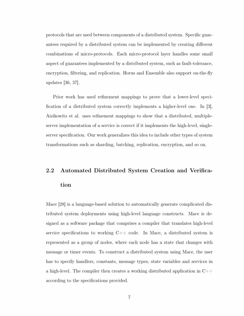
protocols that are used between components of a distributed system. Specific guar-
antees required by a distributed system can be implemented by creating different
combinations of micro-protocols. Each micro-protocol layer handles some small
aspect of guarantees implemented by a distributed system, such as fault-tolerance,
encryption, filtering, and replication. Horus and Ensemble also support on-the-fly
updates [36, 37].
Prior work has used refinement mappings to prove that a lower-level speci-
fication of a distributed system correctly implements a higher-level one. In [3],
Aizikowitz et al. uses refinement mappings to show that a distributed, multiple-
server implementation of a service is correct if it implements the high-level, single-
server specification. Our work generalizes this idea to include other types of system
transformations such as sharding, batching, replication, encryption, and so on.
2.2 Automated Distributed System Creation and Verifica-
tion
Mace [28] is a language-based solution to automatically generate complicated dis-
tributed system deployments using high-level language constructs. Mace is de-
signed as a software package that comprises a compiler that translates high-level
service specifications to working C++ code. In Mace, a distributed system is
represented as a group of nodes, where each node has a state that changes with
message or timer events. To construct a distributed system using Mace, the user
has to specify handlers, constants, message types, state variables and services in
a high-level. The compiler then creates a working distributed application in C++
according to the specifications provided.
7
Orleans [16] and Sapphire [58] offer distributed programming platforms to sim-
plify programming distributed applications that run in cloud environments. Much
like these infrastructure services, Ovid is designed to offer an infrastructure that
allows programmers to offload complicated configuration and maintenance services
to an automatically maintained, fault-tolerant and available service.
CrystalBall [57] is a system built on top of the Mace framework to verify a
distributed system by exploring the space of executions in a distributed manner
and having every node predict the outcome of their behavior. In CrystalBall,
nodes run a state exploration algorithm on a recent consistent snapshot of their
neighborhood and predict possible future violations of specified safety properties, in
effect executing a model checker running concurrently with the distributed system.
This is a more scalable approach compared to running a model checker from the
initial state of a distributed system and doing exhaustive state exploration.
Similarly, other recent projects have been focusing on verifying distributed sys-
tems and their components automatically. In [47] Schiper et al. use the formal
EventML [45] language to create specifications for a Paxos-based broadcast proto-
col that can be formally verified in NuPRL [18]. This specification is then compiled
into a provably correct and executable implementation automatically and used to
build a highly available database.
In [55], Wilcox et al. present a framework, namely Verdi, for implementing
practical fault-tolerant distributed systems and then formally verifying that the
implementations meet their specifications. Verdi provides a Coq toolchain for
writing executable distributed systems and verifying them, a mechanism to spec-
ify fault models as network semantics, and verified system transformers that take
an existing system and transform it to another system that makes different as-
8
sumptions about its environment. Verdi is able to transform systems to assume
different failure models, even if it is not able to transform systems to provide new
guarantees.
IronFleet [22] proposes building and verifying distributed systems using TLA-
style state-machine refinements and Hoare-logic verification. IronFleet employs a
language and program verification toolchain Dafny [34] that automates verification
and it enables proving safety and liveness properties for a given distributed system.
Systems like CrystalBall, Verdi, and IronFleet and languages like EventML can
be used in combination with Ovid to build provably correct large-scale infrastruc-
ture services that comprise multiple distributed systems. These systems can be
employed to prove the safety and liveness properties of different modules in Ovid,
as well as the distributed systems that are transformed by Ovid. This way, large-
scale infrastructure systems that are built as a combination of multiple provably
correct distributed systems can be constructed by Ovid.
2.3 Automated Data Center Management
Automated data center management services have recently emerged to ease the
task of managing large-scale distributed systems [21, 27, 2]. Autopilot [27] is a
Paxos RSM that handles tasks, such as provisioning, deployment and monitoring,
automatically without operator intervention. Centrifuge [2] is a lease manager,
built on top of a Paxos RSM, that can be used to configure and partition requests
among servers.
These services focus on providing tools that ease data center management,
9
whereas Ovid focuses on making distributed systems easy to manage and maintain,
in return making data center management easier. These services underline the
importance of making system management a more feasible task, which we believe
is possible through building systems that can evolve over time and adjust to the
dynamic data center environment they are running in.
10
CHAPTER 3
FAULT-TOLERANCE AS A SERVICE
Most services today are built using distributed systems, because they can with-
stand failures, while still being able to service requests correctly and with good
performance. A typical distributed system maintains state that needs to be repli-
cated and distributed, as well as actively executing threads of control whose be-
havior needs to be controlled. As a result, to be able to build a distributed system
that is available, reliable, correct and scalable, programmers have to implement
complex distributed system constructs.
A clean way of implementing these guarantees in a distributed system is to
separate these guarantees in their own abstraction layers, and implementing them
as stand-alone parts of the system that are independent from each other. This
way, these stand-alone parts can be added, removed or even changed over time
without having to restructure the distributed system as a whole.
In this chapter we show how a distributed system can be automatically made
fault-tolerant. This way fault-tolerance can be decoupled from the implementation
of a distributed system and offered as a service and users can achieve fault-tolerance
in a distributed system without having to implement complicated replication pro-
tocols. Ovid follows this scheme. Moreover, a correct service that implements
fault-tolerance can be used for different distributed systems. Through this mo-
tivating example, we underline the advantages of introducing a new abstraction
layer in a distributed system and concentrating the complexity of implementing
various guarantees in independent layers.
11
3.1 Approach
A fault-tolerant service needs to detect the failure of its components, and change
its configuration accordingly without sacrificing availability. To implement a fault-
tolerant service, many distributed systems [10, 19, 40] use a coordination service
such as Chubby [15] or ZooKeeper [26] to coordinate reconfiguration of distributed
components, while others implement replication in the system itself [38, 49]. Co-
ordination services assist application developers with detecting failures, notifying
and synchronizing distributed components, and storing fault-tolerant metadata for
the distributed application. Using these mechanisms and the passive metadata,
applications are then developed to handle failures and membership changes. As
a result, while coordination services assist system developers with implementing
fault-tolerant services, every service has to be reconstructed to use a coordination
service. For instance, application developers have to implement replication and
failure handling mechanisms, such as leader handoff, state transition, responsibil-
ity changes, and metadata updates in the distributed application itself. Handling
these issues using the basic primitives provided by current coordination services is
non-trivial and error-prone and coordination services do not provide a stand-alone
service that can be just added to the distributed application.
So we set out to build a service that can transform any distributed application
to be fault-tolerant, without requiring the application developer to implement com-
plicated distributed system constructs. We developed OpenReplica [6], which can
transform any system to be fault-tolerant automatically. OpenReplica implements
fault-tolerance as a stand-alone service for large-scale distributed systems by repli-
cating part of the system state. It provides a high-level of abstraction in the form of
programmable, consistent and fault-tolerant coordination objects that can be used
12
to replicate part of an application’s state. Using coordination objects, application
developers can offload any distributed and fault-tolerant computation to Open-
Replica and do not have to implement complicated failure handling, replication
and synchronization mechanisms in their application. Even though coordination
objects can handle distributed executions in a fault-tolerant manner, developers
can implement coordination objects as if they are implementing simple local ob-
jects in their application.
OpenReplica works as follows: Application developers create the local ob-
jects that implement the fault-tolerant logic they want, and use OpenReplica
to distribute this object automatically. OpenReplica treats these objects as
state machines, and transforms them into fault-tolerant replicated state machines
(RSMs) [30, 48] by maintaining them on a set of replicas. These replicas can
provide instant failover and are kept in synchrony using consensus as the state of
the replicated objects change through method invocations. The distributed ap-
plication interacts with the replicated objects through an automatically generated
object proxy, providing the illusion that the replicated object is just another part
of the application. This proxy provides an API that is identical to the original,
non-fault-tolerant object. Through these objects, application developers can use
the guarantees offered by OpenReplica, namely fault-tolerance and consistency, in
their own application as if they are implemented in the application itself.
3.1.1 Maintaining State
OpenReplica keeps shared state in a distributed application fault-tolerant and
consistent, and supports consistent state transitions. OpenReplica improves upon
state-of-the-art coordination libraries that store shared data serialized on a file
13
system interface, by maintaining shared state in any form, supporting any widely
used data structure. Moreover, OpenReplica keeps shared state active and can
update it in a consistent manner without requiring the state to be updated by a
chosen master. This is because in OpenReplica state changes are recorded to a
unified log using the Paxos consensus protocol to agree on the ordering of these
changes. This way, state changes are synchronized automatically, removing the
requirement for a leader or master in the distributed application itself. Any node in
the distributed application can safely update the state maintained in OpenReplica.
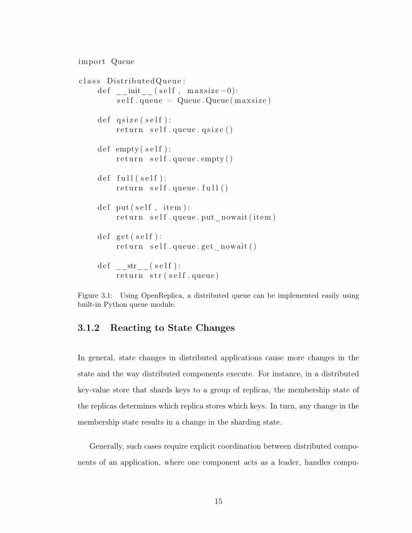
Figure 3.1 shows a sample coordination object implementation for a distributed
queue. The DistributedQueue extends a well-known Queue API, which is modified
through the put method and queried through get, size, empty and full methods.
In effect, the DistributedQueue object encloses the critical state that needs to be
made fault-tolerant, and defines a state machine with a clearly specified set of legal
transitions. OpenReplica ensures that these operations are invoked in a consistent,
totally-ordered manner.
What is noteworthy about this implementation is that it includes no replication-
specific code. In fact, the implementation uses the non-blocking operations from
the existing Python Queue module. The distributed application that is using this
object does not need to be aware that the object is replicated and fault-tolerant.
This way any distributed system can be made fault-tolerant using coordination
objects automatically.
14
import Queue
c l a s s Distr ibutedQueue :de f __init__( s e l f , maxsize =0):
s e l f . queue = Queue . Queue ( maxsize )
de f q s i z e ( s e l f ) :r e turn s e l f . queue . q s i z e ( )
de f empty ( s e l f ) :r e turn s e l f . queue . empty ( )
de f f u l l ( s e l f ) :r e turn s e l f . queue . f u l l ( )
de f put ( s e l f , item ) :r e turn s e l f . queue . put_nowait ( item )
de f get ( s e l f ) :r e turn s e l f . queue . get_nowait ( )
de f __str__( s e l f ) :r e turn s t r ( s e l f . queue )
Figure 3.1: Using OpenReplica, a distributed queue can be implemented easily usingbuilt-in Python queue module.
3.1.2 Reacting to State Changes
In general, state changes in distributed applications cause more changes in the
state and the way distributed components execute. For instance, in a distributed
key-value store that shards keys to a group of replicas, the membership state of
the replicas determines which replica stores which keys. In turn, any change in the
membership state results in a change in the sharding state.
Generally, such cases require explicit coordination between distributed compo-
nents of an application, where one component acts as a leader, handles compu-
15
tations on the application side, and notifies other components accordingly. If the
leader fails during this process, this should be detected, another component should
become the leader, handle the computations on the application side, and notify
other components. To eliminate the need for computing the new state on the ap-
plication side in a non-fault-tolerant way and introducing extra traffic and load to
the application, OpenReplica supports active execution on the coordination object
itself. These active executions are done in a fault-tolerant way and they might
change the maintained state and result in notifications to clients.
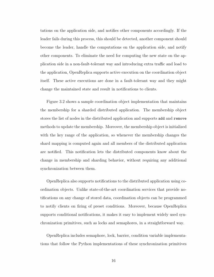
Figure 3.2 shows a sample coordination object implementation that maintains
the membership for a sharded distributed application. The membership object
stores the list of nodes in the distributed application and supports add and remove
methods to update the membership. Moreover, the membership object is initialized
with the key range of the application, so whenever the membership changes the
shard mapping is computed again and all members of the distributed application
are notified. This notification lets the distributed components know about the
change in membership and sharding behavior, without requiring any additional
synchronization between them.
OpenReplica also supports notifications to the distributed application using co-
ordination objects. Unlike state-of-the-art coordination services that provide no-
tifications on any change of stored data, coordination objects can be programmed
to notify clients on firing of preset conditions. Moreover, because OpenReplica
supports conditional notifications, it makes it easy to implement widely used syn-
chronization primitives, such as locks and semaphores, in a straightforward way.
OpenReplica includes semaphore, lock, barrier, condition variable implementa-
tions that follow the Python implementations of these synchronization primitives
16
c l a s s Membership ( ) :de f __init__( s e l f , keyrange ) :
s e l f . membership = [ ]s e l f . shardmap = {}s e l f . keyrange = keyrange
de f add ( s e l f , member ) :i f member not in s e l f . members :
s e l f . members . append (member)s e l f . update_shardmap ( )s e l f . n o t i f y ( )
de f remove ( s e l f , member ) :i f member in s e l f . members :
s e l f . members . remove (member)s e l f . update_shardmap ( )s e l f . n o t i f y ( )
e l s e :r a i s e KeyError (member)
de f update_shardmap ( s e l f ) :remainder = s e l f . keyrange % len ( s e l f . membership )quot i ent = s e l f . keyrange / l en ( s e l f . membership )f o r i in range ( l en ( s e l f . membership ) ) :
s e l f . shardmap [ member ] = [ quot i ent * i , quot i ent *( i +1)]s e l f . shardmap [ s e l f . membership [ i ] ] += remainder
de f n o t i f y ( s e l f ) :f o r member in s e l f . membership :
r a i s e Not i fy ( n o t i f y d i c t=s e l f . shardmap )
Figure 3.2: OpenReplica Membership Object updates sharding information dependingon changes in the membership and notifies all nodes.
directly. Through these primitives, users can implement distributed synchroniza-
tion between components easily. It is important to note that because the network
between clients and OpenReplica may not be reliable or clients can fail, Open-
Replica is specifically implemented to be able to recover from failures of clients
that may be holding a lock. These failures are detected by OpenReplica and a
cleanup function is called in the coordination object to recover from a client fail-
17
ure. Moreover, if there is a packet reordering or duplication in the network, a
request from a lock holding client might arrive after another client has already
acquired that same lock. Because all synchronization operations from clients are
uniquely identified and synchronous, i.e. a client cannot send a client request until
it receives the reply for the previous request, and a release on a lock has to be
executed for another client to acquire the lock, a packet reordering cannot cause a
client not holding a lock to execute a function protected by a lock.
In summary, OpenReplica provides active data maintenance and replication,
as well as consistent updates on this shared data. Moreover, unlike existing state-
of-the-art coordination services, OpenReplica can run active computations and
update shared state in reaction to changes in the distributed environment. This
ability in turn removes the necessity that distributed applications elect and use a
master node to change shared state and indirectly coordinate every state update
on the client-side with a master.
3.2 Implementation
Implementing a service that can automatically make any distributed application-
tem fault-tolerant by maintaining active shared state while supporting dynamic
state changes necessitates numerous design decisions. OpenReplica is implemented
as a Paxos Replicated State Machine that can manage live replicas of coordination
objects. We use the multi-decree Paxos implementation described in detail in our
previous work [51]. There has been much work on employing the Paxos protocol
to achieve fault-tolerance in specific settings [40, 41, 15, 38, 14, 27, 2], in which
Paxos was monolithically integrated into a specific, static API offered by the sys-
18
tem. In contrast, OpenReplica is a dynamic, easy-to-use, and high performance
service that uses an object-oriented approach based on coordination objects.
In this section we will go through the mechanisms used to make OpenReplica
a feasible system. First, we will detail how OpenReplica implements Paxos Repli-
cated State Machines that provide an extensible object-oriented interface. Second,
we will show the implementation techniques used to make OpenReplica an easy-
to-use service that supports single-object semantics. Third, we will cover how
OpenReplica can work in dynamic environments, where the system configuration
might change over time, without suspending the execution. Finally, we will show
how OpenReplica is optimized to provide low latency and high throughput.
3.2.1 Making It Work: Paxos Replicated State Machines
OpenReplica implements an object-oriented service by using coordination objects
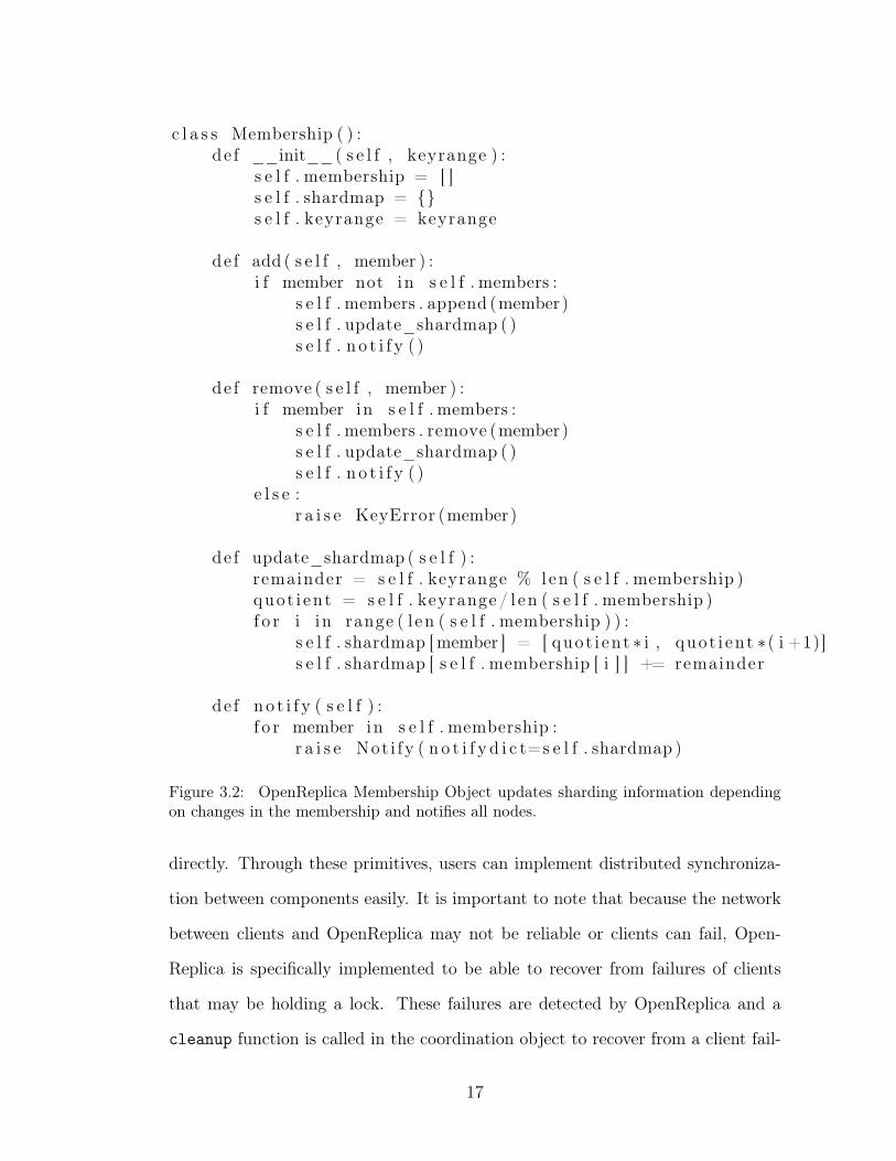
as state machines residing on multiple replicas. Figure 3.3 illustrates the overall
structure of an OpenReplica instance that replicates a coordination object n times.
OpenReplica uses Paxos to ensure that the coordination object replicas are
kept in synchrony by ordering client requests that will be executed. One can also
think that OpenReplica offers Paxos as a service by enabling users to use Paxos
with an extensible API. Paxos provides ordering guarantees and ensures that the
RSM behaves like a single remote state machine. OpenReplica uses a concise and
lightweight multi-decree Paxos implementation we have developed [51]. The cen-
tral task of Paxos is to ensure that all the replicas observe the same sequence of
actions. OpenReplica retains this sequence in a data structure called command his-
19
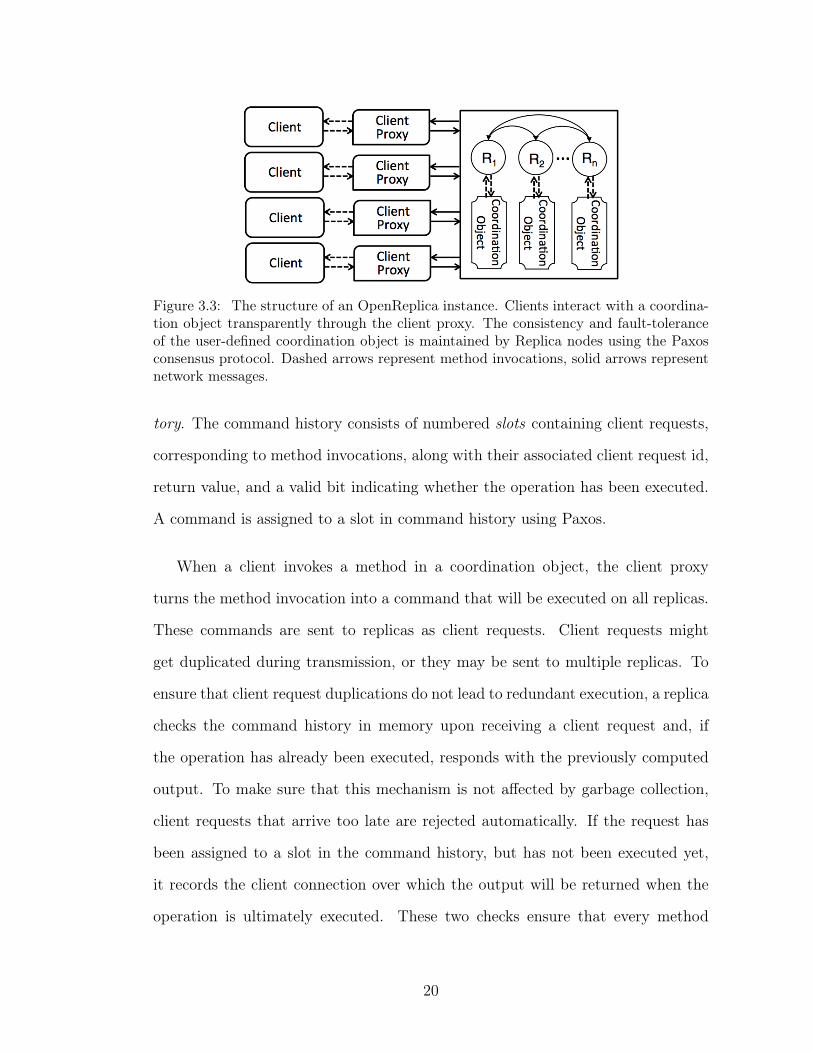
Figure 3.3: The structure of an OpenReplica instance. Clients interact with a coordina-tion object transparently through the client proxy. The consistency and fault-toleranceof the user-defined coordination object is maintained by Replica nodes using the Paxosconsensus protocol. Dashed arrows represent method invocations, solid arrows representnetwork messages.
tory. The command history consists of numbered slots containing client requests,
corresponding to method invocations, along with their associated client request id,
return value, and a valid bit indicating whether the operation has been executed.
A command is assigned to a slot in command history using Paxos.
When a client invokes a method in a coordination object, the client proxy
turns the method invocation into a command that will be executed on all replicas.
These commands are sent to replicas as client requests. Client requests might
get duplicated during transmission, or they may be sent to multiple replicas. To
ensure that client request duplications do not lead to redundant execution, a replica
checks the command history in memory upon receiving a client request and, if
the operation has already been executed, responds with the previously computed
output. To make sure that this mechanism is not affected by garbage collection,
client requests that arrive too late are rejected automatically. If the request has
been assigned to a slot in the command history, but has not been executed yet,
it records the client connection over which the output will be returned when the
operation is ultimately executed. These two checks ensure that every method
20
invocation will execute at most once, even in the presence of client retransmissions
and failures of the previous replicas that the client may have contacted.
If the client request does not appear in the command history, the receiving
replica locates the earliest unassigned slot and proposes to assign that command
for that slot using Paxos. The Paxos proposal will either uncover that there was
an overriding proposal for that slot suggested previously by a different replica
(which will, in turn, defer the client request to a later slot in the command history
and start the process again), or it will be accepted by a majority of replicas.
These proposals are independent and concurrent; failures of replicas may lead to
unassigned slots, which get assigned by following proposals. Once a command is
assigned to a slot by a replica, that replica can propagate the assignment to other
replicas and execute the operation locally as soon as all preceding slots have been
decided. The replica then responds with the return value back to the client. Note
that, while the propagation to other replicas occurs in the background, there is no
danger of losing the agreed-upon slot number assignment, as the Paxos protocol
implicitly stores this decision in a quorum of replicas at the time the proposal is
accepted. For the same reason, OpenReplica does not require the object state to
be written to disk. As long as there are less than a threshold 𝑓 failures in the
system, the state of the object will be preserved.
OpenReplica is a fault-tolerant system that can recover from up to 𝑓 failures
when there are 2𝑓 + 1 replica nodes. The default setting provides fault-tolerance,
a critical goal in many common cloud deployment scenarios. Users who need dura-
bility can achieve it in two different ways. The first option is for the coordination
object to write crucial state to disk and implement a recovery function to be exe-
cuted when necessary. This is often the best option, as it takes writing to disk out
21
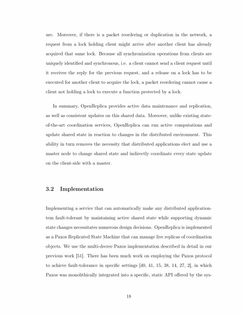
Figure 3.4: Command history OpenReplica maintains for a replicated object.
of the critical path and lets the user decide when the state should be written to
disk, in return making the recovery process easier and faster. As an alternative,
OpenReplica supports logging to disk on the replicas.
OpenReplica implements a functional Paxos RSM that can maintain live ob-
jects and support active state changes, but such a service should also be dynamic,
easy-to-use and fast. Now we go into details of how these are achieved in the
OpenReplica implementation.
3.2.2 Making it Dynamic
Long-lived services need to survive countless network and node failures. To do so
effectively, the system has to provide sufficient flexibility to move every component
at runtime. OpenReplica facilitates this by supporting dynamic view changes to
update the replica set. Over time, a coordination object may completely change
the set of replicas in its configuration.
To support dynamic view changes, OpenReplica implements an internal control
mechanism based on meta commands for managing replicas. Meta commands are
22
special commands recognized by replicas that pertain to the configuration state of
the replicated state machine as opposed to the state of the coordination object.
Meta commands are generated within the system and guaranteed to be executed
at the same logical time and under the same configuration in every replica. This
timing guarantee is required since the underlying protocol typically has many out-
standing proposals being handled simultaneously, and a change in the configuration
would affect later proposals that are being decided. For instance, a change in the
set of replicas would impact all ongoing proposals for all outstanding slots, and
therefore needs to be performed in synchrony on all replicas.
To guarantee consistency through configuration changes, OpenReplica employs
a window to define the number of concurrent proposals a replica can have at any
given time. This number also corresponds to the non-executed commands a replica
can have outstanding. Once a meta command is assigned to a slot in the command
history, its execution is delayed by a window. This way, it is guaranteed that all
the operations that would be affected by this view change are already executed
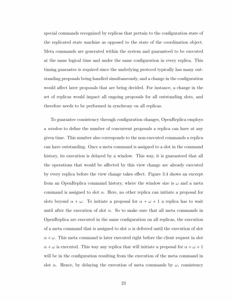
by every replica before the view change takes effect. Figure 3.4 shows an excerpt
from an OpenReplica command history, where the window size is 𝜔 and a meta
command is assigned to slot 𝛼. Here, no other replica can initiate a proposal for
slots beyond 𝛼 + 𝜔. To initiate a proposal for 𝛼 + 𝜔 + 1 a replica has to wait
until after the execution of slot 𝛼. So to make sure that all meta commands in
OpenReplica are executed in the same configuration on all replicas, the execution
of a meta command that is assigned to slot 𝛼 is deferred until the execution of slot
𝛼+𝜔. This meta command is later executed right before the client request in slot
𝛼+ 𝜔 is executed. This way any replica that will initiate a proposal for 𝛼+ 𝜔 + 1
will be in the configuration resulting from the execution of the meta command in
slot 𝛼. Hence, by delaying the execution of meta commands by 𝜔, consistency
23
of the Paxos related state can be maintained through a dynamic configuration
change [33].
Dynamic view changes in our system can be initiated internally, by a replica
that detects a failure or externally, by a system administrator manually issuing
commands. For fast detection, all replicas ping each other periodically if they
haven’t received a message from each other recently. As an optimization, replicas
assume a weak leadership ordering between each other to take responsibility of
updating the view. When a replica detects a failure it checks if it is the weak
leader to reconfigure the system. If this is the case, then it brings up a new replica
node, transfers its state by forwarding all commands in its command history to
the new replica, and then submits two meta commands, one to delete the failed
node and another one to add the new one. When the new replica is added to
the configuration, it will start receiving commands to add to its command history.
Note that, if the meta command that adds a replica is assigned to slot 𝑠, the
new replica will receive commands starting from slot 𝑠+ 𝜔. Accordingly, the new
replica will ask the weak leader for the commands before slot 𝑠+ 𝜔 that have not
been forwarded to it and will consider itself updated once it executes all those
commands. To have the view change take effect quickly, the initiator also invokes
𝜔 NOOP operations.
3.2.3 Making It Easy to Use
OpenReplica includes extensions to the basic Paxos RSM implementation to pro-
vide an easy-to-use interface that can support active state maintenance and up-
dates. We now cover them in turn.
24
1. Client Proxy: OpenReplica clients interact with a coordination object
through a client proxy that is included in the OpenReplica library. The
user invokes methods for any object through this proxy. Underneath the
covers, the client proxy translates method invocations into client requests,
which comprise a unique client request id, method name, and arguments for
invocation. The proxy marshals client requests and sends them to one of
the replicas. OpenReplica also attaches a security token to every proxy to
disable unauthorized method invocations on the replicated object, which is
generated with the same token. Depending on the responses returned from
the replica, the proxy is also capable of notifying the client and suspending
or resuming the execution of the calling client thread, thereby enabling a
coordination object to control the execution of its callers.
The end result of this organization is that the clients can treat the set of
replicas as if they implement a single local object. Due to the replicated
nature of the coordination object, the client proxy might throw additional
OpenReplica exceptions if this option is turned on by the client. In the de-
fault setting, OpenReplica resolves all temporary errors, such as a partitioned
network in the background.
2. DNS Integration: In an environment where the set of nodes implementing
a fault-tolerant object can change at any time, locating the replica set can
be a challenge. To help direct clients to the most up-to-date set of replicas
automatically, replicas can also track the view of the system, update the set
of live nodes, and receive and handle DNS queries.
OpenReplica supports integration with DNS by assigning a DNS domain to
the coordination object instance. A name for a coordination object is selected
by the user and replicas can be configured with the selected name. On boot,
25
the replicas register their IP address and assigned domain with the DNS name
servers for their parent domain. Thereafter, the parent domain designates
them as authoritative name servers for their subdomain and directs queries
accordingly.
OpenReplica replicas also support integration with Amazon Route 53 [9] to
enable users to run stand-alone coordination instances without requiring the
assistance of a parent domain. To run OpenReplica integrated with Amazon
Route 53, the users set up a Route 53 account that is ready to receive requests
and supply the related credentials to OpenReplica. Thereafter, the replicas
track the view of the system and update the Route 53 account automatically.
DNS integration enables the client proxy to initialize its connection to an
RSM through a DNS lookup automatically. After the connection is initial-
ized, following method invocations are submitted using the same connection
as long as it does not fail. When the connection fails, the client proxy per-
forms a new DNS lookup and initializes a new connection transparently. This
way, the view changes that might require new connections to be established
are masked by the client proxy. Short timeouts on DNS responses ensure
that clients do not cache stale DNS results.
3. OpenReplica Manager: To simplify instantiation, OpenReplica also in-
cludes a deployment and maintenance service called OpenReplica Manager.
Similar to OpenDHT [46], OpenReplica Manager enables users to submit
their coordination object and to have the system replicate the coordination
object with user credentials on any machines. Integration with DNS enables
these objects to be located through SRV records while Amazon Route 53
support enables users to tie into Amazon’s resilient DNS infrastructure.
To start an OpenReplica instance, OpenReplica Manager takes a username
26
to use as a DNS name, a user implemented coordination object, the desired
number of replicas and the credentials for the set of machines to deploy the
OpenReplica instance. OpenReplica Manager then starts an OpenReplica
instance with the given number of nodes on the desired set of machines. To
maintain the data for different user deployments, OpenReplica Manager itself
uses a coordination object that maps a DNS name to active set of name server
replicas in a user OpenReplica instance. This coordination object is updated
after deployment of an OpenReplica instance. After initiation, OpenReplica
Manager maintains the OpenReplica instance deployment, forwards name
queries to their designated name server replicas using this coordination ob-
ject.
To access the OpenReplica instance deployed by OpenReplica Manager,
clients can use the generated proxy to invoke methods on the fault-tolerant
coordination object. The clients only need to initialize the proxy with the
DNS name, which is used to locate the nodes in the system transparently
using the DNS integration.
4. Non-deterministic Operations and Side-Effects: During state updates
that happen on replicas, non-deterministic operations might result in differ-
ent states on each replica. OpenReplica deals with non-deterministic opera-
tions by deciding on the assignment of a state to a slot in command history,
instead of the command itself. To enable this kind of behavior, the operations
with non-deterministic behaviors are detected with a blacklist and, if one of
these operations is requested, the client request detects the non-deterministic
invocation and sends a request with non-deterministic flag turned on, which
is then proposed by a replica. When this state is assigned to a slot, the com-
27
mands following this state are executed over this state. This ensures that all
replicas observe the same non-deterministic choices.
Seemingly benign language features in Python can give rise to non-
deterministic behaviors. In particular, dictionary and set enumeration can
yield results in different orders on different replicas, leading to divergence.
This is because in the Python runtime, dictionaries are implemented as
hash tables and sets are implemented as open-addressing hash tables, conse-
quently, inserting and removing items can change their order. OpenReplica
determines method invocations that make use of these components and sim-
ply sorts them to establish a canonical order. Applications wishing to avoid
the sort overhead can use their own deterministic data structures.
3.2.4 Making it Fast
OpenReplica uses a multi-decree Paxos implementation to minimize latency of
assigning a command to a slot in command history. To achieve even better per-
formance, OpenReplica also uses batching and read leases when appropriate.
1. Batching: To improve throughput under load, OpenReplica supports batch-
ing of client requests both on the client and the server side.
On the server side, batching is employed by the replica when there are mul-
tiple client requests waiting for assignment to slots in the command history.
If such requests are found, the replica batches them into a single proposal
and individually responds to the clients. This process performs the standard
sanity checks such as validating security tokens and ensuring at-most-once
semantics individually for every request in the batch.
28
On the client side, a similar process batches concurrent outgoing requests in
the client into a single message to the server. This enables the sanity checks
to be performed just once for the entire batch, reducing overhead. The replica
treats these batched requests as a single client request, executes all requests in
the batch in the order received, batches the replies and returns to the client
proxy with a single client reply. While employed by many other systems
to improve Paxos performance, client-side batching represents a latency for
throughput trade-off and is performed in OpenReplica only when directed
by the programmer.
2. Read Leases: By default, every method invocation in OpenReplica provides
strong consistency, where the client requests are assigned to a single slot in
the command history. The slot location in the command history is the result
of an agreement protocol, and the execution is determined by the globally-
agreed slot assignment. Because no replica executes a command unless it
has seen the entire prefix of commands, the results are guaranteed to be
consistent.
But, since read-only operations do not update the state, it is not necessary
that a new slot in the command history is allocated for a read-only com-
mand. To preserve strong consistency however, it is necessary to ensure that
the read-only command returns the state following the latest update. Accord-
ingly, one can avoid proposing a read-only command for a slot in command
history by using leases [20, 32]. OpenReplica implements the read-lease opti-
mization discussed in the Paxos implementation it uses [51], which assumes
that there is a known bound on clock drift but does not assume that clocks
are synchronized. Following this optimization, the weak leader that proposes
commands also holds a read-lease, and this replica handles all client requests,
29
both read-only and update commands. A weak leader acquires a read lease
for a particular period of time, when it becomes the weak leader. Knowing
that it has the lease, a replica can directly respond to read-only commands
in a consistent way.
3. Garbage Collection: Any long-running system based on agreement on a
shared history will need to occasionally prune its history in order to avoid
running out of memory. In particular, replicas in OpenReplica keep a record
of completely- and partially-decided commands that needs to be compacted
periodically. The key to this compaction is the observation that a prefix
of history that has been executed by all replicas can be elided safely and
replaced with a snapshot of the object. OpenReplica accomplishes this in
two main steps.
First, a replica takes a snapshot of the coordination object every 𝜏 commands,
and issues a meta command to garbage collect the state up to this snapshot.
This meta command proposal serves three purposes; namely, the garbage
collection command is stored in the replicas; the replicas then detect the
meta command and acquiesce only if they themselves have all the ballots for
all preceding slot numbers; and finally, the meta command ensures that at
the time of execution for the meta command, all the replicas will have the
same state. Later, when the meta command is executed, a garbage collection
command is sent to replicas along with the snapshot of the object at that
point in time. Upon receiving this message, the replicas can safely replace
a slot with the snapshot of the object and delete old ballot information.
This way, during a failover, new leader will be able to simply resurrect the
object state after 𝑛𝜏 operations, instead of having to apply as many state
transitions.
30
3.3 Evaluation
We have performed a detailed evaluation of OpenReplica’s performance. In this
section, we present the results of several microbenchmarks which examine the
latency, recovery time from failures, throughput and scalability of OpenReplica.
These experiments reflect end-to-end measurements from clients and include
the full overhead of going over the network. As a result, the latency numbers we
present may not be comparable to numbers presented in related work that reports
performance metrics collected on the same host.
The evaluation is performed on a cluster of eleven servers. Each server has two
Intel Xeon E5420 processors with 4 cores and a clock speed 2.5 GHz and 16 GB
RAM and a 500 GB SATA 3.0 Gbit/s hard disk operating at 7200 RPM. All servers
are running 64-bit Fedora 10 with the Linux 2.6.27 kernel. We spread clients and
replicas on these 11 servers.
3.3.1 Latency
The first experiment examines the latency in OpenReplica. For this experiment, we
used clients that invoke methods from the DistributedQueue object of Section 3.1,
and collected end-to-end latency measurements from the clients. The latency num-
bers include all message delays that are present during the execution of a single
client request. For write-only requests this involves a consensus round of Paxos
to assign the client command to the shared command history, and for read-only
requests the replica with the read lease executes the command and returns directly
to the client.
31
0
1
2
3
4
5
6
7
8
1 2 3 4 5 6 7 8 9
Late
ncy (
msec)
Number of Replicas
write-onlyread-only
Figure 3.5: Latency as a function of the number of replicas.
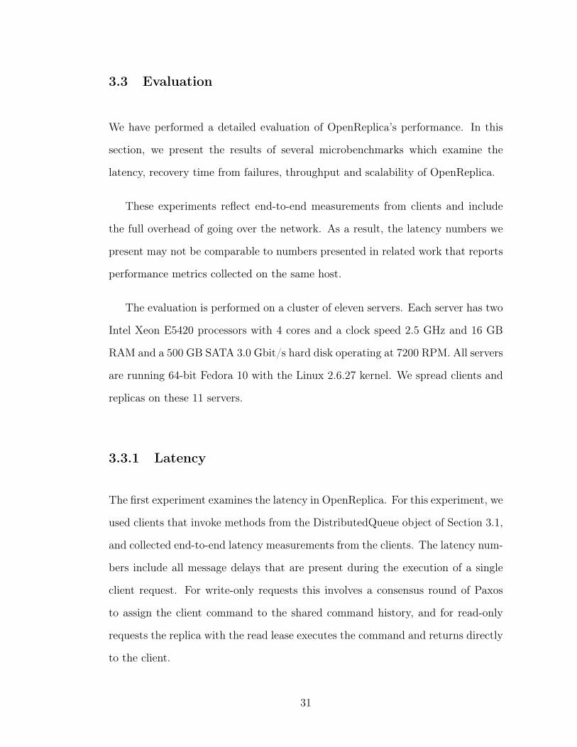
Figure 3.5 plots the latency of write-only and read-only requests against the
number of replicas in OpenReplica. For reads, the latency is between 0.3 and 0.5
milliseconds on average and the read latency is not affected by the fault-tolerance
level, since read-only requests do not require a consensus round. For writes, a
standard deployment of a system such as OpenReplica, with 5 replicas, Open-
Replica has low write latency, between 1.9 and 3.2 milliseconds on average. So,
an update on a queue that is consistently shared between distributed components
of an application has an end-to-end latency of 1.9 to 3.2 milliseconds, depending
on the fault-tolerance level. Because distributed components of an application us-
ing OpenReplica do not need to coordinate between each other to access a shared
queue, this latency corresponds to electing a master node, having this master node
update a replicated queue and returning results to other nodes. As a result, appli-
cations can use OpenReplica to replicate part of their state and to enable shared
updates and events on this state without affecting their performance.
32
20
40
60
80
100
1 2 3 4 5 6 7
CD
F (
%)
Latency (msec)
write-onlyread-only
Figure 3.6: CDF of the latency as a function of the number of replicas.
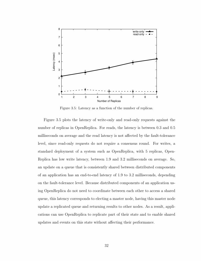
Moreover, Figure 3.5 shows that OpenReplica requests are handled with pre-
dictable latencies, shown with the short error bars exhibiting low standard devi-
ations. This can be interpreted as fairness that is offered by OpenReplica, where
every client is likely to experience very similar latencies while their requests are
handled. The lack of a long tail in the CDF for latency in Figure 3.6 shows this
fairness more explicitly.
3.3.2 Scalability
The next experiment examines the scalability of OpenReplica and shows how
OpenReplica scales with the size of the replicated state.
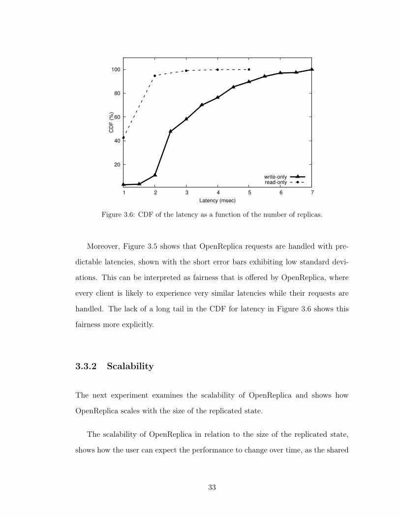
The scalability of OpenReplica in relation to the size of the replicated state,
shows how the user can expect the performance to change over time, as the shared
33
0
1
2
3
4
5
6
7
8
0 200 400 600 800 1000
Late
ncy (
msec)
Replicated State Size (KB)
Figure 3.7: Latency as a function of the size of the replicated state.
state maintained on OpenReplica grows. This scalability metric is very important
when OpenReplica is used to maintain a shared log for instance.
Figure 3.7 shows how latency of OpenReplica scales as the size of the repli-
cated state grows, and how the size of the object does not affect the performance.
This scalability is due to the design decision of maintaining active replicas of the
application state. This way, the replicated application state can be updated using
methods that can actively change it, without requiring to carry the state between
different components in the system. Consequently, the size of the replicated state
does not effect the latency experienced by the clients in OpenReplica, providing
the same performance for any replicated state size.
34
1000
10000
100000
1x10⁶
0 2 4 6 8 10
Thro
ughput (o
ps/s
ec)
Number of Replicas
client-side batchingserver-side batching
Figure 3.8: Throughput as a function of the number of replicas.
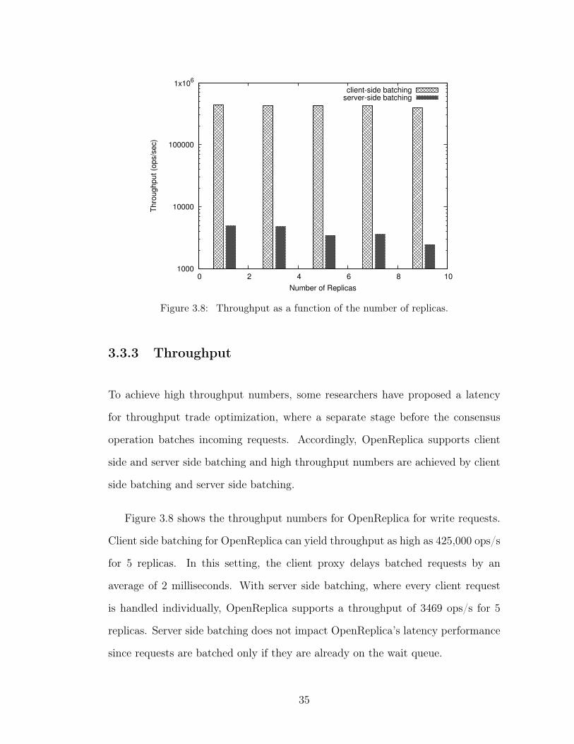
3.3.3 Throughput
To achieve high throughput numbers, some researchers have proposed a latency
for throughput trade optimization, where a separate stage before the consensus
operation batches incoming requests. Accordingly, OpenReplica supports client
side and server side batching and high throughput numbers are achieved by client
side batching and server side batching.
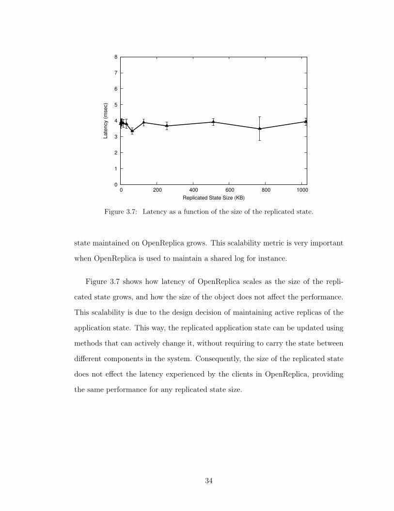
Figure 3.8 shows the throughput numbers for OpenReplica for write requests.
Client side batching for OpenReplica can yield throughput as high as 425,000 ops/s
for 5 replicas. In this setting, the client proxy delays batched requests by an
average of 2 milliseconds. With server side batching, where every client request
is handled individually, OpenReplica supports a throughput of 3469 ops/s for 5
replicas. Server side batching does not impact OpenReplica’s latency performance
since requests are batched only if they are already on the wait queue.
35
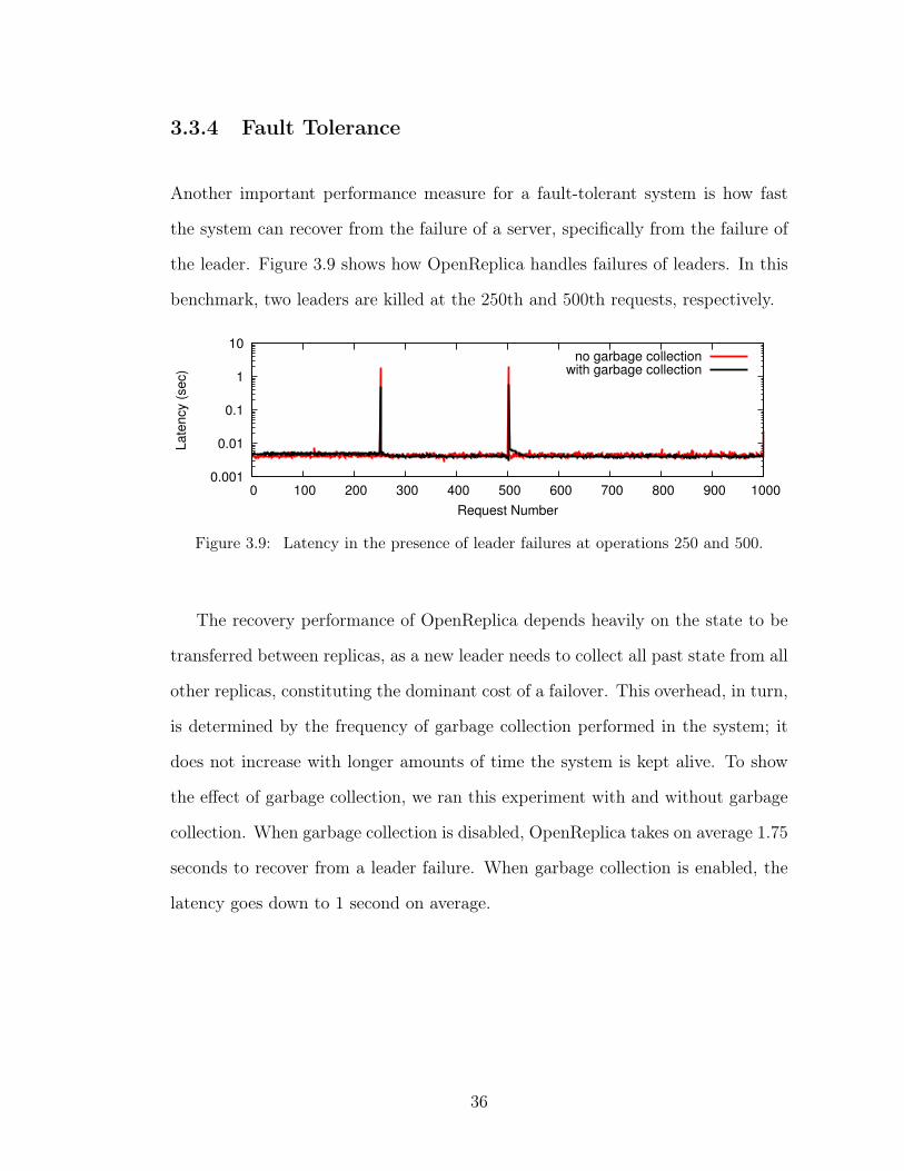
3.3.4 Fault Tolerance
Another important performance measure for a fault-tolerant system is how fast
the system can recover from the failure of a server, specifically from the failure of
the leader. Figure 3.9 shows how OpenReplica handles failures of leaders. In this
benchmark, two leaders are killed at the 250th and 500th requests, respectively.
0.001
0.01
0.1
1
10
0 100 200 300 400 500 600 700 800 900 1000
Late
ncy (
sec)
Request Number
no garbage collectionwith garbage collection
Figure 3.9: Latency in the presence of leader failures at operations 250 and 500.
The recovery performance of OpenReplica depends heavily on the state to be
transferred between replicas, as a new leader needs to collect all past state from all
other replicas, constituting the dominant cost of a failover. This overhead, in turn,
is determined by the frequency of garbage collection performed in the system; it
does not increase with longer amounts of time the system is kept alive. To show
the effect of garbage collection, we ran this experiment with and without garbage
collection. When garbage collection is disabled, OpenReplica takes on average 1.75
seconds to recover from a leader failure. When garbage collection is enabled, the
latency goes down to 1 second on average.
36
3.4 Discussion
In this chapter we presented OpenReplica, a system that offers fault-tolerance as a
service for the cloud environment to show how a guarantee such as fault-tolerance
can be implemented as a stand-alone service.
OpenReplica uses a novel object-oriented approach to providing replication
and synchronization in large-scale distributed systems. This approach is based
around the abstraction of coordination objects; namely, objects that define a repli-
cated state machine that can block and resume the execution of their clients.
Clients can invoke methods of the object transparently using an automatically
generated proxy, as if it were a local object. As a result, OpenReplica renders
the specification of complex distributed synchronization constructs and reliable
data structures straightforward and similar to their non-distributed counterparts.
In addition, OpenReplica manager can deploy coordination objects with desired
fault-tolerance characteristics with minimal programmer effort. Experiments show
that OpenReplica supports low latency, high throughput and scales well as the
number of clients and replicas increase.
OpenReplica is a great example of how to build a service that solves a com-
mon problem for distributed systems, such as coordination. It is important for
services like OpenReplica to be easy to combine with other distributed systems.
Even more importantly, these services should be easy to understand so system
programmers can know the assumptions the system makes about its environment
and the guarantees it provides. This way, system programmers can build systems
that are efficient and engineered well. Ovid tries to make this feat an easier task by
creating a model to think about the complex interactions between systems such as
OpenReplica. In the next chapter, we will show how a distributed system such as
37

OpenReplica can be modeled so that it is easier to understand what kind of guar-
antees it provides in a higher level. Relatedly, these systems can also be evolved
automatically using this model.
38
CHAPTER 4
MODELING A DISTRIBUTED SYSTEM
In this chapter we describe how we model distributed systems and how we use these
models to build and evolve these systems automatically. To model any distributed
system and to build, maintain and evolve them automatically, Ovid introduces new
abstractions that make it easy to represent distributed systems. Through these
abstractions we are able to focus on different aspects of distributed systems and
combine them to work as a whole system. Moreover, because these models can be
used to create a theoretical representation of distributed systems, we can use them
to prove that two distributed system models can be refined to one another. As
a result, we can prove that even if a distributed system evolves and changes over
time, it still implements the same high-level system.
This chapter is structured as follows, first we detail all the new abstractions
introduced by Ovid and explain how we use these to model distributed systems.
Then we show how these models can be transformed to evolve these distributed
systems.
4.1 System Model
4.1.1 Agents
A system consists of a set 𝒜 of agents 𝛼, 𝛽, ... that communicate by exchang-
ing messages. Each agent has a unique identifier. A message is a pair
⟨agent identifier , payload⟩. A message sent by a correct agent to another correct
39
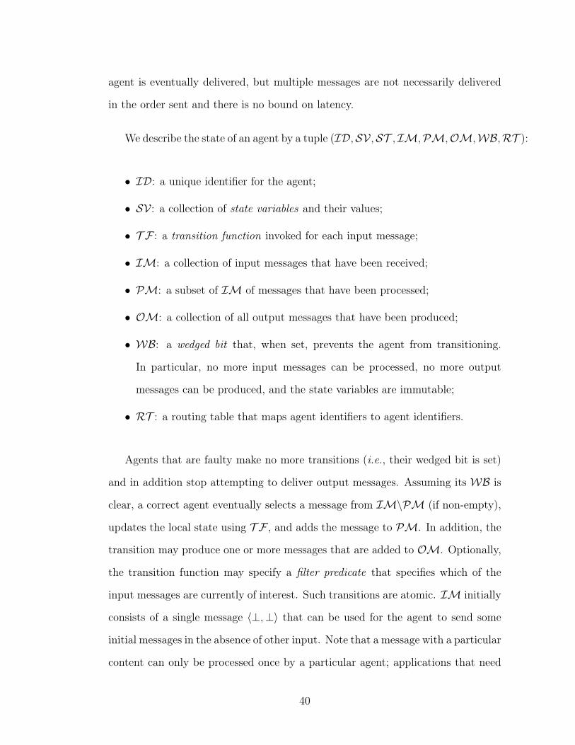
agent is eventually delivered, but multiple messages are not necessarily delivered
in the order sent and there is no bound on latency.
We describe the state of an agent by a tuple (ℐ𝒟,𝒮𝒱 ,𝒮𝒯 , ℐℳ,𝒫ℳ,𝒪ℳ,𝒲ℬ,ℛ𝒯 ):
∙ ℐ𝒟: a unique identifier for the agent;
∙ 𝒮𝒱 : a collection of state variables and their values;
∙ 𝒯 ℱ : a transition function invoked for each input message;
∙ ℐℳ: a collection of input messages that have been received;
∙ 𝒫ℳ: a subset of ℐℳ of messages that have been processed;
∙ 𝒪ℳ: a collection of all output messages that have been produced;
∙ 𝒲ℬ: a wedged bit that, when set, prevents the agent from transitioning.
In particular, no more input messages can be processed, no more output
messages can be produced, and the state variables are immutable;
∙ ℛ𝒯 : a routing table that maps agent identifiers to agent identifiers.
Agents that are faulty make no more transitions (i.e., their wedged bit is set)
and in addition stop attempting to deliver output messages. Assuming its 𝒲ℬ is
clear, a correct agent eventually selects a message from ℐℳ∖𝒫ℳ (if non-empty),
updates the local state using 𝒯 ℱ , and adds the message to 𝒫ℳ. In addition, the
transition may produce one or more messages that are added to 𝒪ℳ. Optionally,
the transition function may specify a filter predicate that specifies which of the
input messages are currently of interest. Such transitions are atomic. ℐℳ initially
consists of a single message ⟨⊥,⊥⟩ that can be used for the agent to send some
initial messages in the absence of other input. Note that a message with a particular
content can only be processed once by a particular agent; applications that need
40
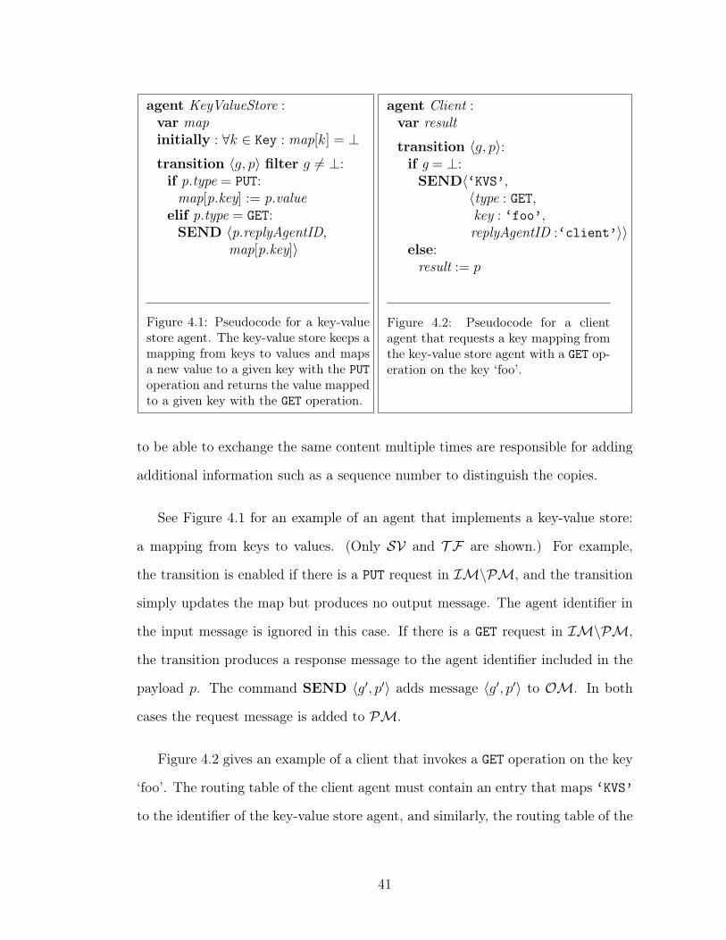
agent KeyValueStore :var mapinitially : ∀𝑘 ∈ Key : map[𝑘] = ⊥transition ⟨𝑔, 𝑝⟩ filter 𝑔 ̸= ⊥:if p.type = PUT:
map[p.key] := p.valueelif p.type = GET:SEND ⟨p.replyAgentID,
map[p.key]⟩
Figure 4.1: Pseudocode for a key-valuestore agent. The key-value store keeps amapping from keys to values and mapsa new value to a given key with the PUToperation and returns the value mappedto a given key with the GET operation.
agent Client :var result
transition ⟨𝑔, 𝑝⟩:if g = ⊥:SEND⟨‘KVS’,
⟨type : GET,key : ‘foo’,replyAgentID :‘client’⟩⟩
else:result := 𝑝
Figure 4.2: Pseudocode for a clientagent that requests a key mapping fromthe key-value store agent with a GET op-eration on the key ‘foo’.
to be able to exchange the same content multiple times are responsible for adding
additional information such as a sequence number to distinguish the copies.
See Figure 4.1 for an example of an agent that implements a key-value store:
a mapping from keys to values. (Only 𝒮𝒱 and 𝒯 ℱ are shown.) For example,
the transition is enabled if there is a PUT request in ℐℳ∖𝒫ℳ, and the transition
simply updates the map but produces no output message. The agent identifier in
the input message is ignored in this case. If there is a GET request in ℐℳ∖𝒫ℳ,
the transition produces a response message to the agent identifier included in the
payload 𝑝. The command SEND ⟨𝑔′, 𝑝′⟩ adds message ⟨𝑔′, 𝑝′⟩ to 𝒪ℳ. In both
cases the request message is added to 𝒫ℳ.
Figure 4.2 gives an example of a client that invokes a GET operation on the key
‘foo’. The routing table of the client agent must contain an entry that maps ‘KVS’
to the identifier of the key-value store agent, and similarly, the routing table of the
41
key-value store agent must contain an entry that maps ‘client’ to the identifier
of the client agent.
We note that our specifications are executable: every state variable is instanti-
ated at an agent and every transition is local to an agent.
4.1.2 Transformation
The specification of an agent 𝛼 can be transformed— replacing it with one or more
new agents in such a way that the new agents collectively implement the same
functionality as the original agent from the perspective of the other, unchanged,
agents. In the context of a particular transformation, we call the original agent
virtual, and the agents that result from the transformation physical.
For example, consider the key-value store agent of Figure 4.1. We can shard the
virtual agent by creating two physical copies of it, one responsible for all keys that
satisfy some predicate 𝑃 (key), and the other responsible for the other keys. That
is, 𝑃 is a binary hashing function. To glue everything together, we add additional
physical agents: a collection of ingress proxy agents, one for each client, and two
egress proxy agents, one for each server.1 An ingress proxy agent mimics the virtual
agent ‘KVS’ to its client, while an egress proxy agent mimics the client to a shard
of the key-value store. The routing table of the client agent is modified to route
messages to ‘KVS’ to the ingress proxy. Figures 4.3 and 4.4 present the code
for these proxies. Note that the proxy agents have no state variables. Moreover,
Figure 4.5 illustrates their configuration as a directed graph. Every physical agent1For this particular example, it would be possible to not use server-side egress proxies and
have the client-side ingress proxies send directly to the shards. The given solution is chosen toillustrate various concepts in our system.
42
agent ShardIngressProxy :transition ⟨𝑔, 𝑝⟩:if 𝑝 ̸= ⊥ ∧ 𝑃 (p.key):SEND ⟨‘KVS/ShardEgressProxy1’, ⟨𝑔, 𝑝⟩⟩
elif 𝑝 ̸= ⊥ ∧ ¬𝑃 (p.key):SEND ⟨‘KVS/ShardEgressProxy2’, ⟨𝑔, 𝑝⟩⟩
Figure 4.3: Pseudocode for a client-side shardingingress proxy agent for the key-value store. Theingress proxy agent mimics ‘KVS’ to the client andforwards client requests to the correct shard depend-ing on the key.
agent ShardEgressProxy :transition ⟨𝑔′, ⟨𝑔, 𝑝⟩⟩:SEND ⟨𝑔, 𝑝⟩
Figure 4.4: Pseudocodefor a server-side shard-ing egress proxy agent forthe key-value store. Theegress proxy agent mimicsthe client to a shard of thekey-value store and simplyforwards a received clientrequest.
is pictured as a separate node and agents that are co-located are shown in the
same rectangle representing a box. The directed edges between nodes illustrate
the message traffic patterns between agents. Lastly, the dotted line is used to
separate two abstraction layers from each other.
A transformation is essentially a special case of a refinement in which an ex-
ecutable specification is refined to another executable specification. To show the
correctness of refinement, one must exhibit:
∙ a mapping of the state of the physical agents to the state of the virtual agent,
∙ a mapping of the transitions of the physical agents to transitions in the virtual
agent, or identify those transitions as stutter transitions that do not change
the state of the virtual agent.
In this example, a possible mapping is as follows:
∙ ℐ𝒟: the identifier of the virtual key-value store agent is unchanged and
constant;
43

∙ 𝒮𝒱 : the map of the virtual agent is the union of the two physical shards;
∙ 𝒯 ℱ : the transition function of the virtual agent is also as specified;
∙ ℐℳ: the set of input messages of the virtual agent is the union of the sets
of input messages of all client-side proxies;
∙ 𝒫ℳ: the set of processed messages of the virtual agent is the union of the
set of processed messages of the two shards;
∙ 𝒪ℳ: the set of output messages of the virtual agent is the union of the sets
of output messages of the two shards;
∙ 𝒲ℬ: the wedged bit is the logical ‘and’ of the wedged bits of the shard agents
(when both shards are wedged, the original agent can no longer transition
either);
∙ ℛ𝒯 : the routing table is a constant.
In addition, the transitions of physical agents map to transitions in the virtual
agent as follows:
∙ receiving a message in one of the ℐℳs of the ingress proxy agents maps to
a message being added to the ℐℳ of the virtual agent;
∙ each 𝒯 ℱ transition in the physical shards maps to the corresponding tran-
sition in the virtual key-value store agent. In addition, adding a message to
either 𝒫ℳ or 𝒪ℳ in one of the shards maps to the same transition in the
virtual agent;
∙ setting the 𝒲ℬ of one of the shards so that both become set causes the 𝒲ℬ
of the virtual agent to become set;
∙ clearing the 𝒲ℬ of one of the shards when both were set causes the 𝒲ℬ of
the virtual agent to become cleared;
44
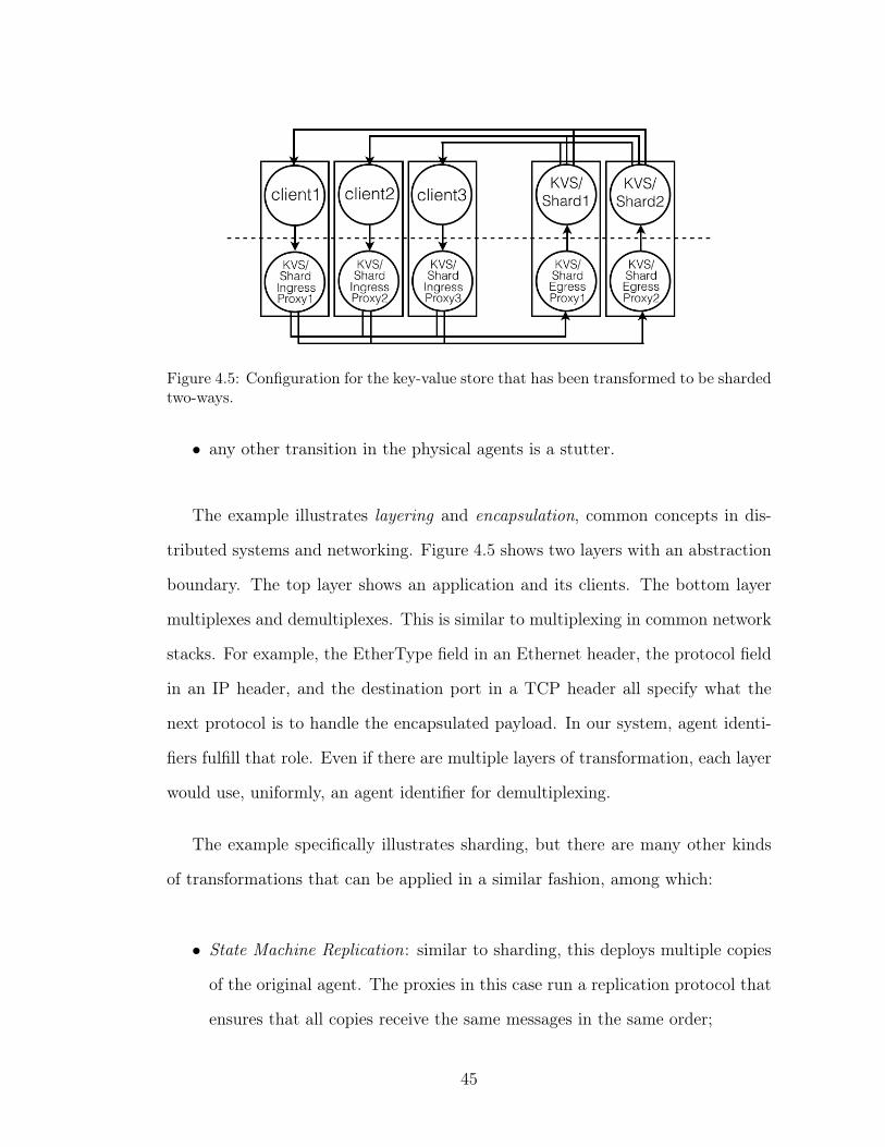
Figure 4.5: Configuration for the key-value store that has been transformed to be shardedtwo-ways.
∙ any other transition in the physical agents is a stutter.
The example illustrates layering and encapsulation, common concepts in dis-
tributed systems and networking. Figure 4.5 shows two layers with an abstraction
boundary. The top layer shows an application and its clients. The bottom layer
multiplexes and demultiplexes. This is similar to multiplexing in common network
stacks. For example, the EtherType field in an Ethernet header, the protocol field
in an IP header, and the destination port in a TCP header all specify what the
next protocol is to handle the encapsulated payload. In our system, agent identi-
fiers fulfill that role. Even if there are multiple layers of transformation, each layer
would use, uniformly, an agent identifier for demultiplexing.
The example specifically illustrates sharding, but there are many other kinds
of transformations that can be applied in a similar fashion, among which:
∙ State Machine Replication: similar to sharding, this deploys multiple copies
of the original agent. The proxies in this case run a replication protocol that
ensures that all copies receive the same messages in the same order;
45
∙ Primary-Backup Replication: this can be applied to applications that keep
state on a separate disk using read and write operations. In our model, such
a disk is considered a separate agent. Fault-tolerance can be achieved by
deploying multiple disk agents, one of which is considered primary and the
others backups;
∙ Load Balancing : also similar to sharding, and particularly useful for stateless
agents, a load balancing agent is an ingress proxy agent that spreads incoming
messages to a collection of server agents;
∙ Encryption, Compression, Batching, ...: between any pair of agents, one
can insert a pair of agents that encode and decode sequences of messages
respectively;
∙ Monitoring, Auditing : between any pair of agents, an agent can be inserted
that counts or logs the messages that flow through it.
Above we have presented transformations as refinements of individual agents.
In limited form, transformations can sometimes also be applied to sets of agents.
For example, a pipeline of agents (in which the output of one agent form the input
to the next) acts essentially as a single agent, and transformations that apply to
a single agent can also be applied to pipelines. Some transformations, such as
Nysiad [24], apply to particular configurations of agents. For simplicity, we will
focus here on transformations of individual agents only, but believe the techniques
can be generalized more broadly.
46
4.1.3 Agent Identifiers and Transformation Trees
Every agent in the system has a unique identifier. The agents that result from
transformation have identifiers that are based on the original agent’s identifier,
by adding new identifiers in a ‘path name’ style. Thus an agent with identi-
fier ‘X/Y/Z’ is part of the implementation of agent ‘X/Y’, which itself is part
of the implementation of agent ‘X’, which is a top level specification. In our
running example, assume the identifier of the original key-value store is ‘KVS’.
Then we can call its shards ‘KVS/Shard1’ and ‘KVS/Shard2’. We can call
the server proxies ‘KVS/ShardEgressProxy1’ and ‘KVS/ShardEgressProxy2’
respectively, and we can call the client proxies ‘KVS/ShardIngressProxy1’,
‘KVS/ShardIngressProxy2’, ... .
The client agent in this example still sends messages to agent identifier ‘KVS’,
but due to transformation the original ‘KVS’ agent no longer exists physically. The
client’s routing table maps agent identifier ‘KVS’ to ‘KVS/ShardIngressProxyX ’
for some X. Agent ‘KVS/ShardIngressProxyX ’ encapsulates the received
message and sends it to agent identifier ‘KVS/ShardEgressProxy1’ or
‘KVS/ShardEgressProxy2’ depending on the hash function. Assuming those
proxy agents have not been transformed themselves, there is again a one-to-
one mapping to corresponding agent identifiers. Each egress proxy ends up
sending to agent identifier ‘KVS’. Agent identifier ‘KVS’ is mapped to agent
‘KVS/Shard1’ at agent ‘KVS/ShardEgressProxy1’ and to agent ‘KVS/Shard2’
at agent ‘KVS/ShardEgressProxy2’. Note that if identifier 𝑋 in a routing table
is mapped to an identifier 𝑌 , it is always the case that 𝑋 is a prefix of 𝑌 (and is
identical to 𝑌 in the case the agent has not been refined).
Given the original specification and the transformations that have been applied,
47
it is always possible to determine the destination agent for a message sent by a
particular source agent to a particular agent identifier.
This even works if agents are created dynamically. For example, if a new client
‘client2’ is added to our example, and sends a message to agent identifier ‘KVS’,
we can determine that agent ‘KVS’ has been transformed and thus a new client-side
ingress proxy agent has to be created, and appropriate agent identifier to agent
identifier mappings must be added. The client’s request can now be delivered
to the appropriate shard through the ingress proxy agent. The shard sends the
response to agent identifier ‘client2’. In this case the new client itself has not
been transformed, and so the mapping for agent identifier ‘client2’ at the shard
can be set up to point directly to agent ‘client2’. Should agent ‘client2’
itself have been transformed, then upon the KVS shard sending to agent identifier
‘client2’ the appropriate proxy agents can be instantiated on the server-side
dynamically as well.
We represent the specification of a system and its transformation in a Logical
Agent Transformation Tree (LATT). A LATT is a directed tree of agents. The
root of this tree is a virtual agent that we call the System Agent. The “children”
of this root are the agents before transformation. Each transformation of an agent
(or set of agents) then results in a collection of children for the corresponding node.
This technique presents, to the best of our knowledge, the first general solu-
tion to composing transformed agents, such as a replicated client interacting with
a replicated server. While certain special case solutions exist (for example, the
Replicated Remote Procedure Call in the Circus system [56]), it has not been clear
how, say, a client replicated using the replicated state machine approach would
interact with a server that is sharded, with each shard chain replicated. At the
48
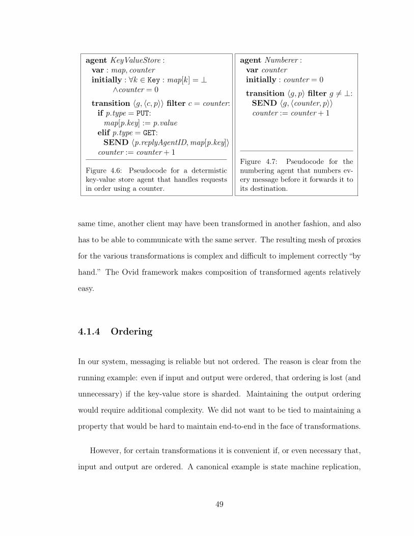
agent KeyValueStore :var : map, counterinitially : ∀𝑘 ∈ Key : map[𝑘] = ⊥
∧counter = 0
transition ⟨𝑔, ⟨𝑐, 𝑝⟩⟩ filter 𝑐 = counter:if p.type = PUT:
map[p.key] := p.valueelif p.type = GET:SEND ⟨p.replyAgentID,map[p.key]⟩
counter := counter + 1
Figure 4.6: Pseudocode for a determistickey-value store agent that handles requestsin order using a counter.
agent Numberer :var counterinitially : counter = 0
transition ⟨𝑔, 𝑝⟩ filter 𝑔 ̸= ⊥:SEND ⟨𝑔, ⟨counter, 𝑝⟩⟩counter := counter + 1
Figure 4.7: Pseudocode for thenumbering agent that numbers ev-ery message before it forwards it toits destination.
same time, another client may have been transformed in another fashion, and also
has to be able to communicate with the same server. The resulting mesh of proxies
for the various transformations is complex and difficult to implement correctly “by
hand.” The Ovid framework makes composition of transformed agents relatively
easy.
4.1.4 Ordering
In our system, messaging is reliable but not ordered. The reason is clear from the
running example: even if input and output were ordered, that ordering is lost (and
unnecessary) if the key-value store is sharded. Maintaining the output ordering
would require additional complexity. We did not want to be tied to maintaining a
property that would be hard to maintain end-to-end in the face of transformations.
However, for certain transformations it is convenient if, or even necessary that,
input and output are ordered. A canonical example is state machine replication,
49
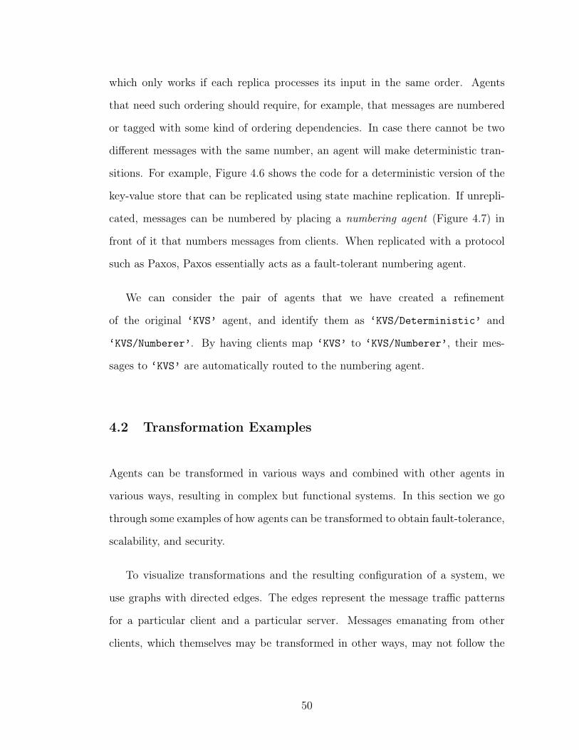
which only works if each replica processes its input in the same order. Agents
that need such ordering should require, for example, that messages are numbered
or tagged with some kind of ordering dependencies. In case there cannot be two
different messages with the same number, an agent will make deterministic tran-
sitions. For example, Figure 4.6 shows the code for a deterministic version of the
key-value store that can be replicated using state machine replication. If unrepli-
cated, messages can be numbered by placing a numbering agent (Figure 4.7) in
front of it that numbers messages from clients. When replicated with a protocol
such as Paxos, Paxos essentially acts as a fault-tolerant numbering agent.
We can consider the pair of agents that we have created a refinement
of the original ‘KVS’ agent, and identify them as ‘KVS/Deterministic’ and
‘KVS/Numberer’. By having clients map ‘KVS’ to ‘KVS/Numberer’, their mes-
sages to ‘KVS’ are automatically routed to the numbering agent.
4.2 Transformation Examples
Agents can be transformed in various ways and combined with other agents in
various ways, resulting in complex but functional systems. In this section we go
through some examples of how agents can be transformed to obtain fault-tolerance,
scalability, and security.
To visualize transformations and the resulting configuration of a system, we
use graphs with directed edges. The edges represent the message traffic patterns
for a particular client and a particular server. Messages emanating from other
clients, which themselves may be transformed in other ways, may not follow the
50
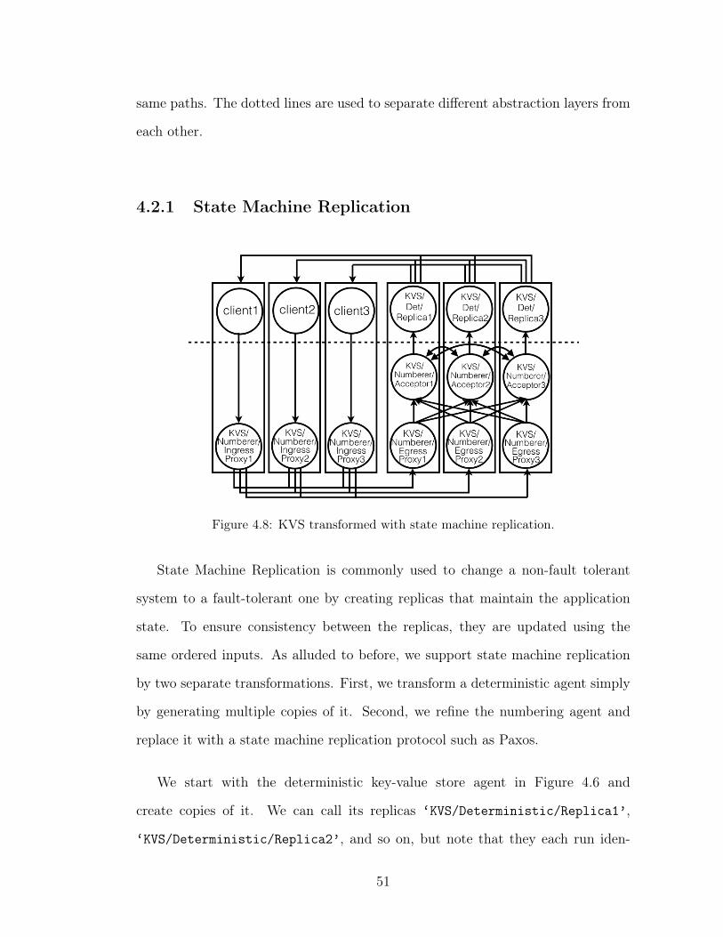
same paths. The dotted lines are used to separate different abstraction layers from
each other.
4.2.1 State Machine Replication
Figure 4.8: KVS transformed with state machine replication.
State Machine Replication is commonly used to change a non-fault tolerant
system to a fault-tolerant one by creating replicas that maintain the application
state. To ensure consistency between the replicas, they are updated using the
same ordered inputs. As alluded to before, we support state machine replication
by two separate transformations. First, we transform a deterministic agent simply
by generating multiple copies of it. Second, we refine the numbering agent and
replace it with a state machine replication protocol such as Paxos.
We start with the deterministic key-value store agent in Figure 4.6 and
create copies of it. We can call its replicas ‘KVS/Deterministic/Replica1’,
‘KVS/Deterministic/Replica2’, and so on, but note that they each run iden-
51
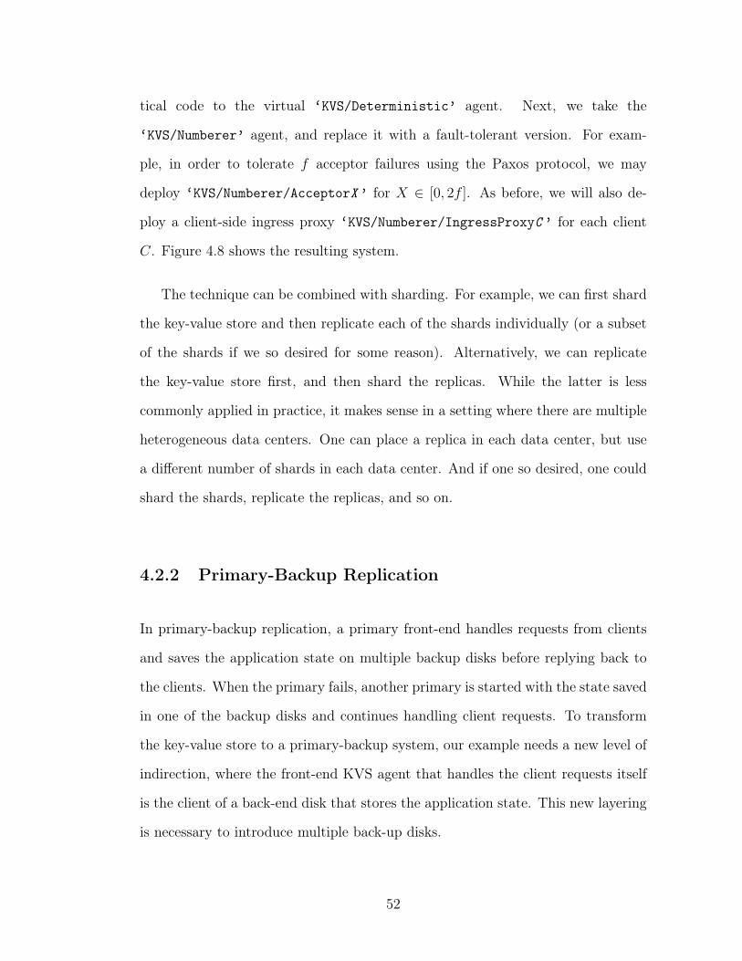
tical code to the virtual ‘KVS/Deterministic’ agent. Next, we take the
‘KVS/Numberer’ agent, and replace it with a fault-tolerant version. For exam-
ple, in order to tolerate 𝑓 acceptor failures using the Paxos protocol, we may
deploy ‘KVS/Numberer/AcceptorX ’ for 𝑋 ∈ [0, 2𝑓 ]. As before, we will also de-
ploy a client-side ingress proxy ‘KVS/Numberer/IngressProxyC ’ for each client
𝐶. Figure 4.8 shows the resulting system.
The technique can be combined with sharding. For example, we can first shard
the key-value store and then replicate each of the shards individually (or a subset
of the shards if we so desired for some reason). Alternatively, we can replicate
the key-value store first, and then shard the replicas. While the latter is less
commonly applied in practice, it makes sense in a setting where there are multiple
heterogeneous data centers. One can place a replica in each data center, but use
a different number of shards in each data center. And if one so desired, one could
shard the shards, replicate the replicas, and so on.
4.2.2 Primary-Backup Replication
In primary-backup replication, a primary front-end handles requests from clients
and saves the application state on multiple backup disks before replying back to
the clients. When the primary fails, another primary is started with the state saved
in one of the backup disks and continues handling client requests. To transform
the key-value store to a primary-backup system, our example needs a new level of
indirection, where the front-end KVS agent that handles the client requests itself
is the client of a back-end disk that stores the application state. This new layering
is necessary to introduce multiple back-up disks.
52
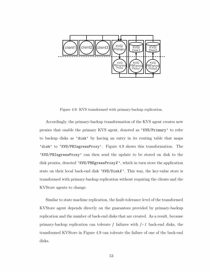
Figure 4.9: KVS transformed with primary-backup replication.
Accordingly, the primary-backup transformation of the KVS agent creates new
proxies that enable the primary KVS agent, denoted as ‘KVS/Primary’ to refer
to backup disks as ‘disk’ by having an entry in its routing table that maps
‘disk’ to ‘KVS/PBIngressProxy’. Figure 4.9 shows this transformation. The
‘KVS/PBIngressProxy’ can then send the update to be stored on disk to the
disk proxies, denoted ‘KVS/PBEgressProxyX ’, which in turn store the application
state on their local back-end disk ‘KVS/DiskX ’. This way, the key-value store is
transformed with primary-backup replication without requiring the clients and the
KVStore agents to change.
Similar to state machine replication, the fault-tolerance level of the transformed
KVStore agent depends directly on the guarantees provided by primary-backup
replication and the number of back-end disks that are created. As a result, because
primary-backup replication can tolerate f failures with f+1 back-end disks, the
transformed KVStore in Figure 4.9 can tolerate the failure of one of the back-end
disks.
53
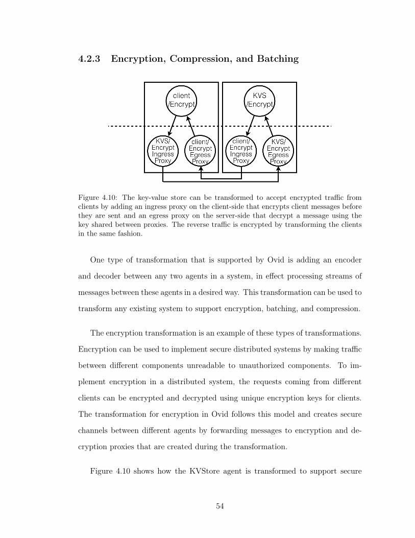
4.2.3 Encryption, Compression, and Batching
Figure 4.10: The key-value store can be transformed to accept encrypted traffic fromclients by adding an ingress proxy on the client-side that encrypts client messages beforethey are sent and an egress proxy on the server-side that decrypt a message using thekey shared between proxies. The reverse traffic is encrypted by transforming the clientsin the same fashion.
One type of transformation that is supported by Ovid is adding an encoder
and decoder between any two agents in a system, in effect processing streams of
messages between these agents in a desired way. This transformation can be used to
transform any existing system to support encryption, batching, and compression.
The encryption transformation is an example of these types of transformations.
Encryption can be used to implement secure distributed systems by making traffic
between different components unreadable to unauthorized components. To im-
plement encryption in a distributed system, the requests coming from different
clients can be encrypted and decrypted using unique encryption keys for clients.
The transformation for encryption in Ovid follows this model and creates secure
channels between different agents by forwarding messages to encryption and de-
cryption proxies that are created during the transformation.
Figure 4.10 shows how the KVStore agent is transformed to support secure
54
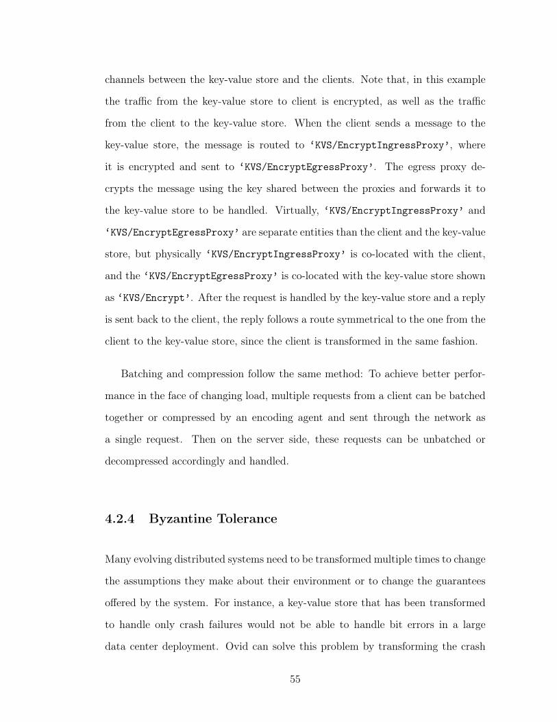
channels between the key-value store and the clients. Note that, in this example
the traffic from the key-value store to client is encrypted, as well as the traffic
from the client to the key-value store. When the client sends a message to the
key-value store, the message is routed to ‘KVS/EncryptIngressProxy’, where
it is encrypted and sent to ‘KVS/EncryptEgressProxy’. The egress proxy de-
crypts the message using the key shared between the proxies and forwards it to
the key-value store to be handled. Virtually, ‘KVS/EncryptIngressProxy’ and
‘KVS/EncryptEgressProxy’ are separate entities than the client and the key-value
store, but physically ‘KVS/EncryptIngressProxy’ is co-located with the client,
and the ‘KVS/EncryptEgressProxy’ is co-located with the key-value store shown
as ‘KVS/Encrypt’. After the request is handled by the key-value store and a reply
is sent back to the client, the reply follows a route symmetrical to the one from the
client to the key-value store, since the client is transformed in the same fashion.
Batching and compression follow the same method: To achieve better perfor-
mance in the face of changing load, multiple requests from a client can be batched
together or compressed by an encoding agent and sent through the network as
a single request. Then on the server side, these requests can be unbatched or
decompressed accordingly and handled.
4.2.4 Byzantine Tolerance
Many evolving distributed systems need to be transformed multiple times to change
the assumptions they make about their environment or to change the guarantees
offered by the system. For instance, a key-value store that has been transformed
to handle only crash failures would not be able to handle bit errors in a large
data center deployment. Ovid can solve this problem by transforming the crash
55
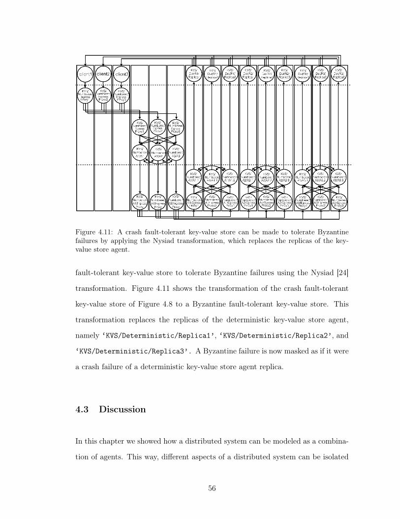
Figure 4.11: A crash fault-tolerant key-value store can be made to tolerate Byzantinefailures by applying the Nysiad transformation, which replaces the replicas of the key-value store agent.
fault-tolerant key-value store to tolerate Byzantine failures using the Nysiad [24]
transformation. Figure 4.11 shows the transformation of the crash fault-tolerant
key-value store of Figure 4.8 to a Byzantine fault-tolerant key-value store. This
transformation replaces the replicas of the deterministic key-value store agent,
namely ‘KVS/Deterministic/Replica1’, ‘KVS/Deterministic/Replica2’, and
‘KVS/Deterministic/Replica3’. A Byzantine failure is now masked as if it were
a crash failure of a deterministic key-value store agent replica.
4.3 Discussion
In this chapter we showed how a distributed system can be modeled as a combina-
tion of agents. This way, different aspects of a distributed system can be isolated
56
and represented as separate entities. This makes it easier to understand the capa-
bilities provided by the system and the interactions between different components.
As a result, transformations such as replication and sharding can be applied to
systems to change their capabilities, while being able to understand and prove
how these transformations will affect the system functionality.
Moreover, using agent-based models of a distributed system, transformations
of a system can be refined to each other. Using refinement, we can prove that
different transformations of a system can all have the same high-level functionality
in the end. In the next chapter we will show how refinements work in more detail
by refining the specification of a key-value store replicated with Chain Replication
to the specification of its non-replicated counterpart. We will also underline how
refinement makes it possible to deeply understand and reason about how complex
systems work.
57
CHAPTER 5
REFINING A DISTRIBUTED SYSTEM
In this chapter we show in detail how a distributed system can be refined to another
distributed system. Through refinement, we can prove that two distributed system
implementations are equivalent to each other, in other words, they implement the
same functionality. Ovid employs refinements to show how a system can evolve and
change to function in different environments while preserving expected guarantees
and adding new capabilities. Through refinements it becomes clear to see how
a very complicated distributed system implements different capabilities and how
different implementations might map to different high-level guarantees.
We use Chain Replication as an example to show how a detailed refinement of
a system is done and how it is used to reason about different aspects of the system
such as fault-tolerance, reconfiguration and supporting various consistency models.
Chain Replication (CR) is a variant of Primary-Backup Replication that supports
high throughput and fast recovery from failures. CR has been widely used in
both commercial systems and academic research prototypes. In so doing, various
shortcomings of the original CR protocol have come to light. Through refinement
we were able to improve a widely used protocol such as Chain Replication and
fine-tune it according to the needs of the system it is used in.
5.1 High-level specification
We first characterize a linearizable service that handles concurrent update and
query operations sent by a collection of clients 𝒞. For each client operation, there
is an invocation event and a completion event. The actual operation appears to
58
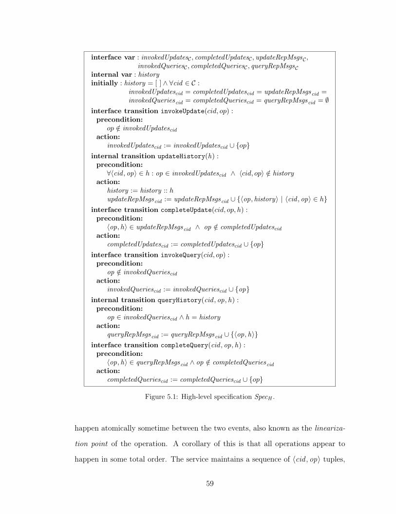
interface var : invokedUpdates𝒞 , completedUpdates𝒞 , updateRepMsgs𝒞 ,invokedQueries𝒞 , completedQueries𝒞 , queryRepMsgs𝒞
internal var : historyinitially : history = [ ] ∧ ∀cid ∈ 𝒞 :
invokedUpdatescid = completedUpdatescid = updateRepMsgscid =invokedQueriescid = completedQueriescid = queryRepMsgscid = ∅
interface transition invokeUpdate(𝑐𝑖𝑑, 𝑜𝑝) :precondition:
𝑜𝑝 /∈ invokedUpdatescidaction:
invokedUpdatescid := invokedUpdatescid ∪ {𝑜𝑝}internal transition updateHistory(h) :precondition:
∀⟨cid , op⟩ ∈ ℎ : op ∈ invokedUpdatescid ∧ ⟨𝑐𝑖𝑑, 𝑜𝑝⟩ /∈ historyaction:
history := history :: ℎupdateRepMsgscid := updateRepMsgscid ∪ {⟨op, history⟩ | ⟨cid , op⟩ ∈ ℎ}
interface transition completeUpdate(𝑐𝑖𝑑, 𝑜𝑝, ℎ) :precondition:
⟨op, ℎ⟩ ∈ updateRepMsgscid ∧ op /∈ completedUpdatescidaction:
completedUpdatescid := completedUpdatescid ∪ {𝑜𝑝}interface transition invokeQuery(𝑐𝑖𝑑, 𝑜𝑝) :precondition:
op /∈ invokedQueriescidaction:
invokedQueriescid := invokedQueriescid ∪ {op}internal transition queryHistory(cid , op, h) :precondition:
op ∈ invokedQueriescid ∧ h = historyaction:
queryRepMsgscid := queryRepMsgscid ∪ {⟨op, h⟩}interface transition completeQuery(cid , op, h) :precondition:
⟨op, h⟩ ∈ queryRepMsgscid ∧ op /∈ completedQueriescidaction:
completedQueriescid := completedQueriescid ∪ {𝑜𝑝}
Figure 5.1: High-level specification SpecH .
happen atomically sometime between the two events, also known as the lineariza-
tion point of the operation. A corollary of this is that all operations appear to
happen in some total order. The service maintains a sequence of ⟨cid , op⟩ tuples,
59
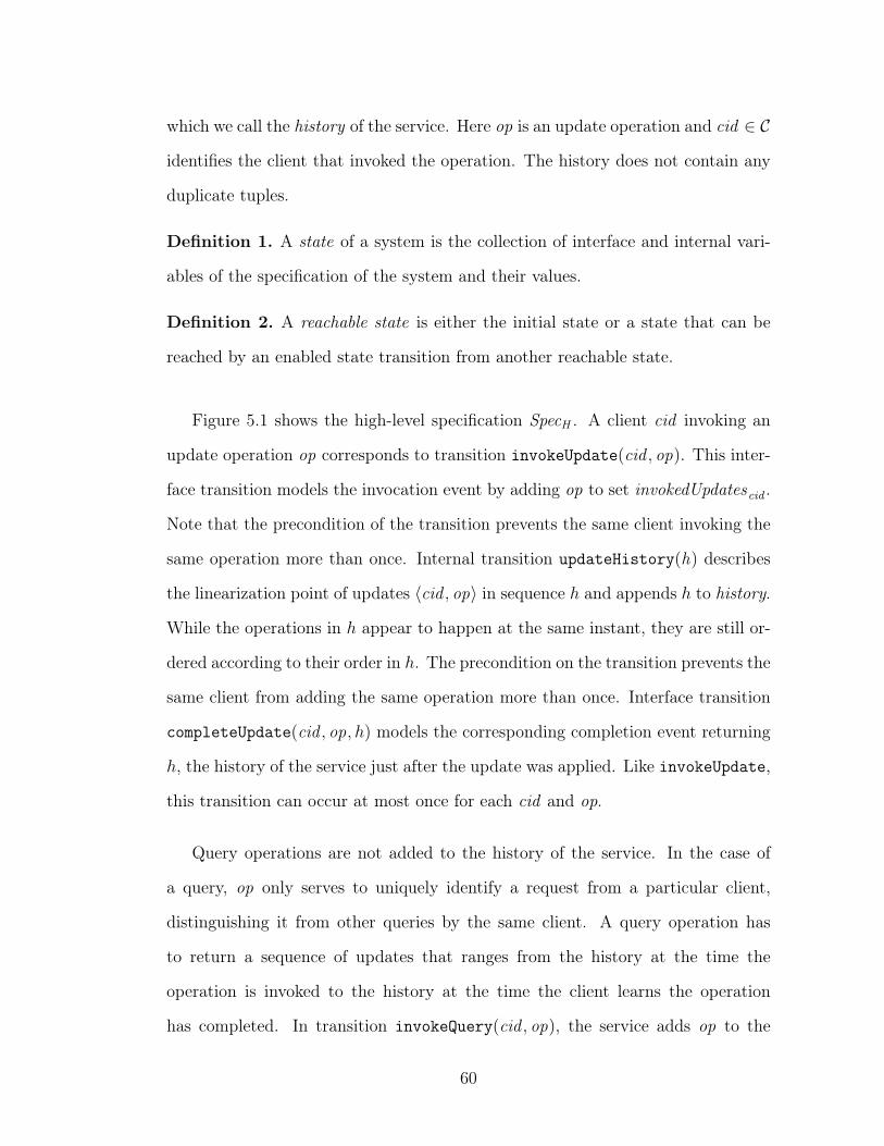
which we call the history of the service. Here op is an update operation and cid ∈ 𝒞
identifies the client that invoked the operation. The history does not contain any
duplicate tuples.
Definition 1. A state of a system is the collection of interface and internal vari-
ables of the specification of the system and their values.
Definition 2. A reachable state is either the initial state or a state that can be
reached by an enabled state transition from another reachable state.
Figure 5.1 shows the high-level specification SpecH . A client cid invoking an
update operation op corresponds to transition invokeUpdate(cid , op). This inter-
face transition models the invocation event by adding op to set invokedUpdatescid .
Note that the precondition of the transition prevents the same client invoking the
same operation more than once. Internal transition updateHistory(h) describes
the linearization point of updates ⟨cid , op⟩ in sequence ℎ and appends ℎ to history.
While the operations in ℎ appear to happen at the same instant, they are still or-
dered according to their order in ℎ. The precondition on the transition prevents the
same client from adding the same operation more than once. Interface transition
completeUpdate(cid , op, ℎ) models the corresponding completion event returning
ℎ, the history of the service just after the update was applied. Like invokeUpdate,
this transition can occur at most once for each cid and op.
Query operations are not added to the history of the service. In the case of
a query, op only serves to uniquely identify a request from a particular client,
distinguishing it from other queries by the same client. A query operation has
to return a sequence of updates that ranges from the history at the time the
operation is invoked to the history at the time the client learns the operation
has completed. In transition invokeQuery(cid , op), the service adds op to the
60
unordered set invokedQueries. Internal transition queryHistory(cid , op, h) at-
taches the current history to the query operation. Note that the transition does
not get “disabled” in any way: an unbounded number of histories can be attached
to the query operation, but only after the operation has been invoked. Transi-
tion completeQuery(cid , op, ℎ) returns one of these histories, in particular a his-
tory between the time of invocation and the current history. The linearization
point is then the queryHistory transition that added this particular history to
queryRepMsgscid .
5.2 Low-level specification
Next, we refine the high-level specification presented above so that the internal
transitions that handle the update and query operations are executed on replicas
of servers that are configured as a chain, using Chain Replication. The purpose
of Chain Replication is to tolerate fail-stop failures, and thus we must be able to
remove crashed nodes from the chain and restore fault tolerance by adding new
nodes to the chain.
Let ℛ be the set of replica identifiers. We consider nodes live1 until they
crash. We add to each replica with identifier rid a boolean variable uprid , initially
true, that transitions to false when replica rid crashes. The replica then stops
making transitions. (To specify this formally we add uprid to the precondition of
all transitions at replica rid .) A replica cannot “uncrash.” In practice, a recovering
machine must join as a new node.1We prefer the term “live” over “correct” because the latter would generally be used for a node
that never crashes. In our model, all nodes are expected to crash eventually with probability 1.
61
Each replica rid also has an interface variable detected rid , which is the set of
replica identifiers that rid has detected as faulty. As required by the fail-stop
model, we assume that crashes can be detected reliably, that is, all crashes are
eventually detected by correct nodes (nodes that never crash) and no live node
ever detects the crash of a node before it crashes. Formally, ∀rid , rip ∈ ℛ :
∙ ¬uprip ⇒ � ¬uprip
∙ (¬uprip ∧� uprid) ⇒ ♦ rip ∈ detected rid
∙ rip ∈ detected rid ⇒ (¬uprip ∧� rip ∈ detected rid)
Note that it follows that ∀rid : uprid ⇒ rid ̸∈ detected rid : a live node never
detects its own failure.
We introduce a special update request from a dedicated client conf: command
⟨conf, addNode(rid)⟩ requests that node rid is added to the end of the current
chain. We call a history with such configuration commands an extended history.
Given an extended history ℎ, hist(ℎ) returns ℎ with all addNode commands re-
moved. Given an extended history ℎ and a set of replica identifiers 𝑅 ⊂ ℛ,
function conf (ℎ,𝑅) returns a configuration (sequence of node identifiers) by ex-
tracting all addNode commands in order and then removing any nodes that are in
𝑅. There cannot be any duplicate requests in an extended history, and therefore
there cannot be configurations with duplicate nodes.
A configuration 𝜅 supports the following operations:
∙ 𝜅.head(): the first entry in the configuration;
∙ 𝜅.tail(): the last entry in the configuration;
62
∙ 𝜅.pred(rid): the predecessor of rid in the configuration, or ⊥ if rid is not in
the configuration or is the head;
∙ 𝜅.succ(rid): the successor of rid in the configuration, or ⊥ if rid is not in
the configuration or is the tail.
Figures 5.2, 5.3, and 5.4 show the specification. Each node maintains a spec-
ulative history and a stable history, both of which are extended. Below we will
use the shorthand 𝜅rid to stand for conf (spcltvHist rid , detected rid), the configura-
tion based on the speculative history and the set of crashed nodes that have been
detected thus far by rid, and we call this the speculative configuration accord-
ing to rid. For all nodes, the initial speculative and stable history both consist
of ⟨conf, addNode(rid init)⟩. Note that the initial speculative configuration of any
node is the singleton sequence [rid init].
Definition 3. We call a replica rid a chain node if ⟨conf, addNode(rid)⟩ ∈
spcltvHist rid ∧ uprid .
Note that initially rid init is the only chain node. For liveness, we need to ensure
that there is always at least one chain node.2 At any time, if there are 𝑛 chain
nodes, 𝑛−1 failures can be tolerated before another live node is added to the chain
and becomes a new chain node.
Informally, the Chain Replication protocol works as follows. Node rid init starts
ordering update requests it receives (transition orderRequest), possibly including
addNode commands creating a chain of nodes (if speculatively). As long as the
head node remains live, no other node can order requests. Nodes, including the
head, propagate such ordered requests down the chain (transition sendPropagate).2This can be weakened slightly—a non-chain node might still become a chain node if there is
an appropriate addNode command enqueued for it.
63
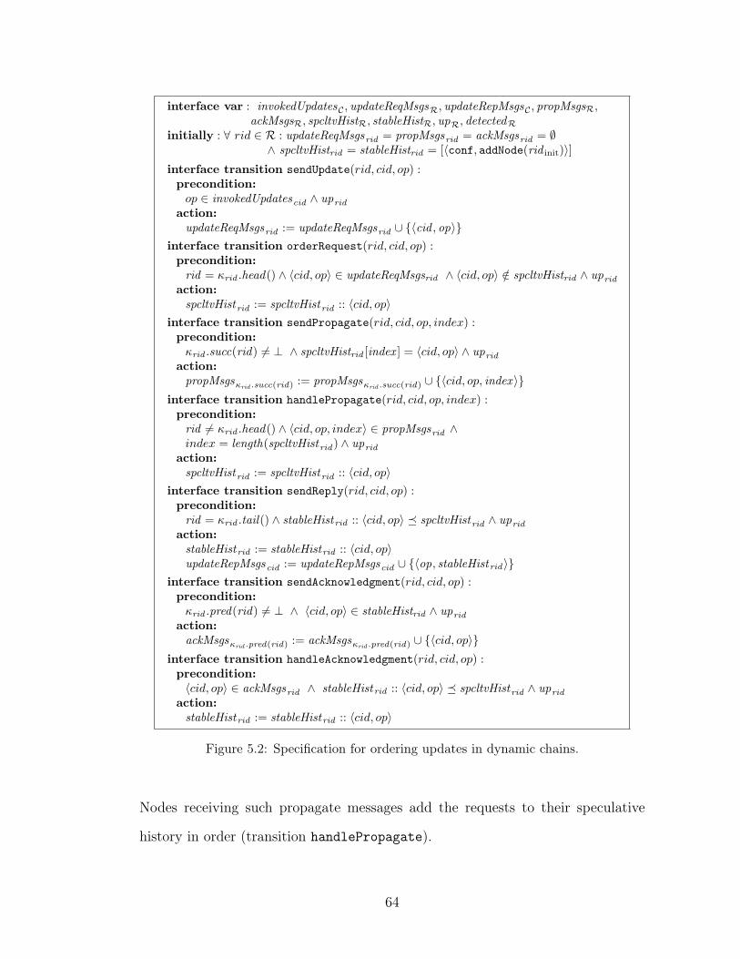
interface var : invokedUpdates𝒞 , updateReqMsgsℛ, updateRepMsgs𝒞 , propMsgsℛ,ackMsgsℛ, spcltvHistℛ, stableHistℛ, upℛ, detectedℛ
initially : ∀ 𝑟𝑖𝑑 ∈ ℛ : updateReqMsgsrid = propMsgsrid = ackMsgsrid = ∅∧ spcltvHistrid = stableHistrid = [⟨conf, addNode(rid init)⟩]
interface transition sendUpdate(𝑟𝑖𝑑, 𝑐𝑖𝑑, 𝑜𝑝) :precondition:𝑜𝑝 ∈ invokedUpdatescid ∧ uprid
action:updateReqMsgsrid := updateReqMsgsrid ∪ {⟨cid , op⟩}
interface transition orderRequest(𝑟𝑖𝑑, 𝑐𝑖𝑑, 𝑜𝑝) :precondition:rid = 𝜅rid .head() ∧ ⟨𝑐𝑖𝑑, 𝑜𝑝⟩ ∈ updateReqMsgsrid ∧ ⟨𝑐𝑖𝑑, 𝑜𝑝⟩ /∈ spcltvHistrid ∧ uprid
action:spcltvHistrid := spcltvHistrid :: ⟨𝑐𝑖𝑑, 𝑜𝑝⟩
interface transition sendPropagate(𝑟𝑖𝑑, 𝑐𝑖𝑑, 𝑜𝑝, 𝑖𝑛𝑑𝑒𝑥) :precondition:𝜅rid .succ(rid) ̸= ⊥ ∧ spcltvHistrid [index ] = ⟨𝑐𝑖𝑑, 𝑜𝑝⟩ ∧ uprid
action:propMsgs𝜅rid .succ(rid)
:= propMsgs𝜅rid .succ(rid)∪ {⟨𝑐𝑖𝑑, 𝑜𝑝, index ⟩}
interface transition handlePropagate(𝑟𝑖𝑑, 𝑐𝑖𝑑, 𝑜𝑝, 𝑖𝑛𝑑𝑒𝑥) :precondition:rid ̸= 𝜅rid .head() ∧ ⟨𝑐𝑖𝑑, 𝑜𝑝, 𝑖𝑛𝑑𝑒𝑥⟩ ∈ propMsgsrid ∧𝑖𝑛𝑑𝑒𝑥 = length(spcltvHistrid) ∧ uprid
action:spcltvHistrid := spcltvHistrid :: ⟨𝑐𝑖𝑑, 𝑜𝑝⟩
interface transition sendReply(𝑟𝑖𝑑, 𝑐𝑖𝑑, 𝑜𝑝) :precondition:rid = 𝜅rid .tail() ∧ stableHistrid :: ⟨𝑐𝑖𝑑, 𝑜𝑝⟩ ⪯ spcltvHistrid ∧ uprid
action:stableHistrid := stableHistrid :: ⟨𝑐𝑖𝑑, 𝑜𝑝⟩updateRepMsgscid := updateRepMsgscid ∪ {⟨op, stableHistrid⟩}
interface transition sendAcknowledgment(𝑟𝑖𝑑, 𝑐𝑖𝑑, 𝑜𝑝) :precondition:𝜅rid .pred(rid) ̸= ⊥ ∧ ⟨𝑐𝑖𝑑, 𝑜𝑝⟩ ∈ stableHistrid ∧ uprid
action:ackMsgs𝜅rid .pred(rid)
:= ackMsgs𝜅rid .pred(rid)∪ {⟨𝑐𝑖𝑑, 𝑜𝑝⟩}
interface transition handleAcknowledgment(𝑟𝑖𝑑, 𝑐𝑖𝑑, 𝑜𝑝) :precondition:⟨𝑐𝑖𝑑, 𝑜𝑝⟩ ∈ ackMsgsrid ∧ stableHistrid :: ⟨𝑐𝑖𝑑, 𝑜𝑝⟩ ⪯ spcltvHistrid ∧ uprid
action:stableHistrid := stableHistrid :: ⟨𝑐𝑖𝑑, 𝑜𝑝⟩
Figure 5.2: Specification for ordering updates in dynamic chains.
Nodes receiving such propagate messages add the requests to their speculative
history in order (transition handlePropagate).
64
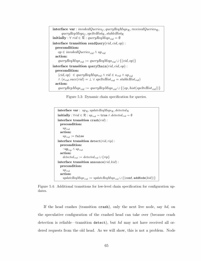
interface var : invokedQueries𝒞 , queryReqMsgsℛ, receivedQueriesℛ,queryRepMsgs𝒞 , spcltvHistℛ, stableHistℛ
initially : ∀ 𝑟𝑖𝑑 ∈ ℛ : queryReqMsgsrid = ∅interface transition sendQuery(𝑟𝑖𝑑, 𝑐𝑖𝑑, 𝑜𝑝) :precondition:𝑜𝑝 ∈ invokedQueriescid ∧ uprid
action:queryReqMsgsrid := queryReqMsgsrid ∪ {⟨𝑐𝑖𝑑, 𝑜𝑝⟩}
interface transition queryChain(𝑟𝑖𝑑, 𝑐𝑖𝑑, 𝑜𝑝) :precondition:⟨𝑐𝑖𝑑, 𝑜𝑝⟩ ∈ queryReqMsgsrid ∧ rid ∈ 𝜅rid ∧ uprid∧ (𝜅rid .succ(rid) = ⊥ ∨ spcltvHistrid = stableHistrid )
action:queryRepMsgscid := queryRepMsgscid ∪ {⟨op, hist(spcltvHistrid )⟩}
Figure 5.3: Dynamic chain specification for queries.
interface var : upℛ, updateReqMsgsℛ, detectedℛ
initially : ∀rid ∈ ℛ : uprid = true ∧ detectedrid = ∅interface transition crash(𝑟𝑖𝑑) :precondition:uprid
action:uprid := false
interface transition detect(𝑟𝑖𝑑, 𝑟𝑖𝑝) :precondition:¬uprip ∧ uprid
action:detectedrid := detectedrid ∪ {rip}
interface transition announce(𝑟𝑖𝑑, 𝑘𝑖𝑑) :precondition:uprid
action:updateReqMsgsrid := updateReqMsgsrid ∪ {⟨conf, addNode(kid)⟩}
Figure 5.4: Additional transitions for low-level chain specification for configuration up-dates.
If the head crashes (transition crash), only the next live node, say hd, on
the speculative configuration of the crashed head can take over (because crash
detection is reliable—transition detect), but hd may not have received all or-
dered requests from the old head. As we will show, this is not a problem. Node
65
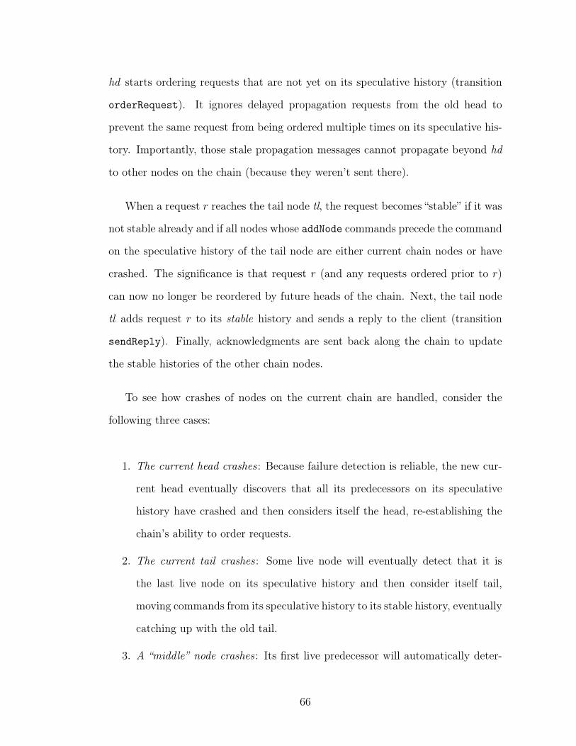
hd starts ordering requests that are not yet on its speculative history (transition
orderRequest). It ignores delayed propagation requests from the old head to
prevent the same request from being ordered multiple times on its speculative his-
tory. Importantly, those stale propagation messages cannot propagate beyond hd
to other nodes on the chain (because they weren’t sent there).
When a request 𝑟 reaches the tail node tl, the request becomes “stable” if it was
not stable already and if all nodes whose addNode commands precede the command
on the speculative history of the tail node are either current chain nodes or have
crashed. The significance is that request 𝑟 (and any requests ordered prior to 𝑟)
can now no longer be reordered by future heads of the chain. Next, the tail node
tl adds request 𝑟 to its stable history and sends a reply to the client (transition
sendReply). Finally, acknowledgments are sent back along the chain to update
the stable histories of the other chain nodes.
To see how crashes of nodes on the current chain are handled, consider the
following three cases:
1. The current head crashes : Because failure detection is reliable, the new cur-
rent head eventually discovers that all its predecessors on its speculative
history have crashed and then considers itself the head, re-establishing the
chain’s ability to order requests.
2. The current tail crashes : Some live node will eventually detect that it is
the last live node on its speculative history and then consider itself tail,
moving commands from its speculative history to its stable history, eventually
catching up with the old tail.
3. A “middle” node crashes : Its first live predecessor will automatically deter-
66
mine the new successor node. Similarly, its first live successor will automat-
ically determine the new predecessor node.
Not modeled in the specification is how clients find out where the current head
and current tail are. We assume that this is managed by some oracle (in practice,
DNS acts as the oracle, updated by the nodes that believe they are the head and
tail, although this mechanism must be careful that an old DNS update does not
overtake a later one).
5.2.1 Refining Chain Replication
Definition 4. We call a replica rid a configured node if there exists a live node
rid ′ such that ⟨conf, addNode(rid)⟩ ∈ spcltvHist rid ′ . (Note that all chain nodes are
configured nodes.)
Definition 5. A state satisfies prefix ordering if given any two live nodes 𝑟 and
𝑟′, either spcltvHist𝑟 ⪯ spcltvHist𝑟′ or spcltvHist𝑟′ ⪯ spcltvHist𝑟.
In a state in which prefix ordering holds, we note that for any two speculative
histories ℎ and ℎ′ of two live nodes, and any two configured nodes 𝑟 and 𝑟′, if
addNode(𝑟) and addNode(𝑟′) are on both ℎ and ℎ′, they must be in the same order.
Thus, prefix ordering induces an ordering on configured nodes, and we say that
𝑟 < 𝑟′ if addNode(𝑟) is ordered before addNode(𝑟′) on some live node’s speculative
history.
Theorem 1 (Invariant Properties). In chain replication, the following properties
are invariant:
67
1. prefix ordering;
2. if 𝑟 and 𝑟′ are configured live nodes and 𝑟 < 𝑟′, then spcltvHist𝑟′ ⪯
spcltvHist𝑟;
3. if 𝑟 and 𝑟′ are configured live nodes and 𝑟 < 𝑟′ and ⟨cid , op, index ⟩ ∈
propMsgs𝑟′, then spcltvHist𝑟[index ] = ⟨cid , op⟩;
4. if propMsgs𝑟 ̸= ∅ ∨ spcltvHist𝑟 ̸= [⟨conf, addNode(rid init])⟩, then 𝑟 is a con-
figured node.
Proof. The proof proceeds by induction. Initially, the speculative history of all
live nodes is identical and consists of [ridinit] while the propMsgs of each node is
empty, and thus the properties hold trivially for the initial state.
Next we show that if the properties hold in a reachable state, then the state
reached by applying any enabled transition also satisfies the same properties.
Taken together, it follows that the properties are invariant.
Note that at any time all chain nodes are ordered, and thus we can speak of a
head chain node and a tail chain node. We note that if a node rid thinks it is the
head node (𝜅rid .head() = rid), it is the head node, but not necessarily vice versa
because the head node may not have detected all failures yet. Same applies to the
tail node.
We enumerate all enabled transitions:
∙ orderRequest(𝑟𝑖𝑑, 𝑐𝑖𝑑, 𝑜𝑝): Because rid = 𝜅rid .head(), rid is the head chain
node. For any other configured live node rid ′ we have that rid < rid ′,
and thus by property (2) we have spcltvHist rid ′ ⪯ spcltvHist rid . Appending
⟨𝑐𝑖𝑑, 𝑜𝑝⟩ to spcltvHist rid clearly maintains property (1).
68
Because ⟨cid , op⟩ /∈ spcltvHist rid and rid is the head node, it cannot be the
case that ⟨cid , op⟩ is in any other speculative history or propMsgs by the
induction hypothesis. Thus in the case that ⟨cid , op⟩ is not a configuration
command, properties (2) and (3) are clearly maintained. If, however, cid =
conf ∧ op = addNode(rid ′), then rid ′ becomes a configured node (with the
highest index). Because of property (4), its speculative history and propMsgs
are still in the initial state, and thus properties (2) and (3) are maintained
as well.
Property (4) continues to hold because rid is a chain node and therefore a
configured node.
∙ sendPropagate(𝑟𝑖𝑑, 𝑐𝑖𝑑, 𝑜𝑝, 𝑖𝑛𝑑𝑒𝑥): This transition does not affect any spec-
ulative histories, and thus properties (1) and (2) are unaffected. Note that
𝜅rid .succ() is a configured node. spcltvHist rid [index ] = ⟨cid , op⟩, and by
property (2), property (3) must be maintained. It is also clear that property
(4) continues to hold.
∙ handlePropagate(𝑟𝑖𝑑, 𝑐𝑖𝑑, 𝑜𝑝, 𝑖𝑛𝑑𝑒𝑥): This transition adds ⟨cid , op⟩ from
propMsgsrid to spcltvHist rid , but only if it is at the correct next position.
Properties (1) and (2) follow directly from property (3). Note that if
cid = conf ∧ op = addNode(rid ′), then rid ′ must already be a configured
node. Property (4) is unaffected.
∙ any other enabled transition: none of the other transitions touch the variables
under consideration and thus do not affect the invariance of the properties
mentioned.
69
Let the index of a chain node rid be the index of ⟨conf, addNode(rid)⟩ in 𝜅rid .
Because of the prefix invariant, there cannot be two chain nodes with the same
index. We define the current chain 𝜅current to be the set of chain nodes ordered by
index. Note that:
∙ the initial current chain consists only of rid init;
∙ if 𝑟 and 𝑠 are chain nodes and index (𝑟) < index (𝑠), then spcltvHist𝑠 ⪯
spcltvHist𝑟;
∙ the head of the current chain (𝜅current.head()) has the longest speculative
history of the chain nodes (and in fact all live nodes);
∙ the tail of the current chain (𝜅current.tail()) has the shortest speculative his-
tory of the chain nodes.
Another useful invariant is the following:
Theorem 2. For any cid and op, if in any reachable state ∃rid : ⟨cid , op⟩ ∈
specltvHist rid , then op ∈ invokedUpdatescid .
Proof. The only two transitions that add anything to specltvHist rid are
orderRequest and handlePropagate. If orderRequest(rid , cid , op) is enabled,
then ⟨cid , op⟩ ∈ updateReqMsgsrid . updateReqMsgsrid is initially empty. The only
transition that adds ⟨cid , op⟩ to updateReqMsgsrid is sendUpdate(rid , cid , op).
When this sendUpdate transition was enabled, op ∈ invokedUpdatescid . The
theorem follows because there are no transitions that remove elements from
op ∈ invokedUpdatescid .
So consider the case in which handlePropagate(rid , cid , op, index ) is en-
abled, and thus ⟨cid , op, index ⟩ ∈ propMsgsrid . Because propMsgsrid is
70
the empty set in the beginning, ⟨cid , op, index ⟩ had to be added to
propMsgsrid with a sendPropagate(rid ′, cid , op, index ) transition. At that
time sendPropagate(rid ′, cid , op, index ) was enabled and therefore the tu-
ple ⟨cid , op⟩ was in the speculative history of node rid ′ at that index:
spcltvHist rid ′ [index ] = ⟨cid , op⟩. Again, this means that spcltvHist rid ′ was up-
dated by transition handlePropagate or orderRequest. Reasoning iteratively,
eventually the only way ⟨cid , op⟩ can enter in any node’s speculative history
is through an orderRequest transition first. As discussed above, this im-
plies that the sendUpdate transition was also enabled and because the corre-
sponding sendUpdate transition was enabled, it has to be the case that op ∈
invokedUpdatescid .
Definition 6. An operation ⟨cid , op⟩ on the speculative history of a live node rid
is stable iff it is stored at the same index (offset) on the speculative histories of
all live nodes 𝑟 for which ⟨conf, addNode(𝑟)⟩ precedes ⟨cid , op⟩ on the speculative
history of rid. (This operation may itself be an addNode operation.)
Note that if all nodes in addNode commands that precede an operation on a
speculative history have crashed, then the operation is stable. If there are addNode
commands for live nodes that precede the operation, those nodes have the opportu-
nity to influence the operation at the corresponding index. By the prefix property,
it follows that if two live nodes have a stable operation at the same index, they
are the same operation. Once an operation is stable, it will always remain stable
because there are no operations that change the value at a particular index in a
speculative history once stored.
Note that if an operation is stable on some speculative history, then so are
all operations that precede it on the same speculative history. Thus all stable
71
operations on the speculative history of the tail node are also stable on all chain
nodes, because the tail has the shortest speculative history. Note that if the current
tail crashes and another node becomes the tail as a result, the operations on the
speculative history of the new tail that had not yet been received by the old tail
become instantly stable.
Theorem 3. A command that is stable is stored on all chain nodes.
Proof. Because the tail has the shortest speculative history it is sufficient to show
that all stable commands are stored at the tail. Let tl be the identifier of the tail
node. By contradiction, suppose there were a stable command not on spcltvHist 𝑡𝑙.
Because of the prefix property (Theorem 1.1), the command must be stored on one
of the live predecessors of tl, after the ⟨conf, addNode(tl)⟩ command. But since tl
is live, the command cannot be stable.
Definition 7. The longest stable prefix, or lsp, is the history containing all stable
commands.
Theorem 4. If a live node tl thinks it is the tail, its speculative history equals the
longest stable prefix:
(uptl ∧ 𝜅tl .tail() = tl) =⇒ (spcltvHist 𝑡𝑙 = lsp)
Proof. Assume 𝜅tl .tail() = tl . Because of Theorem 3, all we need to show is that
all commands on spcltvHist 𝑡𝑙 are stable. Because 𝜅tl .tail() = tl , there are no live
nodes on the speculative configuration of tl that succeed tl. From Theorem 1.1
and 1.2 we know that all other live nodes on the speculative configuration store
the same commands and the same indices, so all commands on spcltvHist 𝑡𝑙 are
stable.
72
Theorem 5 (Stability Invariant). For each chain node rid : stableHist rid ⪯ lsp ⪯
spcltvHist rid .
Proof. By Theorem 3, lsp ⪯ spcltvHist rid for all chain nodes. Thus we only need to
show that for any chain node rid, stableHist rid ⪯ lsp. By induction, it is easy to see
that initially the stableHist rid of any node is exactly the lsp. Assume now a state
in which for all chain nodes rid stableHist rid ⪯ lsp. There are two transitions that
can update the stable history of a node: sendReply and handleAcknowledgment.
In addition, the transition handlePropagate can create a new chain node.
∙ sendReply(rid , cid , op) : This transition adds ⟨cid , op⟩ from the speculative
history of rid to its stable history. Note that by the precondition of the
transition and Theorem 4, the speculative history of rid is lsp, and thus
stableHist rid ⪯ lsp as a result.
∙ handleAcknowledgment(rid , cid , op) : This transition adds ⟨cid , op⟩ to the
stable history of rid. By the precondition, ⟨cid , op⟩ ∈ ackMsgsrid . The
only transition that adds to ackMsgsrid is sendAcknowledgment. Transi-
tion sendAcknowledgment(rid ′, cid , op) only sends commands from the sta-
ble history of rid ′. Reasoning iteratively, ⟨cid , op⟩ must have been stable and
therefore part of lsp.
∙ handlePropagate(rid , conf, addNode(rid), length(spcltvHist rid) : This tran-
sition causes rid to become a chain node. Until rid is a chain node, there is
no transition that adds commands to its stable history, and thus its stable
history is still in its initial state, and remains in its initial state as a result
of this transition. Thus stableHist rid ⪯ lsp.
There are no other transitions that can affect stable histories of chain nodes.
73
Theorem 6. The dynamic chain replication specification SpecCR refines the high-
level specification SpecH .
Proof. To show that SpecCR is a refinement of SpecH , we exhibit a refinement
mapping by creating:
∙ A state mapping: To show that a state mapping exists, we show how the
state of SpecH is derived from the state of SpecCR. For this, we represent
all internal variables in the high-level specification SpecH as a function of
the variables in the low-level specification SpecCR. Note that the interface
variables in SpecH are the same as the ones in SpecCR. We also have to show
that the initial state of SpecCR corresponds to the initial state of SpecH .
∙ A state transition mapping: To show that a state transition mapping
exists, for every enabled transition in the low-level specification SpecCR, we
either map it to an enabled transition in the high-level specification SpecH , or
we show that the state transition in SpecCR leaves the internal and interface
variables in SpecH unchanged. The latter state transitions are called stutter
transitions.
The only internal variable in SpecH is history , and in the proposed mapping we
derive it from the longest stable prefix by removing the configuration commands:
history = hist(lsp). Note that the initial state of SpecCR then maps to the initial
state of SpecH .
Next, we must show that every enabled state transition in SpecCR can be
mapped to an enabled state transition in SpecH . For this, we enumerate all enabled
state transitions in SpecCR.
74
∙ orderRequest(rid , cid , op): This transition orders a given ⟨cid , op⟩ pair
on the head of the chain. Under certain circumstances ⟨cid , op⟩ may be-
come stable, and, if it is not a configuration command, become part of
history. In those circumstances, it is clear that this transition maps to
updateHistory([⟨cid , op⟩]), but we we have to show that this transition is
enabled:
1. op ∈ invokedUpdatescid , and
2. ⟨cid , op⟩ /∈ history .
So assume the command is not a configuration command. By definition, it
becomes stable if it is stored at the same index on the speculative histories
of all live nodes 𝑟 for which ⟨conf, addNode(𝑟)⟩ precedes ⟨cid , op⟩ on the
speculative history of rid. Precondition (1) follows from Theorem 2. To show
(2), note that ⟨cid , op⟩ was not stable before the orderRequest transition
and therefore ⟨cid , op⟩ /∈ history .
In any other circumstances, either ⟨cid , op⟩ does not become stable or the
command is a configuration command. In those circumstances, history re-
mains unchanged and the transition is a stutter.
∙ handlePropagate(rid , cid , op, index ): This transition adds ⟨cid , op⟩ from
propMsgsrid to spcltvHist rid if it is at the correct next position. As
for transition orderRequest, there circumstances under which ⟨cid , op⟩
becomes stable and part of history, so that the transition maps to
updateHistory([⟨cid , op⟩]). In any other circumstances, history is un-
changed and the transition is a stutter.
Again, assume the command becomes stable but is not a configura-
tion command. Also assume the command is not yet stable already.
75
updateHistory([⟨cid , op⟩]) is enabled for the same reasons as for transition
orderRequest.
∙ crash(rid): an operation ⟨cid , op⟩ on the speculative history of a live node
rid is stable iff it is stored at the same index on the speculative histories
of all live nodes 𝑟 for which ⟨conf, addNode(𝑟)⟩ precedes ⟨cid , op⟩ on the
speculative history of rid, and thus the crash of a node may make one or
more operations stable, mapping to an updateHistory(ℎ) where ℎ consists
of the newly stable operations.
Again, we have to show that updateHistory([⟨cid , op⟩]) is enabled, which
follows for the same reasons as before.
∙ queryChain(rid , cid , op): This transition returns the stable history of a chain
node rid, if rid is the tail or if its speculative history is equal to its stable
history. By Theorem 4, we know that if rid thinks it is the tail node, then
its speculative history is equal to the longest stable prefix. By Theorem 5
we know that if the speculative history of a chain node is equal to its stable
history, then they are also equal to the longest stable prefix. So, this tran-
sitions returns hist(lsp). By our state mapping, history = hist(lsp), so this
transition maps to queryHistory(cid , op, h) in the high-level specification
SpecH .
We need to show that queryHistory(cid , op, h) is enabled when
queryChain(rid , cid , op) is enabled, that is, op ∈ invokedQueriescid . Be-
cause queryChain is enabled, we know that ⟨cid , op⟩ ∈ queryReqMsgsrid .
Initially queryReqMsgsrid is the empty set and the only transition that adds
tuples to it is sendQuery(rid , cid , op), so this transition was also enabled
at some time. Because there are no transitions that remove tuples from
invokedQueriescid , this means that op ∈ invokedQueriescid .
76
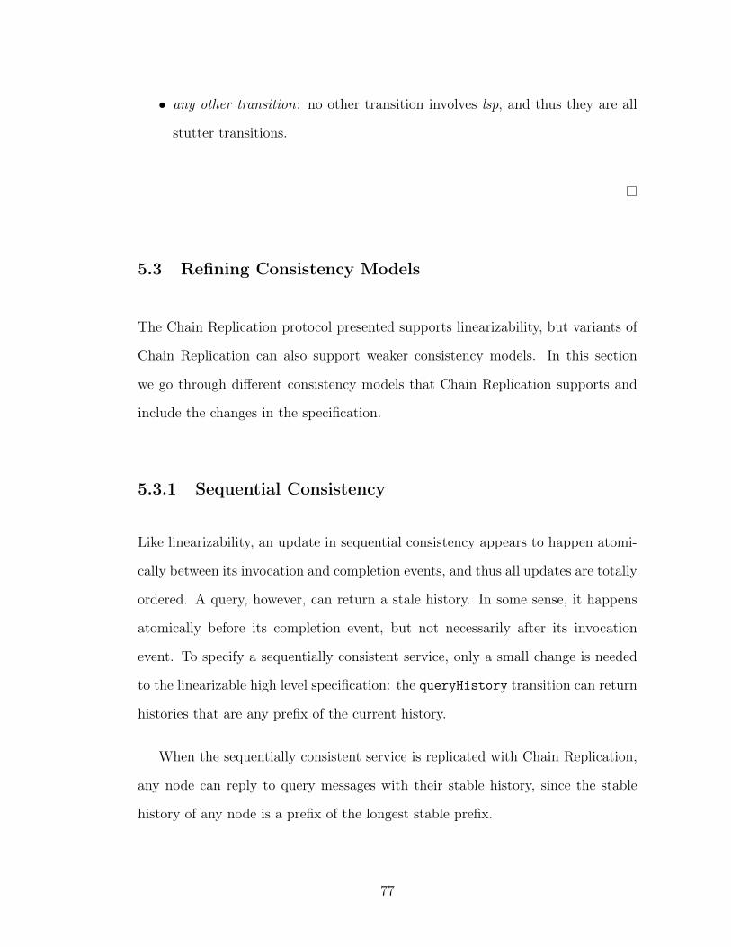
∙ any other transition: no other transition involves lsp, and thus they are all
stutter transitions.
5.3 Refining Consistency Models
The Chain Replication protocol presented supports linearizability, but variants of
Chain Replication can also support weaker consistency models. In this section
we go through different consistency models that Chain Replication supports and
include the changes in the specification.
5.3.1 Sequential Consistency
Like linearizability, an update in sequential consistency appears to happen atomi-
cally between its invocation and completion events, and thus all updates are totally
ordered. A query, however, can return a stale history. In some sense, it happens
atomically before its completion event, but not necessarily after its invocation
event. To specify a sequentially consistent service, only a small change is needed
to the linearizable high level specification: the queryHistory transition can return
histories that are any prefix of the current history.
When the sequentially consistent service is replicated with Chain Replication,
any node can reply to query messages with their stable history, since the stable
history of any node is a prefix of the longest stable prefix.
77
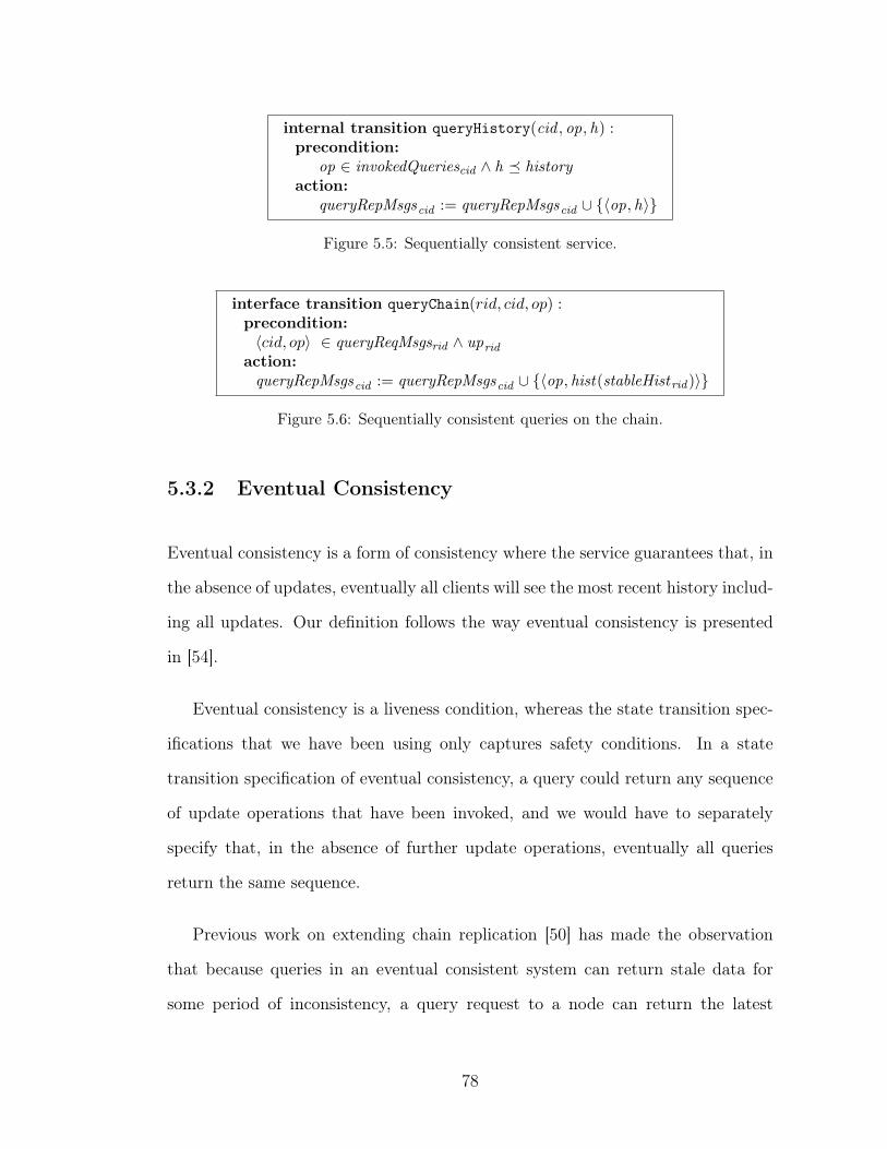
internal transition queryHistory(cid , op, h) :precondition:
op ∈ invokedQueriescid ∧ h ⪯ historyaction:
queryRepMsgscid := queryRepMsgscid ∪ {⟨op, h⟩}
Figure 5.5: Sequentially consistent service.
interface transition queryChain(𝑟𝑖𝑑, 𝑐𝑖𝑑, 𝑜𝑝) :precondition:⟨𝑐𝑖𝑑, 𝑜𝑝⟩ ∈ queryReqMsgsrid ∧ uprid
action:queryRepMsgscid := queryRepMsgscid ∪ {⟨op, hist(stableHistrid )⟩}
Figure 5.6: Sequentially consistent queries on the chain.
5.3.2 Eventual Consistency
Eventual consistency is a form of consistency where the service guarantees that, in
the absence of updates, eventually all clients will see the most recent history includ-
ing all updates. Our definition follows the way eventual consistency is presented
in [54].
Eventual consistency is a liveness condition, whereas the state transition spec-
ifications that we have been using only captures safety conditions. In a state
transition specification of eventual consistency, a query could return any sequence
of update operations that have been invoked, and we would have to separately
specify that, in the absence of further update operations, eventually all queries
return the same sequence.
Previous work on extending chain replication [50] has made the observation
that because queries in an eventual consistent system can return stale data for
some period of inconsistency, a query request to a node can return the latest
78
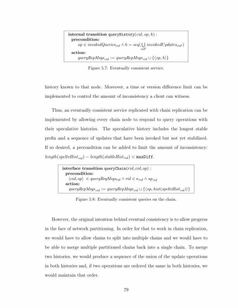
internal transition queryHistory(cid , op, h) :precondition:
op ∈ invokedQueriescid ∧ ℎ = 𝑠𝑒𝑞(⋃︀𝑐𝑖𝑑′
𝑖𝑛𝑣𝑜𝑘𝑒𝑑𝑈𝑝𝑑𝑎𝑡𝑒𝑠𝑐𝑖𝑑′)
action:queryRepMsgscid := queryRepMsgscid ∪ {⟨op, h⟩}
Figure 5.7: Eventually consistent service.
history known to that node. Moreover, a time or version difference limit can be
implemented to control the amount of inconsistency a client can witness.
Thus, an eventually consistent service replicated with chain replication can be
implemented by allowing every chain node to respond to query operations with
their speculative histories. The speculative history includes the longest stable
prefix and a sequence of updates that have been invoked but not yet stabilized.
If so desired, a precondition can be added to limit the amount of inconsistency:
length(spcltvHist rid)− length(stableHist rid) < maxDiff.
interface transition queryChain(𝑟𝑖𝑑, 𝑐𝑖𝑑, 𝑜𝑝) :precondition:⟨𝑐𝑖𝑑, 𝑜𝑝⟩ ∈ queryReqMsgsrid ∧ rid ∈ 𝜅rid ∧ uprid
action:queryRepMsgscid := queryRepMsgscid ∪ {⟨op, hist(spcltvHistrid )⟩}
Figure 5.8: Eventually consistent queries on the chain.
However, the original intention behind eventual consistency is to allow progress
in the face of network partitioning. In order for that to work in chain replication,
we would have to allow chains to split into multiple chains and we would have to
be able to merge multiple partitioned chains back into a single chain. To merge
two histories, we would produce a sequence of the union of the update operations
in both histories and, if two operations are ordered the same in both histories, we
would maintain that order.
79
5.3.3 Causal Consistency
Causal consistency guarantees that if a client cid has witnessed a history ℎ and
subsequently sent a message to another client cid ′, then after receipt client cid ′ has
also witnessed ℎ and any query by that client will see a history including ℎ. Note
that linearizability is strictly stronger than causal consistency: any linearizable
execution satisfies causal consistency (because it takes time to send a message from
one client to another), but not vice versa. In order to specify causal consistency, we
would have to model communication between clients, which is outside the scope of
this work. Previous work [5] has considered causal consistency for chain replication.
5.3.4 Read-Your-Writes Consistency
Read-your-writes consistency guarantees that a query from a client always returns
the history including the latest update issued by that client. A service that sup-
ports read-your-writes consistency can be implemented by making sure that a
history returned by a query includes all updates that have been completed. This
is implemented easily in the completeQuery transition, and since this interface
transition is also used by the service that is replicated by chain replication, the
same method works for that too.
interface transition completeQuery(cid , op, h) :precondition:
⟨op, h⟩ ∈ queryRepMsgscid ∧ op /∈ completedQueriescid∧ ∀ op ∈ completedUpdatescid : ⟨cid , op⟩ ∈ h
action:completedQueriescid := completedQueriescid ∪ {𝑜𝑝}
Figure 5.9: Service that supports read-your-writes consistency.
80
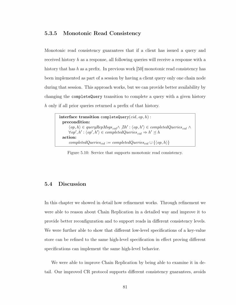
5.3.5 Monotonic Read Consistency
Monotonic read consistency guarantees that if a client has issued a query and
received history h as a response, all following queries will receive a response with a
history that has h as a prefix. In previous work [50] monotonic read consistency has
been implemented as part of a session by having a client query only one chain node
during that session. This approach works, but we can provide better availability by
changing the completeQuery transition to complete a query with a given history
h only if all prior queries returned a prefix of that history.
interface transition completeQuery(cid , op, h) :precondition:
⟨op, h⟩ ∈ queryRepMsgscid∧ ̸ ∃ℎ′ : ⟨op, ℎ′⟩ ∈ completedQueriescid ∧∀op′, ℎ′ : ⟨op′, ℎ′⟩ ∈ completedQueriescid ⇒ ℎ′ ⪯ ℎ
action:completedQueriescid := completedQueriescid ∪ {⟨op, ℎ⟩}
Figure 5.10: Service that supports monotonic read consistency.
5.4 Discussion
In this chapter we showed in detail how refinement works. Through refinement we
were able to reason about Chain Replication in a detailed way and improve it to
provide better reconfiguration and to support reads in different consistency levels.
We were further able to show that different low-level specifications of a key-value
store can be refined to the same high-level specification in effect proving different
specifications can implement the same high-level behavior.
We were able to improve Chain Replication by being able to examine it in de-
tail. Our improved CR protocol supports different consistency guarantees, avoids
81

the tail bottleneck for reads, and introduces autonomous reconfiguration of the
system without requiring an external master. Additionally, we developed a formal
end-to-end specification of the protocol, including the actions of clients, detailing
reconfiguration and linearizable execution of client requests. Through this specifi-
cation, we are able to reason about the new protocol more precisely and implement
the protocol effortlessly.
We believe that this way of implementing distributed systems makes distributed
system design a more manageable task. Moreover, a clear understanding of how
a system works makes it straightforward to build, deploy and later evolve this
system. In the next chapter, we will talk about how we build and evolve such
systems easily.
82
CHAPTER 6
BUILDING AND EVOLVING A DISTRIBUTED SYSTEM
Ovid framework can be used to build, deploy, maintain and evolve systems easily.
In this chapter, we will explain how this is done in more detail and also present
the implementation of Ovid itself, which is done using the same technique.
First, we discuss how Ovid can be used to design a distributed system that is
tailored by the programmer, using high-level abstractions. Second, we detail how
Ovid uses this high-level model to construct a software-defined distributed system,
which can evolve automatically. Finally, we describe how Ovid itself is designed
and built as a system and discuss the engineering challenges that we faced while
building our live deployment, and how we addressed them.
6.1 Running Agents
Ovid can deploy distributed systems automatically on a data center environment
using the agent-based model it uses. Automating the deployment and the main-
tenance of a distributed system of course requires attention to important details
about where different components will run, how they will communicate with each
other, and what will happen when inevitable failures occur. We discuss these in
turn.
83
6.1.1 Boxing
An agent is a logical location, but it is not necessary to run each agent on a separate
host. Figure 4.5 illustrates boxing : co-locating agents in some way, such as on the
same machine or even within a single process.
A box is an execution environment or virtual machine for agents. For each
agent, the box keeps track of the agent’s attributes and runs transitions for mes-
sages that have arrived. In addition, each box runs a Box Manager Agent that
supports management operations such as starting a new agent or updating an
agent’s routing table.
Boxes also implement the reliable transport of messages between agents. A box
is responsible for making sure that the set of output messages of an agent running
on the box is transferred to the sets of input messages of the destination agents.
For each destination agent, this assumes there is an entry for the message’s agent
identifier in the source agent’s routing table, and the box also needs to know how
to map the destination agent identifier to one or more network addresses of the box
that runs the destinating agent. A box maintains the Box Routing Table (BRT)
for this purpose. For now, we assume that each BRT is filled with the necessary
information.
The box transmits the message to the destination box. Upon arrival, the des-
tination box determines if the destination agent exists. If so, the box adds the
message to the end of the agent’s input messages, and returns an acknowledgment
to the source box. The source box keeps retransmitting (without timeout) the
message until it has received an acknowledgment. This process must restart if
there is a reconfiguration of the destination agent. An output message can be dis-
84
carded only if it is known that the message has been processed by the destination
agent—being received is not a safe condition.
6.1.2 Placement
While resulting in more efficient usage of resources, boxing usually leads to a form
fate sharing : a problem with a box such as a crash is often experienced by all
agents running inside the box. Fate sharing makes sense for agents and its proxies,
but it would be unwise to run replicas of the same agent within the same box.
We use agent placement annotations to indicate placement desirables and con-
straints. For example, agent 𝛼 can have a set of annotations of the following form:
∙ 𝛼.SameBoxPreferred(𝛽): 𝛽 ideally is placed on the same box as 𝛼;
∙ 𝛼.SameBoxImpossible(𝛽): 𝛽 cannot run on the same box as 𝛼.
Placing agents in boxes can be automatically performed based on such annota-
tions using a constraint optimizer. Placement is final: we do not currently consider
support for live migration of agents between boxes. It is, however, possible to start
a new agent in another box, migrate the state from an old agent, and update the
routing tables of other agents.
6.1.3 Controller Agent
So far we have glossed over several administrative tasks, including:
∙ What boxes are there, and what are their network addresses?
85
∙ What agents are there, and in which boxes are they running?
∙ How do agents get started in the first place?
∙ How do boxes know which agents run where?
As in other Software-Defined architectures, we deploy a logically centralized
controller for administration. The controller itself is just another agent, and has
identifier “controller”. The controller agent itself can be refined by replication,
sharding and so on. For scale, the agent may also be hierarchically structured. But
for now we will focus on the high-level specification of a controller agent before
transformation. In other words, for simplicity we assume that the controller agent
is physically centralized and runs on a specific box.
As a starting point, the controller is configured with the LATT (Logical Agent
Transformation Tree), as well as the identifiers of the box managers on those boxes.
The BRT (Box Routing Table) of the box in which the controller runs is configured
with the network addresses of the box managers.
First, the controller sends a message to each box manager imparting the net-
work addresses of the box in which the controller agent runs. Upon receipt, the
box manager adds a mapping for the controller agent to its BRT. (If the controller
had been transformed, the controller would need to send additional information to
each box manager and possibly instantiate proxy agents so the box manager can
communicate with the controller.)
Using the agent placement annotations, the controller can now instantiate the
agents of the LATT. This may fail if there are not enough boxes to satisfy the
constraints specified by the annotations. Instantiation is accomplished by the
controller sending requests to the various box managers.
86
Initially, the agents’ routing tables start out containing only the “controller”
mapping. When an agent sends a message to a particular agent identifier, there
is an “agent identifier miss” event. On such an event, the agent ends up implicitly
sending a request to the controller asking it to resolve the agent identifier to agent
identifier binding. The controller uses the LATT to determine this binding and
responds to the client with the destination agent identifier. The client then (again,
implicitly) adds the mapping to its routing table.
Next, the box tries to deliver the message to the destination agent. To do this,
the box looks up the destination agent identifier in its BRT, and may experience a
“BRT miss”. In this case, the box sends a request to the controller agent asking to
resolve that binding as well. The destination agent may be within the same box as
the source agent, but this can only be learned from the controller. One may think
of routing tables as caches for the routes that the controller decides.
6.1.4 Evolution
A deployed system evolves. There can be many sources of such evolution, including:
∙ client agents come and go;
∙ in the face of changing workloads, applications may be elastic, and server
agents may come an go as well;
∙ new functionality may be deployed in the form of new server agents;
∙ existing agents may be enhanced with additional functionality;
∙ bug fixes also lead to new versions of agents;
87
∙ the performance or fault tolerance of agents may be improved by applying
transformations to them;
∙ a previously transformed agent may be “untransformed” to save cost;
∙ new transformations may be developed, possibly replacing old ones.
Our system supports such evolution, even as it happens “on-the-fly.” As evolu-
tion happens, various correctness guarantees must be maintained. Instrumental in
this are agents’ wedged bits: we have the ability to temporarily halt an agent, even
a virtual one. While halted, we can extract its state, transfer it to a new agent,
update routing tables, and restart by unwedging the new agent. It is convenient to
think of versions of an agent as different refinements of a higher level specification.
Similarly, an old version has to be wedged, and state has to be transferred from
an old version of an agent to a new one. The identifiers of such new agents should
be different from old ones. We do this by incorporating version numbers into the
identifiers of agents. For example, ‘KVS:v2/IngressProxy:v3:2’ would name the
second incarnation of version 3 of an ingress proxy agent, and this refines version 2
of the virtual KVS agent.
Obtaining the state of a wedged physical agent is trivial, and starting a physical
agent with a particular state is also a simple operation. However, a wedged virtual
agent may have its state distributed among various physical agents and thus ob-
taining or initializing the state is not straightforward. And even if a virtual agent
is wedged, not all of its physical agents are necessarily wedged. For example, in
the case of the sharded key-value store, the virtual agent is wedged if all shards are
wedged, but it does not require that the proxies are wedged. Note also that there
may be multiple levels of transformation: in the context of one transformation
88
an agent may be physical, but in the context of another it may be virtual. For
example, the shards in the last example may be replicated.
We require that each transformation provide a function getState that obtains
the state of a virtual agent given the states of its physical agents. It is not nec-
essarily the case that all physical agents are needed. For example, in the case
of a replicated agent, some physical agents may be unavailable and it should not
be necessary to obtain the state of the virtual agent. Given the state of a vir-
tual agent, a transformation also needs to provide a function that instantiates the
physical agents and initializes their state.
While this solution works, it can lead to a significant performance hiccup. We
are designing a new approach where the new physical agents can be started without
an initial state before the virtual agent is even wedged. Then the virtual agent is
wedged (by wedging the physical agents of its original transformation). This is a
low-cost operation. Upon completion, the new physical agents are unwedged and
“demand-load” state as needed from the old physical agents. Once all state has
been transferred, the old physical agents can be shut down and garbage collected.
This is most easily accomplished if the virtual agent has state that is easily divided
into smaller, functional pieces. For example, in the case of a key-value store, each
key/value pair can be separately transferred when needed.
6.2 Implementation
Implementing Ovid, a system that can transform distributed systems requires
many different components and unique design decisions. Our implementation is
comprised of two main parts: The designer creates an environment model as a
89
combination of LATTs that represent distributed system specifications and trans-
forms these LATTs, creating new distributed systems and the environment they
comprise. Moreover, the designer can translate a given environment into a config-
uration that can be deployed. Ovid core then takes the configuration generated by
the designer, builds the LATT as a real system with a collection of agent processes
and deploys it in a given setting. In this section we go through how the designer
and Ovid core are implemented.
6.2.1 The Designer
The designer models a given distributed system in the form of a LATT, and applies
transformations on this LATT. The transformations applied create a new LATT
that represents the specification of a new distributed system, as a combination of
agents. Using the designer, users can design the distributed system they want with
the requirements they have and the assumptions that are allowed by their model.
For example, the user can create the LATT for a centralized key-value store, then
see how sharding the key-value store changes the LATT of the key-value store and
how clients of the key-value store would interact with the new key-value store.
To model these interactions, the designer also models connections between agents
as preconnect and postconnect functions. A preconnect function expresses how
an agent gets transformed to connect to another agent as a client. Similarly, a
postconnect function expresses how an agent gets transformed when another agent
connects to it. These connection functions are also updated with transformations
and create the basic mechanism for combining subsystems that comprise of agents.
Lastly, the designer can visualize how the LATT for different abstraction layers get
90
updated, making it easier for the user to understand that even if the underlying
specification of a system changes, the high-level specification stays the same.
The designer is implemented in JavaScript, to make it easy to run it in a
web browser, with 1200 lines of code. The designer has an interactive shell, a
transformation engine, a LATT visualizer, and a configuration manager.
Interactive Shell
Using the interactive shell, users can model an environment that includes multi-
ple systems and they can model how these systems interact with each other and
how they are transformed. Systems are created with the create command which
expects two arguments, a name for the system agent and the code it has to run
to deploy the system. The create command creates a LATT for a given system
agent and includes it in the environment. To create the LATT for the key-value
store in our example, the arguments that are required are ‘KVS’ and the file name
of the key-value store implementation. Multiple systems can be added to the en-
vironment using the create command. The shell also provides transformation
commands and every system can be transformed with a transformation command,
such as paxos, shard, encrypt, etc. When a transformation command is applied
to a system, its LATT is changed as explained earlier. In addition, the shell pro-
vides a connect command to establish a client/server relationship between two
agents in the environment. The connection does not affect the LATTs of the sys-
tems involved, but it affects how the high-level environment is modeled and how
it will be deployed. A user can create multiple clients and connect them to the
‘KVS’ to model a key-value store with multiple clients.
91
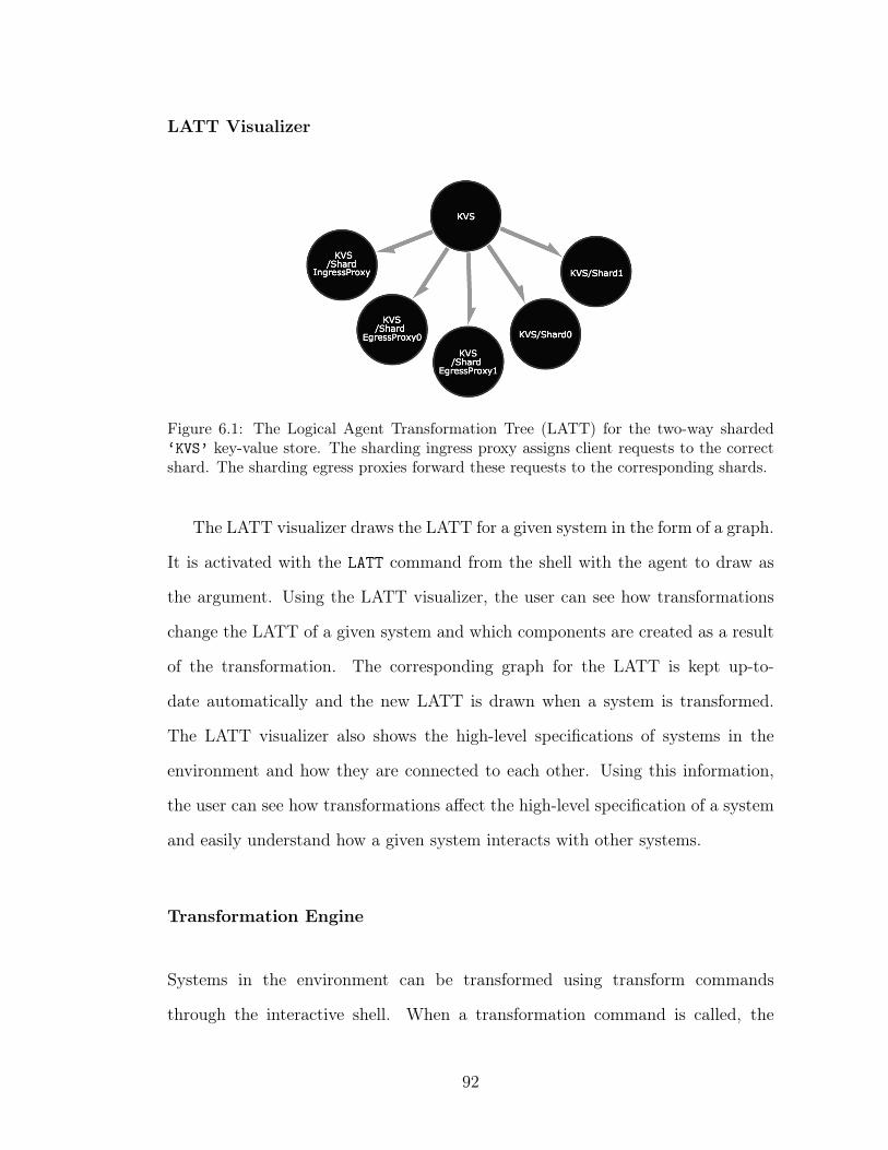
LATT Visualizer
Figure 6.1: The Logical Agent Transformation Tree (LATT) for the two-way sharded‘KVS’ key-value store. The sharding ingress proxy assigns client requests to the correctshard. The sharding egress proxies forward these requests to the corresponding shards.
The LATT visualizer draws the LATT for a given system in the form of a graph.
It is activated with the LATT command from the shell with the agent to draw as
the argument. Using the LATT visualizer, the user can see how transformations
change the LATT of a given system and which components are created as a result
of the transformation. The corresponding graph for the LATT is kept up-to-
date automatically and the new LATT is drawn when a system is transformed.
The LATT visualizer also shows the high-level specifications of systems in the
environment and how they are connected to each other. Using this information,
the user can see how transformations affect the high-level specification of a system
and easily understand how a given system interacts with other systems.
Transformation Engine
Systems in the environment can be transformed using transform commands
through the interactive shell. When a transformation command is called, the
92
interactive shell passes the name of the system to be transformed as an argument
to the transformation engine, along with the desired type of transformation. The
transformation engine transforms the LATT of the given system according to the
rules defined in the engine.
The current LATT of every system is maintained as objects in the environment.
The transformations in the engine are functions that can retrieve the LATT of a
system agent using its name and create a new LATT by adding and removing
nodes and edges to the original LATT. Finally, the transformation engine updates
the LATT maintained in the environment.
It is important to note that when a system is transformed only the LATT of
that system is affected, but when it comes to deployment, other systems that are
connected to the given system might get affected too. To implement this behavior,
the transformation of a system also transforms how the connect function works
for a transformed system and how the deployment information of the systems are
changed that are already connected to the transformed system.
To understand how transformation functions work, let us consider the sharding
transformation done on ‘KVS’ that has two clients that are connected to it. When
the shard transformation is applied to the ‘KVS’ system agent, the LATT gets
updated to include the ingress proxy that is used by the clients to assign their
requests to the correct shards, the egress proxy that forwards client requests to
the correct ‘KVS’ shards, and the ‘KVS’ shards themselves. Figure 6.1 shows the
resulting LATT. During this transformation, the LATTs of the clients that are
connected to the ‘KVS’ system are not transformed, but during the deployment
the clients require the ingress proxies to be able to send their requests to the correct
93
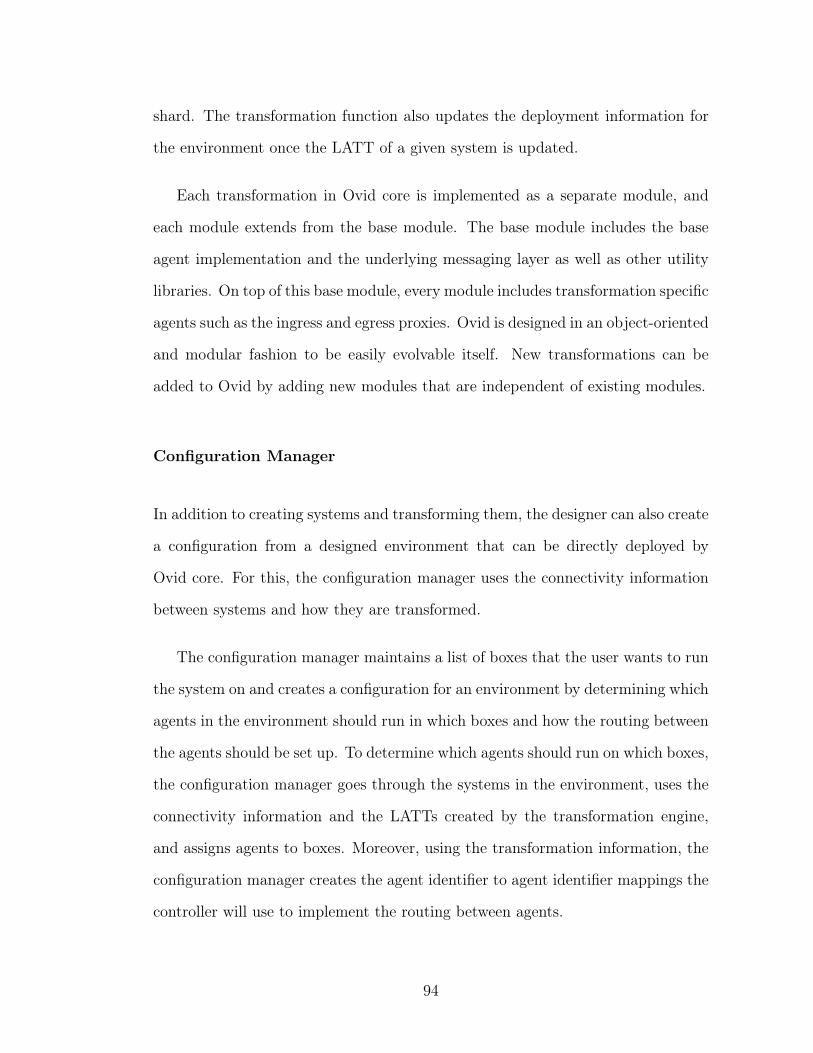
shard. The transformation function also updates the deployment information for
the environment once the LATT of a given system is updated.
Each transformation in Ovid core is implemented as a separate module, and
each module extends from the base module. The base module includes the base
agent implementation and the underlying messaging layer as well as other utility
libraries. On top of this base module, every module includes transformation specific
agents such as the ingress and egress proxies. Ovid is designed in an object-oriented
and modular fashion to be easily evolvable itself. New transformations can be
added to Ovid by adding new modules that are independent of existing modules.
Configuration Manager
In addition to creating systems and transforming them, the designer can also create
a configuration from a designed environment that can be directly deployed by
Ovid core. For this, the configuration manager uses the connectivity information
between systems and how they are transformed.
The configuration manager maintains a list of boxes that the user wants to run
the system on and creates a configuration for an environment by determining which
agents in the environment should run in which boxes and how the routing between
the agents should be set up. To determine which agents should run on which boxes,
the configuration manager goes through the systems in the environment, uses the
connectivity information and the LATTs created by the transformation engine,
and assigns agents to boxes. Moreover, using the transformation information, the
configuration manager creates the agent identifier to agent identifier mappings the
controller will use to implement the routing between agents.
94
6.2.2 Ovid Core
Ovid core builds and deploys a distributed system created by the designer in a given
data center setting using the configuration created by the configuration manager.
The current version of Ovid core is implemented with 5000 lines of Python code.
Each box is implemented as a Python process, and agents run as threads inside
a box. Ovid core is started by the bootstrap box manager and controller agents,
which use the configuration created by the configuration manager to set up the
distributed system designed by the user. This includes starting all box managers
and the agents that will run on every box. Once every agent is started, no extra
configuration is required, since the controller manages the routing between all
agents.
Ovid core is implemented in an object-oriented manner, where every agent in
the system extends from an Agent class. Every agent has a receive queue and an
outbox. An agent receives messages on its receive queue and processes messages
one by one, removing them from its receive queue. Agents send a message by
adding the message to the box’s send queue. Every message has a type, a source,
and a destination. When the agent creates a message, it uses the agentid of the
destination agent that is in the same abstraction level as the source agent. For
instance, when ‘client1’ in our sharding example, shown in Figure 4.5 sends a
message to the key-value store ‘KVS’, it uses ‘KVS’ as the destination agentid,
only including the first part of the agentid. Before the message is added to the
send queue of the agent, the agent does a look up from its routing table, to include
the absolute agentid for ‘KVS’ in the message as a header. If this lookup does
not return a result, the message is added to the outbox to wait until the agentid
matching is looked up from the controller. When a matching for an agentid is
95
added to the routing table, all the messages in the outbox for that given agentid are
updated with the new header and added to the send queue. When an agent sends
a message, the box looks up the destination agent identifier in the agent’s routing
table. If not there, the box sends a request for the mapping to the controller and
temporarily adds the message to the agent’s outbox. Once resolved, the message
is placed on the box’s send queue.
The box manager is in charge of handling receive and send queues of all agents
that run on that box and delivering the messages to their destination. Each box
manager itself is an agent. It maintains the lower-level Box Routing Table (BRT)
that maps agent identifiers to IP:Port pairs. Communication between boxes is
done over TCP and connections between boxes are saved in connection pools that
are maintained by box managers. To deliver the messages to the agents, the box
manager uses the destination in the header of a message to lookup the receive
queue for that agent and adds the rest of the message to the receive queue. This
way, the agent is never aware of the lower-level abstraction that uses its absolute
agentid.
6.3 Discussion
Ovid can deploy a distributed system modeled as a combination of agents automat-
ically in a data center. To do this, it uses box managers that support management
operations such as starting a new agent or updating an agent’s routing table so
it can communicate with other agents. Moreover, Ovid uses a controller to man-
age how agents communicate with each other and how the LATT is deployed on
boxes. Since the controller knows how the distributed system is modeled, it can
96
also change the deployment of agents and control the evolution of the distributed
system when the LATT is changed.
Ovid is implemented to make distributed system design, deployment and evo-
lution an easy task and has two main components, the designer and the Ovid core.
The designer is used to create the LATT and evolve it as needed by the user. It
makes it easier to understand the agent-based model of a distributed system and
how it evolves. The visual tool for the designer makes it simple to use even for
novice users. And the designer creates a configuration for the controller to use for
deployment. The Ovid core then takes the configuration generated by the designer,
builds the LATT as a real system with a collection of agent processes and deploys
it in a given setting.
Being able to deploy and evolve distributed systems using Ovid has also per-
formance advantages. In the next chapter we will evaluate a key-value store imple-
mented using Ovid to underline the performance advantages of building evolvable
distributed systems.
97
CHAPTER 7
EVALUATION
In this chapter we present an evaluation of Ovid’s performance. We evaluated our
Python prototype implementation and we present results of several microbench-
marks which examine throughput, latency, scalability, and recovery time of systems
built and evolved using Ovid.
These experiments reflect end-to-end measurements from clients and include
full overhead of going over the network. The evaluation is performed on a private
cluster running the Eucalyptus [44] cloud computing infrastructure. All servers
and clients are deployed on virtual machine instances with 4 virtual CPUs, 16 GB
of memory, 30 GB of disk and a measured network performance of 0.6 Mbit/s,
which was throttled for individual VMs by Eucalyptus.
Our experiments focus on showing the feasibility of our design. We imple-
mented Ovid in Python, which is convenient for fast prototyping but it does not
focus on high performance. Our prototype focuses on testing out our approach
to building and evolving distributed systems automatically. For instance, to in-
vestigate what the correct level of abstraction is, every agent is implemented as a
process to make changing the overall design easier. This enabled us to implement
the controller and the box manager as agents but also results in more context
switches when agents are running.
We used Ovid to build a key-value store that can be sharded or replicated au-
tomatically. First, we will present the base performance numbers and then see the
effect of sharding and replication on throughput and fault-tolerance respectively.
98
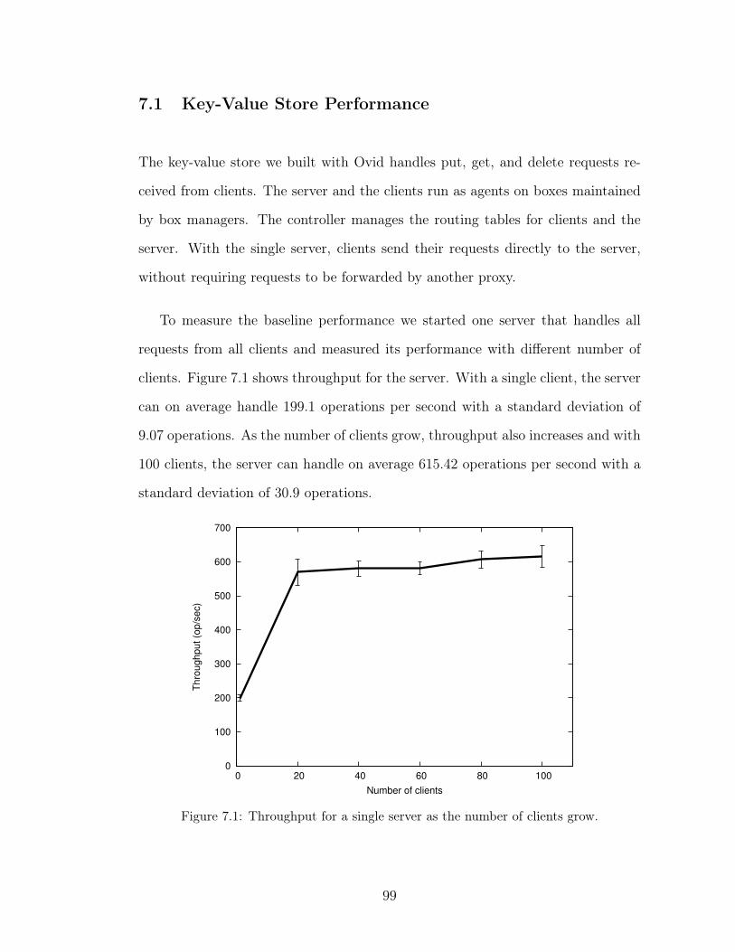
7.1 Key-Value Store Performance
The key-value store we built with Ovid handles put, get, and delete requests re-
ceived from clients. The server and the clients run as agents on boxes maintained
by box managers. The controller manages the routing tables for clients and the
server. With the single server, clients send their requests directly to the server,
without requiring requests to be forwarded by another proxy.
To measure the baseline performance we started one server that handles all
requests from all clients and measured its performance with different number of
clients. Figure 7.1 shows throughput for the server. With a single client, the server
can on average handle 199.1 operations per second with a standard deviation of
9.07 operations. As the number of clients grow, throughput also increases and with
100 clients, the server can handle on average 615.42 operations per second with a
standard deviation of 30.9 operations.
0
100
200
300
400
500
600
700
0 20 40 60 80 100
Thro
ughput (o
p/s
ec)
Number of clients
Figure 7.1: Throughput for a single server as the number of clients grow.
99
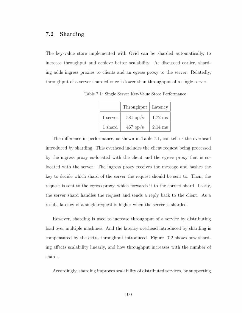
7.2 Sharding
The key-value store implemented with Ovid can be sharded automatically, to
increase throughput and achieve better scalability. As discussed earlier, shard-
ing adds ingress proxies to clients and an egress proxy to the server. Relatedly,
throughput of a server sharded once is lower than throughput of a single server.
Table 7.1: Single Server Key-Value Store Performance
Throughput Latency
1 server 581 op/s 1.72 ms
1 shard 467 op/s 2.14 ms
The difference in performance, as shown in Table 7.1, can tell us the overhead
introduced by sharding. This overhead includes the client request being processed
by the ingress proxy co-located with the client and the egress proxy that is co-
located with the server. The ingress proxy receives the message and hashes the
key to decide which shard of the server the request should be sent to. Then, the
request is sent to the egress proxy, which forwards it to the correct shard. Lastly,
the server shard handles the request and sends a reply back to the client. As a
result, latency of a single request is higher when the server is sharded.
However, sharding is used to increase throughput of a service by distributing
load over multiple machines. And the latency overhead introduced by sharding is
compensated by the extra throughput introduced. Figure 7.2 shows how shard-
ing affects scalability linearly, and how throughput increases with the number of
shards.
Accordingly, sharding improves scalability of distributed services, by supporting
100
0
200
400
600
800
1000
1200
1400
1600
1800
2000
0 1 2 3 4 5 6
Thro
ughput (o
p/s
ec)
Number of shards
Figure 7.2: Throughput of Ovid with 60 clients as we change the number of shards.
more clients in parallel. In most distributed services, deploying new shards requires
the service to be paused and reconfigured. This reconfiguration includes starting
new shards, deciding which request should be directed to which shard, and having
clients send their requests to the correct shard, and most services cannot apply
these changes dynamically. Moreover, sharding is useful if it can be used to scale
the service dynamically as the number of clients increase. If sharding is not used
in this way, it can stop being an effective solution as shown in Figure 7.3.
Using Ovid, the controller can add new shards and reconfigure the service to
support more clients. As a result, the controller can keep latency constant by
starting new shards as shown in Figure 7.2. This way, even if the number of
clients increase dynamically, the service can offer similar latency to all clients and
increase overall throughput. Currently, Ovid requires system to be halted briefly
and shards to be rebalanced before new configuration is applied, but we are also
implementing automatic rebalancing to enable dynamic sharding changes.
101
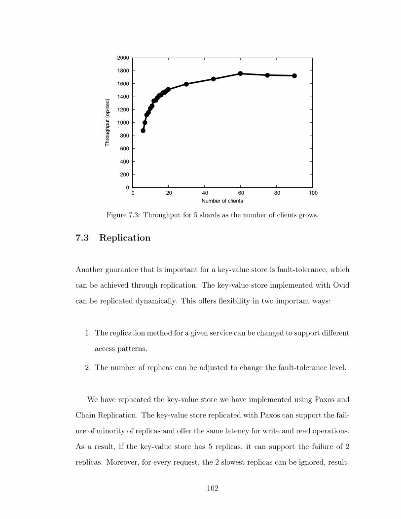
0
200
400
600
800
1000
1200
1400
1600
1800
2000
0 20 40 60 80 100
Thro
ughput (o
p/s
ec)
Number of clients
Figure 7.3: Throughput for 5 shards as the number of clients grows.
7.3 Replication
Another guarantee that is important for a key-value store is fault-tolerance, which
can be achieved through replication. The key-value store implemented with Ovid
can be replicated dynamically. This offers flexibility in two important ways:
1. The replication method for a given service can be changed to support different
access patterns.
2. The number of replicas can be adjusted to change the fault-tolerance level.
We have replicated the key-value store we have implemented using Paxos and
Chain Replication. The key-value store replicated with Paxos can support the fail-
ure of minority of replicas and offer the same latency for write and read operations.
As a result, if the key-value store has 5 replicas, it can support the failure of 2
replicas. Moreover, for every request, the 2 slowest replicas can be ignored, result-
102
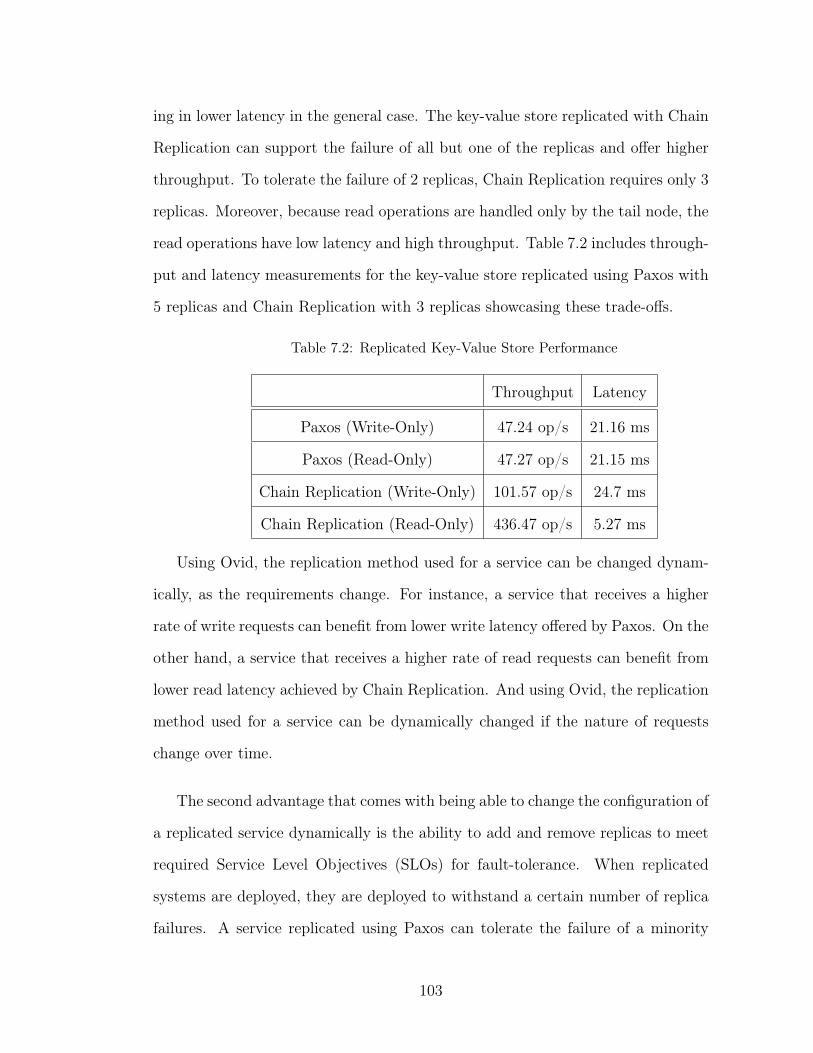
ing in lower latency in the general case. The key-value store replicated with Chain
Replication can support the failure of all but one of the replicas and offer higher
throughput. To tolerate the failure of 2 replicas, Chain Replication requires only 3
replicas. Moreover, because read operations are handled only by the tail node, the
read operations have low latency and high throughput. Table 7.2 includes through-
put and latency measurements for the key-value store replicated using Paxos with
5 replicas and Chain Replication with 3 replicas showcasing these trade-offs.
Table 7.2: Replicated Key-Value Store Performance
Throughput Latency
Paxos (Write-Only) 47.24 op/s 21.16 ms
Paxos (Read-Only) 47.27 op/s 21.15 ms
Chain Replication (Write-Only) 101.57 op/s 24.7 ms
Chain Replication (Read-Only) 436.47 op/s 5.27 ms
Using Ovid, the replication method used for a service can be changed dynam-
ically, as the requirements change. For instance, a service that receives a higher
rate of write requests can benefit from lower write latency offered by Paxos. On the
other hand, a service that receives a higher rate of read requests can benefit from
lower read latency achieved by Chain Replication. And using Ovid, the replication
method used for a service can be dynamically changed if the nature of requests
change over time.
The second advantage that comes with being able to change the configuration of
a replicated service dynamically is the ability to add and remove replicas to meet
required Service Level Objectives (SLOs) for fault-tolerance. When replicated
systems are deployed, they are deployed to withstand a certain number of replica
failures. A service replicated using Paxos can tolerate the failure of a minority
103
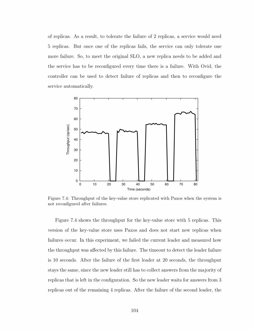
of replicas. As a result, to tolerate the failure of 2 replicas, a service would need
5 replicas. But once one of the replicas fails, the service can only tolerate one
more failure. So, to meet the original SLO, a new replica needs to be added and
the service has to be reconfigured every time there is a failure. With Ovid, the
controller can be used to detect failure of replicas and then to reconfigure the
service automatically.
0
10
20
30
40
50
60
70
80
0 10 20 30 40 50 60 70 80
Thro
ughput (o
p/s
ec)
Time (seconds)
Figure 7.4: Throughput of the key-value store replicated with Paxos when the system isnot reconfigured after failures.
Figure 7.4 shows the throughput for the key-value store with 5 replicas. This
version of the key-value store uses Paxos and does not start new replicas when
failures occur. In this experiment, we failed the current leader and measured how
the throughput was affected by this failure. The timeout to detect the leader failure
is 10 seconds. After the failure of the first leader at 20 seconds, the throughput
stays the same, since the new leader still has to collect answers from the majority of
replicas that is left in the configuration. So the new leader waits for answers from 3
replicas out of the remaining 4 replicas. After the failure of the second leader, the
104
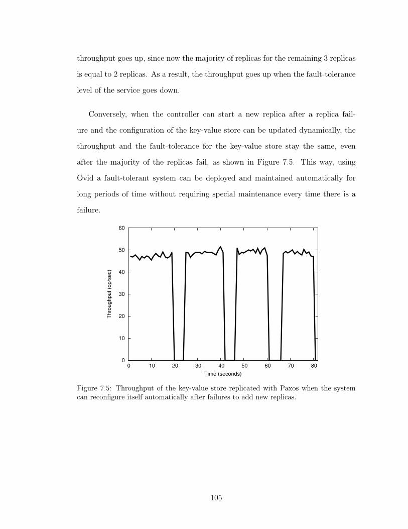
throughput goes up, since now the majority of replicas for the remaining 3 replicas
is equal to 2 replicas. As a result, the throughput goes up when the fault-tolerance
level of the service goes down.
Conversely, when the controller can start a new replica after a replica fail-
ure and the configuration of the key-value store can be updated dynamically, the
throughput and the fault-tolerance for the key-value store stay the same, even
after the majority of the replicas fail, as shown in Figure 7.5. This way, using
Ovid a fault-tolerant system can be deployed and maintained automatically for
long periods of time without requiring special maintenance every time there is a
failure.
0
10
20
30
40
50
60
0 10 20 30 40 50 60 70 80
Thro
ughput (o
p/s
ec)
Time (seconds)
Figure 7.5: Throughput of the key-value store replicated with Paxos when the systemcan reconfigure itself automatically after failures to add new replicas.
105
7.4 Discussion
We evaluated Ovid to further understand and present the performance benefits that
can be achieved through having services that can dynamically adjust to the changes
in their environment. We used our prototype key-value store implementation to see
the advantages of being able to shard and replicate a key-value store dynamically.
We demonstrated that our prototype implementation can easily handle spikes
in number of client requests by adding new shards on demand, in effect meeting
performance SLOs easily. Additionally, using Ovid, we could implement a key-
value store whose replication method can be changed dynamically, being able to
take advantage of low-latency writes of Paxos or high-throughput reads of Chain
Replication depending on the nature of the requests. Lastly, we showed that the
key-value store was able to maintain a steady fault-tolerance level in the presence
of replica failures by adding new replicas automatically as other replicas fail. This
way, fault-tolerance SLOs could be met at all times.
In this chapter, we showed the advantages and benefits of building a system
using Ovid. A system that can be evolved automatically and can be matched to its
environment offers performance benefits on top of the benefits we had underlined
in previous chapters.
106
CHAPTER 8
CONCLUSION
8.1 Summary
This thesis introduces Ovid, a framework for building large-scale distributed sys-
tems that can easily evolve and adjust to the changes in their environment or in
their expected functionality. Most state-of-the-art distributed systems that un-
dergo evolution and growth become more complex and unmanageable over time,
making maintenance of such systems an increasingly difficult task. To help with
this, Ovid models distributed systems as a collection of agents and applies trans-
formations to agents that allow distributed systems to be evolved automatically
and to be developed from simple components.
Agents that make up a distributed system in the Ovid framework are self-
contained state machines that communicate with one another by exchanging mes-
sages. An agent transitions in response to messages it receives from other agents
and may produce output messages for other agents. As a result, Ovid can model
distributed systems as a collection of agents. To change the way agents work
together, transformations such as replication, sharding, encryption, and batching
can be applied. But once a system undergoes a transformation, it is important to
understand if the system still behaves in the way that is expected from it. To this
end, Ovid uses refinement mappings to prove that transformed systems implement
the original specification by creating a refinement mapping from the new agents
to the original agent to demonstrate correctness. Consequently, Ovid can auto-
matically replicate for fault-tolerance, shard for scalable capacity, batch for higher
throughput, and encrypt for better security.
107
In this thesis, we first present how distributed system guarantees, such as fault-
tolerance, can be offered as a stand-alone service that can work with other systems.
Then, we show in detail how Ovid models a distributed system, how it applies
transformations and how refinement mappings are used to prove correctness. Ad-
ditionally, to demonstrate the power of refinement, we present a full refinement
of a storage system replicated with the Chain Replication protocol to a central-
ized storage system. Through this refinement we introduce a new version of the
Chain Replication protocol that can reconfigure itself without requiring an exter-
nal master, support various consistency models at the same time, and has better
performance and scalability. This exhibits the power of refinement and shows how
it can be used to reason about a complex system in detail and improve it in a
principled way.
Moreover, we explain how Ovid uses a logically centralized controller to help
system programmers model, build, deploy, and evolve the distributed system they
want. The controller specifies the agents, their interactions, and their transforma-
tions. The controller can create a distributed system model with agents according
to high-level requirements given by the user, transform this agent-based model,
and deploy it. The result is a software-defined distributed system, which can be
created, deployed, and evolved on the fly.
We also present how we implemented Ovid and how this implementation es-
tablishes a novel way of building distributed systems that is built on making dis-
tributed components work together work in a principled way. The Ovid implemen-
tation includes an interactive and visual tool that helps distributed programmers
to model a distributed system. Using the interactive designer even novice users
can construct systems that are scalable and reliable. The run-time environment
108
then deploys and runs the agents that make up this distributed system in a data
center. The run-time environment evolves systems deployed in a data center and
manages all execution and communication fully automatically.
Lastly, we present the evaluation for a key-value store that can be easily sharded
and replicated using Ovid and show the benefits of building a system using the
Ovid framework. The performance evaluation underlines that systems that can
evolve and adjust to their environment offer various performance benefits as well
as making systems easier to model, build and maintain.
8.2 Future Work
In this thesis we present a novel way of building distributed systems that can evolve
and adjust to their environment. We created the Ovid framework to present the
benefits of building distributed systems in a principled way, relying on the theory to
understand the trade-offs we have to make as systems programmers when we build
systems. Ovid shows how we can build systems that we can deeply understand,
while also being able to easily build, run, and maintain them.
This thesis includes our work on Ovid thus far, but this is the underlying frame-
work and vision for a project that is still continuing. We currently have a prototype
implementation for Ovid in Python, which enabled us to prototype fast and un-
derstand the best ways to build our framework. Relying on our experiences with
this prototype, we are currently working on a more efficient C++ implementation.
Following our C++ implementation, we also want to develop tools to verify per-
formance and reliability objectives of a deployment and examining the trade-offs
associated with various deployment scenarios.
109
There is still much work to be done to reach our objective for creating princi-
pled ways for building systems that we can deeply understand, and easily build.
We would like to establish an automated way of creating refinement mappings and
fully incorporating validation to the creation of distributed system models. More-
over, we are still working on the complete algebra of combining and transforming
systems, that can be used to model all interactions in a distributed system. The
more we build components that are theoretically sound inherently and the better
we understand how these components work together, we can build larger-scale in-
frastructure systems without introducing more complexity. And this vision will
keep fueling the way we do systems research.
110
BIBLIOGRAPHY
[1] Hussam Abu-Libdeh, Robbert van Renesse, and Ymir Vigfusson. Leveragingsharding in the design of scalable replication protocols. In Proceedings of theSymposium on Cloud Computing, SoCC ’13, Farmington, PA, USA, October2013.
[2] Atul Adya, John Dunagan, and Alec Wolman. Centrifuge: Integrated leasemanagement and partitioning for cloud services. In Proceedings of the 7thUSENIX Conference on Networked Systems Design and Implementation,NSDI’10, pages 1–1, Berkeley, CA, USA, 2010. USENIX Association.
[3] Jacob I. Aizikowitz. Designing Distributed Services Using Refinement Map-pings. PhD thesis, Cornell University, Ithaca, NY, USA, August 1989. Alsoavailable as technical report TR 89-1040.
[4] Sameer Ajmani, Barbara Liskov, and Liuba Shrira. Modular software up-grades for distributed systems. In Proceedings of the 20th European Confer-ence on Object-Oriented Programming, ECOOP’06, pages 452–476, Berlin,Heidelberg, 2006. Springer-Verlag.
[5] Sérgio Almeida, Jo ao Leitão, and Luís Rodrigues. Chainreaction: A causal+consistent datastore based on chain replication. In Proceedings of the 8th ACMEuropean Conference on Computer Systems, EuroSys ’13, pages 85–98, NewYork, NY, USA, 2013. ACM.
[6] Deniz Altınbüken and Emin Gün Sirer. Commodifying replicated state ma-chines with openreplica. Technical report, Cornell University, Department ofComputer Science, 06 2012.
[7] Deniz Altınbüken and Robbert van Renesse. Ovid: A software-defined dis-tributed systems framework. In Proceedings of the 8th USENIX Conferenceon Hot Topics in Cloud Computing, HotCloud’16, pages 26–32, Berkeley, CA,USA, 2016. USENIX Association.
[8] Deniz Altınbüken and Robbert van Renesse. Ovid: A software-defined dis-tributed systems framework to support consistency and change. IEEE DataEngineering Bulletin, 39(1):65–80, March 2016.
[9] Amazon Web Services LLC. Amazon route 53, 2016.
111
[10] Mahesh Balakrishnan, Dahlia Malkhi, John D. Davis, Vijayan Prabhakaran,Michael Wei, and Ted Wobber. Corfu: A distributed shared log. ACM Trans-actions on Computer Systems, 31(4):10:1–10:24, December 2013.
[11] Christophe Bidan, Valérie Issarny, Titos Saridakis, and Apostolos Zarras. Adynamic reconfiguration service for corba. In 4th International Conferenceon Distributed Computing Systems, ICCDS’98, pages 35–42. IEEE ComputerSociety Press, 1998.
[12] Ken Birman, Dahlia Malkhi, and Robbert van Renesse. Virtually synchronousmethodology for dynamic service replication. Technical Report MSR-TR-2010-151, Microsoft Research, 2010.
[13] Toby Bloom. Dynamic module replacement in a distributed programmingsystem. Technical Report MIT-LCSTR-303, MIT, 1983.
[14] William J. Bolosky, Dexter Bradshaw, Randolph B. Haagens, Norbert P.Kusters, and Peng Li. Paxos replicated state machines as the basis of ahigh-performance data store. In Proceedings of the 8th USENIX Conferenceon Networked Systems Design and Implementation, NSDI’11, pages 11–11,Berkeley, CA, USA, 2011. USENIX Association.
[15] Mike Burrows. The chubby lock service for loosely-coupled distributed sys-tems. In Proceedings of the 7th USENIX Conference on Operating SystemsDesign and Implementation, OSDI’06, pages 335–350, Berkeley, CA, USA,2006. USENIX Association.
[16] Sergey Bykov, Alan Geller, Gabriel Kliot, James Larus, Ravi Pandya, andJorgen Thelin. Orleans: Cloud computing for everyone. In Proceedings ofthe 2Nd ACM Symposium on Cloud Computing, SOCC ’11, pages 16:1–16:14,New York, NY, USA, 2011. ACM.
[17] Martin Casado, Michael J. Freedman, Justin Pettit, Jianying Luo, Nick McK-eown, and Scott Shenker. Ethane: Taking control of the enterprise. In Pro-ceedings of the 2007 Conference on Applications, Technologies, Architectures,and Protocols for Computer Communications, SIGCOMM ’07, pages 1–12,New York, NY, USA, 2007. ACM.
[18] R. L. Constable, S. F. Allen, H. M. Bromley, W. R. Cleaveland, J. F. Cremer,R. W. Harper, D. J. Howe, T. B. Knoblock, N. P. Mendler, P. Panangaden,J. T. Sasaki, and S. F. Smith. Implementing Mathematics with the Nuprl ProofDevelopment System. Prentice-Hall, Inc., Upper Saddle River, NJ, USA, 1986.
112
[19] Sanjay Ghemawat, Howard Gobioff, and Shun-Tak Leung. The google filesystem. In Proceedings of the 19th ACM Symposium on Operating SystemsPrinciples, SOSP’03, pages 29–43, New York, NY, USA, 2003. ACM.
[20] C. Gray and D. Cheriton. Leases: An efficient fault-tolerant mechanism fordistributed file cache consistency. In Proceedings of the 12th ACM Symposiumon Operating Systems Principles, SOSP’89, pages 202–210, New York, NY,USA, 1989. ACM.
[21] Pradeep Kumar Gunda, Lenin Ravindranath, Chandramohan A. Thekkath,Yuan Yu, and Li Zhuang. Nectar: automatic management of data and com-putation in datacenters. In Proceedings of the 9th USENIX Conference onOperating Systems Design and Implementation, OSDI’10, pages 1–8, Berke-ley, CA, USA, 2010. USENIX Association.
[22] Chris Hawblitzel, Jon Howell, Manos Kapritsos, Jacob R. Lorch, Bryan Parno,Michael L. Roberts, Srinath Setty, and Brian Zill. Ironfleet: Proving practicaldistributed systems correct. In Proceedings of the 25th ACM Symposium onOperating Systems Principles, SOSP ’15. ACM, October 2015.
[23] Mark Garland Hayden. The Ensemble System. PhD thesis, Cornell University,Ithaca, NY, USA, 1998. AAI9818467.
[24] Chi Ho, Robbert van Renesse, Mark Bickford, and Danny Dolev. Nysiad:Practical protocol transformation to tolerate Byzantine failures. In Proceed-ings of the 5th USENIX Symposium on Networked Systems Design and Im-plementation, NSDI ’08, pages 175–188, Berkeley, CA, USA, 2008. USENIXAssociation.
[25] Christine R. Hofmeister and James M. Purtilo. A framework for dynamic re-configuration of distributed programs. In Proceedings of the 11th InternationalConference on Distributed Computing Systems, ICDCS 1991, pages 560–571,1991.
[26] Patrick Hunt, Mahadev Konar, Flavio P. Junqueira, and Benjamin Reed.Zookeeper: Wait-free coordination for internet-scale systems. In Proceedingsof the 2010 USENIX Annual Technical Conference, USENIX ATC’10, pages30–45, Berkeley, CA, USA, 2010. USENIX Association.
[27] Michael Isard. Autopilot: Automatic data center management. SIGOPSOperating Systems Review, 41(2):60–67, 2007.
113
[28] Charles Edwin Killian, James W. Anderson, Ryan Braud, Ranjit Jhala, andAmin M. Vahdat. Mace: Language support for building distributed systems.In Proceedings of the 28th ACM SIGPLAN Conference on Programming Lan-guage Design and Implementation, PLDI ’07, pages 179–188, New York, NY,USA, 2007. ACM.
[29] Jeff Kramer and Jeff Magee. The evolving philosophers problem: Dy-namic change management. IEEE Transactions on Software Engineering,16(11):1293–1306, November 1990.
[30] Leslie Lamport. Time, clocks, and the ordering of events in a distributedsystem. Communications of ACM, 21:558–565, July 1978.
[31] Leslie Lamport. Specifying concurrent program modules. Transactions onProgramming Languages and Systems, 5(2):190–222, April 1983.
[32] Leslie Lamport. The part-time parliament. ACM Transactions on ComputerSystems, 16:133–169, 1998.
[33] Leslie Lamport and Mike Massa. Cheap paxos. In Proceedings of the 2004 In-ternational Conference on Dependable Systems and Networks, DSN’04, pages307–315, Washington, DC, USA, 2004. IEEE Computer Society.
[34] K. Rustan M. Leino. Dafny: An automatic program verifier for functionalcorrectness. In Proceedings of the 16th International Conference on Logic forProgramming, Artificial Intelligence, and Reasoning, LPAR’10, pages 348–370, Berlin, Heidelberg, Germany, 2010. Springer-Verlag.
[35] Xiaoming Liu, Christoph Kreitz, Robbert van Renesse, Jason Hickey, MarkHayden, Ken Birman, and Robert Constable. Building reliable, high-performance communication systems from components. In 17th ACM Sym-posium on Operating System Principles, Kiawah Island Resort, SC, USA, De-cember 1999.
[36] Xiaoming Liu and Robbert van Renesse. Fast protocol transition in a dis-tributed environment. In 19th ACM Conference on Principles of DistributedComputing (PODC 2000), Portland, OR, USA, July 2000.
[37] Xiaoming Liu, Robbert van Renesse, Mark Bickford, Christoph Kreitz, andRobert Constable. Protocol switching: Exploiting meta properties. In Inter-national Workshop on Applied Reliable Group Communication at the Interna-tional Conference on Distributed Computing Systems, ICDCS 2011, Phoenix,AZ, USA, April 2001.
114
[38] Jacob R. Lorch, Atul Adya, William J. Bolosky, Ronnie Chaiken, John R.Douceur, and Jon Howell. The smart way to migrate replicated stateful ser-vices. In Proceedings of the 1st ACM SIGOPS/EuroSys European Conferenceon Computer Systems 2006, EuroSys’06, pages 103–115, New York, NY, USA,2006. ACM.
[39] Nancy A. Lynch and Frits W. Vaandrager. Forward and backward simulations:Ii. timing-based systems. Information and Computation, 128(1):1–25, 1996.
[40] John MacCormick, Nick Murphy, Marc Najork, Chandramohan A. Thekkath,and Lidong Zhou. Boxwood: Abstractions as the foundation for storage infras-tructure. In Proceedings of the 6th USENIX Conference on Operating SystemsDesign and Implementation, OSDI’04, pages 22–31, Berkeley, CA, USA, 2004.USENIX Association.
[41] Yanhua Mao, Flavio P. Junqueira, and Keith Marzullo. Mencius: Buildingefficient replicated state machines for wans. In Proceedings of the 8th USENIXConference on Operating Systems Design and Implementation, OSDI’08,pages 369–384, Berkeley, CA, USA, 2008. USENIX Association.
[42] Nick McKeown, Tom Anderson, Hari Balakrishnan, Guru Parulkar, Larry Pe-terson, Jennifer Rexford, Scott Shenker, and Jonathan Turner. Openflow:Enabling innovation in campus networks. ACM SIGCOMM Computer Com-munication Review, 38(2):69–74, March 2008.
[43] William Miller. Death of a genius. Life Magazine, pages 61–64, May 1955.
[44] Daniel Nurmi, Rich Wolski, Chris Grzegorczyk, Graziano Obertelli, Sunil So-man, Lamia Youseff, and Dmitrii Zagorodnov. The eucalyptus open-sourcecloud-computing system. In Proceedings of the 2009 9th IEEE/ACM Interna-tional Symposium on Cluster Computing and the Grid, CCGRID ’09, pages124–131, Washington, DC, USA, 2009. IEEE Computer Society.
[45] Vincent Rahli, David Guaspari, Mark Bickford, and Robert L. Constable. For-mal specification, verification, and implementation of fault-tolerant systemsusing eventml. ECEASST, 72, 2015.
[46] Sean Rhea, Brighten Godfrey, Brad Karp, John Kubiatowicz, Sylvia Rat-nasamy, Scott Shenker, Ion Stoica, and Harlan Yu. Opendht: A public dhtservice and its uses. SIGCOMM Computer Communication Review, 35:73–84,August 2005.
115
[47] Nicolas Schiper, Vincent Rahli, Robbert van Renesse, Marck Bickford, andRobert L. Constable. Developing correctly replicated databases using for-mal tools. In Proceedings of the 2014 44th Annual IEEE/IFIP InternationalConference on Dependable Systems and Networks, DSN ’14, pages 395–406,Washington, DC, USA, 2014. IEEE Computer Society.
[48] Fred B. Schneider. Implementing fault-tolerant services using the state ma-chine approach: A tutorial. ACM Computing Surveys, 22:299–319, December1990.
[49] Alexander Shraer, Benjamin Reed, Dahlia Malkhi, and Flavio Junqueira. Dy-namic reconfiguration of primary/backup clusters. In Proceedings of the 2012USENIX Annual Technical Conference, USENIX ATC’12, pages 39–39, Berke-ley, CA, USA, 2012. USENIX Association.
[50] Jeff Terrace and Michael J. Freedman. Object storage on CRAQ: High-throughput chain replication for read-mostly workloads. In Proceedings ofthe 2009 Conference on USENIX Annual Technical Conference, USENIX’09,pages 11–11, Berkeley, CA, USA, 2009. USENIX Association.
[51] Robbert van Renesse and Deniz Altınbüken. Paxos made moderately complex.ACM Computing Surveys, 47(3):42:1–42:36, February 2015.
[52] Robbert van Renesse, Kenneth P. Birman, Mark Hayden, Alexey Vaysburd,and David Karr. Building adaptive systems using ensemble. Software Practiceand Experience, 28(9):963–979, August 1998.
[53] Robbert van Renesse, Kenneth P. Birman, and Silvano Maffeis. Horus: Aflexible group communication system. Communications of the ACM, 39(4):76–83, April 1996.
[54] Werner Vogels. Eventually consistent. Communications of the ACM, 52(1):40–44, January 2009.
[55] James R. Wilcox, Doug Woos, Pavel Panchekha, Zachary Tatlock, Xi Wang,Michael D. Ernst, and Thomas Anderson. Verdi: A framework for imple-menting and formally verifying distributed system. In Proceedings of the 36thannual ACM SIGPLAN conference on Programming Language Design andImplementation, PLDI 2015, Portland, OR, USA, June 2015.
[56] J.C.P. Woodcock and Carroll Morgan. Refinement of state-based concurrentsystems. In VDM ’90 VDM and Z – Formal Methods in Software Development,
116
volume 428 of Lecture Notes in Computer Science, pages 340–351. SpringerBerlin Heidelberg, 1990.
[57] Maysam Yabandeh, Nikola Knezevic, Dejan Kostic, and Viktor Kuncak. Crys-talball: Predicting and preventing inconsistencies in deployed distributed sys-tems. In Proceedings of the 6th USENIX Symposium on Networked SystemsDesign and Implementation, NSDI’09, pages 229–244, Berkeley, CA, USA,2009. USENIX Association.
[58] Irene Zhang, Adriana Szekeres, Dana Van Aken, Isaac Ackerman, Steven D.Gribble, Arvind Krishnamurthy, and Henry M. Levy. Customizable and exten-sible deployment for mobile/cloud applications. In 11th USENIX Symposiumon Operating Systems Design and Implementation, OSDI’14, pages 97–112,Broomfield, CO, USA, October 2014. USENIX Association.
117
Related Documents