Building Bare-Metal ARM Systems with GNU Miro Samek Quantum Leaps, LLC Article Published online at www.Embedded.com July/August 2007 Copyright © Quantum Leaps, LLC www.quantum-leaps.com www.state-machine.com

Building Bare-metal ARM With GNU
Oct 24, 2014
Welcome message from author
This document is posted to help you gain knowledge. Please leave a comment to let me know what you think about it! Share it to your friends and learn new things together.
Transcript

Building Bare-Metal ARM Systems with GNU
Miro Samek
Quantum Leaps, LLC
Article Published online at www.Embedded.com July/August 2007 Copyright © Quantum Leaps, LLC www.quantum-leaps.com www.state-machine.com
Part 1 What’s Needed in a Bare-Metal ARM Project?.............................................................................1-1 1.1 What’s Needed in a Real-Life Bare-Metal ARM Project?.................................................................1-1 1.2 Support for ARM Vectors Remapping ..............................................................................................1-1 1.3 Low-level Initialization in C/C++ .......................................................................................................1-2 1.4 Executing Code from RAM ...............................................................................................................1-2 1.5 Mixing ARM and THUMB Instruction Sets........................................................................................1-2 1.6 Separate Stack Section ....................................................................................................................1-2 1.7 Debug and Release Configurations..................................................................................................1-2 1.8 Support for C++ ................................................................................................................................1-2 1.9 Minimizing the Impact of C++ ...........................................................................................................1-3 1.10 ARM Exceptions and Interrupt Handling ..........................................................................................1-3 1.11 References .......................................................................................................................................1-3
Part 2 Startup Code and the Low-level Initialization..............................................................................2-1 2.1 The Startup Code .............................................................................................................................2-1 2.2 Low-Level Initialization......................................................................................................................2-5 2.3 References .......................................................................................................................................2-8
Part 3 The Linker Script ............................................................................................................................3-1 3.1 Linker Script ......................................................................................................................................3-1 3.2 References .......................................................................................................................................3-5
Part 4 C/C++ Compiler Options and Minimizing the Overhead of C++.................................................4-1 4.1 Compiler Options for C .....................................................................................................................4-1 4.2 Compiler Options for C++.................................................................................................................4-2 4.3 Reducing the Overhead of C++........................................................................................................4-2 4.4 References .......................................................................................................................................4-3
Part 5 Fine-tuning the Application ...........................................................................................................5-1 5.1 ARM/THUMB compilation.................................................................................................................5-1 5.2 Placing the Code in RAM..................................................................................................................5-1 5.3 References .......................................................................................................................................5-1
Part 6 General Description of Interrupt Handling...................................................................................6-1 6.1 Problem Description .........................................................................................................................6-1 6.2 Interrupt Handling Strategy...............................................................................................................6-1 6.3 FIQ Handling.....................................................................................................................................6-3 6.4 No Auto-Vectoring ............................................................................................................................6-4 6.5 References .......................................................................................................................................6-4
Part 7 Interrupt Locking and Unlocking ..................................................................................................7-1 7.1 Problem Description .........................................................................................................................7-1 7.2 The Policy of Saving and Restoring Interrupt Status........................................................................7-1 7.3 Critical Section Implementation with GNU gcc.................................................................................7-2 7.4 Discussion of the Critical Section Implementation ...........................................................................7-3 7.5 References .......................................................................................................................................7-4
Part 8 Low-level Interrupt Wrapper Functions........................................................................................8-1 8.1 The IRQ Interrupt Wrapper ARM_irq................................................................................................8-1 8.2 The FIQ Interrupt Wrapper ARM_fiq ................................................................................................8-4 8.3 References .......................................................................................................................................8-5
Part 9 C-Level ISRs and Other ARM Exceptions ....................................................................................9-1 9.1 The BSP_irq Handler Function.........................................................................................................9-1 9.2 The BSP_fiq Handler Function .........................................................................................................9-2 9.3 Interrupt Service Routines ................................................................................................................9-3 9.4 Initialization of the Vector Table and the Interrupt Controller ...........................................................9-4 9.5 Other ARM Exception Handlers .......................................................................................................9-5 9.6 References .......................................................................................................................................9-6
Copyright © Quantum Leaps. All Rights Reserved. i
Part 10 Example Application and Testing Strategies.............................................................................10-1 10.1 The Blinky Example Application .....................................................................................................10-1 10.2 Manual Testing of Interrupt Preemptions Scenario ........................................................................10-4 10.3 Summary.........................................................................................................................................10-5 10.4 References .....................................................................................................................................10-5
Part 11 Contact Information......................................................................................................................11-1
Copyright © Quantum Leaps. All Rights Reserved. ii
Building Bare Metal ARM Systems with GNU
Part 1 What’s Needed in a Bare-Metal ARM Project?
The ubiquitous ARM processor family is very well supported by the GNU C/C++ toolchain. While many online and printed resources [1-1, 1-2] focus on building and installing the GNU toolchain, it is quite hard to find a comprehensive example of using the GNU C/C++ toolchain for a bare-metal ARM system that would have all the essential features needed in a real-life project. And even if you do find such an example, you most likely won’t know WHY things are done the particular way.
In this multi-part article I provide and explain all the elements you’ll need to build and fine-tune a bare-metal ARM-based project with the GNU toolchain. I start with enumerating the features needed in real-life ARM projects. I then describe a generic startup code, the matching linker script, low-level initialization, the compiler options and a basic board support package (BSP). I subsequently show how to initialize the system for C++ and how to reduce the overhead of C++ so that it’s usable for low-end ARM-based MCUs. Next, I cover interrupt handling for ARM projects in the simple foreground/background software architecture. I describe interrupt locking policy, interrupt handling in the presence of a prioritized interrupt controller, IRQ and FIQ assembly “wrapper” functions as well as other ARM exception handlers. I conclude with the description of testing strategy for various interrupt preemption scenarios.
To focus the discussion, this article is based on the latest CodeSourcery G++ GNU toolchain for ARM [1-3] and the Atmel AT91SAM7S-EK evaluation board with the AT91SAM7S64 microcontroller (64KB of on-chip flash ROM and 16KB of static RAM). The discussion should be generally applicable to other GNU-toolchain distributions [1-4, 1-5] for ARM and other ARM7- or ARM9- based microcontrollers. I present separate projects in C and C++ to illuminate the C++-specific issues.
1.1 What’s Needed in a Real-Life Bare-Metal ARM Project? The tremendously popular ARM7/ARM9 core is quite a complicated processor in that it supports two operating states: ARM state, which executes 32-bit, word-aligned ARM instructions, and Thumb state, which operates with 16-bit, halfword-aligned Thumb instructions. Additionally, the CPU has several operating modes, such as USER, SYSTEM, SUPERVISOR, ABORT, UNDEFINED, IRQ, and FIQ. Each of these operating modes differs in visibility of registers (register banking) and sometimes privileges to execute instructions. On top of this, virtually every ARM-based MCU provides ARM vector remapping and a vendor-specific interrupt controller that allows nesting of the IRQ interrupts.
Unfortunately, a real-life ARM-based project needs to use many of the features of the ARM core and the critical peripherals. The following subsections describe what’s typically required in a bare-metal ARM-based project.
1.2 Support for ARM Vectors Remapping The first 32 bytes of memory at address 0x0 contain the ARM processor exception vectors, in par-ticular, the Reset Vector at address 0x0. At boot time, the Reset Vector must be mapped to ROM. However, most ARM microcontrollers provide an option to remap the memories to put RAM at the ARM vector addresses, so that the vectors can be dynamically changed under software control.
The memory remapping option is implemented differently in various ARM microcontrollers and it is typically a source of endless confusion during flash-loading and debugging the application. None-theless, a real-life project typically needs to use the ARM vector remapping. This article addresses the issue and presents a fairly general solution.
Copyright © Quantum Leaps. All Rights Reserved. 1-1
Building Bare-Metal ARM Systems with GNU
www.state-machine.com/arm
1.3 Low-level Initialization in C/C++ The ARM vector remapping is just one action that must be performed early in the boot sequence. The other actions might include CPU clock initialization (to speed up the rest of the boot process), external bus interface configuration, critical hardware initialization, and so on. Most of these actions don’t require assembly programming and are in fact much easier to accomplish from C/C++, yet they need to happen before main() is called. The startup sequence discussed in this article allows performing the low-level initialization either from C/C++ or from assembly.
1.4 Executing Code from RAM The majority of low-end ARM-based microcontrollers are designed to run the code directly from ROM (typically NOR flash). However, the ROM often requires more wait-states than the RAM and for some ARM devices the ROM is accessible only through the narrow 16-bit wide bus interface. Also, executing code from flash requires more power than executing the same code from SRAM.
For better performance and lower power dissipation it may be often advantageous to execute the hot-spot portions of the code from RAM. This article provides support for executing code from RAM, which includes copying the RAM-based code from ROM to RAM at boot time, long jumps between ROM- and RAM-based code, as well as the linker script that allows very fine-granularity control over the functions placed in RAM.
1.5 Mixing ARM and THUMB Instruction Sets In most low-end ARM microcontrollers the 16-bit THUMB instruction set offers both better code density and actually better performance when executed from ROM, even though the 16-bit THUMB instruction set is less powerful than the 32-bit ARM instruction set. This article shows how to use any combination of ARM and THUMB instruction sets for optimal performance.
1.6 Separate Stack Section Most standard GNU linker scripts simply supply a symbol at the top of RAM to initialize the stack pointer. The stack typically grows towards the heap and it’s hard to determine when the stack overflow occurs. This article uses the specific stack section, which is pre-filled at boot-time with a specified bit pattern to allow better monitoring of the stack usage. The benefit of this approach is the ability to detect when you run out of RAM for the stack at link time, rather than crash-and-burn at runtime. Moreover, the separate stack section allows you to easily locate the stack in the fastest RAM available.
1.7 Debug and Release Configurations The Makefile described in this article supports building the separate debug and release configurations, each with different compiler and linker options.
1.8 Support for C++ C++ requires extra initialization step to invoke the static constructors. GNU C++ generates some extra sections for placing the tables of static constructors and destructors. The linker script needs to locate the extra sections, and the startup code must arrange for calling the static constructors. This article provides a universal startup code and linker script that works for C++ as well as C applications.
Copyright © Quantum Leaps. All Rights Reserved. 1-2
Building Bare-Metal ARM Systems with GNU
www.state-machine.com/arm
1.9 Minimizing the Impact of C++ If you are not careful and use the standard GNU g++ settings, the code size overhead of C++ can easily take up 50KB of code or more, which renders C++ unusable for most low-level ARM MCUs. However, by restricting C++ to the Embedded C++ subset, the impact of C++ can be negligible. This article shows how to reduce the C++ overhead with the GNU toolchain below 300 bytes of additional code compared to pure C implementation.
1.10 ARM Exceptions and Interrupt Handling The ARM core supports several exceptions (Undefined Instruction, Prefetch Abort, Data Abort, Software Interrupt) as well as two types of interrupts: Interrupt Request (IRQ) and Fast Interrupt Request (FIQ). Upon encountering an interrupt or an exception the ARM core does not automatically push any registers to the stack. If the application wants to nest interrupts (to take advantage of the prioritized interrupt controller available in most ARM-based MCSs), the responsibility is entirely with the application programmer to save and restore the ARM registers. The GNU compiler’s __attribute__ ((interrupt ("IRQ"))) cannot handle nested interrupts, so assembly programming is required. All this makes the handling of interrupts and exceptions quite complicated.
This article covers robust handling of nested interrupts in the presence of a prioritized interrupt controller. The approach that will be described paves the way to much better code compatibility between the traditional ARMv4T and the new ARMv7-M (Cortex) devices than the conventional ARM interrupt handling.
Coming Up Next: In the next part I’ll describe the generic startup code for the GNU toolchain as well as the low-level initialization for a bare-metal ARM system. Stay tuned.
1.11 References [1-1] Lewin A.R.W. Edwards, “Embedded System Design on a Shoestring”, Elsevier 2003.
[1-2] ARM Projects, http://www.siwawi.arubi.uni-kl.de/avr_projects/arm_projects
[1-3] GNU Toolchain for ARM, CodeSourcery, http://www.codesourcery.com/gnu_toolchains/arm
[1-4] GNU ARM toolchain, http://www.gnuarm.com
[1-5] GNU X-Tools™, Microcross, http://www.microcross.com
[1-6] Sloss, Andrew, Dominic Symes, and Chris Wright, “ARM System Developer's Guide: Designing and Optimizing System Software”, Morgan Kaufmann, 2004
Copyright © Quantum Leaps. All Rights Reserved. 1-3
Building Bare Metal ARM Systems with GNU
Copyright © Quantum Leaps. All Rights Reserved. 2-1
Part 2 Startup Code and the Low-level Initialization
In this part I start digging into the code that is available online at <provide embedded.com link to code>. The code contains C and C++ versions of the example application called “Blinky”, because it blinks the 4 user LEDs of the Atmel AT91SAM7S-EK evaluation board. The C version is located in the subdirectory c_blinky, and the equivalent C++ version is located in the subdirectory cpp_blinky. The Blinky application is primitive, but is carefully designed to use all the features covered in this multi-part article. The projects are based on the latest CodeSourcery G++ GNU toolchain for ARM [2-1].
In this part, I describe the generic startup code for the GNU toolchain as well as the low-level initialization for a bare-metal ARM system. The recommended reading for this part includes the “IAR Compiler Reference Guide” [2-2], specifically sections “System startup and termination” as well as “Customizing system initialization”.
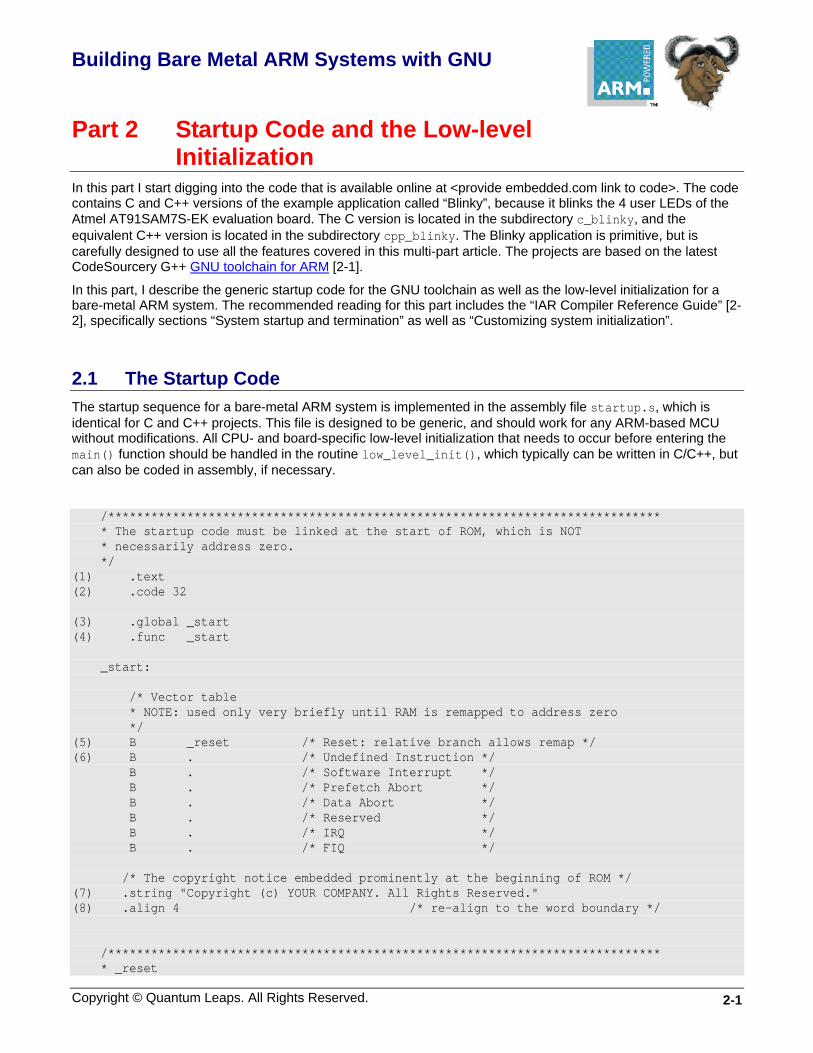
2.1 The Startup Code The startup sequence for a bare-metal ARM system is implemented in the assembly file startup.s, which is identical for C and C++ projects. This file is designed to be generic, and should work for any ARM-based MCU without modifications. All CPU- and board-specific low-level initialization that needs to occur before entering the main() function should be handled in the routine low_level_init(), which typically can be written in C/C++, but can also be coded in assembly, if necessary.
/***************************************************************************** * The startup code must be linked at the start of ROM, which is NOT * necessarily address zero. */ (1) .text (2) .code 32 (3) .global _start (4) .func _start _start: /* Vector table * NOTE: used only very briefly until RAM is remapped to address zero */ (5) B _reset /* Reset: relative branch allows remap */ (6) B . /* Undefined Instruction */ B . /* Software Interrupt */ B . /* Prefetch Abort */ B . /* Data Abort */ B . /* Reserved */ B . /* IRQ */ B . /* FIQ */ /* The copyright notice embedded prominently at the beginning of ROM */ (7) .string "Copyright (c) YOUR COMPANY. All Rights Reserved." (8) .align 4 /* re-align to the word boundary */ /***************************************************************************** * _reset
Building Bare-Metal ARM Systems with GNU
www.state-machine.com/arm
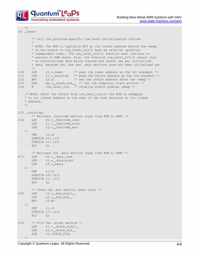
*/ (9) _reset: /* Call the platform-specific low-level initialization routine * * NOTE: The ROM is typically NOT at its linked address before the remap, * so the branch to low_level_init() must be relative (position * independent code). The low_level_init() function must continue to * execute in ARM state. Also, the function low_level_init() cannot rely * on uninitialized data being cleared and cannot use any initialized * data, because the .bss and .data sections have not been initialized yet. */ (10) LDR r0,=_reset /* pass the reset address as the 1st argument */ (11) LDR r1,=_cstartup /* pass the return address as the 2nd argument */ (12) MOV lr,r1 /* set the return address after the remap */ (13) LDR sp,=__stack_end__ /* set the temporary stack pointer */ (14) B low_level_init /* relative branch enables remap */ /* NOTE: after the return from low_level_init() the ROM is remapped * to its linked address so the rest of the code executes at its linked * address. */ (15) _cstartup: /* Relocate .fastcode section (copy from ROM to RAM) */ (16) LDR r0,=__fastcode_load LDR r1,=__fastcode_start LDR r2,=__fastcode_end 1: CMP r1,r2 LDMLTIA r0!,{r3} STMLTIA r1!,{r3} BLT 1b /* Relocate the .data section (copy from ROM to RAM) */ (17) LDR r0,=__data_load LDR r1,=__data_start LDR r2,=_edata 1: CMP r1,r2 LDMLTIA r0!,{r3} STMLTIA r1!,{r3} BLT 1b /* Clear the .bss section (zero init) */ (18) LDR r1,=__bss_start__ LDR r2,=__bss_end__ MOV r3,#0 1: CMP r1,r2 STMLTIA r1!,{r3} BLT 1b (19) /* Fill the .stack section */ LDR r1,=__stack_start__ LDR r2,=__stack_end__ LDR r3,=STACK_FILL 1:
Copyright © Quantum Leaps. All Rights Reserved. 2-2

Building Bare-Metal ARM Systems with GNU
www.state-machine.com/arm
CMP r2,r2 STMLTIA r1!,{r3} BLT 1b (20) /* Initialize stack pointers for all ARM modes */ MSR CPSR_c,#(IRQ_MODE | I_BIT | F_BIT) LDR sp,=__irq_stack_top__ /* set the IRQ stack pointer */ MSR CPSR_c,#(FIQ_MODE | I_BIT | F_BIT) LDR sp,=__fiq_stack_top__ /* set the FIQ stack pointer */ MSR CPSR_c,#(SVC_MODE | I_BIT | F_BIT) LDR sp,=__svc_stack_top__ /* set the SVC stack pointer */ MSR CPSR_c,#(ABT_MODE | I_BIT | F_BIT) LDR sp,=__abt_stack_top__ /* set the ABT stack pointer */ MSR CPSR_c,#(UND_MODE | I_BIT | F_BIT) LDR sp,=__und_stack_top__ /* set the UND stack pointer */ (21) MSR CPSR_c,#(SYS_MODE | I_BIT | F_BIT) LDR sp,=__c_stack_top__ /* set the C stack pointer */ /* Invoke all static constructors */ (22) LDR r12,=__libc_init_array MOV lr,pc /* set the return address */ BX r12 /* the target code can be ARM or THUMB */ /* Enter the C/C++ code */ (23) LDR r12,=main MOV lr,pc /* set the return address */ BX r12 /* the target code can be ARM or THUMB */ (24) SWI 0xFFFFFF /* cause exception if main() ever returns */ .size _start, . - _start .endfunc .end
Listing 2-1 Startup code in GNU assembly (startup.s)
Listing 2-1 shows the complete startup code in assembly. The highlights of the startup sequence are as follows:
(1) The .text directive tells GNU assembler (as) to assemble the following statements onto the end of the text subsection.
(2) The .code 32 directive selects the 32-bit ARM instruction set (the value 16 selects THUMB). The ARM core starts execution in the ARM state.
(3) The .global directive makes the symbol _start visible to the GNU linker (ld).
(4) The .func directive emits debugging information for the function _start. (The function definition must end with the directive .endfunc).
(5) Upon reset, the ARM core fetches the instruction at address 0x0, which at boot time must be mapped to a non-volatile memory (ROM). However, later the ROM might be remapped to a different address range by means of a memory remap operation. Therefore the code in ROM is typically linked to the final ROM location and not to
Copyright © Quantum Leaps. All Rights Reserved. 2-3
Building Bare-Metal ARM Systems with GNU
www.state-machine.com/arm
the ROM location at boot time. This dynamic changing of the memory map has at least two consequences. First, the few initial instructions must be position-independent meaning that only PC-relative addressing can be used. Second, the initial vector table is used only very briefly and is replaced with a different vector table established in RAM.
(6) The initial vector table contains just endless loops (relative branches to self). This vector table is used only very briefly until it is replaced by the vector table in RAM. Should an exception occur during this transient, the board is most likely damaged and the CPU cannot recover by itself. A safety-critical device should have a secondary circuit (such as an external watchdog timer driven by a separate clock source) that would announce the condition to the user.
(7) It is always a good idea to embed a prominent copyright message close to the beginning of the ROM image. You should customize this message for your company.
(8) Alignment to the word boundary is necessary after a string embedded directly in the code.
(9) The reset vector branches to this label.
(10) The r0 and r1 registers are used as the arguments of the upcoming call to the low_level_init() function. The register r0 is loaded with the linked address of the reset handler, which might be useful to set up the RAM-based vector table inside the low_level_init() function.
(11) The r1 register is loaded with the linked address of the C-initialization code, which also is the return address from the low_level_init() function. Some MCUs (such as AT91x40 with the EBI) might need this address to perform a direct jump after the memory remap operation.
(12) The link register is loaded with the return address. Please note that the return address is the _cstartup label at its final linked location, and not the subsequent PC value (so loading the return address with LDR lr,pc would be incorrect.)
(13) The temporary stack pointer is initialized to the end of the stack section. The GNU toolset uses the full descending stack meaning that the stack grows towards the lower memory addresses.
NOTE: The stack pointer initialized in this step might be not valid in case the RAM is not available at the linked address before the remap operation. It is not an issue in the AT91SAM7S family, because the RAM is always available at the linked address (0x00200000). However, in other devices (such as AT91x40) the RAM is not available at its final location before the EBI remap. In this latter case you might need to writhe the low_level_init() function in assembly to make sure that the stack pointer is not used until the memory remap.
(14) The function low_level_init() is invoked with a relative branch instruction. Please note that the branch-with-link (BL) instruction is specifically NOT used because the function might be called not from its linked address. Instead the return address has been loaded explicitly in the previous instruction.
NOTE: The function low_level_init() can be coded in C/C++ with the following restrictions. The function must execute in the ARM state and it must not rely on the initialization of .data section or clearing of the .bss section. Also, if the memory remapping is performed at all, it must occur inside the low_level_init() function because the code is no longer position-independent after this function returns.
(15) The _cstartup label marks the beginning of C-initialization.
(16) The section .fastcode is used for the code executed from RAM. Here this section is copied from ROM to its linked address in RAM (see also the linker script).
(17) The section .data is used for initialized variables. Here this section is copied from its load address in ROM to its linked address in RAM (see also the linker script).
Copyright © Quantum Leaps. All Rights Reserved. 2-4
Building Bare-Metal ARM Systems with GNU
www.state-machine.com/arm
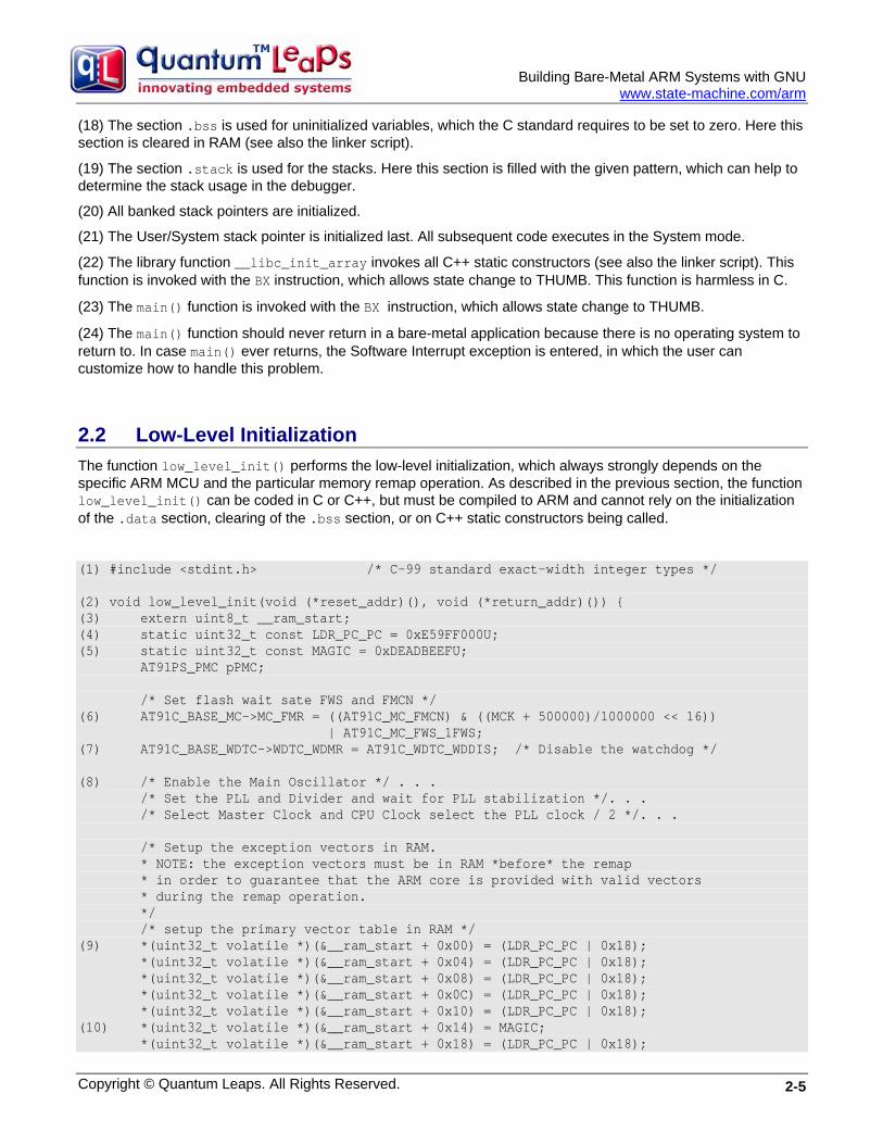
(18) The section .bss is used for uninitialized variables, which the C standard requires to be set to zero. Here this section is cleared in RAM (see also the linker script).
(19) The section .stack is used for the stacks. Here this section is filled with the given pattern, which can help to determine the stack usage in the debugger.
(20) All banked stack pointers are initialized.
(21) The User/System stack pointer is initialized last. All subsequent code executes in the System mode.
(22) The library function __libc_init_array invokes all C++ static constructors (see also the linker script). This function is invoked with the BX instruction, which allows state change to THUMB. This function is harmless in C.
(23) The main() function is invoked with the BX instruction, which allows state change to THUMB.
(24) The main() function should never return in a bare-metal application because there is no operating system to return to. In case main() ever returns, the Software Interrupt exception is entered, in which the user can customize how to handle this problem.
2.2 Low-Level Initialization The function low_level_init() performs the low-level initialization, which always strongly depends on the specific ARM MCU and the particular memory remap operation. As described in the previous section, the function low_level_init() can be coded in C or C++, but must be compiled to ARM and cannot rely on the initialization of the .data section, clearing of the .bss section, or on C++ static constructors being called.
(1) #include <stdint.h> /* C-99 standard exact-width integer types */ (2) void low_level_init(void (*reset_addr)(), void (*return_addr)()) { (3) extern uint8_t __ram_start; (4) static uint32_t const LDR_PC_PC = 0xE59FF000U; (5) static uint32_t const MAGIC = 0xDEADBEEFU; AT91PS_PMC pPMC; /* Set flash wait sate FWS and FMCN */ (6) AT91C_BASE_MC->MC_FMR = ((AT91C_MC_FMCN) & ((MCK + 500000)/1000000 << 16)) | AT91C_MC_FWS_1FWS; (7) AT91C_BASE_WDTC->WDTC_WDMR = AT91C_WDTC_WDDIS; /* Disable the watchdog */ (8) /* Enable the Main Oscillator */ . . . /* Set the PLL and Divider and wait for PLL stabilization */. . . /* Select Master Clock and CPU Clock select the PLL clock / 2 */. . . /* Setup the exception vectors in RAM. * NOTE: the exception vectors must be in RAM *before* the remap * in order to guarantee that the ARM core is provided with valid vectors * during the remap operation. */ /* setup the primary vector table in RAM */ (9) *(uint32_t volatile *)(&__ram_start + 0x00) = (LDR_PC_PC | 0x18); *(uint32_t volatile *)(&__ram_start + 0x04) = (LDR_PC_PC | 0x18); *(uint32_t volatile *)(&__ram_start + 0x08) = (LDR_PC_PC | 0x18); *(uint32_t volatile *)(&__ram_start + 0x0C) = (LDR_PC_PC | 0x18); *(uint32_t volatile *)(&__ram_start + 0x10) = (LDR_PC_PC | 0x18); (10) *(uint32_t volatile *)(&__ram_start + 0x14) = MAGIC; *(uint32_t volatile *)(&__ram_start + 0x18) = (LDR_PC_PC | 0x18);
Copyright © Quantum Leaps. All Rights Reserved. 2-5
Building Bare-Metal ARM Systems with GNU
www.state-machine.com/arm
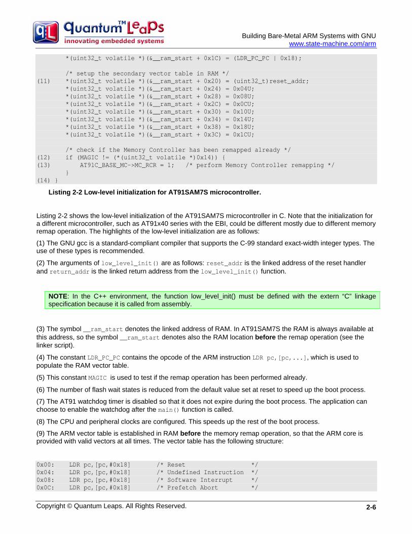
*(uint32_t volatile *)(&__ram_start + 0x1C) = (LDR_PC_PC | 0x18); /* setup the secondary vector table in RAM */ (11) *(uint32_t volatile *)(&__ram_start + 0x20) = (uint32_t)reset_addr; *(uint32_t volatile *)(&__ram_start + 0x24) = 0x04U; *(uint32_t volatile *)(&__ram_start + 0x28) = 0x08U; *(uint32_t volatile *)(&__ram_start + 0x2C) = 0x0CU; *(uint32_t volatile *)(&__ram_start + 0x30) = 0x10U; *(uint32_t volatile *)(&__ram_start + 0x34) = 0x14U; *(uint32_t volatile *)(&__ram_start + 0x38) = 0x18U; *(uint32_t volatile *)(&__ram_start + 0x3C) = 0x1CU; /* check if the Memory Controller has been remapped already */ (12) if (MAGIC != (*(uint32_t volatile *)0x14)) { (13) AT91C_BASE_MC->MC_RCR = 1; /* perform Memory Controller remapping */ } (14) }
Listing 2-2 Low-level initialization for AT91SAM7S microcontroller.
Listing 2-2 shows the low-level initialization of the AT91SAM7S microcontroller in C. Note that the initialization for a different microcontroller, such as AT91x40 series with the EBI, could be different mostly due to different memory remap operation. The highlights of the low-level initialization are as follows:
(1) The GNU gcc is a standard-compliant compiler that supports the C-99 standard exact-width integer types. The use of these types is recommended.
(2) The arguments of low_level_init() are as follows: reset_addr is the linked address of the reset handler and return_addr is the linked return address from the low_level_init() function.
NOTE: In the C++ environment, the function low_level_init() must be defined with the extern “C” linkage specification because it is called from assembly.
(3) The symbol __ram_start denotes the linked address of RAM. In AT91SAM7S the RAM is always available at this address, so the symbol __ram_start denotes also the RAM location before the remap operation (see the linker script).
(4) The constant LDR_PC_PC contains the opcode of the ARM instruction LDR pc,[pc,...], which is used to populate the RAM vector table.
(5) This constant MAGIC is used to test if the remap operation has been performed already.
(6) The number of flash wait states is reduced from the default value set at reset to speed up the boot process.
(7) The AT91 watchdog timer is disabled so that it does not expire during the boot process. The application can choose to enable the watchdog after the main() function is called.
(8) The CPU and peripheral clocks are configured. This speeds up the rest of the boot process.
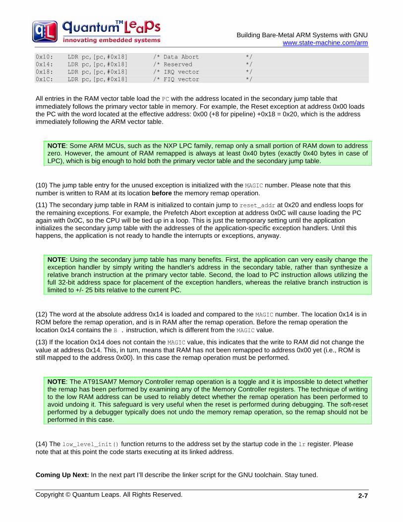
(9) The ARM vector table is established in RAM before the memory remap operation, so that the ARM core is provided with valid vectors at all times. The vector table has the following structure:
0x00: LDR pc,[pc,#0x18] /* Reset */ 0x04: LDR pc,[pc,#0x18] /* Undefined Instruction */ 0x08: LDR pc,[pc,#0x18] /* Software Interrupt */ 0x0C: LDR pc,[pc,#0x18] /* Prefetch Abort */
Copyright © Quantum Leaps. All Rights Reserved. 2-6
Building Bare-Metal ARM Systems with GNU
www.state-machine.com/arm
0x10: LDR pc,[pc,#0x18] /* Data Abort */ 0x14: LDR pc,[pc,#0x18] /* Reserved */ 0x18: LDR pc,[pc,#0x18] /* IRQ vector */ 0x1C: LDR pc,[pc,#0x18] /* FIQ vector */
All entries in the RAM vector table load the PC with the address located in the secondary jump table that immediately follows the primary vector table in memory. For example, the Reset exception at address 0x00 loads the PC with the word located at the effective address: 0x00 (+8 for pipeline) +0x18 = 0x20, which is the address immediately following the ARM vector table.
NOTE: Some ARM MCUs, such as the NXP LPC family, remap only a small portion of RAM down to address zero. However, the amount of RAM remapped is always at least 0x40 bytes (exactly 0x40 bytes in case of LPC), which is big enough to hold both the primary vector table and the secondary jump table.
(10) The jump table entry for the unused exception is initialized with the MAGIC number. Please note that this number is written to RAM at its location before the memory remap operation.
(11) The secondary jump table in RAM is initialized to contain jump to reset_addr at 0x20 and endless loops for the remaining exceptions. For example, the Prefetch Abort exception at address 0x0C will cause loading the PC again with 0x0C, so the CPU will be tied up in a loop. This is just the temporary setting until the application initializes the secondary jump table with the addresses of the application-specific exception handlers. Until this happens, the application is not ready to handle the interrupts or exceptions, anyway.
NOTE: Using the secondary jump table has many benefits. First, the application can very easily change the exception handler by simply writing the handler’s address in the secondary table, rather than synthesize a relative branch instruction at the primary vector table. Second, the load to PC instruction allows utilizing the full 32-bit address space for placement of the exception handlers, whereas the relative branch instruction is limited to +/- 25 bits relative to the current PC.
(12) The word at the absolute address 0x14 is loaded and compared to the MAGIC number. The location 0x14 is in ROM before the remap operation, and is in RAM after the remap operation. Before the remap operation the location 0x14 contains the B . instruction, which is different from the MAGIC value.
(13) If the location 0x14 does not contain the MAGIC value, this indicates that the write to RAM did not change the value at address 0x14. This, in turn, means that RAM has not been remapped to address 0x00 yet (i.e., ROM is still mapped to the address 0x00). In this case the remap operation must be performed.
NOTE: The AT91SAM7 Memory Controller remap operation is a toggle and it is impossible to detect whether the remap has been performed by examining any of the Memory Controller registers. The technique of writing to the low RAM address can be used to reliably detect whether the remap operation has been performed to avoid undoing it. This safeguard is very useful when the reset is performed during debugging. The soft-reset performed by a debugger typically does not undo the memory remap operation, so the remap should not be performed in this case.
(14) The low_level_init() function returns to the address set by the startup code in the lr register. Please note that at this point the code starts executing at its linked address.
Coming Up Next: In the next part I’ll describe the linker script for the GNU toolchain. Stay tuned.
Copyright © Quantum Leaps. All Rights Reserved. 2-7
Building Bare-Metal ARM Systems with GNU
www.state-machine.com/arm
2.3 References [2-1] GNU Assembler (as) HTML documentation included in the CodeSourcery Toolchain for ARM,
http://www.codesourcery.com/gnu_toolchains/arm.
[2-2] IAR Systems, “ARM® IAR C/C++ Compiler Reference Guide for Advanced RISC Machines Ltd’s ARM Cores”, Part number: CARM-13, Thirteenth edition: June 2006. Included in the free EWARM KickStart edition http://supp.iar.com/Download/SW/?item=EWARM-KS32
[2-3] Lewin A.R.W. Edwards, “Embedded System Design on a Shoestring”, Elsevier 2003.
[2-4] ARM Projects, http://www.siwawi.arubi.uni-kl.de/avr_projects/arm_projects
Copyright © Quantum Leaps. All Rights Reserved. 2-8
Building Bare Metal ARM Systems with GNU
Copyright © Quantum Leaps. All Rights Reserved. 3-1
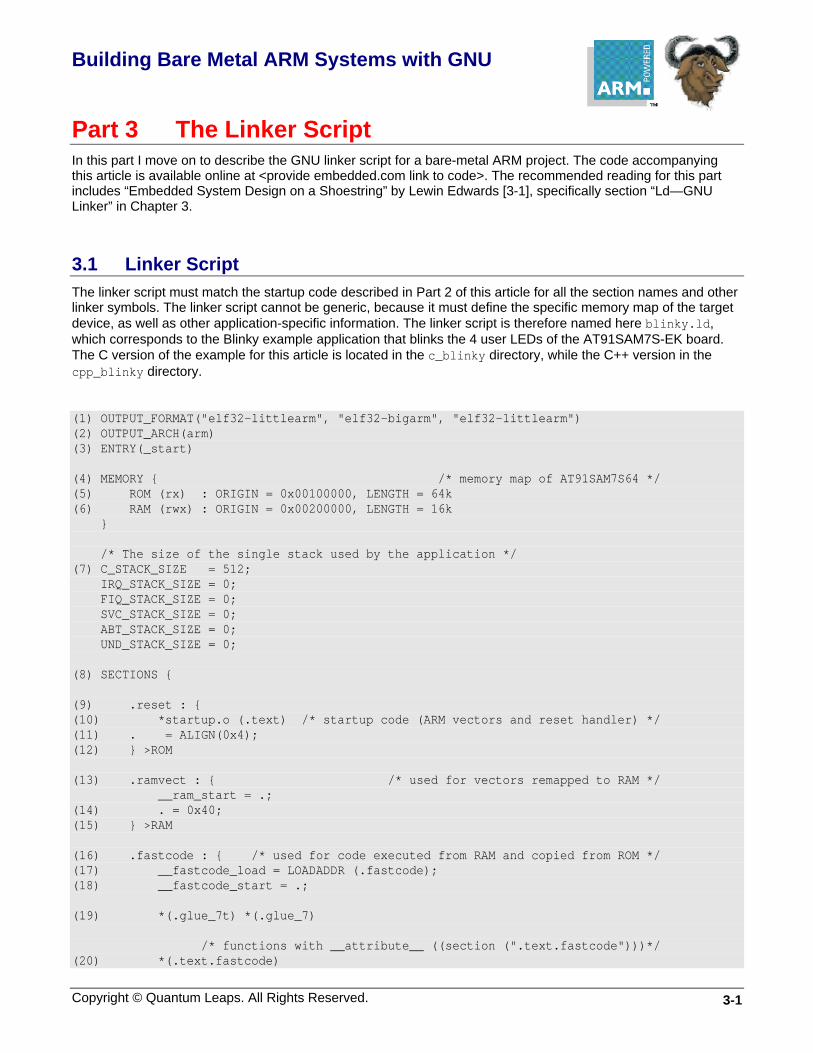
Part 3 The Linker Script In this part I move on to describe the GNU linker script for a bare-metal ARM project. The code accompanying this article is available online at <provide embedded.com link to code>. The recommended reading for this part includes “Embedded System Design on a Shoestring” by Lewin Edwards [3-1], specifically section “Ld—GNU Linker” in Chapter 3.
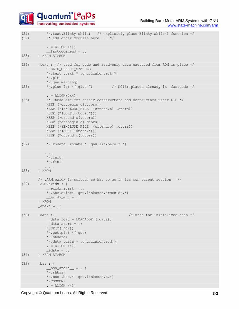
3.1 Linker Script The linker script must match the startup code described in Part 2 of this article for all the section names and other linker symbols. The linker script cannot be generic, because it must define the specific memory map of the target device, as well as other application-specific information. The linker script is therefore named here blinky.ld, which corresponds to the Blinky example application that blinks the 4 user LEDs of the AT91SAM7S-EK board. The C version of the example for this article is located in the c_blinky directory, while the C++ version in the cpp_blinky directory.
(1) OUTPUT_FORMAT("elf32-littlearm", "elf32-bigarm", "elf32-littlearm") (2) OUTPUT_ARCH(arm) (3) ENTRY(_start) (4) MEMORY { /* memory map of AT91SAM7S64 */ (5) ROM (rx) : ORIGIN = 0x00100000, LENGTH = 64k (6) RAM (rwx) : ORIGIN = 0x00200000, LENGTH = 16k } /* The size of the single stack used by the application */ (7) C_STACK_SIZE = 512; IRQ_STACK_SIZE = 0; FIQ_STACK_SIZE = 0; SVC_STACK_SIZE = 0; ABT_STACK_SIZE = 0; UND_STACK_SIZE = 0; (8) SECTIONS { (9) .reset : { (10) *startup.o (.text) /* startup code (ARM vectors and reset handler) */ (11) . = ALIGN(0x4); (12) } >ROM (13) .ramvect : { /* used for vectors remapped to RAM */ __ram_start = .; (14) . = 0x40; (15) } >RAM (16) .fastcode : { /* used for code executed from RAM and copied from ROM */ (17) __fastcode_load = LOADADDR (.fastcode); (18) __fastcode_start = .; (19) *(.glue_7t) *(.glue_7) /* functions with __attribute__ ((section (".text.fastcode")))*/ (20) *(.text.fastcode)
Building Bare-Metal ARM Systems with GNU
www.state-machine.com/arm
(21) *(.text.Blinky_shift) /* explicitly place Blinky_shift() function */ (22) /* add other modules here ... */ . = ALIGN (4); __fastcode_end = .; (23) } >RAM AT>ROM (24) .text : {/* used for code and read-only data executed from ROM in place */ CREATE_OBJECT_SYMBOLS *(.text .text.* .gnu.linkonce.t.*) *(.plt) *(.gnu.warning) (25) *(.glue_7t) *(.glue_7) /* NOTE: placed already in .fastcode */ . = ALIGN(0x4); (26) /* These are for static constructors and destructors under ELF */ KEEP (*crtbegin.o(.ctors)) KEEP (*(EXCLUDE_FILE (*crtend.o) .ctors)) KEEP (*(SORT(.ctors.*))) KEEP (*crtend.o(.ctors)) KEEP (*crtbegin.o(.dtors)) KEEP (*(EXCLUDE_FILE (*crtend.o) .dtors)) KEEP (*(SORT(.dtors.*))) KEEP (*crtend.o(.dtors)) (27) *(.rodata .rodata.* .gnu.linkonce.r.*) . . . *(.init) *(.fini) . . . (28) } >ROM /* .ARM.exidx is sorted, so has to go in its own output section. */ (29) .ARM.exidx : { __exidx_start = .; *(.ARM.exidx* .gnu.linkonce.armexidx.*) __exidx_end = .; } >ROM _etext = .; (30) .data : { /* used for initialized data */ __data_load = LOADADDR (.data); __data_start = .; KEEP(*(.jcr)) *(.got.plt) *(.got) *(.shdata) *(.data .data.* .gnu.linkonce.d.*) . = ALIGN (4); _edata = .; (31) } >RAM AT>ROM (32) .bss : { __bss_start__ = . ; *(.shbss) *(.bss .bss.* .gnu.linkonce.b.*) *(COMMON) . = ALIGN (4);
Copyright © Quantum Leaps. All Rights Reserved. 3-2
Building Bare-Metal ARM Systems with GNU
www.state-machine.com/arm
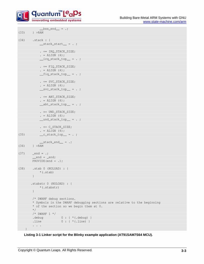
__bss_end__ = .; (33) } >RAM (34) .stack : { __stack_start__ = . ; . += IRQ_STACK_SIZE; . = ALIGN (4); __irq_stack_top__ = . ; . += FIQ_STACK_SIZE; . = ALIGN (4); __fiq_stack_top__ = . ; . += SVC_STACK_SIZE; . = ALIGN (4); __svc_stack_top__ = . ; . += ABT_STACK_SIZE; . = ALIGN (4); __abt_stack_top__ = . ; . += UND_STACK_SIZE; . = ALIGN (4); __und_stack_top__ = . ; . += C_STACK_SIZE; . = ALIGN (4); (35) __c_stack_top__ = . ; __stack_end__ = .; (36) } >RAM (37) _end = .; __end = _end; PROVIDE(end = .); (38) .stab 0 (NOLOAD) : { *(.stab) } .stabstr 0 (NOLOAD) : { *(.stabstr) } /* DWARF debug sections. * Symbols in the DWARF debugging sections are relative to the beginning * of the section so we begin them at 0. */ /* DWARF 1 */ .debug 0 : { *(.debug) } .line 0 : { *(.line) } . . . }
Listing 3-1 Linker script for the Blinky example application (AT91SAM7S64 MCU).
Copyright © Quantum Leaps. All Rights Reserved. 3-3

Building Bare-Metal ARM Systems with GNU
www.state-machine.com/arm
Listing 3-1 shows the linker script for the Blinky example application. The script is almost identical for C and C++ versions, with the minor differences discussed later in this section. The highlights of the linker script are as follows:
(1) The OUTPUT_FORMAT directive specifies the format of the output image (elf32, little-endian, ARM)
(2) OUTPUT_ARCH specifies the target machine architecture.
(3) ENTRY explicitly specifies the first instruction to execute in a program
(4) The MEMORY command describes the location and size of blocks of memory in the target.
(5) The region ROM corresponds to the on-chip flash of the AT91SAM7S64 device. It can contain read-only and executable sections (rx), it starts at 0x00100000 and is 64KB in size.
(6) The region RAM corresponds to the on-chip SRAM of the AT91SAM7S64 device. It can contain read-only, read-write and executable sections (rwx), it starts at 0x00200000 and is 16KB in size.
(7) The following symbols denote the sizes of the ARM stacks. You need to adjust the sizes for your particular application. The C-stack cannot be zero.
(8) The SECTIONS command opens the definition of all the sections for the linker.
(9) The .reset section contains the startup code (including the ARM vectors) and must be located as the first section in ROM.
(10) This line locates all .text sections from the startup.o object module.
(11) The section size is aligned to the 4-byte boundary
(12) This section is loaded directly to the ROM region defined in the MEMORY command.
(13) The .ramvect section contains the RAM-based ARM vector table and the secondary jump table and must be loaded as the first section in RAM
(14) The ARM vector table and the secondary jump table have known size of 0x40 bytes. The current location counter is simply incremented to reserve 0x40 bytes for the section.
(15) The .ramvect section goes into the RAM region.
(16) The .fastcode section is used for RAM-based code, which needs to be loaded to ROM, but copied and executed from RAM.
(17) The .fastcode section has different load memory address (LMA) than the virtual memory address (VMA). The symbol __fastcode_load corresponds to the LMA in ROM and is needed by the startup code to copy the section from ROM to RAM.
(18) The __fastcode_start symbol corresponds to the VMA of the .fastcode section and is needed by the startup code to copy the section from ROM to RAM.
(19) The .glue_7t and .glue_7 sections are synthesized by the compiler when you specify the ARM-THUMB interworking option. The sections contain the “call veneers” between THUMB and ARM code and are accessed frequently by every call between ARM and THUMB. It’s typically advantageous to place this small amount of hot-spot code in RAM.
(20) The .text.fastcode section is assigned explicitly to individual functions in the C/C++ code by means of the __attribute__ ((section (".text.fastcode"))) command.
(21) The GNU compiler is also capable of placing each function in the separate section named after the function (requires specifying the option -ffunction-sections). This allows you to be very selective and to place individual functions (e.g. the function Blinky_shift()) in RAM.
Copyright © Quantum Leaps. All Rights Reserved. 3-4
Building Bare-Metal ARM Systems with GNU
www.state-machine.com/arm
NOTE: The C++ compiler performs function name-mangling and you need to consult the map file to figure out the section name assigned to a given function. For example, the class method Blinky::shift() is placed in the section .text._ZN6Blinky5shiftEv)
(22) You can place more hot-spot functions in RAM during the fine-tuning stage of the project.
(23) The .fastcode section is located in RAM, but is loaded at the ROM address.
(24) The .text section is for code and read-only data accessed in place.
(25) If you repeat sections already located in the .fastcode section, the earlier location will take precedence. However, if you decide to remove these sections from .fastcode, they will be located per the second specification.
(26) The following sections are synthesized by the GNU C++ compiler and are used for static constructors and destructors.
(27) The section .rodata is used for read-only (constant) data, such as look-up tables. Just as code, you might choose to place some frequently accessed constants in RAM by locating these sections in the .fastcode section.
(28) The .text section is located and loaded to ROM.
(29) The .ARM.exidx section is used for C++ exception handling. It is located here for completeness. Bare-metal ARM projects typically cannot afford the overhead associated with C++ exceptions handling.
(30) The .data section contains initialized data.
(31) The .data section is located in RAM, but is loaded to ROM and copied to RAM during startup.
(32) The .bss section contains uninitialized data. The C/C++ standard requires that this section must be cleared at startup.
(33) The .bss section is located in RAM only.
(34) The .stack section contains all the stacks. The section is initialized with a given bit-pattern at startup.
(35) The ARM GNU toolset uses full descending stack. Therefore the linker script provides only the top of stack symbols to initialize the various ARM stack pointers. In particular the C stack (SYS stack) is allocated at the end of the .stack section.
(36) The .stack section is located in RAM.
(37) The symbols _end, __end, and end are used to set up the beginning of the heap, if the heap is used.
(38) The following sections are for the debugger only and are never loaded to the target.
Coming Up Next: In the next part I’ll describe the C and C++ compiler options as well as how to minimize the overhead of C++ using the GNU toolchain. Stay tuned.
3.2 References [3-1] Lewin A.R.W. Edwards, “Embedded System Design on a Shoestring”, Elsevier 2003.
[3-2] GNU Linker (ld) HTML documentation included in the CodeSourcery Toolchain for ARM, http://www.codesourcery.com/gnu_toolchains/arm.
[3-3] ARM Projects, http://www.siwawi.arubi.uni-kl.de/avr_projects/arm_projects
Copyright © Quantum Leaps. All Rights Reserved. 3-5

Building Bare Metal ARM Systems with GNU
Copyright © Quantum Leaps. All Rights Reserved. 4-1
Part 4 C/C++ Compiler Options and Minimizing the Overhead of C++
In this part I describe the C and C++ compiler options that allow freely mixing ARM and Thumb code, as well as supporting fine-granularity code sections for functions. The code accompanying this article is available online at www.state-machine.com/resources/papers.htm.
4.1 Compiler Options for C The compiler options for C are defined in the Makefile located in the c_blinky subdirectory. The Makefile specifies different options for building debug and release configurations and allows compiling to ARM or Thumb on the module-by-module basis.
ARM_CPU = arm7tdmi CCFLAGS = -gdwarf-2 -c \ (1a) -mcpu=$(ARM_CPU) \ (2a) -mthumb-interwork \ (3a) -mlong-calls \ (4a) -ffunction-sections \ (5a) -O \ -Wall CCFLAGS = -c \ (1b) -mcpu=$(ARM_CPU) \ (2b) -mthumb-interwork \ (3b) -mlong-calls \ (4b) -ffunction-sections \ (5b) -O3 \ (6b) -DNDEBUG \ -Wall
Listing 4-1 Compiler options used for C project, debug configuration (a) and release configuration (b).
Listing 4-1 shows the most important compiler options for C, which are:
(1) –mcpu option specifies the name of the target ARM processor. GCC uses this name to determine what kind of instructions it can emit when generating assembly code. Currently, the ARM_CPU symbol is set to arm7tdmi.
(2) –mthumb-interwork allows freely mixing ARM and Thumb code
(3) –mlong-calls tells the compiler to perform function calls by first loading the address of the function into a register and then performing a subroutine call on this register (BX instruction). This allows the called function to be located anywhere in the 32-bit address space, which is sometimes necessary for control transfer between ROM- and RAM-based code.
NOTE: The need for long calls really depends on the memory map of a given ARM-based MCU. For example, the Atmel AT91SAM7 family actually does not require long calls between ROM and RAM, because the memories are less than 25-bits apart. On the other hand, the NXP LPC2xxx family requires long calls because the ROM and RAM are mapped to addresses 0x0 and 0x40000000, respectively. The long-calls option is safe for any memory map.

Building Bare-Metal ARM Systems with GNU
www.state-machine.com/arm
(4) –ffunction-sections instructs the compiler to place each function into its own section in the output file. The name of the function determines the section's name in the output file. For example, the function Blinky_shift() is placed in the section .text.Blinky_shift. You can then choose to locate just this section in the most appropriate memory, such as RAM (see also Listing 3-1(21)).
(5) –O chooses the optimization level. Release configuration has a higher optimization level (5b).
(6) the release configuration defines the macro NDEBUG.
4.2 Compiler Options for C++ The compiler options for C++ are defined in the Makefile located in the cpp_blinky subdirectory. The Makefile specifies different options for building the Debug and Release configurations and allows compiling to ARM or Thumb on the module-by-module basis.
CPPFLAGS = -g -gdwarf-2 -c -mcpu=$(ARM_CPU) -mthumb-interwork \ -mlong-calls -ffunction-sections -O \ (1) -fno-rtti \ (2) -fno-exceptions \ -Wall
Listing 4-2 Compiler options used for C++ project.
The C++ Makefile located in the directory cpp_blinky uses the same options as C discussed in the previous section plus two options that control the C++ dialect:
(1) –fno-rtti disables generation of information about every class with virtual functions for use by the C++ runtime type identification features (dynamic_cast and typeid). Disabling RTTI eliminates several KB of support code from the C++ runtime library (assuming that you don’t link with code that uses RTTI). Note that the dynamic_cast operator can still be used for casts that do not require runtime type information, i.e. casts to void * or to unambiguous base classes.
(1) –fno-exceptions stops generating extra code needed to propagate exceptions, which can produce significant data size overhead. Disabling exception handling eliminates several KB of support code from the C++ runtime library (assuming that you don’t link external code that uses exception handling).
4.3 Reducing the Overhead of C++ The compiler options controlling the C++ dialect are closely related to reducing the overhead of C++. However, disabling RTTI and exception handling at the compiler level is still not enough to prevent the GNU linker from pulling in some 50KB of library code. This is because the standard new and delete operators throw exceptions and therefore require the library support for exception handling. (The new and delete operators are used in the static constructor/destructor invocation code, so are linked in even if you don’t use the heap anywhere in your application.)
Most low-end ARM-based MCUs cannot tolerate 50KB code overhead. To eliminate that code you need to define your own, non-throwing versions of global new and delete, which is done in the module mini_cpp.cpp located in the directory cpp_blinky1.
#include <stdlib.h> // for prototypes of malloc() and free() //............................................................................
Copyright © Quantum Leaps. All Rights Reserved. 4-2

Building Bare-Metal ARM Systems with GNU
www.state-machine.com/arm
(1) void *operator new(size_t size) throw() { return malloc(size); } //............................................................................ (2) void operator delete(void *p) throw() { free(p); } //............................................................................ (3) extern "C" int __aeabi_atexit(void *object, void (*destructor)(void *), void *dso_handle) { return 0; }
Listing 4-3 The mini_cpp.cpp module with non-throwing new and delete as well as dummy version of __aeabi_atexit().
Listing 4-3 shows the minimal C++ support that eliminates entirely the exception handling code. The highlights are as follows:
(1) The standard version of the operator new throws std::bad_alloc exception. This version explicitly throws no exceptions. This minimal implementation uses the standard malloc().
(2) This minimal implementation uses the standard free().
(3) The function __aeabi_atexit() handles the static destructors. In a bare-metal system this function can be empty because application has no operating system to return to, and consequently the static destructors are never called.
Finally, if you don’t use the heap, which you shouldn’t in robust, deterministic applications, you can reduce the C++ overhead even further. The module no_heap.cpp provides dummy empty definitions of malloc() and free():
#include <stdlib.h> // for prototypes of malloc() and free() //............................................................................ extern "C" void *malloc(size_t) { return (void *)0; } //............................................................................ extern "C" void free(void *) { }
Coming Up Next: In the next part I’ll describe the options for fine-tuning the application by selective ARM/Thumb compilation and by placing hot-spot parts of the code in RAM. Stay tuned.
4.4 References [4-1] Lewin A.R.W. Edwards, “Embedded System Design on a Shoestring”, Elsevier 2003.
[4-2] GNU Toolchain for ARM, CodeSourcery, http://www.codesourcery.com/gnu_toolchains/arm.
[4-3] GNU ARM toolchain, http://www.gnuarm.com
[4-4] GNU X-Tools™, Microcross, http://www.microcross.com.
[4-5] ARM Projects, http://www.siwawi.arubi.uni-kl.de/avr_projects/arm_projects
Copyright © Quantum Leaps. All Rights Reserved. 4-3
Building Bare Metal ARM Systems with GNU
Copyright © Quantum Leaps. All Rights Reserved. 5-1
Part 5 Fine-tuning the Application In this part I describe the options for fine-tuning the application by selective ARM/Thumb compilation and by placing hot-spot parts of the code in RAM. I also mention the
5.1 ARM/THUMB compilation The compiler options discussed in the previous part of this article (the CCFLAGS symbol) specifically do not include the instruction set option (-marm for ARM, and –mthumb for THUMB). This option is selected individually for every module in the Makefile. For example, in the following example the module low_level_init.c is compiled to THUMB and module blinky.c is compiled to THUMB:
$(BINDIR)\low_level_init.o: $(BLDDIR)\low_level_init.c $(APP_DEP) $(CC) -marm $(CCFLAGS) $(CCINC) $< $(BINDIR)\blinky.o: $(BLDDIR)\blinky.c $(APP_DEP) $(CC) -mthumb $(CCFLAGS) $(CCINC) $<
5.2 Placing the Code in RAM As mentioned in part 1 of this article, placing strategic parts of the hot-spot code in RAM can significantly improve performance and reduce power dissipation of most ARM-based MCUs. The startup code and the linker script discussed in parts 2 and 3 of this article support the .fastcode section that is located in RAM, but is loaded to ROM and copied to RAM upon startup.
You have two options to assign individual functions to the .fastcode section:
1. Because each function is located in a separate section (see the –ffunction-sections compiler option described in part 4), you can explicitly locate the code for every function in the linker script for your applications. The linker scripts blinky.ld for the Blinky application provide an example how to locate the Blinky_shift() function in RAM.
2. You can assign any function to the .fastcode.text section, by means of the __attribute__ ((section (".text.fastcode"))) directive. The module blinky.c provides an example for the Blinky_flash() function.
__attribute__ ((section (".text.fastcode"))) void Blinky_flash(Blinky *me, uint8_t n) { . . . }
Coming Up Next: The provided code examples and the discussion should provide you with a head-start on any bare-metal ARM-based project with the GNU toolchain. The second part of this article will describe ARM exceptions and interrupt handling.
5.3 References [5-1] Lewin A.R.W. Edwards, “Embedded System Design on a Shoestring”, Elsevier 2003.
[5-2] GNU Toolchain for ARM, CodeSourcery, http://www.codesourcery.com/gnu_toolchains/arm.

Building Bare-Metal ARM Systems with GNU
www.state-machine.com/arm
[5-3] GNU ARM toolchain, http://www.gnuarm.com
[5-4] GNU X-Tools™, Microcross, http://www.microcross.com.
[5-5] ARM Projects, http://www.siwawi.arubi.uni-kl.de/avr_projects/arm_projects
Copyright © Quantum Leaps. All Rights Reserved. 5-2
Building Bare Metal ARM Systems with GNU
Copyright © Quantum Leaps. All Rights Reserved. 6-1
Part 6 General Description of Interrupt Handling In this part of the article I tackle interrupt handling for the ARM processor in the simple foreground/background architecture without any underlying multitasking OS or kernel (bare metal). The interrupt handling scheme presented here fully supports nesting of interrupts and can work with or without an interrupt controller external to the ARM7/ARM9 core.
In this part I describe interrupt handling in general terms and in the following installments I provide detailed description of interrupt locking policy, interrupt handler “wrappers” in assembly, C-level interrupt service routines, and finally interrupt testing strategies for ARM-based MCUs. The recommended reading for this part includes: ARM Technical Support Note “Writing Interrupt Handlers” [6-1], Philips Application Note AN10381 ”Nesting of Interrupts in the LPC2000” [6-2], and Atmel Application Note “Interrupt Management: Auto-vectoring and Prioritization” [6-3].
6.1 Problem Description The ARM core supports two types of interrupts: Interrupt Request (IRQ) and Fast Interrupt Request (FIQ), as well as several exceptions: Undefined Instruction, Prefetch Abort, Data Abort, and Software Interrupt. Upon encountering an interrupt or an exception the ARM core does not automatically push any registers to the stack. If the application wants to nest interrupts (to take advantage of the prioritized interrupt controller available in most ARM-based MCUs), the responsibility is entirely with the application programmer to save and restore the ARM registers.
GNU gcc provides the function __attribute__ ((interrupt ("IRQ"))) to indicate that the specified C/C++ function is an IRQ handler (similarly the __attribute__ ((interrupt ("FIQ"))) is provided for FIQ handlers). However, these attributes are only designed for “simple” (non-nesting) interrupt handlers. This is because functions designated as interrupts do not store all of the context information (e.g., the SPSR is not saved), which is necessary for fully re-entrant interrupts [6-1].
At the same time, most ARM-based MCUs contain a prioritized interrupt controller that specifically supports nesting and prioritization of multiple interrupt sources. This powerful hardware feature cannot be used, however, unless the software is actually capable of handling nested interrupts.
6.2 Interrupt Handling Strategy To enable interrupt nesting, the handler must at some point unlock interrupts, which are automatically locked at the ARM core level upon the IRQ/FIQ entry. Generally, all documented strategies for handling nested interrupts in the ARM architecture involve switching the mode away from IRQ (or FIQ) to the mode used by the task-level code before enabling interrupts [6-1, 6-2, 6-3, 6-4]. The standard techniques also use multiple stacks during interrupt handling. The IRQ/FIQ mode stack is used for saving a part of the interrupt context and the SYSTEM/USER stack (or sometimes the SVC stack) is used for saving the rest of the context. ARM Ltd. recommends using SYSTEM mode while programming reentrant interrupt handlers [6-1].
The interrupt handling strategy for bare-metal ARM system described here also switches away from the IRQ/FIQ mode to SYSTEM mode before enabling interrupt nesting, but differs from the other schemes in that all the CPU context is saved to the SYSTEM/USER stack and the IRQ/FIQ stacks are not used at all. Saving the context to the separate interrupt stack has value only in multitasking kernels that employ a separate stack for each task. Using multiple stacks in the simple foreground/background architecture with only one background task (the main() loop) has no value and only adds complexity.
Building Bare-Metal ARM Systems with GNU
www.state-machine.com/arm
0x00 LDR pc,[pc,#0x18]
0x180x1C
0x20 _reset
0x38 ARM_irq0x3C
LDR pc,[pc,#0x18]LDR pc,[pc,#0x18]
reset
IRQFIQ ARM_fiq
AIC_IVR current ISR
AIC_ID_SYS &ISR_pitAIC_ID_TC0 &ISR_timer0
void ISR_pit(void) { . . . /* handle the interrupt */}
. . . /* handle the interrupt */
typedef void (*IntVector)(void); IntVector vect = (IntVector)AIC_IVR;
asm("MSR cpsr_c,#( )"); (*vect)(); /* call the C-handler */ asm("MSR cpsr_c,#( )");
AIC_EOICR = (AT91_REG)vect;
AIC_SPU &ISR_spur
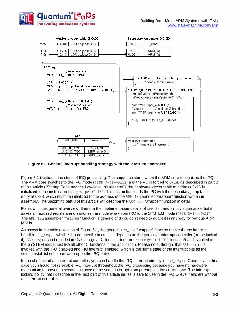
Figure 6-1 General interrupt handling strategy with the interrupt controller
Figure 6-1 illustrates the steps of IRQ processing. The sequence starts when the ARM core recognizes the IRQ. The ARM core switches to the IRQ mode (CPSR[0-4]==0x12) and the PC is forced to 0x18. As described in part 2 of this article (“Startup Code and the Low-level Initialization”), the hardware vector table at address 0x18 is initialized to the instruction LDR pc,[pc,#0x18]. This instruction loads the PC with the secondary jump table entry at 0x38, which must be initialized to the address of the ARM_irq handler “wrapper” function written in assembly. The upcoming part 8 of this article will describe the ARM_irq “wrapper” function in detail.
For now, in this general overview I’ll ignore the implementation details of ARM_irq and simply summarize that it saves all required registers and switches the mode away from IRQ to the SYSTEM mode (CPSR[0-4]==0x1F). The ARM_irq assembler “wrapper” function is generic and you don’t need to adapt it in any way for various ARM MCUs.
As shown in the middle section of Figure 6-1, the generic ARM_irq “wrapper” function then calls the interrupt handler BSP_irq(), which is board-specific because it depends on the particular interrupt controller (or the lack of it). BSP_irq() can be coded in C as a regular C-function (not an interrupt ("IRQ") function!) and is called in the SYSTEM mode, just like all other C functions in the application. Please note, though, that BSP_irq() is invoked with the IRQ disabled and FIQ interrupt enabled, which is the same state of the interrupt bits as the setting established in hardware upon the IRQ entry.
In the absence of an interrupt controller, you can handle the IRQ interrupt directly in BSP_irq(). Generally, in this case you should not re-enable IRQ interrupt throughout the IRQ processing because you have no hardware mechanism to prevent a second instance of the same interrupt from preempting the current one. The interrupt locking policy that I describe in the next part of this article series is safe to use in the IRQ C-level handlers without an interrupt controller.
Copyright © Quantum Leaps. All Rights Reserved. 6-2

Building Bare-Metal ARM Systems with GNU
www.state-machine.com/arm
In the presence of an interrupt controller, the sequence is a bit more involved (see again Figure 6-1). The function BSP_irq() first reads the current interrupt vector from the interrupt controller. The read cycle of the vector address starts prioritization of this interrupt level in the interrupt controller, so after this instruction it’s safe to re-enable all interrupts (e.g., via the assembly instruction asm(“MSR cpsr_c,#0x1F”);). Next, the BSP_irq() function calls the interrupt vector via the pointer to function syntax ((*vect)()). For this to work, the interrupt controller must be initialized with the addresses of the interrupt service routines (ISRs), as shown in the bottom part of Figure 6-1. After the interrupt handler returns, the BSP_irq() function locks both IRQ and FIQ interrupts (e.g., via the assembly instruction asm(“MSR cpsr_c,#(0x1F | 0x80 | 0x40)”);). Finally, BSP_irq() writes the End-Of-Interrupt instruction to the interrupt controller, which terminates the prioritization of this interrupt level. The code accompanying this article provides the example of the BSP_irq() function for the Atmel Advanced Interrupt Controller (AIC). Other interrupt controllers use slightly different register names and addresses, but work very similarly.
NOTE: The function BSP_irq() must be compiled to ARM, if you use the inline assembly instruction asm(“MSR cpsr_c,#0x1F”) to unlock and instruction asm(“MSR cpsr_c,#(0x1F | 0x80)”) to lock interrupts. The MSR instruction is not available in the Thumb instruction set.
The BSP_irq() function returns eventually to the generic ARM_irq() assembler wrapper function (see the middle section of Figure 6-1). The ARM_irq() assembler “wrapper” restores the context from the SYSTEM stack, performs the mode switch back to IRQ and performs the standard return from exception via the MOVS pc,lr instruction.
6.3 FIQ Handling Handling of FIQ interrupts is similar to IRQ as far as the assembler “wrapper” function and the vector table initialization are concerned. The main difference between FIQ and IRQ is that the FIQ line is typically not managed by the priority controller (such as the Atmel AIC, NXP VIC, or others), as illustrated in Figure 6-2.
Figure 6-2 Typical ARM system with an interrupt controller external to the ARM core
The consequences of this hardware design are at least two-fold. First, you can simply handle the FIQ directly in the BSP_fiq() C-level function, without any indirection via the interrupt controller. In other words, even though most interrupt controllers inside popular ARM MCUs support the vectoring feature for FIQ, it does not add much value. The second, and far more important consequence, is that you should never enable FIQ or IRQ interrupts throughout the FIQ processing. If you were to enable FIQ or IRQ, you would make the currently executing FIQ handler vulnerable to preemptions by the IRQs or the second instance of the currently handled FIQ. Both cases
Copyright © Quantum Leaps. All Rights Reserved. 6-3
Building Bare-Metal ARM Systems with GNU
www.state-machine.com/arm
represent priority inversions. The interrupt locking policy that I describe in the next part of this article series is safe to use in the FIQ C-level handler function. The accompanying code for this article includes the example of the FIQ coded directly in BSP_fiq() handler function.
6.4 No Auto-Vectoring It’s perhaps important to note that the interrupt handling strategy presented here does not use the auto-vectoring feature described in the application notes [6-2 and 6-3]. Auto-vectoring occurs when the following LDR instruction is located at the address 0x18 for the IRQ (this example pertains to the Atmel’s AIC):
ORG 0x18 LDR pc,[pc,#-0xF20]
When an IRQ occurs, the ARM core forces the PC to address 0x18 and executes the LDR pc,[pc,#-0xF20] instruction. When the instruction at address 0x18 is executed, the effective address is: 0x20 – 0xF20 = 0xFFFFF100 (0x20 is the value of the PC when the instruction at address 0x18 is executed due to pipelining of the ARM core).
This causes the ARM core to load the PC with the value read from the AIC_IVR register located at 0xFFFFF100. The read cycle causes the AIC_IVR register to return the address of the currently active interrupt service routine. Thus, the single LDR pc,[pc,#-0xF20] instruction has the effect of starting the prioritization of the current IRQ and directly jumping to the correct ISR, which is called auto-vectoring.
The consequence of auto-vectoring is that the interrupt service routines hooked to the interrupt controller cannot be plain C-functions but rather each one of them must deal directly with the complexities of the IRQ or FIQ modes.
Instead of repeating the IRQ entry and exit sequence in each and every IRQ interrupt service routine, the implementation I describe here uses only one generic, low-level, re-entrant IRQ handler (ARM_irq) that encapsulates the “ARM-magic” and then calls the higher-level handler BSP_irq(), which can be a plain C function. Similar approach is taken for handling FIQs.
Please note that even though “auto-vectoring” is not used, the BSP_irq() function can take full advantage of the vectoring feature of the interrupt controller by reading the vector from the interrupt controller and calling the handler via a pointer-to-function. This, however, happens later in the IRQ sequence and strictly speaking cannot be called “auto-vectoring”.
Coming Up Next: In the next part of this article I’ll describe the interrupt locking policy for ARM that would be safe for both IRQ and FIQ interrupts as well as the task level code (the code called from main()). I’ll explain the details of the low-level interrupt handlers in Part 8. Stay tuned.
6.5 References [6-1] Lewin A.R.W. Edwards, “Embedded System Design on a Shoestring”, Elsevier 2003.
[6-2] Philips Application Note AN10381 “Nesting of Interrupts in the LPC2000” available online at www.nxp.com/acrobat_download/applicationnotes/AN10381_1.pdf
[6-3] Atmel Application Note “Interrupt Management: Auto-vectoring and Prioritization” available online at www.atmel-grenoble.com/dyn/resources/prod_documents/DOC1168.PDF
Copyright © Quantum Leaps. All Rights Reserved. 6-4
Building Bare Metal ARM Systems with GNU
Copyright © Quantum Leaps. All Rights Reserved. 7-1
Part 7 Interrupt Locking and Unlocking In this part of this article series I describe the interrupt locking and unlocking policy for ARM that will be safe for both IRQ and FIQ interrupt handlers as well as the task level code (the code called from main()). You would probably never think that interrupt locking could deserve the whole article. But the ARM architecture somehow manages to make it amazingly complex. The recommended reading for this part includes: ARM Technical Support Note “What happens if an interrupt occurs as it is being disabled?” [7-1], and Atmel Application Note “Disabling Interrupts at Processor Level” [7-2].
7.1 Problem Description In the simple foreground/background architecture without any underlying multitasking OS or kernel (bare metal) the foreground (ISRs) communicates with the background (the main() loop) by means of shared variables. The background code has the responsibility of protecting these shared variables from corruption by the asynchronously firing ISRs. The only mutual exclusion mechanism available in this simple architecture is to briefly lock interrupts before accessing the shared resource and to unlock the interrupts after releasing the resource. The section of code executing atomically between locking and unlocking interrupts is often called the critical section or critical region. Of course, you should keep the time spend inside each critical section to the minimum, so that you don’t extend the interrupt latency of the system.
Critical sections are necessary not just in the task-level code callable from the main() loop. If nesting of IRQ interrupts is allowed (which I assume in this article) critical sections are necessary also inside the IRQ interrupts.
Finally, the same critical sections used in the IRQs handlers might be also used inside the FIQ handler, simply because of the coding convenience. Even though the FIQ handler runs with interrupts locked at all times, so it does not really need to use a critical section (see part 6 of this article), experience shows that programmers can all too easily forget that FIQ requires a completely different interrupt locking policy than all other interrupt handlers. A problem would arise if interrupts were inadvertently unlocked inside the FIQ handler upon the exit from a critical section. Please note that a critical section can be buried inside a deeply nested function call chain.
In summary, a real-life, bare-metal ARM project requires a universal interrupt locking and unlocking policy that would be safe to use from the task-level, nested IRQ handlers, and the FIQ handler.
7.2 The Policy of Saving and Restoring Interrupt Status The interrupt locking policy that has all the properties required in this case is the policy of saving and restoring the interrupt status. This policy is common, and is used for example inside the VxWorks RTOS (see the function pair intLock()/intUnlock() documented at www.slac.stanford.edu/¬exp/glast/flight/sw/vxdocs/vxworks/ref/-intArchLib.html#intLock ) The following code snippet shows how you use this type of critical section:
void your_function() { (1) ARM_INT_KEY_TYPE int_lock_key; . . . (2) ARM_INT_LOCK(int_lock_key); /* enter the critical section */ . . . /* access the shared resource */ (3) ARM_INT_UNLOCK(int_lock_key); /* leave the critical section */ . . . }
First, you need to declare a temporary variable (typically a stack or register variable) that will hold the interrupt status throughout the duration of the critical section (1). For portability, the type of the interrupt status is declared as a macro ARM_INT_KEY_TYPE, which along with the macros for locking and unlocking interrupts, is defined in the
Building Bare-Metal ARM Systems with GNU
www.state-machine.com/arm
file arm_exc.h included in the code accompanying this article. Next, you lock interrupts by means of another macro ARM_INT_LOCK(), which saves the interrupt status in the int_lock_key variable (2). Finally, you unlock the interrupts by means of the macro ARM_INT_UNLOCK(), which restores the interrupt lock to the state before the matching ARM_INT_LOCK() has been called (3).
This policy allows nesting critical sections, because the interrupt state is preserved across the critical section in a temporary variable. In other words, upon the exit from a critical section the interrupts are actually unlocked in the ARM_INT_UNLOCK() macro only if they were unlocked before the invocation of the matching ARM_INT_LOCK() macro. Conversely, interrupts will remain locked after the ARM_INT_UNLOCK() macro if they were locked before the matching ARM_INT_LOCK() macro.
7.3 Critical Section Implementation with GNU gcc The macros ARM_INT_KEY_TYPE, ARM_INT_LOCK(), and ARM_INT_UNLOCK() are defined in the arm_exc.h header file provided in the code accompanying this article and shown in Listing 7-1
(1) #define ARM_INT_KEY_TYPE int (2) #ifdef __thumb__ (3) #define ARM_INT_LOCK(key_) ((key_) = ARM_int_lock_SYS()) (4) #define ARM_INT_UNLOCK(key_) (ARM_int_unlock_SYS(key_)) (5) ARM_INT_KEY_TYPE ARM_int_lock_SYS(void); (6) void ARM_int_unlock_SYS(ARM_INT_KEY_TYPE key); (7) #else (8) #define ARM_INT_LOCK(key_) do { \ (9) asm("MRS %0,cpsr" : "=r" (key_)); \ (10) asm("MSR cpsr_c,#(0x1F | 0x80 | 0x40)"); \ (11) } while (0) (12) #define ARM_INT_UNLOCK(key_) asm("MSR cpsr_c,%0" : : "r" (key_)) #endif
Listing 7-1 Implementation of the critical for ARM with GNU gcc
The main points of the implementation are as follows:
(1) The ARM_INT_KEY_TYPE macro represents the type of the interrupt lock status preserved across the critical section. In the case of the ARM processor, the interrupt lock key is the value of the CPSR register (an int is 32-bit wide in ARM gcc).
(2) GNU gcc for ARM pre-defines the macro __thumb__ when it is invoked with the -mthumb compiler option to compile the code in the 16-bit Thumb mode.
(3) The Thumb instruction set does not include the MSR/MRS instructions, which are the only way to manipulate the interrupt bits in the CPSR register. Therefore the ARM_INT_LOCK() macro invokes an ARM function ARM_int_lock_SYS(), which locks the interrupts and returns the value of the CPSR before locking both the IRQ and FIQ in the CPSR. The gcc compiler and linker add the appropriate Thumb-to-ARM and ARM-to-Thumb call “veneers” automatically thanks to the –mthumb-interwork compiler option (see part 4 of this article series).
Copyright © Quantum Leaps. All Rights Reserved. 7-2
Building Bare-Metal ARM Systems with GNU
www.state-machine.com/arm
(4) The ARM_INT_UNLOCK() macro is defined as a call to the ARM function ARM_int_unlock_SYS(), which restores the CPSR from the interrupt lock key argument. Both ARM_int_lock_SYS() and ARM_int_unlock_SYS() are defined in the assembly module arm_exc.s. The assembly code used inside these two functions is actually identical as the inline assembly used when the code is compiled to ARM (see highlights for Listing 7-1(9-11)).
(5-6) The C-prototypes of the assembly functions must be provided for the C compiler. (NOTE: for the C++ version, the prototypes must be defined with the extern “C” linkage specification.)
(7) If the ARM instruction set is used (the GNU gcc is invoked with the compiler option –marm), the critical section can be defined more optimally without the overhead of a function call for each entry and exit from a critical section.
(8,11) The macro ARM_INT_LOCK() is defined as the do {...} while (0) compound statement to guarantee syntactically-correct parsing of the macro in every context (including the dangling-else case).
(9) The GNU gcc supports the C assembler instructions with C expression operands. This feature is used to pass the C argument (key_) to the assembly instruction MSR, which saves the state of the CPSR into the provided register argument.
(10) The interrupts are disabled by setting the IRQ and FIQ bits simultaneously in the CPSR register. The most compact load-immediate form of the MSR instruction is used which does not clobber any registers.
NOTE: The MSR instruction has a side effect of also setting the ARM mode to SYSTEM. This is not a problem in this case, because all C-code, including the C-level IRQ and FIQ handlers, execute in the SYSTEM mode and no other ARM mode is ever visible to the C-level code (see part 6 of this article).
(12) The macro ARM_INT_UNLOCK() restores the CPSR from the interrupt lock key argument (key_) passed to the macro. Again, the most efficient store-immediate version of the MRS instruction is used, which does not clobber any additional registers.
7.4 Discussion of the Critical Section Implementation Various application notes available online (e.g., [7-1, 7-2]) provide more elaborate implementations of interrupt locking and unlocking for ARM. In particular they use read-modify-write to the CPSR rather than load-immediate to CPSR. In this section I discuss how the simple critical section implementation shown in Listing 7-1 addresses the potential problems identified in the various application notes.
When the IRQ line of the ARM processor is asserted, and the I bit (bit CPSR[7]) is cleared, the core ends the instruction currently in progress, and then starts the IRQ sequence, which performs the following actions (“ARM Architecture Reference Manual, 2nd Edition”, Section 2.6.6 [7-3]):
• R14_irq = address of next instruction to be executed + 4
• SPSR_irq = CPSR
• CPSR[4:0] = 0b10010 (enter IRQ mode)
• CPSR[7] = 1, NOTE: CPSR[6] is unchanged
• PC = 0x00000018
The ARM Technical Note “What happens if an interrupt occurs as it is being disabled?” [7-1] points out two potential problems. Problem 1 is related to using a particular function as an IRQ handler and as a regular subroutine called outside of the IRQ scope. Such a dual-purpose function must inspect the SPSR_irq register to detect in which context the handler function is called, which can be problematic. This scenario is impossible in the interrupt handling policy discussed in this article series, because there is no possibility of dual-purpose functions
Copyright © Quantum Leaps. All Rights Reserved. 7-3
Building Bare-Metal ARM Systems with GNU
www.state-machine.com/arm
since all C-level IRQ handlers are always called in the SYSTEM mode, where the application programmer has no access to the SPSR register. Problem 2 described in the ARM Technical Note [7-1] is more applicable to this article and relates to the situation when both IRQ and FIQ are disabled simultaneously, which is actually the case in the implementation of the critical section (see Listing 7-1(10)). If the IRQ is received during the CPSR write, the ARM7TDMI core sets the I and F bits in both CPSR and in SPSR_irq (Saved Program Status Register), and the interrupt is entered. If the IRQ handler never explicitly re-enables the FIQ, the fast interrupt will be disabled for the execution time of the IRQ handler and even beyond, until the exit from the critical section. Such situation represents a priority inversion and can extend the FIQ latency beyond the acceptable limit. One of the workarounds recommended in the ARM Note is to explicitly enable FIQ early in the IRQ handler. This is exactly done in the ARM_irq assembler “wrapper”, which I will discuss in detail in the next part (part 8) of this article.
For completeness, this discussion should mention the Atmel Application Note “Disabling Interrupts at Processor Level” [7-2], which describes another potential problem that might occur when the IRQ or FIQ interrupt is recognized exactly at the time that it is being disabled. The problem addressed in the Atmel Application Note [7-2] arises when the IRQ or FIQ handler manipulates the I or F bits in the SPSR register, which might lead to enabling interrupts upon the exit from the interrupt right at the beginning of a critical section. This scenario is not applicable in the interrupt handling policy used in this article, because the both the ARM_irq and ARM_fiq “wrapper” functions in assembly never change any bits in the SPSR, which corresponds to the Workaround 1 described in the Atmel Application Note [7-2].
Coming Up Next: In the next part of this article I’ll describe the interrupt “wrapper” functions ARM_irq and ARM_fiq in assembly (the ARM_irq and ARM_fiq functions have been introduced in Part 6). Stay tuned.
7.5 References [7-1] ARM Technical Support Note “What happens if an interrupt occurs as it is being disabled?”, available
online at http://www.arm.com/support/faqip/3677.html
[7-2] Atmel Application Note “Disabling Interrupts at Processor Level”, available online at http://www.atmel.com/dyn/resources/prod_documents/DOC1156.PDF
[7-3] Seal, David, editor, “ARM Architecture Reference Manual Second Edition”, Addison Wesley, 2000.
Copyright © Quantum Leaps. All Rights Reserved. 7-4

Building Bare Metal ARM Systems with GNU
Copyright © Quantum Leaps. All Rights Reserved. 8-1
Part 8 Low-level Interrupt Wrapper Functions In this part I describe the low-level interrupt wrapper functions ARM_irq() and ARM_fiq(). These functions have been introduced in part 6 of this article series, and their purpose is to allow handling of nested interrupts in the ARM architecture, which the GNU gcc __attribute__ ((interrupt ("IRQ"))) cannot do.
Perhaps the most interesting aspect of the implementation that I present here is its close compatibility with the new ARM v7-M architecture (e.g., Cortex-M3) [8-4]. Specifically, the low-level wrapper functions deal with all the ARM-magic internally, so that the interrupt service routines (ISRs) that you hook to the interrupt controller can be regular C-functions. The C-level ISRs run in the same processor mode (SYSTEM) as the code called from main() (task-level). Also, the assembler wrapper functions expressly avoid using the IRQ/FIQ stacks and instead nest interrupts of all types (IRQs and FIQs) on the SYSTEM/USER stack. The interrupt context saved to the stack is optimized for high-level languages and just like in the ARM v7-M specification, the wrapper functions save only the 8 registers clobbered in the ARM Architecture Procedure Calling Standard (AAPCS) [8-4]. In fact, the interrupt wrapper functions generate in software the exact same interrupt stack frame (SPSR, PC, LR, R12, R3, R2, R1, R0) as the ARM v7-M processors generate in hardware [8-4].
I should perhaps note right away that the ARM interrupt handling implementation described here goes off the beaten path established by the traditional approaches [8-1, 8-2, 8-3, 8-5]. Most published implementations recommend initializing the ARM vector table to use the “auto-vectoring” feature of the interrupt controller (see part 6 of this article series). Consequently the ISRs that you hook to the interrupt controller require very special entry and exit sequences, so they cannot be regular C-functions. Also, the interrupt handlers execute in IRQ or FIQ mode and use the IRQ and FIQ stacks (at least for some portion of the saved context). Consequently the stack frames as well as stack usage in the traditional implementations are quite different compared to ARM v7-M.
8.1 The IRQ Interrupt Wrapper ARM_irq The interrupt “wrapper” function ARM_irq() for handling the IRQ-type interrupts is provided in the file arm_exc.s included in the code accompanying this article series. Listing 8-1 shows the entire function.
.equ NO_IRQ, 0x80 /* mask to disable IRQ */ .equ NO_FIQ, 0x40 /* mask to disable FIQ */ .equ NO_INT, (NO_IRQ | NO_FIQ) /*mask to disable IRQ and FIQ */ .equ FIQ_MODE, 0x11 .equ IRQ_MODE, 0x12 .equ SYS_MODE, 0x1F . . . .text (1) .code 32 (2) .section .text.fastcode . . . . . . ARM_irq: /* IRQ entry {{{ */ (3) MOV r13,r0 /* save r0 in r13_IRQ */ (4) SUB r0,lr,#4 /* put return address in r0_SYS */ (5) MOV lr,r1 /* save r1 in r14_IRQ (lr) */ (6) MRS r1,spsr /* put the SPSR in r1_SYS */ (7) MSR cpsr_c,#(SYS_MODE | NO_IRQ) /* SYSTEM mode, no IRQ/FIQ enabled! */ (8) STMFD sp!,{r0,r1} /* save SPSR and PC on SYS stack */ (9) STMFD sp!,{r2-r3,r12,lr} /* save AAPCS-clobbered regs on SYS stack */ (10) MOV r0,sp /* make the sp_SYS visible to IRQ mode */ (11) SUB sp,sp,#(2*4) /* make room for stacking (r0_SYS, r1_SYS) */
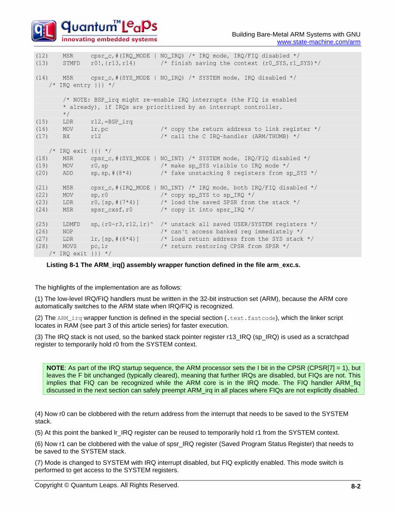
Building Bare-Metal ARM Systems with GNU
www.state-machine.com/arm
(12) MSR cpsr_c,#(IRQ_MODE | NO_IRQ) /* IRQ mode, IRQ/FIQ disabled */ (13) STMFD r0!,{r13,r14} /* finish saving the context (r0_SYS,r1_SYS)*/ (14) MSR cpsr_c,#(SYS_MODE | NO_IRQ) /* SYSTEM mode, IRQ disabled */ /* IRQ entry }}} */ /* NOTE: BSP_irq might re-enable IRQ interrupts (the FIQ is enabled * already), if IRQs are prioritized by an interrupt controller. */ (15) LDR r12,=BSP_irq (16) MOV lr,pc /* copy the return address to link register */ (17) BX r12 /* call the C IRQ-handler (ARM/THUMB) */ /* IRQ exit {{{ */ (18) MSR cpsr_c,#(SYS_MODE | NO_INT) /* SYSTEM mode, IRQ/FIQ disabled */ (19) MOV r0,sp /* make sp_SYS visible to IRQ mode */ (20) ADD sp,sp,#(8*4) /* fake unstacking 8 registers from sp_SYS */ (21) MSR cpsr_c,#(IRQ_MODE | NO_INT) /* IRQ mode, both IRQ/FIQ disabled */ (22) MOV sp,r0 /* copy sp_SYS to sp_IRQ */ (23) LDR r0,[sp,#(7*4)] /* load the saved SPSR from the stack */ (24) MSR spsr_cxsf,r0 /* copy it into spsr_IRQ */ (25) LDMFD sp,{r0-r3,r12,lr}^ /* unstack all saved USER/SYSTEM registers */ (26) NOP /* can't access banked reg immediately */ (27) LDR lr,[sp,#(6*4)] /* load return address from the SYS stack */ (28) MOVS pc,lr /* return restoring CPSR from SPSR */ /* IRQ exit }}} */
Listing 8-1 The ARM_irq() assembly wrapper function defined in the file arm_exc.s.
The highlights of the implementation are as follows:
(1) The low-level IRQ/FIQ handlers must be written in the 32-bit instruction set (ARM), because the ARM core automatically switches to the ARM state when IRQ/FIQ is recognized.
(2) The ARM_irq wrapper function is defined in the special section (.text.fastcode), which the linker script locates in RAM (see part 3 of this article series) for faster execution.
(3) The IRQ stack is not used, so the banked stack pointer register r13_IRQ (sp_IRQ) is used as a scratchpad register to temporarily hold r0 from the SYSTEM context.
NOTE: As part of the IRQ startup sequence, the ARM processor sets the I bit in the CPSR (CPSR[7] = 1), but leaves the F bit unchanged (typically cleared), meaning that further IRQs are disabled, but FIQs are not. This implies that FIQ can be recognized while the ARM core is in the IRQ mode. The FIQ handler ARM_fiq discussed in the next section can safely preempt ARM_irq in all places where FIQs are not explicitly disabled.
(4) Now r0 can be clobbered with the return address from the interrupt that needs to be saved to the SYSTEM stack.
(5) At this point the banked lr_IRQ register can be reused to temporarily hold r1 from the SYSTEM context.
(6) Now r1 can be clobbered with the value of spsr_IRQ register (Saved Program Status Register) that needs to be saved to the SYSTEM stack.
(7) Mode is changed to SYSTEM with IRQ interrupt disabled, but FIQ explicitly enabled. This mode switch is performed to get access to the SYSTEM registers.
Copyright © Quantum Leaps. All Rights Reserved. 8-2
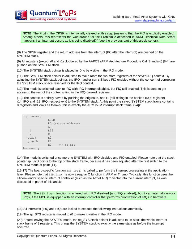
Building Bare-Metal ARM Systems with GNU
www.state-machine.com/arm
NOTE: The F bit in the CPSR is intentionally cleared at this step (meaning that the FIQ is explicitly enabled). Among others, this represents the workaround for the Problem 2 described in ARM Technical Note “What happens if an interrupt occurs as it is being disabled?” (see the previous part of this article series).
(8) The SPSR register and the return address from the interrupt (PC after the interrupt) are pushed on the SYSTEM stack.
(9) All registers (except r0 and r1) clobbered by the AAPCS (ARM Architecture Procedure Call Standard) [8-4] are pushed on the SYSTEM stack.
(10) The SYSTEM stack pointer is placed in r0 to be visible in the IRQ mode.
(11) The SYSTEM stack pointer is adjusted to make room for two more registers of the saved IRQ context. By adjusting the SYSTEM stack pointer, the IRQ handler can still keep FIQ enabled without the concern of corrupting the SYSTEM stack space reserved for the IRQ context.
(12) The mode is switched back to IRQ with IRQ interrupt disabled, but FIQ still enabled. This is done to get access to the rest of the context sitting in the IRQ-banked registers.
(13) The context is entirely saved by pushing the original r0 and r1 (still sitting in the banked IRQ Registers r14_IRQ and r13_IRQ, respectively) to the SYSTEM stack. At this point the saved SYSTEM stack frame contains 8 registers and looks as follows (this is exactly the ARM v7-M interrupt stack frame [8-4]):
high memory SPSR PC (return address) LR | R12 v R3 stack R2 growth R1 R0 <-- sp_SYS low memory
(14) The mode is switched once more to SYSTEM with IRQ disabled and FIQ enabled. Please note that the stack pointer sp_SYS points to the top of the stack frame, because it has been adjusted after the first switch to the SYSTEM mode at point (11).
(15-17) The board-specific function BSP_irq() is called to perform the interrupt processing at the application-level. Please note that BSP_irq() is now a regular C function in ARM or Thumb. Typically, this function uses the silicon-vendor specific interrupt controller (such as the Atmel AIC) to vector into the current interrupt, as was discussed in part 6 of this article.
NOTE: The BSP_irq() function is entered with IRQ disabled (and FIQ enabled), but it can internally unlock IRQs, if the MCU is equipped with an interrupt controller that performs prioritization of IRQs in hardware.
(18) All interrupts (IRQ and FIQ) are locked to execute the following instructions atomically.
(19) The sp_SYS register is moved to r0 to make it visible in the IRQ mode.
(20) Before leaving the SYSTEM mode, the sp_SYS stack pointer is adjusted to un-stack the whole interrupt stack frame of 8 registers. This brings the SYSTEM stack to exactly the same state as before the interrupt occurred.
Copyright © Quantum Leaps. All Rights Reserved. 8-3
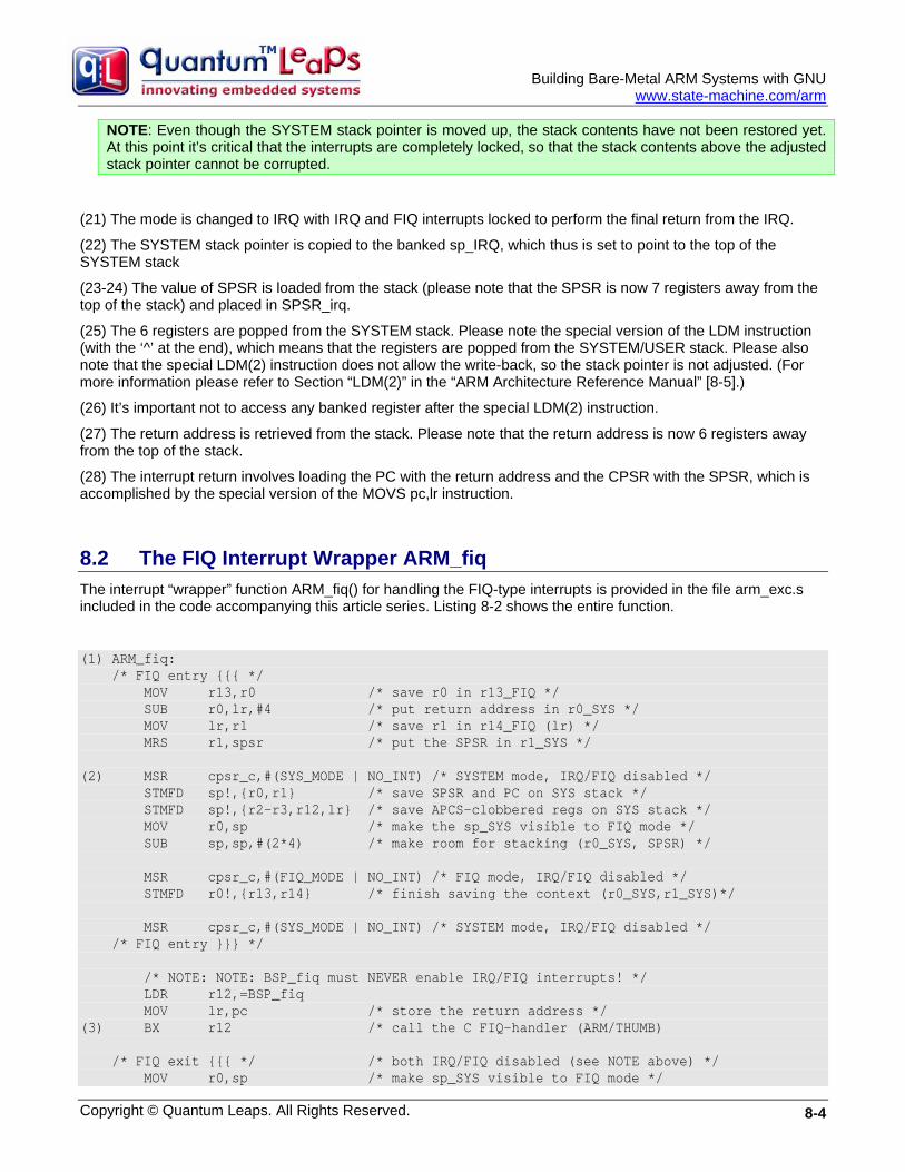
Building Bare-Metal ARM Systems with GNU
www.state-machine.com/arm
NOTE: Even though the SYSTEM stack pointer is moved up, the stack contents have not been restored yet. At this point it’s critical that the interrupts are completely locked, so that the stack contents above the adjusted stack pointer cannot be corrupted.
(21) The mode is changed to IRQ with IRQ and FIQ interrupts locked to perform the final return from the IRQ.
(22) The SYSTEM stack pointer is copied to the banked sp_IRQ, which thus is set to point to the top of the SYSTEM stack
(23-24) The value of SPSR is loaded from the stack (please note that the SPSR is now 7 registers away from the top of the stack) and placed in SPSR_irq.
(25) The 6 registers are popped from the SYSTEM stack. Please note the special version of the LDM instruction (with the ‘^’ at the end), which means that the registers are popped from the SYSTEM/USER stack. Please also note that the special LDM(2) instruction does not allow the write-back, so the stack pointer is not adjusted. (For more information please refer to Section “LDM(2)” in the “ARM Architecture Reference Manual” [8-5].)
(26) It’s important not to access any banked register after the special LDM(2) instruction.
(27) The return address is retrieved from the stack. Please note that the return address is now 6 registers away from the top of the stack.
(28) The interrupt return involves loading the PC with the return address and the CPSR with the SPSR, which is accomplished by the special version of the MOVS pc,lr instruction.
8.2 The FIQ Interrupt Wrapper ARM_fiq The interrupt “wrapper” function ARM_fiq() for handling the FIQ-type interrupts is provided in the file arm_exc.s included in the code accompanying this article series. Listing 8-2 shows the entire function.
(1) ARM_fiq: /* FIQ entry {{{ */ MOV r13,r0 /* save r0 in r13_FIQ */ SUB r0,lr,#4 /* put return address in r0_SYS */ MOV lr,r1 /* save r1 in r14_FIQ (lr) */ MRS r1,spsr /* put the SPSR in r1_SYS */ (2) MSR cpsr_c,#(SYS_MODE | NO_INT) /* SYSTEM mode, IRQ/FIQ disabled */ STMFD sp!,{r0,r1} /* save SPSR and PC on SYS stack */ STMFD sp!,{r2-r3,r12,lr} /* save APCS-clobbered regs on SYS stack */ MOV r0,sp /* make the sp_SYS visible to FIQ mode */ SUB sp,sp,#(2*4) /* make room for stacking (r0_SYS, SPSR) */ MSR cpsr_c,#(FIQ_MODE | NO_INT) /* FIQ mode, IRQ/FIQ disabled */ STMFD r0!,{r13,r14} /* finish saving the context (r0_SYS,r1_SYS)*/ MSR cpsr_c,#(SYS_MODE | NO_INT) /* SYSTEM mode, IRQ/FIQ disabled */ /* FIQ entry }}} */ /* NOTE: NOTE: BSP_fiq must NEVER enable IRQ/FIQ interrupts! */ LDR r12,=BSP_fiq MOV lr,pc /* store the return address */ (3) BX r12 /* call the C FIQ-handler (ARM/THUMB) /* FIQ exit {{{ */ /* both IRQ/FIQ disabled (see NOTE above) */ MOV r0,sp /* make sp_SYS visible to FIQ mode */
Copyright © Quantum Leaps. All Rights Reserved. 8-4
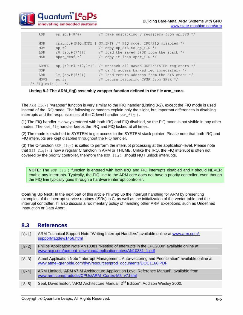
Building Bare-Metal ARM Systems with GNU
www.state-machine.com/arm
ADD sp,sp,#(8*4) /* fake unstacking 8 registers from sp_SYS */ MSR cpsr_c,#(FIQ_MODE | NO_INT) /* FIQ mode, IRQ/FIQ disabled */ MOV sp,r0 /* copy sp_SYS to sp_FIQ */ LDR r0,[sp,#(7*4)] /* load the saved SPSR from the stack */ MSR spsr_cxsf,r0 /* copy it into spsr_FIQ */ LDMFD sp,{r0-r3,r12,lr}^ /* unstack all saved USER/SYSTEM registers */ NOP /* can't access banked reg immediately */ LDR lr,[sp,#(6*4)] /* load return address from the SYS stack */ MOVS pc,lr /* return restoring CPSR from SPSR */ /* FIQ exit }}} */
Listing 8-2 The ARM_fiq() assembly wrapper function defined in the file arm_exc.s.
The ARM_fiq() “wrapper” function is very similar to the IRQ handler (Listing 8-2), except the FIQ mode is used instead of the IRQ mode. The following comments explain only the slight, but important differences in disabling interrupts and the responsibilities of the C-level handler BSP_fiq().
(1) The FIQ handler is always entered with both IRQ and FIQ disabled, so the FIQ mode is not visible in any other modes. The ARM_fiq handler keeps the IRQ and FIQ locked at all times.
(2) The mode is switched to SYSTEM to get access to the SYSTEM stack pointer. Please note that both IRQ and FIQ interrupts are kept disabled throughout the FIQ handler.
(3) The C-function BSP_fiq() is called to perform the interrupt processing at the application-level. Please note that BSP_fiq() is now a regular C function in ARM or THUMB. Unlike the IRQ, the FIQ interrupt is often not covered by the priority controller, therefore the BSP_fiq() should NOT unlock interrupts.
NOTE: The BSP_fiq() function is entered with both IRQ and FIQ interrupts disabled and it should NEVER enable any interrupts. Typically, the FIQ line to the ARM core does not have a priority controller, even though the FIQ line typically goes through a hardware interrupt controller.
Coming Up Next: In the next part of this article I’ll wrap up the interrupt handling for ARM by presenting examples of the interrupt service routines (ISRs) in C, as well as the initialization of the vector table and the interrupt controller. I’ll also discuss a rudimentary policy of handling other ARM Exceptions, such as Undefined Instruction or Data Abort.
8.3 References [8-1] ARM Technical Support Note “Writing Interrupt Handlers” available online at www.arm.com/-
support/faqdev/1456.html
[8-2] Philips Application Note AN10381 “Nesting of Interrupts in the LPC2000” available online at www.nxp.com/acrobat_download/applicationnotes/AN10381_1.pdf
[8-3] Atmel Application Note “Interrupt Management: Auto-vectoring and Prioritization” available online at www.atmel-grenoble.com/dyn/resources/prod_documents/DOC1168.PDF
[8-4] ARM Limited, “ARM v7-M Architecture Application Level Reference Manual”, available from www.arm.com/products/CPUs/ARM_Cortex-M3_v7.html
[8-5] Seal, David Editor, “ARM Architecture Manual, 2nd Edition”, Addison Wesley 2000.
Copyright © Quantum Leaps. All Rights Reserved. 8-5
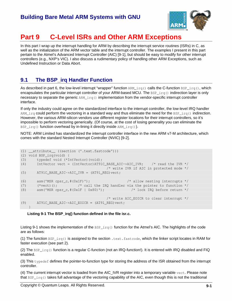
Building Bare Metal ARM Systems with GNU
Copyright © Quantum Leaps. All Rights Reserved. 9-1
Part 9 C-Level ISRs and Other ARM Exceptions In this part I wrap up the interrupt handling for ARM by describing the interrupt service routines (ISRs) in C, as well as the initialization of the ARM vector table and the interrupt controller. The examples I present in this part pertain to the Atmel’s Advanced Interrupt Controller (AIC) [9-1], but should be easy to modify for other interrupt controllers (e.g., NXP’s VIC). I also discuss a rudimentary policy of handling other ARM Exceptions, such as Undefined Instruction or Data Abort.
9.1 The BSP_irq Handler Function As described in part 6, the low-level interrupt “wrapper” function ARM_irq() calls the C-function BSP_irq(), which encapsulates the particular interrupt controller of your ARM-based MCU. The BSP_irq() indirection layer is only necessary to separate the generic ARM_irq() implementation from the vendor-specific interrupt controller interface.
If only the industry could agree on the standardized interface to the interrupt controller, the low-level IRQ handler ARM_irq could perform the vectoring in a standard way and thus eliminate the need for the BSP_irq() indirection. However, the various ARM-silicon vendors use different register locations for their interrupt controllers, so it’s impossible to perform vectoring generically. (Of course, at the cost of losing generality you can eliminate the BSP_irq() function overhead by in-lining it directly inside ARM_irq()).
NOTE: ARM Limited has standardized the interrupt controller interface in the new ARM v7-M architecture, which comes with the standard Nested Interrupt Controller (NVIC) [9-2].
(1) __attribute__ ((section (".text.fastcode"))) (2) void BSP_irq(void) { (3) typedef void (*IntVector)(void); (4) IntVector vect = (IntVector)AT91C_BASE_AIC->AIC_IVR; /* read the IVR */ /* write IVR if AIC in protected mode */ (5) AT91C_BASE_AIC->AIC_IVR = (AT91_REG)vect; (6) asm("MSR cpsr_c,#(0x1F)"); /* allow nesting interrupts */ (7) (*vect)(); /* call the IRQ handler via the pointer to function */ (8) asm("MSR cpsr_c,#(0x1F | 0x80)"); /* lock IRQ before return */ /* write AIC_EOICR to clear interrupt */ (9) AT91C_BASE_AIC->AIC_EOICR = (AT91_REG)vect; }
Listing 9-1 The BSP_irq() function defined in the file isr.c.
Listing 9-1 shows the implementation of the BSP_irq() function for the Atmel’s AIC. The highlights of the code are as follows:
(1) The function BSP_irq() is assigned to the section .text.fastcode, which the linker script locates in RAM for faster execution (see part 2).
(2) The BSP_irq() function is a regular C-function (not an IRQ-function!). It is entered with IRQ disabled and FIQ enabled.
(3) This typedef defines the pointer-to-function type for storing the address of the ISR obtained from the interrupt controller.
(4) The current interrupt vector is loaded from the AIC_IVR register into a temporary variable vect. Please note that BSP_irq() takes full advantage of the vectoring capability of the AIC, even though this is not the traditional
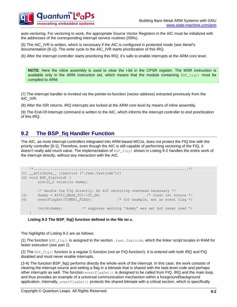
Building Bare-Metal ARM Systems with GNU
www.state-machine.com/arm
auto-vectoring. For vectoring to work, the appropriate Source Vector Registers in the AIC must be initialized with the addresses of the corresponding interrupt service routines (ISRs).
(5) The AIC_IVR is written, which is necessary if the AIC is configured in protected mode (see Atmel’s documentation [9-1]). The write cycle to the AIC_IVR starts prioritization of this IRQ.
(6) After the interrupt controller starts prioritizing this IRQ, it’s safe to enable interrupts at the ARM core level.
NOTE: Here the inline assembly is used to clear the I-bit in the CPSR register. The MSR instruction is available only in the ARM instruction set, which means that the module containing BSP_irq() must be compiled to ARM.
(7) The interrupt handler is invoked via the pointer-to-function (vector address) extracted previously from the AIC_IVR.
(8) After the ISR returns, IRQ interrupts are locked at the ARM core level by means of inline assembly.
(9) The End-Of-Interrupt command is written to the AIC, which informs the interrupt controller to end prioritization of this IRQ.
9.2 The BSP_fiq Handler Function The AIC, as most interrupt controllers integrated into ARM-based MCUs, does not protect the FIQ line with the priority controller [9-1]. Therefore, even though the AIC is still capable of performing vectoring of the FIQ, it doesn’t really add much value. The implementation of BSP_fiq() shown in Listing 9-2 handles the entire work of the interrupt directly, without any interaction with the AIC.
/*..........................................................................*/ (1) __attribute__ ((section (".text.fastcode"))) (2) void BSP_fiq(void) { uint32_t volatile dummy; /* Handle the FIQ directly. No AIC vectoring overhead necessary */ (3) dummy = AT91C_BASE_TC1->TC_SR; /* clear int soruce */ (4) eventFlagSet(TIMER1_FLAG); /* for example, set an event flag */ (void)dummy; /* suppress warning "dummy" was set but never used */ }
Listing 9-2 The BSP_fiq() function defined in the file isr.c.
The highlights of Listing 9-2 are as follows:
(1) The function BSP_fiq() is assigned to the section .text.fastcode, which the linker script locates in RAM for faster execution (see part 2).
(2) The BSP_fiq() function is a regular C-function (not an FIQ-function!). It is entered with both IRQ and FIQ disabled and must never enable interrupts.
(3-4) The function BSP_fiq() performs directly the whole work of the interrupt. In this case, the work consists of clearing the interrupt source and setting a flag in a bitmask that is shared with the task-level code and perhaps other interrupts as well. The function eventFlagSet() is designed to be called from FIQ, IRQ and the main loop, and thus provides an example of a universal communication mechanism within a foreground/background application. Internally, eventFlagSet() protects the shared bitmask with a critical section, which is specifically
Copyright © Quantum Leaps. All Rights Reserved. 9-2
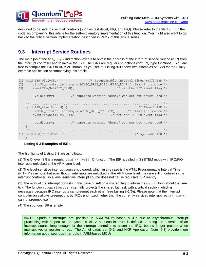
Building Bare-Metal ARM Systems with GNU
www.state-machine.com/arm
designed to be safe to use in all contexts (such as task-level, IRQ, and FIQ). Please refer to the file isr.c in the code accompanying this article for the self-explanatory implementation of this function. You might also want to go back to the critical section implementation described in Part 7 of this article series.
9.3 Interrupt Service Routines The main job of the BSP_irq() indirection layer is to obtain the address of the interrupt service routine (ISR) from the interrupt controller and to invoke the ISR. The ISRs are regular C-functions (not IRQ-type functions!). You are free to compile the ISRs to ARM or Thumb, as you see fit. Listing 9-3 shows two examples of ISRs for the Blinky example application accompanying this article.
(1) void ISR_pit(void) { /* Programmable Interval Timer (PIT) ISR */ (2) uint32_t volatile dummy = AT91C_BASE_PITC->PITC_PIVR;/*clear int source */ (3) eventFlagSet(PIT_FLAG); /* set the PIT event flag */ (void)dummy; /* suppress warning "dummy" was set but never used */ } /*..........................................................................*/ void ISR_timer0(void) { /* Timer0 ISR */ uint32_t volatile dummy = AT91C_BASE_TC0->TC_SR; /* clear int soruce */ eventFlagSet(TIMER0_FLAG); /* set the TIMER0 event flag */ (void)dummy; /* suppress warning "dummy" was set but never used */ } /*..........................................................................*/ (4) void ISR_spur(void) { /* spurious ISR */ }
Listing 9-3 Examples of ISRs. The highlights of Listing 9-3 are as follows:
(1) The C-level ISR is a regular void (*)(void) C-function. The ISR is called in SYSTEM mode with IRQ/FIQ interrupts unlocked at the ARM core level.
(2) The level-sensitive interrupt source is cleared, which in this case is the AT91 Programmable Interval Timer (PIT). Please note that even though interrupts are unlocked at the ARM core level, they are still prioritized in the interrupt controller, so a level-sensitive interrupt source does not cause recursive ISR reentry.
(3) The work of the interrupt consists in this case of setting a shared flag to inform the main() loop about the time tick. The function eventFlagSet() internally protects the shared bitmask with a critical section, which is necessary because IRQ interrupts can preempt each other (see Listing 8-1(6)). Please note that the interrupt controller only allows preemptions by IRQs prioritized higher than the currently serviced interrupt, so ISR_tick() cannot preempt itself.
(4) The spurious ISR is empty.
NOTE: Spurious interrupts are possible in ARM7/ARM9-based MCUs due to asynchronous interrupt processing with respect to the system clock. A spurious interrupt is defined as being the assertion of an interrupt source long enough for the interrupt controller to assert the IRQ, but no longer present when interrupt vector register is read. The Atmel datasheet [9-1] and NXP Application Note [9-3] provide more information about spurious interrupts in ARM-based MCUs.
Copyright © Quantum Leaps. All Rights Reserved. 9-3
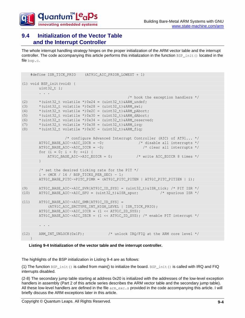
Building Bare-Metal ARM Systems with GNU
www.state-machine.com/arm
9.4 Initialization of the Vector Table and the Interrupt Controller
The whole interrupt handling strategy hinges on the proper initialization of the ARM vector table and the interrupt controller. The code accompanying this article performs this initialization in the function BSP_init() located in the file bsp.c.
#define ISR_TICK_PRIO (AT91C_AIC_PRIOR_LOWEST + 1) (1) void BSP_init(void) { uint32_t i; . . . /* hook the exception handlers */ (2) *(uint32_t volatile *)0x24 = (uint32_t)&ARM_undef; (3) *(uint32_t volatile *)0x28 = (uint32_t)&ARM_swi; (4) *(uint32_t volatile *)0x2C = (uint32_t)&ARM_pAbort; (5) *(uint32_t volatile *)0x30 = (uint32_t)&ARM_dAbort; (6) *(uint32_t volatile *)0x34 = (uint32_t)&ARM_reserved; (7) *(uint32_t volatile *)0x38 = (uint32_t)&ARM_irq; (8) *(uint32_t volatile *)0x3C = (uint32_t)&ARM_fiq; /* configure Advanced Interrupt Controller (AIC) of AT91... */ AT91C_BASE_AIC->AIC_IDCR = ~0; /* disable all interrupts */ AT91C_BASE_AIC->AIC_ICCR = ~0; /* clear all interrupts */ for (i = 0; i < 8; ++i) { AT91C_BASE_AIC->AIC_EOICR = 0; /* write AIC_EOICR 8 times */ } /* set the desired ticking rate for the PIT */ i = (MCK / 16 / BSP_TICKS_PER_SEC) - 1; AT91C_BASE_PITC->PITC_PIMR = (AT91C_PITC_PITEN | AT91C_PITC_PITIEN | i); (9) AT91C_BASE_AIC->AIC_SVR[AT91C_ID_SYS] = (uint32_t)&ISR_tick; /* PIT ISR */ (10) AT91C_BASE_AIC->AIC_SPU = (uint32_t)&ISR_spur; /* spurious ISR */ (11) AT91C_BASE_AIC->AIC_SMR[AT91C_ID_SYS] = (AT91C_AIC_SRCTYPE_INT_HIGH_LEVEL | ISR_TICK_PRIO); AT91C_BASE_AIC->AIC_ICCR = (1 << AT91C_ID_SYS); AT91C_BASE_AIC->AIC_IECR = (1 << AT91C_ID_SYS); /* enable PIT interrupt */ . . . (12) ARM_INT_UNLOCK(0x1F); /* unlock IRQ/FIQ at the ARM core level */ }
Listing 9-4 Initialization of the vector table and the interrupt controller.
The highlights of the BSP initialization in Listing 9-4 are as follows:
(1) The function BSP_init() is called from main() to initialize the board. BSP_init() is called with IRQ and FIQ interrupts disabled.
(2-8) The secondary jump table starting at address 0x20 is initialized with the addresses of the low-level exception handlers in assembly (Part 2 of this article series describes the ARM vector table and the secondary jump table). All these low-level handlers are defined in the file arm_exc.s provided in the code accompanying this article. I will briefly discuss the ARM exceptions later in this article.
Copyright © Quantum Leaps. All Rights Reserved. 9-4
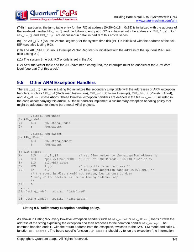
Building Bare-Metal ARM Systems with GNU
www.state-machine.com/arm
(7-8) In particular, the jump table entry for the IRQ at address (0x20+0x18==0x38) is initialized with the address of the low-level handler ARM_irq() and the following entry at 0x3C is initialized with the address of ARM_fiq(). Both ARM_irq() and ARM_fiq() are discussed in detail in part 8 of this article series.
(9) The AIC_SVR (Source Vector Register) for the system time tick (PIT) is initialized with the address of the tick ISR (see also Listing 9-3).
(10) The AIC_SPU (Spurious Interrupt Vector Register) is initialized with the address of the spurious ISR (see also Listing 9-3).
(11) The system time tick IRQ priority is set in the AIC.
(12) After the vector table and the AIC have been configured, the interrupts must be enabled at the ARM core level (see part 7 of this article).
9.5 Other ARM Exception Handlers The BSP_init() function in Listing 9-5 initializes the secondary jump table with the addresses of ARM exception handlers, such as ARM_und (Undefined Instruction), ARM_swi (Software Interrupt), ARM_pAbort (Prefetch Abort), and ARM_dAbort (Data Abort). These low-level exception handlers are defined in the file arm_exc.c included in the code accompanying this article. All these handlers implement a rudimentary exception handling policy that might be adequate for simple bare-metal ARM projects.
.global ARM_undef (1) ARM_undef: (2) LDR r0,Csting_undef (3) B ARM_except . . . .global ARM_dAbort (4) ARM_dAbort: LDR r0,Csting_dAbort B ARM_except . . . (5) ARM_except: (6) SUB r1,lr,#4 /* set line number to the exception address */ (7) MSR cpsr_c,#(SYS_MODE | NO_INT) /* SYSTEM mode, IRQ/FIQ disabled */ (8) LDR r12,=BSP_abort (9) MOV lr,pc /* store the return address */ (10) BX r12 /* call the assertion-handler (ARM/THUMB) */ /* the abort handler should not return, but in case it does * hang up the machine in the following endless loop */ (11) B . . . . . (12) Csting_undef: .string "Undefined" . . . (13) Csting_undef: .string "Data Abort" . . .
Listing 9-5 Rudimentary exception handling policy.
As shown in Listing 9-5, every low-level exception handler (such as ARM_undef or ARM_dAbort) loads r0 with the address of the string explaining the exception and then branches to the common handler ARM_except. The common handler loads r1 with the return address from the exception, switches to the SYSTEM mode and calls C-function BSP_abort(). The board-specific function BSP_abort() should try to log the exception (the information
Copyright © Quantum Leaps. All Rights Reserved. 9-5
Building Bare-Metal ARM Systems with GNU
www.state-machine.com/arm
about the exception is provided in r0 and r1, which are the arguments of this function call), put the system in a fail-safe state, and possibly reset the system. This function should never return because there is nothing to return to in a bare-metal system. During development, BSP_abort() is a good place to set a permanent breakpoint.
Coming Up Next: In the next and final part of this article I’ll describe the example application that accompanies this article series and provide strategies for testing of the various preemption scenarios of interrupt handling.
9.6 References [9-1] Atmel Datasheet “AT91 ARM/Thumb-based Microcontrollers, AT91SAM7S64 …” available online at
www.atmel.com/dyn/resources/prod_documents/doc6175.pdf.
[9-2] ARM Limited, “ARM v7-M Architecture Application Level Reference Manual”, available from www.arm.com/products/CPUs/ARM_Cortex-M3_v7.html.
[9-3] NXP Application Note AN10414 “Handling of spurious interrupts in the LPC2000”, available online at www.nxp.com/acrobat_download/applicationnotes/AN10414_1.pdf.
Copyright © Quantum Leaps. All Rights Reserved. 9-6

Building Bare Metal ARM Systems with GNU
Copyright © Quantum Leaps. All Rights Reserved.
Part 10 Example Application and Testing Strategies
In this final part of this article series I explain the “Blinky” example application included in the code accompanying this article. I also give some tips for manual testing of various interrupt preemption scenarios.
10.1 The Blinky Example Application The example project is called “Blinky” because it blinks the 4 user LEDs of the AT91SAM7S-EK evaluation board (see Figure 10-1). Blinky is just a primitive foreground/background (main+ISRs) application, but has been carefully design to demonstrate all the features and techniques discussed in this multi-part article.
4 User LEDs
AT91SAM7S64
Figure 10-1 Atmel AT91SAM7S-EK evaluation board executing the Blinky application.
10-1
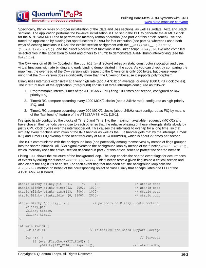
Building Bare-Metal ARM Systems with GNU
www.state-machine.com/arm
Specifically, Blinky relies on proper initialization of the .data and .bss sections, as well as .rodata, .text, and .stack sections. The application performs the low-level initialization in C to setup the PLL to generate the 48MHz clock for the AT91SAM MCU and to perform the memory remap operation (see part 2 of this article series). I’ve fine-tuned the application by placing hot-spot functions in RAM for fast execution (see part 5), whereas I used both ways of locating functions in RAM: the explicit section assignment with the __attribute__ ((section (".text.fastcode"))), and the direct placement of functions in the linker script blinky.ld. I’ve also compiled selected files in the application to ARM and others to Thumb to demonstrate ARM-Thumb interworking (see the Makefile).
The C++ version of Blinky (located in the cpp_blinky directory) relies on static constructor invocation and uses virtual functions with late binding and early binding demonstrated in the code. As you can check by comparing the map files, the overhead of the C++ version with respect to the C version is only 500 bytes, but please keep in mind that the C++ version does significantly more than the C version because it supports polymorphism.
Blinky uses interrupts extensively at a very high rate (about 47kHz on average, or every 1000 CPU clock cycles). The interrupt level of the application (foreground) consists of three interrupts configured as follows:
1. Programmable Interval Timer of the AT91SAM7 (PIT) firing 100 times per second, configured as low-priority IRQ;
2. Timer0 RC-compare occurring every 1000 MCK/2 clocks (about 24kHz rate), configured as high-priority IRQ, and
3. Timer1 RC-compare occurring every 999 MCK/2 clocks (about 24kHz rate) configured as FIQ by means of the “fast forcing” feature of the AT91SAM7S MCU [10-1].
I’ve specifically configured the clocks of Timer0 and Timer1 to the maximum available frequency (MCK/2) and have chosen their periods very close to each other so that the relative phasing of these interrupts shifts slowly by just 2 CPU clock cycles over the interrupt period. This causes the interrupts to overlap for a long time, so that virtually every machine instruction of the IRQ handler as well as the FIQ handler gets “hit” by the interrupt. Timer0 IRQ and Timer1 FIQ overlap at the beat frequency of MCK/2/(1000*999), which is about 27 times per second.
The ISRs communicate with the background loop (and potentially among themselves) by means of flags grouped into the shared bitmask. All ISRs signal events to the background loop by means of the function eventFlagSet(), which internally uses the critical section described in part 7 of this article series to protect the shared bitmask.
Listing 10-1 shows the structure of the background loop. The loop checks the shared event flags for occurrences of events by calling the function eventFlagCheck(). This function tests a given flag inside a critical section and also clears the flag if it’s been set. For each event flag that has been set, the background loop calls the dispatch() method on behalf of the corresponding object of class Blinky that encapsulates one LED of the AT91SAM7S-EK board.
static Blinky blinky_pit (1, 9, 1); // static ctor static Blinky blinky_timer0(2, 9000, 1000); // static ctor static Blinky blinky_timer1(3, 9000, 1000); // static ctor static Blinky blinky_idle (0, 18000, 2000); // static ctor static Blinky *pBlinky[] = { // pointers to Blinky (.data section) &blinky_pit, &blinky_timer0, &blinky_timer1 }; int main (void) { BSP_init(); // initialize the Board Support Package for (;;) { // for-ever if (eventFlagCheck(PIT_FLAG)) { pBlinky[PIT_FLAG]->dispatch(); // late binding
Copyright © Quantum Leaps. All Rights Reserved. 10-2
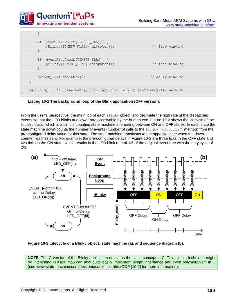
Building Bare-Metal ARM Systems with GNU
www.state-machine.com/arm
} if (eventFlagCheck(TIMER0_FLAG)) { pBlinky[TIMER0_FLAG]->dispatch(); // late binding } if (eventFlagCheck(TIMER1_FLAG)) { pBlinky[TIMER1_FLAG]->dispatch(); // late binding } blinky_idle.dispatch(); // early binding } return 0; // unreachable; this return is only to avoid compiler warning }
Listing 10-1 The background loop of the Blink application (C++ version).
From the user’s perspective, the main job of each Blinky object is to decimate the high rate of the dispatched events so that the LED blinks at a lower rate observable by the human eye. Figure 10-2 shows the lifecycle of the Blinky class, which is a simple counting state machine alternating between ON and OFF states. In each state the state machine down-counts the number of events (number of calls to the Blinky::dispatch() method) from the pre-configured delay value for this state. The state machine transitions to the opposite state when the down-counter reaches zero. For example, the pre-configured delays in Figure 10-2 are three ticks in the OFF state and two ticks in the ON state, which results in the LED blink rate of 1/5 of the original event rate with the duty cycle of 2/3.
OFF ON
dispatch()
OFF
OFF DelayON Delay
Time
Blin
ky_c
tor()
dispatch()
dispatch()
dispatch()
dispatch()
dispatch()
dispatch()
dispatch()
dispatch()
OFF Delay
ON
off
/ ctr = offDelay; LED_OFF(id);
EVENT [--ctr == 0] / ctr = onDelay; LED_ON(id);
EVENT [--ctr == 0] / ctr = offDelay; LED_OFF(id);
on
(a) (b)
:Blinky
BackgroundLoop
ISREvent
Figure 10-2 Lifecycle of a Blinky object: state machine (a), and sequence diagram (b).
NOTE: The C version of the Blinky application emulates the class concept in C. This simple technique might be interesting in itself. You can also quite easily implement single inheritance and even polymorphism in C (see www.state-machine.com/devzone/cookbook.htm#OOP [10-2] for more information).
Copyright © Quantum Leaps. All Rights Reserved. 10-3
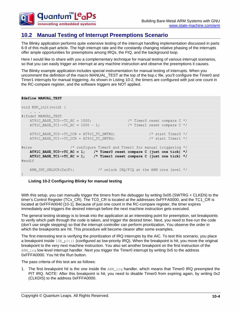
Building Bare-Metal ARM Systems with GNU
www.state-machine.com/arm
10.2 Manual Testing of Interrupt Preemptions Scenario The Blinky application performs quite extensive testing of the interrupt handling implementation discussed in parts 6-9 of this multi-part article. The high interrupt rate and the constantly changing relative phasing of the interrupts offer ample opportunities for preemptions among IRQs, the FIQ, and the background loop.
Here I would like to share with you a complementary technique for manual testing of various interrupt scenarios, so that you can easily trigger an interrupt at any machine instruction and observe the preemptions it causes.
The Blinky example application includes special instrumentation for manual testing of interrupts. When you uncomment the definition of the macro MANUAL_TEST at the top of the bsp.c file, you’ll configure the Timer0 and Timer1 interrupts for manual triggering. As shown in Listing 10-2, the timers are configured with just one count in the RC-compare register, and the software triggers are NOT applied.
#define MANUAL_TEST void BSP_init(void) { . . . #ifndef MANUAL_TEST AT91C_BASE_TC0->TC_RC = 1000; /* Timer0 reset compare C */ AT91C_BASE_TC1->TC_RC = 1000 - 1; /* Timer1 reset compare C */ AT91C_BASE_TC0->TC_CCR = AT91C_TC_SWTRG; /* start Timer0 */ AT91C_BASE_TC1->TC_CCR = AT91C_TC_SWTRG; /* start Timer1 */ #else /* configure Timer0 and Timer1 for manual triggering */ AT91C_BASE_TC0->TC_RC = 1; /* Timer0 reset compare C (just one tick) */ AT91C_BASE_TC1->TC_RC = 1; /* Timer1 reset compare C (just one tick) */ #endif ARM_INT_UNLOCK(0x1F); /* unlock IRQ/FIQ at the ARM core level */ }
Listing 10-2 Configuring Blinky for manual testing
With this setup, you can manually trigger the timers from the debugger by writing 0x05 (SWTRG + CLKEN) to the timer’s Control Register (TCx_CR). The TC0_CR is located at the addresses 0xFFFA0000, and the TC1_CR is located at 0xFFFA0040 [10-1]. Because of just one count in the RC-compare register, the timer expires immediately and triggers the desired interrupt before the next machine instruction gets executed.
The general testing strategy is to break into the application at an interesting point for preemption, set breakpoints to verify which path through the code is taken, and trigger the desired timer. Next, you need to free-run the code (don’t use single stepping) so that the interrupt controller can perform prioritization. You observe the order in which the breakpoints are hit. This procedure will become clearer after some examples.
The first interesting test is verifying the prioritization of IRQ interrupts by the AIC. To test this scenario, you place a breakpoint inside ISR_pit() (configured as low-priority IRQ). When the breakpoint is hit, you move the original breakpoint to the very next machine instruction. You also set another breakpoint on the first instruction of the ARM_irq low-level interrupt handler. Next you trigger the Timer0 interrupt by writing 0x5 to the address 0xFFFA0000. You hit the Run button.
The pass criteria of this test are as follows:
1. The first breakpoint hit is the one inside the ARM_irq handler, which means that Timer0 IRQ preempted the PIT IRQ. NOTE: After this breakpoint is hit, you need to disable Timer0 from expiring again, by writing 0x2 (CLKDIS) to the address 0xFFFA0000.
Copyright © Quantum Leaps. All Rights Reserved. 10-4

Building Bare-Metal ARM Systems with GNU
www.state-machine.com/arm
2. The second breakpoint hit is the one inside ISR_pit(), which means that the low-priority IRQ continues after the Timer0 IRQ completes.
You need to remove all breakpoints before proceeding to the next test.
The next interesting test is verifying that FIQ preempts any IRQ, but only outside a critical section. You start by setting a breakpoint inside any critical section, say in the eventCheckFlag() function. You run the application. After the breakpoint is hit, you trigger both Timer0 and Timer1, by writing 0x5 to 0xFFFA0000 and 0xFFFA0040. Before you free-run again, you move the original breakpoint to the next machine instruction and set another breakpoint one machine instruction after the exit from the critical section (at the BX r14 instruction). You also set breakpoints on the first instruction of ARM_irq and ARM_fiq.
The pass criteria of this test are as follows:
1. The first breakpoint hit is the one inside the eventCheckFlag() function, which means that critical section cannot be preempted by any pending interrupts.
2. The second breakpoint hit is the one in ARM_fiq interrupt handler, which means that FIQ wins the head-to-head run against the IRQ. NOTE: At this point you need to disable the Timer1 clock from expiring again, by writing 0x2 (CLKDIS) to the address 0xFFFA0040.
3. The third breakpoint is the one in ARM_irq, which means that IRQ follows back-to-back the FIQ, before returning to the task-level code. NOTE: At this point you need to disable the Timer0 clock from expiring again, by writing 0x2 (CLKDIS) to the address 0xFFFA0000.
4. Finally, the breakpoint at the end of eventCheckFlag() function is hit, which means that the task continues only after all interrupts complete.
I’m sure that this technique can help you in performing many more interesting tests to study various preemption scenarios.
10.3 Summary In this 10-part article series I’ve explained most of the code and techniques that you will need to build-bare metal ARM systems with the GNU toolchain. I hope that you will find this article a significant time-saver, which will not only help you to jump-start your project, but also form the backbone of your final ARM-based product.
10.4 References [10-1] Atmel Datasheet “AT91 ARM/Thumb-based Microcontrollers, AT91SAM7S64 …” available online at
www.atmel.com/dyn/resources/prod_documents/doc6175.pdf
[10-2] Quantum Leaps, LLC, Object-oriented programming in C, www.state-machine.com/-devzone/cookbook.htm#OOP.
Copyright © Quantum Leaps. All Rights Reserved. 10-5
Building Bare Metal ARM Systems with GNU
Copyright © Quantum Leaps. All Rights Reserved.
Part 11 Contact Information
Dr. Miro Samek is founder and president of Quantum Leaps, an open source company providing lightweight, state machine-based, event-driven application frameworks for embedded systems. He is the author of "Practical UML Statecharts in C/C++, Second Edition: Event-Driven Programming for Embedded Systems" (Newnes 2008), has written numerous articles for magazines, including a column for C/C++ Users Journal, is a regular speaker at the Embedded Systems Conferences, and serves on the editorial review board of the Embedded Systems Design magazine. For a number of years, he worked in various Silicon Valley companies as an embedded software architect and before that he worked as an embedded software engineer at GE Medical Systems (now GE Healthcare). Dr. Samek earned his Ph.D. in nuclear physics at GSI (Darmstadt, Germany). e-mail: miro@quantum-leaps com
Quantum Leaps, LLC 103 Cobble Ridge Drive Chapel Hill, NC 27516 USA +1 866 450 LEAP (toll free, USA only) +1 919 869-2998 (FAX) e-mail: [email protected] WEB : http://www.quantum-leaps.com http://www.state-machine.com
“Practical UML Statecharts in C/C++, Second Edition: Event Driven Programming for Embedded Systems”, by Miro Samek, Newnes, 2008 ISBN-10: 0750687061 ISBN-13: 978- 0750687065
11-1
Related Documents