Page 1 Copyright 2005 Martin Catt, all rights reserved. Building A Variable-Voltage Power Supply For Testing Quartz Movements, Part 1 By Martin Catt In the previous article, we discussed the drawbacks of using a simple resistive voltage divider for testing quartz movements. We saw how the load placed on the voltage divider when the step motor coil fired would cause a momentary but significant drop in voltage. Modern electronic quartz watch test equipment use a more sophisticated power supply circuit that is insensitive to the load from the movement under test. In this next article, I’ll cover how to construct a simple power supply using common components that will match the performance of the most expensive dedicated test instruments for less than twenty-five dollars. Figure 1 shows the completed circuit board. The two large 3-lead components that look like power transistors are actually a pair of sophisticated voltage regulator integrated circuits. The design uses an LM317 voltage regulator integrated circuit (IC) to take the twelve volt direct current from the wall adapter and convert it to a variable output voltage. The LM317 is a simple-looking device, with only three connections to the outside world. Inside, however, is a complicated linear electronic circuit designed to sense and maintain an output voltage determined by a pair of resistors connected across two of the three leads. Using the LM317 drops the number of individual electronic components required from over fifty down to less than ten, greatly simplifying construction. In a perfect world, a single LM317, a couple of fixed resistors, and one variable resistor would be all we need to build our power supply. The LM317 has one drawback, however: the lowest you can drive the output voltage is about 1.2 volts. For most watch testing applications, you need to be able to turn the voltage down to at least .8 volts, and preferably even lower. The problem is solved by adding a second voltage regulator IC, an LM7805. Like the LM317, the LM7805 is a three-lead device. Unlike the LM317, the LM7805 is a fixed-voltage regulator, preset to put out exactly five volts. The output voltage is fixed and cannot be changed. We get the zero-to-three volt range by using the difference in the output voltages from each regulator. The five volts from the LM7805 serves as the ground level for the testing voltage, and is connected to the negative battery terminal of the movement under test. The LM317 is set up to provide a voltage adjustable from five to eight volts. This variable voltage is connected to the positive battery terminal of the movement under test. What the movement sees is the difference between the two voltages. When the LM317 is putting out 6.5 volts, the movement is actually seeing only 1.5 volts (6.5 volts - 5 volts = 1.5 volts). By using the 7805 to shift the ground voltage, we can get the range we require by careful selection of the fixed resistors in the circuit. Figure 2 shows the schematic and parts list. An added benefit of using both the LM317 and LM7805 is that both IC’s have built-in short circuit protection, so if you accidentally short the test leads together, you won’t blow the power supply. Each regulator is rated to provide at least one amp of current, well above the needs of any watch movement. In normal practice, each regulator would have to be mounted on a heat sink to provide their maximum rated current. In our application, however, the current demands are so low that no heat sink is required, and the regulators are simply soldered to the circuit board and the mounting tab provides what little heat dissipation is required. In case you’re worried that you might not be able to find either of the regulator IC’s, let me put your mind at ease. Both of these regulators are among the most commonly used devices in the electronics industry,

Welcome message from author
This document is posted to help you gain knowledge. Please leave a comment to let me know what you think about it! Share it to your friends and learn new things together.
Transcript

Page 1Copyright 2005 Martin Catt, all rights reserved.
Building A Variable-Voltage Power Supply
For Testing Quartz Movements, Part 1
By
Martin Catt
In the previous article, we discussed the drawbacks of
using a simple resistive voltage divider for testing
quartz movements. We saw how the load placed on
the voltage divider when the step motor coil fired
would cause a momentary but significant drop in
voltage. Modern electronic quartz watch test
equipment use a more sophisticated power supply
circuit that is insensitive to the load from the
movement under test. In this next article, I’ll cover
how to construct a simple power supply using
common components that will match the performance
of the most expensive dedicated test instruments for
less than twenty-five dollars.
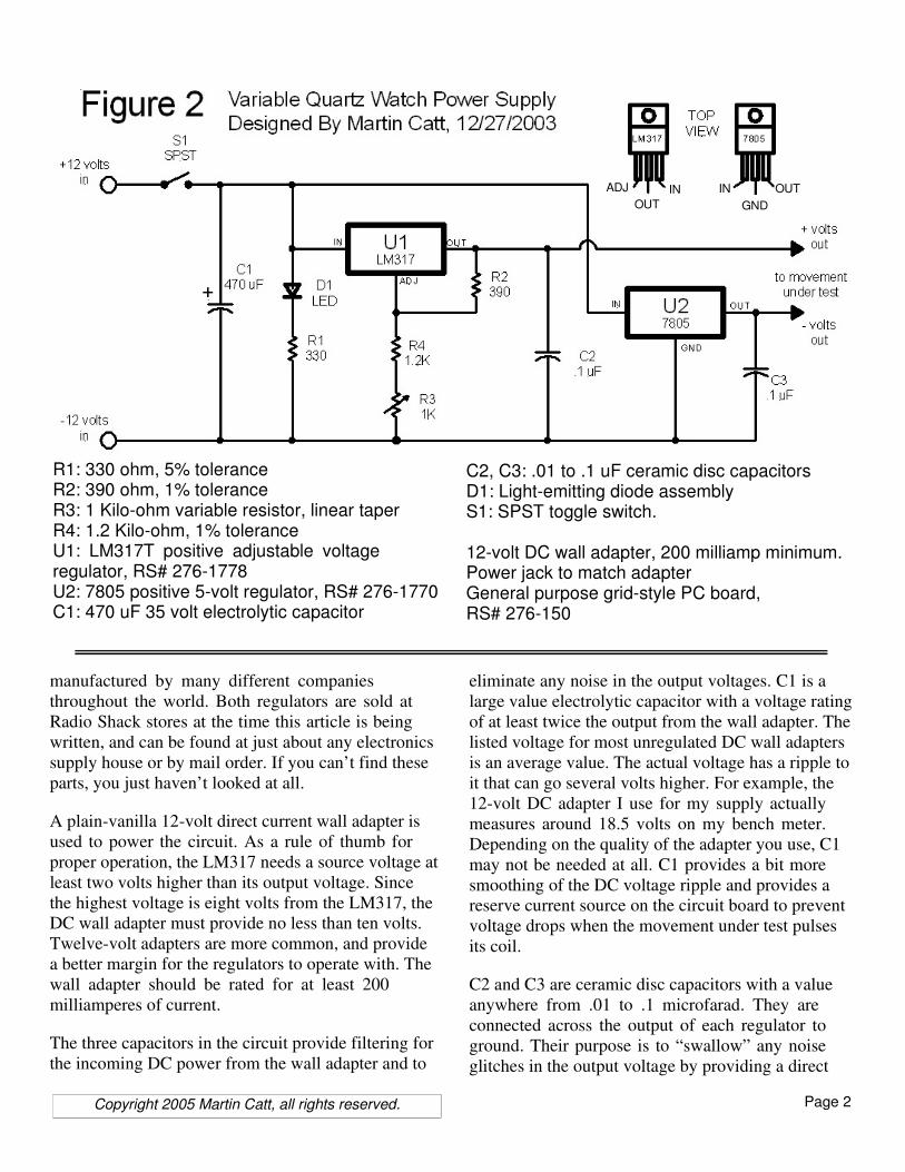
Figure 1 shows the completed circuit board. The two
large 3-lead components that look like power
transistors are actually a pair of sophisticated voltage
regulator integrated circuits. The design uses an
LM317 voltage regulator integrated circuit (IC) to
take the twelve volt direct current from the wall
adapter and convert it to a variable output voltage.
The LM317 is a simple-looking device, with only
three connections to the outside world. Inside,
however, is a complicated linear electronic circuit
designed to sense and maintain an output voltage
determined by a pair of resistors connected across
two of the three leads. Using the LM317 drops the
number of individual electronic components required
from over fifty down to less than ten, greatly
simplifying construction.
In a perfect world, a single LM317, a couple of fixed
resistors, and one variable resistor would be all we
need to build our power supply. The LM317 has one
drawback, however: the lowest you can drive the
output voltage is about 1.2 volts. For most watch
testing applications, you need to be able to turn the
voltage down to at least .8 volts, and preferably even
lower.
The problem is solved by adding a second voltage
regulator IC, an LM7805. Like the LM317, the
LM7805 is a three-lead device. Unlike the LM317,
the LM7805 is a fixed-voltage regulator, preset to put
out exactly five volts. The output voltage is fixed and
cannot be changed.
We get the zero-to-three volt range by using the
difference in the output voltages from each regulator.
The five volts from the LM7805 serves as the ground
level for the testing voltage, and is connected to the
negative battery terminal of the movement under test.
The LM317 is set up to provide a voltage adjustable
from five to eight volts. This variable voltage is
connected to the positive battery terminal of the
movement under test. What the movement sees is the
difference between the two voltages. When the
LM317 is putting out 6.5 volts, the movement is
actually seeing only 1.5 volts (6.5 volts - 5 volts = 1.5
volts). By using the 7805 to shift the ground voltage,
we can get the range we require by careful selection
of the fixed resistors in the circuit. Figure 2 shows the
schematic and parts list.
An added benefit of using both the LM317 and
LM7805 is that both IC’s have built-in short circuit
protection, so if you accidentally short the test leads
together, you won’t blow the power supply. Each
regulator is rated to provide at least one amp of
current, well above the needs of any watch
movement. In normal practice, each regulator would
have to be mounted on a heat sink to provide their
maximum rated current. In our application, however,
the current demands are so low that no heat sink is
required, and the regulators are simply soldered to the
circuit board and the mounting tab provides what
little heat dissipation is required.
In case you’re worried that you might not be able to
find either of the regulator IC’s, let me put your mind
at ease. Both of these regulators are among the most
commonly used devices in the electronics industry,
Page 2Copyright 2005 Martin Catt, all rights reserved.
manufactured by many different companies
throughout the world. Both regulators are sold at
Radio Shack stores at the time this article is being
written, and can be found at just about any electronics
supply house or by mail order. If you can’t find these
parts, you just haven’t looked at all.
A plain-vanilla 12-volt direct current wall adapter is
used to power the circuit. As a rule of thumb for
proper operation, the LM317 needs a source voltage at
least two volts higher than its output voltage. Since
the highest voltage is eight volts from the LM317, the
DC wall adapter must provide no less than ten volts.
Twelve-volt adapters are more common, and provide
a better margin for the regulators to operate with. The
wall adapter should be rated for at least 200
milliamperes of current.
The three capacitors in the circuit provide filtering for
the incoming DC power from the wall adapter and to
eliminate any noise in the output voltages. C1 is a
large value electrolytic capacitor with a voltage rating
of at least twice the output from the wall adapter. The
listed voltage for most unregulated DC wall adapters
is an average value. The actual voltage has a ripple to
it that can go several volts higher. For example, the
12-volt DC adapter I use for my supply actually
measures around 18.5 volts on my bench meter.
Depending on the quality of the adapter you use, C1
may not be needed at all. C1 provides a bit more
smoothing of the DC voltage ripple and provides a
reserve current source on the circuit board to prevent
voltage drops when the movement under test pulses
its coil.
C2 and C3 are ceramic disc capacitors with a value
anywhere from .01 to .1 microfarad. They are
connected across the output of each regulator to
ground. Their purpose is to “swallow” any noise
glitches in the output voltage by providing a direct
IN OUT
GND
ADJ
OUT
IN
R1: 330 ohm, 5% toleranceR2: 390 ohm, 1% toleranceR3: 1 Kilo-ohm variable resistor, linear taperR4: 1.2 Kilo-ohm, 1% toleranceU1: LM317T positive adjustable voltage regulator, RS# 276-1778U2: 7805 positive 5-volt regulator, RS# 276-1770C1: 470 uF 35 volt electrolytic capacitor
C2, C3: .01 to .1 uF ceramic disc capacitorsD1: Light-emitting diode assemblyS1: SPST toggle switch.
12-volt DC wall adapter, 200 milliamp minimum.Power jack to match adapterGeneral purpose grid-style PC board, RS# 276-150

Page 3Copyright 2005 Martin Catt, all rights reserved.
path to ground to any voltage spikes that might
appear. Like C1, they may not be required at all, but
they provide cheap insurance for correct operation
and a clean output voltage.
Light emitting diode D1, called an LED for short,
serves as a power-on indicator. The 330-ohm resistor
R1 limits the current passing through D1 to a safe
level. Some LED assemblies come with the current-
dropping resistor already installed. In that case, the
assembly is connected directly across the two power
traces on the board.
As stated before, the output from the 7805 is fixed at
five volts, and cannot be varied. The output from the
LM317 is set by the ratio of two resistances. The
exact equation is:
Vout = 1.25( 1 + Ra/Rb )
Where Vout is the output voltage, Rb is resistor R2 in
our circuit, and Ra is the combined resistance of R3
and R4. Since R3 is a variable resistor, we can change
the value of Ra, and thereby change the voltage. R4 is
a fixed resistor, and sets the limit for how low the
voltage can be dropped.
A quick word on component values is needed at this
point. Like any mass-manufactured item, resistors
have a tolerance to their exact resistance value. For
example, most resistors you can buy at a local
electronics store have a 5% tolerance, meaning that
while the actual resistance may be either 5% higher
or 5% lower than the marked value. For a resistor
marked 1000 ohms, the actual resistance may be
anywhere between 950 ohms to 1050 ohms.
Now, the only critical values in the circuit are
resistors R2 and R4. The ratio of these two resistors
sets the lower output voltage from regulator U1 to no
less than 5.09 volts. If the voltage from U1 was to
drop below 5 volts, then the polarity to the movement
under test would be reversed. Exactly what would
happen to a movement seeing a reversed voltage is a
matter of speculation. Face it: we’ve all done it at
some time, either installing a cell upside down
underneath a cell strap or placing the wrong test
probes on the contacts. I’ve never seen a movement
damaged by reversing the polarity, but I would rather
be safe than sorry. Therefore, R2 and R4 are specified
as being precision 1% resistors.
Using the exact values specified for R2 (390 ohms)
and R4 (1200 ohms), the lowest output voltage from
U1 will be 5.09 volts. The combination of resistor
tolerance variations which gives the lowest possible
output voltage will be when R2 is at the high end of
its tolerance (394 ohms) and R4 is at the low end of
its tolerance (1188 ohms), which will set the lowest
output voltage to 5.02 volts, which is close, but still
safe. If 5% tolerance resistors are used, with R2 at the
high end (409 ohms) and R4 at the low end (1140
ohms), the lowest output voltage would be 4.73 volts.
Now, having spent the last three paragraphs telling
you why you should use 1% resistors for R2 and R4, I
can tell you from experience that in most cases
regular 5% tolerance resistors can be used. I’ve built
six complete circuit boards while developing this
article and the assembly instructions, with all six
using 5% resistors drawn from the motley assortment
of resistors I’ve accumulated over the years. Not one
of the boards came in with U1’s lowest output voltage
below 5 volts. So the lesson here is: if you can get 1%
resistors, then by all means use them, but if they
aren’t available, use regular 5% resistors and see what
happens. The odds are with you.
Layout and construction of the circuit is not critical.
Those with experience may choose to design their
own printed-circuit board, or point-to-point wiring
techniques can be used. For those of you with little
electronic experience, the following step-by-step
instructions are provided. The circuit is built using an
experimenter’s etched grid-board available from
Radio Shack stores, eliminating the need to produce a
custom printed-circuit board. The board has a series
of holes with pre-etched copper pads on the underside
in various sizes, along with two long copper traces
used for distributing power along its length. With a
little careful forethought, the entire circuit can be built
using both the components themselves and several
jumpers between the pads to serve as the
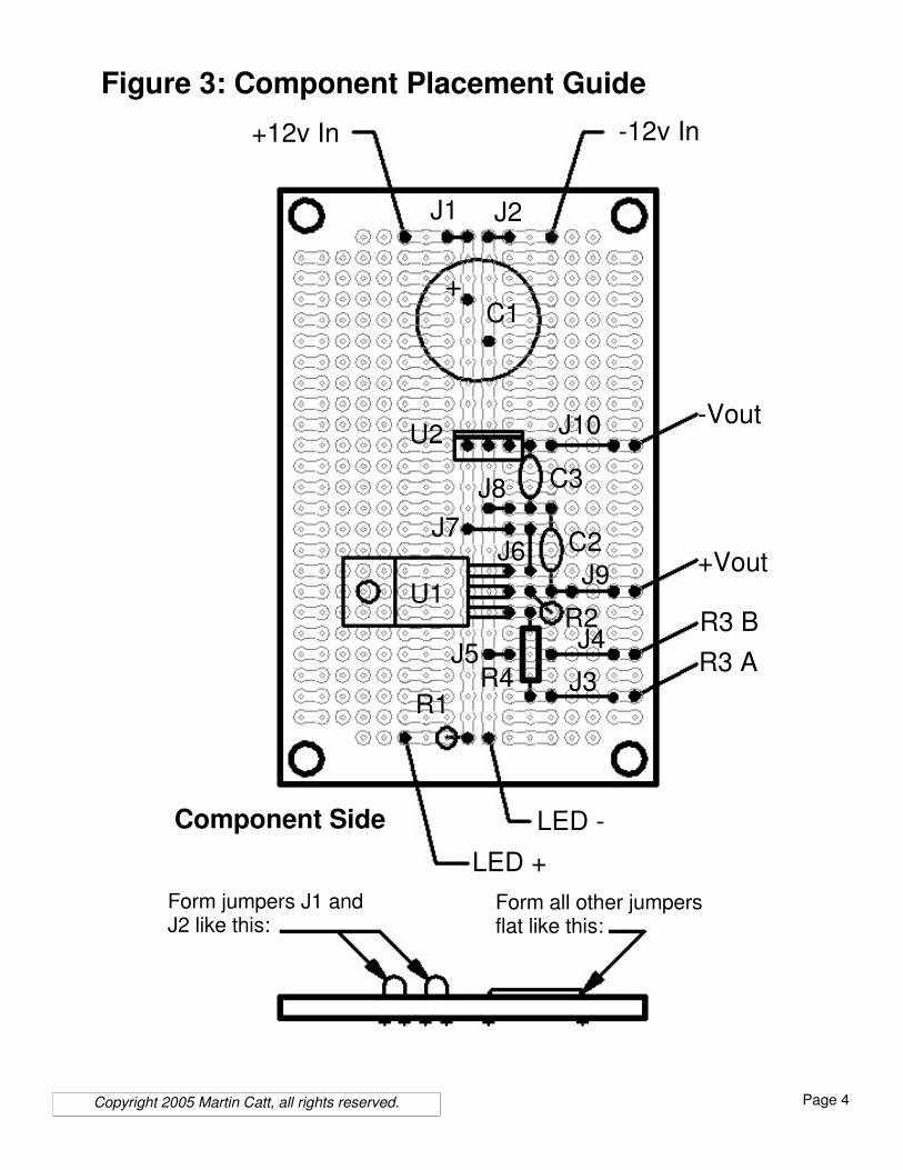
interconnections. Placement diagrams and detailed,
step-by-step instructions are provided. Checkpoints
are included in the instructions to verify the work
done up to that point.
Page 4Copyright 2005 Martin Catt, all rights reserved.
+12v In -12v In
J2J1
C1
C2
C3
U1
U2
J7J6
J9
J4
J3J5
J8
J10
R1
R2
R4R3 A
R3 B
+Vout
-Vout
+
LED +
LED -
Form jumpers J1 andJ2 like this:
Form all other jumpersflat like this:
Figure 3: Component Placement Guide
Component Side

Page 5Copyright 2005 Martin Catt, all rights reserved.
Step-By-Step Assembly Instructions
Note: “Install” means to put the component in place
on the board and solder the leads to the copper pads.
Refer to Figure 3 for the parts placement.
1: Locate and install resistor R1 (330 ohm). Save the
cut-off resistor leads for the next step.
2: Form jumpers J1 and J2 using the leads cut from R1.
Install J1 and J2 where the two jumpers form loops
over the top of the circuit board as shown in the parts
placement diagram. These two loops provide an easy
place to connect your volt-meter leads for testing in
later steps.
3: Solder a length of insulated wire to the +12v In
connection on the board. Solder the free end of this
wire to the positive side of the DC power jack.
4: Solder a length of insulated wire to the –12v In
connection on the board. Solder the free end of this
wire to the negative side of the DC power jack.
5: Plug the 12 volt DC adapter into a wall outlet and
connect the output line to the DC power jack. Using
your volt meter, check for the correct polarity across
jumpers J1 and J2. J1 should be positive and J2 should
be negative. The voltage reading across J1 and J2
should be between 10 and 20 volts DC. Once you have
checked for correct polarity and voltage, disconnect the
DC adapter from the power jack.
6: Install electrolytic capacitor C1 (470 uF, 35 volts).
Pay close attention to correct polarity. Save the cut
leads to make jumpers in later steps.
7: Connect the light-emitting diode D1 to the LED+
and LED- connections on the board, paying attention
to correct polarity. Connect the cathode lead to the
LED- connection.
8: Reconnect the DC adapter to the power jack. The
light-emitting diode D1 should light. If not, reverse the
connections to D1 and test again.
9: Locate and install jumpers J3, J4, and J5. These and
all further jumpers should be installed flat against the
circuit board.
10: Locate and install resistor R4 ( 1.2 Kohm). Save the
clipped leads to make jumpers.
11: Find regulator U1 (LM317T). Look closely at the
three leads. About 3/16” from the body of the
regulator, the leads become narrower. Using needle-
nosed pliers, bend each lead 90 degrees downward at
the point where the lead narrows.
12: Install regulator U1. The heat-sink tab should be
against the circuit board. Once soldered in place, trim
the three leads flush with the copper pads.
13: Locate and install resistor R2 (390 ohm). This
resistor installs upright, with the top lead folded over.
Note that the body of R2 is installed to the right of R4.
14: Locate and install jumpers J6, J7, and J8 flush
against the board.
15: Locate and install jumper J9. Very Important:
note that the left side of J9 is soldered to a single
copper pad that does not connect to anything else at
this point.
16: Locate ceramic disc capacitor C2 (.01-.1 uF ).
Read and understand the rest of this step before
actually soldering C2 in place. Refer to Figure 4 for
details,
Slide C2 into place on the circuit board. Check to see
that C2’s lower lead is in line with the center lead of
U1, and the upper lead of C2 is in line with jumper J8.
Solder the upper lead in place first, and trim it close to
the board.
Looking at the solder-side of the board, bend the lower
lead of C2 over so it touches the free end of jumper J9.
Solder the lower lead of C2 to the copper pad where it
comes through the board. Then, solder the bent part of
the lead to the free end of J9 and trim off any excess
lead.
17: Find variable resistor R3 ( 1 Kohm, linear taper).
Solder a length of insulated wire to the center terminal.
Looking at the back of R3 with the solder terminals
pointing up, solder a second length of insulated wire to
the left terminal. See Figure 5 for a better picture.
18: Solder the free ends of the wires from R3 to the
points marked R3A and R3B on the circuit board.
Either wire can go to either point. Once soldered, turn
the shaft of R3 fully clockwise.

Page 6Copyright 2005 Martin Catt, all rights reserved.
19: Reconnect the DC adapter to the power jack. Diode
D1 should light.
Connect the negative lead of your voltmeter to jumper
J2 and touch the positive voltmeter lead to jumper J9.
With R3 fully clockwise, the voltmeter should read
between 8 to 8.3 volts. While monitoring the voltage,
turn R3 counterclockwise. The voltage should
smoothly drop down to within 5 to 5.2 volts.
If no voltage is present at J9, check to see that the lower
lead of C2 is soldered both to the pad where it comes
through the board and to the left side of J9. If this is
correct, but the output voltage is wrong, check the
location of all jumpers, resistors, and the placement of
regulator U1.
Once the voltage on jumper J9 can be varied from 5 to
8 volts, disconnect the DC adapter and voltmeter from
the circuit board.
20: Locate and install ceramic disc capacitor C3 ( .01 -
.1 uF ).
21: Locate and install regulator U2 (7805). Note that
U2’s leads DO NOT get bent like U1, and that the heat
sink tab goes towards capacitor C1.
22: Locate and install jumper J10 flush against the
board.
23: Solder a length of insulated wire to the point
marked +Vout on the board. Solder a second length of
insulated wire to the point marked –Vout on the board.
24: Reconnect the DC adapter to the power jack. Diode
D1 should light.
25: Connect the negative voltmeter lead to jumper J2,
and the positive voltmeter lead to the wire connected
to –Vout. The voltmeter should read almost exactly 5
volts.
26: Disconnect the voltmeter. Turn R3 fully
clockwise. Connect the positive voltmeter lead to the
wire from +Vout, and the negative voltmeter lead to
the wire from –Vout. With R3 fully clockwise, the
voltmeter should read between 3 to 3.2 volts. While
monitoring the voltage, turn R3 counterclockwise. The
voltage should smoothly drop from around 3 volts to
around .2 volts.
Figure 4:C2 InstallationDetail fold
solder hereand here: cut
Fold C2’s lower lead to overlap J9’sleft side.
Solder folded lead where it comes through theboard and to where it overlaps J9. Cut offexcess lead.
This completes construction on the circuit board. In
the following article, we’ll tie everything together in
a single test fixture.
Figure 5:R3 wiringdetail
C2
J9
Related Documents


![gcseprep.com · Web view05.04.2020 · 5.2 Electricity - Current-Voltage characteristics – Mark schemes. Q1. A [1] Q2. (a) (i) suitable variable input (variable power supply](https://static.cupdf.com/doc/110x72/6011873d52f8a907c13875f4/web-view-05042020-52-electricity-current-voltage-characteristics-a-mark.jpg)
