
Welcome message from author
This document is posted to help you gain knowledge. Please leave a comment to let me know what you think about it! Share it to your friends and learn new things together.
Transcript

Outline● Background● Digital logic● Microprocessors, busses, addresses, peripherals● Building and testing microcomputer circuits● Conclusions
Hardware for software people● In CS, our main concern is software● We take computing hardware for granted● How does it work? Is it magic?● Modern computing hardware: immensely complicated
○ 4th gen Core i7: 1.4 billion transistors! 2000+ pins!
● If you wanted to design and build your own computer, where to start?
8 bit CPUs!● The microcomputer era began in the mid 1970s with 8 bit CPUs
○ Motorola 6800, 6809○ Intel 8080, Zilog Z80○ MOS 6502
● These were used in the first mainstream personal computers!○ Altair 8800○ Apple I, Apple II○ Commodore VIC-20, C64○ Atari 400, 800○ TRS-80 Model I, Color Computer
● These CPUs are surprisingly easy to use and understand!● You can use them to build a complete computer system!
Digital logic

Digital logic● Computer hardware is based on digital logic● In a digital circuit, voltages are either high (true, 1) or low (false, 0)● Logic gates implement boolean operations (AND, OR, NAND, NOR, XOR,
NOT, etc.) on digital signals○ "Signal" just means a digital voltage at a specific point in the circuit
● Any boolean function (with any number of inputs and outputs) can be implemented by connecting logic gates
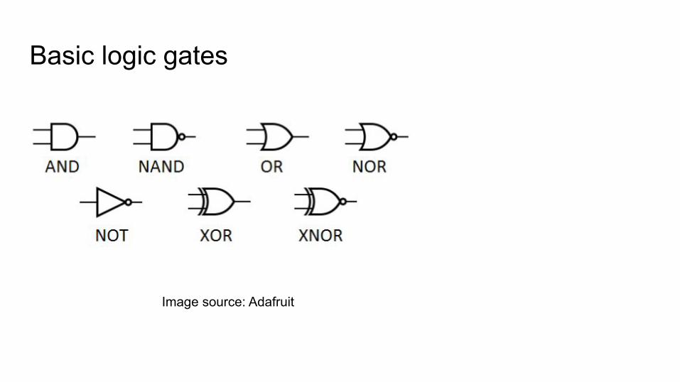
Basic logic gates
Image source: Adafruit
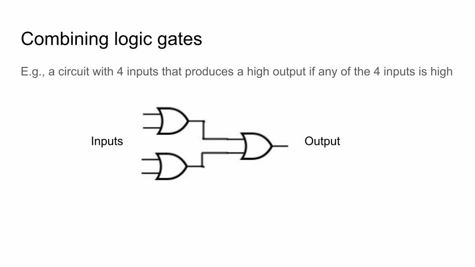
Combining logic gatesE.g., a circuit with 4 inputs that produces a high output if any of the 4 inputs is high
Inputs Output
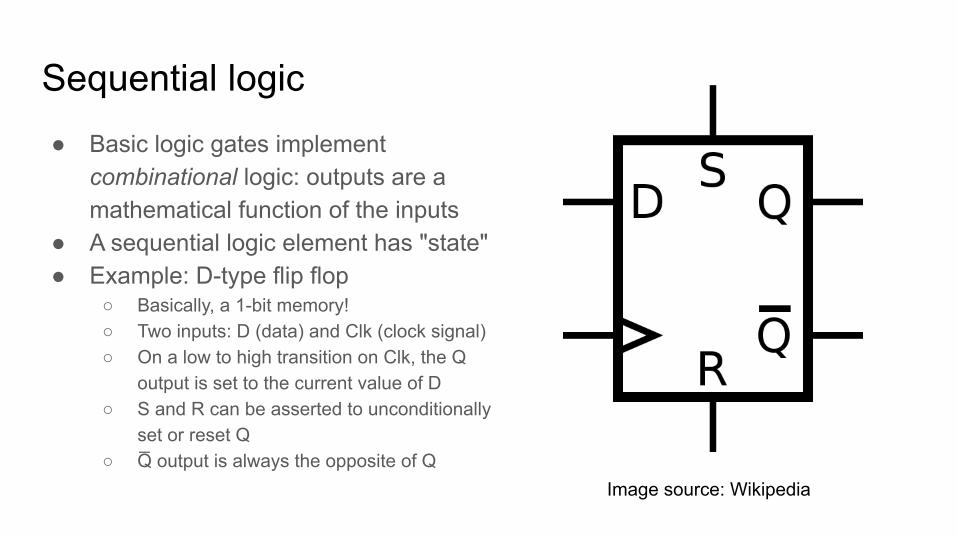
Sequential logic● Basic logic gates implement
combinational logic: outputs are a mathematical function of the inputs
● A sequential logic element has "state"● Example: D-type flip flop
○ Basically, a 1-bit memory!○ Two inputs: D (data) and Clk (clock signal)○ On a low to high transition on Clk, the Q
output is set to the current value of D○ S and R can be asserted to unconditionally
set or reset Q○ Q̅ output is always the opposite of Q
Image source: Wikipedia
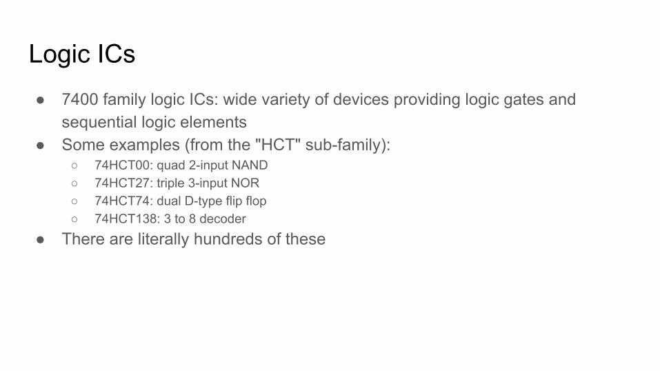
Logic ICs● 7400 family logic ICs: wide variety of devices providing logic gates and
sequential logic elements● Some examples (from the "HCT" sub-family):
○ 74HCT00: quad 2-input NAND○ 74HCT27: triple 3-input NOR○ 74HCT74: dual D-type flip flop○ 74HCT138: 3 to 8 decoder
● There are literally hundreds of these
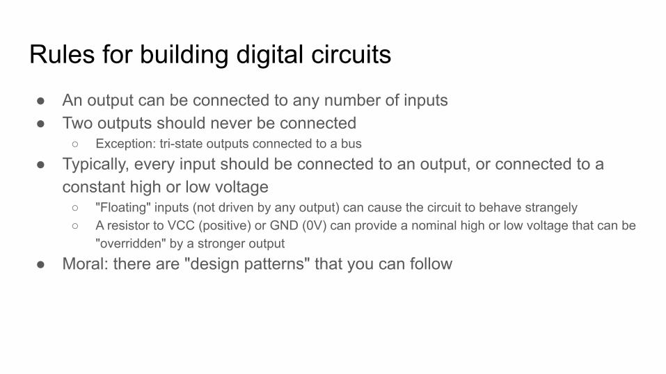
Rules for building digital circuits● An output can be connected to any number of inputs● Two outputs should never be connected
○ Exception: tri-state outputs connected to a bus
● Typically, every input should be connected to an output, or connected to a constant high or low voltage
○ "Floating" inputs (not driven by any output) can cause the circuit to behave strangely○ A resistor to VCC (positive) or GND (0V) can provide a nominal high or low voltage that can be
"overridden" by a stronger output
● Moral: there are "design patterns" that you can follow
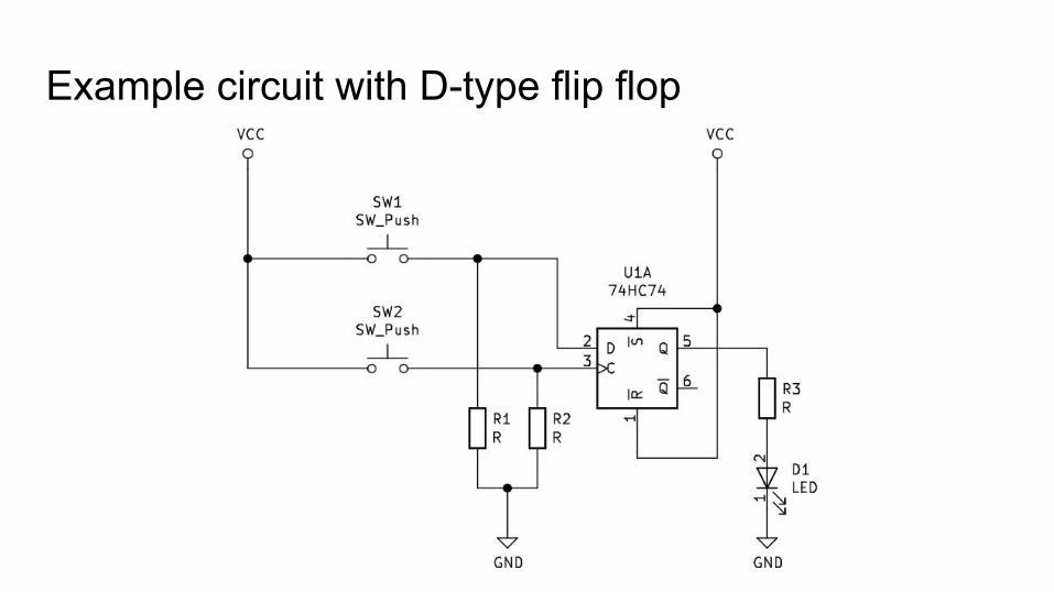
Example circuit with D-type flip flop
Building circuits!● One of the most fun things about digital circuits is that you can build them!● Easiest way: on a solderless breadboard● Groups of 5 holes are connected electrically● Use jumper wires to connect circuit nodes
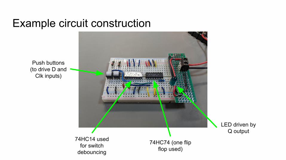
Example circuit construction
LED driven by Q output
74HC74 (one flip flop used)
Push buttons (to drive D and
Clk inputs)
74HC14 used for switch
debouncing
The point● Building digital circuits using logic ICs is pretty easy!
Microprocessor circuits
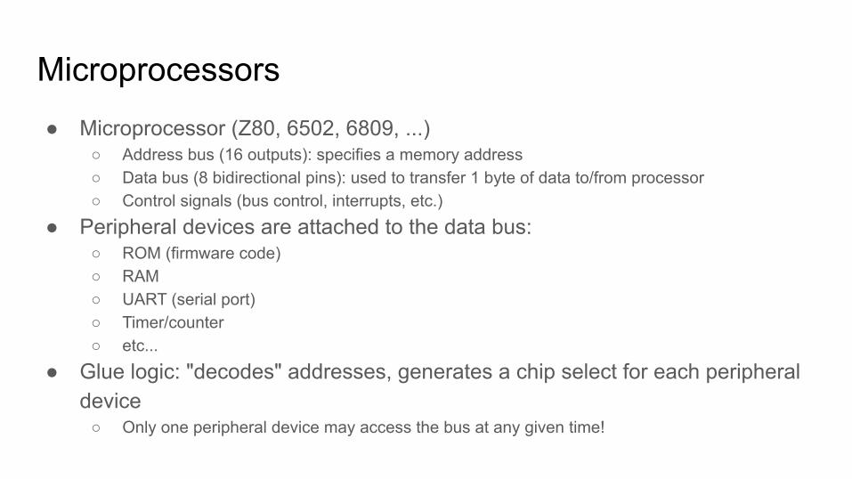
Microprocessors● Microprocessor (Z80, 6502, 6809, ...)
○ Address bus (16 outputs): specifies a memory address○ Data bus (8 bidirectional pins): used to transfer 1 byte of data to/from processor○ Control signals (bus control, interrupts, etc.)
● Peripheral devices are attached to the data bus:○ ROM (firmware code)○ RAM○ UART (serial port)○ Timer/counter○ etc...
● Glue logic: "decodes" addresses, generates a chip select for each peripheral device
○ Only one peripheral device may access the bus at any given time!
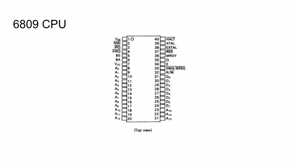
6809 CPU
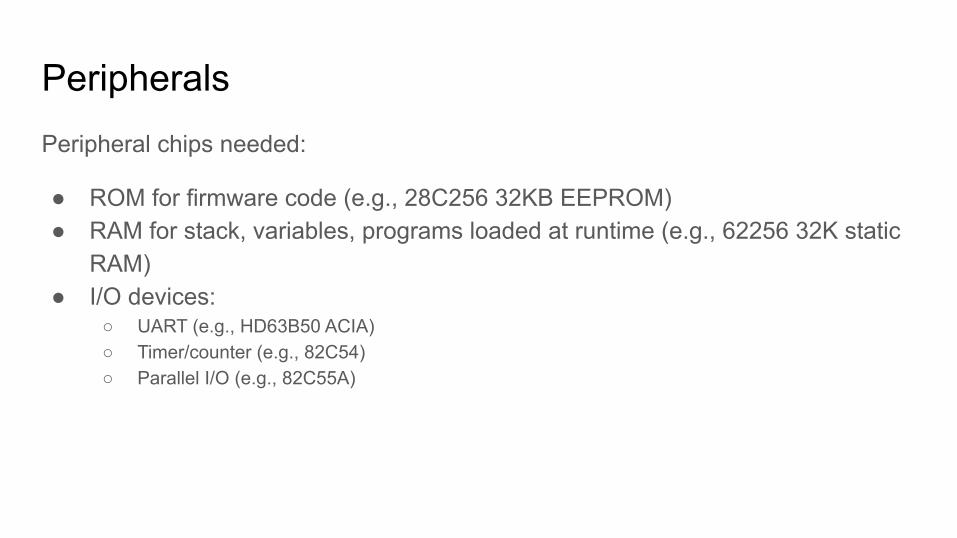
PeripheralsPeripheral chips needed:
● ROM for firmware code (e.g., 28C256 32KB EEPROM)● RAM for stack, variables, programs loaded at runtime (e.g., 62256 32K static
RAM)● I/O devices:
○ UART (e.g., HD63B50 ACIA)○ Timer/counter (e.g., 82C54)○ Parallel I/O (e.g., 82C55A)
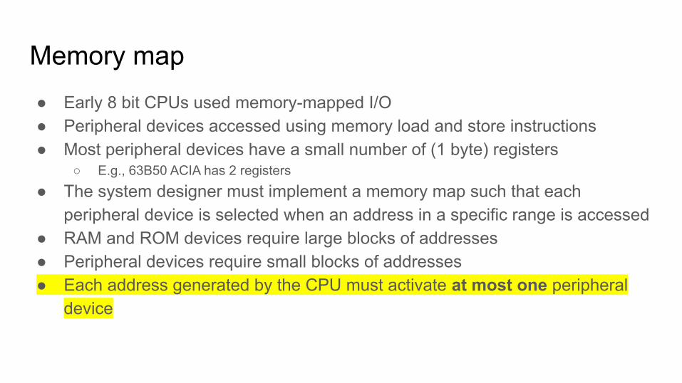
Memory map● Early 8 bit CPUs used memory-mapped I/O● Peripheral devices accessed using memory load and store instructions● Most peripheral devices have a small number of (1 byte) registers
○ E.g., 63B50 ACIA has 2 registers
● The system designer must implement a memory map such that each peripheral device is selected when an address in a specific range is accessed
● RAM and ROM devices require large blocks of addresses● Peripheral devices require small blocks of addresses● Each address generated by the CPU must activate at most one peripheral
device
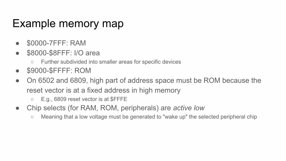
Example memory map● $0000-7FFF: RAM● $8000-$8FFF: I/O area
○ Further subdivided into smaller areas for specific devices
● $9000-$FFFF: ROM● On 6502 and 6809, high part of address space must be ROM because the
reset vector is at a fixed address in high memory○ E.g., 6809 reset vector is at $FFFE
● Chip selects (for RAM, ROM, peripherals) are active low○ Meaning that a low voltage must be generated to "wake up" the selected peripheral chip
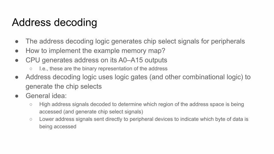
Address decoding● The address decoding logic generates chip select signals for peripherals● How to implement the example memory map?● CPU generates address on its A0–A15 outputs
○ I.e., these are the binary representation of the address
● Address decoding logic uses logic gates (and other combinational logic) to generate the chip selects
● General idea:○ High address signals decoded to determine which region of the address space is being
accessed (and generate chip select signals)○ Lower address signals sent directly to peripheral devices to indicate which byte of data is
being accessed
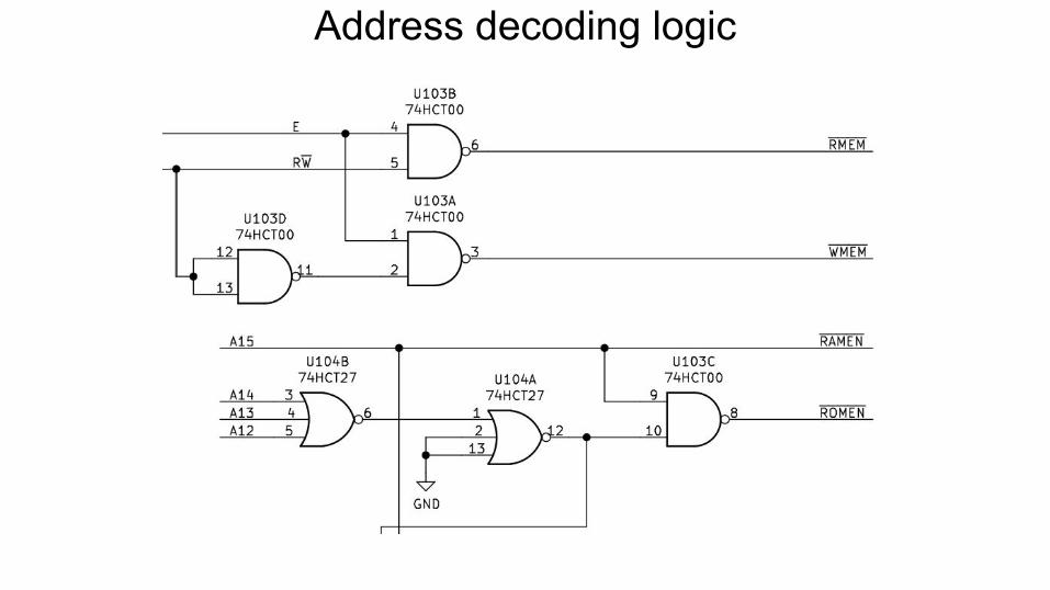
Address decoding logic
Address decoding logic
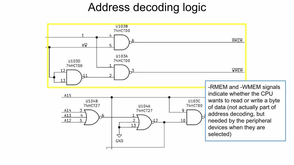
-RMEM and -WMEM signals indicate whether the CPU wants to read or write a byte of data (not actually part of address decoding, but needed by the peripheral devices when they are selected)
Address decoding logic
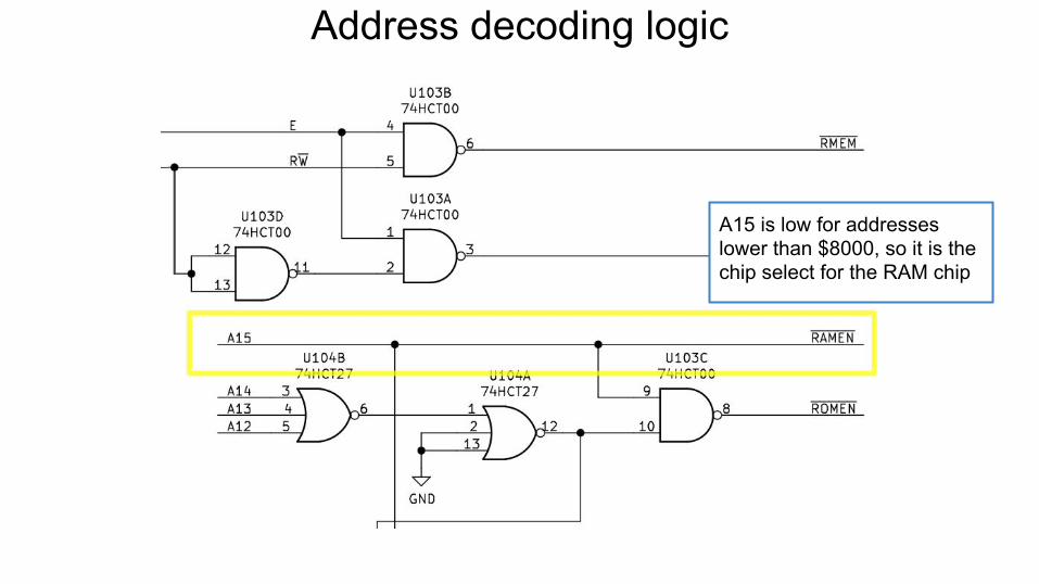
A15 is low for addresses lower than $8000, so it is the chip select for the RAM chip
Address decoding logic
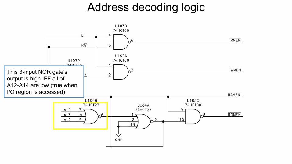
This 3-input NOR gate's output is high IFF all of A12-A14 are low (true when I/O region is accessed)
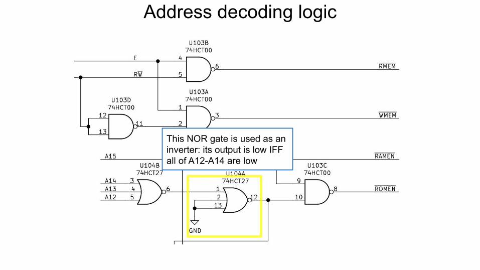
Address decoding logic
This NOR gate is used as an inverter: its output is low IFF all of A12-A14 are low
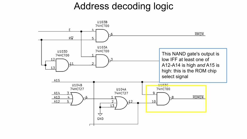
Address decoding logic
This NAND gate's output is low IFF at least one of A12-A14 is high and A15 is high: this is the ROM chip select signal
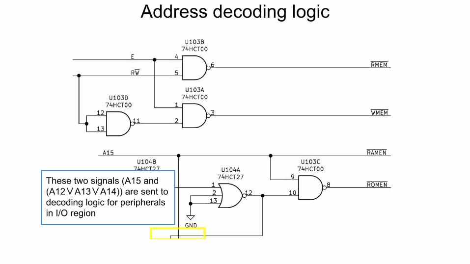
Address decoding logic
These two signals (A15 and (A12∨A13∨A14)) are sent to decoding logic for peripherals in I/O region
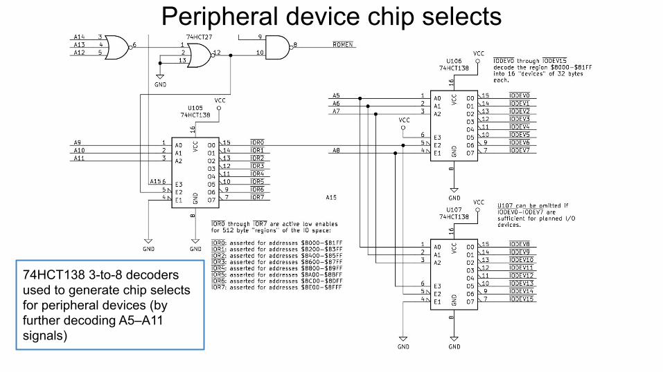
Peripheral device chip selects
74HCT138 3-to-8 decoders used to generate chip selects for peripheral devices (by further decoding A5–A11 signals)
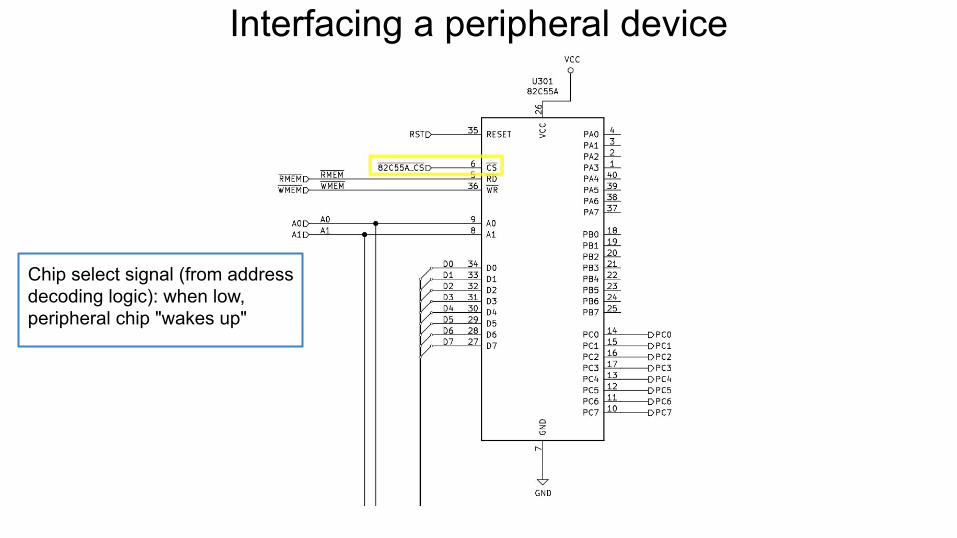
Interfacing a peripheral device
Chip select signal (from address decoding logic): when low, peripheral chip "wakes up"
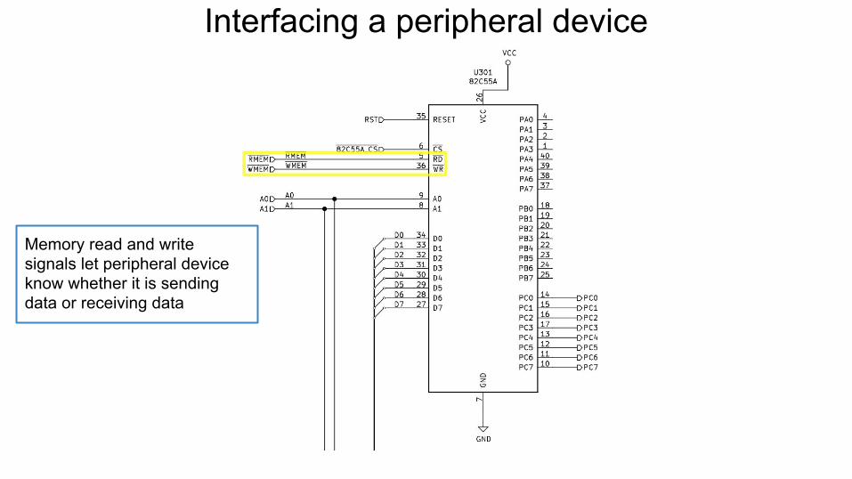
Interfacing a peripheral device
Memory read and write signals let peripheral device know whether it is sending data or receiving data
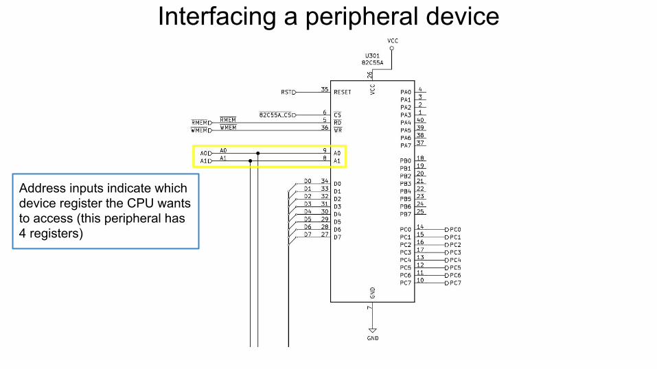
Interfacing a peripheral device
Address inputs indicate which device register the CPU wants to access (this peripheral has 4 registers)
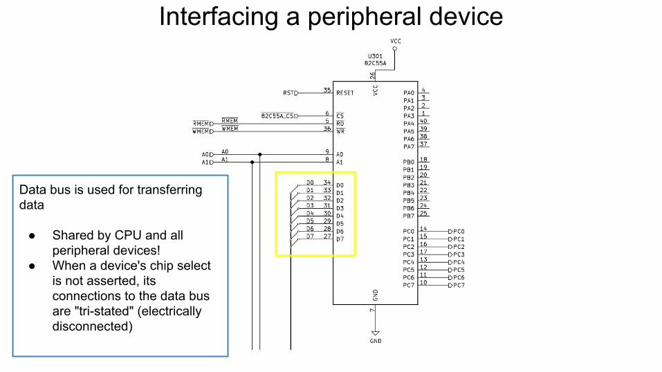
Interfacing a peripheral device
Data bus is used for transferring data
● Shared by CPU and all peripheral devices!
● When a device's chip select is not asserted, its connections to the data bus are "tri-stated" (electrically disconnected)
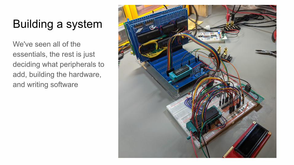
Building a systemWe've seen all of the essentials, the rest is just deciding what peripherals to add, building the hardware, and writing software
Building and testing microprocessor circuits
How to get started?Things you will need if you want to try doing this on your own:
● ICs and components● Prototyping supplies● Test equipment● Software

ICs and components● Logic ICs: expect to pay $0.50 or so each
○ Digi-key, Mouser○ Specialized businesses (e.g., Unicorn Electronics)○ eBay also a possibility (but beware of counterfeit chips)
● 8 bit CPUs○ 6502 is still in production!○ Widely available as used or New Old Stock on eBay, surplus sites○ Expect to pay $5-$10?
● Other devices (ROM, RAM, peripheral chips)● Components (resistors, capacitors, LEDs)
○ Pre-packaged kits with a variety of values are a good option○ Adafruit, Sparkfun
Prototyping stuff● Solderless breadboards: really cheap ones ($2) can be ok● Wire (pre-made jumper kits are helpful)
○ 22 AWG solid core is ideal for breadboard use
● Small hand tools (pliers, wire stippers, wire cutters)● If you want to construct permanent versions of circuits:
○ Soldering station (cheap ones are surprisingly good), solder○ Protoboards○ IC sockets○ Wire (finer gauge, stranded)
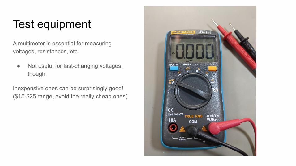
Test equipmentA multimeter is essential for measuring voltages, resistances, etc.
● Not useful for fast-changing voltages, though
Inexpensive ones can be surprisingly good! ($15-$25 range, avoid the really cheap ones)
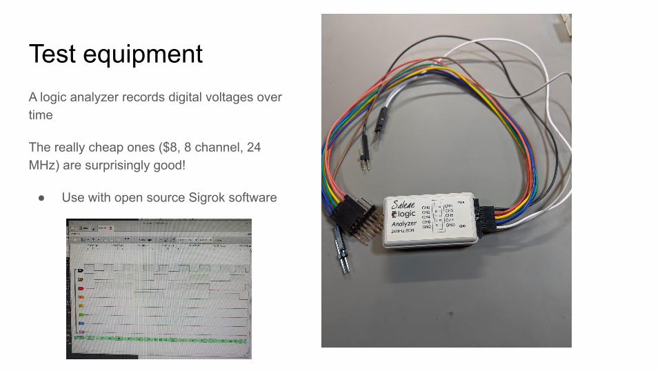
Test equipmentA logic analyzer records digital voltages over time
The really cheap ones ($8, 8 channel, 24 MHz) are surprisingly good!
● Use with open source Sigrok software
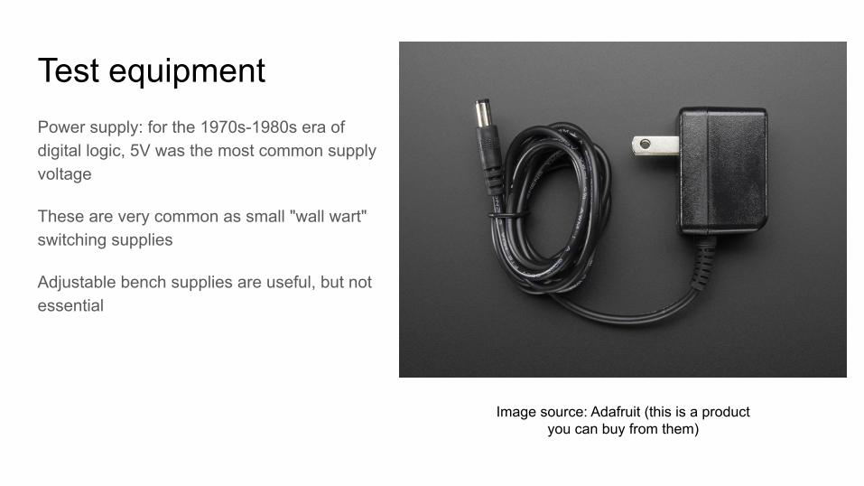
Test equipmentPower supply: for the 1970s-1980s era of digital logic, 5V was the most common supply voltage
These are very common as small "wall wart" switching supplies
Adjustable bench supplies are useful, but not essential
Image source: Adafruit (this is a product you can buy from them)
Software● Assembler (for writing programs to load onto the 8 bit system)● EDA (Electronic Design Automation) software is useful for creating
schematics, designing PCBs○ Recommended: KiCad (open source)
● Sigrok (logic analyzer software)● Serial communications (connect your PC or laptop to the 8 bit system)

Conclusions
Conclusions● Hardware design is surprisingly accessible
○ Lots of great learning resources
● 8-bit computer era is a sweet spot○ Simple/accessible, but can do interesting things
● Modern microcontrollers are incredibly similar to 8-bit microcomputer systems○ Microprocessor+integrated peripherals in a single device

Questions?
Related Documents


