SUITE 900 - 390 BAY STREET, TORONTO ONTARIO, CANADA M5H 2Y2 Telephone (1) (416) 362-5135 Fax (1) (416) 362 5763 CROWFLIGHT MINERALS INCORPORATED TECHNICAL REPORT ON THE BUCKO LAKE NICKEL PROJECT FEASIBILITY STUDY, WABOWDEN, MANITOBA Richard M. Gowans P.Eng. Micon International Limited Dave West P. Eng. Wardrop Engineering Inc. Eugene J. Puritch P.Eng. P&E Mining Consultants Inc. Dr. Wayne D. Ewart P.Geo. P&E Mining Consultants Inc. January 31, 2006

Welcome message from author
This document is posted to help you gain knowledge. Please leave a comment to let me know what you think about it! Share it to your friends and learn new things together.
Transcript
SUITE 900 - 390 BAY STREET, TORONTO ONTARIO, CANADA M5H 2Y2
Telephone (1) (416) 362-5135 Fax (1) (416) 362 5763
CROWFLIGHT MINERALS INCORPORATED
TECHNICAL REPORT ON THE
BUCKO LAKE NICKEL PROJECT
FEASIBILITY STUDY,
WABOWDEN, MANITOBA
Richard M. Gowans P.Eng.
Micon International Limited
Dave West P. Eng. Wardrop Engineering Inc.
Eugene J. Puritch P.Eng. P&E Mining Consultants Inc.
Dr. Wayne D. Ewart P.Geo. P&E Mining Consultants Inc.
January 31, 2006
ii
TABLE OF CONTENTS
Page
1.0 SUMMARY....................................................................................................................... 1
2.0 INTRODUCTION AND TERMS OF REFERENCE ................................................... 8 2.1 TERMS OF REFERENCE AND PREPARATION OF THE FEASIBILITY STUDY .......................... 8
3.0 RELIANCE ON OTHER EXPERTS ........................................................................... 10
4.0 PROPERTY DESCRIPTION AND LOCATION ....................................................... 13 4.1 PROPERTY LOCATION .................................................................................................... 13
4.2 DESCRIPTION AND TENURE............................................................................................ 14
5.0 ACCESSIBILITY, CLIMATE, LOCAL RESOURCES, INFRASTRUCTURE AND PHYSIOGRAPHY................................................................................................ 19
5.1 PROJECT LOCATION AND ACCESS .................................................................................. 19
5.2 CLIMATE AND PHYSIOGRAPHY...................................................................................... 19
6.0 HISTORY........................................................................................................................ 20 6.1 EXPLORATION HISTORY................................................................................................. 20
6.2 HISTORICAL TECHNICAL AND ECONOMIC STUDIES........................................................ 21
6.3 HISTORICAL MINERAL RESOURCE ESTIMATES .............................................................. 21
6.4 HISTORICAL PRODUCTION ............................................................................................. 22
7.0 GEOLOGICAL SETTING............................................................................................ 23 7.1 REGIONAL GEOLOGY..................................................................................................... 23
7.2 LOCAL GEOLOGY........................................................................................................... 26
8.0 DEPOSIT TYPES........................................................................................................... 28
9.0 MINERALIZATION...................................................................................................... 29
10.0 EXPLORATION............................................................................................................. 34
11.0 DRILLING ...................................................................................................................... 34
12.0 SAMPLING METHOD AND APPROACH ................................................................ 34
13.0 SAMPLE PREPARATION, ANALYZES AND SECURITY .................................... 34
14.0 DATA VERIFICATION................................................................................................ 34

iii
15.0 ADJACENT PROPERTIES.......................................................................................... 34
16.0 MINERAL PROCESSING AND METALLURGICAL TESTING .......................... 35 16.1 HISTORICAL TESTWORK................................................................................................ 35
16.1.1 Mineralogy............................................................................................................ 35
16.1.2 Historical Metallurgical Results ........................................................................... 36
16.2 2005 FEASIBILITY TESTWORK PROGRAM ...................................................................... 37
16.2.1 Metallurgical Samples .......................................................................................... 37
16.2.2 Characterization.................................................................................................... 37
16.2.3 Grindability Testwork........................................................................................... 40
16.2.4 Flotation Testwork................................................................................................ 40
16.2.5 Batch Flotation Testwork Results......................................................................... 40
16.2.6 Locked Cycle Flotation Testwork Results............................................................ 42
16.2.7 Discussion of the Flotation Test Results .............................................................. 44
16.2.8 Dewatering Tests .................................................................................................. 48
16.2.9 Concentrate Pyrophoricity .................................................................................... 48
16.3 VARIABILITY TESTWORK............................................................................................... 48
16.3.1 Grindability........................................................................................................... 49
16.3.2 Flotation Response................................................................................................ 50
16.3.3 Observations and Conclusions from Variability Flotation Testwork ................... 52
16.4 METALLURGICAL RECOVERY ESTIMATES...................................................................... 53
16.5 CONCENTRATE QUALITY ............................................................................................... 54
16.6 PROCESS SELECTION...................................................................................................... 54
16.7 HISTORICAL METALLURGICAL REFERENCES ................................................................. 54
17.0 MINERAL RESOURCE AND MINERAL RESERVE ESTIMATES...................... 57 17.1 MINERAL RESOURCE ..................................................................................................... 57
17.2 MINERAL RESERVE........................................................................................................ 58
18.0 OTHER RELEVANT DATA AND INFORMATION................................................ 60 18.1 MINING.......................................................................................................................... 60
18.1.1 Mining Method ..................................................................................................... 60
18.1.2 Geotechnical Investigations.................................................................................. 60
18.1.3 Mine Design.......................................................................................................... 61
18.1.4 Mine Sequence...................................................................................................... 62
iv
18.1.5 Mine Schedule ...................................................................................................... 63
18.1.6 Development Schedule ......................................................................................... 63
18.1.7 Equipment Selection............................................................................................. 68
18.1.8 Mining Services .................................................................................................... 68
18.1.9 Production Schedule ............................................................................................. 68
18.1.10 Waste Handling ................................................................................................ 69
18.1.11 Mine Support Facilities..................................................................................... 69
18.2 PROCESSING PLANT ....................................................................................................... 69
18.2.1 Process Design Criteria......................................................................................... 69
18.2.2 Process Description .............................................................................................. 71
18.2.3 Mass Balance ........................................................................................................ 74
18.3 SURFACE INFRASTRUCTURE........................................................................................... 84
18.3.1 Plant and Site Layout............................................................................................ 84
18.3.2 Crushing Facility and Mill Layout ....................................................................... 84
18.3.3 Electrical Power Supply and Distribution ............................................................ 84
18.3.4 Automation and Instrumentation .......................................................................... 86
18.3.5 Access Road to Site .............................................................................................. 86
18.3.6 Camp..................................................................................................................... 86
18.3.7 Mine Site Entrance/Guardhouse ........................................................................... 87
18.3.8 Service Buildings.................................................................................................. 87
18.3.9 Laboratory and Laboratory Equipment ................................................................ 87
18.3.10 Site Lay Down Area ......................................................................................... 87
18.3.11 Mine Vehicles Maintenance Shop .................................................................... 87
18.3.12 Site Roads (excluding haulage roads)............................................................... 87
18.3.13 Generator Building ........................................................................................... 88
18.3.14 Fuel Storage and Fuelling Station..................................................................... 88
18.3.15 Site Fencing ...................................................................................................... 88
18.3.16 Water Systems .................................................................................................. 88
18.3.17 Potable Water Treatment System ..................................................................... 88
18.3.18 Plant Mobile Equipment ................................................................................... 88
18.3.19 Communications ............................................................................................... 89
18.3.20 Sewerage........................................................................................................... 89
18.4 TAILINGS MANAGEMENT............................................................................................... 89
v
18.4.1 Tailings Disposal Site Options ............................................................................. 89
18.4.2 Tailings Disposal Design...................................................................................... 90
18.4.3 Tailings Characterization...................................................................................... 91
18.5 ENVIRONMENTAL PERMITTING AND MANAGEMENT...................................................... 95
18.5.1 Environmental Permitting..................................................................................... 95
18.5.2 Hydrology/Hydrogeology..................................................................................... 96
18.5.3 Waste Rock Characterization ............................................................................... 96
18.5.4 Environmental Management................................................................................. 97
18.5.5 Closure Considerations....................................................................................... 100
18.5.6 Permitting Requirements .................................................................................... 100
18.5.7 Environmental References.................................................................................. 101
18.6 PROJECT IMPLEMENTATION ......................................................................................... 101
18.6.1 Project Schedule ................................................................................................. 101
18.6.2 Project Priorities and Milestones ........................................................................ 102
18.6.3 Mine Rehabilitation and Development............................................................... 102
18.6.4 Mill Construction Period .................................................................................... 102
18.6.5 Quality Assurance and Quality Control (QA/QC).............................................. 102
18.6.6 Commissioning and Start-up .............................................................................. 103
18.6.7 Gantt Chart.......................................................................................................... 103
18.7 CAPITAL EXPENDITURES.............................................................................................. 105
18.7.1 Mining Capital Costs .......................................................................................... 105
18.7.2 Mining Infrastructure and Equipment Costs....................................................... 105
18.7.3 Process Plant and Infrastructure Direct Capital Costs........................................ 109
18.7.4 Process Plant and Infrastructure Indirect Capital Costs ..................................... 112
18.7.5 Tailings Dam Costs............................................................................................. 113
18.7.6 Owner’s Costs..................................................................................................... 113
18.7.7 Project Closure Costs.......................................................................................... 113
18.7.8 Project Sustaining Capital................................................................................... 113
18.7.9 Equipment Residual Value ................................................................................. 113
18.8 OPERATING COSTS....................................................................................................... 114
18.8.1 Mining Operating Costs...................................................................................... 114
18.8.2 Processing Operating Costs ................................................................................ 115
18.8.3 General and Administration (G&A) Operating Costs ........................................ 117
vi
18.8.4 In-fill Diamond Drilling ..................................................................................... 118
18.8.5 Environmental Costs........................................................................................... 118
18.8.6 Off-Site Costs ..................................................................................................... 119
18.9 FINANCIAL ANALYSIS.................................................................................................. 120
18.9.1 Basis of Evaluation ............................................................................................. 120
18.9.2 Royalties and Taxes............................................................................................ 121
18.9.3 Sensitivity Study and Risk Analysis................................................................... 122
19.0 INTERPRETATION AND CONCLUSIONS............................................................ 125 19.1 CONCLUSIONS.............................................................................................................. 125
20.0 RECOMMENDATIONS ............................................................................................. 126
21.0 REFERENCES ............................................................................................................. 128
22.0 CERTIFICATES OF AUTHORS............................................................................... 129
vii
List of Tables
Page Table 1.1 Estimate of Mineral Resources at a Variety of Nickel Cut-Off Grades .............................. 2
Table 1.2 Estimated Life-of-Mine Unit Operating Costs .................................................................... 4
Table 1.3 Summary of Estimated Pre-Production Project Capital Costs ............................................ 5
Table 1.4 Economic Evaluation Summary .......................................................................................... 6
Table 2.1 Feasibility Study Team........................................................................................................ 9
Table 3.1 List of Abbreviations ......................................................................................................... 11
Table 4.1 Bucko Lake Property Claims and Mining Lease............................................................... 14
Table 5.1 Average Monthly Climate Statistics. ................................................................................. 19
Table 6.1 Summary of Bucko Lake Mineral Inventory Estimates 1968 – 2000 ............................... 22
Table 16.1 Metallurgical Composite Sample (2005)....................................................................... 38
Table 16.2 Metallurgical Composite (2005) Feed Main Element Analysis .................................... 38
Table 16.3 Metallurgical Composite (2005) Feed Minor Element Analysis................................... 39
Table 16.4 Metallurgical Composite (2005) Summary of Qualitative X-ray Diffraction Analysis 40
Table 16.5 Summary of Locked cycle Flotation Test Results ......................................................... 43
Table 16.6 Locked Cycle Final Concentrate Detailed Analyzes ..................................................... 44
Table 16.7 Estimates of Recoveries and Concentrate Grades for a Range of Products .................. 45
Table 16.8 Summary of Variability Flotation Test Results ............................................................. 49
Table 16.9 Variability Sample Comparative Bond Ball Mill Indices.............................................. 50
Table 16.10 Summary of Variability Flotation Test Results ............................................................. 52
Table 16.11 Summary Estimate of Recoveries and Concentrate Grades .......................................... 53
Table 17.1 Ni Cut-Off Grade Calculation Parameters (All currency is $US) ................................. 57
Table 17.2 Resource Estimate @ 1.1% Ni Cut-Off Grade .............................................................. 57
Table 17.3 Resource Estimate Sensitivity ....................................................................................... 58
Table 17.4 Comparison of Capped Assays, Composites and Block Model Average Grade........... 58
Table 17.5 Mineable Reserves......................................................................................................... 59
Table 18.1 Mine Production Schedule............................................................................................. 69
Table 18.2 Process Design Basis ..................................................................................................... 70
Table 18.3 Summary of Key Process Design Criteria ..................................................................... 71
Table 18.4 Bucko Lake Process Mass Balance ............................................................................... 75
Table 18.5 Metal Concentrations in Bucko Tailings. ...................................................................... 92
Table 18.6 Bucko Tailings Acid Generation Potential Assays........................................................ 93
viii
Table 18.7 Morphometric and Hydrologic Characteriztics of Bucko Lake and Its Watershed....... 96
Table 18.8 Summary of Estimated Pre-Production Project Capital Costs ................................... 105
Table 18.9 Mine Infrastructure and Equipment Capital Costs ...................................................... 108
Table 18.10 Development Costs...................................................................................................... 109
Table 18.11 Process Plant and Infrastructure Capital Cost Estimate ............................................. 110
Table 18.12 Estimated Operating Cost ............................................................................................ 114
Table 18.13 Mining Unit Operating Costs....................................................................................... 114
Table 18.14 Mining Labour and Consumable Unit Costs ............................................................... 115
Table 18.15 Mine Development Unit Costs .................................................................................... 115
Table 18.16 Processing Operating Cost Summary .......................................................................... 116
Table 18.17 Processing Operating Cost Summary .......................................................................... 116
Table 18.18 Mine Engineering Personnel........................................................................................ 117
Table 18.19 Administration Personnel ............................................................................................ 117
Table 18.20 General and Administration Costs............................................................................... 119
Table 18.21 Smelting and Refining Costs ....................................................................................... 120
Table 18.22 Economic Evaluation Summary .................................................................................. 121
Table 18.23 Combined Positive Sensitivity Case............................................................................ 124
ix
List of Figures
Page Figure 1.1 Sensitivity Analysis – IRR............................................................................................... 6
Figure 4.1 Bucko Lake Project Location Map ................................................................................ 13
Figure 4.2 Thompson Nickel Balt South Project Area ................................................................... 15
Figure 4.3 Bucko Lake Property Claims and Mining Lease........................................................... 16
Figure 7.1 Regional Geology of the Bucko Lake Deposit .............................................................. 24
Figure 7.2 Major Nickel Sulphide Deposits of the Thompson Nickel Belt .................................... 25
Figure 7.3 Bucko Lake Property Geology ...................................................................................... 27
Figure 9.1 Level Plan 1000 Showing Zones of Mineralization ...................................................... 30
Figure 9.2 Cross Section 519 N, Showing Zones of Mineralization .............................................. 31
Figure 9.3 Cross Section 522 N, Showing Zones of Mineralization .............................................. 32
Figure 9.4 Cross Section 527 N, Showing Zones of Mineralization .............................................. 33
Figure 16.1 Historical Bench-Scale Flotation Test Results .............................................................. 36
Figure 16.2 Long Section Showing the Metallurgical Sample Location .......................................... 39
Figure 16.3 Batch Cleaner Flotation Test Results ............................................................................ 41
Figure 16.4 Locked Cycle Test Rougher and Final Cleaner Ni Recoveries vs MgO in Concentrate ....................................................................................................................42
Figure 16.5 Locked Cycle Flotation Tests Grade-Recovery Relationships (1 of 2) ......................... 46
Figure 16.6 Locked Cycle Flotation Tests Grade-Recovery Relationships (2 of 2) ......................... 47
Figure 16.7 Variability Flotation Test Results.................................................................................. 51
Figure 16.8 Variability Tests – Recovery vs c/f ............................................................................... 54
Figure 18.1 Start of Mine Development (January 2007) .................................................................. 64
Figure 18.2 Mine Development (April 2007) ................................................................................... 65
Figure 18.3 Mine Development (July 2007) ..................................................................................... 65
Figure 18.4 Mine Development and Production (December 2008).................................................. 66
Figure 18.5 Lower Ramp Development Completion (September 2010) .......................................... 67
Figure 18.6 End of Mine Life (July 2012) ........................................................................................ 67
Figure 18.7 General Site Plan Layout ............................................................................................... 85
Figure 18.8 Plan of Bucko Lake Tailings Dam Site ......................................................................... 94
Figure 18.9 Bucko Lake Project Schedule...................................................................................... 104
Figure 18.10 Sensitivity Analysis – IRR....................................................................................... 123
Figure 18.11 Sensitivity Analysis –NPV ...................................................................................... 123
1
1.0 SUMMARY The Bucko Lake property (Bucko Deposit, Bucko), in which Crowflight Minerals Incorporated (Crowflight) has the exclusive right to acquire a 100% undivided interest from Falconbridge Nickel Limited (Falconbridge), is located near the town of Wabowden, Manitoba, approximately 105 km southwest of Thompson, Manitoba. Drilling on the Bucko property has delineated a mineral resource, containing nickel, copper, cobalt, platinum, palladium and gold.
At the end of 2004, Crowflight retained Micon International Limited (Micon), to complete a feasibility study on the Bucko Deposit. The terms of reference for this feasibility study included the preparation of a new resource estimate and the design and costing of an underground mine operation with process facilities and associated infrastructure to extract the nickel bearing ore at a rate of both 750 and 1,000 tonnes per day. The product from the operation will be a filtered flotation concentrate containing primarily nickel, plus minor potentially payable amounts of copper, cobalt, platinum group elements (PGEs) and gold. This NI 43-101 Technical Report is in support of the feasibility study.
The Bucko property consists of one Mining Lease totaling 546 hectares and three claim blocks totaling 416 hectares.
Exploration activities have been conducted on the property since 1959. These include numerous ground - and airborne - based magnetic, electromagnetic, seismic refraction and induced polarization geophysical surveys, as well as 75,000 metres of delineation and in-fill drilling and the installation of a shaft and exploration drift.
As part of its earn-in obligations with Falconbridge, Crowflight conducted two diamond drill programs, a 2004 - 2005 winter program and a 2005 summer program. The winter program, comprising 21 holes, was designed to in-fill and delineate areas of known mineralization and to provide a bulk sample for metallurgical testing. The summer 2005 drill program consisted of 10 holes, designed to convert Inferred Resources to Indicated Resources in areas of potentially greater thickness of higher grade nickel mineralization.
An updated resource estimate, which included the results from the Crowflight 2004 – 2005 drill programs, was completed by P & E Mining Consultants Inc. and a NI 43-101 report issued in December 2005.
The cut-off grade used in calculating the mineral resource estimate was 1.10% nickel. This cut-off grade was derived by applying a series of increasing nickel cut-off grades to the five domains which constrain the mineralization. These domains were developed utilizing an approximate 1.25% nickel cut-off grade as this grade was found to be the grade at which the domains demonstrate the optimal lithological and structural zonal continuity along strike and down dip. This set of domains was subsequently used during the application of all cut-off grades within the sensitivity table.
The resource at 1.5% nickel grade cut-off was used in the feasibility study. This was based on a combination of adequate lithological and structural continuity among the five domains for the purposes of mining plus provided the combination of an acceptable economic return when considering the mine plan, mill costs and metallurgical recovery test work.

2
A summary of the estimated mineral resource at a variety of cut-off grades is shown in Table 1.1.
Table 1.1 Estimate of Mineral Resources at a Variety of Nickel Cut-Off Grades
The estimation presented in Table 1.1 has been completed according to the Canadian Institute of Mining (CIM) Standards on Mineral Resources and Reserves of August 2000.
The underground mining method selected by Crowflight is longhole open stoping with sublevel access on 30.5 m intervals. The stopes will to be backfilled with cemented hydraulic fill. The sublevels will be connected via an internal ramp or decline.
Existing mine infrastructure includes a 340 m deep shaft to the 1000 level and an exploration drift (on the same level) that lies on the hangingwall of the ore-body. Main access to the ore-body will be via this existing shaft located to the southwest of the ore-body. A primary haulage drift, located in the footwall, will be excavated from the shaft to the ore-body. Ore and waste will be hauled from the levels to a loading pocket at the shaft.
The life-of-mine mineable reserves at a cut-off grade of 1.5% Ni are estimated at 1,685,000 tonnes grading 1.92% Ni and 0.14% copper. The cut-off grade was calculated using estimated total operating costs of CAD$80/t, a nickel recovery of 80% and a nickel price of US$4.00, with an exchange rate of CAD$1.22 to the US$.
Metallurgical testwork addressed grinding, (Bond work and abrasion indices), flotation, thickening, filtration and potential concentrate pyrophoricity. Test-work was carried out using industry-accepted procedures by reputable testing facilities. Although considerable metallurgical testwork has been carried out over the years, a specific test campaign was conducted during 2005 to obtain detailed design data which could be applied to this feasibility study.
Samples taken for metallurgical test-work purposes comprised 142 m of split drill core weighing approximately 255 kg from 10 drill holes. Considerable effort was made to ensure the representivity of the samples with respect to the entire deposit, however it remains possible that certain mineral assemblages were not accurately identified or tested. It is important that in future drilling, Crowflight sample for potentially metallurgically deleterious elements such as MgO. Enhanced knowledge of the occurrences of such mineral assemblages, should they exist, will permit improved mine planning and delivery or blending of such material prior to processing.
Cut-Off Indicated Inferred Ni % Tonnes Ni % Cu % Tonnes Ni % Cu % 1.90 905,000 2.53 0.17 609,000 2.23 0.11 1.70 1,265,000 2.32 0.16 940,000 2.07 0.11 1.50 1,816,000 2.10 0.15 1,551,000 1.88 0.11 1.30 2,817,000 1.85 0.13 2,917,000 1.65 0.10 1.10 4,695,000 1.58 0.12 5,803,000 1.42 0.09

3
The objective of the 2005 metallurgical test-work campaign was to develop a process to recover pentlandite, chalcopyrite and other Ni/Cu/PGM bearing minerals and reject sulphide gange mineral comprising mainly pyrrhotite and pyrite, as well as the non sulphide gangue, including MgO containing minerals.
The process selected for the feasibility study is based on the interpretation of the metallurgical results from the historic and 2005 metallurgical test-work programs. The basic process selected comprises primary crushing, grinding to 80% passing 98 microns, flotation to produce a single bulk concentrate, concentrate dewatering and tailings disposal.
The overall life-of-mine nickel and copper recoveries, based on a MgO in concentrate criterion of less than 7%, are estimated to be 80.8% and 79.6%, respectively, to a concentrate grading approximately 17.3% nickel plus other metal credits.
Flotation tailings will be used to produce hydraulic backfill as required by the mine schedule. Approximately one half of the tailings will be returned underground whilst the remainder will be pumped to the tailings deposition area.
The feasibility study envisions the tailings deposition area to be located in the northern portion of Bucko Lake, to the north of the mine site. Bucko tailings are potentially acid generating on the basis of acid-base accounting analysis on a bench scale tailings sample. However, acid generation is to be managed by underwater disposal and the maintenance of a permanent water cover. Test work illustrated acid generation to be mitigated with this design and plan.
The mine site power will be supplied by a new 66 kV overhead electrical power line built by Manitoba Hydro over a distance of 3.4 km from the main north – south provincial power grid. The main substation transforms the power to 4.16 kV. The power demand for the mine site is conservatively estimated at 7,937 kW, based on electrical process and surface infrastructure, and the underground mine designed demands at production rates of 1,000 tonne per day.
Access to the site is on an existing all weather road from the town of Wabowden, a distance of approximately 6.3 km. Wabowden is located 4 km from the main provincial highway 6 which connects Winnipeg in southern Manitoba to Thompson in Northern Manitoba.
Site infrastructure will include a main mill building (20 m wide by 50 m long), including mill offices, electrical building, boiler room, maintenance shops and analytical laboratory. The concentrate load-out area is located in a non-heated but enclosed portion of the mill building. Dump trucks will deliver concentrate to a railroad load-out station. A service building located east of the concentrator building and south of the shaft will include the hoist room, a garage/warehouse and the administration office building.
Fresh water will be pumped from a nearby well located west of the plant to the site fresh/fire water tank.
Environmental management issues associated with the proposed Bucko nickel mine and mill project are primarily associated with aquatic resources. The mine, mill facility and power supply line will be established on a previously disturbed site. The existing access road requires minor upgrading.
4
Crowflight has an environmental management plan for the prevention of adverse environmental impacts during the different phases of the project, including exploration, construction, operation and closure.
The project has a current Manitoba Environment Act License for advanced stage exploration, which permits rehabilitation and upgrading of the existing site infrastructure and extraction of a bulk sample from underground. The proposed project development is to be a Class 2 development under the Act and the license proposal will need to be accompanied by a comprehensive Environmental Impact Assessment (EIA), which is scheduled for completion by the end of January 2006.
In addition to the EIA, the permits/licenses required before production commences include a water rights license for water well extraction, withdrawal and recycle from Bucko Lake and for construction and operation of the Bucko Lake outlet control weir. Also required are a septic holding tank permit and a petroleum storage tank(s) permit.
Any impact assessment/mitigation matters that may be associated with the above will be addressed in the EIA.
The project implementation schedule has been developed to achieve full production within approximately 19 months of project approval.
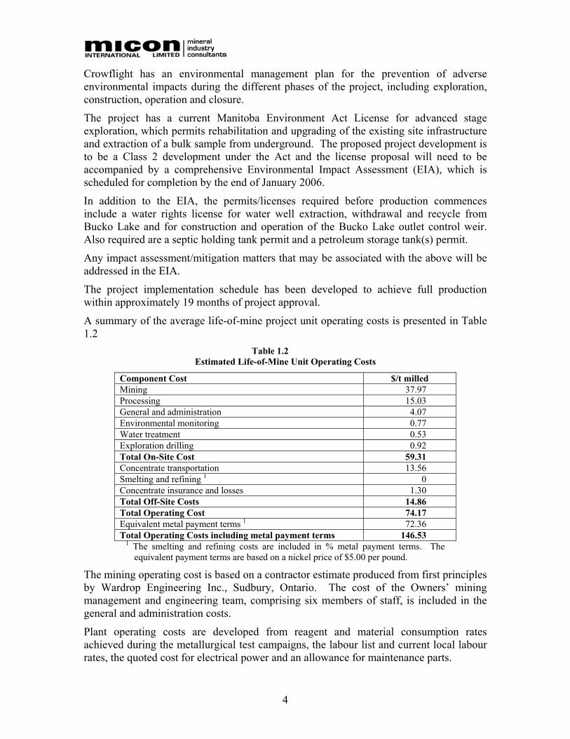
A summary of the average life-of-mine project unit operating costs is presented in Table 1.2
Table 1.2 Estimated Life-of-Mine Unit Operating Costs
Component Cost $/t milled Mining 37.97 Processing 15.03 General and administration 4.07 Environmental monitoring 0.77 Water treatment 0.53 Exploration drilling 0.92 Total On-Site Cost 59.31 Concentrate transportation 13.56 Smelting and refining 1 0 Concentrate insurance and losses 1.30 Total Off-Site Costs 14.86 Total Operating Cost 74.17 Equivalent metal payment terms 1 72.36 Total Operating Costs including metal payment terms 146.53
1 The smelting and refining costs are included in % metal payment terms. The equivalent payment terms are based on a nickel price of $5.00 per pound.
The mining operating cost is based on a contractor estimate produced from first principles by Wardrop Engineering Inc., Sudbury, Ontario. The cost of the Owners’ mining management and engineering team, comprising six members of staff, is included in the general and administration costs.
Plant operating costs are developed from reagent and material consumption rates achieved during the metallurgical test campaigns, the labour list and current local labour rates, the quoted cost for electrical power and an allowance for maintenance parts.
5
General and administration (G&A) costs are developed from staff lists and typical cost of salaries and expense items.
The smelting and refining costs, provided by Crowflight, are based on a quote received from an international base metals broker acting as agent to a nickel concentrate treatment facility. This quote only charges a payable metal portion which incorporates a deduction for unit treatment and refining plus transportation handling and insurance charges.
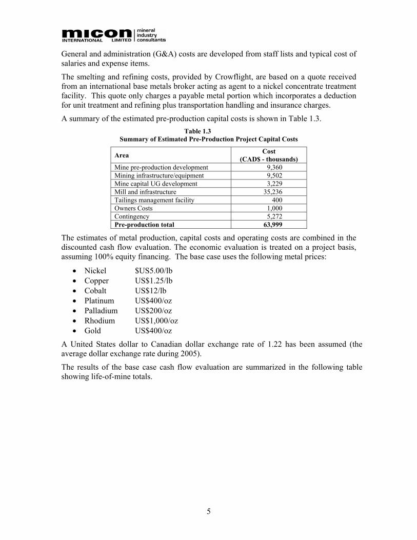
A summary of the estimated pre-production capital costs is shown in Table 1.3. Table 1.3
Summary of Estimated Pre-Production Project Capital Costs
Area Cost (CAD$ - thousands)
Mine pre-production development 9,360 Mining infrastructure/equipment 9,502 Mine capital UG development 3,229 Mill and infrastructure 35,236 Tailings management facility 400 Owners Costs 1,000 Contingency 5,272 Pre-production total 63,999
The estimates of metal production, capital costs and operating costs are combined in the discounted cash flow evaluation. The economic evaluation is treated on a project basis, assuming 100% equity financing. The base case uses the following metal prices:
• Nickel $US5.00/lb • Copper US$1.25/lb • Cobalt US$12/lb • Platinum US$400/oz • Palladium US$200/oz • Rhodium US$1,000/oz • Gold US$400/oz
A United States dollar to Canadian dollar exchange rate of 1.22 has been assumed (the average dollar exchange rate during 2005).
The results of the base case cash flow evaluation are summarized in the following table showing life-of-mine totals.

6
Table 1.4 Economic Evaluation Summary
Item Unit Value Pre-production capital cost $000 63,999 Sustaining capital $000 1,850 Residual plant value $000 4,764 Operating cost, excl. royalties $000 99,945 Cash operating cost $/t milled 59.31 Total royalties $000 5,575 Ni production lb (000’s) 57,455 Cu production lb (000’s) 4,232 Metal sales1 $000 248,065 Off-site costs $000 25,047 Net revenue $000 117,498 Project cash flow before tax $000 56,435 Pre-tax NPV@ 10 % discount rate $000 21,501 Pre-tax NPV@ 5 % discount rate $000 36,023 Pre-tax IRR % 23.0 1 Metal sales revenue is after deduction for smelter/refining terms.
Figure 1.1 presents the IRR sensitivities compared to the base case for the nickel price, nickel grade, ore reserves, operating costs, currency, and off-take terms. The IRR is most sensitive to changes in nickel price, grade, currency, and off-take terms and least sensitive to changes in operating costs and reserves.
Figure 1.1 Sensitivity Analysis – IRR
0%
10%
20%
30%
40%
50%
60%
-20% -15% -10% -5% 0% 5% 10% 15% 20%
Percent Change
IRR
Operating Cost Ni Price Offtake Terms Currency Reserves Ni Grade
7
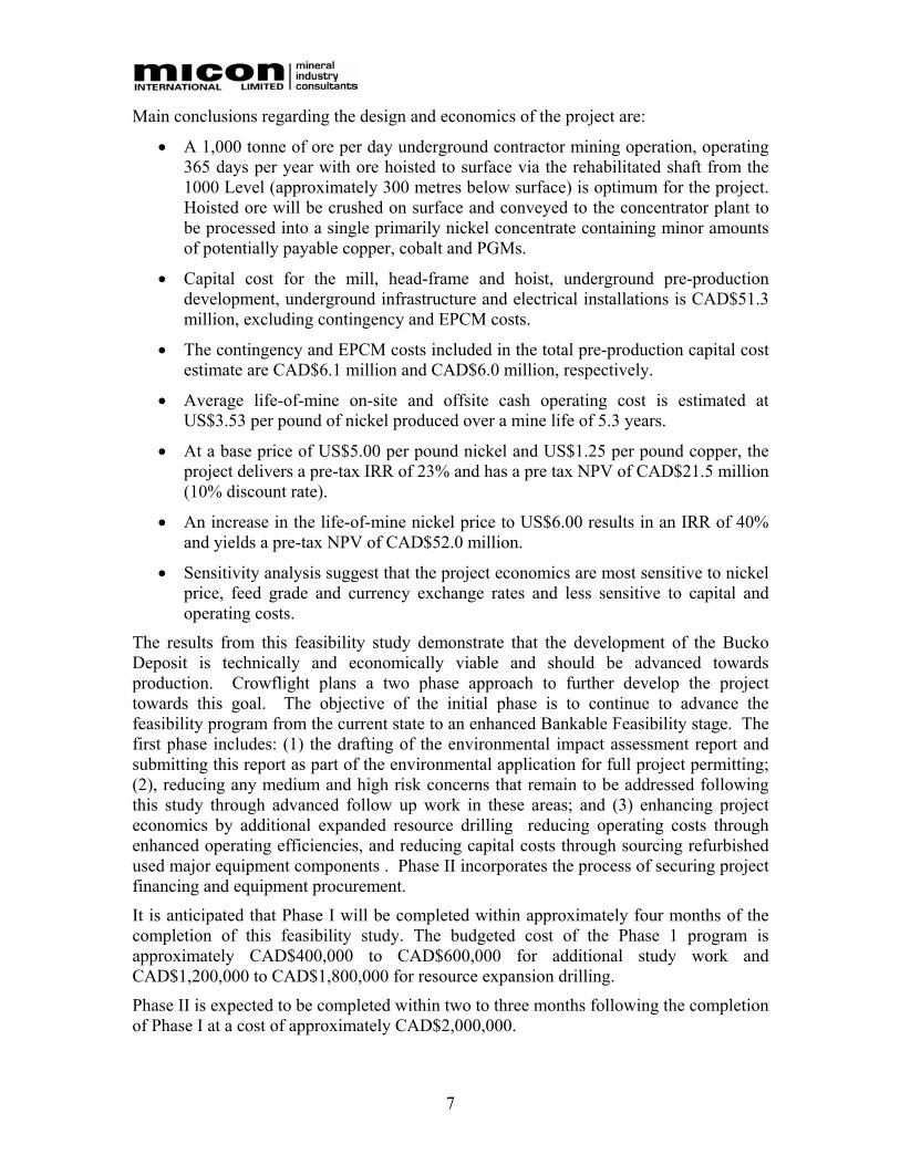
Main conclusions regarding the design and economics of the project are:
• A 1,000 tonne of ore per day underground contractor mining operation, operating 365 days per year with ore hoisted to surface via the rehabilitated shaft from the 1000 Level (approximately 300 metres below surface) is optimum for the project. Hoisted ore will be crushed on surface and conveyed to the concentrator plant to be processed into a single primarily nickel concentrate containing minor amounts of potentially payable copper, cobalt and PGMs.
• Capital cost for the mill, head-frame and hoist, underground pre-production development, underground infrastructure and electrical installations is CAD$51.3 million, excluding contingency and EPCM costs.
• The contingency and EPCM costs included in the total pre-production capital cost estimate are CAD$6.1 million and CAD$6.0 million, respectively.
• Average life-of-mine on-site and offsite cash operating cost is estimated at US$3.53 per pound of nickel produced over a mine life of 5.3 years.
• At a base price of US$5.00 per pound nickel and US$1.25 per pound copper, the project delivers a pre-tax IRR of 23% and has a pre tax NPV of CAD$21.5 million (10% discount rate).
• An increase in the life-of-mine nickel price to US$6.00 results in an IRR of 40% and yields a pre-tax NPV of CAD$52.0 million.
• Sensitivity analysis suggest that the project economics are most sensitive to nickel price, feed grade and currency exchange rates and less sensitive to capital and operating costs.
The results from this feasibility study demonstrate that the development of the Bucko Deposit is technically and economically viable and should be advanced towards production. Crowflight plans a two phase approach to further develop the project towards this goal. The objective of the initial phase is to continue to advance the feasibility program from the current state to an enhanced Bankable Feasibility stage. The first phase includes: (1) the drafting of the environmental impact assessment report and submitting this report as part of the environmental application for full project permitting; (2), reducing any medium and high risk concerns that remain to be addressed following this study through advanced follow up work in these areas; and (3) enhancing project economics by additional expanded resource drilling reducing operating costs through enhanced operating efficiencies, and reducing capital costs through sourcing refurbished used major equipment components . Phase II incorporates the process of securing project financing and equipment procurement.
It is anticipated that Phase I will be completed within approximately four months of the completion of this feasibility study. The budgeted cost of the Phase 1 program is approximately CAD$400,000 to CAD$600,000 for additional study work and CAD$1,200,000 to CAD$1,800,000 for resource expansion drilling.
Phase II is expected to be completed within two to three months following the completion of Phase I at a cost of approximately CAD$2,000,000.
8
2.0 INTRODUCTION AND TERMS OF REFERENCE The Bucko Lake property is located near the town of Wabowden, Manitoba, approximately 105 km southwest of Thompson, Manitoba. Various drilling campaigns on the Bucko Lake property over the past 35 years have delineated a mineral resource, containing nickel, copper, cobalt, platinum, palladium and gold.
Crowflight Minerals Incorporated (Crowflight) entered into an option agreement (the “Agreement”) with Falconbridge Nickel Limited (Falconbridge) on June 15, 2004. Under the terms of the Agreement, Crowflight has the exclusive right to acquire a 100% undivided interest in the Bucko Lake Deposit (Bucko Deposit) from Falconbridge. The completion of a Bankable Feasibility Study is one of the conditions included in the Agreement. All information pertaining to this Agreement and ownership of the property was provided by Crowflight, details can be found in a Crowflight press release dated June 16, 2004.
Micon International Limited (Micon) was retained by Crowflight to prepare a feasibility study for the development, at the Bucko Lake property, of an underground mining operation with on-site production of saleable sulphide nickel concentrate. This NI 43-101 Technical Report was prepared in support of disclosing the results of the feasibility study.
2.1 TERMS OF REFERENCE AND PREPARATION OF THE FEASIBILITY STUDY
In October, 2004, Crowflight initiated the feasibility study. The majority of the team of outside consultants (Table 2.1) were selected through the period October 2004 to early 2005. The program of metallurgical and delineation drilling was jointly planned by Crowflight and Falconbridge personnel and performed by Falconbridge personnel during the First quarter of 2005. Feasibility study activities began with earnest during the second quarter of 2005 with the selection and shipment of samples for metallurgical testing and initial resource modeling activities.
Micon was engaged by Crowflight to complete the final feasibility study report. A copy of the final feasibility study report and appendices can be found in Crowflight’s offices.
The mineral resource, mine plan and mine costing were based on the December 2005, NI 43-101 Technical Report completed by P & E Mining Consultants Inc. entitled “Technical Report and Resource Estimate on the Bucko Lake Property, the Pas Mining District, Manitoba, Canada”.
The mining plans and costs used in this feasibility study were developed by Wardrop Engineering Limited, based on AST Mining’s Mine 2-4D mine design. The mine design was supervised by Crowflight and Wardrop.
G&T Metallurgical conducted the metallurgical testwork program under the supervision of Richard Gowans, P.Eng, a Senior Metallurgist and Vice President from Micon.
Geotechnical support for the mine design, tailings disposal, site and infrastructure was provided by Golder and Associates.
Supervisory process engineering performed by Micon, included metallurgical testwork interpretation, flowsheet selection, process design criteria, mass balances and main equipment sizing. Met-Chem was responsible for the detailed process engineering as
9
well as the design, engineering and costing of the beneficiation plant and site infrastructure.
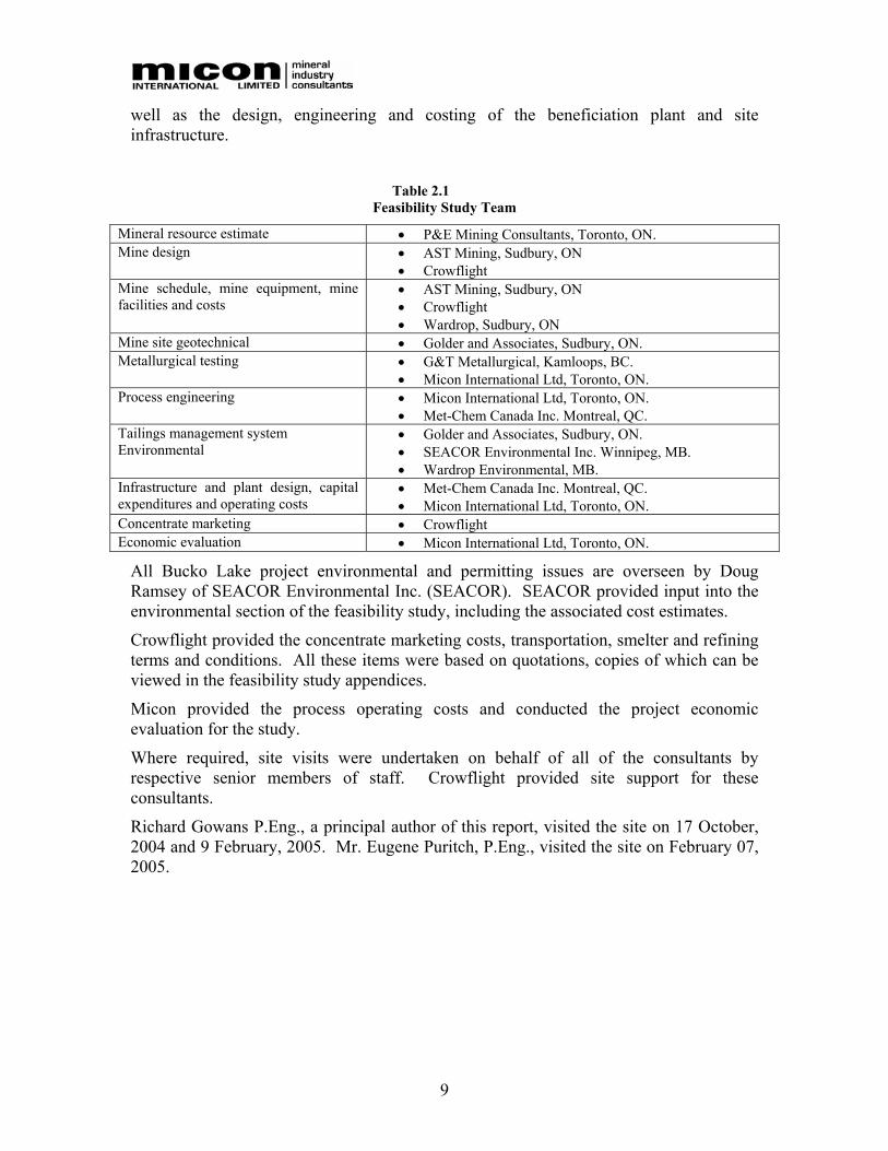
Table 2.1
Feasibility Study Team
Mineral resource estimate • P&E Mining Consultants, Toronto, ON. Mine design • AST Mining, Sudbury, ON
• Crowflight Mine schedule, mine equipment, mine facilities and costs
• AST Mining, Sudbury, ON • Crowflight • Wardrop, Sudbury, ON
Mine site geotechnical • Golder and Associates, Sudbury, ON. Metallurgical testing • G&T Metallurgical, Kamloops, BC.
• Micon International Ltd, Toronto, ON. Process engineering • Micon International Ltd, Toronto, ON.
• Met-Chem Canada Inc. Montreal, QC. Tailings management system Environmental
• Golder and Associates, Sudbury, ON. • SEACOR Environmental Inc. Winnipeg, MB. • Wardrop Environmental, MB.
Infrastructure and plant design, capital expenditures and operating costs
• Met-Chem Canada Inc. Montreal, QC. • Micon International Ltd, Toronto, ON.
Concentrate marketing • Crowflight Economic evaluation • Micon International Ltd, Toronto, ON.
All Bucko Lake project environmental and permitting issues are overseen by Doug Ramsey of SEACOR Environmental Inc. (SEACOR). SEACOR provided input into the environmental section of the feasibility study, including the associated cost estimates.
Crowflight provided the concentrate marketing costs, transportation, smelter and refining terms and conditions. All these items were based on quotations, copies of which can be viewed in the feasibility study appendices.
Micon provided the process operating costs and conducted the project economic evaluation for the study.
Where required, site visits were undertaken on behalf of all of the consultants by respective senior members of staff. Crowflight provided site support for these consultants.
Richard Gowans P.Eng., a principal author of this report, visited the site on 17 October, 2004 and 9 February, 2005. Mr. Eugene Puritch, P.Eng., visited the site on February 07, 2005.

10
3.0 RELIANCE ON OTHER EXPERTS The Authors of this Technical Report have reviewed and analyzed data provided by Crowflight Minerals and the technical team listed in Table 2.1, and have drawn there own conclusions there from, augmented by its direct field examination. Micon has not carried out any independent exploration work, drilled any holes or carried out any sampling and assaying. However, the presence of nickel in the local rocks is substantiated by the previous exploration and development work completed on the property.
The authors have relied upon the data presented by Crowflight and the feasibility technical team in formulating its opinion, although all reasonable diligence in checking, confirming and validating data was exercised. Micon accepts in good faith that Crowflight and the members of the feasibility technical team, not working under Micon’s direct supervision, disclosed all relevant data during the development and preparation of the feasibility study.
The various agreements under which Crowflight Minerals holds title to the mineral lands for this project have not been investigated or confirmed by Micon and Micon offers no opinion as to the validity of the mineral title claims. The description of the property, and ownership thereof, lease payments, royalties, etc. as set out in this report, are provided for general information purposes only.
The description of the geology, mineralization, exploration and resource estimate included in the feasibility study and this report are based on the NI 43-101 Technical Report completed by P & E Mining Consultants Inc. in December 2005 entitled “Technical Report and Resource Estimate on the Bucko Lake Property, the Pas Mining District, Manitoba, Canada”.
All currency amounts are stated in Canadian dollars, most frequently expressed in terms of constant fourth quarter, 2005 value.
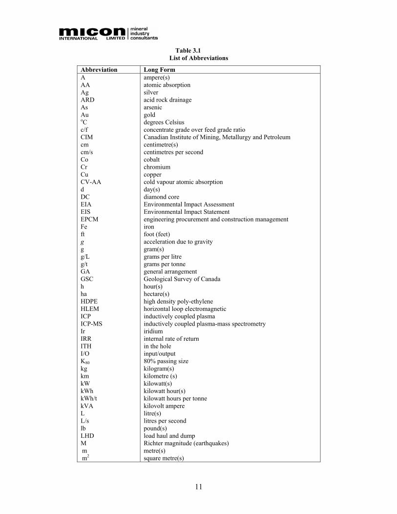
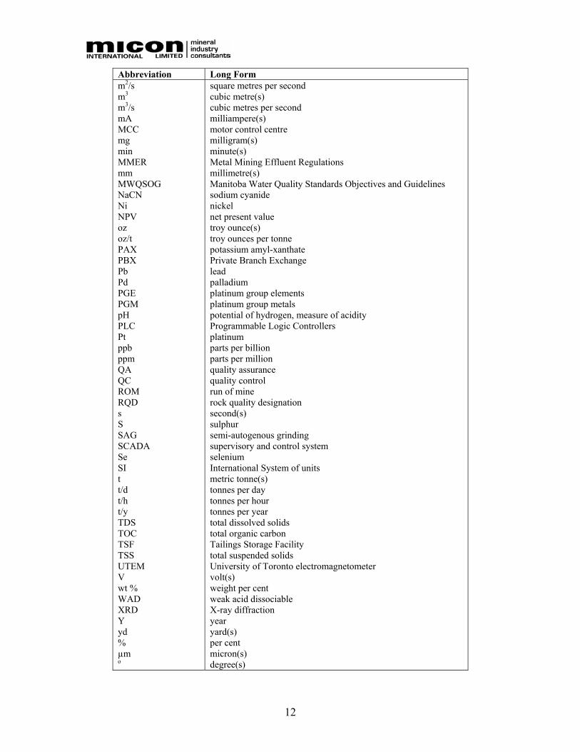
Quantities are stated primarily in SI units, the Canadian and international practice although in some instances American Customary units are used for specific values and engineering constants. A detailed list of abbreviations used in this report is provided in Table 3.1.
11
Table 3.1 List of Abbreviations
Abbreviation Long Form A AA Ag ARD As Au oC c/f CIM cm cm/s Co Cr Cu CV-AA d DC EIA EIS EPCM Fe ft g g g/L g/t GA GSC h ha HDPE HLEM ICP ICP-MS Ir IRR ITH I/O K80 kg km kW kWh kWh/t kVA L L/s lb LHD M m m2
ampere(s) atomic absorption silver acid rock drainage arsenic gold degrees Celsius concentrate grade over feed grade ratio Canadian Institute of Mining, Metallurgy and Petroleum centimetre(s) centimetres per second cobalt chromium copper cold vapour atomic absorption day(s) diamond core Environmental Impact Assessment Environmental Impact Statement engineering procurement and construction management iron foot (feet) acceleration due to gravity gram(s) grams per litre grams per tonne general arrangement Geological Survey of Canada hour(s) hectare(s) high density poly-ethylene horizontal loop electromagnetic inductively coupled plasma inductively coupled plasma-mass spectrometry iridium internal rate of return in the hole input/output 80% passing size kilogram(s) kilometre (s) kilowatt(s) kilowatt hour(s) kilowatt hours per tonne kilovolt ampere litre(s) litres per second pound(s) load haul and dump Richter magnitude (earthquakes) metre(s) square metre(s)
12
Abbreviation Long Form m2/s m3 m3/s mA MCC mg min MMER mm MWQSOG NaCN Ni NPV oz oz/t PAX PBX Pb Pd PGE PGM pH PLC Pt ppb ppm QA QC ROM RQD s S SAG SCADA Se SI t t/d t/h t/y TDS TOC TSF TSS UTEM V wt % WAD XRD Y yd % µm o
square metres per second cubic metre(s) cubic metres per second milliampere(s) motor control centre milligram(s) minute(s) Metal Mining Effluent Regulations millimetre(s) Manitoba Water Quality Standards Objectives and Guidelines sodium cyanide nickel net present value troy ounce(s) troy ounces per tonne potassium amyl-xanthate Private Branch Exchange lead palladium platinum group elements platinum group metals potential of hydrogen, measure of acidity Programmable Logic Controllers platinum parts per billion parts per million quality assurance quality control run of mine rock quality designation second(s) sulphur semi-autogenous grinding supervisory and control system selenium International System of units metric tonne(s) tonnes per day tonnes per hour tonnes per year total dissolved solids total organic carbon Tailings Storage Facility total suspended solids University of Toronto electromagnetometer volt(s) weight per cent weak acid dissociable X-ray diffraction year yard(s) per cent micron(s) degree(s)
13
4.0 PROPERTY DESCRIPTION AND LOCATION
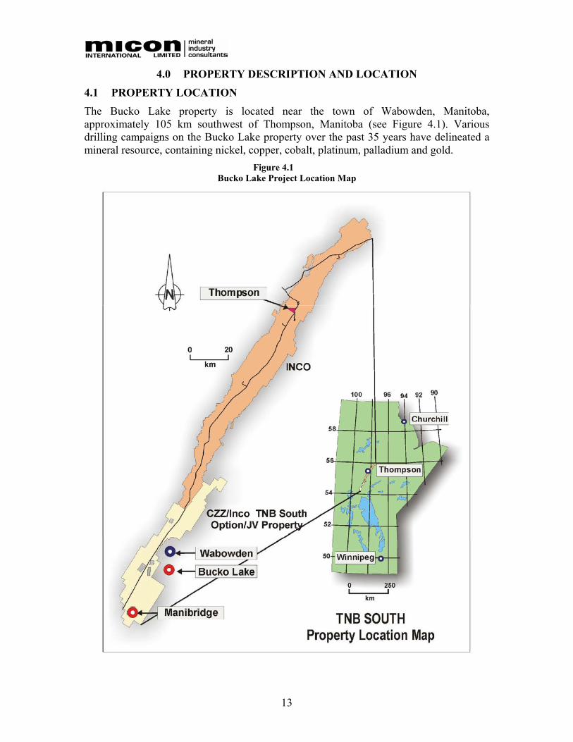
4.1 PROPERTY LOCATION The Bucko Lake property is located near the town of Wabowden, Manitoba, approximately 105 km southwest of Thompson, Manitoba (see Figure 4.1). Various drilling campaigns on the Bucko Lake property over the past 35 years have delineated a mineral resource, containing nickel, copper, cobalt, platinum, palladium and gold.
Figure 4.1 Bucko Lake Project Location Map
14
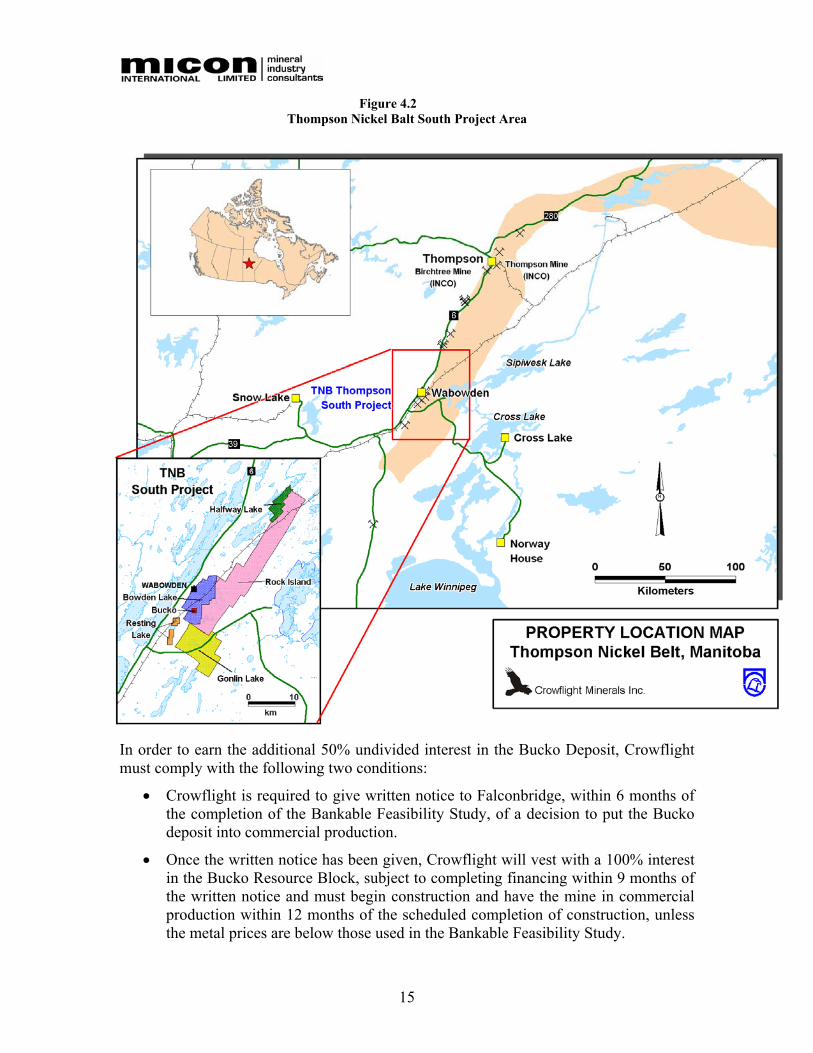
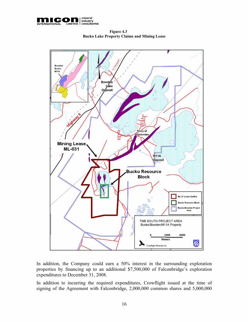
4.2 DESCRIPTION AND TENURE The Bucko property consists of one Mining Lease # 031 totaling 546 hectares and three claim blocks (Bow 6, 8 and 11) totaling 416 hectares. Table 4.1 summarizes land status details of the property as depicted in Figure 4.3.
Table 4.1 Bucko Lake Property Claims and Mining Lease
Lease/Claim No. Area (Ha) Record Date Due Date Mining Lease ML #031 546 01 April 1992 01 April 2013 Claims
Bow 3 P7594E 144 20 April 1988 19 June 2006 Bow 6 P7597E 112 20 April 1988 19 June 2006 Bow 11 P7602E 160 20 April 1988 19 June 2006
Total 416
A Mining Lease has a term of 21 years and requires that the party holding such lease make annual payments of CAD$8.00 per hectare if in production, or if not in production at the annual rate of CAD$12.00 per hectare. Mining leases which terminate after the initial 21 year period can be renewed for an additional 21 year period on into perpetuity through the payment of the annual CAD$8.00 or CAD$12.00 per hectare fee.
Exploration Claims require neither payment nor work commitments for the initial two year period following the registration of such claims. From the third until tenth year of title, claim holders must expend a minimum CAD$12.50 per hectare in exploration activities. From the eleventh year onward to perpetuity Exploration Claim holders must expend a minimum CAD$25.00 per hectare in exploration activities. Once a total of CAD$625 has been spent per hectare of an Exploration Claim, exploration claim holders are entitled to convert an Exploration Claim into a Mining Lease.
Based on exploration expenditures and Mining Lease payments during the 2004 and 2005 periods all Mining Leases and Exploration Claims are in good standing well into the future.
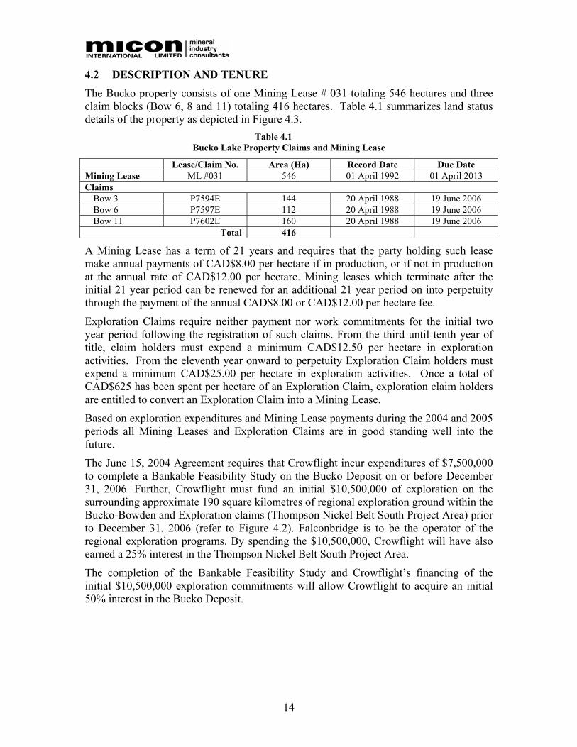
The June 15, 2004 Agreement requires that Crowflight incur expenditures of $7,500,000 to complete a Bankable Feasibility Study on the Bucko Deposit on or before December 31, 2006. Further, Crowflight must fund an initial $10,500,000 of exploration on the surrounding approximate 190 square kilometres of regional exploration ground within the Bucko-Bowden and Exploration claims (Thompson Nickel Belt South Project Area) prior to December 31, 2006 (refer to Figure 4.2). Falconbridge is to be the operator of the regional exploration programs. By spending the $10,500,000, Crowflight will have also earned a 25% interest in the Thompson Nickel Belt South Project Area.
The completion of the Bankable Feasibility Study and Crowflight’s financing of the initial $10,500,000 exploration commitments will allow Crowflight to acquire an initial 50% interest in the Bucko Deposit.
15
Figure 4.2 Thompson Nickel Balt South Project Area
In order to earn the additional 50% undivided interest in the Bucko Deposit, Crowflight must comply with the following two conditions:
• Crowflight is required to give written notice to Falconbridge, within 6 months of the completion of the Bankable Feasibility Study, of a decision to put the Bucko deposit into commercial production.
• Once the written notice has been given, Crowflight will vest with a 100% interest in the Bucko Resource Block, subject to completing financing within 9 months of the written notice and must begin construction and have the mine in commercial production within 12 months of the scheduled completion of construction, unless the metal prices are below those used in the Bankable Feasibility Study.
16
Figure 4.3 Bucko Lake Property Claims and Mining Lease
In addition, the Company could earn a 50% interest in the surrounding exploration properties by financing up to an additional $7,500,000 of Falconbridge’s exploration expenditures to December 31, 2008.
In addition to incurring the required expenditures, Crowflight issued at the time of signing of the Agreement with Falconbridge, 2,000,000 common shares and 5,000,000

17
warrants to Falconbridge. The 5,000,000 warrants consist of 2,500,000 warrants exercisable at $0.35 and 2,500,000 warrants exercisable at $0.75 both valid for a period of 2 years. Crowflight will also issue Falconbridge an additional 1,000,000 common shares in June of each of the subsequent years for a potential total of an additional 4,000,000 common shares.
On December 16, 2005 Crowflight issued a press release wherein it was stated that the Company and Falconbridge have, subject to completing a binding Amended Agreement by January 31, 2006, agreed in principle on a number of revisions to the original Agreement between the two parties with respect to Crowflight’s commitments to earn its interests in the Bucko Deposit and the Thompson Nickel Belt (TNB) South project area.
The terms of the original Agreements between Crowflight and Falconbridge are being revised in three primary areas, subject to completing a definitive Amended Agreement by January 31, 2006:
1. Crowflight to Earn an Interest in the Larger Mining Lease ML-031. Under the proposed terms of the Amended Agreement, Crowflight can earn an initial 33% interest in the entire Mining Lease ML-031 which includes the Bucko Resource Block as defined in the Original Agreement.
2. Crowflight to Earn Up To a 100% Interest in ML-031. Under the proposed terms of the Amended Agreement, Crowflight can earn an initial 33% interest in ML-031, by funding the revised 2006 TNB South regional exploration commitment of $1.5 million and by providing funding or having funded the required amount to complete a Bankable Feasibility Study as described in the original Agreement. Crowflight can earn up to a 50% interest in ML-031 by completing the Bankable Feasibility study on or before December 31, 2006 and incurring $6.0 million in obligatory exploration funding on the TNB South Property by April 30, 2009. Crowflight can earn a 100% interest in ML-031 subject to a 2.5% NSR payable to Falconbridge, by achieving Commercial Production as defined in the original Agreement.
Crowflight may at its option vest early by completing the requirements to vest as described in the original Agreement on an accelerated schedule and advancing in cash to Falconbridge the amount required to complete the firm commitments on the TNB South Property. Falconbridge retains a 50% back-in right on any new resources exceeding 200 million pounds of nickel discovered outside of the boundaries of the original Bucko Resource Block by matching Crowflight’s prior exploration expenditures on such resources.
3. Rescheduled Annual Regional Exploration Commitments.
Under the terms of the Amended Agreement, Falconbridge has agreed in principle to provide Crowflight an extension of the period under which it is required to complete its obligatory exploration commitments on the TNB South Property with the result that the annual obligatory commitments to the regional exploration, due in 2005 and 2006, are lowered from a total of $6.25 million to $1.5 million for 2006

18
commitments. The remaining commitments have been redistributed at $1.5 million per year over the four year period 2006 to 2009.
Following completion of its earn-in to an initial 25% interest in the exploration Claims on the TNB South Property, Crowflight may earn an additional 25% interest in the TNB South Property by incurring a total of $7.0 million in optional expenditures that are distributed over four years, following vesting its 25% interest.

19
5.0 ACCESSIBILITY, CLIMATE, LOCAL RESOURCES, INFRASTRUCTURE AND PHYSIOGRAPHY
5.1 PROJECT LOCATION AND ACCESS The Bucko Lake nickel deposit is located near the town of Wabowden, Manitoba, 105 km southwest of Thompson, Manitoba. Wabowden is a small town of about 550 people with electrical and telephone service, a post office and a single gas station. There is also a small motel and attached restaurant. Figure 4.1 and Figure 4.2 show the location of the project.
The Bucko deposit is situated under Bucko Lake, a small body of shallow water, believed not to exceed 2.0 m depth at its deepest point, 5 km south of Wabowden. The lake is not surrounded by any cottages and is understood to be an area of little interest to the local inhabitants.
The Town of Wabowden is serviced by a 5 km long all-weather road from Provincial Highway 6, one of two main, north-south highways in the province. The Bucko deposit is accessed by an all weather gravel road built in 1970 and recently upgraded by Crowflight.
The property is in close proximity to electrical and telephone services and the Hudson Bay Railway (a subsidiary of Omnitrax - formerly CNR) passes within 1.5 km to the west of the Bucko Deposit shaft. The Falconbridge Manibridge Mine property (operated in the 1970’s and since inactive) is situated about 30 km southwest of Bucko Lake by existing roads.
5.2 CLIMATE AND PHYSIOGRAPHY The climate is typical of northern areas within the Canadian Shield with long winters and short but warm to hot summers. Average temperatures range from a low average of -25 ºC in January to a high average of +16.9 ºC in July. The average number of frost free days is 104. The annual precipitation averages 315 cm of rain and 147.5 cm of snow. The average low, high and mean monthly temperatures measured from 1961 to 2004 are presented in Table 5.1. This table also shows average precipitation data for the same period.
Table 5.1 Average Monthly Climate Statistics.
Temperature (ºC) J F M A M J J A S O N D Maximum -19 -13 -5 5 13 19 23 21 13 4 -6 -16 Minimum -30 -27 -20 -9 0 5 9 7 2 -3 -16 -26 Mean -24 -20 -12 -1 6 12 16 14 7 0 -11 -21 Precipitation Rain (mm) 0 0 1 6 31 69 84 78 59 21 2 0 Snow (cm) 23 16 22 23 16 3 0 0 4 27 36 32
The Bucko property is located in an area of generally flat to moderately low hilly terrain typical of glaciated areas of the Canadian Shield. Ponds, swamps and small lakes are common. Vegetation consists of spruce and fir species intermingled with re-growth of alder, birch and young fir. Alders are prevalent in older stripped and wet areas.
The property lies at an elevation of approximately 250 m above sea level.

20
6.0 HISTORY
6.1 EXPLORATION HISTORY The Bucko Lake deposit was originally acquired in 1959 by Consolidated Marbenor Mines Limited (CMML) and optioned to Falconbridge in 1962 after the drilling of hole M77-B, which intersected 1.54% Ni over 6.3 m. CMML and Falconbridge conducted numerous follow-up ground and airborne-based magnetic, electromagnetic (EM), seismic refraction and induced polarization (IP) surveys on the claims at various periods during the 1960's.
The Bucko Lake mineralization was discovered in a 1964 drill program (3,720 m) that tested high priority geophysical targets. By 1970, some 53-drill holes totalling about 21,050 m had been drilled. At that time, a decision was made to go underground and conduct an exploration program.
Between 1971 and 1972, an all-weather access road was developed and a three-compartment shaft was sunk to the 305 m level (1000 Level). Approximately 915 m of drifting, in the hangingwall, was completed on the 1000 Level and an underground diamond drill program consisting of 12,739 m of coring in 61 holes was completed. The shaft was sunk in the footwall gneisses although the exploration drifting crossed through the mineralization-hosting ultramafic unit into the hangingwall gneisses where the bulk of the development occurred. The mineralized zone was intersected by the drift at the extreme south end of the zone but no substantial development was completed within the body. In 1974 the shaft was capped, allowed to flood and the site demobilized. By late 1974 the property had become dormant.
Additional geophysical work was completed in 1990 and 6,880 m of additional drilling was completed in 9 holes and three wedges (Falconbridge 1994). The reported drilling in and around the Bucko Lake deposit, between 1972 and 1994, by Falconbridge and CMML consisted of some 130 surface drill holes totalling 43,091 m.
In 2000, Nuinsco Resources Ltd. conducted a 4,628 m due-diligence drill program in 13-holes to confirm some of the Falconbridge results and to test the continuity and projection of certain zones of nickel mineralization. Nuinsco carried out an additional 2,500 m of diamond drilling in the first quarter of 2001.
As part of its efforts to test the potential of the deposit Crowflight conducted two diamond drill programs, a 2004-2005 winter program and a 2005 summer program. The winter program, comprising 21 holes, was designed to not only in-fill areas of known mineralization and to provide a bulk sample for metallurgical testing, but also to delineate the extent of known mineralization and to test potential extensions to the Bucko mineralization. Ten of these drill holes were used for the metallurgical composite sample.
The summer 2005 drill program consisted of a series of ten of eleven planned surface holes designed to evaluate areas potentially containing greater thicknesses of higher grade nickel mineralization below 305 vertical metres (depth of existing historical exploration workings) to a depth of about 450 metres.
21
6.2 HISTORICAL TECHNICAL AND ECONOMIC STUDIES An internal feasibility study was conducted by Dennis Miller from Falconbridge in 1989. It was based on underground mining of the high-grade portion of the reserves only; comparing different production rates as well as different milling options (on-site mill vs. custom milling at Inco's Thompson operation). Another study (contracted to Marston Mining Services in 1991) estimated the economics of open pit mining the top part of the ore-body. Optimum depth of the pit was determined to be 900 feet and this option involved dredging about half of the overlying lake.
In 1992, Hudson Bay Mining and Smelting Co. Limited (HBMS) proceeded with another review of the project to evaluate acquisition of the property as possible feed for the Namew Mill after exhaustion of the Namew Lake ore reserves. HBMS considered the two previously evaluated options; i.e. open pit mining and underground mining of high-grade reserves. For each option, different milling scenarios were considered. HBMS concluded that it was not economic to process Bucko ore at Namew Lake. However, the property was considered to have potential, depending on mineral reserves, nickel price and treatment charges, to produce nickel in a cost effective manner.
A pre-feasibility study, completed in 1994 by Falconbridge, considered a combination of both open pit and underground mining. According to this study, the open pit would ensure an important start-up feed to the mill while underground ore would increase the pounds of nickel produced. The open pit design and pit reserves were kept similar to previous evaluations, mainly because of the lack of any new diamond drilling information. Different ways of removing the overburden were evaluated for an open pit option, together with an underground mining option that evaluated different mining methods and ore and waste handling systems. The results of the study indicated that both the open pit and underground high grade portion of the Bucko Lake ore-body were economically extractable at nickel prices in excess of US$4.09/lb (15% IRR).
6.3 HISTORICAL MINERAL RESOURCE ESTIMATES A detailed description of the historical resource estimates can be found in the December 2005, NI 43-101 Technical Report completed by P & E Mining Consultants Inc. (P&E) entitled “Technical Report and Resource Estimate on the Bucko Lake Property, the Pas Mining District, Manitoba, Canada”. The following table is copied from the P&E report.

22
Table 6.1 Summary of Bucko Lake Mineral Inventory Estimates 1968 – 2000
The historical mineral resources at Bucko Lake were estimated using various, sometimes undefined codes of reporting and classification. These estimates have frequently been reported as unclassified resources (measured, indicated or inferred) or with measured and indicated resources summed together. As such, they do not comply with NI 43-101. The historical resource estimates are no longer relevant and have been superseded with a more recent resource estimate, which was included in the P&E December 2005 Technical Report. This resource estimate is discussed in Section 17 of this Technical Report.
6.4 HISTORICAL PRODUCTION There has been no historical production form the Bucko Lake property.
Elevation (m)Cut off %Ni
SG Hinge Zone
Included
Date Estimated By Surface ddh
u/g ddh From To
Tonnes Millions
% Ni % Cu Tonnes Ni Remarks
0.50 2.7 Partly 1968 C. Coats 25 2469 2941 27.1 0.78 -- 211,669 1.00 2.7 Partly 1968 C. Coats 25 2469 2941 9.2 1.22 -- 111,885 0.70 2.7 Partly 1972 P. Mattinen 25 61 2477 2987 7.5 1.40 0.10 103,845 1.10 2.7 Partly 1972 P. Mattinen 25 61 2477 2987 4.2 1.71 0.12 72,566 1.50 3.2 Partly 1972 P. Mattinen 25 61 2477 2987 2.6 2.18 0.16 57,003
1.00 2.7 No 1976 H.J. Coats -- 61 2438 2926 9.1 1.19 108,647 Some speculative inventory
1.00 2.8 No 1976 H.J. Coats 61 2560 2865 2.1 1.85 38,887
1.00 2.8 No 1976 H.J. Coats 61 2560 2865 3.1 1.82 56,646 Some speculative inventory
1.00 2.8 Partly 1981 L.Wigglesworth 61 2560 2865 1.54 2.32 0.19 35,688 22.4 % External dilution added
1.00 2.8 Yes 1990 Derweduwen 6 61 2286 2865 6.5 1.50 0.10 97,138 20 % dilution at zero grade added
1.50 2.8 Yes 1990 Derweduwen 6 61 2286 2865 2.5 2.23 0.17 56,186 0.70 2.8 Yes 1990 Derweduwen 6 61 2286 2865 9.7 1.11 0.08 107,824
-- 2.7 Yes 1991 Derweduwen 61 2591 2987 32.9 0.64 0.05 210,689 Total ultramafic 0.50 -- Yes 1991 P.J. Chornby 61 2560 2865 13.4 1.00 -- 134,000 Open Pit 0.50 -- Yes 1992 HBM&S 61 2560 2865 12.1 0.91 121,000 Open Pit 1.50 2.8 Partly 1999 L.Wigglesworth 16(+) 61 2216 2865 1.8 2.27 40,800
23
7.0 GEOLOGICAL SETTING A detailed description of the geology can be found in the December 2005, NI 43-101 Technical Report completed by P & E Mining Consultants Inc. entitled “Technical Report and Resource Estimate on the Bucko Lake Property, the Pas Mining District, Manitoba, Canada”. A summary is provided below.
7.1 REGIONAL GEOLOGY
The Thompson Nickel Belt is a 10 km to 35 km wide belt of variably reworked Archean basement gneisses and early Proterozoic cover rocks between the Superior and Churchill Provinces in northern Manitoba. Strong gravity and magnetic expressions allow delineation of the belt and permit its extension beneath platformal cover. It is comprised of gneisses, metasedimentary, metavolcanic and ultramafic rocks and felsic plutons. Most of the metasedimentary, metavolcanic and ultramafic rocks are on the western side of the belt, which also contains the known nickel deposits. The intermediate to felsic gneisses are stratiform in character and have a complex tectonic and metamorphic history. They show an earlier Archean granulite facies and a pervasive retrograde Proterozoic amphibolite facies metamorphism.
The metasedimentary-metavolcanic assemblages are long, thin, complexly deformed bands. Some are younger and others coeval with the gneisses. Metasedimentary sequences include siliceous, calcareous, pelitic and ferruginous rocks of high metamorphic grade and complex metamorphic histories.
A minimum of two structural events has been recognized. Earlier folding produced tight, sub-horizontally plunging synclinal structures. Later cross folding produced sub-vertically plunging folds.
The metavolcanic pile consists of pillowed and massive meta-basalt flows. They are recrystallized to amphibolites and no primary textures are evident. Associated are magnesian meta-basalt and minor ultramafic flows. Field relationships suggest that the metavolcanic rocks are coeval with the metasedimentary rocks.
The ultramafic rocks have been divided into serpentinite and ultramafic amphibolite units, both of which occur as sheet-like or lenticular concordant bodies in the gneisses. They range from dunite to peridotite to pyroxenite in composition. The general character of the ultramafic rocks suggests that they were originally intruded as sills and are early "Hudsonian" or "pre Hudsonian" in age.
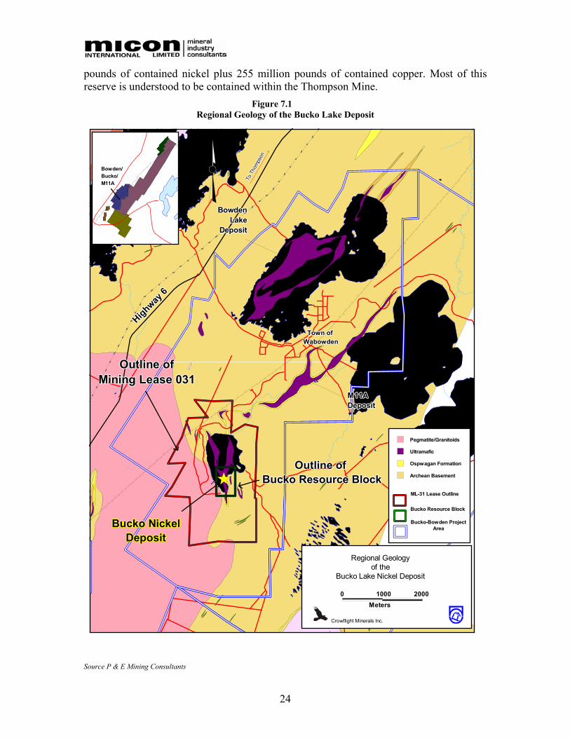
The regional geology of the Bucko Deposit is depicted in Figure 7.1 and the major nickel sulphide deposits of the Thompson Nickel Belt are shown on Figure 7.2. A review of available historical production records by Crowflight and Falconbridge personnel indicates that approximately 28 billion pounds of nickel has been produced from various mining operations, including the Manibridge, Thompson, Pipe and Birchtree mines in the Thompson Nickel Belt. Currently producing mines include the Thompson and Birchtree Mines. Past Producers include the Pipe, Soab and Manibridge deposits. Individual mine tonnage and grade data are difficult to obtain. Eckstrand (1996) estimated a reserve for the entire belt of 89 million tonnes at 2.5% Ni and 0.13% Cu for a total of 4.9 billion
24
pounds of contained nickel plus 255 million pounds of contained copper. Most of this reserve is understood to be contained within the Thompson Mine.
Figure 7.1 Regional Geology of the Bucko Lake Deposit
M11AM11AM11AM11AM11AM11AM11AM11AM11ADepositDepositDepositDepositDepositDepositDepositDepositDeposit
BowdenBowdenBowdenBowdenBowdenBowdenBowdenBowdenBowdenLakeLakeLakeLakeLakeLakeLakeLakeLake
DepositDepositDepositDepositDepositDepositDepositDepositDeposit
N
Crowflight Minerals Inc.
Regional Geologyof the
Bucko Lake Nickel Deposit
0 1000 2000Meters
Bowden/Bowden/Bowden/Bowden/Bowden/Bowden/Bowden/Bowden/Bowden/Bucko/Bucko/Bucko/Bucko/Bucko/Bucko/Bucko/Bucko/Bucko/M11AM11AM11AM11AM11AM11AM11AM11AM11A
Ospwagan Formation
Pegmatite/Granitoids
Archean Basement
Ultramafic
Bucko-Bowden ProjectArea
ML-31 Lease Outline
Bucko Resource Block
Outline ofOutline ofOutline ofOutline ofOutline ofOutline ofOutline ofOutline ofOutline ofMining Lease 031Mining Lease 031Mining Lease 031Mining Lease 031Mining Lease 031Mining Lease 031Mining Lease 031Mining Lease 031Mining Lease 031
Highway 6
Highway 6
Highway 6
Highway 6
Highway 6
Highway 6
Highway 6
Highway 6
Highway 6
Town of Town of Town of Town of Town of Town of Town of Town of Town of WabowdenWabowdenWabowdenWabowdenWabowdenWabowdenWabowdenWabowdenWabowden
To T
hom
pson
To T
hom
pson
To T
hom
pson
To T
hom
pson
To T
hom
pson
To T
hom
pson
To T
hom
pson
To T
hom
pson
To T
hom
pson
Outline of Outline of Outline of Outline of Outline of Outline of Outline of Outline of Outline of Bucko Resource BlockBucko Resource BlockBucko Resource BlockBucko Resource BlockBucko Resource BlockBucko Resource BlockBucko Resource BlockBucko Resource BlockBucko Resource Block
Bucko NickelBucko NickelBucko NickelBucko NickelBucko NickelBucko NickelBucko NickelBucko NickelBucko NickelDepositDepositDepositDepositDepositDepositDepositDepositDeposit
Source P & E Mining Consultants
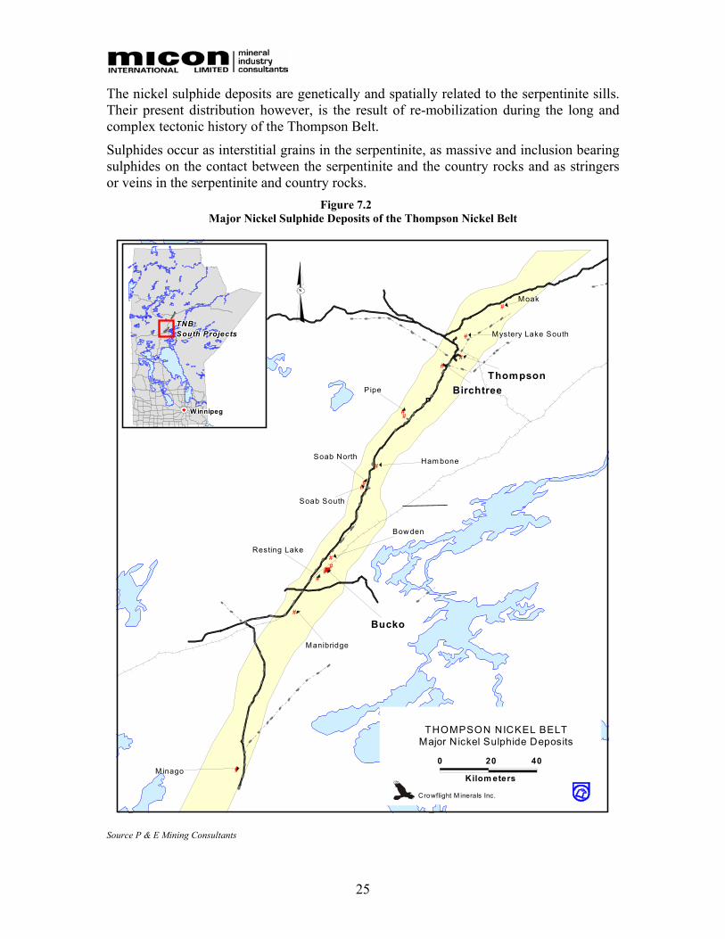
25
The nickel sulphide deposits are genetically and spatially related to the serpentinite sills. Their present distribution however, is the result of re-mobilization during the long and complex tectonic history of the Thompson Belt.
Sulphides occur as interstitial grains in the serpentinite, as massive and inclusion bearing sulphides on the contact between the serpentinite and the country rocks and as stringers or veins in the serpentinite and country rocks.
Figure 7.2 Major Nickel Sulphide Deposits of the Thompson Nickel Belt
#
#
##
#
#
#
#
#
#
#
#
#
##
#
6
BirchtreeBirchtreeBirchtreeBirchtreeBirchtreeBirchtreeBirchtreeBirchtreeBirchtreeThompsonThompsonThompsonThompsonThompsonThompsonThompsonThompsonThompson
Pipe
Soab North
Soab South
Ham bone
Bow den
BuckoBuckoBuckoBuckoBuckoBuckoBuckoBuckoBucko
Resting Lake
Manibridge
Mystery Lake South
Moak
Minago
W innipegW innipegW innipegW innipegW innipegWinnipegWinnipegWinnipegW innipeg
TNBTNBTNBTNBTNBTNBTNBTNBTNBSouth ProjectsSouth ProjectsSouth ProjectsSouth ProjectsSouth ProjectsSouth ProjectsSouth ProjectsSouth ProjectsSouth Projects
N
THOMPSON NICKEL BELTMajor Nickel Sulphide Deposits
Crowflight M inerals Inc.
0 20 40
Kilom eters
Source P & E Mining Consultants

26
7.2 LOCAL GEOLOGY
The Bucko Lake property is underlain by Archean gneisses and Proterozoic ultramafic intrusive rocks (Figure 7.3). The Archean magmatite gneisses have been subdivided into granite gneiss, amphibole gneiss and amphibolite. Granitic gneisses are primarily quartz and potassium feldspar with less than 25% mafic minerals. Amphibole gneisses are 25% to 50% amphibole with the remainder quartz and feldspar. Amphibolites contain more than 60% amphibole.
The Archean gneisses were intruded by Aphebian ultramafic sills including the Bucko Lake ultramafic which hosts the nickel mineralization on the property. The Bucko Lake ultramafic sill is on the northeast flank of the Resting Lake intrusion and is entirely within granodiorite gneiss. It is a linear body, 22 m wide at the south end, gradually increasing to over 150 m wide at the north end. The Bucko Lake Sill has been traced about 800 m north-south and dips steeply (75° to 80°) to the east.
The ultramafic body is complexly folded in the form of a synform with a fold axis plunging steeply to the south. Both limbs of the folded sill face east suggesting that the west limb has been duplicated by faulting.
The Bucko Lake ultramafic sill is primarily peridotite and dunite with lesser amounts of olivine orthopyroxenite, poikilitic harzburgite, orthopyroxenite and amphibole bearing peridotite.
Contacts of the ultramafic rocks with the surrounding country rocks are usually obscured by alteration, shearing or late stage pegmatite dikes. Blocks of amphibolite rich gneiss called plagioclase amphibole, ranging from a few metres to over 30 m in width, occur in the northern part of the ultramafic sill. The larger xenoliths occur within a distinct bulge or keel in the footwall of the ultramafics adjacent to the Hinge Zone. These blocks appear to be xenoliths of country rock incorporated into the sill during its emplacement.
The sill has undergone two stages of metasomatic alteration. First was the serpentinization of the olivine with concurrent alteration of the orthopyroxene to anthophyllite, tremolite and phlogopite. The second stage of alteration, which is superimposed on the serpentinized ultramafics, occurs as envelopes around pegmatite dikes and fractures. The envelopes range from centimetres to metres in width and consist of an outer zone of anthophyllite, talc and tremolite, a central zone of fibrous tremolite and an inner zone of phlogopite and minor anthophyllite.
Similar alteration zones were studied in detail by Coats (1966) at the M11A ultramafic sill, located approximately 3 km northeast of Bucko Lake and were also noted by Coats et al (1976) at the Manibridge Mine, 24 km southwest of Bucko Lake.

27
Figure 7.3 Bucko Lake Property Geology
Source P & E Mining Consultants, Geologica Inc and Roscoe Postle and Associates Inc

28
8.0 DEPOSIT TYPES A detailed description of the geology and deposit types can be found in the December 2005, NI 43-101 Technical Report completed by P & E Mining Consultants Inc. entitled “Technical Report and Resource Estimate on the Bucko Lake Property, the Pas Mining District, Manitoba, Canada”. A short summary is provided below.
Manitoba’s nickel deposits are concentrated in the Manitoba Nickel Belt, although there has been significant production from deposits outside the belt such as those associated with gabbro intrusions at Lynn Lake (R.B. Band, 1988). The Nickel Belt forms part of the “Churchill-Superior Boundary Zone”, a pronounced linear break separating the Archean Superior and Proterozoic Churchill Provinces. This zone has a distinctive gravity and magnetic signature.
Rock units within the Nickel Belt are subdivided into an eastern magmatitic gneiss unit and a narrower zone of metasediments and metavolcanics along the Belt’s western margin. A major fault zone, referred to as the Setting Lake Lineament, forms the western boundary of the Nickel Belt. The Nickel Belt rocks are highly deformed, with up to three phases of folding. Nickel deposits in the Belt fall into two major categories:
1. Thompson-style mineralization consisting of a laterally extensive, strongly deformed massive sulphide horizon within a characteristic metasedimentary sequence (Thompson Band Sediments). This is overwhelmingly the most important deposit style in the Nickel Belt. The high-grade (2.75% Ni), very large tonnage Thompson deposits provide the bulk of Inco’s Manitoba production.
2. Disseminated to semi-massive sulphides in serpentinized peridotite. These tend to be large tonnage, low-grade deposits but if concentrated by folding, may contain higher grade cores within a low tonnage host. Host serpentinite may occur within the metasedimentary (e.g. Pipe) or gneiss units (e.g. Bucko).
Falconbridge discoveries (Manibridge, Bucko and Bowden) are of the latter type.
The Bucko Deposit is hosted by an ultramafic body of komatiitic affinity and Proterozoic age. Ni-sulphide mineralization at Bucko is typical of komatiitic dunite-associated deposits described by Lesher and Groves (1984). Two important types of mobilized sulphide are xenolith hosted sulphides and stringer sulphides.
The abundance of platinum-group elements in disseminated to net-textured sulphides was apparently unaffected by serpentinization and amphibolite grade metamorphism, but Cu and Au were lost during intense metasomatic alteration next to Granitic dykes. No assaying for PGEs was historically carried out by Falconbridge and Nuinsco on samples taken from the Bucko deposit.
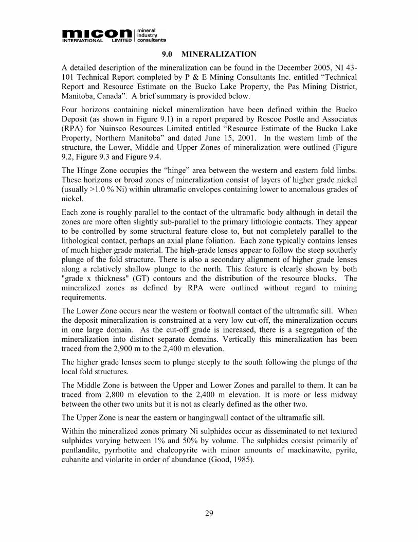
29
9.0 MINERALIZATION A detailed description of the mineralization can be found in the December 2005, NI 43-101 Technical Report completed by P & E Mining Consultants Inc. entitled “Technical Report and Resource Estimate on the Bucko Lake Property, the Pas Mining District, Manitoba, Canada”. A brief summary is provided below.
Four horizons containing nickel mineralization have been defined within the Bucko Deposit (as shown in Figure 9.1) in a report prepared by Roscoe Postle and Associates (RPA) for Nuinsco Resources Limited entitled “Resource Estimate of the Bucko Lake Property, Northern Manitoba” and dated June 15, 2001. In the western limb of the structure, the Lower, Middle and Upper Zones of mineralization were outlined (Figure 9.2, Figure 9.3 and Figure 9.4.
The Hinge Zone occupies the “hinge” area between the western and eastern fold limbs. These horizons or broad zones of mineralization consist of layers of higher grade nickel (usually >1.0 % Ni) within ultramafic envelopes containing lower to anomalous grades of nickel.
Each zone is roughly parallel to the contact of the ultramafic body although in detail the zones are more often slightly sub-parallel to the primary lithologic contacts. They appear to be controlled by some structural feature close to, but not completely parallel to the lithological contact, perhaps an axial plane foliation. Each zone typically contains lenses of much higher grade material. The high-grade lenses appear to follow the steep southerly plunge of the fold structure. There is also a secondary alignment of higher grade lenses along a relatively shallow plunge to the north. This feature is clearly shown by both "grade x thickness" (GT) contours and the distribution of the resource blocks. The mineralized zones as defined by RPA were outlined without regard to mining requirements.
The Lower Zone occurs near the western or footwall contact of the ultramafic sill. When the deposit mineralization is constrained at a very low cut-off, the mineralization occurs in one large domain. As the cut-off grade is increased, there is a segregation of the mineralization into distinct separate domains. Vertically this mineralization has been traced from the 2,900 m to the 2,400 m elevation.
The higher grade lenses seem to plunge steeply to the south following the plunge of the local fold structures.
The Middle Zone is between the Upper and Lower Zones and parallel to them. It can be traced from 2,800 m elevation to the 2,400 m elevation. It is more or less midway between the other two units but it is not as clearly defined as the other two.
The Upper Zone is near the eastern or hangingwall contact of the ultramafic sill.
Within the mineralized zones primary Ni sulphides occur as disseminated to net textured sulphides varying between 1% and 50% by volume. The sulphides consist primarily of pentlandite, pyrrhotite and chalcopyrite with minor amounts of mackinawite, pyrite, cubanite and violarite in order of abundance (Good, 1985).
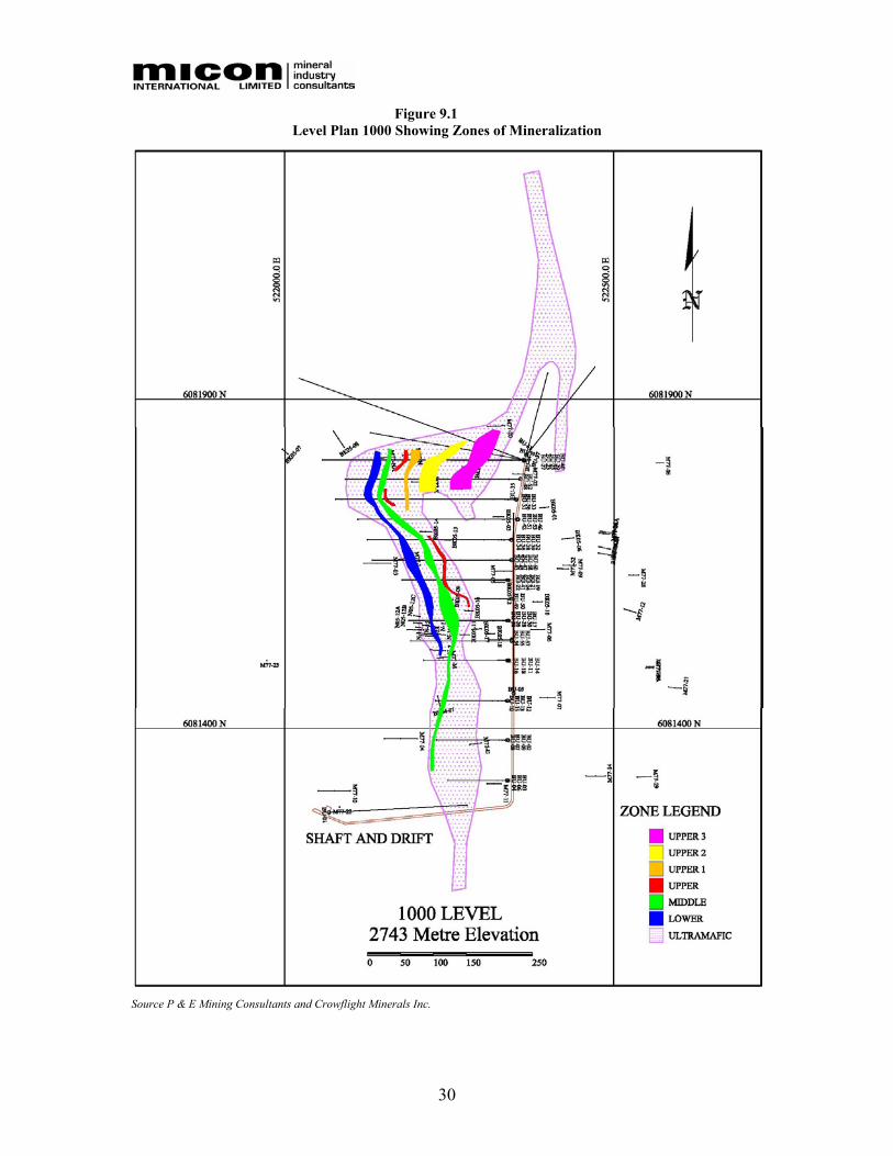
30
Figure 9.1 Level Plan 1000 Showing Zones of Mineralization
Source P & E Mining Consultants and Crowflight Minerals Inc.
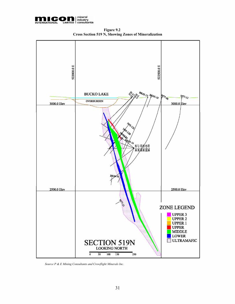
31
Figure 9.2 Cross Section 519 N, Showing Zones of Mineralization
Source P & E Mining Consultants and Crowflight Minerals Inc.
32
Figure 9.3 Cross Section 522 N, Showing Zones of Mineralization
Source P & E Mining Consultants and Crowflight Minerals Inc.
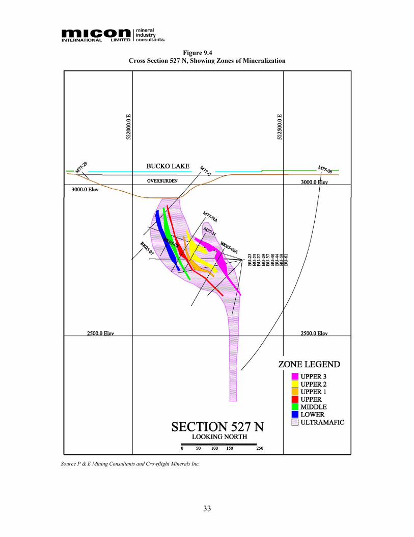
33
Figure 9.4 Cross Section 527 N, Showing Zones of Mineralization
Source P & E Mining Consultants and Crowflight Minerals Inc.

34
10.0 EXPLORATION A detailed description of the exploration can be found in the December 2005, NI 43-101 Technical Report completed by P & E Mining Consultants Inc. entitled “Technical Report and Resource Estimate on the Bucko Lake Property, the Pas Mining District, Manitoba, Canada”.
11.0 DRILLING A detailed description of the drilling conducted on the property can be found in the December 2005, NI 43-101 Technical Report completed by P & E Mining Consultants Inc. entitled “Technical Report and Resource Estimate on the Bucko Lake Property, the Pas Mining District, Manitoba, Canada”.
12.0 SAMPLING METHOD AND APPROACH A detailed description of the sampling method and approach can be found in the December 2005, NI 43-101 Technical Report completed by P & E Mining Consultants Inc. entitled “Technical Report and Resource Estimate on the Bucko Lake Property, the Pas Mining District, Manitoba, Canada”.
13.0 SAMPLE PREPARATION, ANALYZES AND SECURITY A detailed description of the sampling methods and analytical procedures can be found in the December 2005, NI 43-101 Technical Report completed by P & E Mining Consultants Inc. entitled “Technical Report and Resource Estimate on the Bucko Lake Property, the Pas Mining District, Manitoba, Canada”.
14.0 DATA VERIFICATION A detailed description of the data verification procedures can be found in the December 2005, NI 43-101 Technical Report completed by P & E Mining Consultants Inc. entitled “Technical Report and Resource Estimate on the Bucko Lake Property, the Pas Mining District, Manitoba, Canada”.
15.0 ADJACENT PROPERTIES A description of the adjacent properties can be found in the December 2005, NI 43-101 Technical Report completed by P & E Mining Consultants Inc. entitled “Technical Report and Resource Estimate on the Bucko Lake Property, the Pas Mining District, Manitoba, Canada”.
35
16.0 MINERAL PROCESSING AND METALLURGICAL TESTING A number of metallurgical testing campaigns have been conducted on samples of Bucko Deposit mineralized material over the years. The majority of the historical work was completed on behalf of Falconbridge by Lakefield Research, now SGS-Lakefield Laboratories (SGS-L), Lakefield, Ontario during the 1960s and 1970s. More recently, additional work was undertaken in 1991, also by SGS-L for Falconbridge. In 2005, a program of metallurgical testwork was performed by G&T Metallurgical laboratories, Kamloops, British Columbia (G&T).
The metallurgical process design for the Bucko Deposit is predominantly based on the G&T work.
The 2005 metallurgical test program undertaken by G&T was supervised by Micon.
16.1 HISTORICAL TESTWORK
16.1.1 Mineralogy
A review of the available mineralogical reports, suggests the following:
• Pentlandite ([Ni,Fe]9S8) is the most abundant sulphide occurring in the ultra-mafic rocks, followed by pyrrhotite (FeS), pyrite (FeS2) and chalcopyrite (CuFeS2). Minor sulphide minerals present include violarite (FeNi2S4), millerite (NiS), cubanite (CuFe2S3), mackinawite (Ni,FeS0.9) and valleriite (4[Fe,Cu]S·3[Mg,Al][OH]2).
• Pentlandite is generally observed as blocky, subhedral, friable grains often containing “blade like” pyrrhotite and wormy blebs of pyrite. Occasionally, pentlandite has partially or completely altered to violarite. Average grain size is fine, typically about 15 to 30 microns.
• Pyrrhotite occurs as a number of distinct habits. It occasionally contains pentlandite exsolution flames.
• Minor amounts of chalcopyrite occur as rounded to subhedral grains in most rock types, generally associated with pentlandite and violarite.
• Pyrite occurs included with pyrrhotite, as rims around millerite and associated with viorite and pentlandite.
• Serpentine is the most abundant gangue mineral and nodules or grains of this mineral tend to be cemented together with antigorite or other alteration products. Other gangue minerals, which occur in varying amounts throughout the ore-body, include pyroxene, amphibolite, olivine, phlogopite, biotite, chlorite, magnetite, talc and carbonate.
• An estimate of the principal elemental and mineral compositions is as follows:
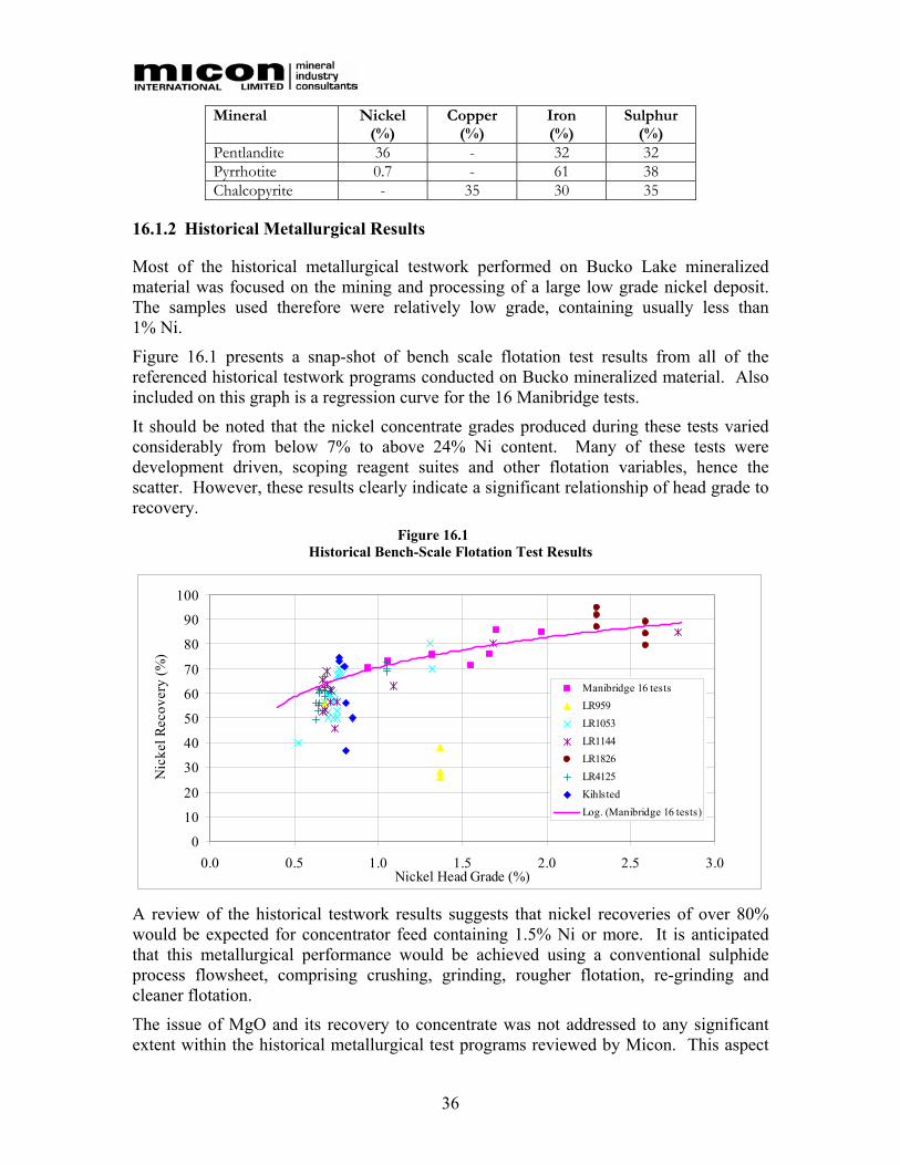
36
Mineral Nickel (%)
Copper (%)
Iron (%)
Sulphur (%)
Pentlandite 36 - 32 32 Pyrrhotite 0.7 - 61 38 Chalcopyrite - 35 30 35
16.1.2 Historical Metallurgical Results
Most of the historical metallurgical testwork performed on Bucko Lake mineralized material was focused on the mining and processing of a large low grade nickel deposit. The samples used therefore were relatively low grade, containing usually less than 1% Ni.
Figure 16.1 presents a snap-shot of bench scale flotation test results from all of the referenced historical testwork programs conducted on Bucko mineralized material. Also included on this graph is a regression curve for the 16 Manibridge tests.
It should be noted that the nickel concentrate grades produced during these tests varied considerably from below 7% to above 24% Ni content. Many of these tests were development driven, scoping reagent suites and other flotation variables, hence the scatter. However, these results clearly indicate a significant relationship of head grade to recovery.
Figure 16.1 Historical Bench-Scale Flotation Test Results
0
10
20
30
40
50
60
70
80
90
100
0.0 0.5 1.0 1.5 2.0 2.5 3.0Nickel Head Grade (%)
Nic
kel R
ecov
ery
(%)
Manibridge 16 testsLR959LR1053LR1144LR1826LR4125KihlstedLog. (Manibridge 16 tests)
A review of the historical testwork results suggests that nickel recoveries of over 80% would be expected for concentrator feed containing 1.5% Ni or more. It is anticipated that this metallurgical performance would be achieved using a conventional sulphide process flowsheet, comprising crushing, grinding, rougher flotation, re-grinding and cleaner flotation.
The issue of MgO and its recovery to concentrate was not addressed to any significant extent within the historical metallurgical test programs reviewed by Micon. This aspect

37
was defined as a key variable during the planning for the 2005 feasibility testwork program.
16.2 2005 FEASIBILITY TESTWORK PROGRAM
The objective of the 2005 metallurgical test program conducted by G&T was to develop a definitive feasibility flowsheet and process design criteria for an on-site processing facility. The aim of the testing program was to initially develop an optimized process route to maximize nickel, copper and PGM recovery to a single concentrate with a target nickel content of 15% or higher and an MgO content of 5% or lower.
The 2005 feasibility study testwork program comprised grindability work, mineralogical investigations, bench scale batch flotation tests, bench scale locked cycle tests, concentrate and tailings settling tests, concentrate filtration tests, concentrate pyrophicity assessment and a metallurgical variability program. .
16.2.1 Metallurgical Samples
The samples used in this test program were selected by Crowflight and packaged for delivery on-site by Falconbridge and Crowflight personnel. The sample comprised a single metallurgical composite made up from 10 drill holes and totalling 142 m of split drill core weighing approximately 255 kg, details of this sample are included in Table 16.1.
The composite metallurgical sample included Upper, Middle and Lower zones of mineralization from different locations within the identified resource.
Figure 16.2 shows the Bucko Deposit mineral resource and the drill and metallurgical sample locations.
The metallurgical composite was transported to G&T as 138 individual packages. G&T crushed, mixed, split and combined 50% of each sample to obtain the composite. The remaining individual samples were combined to produce the 16 variability samples, details of which are discussed in Section 16.2.9.
16.2.2 Characterization
The main economic element assays for the metallurgical composite sample are reported in Table 16.2 and the multi minor elements, from an inductively coupled plasma (ICP) scan of a head sample, in Table 16.3.

38
Table 16.1 Metallurgical Composite Sample (2005)
Location Interval Hole ID
East. North. Azimuth Dip From (m) To (m) Length
(m) Ni Grade
(%)
BK-05-01 522511 6081748 262.6 -70.0 591.2 593.6 2.4 1.74 BK-05-01 599.2 601.2 1.9 2.02 BK-05-01 604.0 606.1 2.1 1.46 BK-05-2A 522433 6081778 274.6 -65.0 310.6 315.8 5.2 1.69 BK-05-2A 318.9 329.4 10.5 1.74 BK-05-2A 380.0 383.3 3.3 1.72 BK-05-03 522472 6081727 266.3 -66.0 560.4 562.5 2.1 3.05 BK-05-03 572.4 574.3 1.9 1.50 BK-05-03 601.9 605.5 3.6 1.79 N05-12A 522423 6081539 272.3 -57.0 308.4 311.4 3.0 10.19 N05-12A 330.0 340.4 10.4 2.00 N05-12B 522423 6081539 272.3 -57.0 298.0 300.2 2.1 3.67 N05-12B 313.8 316.0 2.2 1.99 N05-12B 336.9 342.8 5.9 1.87 N05-12C 522423 6081539 272.3 -57.0 313.4 322.0 8.6 2.14 N05-12C 324.5 327.7 3.2 1.75 N05-12C 336.4 339.5 3.1 1.53 N05-15A 522325 6081590 268.3 -45.0 203.8 210.5 6.7 2.21 N05-15A 221.6 227.3 5.6 1.60 N05-15B 522325 6081590 268.3 -45.0 191.4 193.6 2.3 1.86 N05-15B 199.9 204.5 4.6 1.74 N05-15B 207.0 210.5 3.5 1.60 N05-21A 522337 6081606 266.3 -50.0 201.6 205.5 3.9 2.31 N05-21A 217.0 219.3 2.4 1.70 N05-21A 222.7 229.6 6.9 2.57 N05-21A 232.7 237.9 5.2 1.66 N05-21B 522337 6081606 266.3 -50.0 202.0 205.0 3.0 1.87 N05-21B 215.4 241.5 26.1 2.75 Total 141.8 2.27
Table 16.2
Metallurgical Composite (2005) Feed Main Element Analysis
Cu Ni Co Fe S(T) S(s) MgO Au Pt Pd Rh SiO2
(%) (%) (%) (%) (%) (%) (%) (g/t) (g/t) (g/t) (g/t) (%) 0.17 2.23 0.03 7.08 3.94 3.81 27.57 0.03 0.18 0.44 0.07 43.36
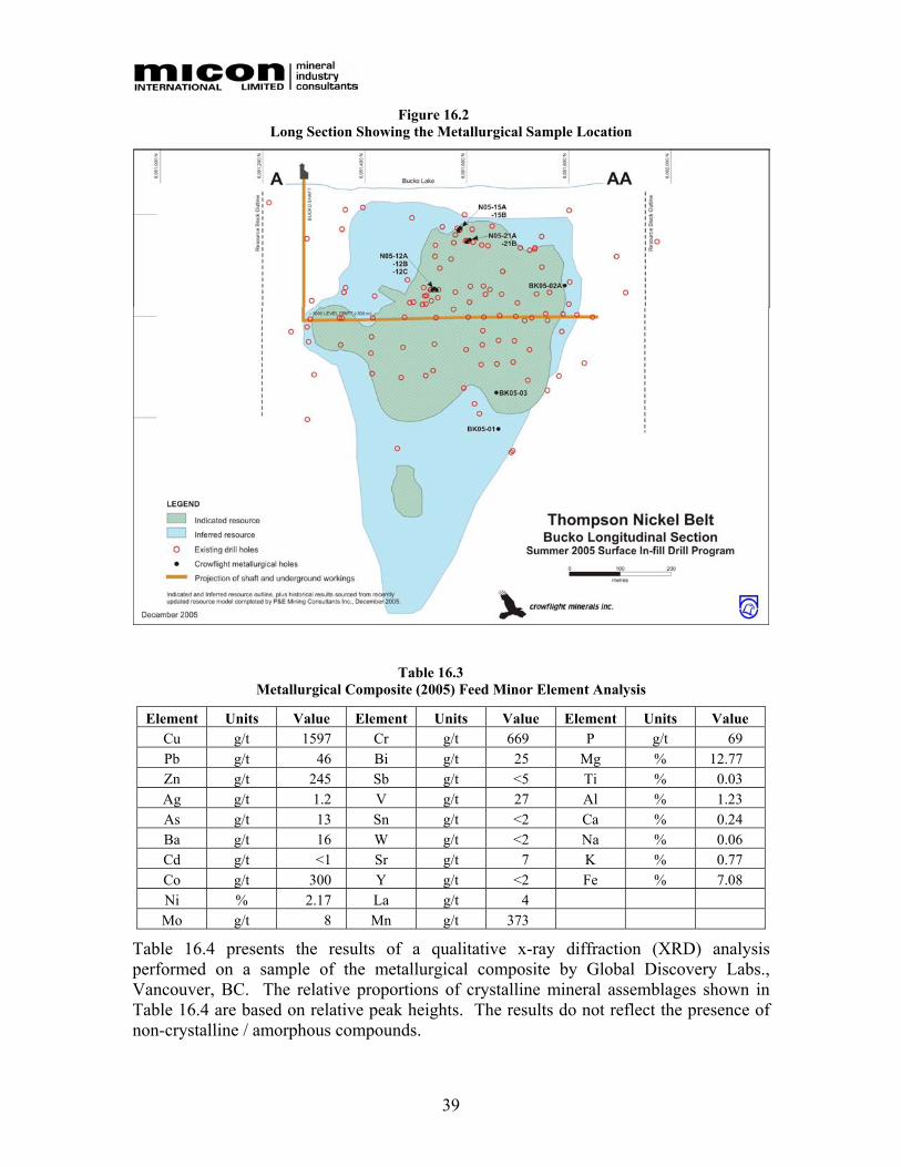
39
Figure 16.2 Long Section Showing the Metallurgical Sample Location
Table 16.3 Metallurgical Composite (2005) Feed Minor Element Analysis
Element Units Value Element Units Value Element Units Value Cu g/t 1597 Cr g/t 669 P g/t 69 Pb g/t 46 Bi g/t 25 Mg % 12.77 Zn g/t 245 Sb g/t <5 Ti % 0.03 Ag g/t 1.2 V g/t 27 Al % 1.23 As g/t 13 Sn g/t <2 Ca % 0.24 Ba g/t 16 W g/t <2 Na % 0.06 Cd g/t <1 Sr g/t 7 K % 0.77 Co g/t 300 Y g/t <2 Fe % 7.08 Ni % 2.17 La g/t 4 Mo g/t 8 Mn g/t 373
Table 16.4 presents the results of a qualitative x-ray diffraction (XRD) analysis performed on a sample of the metallurgical composite by Global Discovery Labs., Vancouver, BC. The relative proportions of crystalline mineral assemblages shown in Table 16.4 are based on relative peak heights. The results do not reflect the presence of non-crystalline / amorphous compounds.
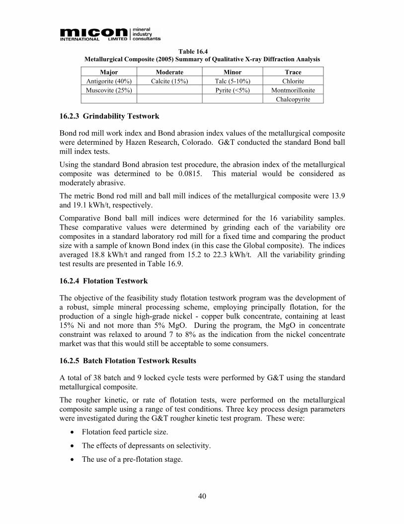
40
Table 16.4 Metallurgical Composite (2005) Summary of Qualitative X-ray Diffraction Analysis
Major Moderate Minor Trace Antigorite (40%) Calcite (15%) Talc (5-10%) Chlorite Muscovite (25%) Pyrite (<5%) Montmorillonite
Chalcopyrite
16.2.3 Grindability Testwork
Bond rod mill work index and Bond abrasion index values of the metallurgical composite were determined by Hazen Research, Colorado. G&T conducted the standard Bond ball mill index tests.
Using the standard Bond abrasion test procedure, the abrasion index of the metallurgical composite was determined to be 0.0815. This material would be considered as moderately abrasive.
The metric Bond rod mill and ball mill indices of the metallurgical composite were 13.9 and 19.1 kWh/t, respectively.
Comparative Bond ball mill indices were determined for the 16 variability samples. These comparative values were determined by grinding each of the variability ore composites in a standard laboratory rod mill for a fixed time and comparing the product size with a sample of known Bond index (in this case the Global composite). The indices averaged 18.8 kWh/t and ranged from 15.2 to 22.3 kWh/t. All the variability grinding test results are presented in Table 16.9.
16.2.4 Flotation Testwork
The objective of the feasibility study flotation testwork program was the development of a robust, simple mineral processing scheme, employing principally flotation, for the production of a single high-grade nickel - copper bulk concentrate, containing at least 15% Ni and not more than 5% MgO. During the program, the MgO in concentrate constraint was relaxed to around 7 to 8% as the indication from the nickel concentrate market was that this would still be acceptable to some consumers.
16.2.5 Batch Flotation Testwork Results
A total of 38 batch and 9 locked cycle tests were performed by G&T using the standard metallurgical composite.
The rougher kinetic, or rate of flotation tests, were performed on the metallurgical composite sample using a range of test conditions. Three key process design parameters were investigated during the G&T rougher kinetic test program. These were:
• Flotation feed particle size.
• The effects of depressants on selectivity.
• The use of a pre-flotation stage.
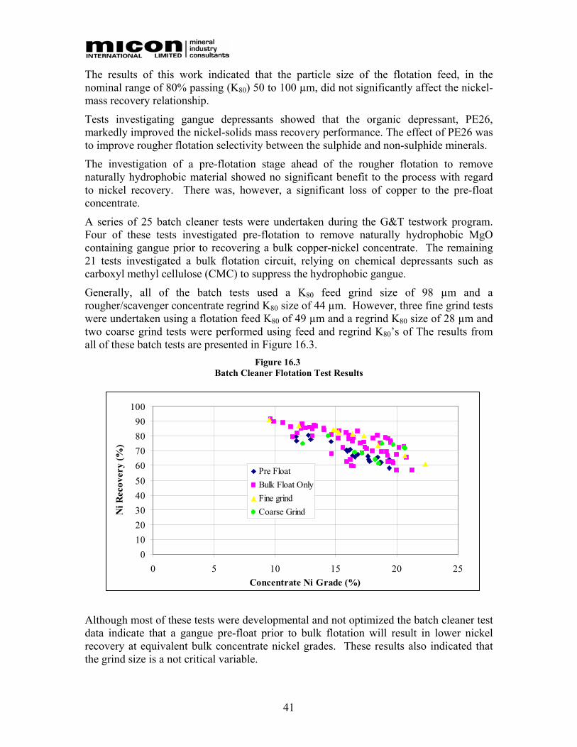
41
The results of this work indicated that the particle size of the flotation feed, in the nominal range of 80% passing (K80) 50 to 100 µm, did not significantly affect the nickel-mass recovery relationship.
Tests investigating gangue depressants showed that the organic depressant, PE26, markedly improved the nickel-solids mass recovery performance. The effect of PE26 was to improve rougher flotation selectivity between the sulphide and non-sulphide minerals.
The investigation of a pre-flotation stage ahead of the rougher flotation to remove naturally hydrophobic material showed no significant benefit to the process with regard to nickel recovery. There was, however, a significant loss of copper to the pre-float concentrate.
A series of 25 batch cleaner tests were undertaken during the G&T testwork program. Four of these tests investigated pre-flotation to remove naturally hydrophobic MgO containing gangue prior to recovering a bulk copper-nickel concentrate. The remaining 21 tests investigated a bulk flotation circuit, relying on chemical depressants such as carboxyl methyl cellulose (CMC) to suppress the hydrophobic gangue.
Generally, all of the batch tests used a K80 feed grind size of 98 µm and a rougher/scavenger concentrate regrind K80 size of 44 µm. However, three fine grind tests were undertaken using a flotation feed K80 of 49 µm and a regrind K80 size of 28 µm and two coarse grind tests were performed using feed and regrind K80’s of The results from all of these batch tests are presented in Figure 16.3.
Figure 16.3 Batch Cleaner Flotation Test Results
Although most of these tests were developmental and not optimized the batch cleaner test data indicate that a gangue pre-float prior to bulk flotation will result in lower nickel recovery at equivalent bulk concentrate nickel grades. These results also indicated that the grind size is a not critical variable.
0102030405060708090
100
0 5 10 15 20 25Concentrate Ni Grade (%)
Ni R
ecov
ery
(%)
Pre FloatBulk Float OnlyFine grindCoarse Grind
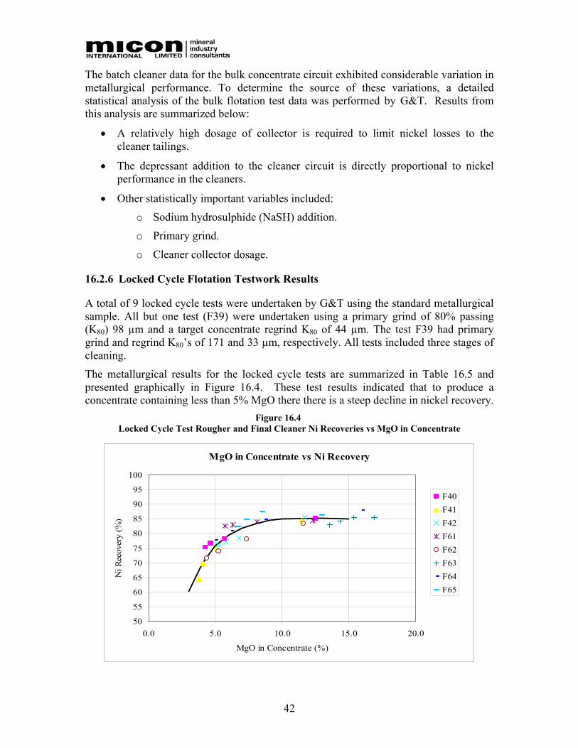
42
The batch cleaner data for the bulk concentrate circuit exhibited considerable variation in metallurgical performance. To determine the source of these variations, a detailed statistical analysis of the bulk flotation test data was performed by G&T. Results from this analysis are summarized below:
• A relatively high dosage of collector is required to limit nickel losses to the cleaner tailings.
• The depressant addition to the cleaner circuit is directly proportional to nickel performance in the cleaners.
• Other statistically important variables included:
o Sodium hydrosulphide (NaSH) addition.
o Primary grind.
o Cleaner collector dosage.
16.2.6 Locked Cycle Flotation Testwork Results
A total of 9 locked cycle tests were undertaken by G&T using the standard metallurgical sample. All but one test (F39) were undertaken using a primary grind of 80% passing (K80) 98 µm and a target concentrate regrind K80 of 44 µm. The test F39 had primary grind and regrind K80’s of 171 and 33 µm, respectively. All tests included three stages of cleaning.
The metallurgical results for the locked cycle tests are summarized in Table 16.5 and presented graphically in Figure 16.4. These test results indicated that to produce a concentrate containing less than 5% MgO there there is a steep decline in nickel recovery.
Figure 16.4 Locked Cycle Test Rougher and Final Cleaner Ni Recoveries vs MgO in Concentrate
MgO in Concentrate vs Ni Recovery
50
55
60
65
70
75
80
85
90
95
100
0.0 5.0 10.0 15.0 20.0
MgO in Concentrate (%)
Ni R
ecov
ery
(%)
F40F41F42F61F62F63F64F65
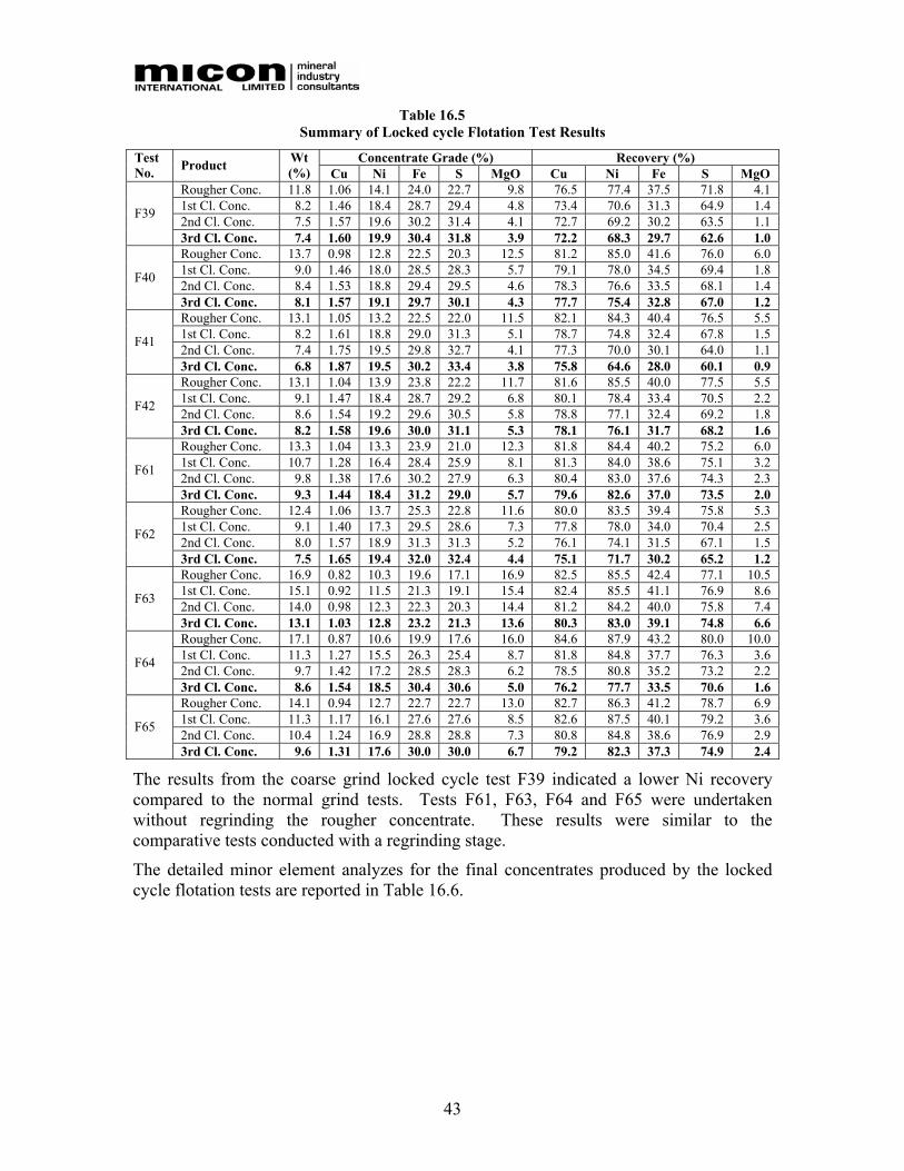
43
Table 16.5 Summary of Locked cycle Flotation Test Results
Concentrate Grade (%) Recovery (%) Test No. Product Wt
(%) Cu Ni Fe S MgO Cu Ni Fe S MgO Rougher Conc. 11.8 1.06 14.1 24.0 22.7 9.8 76.5 77.4 37.5 71.8 4.1 1st Cl. Conc. 8.2 1.46 18.4 28.7 29.4 4.8 73.4 70.6 31.3 64.9 1.4 2nd Cl. Conc. 7.5 1.57 19.6 30.2 31.4 4.1 72.7 69.2 30.2 63.5 1.1 F39
3rd Cl. Conc. 7.4 1.60 19.9 30.4 31.8 3.9 72.2 68.3 29.7 62.6 1.0 Rougher Conc. 13.7 0.98 12.8 22.5 20.3 12.5 81.2 85.0 41.6 76.0 6.0 1st Cl. Conc. 9.0 1.46 18.0 28.5 28.3 5.7 79.1 78.0 34.5 69.4 1.8 2nd Cl. Conc. 8.4 1.53 18.8 29.4 29.5 4.6 78.3 76.6 33.5 68.1 1.4 F40
3rd Cl. Conc. 8.1 1.57 19.1 29.7 30.1 4.3 77.7 75.4 32.8 67.0 1.2 Rougher Conc. 13.1 1.05 13.2 22.5 22.0 11.5 82.1 84.3 40.4 76.5 5.5 1st Cl. Conc. 8.2 1.61 18.8 29.0 31.3 5.1 78.7 74.8 32.4 67.8 1.5 2nd Cl. Conc. 7.4 1.75 19.5 29.8 32.7 4.1 77.3 70.0 30.1 64.0 1.1 F41
3rd Cl. Conc. 6.8 1.87 19.5 30.2 33.4 3.8 75.8 64.6 28.0 60.1 0.9 Rougher Conc. 13.1 1.04 13.9 23.8 22.2 11.7 81.6 85.5 40.0 77.5 5.5 1st Cl. Conc. 9.1 1.47 18.4 28.7 29.2 6.8 80.1 78.4 33.4 70.5 2.2 2nd Cl. Conc. 8.6 1.54 19.2 29.6 30.5 5.8 78.8 77.1 32.4 69.2 1.8 F42
3rd Cl. Conc. 8.2 1.58 19.6 30.0 31.1 5.3 78.1 76.1 31.7 68.2 1.6 Rougher Conc. 13.3 1.04 13.3 23.9 21.0 12.3 81.8 84.4 40.2 75.2 6.0 1st Cl. Conc. 10.7 1.28 16.4 28.4 25.9 8.1 81.3 84.0 38.6 75.1 3.2 2nd Cl. Conc. 9.8 1.38 17.6 30.2 27.9 6.3 80.4 83.0 37.6 74.3 2.3 F61
3rd Cl. Conc. 9.3 1.44 18.4 31.2 29.0 5.7 79.6 82.6 37.0 73.5 2.0 Rougher Conc. 12.4 1.06 13.7 25.3 22.8 11.6 80.0 83.5 39.4 75.8 5.3 1st Cl. Conc. 9.1 1.40 17.3 29.5 28.6 7.3 77.8 78.0 34.0 70.4 2.5 2nd Cl. Conc. 8.0 1.57 18.9 31.3 31.3 5.2 76.1 74.1 31.5 67.1 1.5 F62
3rd Cl. Conc. 7.5 1.65 19.4 32.0 32.4 4.4 75.1 71.7 30.2 65.2 1.2 Rougher Conc. 16.9 0.82 10.3 19.6 17.1 16.9 82.5 85.5 42.4 77.1 10.5 1st Cl. Conc. 15.1 0.92 11.5 21.3 19.1 15.4 82.4 85.5 41.1 76.9 8.6 2nd Cl. Conc. 14.0 0.98 12.3 22.3 20.3 14.4 81.2 84.2 40.0 75.8 7.4 F63
3rd Cl. Conc. 13.1 1.03 12.8 23.2 21.3 13.6 80.3 83.0 39.1 74.8 6.6 Rougher Conc. 17.1 0.87 10.6 19.9 17.6 16.0 84.6 87.9 43.2 80.0 10.0 1st Cl. Conc. 11.3 1.27 15.5 26.3 25.4 8.7 81.8 84.8 37.7 76.3 3.6 2nd Cl. Conc. 9.7 1.42 17.2 28.5 28.3 6.2 78.5 80.8 35.2 73.2 2.2 F64
3rd Cl. Conc. 8.6 1.54 18.5 30.4 30.6 5.0 76.2 77.7 33.5 70.6 1.6 Rougher Conc. 14.1 0.94 12.7 22.7 22.7 13.0 82.7 86.3 41.2 78.7 6.9 1st Cl. Conc. 11.3 1.17 16.1 27.6 27.6 8.5 82.6 87.5 40.1 79.2 3.6 2nd Cl. Conc. 10.4 1.24 16.9 28.8 28.8 7.3 80.8 84.8 38.6 76.9 2.9 F65
3rd Cl. Conc. 9.6 1.31 17.6 30.0 30.0 6.7 79.2 82.3 37.3 74.9 2.4
The results from the coarse grind locked cycle test F39 indicated a lower Ni recovery compared to the normal grind tests. Tests F61, F63, F64 and F65 were undertaken without regrinding the rougher concentrate. These results were similar to the comparative tests conducted with a regrinding stage.
The detailed minor element analyzes for the final concentrates produced by the locked cycle flotation tests are reported in Table 16.6.
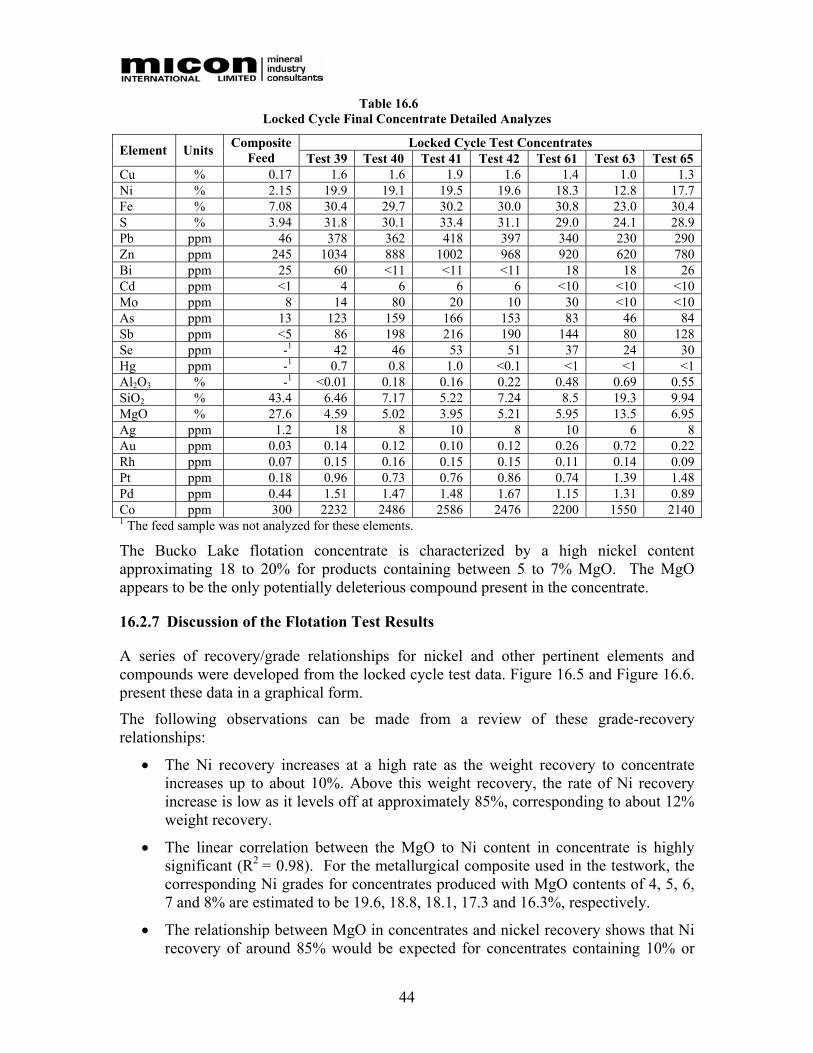
44
Table 16.6 Locked Cycle Final Concentrate Detailed Analyzes
Locked Cycle Test Concentrates Element Units Composite Feed Test 39 Test 40 Test 41 Test 42 Test 61 Test 63 Test 65
Cu % 0.17 1.6 1.6 1.9 1.6 1.4 1.0 1.3 Ni % 2.15 19.9 19.1 19.5 19.6 18.3 12.8 17.7 Fe % 7.08 30.4 29.7 30.2 30.0 30.8 23.0 30.4 S % 3.94 31.8 30.1 33.4 31.1 29.0 24.1 28.9 Pb ppm 46 378 362 418 397 340 230 290 Zn ppm 245 1034 888 1002 968 920 620 780 Bi ppm 25 60 <11 <11 <11 18 18 26 Cd ppm <1 4 6 6 6 <10 <10 <10 Mo ppm 8 14 80 20 10 30 <10 <10 As ppm 13 123 159 166 153 83 46 84 Sb ppm <5 86 198 216 190 144 80 128 Se ppm -1 42 46 53 51 37 24 30 Hg ppm -1 0.7 0.8 1.0 <0.1 <1 <1 <1 Al2O3 % -1 <0.01 0.18 0.16 0.22 0.48 0.69 0.55 SiO2 % 43.4 6.46 7.17 5.22 7.24 8.5 19.3 9.94 MgO % 27.6 4.59 5.02 3.95 5.21 5.95 13.5 6.95 Ag ppm 1.2 18 8 10 8 10 6 8 Au ppm 0.03 0.14 0.12 0.10 0.12 0.26 0.72 0.22 Rh ppm 0.07 0.15 0.16 0.15 0.15 0.11 0.14 0.09 Pt ppm 0.18 0.96 0.73 0.76 0.86 0.74 1.39 1.48 Pd ppm 0.44 1.51 1.47 1.48 1.67 1.15 1.31 0.89 Co ppm 300 2232 2486 2586 2476 2200 1550 2140 1 The feed sample was not analyzed for these elements.
The Bucko Lake flotation concentrate is characterized by a high nickel content approximating 18 to 20% for products containing between 5 to 7% MgO. The MgO appears to be the only potentially deleterious compound present in the concentrate.
16.2.7 Discussion of the Flotation Test Results
A series of recovery/grade relationships for nickel and other pertinent elements and compounds were developed from the locked cycle test data. Figure 16.5 and Figure 16.6. present these data in a graphical form.
The following observations can be made from a review of these grade-recovery relationships:
• The Ni recovery increases at a high rate as the weight recovery to concentrate increases up to about 10%. Above this weight recovery, the rate of Ni recovery increase is low as it levels off at approximately 85%, corresponding to about 12% weight recovery.
• The linear correlation between the MgO to Ni content in concentrate is highly significant (R2 = 0.98). For the metallurgical composite used in the testwork, the corresponding Ni grades for concentrates produced with MgO contents of 4, 5, 6, 7 and 8% are estimated to be 19.6, 18.8, 18.1, 17.3 and 16.3%, respectively.
• The relationship between MgO in concentrates and nickel recovery shows that Ni recovery of around 85% would be expected for concentrates containing 10% or
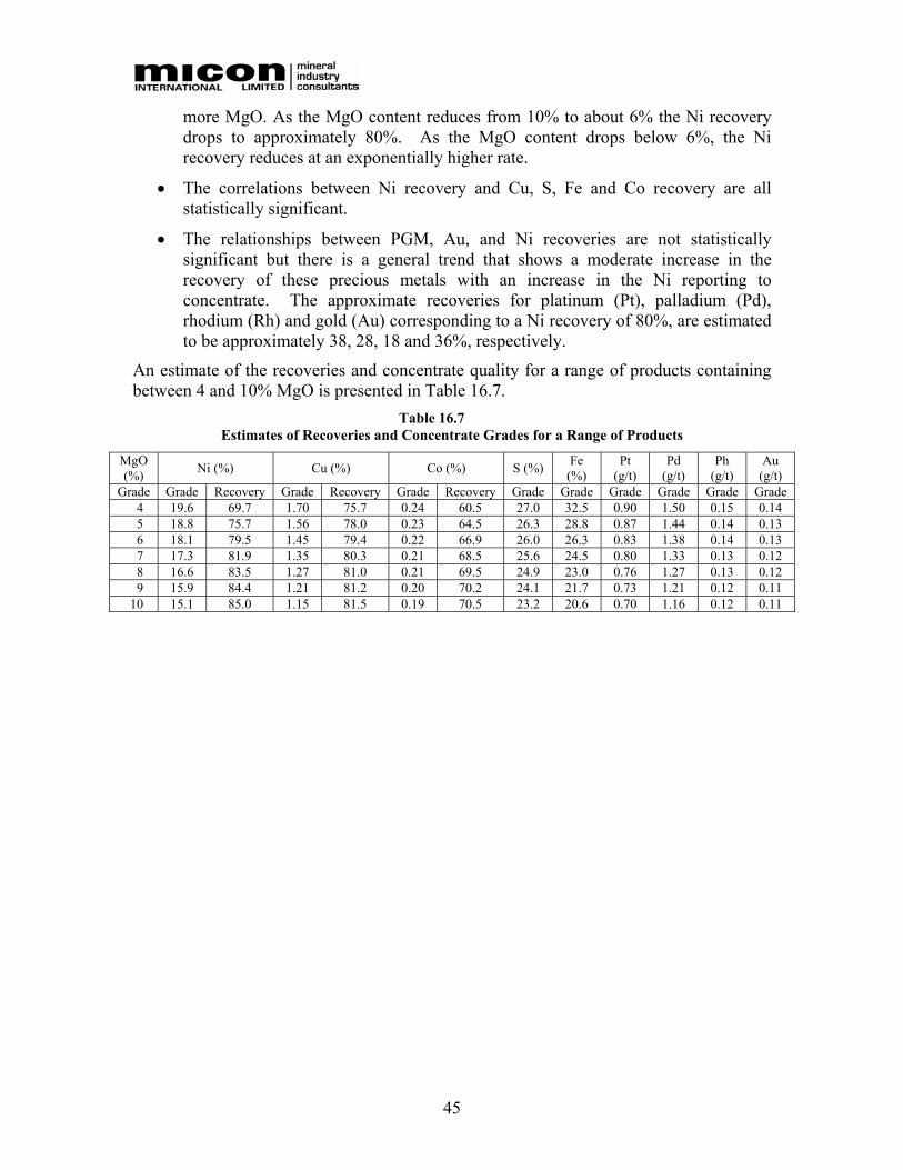
45
more MgO. As the MgO content reduces from 10% to about 6% the Ni recovery drops to approximately 80%. As the MgO content drops below 6%, the Ni recovery reduces at an exponentially higher rate.
• The correlations between Ni recovery and Cu, S, Fe and Co recovery are all statistically significant.
• The relationships between PGM, Au, and Ni recoveries are not statistically significant but there is a general trend that shows a moderate increase in the recovery of these precious metals with an increase in the Ni reporting to concentrate. The approximate recoveries for platinum (Pt), palladium (Pd), rhodium (Rh) and gold (Au) corresponding to a Ni recovery of 80%, are estimated to be approximately 38, 28, 18 and 36%, respectively.
An estimate of the recoveries and concentrate quality for a range of products containing between 4 and 10% MgO is presented in Table 16.7.
Table 16.7 Estimates of Recoveries and Concentrate Grades for a Range of Products
MgO (%) Ni (%) Cu (%) Co (%) S (%) Fe
(%) Pt
(g/t) Pd
(g/t) Ph
(g/t) Au
(g/t) Grade Grade Recovery Grade Recovery Grade Recovery Grade Grade Grade Grade Grade Grade
4 19.6 69.7 1.70 75.7 0.24 60.5 27.0 32.5 0.90 1.50 0.15 0.14 5 18.8 75.7 1.56 78.0 0.23 64.5 26.3 28.8 0.87 1.44 0.14 0.13 6 18.1 79.5 1.45 79.4 0.22 66.9 26.0 26.3 0.83 1.38 0.14 0.13 7 17.3 81.9 1.35 80.3 0.21 68.5 25.6 24.5 0.80 1.33 0.13 0.12 8 16.6 83.5 1.27 81.0 0.21 69.5 24.9 23.0 0.76 1.27 0.13 0.12 9 15.9 84.4 1.21 81.2 0.20 70.2 24.1 21.7 0.73 1.21 0.12 0.11
10 15.1 85.0 1.15 81.5 0.19 70.5 23.2 20.6 0.70 1.16 0.12 0.11
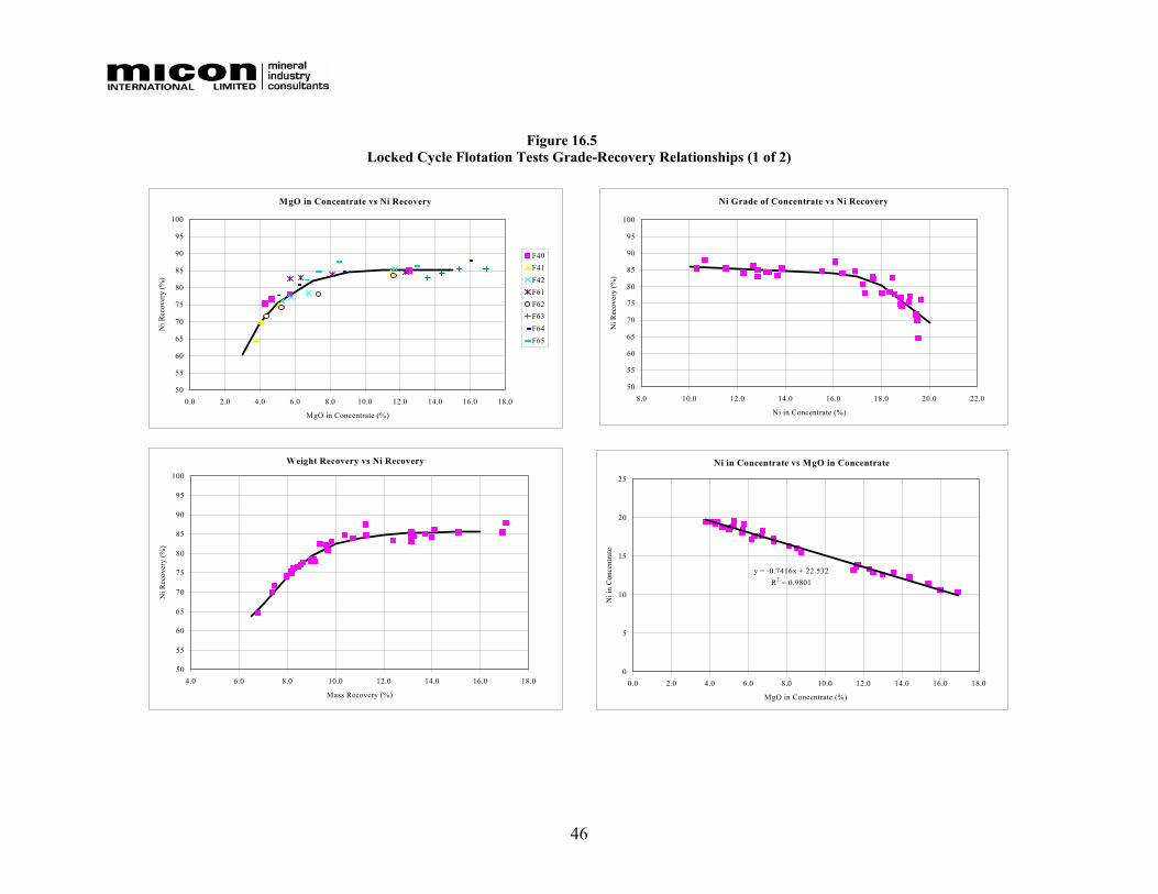
46
Figure 16.5 Locked Cycle Flotation Tests Grade-Recovery Relationships (1 of 2)
MgO in Concentrate vs Ni Recovery
50
55
60
65
70
75
80
85
90
95
100
0.0 2.0 4.0 6.0 8.0 10.0 12.0 14.0 16.0 18.0
MgO in Concentrate (%)
Ni R
ecov
ery
(%)
F40F41F42F61F62F63F64F65
Weight Recovery vs Ni Recovery
50
55
60
65
70
75
80
85
90
95
100
4.0 6.0 8.0 10.0 12.0 14.0 16.0 18.0
Mass Recovery (%)
Ni R
ecov
ery
(%)
Ni Grade of Concentrate vs Ni Recovery
50
55
60
65
70
75
80
85
90
95
100
8.0 10.0 12.0 14.0 16.0 18.0 20.0 22.0
Ni in Concentrate (%)
Ni R
ecov
ery
(%)
Ni in Concentrate vs MgO in Concentrate
y = -0.7416x + 22.532R2 = 0.9801
0
5
10
15
20
25
0.0 2.0 4.0 6.0 8.0 10.0 12.0 14.0 16.0 18.0
MgO in Concentrate (%)
Ni i
n C
once
ntra
te

47
Figure 16.6 Locked Cycle Flotation Tests Grade-Recovery Relationships (2 of 2)
Cu Recovery vs Ni Recovery
y = 0.3739x + 49.681R2 = 0.8041
60
65
70
75
80
85
90
60 65 70 75 80 85 90
Ni Recovery (%)
Cu
Rec
over
y (%
)
Fe Recovery vs Ni Recovery
y = 0.0203x2 - 2.4637x + 102.32R2 = 0.9454
0
5
10
15
20
25
30
35
40
45
50
60 65 70 75 80 85 90
Ni Recovery (%)
Fe R
ecov
ery
(%)
S Recovery vs Ni Recovery
y = 0.8741x + 2.2638R2 = 0.9828
50
55
60
65
70
75
80
85
60 65 70 75 80 85 90
Ni Recovery (%)
S R
ecov
ery
(%)
Cu and Co Recoveries vs Ni Recovery(Final Concentrate Data Only)
y = 0.6533x + 15.014R2 = 0.7623
0
10
20
30
40
50
60
70
80
90
60 65 70 75 80 85
Ni Recovery (%)
Cu
and
Co
Rec
over
y (%
)
CoCu
48
16.2.8 Dewatering Tests
Filtration tests were conducted by G&T on samples of flotation concentrate. Standard settling tests were also performed by G&T using samples of the bulk flotation concentrates and rougher tailings produced in the laboratory flotation locked cycle tests.
The Talmadge-Fitch protocol for conducting sedimentation or settling tests was used to investigate the settling characteristics of the samples and to estimate the solids settling areas for thickener design. The results indicate relatively low settling area requirements for both the bulk concentrate and the rougher tailings. Flocculent additions equivalent to less than 10 g/t of solids achieved settling area requirements of about 0.04 m2/t/24h for concentrate. These additions produced an underflow product containing about 65% solids by weight. The tailings area requirements at 10 g/t flocculant addition was approximately 0.16 m2/t/24h. This produced an underflow product containing about 54% solids by weight.
Using the standard horizontal belt filter procedure, which relates cake moisture content to time of applied vacuum, filter cake moisture of about 12% by weight was achieved after vacuum drying concentrate for about 2.5 minutes.
16.2.9 Concentrate Pyrophoricity
A standard pyrophoric test was performed on a sample of concentrate to investigate the potential self-heating characteristics of the product. The test showed that the Bucko flotation concentrate has no self-heating or spontaneous combustion properties.
16.3 VARIABILITY TESTWORK
An assessment of variability in ore response across the deposit was measured for both grindability and for flotation response for 16 sub-composites. Grindability was determined by performing comparative Bond Index determinations and flotation response was assessed by conducting un-optimized open circuit cleaner tests on each of the sub-composites.
Each of the sub-composites was selected from individual samples that made up the 2005 metallurgical composite. The selection criteria were based on assessing the metallurgical variability of the ore-body spatially in terms of nickel grade and mineralogy. A description of the variability composites is included in Table 16.8.

49
Table 16.8 Summary of Variability Flotation Test Results
Feed Grade1
Number Hole No. From (m)
To (m) %Ni
(Assay) %Ni
(Calc)
VB1 Hole 01 591.2 599.2 604.0
593.6 601.2 606.1
1.72 1.70
VB2 Hole 02A 310.5 315.8 1.69 1.59 VB3 Hole 02A 318.9 329.4 1.72 1.60 VB4 Hole 02A 380.0 383.0 1.16 1.16
VB5 Hole 12A Hole 12B
308.4 298.0
311.4 300.2 7.85 6.99
VB6 Hole 12A 330.0 340.4 2.12 2.34
VB7 Hole 12B Hole 12C
313.8 313.4
316.0 322.0 2.21 1.96
VB8 Hole 12B Hole 12C
336.9 336.4
342.8 339.5 1.73 1.62
VB9 Hole 15A Hole 15B
203.8 199.9
210.5 203.5 2.19 2.23
VB10 Hole 15A Hole 15B
221.6 207.0
227.3 210.5 1.59 1.42
VB11 Hole 21A Hole 21B
201.6 202.0
205.5 205.0 2.32 2.25
VB12 Hole 21A 222.7 229.6 2.57 2.35 VB13 Hole 21A 232.7 237.9 1.76 1.38 VB14 Hole 21B 215.4 222.5 1.12 0.97 VB15 Hole 21B 222.5 233.9 4.37 3.57 VB16 Hole 21B 233.9 241.5 1.89 1.59
1 The Ni assay grade is a numerical average of the individual samples and the calculated grade is based on the flotation test results.
16.3.1 Grindability
The comparative Bond ball mill indices for the various variability samples are listed in Table 16.9. The comparative indices were determined by grinding each of the variability samples in a standard laboratory rod mill for a fixed time. As was the case with the grindability testwork on the Bucko composite sample, the size distribution of the ground product was then measured and compared to the metallurgical composite. The ratio of the product sizes was then used to calculate the comparative Bond Ball mill index.

50
Table 16.9 Variability Sample Comparative Bond Ball Mill Indices
Number Composite Description Metric Work Index
(kWh/t) Metallurgical composite 19.1 VB1 Hole 01 22.3 VB2 Hole 02A – upper 17.6 VB3 Hole 02A – middle 16.0 VB4 Hole 02A – bottom 16.4 VB5 Hole 12A/B – upper 15.2 VB6 Hole 12A – middle 16.4 VB7 Hole 12B/C – middle 18.1 VB8 Hole 12B/C – bottom 19.9 VB9 Hole 15A/B upper 19.1 VB10 Hole 15 A/B bottom 21.9 VB11 Hole 21A/B upper 19.2 VB12 Hole 21 A middle 20.5 VB13 Hole 21 A bottom 18.7 VB14 Hole 21 B middle - low grade 20.6 VB15 Hole 21 B middle - high grade 19.7 VB16 Hole 21B bottom - medium grade 19.8
16.3.2 Flotation Response
Table 16.10 summarizes the metallurgical flotation performance for the 16 variability samples selected as part of the Bucko Lake feasibility study metallurgical testwork program. The results are presented in Figure 16.7 as nickel recovery versus MgO in concentrate, Ni in concentrate, MgO in feed and Ni in feed results
It should be noted that the variability tests were undertaken using the standard flotation conditions and consequently no attempt was made to optimize the performance of the individual tests. Furthermore given that the variability samples were selected to represent the extremes of the ore-body based on the samples available, it would be expected that in general, the overall results would be worse than the average locked cycle tests and as such represent conservative estimates of actual potential flotation responses within the range of the samples tested.

51
Figure 16.7 Variability Flotation Test Results
Bucko Lake Variability Flotation TestsMgO Conc Grade vs Ni Recovery
40
50
60
70
80
90
100
0 5 10 15 20 25 30
MgO in Concentrate (%)
Ni R
ecov
ery
(%)
VB1VB2VB3VB4VB5VB6VB7VB8Cycle
Bucko Lake Varibility Flotation TestsMgO Conc. Grade vs Ni Recovery
40
50
60
70
80
90
100
0 5 10 15 20 25 30
MgO in Concentrate (%)
Ni R
ecov
ery
(%)
VB9VB10VB11VB12VB13VB14VB15VB16Cycle
Bucko Variability Flotation TestsNi Feed grade vs Recovery
40
50
60
70
80
90
100
0.0 1.0 2.0 3.0 4.0 5.0 6.0 7.0 8.0
Ni feed grade (%)
Ni R
ecov
ery
(%)
RougherCleaner
Bucko Variability Flotation TestsMgO Feed grade vs Ni Recovery
40
50
60
70
80
90
100
10 15 20 25 30 35 40MgO feed grade (%)
Ni R
ecov
ery
(%)
RougherCleaner
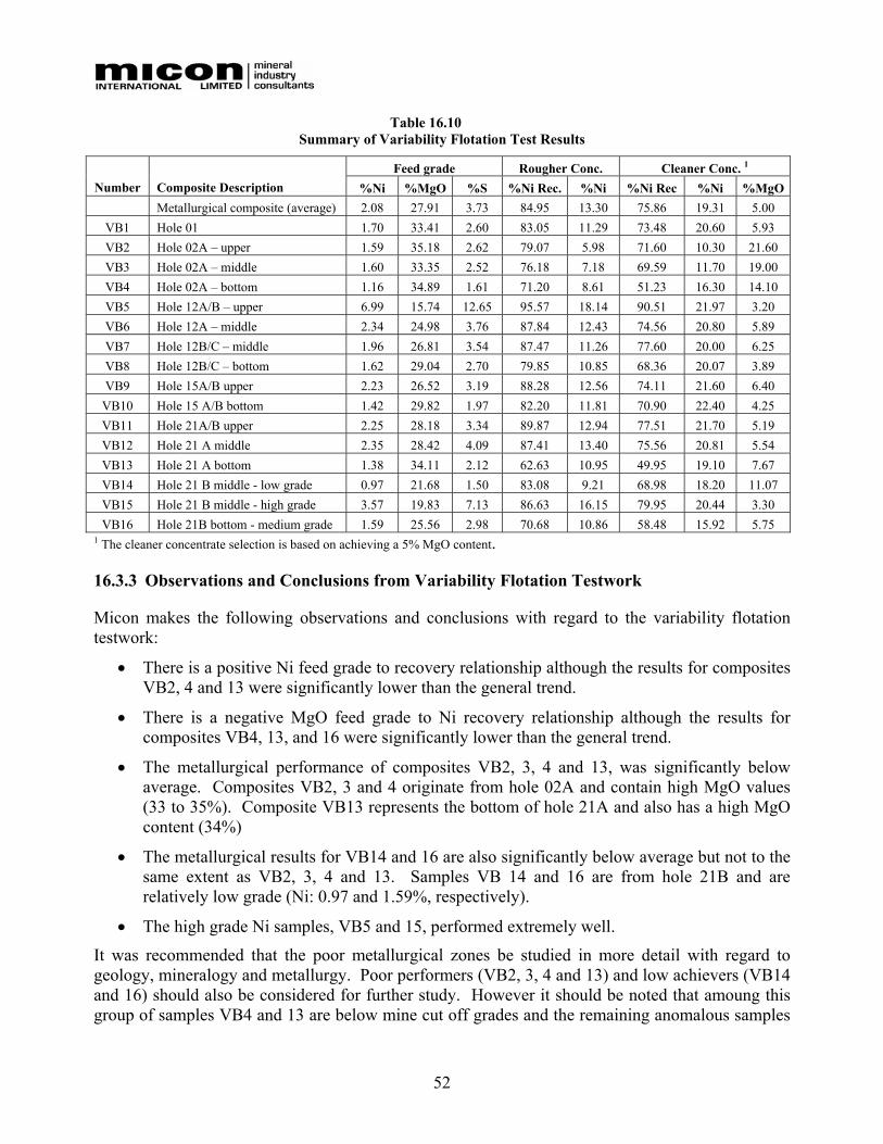
52
Table 16.10 Summary of Variability Flotation Test Results
Feed grade Rougher Conc. Cleaner Conc. 1
Number Composite Description %Ni %MgO %S %Ni Rec. %Ni %Ni Rec %Ni %MgO Metallurgical composite (average) 2.08 27.91 3.73 84.95 13.30 75.86 19.31 5.00
VB1 Hole 01 1.70 33.41 2.60 83.05 11.29 73.48 20.60 5.93 VB2 Hole 02A – upper 1.59 35.18 2.62 79.07 5.98 71.60 10.30 21.60 VB3 Hole 02A – middle 1.60 33.35 2.52 76.18 7.18 69.59 11.70 19.00 VB4 Hole 02A – bottom 1.16 34.89 1.61 71.20 8.61 51.23 16.30 14.10 VB5 Hole 12A/B – upper 6.99 15.74 12.65 95.57 18.14 90.51 21.97 3.20 VB6 Hole 12A – middle 2.34 24.98 3.76 87.84 12.43 74.56 20.80 5.89 VB7 Hole 12B/C – middle 1.96 26.81 3.54 87.47 11.26 77.60 20.00 6.25 VB8 Hole 12B/C – bottom 1.62 29.04 2.70 79.85 10.85 68.36 20.07 3.89 VB9 Hole 15A/B upper 2.23 26.52 3.19 88.28 12.56 74.11 21.60 6.40
VB10 Hole 15 A/B bottom 1.42 29.82 1.97 82.20 11.81 70.90 22.40 4.25 VB11 Hole 21A/B upper 2.25 28.18 3.34 89.87 12.94 77.51 21.70 5.19 VB12 Hole 21 A middle 2.35 28.42 4.09 87.41 13.40 75.56 20.81 5.54 VB13 Hole 21 A bottom 1.38 34.11 2.12 62.63 10.95 49.95 19.10 7.67 VB14 Hole 21 B middle - low grade 0.97 21.68 1.50 83.08 9.21 68.98 18.20 11.07 VB15 Hole 21 B middle - high grade 3.57 19.83 7.13 86.63 16.15 79.95 20.44 3.30 VB16 Hole 21B bottom - medium grade 1.59 25.56 2.98 70.68 10.86 58.48 15.92 5.75
1 The cleaner concentrate selection is based on achieving a 5% MgO content.
16.3.3 Observations and Conclusions from Variability Flotation Testwork
Micon makes the following observations and conclusions with regard to the variability flotation testwork:
• There is a positive Ni feed grade to recovery relationship although the results for composites VB2, 4 and 13 were significantly lower than the general trend.
• There is a negative MgO feed grade to Ni recovery relationship although the results for composites VB4, 13, and 16 were significantly lower than the general trend.
• The metallurgical performance of composites VB2, 3, 4 and 13, was significantly below average. Composites VB2, 3 and 4 originate from hole 02A and contain high MgO values (33 to 35%). Composite VB13 represents the bottom of hole 21A and also has a high MgO content (34%)
• The metallurgical results for VB14 and 16 are also significantly below average but not to the same extent as VB2, 3, 4 and 13. Samples VB 14 and 16 are from hole 21B and are relatively low grade (Ni: 0.97 and 1.59%, respectively).
• The high grade Ni samples, VB5 and 15, performed extremely well.
It was recommended that the poor metallurgical zones be studied in more detail with regard to geology, mineralogy and metallurgy. Poor performers (VB2, 3, 4 and 13) and low achievers (VB14 and 16) should also be considered for further study. However it should be noted that amoung this group of samples VB4 and 13 are below mine cut off grades and the remaining anomalous samples
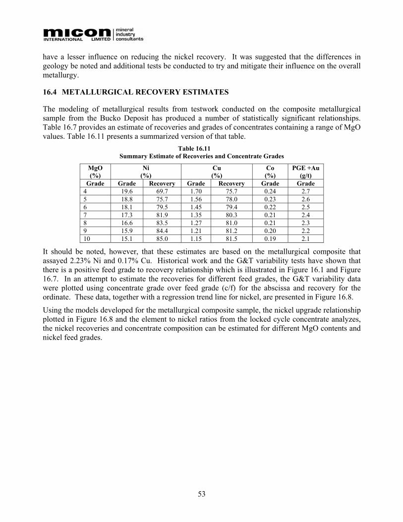
53
have a lesser influence on reducing the nickel recovery. It was suggested that the differences in geology be noted and additional tests be conducted to try and mitigate their influence on the overall metallurgy.
16.4 METALLURGICAL RECOVERY ESTIMATES
The modeling of metallurgical results from testwork conducted on the composite metallurgical sample from the Bucko Deposit has produced a number of statistically significant relationships. Table 16.7 provides an estimate of recoveries and grades of concentrates containing a range of MgO values. Table 16.11 presents a summarized version of that table.
Table 16.11 Summary Estimate of Recoveries and Concentrate Grades
MgO (%)
Ni (%)
Cu (%)
Co (%)
PGE +Au (g/t)
Grade Grade Recovery Grade Recovery Grade Grade 4 19.6 69.7 1.70 75.7 0.24 2.7 5 18.8 75.7 1.56 78.0 0.23 2.6 6 18.1 79.5 1.45 79.4 0.22 2.5 7 17.3 81.9 1.35 80.3 0.21 2.4 8 16.6 83.5 1.27 81.0 0.21 2.3 9 15.9 84.4 1.21 81.2 0.20 2.2 10 15.1 85.0 1.15 81.5 0.19 2.1
It should be noted, however, that these estimates are based on the metallurgical composite that assayed 2.23% Ni and 0.17% Cu. Historical work and the G&T variability tests have shown that there is a positive feed grade to recovery relationship which is illustrated in Figure 16.1 and Figure 16.7. In an attempt to estimate the recoveries for different feed grades, the G&T variability data were plotted using concentrate grade over feed grade (c/f) for the abscissa and recovery for the ordinate. These data, together with a regression trend line for nickel, are presented in Figure 16.8.
Using the models developed for the metallurgical composite sample, the nickel upgrade relationship plotted in Figure 16.8 and the element to nickel ratios from the locked cycle concentrate analyzes, the nickel recoveries and concentrate composition can be estimated for different MgO contents and nickel feed grades.
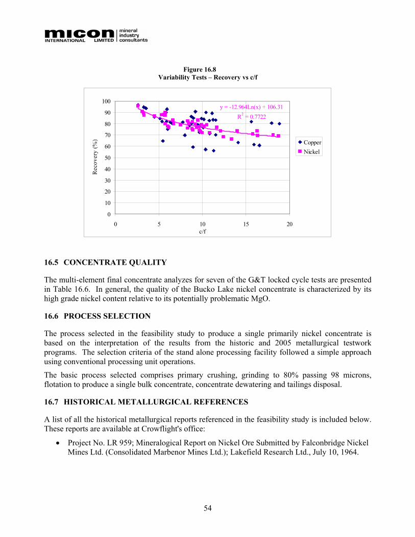
54
Figure 16.8 Variability Tests – Recovery vs c/f
16.5 CONCENTRATE QUALITY
The multi-element final concentrate analyzes for seven of the G&T locked cycle tests are presented in Table 16.6. In general, the quality of the Bucko Lake nickel concentrate is characterized by its high grade nickel content relative to its potentially problematic MgO.
16.6 PROCESS SELECTION
The process selected in the feasibility study to produce a single primarily nickel concentrate is based on the interpretation of the results from the historic and 2005 metallurgical testwork programs. The selection criteria of the stand alone processing facility followed a simple approach using conventional processing unit operations.
The basic process selected comprises primary crushing, grinding to 80% passing 98 microns, flotation to produce a single bulk concentrate, concentrate dewatering and tailings disposal.
16.7 HISTORICAL METALLURGICAL REFERENCES
A list of all the historical metallurgical reports referenced in the feasibility study is included below. These reports are available at Crowflight's office:
• Project No. LR 959; Mineralogical Report on Nickel Ore Submitted by Falconbridge Nickel Mines Ltd. (Consolidated Marbenor Mines Ltd.); Lakefield Research Ltd., July 10, 1964.
y = -12.964Ln(x) + 106.31R2 = 0.7722
0
10
20
30
40
50
60
70
80
90
100
0 5 10 15 20c/f
Rec
over
y (%
) CopperNickel

55
• Project No. LR 959; An Investigation of The Recovery of Nickel From Drill Core Rejects Submitted by Falconbridge Nickel Mines Ltd. (Consolidated Marbenor Mines Ltd.) Progress Report No. 1; Lakefield Research Ltd., July 14, 1964.
• Project No. LR 959; Progress Report No. 2; Lakefield Research Ltd., September 21, 1964.
• Project No. LR 959; Progress Report No. 3; Lakefield Research Ltd., February, 1966.
• Project No. LR 1053; Investigation of The Recovery of Nickel From Samples of Bucko Lake Ore Submitted by Falconbridge Nickel Mines Ltd. (Consolidated Marbenor Mines Ltd.), Progress Report No. 1; Lakefield Research Ltd., March 10, 1967,
• Project No. LR 1053; Progress Report No. 2; Lakefield Research Ltd., June 15, 1967
• Project No. LR 1053; Progress Report No. 3; Lakefield Research Ltd., December 1967
• Project No. LR 1144; Progress Report No. 4; Lakefield Research Ltd., January 10, 1968
• Project No. LR 1144; Progress Report No. 5; Lakefield Research Ltd., February 21, 1968
• Project No. LR 1144; Progress Report No. 6; Lakefield Research Ltd., April 9, 1968
• Project No. LR 1144; Progress Report No. 7; Lakefield Research Ltd., June 5, 1968
• Flotation Investigation of Nickel-Containing Periotite for Singmaster & Breyer, Royal Institute of Technology, Progress Reports 1 to 5 and Summary Report, P.G.Kihlsted, May to December 1969.
• Mineralogical Examination of 3 Flotation Test Samples From Kihlstedt Tests; Lakefield Research, February 2, 1970.
• Microscopic Examination of Nickel-Ore Samples Submitted by Falconbridge Nickel Mines Ltd. (Bucko Bowden Lakes) Progress Report No. 10; Lakefield Research Ltd., December 7, 1970.
• Inter office memo, Falconbridge Nickel Mines Ltd. Bucko Metallurgy M-77; J Mortimer, May 8, 1972; Tabulation of head grade, recovery and conc. grades.
• Inter office memo, Falconbridge Nickel Mines Ltd, 16 Bench tests at Manibridge on 5 DD core samples, Falconbridge, July/Aug 1972.
• Mineralogical Report No 816 “Mineralogical Examination of 40 Selected Samples of Host rock and Sulphides from Bucko Lake”; J.E. Muir, Falconbridge, April 16, 1973.
• Project No. LR 1826; Investigation of The Recovery of Copper and Nickel From Bucko Lake Samples Submitted by Falconbridge Nickel Mines Ltd.; Progress Report No. 1; Lakefield Research Ltd., May 26, 1975.
• Inter office memo, Falconbridge Nickel Mines Ltd. Bucko Lake Grade and Recovery; F. Pickard, May 13, 1977.
• Project No. LR 4125; Investigation of The Recovery of Nickel From Wabowden Project Samples Submitted by Falconbridge Nickel Mines Ltd.; Progress Report No. 1; Lakefield Research Ltd., March 22, 1991.

56
• Project No. LR 4125; Fax; Test Results From Composite M77-26A and Concentrate Assays; Lakefield Research Ltd., October 22, 1991.
• Bucko Lake Pre-Feasibility Study, Falconbridge Limited, 1994.
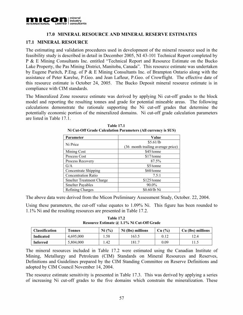
57
17.0 MINERAL RESOURCE AND MINERAL RESERVE ESTIMATES
17.1 MINERAL RESOURCE The estimating and validation procedures used in development of the mineral resource used in the feasibility study is described in detail in December 2005, NI 43-101 Technical Report completed by P & E Mining Consultants Inc. entitled “Technical Report and Resource Estimate on the Bucko Lake Property, the Pas Mining District, Manitoba, Canada”. This resource estimate was undertaken by Eugene Puritch, P.Eng. of P & E Mining Consultants Inc. of Brampton Ontario along with the assistance of Peter Karelse, P.Geo. and Jean Lafleur, P.Geo. of Crowflight. The effective date of this resource estimate is October 24, 2005. The Bucko Deposit mineral resource estimate is in compliance with CIM standards.
The Mineralized Zone resource estimate was derived by applying Ni cut-off grades to the block model and reporting the resulting tonnes and grade for potential mineable areas. The following calculations demonstrate the rationale supporting the Ni cut-off grades that determine the potentially economic portion of the mineralized domains. Ni cut-off grade calculation parameters are listed in Table 17.1.
Table 17.1 Ni Cut-Off Grade Calculation Parameters (All currency is $US)
Parameter Value
Ni Price $5.61/lb (36 month trailing average price)
Mining Cost $45/tonne Process Cost $17/tonne Process Recovery 87.5% G/A $5/tonne Concentrate Shipping $60/tonne Concentration Ratio 7.5:1 Smelter Treatment Charge $125/tonne Smelter Payables 90.0% Refining Charges $0.60/lb Ni
The above data were derived from the Micon Preliminary Assessment Study, October. 22, 2004.
Using these parameters, the cut-off value equates to 1.09% Ni. This figure has been rounded to 1.1% Ni and the resulting resources are presented in Table 17.2.
Table 17.2 Resource Estimate @ 1.1% Ni Cut-Off Grade
Classification Tonnes Ni (%) Ni (lbs) millions Cu (%) Cu (lbs) millions Indicated 4,695,000 1.58 163.5 0.12 12.4 Inferred 5,804,000 1.42 181.7 0.09 11.5
The mineral resources included in Table 17.2 were estimated using the Canadian Institute of Mining, Metallurgy and Petroleum (CIM) Standards on Mineral Resources and Reserves, Definitions and Guidelines prepared by the CIM Standing Committee on Reserve Definitions and adopted by CIM Council November 14, 2004. The resource estimate sensitivity is presented in Table 17.3. This was derived by applying a series of increasing Ni cut-off grades to the five domains which constrain the mineralization. These
58
domains were developed utilizing an approximate 1.25% Ni cut-off grade. This 1.25% Ni cut-off was found to be the grade at which the domains demonstrate the optimal lithological and structural zonal continuity along strike and down dip. This set of domains was subsequently used during the application of all cut-off grades within the sensitivity table.
The resource at 1.5% nickel grade cut-off was used in the feasibility study based on a combination of adequate lithological and structural continuity among the five domains for the purposes of mining plus provided the combination of an acceptable economic return when considering the mine plan, mill costs and metallurgical recovery test work.
Table 17.3 Resource Estimate Sensitivity
Cut-Off Indicated Inferred Ni % Tonnes Ni % Cu % Tonnes Ni % Cu % 1.90 905,000 2.53 0.17 609,000 2.23 0.11 1.70 1,265,000 2.32 0.16 940,000 2.07 0.11 1.50 1,816,000 2.10 0.15 1,551,000 1.88 0.11 1.30 2,817,000 1.85 0.13 2,917,000 1.65 0.10 1.10 4,695,000 1.58 0.12 5,804,000 1.42 0.09
As a test of the reasonableness of the estimate, the block model was queried at a 0.001% Ni cut off grade, with blocks in all classifications summed and their grades weight averaged. This average is the average grade of all blocks within the mineralized domain. The values of the interpolated grades for the block model were compared to the length weighted capped average grades and average grade of composites of all samples from within the domain. The results are presented in Table 17.4.
Table 17.4 Comparison of Capped Assays, Composites and Block Model Average Grade
Category Ni (%) Cu (%) Capped Assays 1.19 0.08 Composites 1.20 0.08 Block Model 1.20 0.09
The comparison above shows the average grade of all the blocks in the domain to be very close to the weighted average of all capped assays and composites used for grade estimation. This analysis illustrates that through the interpolation of the resource data set the average grade calculated at each step for all of the data were consistent with the average grade for all of the original capped data. Therefore the data set does not appear to have been biased at any stage by the data interpolation process, including grade capping.
17.2 MINERAL RESERVE The Bucko mineral reserve was derived from the mineable portion of the 1,815,653 tonne indicated resource grading 2.10% Ni as defined by a cut-off grade of 1.5% Ni. The computerized mine design program Mine 2-4D, in conjunction with Earthworks scheduling program, were used to create stope layouts, development layouts and mining schedules. The model incorporated the block model resource defined by the cut-off grade of 1.5% Ni and dilution was fixed at a 0.6% Ni grade. True ore grade was applied to ‘In Ore Development’ where the development drift was narrower than the ore boundary. Where development was narrower than the ore width, the true diluted mined
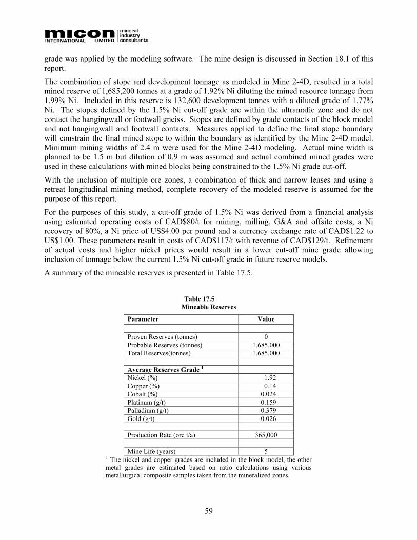
59
grade was applied by the modeling software. The mine design is discussed in Section 18.1 of this report.
The combination of stope and development tonnage as modeled in Mine 2-4D, resulted in a total mined reserve of 1,685,200 tonnes at a grade of 1.92% Ni diluting the mined resource tonnage from 1.99% Ni. Included in this reserve is 132,600 development tonnes with a diluted grade of 1.77% Ni. The stopes defined by the 1.5% Ni cut-off grade are within the ultramafic zone and do not contact the hangingwall or footwall gneiss. Stopes are defined by grade contacts of the block model and not hangingwall and footwall contacts. Measures applied to define the final stope boundary will constrain the final mined stope to within the boundary as identified by the Mine 2-4D model. Minimum mining widths of 2.4 m were used for the Mine 2-4D modeling. Actual mine width is planned to be 1.5 m but dilution of 0.9 m was assumed and actual combined mined grades were used in these calculations with mined blocks being constrained to the 1.5% Ni grade cut-off.
With the inclusion of multiple ore zones, a combination of thick and narrow lenses and using a retreat longitudinal mining method, complete recovery of the modeled reserve is assumed for the purpose of this report.
For the purposes of this study, a cut-off grade of 1.5% Ni was derived from a financial analysis using estimated operating costs of CAD$80/t for mining, milling, G&A and offsite costs, a Ni recovery of 80%, a Ni price of US$4.00 per pound and a currency exchange rate of CAD$1.22 to US$1.00. These parameters result in costs of CAD$117/t with revenue of CAD$129/t. Refinement of actual costs and higher nickel prices would result in a lower cut-off mine grade allowing inclusion of tonnage below the current 1.5% Ni cut-off grade in future reserve models.
A summary of the mineable reserves is presented in Table 17.5.
Table 17.5
Mineable Reserves
Parameter Value Proven Reserves (tonnes) 0 Probable Reserves (tonnes) 1,685,000 Total Reserves(tonnes) 1,685,000 Average Reserves Grade 1 Nickel (%) 1.92 Copper (%) 0.14 Cobalt (%) 0.024 Platinum (g/t) 0.159 Palladium (g/t) 0.379 Gold (g/t) 0.026 Production Rate (ore t/a) 365,000 Mine Life (years) 5
1 The nickel and copper grades are included in the block model, the other metal grades are estimated based on ratio calculations using various metallurgical composite samples taken from the mineralized zones.

60
18.0 OTHER RELEVANT DATA AND INFORMATION
18.1 MINING AST Mining was contracted by Crowflight to complete the Feasibility Study mine design and scheduling of the Bucko Lake deposit. Wardrop Engineering (Wardrop) was retained to provide planning and scheduling to refine the design. The work consisted of designing stopes and development based on a geological block model created with Gemcom mine planning software.
The geotechnical input into the mine design was provided by Golder Associates (Golder).
18.1.1 Mining Method The mining method selected by Crowflight is longhole open stoping with sublevel access on 30.5 m intervals (100 ft). The stopes are to be backfilled with cemented hydraulic fill and development waste. The sublevels will be connected via an internal ramp or decline. Maximum stope dimensions were defined as 20 m wide by 20 m long by 30 m high.
Backfill will be introduced underground via a series of boreholes and HDPE piping located in the ramp.
18.1.2 Geotechnical Investigations A geotechnical study has been completed by Golder. Included in this geotechnical study is a review of the database containing geotechnical information gathered during various drilling campaigns on the property. A geotechnical model was created using the information in the database to infer rock mass quality, rock strength and major discontinuities in the four zones of nickel mineralization. These include the Lower, Middle and Upper Zones in the western limb containing anomalous nickel within the ultramafic sill separated by ultramafic rocks and the Hinge Zone which exists as a series of tight north-south similar folds plunging steeply south.
The geotechnical model was built using the GoCAD software. Representative horizontal and vertical contoured sections of rock mass quality and rock quality designation (RQD) were created in the GoCAD geotechnical model. Based on these sections, a ground support assessment was completed on the various underground drift infrastructures.
Based on the design methodology used by Golder for the development of the recommended ground support for the Bucko Lake Project, a minimum rock support class system was recommended that uses different support type categories on the measured rock mass conditions and the drift dimensions. The results from the ground support assessment recommended a three-class support system which was based on rock mass quality. The three-class support system was defined as:
• Systematic pattern bolting support for Q>4.
• Systematic pattern bolting support and 4-10 cm shotcrete for Q<4 and Q>1.
• Systematic pattern bolting support, metal screen and 4-10 cm of plain shotcrete for Q<1.
Q is defined as the “Rock Mass Quality”, the value of which varies logarithmically, ranging from 1 for poor ground to 1,000 for exceptionally good quality rock which is practically unjointed.
A stope stability assessment was completed using the Mathews Method based on the maximum stope dimensions for open stoping (20 m by 20 m by 30 m high) considered for use at Bucko Lake.
61
The results from the stope stability assessment indicated that the initial stope dimensions for open stoping ranged in rankings from stable to requiring support to potentially caving.
A crown pillar assessment was completed for the four crown pillars included in the Bucko Lake 3-dimensional mine design using the empirical Scaled Span Method. All four crown pillars were found to be potentially stable using the minimum and maximum rock mass rating inferred for the crown pillars for the analysis.
Due to the limited geotechnical data currently available in portions of the deposit and crown pillar, Golder recommends obtaining additional geotechnical data from the recent summer 2005 drill program and future drilling programs. Geotechnical information from these drilling programs is required before finalizing the detailed mine design. These new data can be used to update the geotechnical model (i.e., GoCAD model) and the assessments completed as part of the Golder study report can be validated, including support designs, stope sizing/stability and crown pillar assessment.
18.1.3 Mine Design
Existing Mine Infrastructure Existing infrastructure includes a 340 m deep shaft with a shaft station and crosscut to the hangingwall on the 1000 Level plus a hangingwall exploration drift (on the same level). The timbered shaft has three compartments, each compartment measuring 1.8 m by 1.8 m. Two of the compartments will be used for hoisting with the remaining compartment to be used as a manway to surface.
Primary Development Main access to the ore-body will be via the existing shaft located to the southeast of the ore-body. A primary haulage drift approximately 4.2 m wide by 4.5 m high, located in the footwall, will be excavated from the shaft to the ore-body. Ore and waste will be hauled from the levels with 13-tonne trucks to a loading pocket at the shaft. The loading pocket will have a grizzly to control muck size plus a mobile rock breaker to size oversize rock.
There will be a 400 Level decline (3.8 m by 3.8 m) starting near the 400 Level shaft station to the ore-body on the 500 Level.
Each sublevel will be connected by a ramp or decline, located in the footwall, from the 1000 Level haulage drift. The ramp is designed at a 15% grade with a minimum centreline turning radius of 20 m providing access to each of the levels with the exception of the 500 Level. The 500 Level is not connected to the ramp. The ramp was designed up from 1000 Level to the 600 Level, and down from the 1000 Level to the 1600 Level, to access the lower ore lobe. The ramp profile is 4.2 m wide by 4.5 m high. Remuck stations and safety bays will be excavated during the mining of the ramp. The safety bays will measure 1.5 m by 2.0 m and will be driven every 30 m.
Levels are to be developed on the 500, 600, 700, 800, 900, 1000, 1100, 1200, 1300, 1400, 1500, and 1600 Level elevations.
A 3.0 m by 3.0 m ventilation raise will extend from the 1600 Level to surface to provide primary ventilation to the mine. The ventilation raise will be driven using an Alimak with an Alimak nest measuring 3.8 m wide by 5.5 m high. This raise will be equipped with ladders and landings and act as a means of second egress in combination with the ramp.

62
All primary development will be located at least 20 m from the ultramafic contacts. The ultramafics are partially mineralized and weaker than the surrounding host rock. Development ground support will consist of resin rebar bolting in non-ultramfic zones and resin rebar and screen in the ultramafic zone. Some locations estimated to total 25% of total underground development will require additional support of layered screen and shotcrete..
Secondary Development A garage/shop facility, a permanent refuge station, fuel storage and loading facility and a powder magazine will be located on the 1000 Level. The dimensions of these facilities are as follows:
• Detonator magazine (4 m x 4 m x 4 m), at least 8 m from the powder magazine.
• Powder magazine (7 m x 5.5 m x 5 m).
• Refuge station (5.5 m x 5 m x 6 m).
• Workshop (5.5 m x 5 m x 8 m).
• Fuel bay (5.5 m x 5 m x 8 m).
• Rock breaker station (3.8 m x 3.8 m x 5 m).
There will be one sump per level for trapping and containing water inflows. The sumps will be interconnected by boreholes to pumping stations located on the 400, 1000 and 1500 Levels for removal of the mine water to the surface mill. Each sump will measure 2.4 m wide by 2.4 m high by 3.8 m deep.
Level and Stope Development Level development consists of a central crosscut from the ramp. Each Level is on a 30.5 m vertical spacing (100 ft). The crosscut is 3.8 m wide by 3.8 m high. The stopes are to be mined using longhole open stoping, starting on the abutments and retreating towards the ramp. Stopes will be backfilled where required given the nature of the ground and mine sequencing with hydraulic cemented fill, development waste or a combination of both.
The excavated quantities of waste rock, partially mineralized ultramafics and the ore were scheduled taking into account maximum flexibility with multiple faces and a reduced delay due to backfill curing.
18.1.4 Mine Sequence
Development The existing shaft provides access on the 400 and 1000 Levels. The mine plan is to develop a footwall drift on the 400 Level and then drive an Alimak ventilation raise to the surface. On the 1000 Level, a footwall drive and ramp will be developed and a ventilation raise will be driven by Alimak. Each Level will be developed as it is accessed by the ramp.
Stoping Stoping can begin in the upper lobe once the ventilation raise is broken through on the 500 Level. In general the stope sequence rules are:
• Ore development for each stope must be complete above and below the stope.
63
• Each 20 m long stope must be mined and filled from the abutments of the deposit and retreated towards the central access.
• Stopes that run parallel to each other along strike must be mined and filled moving from the hangingwall to the footwall.
• The stopes will be mined from the bottom up (1100 Level up for the upper lobe and 1600 Level up for the lower lobe).
The sequence for each stope is:
Drill Load/Blast Muck Fill Cure (28 days)
18.1.5 Mine Schedule The design criteria used to develop the mine plan, are as follows:
• In any single heading, the advance rate is 7.6 m per day or 3.8 m per shift.
• The 400 level development will be advanced by Long Tom or single boom jumbo at the rate of 5 m per day.
• Alimak raising advances at 5 m per day or 2.5 m per shift.
• Stoping – Overall limitation of 1000 mined tonnes per day. Each stope can produce up to 500 tonnes per day. The following activities were included in the stoping process:
o Longhole drilling – 280 m/day.
o Loading explosives – 1,400 t/d (explosive tonnes).
o Mucking – 750 t/d (mined tonnes).
o Filling – 600 t/d (backfill tonnes) and a 28-day curing period.
The mining resources used in preparing the following mine schedule include:
• Two 13-t capacity haulage trucks.
• Two 6 cubic yard LHDs.
• Two drill jumbos.
• Two longhole drills.
• Two development crews.
• Two stoping crews.
• One Alimak raise crew.
• One backfill crew.
18.1.6 Development Schedule
(Note: For discussion purposes the schedule begins in January 2007, however, the actual start date will depend on project commitment and financing)
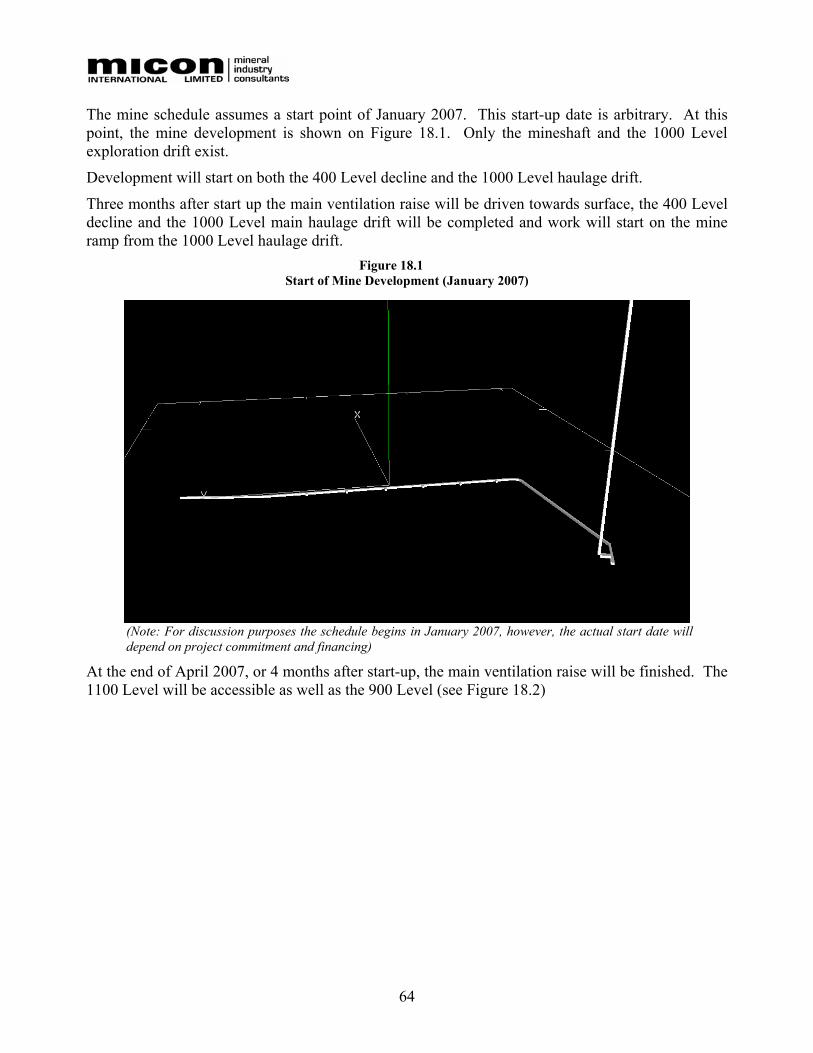
64
The mine schedule assumes a start point of January 2007. This start-up date is arbitrary. At this point, the mine development is shown on Figure 18.1. Only the mineshaft and the 1000 Level exploration drift exist.
Development will start on both the 400 Level decline and the 1000 Level haulage drift.
Three months after start up the main ventilation raise will be driven towards surface, the 400 Level decline and the 1000 Level main haulage drift will be completed and work will start on the mine ramp from the 1000 Level haulage drift.
Figure 18.1 Start of Mine Development (January 2007)
(Note: For discussion purposes the schedule begins in January 2007, however, the actual start date will depend on project commitment and financing)
At the end of April 2007, or 4 months after start-up, the main ventilation raise will be finished. The 1100 Level will be accessible as well as the 900 Level (see Figure 18.2)

65
Figure 18.2 Mine Development (April 2007)
(Note: For discussion purposes the schedule begins in January 2007, however, the actual start date will depend on project commitment and financing)
Work will then proceed to the stope development work on the 1000 and 900 Levels and will be completed by the end of July 2007 (i.e. 7 months from start of project). At this point, the mine development work will be similar to that shown on Figure 18.3.
Figure 18.3 Mine Development (July 2007)
(Note: For discussion purposes the schedule begins in January 2007, however, the actual start date will depend on project commitment and financing)
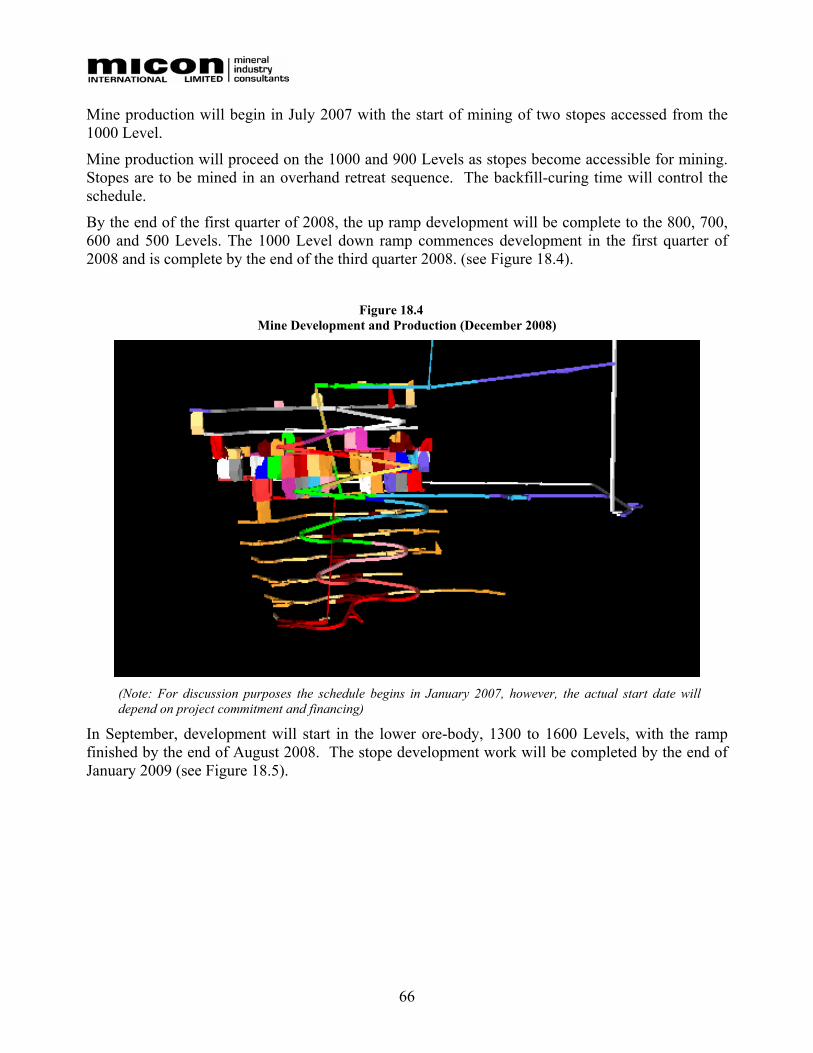
66
Mine production will begin in July 2007 with the start of mining of two stopes accessed from the 1000 Level.
Mine production will proceed on the 1000 and 900 Levels as stopes become accessible for mining. Stopes are to be mined in an overhand retreat sequence. The backfill-curing time will control the schedule.
By the end of the first quarter of 2008, the up ramp development will be complete to the 800, 700, 600 and 500 Levels. The 1000 Level down ramp commences development in the first quarter of 2008 and is complete by the end of the third quarter 2008. (see Figure 18.4).
Figure 18.4
Mine Development and Production (December 2008)
(Note: For discussion purposes the schedule begins in January 2007, however, the actual start date will depend on project commitment and financing)
In September, development will start in the lower ore-body, 1300 to 1600 Levels, with the ramp finished by the end of August 2008. The stope development work will be completed by the end of January 2009 (see Figure 18.5).
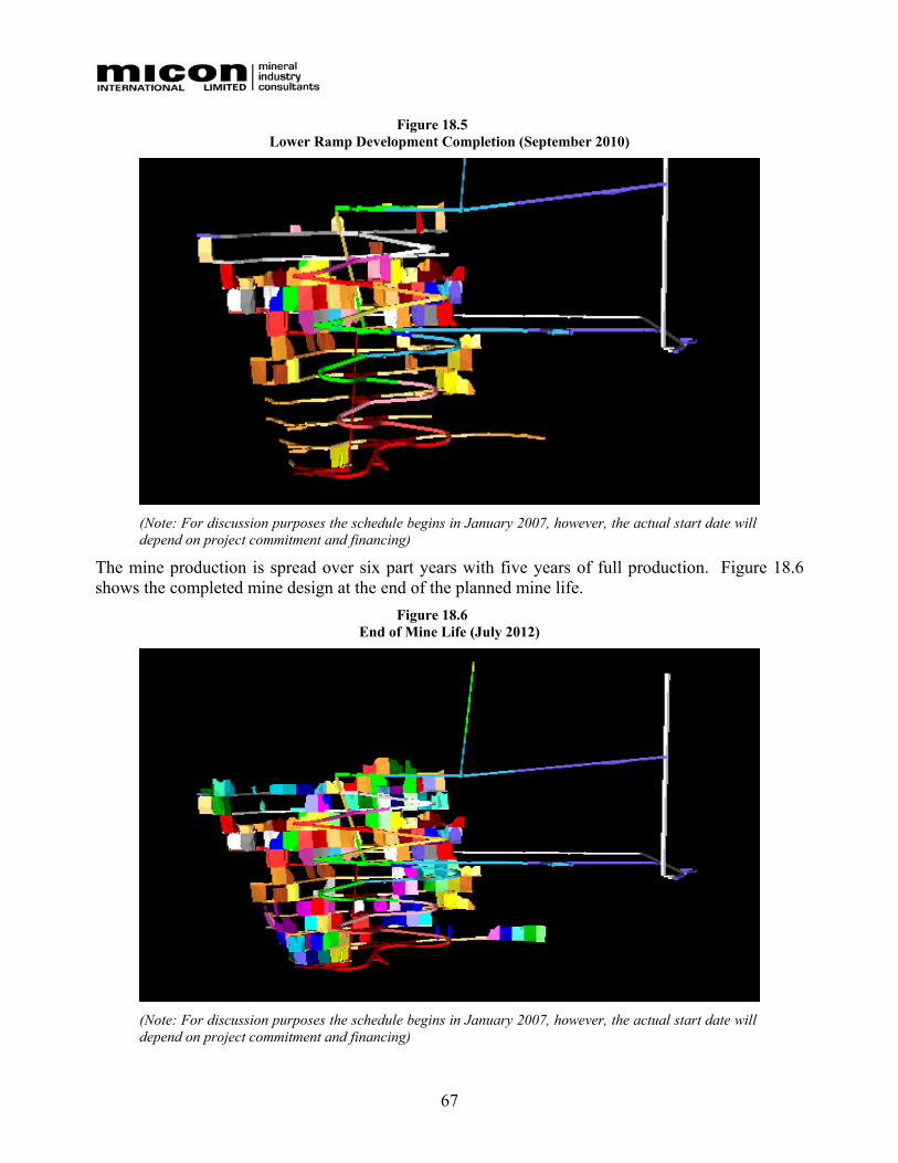
67
Figure 18.5 Lower Ramp Development Completion (September 2010)
(Note: For discussion purposes the schedule begins in January 2007, however, the actual start date will depend on project commitment and financing)
The mine production is spread over six part years with five years of full production. Figure 18.6 shows the completed mine design at the end of the planned mine life.
Figure 18.6 End of Mine Life (July 2012)
(Note: For discussion purposes the schedule begins in January 2007, however, the actual start date will depend on project commitment and financing)
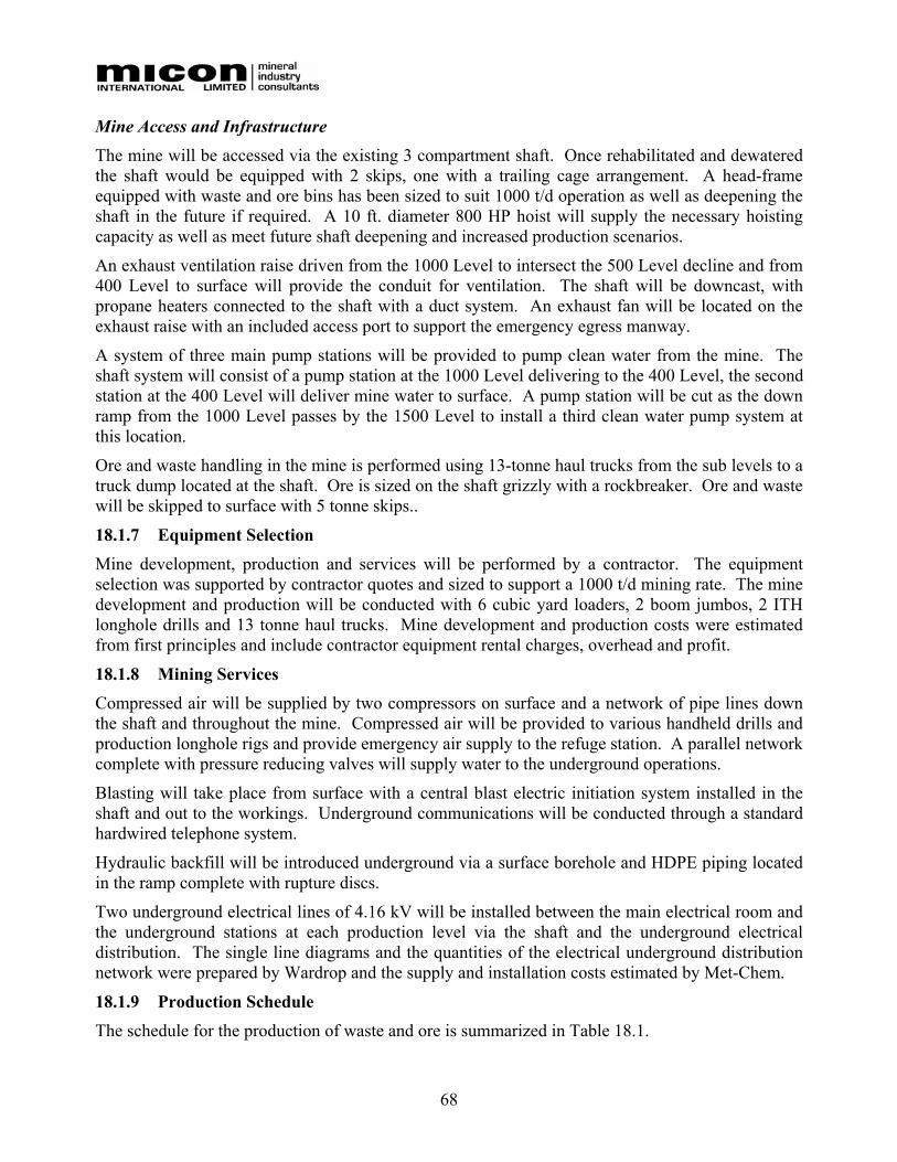
68
Mine Access and Infrastructure The mine will be accessed via the existing 3 compartment shaft. Once rehabilitated and dewatered the shaft would be equipped with 2 skips, one with a trailing cage arrangement. A head-frame equipped with waste and ore bins has been sized to suit 1000 t/d operation as well as deepening the shaft in the future if required. A 10 ft. diameter 800 HP hoist will supply the necessary hoisting capacity as well as meet future shaft deepening and increased production scenarios.
An exhaust ventilation raise driven from the 1000 Level to intersect the 500 Level decline and from 400 Level to surface will provide the conduit for ventilation. The shaft will be downcast, with propane heaters connected to the shaft with a duct system. An exhaust fan will be located on the exhaust raise with an included access port to support the emergency egress manway.
A system of three main pump stations will be provided to pump clean water from the mine. The shaft system will consist of a pump station at the 1000 Level delivering to the 400 Level, the second station at the 400 Level will deliver mine water to surface. A pump station will be cut as the down ramp from the 1000 Level passes by the 1500 Level to install a third clean water pump system at this location.
Ore and waste handling in the mine is performed using 13-tonne haul trucks from the sub levels to a truck dump located at the shaft. Ore is sized on the shaft grizzly with a rockbreaker. Ore and waste will be skipped to surface with 5 tonne skips..
18.1.7 Equipment Selection Mine development, production and services will be performed by a contractor. The equipment selection was supported by contractor quotes and sized to support a 1000 t/d mining rate. The mine development and production will be conducted with 6 cubic yard loaders, 2 boom jumbos, 2 ITH longhole drills and 13 tonne haul trucks. Mine development and production costs were estimated from first principles and include contractor equipment rental charges, overhead and profit.
18.1.8 Mining Services Compressed air will be supplied by two compressors on surface and a network of pipe lines down the shaft and throughout the mine. Compressed air will be provided to various handheld drills and production longhole rigs and provide emergency air supply to the refuge station. A parallel network complete with pressure reducing valves will supply water to the underground operations.
Blasting will take place from surface with a central blast electric initiation system installed in the shaft and out to the workings. Underground communications will be conducted through a standard hardwired telephone system.
Hydraulic backfill will be introduced underground via a surface borehole and HDPE piping located in the ramp complete with rupture discs.
Two underground electrical lines of 4.16 kV will be installed between the main electrical room and the underground stations at each production level via the shaft and the underground electrical distribution. The single line diagrams and the quantities of the electrical underground distribution network were prepared by Wardrop and the supply and installation costs estimated by Met-Chem.
18.1.9 Production Schedule The schedule for the production of waste and ore is summarized in Table 18.1.
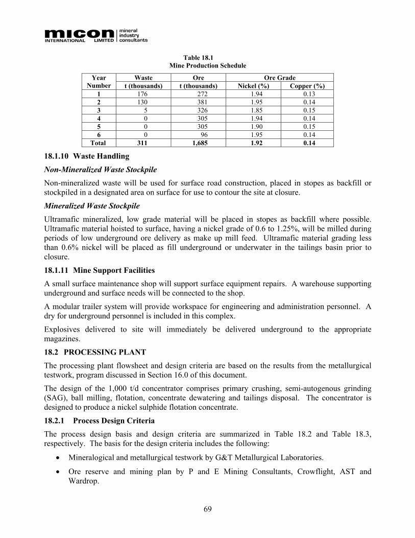
69
Table 18.1 Mine Production Schedule
Waste Ore Ore Grade Year Number t (thousands) t (thousands) Nickel (%) Copper (%)
1 176 272 1.94 0.13 2 130 381 1.95 0.14 3 5 326 1.85 0.15 4 0 305 1.94 0.14 5 0 305 1.90 0.15 6 0 96 1.95 0.14
Total 311 1,685 1.92 0.14
18.1.10 Waste Handling
Non-Mineralized Waste Stockpile Non-mineralized waste will be used for surface road construction, placed in stopes as backfill or stockpiled in a designated area on surface for use to contour the site at closure.
Mineralized Waste Stockpile Ultramafic mineralized, low grade material will be placed in stopes as backfill where possible. Ultramafic material hoisted to surface, having a nickel grade of 0.6 to 1.25%, will be milled during periods of low underground ore delivery as make up mill feed. Ultramafic material grading less than 0.6% nickel will be placed as fill underground or underwater in the tailings basin prior to closure.
18.1.11 Mine Support Facilities A small surface maintenance shop will support surface equipment repairs. A warehouse supporting underground and surface needs will be connected to the shop.
A modular trailer system will provide workspace for engineering and administration personnel. A dry for underground personnel is included in this complex.
Explosives delivered to site will immediately be delivered underground to the appropriate magazines.
18.2 PROCESSING PLANT The processing plant flowsheet and design criteria are based on the results from the metallurgical testwork, program discussed in Section 16.0 of this document.
The design of the 1,000 t/d concentrator comprises primary crushing, semi-autogenous grinding (SAG), ball milling, flotation, concentrate dewatering and tailings disposal. The concentrator is designed to produce a nickel sulphide flotation concentrate.
18.2.1 Process Design Criteria
The process design basis and design criteria are summarized in Table 18.2 and Table 18.3, respectively. The basis for the design criteria includes the following:
• Mineralogical and metallurgical testwork by G&T Metallurgical Laboratories.
• Ore reserve and mining plan by P and E Mining Consultants, Crowflight, AST and Wardrop.
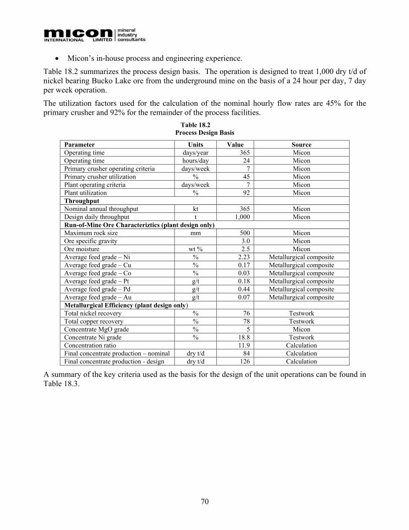
70
• Micon’s in-house process and engineering experience.
Table 18.2 summarizes the process design basis. The operation is designed to treat 1,000 dry t/d of nickel bearing Bucko Lake ore from the underground mine on the basis of a 24 hour per day, 7 day per week operation.
The utilization factors used for the calculation of the nominal hourly flow rates are 45% for the primary crusher and 92% for the remainder of the process facilities.
Table 18.2 Process Design Basis
Parameter Units Value Source Operating time days/year 365 Micon Operating time hours/day 24 Micon Primary crusher operating criteria days/week 7 Micon Primary crusher utilization % 45 Micon Plant operating criteria days/week 7 Micon Plant utilization % 92 Micon Throughput Nominal annual throughput kt 365 Micon Design daily throughput t 1,000 Micon Run-of-Mine Ore Characteriztics (plant design only) Maximum rock size mm 500 Micon Ore specific gravity 3.0 Micon Ore moisture wt % 2.5 Micon Average feed grade – Ni % 2.23 Metallurgical composite Average feed grade – Cu % 0.17 Metallurgical composite Average feed grade – Co % 0.03 Metallurgical composite Average feed grade – Pt g/t 0.18 Metallurgical composite Average feed grade – Pd g/t 0.44 Metallurgical composite Average feed grade – Au g/t 0.07 Metallurgical composite Metallurgical Efficiency (plant design only) Total nickel recovery % 76 Testwork Total copper recovery % 78 Testwork Concentrate MgO grade % 5 Micon Concentrate Ni grade % 18.8 Testwork Concentration ratio 11.9 Calculation Final concentrate production – nominal dry t/d 84 Calculation Final concentrate production - design dry t/d 126 Calculation
A summary of the key criteria used as the basis for the design of the unit operations can be found in Table 18.3.
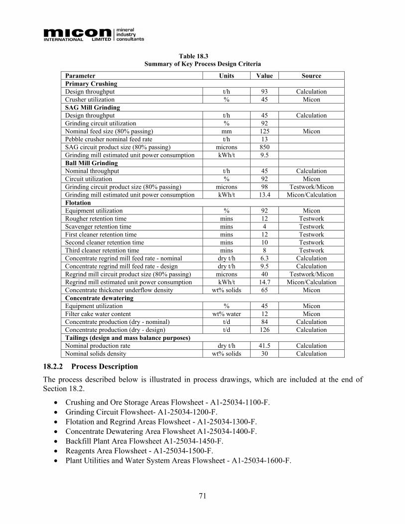
71
Table 18.3 Summary of Key Process Design Criteria
Parameter Units Value Source Primary Crushing Design throughput t/h 93 Calculation Crusher utilization % 45 Micon SAG Mill Grinding Design throughput t/h 45 Calculation Grinding circuit utilization % 92 Nominal feed size (80% passing) mm 125 Micon Pebble crusher nominal feed rate t/h 13 SAG circuit product size (80% passing) microns 850 Grinding mill estimated unit power consumption kWh/t 9.5 Ball Mill Grinding Nominal throughput t/h 45 Calculation Circuit utilization % 92 Micon Grinding circuit product size (80% passing) microns 98 Testwork/Micon Grinding mill estimated unit power consumption kWh/t 13.4 Micon/Calculation Flotation Equipment utilization % 92 Micon Rougher retention time mins 12 Testwork Scavenger retention time mins 4 Testwork First cleaner retention time mins 12 Testwork Second cleaner retention time mins 10 Testwork Third cleaner retention time mins 8 Testwork Concentrate regrind mill feed rate - nominal dry t/h 6.3 Calculation Concentrate regrind mill feed rate - design dry t/h 9.5 Calculation Regrind mill circuit product size (80% passing) microns 40 Testwork/Micon Regrind mill estimated unit power consumption kWh/t 14.7 Micon/Calculation Concentrate thickener underflow density wt% solids 65 Micon Concentrate dewatering Equipment utilization % 45 Micon Filter cake water content wt% water 12 Micon Concentrate production (dry - nominal) t/d 84 Calculation Concentrate production (dry - design) t/d 126 Calculation Tailings (design and mass balance purposes) Nominal production rate dry t/h 41.5 Calculation Nominal solids density wt% solids 30 Calculation
18.2.2 Process Description The process described below is illustrated in process drawings, which are included at the end of Section 18.2.
• Crushing and Ore Storage Areas Flowsheet - A1-25034-1100-F. • Grinding Circuit Flowsheet- A1-25034-1200-F. • Flotation and Regrind Areas Flowsheet - A1-25034-1300-F. • Concentrate Dewatering Area Flowsheet A1-25034-1400-F. • Backfill Plant Area Flowsheet A1-25034-1450-F. • Reagents Area Flowsheet - A1-25034-1500-F. • Plant Utilities and Water System Areas Flowsheet - A1-25034-1600-F.
72
The process selected for the concentration of the Bucko Lake ore is based on design criteria summarized in Section 18.2.1.
Crushing and Storage Area.
The ore from the underground mine is hoisted to surface and stored in the coarse ore shaft bin. A pan feeder transfers the ore from the bin to a 0.91 m wide by 12 m long belt conveyor which discharges on to a 125 mm grizzly situated above the primary crusher. The oversize from the grizzly feeds the primary 32 inch (0.81 m) by 22 inch (0.55 m) jaw crusher. The crusher, which is equipped with a dust collector, is of a compact design, set up on light concrete foundations and covered with a winterized building. An operator’s cabin is located in close proximity to the crusher.
The minus 125 mm grizzly undersize and jaw crusher product discharges onto a 0.76 m wide conveyor belt which discharges into the 11 m diameter by 11 m high coarse ore bin. The course ore bin holds a live capacity of 1,000 tonnes. A fixed magnet is installed at the head-end of the coarse ore conveyor to remove tramp steel.
Four vibrating feeders located under the coarse ore bin are used to feed the crushed ore at a controlled rate, via a 0.61 m wide conveyor, to the semi-autogenous grinding (SAG) mill, which is situated in the main mill building. A weightometer is installed on the mill feed belt.
Grinding The grinding circuit comprises an 18 foot (5.50 m) diameter by 6 foot (1.83 m) long SAG mill, fitted with a 650 HP (488 kW) motor and a 10 foot (3.05 m) diameter by 15 foot (4.57 m) long ball mill, connected to a 900 HP (672 kW) motor. A 3 foot (0.91 m) diameter short head cone crusher is included in the SAG mill circuit. Plus 15 mm pebbles are separated from the SAG mill discharge using a 1 m by 1.3 m double deck vibrating screen and conveyed to the pebble crusher. The pebble crusher discharge is fed on to the SAG mill feed belt. The undersize from the SAG mill discharge screen and the product from the ball mill feed the cyclone feed pump box.
The discharge product from both mills is pumped from the cyclone feed pumpbox to a cyclone cluster from which the overflow sizing 80% passing 98 microns is routed to the flotation circuit. The underflow from the cyclone cluster, comprising two 457 mm diameter cyclones, is recycled to the ball mill.
Flotation Circuit The flotation circuit comprises a rougher/scavenger stage (10 x 3 m3 cells) and three cleaner stages. The cleaner circuits consist of 2 x 3 m3 primary cells, 6 x 0.5 m3 secondary cells and 4 x 0.5 m3 tertiary cells.
The rougher circuit is fed from the second of two 1.8 m wide by 3.7 m high conditioners, which are used to mix the initial dose of reagents with the grinding circuit product.
The rougher and scavenger concentrate is fed to the regrind mill circuit. The discharge from the 6 foot (1.83 m) diameter by 10 foot (3.05 m) long 200 HP (150 kW motor) regrind mill is pumped to two 254 mm diameter cyclones. The cyclone underflow returns to the mill while the overflow stream, sizing 80% passing 40 microns, feeds the primary cleaner circuit
The tailings product from the scavenger cells is combined with the primary cleaner tailings and pumped to either the tailings dam or the backfill plant. The tertiary cleaner concentrate is the final product and is pumped to the concentrate thickener and filter section for dewatering.
73
The routing of the intermediate flotation streams within the flotation circuit is portrayed visually on the flowsheet.
Concentrate Dewatering The overflow from the 5 m diameter thickener discharges into the process water tank while the underflow is pumped to the 5.1 m diameter concentrate stock tank. The concentrate stock tank is sized to hold 18 hours of flotation concentrate. The thickener operates continuously while the filter circuit operates only 12 hours per day.
The thickened concentrate is pumped at a controlled rate from the stock tank and fed to the vacuum disc filter. The filtrate product from the filter is recovered and recycled to the concentrate thickener while the concentrate filter cake, containing about 12% moisture, is conveyed to a stockpile area. The concentrate is periodically loaded into trucks and transported to the concentrate storage stockpile, which is situated in close proximity to the rail loadout facility.
Backfill Plant The backfill plant is designed to supply the underground mine with hydraulic backfill. A dedicated pump attached to the final tailing pump box delivers tailings to the backfill cyclone cluster. The backfill cyclone cluster comprises three operating and one standby hydrocyclone. The cyclone overflow, containing approximately 15% solids by weight, gravitates to the flotation tailings pumpbox while the underflow, containing about 70% solids, discharges onto the backfill dewatering screen.
The undersize from the screen is pumped back to the flotation tailings pumpbox and the oversize is conveyed to a stockpile. This stockpiled material is reclaimed using a front end loader and mixed with water and cement in the backfill slurry batch mixing tank. When required underground the hydraulic backfill gravitates from the batch mixing tank through a borehole to the underground distribution system.
Reagents The reagents used in the flotation circuit are:
• Isopropyl Xanthate (collector); 500 g/t float feed or 500 kg/d.
• Dowfroth 250 (frother); 27 g/t float feed or 27 kg/d.
• MIBC (frother); 120 g/t float feed or 120 kg/d.
• Sodium Sulphydrate (NaHS); 125 g/t float feed or 125 kg/d.
• PE26 - CMC (gangue depressant); 1,300 g/t or 1,300 kg/d.
• Aero Promoter 3418A (collector); 10 g/t or 10 kg/d.
The flocculent recommended from metallurgical testing for concentrate thickening is:
• Superfloc A130 (Flocculent); 10 g/t of concentrate or 0.8 kg/d.
Suitable storage, make-up systems and dosing facilities have been included within scope of the process plant and infrastructure design.
Plant Utilities, Services and Water Systems

74
A low-pressure air blower, plant air compressor and instrument air compressor with ancillaries have been included within the scope of concentrator building services.
The reclaim water pumps and line from the Bucko Lake tailings deposition area feed the 7 m diameter by 7 m high process water tank, which is situated near the main process building. Process water pumps (100 mm x 75 mm) are utilized to feed the process water distribution system. Emergency fire water demand is also supplied from the process water tank.
The 5 m diameter by 5 m high fresh water tank is supplied by two 100 mm well water pumps. Fresh water is used for the potable water system, gland seal water and the fresh water distribution system.
18.2.3 Mass Balance The mass balance is provided in Table 18.4
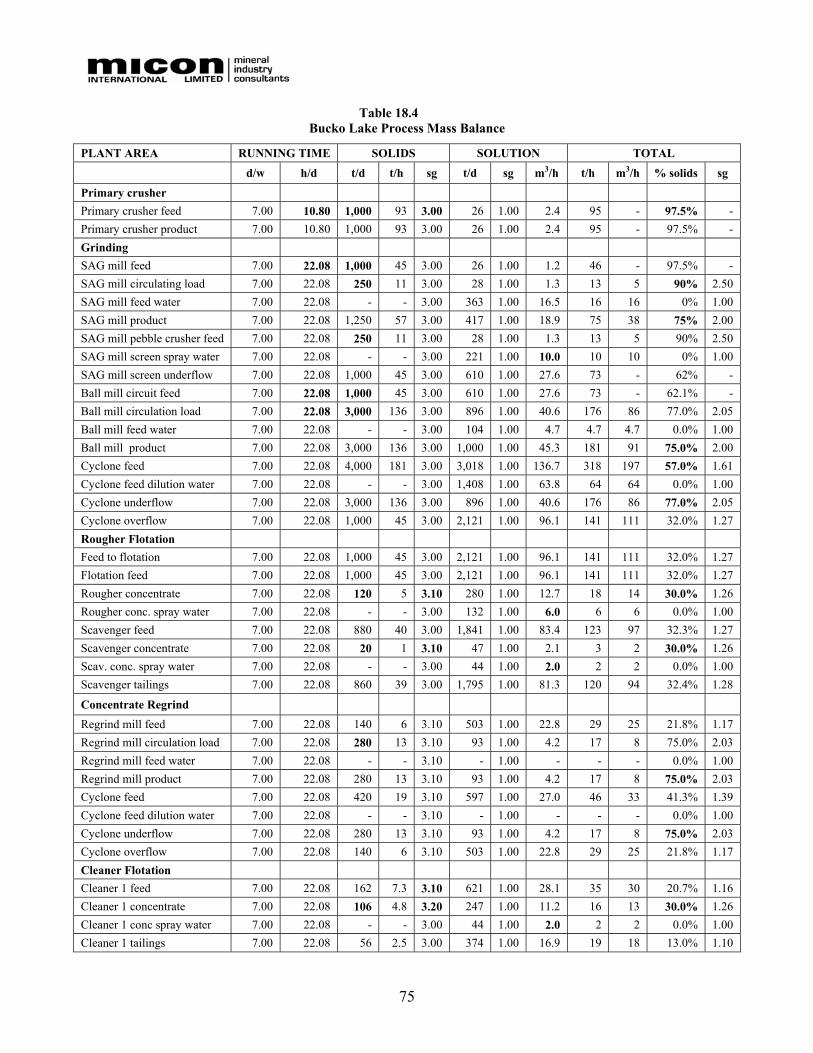
75
Table 18.4 Bucko Lake Process Mass Balance
PLANT AREA RUNNING TIME SOLIDS SOLUTION TOTAL
d/w h/d t/d t/h sg t/d sg m3/h t/h m3/h % solids sg
Primary crusher Primary crusher feed 7.00 10.80 1,000 93 3.00 26 1.00 2.4 95 - 97.5% - Primary crusher product 7.00 10.80 1,000 93 3.00 26 1.00 2.4 95 - 97.5% - Grinding SAG mill feed 7.00 22.08 1,000 45 3.00 26 1.00 1.2 46 - 97.5% - SAG mill circulating load 7.00 22.08 250 11 3.00 28 1.00 1.3 13 5 90% 2.50 SAG mill feed water 7.00 22.08 - - 3.00 363 1.00 16.5 16 16 0% 1.00 SAG mill product 7.00 22.08 1,250 57 3.00 417 1.00 18.9 75 38 75% 2.00 SAG mill pebble crusher feed 7.00 22.08 250 11 3.00 28 1.00 1.3 13 5 90% 2.50 SAG mill screen spray water 7.00 22.08 - - 3.00 221 1.00 10.0 10 10 0% 1.00 SAG mill screen underflow 7.00 22.08 1,000 45 3.00 610 1.00 27.6 73 - 62% - Ball mill circuit feed 7.00 22.08 1,000 45 3.00 610 1.00 27.6 73 - 62.1% - Ball mill circulation load 7.00 22.08 3,000 136 3.00 896 1.00 40.6 176 86 77.0% 2.05 Ball mill feed water 7.00 22.08 - - 3.00 104 1.00 4.7 4.7 4.7 0.0% 1.00 Ball mill product 7.00 22.08 3,000 136 3.00 1,000 1.00 45.3 181 91 75.0% 2.00 Cyclone feed 7.00 22.08 4,000 181 3.00 3,018 1.00 136.7 318 197 57.0% 1.61 Cyclone feed dilution water 7.00 22.08 - - 3.00 1,408 1.00 63.8 64 64 0.0% 1.00 Cyclone underflow 7.00 22.08 3,000 136 3.00 896 1.00 40.6 176 86 77.0% 2.05 Cyclone overflow 7.00 22.08 1,000 45 3.00 2,121 1.00 96.1 141 111 32.0% 1.27 Rougher Flotation Feed to flotation 7.00 22.08 1,000 45 3.00 2,121 1.00 96.1 141 111 32.0% 1.27 Flotation feed 7.00 22.08 1,000 45 3.00 2,121 1.00 96.1 141 111 32.0% 1.27 Rougher concentrate 7.00 22.08 120 5 3.10 280 1.00 12.7 18 14 30.0% 1.26 Rougher conc. spray water 7.00 22.08 - - 3.00 132 1.00 6.0 6 6 0.0% 1.00 Scavenger feed 7.00 22.08 880 40 3.00 1,841 1.00 83.4 123 97 32.3% 1.27 Scavenger concentrate 7.00 22.08 20 1 3.10 47 1.00 2.1 3 2 30.0% 1.26 Scav. conc. spray water 7.00 22.08 - - 3.00 44 1.00 2.0 2 2 0.0% 1.00 Scavenger tailings 7.00 22.08 860 39 3.00 1,795 1.00 81.3 120 94 32.4% 1.28
Concentrate Regrind
Regrind mill feed 7.00 22.08 140 6 3.10 503 1.00 22.8 29 25 21.8% 1.17 Regrind mill circulation load 7.00 22.08 280 13 3.10 93 1.00 4.2 17 8 75.0% 2.03 Regrind mill feed water 7.00 22.08 - - 3.10 - 1.00 - - - 0.0% 1.00 Regrind mill product 7.00 22.08 280 13 3.10 93 1.00 4.2 17 8 75.0% 2.03 Cyclone feed 7.00 22.08 420 19 3.10 597 1.00 27.0 46 33 41.3% 1.39 Cyclone feed dilution water 7.00 22.08 - - 3.10 - 1.00 - - - 0.0% 1.00 Cyclone underflow 7.00 22.08 280 13 3.10 93 1.00 4.2 17 8 75.0% 2.03 Cyclone overflow 7.00 22.08 140 6 3.10 503 1.00 22.8 29 25 21.8% 1.17 Cleaner Flotation Cleaner 1 feed 7.00 22.08 162 7.3 3.10 621 1.00 28.1 35 30 20.7% 1.16 Cleaner 1 concentrate 7.00 22.08 106 4.8 3.20 247 1.00 11.2 16 13 30.0% 1.26 Cleaner 1 conc spray water 7.00 22.08 - - 3.00 44 1.00 2.0 2 2 0.0% 1.00 Cleaner 1 tailings 7.00 22.08 56 2.5 3.00 374 1.00 16.9 19 18 13.0% 1.10
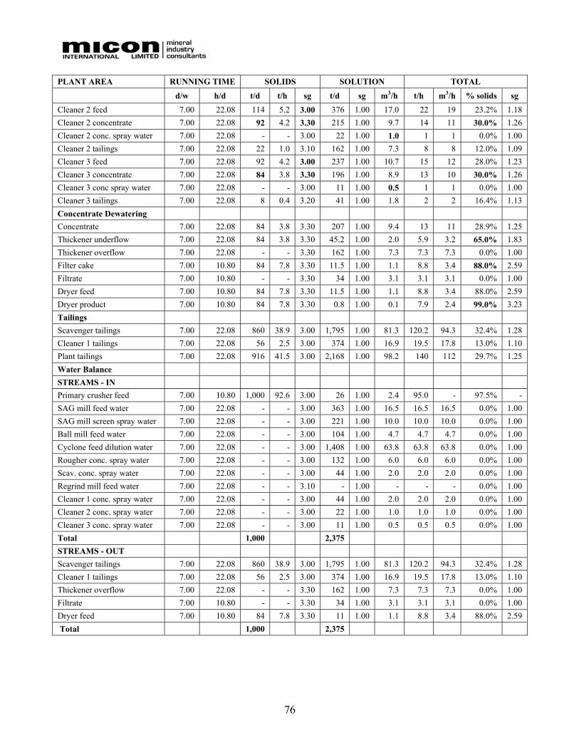
76
PLANT AREA RUNNING TIME SOLIDS SOLUTION TOTAL
d/w h/d t/d t/h sg t/d sg m3/h t/h m3/h % solids sg Cleaner 2 feed 7.00 22.08 114 5.2 3.00 376 1.00 17.0 22 19 23.2% 1.18 Cleaner 2 concentrate 7.00 22.08 92 4.2 3.30 215 1.00 9.7 14 11 30.0% 1.26 Cleaner 2 conc. spray water 7.00 22.08 - - 3.00 22 1.00 1.0 1 1 0.0% 1.00 Cleaner 2 tailings 7.00 22.08 22 1.0 3.10 162 1.00 7.3 8 8 12.0% 1.09 Cleaner 3 feed 7.00 22.08 92 4.2 3.00 237 1.00 10.7 15 12 28.0% 1.23 Cleaner 3 concentrate 7.00 22.08 84 3.8 3.30 196 1.00 8.9 13 10 30.0% 1.26 Cleaner 3 conc spray water 7.00 22.08 - - 3.00 11 1.00 0.5 1 1 0.0% 1.00 Cleaner 3 tailings 7.00 22.08 8 0.4 3.20 41 1.00 1.8 2 2 16.4% 1.13 Concentrate Dewatering Concentrate 7.00 22.08 84 3.8 3.30 207 1.00 9.4 13 11 28.9% 1.25 Thickener underflow 7.00 22.08 84 3.8 3.30 45.2 1.00 2.0 5.9 3.2 65.0% 1.83 Thickener overflow 7.00 22.08 - - 3.30 162 1.00 7.3 7.3 7.3 0.0% 1.00 Filter cake 7.00 10.80 84 7.8 3.30 11.5 1.00 1.1 8.8 3.4 88.0% 2.59 Filtrate 7.00 10.80 - - 3.30 34 1.00 3.1 3.1 3.1 0.0% 1.00 Dryer feed 7.00 10.80 84 7.8 3.30 11.5 1.00 1.1 8.8 3.4 88.0% 2.59 Dryer product 7.00 10.80 84 7.8 3.30 0.8 1.00 0.1 7.9 2.4 99.0% 3.23 Tailings Scavenger tailings 7.00 22.08 860 38.9 3.00 1,795 1.00 81.3 120.2 94.3 32.4% 1.28 Cleaner 1 tailings 7.00 22.08 56 2.5 3.00 374 1.00 16.9 19.5 17.8 13.0% 1.10 Plant tailings 7.00 22.08 916 41.5 3.00 2,168 1.00 98.2 140 112 29.7% 1.25 Water Balance STREAMS - IN Primary crusher feed 7.00 10.80 1,000 92.6 3.00 26 1.00 2.4 95.0 - 97.5% - SAG mill feed water 7.00 22.08 - - 3.00 363 1.00 16.5 16.5 16.5 0.0% 1.00 SAG mill screen spray water 7.00 22.08 - - 3.00 221 1.00 10.0 10.0 10.0 0.0% 1.00 Ball mill feed water 7.00 22.08 - - 3.00 104 1.00 4.7 4.7 4.7 0.0% 1.00 Cyclone feed dilution water 7.00 22.08 - - 3.00 1,408 1.00 63.8 63.8 63.8 0.0% 1.00 Rougher conc. spray water 7.00 22.08 - - 3.00 132 1.00 6.0 6.0 6.0 0.0% 1.00 Scav. conc. spray water 7.00 22.08 - - 3.00 44 1.00 2.0 2.0 2.0 0.0% 1.00 Regrind mill feed water 7.00 22.08 - - 3.10 - 1.00 - - - 0.0% 1.00 Cleaner 1 conc. spray water 7.00 22.08 - - 3.00 44 1.00 2.0 2.0 2.0 0.0% 1.00 Cleaner 2 conc. spray water 7.00 22.08 - - 3.00 22 1.00 1.0 1.0 1.0 0.0% 1.00 Cleaner 3 conc. spray water 7.00 22.08 - - 3.00 11 1.00 0.5 0.5 0.5 0.0% 1.00 Total 1,000 2,375 STREAMS - OUT Scavenger tailings 7.00 22.08 860 38.9 3.00 1,795 1.00 81.3 120.2 94.3 32.4% 1.28 Cleaner 1 tailings 7.00 22.08 56 2.5 3.00 374 1.00 16.9 19.5 17.8 13.0% 1.10 Thickener overflow 7.00 22.08 - - 3.30 162 1.00 7.3 7.3 7.3 0.0% 1.00 Filtrate 7.00 10.80 - - 3.30 34 1.00 3.1 3.1 3.1 0.0% 1.00 Dryer feed 7.00 10.80 84 7.8 3.30 11 1.00 1.1 8.8 3.4 88.0% 2.59 Total 1,000 2,375

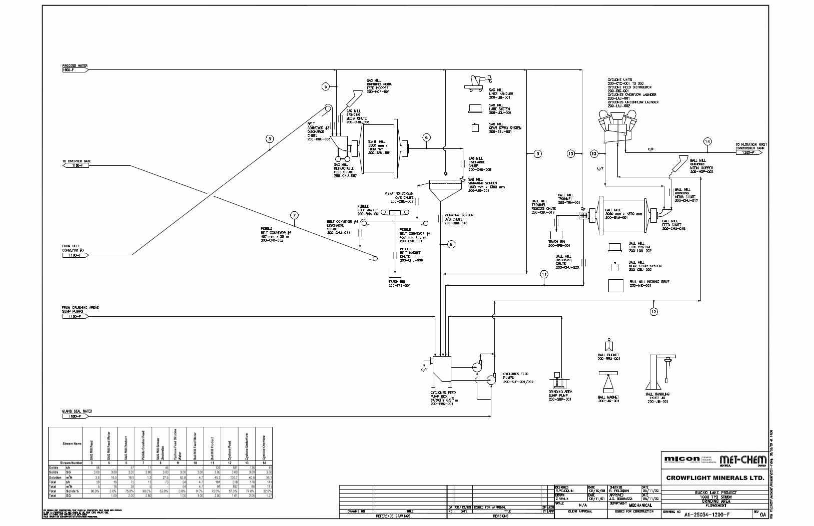
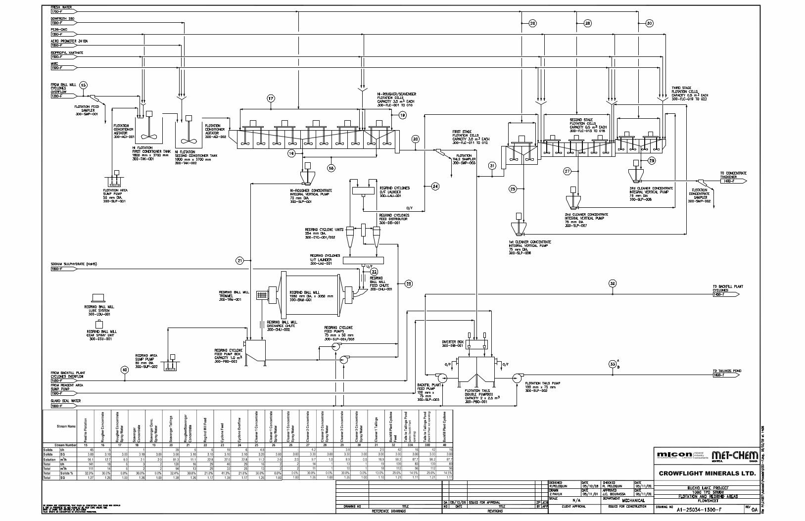
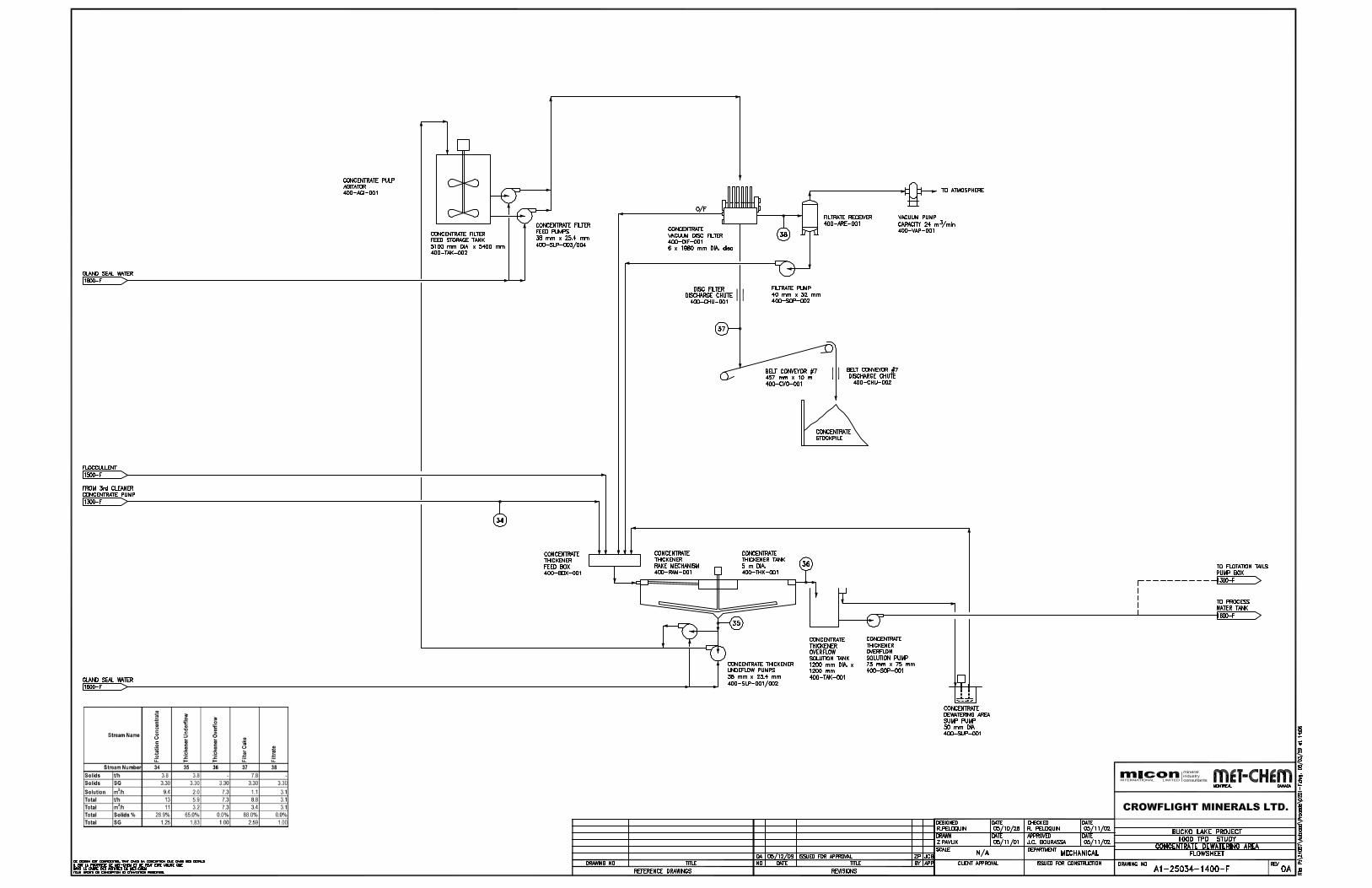
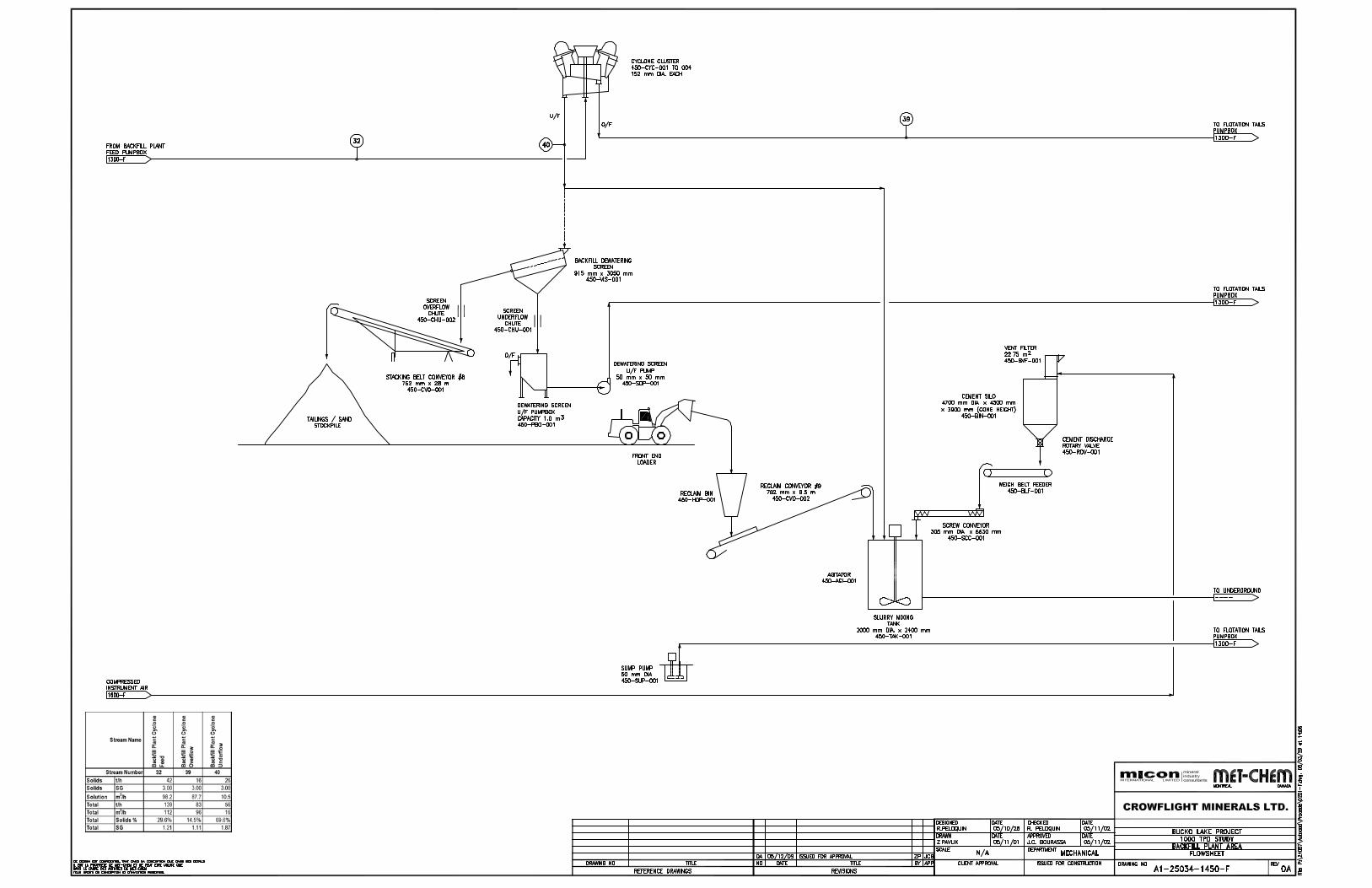
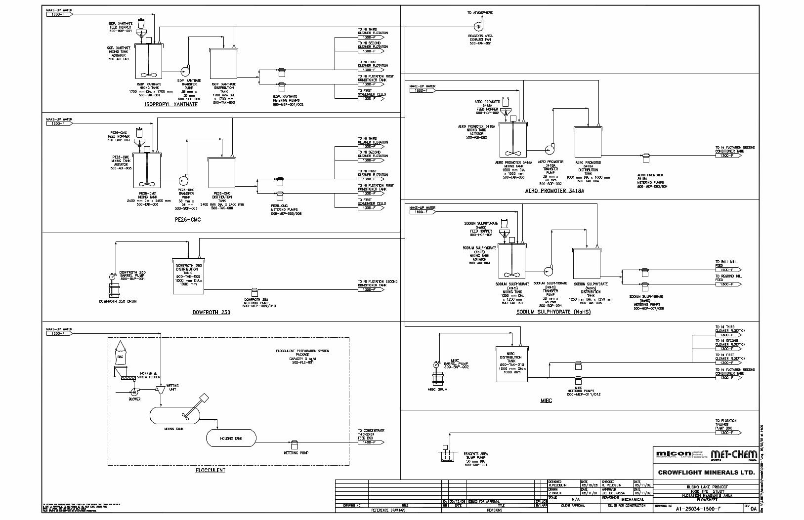
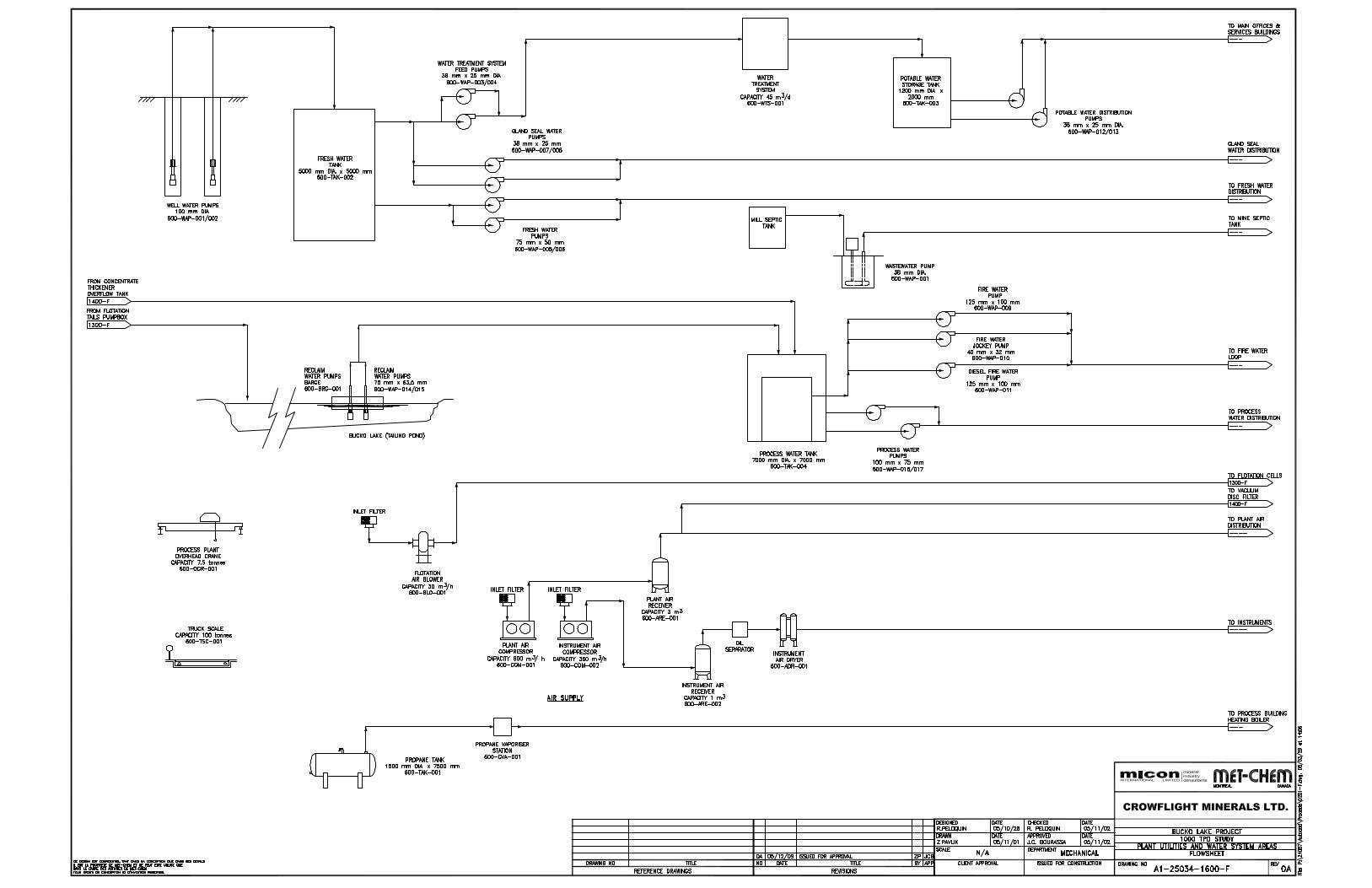
84
18.3 SURFACE INFRASTRUCTURE The general site and plant layout is shown in Figure 18.7.
Other engineering drawings produced by Met-Chem that were used as a basis for the capital cost estimate, are included in the feasibility study.
18.3.1 Plant and Site Layout The main criteria considered during the site layout development for the processing plant and other surface infrastructure were:
• Close proximity to the underground shaft access.
• Level ground with foundation bed rock close to surface.
• Minimal land disturbance in the immediate vicinity of the mine.
• Minimal noise emissions from the plant site.
18.3.2 Crushing Facility and Mill Layout The dimensions of the main concentrator building are 20 m wide by 50 m long. The building includes a 4 m by 14 m extension to house the water pumping area. The mill offices, electrical building, boiler room, maintenance shops and analytical laboratory are included within a 5 m by 42 m lean-to expansion on the side of the mill building. The concentrate load-out area is located in an unheated but enclosed portion of the mill building where a front-end loader loads rear end dump trucks carrying concentrate to the railroad load-out station.
18.3.3 Electrical Power Supply and Distribution Met-Chem was commissioned by Micon and Crowflight to prepare electrical single line diagrams and a project load list in order for Crowflight to be able to discuss the necessary power supply requirements with Manitoba Hydro. Met-Chem was also commissioned to undertake the necessary design and engineering to prepare a feasibility study cost estimate for the electrical supply and distribution systems for the mine, surface facilities and process plant. The design and needs of electrical power for the underground mining operation were prepared by Wardrop while Met-Chem estimated its costs. A detailed report produced by Met-Chem is included in the feasibility study.
The Bucko project mine site will be fed by a new 66 kV overhead electrical power line built by Manitoba Hydro over a distance of 3,400 m. The point of feed of the proposed electrical power line is the existing power line along Highway 6. The delivery point is the main substation at the mine site adjacent to the main electrical room. The main substation transforms the power to 4.16 kV.
A 900 kW, 4.16 kV, emergency diesel generator will be located near the main electrical room and will feed the main busbar at 4.16 kV to provide emergency power to the critical loads in the concentrator as well as the critical loads for underground distribution.
The power demand for the mine site is estimated at 7,937 kW, including the underground facilities.
A single line diagram showing the main electrical feed and distribution and detailed drawings for the different supply areas are included in the feasibility study.

86
18.3.4 Automation and Instrumentation The conceptual control system architecture for the new mineral complex was designed to use Programmable Logic Controllers (PLC) in each key process area. The areas will be interconnected by Network via an Ethernet communication fibre optic system throughout the concentrator. The Ethernet communication system is fast, reliable and is the standard in the industry. All PLC manufacturers’ support the Ethernet protocol. The PLC’s will be installed in the following areas:
• Main Plant Programmable Logic Controller (PLC):
• A PLC in the Grinding- Regrind Flotation – Main sub-station areas 200 / 300;
• A PLC in Concentrate Filter- Thickener – Reagent- Backfill areas 400/450/500;
• A PLC in the Services area 600;
• A PLC in the Emergency Generator Station;
• A PLC in the Crusher and transfer tower area 100;
• A PLC in the Hoist service area.
The control system is designed with two operator’s workstations in the central control room to control and supervise the plant operation. Other operator interface stations will be installed in the grinding area, the hoist and mine area and one for the engineer stations located in the main electrical room for the system programming and the maintenance debugging. The operator and the Engineer stations are connected to the PLC network system by Ethernet fibre and are part of the same network.
Each PLC system is designed with a sub-network to communicate with remote PLC Input/Output (I/O) rack mounted in different cabinets. The remote I/O will be installed in the cabinet closer to the equipment to reduce the cabling cost.
The variable frequency drive and soft-start starters will be equipped with communication capability for data monitoring. Communication cards will be installed in each area PLC when applicable to communicate with drives and soft-start.
The proposed system is designed with multiple (PLC) type systems equipped with standard PLC programming software and Standard software for the supervisory and control system (SCADA), available from any major PLC suppliers and SCADA software suppliers.
Met-Chem reviewed the process flowsheet and developed the instrument list and the I/O count for each process area.
The instrument list was developed using the process flowsheet and co-ordination meetings with the process group and verification with potential suppliers. The instruments will be wired to the analogue I/O module located in different electrical rooms by standard 4-20 mA signals.
18.3.5 Access Road to Site Access to the site is on an existing all weather road from the town of Wabowden up to the site’s main gate, a distance of approximately 6.3 km. This access road recently went upgrading.

87
18.3.6 Camp No permanent or temporary camp is included. Given the proximity of Wabowden and Thompson to the north, these townsites should be able to accommodate the mineworkers. However, during construction the cost of room and board for the contractor’s personnel has been included in the hourly cost of the construction workers as it was assumed that the nearby town would not have specialized tradesmen.
18.3.7 Mine Site Entrance/Guardhouse All visitors, contractors, delivery personnel and mine personnel will go through a main entrance located on the southwest side of the site. A guardhouse is erected at this point and anyone entering the site will do so only after being authorized by security personnel. The guardhouse is sized at 80 m2 and comprises two Atco type trailers installed on compacted soil foundations. There are two offices for the safety coordinator and the guard on duty. This building also has a washroom, controls for the gate, and houses the telecommunication equipment. A fenced-in car park suitable for 20 cars is located next to the gate and has electric outlets to plug in the vehicles during cold weather.
18.3.8 Service Buildings The service buildings are located east of the concentrator building and south of the shaft. These buildings are joined together and include the hoist room, a garage/warehouse and the office building. Except for the hoist room, which also houses the electrical switchgear for the hoist motor and the distribution panels for the underground, the buildings are portable structures.
The garage/warehouse is an 18.3 m x 12.2 m (60 ft x 40 ft) Atco fold-a-way type building, erected on concrete foundations, sitting on bedrock. The office building comprises 10 trailers, each measuring 12.2 m x 3 m (40 ft x10 ft), connected together and sitting on wooden crib foundations.
18.3.9 Laboratory and Laboratory Equipment The laboratory is part of the mill building. The laboratory covers approximately 35 m2 and it houses a sample preparation area, an analytical laboratory, storage areas, balances and an atomic adsorption analytical instrument.
The different areas of the laboratory are air conditioned, ventilated and have proper dust collection systems, all located on the roof of the laboratory on a slab on deck.
Most of the laboratory supplies will be stored in the laboratory facilities or in the adjacent mill building near the reagent storage area.
18.3.10 Site Lay Down Area There are two outside lay down areas, both very close to the concentrator building on the north side.
18.3.11 Mine Vehicles Maintenance Shop This building is located next to the hoist room on its south side. The building’s area is 240 m2 and it houses a secure warehouse for spare parts equipment. The maintenance shop is designed only for the service of surface vehicles. Underground mine equipment will be serviced and repaired underground.
88
18.3.12 Site Roads (excluding haulage roads) Site roads connect the mill building with the shaft house, head-frame and the office building. Site roads are a minimum of 8 m wide and are constructed from inert barren mine rock.
Access roads to the reclaim water pump on the east side of Bucko and to the mine ventilation fan on the north side of Bucko Lake are also constructed with barren mine rock. They follow natural ground and are 310 m and 1,200 m long, respectively. The power line to the fan, the pump and the reclaim pipeline, are located along side of the access roads.
18.3.13 Generator Building There is no emergency generator building as this equipment is a complete mobile generator unit housed in a container. The generator will be located on the north side of the main substation near to the main distribution and switchgear equipment..
18.3.14 Fuel Storage and Fuelling Station The fuel storage and fuelling station is located to the south of the plant site. One diesel tank of 23,500 L capacity will be in use. The tank has a double wall which meets the environmental regulations. The diesel fuel supplier supplies the tank. There is no gas station as only surface pick-up trucks are gas operated and they will be fuelled in town.
18.3.15 Site Fencing Fencing will only be provided for the main substation, the propane tanks and for a short distance on each side of the main entrance gate.
18.3.16 Water Systems Fresh water will consist of pumped water from a nearby well located west of the plant. A pumping station will supply the water to the fresh/fire water tank at site.
The reclaim water from the tailings surplus will be pumped to site via a HDPE pipe. Following the access road, the pipe will pass north of the site delivering water to the process water tank.
The firewater pumping system consists of one electric fire pump, one diesel fire pump and one jockey pump. The firewater will be distributed to all buildings, conveyors and the tank farm.
Due to the abundance of bedrock or near-surface bedrock, fire hydrants are not considered. However, exterior wall connections are provided at each building to ensure ready access to water throughout the surface installations in the event of a fire.
18.3.17 Potable Water Treatment System The potable water system comprises skid mounted portable equipment supplied by Chamco and is located inside the concentrator building. The system is designed to serve all the surface installations with potable water. The potable water treatment system is fed from the fresh water tank.
Potable water for the underground facilities is supplied in 18 litre canisters, located at the level station near the lunch room.
18.3.18 Plant Mobile Equipment Plant mobile equipment consists of the following:
89
• Three pick-up trucks;
• One front end loader, equipped with quick couplers for sand bucket, jib mast and forks;
• One fork lift; and
• One bobcat.
18.3.19 Communications A combined fibre optic/copper wire backbone interconnects all areas. The backbone shares the same poles as the 4.16 kV distribution line and can transmit voice, fax, video and data.
Communication requirements between the mine site and the town are carried out by a microwave link capable of transmitting voice, fax, video, and data.
The telephone system will link all locations using a mix of copper and fibre optics. All locations have cable facilities linking back to the guardhouse where the main Private Branch Exchange (PBX) is located. The PBX has the capability of voice mail, paging and hold music.
A local area network is installed in the main office. Dedicated servers are installed to handle electronic mail, fax transmissions, administration, engineering and operations, and all users are linked to each other through the fibre optic backbone.
18.3.20 Sewerage Sewage generated at the mine site is to be collected in septic holding tanks and treated in the septic tank and filtration bed system. A single facility is required. The design of this facility meets the Manitoba Ministry of the Environment requirements for an industrial usage installation. Special design and permitting of the installation will be required based on the number of employees and water usages to be treated. Sewage would be collected in septic tanks and overflow water sent to a filtration bed for treatment and release.
All non-toxic garbage from the operation would be disposed of using a waste disposal contractor removing materials to an appropriate disposal site.
18.4 TAILINGS MANAGEMENT
18.4.1 Tailings Disposal Site Options Two approaches to tailings disposal have been evaluated for the project; disposal to a containment facility constructed on land adjacent to Bucko Lake and disposal to Bucko Lake itself. The advantages and disadvantages of each approach were evaluated by Golder and the lake disposal alternative is the selected option.
Land Based Option Based on a review of available surficial geology maps for the area and discussions with Crowflight, Golder determined the predominant construction material available locally for dam building will be till, with only limited amounts of rock fill. Based on discussions with Crowflight and a review of local topographic mapping, the terrain was determined to have very little relief and is swampy in places, providing poor foundation conditions. Based on the anticipated foundation conditions and available construction material, side slopes are to be constructed at shallow angles, on the order of 3 Horizontal to 1 Vertical (3H:1V) to ensure adequate strength and stability.
90
Using the design criteria of 3H:1V side slopes and assuming a square footprint, a number of tailings pond configurations were assessed in order to obtain the required storage volume. The drawing included at the end of this section illustrates the proposed location of a land based tailings area together with a conceptual cross section through the dam.
The conceptual land based tailings area would cover approximately 224,000 m2 area with dam heights anticipated to be approximately 6 m. Drainage from the tailings area would be directed toward Bucko Lake and ultimately to Rock Island Lake. Based on the anticipated dimensions of the tailings pond, an estimated 203,000 m3 of material would be required to construct the dams. Assuming a hauled and placed unit cost of $20/m3 , the cost of dam earthworks would be approximately $4.1 million This estimate does not account for grubbing, a liner if required, and ancillary structure costs (spillways, decant systems, water diversion works, etc.). These costs could represent an additional $4.0 million Should subsequent analysis contradict the current data and it be determined that the tailings are potentially acid generating, this would necessitate inclusion of a liner in the design along with provision for water cover or an engineered cover at closure.
Bucko Lake Option Based on the size and topography of Bucko Lake and the quantity of tailings to be placed, tailings to a depth of approximately 1 m will be deposited in the lake. Tailings will be placed at the southern end of the lake with the settling pond situated at the northern end. Discharge from Bucko Lake will be toward Rock Island Lake. Discharge will be controlled by a concrete weir as indicated on the drawing. It is understood that the base of the lake consists of loose sediments underlain by till soils. Golder anticipates that much of the tailings will settle into the existing loose sediments over time, resulting in a water cover over much of the tailings area. The cost of the lake disposal option was estimated at approximately $500,000. This estimate did not include water diversion work if necessary.
Bucko Lake is not a productive fish habitat which opens this option to consideration without the need for extensive fish habitat disturbance or compensation. The lake disposal option offers a number of advantages, including: long-term stability of the tailings; and the use of water cover at closure, the best practice for the prevention of tailings acid generation. The land option offers fewer advantages than the lake option for tailings placement with respect to water cover to prevent tailings acid generation and it encroaches upon an adjacent woodland caribou summer habitat east of Bucko Lake (Agassiz North 2000a).
Given these considerations, Crowflight has determined that the lake disposal option is the preferred approach for the management of tailings from the Bucko Nickel Project.
18.4.2 Tailings Disposal Design
The selected tailings impoundment system developed by Golder, comprises two embankments, one at the outlet of Bucko lake and the other downstream of the outlet to contain a polishing pond. The design volumes and capital cost estimate associated with constructing these embankments were based on the following assumptions:
• Based on the anticipated foundation conditions and available construction material, side slopes for the embankments are anticipated to be shallow, on the order of 3 Horizontal to 1 Vertical (3H:1V).
91
• Embankments will be approximately 375 and 250 m long for the lake outlet and polishing ponds, respectively.
• Two small, concrete control weirs will be constructed at the outlets.
A site plan showing the location of the tailings embankments is included in Figure 18.8.
18.4.3 Tailings Characterization Chemical and geochemical characteriztics of the Bucko tailings were determined on a sample of bench scale tailings. Metal concentrations were determined by aqua regia digestion followed by quantification using ICP-MS or CVAA (mercury only). Results are listed in Table 18.5. Acid generation potential was determined using the modified Sobek method. Canadian Environmental and Metallurgical Inc. in Burnaby, BC conducted all analyzes under the direction of Stephen Day at SRK Consulting Inc.
Based on acid-base accounting, the tailings are expected to be acid generating with a negative net neutralisation potential (Table 18.6). Consequently, the tailings need to be managed in a manner that does not promote sulphide oxidation and resultant acid generation.
The expected effluent quality from the tailings management area was estimated by analysis of the quality of water overlying a bench scale tailings sample. With a limited sample volume, the analysis of this water was restricted to pH, conductivity, and dissolved metals. The dissolved metal concentration should approximate the total metal concentrations in the effluent after suspended solids have settled in the polishing pond. Based on this analysis, the effluent would comply with the Metal Mining Effluent Regulations for pH and deleterious substances and with the Tier II Manitoba Water Quality Standards Objectives and Guidelines (MWQSOG) at the point of release from the tailings impoundment facility.
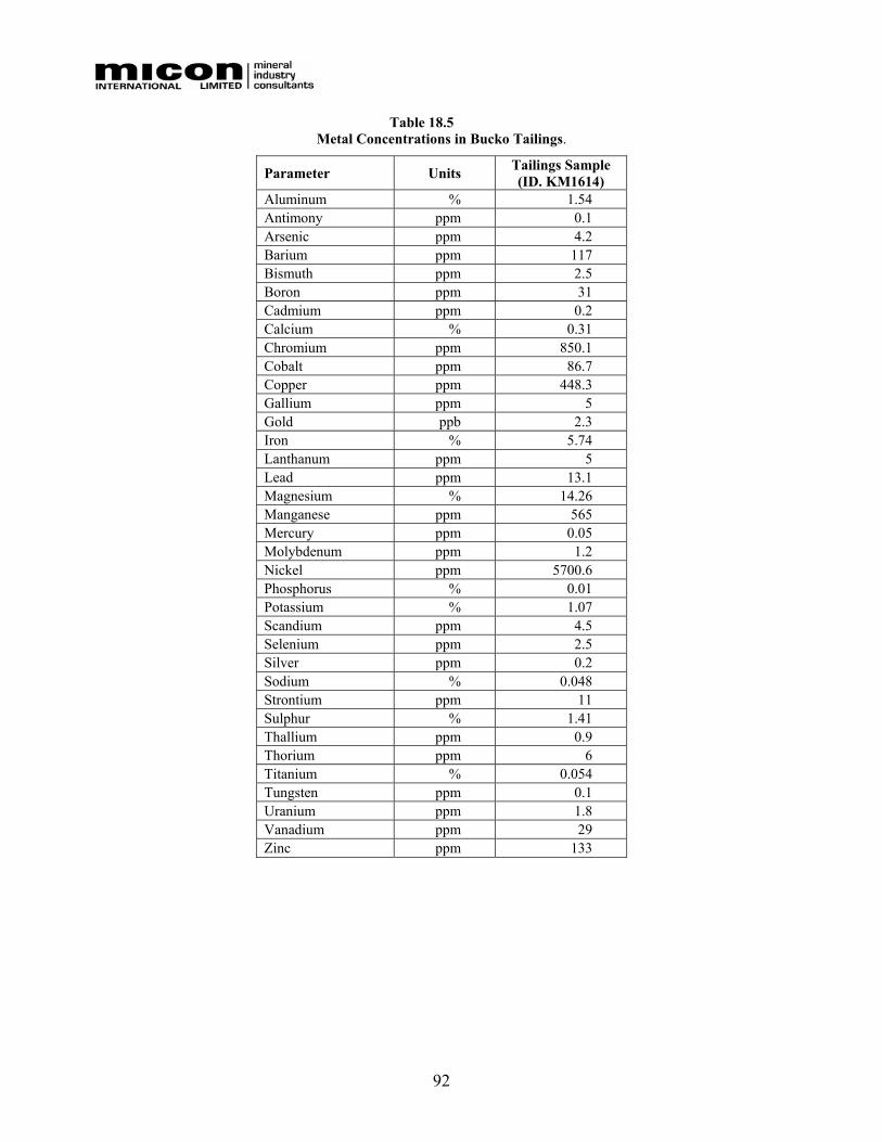
92
Table 18.5 Metal Concentrations in Bucko Tailings.
Parameter Units Tailings Sample (ID. KM1614)
Aluminum % 1.54 Antimony ppm 0.1 Arsenic ppm 4.2 Barium ppm 117 Bismuth ppm 2.5 Boron ppm 31 Cadmium ppm 0.2 Calcium % 0.31 Chromium ppm 850.1 Cobalt ppm 86.7 Copper ppm 448.3 Gallium ppm 5 Gold ppb 2.3 Iron % 5.74 Lanthanum ppm 5 Lead ppm 13.1 Magnesium % 14.26 Manganese ppm 565 Mercury ppm 0.05 Molybdenum ppm 1.2 Nickel ppm 5700.6 Phosphorus % 0.01 Potassium % 1.07 Scandium ppm 4.5 Selenium ppm 2.5 Silver ppm 0.2 Sodium % 0.048 Strontium ppm 11 Sulphur % 1.41 Thallium ppm 0.9 Thorium ppm 6 Titanium % 0.054 Tungsten ppm 0.1 Uranium ppm 1.8 Vanadium ppm 29 Zinc ppm 133
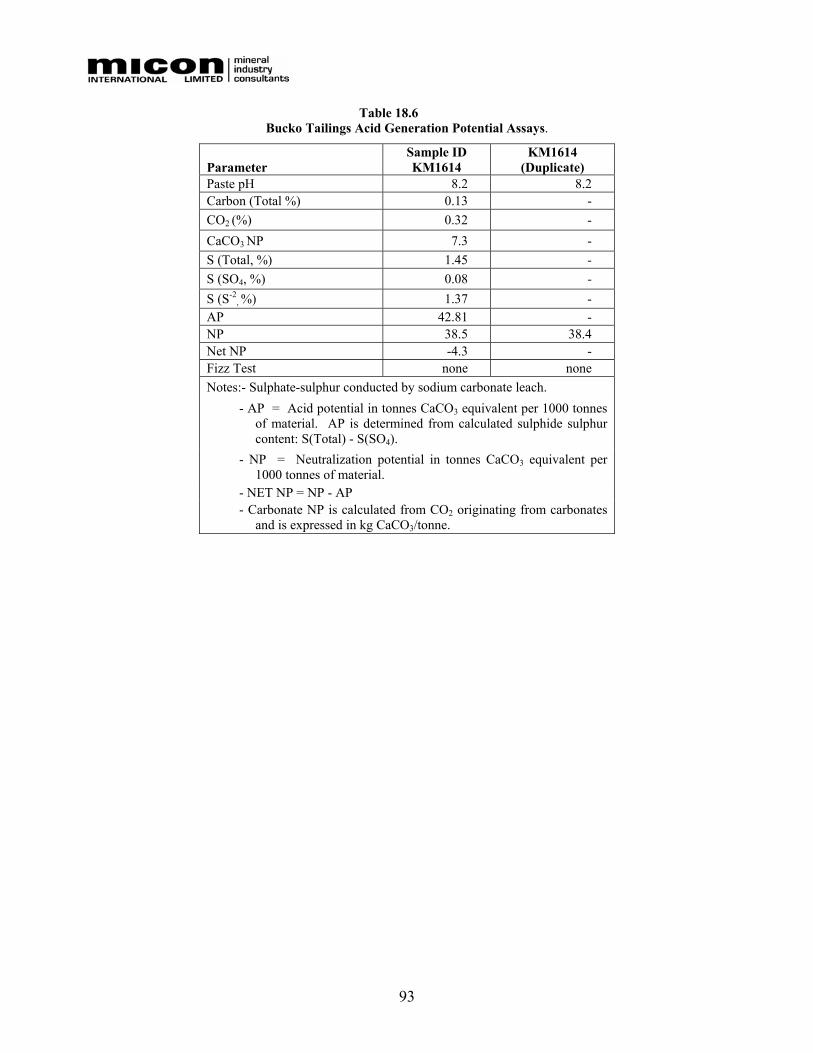
93
Table 18.6 Bucko Tailings Acid Generation Potential Assays.
Parameter Sample ID KM1614
KM1614 (Duplicate)
Paste pH 8.2 8.2 Carbon (Total %) 0.13 - CO2 (%) 0.32 - CaCO3 NP 7.3 - S (Total, %) 1.45 - S (SO4, %) 0.08 - S (S-2
, %) 1.37 - AP 42.81 - NP 38.5 38.4 Net NP -4.3 - Fizz Test none none Notes:- Sulphate-sulphur conducted by sodium carbonate leach.
- AP = Acid potential in tonnes CaCO3 equivalent per 1000 tonnes of material. AP is determined from calculated sulphide sulphur content: S(Total) - S(SO4).
- NP = Neutralization potential in tonnes CaCO3 equivalent per 1000 tonnes of material.
- NET NP = NP - AP - Carbonate NP is calculated from CO2 originating from carbonates
and is expressed in kg CaCO3/tonne.
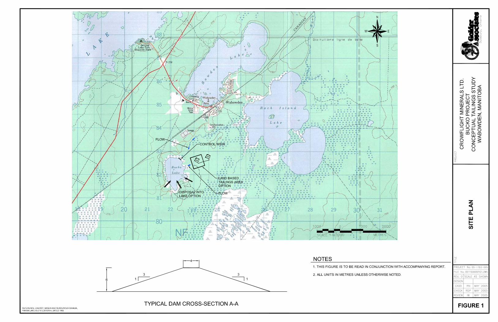
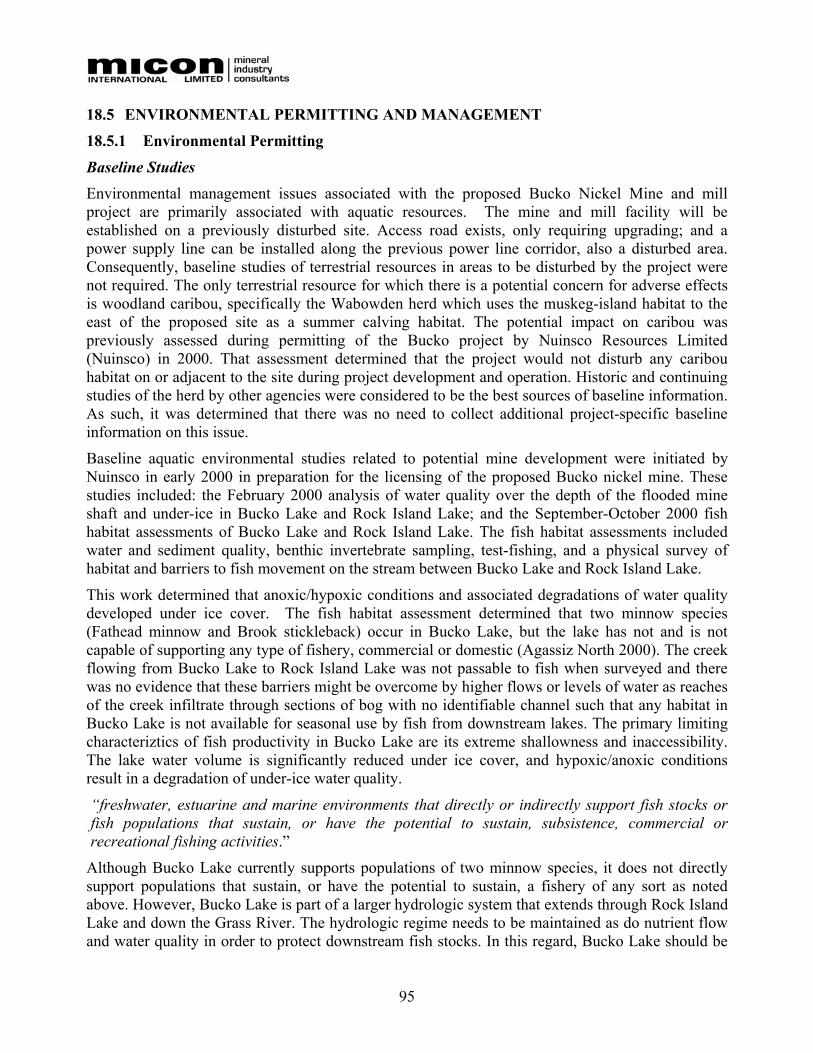
95
18.5 ENVIRONMENTAL PERMITTING AND MANAGEMENT
18.5.1 Environmental Permitting
Baseline Studies Environmental management issues associated with the proposed Bucko Nickel Mine and mill project are primarily associated with aquatic resources. The mine and mill facility will be established on a previously disturbed site. Access road exists, only requiring upgrading; and a power supply line can be installed along the previous power line corridor, also a disturbed area. Consequently, baseline studies of terrestrial resources in areas to be disturbed by the project were not required. The only terrestrial resource for which there is a potential concern for adverse effects is woodland caribou, specifically the Wabowden herd which uses the muskeg-island habitat to the east of the proposed site as a summer calving habitat. The potential impact on caribou was previously assessed during permitting of the Bucko project by Nuinsco Resources Limited (Nuinsco) in 2000. That assessment determined that the project would not disturb any caribou habitat on or adjacent to the site during project development and operation. Historic and continuing studies of the herd by other agencies were considered to be the best sources of baseline information. As such, it was determined that there was no need to collect additional project-specific baseline information on this issue.
Baseline aquatic environmental studies related to potential mine development were initiated by Nuinsco in early 2000 in preparation for the licensing of the proposed Bucko nickel mine. These studies included: the February 2000 analysis of water quality over the depth of the flooded mine shaft and under-ice in Bucko Lake and Rock Island Lake; and the September-October 2000 fish habitat assessments of Bucko Lake and Rock Island Lake. The fish habitat assessments included water and sediment quality, benthic invertebrate sampling, test-fishing, and a physical survey of habitat and barriers to fish movement on the stream between Bucko Lake and Rock Island Lake.
This work determined that anoxic/hypoxic conditions and associated degradations of water quality developed under ice cover. The fish habitat assessment determined that two minnow species (Fathead minnow and Brook stickleback) occur in Bucko Lake, but the lake has not and is not capable of supporting any type of fishery, commercial or domestic (Agassiz North 2000). The creek flowing from Bucko Lake to Rock Island Lake was not passable to fish when surveyed and there was no evidence that these barriers might be overcome by higher flows or levels of water as reaches of the creek infiltrate through sections of bog with no identifiable channel such that any habitat in Bucko Lake is not available for seasonal use by fish from downstream lakes. The primary limiting characteriztics of fish productivity in Bucko Lake are its extreme shallowness and inaccessibility. The lake water volume is significantly reduced under ice cover, and hypoxic/anoxic conditions result in a degradation of under-ice water quality.
“freshwater, estuarine and marine environments that directly or indirectly support fish stocks or fish populations that sustain, or have the potential to sustain, subsistence, commercial or recreational fishing activities.”
Although Bucko Lake currently supports populations of two minnow species, it does not directly support populations that sustain, or have the potential to sustain, a fishery of any sort as noted above. However, Bucko Lake is part of a larger hydrologic system that extends through Rock Island Lake and down the Grass River. The hydrologic regime needs to be maintained as do nutrient flow and water quality in order to protect downstream fish stocks. In this regard, Bucko Lake should be
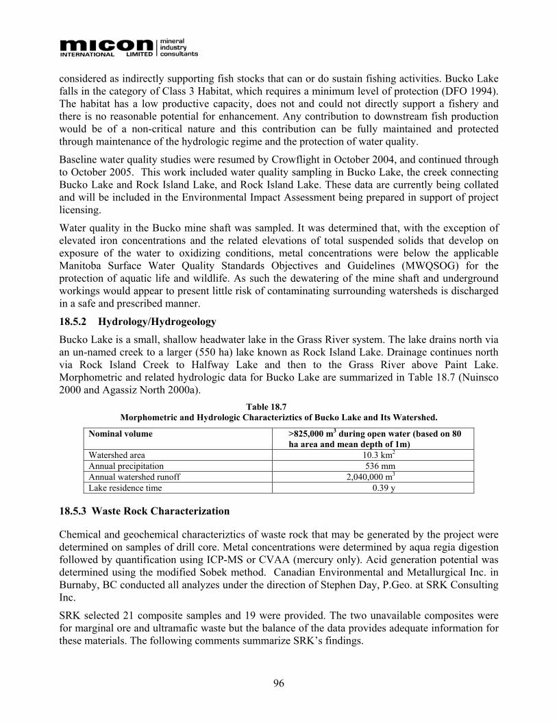
96
considered as indirectly supporting fish stocks that can or do sustain fishing activities. Bucko Lake falls in the category of Class 3 Habitat, which requires a minimum level of protection (DFO 1994). The habitat has a low productive capacity, does not and could not directly support a fishery and there is no reasonable potential for enhancement. Any contribution to downstream fish production would be of a non-critical nature and this contribution can be fully maintained and protected through maintenance of the hydrologic regime and the protection of water quality.
Baseline water quality studies were resumed by Crowflight in October 2004, and continued through to October 2005. This work included water quality sampling in Bucko Lake, the creek connecting Bucko Lake and Rock Island Lake, and Rock Island Lake. These data are currently being collated and will be included in the Environmental Impact Assessment being prepared in support of project licensing.
Water quality in the Bucko mine shaft was sampled. It was determined that, with the exception of elevated iron concentrations and the related elevations of total suspended solids that develop on exposure of the water to oxidizing conditions, metal concentrations were below the applicable Manitoba Surface Water Quality Standards Objectives and Guidelines (MWQSOG) for the protection of aquatic life and wildlife. As such the dewatering of the mine shaft and underground workings would appear to present little risk of contaminating surrounding watersheds is discharged in a safe and prescribed manner.
18.5.2 Hydrology/Hydrogeology Bucko Lake is a small, shallow headwater lake in the Grass River system. The lake drains north via an un-named creek to a larger (550 ha) lake known as Rock Island Lake. Drainage continues north via Rock Island Creek to Halfway Lake and then to the Grass River above Paint Lake. Morphometric and related hydrologic data for Bucko Lake are summarized in Table 18.7 (Nuinsco 2000 and Agassiz North 2000a).
Table 18.7 Morphometric and Hydrologic Characteriztics of Bucko Lake and Its Watershed.
Nominal volume >825,000 m3 during open water (based on 80 ha area and mean depth of 1m)
Watershed area 10.3 km2 Annual precipitation 536 mm Annual watershed runoff 2,040,000 m3 Lake residence time 0.39 y
18.5.3 Waste Rock Characterization
Chemical and geochemical characteriztics of waste rock that may be generated by the project were determined on samples of drill core. Metal concentrations were determined by aqua regia digestion followed by quantification using ICP-MS or CVAA (mercury only). Acid generation potential was determined using the modified Sobek method. Canadian Environmental and Metallurgical Inc. in Burnaby, BC conducted all analyzes under the direction of Stephen Day, P.Geo. at SRK Consulting Inc.
SRK selected 21 composite samples and 19 were provided. The two unavailable composites were for marginal ore and ultramafic waste but the balance of the data provides adequate information for these materials. The following comments summarize SRK’s findings.
97
The testing confirmed that earlier work performed for Nuinsco was erroneous when it indicated that a significant proportion of the sulphur was present as sulphate. The current results are consistent with the geology, which shows that sulphate is negligible. Use of nickel and copper concentrations to evaluate sulphide speciation shows, as indicated by the assay database, that the nickel sulphide association is significant in marginal ore and ultramafic waste but unimportant in the gneissic waste.
The rocks appear to contain some carbonate, probably at low levels of calcite in the gneissic waste rock and higher levels of calcite and magnesium carbonates in the ultramafic waste in marginal ore.
The findings on a rock-type basis were as follows:
• Waste Rock. The sulphide and metal content of waste rock is low, and the buffering capacity represented by carbonate is sufficient to offset the very low acid potential. Waste rock has low potential for acid rock drainage (ARD).
• UM Waste. This material seems to have variable characteriztics and the potential for ARD relies on whether the magnesium silicates will neutralize acid. It is possible that this could occur. Leaching of nickel from this material under non-acidic conditions could be important depending on whether nickel is associated with sulphides or silicates.
• Marginal Ore. This material is potentially ARD producing.
The waste rock and marginal ore management approaches described in Sections 18.1.10 and were developed on the basis of these findings.
18.5.4 Environmental Management Crowflight’s environmental management practices for the prevention of adverse environmental impacts are detailed below.
All site construction activities with the potential to introduce sediment to the Bucko drainage will be conducted in accordance with a sediment and erosion control plan. Any areas disturbed in site development will be stabilized or re-vegetated promptly.
Mine Water Management – Initial Development Mine water pumped during initial underground exploration and development will be passed through a two-cell settling pond prior to release into Bucko Lake. Based on the October 2004 sampling, the only water quality management issue related to mine dewatering is control of suspended solids generated by the oxidation of dissolved iron. All other metals occur in the mine water at concentrations below the MWQSOG for the protection of aquatic life and wildlife.
Mine Water Management - Operation During production and any period of care and maintenance, mine water will be directed to the tailings management area (TMA).
98
Tailings Management The Bucko tailings are potentially acid generating on the basis of acid-base accounting analysis on a bench scale tailings sample. Acid generation will be managed by underwater disposal and the maintenance of a permanent water cover.
Chemical analysis of the overlying wastewater from the bench scale tailings sample indicates that, after settling of suspended solids, no additional treatment of the wastewater will be necessary. Testing to date indicates the tailings effluent will meet the Metal Mining Effluent Regulations and the Manitoba Water Quality Standards Objectives and Guidelines for the protection of aquatic life and wildlife at the point of discharge.
Natural surface runoff to the tailings management area will be maintained in order to ensure adequate water cover. The water level in the tailings area will be managed within the natural range of variation and the lake outlet will be operated to substantially maintain the natural seasonal discharge pattern.
Sewage and Grey Water Sewage (black water) generated at the mine site is to be collected in septic holding tanks and treated in the septic tank and filtration bed system. A single facility is required. The design of this facility meets the Manitoba Ministry of the Environment requirements for an industrial usage installation. Special design and permitting of the installation will be required based on the number of employees and water usages to be treated.
Grey water production in the dry will be segregated from black water and directed to the tailings line for disposal in the TMA. The holding tank will require a permit under Manitoba Regulation 83/2003.
Crowflight will require special approval under Manitoba Regulation 83/2003 in order to direct grey water to the tailings management area.
Runoff Management Site runoff will be directed to the Bucko Lake tailings management area. A perimeter runoff diversion ditch will be developed around the mine site to divert clean surface runoff into the TMA.
Miscellaneous Site Environmental Management
Explosives will be delivered directly to the head-frame and then will be transported immediately to the underground designated storage locations. No explosive will be stored on surface. Management of explosive use and blasting practices will ensure ammonia nitrate levels in the mine discharge water will remain below accepted discharge limits.
Bulk quantities of petroleum hydrocarbons will be stored and handled in accordance with Manitoba Regulation 188/2001 and any subsequent amendments.
Used oil and oil filters will be collected and periodically returned to a licensed facility for recycling.
Used batteries will be collected and periodically returned to a licensed facility for recycling.
Used tires will be collected and periodically returned to a licensed facility for recycling
All other solid waste will be collected and disposed of at the Wabowden waste disposal grounds.
99
Emergency Response Plan An emergency response plan, detailed procedures to be followed in the event of systems failures, tailings or reclaim line rupture, leaks or spills of hazardous or dangerous materials, fire, or other potential site emergency are required and will be developed prior to the start of operations.
Monitoring Crowflight will develop and implement environmental monitoring programs to address its regulatory obligations under the Manitoba Environment Act License for the project and the Metal Mining Effluent Regulations (MMER) of the Fisheries Act.
Air Quality Environment Act Licenses for mining projects in Manitoba typically include a requirement to demonstrate that the mine is not a source of nuisance dusts or other particulate contaminants. A periodic (typically varying in frequency from one time to annual depending on-site-specific issues) quantitative dust monitoring program is necessary to make this demonstration. For the purpose of this estimate it has been assumed that an air study would be conducted in each of operating years 1 and 4.
Waste Rock Acid-Base Accounting The License is likely to require that any waste rock permanently brought to surface either for disposal on surface or for use as a construction material be tested for acid generation potential. A typical testing frequency is once every 5,000 tonnes.
Effluent Quality The effluent quality monitoring obligations of the project Environment Act License are expected to be similar, but not identical, to the MMER monitoring requirements. In addition to the MMER parameters (pH, TSS, deleterious substances, acute toxicity), Manitoba is likely to require measurement of dissolved metals and of total and dissolved phosphorus.
Receiving Waters Based on the monitoring requirements of Environment Act licenses for other metal mines in Manitoba, including the license for mining at Bucko Lake issued to Nuinsco in 2000, regular monitoring of receiving water quality can be expected to be required. Monitoring of receiving water quality near the inlet and outlet of Rock Island Lake are expected to be required on a quarterly basis.
Periodic (typically once every three years) sampling of sediment chemistry (metals, TOC, moisture content) and of benthic invertebrates at these locations also is likely to be required.
Fisheries Act Metal Mining Effluent Regulations (MMER) The project will be subject to the effluent quality and Environmental Effects Monitoring requirements stipulated in the Metal Mining Effluent Regulations of the Fisheries Act. For cost estimation purposes at feasibility, the following assumptions were employed:
• Effluent monitoring conducted as per regulations at maximum specified frequency for the duration of mine life (i.e., pH, TSS, and deleterious substances weekly; acute toxicity monthly; chronic toxicity twice yearly; effluent characterization four times per year).
100
• Environmental Effects Monitoring (receiving water quality and biological studies) at maximum specified frequency and requiring all of a benthic invertebrate study, a fish population study and a fish tissue study.
• Emergency Response Planning – the MMER include a specific requirement for an emergency response plan that is regularly reviewed and updated as the project evolves.
The cost of the biological studies was based on the recommended minimum numbers of samples for benthos, fish, and fish tissue as set out in the EEM Guidance Manual (Environment Canada 2002).
18.5.5 Closure Considerations Mine site closure will involve the removal of all equipment and the dismantling/demolition of all buildings. All hazardous materials will be removed from the site. Concrete foundations will be demolished to near ground level and then covered with waste rock and seeded. The power line will be removed. The road will be decommissioned by removing all culverts, scarifying the surface and seeding.
The project will generate two types of waste rock: gneissic and ultramafic. The gneissic waste is net acid consuming based on acid-base accounting and can be disposed of on surface. Gneissic waste will be used for construction purposes on-site or made available for other local construction uses. Representative samples of any waste used for construction, released for use offsite, or permanently disposed of on surface will be tested for acid generation potential. No potentially acid-generating materials will be managed or disposed of on surface, used for construction on-site, or released for off-site use.
The ultramafic rock is potentially acid generating and no permanent stockpiles will be developed on surface. This rock type will be used as backfill in the mine to the extent possible and any material brought to surface will either be milled or directly disposed of in the tailings management area.
The tailings are potentially acid generating and will require a permanent water cover with a minimum depth of 0.5 m to maintain anoxic conditions below the surface of the tailings for the prevention of sulphide oxidation. On closure, the Bucko Lake tailings management area will be reclaimed to achieve a state similar to the present condition, open water with perimeter emergent vegetation. The outlet dam and weir would be left in place with the overflow spillway height adjusted to maintain the planned post-closure water level.
18.5.6 Permitting Requirements The project has a current Manitoba Environment Act License for advanced stage exploration. This license permits rehabilitation and upgrading of the access road, dewatering of the underground workings, erection of a head-frame, rehabilitation of the shaft, underground exploration drilling and mining of a bulk sample.
A Manitoba Environment Act License is required to take the project into operation and must be issued prior to the start of construction of surface facilities. The project is a Class 2 development under the Act and the license proposal will need to be accompanied by a comprehensive Environmental Impact Assessment (EIA).
In addition, the following permits/licenses will be required:
• Water rights license – fresh water well (Manitoba Regulation 126/87).
101
• Water rights license – for water withdrawal and recycle from Bucko Lake (Manitoba Regulation 126/87).
• Water rights license – for construction and operation of the Bucko Lake outlet control weir (Manitoba Regulation 126/87).
• Septic holding tank permit – for installation and operation of the minesite wastewater holding tank (Manitoba Regulation 83/2003).
• Petroleum storage tanks – permits are required both for the construction/installation and operation of petroleum storage tanks with a capacity of 5000 L or more (Manitoba Regulation 188/2001).
Any impact assessment/mitigation matters that may be associated with the above will be addressed in the EIA.
Crowflight also will be required to register as a Hazardous Waste Generator under Manitoba Regulation before they will be permitted to commence production.
18.5.7 Environmental References
• Agassiz North Associates Limited. 2000a. Nuinsco Resources – Bucko Project. Response to Manitoba Conservation, Project Impacts on Woodland Caribou. Report prepared for Nuinsco Resources, Toronto, ON, 29 November 2000.
• Agassiz North Associates Limited. 2000b. Nuinsco Resources – Bucko Project. Mine Water Quality Investigation. Report prepared for Nuinsco Resources, Toronto, ON, 12 May 2000.
• Agassiz North Associates Limited. 2000c. Nuinsco Resources – Bucko Project. Bucko Lake Aquatic Habitat Assessment (Draft). Report prepared for Nuinsco Resources, Toronto, ON, 30 November 2000.
• Department of Fisheries and Oceans (DFO). 1994. Habitat conservation and protection guidelines: First edition. Department of Fisheries and Oceans, Ottawa.
• Environment Canada. 2002. Metal Mining Guidance Document for Aquatic Environmental Effects Monitoring. Environment Canada, Ottawa.
• Nuinsco Resources Limited. 2000. Bucko Lake Project, Wabowden, Manitoba. Proposal for the Development and Operation of an Underground Nickel Mine Under the Manitoba Environment Act. Report prepared by Laxey Mining Services, Inc., in collaboration with Agassiz North Associates Limited for Nuinsco Resources Limited, Toronto, ON, May 12, 2000.
18.6 PROJECT IMPLEMENTATION
18.6.1 Project Schedule
The project implementation schedule, which is shown in the Gantt chart (Figure 18.9), has been developed to achieve full production within approximately 19 months of project approval.
Principal assumptions at this time are that project permitting and financing activities are completed prior to any construction activities at the site. The "go ahead" date is defined as the date that the feasibility study is completed, this date is assumed to be at the end of December 2005.
102
18.6.2 Project Priorities and Milestones The initial project priorities that will be critical to meet the schedule, and in some cases capital cost projections, are as follows:
Permanent Power To be provided to the site as quickly as possible. This will minimize the need for temporary power during the construction period, significantly more expensive than permanent power. The early provision of permanent power will be especially critical for the underground development as the power requirements of the electric hydraulic drill jumbos and fans are quite large.
Procure Long Delivery Items Initially, basic engineering will need to focus on the preparation and issue of specifications for long delivery items such as ball mills, filters and electrical transformers.
Used Equipment It is important to begin the search for suitable used equipment that could be substituted for certain new equipment items at a savings early in the development timeline in order to permit sufficient time for refurbishment, or ordering of new equipment if suitable used equipment is not found.
Site Geotechnical Testwork Further geotechnical test pits and bore holes will be required as the basis for detailed design of the plant. These should be completed early in the schedule.
18.6.3 Mine Rehabilitation and Development The hoist and head-frame will be purchased, refurbished, transported to site and installed by August 2006. Assuming the main power distribution system is available, the existing shaft will be dewatered and refurbished by the end of December 2006.
Following the existing mine refurbishment, development will commence in earnest and ore production will be available by the end of March 2007.
18.6.4 Mill Construction Period The construction period will span approximately 12 months followed an additional month for commissioning and start-up.
The construction effort will require approximately 82,000 direct labour man-hours over the 12-month period. A peak manpower level of 70 construction workers and associated staff will be reached during second month of construction and maintained for about 3 ½ months.
18.6.5 Quality Assurance and Quality Control (QA/QC)
QA/QC programs will be established for all aspects of the project to ensure that the facilities are constructed in accordance with the project design documents and all prevailing health, safety and environmental regulations.
The implementation team will retain the services of a geotechnical consultant to conduct a QA/QC program on behalf of the project. Surveying services will be required for surface construction. An outside contractor on an as-required basis will provide surveying services required for civil construction, QA/QC and contract administration.

103
18.6.6 Commissioning and Start-up As final designs are completed, detailed commissioning and start-up plans will be developed for all elements of the project. Commissioning of the facilities will be conducted throughout the implementation phase as each facility is completed and readied for service
18.6.7 Gantt Chart A Gantt chart showing the main project activities throughout the schedule is included in Figure 18.9.
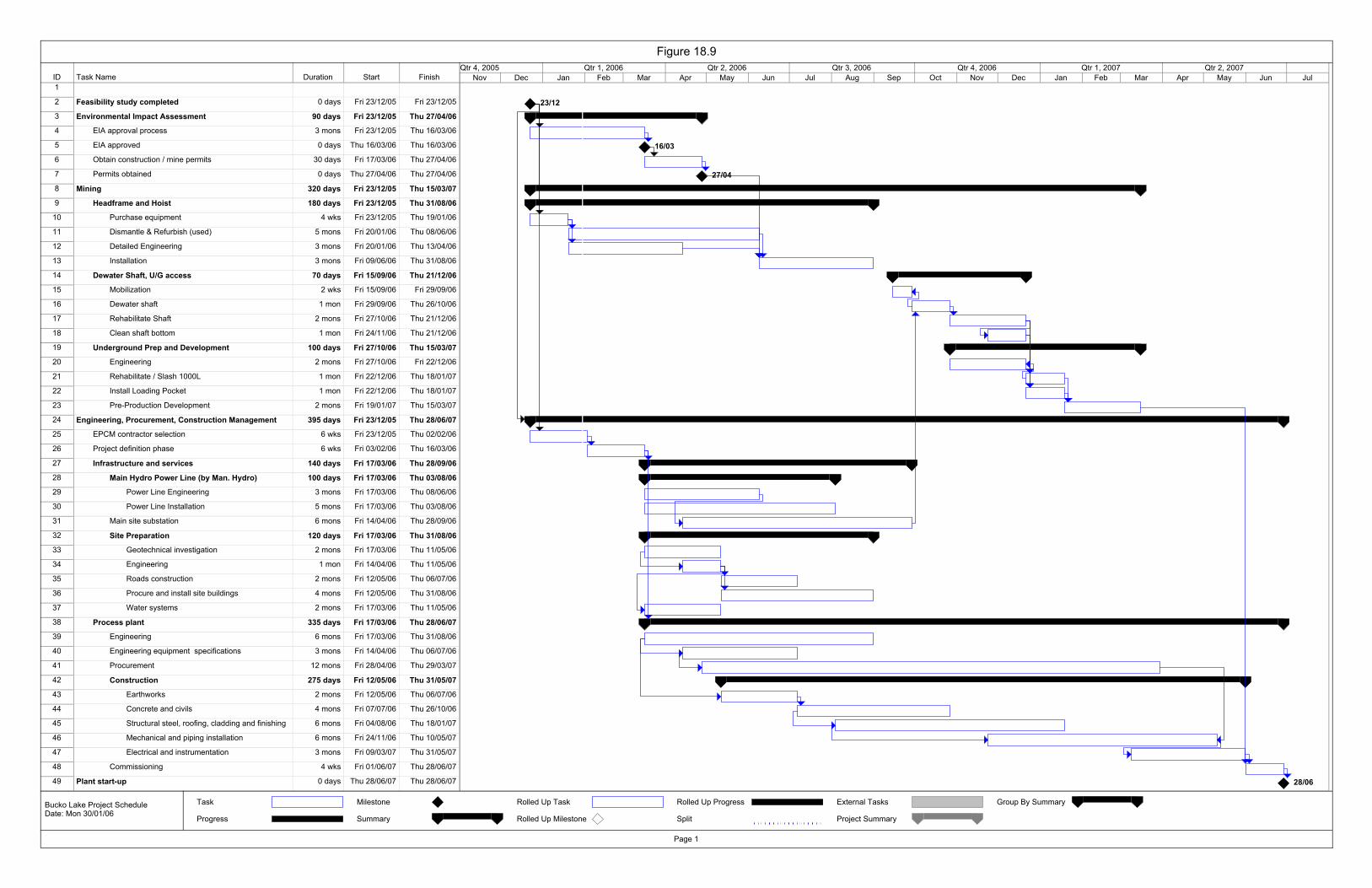
ID Task Name Duration Start Finish1
2 Feasibility study completed 0 days Fri 23/12/05 Fri 23/12/05
3 Environmental Impact Assessment 90 days Fri 23/12/05 Thu 27/04/06
4 EIA approval process 3 mons Fri 23/12/05 Thu 16/03/06
5 EIA approved 0 days Thu 16/03/06 Thu 16/03/06
6 Obtain construction / mine permits 30 days Fri 17/03/06 Thu 27/04/06
7 Permits obtained 0 days Thu 27/04/06 Thu 27/04/06
8 Mining 320 days Fri 23/12/05 Thu 15/03/07
9 Headframe and Hoist 180 days Fri 23/12/05 Thu 31/08/06
10 Purchase equipment 4 wks Fri 23/12/05 Thu 19/01/06
11 Dismantle & Refurbish (used) 5 mons Fri 20/01/06 Thu 08/06/06
12 Detailed Engineering 3 mons Fri 20/01/06 Thu 13/04/06
13 Installation 3 mons Fri 09/06/06 Thu 31/08/06
14 Dewater Shaft, U/G access 70 days Fri 15/09/06 Thu 21/12/06
15 Mobilization 2 wks Fri 15/09/06 Fri 29/09/06
16 Dewater shaft 1 mon Fri 29/09/06 Thu 26/10/06
17 Rehabilitate Shaft 2 mons Fri 27/10/06 Thu 21/12/06
18 Clean shaft bottom 1 mon Fri 24/11/06 Thu 21/12/06
19 Underground Prep and Development 100 days Fri 27/10/06 Thu 15/03/07
20 Engineering 2 mons Fri 27/10/06 Fri 22/12/06
21 Rehabilitate / Slash 1000L 1 mon Fri 22/12/06 Thu 18/01/07
22 Install Loading Pocket 1 mon Fri 22/12/06 Thu 18/01/07
23 Pre-Production Development 2 mons Fri 19/01/07 Thu 15/03/07
24 Engineering, Procurement, Construction Management 395 days Fri 23/12/05 Thu 28/06/07
25 EPCM contractor selection 6 wks Fri 23/12/05 Thu 02/02/06
26 Project definition phase 6 wks Fri 03/02/06 Thu 16/03/06
27 Infrastructure and services 140 days Fri 17/03/06 Thu 28/09/06
28 Main Hydro Power Line (by Man. Hydro) 100 days Fri 17/03/06 Thu 03/08/06
29 Power Line Engineering 3 mons Fri 17/03/06 Thu 08/06/06
30 Power Line Installation 5 mons Fri 17/03/06 Thu 03/08/06
31 Main site substation 6 mons Fri 14/04/06 Thu 28/09/06
32 Site Preparation 120 days Fri 17/03/06 Thu 31/08/06
33 Geotechnical investigation 2 mons Fri 17/03/06 Thu 11/05/06
34 Engineering 1 mon Fri 14/04/06 Thu 11/05/06
35 Roads construction 2 mons Fri 12/05/06 Thu 06/07/06
36 Procure and install site buildings 4 mons Fri 12/05/06 Thu 31/08/06
37 Water systems 2 mons Fri 17/03/06 Thu 11/05/06
38 Process plant 335 days Fri 17/03/06 Thu 28/06/07
39 Engineering 6 mons Fri 17/03/06 Thu 31/08/06
40 Engineering equipment specifications 3 mons Fri 14/04/06 Thu 06/07/06
41 Procurement 12 mons Fri 28/04/06 Thu 29/03/07
42 Construction 275 days Fri 12/05/06 Thu 31/05/07
43 Earthworks 2 mons Fri 12/05/06 Thu 06/07/06
44 Concrete and civils 4 mons Fri 07/07/06 Thu 26/10/06
45 Structural steel, roofing, cladding and finishing 6 mons Fri 04/08/06 Thu 18/01/07
46 Mechanical and piping installation 6 mons Fri 24/11/06 Thu 10/05/07
47 Electrical and instrumentation 3 mons Fri 09/03/07 Thu 31/05/07
48 Commissioning 4 wks Fri 01/06/07 Thu 28/06/07
49 Plant start-up 0 days Thu 28/06/07 Thu 28/06/07
23/12
16/03
27/04
28/06
Nov Dec Jan Feb Mar Apr May Jun Jul Aug Sep Oct Nov Dec Jan Feb Mar Apr May Jun JulQtr 4, 2005 Qtr 1, 2006 Qtr 2, 2006 Qtr 3, 2006 Qtr 4, 2006 Qtr 1, 2007 Qtr 2, 2007
Task
Progress
Milestone
Summary
Rolled Up Task
Rolled Up Milestone
Rolled Up Progress
Split
External Tasks
Project Summary
Group By Summary
Figure 18.9
Page 1
Bucko Lake Project ScheduleDate: Mon 30/01/06
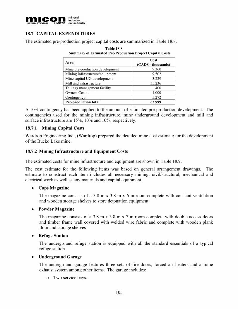
105
18.7 CAPITAL EXPENDITURES The estimated pre-production project capital costs are summarized in Table 18.8.
Table 18.8 Summary of Estimated Pre-Production Project Capital Costs
Area Cost (CAD$ - thousands)
Mine pre-production development 9,360 Mining infrastructure/equipment 9,502 Mine capital UG development 3,229 Mill and infrastructure 35,236 Tailings management facility 400 Owners Costs 1,000 Contingency 5,272 Pre-production total 63,999
A 10% contingency has been applied to the amount of estimated pre-production development. The contingencies used for the mining infrastructure, mine underground development and mill and surface infrastructure are 15%, 10% and 10%, respectively.
18.7.1 Mining Capital Costs Wardrop Engineering Inc., (Wardrop) prepared the detailed mine cost estimate for the development of the Bucko Lake mine.
18.7.2 Mining Infrastructure and Equipment Costs
The estimated costs for mine infrastructure and equipment are shown in Table 18.9.
The cost estimate for the following items was based on general arrangement drawings. The estimate to construct each item includes all necessary mining, civil/structural, mechanical and electrical work as well as any materials and capital equipment.
• Caps Magazine The magazine consists of a 3.8 m x 3.8 m x 6 m room complete with constant ventilation and wooden storage shelves to store detonation equipment.
• Powder Magazine The magazine consists of a 3.8 m x 3.8 m x 7 m room complete with double access doors and timber frame wall covered with welded wire fabric and complete with wooden plank floor and storage shelves
• Refuge Station The underground refuge station is equipped with all the standard essentials of a typical refuge station.
• Underground Garage The underground garage features three sets of fire doors, forced air heaters and a fume exhaust system among other items. The garage includes:
o Two service bays.
106
o One welding bay.
o One sump.
o One wash bay.
o Two storage bays.
• Fuelling Station The underground fuelling station is complete with dispensing equipment, containment area and sprinkler system. The fuelling station features a ventilation system and roll up fire door equipped with two fusible links.
• Truck Dump The underground truck dump consists primarily of a 4.2 m x 5.2 m grizzly and associated installation steel and concrete.
• Loading Pocket The loading pocket consists of two 5-tonne capacity measuring boxes complete with associated chutes and controls.
• Main Sump The main sump design comprises essentially one submersible and one surface pump. One duty and one spare borehole have also been included in the materials list.
• Vent Raise Manway The vent raise extends from surface down to the 1600 Level. The materials estimate for the vent raise is based on the total weight of steel required to construct the raise. A weight of 82 kg (181 lb.) per linear metre of raise is used in the estimate.
• Ventilation System The main mine ventilation is provided through the shaft. A main exhaust fan is located on the exhaust raise connected from surface to the 400 Level. A ducting system and propane heaters are located adjacent to the shaft to supply adequate intake air at a rate of 57 m3/s (120,000 cfm) to the underground workings. The ventilation flow is routed down the shaft to the 1000 Level, down a raise to the lowest working level and up the ramp to the 500 Level vent raise, then to the 400 Level and along the 400 Level and up the main exhaust raise to surface. A set of steel doors on the 400 Level separates the intake shaft ventilation from the exhaust conduit. Throughout the workings, ventilation is supplied with 36 inch, 50 HP powered ventilation fans and flexible tubing.
• Compressed Air Compressed air is supplied from surface compressors located in the hoist house, directed underground in 150 mm steel pipes in the shaft and ramp system and 100 mm pipe in the workings.
• Process / Mine Water

107
Process water is distributed underground in a parallel system (to the compressed air) comprising 100 mm and 50 mm diameter piping. Water for mine use will initially be pumped from Bucko Lake. After mill start up, water will be supplied by reclaimed mine water diluted with fresh water pumped from a borehole.
Underground mine water is collected in clean water sumps on levels 1000, 1500 and 400. The 1500 Level sump pump delivers mine water to the 1000 Level, which pumps to the 400 Level sump and the 400 Level pump delivers the mine water to surface settling ponds. A portion of the clean water is reused in the mine and the excess is sent to the mill or tailings basin. Throughout the mine, water is collected on each level and directed with boreholes to the sump system to maintain pumping efficiency. The system incorporates high head clean water pumps at the main collection stations and air driven diaphragm pumps in the workings.
• Hydraulic Backfill Hydraulic backfill is distributed from the plant (located on surface) to the stopes underground via a system of boreholes and 80 mm diameter HDPE piping. The planned solids concentration of the backfill is 70% by weight (+/-3%), and the design fill rate is 40 dry t/h (+/- 10%). Only one stope will be backfilled at a time. Diversion to the different stopes will be achieved by removing the lateral piping.
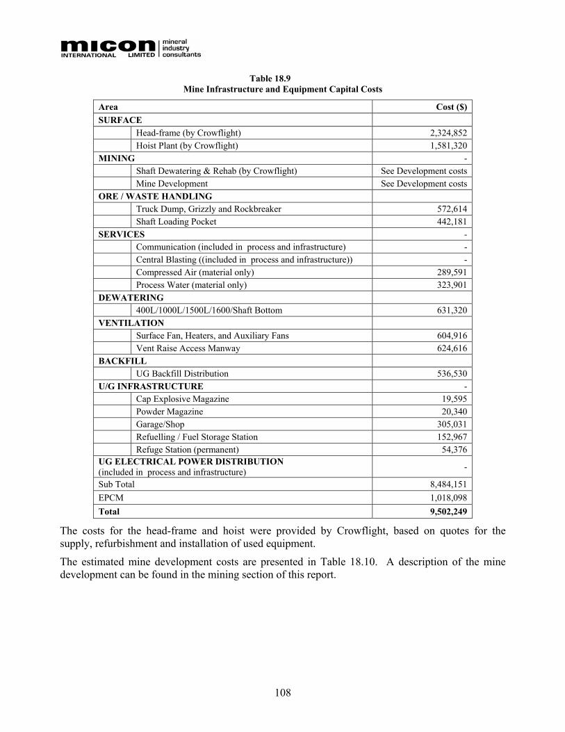
108
Table 18.9 Mine Infrastructure and Equipment Capital Costs
Area Cost ($) SURFACE Head-frame (by Crowflight) 2,324,852 Hoist Plant (by Crowflight) 1,581,320 MINING - Shaft Dewatering & Rehab (by Crowflight) See Development costs Mine Development See Development costs ORE / WASTE HANDLING
Truck Dump, Grizzly and Rockbreaker 572,614 Shaft Loading Pocket 442,181
SERVICES - Communication (included in process and infrastructure) - Central Blasting ((included in process and infrastructure)) - Compressed Air (material only) 289,591 Process Water (material only) 323,901
DEWATERING 400L/1000L/1500L/1600/Shaft Bottom 631,320 VENTILATION Surface Fan, Heaters, and Auxiliary Fans 604,916 Vent Raise Access Manway 624,616 BACKFILL UG Backfill Distribution 536,530 U/G INFRASTRUCTURE -
Cap Explosive Magazine 19,595 Powder Magazine 20,340 Garage/Shop 305,031 Refuelling / Fuel Storage Station 152,967 Refuge Station (permanent) 54,376
UG ELECTRICAL POWER DISTRIBUTION (included in process and infrastructure) -
Sub Total 8,484,151 EPCM 1,018,098 Total 9,502,249
The costs for the head-frame and hoist were provided by Crowflight, based on quotes for the supply, refurbishment and installation of used equipment.
The estimated mine development costs are presented in Table 18.10. A description of the mine development can be found in the mining section of this report.
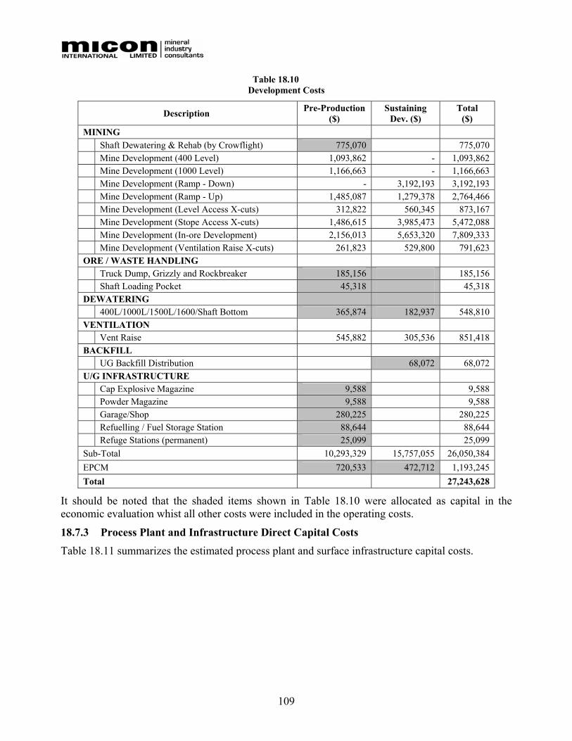
109
Table 18.10 Development Costs
Description Pre-Production ($)
Sustaining Dev. ($)
Total ($)
MINING Shaft Dewatering & Rehab (by Crowflight) 775,070 775,070 Mine Development (400 Level) 1,093,862 - 1,093,862 Mine Development (1000 Level) 1,166,663 - 1,166,663 Mine Development (Ramp - Down) - 3,192,193 3,192,193 Mine Development (Ramp - Up) 1,485,087 1,279,378 2,764,466 Mine Development (Level Access X-cuts) 312,822 560,345 873,167 Mine Development (Stope Access X-cuts) 1,486,615 3,985,473 5,472,088 Mine Development (In-ore Development) 2,156,013 5,653,320 7,809,333 Mine Development (Ventilation Raise X-cuts) 261,823 529,800 791,623 ORE / WASTE HANDLING Truck Dump, Grizzly and Rockbreaker 185,156 185,156 Shaft Loading Pocket 45,318 45,318
DEWATERING 400L/1000L/1500L/1600/Shaft Bottom 365,874 182,937 548,810 VENTILATION Vent Raise 545,882 305,536 851,418 BACKFILL UG Backfill Distribution 68,072 68,072 U/G INFRASTRUCTURE Cap Explosive Magazine 9,588 9,588 Powder Magazine 9,588 9,588 Garage/Shop 280,225 280,225 Refuelling / Fuel Storage Station 88,644 88,644 Refuge Stations (permanent) 25,099 25,099
Sub-Total 10,293,329 15,757,055 26,050,384 EPCM 720,533 472,712 1,193,245 Total 27,243,628
It should be noted that the shaded items shown in Table 18.10 were allocated as capital in the economic evaluation whist all other costs were included in the operating costs.
18.7.3 Process Plant and Infrastructure Direct Capital Costs
Table 18.11 summarizes the estimated process plant and surface infrastructure capital costs.
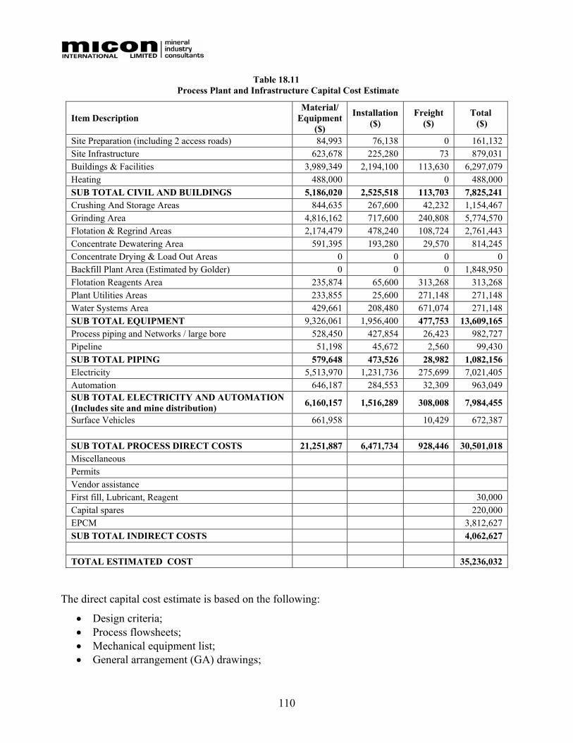
110
Table 18.11 Process Plant and Infrastructure Capital Cost Estimate
Item Description Material/
Equipment ($)
Installation ($)
Freight ($)
Total ($)
Site Preparation (including 2 access roads) 84,993 76,138 0 161,132 Site Infrastructure 623,678 225,280 73 879,031 Buildings & Facilities 3,989,349 2,194,100 113,630 6,297,079 Heating 488,000 0 488,000 SUB TOTAL CIVIL AND BUILDINGS 5,186,020 2,525,518 113,703 7,825,241 Crushing And Storage Areas 844,635 267,600 42,232 1,154,467 Grinding Area 4,816,162 717,600 240,808 5,774,570 Flotation & Regrind Areas 2,174,479 478,240 108,724 2,761,443 Concentrate Dewatering Area 591,395 193,280 29,570 814,245 Concentrate Drying & Load Out Areas 0 0 0 0 Backfill Plant Area (Estimated by Golder) 0 0 0 1,848,950 Flotation Reagents Area 235,874 65,600 313,268 313,268 Plant Utilities Areas 233,855 25,600 271,148 271,148 Water Systems Area 429,661 208,480 671,074 271,148 SUB TOTAL EQUIPMENT 9,326,061 1,956,400 477,753 13,609,165 Process piping and Networks / large bore 528,450 427,854 26,423 982,727 Pipeline 51,198 45,672 2,560 99,430 SUB TOTAL PIPING 579,648 473,526 28,982 1,082,156 Electricity 5,513,970 1,231,736 275,699 7,021,405 Automation 646,187 284,553 32,309 963,049 SUB TOTAL ELECTRICITY AND AUTOMATION (Includes site and mine distribution) 6,160,157 1,516,289 308,008 7,984,455
Surface Vehicles 661,958 10,429 672,387 SUB TOTAL PROCESS DIRECT COSTS 21,251,887 6,471,734 928,446 30,501,018 Miscellaneous Permits Vendor assistance First fill, Lubricant, Reagent 30,000 Capital spares 220,000 EPCM 3,812,627 SUB TOTAL INDIRECT COSTS 4,062,627 TOTAL ESTIMATED COST 35,236,032
The direct capital cost estimate is based on the following:
• Design criteria; • Process flowsheets; • Mechanical equipment list; • General arrangement (GA) drawings;
111
• Single line electrical drawings; • Budget quotations from vendors and contractors; and • New equipment.
The battery limits of this cost estimate include the overall mine site for the electrical work, the mine site preparation, the surface facilities for civil and building works and full coverage for the process plant. The process plant limits start at the coarse ore feeder under the coarse ore storage bin, and end at the tailings pipeline exit at the Bucko Lake disposal area (initial discharge point location).
Mine site preparation (clearing, grubbing and grading), and secondary roads quantity requirements were taken off a plot plan drawing (site layout), taking into account the thin depth of mine site overburden.
Unit costs for earthworks were obtained from short assembly cost lines of R. S. Means’ “2005 Building Construction Cost Data”.
Prices for process equipment were obtained from budgetary quotes received from suppliers. All costs are given in Canadian currency. An exchange rate of CAD$ 1.00 = US$ 0.82 was used to convert quotes received in US currency. Quotations were received from potential suppliers for all major equipment. Approximately 93% of the total equipment value is based on quotations; the rest was extracted from Met-Chem’s database.
In plant “large bore” piping (>1 ½ inch) quantities were taken from process plant general arrangement drawings. Overland process piping was taken off the plot plan drawing. This take off procedure yields quantities and size for pipes, valves, couplings, fittings and supports.
Piping system material pricing for “large bore” pipe lines was obtained from a recent price list provided by a piping supplier while installation hours come from Met-Chem in-house database. A “small bore” piping system cost allowance was developed by deducting the “large bore” piping system cost from the global process plant piping cost obtained by the process area factoring method. This “small bore” piping estimated cost was cross checked with Met-Chem in-house “small bore/large bore” piping cost ratio for the same mineral process plant sizes.
Major electrical equipment quantities were calculated from single line diagrams and layout arrangements. Costs were received from potential suppliers. Installation man-hours were estimated based on Met-Chem in-house database for similar projects. The general electrical costs were calculated on a per motor basis per sector. Motor quantities were calculated from the mechanical equipment list and the single line diagram. The total general electrical cost includes supply and installation of miscellaneous electrical equipment such as trays, cables, junction boxes, etc.
Major instrumentation/automation equipment quantities were calculated from the control system architecture diagram and the instrument list. Costs and installation man-hours were estimated based on Met-Chem in-house database for similar projects. The general automation costs were calculated on a per I/O basis per sector. I/O quantities were calculated from the instrument list.
The quantity requirement for each construction material (steel, concrete and architectural products) was taken off the general arrangement drawings.
For construction materials, unit prices were obtained from local contractors for most of construction material, namely:
• Concrete in place.

112
• Structural steel. • Ladders, stairs with handrail. • Steel platforms, decks & gratings. • Handrails.
For other materials, according to the different applications, cost lines were obtained from R. S. Means’ “2005 Building Construction Cost Data”. These cost lines enable Met Chem to develop material unit costs and the required crew installation hours per material unit. The materials that were costed in this manner are:
• Backfill. • Steel roofing & siding. • Doors & windows c/w frames. • Concrete blocks.
Labour base rates were obtained from a local contractor. For this remote northern construction-site, a construction schedule of 70 hours per week at 10 hours per day was adopted. Taking in account this schedule and computing an average base labour rate from the pool of trade unit costs an all-in labour hour cost was developed. This all-in labour cost included the following items:
• Base labour wage rate. • Benefits and burdens. • Workers’ compensation premiums. • Direct supervision, site personnel. • Contractor site establishment and equipment (including small tools and consumables). • Major cranes. • Contractor’s overhead & profit.
The resulting all-in labour rate used is CAD$80 per hour.
The North American productivity factor was used. The installation hours for mechanical, piping, electrical and instrumentation trades were obtained from Met-Chem’s in-house database.
A factor of 5% of procurement cost was used to allow for inland freight for all equipment and material. The exception to this was where a supplier’s quote included the freight.
18.7.4 Process Plant and Infrastructure Indirect Capital Costs
The cost for EPCM services is not a quotation from Met-Chem, but rather an indicative cost for the services of an EPCM provider. This cost is not a straight factor applied to the equipment cost and its installation because some very expensive pieces of equipment would distort the factoring. However, the specifications and construction bid packages do represent an estimated 15% of the value of the equipment. The overall factor becomes 12.4% when considering all the scope of work associated with the EPCM work.
The contingency also was not taken at a fixed percentage of the value of the project, but rather analyzed on an item-by-item basis. For example, quotations received for the mobile equipment should not receive more than 5% contingency, and this covers only cases where a special requirement would have been forgotten. On a similar basis, the contingency for the cost of “small bore” piping and its installation are more difficult to evaluate precisely and therefore attract the maximum contingency allowable. The overall factor for contingency becomes 10%.

113
18.7.5 Tailings Dam Costs The estimated cost of two embankments, one at the outlet of Bucko Lake and the other downstream of the outlet to contain a polishing pond, was developed by Golder.
The estimated cost of the dams and two control weirs would be approximately $320,000, not accounting for grubbing, a liner if required, and ancillary structure costs (water diversion works, etc.). Including a contingency, the total estimated cost of the tailings facility is $500,000.
18.7.6 Owner’s Costs The estimate of Owner’s costs for the project is $1,000,000.
The Owner’s costs generally cover the following:
• Operating personnel. • Project management, other than the construction management under EPCM. • Temporary site facilities. • Worker’s training. • Insurance.
18.7.7 Project Closure Costs An allowance of $1,000,000 is assumed to cover the closure issues discussed in the environmental portion of this report.
18.7.8 Project Sustaining Capital The mine on-going or sustaining capital is included in the mine development shown in Table 18.10. The estimated cost is $16.2 million most of which is allocated to mine operating costs.
Other sustaining, on-going or deferred capital cost items include $750,000 for the mill and infrastructure and the aforementioned $1,000,000 for project closure.
18.7.9 Equipment Residual Value Considering the short life of the mine, Crowflight has allocated a residual value of 23.5% of the direct equipment cost. This rate is based on a quotation received from a used equipment broker for the purchase of the mechanical equipment after a five year mine life.
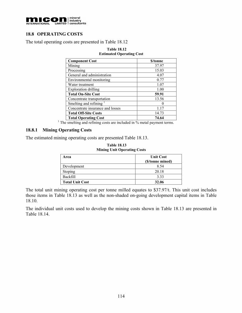
114
18.8 OPERATING COSTS The total operating costs are presented in Table 18.12
Table 18.12 Estimated Operating Cost
Component Cost $/tonne Mining 37.97 Processing 15.03 General and administration 4.07 Environmental monitoring 0.77 Water treatment 1.07 Exploration drilling 1.00 Total On-Site Cost 59.91 Concentrate transportation 13.56 Smelting and refining 1 0 Concentrate insurance and losses 1.17 Total Off-Site Costs 14.73 Total Operating Cost 74.64
1 The smelting and refining costs are included in % metal payment terms.
18.8.1 Mining Operating Costs The estimated mining operating costs are presented Table 18.13.
Table 18.13 Mining Unit Operating Costs
Area
Unit Cost ($/tonne mined)
Development 8.54 Stoping 20.18 Backfill 3.33 Total Unit Cost 32.06
The total unit mining operating cost per tonne milled equates to $37.97/t. This unit cost includes those items in Table 18.13 as well as the non-shaded on-going development capital items in Table 18.10.
The individual unit costs used to develop the mining costs shown in Table 18.13 are presented in Table 18.14.
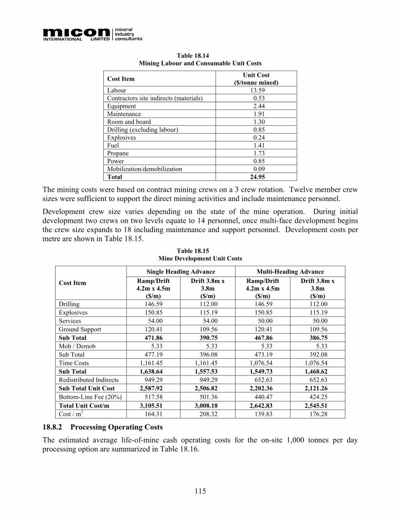
115
Table 18.14 Mining Labour and Consumable Unit Costs
Cost Item Unit Cost ($/tonne mined)
Labour 13.59 Contractors site indirects (materials) 0.53 Equipment 2.44 Maintenance 1.91 Room and board 1.30 Drilling (excluding labour) 0.85 Explosives 0.24 Fuel 1.41 Propane 1.73 Power 0.85 Mobilization/demobilization 0.09 Total 24.95
The mining costs were based on contract mining crews on a 3 crew rotation. Twelve member crew sizes were sufficient to support the direct mining activities and include maintenance personnel.
Development crew size varies depending on the state of the mine operation. During initial development two crews on two levels equate to 14 personnel, once multi-face development begins the crew size expands to 18 including maintenance and support personnel. Development costs per metre are shown in Table 18.15.
Table 18.15 Mine Development Unit Costs
Single Heading Advance Multi-Heading Advance
Cost Item Ramp/Drift 4.2m x 4.5m
($/m)
Drift 3.8m x 3.8m ($/m)
Ramp/Drift 4.2m x 4.5m
($/m)
Drift 3.8m x 3.8m ($/m)
Drilling 146.59 112.00 146.59 112.00 Explosives 150.85 115.19 150.85 115.19 Services 54.00 54.00 50.00 50.00 Ground Support 120.41 109.56 120.41 109.56 Sub Total 471.86 390.75 467.86 386.75 Mob / Demob 5.33 5.33 5.33 5.33 Sub Total 477.19 396.08 473.19 392.08 Time Costs 1,161.45 1,161.45 1,076.54 1,076.54 Sub Total 1,638.64 1,557.53 1,549.73 1,468.62 Redistributed Indirects 949.29 949.29 652.63 652.63 Sub Total Unit Cost 2,587.92 2,506.82 2,202.36 2,121.26 Bottom-Line Fee (20%) 517.58 501.36 440.47 424.25 Total Unit Cost/m 3,105.51 3,008.18 2,642.83 2,545.51 Cost / m3 164.31 208.32 139.83 176.28
18.8.2 Processing Operating Costs The estimated average life-of-mine cash operating costs for the on-site 1,000 tonnes per day processing option are summarized in Table 18.16.
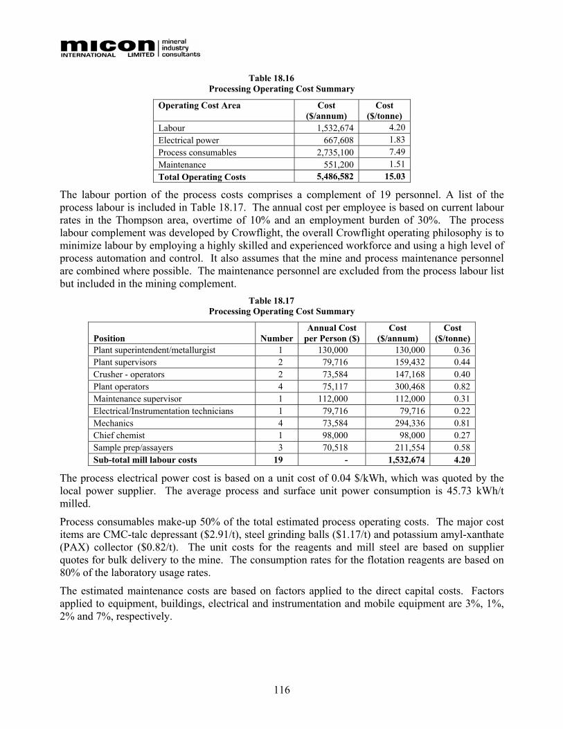
116
Table 18.16 Processing Operating Cost Summary
Operating Cost Area
Cost ($/annum)
Cost ($/tonne)
Labour 1,532,674 4.20 Electrical power 667,608 1.83 Process consumables 2,735,100 7.49 Maintenance 551,200 1.51 Total Operating Costs 5,486,582 15.03
The labour portion of the process costs comprises a complement of 19 personnel. A list of the process labour is included in Table 18.17. The annual cost per employee is based on current labour rates in the Thompson area, overtime of 10% and an employment burden of 30%. The process labour complement was developed by Crowflight, the overall Crowflight operating philosophy is to minimize labour by employing a highly skilled and experienced workforce and using a high level of process automation and control. It also assumes that the mine and process maintenance personnel are combined where possible. The maintenance personnel are excluded from the process labour list but included in the mining complement.
Table 18.17 Processing Operating Cost Summary
Position Number Annual Cost
per Person ($) Cost
($/annum) Cost
($/tonne) Plant superintendent/metallurgist 1 130,000 130,000 0.36 Plant supervisors 2 79,716 159,432 0.44 Crusher - operators 2 73,584 147,168 0.40 Plant operators 4 75,117 300,468 0.82 Maintenance supervisor 1 112,000 112,000 0.31 Electrical/Instrumentation technicians 1 79,716 79,716 0.22 Mechanics 4 73,584 294,336 0.81 Chief chemist 1 98,000 98,000 0.27 Sample prep/assayers 3 70,518 211,554 0.58 Sub-total mill labour costs 19 - 1,532,674 4.20
The process electrical power cost is based on a unit cost of 0.04 $/kWh, which was quoted by the local power supplier. The average process and surface unit power consumption is 45.73 kWh/t milled.
Process consumables make-up 50% of the total estimated process operating costs. The major cost items are CMC-talc depressant ($2.91/t), steel grinding balls ($1.17/t) and potassium amyl-xanthate (PAX) collector ($0.82/t). The unit costs for the reagents and mill steel are based on supplier quotes for bulk delivery to the mine. The consumption rates for the flotation reagents are based on 80% of the laboratory usage rates.
The estimated maintenance costs are based on factors applied to the direct capital costs. Factors applied to equipment, buildings, electrical and instrumentation and mobile equipment are 3%, 1%, 2% and 7%, respectively.
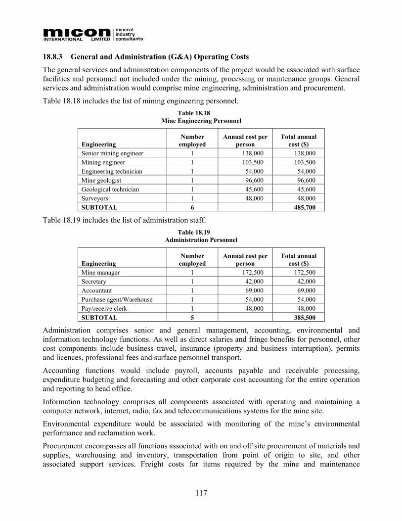
117
18.8.3 General and Administration (G&A) Operating Costs The general services and administration components of the project would be associated with surface facilities and personnel not included under the mining, processing or maintenance groups. General services and administration would comprise mine engineering, administration and procurement.
Table 18.18 includes the list of mining engineering personnel. Table 18.18
Mine Engineering Personnel
Engineering Number
employed Annual cost per
person Total annual
cost ($) Senior mining engineer 1 138,000 138,000 Mining engineer 1 103,500 103,500 Engineering technician 1 54,000 54,000 Mine geologist 1 96,600 96,600 Geological technician 1 45,600 45,600 Surveyors 1 48,000 48,000 SUBTOTAL 6 485,700
Table 18.19 includes the list of administration staff. Table 18.19
Administration Personnel
Engineering Number
employed Annual cost per
person Total annual
cost ($) Mine manager 1 172,500 172,500 Secretary 1 42,000 42,000 Accountant 1 69,000 69,000 Purchase agent/Warehouse 1 54,000 54,000 Pay/receive clerk 1 48,000 48,000 SUBTOTAL 5 385,500
Administration comprises senior and general management, accounting, environmental and information technology functions. As well as direct salaries and fringe benefits for personnel, other cost components include business travel, insurance (property and business interruption), permits and licences, professional fees and surface personnel transport.
Accounting functions would include payroll, accounts payable and receivable processing, expenditure budgeting and forecasting and other corporate cost accounting for the entire operation and reporting to head office.
Information technology comprises all components associated with operating and maintaining a computer network, internet, radio, fax and telecommunications systems for the mine site.
Environmental expenditure would be associated with monitoring of the mine’s environmental performance and reclamation work.
Procurement encompasses all functions associated with on and off site procurement of materials and supplies, warehousing and inventory, transportation from point of origin to site, and other associated support services. Freight costs for items required by the mine and maintenance
118
departments are included in those department’s costs. The main cost components comprise wages and warehouse supplies. Salaries and fringe benefits for staff, warehouse supplies such as personal protective gear (gloves, etc.), and small equipment (pallet lifters, forklifts, etc.) parts for operating the warehousing, purchasing and logistics groups are included. Surface support includes unloading and loading of trailers and shipping containers, movement of materials on-site and maintenance of the warehousing and associated facilities.
A list of all the estimated general and administration expenses and costs is provided in Table 18.20.
The general services and administration operating costs are all costs associated with operating the offices and providing materials and supplies for the staff functions. The total yearly operating costs are estimated to be approximately $1.5 million, of which $0.9 million provides for staff salaries and benefits. This cost equates to $4.07/t of ore milled.
In addition to labour and materials, the administration operating costs include costs and taxes for maintaining the property in good standing, paying land taxes, etc. and resource usage fees (water, etc). The administration account also includes the cost of operating all infrastructure facilities and provision for contract security services.
18.8.4 In-fill Diamond Drilling An allowance of $1/t of ore is estimated for in-fill diamond drilling during production.
18.8.5 Environmental Costs Day to day environmental monitoring will be conducted by the plant superintendent with professional expertise and supervision provided by an environmental consultant. This outside consultant and Crowflight’s environmental person will ensure that all monitoring and reporting required by the mine, external organizations and government are met. Costs to provide the monitoring and reporting of environmental performance at the mining operation are estimated as follows:
• The annual costs for environmental monitoring have been estimated by Seacor for the production period and for 3 years following mine closure. These costs vary between $180,000 and $120,000 per annum and equate to a life-of-mine unit cost of $0.71/t milled.
• Although environmental testing has indicated that the tailings and the majority of the waste rock are not acid generating and unlikely to pose an environmental risk, $100,000 per year for three years following closure has been allocated to the treatment of excess site water.
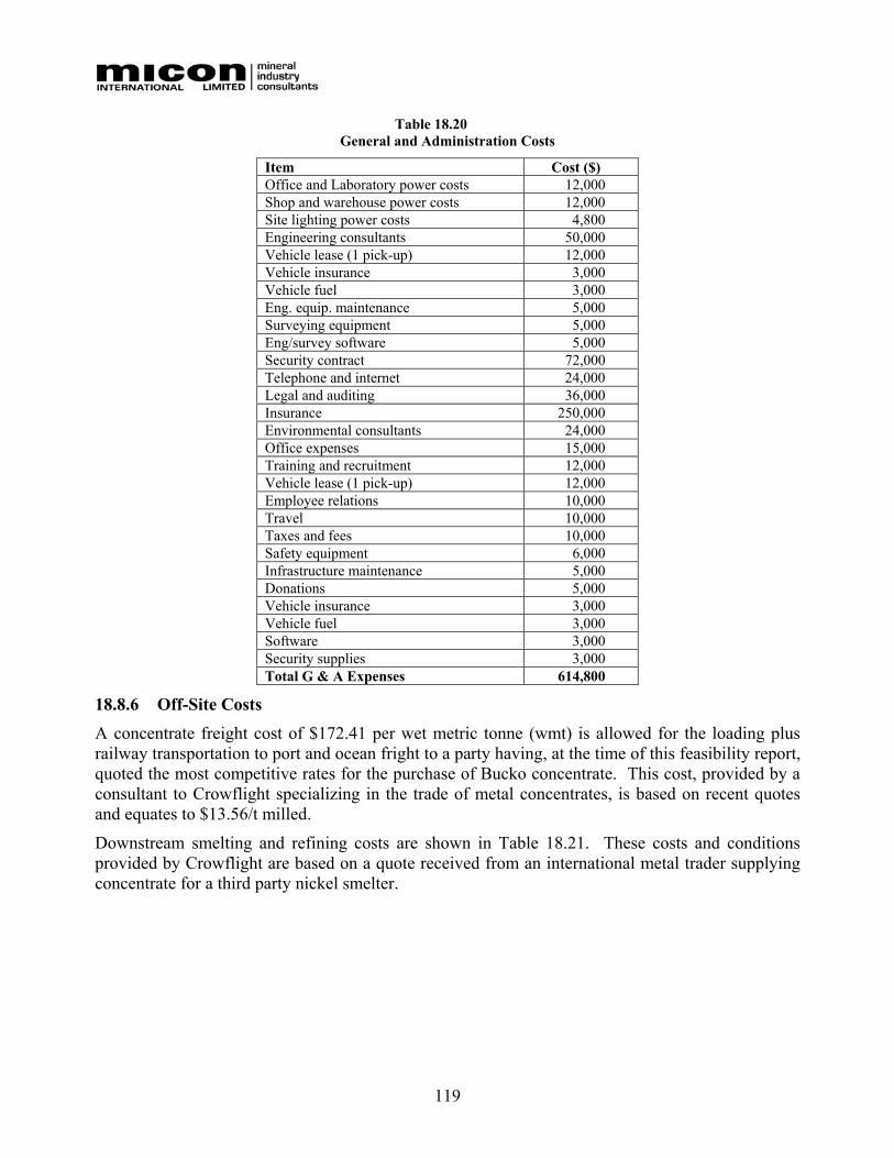
119
Table 18.20 General and Administration Costs
Item Cost ($) Office and Laboratory power costs 12,000 Shop and warehouse power costs 12,000 Site lighting power costs 4,800 Engineering consultants 50,000 Vehicle lease (1 pick-up) 12,000 Vehicle insurance 3,000 Vehicle fuel 3,000 Eng. equip. maintenance 5,000 Surveying equipment 5,000 Eng/survey software 5,000 Security contract 72,000 Telephone and internet 24,000 Legal and auditing 36,000 Insurance 250,000 Environmental consultants 24,000 Office expenses 15,000 Training and recruitment 12,000 Vehicle lease (1 pick-up) 12,000 Employee relations 10,000 Travel 10,000 Taxes and fees 10,000 Safety equipment 6,000 Infrastructure maintenance 5,000 Donations 5,000 Vehicle insurance 3,000 Vehicle fuel 3,000 Software 3,000 Security supplies 3,000 Total G & A Expenses 614,800
18.8.6 Off-Site Costs A concentrate freight cost of $172.41 per wet metric tonne (wmt) is allowed for the loading plus railway transportation to port and ocean fright to a party having, at the time of this feasibility report, quoted the most competitive rates for the purchase of Bucko concentrate. This cost, provided by a consultant to Crowflight specializing in the trade of metal concentrates, is based on recent quotes and equates to $13.56/t milled.
Downstream smelting and refining costs are shown in Table 18.21. These costs and conditions provided by Crowflight are based on a quote received from an international metal trader supplying concentrate for a third party nickel smelter.

120
Table 18.21 Smelting and Refining Costs
Component Units Value Smelter charge $/t conc. 0 Refining charge ($/lb or oz of payable metal) 0 Payable metals
Nickel % 69 Copper % 40 Cobalt % 28 Gold % 50 Platinum % 50 Palladium % 50
Deductions ($/lb or oz of payable metal) None Price participation None Penalties None
Insurance and concentrate losses are taken into account by applying allowances of 0.08% and 1% respectively to the payable metal revenue. These life-of-mine costs total $0.08 and $1.09/ t milled, respectively.
18.9 FINANCIAL ANALYSIS
18.9.1 Basis of Evaluation Based on the estimated mineral reserves, Micon, Wardrop and Crowflight have developed a mine plan and processing design to mine and treat 1,000 t/d of ore of nickel ore. Based on the total of 1,685,000 tonnes contained in the mineable reserves, a mine life of about 6 years 3 months is proposed, including 19 months of construction and pre-production followed by 4 years 8 months of production.
The estimates of metal production, capital costs and operating costs are combined in the discounted cash flow evaluation. The economic evaluation is treated on a project basis, assuming 100% equity financing. The base case uses the following metal prices:
• Nickel US$5.00/lb • Copper US$1.25/lb • Cobalt US$12/lb • Platinum US$400/oz • Palladium US$200/oz • Rhodium US$1,000/oz • Gold US$400/oz
A Canadian dollar to US dollar exchange rate of 1.22 has been assumed.
The results of the base case cash flow evaluation are summarized in the following table showing life-of-mine totals.
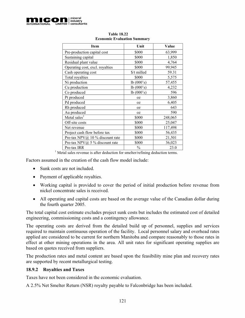
121
Table 18.22 Economic Evaluation Summary
Item Unit Value Pre-production capital cost $000 63,999 Sustaining capital $000 1,850 Residual plant value $000 4,764 Operating cost, excl. royalties $000 99,945 Cash operating cost $/t milled 59.31 Total royalties $000 5,575 Ni production lb (000’s) 57,455 Cu production lb (000’s) 4,232 Co produced lb (000’s) 596 Pt produced oz 3,860 Pd produced oz 6,405 Rh produced oz 643 Au produced oz 590 Metal sales1 $000 248,065 Off-site costs $000 25,047 Net revenue $000 117,498 Project cash flow before tax $000 56,435 Pre-tax NPV@ 10 % discount rate $000 21,501 Pre-tax NPV@ 5 % discount rate $000 36,023 Pre-tax IRR % 23.0
1 Metal sales revenue is after deduction for smelter/refining deduction terms.
Factors assumed in the creation of the cash flow model include:
• Sunk costs are not included.
• Payment of applicable royalties.
• Working capital is provided to cover the period of initial production before revenue from nickel concentrate sales is received.
• All operating and capital costs are based on the average value of the Canadian dollar during the fourth quarter 2005.
The total capital cost estimate excludes project sunk costs but includes the estimated cost of detailed engineering, commissioning costs and a contingency allowance.
The operating costs are derived from the detailed build up of personnel, supplies and services required to maintain continuous operation of the facility. Local personnel salary and overhead rates applied are considered to be current for northern Manitoba and compare reasonably to those rates in effect at other mining operations in the area. All unit rates for significant operating supplies are based on quotes received from suppliers.
The production rates and metal content are based upon the feasibility mine plan and recovery rates are supported by recent metallurgical testing.
18.9.2 Royalties and Taxes Taxes have not been considered in the economic evaluation.
A 2.5% Net Smelter Return (NSR) royalty payable to Falconbridge has been included.
122
18.9.3 Sensitivity Study and Risk Analysis Sensitivity analysis has been applied to the base case cash flow by varying the following parameters:
• Nickel price.
• Operating costs.
• Pre-production capital costs.
• Reserves.
• Off-site costs, including concentrate treatment charges (TC), refinery charges (RC) and transportation.
• Throughput rate.
• Nickel feed grade.
Figure 18.10 and Figure 18.11 present the IRR and NPV sensitivities compared to the base case for the nickel price, nickel grade, ore reserves, operating costs, currency, and off-take terms.
Figure 18.10 presents project IRR sensitivity as the base used in the feasibility report is varied positively or negatively from -20% to +20%. The IRR is most sensitive to changes in nickel price, grade, currency, and off-take terms and least sensitive to changes in operating costs and reserves.
Figure 18.11 presents project NPV sensitivity as the base used in the feasibility report is varied positively or negatively in from -20% to +20%. The NPV is affected similarly as the IRR with the impact felt strongest when changes of nickel price, grade, currency, and off-take terms occur and least sensitive to changes in operating costs and reserves.
The sensitivity to operating cost shows fairly flat sloped curves but gives an indication of potential performance objectives for future operating improvements.
The sensitivity analysis indicates that project valuation improvement could be achieved through a 10% reduction in the treatment and refining charges and shipping charges. Crowflight intends to pursue competitive off-take terms with Falconbridge and other third parties in an effort to achieve reductions from the terms presented in this study.
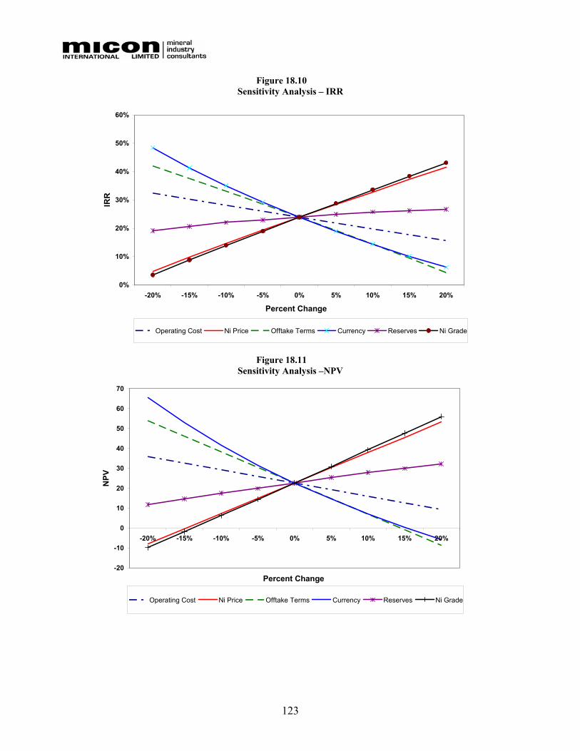
123
Figure 18.10 Sensitivity Analysis – IRR
0%
10%
20%
30%
40%
50%
60%
-20% -15% -10% -5% 0% 5% 10% 15% 20%
Percent Change
IRR
Operating Cost Ni Price Offtake Terms Currency Reserves Ni Grade
Figure 18.11
Sensitivity Analysis –NPV
-20
-10
0
10
20
30
40
50
60
70
-20% -15% -10% -5% 0% 5% 10% 15% 20%
Percent Change
NPV
Operating Cost Ni Price Offtake Terms Currency Reserves Ni Grade
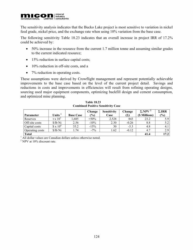
124
The sensitivity analysis indicates that the Bucko Lake project is most sensitive to variation in nickel feed grade, nickel price, and the exchange rate when using 10% variation from the base case.
The following sensitivity Table 18.23 indicates that an overall increase in project IRR of 17.2% could be achieved by:
• 50% increase in the resource from the current 1.7 million tonne and assuming similar grades to the current indicated resource;
• 15% reduction in surface capital costs;
• 10% reduction in off-site costs, and a
• 7% reduction in operating costs.
These assumptions were derived by Crowflight management and represent potentially achievable improvements to the base case based on the level of the current project detail. Savings and reductions in costs and improvements in efficiencies will result from refining operating designs, sourcing used major equipment components, optimizing backfill design and cement consumption, and optimized mine planning.
Table 18.23 Combined Positive Sensitivity Case
Parameter Units 1 Base Case Change
(%) Sensitivity
Case Change
(Σ) Σ.NPV 2
($ Millions) Σ.IRR
(%) Reserves t x 103 1,685 +50% 2,528 843 23.2 5.9Off-site costs $/lb Ni 2.56 -10% 2.30 -0.26 8.8 5.2Capital costs $ x 106 35.2 -15% 30 -5.3 4.8 4.1Operating costs $/lb Ni 1.74 -7% 1.62 -0.12 4.7 2.9Total 41.4 17.2
1 All dollar values are Canadian dollars unless otherwise noted. 2 NPV at 10% discount rate.
125
19.0 INTERPRETATION AND CONCLUSIONS The feasibility report was prepared to analyze the operating and economic parameters of the development of the Bucko Lake Nickel Mine project as an underground mining operation with an on-site nickel concentrating facility. To minimize capital requirements the report studied contractor underground mining. The owner would be responsible for operation of the concentrator plant, on-site administration, engineering, purchasing and site and underground mine contractor management.
The underground mining plan envisions service and equipment access to, and ore hoisting from, the underground via the 3-compartment shaft. The mine will employ the efficient longhole stope mining method with access to and from levels of the mine via an internal ramp system. Cemented hydraulic tailings backfill and development waste, where required, will be employed in mined-out stopes for purposes of maintaining ground control. Nickel ore is to be concentrated at an on-site facility with train or truck shipment of the concentrate end product to smelters within the continent or a combination of rail and ocean freight to smelters and refineries located overseas.
19.1 CONCLUSIONS
Main conclusions regarding the design and economics of the project are summarized below:
• Mining of 1,000 tonnes of ore per day utilizing underground contractor mining is envisaged, operating 365 days per year with underground ore hoisted to surface via the rehabilitated shaft from the 1000 Level (approximately 300 metres below surface). Hoisted ore will be crushed on surface and conveyed to the concentrator plant to be processed into a single primarily nickel concentrate containing minor amounts of potentially payable copper, cobalt and PGMs.
• The estimated capital cost for the process plant, head-frame and hoist, underground pre-production development, underground infrastructure and electrical installations is CAD$51.3 million, excluding contingency and EPCM costs.
• The contingency and EPCM costs included in the total pre-production capital cost estimate are CAD$6.1 million and CAD$6.0 million, respectively.
• Average life-of-mine on-site and offsite cash operating cost is estimated at US$3.53 per pound of nickel produced over a mine life of 4.8 years.
• At a base price of US$5.00 per pound nickel and US$1.25 per pound copper, the project delivers an IRR of 23.0% and has a pre-tax NPV of CAD$21.5 million (10% discount rate).
• An increase in the life-of-mine nickel price to US$6.00 results in an IRR of 40.2% and yields a pre-tax NPV of CAD$52.0 million (10% discount rate).
• Sensitivity analysis suggest that the project economics are most sensitive to nickel price, feed grade and offsite charges for smelting and refining and less sensitive to capital and operating costs.
126
20.0 RECOMMENDATIONS The results from this feasibility study demonstrate that the Bucko Lake nickel project is technically and economically viable and should be advanced towards production. Crowflight plans a two phase approach to further develop the project towards this goal. The objective of the first phase is to continue to advance the feasibility program from the current state to an enhanced Bankable Feasibility stage. The first phase includes the finalizing of the environmental application and permitting process, reducing the medium and high risk concerns with advanced follow-up work in these areas, additional resource expansion drilling and enhancing the project economics by refining operating costs and sourcing used major equipment components. Phase II incorporates the process of securing project financing and equipment procurement.
Phase I:
• Environmental permitting and licensing. Permit application to be complete by the second quarter 2006 including public consultation.
• Continue surface resource expansion drill program with the purpose of converting Inferred Resources to the Indicated Resource category for inclusion in an enhanced Bankable Feasibility Study. Resources to be converted down to the 2000 Level (approximately 600 metres below surface).
• Review project design parameters and operating plans in pursuit of potential capital and operating cost reductions. Such areas include: purchase and refurbishment of used mill components or entire milling process plant; used electrical transformer(s) and switchgear; refined backfill procedures, including cement addition; mine design; mine planning; production rescheduling to advance the mining of higher grade areas of the mine in earlier years of the mine life; enhanced throughput by incorporating a ramp to surface and hoist/haul through a combination of the shaft and ramp access trucks.
• Obtain contractor quotes for development and ongoing mining.
• Secure competitive off-take rate(s) and contract(s).
• Secure shipping rate(s) and contract(s).
• Major process plant to be identified and purchased second-hand, including SAG or rod mill, ball mill, crusher, conveyors and buildings, and electrical substations, thereby reducing project capital cost.
• Hiring of owner management staff to complement the operation plan.
Phase II:
• Preparation of bid packages and solicitation of competitive bids for project construction and underground development and consumables.
• Completion of project financing.
• Commence long lead-time infrastructure and capital component investment activities (site electrical power, hoist and head-frame and rehabilitation of the underground shaft).
• Consider upgrading portions of the Indicated Resource to the Measured Resource category in areas to be mined during the first two years of the mine life.
127
Schedule and Estimated Costs for Phase I and II It is anticipated that Phase I will be completed within four months at a cost of approximately CAD$1,800,000 to CAD$2,500,000.
Phase II is expected to be completed within two to three months following the completion of Phase I at a cost of approximately CAD$2,000,000.
Richard M Gowans Richard M Gowans, P.Eng.
Vice President and Senior Metallurgist Micon International Limited
January 30, 2006

128
21.0 REFERENCES Feasibility Study Report entitled “Feasibility Study for the Bucko Lake Nickel Project Wabowden, Manitoba”, dated January 31, 2006 by Micon International Limited.
NI 43-101 Technical Report “Technical Report and Resource Estimate on the Bucko Lake Property, the Pas Mining District, Manitoba, Canada”, dated 15 December 2005 by P & E Mining Consultants Inc.

Related Documents