BU208A BU508A/BU508AFI HIGH VOLTAGE FAST-SWITCHING NPN POWER TRANSISTORS s STMicr oelectronics PREFER RED SALESTYPES s HIGH VO LTAGE CAPABIL ITY s U.L. RECOGNISED ISOWATT 218 PACKAGE (U.L.FILE # E81734(N) s JEDEC TO-3METAL CASE. APPLICATIONS: s HORIZONTAL DEFLECTION FOR COLOUR TV DESCRIPTION Th e BU20 8A, BU50 8A and BU508AFI are manu fa ctur ed usi ng Mu lt ie pi ta xi al Me sa techn ology for cost- effecti ve high perf orma nce and use a Hollow Emitter structure to enhance switch ing speed s. INTERNAL SCHEMAT IC DIAGRAM November 1999 ABSOLUTE MAXIMUM RATINGS Symbol Par ame ter Va lue Unit VCES Collector-Emitter Voltage (V BE = 0) 1500 V V CE O Collector-Emitter Voltage (I B = 0) 700 V VEBO Emitter-Base Voltage (I C = 0) 10 V I C Collec t or Current 8 A I CM Collector Peak Current (t p < 5 ms) 15 A TO - 3 TO - 218 ISOWATT218 P t ot Total Dissipation at T c = 25 o C 150 125 50 W Tst g St orage Temperatur e -65 to 175 - 65 to 150 - 65 t o 150 o C T j Max . Operating Junct i on Temperature 175 150 150 o C 1 2 3 TO-218 ISOWATT218 1 2 3 1 2 TO-3 For TO-3 : C = Tab E = Pin2. ® 1/8

Welcome message from author
This document is posted to help you gain knowledge. Please leave a comment to let me know what you think about it! Share it to your friends and learn new things together.
Transcript

7/31/2019 BU 808 AFI
http://slidepdf.com/reader/full/bu-808-afi 1/9
BU208ABU508A/BU508AFI
HIGH VOLTAGE FAST-SWITCHINGNPN POWER TRANSISTORS
s STMicroelectronics PREFERREDSALESTYPES
s HIGH VOLTAGE CAPABILITYs U.L. RECOGNISED ISOWATT218 PACKAGE
(U.L. FILE # E81734(N)s JEDEC TO-3 METAL CASE.
APPLICATIONS:
s HORIZONTAL DEFLECTION FOR COLOURTV
DESCRIPTION
The BU208A, BU508A and BU508AFI aremanufactured using Multiepitaxial Mesatechnology for cost-effective high performanceand use a Hollow Emitter structure to enhanceswitching speeds.
INTERNAL SCHEMATIC DIAGRAM
November 1999
ABSOLUTE MAXIMUM RATINGS
Symbol Parameter Value Unit
VCES Collector-Emitter Voltage (VBE = 0) 1500 V
VCEO Collector-Emitter Voltage (IB = 0) 700 V
VEBO Emitter-Base Voltage (IC = 0) 10 V
IC Collector Current 8 A
ICM Collector Peak Current (tp < 5 ms) 15 A
T O - 3 TO - 21 8 I SO WAT T21 8
Ptot Total Dissipation at Tc = 25 oC 150 125 50 W
Tst g Storage Temperature -65 to 175 -65 to 150 -65 to 150oC
T j Max. Operating Junction Temperature 175 150 150oC
12
3
TO-218 ISOWATT218 12
3
1
2
TO-3
For TO-3 :C = TabE = Pin2.
®
1/8

7/31/2019 BU 808 AFI
http://slidepdf.com/reader/full/bu-808-afi 2/9
THERMAL DATA
T O -3 T O -2 18 I SO W AT T2 18
Rthj-case Thermal Resistance Junction-case Max 1 1 2.5oC/W
ELECTRICAL CHARACTERISTICS (Tcase = 25 oC unlessotherwise specified)
Symb ol Parameter Test Conditions Min. Typ. Max. Un it
ICES Collector Cut-offCurrent (VBE = 0)
VCE = 1500 V TC = 125oC
VCE = 1500 V12
mAmA
IEBO Emitter Cut-off Current(IC = 0)
VEB = 5 V 100 µA
VCEO(sus)∗ Collector-EmitterSustaining Voltage(IB = 0)
IC = 100 mA 700 V
VEBO Emitter Base Voltage
(IC = 0)
IE = 10 mA 10 V
VCE(sat)∗ Collector-EmitterSaturation Voltage
IC = 4.5 A IB = 2 A 1 V
VBE(sat)∗ Base-EmitterSaturation Voltage
IC = 4.5 A IB = 2 A 1.3 V
ts
tf
INDUCTIVE LOADStorage Time
Fall Time
IC = 4. 5 A hFE = 2 .5 VCC = 140 V
LC = 0 .9 m H LB = 3 µH 7
0.55
µs
µs
fT Transition Frequency IC = 0.1 A VCE = 5 V f = 5 MHz 7 MHz
∗ Pulsed: Pulse duration = 300 µs, duty cycle 1.5 %
Safe Operating Area (TO-3) Safe Operating Areas (TO-218/ISOWATT218)
BU208A / BU508A / BU508AFI
2/8
7/31/2019 BU 808 AFI
http://slidepdf.com/reader/full/bu-808-afi 3/9
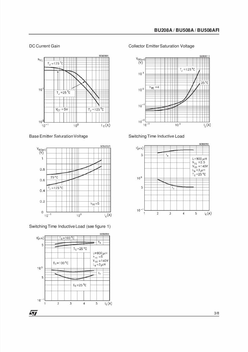
DC Current Gain
Base Emitter SaturationVoltage
Switching Time Inductive Load (see figure 1)
Collector Emitter Saturation Voltage
Switching Time Inductive Load
BU208A / BU508A / BU508AFI
3/8

7/31/2019 BU 808 AFI
http://slidepdf.com/reader/full/bu-808-afi 4/9
Figure 1: Inductive LoadSwitching TestCircuit.
BU208A / BU508A / BU508AFI
4/8

7/31/2019 BU 808 AFI
http://slidepdf.com/reader/full/bu-808-afi 5/9
DIM.mm inch
MIN. TYP. MAX. MIN. TYP. MAX.
A 11.00 13.10 0.433 0.516
B 0.97 1.15 0.038 0.045
C 1.50 1.65 0.059 0.065
D 8.32 8.92 0.327 0.351
E 19.00 20.00 0.748 0.787
G 10.70 11.10 0.421 0.437
N 16.50 17.20 0.649 0.677
P 25.00 26.00 0.984 1.023
R 4.00 4.09 0.157 0.161
U 38.50 39.30 1.515 1.547
V 30.00 30.30 1.187 1.193
E
B
R
C
DAP
G
N
V U
O
P003F
TO-3 MECHANICAL DATA
BU208A / BU508A / BU508AFI
5/8

7/31/2019 BU 808 AFI
http://slidepdf.com/reader/full/bu-808-afi 6/9
DIM.mm inch
MIN. TYP. MAX. MIN. TYP. MAX.
A 4.7 4.9 0.185 0.193
C 1.17 1.37 0.046 0.054
D 2.5 0.098
E 0.5 0.78 0.019 0.030
F 1.1 1.3 0.043 0.051
G 10.8 11.1 0.425 0.437
H 14.7 15.2 0.578 0.598
L2 – 16.2 – 0.637
L3 18 0.708
L5 3.95 4.15 0.155 0.163
L6 31 1.220
R – 12.2 – 0.480
Ø 4 4.1 0.157 0.161
R
A
C D
E
H
F
G
L6
¯
L3
L2
L5
1 2 3
TO-218 (SOT-93) MECHANICAL DATA
P025A
BU208A / BU508A / BU508AFI
6/8

7/31/2019 BU 808 AFI
http://slidepdf.com/reader/full/bu-808-afi 7/9
DIM.mm inch
MIN. TYP. MAX. MIN. TYP. MAX.
A 5.35 5.65 0.211 0.222
C 3.30 3.80 0.130 0.150
D 2.90 3.10 0.114 0.122
D1 1.88 2.08 0.074 0.082
E 0.75 0.95 0.030 0.037
F 1.05 1.25 0.041 0.049
F2 1.50 1.70 0.059 0.067
F3 1.90 2.10 0.075 0.083
G 10.80 11.20 0.425 0.441
H 15.80 16.20 0.622 0.638L 9 0.354
L1 20.80 21.20 0.819 0.835
L2 19.10 19.90 0.752 0.783
L3 22.80 23.60 0.898 0.929
L4 40.50 42.50 1.594 1.673
L5 4.85 5.25 0.191 0.207
L6 20.25 20.75 0.797 0.817
N 2.1 2.3 0.083 0.091
R 4.6 0.181
DIA 3.5 3.7 0.138 0.146
P025C/A
ISOWATT218 MECHANICAL DATA
- Weight : 4.9g (typ.)- MaximumTorque (applied to mounting flange) Recommended: 0.8 Nm; Maximum:1 Nm- The side of thedissipator must be flat within 80 µm
BU208A / BU508A / BU508AFI
7/8

7/31/2019 BU 808 AFI
http://slidepdf.com/reader/full/bu-808-afi 8/9
Information furnished isbelieved to be accurate and reliable. However, STMicroelectronics assumes noresponsibility for the consequencesof use of such information nor for any infringement of patents or other rights of third parties which may result from its use. No license isgranted by implication or otherwise under any patent or patent rights of STMicroelectronics. Specification mentioned in this publication aresubject to change without notice.This publication supersedes and replaces all information previously supplied. STMicroelectronics productsare not authorized for use as critical components in life support devices or systems without express written approval of STMicroelectronics.
The ST logo is a trademark of STMicroelectronics
©1999 STMicroelectronics – Printed in Italy – All Rights Reserved
STMicroelectronics GROUP OF COMPANIES
Australia - Brazil - China - Finland - France - Germany - Hong Kong - India - Italy - Japan - Malaysia - Malta - Morocco -Singapore - Spain - Sweden - Switzerland - United Kingdom - U.S.A.
http://www.st.com
.
BU208A / BU508A / BU508AFI
8/8

7/31/2019 BU 808 AFI
http://slidepdf.com/reader/full/bu-808-afi 9/9
This datasheet has been download from:
www.datasheetcatalog.com
Datasheets for electronics components.
Related Documents