BTS3900A V300R008 Product Description Issue 02 Date 2008-04-30 Part Number Huawei Proprietary and Confidential Copyright © Huawei Technologies Co., Ltd

Welcome message from author
This document is posted to help you gain knowledge. Please leave a comment to let me know what you think about it! Share it to your friends and learn new things together.
Transcript

BTS3900A
V300R008
Product Description
Issue 02
Date 2008-04-30
Part Number
Huawei Proprietary and ConfidentialCopyright © Huawei Technologies Co., Ltd

Huawei Technologies Co., Ltd. provides customers with comprehensive technical support and service. For anyassistance, please contact our local office or company headquarters.
Huawei Technologies Co., Ltd.Address: Huawei Industrial Base
Bantian, LonggangShenzhen 518129People's Republic of China
Website: http://www.huawei.com
Email: [email protected]
Copyright © Huawei Technologies Co., Ltd. 2008. All rights reserved.No part of this document may be reproduced or transmitted in any form or by any means without prior writtenconsent of Huawei Technologies Co., Ltd. Trademarks and Permissions
and other Huawei trademarks are the property of Huawei Technologies Co., Ltd.All other trademarks and trade names mentioned in this document are the property of their respective holders. NoticeThe information in this document is subject to change without notice. Every effort has been made in thepreparation of this document to ensure accuracy of the contents, but the statements, information, andrecommendations in this document do not constitute a warranty of any kind, express or implied.
Huawei Proprietary and ConfidentialCopyright © Huawei Technologies Co., Ltd

Contents
About This Document.....................................................................................................................1
1 System Architecture of the BTS3900A...................................................................................1-1
2 Introduction to the BTS3900A.................................................................................................2-12.1 Overview of the BTS3900A............................................................................................................................2-22.2 Structure of the BTS3900A Cabinet...............................................................................................................2-22.3 Logical Structure of the BTS3900A................................................................................................................2-72.4 Software Structure of the BTS........................................................................................................................2-8
3 Power Distribution of the BTS3900A.....................................................................................3-1
4 BTS3900A Monitoring System................................................................................................4-1
5 Reference Clocks of the BTS3900/BTS3900A........................................................................5-1
6 Signal Flow of the BTS3900/BTS3900A.................................................................................6-1
7 Topologies of the BTS...............................................................................................................7-1
8 Configuration of the BTS3900/BTS3900A.............................................................................8-18.1 Configuration Principles of the BTS3900/BTS3900A....................................................................................8-28.2 RF Signal Cable Connections of the DRFU....................................................................................................8-68.3 Topology of DRFUs Connected by CPRI Cables.........................................................................................8-128.4 Typical Configuration of the BTS3900/BTS3900A.....................................................................................8-14
9 OM System of the BTS..............................................................................................................9-19.1 OM Modes of the BTS....................................................................................................................................9-29.2 OM Functions of the BTS...............................................................................................................................9-6
10 Technical Specifications of the BTS3900A........................................................................10-110.1 Capacity Specifications of the BTS3900/BTS3900A.................................................................................10-210.2 RF Specifications of the BTS3900/BTS3900A..........................................................................................10-210.3 Engineering Specifications of the BTS3900A............................................................................................10-310.4 Surge Protection Specifications of the BTS3900A.....................................................................................10-410.5 Ports of the BTS3900A...............................................................................................................................10-510.6 Compliance Standards of the BTS3900/BTS3900A...................................................................................10-710.7 Environmental Requirements of the BTS3900A........................................................................................10-9
10.7.1 Environmental Requirements for Operating the BTS3900A.............................................................10-9
BTS3900AProduct Description Contents
Issue 02 (2008-04-30) Huawei Proprietary and ConfidentialCopyright © Huawei Technologies Co., Ltd
i

10.7.2 Environmental Requirements for Transporting the BTS3900A......................................................10-1110.7.3 Environmental Requirements for Storing the BTS3900A...............................................................10-14
ContentsBTS3900A
Product Description
ii Huawei Proprietary and ConfidentialCopyright © Huawei Technologies Co., Ltd
Issue 02 (2008-04-30)

Figures
Figure 1-1 BTS3900A system..............................................................................................................................1-2Figure 2-1 Typical configuration of a BTS3900A cabinet (1).............................................................................2-3Figure 2-2 Typical configuration of a BTS3900A cabinet (2).............................................................................2-4Figure 2-3 Typical configuration of a BTS3900A cabinet (3).............................................................................2-5Figure 2-4 Typical configuration of a BTS3900A cabinet (4).............................................................................2-6Figure 2-5 Logical structure of the BTS3900A....................................................................................................2-7Figure 2-6 Software structure of the BTS............................................................................................................2-8Figure 3-1 Power distribution of the BTS3900A.................................................................................................3-1Figure 4-1 Monitoring ports of the BBU..............................................................................................................4-1Figure 4-2 Components of the monitoring system...............................................................................................4-2Figure 6-1 DL traffic signal flow.........................................................................................................................6-1Figure 6-2 UL traffic signal flow.........................................................................................................................6-2Figure 6-3 Signaling flow.....................................................................................................................................6-3Figure 7-1 Star topology of the BTS....................................................................................................................7-1Figure 7-2 Chain topology of the BTS.................................................................................................................7-1Figure 7-3 Tree topology of the BTS...................................................................................................................7-2Figure 7-4 Ring topology of the BTS...................................................................................................................7-2Figure 7-5 Regroupment for disconnection in the ring topology.........................................................................7-5Figure 8-1 Mapping between the RF signal cables and their colors....................................................................8-6Figure 8-2 Connections of RF cables for S1 (without transmit diversity/with transmit diversity)/S2 (withouttransmit diversity).................................................................................................................................................8-7Figure 8-3 Connections of RF cables for S2 (PBT)/S3 (without transmit diversity)/S4 (without transmit diversity)...............................................................................................................................................................................8-8Figure 8-4 Connections of RF signal cables for S2 (4-way receive diversity)....................................................8-9Figure 8-5 Connections of RF cables for S2 (transmit diversity)/S4 (transmit independency).........................8-10Figure 8-6 Connections of RF cables for S5 (without transmit diversity)/S6 (without transmit diversity).......8-11Figure 8-7 Connections of RF cables for S7 (without transmit diversity)/S8 (without transmit diversity).......8-12Figure 8-8 Typical topology of the DRFUs.......................................................................................................8-13Figure 9-1 Network structure of the OM system.................................................................................................9-2
BTS3900AProduct Description Figures
Issue 02 (2008-04-30) Huawei Proprietary and ConfidentialCopyright © Huawei Technologies Co., Ltd
iii


Tables
Table 4-1 Monitoring modules of the BTS3900A................................................................................................4-2Table 4-2 Functions of the BTS3900A monitoring system..................................................................................4-2Table 7-1 Comparison of network topologies......................................................................................................7-3Table 8-1 RF configuration principles of the BTS3900.......................................................................................8-3Table 8-2 Configuration principles of the boards in the BBU.............................................................................8-5Table 8-3 Configuration (1)..................................................................................................................................8-6Table 8-4 Configuration (2)..................................................................................................................................8-7Table 8-5 Configuration (3)..................................................................................................................................8-9Table 8-6 Configuration (4)................................................................................................................................8-10Table 8-7 Configuration (5)................................................................................................................................8-12Table 8-8 Comparison of the three typical topologies of the DRFUs................................................................8-13Table 8-9 Typical configuration of the BTS3900/BTS3900A...........................................................................8-14Table 9-1 Functions of the BTS OM system........................................................................................................9-3Table 10-1 Operating frequency bands of the BTS3900/BTS3900A.................................................................10-2Table 10-2 Output power of the DRFU in the BTS3900/BTS3900A................................................................10-2Table 10-3 Receiver sensitivity of the BTS3900/BTS3900A............................................................................10-3Table 10-4 Dimensions.......................................................................................................................................10-3Table 10-5 Weight..............................................................................................................................................10-4Table 10-6 Specifications of the input power.....................................................................................................10-4Table 10-7 Power consumption of the BTS3900A (S4/4/4)..............................................................................10-4Table 10-8 Surge protection specifications of the BTS3900A...........................................................................10-5Table 10-9 Power ports of the BTS3900A.........................................................................................................10-5Table 10-10 BBU transmission ports.................................................................................................................10-6Table 10-11 DRFU transmission ports...............................................................................................................10-6Table 10-12 BTS3900A alarm ports..................................................................................................................10-7Table 10-13 Other external ports of the BTS3900A..........................................................................................10-7Table 10-14 Climatic requirements..................................................................................................................10-10Table 10-15 Requirements for the density of chemically active substances....................................................10-10Table 10-16 Mechanical stress requirements...................................................................................................10-11Table 10-17 Climatic requirements..................................................................................................................10-12Table 10-18 Requirements for the density of mechanically active substances................................................10-13Table 10-19 Requirements for the density of chemically active substances....................................................10-13Table 10-20 Mechanical stress requirements...................................................................................................10-13
BTS3900AProduct Description Tables
Issue 02 (2008-04-30) Huawei Proprietary and ConfidentialCopyright © Huawei Technologies Co., Ltd
v

Table 10-21 Climatic requirements..................................................................................................................10-14Table 10-22 Requirements for the density of mechanically active substances................................................10-15Table 10-23 Requirements for the density of chemically active substances....................................................10-16Table 10-24 Mechanical stress requirements...................................................................................................10-16
TablesBTS3900A
Product Description
vi Huawei Proprietary and ConfidentialCopyright © Huawei Technologies Co., Ltd
Issue 02 (2008-04-30)

About This Document
PurposeThis document provides an overview of the BTS3900A. It also describes the system architecture,features, software and hardware structure, functional subsystems, configuration types, signalflow, clock synchronization, and topologies of the BTS3900A. This document also lists thespecifications for the capacity, radio frequency (RF), engineering, surge protection, and physicalports of the BTS3900A.
Product VersionThe following table lists the product version related to this document.
Product Name Product Version
BTS3900A V300R008
Intended AudienceThis document is intended for:
l Network planners
l Field engineers
l System engineers
Change HistoryFor changes in the document, refer to Changes in BTS3900A Product Description.
Organization1 System Architecture of the BTS3900A
The BTS3900A system consists of the BBU3900, DRFUs, power cabinet, and RF cabinet. TheBBU3900 is installed in the power cabinet and the DRFUs are installed in the RF cabinet.
2 Introduction to the BTS3900A
This describes the features, physical structure, software structure, and logical structure of theBTS3900A.
BTS3900AProduct Description About This Document
Issue 02 (2008-04-30) Huawei Proprietary and ConfidentialCopyright © Huawei Technologies Co., Ltd
1

3 Power Distribution of the BTS3900A
The BTS3900A allows the 220 V AC input.
4 BTS3900A Monitoring System
The BTS3900A monitoring system enables the power monitoring, fan monitoring, andenvironment monitoring.
5 Reference Clocks of the BTS3900/BTS3900A
The BTS3900/BTS3900A supports three types of reference clocks: line clock, BITS clock, andfree-run clock.
6 Signal Flow of the BTS3900/BTS3900A
The signal flow of the BTS3900/BTS3900A consists of the traffic signal flow and the signalingflow of the BTS. The BTS3900/BTS3900A signal flow is classified into the DL traffic signalflow, UL traffic signal flow, and signaling flow.
7 Topologies of the BTS
The topologies of the BTS are classified into star, chain, tree, and ring topologies. The BBU andDRFUs support multiple network topologies such as star, chain, and ring topologies. In practice,these topologies can be combined. Optimum utilization of the topologies can improve the qualityof service and save the investment on the transmission equipment.
8 Configuration of the BTS3900/BTS3900A
This describes the configuration principles and typical configurations of the BTS3900/BTS3900A.
9 OM System of the BTS
The OM system implements the management, monitoring, and maintenance tasks of theBTS3900. It provides various OM modes and multiple maintenance platforms to meet differentmaintenance requirements.
10 Technical Specifications of the BTS3900A
The technical specifications of the BTS3900A consist of the capacity specifications, RFspecifications, engineering specifications, surge protection specifications, physical ports,environmental requirements, and compliance standards.
Conventions
1. Symbol Conventions
The following symbols may be found in this document. They are defined as follows
Symbol Description
DANGERIndicates a hazard with a high level of risk that, if not avoided,will result in death or serious injury.
About This DocumentBTS3900A
Product Description
2 Huawei Proprietary and ConfidentialCopyright © Huawei Technologies Co., Ltd
Issue 02 (2008-04-30)

Symbol Description
WARNINGIndicates a hazard with a medium or low level of risk which, ifnot avoided, could result in minor or moderate injury.
CAUTIONIndicates a potentially hazardous situation that, if not avoided,could cause equipment damage, data loss, and performancedegradation, or unexpected results.
TIP Indicates a tip that may help you solve a problem or save yourtime.
NOTE Provides additional information to emphasize or supplementimportant points of the main text.
2. General Conventions
Convention Description
Times New Roman Normal paragraphs are in Times New Roman.
Boldface Names of files,directories,folders,and users are in boldface. Forexample,log in as user root .
Italic Book titles are in italics.
Courier New Terminal display is in Courier New.
3. Command Conventions
Convention Description
Boldface The keywords of a command line are in boldface.
Italic Command arguments are in italic.
[ ] Items (keywords or arguments) in square brackets [ ] are optional.
{x | y | ...} Alternative items are grouped in braces and separated by verticalbars.One is selected.
[ x | y | ... ] Optional alternative items are grouped in square brackets andseparated by vertical bars.One or none is selected.
{ x | y | ... } * Alternative items are grouped in braces and separated by verticalbars.A minimum of one or a maximum of all can be selected.
[ x | y | ... ] * Alternative items are grouped in braces and separated by verticalbars.A minimum of zero or a maximum of all can be selected.
4. GUI Conventions
BTS3900AProduct Description About This Document
Issue 02 (2008-04-30) Huawei Proprietary and ConfidentialCopyright © Huawei Technologies Co., Ltd
3

Convention Description
Boldface Buttons,menus,parameters,tabs,window,and dialog titles are inboldface. For example,click OK.
> Multi-level menus are in boldface and separated by the ">" signs.For example,choose File > Create > Folder .
5. Keyboard Operation
Convention Description
Key Press the key.For example,press Enter and press Tab.
Key1+Key2 Press the keys concurrently.For example,pressing Ctrl+Alt+Ameans the three keys should be pressed concurrently.
Key1,Key2 Press the keys in turn.For example,pressing Alt,A means the twokeys should be pressed in turn.
6. Mouse Operation
Action Description
Click Select and release the primary mouse button without moving thepointer.
Double-click Press the primary mouse button twice continuously and quicklywithout moving the pointer.
Drag Press and hold the primary mouse button and move the pointerto a certain position.
About This DocumentBTS3900A
Product Description
4 Huawei Proprietary and ConfidentialCopyright © Huawei Technologies Co., Ltd
Issue 02 (2008-04-30)
1 System Architecture of the BTS3900A
The BTS3900A system consists of the BBU3900, DRFUs, power cabinet, and RF cabinet. TheBBU3900 is installed in the power cabinet and the DRFUs are installed in the RF cabinet.
Figure 1-1 shows the BTS3900A system.
BTS3900AProduct Description 1 System Architecture of the BTS3900A
Issue 02 (2008-04-30) Huawei Proprietary and ConfidentialCopyright © Huawei Technologies Co., Ltd
1-1

Figure 1-1 BTS3900A system
BBU
Powercabinet
RF cabinet
DRFU
The BTS3900A mainly consists of the following components:
l The BBU3900 is used for baseband processing and enables interaction between the BTSand the BSC.
l The DRFU is a double radio filter unit that processes two carriers. The DRFU performsmodulation and demodulation between baseband signals and RF signals, processes data,and combines and divides signals.
l The power cabinet houses the BBU3900 and the RF cabinet houses the DRFUs. In addition,the power cabinet and the RF cabinet provide the functions such as power distribution, heatdissipation, and surge protection.
1 System Architecture of the BTS3900ABTS3900A
Product Description
1-2 Huawei Proprietary and ConfidentialCopyright © Huawei Technologies Co., Ltd
Issue 02 (2008-04-30)

2 Introduction to the BTS3900A
About This Chapter
This describes the features, physical structure, software structure, and logical structure of theBTS3900A.
2.1 Overview of the BTS3900AThe BTS3900A is an outdoor separated macro base station developed by Huawei. TheBTS3900A mainly consists of the BBU and the DRFUs. Compared with traditional BTSs, theBTS3900A features simpler structure and higher integration.
2.2 Structure of the BTS3900A CabinetThe BTS3900A cabinet consists of the RF cabinet and the APM30 power cabinet. The RF cabinetis categorized into two types, namely 3RFU cabinet and 6RFU cabinet. The APM30 batterycabinet and APM30 transmission cabinet, which provide backup power for a long period of timeand space for user equipment respectively, are optional for the BTS3900A.
2.3 Logical Structure of the BTS3900AThe BTS3900A mainly consists of the BBU and the DRFUs. The logical structure of theBTS3900A consists of the RF subsystem, control subsystem, power subsystem, and antennasubsystem.
2.4 Software Structure of the BTSThe BTS software consists of the platform software, signaling protocol software, OM software,and data center. The latter three are application software, and the platform software providessupport for the application software.
BTS3900AProduct Description 2 Introduction to the BTS3900A
Issue 02 (2008-04-30) Huawei Proprietary and ConfidentialCopyright © Huawei Technologies Co., Ltd
2-1

2.1 Overview of the BTS3900AThe BTS3900A is an outdoor separated macro base station developed by Huawei. TheBTS3900A mainly consists of the BBU and the DRFUs. Compared with traditional BTSs, theBTS3900A features simpler structure and higher integration.
The features of the BTS3900A are as follows:
l It is developed on the basis of the unified BTS platform for Huawei wireless products andenables the smooth evolution from 2G to 3G.
l It supports the Abis IP/FE interface in hardware and enables Abis over IP through softwareupgrade if required.
l It shares the BBU, which is the central processing unit, with the DBS3900 to minimize thenumber of spare parts and reduce the cost.
l It can be flexibly installed in a small footprint and can be easily maintained with low cost.
l It supports multiple frequency bands, such as PGSM900, EGSM900, and DCS1800.
l It supports transmit diversity and PBT.
l It supports two-antenna and four-antenna receive diversity to improve the uplink coverage.
l It supports the GPRS and the EGPRS.
l It supports omnidirectional cells and directional cells.
l It supports the hierarchical cell, concentric cell, and micro cell.
l It supports multiple network topologies, such as star, tree, chain, ring, and hybridtopologies.
l It supports the A5/3, A5/2, and A5/1 encryption and decryption algorithms.
l It supports the cell broadcast SMS and point-to-point SMS.
l It supports synchronization with the BTS3012.
l A single cabinet supports up to 12 TRXs in the maximum cell configuration of S4/4/4.
l Multiple cabinets support up to 72 TRXs in the maximum cell configuration of S24/24/24.
2.2 Structure of the BTS3900A CabinetThe BTS3900A cabinet consists of the RF cabinet and the APM30 power cabinet. The RF cabinetis categorized into two types, namely 3RFU cabinet and 6RFU cabinet. The APM30 batterycabinet and APM30 transmission cabinet, which provide backup power for a long period of timeand space for user equipment respectively, are optional for the BTS3900A.
The function modules of the BTS3900A include the DRFU, BBU, DCDU-02, FMUA, FANunit, and GATM, among which the GATM is optional.
Figure 2-1 shows the typical configuration of a BTS3900A cabinet that consists of a 6RFUcabinet and an APM30 power cabinet.
2 Introduction to the BTS3900ABTS3900A
Product Description
2-2 Huawei Proprietary and ConfidentialCopyright © Huawei Technologies Co., Ltd
Issue 02 (2008-04-30)
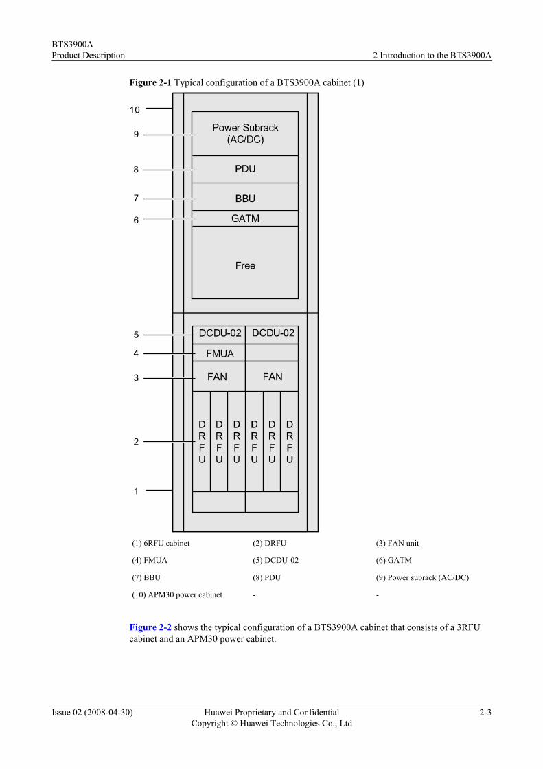
Figure 2-1 Typical configuration of a BTS3900A cabinet (1)
(1) 6RFU cabinet (2) DRFU (3) FAN unit
(4) FMUA (5) DCDU-02 (6) GATM
(7) BBU (8) PDU (9) Power subrack (AC/DC)
(10) APM30 power cabinet - -
Figure 2-2 shows the typical configuration of a BTS3900A cabinet that consists of a 3RFUcabinet and an APM30 power cabinet.
BTS3900AProduct Description 2 Introduction to the BTS3900A
Issue 02 (2008-04-30) Huawei Proprietary and ConfidentialCopyright © Huawei Technologies Co., Ltd
2-3

Figure 2-2 Typical configuration of a BTS3900A cabinet (2)
(1) Battery (2) 3RFU cabinet (3) DRFU
(4) FAN unit (5) FMUA (6) DCDU-02
(7) GATM (8) BBU (9) PDU
(10) Power subrack (AC/DC) (11) APM30 power cabinet -
Figure 2-3 shows the typical configuration of a BTS3900A cabinet that consists of a 3RFUcabinet, a 6RFU cabinet, and an APM30 power cabinet.
2 Introduction to the BTS3900ABTS3900A
Product Description
2-4 Huawei Proprietary and ConfidentialCopyright © Huawei Technologies Co., Ltd
Issue 02 (2008-04-30)

Figure 2-3 Typical configuration of a BTS3900A cabinet (3)
2
311
12
5
4
1
6
7
9
8
10
(1) 6RFU cabinet (2) DRFU (3) FAN unit
(4) FMUA (5) DCDU-02 (6) GATM
(7) BBU (8) PDU (9) Power subrack (AC/DC)
(10) APM30 power cabinet (11) Battery (12) 3RFU cabinet
Figure 2-4 shows the BTS3900A cabinet that consists of a 6RFU cabinet, an APM30 powercabinet, an APM30 transmission cabinet and an APM30 battery cabinet.
BTS3900AProduct Description 2 Introduction to the BTS3900A
Issue 02 (2008-04-30) Huawei Proprietary and ConfidentialCopyright © Huawei Technologies Co., Ltd
2-5

Figure 2-4 Typical configuration of a BTS3900A cabinet (4)
(1) 6RFU cabinet (2) DRFU (3) FAN unit
(4) FMUA (5) DCDU-02 (6) GATM
(7) BBU (8) PDU (9) Power subrack (AC/DC)
(10) APM30 power cabinet (11) DCDU-03A (12) Transmission unit
(13) APM30 transmission cabinet (14) Battery (15) APM30 battery cabinet
NOTE
For details on the configurations of the APM30 power cabinet, APM30 transmission cabinet, and APM30power cabinet, refer to APM30 User Guide.
2 Introduction to the BTS3900ABTS3900A
Product Description
2-6 Huawei Proprietary and ConfidentialCopyright © Huawei Technologies Co., Ltd
Issue 02 (2008-04-30)
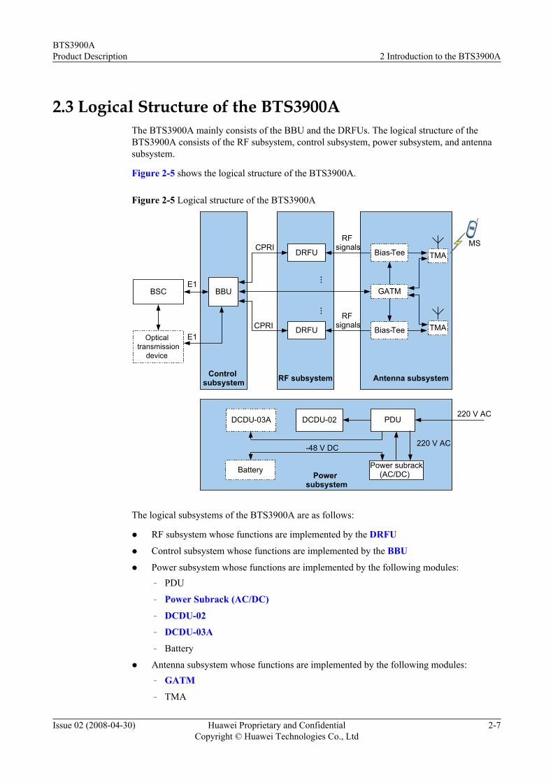
2.3 Logical Structure of the BTS3900AThe BTS3900A mainly consists of the BBU and the DRFUs. The logical structure of theBTS3900A consists of the RF subsystem, control subsystem, power subsystem, and antennasubsystem.
Figure 2-5 shows the logical structure of the BTS3900A.
Figure 2-5 Logical structure of the BTS3900A
Antenna subsystem
GATM
Powersubsystem
CPRI
CPRI
TMA
TMA
MS
RF subsystem
…
DRFU
DRFU
BSCE1
BBU
E1
…
DCDU-02DCDU-03A PDU220 V AC
Battery
220 V AC-48 V DC
Opticaltransmission
device
Controlsubsystem
RFsignals
RFsignals
Bias-Tee
Bias-Tee
Power subrack(AC/DC)
The logical subsystems of the BTS3900A are as follows:
l RF subsystem whose functions are implemented by the DRFU
l Control subsystem whose functions are implemented by the BBU
l Power subsystem whose functions are implemented by the following modules:– PDU
– Power Subrack (AC/DC)
– DCDU-02
– DCDU-03A
– Battery
l Antenna subsystem whose functions are implemented by the following modules:– GATM
– TMA
BTS3900AProduct Description 2 Introduction to the BTS3900A
Issue 02 (2008-04-30) Huawei Proprietary and ConfidentialCopyright © Huawei Technologies Co., Ltd
2-7

– Antenna
2.4 Software Structure of the BTSThe BTS software consists of the platform software, signaling protocol software, OM software,and data center. The latter three are application software, and the platform software providessupport for the application software.
Figure 2-6 shows the software structure of the BTS.
Figure 2-6 Software structure of the BTS
Data center
Signalingprotocol software OM software
Platform software
Platform Software
The platform software provides support for the signaling protocol software, OM software, anddata center. The functions of the platform software are as follows:
l Timing Management
l Task Management
l Memory Management
l Module Management
l Managing the loading and running of the application software
l Providing the message forwarding mechanism between modules
l Tracing massages between modules to facilitate troubleshooting
Signaling Protocol Software
The functions of the signaling protocol software are as follows:
l Processing the radio network layer protocol.
l Processing the transport network layer protocol. The transport network layer protocolperforms transport data configuration, ALCAP processing, and SAAL processing.
l Managing the internal logical resources (such as cells and channels) of the BTS and themapping between physical resources and logical resources.
2 Introduction to the BTS3900ABTS3900A
Product Description
2-8 Huawei Proprietary and ConfidentialCopyright © Huawei Technologies Co., Ltd
Issue 02 (2008-04-30)
OM SoftwareThe OM software works together with the maintenance terminals such as the LMT to maintainthe BTS. The functions of the OM software are as follows:
l Equipment Management
l Data Configuration
l Performance Management
l Commissioning Management
l Alarm Management
l Software Management
l Tracing Management
l Security Management
l Backup Management
l Log Management
Data CenterThe data center stores the configuration data of each module.
BTS3900AProduct Description 2 Introduction to the BTS3900A
Issue 02 (2008-04-30) Huawei Proprietary and ConfidentialCopyright © Huawei Technologies Co., Ltd
2-9


3 Power Distribution of the BTS3900A
The BTS3900A allows the 220 V AC input.
Figure 3-1 shows the power distribution of the BTS3900A.
Figure 3-1 Power distribution of the BTS3900A
BTS3900A power system
220V AC
-48V DC
DRFU3-5
PDU
Power subrack(AC/DC)
DRFU0-2
FMUA
GATM
DCDU-03A
BBU
Battery
AFMU
220V AC
-48V DC
DCDU-02
DCDU-02
The descriptions of the power distribution are as follows:
l When the external 220 V AC is used, the PDU leads the 220 V AC into the PSU (AC/DC)in the power subrack (AC/DC). The PSU converts the 220 V AC to -48 V DC, and thentransmits the converted DC back to the PDU.
BTS3900AProduct Description 3 Power Distribution of the BTS3900A
Issue 02 (2008-04-30) Huawei Proprietary and ConfidentialCopyright © Huawei Technologies Co., Ltd
3-1
l The PDU distributes the -48 V DC. Part of the -48 V DC is directly distributed to certainmodules. Part of the -48 V DC is distributed to the DCDU-02. The DCDU-02 thendistributes the -48 V DC to certain modules.
l When the APM30 transmission cabinet is configured, the PDU leads the -48 V DC to theDCDU-03A in the transmission cabinet. The DCDU-03A then distributes the -48 V DC tocertain modules.
l The power subrack (AC/DC) performs the charging and discharging of the batteries.
3 Power Distribution of the BTS3900ABTS3900A
Product Description
3-2 Huawei Proprietary and ConfidentialCopyright © Huawei Technologies Co., Ltd
Issue 02 (2008-04-30)

4 BTS3900A Monitoring System
The BTS3900A monitoring system enables the power monitoring, fan monitoring, andenvironment monitoring.
BBU Monitoring PortsFigure 4-1 shows the monitoring ports of the BBU.
Figure 4-1 Monitoring ports of the BBU
GTMU
ETH FE0 FE1
CPRI0 CPR12 CPR14
CPR13CPR11 CPR15TX RX
TX0 RX0 TX1 RX1 TX2 RX2 TX3 RX3 TX4 RX4 TX5 RX5 LIU0LIU1
LIU2LIU3
USBTEST E1/T1 RST
RUNALMACT
1 2 3 4 5
INSIDE OUTSIDE
UELP
EXT-ALM1 EXT-ALM0 MON1 MON0
PWR
EXT-ALM1 EX T-ALM0 MON1 MON0
RUN
Alarm signal 0 to 3
Monitoring signal bus 0Monitoring signal bus 1
Alarm signal 4 to 7
Alarm signal 12 to 15Alarm signal 8 to 11
Monitoring signal bus 0Monitoring signal bus 1
l The BBU provides a maximum of two RS485 buses and 16 Boolean signals.
l The modules on RS485 bus 0 cannot be interchanged with the modules on RS485 bus 1.
l When two PMUs are configured, they cannot be connected to the same bus if the settingsof the DIP switches on the two PMUs are the same.
Components of the Monitoring SystemFigure 4-2 shows the components of the BTS3900A monitoring system.
BTS3900AProduct Description 4 BTS3900A Monitoring System
Issue 02 (2008-04-30) Huawei Proprietary and ConfidentialCopyright © Huawei Technologies Co., Ltd
4-1

Figure 4-2 Components of the monitoring system
BBU
RS485 bus0
RS485 bus1
Boolean0-15
PMUEMUA
DCDU-02 1
BSC
GATM2 FMUA1
AFMU1 GATM1
DCDU-02 2
Door sensor of the power cabinet
Door sensor of the battery cabinet
Door sensor of thetransmission cabinet
FAN1 FAN2
FMUA2 ……
AFMU2DCDU-03A User interface
NOTE
The RS485 bus 0 is indicated by bus0. The RS485 bus 1 is indicated by bus1.
Table 4-1 lists the monitoring modules of the BTS3900A.
Table 4-1 Monitoring modules of the BTS3900A
Module Bus No.
FMUA (mandatory) bus0
GATM2 (optional) bus0
PMU (mandatory) bus1
AFMU (mandatory) bus1
GATM1 (optional) bus1
EMUA (optional) bus1
Functions of the BTS3900A Monitoring System
Table 4-2 describes the functions of the BTS3900A monitoring system.
Table 4-2 Functions of the BTS3900A monitoring system
Module Monitoring Function
FAN l Detecting fan fault
l Adjusting rotation speed of the fans
l Detecting temperature and rotation speedof the fans
4 BTS3900A Monitoring SystemBTS3900A
Product Description
4-2 Huawei Proprietary and ConfidentialCopyright © Huawei Technologies Co., Ltd
Issue 02 (2008-04-30)

Module Monitoring Function
GATM Reporting the RET control alarm signals
EMUA l Communicating with the centralprocessing unit through two RS485 ports
l Detecting the input voltage
l Providing independent 12 V DC/24 V DChumidity and temperature sensor ports
l Providing the signal detection port forBoolean input signals in dry contact modeand in OC mode
l Providing six external Boolean outputcontrol ports of the relay node type
PMU l Communicating with the centralprocessing unit through the RS232/RS422serial port
l Managing the power system and thebattery charging and discharging
l Detecting and reporting water immersionalarms, smoke alarms, door status alarms,and standby Boolean value alarms;reporting ambient humidity andtemperature, battery temperature, andstandby analog values
l Detecting power distribution and reportingalarms
DCDU-02 Providing dry contact for surge protectionfailure
BTS3900AProduct Description 4 BTS3900A Monitoring System
Issue 02 (2008-04-30) Huawei Proprietary and ConfidentialCopyright © Huawei Technologies Co., Ltd
4-3

Module Monitoring Function
FMUA l Collecting environment alarm informationin the cabinet. The environment alarm isclassified into temperature alarm,humidity alarm, smoke alarm, waterimmersion alarm, and door status alarm.
l Collecting surge protection alarminformation of the DC power distributionunit
l Monitoring the operating status of fans.The fan speed can be adjusted based on thetemperature or adjusted by the centralprocessing unit.
l Stopping the rotation of the fans when theambient temperature is low
l Detecting the temperature and reportingthe alarm if necessary
l Supporting cascaded RS485 ports andextended RS485 ports
l Supporting cascaded FMUAs
4 BTS3900A Monitoring SystemBTS3900A
Product Description
4-4 Huawei Proprietary and ConfidentialCopyright © Huawei Technologies Co., Ltd
Issue 02 (2008-04-30)

5 Reference Clocks of the BTS3900/BTS3900A
The BTS3900/BTS3900A supports three types of reference clocks: line clock, BITS clock, andfree-run clock.
Line ClockThe BBU3900 directly extracts clock signals from the E1/T1 interface. Then, the BBU exportsthe precise 2 MHz and 8 kHz clocks after frequency dividing, phase locking, and phase adjusting.The 2 MHz and 8 kHz clocks are used for frame synchronization and bit synchronization in theBTS3900/BTS3900A.
BITS ClockThe BBU3900 supports the BITS clock mode by providing a port for the 2.048 MHz BITS clock.
Free-Run ClockWhen the external reference clocks are unavailable, the oven controlled crystal oscillator(OCXO) on the GTMU of the BBU3900 provides the 13 MHz clock to ensure the normaloperation of the BTS.
BTS3900AProduct Description 5 Reference Clocks of the BTS3900/BTS3900A
Issue 02 (2008-04-30) Huawei Proprietary and ConfidentialCopyright © Huawei Technologies Co., Ltd
5-1


6 Signal Flow of the BTS3900/BTS3900A
The signal flow of the BTS3900/BTS3900A consists of the traffic signal flow and the signalingflow of the BTS. The BTS3900/BTS3900A signal flow is classified into the DL traffic signalflow, UL traffic signal flow, and signaling flow.
DL Traffic Signal Flow
The DL traffic signal flow is transmitted from the BSC to the MS through the BTS3900/BTS3900A. In the BTS3900/BTS3900A, the BBU and DRFUs work together to process the DLtraffic signals. Figure 6-1 shows the DL traffic signal flow of the BTS3900/BTS3900A.
Figure 6-1 DL traffic signal flow
DBUSCBUS
FHBUS
3
…
32
DRFU
DRFU
DRFU
BBU MS1
RF signal
3
CPRIE1
BSC
Downlink traffic signal flow
RF signal
RF signal
The DL traffic signal flow is as follows:
1. The BSC sends E1 signals to the BBU through E1 or optical cables.
2. After receiving the E1 signals, the BBU processes the E1 signals as follows:
(1) Extracts clock signals from the E1 signals
(2) Configures the BTS system based on the data configuration on the OML
(3) Encapsulates the E1 data in the format of the CPRI frame, and then transmits the datato the DRFU through the CPRI signal cable
BTS3900AProduct Description 6 Signal Flow of the BTS3900/BTS3900A
Issue 02 (2008-04-30) Huawei Proprietary and ConfidentialCopyright © Huawei Technologies Co., Ltd
6-1

3. After receiving the signals, the DRFU processes the signals as follows:
(1) Decapsulates the high-speed CPRI frames to obtain the baseband signals(2) Transmits the baseband signals to the relevant operation units for encapsulation and
interleaving(3) Converts the digital signals into the analog signals and modulates the analog signals
into RF signals(4) Combines or divides the RF signals based on its own configuration(5) Transmits the combined or divided signals to the antenna subsystem
UL Traffic Signal FlowOpposite to the DL traffic signal flow, the UL traffic signal flow is transmitted from the MS tothe BSC through the BTS3900/BTS3900A. In the BTS3900/BTS3900A, the BBU and DRFUswork together to process the UL traffic signals. Figure 6-2 shows the UL traffic signal flow.
Figure 6-2 UL traffic signal flow
DBUSCBUS
FHBUS
3
…
32
DRFU
DRFU
DRFU
BBU MS1
RF signal
3
CPRIE1
BSC
Uplink traffic signal flow
RF signal
RF signal
The UL traffic signal flow is as follows:
1. The antenna receives the signals sent from the MS. If the TMA is configured, the receivedsignals are amplified by the TMA and then transmitted to the DRFU through the feeder.
2. After receiving the UL signals, the DRFU processes the signals as follows:
(1) Divides the UL signals received from the antenna, Rx1 in, or Rx2 in(2) Converts the divided analog signals into the digital signals to obtain the baseband
signals(3) Transmits the baseband signals to the relevant operation units for decryption and de-
interleaving(4) Encapsulates the processed data in the format of the CPRI frame, and then transmits
the data to the BBU through the CPRI signal cable3. After receiving the signals, the BBU processes the signals as follows:
(1) Decapsulates the high-speed CPRI frames to obtain the baseband signals(2) Encapsulates the baseband signals in the format of the E1 frame, and then transmits
the signals to the BSC through the E1 cable or the optical cable
6 Signal Flow of the BTS3900/BTS3900ABTS3900A
Product Description
6-2 Huawei Proprietary and ConfidentialCopyright © Huawei Technologies Co., Ltd
Issue 02 (2008-04-30)

Signaling FlowThis describes the BTS3900/BTS3900A signaling flow on the Abis interface. The BBU servesas the control unit and works with DRFU to process the signaling. Figure 6-3 shows the signalingflow of the BTS3900/BTS3900A.
Figure 6-3 Signaling flow
…
DRFU
DRFU
DRFU
BBUE1
BSC
DBUSCBUS
FHBUS
2 CPRI
Signaling flow
1
The signaling flow is as follows:
1. The signaling data received from the BSC is transmitted to the BBU through the Abisinterface.
2. The BBU encapsulates the signaling data in the format of the CPRI frame, and thentransmits the signaling data to the DRFU through the CPRI signal cable.
3. The DRFU decapsulates the CPRI signals into the baseband signals, transmits the basebandsignals to the relevant operation units for processing.
4. The BBU encapsulates the data of its own status in the format of the CPRI frame, and thentransmits the data to the DRFU through the CPRI signal cable.
5. The BBU decapsulates the received CPRI signals to obtain the baseband signals.6. The BBU obtains the status of the BTS by analyzing the baseband signals. Then, the BBU
transmits the information on the BTS status to the BSC through the Abis interface.
BTS3900AProduct Description 6 Signal Flow of the BTS3900/BTS3900A
Issue 02 (2008-04-30) Huawei Proprietary and ConfidentialCopyright © Huawei Technologies Co., Ltd
6-3


7 Topologies of the BTS
The topologies of the BTS are classified into star, chain, tree, and ring topologies. The BBU andDRFUs support multiple network topologies such as star, chain, and ring topologies. In practice,these topologies can be combined. Optimum utilization of the topologies can improve the qualityof service and save the investment on the transmission equipment.
Network TopologyFigure 7-1 shows the star topology of the BTS.
Figure 7-1 Star topology of the BTS
BSC
BTS
BTS
BTS
Figure 7-2 shows the chain topology of the BTS.
Figure 7-2 Chain topology of the BTS
BSC BTS BTS BTS
Figure 7-3 shows the tree topology of the BTS.
BTS3900AProduct Description 7 Topologies of the BTS
Issue 02 (2008-04-30) Huawei Proprietary and ConfidentialCopyright © Huawei Technologies Co., Ltd
7-1
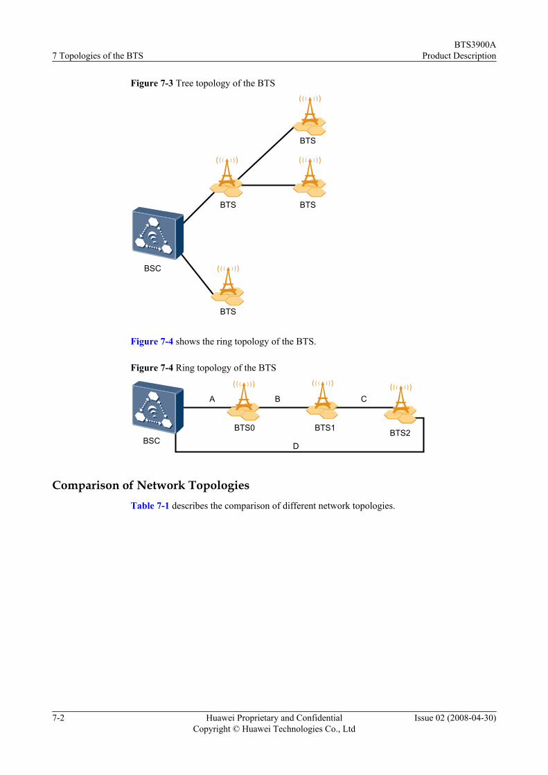
Figure 7-3 Tree topology of the BTS
BSC
BTS
BTS
BTS
BTS
Figure 7-4 shows the ring topology of the BTS.
Figure 7-4 Ring topology of the BTS
BSCBTS0 BTS1 BTS2
A B C
D
Comparison of Network TopologiesTable 7-1 describes the comparison of different network topologies.
7 Topologies of the BTSBTS3900A
Product Description
7-2 Huawei Proprietary and ConfidentialCopyright © Huawei Technologies Co., Ltd
Issue 02 (2008-04-30)

Table 7-1 Comparison of network topologies
NetworkTopologies
ApplicationScenario
Advantage Disadvantage
Star topology Applies to commonareas, especiallydensely populatedareas, such as cities.
l Simplenetworking
l Easy projectimplementation
l Convenientmaintenance
l Flexible capacityexpansion
l High networkreliability
Compared with othertopologies, the startopology requiresmore transmissioncables.
Chain topology Applies to sparselypopulated areas instrip-like terrain,such as areas alonghighways andrailway tracks.
Reduces costs intransmissionequipment,construction, andtransmission linklease.
l As signals passthrough manynodes, thetransmissionreliability in thechain topology isreduced.
l The faults in thecurrent-levelBTSs may affectthe lower-levelBTSs.
l The number oflevels in a chainnetwork shouldnot exceed five.
BTS3900AProduct Description 7 Topologies of the BTS
Issue 02 (2008-04-30) Huawei Proprietary and ConfidentialCopyright © Huawei Technologies Co., Ltd
7-3

NetworkTopologies
ApplicationScenario
Advantage Disadvantage
Tree topology Applies to areaswhere networkstructures, sitedistribution, andsubscriberdistribution arecomplicated, forexample, an areawhere large-scalecoverage overlapshot spot or small-scale coverage.
Requires fewertransmission cablescompared with thestar topology.
l As signals passthrough manynodes, thetransmissionreliability isreduced. Thismakes it difficultfor maintenanceand engineering.
l The faults in thecurrent-levelBTSs may affectthe lower-levelBTSs.
l Capacityexpansion isdifficult.
l The number oflevels in the treeshould not exceedfive.
7 Topologies of the BTSBTS3900A
Product Description
7-4 Huawei Proprietary and ConfidentialCopyright © Huawei Technologies Co., Ltd
Issue 02 (2008-04-30)
NetworkTopologies
ApplicationScenario
Advantage Disadvantage
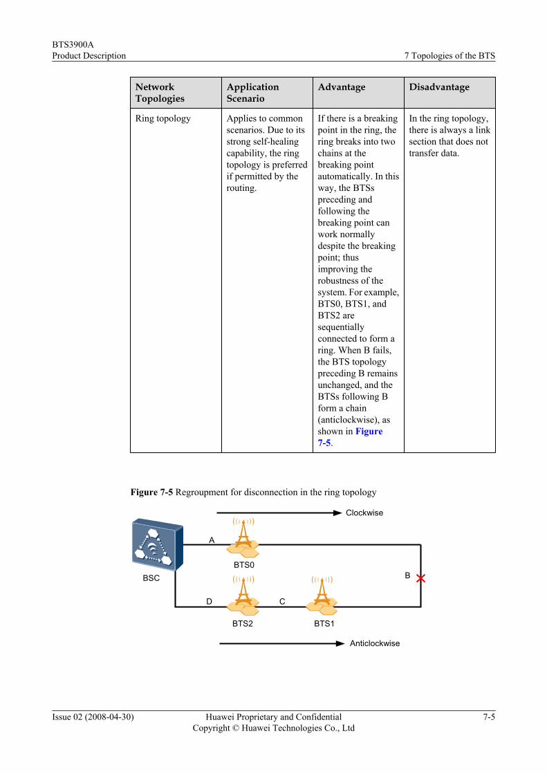
Ring topology Applies to commonscenarios. Due to itsstrong self-healingcapability, the ringtopology is preferredif permitted by therouting.
If there is a breakingpoint in the ring, thering breaks into twochains at thebreaking pointautomatically. In thisway, the BTSspreceding andfollowing thebreaking point canwork normallydespite the breakingpoint; thusimproving therobustness of thesystem. For example,BTS0, BTS1, andBTS2 aresequentiallyconnected to form aring. When B fails,the BTS topologypreceding B remainsunchanged, and theBTSs following Bform a chain(anticlockwise), asshown in Figure7-5.
In the ring topology,there is always a linksection that does nottransfer data.
Figure 7-5 Regroupment for disconnection in the ring topology
BSCBTS0
A
B
CD
BTS2 BTS1
Clockwise
Anticlockwise
BTS3900AProduct Description 7 Topologies of the BTS
Issue 02 (2008-04-30) Huawei Proprietary and ConfidentialCopyright © Huawei Technologies Co., Ltd
7-5


8 Configuration of the BTS3900/BTS3900A
About This Chapter
This describes the configuration principles and typical configurations of the BTS3900/BTS3900A.
8.1 Configuration Principles of the BTS3900/BTS3900AA single BTS3900/BTS3900A cabinet provides up to 12 carriers with the maximum cellconfiguration of S4/4/4, and supports the dual-band application. In the BTS3900/BTS3900A,the antenna subsystem, DRFUs, and BBU need to be configured.
8.2 RF Signal Cable Connections of the DRFUOne end of the RF jumper is connected to the RF port on the DRFU and the other end is connectedto the feeder. You can determine the appropriate RF ports based on the actual configurationmodes.
8.3 Topology of DRFUs Connected by CPRI CablesThe DRFUs support various network topologies: star, chain, and ring.
8.4 Typical Configuration of the BTS3900/BTS3900AThis lists the number of components required for the cell configuration of S1/1/1, S2/2/2, S4/4/4,S6/6/6, S1/1/1 + S3/3/3, S2/2/2 + S2/2/2, and S4/4/4 + S4/4/4.
BTS3900AProduct Description 8 Configuration of the BTS3900/BTS3900A
Issue 02 (2008-04-30) Huawei Proprietary and ConfidentialCopyright © Huawei Technologies Co., Ltd
8-1

8.1 Configuration Principles of the BTS3900/BTS3900AA single BTS3900/BTS3900A cabinet provides up to 12 carriers with the maximum cellconfiguration of S4/4/4, and supports the dual-band application. In the BTS3900/BTS3900A,the antenna subsystem, DRFUs, and BBU need to be configured.
Basic Configuration Principlesl Smooth upgrade of configuration. If multiple types of hardware configurations meet the
requirements for configuring the parameters in network planning, the configuration modethat implements the smooth upgrade is preferred.
l The BTS3900/BTS3900A solution is recommended in S4/4/4 cell configuration or lowerconfigurations. When multiple antennas are permitted, the BTS3900/BTS3900A solutioncan be applied in S6/6/6 and S4/4/4+S4/4/4 dual-band cell configurations.
l Wide coverage. The DRFU supports wide coverage. If required, the DRFU can work inPBT, transmit diversity, or 4-way receive diversity mode in configurations lower than S2.
l Antenna configuration principles: the dual-polarized antenna is used in S4/4/4 or lowerconfigurations; the dual-band dual-polarized antenna or two dual-polarized antennas ondifferent frequency bands are used in S4/4/4 + S4/4/4 cell configuration.
Antenna Configuration Principlesl One antenna can serve up to two DRFUs.
NOTE
Single antenna refers to a bi-polarization antenna, which provides two antenna ports.
l The single antenna mode supports the maximum cell configuration of S4; the doubleantenna mode supports the cell configurations of S4 to S12.
l By default, the receive diversity is adopted in the GSM. That is, one dual-polarized antennamust be configured in a cell.
l In a single cell, one dual-polarized antenna is required in the cell configurations lower thanS4 and two dual-polarized antennas are required in the cell configurations of S5 to S8.
RF Configuration PrinciplesTable 8-1 describes the RF configuration principles of the BTS3900.
8 Configuration of the BTS3900/BTS3900ABTS3900A
Product Description
8-2 Huawei Proprietary and ConfidentialCopyright © Huawei Technologies Co., Ltd
Issue 02 (2008-04-30)

Table 8-1 RF configuration principles of the BTS3900
Principle Description Example
Configuration principles of asingle cabinet
l Star topology is adoptedbetween the BBU andDRFUs. The DRFUs andthe high-speed interfaceson the BBU have a one-to-one mapping relationship.That is, if DRFU slot 1 isidle, CPRI port 1 on theBBU is also idle.
l A single cabinet supportsthe maximum cellconfiguration of S4/4/4.
None
Configuration principles ofmultiple cabinets
l When star and ringtopologies are adoptedbetween the BBU andDRFUs, three levels ofDRFUs in a ring can beconnected to one BBU.That is, one BBU supports3 x 3 = 9 DRFUs.
l When star and chaintopologies are adoptedbetween the BBU andDRFUs, three levels ofDRFUs on a chain can beconnected to one BBU.That is, one BBU supports6 x 3 = 18 DRFUs.
None
Minimum number ofantennas
l Each sector of the BTSmust be configured withthe minimum number ofantennas.
l For the 2-antenna receivediversity, each sector hastwo antenna channels; forthe 4-antenna receivediversity, each sector hasfour antenna channels.
None
BTS3900AProduct Description 8 Configuration of the BTS3900/BTS3900A
Issue 02 (2008-04-30) Huawei Proprietary and ConfidentialCopyright © Huawei Technologies Co., Ltd
8-3

Principle Description Example
Non-combination in thetransmit channel
l The non-combinationconfiguration isrecommended for theDRFU to avoid the powerloss in combination and toreduce the powerconsumption of the BTS.
l If combination is required,the cavity combiner mustbe configured outside theDRFU and onecombination isrecommended.
None
Configuring two TRXs inone sector
l A single DRFU does notsupport the S1/1application; however,three DRFUs support theS3/3 application.
l When the DRFU works intransmit PBT, transmitdiversity, or 4-way receivediversity mode, a DRFUprovides only one TRX.Therefore, the actualconfiguration does notinvolve the mode ofconfiguring two TRXs inone sector.
For example, for a site inS5/4/7 cell configuration,nine DRFUs are installedmeeting the requirements ofS6/4/8 cell configuration butdata is still configured inS5/4/7 cell configuration.
Parity cell configuration When the sectorconfiguration in the middle isS4 or S8, the TRXs in theneighbor sectors can beconfigured to the middlesector.
S3/4/3, S3/4/5, S5/4/3,S3/4/7, S7/4/3, S5/4/5,S5/4/7, S7/4/5, S7/4/7,S3/8/3, S3/8/5, S3/8/7,S5/8/3, S5/8/5, S5/8/7,S7/8/3, S7/8/5, and S7/8/7
Number of DRFUs Number of DRFUs = (Roundup) Number of S1 sectors +(Number of TRXs - Numberof S1 sectors) ÷ 2
l S1/1/1: Number ofDRFUs = 3
l S3/3/3: Number ofDRFUs = (Round up) (9 ÷2) = 5
l S1/2/3, Number of DRFUs= 1 + (Round up) ((6 - 1) ÷2) = 4
l S1/1/3, Number of DRFUs= 2 + (Round up) ((5 - 2) ÷2) = 4
8 Configuration of the BTS3900/BTS3900ABTS3900A
Product Description
8-4 Huawei Proprietary and ConfidentialCopyright © Huawei Technologies Co., Ltd
Issue 02 (2008-04-30)

Principle Description Example
TRX allocation in doubleantenna mode
After TRX allocation, thecells with the odd number ofTRXs are adjacent cells.l S5 = S3 + S2 or S5 = S2 +
S3l S6 = S4 + S2 or S6 = S3 +
S3l S7 = S4 + S3 or S7 = S3 +
S4l S8 = S4 + S4
l In S3/5/4, S5 can bedivided into S3 + S2.Then, the cellconfiguration is S3/(3/2)/4.
l In S2/5/5, the first S5 isdivided into S2 + S3; thesecond S5 is divided intoS3 + S2. Then, the cellconfiguration is S2/(2/3)/(3/2).
NOTE
In the mode of configuring two TRXs in one sector, a DRFU belongs to only one sector.
Configuration Principles of the BBUl One BBU provides six CPRI ports. In the ring topology, a single BBU supports up to 18
TRXs; in the chain topology, a single BBU supports up to 36 TRXs.l Table 8-2 describes the configuration principles of the boards in the BBU.
Table 8-2 Configuration principles of the boards in the BBU
Board/Module Description
BSBC One BSBC must be configured.
UBFA One UBFA must be configured.
UPEU l One UPEU must be configured.
l One additional UPEU can be configuredwhen the backup power is required. Theadditional UPEU, however, cannot beconfigured with the UEIU at the sametime.
UEIU l One UEIU must be configured when twoBTS3900 cabinets are configured.
l One UEIU must be configured when twoAPM30 power cabinets are configured.
GTMU l One GTMU must be configured.
l The GTMU occupies slot 5 and slot 6.
UELP l The UELP is not required in theBTS3900.
l One UELP must be configured in theBTS3900A.
BTS3900AProduct Description 8 Configuration of the BTS3900/BTS3900A
Issue 02 (2008-04-30) Huawei Proprietary and ConfidentialCopyright © Huawei Technologies Co., Ltd
8-5

8.2 RF Signal Cable Connections of the DRFUOne end of the RF jumper is connected to the RF port on the DRFU and the other end is connectedto the feeder. You can determine the appropriate RF ports based on the actual configurationmodes.
RF Cable Connections of the DRFUl The transmit mode and antenna mode described in the following list are set on the BSC
side.
l The RF cables differ from each other in colors. Figure 8-1 shows the mapping between theRF signal cables and their colors.
Figure 8-1 Mapping between the RF signal cables and their colors
RF jumper betweenthe cascaded DRFUs
Feeder jumperCPRI signal cableCPRI signal cable for
cascaded DRFU modules
S1 Without Transmit Diversity, S1 with Transmit Diversity, and S2 WithoutTransmit Diversity
The S1 without transmit diversity, S1 with transmit diversity, and S2 without transmit diversityuse the configuration of one DRFU and one dual-polarized antenna. Table 8-3 describes therelated configurations.
Table 8-3 Configuration (1)
TypicalConfigurationMode
Transmit Mode Antenna Mode CableConfiguration
S1 without transmitdiversity
Transmitindependency orcombining
Single AntennaDouble Receiver
l One DRFUmodule
l One dual-polarized antennaS1 with transmit
diversityTransmit diversity Double Antenna
S2 without transmitdiversity
Transmitindependency orcombining
Single AntennaDouble Receiver
Figure 8-2 shows the cable connections.
8 Configuration of the BTS3900/BTS3900ABTS3900A
Product Description
8-6 Huawei Proprietary and ConfidentialCopyright © Huawei Technologies Co., Ltd
Issue 02 (2008-04-30)

Figure 8-2 Connections of RF cables for S1 (without transmit diversity/with transmit diversity)/S2 (without transmit diversity)
INSIDE OUTSIDE
UELP
Antenna
S2 with PBT, S3 Without Transmit Diversity, and S4 Without Transmit DiversityThe S2 with PBT, S3 without transmit diversity, and S4 without transmit diversity use theconfiguration of two DRFUs and one dual-polarized antenna. Table 8-4 describes the relatedconfigurations.
Table 8-4 Configuration (2)
TypicalConfigurationMode
Transmit Mode Antenna Mode CableConfiguration
S2 with PBT PBT Single AntennaDouble Receiver
l Two DRFUsl One dual-
polarized antennaS3 without transmitdiversity
Transmitindependency orcombining
Single AntennaDouble Receiver
S4 without transmitdiversity
Transmitindependency orcombining
Single AntennaDouble Receiver
Figure 8-3 shows the cable connections.
BTS3900AProduct Description 8 Configuration of the BTS3900/BTS3900A
Issue 02 (2008-04-30) Huawei Proprietary and ConfidentialCopyright © Huawei Technologies Co., Ltd
8-7

Figure 8-3 Connections of RF cables for S2 (PBT)/S3 (without transmit diversity)/S4 (withouttransmit diversity)
Antenna
INSIDE OUTSIDE
UELP
S2 (4-Way Receive Diversity)The S2 with 4-way receive diversity uses the configuration of two DRFUs and two dual-polarized antennas. The related configuration is as follows:
l Receive mode: 4-Way Receive Diversity
l Set the antenna mode to Double Antenna 4-Way Receiver.
Figure 8-4 shows the cable connections.
8 Configuration of the BTS3900/BTS3900ABTS3900A
Product Description
8-8 Huawei Proprietary and ConfidentialCopyright © Huawei Technologies Co., Ltd
Issue 02 (2008-04-30)

Figure 8-4 Connections of RF signal cables for S2 (4-way receive diversity)
Antenna Antenna
INSIDE OUTSIDE
UELP
S2 with Transmit Diversity and S4 with Transmit IndependencyThe S2 with transmit diversity and S4 with transmit independency use the configuration of twoDRFUs and two dual-polarized antennas. Table 8-5 describes the related configurations.
Table 8-5 Configuration (3)
TypicalConfigurationMode
Transmit Mode Antenna Mode CableConfiguration
S2 (with transmitdiversity)
Transmit diversity Double Antenna l Two DRFUsl Two dual-
polarizedantennas
S4 with transmitindependency
Transmitindependency orcombining
Double Antenna
Figure 8-5 shows the cable connections.
BTS3900AProduct Description 8 Configuration of the BTS3900/BTS3900A
Issue 02 (2008-04-30) Huawei Proprietary and ConfidentialCopyright © Huawei Technologies Co., Ltd
8-9

Figure 8-5 Connections of RF cables for S2 (transmit diversity)/S4 (transmit independency)
INSIDE OUTSIDE
UELP
Antenna Antenna
S5 Without Transmit Diversity and S6 Without Transmit DiversityThe S5 without transmit diversity and S6 without transmit diversity use the configuration ofthree DRFUs and two dual-polarized antennas. Table 8-6 describes the related configurations.
Table 8-6 Configuration (4)
TypicalConfigurationMode
Transmit Mode Antenna Mode CableConfiguration
S5 without transmitdiversity
Transmitindependency orcombining
l DRFU0: SingleAntenna DoubleReceiver
l DRFU1: SingleAntenna DoubleReceiver
l DRFU2: SingleAntenna DoubleReceiver
l Three DRFUs
l Two dual-polarizedantennas
8 Configuration of the BTS3900/BTS3900ABTS3900A
Product Description
8-10 Huawei Proprietary and ConfidentialCopyright © Huawei Technologies Co., Ltd
Issue 02 (2008-04-30)

TypicalConfigurationMode
Transmit Mode Antenna Mode CableConfiguration
S6 without transmitdiversity
Transmitindependency orcombining
l DRFU0: SingleAntenna DoubleReceiver
l DRFU1: SingleAntenna DoubleReceiver
l DRFU2: DoubleAntenna
Figure 8-6 shows the cable connections.
Figure 8-6 Connections of RF cables for S5 (without transmit diversity)/S6 (without transmitdiversity)
INSIDE OUTSIDE
UELP
Antenna Antenna
S7 Without Transmit Diversity and S8 Without Transmit DiversityThe S7 without transmit diversity and S8 without transmit diversity use the configuration of fourDRFUs and two dual-polarized antennas. Table 8-7 describes the related configurations.
BTS3900AProduct Description 8 Configuration of the BTS3900/BTS3900A
Issue 02 (2008-04-30) Huawei Proprietary and ConfidentialCopyright © Huawei Technologies Co., Ltd
8-11

Table 8-7 Configuration (5)
TypicalConfigurationMode
Transmit Mode Antenna Mode CableConfiguration
S7 without transmitdiversity
Transmitindependency orcombining
Single AntennaDouble Receiver
l Four DRFUsl Two dual-
polarizedantennasS8 without transmit
diversityTransmitindependency orcombining
Single AntennaDouble Receiver
Figure 8-7 shows the cable connections.
Figure 8-7 Connections of RF cables for S7 (without transmit diversity)/S8 (without transmitdiversity)
INSIDE OUTSIDE
UELP
Antenna Antenna
8.3 Topology of DRFUs Connected by CPRI CablesThe DRFUs support various network topologies: star, chain, and ring.
Figure 8-8 shows the typical topology of the DRFUs.
8 Configuration of the BTS3900/BTS3900ABTS3900A
Product Description
8-12 Huawei Proprietary and ConfidentialCopyright © Huawei Technologies Co., Ltd
Issue 02 (2008-04-30)

Figure 8-8 Typical topology of the DRFUs
INSIDE OUTSIDE
UELP
Star connection Ring connection
Chain connection
NOTE
When the chain topology is used, a maximum of three levels of DRFUs can be connected to one BBU.
Table 8-8 describes the three typical topologies of the DRFUs.
Table 8-8 Comparison of the three typical topologies of the DRFUs
Topology Advantage Disadvantage
Star l Simple networking
l Easy projectimplementation
l Convenient maintenance
l Flexible capacityexpansion
l High network reliability
Compared with othertopologies, the star topologyrequires more transmissioncables.
Chain Supports the maximumconfiguration
l Low network reliability
l Requires a large quantityof transmission cables
BTS3900AProduct Description 8 Configuration of the BTS3900/BTS3900A
Issue 02 (2008-04-30) Huawei Proprietary and ConfidentialCopyright © Huawei Technologies Co., Ltd
8-13

Topology Advantage Disadvantage
Ring High network reliability Complicated networkstructure
8.4 Typical Configuration of the BTS3900/BTS3900AThis lists the number of components required for the cell configuration of S1/1/1, S2/2/2, S4/4/4,S6/6/6, S1/1/1 + S3/3/3, S2/2/2 + S2/2/2, and S4/4/4 + S4/4/4.
Table 8-9 lists the typical configuration of the BTS3900/BTS3900A.
Table 8-9 Typical configuration of the BTS3900/BTS3900A
TypicalConfiguration
Number ofDRFUs
Number ofAntennas
Number of OtherComponents ofthe BTS3900
Number of OtherComponents ofthe BTS3900A
S1/1/1 3 3 l BTS3900cabinet: 1
l FAN unit: 1l DCDU-01: 1l BBU: 1l Power subrack
(DC/DC): 1 (+24V DC input)
l Power subrack(AC/DC): 1 (220V AC input)
l GATM: optional
l APM30 powercabinet: 1
l Power subrack(AC/DC): 1
l PDU: 1l BBU: 1l GATM: optionall RF cabinet: 1l FMUA: 1l DCDU-02: 2l FAN unit: 2
S2/2/2 3 3
S4/4/4 6 3
S2/2/2 +S2/2/2
6 6
S6/6/6 9 6 l BTS3900cabinet: 2
l FAN unit: 2l DCDU-01: 2l BBU: 1l Power subrack
(DC/DC): 1 (+24V DC input)
l Power subrack(AC/DC): 1 (220V AC input)
l GATM: optional
l APM30 powercabinet: 1
l Power subrack(AC/DC): 1
l PDU: 1l BBU: 1l GATM: optionall RF cabinet: 2l FMUA: 2l DCDU-02: 4l FAN unit: 4
S1/1/1 +S3/3/3
8 6
S4/4/4 +S4/4/4
12 6
8 Configuration of the BTS3900/BTS3900ABTS3900A
Product Description
8-14 Huawei Proprietary and ConfidentialCopyright © Huawei Technologies Co., Ltd
Issue 02 (2008-04-30)

NOTE
The number of antennas in a dual-band network is applicable to the configuration that the two bands donot share the antennas. When the two bands share the antennas, the number of antennas in the dual-bandnetwork is calculated in the same way as that in the single-band network.
BTS3900AProduct Description 8 Configuration of the BTS3900/BTS3900A
Issue 02 (2008-04-30) Huawei Proprietary and ConfidentialCopyright © Huawei Technologies Co., Ltd
8-15


9 OM System of the BTS
About This Chapter
The OM system implements the management, monitoring, and maintenance tasks of theBTS3900. It provides various OM modes and multiple maintenance platforms to meet differentmaintenance requirements.
9.1 OM Modes of the BTSThe OM modes of the BTS consist of the Site Maintenance Terminal mode, Local MaintenanceTerminal mode, and centralized network management mode.
9.2 OM Functions of the BTSThe OM functions of the BTS3900 consist of equipment management, software management,configuration management, service management, performance management, securitymanagement, alarm management, and environment monitoring.
BTS3900AProduct Description 9 OM System of the BTS
Issue 02 (2008-04-30) Huawei Proprietary and ConfidentialCopyright © Huawei Technologies Co., Ltd
9-1
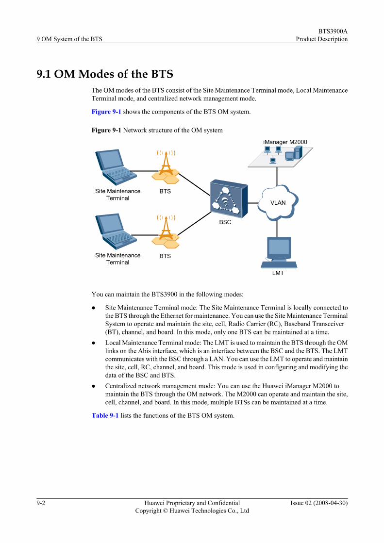
9.1 OM Modes of the BTSThe OM modes of the BTS consist of the Site Maintenance Terminal mode, Local MaintenanceTerminal mode, and centralized network management mode.
Figure 9-1 shows the components of the BTS OM system.
Figure 9-1 Network structure of the OM system
Site MaintenanceTerminal
BSC
VLAN
iManager M2000
LMT
BTS
BTSSite MaintenanceTerminal
You can maintain the BTS3900 in the following modes:
l Site Maintenance Terminal mode: The Site Maintenance Terminal is locally connected tothe BTS through the Ethernet for maintenance. You can use the Site Maintenance TerminalSystem to operate and maintain the site, cell, Radio Carrier (RC), Baseband Transceiver(BT), channel, and board. In this mode, only one BTS can be maintained at a time.
l Local Maintenance Terminal mode: The LMT is used to maintain the BTS through the OMlinks on the Abis interface, which is an interface between the BSC and the BTS. The LMTcommunicates with the BSC through a LAN. You can use the LMT to operate and maintainthe site, cell, RC, channel, and board. This mode is used in configuring and modifying thedata of the BSC and BTS.
l Centralized network management mode: You can use the Huawei iManager M2000 tomaintain the BTS through the OM network. The M2000 can operate and maintain the site,cell, channel, and board. In this mode, multiple BTSs can be maintained at a time.
Table 9-1 lists the functions of the BTS OM system.
9 OM System of the BTSBTS3900A
Product Description
9-2 Huawei Proprietary and ConfidentialCopyright © Huawei Technologies Co., Ltd
Issue 02 (2008-04-30)
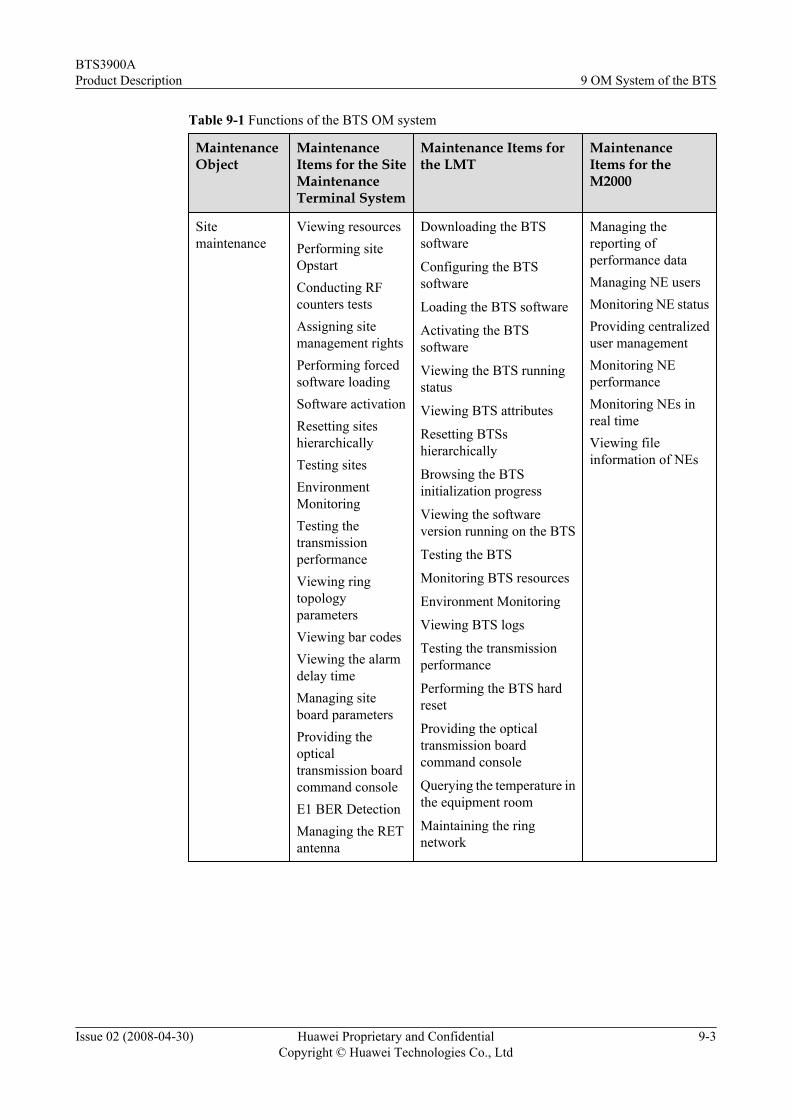
Table 9-1 Functions of the BTS OM system
MaintenanceObject
MaintenanceItems for the SiteMaintenanceTerminal System
Maintenance Items forthe LMT
MaintenanceItems for theM2000
Sitemaintenance
Viewing resourcesPerforming siteOpstartConducting RFcounters testsAssigning sitemanagement rightsPerforming forcedsoftware loadingSoftware activationResetting siteshierarchicallyTesting sitesEnvironmentMonitoringTesting thetransmissionperformanceViewing ringtopologyparametersViewing bar codesViewing the alarmdelay timeManaging siteboard parametersProviding theopticaltransmission boardcommand consoleE1 BER DetectionManaging the RETantenna
Downloading the BTSsoftware
Configuring the BTSsoftware
Loading the BTS software
Activating the BTSsoftware
Viewing the BTS runningstatus
Viewing BTS attributes
Resetting BTSshierarchically
Browsing the BTSinitialization progress
Viewing the softwareversion running on the BTS
Testing the BTS
Monitoring BTS resources
Environment Monitoring
Viewing BTS logs
Testing the transmissionperformance
Performing the BTS hardreset
Providing the opticaltransmission boardcommand console
Querying the temperature inthe equipment room
Maintaining the ringnetwork
Managing thereporting ofperformance dataManaging NE usersMonitoring NE statusProviding centralizeduser managementMonitoring NEperformanceMonitoring NEs inreal timeViewing fileinformation of NEs
BTS3900AProduct Description 9 OM System of the BTS
Issue 02 (2008-04-30) Huawei Proprietary and ConfidentialCopyright © Huawei Technologies Co., Ltd
9-3

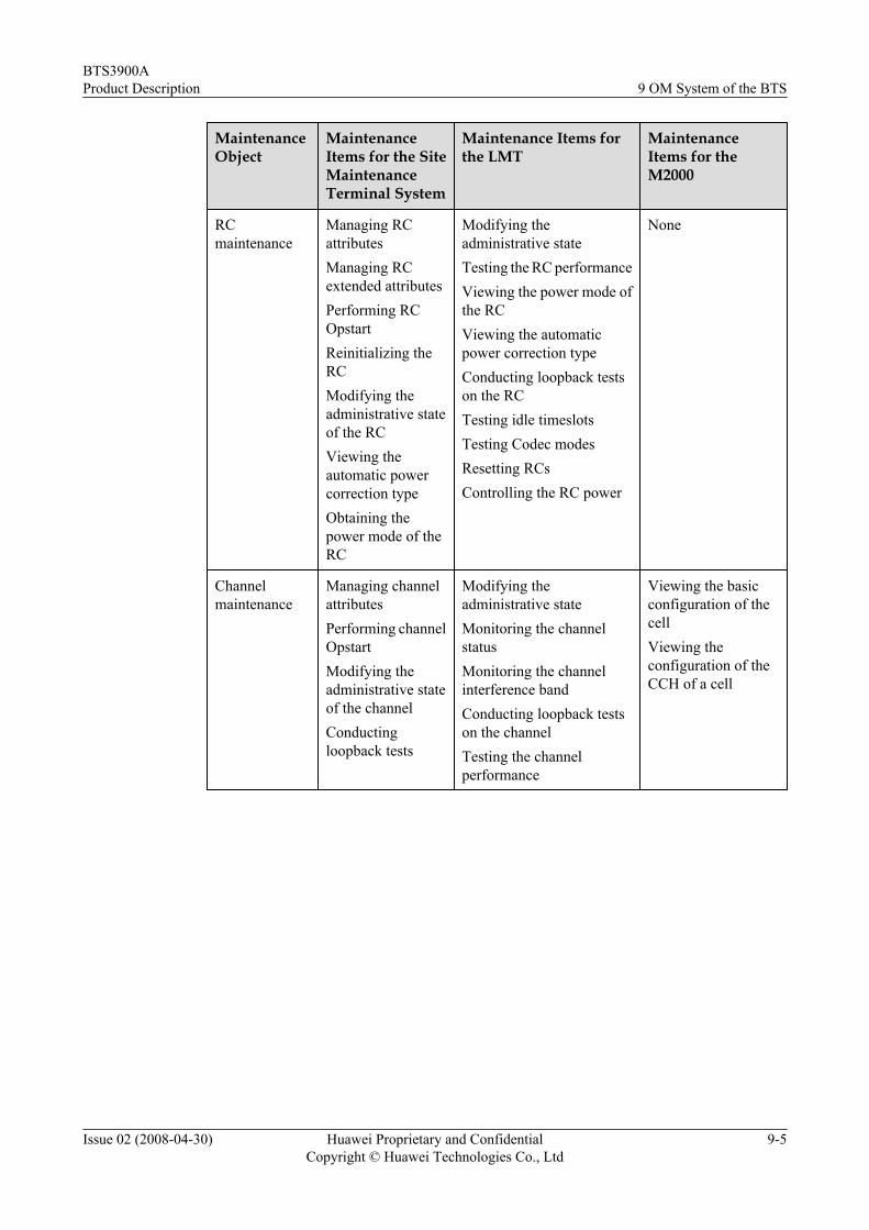
MaintenanceObject
MaintenanceItems for the SiteMaintenanceTerminal System
Maintenance Items forthe LMT
MaintenanceItems for theM2000
Cellmaintenance
Managing cellattributesManaging extendedcell attributesPerforming cellOpstartTesting the cellperformanceModifying theadministrative stateof the cell
Modifying theadministrative statePerforming force handoversSending cell systemmessagesQuerying frequencyscanningConfiguring frequencyscanning
Viewing the statisticsof the celldistributionViewing the basicconfiguration of thecellViewing theconfiguration of theCCH of a cellViewing neighborcellsMonitoring theconfiguration of anobjectCollecting the alarmsof the monitoredobjectBlocking/unblockingcells
BTmaintenance
Performing BTOpstartReinitializing theBTTRX Full PowerEmissionModifying theadministrative stateof the BTTesting the BTViewing thechannel status
None None
9 OM System of the BTSBTS3900A
Product Description
9-4 Huawei Proprietary and ConfidentialCopyright © Huawei Technologies Co., Ltd
Issue 02 (2008-04-30)
MaintenanceObject
MaintenanceItems for the SiteMaintenanceTerminal System
Maintenance Items forthe LMT
MaintenanceItems for theM2000
RCmaintenance
Managing RCattributesManaging RCextended attributesPerforming RCOpstartReinitializing theRCModifying theadministrative stateof the RCViewing theautomatic powercorrection typeObtaining thepower mode of theRC
Modifying theadministrative stateTesting the RC performanceViewing the power mode ofthe RCViewing the automaticpower correction typeConducting loopback testson the RCTesting idle timeslotsTesting Codec modesResetting RCsControlling the RC power
None
Channelmaintenance
Managing channelattributesPerforming channelOpstartModifying theadministrative stateof the channelConductingloopback tests
Modifying theadministrative stateMonitoring the channelstatusMonitoring the channelinterference bandConducting loopback testson the channelTesting the channelperformance
Viewing the basicconfiguration of thecellViewing theconfiguration of theCCH of a cell
BTS3900AProduct Description 9 OM System of the BTS
Issue 02 (2008-04-30) Huawei Proprietary and ConfidentialCopyright © Huawei Technologies Co., Ltd
9-5
MaintenanceObject
MaintenanceItems for the SiteMaintenanceTerminal System
Maintenance Items forthe LMT
MaintenanceItems for theM2000
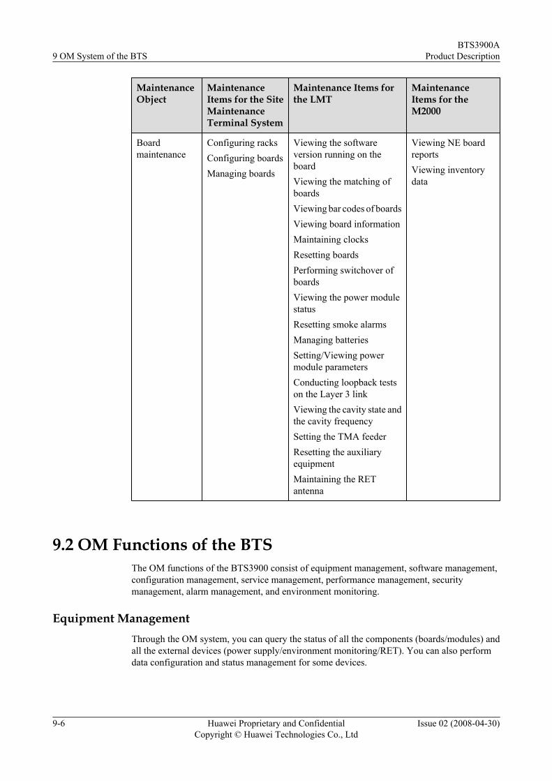
Boardmaintenance
Configuring racksConfiguring boardsManaging boards
Viewing the softwareversion running on theboardViewing the matching ofboardsViewing bar codes of boardsViewing board informationMaintaining clocksResetting boardsPerforming switchover ofboardsViewing the power modulestatusResetting smoke alarmsManaging batteriesSetting/Viewing powermodule parametersConducting loopback testson the Layer 3 linkViewing the cavity state andthe cavity frequencySetting the TMA feederResetting the auxiliaryequipmentMaintaining the RETantenna
Viewing NE boardreportsViewing inventorydata
9.2 OM Functions of the BTSThe OM functions of the BTS3900 consist of equipment management, software management,configuration management, service management, performance management, securitymanagement, alarm management, and environment monitoring.
Equipment ManagementThrough the OM system, you can query the status of all the components (boards/modules) andall the external devices (power supply/environment monitoring/RET). You can also performdata configuration and status management for some devices.
9 OM System of the BTSBTS3900A
Product Description
9-6 Huawei Proprietary and ConfidentialCopyright © Huawei Technologies Co., Ltd
Issue 02 (2008-04-30)
Software Managementl Provides various functions, such as downloading and activating the BTS software,
upgrading patches, and loading and downloading files. The associated tasks involveconsistency check on the software and hardware releases, release management, andsoftware upgrade.
l Allows the BTS software upgrade through the USB port on the BBU without a PC.
Configuration Managementl Checks whether the added, deleted, or changed BTS data is consistent with the actual
situation.
l Supports automatic data backup.
l Supports dynamic and static data configuration. In dynamic data configuration, the dataimmediately take effect after modification; in static data configuration, the modified datatake effect after the BTS is reset.
Service Managementl Supports parameter setting and alarm query for the baseband boards, RET antenna, and
environment monitoring device.
l Supports various OM functions for the RET antenna, such as automatic scanning, dataconfiguration (antenna tilt and TMA gain), status query, and alarm reporting.
l Supports perfect self-test on hardware installation. The BTS can use the software packagesaved in the USB disk to perform local upgrade; thus shortening the upgrade period.
Performance Managementl Monitors the performance of the internal and external telecommunications networks and
generates alarms when the performance deteriorates
l Monitors the operating status of the BTS, such as monitors the traffic volume on the portsand measures the technical data of the BTS
l Monitoring the usage of key components in the board, such as the CPU and DSP
Security Management
The O&M system provides security management functions, such as connection management,user authentication, encryption, and forward and backward resolution of the interface messagesbetween the BTS software and the OMC.
Alarm Managementl Supports query of real-time alarms and history alarms
l Collects internal and external alarms, such as the environment monitoring device inputsand Boolean inputs
l Processes alarm correlation to ensure precision and accuracy in locating alarms
l Provides functions of saving, interpreting, prompting, shielding, filtering, confirming,clearing, post processing, and reporting of alarms
l Detecting and reporting alarms, and processing alarm correlation in the system
BTS3900AProduct Description 9 OM System of the BTS
Issue 02 (2008-04-30) Huawei Proprietary and ConfidentialCopyright © Huawei Technologies Co., Ltd
9-7

Environment Monitoringl The BTS has a perfect environment monitoring system.
l The environment monitoring system provides customized solutions regarding door control,infrared, smoke, water damage, humidity, and temperature monitoring.
9 OM System of the BTSBTS3900A
Product Description
9-8 Huawei Proprietary and ConfidentialCopyright © Huawei Technologies Co., Ltd
Issue 02 (2008-04-30)

10 Technical Specifications of theBTS3900A
About This Chapter
The technical specifications of the BTS3900A consist of the capacity specifications, RFspecifications, engineering specifications, surge protection specifications, physical ports,environmental requirements, and compliance standards.
10.1 Capacity Specifications of the BTS3900/BTS3900AThe BTS3900/BTS3900A capacity specifications are in terms of the number of TRXs and cells.
10.2 RF Specifications of the BTS3900/BTS3900AThe radio frequency specifications of the BTS3900/BTS3900A involve the specifications relatedto the operating frequency bands, the transmitter, and the receiver.
10.3 Engineering Specifications of the BTS3900AThe engineering specifications consist of the dimensions, weight, power supply, and powerconsumption.
10.4 Surge Protection Specifications of the BTS3900AThe BTS3900A provides surge protection for each type of port. The surge protectionspecifications of the BTS3900A ports consist of the DC or AC power supply, antenna, signal,and dry contact alarms.
10.5 Ports of the BTS3900AThis describes the physical ports of the BTS3900A. The BTS3900A provides various types ofphysical ports for the external equipment connection. The ports of the BTS3900A consist of thepower ports, transmission ports, and alarm ports.
10.6 Compliance Standards of the BTS3900/BTS3900AThe BTS3900/BTS3900A complies with the standards of power distribution, EMC, surgeprotection, safety, operating environment, transportation adaptability, and storage adaptability.
10.7 Environmental Requirements of the BTS3900AThe environmental requirements of the BTS3900A consist of the environmental requirementsfor operating, transporting, and storing the BTS3900A.
BTS3900AProduct Description 10 Technical Specifications of the BTS3900A
Issue 02 (2008-04-30) Huawei Proprietary and ConfidentialCopyright © Huawei Technologies Co., Ltd
10-1

10.1 Capacity Specifications of the BTS3900/BTS3900AThe BTS3900/BTS3900A capacity specifications are in terms of the number of TRXs and cells.
l A single cabinet holds up to six DRFUs.
l A single cabinet serves up to six sectors.
l A single cabinet supports the maximum configuration of S4/4/4, up to 12 GSM TRXs.
l Multiple cabinets support the maximum configuration of S24/24/24, up to 72 GSM TRXs.
10.2 RF Specifications of the BTS3900/BTS3900AThe radio frequency specifications of the BTS3900/BTS3900A involve the specifications relatedto the operating frequency bands, the transmitter, and the receiver.
Operating Frequency Band
Table 10-1 lists the frequency bands supported by the BTS3900/BTS3900A. The spacingbetween two frequencies is 200 kHz.
Table 10-1 Operating frequency bands of the BTS3900/BTS3900A
Operating FrequencyBand
Receive Band Transmit Band
PGSM 900 MHz 890-915 MHz 935-960 MHz
EGSM 900 MHz 880-915 MHz 925-960 MHz
GSM 1800 MHz 1710-1785 MHz 1805-1880 MHz
Transmitter Specifications
Table 10-2 lists the rated output power of the DRFU in the BTS3900/BTS3900A.
Table 10-2 Output power of the DRFU in the BTS3900/BTS3900A
Operating FrequencyBand
Work Mode Output Power (GMSK/8PSK TOC)
900 MHz Non-combination 45 W/30 W
900 MHz Combination 20 W/14 W
900 MHz PBT 71 W/47 W
1800 MHz Non-combination 40 W/26 W
1800 MHz Combination 18 W/12 W
10 Technical Specifications of the BTS3900ABTS3900A
Product Description
10-2 Huawei Proprietary and ConfidentialCopyright © Huawei Technologies Co., Ltd
Issue 02 (2008-04-30)

Operating FrequencyBand
Work Mode Output Power (GMSK/8PSK TOC)
1800 MHz PBT 63 W/42 W
Receiver Specifications
Table 10-3 lists the static receiver sensitivity of the BTS3900/BTS3900A.
Table 10-3 Receiver sensitivity of the BTS3900/BTS3900A
Receive Mode Operating Frequency Band Static Sensitivity (TypicalValue)
Receive independency 900 MHz -113 dBm
1800 MHz -113 dBm
Two-way receivediversity
900 MHz -116 dBm
1800 MHz -116 dBm
Four-way receivediversity
900 MHz -118.5 dBm
1800 MHz -118.5 dBm
10.3 Engineering Specifications of the BTS3900AThe engineering specifications consist of the dimensions, weight, power supply, and powerconsumption.
Dimensions
Table 10-4 lists the dimensions of the BTS3900A cabinet.
Table 10-4 Dimensions
Cabinet Type Width (mm) Depth (mm) Height (mm)
RF cabinet 600 480 700
APM30 power cabinet 600 480 700
Cabinet base 600 480 200
Weight
Table 10-5 lists the weight of the BTS3900A cabinet.
BTS3900AProduct Description 10 Technical Specifications of the BTS3900A
Issue 02 (2008-04-30) Huawei Proprietary and ConfidentialCopyright © Huawei Technologies Co., Ltd
10-3

Table 10-5 Weight
Cabinet Type Weight (kg)
RF cabinet (DRFUs not involved) 58
RF cabinet (DRFUs involved) 130
APM30 power cabinet (BBU not involved) 65
APM30 power cabinet + RF cabinet 205
Power SupplyTable 10-6 lists the specifications of the power input for the BTS3900A.
Table 10-6 Specifications of the input power
Power Type Rated Value Permissible Range
220 V AC 220 V AC 176 V AC to 280 V AC
Power ConsumptionTable 10-7 lists the power consumption value of the BTS3900A in S4/4/4 configuration.
Table 10-7 Power consumption of the BTS3900A (S4/4/4)
Mode Maximum PowerConsumption (W)
Typical PowerConsumption (W)
GSM900, TOC = 20 W 2120 1150
DCS1800, TOC = 18 W 2070 1140
10.4 Surge Protection Specifications of the BTS3900AThe BTS3900A provides surge protection for each type of port. The surge protectionspecifications of the BTS3900A ports consist of the DC or AC power supply, antenna, signal,and dry contact alarms.
NOTE
l The surge protection specifications of the BTS3900A are defined in compliance with EN300 253. Inaddition, the specifications meet ITU-TK series and IEC61000-4-5.
l The unspecified surge current with maximum discharge current is called nominal discharge current.
10 Technical Specifications of the BTS3900ABTS3900A
Product Description
10-4 Huawei Proprietary and ConfidentialCopyright © Huawei Technologies Co., Ltd
Issue 02 (2008-04-30)

Table 10-8 Surge protection specifications of the BTS3900A
Port Surge Protection Mode Surge Current
Signal port Differential mode 3 kA (8/20 us surgecurrent)
Common mode 5 kA (8/20 us surgecurrent)
Transmission port Differential mode 3 kA (8/20 us surgecurrent)
Common mode 5 kA (8/20 us surgecurrent)
E1 port Differential mode 3 kA (8/20 us surgecurrent)
Common mode 5 kA (8/20 us surgecurrent)
AC input port Differential mode 60 kA (8/20 us surgecurrent)
Common mode 60 kA (8/20 us surgecurrent)
DC input port Differential mode 10 kA (8/20 us surgecurrent)
Common mode 15 kA (8/20 us surgecurrent)
10.5 Ports of the BTS3900AThis describes the physical ports of the BTS3900A. The BTS3900A provides various types ofphysical ports for the external equipment connection. The ports of the BTS3900A consist of thepower ports, transmission ports, and alarm ports.
Power Ports
Table 10-9 Power ports of the BTS3900A
Port Module Description
Power input terminal Wiring Unit of the PowerSubrack (220 V)
220 V AC input
BTS3900AProduct Description 10 Technical Specifications of the BTS3900A
Issue 02 (2008-04-30) Huawei Proprietary and ConfidentialCopyright © Huawei Technologies Co., Ltd
10-5

Transmission Ports
Table 10-10 BBU transmission ports
Port Type Description
INSIDE DB25 male connector Transmits the four E1/T1 signalsbetween the UELP and the GTMU
OUTSIDE DB26 male connector Provides the input and output of thefour E1/T1 signals between the BBUand the BSC
CPRI0-CPRI5 SFP connector Provides the input and output of theoptical and electrical transmissionsignals between the BBU and the RFmodule
E1/T1 DB26 male connector Provides the input and output of thefour E1/T1 signals between theGTMU and the UELP or between theGTMU and the BSC
FE0 RJ45 connector A reserved port that performs thefollowing function:Connects the BBU to a routing devicein the equipment room through theEthernet cable to transmit networkinformation
FE1 DLC connector A reserved port that performs thefollowing function:Connects the BBU to a routing devicein the equipment room through theEthernet cable to transmit networkinformation
Table 10-11 DRFU transmission ports
Port Type Description
CPRI0 SFP female connector Connected to the BBU directly, orconnected to the upper-level DRFU inthe cascading configuration
CPRI1 SFP female connector Connected to the lower-level DRFUin the cascading configuration
10 Technical Specifications of the BTS3900ABTS3900A
Product Description
10-6 Huawei Proprietary and ConfidentialCopyright © Huawei Technologies Co., Ltd
Issue 02 (2008-04-30)

Alarm PortsIn the BTS3900A system, the alarms ports vary with the optional modules configured in theBBU3900.
l When the BBU3900 is configured with one UPEU, two RS485 buses and eight dry contactsignals are provided.
l When the BBU3900 is configured with two UPEUs or one UPEU plus one UEIU, 4 RS485buses and 16 dry contact signals are provided.
Table 10-12 BTS3900A alarm ports
Port Type Description
MON0 RJ45connector
Provides the input and output of theexternally collected environmentmonitoring signals in format of the RS485frame to the GTMU
MON1 RJ45connector
Reserved
EXT-ALM0 RJ45connector
Transmits the externally collectedenvironment monitoring signals in formatof the dry contact signals to the GTMU
EXT-ALM1 RJ45connector
Reserved
Other External Ports
Table 10-13 Other external ports of the BTS3900A
Port Type Description
ETH RJ45 connector Used for local maintenance andcommissioning
USB USB connector A reserved port that performs thefollowing function:Used in software upgrade from aUSB disk
TST USB connector Connected to a tester for testing theoutput clock signals
10.6 Compliance Standards of the BTS3900/BTS3900AThe BTS3900/BTS3900A complies with the standards of power distribution, EMC, surgeprotection, safety, operating environment, transportation adaptability, and storage adaptability.
BTS3900AProduct Description 10 Technical Specifications of the BTS3900A
Issue 02 (2008-04-30) Huawei Proprietary and ConfidentialCopyright © Huawei Technologies Co., Ltd
10-7

Power Distribution StandardsThe compliance standards are as follows:
l ETS300132-1-1 Power Supply Interface at the Input to Telecommunication Equipment
l ETS300132-1-2 Power Supply Interface at the Input to Telecommunication Equipment
EMC StandardsThe compliance standards are as follows:
l CISPR 22 (1997): limits and methods of measurement of radio disturbance characteristicsof information
l EN55022 (1998): limits and methods of measurement of radio disturbance characteristicsof information
l CISPR 24 (1998): Information Technology Equipment --Immunity characteristics --Limitsand methods measurement
l IEC61000-4-2: Electromagnetic compatibility (EMC) Part 2: Testing and measurementtechniques Section 2: Electrostatic discharge immunity test Basic EMC Publication
l IEC61000-4-3: Electromagnetic compatibility; Part 3: Testing and measurementtechniques Section 3 radio frequency electromagnetic fields; immunity test
l IEC61000-4-4: Electromagnetic compatibility (EMC) Part 4: Testing and measurementtechniques Section 4: Electrical fast transient/burst immunity test Basic EMCpublication
l IEC61000-4-5: Electromagnetic compatibility (EMC) Part 5: Testing and measurementtechniques Section 5: Surge immunity test
l IEC61000-4-6: Electromagnetic compatibility: Part 6: Testing and measurementtechniques: Section 6 conducted disturbances induced by radio-frequency fields; immunitytest
l IEC61000-4-29: Electromagnetic compatibility: Part 29: Testing and measurementtechniques and voltage variations on d.c. Input power port immunity test
l ETSI 301 489-1 V1.3.1 (2001-09): Electromagnetic compatibility and Radio spectrumMatters (ERM); Electromagnetic Compatibility (EMC) standard for radio equipmentand services; Part 1: Common technical requirements
l FCC Part 15: Federal Communication Committee - part 15- radio frequency device
Surge Protection StandardsThe compliance standards are as follows:
l IEC 61312-1(1995) Protection Against Lightning Electromagnetic Impulse Part I : GeneralPrinciples
l IEC 61643-1(1998) Surge Protective devices connected to low-voltage power distributionsystems
l ITU-T K.11(1993) Principles of Protection Against Overvoltage and Overcurrents
l ITU-T K.27(1996) Bonding Configurations and Earthing Inside a TelecommunicationBuilding
l ETS 300 253(1995) Equipment Engineering; Earthing and bonding of telecommunicationequipment in telecommunication centers
10 Technical Specifications of the BTS3900ABTS3900A
Product Description
10-8 Huawei Proprietary and ConfidentialCopyright © Huawei Technologies Co., Ltd
Issue 02 (2008-04-30)

Safety StandardsThe compliance standards are as follows:
l 3G TR34.907 V3.0.0 Report on electrical safety requirements and regulations
l IEC 60950-1 Safety of information technology equipmentl EN 60950-1 Safety of information technology equipmentl IEC60215 Safety requirement for radio transmitting equipment
Operating Environment StandardsThe compliance standards are as follows:
l EUROPEAN ETS 300 019-1-3 Class 3.1 "Stationary use at weatherprotected locations"
l EUROPEAN ETS 300 753: Equipment Engineering(EE) Acoustic noise emitted bytelecommunications equipment 1997
l EUROPEAN ETS 300 019-1-3-Amd
Transportation Adaptability StandardsThe compliance standard is as follows:
EUROPEAN ETS 300 019-1-2 Class 2.3 "PUBLIC transportation"
Storage Adaptability StandardsThe compliance standard is as follows:
EUROPEAN ETS 300 019-1-1 Class 1.2 "not temperature-controlled storage"
10.7 Environmental Requirements of the BTS3900AThe environmental requirements of the BTS3900A consist of the environmental requirementsfor operating, transporting, and storing the BTS3900A.
10.7.1 Environmental Requirements for Operating the BTS3900AThis describes the optimal operating environment of the BTS3900A. It focuses on the climatic,biological, air purity, and mechanical stress requirements for operating the BTS3900A.
10.7.2 Environmental Requirements for Transporting the BTS3900AThis describes the optimal transportation environment of the BTS3900A. It focuses on theclimatic, waterproofing, biological, air purity, and mechanical stress requirements fortransporting the BTS3900A.
10.7.3 Environmental Requirements for Storing the BTS3900AThis describes the optimal storage environment of the BTS3900A. It focuses on the climatic,waterproofing, biological, air purity, and mechanical stress requirements for storing theBTS3900A.
10.7.1 Environmental Requirements for Operating the BTS3900AThis describes the optimal operating environment of the BTS3900A. It focuses on the climatic,biological, air purity, and mechanical stress requirements for operating the BTS3900A.
BTS3900AProduct Description 10 Technical Specifications of the BTS3900A
Issue 02 (2008-04-30) Huawei Proprietary and ConfidentialCopyright © Huawei Technologies Co., Ltd
10-9

Climatic Requirements
Table 10-14 lists the climatic requirements for the normal operation of the BTS.
Table 10-14 Climatic requirements
Item Specification
Temperature -40℃ to +50℃ (without canopy)-40℃ to +55℃ (with canopy)
Temperature variation rate ≤ 3℃/min
Relative humidity 5% to 100%
Altitude ≤ 3,000 m
Air pressure 70 kPa to 106 kPa
Solar radiation ≤ 1120 W/s2
Thermal radiation ≤ 600 W/s2
Wind speed ≤ 50 m/s
Biological Environment Requirements
The biological requirements related to the operating environment are as follows:
l The environment should not be conducive for the growth of fungus or mildew.
l There should be no rodents, such as rats.
Air Purity Requirements
The air purity requirements related to the operating environment are as follows:
l The air should be free from explosive, conductive, magneto-conductive, or corrosive dust.
l The density of chemically active substances should comply with the requirements listed inTable 10-15.
Table 10-15 Requirements for the density of chemically active substances
Chemically ActiveSubstance
Unit Density
SO2 mg/m3 ≤ 0.30
H2S mg/m3 ≤ 0.10
NH3 mg/m3 ≤ 1.00
Cl2 mg/m3 ≤ 0.10
10 Technical Specifications of the BTS3900ABTS3900A
Product Description
10-10 Huawei Proprietary and ConfidentialCopyright © Huawei Technologies Co., Ltd
Issue 02 (2008-04-30)

Chemically ActiveSubstance
Unit Density
HCl mg/m3 ≤ 0.10
HF mg/m3 ≤ 0.01
O3 mg/m3 ≤ 0.05
NOx mg/m3 ≤ 0.05
Mechanical Stress RequirementsTable 10-16 lists the mechanical stress requirements for the normal operation of the BTS.
Table 10-16 Mechanical stress requirements
Item Sub Item Specification
Sinusoidalvibration
Offset ≤ 3 mm None
Accelerationspeed
None ≤ 10.0 m/s2
Frequencyrange
2-9 Hz 9-200 Hz
Unsteadyimpact
Impactresponsespectrum II
≤ 250 m/s2
Staticpayload
0
NOTE
l Impact response spectrum refers to the maximum acceleration response curve generated by theequipment under specified impact excitation. Impact response spectrum II means that the durationof semi-sine impact response spectrum is 6 ms.
l Static payload refers to the capability of the equipment in package to bear the pressure from the topin normal pile-up method.
10.7.2 Environmental Requirements for Transporting theBTS3900A
This describes the optimal transportation environment of the BTS3900A. It focuses on theclimatic, waterproofing, biological, air purity, and mechanical stress requirements fortransporting the BTS3900A.
Climatic RequirementsTable 10-17 lists the climatic requirements for transporting the BTS.
BTS3900AProduct Description 10 Technical Specifications of the BTS3900A
Issue 02 (2008-04-30) Huawei Proprietary and ConfidentialCopyright © Huawei Technologies Co., Ltd
10-11

Table 10-17 Climatic requirements
Item Specification
Temperature -40℃ to +70℃
Temperature variation rate ≤ 3℃/min
Relative humidity 10% to 100% (irrespective of air speed)
Altitude ≤ 3,000 m
Air pressure 70 kPa to 106 kPa
Solar radiation ≤ 1,120 W/m2
Thermal radiation ≤ 600 W/m2
Wind speed ≤ 50 m/s
Road class 2K4, including 2K3 and package transportationon 3rd-level roads in high altitude areas withoutenvironment protection
Waterproofing RequirementsThe waterproofing requirements related to the transportation of the BTS are as follows:
l The package should be intact.
l Waterproofing measures should be taken to prevent rainwater from leaking into thepackage.
l There should be no water accumulated inside transportation vehicles.
Biological Environment RequirementsThe biological requirements related to the transportation of the BTS are as follows:
l The environment should not be conducive for the growth of fungus or mildew.
l There should be no rodents, such as rats.
Air Purity RequirementsThe air purity requirements related to the transportation of the BTS are as follows:
l The air should be free from explosive, conductive, magneto-conductive, or corrosive dust.
l The density of mechanically active substances should comply with the requirements listedin Table 10-18.
10 Technical Specifications of the BTS3900ABTS3900A
Product Description
10-12 Huawei Proprietary and ConfidentialCopyright © Huawei Technologies Co., Ltd
Issue 02 (2008-04-30)
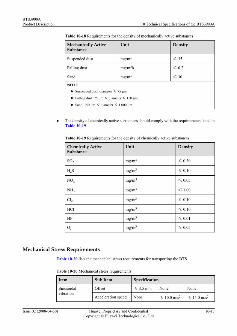
Table 10-18 Requirements for the density of mechanically active substances
Mechanically ActiveSubstance
Unit Density
Suspended dust mg/m3 ≤ 35
Falling dust mg/m2h ≤ 0.2
Sand mg/m3 ≤ 30
NOTE
l Suspended dust: diameter ≤ 75 μm
l Falling dust: 75 μm ≤ diameter ≤ 150 μm
l Sand: 150 μm ≤ diameter ≤ 1,000 μm
l The density of chemically active substances should comply with the requirements listed inTable 10-19.
Table 10-19 Requirements for the density of chemically active substances
Chemically ActiveSubstance
Unit Density
SO2 mg/m3 ≤ 0.30
H2S mg/m3 ≤ 0.10
NOx mg/m3 ≤ 0.05
NH3 mg/m3 ≤ 1.00
Cl2 mg/m3 ≤ 0.10
HCl mg/m3 ≤ 0.10
HF mg/m3 ≤ 0.01
O3 mg/m3 ≤ 0.05
Mechanical Stress Requirements
Table 10-20 lists the mechanical stress requirements for transporting the BTS.
Table 10-20 Mechanical stress requirements
Item Sub Item Specification
Sinusoidalvibration
Offset ≤ 3.5 mm None None
Acceleration speed None ≤ 10.0 m/s2 ≤ 15.0 m/s2
BTS3900AProduct Description 10 Technical Specifications of the BTS3900A
Issue 02 (2008-04-30) Huawei Proprietary and ConfidentialCopyright © Huawei Technologies Co., Ltd
10-13

Item Sub Item Specification
Frequency range 2-9 Hz 9-200 Hz 200-500 Hz
Random vibration Spectrum density ofaccelerated speed
30 m2/s3 3 m2/s3 1 m2/s3
Frequency range 2-10 Hz 10-200 Hz 200-500 Hz
Unsteady impact Impact responsespectrum II
≤ 250 m/s3
Static payload ≤ 10 kPa
NOTE
l Impact response spectrum refers to the maximum acceleration response curve generated by theequipment under specified impact excitation. Impact response spectrum II means that the duration ofsemi-sine impact response spectrum is 6 ms.
l Static payload refers to the capability of the equipment in package to bear the pressure from the top innormal pile-up method.
10.7.3 Environmental Requirements for Storing the BTS3900AThis describes the optimal storage environment of the BTS3900A. It focuses on the climatic,waterproofing, biological, air purity, and mechanical stress requirements for storing theBTS3900A.
Climatic RequirementsThe storage of the BTS should meet the climatic requirements listed in Table 10-21.
Table 10-21 Climatic requirements
Item Specification
Temperature -40℃~+70℃
Temperature variation rate ≤ 0.5 ℃/min
Relative humidity 10%~ 100%
Altitude ≤ 3,000 m
Air pressure 70 kPa to 106 kPa
Solar radiation ≤ 1,120 W/m2
Thermal radiation ≤ 600 W/m2
Wind speed ≤ 50 m/s
10 Technical Specifications of the BTS3900ABTS3900A
Product Description
10-14 Huawei Proprietary and ConfidentialCopyright © Huawei Technologies Co., Ltd
Issue 02 (2008-04-30)

Waterproofing RequirementsThe storage environment of the BTS should be waterproofed. The waterproofing requirementsrelated to the indoor storage environment of the BTS are as follows:
l There should be no water on the ground, and water should not leak into the package of theequipment.
l The equipment must be kept away from the auto fire-protection devices and air-conditionersthat are prone to leakage.
If the equipment has to be placed outdoors, ensure that:
l The package is intact.
l Waterproofing measures are taken to prevent rainwater from leaking into the package.
l There is no water on the ground and water does not leak into the package.
l The package is not exposed to direct sunlight.
Biological Environment RequirementsThe biological requirements related to the indoor storage environment of the BTS are as follows:
l The environment should not be conducive for the growth of fungus or mildew.
l There should be no rodents, such as rats.
Air Purity RequirementsThe air purity requirements related to the indoor storage environment of the BTS are as follows:
l There should be no explosive, conductive, magneto-conductive, or corrosive dust in theair.
l The density of mechanically active substances should comply with the requirements listedin Table 10-22.
Table 10-22 Requirements for the density of mechanically active substances
Mechanically ActiveSubstance
Unit Density
Suspended dust mg/m3 ≤5.00
Falling dust mg/m2h ≤500.00
Sand mg/m3 ≤300
NOTE
l Suspended dust: diameter ≤ 75 μm
l Falling dust: 75 μm ≤ diameter ≤ 150 μm
l Sand: 150 μm ≤ diameter ≤ 1,000 μm
l The density of chemically active substances should comply with the requirements listed in
Table 10-23.
BTS3900AProduct Description 10 Technical Specifications of the BTS3900A
Issue 02 (2008-04-30) Huawei Proprietary and ConfidentialCopyright © Huawei Technologies Co., Ltd
10-15

Table 10-23 Requirements for the density of chemically active substances
Chemically ActiveSubstance
Unit Density
SO2 mg/m3 ≤0.30
H2S mg/m3 ≤0.10
NOx mg/m3 ≤0.50
NH3 mg/m3 ≤1.00
Cl2 mg/m3 ≤0.10
HCl mg/m3 ≤0.10
HF mg/m3 ≤0.01
O3 mg/m3 ≤0.05
Mechanical Stress RequirementsThe storage of the BTS should meet the mechanical stress requirements listed in Table 10-24.
Table 10-24 Mechanical stress requirements
Item Sub Item Specification
Sinusoidalvibration
Offset ≤ 1.5mm -
Accelerationspeed
- ≤ 5.0m/s2
Frequency range 2-9 Hz 9-200 Hz
Unsteadyimpact
Impact responsespectrum II
≤ 250 m/s2
Static payload ≤ 5 kPa
NOTE
l Impact response spectrum refers to the maximum acceleration response curve generated by theequipment under specified impact excitation. Impact response spectrum II means that the duration ofsemi-sine impact response spectrum is 6 ms.
l Static payload refers to the capability of the equipment in package to bear the pressure from the top innormal pile-up method.
10 Technical Specifications of the BTS3900ABTS3900A
Product Description
10-16 Huawei Proprietary and ConfidentialCopyright © Huawei Technologies Co., Ltd
Issue 02 (2008-04-30)
Related Documents