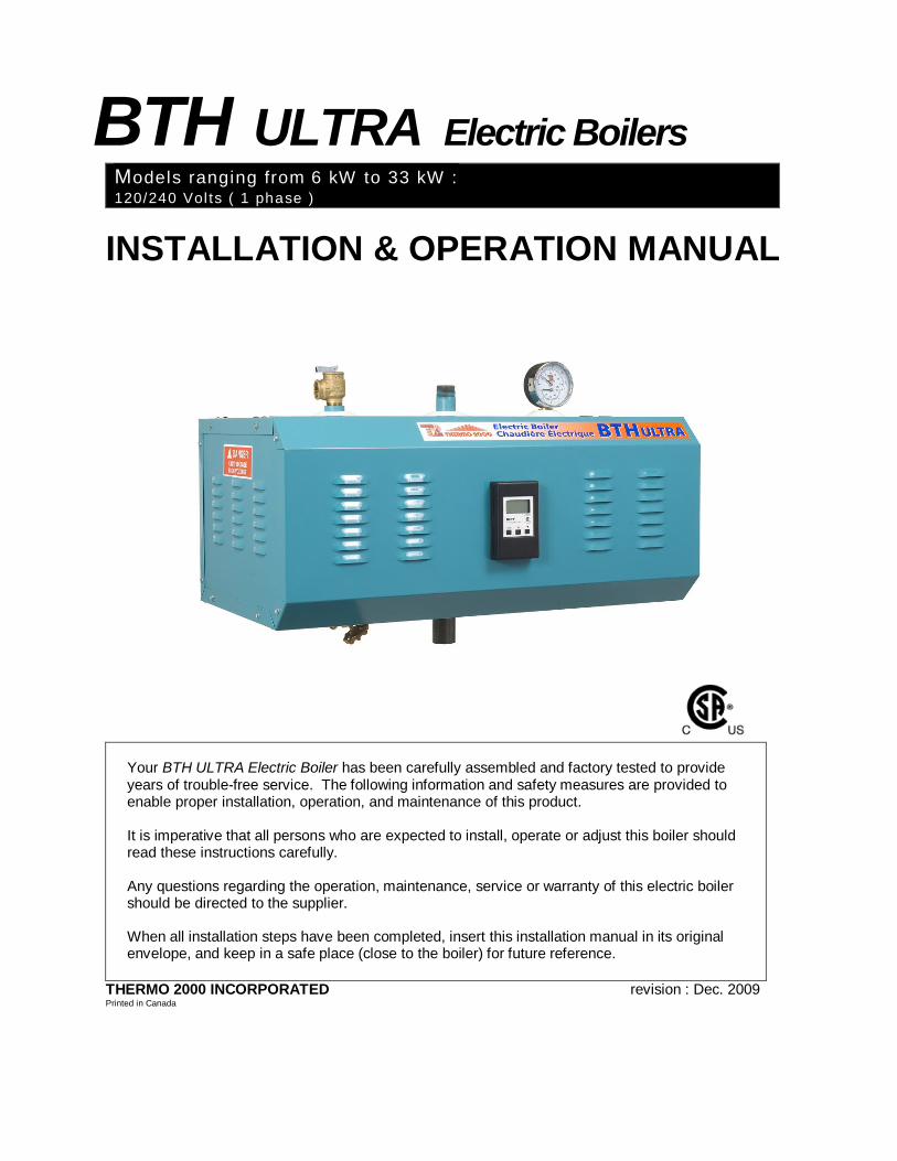
BTH ULTRA Electric Boilers M odels ranging from 6 kW to 33 kW : 120/240 Volts ( 1 phase ) INSTALLATION & OPERATION MANUAL Your BTH ULTRA Electric Boiler has been carefully assembled and factory tested to provide years of trouble-free service. The following information and safety measures are provided to enable proper installation, operation, and maintenance of this product. It is imperative that all persons who are expected to install, operate or adjust this boiler should read these instructions carefully. Any questions regarding the operation, maintenance, service or warranty of this electric boiler should be directed to the supplier. When all installation steps have been completed, insert this installation manual in its original envelope, and keep in a safe place (close to the boiler) for future reference. THERMO 2000 INCORPORATED revision : Dec. 2009 Printed in Canada

Welcome message from author
This document is posted to help you gain knowledge. Please leave a comment to let me know what you think about it! Share it to your friends and learn new things together.
Transcript
BTH ULTRA Electric BoilersModels ranging from 6 kW to 33 kW : 120/240 Vol ts ( 1 phase )
INSTALLATION & OPERATION MANUAL
Your BTH ULTRA Electric Boiler has been carefully assembled and factory tested to provide years of trouble-free service. The following information and safety measures are provided to enable proper installation, operation, and maintenance of this product. It is imperative that all persons who are expected to install, operate or adjust this boiler should read these instructions carefully. Any questions regarding the operation, maintenance, service or warranty of this electric boiler should be directed to the supplier. When all installation steps have been completed, insert this installation manual in its original envelope, and keep in a safe place (close to the boiler) for future reference.
THERMO 2000 INCORPORATED revision : Dec. 2009 Printed in Canada

BTH ULTRA Electric Boilers USE & CARE MANUAL (Revision Dec. 2009), Page 2.
TABLE OF CONTENT Section 1 : Dimensions & specifications …………………………………………………….. P.3 Section 2 : Introduction …………………………………………………………………………. P.5 Section 3 : Installation …………………………………………………………………………. P.6
3.1 Security considerations ………………………………………………………… P.6 3.2 Location ………………………………………………………………………….. P.6 3.3 Clearances ……………………………………………………………………….. P.6 3.4 Selection of the application type …………………………………………….. .. P.6 3.5 Piping installation ………………………………………………………………… P.8 3.6 Electrical connections ……………………………………………………………. P.9
Section 4: Controller module adjustments …………………………………………………… P.12 4.1 Introduction ……………………………………………………………………… P.12 4.2 Information on the display ……………………………………………………… P.12 4.3 Interface operation ……………………………………………………………… P.12 4.4 Adjustments
4.4.1 Settings in Mode 1 (Fix set point / Parallel piping) ……………………. P.13 4.4.2 Settings in Mode 2 (Fix set point / Primary-secondary piping) ………. P.14 4.4.3 Settings in Mode 3 (Domestic hot water supply only) ………………… P.15 4.4.4 Settings of the Outdoor reset operation in mode 4 & 5 ……………….. P.17 4.4.5 Settings in Mode 4 (Outdoor reset modulating temp. / Parallel
Piping)………………………………………………………………………. P.18 4.4.6 Settings in Mode 5 (Outdoor reset modulating temp. / Primary-secondary
piping) ……………………………………………………………………….. P.20 4.4.7 Settings in Bi-Energy Mode …………………………………………… P.22
4.5 Differential setting and operation of the power modulation …………………. P.22
Section 5: Start up procedure ………………………………………………………………… P.23 Section 6: Maintenance ……………………………………………………………………….. P.24 Section 7: Trouble Shooting ………………………………………………………………….. P.25 Replacement parts P.27 Warranty …………………………………………………………………………………………. P.28 Figure 5: Typ. installation in Mode 1- Fix set point with motorized zone valves ……… P.29 Figure 6: Typ. installation in Mode 1- Fix set point with pump zoning system ……………. P.30 Figure 7: Typ. installation in Mode 2 & 5-Typical piping in Primary-secondary …………. P.31 Figure 8: Typ. installation in Mode 3- Domestic hot water production with ind.water heater. P.32 Figure 9: Typ.l installation in Mode 4- Outdoor reset modulating temp……………………… P.33 Figure 10: Typ. installation in Mode 4- Heating and domestic hot water production ………. P.34 Figure 11: Typ.l installation in Bi-Energy mode in parallel with a three way diverting valve . P.35 Figure 12: Typ. installation in Bi-Energy mode in series without a three way valve ……….. P.36 Figure 13: Electrical connections on multi-zone systems with electric zone valves ……….. P.37 Figure 14: Electrical connections on multi-zone systems with many pumps ………………. P.37 Figure 15: Electrical diagram BTH Ultra 240-6&10kW ………………………………………… P.38 Figure 16: Electrical diagram BTH Ultra 240-12to24kW ………………………………………. P.39 Figure 17: Electrical diagram BTH Ultra 240-27kW ……………………………………………. P.40 Figure 18: Electrical diagram BTH Ultra 240-30&33kW ………………………………………. P.41

BTH ULTRA Electric Boilers USE & CARE MANUAL (Revision Dec. 2009), Page 3.
Section 1: Dimensions & Specifications
Table 1: Electric Ratings for 120/240 VAC (1 phase) Electric Boilers:
Current Amp
Model P KW
Heating Elements
Total with
Circulator
Elem
ents
Stag
es
Elec
tron
ic
Con
trol
Pow
er R
elay
s
Mai
n C
onta
ctor
s
Wire CU
90oC Fuse
A
BTH ULTRA 6 6 25.0 30.0 2 X 3KW 2 1 1 2 8 40
BTH ULTRA 8 8 33.3 38.3 1X 3KW 1 X 5KW 2 1 1 2 8 50
BTH ULTRA 10 10 41.6 46.6 2 X 5KW 2 1 1 2 6 60 BTH ULTRA 12 12 50.0 55.0 4 X 3KW 4 1 1 4 6 70
BTH ULTRA 15 15 62.5 67.5 2 X 3KW 2 X 4.5KW 4 1 1 4 4 100
BTH ULTRA 18 18 75.0 80.0 4 X 4.5KW 4 1 1 4 3 100 BTH ULTRA 20 20 83.4 88.4 4 X 5KW 4 1 1 4 3 110 BTH ULTRA 24 24 100.0 105.0 4 X 6KW 4 1 1 4 2 150 BTH ULTRA 27 27 112.5 117.5 6 X 4.5KW 4 1 2 6 1 150 BTH ULTRA 30 30 125.0 130.0 6 X 5KW 4 1 2 6 1/0 175
BTH ULTRA 33 33 138.0 143.0 3 X 5KW 3 X 6KW 4 1 2 6 2/0 200
*Current for circulator : 5 amps. (1/6 HP Max.)
Table 2: Connections sizes & Boiler overall dimensions
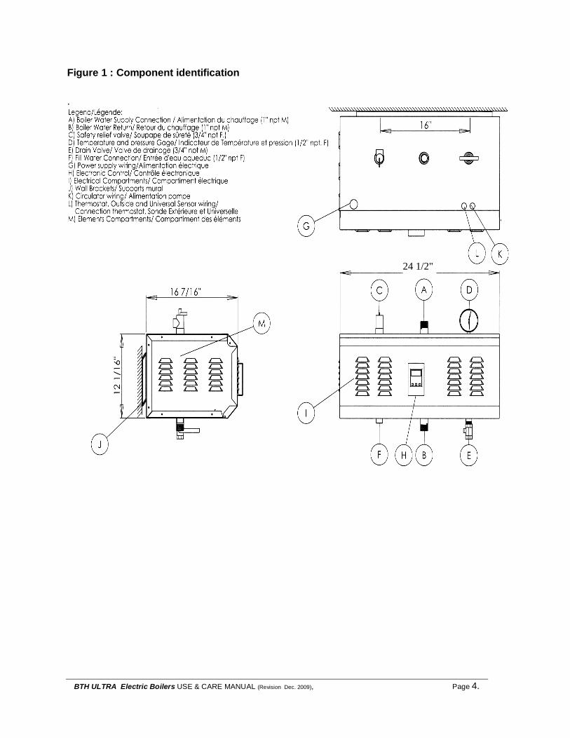
Connections sizes Boiler overall dimensions Boiler return 1 “ NPT M Height 12 3/16 inches Boiler feed 1 “ NPT M Width 16 7/16 inches Waterworks 1/2 “ NPT F Depth 24 ½ inches Safety valve 3/4 “ NPT F Shipping weight 99 lbs. Drain valve 1/2 “ NPT F
Operating temperature : from 70°F to 194°F.; Maximum operating pressure: 30 p. s.i.
BTH ULTRA Electric Boilers USE & CARE MANUAL (Revision Dec. 2009), Page 4.
Figure 1 : Component identification
.
24 1/2"

BTH ULTRA Electric Boilers USE & CARE MANUAL (Revision Dec. 2009), Page 5.
General Safety Precautions Be sure to read and understand the entire Use & Care Manual before attempting to install or to operate this electric boiler. Pay particular attention to the following General Safety Precautions. Failure to follow these warnings could cause property damage, bodily injury or death. Should you have any problems understanding the instructions in this manual, get help from a qualified installer or technician.
Section 2: Introduction
The important safeguards and instructions appearing in this manual are not meant to cover all possible conditions and situations that may occur. It should be understood that common sense, caution and care are factors which cannot be built into every product. They are the responsibility of the person(s) caring for and operating the unit. 2.1 LOCAL INSTALLATION REGULATIONS This electric boiler must be installed in accordance with these instructions and in conformity with local codes, or in the absence of local codes, with the National Plumbing Code and the National Electric Code current edition. In any case where instructions in this manual differ from local or national codes, the local or national codes take precedence. 2.2 CORROSIVE ATMOSPHERE The electric boiler should not be located near an air vent containing a corrosive atmosphere or high humidity. The limited warranty is void when the failure of the electric boiler is due to a corrosive atmosphere. 2.3 INSPECT SHIPMENT Inspect the electric boiler for possible shipping damage. The manufacturer’s responsibility ceases upon delivery of goods to the carrier in good condition. Consignee must file any claims for damage, shortage in shipments, or non-delivery immediately against carrier.
2.4 CHECK LIST Please check the identification tag on the unit to make sure you have the right model.
List of components shipped with the unit : • Pressure relief valve set at 30 PSI. • Drain valve. • Tridicator (temperature & pressure
gage). The electric boiler should not be located in an area where leakage of the tank or water connections will result in damage to the adjacent area or to lower floors of the structure. When such areas cannot be avoided, a suitable drain pan or non-flammable catch pan, adequately drained, must be installed under the boiler. The pan must be connected to a drain. NOTE: Auxiliary catch pan MUST conform to local codes.
!
CAUTION !
WARNING !

BTH ULTRA Electric Boilers USE & CARE MANUAL (Revision Dec. 2009), Page 6.
Section 3: Installation The manufacturer’s warranty does not cover any damage or defect caused by installation, or attachment, or use of any special attachment other than those authorized by the manufacturer into, onto, or in conjunction with the boiler. The use of such unauthorized devices may shorten the life of the boiler may endanger life and property. The manufacturer disclaims any responsibility for such loss or injury resulting from the use of such unauthorized devices 3.1 SECURITY CONSIDERATIONS Domestic and commercial installations have a maximum design operating pressure limited to 30 psi (207 kPa) by a safety relief valve. This boiler is designed to operate on close circuit system operating between 70 to 194°F. This boiler is designed to be used only in a hot water heating system. The hi-limit control of the unit is fixed and set at 212F. If the heating distribution system on which the boiler is installed requires a hi limit controller set at a lower temperature, this controller will have to be added to the system and connected in series with the hi-limit installed at the factory. The heat transfer medium must be water or other non-toxic fluid having a toxicity rating or class of 1, as listed in clinical Toxicology of Commercial products, 5th edition 3.2 LOCATION The electric boiler should be installed in a clean, dry location. Long hot water lines should be insulated to conserve water and energy. The electric boiler and water lines should be protected from exposure to freezing temperatures. The electric boiler must be installed horizontally, directly on the wall. Use the wall mounting brackets to make the unit level. The wall mounting brackets are held by four 5/16’’ lag screws. The openings are located at 16’’ intervals (i.e. standard stud spacing). When the first bracket is installed you can hang the boiler
on the wall (see figure 1). The lag screws must be suitably anchored to safely support the weight of the boiler including water content, piping and wiring. The electric boiler must be located or protected so as not to be subject to physical damage, for example, by moving vehicles, area flooding, etc. All models can be installed on combustible floors and in alcoves. Ambient temperature must not exceed 90°F or 32°C. 3.3 CLEARANCE Minimum clearances for adequate inspection and servicing are listed in the following table: Table 3: Boiler clearance
Left side 16 inches Right side 6 inches
Top & Bottom of the boiler 6 inches Front side of the boiler 24 inches Back side of the boiler 0 inch
3.4 PIPING ARRANGEMENT The recommended piping arrangement for the 5 modes of operation of boiler BTH ULTRA and for Bi-Energy applications are shown in figures 5 to 12. The location of the different components required on the heating distribution system may differ from the location shown on the typical piping lay out. Most of the installation requires modes 1 or 4. You will find more details about the operation of each mode below. Mode 1 (fig.5&6 p.29-30) : For fix setpoint operation using parallel piping,
Mode 2 (fig.7 p.31) : For fix setpoint operation using primary / secondary piping.
Mode 3 (fig.8 p.32) : Dedicated for production of domestic hot water with an indirect water heater
Mode 4 (fig 9 & 10 p.33-34) : For modulation of the boiler set point vs outdoor temperature and override operation from an auxiliary demand. Parallel piping.
Mode 5 (fig.7 p.31): For modulation of the boiler et point vs outdoor temperature and reset override operation from an auxiliary demand. Primary / secondary piping. Mode Bi-Energie: (fig.11 &12 p.35-36) : Applicable on all above modes
WARNING !
!
BTH ULTRA Electric Boilers USE & CARE MANUAL (Revision Dec. 2009), Page 7.
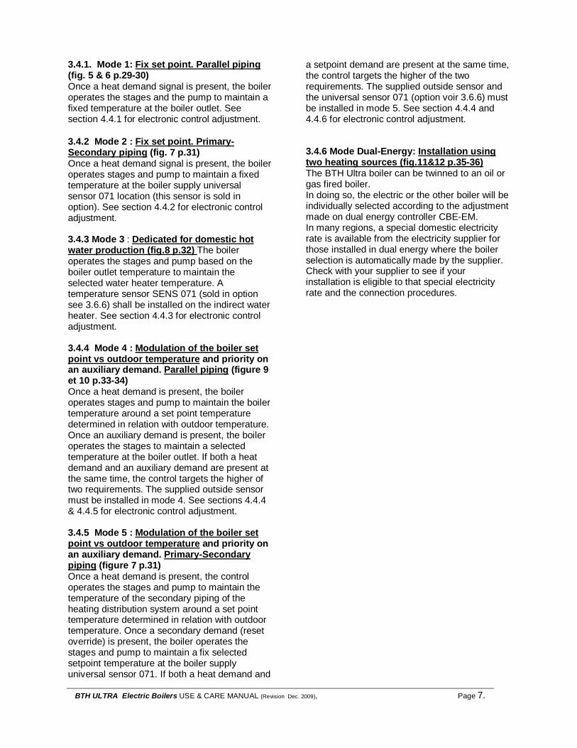
3.4.1. Mode 1: Fix set point. Parallel piping (fig. 5 & 6 p.29-30) Once a heat demand signal is present, the boiler operates the stages and the pump to maintain a fixed temperature at the boiler outlet. See section 4.4.1 for electronic control adjustment. 3.4.2 Mode 2 : Fix set point. Primary-Secondary piping (fig. 7 p.31) Once a heat demand signal is present, the boiler operates stages and pump to maintain a fixed temperature at the boiler supply universal sensor 071 location (this sensor is sold in option). See section 4.4.2 for electronic control adjustment. 3.4.3 Mode 3 : Dedicated for domestic hot water production (fig.8 p.32) The boiler operates the stages and pump based on the boiler outlet temperature to maintain the selected water heater temperature. A temperature sensor SENS 071 (sold in option see 3.6.6) shall be installed on the indirect water heater. See section 4.4.3 for electronic control adjustment. 3.4.4 Mode 4 : Modulation of the boiler set point vs outdoor temperature and priority on an auxiliary demand. Parallel piping (figure 9 et 10 p.33-34) Once a heat demand is present, the boiler operates stages and pump to maintain the boiler temperature around a set point temperature determined in relation with outdoor temperature. Once an auxiliary demand is present, the boiler operates the stages to maintain a selected temperature at the boiler outlet. If both a heat demand and an auxiliary demand are present at the same time, the control targets the higher of two requirements. The supplied outside sensor must be installed in mode 4. See sections 4.4.4 & 4.4.5 for electronic control adjustment. 3.4.5 Mode 5 : Modulation of the boiler set point vs outdoor temperature and priority on an auxiliary demand. Primary-Secondary piping (figure 7 p.31) Once a heat demand is present, the control operates the stages and pump to maintain the temperature of the secondary piping of the heating distribution system around a set point temperature determined in relation with outdoor temperature. Once a secondary demand (reset override) is present, the boiler operates the stages and pump to maintain a fix selected setpoint temperature at the boiler supply universal sensor 071. If both a heat demand and
a setpoint demand are present at the same time, the control targets the higher of the two requirements. The supplied outside sensor and the universal sensor 071 (option voir 3.6.6) must be installed in mode 5. See section 4.4.4 and 4.4.6 for electronic control adjustment. 3.4.6 Mode Dual-Energy: Installation using two heating sources (fig.11&12 p.35-36) The BTH Ultra boiler can be twinned to an oil or gas fired boiler. In doing so, the electric or the other boiler will be individually selected according to the adjustment made on dual energy controller CBE-EM. In many regions, a special domestic electricity rate is available from the electricity supplier for those installed in dual energy where the boiler selection is automatically made by the supplier. Check with your supplier to see if your installation is eligible to that special electricity rate and the connection procedures.

BTH ULTRA Electric Boilers USE & CARE MANUAL (Revision Dec. 2009), Page 8.
3.5 PIPING CONNECTIONS 3.5.1 Boiler piping This electric boiler may be connected individually or in parallel with other boilers. If two or more boilers are connected, the “reverse-return piping” method (whereby the boiler with the first return inlet also has the last supply outlet and so forth until the last return inlet corresponds to the first supply outlet) should be used to connect the boilers in parallel, to ensure an equal water flow rate through each boiler. The BOILER WATER SUPPLY, located on the top side, and the BOILER WATER RETURN, located on the bottom side of the boiler are steel pipes (1”male NPT threaded connection) where supply and return line connections are to be made. Installing a union is recommended on the boiler water supply and return lines to facilitate boiler disconnection for servicing. Dielectric unions are required for protection of the boiler and piping if dissimilar pipe material such as galvanized steel and copper are present. Use only clean pipe for boiler water lines. Local codes or regulations shall govern the exact type of material to be used. Insulate all pipes containing hot water, especially in unheated areas. Install shutoff (ball) valves for servicing convenience. Thermometer(s) should be installed on the boiler water supply and return lines. Cap or plug unused connections on the boiler. Do not cap the pressure relief valve on the boiler since it will damage and shorten the life of the boiler and may endanger life and property. 3.5.2 Pressure relief valve An automatic pressure relief valve must be installed during boiler setup. The pressure rating of the relief valve must not exceed 30 psi. The safety relief valve must meet the requirements of the ASME Boiler and Pressure Vessel Code and limit the maximum operating boiler pressure. It is a safety device, not an operating control.
The BTU per hour rating of the relief valve must equal or exceed the BTU per hour input of the boiler(s) or heat source(s) as marked on the boiler(s) rating plate. Connect the outlet of the relief valve to a discharge line with its lower tip at most 6” above a floor drain, well clear of any live electrical parts. The discharge line must pitch downward from the valve to allow complete draining by gravity of the relief valve and discharge line, and be of a diameter no smaller than that of the valve outlet. The tip of the discharge line should not be threaded or concealed and should be protected from freezing. No valve of any type, restriction or reducer coupling should be installed on the discharge line. Local codes shall govern the installation of relief valves. 3.5.3 Piping system pressurization & expansion tank Pressure control devices within the system ensure that each component operates within minimum and maximum allowable pressures and maintain minimum pressure for all normal operating temperatures. They also allow air bleeding, prevent cavitation at the pump inlet and prevent water from boiling within the system; all this is accomplished with minimal addition of new water. The increase in boiler water volume resulting from higher temperature is stored in the expansion tank during periods of high operating temperature and is returned to the system when the temperature decreases. The expansion tank must be able to store the required volume of boiler water during maximum design operating temperature without exceeding the maximum allowable operating pressure, and to maintain the required minimum pressure when the system is cold. Contact your installing contractor, plumbing supply house, or local plumbing inspector for assistance. The point where the expansion tank is connected should be carefully selected to avoid the possibility that normal operation of automatic check or manual valves will isolate the tank from a hot boiler or any part of the system. Pre-charged diaphragm expansion tanks are preferable to air control.
BTH ULTRA Electric Boilers USE & CARE MANUAL (Revision Dec. 2009), Page 9.
These tanks incorporate a balloon-like bladder or diaphragm. It is inflated, prior to filling the system, to a pressure equal to the setting of the water pressure makeup regulator. The expansion tank should be located on the suction or intake side of the pump. The pump can be located either just upstream or just downstream from the boiler. 3.5.4 Water pressure makeup regulator Make-up systems must be employed as required by codes. An automatic fill valve must be used with a backflow preventer as required, to maintain minimum system pressure by supplying water to make up for leakage. 3.5.5 Air bleeder Oxygen should be expelled from the system to prevent corrosion. Installation of manual or automatic air vent devices prevents air from accumulating in the system. Air vents should be installed at all high points to remove trapped air during initial setup and to ensure that the system is tight. Regularly purge the air out of the system while taking care to avoid personal injuries or property damage caused by hot boiler water spray. 3.5.6 Circulator zoning recommendations The preferred location of the circulator pump for each zone is on the boiler supply side, with the expansion tank between the boiler and the pump. A flow check valve must be installed in each zone, preferably on the outlet side of each circulator pump, to prevent water flow to other zones where no heat is required. 3.5.7 Motorized valve zoning recommendations The preferred location of the circulator pump is on the boiler supply side, with the expansion
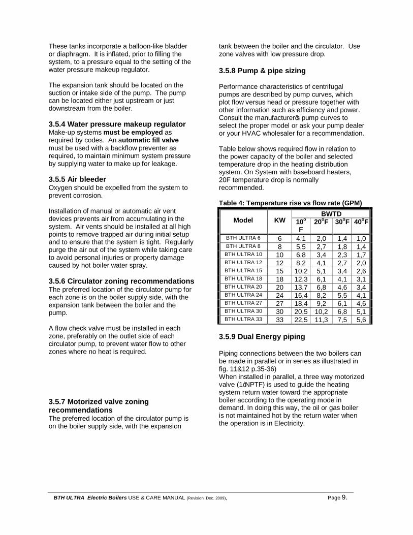
tank between the boiler and the circulator. Use zone valves with low pressure drop. 3.5.8 Pump & pipe sizing Performance characteristics of centrifugal pumps are described by pump curves, which plot flow versus head or pressure together with other information such as efficiency and power. Consult the manufacturer’s pump curves to select the proper model or ask your pump dealer or your HVAC wholesaler for a recommendation. Table below shows required flow in relation to the power capacity of the boiler and selected temperature drop in the heating distribution system. On System with baseboard heaters, 20F temperature drop is normally recommended. Table 4: Temperature rise vs flow rate (GPM)
BWTD Model KW 10o
F 20oF 30oF 40oF
BTH ULTRA 6 6 4,1 2,0 1,4 1,0 BTH ULTRA 8 8 5,5 2,7 1,8 1,4 BTH ULTRA 10 10 6,8 3,4 2,3 1,7 BTH ULTRA 12 12 8,2 4,1 2,7 2,0 BTH ULTRA 15 15 10,2 5,1 3,4 2,6 BTH ULTRA 18 18 12,3 6,1 4,1 3,1 BTH ULTRA 20 20 13,7 6,8 4,6 3,4 BTH ULTRA 24 24 16,4 8,2 5,5 4,1 BTH ULTRA 27 27 18,4 9,2 6,1 4,6 BTH ULTRA 30 30 20,5 10,2 6,8 5,1 BTH ULTRA 33 33 22,5 11,3 7,5 5,6
3.5.9 Dual Energy piping Piping connections between the two boilers can be made in parallel or in series as illustrated in fig. 11&12 p.35-36) When installed in parallel, a three way motorized valve (1”NPTF) is used to guide the heating system return water toward the appropriate boiler according to the operating mode in demand. In doing this way, the oil or gas boiler is not maintained hot by the return water when the operation is in Electricity.
BTH ULTRA Electric Boilers USE & CARE MANUAL (Revision Dec. 2009), Page 10.
3.6 ELECTRIC CONNECTIONS 3.6.1 Main Electric supply Wiring must conform to the National Electrical Code and to state or local code requirements. The electric boiler must be electrically grounded in accordance with local codes, or, in the absence of local codes, with the National Electrical Code. Wiring must be from a 120/240 Volt (single phase, 60 Hz) circuit protected by a properly sized breaker. Wire gage (3 wires+ground) must be properly sized. Consult the boiler rating plate to select the proper breaker and wire gage Models 6 to 24 kW are certified for CU/AL cables. 3.6.2 Connecting the thermostat (Modes 1, 2, 4 and 5)
3.6.2.1 Single heating zone
Connect a low voltage thermostat to terminals T and T on the electric panel (DO NOT apply any power to these terminals!). It is recommended to use a thermostat having a dry contact that closes when in demand. If an electronic 2wire thermostat is used, it may happen that the heat demand to the boiler will be maintained even when the thermostat is not calling for heat. If such a case happen, call us and we will send you an adaptation kit that should solve the problem.
3.6.2.2Multiple heating zone
q Zone valve zoning Connect the zone valve end switch to terminals T and T on the electric pannel (DO NOT apply any power to these terminals!). See figure 13 p.37..
q Circulator zoning Connect the low voltage thermostat to the corresponding pump relay (Honeywell #RA-832 or multipump relay) and connect its auxiliairy dry contact to terminals T and T on the electric pannel (DO NOT apply any power to these terminals!). See figure 14 p.37. 3.6.3 Auxilliary demand signal (Indirect water heater or second heating stage of thermostat) Mode 4 & 5 only. Not applicable on Bi-Energy installations
This connection is not an obligation it gives priority to the operation of the boiler at a fix selected temperature in overriding the outdoor reset setpoint demand when an auxiliary demand happens (ex: aquastat on an indirect hot water heater see fig.10 or a second heating stage on a room thermostat). Connect the auxiliary contact (ex:Indirect water heater aquastat) to terminals E1 and E2 on the electric panel (DO NOT apply any power to these terminals!). 3.6.4 Pump power supply (All Modes) If your heating system uses only on circulating pump working on 120 Vac, 5 amp. (maximum): it can be directly connected to terminals C and C on the electric pannel. Do not use a 600 Vac pump or one drawing more than 5 amps. The logic circuit is designed to activate the circulator based only on demand by the thermostat or an auxiliary demand after a time delay. On heating systems with more than one pump, they will have to be connected on an outside controller see section 3.6.2.2 for details 3.6.5 Outdoor sensor (Required only in Modes 4 and 5) Connect the outdoor sensor to terminals S1 and S1 on the electric panel (DO NOT apply any power to these terminals!). The outdoor sensor is used to measure the outdoor air temperature. It has to be connected in mode 4 & 5 otherwise an error message (OPN) will appear on the display. 3.6.6 Boiler supply univesal sensor SENS
071 (option) (Required only in modes 2, 3 et 5)
This sensor measure the temperature of the heating circuit in primary/secondary piping installation (Mode 2 & 5) It is also used to measure the water temperature of the storage tank indirect water heater used in Mode 3.

BTH ULTRA Electric Boilers USE & CARE MANUAL (Revision Dec. 2009), Page 11.
Connect the boiler supply universal sensor to terminals S2 and S2 on the electric panel (DO NOT apply any power to these terminals!). The boiler supply universal sensor is used to measure the supply temperature in modes 2 and 5. 3.6.7 CBE-EM dual energy contoller installation (Option) To facilitate the connection of the controls between the electric boiler, the auxiliary boiler and the automatic transfer signal from your electricity supplier, a CBE_EM controller is offered in option. It allows the operator to manually select three different ways of operation Oil/Electricity/Bi-Energy (see fig 11 & 12 p.35-36).
The following steps are required to install BTH ULTRA boiler in dual energy configuration.
1. Connect the 3 way valve (if used) to the dual energy control CBE-EM (option) 2. Connect the TT terminals of the oil burner combustion relay to the t1/T2 terminals of the CBE-EM controller. 3. Connect electric boiler terminals E1-E2 to the CBE-EM corresponding terminals 4. Connect the normally open contact (R&J terminals)of the outdoor sensor supplied by your electic utility to the “HH” terminals of the dual energy control CBE-EM. 5. Connect the heat demand signal of the building to teminals T3-T4 in the controller. 6. Connect terminals T5-T6 of the controller to terminals “TT” of the electric boiler.When installing the BTH ULTRA in dual energy configuration in mode 4 or 5, you cannot operate the auxiliary demand explained in 3.6.3 because terminals E1-E2 are used by the dual energy control CBE-EM.

BTH ULTRA Electric Boilers USE & CARE MANUAL (Revision Dec. 2009), Page 12.
Section 4: Controller adjustments 4.1 INTRODUCTION The operating characteristics of a hot water heating system vary in relation to the type of distribution system on which the boiler has been installed.(ex: warm floor system will operate at a very low water temperature compare to hot water baseboards systems) These operating characteristics of the system must be communicated to the boiler controller so that it could properly operate during the heating season. 4.2 DISPLAY INFORMATION The electronic control uses a Liquid Crystal Display (LCD) as a method of supplying information. You use the LCD in order to setup and monitor the operation of your system. The control uses three push buttons (Item, p, q) for selecting and adjusting settings.
VIEW
180FBOIL
TARGET
DEM
1 23 4
Item
Menu
Statut/Status
Paramètre/Item Field
Boutons/Buttons
Aux Dem
Symbol Description
Displays when the boiler pump is in operation
1 2 3 4
Displays when the stage 1 and/or 2, 3, 4 relay is turned on.
oF, oC Units of measurement
In standard configuration, it indicates that an auxiliary demand is present. In Bi-Energy, it indicated that the electric boiler has been selected
4.3 OPERATION OF THE INTERFACE All of the items displayed by the control are organized into two menus. These menus are listed on the upper right hand side of the display (View, Adjust). The default menu for the control is the View menu. To select the Adjust menu, press and hold simultaneously all three buttons (Item, p, q) for 1 second. The display then advances to the Adjust menu and the Adjust segment is turned on in the display. The display will automatically revert back to the View menu after 20 seconds of keypad inactivity. Once in a menu, there will be a group of items that can be viewed whitin that menu.
4.3.1 Item The abbreviated name of the selected item will be displayed in the item field of the display “DEM” will be shown when a heat demand from the thermostat will appear. To view the next available item, press and release the Item button. “BOIL OUT”: Real boiler water temperature leaving the boiler “BOIL TARGET”: Target temperature that the boiler will try to maintain. The display will show ”---“ when no demand is present. “OUTDOOR”: The temperature at the sensor located outside the building.
4.3.2 Adjustment procedure To make an adjustement to a setting in the control, begin by selecting the Adjust menu by pressing and holding simultaneously all three buttons (Item, p, q). Then select the desired item using the Item button. Finally, use the p or q button to make the adjustment.

BTH ULTRA Electric Boilers USE & CARE MANUAL (Revision Dec. 2009), Page 13.
4.4 ADJUSTMENTS 4.4.1 Mode 1 Settings :Fix target temperature / Parallel piping To configure the control in mode 1, begin by selecting the Adjust menu by pressing and holding simultaneously all three buttons (Item, p, q). Then select the item MODE using the Item button. Finally, use the p or q button to set the value to 1. VIEW MENU
Item Description BOIL TARGET
BOIL
TARGET
VIEW
180 F
Boiler target supply is the temperature the control is currently trying to maintain at the boiler outlet. The display will show --- when no heat demand is present.
BOIL OUT
BOIL OUT
VIEW
185 F
Current boiler outlet water temperature.
ADJUST Menu
Item Description Default Range MODE
M O D E
A D J U S T
1
Set the operating mode for the control to 1. 1 1, 2, 3, 4, 5
BOIL TARGET
B O IL E R
T A R G E T
A D J U S T
1 8 0 F
Set the boiler target temperature during heat demand. If you don’t know the operating temperature of the heat distribution system, you could start by using the following proposed values.
TH2000 Default
Baseboard Cast Iron radiator
Warm floor high mass
Warm floor low mass
BOIL TARGET 180F 180F 155F 115F 140F
180oF 70 oF à 200 oF
DIFF DIF F AD JUS T
10 F
The differential that the control is to use when it is operating the boiler. It correspond to the differential in boiler temp. required between the de-activation and activation of the elements.
10 oF 2 oF à 42 oF
PUMP’ DLY
D L Y
A D J U S T
0 :2 0
Determine the purge period of the pump upon the completion of a heat demand from the thermostat.
0:20 min OFF, 0:20 min, ON
Units F
A D J U S T
The unit of measure that all of the temperatures are to be displayed in by the control.
oF oF ou oC

BTH ULTRA Electric Boilers USE & CARE MANUAL (Revision Dec. 2009), Page 14.
4.4.2 Mode 2 Settings: Fix target temperature / Primary-Secondary piping To configure the control in mode 1, begin by selecting the Adjust menu by pressing and holding simultaneously all three buttons (Item, p, q). Then select the item MODE using the Item button. Finally, use the p or q button to set the value to 2. VIEW Menu
Item Description BOIL TARGET
BOIL
TARGET
VIEW
180 F
Boiler target supply is the temperature the control is currently trying to maintain at the boiler supply sensor. The display will show --- when no heat demand is present.
BOIL SUP
BOILSUP
VIEW
175 F
Current boiler supply water temperature as measured by the boiler supply sensor.
ADJUST Menu
Item Description Default Range MODE
M O D E
A D J U S T
2
Sets the operating mode for the control to 2. 1 1, 2, 3, 4, 5
BOIL TARGET
B O IL E R
T A R G E T
A D J U S T
1 8 0 F
Set the boiler target temperature during heat demand. If you don’t know the operating temperature of the heat distribution system, you could start by using the following proposed values.
TH2000 Default
Baseboard Cast Iron radiator
Warm floor high mass
Warm floor low mass
BOIL TARGET 180F 180F 155F 115F 140F
180oF 70 oF à 200 oF
DIFF DIFF AD JUST
10 F
The differential that the control is to use when it is operating the boiler. It correspond to the differential in boiler temp. required between the de-activation and activation of the elements
10 oF 2 oF à 42 oF
‘PUMP’ DLY
D L Y
A D J U S T
0 :2 0
Determine the purge period of the pump upon the completion of a heat demand from the thermostat.
0:20 min OFF, 0:20 min, ON
Units
FA D J U S T
The unit of measure that all of the temperatures are to be displayed in by the control.
oF oF ou oC

BTH ULTRA Electric Boilers USE & CARE MANUAL (Revision Dec. 2009), Page 15.
4.4.3 Mode 3 Settings: For domestic hot water production only To configure the control in mode 1, begin by selecting the Adjust menu by pressing and holding simultaneously all three buttons (Item, p, q). Then select the item MODE using the Item button. Finally, use the p or q button to set the value to 3. VIEW Menu
Item Description BOIL TARGET
BOIL
TARGET
VIEW
180 F
Boiler Target supply is the temperature the control is currently trying to maintain at the boiler outlet. The display will show --- when no heat demand is present.
BOIL OUT
BOIL OUT
VIEW
185 F
Current boiler outlet water temperature.
TANK
TANK
VIEW
140 F
Current DHW tank temperature as measured by the DHW sensor.
ADJUST Menu
Item Description Default Range MODE
MODE
ADJUST
3
Sets the operating mode for the control to 3. 1 1, 2, 3, 4, 5
BOIL TARGET
BOILER
TARGET
ADJUST
180 F
Boiler target temperature at the outlet of the boiler during DHW operation. 180oF 70 oF à 200 oF
TANK TARGET
TARGET
TANK
ADJUST
140F
Sets the indirect domestic hot water heater storage tank’s temperature. 140 oF OFF, 70 oF à
190 oF
TANK DIFF
TANK
ADJUST
10FDIFF
Sets the differential for the DHW storage tank. 10 oF 2oF à 10oF
BTH ULTRA Electric Boilers USE & CARE MANUAL (Revision Dec. 2009), Page 16.
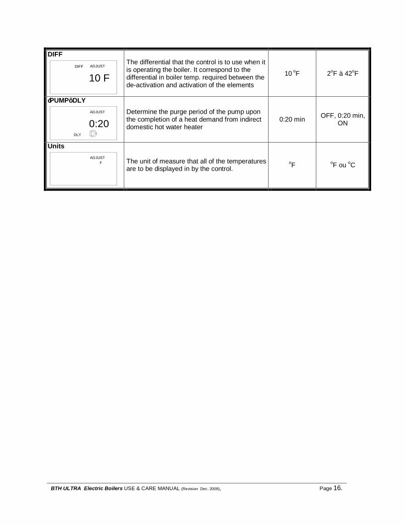
DIFF DIFF ADJUST
10 F
The differential that the control is to use when it is operating the boiler. It correspond to the differential in boiler temp. required between the de-activation and activation of the elements
10 oF 2oF à 42oF
‘PUMP’ DLY
DLY
ADJUST
0:20
Determine the purge period of the pump upon the completion of a heat demand from indirect domestic hot water heater
0:20 min OFF, 0:20 min, ON
Units
FADJUST
The unit of measure that all of the temperatures are to be displayed in by the control.
oF oF ou oC

BTH ULTRA Electric Boilers USE & CARE MANUAL (Revision Dec. 2009), Page 17.
4.4.4 Outdoor Reset Operation (Mode 4 and Mode 5) When either mode 4 or 5 is selected, the control uses outdoor reset to control the water temperature. Outdoor reset adjusts the boiler target temperature based on the outdoor air temperature and reset ratio. The reset ratio and the target temperature are determined from: BOIL START, BOIL DSGN, OUTDR START, OUTDR DSGN, BOIL MAX, WWSD. The settings are explained in section « Mode 4 Adjustment» and/or « Mode 5 Adjustment » and are shown in figure 3.
Diminution de la température extérieure/Decreasing Outdoor Temperature
Aug
men
tatio
n de
la te
mpé
ratu
re d
e l'e
au/
Incr
easi
ng W
ater
Tem
pera
ture
OUTDRSTART
BOILDSGN
WWSD
BOILMAX
BOILSTART
OUTDRDSGN
Figure 3 : Outdoor reset operation
The flexibility of the electronic controller allows for the adjustment of multiple operating parameters to adapt to your needs. For a quick installation we recommend the use of the appropriate settings values found in table 5 according to the type of heating system on which the boiler is installed ( baseboard heaters, radiators or radiant floor). See Figure 4 for a visual interpretation of these settings depending on outdoor temperature.
Table 5 : Setting value TH2000
Défault Basebo
ard Cast iron radiator
Warm floor high
mass
Warm floor low
mass BOIL START 125oF 125oF 100oF 75oF 90oF
BOIL DSGN 180 oF 180 oF 155 oF 115 oF 140 oF
OUTDR START 70 oF 70 oF 70 oF 70 oF 70 oF
OUTDR DSGN -10 oF -10 oF -10 oF -10 oF -10 oF
BOIL MAX 190 oF 190 oF 170 oF 125 oF 150 oF
WWSD 75 oF 75 oF 75 oF 75 oF 75 oF
Courbe Type Modulation Intérieur - Extérieur/Mode 4 et 5
Diff= 10F
70
90
110
130
150
170
190
210
80 75 70 65 60 55 50 45 40 35 30 25 20 15 10 5 0 -5 -10 -15 -20 -25 -30 -35T outdoor (F)
T ta
rget
(F)
TH2000 DéfautPlinthesRadiateur FontesPlancher Chauffant
Figure 4: Outdoor reset operation lines

BTH ULTRA Electric Boilers USE & CARE MANUAL (Revision Dec. 2009), Page 18.
4.4.5 Mode 4 Settings: Modulation of the boiler target in relation to the outdoor
temperature / Parallel piping (Outside sensor required) To configure the control in mode 1, begin by selecting the Adjust menu by pressing and holding simultaneously all three buttons (Item, p, q). Then select the item MODE using the Item button. Finally, use the p or q button to set the value to 4. VIEW Menu
Item Description OUTDR
OUTDR VIEW
32 F
Current outdoor air temperature as measured by the outdoor sensor.
BOIL TARGET
BOIL
TARGET
VIEW
180 F
Target boiler supply is the temperature the control is currently trying to maintain at the boiler supply sensor. The display will show --- when no heat demand is present.
BOIL OUT
BOIL OUT
VIEW
185 F
Current boiler outlet water temperature.
ADJUST Menu
Item Description Default Range MODE
MODE
ADJUST
4
Sets the operating mode for the control to 4. 1 1, 2, 3, 4, 5
BOIL TARGET
BOILER
TARGET
ADJUST
180 F
Boiler target temperature when an auxiliary demand is present (Demand from an indirect hot water heater or a second stage from a thermostat)
180oF OFF
70 oF à 200 oF
OUTDR START OUTDR
START
ADJUST
70F
The outdoor air temperature at which the control provides the “BOIL START” water temperature to the system.
Baseboard Cast iron radiator
Warm floor high mass
Warm floor low mass
OUTDR START 70 oF 70 oF 70 oF 70 oF
70 oF 35 oF à 80 oF

BTH ULTRA Electric Boilers USE & CARE MANUAL (Revision Dec. 2009), Page 19.
OUTDR DSGN OUTDR DSGN ADJUST
-10F
The outdoor air temperature that is the typical coldest temperature of the year where the building is located .
Baseboard Cast iron radiator
Warm floor high mass
Warm floor low mass
OUTDR DSGN -10 oF -10 oF -10 oF -10 oF
-10 oF -60oF à 10oF
BOIL START
BOILSTART
ADJUST
125F
The theoretical boiler supply water temperature that the heating system requires when the outdoor air temperature equals the OUTDR START temperature setting.
Baseboard Cast iron radiator
Warm floor high mass
Warm floor low mass
BOIL START 125oF 100oF 75oF 90oF
80 oF 35oF à 150oF
BOIL DSGN
BOIL
ADJUST
180FDSGN
The water temperature required to heat the building when the outdoor air is as cold as the OUTDR DSGN temperature.
Baseboard Cast iron radiator
Warm floor high mass
Warm floor low mass
BOIL DSGN 180F 155F 115F 140F
180 oF 70oF à 200oF
BOIL MAX ADJUST
190FBOILMAX
The maximum boiler target temperature.
Baseboard Cast iron radiator
Warm floor high mass
Warm floor low mass
BOIL MAX 190 oF 170 oF 125 oF 150 oF
210 oF 100oF à 210oF
DIFF DIFF ADJUST
10 F
The differential that the control is to use when it is operating the boiler. It correspond to the differential in boiler temp. required between the de-activation and activation of the elements
10 oF 2oF à 42oF
‘PUMP’ DLY
DLY
ADJUST
0:20
Determine the purge period of the pump upon the completion of a heat demand from the thermostat
0:20 min
OFF, 0:20
min, ON
WWSD ADJUST
75FWWSD
The outdoor air temperature at which the control will shut down the boiler operation even if there a heat demand present 75 oF
35oF à 105oF, OFF
Units
FADJUST
The unit of measure that all of the temperatures are to be displayed in by the control.
oF oF ou oC

BTH ULTRA Electric Boilers USE & CARE MANUAL (Revision Dec. 2009), Page 20.
4.4.6 Mode 5 Settings: Modulation of the boiler target in relation to the outdoor temperature / Primiray-Secondary piping (Outside sensor required)
To configure the control in mode 1, begin by selecting the Adjust menu by pressing and holding simultaneously all three buttons (Item, p, q). Then select the item MODE using the Item button. Finally, use the p or q button to set the value to 5. VIEW Menu
Item Description OUTDR
OUTDR VIEW
32 F
Current outdoor air temperature as measured by the outdoor sensor.
BOIL TARGET
BOIL
TARGET
VIEW
180 F
Target boiler supply is the temperature the control is currently trying to maintain at the boiler supply sensor. The display will show --- when no heat demand is present.
BOIL SUP
BOILSUP
VIEW
175 F
Temperature of the water measured at the distribution heating sensor.
ADJUST Menu
Item Description Default Range MODE
MODE
ADJUST
5
Sets the operating mode for the control to 5. 1 1, 2, 3, 4, 5
BOIL TARGET
BOILER
TARGET
ADJUST
180 F
Boiler target temperature when an auxiliary demand is present (Demand from an indirect hot water heater or a second stage from a thermostat
180oF 70 oF à 200 oF
OUTDR START OUTDR
START
ADJUST
70F
The outdoor air temperature at which the control provides the “BOIL START” water temperature to the system.
Baseboard Cast iron radiator
Warm floor high mass
Warm floor low mass
OUTDR START 70 oF 70 oF 70 oF 70 oF
70 oF 35 oF à 80 oF

BTH ULTRA Electric Boilers USE & CARE MANUAL (Revision Dec. 2009), Page 21.
OUTDR DSGN OUTDR DSGN ADJUST
-10F
The outdoor air temperature that is the typical coldest temperature of the year where the building is located .
Baseboard Cast iron radiator
Warm floor high mass
Warm floor low mass
OUTDR DSGN -10 oF -10 oF -10 oF -10 oF
-10 oF -60oF à 10oF
BOIL START
BOILSTART
ADJUST
80F
The theoretical boiler supply water temperature that the heating system requires when the outdoor air temperature equals the OUTDR START temperature setting.
Baseboard Cast iron radiator
Warm floor high mass
Warm floor low mass
BOIL START 125oF 100oF 75oF 90oF
80 oF 35oF à 150oF
BOIL DSGN
BOIL
ADJUST
180FDSGN
The water temperature required to heat the building when the outdoor air is as cold as the OUTDR DSGN temperature.
Baseboard Cast iron radiator
Warm floor high mass
Warm floor low mass
BOIL DSGN 180F 155F 115F 140F
180 oF 70oF à 200oF
BOIL MAX ADJUST
210FBOILMAX
The maximum boiler target temperature.
Baseboard Cast iron radiator
Warm floor high mass
Warm floor low mass
BOIL MAX 190 oF 170 oF 125 oF 150 oF
210 oF 100oF à 210oF
DIFF DIFF ADJUST
10 F
The differential of the distribution water temperature loop that the control use to operate the boiler. 10 oF 2oF à
42oF
‘PUMP’ DLY
DLY
ADJUST
0:20
Determine the purge period of the pump upon the completion of a heat demand from the thermostat
0:20 min
OFF, 0:20
min, ON
WWSD ADJUST
75FWWSD
The outdoor air temperature at which the control will shut down the boiler operation even if there a heat demand present 75 oF
35oF à 105oF, OFF
Units
FA D JU S T
The unit of measure that all of the temperatures are to be displayed in by the control. oF oF ou
oC

BTH ULTRA Electric Boilers USE & CARE MANUAL (Revision Dec. 2009), Page 22.
4.4.7 Dual-Energy mode settings: (in mode1 to 5) Open the enclosure of the Thermo 2000 inc. control and the plastic cover located at the bottom of tbe control. Set the dip switch B in OFF position.
Item
BA
ON OFFON OFF
ENLEVER COUVERCLEDU CONTRÔLEUR
Adjust the operating parameters of the controller according to the operating mode selected and the corresponding settings described above. The circulating pump of the heating system (on one pump system only) is connected on terminals “CC” on the BTH Ultra boiler. It will operate when a heat demand from the building and this independently of the boiler (Electric or oil) that will be selected. When the oil or gas boiler is selected, the dual energy controller CBE-EM will activate the burner only when a heat demand from the building is present. It will stop when the boiler temperature gets to the target temperature of its temperature control or when the heat demand is completed.
When the installation is made in dual energy configuration in mode 4 or 5, it is important to note that the priorisation of an auxiliary demand is not possible because terminal E1-E2 are used by the CBE-EM controller for the electric boiler selection.
4.5 DIFFERENTIAL SETTING AND
MODULATION OF BOILER CAPACITY The controller is designed in such a way that the capacity drawn by the boiler depends on the actual heating load of the building. If you need only one stage to heat your home, only one will be turned on; if you need two stages, two will be turned on. Excessive cycling and wear and tear of electric components will be avoided, thus increasing their life reducing heating cost.
Différentiel = 10FDifferential = 10F
185 F
180 F
Point de consigne = 180FTarget temperature = 180F
Stg 1 ONStg 2 ON
Stg 3 ONStg 4 ON
Stg 4 OFF
Stg 4 ON
BTH ULTRA 20 with heating load of 17.5 KWDémarrage/Start
Différentiel = 10FDifferential = 10F
185 F
180 F
Point de consigne = 180FTarget temperature = 180F
Stg 1 ONStg 2 ONStg 3 ON
Stg 4 ON
Stg 4 OFF
Stg 4 ON
BTH ULTRA 20 with heating load of 12.5KWDémarrage/Start Stg 3 OFF
Modulation of the boiler capacity

BTH ULTRA Electric Boilers USE & CARE MANUAL (Revision Dec. 2009), Page 23.
Section 5: Start up Before operating this boiler, be sure to read and follow these instructions, as well as the warnings printed in this manual. Failure to do so can result in unsafe operation of the boiler resulting in property damage, bodily injury, or death. Should you have any problems reading, following or difficulty in understanding the instructions in this manual, STOP, and get help from a qualified person. Do not turn on the boiler unless it is filled with water. Do not turn on the boiler if the cold water supply shut-off valve is closed. After the boiler has been plumbed and wired, it is now ready to be set for automatic operation. 5.1 FILLING THE BOILER Open the shutoff valve (and on a zone valve system, manually open zone valve) on the supply piping from the boiler. Open cold water supply valve (fill or makeup water valve) to boiler. To let the air out of the boiler tank during the fill process open the relief valve on top of the boiler. Leave all shutoff valves open. Return zone valves to automatic operation.
Check system for leaks and repair. Purge air from the remaining zones, if necessary. Check boiler pressure gage reading. 15 to 20 psi is normal for most installations. 5.2 STARTUP PROCEDURE After the system has been manually purged of air, and all components (valves, vents, controllers) have been set properly, the boiler can be started. Never operate this boiler until this has been done.
1. Fill the boiler as described in section 5.1.
2. Turn down all room thermostats setting under room temperature
3. Turn on the boiler power breakers and switch.
4. The main contactor should close. 5. Adjust the electronic controller
according section 4.3 6. Turn up all room thermostats above
room 7. The circulator should start. 8. The elements should turn on in
sequence. This could take many minutes.
9. When the heat demand is satisfied, the boiler turns off all boiler stages and operates the pump based on the purged setting on the controller.
SAFETY PRECAUTIONS

BTH ULTRA Electric Boilers USE & CARE MANUAL (Revision Dec. 2009), Page 24.
Section 6: Maintenance INTRODUCTION Properly maintained, your boiler will provide years of dependable, trouble free service. It is recommended that a regular routine maintenance program be established and followed by the user. Components are subject to eventual failure that requires service. Failure to use the correct procedures or parts in these circumstances may make the unit unsafe or reduce the life of the boiler. The owner should have the following inspection and maintenance procedures performed: At all time an immediate inspection shall be made if:
q An odor of melted plastic or overheating material is detected
q If a leak coming from the unit is observed 6.1 BOILER WATER PIPING:
q Yearly visual inspection. Check all piping for signs of leakage near joints, unions and shut-off valves. Repair as needed. 6.2 PRESSURE RELIEF VALVE ON TOP OF BOILER:
q Bi-annual inspection. Make sure that the discharged water is directed to a suitable drain or other collection device, and will not spray onto anyone. If the safety valve leaks and the boiler pressure is under 28psi, it must be replaced with the same model or its equivalent. If the pressure is above 28psi ask our heating specialist to determine the cause of the high pressure and have the problem repaired. Do not plug the outlet of this valve if a dripping condition occurs. The manufacturer’s warranties DO NOT cover tank failure due to improper installation or maintenance. If the pressure relief valve on the heater discharges periodically, this may be due to thermal expansion. Immediately call a
qualified service technician to inspect and to remedy as needed. 6.3 AIR ELIMINATION
q Bi-annual inspection Check the operation of the automatic air purgers and manually open the manual air vents located on your distribution system to eliminate the air that could be present. 6.4 ELECTRIC INSPECTION
q Annually It is recommended that a visual inspection be made on the electrical compartments of the boiler to check the stanchness of the gasket on the element flange an also check for any overheating signs of the components and wires. Required corrections shall be made as soon as possible. Parts used for replacement shall be the same as the original equipment. Make sure that the power on the unit has been turn off before opening the electrical compartments of the boiler.
WARNING !
WARNING !
BTH ULTRA Electric Boilers USE & CARE MANUAL (Revision Dec, 2009), Page 25.
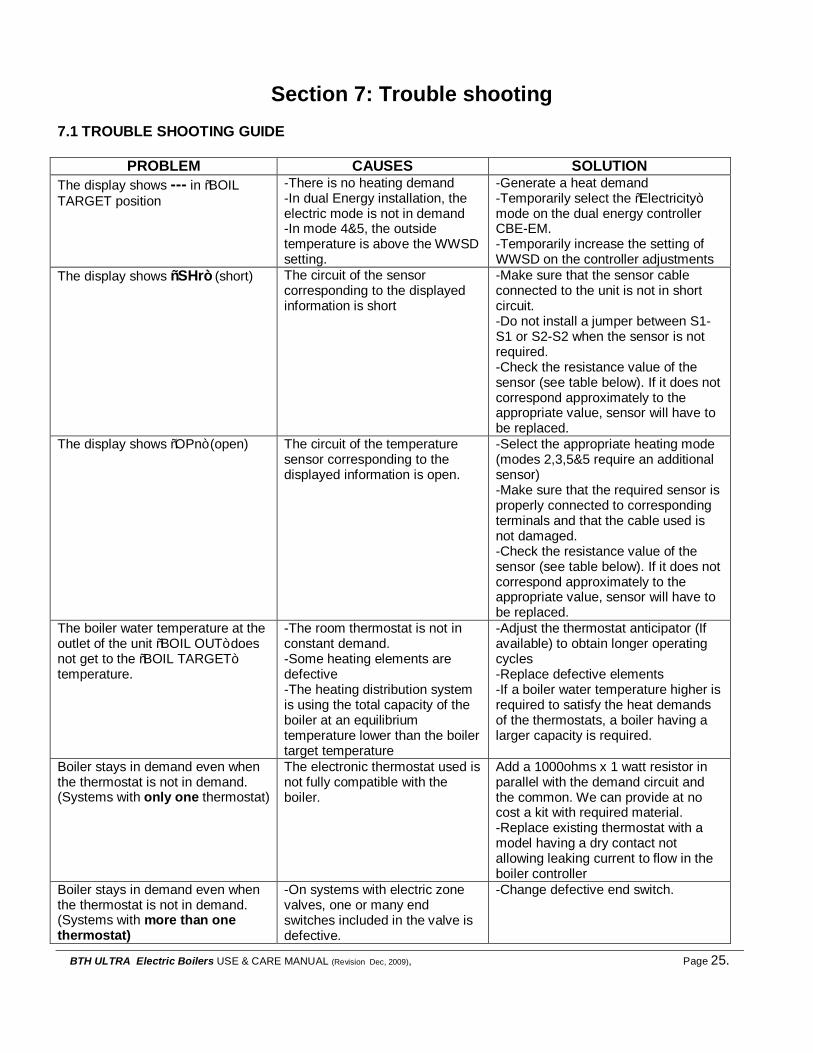
Section 7: Trouble shooting 7.1 TROUBLE SHOOTING GUIDE
PROBLEM CAUSES SOLUTION The display shows --- in “BOIL TARGET position
-There is no heating demand -In dual Energy installation, the electric mode is not in demand -In mode 4&5, the outside temperature is above the WWSD setting.
-Generate a heat demand -Temporarily select the “Electricity” mode on the dual energy controller CBE-EM. -Temporarily increase the setting of WWSD on the controller adjustments
The display shows “SHr” (short) The circuit of the sensor corresponding to the displayed information is short
-Make sure that the sensor cable connected to the unit is not in short circuit. -Do not install a jumper between S1-S1 or S2-S2 when the sensor is not required. -Check the resistance value of the sensor (see table below). If it does not correspond approximately to the appropriate value, sensor will have to be replaced.
The display shows “OPn” (open) The circuit of the temperature sensor corresponding to the displayed information is open.
-Select the appropriate heating mode (modes 2,3,5&5 require an additional sensor) -Make sure that the required sensor is properly connected to corresponding terminals and that the cable used is not damaged. -Check the resistance value of the sensor (see table below). If it does not correspond approximately to the appropriate value, sensor will have to be replaced.
The boiler water temperature at the outlet of the unit “BOIL OUT” does not get to the “BOIL TARGET” temperature.
-The room thermostat is not in constant demand. -Some heating elements are defective -The heating distribution system is using the total capacity of the boiler at an equilibrium temperature lower than the boiler target temperature
-Adjust the thermostat anticipator (If available) to obtain longer operating cycles -Replace defective elements -If a boiler water temperature higher is required to satisfy the heat demands of the thermostats, a boiler having a larger capacity is required.
Boiler stays in demand even when the thermostat is not in demand. (Systems with only one thermostat)
The electronic thermostat used is not fully compatible with the boiler.
Add a 1000ohms x 1 watt resistor in parallel with the demand circuit and the common. We can provide at no cost a kit with required material. -Replace existing thermostat with a model having a dry contact not allowing leaking current to flow in the boiler controller
Boiler stays in demand even when the thermostat is not in demand. (Systems with more than one thermostat)
-On systems with electric zone valves, one or many end switches included in the valve is defective.
-Change defective end switch.

BTH ULTRA Electric Boilers USE & CARE MANUAL (Revision Dec. 2009), Page 26.
-A jumper has been installed on terminals TT of the boiler -On an installation in Dual Energy, the position of the dipswitch B on the boiler control is not in the proper position. (see section 4.4.7)
-Make appropriate connections as shown in fig.14 -Set the dipswitch on “B”
In Bi-Energy mode, the operation in oil an electricity is inverted
The automatic transfer contact used to switch from electricity to oil is not appropriate
Use a N.O. contact (contact is open when operation in electricity is requested) to be connected to the dual energy controller CBE-EM . The N.F. contact of the CBE-EM controller at E1E2 terminals will authorize the operation of the electric boiler
An overheated plastic odour is released from the boiler
Turn the power OFF to the boiler. Open the front and left side panel of the boiler. Check the components and electric wires for overheating indications.
Replace overheated components and check supply voltage to the boiler.
Boiler safety valve is leaking -Pressure reading at the indicator shows a pressure above 28psi -Pressure is below 28psi
-The pressure regulator on the distribution system is defective or the expansion tank is too small or defective. -Replace the safety valve
Table 6: Resistance value of the temperature sensors in relation to the exposed temperature

BTH ULTRA Electric Boilers USE & CARE MANUAL (Revision Dec. 2009), Page 27.
7.2 REPLACEMENT PART & CONTROL TERMINALS IDENTIFICATION
Call your local distributor to get required parts.

BTH ULTRA Electric Boilers USE & CARE MANUAL (Revision Dec. 2009), Page 28.
BTH ULTRA LIMITED WARRANTY Warranty Coverage for Residential Installation. Thermo 2000 Inc. hereby warrants to the original residential purchaser that the BTH ULTRA tank installed in a residential setting shall be free of leaks during normal use and service for a period of ten (10) years from the date of purchase as long as the original residential purchaser owns the home in which the unit was originally installed, the first (5) years in full and years six (6) through ten (10) prorated 20% each year at suggested retail price. Residential setting shall mean usage in a single-family dwelling in which the consumer resides on a permanent basis. Also, residential setting shall mean use in multiple family dwellings in which one (1) BTH ULTRA tank is to be use in only one (1) dwelling. In the event that a leak should develop and occur within this limited warranty period due to defective material or workmanship, such leak having been verified by an authorized company representative, Thermo 2000 inc. will repair or replace at our sole option the failed unit with the nearest comparable model at the time of replacement. The original residential purchaser is responsible for all costs associated with the removal and reinstallation, shipping and handling to and from manufacturing plant. The replacement unit will be warranted for the remaining portion of the original Warranty. Warranty Coverage for Commercial Installation. Thermo 2000 Inc. warrants to the original purchaser that the BTH ULTRA tank installed in a commercial setting for ten years, the first (5) years in full and years six (6) through ten (10) prorated 20% each year at suggested retail price Commercial setting shall mean use in other than residential setting stated above in the residential setting definition. In the event that a leak should develop and occur within this limited warranty period due to defective material or workmanship, such leak having been verified by an authorized company representative, Thermo 2000 inc. will repair or replace at our sole option the failed unit with the nearest comparable model at the time of replacement. The original purchaser is responsible for all costs associated with the removal and reinstallation, shipping and handling to and from Manufacturer. The replacement unit will be warranted for the remaining portion of the original Warranty. Limited two years warranty on all BTH ULTRA components & parts All other BTH ULTRA components & parts are warranted for a period of two (2) years against defects due to defective material or workmanship. The original purchaser is responsible for all costs associated with the removal and reinstallation, shipping and handling to and from Manufacturer. The components, repaired or replaced are warranted for the residual period of the initial warranty on the unit. Exclusions. This warranty is void and shall not apply if: 1. Defects or malfunctions resulting from installation, repair, maintenance and/or
usage that are not done in conformity with the manufacturer’s installation manual; or
2. Defects or malfunctions resulting from installation, maintenance, or repair that are not done in accordance with regulations in force; or
3. Defects or malfunctions resulting from improper installation, maintenance or repair done carelessly or resulting from consumer damage (improper maintenance, misuse, abuse, accident or alteration); or
4. Installation in which a relief valve (pressure) is not installed or if it is not functioning properly, or when it is not connected to a drain to avoid damage to the property; or
5. Installation in which liquid circulating in the tank does not remain in closed circuit or installation in which piping is leaking; or
6. A polybutylene pipe or radiant panel installation without an oxygen absorption barrier is used; or
7. Installation where the acidity of water is not within the normal Environmental Protection Agency (EPA) (between pH 6.5 – 8.5) guidelines or the domestic water contains abnormal levels of particulate matter or water exceeding 10.5 gpg; or
8. Your home contains any type of water softener system and the unit is not installed and maintained in accordance with the manufacturer specifications; or
9. The BTH ULTRA unit is being subject to non authorized modifications; or 10. Defects or malfunction resulting of storing or handling done elsewhere than Thermo
2000’s manufacturing plant; or 11. Units on which the serial number is removed or obliterated.
Limitations. Thermo 2000 shall not be responsible for any damage, loss, and inconvenience of any nature whatsoever, directly or indirectly, relating to the breakdown or malfunction of the unit. This warranty limits its beneficiary’s rights. Nevertheless, the beneficiary may have other rights, which vary from state to state. This warranty replaces any other expressed or implicit warranty and constitutes the sole obligation of Thermo 2000 towards the consumer. The warranty does not cover cost of removal, reinstallation or shipping to repair or replace the unit, nor administration fees incurred by the original consumer purchaser. Thermo 2000 reserves its rights to make changes in the details of design, construction, or material, as shall in its judgment constitute an improvement of former practices. This warranty is valid only for installations made within the territorial limits of Canada and the United States. In order to receive the benefit of this warranty, the original consumer purchaser must fill in and return the attached registration card within thirty (30) days of date of purchase. Warranty service procedure Only authorized BTH ULTRA dealers are permitted to perform warranty obligations. The owner or its contractor must provide Thermo 2000’s head office or authorized depot with defect unit together with the following information: BTH ULTRA model and serial number, copy of the original sales receipt and owner’s identification certificate
THERMO 2OOO INC. 500, 9th Avenue, Richmond (Qc) Canada J0B 2H0 Phone: (819) 826-5613 Fax: (819) 826-6370 www.thermo2000.com

BTH ULTRA Electric Boilers USE & CARE MANUAL (Revision Dec. 2009), Page 29.
Figure 5 : Application en/in Mode 1
Point de consigne fixe sur systèmes multi-zones avec valves de zone motorisées Fix target temperature on multi-zone systems with motorised zone valves

BTH ULTRA Electric Boilers USE & CARE MANUAL (Revision Dec. 2009), Page 30.
Figure 6: Application en/in Mode 1
Point de consigne fixe sur systèmes multi-zones avec pompes Fix target temperature on multi-zone systems with pumps
BTH ULTRA Electric Boilers USE & CARE MANUAL (Revision Dec. 2009), Page 31.
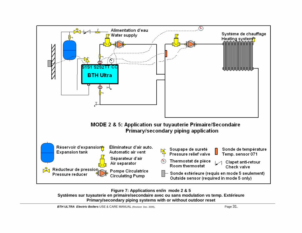
Figure 7: Applications en/in mode 2 & 5
Systèmes sur tuyauterie en primaire/secondaire avec ou sans modulation vs temp. Extérieure Primary/secondary piping systems with or without outdoor reset

BTH ULTRA Electric Boilers USE & CARE MANUAL (Revision Dec. 2009), Page 32.
Figure 8: Application en/in Mode 3
Pour chauffage de l’eau domestique avec chauffe-eau indirecte For domestic hot water with indirect water heater

BTH ULTRA Electric Boilers USE & CARE MANUAL (Revision Dec. 2009), Page 33.
Figure 9: Application en/in mode 4
Modulation de la température de l’eau en fonction de la température extérieure Boiler reset temperature vs outside temperature

BTH ULTRA Electric Boilers USE & CARE MANUAL (Revision Dec. 2009), Page 34.
Figure 10: Application en/in mode 4
Modulation temp. Chaudière + haute température pour eau chaude domestique Boiler temp. Reset + high temperature for domestic hot water production

BTH ULTRA Electric Boilers USE & CARE MANUAL (Revision Dec. 2009), Page 35.
Figure 11: Application en/in Mode Bi-Énergie
Systèmes en parallèles avec valve de contrôle trois voies Parallel systems with motorised three way control valve

BTH ULTRA Electric Boilers USE & CARE MANUAL (Revision Dec. 2009), Page 36.
Figure 12: Application en/in Bi-Energie
Système parallèle en série sans valve trois voies Parallel system in series without three way valve

BTH ULTRA Electric Boilers USE & CARE MANUAL (Revision Dec. 2009), Page 37.
Figure 13: Raccordements électriques/ Electrical wiring Systèmes multi-zone avec valves électriques de zone/
Systems multi-zone with motorised zone valves
Figure 14: Raccordements électriques /Electrical wiring
Systèmes multi-zone avec pompes/ Multi-zone systems with pumps

BTH ULTRA Electric Boilers USE & CARE MANUAL (Revision Dec. 2009), Page 38.
Figure 15: Diagramme électrique/ wiring diagram BTH Ultra 240-6&10KW

BTH ULTRA Electric Boilers USE & CARE MANUAL (Revision Dec. 2009), Page 39.
Figure 16 : Diagramme électrique / Wiring diagram BTH Ultra 12 à 24 KW

BTH ULTRA Electric Boilers USE & CARE MANUAL (Revision Dec. 2009), Page 40.
Figure 17 : Diagramme électrique / Wiring diagram BTH Ultra 240-27

BTH ULTRA Electric Boilers USE & CARE MANUAL (Revision Dec. 2009), Page 41.
Figure 18 : Diagramme électrique / Wiring diagram BTH Ultra 240-30 & 33
Related Documents