ACKNOWLEDGEMENT I feel immense pleasure and deep feeling of gratitude towards Mrs. Aasha Goswami, Mr. Hitesh Yadav, Rahul Shrivastav and R.K. jain of Bharat Sanchar Nigam Limited (BSNL), of Telecom District, Sagar for their skillful guidance, constructive and valuable suggestions and encouraging cooperation for my project. I also thank my team members for their cooperation during the entire training period. Report 1

Welcome message from author
This document is posted to help you gain knowledge. Please leave a comment to let me know what you think about it! Share it to your friends and learn new things together.
Transcript
ACKNOWLEDGEMENT
I feel immense pleasure and deep feeling of gratitude towards Mrs. Aasha Goswami, Mr. Hitesh Yadav, Rahul Shrivastav and R.K. jain of Bharat Sanchar Nigam Limited (BSNL), of Telecom District, Sagar for their skillful guidance, constructive and valuable suggestions and encouraging cooperation for my project.
I also thank my team members for their cooperation during the entire training period.
Report 1
INDEX
1. History of BSNL.
2. Various unit of BSNL.
3. Switches / Exchange
OCB -283-Tandom Exchange
C-DOT -Tandom Exchange
E-10B-Tandom Exchange
Access network
4. Inter – Connectivity diagrams
5. Transmission system
6. GSM
BSS
NSS
7. Main Distribution Frame
8. Broadband
Introduction to National Internet Backbone-ii (NIB-ii)
Modem DSLAM Broadband Network Gateway (BNG
Various units of BSNL Sagar :
1. MDF & Power plant
2. Electronic Switches
a. E-10B
b. C-DOT
c. OCB-283
3. MUX room
4. Transmission room
Report 2

5. Customer Service Center
6. SDCA of Sagar :
a) Khurai
b) Bina
c) Deori
d) Banda
e) Rehli
HISTORY OF BSNL
Bharat Sanchar Nigam Ltd. formed in October, 2000, is World's 7th largest Telecommunications Company providing comprehensive range of telecom services in India: Wireline, CDMA mobile, GSM Mobile, Internet, Broadband, Carrier service, MPLS-VPN, VSAT, VoIP services, IN Services etc. Presently it is one of the largest & leading public sector unit in India.
BSNL has installed Quality Telecom Network in the country and now focusing on improving it, expanding the network, introducing new telecom services with ICT applications in villages and wining customer's confidence. Today, it has about 46 million line basic telephone capacity, 8 million WLL capacity, 52 Million GSM Capacity, more than 38302 fixed exchanges, 46565 BTS, 3895 Node B ( 3G BTS), 287 Satellite Stations, 614755 R km of OFC Cable, 50430 R km of Microwave Network connecting 602 Districts, 7330 cities/towns and 5.6 Lakhs villages.
BSNL is the only service provider, making focused efforts and planned initiatives to bridge the Rural-Urban Digital Divide ICT sector. In fact there is no telecom operator in the country to beat its reach with its wide network giving services in every nook & corner of country and operates across India except Delhi & Mumbai. Whether it is inaccessible areas of Siachen glacier and North-eastern region of the country. BSNL serves its customers with its wide bouquet of telecom services.
BSNL is numerouno operator of India in all services in its license area. The company offers vide ranging & most transparent tariff schemes designed to suite every
Report 3
customer.BSNL cellular service, CellOne, has 55,140,282 2G cellular customers and 88,493 3Gcustomers as on 30.11.2009. In basic services, BSNL is miles ahead of its rivals, with 35.1 million Basic Phone subscribers i.e. 85 per cent share of the subscriber base and 92 percent share in revenue terms. BSNL has more than 2.5 million WLL subscribers and 2.5 million Internet Customers who access Internet through various modes viz. Dial-up, Leased Line, DIAS, Account Less Internet (CLI). BSNL has been adjudged as the NUMBER ONE ISP in the country. BSNL has set up a world class multi-gigabit, multi-protocol convergent IP infrastructure that provides convergent services like voice, data and video through the same Backbone and Broadband Access Network. At present there are 0.6 million DataOne broadband customers. The company has vast experience in Planning, Installation, network integration and Maintenance of Switching & Transmission Networks and also has a world class ISO 9000 certified Telecom Training Institute. Scaling new heights of success, the present turnover of BSNL is more than Rs.351, 820 million (US $ 8 billion) with net profit to the tune of Rs.99,390 million (US $ 2.26 billion) for last financial year. The infrastructure asset on telephone alone is worth about Rs.630, 000 million (US $ 14.37 billion).
The turnover, nationwide coverage, reach, comprehensive range of telecom services and the desire to excel has made BSNL the No. 1 Telecom Company of India.
OCB-283-Tandom Exchange
Introduction
Telecommunication Networks Are Constantly Changing. The Rapid Growth Of The Digital Network, Mobile Network And Intelligent Network And The Proliferation Of New Services Being Constantly Offered To Subscriber Means That Equipment Must Be Continuously Adapted To New Requirements. All The New Switching Systems Are Based On Stored Program Control Concept. The Call Processing Programmes Are Distributed Over Different Control Organs Of The System And Are Stored In Rom/Ram Of The Units Processor In The Control Units By Using The Programme And Data Stored In Unit Rom/Ram Process And Handle Calls. Handling Or Processing A Call Means To Ultimately Establish A Connection In Between Incoming And Outgoing Ends. Depending On The System The Name And Architecture Of Control Units And Switch May Change But Basic Criterion For Switching More Or Less Remains Same.
The Alcatel 1000E10 Exchange Also Known By Its Other Name Ocb283 Is Designed To Cater For Evolving Networks And The Need To Rationalize Equipment Operation. Its Modular Architecture Means That New Services Can Be Added And Processing Capacity Can Be Increased Without Interrupting Operation Of The Exchange. Ocb 283
Report 4
Is A Digital Switching System Which Supports A Variety Of Communication Needs Like Basic Telephony, Isdn, Interface To Mobile Communication, Data Communication Etc. This System Has Been Developed By Alcatel Of France And Therefore Has Many Similarities To Its Predecessor E-10. The First Ocb283 Exchange Of R11 Version Came To India In 1993. At Present R23 And R24 Are Also Being Supplied. The Basic Architecture Remaining Same, More Facilities To Subscriber And Administration Are Supported By Later Versions
OCB 283 Functional Diagram
The main functional blocks of a ocb-283 switch are:
Subscriber access sub system which carries out connection of different types of analogue and digital subscriber.
“Connection and control” sub system which carries out connections and processing of calls including pcm connections.
Operation and mtce.sub function which does the management of database and helps in carrying out various maintenance procedures in built in the systems.
BRIEF DESCRIPTION OF THE FUNCTIONAL COMPONENTS:
1. BT (TIME BASE):
Time pulses are generated in triplicate and distributed to lr’s at switching unit.The time base is usually synchronised with the network by a synch.interface. It gets the clock from pcms which carry traffic also and synchronises the local clock with the pcm clock and thus network synchronisation is achieved.
2. HOST SWITCHING MATRIX:
This is a pure switch of maximum 2048 lrs connectivity capability. The switching of time slots are controlled by the function com which in turn obtains the particulars from call handler known as multiregister.
3. AUXILIARIES:
Auxiliary Equipment Manager(ETA).It supports following functions:
-Tone generation
-Frequency generation and reception
Report 5
-Conference call facility
-Exchange clock
4. CALL HANDLER (MR):
This obtains necessary data from subs.& ckts.&process for connection and disconnection of call with the help of a database manager tr. In addition this helps in carrying out ckt.tests and some observations. It establishes and releases the calls. It takes real time decisions for processing of a call. The MR also consults TR to find out subscribers entitlements
5. DATA MANAGER (TR):
This is responsible for managing &storing various subscriber and trunks related database. The data is returned by the call handler as & when required during call processing. It also stores routing and analysis data. It converts (or) translates the received digits into equipment number of the called subscriber.
6. CHARGING FUNCTION (TX):
This function is responsible for charge computation on the basis of certain charging parameters supplied by the translator during analysis of digits received from a source. This also prepares detailed billing messages & forwarding the same to the operation & maintenance function for further processing .
7. MATRIX HANDLER (GX):
This function is responsible for processing and for defence of connections on receipt of-
-Request for connection & disconnection from MR or MQ.
-Fault in connection
8. MESSAGE DISTRIBUTION FUNCTION MARKER:
Its function is to format if required & distribute messages. Also supervises semi permanent links& inter messages between different communication multiplexes.
9. PCM CONTROLLER(URM):
PCM interface receives PCM from other exchanges remote subs. access units, access networks and digital recorded announcement systems and the URM function carries out the following—
-hdb3/binary code conversion
Report 6
-injection/extraction of ts 16 for cas.
10. OM FUNCTION:
This function enables to create all data required for subs/circuits and their testing. This also enables spontaneously issuing faults & alarm messages in case ofindications coming from OCB units. Also provides features for saving detail billing/bulk billing messages on magnetic tape. It possess a two way communication path with the exchange.
11. CSNL/CSBD
This is implemented in CSNL/CSBD & is responsible to forward new call connection & disconnection requests to control functions.
Installation/Commissioning/Maintenance of OCB-283 AMC for BSNL and MTNL
The OCB 283 / CSN Exchange is a Multiservice Switching System which serves as Local, TAX, Tandem, International Gateway Exchange and Service Switching Point (SSP) from Mobile Radio and Intelligent Network (IN).OCB 283 is the controller part of the exchange, which has a distributed architecture with control station like Main Control Station (SMC) consisting of Call Processing, Data Base, Charging, Message Distribution Management of connection etc. CSN is Digital Subscriber Concentrated to Interface Subscribers. CSN could be co-located (CSNL) or remoted (CSND). The switch also incorporates second level remoting (CNE) at Distant Subscriber Equipment (CSND). The main services are Plain Old Telephone Services (POTS) ISDN Services, Intelligent Network Services, Digital Circular Radio Telephone Services etc.
As part of AMC (Annual Maintenance Contract) of new technology switches for BSNL and MTNL, ITI has been awarded 40% of the total working lines of OCB 283 with respect of BSNL and 70% of the total working lines of OCB 283 with respect of MTNL through Tender. The total order value of the project being implemented by NS Unit is as follows:
1. OCB 283 AMC for BSNL is Rs. 33 Crores per annum.
2. OCB 283 AMC for MTNL (both Mumbai and Delhi) is Rs. 21 Crores per annum.
Report 7

The BSNL OCB 283 AMC started in the year 2005-06 for a period of 3 years and extended upto two more years.The MTNL OCB 283 AMC started in the year 2007-08 for a period of 4 years
Hardware Configuration
Ocb 283 Exchange Comprises Following Hardware Units :
1. Subscriber Access Units (Csnl, Csnd, Csed).
2. Trunk And Junction Connection Units (Smt).
3. Switching Matrix (Smx).
4. Auxiliary Equipments (Sma).
5. Control Units (Smc).
6. Communication Multiplex.
7. Time Base Generator (Sts)
8. Operation And Maintenance Unit (Smm).
Features Of The System
1) It Is A Digital Switching System With Single ‘T’ Stage Switch. A Maximum Of 2048 Pcms Can Be Connected.
2) It Supports Both Analogue And Digital Subscriber.
3) The System Supports All The Existing Signaling System Like Decadic, Mf, Cas And Also Ccitt#7 Signaling System.
4) It Provides Telephony, Isdn, Data Communication, Cellular Radio And Other Value Added Services.
5) The System Has ‘Auto Recovery’ Feature. When A Serious Fault Occur In A Control Unit, It Gives A Message To Smm(Operation & Maintenance Unit). The Smm Puts This Unit Out Of Service, Loads The Software Of Faulty Unit In A Backup Unit And Bring It Into Service. Diagnostic Programmes Are Run On The Faulty System And Diagnostics Are Printed On The Terminal.
Report 8
6) Ocb283 Has Double Remoting Facility. Subscriber Access Unit Csnd Can Be Placed At A Remote Place And Connected To The Main Exchange Through Pcm Links. Further Line Concentrators Are Placed At A Remote Location And Connected To The Csnl Or Csnd Through Pcms. This Special Feature Can Meet Entire Range Of Necessities Like Urban, Semi-Urban And Rural.
7) Various Units Of Ocb283 System Are Connected Over Token Rings. This Enables Fast Exchange Of Information And Avoid Complicated Links And Wiring Between Various Units.
8) The Charge Accounts Of The Subscribers Are Automatically Saved On The Disc, Once In A Day. This Avoids Loss Of Revenue In Case Of Total Power Supply/ Battery Failure Or Any Other Type Of Exchange Failure.
9) Traffic Handling Capacity Of The System Is Very Huge. It Can Handle 8,00,000 Bhca And 25,000 Erlangs Of Traffic. Depending On The Traffic, A Maximum Of 2,00,000 Subscribers Or 60,000 Circuits Can Be Connected.
10) The Exchange Can Be Managed Either Locally Or Through Nmc Of 64Kbps Link.
11) The Ocb283 System Is Made Up Of Only 35 Different Type Of Cards. This Excludes Cards Required For Csn. Because Of This The Number Of Spare Cards Required For Maintenance Purpose, Are Drastically Reduced.
12) All The Control Units Are Implemented Are Implemented On The Same Type Of Hardware. This Is Called A Station. Depending On The Requirement Of Processing Capacity, Software Of Either One Or Several Control Units Can Be Located On The Same Station. For All These Control Units, Only One Backup Station Is Provided, Enabling ‘Automatic Recovery’ In Case Of Fault.
13) The System Has Very Modular Structure. The Expansion Can Be Carried Out Very Easily By Adding Necessary Hardware & Software.
14) The Smm(O&M Units) Are Duplicated, With One Active And Other Hot Standby. In Case Of Faults, The Switchover Takes Place Automatically. Moreover, Discs Are Also Connected To Both The Smms, There Is No Necessity Of Changing Of Cables From One To Another.
15) The Hard Disc Is Very Small In Size, Compact And Maintenance Free. It Has A Very Huge Memory Capacity Of 1.2Gb. The Detail Billing Data Are Regularly Saved In These Discs Itself, From There It Can Be Transferred To The Magnetic Tapes For The Purpose Of Processing.
Report 9
16) There Is No Fixed Rack And Rigid Suite Configuration In This System. It Provides Greater Flexibility And Adjustment In The Available Space.
17) This System Can Work At A Temperature 5°C To 45°C, Though The Optimum Temperature To Work Is 22°C.
Subscriber Facilities Provided By Ocb283
1) A Line Can Be Made Only Outgoing And Incoming.
2) Immediate Hotline Facility – The Subscriber Is Connected To Another Predetermined Subscriber On Lifting The Handset, Without Dialing Any Number.
3) Delay Hotline Facility – When Subscriber Lifts The Handset, Dial Tone Is Provided, He Can Dial Any Number. If He Does Not Dial A Number, Within A Predetermined Time, He Is Connected To Predetermined Number.
4) Abbreviated Dialing – The Subscriber Can Record A Short Code And Its Corresponding Full Number In The Memory. Later To Dial This Number He Has To Dial Only Short Code Of That Number.
5) Call Waiting Indication – When A Subscriber Is Engaged In Conversation And If Getting An Incoming Call, An Indication Is Given In The Form Of A Tone. Hearing This, The Subscriber Has Option, Either To Hold The Subscriber In Conversation And Attend The Waiting Call Or To Disconnect This Subscriber And Attend To The Waiting Call. In The Former Case He Can Revert Back To The Earlier Subscriber.
6) Call Forwarding – When Provided, Incoming Calls To The Subscriber Gets Transferred To The Number Mentioned By The Subscriber While Activating The Facility. This Facility Is Especially Very Useful For Those Person Who Are Always On Move.
7) Conference Between 4 Subscribers – The Subscriber A & B While In Conversation, Can Include Two More Subscriber By Pressing ‘* Button’ And Dialing Their Numbers.
8) Automatic Call Back On Busy – If This Facility Is Activated And If The Called Subscriber Is Found Busy, The Calling Subscriber Simply
Report 10
Replaces The Receiver. The System Keeps Watch On The Called Subscriber And When It Becomes Free, A Ring Is Given To Both The Subscribers. On Lifting They Can Talk To Each Other.
9) Priority Lines – Calls From These Lines Are Processed And Put Through Even When The Number Of Free Channels Are Within A Threshold Or When The System Is Operating In Catastrophic Mode.
10) Malicious Call Identification – When This Category Is Given To A Subscriber, The Number Of Calling Subscriber, The Number Of Calling Subscriber To This Number Is Printed On The Terminal Or Displayed On The Caller Identification Instrument.
11) 12 Or 16Khz Meter Pulses – The System Can Send 12 Or 16Khz Meter Pulses On The Subscriber Line For The Operating Of The Home Meter.
12) Battery Reversal – The System Extends Battery Reversal When Called Subscriber Answers. This Is Useful In Case Of Ccbs( Coin Collection Box ).
13) Detailed Billing – The System Provides Detail Bills Given Details Of Date, Time, Metered Units Etc.
14) Absent Subscriber Service – When Activated, The Incoming Calls Are Diverted To Absent Subscriber Service For Suitable Instruction Or Information.
15) It Provides 64 Kb/S Digital Connectivity Between Two Subscribers For Data Communication.
16) This System Provides Facsimile (Fax) Services And Videotext Services Also.
17) This System Also Provides The Facility For Restriction Of The Display Of Calling Subscriber Number On Called Subscriber’S Telephone Terminal Or Caller Id Set. To Avail This Facility The Subscriber Has To Be Given A Category Like Some Vvips Or Some Beurocrats.
18) User To User Signaling – The System Permits Of Mini Messages Between Calling And Called Subscribers During Call Setup And Ringing Phase.
19) Terminal Portability During The Call – A Subscriber (Calling Subscriber As Well As Called Subscriber) Can Unplug Telephone Instrument,
Report 11

Carry It To Some Other Place Or Room And Resume The Call Within 3 Minutes
20) Listing Of Unanswered Calls – The Number Of Calling Subscribers, Who Calls During The Absence Of Called Subscriber, Are Recorded In Called Subscriber’S Terminal. The Called Subscriber Than Check Up These Numbers And Call Them Back, If He So Wishes.
21) This System Provides Two Type Of Isdn Connections To The Digital Subscriber, One Is Of 2 B + D Line (2 Voice Channels Of 64Kbps & I Data Channel Of 16Kbps) Type And Other Is Of 30 B + D Line (30 Voice Channels Of 64Kbps & 1 Data Channel Of 16Kbps) Type.
C-DOT TANDOM EXCHANGE
BRIEF HISTORY : -
The Center for Development of Telematics (C-DOT) is the telecom technology
development center of the government , It was established in August 1984 as an
autonomous body. It was vested with full authority and total flexibility to develop state-
of-the-art telecommunication technology to meet the needs of the Indian
telecommunication network. The key objective was to build a center for excellence in
the area of telecom technology .
ORGANIZATION : -
The management of C-DOT has a three-tier structure: -The governing
Council: provides policy guidelines and approves the annual budget of the center. The
Steering Committee: has the role of reviewing and monitoring the performance of the
center.
The Project Board: is responsible for the implementation of C-DOT’s project and the day-to-day function of the center.
Architecture
C-DOT switches have distributed architecture .a base moduke (BM) has 512 port which can provide non-blocking connectivity and can accept concentrated subscriber lines. The BM, capable of serving upto 2000 lines or 512 trunks, is used as the basic building
Report 12
block. Each BM is the housed in a single Cabinate. By interconnecting upto 35 such BMs through a central module (CM),the switch can support upto 40,000 lines. The system can support upto 4:1 concentration. Lines and trunks can be intermixed in the same BM.The front-end of the system consists of an input output processor(IOP) connected to the administration processor(IOP) connected to the administration processor (AP). Each System consist of two IOPs working in duplex mode .IOP, based on Motorola 68040 and supporting UNIX environment, provides interface for the main machine communication, system initialization support ,operator features etc
OBJECTIVES: -
Work on telecom technology products and services.
Provide solutions for current and future requirements of telecommunication and
converged networks including those required for rural application
Provide market orientation to R & D activities and sustain C-DOT as center of
excellence
Build partnerships and joint alliances with industry , solution provides, telcos and
other development organizations to offer cost effective solution .
Support telcos and service provides in the introduction of new technologies ,
features and services by optimal utilization of installed network.
MANPOWER : -
Electronic Design automation (EDA) Tools for hardware and ASIC Design
Case Tools for Development and testing of software
Captive labs
Computing center
Pilot production plant
Existing manpower –907
Planned Manpower – 963
The Center has state-of-the-art development environment comprising client/ server
network of RISC workstation, latest software development tools and very mature and
effective development ad support methodologies, Extensive use is made of case tools,
object-oriented methodologies, software metric etc.The jobs have the latest test and
Report 13

measurement instrument, microprocessor development system and prototyping
facilities.
ACHIEVEMENTS : -
C-DOT Technology based system from 200 lines to 40,000 lines capacity in
operation. More than 30,000 C-DOT Exchange totaling approximately 25 million telephone
lines installed and operational in field.
Deployed telecom equipment value of Rs.7500 crore.
Significant technology transfer and royalty earnings.
Technology development with low capital investment.
Wide portfolio technologies, products and solution. Created large reservoir of technical manpower in telecom Established a technology transfer process for production by multiple
manufacturers.
The C-DOT DSS FAMILY
C-DOT DSS MAX is a universal digital switch can be configured for different
application as local, transit or integrated local and transit switch. High traffic or capacity
of 40000 lines as local exchange or 15000 trunks as Trunk automatic exchange. The
design of C-DOT DSS MAX has seen by a family concept because of it’s advantages
like standardized components, commonality in hardware, field hardware that used
minimum number of cards, standard cards, racks, frames, cabinets and distribution
frames are used which facilitated flexible system growth that make C-DOR DSS MAX
easy to maintain and highly reliable.
FLEXIBLE ARCHITECTUR
C-DOT DSS is a modular and flexible digital switching system which provides
economical means of serving metropolitan, urban and rural environments. It include all
important feature and compulsory services, required by the user with option of up
gradation to add new feature and services in future. The architecture for the C-DOT
DSS is such that it is possible to upgrade a working C-DOT Single Base Module.(SBM)
or Multi Base Module (MBM)exchange to provide Integrated Services Digital Network
Report 14
(ISDN) service by adding minimum addition hardware modules while continue to having
existing hardware units. Another factor of architecture Remote Switching Unit(RSU). Is
support ISDN. This RSU provides switching facility locally even in case of failure of the
communication path to the parent exchange.The resources, which depend upon the
number of terminal, are provided within the basic growth unit the Base Module. Base
Processors are provided for handling call processing locally. In a small system
application, these processors independently support call processing, exchange
operation and maintenance function.
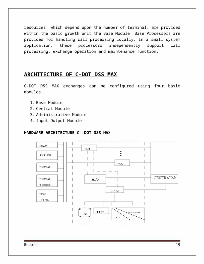
ARCHITECTURE OF C-DOT DSS MAX
C-DOT DSS MAX exchanges can be configured using four basic modules.
1. Base Module
2. Central Module
3. Administrative Module
4. Input Output Module
HARDWARE ARCHITECTURE C –DOT DSS MAX
Report 15
C-DOT MAX exchange can be configured using four basic modules:-
1. BASE MODULE (BM). 2. CENTRAL MODULE (CM) C. 3. ADMINISTRATION STRATIVE MODULE (AM). 4. INPUT OUTPUT MODULE (IOM&IOP).
(a) BASE MODULE (BM): -
The Base Module is the basic growth unit of the system . It interfaces the
external world to the switch. The interfaces may be subscriber lines, Along and digital
trunks. Each Base Module can interface up to 2024 terminations. The number of Base
Modules directly corresponds to the exchange size. It carries out majority of call
processing function and in a small exchange application, it also carries out operation
and maintenance function with the help of Input-Output Module.
The Basic functions of a base modules are:-
1. Analog to digital conversion of all signals on analog lines and trunks.
2. Interface to digital trunks and digital subscriber.
3. Switching the calls between terminals connected to the same Base Module.
Report 16

4. Communication with the AM via the CM for administrative(i.e. Call processing )
functions.
5. Provision of special circuits for call processing support e.g. Digital
6. Tones, announcement, MF/DTMF Senders/receivers.
7. 6. Provision for local switching Unit(RSU) as well as in case of Single Base
Module Exchange(SBM_RAX).
There are two types of Base Modules:-
1. Single Base Modules(SBM)
2. Multi Base Module (MBM)
In SBM exchange configuration, the Base Module acts as an independent
switching BM directly interface with the Input Output Module for bulk data storage,
operations and maintenance function. Clock and synchronization is provided by a
Report 17

source within the BM. It is a very useful application for small urban and rural
environments.The Base cabinet houses total 6 frames:-
Terminal Unit (TU, Top 4 Frames) system and provides connection to 1500 lines and 128 trunks. In such a configuration ,the
Base Processor Unit ( BPU,5th frame) Time switch unit (TSU)
There are following four terminals units:-
1. ANALOG TERMINAL UNIT (ATU):-
The Analog Terminals Unit (ATU) is used for interfacing 128 analog termination
which may be lines or trunks and providing special circuits as conference
announcements and terminal tester. It consists of terminal cards, which may be a
combination of Analog Subscriber Line Cards, Analog Trunk card & some Special
Service Cards.
(a) Analog Subscriber Ling Cards : -
Two variants of subscriber line cards as LCC(Line Circuit Card) or CCM(Coin
Collection Monitering) with interfaces upto 8 subscribers. Analog to digital conversion is
done by per channel CODEC according to A-Law of Pulse Code Modulation so we can
say that it for the subscriber connected for subscriber to exchange. A unit has 16 line
cards so 16*8=128 subscribers. There are 4 unit so 4*128= 512 subscribers.4 cards
make 1 Terminal Group(TG) so TG = 4.
(b) Analog Trunks Cards :-
Analog trunk cards interface analog inter exchange trunks which may be of three
types as TWT,EMT & EMF. These interfaces are similar to subscriber Line Cards, with
only difference that the interfaces are designed to scan/drive events on the trunks as
predefined signaling requirement.
(c) Signaling Processor Cards : -
SP Processes the signaling information received from the terminals cards. SP
processes the signaling information consists of scan/drive function like original
Report 18
detection, answer detection, digit reception, reversal detection etc. The validated events
are reported to Terminal interface controller for further processing.
(d) Terminal interface controller (TIC) Cards : -
TIC controls the four terminals group ( TG) of 32 channels and multiplex them to
form a duplicated 128 channels, 8 mbps link towards the Time Switch. For Signaling
information of 128 channels it communicates with signaling processor to receive/send
the signaling event on analog terminations. It also uses to communicate with BPU.
(e) Special Service Cards : -
A Terminal unit has some special service cards such as Conference (CNF) cards
to provide six party conference. Speech Samles from five parties are Terminal Test
Controller (TTC) card is used to test analog terminal interfaces via the test access
relays on the terminal cards. Announcement controller card provides 15 announcement
on board cast basis.
(2) DIGITAL TERMINAL UNIT( DTU ) : -
Digital terminal unit is used to interface digital trunks, i.e. used between the
exchanges. one set of Digital Trunks Synchronization (DTS) Card along with the Digital
Trunk Controller(DTC) card is used to provide one E-1 interface of 2mbps.Each
interface occupies one TG of 32 channels and four such interfaces share 4 TGs in a
DTU. Here Terminal Unit Controller (TUC) is used of TIC and DSP cards. Out of 32
channels, 30 for voice communication and remaining two for Signaling and
Synchronization. In DTU 4 TGs are there so total number of unit are 4*30 = 120 units in
DTU.
(3) # 7 or Signaling Unit Module(SUM) : -
It is used to support SS7 protocol handlers and some call processing function for
CCS7 calls.SS7 capability in C_DOT DSS MAX exchanges is implemented in the form
of a SS& Signaling Unit Module (SUM) The sum hardware is packaged into a standard
equipment frame, similar to that of terminal unit. It is a module by itself and contains
global resources. It interfaces with the Time Switch via Terminal Unit Controller (TUC)
on a 128 channel PCM link operating at 8mbps.
Report 19
CALL PROCESSING
GENERAL CONCEPT
There are five function steps of call processing including the location of the originating
and terminating equipment. These steps are : -
Origination : - Origination begins when the subscriber line goes off hookor incoming trunks seized. It receives the incoming digits, selects the digit analysis tables, and determines the screening information for this call.
Digit Analysis: - It interprets the digits it receives from origination ,select a destination for each call, and passes the dialed digits to routing.
Routing/Screening:- Routing uses the destination information from digit analysis and screening information origination to select the terminating trunk group or line.
Charging : - It uses the charging information from routing to expand the charging data into a formate usable by call accounting process.
Termination : - The last step in call processing is termination. Termination Processor is different for calls destined for lines and call destined for trunks.
Trunk termination : - A trunk member of the trunks group is selected based on a
predetermined pattern. After selection the digits are out pulsed to the distant office.
Line termination : - The line identified in routing is checked to determine the line has
any special features. Ringing is applied to the line if applicable or the special feature is
activated.
ROLE OF SOFTWARE IN C-DOT DSS
INTRODUCTION
The main feature of the software architecture of DSS-MAX are as:
1) Distributed architecture to ma the distributed control architecture
2) Layered architecture with loosely coupled modules & well defined message
interfaces.
3) Use of high level language
Report 20

4) Modular design with each layer providing higher of abstraction
5) Time critical processes in assembly language
These feature help in to achieve the following objectives:
Simplicity in design
Increased reliability due to fault tolerant software
Flexibility with option of up gradation to add feature & service
Efficiency and strict time check
Ease of Maintainability
C-DOT DSS MAX Layered Software Architecture
SOFTWARE SUBSYSTEMS
The main subsystem of C-DOT DSS MAX are as :
C-DOT real Time operating system
Peripheral Processors subsystem
Maintenance subsystem
Database subsystem
Administration subsystem
IOP subsystem
Call Processing subsystem
These subsystem are responsible for providing the following basic services:
1. CDOS :
It is the operating system & provides the following function :
Process management
Resource management
Interrupt handling
Online & offline debugging
2. Peripheral Processor subsystem :
Report 21
It controls all the telephony software. It also carries out the commands given by
the Base Processor for generating suitable telephony events. Another function is to
carry out all the maintenance related test function on hardware. It consists of 8-bit
microprocessors programmed in assembly language
3. Call processing subsystem:
It receives the information about telephony event that occur outside the
exchange. It processing this incoming information & gives commands to the peripheral
processors for interconnecting subscriber through the switching network. A special
feature is to generate Exhaustive Call Event Record for every call.
4. Maintenance subsystem:
It provides the following function:
Initialization System integrity Switch maintenance Terminal interface Human interface
5. Administration subsystem:
It consist of traffic, billing exchange performance measurement & human
interface functions. It also provides online software patching capability. It is responsible
for maintaining a large number of traffic records on the basis of information received by
it through Call Event Records. Over 200 man-machine commands are provided for
these operations.
6. Database Subsystem:
It provides for the management of global data.
The main objectives are:(a) Easy access(b) Quick access(c) Transparency(d) Consistency(e) Security(f) Synchronization
Report 22
POWER PLANT OF C-DOT DSS MAX
From the power supply bus bar power is tapped through cables to each suite separately. In this there is five modules, each having 200amp. As input. In this, AC is input and DC is output. In this input is between 340-475 V and output is 48V. There are two batteries if one is not conduct than other is used. These are connected together if both are disconnected than till 15-20 minutes power is supplied. From the rectifier, which derives 48V DC from 440V AC. Power cables are terminated on the DC distribution panel (DCDP). From the DCDP, power cables run along the cable runways and ladders and terminated on the power distribution panel(PDP). Distribution panel consists of two bus bars for –48V, one each for copy 0 and copy 1 equipment. Similarly there are two bus bars for ground. For each base module cabinet, the power i.e.-48V is tapped twice one for each plane through a fuse. Whenever the fuse blows off the LED, which is connected in parallel glows on the FBI card, and an audio alarm is given at a centrally located point.
SUMMARY
C-DOT DSS is a modular and flexible Digital Switching System which provides economical means of serving metropolitan, urban and rural environment. It incorporated all important feature and mandatory service, required by the user with option of up gradation to add new features and service in future. The architecture for the C-DOT DSS is such that it is possible to upgrade a working C-DOT SBM or MBM exchange to provide ISDN service by adding minimum addition hardware modules while retaining existing hardware units.
C-DOT DSS MAX is a universal digital switch which can be Configured for different application as local, transit, or integrated local and transit switch. The design of C-DOT DSS MAX has envisaged a family concept. The advantages of family concept are standardized components, commonality in hardware, documentation, training, installation and field support for all product and minimization of inventory of spares. Infact this Modular design has been consciously achieved by employing appropriate hardware, software, and equipment practices.
Software is written in high level language ‘C’ and distributed over various processor and is structured as a hierarchy of virtual machines. It can be distributed over appropriate controllers. The Software failures are implemented by communicating processes.
E-10B TANDOM EXCHANGE
ESTABLISHMENT OF E10B
Report 23
The first E-l0-B system (a training model) was commissioned at ALTCC, Ghaziabad in July 84. The first commercial E-I0-B system was setup at Bombay in April 85 supporting 10,000 lines. Also 22,000 lines of digital TAX (E-I0-B type) have been installed at 16 stations all over the country.(The first at Agra in Feb. 87) Palaghat (Kera1a) unit of ITI manufactures E-I0-B TAX equipments. Another ITI factory at MANKAPUR in GONDA (UP) produces annually 500,000 E-l 0B local lines
EVOLUTION OF E-10B SYSTEM
The predecessor of E-10B is the E-10A system developed in France in early Seventies. Based on the structure of E-10A, a more powerful\system with a significantly higher call handling / traffic capacity was developed in early 80's. The first E-10system was commissioned at BREST in FRANCE. The system has many versions. Tile INDIAN version is the 384 PCM versions and can handle max traffic capacity of 4000 erlangs. The BHCA is 1,90,000.
APPLICATIONS OF THE E-10-B SYSTEM
(a) LOCAL EXCHANGES
These exchanges terminate local subscriber lines and are connected to other exchanges in the local network. The limit of max traffic handling capacity is 4000 erlangs. Within this, any proportion of subscribers and junctions is possible.
(b) LOCAL, TRANSIT, TANDEM EXCHANGES
E-10B system can be used to carry pure transit traffic. Here, subscribers line providing terminating equipments will not be provided. Only equipments needed for connecting junctions will be provided.
(c) TAX
Here, the system provides for termination of long distances circuits. Digital Tax’s has a max capacity of 11,000 lines (o/g and I/g) in 384 versions.
(d) LOCAL CUM TRANSIT OR TAX
The facilities of local and transit can be combined.
Report 24
FACILITIES AND SERVICES TO THE SUBSCRIBER
1. Call forwarding
2. Short code Dialing
3. Malicious call tracing
4. Conference calls
5. Call waiting
6. Detailed billing
7. Automatic alarm call
8. Barred access
9. Hotline facility
10.Pushbutton telephone
11.Last number redial
Because of its modular structure, E-10-B can be expanded to meet its demands and new services can be introduced with modification of software.
Features of E10-B system
The system is based on these features.
(I) Stored program control
(2) TDM digital switching
(3) PCM principals and techniques
(4) Segregation of switching and management facilities.
(5) Distributed control using dedicated microprocessors,
e.g. 8085, ELS-48
(6) Centralized management for a group or E-1 0-B exchanges.
Report 25

Stored Program Control
Control functions relating to call processing are carried out by execution of program instructions stored in the memory of computers. In electromechanical systems, these functions are hardware based. In E-l0B, these arc software based.
TDM Digital SwitchingThe system switches signals to digital form. Analog signals are converted to TDM
multiplexed digital signals, prior to switching.
PCM Principles
Systems have been developed for 30 channels PCM corresponding to Relevant CCITT recommendations.
Segregation b/w switching and management functions
Switching functions like reception of dialed digits, the storage, the analysis, routing of the call etc. arc performed by the control unit in the exchange, which has a decentralized architecture, employing dedicated processors. Functions like subscribe lines and circuit group management, faults and alarm management etc. are done by a separate mini computer, located at a centralized operation and maintenance center (OMC), which is common for a number of E-10-B exchanges. OMC and switching centers are interconnected by PCM links. They could be in the same- premises or far apart.
Distributed controlCall handling and call processing functions like scanning of subscriber lines,
detection of loop status, reception and storage of digits etc. are distributed over functional units. Dedicated processors like Intel 8085 and dedicated mini computers like ELS-48 handle them.
Centralized management for a group of E – 10 B exchanges
The O&M functions for a group of E-I 0-8 exchanges (upto a maximum of 6
Report 26
exchanges or '80,000 lines) are carried out by single OMC, which is connected to various exchanges by PCM links.
The E-IO-8 exchange consists of three blocks:
a. Connection units
b. Switching networks
c. Control units
Connection Units
They act as an interface between external environment (i.e. subscribers and trunks) and central units. Units, which manage the generation and transmission of, digitalized tones and frequencies and dissemination of recorded announcements to subscribers are also called connection units.
Switching networks (CX)
This is a TDM switching network having a three stage time-space-time architecture. It uses four wires switching (4W) for connecting time slots of calling and called parties.
Control Units
The control unit handles telephone call setup, supervision, clear down and charging functions.
Specifications of E-10B:-
I. Number of switchable PCM links: 384
2. Processing capacity: 1,90,000 BHCA
3. Traffic handling capacity: 4000 erlangs
4. Subscriber exchange: 45,000 lines & 5000 circuits
SYSTEM FEATURES:-
I. Time division multiplexing
Report 27
2. PCM to CCITT standards
3. 2 Mbit/s PCM link
4. 30 telephone channels per PCM link
5. 8 bits per telephone channel
6. Stored program control
7. Dedicated processors for program control
8. Non dedicated processor for operation functions
SUBSCRIBER LINE
1. Dial or pushbutton VF telephone
2. Maximum loop resistance inclusive of telephone set 2400 ohms
3. Ringing current: 80 V, 25 and 50 Hz
ENVIRONMENTAL CONDITIONS
Exchange:
1. Ambient temp of air drawn into racks: 18 - 20 deg C
2. Relative humidity: 30 - 70 %
Satellite exchange:
1. Ambient temp: 5 -35 deg C
2. Relative humidity: 20 - 80 %
DIMENSIONS OF E-10B:-
Report 28

1. Rack dimension: height: 2 mt, width 0.75 mt, depth 0.5 mt, Distributive floor loading, less than 500 kg/sq. mt
2. Floor area: 45,000 lines subscriber exchange = 154 sq. mt
11,000 lines subscriber exchange = 90 sq. mt
POWER SUPPLY REQUIREMENTS:-1. Exchange and satellite exchange = -48 V
2. OMC: 220 V, 50 Hz
3. Power supply current online: 23 - 60 mA
4. Loop resistance: 1500 to 2400 ohms
CALL PROCESSING IN E-IO B EXCHANGE
The following types of call processing has been described:
1) Local call
2) I/C call
3) O/g call
A call is processed in the following four stages:
1) Pre-selection
2) Selection
3) Connection and charging
4) Release
PURPOSE OF MDF AND DDF IN E-10B EXCHANGE
E-10B switching system is a digital switching system and accepts both analog and digital signals. The signals from subscriber are analog whereas the trunk signals are
Report 29
digital (if coming from analog source, these are converted into digital 30 channel PCM signals and then fed to switch room).
The analog signals are received by CSE and digital signals by URM in E-10B system. For these two types of signals we use two types distribution frames in E-10B. One is called Main Distribution Frame (MDF) and the other one is called Digital Distribution Frame (DDF).
Access network
An access network is that part of a communications network which connects subscribers to their immediate service provider. It is contrasted with the core network, for example the Network Switching Subsystem in GSM. The access network may be further divided between feeder plant or distribution network, and drop plant or edge network.
Fixed Line Access Network - Telephone
An access network or outside plant refers to the series of wires, cables and equipment lying between a consumer/business telephone termination point (the point at which a telephone connection reaches the customer) and the local telephone exchange. The local exchange contains banks of automated switching equipment to direct a call or connection to the consumer. The access network is perhaps one of the oldest assets a telecoms operator owns, and is constantly evolving, growing as new customers are connected, and as new services are offered. This makes the access network one of the most complex networks in the world to maintain and keep track of.In 2007-2008 many telecommunication operators experienced increasing problems maintaining the quality of the records which describe the network. In 2006, according to an independent Yankee Group report, globally operators experience profit leakage in excess of €15 Billion each year.The access network is also perhaps the most valuable asset an operator owns, since this is what physically allows them to offer a service.
Access networks consist largely of pairs of copper wires, each traveling in a direct path between the exchange and the customer. In some instances, these wires may even be aluminum, the use of which was common in the 1960s and 1970s following a massive increase in the cost of copper. As it happened, the price increase was temporary, but the effect of this decision is still felt today because the aluminum wires oxidize and lose their ability to carry large quantities of data.Access is essential to the future profitability of operators who are experiencing massive reductions in revenue from POTS (plain old telephone services), due in part to the opening of historically nationalized companies to competition, and in part to increased use of mobile phones and VOIP (voice over IP) services. Operators now look toward additional services such as xDSL based
Report 30
broadband and IPTV (Internet Protocol Television) to guarantee future profit. The access network is again the main barrier to achieving these profits since operators world wide have accurate records of only 40% to 60% of the network. Without understanding or even knowing the characteristics of these enormous copper spider webs, it is very difficult, and expensive to 'provision' (connect) new customers and assure the data rates required to receive next generation services.Over time, we will see the access networks around the world evolve to include more and more optical fiber technology. Optical fibre already makes up the majority of core networks and will start to creep closer and closer to the customer, until a full transition to 21st Century Networks is achieved, delivering value added services over fiber to the home (FTTH).
(Access process)Access Network Authentication High-Level Example
The process of communicating with a network begins with an access attempt, in which one or more users interact with a communications system to enable initiation of user information transfer. An access attempt itself begins with an issuance of an access request by an access originator. An access attempt ends either in successful access or in access failure - an unsuccessful access that results in termination of the attempt in any manner other than initiation of user information transfer between the intended source and destination (sink) within the specified maximum access time. Access failure can be the result of access outage, user blocking, incorrect access, or access denial. Access denial (system blocking) can include: Access failure caused by the issuing of a system blocking signal by a communications system that does not have a call-originator camp-on feature. Access failure caused by exceeding the maximum access time and nominal system access time fraction during an access attempt. Without an access network, a fixed line telco can not exist, yet this network has been undervalued and under invested for decades. Telcos today need to massively improve their understanding of these networks to remain profitable in the short term and remain in existence in the longer term. British Telecom has produced an interactive presentation introducing the technology and design of access networks
Charging for access
An access charge is a charge made by a local exchange carrier for use of its local exchange facilities for a purpose such as the origination or termination of traffic that is carried to or from a distant exchange by an interexchange carrier
Transmission system
In telecommunications a transmission system is a system that transmits a signal from one place to another. The signal can be an electrical, optical or radio signal.
Report 31
Some transmission systems contain multipliers, which amplify a signal prior to re-transmission, or regenerators, which attempt to reconstruct and re-shape the coded message before re-transmission.
Pulse-code modulation
Pulse-code modulation (PCM) is a digital representation of an analog signal where the magnitude of the signal is sampled regularly at uniform intervals, then quantized to a series of symbols in a digital (usually binary) code. PCM has been used in digital telephone systems and is also the standard form for digital audio in computers and the compact disc red book format. It is also standard in digital video, for example, using ITU-R BT.601. However, straight PCM is not typically used for video in consumer applications such as DVD or DVR because it requires too high a bit rate (PCM audio is supported by the DVD standard but rarely used). Instead, compressed variants of PCM are normally employed. However, many Blu-ray Disc movies use uncompressed PCM for audio. Very frequently, PCM encoding facilitates digital transmission from one point to another (within a given system, or geographically) in serial form.
History of PCM
In retrospect, PCM, like many other great inventions, appears to be simple and obvious. In the history of electrical communications, the earliest reason for sampling a signal was to interlace samples from different telegraphy sources, and convey them over a single telegraph cable. Telegraph time-division multiplexing (TDM) was conveyed as early as 1853, by the American inventor M.B. Farmer. The electrical engineer W.M. Miner, in 1903, used an electro-mechanical commutator for time-division multiplex of multiple telegraph signals, and also applied this technology to telephony. He obtained intelligible speech from channels sampled at a rate above 3500–4300 Hz: below this was unsatisfactory. This was TDM, but pulse-amplitude modulation (PAM) rather than PCM. Paul M. Rainey of Western Electric in 1926 patented a facsimile machine using an optical mechanical analog to digital converter. The machine did not go into production. British engineer Alec Reeves, unaware of previous work, conceived the use of PCM for voice communication in 1937 while working for International Telephone and Telegraph in France. He described the theory and advantages, but no practical use resulted. Reeves filed for a French patent in 1938, and his U.S. patent was granted in 1943.
The first transmission of speech by digital techniques was the SIGSALY vocoder encryption equipment used for high-level Allied communications during World War II from 1943.It was not until about the middle of 1943 that the Bell Labs people who designed the SIGSALY system, became aware of the use of PCM binary coding as already proposed by Alec Reeves.PCM in the 1950s used a cathode-ray coding tube with a grid having encoding perforations. As in an oscilloscope, the beam was swept
Report 32
horizontally at the sample rate while the vertical deflection was controlled by the input analog signal, causing the beam to pass through higher or lower portions of the perforated grid. The grid interrupted the beam, producing current variations in binary code. Rather than natural binary, the grid was perforated to produce Gray code lest a sweep along a transition zone produce glitches
Managed Leased Line Network (MLLN)
Leased Line services with flexible access bandwidth. The MLLN is a Managed Leased Line Network system which is proposed to provide Leased line connectivity. With the State-of-the-art technology equipment, MLLN is designed mainly for having effective control and monitor on the leased line so that the down time is very much minimised and the circuit efficiency is increased thus achieving more customer satisfaction. This mainly deals with data circuits ranging from 64 KBPs to 2048 KBPs.
In MLLN network conventional PCM primary MUX and subscriber Modems are replaced by versatile MUX and network terminating units respectively. MLLN mainly consists of Digital Cross Connect (DXC), versatile MUX (V MUX), Network Terminating Units (NTU) and Network Management System(NMS). DXC's and VMUX's are inter connected via optical fibre links with alternate routing facility in case of any route failure. VMUX is in turn connected to NTU's placed at customer premises through 2 wire copper pair. At the top of it NMS is suitably placed at the Central location for effective control & monitor. NTUs are fully managed from NMS. They are programmable for different data speeds ranging from 64 KBPs (n x64 KBPs: nx1 to 32) depending upon the customer demand, thus having bandwidth control without changing Modem at his premises. NTUs operate on 230 V AC.
Features of MLLN
Control, Manage the leased line network.
Bandwidth management as per the customer demand.
Pro-active maintenance, without waiting for customer to book a complaint.
Self Diagnostic/software loops to check E1 connectivity to DXC, VMUX/software loops for checking copper pair at NTU point for immediately identifying the faulty section for trouble shooting .
Alternate routing in case of any route failure.
Generation of the periodic performance reports for self-analysis/customer.
Synchronous Digital Hierarchy
Report 33

SDH (Synchronous Digital Hierarchy) is a standard technology for synchronous data transmission on optical media. It is the international equivalent of Synchronous Optical Network. Both technologies provide faster and less expensive network interconnection than traditional PDH (Plesiochronous Digital Hierarchy) equipment. In digital telephone transmission, "synchronous" means the bits from one call are carried within one transmission frame. "Plesiochronous" means "almost (but not) synchronous," or a call that must be extracted from more than one transmission frame.SDH uses the following Synchronous Transport Modules (STM) and rates: STM-1 (155 megabits per second), STM-4 (622 Mbps), STM-16 (2.5 gigabits per second), and STM-64 (10 Gbps).
GSM(Global System for Mobile Communications)
GSM (Global System for Mobile Communications, originally Groupe Spécial Mobile), is a standard set developed by the European Telecommunications Standards Institute (ETSI) to describe technologies for second generation (or "2G") digital cellular networks. Developed as a replacement for first generation analogue cellular networks, the GSM standard originally described a digital, circuit switched network optimized for full duplex voice telephony. The standard was expanded over time to include first circuit switched data transport, then packet data transport via GPRS. Packet data transmission speeds were later increased via EDGE. The GSM standard is succeeded by the third generation (or "3G") UMTS standard developed by the 3GPP. GSM networks will evolve further as they begin to incorporate fourth generation (or "4G") LTE Advanced standards. "GSM" is a trademark owned by the GSM Association.
The GSM Association estimates that technologies defined in the GSM standard serve 80% of the global mobile market, encompassing more than 1.5 billion people across more than 212 countries and territories, making GSM the most ubiquitous of the many standards for cellular networks.
Introduction to GSM Networks
The various interface labels are the formal names given to these interfaces. More details about these interfaces are found in GSM TS 03.02 [26].
The GSM network consists mainly of the following functional parts:
Report 34
i. MSC – the mobile service switching centre (MSC) is the core switching entity in the network. The MSC is connected to the radio access network (RAN); the RAN is formed by the BSCs and BTSs within the Public Land Mobile Network (PLMN). Users of the GSM network are registered with an MSC; all calls to and from the user are controlled by the MSC. A GSM network has one or more MSCs, geographically distributed.
ii. VLR – the visitor location register (VLR) contains subscriber data for subscribers registered in an MSC. Every MSC contains a VLR. Although MSC and VLR are individually addressable, they are always contained in one integrated node.
iii. GMSC – the gateway MSC (GMSC) is the switching entity that controls mobile terminating calls. When a call is established towards a GSM subscriber, a GMSC contacts the HLR of that subscriber, to obtain the address of the MSC where that subscriber is currently registered. That MSC address is used to route the call to that subscriber.
iv. HLR – the home location register (HLR) is the database that contains a subscription record for each subscriber of the network. A GSM subscriber is normally associated with one particular HLR. The HLR is responsible for the sending of subscription data to the VLR (during registration) or GMSC (during mobile terminating call handling).
v. CN – the core network (CN) consists of, amongst other things, MSC(s), GMSC(s) and HLR(s). These entities are the main components for call handling and subscriber management. Other main entities in the CN are the equipment identification register (EIR) and authentication centre(AUC). CAMEL has no interaction with the EIR and AUC; hence EIR and AUC are not further discussed.
vi. BSS – the base station system (BSS) is composed of one or more base station controllers (BSC) and one or more base transceiver stations (BTS). The BTS contains one or more transceivers
vii. (TRX)- The TRX is responsible for radio signal transmission and reception. BTS and BSC are connected through the Abis interface. The BSS is connected to the MSC through the A interface.
viii. MS – the mobile station (MS) is the GSM handset. The structure of the MS will be described in more detail in a next section. A GSM network is a public land mobile network (PLMN). Other types of PLMN are the time division
Report 35
multiple access (TDMA) network or code division multiple access (CDMA) network. GSM uses the following sub-division of the PLMN:
ix. Home PLMN (HPLMN) – the HPLMN is the GSM network that a GSM user is a subscriber of. That implies that GSM user’s subscription data resides in the HLR in that PLMN. The HLR may transfer the subscription data to a VLR (during registration in a PLMN) or a GMSC (during mobile terminating call handling). The HPLMN may also contain various service nodes, such as a short message service centre (SMSC), service control point (SCP), etc.
x. Visited PLMN (VPLMN) – the VPLMN is the GSM network where a subscriber is currently registered. The subscriber may be registered in her HPLMN or in another PLMN. In the latter case, the subscriber is outbound roaming (from HPLMN’s perspective) and inbound roaming (from VPLMN’s perspective). When the subscriber is currently registered in her HPLMN, then the HPLMN is at the same time VPLMN.
xi. Interrogating PLMN (IPLMN) – the IPLMN is the PLMN containing the GMSC that handles mobile terminating (MT) calls. MT calls are always handled by a GMSC in the PLMN, regardless of the origin of the call. For most operators, MT call handling is done by a GMSC in the HPLMN; in that case, the HPLMN is at the same time IPLMN. This implies that calls destined for a GSM subscriber are always routed to the HPLMN of that GSM subscriber. Once the call has arrived in the HPLMN, the HPLMN acts as IPLMN. MT call handling will be described in more detail in subsequent sections. When basic optimal routing (BOR) is applied, the IPLMN is not the same PLMN as the HPLMN.The user of a GSM network is referred to as the served subscriber ; the MSC that is serving that subscriber is known as the serving MSC.
xii. Mobile originated call – the MSC that is handling the call is the serving MSC for this call; the calling subscriber is the served subscriber.
xiii. Mobile terminated call – the GMSC that is handling the call is the serving GMSC for this call; the called subscriber is the served subscriber.
Signalling in GSM
The various entities in the GSM network are connected to one another through signalling networks.Signalling is used for example, for subscriber mobility, subscriber registration, call establishment,etc. The connections to the various entities are known as ‘reference points’. Examples include:
Report 36
a. A interface – the connection between MSC and BSC;
b. Abis interface – the connection between BSC and BTS;
c. D interface – the connection between MSC and HLR;
d. Um interface – the radio connection between MS and BTS.
Various signaling protocols are used over the reference points. Some of these protocols for GSM are the following:
a. mobile application part (MAP) – MAP is used for call control, subscriber registration, short message service, etc.; MAP is used over many of the GSM network interfaces;
b. base station system application part (BSSAP) – BSSAP is used over the A interface;
c. direct transfer application part (DTAP) – DTAP is used between MS and MSC; DTAP is carried over the Abis and the A interface. DTAP is specified in GSM TS 04.08 [49];
d. ISDN user part (ISUP) – ISUP is the protocol for establishing and releasing circuit switched calls. ISUP is also used in landline Integrated Services Digital Network (ISDN). A circuit is the data channel that is established between two users in the network. Within ISDN, the data channel is generally a 64 kbit/s channel. The circuit is used for the transfer of the encoded speech or other data. ISUP is specified in ITU-T Q.763 [137].
e. When it comes to call establishment, GSM makes a distinction between signaling and payload. Signaling refers to the exchange of information for call set up; payload refers to the data that is transferred within a call, i.e. voice, video, fax etc. For a mobile terminated GSM call, the signaling consists of exchange of MAP messages between GMSC, HLR and visited MSC (VMSC). The payload is transferred by the ISUP connection between GMSC and VMSC. It is a continual aim to optimize the payload transfer through the network, as payload transfer has a direct cost aspect Associated with it. Some network services are designed to optimize the payload transfer. One Example is optimal routing.
The network is structured into a number of discrete sections:
The Base Station Subsystem (the base stations and their controllers).
The Network and Switching Subsystem (the part of the network most similar to a fixed network). This is sometimes also just called the core network.
Report 37

I). Base station subsystem
The base station subsystem (BSS) is the section of a traditional cellular telephone network which is responsible for handling traffic and signaling between a mobile phone and the network switching subsystem. The BSS carries out transcoding of speech channels, allocation of radio channels to mobile phones, paging, transmission and reception over the air interface and many other tasks related to the radio network.
Base transceiver station
The base transceiver station, or BTS, contains the equipment for transmitting and receiving radio signals (transceivers), antennas, and equipment for encrypting and decrypting communications with the base station controller (BSC). Typically a BTS for anything other than a picocell will have several transceivers (TRXs) which allow it to serve several different frequencies and different sectors of the cell (in the case of sectorised base stations).
A BTS is controlled by a parent BSC via the "base station control function" (BCF). The BCF is implemented as a discrete unit or even incorporated in a TRX in compact base stations. The BCF provides an operations and maintenance (O&M) connection to the network management system (NMS), and manages operational states of each TRX, as well as software handling and alarm collection. The functions of a BTS vary depending on the cellular technology used and the cellular telephone provider. There are vendors in which the BTS is a plain transceiver which receives information from the MS (mobile station) through the Um (air interface) and then converts it to a TDM (PCM) based interface, the Abis interface, and sends it towards the BSC. There are vendors which build their BTSs so the information is preprocessed, target cell lists are generated and even intracell handover (HO) can be fully handled. The advantage in this case is less load on the expensive Abis interface.
The BTSs are equipped with radios that are able to modulate layer 1 of interface Um; for GSM 2G+ the modulation type is GMSK, while for EDGE-enabled networks it is GMSK and 8-PSK. Antenna combiners are implemented to use the same antenna for several TRXs (carriers), the more TRXs are combined the greater the combiner loss will be. Up to 8:1 combiners are found in micro and pico cells only. Frequency hopping is often used to increase overall BTS performance; this involves the rapid switching of voice traffic between TRXs in a sector. A hopping sequence is followed by the TRXs and handsets using the sector. Several hopping sequences are available, and the sequence in use for a particular cell is continually broadcast by that cell so that it is known to the handsets.
Report 38
A TRX transmits and receives according to the GSM standards, which specify eight TDMA timeslots per radio frequency. A TRX may lose some of this capacity as some information is required to be broadcast to handsets in the area that the BTS serves. This information allows the handsets to identify the network and gain access to it. This signalling makes use of a channel known as the Broadcast Control Channel (BCCH).
Base station controller
The base station controller (BSC) provides, classically, the intelligence behind the BTSs. Typically a BSC has tens or even hundreds of BTSs under its control. The BSC handles allocation of radio channels, receives measurements from the mobile phones, and controls handovers from BTS to BTS (except in the case of an inter-BSC handover in which case control is in part the responsibility of the anchor MSC). A key function of the BSC is to act as a concentrator where many different low capacity connections to BTSs (with relatively low utilisation) become reduced to a smaller number of connections towards the mobile switching center (MSC) (with a high level of utilisation). Overall, this means that networks are often structured to have many BSCs distributed into regions near their BTSs which are then connected to large centralised MSC sites.
The BSC is undoubtedly the most robust element in the BSS as it is not only a BTS controller but, for some vendors, a full switching center, as well as an SS7 node with connections to the MSC and serving GPRS support node (SGSN) (when using GPRS). It also provides all the required data to the operation support subsystem (OSS) as well as to the performance measuring centers.
A BSC is often based on a distributed computing architecture, with redundancy applied to critical functional units to ensure availability in the event of fault conditions. Redundancy often extends beyond the BSC equipment itself and is commonly used in the power supplies and in the transmission equipment providing the A-ter interface to PCU.
The databases for all the sites, including information such as carrier frequencies, frequency hopping lists, power reduction levels, receiving levels for cell border calculation, are stored in the BSC. This data is obtained directly from radio planning engineering which involves modelling of the signal propagation as well as traffic projections.
Report 39

Transcoder
The transcoder is responsible for transcoding the voice channel coding between the coding used in the mobile network, and the coding used by the world's terrestrial circuit-switched network, the Public Switched Telephone Network. Specifically, GSM uses a regular pulse excited-long term prediction (RPE-LTP) coder for voice data between the mobile device and the BSS, but pulse code modulation (A-law or μ-law standardized in ITU G.711) upstream of the BSS. RPE-LPC coding results in a data rate for voice of 13 kbit/s where standard PCM coding results in 64 kbit/s. Because of this change in data rate for the same voice call, the transcoder also has a buffering function so that PCM 8-bit words can be recoded to construct GSM 20 ms traffic blocks.
Although transcoding (compressing/decompressing) functionality is defined as a base station function by the relevant standards, there are several vendors which have implemented the solution outside of the BSC. Some vendors have implemented it in a stand-alone rack using a proprietary interface. In Siemens' and Nokia's architecture, the transcoder is an identifiable separate sub-system which will normally be co-located with the MSC. In some of Ericsson's systems it is integrated to the MSC rather than the BSC. The reason for these designs is that if the compression of voice channels is done at the site of the MSC, the number of fixed transmission links between the BSS and MSC can be reduced, decreasing network infrastructure costs. This subsystem is also referred to as the transcoder and rate adaptation unit (TRAU). Some networks use 32 kbit/s ADPCM on the terrestrial side of the network instead of 64 kbit/s PCM and the TRAU converts accordingly. When the traffic is not voice but data such as fax or email, the TRAU enables its rate adaptation unit function to give compatibility between the BSS and MSC data rates.
II). Network switching subsystem
Network switching subsystem (NSS) (or GSM core network) is the component of a GSM system that carries out call switching and mobility management functions for mobile phones roaming on the network of base stations. It is owned and deployed by mobile phone operators and allows mobile devices to communicate with each other and telephones in the wider Public Switched Telephone Network or (PSTN). The architecture contains specific features and functions which are needed because the phones are not fixed in one location.
The NSS originally consisted of the circuit-switched core network, used for traditional GSM services such as voice calls, SMS, and circuit switched data calls. It was extended with an overlay architecture to provide packet-switched data services known as the GPRS core network. This allows mobile phones to have access to services such as WAP, MMS, and the Internet.
Report 40
All mobile phones manufactured today have both circuit and packet based services, so most operators have a GPRS network in addition to the standard GSM core network.
Mobile switching center (MSC)
The mobile switching center (MSC) is the primary service delivery node for GSM/CDMA, responsible for routing voice calls and SMS as well as other services (such as conference calls, FAX and circuit switched data). The MSC sets up and releases the end-to-end connection, handles mobility and hand-over requirements during the call and takes care of charging and real time pre-paid account monitoring. In the GSM mobile phone system, in contrast with earlier analogue services, fax and data information is sent directly digitally encoded to the MSC. Only at the MSC is this re-coded into an "analogue" signal (although actually this will almost certainly mean sound encoded digitally as PCM signal in a 64-kbit/s timeslot, known as a DS0 in America). There are various different names for MSCs in different contexts which reflects their complex role in the network, all of these terms though could refer to the same MSC, but doing different things at different times.
The Gateway MSC (G-MSC) is the MSC that determines which visited MSC the subscriber who is being called is currently located at. It also interfaces with the PSTN. All mobile to mobile calls and PSTN to mobile calls are routed through a G-MSC. The term is only valid in the context of one call since any MSC may provide both the gateway function and the Visited MSC function, however, some manufacturers design dedicated high capacity MSCs which do not have any BSSs connected to them. These MSCs will then be the Gateway MSC for many of the calls they handle.
The visited MSC (V-MSC) is the MSC where a customer is currently located. The VLR associated with this MSC will have the subscriber's data in it. The anchor MSC is the MSC from which a handover has been initiated.
Mobile switching centre server (MSCS)
The mobile switching centre server is a soft-switch variant of the mobile switching centre, which provides circuit-switched calling, mobility management, and GSM services to the mobile phones roaming within the area that it serves. MSS functionality enables split between control (signalling) and user plane (bearer in network element called as media gateway/MG), which guarantees better placement of network elements within the network. MSS and MGW media gateway makes it possible to cross-connect circuit switched calls switched by using IP, ATM AAL2 as well as TDM. More information is available in 3GPP TS 23.205.
The MSC connects to the following elements:
Report 41
The home location register (HLR) for obtaining data about the SIM and mobile
services ISDN number (MSISDN; i.e., the telephone number).
The base station subsystem which handles the radio communication
with 2G and 2.5G mobile phones.
The UMTS terrestrial radio access network (UTRAN) which handles the radio
communication with 3G mobile phones.
The visitor location register (VLR) for determining where other mobile subscribers
are located.
Other MSCs for procedures such as handover.
Main distribution frame
In telephony, a main distribution frame (MDF or main frame) is a signal distribution frame for connecting equipment (inside plant) to cables and subscriber carrier equipment (outside plant). The MDF is a termination point within the local telephone exchange where exchange equipment and terminations of local loops are connected by jumper wires at the MDF. All cable copper pairs supplying services through user telephone lines are terminated at the MDF and distributed through the MDF to equipment within the local exchange e.g. repeaters and DSLAM. Cables to intermediate distribution frames terminate at the MDF. Trunk cables may terminate on the same MDF or on a separate trunk main distribution frame (TMDF).
Like other distribution frames the MDF provides flexibility in assigning facilities, at lower cost and higher capacity than a patch panel.
The most common kind of large MDF is a long steel rack accessible from both sides. On one side, termination blocks are arranged horizontally at the front of rack shelves. Jumpers lie on the shelves and go through a steel hoop to run vertically to other termination blocks that are arranged vertically. There is a hoop or ring at the intersection of each level and each vertical. Installing a jumper requires two workers, one on each side. The shelves are shallow enough to allow the rings to be within arm's reach, but the workers prefer to hang the jumper on a hook on a pole so their partner can pull it through the ring. A fanning strip at the back of the termination block prevents the wires from covering each others' terminals. With disciplined administration the MDF can hold over a hundred thousand jumpers, changing dozens of them every day, for decades without tangling.
For the first half of the 20th Century, all MDF jumpers were soldered. This was reliable but slow and expensive. In the 1960s wire wrap was introduced, and in the 1970s punch blocks.
Report 42
Each jumper is a twisted pair. Middle 20th century jumper wires in the USA were 24 AWG single strand copper, with a soft polyethylene inner jacket and a cotton wrapper, impregnated to make it slightly brittle and easy to remove neatly. Late 20th century ones had a single, thicker coating of polyethylene, cross-linked to provide the correct degree of brittleness.
Some urban central office MDFs are two stories high so they don't have to be more than a city block long. A few are three stories. By British custom the cables to the outside world are terminated on the horizontal side, and the indoors equipment on the vertical side. American usage is the opposite.
Smaller MDFs, and some modern large ones, are single sided so one worker can install, remove or change a jumper. COSMOS and other computerized Operations Support Systems help by assigning terminals close to one another, so most jumpers need not be long and shelves on either type of MDF do not become congested. This database keeps track of all terminals and jumpers. In the early and middle 20th century these records were kept as pencil entries in ledger books. The later database method saves much labor by permitting old jumpers to be reused for new lines.
The adoption of distributed switching in the late 20th century diminished the need for large, active, central MDFs.
The MDF usually holds central office protective devices including heat coils and functions as a test point between a line and the office. Sometimes the MDF is combined with other kinds of distribution frame in a CDF The MDF in a private branch exchange performs functions similar to those performed by the MDF in a central office. In order to automate the manual jumpering the Automated Main Distribution Frame (AMDF) becomes an important role.
Function of Main distribution frame:
• A fixed means of terminating the external cables.
• A means for mounting the protective devices for incoming circuits.
• A convenient point of interception for locating of faults.
• A means for cross connecting the external circuits to the appropriate
PARTS OF THE MDF
1. HORIZONTAL SIDE:
It is again subdivided in to two parts
Report 43
a. Exchange side
b. Line side
Description of the horizontal side:-
RACK: - On the rack, the tags are situated. One rack is having eight tags. The courting is done from up (0) to down (7).
TAG: - Each rack consists of eight tags.
1 tag = 4 core
1 core = 4 bunch
1 bunch = 2 line
N.E.:- The word NE stands for the ‘NUMBER OF EQUIPMENT’.
It is a 128 pair cable. The EWSD and MDF connected by NE.
WEDGE:- If we want to disconnect any two numbers then we insert a wedge between subscriber side and exchange side. Here wedge works as insulator made of plastic.
2). VERTICAL SIDE:
The vertical aside connected to the underground cable. This cable is having 100 pairs.These pair is distributed when we allot the telephone number to the subscriber.
Vertical side is again subdivided in two parts:
a) One part is connected with the horizontal side
b) Another with the subscriber line by using 100 pair underground cable.
This is how the present day telephone system works. Different exchanges have different architectures of switching call routing and other features. Now let us see how BSNL has kept up with the changing world and provided the subscribers with the latest facilities technologies, which include the V-SAT network, Internet, the WLL (wireless in local loop) and the GSM mobile.
Broadband
The term broadband refers to a telecommunications signal or device of greater bandwidth, in some sense, than another standard or usual signal or device (and the broader the band, the greater the capacity for traffic).
Report 44

Prior to the invention of home broadband, dial-up internet was the only means by which one could download songs, movies, e-mails, etc. Unfortunately, it would take up to 10-30 minutes to download one song (3.5MB) and over 28 hours to download a movie (700MB). Dial-up internet was also extremely inconvenient since it took up the use of the home telephone line, and homes would have to decide if paying for a second telephone line was worth its cost.
The cable modem was the first broadband option available, but due to the small amount of cable Internet subscribers for the first year in 1997, broadband didn’t take off until 2001. Having home broadband made downloading times 10X faster than dial-up. Unfortunately, like many new technologies, most consumers were unable to afford such a luxury of fast internet. Price barriers weren’t a factor for long, and by 2004 the average American households considered home broadband to be affordable. Since its creation, broadband has continually strengthened and available speeds have become faster and faster.
Different criteria for "broad" have been applied in different contexts and at different times. Its origin is in physics, acoustics and radio systems engineering, where it had been used with a meaning similar to wideband. However, the term became popularized through the 1990s as a vague marketing term for Internet access.
INTRODUCTION TO NATIONAL INTERNET BACKBONE-II (NIB-II)1.SCOPEThis Engineering Instruction presents an introduction to National Internet Backbone-II (NIB-II)conceived by BSNL to provide infrastructure for providing number of value added services tobroadband customers countywide with guaranteed quality of service (QoS).2.GENERALBSNL has planned to setup NIB-II to provide world class infrastructure to offer various valueadded services to a broader customer base county-wide that will help to accelerate the Internetrevolution in India. Moreover the NIB-II will create a platform, which enables e-governance, e-banking, e-learning, etc. with the key point of Service Level Agreements & Guarantee in tune withGlobal standards and customer expectations.NIB-II has been grouped into following three major projects.
Report 45
Fig. 1: Core Network Architecture for NIB-II
Report 46
Report 47
Modem
A modem (modulator-demodulator) is a device that modulates an analog carrier signal to encode digital information, and also demodulates such a carrier signal to decode the transmitted information. The goal is to produce a signal that can be transmitted easily and decoded to reproduce the original digital data. Modems can be used over any
Report 48
means of transmitting analog signals, from light emitting diodes to radio. The most familiar example is avoice band modem that turns the digital data of a personal computer into modulated electrical signals in the voice frequency range of a telephonechannel. These signals can be transmitted over telephone lines and demodulated by another modem at the receiver side to recover the digital data.
Modems are generally classified by the amount of data they can send in a given unit of time, usually expressed in bits per second (bit/s, or bps). Modems can alternatively be classified by their symbol rate, measured in baud. The baud unit denotes symbols per second, or the number of times per second the modem sends a new signal. For example, the ITU V.21 standard used audio frequency-shift keying, that is to say, tones of different frequencies, with two possible frequencies corresponding to two distinct symbols (or one bit per symbol), to carry 300 bits per second using 300 baud. By contrast, the original ITU V.22 standard, which was able to transmit and receive four distinct symbols (two bits per symbol), handled 1,200 bit/s by sending 600 symbols per second (600 baud) using phase shift keying.
DSLAM
A digital subscriber line access multiplexer (DSLAM, often pronounced dee-slam) is a network device, often located in the telephone exchanges of the telecommunications operators. It connects multiple customer digital subscriber line (DSL) interfaces to a high-speed digital communications channel using multiplexing techniques.[1]
By placing additional DSLAMs at locations remote from the telephone exchange, telephone companies provide DSL service to locations previously beyond effective range.
Broadband Network Gateway(BNG)
A network gateway is an internetworking system capable of joining together two networks that use different base protocols. A network gateway can be implemented completely in software, completely in hardware, or as a combination of both. Depending on the types of protocols they support, network gateways can operate at any level of the OSI model.
Report 49
Related Documents