DeepStar CTR 7501 Drillin g and Comp letion Gaps fo r HPHT Well s i n Deep Water Final Report MMS Project No.: 519 MMS Contract No.: 1435-01-04 CT 37258 Prepared for : U.S. Department o f th e Interior Minerals Management Service Offsho re Minerals Management Technolo gy Assessment & Research Program 381 Elden Street Herndon, Virgin ia 20170 Prepared by: Tom Proehl Triton Engineering Services Company 13135 South Dairy As hfor d Sugar L and, Texas 77478 Fred Sabin s CSI Technolo gies 2202 Oil Center Court Houston, Texas 77073 21 Jun e 2006

Welcome message from author
This document is posted to help you gain knowledge. Please leave a comment to let me know what you think about it! Share it to your friends and learn new things together.
Transcript

8/21/2019 BSEE Drilling and Completion Gaps for HTHP
http://slidepdf.com/reader/full/bsee-drilling-and-completion-gaps-for-hthp 1/184
DeepStar CTR 7501
Dril ling and Completion Gaps for
HPHT Wells in Deep WaterFinal Report
MMS Project No.: 519MMS Contract No.: 1435-01-04 CT 37258
Prepared for :U.S. Department of the InteriorMinerals Management Service
Offshore Minerals ManagementTechnology Assessment & Research Program
381 Elden StreetHerndon, Virginia 20170
Prepared by:Tom Proehl
Triton Engineering Services Company13135 South Dairy AshfordSugar Land, Texas 77478

8/21/2019 BSEE Drilling and Completion Gaps for HTHP
http://slidepdf.com/reader/full/bsee-drilling-and-completion-gaps-for-hthp 2/184
Drilling and Completion Gaps for HPHT Wells in Deep Water
Table of Contents
1. Int roduct ion ...........................................................................................................................1 1.1 Background ....................................................................................................................................1 1.2 Statement of Purpose.....................................................................................................................2 1.3 Approach to Research....................................................................................................................2 1.4 Taxonomy of Technology Gaps .....................................................................................................2 1.5 Who Needs What? .........................................................................................................................3
2. HPHT Design Cases ..............................................................................................................5 2.1 Project Objectives...........................................................................................................................5 2.2 Deepwater Drilling Cases...............................................................................................................5 2.3 Industry Survey Method .................................................................................................................7 2.4 Design of Base Cases....................................................................................................................8
3. Drilling Assessment............................................................................................................10 3.1 Issues for HPHT Drilling ............................................................................................................... 10
3.1.1 Limited Evaluation Capabilities .........................................................................................10 3.1.2 Slow Rate of Penetration in Producing Zone....................................................................10 3.1.3 Well Control....................................................................................................................... 10 3.1.4 Non-Productive Time ........................................................................................................10 3.2 Drilling Technology Concerns ......................................................................................................11 3.2.1 Wellheads .........................................................................................................................11 3.2.2 Drilling Fluids..................................................................................................................... 12 3.2.3 LWD/MWD........................................................................................................................12 3.2.4 Drilling System/Bits ...........................................................................................................12
3.3 Analysis of Historic Well Data ......................................................................................................14 3.4 Analysis of Industry Survey ..........................................................................................................17
3.4.1 Wellhead & Casing Hanger...............................................................................................17 3.4.2 Drilling Fluids..................................................................................................................... 18 3.4.3 LWD/MWD........................................................................................................................19 3.4.4 Openhole Logging.............................................................................................................20 3.4.5 Directional Drilling .............................................................................................................21 3.4.6 Drill Bits and Cutters .........................................................................................................22 3.4.7 Inspection, Quality Control and Development of Standards.............................................23
3.5 The “Prize”....................................................................................................................................25 4. Cementing Assessment .....................................................................................................26
4.1 Analysis Method ...........................................................................................................................26 4.2 Assessment of Cementing Technology........................................................................................26 4.2.1 Primary Cementing ...........................................................................................................26
4.2.2 Squeeze Cementing.......................................................................................................... 30 4.2.3 Tieback Cementing ...........................................................................................................31 4.2.4 Plug Cementing.................................................................................................................33
5. Completion Assessment ....................................................................................................36 5 1 Issues for HPHT Completions 36

8/21/2019 BSEE Drilling and Completion Gaps for HTHP
http://slidepdf.com/reader/full/bsee-drilling-and-completion-gaps-for-hthp 3/184
Drilling and Completion Gaps for HPHT Wells in Deep Water
5.1.10 Wireline Testing ................................................................................................................37 5.1.11 Technology Concerns .......................................................................................................38
5.2 Analysis Method ...........................................................................................................................38 5.3 Completion Technology Limits .....................................................................................................38
5.3.1 Completion Fluids .............................................................................................................39 5.3.2 Stimulation ........................................................................................................................39 5.3.3 Flow Assurance/Production Chemistry.............................................................................39 5.3.4 Perforating......................................................................................................................... 39 5.3.5 Completion Equipment......................................................................................................39 5.3.6 Well Testing ......................................................................................................................40 5.3.7 Smartwell ..........................................................................................................................42 5.3.8 Packers .............................................................................................................................42 5.3.9 Elastomers ........................................................................................................................44 5.3.10 Wireline Testing ................................................................................................................45
5.4 Assessment of Completion Technology.......................................................................................49 5.4.1 Completion Fluids .............................................................................................................49 5.4.2 Stimulation ........................................................................................................................50 5.4.3 Flow Assurance.................................................................................................................51 5.4.4 Perforating......................................................................................................................... 52 5.4.5 Completion Equipment......................................................................................................53 5.4.6 Well Testing ......................................................................................................................54 5.4.7 Smartwell ..........................................................................................................................55 5.4.8 Packers .............................................................................................................................56 5.4.9 Elastomers ........................................................................................................................57 5.4.10 Wireline Testing ................................................................................................................57
6. Recommended Projects .....................................................................................................60 6.1 Drilling Projects............................................................................................................................. 60 6.2 Cementing Projects ......................................................................................................................61 6.3 Completion Projects .....................................................................................................................61
7.
Conclusions.........................................................................................................................63
7.1 HPHT Drilling Gaps ......................................................................................................................63 7.2 HPHT Cementing Gaps................................................................................................................64 7.3 HPHT Completion Gaps...............................................................................................................64
Appendix A – Nomenclature ....................................................................................................65 Appendix B – Summary of Meeting Notes from DeepStar Public Workshop on HPHTTechnology Gaps (3/30/06) ......................................................................................................66
Appendix C – Results from Survey of At tendees of DeepStar Pub lic Workshop on HPHT
Technology Gaps ......................................................................................................................67 Appendix D – Presentations on Dri ll ing, Cementing and Completion Gaps from DeepStarPublic Workshop on HPHT Technology Gaps (3/30/06)........................................................68
Appendix E – Presentation on Chal lenges, Oppor tuni ties, and the Way Forward fromDeepStar Public Workshop on HPHT Technology Gaps (3/30/06) .......................................69

8/21/2019 BSEE Drilling and Completion Gaps for HTHP
http://slidepdf.com/reader/full/bsee-drilling-and-completion-gaps-for-hthp 4/184
Drilling and Completion Gaps for HPHT Wells in Deep Water
1. Introduction
1.1 BackgroundDeepStar is the industry’s preeminent collaborative deepwater technology consortium of oil companies,vendors, regulators, universities and research consortia. This globally-aligned, cooperative effort isfocused on identifying and developing economically viable methods to drill, produce, and transporthydrocarbons from deepwater environments. Phase VII, initiated in January 2004 by DeepStar underCTR 7501, concentrates on current technology available for drilling and completing high-pressure, high-temperature (HPHT) wells in 4,000–7,500 ft water depths. Due to its parallel interest in gauging the most
critical gaps in HPHT technology, the Minerals Management Service (MMS) co-sponsored this effortunder the Technology Research and Assessment Program.
Triton Engineering Services Company was tasked by the group with identifying technologicalrequirements to conduct successful operations on future deepwater HPHT wells. Triton enlisted theservices of CSI Technologies for their expertise in cementing and completions. By defining gaps betweenexisting and required technologies, manufacturers and industry vendors were able to develop scope,time, and cost proposals to resolve any disparities.
The future of oil and gas exploration and production may lie in deepwater wells drilled in HPHT andextreme HPHT (xHPHT) environments. The industry has been working to identify and bridge gapsbetween currently available technology and what is required to drill, complete, and produce wells in HPHTdeepwater environments. Deep resources represent approximately 158 TCF (at depths greater than15,000 ft), and are one of the sources of natural gas that will play an important role in meeting thegrowing need for natural gas in the United States. The Energy Information Agency estimated that 7% ofU.S gas production came from deep formations in 1999. This contribution is expected to increase to 14%by 2010. Much of this deep gas production will come from the Rocky Mountain, Gulf Coast, and GOMsedimentary basins. Challenges for drilling and completing deep HPHT wells are significant. Topics asbasic as rock mechanics are not well understood in deep, highly pressured formations.
An interim report issued by the project team on November 30, 2004 described details of the designdrivers for HPHT conditions specified by the DeepStar group. It also included casing point selections forfour wells in 4,000 ft of water and three in 7,500 ft of water. This final report uses existing data as afoundation on which to expand testing parameters of current deepwater technologies.
A base case, a sensitivity case, and various well profiles were discussed with DeepStar participantcompanies considered to have significant interests in deepwater technology. Baker-Hughes, FMC,Halliburton, M-I Swaco, Schlumberger, Smith International, and Technical Industries were selected for
this purpose. Multiple product and service lines are represented, including wellheads, drilling fluids,LWD/MWD, bits and cutters, drilling systems, inspections/QC/development of standards, and openholelogging. Several industry sources contributed information that helped define HPHT drilling issues; thesesources included the DEA, DeepTrek participants, industry experts, and drilling engineer consultants withexperience in extreme deepwater environments.
The effect of high temperatures on equipment continues to be the primary obstacle in successful HPHTll l ti I dditi ti i d d f l ti d t th i d f ti l ti

8/21/2019 BSEE Drilling and Completion Gaps for HTHP
http://slidepdf.com/reader/full/bsee-drilling-and-completion-gaps-for-hthp 5/184
Drilling and Completion Gaps for HPHT Wells in Deep Water
current technology must adequately address the three issues at the heart of HPHT drilling safety: kickprevention, kick detection and well control. For example, the volume of an HPHT gas kick remainsvirtually unchanged as it rises in the annulus from 14,000 to 10,000 ft (4265 to 3050 m). From 10,000 to2,000 ft (610 m) its volume triples. But from 2,000 ft to the surface, there is a 100-fold expansion. Thereare other safety concerns that have a similar exponential increase of exposure that must be taken intoaccount while new protocols are developed to drill wells in HPHT deepwater environments. HSE issueswith regard to hot drilling fluids and tripping hot drill strings are also critical to the success of futureoperations.
1.2 Statement of PurposeThe purpose of DeepStar CTR 7501A study is to identify, understand, and prioritize gaps that exist
between current capabilities and required capabilities to drill and complete the defined HPHT deepwaterwells. The aim is an understanding that is sufficient for vendors to develop project scope, time, and costproposals to close identified gaps.
1.3 Approach to ResearchTwo parallel approaches were pursued to document the industry’s capabilities in HPHT operations. Thesewere:
1. Analysis of Historic Well Data
2. Survey of Industry Service Providers
These approaches were designed to contrast what the industry believes (claims) are its performancelimits versus what has actually been achieved in recent applications.
Recent historic well data were reviewed in detail to discern patterns of failure for tools and equipment inHPHT operations. This study included 31 deepwater wells and four “deep” shelf wells. Most of these arein the GoM. Data for the deepwater wells were derived from Triton’s in-house database or contributed byseveral participant companies in CTR 7501. Six of the deepwater wells encountered temperatures greaterthan 300°F at total depth. The four shelf wells were contributed by a company that is not a DeepStarmember. All four deep, directional wells encountered temperatures greater than 300°F, and all featuredmultiple failures of MWD and LWD equipment and drilling motors.
The service industry was surveyed to document the capabilities of current tools and systems. The projectteam developed a series of interview questions, and interviewed several service companies in an iterativeprocess. Based on their responses, we identified physical design drivers and defined the current practiceand state-of-the-art technology.
Both historic well data and service company information were then used to Define limits of existing skills,
equipment, and services. From there, we identified gaps and estimated the time, cost, and technicalcomplexity required to close those gaps to achieve DeepStar performance objectives.
1.4 Taxonomy of Technology GapsEarly in the process of examining technology gaps for HPHT wells in deep water, it was recognized thatthere are several types of technology gaps that may exist These are:

8/21/2019 BSEE Drilling and Completion Gaps for HTHP
http://slidepdf.com/reader/full/bsee-drilling-and-completion-gaps-for-hthp 6/184
Drilling and Completion Gaps for HPHT Wells in Deep Water
These gaps are inter-related and can be very difficult to segregate under certain circumstances. Forexample, modern drilling standards call for very strict real-time monitoring and control of wellbore paths.Control of wellbore paths is made possible by combining capabilities of MWD, LWD, and various toolsthat adjust wellbore trajectory. In the last 15 years, real-time control of wellbore paths has evolved frombeing somewhat of a luxury to being a virtual necessity. This transition was driven by the need to controlincreasing costs and also by the need to meet regulatory requirements. This begs the questions: Whathappens in the event it is impossible to physically employ any or all of the technology needed to exertreal-time control over the wellbore path? What will the regulatory and economic consequences be? Whatwill be necessary to develop and commercialize technologies to extend current capabilities into harsherenvironments? Can regulatory regimes be relaxed to secure access to needed hydrocarbon supplies?
While there are no simple answers to these questions, we know that the exploration and productionindustry has a long history of developing technologies to meet emerging challenges. We also know thatthe first step toward developing technology is to examine what each economic actor wants and needs,define the prize, and negotiate a way to go after it.
1.5 Who Needs What?In the universe of deepwater drilling and completion, there are generally fours types of actors. These are:
1. Operating companies who integrate economic factor inputs and actually assume the risk in drilling
wells2. Drilling contractors who provide the plant for drilling wells3. Service companies who provide specialized equipment, materials, and services to amplify the
capabilities of the plant4. Regulatory agencies who define what is permissible (and not permissible) within a general
framework of enabling legislation
Each group of actors has specific wants and needs. Operating companies need access to a drilling plant;specialized equipment, materials, and services needed for the plant; and a regulatory environment thatallows them to take risks. Generally, drilling technology offers a transitory competitive advantage, at best.The key word is “risk” – the known chance that an event will occur. In general, deepwater drilling rigs arefit to drill deeper, hotter wells than they have drilled up to this time. The operator’s risk associated withtechnical capabilities of existing drilling rigs is fairly small (and primarily associated with temperatureissues) as we look to a future full of HPHT drilling opportunities. Over the past 15 or so years, operatorshave all but abandoned their basic work with R&D in the development of new enabling and frontier-conquering technology. Savings in direct cost have been offset by the dependence on outside parties todevelop appropriate technology in a timely manner. Operating companies must rely on their own humancapital, backed up as needed by a “reserve army” of contractor and service company personnel, goods,and services to be successful.
Drilling contractors need to amortize their huge financial capital assets while maintaining or evenexpanding access to more capital necessary for building and upgrading drilling assets for future work.The specific focus on making assets perform well and safe tends to limit the ability and desire ofcontractors to engage in development of technology. Generally, drilling technology does not offer a drillingcontractor much of a competitive advantage because they have such a huge capital base that must beserviced. Many new drilling technologies are operator-driven and applied by the contractor. Given the

8/21/2019 BSEE Drilling and Completion Gaps for HTHP
http://slidepdf.com/reader/full/bsee-drilling-and-completion-gaps-for-hthp 7/184
Drilling and Completion Gaps for HPHT Wells in Deep Water
serve the demands of operating companies. The accelerating rate of technological change exposesservice companies to the issue of obsolescence. The threat of obsolescence leads service companies toavoid overbuilding, engage in “just-in-time” delivery of tools and equipment, and to use pricing powerwhenever possible. Service companies need to see a path leading to good financial returns before theyembark on technological development. It should be noted that service companies can share some of theirtechnological risks with other (non-competitive) service companies such as their suppliers. That approachis generally not attractive to either operating companies dealing with technology or drilling contractors.
Regulators need to create a setting where operators can work, exploring and developing the public assetsfor the greater good of the economy, while serving their mission of protecting public safety and theenvironment. They also need to be very sensitive to “soft” political issues and be seen as the defenders ofthe public interest in resource development. Regulatory agencies tend to engage larger issues by funding
projects directed toward facilitating and influencing the kinds of higher-risk or longer-term appliedpowerful commercial development research undertaken by service companies and applied by operatingcompanies.
The commonality among these four actors is that their long- and short-term interests are best served ifaccurate forecasts of future activity are available, and by knowing the cost of future opportunities. For thisstudy, a detailed cost assessment for deepwater drilling was conducted. The prize available to technologyis then defined in terms of the cost of the alternative(s). In the example of wellbore path control, the prizeavailable to HPHT LWD and MWD tools might be defined in terms of the number of wells to be dril led and
the cost of surveying every 500 ft with a heat-shielded single-shot tool, or tripping the drill string to run asurvey tool on a wireline sonde. Clearly, if regulators, hence operators, did not insist on knowing thebottomhole location, we could avoid developing real-time technology altogether. Clearly, nothing isindependent, and nothing is free with regard to technology. The optimal situation occurs when appropriatetechnology is available to meet physical, economic, and regulatory demands of a particular task at hand.

8/21/2019 BSEE Drilling and Completion Gaps for HTHP
http://slidepdf.com/reader/full/bsee-drilling-and-completion-gaps-for-hthp 8/184
Drilling and Completion Gaps for HPHT Wells in Deep Water
2. HPHT Design Cases
2.1 Project ObjectivesThe purpose of DeepStar CTR 7501A study is to identify, understand, and prioritize gaps that existbetween current capabilities and required capabilities to drill and complete the defined HPHT deepwaterwells. The conditions defined are wells drilled 27,000 ft below mud line with reservoir temperatures inexcess of 350°F and reservoir pressures of 24,500 psi. It is explicitly recognized that reservoirtemperatures on the order of 500°F are ultimately possible. Sensitivity cases involved wells in 4,000 and7,500 ft of water, and sub-salt wells in each water depth. The aim is an understanding that is sufficient for
vendors to develop project scope, time, and cost proposals to close identified gaps.
2.2 Deepwater Drill ing CasesDefining the value of the prize demands identification of representative well time and costs for HPHTprojects. At the outset of CTR 7501, Triton solicited information from the DeepStar group about thedistribution of subsurface pressures that might be encountered on future wells. The consensus of themembership was that it would be best if Triton extracted case histories from its files, with the presumptionthat these case histories (extrapolated/adjusted to the CTR 7501 total depth and water depth conditions)would be representative of the kinds of subsurface conditions to be encountered as wells are drilleddeeper. Conditions already encountered in deepwater wells extrapolated very smoothly and easily to theCTR 7501 conditions at greater depth, lending credence to the approach taken by the team.
The DeepStar CTR 7501 criteria call for wells with bottom-hole pressures of 24,500 psi and bottom-holetemperatures greater than or equal to 350°F at 27,000 ft below the mud line. Water depth cases of 4,000and 7,500 ft with subsalt sensitivities for each water depth were defined. Triton selected seven well casesfrom its files (Table 1).
Table 1. Representative Well Cases for Time/Cost Analysis
Case A 4,000’ WD GOMCase B 7,500’ WD GOMCase C 4,000’ WD GOM SubsaltCase D 4,000’ WD GOMCase E 7,500’ WD GOM SubsaltCase F 7,500’ WD W. AfricaCase G 4,000’ WD S.E. Asia
These cases encompass all DeepStar requirements and also provide geographic diversity in areas that
are likely to encounter high temperatures and elevated pressures at great depths.
Cost data for the Case Wells are presented in Table 2. The ideal drilling days (roughly equivalent to thetechnical limit or “P-10” cases) vary from 58.5 to 150.7, averaging 83.6 ±29.2. When all “optional” wellactivities such as abandonment and probable casing strings are included, overall ideal days vary from90.3 to 166.2, averaging 111.6 ±23.4. “Ideal” days consist of rotating and tripping time derived from actualrecords of each well and the statistically-robust flat times for setting each casing string and running ab i i li l t t t l d th MWD/LWD i id d f th d ti f h ll N il t h l

8/21/2019 BSEE Drilling and Completion Gaps for HTHP
http://slidepdf.com/reader/full/bsee-drilling-and-completion-gaps-for-hthp 9/184
Drilling and Completion Gaps for HPHT Wells in Deep Water
Table 2. DeepStar Case Wells – Time and CostCASE A CASE B CASE C CASE D CASE E CASE F CASE G AVG STD DEV
WELL DATA
LOCATION GOM GOM GOM GOM GOM WA SEA SALT? S/S S/S AIR GAP 100 100 100 100 100 100 100 WATER DEPTH 4000 7500 4000 4000 7500 7500 4000 BML DEPTH 27000 27000 27000 27000 27000 27000 27000 TOTAL DEPTH 31100 34600 31100 31100 34600 34600 31100DRILLING TIME IDEAL DAYS 58.46 66.14 62.36 76.27 85.96 85.05 150.72 83.57 29.17 OPT INT CSG 4.23 4.23 4.23 OPT DRLG LNR 1 11.11 11.11 11.11 11.11 11.71 14.33 7.94 OPT DRLG LNR 2 13.25 13.25 13.25 13.25 P&A 7.5 7.5 7.5 7.5 7.5 7.5 7.5
TOTAL IDEAL TIME w/ OPTS 90.32 98 98.45 112.36 109.4 106.88 166.16 111.65 23.35
LTF 0.571 0.571 0.571 0.571 0.571 0.571 0.571 TRIP SPEED (ft/hr) 695 695 695 695 695 695 695
AFE DAYS 91.83 103.89 97.97 119.81 114.33 133.62 236.8 128.32 46.16 OPT INT CSG 6.64 6.64 6.64 OPT DRLG LNR 1 17.45 17.45 17.45 17.45 18.4 22.51 12.5 OPT DRLG LNR 2 20.81 20.81 20.81 20.81 P&A 11.78 11.78 11.78 11.78 11.78 11.78 11.78 TOTAL AFE TIME w/ OPTS 141.87 153.93 154.65 176.49 151.15 167.91 261.08 172.44 37.68DRILLING COSTS ($1000)
AFE COST $55,469 $75,814 $57,260 $68,068 $81,452 $104,311 $149,048 $84,489 $30,469 OPT INT CSG $4,671 $4,702 $4,263 OPT DRLG LNR 1 $8,067 $10,537 $9,681 $9,692 $11,468 $14,601 $6,636 OPT DRLG LNR 2 $9,086 $12,261 $9,236 $9,373 P&A $5,161 $6,756 $5,158 $5,177 $5,298 $5,385 $4,750 TOTAL AFE COSTS W/OPTS $77,783 $105,368 $86,006 $97,012 $102,481 $124,297 $160,434 $107,626 $25,548SUMMARY COST INDICATORSCOST per DAY ($1000) $548.27 $684.52 $556.13 $549.67 $678.01 $740.26 $614.50 $624.48 $71.76COST per DRLD FOOT $2,881 $3,903 $3,185 $3,593 $3,796 $4,604 $5,942 $3,986 $946RIG RATE MULTIPLIER for TOTAL 1.69 1.22 1.71 1.69 1.22 1.51 1.89 1.56 0.24
All time not spent in planned rotating and tripping operations or in planned flat spot activities is bydefinition “lost.” This does not imply the time was unproductive; but rather that lost time did not contributedirectly to the most efficient path for drilling the well. The lost time factor (LTF) for complex deep water is0.571, another statistically robust number. Inclusion of the LTF increases drilling days to a range between91.8 and 236.8, for an average of 128.3 ±46.2. Adding the LTF to drilling, abandonment, and “probable”casing string days gives a grand total range for the AFE days of 141.9–261.1. Average AFE days are172.4 ±37.7.
Converting days to cost using prevailing rig and other prices leads to a basic drilling cost range of
$55,469k to $149,048k, averaging $84,489k ±$30,469k. Including abandonment and “probable” casingstrings results in a final AFE cost range of $77,783k to $160,434k. The average well costs $107,626k±$25,548k.
The overall daily rate ranges between $548.27k and $740.26k, for an average of $624.48k ±$71.76k.Cost per drilled foot is between $2,881 and $5,942, averaging $3,986 ±$946. The average rig ratemultiplier (the number by which the rig rate is multiplied to arrive at an estimated total daily spread cost) is
$

8/21/2019 BSEE Drilling and Completion Gaps for HTHP
http://slidepdf.com/reader/full/bsee-drilling-and-completion-gaps-for-hthp 10/184
Drilling and Completion Gaps for HPHT Wells in Deep Water
Figure 1. DeepStar CTR 7501 Case Well Times
0
50
100
150
200
250
300
CASE A CASE B CASE C CASE D CASE E CASE F CASE G
WELL
T
I M E ( d a y s )
Ideal - Drill ing Only Ideal - Total AFE - Drill ing Only AFE - Total
Figure 2. DeepStar CTR 7501 Case Well Costs
$0
$10,000
$20,000
$30,000
$40,000
$50,000
$60,000
$70,000
$80,000
$90,000
$100,000
$110,000
$120,000
$130,000
$140,000
$150,000
$160,000
$170,000
CASE A CASE B CASE C CASE D CASE E CASE F CASE G
WELL
C O S T ( $ U S 1 0 0 0 )
AFE Cost - Drilling Only AFE Cost - Total

8/21/2019 BSEE Drilling and Completion Gaps for HTHP
http://slidepdf.com/reader/full/bsee-drilling-and-completion-gaps-for-hthp 11/184
Drilling and Completion Gaps for HPHT Wells in Deep Water
Identify impact of those drivers on well design
Define current and state-of-the-art technology for meeting the DeepStar objectives
Define limits of existing skills, equipment, and services Identify gap-closure requirements
Quantify time, cost, and technical complexity required to close gaps
2.4 Design of Base CasesTriton generated several different casing programs to meet objective well conditions. The casingprograms and design criteria were used as a basis for the interviews (see Table 2 and accompanying wellprofiles). Note that these well profiles were selected because the project team concluded that they were
representative of real-world situations and allowed comparative analysis of key drilling concerns.
Table 2. HPHT Case Design CriteriaWELL PARAMETERS BASE CASE ALTERNATE CASE
Water Depth In Field 4,000 ft 7,500 ftNumber of Producing Wells 6 6
Non-Subsalt SubsaltHydrocarbon Type Dry gas with contaminants Dry gas with contaminants
Net Reservoir Thickness300–600 ft (Singleproduction zone)
300–600 ft (Single productionzone)
Reservoir RockVery fine to medium grainsubarkoses
Very fine to medium grainsubarkoses
Reservoir TypeDune (50%); Sheet Sand(30%) with jigsaw puzzlediscontinuous faults
Dune (50%); Sheet Sand(30%) with jigsaw puzzlediscontinuous faults
Reservoir Depth 27,000 ft BML 34,000 ft BMLBHP 24,500 psi 24,500 psiPressure Gradient(psi/ft from mudline)
0.84 0.84
BHT 400ºF 500ºFTemperature Gradient 75 ft/ºF 75 ft/ºFSIWP 21,000 psi 25,000 psiProducible Reserves 600 bcfg (75% RF) 600 bcfg (75% RF)Typical Reserves Per Well 100 bcfg 100 bcfgNatural Drive Mechanism Pressure Depletion Pressure DepletionProduction Well Spacing Approx. 700 acres Approx. 700 acresInitial Production Rate Per Well 100 MMscf/d 100 MMscf/d
Typical Production Rate Per Well100 MMscf/d and10 bbl/MMscf liquids
100 MMscf/d and10 bbl/MMscf liquids
NOTE: The wells are expected to produce at near or at erosional flow velocity limits for most of their productive life.Thus, the largest bore equipment compatible with reservoir conditions should be used.

8/21/2019 BSEE Drilling and Completion Gaps for HTHP
http://slidepdf.com/reader/full/bsee-drilling-and-completion-gaps-for-hthp 12/184
Drilling and Completion Gaps for HPHT Wells in Deep Water
Figure 3. Well Profiles – Case G and Case B
Case G – 4000-ft Water Depth
EMW (ppg)
D e p t h ( f t S S )
Case B – 7500-ft Water Depth
EMW (ppg)
D e p t h ( f t S S )
MMS Project No.: 519 Page 9

8/21/2019 BSEE Drilling and Completion Gaps for HTHP
http://slidepdf.com/reader/full/bsee-drilling-and-completion-gaps-for-hthp 13/184
Drilling and Completion Gaps for HPHT Wells in Deep Water
3. Dril ling Assessment
3.1 Issues for HPHT Drill ingDevelopment of new approaches to drilling deep HPHT wells is required to meet engineeringrequirements while keeping projects economically viable. Developing optimum drilling technologies andtechniques must also take place within the framework of completion requirements. For example, casing-while-drilling could significantly decrease the time spent on downhole problems not associated with actualdrilling processes (e.g., stuck pipe, lost circulation, and well control situations). This in turn leads to asafer and less expensive drill ing operation (fewer people, less pipe handling, fewer trips, and less mud).2
Issues listed below represent primary concerns of drillers planning HPHT deep wells. As the state of theart advances, additional concerns will surface that merit evaluation.
3.1.1 Limited Evaluation Capabili ties
• Most tools work to 425°F on wireline; very limited tool availability from 425°F to 450°F onwireline.
• Battery technology works to 400°F (mercury) for MWD applications.
•
Sensor accuracy decreases with increasing temperature.• LWD/MWD tools are reliable to 275°F with an exponential decrease in dependability to 350°F.
3.1.2 Slow Rate of Penetration in Produc ing Zone
• Bits typically remove 10% of the rock per bit rotation in this environment compared to normaldrilling conditions for Gulf of Mexico wells.
• Crystalline structure breaks down in PDC bits at these conditions. (Boron expansion is anissue.)
• Roller-cone bits are unsuitable for this environment.• Impregnated cutter drilling is often slow.
3.1.3 Well Control
• Pore pressure is near frac gradient causing potential well control problems.
• Mud loss is an issue due to lithology and geopressure.
• Hole ballooning causes mud storage problems. The walls of the well expand outward becauseof increased pressure during pumping. When pumping stops, the walls contract and return tonormal size. Excess mud is then forced out of the well.
• Methane and H2S (hydrogen sulfide) are soluble in oil-base mud and are released from thesolution as pressure decreases. The fluid column is thereby lightened.
• Wellhead design for 25 ksi, 450°F is needed. Current rating is 15 ksi, 350°F H2S service withwork in progress for 20 ksi, 350°F equipment. Similar concerns with BOPE.

8/21/2019 BSEE Drilling and Completion Gaps for HTHP
http://slidepdf.com/reader/full/bsee-drilling-and-completion-gaps-for-hthp 14/184
Drilling and Completion Gaps for HPHT Wells in Deep Water
Interviews based on the above issues, helped identify gaps in current technology. Management andtechnical personnel were interviewed to get a broad view of the issues and possible solutions. Thesegaps and opportunities are summarized in Table 3 according to service line. We conclude that wells can
be drilled to conditions defined by base and sensitivity cases, but formation evaluation remains difficultand indeed, very problematic for real-time control and navigation. However, opportunities exist in theareas of improved drilling performance, especially in ROP and well control.
3.2 Drilling Technology ConcernsThe following technology concerns were identified by service companies and operators as the principalissues facing drillers operating in HPHT, deepwater environments. Supplied data came principally fromservice companies as part of the industry interviews. Information from the Department of Energy, Minerals
Management Service, and the report’s authors augmented the data set.• Wellheads and casing hangers
• Drilling fluids
• Directional drilling
• LWD/MWD
• Openhole logging
• Bits
• Inspection, QA/QC, and Standards
The principal source for each technology concern is summarized in Table 3.
Table 3. Data Sources for Drilling Technology Concerns
Baker FMC Halliburton M-I Schlumberger SmithTechnicalIndustries
Bits BitsDrilling Mud Drilling Mud
Drilling
Systems
Drilling
Systems Drilling Systems
Drilling
SystemsInspection
LWD/MWD LWD/MWD LWD/MWDOpenhole Openhole
Wellheads
Additional companies, including Compliance Inspection Services and Gatorhawk, participated in the fact-finding phase of this study. However, only those exhibiting advanced technologies were used asbenchmarks in their areas of expertise. Those with the most impact on total depth drilling are discussed
below; some were combined because of inter-relationships. Inspection, QA/QC, and Standards arecovered in investigations conducted by other industry groups, although updating API and NACEstandards involving wellheads, drilling fluids and corrosion is recommended. Electronic issues related toopenhole logging are presented in other studies.
Service line parameters follow. Table 4 outlines identified service lines, present day issues, and futureopportunities for drilling in deepwater HPHT conditions

8/21/2019 BSEE Drilling and Completion Gaps for HTHP
http://slidepdf.com/reader/full/bsee-drilling-and-completion-gaps-for-hthp 15/184
Drilling and Completion Gaps for HPHT Wells in Deep Water
3.2.2 Drilling Fluids
• Serves as a coolant for LWD/MWD.
• H2S and gas are soluble in OBM.
• Reduced friction pressure will improve ECD control.
• Mud loss is an issue.
3.2.3 LWD/MWD
• Extending ongoing electronics and sensor projects to achieve DeepStar goals would beadvantageous.
•
A high-temperature battery is being developed by Los Alamos National Laboratory and isscheduled for completion in 2006.
• A prototype retrievable MWD system rated to 400°F is under development by Schlumbergerand will be available by the end of 2005.
3.2.4 Drilling System/Bits
• Terra-Tek and Sandia National Laboratories have demonstrated improvements in ROP andcutter performance for a reduction in drilling costs.
1. Work at Terra-Tek combined bit and mud studies to improve drilling performance.2. Sandia National Laboratories, in conjunction with U.S. Synthetics, has developed cutter
technology for improved bit performance. Further enhancements are due by year-end.
• Improvements in turbines and motor design have enhanced ROP by increasing rpm.
• Torque is the main issue, although work on sealless Moyno pumps offers high torque solutions.
• Optimizing bit, motor, mud and drillstring dynamics as a system offers possibilities to improvereliability and penetration rates.

8/21/2019 BSEE Drilling and Completion Gaps for HTHP
http://slidepdf.com/reader/full/bsee-drilling-and-completion-gaps-for-hthp 16/184
Drilling and Completion Gaps for HPHT Wells in Deep Water
Table 4. Drilling Technology Service Line Limits
Pres Temp Service Issues Opportunities
Wellheads & Casing Hanger(Also addressed in HIPPS) 15 kpsi 350°F H2S
20k 350°F system will be a stretch of 15k .25k system will require a totally new design.
Improve sealing technology. Amend API specs.Metal-to-metal sealing required for 25k.
Drilling Fluids Oil Base Mud Water Base Mud Synthetic
30 kpsi
30 kpsi
30 kpsi
500°F500°F500°F
H2SFriction pressure contributes to losses.Mud cooling is beneficial.Gas and H2S soluble in OBM.
Reduce friction.Reduce H2S and methane sol. in OBM.Improve cooling.
Directional Drilling
Motors Control/Steering Long Sections
25 kpsiSee MWD 425°FSee MWD
425°F
300 hr
300 hr
Torque is the issue.Lack of torque causes motors to stall.Motor seals are an issue at high temps.
Improve turbines - Higher RPM andhigher torque motors.Motor rated to higher operating temp.
LWD / MWD High Reliability Limit
275°F350°F
H2SH2S
Exponential decrease in reliability from275°F to 350°F.
Calibration shifts at higher temperatures.Batteries have a 400°F limitation.Vibration reduces reliability.Telemetry is relatively slow.
Improve batteries (500°F).High temp electronics.Reduce work string vibration.Improve sealing.Real-time telemetry.H2S and gas sensors.
Openhole Logging All tools Limited Tools
25 kpsi25 kpsi
350°F450°F
H2SH2S
Limited tool availability at higher temps.Calibration shifts at higher temperatures.
Extend range to 500°F.Develop more tools for 500°F service.Consider fiber optics.
Bits PDC & TSP Roller Cone Not Desirable
30 kpsi 500°F Penetration rate is low.10% of normal ROP.
Take a Systems Approach.Bits, Motors, Mud, Drill String.Continue work on cutters.
MMS Project No.: 519 Page 13

8/21/2019 BSEE Drilling and Completion Gaps for HTHP
http://slidepdf.com/reader/full/bsee-drilling-and-completion-gaps-for-hthp 17/184
Drilling and Completion Gaps for HPHT Wells in Deep Water
3.3 Analysis of Historic Well Data
Basic steel drilling tools (“dumb iron”) and bits can be used to drill very hot, high-pressure wells. Water-base and oil-base muds demonstrate similar capability. HPHT wells are successfully logged with wirelinesondes on a consistent basis. Cementing has been a challenge at high temperatures, but thesechallenges can be successfully and consistently addressed.
We identified what we consider to be real technology gaps in HPHT drilling involving combinations ofelectronics, moving parts, power sources, seal technology, elastomers in general, and acceleration orshock loading. In practice, that means that surveying and guiding a well path in real time are problematicactivities and that the focus on breaking through existing technology gaps must be directed toward those
areas. LWD and MWD are weak links that are only now becoming highly stressed in deep water.
This study includes analysis of 31 deepwater wells, mostly in the GOM and four deep shelf wells in theGOM. The deepwater wells are a combination of wells Triton has worked on in the past and wellscontributed by several of the participant companies in CTR 7501 (see Section 2.2). Six of the deepwaterwells encountered temperatures greater than 300°F at total depth. Most of the other wells were subsalt,and were, thus, in much cooler environments. The four shelf wells were all in temperatures of greaterthan 300°F, and all featured multiple failures of MWD and LWD equipment and drilling motors.
The shelf data were submerged to an equivalent of 4,000 ft of water depth to facilitate comparison withfailures noted in the “hot” deepwater wells. With regard to technology gaps, Figure 4, Figure 5, and Figure6 clearly tell the tale.
Figure 4 is a cross-plot of temperatures and pressures. The small blue diamonds on the upper right sideof the plot are data points from high-temperature wells in China, all drilled with “dumb iron” and nodirectional control. The large blue X’s on the plot represent failures of a smart component—either LWD,MWD, a motor or RSS, or some combination. These were termed “noise” because the failures wereprobably due to vibration and shock loading, often apparently associated with drilling salt. The blue andorange triangles represent failures of “smart” components in deepwater and shelf wells, respectively.
Superimposed on the symbols are bold lines representing the CTR 7501 specified conditions. The redline represents the low condition of 350°F BHST. The yellow line represents the high condition of 450°FBHST. Finally, there are four diamonds on the bottom of the chart at 30,000 psi. These represent, inincreasing order, the current public claims made by vendors for motors (320°F), MWD and Resistivity GRLWD (350°F), MDT Sapphire Gauge pressure measurement capability (375°F), and wireline sondecapability (500°F).

8/21/2019 BSEE Drilling and Completion Gaps for HTHP
http://slidepdf.com/reader/full/bsee-drilling-and-completion-gaps-for-hthp 18/184
Drilling and Completion Gaps for HPHT Wells in Deep Water
Figure 4. Temperature and Pressure Conditions in HPHT Wells
0.000
5.000
10.000
15.000
20.000
25.000
30.000
0 100 200 300 400 500
STATIC TEMPERATURE (deg F)
P R E S S U R E
( 1 0 0 0 p s i )
DUMB IRON CHINA DATA CTR 7501 LOW SPECIFICATION GOM SHELF
CTR 7501 WELLS noise CTR 7501 WELLS REAL CTR 7501 HIGH SPECIFICATION
W/L CAPABILITY MWD ResGR CAPABILITY MDT CAPABILITY
MOTOR CAPABILITY

8/21/2019 BSEE Drilling and Completion Gaps for HTHP
http://slidepdf.com/reader/full/bsee-drilling-and-completion-gaps-for-hthp 19/184
Drilling and Completion Gaps for HPHT Wells in Deep Water
Figure 5. Temperature versus Depth for HPHT Wells
0
1000
2000
3000
4000
5000
6000
7000
8000
9000
10000
11000
12000
13000
14000
15000
16000
17000
18000
19000
20000
21000
22000
23000
24000
25000
26000
27000
28000
29000
30000
31000
32000
33000
0 100 200 300 400 500
STATIC TEMPERATURE (deg F)
T V D
( f e e t )
CHINA DATA DUMB IRON CTR 7501 LOW SPECIFICATION GOM SHELF
CTR 7501 HIGH SPECIFICATION CTR 7501 REAL CTR 7501 NOISE
Figure 6 shows the same well data with pressure versus depth. The maroon squares represent averagemud pressure from the four case wells in 4,000 ft of water. Clearly, the available smart technology isbetter able to withstand pressure than temperature. We found almost no instances of pressure-induced

8/21/2019 BSEE Drilling and Completion Gaps for HTHP
http://slidepdf.com/reader/full/bsee-drilling-and-completion-gaps-for-hthp 20/184
Drilling and Completion Gaps for HPHT Wells in Deep Water
Figure 6. Pressure versus Depth for HPHT Wells
0
1000
2000
3000
4000
5000
6000
7000
8000
9000
10000
11000
12000
13000
14000
15000
16000
17000
18000
19000
20000
21000
22000
23000
24000
25000
26000
27000
28000
29000
30000
31000
32000
33000
0 1 2 3 4 5 6 7 8 9 10 11 12 13 14 15 16 17 18 19 20 21 22 23 24 25 26 27 28 29 30
PRESSURE (1000 psi)
T V D (
f e e t )
CHINA DATA DUMB IRON CTR 7501 SPECIFICATION GOM SHELF CTR 7501 NOISE CTR 7501 REAL CASE WELLS, 4000' WD
3.4 Analysis of Industry SurveyBased on the survey of industry service providers an individual assessment for each of the selected

8/21/2019 BSEE Drilling and Completion Gaps for HTHP
http://slidepdf.com/reader/full/bsee-drilling-and-completion-gaps-for-hthp 21/184
Drilling and Completion Gaps for HPHT Wells in Deep Water
1) Identify physical design parameters in the objective environment.
• Cost – Tooling cost, maintainability, and manufacturability
•
Equipment Limits – Pressure, temperature, service, injection and control lines• Size – ID, bowls
2) Identify impact of selected drivers on well design.
• Equipment Limits – (High) – Determines pressure, temperature and service limitations forproduction. Sealing is critical. Injection and control line feed-through are also important.
• Cost (Medium) – In line with other well equipment
• Size (Medium) – Determines number and size of casing strings that can be run.
3) Define limits of current technology vis-à-vis DeepStar requirements:
• Cost – Maintainability is a major issue from a cost and safety perspective, although it isadequate for current systems. Manufacturability determines equipment cost which is expensivealthough not necessarily a limiting factor.
• Equipment Limits – Current ratings are 15,000 psi with sour gas service to 350°F. Metal-to-metal seals with elastomer back-up seals are currently used; this combination has reached itsoperational threshold.
• Size – Based on the scenarios provided, five to six bowls should be adequate as well as casing
sizes currently used.
4) Identify necessary gap closures prior to drilling DeepStar wells.
• Initial cost estimates to develop wellheads for this environment are in the range of $2 to $3million. Dual metal sealing will also be required.
• Cost – While costs will be substantially more, they should be proportional to other drillingproject costs.
• Equipment Limits – Designs to 25,000 psi and 450°F will be required
3.4.2 Drilling Fluids
Requirements: Maintains well control, cools the drilling bit, serves as lubrication, removes formationcuttings and prevents sloughing with minimal damage to the formation.
1) Identify physical design parameters in the objective environment.
• Storage and Mixing – Volumetric requirements, types of mixing equipment
• Hole Stability – Formation type, pore pressure, frac gradient, lost circulation control, filter cake
• Cutting Removal – Transport properties, conditioning, removal• Fluid Stability – Pressure, temperature, barite sag resistance, contamination removal
• ECD Management – Pressure, density, rheology, surge/swab pressure, pore pressure, fracgradient
• Testing Equipment – Rheology, filter cake, and fluid loss
8/21/2019 BSEE Drilling and Completion Gaps for HTHP
http://slidepdf.com/reader/full/bsee-drilling-and-completion-gaps-for-hthp 22/184
Drilling and Completion Gaps for HPHT Wells in Deep Water
• Fluid Stability (High) – Determines ECD, barite sag resistance, H2S and CO2 solubility, well
control in general
• Testing Equipment (High)– Equipment used to evaluate drilling fluid properties at wellconditions
• Formation Type (Medium) – Formation damage, rock mechanics
• Cutting Removal (Medium)– Related to fluid properties and pump rate
• HSE (Medium) – Handling, transport, disposal
• Storage and Mixing (Low) – Tanks, piping, blenders
3) Define limits of current technology vis-à-vis DeepStar requirements:
•
Storage and Mixing – Existing drilling fluid storage and mixing technology is adequate for boththe 400°F and 500°F scenarios.
• Hole Stability – Managing ECD, sloughing, and hole ballooning are marginally handled in thisenvironment.
4) Identify necessary gap closures prior to drilling DeepStar wells
• Formation Type – Wells are currently drilled to 25,000 ft below the mud line in deep water withreasonable success. Limits at 30,000 ft below the mud line and possible formation damage areunknown at this time.
• Cutting Removal – Existing mud systems adequately remove drill cuttings. Current shaleshaker technology is also satisfactory.
• Fluid Stability – Water-based mud realistically works to 425°F while oil and synthetic mud isstable up to 500°F. Drilling in HPHT formations are 10% of normal drilling conditions;improvements in fluid properties and drilling bit technology could substantially improve ROP.
• Test Equipment – Rheology equipment is being developed to work at 600°F.
• HSE – Disposal, toxicity, and treatment of cuttings are adequately handled. Mud cooling hasbeen added to safely handle pipe and to reduce LWD/MWD tool temperature.
• Drilling Performance – Research is being conducted to determine mud conditions to improvedrilling performance.
3.4.3 LWD/MWD
Requirements : Measure downhole formation and well characteristics. Transmit information to thesurface via telemetry for improved decision-making capabilities.
1) Identify physical design parameters in the targeted environment.
• Measurements – Formation, well bore parameters, well fluid parameters
• Equipment limits – Pressure, temperature, power, vibration
• Cost – Tool cost, maintainability
• Manufacturability – Selection process, limited quantity runs.
• Hole size – Tool OD, run rate

8/21/2019 BSEE Drilling and Completion Gaps for HTHP
http://slidepdf.com/reader/full/bsee-drilling-and-completion-gaps-for-hthp 23/184
Drilling and Completion Gaps for HPHT Wells in Deep Water
• Manufacturability (High) – Chips have to be manufactured and depend on quantity ordered.
• Telemetry (High) – Information must be transmitted from downhole tool string to the surface.
•
Power (High) – Required to operate tools while running in and out of the hole.• Hole Size (Medium) – Tool diameter must allow them to run in and out of the hole.
• Storage and Transport (Medium) – Skids, radioactive material, batteries.
3) Define limits of current technology vis-à-vis DeepStar requirements.
• Measurements – Electronics for sensing and processing in downhole applications work reliablyto 275°F and function up to 350°F with an exponential failure rate above 275°F.
• Equipment Limits – Sealing is a major issue. Double sealing techniques are typically used to
prevent leaks.• Cost – Electronic components for this environment are expensive, if they exist. Two projects
are currently underway to address this issue.
• Manufacturability – See Cost.
• Hole Size – Tool sizes are available for most well conditions. Casing/well programs need to bedefined before making a determination.
• Telemetry– Current data transmission methods are limited to 20,000 ft and 350°F. Operatorsare also requesting real-time service. Intelligent pipe is being tested and could provide asolution. A project on low frequency transmission is also underway.
• Power – Turbines are adequate for current conditions. Batteries are limited to 350°F for lithiumthynol chloride and 400°F for mercury.
4) Identify necessary gap closures prior to drilling DeepStar wells.
• Measurements – Extend the existing electronic projects to 500°F.
• Equipment Limits – Sealing is a major issue and double sealing techniques are typically usedto prevent leaks. Improved sealing will be required for 30,000 psi and 500°F.
• Telemetry – A solution is needed for 30,000 ft and real-time service.
• Power – Major improvements in both turbines and battery technology will be required.
3.4.4 Openhole Logging
Requirement: Measure formation and well characteristics by introducing a suite of tools in the well thatconvert electrical and radioactive parameters into meaningful data.
1) Identify physical design parameters in specified environment.
• Tool string conveyance – Methods, reliability, pull strength, rate, well conditions
• Measurements – Formation, well bore parameters, well fluid parameters
• Equipment Limits – Pressure, temperature
• Hole Size – Tool OD, run rate
• Telemetry – Speed, interfaces

8/21/2019 BSEE Drilling and Completion Gaps for HTHP
http://slidepdf.com/reader/full/bsee-drilling-and-completion-gaps-for-hthp 24/184
Drilling and Completion Gaps for HPHT Wells in Deep Water
3) Define limits of current technology vis-à-vis DeepStar requirements:
• Tool string Conveyance – Special line and line cutting devices have been developed to runelectric line in deepwater, HPHT wells. Service companies are experienced logging to 32,600
ft on the shelf ;and in deep water, to depths of 10,000 ft. For deviated situations, drill pipeconveyed systems are available.
• Equipment limits– Current limitations are 25 kpsi and 450°F. See LWD/MWD for electronicrequirements.
• Measurements – See LWD/MWD. Most sensors are available for 400°F service. Resistivity,density, neutron, dipole, and sonic are available to 450°F.
• Hole size – Current equipment is available to 2¾” OD.
4) Identify necessary gap closures prior to drilling DeepStar wells.• Develop sensors and electronics to operate at 500°F.
3.4.5 Directional Drilling
Requirement : Provide reliable information on bit location and drilling angle from downhole to the surfacethereby allowing the operator to steer the bit in the desired location. Low-cost systems are beingrequested by operators.
1) Identify physical design parameters in the objective environment.• Storage and Transport – Skids, mounting, spares.
• Drilling Equipment and Stabilizers – Pressure, temperature, tensile loading, torque rating,method and range of operation.
• Electronics – Temperature, vibration, power.
• Drilling Motors – Type, reliability, rpm, seals, bearings.
• Telemetry – Transfer speed, relay equipment, method.
• Pressure Drop – Motor type, design, flow rate.
• Vibration – Bits, damping.
2) Identify impact of those drivers on well design.
• Size (High) – Tool diameter, length, connections, flow rate.
• Steering (High) – Build rate.
• Strength (High) – Overpull, torque, WOB.
• Electronics (High) – See LWD/MWD.
•
Drilling Motors (High) – Determine ROP through RPM and torque.• Telemetry (High) – Required for controlling steering. See LWD/MWD.
• LCM Size (High) – Plugging.
• Power (High) – See LWD/MWD.
• Vibration (High) – Affects tool reliability.
( ) f

8/21/2019 BSEE Drilling and Completion Gaps for HTHP
http://slidepdf.com/reader/full/bsee-drilling-and-completion-gaps-for-hthp 25/184
Drilling and Completion Gaps for HPHT Wells in Deep Water
• Drilling Motors – Recently turbines have been introduced that are more reliable than theirpredecessors. These have improved ROP substantially. Moyno style motors are also beingimproved by replacing rubber liners with tight- tolerance impellers to increase performance.
Current equipment could be stretched to its limit at the higher end of DeepStar requirements.• Telemetry – Limited to 20,000 ft and 350°F. Data rates are relatively slow and real-time is
required for decision-making. See LWD/MWD Section 3.4.3.
• Pressure Drop – Pressure drop is an issue, although minor in comparison to other challengespresented by HPHT wells.
• Vibration – Better bit design and analysis of harmonics could reduce the problem. This is oneof the contributing factors in equipment failures.
4) Identify necessary gap closures prior to drilling DeepStar wells.• Equipment – Electronics and telemetry are addressed in LWD/MWD.
• Lower cost and reliable systems are needed to improve drilling performance.
• Drilling Motors – Turbine and bearing improvements are necessary to reach 30,000 psi and500°F. Moyno upgrades are also required.
• Vibration – Addressed in the drill bits section.
3.4.6 Drill Bits and Cutters
Requirement: Remove formation material efficiently and economically to create a wellbore suitable forhydrocarbon production.
1) Identify physical design parameters in the targeted environment.
• Types – Roller, PDC, TSP, impregnated
• Formation – Type, porosity, compressive strength, shear strength
• Size Availability – Casing size, weight
• Design Limits – Pressure, temperature, WOB, torque, vibration
• Jet Size – Lubrication, cooling, cutting efficiency
2) Identify impact of those drivers on well design.
• Types – (High) Bit type determines penetration rate and longevity.
• Formation – (High) HPHT environments have higher compressive and shear strengthcompared to normal formations. As a result, thousandths-of-an-inch are removed per bitrotation versus hundredths-of-an-inch in normal drilling conditions.
• Size Availability (High) – Casing programs determine bit size. Using the correct bit determines
the next size casing that can be set.• Design Limits (High) – Cutter technology and patterns determine ROP. Vibration is also an
issue since it affects other equipment in the hole.
• Jet Size (Medium) – See Design Limits.
3) Define limits of current technology vis-à-vis DeepStar requirements

8/21/2019 BSEE Drilling and Completion Gaps for HTHP
http://slidepdf.com/reader/full/bsee-drilling-and-completion-gaps-for-hthp 26/184
Drilling and Completion Gaps for HPHT Wells in Deep Water
• Size Availability – Suppliers are reluctant to build on speculation because of low volumes forcasing sizes and weights used in HPHT environments.
• Design Limits – Currently, there are no design limits. Project wells requiring higher criteria
could present design problems from a temperature/metallurgy perspective. Energy balancehas improved bit performance and reduced vibration. Techniques are available to reducevibration by optimizing drilling equipment location.
4) Identify necessary gap closures prior to drilling DeepStar wells.
• Types – Continue work on cutter performance improvements. Roller cone bit bearings can bedeveloped for HPHT environments at a cost of $2 to $3 million. Extremely tight tolerancemachining will replace seals.
•
Size Availability – Standardizing drilling programs could make it more attractive for bitmanufacturers to build equipment for this environment. Custom built equipment adds to costand limits availability.
• Vibration – Continue to reduce vibration including energy balance and drillstring equipmentoptimization.
3.4.7 Inspection, Quality Control and Development of Standards
Requirement : Determine if design, manufacturing and installation of equipment meets a minimum set ofstandards. Identify current standards that are applicable for deepwater HPHT.
1) Identify physical design parameters in the target environment.
• Types – Mag particle, ultrasonic, pressure, temperature, vibration, x-ray.
• Cataloging and Recording – Databases, identification, reporting.
• Standards – API, NACE, ASME, IEEE.
2) Identify impact of those drivers on well design.
• Standards (High) – Defines minimum acceptable design or service levels that ensure safe and
secure operating limits for equipment and services.
• Types (Medium) – Mag particle, ultrasonic and x-rays are used to identify non-conformities inmetal goods and products. Pressure and temperature testing measure the integrity ofequipment. Vibration testing is used to validate electronic system suitability for LWD/MWD/
• Cataloging and Recording – (Medium) Databases keep and retrieve records thereby identifyingusage, service history, and maintenance history.
3) Define limits of current technology vis-à-vis DeepStar requirements.
• Types – Mag particle, ultrasonic and x-ray have no known limits for this environment.• Cataloging and Reporting – Systems are currently being developed.
• Standards – API Standards will have to be updated, particularly those for subsea wellheadsworking at 25 kpsi pressure. NACE requirements do not exceed 400°F.
4) Identify necessary gap closures prior to drilling DeepStar wells.
D illi d C l ti G f HPHT W ll i D W t

8/21/2019 BSEE Drilling and Completion Gaps for HTHP
http://slidepdf.com/reader/full/bsee-drilling-and-completion-gaps-for-hthp 27/184
Drilling and Completion Gaps for HPHT Wells in Deep Water
Table 5. Comparison of Drilling Service Line Assessments
HIGH
MEDIUM
LOW
S E
L E C T E D
D R I V E R S
E q u i p
m e n t L i m i t s
C o s t
S i z e
D r i l l P
e r f o r m a n c e
H o l e S
t a b i l i t y
F l u i d S t a b i l i t y
T e s t E
q u i p m e n t
F o r m a
t i o n T y p e
C u t t i n
g R e m o v a l
H S E
S t o r a g e & M i x i n g
M e a s u r e m e n t s
E q u i p
m e n t L i m i t s
C o s t
M a n u f a c t u r a b i l i t y
T e l e m
e t r y
P o w e r
H o l e S
i z e
S t o r a g e & T r a n s p o r t
M e a s u r e m e n t s
E q u i p
m e n t
T o o l s t r i n g C o n v e y
H o l e S
i z e
T e l e m
e t r y
S i z e
S t e e r i n g
S t r e n g t h
E l e c t r
o n i c s
D r i l l i n g M o t o r s
T e l e m
e t r y
L C M S i z e
P o w e r
V i b r a t
i o n
P r e s s
u r e D r o p
S t o r a g e & T r a n s p o r t
T y p e s
F o r m a
t i o n
S i z e A
v a i l a b i l i t y
D e s i g
n L i m i t s
J e t S i z e
S t a n d
a r d s
T y p e s
C a t a l o
g & R e c o r d
Wellhead
& Casing
Hanger
Drilling Fluids LWD/MWD Open Hole
Logging
COMPARISON OF TECHNOLOGY ASSESSMENTS & ASSOCIATED RISKS
Directional Drilling Drill Bits
& Cutters
Standards
Inspect.,
QC &
MMS Project No.: 519 Page 24
Drilling and Completion Gaps for HPHT Wells in Deep Water

8/21/2019 BSEE Drilling and Completion Gaps for HTHP
http://slidepdf.com/reader/full/bsee-drilling-and-completion-gaps-for-hthp 28/184
Drilling and Completion Gaps for HPHT Wells in Deep Water
3.5 The “ Prize”
The prize associated with closing HPHT drilling technology gaps is money saved by avoiding methodsand operations that are unnecessarily slow and cumbersome. The industry’s problem is the reliabilityof smart components that allow us to survey and measure in real time. Most probably, there will beno regulatory waivers allowed for drilling wells wherever they might meander in the subsurface in theabsence of positive control. Even if regulatory waivers were granted, wells must be located in relation togeological data or the entire basis for exploration and development plans becomes seriouslycompromised. Risk vanishes because no one knows what the chances are, and uncertainty becomesdominant. LWD and MWD are real-time tools to convert uncertainty to risk. Risk can be managed;uncertainty cannot.
LWD and MWD are the preferred methods for assessing the state of a wellbore. The extremealternative—drilling ahead blindly—is largely unacceptable. Intermediate alternatives include droppingheat-shielded single-shot instruments at least every 500 ft, tripping for wireline-sonde logging andsurveying, and running a miniature tool string inside drill pipe that is not moving. Leaving the drill stringstill for a long time interval is not an acceptable option due to the mechanical risk of sticking pipe.Dropping a single shot entails the possibility that the instrument will fail in temperature, may get stuck inthe drill string (forcing a trip), or may coincide with another event, and limit or complicate options forhandling the event, such as well flow or stuck pipe.
In all probability, logging every 500 ft on a planned vertical borehole would be a viable alternative in anexploratory situation. Direction can be maintained vertically by the judicious placement of dumb ironstabilizers. Assuming casing is set at 21,000 ft on a planned 31,000 ft well and the temperature is above300°F at 21,000 ft, the possibility exists for 19 trips for intermediate logging and surveying. Four of thosetrips would be for bit changes, 15 would be needed for surveying and there would also be a survey run oneach bit change. Fifteen survey trips from an average depth of 26,000 ft at 695 ft/hr would consume about23.4 days. Assuming an average cost per day of $624.5k, incremental rig and spread cost would beabout $14,600k. To that total, the logging cost for 19 runs must be added. Assuming a cost of $250k perrun on average (accurate quotations could be obtained) adds almost $5,000k, for a grand total of
$20,000k per well, or about 1.25 times the well cost if conventional LWD is used and performs reliably. Ifthe industry drills 10 wells per year, this cost would be near $200,000k. That total would fund significantR&D work.
It is more likely that companies will run MWD and LWD tools and run them to destruction. For the fourshelf wells, the average vertical interval between smart failures at temperatures in excess of 300°F was729 ft, with a range of 177 to 2,724 ft. These tools were run in maximum temperatures of 370°F, so thetools apparently will work at such extreme conditions. Continuous circulation has the potential to keep tooltemperatures below the rated limit of 350°F. However, their reliability is in question whenever circulation
stops and basic tool temperature increases in response to the static conditions in the well. An interval of729 ft with some relogging of intervals due to tool failures would entail about 14 trips for a total time ofabout 21.8 days and an associated cost of about $13,600k. Thus, it is clear that about $6,400k is theexpected savings for running smart tools (with their inherent unreliability) as compared to the alternativeof tripping to wireline log every 500 ft. Again, assuming 10 wells are drilled per year, the expected totalcost of LWD unreliability is about $136,000k, a savings of $64,000k over the trip and wireline option. Thislevel of savings would also fund very large R&D programs.
Drilling and Completion Gaps for HPHT Wells in Deep Water

8/21/2019 BSEE Drilling and Completion Gaps for HTHP
http://slidepdf.com/reader/full/bsee-drilling-and-completion-gaps-for-hthp 29/184
Drilling and Completion Gaps for HPHT Wells in Deep Water
4. Cementing Assessment
4.1 Analysis MethodTo attain the deliverables for this project, the following steps were taken for each of the four cementingsub-categories: Primary, Squeeze, Tieback, and Plug.
• Identify physical design drivers
• Identify the impact of those drivers on well design
• Define current and state-of-the-art technology for meeting DeepStar objectives
• Define limits of existing skills, equipment, and services
• Identify gap-closure requirements
• Quantify time, cost, and technical complexity required to close gaps
4.2 Assessment of Cementing TechnologyCementing in offshore, deepwater wells is a complex operation compared to traditional cementingoperations on the shelf and land.
3 Specialized equipment, materials, and well planning complicate the
entire drilling process including the cementing operation. Issues listed in each section that follows
summarize the major challenges facing deepwater operators when drilling an HPHT well. Table 10 (onpage 35) presents an overall risk comparison of selected well drivers on well cementing.
4.2.1 Primary Cementing
Requirements: Provide isolation of zones and well integrity from conductor pipe all the way down to TD.
1) Identify physical design parameters in the objective environment.
Small Annulus in Deep Wellbore
• No returns during cement job
• Difficulty with mud removal and high ECDs
• Small cement/sealant volumes and contamination issues
Hot, High Pressure Environment
• Accurate temperature prediction for cement job, particularly in deepwater
• Long placement times
• Cement retrogression and instability at high temperatures
Cement/Sealant Long-term Integrity in HPHT Environment with H2S and CO2 Present
• Corrosion issues
• Material selection
Drilling and Completion Gaps for HPHT Wells in Deep Water

8/21/2019 BSEE Drilling and Completion Gaps for HTHP
http://slidepdf.com/reader/full/bsee-drilling-and-completion-gaps-for-hthp 30/184
Drilling and Completion Gaps for HPHT Wells in Deep Water
• Tight annular clearance
Intervention/Remediation Difficult or Unlikely
• Pipe/hole size small• Pressure and temperature too high for some equipment
• Intervention/remediation not economically viable
Salt Complications
• Optimizing placement technique through salt zones
• Minimizing washout in salt sections
• Cement/sealant sheath integrity across salt formations
• Deformation of salt over the long-term
Delta Temp and Delta Pressure Gradients
• Induced stress due to cyclic loading
• Plastic deformation of sealants can occur
Managing Pressure and Temperature Throughout Well Life
• Thermodynamic issues associated with deep production at surface temperatures
• Failure of tubular equipment
• Managed pressure drilling (MPD) technology needed to control well
2) Identify impact of selected drivers on well design.
High Impact Issues
• Sealant Performance Criteria – Fluid and Mechanical Properties, H2S and CO2 StabilityFluid properties
a. Pumped into place easily
b. Gas flow must be controlled; this will be exaggerated in HPHT environment
c. Pumpable at elevated temperature/pressure
d. Stable/homogeneous at elevated temperature/pressure
e. Filtrate loss must be controlled at BHCT
f. Compatible with all well fluids at BHCT
g. Limited shrinkage over time
h. Consider formation damage issues
Mechanical properties
a. Adequate strength for long-term structural integrity
b. Must provide a good shear bond
Drilling and Completion Gaps for HPHT Wells in Deep Water

8/21/2019 BSEE Drilling and Completion Gaps for HTHP
http://slidepdf.com/reader/full/bsee-drilling-and-completion-gaps-for-hthp 31/184
Drilling and Completion Gaps for HPHT Wells in Deep Water
• Sealant Density Control – Equipment must be capable of mixing high density sealantsaccurately.
• Hole Stability – Wellbore strengthening/stability products to reach targets
• Bond Logs and Evaluation – Ensure zonal isolation and bond to the formation and the pipe.
• Rheological Model – Accurate computer simulations and rheology measurements that occur indownhole conditions are required in predicting wellbore pressures during cement placement.
• Friction Pressure – Friction pressure should be taken into consideration for all HPHT jobsbecause very long work strings may be encountered. And as previously stated, annulusclearances will be tight.
Medium Impact Issues
• Design Testing in Lab – Required to verify placement time and that sealant performancecriteria will be met.
• Plug and Float Equipment – Rated for anticipated temperature, pressure, flow rate, mud type,and fluid solid content.
• Openhole ECP (Expandable Casing Packer) – Isolates lost circulation zones, controls gasmigration and prevents water encroachment into production zones.
• Liner Top Packers – Rated for anticipated temperature, pressure, flow rate, mud type, and fluidsolid content.
• Low Density Cements – A low density sealant with the mechanical properties described abovemay be required in certain sections of the well.
Low Impact Issues
• Expandable Tubular – Often planned as a contingency.
• Conventional Portland Cement – Lacks some of the desired properties required for the HPHTenvironment.
• Casing Attachments – May be limited by hole size; not available for expanded tubular jobs.
3) Define current and state-of-the-art technology for meeting DeepStar objectives:
• Friction Pressure – Sophisticated software packages designed to simulate and predict thefriction pressure during the job are offered by many service companies. Also, laboratoryprocedures are being modified to assist with these calculations.
• Hole Stability – This is an evolving technology, and many products are being introduced in themarketplace including resins, polymers, and specialized drilling fluids.
• Low Density Cements – Foam cement systems and ceramic bead systems.
• Bond Logs and Evaluation – Acoustic, Segmented Bond, and Ultrasonic.• Plug and Float Equipment – See API RB-10-F.
• Openhole ECP – Several service companies have HPHT ECP’s available.
• Liner Top Packers – Several service companies have HPHT packers available.
4) Define limits of current technology vis à vis the DeepStar requirements
Drilling and Completion Gaps for HPHT Wells in Deep Water

8/21/2019 BSEE Drilling and Completion Gaps for HTHP
http://slidepdf.com/reader/full/bsee-drilling-and-completion-gaps-for-hthp 32/184
g p p p
• Friction Pressure – Many computer models lack the capability to predict the ECD on reverse jobs. Also, accurate rheology numbers at elevated temperatures are difficult to obtain.
• Hole Strengthening/Stability – Polymer Fluid Blends, Membrane Forming Fluids, Solid-free
Penetrating Fluids.a. Polymer fluid blends are primarily used when severe lost circulation occurs and to
also increase the apparent fracture gradient of the well.
b. The membrane forming fluids also help with lost circulation and enhance thesuccess rate of primary cement jobs.
c. Solids-free penetrating fluids are used to consolidate formations thereby preventinghole collapse. Pressure limit 25 kpsi; temperature limit 350°F.
• Mechanical Properties – It is possible to achieve classic desired mechanical properties;
however, it may be quite challenging in the HPHT environment to achieve properties which willminimize the long-term effects of anelastric strain.
• Rheological Model – Limited to 190°F. HPHT rheometer currently in development.
• Bond Logs and Evaluation – CBL limit is 350°F and 15 kpsi; ultrasonic logging tool limit is400°F and 15 kpsi.
• Design Testing in Lab – Machines are available for testing up to 50 kpsi and 500°F.
• Plug and Float Equipment – Premium lines are rated for 5 kpsi differential and 400°F.
• Openhole ECP – Practical limit is 20 kpsi and 400°F; elastomer performance decreasessignificantly beyond 400°F.
• Liner Top Packers - Premium lines are rated for 20 kpsi and 430°F.
• Expandable Tubular – Pressure is limited to 20 kpsi; temperature is limited to 400°F.
• Conventional Portland Cement – Sufficient mechanical properties and long-term durability willbe very hard to attain in the HPHT environment.
5) Identify necessary gap closures prior to drilling DeepStar wells.
•
Lab testing at BHST/BHP – Implement a standard, objective, compatibility test format for usewith HPHT wells. Also, use verification testing to confirm that preferred mechanical propertiesand long-term durability are achieved by the sealing material.
• H2S and CO2 – Investigate long-term effects of H2S and CO2 at BHST/BHP.
• Optimizing Sealant Placement – Develop procedures and methods to optimize drilling fluiddisplacement during cement jobs in HPHT conditions.
• Bond Logs and Evaluation – Develop sensors and electronics that will operate in temperaturesas high as 500°F or develop a cooling system to maintain the electronic componenttemperature within the current operating range of the existing logging tools.
• Alternative Sealants – Continue to research and test new products and technologies as theyare introduced as replacements for conventional Portland cement.
6) Quantify time, cost, and technical complexity required to close gaps.
Table 6. Time Required to Close Primary Cementing Gaps
Drilling and Completion Gaps for HPHT Wells in Deep Water

8/21/2019 BSEE Drilling and Completion Gaps for HTHP
http://slidepdf.com/reader/full/bsee-drilling-and-completion-gaps-for-hthp 33/184
4.2.2 Squeeze Cementing
Requirements: Remedy the deficiencies of a primary cementing job.
1) Identify physical design parameters in the objective environment.Hot, High Pressure Environment
• Accurate temperature prediction for squeeze job particularly in deepwater.
• Cement instability at high temperatures.
Intervention/Remediation Difficult or Unlikely
• Pipe/hole size small.
• Pressure and temperature too high for some equipment.
• Intervention/remediation not economically viable.
Salt Complications
• Cement/sealant sheath integrity across salt formations.
Cement/Sealant Long-term Integrity in HPHT Environment with H2S and CO2 Present
• Corrosion issues
Pressure Control and Interpretation• Correlation between downhole pressure and surface pressure
• Interpretation of squeeze performance and use of PWD to enhance understanding.
2) Identify impact of selected drivers on well design.
High Impact Issues
• Sealant Performance Criteria – Fluid and Mechanical Properties, H2S and CO2 Issues
Fluid propertiesa. Pumpable at elevated temperatures/pressures.
b. Stable/homogeneous at elevated temperatures/pressures.
c. Compatible with all well fluids at BHCT.Mechanical properties
a. Develop adequate strength to provide zonal isolation.
b. Low permeability.
H2S and CO2 issuesa. Provide corrosion resistance.
b. Seal/Bond for the long-term with H2S and CO2 present in the HPHT environment.
• Sealant Density Control – Equipment must be capable of mixing high density sealantsaccurately.
Drilling and Completion Gaps for HPHT Wells in Deep Water

8/21/2019 BSEE Drilling and Completion Gaps for HTHP
http://slidepdf.com/reader/full/bsee-drilling-and-completion-gaps-for-hthp 34/184
3) Define current and state-of-the-art technology for meeting DeepStar objectives.
• Squeeze Packer Equipment – Several service companies have HPHT packers available.
4) Define limits of current technology vis-à-vis the DeepStar requirements.
• Sealant Density Control – Current Density limit is ±22 lb/gal.
• Squeeze Packer Equipment – Premium lines are rated for 12 kpsi differential and 430°F.
5) Identify necessary gap closures prior to drilling DeepStar wells.
• Lab Testing at BHST/BHP – Implement a standard, objective compatibility test format for usewith HPHT wells. Also, implement verification testing to confirm that the sealing materialachieves preferred mechanical properties and long-term durability.
• Alternative Sealants – Continue to research and test new products and technologies as theyare introduced as replacements for conventional Portland cement.
• H2S and CO2 – Investigate long-term effects of H2S and CO2 at BHST/BHP.
6) Quantify time, cost, and technical complexity required to close gaps.
Table 7. Time Require to Close Squeeze Cementing Gaps
Issue Timeframe CostTechnical
Complexity
H2S and CO2 Issues 18 months $1,000,000 High Alternative Sealants 18 months $1,000,000 HighLab Testing at BHST/BHP 6 months $300,000 Medium
4.2.3 Tieback Cementing
Requirements: Support tieback casing and insure isolation of production zones.
1) Identify physical design parameters in the objective environment.Hot, High Pressure Environments
• Accurate temperature prediction for cement job, particularly in deepwater.
• Long placement times.
• Cement retrogression and instability at high temperatures.
Delta Temp and Delta Pressure Gradients
• Induced stress due to cyclic loading.
• Plastic deformation of sealants can occur.
Managing Pressure and Temperature Throughout Well Life
• Thermodynamic issues associated with deep production at surface temperatures.
• Failure of tubular equipment.
• Managed Pressure Drilling (MPD) technology needed to control well.
Drilling and Completion Gaps for HPHT Wells in Deep Water

8/21/2019 BSEE Drilling and Completion Gaps for HTHP
http://slidepdf.com/reader/full/bsee-drilling-and-completion-gaps-for-hthp 35/184
c. Compatible with well fluids at BHCT.
Mechanical properties
a. Develop adequate strength to provide zonal isolation and casing support.
b. Low permeability.
• Pressure Maintenance – Accurate pressure estimation (between tieback and existing pipe) isrequired for optimizing tieback designs.
• APB (Annular pressure buildup) In-between Casings – Have mitigation plan in design.
• Bond Logs and Evaluation – Insure cement has bonded to the pipe.Medium Impact Issues:
• Rheological Model – Not as critical as openhole jobs; needed to predict surface pressures.
• Friction Pressure – Not as critical for tieback jobs because job entails cementingpipe-in-pipe.
• Design Testing in Lab – Required to verify placement time and sealant performance criteria ismet.
3) Define current and state-of-the-art technology for meeting DeepStar objectives.
• Pressure Maintenance – Conventional cement with or without gas generating additivematerials.
•
APB In-between Casings – Current technique pumps a foamed spacer ahead of the cement job. Also, technology exists to create VIT (Vacuum insulated tubing).
4) Define limits of current technology vis-à-vis the DeepStar requirements.
• Pressure Maintenance – Current sealant limit is 25 kpsi and 400°F.
• APB In-between Casings – Research is currently being conducted to help the industryunderstand and implement different methods to control these thermal expansion issues.
• Bond Logs and Evaluation – CBL limit is 350°F and 15 kpsi; Ultrasonic logging tool limit is400°F and 15 kpsi.
5) Identify necessary gap closures prior to drilling DeepStar wells.
• Annular Pressure In-between Casings – Continue research to insure we have a betterunderstanding of how we can handle these issues.
• Bond Logs and Evaluation – Develop sensors and electronics to operate in temperatures ashigh as 500°F or develop a cooling system which will maintain the electronic componenttemperature within the current operating range of the existing logging tools.
• Pressure Maintenance – Research application of alternative sealants for tieback jobs to better
define optimization techniques.
6) Quantify time, cost, and technical complexity required to close gaps.
Table 8. Time Required to Close Tieback Cementing Gaps
Issue Timeframe CostTechnical
Complexity
Drilling and Completion Gaps for HPHT Wells in Deep Water

8/21/2019 BSEE Drilling and Completion Gaps for HTHP
http://slidepdf.com/reader/full/bsee-drilling-and-completion-gaps-for-hthp 36/184
4.2.4 Plug Cementing
Requirements: Provides isolation from an abandoned well, supplies sufficient compressive strength forobtaining a successful kickoff for a sidetrack/bypasses well, and remedies problems associated with lostcirculation.
1) Identify physical design parameters in the objective environment.
Hot, High Pressure Environment
• Accurate temperature prediction for cement job, particularly in deepwater.
• Long placement times.
• Cement retrogression and instability at high temperatures.
Salt Complications
• Optimizing placement technique through salt zones.
• Minimizing washout in salt sections.
• Cement/sealant sheath integrity across salt formations.
• Deformation of salt over the long-term.
Cement/Sealant Long-term Integrity in HPHT Environment with H2S and CO2 Present
• Corrosion issues• Material selection
Cement/Sealant Strength and Seal Capabilities
• Contamination issues.
• Accurate displacement.
• Solutions for lost circulation and wellbore strengthening/stability.
• Successful kickoff in ultra deep well.
2) Identify impact of selected drivers on well design.
High Impact Issues
• Sealant Performance Criteria – Fluid and Mechanical Properties, H2S and CO2 Stability.Fluid properties
a. Pumpable at elevated temperature/pressure.
b. Stable/homogeneous at elevated temperature/pressure.
c. Compatible with well fluids at BHCT.
Mechanical properties
a. Sufficient tensile and compressive strength to insure successful isolation and theability to kickoff.
Drilling and Completion Gaps for HPHT Wells in Deep Water

8/21/2019 BSEE Drilling and Completion Gaps for HTHP
http://slidepdf.com/reader/full/bsee-drilling-and-completion-gaps-for-hthp 37/184
Medium Impact Issues
• Design Testing in Lab – Required to verify sealant performance criteria will be met.
• Rheological Model – YP is somewhat critical for plug jobs.
Low Impact Issues
• Friction Pressure – Not critical for plug jobs.
3) Define current and state-of-the-art technology for meeting DeepStar objectives.
• Plug Catchers – Reduces contamination and maximizes accuracy.
• Tubing release tool – Minimizes contamination and maximizes accuracy. Tubing is left in thewell after being released by a ball-catching mechanism.
• Diverter Sub – Aides with mud removal downhole.
• Kickoff Plug in Ultra deep well – Class H Cement with Silica or Sand.
• Hole Strengthening/Stability – This is an evolving technology and there are many productsbeing introduced into the market including resins, polymers, and specialized drilling fluids.
4) Define limits of current technology vis-à-vis DeepStar requirements.
• Plug Catchers – Limit is 20 kpsi and 400°F.
• Tubing Release Tool – Current tool is rated to 20 kpsi and 400°F.
• Diverter Sub – Limit not applicable.
• Kickoff Plug in Ultra Deep Well – 5 kpsi compressive strength.
• Hole Strengthening/Stability – Polymer Fluid Blends, Membrane Forming Fluids, Solid-freePenetrating Fluids.
a. Polymer fluid blends are primarily used when severe lost circulation occurs and toalso increase the apparent fracture gradient of the well.
b. The membrane forming fluids also help with lost circulation and enhance thesuccess rate of primary cement jobs.
c. Solid-free penetrating fluids are used to consolidate formations thereby preventinghole collapse. Pressure limit 25 kpsi; temperature limit 350°F.
5) Identify necessary gap closures prior to drilling DeepStar wells.
• Lab Testing at BHST/BHP – Implement a standard, objective compatibility test format for usewith HPHT wells. Also, implement verification testing which will confirm that the sealingmaterial achieves preferred mechanical properties and long-term durability.
• Alternative Sealants – Continue researching and testing as new products and technologies
continue to be introduced to the industry as a replacement for conventional Portland cement.• Kick-off Plug in Ultra Deep Well - Research current kick off plug materials and alternative
materials in order to maximize strengths and insure successful sidetracks in ultra deep wells.
• H2S and CO2 – Investigate long-term effects of H2S and CO2 at BHST/BHP.
6) Quantify time cost and technical complexity required to close gaps
Drilling and Completion Gaps for HPHT Wells in Deep Water

8/21/2019 BSEE Drilling and Completion Gaps for HTHP
http://slidepdf.com/reader/full/bsee-drilling-and-completion-gaps-for-hthp 38/184
Table 10. Comparison of Cementing Technology Limits
HIGH
MEDIUM
LOW
S E L E C T E D D
R I V E R S
D r i l l i n g F l u i d P r o p
e r t i e s
M e c h a n i c a l P r o p e
r t i e s
H 2 S a n d C O 2 S t a
b i l i t y
S e a l a n t D e n s i t y C
o n t r o l
H o l e S t a b i l i t y
B o n d L o g s & E v a l u a t i o n
R h e o l o g i c a l M o d e
l
F r i c t i o n P r e s s u r e
L o w
D e n s i t y C e m
e n t s
L i n e r T o p P a c k e r s
O p e n h o l e E C P
D e s i g n T e s t i n g i n
L a b
P l u g & F l o a t E q u i p m e n t
C a s i n g A t t a c h m e n t s
E x p a n d a b l e T u b u
l a r
C o n v e n t i o n a l P o r t l a n d C e m e n t
D r i l l i n g F l u i d P r o p
e r t i e s
M e c h a n i c a l P r o p e
r t i e s
H 2 S a n d C O 2 S t a
b i l i t y
S e a l a n t D e n s i t y C
o n t r o l
S q u e e z e P a c k e r E q u i p
D e s i g n T e s t i n g i n
L a b
D r i l l i n g F l u i d P r o p
e r t i e s
M e c h a n i c a l P r o p e
r t i e s
P r e s s u r e M a i n t e n
a n c e
A P B I n - b e t w e e n C
a s i n g s
B o n d L o g s & E v a l u a t i o n
R h e o l o g i c a l M o d e
l
F r i c t i o n P r e s s u r e
D e s i g n T e s t i n g i n
L a b
D r i l l i n g F l u i d P r o p
e r t i e s
M e c h a n i c a l P r o p e
r t i e s
H 2 S a n d C O 2 I s s u e s
H o l e S t r e n g t h / S t a
b i l i t y
D i s p l a c e m e n t A c c
u r a c y
S e a l a n t C o n t a m i n
a t i o n
D e s i g n T e s t i n g i n
L a b
R h e o l o g i c a l M o d e
l
F r i c t i o n P r e s s u r e
Primary Cementing Squeeze Tieback CementingCementing
CEMENTING - COMPARISON OF TECHNOLOGY LIMITS & ASSOCIATED RISKS
Plug Cementing
MMS Project No.: 519 Page 35
Drilling and Completion Gaps for HPHT Wells in Deep Water

8/21/2019 BSEE Drilling and Completion Gaps for HTHP
http://slidepdf.com/reader/full/bsee-drilling-and-completion-gaps-for-hthp 39/184
5. Completion Assessment
5.1 Issues for HPHT CompletionsChallenges of completing deep HPHT wells are significant. New completion techniques, which allow wellsto flow at increasingly higher rates without damaging the near-wellbore area, are raising not onlyproductivity but also wellhead temperatures. Higher rates bring high temperatures to the surface, withliquid being a more-efficient temperature carrier than gas. Water present in the flow stream or annulusalso assists in transferring heat up the hole.
4
Acid gases, H2S and CO2, have severe cracking and weight-loss consequences when encountered in
significant concentrations. H2S should be reckoned with whenever it is detected, and sour-servicemeasures should be implemented whenever concentrations greater than 0.05-psi partial pressure areencountered. Temperature and reservoir fluids must be matched to the proper material or the operatorcan spend a bundle on shiny pipe and have it degrade in a hurry. Unfortunately, there is no clear-cutanswer; each well must be designed based on its unique environment.
Wellhead equipment is subject to pressure derating in service above 300°F and shares problemsassociated with accelerated corrosion of tubulars. Wellheads and trees have successfully used CRAs tomaintain seal integrity. Cladding techniques (weld clad, HIP) have evolved to the state that entire valve
bodies can be protected from the producing environment by a thin layer of CRA material applied to thevalve's inside surface. Again, a definition of the produced fluid will greatly aid in wellhead designconsiderations.
5.1.1 Flow Assurance / Production Chemistry
• Hydrates formation
• Injection points, pressure, and equipment
• Temperature limitations on chemicals
• Scale• Paraffin
5.1.2 Completion Fluids
• Expansion and contraction due to temperature fluctuations
• Corrosivity and handling safety
• Density limits to 20 lb/gallon
•
Non-damaging• Low fluid loss
5.1.3 Completion Equipment
• Limited availability of equipment designed for service conditions
Drilling and Completion Gaps for HPHT Wells in Deep Water

8/21/2019 BSEE Drilling and Completion Gaps for HTHP
http://slidepdf.com/reader/full/bsee-drilling-and-completion-gaps-for-hthp 40/184
5.1.4 Perforating
• Charge chemistry to 500°F
•
Improvements in case design• Sealing is an issue at 500°F
• Transmitting pressure to fire TCP guns in mud is difficult
5.1.5 Stimulation
• Test equipment for XHPHT conditions to evaluate designs
• Wellhead isolation during treating may be required
• Carrier fluids with proppant carrying capacity at 500°F
• Densified carrier fluids to reduce horsepower requirements
• High-strength proppants to withstand closure stresses
5.1.6 Complex Well Completions
• Electronics, power, and flow control equipment that withstand 500°F
• Telemetry that functions at 500°F
5.1.7 Well Testing• Surface equipment must cope with long flow periods
• Test equipment limited by operating temperatures and pressures
• Wellbore storage can necessitate longer shut-in periods
• High density, high solids drilling fluid can plug pressure ports, reduce tool reliability, and stickthe test string after settling
• Hydrate formation can plug lines
5.1.8 Packers
• Pipe movement and high compression loads at the packer
• Mechanical and fluid friction increases with well depth and vertical deviations
• Thermal cycling and tubing stresses result in excessive burst and collapse pressures
• Most packer and seal materials are reliable to 350–400°F and 10,000–12,000 psi
5.1.9 Elastomers
• As temperature increases, extrusion of the elastomeric sealants is likely.
• High temperatures shorten elastomer performance life.
• Surface pressure tests prove difficult since high temperature elastomers may not seal atambient temperatures.
Drilling and Completion Gaps for HPHT Wells in Deep Water

8/21/2019 BSEE Drilling and Completion Gaps for HTHP
http://slidepdf.com/reader/full/bsee-drilling-and-completion-gaps-for-hthp 41/184
5.1.11 Technology Concerns
The following technology concerns were identified by service companies and operators as the principalcompletion issues facing drillers operating in HPHT, deepwater environments. The supplied data came
principally from service companies. Information from the Department of Energy, the Mineral ManagementServices agency, and the report’s authors augmented the data set.
• Completion Fluids
• Well Testing
• Stimulation
• Flow Assurance/Production Chemistry
• Instrumentation
•
Perforating• Smart Technology and Completion equipment
Table 11. Data Sources for Completion Technology
Baker Well Dynamics TerraTek BJS Schlumberger HES Power WellCompletion Fluids
Well Testing &Flowback
Stimulation Stimulation StimulationFlow Assurance
InstrumentationPerforating
CompletionEquipment
Smart TechnologyPackers
ElastomersPackers
ElastomersPackers
Elastomers
Well TestingDownhole Equipment
Subsea SystemsSurface Equipment
5.2 Analysis MethodTo attain the deliverables for this project, the following steps were undertaken:
• Develop interview questions
• Interview service companies
• Identify physical design drivers
• Identify impact of those drivers on well design
• Define current and state-of-the-art technology for meeting the DeepStar objectives
• Define limits of existing skills, equipment, and services
• Identify gap-closure requirements
• Quantify time, cost, and technical complexity required to close gaps
5.3 Completion Technology LimitsTechnology limits for HPHT completions are summarized below. Table 14 (on page 46) outlinestechnology limits present day issues and research/development requirements for completions in
Drilling and Completion Gaps for HPHT Wells in Deep Water

8/21/2019 BSEE Drilling and Completion Gaps for HTHP
http://slidepdf.com/reader/full/bsee-drilling-and-completion-gaps-for-hthp 42/184
5.3.1 Completion Fluids
• Hole Stability – fluid density is currently limited to 20 lb/gal
• Corrosivity – new alloys may require new corrosion control
• Fluid Stability – testing equipment for 500°F evaluation
• Formation compatibility – testing equipment for 500°F evaluation
5.3.2 Stimulation
• Proppants – Current technology limited to 400°F and 25 kpsi
• Transport fluids – Higher density to counter act friction pressure
• Wellhead Pressure Control – Isolation equipment pressure limits are currently 20 kpsi. Subseaoperation required.
• Test equipment – Laboratory equipment for testing proppant function and formationcompatibility is currently rated to 400º F
5.3.3 Flow Assurance/Production Chemistry
• Metering systems for chemical injection
• Injection points-much deeper than current practice
• Produced fluids may require improved control chemistry.
• Laboratory test equipment for evaluating chemical control limited to 20 kpsi.
5.3.4 Perforating
• Ignition and detonation of explosive charges – limit is 400°F to 450°F
• Mechanical Reliability of Cases – Current cases collapse at pressures above 20 kpsi.
5.3.5 Completion Equipment• Seal Technology – Current limit for dynamic seals is 400º
F.
• Operation and Maintenance – Reliable remote control and minimum maintenance requirementare dictated by extreme depths.
• Mechanical integrity – Large temperature gradients up hole caused by hot produced fluid flowimpose extreme mechanical stresses on casing and completion equipment. Currentmechanical limits are 400°F.
Drilling and Completion Gaps for HPHT Wells in Deep Water

8/21/2019 BSEE Drilling and Completion Gaps for HTHP
http://slidepdf.com/reader/full/bsee-drilling-and-completion-gaps-for-hthp 43/184
Table 12. Completion Equipment Design Issues
Component Drivers Design IssuesRegulatory
Issues
Packer Systems
• Rig Cost/time (onetrip andinterventionlesscompletiontechnology)
• Reduce casingstress caused by
packer slips andelements
• Metallurgy selection(downhole environmentalconditions are key)
• Sealing technologies (staticand dynamic)
• Packer to tubing interfaces
• Combined loading andpressure differential
• Interventionless packer
setting devices• Reduce casing stress
caused by packer slips andelements
• ISO/APIQualifications
Surface ControlledSubsurface Safety Valves
• Reliable wellcontrol
• OD/ID
• Cable bypass fordownholepressure gauges
• Seal technology
• Metallurgy selection(downhole environmentalconditions are key)
• Closure mechanism design
• Combined loading andpressure differential
• Control line and fluids
• Rod piston design
• APIQualifications/
Test Pressure
Issues
Flow Control Systems
• Reliable wellcontrol
• Select packersetting devices
• Monobore vs. step
down nipplecompletions
• Seal technology
• Metallurgy
• Pressure differential
• ISO/APIQualifications
5.3.6 Well Testing
Overview: Rates and pressures while testing HPHT wells are prodigious. Well-control equipment usedduring drilling is designed to handle reservoir fluids for relatively short periods. During a test, the surfaceequipment must cope with long flow periods. Where possible, elastomers are replaced by metal-to-metalseals, removing the temperature limitation of test equipment. Surface and subsea equipment aremonitored using temperature and pressure sensors that report back to a real-time monitoring system,
which initiates the emergency shutdown (ESD) system if limits are breached. In addition, the number ofdownhole test tools and the number of operations they perform are kept to a minimum.
Because of the extreme conditions, HPHT test planning and equipment selection have to be meticulous,and the personnel performing the tests highly trained. With information from offsets, the first task is toanticipate likely maximum values for several key parameters like shut-in tubing-head pressure and
Drilling and Completion Gaps for HPHT Wells in Deep Water

8/21/2019 BSEE Drilling and Completion Gaps for HTHP
http://slidepdf.com/reader/full/bsee-drilling-and-completion-gaps-for-hthp 44/184
When the equipment package is determined, a piping and instrumentation diagram may be prepared,which specifies all equipment, piping, safety devices, and their operating parameters (above). A rig layoutdiagram highlights positions of key well test equipment making sure that they interface with existing rigemergency shutdown (ESD) systems and fit into limited space.
Safety checks and analyses are carried out according to API recommendations. Procedures areestablished for key operations like perforating the well, changing chokes or pressure testing allequipment. Contingency plans are made to cope with a range of possible incidents: downhole leaks orfailures, surface leaks, deterioration in the sea state or weather, or the formation of hydrates at surface.
This information is submitted to an independent certifying authority that must approve the plans beforethe test can proceed. In addition, inspection certificates are checked before each piece of equipment isdispatched offshore. Finally, the certifying authority has to approve the rig up.
Test equipment and operations may be divided into three sections: downhole, subsea and surface.
Downhole Equipment: Sealing off the candidate formation requires a packer. During an HPHT test,differential pressures across the packer may exceed 10,000 psi. For this reason, permanent packers areusually chosen, rather than the retrievable packers used in lower pressure tests. With wireline (or veryoccasionally drill pipe), the packer is installed complete with a sealbore, and a seal assembly is then runwith the test string to seal into the packer. The seal assembly is usually about 40 ft long to allow thermalexpansion of the test string as hot reservoir fluid flows.
Perforating with wireline guns is generally avoided during HPHT tests, so tubing-conveyed perforating(TCP) is preferred. Unlike wireline perforating, TCP allows the reservoir to be perforated underbalanceand immediately flowed through the test string. Because the guns will spend hours in the well prior tofiring, high-temperature explosive is used. In most cases, the TCP guns are run as part of the test string,rather than hung off below the packer. This reduces the time that the explosives spend downhole andallows the guns to be retrieved in case of total failure.
In most HPHT wells, TCP guns are fired using a time-delay, tubing-pressure firing mechanism. Tubingpressure initiates the firing process, but the pressure is then bled down to underbalance pressure. Theguns fire after a preset delay, long enough to achieve underbalanced conditions. A secondary firingsystem is usually included in case the primary system fails.
Although the number of downhole tools is reduced to a minimum, HPHT tests stil l require a number ofcomponents to allow downhole shut-in, pressure testing of the string, reverse circulation to removehydrocarbons from the string prior to pulling out of hole, and downhole measurement of pressurechanges. Sometimes to simplify the test procedure, surface shut-in is substituted for downhole shut-in.However, this introduces wellbore storage—the spring effect of the column of fluid in the well below thesurface valve that must be accounted for by data analysis—usually necessitates longer shut-in periods.
In most cases, test tools are operated using annular pressure. The condition of the fluid in the annulus,usually drilling mud, plays a critical factor. High-density, high-solids drilling fluid may plug pressure portsand reduce tool reliability. Solids may also settle, potentially sticking the test string. The effects on heavy,water-base mud of being static in a hot well have been thoroughly investigated in the laboratory and theperformance of test tools has been improved to reduce downhole failures. In some cases, the annular
Drilling and Completion Gaps for HPHT Wells in Deep Water

8/21/2019 BSEE Drilling and Completion Gaps for HTHP
http://slidepdf.com/reader/full/bsee-drilling-and-completion-gaps-for-hthp 45/184
Surface Equipment: At any time during the test it must be possible to shut in the well. Conventionally,this is carried out using the choke manifold valve. In HPHT well tests, a hydraulic actuator is fitted to theflowline valve of the flowhead, or christmas tree, and a hydraulic isolation valve is installed between theflowhead and the choke manifold. Furthermore, a shut-in valve within the subsea safety tree is linked tothe ESD panel.
At the heart of the pressure control equipment is the choke manifold. Although separate from the drill ingchoke, the test manifold has the same purpose, to reduce fluid pressure, usually to less than 1000 psi.The manifold contains adjustable and fixed chokes. To change one of these—either because a differentsize is required or because of choke erosion—the path through the choke must be isolated by closingvalves on either side of it. When a choke is being changed, conventional four-valve manifolds do not offerthe double isolation required for HPHT tests. For this reason, eight-valve manifolds that are nearly twicethe size of the four-valve version are often used. In other cases, two four-valve manifolds separated by
isolation valves are specified.
Hydrate formation is a serious problem, especially early in the test when the well has not been warmed byextended flow. To avoid plugging the line with hydrate, glycol or methanol may be injected into the fluidbefore it reaches the choke. Additionally, a heat exchanger warms fluid downstream of the choke.Peculiar to HPHT tests, an extra 15,000-psi choke is sometimes incorporated in the heat exchanger.
Therefore, early in the test when hydrates could form in the line, pressure is initially reduced by the heaterchoke. Heating the reservoir fluid also aids separation. For HPHT wells, conventional separation and
sampling techniques are sufficient. Fluid volumes are then metered and disposed of, usually by flaring.
5.3.7 Smartwell
To achieve optimum production, complex reservoir management is required. Smartwell is similar tocompletion equipment with the addition of inflow control, enhanced measurements, and reservoirmanagement.
• Electronics – Current technology is limited to 15 kpsi and 275º F.
• Power – Current battery limit is 350º F.
• Dynamic Seals – Current limit for dynamic seal technology is 400ºF.• Maintenance – Current systems require ability to replace or calibrate components
5.3.8 Packers
Packers factor heavily in testing strategies for HPHT drilling and completion programs. High temperaturescan cause:
• Significant pipe movement or high compression loads at the packer, particularly when hightemperatures are combined with high operating pressures
• Increased mechanical and fluid friction as the well depth increases and/or deviates fromvertical
• Thermal cycling and resulting tubing stresses requiring careful consideration of the use oftubing to packer connections (floating seals vs. static or no seals at all)
• Shorter elastomer performance life and de-rated yield strength of metals used in packers and
Drilling and Completion Gaps for HPHT Wells in Deep Water

8/21/2019 BSEE Drilling and Completion Gaps for HTHP
http://slidepdf.com/reader/full/bsee-drilling-and-completion-gaps-for-hthp 46/184
The driving issues in packer systems involve rig cost/time and reduction of casing stresses caused bypacker slips. Design issues include:
• Metallurgy selection
• Sealing technologies (static/dynamic)• Packer to tubing interfaces
• Combined loading and pressure differential
• Interventionless packer setting devices
Safeguards and processes from earlier stages of the projects are wasted if the HPHT equipment is notdeployed flawlessly at the well site. A multi-member team consisting of the operating and completioncompany project management, service center personnel, and field service technicians should be involved
throughout the drilling and completion phases.
Table 13 defines the current state of the art for packer technology and current applications.
Drilling and Completion Gaps for HPHT Wells in Deep Water

8/21/2019 BSEE Drilling and Completion Gaps for HTHP
http://slidepdf.com/reader/full/bsee-drilling-and-completion-gaps-for-hthp 47/184
Table 13. HPHT Packers
Temp Max. Differential Setting Casing ISO Hostile
Pressure Method Sizes Rating Environ(psi) & Grade
BAKER OIL TOOLSPermanent Retainer Production Packers
Model SAB 450°F 15,000 Hydraulic 9 ISO 14310 VO Yes
Model SB-3H 400°F 10,000 Hydrostatic 3 ISO 14310 VO Yes
Model DAB 400°F 10,000 Wireline/Hydraulic 14 * Yes
Model FAB 400°F 10,000 Wireline/Hydraulic 10 * Yes
Model FB-3 450°F 15,000 Wireline/Hydraulic 4 ISO 14310 Yes
Model HEA 400°F 15,000 Wireline/Hydraulic 5 Y
Retrievable Retainer Production Packers
Model Hornet 350°F 10,000 Compression or Tension 7 ISO 14310 V3 Yes
Model Premier 350°F 10,000 Hydraulic 7 ISO 14310 VO Yes
Model Premier with Striker Module 350°F 10,000 Hydrostatic 4 ISO 14310 VO YesModel HP-1AH 450°F 12,000 Hydraulic 4 * Yes
Model M Reliant Series 350°F 10,000 Compression 4 * Yes
Model WL 350°F 10,000 Wireline 5 * Yes
Model HPR Edge 250°F 10,000 Electronic/Hydrostatic 2 * Yes
Model HP/HT Edge 250°F 10,000 Electronic/Hydrostatic 2 * Yes* ISO 14310 qualification can be achieved for most packers through testing. Packers not ISO 14310 rated have packer envelopes correlated to performance testing.
Packing elements will be selected according to hostile environment conditions.
HALLIBURTONPermanent
Perma Series HPHT Hydrostatic Set Packer 450°F 20,000 Hydrostatic 2 ISO 14310 VO YesPerma Series HPHT Hydraulic/Hydrostatic Set Packer 450°F 15,000 Hydraulic/Hydrostatic 6 ISO 14310 VO Yes
Sealbor e Permanent
Perma Series Permanent Seal Bore Packer 450°F 15,000 7 YesRetrievable
"Triple H" Hydrostatic Retrievable Packer 400°F 15,000 Hydrostatic 1 ISO 14310 VO YesHPH Hydraulic Set Retrievable Packer 400°F 10,000 - 15,000 Hydraulic 4 ISO 14310 V3/VO Yes
Sealbore Retri evable
Versatrieve Retrievable Sand Control Packer 400°F 10,000 - 16,500 4 ISO 14310 V3 YesMechanical Set Packers
PLT Mechanical Set Packer 325°F 10,000 Mechanical 3 ISO 14310 V3 No
SCHLUMBERGERTubing Mounted
XHP Premium Production Packer 325°F 10,000 Hydraulic 3 ISO 14310 VO NoOmegamatic Packer 325°F 8,000 Compression 10 NoOmegamatic Long-Stroke Packer 325°F 6,000 Compression 4 No
Sealbor e PermanentHSP-1 Hydraulic-Set Permanent Packe
es
r * 325°F 7,500 Hydraulic 8 ISO 14310 V6 Yes
Sealbore Retri evable
Quantum X Packer 325°F 10,000 Hydraulic 4 Exceeds ISO Yes14310 V3
Notes:
1) Max. Differential Pressures are averages. Some specific sizes may have higher or lower rating.2) In the Casing Size column, the total number of casing sizes offered for that particular packer are listed.
3) Hostile environments are defined as having CO2 or H2S conditions present.
*Dual piston packer originally used in the North Sea. No longer being developed unless by special request.
HPHT PACKERS USED IN OFFSHORE DRILLING
5.3.9 Elastomers
Demands imposed on elastomers by deepwater, HPHT conditions remain severe despite advances intechnology. Higher valve-opening pressures associated with deep-set applications have emerged, and toaddress those needs conventional solutions have focused on balancing the wellbore and its reaction tothe hydraulic piston area using mechanisms that require seals and/or gas chambers These solutions are
Drilling and Completion Gaps for HPHT Wells in Deep Water

8/21/2019 BSEE Drilling and Completion Gaps for HTHP
http://slidepdf.com/reader/full/bsee-drilling-and-completion-gaps-for-hthp 48/184
have to withstand prolonged temperatures that top 400ºF, which is beyond the limits of ordinarycomponents. Finite-element analysis has been used to identify which areas of the BOPs are mostaffected by heat and which seals need special elastomers rated to 350ºF.
6 Sometimes, special BOP
temperature monitors are used to ensure these extended limits are not breached. However, high-temperature elastomers are harder than their low-temperature counterparts and may not seal at ambienttemperature, making surface pressure tests difficult.
Once BOPs and choke are closed, pressure builds in the annulus and drill pipe. The maximum drill pipepressure is used to calculate bottomhole pressure, which in turn determines the kill strategy.
Well-control equipment used during drilling is designed to handle reservoir fluids for relatively shortperiods. During a test, the surface equipment must cope with long flow periods. Where possible,elastomers are replaced by metal-to-metal seals, removing the temperature limitation of test equipment.Surface and subsea equipment are monitored using temperature and pressure sensors that report backto a real-time monitoring system, which initiates the emergency shutdown (ESD) system if limits arebreached. In addition, the number of downhole test tools and the number of operations they perform arekept to a minimum.
5.3.10 Wireline Testing
Optimizing wireline formation evaluation begins with planning that weighs both the prioritized datarequirements and time constraints posed by logging in HPHT environments. Since all practical methods
of protecting sensors and electronics are time constrained, all options must be explored to acquire amaximum amount of data in a finite amount of time downhole.
Priorities are given to data that operators believe are most important for well evaluation. If those data area deliverable, then other lower priority services may be addressed.
Tool systems that can deliver a wider range of data will be designed to optimize the amount of time spentdownhole. Indirect measurement techniques can minimize the number of tools and time spent downhole.
For example, if porosity measurements are required, there may be indirect methods to determineporosity. Hence, a porosity measurement may be inferred indirectly from a combination of other toolmeasurements, charts, and samples.
The normal break-over point for HPHT specs is temperature over 350°F. This point precludes manyelectronic components. Motorized tools are especially susceptible to high temperatures as they need todissipate internal heat to the wellbore. Many internal motors, therefore, operate at temperatures that are50°F (28°C) over ambient. Other very basic principles also are jeopardized in high temperatures.Common thermal shielding traps may prohibit the sensor from making the intended measurement,mandating that some sensors be left unshielded.
The issue of finding and utilizing electrical insulating materials such as elastomers and epoxies that canwithstand HPHT conditions also must be addressed. Suppliers have done a good job of upgradingmaterials used in logging systems, including seals, adhesives, rubber components, fiberglasscomponents, etc.
Drilling and Completion Gaps for HPHT Wells in Deep Water

8/21/2019 BSEE Drilling and Completion Gaps for HTHP
http://slidepdf.com/reader/full/bsee-drilling-and-completion-gaps-for-hthp 49/184
Table 14. Completion Technology Gap Analysis (part 1)
Pres Temp Service Issues R&D Requirements
Completion Fluids N/A N/A N/ABecause fluid volume changes withtemperature, fluid expansion is an issue.Density is limited to 20#/gallon.Fluid loss and corrosion are problems.
Develop additives to reduce fluidloss and formation damage.Find materials with lower expansioncharacteristics and corrosion rates.
Flow Assurance/Prod. Chem Surface
Bottomhole
N/AN/A
N/A450°F
N/AH2S
Injection pressure and depth are limitingfactors .Low dose hydrate inhibitor tested to 275°F.
Improved injection systems.Testing equipment rated to 500°F –30,000 psi.
Stimulation 15K 400°F N/A
Wellhead treating pressures are limited by
subsea tree ratings.Proppants could be an issue.
Design & build wellhead isolation
tool.Examine proppant suitability at 30kpsi – 500°F.Determine best completion methods.
Perforating
Rated Case Basis
N/AN/A
400°F450°F
N/AN/A
Advertised perforation rating is 400°F; withHMX temperatures of 450°F, perforationcan still be achieved.Issues with TCP include amount of timesystem is on, transmitting pressure for firing,and wireline takes too many trips.
Improve charge chemistry.Increase operational temperatures ofelectronic firing systems to 500°F.Discover better conveyancemethods.
MMS Project No.: 519 Page 46
Drilling and Completion Gaps for HPHT Wells in Deep Water

8/21/2019 BSEE Drilling and Completion Gaps for HTHP
http://slidepdf.com/reader/full/bsee-drilling-and-completion-gaps-for-hthp 50/184
Table 14. Completion Technology Gap Analysis (part 2)
Pres Temp Service Issues R&D Requirements
Completion Equipment
Equipment (Seals)SlipsMeasurements
25 kpsi500,000#N/A
400°FN/A350°F
H2SH2SH2S
Injection equipment.Seal leakage.Slip damage to casing walls.Measurement technology.Lack of adequate testing facilities.
Improved injection systems.High temp sealing or “0” leak path.Better or new slip design.Improved electronics or fiber opticmeasurements.Testing facilities are needed toevaluate designs
SmartWell 15K 275°F N/A
Sensors (Measurements) – SeeCompletion Equipment.Dynamic Seal technology – limit 400°F.Downhole power – battery limit 350°F.
Valve technology rated to 30,000 psi/800°F.Electronics or fiber rated to 800°F.Downhole power sources.
Well Testing 10 kpsi + 350°F N/A
Accurate data collection and testingrequired. HPHT laboratory testing atsurface limited to 300°F and 20 kpsi. Testequipment limited by operatingtemperature/pressure confines.Hydrate formation can plug lines and poseserious problems early in testing.
Laboratory facilities/test equipmentmust be able to reconstruct downholetemperature and pressure conditionsfor accurate evaluations.
MMS Project No.: 519 Page 47
Drilling and Completion Gaps for HPHT Wells in Deep Water

8/21/2019 BSEE Drilling and Completion Gaps for HTHP
http://slidepdf.com/reader/full/bsee-drilling-and-completion-gaps-for-hthp 51/184
Table 14. Completion Technology Gap Analysis (part 3)
Pres Temp Service Issues R&D Requirements
PackersPermanentRetrievable
10–15 kpsi300°F450°F
CO2 & H2S
Rig cost/time.Casing stresses caused by packerslips and thermal cycling.Downhole temperatures,pressures, and corrosive elements.
One trip/interventionless packer-settingdevices need further development.Packer to tubing interfaces.Combined loading and pressuredifferential.Metallurgy selection and availability.Continuing instrumentation and materialdevelopment to meet ever increasingdownhole temperature and pressureconditions.
Elastomers400°Fmax
N/AElastomeric seals are not reliablein retaining life-of-the-well integrityin managing pressures in BOPs.
Further development of polymers andmetal-to-metal seals that can withstandextreme, corrosive, HPHT wellconditions while retaining mechanicalproperties, chemical performance, andwell fluid compatibility.
Wireline Testing 10 kpsi + 350°F N/A
HPHT conditions limitsinstrumentation time for dataretrieval while making downhole
well evaluations.
Develop tool systems for reliableevaluations in HPHT conditions.
Utilize indirect measurement techniques.
MMS Project No.: 519 Page 48
Drilling and Completion Gaps for HPHT Wells in Deep Water
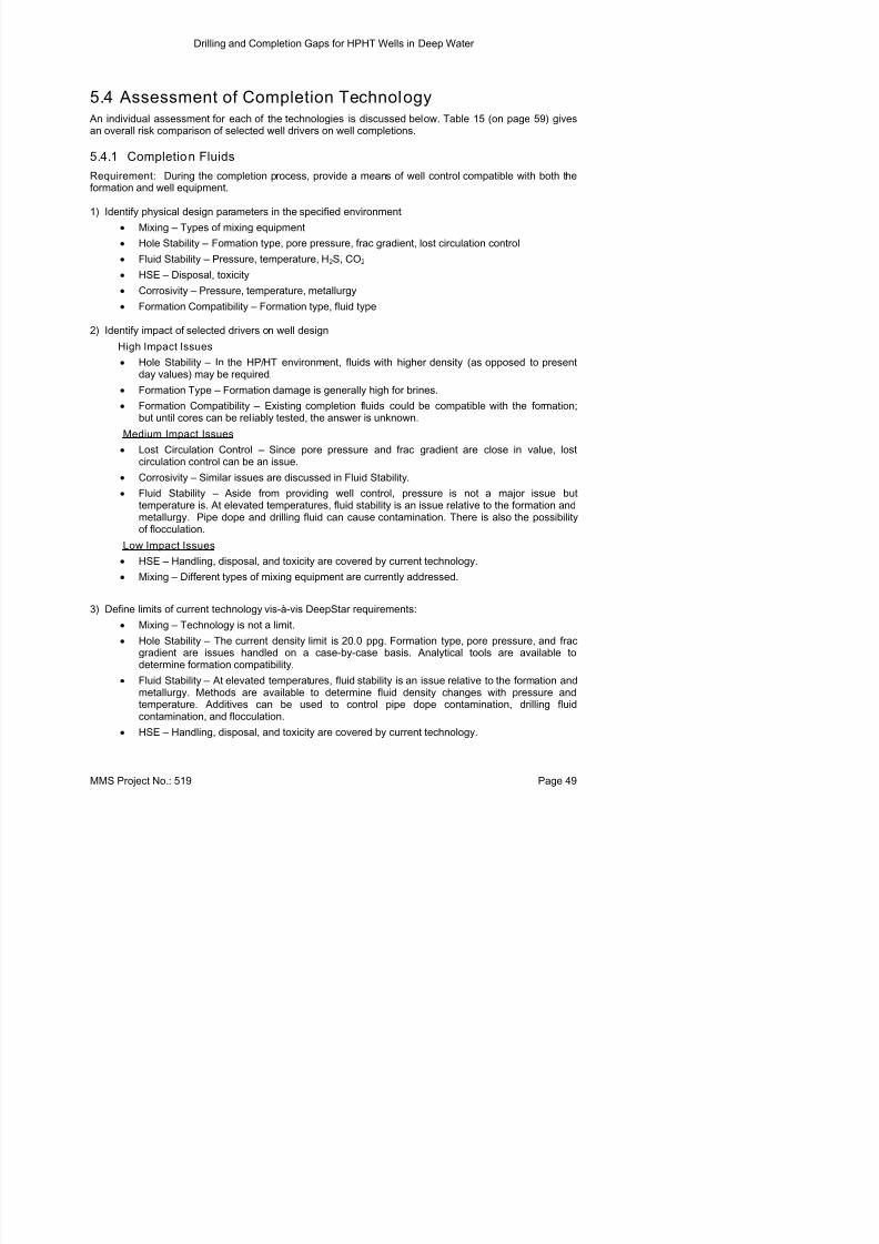
8/21/2019 BSEE Drilling and Completion Gaps for HTHP
http://slidepdf.com/reader/full/bsee-drilling-and-completion-gaps-for-hthp 52/184
5.4 Assessment of Completion Technology An individual assessment for each of the technologies is discussed below. Table 15 (on page 59) givesan overall risk comparison of selected well drivers on well completions.
5.4.1 Completion Fluids
Requirement: During the completion process, provide a means of well control compatible with both theformation and well equipment.
1) Identify physical design parameters in the specified environment
• Mixing – Types of mixing equipment
• Hole Stability – Formation type, pore pressure, frac gradient, lost circulation control
• Fluid Stability – Pressure, temperature, H2S, CO2
• HSE – Disposal, toxicity
• Corrosivity – Pressure, temperature, metallurgy
• Formation Compatibility – Formation type, fluid type
2) Identify impact of selected drivers on well design
High Impact Issues • Hole Stability – In the HP/HT environment, fluids with higher density (as opposed to present
day values) may be required.
• Formation Type – Formation damage is generally high for brines.
• Formation Compatibility – Existing completion fluids could be compatible with the formation;but until cores can be reliably tested, the answer is unknown.
Medium Impact Issues
• Lost Circulation Control – Since pore pressure and frac gradient are close in value, lost
circulation control can be an issue.• Corrosivity – Similar issues are discussed in Fluid Stability.
• Fluid Stability – Aside from providing well control, pressure is not a major issue buttemperature is. At elevated temperatures, fluid stability is an issue relative to the formation andmetallurgy. Pipe dope and drilling fluid can cause contamination. There is also the possibilityof flocculation.
Low Impact Issues
• HSE – Handling, disposal, and toxicity are covered by current technology.
• Mixing – Different types of mixing equipment are currently addressed.
3) Define limits of current technology vis-à-vis DeepStar requirements:
• Mixing – Technology is not a limit.
H l S bili Th d i li i i 20 0 F i d f
Drilling and Completion Gaps for HPHT Wells in Deep Water
• Corrosivity – Issues are similar to those discussed under Fluid Stability Corrosivity additives

8/21/2019 BSEE Drilling and Completion Gaps for HTHP
http://slidepdf.com/reader/full/bsee-drilling-and-completion-gaps-for-hthp 53/184
• Corrosivity – Issues are similar to those discussed under Fluid Stability. Corrosivity additivescould be improved based on metallurgy.
• Formation Compatibility – Equipment to test formations with completion fluids is needed. With
outside funding, StimLab is designing and building HPHT equipment for stimulation projects.
4) Identify necessary gap closures prior to drilling DeepStar wells.
• Hole Stability – In this environment, controlling fluid density since pore pressure and fracgradient are nearly equal. Calculations may be the answer, but an additive to control densityvariation would be beneficial.
• Corrosivity – Existing chemicals adequately control corrosivity. New metals may requireadditional additives to control corrosion.
• Formation Compatibility – Equipment to address testing at 500°F is needed.
5.4.2 Stimulation
Requirement: Improve well performance by changing reservoir characteristics.
1) Identify physical design parameters in the specified environment
• Storage – Bulk volume storage, conveyance, liquid storage
• Mixing – Accuracy, quality control, proportioning
•
Proppants – Strength, effluent compatibility, temperature• Formation Type – Solubility, reactivity, temperature, pressure, composition
• Transport Fluids – Gel strength, viscosity, pressure, temperature, pH
• Treating Fluids – pH, inhibition, corrosivity, temperature stabilization
• Wellhead Pressure Control – Wellhead treating pressure
• HSE disposal, toxicity
2) Identify impact of selected drivers on well design
High Impact Issues
• Proppants (High) – Ceramic proppants are subject to damage by well effluents because of pinholes in their coatings.
• Formation type (High) – Including the issues mentioned in proppants, there are issues relatedto formation compatibility with frac-fluids.
• Transport fluids (High) – Because of the cooling action, when pumped from the surface,transport fluids are not currently an issue.
• Wellhead pressure control (High) – Wellhead treating pressure could exceed subsea tree
working pressure.Low Impact Issues
• HSE (Low) – DOT, disposal and toxicity are similar to currently available products.
• Treating fluids (Low) – Fluid density determines bottom hole treating pressure. This is critical inXHPHT acidizing If acidizing is needed for XHPHT wells inhibitors for 500F may be required
Drilling and Completion Gaps for HPHT Wells in Deep Water
3) Define limits of current technology vis-à-vis DeepStar requirements:

8/21/2019 BSEE Drilling and Completion Gaps for HTHP
http://slidepdf.com/reader/full/bsee-drilling-and-completion-gaps-for-hthp 54/184
3) Define limits of current technology vis à vis DeepStar requirements:
• Storage – Storage on stimulation vessels is adequate. Additional vessels can be called intoservice for large jobs.
• Mixing – Computerized mixing and ramping systems provide adequate control andproportioning.
• Proppants – Current technology is at it limits. Because of pin holes in their coatings, ceramicproppants are subject to damage by well effluents. Equipment for testing proppants with coresamples is required for XHPHT environments. There is also a possibility of proppantsimbedding in the formation and reducing frac conductivity.
• Formation Type – See Proppants. There are issues related to formation compatibility with frac-fluids; testing equipment will have to be designed for 500°F.
• Transport Fluids– Wellhead treating pressure can be exceeded with conventional treating fluids(i.e., weighted brines reduce wellhead treating pressure). And because transport fluids have acooling action when pumped from the surface, they are not an issue at this point. Currenttechnology used in 500°F wells should be adequate.
• Treating Fluids–If acidizing is needed for XHPHT wells, inhibitors for 500°F may be required.This treatment is formation-dependent; at this time, this is a non-issue.
• Wellhead Pressure Control – Current wellhead technology is limited to15 kpsi. Equipmentdesigns are being considered for 20 kpsi and should be available in 2–3 years.
• HSE – Currently available methods are adequate.
4) Identify necessary gap closures prior to drilling DeepStar wells.
• Proppants – Current technology is at its limit. Improved coatings or a new material will berequired to meet XHPHT conditions. Testing equipment needs to be designed to analyzeproppants imbedding in the formation, frac conductivity reduction, or proppant crushing due toexcessive reservoir stress caused by geo-pressure.
• Formation Type – See Proppants.
• Transport Fluids – Weighted brine gels are required to reduce wellhead treating pressures.
• Wellhead Pressure Control - Wellhead isolation equipment will be necessary to addresswellhead treating pressure.
5.4.3 Flow Assurance
Requirements : Through chemistry or insulation, reduce the effects of hydrates, asphaltenes, paraffins,scale, corrosion, H2S, CO2 and emulsions in wells and flow lines.
1) Identify physical design parameters in the specified environment.
• Deployment – Types of metering systems.• Injection – Location and method of injection.
• Areas of Control – Hydrates, scale, corrosion, CO2, emulsions.
• Compatibility with Well Effluents – Test equipment, monitoring.
• Compatibility with Equipment Seafloor conditions flowline conditions
Drilling and Completion Gaps for HPHT Wells in Deep Water
• Injection – Particularly in situations where asphaltenes and paraffins are present. Chemical

8/21/2019 BSEE Drilling and Completion Gaps for HTHP
http://slidepdf.com/reader/full/bsee-drilling-and-completion-gaps-for-hthp 55/184
j y p p pinjection will have to occur in excess of 10,000 ft. below the mud line; very high injectionpressures will be required.
•
Areas of Control – While products are available for hydrates, scale, corrosion, H2S, CO2 andemulsion control, enhanced products may be required to handle effluents produced in morehostile environments, particularly hydrates and H2S.
• Compatibility with Well Effluents – Improved test equipment is required to determine suitableproducts for this environment.
Medium Impact Issues
• Compatibility with Equipment – Equipment to introduce production chemicals is needed atseafloor and flowline conditions. Existing equipment could prove to be adequate, butinvestigation may be worthwhile.
Low Impact Issues
• HSE – Current technology is adequate for handling, disposal, and toxicity requirements.
3) Define limits of current technology vis-à-vis DeepStar requirements.
• Deployment – Most metering is done with a stop watch and control valve.
• Injection – Injection pressures could exceed umbilical pressure ratings, and injection points willsurpass the design limits of currently available equipment.
• Areas of Control – Current chemicals will work to a bottomhole temperature of 450°F. Lowdosage hydrate inhibitor currently works to 275°F wellhead temperature. Insulation is alsobeing used to minimize seafloor cooling effects.
• Compatibility with Well Effluents – These HPHT deepwater well conditions will challenge thecapabilities of existing equipment.
• Compatibility with Equipment – Pressure ratings of wellhead equipment and the number ofinjection line feed-throughs may have to be increased on wellheads. Current rating is 15 kpsi.
4) Identify necessary gap closures prior to drilling DeepStar wells.
• Deployment – Install automated injection systems.
• Injection – Until well fluids are actually produced, this is an open area. Higher pressure ratingsfor umbilical lines and injection subs could be required.
• Areas of Control – Chemicals that will work for conditions of 500°F BHT.
• Compatibility with Equipment – Equipment requirements are driven by the well injection pointsthat will be determined according to the well fluids produced.
5.4.4 PerforatingRequirement: Perforate the casing wall, cement sheath, and formation to create a flow path to allow welleffluents to enter the wellbore or allow injection into the formation.
1) Identify physical design parameters in the specified environment.
Fi i D i O ti th d i l d h i l d l t i l
Drilling and Completion Gaps for HPHT Wells in Deep Water
2) Identify impact of those drivers on well design.

8/21/2019 BSEE Drilling and Completion Gaps for HTHP
http://slidepdf.com/reader/full/bsee-drilling-and-completion-gaps-for-hthp 56/184
High Impact Issues
• Firing Heads – The ability to initiate ignition is critical to successful detonation.
• Initiator – This second stage in the detonation process is also a critical point.• Primer Cord – Responsible for detonating shape charges and propagating detonation.
• Shape Charges – Performance and reliability (size and penetration) dependent on duration ofhigh temperatures, the amount of powder, and chemistry.
• Gun Case – Collapse is an issue at HPHT conditions.
3) Define limits of current technology vis-à-vis DeepStar requirements:
• Firing Heads – Current equipment works to 450°F with extensive pre-job planning. Improved
charge-chemistry is required.• Initiators – Current equipment works to 450°F with extensive pre-job planning. Improved
charge-chemistry is required.
• Primer Cord – Current equipment works to 450°F with extensive pre-job planning. Improvedcharge-chemistry is required.
• Shape Charges – Current equipment works to 450°F with extensive pre-job planning.Improved charge-chemistry is required.
• Gun Case – Sleeves are installed over gun cases to prevent collapse. This additional wall
thickness is effective in improving the gun collapse rating to meet DeepStar objectives.
4) Identify necessary gap closures prior to drilling DeepStar wells.
• Develop explosive chemistry rated to 500°F or conceive another means to create perforations.Currently available systems are limited to 400°F.
5.4.5 Completion Equipment
Requirement : Manage production by isolating well segments, initiating production, providing
safety/emergency systems, and controlling inflow/injection performance.
1) Identify physical design parameters in the specified environment.
• Equipment – Component sealing, wellbore sealing, pressure, service, temperature, and stress.
• Maintenance – Plugs, safety valves, sliding sleeves, and injection subs.
• Operation – Slick line, coil tubing, HWO, and remote control.
• Measurements – Pressure, temperature, and flow.
• Casing damage – Slip design, setting force, and setting.
2) Identify impact of those drivers on well design.
High Impact Issues
• Equipment – Correct operation and well control depend on both internal and external seals.Ratings for pressure, service, temperature, and stress determine suitability for use.
Drilling and Completion Gaps for HPHT Wells in Deep Water
Medium Impact Issues

8/21/2019 BSEE Drilling and Completion Gaps for HTHP
http://slidepdf.com/reader/full/bsee-drilling-and-completion-gaps-for-hthp 57/184
• Measurements – Measurements provide input in the decision making process. Readilyavailable information will improve reservoir management.
3) Define limits of current technology vis-à-vis DeepStar requirements.
• Equipment – Seal technology is a major issue. Metal serves well in static situations although itleaks in dynamic situations (excepting balls and valves). Elastomers, used in dynamic sealingdesigns, fail after several cycles above 400°F. The ability to inject chemicals through aninjection sub into the wellstream is not only critical, but also limited to the umbilical rating andthe location of the sub in the production string.
• Maintenance – Because of the water depth, intervention is extremely difficult. Riserless andsea floor intervention offers promise, but it is outside the scope of this project.
• Operation – See Maintenance. Remote operation is possible but faces the same issuesmentioned in Equipment. Electro-magnetic technology has potential and is now available forSSCV. Slick line could break under its own weight in this situation.
• Measurements – Measurements are limited to 350°F, and cabling can be problematic. Fiberoptics offer possibilities but are only available for temperature (work in progress for pressure).
• Casing Damage – Because of large temperature changes in the wellbore, weights of 500,000pounds can rest on the packer and be transferred to the casing walls. This is a major issue.
4) Identify necessary gap closures prior to drilling DeepStar wells.
• Equipment – Improved methods of sealing are required to operate in this environment bothfrom a dynamic and static standpoint. Injection methods require improvement to inject into thewell stream at the 30 kpsi, 500°F case.
• Operation – Further work, like the electro-magnetic operated SSCV, will eliminate possibilitiesof leaks from the tubing to the annulus thereby ensuring well integrity. Improvements inelectronics and actuators offer major advantages for controlling downhole equipment.Providing downhole power to operate equipment would simplify operations.
• Measurements – Accurate pressure and flow measurements rated to 500°F is advantageous in
optimizing reservoir management.• Casing Damage – Methods for setting packers without slips would ensure well integrity and
reduce casing damage.
5.4.6 Well Testing
Requirement: Gather accurate downhole data that can be used for equipment selection, drillingparameters, and operational capabilities of the HPHT well.
1) Identify physical design parameters in the specified environment.• Managing pipe movement or high compression loads at the packer particularly when the high
temperatures are combined with high operating pressures.
• Controlling increased mechanical and fluid friction as well depth increases and/or deviates fromvertical.
Drilling and Completion Gaps for HPHT Wells in Deep Water
• Wellbore storage can necessitate longer shut-in periods.

8/21/2019 BSEE Drilling and Completion Gaps for HTHP
http://slidepdf.com/reader/full/bsee-drilling-and-completion-gaps-for-hthp 58/184
• High density, high solids drilling fluid can plug pressure ports, reduce tool reliability, and stickthe test string upon settling.
•
Hydrate formation can plug lines.
Medium Impact Issues
• Continued need for training and qualified personnel.
• Accurate data collection is essential to successful estimation of testing parameters.
3) Define limits of current technology vis-à-vis DeepStar requirements.
• Equipment – Current integrated circuit technology is limited to 10,000 psi and 350°F.
•
Maintenance – Intervention requires re-entry into the wellbore through risers or using riserlessmethods.
4) Identify necessary gap closures prior to drilling DeepStar wells.
• Surface equipment design must be modified to take into flow periods, volumes, and spaceconsiderations on deepwater platforms.
• Fluid engineering and design must advance to minimize plugging pressure ports, improve toolreliability, and reduce negative impact on test strings.
• Integrated circuit technology must advance to reliably address pressure and testingconsiderations for deepwater, HPHT well testing conditions.
• Monitoring technology must advance to allow for the continuous monitoring of all producedfluids to enable remote, real-time intervention by operators.
5.4.7 Smartwell
Requirement: To achieve optimum production, complex reservoir management is required. Smartwell issimilar to completion equipment with the addition of inflow control, enhanced measurements, andreservoir management.
1) Identify physical design parameters in the specified environment.
• Equipment – Sealing, reliability, electronics, control devices, actuators, power, flow,communications, pressure, and temperature.
• Maintenance – Repair, calibration, and replacement.
• Reservoir management – Out of scope.
2) Identify impact of those drivers on well design.
High Impact Issues• Equipment – Sealing, reliability, and electronic issues have been previously discussed in
Completion Equipment. Control devices and actuators will be needed to facilitate operations.Reliable sensors are paramount to successful operations and reservoir management.
• Maintenance – The ability to repair, calibrate, and replace equipment is necessary.
Drilling and Completion Gaps for HPHT Wells in Deep Water
4) Identify necessary gap closures prior to drilling DeepStar wells.

8/21/2019 BSEE Drilling and Completion Gaps for HTHP
http://slidepdf.com/reader/full/bsee-drilling-and-completion-gaps-for-hthp 59/184
• Equipment – Develop equipment, actuators and sensors that will work at 20,000 psi and 500°For above. Low cost downhole power is needed to operate equipment and sensors.
•
Maintenance – Develop intervention processes that will result in lower cost methods of repair,calibration, and replacement.
5.4.8 Packers
Requirement: Seal the wellbore, isolate the productive zone, and redirect the flow downhole. A packingelement seals off the inside of the casing and contains pressure when the packer is set.
1) Identify physical design parameters in the specified environment.
• Equipment – Operational parameters and performance rating requirements
• Sealing technologies – Static and dynamic
• Operation – One trip and/or interventionless
• Combined loading, pressure differential, and thermal cycling – Selection of tubing to packerconnections (floating seals vs. static or no seals at all).
2) Identify impact of those drivers on well design.
High Impact Issues
•
Pipe Movement and High Compression Loads at the Packer – Results from the combination ofhigh temperatures with high pressures.
• Mechanical and Fluid Friction – Increases with well depth or with vertical deviations.
• Thermal Cycling and Tubing Stresses – Thicker cross sections in all tubulars and high yieldstrength materials to handle excessive burst and collapse pressures.
• Materials Used in Packers and Seals – Shorter elastomer performance life and de-rated yieldstrength of metals.
Medium Impact Issues
• Installation Mishaps – Detailed knowledge required of equipment design, testing, andassemblage.
• Contingency Planning – Crucial for situations requiring lead times for alternate equipment.
3) Define limits of current technology vis-à-vis DeepStar requirements:
• Packer and Seal Materials – Current metallurgy and materials are reliable for applicationsrequiring 300 to 350°F at 10,000 psi.
• Packer Setting Devices – Current equipment works to 450°F with extensive pre-job planning.
Need for interventionless packer setting devices and the reduction in the number of downholetrips.
4) Identify necessary gap closures prior to drilling DeepStar wells.
• For temperatures and pressures above the 400°F, 10,000 psi limits, more exotic alloys andcomponents that require ratings and standardized testing are required However their
Drilling and Completion Gaps for HPHT Wells in Deep Water
5.4.9 Elastomers

8/21/2019 BSEE Drilling and Completion Gaps for HTHP
http://slidepdf.com/reader/full/bsee-drilling-and-completion-gaps-for-hthp 60/184
Requirement: Used as a sealant in blow-out preventers thereby increasing the resistance of the BOP toincreased pressure demands.
1) Identify physical design parameters in the specified environment.
• Sealing Technology (static and dynamic).
• Seal Durability.
2) Identify impact of those drivers on well design.
High Impact Issues
• Reliability – As temperature increases, extrusion of the elastomeric sealants likely.
• Temperature – High temperatures shorten elastomer performance life.• Testing – High temperature elastomers are harder than their low temperature counterparts and
may not seal at ambient temperatures, thereby making surface pressure tests difficult.
3) Define limits of current technology vis-à-vis DeepStar requirements.
• Reliability – No current tests can adequately predict reliability.
• Temperature – Currently can withstand temperatures to 350°F.
• Testing – High temperature elastomers are harder than their low temperature counterparts and
may not seal at ambient temperatures, thereby making surface pressure tests difficult.
4) Identify necessary gap closures prior to drilling DeepStar wells.
• Further development of polymers and seals that can withstand extreme, corrosive, HPHT wellconditions while retaining mechanical properties, chemical performance, and well fluidcompatibility.
• Extensive seal research required. In some cases, metal-to-metal seals may replaceelastomers.
•
Better surface testing procedures that can help predict downhole reliability.
5.4.10 Wireline Testing
Requirement: Acquire the maximum amount of downhole data in the minimum amount of time.
1) Identify physical design parameters in the specified environment.
• Reliability – Measurement components become unreliable according to the amount of timespent downhole.
•
Temperature – Cannot withstand temperatures above 250°F.• Equipment – Motorized machinery adds to the downhole temperature. Electronic components
cannot withstand HPHT conditions. Thermal shielding may influence readings.
2) Identify impact of those drivers on well design.
Hi h I t I
Drilling and Completion Gaps for HPHT Wells in Deep Water
3) Define limits of current technology vis-à-vis DeepStar requirements.
Equipment and Components Research on nonconductive materials needs to be incorporated

8/21/2019 BSEE Drilling and Completion Gaps for HTHP
http://slidepdf.com/reader/full/bsee-drilling-and-completion-gaps-for-hthp 61/184
• Equipment and Components – Research on nonconductive materials needs to be incorporatedinto test equipment .
•
Temperature – Currently can withstand temperatures to 250°F.• Time Constraints – Amount of time equipment can remain downhole is limited.
4) Identify necessary gap closures prior to drilling DeepStar wells.
• Tool systems that can deliver a wider range of data need to be developed.
• Indirect measurement techniques need to be refined.
• Data requirements need to be prioritized.
• Equipment needs to be developed to withstand temperatures ranging from 250–435°F for long
periods of time, including the use of non-conductive materials.
Drilling and Completion Gaps for HPHT Wells in Deep Water
Table 15. Comparison of Completion Technology Limits

8/21/2019 BSEE Drilling and Completion Gaps for HTHP
http://slidepdf.com/reader/full/bsee-drilling-and-completion-gaps-for-hthp 62/184
Table 15. Comparison of Completion Technology Limits
MMS Project No.: 519 Page 59
Drilling and Completion Gaps for HPHT Wells in Deep Water
6. Recommended Projects

8/21/2019 BSEE Drilling and Completion Gaps for HTHP
http://slidepdf.com/reader/full/bsee-drilling-and-completion-gaps-for-hthp 63/184
j
6.1 Drilling ProjectsIndustry groups are currently funding projects that address many of the issues related to extreme HPHT.More than half of these projects are devoted to technology that will enable LWD/MWD and logging inthese environments. Most service companies prefer to keep their R&D spending confidential; as a result,those expenditures are not included in any figures used for this report. Two major technological areasidentified as investment opportunities include a systems approach to drilling and test facilities whichsimulate extreme HPHT conditions. Estimates follow.
Cost Time
•
Work with DOE, DeepTrek and DEA to incorporate DeepStar $0 3 yr Goals into existing projects related to electronics and sensors (Already funded)
1. High temp electronics – 30,000 psi, 500°F
2. Continue work on fiber optic sensors
3. Advance battery technology
4. Lower manufacturing costs for components
5. Improve reliabilitya) Temperature
b) Vibration• Inclinometer (MWD/LWD) $500,000 1 yr
Project currently planned for 2007 budget year. Couldbe accelerated by one year with identified funds.
• Take a systems approach
1. Bits, mud, motors, drill string dynamics and rock $1,000,000 2 yr dynamics to improve ROP
2. Mud, drill string dynamics, cooling to improve MWD/LWD reliability
3. Identify best practices (Knowledge Management)
4. Investigate methods to better manage equivalent circulating density (ECD)
• Use Best-in-Class services
• Enhanced operator training (rig operators)
• Improve MWD motor and turbine designs $1,000,000 2 yr
1. Torque
2. Faster RPM
• Study rock mechanics to improve ROP $300,000 1 yr• Mud system improvement to reduce friction pressure, improve $750,000 2 yr
thermal properties, control density, and improve ROP.
• Test fixtures and equipment $2,500,000 3 yr (Multi-purpose drilling and completions)
Drilling and Completion Gaps for HPHT Wells in Deep Water
• Review/Recommend revision of API, NACE and ASME $250,000 1 yr specifications related to extreme HPHT
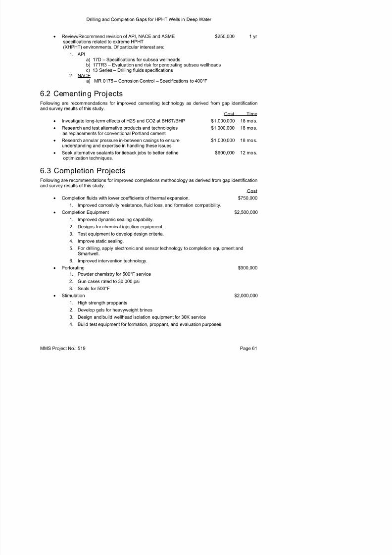
8/21/2019 BSEE Drilling and Completion Gaps for HTHP
http://slidepdf.com/reader/full/bsee-drilling-and-completion-gaps-for-hthp 64/184
(XHPHT) environments. Of particular interest are:
1. APIa) 17D – Specifications for subsea wellheadsb) 17TR3 – Evaluation and risk for penetrating subsea wellheadsc) 13 Series – Drilling fluids specifications
2. NACEa) MR 0175 – Corrosion Control – Specifications to 400°F
6.2 Cementing ProjectsFollowing are recommendations for improved cementing technology as derived from gap identification
and survey results of this study.Cost Time
• Investigate long-term effects of H2S and CO2 at BHST/BHP $1,000,000 18 mos.
• Research and test alternative products and technologies $1,000,000 18 mos.as replacements for conventional Portland cement.
• Research annular pressure in-between casings to ensure $1,000,000 18 mos. understanding and expertise in handling these issues.
• Seek alternative sealants for tieback jobs to better define $600,000 12 mos.
optimization techniques.
6.3 Completion ProjectsFollowing are recommendations for improved completions methodology as derived from gap identificationand survey results of this study.
Cost
• Completion fluids with lower coefficients of thermal expansion. $750,000
1. Improved corrosivity resistance, fluid loss, and formation compatibility.• Completion Equipment $2,500,000
1. Improved dynamic sealing capability.
2. Designs for chemical injection equipment.
3. Test equipment to develop design criteria.
4. Improve static sealing.
5. For drilling, apply electronic and sensor technology to completion equipment andSmartwell.
6. Improved intervention technology.
• Perforating $900,000
1. Powder chemistry for 500°F service
2. Gun cases rated to 30,000 psi
Drilling and Completion Gaps for HPHT Wells in Deep Water
• Flow Assurance $750,000
1. Completion equipment designed for injection

8/21/2019 BSEE Drilling and Completion Gaps for HTHP
http://slidepdf.com/reader/full/bsee-drilling-and-completion-gaps-for-hthp 65/184
p q p g j
2. Hydrate and scale inhibition
• Smartwell Already Funded1. Develop batteries that will function at 500°F and 30 kpsi.
2. Develop electronics that will function at 500°F and 30 kpsi.
• Packers $1,000,000
1. Develop elastomer seals for 500°F and 30 kpsi conditions
2. Revise metallurgy to withstand XHPHT conditions
3. Develop metal-to-metal seals applicable to XHPHT conditions
• Elastomers Ongoing
1. Formulate elastomers to withstand XHPHT pressures and temps.
• Wireline Testing $750,000
1. Develop HPHT electrical insulator materials.
2. Develop inferential test methods.
3. Develop continuous duty HPHT electronics.
• Well Testing $1,500,000
1. Packer and downhole equipment development.2. Originate and update laboratory test equipment for XHPHT conditions
Drilling and Completion Gaps for HPHT Wells in Deep Water
7. Conclusions

8/21/2019 BSEE Drilling and Completion Gaps for HTHP
http://slidepdf.com/reader/full/bsee-drilling-and-completion-gaps-for-hthp 66/184
7.1 HPHT Dril ling GapsBased on analysis of historic HPHT well data and a survey of industry’s capabilities, the major obstaclesencountered when drilling XHPHT wells are formation and well evaluation tools. In most cases, wells canbe drilled to the sensitivity objective, although obtaining logs and running LWD/MWD at these conditionsis difficult.
Ongoing research is focused on addressing many of these challenges. This assessment has identifiedseveral areas that require attention. Elastomers, battery technology, and electronics/sensors are coretechnologies which require additional focus. Several emerging products offer potential solutions. If those
products appear promising, they must be integrated into workable downhole tools.
Well drilling will also benefit from projects that optimize ROP through careful selection of bits, drillingfluids, motors, and string design. Test fixtures will be required to establish equipment design criteria andto provide a means for testing well equipment.
There are unique safety concerns for HPHT operations that must be addressed for future technologydevelopment and applied engineering activities.
The way forward is clear if reliability of smart tools is to be increased. Operating companies, as risk-takersand technology integrators, need to devote resources to the problem. Resources needed include money,expertise, and time. Residence of the resources may be at the operating companies or their proxies in theservice sector. The key is to optimize the use of resources. The following recommendations are offered:
1. Hire/appoint an engineer or committee to champion this effort
2. Expand the group to include shelf drillers
3. Construct a detailed data base of all related past and current HPHT failures
4. Monitor all service company progress in regard to improved tool performance
5. Work with operations personnel to optimize procedures for use of smart tools
6. Integrate research efforts and focus on cooperation and technology application
7. Drill wells with the intention of sharing HPHT equipment data
Precise funding mechanisms for each aspect of technology research and development need to bedefined. Participants in any or all projects will come from the group of operators, possibly drillingcontractors, service companies, and regulatory agencies.
The engineer/champion could be a DeepStar representative, an individual seconded from a DeepStarmember company, or a contractor. The engineer’s sole job function would be to work on issuesassociated with smart tools; electronics, elastomers, environmental loading, application, reliability,operating techniques, and economics. To perform the job properly, the engineer would require access todata. That means daily drilling reports, equipment failure reports, and all other pertinent data needed toevaluate smart tool performance and evolution The engineer could follow the procedure done in this
Drilling and Completion Gaps for HPHT Wells in Deep Water
With regard to drilling issues, there is not a well drilled in the GOM where interested parties cannotdetermine exactly what particular service companies did. Rig crews are often a source of amazing detailsthrough informal discussions Given that logs costing millions can be obtained for fractions of

8/21/2019 BSEE Drilling and Completion Gaps for HTHP
http://slidepdf.com/reader/full/bsee-drilling-and-completion-gaps-for-hthp 67/184
through informal discussions. Given that logs costing millions can be obtained for fractions ofpennies on the dollar a short time later, it makes absolute sense for oil companies to reveal their
drilling “secrets” under strict confidentiality agreements within a framework of improving acritical set of technologies that directly impact drilling economics. As soon as a well is drilled, onemust consider what value those reports now have. These are seldom analyzed in great detail (the nextproject takes precedence) and are expensive to store in either paper or electronic formats. Discovery ordry hole, the well cost is sunk as soon as operations are completed. The only future value the informationitself holds is realized if the lessons can be actively extracted and applied to future wells.
7.2 HPHT Cementing Gaps
There are many obstacles encountered when cementing HPHT wells. In most cases these wells can becemented, although achieving quality cement jobs is sometimes quite complex. Ongoing research isfocused on addressing many of these challenges. This assessment has identified several areas thatrequire attention. Alternative sealing agents, modified testing procedures, and HPHT cement job designare a few of the core technologies which require additional research and focus.
In a time where exploration water depths and well depths are continuously getting deeper, we need tocontinuously pursue new procedures and technologies that will enable us to effectively isolate zones in oiland gas wells. Current products and materials work (to a greater or lesser extent) if an earnest amount ofeffort is expended. However, there is an irrefutable need for continuous research and development inoilfield cementing. Without these solutions, the industry cannot continue to effectively and efficientlypursue oil and gas in the most challenging environments.
7.3 HPHT Completion GapsIn most cases, the industry has adopted a “wait and see” attitude concerning product developmentpending the issuance of exploration and development plans by operators. Currently, operators fundspecific equipment and services necessitated by field demand rather than financially supporting productdevelopment prior to the actual need.
Flow assurance is the most critical issue in completion technology since production is paramount to thesuccess of these developments. Many flow assurance issues are addressed in CTR 7201, 7202, 7204,and 7205. Completion fluids, completion equipment, and perforating are areas that require additionalfocus to meet DeepStar requirements.
Current laboratory test facilities are in general suitable for testing today’s HPHT systems and theircomponents. However, the industry will have to undertake significant investment in equipment andmaterials to generate the technologies and qualify the equipment for future HPHT wells that will soon
require limits of 30,000 psi and/or temperatures up to 500°F.
First and foremost, metallurgy must be available. Sourcing metals such as nickel, alloys, Hastelloy (C-276), or possibly titanium, will be a challenge. Polymers and seals must be developed to withstandincreased HPHT conditions while retaining mechanical properties, chemical performance, and well fluidcompatibility Standards performance ratings and quality assurance requirements need to be adopted
Drilling and Completion Gaps for HPHT Wells in Deep Water
Appendix A – Nomenclature

8/21/2019 BSEE Drilling and Completion Gaps for HTHP
http://slidepdf.com/reader/full/bsee-drilling-and-completion-gaps-for-hthp 68/184
API American Petroleum Institute ASME American Society of Mechanical Engineersbbl/MMscf Barrels/million standard cubic feetbcfg Billion cubic feet gasBHA Bottomhole assemblyBHP Bottomhole pressureBHT Bottomhole temperatureBML Below mudlineBOP Blow out preventerDEA Drilling Engineering AssociationDOE Department of EnergyECD Equivalent circulating densityFrac FractureGOM Gulf of MexicoHIPPS High integrity pressure protection systemsHPHT High pressure, high temperatureHSE Health, safety, and environmentIEEE International Electrical & Electronics Engineers
JIP Joint industry projectsKpsi 1,000 pounds per square inch (pressure)LWD Logging while drillingMMS Minerals Management ServiceMWD Measurement while drillingNACE National Association of Corrosion EngineersNPT Non-productive timeID Internal diameterOD Outside diameter
OBM Oil based mudPDC Polycrystalline diamond cuttersPsi Pounds per square inchQAQC Quality assurance, quality controlR&D Research and DevelopmentRPM Revolutions per minuteROP Rate of penetrationSIWP Shut-in wellhead pressureTD Total depth
TSP Thermally stable polycrystallineWBM Water based mudWOB Weight on bitXHPHT Extreme high-pressure, high-temperature
Drilling and Completion Gaps for HPHT Wells in Deep Water

8/21/2019 BSEE Drilling and Completion Gaps for HTHP
http://slidepdf.com/reader/full/bsee-drilling-and-completion-gaps-for-hthp 69/184
Appendix B – Summary of Meeting Notes fromDeepStar Public Workshop on HPHT Technology
Gaps (3/30/06)
Notes from DeepStar Workshop on HPHT Gaps
M h 30 2006

8/21/2019 BSEE Drilling and Completion Gaps for HTHP
http://slidepdf.com/reader/full/bsee-drilling-and-completion-gaps-for-hthp 70/184
March 30, 2006
Top HPHT Priori ties for Dril ling
The attendees and project team worked together to develop a list of priorities:
1. Accurate measurements of what is failing in HPHT wells. We must document failuremechanisms for LWD/MWD, RSS, and motors. This is necessary to accurately define theHPHT “prize,” to focus and direct research efforts, and to provide a baseline for
performance improvements associated with application of HPHT research products.
2. Shelf wells must be included if there is an established process to measure, manage andexpand information. These wells currently encounter the most elevated temperatures andpressures in the GOM. Several member companies have been partners or operators indeep shelf wells recently.
3. Recording well data and extracting useful information from data. The most effectiveresearch will be done if a large volume of applications are analyzed.
4. Effective means to control downhole pressures—BOP’s, seals, materials, APB. This iscritical with BOPE, casing metallurgy, casing connections, and well heads.
5. The effects of vibration on “smart” components need to be understood. Considerationshould be made of means for obtaining and analyzing vibrational data in real time. Vibrationintensifies the severe operating conditions associated with high temperatures.
6. A good first step toward extending the capabilities of currently-available “smart”components and motors will be development of a set of “best practices” based on a
detailed analysis of well records. This should be possible to accomplish in a matter ofmonths, provided sufficient well data are available to form a statistically-valid view offailures associated with current state of the art.
Top HPHT Priori ties for Cementing/Completion
1. Higher performance materials for zone isolation. This includes better cements and effectiveseals (metal-to-metal and elastomers).
2. Equipment and techniques that minimize the need for workover intervention in wells.Completion add-ons that improve outcome.
3. Contingency options for later intervention.
4. Optimal stimulation methods.
2. Regarding allocation of R&D funding, service companies need to consider tasks andequipment whose application will cross over to other environments beyond HPHT. Theysee HPHT as a niche market and need cross-over benefits from new tools they develop.

8/21/2019 BSEE Drilling and Completion Gaps for HTHP
http://slidepdf.com/reader/full/bsee-drilling-and-completion-gaps-for-hthp 71/184
see HPHT as a niche market and need cross over benefits from new tools they develop.
3. Deeper wells require stimulation efforts beyond conventional wells due to formationcompaction, and problems with fluid stability.
4. Technologies that improve safety, including Recommended Practices, are high priority.
5. H2S is a critical concern. In deeper wells, you should assume the well is sour, until youknow different. Materials are needed, including metals, cements, and seals. Shell publisheda paper at 2005 SPE showing a correlation between depth and CO2/H2S.
6. Annular pressure buildup (APB) is a critical issue. Need the ability to monitor integrity of
tubulars. Vacuum-insulated tubing isn’t a good answer. Some other alternatives should beconsidered.
7. We can’t now design a tie-back liner at HP.
8. Completion needs are our current show-stoppers. We can drill these wells (maybe not cost-effectively), but cannot complete and produce many HPHT wells (including deep shelfwells). The industry lacks:
a. BOPs
b. Treesc. Hardware
9. Regarding elastomers, we need to think more generically (that is, resilient seals) to not limitour search for new materials.
10. Service limits for designing HPHT completions are not well understood. What are the flowtesting needs? We don’t know shut-in pressures for these wells. We need better analyticalmodels to aid in sizing equipment for these wells.
11. The inability to properly evaluate xHPHT wells prevents proper completion and productiondesigns. If better modeling for prediction capabilities were developed, we currently can’t getadequate data and reservoir samples.
12. Proposed JIP on HPHT Data Mining.
In his summary of HPHT gaps, Tom Proehl highlighted the critical need for bettermeasurements and documentation. He said,
“If you can measure it, you can manage it
If you don’t measure it, you need luck
Good luck is what happens when preparedness meets opportunity”
There was wide agreement among the attendees that industry’s efforts to overcome HPHT
Bridging the Technology GapBridging the Technology Gap

8/21/2019 BSEE Drilling and Completion Gaps for HTHP
http://slidepdf.com/reader/full/bsee-drilling-and-completion-gaps-for-hthp 72/184
Bridging the Technology GapBridging the Technology Gap
Appropriate R&D
role for DeepStar,
DOE, MMS, JIP’s?
Other Offshore
Other Offshore
H P H T
H P H T
Current Market
Future – 3, 5, or 7 Years?
T e c h n o l o g y
The project team requested comments and feedback on the materials presented and the report;and a discussion on the impact of the API RP 6 committed, as well as the proper and most
productive role of Industry; DeepStar; JIP’s; DOE; MMS, or other options to close the gaps.
Drilling and Completion Gaps for HPHT Wells in Deep Water

8/21/2019 BSEE Drilling and Completion Gaps for HTHP
http://slidepdf.com/reader/full/bsee-drilling-and-completion-gaps-for-hthp 73/184
Appendix C – Results from Survey of Attendeesof DeepStar Public Workshop on HPHT
Technology Gaps
DeepStar Workshop on HPHT GapsMarch 30, 2006

8/21/2019 BSEE Drilling and Completion Gaps for HTHP
http://slidepdf.com/reader/full/bsee-drilling-and-completion-gaps-for-hthp 74/184
Comments Returned by Attendees(compi led April 21, 2006)
After the HPHT Workshop was conducted, attendees were contacted by email andasked to complete a short survey. Their responses are summarized below.
1. Was the info rmation benefic ial? “ Yes” (13 responses)
Additional comments:• I was not aware of the big gap between the technology for drilling the wells and the
technology for completing them.
• Yes, but until some action is taken to determine how the "gaps" will be overcome, itwon't do much good in reality. Also, there seem to be many more questions thatmust be considered before the "gap" list is complete, but this is a good start.
• It seemed like the principal investigators may have been a little self serving. I may becynical, but here are my observations. The investigator from CSI concluded that oneof the biggest needs is better sealant/cement, which just happens to be what hiscompany does. The investigator that gets consulting work analyzing the drilling dataconcluded that the most important thing is to collect more data (that he will get toanalyze).
• I was very impressed with the progress made by the NETL people (especially the
computer chips/processors developed with a grant to Oklahoma State). I thinkserious consideration should be given as to how these people from Oklahoma Stateand other researchers can be given opportunities for field experience on the rigsdoing this type of work. In addition to verifying and validating theoretical andlaboratory work, this would give researchers a chance at direct feedback from thedrillers, who have a vast wealth of knowledge on "what happens," which would bevaluable input to the research people working on "why things happen" (and viceversa).
• I noted with interest the comments about using some of the sections out of the Boiler& Pressure Vessel Code (ASME Section VIII, Div 3) as criteria for the HPHT. Thisshould be taken beyond just the code and should also explore some of the MaterialsEngineering developed over the years by the downstream engineers that use thiscode (We may need to familiarize ourselves with the Pressure Temperature Phase
should look at these materials and others. In addition to (1) Cement; (2) Metals and(3) Elastomers; we should look at the way soils and rock behave at hightemperatures and pressures. A HPHT sealing material would not be effective if the
il k th t it l i t ill i t f il d hi h d

8/21/2019 BSEE Drilling and Completion Gaps for HTHP
http://slidepdf.com/reader/full/bsee-drilling-and-completion-gaps-for-hthp 75/184
soil or rock that it seals against will in turn fail under high pressures and
temperatures. Do we need to know more about this?
Corrosion and Erosion of metallic materials at HPHT c
• onditions did not seem to becovered. An anode material, working in 400°F seawater is hard to envision. If we
• e. I am glad you mentioned the need for a
CTR for data mining. DeepStar badly needs this to provide data for a number of
• should document failures to include the shelf. Project is well justified.
es)
can't cathodically protect these materials, then the phase envelopes for thesematerials become even more important.
Overall this workshop was quite well don
studies.
DeepStar 2. Was the facili ty (other than the power outage) adequate? “ Yes” (13 respons Additional comments:
The facility was ideal. An offsite location ensures that everyone is focused on the•
workshop and not scurrying away checking e-mails!
•
Marriott issue as host.Great facility, noise outside started to roar at times, but we asked the hotel tomanage. They could have quieted the hallway a bit better –
3. Was the location convenient? “ Yes” (13 responses)
Additional comments:
For me it was an ideal location. I think Beltway 8 is a good artery from all areas of•
town.
4. Did the format allow sufficient discussion? “ Yes” (10 responses)
Additional comments:I think there was good discussion and the time allowed was adequate. If I recall we
ttle early.
responses)
•
actually finished a li • Discussion could have been a bit more focused.
• Power outage was overcome with the discussion.
5 Were the materials adequate/effect ive? “ Yes” (8
• The handout did not match up well with the slides so people spent too much timetrying to find the right place. I suggest either not handing the document out until theend or making the document match closely the slides to be shown

8/21/2019 BSEE Drilling and Completion Gaps for HTHP
http://slidepdf.com/reader/full/bsee-drilling-and-completion-gaps-for-hthp 76/184
end or making the document match closely the slides to be shown.
•
. How could we improve the workshop?
While recording issues on the flip charts there was too much force fitting into threeue meaning of the comment was often lost
r for this kind of “brainstorm”.
•
not want share statements with competitors. Sort of a dual track with other service
•
er group for discussion and present ideas to workshop.
eemed like the discussionke very fewt (wanted to
•
Provide a list of abbreviations used in the slides as part of the handout.
6 •
arbitrary categories. This meant that the tr or changed. Not grouping would have been bette
For service companies to share details with operators only, could you set up asession where you have HAL addressing operators only, then SLB, etc.? as they do
sector people, NGO’s, GOV, consultant members of DeepStar working some otherissues while service companies can have a one on one with a group of producers. Atthe end, producers then agree based upon all they have heard, that you redirectfocus on specific R&D projects. Is this workable? Giving them confidential time withoperators would open up for frank discussions.
Perhaps have a session where various areas of interest could be discussed insmaller groups.
• Appears some operators were holding some things back.
Divide into small•
Would have been better to have had more discussion. It s•
was dominated by the principal investigators. I gave input but it seems liothers did. I am not sure if more people in the Forum did not have inpulearn from study, not contribute to the direction of future work) or was limited by theformat.
I wasn't too clear on the agenda until I arrived at the meeting. An early agenda withan opportunity to suggest additional (or future) topics might have been useful.
• Overall, I thought the workshop was well conducted. I will be interested to see whatcomes from all the comments that were made during the discussion. I think that willbe the true test of how successful the workshop was.
• Difficult to extract accurate/objective information from service companies I would
Drilling and Completion Gaps for HPHT Wells in Deep Water

8/21/2019 BSEE Drilling and Completion Gaps for HTHP
http://slidepdf.com/reader/full/bsee-drilling-and-completion-gaps-for-hthp 77/184
Appendix D – Presentations on Drilling,Cementing and Completion Gaps from DeepStar
Public Workshop on HPHT Technology Gaps(3/30/06)

8/21/2019 BSEE Drilling and Completion Gaps for HTHP
http://slidepdf.com/reader/full/bsee-drilling-and-completion-gaps-for-hthp 78/184
11
DeepStar CTR 7501Drilling and Completion Technology Gaps for
HPHT Deepwater Wells
WorkshopMarch 30, 2006
by
Tom Proehl, Triton Engineering ServicesFred Sabins, CSI Technologies
Tom Williams, Maurer Technology Inc.
8/21/2019 BSEE Drilling and Completion Gaps for HTHP
http://slidepdf.com/reader/full/bsee-drilling-and-completion-gaps-for-hthp 79/184
22
Drilling AssessmentDrilling Assessment
PurposePurpose

8/21/2019 BSEE Drilling and Completion Gaps for HTHP
http://slidepdf.com/reader/full/bsee-drilling-and-completion-gaps-for-hthp 80/184
33
HPHT Deepwater Drilling TechnologyHPHT Deepwater Drilling Technology
GapsGaps – – IdentifyIdentify
– –
UnderstandUnderstand – – PrioritizePrioritize
HPHT DefinitionHPHT Definition
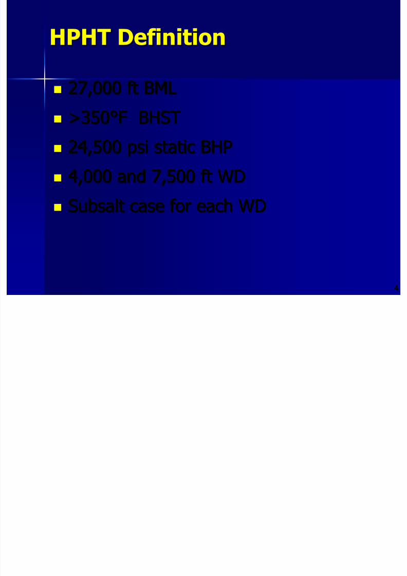
8/21/2019 BSEE Drilling and Completion Gaps for HTHP
http://slidepdf.com/reader/full/bsee-drilling-and-completion-gaps-for-hthp 81/184
44
27,000 ft BML27,000 ft BML
>350°F BHST>350°F BHST
24,50024,500 psipsi static BHPstatic BHP
4,000 and 7,500 ft WD4,000 and 7,500 ft WD
SubsaltSubsalt case for each WDcase for each WD
MethodologyMethodology

8/21/2019 BSEE Drilling and Completion Gaps for HTHP
http://slidepdf.com/reader/full/bsee-drilling-and-completion-gaps-for-hthp 82/184
55
Analysis of Historical Well Data Analysis of Historical Well Data
– – Some data availableSome data available
– – Failures, successes, limitsFailures, successes, limits
Survey of Industry Service ProvidersSurvey of Industry Service Providers – – Standard limits and usagesStandard limits and usages
– – Real limits and gapsReal limits and gaps
Compare Industry Claims with DataCompare Industry Claims with Data
Industry Survey MethodIndustry Survey Method

8/21/2019 BSEE Drilling and Completion Gaps for HTHP
http://slidepdf.com/reader/full/bsee-drilling-and-completion-gaps-for-hthp 83/184
66
Develop surveyDevelop survey
InterviewInterview Identify physical driversIdentify physical drivers
Identify impact of driversIdentify impact of drivers
Define SOA Define SOA
Define limits of existing skills, equipment andDefine limits of existing skills, equipment and
servicesservices
Identify requirements to close gapsIdentify requirements to close gaps
Quantify time, cost, technical to close gapsQuantify time, cost, technical to close gaps
Taxonomy of Technology GapsTaxonomy of Technology Gaps

8/21/2019 BSEE Drilling and Completion Gaps for HTHP
http://slidepdf.com/reader/full/bsee-drilling-and-completion-gaps-for-hthp 84/184
77
Physical gapsPhysical gaps
– – Is it physically possible to implementIs it physically possible to implementmethod or objective?method or objective?
Economic gapsEconomic gaps – – Is operation or method worth the cost?Is operation or method worth the cost?
Regulatory gapsRegulatory gaps – – Is it permissible by regulatory bodies?Is it permissible by regulatory bodies?
Who Needs What?Who Needs What?

8/21/2019 BSEE Drilling and Completion Gaps for HTHP
http://slidepdf.com/reader/full/bsee-drilling-and-completion-gaps-for-hthp 85/184
88
Operating CompaniesOperating Companies
Drilling ContractorsDrilling Contractors
Service CompaniesService Companies
Regulatory AgenciesRegulatory Agencies
Key Issues for DrillingKey Issues for Drilling

8/21/2019 BSEE Drilling and Completion Gaps for HTHP
http://slidepdf.com/reader/full/bsee-drilling-and-completion-gaps-for-hthp 86/184
99
Limited Evaluation CapabilityLimited Evaluation Capability
Limited Directional CapabilityLimited Directional Capability
Low ROPLow ROP
Well ControlWell Control
NonNon--productive Timeproductive Time
Drilling Technology ConcernsDrilling Technology Concerns

8/21/2019 BSEE Drilling and Completion Gaps for HTHP
http://slidepdf.com/reader/full/bsee-drilling-and-completion-gaps-for-hthp 87/184
1010
Wellheads and Casing HangersWellheads and Casing Hangers
Drilling FluidsDrilling Fluids
Directional DrillingDirectional Drilling
LWD/MWDLWD/MWD
Openhole LoggingOpenhole Logging
BitsBits
Inspection, QA/QC, and StandardsInspection, QA/QC, and Standards
Data SourcesData Sources

8/21/2019 BSEE Drilling and Completion Gaps for HTHP
http://slidepdf.com/reader/full/bsee-drilling-and-completion-gaps-for-hthp 88/184
1111
WellheadsWellheads
OpenholeOpenholeOpenholeOpenhole
LWD/MWDLWD/MWDLWD/MWDLWD/MWDLWD/MWDLWD/MWD
InspectionInspection
DrillingDrillingSystemsSystems
DrillingDrillingSystemsSystems
DrillingDrillingSystemsSystems
DrillingDrillingSystemsSystems
DrillingDrillingMudMud
Drilling MudDrill ing Mud
BitsBitsBitsBits
TechnicalIndustries
SmithSchlum-berger
M-IHalliburtonFMCBaker
Drilling CostDrilling Cost

8/21/2019 BSEE Drilling and Completion Gaps for HTHP
http://slidepdf.com/reader/full/bsee-drilling-and-completion-gaps-for-hthp 89/184
1212
Seven actual wellsSeven actual wells
Good variation in wellsGood variation in wells
Available technology drives cost Available technology drives cost
Cost drives technology developmentCost drives technology development
Want to reduce time/cost withWant to reduce time/cost with
technology innovationtechnology innovation
Design CasesDesign Cases

8/21/2019 BSEE Drilling and Completion Gaps for HTHP
http://slidepdf.com/reader/full/bsee-drilling-and-completion-gaps-for-hthp 90/184
1313
Case A Case A 4,000’ WD4,000’ WD GOMGOM
Case BCase B 7,500’ WD7,500’ WD GOMGOM Case CCase C 4,000’ WD4,000’ WD GOMGOM SubsaltSubsalt
Case DCase D 4,000’ WD4,000’ WD GOMGOM Case ECase E 7,500’ WD7,500’ WD GOMGOM SubsaltSubsalt
Case FCase F 7,500’ WD7,500’ WD W. AfricaW. Africa Case GCase G 4,000’ WD4,000’ WD S.E. AsiaS.E. Asia
Design CasesDesign Cases
CASE A CASE B CASE C CASE D CASE E CASE F CASE G AVG STD DEVWELL DAT A LOCATION GOM GOM GOM GOM GOM WA SEA SALT? S/S S/S
AIR GAP 100 100 100 100 100 100 100WATER DEPTH 4000 7500 4000 4000 7500 7500 4000

8/21/2019 BSEE Drilling and Completion Gaps for HTHP
http://slidepdf.com/reader/full/bsee-drilling-and-completion-gaps-for-hthp 91/184
1414
AIR GAP 100 100 100 100 100 100 100 WATER DEPTH 4000 7500 4000 4000 7500 7500 4000 BML DEPTH 27000 27000 27000 27000 27000 27000 27000 TOTAL DEPTH 31100 34600 31100 31100 34600 34600 31100DRILLING TIME IDEAL DAYS 58.46 66.14 62.36 76.27 85.96 85.05 150.72 83.57 29.17 OPT INT CSG 4.23 4.23 4.23
OPT DRLG LNR 1 11.11 11.11 11.11 11.11 11.71 14.33 7.94 OPT DRLG LNR 2 13.25 13.25 13.25 13.25 P&A 7.5 7.5 7.5 7.5 7.5 7.5 7.5 TOTAL IDEAL TIME w/ OPTS 90.32 98 98.45 112.36 109.4 106.88 166.16 111.65 23.35
LTF 0.571 0.571 0.571 0.571 0.571 0.571 0.571 TRIP SPEED (ft/hr) 695 695 695 695 695 695 695
AFE DAYS 91.83 103.89 97.97 119.81 114.33 133.62 236.8 128.32 46.16 OPT INT CSG 6.64 6.64 6.64 OPT DRLG LNR 1 17.45 17.45 17.45 17.45 18.4 22.51 12.5 OPT DRLG LNR 2 20.81 20.81 20.81 20.81 P&A 11.78 11.78 11.78 11.78 11.78 11.78 11.78 TOTAL AFE TIME w/ OPTS 141.87 153.93 154.65 176.49 151.15 167.91 261.08 172.44 37.68
DRILLING COSTS ($1000) AFE COST $55,469 $75,814 $57,260 $68,068 $81,452 $104,311 $149,048 $84,489 $30,469 OPT INT CSG $4,671 $4,702 $4,263 OPT DRLG LNR 1 $8,067 $10,537 $9,681 $9,692 $11,468 $14,601 $6,636 OPT DRLG LNR 2 $9,086 $12,261 $9,236 $9,373 P&A $5,161 $6,756 $5,158 $5,177 $5,298 $5,385 $4,750 TOTAL AFE COSTS W/OPTS $77,783 $105,368 $86,006 $97,012 $102,481 $124,297 $160,434 $107,626 $25,548
SUMMARY COST INDICATORSCOST per DAY ($1000) $548.27 $684.52 $556.13 $549.67 $678.01 $740.26 $614.50 $624.48 $71.76COST per DRLD FOOT $2,881 $3,903 $3,185 $3,593 $3,796 $4,604 $5,942 $3,986 $946RIG RATE MULTIPLIER for TOTAL 1.69 1.22 1.71 1.69 1.22 1.51 1.89 1.56 0.24
Design CasesDesign Cases – – Operations TimeOperations Time
300

8/21/2019 BSEE Drilling and Completion Gaps for HTHP
http://slidepdf.com/reader/full/bsee-drilling-and-completion-gaps-for-hthp 92/184
1515
0
50
100
150
200
250
300
CASE A CASE B CASE C CASE D CASE E CASE F CASE G
Design Case
T i m
e ( d a y s )
IDEAL, DRL ONLY IDEAL, ALL IN AFE, DRL ONLY AFE, ALL IN
Design CasesDesign Cases – – CostCost
170 000

8/21/2019 BSEE Drilling and Completion Gaps for HTHP
http://slidepdf.com/reader/full/bsee-drilling-and-completion-gaps-for-hthp 93/184
1616
0
10,000
20,000
30,000
40,000
50,000
60,000
70,000
80,000
90,000
100,000
110,000
120,000
130,000
140,000
150,000
160,000
170,000
CASE A CASE B CASE C CASE D CASE E CASE F CASE G
Well
C o s t
( $ 1 0 0 0 U S )
AFE COST, DRL ONLY AFE COST, ALL IN
Yacheng Yacheng Area Temperatures Area Temperatures
Temperature (°F)

8/21/2019 BSEE Drilling and Completion Gaps for HTHP
http://slidepdf.com/reader/full/bsee-drilling-and-completion-gaps-for-hthp 94/184
1717
0
1,000
2,000
3,000
4,000
5,000
6,000
7,0008,000
9,000
10,000
11,000
12,00013,000
14,000
15,000
16,000
17,00018,000
150 200 250 300 350 400 450
Temperature ( F)
T V D ( f t )
Temperature & Pressure ConditionsTemperature & Pressure Conditions
0.000
0 100 200 300 400 500
Static Temperature (°F)

8/21/2019 BSEE Drilling and Completion Gaps for HTHP
http://slidepdf.com/reader/full/bsee-drilling-and-completion-gaps-for-hthp 95/184
1818
5.000
10.000
15.000
20.000
25.000
30.000
P r e s s
u r e ( 1 0 0 0 p s
i )
DUMB IRON CHINA DATA CTR 7501 LOW SPECIFICATION GOM SHELF
CTR 7501 WELLS noise CTR 7501 WELLS REAL CTR 7501 HIGH SPECIFICATION
W/L CAPABILITY MWD ResGR CAPABILITY MDT CAPABILITY
MOTOR CAPABILITY
0
0 100 200 300 400 500
Static Temperature (°F)
Temperature versus DepthTemperature versus Depth

8/21/2019 BSEE Drilling and Completion Gaps for HTHP
http://slidepdf.com/reader/full/bsee-drilling-and-completion-gaps-for-hthp 96/184
1919
5,000
10,000
15,000
20,000
25,000
30,000
35,000
T V
D ( f t )
CHINA DATA DUMB IRON CTR 7501 LOW SPECIFICATION GOM SHELF
CTR 7501 HIGH SPECIFICATION CTR 7501 REAL CTR 7501 NOISE
0
0 2 4 6 8 10 12 14 16 18 20 22 24 26 28 30
Pressure (1000 psi)
Pressure versus DepthPressure versus Depth

8/21/2019 BSEE Drilling and Completion Gaps for HTHP
http://slidepdf.com/reader/full/bsee-drilling-and-completion-gaps-for-hthp 97/184
2020
5000
10000
15000
20000
25000
30000
35000
T V
D ( f t )
CHINA DATA DUMB IRON CTR 7501 SPECIFICATION GOM SHELF
CTR 7501 NOISE CTR 7501 REAL CASE WELLS, 4000' WD
Drilling GapsDrilling Gaps – – Service Line SummaryService Line Summary
HH22SS350350°°FF15 kpsi15 kpsiWellheads & Casing Hanger Wellheads & Casing Hanger (Al dd d i HIPPS)(Al dd d i HIPPS)
ServiceTempPressure

8/21/2019 BSEE Drilling and Completion Gaps for HTHP
http://slidepdf.com/reader/full/bsee-drilling-and-completion-gaps-for-hthp 98/184
2121
500500°°FF30 kpsi30 kpsiBitsBits PDC & TSPPDC & TSP Roller Cone Not DesirableRoller Cone Not Desirable
HH22SSHH22SS
350350°°FF450450°°FF
25 kpsi25 kpsi25 kpsi25 kpsi
Openhole LoggingOpenhole Logging All tools All tools Limited ToolsLimited Tools
HH22SSHH22SS
275275°°FF350350°°FF
LWD / MWDLWD / MWD High Reliabil ityHigh Reliabil ity LimitLimit
300 hr 300 hr 300 hr 300 hr
425425°°FF
See MWDSee MWD
425425°°FF
25 kpsi25 kpsiSee MWDSee MWD
Directional DrillingDirectional Drilling MotorsMotors Control/SteeringControl/Steering
Long SectionsLong Sections
HH22SS500500°°FF500500°°FF500500°°FF
30 kpsi30 kpsi30 kpsi30 kpsi30 kpsi30 kpsi
Drilling FluidsDrilling Fluids Oil Base MudOil Base Mud Water Base MudWater Base Mud SyntheticSynthetic
ppg gg g(Also addressed in HIPPS)(Also addressed in HIPPS)
Wellhead and Casing HangerWellhead and Casing Hanger

8/21/2019 BSEE Drilling and Completion Gaps for HTHP
http://slidepdf.com/reader/full/bsee-drilling-and-completion-gaps-for-hthp 99/184
2222
Current LimitsCurrent Limits
– – Cost/maintainability, large cost for performanceCost/maintainability, large cost for performance
– – Equipment limitsEquipment limits – – 15,000 psi with H15,000 psi with H22S to 350°FS to 350°F
MetalMetal--toto--metal seals/elastomermetal seals/elastomer
– – SizeSize – – five to six types should be adequatefive to six types should be adequate
Gap ClosureGap Closure
– – $2 to $3 million new well heads$2 to $3 million new well heads
– – Need 25,000 psi and 450°FNeed 25,000 psi and 450°F
Drilling FluidsDrilling Fluids
Current LimitsCurrent Limits

8/21/2019 BSEE Drilling and Completion Gaps for HTHP
http://slidepdf.com/reader/full/bsee-drilling-and-completion-gaps-for-hthp 100/184
2323
Current LimitsCurrent Limits
– – Storage and mixing are adequateStorage and mixing are adequate
– – Hole stability marginally handledHole stability marginally handled
– – Cuttings removal, fluid stability goodCuttings removal, fluid stability good
– – Lab equipment, HSE currently addressingLab equipment, HSE currently addressing
– – Drilling Performance underwayDrilling Performance underway
Gap ClosureGap Closure
– – Fluid properties could improve ROPFluid properties could improve ROP
– – Facilities to test at 500°F and 30,000 psiFacilities to test at 500°F and 30,000 psi
– – New methods for cooling drilling fluids at surfaceNew methods for cooling drilling fluids at surface
and help cooling LWD/MWDand help cooling LWD/MWD
LWD/MWDLWD/MWD

8/21/2019 BSEE Drilling and Completion Gaps for HTHP
http://slidepdf.com/reader/full/bsee-drilling-and-completion-gaps-for-hthp 101/184
2424
Current LimitsCurrent Limits – – Gap ClosureGap Closure
– – Temperature limits 275Temperature limits 275 – –350°F; need 500°F350°F; need 500°F
– – Seals, cost, hole sizeSeals, cost, hole size
– – Telemetry 20,000’ and 350°FTelemetry 20,000’ and 350°F
– – Power, batteries to 350°F with lithium andPower, batteries to 350°F with lithium and
400°F with mercury400°F with mercury
Openhole LoggingOpenhole Logging

8/21/2019 BSEE Drilling and Completion Gaps for HTHP
http://slidepdf.com/reader/full/bsee-drilling-and-completion-gaps-for-hthp 102/184
2525
Current LimitsCurrent Limits – – Gap ClosureGap Closure
– – Conveyance, special line and drill pipe toConveyance, special line and drill pipe to32,000’ 32,000’
– – EquipmentEquipment – – 25 kpsi and 450°F; need25 kpsi and 450°F; need
500°F500°F
– – MeasurementsMeasurements – – 400°F to 450°F; need400°F to 450°F; need
500°F500°F
Directional DrillingDirectional Drilling

8/21/2019 BSEE Drilling and Completion Gaps for HTHP
http://slidepdf.com/reader/full/bsee-drilling-and-completion-gaps-for-hthp 103/184
2626
Current IssuesCurrent Issues – – GapsGaps
– – Drilling Equipment/StabilizersDrilling Equipment/Stabilizers – – multiplemultiplefailures in E&P drillingfailures in E&P drilling
– – Electronics/TelemetryElectronics/Telemetry – – same as LWD/MWDsame as LWD/MWD
up to 350°F; need 500°Fup to 350°F; need 500°F
– – Vibration is a complicating issue Vibration is a complicating issue
– – Drilling MotorsDrilling Motors – – turbine and Moynoturbine and Moynoupgrades are required; need 30 kpsi andupgrades are required; need 30 kpsi and
500°F500°F
Drill Bits and CuttersDrill Bits and Cutters
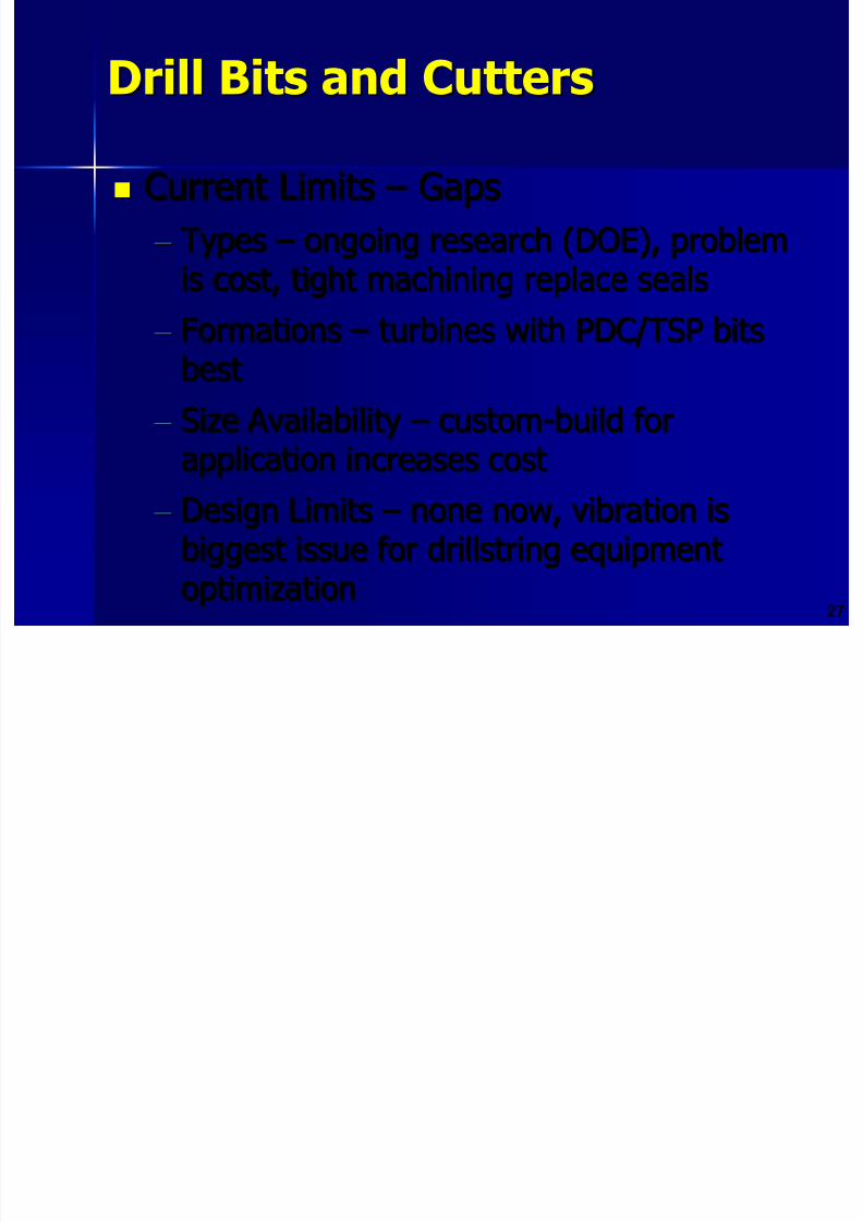
8/21/2019 BSEE Drilling and Completion Gaps for HTHP
http://slidepdf.com/reader/full/bsee-drilling-and-completion-gaps-for-hthp 104/184
2727
Current LimitsCurrent Limits – – GapsGaps
– – TypesTypes – – ongoing research (DOE), problemongoing research (DOE), problemis cost, tight machining replace sealsis cost, tight machining replace seals
– – FormationsFormations – – turbines with PDC/TSP bitsturbines with PDC/TSP bits
bestbest
– – Size AvailabilitySize Availability – – customcustom--build forbuild for
application increases costapplication increases cost – – Design LimitsDesign Limits – – none now, vibration isnone now, vibration is
biggest issue forbiggest issue for drillstringdrillstring equipmentequipment
optimizationoptimization
Inspection, QC, and StandardsInspection, QC, and Standards

8/21/2019 BSEE Drilling and Completion Gaps for HTHP
http://slidepdf.com/reader/full/bsee-drilling-and-completion-gaps-for-hthp 105/184
2828
Current LimitsCurrent Limits – – GapsGaps
– – StandardsStandards – – update API for wellheads atupdate API for wellheads at25 kpsi, NACE standards to 500°F25 kpsi, NACE standards to 500°F
– – TypesTypes – – current types are sufficientcurrent types are sufficient
– – Cataloging and ReportingCataloging and Reporting – – driven bydriven by
industry groupsindustry groups
The “Prize” The “Prize”

8/21/2019 BSEE Drilling and Completion Gaps for HTHP
http://slidepdf.com/reader/full/bsee-drilling-and-completion-gaps-for-hthp 106/184
2929
Money saved by avoiding methods andMoney saved by avoiding methods and
operations that are unnecessarily slowoperations that are unnecessarily slowand cumbersomeand cumbersome
Slow and cumbersome operations areSlow and cumbersome operations are
eliminated by closing technology gapseliminated by closing technology gaps
Key Technology Gap:Key Technology Gap:
MWD/LWD Well Path ControlMWD/LWD Well Path Control

8/21/2019 BSEE Drilling and Completion Gaps for HTHP
http://slidepdf.com/reader/full/bsee-drilling-and-completion-gaps-for-hthp 107/184
3030
MWD/LWD Well Path Control Assume: Assume:
– – Vertical well Vertical well – – BHA maintains vertical pathBHA maintains vertical path
– – Temperature >300°F, MWD/LWD unreliableTemperature >300°F, MWD/LWD unreliable
– – 500’ survey interval500’ survey interval – – 21,00021,000 – –31,000’ TD31,000’ TD
– – Four bit trips requiredFour bit trips required
– – 15 survey trips required15 survey trips required
– – Need a log on each tripNeed a log on each trip
Costs (No Smart Tools)Costs (No Smart Tools)

8/21/2019 BSEE Drilling and Completion Gaps for HTHP
http://slidepdf.com/reader/full/bsee-drilling-and-completion-gaps-for-hthp 108/184
3131
Tripping:Tripping: 23.4 days23.4 days $14,600k/well$14,600k/well
Logging:Logging: ±$250k/run±$250k/run $5,000k/well$5,000k/well Total:Total: ±$20,000k/well±$20,000k/well
((incremincrem. to AFE). to AFE)
Alternative: Use Currently Available Alternative: Use Currently AvailableSmart Tools to Destruction Smart Tools to Destruction
Costs (Smart Tools)Costs (Smart Tools)

8/21/2019 BSEE Drilling and Completion Gaps for HTHP
http://slidepdf.com/reader/full/bsee-drilling-and-completion-gaps-for-hthp 109/184
3232
Use currently available “smart” toolsUse currently available “smart” tools
729 ft MDBF: LWD/MWD729 ft MDBF: LWD/MWD Some ability to alter well path toSome ability to alter well path to
verticalvertical ±14 trips required±14 trips required
Cost: 21.8 days; $13,600k ($6,400k orCost: 21.8 days; $13,600k ($6,400k or30% savings over drilling blind)30% savings over drilling blind)
The Way ForwardThe Way Forward
f

8/21/2019 BSEE Drilling and Completion Gaps for HTHP
http://slidepdf.com/reader/full/bsee-drilling-and-completion-gaps-for-hthp 110/184
3333
If you can measure it, you can manage itIf you can measure it, you can manage it
If you don’t measure it, you need luck If you don’t measure it, you need luck
Good luck is what happens whenGood luck is what happens when
preparedness meets opportunitypreparedness meets opportunity
OptionsOptions
hD hi d li d l

8/21/2019 BSEE Drilling and Completion Gaps for HTHP
http://slidepdf.com/reader/full/bsee-drilling-and-completion-gaps-for-hthp 111/184
3434
Do nothingDo nothing – – await developmentsawait developments
Develop technology yourself Develop technology yourself
Develop technology with small consortiaDevelop technology with small consortia
DeepStarDeepStar--scale JIP effortscale JIP effort
Analysis Analysis – – The Stakes Justify SubstantialThe Stakes Justify SubstantialEffort in R&D Effort in R&D
Concepts and PossibilitiesConcepts and Possibilities
Expand JIP to include shelf drillersExpand JIP to include shelf drillers

8/21/2019 BSEE Drilling and Completion Gaps for HTHP
http://slidepdf.com/reader/full/bsee-drilling-and-completion-gaps-for-hthp 112/184
3535
Develop detailed database on all HTHP techDevelop detailed database on all HTHP tech
failuresfailures Monitor/measure improvement in toolMonitor/measure improvement in tool
performanceperformance
Optimize procedures for applying toolsOptimize procedures for applying tools
Integrate research effortsIntegrate research efforts
Focus on cooperation, application, feedback Focus on cooperation, application, feedback
Engage/empower an engineer to championEngage/empower an engineer to champion
HPHT gapsHPHT gaps

8/21/2019 BSEE Drilling and Completion Gaps for HTHP
http://slidepdf.com/reader/full/bsee-drilling-and-completion-gaps-for-hthp 113/184
3636
Cementing AssessmentCementing Assessment
Cementing AssessmentCementing Assessment
Project TeamProject Team

8/21/2019 BSEE Drilling and Completion Gaps for HTHP
http://slidepdf.com/reader/full/bsee-drilling-and-completion-gaps-for-hthp 114/184
3737
– – DOE, MMSDOE, MMS
– – Deep Trek participants: Conoco, Anadarko,Deep Trek participants: Conoco, Anadarko,Dominion, Chevron, BHPDominion, Chevron, BHP
–
–
Service CompaniesService Companies Address four areas Address four areas
– –
Primary cementingPrimary cementing – – Squeeze cementingSqueeze cementing
– – Tieback cementingTieback cementing
– – Plug cementingPlug cementing
Primary Cement AssessmentPrimary Cement Assessment
C t ICurrent Issues GGaps

8/21/2019 BSEE Drilling and Completion Gaps for HTHP
http://slidepdf.com/reader/full/bsee-drilling-and-completion-gaps-for-hthp 115/184
3838
Current IssuesCurrent Issues – – GapsGaps
– – HH22S and COS and CO22 corrosion issuescorrosion issues – – need to beneed to beup to 500°F, and HP (up to 500°F, and HP (longtermlongterm integrity)integrity)
– – Bond Logs and EvaluationBond Logs and Evaluation – – 350 to 400°F350 to 400°F
now; need 500°Fnow; need 500°F
– – Plugs and floating equipmentPlugs and floating equipment – – 400°F and400°F and
55 kpsikpsi now; need 500°Fnow; need 500°F – – OpenholeOpenhole ECP/Liner Top packersECP/Liner Top packers – – 400°F400°F
and 20and 20 kpsikpsi; need 500°F; need 500°F
Primary Cement AssessmentPrimary Cement Assessment
Current IssuesCurrent Issues – – GapsGapsS i li d tS i li d t

8/21/2019 BSEE Drilling and Completion Gaps for HTHP
http://slidepdf.com/reader/full/bsee-drilling-and-completion-gaps-for-hthp 116/184
3939
– – Specialized cementsSpecialized cements
Saturated saltSaturated salt
Penetrating sealantsPenetrating sealants
– – Mechanical Property ModificationMechanical Property Modification
Tensile strength increasesTensile strength increases – – up to 700up to 700 psipsi; need; need20002000 psipsi
ExpansionExpansion – – now 300°F; need 500°Fnow 300°F; need 500°F
Bond to pipe, formationBond to pipe, formation – – now 500now 500 psipsi; need; need
20002000 psipsi
– –
Expandable TubularsExpandable Tubulars – – now 20now 20 kpsikpsi andand400°F; need 500°F400°F; need 500°F
Primary Cement AssessmentPrimary Cement Assessment
Current IssuesCurrent Issues GapsGaps

8/21/2019 BSEE Drilling and Completion Gaps for HTHP
http://slidepdf.com/reader/full/bsee-drilling-and-completion-gaps-for-hthp 117/184
4040
Current IssuesCurrent Issues – – GapsGaps
–
–
Hole strengthening/stabilityHole strengthening/stability Currently have polymers, membrane forming,Currently have polymers, membrane forming,
solidssolids--free penetrating fluidsfree penetrating fluids
350°F; need 500°F350°F; need 500°F
Squeeze CementingSqueeze Cementing
Current IssuesCurrent Issues GapsGaps

8/21/2019 BSEE Drilling and Completion Gaps for HTHP
http://slidepdf.com/reader/full/bsee-drilling-and-completion-gaps-for-hthp 118/184
4141
Current IssuesCurrent Issues – – GapsGaps
–
–
All issues are with primary cementing All issues are with primary cementing – – Lab testing at BHST/BHPLab testing at BHST/BHP
Standard compatibility well fluids testingStandard compatibility well fluids testing
– – SolidsSolids--free materials for penetratingfree materials for penetrating – – nownow
350°F, need 500°F350°F, need 500°F
– – Squeeze packersSqueeze packers – – now 400°F; need 500°Fnow 400°F; need 500°F
– – Casing leaksCasing leaks – – some current materials limitsome current materials limit
of 400°F; need 500°Fof 400°F; need 500°F
Tieback CementingTieback Cementing
Current IssuesCurrent Issues GapsGaps

8/21/2019 BSEE Drilling and Completion Gaps for HTHP
http://slidepdf.com/reader/full/bsee-drilling-and-completion-gaps-for-hthp 119/184
4242
Current IssuesCurrent Issues – – GapsGaps
–
–
APB in between casing, current research APB in between casing, current researchongoing (Chevron)ongoing (Chevron)
– – PressurePressure maintaincemaintaince for tieback casingfor tieback casing
designdesign
– – Friction pressure testing and modeling atFriction pressure testing and modeling at
HPHT conditionsHPHT conditions
Plug CementingPlug Cementing
Current IssuesCurrent Issues GapsGaps

8/21/2019 BSEE Drilling and Completion Gaps for HTHP
http://slidepdf.com/reader/full/bsee-drilling-and-completion-gaps-for-hthp 120/184
4343
Current IssuesCurrent Issues – – GapsGaps
– – Tools needed (plug catcher, diverter sub,Tools needed (plug catcher, diverter sub,tubing release tool), 350°F; need 500°Ftubing release tool), 350°F; need 500°F
– – HighHigh--strength materials for kick off/strength materials for kick off/
lateralslaterals – – now 5now 5 kpsikpsi; need 10 to 15; need 10 to 15 kpsikpsi
– – SolidsSolids--free sealant for boreholefree sealant for borehole
strengtheningstrengthening – – now 350°F; need 500°Fnow 350°F; need 500°F

8/21/2019 BSEE Drilling and Completion Gaps for HTHP
http://slidepdf.com/reader/full/bsee-drilling-and-completion-gaps-for-hthp 121/184
4444
Completion AssessmentCompletion Assessment
Completion AssessmentCompletion Assessment
Most difficult area for DeepStarMost difficult area for DeepStar

8/21/2019 BSEE Drilling and Completion Gaps for HTHP
http://slidepdf.com/reader/full/bsee-drilling-and-completion-gaps-for-hthp 122/184
4545
Most difficult area for DeepStarMost difficult area for DeepStarrequirementsrequirements
Wide range of issues that requireWide range of issues that requireindividual attentionindividual attention
– – ChemicalsChemicals
– – Production issuesProduction issues
– – EquipmentEquipment
– – Mechanical perforationMechanical perforation
– – TestingTesting
Data SourcesData Sources
CompletionCompletion
PowerWellHESSchlumberger BJSTerraTekWellDynamicsBaker

8/21/2019 BSEE Drilling and Completion Gaps for HTHP
http://slidepdf.com/reader/full/bsee-drilling-and-completion-gaps-for-hthp 123/184
4646
DownholeDownholeEquipmentEquipment
Subsea SystemsSubsea SystemsSurfaceSurface
EquipmentEquipment
WellWellTestingTesting
PackersPackers
ElastomersElastomers
PackersPackers
ElastomersElastomers
PackersPackers
ElastomersElastomers
SmartSmart
TechnologyTechnology
CompletionCompletion
EquipmentEquipment
PerforatingPerforating
InstrumentationInstrumentation
FlowFlow Assurance Assurance
StimulationStimulationStimulationStimulationStimulationStimulation
WellWell
Testing &Testing &FlowbackFlowback
ppFluidsFluids
Completion FluidsCompletion Fluids
Current LimitsCurrent Limits –– GapsGaps

8/21/2019 BSEE Drilling and Completion Gaps for HTHP
http://slidepdf.com/reader/full/bsee-drilling-and-completion-gaps-for-hthp 124/184
4747
Current LimitsCurrent Limits GapsGaps
–
–
Hole StabilityHole Stability – – current 20 ppg, porecurrent 20 ppg, porepressure frac pressure almost equal,pressure frac pressure almost equal,
additive to control density variation neededadditive to control density variation needed
– – CorrosivityCorrosivity – – now not a problem, newnow not a problem, newmetals need additional controlmetals need additional control
– – Formation compatibilityFormation compatibility – – up to 400°F; needup to 400°F; needup to 500°F (Stim Lab is designing HPHTup to 500°F (Stim Lab is designing HPHT
equipment)equipment)
StimulationStimulation
Current LimitsCurrent Limits –– GapsGaps

8/21/2019 BSEE Drilling and Completion Gaps for HTHP
http://slidepdf.com/reader/full/bsee-drilling-and-completion-gaps-for-hthp 125/184
4848
Current LimitsCurrent Limits GapsGaps
–
–
ProppantsProppants – – 400°F and 25 kpsi, need400°F and 25 kpsi, needcoatings or new materials to preventcoatings or new materials to prevent
imbedding, frac conductivity, crushingimbedding, frac conductivity, crushing
– – Transport FluidsTransport Fluids – – current technology iscurrent technology isOK, need weighted brines to reduceOK, need weighted brines to reduce
wellhead pressurewellhead pressure
– – Wellhead ControlWellhead Control – – wellhead isolationwellhead isolation
equipment to address treating pressureequipment to address treating pressure
Flow AssuranceFlow Assurance
Current IssuesCurrent Issues – – GapsGaps

8/21/2019 BSEE Drilling and Completion Gaps for HTHP
http://slidepdf.com/reader/full/bsee-drilling-and-completion-gaps-for-hthp 126/184
4949
Current Issues Gapsp
– –
DeploymentDeployment
– –
currently simplistic, needcurrently simplistic, need
automated injection, high injection pressuresautomated injection, high injection pressures
– – InjectionInjection – – unknowns until HPHT wellsunknowns until HPHT wells
produced; higher pressures for umbilical linesproduced; higher pressures for umbilical linesand injection subsand injection subs
– – Areas of Control Areas of Control – – 450°F at bottom, 275°F450°F at bottom, 275°F
well head; need 500°F bottom hole andwell head; need 500°F bottom hole and
300°F+ at surface300°F+ at surface
– – Well head issues againWell head issues again
PerforatingPerforating
Current LimitsCurrent Limits –– GapsGaps

8/21/2019 BSEE Drilling and Completion Gaps for HTHP
http://slidepdf.com/reader/full/bsee-drilling-and-completion-gaps-for-hthp 127/184
5050
Current LimitsCurrent Limits GapsGaps
– –
EquipmentEquipment – – all works to 450°F; need 500°Fall works to 450°F; need 500°F Firing headsFiring heads
InitiatorsInitiators
Primer cordPrimer cord
Shape chargesShape charges
Gun caseGun case
Completion EquipmentCompletion Equipment
Current IssuesCurrent Issues – – GapsGaps

8/21/2019 BSEE Drilling and Completion Gaps for HTHP
http://slidepdf.com/reader/full/bsee-drilling-and-completion-gaps-for-hthp 128/184
5151
pp
– – EquipmentEquipment – – sealing is major issue withsealing is major issue withelastomerselastomers, dynamic design at 400°F;, dynamic design at 400°F;need 500°Fneed 500°F
– –
OperationOperation – – SSCV pressure activated,SSCV pressure activated,electroelectro--magnetic needed, downholemagnetic needed, downholepower neededpower needed
– – MeasurementMeasurement – – need 500°F capabilityneed 500°F capability
– – Casing damageCasing damage – – setting packers withoutsetting packers withoutslips necessaryslips necessary
SmartwellSmartwell
Current IssuesCurrent Issues – – GapsGaps

8/21/2019 BSEE Drilling and Completion Gaps for HTHP
http://slidepdf.com/reader/full/bsee-drilling-and-completion-gaps-for-hthp 129/184
5252
Cu e ssues Gapsp
– –
Similar to equipment sectionSimilar to equipment section – – EquipmentEquipment – – need actuators and sensorsneed actuators and sensors
that will work at 20 kpsi and 500°Fthat will work at 20 kpsi and 500°F
– – MaintenanceMaintenance – – intervention processes lowerintervention processes lower
cost of repair, calibration, replacementcost of repair, calibration, replacement
Well TestingWell Testing
Current IssuesCurrent Issues – – GapsGaps

8/21/2019 BSEE Drilling and Completion Gaps for HTHP
http://slidepdf.com/reader/full/bsee-drilling-and-completion-gaps-for-hthp 130/184
5353
pp
– – Big topicBig topic
– – Surface Equipment Design (volumes, flowSurface Equipment Design (volumes, flowperiods etc.)periods etc.)
– – Fluid EngineeringFluid Engineering – – pressure port plugging,pressure port plugging,tool reliability, negative impact on testtool reliability, negative impact on teststringsstrings
– – Circuit TechnologyCircuit Technology – – pressure and testingpressure and testingrequirementsrequirements
– – Monitoring TechnologyMonitoring Technology – – continuouscontinuousmonitoring produced fluids remotemonitoring produced fluids remote
Packers/ElastomersPackers/Elastomers
Current IssuesCurrent Issues – – GapsGaps

8/21/2019 BSEE Drilling and Completion Gaps for HTHP
http://slidepdf.com/reader/full/bsee-drilling-and-completion-gaps-for-hthp 131/184
5454
pp
– –
More exotic alloys and components areMore exotic alloys and components areneededneeded
– – Compatibility of tubing, packer, well fluidsCompatibility of tubing, packer, well fluids
requiredrequired
– – Polymers, seals to withstand corrosive,Polymers, seals to withstand corrosive,
HPHT conditions, chemical performanceHPHT conditions, chemical performance – – MetalMetal--toto--metal seal may replacemetal seal may replace
elastomerselastomers
– – Surface testing procedures neededSurface testing procedures needed
Wireline TestingWireline Testing
Current IssuesCurrent Issues – – GapsGaps

8/21/2019 BSEE Drilling and Completion Gaps for HTHP
http://slidepdf.com/reader/full/bsee-drilling-and-completion-gaps-for-hthp 132/184
5555
pp
– –
Tools and systems to deliver wider range ofTools and systems to deliver wider range ofdatadata
– – Indirect measurements need to be refinedIndirect measurements need to be refined
– – Data requirements prioritizedData requirements prioritized
– – Equipment to withstand 250Equipment to withstand 250 – –450°F for long450°F for long
periods of time, nonperiods of time, non--conductive metalsconductive metals

8/21/2019 BSEE Drilling and Completion Gaps for HTHP
http://slidepdf.com/reader/full/bsee-drilling-and-completion-gaps-for-hthp 133/184
5656
The EndThe End
Drilling and Completion Gaps for HPHT Wells in Deep Water

8/21/2019 BSEE Drilling and Completion Gaps for HTHP
http://slidepdf.com/reader/full/bsee-drilling-and-completion-gaps-for-hthp 134/184
Appendix E – Presentation on Challenges,Opportunities, and the Way Forward from
DeepStar Public Workshop on HPHT TechnologyGaps (3/30/06)
DeepStar CTR 7501Drilling and Completion Technology Gaps for

8/21/2019 BSEE Drilling and Completion Gaps for HTHP
http://slidepdf.com/reader/full/bsee-drilling-and-completion-gaps-for-hthp 135/184
11
Drilling and Completion Technology Gaps for
HPHT Deepwater Wells
Workshop
Discussion
Challenges, Opportunities and Way Forward
March 30, 2006
Bridging the Technology GapBridging the Technology Gap
A i t R&D H P H T

8/21/2019 BSEE Drilling and Completion Gaps for HTHP
http://slidepdf.com/reader/full/bsee-drilling-and-completion-gaps-for-hthp 136/184
22
Appropriate R&D
role for DeepStar,DOE, MMS, JIP’s?
Other Offshore
Other Offshore
H P H T
Current Market
Future – 3, 5, or 7 Years?
T e c h n o l o g y
Who Needs What?Who Needs What?Investment Risks and What is at StakeInvestment Risks and What is at Stake
Operating CompaniesOperating Companies

8/21/2019 BSEE Drilling and Completion Gaps for HTHP
http://slidepdf.com/reader/full/bsee-drilling-and-completion-gaps-for-hthp 137/184
33
p g pp g p
Drilling ContractorsDrilling Contractors
Service CompaniesService Companies
Regulatory AgenciesRegulatory Agencies
Why Should ServiceWhy Should Service
Companies Invest?Companies Invest?

8/21/2019 BSEE Drilling and Completion Gaps for HTHP
http://slidepdf.com/reader/full/bsee-drilling-and-completion-gaps-for-hthp 138/184
44
Will the size of the marketWill the size of the market justify the investment? justify the investment?
What is their timing horizon?What is their timing horizon?
Why Should OperatorsWhy Should Operators
Invest?Invest?

8/21/2019 BSEE Drilling and Completion Gaps for HTHP
http://slidepdf.com/reader/full/bsee-drilling-and-completion-gaps-for-hthp 139/184
55
Easy prospects are goneEasy prospects are gone
Huge resourceHuge resource
Is There a Role forIs There a Role for DeepStarDeepStar??

8/21/2019 BSEE Drilling and Completion Gaps for HTHP
http://slidepdf.com/reader/full/bsee-drilling-and-completion-gaps-for-hthp 140/184
66
Are Are JIPsJIPs the way to go? They have a lot ofthe way to go? They have a lot ofadvantages for everyone, but require freeadvantages for everyone, but require free
flow of information and data.flow of information and data.
What is Best and MostWhat is Best and Most
Appropriate Role for Appropriate Role forGovernment?Government?

8/21/2019 BSEE Drilling and Completion Gaps for HTHP
http://slidepdf.com/reader/full/bsee-drilling-and-completion-gaps-for-hthp 141/184
77
R&DR&D
IncentivesIncentives RegulatoryRegulatory
OptionsOptions
Do nothingDo nothing – – await developmentsawait developments

8/21/2019 BSEE Drilling and Completion Gaps for HTHP
http://slidepdf.com/reader/full/bsee-drilling-and-completion-gaps-for-hthp 142/184
88
Develop technology yourself Develop technology yourself Develop technology with small consortiaDevelop technology with small consortia
DeepStarDeepStar--scale JIP effortscale JIP effort Government coGovernment co--fundingfunding
Analysis Analysis – – The Stakes Justify Substantial EffortThe Stakes Justify Substantial Effort
in R&D in R&D
The “Prize” The “Prize”
Money saved by avoiding methods andMoney saved by avoiding methods and
ti th t il lope ations that a e nnecessa il slo

8/21/2019 BSEE Drilling and Completion Gaps for HTHP
http://slidepdf.com/reader/full/bsee-drilling-and-completion-gaps-for-hthp 143/184
99
operations that are unnecessarily slowoperations that are unnecessarily slow
and cumbersomeand cumbersome
Slow and cumbersome operations areSlow and cumbersome operations are
eliminated by closing technology gapseliminated by closing technology gaps

8/21/2019 BSEE Drilling and Completion Gaps for HTHP
http://slidepdf.com/reader/full/bsee-drilling-and-completion-gaps-for-hthp 144/184
1010
Recommended ProjectsRecommended Projects
Drilling Gaps/ProjectsDrilling Gaps/Projects
Electronics and Sensors (funded)Electronics and Sensors (funded)
DOE D T k d DEADOE Deep Trek and DEA

8/21/2019 BSEE Drilling and Completion Gaps for HTHP
http://slidepdf.com/reader/full/bsee-drilling-and-completion-gaps-for-hthp 145/184
1111
– – DOE, Deep Trek and DEA DOE, Deep Trek and DEA
Inclinometer (MWD/LWD)Inclinometer (MWD/LWD)
– – 2007 budget2007 budget
Systems look Systems look
– – Bits, mud, motors, drill string dynamicsBits, mud, motors, drill string dynamics
– – Cooling to improve MWD/LWDCooling to improve MWD/LWD
– – Best practicesBest practices
– – Manage of ECD’sManage of ECD’s
Drilling Gaps/ProjectsDrilling Gaps/Projects
Improve MWD motor and turbine designImprove MWD motor and turbine design
R k h i t i ROPR k h i t i ROP

8/21/2019 BSEE Drilling and Completion Gaps for HTHP
http://slidepdf.com/reader/full/bsee-drilling-and-completion-gaps-for-hthp 146/184
1212
Rock mechanics to improve ROPRock mechanics to improve ROP
Mud system for friction, thermal properties,Mud system for friction, thermal properties,
control density, ROPcontrol density, ROP
Text fixtures and equipmentText fixtures and equipment
NanotechnologyNanotechnology
SolidSolid--state battery (JIP)state battery (JIP)
HPHT turbine generatorHPHT turbine generator
– – DOE to Dexter Magnetic TechDOE to Dexter Magnetic Tech
Drilling Gaps/ProjectsDrilling Gaps/Projects
Wellheads for 25 kpsi and 450°F HWellheads for 25 kpsi and 450°F H22SS

8/21/2019 BSEE Drilling and Completion Gaps for HTHP
http://slidepdf.com/reader/full/bsee-drilling-and-completion-gaps-for-hthp 147/184
1313
Review/recommend revision of API,Review/recommend revision of API,NACE and ASME specs for HPHTNACE and ASME specs for HPHT
Cementing Gaps/ProjectsCementing Gaps/Projects
HH22S and COS and CO22 issues with sealantsissues with sealants
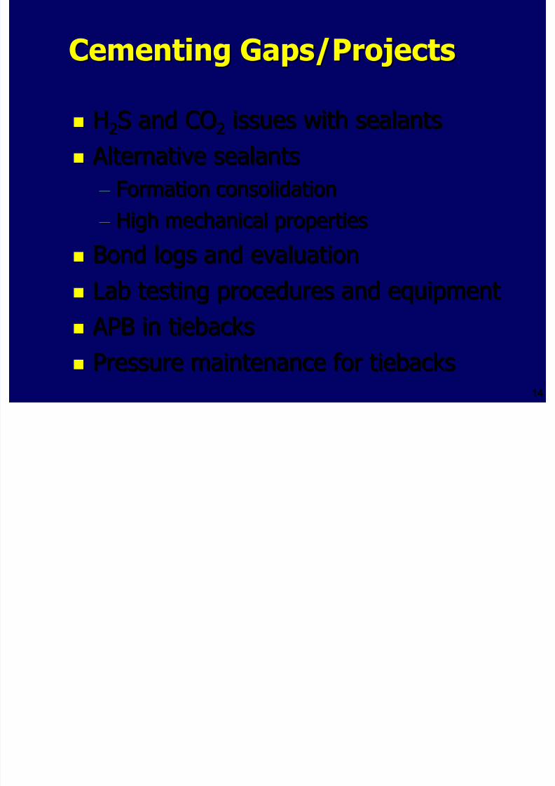
8/21/2019 BSEE Drilling and Completion Gaps for HTHP
http://slidepdf.com/reader/full/bsee-drilling-and-completion-gaps-for-hthp 148/184
1414
Alternative sealants Alternative sealants – – Formation consolidationFormation consolidation
– – High mechanical propertiesHigh mechanical properties
Bond logs and evaluationBond logs and evaluation
Lab testing procedures and equipmentLab testing procedures and equipment
APB in tiebacks APB in tiebacks
Pressure maintenance for tiebacksPressure maintenance for tiebacks
Completion Gaps/ProjectsCompletion Gaps/Projects
Completion fluids with improvedCompletion fluids with improvedthermal propertiesthermal properties

8/21/2019 BSEE Drilling and Completion Gaps for HTHP
http://slidepdf.com/reader/full/bsee-drilling-and-completion-gaps-for-hthp 149/184
1515
thermal propertiesthermal properties
Modified completion equipmentModified completion equipment
– – Dynamic sealing, chemical injection, staticDynamic sealing, chemical injection, static
sealing, electronic and sensor tech,sealing, electronic and sensor tech,intervention techintervention tech
StimulationStimulation
– – HighHigh--strength proppants, gels with heavystrength proppants, gels with heavyweight brines, well heads for 30 kpsiweight brines, well heads for 30 kpsi
serviceservice
Completion Gaps/ProjectsCompletion Gaps/Projects
Flow AssuranceFlow Assurance
New completion equipment for injectionNew completion equipment for injection

8/21/2019 BSEE Drilling and Completion Gaps for HTHP
http://slidepdf.com/reader/full/bsee-drilling-and-completion-gaps-for-hthp 150/184
1616
– – New completion equipment for injectionNew completion equipment for injection
– – Hydrate and scale inhibitionHydrate and scale inhibition
Smartwell (already funded)Smartwell (already funded)
– – Batteries and electronicsBatteries and electronics
PackersPackers
– – Elastomers for 500°F and 30 kpsiElastomers for 500°F and 30 kpsi
– – Metallurgy for 500°F and 30 kpsiMetallurgy for 500°F and 30 kpsi
– – MetalMetal--toto--metal sealsmetal seals
Completion Gaps/ProjectsCompletion Gaps/Projects
ElastomersElastomers

8/21/2019 BSEE Drilling and Completion Gaps for HTHP
http://slidepdf.com/reader/full/bsee-drilling-and-completion-gaps-for-hthp 151/184
1717
Wireline TestingWireline Testing – – HPHT electrical insulator materialsHPHT electrical insulator materials
– –
Inferential test methodsInferential test methods – – Continuous duty HPHT electronicsContinuous duty HPHT electronics
Well TestingWell Testing – – Packer and downhole equipmentPacker and downhole equipment
– – Lab test equipment for HPHT conditionsLab test equipment for HPHT conditions
ConclusionsConclusions -- DiscussionDiscussion
HPHT wells can be drilled, but with limitationsHPHT wells can be drilled, but with limitations
Economic impediments include equipment

8/21/2019 BSEE Drilling and Completion Gaps for HTHP
http://slidepdf.com/reader/full/bsee-drilling-and-completion-gaps-for-hthp 152/184
1818
Economic impediments include equipment,Economic impediments include equipment,
process and regulatory componentsprocess and regulatory components
Controlling risks? They must first be defined!!Controlling risks? They must first be defined!!
Existing gaps support large R&D fundingExisting gaps support large R&D funding
Collaboration is critical to successCollaboration is critical to success
Discussion PointsDiscussion Points
Review report and discuss intraReview report and discuss intra--companycompany

8/21/2019 BSEE Drilling and Completion Gaps for HTHP
http://slidepdf.com/reader/full/bsee-drilling-and-completion-gaps-for-hthp 153/184
1919
Way Forward: DeepStar Role?Way Forward: DeepStar Role? Way Forward:Way Forward: Role(sRole(s) for other players?) for other players?
RecommendationsRecommendations Expand JIP to include shelf drillersExpand JIP to include shelf drillers
Develop detailed database on all HPHT techDevelop detailed database on all HPHT techfailuresfailures

8/21/2019 BSEE Drilling and Completion Gaps for HTHP
http://slidepdf.com/reader/full/bsee-drilling-and-completion-gaps-for-hthp 154/184
2020
Monitor/measure improvement in toolMonitor/measure improvement in toolperformanceperformance
Optimize procedures for applying toolsOptimize procedures for applying tools
Integrate research effortsIntegrate research efforts
– – Prioritize and Consider Funding Study’sPrioritize and Consider Funding Study’sRecommended R&D ProjectsRecommended R&D Projects
Focus on cooperation, application, feedback Focus on cooperation, application, feedback
Engage/empower an engineer to championEngage/empower an engineer to champion
HPHT gapsHPHT gaps
The Way ForwardThe Way Forward
If you can measure it, you can manage itIf you can measure it, you can manage it

8/21/2019 BSEE Drilling and Completion Gaps for HTHP
http://slidepdf.com/reader/full/bsee-drilling-and-completion-gaps-for-hthp 155/184
2121
If you don’t measure it, you need luck If you don’t measure it, you need luck Good luck is what happens whenGood luck is what happens when
preparedness meets opportunitypreparedness meets opportunity
The main step toward preparedness isThe main step toward preparedness ismeasurement!!!! Quantify industrymeasurement!!!! Quantify industry
experience first!!!!experience first!!!!

8/21/2019 BSEE Drilling and Completion Gaps for HTHP
http://slidepdf.com/reader/full/bsee-drilling-and-completion-gaps-for-hthp 156/184
2222
The EndThe End
Drilling and Completion Gaps for HPHT Wells in Deep Water
8/21/2019 BSEE Drilling and Completion Gaps for HTHP
http://slidepdf.com/reader/full/bsee-drilling-and-completion-gaps-for-hthp 157/184
Appendix F – Presentation Summarizing MMSProject 519 on HPHT Technology Gaps (by TomWilliams at MMS Overview Meeting on 5/23/06)
DeepStar CTR 7501Drilling and Completion Technology Gaps for

8/21/2019 BSEE Drilling and Completion Gaps for HTHP
http://slidepdf.com/reader/full/bsee-drilling-and-completion-gaps-for-hthp 158/184
11
HPHT Deepwater Wells
Participants: DeepStar, MMS, DOE, Triton EngineeringParticipants: DeepStar, MMS, DOE, Triton Engineering
Services, CSI Technologies, Noble Technology ServicesServices, CSI Technologies, Noble Technology Services
Challenges, Opportunities and Way ForwardMMS Overview Meeting May 23, 2006
PurposePurpose

8/21/2019 BSEE Drilling and Completion Gaps for HTHP
http://slidepdf.com/reader/full/bsee-drilling-and-completion-gaps-for-hthp 159/184
22
HPHT Deepwater Drilling andHPHT Deepwater Drilling andCompletion Technology GapsCompletion Technology Gaps
– – IdentifyIdentify
– – UnderstandUnderstand
– – PrioritizePrioritize
Project CompletedProject Completed
1/30/06 Report vetted by DeepStar1/30/06 Report vetted by DeepStar
DeepStar Review 3/2/06DeepStar Review 3/2/06

8/21/2019 BSEE Drilling and Completion Gaps for HTHP
http://slidepdf.com/reader/full/bsee-drilling-and-completion-gaps-for-hthp 160/184
33
p
Workshop 3Workshop 3--3030--0606
Summary and RecommendationsSummary and Recommendations
Report includes technical limits and needsReport includes technical limits and needsfor drilling, cementing, fluids, completionsfor drilling, cementing, fluids, completions
This presentation includes recommendedThis presentation includes recommendedprojectsprojects
HPHT DefinitionHPHT Definition
27,000 ft BML27,000 ft BML

8/21/2019 BSEE Drilling and Completion Gaps for HTHP
http://slidepdf.com/reader/full/bsee-drilling-and-completion-gaps-for-hthp 161/184
44
>350°F BHST>350°F BHST 24,50024,500 psipsi static BHPstatic BHP
4,000 and 7,500 ft WD4,000 and 7,500 ft WD
SubsaltSubsalt case for each WDcase for each WD
ParticipantsParticipants
CoCo--funding and datafunding and data werewere provided by:provided by:

8/21/2019 BSEE Drilling and Completion Gaps for HTHP
http://slidepdf.com/reader/full/bsee-drilling-and-completion-gaps-for-hthp 162/184
55
DeepStar ConsortiumDeepStar Consortium – – DeepStar Operators and Service CompaniesDeepStar Operators and Service Companies
U.S. DOE National Energy TechnologyU.S. DOE National Energy TechnologyLaboratoryLaboratory
Minerals Management ServiceMinerals Management Service
Study MethodologyStudy Methodology
Identify State of the Art, including on goingIdentify State of the Art, including on goingR&D, worldwide activityR&D, worldwide activity

8/21/2019 BSEE Drilling and Completion Gaps for HTHP
http://slidepdf.com/reader/full/bsee-drilling-and-completion-gaps-for-hthp 163/184
66
Analysis of Historical Well Data Analysis of Historical Well Data – – Some data availableSome data available
– – Failures, successes, limitsFailures, successes, limits
Survey of Industry Service ProvidersSurvey of Industry Service Providers – – Standard limits and usagesStandard limits and usages
– – Real limits and gapsReal limits and gaps
Compare Industry Claims with DataCompare Industry Claims with Data
Industry Survey MethodIndustry Survey Method
Develop surveyDevelop survey
InterviewInterview

8/21/2019 BSEE Drilling and Completion Gaps for HTHP
http://slidepdf.com/reader/full/bsee-drilling-and-completion-gaps-for-hthp 164/184
77
Identify physical driversIdentify physical drivers
Identify impact of driversIdentify impact of drivers
Define limits of existing skills, equipment andDefine limits of existing skills, equipment andservicesservices
Identify requirements to close gapsIdentify requirements to close gaps Quantify time, cost, technical to close gapsQuantify time, cost, technical to close gaps
Temperature & Pressure ConditionsTemperature & Pressure Conditions35 wells (31 DW, 4 shelf)35 wells (31 DW, 4 shelf)
0.000
5.000
0 100 200 300 400 500
Static Temperature (°F)
)

8/21/2019 BSEE Drilling and Completion Gaps for HTHP
http://slidepdf.com/reader/full/bsee-drilling-and-completion-gaps-for-hthp 165/184
88
10.000
15.000
20.000
25.000
30.000
P r e s s
u r e ( 1 0 0 0 p s i
DUMB IRON CHINA DATA CTR 7501 LOW SPECIFICATION GOM SHELF
CTR 7501 WELLS noise CTR 7501 WELLS REAL CTR 7501 HIGH SPECIFICATION
W/L CAPABILITY MWD ResGR CAPABILITY MDT CAPABILITY
MOTOR CAPABILITY
Bridging the Technology GapBridging the Technology Gap
Appropriate R&D H P H T

8/21/2019 BSEE Drilling and Completion Gaps for HTHP
http://slidepdf.com/reader/full/bsee-drilling-and-completion-gaps-for-hthp 166/184
99
role for DeepStar,DOE, MMS, JIP’s?
Other Offshore
Other Offshore
H P H T
Current Market
Future – 3, 5, or 7 Years?
T e c h n o l o g y
LWD/MWD LimitsLWD/MWD Limits
Current LimitsCurrent Limits – – Gap ClosureGap Closure
– – Temperature limits 275Temperature limits 275 – –350°F; need 500°F350°F; need 500°F

8/21/2019 BSEE Drilling and Completion Gaps for HTHP
http://slidepdf.com/reader/full/bsee-drilling-and-completion-gaps-for-hthp 167/184
1010
– – Seals, cost, hole sizeSeals, cost, hole size
– – Telemetry 20,000Telemetry 20,000 psipsi and 350°Fand 350°F
– – Power, batteries to 350°F with lithium andPower, batteries to 350°F with lithium and400°F with mercury400°F with mercury
Options Presented at theOptions Presented at theWorkshopWorkshop
Do nothingDo nothing – – await developmentsawait developments
Develop technology yourself Develop technology yourself

8/21/2019 BSEE Drilling and Completion Gaps for HTHP
http://slidepdf.com/reader/full/bsee-drilling-and-completion-gaps-for-hthp 168/184
1111
Develop technology with small consortiaDevelop technology with small consortia
DeepStarDeepStar--scale JIP effortscale JIP effort Government coGovernment co--fundingfunding
Analysis Analysis – – The Stakes Justify Substantial EffortThe Stakes Justify Substantial Effortin R&D in R&D
The “Prize” The “Prize”
Money saved by avoiding methods andMoney saved by avoiding methods and
operations that are unnecessarily slowoperations that are unnecessarily slow

8/21/2019 BSEE Drilling and Completion Gaps for HTHP
http://slidepdf.com/reader/full/bsee-drilling-and-completion-gaps-for-hthp 169/184
1212
and cumbersomeand cumbersome
Slow and cumbersome operations areSlow and cumbersome operations are
eliminated by closing technology gapseliminated by closing technology gaps

8/21/2019 BSEE Drilling and Completion Gaps for HTHP
http://slidepdf.com/reader/full/bsee-drilling-and-completion-gaps-for-hthp 170/184
1313
Recommended ProjectsRecommended Projects
Drilling Gaps/ProjectsDrilling Gaps/Projects
Electronics and Sensors (funded)Electronics and Sensors (funded)
– – DOE, Deep Trek and DEA DOE, Deep Trek and DEA

8/21/2019 BSEE Drilling and Completion Gaps for HTHP
http://slidepdf.com/reader/full/bsee-drilling-and-completion-gaps-for-hthp 171/184
1414
Inclinometer (MWD/LWD)Inclinometer (MWD/LWD)
Systems look Systems look
– – Bits, mud, motors, drill string dynamicsBits, mud, motors, drill string dynamics
– – Cooling to improve MWD/LWDCooling to improve MWD/LWD
– – Best practicesBest practices
– – Manage of ECD’sManage of ECD’s
Drilling Gaps/ProjectsDrilling Gaps/Projects
Improve MWD motor and turbine designImprove MWD motor and turbine design
Rock mechanics to improve ROPRock mechanics to improve ROP

8/21/2019 BSEE Drilling and Completion Gaps for HTHP
http://slidepdf.com/reader/full/bsee-drilling-and-completion-gaps-for-hthp 172/184
1515
Mud system for friction, thermal properties,Mud system for friction, thermal properties,
control density, ROPcontrol density, ROP
Test fixtures and equipmentTest fixtures and equipment
NanotechnologyNanotechnology
SolidSolid--state battery (JIP)state battery (JIP)
HPHT turbine generatorHPHT turbine generator
Drilling Gaps/ProjectsDrilling Gaps/Projects
Wellheads for 25 kpsi and 450°F HWellheads for 25 kpsi and 450°F H22SS
R i / d i i f APIR i / d i i f API

8/21/2019 BSEE Drilling and Completion Gaps for HTHP
http://slidepdf.com/reader/full/bsee-drilling-and-completion-gaps-for-hthp 173/184
1616
Review/recommend revision of API,Review/recommend revision of API,NACE and ASME specs for HPHTNACE and ASME specs for HPHT
Cementing Gaps/ProjectsCementing Gaps/Projects
HH22S and COS and CO22 issues with sealantsissues with sealants
Alternative Sealants Alternative Sealants

8/21/2019 BSEE Drilling and Completion Gaps for HTHP
http://slidepdf.com/reader/full/bsee-drilling-and-completion-gaps-for-hthp 174/184
1717
– – Formation consolidationFormation consolidation
– – High mechanical propertiesHigh mechanical properties
Bond logs and evaluationBond logs and evaluation
Lab testing procedures and equipmentLab testing procedures and equipment
APB in tiebacks APB in tiebacks
Pressure maintenance for tiebacksPressure maintenance for tiebacks
Completion Gaps/ProjectsCompletion Gaps/Projects
Completion fluids with improvedCompletion fluids with improvedthermal propertiesthermal properties
M difi d l ti i tM difi d l ti i t

8/21/2019 BSEE Drilling and Completion Gaps for HTHP
http://slidepdf.com/reader/full/bsee-drilling-and-completion-gaps-for-hthp 175/184
1818
Modified completion equipmentModified completion equipment
– – Dynamic sealing, chemical injection, staticDynamic sealing, chemical injection, static
sealing, electronic and sensor tech,sealing, electronic and sensor tech,intervention techintervention tech
StimulationStimulation
– – HighHigh--strength proppants, gels with heavystrength proppants, gels with heavyweight brines, well heads for 30 kpsiweight brines, well heads for 30 kpsiserviceservice
Completion Gaps/ProjectsCompletion Gaps/Projects
Flow AssuranceFlow Assurance
– – New completion equipment for injectionNew completion equipment for injection
Hydrate and scale inhibitionHydrate and scale inhibition

8/21/2019 BSEE Drilling and Completion Gaps for HTHP
http://slidepdf.com/reader/full/bsee-drilling-and-completion-gaps-for-hthp 176/184
1919
– – Hydrate and scale inhibitionHydrate and scale inhibition
Smartwell (already funded)Smartwell (already funded)
– – Batteries and electronicsBatteries and electronics
PackersPackers
– – Elastomers for 500°F and 30 kpsiElastomers for 500°F and 30 kpsi
– – Metallurgy for 500°F and 30 kpsiMetallurgy for 500°F and 30 kpsi
– –
MetalMetal--toto--metal sealsmetal seals
Completion Gaps/ProjectsCompletion Gaps/Projects
ElastomersElastomers
Wireline TestingWireline Testing

8/21/2019 BSEE Drilling and Completion Gaps for HTHP
http://slidepdf.com/reader/full/bsee-drilling-and-completion-gaps-for-hthp 177/184
2020
Wireline TestingWireline Testing – – HPHT electrical insulator materialsHPHT electrical insulator materials
– – Inferential test methodsInferential test methods
– – Continuous duty HPHT electronicsContinuous duty HPHT electronics
Well TestingWell Testing
– – Packer and downhole equipmentPacker and downhole equipment
– – Lab test equipment for HPHT conditionsLab test equipment for HPHT conditions
ConclusionsConclusions -- DiscussionDiscussion
HPHT Wells can be drilled, but withHPHT Wells can be drilled, but withlimitationslimitations
Economic impediments include equipmentEconomic impediments include equipment

8/21/2019 BSEE Drilling and Completion Gaps for HTHP
http://slidepdf.com/reader/full/bsee-drilling-and-completion-gaps-for-hthp 178/184
2121
Economic impediments include equipment,Economic impediments include equipment,process and regulatory componentsprocess and regulatory components
Controlling risks? They must first beControlling risks? They must first be
defined!!defined!!
Existing gaps support large R&D fundingExisting gaps support large R&D funding
Collaboration is critical to successCollaboration is critical to success
RecommendationsRecommendations
Expand JIP to include shelf drillersExpand JIP to include shelf drillers Develop detailed database on all HPHT techDevelop detailed database on all HPHT tech
failuresfailures
Monitor/measure improvement in toolMonitor/measure improvement in tool

8/21/2019 BSEE Drilling and Completion Gaps for HTHP
http://slidepdf.com/reader/full/bsee-drilling-and-completion-gaps-for-hthp 179/184
2222
Monitor/measure improvement in toolMonitor/measure improvement in toolperformanceperformance
Optimize procedures for applying toolsOptimize procedures for applying tools
Integrate research effortsIntegrate research efforts – – Prioritize and Consider Funding Study’sPrioritize and Consider Funding Study’s
Recommended R&D ProjectsRecommended R&D Projects
Focus on cooperation, application, feedback Focus on cooperation, application, feedback
Engage/empower an engineer to championEngage/empower an engineer to championHPHT gapsHPHT gaps
The Way ForwardThe Way Forward
If you can measure it, you can manage itIf you can measure it, you can manage it
If you don’t measure it, you need luck If you don’t measure it, you need luck

8/21/2019 BSEE Drilling and Completion Gaps for HTHP
http://slidepdf.com/reader/full/bsee-drilling-and-completion-gaps-for-hthp 180/184
2323
Good luck is what happens whenGood luck is what happens whenpreparedness meets opportunitypreparedness meets opportunity
The main step toward preparedness isThe main step toward preparedness ismeasurement!!!! Quantify industrymeasurement!!!! Quantify industry
experience first!!!!experience first!!!!
Workshop Recommendations forDrilling
Accurate measurements and documentation Accurate measurements and documentationof what is failing in HPHT wells.of what is failing in HPHT wells.
Failure mechanisms for LWD/MWD RSS and motors ThisFailure mechanisms for LWD/MWD RSS and motors This

8/21/2019 BSEE Drilling and Completion Gaps for HTHP
http://slidepdf.com/reader/full/bsee-drilling-and-completion-gaps-for-hthp 181/184
2424
– – Failure mechanisms for LWD/MWD, RSS, and motors. ThisFailure mechanisms for LWD/MWD, RSS, and motors. Thisis necessary to accurately define the HTHP “prize”, tois necessary to accurately define the HTHP “prize”, tofocus and direct research efforts, and to provide a baselinefocus and direct research efforts, and to provide a baselinefor performance improvements associated with applicationfor performance improvements associated with application
of HTHP research products.of HTHP research products.
Effective means to control downholeEffective means to control downholepressures is criticalpressures is critical – – BOP’sBOP’s, seals, materials,, seals, materials,
APB. APB.
Needs/Comments fromWorkshop Attendees
Participation in API RP 6Participation in API RP 6
H2S is a critical concern. In deeper wells,H2S is a critical concern. In deeper wells,
assume the well is sour Materials areassume the well is sour Materials are

8/21/2019 BSEE Drilling and Completion Gaps for HTHP
http://slidepdf.com/reader/full/bsee-drilling-and-completion-gaps-for-hthp 182/184
2525
assume the well is sour. Materials areassume the well is sour. Materials areneeded, including metals, cements, andneeded, including metals, cements, and
seals.seals.
Annular pressure buildup (APB) is a critical Annular pressure buildup (APB) is a critical
issue. Need the ability to monitor integrityissue. Need the ability to monitor integrity
of tubulars. Vacuumof tubulars. Vacuum--insulated tubing isn’t ainsulated tubing isn’t agood answer. Some other alternativesgood answer. Some other alternatives
should be considered.should be considered.
Needs/Comments fromNeeds/Comments fromWorkshop AttendeesWorkshop Attendees
Completion needs are showCompletion needs are show--stoppers. We can drillstoppers. We can drillthese wells (maybe not costthese wells (maybe not cost--effectively), but cannoteffectively), but cannotcomplete and produce many HPHT wells (includingcomplete and produce many HPHT wells (including
deep shelf wells) The industry lacks adequate:deep shelf wells) The industry lacks adequate:

8/21/2019 BSEE Drilling and Completion Gaps for HTHP
http://slidepdf.com/reader/full/bsee-drilling-and-completion-gaps-for-hthp 183/184
2626
deep shelf wells). The industry lacks adequate:deep shelf wells). The industry lacks adequate: – – BOPsBOPs, Trees, Hardware, DH Electronics, Trees, Hardware, DH Electronics
Need improved analytical models to aid in sizingNeed improved analytical models to aid in sizing
equipment.equipment. Inability to evaluateInability to evaluate xHPHTxHPHT wells prevents properwells prevents proper
completion and production designs.completion and production designs.
Consensus recommended a JIP on HPHT DataConsensus recommended a JIP on HPHT DataMining.Mining.
h d

8/21/2019 BSEE Drilling and Completion Gaps for HTHP
http://slidepdf.com/reader/full/bsee-drilling-and-completion-gaps-for-hthp 184/184
2727
The EndThe End
Related Documents