MARS2000 User’s guide Booklet 1 February 2000 /1 Dev/UG/MARS2000/01 MARINE DIVISION DEVELOPMENT DEPARTMENT 17 bis, place des Reflets – La Défense 2 92077 Paris – La Défense Cedex Tel.: + 33 (0)1 42 91 52 91 Fax: + 33 (0)1 42 91 52 98 INTRODUCTION SHELL / BASIC SHIP DATA

Welcome message from author
This document is posted to help you gain knowledge. Please leave a comment to let me know what you think about it! Share it to your friends and learn new things together.
Transcript
MARS2000User’s guide
Booklet 1
February 2000 /1Dev/UG/MARS2000/01
MARINE DIVISIONDEVELOPMENT DEPARTMENT
17 bis, place des Reflets – La Défense 292077 Paris – La Défense Cedex
Tel.: + 33 (0)1 42 91 52 91Fax: + 33 (0)1 42 91 52 98
INTRODUCTIONSHELL / BASIC SHIP DATA

MARS2000 User’s Guide Booklet 1: Shell / Basic Ship Data
Bureau Veritas 1
TABLE OF CONTENTS
Chapter 1 : GENERAL COMMENTS ...........................................................21.1 GENERAL............................................................................................2
Chapter 2 : SHELL.......................................................................................32.1 MAIN FEATURES................................................................................32.2 MENUS................................................................................................4
Chapter 3 : BASIC SHIP DATA ...................................................................63.1 GENERAL COMMENTS......................................................................63.1.1 MAIN FEATURES 6
3.2 GENERAL............................................................................................73.3 NOTATION AND MAIN DATA .............................................................83.3.1 NOTATION 83.3.2 MAIN DIMENSION 93.3.3 LOCATION OF HOLD REGIONS 93.3.4 DEPTHS 10
3.4 MOMENT AND DRAUGHT................................................................103.4.1 SCANTLING CASE 103.4.2 BALLAST CASE 113.4.3 DREDGING CASE 12
3.5 BOW FLARE......................................................................................123.6 MATERIALS ......................................................................................143.7 FRAME LOCATIONS.........................................................................153.8 HOPPER WELLS ..............................................................................163.8.1 HOPPER DREDGER CASE 163.8.2 SPLIT HOPPER DREDGER CASE 16
3.9 CALCULATION AND PRINT .............................................................173.9.1 PRINTING DATA 173.9.2 CALCULATION 183.9.2.1 STILL WATER, WAVE MOMENTS, SHEAR FORCE 183.9.2.2 BASIC CALCULATIONS 193.9.3 PRINTING RESULT 20
Table of Figure ................................................................................................21
MARS2000 User’s Guide Booklet 1: Shell / Basic Ship Data
2 Bureau Veritas
Chapter 1 : GENERAL COMMENTS
1.1 GENERAL
MARS2000 is a software tool that allows to input sections, bulkheads and torsion models; it is organized aroundthe following seven modules:
• MARS2000 (Shell).
• MIRE2000 (Basic Ship Data).
• MarsIn2000 (Section’s Input).
• MarsRule2000 (Section’s Check).
• BhaIn (Bulkhead Arrangement’s Input).
• BhaRule (Bulkhead Arrangement’s Check).
• Torsion (Input of torsion model and check).
The geometry and the scantling are defined using an user friendly process. MARS2000 checks that the actuallocal scantlings (Hull girder strength, plating and ordinary stiffeners) are in accordance with the Rules.
The program is updated each time the Rules are modified.
MARS2000 User’s Guide Booklet 1: Shell / Basic Ship Data
Bureau Veritas 3
Chapter 2 : SHELL
2.1 MAIN FEATURES
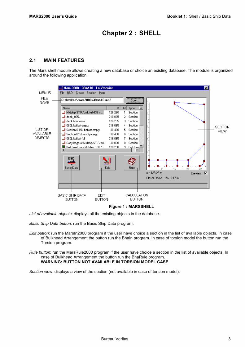
The Mars shell module allows creating a new database or choice an existing database. The module is organizedaround the following application:
Figure 1 : MARSSHELLList of available objects: displays all the existing objects in the database.
Basic Ship Data button: run the Basic Ship Data program.
Edit button: run the MarsIn2000 program if the user have choice a section in the list of available objects. In caseof Bulkhead Arrangement the button run the BhaIn program. In case of torsion model the button run theTorsion program.
Rule button: run the MarsRule2000 program if the user have choice a section in the list of available objects. Incase of Bulkhead Arrangement the button run the BhaRule program.WARNING: BUTTON NOT AVAILABLE IN TORSION MODEL CASE
Section view: displays a view of the section (not available in case of torsion model).
MARS2000 User’s Guide Booklet 1: Shell / Basic Ship Data
4 Bureau Veritas
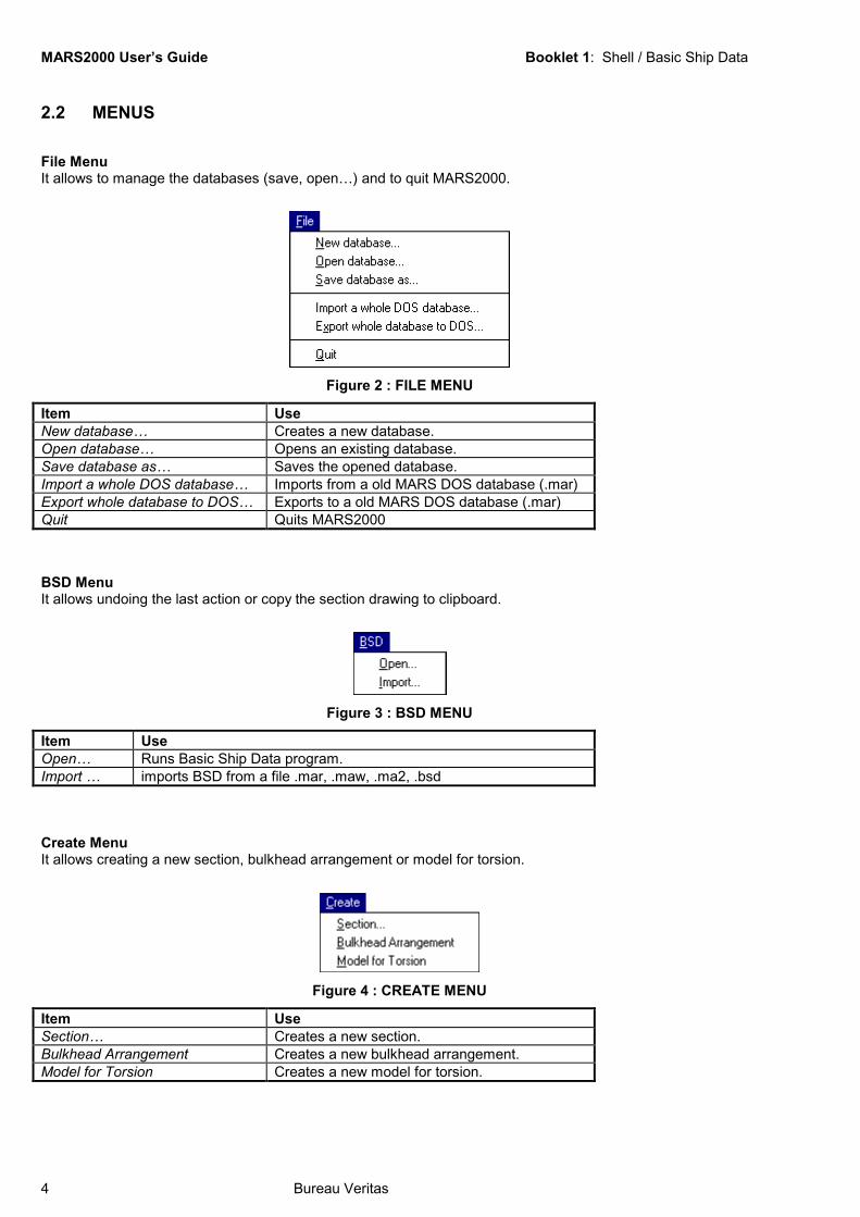
2.2 MENUS
File MenuIt allows to manage the databases (save, open…) and to quit MARS2000.
Figure 2 : FILE MENU
Item UseNew database… Creates a new database.Open database… Opens an existing database.Save database as… Saves the opened database.Import a whole DOS database… Imports from a old MARS DOS database (.mar)Export whole database to DOS… Exports to a old MARS DOS database (.mar)Quit Quits MARS2000
BSD MenuIt allows undoing the last action or copy the section drawing to clipboard.
Figure 3 : BSD MENU
Item UseOpen… Runs Basic Ship Data program.Import … imports BSD from a file .mar, .maw, .ma2, .bsd
Create MenuIt allows creating a new section, bulkhead arrangement or model for torsion.
Figure 4 : CREATE MENU
Item UseSection… Creates a new section.Bulkhead Arrangement Creates a new bulkhead arrangement.Model for Torsion Creates a new model for torsion.

MARS2000 User’s Guide Booklet 1: Shell / Basic Ship Data
Bureau Veritas 5
Section MenuIt allows managing the objects.
Figure 5 : SECTION MENU
Item UseEdit… Runs input module related to selected object.Rule… Runs check module related to selected object.Copy… Copy the selected object.Delete… Delete the selected object.Import from another DB (DOS or Win)… Imports section from a file .mar, .maw, .ma2Export to Mars Dos… Exports to a old section DOS (.mar)

MARS2000 User’s Guide Booklet 1: Shell / Basic Ship Data
6 Bureau Veritas
Chapter 3 : BASIC SHIP DATA
3.1 GENERAL COMMENTS
3.1.1 MAIN FEATURES
The Basic Ship Data module allows the input of general data common for all the transverse sections, bulkheadarrangements and models of torsion. It also performs calculations that may be done from those data. Themodule is organized around the following application:
Figure 6 : BASIC SHIP DATA
The BSD module is divided into eight main parts:
• General.
• Notations & Main Data.
• Moment & Draught.
• Bow Flare.
• Materials
• Frame Locations.
• Hopper wells (Hopper dredgers & split hopper dredgers only)
• Calculation & Print.
MARS2000 User’s Guide Booklet 1: Shell / Basic Ship Data
Bureau Veritas 7
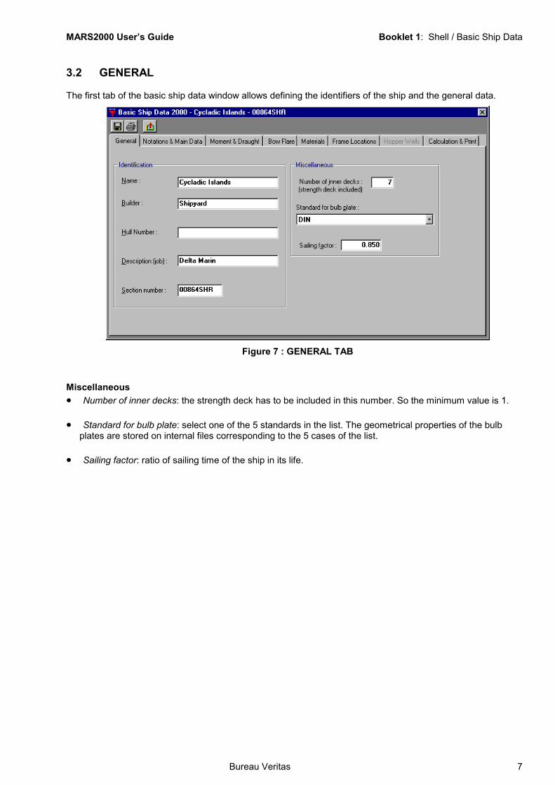
3.2 GENERAL
The first tab of the basic ship data window allows defining the identifiers of the ship and the general data.
Figure 7 : GENERAL TAB
Miscellaneous• Number of inner decks: the strength deck has to be included in this number. So the minimum value is 1.
• Standard for bulb plate: select one of the 5 standards in the list. The geometrical properties of the bulbplates are stored on internal files corresponding to the 5 cases of the list.
• Sailing factor: ratio of sailing time of the ship in its life.
MARS2000 User’s Guide Booklet 1: Shell / Basic Ship Data
8 Bureau Veritas
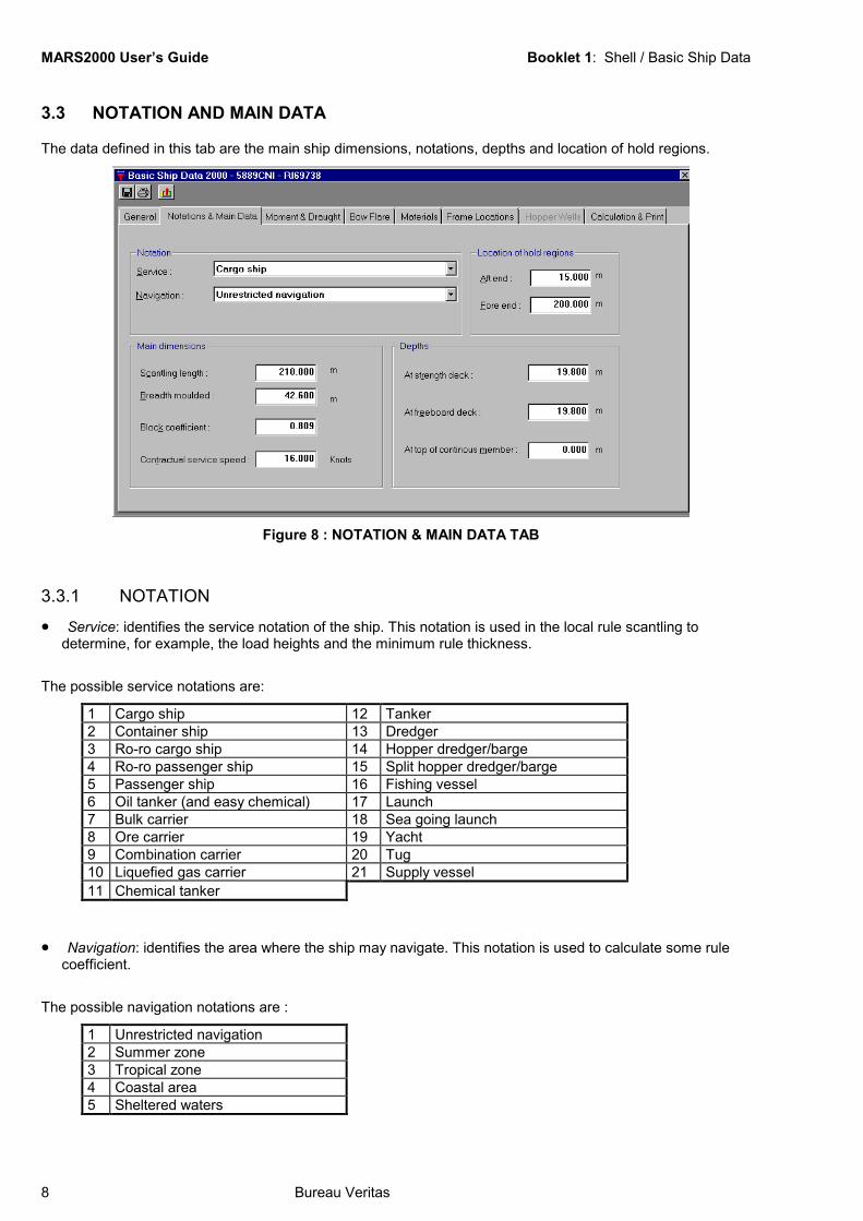
3.3 NOTATION AND MAIN DATA
The data defined in this tab are the main ship dimensions, notations, depths and location of hold regions.
Figure 8 : NOTATION & MAIN DATA TAB
3.3.1 NOTATION
• Service: identifies the service notation of the ship. This notation is used in the local rule scantling todetermine, for example, the load heights and the minimum rule thickness.
The possible service notations are:
1 Cargo ship 12 Tanker2 Container ship 13 Dredger3 Ro-ro cargo ship 14 Hopper dredger/barge4 Ro-ro passenger ship 15 Split hopper dredger/barge5 Passenger ship 16 Fishing vessel6 Oil tanker (and easy chemical) 17 Launch7 Bulk carrier 18 Sea going launch8 Ore carrier 19 Yacht9 Combination carrier 20 Tug10 Liquefied gas carrier 21 Supply vessel11 Chemical tanker
• Navigation: identifies the area where the ship may navigate. This notation is used to calculate some rulecoefficient.
The possible navigation notations are :
1 Unrestricted navigation2 Summer zone3 Tropical zone4 Coastal area5 Sheltered waters
MARS2000 User’s Guide Booklet 1: Shell / Basic Ship Data
Bureau Veritas 9
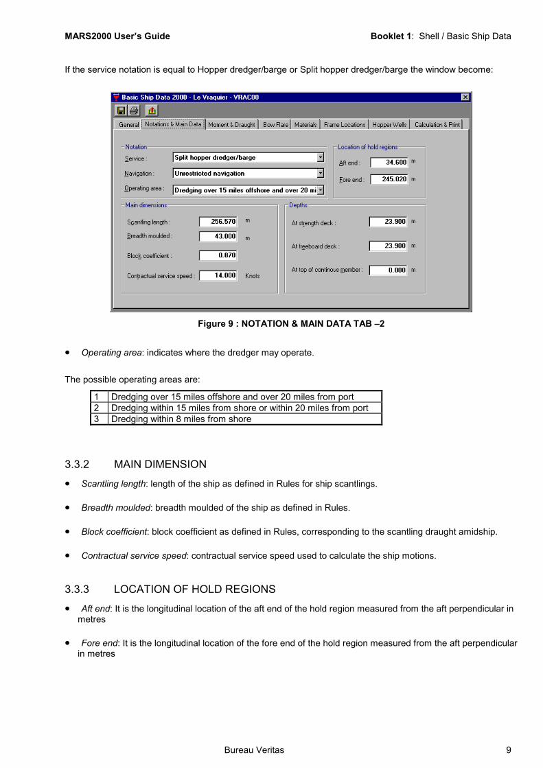
If the service notation is equal to Hopper dredger/barge or Split hopper dredger/barge the window become:
Figure 9 : NOTATION & MAIN DATA TAB –2
• Operating area: indicates where the dredger may operate.
The possible operating areas are:
1 Dredging over 15 miles offshore and over 20 miles from port2 Dredging within 15 miles from shore or within 20 miles from port3 Dredging within 8 miles from shore
3.3.2 MAIN DIMENSION
• Scantling length: length of the ship as defined in Rules for ship scantlings.
• Breadth moulded: breadth moulded of the ship as defined in Rules.
• Block coefficient: block coefficient as defined in Rules, corresponding to the scantling draught amidship.
• Contractual service speed: contractual service speed used to calculate the ship motions.
3.3.3 LOCATION OF HOLD REGIONS
• Aft end: It is the longitudinal location of the aft end of the hold region measured from the aft perpendicular inmetres
• Fore end: It is the longitudinal location of the fore end of the hold region measured from the aft perpendicularin metres

MARS2000 User’s Guide Booklet 1: Shell / Basic Ship Data
10 Bureau Veritas
3.3.4 DEPTHS
• At strength deck: depth moulded at strength deck in metres. The strength deck is defined in Rules.
• At freeboard deck: depth moulded at freeboard deck. When this value is not defined the strength deck issupposed to be freeboard deck also.
• At top of continuous member: this depth has to be defined when there are continuous member above thestrength deck taking part into the longitudinal strength. This value is useful to determine the scale of plotting.But even when it is no completed the program searches for continuous member above the strength deck tocalculate a modulus at top if necessary.
3.4 MOMENT AND DRAUGHT
The third tab of the basic ship data window allows defining moments and draughts for scantling or ballast.
3.4.1 SCANTLING CASE
Figure 10 : MOMENT & DRAUGHT TAB – SCANTLING CASE
Still water bending momentsThis item allows defining the still water bending moment in midship region, in hogging and sagging conditions,for which the ship will be calculated. If these value are yet unknown, the scantling will be done using permissiblerule value.• Hogging condition: still water bending moment in hogging condition and calculated in midship region.
• Sagging condition: still water bending moment in sagging condition and calculated in midship region.
MARS2000 User’s Guide Booklet 1: Shell / Basic Ship Data
Bureau Veritas 11
Ship• Ship behavior: this data is used in buckling calculation.
The possible ship behaviors are:
1 Both Hogging / Sagging The different loadings of the ship cause both hogging andsagging condition
2 Always in sagging The ship is always in sagging condition whatever the loadings3 Always in hogging The ship is always in hogging condition whatever the loadings
Vertical wave bending momentsThe vertical wave bending moments are rule values that are determined automatically by the program. Howeverthe user can define other bending moments clicking on Rule vertical wave bending moments but it is importantto know that WAVE BENDING MOMENTS DEFINED BY THE USER LEAD TO NON RULE SCANTLINGSCALCULATIONThis option may be used in a vue of experimental calculation.
DraughtsThis item is used to define the scantling draught.• Scantling draught: at midship perpendicular used for scantlings. This data is compulsory.
• GM transverse metacentre: GM corresponding to scantling draught or minimum ballast draught definedhereabove.
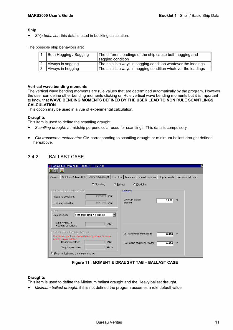
3.4.2 BALLAST CASE
Figure 11 : MOMENT & DRAUGHT TAB – BALLAST CASE
DraughtsThis item is used to define the Minimum ballast draught and the Heavy ballast draught.• Minimum ballast draught: if it is not defined the program assumes a rule default value.
MARS2000 User’s Guide Booklet 1: Shell / Basic Ship Data
12 Bureau Veritas
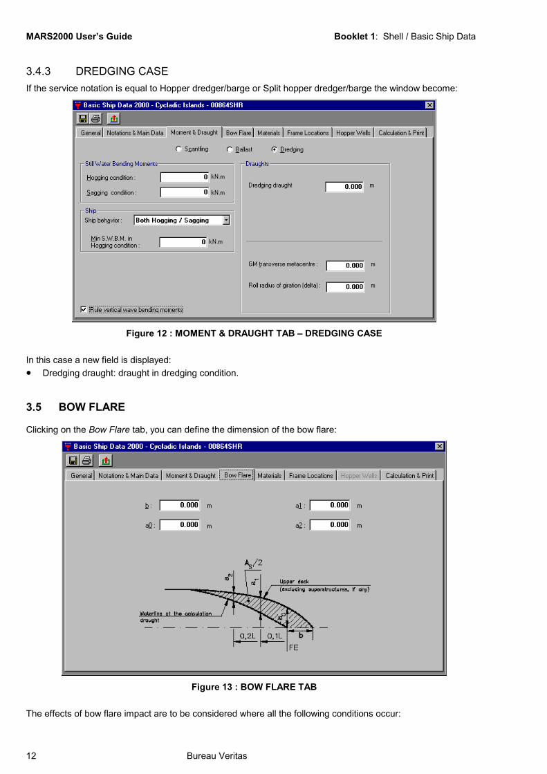
3.4.3 DREDGING CASEIf the service notation is equal to Hopper dredger/barge or Split hopper dredger/barge the window become:
Figure 12 : MOMENT & DRAUGHT TAB – DREDGING CASE
In this case a new field is displayed:• Dredging draught: draught in dredging condition.
3.5 BOW FLARE
Clicking on the Bow Flare tab, you can define the dimension of the bow flare:
Figure 13 : BOW FLARE TAB
The effects of bow flare impact are to be considered where all the following conditions occur:
MARS2000 User’s Guide Booklet 1: Shell / Basic Ship Data
Bureau Veritas 13
• Ship length between 120 m and 180 m.
• Maximum ahead service speed greater than 17.5 knots.
• LBFAs100
> 1
,where As is twice the shaded area shown inFigure 13.
MARS2000 User’s Guide Booklet 1: Shell / Basic Ship Data
14 Bureau Veritas
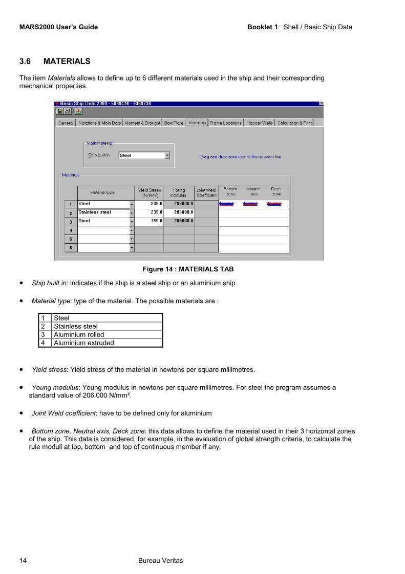
3.6 MATERIALS
The item Materials allows to define up to 6 different materials used in the ship and their correspondingmechanical properties.
Figure 14 : MATERIALS TAB
• Ship built in: indicates if the ship is a steel ship or an aluminium ship.
• Material type: type of the material. The possible materials are :
1 Steel2 Stainless steel3 Aluminium rolled4 Aluminium extruded
• Yield stress: Yield stress of the material in newtons per square millimetres.
• Young modulus: Young modulus in newtons per square millimetres. For steel the program assumes astandard value of 206.000 N/mm².
• Joint Weld coefficient: have to be defined only for aluminium
• Bottom zone, Neutral axis, Deck zone: this data allows to define the material used in their 3 horizontal zonesof the ship. This data is considered, for example, in the evaluation of global strength criteria, to calculate therule moduli at top, bottom and top of continuous member if any.
MARS2000 User’s Guide Booklet 1: Shell / Basic Ship Data
Bureau Veritas 15
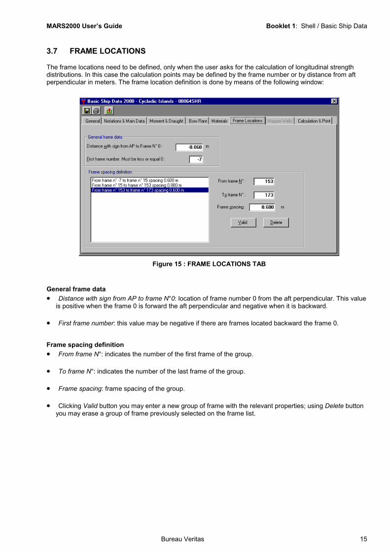
3.7 FRAME LOCATIONS
The frame locations need to be defined, only when the user asks for the calculation of longitudinal strengthdistributions. In this case the calculation points may be defined by the frame number or by distance from aftperpendicular in meters. The frame location definition is done by means of the following window:
Figure 15 : FRAME LOCATIONS TAB
General frame data• Distance with sign from AP to frame N°0: location of frame number 0 from the aft perpendicular. This value
is positive when the frame 0 is forward the aft perpendicular and negative when it is backward.
• First frame number: this value may be negative if there are frames located backward the frame 0.
Frame spacing definition• From frame N°: indicates the number of the first frame of the group.
• To frame N°: indicates the number of the last frame of the group.
• Frame spacing: frame spacing of the group.
• Clicking Valid button you may enter a new group of frame with the relevant properties; using Delete buttonyou may erase a group of frame previously selected on the frame list.
MARS2000 User’s Guide Booklet 1: Shell / Basic Ship Data
16 Bureau Veritas
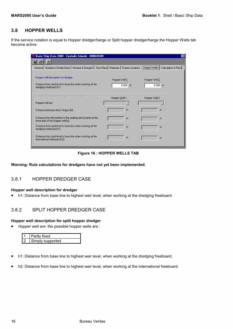
3.8 HOPPER WELLS
If the service notation is equal to Hopper dredger/barge or Split hopper dredger/barge the Hopper Wells tabbecome active:
Figure 16 : HOPPER WELLS TAB
Warning: Rule calculations for dredgers have not yet been implemented.
3.8.1 HOPPER DREDGER CASE
Hopper well description for dredger• h1: Distance from base line to highest weir level, when working at the dredging freeboard.
3.8.2 SPLIT HOPPER DREDGER CASE
Hopper well description for split hopper dredger• Hopper well are: the possible hopper wells are :
1 Partly fixed2 Simply supported
• h1: Distance from base line to highest weir level, when working at the dredging freeboard.
• h2: Distance from base line to highest weir level, when working at the international freeboard.
MARS2000 User’s Guide Booklet 1: Shell / Basic Ship Data
Bureau Veritas 17
3.9 CALCULATION AND PRINT
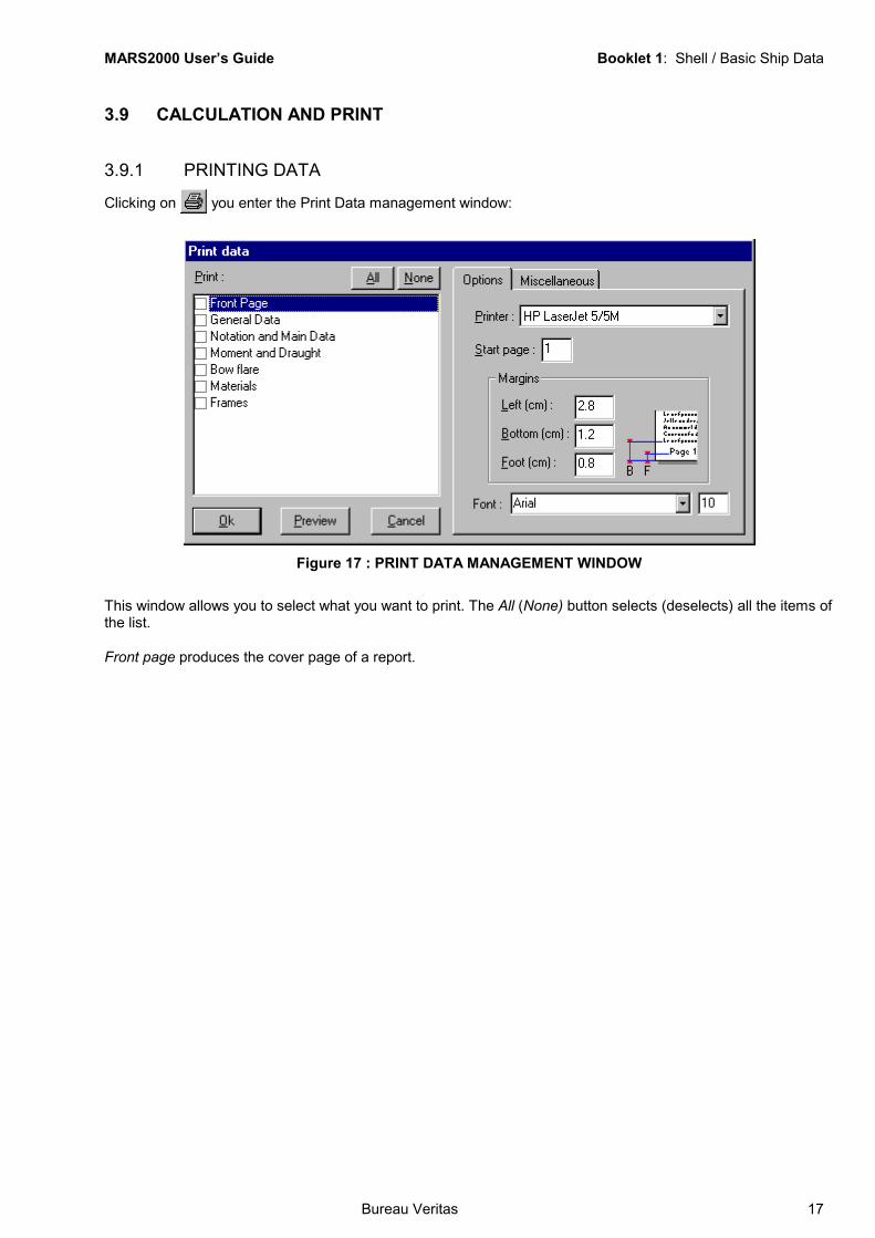
3.9.1 PRINTING DATA
Clicking on you enter the Print Data management window:
Figure 17 : PRINT DATA MANAGEMENT WINDOW
This window allows you to select what you want to print. The All (None) button selects (deselects) all the items ofthe list.
Front page produces the cover page of a report.

MARS2000 User’s Guide Booklet 1: Shell / Basic Ship Data
18 Bureau Veritas
3.9.2 CALCULATIONThe program is able to perform basic calculations from the basic ship data only. The window with the availablepossibilities is the following:
Figure 18 : CALCULATION & PRINT TAB
3.9.2.1 STILL WATER, WAVE MOMENTS, SHEAR FORCEThe longitudinal strength distributions which can be obtained clicking on Rule strength distributions are :• Vertical still water bending moments, in hogging and sagging conditions.
• Vertical wave bending moments, in hogging and sagging conditions.
• The resultant moments, in hogging and sagging conditions corresponding to the combined effect of the stillwater bending moments and wave bending moments, as defined in Rules.
• The horizontal wave bending moment.
• The horizontal wave shear force.
The distribution of still water bending moments is based on values in hogging and sagging conditions in midshipregion with the rule longitudinal distribution applied. Those values may have different origine selected from thewindow:• User’s proposal value of S.W.B.M.: distribution based on user’s proposal values in midship region in hogging
and sagging conditions.
• Rule standard value: distribution based on the rule permissible still water bending moments.
• Standard value based on user’s proposal modulus: the section modulus amidships is a user’s proposalvalue. The still water bending moment amidships are calculated from this user’s proposal modulus amidshipsand from the rule horizontal wave bending moment amidships.

MARS2000 User’s Guide Booklet 1: Shell / Basic Ship Data
Bureau Veritas 19
The longitudinal strength distributions are displayed for calculation points selected by the user. There are 3 waysto define those points:
• Direct input of their X coordinates.
• Selection of a list of frame numbers.
• Both, X coordinates and list of frames.
• Clicking on Calculation points button you enter the following window which allows the definition of thelongitudinal calculation points:
Figure 19 : CALCULATION POINTS WINDOW
3.9.2.2 BASIC CALCULATIONS• Rule coefficients: provides the rule coefficients, parameters and material factors.
• Ship motions: provides the ship acceleration and amplitude of motions.
• Rule moduli: provides the rule section moduli at midship perpendicular.
• Resultant acceleration: this item allows to calculate the components of the resultant acceleration in uprightship condition and inclined ship condition at scantling and minimum ballast draughts for a list of points thecoordinate of which are defined with the following window:
MARS2000 User’s Guide Booklet 1: Shell / Basic Ship Data
20 Bureau Veritas
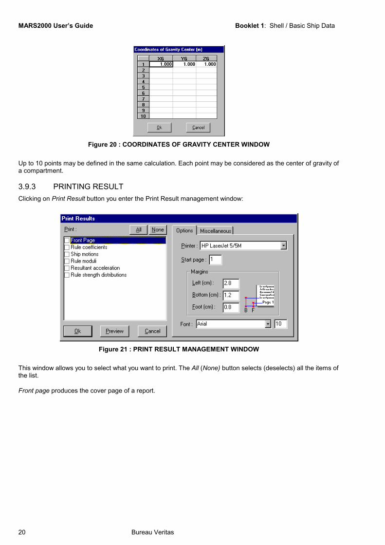
Figure 20 : COORDINATES OF GRAVITY CENTER WINDOW
Up to 10 points may be defined in the same calculation. Each point may be considered as the center of gravity ofa compartment.
3.9.3 PRINTING RESULTClicking on Print Result button you enter the Print Result management window:
Figure 21 : PRINT RESULT MANAGEMENT WINDOW
This window allows you to select what you want to print. The All (None) button selects (deselects) all the items ofthe list.
Front page produces the cover page of a report.
MARS2000 User’s Guide Booklet 1: Shell / Basic Ship Data
Bureau Veritas 21
Table of FigureFigure 1 : MARSSHELL ................................................................................................................... 3Figure 2 : FILE MENU...................................................................................................................... 4Figure 3 : BSD MENU...................................................................................................................... 4Figure 4 : CREATE MENU............................................................................................................... 4Figure 5 : SECTION MENU ............................................................................................................. 5Figure 6 : BASIC SHIP DATA .......................................................................................................... 6Figure 7 : GENERAL TAB................................................................................................................ 7Figure 8 : NOTATION & MAIN DATA TAB ...................................................................................... 8Figure 9 : NOTATION & MAIN DATA TAB –2 ................................................................................. 9Figure 10 : MOMENT & DRAUGHT TAB – SCANTLING CASE ................................................... 10Figure 11 : MOMENT & DRAUGHT TAB – BALLAST CASE........................................................ 11Figure 12 : MOMENT & DRAUGHT TAB – DREDGING CASE .................................................... 12Figure 13 : BOW FLARE TAB ....................................................................................................... 12Figure 14 : MATERIALS TAB ........................................................................................................ 14Figure 15 : FRAME LOCATIONS TAB .......................................................................................... 15Figure 16 : HOPPER WELLS TAB ................................................................................................ 16Figure 17 : PRINT DATA MANAGEMENT WINDOW ................................................................... 17Figure 18 : CALCULATION & PRINT TAB .................................................................................... 18Figure 19 : CALCULATION POINTS WINDOW ............................................................................ 19Figure 20 : COORDINATES OF GRAVITY CENTER WINDOW .................................................. 20Figure 21 : PRINT RESULT MANAGEMENT WINDOW............................................................... 20
Related Documents