Brussels, 18-20 February 2008 – Dissemination of information workshop 1 EUROCODES Background and Applications EN1997-1: Anchorages and Retaining structures EN 1997-1 Eurocode 7 Section 8 – Anchorages Section 9 – Retaining structures Brian Simpson Arup Geotechnics

Welcome message from author
This document is posted to help you gain knowledge. Please leave a comment to let me know what you think about it! Share it to your friends and learn new things together.
Transcript

Brussels, 18-20 February 2008 – Dissemination of information workshop 1
EUROCODESBackground and Applications EN1997-1: Anchorages and Retaining structures
EN 1997-1 Eurocode 7Section 8 – AnchoragesSection 9 – Retaining structures
Brian SimpsonArup Geotechnics
2 ©
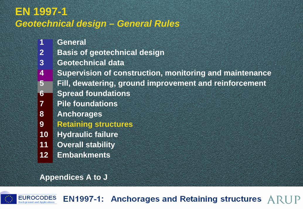
EN 1997-1 Geotechnical design – General Rules BP106.9
BP111.5 BP112.6 BP124-T1.311 General2 Basis of geotechnical design3 Geotechnical data4 Supervision of construction, monitoring and maintenance5 Fill, dewatering, ground improvement and reinforcement6 Spread foundations7 Pile foundations8 Anchorages9 Retaining structures10 Hydraulic failure11 Overall stability12 Embankments
Appendices A to J
3 ©
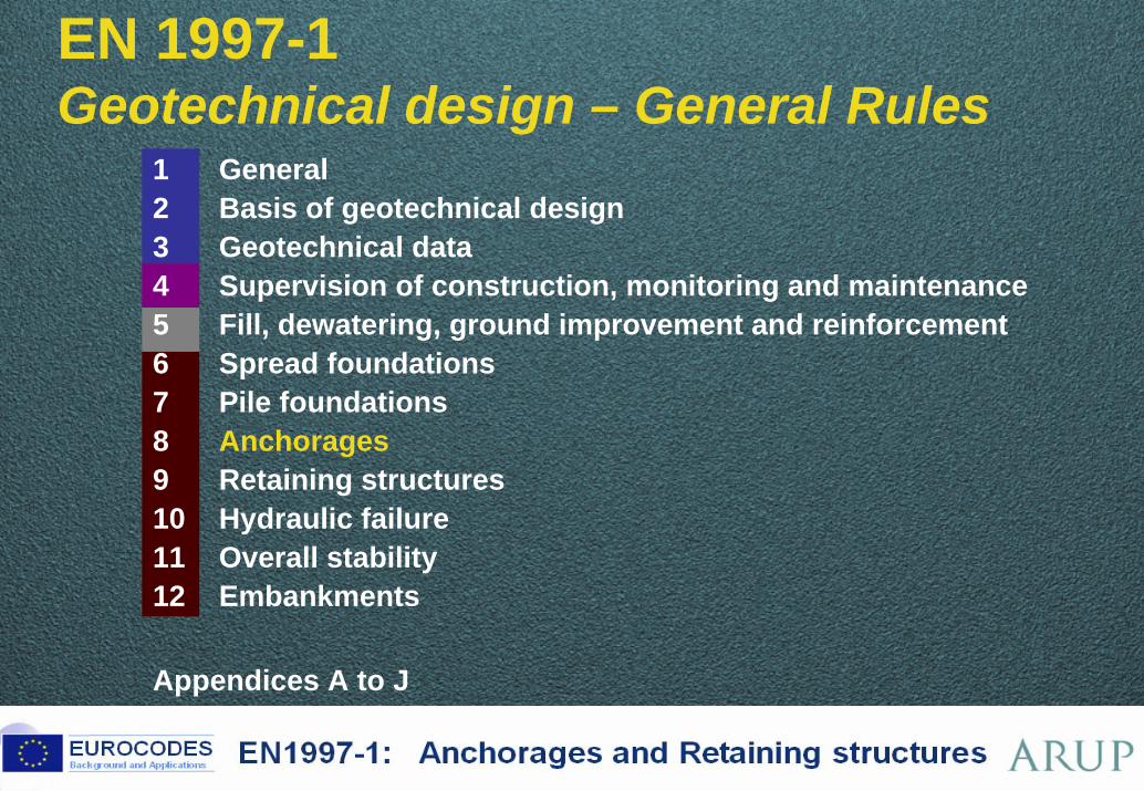
8 AnchoragesBP124-F3.6
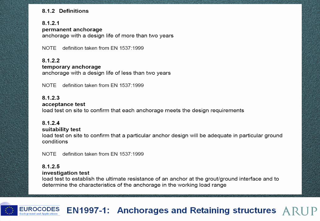
8.1 General
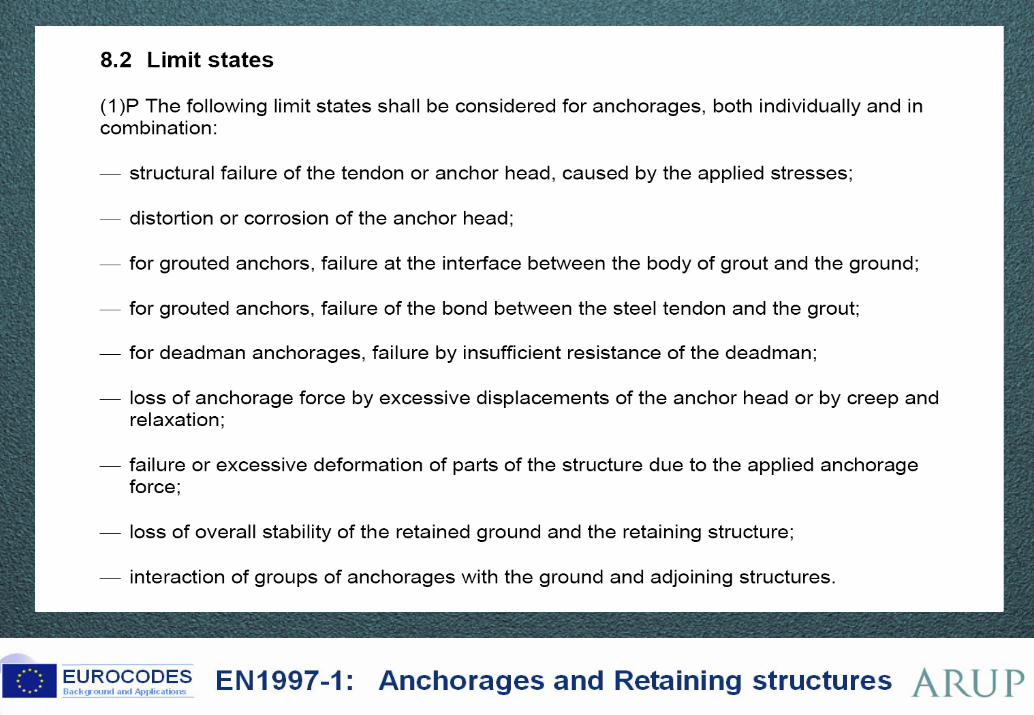
8.2 Limit states
8.3 Design situations and actions
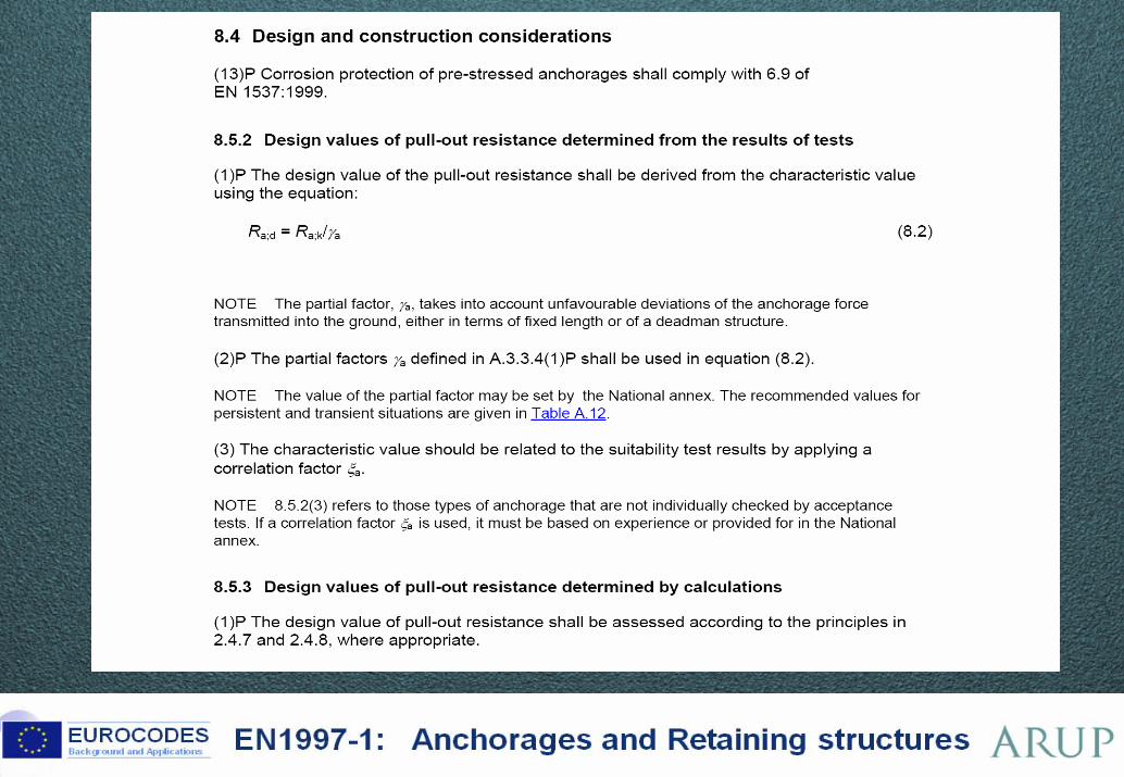
8.4 Design and construction considerations
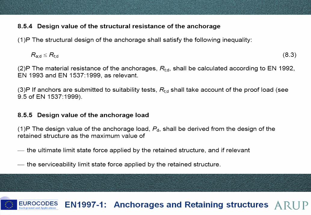
8.5 Ultimate limit state design
8.6 Serviceability limit state design
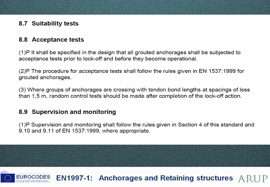
8.7 Suitability tests
8.8 Acceptance tests
8.9 Supervision and monitoring
4 ©
5 ©
6 ©
7 ©
8 ©
9 ©
10 ©
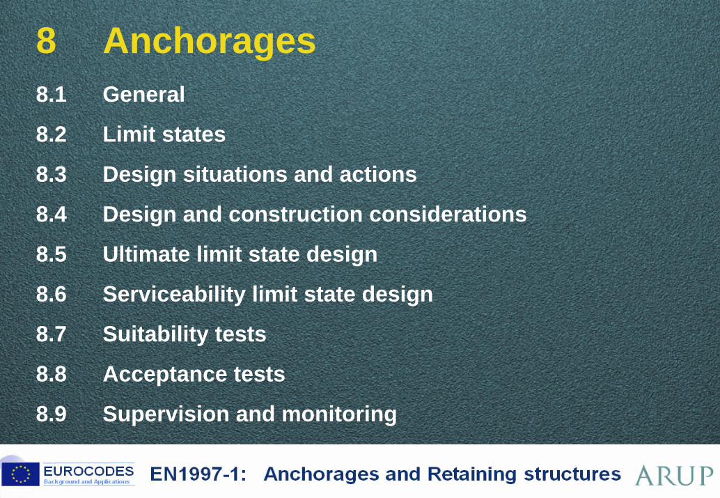
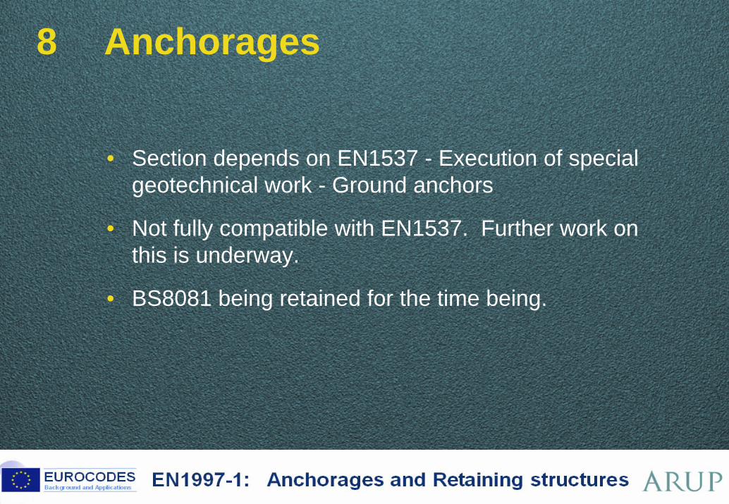
8 Anchorages
• Section depends on EN1537 - Execution of special geotechnical work - Ground anchors
• Not fully compatible with EN1537. Further work on this is underway.
• BS8081 being retained for the time being.
11 ©
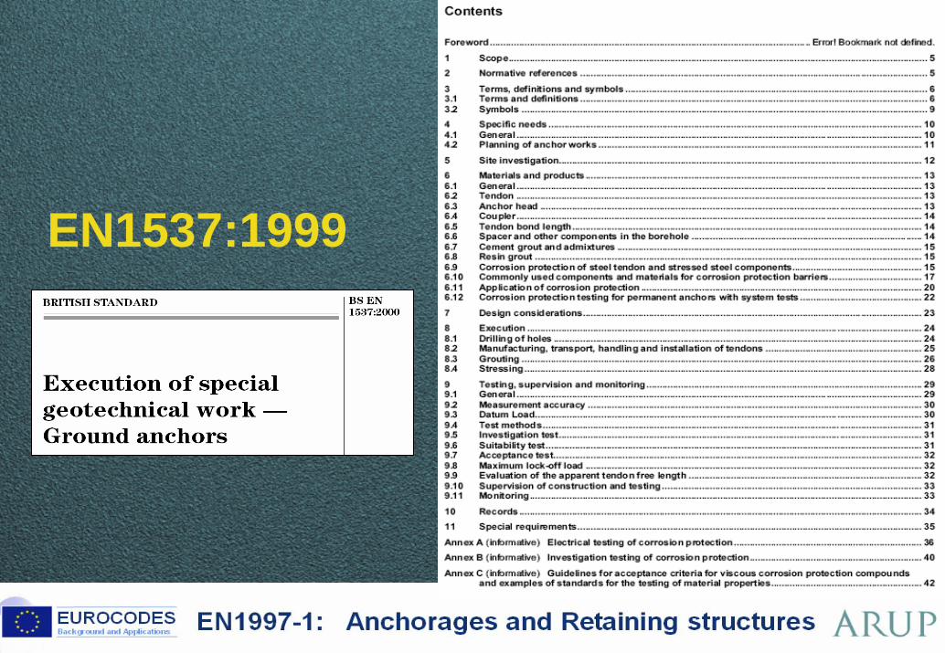
EN1537:1999
12 ©
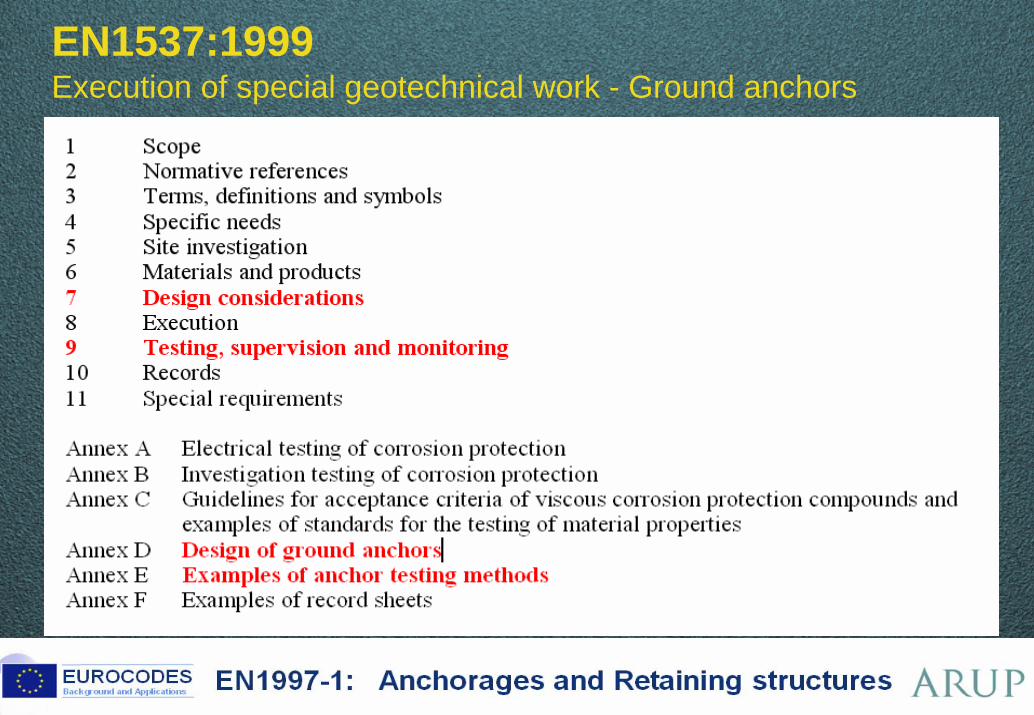
EN1537:1999Execution of special geotechnical work - Ground anchors

13 ©
EN1537:1999 Execution of special geotechnical work - Ground anchors
- provides details of test procedures (creep load etc)
14 ©
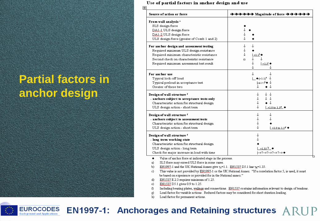
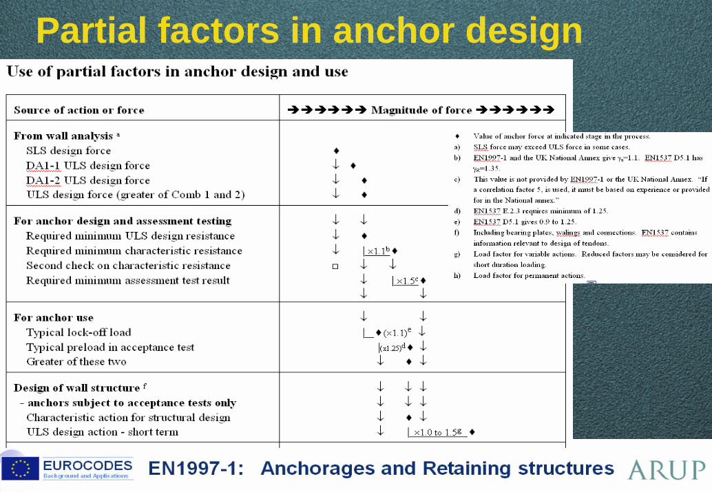
Partial factors in anchor design
15 ©
Partial factors in anchor design

Brussels, 18-20 February 2008 – Dissemination of information workshop 16
EUROCODESBackground and Applications EN1997-1: Anchorages and Retaining structures
EN 1997-1 Eurocode 7Section 8 – AnchoragesSection 9 – Retaining structures
Brian SimpsonArup Geotechnics
Brussels, 18-20 February 2008 – Dissemination of information workshop 17
EUROCODESBackground and Applications EN1997-1: Anchorages and Retaining structures
EN 1997-1 Eurocode 7
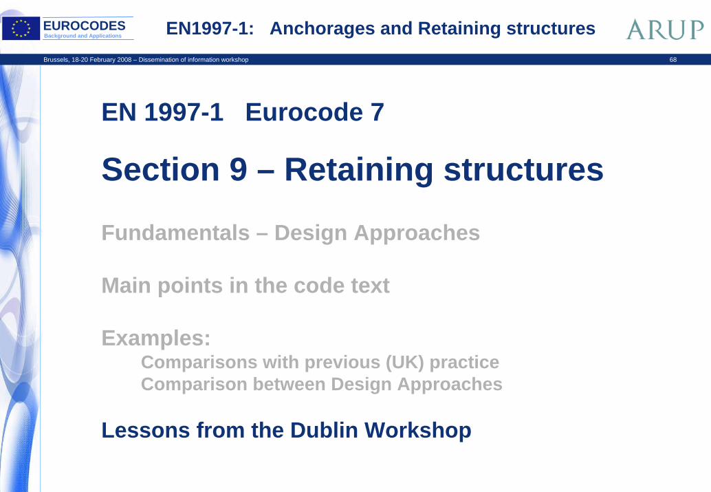
Section 9 – Retaining structures
Fundamentals – Design Approaches
Main points in the code text
Examples:Comparisons with previous (UK) practiceComparison between Design Approaches
Lessons from the Dublin Workshop
Brussels, 18-20 February 2008 – Dissemination of information workshop 18
EUROCODESBackground and Applications EN1997-1: Anchorages and Retaining structures
EN 1997-1 Eurocode 7
Section 9 – Retaining structures
Fundamentals – Design Approaches
Main points in the code text
Examples:Comparisons with previous (UK) practiceComparison between Design Approaches
Lessons from the Dublin Workshop
19 ©
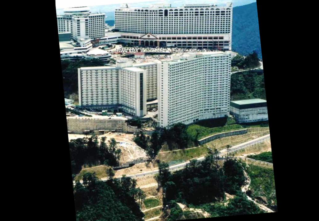
Genting Highlands BP87.59 BP106.30 BP111.22 BP112.43 BP119.43 BP124-F3.9 BP130.33 BP145a.8
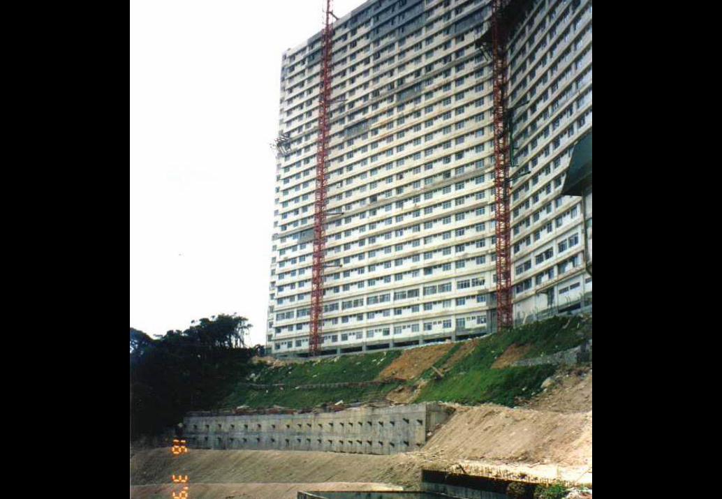
Genting Highlands BP87.60 BP106.31 BP111.23 BP112.44 BP119.44 BP124-F3.10 BP130.34 BP145a.9
21 ©
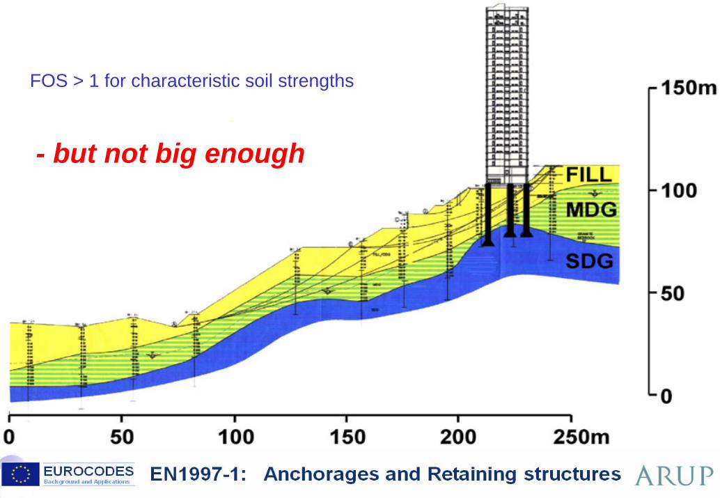
FOS > 1 for characteristic soil strengthsBP87.61 BP106.32 BP111.24 BP112.45
BP119.45 BP124-F3.11 BP130.35 BP145a.10
- but not big enough
22 ©
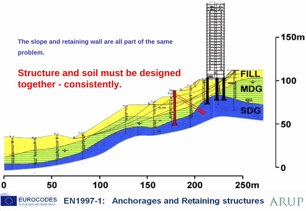
The slope and retaining wall are all part of the same problem. BP87.62 BP106.33 BP111.25 BP112.46
BP119.46 BP124-F3.12 BP130.36 BP145a.11
Structure and soil must be designed together - consistently.
23 ©
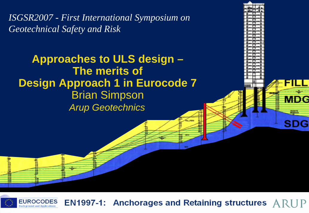
Approaches to ULS design –The merits of
Design Approach 1 in Eurocode 7Brian SimpsonArup Geotechnics BP145a.1
ISGSR2007 - First International Symposium on Geotechnical Safety and Risk
Brussels, 18-20 February 2008 – Dissemination of information workshop 24
EUROCODESBackground and Applications EN1997-1: Anchorages and Retaining structures
EN 1997-1 Eurocode 7
Section 9 – Retaining structures
Fundamentals – Design Approaches
Main points in the code text
Examples:Comparisons with previous (UK) practiceComparison between Design Approaches
Lessons from the Dublin Workshop
25 ©
EN 1997-1 Geotechnical design – General Rules BP106.9 BP111.5 BP112.6 BP124-T1.31
1 General2 Basis of geotechnical design3 Geotechnical data4 Supervision of construction, monitoring and maintenance5 Fill, dewatering, ground improvement and reinforcement6 Spread foundations7 Pile foundations8 Anchorages9 Retaining structures10 Hydraulic failure11 Overall stability12 Embankments
Appendices A to J
26 ©
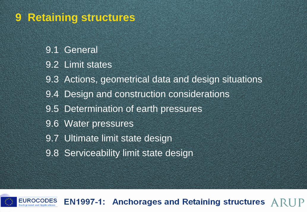
9 Retaining structures
9.1 General9.2 Limit states9.3 Actions, geometrical data and design situations 9.4 Design and construction considerations 9.5 Determination of earth pressures 9.6 Water pressures 9.7 Ultimate limit state design 9.8 Serviceability limit state design
27 ©
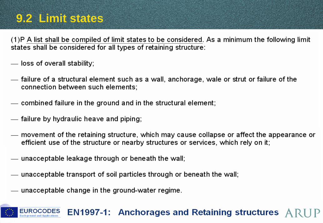
9.2 Limit states
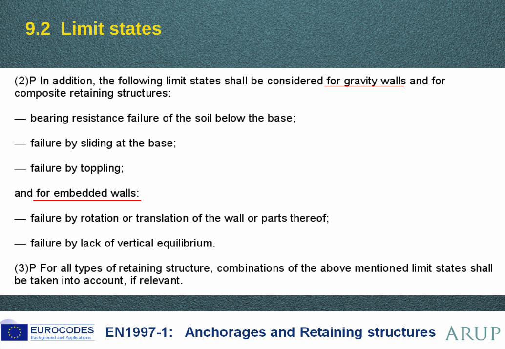
28 ©
9.2 Limit states
29 ©
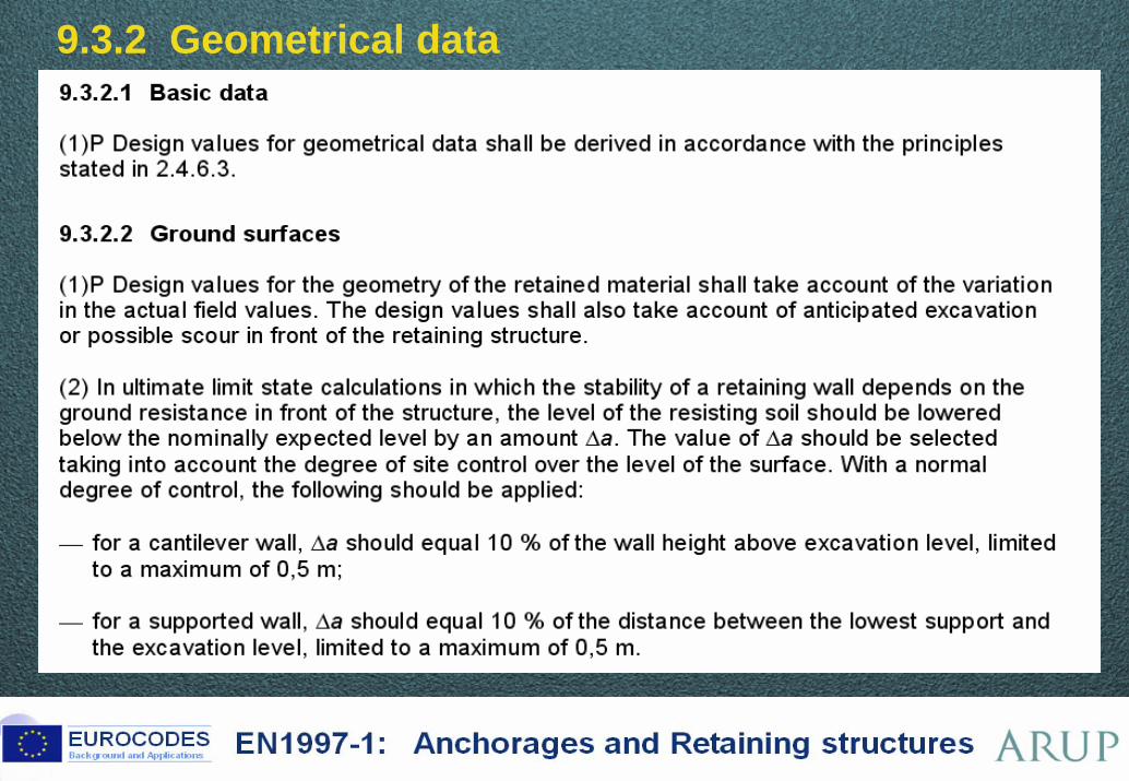
9.3.2 Geometrical data
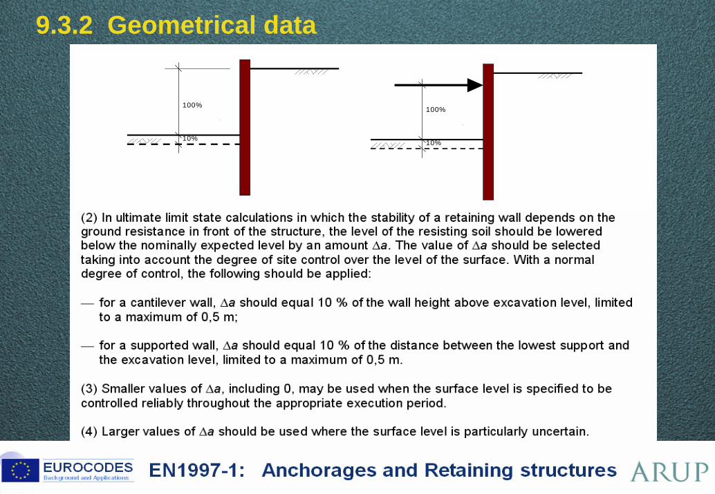
30 ©
9.3.2 Geometrical data
100%
10%
100%
10%
31 ©
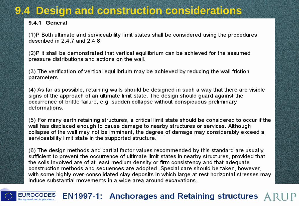
9.4 Design and construction considerations
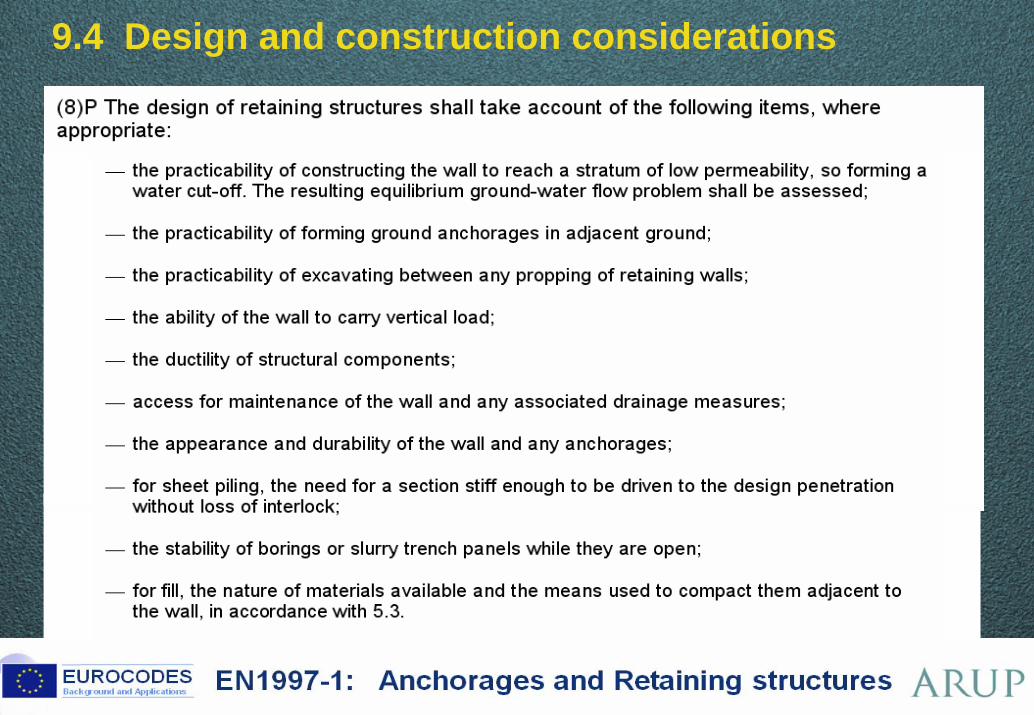
32 ©
9.4 Design and construction considerations
33 ©
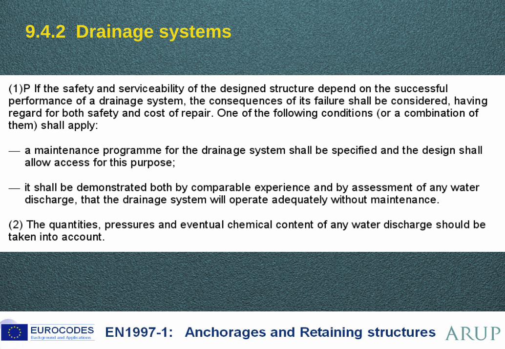
9.4.2 Drainage systems
34 ©
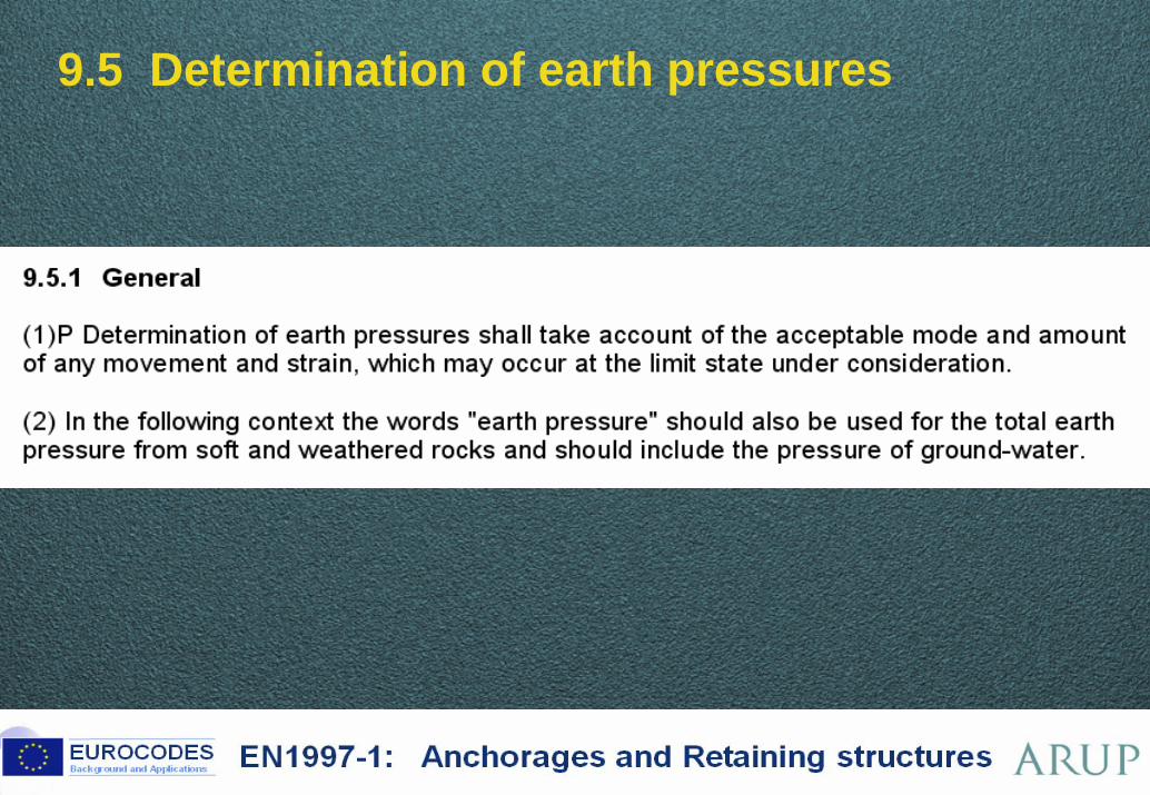
9.5 Determination of earth pressures
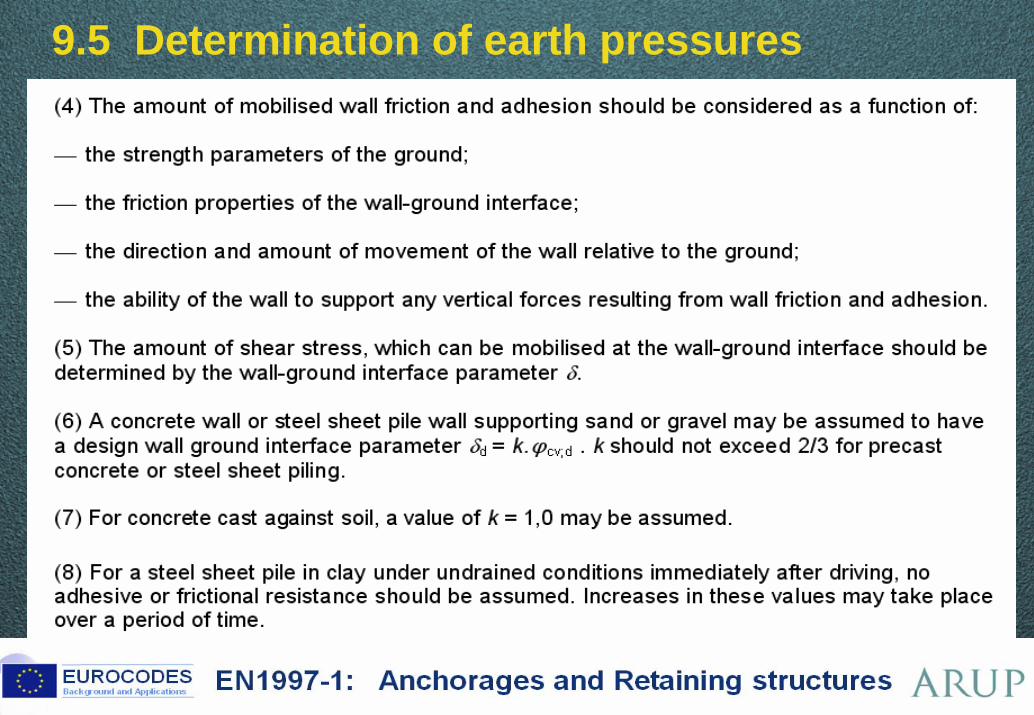
35 ©
9.5 Determination of earth pressures
36 ©
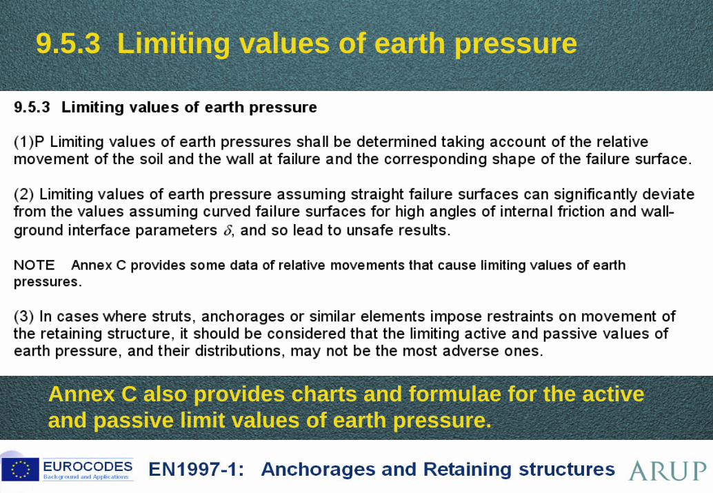
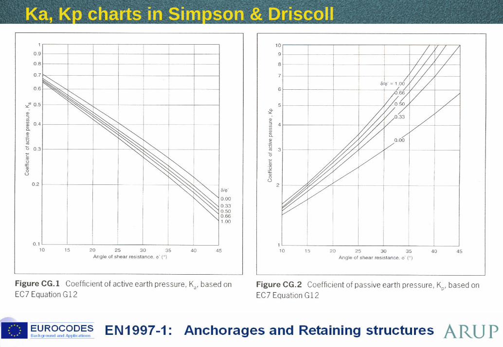
9.5.3 Limiting values of earth pressure
Annex C also provides charts and formulae for the active and passive limit values of earth pressure.
37 ©
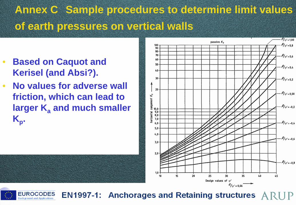
Annex C Sample procedures to determine limit values of earth pressures on vertical walls
• Based on Caquot and Kerisel (and Absi?).
• No values for adverse wall friction, which can lead to larger Ka and much smaller Kp.
38 ©
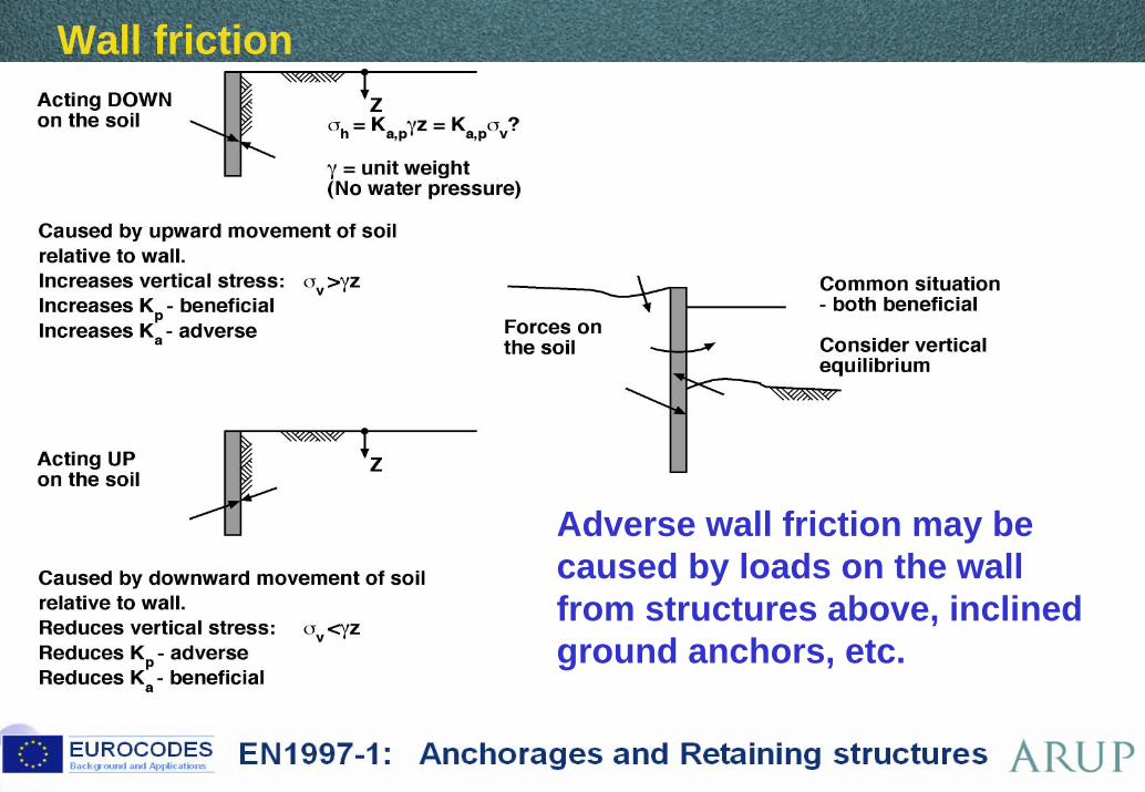
Wall friction
Adverse wall friction may be caused by loads on the wall from structures above, inclined ground anchors, etc.
39 ©
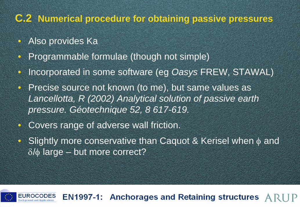
C.2 Numerical procedure for obtaining passive pressures
• Also provides Ka
• Programmable formulae (though not simple)
• Incorporated in some software (eg Oasys FREW, STAWAL)
• Precise source not known (to me), but same values as Lancellotta, R (2002) Analytical solution of passive earth pressure. Géotechnique 52, 8 617-619.
• Covers range of adverse wall friction.
• Slightly more conservative than Caquot & Kerisel when φ and δ/φ large – but more correct?
40 ©
Ka, Kp charts in Simpson & Driscoll
41 ©
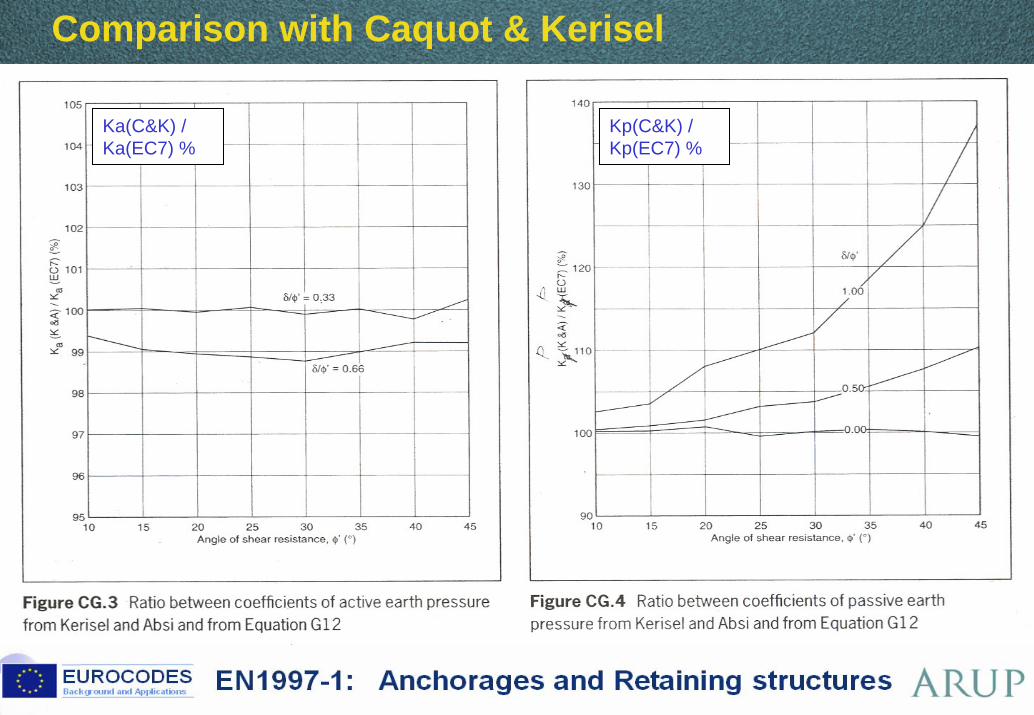
Comparison with Caquot & Kerisel
Kp(C&K) / Kp(EC7) %
Ka(C&K) / Ka(EC7) %
42 ©
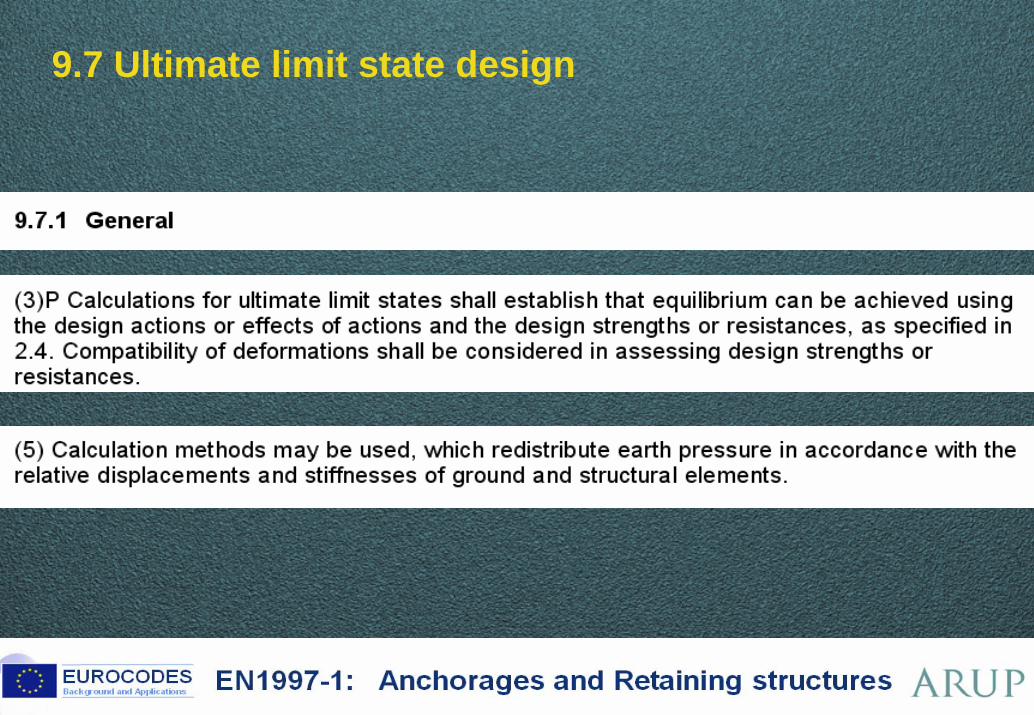
9.7 Ultimate limit state design
43 ©
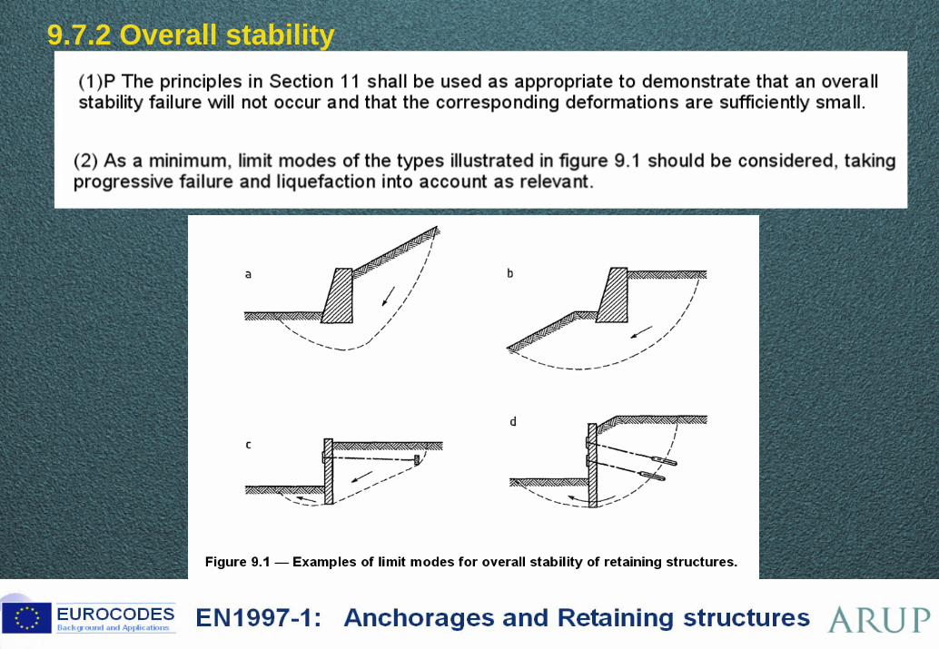
9.7.2 Overall stability
44 ©
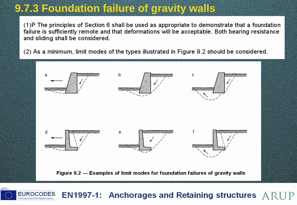
9.7.3 Foundation failure of gravity walls
45 ©
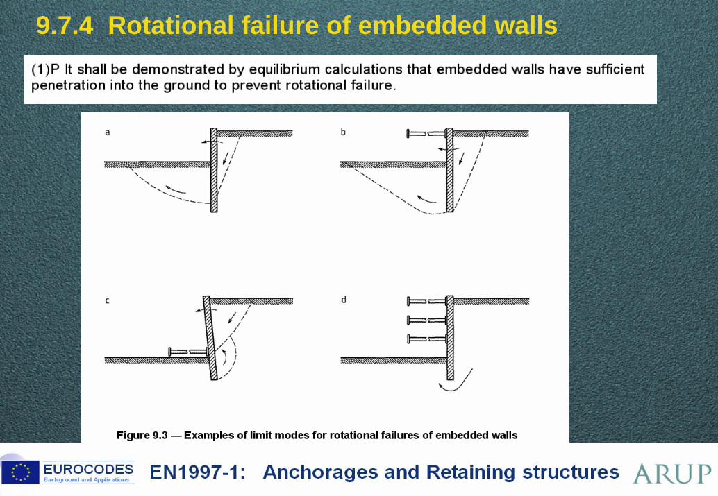
9.7.4 Rotational failure of embedded walls
46 ©
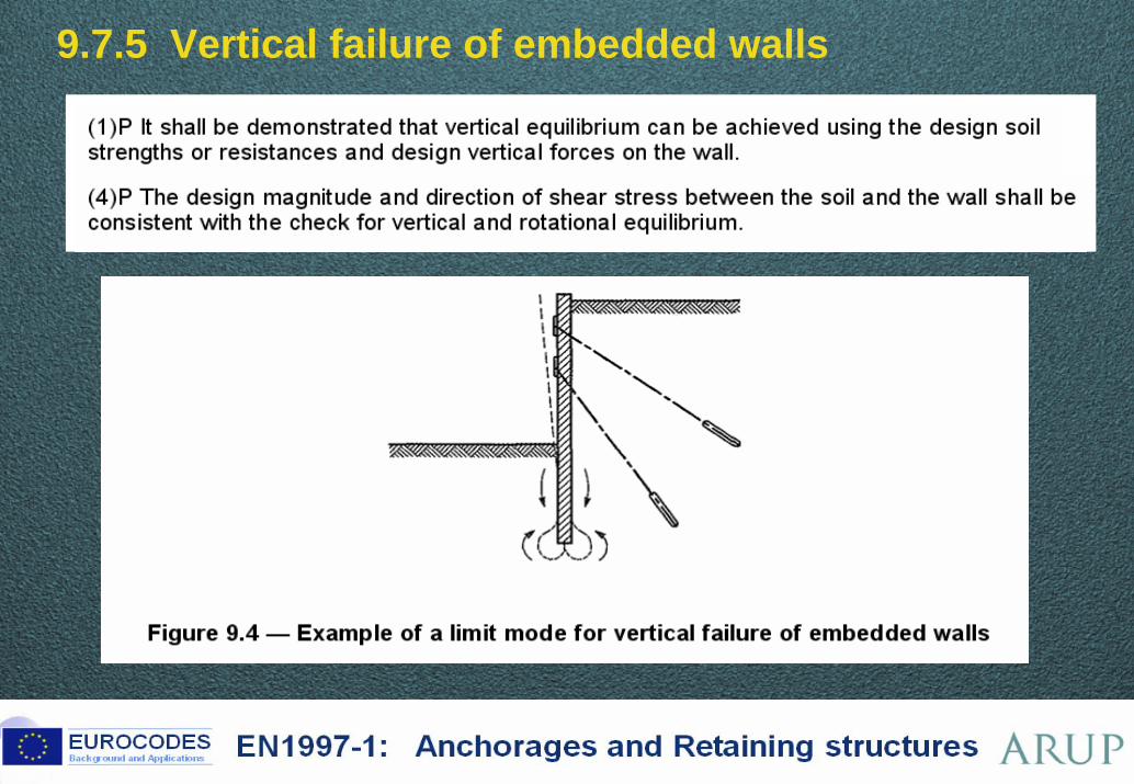
9.7.5 Vertical failure of embedded walls
47 ©
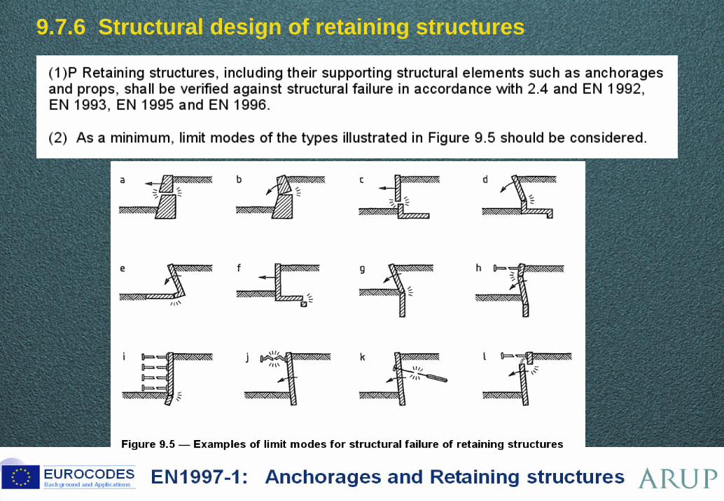
9.7.6 Structural design of retaining structures
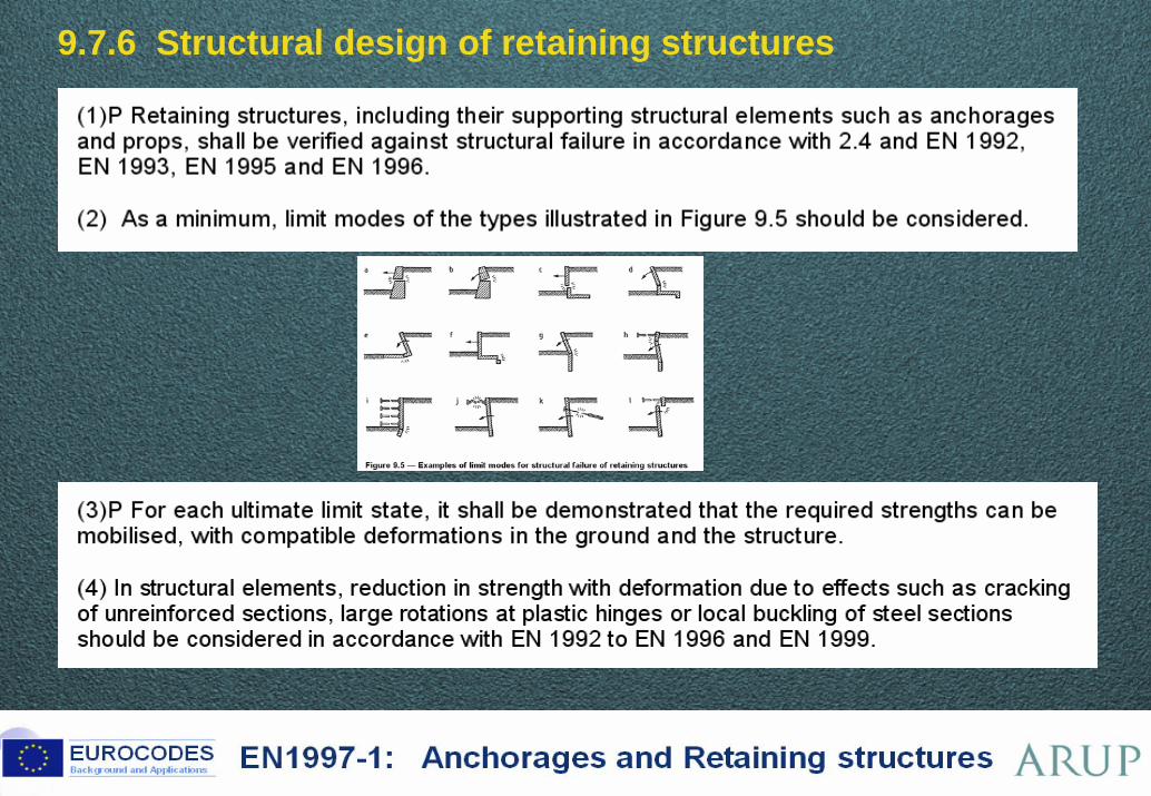
48 ©
9.7.6 Structural design of retaining structures
49 ©
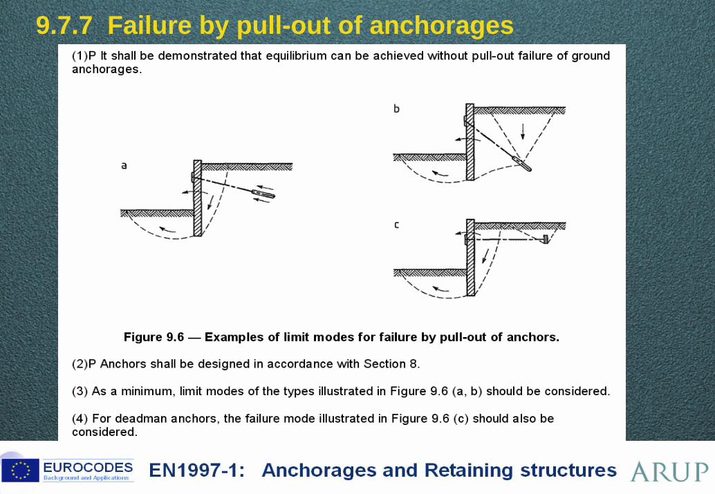
9.7.7 Failure by pull-out of anchorages
50 ©
9.8 Serviceability limit state design
51 ©
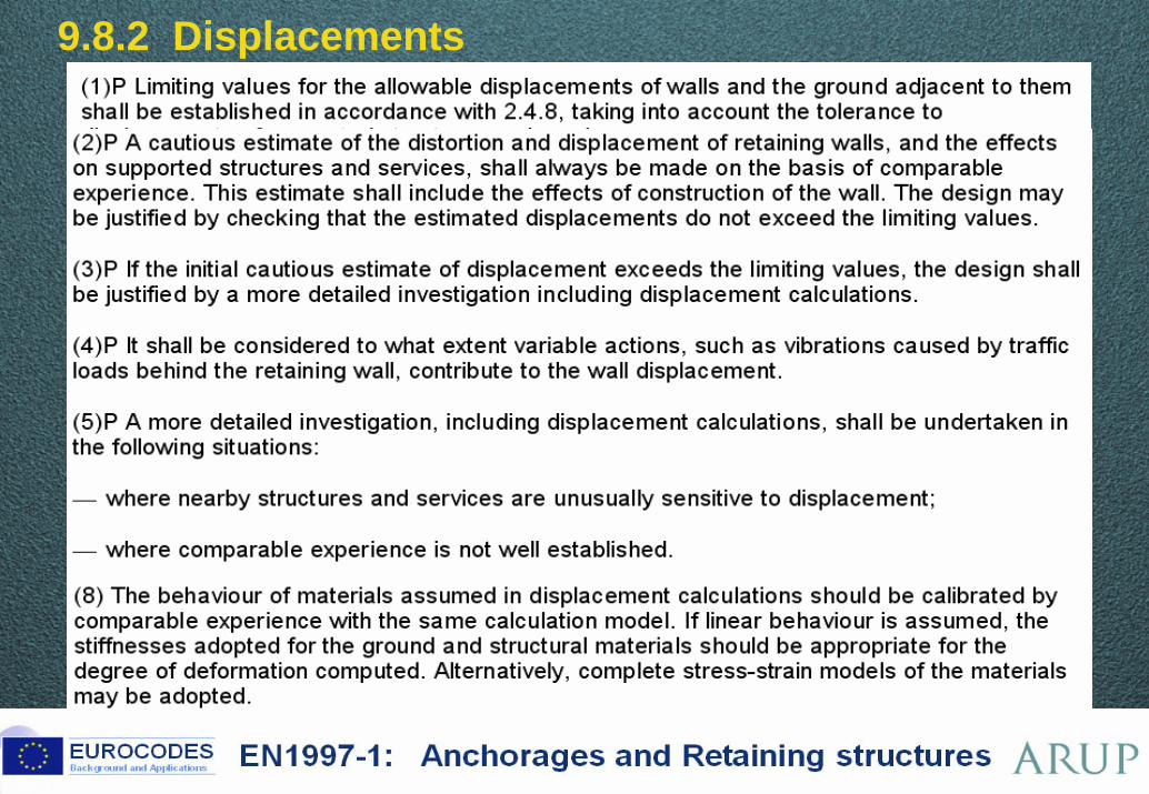
9.8.2 Displacements
Brussels, 18-20 February 2008 – Dissemination of information workshop 52
EUROCODESBackground and Applications EN1997-1: Anchorages and Retaining structures
EN 1997-1 Eurocode 7
Section 9 – Retaining structures
Fundamentals – Design Approaches
Main points in the code text
Examples:Comparisons with previous (UK) practiceComparison between Design Approaches
Lessons from the Dublin Workshop
53 ©
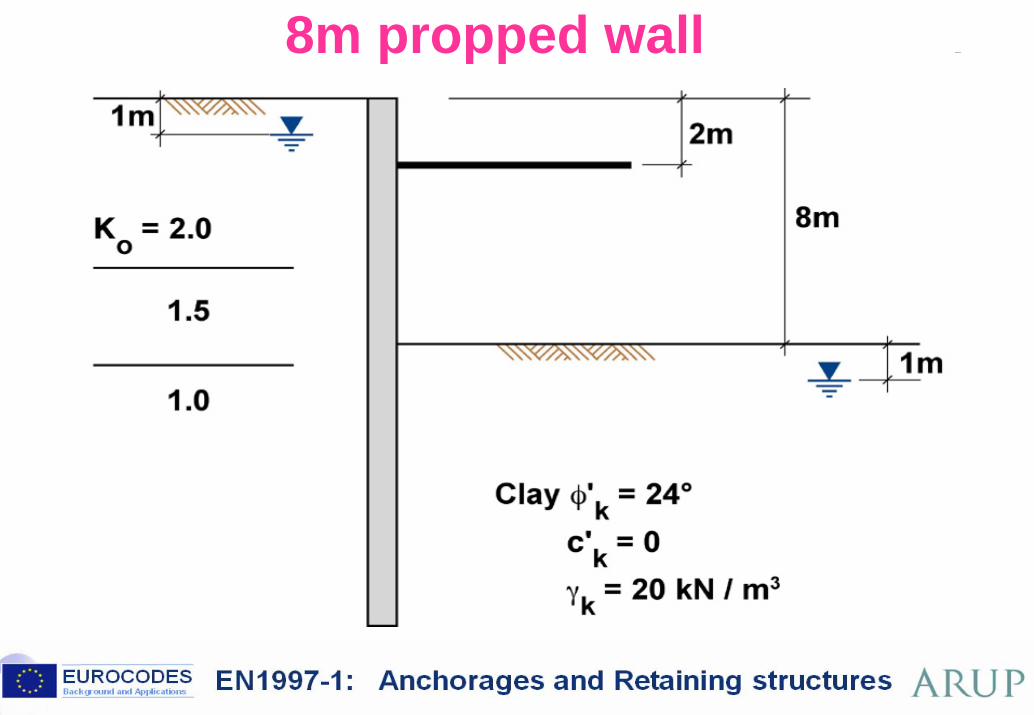
8m propped wall BP87.71 BP111.33 BP112.49
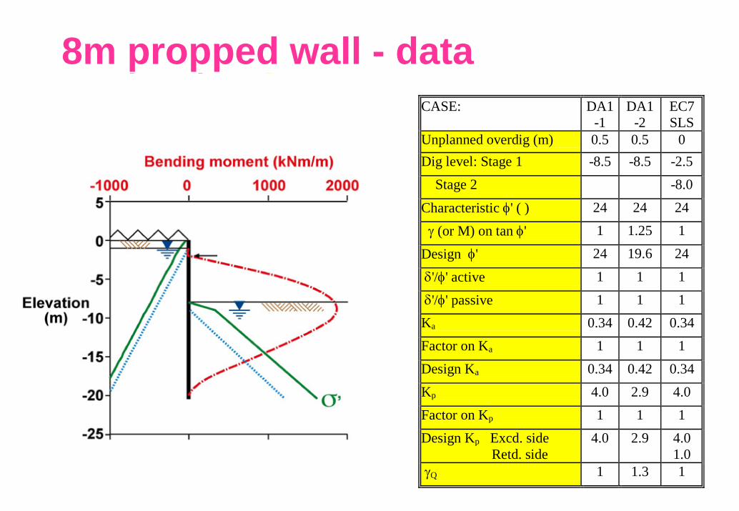
8m propped wall - data BP78.26 BP111.34
BP112.50 BP119.50 BP124-F3.15
CASE: DA1
-1 DA1
-2 EC7 SLS
Unplanned overdig (m) 0.5 0.5 0 Dig level: Stage 1 -8.5 -8.5 -2.5 Stage 2 -8.0 Characteristic φ' ( ) 24 24 24 γ (or M) on tan φ' 1 1.25 1 Design φ' 24 19.6 24 δ'/φ' active 1 1 1 δ'/φ' passive 1 1 1 Ka 0.34 0.42 0.34 Factor on Ka 1 1 1 Design Ka 0.34 0.42 0.34 Kp 4.0 2.9 4.0 Factor on Kp 1 1 1 Design Kp Excd. side Retd. side
4.0 2.9 4.0 1.0
γQ 1 1.3 1
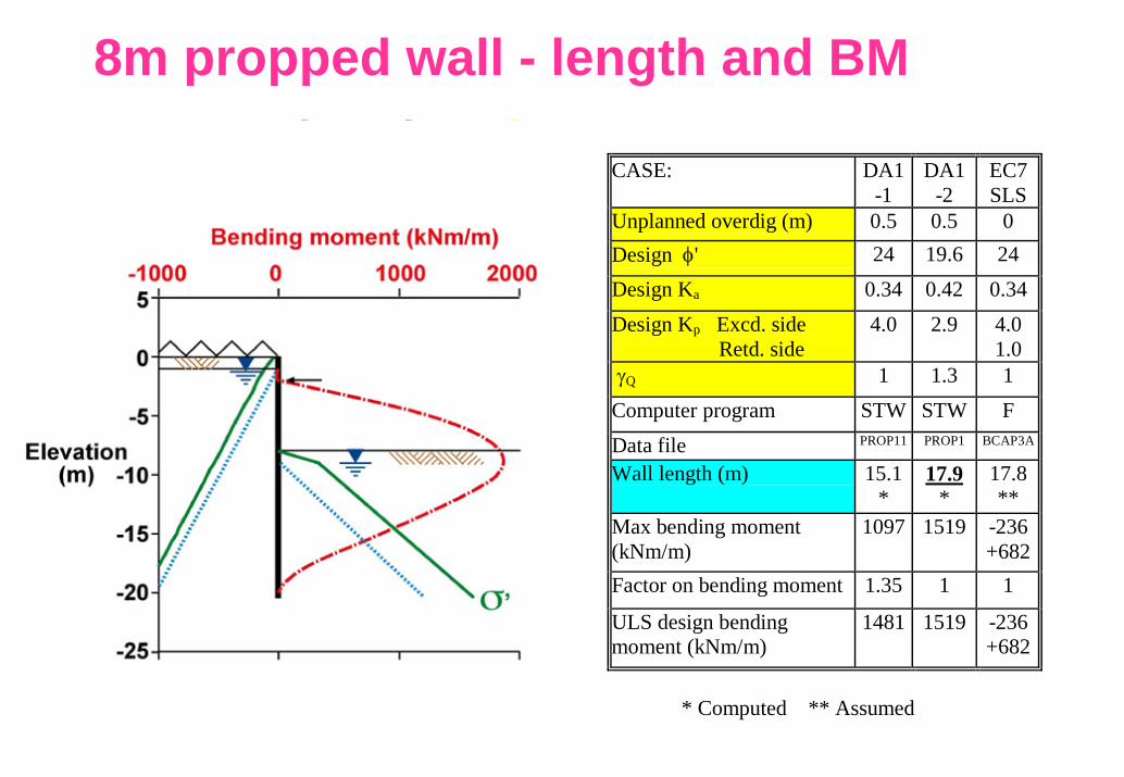
8m propped wall - length and BM BP78.28
BP111.35 BP112.51 BP119.51 BP124-F3.16
CASE: DA1
-1 DA1
-2 EC7 SLS
Unplanned overdig (m) 0.5 0.5 0 Design φ' 24 19.6 24 Design Ka 0.34 0.42 0.34Design Kp Excd. side Retd. side
4.0 2.9 4.0 1.0
γQ 1 1.3 1 Computer program STW STW F Data file PROP11 PROP1 BCAP3A
Wall length (m) 15.1*
17.9 *
17.8 **
Max bending moment (kNm/m)
1097 1519 -236 +682
Factor on bending moment 1.35 1 1 ULS design bending moment (kNm/m)
1481 1519 -236 +682
* Computed ** Assumed
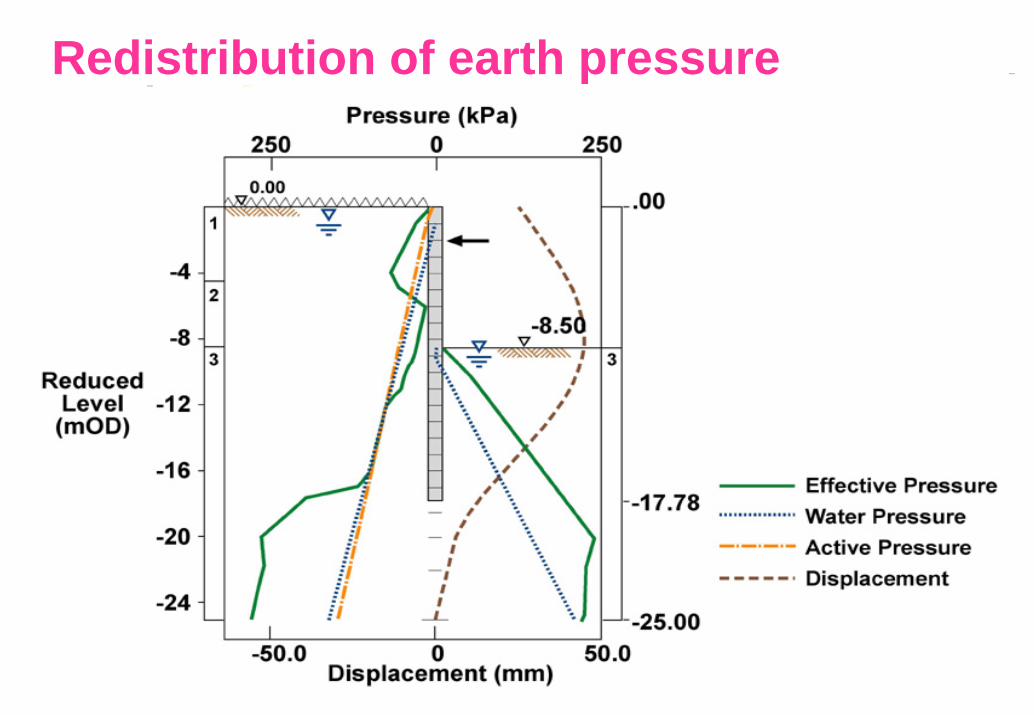
Redistribution of earth pressure BP87.75 BP111.36 BP112.52
BP119.52 BP124-F3.17
57 ©
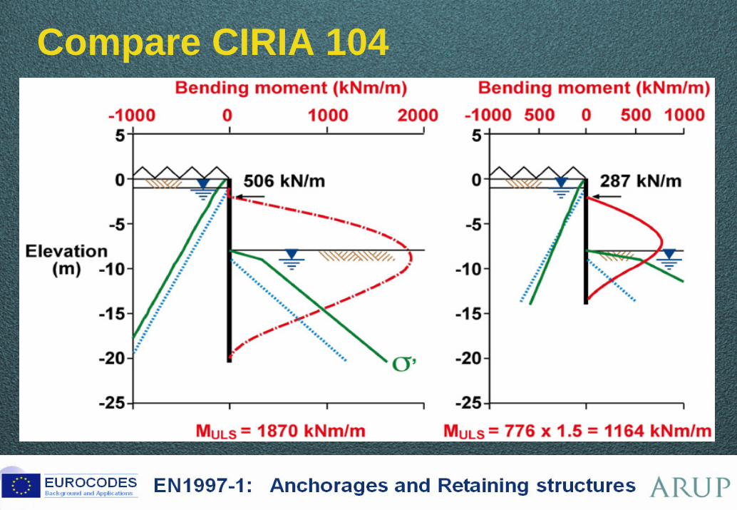
Compare CIRIA 104 BP87.2 BP111.54 BP112.54 BP119.53 BP124-F3.18
58 ©
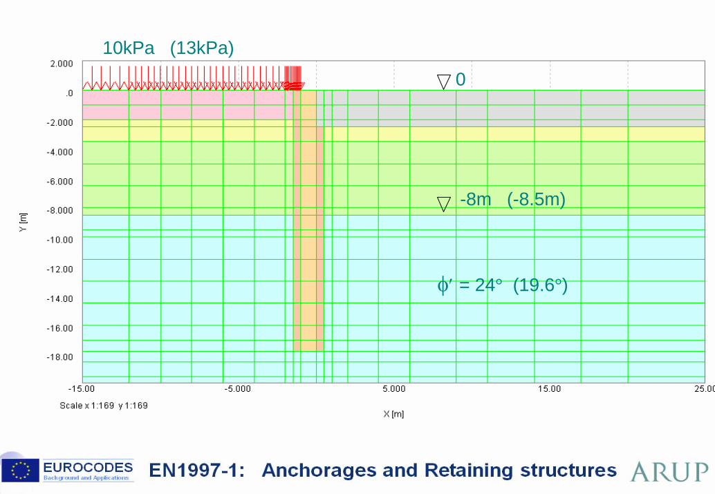
10kPa (13kPa)
0
-8m (-8.5m)
φ′ = 24° (19.6°)
59 ©
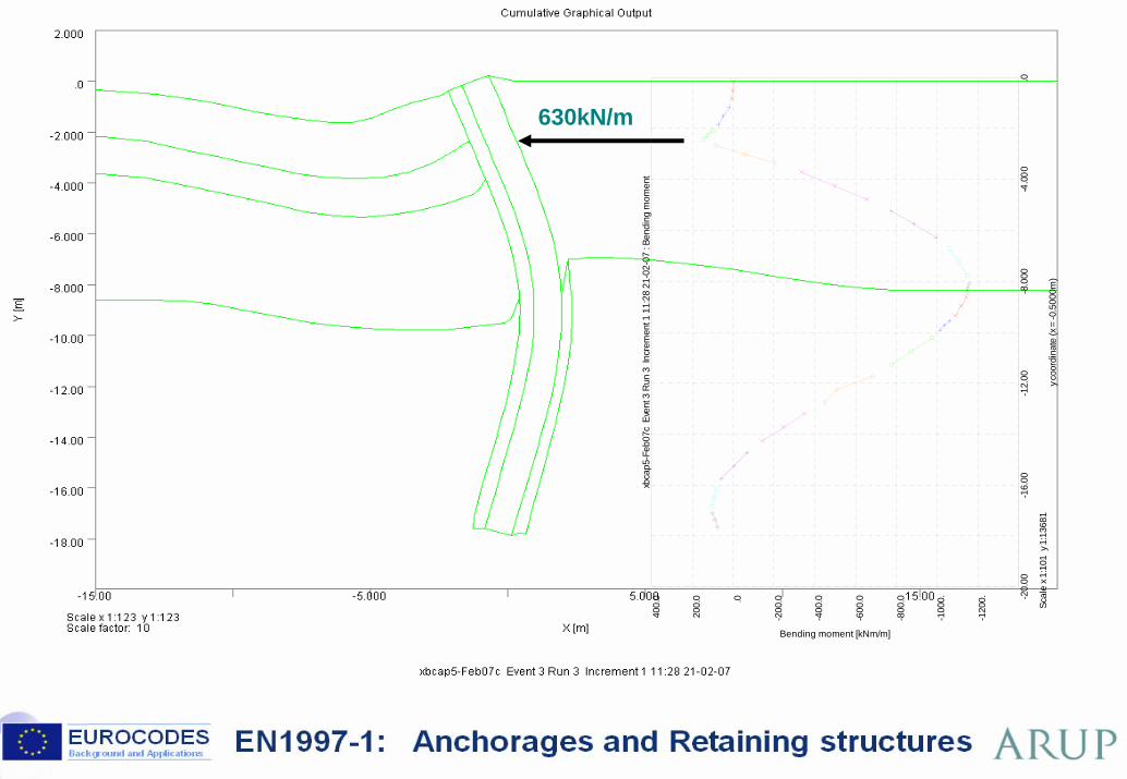
xbca
p5-F
eb07
c E
vent
3 R
un 3
Inc
rem
ent 1
11:
28 2
1-02
-07
: Ben
ding
mom
ent
-20.
00-1
6.00
-12.
00-8
.000
-4.0
00.0
y coo
rdin
ate
(x =
-0.5
000m
)Sc
ale
x 1:1
01 y
1:1
3681
-120
0.
-100
0.
-800
.0
-600
.0
-400
.0
-200
.0.0
200.
0
400.
0
Bending moment [kNm/m]
630kN/m
8m propped wall - length and BM BP78.32
BP111.38 BP112.55 BP119.54 BP124-F3.19
CASE: CIRIA
Fs CIRIA
Fs BS
8002 DA1
-1 DA1
-2 EC7 SLS
DA1 -1
DA1 -2
DA1 -2
DA1-2
Unplanned overdig (m) 0 0 0.5 0.5 0.5 0 0.5 0.5 0.5 0.5 Design φ' 16.5 24 20.4 24 19.6 24 24 19.6 19.6 19.6Design Ka 0.49 0.36 0.41 0.34 0.42 0.34 0.34 0.42 0.42 Design Kp Excd. side Retd. side
2.1 3.4 2.8 4.0 2.9 4.0 1.0
4.0 2.9 1.0
2.9 1.0
γQ 1 1 1 1 1.3 1 1 1.3 1.3 1.3 Computer program STW STW STW STW STW FREW FREW FREW FREW SAFE
Data file PROP4 PROP5 PR1B-03 PROP11 PROP1 BCAP3A BCAPBA BCAP1A BCAP4A XBCAP5
Wall length (m) 20.4 **
14.1 **
17.9 *
15.1 *
17.9 *
17.8 **
17.8 **
17.8 **
17.8 **
17.8 **
Max bending moment (kNm/m)
1870 ##
776 1488 1097 1519 -236 +682
-241 838
1359 -308 1158
-229 1131
Factor on bending moment 1.5 1.0? 1.35 1 1 1.35 1 1 1 ULS design bending moment (kNm/m)
1164 1488? 1481 1519 -236 +682
-325 1131
1359 -308 1158
-229 1131
* Computed ** Assumed ## Not used in design
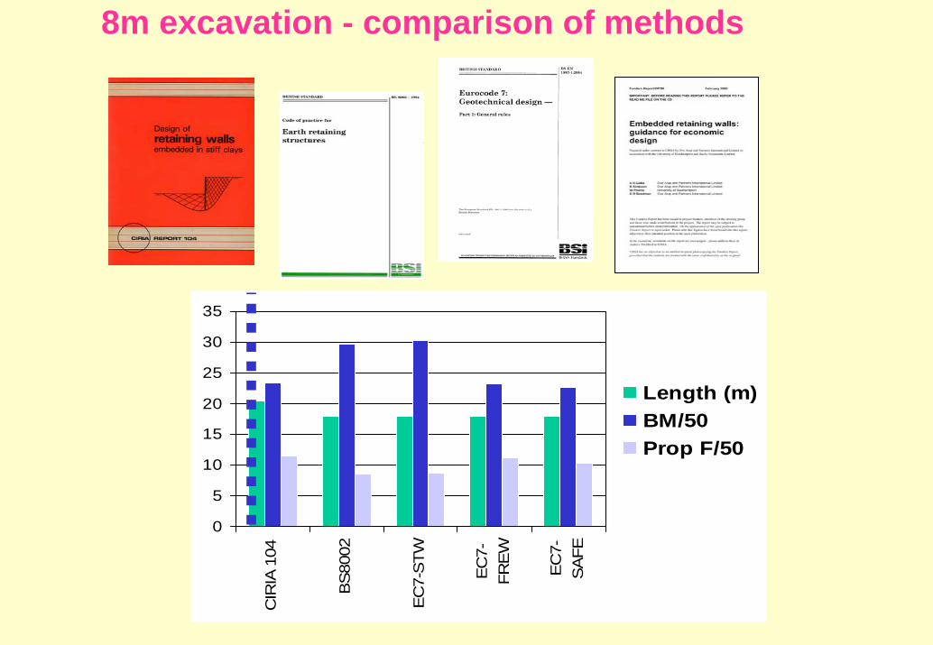
8m excavation - comparison of methods BP78.34
BP111.39 BP112.56 BP119.55 BP124-F3.20
0
5
10
15
20
25
30
35
CIR
IA 1
04
BS
8002
EC
7-S
TW
EC
7-FR
EW
EC
7-S
AFE
Length (m)BM/50Prop F/50

Redistribution of earth pressure BP87.75 BP111.36 BP112.52
BP119.56 BP124-F3.21
63 ©
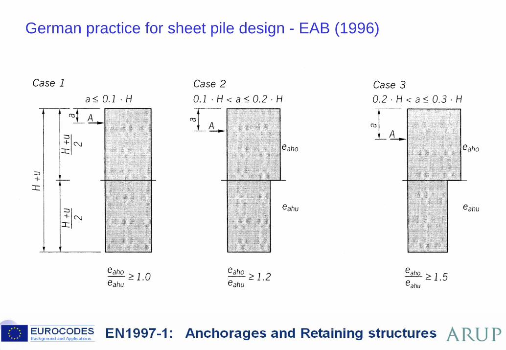
German practice for sheet pile design - EAB (1996) BP87.39 BP111.37 BP112.53
BP119.57 BP124-F3.22
64 ©
Weissenbach, A, Hettler, A and Simpson, B (2003). Stability of excavations.
In Geotechnical Engineering Handbook,
Vol 3: Elements and Structures (Ed U Smoltczyk). Ernst & Sohn/ Wiley.
65 ©
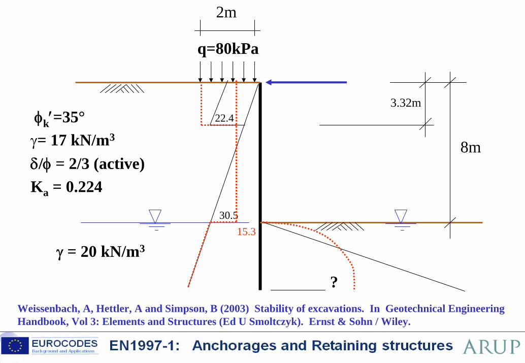
SAFE Grundbau2 BP116.24 BP119.58 BP124-F3.24
8m
φk′=35°γ= 17 kN/m3
δ/φ = 2/3 (active) Ka = 0.224
?
2m
q=80kPa
γ = 20 kN/m3
22.4
30.515.3
Weissenbach, A, Hettler, A and Simpson, B (2003) Stability of excavations. In Geotechnical Engineering Handbook, Vol 3: Elements and Structures (Ed U Smoltczyk). Ernst & Sohn / Wiley.
3.32m
66 ©
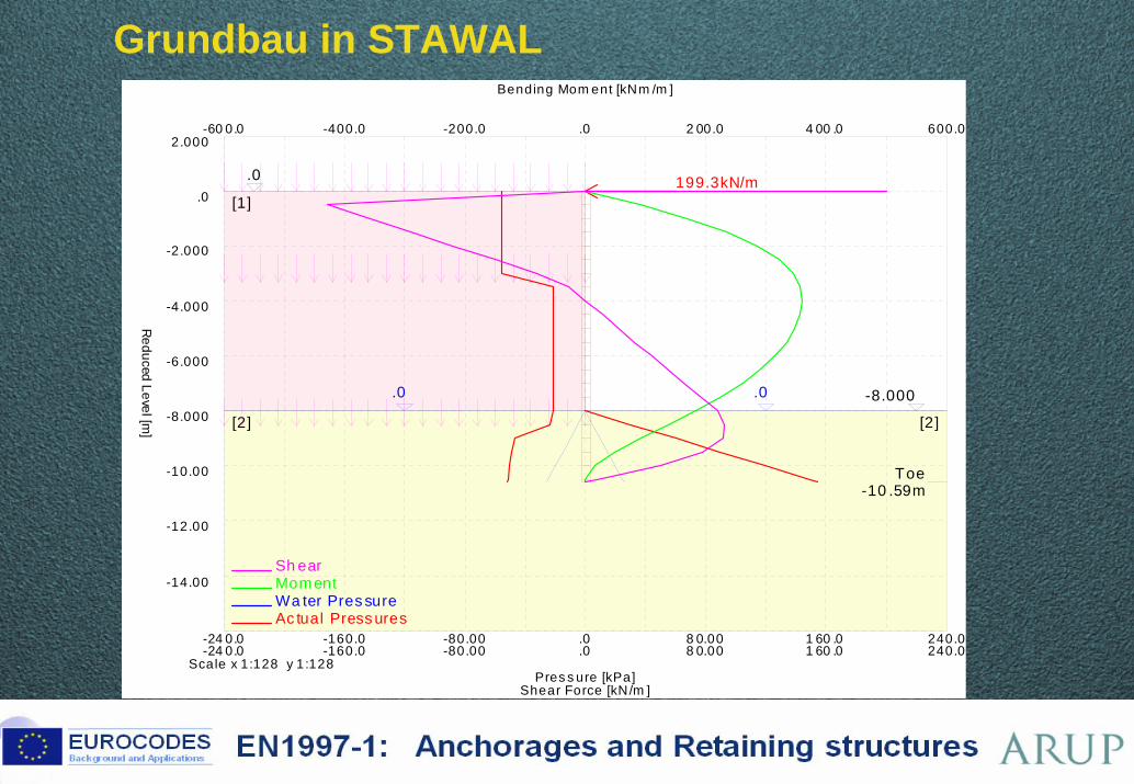
Grundbau in STAWAL BP119.59 BP124-F3.25
[1]
.0
[2] [2]
-8.000
Toe-10 .59m
.0 .0
199.3kN/m
Ac tual Press uresWa ter Pres sureMomentSh ear
-24 0.0 -160.0 -80.00 .0 8 0.00 1 60 .0 240.0
-60 0.0 -400.0 -200.0 .0 2 00.0 4 00 .0 600.0
-24 0.0 -160.0 -80.00 .0 8 0.00 1 60 .0 240.0
Pres s ure [kPa]
Bending Mom ent [kNm /m ]
Shear Force [kN/m ]
Scale x 1:128 y 1:128
-14.00
-12.00
-10.00
-8.000
-6.000
-4.000
-2.000
.0
2.000
Reduced Level [m
]
67 ©
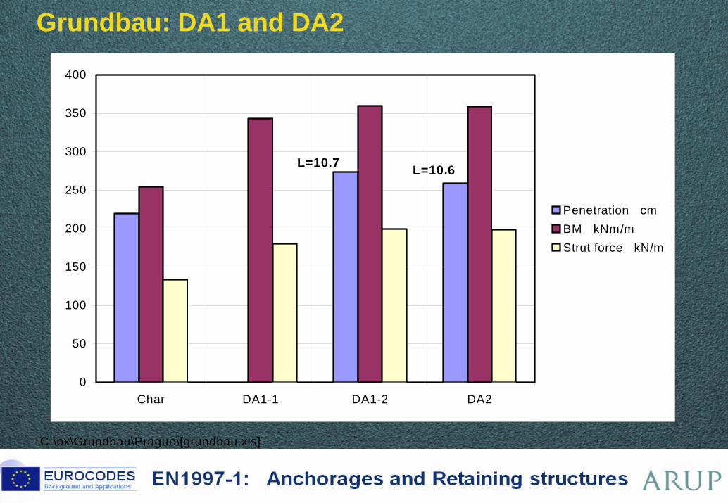
Grundbau: DA1 and DA2 XBP119.60 BP124-F3.26
C:\bx\Grundbau\Prague\[grundbau.xls]
0
50
100
150
200
250
300
350
400
Char DA1-1 DA1-2 DA2
Penetration cmBM kNm/mStrut force kN/m
L=10.6L=10.7
Brussels, 18-20 February 2008 – Dissemination of information workshop 68
EUROCODESBackground and Applications EN1997-1: Anchorages and Retaining structures
EN 1997-1 Eurocode 7
Section 9 – Retaining structures
Fundamentals – Design Approaches
Main points in the code text
Examples:Comparisons with previous (UK) practiceComparison between Design Approaches
Lessons from the Dublin Workshop
69 ©
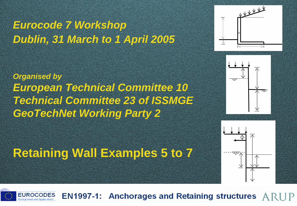
Eurocode 7 WorkshopDublin, 31 March to 1 April 2005 BP130.1
Organised byEuropean Technical Committee 10Technical Committee 23 of ISSMGEGeoTechNet Working Party 2
Retaining Wall Examples 5 to 7
70 ©
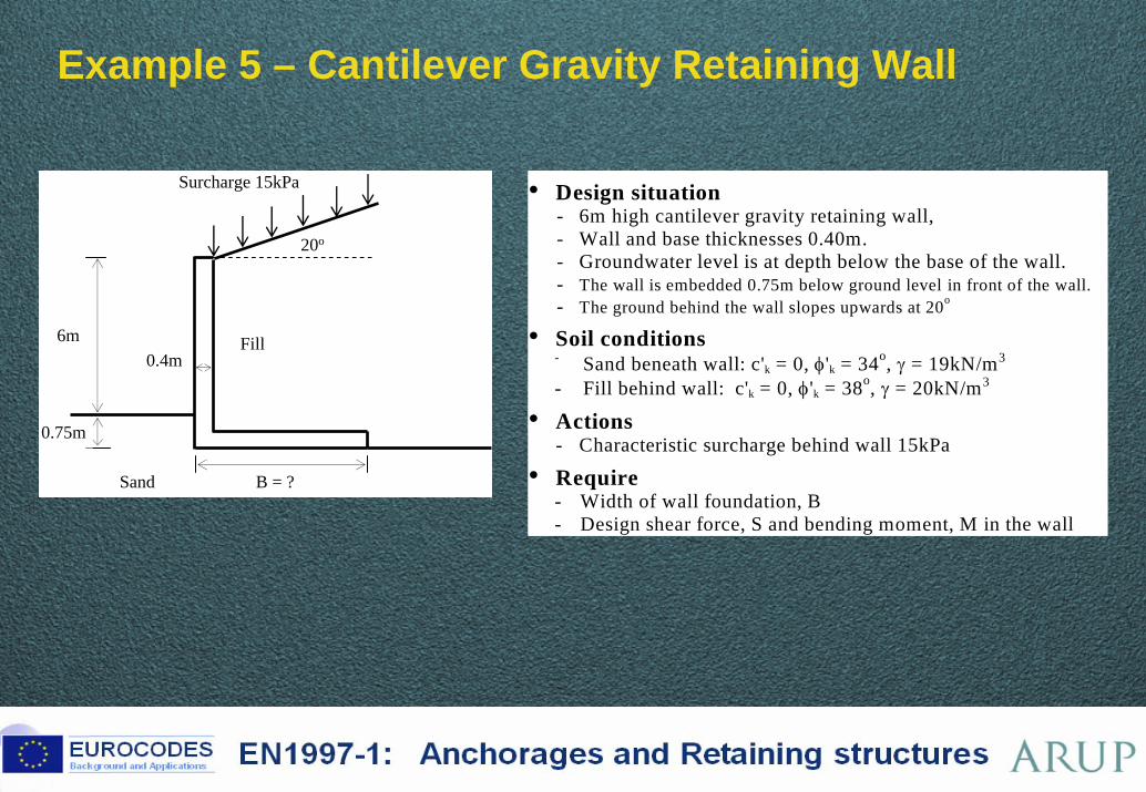
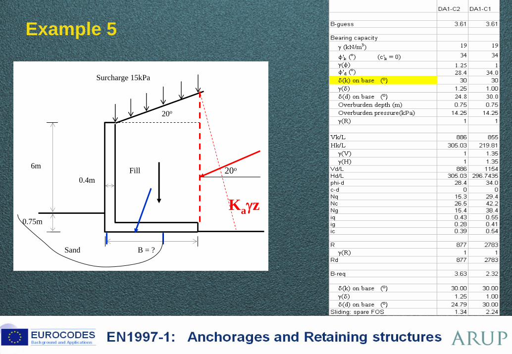
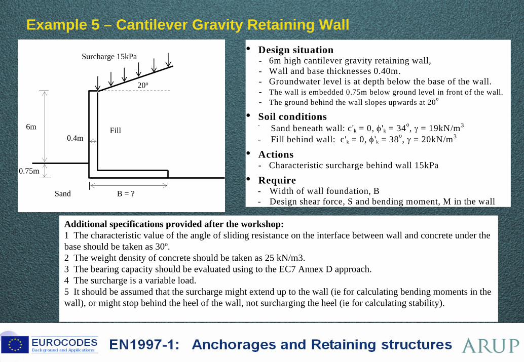
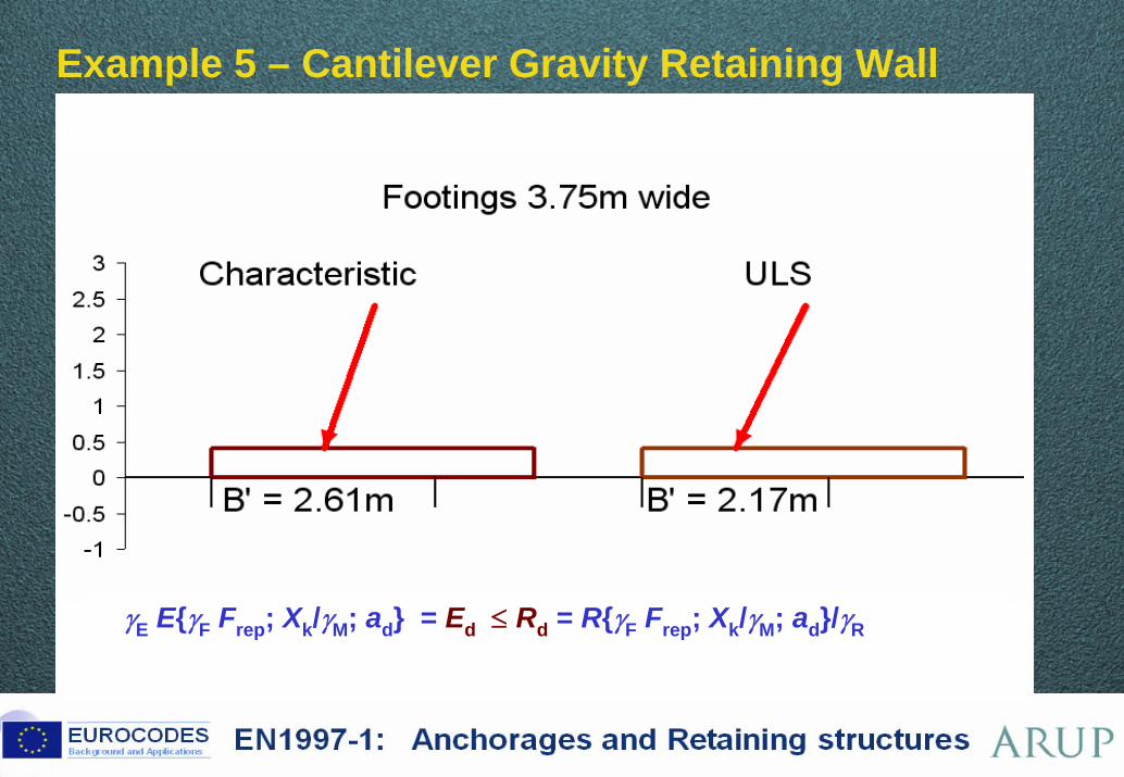
Example 5 – Cantilever Gravity Retaining Wall BP130.2
0.75m
B = ?
6m0.4m
Fill
Sand
20o
Surcharge 15kPa • Design situation - 6m high cantilever gravity retaining wall, - Wall and base thicknesses 0.40m. - Groundwater level is at depth below the base of the wall. - The wall is embedded 0.75m below ground level in front of the wall. - The ground behind the wall slopes upwards at 20o
• Soil conditions - Sand beneath wall: c'k = 0, φ'k = 34o, γ = 19kN/m3
- Fill behind wall: c'k = 0, φ'k = 38o, γ = 20kN/m3
• Actions - Characteristic surcharge behind wall 15kPa
• Require - Width of wall foundation, B - Design shear force, S and bending moment, M in the wall
71 ©
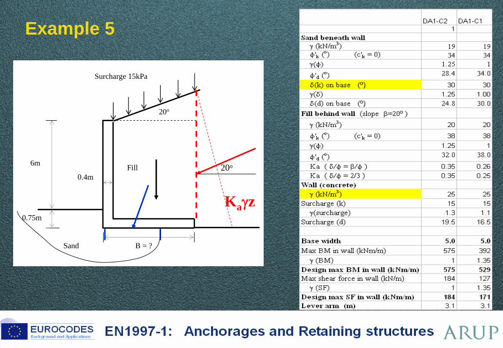
Example 5 BP130.3
0.75m
B = ?
6m
0.4mFill
Sand
20o
Surcharge 15kPa
20o
Kaγz
72 ©
Example 5 BP130.4
0.75m
B = ?
6m
0.4mFill
Sand
20o
Surcharge 15kPa
20o
Kaγz
73 ©
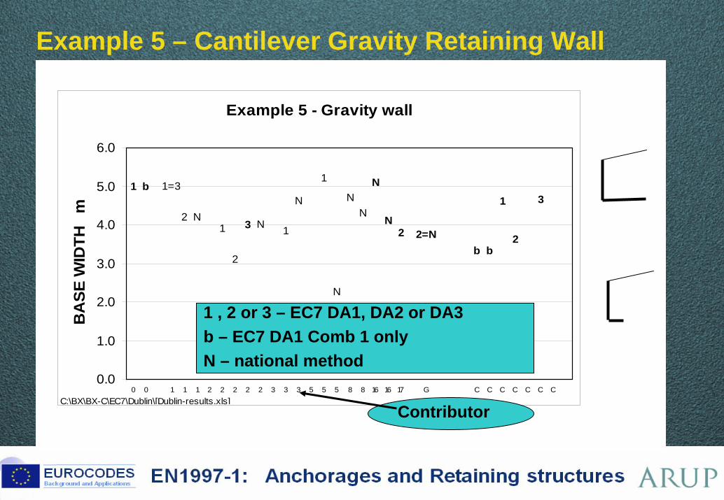
Example 5 – Cantilever Gravity Retaining Wall BP130.5
Example 5 - Gravity wall
1 b
2 N1
2
3 N 1
N
1
N
NN
N
N
1=3
2 2=Nb b
1
2
3
0.0
1.0
2.0
3.0
4.0
5.0
6.0
0 0 1 1 1 2 2 2 2 2 3 3 3 5 5 5 8 8 16 16 17 G C C C C C C C
BA
SE W
IDTH
m
C:\BX\BX-C\EC7\Dublin\[Dublin-results.xls]
1 , 2 or 3 – EC7 DA1, DA2 or DA3b – EC7 DA1 Comb 1 onlyN – national method
Contributor
74 ©
Example 5 – Cantilever Gravity Retaining Wall BP130.2 BP124.A6.11
0.75m
B = ?
6m0.4m
Fill
Sand
20o
Surcharge 15kPa• Design situation
- 6m high cantilever gravity retaining wall, - Wall and base thicknesses 0.40m. - Groundwater level is at depth below the base of the wall. - The wall is embedded 0.75m below ground level in front of the wall. - The ground behind the wall slopes upwards at 20o
• Soil conditions - Sand beneath wall: c'k = 0, φ'k = 34o, γ = 19kN/m3
- Fill behind wall: c'k = 0, φ'k = 38o, γ = 20kN/m3
• Actions - Characteristic surcharge behind wall 15kPa
• Require - Width of wall foundation, B - Design shear force, S and bending moment, M in the wall
Additional specifications provided after the workshop:1 The characteristic value of the angle of sliding resistance on the interface between wall and concrete under the base should be taken as 30º.2 The weight density of concrete should be taken as 25 kN/m3.3 The bearing capacity should be evaluated using to the EC7 Annex D approach.4 The surcharge is a variable load.5 It should be assumed that the surcharge might extend up to the wall (ie for calculating bending moments in the wall), or might stop behind the heel of the wall, not surcharging the heel (ie for calculating stability).
75 ©
Example 5 – Cantilever Gravity Retaining Wall BP124.A6.12
C:\BX\BX-C\EC7\Dublin\[Dublin-results (version 1).xls] 23-Jun-05 00:02
Example 5 - Gravity wall
3
2
1
bb2=N2
1=3
N
N
NN
N
1
N
1N3
2
1N2
b1
0.0
1.0
2.0
3.0
4.0
5.0
6.0
0 0 1 1 1 2 2 2 2 2 3 3 3 5 5 5 8 8 16 16 17 E C C C C C C C
BA
SE W
IDTH
m
76 ©
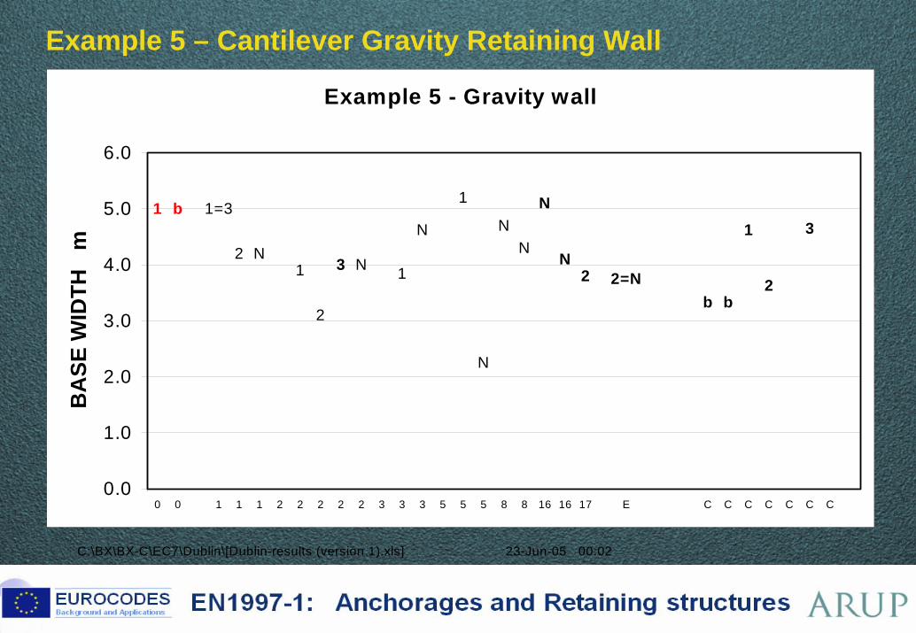
Example 5 – Cantilever Gravity Retaining Wall BP130.5
γE E{γF Frep; Xk/γM; ad} = Ed ≤ Rd = R{γF Frep; Xk/γM; ad}/γR
77 ©
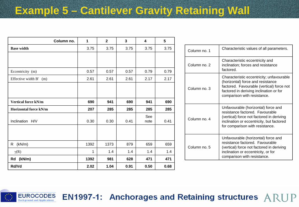
Example 5 – Cantilever Gravity Retaining Wall BP130.5
Column no. 1 Characteristic values of all parameters.
Column no. 2Characteristic eccentricity and inclination; forces and resistance factored.
Column no. 3
Characteristic eccentricity; unfavourable (horizontal) force and resistance factored. Favourable (vertical) force not factored in deriving inclination or for comparison with resistance.
Column no. 4
Unfavourable (horizontal) force and resistance factored. Favourable (vertical) force not factored in deriving inclination or eccentricity, but factored for comparison with resistance.
Column no. 5
Unfavourable (horizontal) force and resistance factored. Favourable (vertical) force not factored in deriving inclination or eccentricity, or for comparison with resistance.
Column no. 1 2 3 4 5
Base width 3.75 3.75 3.75 3.75 3.75
Eccentricity (m) 0.57 0.57 0.57 0.79 0.79
Effective width B' (m) 2.61 2.61 2.61 2.17 2.17
Vertical force kN/m 690 941 690 941 690
Horizontal force kN/m 207 285 285 285 285
Inclination H/V 0.30 0.30 0.41See note 0.41
R (kN/m) 1392 1373 879 659 659
γ(R) 1 1.4 1.4 1.4 1.4
Rd (kN/m) 1392 981 628 471 471
Rd/Vd 2.02 1.04 0.91 0.50 0.68
78 ©
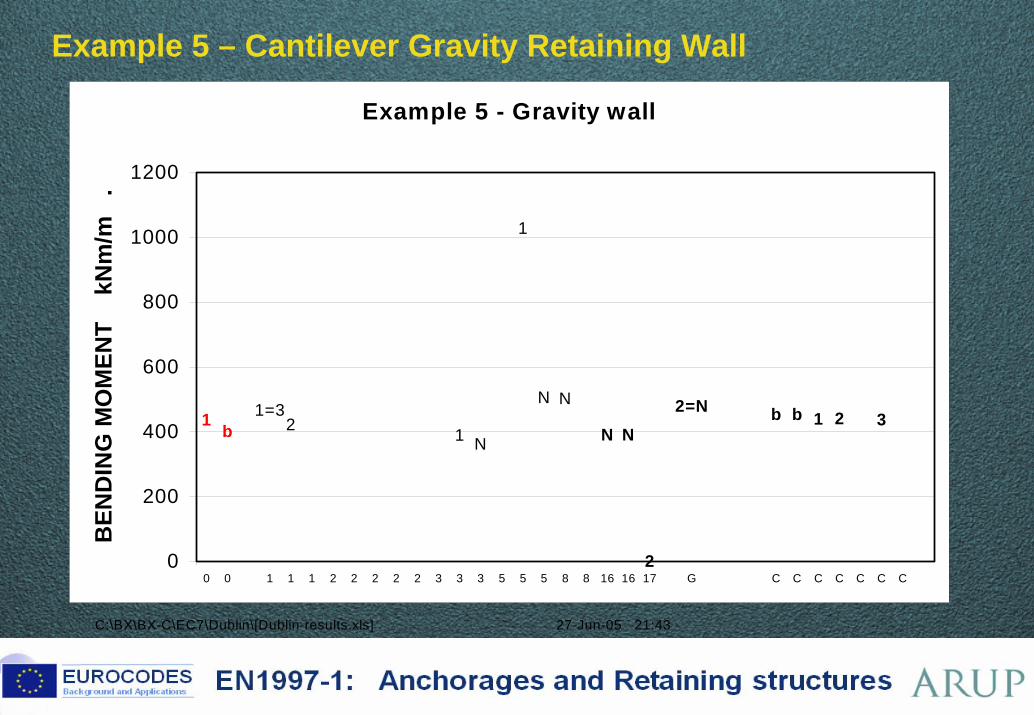
Example 5 – Cantilever Gravity Retaining Wall BP124.A6.12
C:\BX\BX-C\EC7\Dublin\[Dublin-results.xls] 27-Jun-05 21:43
Example 5 - Gravity wall
321bb2=N
2
1=31 b 2 1 N
1
N N
N N
0
200
400
600
800
1000
1200
0 0 1 1 1 2 2 2 2 2 3 3 3 5 5 5 8 8 16 16 17 G C C C C C C C
BEN
DIN
G M
OM
ENT
kN
m/m
.
79 ©
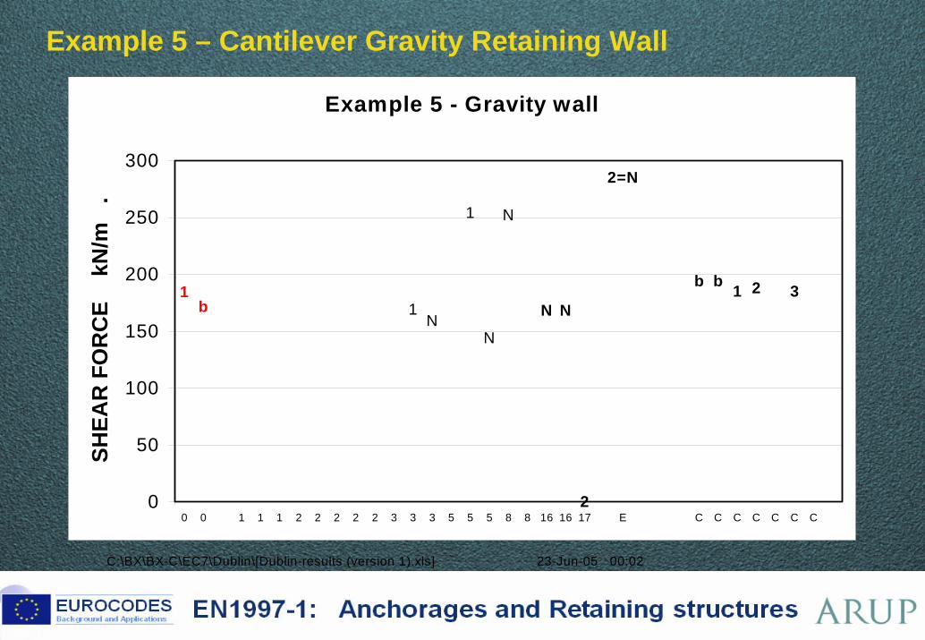
Example 5 – Cantilever Gravity Retaining Wall BP124.A6.14
C:\BX\BX-C\EC7\Dublin\[Dublin-results (version 1).xls] 23-Jun-05 00:02
Example 5 - Gravity wall
321bb
2=N
2
NN
N
N
1
N1b
1
0
50
100
150
200
250
300
0 0 1 1 1 2 2 2 2 2 3 3 3 5 5 5 8 8 16 16 17 E C C C C C C C
SHEA
R F
OR
CE
kN
/m
.
80 ©
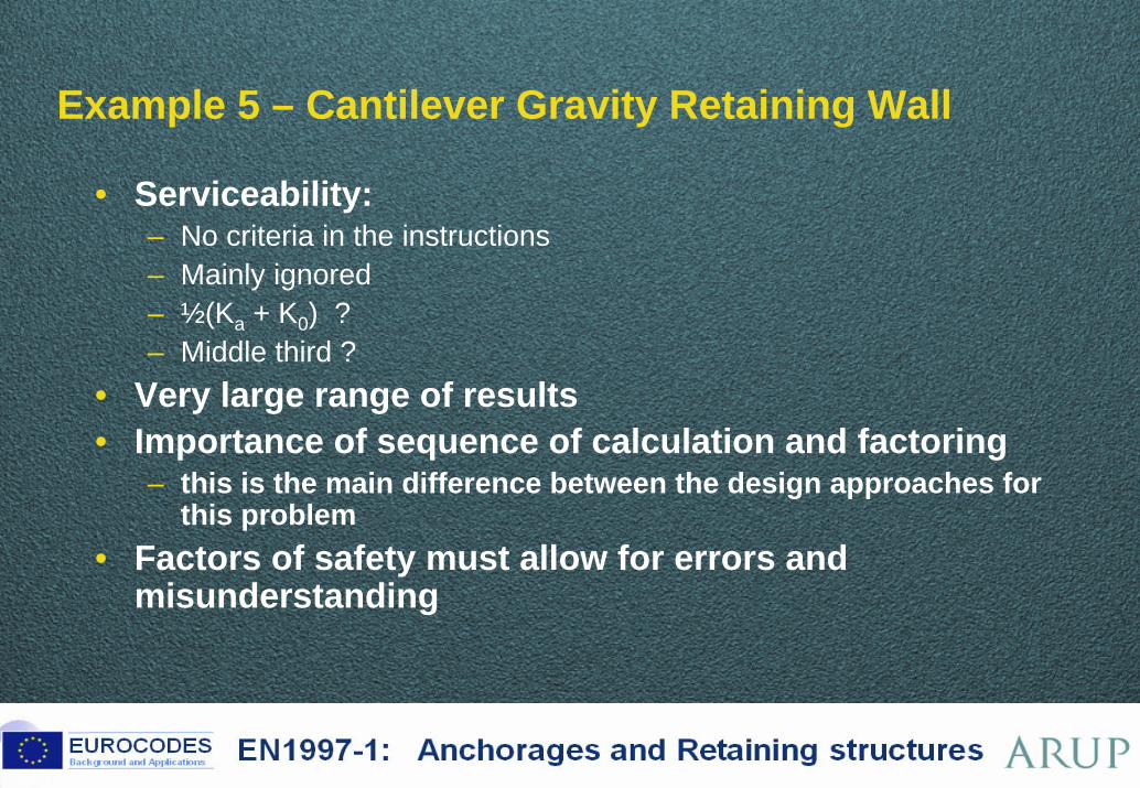
Example 5 – Cantilever Gravity Retaining Wall BP130.8
• Serviceability:– No criteria in the instructions– Mainly ignored– ½(Ka + K0) ?– Middle third ?
• Very large range of results• Importance of sequence of calculation and factoring
– this is the main difference between the design approaches for this problem
• Factors of safety must allow for errors and misunderstanding
81 ©
Example 6 – Embedded sheet pile retaining wall BP130.9
Sand
10kPa
3.0m
D= ?
1.5m
• Design situation - Embedded sheet pile retaining wall for a
3m deep excavation with a 10kPa surcharge on the surface behind the wall
• Soil conditions - Sand: c'k = 0, φ'k = 37o, γ = 20kN/m3
• Actions - Characteristic surcharge behind wall
10kPa - Groundwater level at depth of 1.5m
below ground surface behind wall and at the ground surface in front of wall
• Require - Depth of wall embedment, D - Design bending moment in the wall, M
82 ©
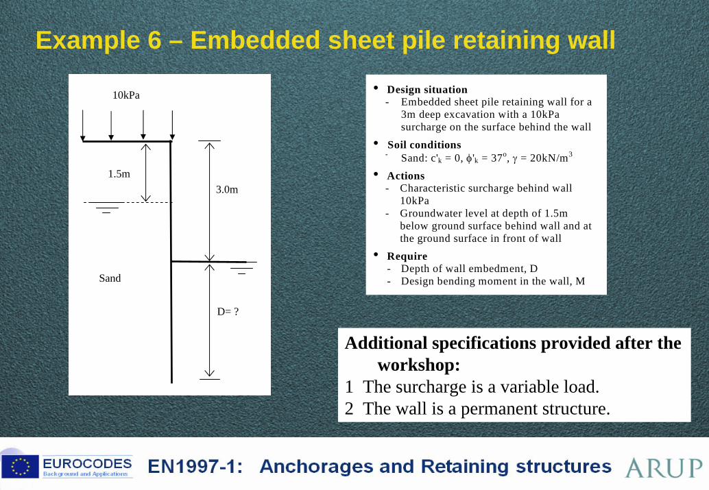
Example 6 – Embedded sheet pile retaining wall BP130.9
Sand
10kPa
3.0m
D= ?
1.5m
• Design situation - Embedded sheet pile retaining wall for a
3m deep excavation with a 10kPa surcharge on the surface behind the wall
• Soil conditions - Sand: c'k = 0, φ'k = 37o, γ = 20kN/m3
• Actions - Characteristic surcharge behind wall
10kPa - Groundwater level at depth of 1.5m
below ground surface behind wall and at the ground surface in front of wall
• Require - Depth of wall embedment, D - Design bending moment in the wall, M
Additional specifications provided after the workshop:
1 The surcharge is a variable load.2 The wall is a permanent structure.
83 ©
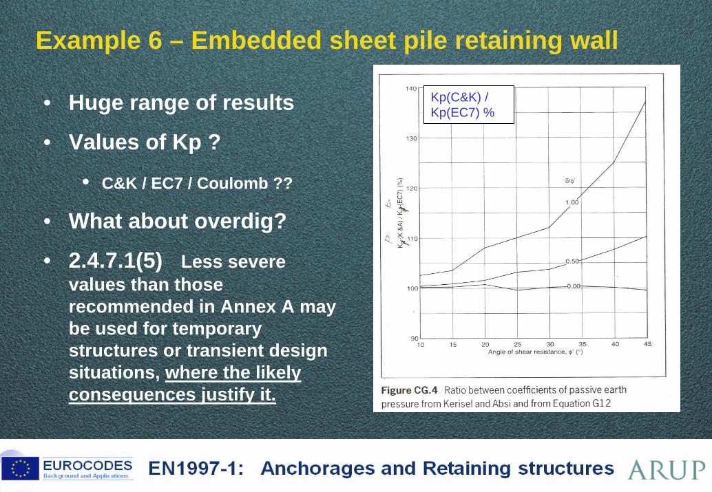
Example 6 – Embedded sheet pile retaining wall BP130.14
• Huge range of results
• Values of Kp ?
• C&K / EC7 / Coulomb ??
• What about overdig?
• 2.4.7.1(5) Less severe values than those recommended in Annex A may be used for temporary structures or transient design situations, where the likely consequences justify it.
Kp(C&K) / Kp(EC7) %
84 ©
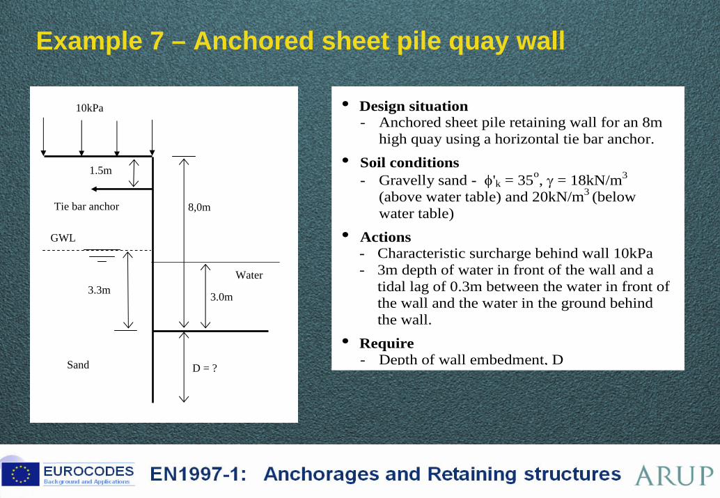
Example 7 – Anchored sheet pile quay wall BP130.16
10kPa
D = ?
1.5m
Tie bar anchor
3.0m3.3m
Sand
Water
GWL
8,0m
• Design situation - Anchored sheet pile retaining wall for an 8m
high quay using a horizontal tie bar anchor.
• Soil conditions - Gravelly sand - φ'k = 35o, γ = 18kN/m3
(above water table) and 20kN/m3 (below water table)
• Actions - Characteristic surcharge behind wall 10kPa - 3m depth of water in front of the wall and a
tidal lag of 0.3m between the water in front of the wall and the water in the ground behind the wall.
• Require - Depth of wall embedment, D
85 ©
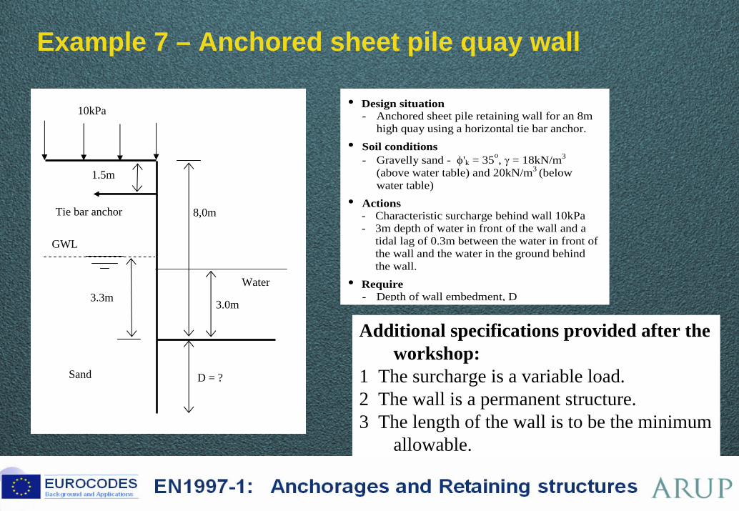
Example 7 – Anchored sheet pile quay wall BP130.16
10kPa
D = ?
1.5m
Tie bar anchor
3.0m3.3m
Sand
Water
GWL
8,0m
• Design situation - Anchored sheet pile retaining wall for an 8m
high quay using a horizontal tie bar anchor. • Soil conditions
- Gravelly sand - φ'k = 35o, γ = 18kN/m3 (above water table) and 20kN/m3 (below water table)
• Actions - Characteristic surcharge behind wall 10kPa - 3m depth of water in front of the wall and a
tidal lag of 0.3m between the water in front of the wall and the water in the ground behind the wall.
• Require - Depth of wall embedment, D
Additional specifications provided after the workshop:
1 The surcharge is a variable load.2 The wall is a permanent structure.3 The length of the wall is to be the minimum
allowable.
86 ©
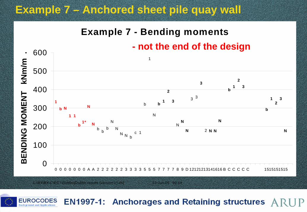
Example 7 – Anchored sheet pile quay wall BP130.23
C:\BX\BX-C\EC7\Dublin\[Dublin-results (version 1).xls] 23-Jun-05 00:14
Example 7 - Bending moments
b
N
NN2
331
b N
1 1
b1*
N
Nb b
bN
NN N b
c 1
b
1
N
b 1
2
3
N N
N
31
2
b
12
3
N
3
0
100
200
300
400
500
600
0 0 0 0 0 0 0 A A 2 2 2 2 2 2 3 3 3 3 5 5 5 7 7 7 7 8 9 D 12121213141616 B C C C C C 1515151515
BEN
DIN
G M
OM
ENT
kN
m/m
.
- not the end of the design
87 ©
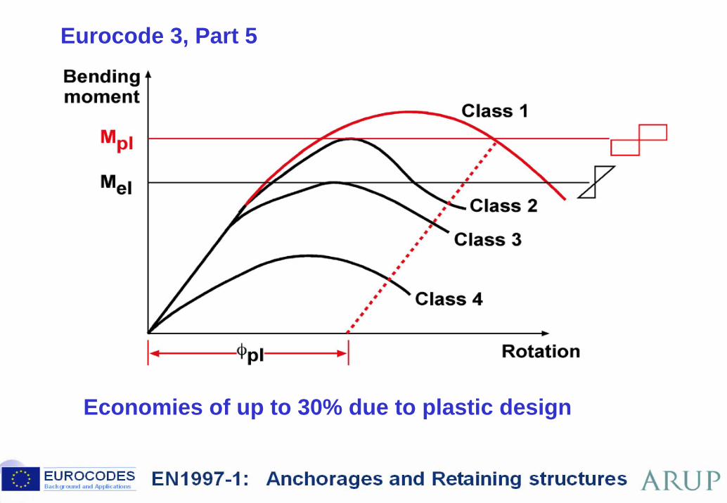
Eurocode 3, Part 5BP87.78 BP130.26
Economies of up to 30% due to plastic design
88 ©
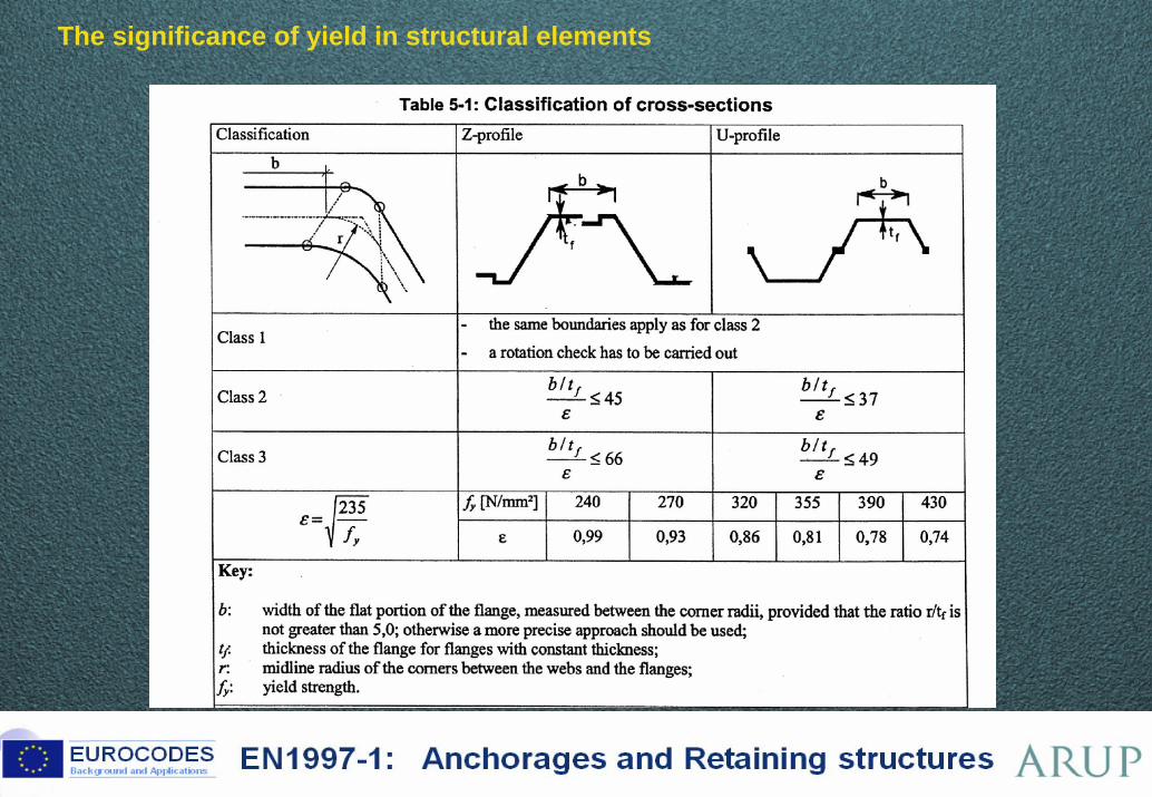
The significance of yield in structural elements BP114.32 BP116.50 BP130.27
89 ©
Example 7 – Anchored sheet pile quay wall BP130.28
• Large range of results
• SSI important
• Optimise: length, BM, anchor force?
• Design doesn’t end at the bending moment
• Nobody considered SLS
90 ©
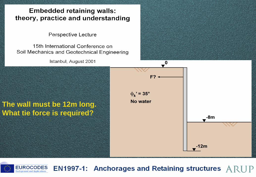
The wall must be 12m long.What tie force is required? BP87.114
BP99.90 BP130.37
91 ©
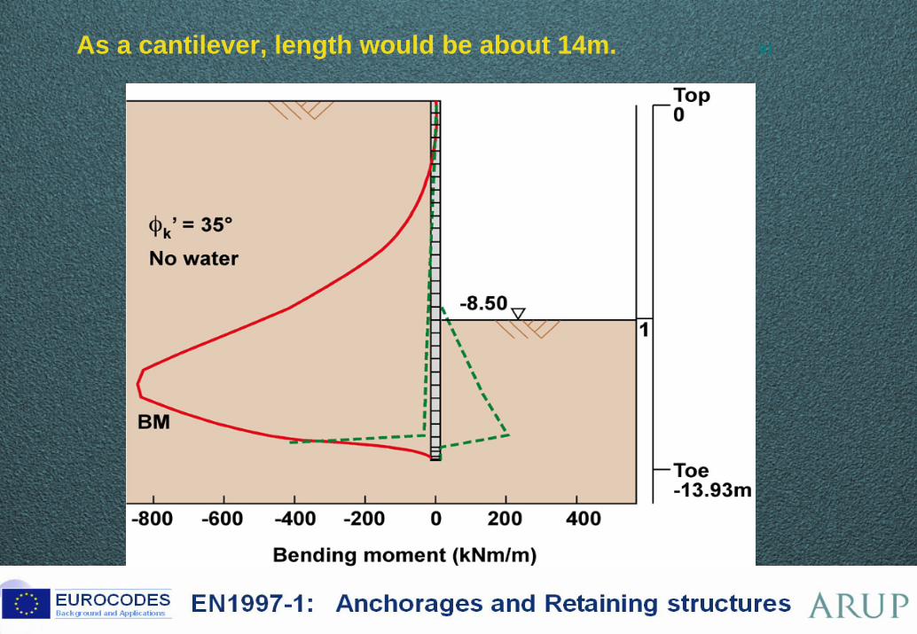
As a cantilever, length would be about 14m. BP87.115 BP99.91BP130.38
92 ©
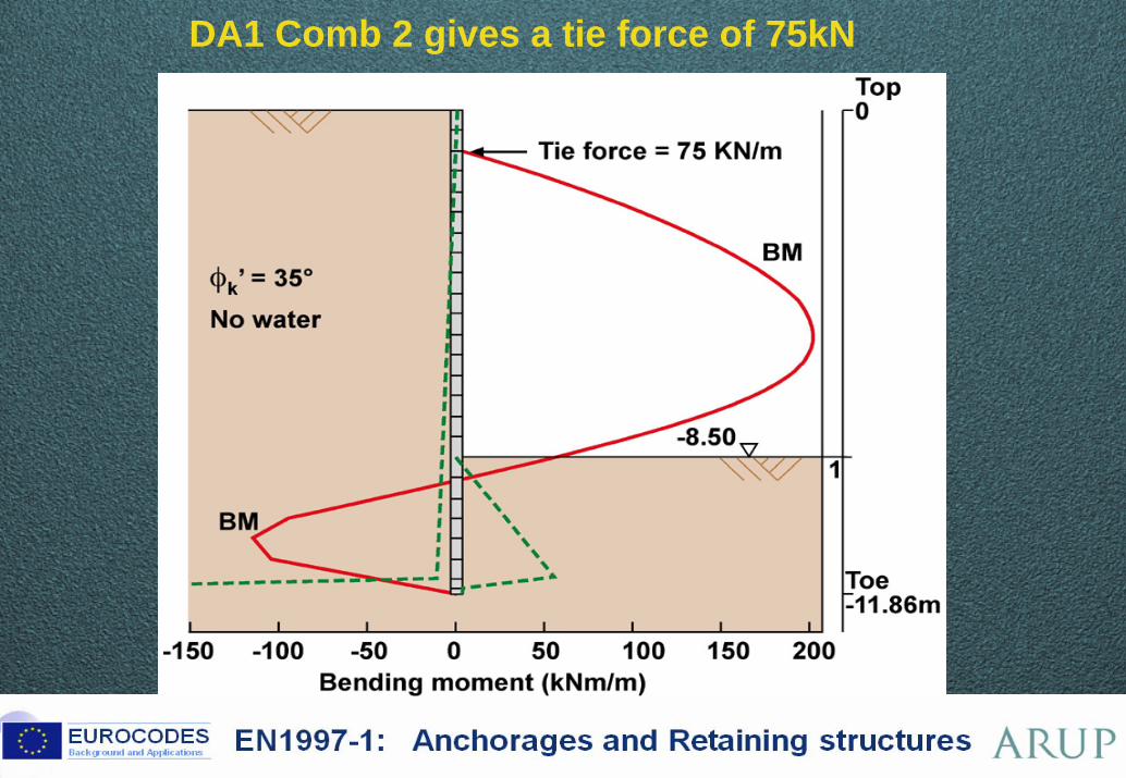
DA1 Comb 2 gives a tie force of 75kN BP87.116
BP99.92 BP130.39
93 ©
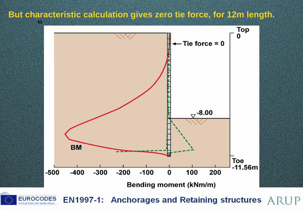
But characteristic calculation gives zero tie force, for 12m length. BP87.117
BP99.93 BP130.40
Brussels, 18-20 February 2008 – Dissemination of information workshop 94
EUROCODESBackground and Applications EN1997-1: Anchorages and Retaining structures
EN 1997-1 Eurocode 7
Section 9 – Retaining structuresFundamentals – Design Approaches
Slopes and walls all one problemDesign Approaches matter!
Main points in the code textGood basic check listsValues of Ka and KpOverdigNot enough attention to SLS (by users, at least)
Examples:Results broadly similar to existing practiceDAs: big effect on gravity walls; small effect on embedded
Lessons from the Dublin WorkshopVery wide range of resultsEffect of DAs for gravity walls and Kp for embeddedHuman error important – partly offset by safety factorsNeed to work with EC3-5
Brussels, 18-20 February 2008 – Dissemination of information workshop 95
EUROCODESBackground and Applications EN1997-1: Anchorages and Retaining structures
EN 1997-1 Eurocode 7Section 8 – AnchoragesSection 9 – Retaining structures
Brian SimpsonArup Geotechnics
Related Documents