External Micrometers E- 10 Mechanical Dial Indicators 5 10 15 20 15 10 5 -0+ 0.001 in. Type 71 1 1 2 3 4 5 4 3 2 0.0001 in. Type 73 -0+ Brown & Sharpe Dial Indicators Better Response - Better Reliability Unlimited application for set up and checking of turned, milled and ground parts; for tool setting gages, fixtures and inspection, etc. The AGD Dial Indicator Series likely meets more requirements than any other indicators. Racks and bottom bearings are made from stainless steel. Rack teeth are ground to ensure accuracy, responsiveness and reliability that you can count on. All AGD Indicators are supplied with central lug back which can be rotated 90° for vertical or horizontal use. Now available in easy-to-read satin black “Jet Console” face with high visibility orange hand or standard white face with black hand. Series 0 Indicators - 1-1/8" Diameter Dial Combining precision with reliability, the small size and light weight of the Series 0 indicators make them ideal for multidimensional fixture applications. Fitted with central lug back and ball contact tip as standard. A flat back is also available as an accessory. Contact point thread is No. 10 BA. Travel Total Dial Hand Series per rev. Travel Color Color 14.81000 81000 MW73 0.0001 in 0.01 in 0.05 in 0-5-0 White Black 14.81001 81001 MB73 0.0001 in 0.01 in 0.05 in 0-5-0 Black Orange 14.81002 81002 MW71 0.001 in 0.04 in 0.05 in 0-20-0 White Black 14.81003 81003 MB71 0.001 in 0.04 in 0.05 in 0-20-0 Black Orange

Welcome message from author
This document is posted to help you gain knowledge. Please leave a comment to let me know what you think about it! Share it to your friends and learn new things together.
Transcript

External Micrometers
E-10
Mechanical Dial Indicators
5
10
1520
15
10
5-0+
0.001 in.Type 71
11
2
3
45
4
3
20.0001 in.Type 73
-0+
Brown & Sharpe Dial IndicatorsBetter Response - Better Re li abil i ty
Unlimited application for set up and checking of turned, milled and groundparts; for tool setting gages, fixtures and in spec tion, etc. The AGD DialIndicator Series likely meets more re quire ments than any other indicators.
Racks and bottom bearings are made from stainless steel. Rack teeth areground to ensure ac cu ra cy, responsiveness and re li abil i ty that you can count on.
All AGD In di ca tors are supplied with central lug back which can be rotated 90°for vertical or hor i zon tal use.
Now available in easy-to-read satin black “Jet Console” face with high visibilityorange hand or standard white face with black hand.
Series 0 Indicators - 1-1/8" Diameter Dial
Combining precision with re li abil i ty,the small size and light weight ofthe Series 0 indicators make themideal for mul ti di men sion al fixtureap pli ca tions.
Fitted with central lug back and ballcontact tip as standard. A flat backis also available as an ac ces so ry.
Contact point thread is No. 10 BA.
Travel Total Dial HandSeries per rev. Travel Color Color
14.81000 81000 MW73 0.0001 in 0.01 in 0.05 in 0-5-0 White Black14.81001 81001 MB73 0.0001 in 0.01 in 0.05 in 0-5-0 Black Orange14.81002 81002 MW71 0.001 in 0.04 in 0.05 in 0-20-0 White Black14.81003 81003 MB71 0.001 in 0.04 in 0.05 in 0-20-0 Black Orange
BRO-03-015E_Indic_1-23:BRO 03 015E Indic 1-23 8/7/06 1:45 PM Page 10

External Micrometers
E-11
External MicrometersMechanical Dial Indicators
AGD 1 Indicators — 1-11/16" Diameter DialThe AGD 1 series dial indicators are supplied with revolution counter, tolerancepointers, central lug back and ball contact tip as stan dard.
Alternative flat and slide back are available as accessories.
5
10
15
2025
20
15
10
5
183
1
2
3
45
4
3
2
1
193
-0+-0+10
20
30
4050
40
30
20
10-0+
181
Travel Total Dial HandSeries per rev. Travel Color Color
14.83004 88335 MW193 0.0001 in 0.01 in 0.05 in 0-5-0 White Black14.83005 88336 MB193 0.0001 in 0.01 in 0.05 in 0-5-0 Black Orange14.83006 88333 MW183 0.0005 in 0.05 in 0.25 in 0-25-0 White Black14.83007 88334 MB183 0.0005 in 0.05 in 0.25 in 0-25-0 Black Orange14.83008 88331 MW181 0.001 in 0.1 in 0.25 in 0-50-0 White Black14.83009 88332 MB181 0.001 in 0.1 in 0.25 in 0-50-0 Black Orange
BRO-03-015E_Indic_1-23:BRO 03 015E Indic 1-23 8/7/06 1:46 PM Page 11

External Micrometers
E-12
Mechanical Dial Indicators
AGD 2 Indicators — 2-1/4" Diameter Dial
AGD 2 - SHOCKPROOF MODELSThe models MB211 and MW211 are supplied with a full shockproof mech a nism, which is ideal where the indicators may be subjected to suddenimpacts to the rack.
5
10
15
2025
20
15
10
5
212SP
-0+10
20
30
4050
60
70
80
900
211SP 216
10
20
30
4050
40
30
20
10-0+
210
5
-0+
15
10
20
15
10
5
214
05
10
15
2025
30
35
40
45
217
1
2
3
45
4
3
2
1
240
-0+
Travel Total Dial HandSeries per rev. Travel Color Color
14.83020 88346 MW211SP 0.001 in 0.10 in 0.5 in 0-100 White Black14.83021 88347 MB211SP 0.001 in 0.10 in 0.5 in 0-100 Black Orange14.83014 88348 MW212SP 0.0005 in 0.05 in 0.5 in 0-25-0 White Black
14.81029w/specialyellow dial
14.82022
The AGD 2 series of dialin di ca tors are the mostpopular indicators in theBrown & Sharpe range.All models are suppliedwith a rev o lu tion counter,tolerance pointers, centrallug back and ball contacttip as standard.
Alternative flat and slidebacks are available asaccessories.
14.82023
Travel Total Dial HandSeries per rev. Travel Color Color
14.83018 88337 MW210 0.001 in 0.10 in .350 in 0-50-0 White Black14.83019 88338 MB210 0.001 in 0.10 in .350 in 0-50-0 Black Orange14.83012 88339 MW214 0.0005 in 0.04 in .350 in 0-20-0 White Black14.83013 88340 MB214 0.0005 in 0.04 in .350 in 0-20-0 Black Orange
14.82022 26862 MW216 0.001 in 0.10 in 1.0 in 0-100 White Black14.82023 26863 MB216 0.001 in 0.10 in 1.0 in 0-100 Black Orange14.82028 26864 MW216 0.001 in 0.10 in 1.0 in 0-100† White Black14.82016 26860 MW217 0.0005 in 0.05 in 1.0 in 0-50 White Black14.82017 26861 MB217 0.0005 in 0.05 in 1.0 in 0-50 Black Orange14.82010 26858 MW240 0.0001 in 0.01 in 0.2 in 0-5-0 White Black14.82011 26859 MB240 0.0001 in 0.01 in 0.2 in 0-5-0 Black Orange
14.81029 27058 MB216Y 0.001 in 0.10 in 1.0 in 0-100 Yellow Black
† Counterclockwise dial for depth gages.
BRO-03-015E_Indic_1-23:BRO 03 015E Indic 1-23 8/7/06 1:47 PM Page 12
External Micrometers
E-13
External MicrometersMechanical Dial Indicators
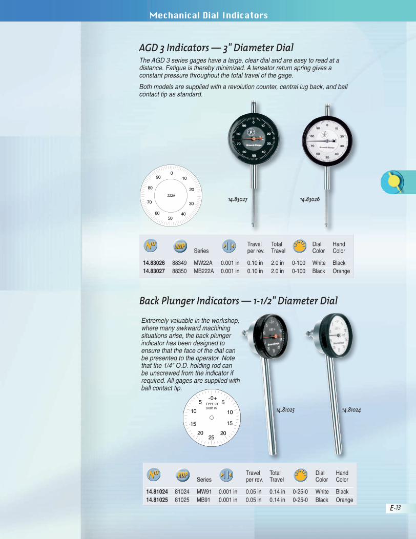
AGD 3 Indicators — 3" Diameter DialThe AGD 3 series gages have a large, clear dial and are easy to read at a distance. Fatigue is thereby min i mized. A tensator return spring gives a constant pressure through out the total travel of the gage.
Both models are supplied with a revolution counter, central lug back, and ballcontact tip as standard.
10
20
30
4050
60
70
80
900
222A
Extremely valuable in the work shop,where many awk ward machining situations arise, the back plungerindicator has been designed toensure that the face of the dial canbe pre sent ed to the op er a tor. Notethat the 1/4" O.D. holding rod can be un screwed from the indicator ifrequired. All gages are supplied withball contact tip.
-0+5
10
15
2025
20
15
10
5 TYPE 910.001 in.
Back Plunger Indicators — 1-1/2" Diameter Dial
Travel Total Dial HandSeries per rev. Travel Color Color
14.83026 88349 MW22A 0.001 in 0.10 in 2.0 in 0-100 White Black14.83027 88350 MB222A 0.001 in 0.10 in 2.0 in 0-100 Black Orange
Travel Total Dial HandSeries per rev. Travel Color Color
14.81024 81024 MW91 0.001 in 0.05 in 0.14 in 0-25-0 White Black14.81025 81025 MB91 0.001 in 0.05 in 0.14 in 0-25-0 Black Orange
14.83027 14.83026
14.81025 14.81024
BRO-03-015E_Indic_1-23:BRO 03 015E Indic 1-23 8/7/06 1:47 PM Page 13

External Micrometers
E-14
Mechanical Dial Indicators
Actual Size Dial Faces
AGD Dial Indicator DimensionsAll Brown & Sharpe Dial Indicators conform to ANSI B89.1.10M specifications.
010
20
30
4050
40
30
20
10
SHOC
K PROOF
.001¨
010
20
30
4050
40
30
20
10
SHOC
K PROO
F
.001¨
*Dimensions courtesy of The American Society Of Mechanical Engineers, ANSI SPEC. B89.1.10M.
C
D
B
1/4 in.3/4 in.
A
5/16 in.
Range
Minimum distancefrom center of holeto nearest projectionon back.
0.375 in.diam.
No. 4-48thread
1/4 in.
Dimension Reference
Bezel Diameter A 1.812 2.250Center Line to Tip of Contact B 1.625 2.000Case Diameter C 1.608 2.031Stem Length D 0.572* 0.739*
*Long Stem Indicators – “D” equals 3.000 inches.
AGD Size (in)1 2
BRO-03-015E_Indic_1-23:BRO 03 015E Indic 1-23 8/7/06 1:48 PM Page 14

External Micrometers
E-15
External MicrometersMechanical Dial Indicators
Quick Selection TableThe Industry’s Most Popular IndicatorsThis quick selection table has been arranged to make it easier to locate theAGD Indicators that you demand most often. Each one is listed again among itsdesignated group in the pages that follow.
Regular ModelsD1-20141A 33638 1 .025 in .0001 in 1.75 0-5-0D1-20241A 33836 2 .025 in .0001 in 2.25 0-5-0D1-20126A 33611 1 .075 in .0005 in 1.75 0-15-0D1-20226A 33786 2 .075 in .0005 in 2.25 0-15-0D1-20111A 33557 1 .250 in .001 in 1.75 0-50-0D1-20211A 33705 2 .250 in .001 in 2.25 0-50-0
Long-Range IndicatorsD5-21221F 86002 2 1.00 in .0005 in 2.25 0-50
1-Rev IndicatorsD1-23226A 86006 2 .025 in .0005 in 2.25 0-10-0D1-23241A 34018 2 .008 in .0001 in 2.25 0-4-0
Metric IndicatorsD1-20261A 33857 2 2.5mm 0.01 mm 2.25 0-50-0D1-20281A 33886 2 0.5mm 0.002 mm 2.25 0-10-0
AGDGroup
DialDia.
BRO-03-015E_Indic_1-23:BRO 03 015E Indic 1-23 8/7/06 1:48 PM Page 15

External Micrometers
E-16
Mechanical Dial Indicators
�
Rotating dialwith lock
Full metal case housing
and bevel
Identificationnumber
Declaration ofconformity
Plastic box
in in in
D1-20111A 33557 1 .250 .100 .001D1-20211A 33705 2 .250 .100 .001D1-20126A 33611 1 .075 .030 .0005D1-20226A 33786 2 .075 .030 .0005D1-20141A 33638 1 .025 .010 .0001D1-20241A 33836 2 .025 .010 .0001
AGDGroup
Regular ModelsConform to ANSI B89.1.10M Specifications.
• High performance, shockproof design.• Hardened steel contact point.• Vertical centered lug back.• Balanced dial reading.
Precision BearingsThe sizes, materials, and finishes of pivots and bearings are the best possiblechoice for optimum Indicator performance and lowest cost of ownership.
*For AGD Dimensions, see page E-15.
BRO-03-015E_Indic_1-23:BRO 03 015E Indic 1-23 8/7/06 1:49 PM Page 16

External Micrometers
E-17
External MicrometersMechanical Dial Indicators
Intermediate RangeIndicators are a standardmodification of the RegularAGD Indicators. Designedto meet the occasionalrequirement for extrarange, they are suppliedwith a balanced dial and a revolution counter forcomparative-type readingapplications.
Intermediate Range IndicatorsConform to ANSI B89.1.10M Specifications.
• High performance, shockproof design.• Hardened steel contact point.• Vertical centered lug back.• Balanced dial reading.• Revolution counter.• Tolerance pointers.
D2-29111E 34052 1 .312 in .100 in .001 inD2-29211E 34117 2 .312 in .100 in .001 inD2-29128E 34080 1 .312 in .040 in .0005 inD2-29228E 34157 2 .312 in .040 in .0005 inD2-29141E 34088 1 .100 in .010 in .0001 inD2-29241E 34169 2 .100 in .010 in .0001 inD2-29161E 34097 1 8.0 mm 1.0 mm .01 mmD2-29261E 34181 2 8.0 mm 1.0 mm .01 mmD2-29181E 34112 1 1.9 mm 0.2 mm .002 mmD2-29281E 34192 2 1.9 mm 0.2 mm .002 mm
AGDGroup
02
4
9
1
4
6
89 10
D2-29181
SH
OCKPROOF
0.002mm
0 987
65432
1
23
5
78
7
6
5
3
1010
20
30
10
20
30
4050
40D2-29161
SH
OCKPROOF
0.01mm
0 987
65432
1
01
2
3
45
4D1-29141
SH
OCKPROOF
.0001"3
4
5
6
7
23
0
5
10
15
20
D1-29128
.0005"
SH
OCKPROOF
23
010
20
30
10
20
30
4050
40D1-29111
SH
OCKPROOF
.001"
0 123
45432
1
*The periphery of dial designs are identical to Regular Model dials.*For AGD Dimensions, see page E-15.
�
Rotating dialwith lock
Full metal case housing
and bevel
Identificationnumber
Declaration ofconformity
Plastic box
BRO-03-015E_Indic_1-23:BRO 03 015E Indic 1-23 8/7/06 1:51 PM Page 17
External Micrometers
E-18
Mechanical Dial Indicators
�
Rotating dialwith lock
Full metal case housing
and bevel
Identificationnumber
Declaration ofconformity
Plastic box
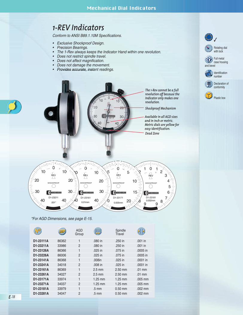
1-REV IndicatorsConform to ANSI B89.1.10M Specifications.
• Exclusive Shockproof Design.• Precision Bearings.• The 1-Rev always keeps the Indicator Hand within one revolution.• Does not restrict spindle travel.• Does not affect magnification.• Does not damage the movement.• Provides accurate, instant readings.
D1-23111A 86362 1 .080 in .250 in .001 inD1-23211A 33986 2 .080 in .250 in .001 inD1-23126A 86366 1 .025 in .075 in .0005 inD1-23226A 86006 2 .025 in .075 in .0005 inD1-23141A 86368 1 .008in .025 in .0001 inD1-23241A 34018 2 .008 in .025 in .0001 inD1-23161A 86369 1 2.5 mm 2.50 mm .01 mmD1-23261A 34027 2 2.5 mm 2.50 mm .01 mmD1-23171A 33974 1 1.25 mm 1.25 mm .005 mmD1-23271A 34037 2 1.25 mm 1.25 mm .005 mmD1-23181A 33979 1 .5 mm 0.50 mm .002 mmD1-23281A 34047 2 .5 mm 0.50 mm .002 mm
SpindleTravel
AGDGroup
*For AGD Dimensions, see page E-15.
02
4
6
2
8 8D1-23181
REV
1
3
5
7
99
1
SHOCKPROOF
0.002mmD1-23171
0.005mm
05
10
15
20
5
10
5
0
SHOCKPROOF
REV
010
20
30
10
40 40D1-23161
REV
SHOCKPROOF
0.01mm
D1-23211
REV
SHOCKPROOF
.001"
010
20
30
10
40 40
30
20
The 1-Rev cannot be a fullrevolution off because theIndicator only makes onerevolution.
Shockproof Mechanism
Available in all AGD sizesand in inch or metric.Metric dials are yellow foreasy identification.Dead Zone
BRO-03-015E_Indic_1-23:BRO 03 015E Indic 1-23 8/7/06 1:52 PM Page 18

External Micrometers
E-19
External MicrometersMechanical Dial Indicators
�
Rotating dialwith lock
Full metal case housing
and bevel
Identificationnumber
Declaration ofconformity
Plastic box
5" Long Stem IndicatorsConform to ANSI B89.1.10M Specifications.
When a surface is difficult to access, a Long Stem Indicator can be used toreach it without losing measuring accuracy and without great expense. Stemlengths are 5" long.
• High performance, shockproof design.• Hardened steel contact point.• Vertical centered lug back.• Balanced dial reading.• Revolution counter.• Tolerance pointers.
*For AGD Dimensions, see page E-15.
D4-20226A 34400 2 .075 in .030 in .0005 inD4-20261A 34417 2 2.5 mm 1.0 mm .01 mm
AGDGroup
BRO-03-015E_Indic_1-23:BRO 03 015E Indic 1-23 8/7/06 1:53 PM Page 19

External Micrometers
E-20
Mechanical Dial Indicators
�
Rotating dialwith lock
Full metal case housing
and bevel
Identificationnumber
Declaration ofconformity
Plastic box
Metric Indicators – Regular Models• High performance, shockproof design.• Hardened steel contact point.• Vertical centered lug back.• Balanced dial reading.
mm mm mm
D1-20161A 33653 1 2.5 1.0 .01D1-20261A 33857 2 2.5 1.0 .01D1-20171A 33670 1 1.25 0.5 .005D1-20271A 33873 2 1.25 0.5 .005D1-20181A 33686 1 0.5 0.2 .002D1-20281A 33886 2 0.5 0.2 .002
AGDGroup
BRO-03-015E_Indic_1-23:BRO 03 015E Indic 1-23 8/7/06 1:53 PM Page 20

External Micrometers
E-21
External MicrometersMechanical Dial Indicators
D5-21221F 86002 2 1.000 in .050 in .0005 inD5-21201F 34434 2 30 mm 1 mm .01 mm
AGDGroup
Long Range Indicators
• Continuous and Balanced Dials.• Revolution Counter.• Precision Bearings.
Long-Range Lifting LeverCatalog No. 599-8400-279
*For AGD Dimensions, see page E-15.
�
Rotating dialwith lock
Full metal case housing
and bevel
Identificationnumber
Declaration ofconformity
Plastic box
BRO-03-015E_Indic_1-23:BRO 03 015E Indic 1-23 8/7/06 1:54 PM Page 21

External Micrometers
E-22
Mechanical Dial Indicators
IP54 IndicatorIP54 – Waterproof protection (Norm IEC 60529)
Fully protected against the penetration of liquid or solid contaminants. Dust,particles of metal, spraying water or oil are prevented from entering the indicator.
• Corrosion resistant.• High performance, shockproof design.• Hardened steel contact point.• Vertical centered lug back.• Balanced dial reading.• Revolution counter.• Tolerance pointers.
D2-29111F-W 28629 .001 in .100 in .200 in 0-50-0 WhiteD2-29228F-W 28630 .0005 in .050 in .400 in 0-25-0 WhiteD2-29161F-W 28631 0.01 mm 0.5 mm 5 mm 0-50 YellowD2-29261F-W 28632 0.01 mm 1 mm 10 mm 0-100 Yellow
DialColor
In a shop environment, Precision Dial Gages are in constant contact with oil,water mist and dust. Hermetically sealed IP54 waterproof gages from Brown &Sharpe are specifically designed to withstand these conditions.
Features:• A flexible rubber bellows is fitted where the spindle enters the stem.• The upper end of the measuring spindle is sealed by a safety cap and an
“O” ring.• A new design of the external metal ring and its assembly produces a perfect
seal. Its special features include “O” rings, flat glasses and a screwed onbrass ring. An additional “O” ring is placed between the rotating outer ringand the indicator’s metal housing.
• The back plate is fitted to prevent foreign matter from entering.
BRO-03-015E_Indic_1-23:BRO 03 015E Indic 1-23 8/7/06 1:55 PM Page 22

External Micrometers
E-23
External MicrometersMechanical Dial Indicators
90˚ Models• Precision Bearings.• Metric Indicators are supplied with yellow tinted faces.• 8 mm stem supplied with .375" bushing.• Revolution counter.• Tolerance pointer.
D9-20111E 34479 1 .200 in .100 in .001 inD9-20221E 34526 2 .125 in .050 in .0005 inD9-20161E 34507 1 2.5 mm 1.0 mm .01 mmD9-20261E 34552 2 2.5 mm 1.0 mm .01 mm
AGDGroup
.375" bushing35.60101
BRO-03-015E_Indic_1-23:BRO 03 015E Indic 1-23 8/7/06 1:56 PM Page 23

E-24
External MicrometersElectronic IndicatorsMechnical Dial Indicators
AGD Dial Indicator Contacts
Mushroom
Material in
D0-03405 33480 Steel 3/32D0-80109 33477 Steel 1/8D0-03466 33481 Carbide 1/8
RegularFurnished on all in di ca tors unless otherwise specified.
Material in
D0-80001 33460 Steel 1/8D0-80104 33474 Steel 1/4D0-03024 33430 Steel 3/8D0-03032 33433 Steel 1/2D0-03040 33436 Steel 5/8D0-03048 33438 Steel 3/4D0-03056 33439 Steel 7/8D0-03100 33447 Steel 1D0-03132 33452 Steel 1-1/2D0-03140 33453 Steel 1-5/8D0-03148 33454 Steel 1-3/4D0-03156 33455 Steel 1-7/8D0-03200 33456 Steel 2D0-03208 33457 Steel 2-1/8D0-03216 33458 Steel 2-1/4D0-03224 33459 Steel 2-3/8D0-03240 33462 Steel 2-5/8D0-03248 33463 Steel 2-3/4D0-03256 33467 Steel 2-7/8D0-03263 33468 Steel 3D0-03308 33469 Steel 3-1/8D0-03316 33470 Steel 3-1/4D0-03366 33475 Carbide 1/4D0-03250 33464 Diamond 1/4
Flat
Material in
D0-80101 33476 Steel 5/32D0-03364 33473 Steel 1/4D0-03013 33420 Steel 3/8D0-03014 33421 Steel 1/2D0-03015 33422 Steel 5/8D0-03016 33423 Steel 3/4D0-03017 33424 Steel 7/8D0-03018 33425 Steel 1D0-03363 33472 Carbide 1/4
Extension
Material in
D0-80102 33431 Steel 7/16D0-03058 33440 Steel 7/8D0-70160 33539 Steel 1D0-03123 33450 Steel 1-3/8
Large Wide Face
Material in
D0-03403 33478 Steel 1/8
Presser Foot
Material in
D0-80103 33543 Steel 7/16
Needle Point
Material in
D0-80007 33545 Steel 1/2D0-80007 33544 Steel 5/8D0-73517A 33547 Carbide 1/2D0-73517 33546 Carbide 5/8
Taper
Material in
D0-80005 33426 Steel 7/16D0-80010 33427 Steel 1D0-03021 33428 Steel 1-7/16D0-03022 33429 Steel 2
Shock Absorbing
Material in
D0-80105 33471 Steel 5/8
BRO-03-015E_Indic_24-53:BRO 03 015E_Indic_24-56 8/7/06 2:01 PM Page 24

E-25
Mechnical Dial Indicators
Contact Points with M2.5 Threads
Measuring insert with off-center, narrowmeasuring face. Lock nut for radial alignment.
Bmm
35.10602 28662 Carbide 0.5
Measuring insert with adjustable narrowmeasuring face (parallelism). Lock nut for radial alignment.
Bmm
35.10702 28663 Carbide 0.5
Measuring insert with a flat, adjustable measuring face (parallelism). Lock nutfor radial alignment.
mm
35.10902 28668 Carbide 2.5
16
3,3
56,
5 1
5
0,5
Measuring insert with a cylindrical measuring face. Lock nut for radial alignment.
35.10502 28661 CarbideMeasuring inserts with blade-shapedmeasuring faces. Lock nut for radial alignment.
Bmm
35.60024 28655 Steel 0.335.60025 28656 Carbide 0.3
Measuring inserts with blade-shapedmeasuring faces, in steel. Lock nut forradial alignment.
35.60031 28657 5 0.235.60032 28658 10 0.235.60033 28659 15 0.235.60034 28660 20 0.2
Lmm
Bmm
Measuring insert with needle contactpoint.
35.60030 28652 Steel
Measuring inserts with ball-bearingrollers. Lock nut for radial alignment.
Shape
35.60010 28653 Steel Cylindrical35.60011 28654 Steel ball-shaped
Measuring insert with offset (A) contact point. Lock nut for radial alignment.
Amm
35.60063 28651 Steel 12
ø2
6
3,3
2,5
1.6
3,02,0
8
7,5
7
13
6
1,6
0,00
3
2,5
ø4
2,3
16
0,5 ø7,5
Measuring inserts with a flat measuring face.
mm
35.10801 28664 Steel 2.535.10802 28665 Carbide 2.535.60022 28666 Steel 3.435.60023 28667 Carbide 3.4
6ø
D
ø4
DO-69998 28650
BRO-03-015E_Indic_24-53:BRO 03 015E_Indic_24-56 8/7/06 2:01 PM Page 25

E-26
External MicrometersElectronic IndicatorsMechnical Dial Indicators
AGD Dial Indicator Backs for Prior Design(Indicators purchased before 01/2002)
A.G.D. Mil. Spec. LugFurnished on all dial indicators unless otherwise specified.
D0-29002 33497 1D0-29202 33507 2
AGDGroup
A.G.D. Mil. Spec. Offset Lug
D0-29001 33496 1D0-29201 33506 2
AGDGroup
LC
LC
Dovetail Rack
D0-29056 33500 1D0-29256 33511 2
AGDGroup
A.G.D. Mil. Spec. Post
D0-29069 33504 1D0-29269 33515 2
AGDGroup
.875 to Spindle
Lc
.5621.50
.635
1.001.50
.938
Flat
D0-29021 33499 1D0-29221 33509 2
AGDGroup
Dovetail Bracket
D0-29253 33510(fits both sizes)
A.G.D. Mil. Spec. Screw
D0-29068 33503 1D0-29268 33514 2
AGDGroup
A.G.D. Mil. Spec. Adjustable
D0-29003 33498 1D0-29203 33508 2
AGDGroup
Style H
Style K Style M Style N
Style P Style R Style T
BRO-03-015E_Indic_24-53:BRO 03 015E_Indic_24-56 8/7/06 2:03 PM Page 26

E-27
Mechnical Dial Indicators
AGD Dial Indicator Backs for Current Design(Indicators purchased during or after 01/2002)
A.G.D. Mil. Spec. LugFurnished on all dial indicators unless otherwise specified.
D0-29002-1 28669 1D0-29202-1 28670 2
AGDGroup
A.G.D. Mil. Spec. Offset Lug
D0-29001-1 28671 1D0-29201-1 28672 2
AGDGroup
LC
Flat
D0-29021-1 28673 1D0-29221-1 28674 2
AGDGroup
A.G.D. Mil. Spec. Post
D0-29069-1 28675 1D0-29269-1 28676 2
AGDGroup
A.G.D. Mil. Spec. Screw
D0-29068-1 28677 1D0-29268-1 28678 2
AGDGroup
To order an indicatorwith a specif ic back,place the style let terdesignat ion at the endof the indictator partnumber. For example,a D1-20241A indicator(shown on page E-17)wi l l be shipped with af lat back i f the stylelet ter K is added to theend of the part number,as D1-20241AK.
Style NStyle K
Style P Style R
A.G.D. Mil. Spec. Adjustable
D0-29203 -1 2
AGDGroup
Style H
BRO-03-015E_Indic_24-53:BRO 03 015E_Indic_24-56 8/7/06 2:04 PM Page 27

E-28
External MicrometersElectronic IndicatorsMechnical Dial Indicators
Indicator Dial OptionsSolid DialContinuous dial reading clockwise or coun ter clockwise, or balanced dial with“plus" or “minus" signs.
Format ABalanced Numbering
(Plus on right, minus on left)
010
20
30
4050
40
30
20
10.001¨
Double Dials - Revolution Counting HandsCon tin u ous dials reading clock wise or coun ter clock wise, or balanced dialswithout “plus” or “minus” signs, complete with revolution counting hands.
Format EBalanced Numbering
(Plus and minus omitted)
Format FContinuous Clockwise
Numbering
010
20
30
4050
40
30
20
10 .001¨
0 123
45
1234
0
10
20
30
4050
60
70
80
90 .001¨
0 987
65
1234
MADE IN U.S.A.
BRO-03-015E_Indic_24-53:BRO 03 015E_Indic_24-56 8/7/06 2:04 PM Page 28

E-29
Mechnical Dial Indicators
AGD Dial Indicator Accessories
D0-69984 33538
Moisture Seal*
Bell Crank*Collet Clamp
in
D0-48255 33521 12
B&S 599-8941 45054B&S 599-8940 (9/16-18 Thrd.) 45053
* Fits all .375 AGD Mil. Spec. stem diameters
Hole Attachments*
in
D0-69974 33534 .25D0-69975 33535 .50
.81
2.06
.87
1.81
3.81
.87
1.125"
1.125"
BRO-03-015E_Indic_24-53:BRO 03 015E_Indic_24-56 8/7/06 2:05 PM Page 29

E-30
External MicrometersElectronic IndicatorsMechnical Dial Indicators
Long-Range Lifting Lever
Split Bushing*
Holding Rod
in
For 90° IndicatorsD0-95020 33548 0.31D0-95030 33549 0.25D0-95050 33550 0.38
D0-69976 33536
All dimensions are in inches unless otherwise specified.
* Fits all .375 AGD Mil. Spec. stem diameters
in
D0-48279 33522 0 - 1
Used primarily on D5-21211 to providefor full spindle re trac tion.
AGD Dial Indicator Accessories (cont.)
.50
.50
2.50
BRO-03-015E_Indic_24-53:BRO 03 015E_Indic_24-56 8/7/06 2:06 PM Page 30

E-31
Mechnical Dial Indicators
�
Wood case
Contact Point SetEliminates trouble in measuring hard-to-get-at places and en ables you to makecomplete use of your Dial Indicator. The set includes 22 points in variousshapes and sizes.
The set is supplied with a fitted case. Points have AGD Stan dard #4-48 threadsand are protected against corrosion.
AGD Dial Indicator Accessories
599-7886 44958
Material in
BlanksD0-03007 33414 Steel 1/2D0-03008 33415 Steel 3/4D0-03009 33416 Steel 1D0-03010 33417 Steel 1-1/2D0-03011 33418 Steel 2D0-03012 33419 Steel 2-1/2
BRO-03-015E_Indic_24-53:BRO 03 015E_Indic_24-56 8/7/06 2:07 PM Page 31
Related Documents