SERVICE MANUAL MODEL:HL-1260 R LASER PRINTER Downloaded from www.Manualslib.com manuals search engine

Brother Hl1260 Manual
Dec 23, 2015
Service manual fot Brother HL1260 laser printer
Welcome message from author
This document is posted to help you gain knowledge. Please leave a comment to let me know what you think about it! Share it to your friends and learn new things together.
Transcript
SERVICE MANUAL
MODEL:HL-1260
R
LASER PRINTER
Downloaded from www.Manualslib.com manuals search engine

No part this publication may be reproduced in any form or by any means without permission in writingfrom the publisher.
Trademarks:• BR-Script, and DX-1200 are registered trademarks of Brother Industries, Ltd.• Centronics is a registered trademark of Genicom Corporation.• PostScrip is a registered trademark of Adobe Systems Incorporated.• IBM Proprinter XL is a registered trademark of International Business Machines Corporation.• EPSON FX-850 is a registered trademark of Seiko Epson Corporation.• HP-GL and HP Laser Jet 4 are registered trademarks of Hewlett Packard Company.
Downloaded from www.Manualslib.com manuals search engine

This service manual contains basic information required for after-sales service of the laser printer(hereinafter referred to as ”this machine” or ” the printer”). This information is vital to the service technicianin maintaining the high printing quality and performance of the printer.
This manual consists of the following chapters:
Chapter I : General
Features, specifications, etc.
Chapter II : Theory of Operation
Basic operation of the mechanical system and the electrical system, and their timing.
Chapter III : Electrical System
Theory of the electronics circuit
Chapter IV : Mechanical System
Requirements for a suitable location, disassembling and reassembling procedure ofmechanical system.
Chapter V : Maintenance and Servicing
Parts replacement schedule, list of tools, lubricants and cleaners.
Chapter VI : Troubleshooting
Reference values and adjustment, troubleshooting for image defects, troubleshootingfor malfunctions, etc.
Appendices : Engine Block Diagram, PCB Circuitry Diagrams, etc.
Information in this manual is subject to change due to improvement or re-design of the product. All relevantinformation in such cases will be supplied in service information bulletins (Technical Information).
A thorough understanding of this printer, based on information in this service manual and serviceinformation bulletins, is required for maintaining its quality performance and for fostering the practical abilityto find the cause of troubles.
PREFACE
Downloaded from www.Manualslib.com manuals search engine
i
CONTENTS
CHAPTER I GENERAL
1. FEATURES ........................................................................................................................ I-1
2. SPECIFICATIONS .............................................................................................................. I-1
3. SAFETY INFORMATION.................................................................................................... I-6
3.1 Laser Safety (110 - 120V Model only) ...................................................................... I-63.2 CDRH Regulations (110 - 120V Model only) ............................................................ I-73.3 Additional Information .............................................................................................. I-7
4. PARTS OF THE PRINTER ................................................................................................. I-8
4.1 External Views ......................................................................................................... I-84.2 Cross Sectional View ............................................................................................... I-9
5. STORAGE AND HANDLING OF EP-ED CARTRIDGES .................................................. I-10
5.1 Storage of Sealed EP-ED Cartridges ..................................................................... I-105.2 Storage of Unsealed EP-ED Cartridges ................................................................. I-10
CHAPTER II THEORY OF OPERATION
1. BASIC OPERATIONS ....................................................................................................... II-1
1.1 Mechanical Configuration ........................................................................................ II-11.2 Main Drive ............................................................................................................... II-21.3 Basic Sequence of Operations ................................................................................ II-3
2. LASER/SCANNER SYSTEM ............................................................................................ II-4
3. IMAGE FORMATION SYSTEM ......................................................................................... II-5
3.1 Outline ..................................................................................................................... II-53.2 Printing Process ...................................................................................................... II-5
3.2.1 Electrostatic latent image formation stage ................................................ II-63.2.2 Developing stage ...................................................................................... II-83.2.3 Transfer stage ........................................................................................... II-93.2.4 Fixing stage ............................................................................................ II-103.2.5 Drum cleaning stage ............................................................................... II-10
3.3 Operation .............................................................................................................. II-114. PAPER PICK-UP/FEED SYSTEM ................................................................................... II-12
4.1 Outline ................................................................................................................... II-124.2 Cassette Feed ....................................................................................................... II-134.3 MP Tray Feed ........................................................................................................II-144.4 Paper Jam Detection ............................................................................................. II-15
Downloaded from www.Manualslib.com manuals search engine
ii
CHAPTER III ELECTRICAL SYSTEM
1. MAIN PCB ........................................................................................................................ III-1
1.1 Outline .................................................................................................................... III-11.2 Video Controller Circuit .......................................................................................... III-21.3 Engine Controller Circuit ........................................................................................ III-7
2. PAPER FEED DRIVE CIRCUIT ....................................................................................... III-9
3. DISPLAY CIRCUIT ......................................................................................................... III-11
3.1 Outline ..................................................................................................................III-113.2 Operation .............................................................................................................III-11
4. LOW-VOLTAGE POWER SUPPLY ASSY ....................................................................... III-12
4.1 Outline ..................................................................................................................III-124.2 Protection Functions ............................................................................................III-12
5. HIGH-VOLTAGE POWER SUPPLY ASSY ...................................................................... III-14
5.1 Outline ..................................................................................................................III-145.2 Operation of the Components of the High-Voltage Power Supply Assy ............... III-14
CHAPTER IV MECHANICAL SYSTEM
PRINTER DISASSEMBLING PROCEDURE
PRINTER BODY1.1 Configuration .......................................................................................................... IV-31.2 Toner Cartridge Lid ................................................................................................ IV-31.3 Side Cover L .......................................................................................................... IV-31.4 Font Cover Assy ..................................................................................................... IV-41.5 Upper Cover Assy, Rear Cover Assy ...................................................................... IV-4
1.5.1 Upper cover assy, rear cover assy ........................................................... IV-41.5.2 Changeover guide, jam remove cover ...................................................... IV-5
1.6 Side Cover R .......................................................................................................... IV-51.7 DC Fan Motor ......................................................................................................... IV-61.8 Main PCB ............................................................................................................... IV-61.9 Control Panel Unit .................................................................................................. IV-81.10 Scanner Unit .......................................................................................................... IV-91.11 Cartridge Stopper Assy .......................................................................................... IV-91.12 Paper Feed Chassis Unit ..................................................................................... IV-101.13 Separation Pad Assy ............................................................................................ IV-111.14 MP PE Sub Actuator ............................................................................................ IV-121.15 P Feed /Size-SW PCB Assy ................................................................................. IV-121.16 Side-Switch Spring ............................................................................................... IV-121.17 Regist Sensor Actuator ........................................................................................ IV-131.18 MP Paper Detection Actuator ............................................................................... IV-131.19 PE Sensor Actuator MP ....................................................................................... IV-131.20 Tray Sensor Holder .............................................................................................. IV-141.21 Roller Holder ........................................................................................................ IV-141.22 Paper Pick-up Roller Assy, Bearing ...................................................................... IV-151.23 Paper Pick-up Solenoid ........................................................................................ IV-161.24 Paper Feed Motor Assy ........................................................................................ IV-161.25 MP Tray Cover ...................................................................................................... IV-171.26 MP Tray Assy ....................................................................................................... IV-171.27 Paper Path Separation Plate, Paper Path Separation Film .................................. IV-181.28 Latch .................................................................................................................... IV-191.29 Fixing Unit (for both 120V and 230V, the only difference is the halogen heater) . IV-191.30 Transfer Unit ......................................................................................................... IV-22
Downloaded from www.Manualslib.com manuals search engine
iii
1.31 DC Gear Holder Assy ........................................................................................... IV-231.32 PS Switch Wire, Remote Switch .......................................................................... IV-231.33 High-Voltage Power Supply PCB Assy ................................................................. IV-241.34 Low-Voltage Power Supply PCB Assy .................................................................. IV-241.35 Toner Cartridge (EP-ED Cartridge) ...................................................................... IV-251.36 Paper Tray ............................................................................................................ IV-25
CHAPTER V MAINTENANCE AND SERVICING
1. PERIODICAL REPLACEMENT PARTS ............................................................................ V-1
2. CONSUMABLE PARTS STANDARD ENDURANCE TABLE ............................................. V-1
3. LIST OF STANDARD TOOLS ............................................................................................ V-2
4. LIST OF LUBRICANTS AND CLEANERS ........................................................................ V-3
CHAPTER VI TROUBLESHOOTING
1. INTRODUCTION ..............................................................................................................VI-1
1.1 Initial Check............................................................................................................VI-11.2 Basic Procedure .....................................................................................................VI-2
2. TEST PRINTING AND MECHANICAL CHECK ...............................................................VI-2
2.1 Test Printing ........................................................................................................... VI-23. IMAGE DEFECTS ............................................................................................................VI-3
3.1 Image Defect Examples .........................................................................................VI-33.2 Troubleshooting Image Defects ..............................................................................VI-4
4. TROUBLESHOOTING OF MALFUNCTIONS ................................................................ VI-11
5. TROUBLESHOOTING PAPER TRANSPORT PROBLEMS ........................................... VI-19
5.1 Paper Jams ..........................................................................................................VI-195.2 Incomplete Paper Feed ........................................................................................VI-22
6. OPERATION ..................................................................................................................VI-23
6.1 Line Inspection Mode Procedure .........................................................................VI-236.2 DRAM Test ...........................................................................................................VI-25
7. STATUS MESSAGE LIST ............................................................................................... VI-26
APPENDICES
1. Engine Block Diagram ....................................................................................................... A-1
2. Paper Feed/Size-SW PCB Circuitry Diagram (1/1)............................................................ A-2
3. Main PCB Circuitry Diagram (1/8) ..................................................................................... A-3
4. Main PCB Circuitry Diagram (2/8) ..................................................................................... A-4
5. Main PCB Circuitry Diagram (3/8) ..................................................................................... A-5
6. Main PCB Circuitry Diagram (4/8) ..................................................................................... A-6
7. Main PCB Circuitry Diagram (5/8) ..................................................................................... A-7
8. Main PCB Circuitry Diagram (6/8) ..................................................................................... A-8
9. Main PCB Circuitry Diagram (7/8) ..................................................................................... A-9
10. Main PCB Circuitry Diagram (8/8) ................................................................................... A-10
11. Control Panel PCB Circuitry Diagram (1/1) ..................................................................... A-11
12. Scanner LD PCB Circuitry Diagram (1/1) ........................................................................ A-12
Downloaded from www.Manualslib.com manuals search engine
I - 1
CHAPTER I GENERAL
1. FEATURES
A. This high-speed, non-impact (low-noise) printer is based on electrophotography, electronicsand laser technology.
B. The printer is compact and easy to carry. The internally-storable, front-loading papercassette enables you to save an occupation space for the machine; the printer can nowbe installed in a smaller place.
C. The charging roller, developing cylinder, photosensitive drum and cleaner of the printerare combined into a single assembly called an ”EP-ED cartridge”. The cartridge can bereplaced by the user when necessary without a need of service call. High printing qualityis maintained by a simple cleaning procedure.
D. Laser beam safety is designed into the printer. The printer is approved by the US Centerfor Devices and Radiological Health (CDRH).
E. Paper can be fed in two ways, by the multi-purpose paper feed tray and paper cassette.
F. Maintenance is easy with print component units which are directly detachable, and theyrequire no adjustment after reassembly.
2. SPECIFICATIONS
(1) Type Desktop page printer
(2) Printing method Electrophotography (single-component dry toner)
(3) Printing speed
Cassette feed 12 pages/minute (A4/Letter size by cassette feed)10.2 pages/minute (Legal size)
(4) First print time Approx. 20 seconds(A4 size by face-down print delivery from the paper cassette)
(5) Warm-up (WAIT) time Max. 1 minute at 20°C (68°F)
(6) Optical system
Laser Semiconductor laserOutput power : 5mW max.Wave length : 780 nm
Scanning system Rotating six-faced polygon mirror
(7) Resolution
Horizontal 600 dots/inch and high resolution control (HRC)Vertical 600 raster lines/inch
Downloaded from www.Manualslib.com manuals search engine
I - 2
(8) Printing system
Photosensitive drum OPCCharging Charging RollerExposure Laser scanning systemDevelopment Toner projection development systemPaper feed Cassette or manual feedImage transfer Roller methodSeparation Natural(utilizing a small drum radius), Static charge eliminatorFixing Heated fixing rollerToner supply Included in the replaceable EP-ED cartridgeLife expectancy 6000 pages/cartridge
(9) Paper
Cassette feed Plain paper for Letter, Legal, A4, ISO B5, A5, ISO B6, A6,Executive (A4 or letter size paper with the print density set atlevel 8 with 4% coverage, recommended: 60 g/m 105 g/m )and Envelope (com10, monarch, C5, DL, ISO B5)
Multi-purpose Tray Plain paper of 90 x 148 mm 216 x 356 mm (recommended:60g/m 135 g/m , overhead projector (OHP) film, postcards,label stock and envelopes (specified sizes)
(10) Cassette (Tray 1)
Universal cassette A4, Letter, Legal, ISO B5, Executive, A5, ISO B6, and A6
Maximum load height 55 mm (500 sheets of 80 g/m paper)
Feedable paper type 60 105 g/m
Envelopes 40 envelopes
(11) Print delivery Face-down or (face-up)
(12) Print delivery tray capacity
Face-down 250 sheets (80 g/m )Face-up Discharge only
2
2
2 2
2
2
2
Downloaded from www.Manualslib.com manuals search engine
I - 3
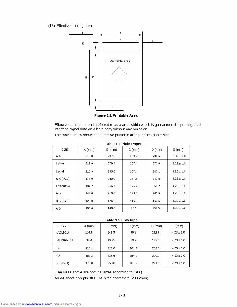
Effective printable area is referred to as a area within which is guaranteed the printing of allinterface signal data on a hard copy without any omission.
The tables below shows the effective printable area for each paper size.
SIZE A (mm) B (mm) C (mm) D (mm)
COM-10
MONARCH
DL
B5 (ISO)
C5
104.8 241.3 96.3 232.8
98.4 190.5 89.9 182.0
110.1 221.0 101.6 212.5
162.2 228.6 154.1 220.1
176.0 250.0 167.5 241.5
E (mm)
4.23 ± 1.0
4.23 ± 1.0
4.23 ± 1.0
4.23 ± 1.0
4.23 ± 1.0
SIZE A (mm) B (mm) C (mm) D (mm)
A 4
Letter
Legal
Executive
B 6 (ISO)
A 6
B 5 (ISO)
A 5
210.0 297.0 203.2 288.5
215.9 279.4 207.4 270.9
215.9 355.6 207.4 347.1
176.0 250.0 167.5 241.5
184.2 266.7 175.7 258.2
148.0 210.0 139.5 201.5
125.0 176.0 116.5 167.5
105.0 148.0 96.5 139.5
E (mm)
3.39 ± 1.0
4.23 ± 1.0
4.23 ± 1.0
4.23 ± 1.0
4.23 ± 1.0
4.23 ± 1.0
4.23 ± 1.0
4.23 ± 1.0
(The sizes above are nominal sizes according to ISO.)
An A4 sheet accepts 80 PICA-pitch characters (203.2mm).
(13) Effective printing area
Printable area
E
DB
C EE
AE
Figure 1.1 Printable Area
Table 1.2 Envelope
Table 1.1 Plain Paper
Downloaded from www.Manualslib.com manuals search engine
I - 4
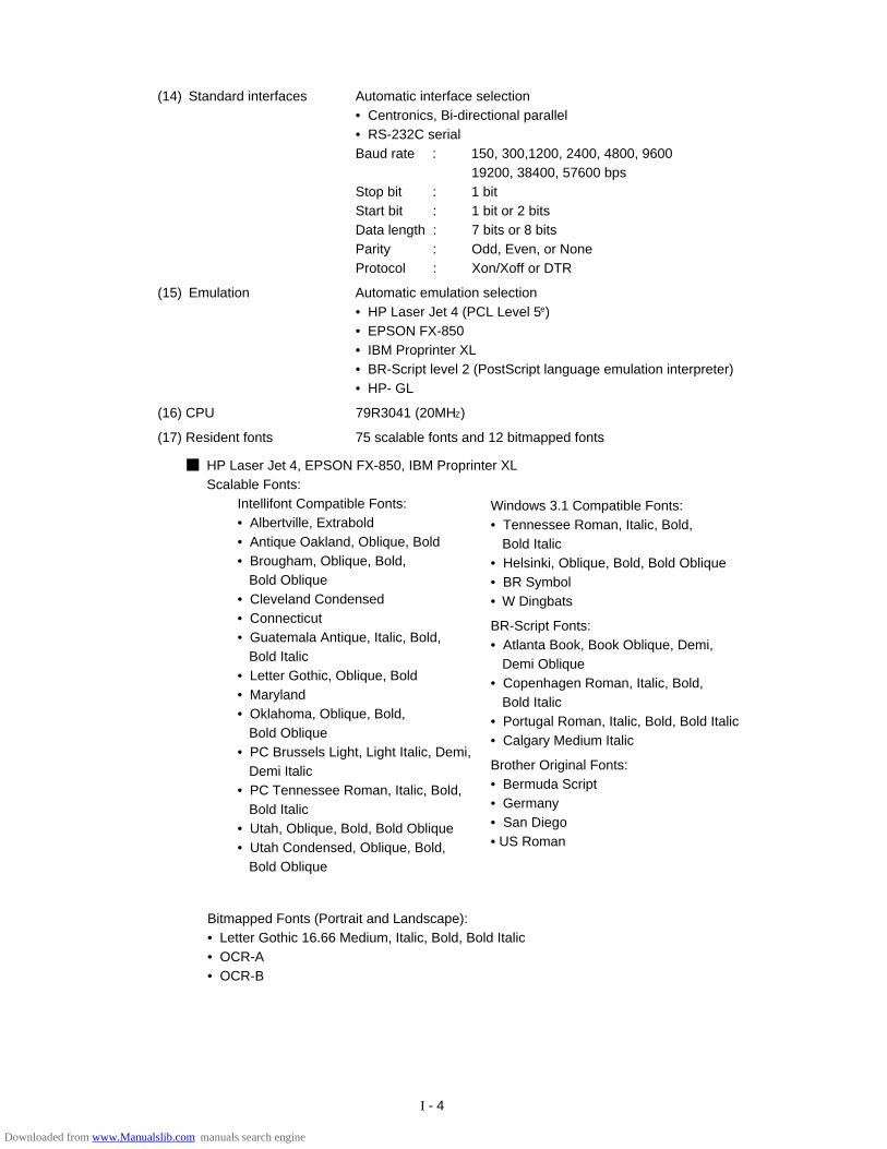
(14) Standard interfaces Automatic interface selection• Centronics, Bi-directional parallel• RS-232C serialBaud rate : 150, 300,1200, 2400, 4800, 9600
19200, 38400, 57600 bpsStop bit : 1 bitStart bit : 1 bit or 2 bitsData length : 7 bits or 8 bitsParity : Odd, Even, or NoneProtocol : Xon/Xoff or DTR
(15) Emulation Automatic emulation selection• HP Laser Jet 4 (PCL Level 5e)• EPSON FX-850• IBM Proprinter XL• BR-Script level 2 (PostScript language emulation interpreter)• HP- GL
(16) CPU 79R3041 (20MHZ)
(17) Resident fonts 75 scalable fonts and 12 bitmapped fonts
HP Laser Jet 4, EPSON FX-850, IBM Proprinter XLScalable Fonts:
Intellifont Compatible Fonts:• Albertville, Extrabold• Antique Oakland, Oblique, Bold• Brougham, Oblique, Bold,
Bold Oblique• Cleveland Condensed• Connecticut• Guatemala Antique, Italic, Bold,
Bold Italic• Letter Gothic, Oblique, Bold• Maryland• Oklahoma, Oblique, Bold,
Bold Oblique• PC Brussels Light, Light Italic, Demi,
Demi Italic• PC Tennessee Roman, Italic, Bold,
Bold Italic• Utah, Oblique, Bold, Bold Oblique• Utah Condensed, Oblique, Bold,
Bold Oblique
Bitmapped Fonts (Portrait and Landscape):• Letter Gothic 16.66 Medium, Italic, Bold, Bold Italic• OCR-A• OCR-B
Windows 3.1 Compatible Fonts:• Tennessee Roman, Italic, Bold,
Bold Italic• Helsinki, Oblique, Bold, Bold Oblique• BR Symbol• W Dingbats
BR-Script Fonts:• Atlanta Book, Book Oblique, Demi,
Demi Oblique• Copenhagen Roman, Italic, Bold,
Bold Italic• Portugal Roman, Italic, Bold, Bold Italic• Calgary Medium Italic
Brother Original Fonts:• Bermuda Script• Germany• San Diego• US Roman
Downloaded from www.Manualslib.com manuals search engine

I - 5
(18) RAM 2M bytes (expandable to 26M bytes)
(19) Font cartridge/card slots Two slotsOne font cartridge slot and one font card slot
(20) Power souse USA and Canada : AC 110 to 120 V, 60 HZ
Europe and Australia : AC 220 to 240 V, 50 HZ
(21) Power consumption Printing : 500 WH or lessStand-by : 80 WH or lessSleep : 20 WH
(22) Noise Printing : 49 dB A or lessStand-by : 40 dB A or less
(23) Dimensions (W x H x D) 371.6 x 326.5 x 393 mm (14.6 x12.9 x 15.5 inches)
(24) Weight Approx. 15 kg (32.6 Ibs)
(25) Environmental conditions
Operating Temperature 10 ~ 32.5°Cenvironment Relative humidity 20 ~ 80%RH
(No condensation allowed)Air pressure 613 ~ 1013 hPa
(0 ~ 2,500 m above sea level)
Non-operating Temperature 0 ~ 35°Cenvironment Relative humidity 10 ~ 80%RH
(No condensation allowed)
Storage conditions
• Printer TemperatureNormal (total storage time x 9/10)
0 ~ 35°CSevere (total storage time x 1/10)
High Low35°C ~ 60°C -20°C ~ 0°C
Temperature change (within 3 minutes) High Low
60°C 15°C -20°C 25°C
• Albertville, Extrabold• Antique Oakland, Oblique, Bold• Cleveland Condensed• Conecticut• Guatemala Antique, Italic, Bold, Bold Italic• Letter Gothic, Oblique, Bold• Maryland• Oklahoma, Oblique, Bold, Bold Oblique• Utah, Oblique, Bold, Bold Oblique• Utah Condensed, Oblique, Bold,
Bold Oblique• Bermuda Script• Germany• San Diego• US Roman
BR-Script Level 2 Mode
Scalable Fonts:• Atlanta Book, Book Oblique, Demi,
Demi Oblique• Brussels Light, Light Italic, Demi,
Demi Italic• Brougham, Oblique, Bold, Bold Oblique• Helsinki, Oblique, Bold, Bold Oblique• Helsinki Narrow, Oblique, Bold,
Bold Oblique• Copenhagen Roman, Italic, Bold,
Bold Italic• Portugal Roman, Italic, Bold, Bold Italic• Tennessee Roman, Italic, Bold, Bold Italic• Calgary Medium Italic• BR Symbol• BR Dingbats
Downloaded from www.Manualslib.com manuals search engine
I - 6
• EP-ED cartridge TemperatureNormal (2.45 years max.)
0 ~ 35°CSevere (0.05 years max.)
High Low35°C ~ 40°C -20°C ~ 0°C
Temperature change (within 3 minutes) High Low40°C 15°C -20°C 25°C
Relative humidityNormal (2.45 years max.)
35 ~ 85%RHSevere (0.05 years max.)
High Low85 ~ 95%RH 10 ~ 35%RH
Air pressure 613 ~ 1013 hPa
Maximum total storage time: 2.5 years including used time
3. SAFETY INFORMATION
3.1 Laser Safety (110 ~ 120V Model only)
This printer is certified as a Class 1 laser product under the US Department of Health andHuman Services (DHHS) Radiation Performance Standard according to the RadiationControl for Health and Safety Act of 1968. This means that the printer does not producehazardous laser radiation,
Since radiation emitted inside the printer is completely confined within the protectivehousings and external covers, the laser beam cannot escape from the machine during anyphase of user operation.
Relative humidityNormal (total storage time x 9/10)
35 ~ 85%RHSevere (total storage time x 1/10)
High Low85 ~ 95%RH 10 ~ 35%RH
Air pressure 613 ~ 1013 hPa
Total storage time 0.5 years
Downloaded from www.Manualslib.com manuals search engine
I - 7
3.2 CDRH Regulations (110 ~ 120V Model only)
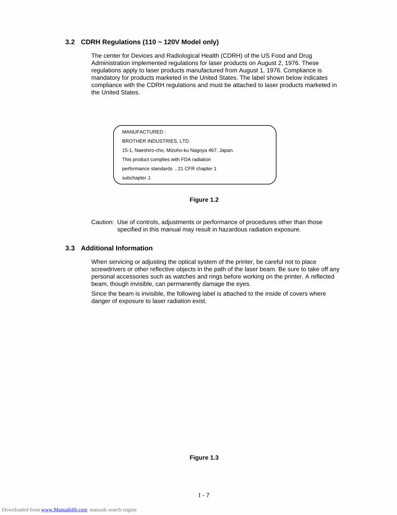
The center for Devices and Radiological Health (CDRH) of the US Food and DrugAdministration implemented regulations for laser products on August 2, 1976. Theseregulations apply to laser products manufactured from August 1, 1976. Compliance ismandatory for products marketed in the United States. The label shown below indicatescompliance with the CDRH regulations and must be attached to laser products marketed inthe United States.
Caution: Use of controls, adjustments or performance of procedures other than thosespecified in this manual may result in hazardous radiation exposure.
Figure 1.2
MANUFACTURED :
BROTHER INDUSTRIES, LTD.
15-1, Naeshiro-cho, Mizuho-ku Nagoya 467, Japan.
This product complies with FDA radiation
performance standards , 21 CFR chapter 1
subchapter J.
3.3 Additional Information
When servicing or adjusting the optical system of the printer, be careful not to placescrewdrivers or other reflective objects in the path of the laser beam. Be sure to take off anypersonal accessories such as watches and rings before working on the printer. A reflectedbeam, though invisible, can permanently damage the eyes.
Since the beam is invisible, the following label is attached to the inside of covers wheredanger of exposure to laser radiation exist.
Figure 1.3
Downloaded from www.Manualslib.com manuals search engine
I - 8
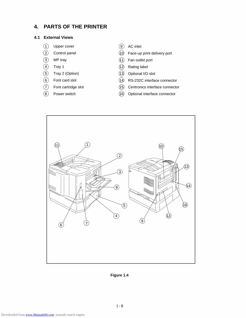
9 AC inlet
10 Face-up print delivery port
11 Fan outlet port
12 Rating label
13 Optional I/O slot
14 RS-232C interface connector
15 Centronics interface connector
16 Optional interface connector
4. PARTS OF THE PRINTER
4.1 External Views
1 Upper cover
2 Control panel
3 MP tray
4 Tray 1
5 Tray 2 (Option)
6 Font card slot
7 Font cartridge slot
8 Power switch
2
4
1011
6
3
8
5
7
1
9
15
13
16
12
14
Figure 1.4
Downloaded from www.Manualslib.com manuals search engine
I - 9
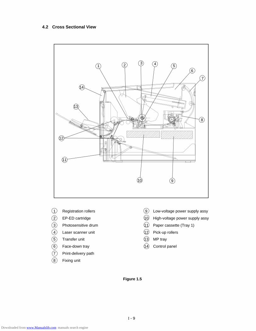
1 Registration rollers
2 EP-ED cartridge
3 Photosensitive drum
4 Laser scanner unit
5 Transfer unit
6 Face-down tray
7 Print-delivery path
8 Fixing unit
9 Low-voltage power supply assy
10 High-voltage power supply assy
11 Paper cassette (Tray 1)
12 Pick-up rollers
13 MP tray
14 Control panel
9
13
8
1 2 3 4 5
12
11
7
6
10
4.2 Cross Sectional View
14
Figure 1.5
Downloaded from www.Manualslib.com manuals search engine
I - 10
5. STORAGE AND HANDLING OF EP-ED CARTRIDGES
An EP-ED cartridge is influenced by the storage conditions even if it is sealed in its package,so its life depends on the way in which it is used or stored. EP-ED cartridges should behandled carefully.
5.1 Storage of Sealed EP-ED Cartridges
When storing sealed EP-ED cartridges in a warehouse or workshop, the storage conditionsshown in (25) Environmental conditions on Page 1-5 must be met. Follow the instructionsbelow:
1) Avoid direct sunlight.
2) Do not store cartridges on a surface that is subject to vibration.
3) Do not hit or drop the packages containing cartridges.
4) The cartridges should be stored horizontal when they are removed from the body (withtheir label side upside).
5) Avoid putting the cartridges near a CRT screen, a disk or a floppy disk (to keep their datafrom being destroyed).
5.2 Storage of Unsealed EP-ED Cartridges
Each EP-ED cartridge contains a photosensitive drum that has an organic photoconductor(OPC) which deteriorates when exposed to strong light. It also contains toner. The user,therefore, should be fully informed about the correct storage and handling of EP-EDcartridges.
(1) Storage requirements
1) Avoid places exposed to direct sunlight or near a window. Do not leave an EP-EDcartridge in a car in warm or hot weather even if it is in its storage box.
2) Avoid places with a too-high or too-cool temperature and/or humidity. Also avoidplaces exposed to sudden temperature or humidity changes (such as near an airconditioner outlet).
3) Avoid dusty places or places exposed to ammonia fumes or other harmful fumes.
4) Do not store an EP-ED cartridge in a temperature above 40°C.
(2) EP-ED cartridge life
The effective life of an EP-ED cartridge is 2.5 years from the date of manufacture(printed on the cartridge.) The expiry year and month (date of manufacture plus 2.5years) is shown on the EP-ED cartridge box. An EP-ED cartridge used after the expirymay produce low-quality printing, so a cartridge should be used within the statedperiod.
Downloaded from www.Manualslib.com manuals search engine
II - 1
CHAPTER II THEORY OF OPERATIONThis chapter describes the printer functions, the relationship between the electrical systems andmechanical systems, and the timing of operations. Striped conduits ( ) indicate mechanicallinkages; solid thin arrows ( ) appearing with a signal name indicate the transmission ofsingle control signals and outlined thick arrows ( ) indicate the transmission of groups ofsignals.
1. BASIC OPERATIONS
1.1 Mechanical Configuration
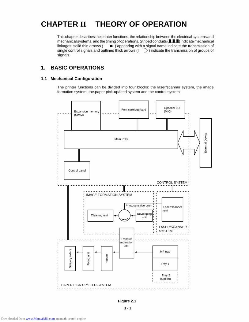
The printer functions can be divided into four blocks: the laser/scanner system, the imageformation system, the paper pick-up/feed system and the control system.
Figure 2.1
Expansion memory(SIMM)
Font cartridge/card Optional I/O(MIO)
Ext
erna
l Dev
ice
Control panel
IMAGE FORMATION SYSTEM
Cleaning unit
Photosensitive drum
Developing unit
Laser/scannerunit
LASER/SCANNERSYSTEM
Transferseparation
unit
Del
iver
y ro
llers
Fix
ing
unit
Fee
der
Tray 1
Tray 2(Option)
MP tray
Main PCB
CONTROL SYSTEM
PAPER PICK-UP/FEED SYSTEM
Downloaded from www.Manualslib.com manuals search engine
II - 2
1.2 Main Drive
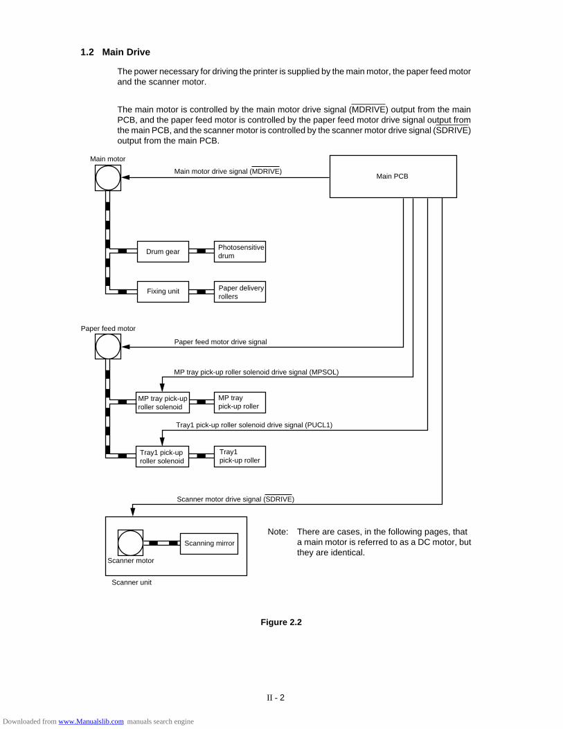
The power necessary for driving the printer is supplied by the main motor, the paper feed motorand the scanner motor.
The main motor is controlled by the main motor drive signal (MDRIVE) output from the mainPCB, and the paper feed motor is controlled by the paper feed motor drive signal output fromthe main PCB, and the scanner motor is controlled by the scanner motor drive signal (SDRIVE)output from the main PCB.
Figure 2.2
Main motor
Main motor drive signal (MDRIVE) Main PCB
Drum gearPhotosensitive drum
Fixing unit Paper deliveryrollers
Paper feed motor
Paper feed motor drive signal
MP tray pick-up roller solenoid drive signal (MPSOL)
MP tray pick-uproller solenoid
MP traypick-up roller
Tray1 pick-up roller solenoid drive signal (PUCL1)
Tray1 pick-uproller solenoid
Tray1 pick-up roller
Scanner motor drive signal (SDRIVE)
Scanner motor
Scanning mirror
Scanner unit
Note: There are cases, in the following pages, thata main motor is referred to as a DC motor, butthey are identical.
Downloaded from www.Manualslib.com manuals search engine
II - 3
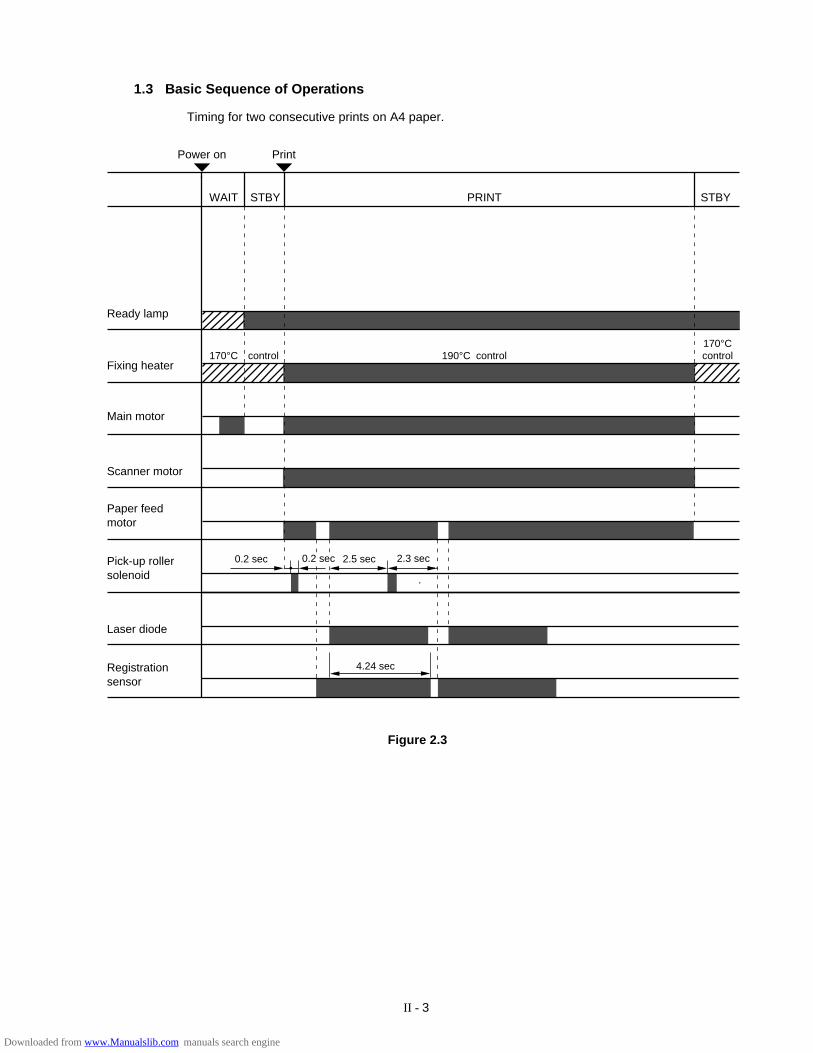
1.3 Basic Sequence of Operations
Timing for two consecutive prints on A4 paper.
Power on Print
WAIT STBY PRINT
Ready lamp
Fixing heater
Main motor
170°C control 190°C
STBY
control170°Ccontrol
Scanner motor
Paper feed motor
Pick-up rollersolenoid
Laser diode
Registrationsensor
0.2 sec 0.2 sec 2.5 sec 2.3 sec
4.24 sec
Figure 2.3
Downloaded from www.Manualslib.com manuals search engine
II - 4
2. LASER/SCANNER SYSTEM
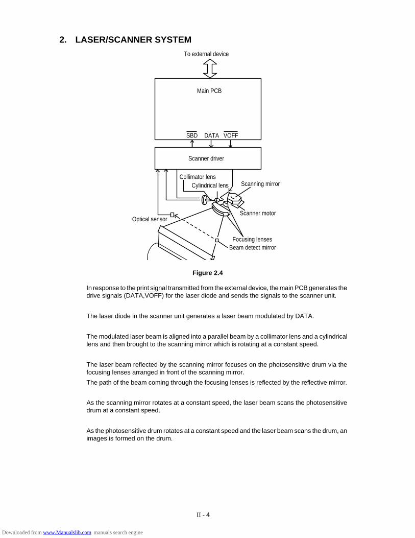
In response to the print signal transmitted from the external device, the main PCB generates thedrive signals (DATA,VOFF) for the laser diode and sends the signals to the scanner unit.
The laser diode in the scanner unit generates a laser beam modulated by DATA.
The modulated laser beam is aligned into a parallel beam by a collimator lens and a cylindricallens and then brought to the scanning mirror which is rotating at a constant speed.
The laser beam reflected by the scanning mirror focuses on the photosensitive drum via thefocusing lenses arranged in front of the scanning mirror.
The path of the beam coming through the focusing lenses is reflected by the reflective mirror.
As the scanning mirror rotates at a constant speed, the laser beam scans the photosensitivedrum at a constant speed.
As the photosensitive drum rotates at a constant speed and the laser beam scans the drum, animages is formed on the drum.
Scanner driver
Collimator lensCylindrical lens
Scanner motor
Scanning mirror
Focusing lensesBeam detect mirror
Optical sensor
To external device
Main PCB
SBD DATA VOFF
Figure 2.4
Downloaded from www.Manualslib.com manuals search engine
II - 5
3. IMAGE FORMATION SYSTEM
3.1 Outline
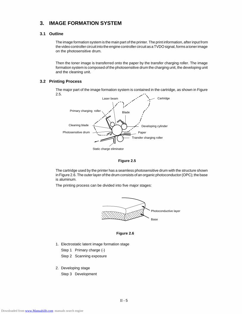
The image formation system is the main part of the printer. The print information, after input fromthe video controller circuit into the engine controller circuit as a TVDO signal, forms a toner imageon the photosensitive drum.
Then the toner image is transferred onto the paper by the transfer charging roller. The imageformation system is composed of the photosensitive drum the charging unit, the developing unitand the cleaning unit.
3.2 Printing Process
The major part of the image formation system is contained in the cartridge, as shown in Figure2.5.
The cartridge used by the printer has a seamless photosensitive drum with the structure shownin Figure 2.6. The outer layer of the drum consists of an organic photoconductor (OPC); the baseis aluminum.
The printing process can be divided into five major stages:
Figure 2.5
Base
Photoconductive layer
Laser beam
Developing cylinder
Primary charging roller
Cleaning blade
Photosensitive drum
Static charge eliminator
Cartridge
Transfer charging roller
Blade
Figure 2.6
1. Electrostatic latent image formation stage
Step 1 Primary charge (-)
Step 2 Scanning exposure
2. Developing stage
Step 3 Development
Paper
Downloaded from www.Manualslib.com manuals search engine
II - 6
3. Transfer stage
Step 4 Transfer (+)
Step 5 Separation
4. Fixing stage
Step 6 Fixing
5. Drum cleaning stage
Step 7 Drum cleaning
Electrostatic latent image formation stage
Transfer stage
Fixing stage
Drum cleaning stage
Developing stage
Paper path
Direction of drum rotation
2. Scanning exposure
1. Primary charge
7. Drum cleaning
Print delivery 6. Fixing
5. Separa- tion 4. Transfer Registration Multi-purpose tray feed
Cassette feed
3. Develop ment
Figure 2.7
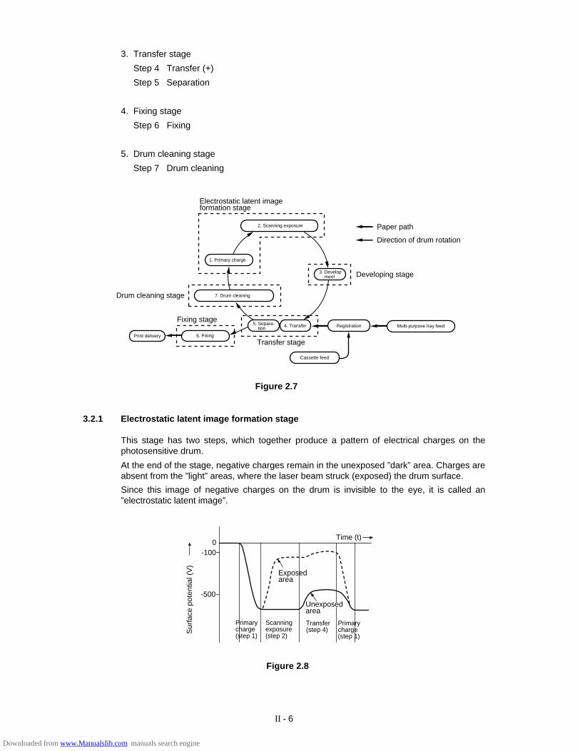
3.2.1 Electrostatic latent image formation stage
This stage has two steps, which together produce a pattern of electrical charges on thephotosensitive drum.
At the end of the stage, negative charges remain in the unexposed ”dark” area. Charges areabsent from the ”light” areas, where the laser beam struck (exposed) the drum surface.
Since this image of negative charges on the drum is invisible to the eye, it is called an”electrostatic latent image”.
Time (t)0
-100
Exposedarea
Unexposedarea
Primarycharge(step 1)
Scanningexposure(step 2)
Primarycharge(step 1)
Transfer(step 4)S
urfa
ce p
oten
tial (
V)
-500
Figure 2.8
Downloaded from www.Manualslib.com manuals search engine
II - 7
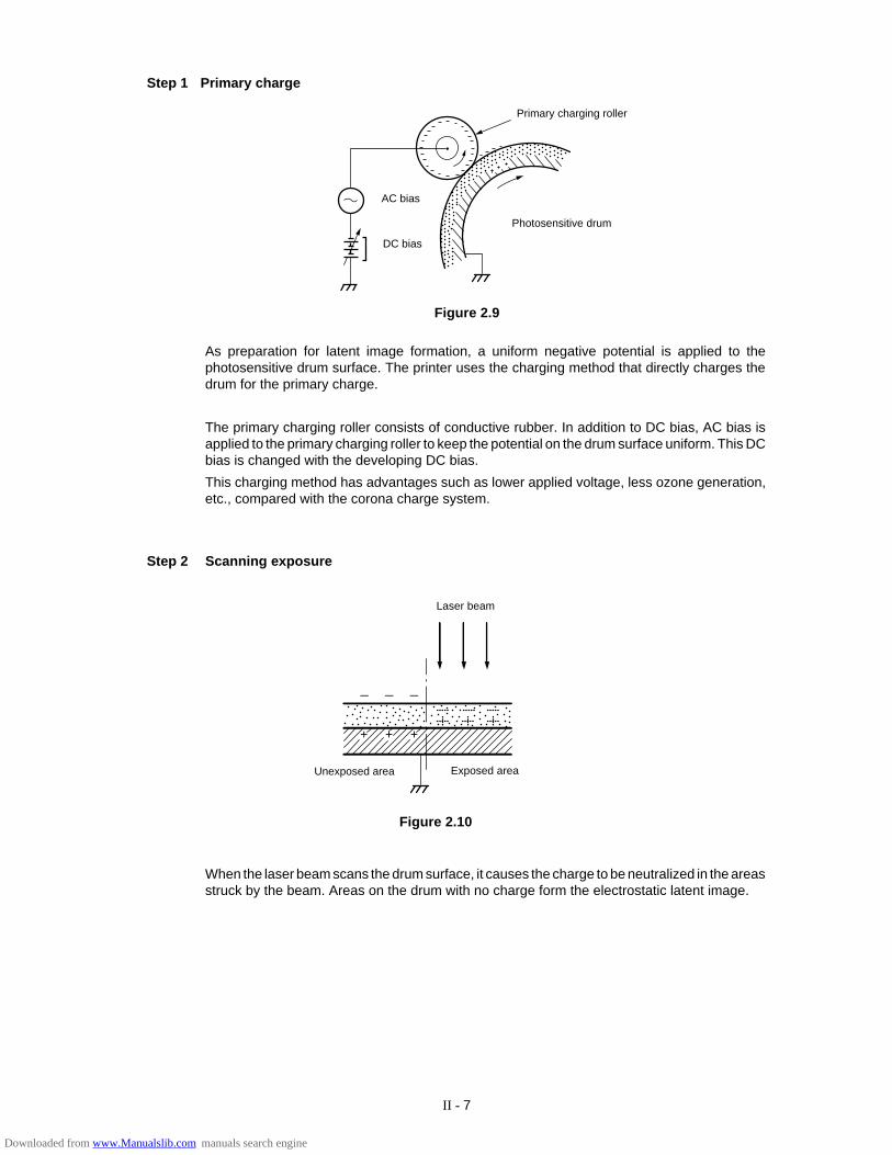
Step 1 Primary charge
As preparation for latent image formation, a uniform negative potential is applied to thephotosensitive drum surface. The printer uses the charging method that directly charges thedrum for the primary charge.
The primary charging roller consists of conductive rubber. In addition to DC bias, AC bias isapplied to the primary charging roller to keep the potential on the drum surface uniform. This DCbias is changed with the developing DC bias.
This charging method has advantages such as lower applied voltage, less ozone generation,etc., compared with the corona charge system.
Step 2 Scanning exposure
Figure 2.10
+ + +
___
Laser beam
Unexposed area Exposed area
When the laser beam scans the drum surface, it causes the charge to be neutralized in the areasstruck by the beam. Areas on the drum with no charge form the electrostatic latent image.
DC bias
AC bias
Photosensitive drum
Primary charging roller
���
���
��
����
����
���
��
���
�
��
���
�
��
��
��
��
���
��
���
���
���
���
���
���
����
���
��
����
����
����
����
�������
�
���
���
�
��
����
����
��
���
���
Figure 2.9
Downloaded from www.Manualslib.com manuals search engine
II - 8
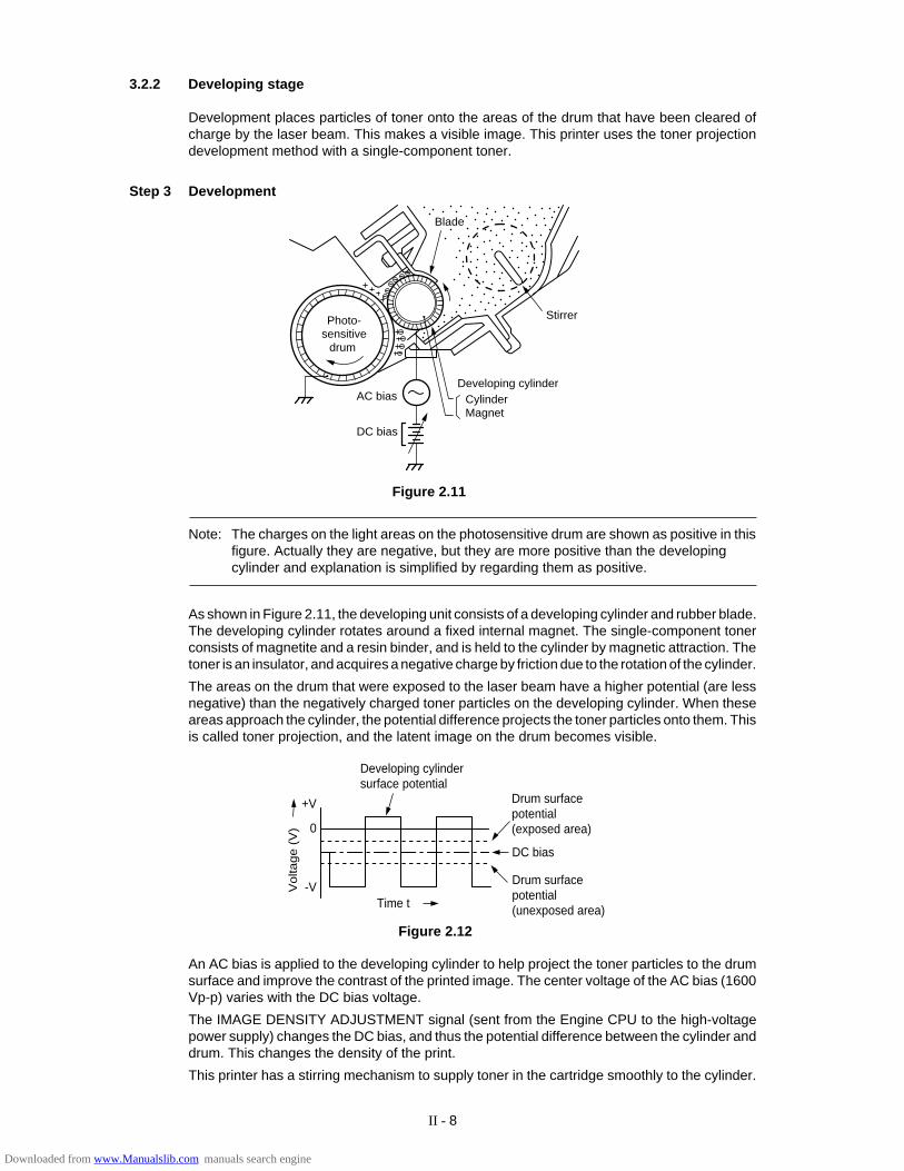
3.2.2 Developing stage
Development places particles of toner onto the areas of the drum that have been cleared ofcharge by the laser beam. This makes a visible image. This printer uses the toner projectiondevelopment method with a single-component toner.
Blade
Stirrer
Developing cylinderCylinderMagnet
DC bias
AC bias
Photo-sensitive
drum
Figure 2.11
Note: The charges on the light areas on the photosensitive drum are shown as positive in thisfigure. Actually they are negative, but they are more positive than the developingcylinder and explanation is simplified by regarding them as positive.
As shown in Figure 2.11, the developing unit consists of a developing cylinder and rubber blade.The developing cylinder rotates around a fixed internal magnet. The single-component tonerconsists of magnetite and a resin binder, and is held to the cylinder by magnetic attraction. Thetoner is an insulator, and acquires a negative charge by friction due to the rotation of the cylinder.
The areas on the drum that were exposed to the laser beam have a higher potential (are lessnegative) than the negatively charged toner particles on the developing cylinder. When theseareas approach the cylinder, the potential difference projects the toner particles onto them. Thisis called toner projection, and the latent image on the drum becomes visible.
Developing cylindersurface potential
Drum surfacepotential(exposed area)
DC bias
Drum surfacepotential(unexposed area)Time t
+V
0
-VVolta
ge (
V)
Figure 2.12
An AC bias is applied to the developing cylinder to help project the toner particles to the drumsurface and improve the contrast of the printed image. The center voltage of the AC bias (1600Vp-p) varies with the DC bias voltage.
The IMAGE DENSITY ADJUSTMENT signal (sent from the Engine CPU to the high-voltagepower supply) changes the DC bias, and thus the potential difference between the cylinder anddrum. This changes the density of the print.
This printer has a stirring mechanism to supply toner in the cartridge smoothly to the cylinder.
Step 3 Development
Downloaded from www.Manualslib.com manuals search engine
II - 9
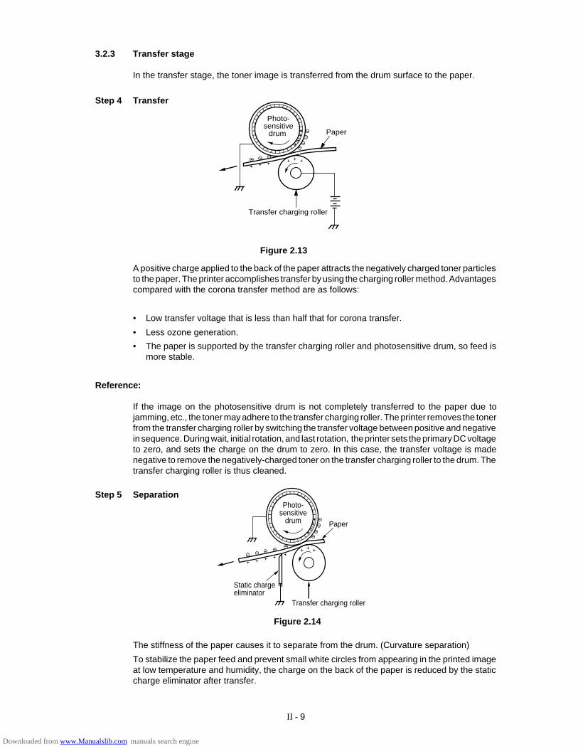
A positive charge applied to the back of the paper attracts the negatively charged toner particlesto the paper. The printer accomplishes transfer by using the charging roller method. Advantagescompared with the corona transfer method are as follows:
• Low transfer voltage that is less than half that for corona transfer.
• Less ozone generation.
• The paper is supported by the transfer charging roller and photosensitive drum, so feed ismore stable.
Reference:
If the image on the photosensitive drum is not completely transferred to the paper due tojamming, etc., the toner may adhere to the transfer charging roller. The printer removes the tonerfrom the transfer charging roller by switching the transfer voltage between positive and negativein sequence. During wait, initial rotation, and last rotation, the printer sets the primary DC voltageto zero, and sets the charge on the drum to zero. In this case, the transfer voltage is madenegative to remove the negatively-charged toner on the transfer charging roller to the drum. Thetransfer charging roller is thus cleaned.
3.2.3 Transfer stage
In the transfer stage, the toner image is transferred from the drum surface to the paper.
Step 4 Transfer
Figure 2.13
The stiffness of the paper causes it to separate from the drum. (Curvature separation)
To stabilize the paper feed and prevent small white circles from appearing in the printed imageat low temperature and humidity, the charge on the back of the paper is reduced by the staticcharge eliminator after transfer.
Figure 2.14
Photo-sensitive
drum Paper
Transfer charging roller
Photo-sensitive
drum Paper
Transfer charging roller
Static chargeeliminator
Step 5 Separation
Downloaded from www.Manualslib.com manuals search engine
II - 10
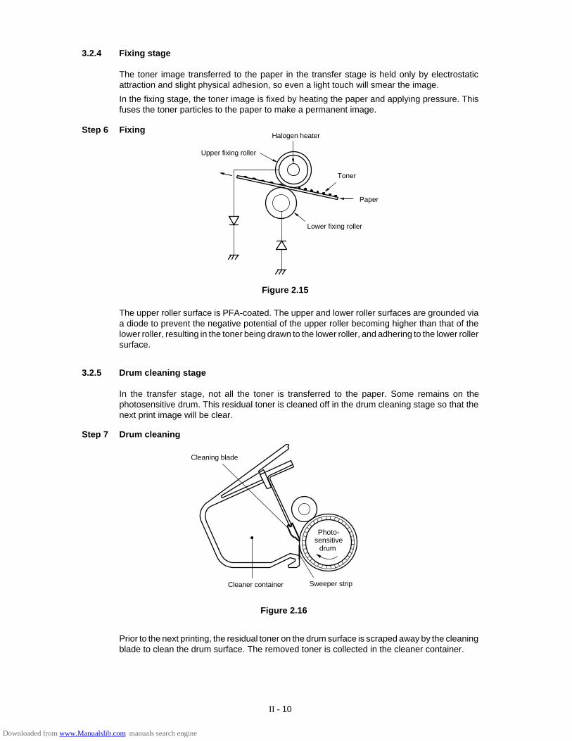
3.2.4 Fixing stage
The toner image transferred to the paper in the transfer stage is held only by electrostaticattraction and slight physical adhesion, so even a light touch will smear the image.
In the fixing stage, the toner image is fixed by heating the paper and applying pressure. Thisfuses the toner particles to the paper to make a permanent image.
Figure 2.15
Step 6 Fixing
The upper roller surface is PFA-coated. The upper and lower roller surfaces are grounded viaa diode to prevent the negative potential of the upper roller becoming higher than that of thelower roller, resulting in the toner being drawn to the lower roller, and adhering to the lower rollersurface.
3.2.5 Drum cleaning stage
In the transfer stage, not all the toner is transferred to the paper. Some remains on thephotosensitive drum. This residual toner is cleaned off in the drum cleaning stage so that thenext print image will be clear.
Step 7 Drum cleaning
Photo-sensitive
drum
Prior to the next printing, the residual toner on the drum surface is scraped away by the cleaningblade to clean the drum surface. The removed toner is collected in the cleaner container.
Cleaning blade
Sweeper stripCleaner container
Figure 2.16
Upper fixing roller
Toner
Paper
Lower fixing roller
Halogen heater
Downloaded from www.Manualslib.com manuals search engine

II - 11
3.3 Operation
When the engine controller circuit receives a print signal (PRINT) or a pre-feed signal (PRFD)from the video controller circuit, the engine controller circuit drives the main motor to rotate thephotosensitive drum.
After the drum surface is charged negatively by the primary charge roller, the laser beammodulated by a DATA signal scans the drum surface to from a latent image on the drum.
The latent image formed on the drum surface is converted into a visible image by the toner onthe developing cylinder and then image is transferred onto the paper by the transfer roller unit.Then the residual toner is removed from the drum surface with the cleaner blade.
The cartridge also has a toner sensor. When the output from this sensor falls below a certainlevel, it warns that the EP-ED cartridge will be out of toner with an alarm.
Primary charge (AC) drive (HV1AC)
Primary charge (DC) drive (HV1DC)
Developing bias (AC) drive (DBAC)
Developing bias (DC) drive (DBDC)
Transfer charger 1 drive (HVT1)
Transfer charger 2 drive (HVT2)
Transfer charger 3 drive (HVT3)
Transfer charger 4 drive (HVT4)
Toner sensor signal 1 (TONER 1)
Toner sensor signal 2 (TONER 2)
MainPCB
Scanner unit
EP-ED cartridge
Transferroller
High-voltagepower supplyPCB
Laser beamReflection mirror
Sca
nner
mot
or d
rive
sign
al (
SD
RIV
E)
Lase
r dio
de d
rive
sign
al (
DA
TA)
Figure 2.17
Downloaded from www.Manualslib.com manuals search engine
II - 12
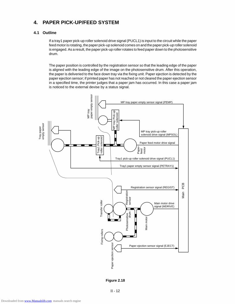
4. PAPER PICK-UP/FEED SYSTEM
4.1 Outline
If a tray1 paper pick-up roller solenoid drive signal (PUCL1) is input to the circuit while the paperfeed motor is rotating, the paper pick-up solenoid comes on and the paper pick-up roller solenoidis engaged. As a result, the paper pick-up roller rotates to feed paper down to the photosensitivedrum.
The paper position is controlled by the registration sensor so that the leading edge of the paperis aligned with the leading edge of the image on the photosensitive drum. After this operation,the paper is deliveried to the face down tray via the fixing unit. Paper ejection is detected by thepaper ejection sensor; if printed paper has not reached or not cleared the paper ejection sensorin a specified time, the printer judges that a paper jam has occurred. In this case a paper jamis noticed to the external devise by a status signal.
Figure 2.18
Mai
n P
CB
Pap
er e
ject
ion
sens
orFix
ing
rolle
rsT
rans
fer
rolle
r
Mai
n m
otor
Pho
tose
nsiti
vedr
umR
egis
trat
ion
sens
or
Tra
y1 P
ick-
upro
ller
sole
noid
Pap
er-
feed
mot
or
MP
tray
Pic
k-up
rolle
r so
leno
id
MP
tray
pape
r em
pty
sens
or
Tra
y pa
per
empt
y se
nsor
MP tray paper empty sensor signal (PEMP)
MP tray pick-up rollersolenoid drive signal (MPSOL)
Paper feed motor drive signal
Tray1 pick-up roller solenoid drive signal (PUCL1)
Tray1 paper empty sensor signal (PETRAY1)
Registration sensor signal (REGIST)
Main motor drive signal (MDRIVE)
Paper ejection sensor signal (EJECT)
Downloaded from www.Manualslib.com manuals search engine
II - 13
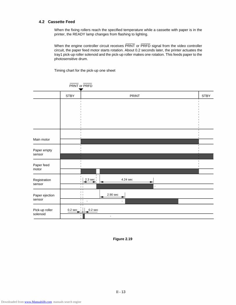
Figure 2.19
0.2 sec
2.90 sec
2.3 sec 4.24 sec
Main motor
Paper feed motor
Registrationsensor
Paper empty sensor
Pick-up rollersolenoid
Paper ejection sensor
STBY PRINT STBY
PRNT or PRFD
0.2 sec
4.2 Cassette Feed
When the fixing rollers reach the specified temperature while a cassette with paper is in theprinter, the READY lamp changes from flashing to lighting.
When the engine controller circuit receives PRNT or PRFD signal from the video controllercircuit, the paper feed motor starts rotation. About 0.2 seconds later, the printer actuates thetray1 pick-up roller solenoid and the pick-up roller makes one rotation. This feeds paper to thephotosensitive drum.
Timing chart for the pick-up one sheet
Downloaded from www.Manualslib.com manuals search engine
II - 14
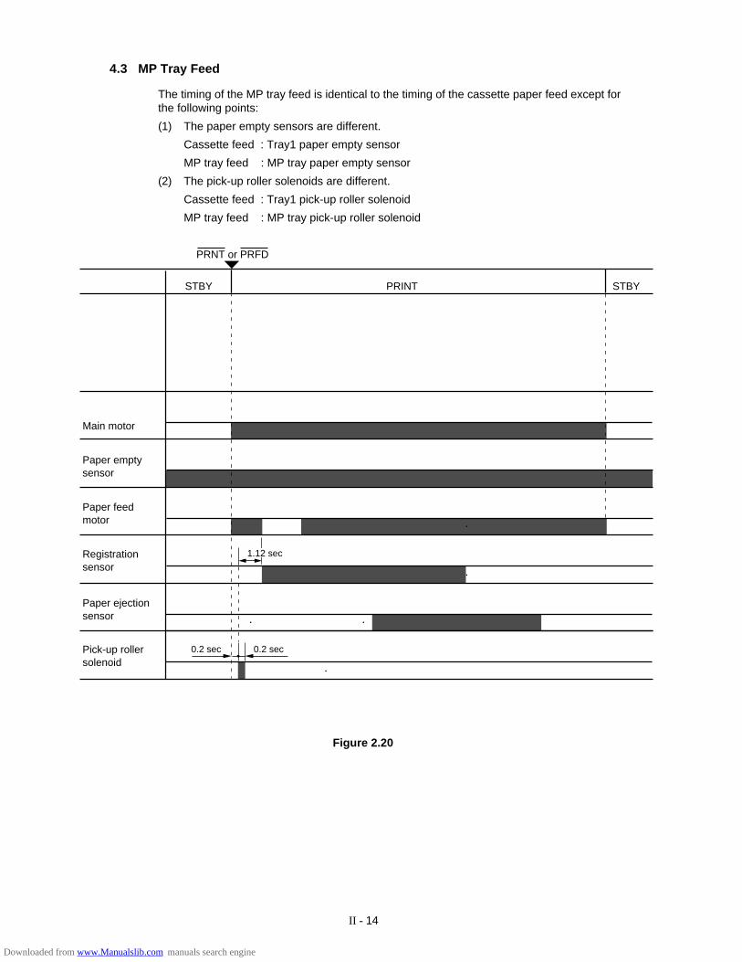
4.3 MP Tray Feed
The timing of the MP tray feed is identical to the timing of the cassette paper feed except forthe following points:
(1) The paper empty sensors are different.
Cassette feed : Tray1 paper empty sensor
MP tray feed : MP tray paper empty sensor
(2) The pick-up roller solenoids are different.
Cassette feed : Tray1 pick-up roller solenoid
MP tray feed : MP tray pick-up roller solenoid
0.2 sec 0.2 sec
Main motor
Paper feed motor
Registrationsensor
Paper empty sensor
Pick-up rollersolenoid
Paper ejection sensor
STBY PRINT STBY
PRNT or PRFD
1.12 sec
Figure 2.20
Downloaded from www.Manualslib.com manuals search engine
II - 15
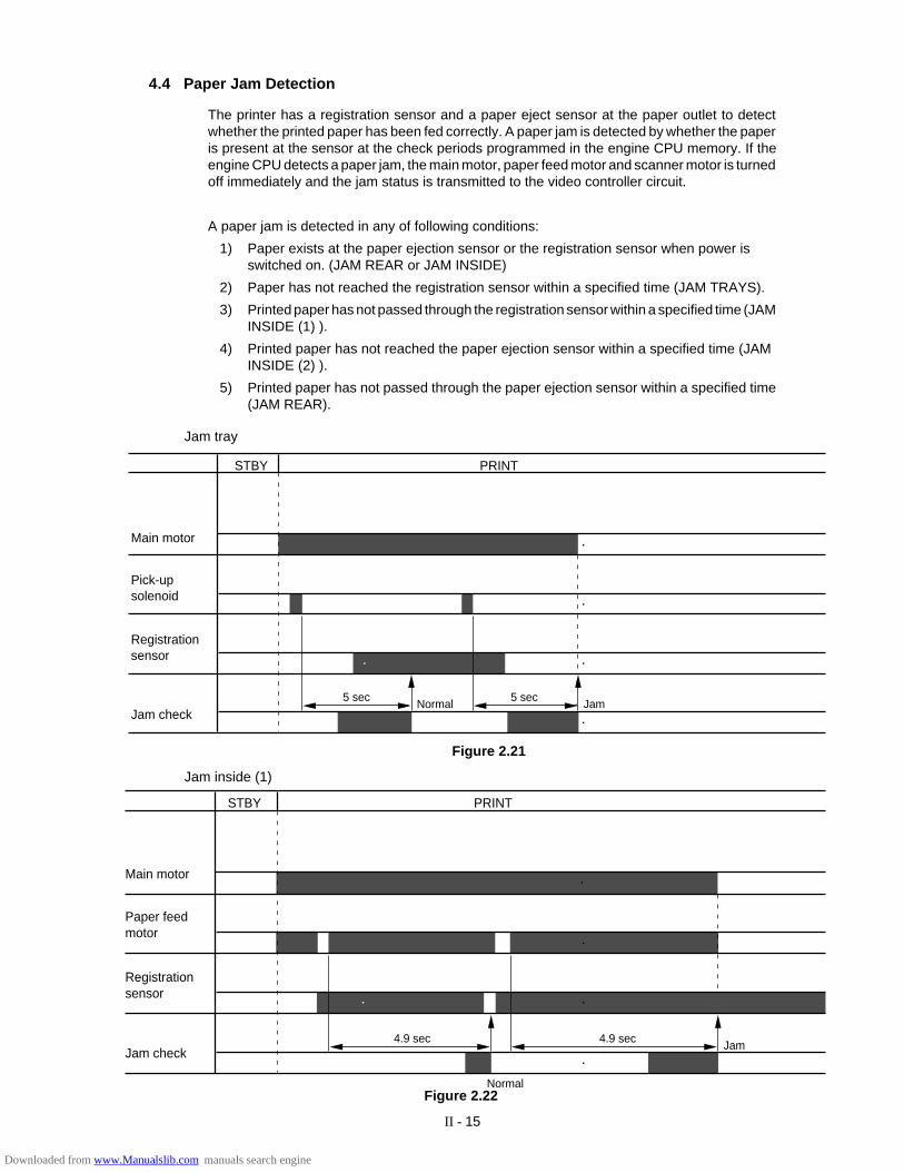
4.4 Paper Jam Detection
The printer has a registration sensor and a paper eject sensor at the paper outlet to detectwhether the printed paper has been fed correctly. A paper jam is detected by whether the paperis present at the sensor at the check periods programmed in the engine CPU memory. If theengine CPU detects a paper jam, the main motor, paper feed motor and scanner motor is turnedoff immediately and the jam status is transmitted to the video controller circuit.
A paper jam is detected in any of following conditions:
1) Paper exists at the paper ejection sensor or the registration sensor when power isswitched on. (JAM REAR or JAM INSIDE)
2) Paper has not reached the registration sensor within a specified time (JAM TRAYS).
3) Printed paper has not passed through the registration sensor within a specified time (JAMINSIDE (1) ).
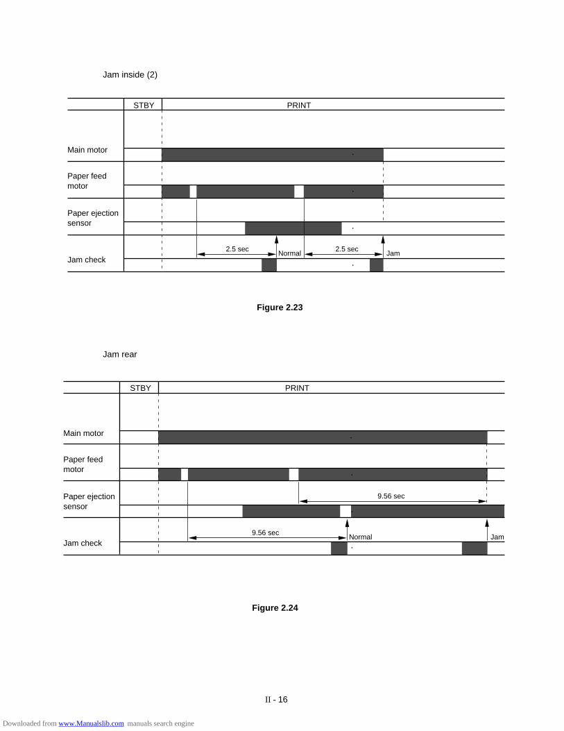
4) Printed paper has not reached the paper ejection sensor within a specified time (JAMINSIDE (2) ).
5) Printed paper has not passed through the paper ejection sensor within a specified time(JAM REAR).
Figure 2.22
Figure 2.21
Main motor
Registrationsensor
Pick-upsolenoid
STBY PRINT
Jam checkJamNormal
5 sec5 sec
Jam4.9 sec4.9 sec
Normal
Main motor
Registrationsensor
Paper feedmotor
Jam check
STBY PRINT
Jam inside (1)
Jam tray
Downloaded from www.Manualslib.com manuals search engine
II - 16
STBY PRINT
JamNormal2.5 sec2.5 sec
Main motor
Paper ejectionsensor
Paper feedmotor
Jam check
Jam inside (2)
Figure 2.23
Jam rear
STBY PRINT
JamNormal
9.56 sec
9.56 sec
Main motor
Paper ejectionsensor
Paper feedmotor
Jam check
Figure 2.24
Downloaded from www.Manualslib.com manuals search engine
III - 1
CHAPTER III ELECTRICAL SYSTEMElectric signal levels are expressed by ”High” (approximate the supply voltage) or ”Low”(approximate 0V). Signals with hyphen or slash, such as -FSRD or FSRD/, are low-active andsignals without hyphen or slash, such as FSRD, are high-active signals.
1. MAIN PCB
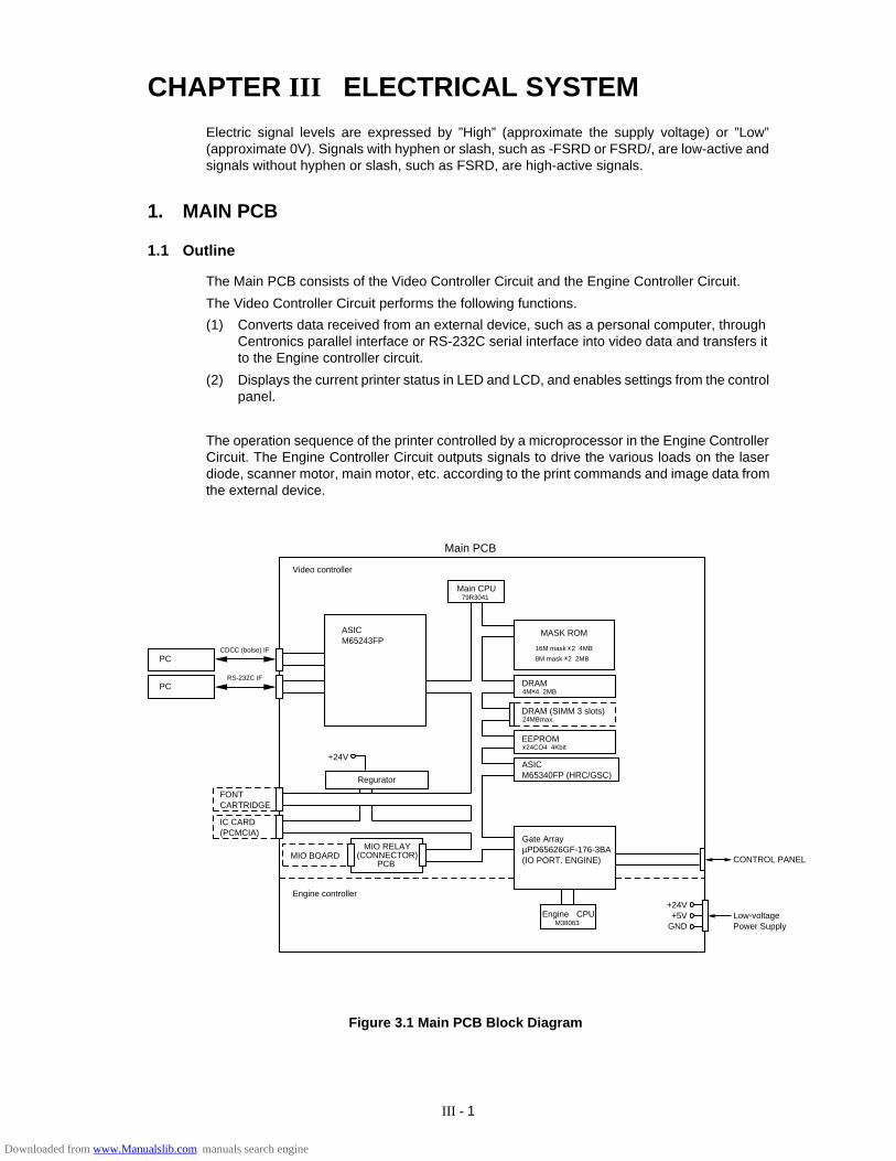
1.1 Outline
The Main PCB consists of the Video Controller Circuit and the Engine Controller Circuit.
The Video Controller Circuit performs the following functions.
(1) Converts data received from an external device, such as a personal computer, throughCentronics parallel interface or RS-232C serial interface into video data and transfers itto the Engine controller circuit.
(2) Displays the current printer status in LED and LCD, and enables settings from the controlpanel.
The operation sequence of the printer controlled by a microprocessor in the Engine ControllerCircuit. The Engine Controller Circuit outputs signals to drive the various loads on the laserdiode, scanner motor, main motor, etc. according to the print commands and image data fromthe external device.
Figure 3.1 Main PCB Block Diagram
FONTCARTRIDGE
IC CARD(PCMCIA)
MIO BOARD
Regurator
+24V
PC
PC
CDCC (bolse) IF
RS-232C IF
ASICM65243FP
Video controller
Engine controller
Engine CPUM38063
+24V+5V
GND
CONTROL PANEL
Low-voltage Power Supply
Gate ArrayµPD65626GF-176-3BA(IO PORT. ENGINE)
MASK ROM
16M mask 2 4MB
8M mask 2 2MB
DRAM4M 4 2MB
DRAM (SIMM 3 slots)24MBmax.
EEPROM 24CO4 4Kbit
ASICM65340FP (HRC/GSC)
Main CPU79R3041
Main PCB
MIO RELAY(CONNECTOR)
PCB
Downloaded from www.Manualslib.com manuals search engine
III - 2
1.2 Video Controller Circuit
(1) CPU block
CPU(#26) IDT79R3041-20J manufactured by Integrated Device Technology
RISC chip
Clock speed: 19.6608 MHz
Appearance: 84-pin PLCC
(2) ASIC/Gate Array Block
• #32 M65243FP(Mitsubishi) - 208-pin QFP
Controls the address decoder, timers and interfaces (Centronics and RS-232C).
• #6 M65340FP(Mitsubishi) 80-pin QFP
Controls HRC(High Resolution Control), GSC(Gray Scale Control) and economy mode.
• #3 µPD65626GF-176-3BA(NEC) - 100-pin QFP
Controls the I/O ports and others.
(3) Font Cartridge/Card Block
• Font cartridge (option)
The font cartridge has a 32MB memory area and is controlled by the 16-bit bus.
The address bus a buffer LS244 and the data bus, a buffer LS245.
• Font Card (option)
The font card has a 32MB memory area and is controlled by the 16-bit bus.
The card is supplied with 12V power because the flash card requires 12V power supply whenwriting or erasing data.
The address bus is buffered by LS244 and the data bus, is buffered by LS245.
(4) Centronics/RS-232C interface block
• Centronics parallel interface
Data transmission and reception are controlled by the M65243FP (#32).
• RS-232C
Data transmission and reception are controlled by the M65243FP (#32).
The ADM202JRN (#38) serves as driver/receiver.
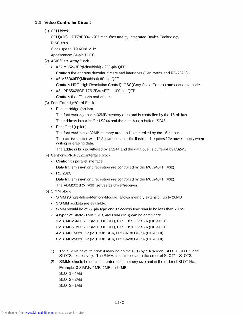
(5) SIMM block
• SIMM (Single-Inline-Memory-Module) allows memory extension up to 26MB
• 3 SIMM sockets are available.
• SIMM should be of 72-pin type and its access time should be less than 70 ns.
• 4 types of SIMM (1MB, 2MB, 4MB and 8MB) can be combined:
1MB MH25632BJ-7 (MITSUBISHI), HB56D25632B-7A (HITACHI)
2MB MH51232BJ-7 (MITSUBISHI), HB56D51232B-7A (HITACHI)
4MB MH1M32EJ-7 (MITSUBISHI), HB56A132BT-7A (HITACHI)
8MB MH2M32EJ-7 (MITSUBISHI), HB56A232BT-7A (HITACHI)
1) The SIMMs have its printed marking on the PCB by silk screen: SLOT1, SLOT2 andSLOT3, respectively. The SIMMs should be set in the order of SLOT1 - SLOT3.
2) SIMMs should be set in the order of its memory size and in the order of SLOT No.
Example: 3 SIMMs: 1MB, 2MB and 4MB
SLOT1 - 4MB
SLOT2 - 2MB
SLOT3 - 1MB
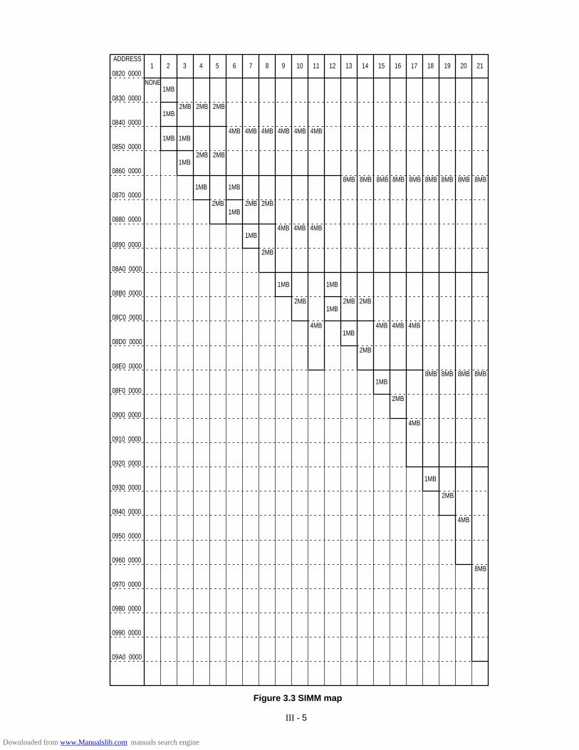
Downloaded from www.Manualslib.com manuals search engine

III - 3
3) The attached Printer SIMM map shows the memory map for 4 SIMMs combined.
(6) ROM block
ROMs store the CPU control program and font data. ROMs are two 16Mbit masked ROMs andtwo 8Mbit masked ROMs.
Optional sockets are available for two 8Mbit EPROM (µPD27C8000DZ-120 - NEC or equiva-lent) for expansion.
ROM access time should be less than 120nsec.
8Mbit EPROMs can be used instead of a 16Mbit masked ROM. To allow this substitution, thesoldering points SP5, SP6 and SP7 should be soldered and the cutting points CP2, CP3 andCP4 should be cut.
(7) DRAM block
DRAMs are used for receiving buffer or working area of the CPU. The DRAM block containsfour 4Mbit DRAMs, thus having 2MB memory capacity in total.
The refreshing method is CBR (Cas Before Ras).
DRAM access time should be less than 80nsec.
Downloaded from www.Manualslib.com manuals search engine
III - 4
Inside M65243
0000_0000
0040_0000
0080_0000
0100_0000
0200_0000
0400_0000
0600_0000
0800_0000
0B00_0000
0C00_0000
0E00_0000
0FC0_0000
0FD0_0000(256MB)
0000_0000
0020_0000
0040_0000
0060_0000
0080_0000
0800_0000
0820_0000
09A0_0000
0B00_0000
0C00_0000
0C10_0000
0C20_0000
0C30_0000
0C40_0000
0C50_0000
0C60_0000
0C70_0000
0C80_0000
0C90_0000
0CA0_0000
0CB0_0000
0CC0_0000
0CD0_0000
0CE0_0000
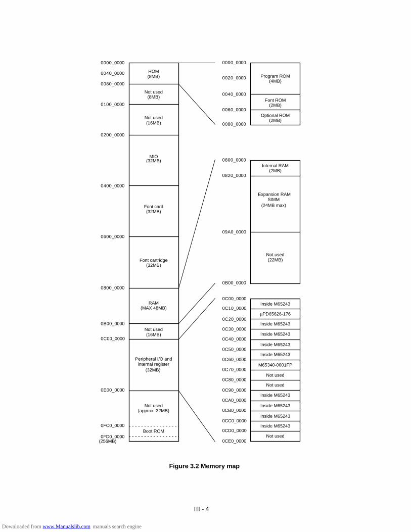
ROM(8MB)
Not used(8MB)
Not used(16MB)
MIO(32MB)
Font card(32MB)
Font cartridge(32MB)
RAM(MAX 48MB)
Not used(16MB)
Peripheral I/O andinternal register
(32MB)
Not used(approx. 32MB)
Boot ROMNot used
Inside M65243
Inside M65243
Inside M65243
Inside M65243
Not used
Not used
M65340-0001FP
Inside M65243
Inside M65243
Inside M65243
Inside M65243
µPD65626-176
Not used(22MB)
Expansion RAMSIMM
(24MB max)
Internal RAM(2MB)
Optional ROM(2MB)
Font ROM(2MB)
Program ROM(4MB)
Figure 3.2 Memory map
Downloaded from www.Manualslib.com manuals search engine
III - 5
Figure 3.3 SIMM map
ADDRESS
0820 00001 2 3 4 5 6 7 8 9 10 11 12 13 14 15 16 17 18 19 20 21
NONE1MB
1MB
1MB
2MB 2MB 2MB
1MB
1MB2MB 2MB
1MB 1MB
2MB 2MB 2MB1MB
1MB
2MB
4MB 4MB 4MB
4MB 4MB 4MB 4MB 4MB 4MB
8MB 8MB 8MB 8MB 8MB 8MB 8MB 8MB 8MB
8MB 8MB 8MB 8MB
1MB
2MB
4MB
1MB
1MB2MB 2MB
4MB 4MB 4MB1MB
2MB
1MB
2MB
4MB
1MB
2MB
4MB
8MB
0830 0000
0840 0000
0850 0000
0860 0000
0870 0000
0880 0000
0890 0000
08A0 0000
08B0 0000
08C0 0000
08D0 0000
08E0 0000
08F0 0000
0900 0000
0910 0000
0920 0000
0930 0000
0940 0000
0950 0000
0960 0000
0970 0000
0980 0000
0990 0000
09A0 0000
Downloaded from www.Manualslib.com manuals search engine
III - 6
01
23
45
67
89
AB
CD
EF
GH
JK
LM
94
96
ROM2H ROM1H ROM0H
ROM0LROM1LROM2L
B4
8K
15
8-3
RE
V
CN3
GN
DV
CC
OPT IO
H.V
OL
#18
#9
PO
WE
R
#1
3
#4
+24B
+5B
+5V
+24V
P.F
EE
D
#8
IC CARD
AN
78
N1
2
#2
#6
#7
#1
4
#1
5
#1
6
#1
0
#1
1
#1
2
#1
7
#1
9
#2
0#2
1
#26
#3
PANEL
CN
2
RC
/RE
SE
T
39
.32
16
MH
Z
#3
4
CDCC
#3
1
#2
9
#3
3
#28
#2
3
FU
SE
R
SCNMTR
SC
NL
SR
MTR
FA
N
#2
2
#36#37
#42
#4
0
#3
8
#4
1#
39
#3
2
0P
#3
0#
27
#35
#24
#1
X24C04F
#5
SLO
T4
SLO
T3
SLO
T2
SLO
T1
P7
P6
(EVEN) (EVEN) (EVEN)
(ODD)(ODD)(ODD)
74
AL
S1
03
47
4A
LS
10
34
LS
74
BZ
1C
N1
Y2
74
F2
45
D7
4F
24
5D
P13
P1
4R
S2
32
C
P1
2(W
HIT
E)
(WH
ITE
)P
10
P9
(RE
D)
P8
R3
04
1
74
F2
45
D7
4F
24
5D
M38063E6FP
P4
S1
P1
P3
µP
D6
56
26
M6
53
40
FP
74
LS
24
57
4L
S2
45
P2
74
LS
24
4
74
LS
24
4
74
LS
24
4
P5
P15
CN4
HM514800
HM514800
HM514800
HM514800
P1
1
M6
52
43
FP
LS
08
71
36
18
31
1
R1
01
D7
CP
5SP
9D8
R9
4
R100
52
C1
17
53
SP
10
R1
17
C1
28
R1
16
R99 R95
C111
R96
R91
C100
C9
9C9
7
C1
05
C1
07R
86
C1
02R
85
R9
3
C118
C1
44
C1
45
R122
C1
42
C1
47
C1
48
C1
49 C
12
9R1
18
C1
46
C1
30
C1
31
C1
32
C1
33
C1
34
C1
35
C1
36
C1
37
C1
38
R1
05
C119
C1
15
10
51
04
R104R102
RA
58
RA
57
RA47
C85
RA46
22
42
RA
38
1
1913
25
1
14
R81 Q18
1
R79
C8
9
C87R72
33
R77
C93C94C95
R63
SP8
20
8
R7
5
R7
0R
71
R6
6
32R
A3
7R
A3
2
535
4
C7
8
R7
3
R6
2R
67
R6
8
C8
6
R6
9R6
5
C8
4R
64
15
7
R78
R83
C9
6
15
6
RA
41
C1
04
C1
08
RA48
C66
C76
C68 C67
75
74
C7
0R
A2
9R
A2
6C
74
C7
11
211
R5
5
C7
5
R59
R5
4Q
15
C7
21
C6
9
4
C8
3R
61
D4
D6
31
Q1
9Q
17
Q1
6
R82R80
D54C
81
C8
0R
60 1
C7
7
RA
35
RA
33
RA
36
RA
34
RA
30
RA
28
RA
31
RA
27
22
C5
9
C1
6(4
8)
B1
6(3
2)
A1
6(1
6)
(33
)C
1(1
7)
B1
(1)
A1
C6
0
R49
62
141
16
15
C55
C5
4
R4
7
C52
C51
C5
3
R4
8C
56
R4
5R
46
R4
0R
41
C4
8
R3
9
D3
Q14
R2
5
R261
R3
6
Q1
2R31R27C34
UPC358
80
C35
Q1
1Q
9
Q8
Q7
C3
1
R3
3C
41
C4
5C
50
C3
7
R30
LS
07
24
R3
5
R37
R34
C42C43C39C38C36
RA
23
25
40
R2
4
XT
15
.0M
HZ
80
65
C26
R20
41
R1
6 R1
5
R1
9
C2
3
R1
8
C21C20
C19
C22
C1
7
C1
4
RA4
C1
6C
15
FLOCK
C1
0R
9
R1
1C
9C
12
80
81
865
L1
64
Q6
GND
GND
+24VRET
+24V
+5V
+5V
HEAT
1
R1
3 C8
Q4Q5R12
C7
1
20
19
21
2021
21
C133346768
RA
3R
A2
51
50
C6
R2RA1
R1S
P1
123536
21212121
74
F0
4
74
F0
4
74
F0
4
74
F0
4
C44C46C47
C49
C61C62C63C64
R44
RA22
RA16 RA15
RA18RA17RA13 RA12 RA11
RA10
R23
C29
C28 C30
RA9
(1)
RA14
A1
B1(26)
(25)A25B25(50)
C27
C24
R2
1
R2
2
CARTRIDGE
C6
5R
28R
29
8M
X6
SO
LD
ER
OU
T
SP
5S
P6
SP
7
CP
2C
P3
CP
4
RA19
CP2
R50 C5
8
#25
R4
3
R4
2
CP
3
SP
6
CP
4
SP
7
SP
5
C3
2
C4
13
30 3
1C
5
Q2
Q3
R8
R6
Q1
R7
D1
1
10
0
C1
86
4
41
40
25
24
C33 SP4RA21 RA20
1
21C
57
222122
21
RA
39
21
1
C92C90C91
22
42
21
1
22
421
21
421421421
R121R120R115
R113
R111
C139C140
C125C127
C121
SP11
C143
C154
SP12
R1
14
C1
41 R
11
2
C1
26
C1
23
R1
10
CP
6C
12
2 C1
20 C
11
2
C1
13
R9
8
C1
10
C1
24
C1
14
AD
M202JR
NA
DM
202JR
N
C1
09
R8
9
R9
0
RA44
R8
8
C116
72
7172
71
72
71 C150C151C152
C153 72
71
1
2
7
81 8
1 2
C9
8C
82
C7
3
C13
2
SP
3
R1
7
Q1
3Q
10
R38
R52R51 RA25 RA24
R9
2
RA
52
PST591DMT
C25
SP
2R
4
R1
23
R3
CP
1
R14
C1
1R
10
RA40
RA45
RA
42
RA49
RA50
R97
RA
53
R1
09
R8
4
R87C106
C1
03
C1
01
RA43
RA
51
RA55 RA54
R106R103R107R108
RA
56
RA
60
RA
59
R1
19
RA64 RA63 RA62 RA61
C8
8R76
R74
C7
9 R
57
R58
R56
R53
C4
0
R32
D2
C3
C2
R1
24
R125
49
.35
76
MH
zY
1
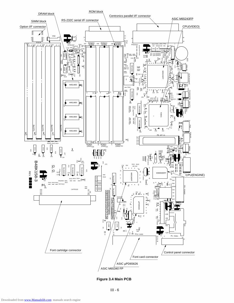
Figure 3.4 Main PCB
ASIC M65243FP
CPU(VIDEO)
CPU(ENGINE)
ASIC µPD65626
ASIC M65340 FP
Control panel connector
Font card connector
Font cartridge connector
Centronics parallel I/F connector
ROM block
RS-232C serial I/F connector
DRAM block
SIMM block
Option I/F connector
Downloaded from www.Manualslib.com manuals search engine
III - 7
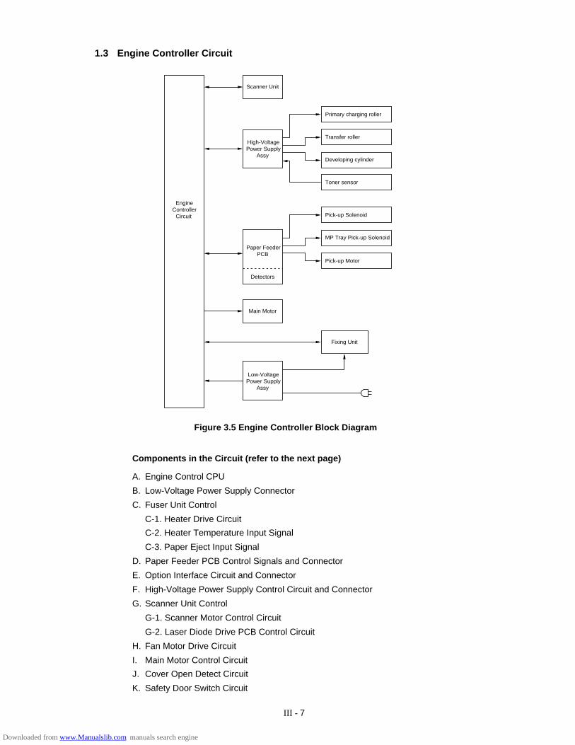
1.3 Engine Controller Circuit
A. Engine Control CPU
B. Low-Voltage Power Supply Connector
C. Fuser Unit Control
C-1. Heater Drive Circuit
C-2. Heater Temperature Input Signal
C-3. Paper Eject Input Signal
D. Paper Feeder PCB Control Signals and Connector
E. Option Interface Circuit and Connector
F. High-Voltage Power Supply Control Circuit and Connector
G. Scanner Unit Control
G-1. Scanner Motor Control Circuit
G-2. Laser Diode Drive PCB Control Circuit
H. Fan Motor Drive Circuit
I. Main Motor Control Circuit
J. Cover Open Detect Circuit
K. Safety Door Switch Circuit
Components in the Circuit (refer to the next page)
EngineController
Circuit
Primary charging roller
MP Tray Pick-up Solenoid
Scanner Unit
High-VoltagePower Supply
Assy
Paper FeederPCB
Detectors
Main Motor
Low-VoltagePower Supply
Assy
Pick-up Motor
Fixing Unit
Transfer roller
Developing cylinder
Toner sensor
Pick-up Solenoid
Figure 3.5 Engine Controller Block Diagram
Downloaded from www.Manualslib.com manuals search engine
III - 8
K
D E
F
A
C-2
C-3
C
C-1
J
B G-2
G-1
GHI
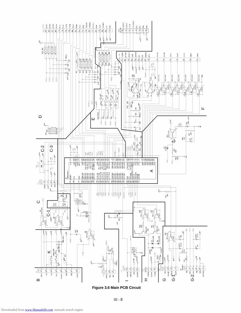
Figure 3.6 Main PCB Circuit
Downloaded from www.Manualslib.com manuals search engine
III - 9
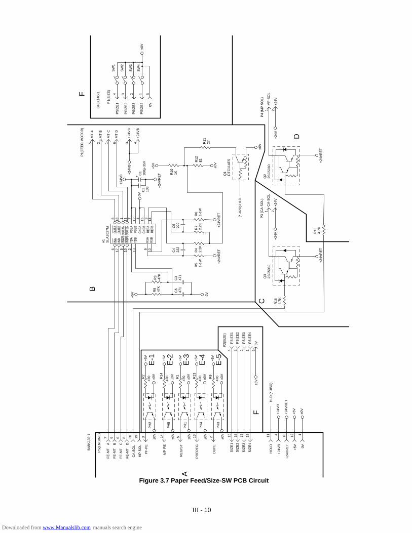
2. PAPER FEED DRIVE CIRCUIT
A. Connector to Main PCB
B. Pick-up Motor Drive Circuit and Connector
C. Pick-up Solenoid Drive Circuit and Connector
D. Multi Purpose Tray Pick-up Solenoid Drive Circuit and Connector
E. Sensors
E-1. Tray1 Paper Empty Sensor
E-2. Multi Purpose Tray Paper Empty Sensor
E-3. Regist Sensor
E-4. Pre-Regist Sensor
E-5. Paper Detect Sensor in Duplex Unit
F. Tray1 Paper Size Detect Switches
Refer to the next page.
Downloaded from www.Manualslib.com manuals search engine
III - 10
Figure 3.7 Paper Feed/Size-SW PCB Circuit
B48
K13
9-1
P5(
EN
GIN
E)
A B C D
FE
-MT
FE
-MT
FE
-MT
FE
-MT
CA
SO
L
MP
SO
L
PF
-PE
7 9 6 8 20 19 3 ±0V
±0V
±0V
±0V
±0V
MP
-PE
RE
GIS
T
PR
ER
EG
DU
PE
PH
2
PH
5
PH
1
PH
4
PH
3
14 5 13 2
±0V
±0V
±0V
±0V
±0V
+5V
470R2
E-1 +5
V
E-2 +5
V
E-3 +5
V
E-4 +5
V
E-5
470
470
470
470R14
R1
R13
R9
P2(
SIZ
E)
PS
IZE
1
PS
IZE
2
PS
IZE
3
PS
IZE
4
±0V
0V
24 3 1 5
1715 16 18
SIZ
E1
SIZ
E2
SIZ
E3
SIZ
E4
HO
LD
+24V
B
+24V
RE
T
+5V 0V
HLD
(*
-05D
)
+24V
B
+24V
RE
T
+5V
±0V
R16
4.7K
+24V
RE
T
±0V
R15
4.7K
0V
Q3
2SC
5060
+24V
+24V
CA
-SO
L
P3
(CA
SO
L)1 2
+24V
RE
T
Q2
2SC
5060
+24V
+24V
MP
-SO
L
P4
(MP
SO
L)1 2
(* -
02D
) H
LD
Q1
DT
C11
4ES
±0V
R12
82R
1127
R10
1K
+5V
+24V
RE
T
+24V
RE
T+2
4VR
ET
R5
1-1W
R6
1-1W
R4
2.2K
R7
2.2K
C4
222
C5
222
C6
471
C3
471
R8
47K
R3
47K
+5V
0VC
210
3
C1
100µ
-35V
+24V
B +24V
B
++2
4VB
+24V
B
43
MT
D6
MT
C1
MT
B2
MT
A5
P1(
FE
ED
MO
TO
R)
#1 SLA
7027
M
B48
K14
0-1
P1(
SIZ
E)
PS
IZE
1
PS
IZE
2
PS
IZE
3
PS
IZE
4
0V
4 3 2 1 5
SW
1
SW
2
SW
3
SW
4±0
V
INA
INB
INAN
INBN
TDA
TDB
OUT
AO
UTB
OUT
ANO
UTBN
VSSA
VSSB
RSA
RSB
GND
AG
NDB
REFA
REFB
6 17 5 16 2 13 9 10
8 18 1 11 7 12 3 144 15
F
D
C
B
F
A
11 4 10 12 1
Downloaded from www.Manualslib.com manuals search engine
III - 11
LCD
LED1
LED3
LED4
LED2
SW8 SW7 SW6 SW5 SW4 SW3 SW2 SW1
PA
D4-
PA
D7
LED
2 (R
EA
DY
)
LED
3 (D
AT
A)
LED
4 (A
LAR
M)
LCD
E, L
CD
RS
LED
1 (O
NLI
NE
)
SW
8 (S
EL)
SW
7 (M
OD
E)
SW
6 (F
ON
T)
SW
5 (F
OR
M F
EE
D)
SW
4 (S
ET
)
SW
3 (C
ON
TIN
UE
)
SW
2 (D
OW
N)
SW
1 (U
P)
Main PCB
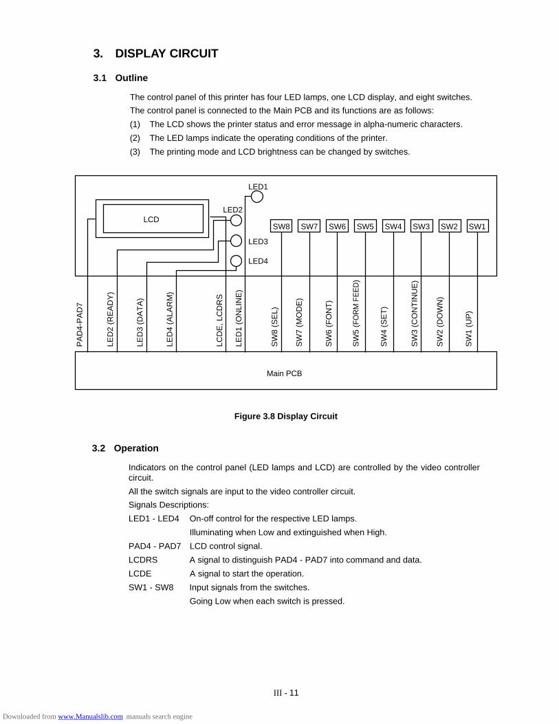
Figure 3.8 Display Circuit
3.2 Operation
Indicators on the control panel (LED lamps and LCD) are controlled by the video controllercircuit.
All the switch signals are input to the video controller circuit.
Signals Descriptions:
LED1 - LED4 On-off control for the respective LED lamps.
Illuminating when Low and extinguished when High.
PAD4 - PAD7 LCD control signal.
LCDRS A signal to distinguish PAD4 - PAD7 into command and data.
LCDE A signal to start the operation.
SW1 - SW8 Input signals from the switches.
Going Low when each switch is pressed.
3. DISPLAY CIRCUIT
3.1 Outline
The control panel of this printer has four LED lamps, one LCD display, and eight switches.
The control panel is connected to the Main PCB and its functions are as follows:
(1) The LCD shows the printer status and error message in alpha-numeric characters.
(2) The LED lamps indicate the operating conditions of the printer.
(3) The printing mode and LCD brightness can be changed by switches.
Downloaded from www.Manualslib.com manuals search engine

III - 12
4. LOW-VOLTAGE POWER SUPPLY ASSY
4.1 Outline
The low-voltage power supply assy consists of the low-voltage generating block (hereinafter theDC block) and the heater drive circuit block to turn the heater on (hereinafter the AC block).
When the power switch (SW1) is turned on, AC power is supplied to the low-voltage power supplyassy.
The DC block generates +5 VDC, and +24 VDC.
When the heater is turned on, AC power is supplied to the AC block under control of the heateron-off signal from the engine controller.
+24V output is reserved in the DC block, for the cooling fan for the low-voltage power supplyassy.
4.2 Protection Functions
Each of the power supply circuits, +5V, and +24V, has a protection function to prevent the circuitfrom accident by automatically cutting off the power supply in the case of a over-voltage or over-current of the load.
When the cooling fan stops to rotating, an over-voltage protection or a short-circuit protectionfunction is activated, and all the DC power supplies are cutoff.
In this case check and clear the cause on the load after turning the power switch (SW1) off, andthen switch the power on again at least one minute after the power shut-down.
Downloaded from www.Manualslib.com manuals search engine
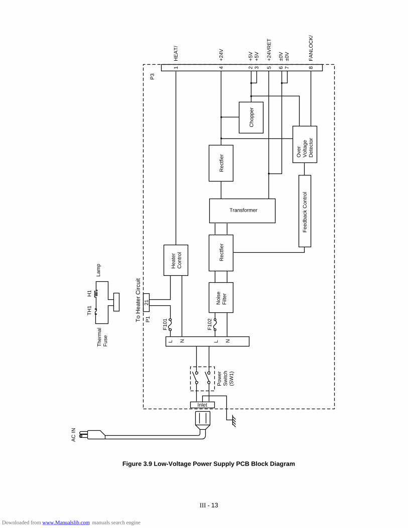
III - 13
Hea
ter
Con
trol
The
rmal
Fus
eLa
mp
H1
TH
1
AC
IN
21
L N L N
Pow
erS
witc
h(S
W1)
Noi
seF
ilter
Rec
tfier
Inlet
Transformer
Rec
tfier
Cho
pper
Ove
rV
olta
geD
etec
tor
Fee
dbac
k C
ontr
ol
1 4 2 3 6 75 8
HE
AT
/
+24
V
+5V
+5V
±0V
±0V
+24
VR
ET
FA
NLO
CK
/
P3
To
Hea
ter
Circ
uit
F10
1
F10
2P1
Figure 3.9 Low-Voltage Power Supply PCB Block Diagram
Downloaded from www.Manualslib.com manuals search engine

III - 14
5. HIGH-VOLTAGE POWER SUPPLY ASSY
5.1 Outline
The High-Voltage Power Supply Assy supplies the high-voltage for the charging roller, thedeveloper cylinder and the transfer roller according to the engine CPU’s control signals.
The block diagrams are shown Fig 3.10 and 3.11.
5.2 Operation of the Components of the High-Voltage Power Supply Assy
(1) Primary charging
When input signal/HV1AC gets the Low level, the primary high-voltage AC is applied to theprimary charging roller. And when input signal/HV1DC gets the Low level, the primary high-voltage DC is applied to the primary charging roller. The primary high-voltage DC changes withdeveloper bias DC according to values of the input signal DNSTY which is for print densityadjustment.
(2) Developer bias
When input signal/DBAC gets the Low level, the developer bias AC is applied to the developercylinder. And when input signal/DBDC gets the Low level, the developer bias DC is applied tothe developer cylinder. The developer bias DC changes according to values of the input signalDNSTY which is for print density adjustment, like the primary high-voltage DC.
(3) Transfer charging
Transfer bias is controlled by the input signals HVT1 - 4 and HVTFB. When the input signal/HVT1 gets the Low level, negative high-voltage is applied to the transfer roller. When the inputsignal/HVT2 gets the Low level, positive high-voltage is applied to the transfer roller. When theinput signal/HVT3 gets the Low level, positive high-voltage about 1100 times that of the inputsignal HVT4 is applied to the transfer roller. The input signal HVTFB has voltage about 1/1100times the positive voltage generated on the transfer roller. Once the engine CPU is informed ofthis voltage, the bias applied to the transfer roller can be known.
Note: The HVT2 signal generates high-voltage irrespective of the HVT4 signal.
(4) Toner sensing
Voltage levels of the input signals TONER1 and TONER2 allow the engine CPU to check if thecartridge is set or not and if toner is empty. The TONER1 carries the voltage generated at thetoner sensor and the TONER2 carries the developing bias output value.
Downloaded from www.Manualslib.com manuals search engine
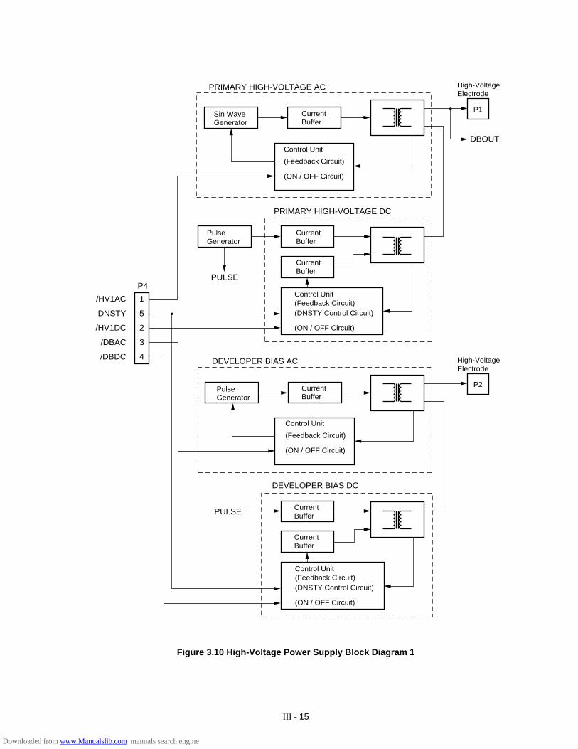
III - 15
CurrentBuffer
CurrentBuffer
CurrentBuffer
CurrentBuffer
CurrentBuffer
CurrentBuffer
Sin WaveGenerator
High-VoltageElectrode
P1
Control Unit
(Feedback Circuit)
(ON / OFF Circuit)
PulseGenerator
Control Unit
(DNSTY Control Circuit)
(ON / OFF Circuit)
(Feedback Circuit)
PulseGenerator
Control Unit
(Feedback Circuit)
(ON / OFF Circuit)
Control Unit
(DNSTY Control Circuit)
(ON / OFF Circuit)
(Feedback Circuit)
PULSE
DEVELOPER BIAS DC
DEVELOPER BIAS AC
PULSE
PRIMARY HIGH-VOLTAGE DC
PRIMARY HIGH-VOLTAGE AC
1
5
2
3
4
/HV1AC
DNSTY
/HV1DC
/DBAC
/DBDC
P4
High-VoltageElectrode
P2
DBOUT
Figure 3.10 High-Voltage Power Supply Block Diagram 1
Downloaded from www.Manualslib.com manuals search engine
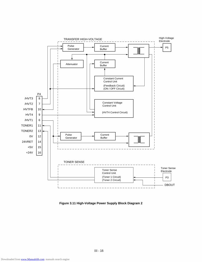
III - 16
TRANSFER HIGH-VOLTAGE
TONER SENSE
DBOUT
P4
8
7
10
9
6
11
13
12
14
15
16
/HVT3
/HVT2
HVTFB
HVT4
/HVT1
TONER1
TONER2
0V
24VRET
+5V
+24V
PulseGenerator
CurrentBuffer
P5
High-VoltageElectrode
CurrentBufferAttenuator
Constant CurrentControl Unit
(Feedback Circuit)(ON / OFF Circuit)
Toner SenseControl Unit
(HVT4 Control Circuit)
CurrentBuffer
(Toner 1 Circuit)(Toner 2 Circuit)
P3
Toner SenseElectrode
PulseGenerator
Constant VoltageControl Unit
Figure 3.11 High-Voltage Power Supply Block Diagram 2
Downloaded from www.Manualslib.com manuals search engine

IV - 1
• Tapping screws
S tight M3 : 7kgf • cm
B tight M3 x 6 : 5kgf • cmM3 x 8 : 7kgf • cm
• Stepped screws
M3 : 7kgf • cmM4 : 10kgf • cm
Safety Precautions
(9) When connecting or disconnecting cable connectors, hold the connector bodies not thecables. If the connector has a lock, always slide the connector lock to unlock it.
(10) After repairs, check not only the repaired portion but also that the connectors and otherrelated portions function properly before operation checks.
Notes
• On the next page is a disassembly order flow which helps you access the object
component.
• Unless otherwise specified, the disassembled parts or components should be
reassembled in the reverse order of removal.
To prevent the creation of secondary problems by mishandling, observe the following precau-tions during maintenance work.
(1) Always turn off the power before replacing parts or units. When having access to the powersupply, be sure to unplug the power cord form the power outlet.
(2) Be careful not to lose screws, washers, or other parts removed for parts replacement.
(3) Be sure to apply grease to the teeth of gears.
(4) When using soldering irons and other heat-generating tools, take care not to damage theresin parts such as wires, PCBs, and covers.
(5) Before handling the PCBs, touch a metal portion of the equipment to discharge staticelectricity, or the electronic parts may be damaged due to the electricity charged in yourbody.
(6) When transporting PCBs, be sure to wrap them in conductive sheets such as aluminumfoil.
(7) Be sure to reinsert self-tapping screws correctly, if removed.
(8) Unless otherwise specified, tighten screws to the torque values listed below.
CHAPTER IV MECHANICAL SYSTEM
Downloaded from www.Manualslib.com manuals search engine
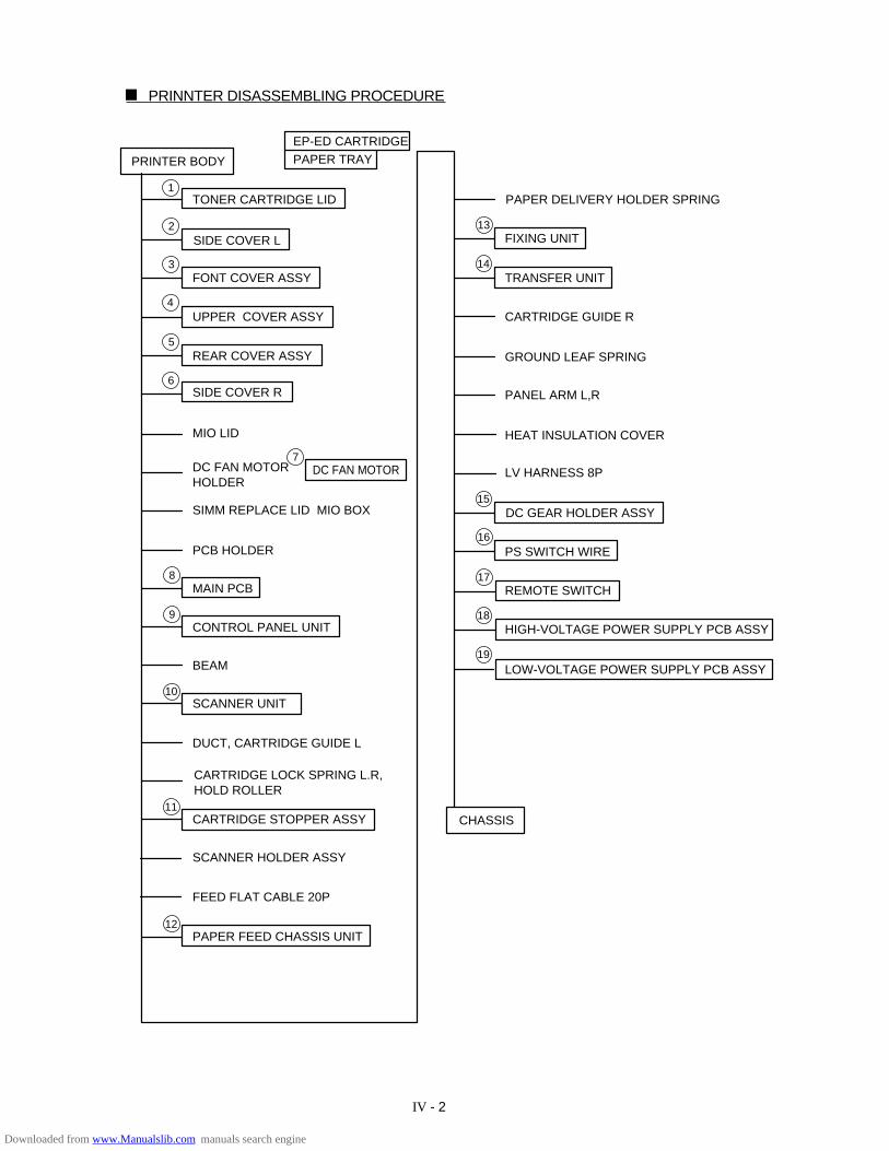
IV - 2
PRINNTER DISASSEMBLING PROCEDURE
PRINTER BODY
1
2
3
4
5
6
8
9
10
11
12
19
18
17
16
15
14
13
EP-ED CARTRIDGEPAPER TRAY
TONER CARTRIDGE LID
SIDE COVER L
FONT COVER ASSY
UPPER COVER ASSY
REAR COVER ASSY
MIO LID
SIDE COVER R
DC FAN MOTOR HOLDER
SIMM REPLACE LID MIO BOX
PCB HOLDER
MAIN PCB
CONTROL PANEL UNIT
BEAM
SCANNER UNIT
DUCT, CARTRIDGE GUIDE L
CARTRIDGE STOPPER ASSY
SCANNER HOLDER ASSY
FEED FLAT CABLE 20P
PAPER FEED CHASSIS UNIT
PAPER DELIVERY HOLDER SPRING
FIXING UNIT
TRANSFER UNIT
CARTRIDGE GUIDE R
GROUND LEAF SPRING
PANEL ARM L,R
HEAT INSULATION COVER
LV HARNESS 8P
DC GEAR HOLDER ASSY
PS SWITCH WIRE
REMOTE SWITCH
HIGH-VOLTAGE POWER SUPPLY PCB ASSY
LOW-VOLTAGE POWER SUPPLY PCB ASSY
CHASSIS
7DC FAN MOTOR
CARTRIDGE LOCK SPRING L.R, HOLD ROLLER
Downloaded from www.Manualslib.com manuals search engine
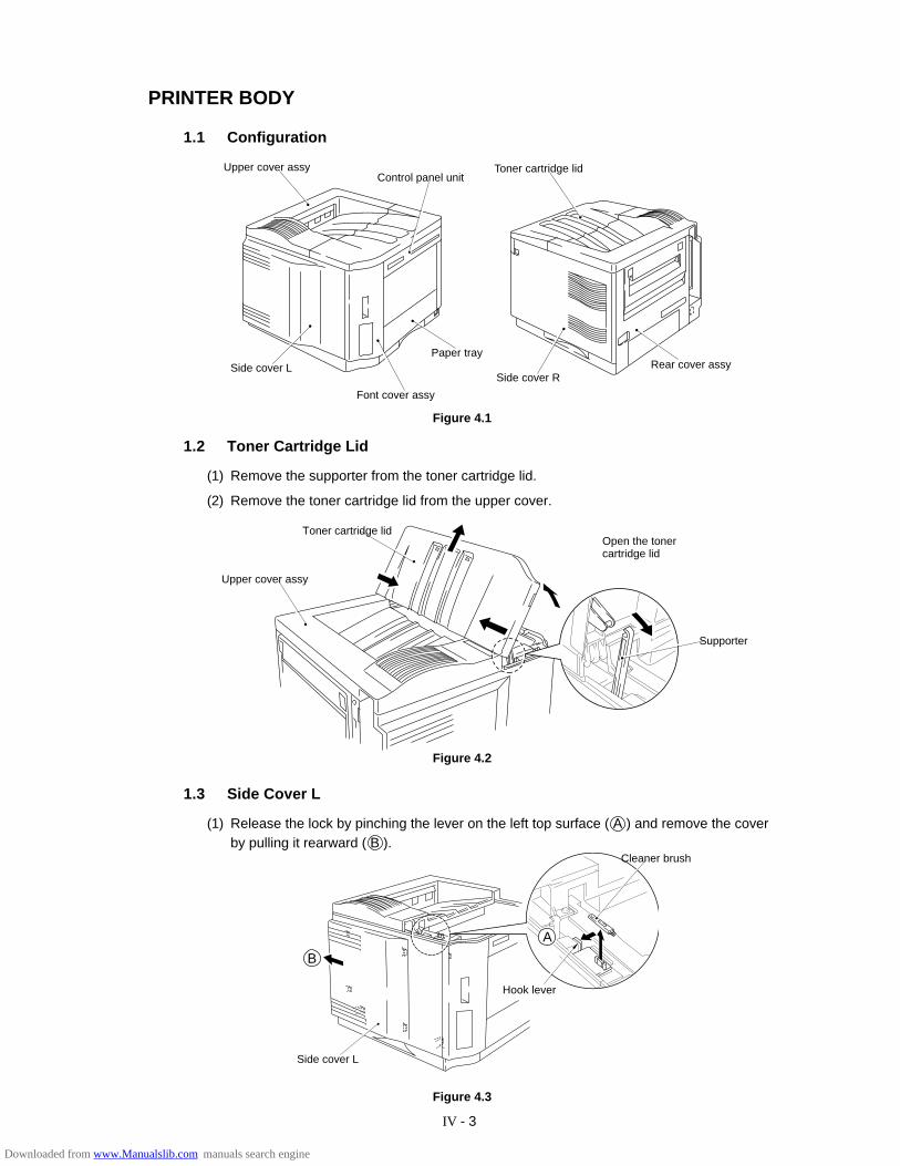
IV - 3
PRINTER BODY
1.1 Configuration
Figure 4.1
1.2 Toner Cartridge Lid
(1) Remove the supporter from the toner cartridge lid.
(2) Remove the toner cartridge lid from the upper cover.
Figure 4.2
1.3 Side Cover L
(1) Release the lock by pinching the lever on the left top surface ( A ) and remove the coverby pulling it rearward ( B ).
Figure 4.3
Toner cartridge lidUpper cover assyControl panel unit
Side cover LPaper tray
Rear cover assy
Cleaner brush
Hook lever
Side cover L
A
Open the tonercartridge lid
Supporter
Upper cover assy
Toner cartridge lid
Side cover R
B
Font cover assy
Downloaded from www.Manualslib.com manuals search engine
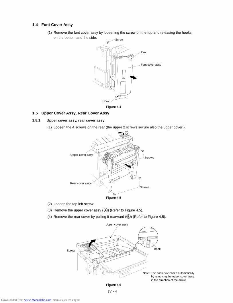
IV - 4
B
1.5 Upper Cover Assy, Rear Cover Assy
1.5.1 Upper cover assy, rear cover assy
(1) Loosen the 4 screws on the rear (the upper 2 screws secure also the upper cover ).
1.4 Font Cover Assy
(1) Remove the font cover assy by loosening the screw on the top and releasing the hookson the bottom and the side.
Figure 4.6
Figure 4.4
A
Screw
Hook
Font cover assy
Hook
Upper cover assyScrews
ScrewsRear cover assy
Figure 4.5
(2) Loosen the top left screw.
(3) Remove the upper cover assy ( A ) (Refer to Figure 4.5).
(4) Remove the rear cover by pulling it rearward ( B ) (Refer to Figure 4.5).
Screw hook
Upper cover assy
Note: The hook is released automaticallyby removing the upper cover assyin the direction of the arrow.
Downloaded from www.Manualslib.com manuals search engine
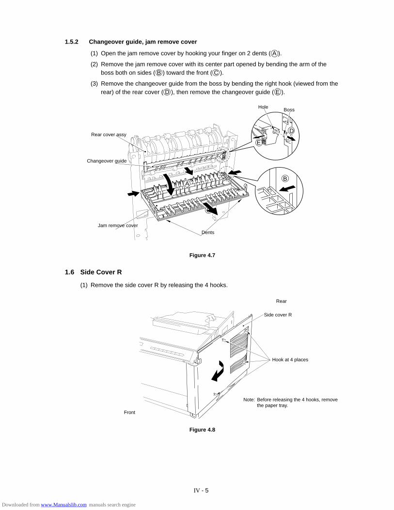
IV - 5
1.5.2 Changeover guide, jam remove cover
(1) Open the jam remove cover by hooking your finger on 2 dents ( A ).
(2) Remove the jam remove cover with its center part opened by bending the arm of theboss both on sides ( B ) toward the front ( C ).
(3) Remove the changeover guide from the boss by bending the right hook (viewed from therear) of the rear cover ( D ), then remove the changeover guide ( E ).
1.6 Side Cover R
(1) Remove the side cover R by releasing the 4 hooks.
Figure 4.7
Hole
Rear cover assy
Changeover guide
Jam remove coverDents
Boss
D
E
B
C
A
Figure 4.8
Front
Side cover R
Hook at 4 places
Note: Before releasing the 4 hooks, removethe paper tray.
Rear
Downloaded from www.Manualslib.com manuals search engine
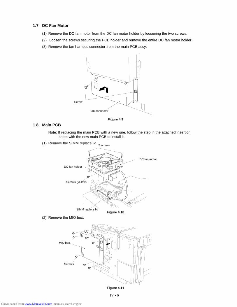
IV - 6
1.7 DC Fan Motor
(1) Remove the DC fan motor from the DC fan motor holder by loosening the two screws.
(2) Loosen the screws securing the PCB holder and remove the entire DC fan motor holder.
(3) Remove the fan harness connector from the main PCB assy.
Figure 4.10
Figure 4.11
1.8 Main PCB
Note: If replacing the main PCB with a new one, follow the step in the attached insertionsheet with the new main PCB to install it.
(1) Remove the SIMM replace lid.
Figure 4.9
2 screws
DC fan holder
Screw
Fan connector
DC fan motor
Screws (yellow)
SIMM replace lid
MIO box
Screws
(2) Remove the MIO box.
Downloaded from www.Manualslib.com manuals search engine
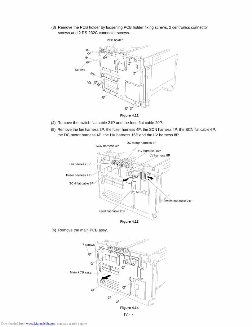
IV - 7
(3) Remove the PCB holder by loosening PCB holder fixing screws, 2 centronics connectorscrews and 2 RS-232C connector screws.
Figure 4.12
(4) Remove the switch flat cable 21P and the feed flat cable 20P.
(5) Remove the fan harness 3P, the fuser harness 4P, the SCN harness 4P, the SCN flat cable 6P,the DC motor harness 4P, the HV harness 16P and the LV harness 8P.
Figure 4.14
Figure 4.13
PCB holder
Screws
SCN harness 4P
HV harness 16P
LV harness 8P
Switch flat cable 21P
Feed flat cable 20P
SCN flat cable 6P
Fuser harness 4P
7 screws
Main PCB assy
(6) Remove the main PCB assy.
Fan harness 3P
DC motor harness 4P
Downloaded from www.Manualslib.com manuals search engine
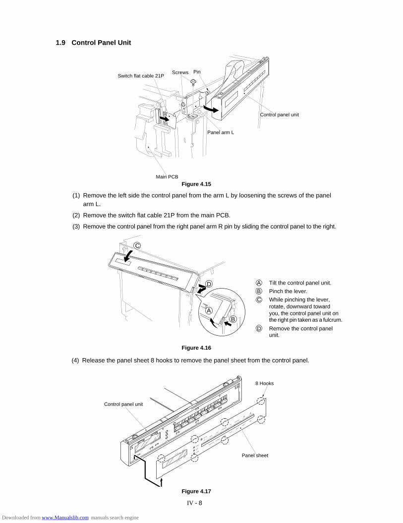
IV - 8
1.9 Control Panel Unit
Figure 4.17
READY
DATA
ALARM
ON LINE
SEL
MODE
FONT
FORM FEED
SET
CONTINUE
EMULATIONECONOMY
FEEDER
COPY
SHIFT
RESET
TEST
COPY PAGES
FEEDER
ORIENTATION
DUPLEX
(4) Release the panel sheet 8 hooks to remove the panel sheet from the control panel.
Figure 4.16
ScrewsSwitch flat cable 21P
Pin
Panel arm L
Control panel unit
Control panel unit
Panel sheet
8 Hooks
C
Main PCB
(1) Remove the left side the control panel from the arm L by loosening the screws of the panelarm L.
(2) Remove the switch flat cable 21P from the main PCB.
(3) Remove the control panel from the right panel arm R pin by sliding the control panel to the right.
Figure 4.15
D
AB
A Tilt the control panel unit.
B Pinch the lever.
C While pinching the lever,rotate, downward towardyou, the control panel unit onthe right pin taken as a fulcrum.
D Remove the control panelunit.
Downloaded from www.Manualslib.com manuals search engine
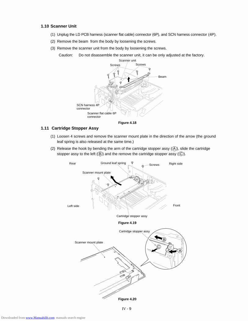
IV - 9
1.10 Scanner Unit
(1) Unplug the LD PCB harness (scanner flat cable) connector (6P), and SCN harness connector (4P).
(2) Remove the beam from the body by loosening the screws.
(3) Remove the scanner unit from the body by loosening the screws.
Caution: Do not disassemble the scanner unit, it can be only adjusted at the factory.
Figure 4.20
Figure 4.19
1.11 Cartridge Stopper Assy
(1) Loosen 4 screws and remove the scanner mount plate in the direction of the arrow (the groundleaf spring is also released at the same time.)
(2) Release the hook by bending the arm of the cartridge stopper assy ( A ), slide the cartridgestopper assy to the left ( B ) and the remove the cartridge stopper assy ( C ).
Figure 4.18
SCN harness 4Pconnector
Screws ScrewsScanner unit
Ground leaf spring
Scanner mount plate
Screws
Cartridge stopper assy
Scanner mount plate
Cartridge stopper assy
C
B
A
Beam
Scanner flat cable 6Pconnector
Right side
Left side
Rear
Front
Downloaded from www.Manualslib.com manuals search engine
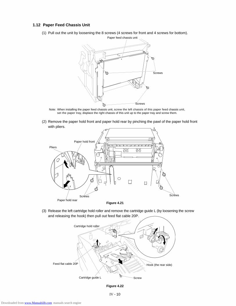
IV - 10
1.12 Paper Feed Chassis Unit
(1) Pull out the unit by loosening the 8 screws (4 screws for front and 4 screws for bottom).
(2) Remove the paper hold front and paper hold rear by pinching the pawl of the paper hold frontwith pliers.
Paper hold front
Screws Screws
(3) Release the left cartridge hold roller and remove the cartridge guide L (by loosening the screwand releasing the hook) then pull out feed flat cable 20P.
Screw
Figure 4.22
Note: When installing the paper feed chassis unit, screw the left chassis of this paper feed chassis unit,set the paper tray, displace the right chassis of this unit up to the paper tray and screw them.
Hook (the rear side)
Cartridge hold roller
Pliers
Figure 4.21Paper hold rear
Feed flat cable 20P
Screws
Screws
Paper feed chassis unit
Cartridge guide L
Downloaded from www.Manualslib.com manuals search engine
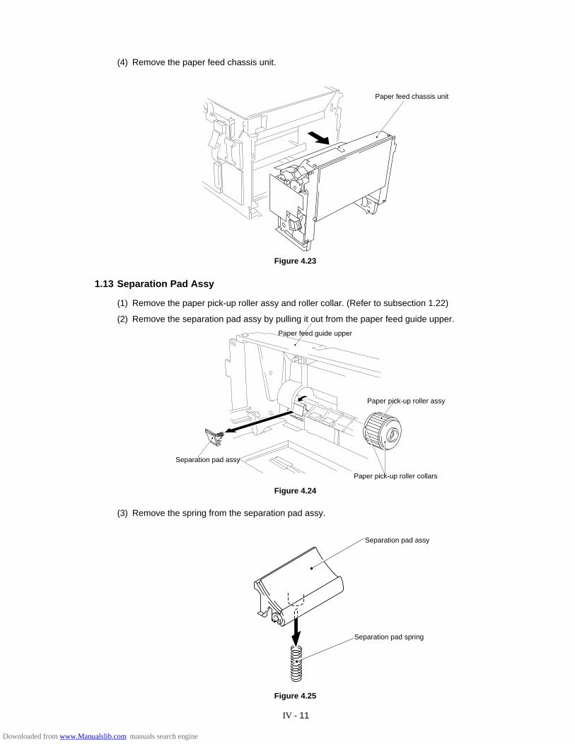
IV - 11
(4) Remove the paper feed chassis unit.
Figure 4.23
1.13 Separation Pad Assy
(1) Remove the paper pick-up roller assy and roller collar. (Refer to subsection 1.22)
(2) Remove the separation pad assy by pulling it out from the paper feed guide upper.
Figure 4.24
(3) Remove the spring from the separation pad assy.
Figure 4.25
Separation pad assy
Separation pad spring
Paper feed chassis unit
Paper feed guide upper
Paper pick-up roller assy
Paper pick-up roller collars
Separation pad assy
Downloaded from www.Manualslib.com manuals search engine
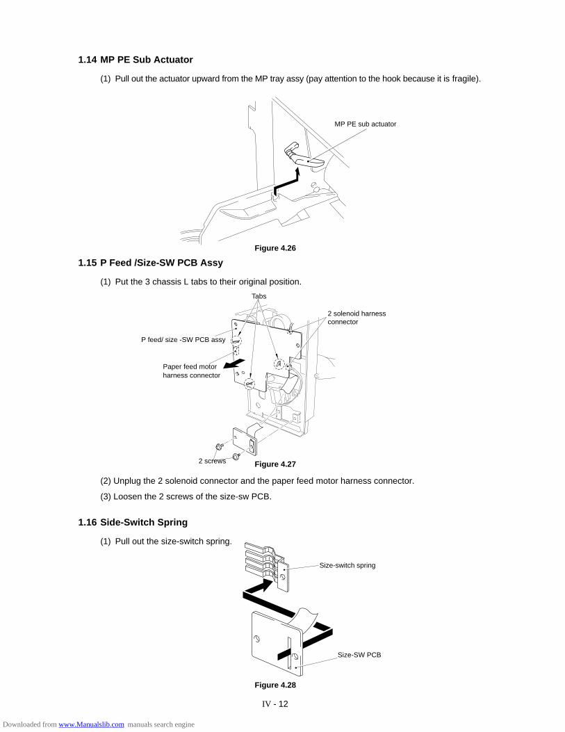
IV - 12
1.14 MP PE Sub Actuator
(1) Pull out the actuator upward from the MP tray assy (pay attention to the hook because it is fragile).
Figure 4.28
MP PE sub actuator
Figure 4.26
1.15 P Feed /Size-SW PCB Assy
(1) Put the 3 chassis L tabs to their original position.
Tabs
2 solenoid harnessconnector
2 screws
Paper feed motorharness connector
Figure 4.27
(2) Unplug the 2 solenoid connector and the paper feed motor harness connector.
(3) Loosen the 2 screws of the size-sw PCB.
Size-switch spring
Size-SW PCB
1.16 Side-Switch Spring
(1) Pull out the size-switch spring.
P feed/ size -SW PCB assy
Downloaded from www.Manualslib.com manuals search engine
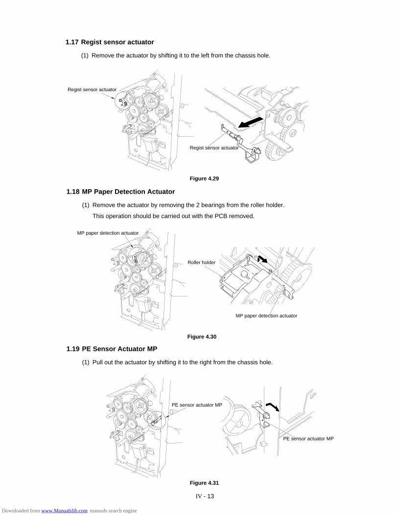
IV - 13
1.17 Regist sensor actuator
(1) Remove the actuator by shifting it to the left from the chassis hole.
1.18 MP Paper Detection Actuator
(1) Remove the actuator by removing the 2 bearings from the roller holder.
This operation should be carried out with the PCB removed.
1.19 PE Sensor Actuator MP
(1) Pull out the actuator by shifting it to the right from the chassis hole.
Figure 4.30
Figure 4.31
Figure 4.29
MP paper detection actuator
Roller holder
MP paper detection actuator
PE sensor actuator MP
Regist sensor actuator
Regist sensor actuator
PE sensor actuator MP
Downloaded from www.Manualslib.com manuals search engine
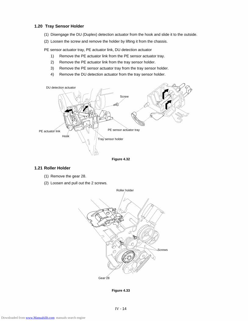
IV - 14
1.20 Tray Sensor Holder
(1) Disengage the DU (Duplex) detection actuator from the hook and slide it to the outside.
(2) Loosen the screw and remove the holder by lifting it from the chassis.
PE sensor actuator tray, PE actuator link, DU detection actuator
1) Remove the PE actuator link from the PE sensor actuator tray.
2) Remove the PE actuator link from the tray sensor holder.
3) Remove the PE sensor actuator tray from the tray sensor holder.
4) Remove the DU detection actuator from the tray sensor holder.
Roller holder
Screws
Figure 4.32
1.21 Roller Holder
(1) Remove the gear 28.
(2) Loosen and pull out the 2 screws.
DU detection actuator
PE actuator link
Tray sensor holder
PE sensor actuator tray
Screw
Hook
Gear 28
Figure 4.33
Downloaded from www.Manualslib.com manuals search engine

IV - 15
1.22 Paper Pick-up Roller Assy, Bearing
(1) Pull out the MP paper pick-up gear 35 and the tray paper pick-up gear 35, from the paper pick-up roller shafts.
(2) Loosen the bearing screws and pull out the paper pick-up rollers.
*When only the paper feed rollers are to be replaced, they can be replaced without removingthe paper feed unit (with the body assembled).
Paper pick-up roller shafts
Tray paper pick-up gear 35
MP paper pick-up gear 35
Bearing
Paper pick-up roller assy
Figure 4.34
Figure 4.35
Paper pick-up roller collars
Paper pick-uproller assy
Bearing
Paper pick-up roller shafts
(3) Pull out the paper pick-up roller shafts.
(4) Remove the paper pick-up roller collars from the paper pick-up rollers assy.
Screws
Paper pick-up roller collars
Bearings
Paper pick-up roller assy
Paper pick-up rollercollars
Figure 4.36
Downloaded from www.Manualslib.com manuals search engine
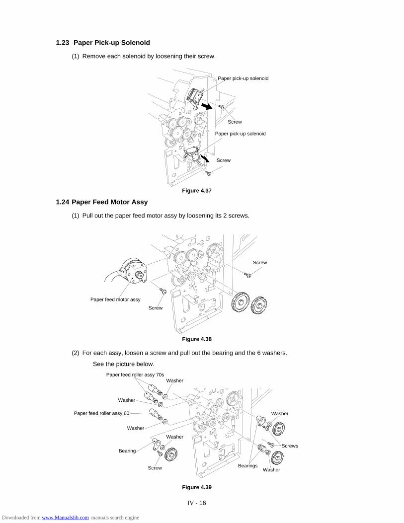
IV - 16
Figure 4.39
1.23 Paper Pick-up Solenoid
(1) Remove each solenoid by loosening their screw.
1.24 Paper Feed Motor Assy
(1) Pull out the paper feed motor assy by loosening its 2 screws.
Figure 4.37
Paper pick-up solenoid
Screw
Paper pick-up solenoid
Screw
Screw
Screw
Paper feed motor assy
(2) For each assy, loosen a screw and pull out the bearing and the 6 washers.
See the picture below.
Figure 4.38
Paper feed roller assy 70s
Washer
Paper feed roller assy 60
Screws
Washer
Washer
Washer
Washer
Bearing
Screw BearingsWasher
Downloaded from www.Manualslib.com manuals search engine
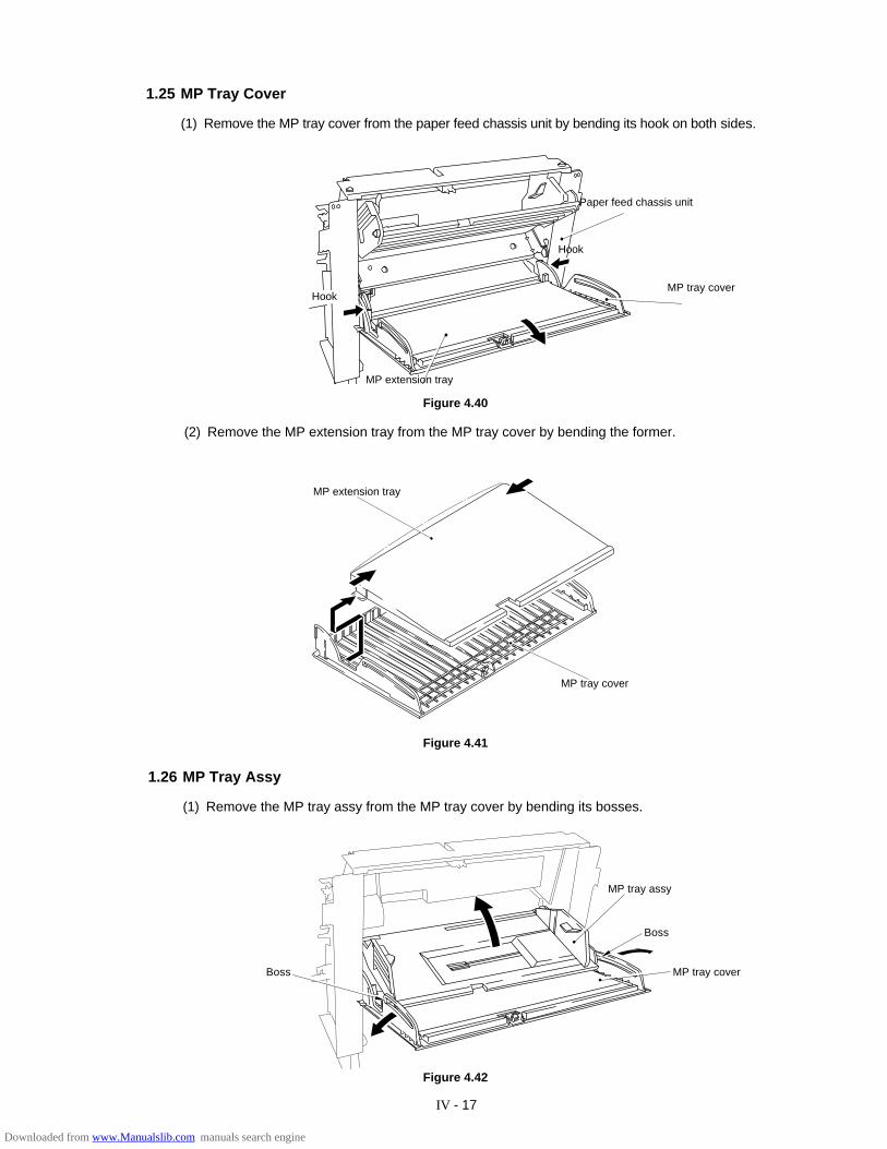
IV - 17
1.25 MP Tray Cover
(1) Remove the MP tray cover from the paper feed chassis unit by bending its hook on both sides.
Figure 4.40
Figure 4.41
Figure 4.42
(2) Remove the MP extension tray from the MP tray cover by bending the former.
1.26 MP Tray Assy
(1) Remove the MP tray assy from the MP tray cover by bending its bosses.
Paper feed chassis unit
Hook
MP tray cover
MP extension tray
Hook
MP extension tray
MP tray cover
Boss
MP tray assy
Boss
MP tray cover
Downloaded from www.Manualslib.com manuals search engine
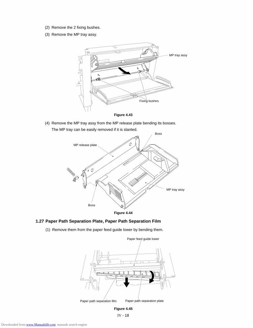
IV - 18
(2) Remove the 2 fixing bushes.
(3) Remove the MP tray assy.
(4) Remove the MP tray assy from the MP release plate bending its bosses.
The MP tray can be easily removed if it is slanted.
Figure 4.44
1.27 Paper Path Separation Plate, Paper Path Separation Film
(1) Remove them from the paper feed guide lower by bending them.
Paper feed guide lower
Paper path separation platePaper path separation film
Fixing bushes
MP tray assy
Figure 4.43
Figure 4.45
MP tray assy
Boss
MP release plate
Boss
Downloaded from www.Manualslib.com manuals search engine
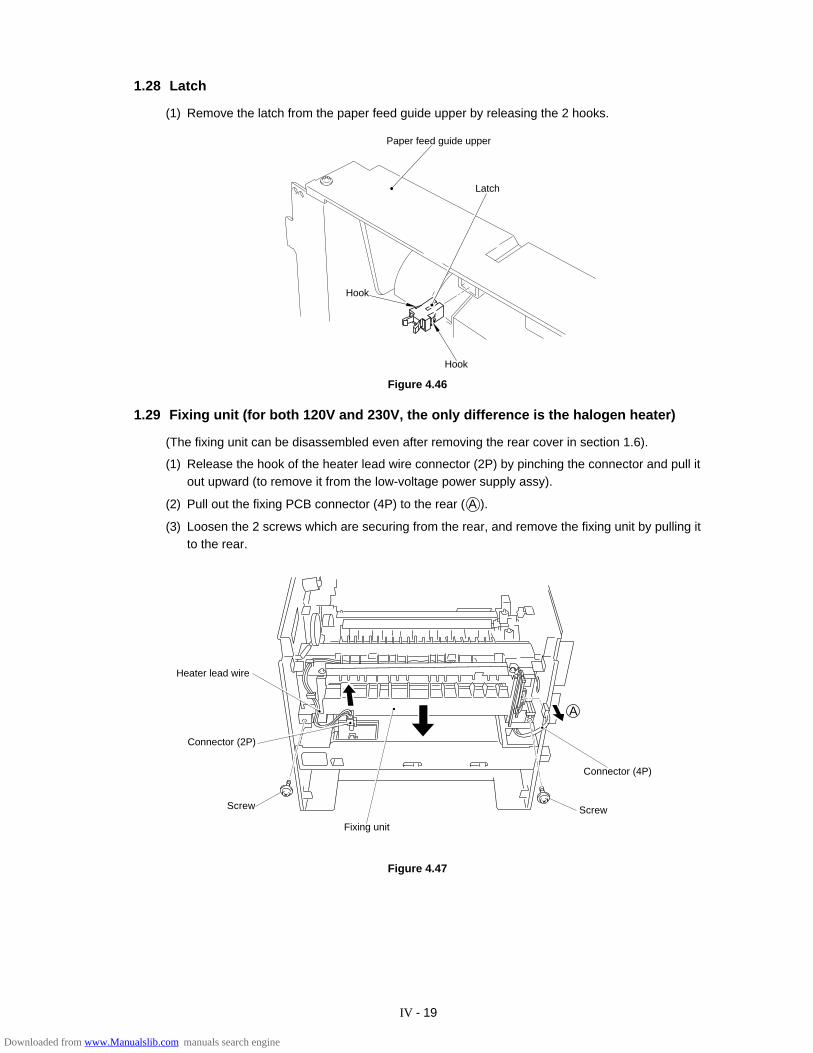
IV - 19
1.28 Latch
(1) Remove the latch from the paper feed guide upper by releasing the 2 hooks.
Figure 4.46
1.29 Fixing unit (for both 120V and 230V, the only difference is the halogen heater)
(The fixing unit can be disassembled even after removing the rear cover in section 1.6).
(1) Release the hook of the heater lead wire connector (2P) by pinching the connector and pull itout upward (to remove it from the low-voltage power supply assy).
(2) Pull out the fixing PCB connector (4P) to the rear ( A ).
(3) Loosen the 2 screws which are securing from the rear, and remove the fixing unit by pulling itto the rear.
Figure 4.47
Paper feed guide upper
Hook
Hook
Latch
Heater lead wire
Fixing unit
Screw
Connector (2P)
Screw
Connector (4P)
A
Downloaded from www.Manualslib.com manuals search engine
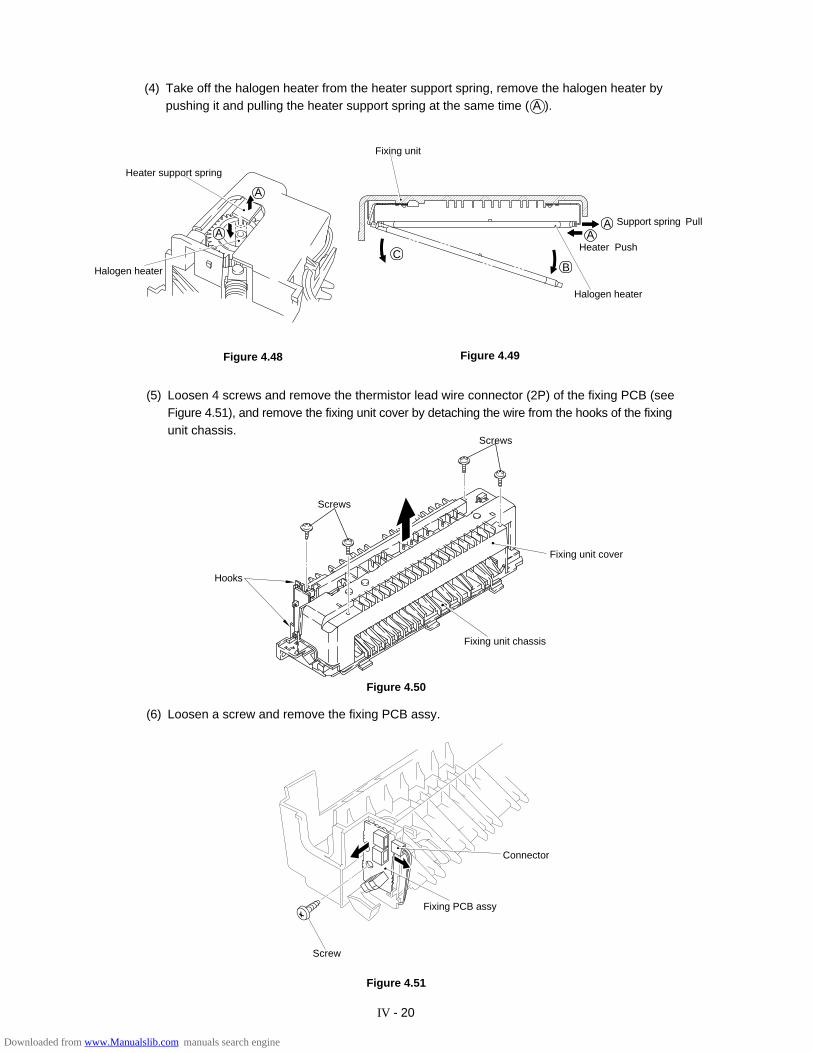
IV - 20
�����
��
����
�����
�����
�����
�����
����
���
��
(4) Take off the halogen heater from the heater support spring, remove the halogen heater bypushing it and pulling the heater support spring at the same time ( A ).
Figure 4.50
(6) Loosen a screw and remove the fixing PCB assy.
Figure 4.51
(5) Loosen 4 screws and remove the thermistor lead wire connector (2P) of the fixing PCB (seeFigure 4.51), and remove the fixing unit cover by detaching the wire from the hooks of the fixingunit chassis.
Heater support spring
Halogen heater
Figure 4.48
Screws
Fixing unit cover
Fixing unit chassis
Hooks
Screws
Screw
Connector
A
A
Fixing PCB assy
Fixing unit
C
Halogen heater
B
AHeater Push
A Support spring Pull
Figure 4.49
Downloaded from www.Manualslib.com manuals search engine
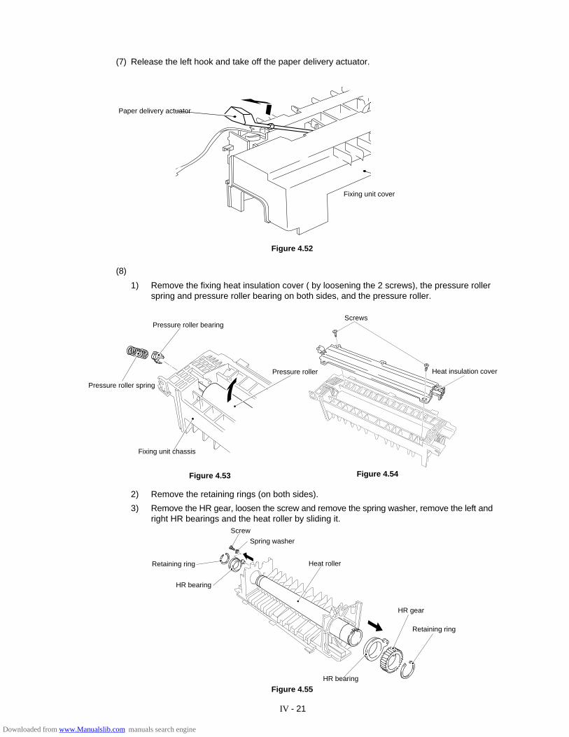
IV - 21
(7) Release the left hook and take off the paper delivery actuator.
Figure 4.55
(8)
1) Remove the fixing heat insulation cover ( by loosening the 2 screws), the pressure rollerspring and pressure roller bearing on both sides, and the pressure roller.
Figure 4.53
2) Remove the retaining rings (on both sides).
3) Remove the HR gear, loosen the screw and remove the spring washer, remove the left andright HR bearings and the heat roller by sliding it.
Figure 4.54
Screws
Heat insulation cover
Retaining ring
HR bearing
Screw
HR bearing
Heat roller
HR gear
Retaining ring
Spring washer
Pressure roller bearing
Pressure roller spring
Fixing unit chassis
Pressure roller
Paper delivery actuator
Fixing unit cover
Figure 4.52
Downloaded from www.Manualslib.com manuals search engine
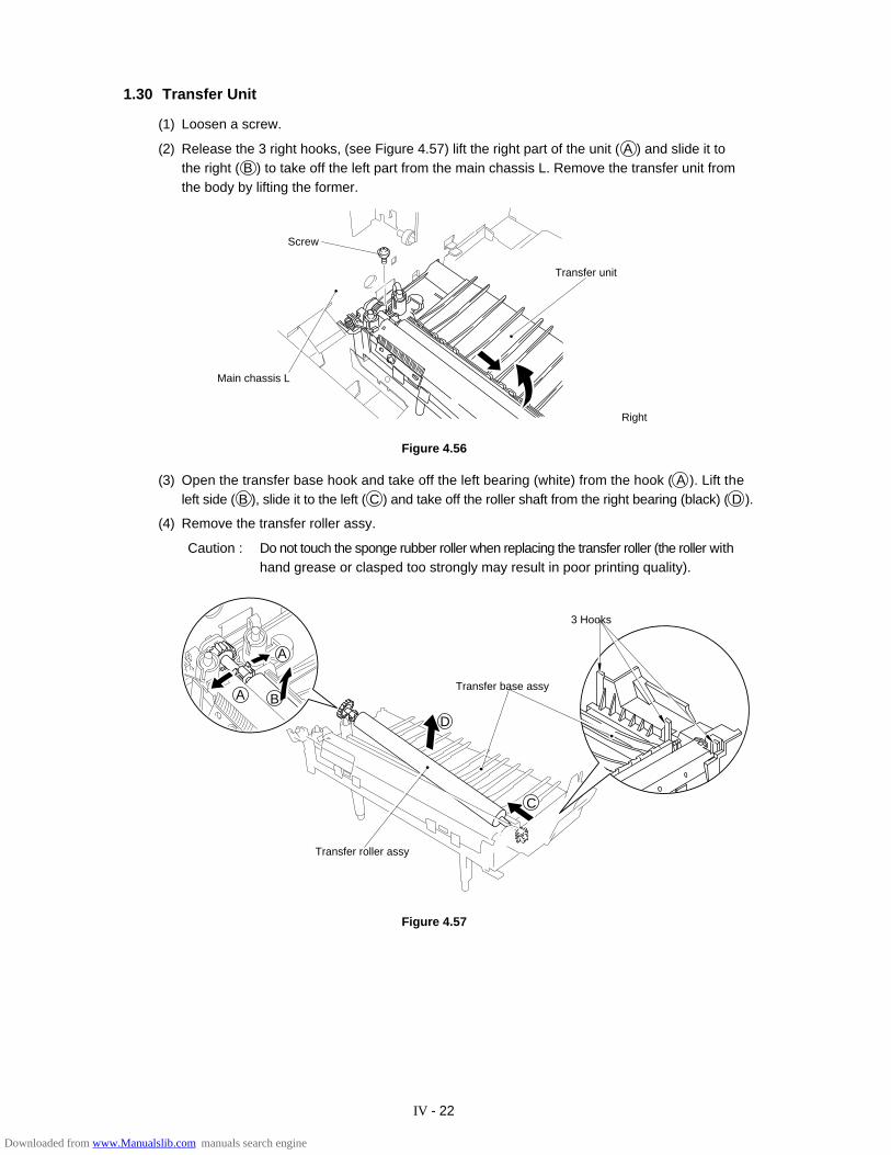
IV - 22
1.30 Transfer Unit
(1) Loosen a screw.
(2) Release the 3 right hooks, (see Figure 4.57) lift the right part of the unit ( A ) and slide it tothe right ( B ) to take off the left part from the main chassis L. Remove the transfer unit fromthe body by lifting the former.
(3) Open the transfer base hook and take off the left bearing (white) from the hook ( A ). Lift theleft side ( B ), slide it to the left ( C ) and take off the roller shaft from the right bearing (black) ( D ).
(4) Remove the transfer roller assy.
Caution : Do not touch the sponge rubber roller when replacing the transfer roller (the roller withhand grease or clasped too strongly may result in poor printing quality).
Figure 4.57
Figure 4.56
Main chassis L
D
Transfer base assy
C
BA
Transfer roller assy
3 Hooks
Screw
Transfer unit
Right
A
Downloaded from www.Manualslib.com manuals search engine
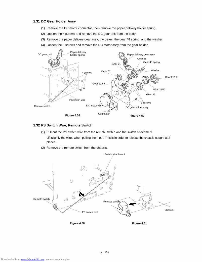
IV - 23
1.31 DC Gear Holder Assy
(1) Remove the DC motor connector, then remove the paper delivery holder spring.
(2) Loosen the 4 screws and remove the DC gear unit from the body.
(3) Remove the paper delivery gear assy, the gears, the gear 48 spring, and the washer.
(4) Loosen the 3 screws and remove the DC motor assy from the gear holder.
Figure 4.61Figure 4.60
Figure 4.58 Figure 4.59
1.32 PS Switch Wire, Remote Switch
(1) Pull out the PS switch wire from the remote switch and the switch attachment.
Lift slightly the wires when pulling them out. This is in order to release the chassis caught at 2places.
(2) Remove the remote switch from the chassis.
Paper deliveryholder springDC gear unit
PS switch wire
Remote switch
Gear 48Gear 48 spring
Gear 24/72
Gear 20/50
Gear 39
3 screws
DC gear holder assy
Gear 22/55
Gear 28
Connector
DC motor assy
Gear 21
Paper delivery gear assy
Washer
Remote switchRemote switch
Chassis
4 screws
Switch attachment
PS switch wire
Downloaded from www.Manualslib.com manuals search engine
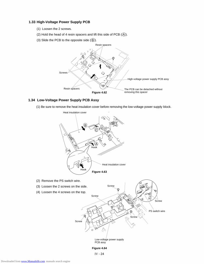
IV - 24
1.33 High-Voltage Power Supply PCB
(1) Loosen the 2 screws.
(2) Hold the head of 4 resin spacers and lift this side of PCB ( A ).
(3) Slide the PCB to the opposite side ( B ).
(2) Remove the PS switch wire.
(3) Loosen the 2 screws on the side.
(4) Loosen the 4 screws on the top.
Figure 4.63
Figure 4.62
1.34 Low-Voltage Power Supply PCB Assy
(1) Be sure to remove the heat insulation cover before removing the low-voltage power supply block.
Figure 4.64
Resin spacers
Screws
The PCB can be detached withoutremoving this spacer
Resin spacers
Heat insulation cover
Heat insulation cover
Screw
Low-voltage power supplyPCB assy
PS switch wire
Screw
Screw
Screw
Screw
Hook
Hook
A
B
C
High-voltage power supply PCB assy
Downloaded from www.Manualslib.com manuals search engine
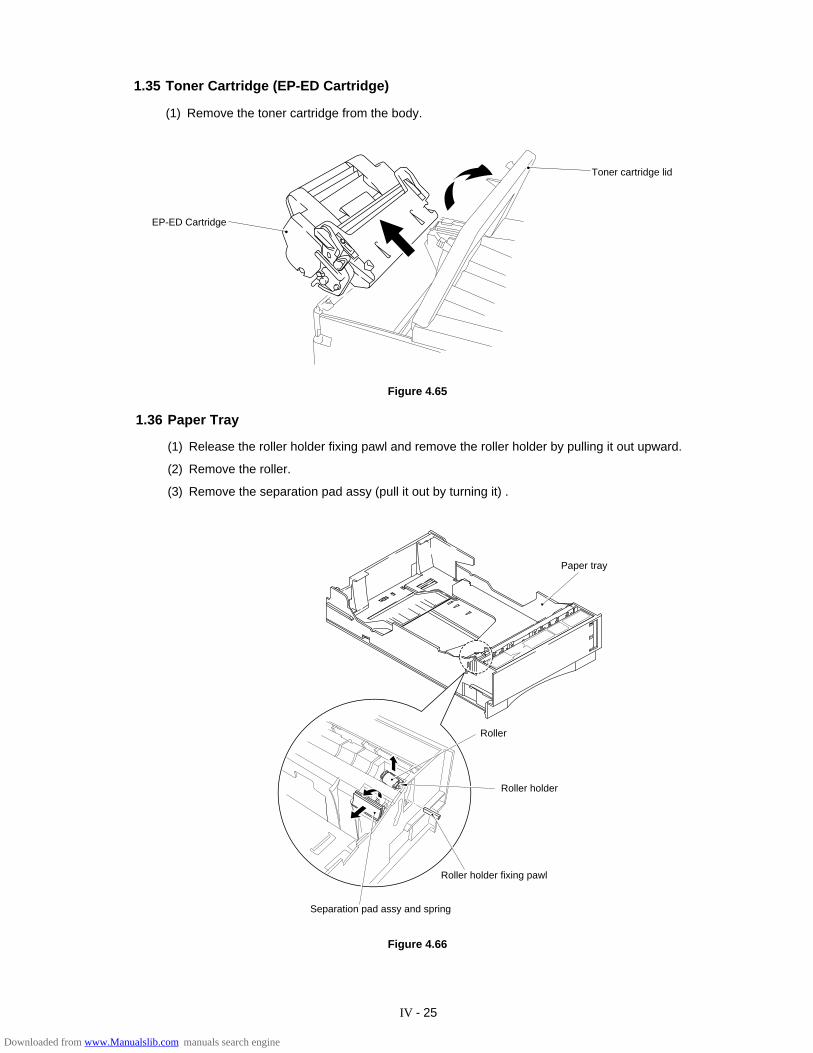
IV - 25
1.35 Toner Cartridge (EP-ED Cartridge)
(1) Remove the toner cartridge from the body.
Figure 4.65
1.36 Paper Tray
(1) Release the roller holder fixing pawl and remove the roller holder by pulling it out upward.
(2) Remove the roller.
(3) Remove the separation pad assy (pull it out by turning it) .
Figure 4.66
Separation pad assy and spring
Roller holder fixing pawl
Paper tray
Roller holder
Toner cartridge lid
EP-ED Cartridge
Roller
Downloaded from www.Manualslib.com manuals search engine
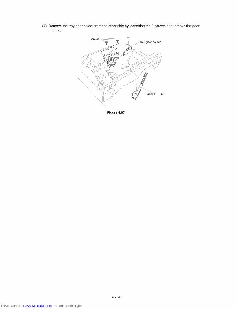
IV - 26
(4) Remove the tray gear holder from the other side by loosening the 3 screws and remove the gear56T link.
Figure 4.67
ScrewsTray gear holder
Gear 56T link
Downloaded from www.Manualslib.com manuals search engine
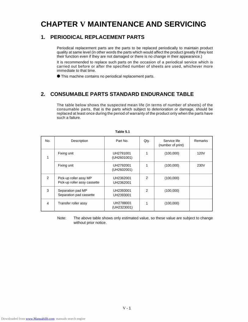
V - 1
Table 5.1
No. Description Part No. Qty. Remarks
1
2
3
4
2
2
1
1
1Fixing unit UH2791001(UH2601001)
(100,000) 120V
Fixing unit UH2792001(UH2602001)
(100,000) 230V
Pick-up roller assy MP Pick-up roller assy cassette
UH2362001 (100,000)UH2362001
Separation pad MPSeparation pad cassette
UH2393001 (100,000)
Transfer roller assy UH2788001 (100,000)
UH2393001
Service life(number of print)
(UH2323001)
Note: The above table shows only estimated value, so these value are subject to changewithout prior notice.
CHAPTER V MAINTENANCE AND SERVICING
1. PERIODICAL REPLACEMENT PARTS
Periodical replacement parts are the parts to be replaced periodically to maintain productquality at same level (in other words the parts which would affect the product greatly if they losttheir function even if they are not damaged or there is no change in their appearance.)
It is recommended to replace such parts on the occasion of a periodical service which iscarried out before or after the specified number of sheets are used, whichever moreimmediate to that time.
This machine contains no periodical replacement parts.
2. CONSUMABLE PARTS STANDARD ENDURANCE TABLE
The table below shows the suspected mean life (in terms of number of sheets) of theconsumable parts, that is the parts which subject to deterioration or damage, should bereplaced at least once during the period of warranty of the product only when the parts havesuch a failure.
Downloaded from www.Manualslib.com manuals search engine
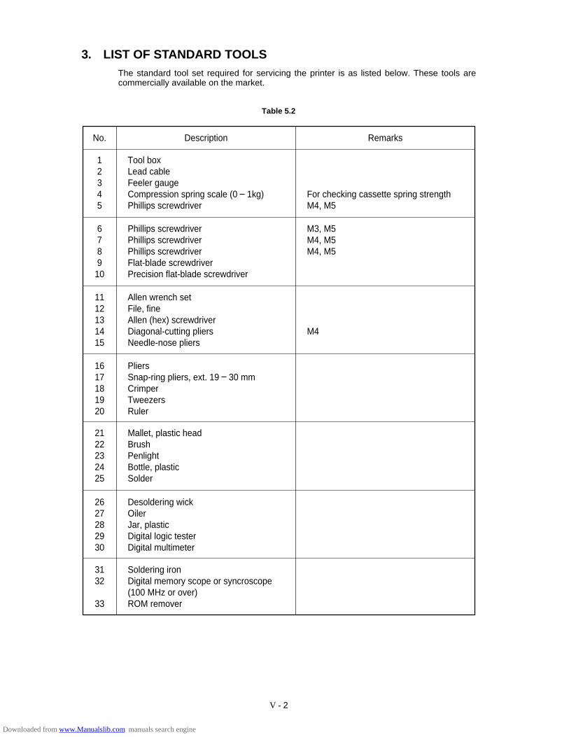
V - 2
3. LIST OF STANDARD TOOLSThe standard tool set required for servicing the printer is as listed below. These tools arecommercially available on the market.
Table 5.2
No. Description Remarks
1
345
Tool box2 Lead cable
Feeler gaugeCompression spring scale (0 1kg)Phillips screwdriver
6
8910
Phillips screwdriver7 Phillips screwdriver
Phillips screwdriverFlat-blade screwdriverPrecision flat-blade screwdriver
11
131415
Allen wrench set12 File, fine
Allen (hex) screwdriverDiagonal-cutting pliersNeedle-nose pliers
16
181920
Pliers17 Snap-ring pliers, ext. 19 30 mm
CrimperTweezersRuler
21
232425
Mallet, plastic head22 Brush
PenlightBottle, plasticSolder
26
282930
Desoldering wick27 Oiler
Jar, plasticDigital logic testerDigital multimeter
31
33
Soldering iron32 Digital memory scope or syncroscope
(100 MHz or over)ROM remover
For checking cassette spring strengthM4, M5
M3, M5M4, M5M4, M5
M4
Downloaded from www.Manualslib.com manuals search engine
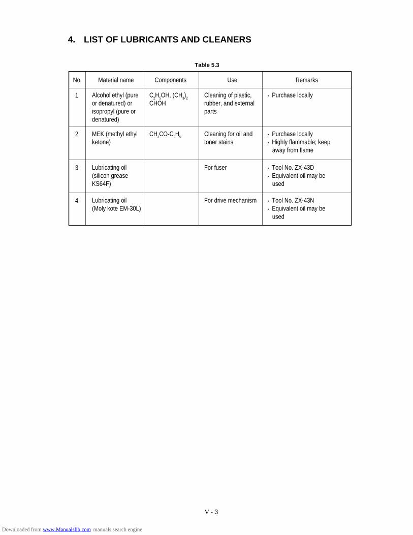
V - 3
4. LIST OF LUBRICANTS AND CLEANERS
No. Material name Components Use Remarks
Alcohol ethyl (pureor denatured) orisopropyl (pure ordenatured)
C2H5OH, (CH3)2
CHOHCleaning of plastic,rubber, and externalparts
• Purchase locally1
MEK (methyl ethylketone)
CH3CO-C2H5 Cleaning for oil andtoner stains
• Purchase locally• Highly flammable; keep away from flame
2
Lubricating oil (silicon grease KS64F)
For fuser • Tool No. ZX-43D• Equivalent oil may be used
3
Lubricating oil(Moly kote EM-30L)
For drive mechanism • Tool No. ZX-43N• Equivalent oil may be used
4
Table 5.3
Downloaded from www.Manualslib.com manuals search engine
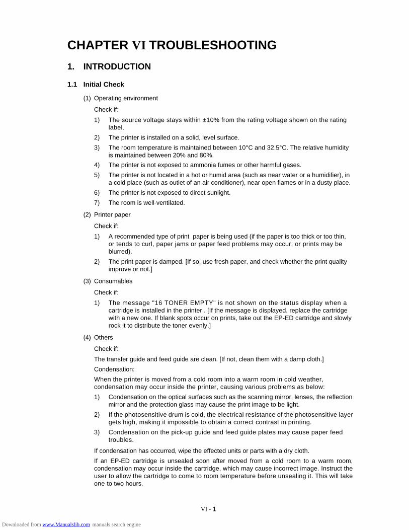
VI - 1
CHAPTER VI TROUBLESHOOTING
1. INTRODUCTION
1.1 Initial Check
(1) Operating environment
Check if:
1) The source voltage stays within ±10% from the rating voltage shown on the ratinglabel.
2) The printer is installed on a solid, level surface.
3) The room temperature is maintained between 10°C and 32.5°C. The relative humidityis maintained between 20% and 80%.
4) The printer is not exposed to ammonia fumes or other harmful gases.
5) The printer is not located in a hot or humid area (such as near water or a humidifier), ina cold place (such as outlet of an air conditioner), near open flames or in a dusty place.
6) The printer is not exposed to direct sunlight.
7) The room is well-ventilated.
(2) Printer paper
Check if:
1) A recommended type of print paper is being used (if the paper is too thick or too thin,or tends to curl, paper jams or paper feed problems may occur, or prints may beblurred).
2) The print paper is damped. [If so, use fresh paper, and check whether the print qualityimprove or not.]
(3) Consumables
Check if:
1) The message "16 TONER EMPTY" is not shown on the status display when acartridge is installed in the printer . [If the message is displayed, replace the cartridgewith a new one. If blank spots occur on prints, take out the EP-ED cartridge and slowlyrock it to distribute the toner evenly.]
(4) Others
Check if:
The transfer guide and feed guide are clean. [If not, clean them with a damp cloth.]
Condensation:
When the printer is moved from a cold room into a warm room in cold weather,condensation may occur inside the printer, causing various problems as below:
1) Condensation on the optical surfaces such as the scanning mirror, lenses, the reflectionmirror and the protection glass may cause the print image to be light.
2) If the photosensitive drum is cold, the electrical resistance of the photosensitive layergets high, making it impossible to obtain a correct contrast in printing.
3) Condensation on the pick-up guide and feed guide plates may cause paper feedtroubles.
If condensation has occurred, wipe the effected units or parts with a dry cloth.
If an EP-ED cartridge is unsealed soon after moved from a cold room to a warm room,condensation may occur inside the cartridge, which may cause incorrect image. Instruct theuser to allow the cartridge to come to room temperature before unsealing it. This will takeone to two hours.
Downloaded from www.Manualslib.com manuals search engine
VI - 2
1.2 Basic Procedure
If a malfunction or incorrect print is appeared, make an initial check, then follow the basicprocedure below:
(1) Check the status display. If any message is shown, see Section 4 for troubleshooting.
(2) If an incorrect image is found, see Section 3.1 to determine the defect type and Section3.2 for image troubleshooting.
2. TEST PRINTING AND MECHANICAL CHECK
2.1 Test Printing
If an image problem occurs, follow the procedure below to produce a test print.
1) Enter the offline mode.
2) Press the SHIFT and TEST switches simultaneously, so the printer enters the test printmode.
3) Press the or switch to appear the message "TEST PRINT" then press the SETswitch.
The message "05 TEST PRINT" will appear on the status display of the control panel and theDATA lamp will come on. Then, the printer will produce the test print.
4) Determine the image trouble type and see Section 3 for troubleshooting.
TEST PRINT
Figure 6.1
Downloaded from www.Manualslib.com manuals search engine
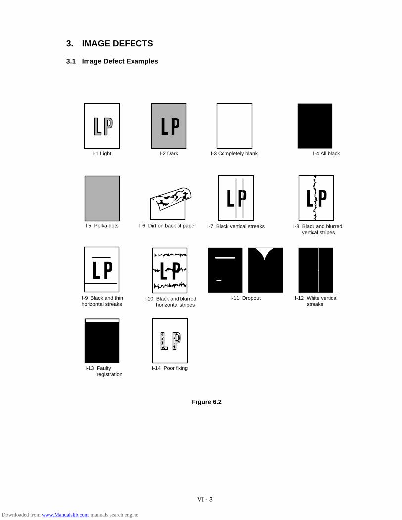
VI - 3
3. IMAGE DEFECTS
3.1 Image Defect Examples
I-1 Light I-2 Dark I-3 Completely blank I-4 All black
I-6 Dirt on back of paper I-7 Black vertical streaks I-8 Black and blurred vertical stripes
I-10 Black and blurred horizontal stripes
I-11 Dropout I-12 White vertical streaks
I-13 Faulty registration
I-14 Poor fixing
I-5 Polka dots
I-9 Black and thinhorizontal streaks
Figure 6.2
Downloaded from www.Manualslib.com manuals search engine
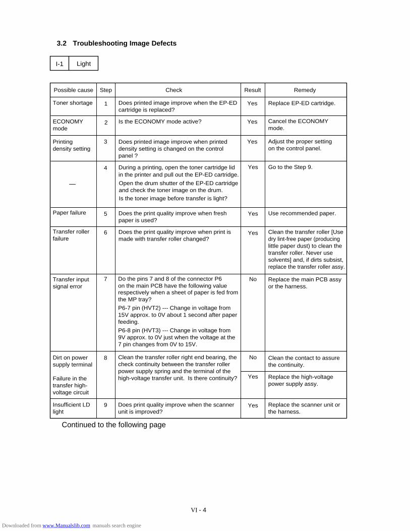
VI - 4
3.2 Troubleshooting Image Defects
Yes
Possible cause Step Check Result Remedy
1 Yes
2
I-1
Yes3
Yes
Light
4
No
5
9 Yes
Toner shortage Replace EP-ED cartridge.
Adjust the proper setting on the control panel.
During a printing, open the toner cartridge lidin the printer and pull out the EP-ED cartridge.
Go to the Step 9.
Paper failure Does the print quality improve when fresh paper is used?
Use recommended paper.
Does printed image improve when printed density setting is changed on the control panel ?
Printing density setting
Does printed image improve when the EP-ED cartridge is replaced?
Transfer input signal error
Do the pins 7 and 8 of the connector P6 on the main PCB have the following value respectively when a sheet of paper is fed from the MP tray?
P6-7 pin (HVT2) --- Change in voltage from 15V approx. to 0V about 1 second after paper feeding.
P6-8 pin (HVT3) --- Change in voltage from 9V approx. to 0V just when the voltage at the7 pin changes from 0V to 15V.
Replace the main PCB assy or the harness.
Dirt on power supply terminal
Failure in the transfer high-voltage circuit
Clean the transfer roller right end bearing, the check continuity between the transfer roller power supply spring and the terminal of the high-voltage transfer unit. Is there continuity?
Clean the contact to assure the continuity.
Replace the high-voltage power supply assy.
Insufficient LD light
Does print quality improve when the scanner unit is improved?
Replace the scanner unit or the harness.
Yes
-
7
8
6
No
ECONOMYmode
Is the ECONOMY mode active? Yes Cancel the ECONOMY mode.
Transfer roller failure
YesDoes the print quality improve when print is made with transfer roller changed?
Clean the transfer roller [Usedry lint-free paper (producing little paper dust) to clean the transfer roller. Never use solvents] and, if dirts subsist, replace the transfer roller assy.
Open the drum shutter of the EP-ED cartridge and check the toner image on the drum.Is the toner image before transfer is light?
Continued to the following page
Downloaded from www.Manualslib.com manuals search engine
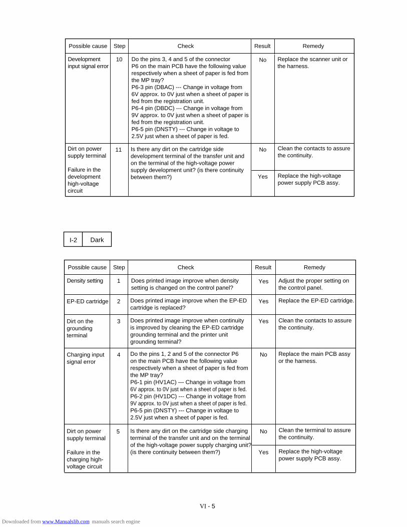
VI - 5
10 NoDevelopment input signal error
Do the pins 3, 4 and 5 of the connector P6 on the main PCB have the following value respectively when a sheet of paper is fed from the MP tray?P6-3 pin (DBAC) --- Change in voltage from 6V approx. to 0V just when a sheet of paper is fed from the registration unit.P6-4 pin (DBDC) --- Change in voltage from 9V approx. to 0V just when a sheet of paper is fed from the registration unit.P6-5 pin (DNSTY) --- Change in voltage to 2.5V just when a sheet of paper is fed.
Replace the scanner unit or the harness.
Possible cause Step Check Result Remedy
Dirt on power supply terminal
Failure in the development high-voltage circuit
Is there any dirt on the cartridge side development terminal of the transfer unit and on the terminal of the high-voltage power supply development unit? (is there continuity between them?)
11 No Clean the contacts to assure the continuity.
Yes Replace the high-voltage power supply PCB assy.
1 YesDensity setting Does printed image improve when density setting is changed on the control panel?
Adjust the proper setting on the control panel.
I-2 Dark
Possible cause Step Check Result Remedy
EP-ED cartridge
Is there any dirt on the cartridge side charging terminal of the transfer unit and on the terminal of the high-voltage power supply charging unit? (is there continuity between them?)
5 No Clean the terminal to assurethe continuity.
Yes Replace the high-voltage power supply PCB assy.
2 Does printed image improve when the EP-ED cartridge is replaced?
Yes Replace the EP-ED cartridge.
Dirt on the grounding terminal
3 Does printed image improve when continuity is improved by cleaning the EP-ED cartridge grounding terminal and the printer unit grounding terminal?
Yes Clean the contacts to assure the continuity.
Charging input signal error
4 Do the pins 1, 2 and 5 of the connector P6on the main PCB have the following value respectively when a sheet of paper is fed from the MP tray?P6-1 pin (HV1AC) --- Change in voltage from 6V approx. to 0V just when a sheet of paper is fed.P6-2 pin (HV1DC) --- Change in voltage from 9V approx. to 0V just when a sheet of paper is fed.P6-5 pin (DNSTY) --- Change in voltage to 2.5V just when a sheet of paper is fed.
No Replace the main PCB assy or the harness.
Dirt on power supply terminal
Failure in the charging high-voltage circuit
Downloaded from www.Manualslib.com manuals search engine

VI - 6
1 YesEP-ED cartridge Does printed image improve when the EP-ED cartridge is replaced?
Replace the EP-ED cartridge.
I-3 Completely blank
Possible cause Step Check Result Remedy
Developmentinput signalerror
2 Do the pins 3, 4 and 5 of the connector? P6 on the main PCB have the following value respectively when a sheet of paper is fed from the MP tray?P6-3 pin (DBAC) --- Change in voltage from 6V approx. to 0V just when a sheet of paper is fed from the registration unit.P6-4 pin (DBDC) --- Change in voltage from 9V approx. to 0V just when a sheet of paper is fed from the registration unit.P6-5 pin (DNSTY) --- Change in voltage to 2.5V just when a sheet of paper is fed.
No Replace the main PCB assyor the harness.
Failure in power supply terminal
3 Is there any dirt on the cartridge side development terminal of the transfer unit and on the terminal of the high-voltage power supply development unit? (is there continuity between them?)
No Clean the terminal to assure the continuity.
LD failure
Failure in development high-voltage circuit
4 Does print quality improve when the scanner unit is improved?
Replace the scanner unit or the harness.
Replace the high-voltage power supply PCB assy.
Yes
No
1 YesBeam detection error
Is the printer hung up with the PRINT message remaining on the display even after a printing when only a copy is printed?
Replace the scanner unit or the harness.
I-4 All black
Possible cause Step Check Result Remedy
EP-ED cartridge 2 Does printed image improve when the EP-ED cartridge is replaced?
Yes Replace the EP-ED cartridge.
Charging input signal error
3 Do the pins 1 and 2 of the connector P6 on the main PCB have the following value respectively when a sheet of paper is fed from the MP tray?
No Replace the main PCB assyor the harness.
Dirt on power supply terminal
Failure in the charging high-voltage circuit
4 Is there any dirt on the cartridge side charging terminal of the transfer unit and on the terminal of the high-voltage power supply charging unit? (is there continuity between them?)
Clean the contact to assure the continuity
No
P6-1 pin (HV1AC) --- Change in voltage from 6V approx. to 0V just when a sheet of paper is fed.P6-2 pin (HV1DC) --- Change in voltage from 9V approx. to 0V just when a sheet of paper is fed.
LD failure
Yes Replace the high-voltage power supply PCB assy and, if the problem is not resolved,replace the scanner unit or the harness.
Downloaded from www.Manualslib.com manuals search engine
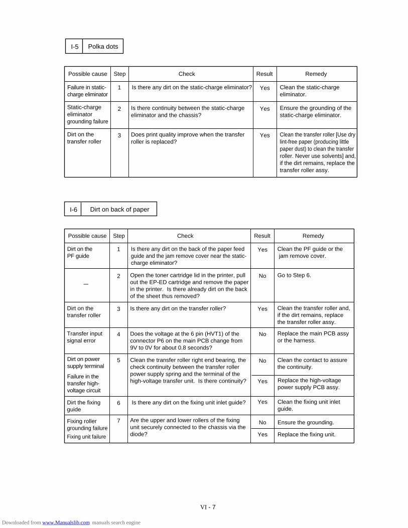
VI - 7
1 YesFailure in static-charge eliminator
Is there any dirt on the static-charge eliminator? Clean the static-charge eliminator.
I-5 Polka dots
Possible cause Step Check Result Remedy
Dirt on the transfer roller
2 Is there continuity between the static-charge eliminator and the chassis?
Yes Ensure the grounding of the static-charge eliminator.
Static-charge eliminator grounding failure
3 Does print quality improve when the transfer roller is replaced?
Yes Clean the transfer roller [Use dry lint-free paper (producing littlepaper dust) to clean the transfer roller. Never use solvents] and,if the dirt remains, replace thetransfer roller assy.
1 YesDirt on the PF guide
Is there any dirt on the back of the paper feed guide and the jam remove cover near the static-charge eliminator?
Clean the PF guide or the jam remove cover.
I-6 Dirt on back of paper
Possible cause Step Check Result Remedy
Dirt on the transfer roller
2 Open the toner cartridge lid in the printer, pull out the EP-ED cartridge and remove the paper in the printer. Is there already dirt on the back of the sheet thus removed?
No Go to Step 6.
-
3 Is there any dirt on the transfer roller? Yes Clean the transfer roller and,if the dirt remains, replace the transfer roller assy.
Transfer input signal error
4 Does the voltage at the 6 pin (HVT1) of the connector P6 on the main PCB change from 9V to 0V for about 0.8 seconds?
Yes
Replace the main PCB assyor the harness.
5 NoDirt on power supply terminal
Clean the transfer roller right end bearing, the check continuity between the transfer roller power supply spring and the terminal of the high-voltage transfer unit. Is there continuity?
Clean the contact to assure the continuity.
Failure in the transfer high-voltage circuit
Replace the high-voltage power supply PCB assy.
No
Dirt the fixing guide
Is there any dirt on the fixing unit inlet guide? 6 Clean the fixing unit inlet guide.
Yes
Fixing roller grounding failure
Are the upper and lower rollers of the fixing unit securely connected to the chassis via the diode?
7 Ensure the grounding. No
Replace the fixing unit.YesFixing unit failure
Downloaded from www.Manualslib.com manuals search engine
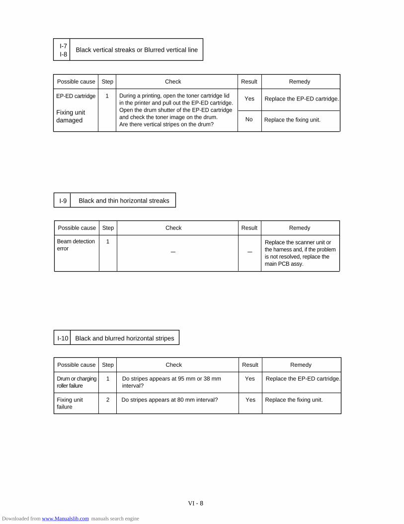
VI - 8
1 YesEP-ED cartridge During a printing, open the toner cartridge lidin the printer and pull out the EP-ED cartridge.Open the drum shutter of the EP-ED cartridge and check the toner image on the drum. Are there vertical stripes on the drum?
Replace the EP-ED cartridge.
I-8Black vertical streaks or Blurred vertical line
Possible cause Step Check Result Remedy
Fixing unit damaged Replace the fixing unit. No
I-7
Possible cause Step Check Result Remedy
Drum or charging roller failure
1 Do stripes appears at 95 mm or 38 mm interval?
Yes Replace the EP-ED cartridge.
Fixing unit failure
2 Do stripes appears at 80 mm interval? Yes Replace the fixing unit.
Black and blurred horizontal stripesI-10
1Beam detection error -
I-9 Black and thin horizontal streaks
Possible cause Step Check Result Remedy
-
Replace the scanner unit or the harness and, if the problem is not resolved, replace themain PCB assy.
Downloaded from www.Manualslib.com manuals search engine
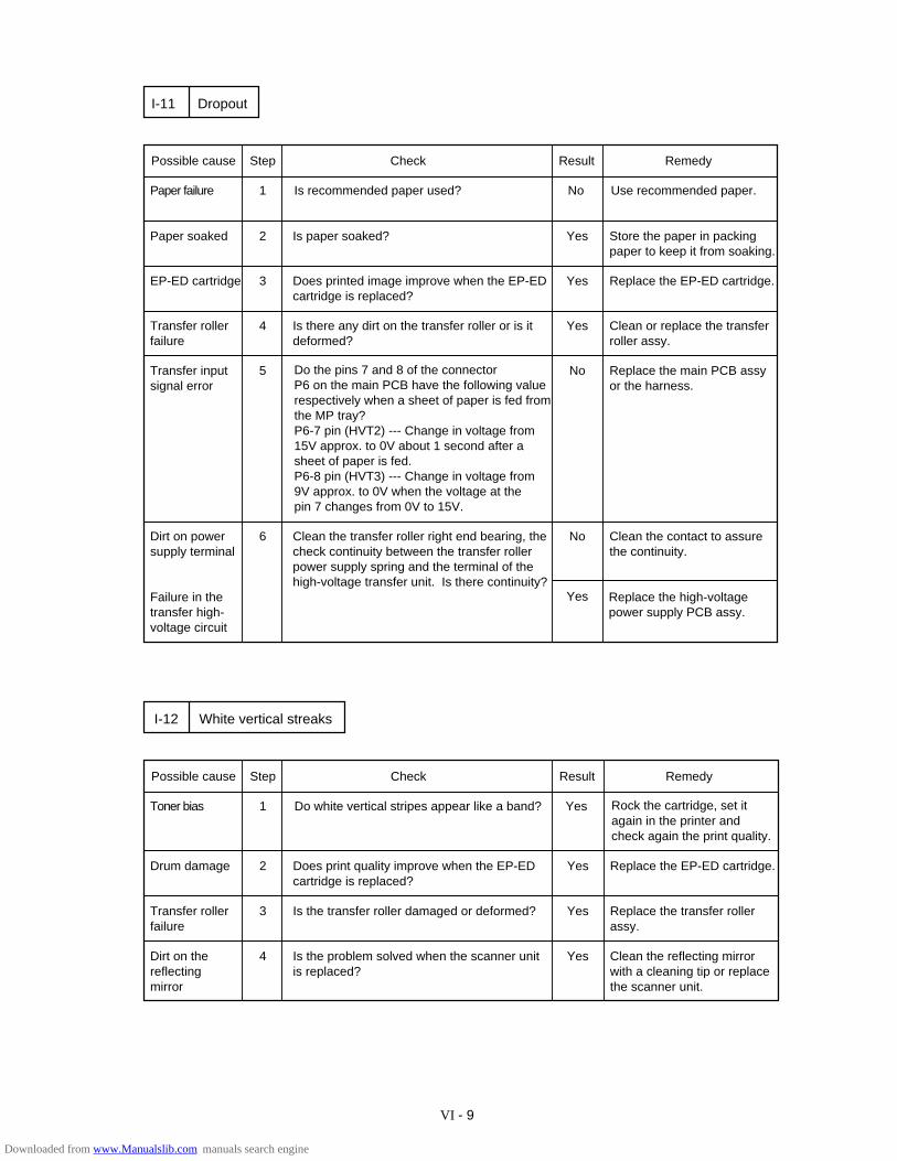
VI - 9
Possible cause Step Check Result Remedy
Paper failure 1 Is recommended paper used? No Use recommended paper.
Paper soaked 2 Is paper soaked? Yes Store the paper in packing paper to keep it from soaking.
DropoutI-11
EP-ED cartridge 3 Does printed image improve when the EP-ED cartridge is replaced?
Yes Replace the EP-ED cartridge.
Transfer roller failure
4 Is there any dirt on the transfer roller or is it deformed?
Yes Clean or replace the transfer roller assy.
Transfer input signal error
5 Do the pins 7 and 8 of the connector P6 on the main PCB have the following value respectively when a sheet of paper is fed from the MP tray?P6-7 pin (HVT2) --- Change in voltage from 15V approx. to 0V about 1 second after a sheet of paper is fed.P6-8 pin (HVT3) --- Change in voltage from 9V approx. to 0V when the voltage at the pin 7 changes from 0V to 15V.
No Replace the main PCB assyor the harness.
Dirt on power supply terminal
6 No Clean the contact to assure the continuity.
Failure in the transfer high-voltage circuit
Clean the transfer roller right end bearing, the check continuity between the transfer roller power supply spring and the terminal of the high-voltage transfer unit. Is there continuity?
Replace the high-voltage power supply PCB assy.
Yes
Possible cause Step Check Result Remedy
Toner bias 1 Do white vertical stripes appear like a band? Yes Rock the cartridge, set it again in the printer and check again the print quality.
Drum damage 2 Does print quality improve when the EP-ED cartridge is replaced?
Yes Replace the EP-ED cartridge.
White vertical streaksI-12
Transfer roller failure
3 Is the transfer roller damaged or deformed? Yes Replace the transfer roller assy.
Dirt on the reflecting mirror
4 Is the problem solved when the scanner unit is replaced?
Yes Clean the reflecting mirror with a cleaning tip or replace the scanner unit.
Downloaded from www.Manualslib.com manuals search engine
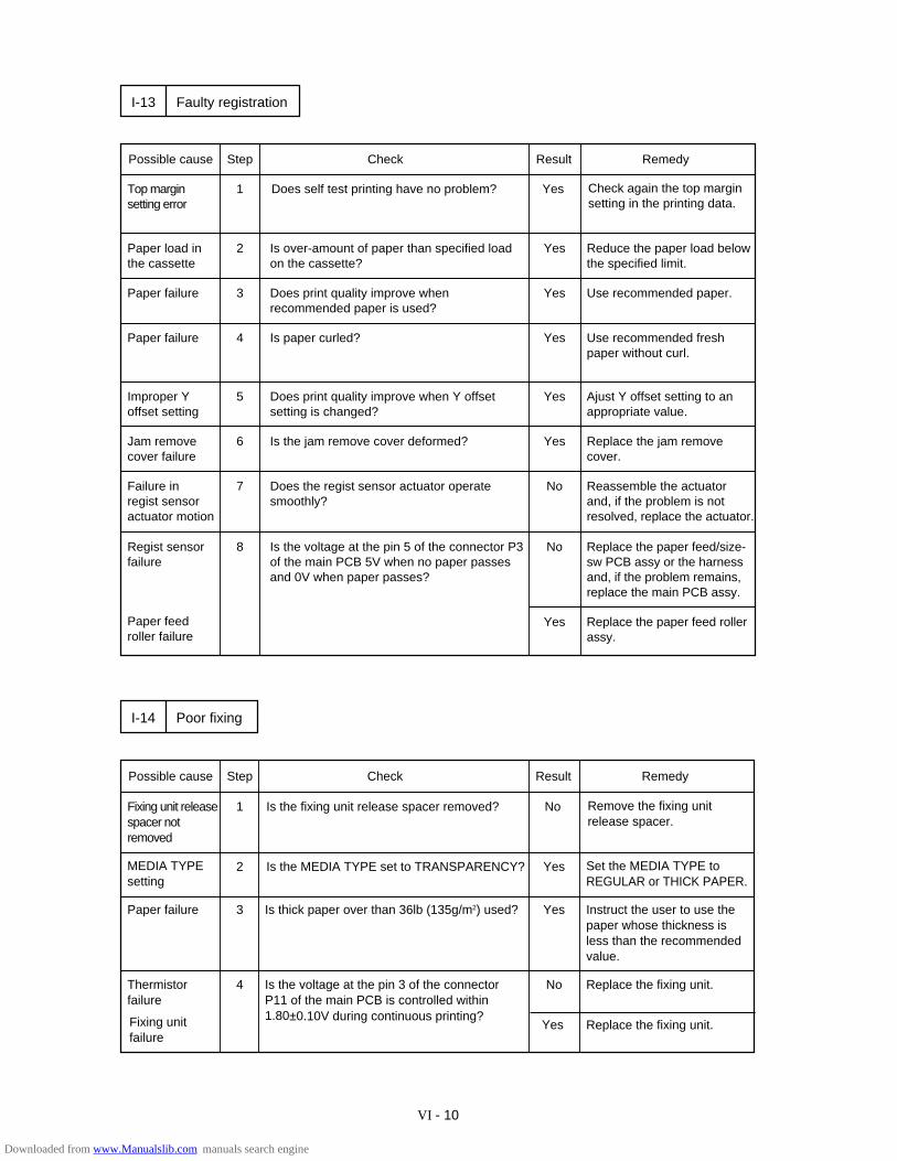
VI - 10
Possible cause Step Check Result Remedy
Top margin setting error
1 Does self test printing have no problem? Yes Check again the top margin setting in the printing data.
Paper load in the cassette
2 Is over-amount of paper than specified load on the cassette?
Yes Reduce the paper load below the specified limit.
Faulty registrationI-13
Paper failure 3 Does print quality improve when recommended paper is used?
Yes Use recommended paper.
Paper failure 4 Is paper curled? Yes Use recommended fresh paper without curl.
Improper Yoffset setting
5 Does print quality improve when Y offset setting is changed?
Yes Ajust Y offset setting to anappropriate value.
Jam removecover failure
6 Is the jam remove cover deformed? Yes Replace the jam remove cover.
Failure in regist sensor actuator motion
7 Does the regist sensor actuator operate smoothly?
No Reassemble the actuator and, if the problem is not resolved, replace the actuator.
Regist sensor failure
8 Is the voltage at the pin 5 of the connector P3 of the main PCB 5V when no paper passes and 0V when paper passes?
No Replace the paper feed/size-sw PCB assy or the harness and, if the problem remains,replace the main PCB assy.
Paper feed roller failure
Yes Replace the paper feed rollerassy.
Possible cause Step Check Result Remedy
Fixing unit release spacer not removed
1 Is the fixing unit release spacer removed? No Remove the fixing unit release spacer.
Paper failure 3 Is thick paper over than 36lb (135g/m2) used? Yes Instruct the user to use the paper whose thickness is less than the recommended value.
Poor fixingI-14
Thermistor failure
4 Is the voltage at the pin 3 of the connector P11 of the main PCB is controlled within 1.80±0.10V during continuous printing?
No Replace the fixing unit.
Replace the fixing unit.Fixing unit failure
Yes
2MEDIA TYPEsetting
YesIs the MEDIA TYPE set to TRANSPARENCY? Set the MEDIA TYPE to REGULAR or THICK PAPER.
Downloaded from www.Manualslib.com manuals search engine
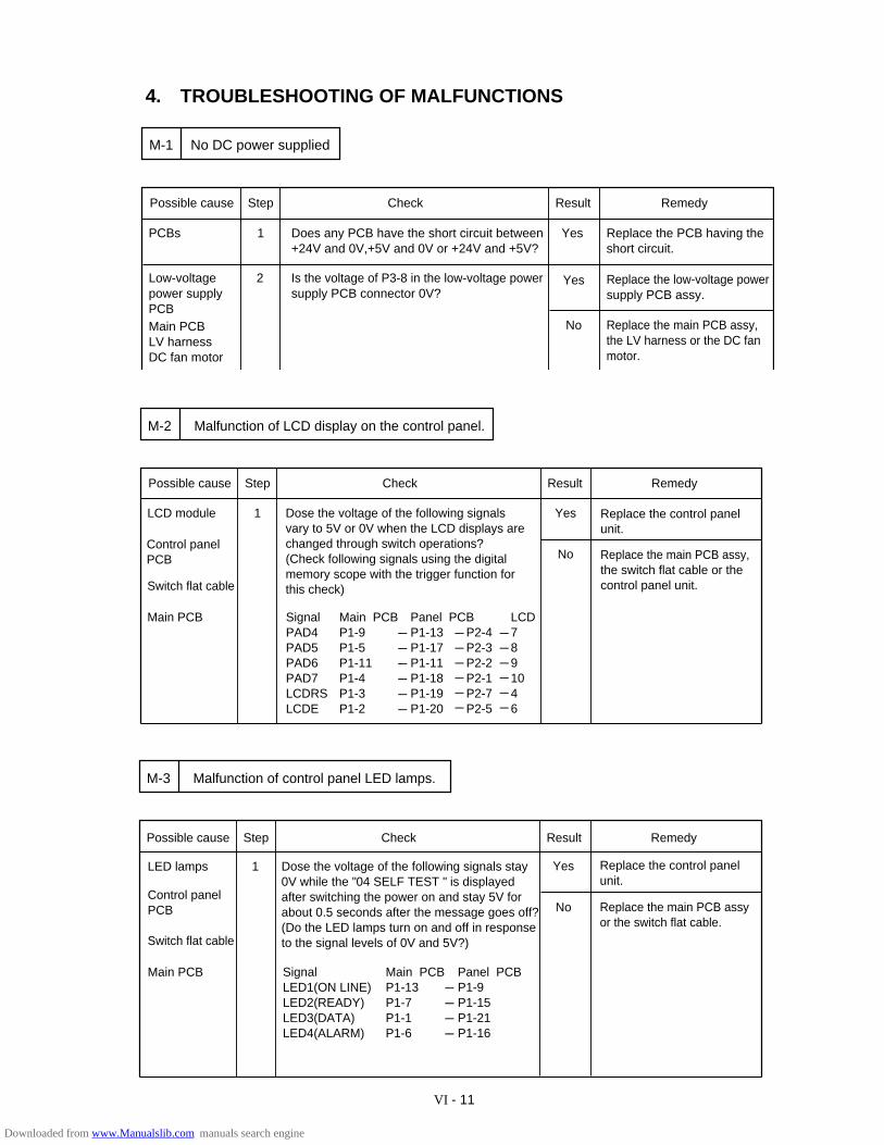
VI - 11
Malfunction of control panel LED lamps.M-3
Possible cause Step Check Result Remedy
LED lamps Dose the voltage of the following signals stay 0V while the "04 SELF TEST " is displayed after switching the power on and stay 5V for about 0.5 seconds after the message goes off? (Do the LED lamps turn on and off in responseto the signal levels of 0V and 5V?)
1
Control panel PCB
Switch flat cable
Main PCB SignalLED1(ON LINE)LED2(READY)LED3(DATA)LED4(ALARM)
Main PCBP1-13P1-7P1-1P1-6
Panel PCBP1-9P1-15P1-21P1-16
Yes
No
Replace the control panelunit.
------------
Replace the main PCB assyor the switch flat cable.
4. TROUBLESHOOTING OF MALFUNCTIONS
Is the voltage of P3-8 in the low-voltage powersupply PCB connector 0V?
Possible cause Step Check Result Remedy
PCBs 1 Does any PCB have the short circuit between +24V and 0V,+5V and 0V or +24V and +5V?
Yes Replace the PCB having the short circuit.
Low-voltagepower supplyPCBMain PCBLV harnessDC fan motor
2 Yes Replace the low-voltage power supply PCB assy.
No Replace the main PCB assy,the LV harness or the DC fan motor.
No DC power suppliedM-1
Possible cause Step Check Result Remedy
LCD module 1 Yes
No Replace the main PCB assy,the switch flat cable or the control panel unit.
Malfunction of LCD display on the control panel.M-2
Dose the voltage of the following signals vary to 5V or 0V when the LCD displays are changed through switch operations?(Check following signals using the digital memory scope with the trigger function forthis check)
Control panelPCB
Switch flat cable
Main PCB Signal PAD4PAD5PAD6PAD7LCDRSLCDE
Main PCBP1-9P1-5 P1-11P1-4P1-3P1-2
Panel PCBP1-13P1-17P1-11P1-18P1-19P1-20
P2-4P2-3P2-2P2-1P2-7P2-5
Replace the control panelunit.
------------------
------------------
LCD7891046
------------------
Downloaded from www.Manualslib.com manuals search engine
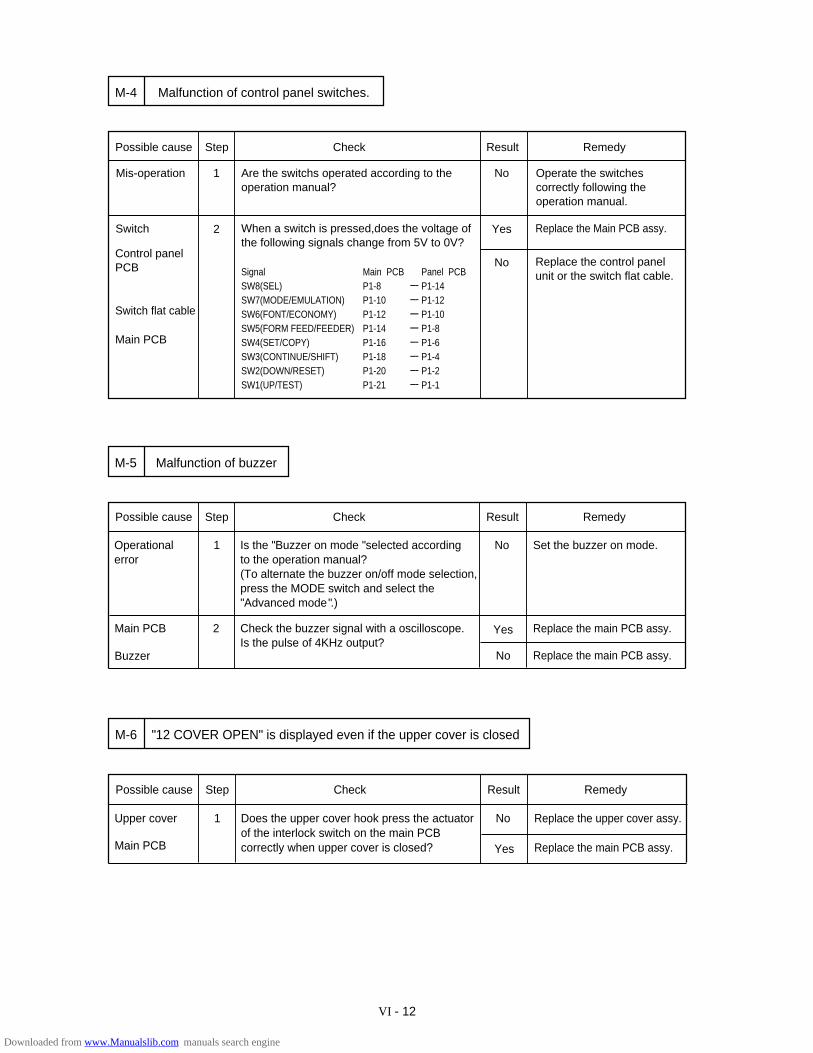
VI - 12
Does the upper cover hook press the actuator of the interlock switch on the main PCBcorrectly when upper cover is closed?
Possible cause Step Check Result Remedy
Upper cover 1 No Replace the upper cover assy.
"12 COVER OPEN" is displayed even if the upper cover is closedM-6
Yes Replace the main PCB assy.Main PCB
Possible cause Step Check Result Remedy
1
Control panel PCB
Switch flat cable
Main PCB
Yes
No
Replace the Main PCB assy.
Mis-operation Are the switchs operated according to the operation manual?
Operate the switches correctly following theoperation manual.
Switch 2 When a switch is pressed,does the voltage ofthe following signals change from 5V to 0V?
SignalSW8(SEL)SW7(MODE/EMULATION)SW6(FONT/ECONOMY)SW5(FORM FEED/FEEDER)SW4(SET/COPY)SW3(CONTINUE/SHIFT)SW2(DOWN/RESET)SW1(UP/TEST)
Main PCBP1-8P1-10P1-12P1-14P1-16P1-18P1-20P1-21
------------
Panel PCBP1-14P1-12P1-10P1-8P1-6P1-4P1-2P1-1
------------
No Replace the control panelunit or the switch flat cable.
Malfunction of control panel switches.M-4
Is the "Buzzer on mode "selected according to the operation manual?(To alternate the buzzer on/off mode selection,press the MODE switch and select the "Advanced mode".)
Check the buzzer signal with a oscilloscope.Is the pulse of 4KHz output?
Possible cause Step Check Result Remedy
Operationalerror
1 No Set the buzzer on mode.
2
No Replace the main PCB assy.
Malfunction of buzzerM-5
Yes Replace the main PCB assy.Main PCB
Buzzer
Downloaded from www.Manualslib.com manuals search engine
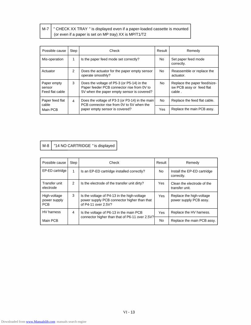
VI - 13
Is the paper feed mode set correctly?
Possible cause Step Check Result Remedy
Mis-operation 1 No Set paper feed mode correctly.
2
No Replace the feed flat cable.
" CHECK XX TRAY " is displayed even if a paper-loaded cassette is mountedM-7
Yes Replace the main PCB assy.Main PCB
Actuator Does the actuator for the paper empty sensoroperate smoothly?
Reassemble or replace theactuator.
No
Paper empty sensor Feed flat cable
Does the voltage of P5-3 (or P5-14) in the Paper feeder PCB connector rise from 0V to 5V when the paper empty sensor is covered?
3 No Replace the paper feed/size-sw PCB assy or feed flat cable .
Paper feed flat cable
Does the voltage of P3-3 (or P3-14) in the main PCB connector rise from 0V to 5V when the paper empty sensor is covered?
(or even if a paper is set on MP tray) XX is MP/T1/T2
4
Yes
Possible cause Step Check Result Remedy
1 No
2 Yes
3 Yes
4
No
M-8 "14 NO CARTRIDGE " is displayed
EP-ED cartridge Is an EP-ED cartridge installed correctly? Install the EP-ED cartridge correctly.
Clean the electrode of thetransfer unit.
Is the electrode of the transfer unit dirty? Transfer unit electrode
High-voltagepower supplyPCB
Is the voltage of P4-13 in the high-voltage power supply PCB connector higher than that of P4-11 over 2.5V?
Is the voltage of P6-13 in the main PCB connector higher than that of P6-11 over 2.5V?
HV harness
Main PCB
Replace the high-voltagepower supply PCB assy.
Replace the HV harness.
Replace the main PCB assy.
Downloaded from www.Manualslib.com manuals search engine
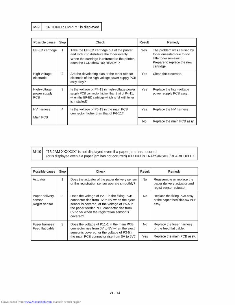
VI - 14
Possible cause Step Check Result Remedy
EP-ED cartridge 1 Take the EP-ED cartridge out of the printer and rock it to distribute the toner evenly. When the cartridge is returned to the printer,does the LCD show "00 READY"?
Yes The problem was caused bytoner onesided due to toolittle toner remaining.Prepare to replace the newcartridge.
High-voltageelectrode
2 Are the developing bias or the toner sensorelectrode of the high-voltage power supply PCBassy dirty?
Yes Clean the electrode.
High-voltagepower supplyPCB
3 Is the voltage of P4-13 in high-voltage power supply PCB connector higher than that of P4-11, when the EP-ED cartridge which is full with toneris installed?
Yes Replace the high-voltage power supply PCB assy.
HV harness 4 Is the voltage of P6-13 in the main PCB connector higher than that of P6-11?
Yes Replace the HV harness.
Replace the main PCB assy.NoMain PCB
M-9 "16 TONER EMPTY " is displayed
Possible cause Step Check Result Remedy
Actuator 1 Does the actuator of the paper delivery sensoror the registration sensor operate smoothly?
No Reassemble or replace thepaper delivery actuator and regist sensor actuator.
Fuser harnessFeed flat cable
3 Does the voltage of P11-1 in the main PCB connector rise from 0V to 5V when the ejectsensor is covered, or the voltage of P3-5 inthe main PCB connector rise from 0V to 5V?
No Replace the fuser harnessor the feed flat cable.
Replace the main PCB assy.Yes
2 Does the voltage of P2-1 in the fixing PCB connector rise from 0V to 5V when the ejectsensor is covered, or the voltage of P5-5 inthe paper feeder PCB connector rise from 0V to 5V when the registration sensor is covered?
No Replace the fixing PCB assyor the paper feed/size-sw PCBassy.
Paper deliverysensor Regist sensor
"13 JAM XXXXXX" is not displayed even if a paper jam has occured(or is displayed even if a paper jam has not occurred) XXXXXX is TRAYS/INSIDE/REAR/DUPLEX.
M-10
Downloaded from www.Manualslib.com manuals search engine
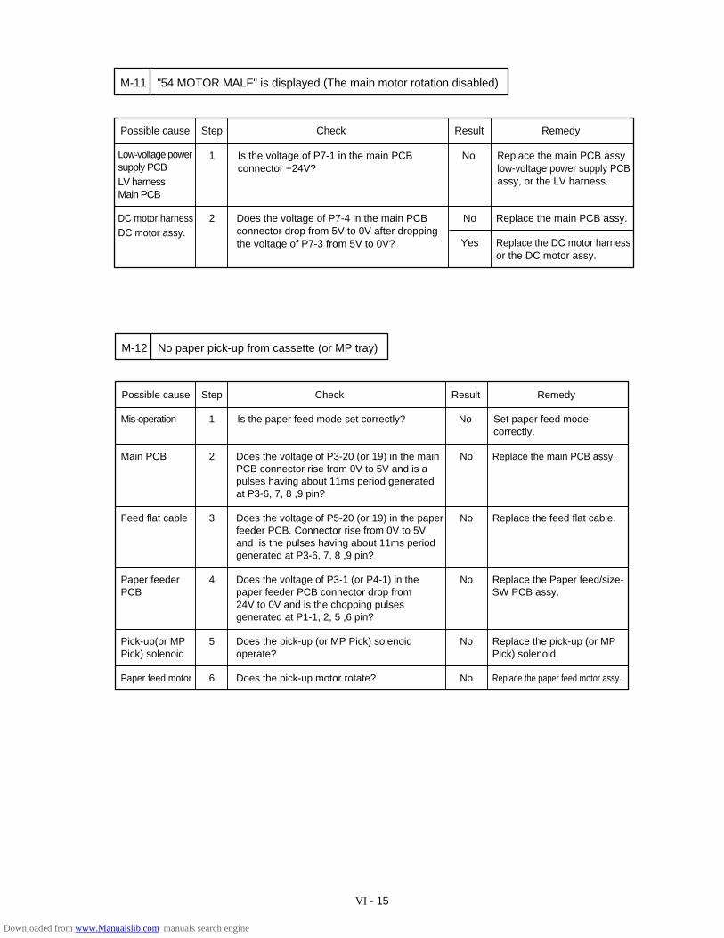
VI - 15
Possible cause Step Check Result Remedy
Low-voltage powersupply PCBLV harnessMain PCB
1 Is the voltage of P7-1 in the main PCBconnector +24V?
No Replace the main PCB assy low-voltage power supply PCBassy, or the LV harness.
DC motor harness DC motor assy.
2 Does the voltage of P7-4 in the main PCBconnector drop from 5V to 0V after droppingthe voltage of P7-3 from 5V to 0V?
No Replace the main PCB assy.
"54 MOTOR MALF" is displayed (The main motor rotation disabled)M-11
Yes Replace the DC motor harness or the DC motor assy.
Possible cause Step Check Result Remedy
Mis-operation 1 Is the paper feed mode set correctly? No Set paper feed mode correctly.
Main PCB 2 Does the voltage of P3-20 (or 19) in the main PCB connector rise from 0V to 5V and is apulses having about 11ms period generated at P3-6, 7, 8 ,9 pin?
No Replace the main PCB assy.
No paper pick-up from cassette (or MP tray)M-12
Feed flat cable 3 Does the voltage of P5-20 (or 19) in the paperfeeder PCB. Connector rise from 0V to 5V and is the pulses having about 11ms periodgenerated at P3-6, 7, 8 ,9 pin?
No Replace the feed flat cable.
Paper feederPCB
4 Does the voltage of P3-1 (or P4-1) in the paper feeder PCB connector drop from 24V to 0V and is the chopping pulses generated at P1-1, 2, 5 ,6 pin?
No Replace the Paper feed/size-SW PCB assy.
Pick-up(or MPPick) solenoid
5 Does the pick-up (or MP Pick) solenoid operate?
No Replace the pick-up (or MPPick) solenoid.
Paper feed motor 6 Does the pick-up motor rotate? No Replace the paper feed motor assy.
Downloaded from www.Manualslib.com manuals search engine
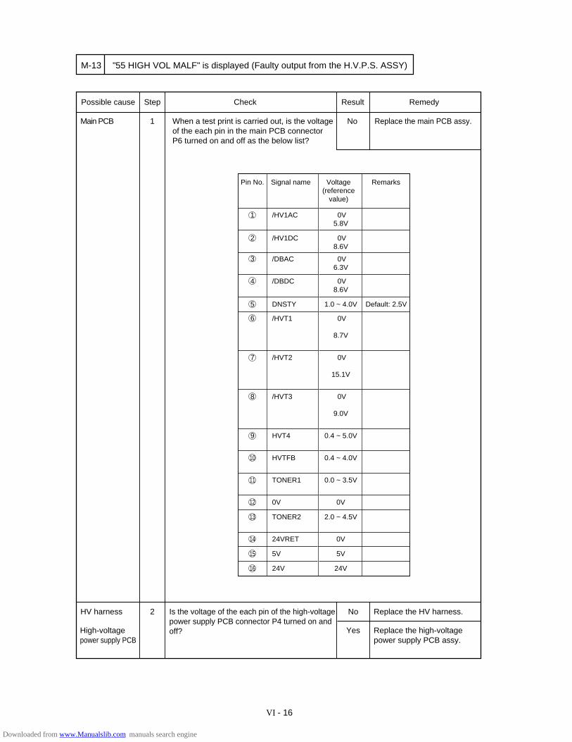
VI - 16
Possible cause Step Check Result Remedy
Main PCB 1 When a test print is carried out, is the voltageof the each pin in the main PCB connectorP6 turned on and off as the below list?
No Replace the main PCB assy.
HV harness 2 Is the voltage of the each pin of the high-voltage power supply PCB connector P4 turned on and off?
No Replace the HV harness.
M-13
Yes Replace the high-voltage power supply PCB assy.
"55 HIGH VOL MALF" is displayed (Faulty output from the H.V.P.S. ASSY)
High-voltage power supply PCB
Pin No. Signal name Voltage (reference
value)
Remarks
/HV1AC 0V5.8V
/HV1DC 0V8.6V
/DBAC 0V6.3V
/DBDC 0V8.6V
DNSTY 1.0 ~ 4.0V
/HVT1 0V
8.7V
/HVT2 0V
15.1V
/HVT3 0V
9.0V
HVT4 0.4 ~ 5.0V
HVTFB 0.4 ~ 4.0V
TONER1 0.0 ~ 3.5V
0V 0V
TONER2 2.0 ~ 4.5V
24VRET 0V
5V 5V
24V 24V
1
2
3
4
5
6
7
8
9
10
11
13
12
14
15
16
Default: 2.5V
Downloaded from www.Manualslib.com manuals search engine
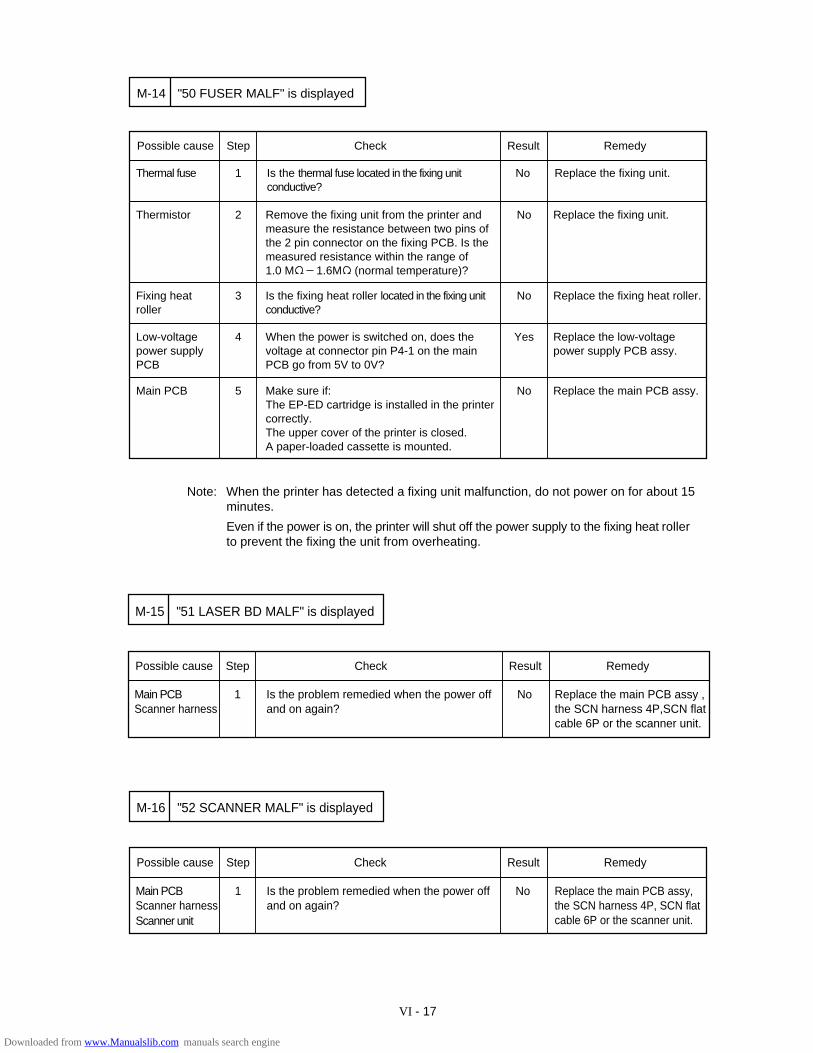
VI - 17
Possible cause Step Check Result Remedy
Thermal fuse 1 Is the thermal fuse located in the fixing unit conductive?
No Replace the fixing unit.
Thermistor 2 Remove the fixing unit from the printer andmeasure the resistance between two pins ofthe 2 pin connector on the fixing PCB. Is themeasured resistance within the range of1.0 M 1.6M (normal temperature)?
No Replace the fixing unit.
"50 FUSER MALF" is displayedM-14
Fixing heat roller
3 Is the fixing heat roller located in the fixing unit conductive?
No Replace the fixing heat roller.
Low-voltagepower supplyPCB
4 When the power is switched on, does thevoltage at connector pin P4-1 on the main PCB go from 5V to 0V?
Yes Replace the low-voltagepower supply PCB assy.
Main PCB 5 Make sure if:The EP-ED cartridge is installed in the printercorrectly.The upper cover of the printer is closed.A paper-loaded cassette is mounted.
No Replace the main PCB assy.
Note: When the printer has detected a fixing unit malfunction, do not power on for about 15minutes.
Even if the power is on, the printer will shut off the power supply to the fixing heat rollerto prevent the fixing the unit from overheating.
Replace the main PCB assy , the SCN harness 4P,SCN flat cable 6P or the scanner unit.
Possible cause Step Check Result Remedy
Main PCBScanner harness
1 Is the problem remedied when the power offand on again?
No
"51 LASER BD MALF" is displayedM-15
Replace the main PCB assy,the SCN harness 4P, SCN flat cable 6P or the scanner unit.
Possible cause Step Check Result Remedy
Main PCBScanner harness
1 Is the problem remedied when the power offand on again?
No
"52 SCANNER MALF" is displayedM-16
Scanner unit
Downloaded from www.Manualslib.com manuals search engine
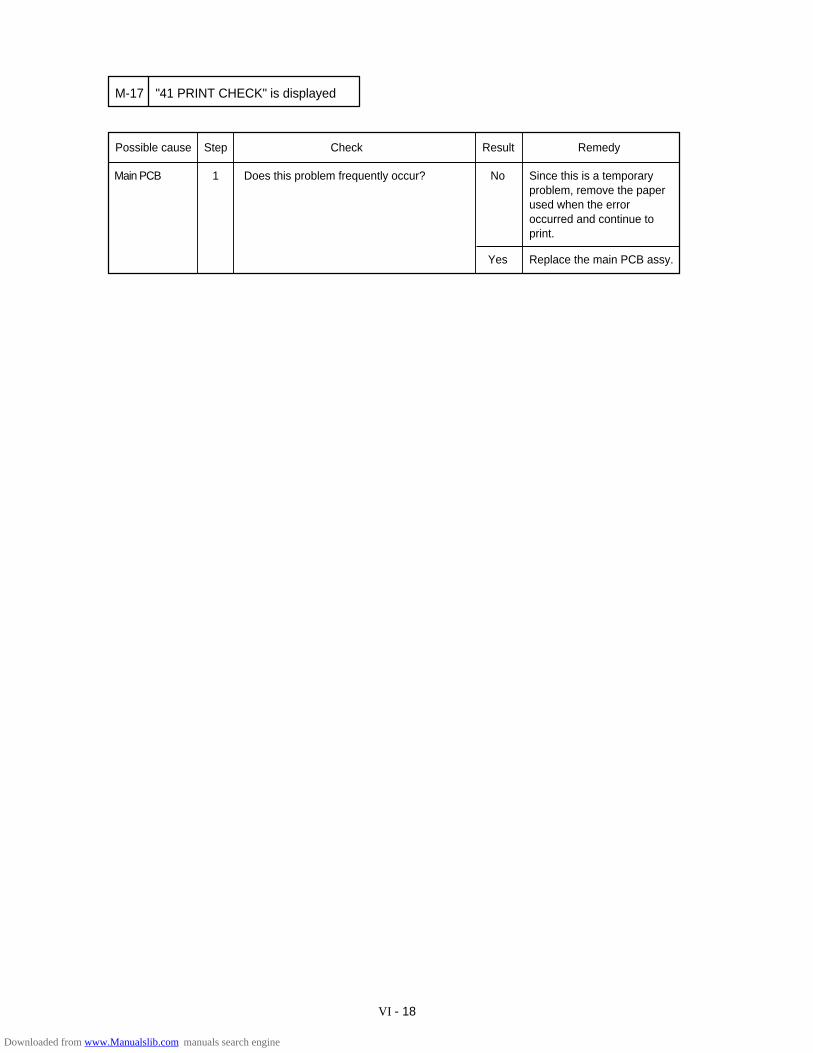
VI - 18
Since this is a temporaryproblem, remove the paperused when the error occurred and continue to print.
Possible cause Step Check Result Remedy
Main PCB 1 Does this problem frequently occur? No
"41 PRINT CHECK" is displayedM-17
Replace the main PCB assy.Yes
Downloaded from www.Manualslib.com manuals search engine
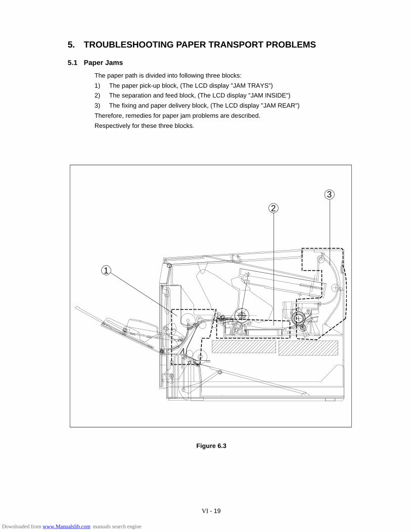
VI - 19
5. TROUBLESHOOTING PAPER TRANSPORT PROBLEMS
5.1 Paper Jams
The paper path is divided into following three blocks:
1) The paper pick-up block, (The LCD display "JAM TRAYS")
2) The separation and feed block, (The LCD display "JAM INSIDE")
3) The fixing and paper delivery block, (The LCD display "JAM REAR")
Therefore, remedies for paper jam problems are described.
Respectively for these three blocks.
Figure 6.3
3
2
1
Downloaded from www.Manualslib.com manuals search engine
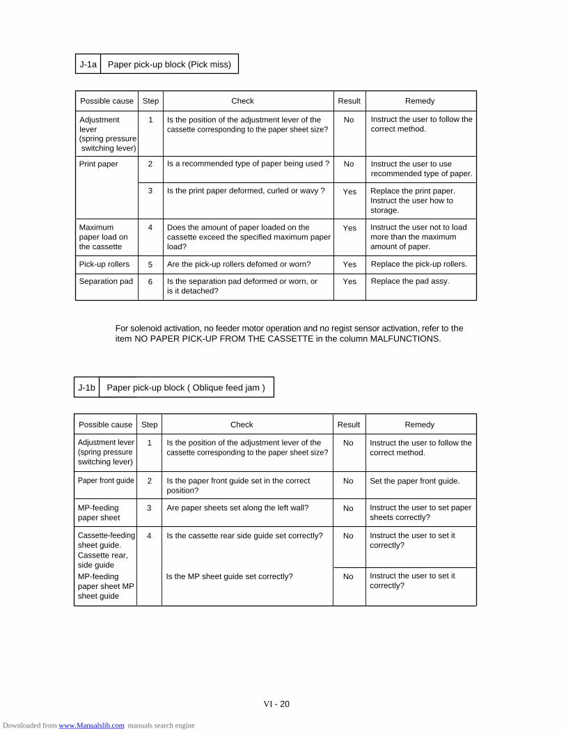
VI - 20
Yes Instruct the user not to load more than the maximumamount of paper.
Possible cause Step Check Result Remedy
Adjustment lever
Is the position of the adjustment lever of the cassette corresponding to the paper sheet size?
(spring pressure switching lever)
1 No
2
J-1a
Print paper Instruct the user to use recommended type of paper.
Instruct the user to follow the correct method.
No
Maximum paper load onthe cassette
3
Is a recommended type of paper being used ?
Is the print paper deformed, curled or wavy ? Yes Replace the print paper.Instruct the user how tostorage.
Does the amount of paper loaded on the cassette exceed the specified maximum paperload?
Paper pick-up block (Pick miss)
4
Yes Replace the pick-up rollers.Pick-up rollers 5 Are the pick-up rollers defomed or worn?
6Separation pad YesIs the separation pad deformed or worn, oris it detached?
Replace the pad assy.
For solenoid activation, no feeder motor operation and no regist sensor activation, refer to theitem NO PAPER PICK-UP FROM THE CASSETTE in the column MALFUNCTIONS.
Possible cause Step Check Result Remedy
2 No
3
4
Paper front guide
J-1b Paper pick-up block ( Oblique feed jam )
No
No
Is the paper front guide set in the correct position?
Set the paper front guide.
Cassette-feedingsheet guide.Cassette rear, side guide
MP-feeding paper sheet
1 NoAdjustment lever(spring pressureswitching lever)
Is the position of the adjustment lever of thecassette corresponding to the paper sheet size?
Instruct the user to follow thecorrect method.
Are paper sheets set along the left wall? Instruct the user to set paper sheets correctly?
MP-feeding paper sheet MPsheet guide
Is the cassette rear side guide set correctly?
NoIs the MP sheet guide set correctly?
Instruct the user to set it correctly?
Instruct the user to set it correctly?
Downloaded from www.Manualslib.com manuals search engine
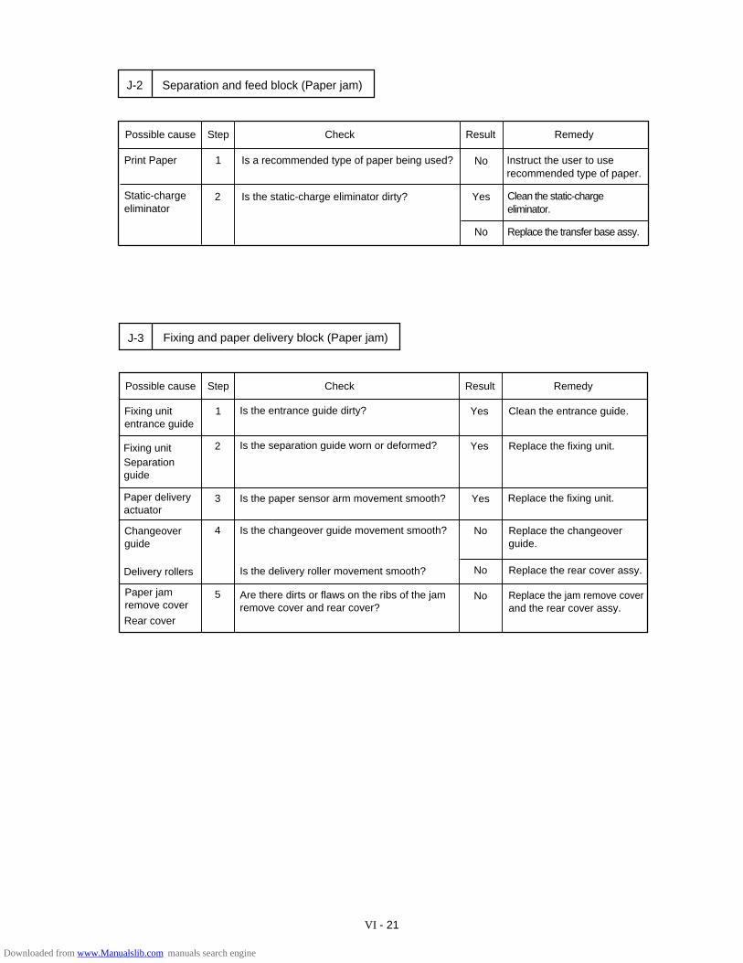
VI - 21
YesIs the static-charge eliminator dirty?
Possible cause Step Check Result Remedy
Static-chargeeliminator
1 Is a recommended type of paper being used? Instruct the user to use recommended type of paper.
2 Clean the static-charge eliminator.
Separation and feed block (Paper jam)J-2
NoPrint Paper
No Replace the transfer base assy.
Possible cause Step Check Result Remedy
Fixing unitentrance guide
1 Yes
2
J-3
Replace the fixing unit.
Clean the entrance guide.
Yes
3
Is the separation guide worn or deformed?
Is the paper sensor arm movement smooth? Yes Replace the fixing unit.
Fixing and paper delivery block (Paper jam)
4
No Replace the jam remove cover and the rear cover assy.
5
Is the entrance guide dirty?
Paper deliveryactuator
No Replace the changeover guide.
Is the changeover guide movement smooth?
Is the delivery roller movement smooth?
Are there dirts or flaws on the ribs of the jam remove cover and rear cover?
Delivery rollers
Changeover guide
No Replace the rear cover assy.
Paper jamremove cover
Rear cover
Separationguide
Fixing unit
Downloaded from www.Manualslib.com manuals search engine
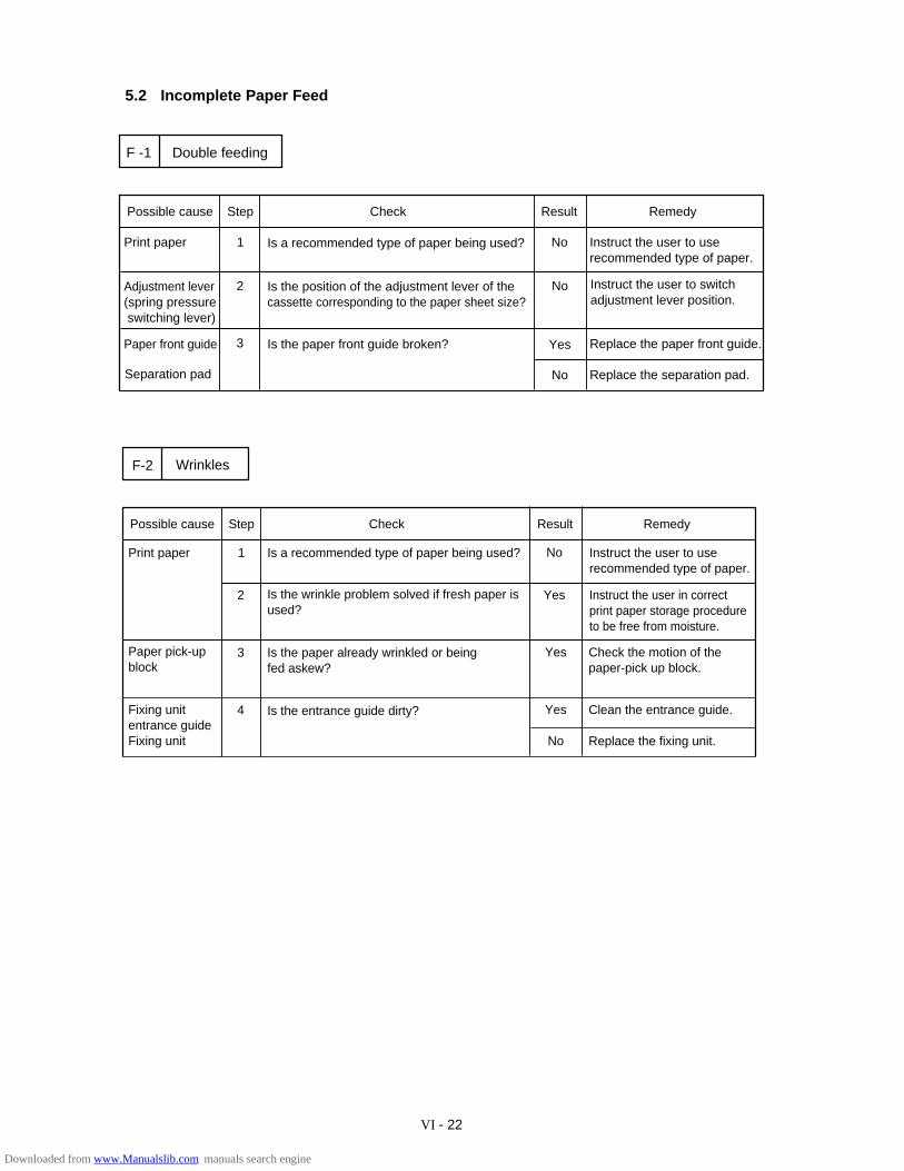
VI - 22
5.2 Incomplete Paper Feed
Yes Clean the entrance guide.
Yes Check the motion of the paper-pick up block.
No Replace the fixing unit.
Possible cause Step Check Result Remedy
1 No
2
F-2
Instruct the user in correctprint paper storage procedure to be free from moisture.
Yes
3
Is the wrinkle problem solved if fresh paper isused?
Is the paper already wrinkled or beingfed askew?
Wrinkles
4
Print paper Is a recommended type of paper being used? Instruct the user to use recommended type of paper.
Paper pick-upblock
Fixing unitentrance guideFixing unit
Is the entrance guide dirty?
Is the position of the adjustment lever of the cassette corresponding to the paper sheet size?
Possible cause Step Check Result Remedy
Print paper 1 No Instruct the user to use recommended type of paper.
Adjustment lever(spring pressure switching lever)
2
Yes Replace the paper front guide.
No Replace the separation pad.
Double feedingF -1
Is a recommended type of paper being used?
3 Is the paper front guide broken? Paper front guide
Separation pad
No Instruct the user to switch adjustment lever position.
Downloaded from www.Manualslib.com manuals search engine
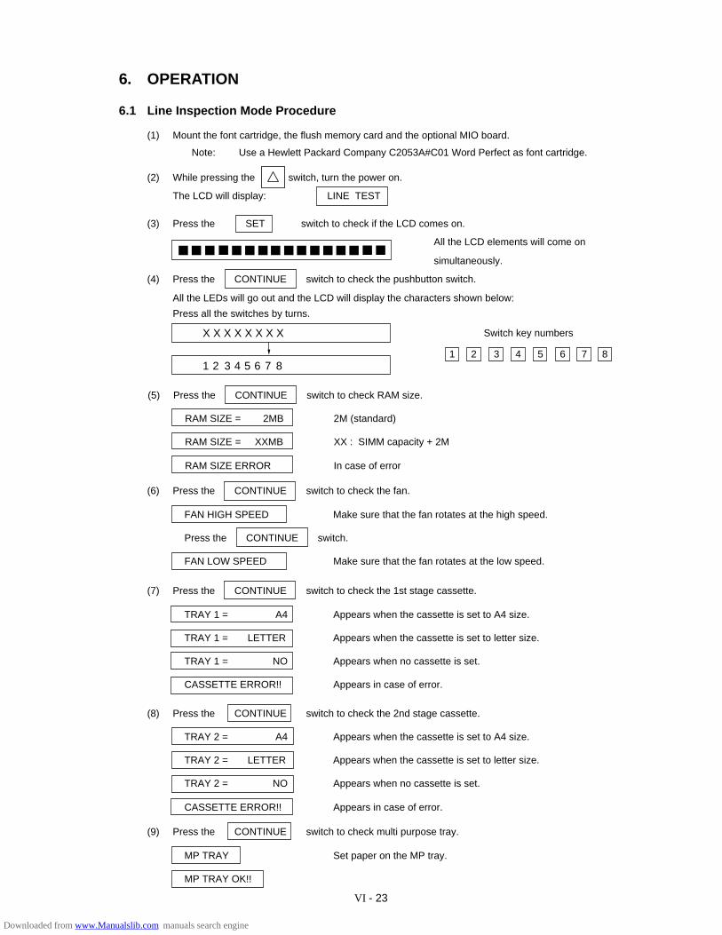
VI - 23
X X X X X X X X
1 2 3 4 5 6 7 8
(2) While pressing the switch, turn the power on.
The LCD will display: LINE TEST
(1) Mount the font cartridge, the flush memory card and the optional MIO board.
Note: Use a Hewlett Packard Company C2053A#C01 Word Perfect as font cartridge.
6. OPERATION
6.1 Line Inspection Mode Procedure
3 4 5 6 7 81 2
(7) Press the CONTINUE switch to check the 1st stage cassette.
TRAY 1 = A4 Appears when the cassette is set to A4 size.
TRAY 1 = LETTER Appears when the cassette is set to letter size.
TRAY 1 = NO Appears when no cassette is set.
CASSETTE ERROR!! Appears in case of error.
(8) Press the CONTINUE switch to check the 2nd stage cassette.
TRAY 2 = A4 Appears when the cassette is set to A4 size.
TRAY 2 = LETTER Appears when the cassette is set to letter size.
TRAY 2 = NO Appears when no cassette is set.
CASSETTE ERROR!! Appears in case of error.
(9) Press the CONTINUE switch to check multi purpose tray.
MP TRAY Set paper on the MP tray.
MP TRAY OK!!
(3) Press the SET switch to check if the LCD comes on.
All the LCD elements will come on
simultaneously.
(4) Press the CONTINUE switch to check the pushbutton switch.
All the LEDs will go out and the LCD will display the characters shown below:
Press all the switches by turns.
(6) Press the CONTINUE switch to check the fan.
FAN HIGH SPEED Make sure that the fan rotates at the high speed.
Press the CONTINUE switch.
FAN LOW SPEED Make sure that the fan rotates at the low speed.
(5) Press the CONTINUE switch to check RAM size.
RAM SIZE = 2MB 2M (standard)
RAM SIZE = XXMB XX : SIMM capacity + 2M
RAM SIZE ERROR In case of error
Switch key numbers
Downloaded from www.Manualslib.com manuals search engine
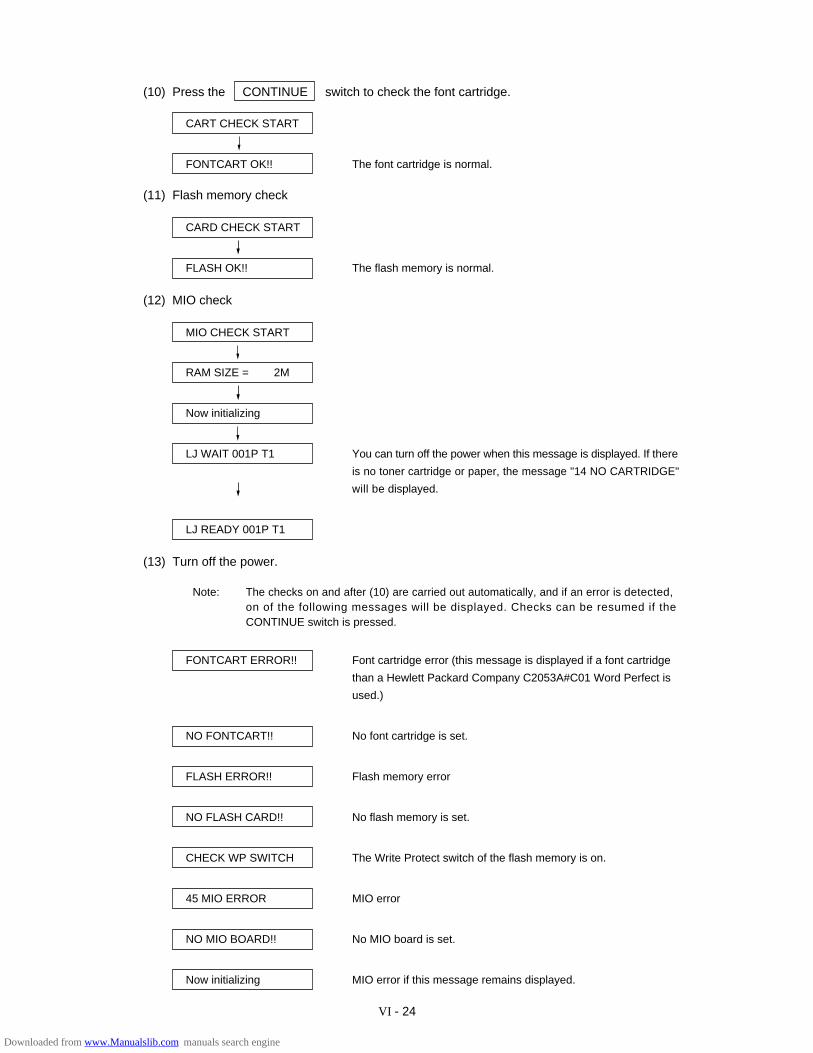
VI - 24
(10) Press the CONTINUE switch to check the font cartridge.
CART CHECK START
FONTCART OK!! The font cartridge is normal.
(11) Flash memory check
CARD CHECK START
FLASH OK!! The flash memory is normal.
(12) MIO check
MIO CHECK START
RAM SIZE = 2M
Now initializing
LJ WAIT 001P T1 You can turn off the power when this message is displayed. If there
is no toner cartridge or paper, the message "14 NO CARTRIDGE"
will be displayed.
LJ READY 001P T1
(13) Turn off the power.
Note: The checks on and after (10) are carried out automatically, and if an error is detected,on of the following messages will be displayed. Checks can be resumed if theCONTINUE switch is pressed.
FONTCART ERROR!! Font cartridge error (this message is displayed if a font cartridge
than a Hewlett Packard Company C2053A#C01 Word Perfect is
used.)
NO FONTCART!! No font cartridge is set.
FLASH ERROR!! Flash memory error
NO FLASH CARD!! No flash memory is set.
CHECK WP SWITCH The Write Protect switch of the flash memory is on.
45 MIO ERROR MIO error
NO MIO BOARD!! No MIO board is set.
Now initializing MIO error if this message remains displayed.
Downloaded from www.Manualslib.com manuals search engine
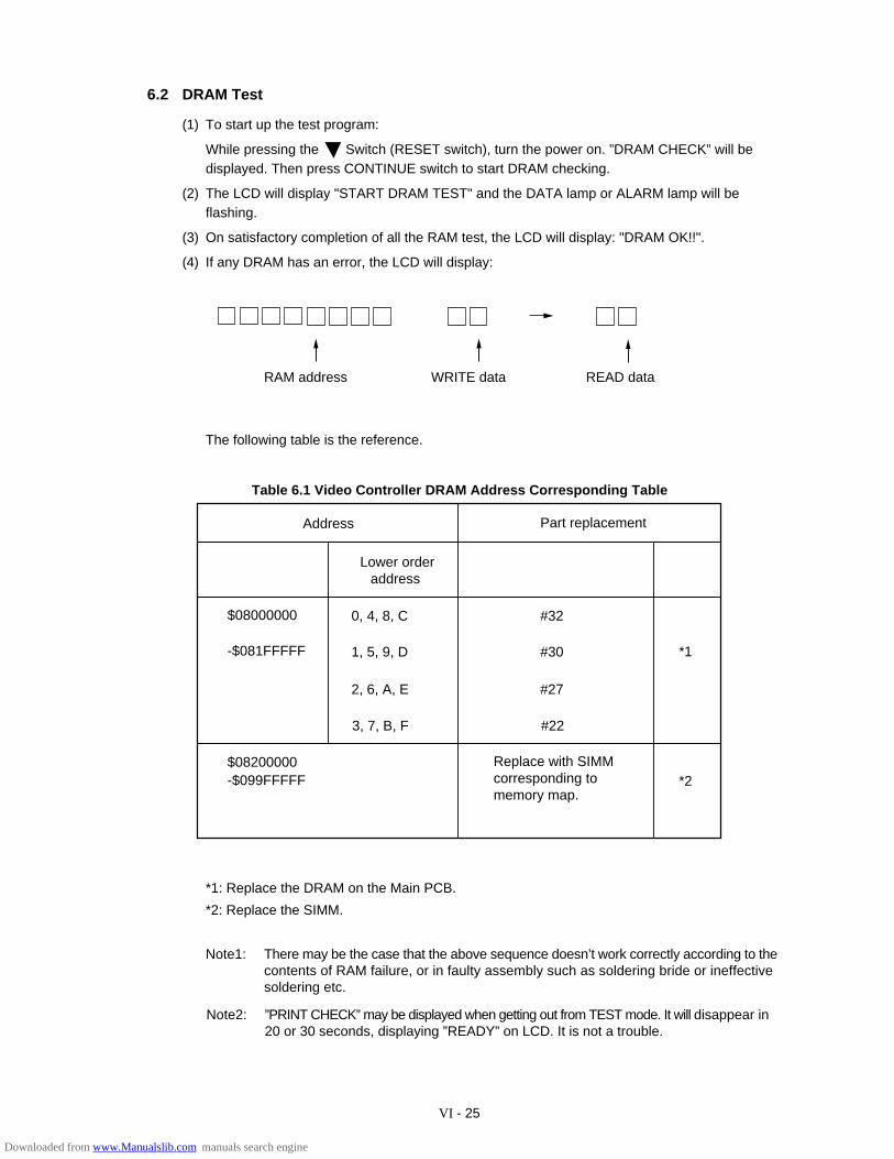
VI - 25
6.2 DRAM Test
(1) To start up the test program:
While pressing the Switch (RESET switch), turn the power on. ”DRAM CHECK” will bedisplayed. Then press CONTINUE switch to start DRAM checking.
(2) The LCD will display "START DRAM TEST" and the DATA lamp or ALARM lamp will beflashing.
(3) On satisfactory completion of all the RAM test, the LCD will display: "DRAM OK!!".
(4) If any DRAM has an error, the LCD will display:
RAM address WRITE data READ data
The following table is the reference.
Address Part replacement
Lower orderaddress
0, 4, 8, C
1, 5, 9, D
2, 6, A, E
3, 7, B, F
$08000000
-$081FFFFF
$08200000-$099FFFFF
Replace with SIMMcorresponding tomemory map.
*1
#32
#30
#27
#22
*2
Table 6.1 Video Controller DRAM Address Corresponding Table
*1: Replace the DRAM on the Main PCB.
*2: Replace the SIMM.
Note1: There may be the case that the above sequence doesn’t work correctly according to thecontents of RAM failure, or in faulty assembly such as soldering bride or ineffectivesoldering etc.
Note2: ”PRINT CHECK” may be displayed when getting out from TEST mode. It will disappear in20 or 30 seconds, displaying ”READY” on LCD. It is not a trouble.
Downloaded from www.Manualslib.com manuals search engine
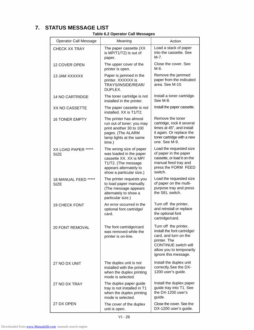
VI - 26
7. STATUS MESSAGE LISTTable 6.2 Operator Call Messages
Operator Call Message Meaning Action
CHECK XX TRAY
12 COVER OPEN
13 JAM XXXXXX
14 NO CARTRIDGE
XX NO CASSETTE
16 TONER EMPTY
XX LOAD PAPER *****SIZE
18 MANUAL FEED *****SIZE
19 CHECK FONT
20 FONT REMOVAL
27 NO DX UNIT
27 NO DX TRAY
27 DX OPEN
The paper cassette (XXis MP/T1/T2) is out ofpaper.
The upper cover of theprinter is open.
Paper is jammed in theprinter. XXXXXX isTRAYS/INSIDE/REAR/DUPLEX.
The toner cartridge is notinstalled in the printer.
The paper cassette is notinstalled. XX is T1/T2.
The printer has almostrun out of toner: you mayprint another 30 to 100pages. (The ALARMlamp lights at the sametime.)
The wrong size of paperwas loaded in the papercassette XX. XX is MP/T1/T2. (The messageappears alternately toshow a particular size.)
The printer requests youto load paper manually.(The message appearsalternately to show aparticular size.)
An error occurred in theoptional font cartridge/card.
The font cartridge/cardwas removed while theprinter is on-line.
The duplex unit is notinstalled with the printerwhen the duplex printingmode is selected.
The duplex paper guidetray is not installed in T1when the duplex printingmode is selected.
The cover of the duplexunit is open.
Load a stack of paperinto the cassette. SeeM-7.
Close the cover. SeeM-6.
Remove the jammedpaper from the indicatedarea. See M-10.
Install a toner cartridge.See M-8.
Install the paper cassette.
Remove the tonercartridge, rock it severaltimes at 45°, and installit again. Or replace thetoner cartridge with a newone. See M-9.
Load the requested sizeof paper in the papercassette, or load it on themanual feed tray andpress the FORM FEEDswitch.
Load the requested sizeof paper on the multi-purpose tray and pressthe SEL switch.
Turn off the printer,and reinstall or replacethe optional fontcartridge/card.
Turn off the printer,install the font cartridge/card, and turn on theprinter. TheCONTINUE switch willallow you to temporarilyignore this message.
Install the duplex unitcorrectly.See the DX-1200 user’s guide.
Install the duplex paperguide tray into T1. Seethe DX-1200 user’sguide.
Close the cover. See theDX-1200 user’s guide.
Downloaded from www.Manualslib.com manuals search engine
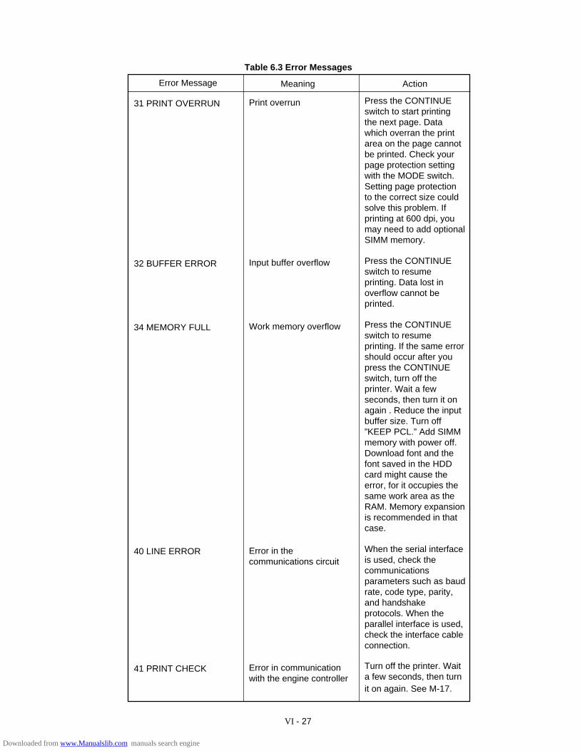
VI - 27
Table 6.3 Error Messages
Error Message Meaning Action
Press the CONTINUEswitch to start printingthe next page. Datawhich overran the printarea on the page cannotbe printed. Check yourpage protection settingwith the MODE switch.Setting page protectionto the correct size couldsolve this problem. Ifprinting at 600 dpi, youmay need to add optionalSIMM memory.
Press the CONTINUEswitch to resumeprinting. Data lost inoverflow cannot beprinted.
Press the CONTINUEswitch to resumeprinting. If the same errorshould occur after youpress the CONTINUEswitch, turn off theprinter. Wait a fewseconds, then turn it onagain . Reduce the inputbuffer size. Turn off”KEEP PCL.” Add SIMMmemory with power off.Download font and thefont saved in the HDDcard might cause theerror, for it occupies thesame work area as theRAM. Memory expansionis recommended in thatcase.
When the serial interfaceis used, check thecommunicationsparameters such as baudrate, code type, parity,and handshakeprotocols. When theparallel interface is used,check the interface cableconnection.
Turn off the printer. Waita few seconds, then turnit on again. See M-17.
Print overrun
Input buffer overflow
Work memory overflow
Error in thecommunications circuit
Error in communicationwith the engine controller
31 PRINT OVERRUN
32 BUFFER ERROR
34 MEMORY FULL
40 LINE ERROR
41 PRINT CHECK
Downloaded from www.Manualslib.com manuals search engine
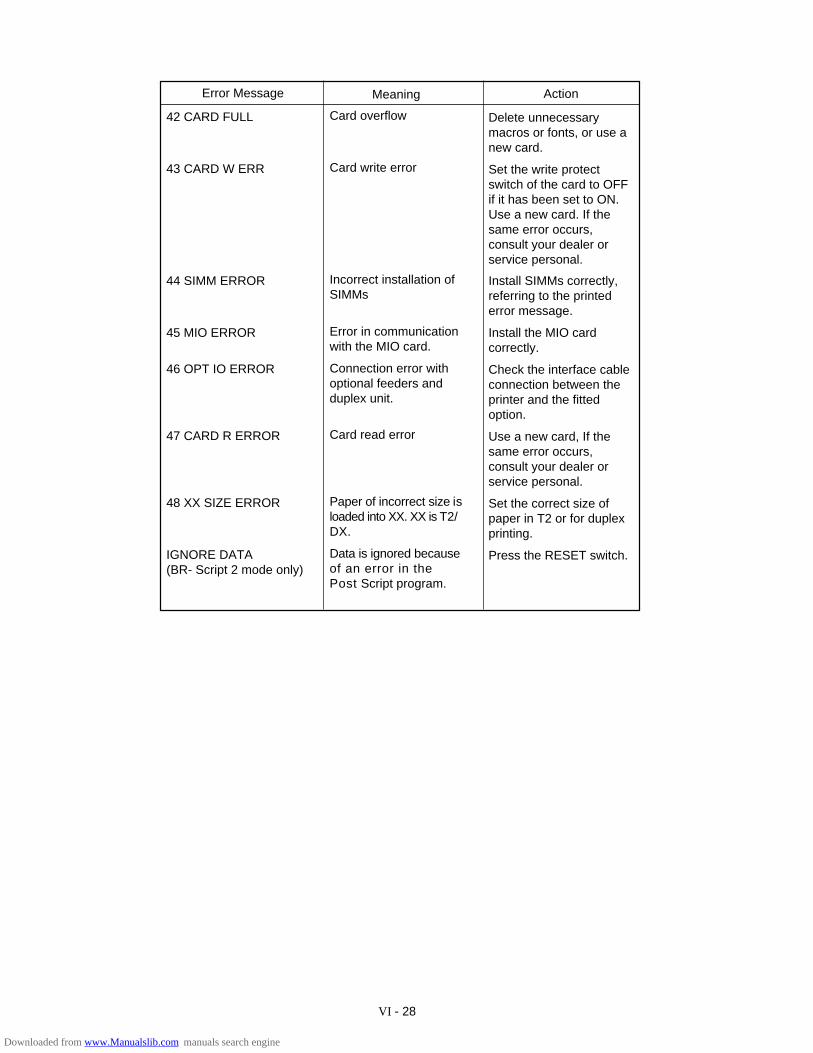
VI - 28
Error Message Meaning Action
42 CARD FULL
43 CARD W ERR
44 SIMM ERROR
45 MIO ERROR
46 OPT IO ERROR
47 CARD R ERROR
48 XX SIZE ERROR
IGNORE DATA(BR- Script 2 mode only)
Delete unnecessarymacros or fonts, or use anew card.
Set the write protectswitch of the card to OFFif it has been set to ON.Use a new card. If thesame error occurs,consult your dealer orservice personal.
Install SIMMs correctly,referring to the printederror message.
Install the MIO cardcorrectly.
Check the interface cableconnection between theprinter and the fittedoption.
Use a new card, If thesame error occurs,consult your dealer orservice personal.
Set the correct size ofpaper in T2 or for duplexprinting.
Press the RESET switch.
Card overflow
Card write error
Incorrect installation ofSIMMs
Error in communicationwith the MIO card.
Connection error withoptional feeders andduplex unit.
Card read error
Paper of incorrect size isloaded into XX. XX is T2/DX.
Data is ignored becauseof an error in thePost Script program.
Downloaded from www.Manualslib.com manuals search engine
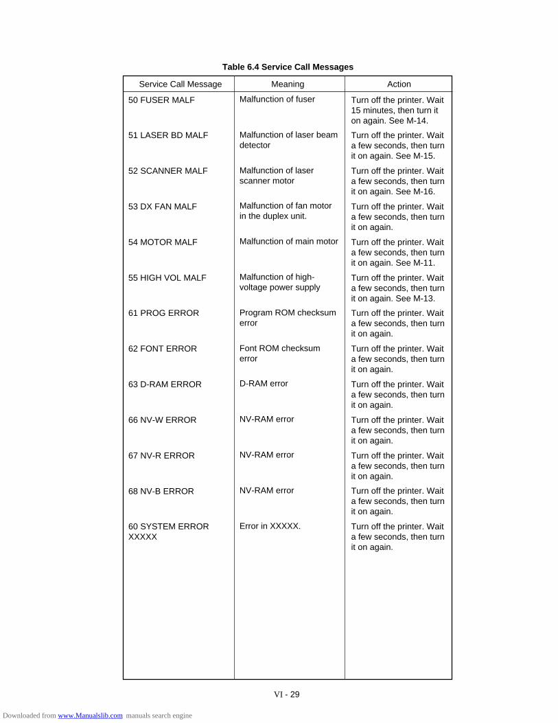
VI - 29
Table 6.4 Service Call Messages
MeaningService Call Message Action
Turn off the printer. Wait15 minutes, then turn iton again. See M-14.
Turn off the printer. Waita few seconds, then turnit on again. See M-15.
Turn off the printer. Waita few seconds, then turnit on again. See M-16.
Turn off the printer. Waita few seconds, then turnit on again.
Turn off the printer. Waita few seconds, then turnit on again. See M-11.
Turn off the printer. Waita few seconds, then turnit on again. See M-13.
Turn off the printer. Waita few seconds, then turnit on again.
Turn off the printer. Waita few seconds, then turnit on again.
Turn off the printer. Waita few seconds, then turnit on again.
Turn off the printer. Waita few seconds, then turnit on again.
Turn off the printer. Waita few seconds, then turnit on again.
Turn off the printer. Waita few seconds, then turnit on again.
Turn off the printer. Waita few seconds, then turnit on again.
Malfunction of fuser
Malfunction of laser beamdetector
Malfunction of laserscanner motor
Malfunction of fan motorin the duplex unit.
Malfunction of main motor
Malfunction of high-voltage power supply
Program ROM checksumerror
Font ROM checksumerror
D-RAM error
NV-RAM error
NV-RAM error
NV-RAM error
Error in XXXXX.
50 FUSER MALF
51 LASER BD MALF
52 SCANNER MALF
53 DX FAN MALF
54 MOTOR MALF
55 HIGH VOL MALF
61 PROG ERROR
62 FONT ERROR
63 D-RAM ERROR
66 NV-W ERROR
67 NV-R ERROR
68 NV-B ERROR
60 SYSTEM ERRORXXXXX
Downloaded from www.Manualslib.com manuals search engine
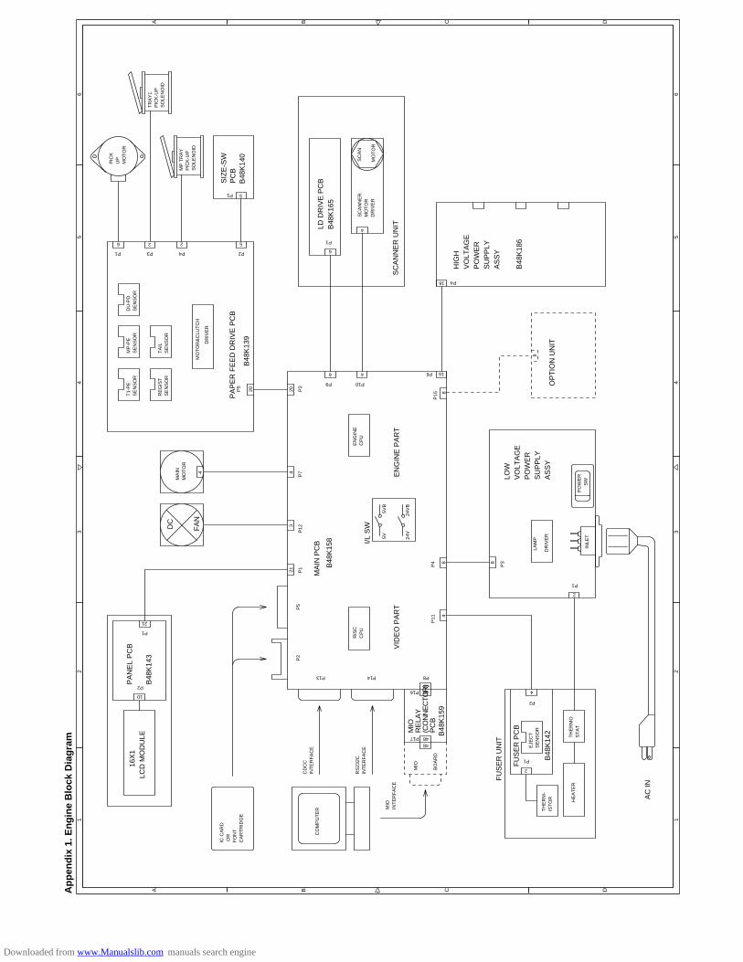
A B C D
12
34
56
Ap
pen
dix
1. E
ng
ine
Blo
ck D
iag
ram
12
34
56
A B C D
SIZ
E-S
W
FA
N
DC
PC
B
B48
K14
0 P
AP
ER
FE
ED
DR
IVE
PC
B
B48
K13
9
LD D
RIV
E P
CB
B48
K16
5
SC
AN
NE
R U
NIT
HIG
HV
OLT
AG
EP
OW
ER
SU
PP
LYA
SS
Y
B48
K18
6
OP
TIO
N U
NIT
I/L S
W
MA
IN P
CB
B48
K15
8
EN
GIN
E P
AR
TV
IDE
O P
AR
T
MIO
RE
LAY
(CO
NN
EC
TOR
)P
CB
B48
K15
9
16X
1LC
D M
OD
ULE
PA
NE
L P
CB
B48
K14
3
FU
SE
R U
NIT
FU
SE
R P
CB
B48
K14
2
AC
IN
MP
TR
AY
PIC
K-U
PS
OLE
NO
ID
PIC
KU
PM
OT
OR
TR
AY
1P
ICK
-UP
SO
LEN
OID
P1
6 2 2 5
P3 P4 P2
5P1
DU
-PD
SE
NS
OR
MP
-PE
SE
NS
OR
T1-
PE
SE
NS
OR
TA
ILS
EN
SO
RR
EG
IST
SE
NS
OR
MO
TO
R&
CLU
TC
H
DR
IVE
R
P5
20 20 P3
6 4
P9 P10
6
4
P1
SC
AN
NE
RM
OT
OR
DR
IVE
R
SC
AN
MO
TO
R
16
P4
P6
8
16
8
MA
INM
OT
OR
4
P7
3
P12
21 P1
P5
P2
P13 P8
RIS
CC
PU
P11 4
P4 8
5V5V
B
24V
24V
B
EN
GIN
EC
PU
48
P14
48P16
48P1748
MIO
BO
AR
D
MIO
INT
ER
FA
CE
RS
232C
INT
ER
FA
CE
CD
CC
INT
ER
FA
CE
CO
MP
UT
ER
IC C
AR
D O
RF
ON
TC
AR
TR
IDG
E
10
P2
21
P1
2
P1
4
P2
EJE
CT
SE
NS
OR
TH
ER
M-
IST
OR
TH
ER
MO
ST
AT
HE
AT
ER
2
P1
INLE
T
PO
WE
R
SW
LAM
P
DR
IVE
R
8
P3
4
P15
LOW
VO
LTA
GE
PO
WE
RS
UP
PLY
AS
SY
Downloaded from www.Manualslib.com manuals search engine
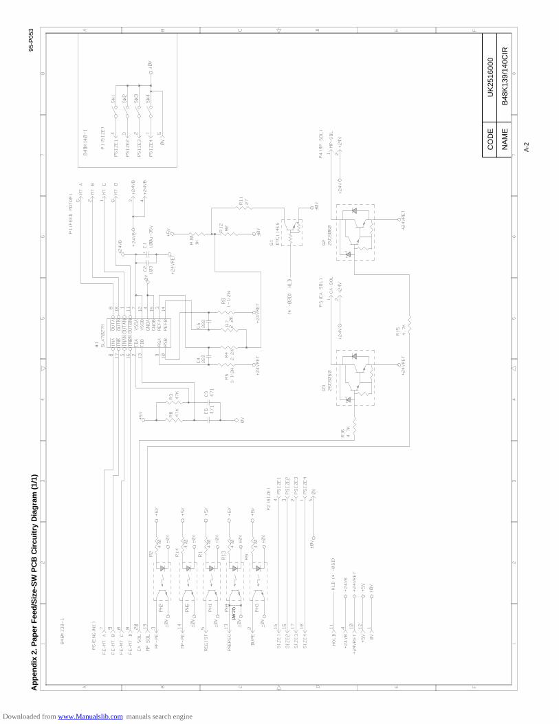
Ap
pen
dix
2. P
aper
Fee
d/S
ize-
SW
PC
B C
ircu
itry
Dia
gra
m (
1/1)
A-2CO
DE
NA
ME
UK
2516
000
B48
K13
9/14
0CIR
(JW
27)
95-P
053
Downloaded from www.Manualslib.com manuals search engine

Ap
pen
dix
3. M
ain
PC
B C
ircu
itry
Dia
gra
m (
1/8)
A-3
CO
DE
NA
ME
UK
2495
000
B48
K15
8/15
9CIR
(1/8
)
Downloaded from www.Manualslib.com manuals search engine
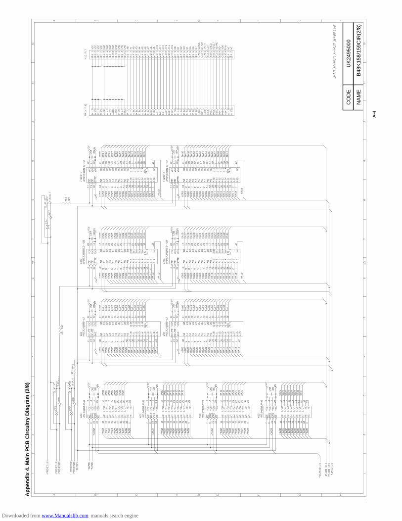
Ap
pen
dix
4. M
ain
PC
B C
ircu
itry
Dia
gra
m (
2/8)
A-4
CO
DE
NA
ME
UK
2495
000
B48
K15
8/15
9CIR
(2/8
)
Downloaded from www.Manualslib.com manuals search engine
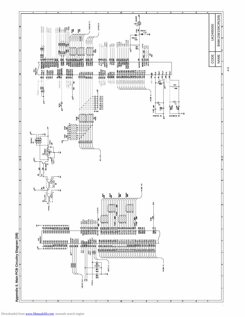
Ap
pen
dix
5. M
ain
PC
B C
ircu
itry
Dia
gra
m (
3/8)
A-5
CO
DE
NA
ME
UK
2495
000
B48
K15
8/15
9CIR
(3/8
)
Downloaded from www.Manualslib.com manuals search engine

Ap
pen
dix
6. M
ain
PC
B C
ircu
itry
Dia
gra
m (
4/8)
A-6
CO
DE
NA
ME
UK
2495
000
B48
K15
8/15
9CIR
(4/8
)
Downloaded from www.Manualslib.com manuals search engine
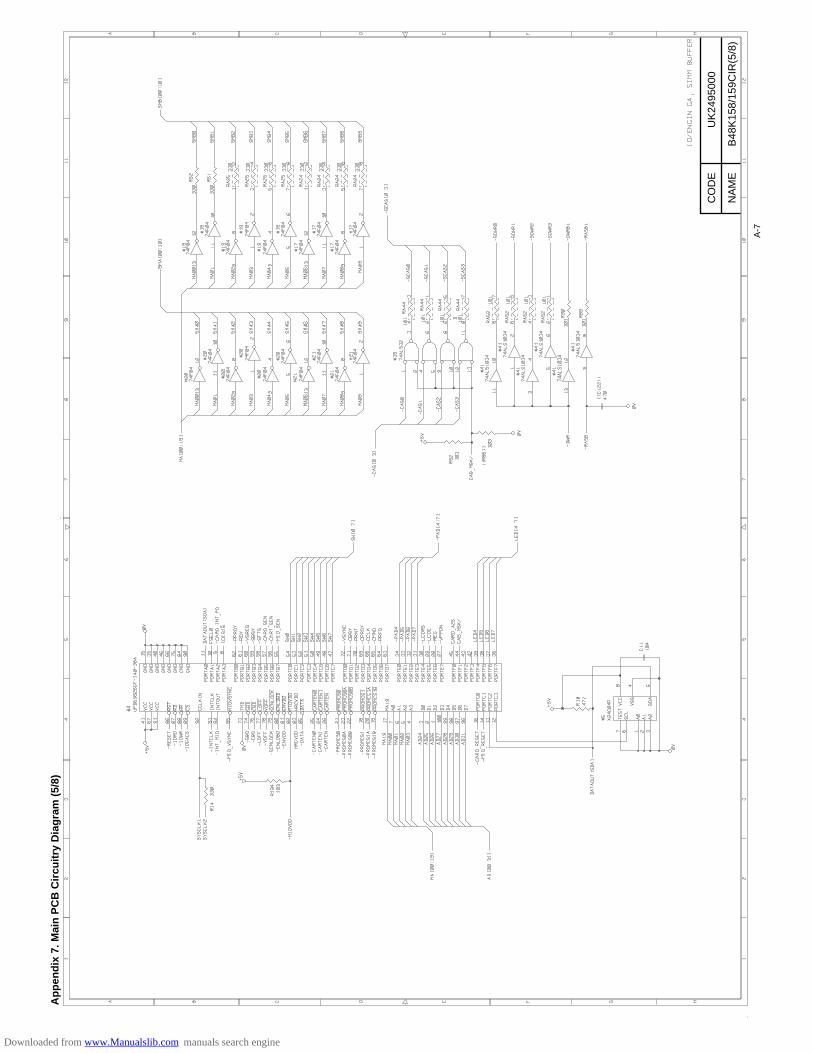
Ap
pen
dix
7. M
ain
PC
B C
ircu
itry
Dia
gra
m (
5/8)
A-7
CO
DE
NA
ME
UK
2495
000
B48
K15
8/15
9CIR
(5/8
)
Downloaded from www.Manualslib.com manuals search engine
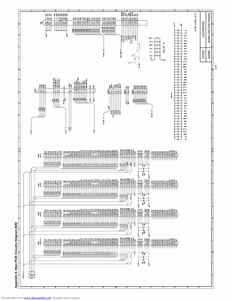
Ap
pen
dix
8. M
ain
PC
B C
ircu
itry
Dia
gra
m (
6/8)
A-8
CO
DE
NA
ME
UK
2495
000
B48
K15
8/15
9CIR
(6/8
)
Downloaded from www.Manualslib.com manuals search engine
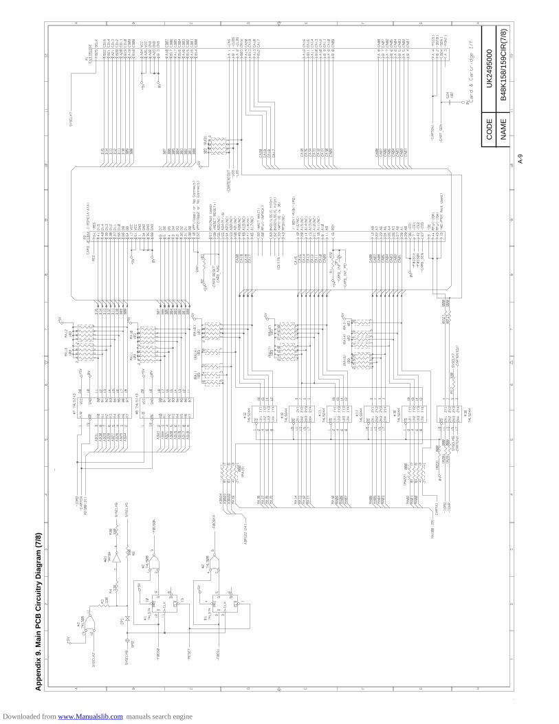
Ap
pen
dix
9. M
ain
PC
B C
ircu
itry
Dia
gra
m (
7/8)
A-9
CO
DE
NA
ME
UK
2495
000
B48
K15
8/15
9CIR
(7/8
)
Downloaded from www.Manualslib.com manuals search engine
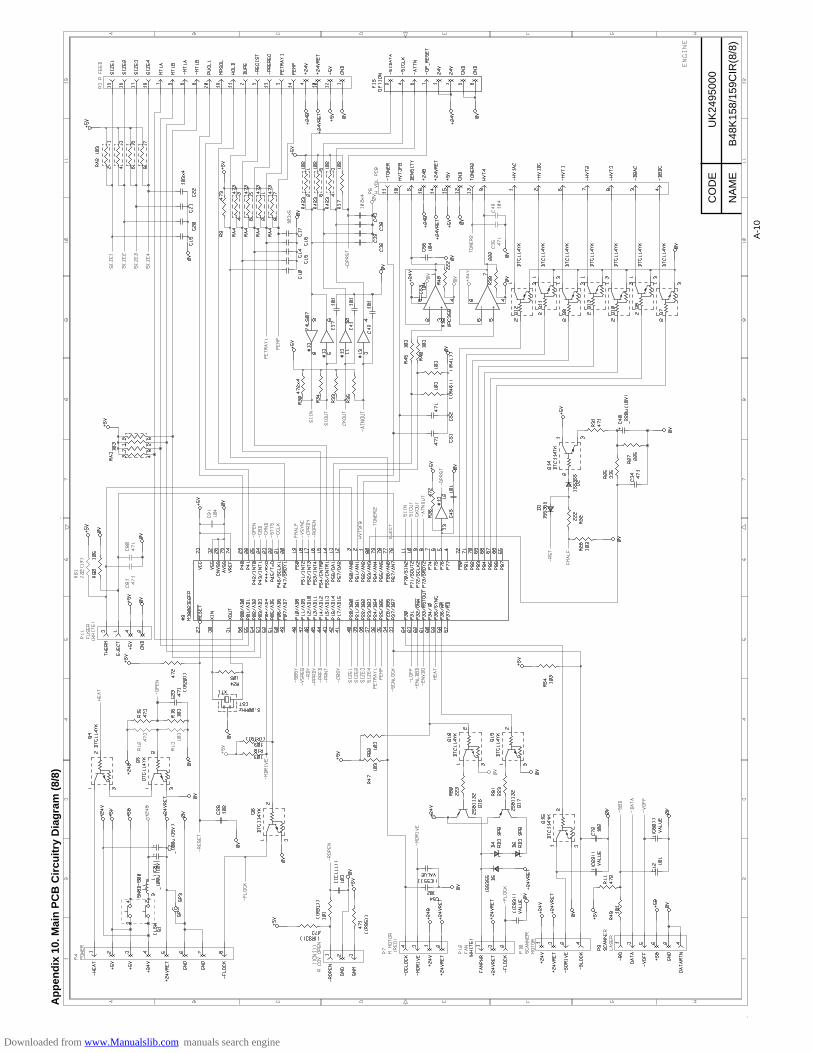
Ap
pen
dix
10.
Mai
n P
CB
Cir
cuit
ry D
iag
ram
(8/
8)
A-1
0
CO
DE
NA
ME
UK
2495
000
B48
K15
8/15
9CIR
(8/8
)
Downloaded from www.Manualslib.com manuals search engine
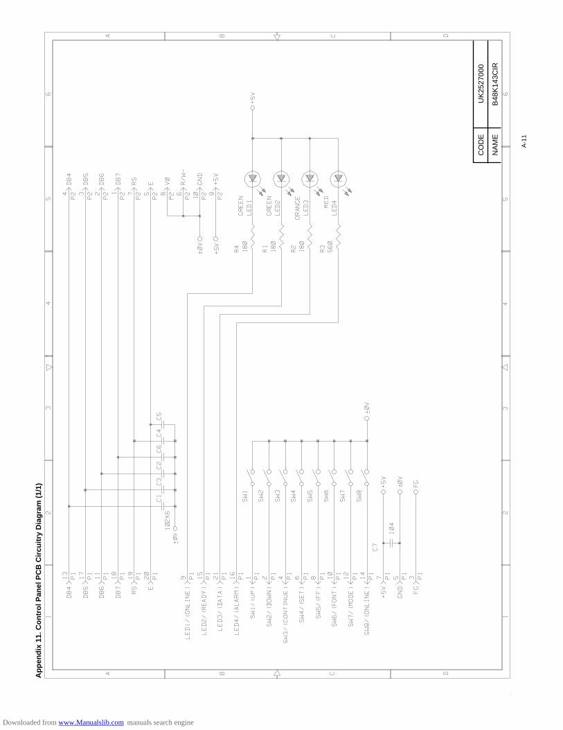
Ap
pen
dix
11.
Co
ntr
ol P
anel
PC
B C
ircu
itry
Dia
gra
m (
1/1)
A-1
1
CO
DE
NA
ME
UK
2527
000
B48
K14
3CIR
Downloaded from www.Manualslib.com manuals search engine
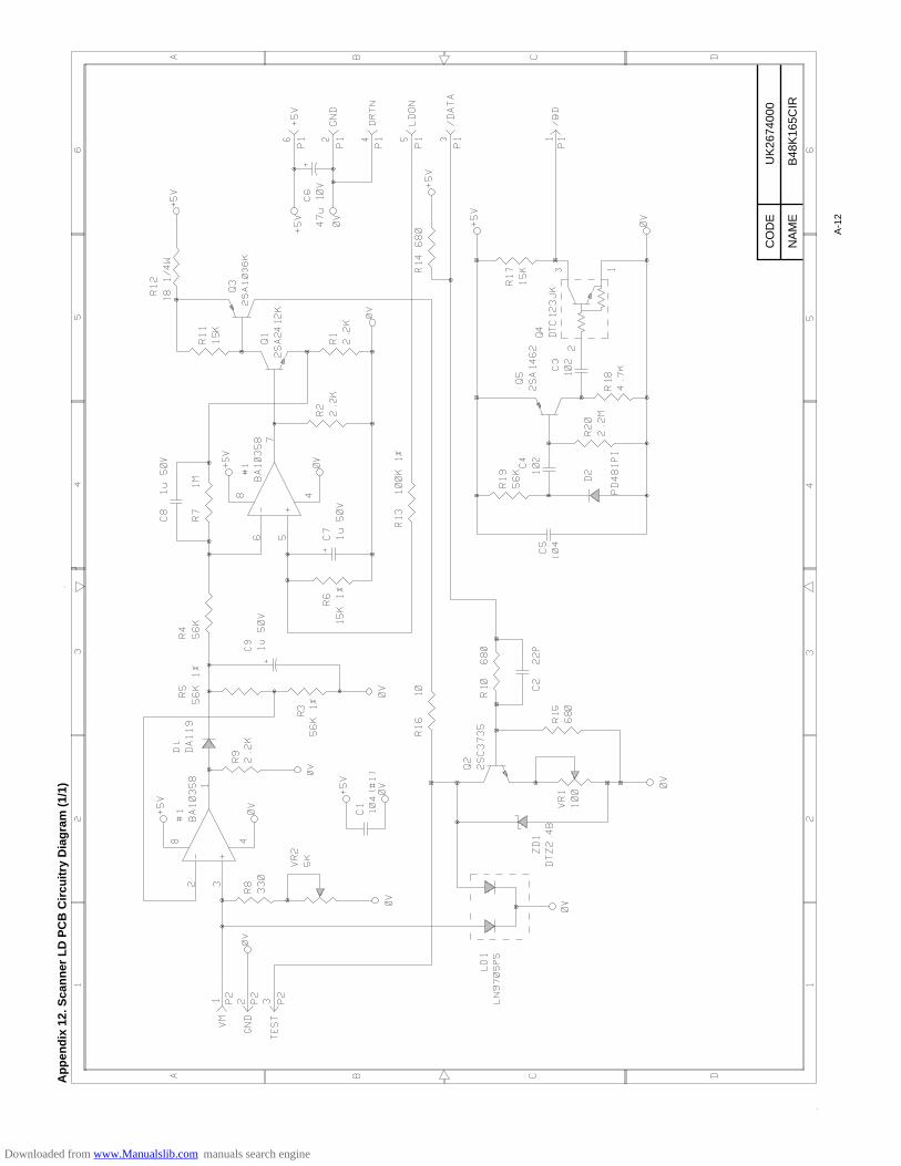
Ap
pen
dix
12.
Sca
nn
er L
D P
CB
Cir
cuit
ry D
iag
ram
(1/
1)
A-1
2
CO
DE
NA
ME
UK
2674
000
B48
K16
5CIR
Downloaded from www.Manualslib.com manuals search engine
SERVICE MANUAL
MODEL:HL-1260e/1660
R
LASER PRINTER
Downloaded from www.Manualslib.com manuals search engine

No part this publication may be reproduced in any form or by any means without permission in writingfrom the publisher.
Trademarks:• BR-Script, DX-1200 and DX-1600 are registered trademarks of Brother Industries, Ltd.• Centronics is a registered trademark of Genicom Corporation.• PostScript is a registered trademark of Adobe Systems Incorporated.• IBM Proprinter XL is a registered trademark of International Business Machines Corporation.• EPSON FX-850 is a registered trademark of Seiko Epson Corporation.• HP-GL and HP Laser Jet 4 are registered trademarks of Hewlett Packard Company.• Windows 3.1 is a registered trademark of Microsoft Corporation in the U.S. and other countries.
Downloaded from www.Manualslib.com manuals search engine
PREFACE
This service manual contains basic information required for after-sales service of the laser printer(hereinafter referred to as ”this machine” or ” the printer”). This information is vital to the service technicianin maintaining the high printing quality and performance of the printer.
This manual consists of the following chapters:
Chapter I : General
Features, specifications, etc.
Chapter II : Theory of Operation
Basic operation of the mechanical system and the electrical system, and their timing.
Chapter III : Electrical System
Theory of the electronics circuit
Chapter IV : Mechanical System
Requirements for a suitable location, disassembling and reassembling procedure of
mechanical system.
Chapter V : Maintenance and Servicing
Parts replacement schedule, list of tools, lubricants and cleaners.
Chapter VI : Troubleshooting
Reference values and adjustment, troubleshooting for image defects, troubleshootingfor malfunctions, etc.
Appendices : Engine Block Diagram, PCB Circuitry Diagrams, etc.
Note: This service manual of the printer (HL-1260e/HL-1660) describes only different parts fromthe each part of the service manual (No.54T039NE0) which was published before. Weomit the same parts with that of HL-1260 and describe the effect of it in contents. Whenyou find the omitted parts, please refer to the service manual of that model.
Information in this manual is subject to change due to improvement or re-design of the product. All relevantinformation in such cases will be supplied in service information bulletins (Technical Information).
A thorough understanding of this printer, based on information in this service manual and serviceinformation bulletins, is required for maintaining its quality performance and for fostering the practical abilityto find the cause of troubles.
Downloaded from www.Manualslib.com manuals search engine
i
CONTENTS
CHAPTER I GENERAL
1. FEATURES ....................................................................................... Refer to HL-1260 (P.I-1)
2. SPECIFICATIONS.............................................................................................................. I-1
3. SAFETY INFORMATION ................................................................................................... I-6
3.1 Laser Safety (110 - 120V Model only) ...................................................................... I-63.2 CDRH Regulations (110 - 120V Model only) ............................................................ I-63.3 Additional Information .............................................................................................. I-7
4. PARTS OF THE PRINTER ............................................................... Refer to HL-1260 (P.I-8)
4.1 External Views ....................................................................... Refer to HL-1260 (P.I-8)4.2 Cross Sectional View ............................................................. Refer to HL-1260 (P.I-9)
5. STORAGE AND HANDLING OF EP-ED CARTRIDGES................ Refer to HL-1260 (P.I-10)
5.1 Storage of Sealed EP-ED Cartridges ................................... Refer to HL-1260 (P.I-10)5.2 Storage of Unsealed EP-ED Cartridges ............................... Refer to HL-1260 (P.I-10)
CHAPTER II THEORY OF OPERATION
1. BASIC OPERATIONS ....................................................................................................... II-1
1.1 Mechanical Configuration ....................................................... Refer to HL-1260 (P.II-1)1.2 Main Drive .............................................................................. Refer to HL-1260 (P.II-2)1.3 Basic Sequence of Operations ................................................................................ II-1
2. LASER/SCANNER SYSTEM ........................................................... Refer to HL-1260 (P.II-4)
3. IMAGE FORMATION SYSTEM ........................................................ Refer to HL-1260 (P.II-5)
3.1 Outline .................................................................................... Refer to HL-1260 (P.II-5)3.2 Printing Process .................................................................... Refer to HL-1260 (P.II-5)
3.2.1 Electrostatic latent image formation stage .............. Refer to HL-1260 (P.II-6)3.2.2 Developing stage .................................................... Refer to HL-1260 (P.II-8)3.2.3 Transfer stage ......................................................... Refer to HL-1260 (P.II-9)3.2.4 Fixing stage .......................................................... Refer to HL-1260 (P.II-10)3.2.5 Drum cleaning stage ............................................. Refer to HL-1260 (P.II-10)
3.3 Operation .............................................................................Refer to HL-1260 (P.II-11)4. PAPER PICK-UP/FEED SYSTEM .................................................................................... II-2
4.1 Outline ................................................................................. Refer to HL-1260 (P.II-12)4.2 Cassette Feed ......................................................................................................... II-24.3 MP Tray Feed.......................................................................................................... II-34.4 Paper Jam Detection............................................................................................... II-4
Downloaded from www.Manualslib.com manuals search engine
CHAPTER III ELECTRICAL SYSTEM
1. MAIN PCB ........................................................................................................................ III-1
1.1 Outline .................................................................................................................... III-11.2 Video Controller Circuit .......................................................................................... III-21.3 Engine Controller Circuit ........................................................................................ III-6
2. PAPER FEED DRIVE CIRCUIT ..................................................... Refer to HL-1260 (P.III-9)
3. DISPLAY CIRCUIT ....................................................................... Refer to HL-1260 (P.III-11)
3.1 Outline ................................................................................ Refer to HL-1260 (P.III-11)3.2 Operation ........................................................................... Refer to HL-1260 (P.III-11)
4. LOW-VOLTAGE POWER SUPPLY ASSY ..................................... Refer to HL-1260 (P.III-12)
4.1 Outline ................................................................................ Refer to HL-1260 (P.III-12)4.2 Protection Functions .......................................................... Refer to HL-1260 (P.III-12)
5. HIGH-VOLTAGE POWER SUPPLY ASSY .................................... Refer to HL-1260 (P.III-14)
5.1 Outline ................................................................................ Refer to HL-1260 (P.III-14)5.2 Operation of the Components of the High-Voltage Power Supply Assy ........................
........................................................................................... Refer to HL-1260 (P.III-14)
CHAPTER IV MECHANICAL SYSTEM
PRINTER DISASSEMBLING PROCEDURE............................................. Refer to HL-1260 (P.IV-2)
1.1 Configuration ........................................................................ Refer to HL-1260 (P.IV-3)1.2 Toner Cartridge Lid................................................................................................. IV-21.3 Side Cover L ........................................................................ Refer to HL-1260 (P.IV-3)1.4 Font Cover Assy ................................................................... Refer to HL-1260 (P.IV-4)1.5 Upper Cover Assy, Rear Cover Assy .................................... Refer to HL-1260 (P.IV-4)
1.5.1 Upper cover assy, rear cover assy ......................... Refer to HL-1260 (P.IV-4)1.5.2 Changeover guide, jam remove cover ................... Refer to HL-1260 (P.IV-5)
1.6 Side Cover R ........................................................................ Refer to HL-1260 (P.IV-5)1.7 DC Fan Motor ........................................................................................................ IV-21.8 Main PCB ............................................................................................................... IV-31.9 Control Panel Unit ................................................................ Refer to HL-1260 (P.IV-8)1.10 Scanner Unit .......................................................................................................... IV-51.11 Cartridge Stopper Assy .......................................................................................... IV-51.12 Paper Feed Chassis Unit ................................................... Refer to HL-1260 (P.IV-10)1.13 Separation Pad Assy .......................................................... Refer to HL-1260 (P.IV-11)1.14 MP PE Sub Actuator .......................................................... Refer to HL-1260 (P.IV-12)1.15 P Feed /Size-SW PCB Assy ............................................... Refer to HL-1260 (P.IV-12)1.16 Size-Switch Spring ............................................................. Refer to HL-1260 (P.IV-12)1.17 Regist Sensor Actuator ...................................................... Refer to HL-1260 (P.IV-13)1.18 MP Paper Detection Actuator ............................................. Refer to HL-1260 (P.IV-13)1.19 PE Sensor Actuator MP ..................................................... Refer to HL-1260 (P.IV-13)1.20 Tray Sensor Holder ............................................................ Refer to HL-1260 (P.IV-14)1.21 Roller Holder ...................................................................... Refer to HL-1260 (P.IV-14)1.22 Paper Pick-up Roller Assy, Bearing .................................... Refer to HL-1260 (P.IV-15)1.23 Paper Pick-up Solenoid...................................................... Refer to HL-1260 (P.IV-16)1.24 Paper Feed Motor Assy...................................................... Refer to HL-1260 (P.IV-16)1.25 MP Tray Cover ................................................................... Refer to HL-1260 (P.IV-17)1.26 MP Tray Assy ..................................................................... Refer to HL-1260 (P.IV-17)1.27 Paper Path Separation Plate, Paper Path Separation Film Refer to HL-1260 (P.IV-18)1.28 Latch .................................................................................. Refer to HL-1260 (P.IV-19)1.29 Fixing Unit (for both 120V and 230V, the only difference is the halogen heater) .........
........................................................................................... Refer to HL-1260 (P. IV-19)1.30 Transfer Unit ...................................................................... Refer to HL-1260 (P.IV-22)
ii
Downloaded from www.Manualslib.com manuals search engine
iii
1.31 DC Gear Holder Assy ............................................................................................. IV-61.31.1 Scanner Fan Motor .................................................................................. IV-6
1.32 PS Switch Wire, Remote Switch ........................................ Refer to HL-1260 (P.IV-23)1.33 High-Voltage Power Supply PCB Assy ............................... Refer to HL-1260 (P.IV-24)1.34 Low-Voltage Power Supply PCB Assy ............................... Refer to HL-1260 (P.IV-24)1.35 Toner Cartridge (EP-ED Cartridge) .................................... Refer to HL-1260 (P.IV-25)1.36 Paper Tray ............................................................................................................. IV-7
CHAPTER V MAINTENANCE AND SERVICING
1. PERIODICAL REPLACEMENT PARTS .......................................... Refer to HL-1260 (P.V-1)
2. CONSUMABLE PARTS STANDARD ENDURANCE TABLE ............................................ V-1
3. LIST OF STANDARD TOOLS ......................................................... Refer to HL-1260 (P.V-2)
4. LIST OF LUBRICANTS AND CLEANERS ...................................... Refer to HL-1260 (P.V-3)
CHAPTER VI TROUBLESHOOTING
1. INTRODUCTION ............................................................................ Refer to HL-1260 (P.VI-1)
1.1 Initial Check.......................................................................... Refer to HL-1260 (P.VI-1)1.2 Basic Procedure ................................................................... Refer to HL-1260 (P.VI-2)
2. TEST PRINTING AND MECHANICAL CHECK .............................. Refer to HL-1260 (P.VI-2)
2.1 Test Printing ......................................................................... Refer to HL-1260 (P.VI-2)3. IMAGE DEFECTS .......................................................................... Refer to HL-1260 (P.VI-3)
3.1 Image Defect Examples ....................................................... Refer to HL-1260 (P.VI-3)3.2 Troubleshooting Image Defects ........................................... Refer to HL-1260 (P.VI-4)
4. TROUBLESHOOTING OF MALFUNCTIONS .................................................................. VI-1
5. TROUBLESHOOTING PAPER TRANSPORT PROBLEMS......... Refer to HL-1260 (P.VI-19)
5.1 Paper Jams ........................................................................ Refer to HL-1260 (P.VI-19)5.2 Incomplete Paper Feed ...................................................... Refer to HL-1260 (P.VI-22)
6. OPERATION ................................................................................ Refer to HL-1260 (P.VI-23)
6.1 Line Inspection Mode Procedure ....................................... Refer to HL-1260 (P.VI-23)6.2 DRAM Test ......................................................................... Refer to HL-1260 (P.VI-25)
7. STATUS MESSAGE LIST ................................................................................................VI-9
APPENDICES
1. Engine Block Diagram ....................................................................................................... A-1
2. Paper Feed/Size-SW PCB Circuitry Diagram (1/1)........................... Refer to HL-1260 (P.A-2)
3. Main PCB Circuitry Diagram (1/7) ..................................................................................... A-2
4. Main PCB Circuitry Diagram (2/7) ..................................................................................... A-3
5. Main PCB Circuitry Diagram (3/7) ..................................................................................... A-4
6. Main PCB Circuitry Diagram (4/7) ..................................................................................... A-5
7. Main PCB Circuitry Diagram (5/7) ..................................................................................... A-6
8. Main PCB Circuitry Diagram (6/7) ..................................................................................... A-7
9. Main PCB Circuitry Diagram (7/7) ..................................................................................... A-8
10. Control Panel PCB Circuitry Diagram (1/1) ....................................Refer to HL-1260 (P.A-11)
11. Scanner LD PCB Circuitry Diagram (1/1) .......................................................................... A-9
Downloaded from www.Manualslib.com manuals search engine
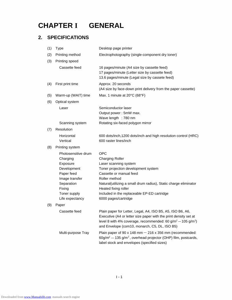
I - 1
CHAPTER I GENERAL
2. SPECIFICATIONS
(1) Type Desktop page printer
(2) Printing method Electrophotography (single-component dry toner)
(3) Printing speed
Cassette feed 16 pages/minute (A4 size by cassette feed)17 pages/minute (Letter size by cassette feed)13.6 pages/minute (Legal size by cassete feed)
(4) First print time Approx. 20 seconds(A4 size by face-down print delivery from the paper cassette)
(5) Warm-up (WAIT) time Max. 1 minute at 20°C (68°F)
(6) Optical system
Laser Semiconductor laserOutput power : 5mW max.Wave length : 780 nm
Scanning system Rotating six-faced polygon mirror
(7) Resolution
Horizontal 600 dots/inch,1200 dots/inch and high resolution control (HRC)Vertical 600 raster lines/inch
(8) Printing system
Photosensitive drum OPCCharging Charging RollerExposure Laser scanning systemDevelopment Toner projection development systemPaper feed Cassette or manual feedImage transfer Roller methodSeparation Natural(utilizing a small drum radius), Static charge eliminatorFixing Heated fixing rollerToner supply Included in the replaceable EP-ED cartridgeLife expectancy 6000 pages/cartridge
(9) Paper
Cassette feed Plain paper for Letter, Legal, A4, ISO B5, A5, ISO B6, A6,Executive (A4 or letter size paper with the print density set atlevel 8 with 4% coverage, recommended: 60 g/m 105 g/m )and Envelope (com10, monarch, C5, DL, ISO B5)
Multi-purpose Tray Plain paper of 90 x 148 mm 216 x 356 mm (recommended:60g/m 135 g/m , overhead projector (OHP) film, postcards,label stock and envelopes (specified sizes)
22
22
Downloaded from www.Manualslib.com manuals search engine
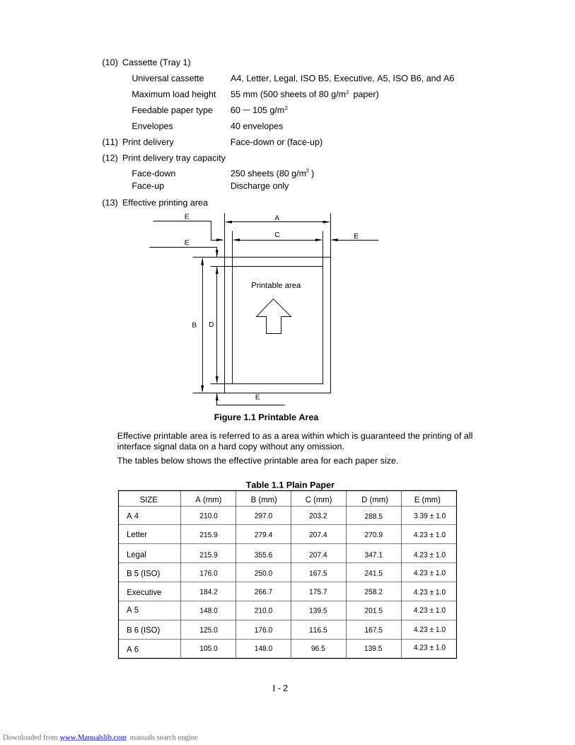
I - 2
(10) Cassette (Tray 1)
Universal cassette A4, Letter, Legal, ISO B5, Executive, A5, ISO B6, and A6
Maximum load height 55 mm (500 sheets of 80 g/m paper)
Feedable paper type 60 105 g/m
Envelopes 40 envelopes
(11) Print delivery Face-down or (face-up)
(12) Print delivery tray capacity
Face-down 250 sheets (80 g/m )Face-up Discharge only
2
2
2
(13) Effective printing area
Figure 1.1 Printable Area
Effective printable area is referred to as a area within which is guaranteed the printing of allinterface signal data on a hard copy without any omission.
The tables below shows the effective printable area for each paper size.
Printable area
E
DB
C EE
AE
SIZE A (mm) B (mm) C (mm) D (mm)
A 4
Letter
Legal
Executive
B 6 (ISO)
A 6
B 5 (ISO)
A 5
210.0 297.0 203.2 288.5
215.9 279.4 207.4 270.9
215.9 355.6 207.4 347.1
176.0 250.0 167.5 241.5
184.2 266.7 175.7 258.2
148.0 210.0 139.5 201.5
125.0 176.0 116.5 167.5
105.0 148.0 96.5 139.5
E (mm)
3.39 ± 1.0
4.23 ± 1.0
4.23 ± 1.0
4.23 ± 1.0
4.23 ± 1.0
4.23 ± 1.0
4.23 ± 1.0
4.23 ± 1.0
Table 1.1 Plain Paper
Downloaded from www.Manualslib.com manuals search engine
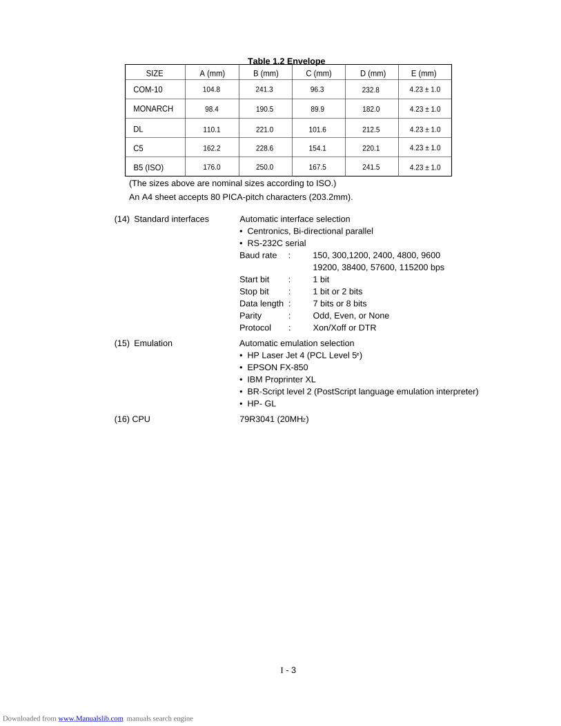
I - 3
SIZE A (mm) B (mm) C (mm) D (mm)
COM-10
MONARCH
DL
B5 (ISO)
C5
104.8 241.3 96.3 232.8
98.4 190.5 89.9 182.0
110.1 221.0 101.6 212.5
162.2 228.6 154.1 220.1
176.0 250.0 167.5 241.5
E (mm)
4.23 ± 1.0
4.23 ± 1.0
4.23 ± 1.0
4.23 ± 1.0
4.23 ± 1.0
Table 1.2 Envelope
(14) Standard interfaces Automatic interface selection• Centronics, Bi-directional parallel• RS-232C serialBaud rate : 150, 300,1200, 2400, 4800, 9600
19200, 38400, 57600, 115200 bpsStart bit : 1 bitStop bit : 1 bit or 2 bitsData length : 7 bits or 8 bitsParity : Odd, Even, or NoneProtocol : Xon/Xoff or DTR
(15) Emulation Automatic emulation selection• HP Laser Jet 4 (PCL Level 5e)• EPSON FX-850• IBM Proprinter XL• BR-Script level 2 (PostScript language emulation interpreter)• HP- GL
(16) CPU 79R3041 (20MHZ)
(The sizes above are nominal sizes according to ISO.)
An A4 sheet accepts 80 PICA-pitch characters (203.2mm).
Downloaded from www.Manualslib.com manuals search engine

I - 4
Windows 3.1 Compatible Fonts:• Tennessee Roman, Italic, Bold,
Bold Italic• Helsinki, Oblique, Bold, Bold Oblique• BR Symbol• W Dingbats
BR-Script Fonts:• Atlanta Book, Book Oblique, Demi,
Demi Oblique• Copenhagen Roman, Italic, Bold,
Bold Italic• Portugal Roman, Italic, Bold, Bold Italic• Calgary Medium Italic
Brother Original Fonts:• Bermuda Script• Germany• San Diego• US Roman
HP Laser Jet 4, EPSON FX-850, IBM Proprinter XLScalable Fonts:
Intellifont Compatible Fonts:• Albertville, Extrabold• Antique Oakland, Oblique, Bold• Brougham, Oblique, Bold,
Bold Oblique• Cleveland Condensed• Connecticut• Guatemala Antique, Italic, Bold,
Bold Italic• Letter Gothic, Oblique, Bold• Maryland• Oklahoma, Oblique, Bold,
Bold Oblique• PC Brussels Light, Light Italic, Demi,
Demi Italic• PC Tennessee Roman, Italic, Bold,
Bold Italic• Utah, Oblique, Bold, Bold Oblique• Utah Condensed, Oblique, Bold,
Bold Oblique
Bitmapped Fonts (Portrait and Landscape):• Letter Gothic 16.66 Medium, Italic, Bold, Bold Italic• OCR-A• OCR-B
• Albertville, Extrabold• Antique Oakland, Oblique, Bold• Cleveland Condensed• Conecticut• Guatemala Antique, Italic, Bold, Bold Italic• Letter Gothic, Oblique, Bold• Maryland• Oklahoma, Oblique, Bold, Bold Oblique• Utah, Oblique, Bold, Bold Oblique• Utah Condensed, Oblique, Bold,
Bold Oblique• Bermuda Script• Germany• San Diego• US Roman
BR-Script Level 2 Mode
Scalable Fonts:• Atlanta Book, Book Oblique, Demi,
Demi Oblique• Brussels Light, Light Italic, Demi,
Demi Italic• Brougham, Oblique, Bold, Bold Oblique• Helsinki, Oblique, Bold, Bold Oblique• Helsinki Narrow, Oblique, Bold,
Bold Oblique• Copenhagen Roman, Italic, Bold,
Bold Italic• Portugal Roman, Italic, Bold, Bold Italic• Tennessee Roman, Italic, Bold, Bold Italic• Calgary Medium Italic• BR Symbol• BR Dingbats
(17) Resident fonts 75 scalable fonts and 12 bitmapped fonts
Downloaded from www.Manualslib.com manuals search engine
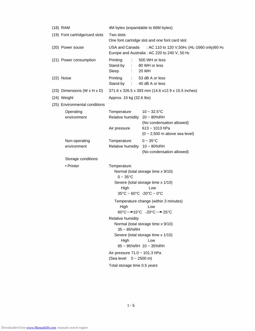
I - 5
(18) RAM 4M bytes (expandable to 66M bytes)
(19) Font cartridge/card slots Two slotsOne font cartridge slot and one font card slot
(20) Power souse USA and Canada : AC 110 to 120 V,50HZ (HL-1660 only)60 HZ
Europe and Australia : AC 220 to 240 V, 50 HZ
(21) Power consumption Printing : 500 WH or lessStand-by : 80 WH or lessSleep : 20 WH
(22) Noise Printing : 53 dB A or lessStand-by : 40 dB A or less
(23) Dimensions (W x H x D) 371.6 x 326.5 x 393 mm (14.6 x12.9 x 15.5 inches)
(24) Weight Approx. 15 kg (32.6 Ibs)
(25) Environmental conditions
Operating Temperature 10 ~ 32.5°Cenvironment Relative humidity 20 ~ 80%RH
(No condensation allowed)Air pressure 613 ~ 1013 hPa
(0 ~ 2,500 m above sea level)
Non-operating Temperature 0 ~ 35°Cenvironment Relative humidity 10 ~ 80%RH
(No condensation allowed)
Storage conditions
• Printer TemperatureNormal (total storage time x 9/10)
0 ~ 35°CSevere (total storage time x 1/10)
High Low35°C ~ 60°C -20°C ~ 0°C
Temperature change (within 3 minutes) High Low
60°C 15°C -20°C 25°C
Relative humidityNormal (total storage time x 9/10)
35 ~ 85%RHSevere (total storage time x 1/10)
High Low85 ~ 95%RH 10 ~ 35%RH
Air pressure 71.0 ~ 101.3 hPa(Sea level 0 ~ 2500 m)
Total storage time 0.5 years
Downloaded from www.Manualslib.com manuals search engine

I - 6
• EP-ED cartridge TemperatureNormal (2.45 years max.)
0 ~ 35°CSevere (0.05 years max.)
High Low35°C ~ 40°C -20°C ~ 0°C
Temperature change (within 3 minutes) High Low40°C 15°C -20°C 25°C
Relative humidityNormal (2.45 years max.)
35 ~ 85%RHSevere (0.05 years max.)
High Low85 ~ 95%RH 10 ~ 35%RH
Air pressure 71.0 ~ 101.3 hPa
Maximum total storage time: 2.5 years including used time
3. SAFETY INFORMATION
3.1 Laser Safety (110 ~ 120V Model only)
This printer is certified as a Class 1 laser product under the US Department of Health andHuman Services (DHHS) Radiation Performance Standard according to the Radiation Control forHealth and Safety Act of 1968. This means that the printer does not produce hazardous laserradiation,
Since radiation emitted inside the printer is completely confined within the protective housingsand external covers, the laser beam cannot escape from the machine during any phase of useroperation.
MANUFACTURED :
BROTHER INDUSTRIES, LTD.
15-1, Naeshiro-cho, Mizuho-ku Nagoya 467, Japan.
This product complies with FDA radiation
performance standards , 21 CFR chapter 1
subchapter J.
3.2 CDRH Regulations (110 ~ 120V Model only)
The center for Devices and Radiological Health (CDRH) of the US Food and DrugAdministration implemented regulations for laser products on August 2, 1976. Theseregulations apply to laser products manufactured from August 1, 1976. Compliance ismandatory for products marketed in the United States. The label shown below indicatescompliance with the CDRH regulations and must be attached to laser products marketed inthe United States.
Caution: Use of controls, adjustments or performance of procedures other than thosespecified in this manual may result in hazardous radiation exposure.
Figure 1.2
Downloaded from www.Manualslib.com manuals search engine

I - 7
Figure 1.3
3.3 Additional Information
When servicing or adjusting the optical system of the printer, be careful not to placescrewdrivers or other reflective objects in the path of the laser beam. Be sure to take off anypersonal accessories such as watches and rings before working on the printer. A reflectedbeam, though invisible, can permanently damage the eyes.
Since the beam is invisible, the following label is attached to the inside of covers wheredanger of exposure to laser radiation exist.
Downloaded from www.Manualslib.com manuals search engine
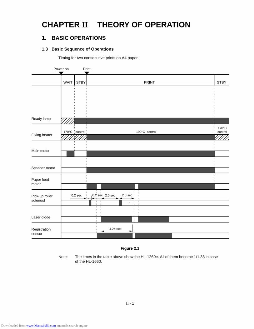
II - 1
CHAPTER II THEORY OF OPERATION
1. BASIC OPERATIONS
1.3 Basic Sequence of Operations
Timing for two consecutive prints on A4 paper.
Power on Print
WAIT STBY PRINT
Ready lamp
Fixing heater
Main motor
170°C control 190°C
STBY
control170°Ccontrol
Scanner motor
Paper feed motor
Pick-up rollersolenoid
Laser diode
Registrationsensor
0.2 sec 0.2 sec 2.5 sec 2.3 sec
4.24 sec
Figure 2.1
Note: The times in the table above show the HL-1260e. All of them become 1/1.33 in caseof the HL-1660.
Downloaded from www.Manualslib.com manuals search engine
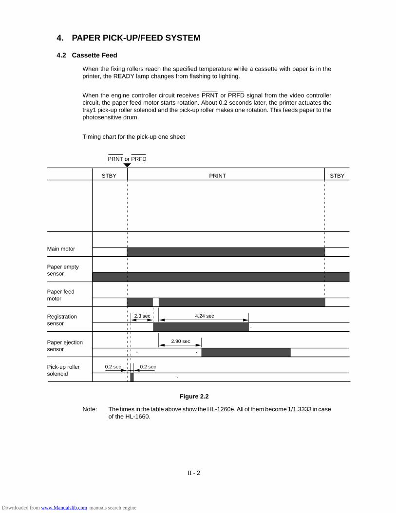
II - 2
4. PAPER PICK-UP/FEED SYSTEM
4.2 Cassette Feed
When the fixing rollers reach the specified temperature while a cassette with paper is in theprinter, the READY lamp changes from flashing to lighting.
When the engine controller circuit receives PRNT or PRFD signal from the video controllercircuit, the paper feed motor starts rotation. About 0.2 seconds later, the printer actuates thetray1 pick-up roller solenoid and the pick-up roller makes one rotation. This feeds paper to thephotosensitive drum.
Timing chart for the pick-up one sheet
0.2 sec
2.90 sec
2.3 sec 4.24 sec
Main motor
Paper feed motor
Registrationsensor
Paper empty sensor
Pick-up rollersolenoid
Paper ejection sensor
STBY PRINT STBY
PRNT or PRFD
0.2 sec
Figure 2.2
Note: The times in the table above show the HL-1260e. All of them become 1/1.3333 in caseof the HL-1660.
Downloaded from www.Manualslib.com manuals search engine

II - 3
0.2 sec 0.2 sec
Main motor
Paper feed motor
Registrationsensor
Paper empty sensor
Pick-up rollersolenoid
Paper ejection sensor
STBY PRINT STBY
PRNT or PRFD
1.12 sec
4.3 MP Tray Feed
The timing of the MP tray feed is identical to the timing of the cassette paper feed except forthe following points:
(1) The paper empty sensors are different.
Cassette feed : Tray1 paper empty sensor
MP tray feed : MP tray paper empty sensor
(2) The pick-up roller solenoids are different.
Cassette feed : Tray1 pick-up roller solenoid
MP tray feed : MP tray pick-up roller solenoid
Figure 2.3
Note: The times in the table above show the HL-1260e. All of them become 1/1.3333 in caseof the HL-1660.
Downloaded from www.Manualslib.com manuals search engine
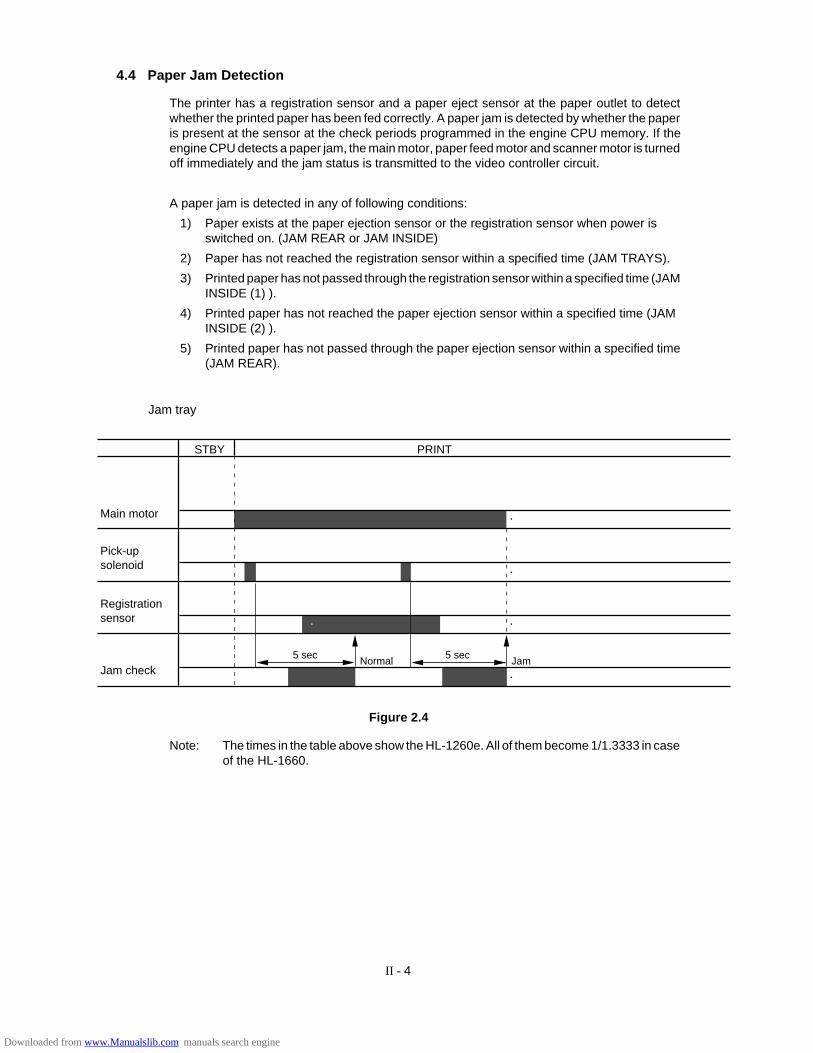
II - 4
4.4 Paper Jam Detection
The printer has a registration sensor and a paper eject sensor at the paper outlet to detectwhether the printed paper has been fed correctly. A paper jam is detected by whether the paperis present at the sensor at the check periods programmed in the engine CPU memory. If theengine CPU detects a paper jam, the main motor, paper feed motor and scanner motor is turnedoff immediately and the jam status is transmitted to the video controller circuit.
A paper jam is detected in any of following conditions:
1) Paper exists at the paper ejection sensor or the registration sensor when power isswitched on. (JAM REAR or JAM INSIDE)
2) Paper has not reached the registration sensor within a specified time (JAM TRAYS).
3) Printed paper has not passed through the registration sensor within a specified time (JAMINSIDE (1) ).
4) Printed paper has not reached the paper ejection sensor within a specified time (JAMINSIDE (2) ).
5) Printed paper has not passed through the paper ejection sensor within a specified time(JAM REAR).
Main motor
Registrationsensor
Pick-upsolenoid
STBY PRINT
Jam checkJamNormal
5 sec5 sec
Jam tray
Figure 2.4
Note: The times in the table above show the HL-1260e. All of them become 1/1.3333 in caseof the HL-1660.
Downloaded from www.Manualslib.com manuals search engine
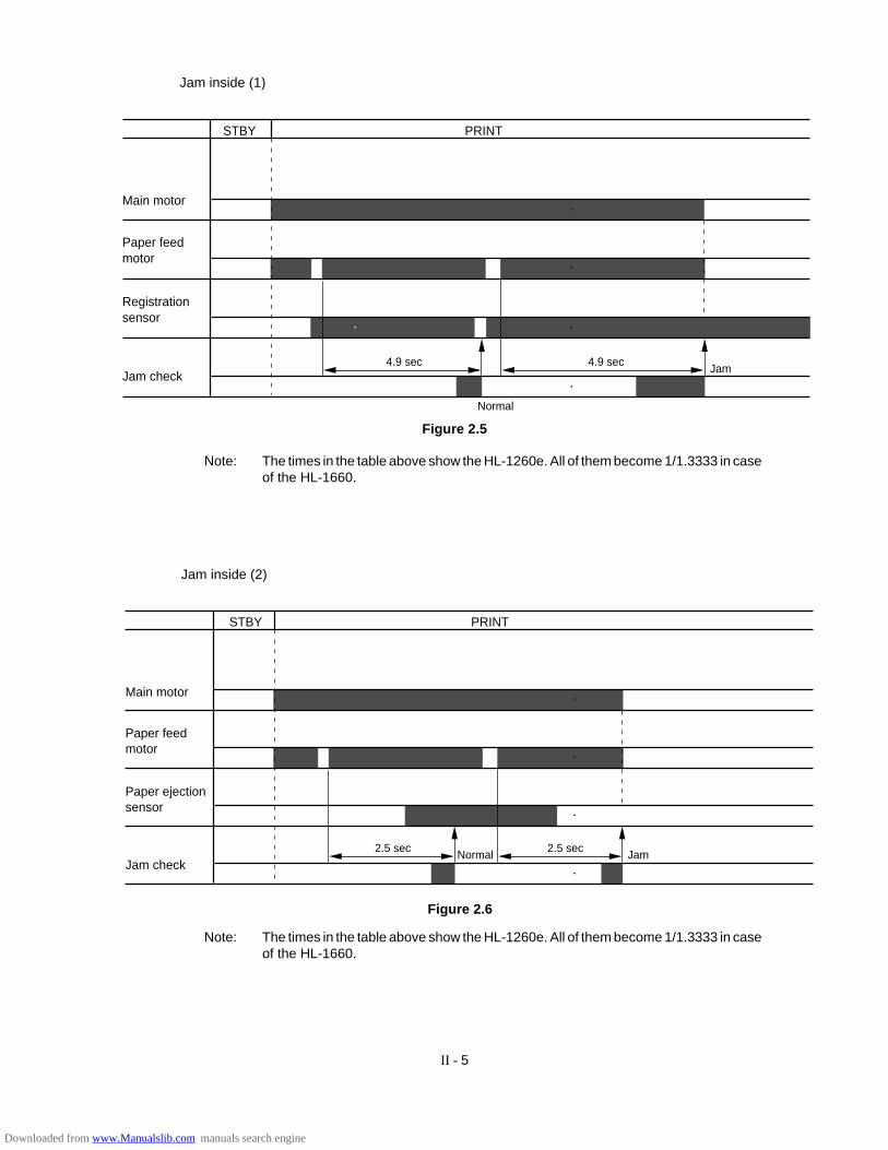
II - 5
Jam inside (1)
Jam4.9 sec4.9 sec
Normal
Main motor
Registrationsensor
Paper feedmotor
Jam check
STBY PRINT
Figure 2.5
Note: The times in the table above show the HL-1260e. All of them become 1/1.3333 in caseof the HL-1660.
STBY PRINT
JamNormal2.5 sec2.5 sec
Main motor
Paper ejectionsensor
Paper feedmotor
Jam check
Jam inside (2)
Figure 2.6
Note: The times in the table above show the HL-1260e. All of them become 1/1.3333 in caseof the HL-1660.
Downloaded from www.Manualslib.com manuals search engine
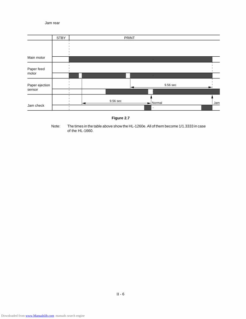
II - 6
STBY PRINT
JamNormal
9.56 sec
9.56 sec
Main motor
Paper ejectionsensor
Paper feedmotor
Jam check
Figure 2.7
Jam rear
Note: The times in the table above show the HL-1260e. All of them become 1/1.3333 in caseof the HL-1660.
Downloaded from www.Manualslib.com manuals search engine
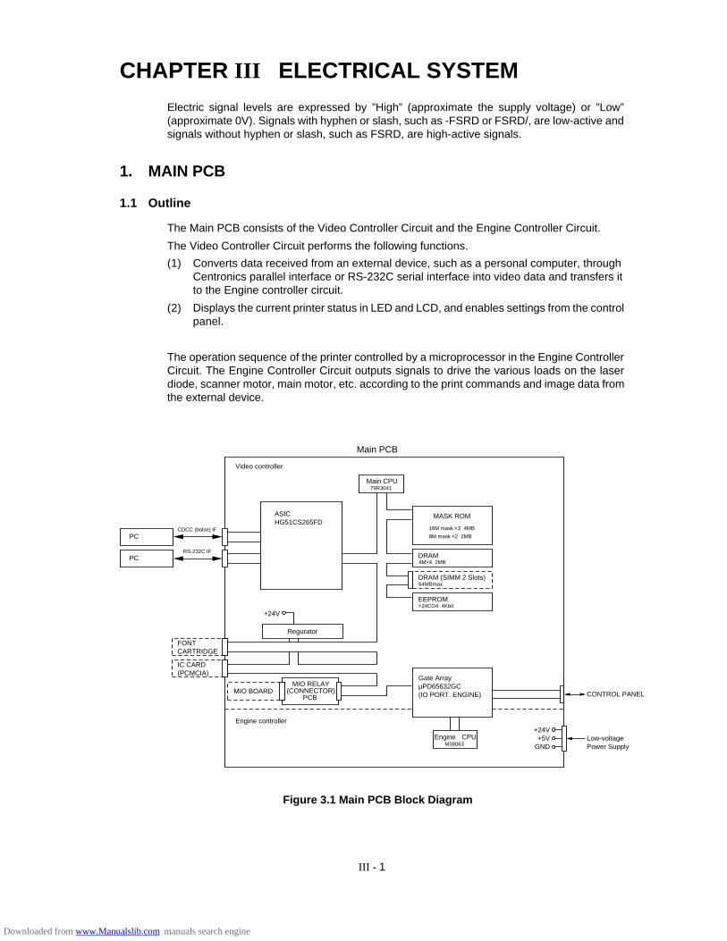
III - 1
CHAPTER III ELECTRICAL SYSTEMElectric signal levels are expressed by ”High” (approximate the supply voltage) or ”Low”(approximate 0V). Signals with hyphen or slash, such as -FSRD or FSRD/, are low-active andsignals without hyphen or slash, such as FSRD, are high-active signals.
1. MAIN PCB
1.1 Outline
The Main PCB consists of the Video Controller Circuit and the Engine Controller Circuit.
The Video Controller Circuit performs the following functions.
(1) Converts data received from an external device, such as a personal computer, throughCentronics parallel interface or RS-232C serial interface into video data and transfers itto the Engine controller circuit.
(2) Displays the current printer status in LED and LCD, and enables settings from the controlpanel.
The operation sequence of the printer controlled by a microprocessor in the Engine ControllerCircuit. The Engine Controller Circuit outputs signals to drive the various loads on the laserdiode, scanner motor, main motor, etc. according to the print commands and image data fromthe external device.
FONTCARTRIDGE
IC CARD(PCMCIA)
MIO BOARD
Regurator
+24V
PC
PC
CDCC (bolse) IF
RS-232C IF
ASICHG51CS265FD
Video controller
Engine controller
Engine CPUM38063
+24V+5V
GND
CONTROL PANEL
Low-voltage Power Supply
Gate ArrayµPD65632GC(IO PORT. ENGINE)
MASK ROM
16M mask 2 4MB
8M mask 2 2MB
DRAM4M 4 2MB
DRAM (SIMM 2 Slots)64MBmax.
EEPROM 24CO4 4Kbit
Main CPU79R3041
Main PCB
MIO RELAY(CONNECTOR)
PCB
Figure 3.1 Main PCB Block Diagram
Downloaded from www.Manualslib.com manuals search engine
III - 2
1.2 Video Controller Circuit
(1) CPU block
CPU IDT79R3041-20J manufactured by Integrated Device Technology
RISC chip
Clock speed: 19.6608 MHz
Appearance: 84-pin PLCC
(2) ASIC/Gate Array Block
• HG51CS265FD (Hitachi) - 208-pin QFP
Controls the address decoder, timers, interfaces (Centronics and RS-232C),HRC and GSC.
• µPD65632GC (NEC) - 100-pin QFP
Controls the I/O ports and others.
(3) Font Cartridge/Card Block
• Font cartridge (option)
The font cartridge has a 64MB memory area and is controlled by the 16-bit bus.
The address bus a buffer LS244 and the data bus, a buffer LS245.
• Font Card (option)
The font card has a 64MB memory area and is controlled by the 16-bit bus.
The card is supplied with 12V power because the flash card requires 12V power supply whenwriting or erasing data.
The address bus is buffered by LS244 and the data bus, is buffered by LS245.
(4) Centronics/RS-232C interface block
• Centronics parallel interface
Data transmission and reception are controlled by the HG51CS265FD .
• RS-232C
Data transmission and reception are controlled by the HG51CS265FD .
The ADM202JRN serves as driver/receiver.
(5) SIMM block
• SIMM (Single-Inline-Memory-Module) allows memory extension up to 66MB
• 2 SIMM sockets are available.
• SIMM should be of 72-pin type and its access time should be less than 80 ns.
• 6 types of SIMM (1MB, 2MB, 4MB, 8MB,16MB and 32MB) can be combined:
1MB MH25632BJ-7 (MITSUBISHI), HB56D25632B-7A (HITACHI)
2MB MH51232BJ-7 (MITSUBISHI), HB56D51232B-7A (HITACHI)
4MB MH1M32EJ-7 (MITSUBISHI), HB56A132BT-7A (HITACHI)
8MB MH2M32EJ-7 (MITSUBISHI), HB56A232BT-7A (HITACHI)
16MB THM324000BSG-70 (TOSHIBA)
32MB THM328020BSG-70 (TOSHIBA)
1) The SIMMs have its printed marking on the PCB by silk screen: SLOT1, and SLOT2, respectively. The SIMMs should be set in the order of SLOT1 - SLOT2.
2) SIMMs should be set in the order of its memory size and in the order of SLOT No.
Example: 2 SIMMs: 1MB, and 4MB
SLOT1 - 4MB
SLOT2 - 1MB
Downloaded from www.Manualslib.com manuals search engine

III - 3
3) The attached Printer SIMM map shows the memory map for 2 SIMMs combined.
(6) ROM block
ROMs store the CPU control program and font data. ROMs are two 16Mbit masked ROMs andtwo 8Mbit masked ROMs.
Optional sockets are available for two 8Mbit EPROM (µPD27C8000DZ-120 - NEC or equiva-lent) for expansion.
ROM access time should be less than 120nsec.
8Mbit EPROMs can be used instead of a 16Mbit masked ROM.
(7) DRAM block
DRAMs are used for receiving buffer or working area of the CPU. The DRAM block containsfour 4Mbit DRAMs, thus having 2MB memory capacity in total.
The refreshing method is CBR (Cas Before Ras).
DRAM access time should be less than 80nsec.
$0000-0000 $0000-0000
$003F-FFFF
$0040-0000
$0060-0000
$007F-FFFF
$1C00-0000
$1CFF-FFFF
$0400-0000
$0410-0000
$0800-0000
$0C00-0000
$1000-0000
$13C0-0000
$13E0-0000
$1400-0000
$1800-0000
$1C00-0000
$1D00-0000
$1F00-0000
$1FFF-FFFF
$1E00-0000
ROMOA, OB, 1A, 1B Program ROM(4MB)
Font ROM (2MB)
Optional ROM (2MB)
SELROM0(External battery terminal)
SELROM1(External battery termial)
ROM1B
Not used
MIO
MIO-EOT
FC
(64 MB)
FC
(64MB)
SIMM
(max64MB)
Reserve
(64MB)
ASIC internal register
Gate Array (16MB)
CDCC read buffer
BOOT-ROM
IRASONot used
Built-in RAM2MB
Soft Support Function
Timer
Serial
CDCC
MED Relation
Not used
HRC/GSC
Memory Wait Control
Interrupt control
Interrupt mask
Memory bank
LSB control
LSB setting
CPU write for LSB
Not used
Not used
Figure 3.2 Memory Map
Downloaded from www.Manualslib.com manuals search engine
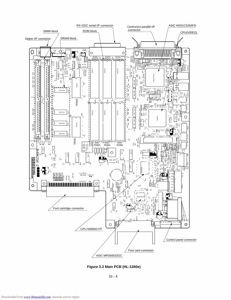
III - 4
1
+
+
#29
#30
C60
C14
C4
C130
R134
C40
RA10 RA9
RA
24
RA
29
C51
RA
22
RA
21
25
24 RA
14
D4
Q19
Q18
Q16
R30
Q13
Q9
H.V
OL
1
MP
C358
Q14
Q11
Q6
SP
1
C31
+
+
D3
RA
28 RA
2340
64
Q3
Q2 C
10
R1
25
X24C
04F
2650 51
DA
1R
A1
100
119
76
A2
RR
A4
RA
3
2 20
P . F
EE
D
PO
WE
RP
4
C2
+
75R156
80
Q7
Q5
L1
Q4
Q15
65
41
M38063F
P
(1)A1
B1(26)
C55
23
21
1C
P1
SP
2R
MV
AD
D
CU
TS
HO
RT
R83,R
85 R
84,R96
2 RO
M8M
X6
C33 P5CARTRIDGE
C39
C65
C77
C64
C86
C76
C67
C85
C66
22
C78
44
27C8000
23C8000
23C8000
23C1600
27C8000
23C8000
23C16000
F245
A25
B25
(25)
C35
CH1
CH2R47
C54
RA25
HM514800
C63
(ODD)
HM514800
HM514800
HM514800
RA27
SLOT1 SLOT2
RA26
GN
DV
CC
F04
RA
41R
A44
RA
30R
A31
1 12 2
LS244
LS244
RA
6
RA
7
RA
8R
A5
R20
LS244
22
W1
+C43
RA
17
C24R13C28
C26C25C23
D1 R8 D2
R17 R15 C29
R12R11R10R7
RA
16 RA
13 RA
15R
A12
RA
114011
BZ
1LS
07
LS00
LS32
LS245
LS245
LS245
RA19 RA18
C45
C42
C34
R34
R49
Q8
R19C30R18R14
R5
R16
R24
R22
R27
R23
FLOCK
GND
GND
+24VRET
+24V
+5V
+5V
HEAT
R37
R33
C48
R48
R60 R59R57
C56R53C52
R35C194
C38R31
C195
RA20R54
R44R50R36
Q12
R3 9R4 1
R21R42R45R25
Q17R32
R28
R29
R4 3C4 4
C200C36
C47
C46
C37C198C197C199
C196
R26
C193C201
R40R38
Q10
R152
R151
R4
R153
C13 C180C179
C183
C181
C184
C178C176
C174
C186C3
C133
C8
C17
+24V
+5B
+5V
+24V
1 PANEL 20
C15+
21
SW
1
2 P1
C19
C18C12
C7C6C5
34
C11
R6
6867
R155
R154
C177C185
C182
C175
MPD65632GC
R3R2
C20C21
C32
R9
C22
C27
Q1
35
12 SP6
IC CARDP2
36
C9
C16
C49R46
C50R51R52R55R56R58
XT15 . 00MHZS
HO
RT
CU
T
FLS
H
W2
W3
W4
21 2122 22
F04
#15
#26
#32
#24
#21
#20
#11
ROM
1L
ROM2L(ODD)
ROM1L(ODD)
ROM0L
ROM1H
CN3
(EVEN )ROM2H
ROM
1H
(EVEN ) (EVEN )ROM 0H
#10
#9
#16
+
(50)
C41
C59C61
C71
C94
C81
RA
34R
A37
RA
40R
A46
F245
RA
43R
A39
RA
36R
A33
C73
C70
A16B16C16
P8OPTION I / O
C80
R70
R69C84
C188
C82R68
Q21
FUSER
SCNMTR
SC
NL S
R
Q22 L5
XT3
XT4
L6
D5R81
C99C104
R106
C118
R112
RA69
C142C150
C143R129R130
C165C160RA78R144
C166
CDCCRS232C
C167C163C159C156
R124R119
19113
25
1
1 2 14
C168
AD
M202JR
NA
DM
202JRN
ALS
1034A
LS1034
23C8000
C147C145C139C137
SP4
R138R131
R123
C146
C138
R122C134C132R117C125C124
C98C119C103
C152
RA65
C121
R135
SP5
C172 R149C171C192 L8
8
2
1
18 7 CN4P15
R148
C170 R147C169R142
R145
SP3
CP5
C136R126
R120C133
R116
R114
C129
C126
C140
R146
C148
23
22
3836
3836
37C102
RA
56R
A60
RA
63R
A67
71 7172 72
+
R139 P
ST
591C
164
RA
77
OP
TIO
N
35
3735
C113
P13P14
C162C158
C161R137C154
C123
RA59
R135C151
C144
208
C117
C114
RA
55
RA
57R
A61
RA
64
RA
70
R121
RA
71R
A68
RA
66
RA
62R
A58
RA
54R
A50
21
222121
22
C100
C101
C95C96C97
22
C111
R118
F245
C131
#34
#17
#18
#19
#31
#35
#39
#38
#33#27
RA
73R
A74
RA
75R
A76
C155
#28
R125
R157 R159 R160 R158 R132
R140 R136 C153
C141
3618
R143R141R150C157
C149R133
+
C128 R113
R128R127
C109RA51 RA52R107
R82
L7
C173R66C75C72
C1
C69
B1A1
C53 C191
R65
C74
C189
C187
C68
C62R64R63R62C58C57R61
7475
C79
C83
RA
45
RA
38C
93R
77R
76R
80R
79R
78
R74 R
71
C92
R73
R72
RA
47
C88
HC
14
(WH
ITE
)(W
HIT
E)
ZD
1Z
D2
Q23
CN
2
Q24
C115
R110
R111
R115C
120
C122
C116
C112
C190
C110
17
L2
R109
R108104
C108
R86
R87
R88
R90
R91
R92
R93
R94
R95
R96
R97
R98 R
83R
84R
85
R89
C107
C106
53R
99R
100C105
RA
48
RA
49
F245
RA
53
R101
R102
R103
R104
R105
HG
51CS
265FD
FA
N
4
13
P12
12.3394MH
Z
RA
42
1
32
R67
4
P10
P9
P6
P7
11
12
45
6Q
20
1211 CH
3RS
T
84
(RE
D)
MT
RP
11
79R3041
33
R75
5453
RA
35R
A32
#23
#13
#5
#2#1
#12#8
#7
#14
#6
#3
P3
#4
#25 #40
#22 +
156157
L4
L3S
P2
CP
1
9.8304MH
Z
C127
44
#37
1
1
1
1
1
1 111
11
#36
01
23
45
67
89
AB
CD
EF
GH
JK
LM
96 97 98
B48K
234 -2
GCMK-C2XR
Figure 3.3 Main PCB (HL-1260e)
Font card connector
CPU M38063 FP
Font cartridge connector
SIMM block
DRAM block Option I/F connector
RS-232C serial I/F connector
ROM block
Centronics parallel I/F connector
ASIC MPD65632GC
CPU(VIDEO)
ASIC HG51CS265FD
Control panel connector
Downloaded from www.Manualslib.com manuals search engine
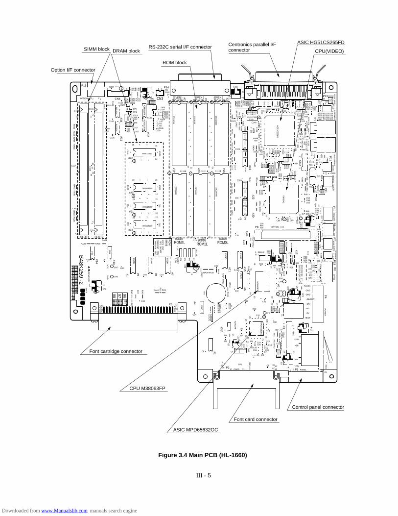
III - 5
1
+
+
#26
#27
C75
C8
C136
C133
C130
C127
+
156157
L7S
P3 X
T4
CP
1
Q24
1P
OW
FA
N9.8304M
HZ
#33
1
1
1
1
1
1 111
1
1
1
1
#32
GC
MK
-C2X
R
C50
RA10 RA9
RA
23
RA
28
C63
C71
C69
C56
C48
C46
RA
21
RA
20
25 24
RA
15
Q14
D5
Q11
Q9
Q7
Q15
Q12
Q10
Q8
H.V
OL
MP
C358
Q6
SP
2
C38
+
+ D3D4
RA
27 RA
2240
64
Q3
Q2
C21
R1
25
X24C
04F
2650 51
DA
1R
A1
100
119
76
A2
RR
A4
RA
3
2 20
P . F
EE
D
PO
WE
RP
4
C3
+
75
R4
80
Q4
L1
Q5
Q13
65
41C
H6
M38063F
P
(1)A1
B1(26)
C68
21
1C
P1
SP
2R
MV
AD
D
CU
TS
HO
RT
R65,R
67 R
66,R78
2 RO
M8M
X6
C40
P5
C49
C79
C93
C78
C104
C95
C82
C103
C125
C126
C94
C83
1528
28 15
14
14
14
28 15
14
15
42
42 42
28
27C8000
23C8000
23C16000
27C8000
23C8000
23C16000
F245
A25
B25
(25)
CH5
CH7 R30
C67
RA24
HM514800
(ODD)
HM514800
HM514800
HM514800
RA26
SLOT1 SLOT2
RA25
GN
D
94V-0
VC
CF
04
RA
40R
A43
RA
29R
A30
12
12
LS244
LS244
RA
6
RA
7
RA
8R
A5
R23
LS244
22
W1
+
C58
RA
17
C34
R17
C37C36C35C33
D2R16 D1R15
R14R13R11
RA
16
SP
7C
P2
RA
14R
A13 R
A12
RA
11
BZ
1LS
07
LS245
LS245
LS245
RA19 RA18
C60
C55
C43
R33
CH3
CH2
R22C39R21R19
R10
R18
FLOCK
GND
GND
+24VRET
+24V
+5V
+5V
HEAT
R26
R27
R28
R31
L2
L3
R29
CH4
C70
R24
R20
R9
R7
R12
C24C20
C23
C19C17
C10C7
C2
C13
C4 C6 C5
C1 33
C16
C28
+24V
+5B
+5V
+24V
1 PANEL 20
C31+
21
SW
1
2 P1
C29
C27C25
C14C12C9
34
C22
R8
6867
R2
R3 C26
C11C15
MP
D65632G
C
R6
R5
CH1C32
C41
Q1
35
12 SP1
IC CARDP236
C18
C30
C66R32 C65
R35R37R39
C64C62
C45 C44
R34
R25
R36R38
R40R41
XT15 . 00MHZ
SH
OR
TC
UT
FLS
H
W2
W3
W4
21 22
F04
#13
#18
#28
#23
#21
#9
ROM2L(ODD)
ROM1L(ODD)
ROM0L
ROM1HCN3 (EVEN )ROM2H(EVEN ) (EVEN )
ROM 0H
#8
#7
#14
(50)
C51
C74C76
C87
C109
C99
RA
33R
A36
RA
39R
A45
F245
RA38
RA42
RA35
RA32
C89
C86
A16B16C16
P8 OPTION I / O
C98
R52
Q20
C102R51
C110
C101R50
FU
SE
RS
CN
MT
RS
CN
L SR
Q21
L4
L5L6
R63C118
C119
C131C134
C113
R96
D7
R107
RA68
C157C153R111R112
C179C180
C181
C176C172C170
R103
R101
19
13 1251
12
14
AD
M202JR
NA
DM
202JRN
ALS
1034A
LS1034
SP5
R122R113
R105
C159
C182
RS232C
C151
R104C 147
C160C155C152C150
C144R 99
C141C139
C117
C165
RA64
C135
C148
SP6
C186 R136C185
C187 L108
2
1
18 7 CN4
P14P15
R135
C184 R134C183R126
C156R109
R133
SP4
CP 5
R102C149
C145
C177
R98R97
C142
C140
R132
C161
3838
3637C
116
RA
55R
A59
RA
62R
A66
7172
7172
R123
PS
T591R
A75
SW
2
OPTION
35
363537
C175C171
C174 R117RA76R131
R121C168
C164
C146
RA58
C154
208C
132C
138
C169
C129
RA
54
RA56
RA60
RA48
RA52
F 245
RA
69
RA
70R106
RA
67
RA
61R
A57
RA
53R
A49
21
42
2221
42
21
22
C114
C115
C111C112C113
22
C128
R100
RA
63
RA
65
#30
#15
#16
#17
#31
#35
#34
#29#24
RA
73R
A 74
R A
71R
A72
#25
R130 R128
C178 C173 R116 C163
R115C162
C158L8
L9CDCC
36
18
R127R125
R114R119
R129R124
C166R118R120
C167
R110R108
C124RA50 RA51R89
R64
R88
C96
R47C92C91C84
C1C85
B1A1
C90 C88
R46
R49
R48
C81
C80
C77R45R44R43C73C72
C61C59
C52 C54C57
C53
C47
R42
7475
C97
C100
RA
44R
A37
C108
R59
R58
R62
R61
R60
R56 R
53
R54
C107
Q18
R55
RA
46 C105
Q19
(WH
ITE
)(W
HIT
E)
ZD
1Z
D2
Q22
CN
2P13
P18
Q23
XT
3
C137
C106
1
1
7105104
D6
R74R
75R
76
R77
R78
R79
R80
R81
R82
R65
R66
R67
R73
R72
R71
R70
R69
R68
R93
R95
R94
R91
R90
R 92
C122
C123
C121C
12053
52
R87
R86
R83
R84
R85
RA
47
F245
HG
51C265F
D
FA
N
P12
16.45253MH
Z
RA
41
32
P10
P7
P9
P6
P19
1
1
12
21
21
415 16
556
Q17
Q16
1211C
H8
RS
T
84
(RE
D)
MT
RS
CN
FA
N
P11
79R3041
33
R57
54
53
RA
34R
A31
#20
#11
#4
#1
#10#6
#2
P3#3
#22
#19
#12
#5
+
01
23
45
67
89
AB
CD
EF
GH
JK
LM
B48K
259 -2
C42
+98 97 96
Figure 3.4 Main PCB (HL-1660)
Option I/F connector
ROM block
Centronics parallel I/Fconnector
Control panel connector
RS-232C serial I/F connector
ASIC MPD65632GC
CPU M38063FP
DRAM blockSIMM block CPU(VIDEO)
Font card connector
Font cartridge connector
ASIC HG51CS265FD
Downloaded from www.Manualslib.com manuals search engine
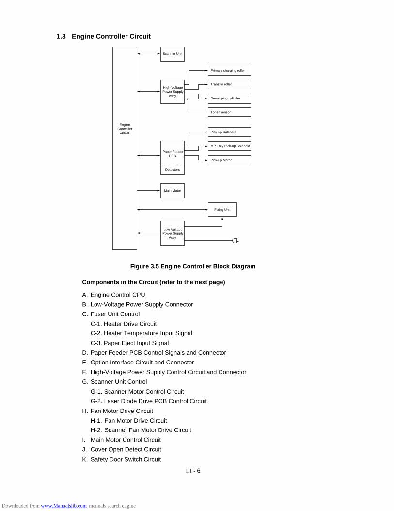
III - 6
1.3 Engine Controller Circuit
EngineController
Circuit
Primary charging roller
MP Tray Pick-up Solenoid
Scanner Unit
High-VoltagePower Supply
Assy
Paper FeederPCB
Detectors
Main Motor
Low-VoltagePower Supply
Assy
Pick-up Motor
Fixing Unit
Transfer roller
Developing cylinder
Toner sensor
Pick-up Solenoid
Figure 3.5 Engine Controller Block Diagram
A. Engine Control CPU
B. Low-Voltage Power Supply Connector
C. Fuser Unit Control
C-1. Heater Drive Circuit
C-2. Heater Temperature Input Signal
C-3. Paper Eject Input Signal
D. Paper Feeder PCB Control Signals and Connector
E. Option Interface Circuit and Connector
F. High-Voltage Power Supply Control Circuit and Connector
G. Scanner Unit Control
G-1. Scanner Motor Control Circuit
G-2. Laser Diode Drive PCB Control Circuit
H. Fan Motor Drive Circuit
H-1. Fan Motor Drive Circuit
H-2. Scanner Fan Motor Drive Circuit
I. Main Motor Control Circuit
J. Cover Open Detect Circuit
K. Safety Door Switch Circuit
Components in the Circuit (refer to the next page)
Downloaded from www.Manualslib.com manuals search engine
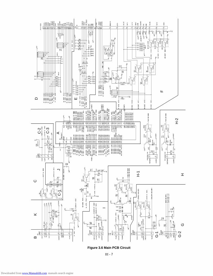
III - 7
Figure 3.6 Main PCB Circuit
AC-2
C-3
C
J
KB
I
H-1
H-2
C-1
HG
G-1
G-2
F
ED
Downloaded from www.Manualslib.com manuals search engine
IV - 1
• Tapping screws
S tight M3 : 7kgf • cm
B tight M3 x 6 : 5kgf • cmM3 x 8 : 7kgf • cm
• Stepped screws
M3 : 7kgf • cmM4 : 10kgf • cm
Safety Precautions
(9) When connecting or disconnecting cable connectors, hold the connector bodies not thecables. If the connector has a lock, always slide the connector lock to unlock it.
(10) After repairs, check not only the repaired portion but also that the connectors and otherrelated portions function properly before operation checks.
Notes
• On the next page is a disassembly order flow which helps you access the object
component.
• Unless otherwise specified, the disassembled parts or components should be
reassembled in the reverse order of removal.
To prevent the creation of secondary problems by mishandling, observe the following precau-tions during maintenance work.
(1) Always turn off the power before replacing parts or units. When having access to the powersupply, be sure to unplug the power cord form the power outlet.
(2) Be careful not to lose screws, washers, or other parts removed for parts replacement.
(3) Be sure to apply grease to the teeth of gears.
(4) When using soldering irons and other heat-generating tools, take care not to damage theresin parts such as wires, PCBs, and covers.
(5) Before handling the PCBs, touch a metal portion of the equipment to discharge staticelectricity, or the electronic parts may be damaged due to the electricity charged in yourbody.
(6) When transporting PCBs, be sure to wrap them in conductive sheets such as aluminumfoil.
(7) Be sure to reinsert self-tapping screws correctly, if removed.
(8) Unless otherwise specified, tighten screws to the torque values listed below.
CHAPTER IV MECHANICAL SYSTEM
Downloaded from www.Manualslib.com manuals search engine

IV - 2
PRINTER DISASSEMBLING PROCEDURE
1.2 Toner Cartridge Lid
(1) Remove the toner cartridge lid from the upper cover.
1.7 DC Fan Motor
(1) Remove the DC fan motor from the DC fan motor holder by loosening the two screws.
(2) Loosen the screws securing the PCB holder and remove the entire DC fan motor holder.
(3) Remove the fan harness connector from the main PCB assy.
Figure 4.1
Open the tonercartridge lid
Toner cartridge lid
Upper cover assy
Screw
Figure 4.2
2 screws
DC fan motor
Core
Fan connector
Holder spacer
DC fan holder
Downloaded from www.Manualslib.com manuals search engine
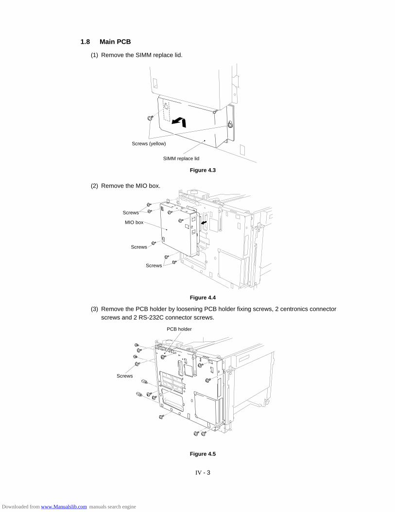
IV - 3
Figure 4.3
1.8 Main PCB
(1) Remove the SIMM replace lid.
Screws (yellow)
SIMM replace lid
(2) Remove the MIO box.
Figure 4.4
(3) Remove the PCB holder by loosening PCB holder fixing screws, 2 centronics connectorscrews and 2 RS-232C connector screws.
PCB holder
Screws
Figure 4.5
MIO box
Screws
Screws
Screws
Downloaded from www.Manualslib.com manuals search engine

IV - 4
Figure 4.6
(6) Remove the main PCB assy.
Figure 4.7
Main PCB assy
7 screws
(4) Remove the switch flat cable 21P and the feed flat cable 20P.
(5) Remove the fan harness 3P, the fuser harness 4P, the Polygon harness 5P, the SCN flatcable 6P, the DC motor harness 4P, the SCN fan harness 2P, the HV harness 16P andthe LV harness 8P.
DC motor harness 4P
Polygon harness 5P
Switch flat cable 21P
SCN flat cable 6P
Fuser harness 4P
Fan harness 3P
SCN fan harness 2PHV harness 16P
LV harness 8P
Feed flat cable 20P
Downloaded from www.Manualslib.com manuals search engine
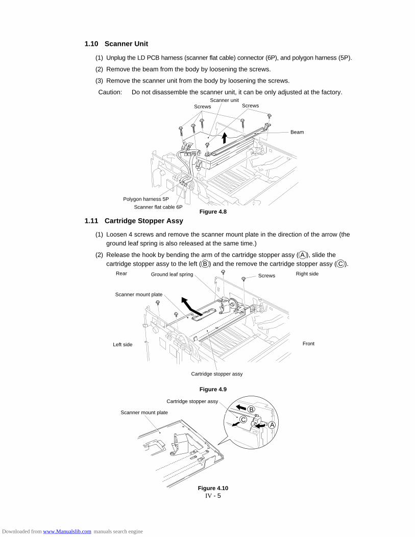
IV - 5
1.10 Scanner Unit
(1) Unplug the LD PCB harness (scanner flat cable) connector (6P), and polygon harness (5P).
(2) Remove the beam from the body by loosening the screws.
(3) Remove the scanner unit from the body by loosening the screws.
Caution: Do not disassemble the scanner unit, it can be only adjusted at the factory.
Left side
Rear
Figure 4.10
Right side
Front
Scanner mount plate
Cartridge stopper assy
C
B
A
Figure 4.9
Cartridge stopper assy
Scanner mount plate
Ground leaf spring Screws
1.11 Cartridge Stopper Assy
(1) Loosen 4 screws and remove the scanner mount plate in the direction of the arrow (theground leaf spring is also released at the same time.)
(2) Release the hook by bending the arm of the cartridge stopper assy ( A ), slide thecartridge stopper assy to the left ( B ) and the remove the cartridge stopper assy ( C ).
Figure 4.8
Polygon harness 5P
Screws Screws
Beam
Scanner unit
Scanner flat cable 6P
Downloaded from www.Manualslib.com manuals search engine
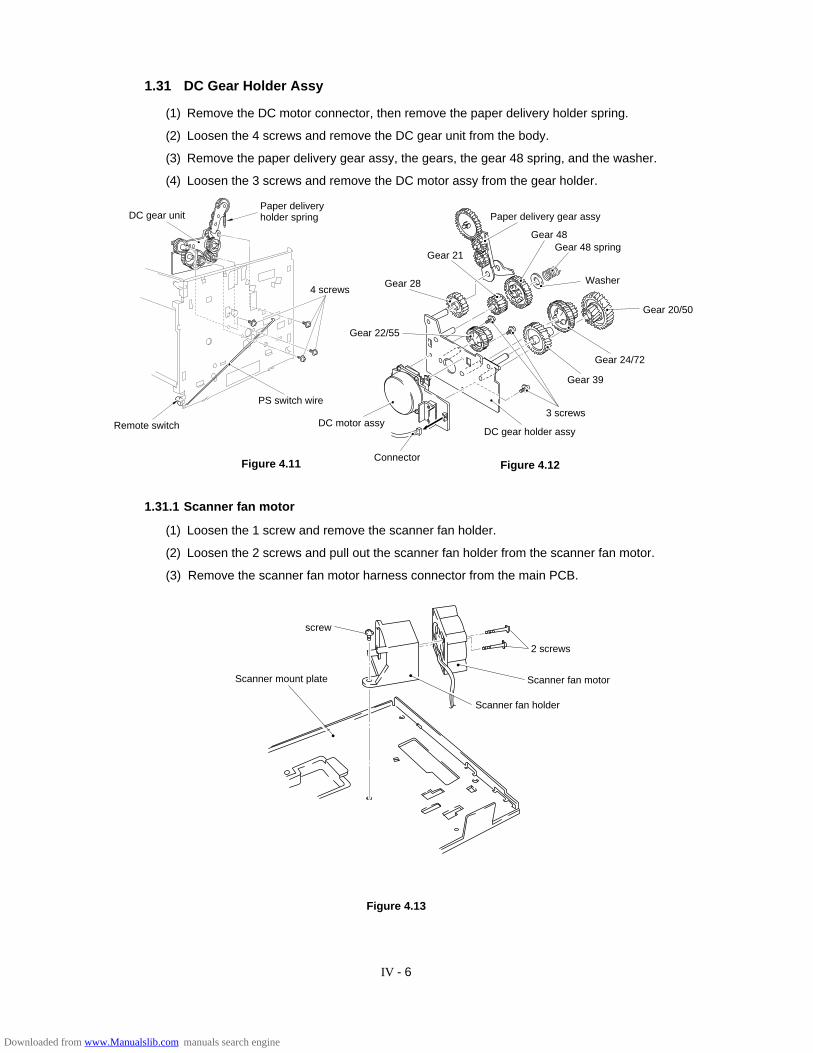
IV - 6
1.31 DC Gear Holder Assy
(1) Remove the DC motor connector, then remove the paper delivery holder spring.
(2) Loosen the 4 screws and remove the DC gear unit from the body.
(3) Remove the paper delivery gear assy, the gears, the gear 48 spring, and the washer.
(4) Loosen the 3 screws and remove the DC motor assy from the gear holder.
Figure 4.11 Figure 4.12
Paper deliveryholder springDC gear unit
PS switch wire
Remote switch
Gear 48Gear 48 spring
Gear 24/72
Gear 20/50
Gear 39
3 screws
DC gear holder assy
Gear 22/55
Gear 28
Connector
DC motor assy
Gear 21
Paper delivery gear assy
Washer4 screws
1.31.1 Scanner fan motor
(1) Loosen the 1 screw and remove the scanner fan holder.
(2) Loosen the 2 screws and pull out the scanner fan holder from the scanner fan motor.
(3) Remove the scanner fan motor harness connector from the main PCB.
screw
2 screws
Scanner fan motor
Scanner fan holder
Scanner mount plate
Figure 4.13
Downloaded from www.Manualslib.com manuals search engine
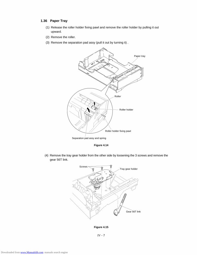
IV - 7
1.36 Paper Tray
(1) Release the roller holder fixing pawl and remove the roller holder by pulling it outupward.
(2) Remove the roller.
(3) Remove the separation pad assy (pull it out by turning it) .
Separation pad assy and spring
Roller holder fixing pawl
Paper tray
Roller holder
Roller
Figure 4.14
Figure 4.15
ScrewsTray gear holder
Gear 56T link
(4) Remove the tray gear holder from the other side by loosening the 3 screws and remove thegear 56T link.
Downloaded from www.Manualslib.com manuals search engine
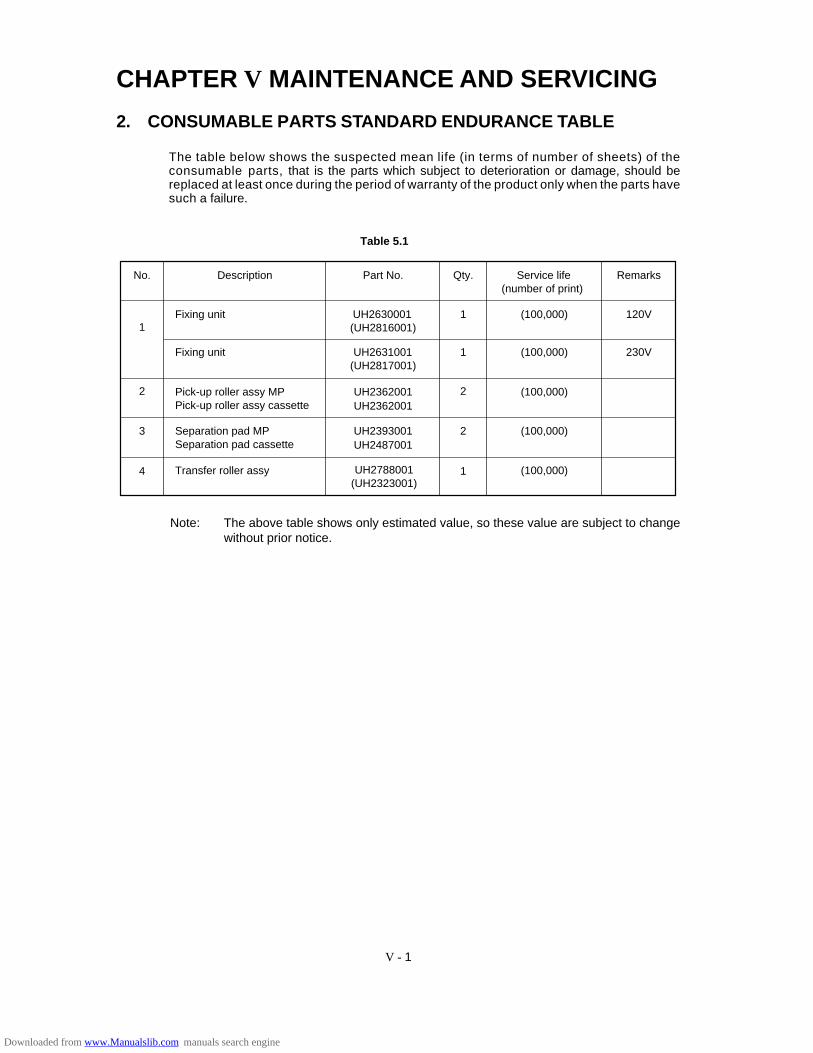
CHAPTER V MAINTENANCE AND SERVICING
2. CONSUMABLE PARTS STANDARD ENDURANCE TABLE
The table below shows the suspected mean life (in terms of number of sheets) of theconsumable parts, that is the parts which subject to deterioration or damage, should bereplaced at least once during the period of warranty of the product only when the parts havesuch a failure.
Table 5.1
No. Description Part No. Qty. Remarks
1
2
3
4
2
2
1
1
1Fixing unit UH2630001(UH2816001)
(100,000) 120V
Fixing unit UH2631001(UH2817001)
(100,000) 230V
Pick-up roller assy MP Pick-up roller assy cassette
UH2362001 (100,000)UH2362001
Separation pad MPSeparation pad cassette
UH2393001 (100,000)
Transfer roller assy UH2788001 (100,000)
UH2487001
Service life(number of print)
(UH2323001)
Note: The above table shows only estimated value, so these value are subject to changewithout prior notice.
V - 1
Downloaded from www.Manualslib.com manuals search engine
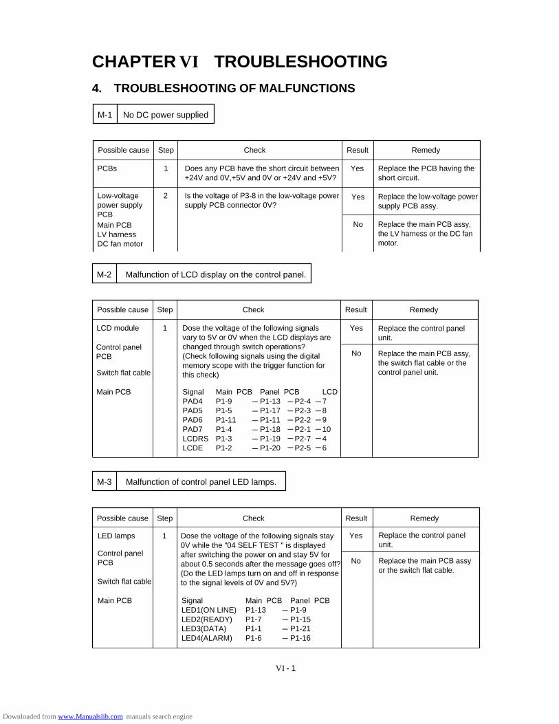
VI - 1
CHAPTER VI TROUBLESHOOTING4. TROUBLESHOOTING OF MALFUNCTIONS
Is the voltage of P3-8 in the low-voltage powersupply PCB connector 0V?
Possible cause Step Check Result Remedy
PCBs 1 Does any PCB have the short circuit between +24V and 0V,+5V and 0V or +24V and +5V?
Yes Replace the PCB having the short circuit.
Low-voltagepower supplyPCBMain PCBLV harnessDC fan motor
2 Yes Replace the low-voltage power supply PCB assy.
No Replace the main PCB assy,the LV harness or the DC fan motor.
No DC power suppliedM-1
Possible cause Step Check Result Remedy
LCD module 1 Yes
No Replace the main PCB assy,the switch flat cable or the control panel unit.
Malfunction of LCD display on the control panel.M-2
Dose the voltage of the following signals vary to 5V or 0V when the LCD displays are changed through switch operations?(Check following signals using the digital memory scope with the trigger function forthis check)
Control panelPCB
Switch flat cable
Main PCB Signal PAD4PAD5PAD6PAD7LCDRSLCDE
Main PCBP1-9P1-5 P1-11P1-4P1-3P1-2
Panel PCBP1-13P1-17P1-11P1-18P1-19P1-20
P2-4P2-3P2-2P2-1P2-7P2-5
Replace the control panelunit.
------------------
------------------
LCD7891046
------------------
Malfunction of control panel LED lamps.M-3
Possible cause Step Check Result Remedy
LED lamps Dose the voltage of the following signals stay 0V while the "04 SELF TEST " is displayed after switching the power on and stay 5V for about 0.5 seconds after the message goes off? (Do the LED lamps turn on and off in responseto the signal levels of 0V and 5V?)
1
Control panel PCB
Switch flat cable
Main PCB SignalLED1(ON LINE)LED2(READY)LED3(DATA)LED4(ALARM)
Main PCBP1-13P1-7P1-1P1-6
Panel PCBP1-9P1-15P1-21P1-16
Yes
No
Replace the control panelunit.
------------
Replace the main PCB assyor the switch flat cable.
Downloaded from www.Manualslib.com manuals search engine

VI - 2
Does the upper cover hook press the actuator of the interlock switch on the main PCBcorrectly when upper cover is closed?
Possible cause Step Check Result Remedy
Upper cover 1 No Replace the upper cover assy.
"12 COVER OPEN" is displayed even if the upper cover is closedM-6
Yes Replace the main PCB assy.Main PCB
Possible cause Step Check Result Remedy
1
Control panel PCB
Switch flat cable
Main PCB
Yes
No
Replace the Main PCB assy.
Mis-operation Are the switchs operated according to the operation manual?
Operate the switches correctly following theoperation manual.
Switch 2 When a switch is pressed,does the voltage ofthe following signals change from 5V to 0V?
SignalSW8(SEL)SW7(MODE/EMULATION)SW6(FONT/ECONOMY)SW5(FORM FEED/FEEDER)SW4(SET/COPY)SW3(CONTINUE/SHIFT)SW2(DOWN/RESET)SW1(UP/TEST)
Main PCBP1-8P1-10P1-12P1-14P1-16P1-18P1-20P1-21
------------
Panel PCBP1-14P1-12P1-10P1-8P1-6P1-4P1-2P1-1
------------
No Replace the control panelunit or the switch flat cable.
Malfunction of control panel switches.M-4
Is the "Buzzer on mode "selected according to the operation manual?(To alternate the buzzer on/off mode selection,press the MODE switch and select the "Advanced mode".)
Check the buzzer signal with a oscilloscope.Is the pulse of 4KHz output?
Possible cause Step Check Result Remedy
Operationalerror
1 No Set the buzzer on mode.
2
No Replace the main PCB assy.
Malfunction of buzzerM-5
Yes Replace the main PCB assy.Main PCB
Buzzer
Downloaded from www.Manualslib.com manuals search engine
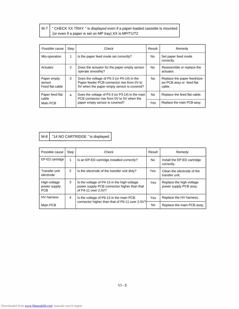
VI - 3
Is the paper feed mode set correctly?
Possible cause Step Check Result Remedy
Mis-operation 1 No Set paper feed mode correctly.
2
No Replace the feed flat cable.
" CHECK XX TRAY " is displayed even if a paper-loaded cassette is mountedM-7
Yes Replace the main PCB assy.Main PCB
Actuator Does the actuator for the paper empty sensoroperate smoothly?
Reassemble or replace theactuator.
No
Paper empty sensor Feed flat cable
Does the voltage of P5-3 (or P5-14) in the Paper feeder PCB connector rise from 0V to 5V when the paper empty sensor is covered?
3 No Replace the paper feed/size-sw PCB assy or feed flat cable .
Paper feed flat cable
Does the voltage of P3-3 (or P3-14) in the main PCB connector rise from 0V to 5V when the paper empty sensor is covered?
(or even if a paper is set on MP tray) XX is MP/T1/T2
4
Yes
Possible cause Step Check Result Remedy
1 No
2 Yes
3 Yes
4
No
M-8 "14 NO CARTRIDGE " is displayed
EP-ED cartridge Is an EP-ED cartridge installed correctly? Install the EP-ED cartridge correctly.
Clean the electrode of thetransfer unit.
Is the electrode of the transfer unit dirty? Transfer unit electrode
High-voltagepower supplyPCB
Is the voltage of P4-13 in the high-voltage power supply PCB connector higher than that of P4-11 over 2.5V?
Is the voltage of P6-13 in the main PCB connector higher than that of P6-11 over 2.5V?
HV harness
Main PCB
Replace the high-voltagepower supply PCB assy.
Replace the HV harness.
Replace the main PCB assy.
Downloaded from www.Manualslib.com manuals search engine

VI - 4
Possible cause Step Check Result Remedy
EP-ED cartridge 1 Take the EP-ED cartridge out of the printer and rock it to distribute the toner evenly. When the cartridge is returned to the printer,does the LCD show "00 READY"?
Yes The problem was caused bytoner onesided due to toolittle toner remaining.Prepare to replace the newcartridge.
High-voltageelectrode
2 Are the developing bias or the toner sensorelectrode of the high-voltage power supply PCBassy dirty?
Yes Clean the electrode.
High-voltagepower supplyPCB
3 Is the voltage of P4-13 in high-voltage power supply PCB connector higher than that of P4-11, when the EP-ED cartridge which is full with toneris installed?
Yes Replace the high-voltage power supply PCB assy.
HV harness 4 Is the voltage of P6-13 in the main PCB connector higher than that of P6-11?
Yes Replace the HV harness.
Replace the main PCB assy.NoMain PCB
M-9 "16 TONER EMPTY " is displayed
Possible cause Step Check Result Remedy
Actuator 1 Does the actuator of the paper delivery sensoror the registration sensor operate smoothly?
No Reassemble or replace thepaper delivery actuator and regist sensor actuator.
Fuser harnessFeed flat cable
3 Does the voltage of P11-1 in the main PCB connector rise from 0V to 5V when the ejectsensor is covered, or the voltage of P3-5 inthe main PCB connector rise from 0V to 5V?
No Replace the fuser harnessor the feed flat cable.
Replace the main PCB assy.Yes
2 Does the voltage of P2-1 in the fixing PCB connector rise from 0V to 5V when the ejectsensor is covered, or the voltage of P5-5 inthe paper feeder PCB connector rise from 0V to 5V when the registration sensor is covered?
No Replace the fixing PCB assyor the paper feed/size-sw PCBassy.
Paper deliverysensor Regist sensor
"13 JAM XXXXXX" is not displayed even if a paper jam has occured(or is displayed even if a paper jam has not occurred) XXXXXX is TRAYS/INSIDE/REAR/DUPLEX.
M-10
Downloaded from www.Manualslib.com manuals search engine

VI - 5
Possible cause Step Check Result Remedy
Low-voltage powersupply PCBLV harnessMain PCB
1 Is the voltage of P7-1 in the main PCBconnector +24V?
No Replace the main PCB assy low-voltage power supply PCBassy, or the LV harness.
DC motor harness DC motor assy.
2 Does the voltage of P7-4 in the main PCBconnector drop from 5V to 0V after droppingthe voltage of P7-3 from 5V to 0V?
No Replace the main PCB assy.
"54 MOTOR MALF" is displayed (The main motor rotation disabled)M-11
Yes Replace the DC motor harness or the DC motor assy.
Possible cause Step Check Result Remedy
Mis-operation 1 Is the paper feed mode set correctly? No Set paper feed mode correctly.
Main PCB 2 Does the voltage of P3-20 (or 19) in the main PCB connector rise from 0V to 5V and is apulses having about 11ms period generated at P3-6, 7, 8 ,9 pin?
No Replace the main PCB assy.
No paper pick-up from cassette (or MP tray)M-12
Feed flat cable 3 Does the voltage of P5-20 (or 19) in the paperfeeder PCB. Connector rise from 0V to 5V and is the pulses having about 11ms periodgenerated at P3-6, 7, 8 ,9 pin?
No Replace the feed flat cable.
Paper feederPCB
4 Does the voltage of P3-1 (or P4-1) in the paper feeder PCB connector drop from 24V to 0V and is the chopping pulses generated at P1-1, 2, 5 ,6 pin?
No Replace the Paper feed/size-SW PCB assy.
Pick-up(or MPPick) solenoid
5 Does the pick-up (or MP Pick) solenoid operate?
No Replace the pick-up (or MPPick) solenoid.
Paper feed motor 6 Does the pick-up motor rotate? No Replace the paper feed motor assy.
Downloaded from www.Manualslib.com manuals search engine

VI - 6
Possible cause Step Check Result Remedy
Main PCB 1 When a test print is carried out, is the voltageof the each pin in the main PCB connectorP6 turned on and off as the below list?
No Replace the main PCB assy.
HV harness 2 Is the voltage of the each pin of the high-voltage power supply PCB connector P4 turned on and off?
No Replace the HV harness.
M-13
Yes Replace the high-voltage power supply PCB assy.
"55 HIGH VOL MALF" is displayed (Faulty output from the H.V.P.S. ASSY)
High-voltage power supply PCB
Pin No. Signal name Voltage (reference
value)
Remarks
/HV1AC 0V5.8V
/HV1DC 0V8.6V
/DBAC 0V6.3V
/DBDC 0V8.6V
DNSTY 1.0 ~ 4.0V
/HVT1 0V
8.7V
/HVT2 0V
15.1V
/HVT3 0V
9.0V
HVT4 0.4 ~ 5.0V
HVTFB 0.4 ~ 4.0V
TONER1 0.0 ~ 3.5V
0V 0V
TONER2 2.0 ~ 4.5V
24VRET 0V
5V 5V
24V 24V
1
2
3
4
5
6
7
8
9
10
11
13
12
14
15
16
Default: 2.5V
Downloaded from www.Manualslib.com manuals search engine
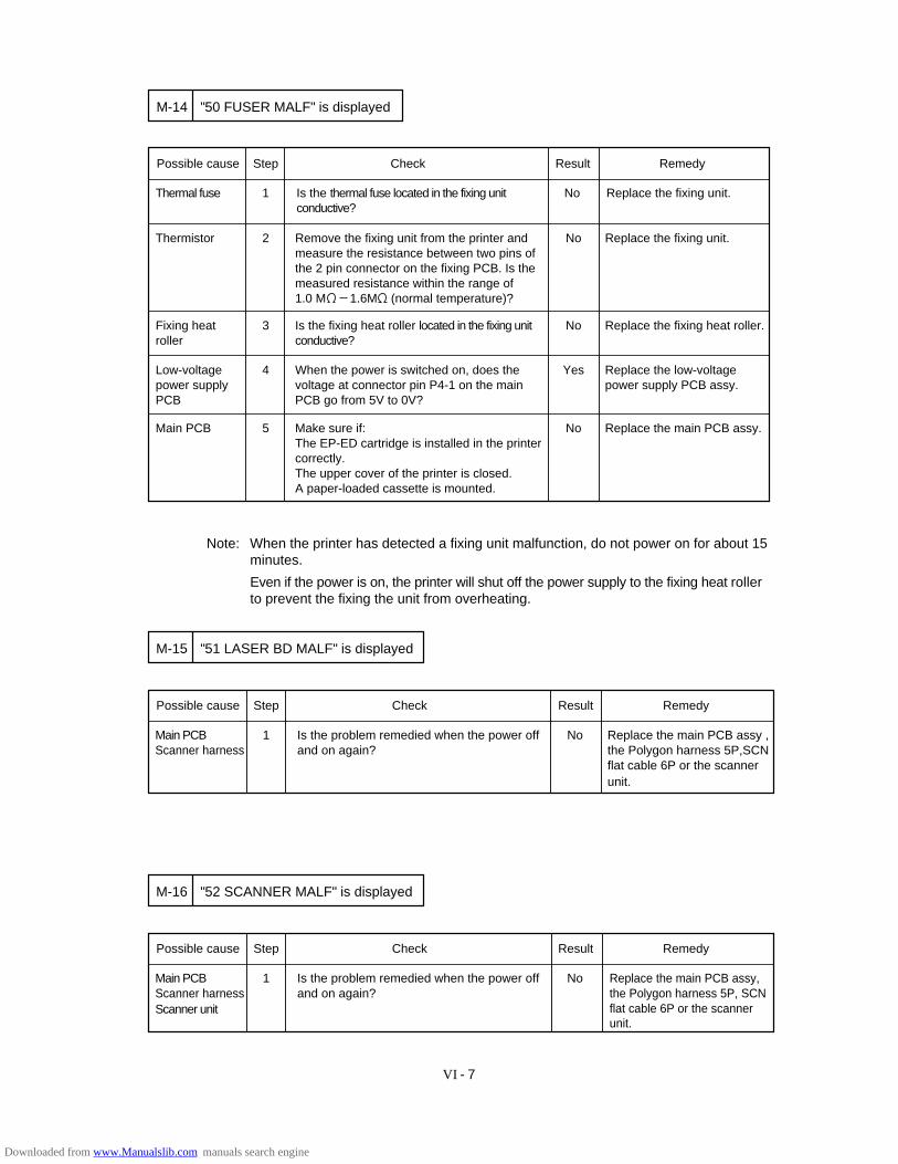
VI - 7
Possible cause Step Check Result Remedy
Thermal fuse 1 Is the thermal fuse located in the fixing unit conductive?
No Replace the fixing unit.
Thermistor 2 Remove the fixing unit from the printer andmeasure the resistance between two pins ofthe 2 pin connector on the fixing PCB. Is themeasured resistance within the range of1.0 M 1.6M (normal temperature)?
No Replace the fixing unit.
"50 FUSER MALF" is displayedM-14
Fixing heat roller
3 Is the fixing heat roller located in the fixing unit conductive?
No Replace the fixing heat roller.
Low-voltagepower supplyPCB
4 When the power is switched on, does thevoltage at connector pin P4-1 on the main PCB go from 5V to 0V?
Yes Replace the low-voltagepower supply PCB assy.
Main PCB 5 Make sure if:The EP-ED cartridge is installed in the printercorrectly.The upper cover of the printer is closed.A paper-loaded cassette is mounted.
No Replace the main PCB assy.
Note: When the printer has detected a fixing unit malfunction, do not power on for about 15minutes.
Even if the power is on, the printer will shut off the power supply to the fixing heat rollerto prevent the fixing the unit from overheating.
Replace the main PCB assy , the Polygon harness 5P,SCN flat cable 6P or the scanner unit.
Possible cause Step Check Result Remedy
Main PCBScanner harness
1 Is the problem remedied when the power offand on again?
No
"51 LASER BD MALF" is displayedM-15
Replace the main PCB assy,the Polygon harness 5P, SCN flat cable 6P or the scanner unit.
Possible cause Step Check Result Remedy
Main PCBScanner harness
1 Is the problem remedied when the power offand on again?
No
"52 SCANNER MALF" is displayedM-16
Scanner unit
Downloaded from www.Manualslib.com manuals search engine
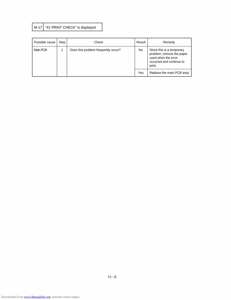
VI - 8
Since this is a temporaryproblem, remove the paperused when the error occurred and continue to print.
Possible cause Step Check Result Remedy
Main PCB 1 Does this problem frequently occur? No
"41 PRINT CHECK" is displayedM-17
Replace the main PCB assy.Yes
Downloaded from www.Manualslib.com manuals search engine

VI - 9
7. STATUS MESSAGE LIST
The paper cassette (XX isMP/T1/T2) is out of paper.
The upper cover of theprinter is open.
Paper is jammed in theprinter. XXXXXX is TRAYS/INSIDE/REAR/DUPLEX.
The toner cartridge is notinstalled in the printer.
The paper cassette is notinstalled. XX is T1/T2.
The printer has almost runout of toner: you may printanother 30 to 100 pages.(The ALARM lamp lights atthe same time.)
The wrong size of paper wasloaded in the paper cassetteXX. XX is MP/ T1/T2. (Themessage appears alternatelyto show a particular size.)
The printer requests you toload paper manually. (Themessage appears alternatelyto show a particular size.)
An error occurred in theoptional font cartridge/card.
The font cartridge/card wasremoved while the printer ison-line.
The duplex unit is notinstalled with the printerwhen the duplex printingmode is selected.
The duplex paper guide trayis not installed in T1 whenthe duplex printing mode isselected.
The cover of the duplex unitis open.
Operator Call Message
CHECK XX TRAY
12 COVER OPEN
13 JAM XXXXXX
14 NO CARTRIDGE
XX NO CASSETTE
16 TONER EMPTY
XX LOAD PAPER *****SIZE
18 MANUAL FEED *****SIZE
19 CHECK FONT
20 FONT REMOVAL
27 NO DX UNIT
27 NO DX TRAY
27 DX OPEN
Meaning
Load a stack of paper intothe cassette. See M-7.
Close the cover. See M-6.
Remove the jammed paperfrom the indicated area. SeeM-10.
Install a toner cartridge. SeeM-8.
Install the paper cassette.
Remove the toner cartridge,rock it several times at 45°,and install it again. Orreplace the toner cartridgewith a new one. See M-9.
Load the requested size ofpaper in the paper cassette,or load it on the manual feedtray and press the FORMFEED switch.
Load the requested size ofpaper on the multi-purposetray and press the SELswitch.
Turn off the printer, andreinstall or replace theoptional font cartridge/card.
Turn off the printer, installthe font cartridge/card, andturn on the printer. TheCONTINUE switch will allowyou to temporarily ignore thismessage.
Install the duplex unitcorrectly.See the DX-1200/DX-1600 user’s guides.
Install the duplex paper guidetray into T1. See the DX-1200/DX-1600 user’s guides.
Close the cover. See the DX-1200/DX-1600 user’sguides.
Action
Table 6.1 Operator Call Messages
Downloaded from www.Manualslib.com manuals search engine
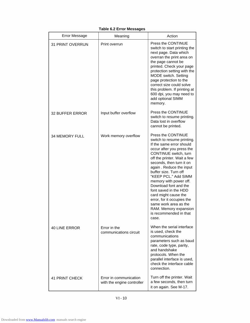
VI - 10
Table 6.2 Error Messages
Error Message Meaning Action
Press the CONTINUEswitch to start printing thenext page. Data whichoverran the print area onthe page cannot beprinted. Check your pageprotection setting with theMODE switch. Settingpage protection to thecorrect size could solvethis problem. If printing at600 dpi, you may need toadd optional SIMMmemory.
Press the CONTINUEswitch to resume printing.Data lost in overflowcannot be printed.
Press the CONTINUEswitch to resume printing.If the same error shouldoccur after you press theCONTINUE switch, turnoff the printer. Wait a fewseconds, then turn it onagain . Reduce the inputbuffer size. Turn off”KEEP PCL.” Add SIMMmemory with power off.Download font and thefont saved in the HDDcard might cause theerror, for it occupies thesame work area as theRAM. Memory expansionis recommended in thatcase.
When the serial interfaceis used, check thecommunicationsparameters such as baudrate, code type, parity,and handshakeprotocols. When theparallel interface is used,check the interface cableconnection.
Turn off the printer. Waita few seconds, then turnit on again. See M-17.
Print overrun
Input buffer overflow
Work memory overflow
Error in thecommunications circuit
Error in communicationwith the engine controller
31 PRINT OVERRUN
32 BUFFER ERROR
34 MEMORY FULL
40 LINE ERROR
41 PRINT CHECK
Downloaded from www.Manualslib.com manuals search engine
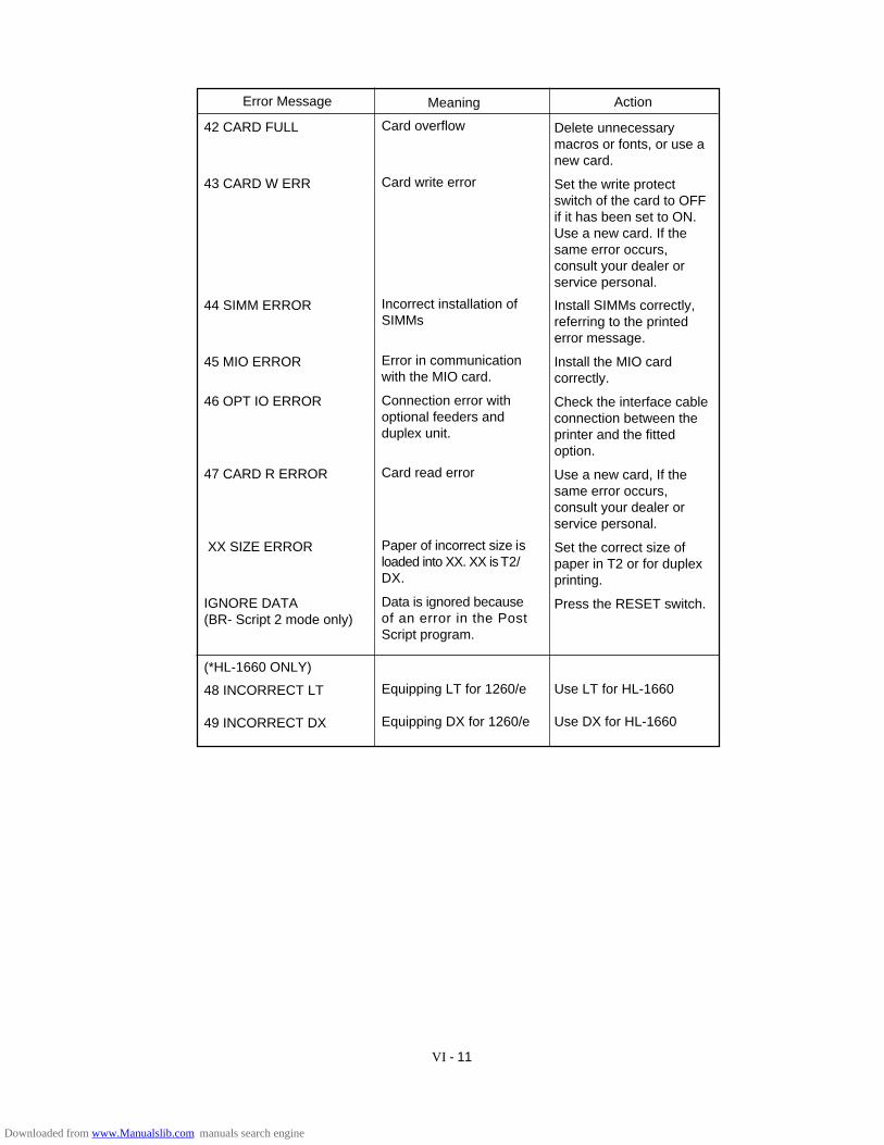
VI - 11
Error Message Meaning Action
42 CARD FULL
43 CARD W ERR
44 SIMM ERROR
45 MIO ERROR
46 OPT IO ERROR
47 CARD R ERROR
XX SIZE ERROR
IGNORE DATA(BR- Script 2 mode only)
(*HL-1660 ONLY)
48 INCORRECT LT
49 INCORRECT DX
Delete unnecessarymacros or fonts, or use anew card.
Set the write protectswitch of the card to OFFif it has been set to ON.Use a new card. If thesame error occurs,consult your dealer orservice personal.
Install SIMMs correctly,referring to the printederror message.
Install the MIO cardcorrectly.
Check the interface cableconnection between theprinter and the fittedoption.
Use a new card, If thesame error occurs,consult your dealer orservice personal.
Set the correct size ofpaper in T2 or for duplexprinting.
Press the RESET switch.
Use LT for HL-1660
Use DX for HL-1660
Card overflow
Card write error
Incorrect installation ofSIMMs
Error in communicationwith the MIO card.
Connection error withoptional feeders andduplex unit.
Card read error
Paper of incorrect size isloaded into XX. XX is T2/DX.
Data is ignored becauseof an error in the PostScript program.
Equipping LT for 1260/e
Equipping DX for 1260/e
Downloaded from www.Manualslib.com manuals search engine
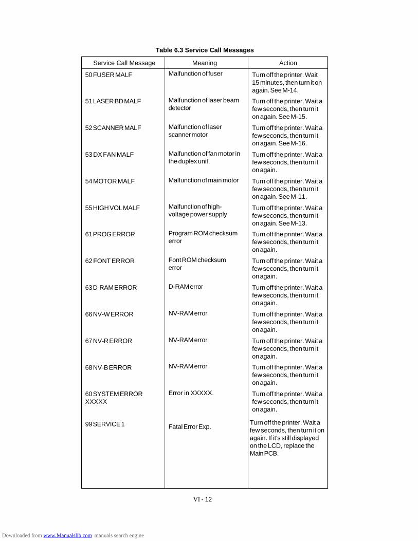
VI - 12
Table 6.3 Service Call Messages
MeaningService Call Message Action
Turn off the printer. Wait15 minutes, then turn it onagain. See M-14.
Turn off the printer. Wait afew seconds, then turn iton again. See M-15.
Turn off the printer. Wait afew seconds, then turn iton again. See M-16.
Turn off the printer. Wait afew seconds, then turn iton again.
Turn off the printer. Wait afew seconds, then turn iton again. See M-11.
Turn off the printer. Wait afew seconds, then turn iton again. See M-13.
Turn off the printer. Wait afew seconds, then turn iton again.
Turn off the printer. Wait afew seconds, then turn iton again.
Turn off the printer. Wait afew seconds, then turn iton again.
Turn off the printer. Wait afew seconds, then turn iton again.
Turn off the printer. Wait afew seconds, then turn iton again.
Turn off the printer. Wait afew seconds, then turn iton again.
Turn off the printer. Wait afew seconds, then turn iton again.
Malfunction of fuser
Malfunction of laser beamdetector
Malfunction of laserscanner motor
Malfunction of fan motor inthe duplex unit.
Malfunction of main motor
Malfunction of high-voltage power supply
Program ROM checksumerror
Font ROM checksumerror
D-RAM error
NV-RAM error
NV-RAM error
NV-RAM error
Error in XXXXX.
Fatal Error Exp.
50 FUSER MALF
51 LASER BD MALF
52 SCANNER MALF
53 DX FAN MALF
54 MOTOR MALF
55 HIGH VOL MALF
61 PROG ERROR
62 FONT ERROR
63 D-RAM ERROR
66 NV-W ERROR
67 NV-R ERROR
68 NV-B ERROR
60 SYSTEM ERRORXXXXX
99 SERVICE 1 Turn off the printer. Wait afew seconds, then turn it onagain. If it's still displayedon the LCD, replace theMain PCB.
Downloaded from www.Manualslib.com manuals search engine

VI - 13
Service Call Message Meaning Action
99 SERVICE 2 Address Error (L) Turn off the printer. Wait afew seconds, then turn it onagain. If it's still displayedon the LCD, replace theMain PCB.
99 SERVICE 3 Address Error (S) Turn off the printer. Wait afew seconds, then turn it onagain. If it's still displayedon the LCD, replace theMain PCB.
99 SERVICE 4 Bus (I) Error Turn off the printer. Wait afew seconds, then turn it onagain. If it's still displayedon the LCD, replace theMain PCB.
99 SERVICE 5 Bus (D) Error Turn off the printer. Wait afew seconds, then turn it onagain. If it's still displayedon the LCD, replace theMain PCB.
99 SERVICE 6 Syscall Exp. Turn off the printer. Wait afew seconds, then turn it onagain. If it's still displayedon the LCD, replace theMain PCB.
Turn off the printer. Wait afew seconds, then turn it onagain. If it's still displayedon the LCD, replace theMain PCB.
Turn off the printer. Wait afew seconds, then turn it onagain. If it's still displayedon the LCD, replace theMain PCB.
Turn off the printer. Wait afew seconds, then turn it onagain. If it's still displayedon the LCD, replace theMain PCB.
Turn off the printer. Wait afew seconds, then turn it onagain. If it's still displayedon the LCD, replace theMain PCB.
Turn off the printer. Wait afew seconds, then turn it onagain. If it's still displayedon the LCD, replace theMain PCB.
Breakpoint Exp.
Reserved Ins.
Copro. Unusable
Overflow Exp.
Undefined Intrpt
99 SERVICE 7
99 SERVICE 8
99 SERVICE 9
99 SERVICE 10
99 SERVICE 11
Downloaded from www.Manualslib.com manuals search engine
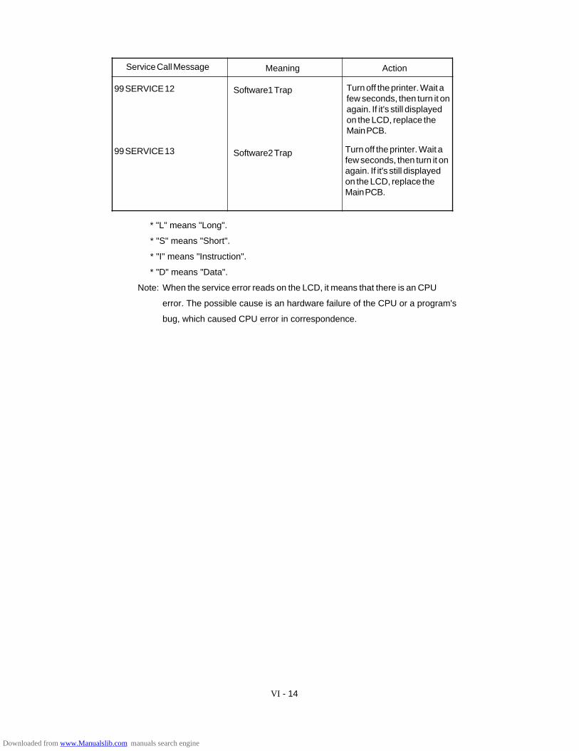
Service Call Message Meaning Action
Turn off the printer. Wait afew seconds, then turn it onagain. If it's still displayedon the LCD, replace theMain PCB.
Turn off the printer. Wait afew seconds, then turn it onagain. If it's still displayedon the LCD, replace theMain PCB.
99 SERVICE 12
99 SERVICE 13
Software1 Trap
Software2 Trap
* "L" means "Long".
* "S" means "Short".
* "I" means "Instruction".
* "D" means "Data".
Note: When the service error reads on the LCD, it means that there is an CPU
error. The possible cause is an hardware failure of the CPU or a program's
bug, which caused CPU error in correspondence.
VI - 14
Downloaded from www.Manualslib.com manuals search engine
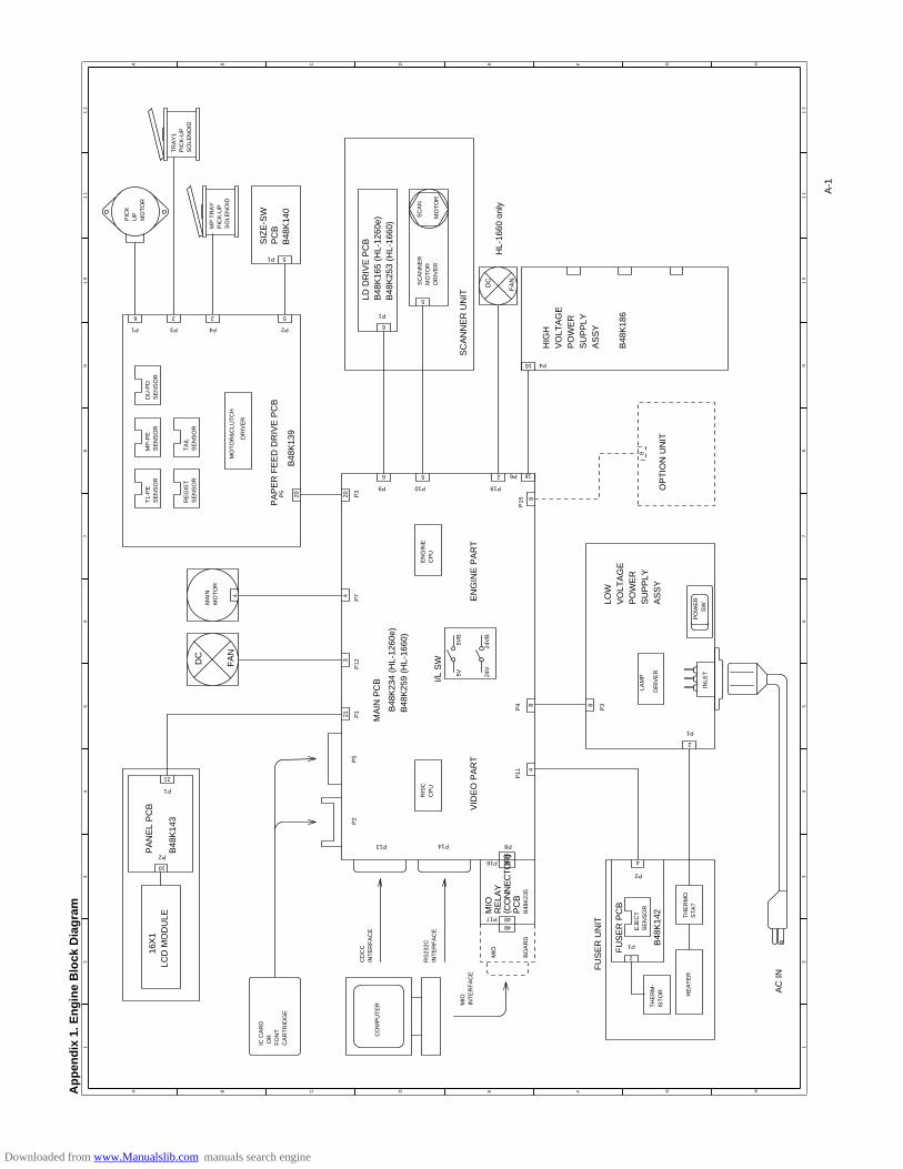
12
34
56
78
91
01
11
2
12
34
56
78
91
01
11
2
A B C E F G H
A B C D E F G H
DAp
pen
dix
1. E
ng
ine
Blo
ck D
iag
ram
SIZ
E-S
W
FA
N
DC
PC
B
B48
K14
0 P
AP
ER
FE
ED
DR
IVE
PC
B
B48
K13
9
LD D
RIV
E P
CB
B48
K16
5 (H
L-12
60e)
B48
K25
3 (H
L-16
60)
SC
AN
NE
R U
NIT
HL-
1660
onl
y
HIG
HV
OLT
AG
EP
OW
ER
SU
PP
LYA
SS
Y
B48
K18
6
OP
TIO
N U
NIT
I/L S
W
MA
IN P
CB
B48
K23
4 (H
L-12
60e)
B48
K25
9 (H
L-16
60)
EN
GIN
E P
AR
TV
IDE
O P
AR
T
FA
N
DC
MIO
RE
LAY
( CO
NN
EC
TOR
)P
CB
B48
K23
5
16X
1LC
D M
OD
ULE
PA
NE
L P
CB
B48
K14
3
FU
SE
R U
NIT
FU
SE
R P
CB
B48
K14
2
AC
IN
MP
TR
AY
PIC
K-U
PS
OLE
NO
ID
PIC
KU
PM
OT
OR
TR
AY
1P
ICK
-UP
SO
LEN
OID
P1
6 2 2 5
P3 P4 P2
5P1
DU
-PD
SE
NS
OR
MP
-PE
SE
NS
OR
T1-
PE
SE
NS
OR
TA
ILS
EN
SO
RR
EG
IST
SE
NS
OR
MO
TO
R&
CLU
TC
H
DR
IVE
R
P5
20 20 P3
6 5
P9 P10
2
P19
6
5
P1
SC
AN
NE
RM
OT
OR
DR
IVE
R
SC
AN
MO
TO
R
16
P4
P6
8
16
8
MA
INM
OT
OR
4
P7
3
P12
21 P1
P5
P2
P13 P8
RIS
CC
PU
P11 4
P4 8
5V5V
B
24V
24V
B
EN
GIN
EC
PU
48
P14
48P16
48P1748
MIO
BO
AR
D
MIO
INT
ER
FA
CE
RS
232C
INT
ER
FA
CE
CD
CC
INT
ER
FA
CE
CO
MP
UT
ER
IC C
AR
D O
RF
ON
TC
AR
TR
IDG
E
10
P2
21
P1
2
P1
4
P2
EJE
CT
SE
NS
OR
TH
ER
M-
IST
OR
TH
ER
MO
ST
AT
HE
AT
ER
2
P1
INLE
T
PO
WE
R
SW
LAM
P
DR
IVE
R
8
P3
4
P15
LOW
VO
LTA
GE
PO
WE
RS
UP
PLY
AS
SY
A-1
Downloaded from www.Manualslib.com manuals search engine
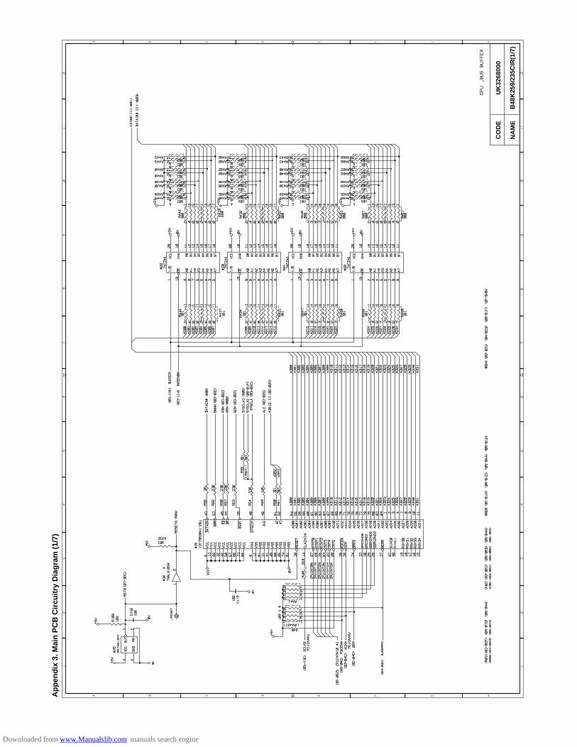
CO
DE
UK
3268
000
B48
K25
9/23
5CIR
(1/7
)N
AM
E
Ap
pen
dix
3. M
ain
PC
B C
ircu
itry
Dia
gra
m (
1/7)
Downloaded from www.Manualslib.com manuals search engine
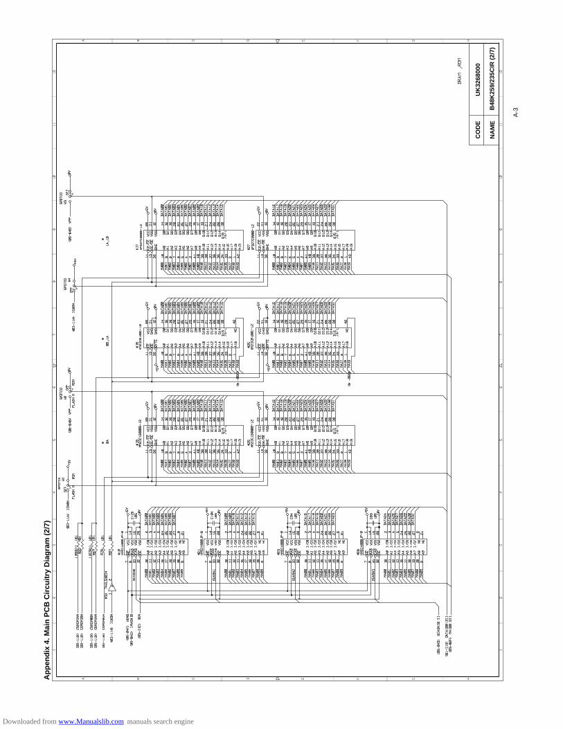
CO
DE
UK
3268
000
B48
K25
9/23
5CIR
(2/
7)N
AM
E
Ap
pen
dix
4. M
ain
PC
B C
ircu
itry
Dia
gra
m (
2/7)
A-3
Downloaded from www.Manualslib.com manuals search engine
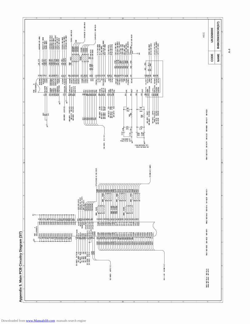
CO
DE
UK
3268
000
B48
K25
9/23
5CIR
(3/7
)N
AM
E
Ap
pen
dix
5. M
ain
PC
B C
ircu
itry
Dia
gra
m (
3/7)
A-4
Downloaded from www.Manualslib.com manuals search engine
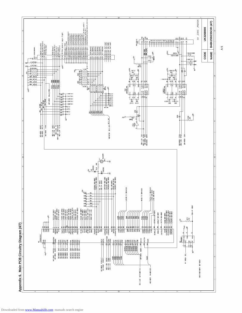
CO
DE
UK
3268
000
B48
K25
9/23
5CIR
(4/
7)N
AM
E
Ap
pen
dix
6.
Mai
n P
CB
Cir
cuit
ry D
iag
ram
(4/
7)
A-5
Downloaded from www.Manualslib.com manuals search engine
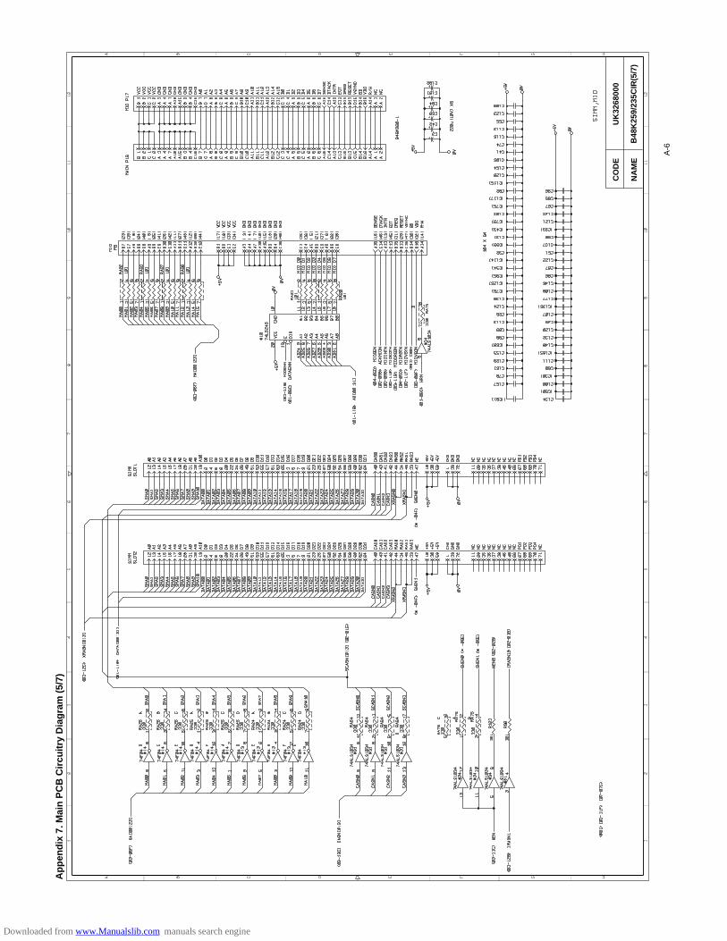
CO
DE
UK
3268
000
B48
K25
9/23
5CIR
(5/7
)N
AM
E
A-6
Ap
pen
dix
7. M
ain
PC
B C
ircu
itry
Dia
gra
m (
5/7)
Downloaded from www.Manualslib.com manuals search engine
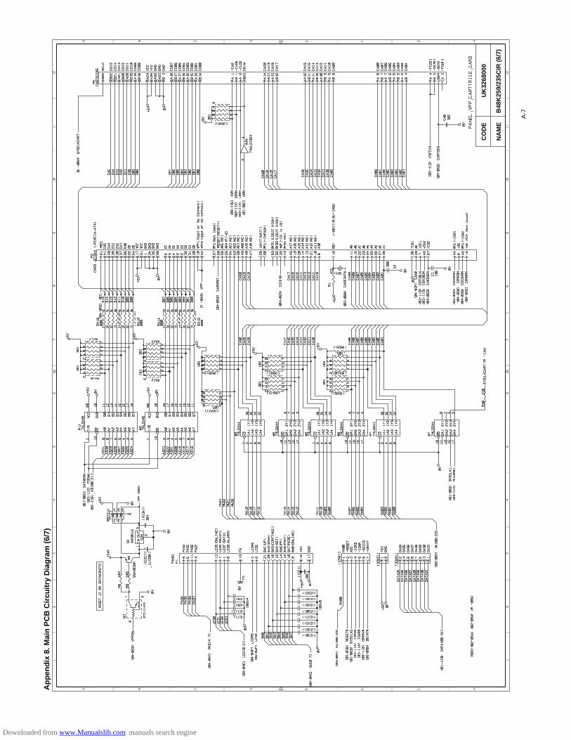
CO
DE
UK
3268
000
B48
K25
9/23
5CIR
(6/
7)N
AM
E
Ap
pen
dix
8. M
ain
PC
B C
ircu
itry
Dia
gra
m (
6/7)
A-7
Downloaded from www.Manualslib.com manuals search engine
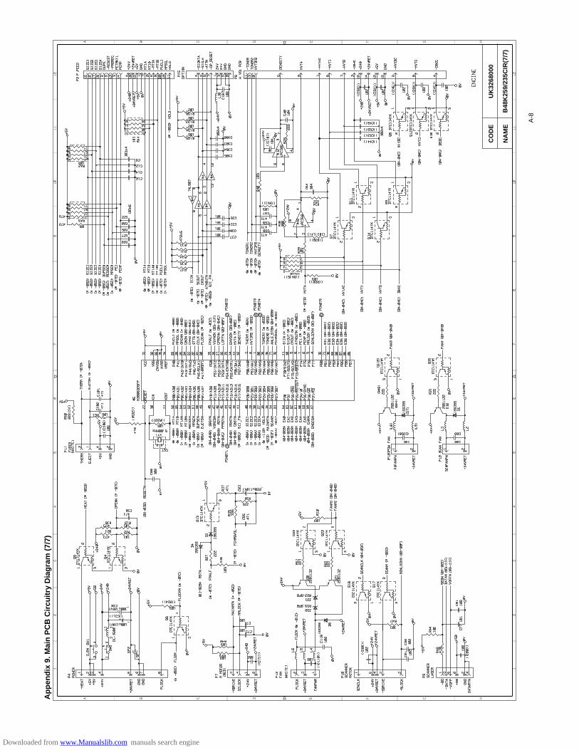
CO
DE
UK
3268
000
B48
K25
9/23
5CIR
(7/7
)N
AM
E
Ap
pen
dix
9. M
ain
PC
B C
ircu
itry
Dia
gra
m (
7/7)
A-8
Downloaded from www.Manualslib.com manuals search engine
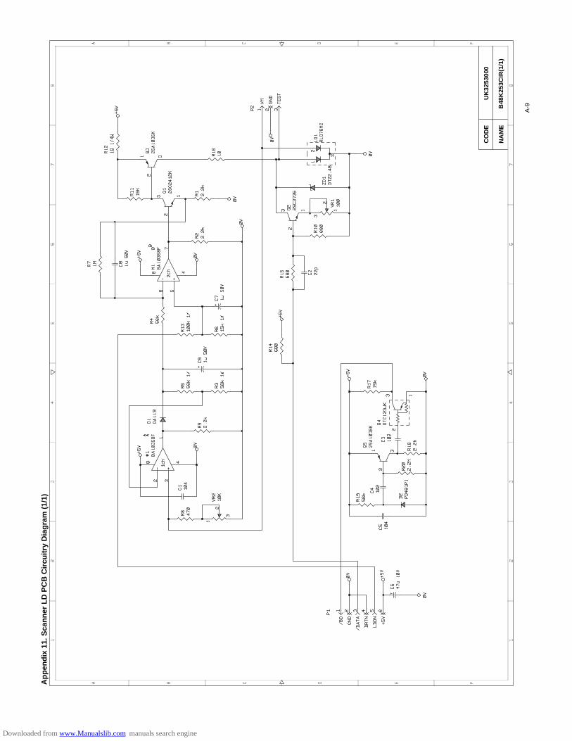
CO
DE
UK
3253
000
B48
K25
3CIR
(1/1
)N
AM
E
Ap
pen
dix
11.
Sca
nn
er L
D P
CB
Cir
cuit
ry D
iag
ram
(1/
1)
A-9
Downloaded from www.Manualslib.com manuals search engine
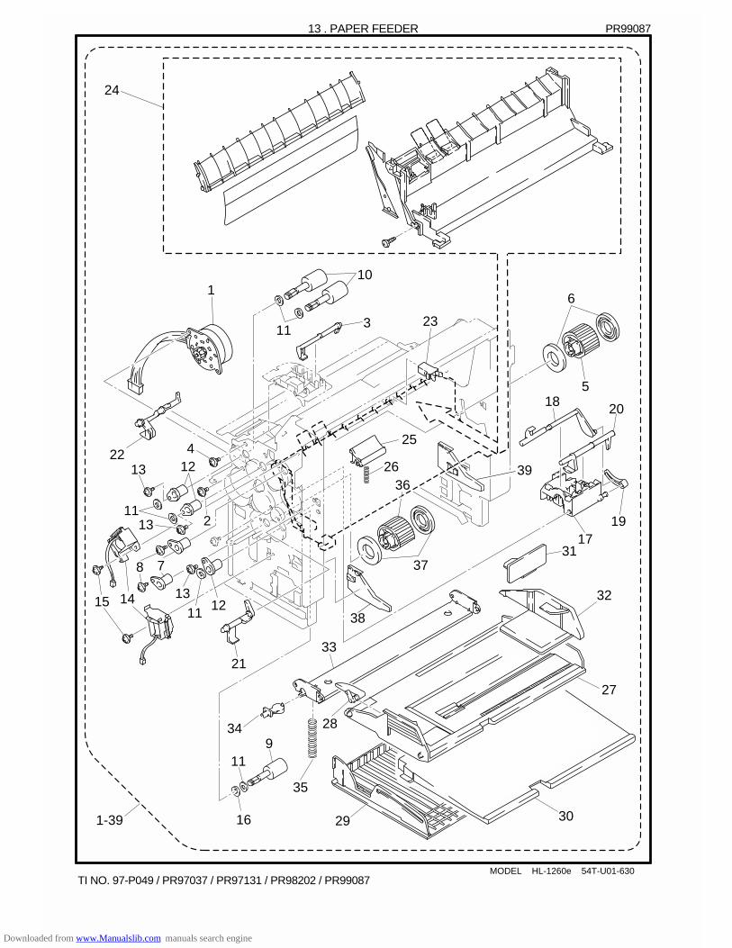
MODEL HL-1260e 54T-U01-630
13 . PAPER FEEDER
110
3
36
37
5
6
7
14
17
18
19
20
21
22
23
25
26
11
11 1213
8
15
4
13
1113
12
2
24
PR99087
TI NO. 97-P049 / PR97037 / PR97131 / PR98202 / PR99087
9
27
28
291-39 30
11
16
31
34
35
33
32
39
38
Downloaded from www.Manualslib.com manuals search engine

13. PAPER FEEDER PR99087REF.NO. CODE Q'TY DESCRIPTION REMARK1-39 UH2824001 1 PAPER FEEDER CHASSIS UNIT 2 (SP)
(WITH PCB/SW SPRING/SCREW)1 UH2357001 1 PAPER FEED MOTOR ASSY2 087320616 2 TAPTITE, CUP S M3X63 UH2359000 1 MP PAPER DETECTION ACTUATOR4 085310815 2 TAPTITE, BIND B M3X85 UH2362001 1 PAPER PICK-UP ROLLER ASSY6 UH2364001 2 PAPER PICK-UP ROLLER COLLAR7 UH2366000 2 BEARING8 085320616 2 TAPTITE, BIND S M3X69 UH2416001 1 PAPER FEED ROLLER ASSY 6010 UH2367001 2 PAPER FEED ROLLER ASSY 7011 UL0633000 6 WASHER, PLAIN12 UH2366000 3 BEARING13 085320616 3 TAPTITE, BIND S M3X614 UH2369001 2 PAPER PICK-UP SOLENOID15 085320416 2 TAPTITE, BIND S M3X416 UH2428000 1 BEARING CALLOR17 UH2379000 1 TRAY SENSOR HOLDER18 UH2380000 1 PE SENSOR ACTUATOR TRAY19 UH2381000 1 PE ACTUATOR LINK20 UH2382000 1 DU DETECTION ACTUATOR21 UH2383000 1 PE SENSOR ACTUATOR MP22 UH2384000 1 REGIST SENSOR ACTUATOR23 UH2136001 1 LATCH24 UH2797001 1 MP PAPER FEED GUIDE ASSY (SP)25 UH2393001 1 SEPARATION PAD ASSY26 UH2433001 1 SEPARATION PAD SPRING MP27 UH2397001 1 MP TRAY ASSY28 UH2400000 1 MP PE SUB ACTUATOR29 UH2406000 1 MP TRAY COVER30 UH2407000 1 MP EXTENSION TRAY31 UH2823001 1 SPACER 32 UH2401000 1 MP PAPER GUIDE 33 UH2402000 1 MP RELEASE PLATE 34 UH2403000 1 MP RELEASE SUPPORTER 35 UH2404000 1 MP SPRING 36 UH2821001 1 PAPER PICK-UP ROLLER ASSY 337 UH2822001 2 PAPER PICK-UP ROLLER COLLAR 3038 UH2356000 1 RELEASE PLATE L ADD39 UH2409000 1 RELEASE PLATE R ADD
MODEL HL-1260e 54T-U01-630T/I NO. PR97037 / PR97131/ PR98001 / PR98202 / PR99087
Downloaded from www.Manualslib.com manuals search engine

12 . PAPER FEEDER
MODEL HL-1660/TMT-17 54T-U02-630
110
3
36
37
5
6
7
9
14
17
18
19
20
21
22
23
25
26
27
31
28
291-39 30
11
11
11 1213
8
15
4
13
1113
12
2
16
24
PR99087
TI NO. 97-P049 / PR97037 / PR97131 / PR98202 / PR99087
33
35
34
32
39
38
Downloaded from www.Manualslib.com manuals search engine
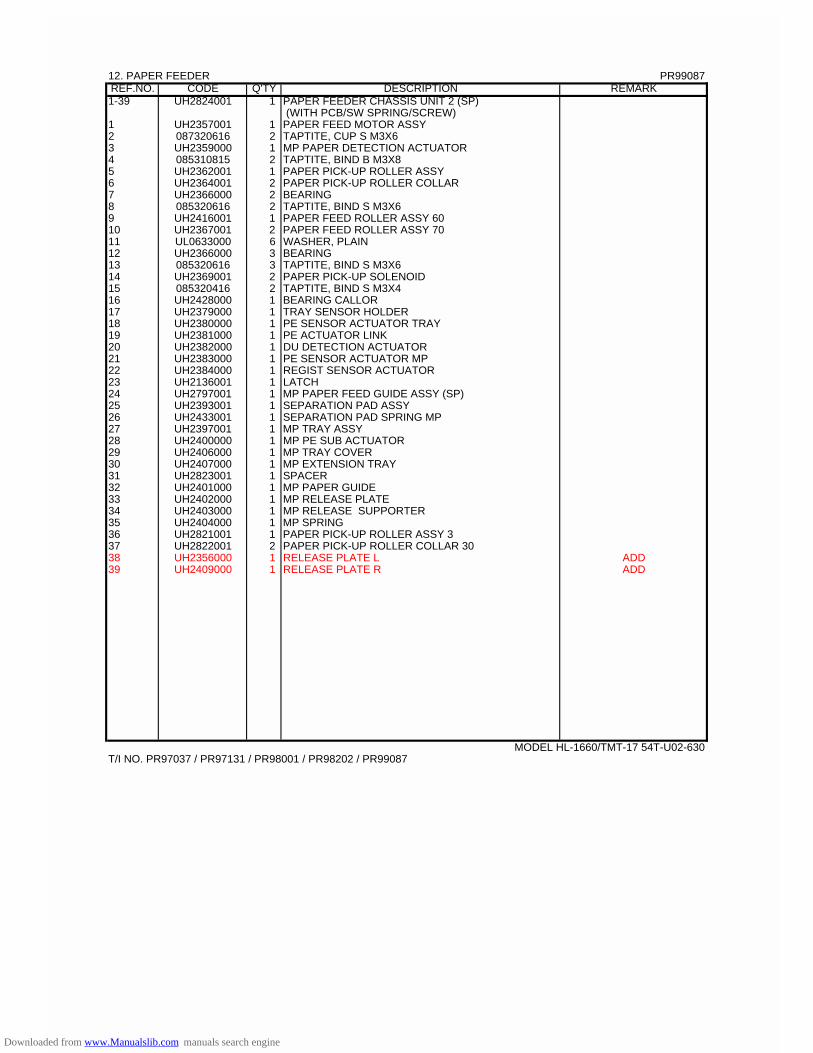
12. PAPER FEEDER PR99087REF.NO. CODE Q'TY DESCRIPTION REMARK1-39 UH2824001 1 PAPER FEEDER CHASSIS UNIT 2 (SP)
(WITH PCB/SW SPRING/SCREW)1 UH2357001 1 PAPER FEED MOTOR ASSY2 087320616 2 TAPTITE, CUP S M3X63 UH2359000 1 MP PAPER DETECTION ACTUATOR4 085310815 2 TAPTITE, BIND B M3X85 UH2362001 1 PAPER PICK-UP ROLLER ASSY6 UH2364001 2 PAPER PICK-UP ROLLER COLLAR7 UH2366000 2 BEARING8 085320616 2 TAPTITE, BIND S M3X69 UH2416001 1 PAPER FEED ROLLER ASSY 6010 UH2367001 2 PAPER FEED ROLLER ASSY 7011 UL0633000 6 WASHER, PLAIN12 UH2366000 3 BEARING13 085320616 3 TAPTITE, BIND S M3X614 UH2369001 2 PAPER PICK-UP SOLENOID15 085320416 2 TAPTITE, BIND S M3X416 UH2428000 1 BEARING CALLOR17 UH2379000 1 TRAY SENSOR HOLDER18 UH2380000 1 PE SENSOR ACTUATOR TRAY19 UH2381000 1 PE ACTUATOR LINK20 UH2382000 1 DU DETECTION ACTUATOR21 UH2383000 1 PE SENSOR ACTUATOR MP22 UH2384000 1 REGIST SENSOR ACTUATOR23 UH2136001 1 LATCH24 UH2797001 1 MP PAPER FEED GUIDE ASSY (SP)25 UH2393001 1 SEPARATION PAD ASSY26 UH2433001 1 SEPARATION PAD SPRING MP27 UH2397001 1 MP TRAY ASSY28 UH2400000 1 MP PE SUB ACTUATOR29 UH2406000 1 MP TRAY COVER30 UH2407000 1 MP EXTENSION TRAY31 UH2823001 1 SPACER 32 UH2401000 1 MP PAPER GUIDE 33 UH2402000 1 MP RELEASE PLATE 34 UH2403000 1 MP RELEASE SUPPORTER 35 UH2404000 1 MP SPRING 36 UH2821001 1 PAPER PICK-UP ROLLER ASSY 337 UH2822001 2 PAPER PICK-UP ROLLER COLLAR 3038 UH2356000 1 RELEASE PLATE L ADD39 UH2409000 1 RELEASE PLATE R ADD
MODEL HL-1660/TMT-17 54T-U02-630T/I NO. PR97037 / PR97131 / PR98001 / PR98202 / PR99087
Downloaded from www.Manualslib.com manuals search engine
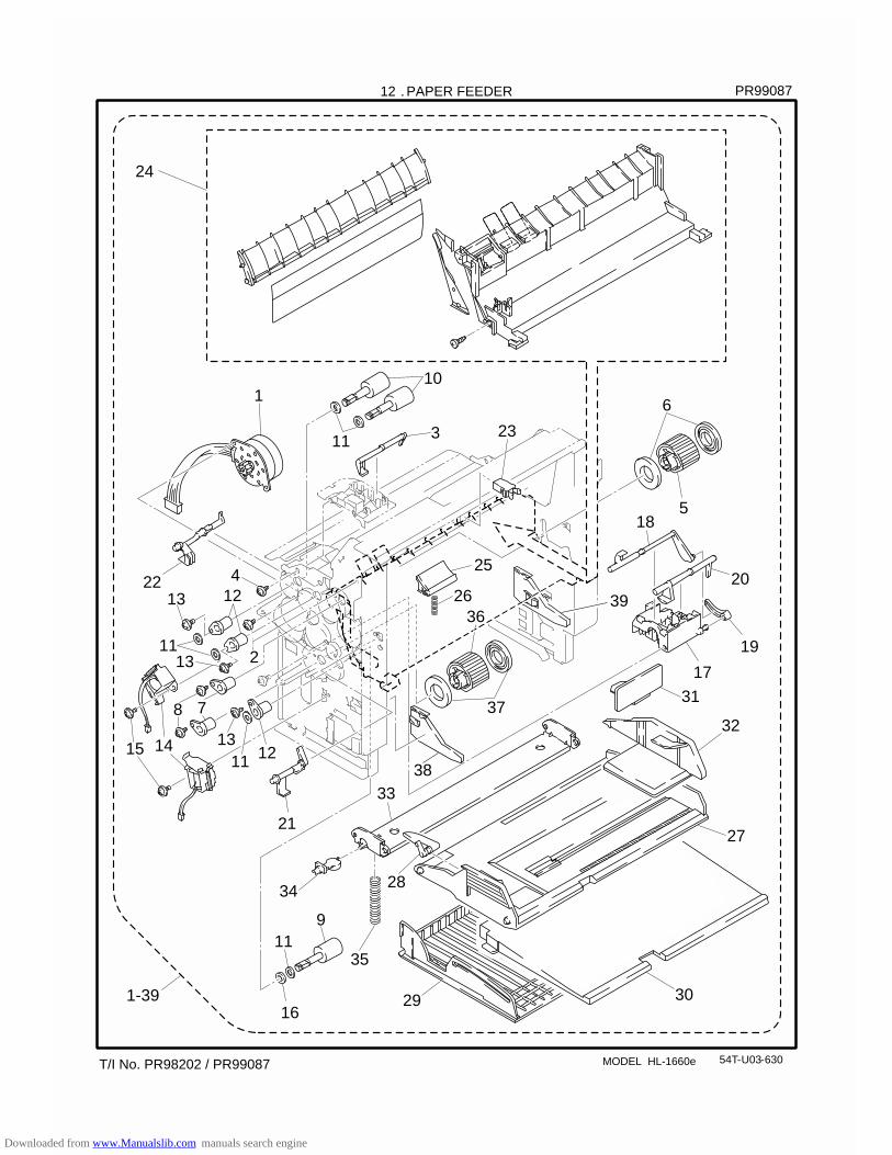
12 . PAPER FEEDER
54T-U03-630
110
3
36
37
5
6
7
9
14
17
18
19
20
21
22
23
25
26
27
31
28
291-39 30
11
11
11 1213
8
15
4
13
1113
12
2
24
16
33
35
34
32
MODEL HL-1660e
PR99087
T/I No. PR98202 / PR99087
39
38
Downloaded from www.Manualslib.com manuals search engine
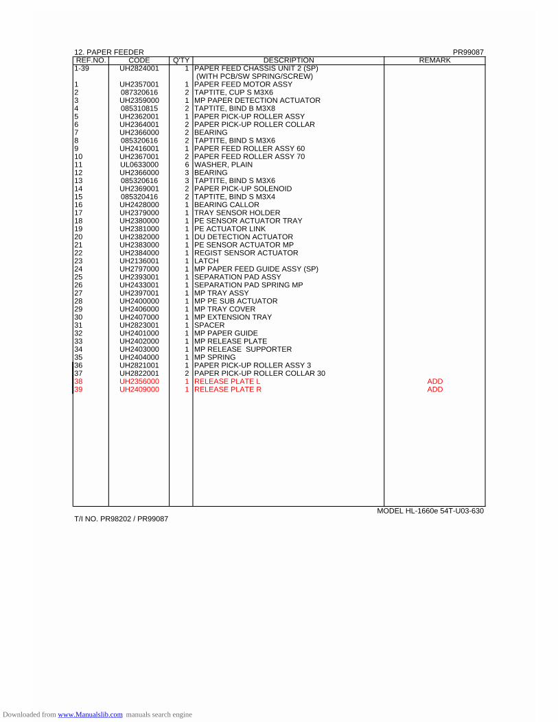
12. PAPER FEEDER PR99087REF.NO. CODE Q'TY DESCRIPTION REMARK1-39 UH2824001 1 PAPER FEED CHASSIS UNIT 2 (SP)
(WITH PCB/SW SPRING/SCREW)1 UH2357001 1 PAPER FEED MOTOR ASSY2 087320616 2 TAPTITE, CUP S M3X63 UH2359000 1 MP PAPER DETECTION ACTUATOR4 085310815 2 TAPTITE, BIND B M3X85 UH2362001 1 PAPER PICK-UP ROLLER ASSY6 UH2364001 2 PAPER PICK-UP ROLLER COLLAR7 UH2366000 2 BEARING8 085320616 2 TAPTITE, BIND S M3X69 UH2416001 1 PAPER FEED ROLLER ASSY 6010 UH2367001 2 PAPER FEED ROLLER ASSY 7011 UL0633000 6 WASHER, PLAIN12 UH2366000 3 BEARING13 085320616 3 TAPTITE, BIND S M3X614 UH2369001 2 PAPER PICK-UP SOLENOID15 085320416 2 TAPTITE, BIND S M3X416 UH2428000 1 BEARING CALLOR17 UH2379000 1 TRAY SENSOR HOLDER18 UH2380000 1 PE SENSOR ACTUATOR TRAY19 UH2381000 1 PE ACTUATOR LINK20 UH2382000 1 DU DETECTION ACTUATOR21 UH2383000 1 PE SENSOR ACTUATOR MP22 UH2384000 1 REGIST SENSOR ACTUATOR23 UH2136001 1 LATCH24 UH2797000 1 MP PAPER FEED GUIDE ASSY (SP)25 UH2393001 1 SEPARATION PAD ASSY26 UH2433001 1 SEPARATION PAD SPRING MP27 UH2397001 1 MP TRAY ASSY28 UH2400000 1 MP PE SUB ACTUATOR29 UH2406000 1 MP TRAY COVER30 UH2407000 1 MP EXTENSION TRAY31 UH2823001 1 SPACER 32 UH2401000 1 MP PAPER GUIDE 33 UH2402000 1 MP RELEASE PLATE 34 UH2403000 1 MP RELEASE SUPPORTER 35 UH2404000 1 MP SPRING 36 UH2821001 1 PAPER PICK-UP ROLLER ASSY 337 UH2822001 2 PAPER PICK-UP ROLLER COLLAR 3038 UH2356000 1 RELEASE PLATE L ADD39 UH2409000 1 RELEASE PLATE R ADD
MODEL HL-1660e 54T-U03-630T/I NO. PR98202 / PR99087
Downloaded from www.Manualslib.com manuals search engine

9 . PAPER FEEDER
MODEL HL-2060 54T-U04-630
24
6
5
418
20
19
40
41
17
38
3536
37
29
27
3433
32
16
119 31
1-4
45
43
44
21
15 14
840
39
713
1112
1311
13
2
123
22
1
23
25
26
30
28
11
1046
-11-
PR99087
TI NO. PR99087
48
47
Downloaded from www.Manualslib.com manuals search engine
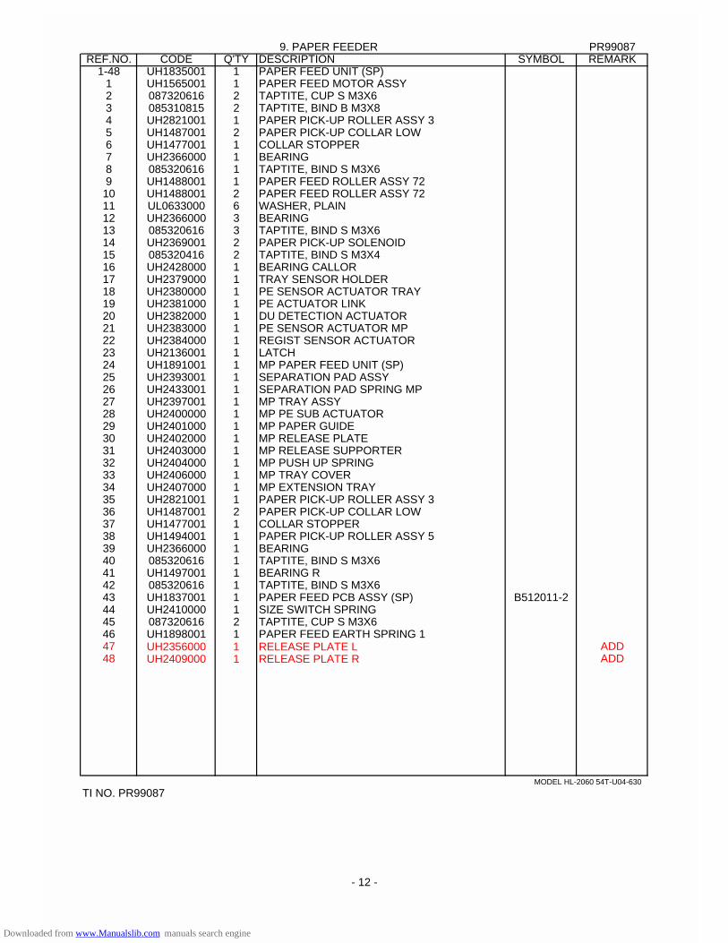
9. PAPER FEEDER PR99087REF.NO. CODE Q'TY DESCRIPTION SYMBOL REMARK
1-48 UH1835001 1 PAPER FEED UNIT (SP)1 UH1565001 1 PAPER FEED MOTOR ASSY2 087320616 2 TAPTITE, CUP S M3X63 085310815 2 TAPTITE, BIND B M3X84 UH2821001 1 PAPER PICK-UP ROLLER ASSY 35 UH1487001 2 PAPER PICK-UP COLLAR LOW6 UH1477001 1 COLLAR STOPPER7 UH2366000 1 BEARING8 085320616 1 TAPTITE, BIND S M3X69 UH1488001 1 PAPER FEED ROLLER ASSY 7210 UH1488001 2 PAPER FEED ROLLER ASSY 7211 UL0633000 6 WASHER, PLAIN12 UH2366000 3 BEARING13 085320616 3 TAPTITE, BIND S M3X614 UH2369001 2 PAPER PICK-UP SOLENOID15 085320416 2 TAPTITE, BIND S M3X416 UH2428000 1 BEARING CALLOR17 UH2379000 1 TRAY SENSOR HOLDER18 UH2380000 1 PE SENSOR ACTUATOR TRAY19 UH2381000 1 PE ACTUATOR LINK20 UH2382000 1 DU DETECTION ACTUATOR21 UH2383000 1 PE SENSOR ACTUATOR MP22 UH2384000 1 REGIST SENSOR ACTUATOR23 UH2136001 1 LATCH24 UH1891001 1 MP PAPER FEED UNIT (SP)25 UH2393001 1 SEPARATION PAD ASSY26 UH2433001 1 SEPARATION PAD SPRING MP27 UH2397001 1 MP TRAY ASSY28 UH2400000 1 MP PE SUB ACTUATOR29 UH2401000 1 MP PAPER GUIDE30 UH2402000 1 MP RELEASE PLATE31 UH2403000 1 MP RELEASE SUPPORTER32 UH2404000 1 MP PUSH UP SPRING33 UH2406000 1 MP TRAY COVER34 UH2407000 1 MP EXTENSION TRAY35 UH2821001 1 PAPER PICK-UP ROLLER ASSY 336 UH1487001 2 PAPER PICK-UP COLLAR LOW37 UH1477001 1 COLLAR STOPPER38 UH1494001 1 PAPER PICK-UP ROLLER ASSY 539 UH2366000 1 BEARING40 085320616 1 TAPTITE, BIND S M3X641 UH1497001 1 BEARING R42 085320616 1 TAPTITE, BIND S M3X643 UH1837001 1 PAPER FEED PCB ASSY (SP) B512011-244 UH2410000 1 SIZE SWITCH SPRING45 087320616 2 TAPTITE, CUP S M3X646 UH1898001 1 PAPER FEED EARTH SPRING 147 UH2356000 1 RELEASE PLATE L ADD48 UH2409000 1 RELEASE PLATE R ADD
MODEL HL-2060 54T-U04-630
TI NO. PR99087
- 12 -
Downloaded from www.Manualslib.com manuals search engine
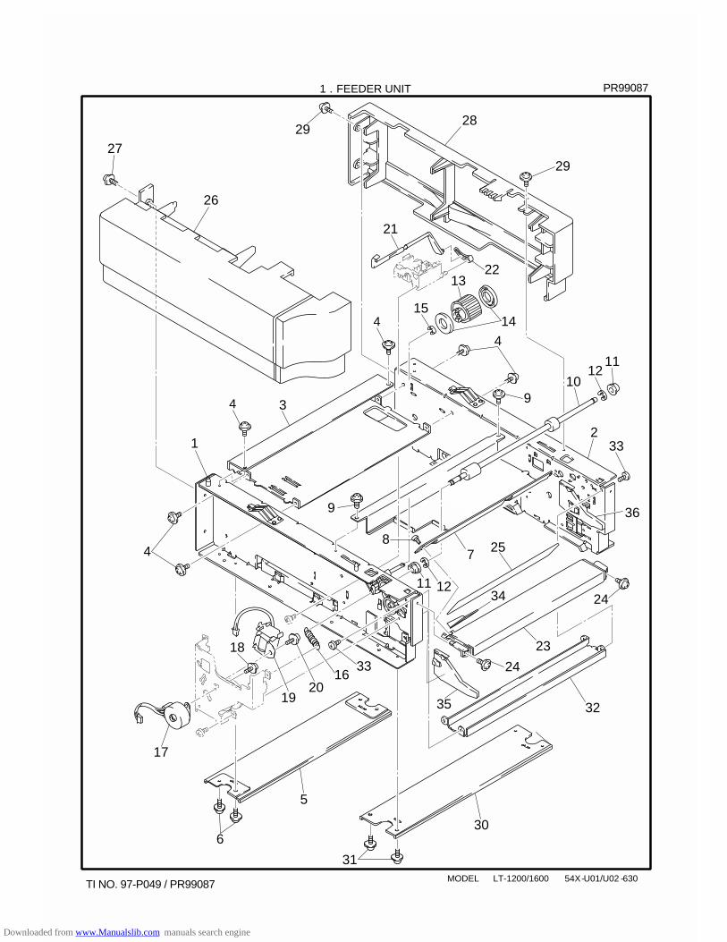
1 . FEEDER UNIT
MODEL LT-1200/1600 54X-U01/U02 -630
12
34
4
4
4
6
78
1210
11
11 12
14
13
15
18
17
16
1920
33
21
22
23
24
25
26
2729
28
29
5
30
31
24
32
34
9
9
33
PR99087
TI NO. 97-P049 / PR99087
35
36
Downloaded from www.Manualslib.com manuals search engine

1 . FEEDER UNIT
MODEL LT-1200/1600 54X-U01/U02 -630
REF.NO. CODE Q'TY DESCRIPTION REMARKS
1 UH2901001 1 FEEDER CHASSIS L ASSY 2 UH2952001 1 FEEDER CHASSIS R ASSY 3 UH2905000 1 STIFFENER PLATE UPPER 4 087320616 6 TAPTITE, CUP S M3X6 5 UH2906000 1 STIFFENER PLATE LOWER 6 087320616 4 TAPTITE, CUP S M3X6 7 UH2907000 1 FEEDER GUIDE 8 085310615 1 TAPTITE, BIND B M3X6 9 087320616 2 TAPTITE, CUP S M3X6
10 UH2954001 1 FEEDER ROLLER ASSY 11 UH2960000 2 BEARING S 12 048040346 2 RETAINING RING, E4 13 UH2362001 1 PAPER PICK-UP ROLLER ASSY 14 UH2364000 2 PAPER PICK-UP ROLLER COLLAR 15 048040346 1 RETAINING RING, E4 16 UH2967000 1 SPRING, EXTENSION 17 UH2357001 1 PAPER FEED MOTOR ASSY 18 087320616 2 TAPTITE, CUP S M3X6 19 UH2369001 1 PAPER PICK-UP SOLENOID 20 087320616 1 TAPTITE, CUP S M3X6 21 UH2911000 1 PAPER EMPTY SENSOR ACTUATOR 22 UH2381000 1 PE ACTUATOR LINK 23 UH2913000 1 FRONT COVER, GRAY1227 24 087320616 2 TAPTITE, CUP S M3X6 25 UH2918001 1 PAPER PATH FILM 26 UH2914000 1 SIDE COVER L, GRAY1227 27 087320616 4 TAPTITE, CUP S M3X6 28 UH2915000 1 SIDE COVER R, GRAY1227 29 087320616 5 TAPTITE, CUP S M3X6 30 UH2957000 1 FRONT STIFFENER CHASSIS 31 087320616 4 TAPTITE, CUP S M3X6 32 UH2958000 1 FRONT CHASSIS 33 087320616 4 TAPTITE, CUP S M3X6 34 UH2959000 1 GUIDE PLATE
PR99087
TI NO. PR99087
35 UH2356000 1 RELEASE PLATE L36 UH2409000 1 RELEASE PLATE R
ADDADD
Downloaded from www.Manualslib.com manuals search engine
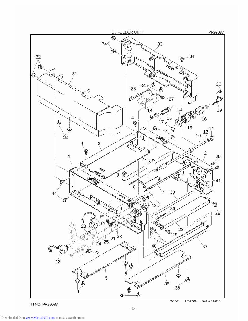
20
19
16
13
14
15
18
17
1 . FEEDER UNIT
MODEL LT-2000 54T -X01-630
12
34
4
6
6
78
1210
11
11 12
23
23
22
2124 25
38
26
27
2829
30
31
32
34 33
34
535
36
36
29
37
39
9
9
38
32
34
4
4
-1-
40
41
PR99087
TI NO. PR99087
Downloaded from www.Manualslib.com manuals search engine
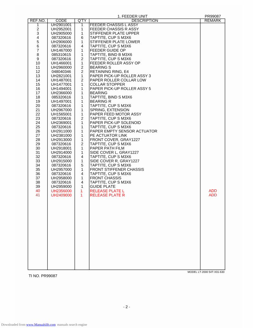
1. FEEDER UNIT PR99087REF.NO. CODE Q'TY DESCRIPTION REMARK
1 UH2901001 1 FEEDER CHASSIS L ASSY 2 UH2952001 1 FEEDER CHASSIS R ASSY 3 UH2905000 1 STIFFENER PLATE UPPER 4 087320616 6 TAPTITE, CUP S M3X6 5 UH2906000 1 STIFFENER PLATE LOWER 6 087320616 4 TAPTITE, CUP S M3X6 7 UH1467000 1 FEEDER GUIDE OP8 085310615 1 TAPTITE, BIND B M3X6 9 087320616 2 TAPTITE, CUP S M3X6 10 UH1466001 1 FEEDER ROLLER ASSY OP11 UH2960000 2 BEARING S 12 048040346 2 RETAINING RING, E4 13 UH2821001 1 PAPER PICK-UP ROLLER ASSY 3 14 UH1487001 2 PAPER ROLLER COLLAR LOW15 UH1477001 1 COLLAR STOPPER 16 UH1494001 1 PAPER PICK-UP ROLLER ASSY 5 17 UH2366000 1 BEARING 18 085320616 1 TAPTITE, BIND S M3X6 19 UH1497001 1 BEARING R20 087320616 1 TAPTITE, CUP S M3X6 21 UH2967000 1 SPRING, EXTENSION 22 UH1565001 1 PAPER FEED MOTOR ASSY 23 087320616 2 TAPTITE, CUP S M3X6 24 UH2369001 1 PAPER PICK-UP SOLENOID 25 087320616 1 TAPTITE, CUP S M3X6 26 UH2911000 1 PAPER EMPTY SENSOR ACTUATOR 27 UH2381000 1 PE ACTUATOR LINK 28 UH2913000 1 FRONT COVER, GRAY1227 29 087320616 2 TAPTITE, CUP S M3X6 30 UH2918001 1 PAPER PATH FILM 31 UH2914000 1 SIDE COVER L, GRAY1227 32 087320616 4 TAPTITE, CUP S M3X6 33 UH2915000 1 SIDE COVER R, GRAY1227 34 087320616 5 TAPTITE, CUP S M3X6 35 UH2957000 1 FRONT STIFFENER CHASSIS 36 087320616 4 TAPTITE, CUP S M3X6 37 UH2958000 1 FRONT CHASSIS 38 087320616 4 TAPTITE, CUP S M3X6 39 UH2959000 1 GUIDE PLATE 40 UH2356000 1 RELEASE PLATE L ADD41 UH2409000 1 RELEASE PLATE R ADD
MODEL LT-2000 54T-X01-630
TI NO. PR99087
- 2 -
Downloaded from www.Manualslib.com manuals search engine

PARTS REFERENCE LIST
MODEL:HL-1260e
R
LASER PRINTER
Downloaded from www.Manualslib.com manuals search engine
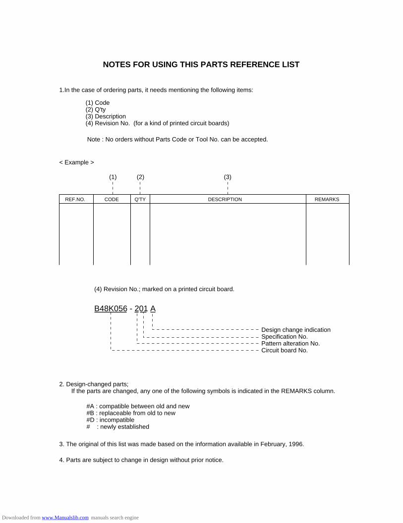
NOTES FOR USING THIS PARTS REFERENCE LIST
1.In the case of ordering parts, it needs mentioning the following items:
(1) Code(2) Q'ty(3) Description(4) Revision No. (for a kind of printed circuit boards)
Note : No orders without Parts Code or Tool No. can be accepted.
< Example >
(4) Revision No.; marked on a printed circuit board.
B48K056 - 201 A
Design change indicationSpecification No.Pattern alteration No.Circuit board No.
2. Design-changed parts; If the parts are changed, any one of the following symbols is indicated in the REMARKS column.
#A : compatible between old and new#B : replaceable from old to new#D : incompatible# : newly established
3. The original of this list was made based on the information available in February , 1996.
4. Parts are subject to change in design without prior notice.
REF.NO. CODE Q'TY DESCRIPTION REMARKS
(1) (2) (3)
Downloaded from www.Manualslib.com manuals search engine
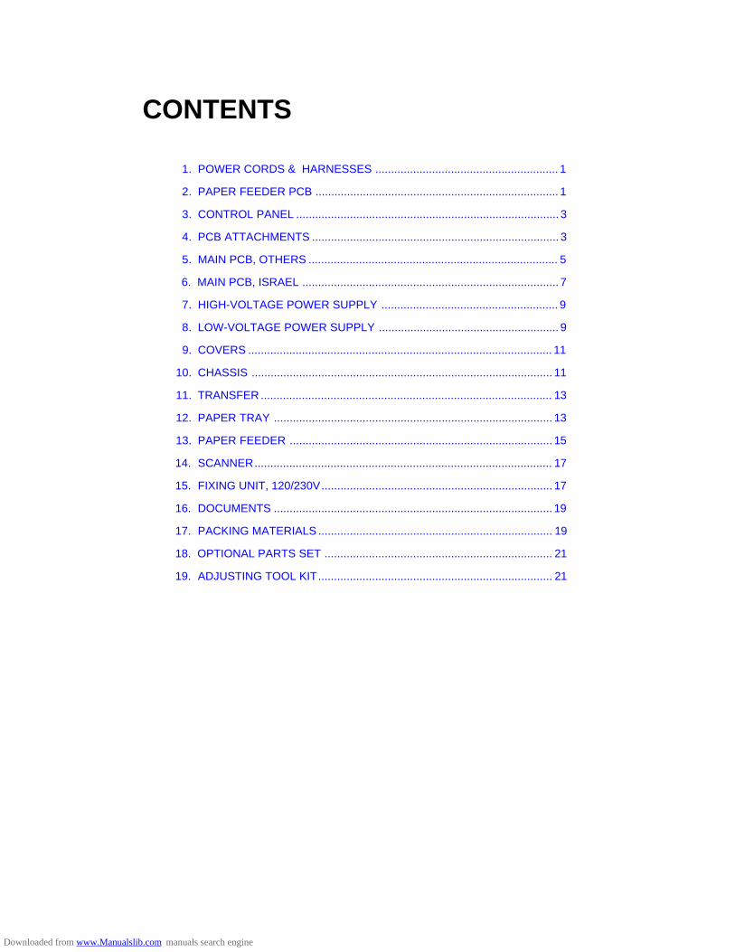
CONTENTS
1. POWER CORDS & HARNESSES .......................................................... 1
2. PAPER FEEDER PCB ............................................................................. 1
3. CONTROL PANEL ................................................................................... 3
4. PCB ATTACHMENTS .............................................................................. 3
5. MAIN PCB, OTHERS ............................................................................... 5
6. MAIN PCB, ISRAEL ................................................................................. 7
7. HIGH-VOLTAGE POWER SUPPLY ........................................................ 9
8. LOW-VOLTAGE POWER SUPPLY ......................................................... 9
9. COVERS ................................................................................................ 11
10. CHASSIS ............................................................................................... 11
11. TRANSFER ............................................................................................ 13
12. PAPER TRAY ........................................................................................ 13
13. PAPER FEEDER ................................................................................... 15
14. SCANNER.............................................................................................. 17
15. FIXING UNIT, 120/230V......................................................................... 17
16. DOCUMENTS ........................................................................................ 19
17. PACKING MATERIALS .......................................................................... 19
18. OPTIONAL PARTS SET ........................................................................ 21
19. ADJUSTING TOOL KIT.......................................................................... 21
Downloaded from www.Manualslib.com manuals search engine
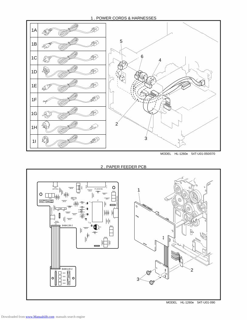
MODEL HL-1260e 54T-U01-050/070
1 . POWER CORDS & HARNESSES
MODEL HL-1260e 54T-U01-090
2 . PAPER FEEDER PCB
1A
1B
1C
1D
1E
1I
1H
1F
1G
4
3
2
6
5
3
2
1
B48K139-2
95 96
2 1P4
(MP SOL) JW18
JW13
JW2
JW3
12
1920
P5 (ENGINE)
R1RH1
JW12
R3
R4
R5
R6R7
R8
C6
JW4
RH2
C3
C4
C5
JW17
JW21
JW20
JW19
R12
Q2
Q1
Q3
JW26
P215
JW14
JW23JW
24
R10
R11
R15
R16
R13R14
1 2
#1
PH4
JW7
JW6
JW5
JW1
JW9
JW8
JW11
JW10
C1
C2
R2
PH3
JW15
R9
JW22
JW25
JW16
1817
16 P
1 (F
EE
D M
OT
OR
)
12
P3
(CA
SO
L)
PH5
9596
B48K140-25 1
SW1
SW2
SW3
SW4
P1
+
JW27
Downloaded from www.Manualslib.com manuals search engine
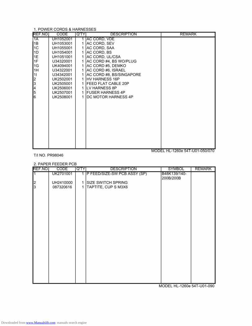
1. POWER CORDS & HARNESSESREF.NO. CODE Q'TY DESCRIPTION REMARK1A UH1052001 1 AC CORD, VDE1B UH1053001 1 AC CORD, SEV1C UH1055001 1 AC CORD, SAA1D UH1054001 1 AC CORD, BS1E UH1051001 1 AC CORD, UL/CSA1F U34320001 1 AC CORD #4, BS WO/PLUG1G UK4094001 1 AC CORD #5, DEMKO 1H U34322001 1 AC CORD #6, ISRAEL1I U34342001 1 AC CORD #8, BS/SINGAPORE2 UK2502001 1 HV HARNESS 16P3 UK2505001 1 FEED FLAT CABLE 20P4 UK2506001 1 LV HARNESS 8P5 UK2507001 1 FUSER HARNESS 4P6 UK2508001 1 DC MOTOR HARNESS 4P
MODEL HL-1260e 54T-U01-050/070T/I NO. PR98046 2. PAPER FEEDER PCBREF.NO. CODE Q'TY DESCRIPTION SYMBOL REMARK1 UK2701001 1 P FEED/SIZE-SW PCB ASSY (SP) B48K139/140-
200B/200B2 UH2410000 1 SIZE SWITCH SPRING3 087320616 1 TAPTITE, CUP S M3X6
MODEL HL-1260e 54T-U01-090
Downloaded from www.Manualslib.com manuals search engine
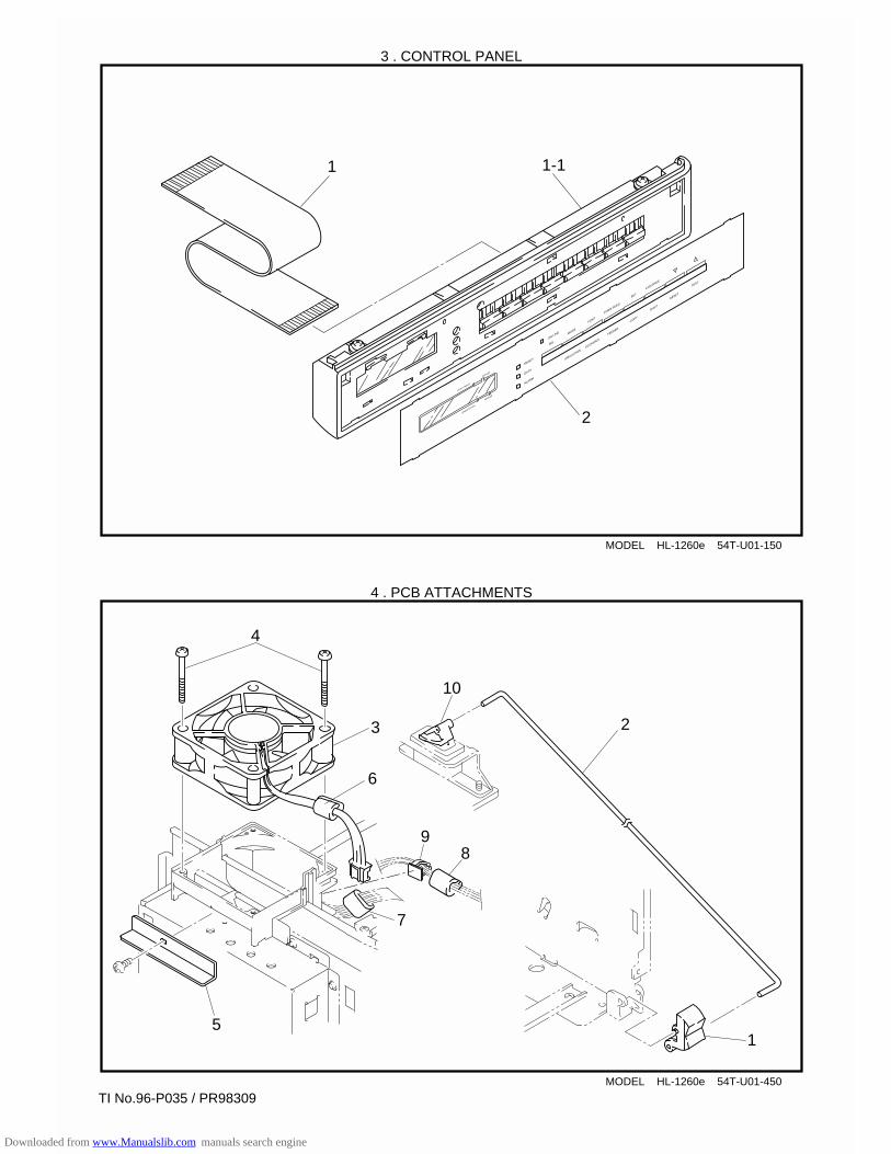
MODEL HL-1260e 54T-U01-150
3 . CONTROL PANEL
MODEL HL-1260e 54T-U01-450
4 . PCB ATTACHMENTS
READY
DATA
ALARM
ON LINE
SEL
MODE
FONT
FORM FEED
SET
CONTINUE
EMULATIONECONOMY
FEEDER
COPY
SHIFT
RESET
TEST
COPY PAGES
FEEDER
ORIENTATION
DUPLEX
1
2
1-1
1
23
4
6
7
98
5
TI No.96-P035 / PR98309
10
Downloaded from www.Manualslib.com manuals search engine
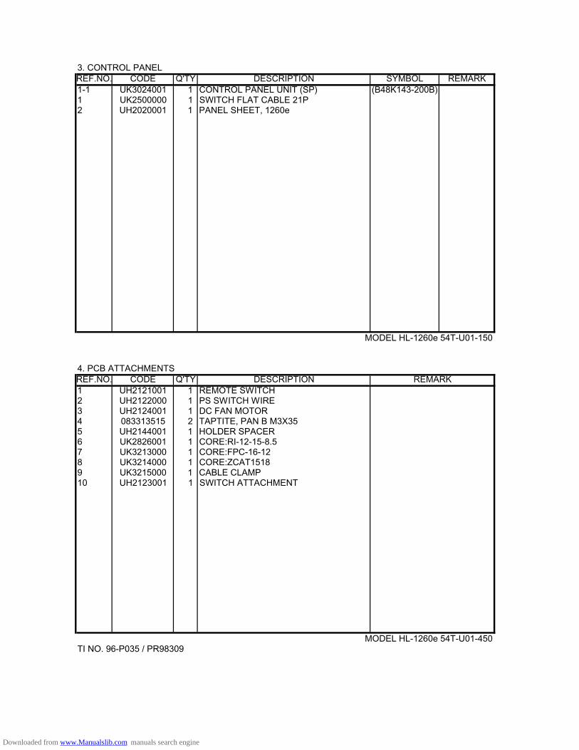
3. CONTROL PANEL REF.NO. CODE Q'TY DESCRIPTION SYMBOL REMARK1-1 UK3024001 1 CONTROL PANEL UNIT (SP) (B48K143-200B)1 UK2500000 1 SWITCH FLAT CABLE 21P2 UH2020001 1 PANEL SHEET, 1260e
MODEL HL-1260e 54T-U01-150
4. PCB ATTACHMENTSREF.NO. CODE Q'TY DESCRIPTION REMARK1 UH2121001 1 REMOTE SWITCH2 UH2122000 1 PS SWITCH WIRE3 UH2124001 1 DC FAN MOTOR4 083313515 2 TAPTITE, PAN B M3X35 5 UH2144001 1 HOLDER SPACER6 UK2826001 1 CORE:RI-12-15-8.57 UK3213000 1 CORE:FPC-16-128 UK3214000 1 CORE:ZCAT15189 UK3215000 1 CABLE CLAMP10 UH2123001 1 SWITCH ATTACHMENT
MODEL HL-1260e 54T-U01-450TI NO. 96-P035 / PR98309
Downloaded from www.Manualslib.com manuals search engine
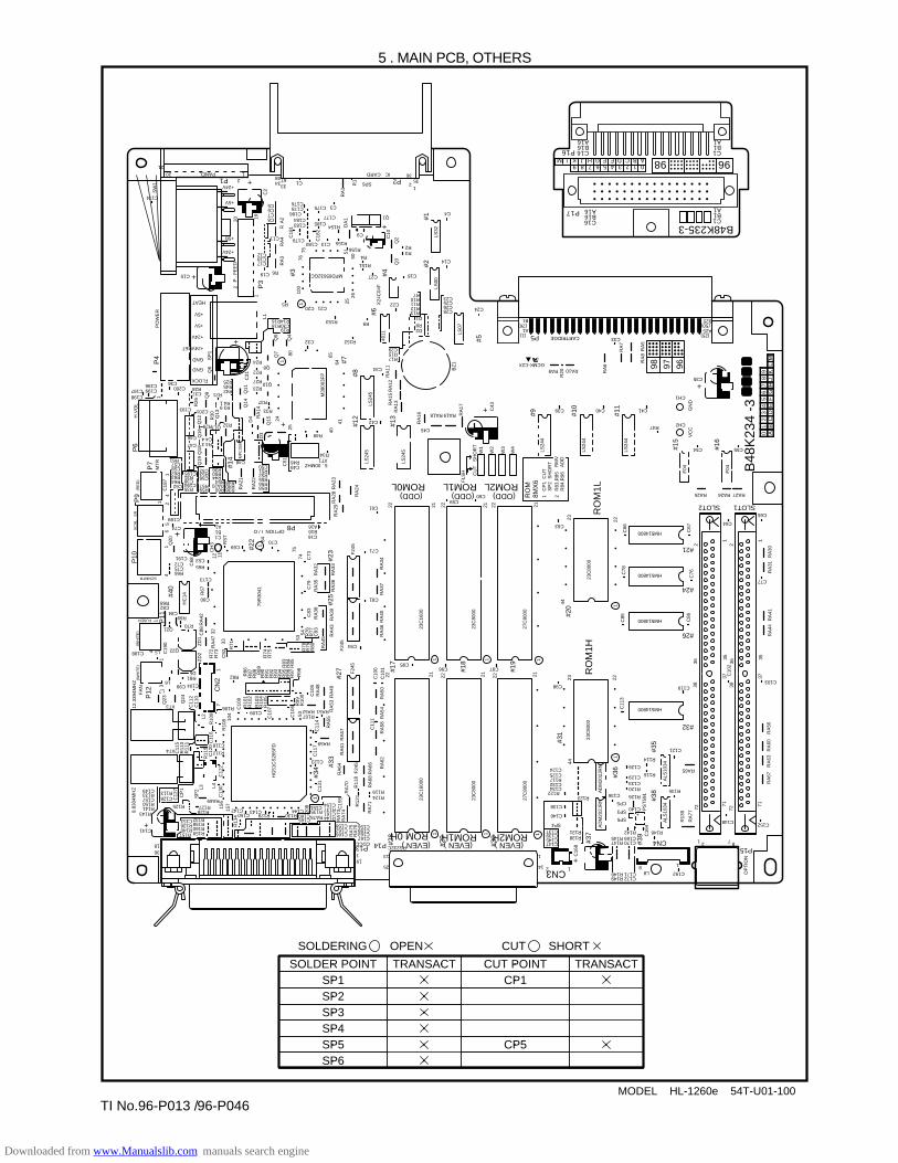
MODEL HL-1260e 54T-U01-100
5 . MAIN PCB, OTHERS
96-P046
SOLDER POINTSP1SP2SP3SP4SP5SP6
TRANSACT CUT POINTCP1
CP5
SOLDERING OPEN
TRANSACT
CUT SHORT
P16
A16P17B16C16
A16B16C16
A1B1C1
A1B1C1
B48K235-3
0123456789ABCDEFGHJKLM
1
+
+
#29
#30
C60
C14
C4
C13
0
R13
4
C40
RA10RA9
RA
24
RA
29
C51
RA
22
RA
21
25
24
RA
14
D4
Q19
Q18
Q16
R30 Q13
Q9
H.V
OL
1
MP
C35
8
Q14
Q11
Q6
SP
1
C31
+
+
D3
RA
28 R
A23
4064
Q3
Q2C
10
R1
25 X24
C04
F
2650
51D
A1
RA
1
100
119
76
A2
RR
A4
RA
3
2 20
P
. F
EE
D
PO
WE
RP
4
C2
+
75
R156
80Q7
Q5
L1
Q4
Q15
65
41
M38
063F
P
(1)A1
B1(26)
C55
23
21
1C
P1
SP
2R
MV
AD
D
CU
TS
HO
RT
R83
,R85
R
84,R
96
2RO
M8M
X6
C33P5 CARTRIDGE
C39
C65
C77
C64
C86
C76
C67
C85
C66
22
C78
44
27C
8000
23C
8000
23C
8000
23C
1600
27C
8000
23C
8000
23C
1600
0
F24
5
A25
B25
(25)
C35
CH1
CH2R47
C54
RA25
HM514800
C63
(ODD)
HM514800
HM514800
HM514800
RA27
SLOT1SLOT2
RA26
GN
DV
CC
F04
RA
41R
A44
R
A30
RA
31
1122
LS24
4
LS24
4
RA
6
RA
7
RA
8R
A5
R20
LS24
4
22
W1
+ C43
RA
17
C24R13 C28
C26C25C23
D1 R8 D2
R17 R15 C29
R12R11R10R7
RA
16
RA
13RA
15R
A12
RA
1140
11
BZ
1LS
07
LS00
LS32
LS24
5
LS24
5LS
245
RA19RA18
C45
C42
C34
R34
R49
Q8
R19C30R18R14
R5
R16
R24
R22
R27
R23
FLOCK
GND
GND
+24VRET
+24V
+5V
+5V
HEAT
R37
R33
C48
R48
R60R59R57
C56R53C52
R35C194
C38R31
C195
RA20R54
R44R50R36
Q12
R3 9R4 1
R21R42R45R25
Q17 R32
R28
R29
R4 3C4 4
C200C36
C47
C46
C37C198C197 C199
C196
R26
C193 C201
R40R38
Q10
R152
R151
R4
R153
C13C180C179
C183
C18
1
C184
C178C176
C174
C186C3
C133
C8
C17
+24V
+5B
+5V
+24V
1PANEL20
C15 +
21
SW
1
2P1
C19
C18C12
C7C6C5
34
C11
R6
68 67
R155
R154
C177C185
C18
2
C175
MPD65632GC
R3R2
C20 C21
C32
R9
C22
C27
Q1
35
12SP6
ICCARDP2
36
C9
C16
C49R46
C50R51R52R55R56R58
XT15 . 00MHZ S
HO
RT
CU
T
FLS
H
W2
W3
W4
2121 2222
F04
#15
#26
#32
#24
#21
#20
#11
RO
M1L
ROM2L(ODD)ROM1L
(ODD)ROM0L
ROM1H
CN3
(EVEN )ROM2H
RO
M1H
(EVEN )(EVEN )ROM 0H
#10
#9
#16
+
(50)
C41
C59C61
C71
C94
C81
RA
34R
A37
RA
40R
A46
F24
5
RA
43R
A39
RA
36R
A33
C73
C70
A16B16C16
P8OPTION I / O
C80
R70
R69C84
C188
C82R68
Q21
FUSER
SCNMTR
SC
NL
SR
Q22L5
XT3
XT4
L6
D5R81
C99 C104
R106
C118
R112
RA69
C142C150
C143R129 R130
C165C160 RA78 R144
C166
CDCCRS232C
C167C163C159C156
R124R119
191 13
25
1
1214
C16
8
AD
M20
2JR
NA
DM
202J
RN
ALS
1034
ALS
1034
23C
8000
C147C145C139C137
SP4
R138R131
R123
C146
C138
R122C134C132R117C125C124
C98 C119C103
C152
RA65
C121
R135
SP5
C172R149C171 C192L8
8
2
1
1 87CN4P15
R148
C170R147C169R142
R145
SP3
CP5
C136 R126
R120C133
R116
R114
C129
C126
C140
R146
C148
23
22
3836
3836
37 C10
2
RA
56R
A60
RA
63R
A67
71717272
+
R13
9 PS
T59
1C
164
RA
77
OP
TIO
N
35
3735
C11
3
P13 P14
C162C158
C161R137C154
C123
RA59
R135C151
C144
208
C11
7C
114
RA
55
RA
57R
A61
RA
64
RA
70
R12
1
RA
71R
A68
RA
66 RA
62R
A58
RA
54R
A50
21 22 21 2122C10
0
C10
1
C95C96 C97
22
C11
1
R11
8F
245
C13
1#3
4
#17
#18
#19
#31
#35
#39
#38
#33
#27
RA
73R
A74
RA
75R
A76
C15
5
#28
R125
R157 R159 R160 R158 R132
R140 R136 C153
C141
3618
R143R141R150C157
C149R133
+
C128 R113
R128R127
C109 RA51RA52R107
R82
L7
C173R66C75C72
C1
C69
B1A1
C53C191
R65
C74
C189
C18
7
C68
C62R64R63R62C58C57R61
7475
C79
C83
RA
45
RA
38C
93R
77R
76R
80R
79R
78
R74
R71
C92
R73
R72
RA
47
C88
HC
14
(WH
ITE
)(W
HIT
E)
ZD
1Z
D2
Q23
CN
2
Q24
C11
5R
110
R11
1
R11
5C
120
C12
2
C11
6
C11
2
C19
0
C11
0
17
L2
R10
9
R10
8 104
C10
8R
86R
87R
88
R90
R91
R92
R93
R94
R95
R96
R97 R98
R83
R84
R85
R89
C10
7
C10
6
53R
99R
100 C
105
RA
48
RA
49
F24
5
RA
53R10
1R
102
R10
3R
104
R10
5
HG
51C
S26
5FD
FA
N
4
13
P12
12.3
394M
HZ
RA
42
1
32
R67
4
P10
P9
P6
P7
11
12
45
6Q
20
12 11
CH
3 RS
T
84
(RE
D)
MT
RP
11
79R
3041
33
R75
5453
RA
35R
A32
#23
#13
#5
#2#1
#12
#8
#7
#14
#6
#3
P3
#4
#25#4
0
#22
+
156
157
L4L3S
P2
CP
1
9.83
04M
HZ
C12
7
44
#37
1
1
1
1
1
11 11
11
#36
01
23
45
67
89
AB
CD
EF
GH
JK
LM
969798
B48
K23
4 -3
GCMK-C2XR
9698
TI No.96-P013 /
Downloaded from www.Manualslib.com manuals search engine
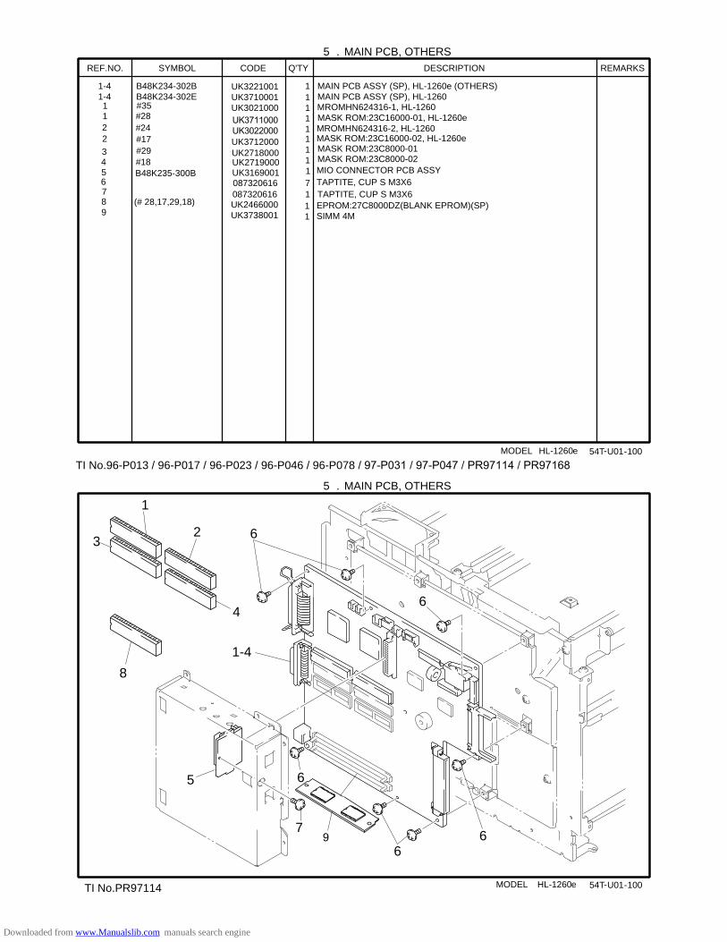
5 . MAIN PCB, OTHERS
MODEL HL-1260e 54T -U01- 100
REF.NO. SYMBOL CODE Q'TY DESCRIPTION REMARKS
1-41-4
B48K234-302BB48K234-302E
1 MAIN PCB ASSY (SP), HL-1260e (OTHERS)MAIN PCB ASSY (SP), HL-1260
1#28
11
MASK ROM:23C16000-01, HL-1260e
2 #17
11
MASK ROM:23C16000-02, HL-1260e
3 #29 UK2718000
1MASK ROM:23C8000-01
4 #18 UK271900011 MASK ROM:23C8000-02
5 B48K235-300B UK3169001 1 MIO CONNECTOR PCB ASSY6 087320616 7 TAPTITE, CUP S M3X67
(# 28,17,29,18)087320616 1 TAPTITE, CUP S M3X6
89
UK2466000UK3738001
11
EPROM:27C8000DZ(BLANK EPROM)(SP)SIMM 4M
5 . MAIN PCB, OTHERS
MODEL HL-1260e 54T -U01- 100
UK3221001UK3710001UK3021000
1
36
6
66
5
1-4
2
4
8
6
7
TI No.96-P013 / 96-P017 / 96-P023 / 96-P046 / 96-P078 / 012345678701234917873:016697873:016;<
=>5166444=>54??444UK3712000
0
TI No.PR97114
MROMHN624316-1, HL-1260
MROMHN624316-2, HL-1260
#35
#2421
Downloaded from www.Manualslib.com manuals search engine
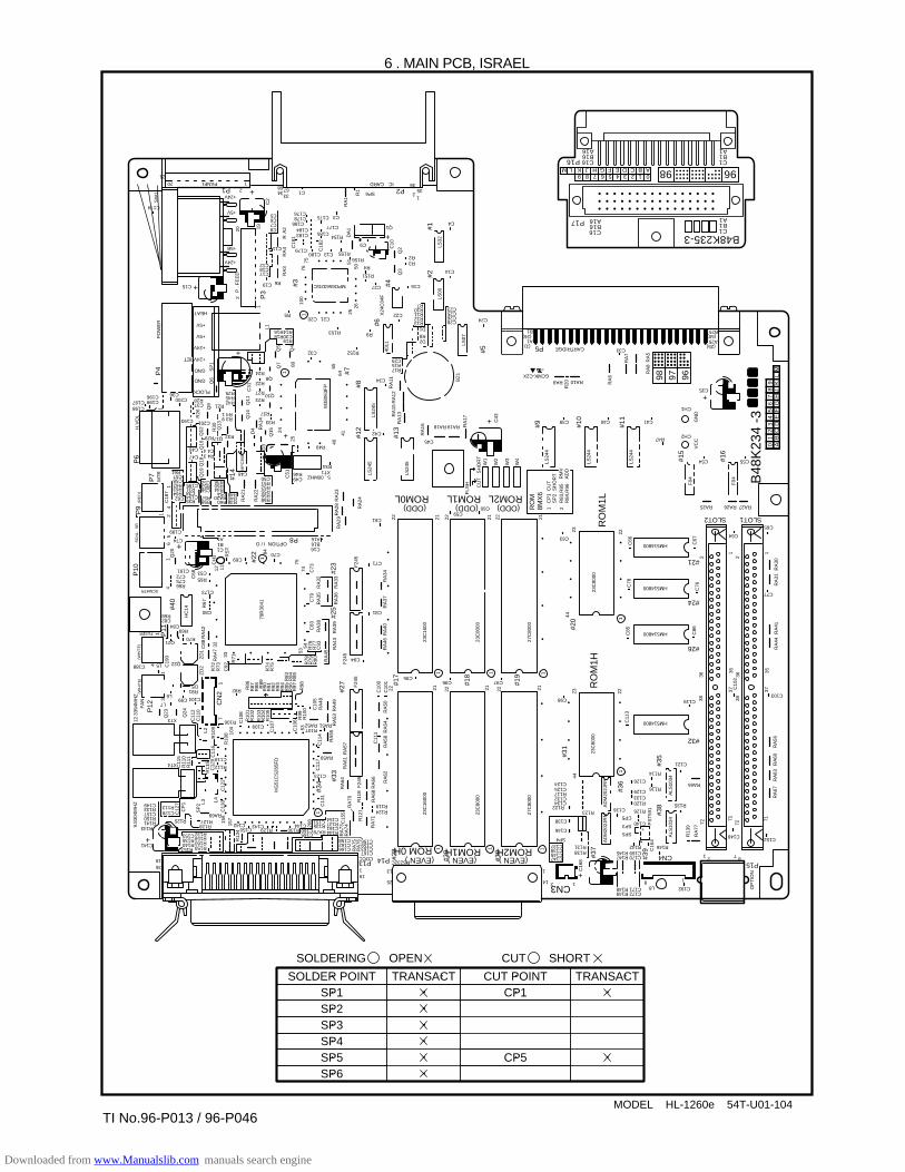
MODEL HL-1260e 54T-U01-104
6 . MAIN PCB, ISRAEL
SOLDER POINTSP1SP2SP3SP4SP5SP6
TRANSACT CUT POINTCP1
CP5
SOLDERING OPEN
TRANSACT
CUT SHORT
P16
A16P17B16C16
A16B16C16
A1B1C1
A1B1C1
B48K235-3
0123456789ABCDEFGHJKLM
1
+
+
#29
#30
C60
C14
C4
C13
0
R13
4
C40
RA10RA9
RA
24
RA
29
C51
RA
22
RA
21
25
24
RA
14
D4
Q19
Q18
Q16
R30 Q13
Q9
H.V
OL
1
MP
C35
8
Q14
Q11
Q6
SP
1
C31
+
+
D3
RA
28 R
A23
4064
Q3
Q2C
10
R1
25 X24
C04
F
2650
51D
A1
RA
1
100
119
76
A2
RR
A4
RA
3
2 20
P
. F
EE
D
PO
WE
RP
4
C2
+
75
R156
80Q7
Q5
L1
Q4
Q15
65
41
M38
063F
P
(1)A1
B1(26)
C55
23
21
1C
P1
SP
2R
MV
AD
D
CU
TS
HO
RT
R83
,R85
R
84,R
96
2RO
M8M
X6
C33P5 CARTRIDGE
C39
C65
C77
C64
C86
C76
C67
C85
C66
22
C78
44
27C
8000
23C
8000
23C
8000
23C
1600
27C
8000
23C
8000
23C
1600
0
F24
5
A25
B25
(25)
C35
CH1
CH2R47
C54
RA25
HM514800
C63
(ODD)
HM514800
HM514800
HM514800
RA27
SLOT1SLOT2
RA26
GN
DV
CC
F04
RA
41R
A44
R
A30
RA
31
1122
LS24
4
LS24
4
RA
6
RA
7
RA
8R
A5
R20
LS24
4
22
W1
+ C43
RA
17
C24R13 C28
C26C25C23
D1 R8 D2
R17 R15 C29
R12R11R10R7
RA
16
RA
13RA
15R
A12
RA
1140
11
BZ
1LS
07
LS00
LS32
LS24
5
LS24
5LS
245
RA19RA18
C45
C42
C34
R34
R49
Q8
R19C30R18R14
R5
R16
R24
R22
R27
R23
FLOCK
GND
GND
+24VRET
+24V
+5V
+5V
HEAT
R37
R33
C48
R48
R60R59R57
C56R53C52
R35C194
C38R31
C195
RA20R54
R44R50R36
Q12
R3 9R4 1
R21R42R45R25
Q17 R32
R28
R29
R4 3C4 4
C200C36
C47
C46
C37C198C197 C199
C196
R26
C193 C201
R40R38
Q10
R152
R151
R4
R153
C13C180C179
C183
C18
1
C184
C178C176
C174
C186C3
C133
C8
C17
+24V
+5B
+5V
+24V
1PANEL20
C15 +
21
SW
1
2P1
C19
C18C12
C7C6C5
34
C11
R6
68 67
R155
R154
C177C185
C18
2
C175
MPD65632GC
R3R2
C20 C21
C32
R9
C22
C27
Q1
35
12SP6
ICCARDP2
36
C9
C16
C49R46
C50R51R52R55R56R58
XT15 . 00MHZ S
HO
RT
CU
T
FLS
H
W2
W3
W4
2121 2222
F04
#15
#26
#32
#24
#21
#20
#11
RO
M1L
ROM2L(ODD)ROM1L
(ODD)ROM0L
ROM1H
CN3
(EVEN )ROM2H
RO
M1H
(EVEN )(EVEN )ROM 0H
#10
#9
#16
+
(50)
C41
C59C61
C71
C94
C81
RA
34R
A37
RA
40R
A46
F24
5
RA
43R
A39
RA
36R
A33
C73
C70
A16B16C16
P8OPTION I / O
C80
R70
R69C84
C188
C82R68
Q21
FUSER
SCNMTR
SC
NL
SR
Q22L5
XT3
XT4
L6
D5R81
C99 C104
R106
C118
R112
RA69
C142C150
C143R129 R130
C165C160 RA78 R144
C166
CDCCRS232C
C167C163C159C156
R124R119
191 13
25
1
1214
C16
8
AD
M20
2JR
NA
DM
202J
RN
ALS
1034
ALS
1034
23C
8000
C147C145C139C137
SP4
R138R131
R123
C146
C138
R122C134C132R117C125C124
C98 C119C103
C152
RA65
C121
R135
SP5
C172R149C171 C192L8
8
2
1
1 87CN4P15
R148
C170R147C169R142
R145
SP3
CP5
C136 R126
R120C133
R116
R114
C129
C126
C140
R146
C148
23
22
3836
3836
37 C10
2
RA
56R
A60
RA
63R
A67
71717272
+
R13
9 PS
T59
1C
164
RA
77
OP
TIO
N
35
3735
C11
3
P13 P14
C162C158
C161R137C154
C123
RA59
R135C151
C144
208
C11
7C
114
RA
55
RA
57R
A61
RA
64
RA
70
R12
1
RA
71R
A68
RA
66 RA
62R
A58
RA
54R
A50
21 22 21 2122C10
0
C10
1
C95C96 C97
22
C11
1
R11
8F
245
C13
1#3
4
#17
#18
#19
#31
#35
#39
#38
#33
#27
RA
73R
A74
RA
75R
A76
C15
5
#28
R125
R157 R159 R160 R158 R132
R140 R136 C153
C141
3618
R143R141R150C157
C149R133
+
C128 R113
R128R127
C109 RA51RA52R107
R82
L7
C173R66C75C72
C1
C69
B1A1
C53C191
R65
C74
C189
C18
7
C68
C62R64R63R62C58C57R61
7475
C79
C83
RA
45
RA
38C
93R
77R
76R
80R
79R
78
R74
R71
C92
R73
R72
RA
47
C88
HC
14
(WH
ITE
)(W
HIT
E)
ZD
1Z
D2
Q23
CN
2
Q24
C11
5R
110
R11
1
R11
5C
120
C12
2
C11
6
C11
2
C19
0
C11
0
17
L2
R10
9
R10
8 104
C10
8R
86R
87R
88
R90
R91
R92
R93
R94
R95
R96
R97 R98
R83
R84
R85
R89
C10
7
C10
6
53R
99R
100 C
105
RA
48
RA
49
F24
5
RA
53R10
1R
102
R10
3R
104
R10
5
HG
51C
S26
5FD
FA
N
4
13
P12
12.3
394M
HZ
RA
42
1
32
R67
4
P10
P9
P6
P7
11
12
45
6Q
20
12 11
CH
3 RS
T
84
(RE
D)
MT
RP
11
79R
3041
33
R75
5453
RA
35R
A32
#23
#13
#5
#2#1
#12
#8
#7
#14
#6
#3
P3
#4
#25#4
0
#22
+
156
157
L4L3S
P2
CP
1
9.83
04M
HZ
C12
7
44
#37
1
1
1
1
1
11 11
11
#36
01
23
45
67
89
AB
CD
EF
GH
JK
LM
969798
B48
K23
4 -3
GCMK-C2XR
9698
TI No.96-P013 / 96-P046
Downloaded from www.Manualslib.com manuals search engine
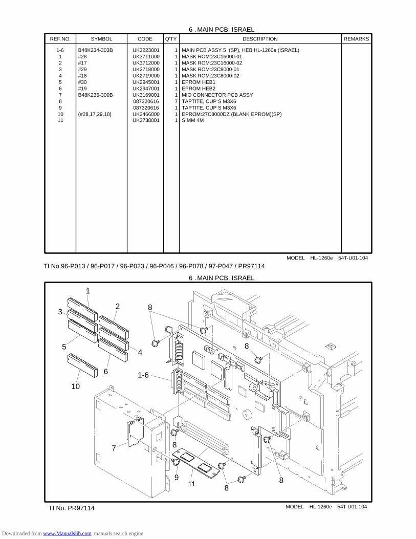
6 . MAIN PCB, ISRAEL
MODEL HL-1260e 54T-U01-104
REF.NO. SYMBOL CODE Q'TY DESCRIPTION REMARKS
1-6 B48K234-303B UK3223001 1 MAIN PCB ASSY 5 (SP), HEB HL-1260e (ISRAEL)1 #28 UK3711000 1 MASK ROM:23C16000-012 #17 UK3712000 1 MASK ROM:23C16000-023 #29 UK2718000 1 MASK ROM:23C8000-014 #18 UK2719000 1 MASK ROM:23C8000-025 #30 UK2945001 1 EPROM HEB16 #19 UK2947001 1 EPROM HEB27 B48K235-300B UK3169001 1 MIO CONNECTOR PCB ASSY8 087320616 7 TAPTITE, CUP S M3X69 087320616 1 TAPTITE, CUP S M3X61011
(#28,17,29,18) UK2466000UK3738001
11
EPROM:27C8000DZ (BLANK EPROM)(SP)SIMM 4M
6 . MAIN PCB, ISRAEL
MODEL HL-1260e 54T-U01-104
1
38
8
88
7
1-6
2
4
10
8
9
5
6
TI No.96-P013 / 96-P017 / 96-P023 / 96-P046 / 96-P078 / 97-P047 / PR97114
66
TI No. PR97114
Downloaded from www.Manualslib.com manuals search engine

7 . HIGH-VOLTAGE POWER SUPPLY
MODEL HL-1260e 54T-U01- 200
8 . LOW-VOLTAGE POWER SUPPLY
MODEL HL-1260e 54T-U01- 300
1
2
1-2
3
31
3
3
3 2
TI No.96-P033
Downloaded from www.Manualslib.com manuals search engine

7. HIGH-VOLTAGE POWER SUPPLY REF.NO. CODE Q'TY DESCRIPTION SYMBOL REMARK1 UK2702001 1 HIGH-VOLTAGE PS PCB ASSY (SP) B48K186-300E2 087320616 2 TAPTITE, CUP S M3X6
MODEL HL-1260e 54T-U01-200TI NO. 96-P028
8. LOW-VOLTAGE POWER SUPPLYREF.NO. CODE Q'TY DESCRIPTION SYMBOL REMARK1-2 UK2753001 1 LOW-VOLT PS PCB ASSY, 115VM(SP)1-2 UK2754001 1 LOW-VOLT PS PCB ASSY, 230VM(SP)1 UK2756001 1 GLASS FUSE, 10A-125VM (PS PCB 115VM) (S F11 UK2759001 1 GLASS FUSE, 6A-250VM (PS PCB 230VM) (SP F12 UK2757001 1 GLASS FUSE, 5A-125VM (PS PCB 115VM) (SP F22 UK2760001 1 GLASS FUSE, 3A-250VM (PS PCB 230VM) (SP F23 087320616 6 TAPTITE, CUP S M3X6
MODEL HL-1260e 54T-U01-300TI NO. 96-P033
Downloaded from www.Manualslib.com manuals search engine
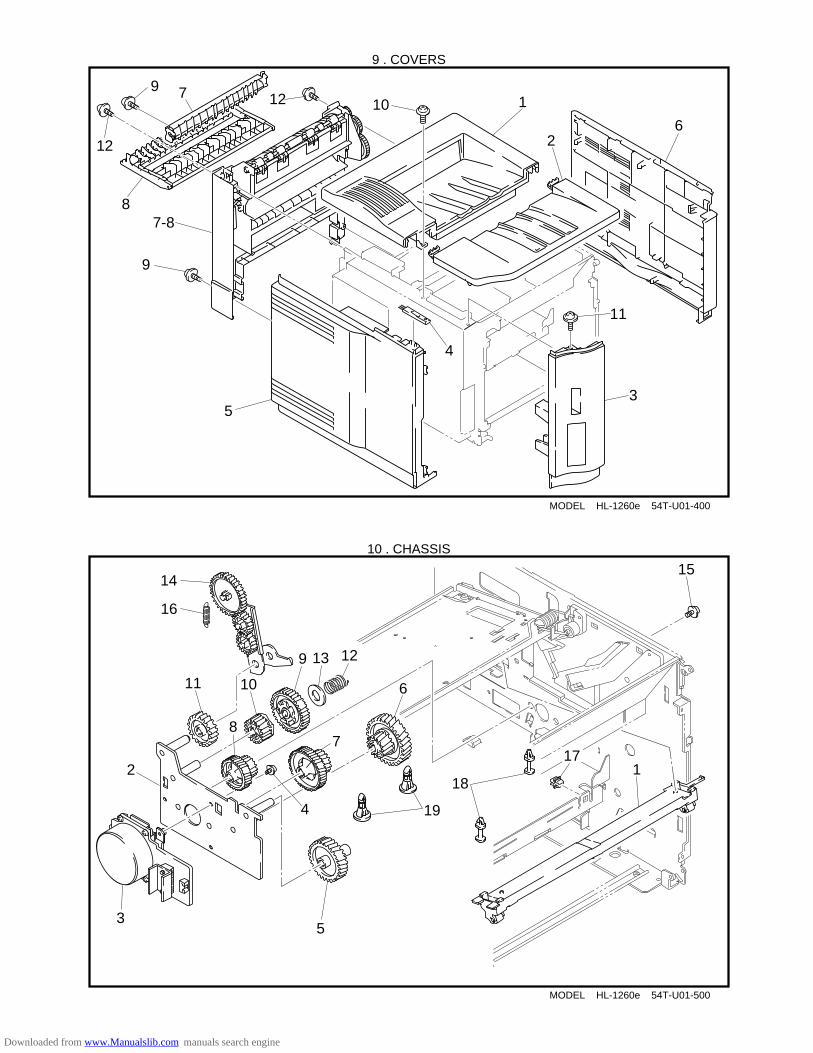
MODEL HL-1260e 54T-U01-400
9 . COVERS
1
2
4
5
6
8
7
12
129
9
10
11
3
7-8
10 . CHASSIS
12
3
4
5
6
78
9
1011
1213
1415
16
MODEL HL-1260e 54T-U01-500
17
19
18
Downloaded from www.Manualslib.com manuals search engine
9. COVERS REF.NO. CODE Q'TY DESCRIPTION REMARK1 UH2065001 1 UPPER COVER ASSY, GRAY1227 2 UH2071001 1 TONER CARTRIDGE LID, GRAY12273 UH2072001 1 FONT COVER ASSY, GRAY12274 UH2076001 1 CLEANER BRUSH5 UH2077001 1 SIDE COVER L, GRAY12276 UH2027001 1 SIDE COVER R2 ASSY, GRAY1227 7-8 UH2082001 1 REAR COVER ASSY, GRAY12277 UH2085001 1 CHANGEOVER GUIDE, GRAY12278 UH2103001 1 JAM REMOVE COVER, GRAY12279 087320616 2 TAPTITE, CUP S M3X610 087320616 1 TAPTITE, CUP S M3X611 087320616 1 TAPTITE, CUP S M3X612 087321016 2 TAPTITE, CUP S M3X10
MODEL HL-1260e 54T-U01-400T/I NO. PR98175
10. CHASSISREF.NO. CODE Q'TY DESCRIPTION REMARK1 UH2229001 1 CARTRIDGE STOPPER ASSY2 UH2233001 1 DC GEAR HOLDER ASSY3 UH2786001 1 DC MOTOR ASSY (SP) 4 087320616 3 TAPTITE, CUP S M3X6 5 UH2238000 1 GEAR 39 6 UH2239000 1 GEAR 20/50 7 UH2240000 1 GEAR 24/728 UH2241000 1 GEAR 22/559 UH2242000 1 GEAR 4810 UH2243000 1 GEAR 2111 UH2244000 1 GEAR 2812 UH2245001 1 GEAR 48 SPRING13 026100136 1 WASHER, PLAIN S 1014 UH2255001 1 PAPER DELIVERY GEAR ASSY15 U74234001 4 TAPTITE, CUP M4X516 UH2250001 1 PAPER DELIVERY HOLDER SPRING17 UH2252000 1 SPACER 218 UH2254000 2 SPACER 119 T31242001 2 SPACER F
MODEL HL-1260e 54T-U01-500
Downloaded from www.Manualslib.com manuals search engine

MODEL HL-1260e 54T-U01-600
11 . TRANSFER
1
2
3
MODEL HL-1260e 54T-U01-650
12 . PAPER TRAY
1
2 3
4
6
1-10
88
5
9
TI No.96-P077 / 97-P021
7
10
Downloaded from www.Manualslib.com manuals search engine
11. TRANSFER REF.NO. CODE Q'TY DESCRIPTION REMARK1 UH2787001 1 TRANSFER BASE ASSY (SP) 2 UH1834001 1 TRANFER ROLLER A ASSY (SP) 3 087321016 1 TAPTITE, CUP S M3X10
MODEL HL-1260e 54T-U01-600T/I NO. PR98174
12. PAPER TRAYREF.NO.CODE Q'TY DESCRIPTION REMARK1-10 UH2806001 1 PAPER TRAY UNIT US (SP), USA1-10 UH2799001 1 PAPER TRAY UNIT EC (SP), EUR1-10 UH2802001 1 PAPER TRAY UNIT CA (SP), CAN1-10 UH3374001 1 PAPER TRAY UNIT, ADP 1 UH2487001 1 SEPARATION PAD ASSY T 2 UH2490001 1 SEPARATION PAD SPRING T3 UH2360000 1 ROLLER4 UH2459000 1 ROLLER HOLDER5 UH2469000 1 PAPER FRONT GUIDE, BLUE61556 UH2463001 1 GEAR 56T LINK7 UH2465001 1 SIZE DRUM8 085310815 3 TAPTITE, BIND B M3X89 UH2472001 1 TRAY GUIDE PLATE 110 UH2804001 1 ADJUST KNOB STOPPER
MODEL HL-1260e 54T-U01-650TI NO. 96-P077 / 97-P021 / PR98270
Downloaded from www.Manualslib.com manuals search engine
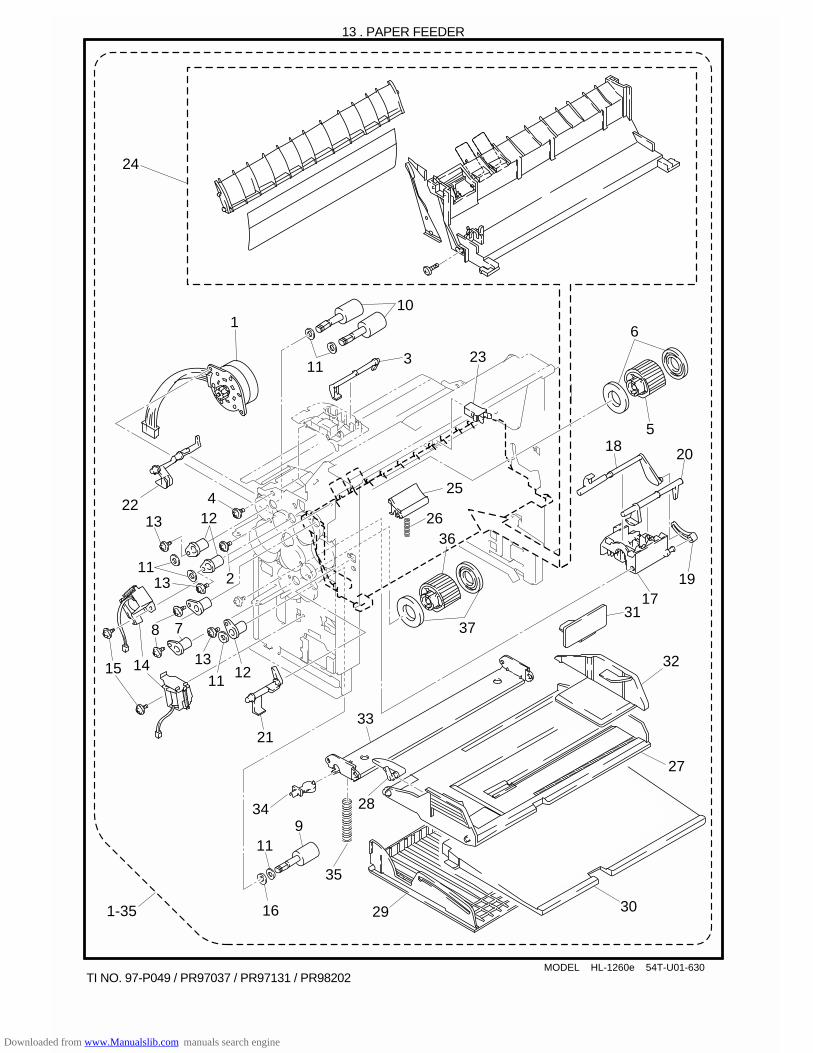
MODEL HL-1260e 54T-U01-630
13 . PAPER FEEDER
110
3
36
37
5
6
7
14
17
18
19
20
21
22
23
25
26
24
11
11 1213
8
15
4
13
1113
12
2
TI NO. 97-P049 / PR97037 / PR97131 / PR98202
9
27
28
291-35 30
11
16
31
34
35
33
32
Downloaded from www.Manualslib.com manuals search engine
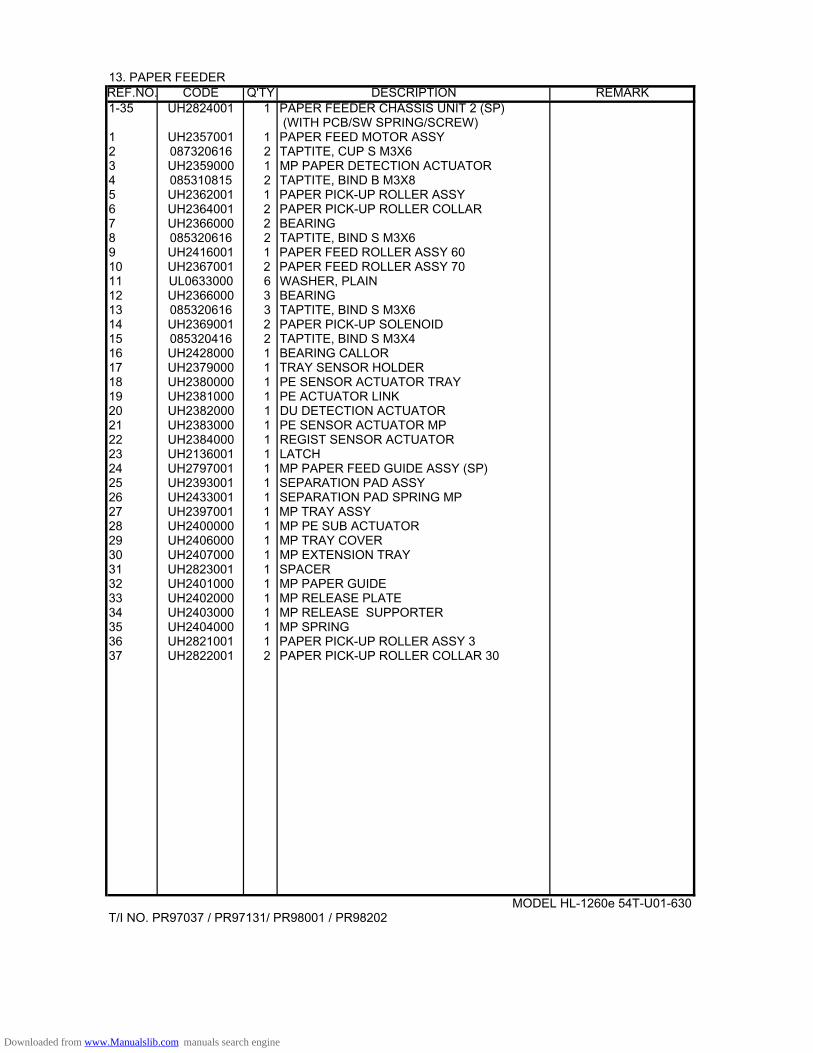
13. PAPER FEEDER REF.NO. CODE Q'TY DESCRIPTION REMARK1-35 UH2824001 1 PAPER FEEDER CHASSIS UNIT 2 (SP)
(WITH PCB/SW SPRING/SCREW)1 UH2357001 1 PAPER FEED MOTOR ASSY2 087320616 2 TAPTITE, CUP S M3X63 UH2359000 1 MP PAPER DETECTION ACTUATOR4 085310815 2 TAPTITE, BIND B M3X85 UH2362001 1 PAPER PICK-UP ROLLER ASSY 6 UH2364001 2 PAPER PICK-UP ROLLER COLLAR 7 UH2366000 2 BEARING8 085320616 2 TAPTITE, BIND S M3X69 UH2416001 1 PAPER FEED ROLLER ASSY 6010 UH2367001 2 PAPER FEED ROLLER ASSY 7011 UL0633000 6 WASHER, PLAIN12 UH2366000 3 BEARING13 085320616 3 TAPTITE, BIND S M3X614 UH2369001 2 PAPER PICK-UP SOLENOID15 085320416 2 TAPTITE, BIND S M3X416 UH2428000 1 BEARING CALLOR17 UH2379000 1 TRAY SENSOR HOLDER18 UH2380000 1 PE SENSOR ACTUATOR TRAY19 UH2381000 1 PE ACTUATOR LINK20 UH2382000 1 DU DETECTION ACTUATOR21 UH2383000 1 PE SENSOR ACTUATOR MP22 UH2384000 1 REGIST SENSOR ACTUATOR23 UH2136001 1 LATCH24 UH2797001 1 MP PAPER FEED GUIDE ASSY (SP)25 UH2393001 1 SEPARATION PAD ASSY26 UH2433001 1 SEPARATION PAD SPRING MP27 UH2397001 1 MP TRAY ASSY28 UH2400000 1 MP PE SUB ACTUATOR29 UH2406000 1 MP TRAY COVER30 UH2407000 1 MP EXTENSION TRAY31 UH2823001 1 SPACER 32 UH2401000 1 MP PAPER GUIDE 33 UH2402000 1 MP RELEASE PLATE 34 UH2403000 1 MP RELEASE SUPPORTER 35 UH2404000 1 MP SPRING 36 UH2821001 1 PAPER PICK-UP ROLLER ASSY 3 37 UH2822001 2 PAPER PICK-UP ROLLER COLLAR 30
MODEL HL-1260e 54T-U01-630T/I NO. PR97037 / PR97131/ PR98001 / PR98202
Downloaded from www.Manualslib.com manuals search engine
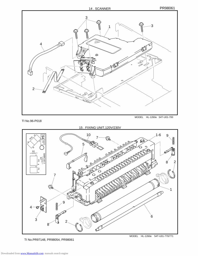
MODEL HL-1260e 54T-U01-700
14 . SCANNER
31
3
2
4
7
MODEL HL-1260e 54T-U01-770/771
15 . FIXING UNIT,120V/230V
1
2
23
4
5
6
7
94B
48K142-2
R1P
24
1P
12
1
R2
C
K
E
APH1
1-6
TI No.96-P018
PR98061
TI No.PR97148, PR98054, PR98061
8
9
8
9
10
Downloaded from www.Manualslib.com manuals search engine
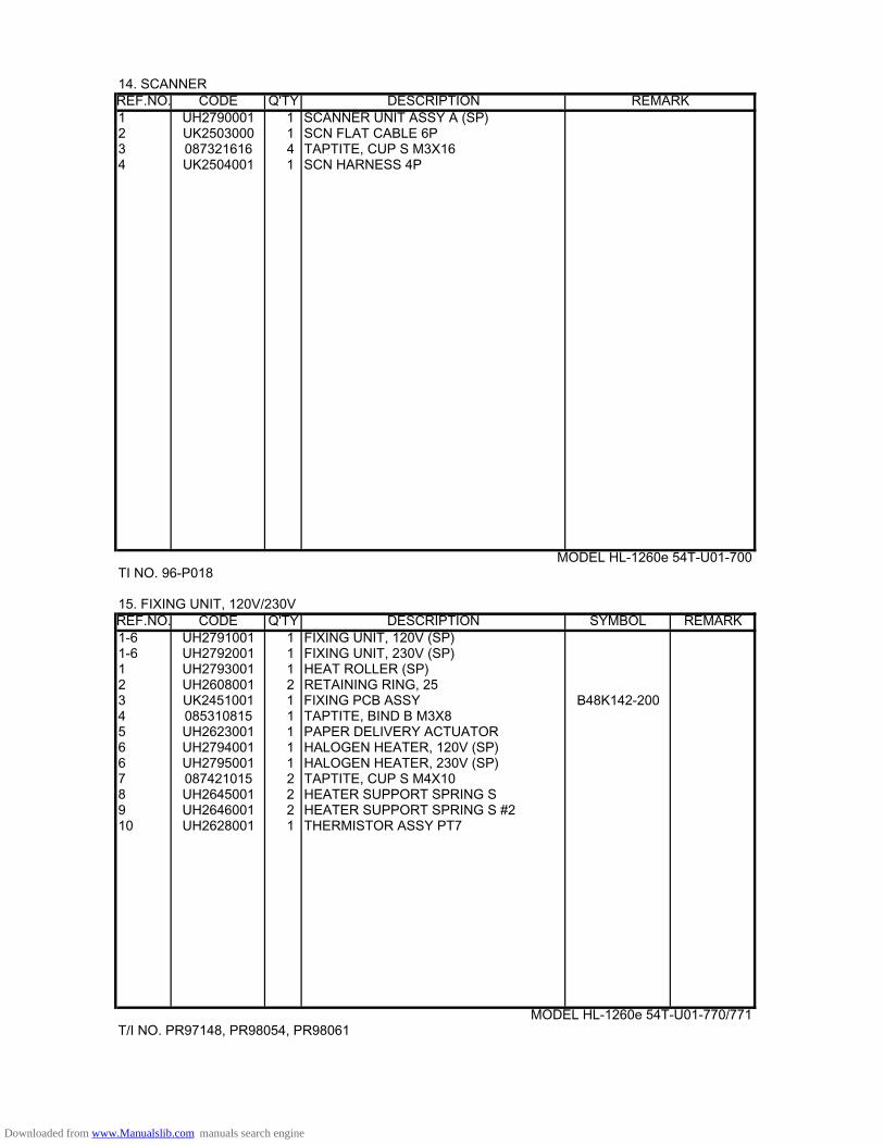
14. SCANNER REF.NO. CODE Q'TY DESCRIPTION REMARK1 UH2790001 1 SCANNER UNIT ASSY A (SP)2 UK2503000 1 SCN FLAT CABLE 6P3 087321616 4 TAPTITE, CUP S M3X164 UK2504001 1 SCN HARNESS 4P MODEL HL-1260e 54T-U01-700TI NO. 96-P018
15. FIXING UNIT, 120V/230VREF.NO. CODE Q'TY DESCRIPTION SYMBOL REMARK1-6 UH2791001 1 FIXING UNIT, 120V (SP)1-6 UH2792001 1 FIXING UNIT, 230V (SP)1 UH2793001 1 HEAT ROLLER (SP)2 UH2608001 2 RETAINING RING, 253 UK2451001 1 FIXING PCB ASSY B48K142-2004 085310815 1 TAPTITE, BIND B M3X85 UH2623001 1 PAPER DELIVERY ACTUATOR6 UH2794001 1 HALOGEN HEATER, 120V (SP)6 UH2795001 1 HALOGEN HEATER, 230V (SP)7 087421015 2 TAPTITE, CUP S M4X108 UH2645001 2 HEATER SUPPORT SPRING S 9 UH2646001 2 HEATER SUPPORT SPRING S #2 10 UH2628001 1 THERMISTOR ASSY PT7
MODEL HL-1260e 54T-U01-770/771
T/I NO. PR97148, PR98054, PR98061
Downloaded from www.Manualslib.com manuals search engine
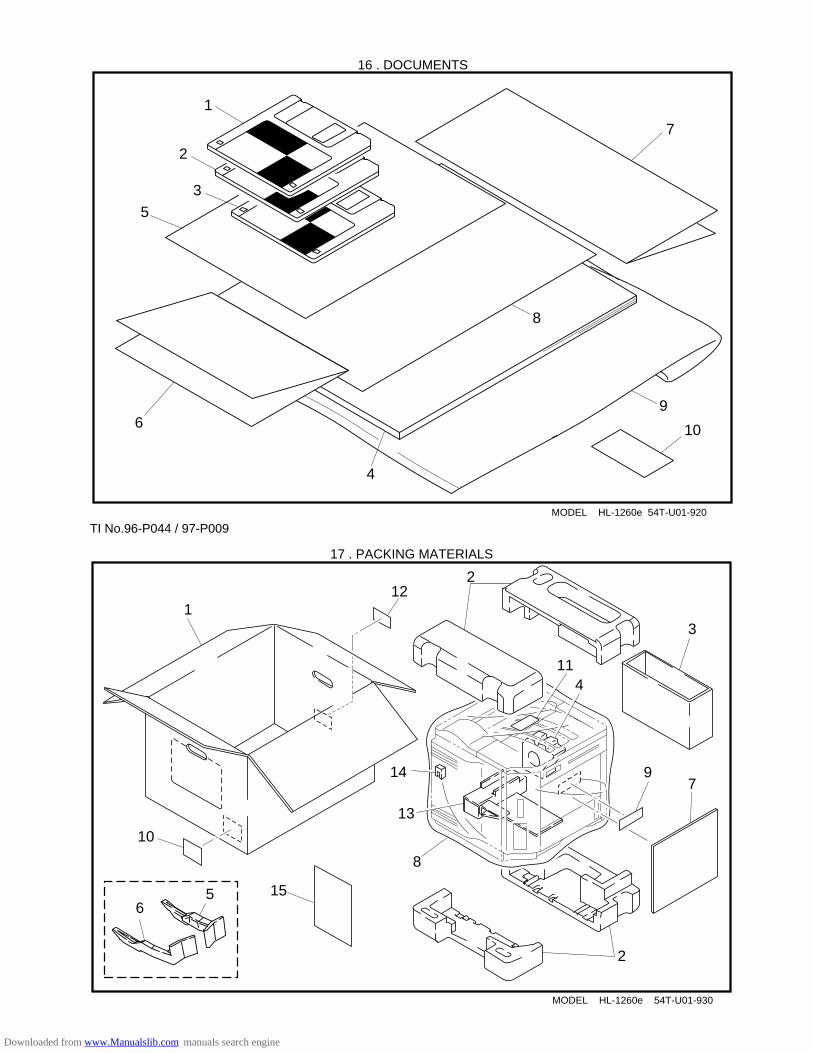
MODEL HL-1260e 54T-U01-920
16 . DOCUMENTS
7
9
10
MODEL HL-1260e 54T-U01-930
17 . PACKING MATERIALS
1
2
2
3
4
9
11
6
714
5
8
13
12
10
1
2
6
3
4
5
8
TI No.96-P044 / 97-P009
15
Downloaded from www.Manualslib.com manuals search engine

16. DOCUMENTS REF.NO. CODE Q'TY DESCRIPTION REMARK1 UK3208001 1 PR DRIVER DISK #1, HL-1260E(FIRST PART 1/2)2 UK3210001 1 PR DRIVER DISK #2, HL-1260E(LATTER PART 2/2)3 UK3198001 1 OP EXPLANATION DISK, ENG HL-1260e3 UK3204001 1 OP EXPLANATION DISK, DEU HL-1260e3 UK3200001 1 OP EXPLANATION DISK, FRA HL-1260e 3 UK3202001 1 OP EXPLANATION DISK, NLD HL-1260e3 UK3206001 1 OP EXPLANATION DISK, NOR HL-1260e4 UH2696001 1 USER'S MANUAL, ENG4 UH2697001 1 USER'S MANUAL, DEU4 UH2698001 1 USER'S MANUAL, FRA4 UH2699001 1 USER'S MANUAL, NLD 4 UH2700001 1 USER'S MANUAL, NOR 5 UK3193001 1 PR DRIVER SET UP, ENG HL-1260e5 UK3196001 1 PR DRIVER SET UP, DEU HL-1260e5 UK3194001 1 PR DRIVER SET UP, FRA HL-1260e5 UK3195001 1 PR DRIVER SET UP, NLD HL-1260e5 UK3197001 1 PR DRIVER SET UP, NOR HL-1260e6 UL5532001 1 WARRANTY CARD, USA6 UH2693001 1 WARRANTY CARD, CAN6 UL7581001 1 WARRANTY CARD, FRA26 237703001 1 WARRANTY CARD, DUTCH7 UL5533001 1 SERVICE CARD 2, USA8 UH1392001 1 EPA INSERTION SHEET, USA9 UE0331001 1 BAG, 215X350H (USER'S MANUAL)10 163528001 1 CAUTION LABEL, BS MODEL HL-1260e 54T-U01-920TI NO. 96-P044 / 96-P063 / 97-P009 / 97-P020 / 97-P038
17. PACKING MATERIALS REF.NO. CODE Q'TY DESCRIPTION REMARK1 UE0490001 1 CARTON, US W/EP-ED HL-1260e1 UE0491001 1 CARTON, EU W/EP-ED HL-1260e2 UE0370000 1 STYROFOAM PAD ASSY3 UE0374000 1 CARTON, TNR CARTRIDGE (W/CARTRIDGE)3 UE0476000 1 CARTON, TNR CARTRIDGE (W.O/CARTRIDGE 4 UE0376000 1 STYROFOAM PAD (PLATE HOLDER)5 UH2735001 1 RELEASE SPACER R6 UH2736001 1 RELEASE SPACER L7 UE0396000 1 PAD (CONTROL PANEL)8 UE0477000 1 BAG, 900X800 (BODY)8 U63969000 1 BAG, 900X800 BS W/HOLE (BODY)9 U62092001 1 CAUTION LABEL 24, US9 163528001 1 CAUTION LABEL BS10 U04510001 1 IMPORTER LABEL, CAN11 X60267002 1 RECYCLE LABEL, DEU/FRA12 UH2743001 1 BAR CODE LABEL, 524236 UPC USA 1260e12 UH2744001 1 BAR CODE LABEL, 525480 EAN EU 1260e13 UE0405000 1 PAD (LETTER SIZE TRAY)13 UE0406000 1 PAD (A4 SIZE TRAY)14 UE0425001 1 POSITION FIXING SPONGE15 UH2741001 1 INSERTION SHEET MODEL HL-1260e 54T-U01-930
Downloaded from www.Manualslib.com manuals search engine
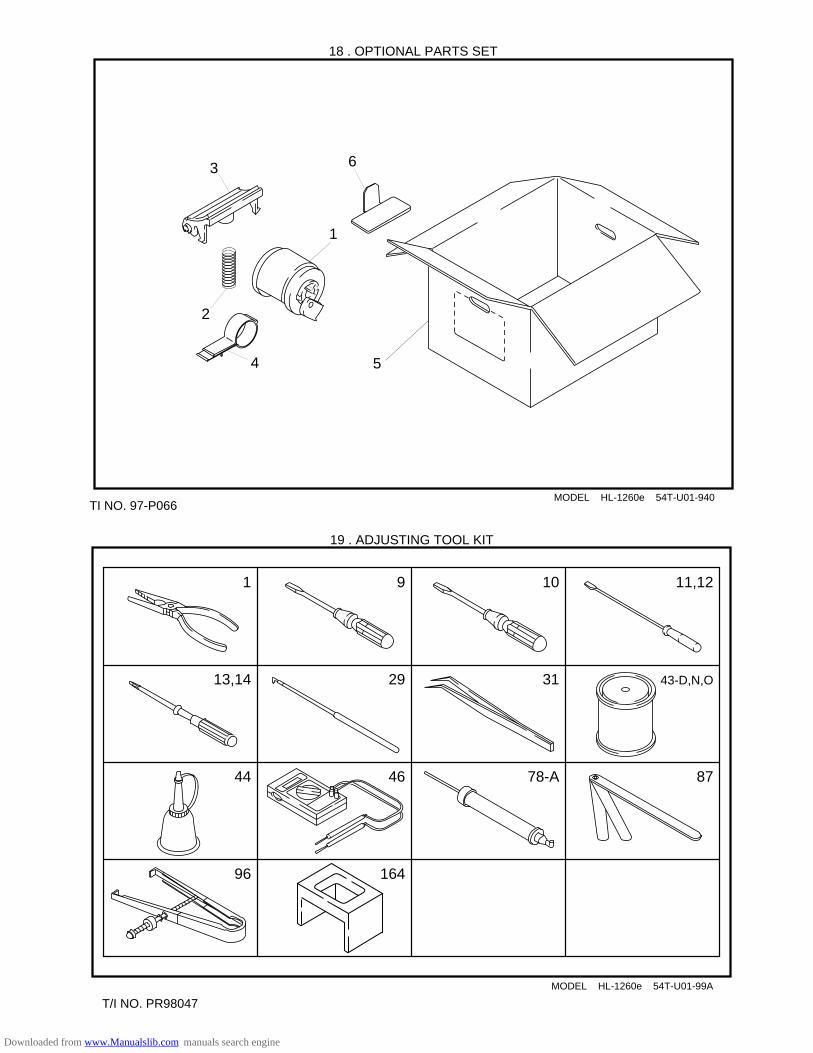
MODEL HL-1260e 54T-U01-99A
19 . ADJUSTING TOOL KIT
91 10 11,12
13,14 29 31 43-D,N,O
44
96
46 78-A 87
164
MODEL HL-1260e 54T-U01-940
18 . OPTIONAL PARTS SET
4 5
3
1
2
TI NO. 97-P066
6
T/I NO. PR98047
Downloaded from www.Manualslib.com manuals search engine
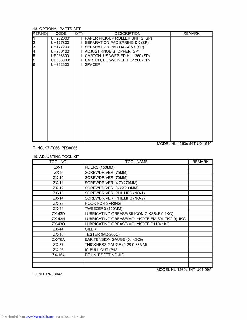
18. OPTIONAL PARTS SETREF.NO. CODE Q'TY DESCRIPTION REMARK1 UH2820001 1 PAPER PICK-UP ROLLER UNIT 2 (SP) 2 UH1778001 1 SEPARATION PAD SPRING DX (SP)3 UH1772001 1 SEPARATION PAD DX ASSY (SP) 4 UH2804001 1 ADJUST KNOB STOPPER (SP)5 UE0368001 1 CARTON, US W/EP-ED HL-1260 (SP)5 UE0369001 1 CARTON, EU W/EP-ED HL-1260 (SP)6 UH2823001 1 SPACER
MODEL HL-1260e 54T-U01-940TI NO. 97-P066, PR98065
19. ADJUSTING TOOL KITTOOL NO. TOOL NAME REMARK
ZX-1 PLIERS (150MM)ZX-9 SCREWDRIVER (75MM)ZX-10 SCREWDRIVER (70MM)ZX-11 SCREWDRIVER (4.7X270MM)ZX-12 SCREWDRIVER, (6.2X200MM)ZX-13 SCREWDRIVER, PHILLIPS (NO-1)ZX-14 SCREWDRIVER, PHILLIPS (NO-2)ZX-29 HOOK FOR SPRINGZX-31 TWEEZERS (150MM)
ZX-43D LUBRICATING GREASE(SILICON G,KS64F 0.1KG)ZX-43N LUBRICATING GREASE(MOLYKOTE EM-30L TKC-0) 1KGZX-43O LUBRICATING GREASE(MOLYKOTE D110) 1KG ZX-44 OILERZX-46 TESTER (MD-200C)
ZX-78A BAR TENSION GAUGE (0.1-5KG)ZX-87 THICKNESS GAUGE (0.28-0.38MM)ZX-96 IC PULL OUT (P42)ZX-164 PF UNIT SETTING JIG
MODEL HL-1260e 54T-U01-99AT/I NO. PR98047
Downloaded from www.Manualslib.com manuals search engine
I
Brother Laser Printer
HL-1260e/HL-1660USER’S GUIDE
Downloaded from www.Manualslib.com manuals search engine
II
Trademarks
Brother is a registered trademark of Brother Industries, Ltd.
Apple and LaserWriter are registered trademarks, and TrueType is a trademark ofApple Computer, Inc.Centronics is a trademark of Genicom Corporation.EPSON is a registered trademark, and FX-850 and FX-80 are trademarks of SeikoEpson Corporation.Hewlett-Packard, HP and PCL are registered trademarks, and HP LaserJet 4+, HPLaserJet Plus, HP LaserJet II, HP LaserJet IID, HP LaserJet IIID, HP-GL, HP-GL/2, and Bi-Tronics are trademarks of Hewlett-Packard Company.IBM, Proprinter XL, Proprinter, and IBM/PC are registered trademarks ofInternational Business Machines Corporation.Intellifont is a registered trademark of AGFA Corporation, a division of Miles, Inc.Microsoft and MS-DOS are registered trademarks of Microsoft Corporation.Windows is a registered trademark of Microsoft Corporation in the United Statesand other countries.PostScript is a registered trademark of Adobe Systems Incorporated.
All other brand and product names mentioned in this user’s guide are registeredtrademarks or trademarks of respective companies.
Compilation and Publication
Under the supervision of Brother Industries Ltd., this manual has been compiledand published, covering the latest product descriptions and specifications.
The contents of this manual and the specifications of this product are subject tochange without notice.
Brother reserves the right to make changes without notice in the specifications andmaterials contained herein and shall not be responsible for any damages (includingconsequential) caused by reliance on the materials presented, including but notlimited to typographical and other errors relating to the publication.
©1996 Brother Industries Ltd.
Shipment of the Printer
If for any reason you must ship your Printer, carefully package the Printer to avoid anydamage during transit. It is recommended that you save and use the original packaging. ThePrinter should also be adequately insured with the carrier.
WARNING
When shipping the Printer, the TONER CARTRIDGE must be removed from the Printer.Failure to remove the Toner Cartridge during shipping will cause severe damage to thePrinter and will VOID THE WARRANTY .
Downloaded from www.Manualslib.com manuals search engine
i
Laser Printer
HL-1260e/HL-1660USER’S GUIDE
(For USA & CANADA Only)
For technical and operational assistance, please call:
In USA 1-800-276-7746 (outside California) 714-859-9700 Ext. 329 (within California)
In CANADA 1-800-853-6660 514-685-6464 (within Montreal)
If you have comments or suggestions, please write us at:
In USA Printer Customer SupportBrother International Corporation15 MusickIrvine, CA 92718
In CANADA Brother International Corporation (Canada), Ltd.- Marketing Dept.1, rue Hôtel de VilleDollard-des-Ormeaux, PQ, Canada H9B 3H6
BBSFor downloading drivers from our Bulletin Board Service, call:In USA 1-714-859-2610In CANADA 1-514-685-2040Please log on to our BBS with your first name, last name and a four digit number for yourpassword. Our BBS supports modem speeds up to 14,400, 8 bits no parity, 1 stop bit.
Fax-Back System (For USA only)Brother Customer Service has installed an easy to use Fax-Back System so you can get instantanswers to common technical questions and product information for all Brother products. This isavailable 24 hours a day, 7 days a week. You can use the system to send the information to anyfax machine, not just the one you are calling from.Please call 1-800-521-2846 and follow the voice prompts to receive faxed instructions on how touse the system and your index of Fax-Back subjects.
DEALERS/SERVICE CENTERS (USA only)For the name of an authorized dealer or service center, call 1-800-284-4357.
SERVICE CENTERS (Canada only)For service center addresses in Canada, call 1-800-853-6660
INTERNET ADDRESSFor technical questions and downloading drivers: http://www.brother.com
Downloaded from www.Manualslib.com manuals search engine
ii
Definitions of Warnings, Cautions, and Notes
The following conventions are used in this User’s Guide:
WarningIndicates warnings that must be observed to prevent possiblepersonal injury.
CautionIndicates cautions that must be observed to use the printer properly orprevent damage to the printer.
✒ NoteIndicates notes and useful tips to remember when using the printer.
To Use the Printer Safely
WarningThe fixing roller is extremely hot during operation. Remove the papercarefully.
Downloaded from www.Manualslib.com manuals search engine
TABLE OF CONTENTS
iii
TABLE OF CONTENTS
IMPORTANT INFORMATION: REGULATIONS ......................... ix
CHAPTER 1 GENERAL.............................................................. 1-1
ABOUT THIS MANUAL...................................................................... 1-1
ABOUT CHAPTERS ON THE FLOPPY DISK ................................... 1-3
ABOUT THIS PRINTER....................................................................... 1-4
Features ............................................................................................ 1-4
Options ............................................................................................. 1-10
CHAPTER 2 GETTING STARTED.............................................. 2-1
BEFORE USING THE PRINTER ......................................................... 2-1
Checking the Components................................................................ 2-1
Printer Carton.............................................................................. 2-1
Toner Cartridge ........................................................................... 2-2
General View .................................................................................... 2-3
Operating and Storage Environment ............................................... 2-4
Power Supply.............................................................................. 2-4
Environment ............................................................................... 2-4
SETTING UP THE PRINTER............................................................... 2-5
Opening and Closing the Printer ...................................................... 2-5
Removing the Protective Parts.......................................................... 2-6
Installing the Toner Cartridge........................................................... 2-7
Loading Paper in the Paper Cassette ................................................ 2-11
Connecting the Printer to Your Computer ........................................ 2-17
Turning the Printer On and Off ........................................................ 2-19
Plugging in the Power Cord ....................................................... 2-19
Pressing the POWER Switch ...................................................... 2-20
Printing the Test Patterns or Lists ..................................................... 2-21
Checking the Printed Test Pattern or Demo Page............................. 2-24
Downloaded from www.Manualslib.com manuals search engine
USER’S GUIDE
iv
CHAPTER 3 BEFORE WORKING WITH THE PRINTER ........... 3-1
SOFTWARE COMPATIBILITY............................................................ 3-1
AUTOMATIC EMULATION SELECTION.......................................... 3-3
AUTOMATIC INTERFACE SELECTION ........................................... 3-5
ABOUT THE CONTROL PANEL ........................................................ 3-7
Adjusting the Control Panel Angle................................................... 3-7
Selecting the Local Language Display ............................................. 3-8
Using the Panel Switches ................................................................. 3-9
Printer Settings ................................................................................. 3-10
User Settings............................................................................... 3-10
Factory Settings .......................................................................... 3-10
PAPER HANDLING.............................................................................. 3-11
Print Media ....................................................................................... 3-11
Paper Size ................................................................................... 3-11
Using Envelopes ......................................................................... 3-13
Cassette Feed.................................................................................... 3-15
Manual Feed..................................................................................... 3-16
Face Down Print Delivery ................................................................ 3-17
Face Up Print Delivery ..................................................................... 3-17
CHAPTER 4 CONTROL PANEL................................................. 4-1
DISPLAY AND LAMPS........................................................................ 4-1
Display ............................................................................................. 4-1
Printer Status Messages .............................................................. 4-2
Lamps ............................................................................................... 4-4
READY....................................................................................... 4-4
DATA .......................................................................................... 4-4
ALARM...................................................................................... 4-4
ON LINE .................................................................................... 4-4
Downloaded from www.Manualslib.com manuals search engine
TABLE OF CONTENTS
v
SWITCHES IN NORMAL MODE........................................................ 4-5
SEL Switch ...................................................................................... 4-5
SET Switch...................................................................................... 4-6
▲ (UP) or ▼ (DOWN) Switch ........................................................ 4-6
MODE Switch ................................................................................. 4-7
MODE Switch Settings in HP LaserJet 4+,
EPSON FX-850, and IBM Proprinter XL Modes....................... 4-8
MODE Switch Settings in BR-Script Mode ............................... 4-11
MODE Switch Settings in HP-GL Mode.................................... 4-13
Basic Operation Procedures........................................................ 4-15
Operation Example: Selecting the Parallel Interface ................. 4-16
INTERFACE MODE .................................................................. 4-17
FORMAT MODE ....................................................................... 4-20
ORIENTATION ..................................................................... 4-20
AUTO MODE........................................................................ 4-21
PAGE FORMAT MODE........................................................ 4-22
GRAPHICS MODE............................................................... 4-25
RESOLUTION MODE............................................................... 4-28
PAGE PROTECTION................................................................. 4-31
CARD OPERATION .................................................................. 4-32
ADVANCED MODE.................................................................. 4-41
NETWORK MODE............................................................... 4-41
ERROR PRINT...................................................................... 4-44
CONTINUE MODE .............................................................. 4-44
BUZZER SETTING .............................................................. 4-45
SCALABLE FONT ............................................................... 4-45
PRINT DENSITY.................................................................. 4-46
INPUT BUFFER.................................................................... 4-46
SAVE SETTINGS.................................................................. 4-47
PAGE COUNTER....................................................................... 4-48
EXIT MODE .............................................................................. 4-48
FONT Switch................................................................................... 4-49
Setting the Font and Symbol Set in the HP LaserJet 4+ Mode... 4-49
Setting the Font and Character Set in the EPSON FX-850,
or IBM Proprinter XL Mode ...................................................... 4-54
List of Fonts ................................................................................ 4-59
List of Symbol/Character Sets .................................................... 4-60
FORM FEED Switch (REPRINT Switch) ...................................... 4-61
Form Feed................................................................................... 4-61
Reprint Function ......................................................................... 4-61
CONTINUE Switch ....................................................................... 4-63
Downloaded from www.Manualslib.com manuals search engine
USER’S GUIDE
vi
SWITCHES IN SHIFT MODE.............................................................. 4-64
SHIFT Switch ................................................................................. 4-64
EMULATION Switch ..................................................................... 4-65
About Emulation Modes............................................................. 4-67
ECONOMY Switch......................................................................... 4-69
TONER SAVE MODE................................................................ 4-69
POWER SAVE MODE............................................................... 4-69
FEEDER Switch.............................................................................. 4-70
FEEDER ..................................................................................... 4-70
MP FIRST................................................................................... 4-72
MANUAL FEED........................................................................ 4-73
MP TRAY SETTING.................................................................. 4-73
MEDIA TYPE ............................................................................ 4-74
DUPLEX MODE........................................................................ 4-75
COPY Switch................................................................................... 4-77
RESET Switch................................................................................. 4-78
List of Factory Settings............................................................... 4-79
TEST Switch.................................................................................... 4-85
HEX DUMP MODE .............................................................................. 4-88
CHAPTER 5 OPTIONS............................................................... 5-1
LOWER TRAY UNIT (LT-1200/LT-1600) ............................................ 5-1
Loading Paper from the Lower Paper Cassette ................................ 5-1
FONT CARTRIDGE/CARD, FLASH MEMORY/HDD CARD........... 5-2
Installing a Font Cartridge/Card, Flash Memory Card and
HDD Card ........................................................................................ 5-2
Selecting the Optional Fonts ............................................................ 5-4
MODULAR I/O CARD ......................................................................... 5-6
RAM EXPANSION ............................................................................... 5-7
DUPLEX UNIT (DX-1200/DX-1600) .................................................. 5-11
Downloaded from www.Manualslib.com manuals search engine
TABLE OF CONTENTS
vii
CHAPTER 6 MAINTENANCE..................................................... 6-1
MAINTENANCE................................................................................... 6-1
Toner Cartridge................................................................................. 6-1
Toner Empty Message ................................................................ 6-1
Replacing the Toner Cartridge .................................................... 6-2
Cleaning ........................................................................................... 6-5
Cleaning the Printer Exterior ...................................................... 6-5
Cleaning the Printer Interior ....................................................... 6-6
CHAPTER 7 TROUBLESHOOTING ............................................... 7-1
TROUBLESHOOTING ......................................................................... 7-1
Operator Call Messages.................................................................... 7-1
Error Messages ................................................................................. 7-3
Service Call Messages ...................................................................... 7-5
Possible Troubles.............................................................................. 7-6
Paper Jam.................................................................................... 7-6
Unsatisfactory Printouts.............................................................. 7-12
APPENDICES ............................................................................Appendix-1
PRINTER SPECIFICATIONS............................................................... Appendix-1
Printing ............................................................................................. Appendix-1
Functions .......................................................................................... Appendix-2
Electrical and Mechanical ................................................................ Appendix-3
PAPER SPECIFICATIONS.................................................................... Appendix-4
INTERFACE SPECIFICATIONS .......................................................... Appendix-8
Bi-directional Parallel Interface........................................................ Appendix-8
Pin Assignment ........................................................................... Appendix-8
Signal Description ...................................................................... Appendix-9
Parallel Cable Connection for IBM-PC/AT or
Compatible Computers and IBM-PS/2 Computers...................Appendix-10
Downloaded from www.Manualslib.com manuals search engine
USER’S GUIDE
viii
RS-232C Serial Interface................................................................Appendix-11
Standard Specifications.............................................................Appendix-11
Interface Connectors .................................................................Appendix-11
Pin Assignment .........................................................................Appendix-11
Signal Description ....................................................................Appendix-12
Serial Cable Connection for IBM-PC/AT or
Compatible Computers and IBM-PS/2 Computers...................Appendix-13
SYMBOL/CHARACTER SETS..........................................................Appendix-14
OCR Symbol Sets...........................................................................Appendix-14
HP LaserJet 4+ Mode .....................................................................Appendix-15
EPSON Mode .................................................................................Appendix-22
IBM Mode ......................................................................................Appendix-25
HP-GL Mode..................................................................................Appendix-27
Symbol Sets Supported by the Printer’s Intellifont Compatible
Typefaces........................................................................................Appendix-32
Symbol Sets Supported by the Printer’s TrueType and Type 1
Font Compatible, and Original Typefaces ......................................Appendix-34
QUICK REFERENCE OF COMMANDS ...........................................Appendix-36
HP LaserJet 4+ Mode .....................................................................Appendix-36
PCL Command Sets..................................................................Appendix-36
CCITT G3/G4 and TIFF ...........................................................Appendix-49
Horizontal 1200-dpi Image Format Mode ................................Appendix-52
HP-GL/2 Command Sets ..........................................................Appendix-55
Printer Job Language Commands Syntax .................................Appendix-57
EPSON FX-850 Mode....................................................................Appendix-58
IBM Proprinter XL Mode...............................................................Appendix-61
HP-GL Mode..................................................................................Appendix-64
Bar Code Control............................................................................Appendix-66
Print Bar Codes or Expanded Characters..................................Appendix-66
INDEX........................................................................................... Index-1
Downloaded from www.Manualslib.com manuals search engine
REGULATIONS
ix
IMPORTANT INFORMATION: REGULATIONS
Federal Communications Commission Compliance Notice(For U.S.A. only)
This equipment has been tested and found to comply with the limits for aClass B digital device, pursuant to Part 15 of the FCC Rules. These limitsare designed to provide reasonable protection against harmfulinterference in a residential installation. This equipment generates, uses,and can radiate radio frequency energy and, if not installed and used inaccordance with the instructions, may cause harmful interference to radiocommunications. However, there is no guarantee that interference willnot occur in a particular installation. If this equipment does cause harmfulinterference to radio or television reception, which can be determined byturning the equipment off and on, the user is encouraged to try to correctthe interference by one or more of the following measures:
– Reorient or relocate the receiving antenna. – Increase the separation between the equipment and receiver. – Connect the equipment into an outlet on a circuit different from that
to which the receiver is connected. – Consult the dealer or an experienced radio/TV technician for help.
Important – About the Interface CableThis printer has been certified to comply with FCC standards, which areapplied to the U.S.A. only. A shielded interface cable should be usedaccording to FCC 15.27(C). In addition, a grounded plug should beplugged into a grounded AC outlet after checking the rating of the localpower supply for the printer to operate properly and safely.
☛ CautionChanges or modifications not expressly approved by Brother Industries,Ltd. could void the user’s authority to operate the equipment.
International Energy Star Compliance Statement (For HL-1660only)
The purpose of the International Energy Star Program is to promote thedevelopment and popularization of energy-efficient office equipments, whichincludes computers, monitors, printers, facsimile receivers and copy machinesworld-wide.As an International Energy Star partner, Brother Industries, Ltd. has decided thatthis product meets the guideline of the program.
Downloaded from www.Manualslib.com manuals search engine

USER’S GUIDE
x
Canadian Department of Communications ComplianceStatement (For Canada only)
This digital apparatus does not exceed the Class B limits for radio noiseemissions from digital apparatus as set out in the interference- causingequipment standard entitled “Digital Apparatus”, ICES-003 of theDepartment of Communications.
Avis de conformité aux normes du ministère desCommunications du Canada (Pour Canada Seul)
Cet appareil numérique respecte les limites de bruits radioélectriquesapplicables aux appareils numériques de Classe B prescrites dans lanorme sur le matériel brouilleur : “Appareils Numériques”, NMB-003édictée par le ministère des Communications.
Laser Safety (110-120 V model only)
This printer is certified as a Class I laser product under the U.S.Department of Health and Human Services (DHHS) RadiationPerformance Standard according to the Radiation Control for Health andSafety Act of 1968. This means that the printer does not producehazardous laser radiation.
Since radiation emitted inside the printer is completely confined withinprotective housings and external covers, the laser beam cannot escapefrom the machine during any phase of user operation.
CDRH Regulations (110-120 V model only)
The Center for Devices and Radiological Health (CDRH) of the U.S.Food and Drug Administration (FDA) implemented regulations for laserproducts on August 2, 1976. These regulations apply to laser productsmanufactured from August 1, 1976. Compliance is mandatory forproducts marketed in the United States. The label shown on the back ofthe printer indicates compliance with the CDRH regulations and must beattached to laser products marketed in the United States.
MANUFACTURED:BROTHER INDUSTRIES, LTD.15-1 Naeshiro-cho Mizuho-ku Nagoya, 467 JapanThis product complies with FDA radiation performance standards, 21CFR chapter 1 subchapter J.
Downloaded from www.Manualslib.com manuals search engine
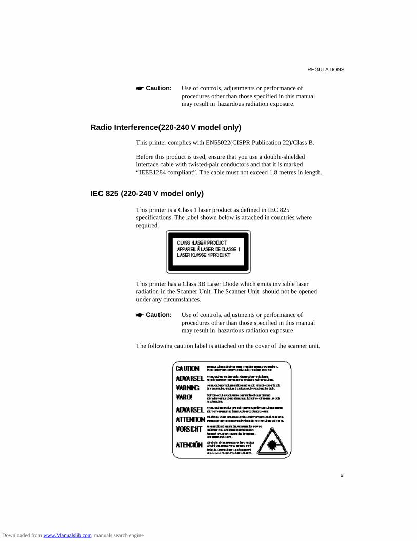
REGULATIONS
xi
☛ Caution: Use of controls, adjustments or performance of procedures other than those specified in this manual may result in hazardous radiation exposure.
Radio Interference(220-240 V model only)
This printer complies with EN55022(CISPR Publication 22)/Class B.
Before this product is used, ensure that you use a double-shieldedinterface cable with twisted-pair conductors and that it is marked“IEEE1284 compliant”. The cable must not exceed 1.8 metres in length.
IEC 825 (220-240 V model only)
This printer is a Class 1 laser product as defined in IEC 825specifications. The label shown below is attached in countries whererequired.
This printer has a Class 3B Laser Diode which emits invisible laserradiation in the Scanner Unit. The Scanner Unit should not be openedunder any circumstances.
☛ Caution: Use of controls, adjustments or performance of procedures other than those specified in this manual may result in hazardous radiation exposure.
The following caution label is attached on the cover of the scanner unit.
Downloaded from www.Manualslib.com manuals search engine
USER’S GUIDE
xii
For Finland and SwedenLUOKAN 1 LASERLAITEKLASS 1 LASER APPARAT
☛ Varoitus! Laitteen käyttäminen muulla kuin tässä käyttöohjeessamainitulla tavalla saattaa altistaa käyttäjän turvallisuusluokan 1 ylittävällenäkymättömälle lasersäteilylle.
Varning – Om apparaten används på annat sätt än i denna Bruksanvisningspecificerats, kan användaren utsättas för osynlig laserstrålning, somöverskrider gränsen för laserklass 1.
For Your Safety
To ensure safe operation the three-pin plug supplied must be insertedonly into a standard three-pin power point which is effectively groundedthrough the normal household wiring.
Extension cords used with the equipment must be three-conductor and becorrectly wired to provide connection to ground. Incorrectly wiredextension cords are a major cause of fatalities.
The fact that the equipment operates satisfactorily does not imply that thepower is grounded and that the installation is completely safe. For yoursafety, if in any doubt about the effective grounding of the power, consulta qualified electrician.
Wiring Information (For U.K. only)
Important
If the mains plug supplied with this printer is not suitable for your socketoutlet, remove the plug from the mains cord and fit an appropriate threepin plug. If the replacement plug is intended to take a fuse then fit thesame rating fuse as the original.
If a moulded plug is severed from the mains cord then it should bedestroyed because a plug with cut wires is dangerous if engaged in a livesocket outlet. Do not leave it where a child might find it!
In the event of replacing the plug fuse, fit a fuse approved by ASTA toBS1362 with the same rating as the original fuse.
Always replace the fuse cover. Never use a plug with the cover omitted.
WARNING - THIS PRINTER MUST BE EARTHED
Downloaded from www.Manualslib.com manuals search engine

REGULATIONS
xiii
The wires in the mains cord are coloured in accordance with thefollowing code :GREEN AND YELLOW : EARTHBLUE : NEUTRALBROWN : LIVE
The colours of the wires in the mains lead of this printer may notcorrespond with the coloured markings identifying the terminals in yourplug.
If you need to fit a different plug, proceed as follows.
Remove a length of the cord outer sheath, taking care not to damage thecoloured insulation of the wires inside.
Cut each of the three wires to the appropriate length. If the constructionof the plug permits, leave the green and yellow wire longer than theothers so that, in the event that the cord is pulled out of the plug, thegreen and yellow wire will be the last to disconnect.
Remove a short section of the coloured insulation to expose the wires.
The wire which is coloured green and yellow must be connected to theterminal in the plug which is marked with the letter “E” or by the safetyearth symbol , or coloured green or green and yellow.
The wire which is coloured blue must be connected to the terminal whichis marked with the letter “N” or coloured black or blue.
The wire which is coloured brown must be connected to the terminalwhich is marked with the letter “L” or coloured red or brown.
The outer sheath of the cord must be secured inside the plug. Thecoloured wires should not hang out of the plug.
Downloaded from www.Manualslib.com manuals search engine

USER’S GUIDE
xiv
DECLARATION OF CONFORMITY (EUROPE)
We, Brother International Europe Ltd.,Brother House 1 tame Street, Guide Bridge,Audenshaw, Manchester M34 5JE, UK.
declare that this product is in conformity with the following normativedocuments:
Safety: EN 60950, EN 60825EMC: EN 55022 Class B, EN 50082-1
following the provisions of the Low Voltage Directive 73/23/EEC and theElectromagnetic Compatibility Directive 89/336/EEC (as amended by91/263/EEC and 92/31/EEC).
Manufacture at the following facilities is carried out under a QualitySystem which is registered by BSI Quality Assurance and JQA QualityAssurance.
Brother Industries, Ltd., Kariya Plant1-5, Kitajizoyama, Noda-cho, Kariya-shi,Aichi-ken 448, Japan.BSI Certificate of Registration No. FM27391JQA Certificate of Registration No. 0340
Issued by:
Brother International Europe Ltd.European Development and Technical Services Division
Downloaded from www.Manualslib.com manuals search engine
CHAPTER 1 GENERAL
1–1
CHAPTER 1GENERAL
ABOUT THIS MANUAL
This manual acts as your guide to the setup and operation of your printerand covers the following topics:
CHAPTER 1 GENERAL provides an overview of the printer. Read thischapter first to get familiar with the printer.
CHAPTER 2 GETTING STARTED gives you general information aboutthis printer. Be sure to read this chapter before you use the printer.
CHAPTER 3 BEFORE WORKIN G WIT H THE PRINTER gives youimportant information on the printer setup to work with your computer andsoftware. Be sure to read this chapter before you work with the printer.
CHAPTER 4 CONTROL PANEL details the functions of the panelswitches and lamps. (Disk)
CHAPTER 5 OPTIONS describes the optional accessories for thisprinter. (Disk)
CHAPTER 6 MAINTENANCE provides guidance on how to maintainyour printer (Disk)
CHAPTER 7 TROUBLESHOOTIN G helps you troubleshoot the printerin case of problems.
APPENDICES contain detailed technical information on the printer aswell as the character sets and a quick reference guide to the printer controlcommands. (Disk)
INDEX provides an alphabetical list of the contents of this manual and thefloppy disk supplied with the printer.
Downloaded from www.Manualslib.com manuals search engine

USER’S GUIDE
1–2
✒ NotesWhen you read this user’s guide, note the following: • Chapters 4, 5, 6 and the Appendices of this User’s Guide are on the
floppy disk provided with this printer. Read ABOUT CHAPTERS ONTHE FLOPPY DISK (See page 1-3) carefully before you print out theadditional chapters included on the floppy disk.
• This user’s guide contains instructions or steps to teach you variousoperations of the printer. Remember that the instructions start with thefactory settings, particularly in Chapter 2 and Chapter 3. If you changethe settings, particularly the emulation mode, the display messageschange accordingly.
• The paper size has been factory set to letter or A4, depending upon thefinal destination of the printer. Some display messages appeardifferently in accordance with this setting.
Downloaded from www.Manualslib.com manuals search engine
CHAPTER 1 GENERAL
1–3
ABOUT CHAPTERS ON THE FLOPPY DISK
■ The floppy disk provided with this printer contains Chapters 4, 5, 6, and the Appendices of this User’s Guide. Follow the steps below to install and print out the sections you need to see.
1. Set up your printer referring to CHAPTER 2 GETTING STARTED.
2. Start your computer and MS-DOS® or Windows 95 / Windows 3.1.
3. Insert the printer User’s Guide floppy disk into the floppy disk drive Aof your computer. It is assumed that A: is your floppy disk drive in thisdescription.
4. Install the Disk Manual into your computer.(for DOS user)Type A:\INSTALL and press ENTER key.Follow the messages on the screen.(for Windows 95 user)Click Start and choose Run.Type A:\SETUP and press the ENTER key.(for Windows 3.1 user)Choose the RUN command from the FILE menu in the ProgramManager.Type A:\SETUP and press the ENTER key.
■ Once you installed the Disk Manual into your computer, follow the steps below to print out the sections you need to see.
Print chapters from the Disk Manual.(for DOS user)Type HL1260e or HL1660 and press ENTER key. You do not need tochoose disk drive nor directory. Follow the messages on the screen.(for Windows 95 user)
Double-click the HL1260e or HL1660 Series folder on the screen, andthen the Disk Manual icon. Follow the messages on the screen.(for Windows 3.1 user)
Double-click the HL1260e or HL1660 group icon (sign on the screen)and then the Disk Manual icon. Follow the messages on the screen.
✒ Notes • You will need a minimum of 6 MB free area on your hard disk drive in
order to print any sections of the User's Guide. • Use A4 or letter size paper for printing.
Downloaded from www.Manualslib.com manuals search engine

USER’S GUIDE
1–4
ABOUT THIS PRINTER
Features
This printer has the following standard features. When you need moreinformation on how to use a particular feature, turn to the page indicated atthe end of the paragraph.
High Speed and Quiet Laser Printing
This printer uses electrophotography technology by laser beam scanning sothat it can print at a speed of 12 pages per minute. The controller utilizes ahigh speed 32-bit RISC microprocessor and special hardware chips. Thequiet printing will not bother you working in your office or at home: max.49 dB A (printing)/40 dB A (stand-by).
600 DPI Resolution
This printer uses a print engine with a resolution of 600 dots per inch (dpi).Compared with a 300-dpi engine, the quality of the output is far superior.See page 4-28. By utilizing the 300-dpi mode, the printer can also print300-dpi data, if necessary. (In HP emulation you can select a horizontal1200-dpi mode by special control command. See page Appendix-52.)
High Resolution Control
The high resolution control (HRC) technology provides clear and crispprintouts and improves even the 600-dpi resolution. See 4-30.
Maintenance-Free Toner Cartridge
The toner cartridge can print up to 6,000 single-sided pages. The one piece,easy-to-replace toner cartridge does not require difficult maintenance. Justinstall it. See 2-7.
Advanced Photoscale Technology
This printer can print graphics in 256 shades of gray in HP® LaserJet 4+™emulation and BR-Script level 2, producing nearly photographic quality.
Downloaded from www.Manualslib.com manuals search engine

CHAPTER 1 GENERAL
1–5
Universal Paper Cassette and Manual Loading
This printer loads paper automatically from the paper cassette. Since thepaper cassette is a universal type, a number of different sizes of paper canbe used. Even envelopes can be loaded from the multi-purpose tray and theupper paper cassette. In addition, the multi-purpose tray allows you to loadpaper sheet by sheet. See 3-15 for auto loading and 3-16 for manualloading.
Three Interfaces
This printer has a high speed bi-directional parallel interface, an RS-232Cserial interface, and a modular input/output (MIO) compatible interface.
If your application software supports the bi-directional parallel interface,you can monitor the printer status. It is fully compatible with theindustry-standard bi-directional parallel interface. See page 2-17.
The RS-232C serial interface is an industry standard so that you canconnect it to any computer using a standard serial cable. See page 2-17.
The MIO interface allows you to install a commercial MIO-compatiblecard. If you install the card, you can use one more interface port for featuressuch as networking or printer sharing. See page 5-6.
Automatic Interface Selection
This printer can automatically select the bi-directional parallel, RS-232Cserial, or MIO interface depending on the interface port through which itreceives data. With this feature, the printer can be connected to more thanone computer. See page 3-5.
Five Emulation Modes
This printer can emulate the Hewlett-Packard® laser printer-LaserJet 4+
(PCL® 5e), PostScript® Level 2 language emulation (Brother BR-ScriptLevel 2) printers, the industry-standard HP-GL™ plotter as well asEPSON® FX-850™, and IBM® Proprinter XL® printers. You can printwith all application programs that support one of these printers. See page3-1.
Downloaded from www.Manualslib.com manuals search engine

USER’S GUIDE
1–6
Automatic Emulation Selection
This printer can automatically select the printer emulation mode dependingon the print commands it receives from the computer software. With thisfeature, many users can share the printer on a network. See page 3-3.
Data Compression Technology
This printer can internally compress the received graphics and font data inits memory so that it can print larger graphics and more fonts withoutadditional memory.
Memory Expansion
This printer has 2-Mbyte or 4-Mbyte of RAM as standard. It can beexpanded up to 66 Mbytes. The memory should be expanded to 6 Mbytes intotal or more to enjoy 600-dpi or APT printouts in the BR-Script 2 mode.When you select duplex mode with an optional duplex unit installed, thememory should be expanded to 10Mbytes in total or more to enjoy 600-dpiduplex printing. See pages 4-28 and 5-7. (The standard memory fitted canvary depending on the printer model and country.)
75 Scalable and 12 Bitmapped Fonts
This printer has the following scalable fonts and bitmapped fonts. The fontsthat can be used vary according to the current emulation mode.
■ HP LaserJet 4+, EPSON FX-850, and IBM Proprinter XL Modes See printed Appendix after Chapter 7.
Scalable Fonts:Intellifont Compatible Fonts:• Alaska, Extrabold• Antique Oakland, Oblique, Bold• Brougham, Oblique, Bold, BoldOblique• Cleveland Condensed• Connecticut• Guatemala Antique, Italic, Bold, BoldItalic• Letter Gothic, Oblique, Bold• Maryland• Oklahoma, Oblique, Bold, BoldOblique• PC Brussels Light, LightItalic, Demi, DemiItalic• PC Tennessee Roman, Italic, Bold, BoldItalic• Utah, Oblique, Bold, BoldOblique• Utah Condensed, Oblique, Bold, BoldOblique
Downloaded from www.Manualslib.com manuals search engine

CHAPTER 1 GENERAL
1–7
Microsoft® Windows® 3.1 / Windows 95 TrueType™Compatible Fonts:• BR Symbol• Helsinki, Oblique, Bold, BoldOblique• Tennessee Roman, Italic, Bold, BoldItalic• W Dingbats
Type 1 Font Compatible Fonts:• Atlanta Book, BookOblique, Demi, DemiOblique• Calgary MediumItalic• Copenhagen Roman, Italic, Bold, BoldItalic• Portugal Roman, Italic, Bold, BoldItalic
Brother Original Fonts:• Bermuda Script• Germany• San Diego• US Roman
Bitmapped Fonts (Portrait and Landscape):• LetterGothic16.66 Medium, Italic, Bold, BoldItalic• OCR-A• OCR-B
■ BR-Script 2 Mode
Scalable Fonts:• Atlanta Book, BookOblique, Demi, DemiOblique• Alaska, Extrabold• Antique Oakland, Oblique, Bold• Bermuda Script• BR Dingbats• BR Symbol• Brougham, Oblique, Bold, BoldOblique• Brussels Light, LightItalic, Demi, DemiItalic• Calgary MediumItalic• Cleveland Condensed• Connecticut• Copenhagen Roman, Italic, Bold, BoldItalic• Germany• Guatemala Antique, Italic, Bold, BoldItalic• Helsinki, Oblique, Bold, BoldOblique• Helsinki Narrow, Oblique, Bold, BoldOblique• Letter Gothic, Oblique, Bold• Maryland• Oklahoma, Oblique, Bold, Bold Oblique• Portugal Roman, Italic, Bold, BoldItalic• San Diego• Tennessee Roman, Italic, Bold, BoldItalic• US Roman• Utah, Oblique, Bold, BoldOblique• Utah Condensed, Oblique, Bold, BoldOblique
Downloaded from www.Manualslib.com manuals search engine

USER’S GUIDE
1–8
High Speed Printing with Microsoft Windows 95 / Windows 3.1
Since TrueType compatible fonts are resident in this printer, the printer canprint them with Microsoft Windows 95 / Windows version 3.1 at a highspeed without downloading them. Because the printer has a TrueType Fontrasterizer, it can rasterize fonts at a high speed.
Bar Code Print
This printer can print the following 11 types of bar codes:
• Code 39 • UPC-E • Interleaved 2 of 5 • Codabar • EAN-8 • US-PostNet • EAN-13 • ISBN • UPC-A • Code 128 • EAN-128
CCITT G3/G4
Since this printer supports the CCITT G3/G4 format in addition to HP-compatible formats, it can quickly receive and print data compressed in thisformat.
Lock Panel
If the panel switch settings have been changed, the printer may not work asyou expect. You can lock your settings to prevent changes from beingmade. See page 4-41.
Power Save Mode
This printer has a power saving mode. As laser printers consume power tokeep the fixing assembly at a high temperature, this feature can saveelectricity when the printer is on but not being used. The factory setting ofthe Power Save mode is ON that complies with EPA Energy Star newspecification. Compared with conventional laser printers, this printerconsumes less power even when the power saving mode is turned off. Seepage 4-69.
Toner Save Mode
This printer has an economical toner save mode. You can cut your printerrunning cost substantially by using this mode in addition to the improvedlife expectancy of the toner cartridge. See page 4-69.
Downloaded from www.Manualslib.com manuals search engine

CHAPTER 1 GENERAL
1–9
Reprint Function
You can reprint the last page printed with a touch of a panel switch whichallows reprinting without sending the data again from the computer. Seepage 4-61.
Flash Memory Card and HDD Card
You can store fonts, macros, logos, and other print data in a commercialPCMCIA-compatible flash memory card or HDD card that is installed inthe upper card slot of this printer. See pages 4-32 and 5-2.
Saving User Settings
You can operate the printer differently from other users with your ownpanel switch settings. Two sets of user settings can be stored. See page 4-47.
Downloaded from www.Manualslib.com manuals search engine
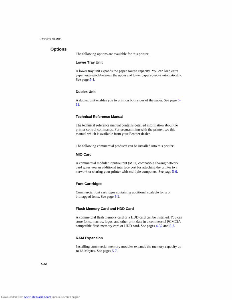
USER’S GUIDE
1–10
OptionsThe following options are available for this printer:
Lower Tray Unit
A lower tray unit expands the paper source capacity. You can load extrapaper and switch between the upper and lower paper sources automatically.See page 5-1.
Duplex Unit
A duplex unit enables you to print on both sides of the paper. See page 5-11.
Technical Reference Manual
The technical reference manual contains detailed information about theprinter control commands. For programming with the printer, see thismanual which is available from your Brother dealer.
The following commercial products can be installed into this printer:
MIO Card
A commercial modular input/output (MIO) compatible sharing/networkcard gives you an additional interface port for attaching the printer to anetwork or sharing your printer with multiple computers. See page 5-6.
Font Cartridges
Commercial font cartridges containing additional scalable fonts orbitmapped fonts. See page 5-2.
Flash Memory Card and HDD Card
A commercial flash memory card or a HDD card can be installed. You canstore fonts, macros, logos, and other print data in a commercial PCMCIA-compatible flash memory card or HDD card. See pages 4-32 and 5-2.
RAM Expansion
Installing commercial memory modules expands the memory capacity upto 66 Mbytes. See pages 5-7.
Downloaded from www.Manualslib.com manuals search engine
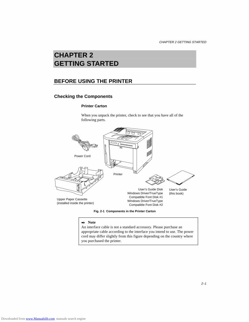
CHAPTER 2 GETTING STARTED
2–1
CHAPTER 2GETTING STARTED
BEFORE USING THE PRINTER
Checking the Components
Printer Carton
When you unpack the printer, check to see that you have all of thefollowing parts.
Fig. 2-1 Components in the Printer Carton
✒ NoteAn interface cable is not a standard accessory. Please purchase anappropriate cable according to the interface you intend to use. The powercord may differ slightly from this figure depending on the country whereyou purchased the printer.
Printer
Power Cord
User’s Guide(this book)
User’s Guide DiskWindows Driver/TrueType
Compatible Font Disk #1Windows Driver/TrueType
Compatible Font Disk #2
Upper Paper Cassette(installed inside the printer)
Downloaded from www.Manualslib.com manuals search engine
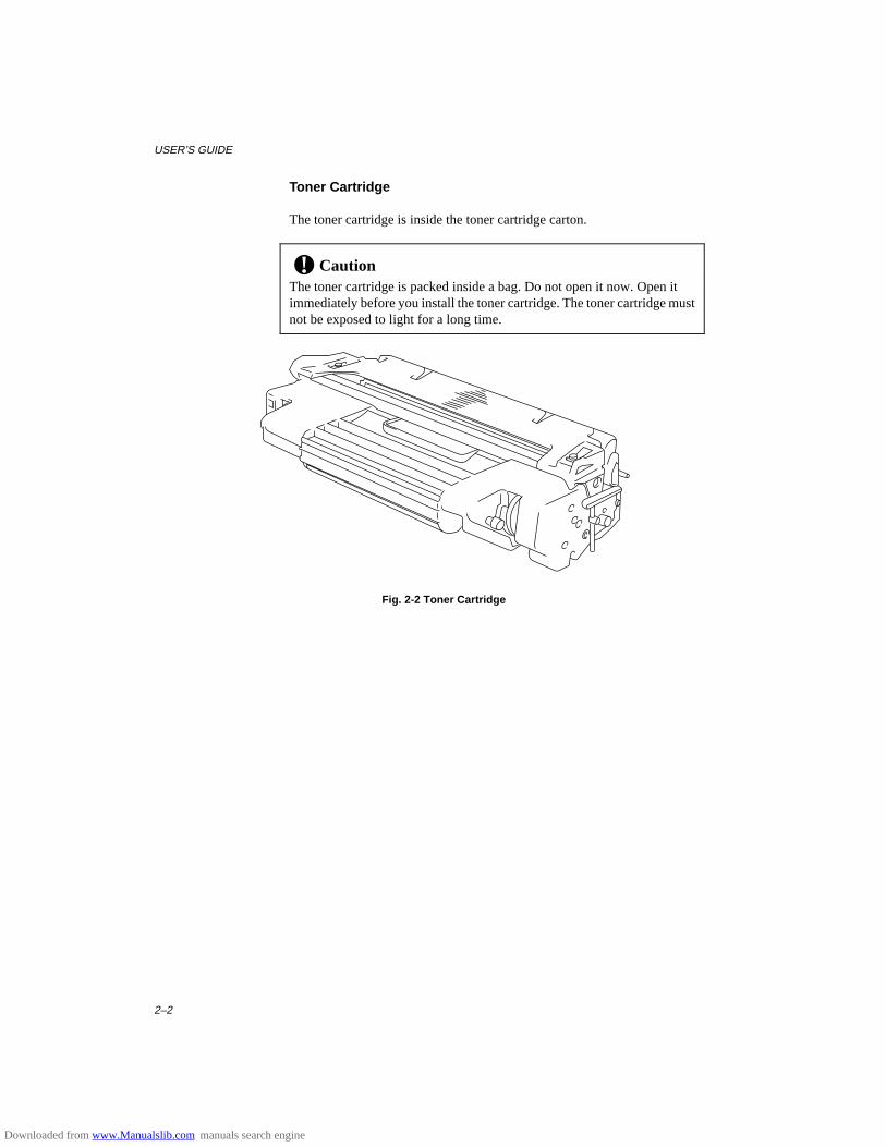
USER’S GUIDE
2–2
Toner Cartridge
The toner cartridge is inside the toner cartridge carton.
! CautionThe toner cartridge is packed inside a bag. Do not open it now. Open itimmediately before you install the toner cartridge. The toner cartridge mustnot be exposed to light for a long time.
Fig. 2-2 Toner Cartridge
Downloaded from www.Manualslib.com manuals search engine
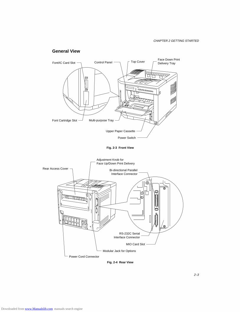
CHAPTER 2 GETTING STARTED
2–3
General View
A
B
Fig. 2-3 Front View
Fig. 2-4 Rear View
Top Cover
Multi-purpose Tray
Face Down PrintDelivery TrayFont/IC Card Slot
Font Cartridge Slot
Upper Paper Cassette
Power Switch
Control Panel
Power Cord Connector
Bi-directional ParallelInterface Connector
RS-232C SerialInterface Connector
MIO Card Slot
Rear Access Cover
Adjustment Knob forFace Up/Down Print Delivery
Modular Jack for Options
Downloaded from www.Manualslib.com manuals search engine
USER’S GUIDE
2–4
Operating and Storage Environment
Please take note of the following before using the printer.
Power Supply
Use the printer within the specified power range.
AC power: ±10% of the rated power voltageFrequency: 50 Hz (220-240 V) or 60 Hz (110-120 V)
The power cord, including extensions, should not exceed 5 meters (16.5feet).
Do not share the same power circuit with other high-power appliances,particularly an air conditioner, copier, shredder, etc. If it is unavoidable thatyou must use the printer with these appliances, we recommend you use avoltage transformer or a high-frequency noise filter.
Use a voltage regulator if the power source is not stable.
Environment
Use the printer only within the following ranges of temperature andhumidity.
Ambient temperature: 10°C to 32.5°C (50°F to 90.5°F)Ambient humidity: 20% to 80% (without condensation)
Do not block the air exit on top of the printer. Do not place objects on top ofthe printer, especially on the air exit.
Ventilate the room where you use the printer.
Do not place the printer where it is exposed to direct sunlight. Use a blindor a heavy curtain to protect the printer from direct sunlight if the printer isunavoidably set up near a window.
Do not install the printer near devices that contain magnets or generatemagnetic fields.
Do not subject the printer to strong physical shocks or vibrations. Do notexpose the printer to open flames or salty or corrosive gasses.
Place the printer on a flat, horizontal surface.
Keep the printer clean. Do not install the printer in a dusty place.Do not install the printer near an air conditioner.
Downloaded from www.Manualslib.com manuals search engine
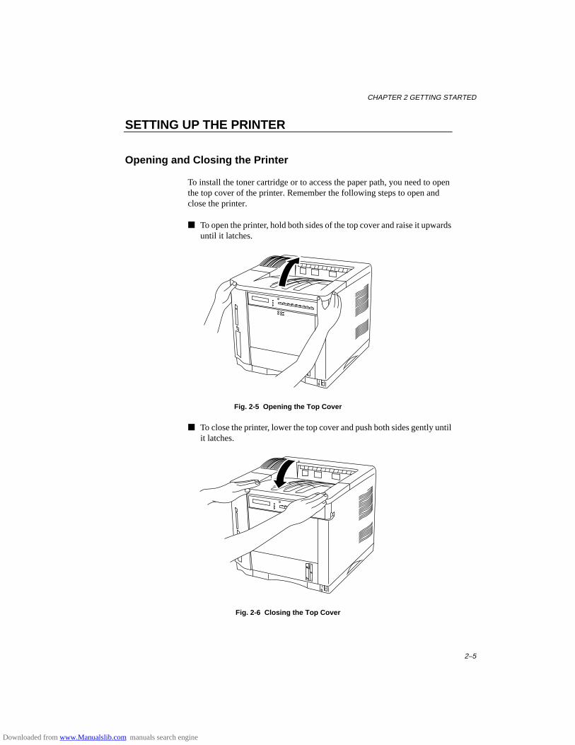
CHAPTER 2 GETTING STARTED
2–5
SETTING UP THE PRINTER
Opening and Closing the Printer
To install the toner cartridge or to access the paper path, you need to openthe top cover of the printer. Remember the following steps to open andclose the printer.
■ To open the printer, hold both sides of the top cover and raise it upwardsuntil it latches.
Fig. 2-5 Opening the Top Cover
■ To close the printer, lower the top cover and push both sides gently untilit latches.
Fig. 2-6 Closing the Top Cover
Downloaded from www.Manualslib.com manuals search engine
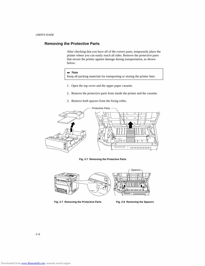
USER’S GUIDE
2–6
Removing the Protective Parts
After checking that you have all of the correct parts, temporarily place theprinter where you can easily reach all sides. Remove the protective partsthat secure the printer against damage during transportation, as shownbelow:
✒ NoteKeep all packing materials for transporting or storing the printer later.
1. Open the top cover and the upper paper cassette.
2. Remove the protective parts from inside the printer and the cassette.
3. Remove both spacers from the fixing roller.
Fig. 2-7 Removing the Protective Parts
Fig. 2-7 Removing the Protective Parts Fig. 2-8 Removing the Spacers
Protective Parts
Spacers
Downloaded from www.Manualslib.com manuals search engine
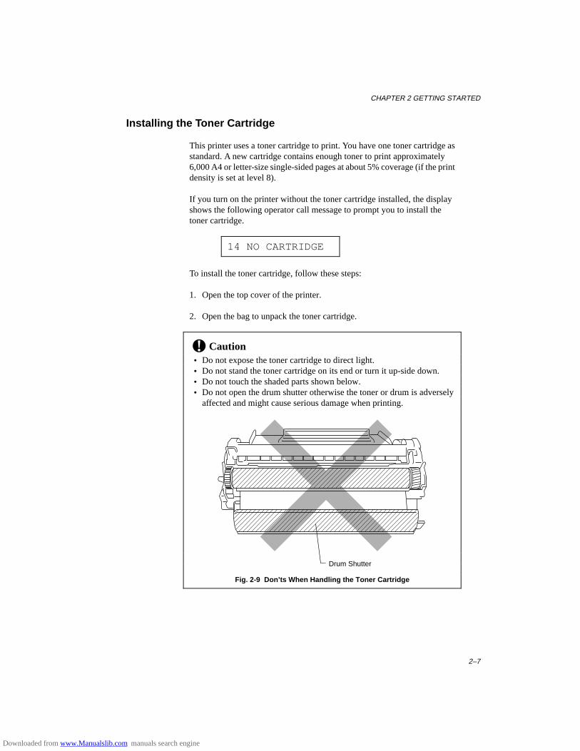
CHAPTER 2 GETTING STARTED
2–7
Installing the Toner Cartridge
This printer uses a toner cartridge to print. You have one toner cartridge asstandard. A new cartridge contains enough toner to print approximately6,000 A4 or letter-size single-sided pages at about 5% coverage (if the printdensity is set at level 8).
If you turn on the printer without the toner cartridge installed, the displayshows the following operator call message to prompt you to install thetoner cartridge.
14 NO CARTRIDGE
To install the toner cartridge, follow these steps:
1. Open the top cover of the printer.
2. Open the bag to unpack the toner cartridge.
! Caution • Do not expose the toner cartridge to direct light. • Do not stand the toner cartridge on its end or turn it up-side down. • Do not touch the shaded parts shown below. • Do not open the drum shutter otherwise the toner or drum is adversely
affected and might cause serious damage when printing.
Fig. 2-9 Don’ts When Handling the Toner Cartridge
Drum Shutter
Downloaded from www.Manualslib.com manuals search engine
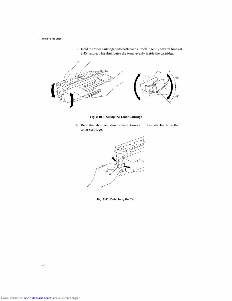
USER’S GUIDE
2–8
3. Hold the toner cartridge with both hands. Rock it gently several times ata 45° angle. This distributes the toner evenly inside the cartridge.
45°
45°
Fig. 2-10 Rocking the Toner Cartridge
4. Bend the tab up and down several times until it is detached from thetoner cartridge.
Fig. 2-11 Detaching the Tab
Downloaded from www.Manualslib.com manuals search engine
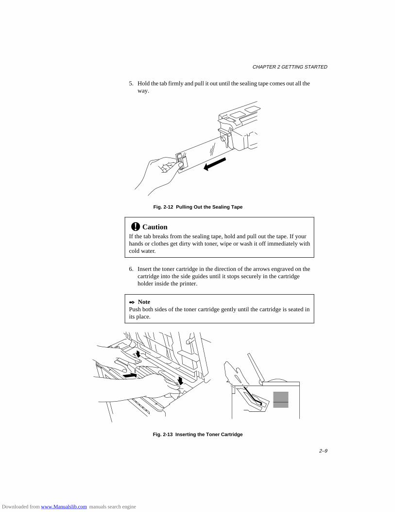
CHAPTER 2 GETTING STARTED
2–9
5. Hold the tab firmly and pull it out until the sealing tape comes out all theway.
Fig. 2-12 Pulling Out the Sealing Tape
! CautionIf the tab breaks from the sealing tape, hold and pull out the tape. If yourhands or clothes get dirty with toner, wipe or wash it off immediately withcold water.
6. Insert the toner cartridge in the direction of the arrows engraved on thecartridge into the side guides until it stops securely in the cartridgeholder inside the printer.
✒ NotePush both sides of the toner cartridge gently until the cartridge is seated inits place.
Fig. 2-13 Inserting the Toner Cartridge
Downloaded from www.Manualslib.com manuals search engine

USER’S GUIDE
2–10
7. Close the top cover of the printer.
When the cartridge has almost run out of toner, the display shows thefollowing operator call message to prompt you to replace the tonercartridge.
16 TONER EMPTY
Although you can print several pages after the toner empty messageappears, be sure to replace the toner cartridge with a new one before itbecomes completely empty.
✒ NoteYou can select the printer’s operation when the “Toner Empty” message isdisplayed with the MODE switch. The printer continues or stops printing.For further information, see “Toner Low” in Chapter 4.
For toner cartridge replacement, see “Toner Cartridge” in Chapter 6.
Downloaded from www.Manualslib.com manuals search engine

CHAPTER 2 GETTING STARTED
2–11
Loading Paper in the Paper Cassette
The printer usually loads paper from the installed multi-purpose tray,upper cassette or optional lower paper cassette.
✒ NoteThe lower tray unit is an option for this printer. This section refers to theupper paper cassette. For information about the lower paper cassette, see“LOWER TRAY UNIT” in Chapter 5.
Since the paper cassette is a universal type, you can set letter, A4, legal, ISOB5, executive, A5, ISO B6, or A6 size cut sheet paper or COM10,Monarch, C5, DL, or ISO B5 size envelopes in the paper cassette.The paper sources have the following limitation. For more informationabout paper, see “PRINT MEDIA” in Chapter 3.
paper source available size available type andcapacity
the multi-purpose tray(MP)
cut sheet : letter, legal, A4, ISO B5, Executive, A5, ISO B6 and A6envelope: COM 10, Monarch, C5, DL and ISO B5other size: wide 90-216mm (3.5”-8.5”) long 148-356mm (5.8”-14”)
plain paper : 150envelope : 15OHP film : 100label stock : 100other type : weight =60 to 135 g/m2
(16 to 36 lbs)
the upperpaper cassette(T1)
cut sheet : letter, legal, A4, ISO B5, Executive, A5, ISO B6 and A6envelope :COM 10, Monarch, C5, DL and ISO B5
plain paper : 500weight =60 to 105 g/m2
(16 to 28 lbs)envelope : 40
the optionallower papercassette (T2)
cut sheet : letter, legal, A4, Executive
plain paper : 500weight =60 to 90 g/m2
(16 to 24 lbs)all sourcesfor duplexprinting (DX)
cut sheet : letter, legal, A4, ISO B5(except T2) and Executive
* The capacity of T1is reduced fromthe above specifiedcapacities withthe duplex unitinstalled.
Downloaded from www.Manualslib.com manuals search engine

USER’S GUIDE
2–12
Follow these steps to set paper and install the paper cassette:
✒ NoteBe sure to select the same paper size as the paper to be used from yourapplication software, or correct printing cannot be obtained.If your application software does not support paper size selection on itsprint menu, you can change the paper size with the MODE switch in theFORMAT MODE. For paper size change, see “MODE Switch” in Chapter4.The paper size has been factory set to letter or A4, depending upon the finaldestination of the printer.
•110/120V model: Letter size paper set.•220/240V model: A4 size paper set.
Load paper into the paper cassette as follows:
1. Pull the paper cassette out of the printer.
Fig. 2-14 Removing the Paper Cassette
Downloaded from www.Manualslib.com manuals search engine
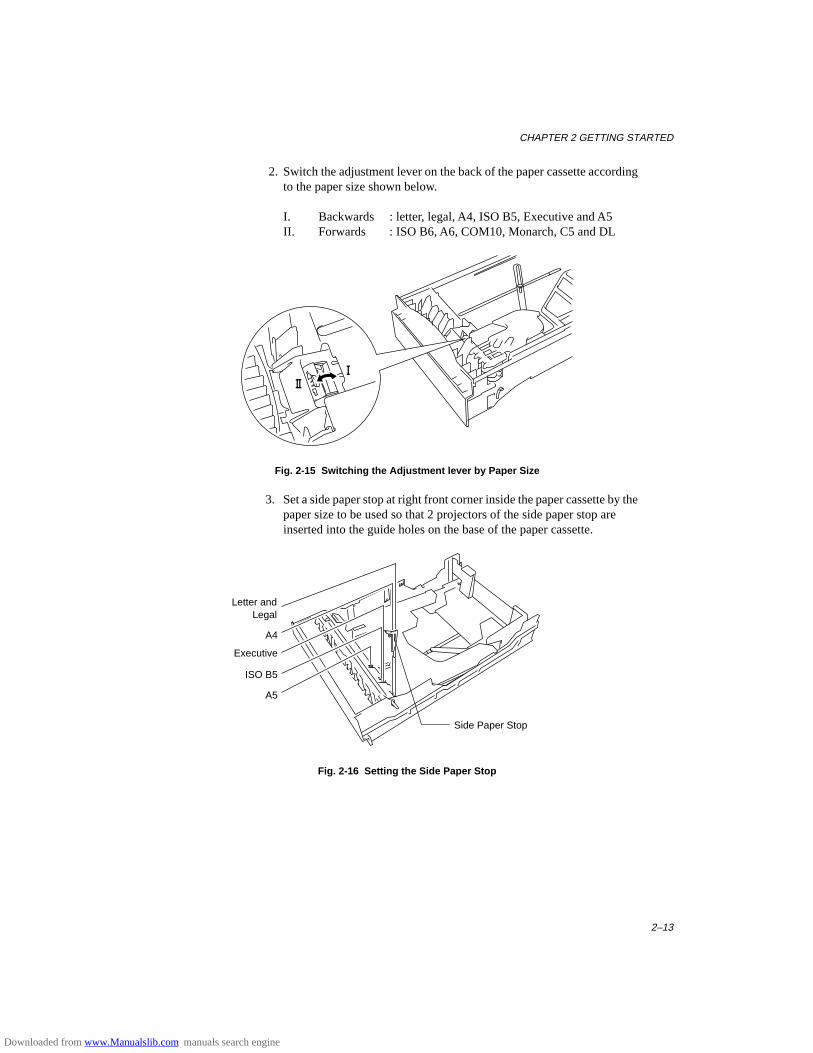
CHAPTER 2 GETTING STARTED
2–13
2. Switch the adjustment lever on the back of the paper cassette accordingto the paper size shown below.
I. Backwards : letter, legal, A4, ISO B5, Executive and A5II. Forwards : ISO B6, A6, COM10, Monarch, C5 and DL
Fig. 2-15 Switching the Adjustment lever by Paper Size
3. Set a side paper stop at right front corner inside the paper cassette by thepaper size to be used so that 2 projectors of the side paper stop areinserted into the guide holes on the base of the paper cassette.
Fig. 2-16 Setting the Side Paper Stop
Side Paper Stop
Letter andLegal
A4
Executive
ISO B5
A5
Downloaded from www.Manualslib.com manuals search engine
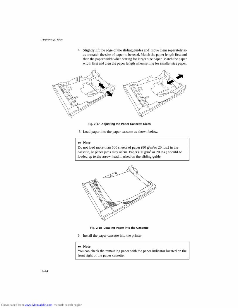
USER’S GUIDE
2–14
4. Slightly lift the edge of the sliding guides and move them separately soas to match the size of paper to be used. Match the paper length first andthen the paper width when setting for larger size paper. Match the paperwidth first and then the paper length when setting for smaller size paper.
Fig. 2-17 Adjusting the Paper Cassette Sizes
5. Load paper into the paper cassette as shown below.
✒ NoteDo not load more than 500 sheets of paper (80 g/m2or 20 lbs.) in thecassette, or paper jams may occur. Paper (80 g/m2 or 20 lbs.) should beloaded up to the arrow head marked on the sliding guide.
Fig. 2-18 Loading Paper into the Cassette
6. Install the paper cassette into the printer.
✒ NoteYou can check the remaining paper with the paper indicator located on thefront right of the paper cassette.
Downloaded from www.Manualslib.com manuals search engine
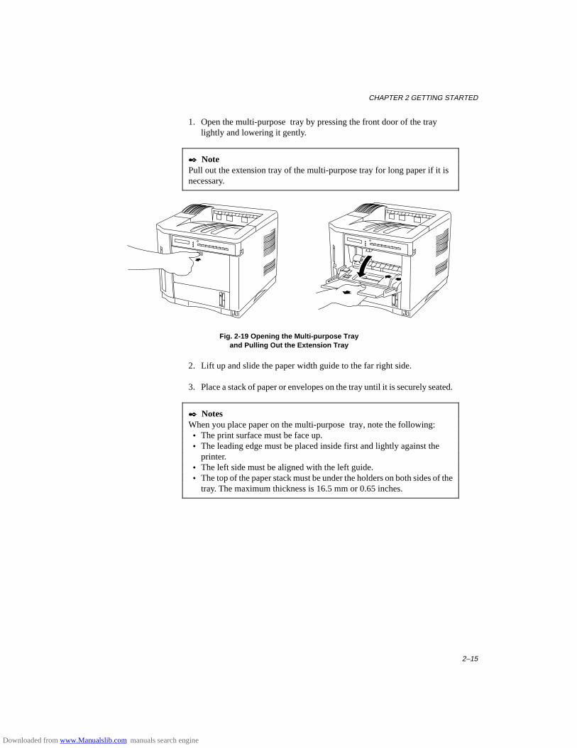
CHAPTER 2 GETTING STARTED
2–15
1. Open the multi-purpose tray by pressing the front door of the traylightly and lowering it gently.
✒ NotePull out the extension tray of the multi-purpose tray for long paper if it isnecessary.
Fig. 2-19 Opening the Multi-purpose Trayand Pulling Out the Extension Tray
2. Lift up and slide the paper width guide to the far right side.
3. Place a stack of paper or envelopes on the tray until it is securely seated.
✒ NotesWhen you place paper on the multi-purpose tray, note the following: • The print surface must be face up. • The leading edge must be placed inside first and lightly against the
printer. • The left side must be aligned with the left guide. • The top of the paper stack must be under the holders on both sides of the
tray. The maximum thickness is 16.5 mm or 0.65 inches.
Downloaded from www.Manualslib.com manuals search engine
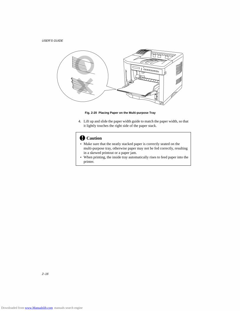
USER’S GUIDE
2–16
Fig. 2-20 Placing Paper on the Multi-purpose Tray
4. Lift up and slide the paper width guide to match the paper width, so thatit lightly touches the right side of the paper stack.
! Caution • Make sure that the neatly stacked paper is correctly seated on the
multi-purpose tray, otherwise paper may not be fed correctly, resultingin a skewed printout or a paper jam.
• When printing, the inside tray automatically rises to feed paper into theprinter.
Downloaded from www.Manualslib.com manuals search engine

CHAPTER 2 GETTING STARTED
2–17
Connecting the Printer to Your Computer
This printer has a bi-directional parallel interface and an RS-232C serialinterface. They allow the printer to communicate with IBM/PC® orcompatible computers. Before connecting the printer and computer, youneed to purchase or make a connecting cable specifically for the interfaceto be used. See “INTERFACE SPECIFICATIONS” in Appendix.
Since the automatic interface selection mode has been factory set, simplyconnect the interface cable to the printer. In some cases, you need to turnoff the high-speed and bi-directional parallel communications with theMODE switch. For further information, see “MODE Switch” in Chapter 4.
When you use the serial interface, you need to have the samecommunications settings on both the printer and computer. Since theautomatic interface selection mode has been factory set with certain factorysettings (baud rate = 9600, code type = 8 bits, parity = none, stop bit = 1,Xon/Xoff = ON, DTR (ER) = ON, and Robust Xon = ON), you may simplyconnect the interface cable if these are the same as the settings on yourcomputer. When necessary, set the communications parameters with theMODE switch on the printer. For further information, see “MODE Switch”in Chapter 4. For the settings on the computer, see the manual of thecomputer or software you use.
Connect the printer to your computer as follows:
1. Make sure that both the computer and the printer are turned off.
! CautionAlways turn off the printer and computer when connecting anddisconnecting the cable.
2. Connect one end of the interface cable to the interface connectorlocated on the back of the printer.
Downloaded from www.Manualslib.com manuals search engine
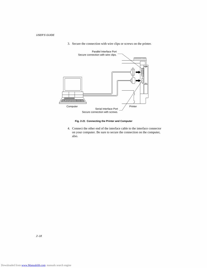
USER’S GUIDE
2–18
3. Secure the connection with wire clips or screws on the printer.
Computer Printer
Fig. 2-21 Connecting the Printer and Computer
4. Connect the other end of the interface cable to the interface connectoron your computer. Be sure to secure the connection on the computer,also.
Parallel Interface PortSecure connection with wire clips.
Serial Interface PortSecure connection with screws.
Downloaded from www.Manualslib.com manuals search engine
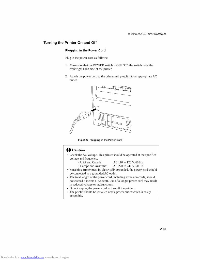
CHAPTER 2 GETTING STARTED
2–19
Turning the Printer On and Off
Plugging in the Power Cord
Plug in the power cord as follows:
1. Make sure that the POWER switch is OFF “O”: the switch is on thefront right hand side of the printer.
2. Attach the power cord to the printer and plug it into an appropriate ACoutlet.
Fig. 2-22 Plugging in the Power Cord
! Caution • Check the AC voltage. This printer should be operated at the specified
voltage and frequency.• USA and Canada: AC 110 to 120 V, 60 Hz• Europe and Australia: AC 220 to 240 V, 50 Hz
• Since this printer must be electrically grounded, the power cord shouldbe connected to a grounded AC outlet.
• The total length of the power cord, including extension cords, shouldnot exceed 5 meters (16.4 feet). Use of a longer power cord may resultin reduced voltage or malfunctions.
• Do not unplug the power cord to turn off the printer. • The printer should be installed near a power outlet which is easily
accessible.
Downloaded from www.Manualslib.com manuals search engine
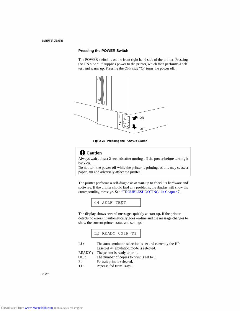
USER’S GUIDE
2–20
Pressing the POWER Switch
The POWER switch is on the front right hand side of the printer. Pressingthe ON side “ | ” supplies power to the printer, which then performs a selftest and warm up. Pressing the OFF side “O” turns the power off.
Fig. 2-23 Pressing the POWER Switch
! CautionAlways wait at least 2 seconds after turning off the power before turning itback on.Do not turn the power off while the printer is printing, as this may cause apaper jam and adversely affect the printer.
The printer performs a self-diagnosis at start-up to check its hardware andsoftware. If the printer should find any problems, the display will show thecorresponding message. See “TROUBLESHOOTING” in Chapter 7.
04 SELF TEST
The display shows several messages quickly at start-up. If the printerdetects no errors, it automatically goes on-line and the message changes toshow the current printer status and settings.
LJ READY 001P T1
LJ : The auto emulation selection is set and currently the HPLaserJet 4+ emulation mode is selected.
READY : The printer is ready to print.001 : The number of copies to print is set to 1.P : Portrait print is selected.T1 : Paper is fed from Tray1.
ON
OFF
Downloaded from www.Manualslib.com manuals search engine
CHAPTER 2 GETTING STARTED
2–21
Printing the Test Patterns or Lists
You can check print quality and print a list of available fonts before youactually start working with the printer. To do so, follow these steps:
1. Make sure that you have already set the toner cartridge and loadedpaper into the cassette or the multi-purpose tray.
2 Turn on the printer. Wait until the display shows the message asfollows.
LJ READY 001P T1
or
LJ READY 001P MP
3. Press the SEL switch to set the printer off-line.
The ON LINE lamp goes off.
4. Hold down the SHIFT switch and press the TEST switch.
5. Press the ▲ or ▼ switch to scroll through the display until the desiredmessage appears. To print your selection, press the SET switch.Choose from one of the following selections :
To print out the demo page,
DEMO PAGE
To print out the test pattern,
TEST PRINT
To print out the list of printer settings,
PRINT CONFIG
To print out the list of internal or resident fonts,
PRINT FONTS I
Downloaded from www.Manualslib.com manuals search engine
USER’S GUIDE
2–22
To print out the list of optional cartridge/card fonts,
PRINT FONTS C
To print out the list of permanent download fonts,
PRINT FONTS P
To exit from the test mode,
exit
✒ NotesThe messages “PRINT FONTS C” or “PRINT FONTS P” appear onlywhen an optional font cartridge/card is installed in the font slot or thepermanent download fonts are stored in printer memory respectively. • If the optional font cartridge/card is installed, you can print out a list of
optional fonts. Since the list shows the ID numbers specific to eachoptional font, it helps you to select them with the FONT switch. Forfurther information, see “FONT Switch” in Chapter 4 and “FONTCARTRIDGE/CARD, FLASH MEMORY/HDD CARD” in Chapter 5.
• If user-defined characters are already downloaded into the printermemory as permanent download fonts, you can print out a list of them.For further information, see “FONT Switch” in Chapter 4.
Downloaded from www.Manualslib.com manuals search engine
CHAPTER 2 GETTING STARTED
2–23
6. Press the SET switch.
The printer starts printing the selected test pattern or list. When theprinter finishes printing, it automatically exits to the off-line state.
!"#$%&'()*+,-./1234567890:;@ABCDEFGHIJKLMNOPQRSTUVWXYZ[\]^_`abcdefghijklmnopqrstuvwxyz[|"#$%&'()*+,-./1234567890:;@ABCDEFGHIJKLMNOPQRSTUVWXYZ[\]^_`abcdefghijklmnopqrstuvwxyz{\}#$%&'()*+,-./1234567890:;@ABCDEFGHIJKLMNOPQRSTUVWXYZ[\]^_`abcdefghijklmnopqrstuvwxyz{\}~$%&'()*+,-./1234567890:;@ABCDEFGHIJKLMNOPQRSTUVWXYZ[\]^_`abcdefghijklmnopqrstuvwxyz{\}~!%&'()*+,-./1234567890:;@ABCDEFGHIJKLMNOPQRSTUVWXYZ[\]^_`abcdefghijklmnopqrstuvwxyz{\}~!"&'()*+,-./1234567890:;@ABCDEFGHIJKLMNOPQRSTUVWXYZ[\]^_`abcdefghijklmnopqrstuvwxyz{\}~!"#'()*+,-./1234567890:;@ABCDEFGHIJKLMNOPQRSTUVWXYZ[\]^_`abcdefghijklmnopqrstuvwxyz{\}~!"#$()*+,-./1234567890:;@ABCDEFGHIJKLMNOPQRSTUVWXYZ[\]^_`abcdefghijklmnopqrstuvwxyz{\}~!"#$%)*+,-./1234567890:;@ABCDEFGHIJKLMNOPQRSTUVWXYZ[\]^_`abcdefghijklmnopqrstuvwxyz{\}~!"#$%&*+,-./1234567890:;@ABCDEFGHIJKLMNOPQRSTUVWXYZ[\]^_`abcdefghijklmnopqrstuvwxyz{\}~!"#$%&'+,-./1234567890:;@ABCDEFGHIJKLMNOPQRSTUVWXYZ[\]^_`abcdefghijklmnopqrstuvwxyz{\}~!"#$%&'(,-./1234567890:;@ABCDEFGHIJKLMNOPQRSTUVWXYZ[\]^_`abcdefghijklmnopqrstuvwxyz{\}~!"#$%&'()-./1234567890:;@ABCDEFGHIJKLMNOPQRSTUVWXYZ[\]^_`abcdefghijklmnopqrstuvwxyz{\}~!"#$%&'()* ./1234567890:;@ABCDEFGHIJKLMNOPQRSTUVWXYZ[\]^_`abcdefghijklmnopqrstuvwxyz{\}~!"#$%&'()*+/1234567890:;@ABCDEFGHIJKLMNOPQRSTUVWXYZ[\]^_`abcdefghijklmnopqrstuvwxyz{\}~!"#$%&'()*+,1234567890:;@ABCDEFGHIJKLMNOPQRSTUVWXYZ[\]^_`abcdefghijklmnopqrstuvwxyz{\}~!"#$%&'()*+,-234567890:;@ABCDEFGHIJKLMNOPQRSTUVWXYZ[\]^_`abcdefghijklmnopqrstuvwxyz{\}~!"#$%&'()*+,-.34567890:;@ABCDEFGHIJKLMNOPQRSTUVWXYZ[\]^_`abcdefghijklmnopqrstuvwxyz{\}~!"#$%&'()*+,-./4567890:;@ABCDEFGHIJKLMNOPQRSTUVWXYZ[\]^_`abcdefghijklmnopqrstuvwxyz{\}~!"#$%&'()*+,-./1567890:;@ABCDEFGHIJKLMNOPQRSTUVWXYZ[\]^_`abcdefghijklmnopqrstuvwxyz{\}~!"#$%&'()*+,-./1267890:;@ABCDEFGHIJKLMNOPQRSTUVWXYZ[\]^_`abcdefghijklmnopqrstuvwxyz{\}~!"#$%&'()*+,-./1237890:;@ABCDEFGHIJKLMNOPQRSTUVWXYZ[\]^_`abcdefghijklmnopqrstuvwxyz{\}~!"#$%&'()*+,-./1234890:;@ABCDEFGHIJKLMNOPQRSTUVWXYZ[\]^_`abcdefghijklmnopqrstuvwxyz{\}~!"#$%&'()*+,-./1234590:;@ABCDEFGHIJKLMNOPQRSTUVWXYZ[\]^_`abcdefghijklmnopqrstuvwxyz{\}~!"#$%&'()*+,-./123456
ABC
TEST PRINT
PRINT CONFIGURAITION(1/2) (LJ):HP LaserJet 4 (BS):BR-Script 2 (GL):HP-GL (FX):EPSON FX-850 (PR):IBMProprinterXL
PAGE COUNTER = 682 RAM SIZE = 10Mbyte
USER SETTINGS SETTING1 SETTING2 < EMULATION > EMULATION AUTO LaserJet4 AUTO LaserJet4 AUTO LaserJet4 AUTO TIME OUT (S) 5 5 5 EPSON/IBM EPSON EPSON EPSON KEEP PCL OFF OFF OFF < MODE > - INTERFACE MODE - I/F PARALLEL <- <- AUTO TIME OUT (S) 5 <- <- PRL SETTING HIGH SPEED ON <- <- BI-DIR ON <- <- RS-232C SETTING BaundRate (BAUD) 9600 <- <- CodeType (bits) 8 <- <- Parity NONE <- <- Stop Bit (bits) 1 <- <- Xon/Xoff ON <- <- DTR(ER) ON <- <- Robust Xon OFF <- <-
- FORMAT MODE - ORIENTATION PORTRAIT <- <- AUTO MODE (LJ) AUTO LF OFF OFF OFF AUTO CR OFF OFF OFF AUTO WRAP OFF OFF OFF AUTO SKIP ON ON ON (FX) AUTO LF OFF OFF OFF AUTO MASK OFF OFF OFF (PR) AUTO LF OFF OFF OFF AUTO CR OFF OFF OFF AUTO MASK OFF OFF OFF PAGE FORMAT MODE X OFFSET (dots) 0 <- <- Y OFFSET (dots) 0 <- <- PAPER A4 A4 A4 (LJ) LEFT M (C) 0 0 0 RIGHT M (C) 78 78 78 TOP M (") 0.5 0.5 0.5 BOTTOM M (") 0.5 0.5 0.5 LINES (L) 64 64 64 (FX) LEFT M (C) 0 0 0 RIGHT M (C) 80 80 80 TOP M (") .33 .33 .33 BOTTOM M (") .33 .33 .33 LINES (L) 66 66 66 (PR) LEFT M (C) 0 0 0 RIGHT M (C) 80 80 80 TOP M (") .33 .33 .33 BOTTOM M (") .33 .33 .33 LINES (L) 66 66 66
- RESOLUTION MODE - RESOLUTION (DPI) 600 <- <- HRC MEDIUM <- <-
TEST PRINT PRINT CONFIG
PORTRAIT LIST
INTERNAL FONT
NUMBER SYMBOL SET
(ID) PITCH SIZE STYLE WEIGHT TYPEFACE F O N T S A M P L E(600dpi)
I000 8U:ROMAN 8...
P: Scalable Upright(0) Medium(0) PcTENNES Reg (4101) ABCDefgh123?!"#$%&'()<>/012 ESC(IDESC(s1p#v0s0b4101T (#:point size 0.25 - 999.75)
I001 8U:ROMAN 8...
P: Scalable Upright(0) Bold(3) PcTENNES Bd (4101) ABCDefgh123?!"#$%&'()<>/01 ESC(IDESC(s1p#v0s3b4101T (#:point size 0.25 - 999.75)
I002 8U:ROMAN 8...
P: Scalable Italic(1) Midium(0) PcTENNES It (4101) ABCDefgh123?!"#$%&'()<>/012 ESC(IDESC(s1p#v1s0b4101T (#:point size 0.25 - 999.75)
I003 8U:ROMAN 8...
P: Scalable Italic(1) Bold(3) PcTENNES BdIt (4101) ABCDefgh123?!"#$%&'()<>/012 ESC(IDESC(s1p#v1s3b4101T (#:point size 0.25 - 999.75)
I004 8U:ROMAN 8...
P: Scalable Upright(0) Medium(0) OKLAHOMA Reg (4113) ABCDefgh123?!"#$%&'()<>/0 ESC(IDESC(s1p#v0s0b4113T (#:point size 0.25 - 999.75)
I005 8U:ROMAN 8...
P: Scalable Upright(0) Bold(3) OKLAHOMA Bd (4113) ABCDefgh123?!"#$%&'()<>/0 ESC(IDESC(s1p#v0s3b4113T (#:point size 0.25 - 999.75)
I006 8U:ROMAN 8...
P: Scalable Italic(1) Medium(0) OKLAHOMA It (4113) ABCDefgh123?!"#$%&'()<>/0 ESC(IDESC(s1p#v1s0b4113T (#:point size 0.25 - 999.75)
I007 8U:ROMAN 8...
P: Scalable Italic(1) Bold(3) OKLAHOMA BdIt (4113) ABCDefgh123?!"#$%&'()<>/0 ESC(IDESC(s1p#v1s3b4113T (#:point size 0.25 - 999.75)
I008 8U:ROMAN 8...
P: Scalable Italic(1) Medium(0) CONNECTICUT (4116) ABCDefgh123?!"#$%&'()<>/0123456 ESC(IDESC(s1p#v1s0b4116T (#:point size 0.25 - 999.75)
I009 8U:ROMAN 8...
P: Scalable Upright(4) Bold(3) CLEVELAND Cd (4140) ABCDefgh123?!"#$%&'()<>/ ESC(IDESC(s1p#v4s3b4140T (#:point size 0.25 - 999.75)
I010 8U:ROMAN 8...
P: Scalable Upright(0) Light(-3) PcBRUSSEL Lt (4143) ABCDefgh123?!"#$%&'()<>/ ESC(IDESC(s1p#v0s-3b4143T (#:point size 0.25 - 999.75)
I011 8U:ROMAN 8...
P: Scalable Upright(0) Bold(2) PcBRUSSEL Bd (4143) ABCDefgh123?!"#$%&'()<> ESC(IDESC(s1p#v0s2b4143T (#:point size 0.25 - 999.75)
I012 8U:ROMAN 8...
P: Scalable Italic(1) Light(-3) PcBRUSSEL LtIt(4143) ABCDefgh123?!"#$%&'()<>/ ESC(IDESC(s1p#v1s-3b4143T (#:point size 0.25 - 999.75)
I013 8U:ROMAN 8...
P: Scalable Italic(1) Bold(2) PcBRUSSEL BdIt(4143) ABCDefgh123?!"#$%&'()<> ESC(IDESC(s1p#v1s2b4143T (#:point size 0.25 - 999.75)
I014 8U:ROMAN 8...
P: Scalable Upright(0) Medium(0) UTAH Reg (4148) ABCDefgh123?!"#$%&'()<>/01 ESC(IDESC(s1p#v0s0b4148T (#:point size 0.25 - 999.75)
I015 8U:ROMAN 8...
P: Scalable Upright(0) Bold(3) UTAH Bd (4148) ABCDefgh123?!"#$%&'()<>/0 ESC(IDESC(s1p#v0s3b4148T (#:point size 0.25 - 999.75)
I016 8U:ROMAN 8...
P: Scalable Italic(1) Medium(0) UTAH It (4148) ABCDefgh123?!"#$%&'()<>/01 ESC(IDESC(s1p#v1s0b4148T (#:point size 0.25 - 999.75)
I017 8U:ROMAN 8...
P: Scalable Italic(1) Bold(3) UTAH BdIt (4148) ABCDefgh123?!"#$%&'()<>/0 ESC(IDESC(s1p#v1s3b4148T (#:point size 0.25 - 999.75)
ID:Symbol Set ID
PRINT FONTS I
Fig. 2-24 Test Pattern, Setting List, and Font List
Downloaded from www.Manualslib.com manuals search engine
USER’S GUIDE
2–24
Checking the Printed Test Pattern or Demo Page
After you print out the test pattern or demo page as described in theprevious section, take a look at the printed sheet to check print quality.
The printer has been shipped with the print density properly adjusted withthe control panel switches. If you are not satisfied with the printout (toolight or dark for example), adjust the print density as follows:
1. Turn on the printer.
2. Press the SEL switch to set the printer off-line state.
3. Press the MODE switch.
4. Press the ▲ or ▼ switch to scroll through the display until the“ADVANCED MODE” appears.
5. Press the SET switch.
6. Press the ▲ or ▼ switch to scroll through the display until the “PRINTDENSITY” appears.
7. Press the SET switch.
8. Press the ▲ or ▼ switch until the desired print density value appears.
The value can change from 1 (light) to 15 (dark).
9. Press the SET switch.
10. Press the SEL switch to exit from the mode menus and set the printer on-line state.
For more information, see “MODE Switch” in Chapter 4.
Downloaded from www.Manualslib.com manuals search engine
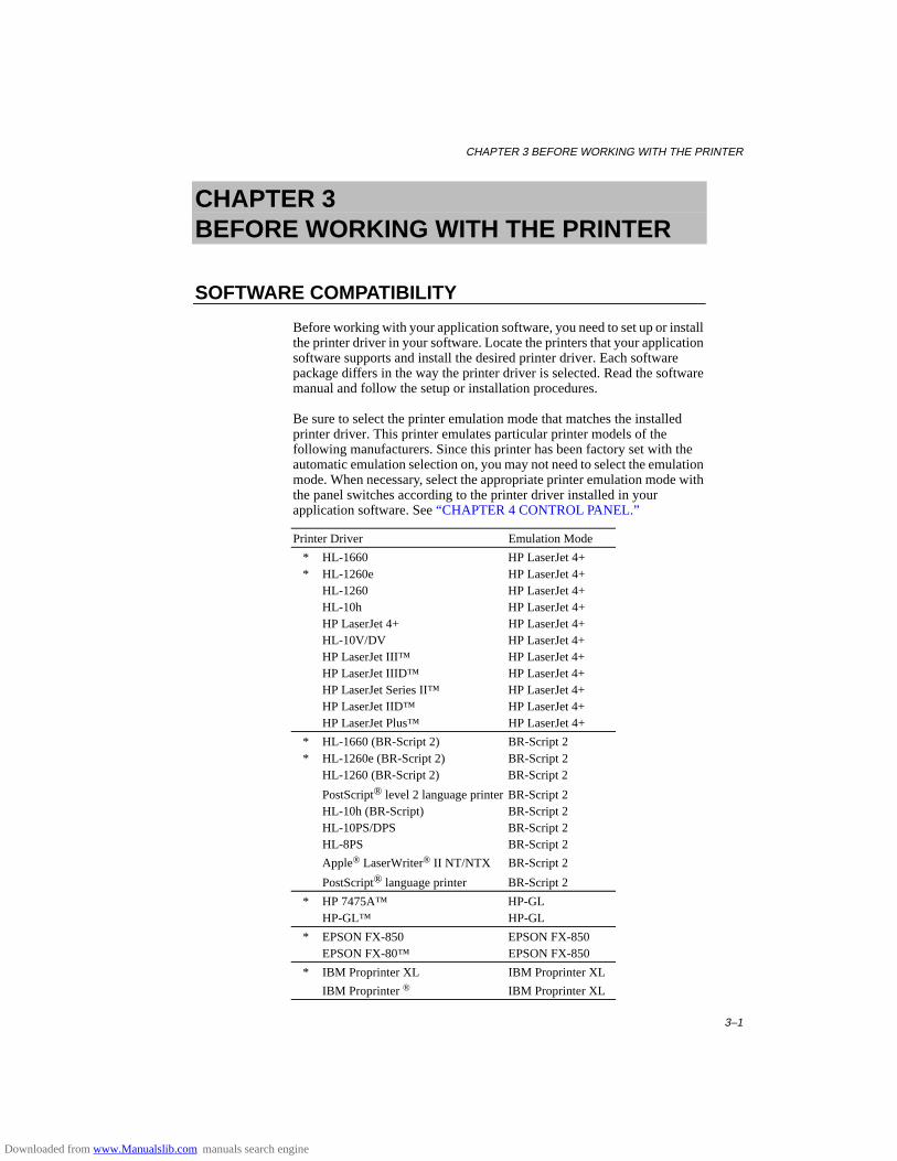
CHAPTER 3 BEFORE WORKING WITH THE PRINTER
3–1
CHAPTER 3BEFORE WORKING WITH THE PRINTER
SOFTWARE COMPATIBILITY
Before working with your application software, you need to set up or installthe printer driver in your software. Locate the printers that your applicationsoftware supports and install the desired printer driver. Each softwarepackage differs in the way the printer driver is selected. Read the softwaremanual and follow the setup or installation procedures.
Be sure to select the printer emulation mode that matches the installedprinter driver. This printer emulates particular printer models of thefollowing manufacturers. Since this printer has been factory set with theautomatic emulation selection on, you may not need to select the emulationmode. When necessary, select the appropriate printer emulation mode withthe panel switches according to the printer driver installed in yourapplication software. See “CHAPTER 4 CONTROL PANEL.”
Printer Driver Emulation Mode
* HL-1660 HP LaserJet 4+* HL-1260e HP LaserJet 4+
HL-1260 HP LaserJet 4+HL-10h HP LaserJet 4+HP LaserJet 4+ HP LaserJet 4+HL-10V/DV HP LaserJet 4+HP LaserJet III™ HP LaserJet 4+HP LaserJet IIID™ HP LaserJet 4+HP LaserJet Series II™ HP LaserJet 4+HP LaserJet IID™ HP LaserJet 4+HP LaserJet Plus™ HP LaserJet 4+
* HL-1660 (BR-Script 2) BR-Script 2* HL-1260e (BR-Script 2) BR-Script 2
HL-1260 (BR-Script 2) BR-Script 2
PostScript® level 2 language printer BR-Script 2HL-10h (BR-Script) BR-Script 2HL-10PS/DPS BR-Script 2HL-8PS BR-Script 2
Apple® LaserWriter® II NT/NTX BR-Script 2
PostScript® language printer BR-Script 2
* HP 7475A™ HP-GLHP-GL™ HP-GL
* EPSON FX-850 EPSON FX-850EPSON FX-80™ EPSON FX-850
* IBM Proprinter XL IBM Proprinter XL
IBM Proprinter ® IBM Proprinter XL
Downloaded from www.Manualslib.com manuals search engine

USER’S GUIDE
3–2
To get the most out of this printer, you need to install the printer driver forthis printer or the HP LaserJet 4+ and select the HP LaserJet 4+ emulationmode: this is the best combination. When any other HP LaserJet seriesprinter driver is installed, select the HP LaserJet 4+ emulation mode. Whenany other printer driver is installed, select the HP-GL, BR-Script 2,EPSON, or IBM emulation mode according to the installed printer driver.You may find difficulty in printing EPS file format pictures with the HPLaserJet 4+ mode. In this case, it is better to select the BR-Script 2 mode.
An asterisk (*) indicates the best or recommended combination of theprinter driver and emulation mode. Be sure to use any of these best orrecommended combinations if circumstances permit. When an emulationmode other than the HP mode or BR-Script 2 is selected, the printout maydiffer slightly from the printout that the target printer produces.
For Windows 95 or Windows 3.1 users, to get the best performance fromyour printer, install the driver supplied with your printer.
Downloaded from www.Manualslib.com manuals search engine
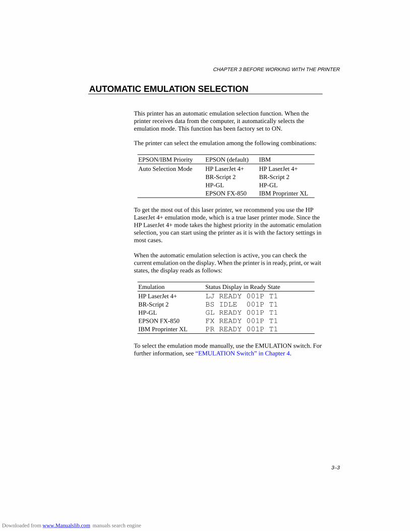
CHAPTER 3 BEFORE WORKING WITH THE PRINTER
3–3
AUTOMATIC EMULATION SELECTION
This printer has an automatic emulation selection function. When theprinter receives data from the computer, it automatically selects theemulation mode. This function has been factory set to ON.
The printer can select the emulation among the following combinations:
EPSON/IBM Priority EPSON (default) IBM
Auto Selection Mode HP LaserJet 4+ HP LaserJet 4+BR-Script 2 BR-Script 2HP-GL HP-GLEPSON FX-850 IBM Proprinter XL
To get the most out of this laser printer, we recommend you use the HPLaserJet 4+ emulation mode, which is a true laser printer mode. Since theHP LaserJet 4+ mode takes the highest priority in the automatic emulationselection, you can start using the printer as it is with the factory settings inmost cases.
When the automatic emulation selection is active, you can check thecurrent emulation on the display. When the printer is in ready, print, or waitstates, the display reads as follows:
Emulation Status Display in Ready State
HP LaserJet 4+ LJ READY 001P T1BR-Script 2 BS IDLE 001P T1HP-GL GL READY 001P T1EPSON FX-850 FX READY 001P T1IBM Proprinter XL PR READY 001P T1
To select the emulation mode manually, use the EMULATION switch. Forfurther information, see “EMUL ATION Switch” in Chapter 4.
Downloaded from www.Manualslib.com manuals search engine

USER’S GUIDE
3–4
✒ NotesWhen you use the automatic emulation selection, note the following: • Once the emulation is automatically changed, it is not changed again
for a short period of time. This time period is called “Time Out” and itcan be set with the EMULATION switch. The factory setting is 5seconds.
• The EPSON or IBM emulation mode priority must be selected, as theprinter cannot distinguish between them. Since the factory setting is theEPSON emulation mode, you might need to select the IBM emulationmode with the EMULATION switch when you need to use thisemulation..
• Try this function with your application software or network server. Ifthe function does not work properly, select the required emulation modemanually using the printer panel switches or use emulation selectioncommands from your software.
Downloaded from www.Manualslib.com manuals search engine
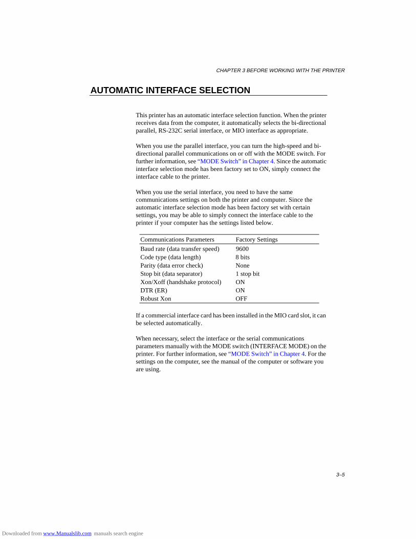
CHAPTER 3 BEFORE WORKING WITH THE PRINTER
3–5
AUTOMATIC INTERFACE SELECTION
This printer has an automatic interface selection function. When the printerreceives data from the computer, it automatically selects the bi-directionalparallel, RS-232C serial interface, or MIO interface as appropriate.
When you use the parallel interface, you can turn the high-speed and bi-directional parallel communications on or off with the MODE switch. Forfurther information, see “MODE Switch” in Chapter 4. Since the automaticinterface selection mode has been factory set to ON, simply connect theinterface cable to the printer.
When you use the serial interface, you need to have the samecommunications settings on both the printer and computer. Since theautomatic interface selection mode has been factory set with certainsettings, you may be able to simply connect the interface cable to theprinter if your computer has the settings listed below.
Communications Parameters Factory Settings
Baud rate (data transfer speed) 9600Code type (data length) 8 bitsParity (data error check) NoneStop bit (data separator) 1 stop bitXon/Xoff (handshake protocol) ONDTR (ER) ONRobust Xon OFF
If a commercial interface card has been installed in the MIO card slot, it canbe selected automatically.
When necessary, select the interface or the serial communicationsparameters manually with the MODE switch (INTERFACE MODE) on theprinter. For further information, see “MODE Switch” in Chapter 4. For thesettings on the computer, see the manual of the computer or software youare using.
Downloaded from www.Manualslib.com manuals search engine

USER’S GUIDE
3–6
✒ NotesWhen you use the automatic interface selection, note the following: • Once the interface is automatically changed, it is not changed again for
a short period of time. This time period is called “Time Out” and it canbe set with the MODE switch. The factory setting is 5 seconds.
• The communications parameters [ baud rate, code type, parity, stop bit,Xon/Xoff, DTR(ER), and Robust Xon] must be set for the serialinterface. Although they have been factory set as shown in the abovetable, you may need to change them with the MODE switch.
• This function takes a few seconds to work. If you want to speed upprinting, select the required interface manually with the MODE switch.
If you constantly use only one interface, we recommend that you select thatinterface in the interface mode. The printer allocates all of the input bufferto that interface if only one interface is selected.
Downloaded from www.Manualslib.com manuals search engine
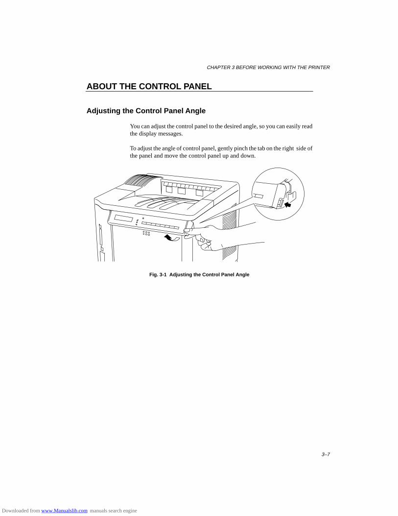
CHAPTER 3 BEFORE WORKING WITH THE PRINTER
3–7
ABOUT THE CONTROL PANEL
Adjusting the Control Panel Angle
You can adjust the control panel to the desired angle, so you can easily readthe display messages.
To adjust the angle of control panel, gently pinch the tab on the right side ofthe panel and move the control panel up and down.
Fig. 3-1 Adjusting the Control Panel Angle
Downloaded from www.Manualslib.com manuals search engine

USER’S GUIDE
3–8
Selecting the Local Language Display
The display usually shows the current printer status. When you operate thecontrol panel switches, it shows functions and settings. If any troubleoccurs, it shows the corresponding error message. You can see thesemessages in several languages. The default language is English.
• English • German • Spanish • Norwegian • Danish• French • Dutch • Italian • Finnish • Portuguese
To change to another language:
1. Turn off the printer.
2. Hold down the FORM FEED switch and turn on the printer.
The message “SELF TEST” appears and then the message changes to“LANG.=ENGLISH * ”.
3. Press the ▲ or ▼ switch until your desired language appears on thedisplay.
4. Press the SET switch to make the selected language message effective.
An asterisk (*) appears at the end of the display for a short time, andthen the printer automatically returns to on-line state with the selectedlanguage message on the display.
Downloaded from www.Manualslib.com manuals search engine

CHAPTER 3 BEFORE WORKING WITH THE PRINTER
3–9
Using the Panel Switches
The printer has a versatile control panel. It has two operation modes:
When you press the switches, they work in the NORMAL mode asindicated above the switches. When you press the switches with the SHIFTswitch held down, they work in the SHIFT mode as indicated below theswitches. You can control the basic printer operations and make variousprinter settings in the NORMAL and SHIFT modes.
For further information, see “SWITCHES IN NORMAL MODE” and“SWITCHES IN SHIFT MODE” in Chapter 4.
▲▲ (UP) – Forward scroll through modes and settings.▼▼ (DOWN) – Reverse scroll through modes and settings.CONTINUE – Ignores the error and resumes operation.SET – Sets selected mode and functions.FORM FEED – Prints out remaining data or reprints the same page.FONT – Selects font and character set.MODE – Sets functions in various modes.SEL – Selects on-line or off-line state.
ON LINE – Lights when printer is inthe on-line state.READY – Lights when printer is ready to print.DATA – Blinks when data is beingreceived and lights when unprinteddata remains in printer memory.ALARM – Lights if any errors occur.Display – Shows various messages.
EMULATION – Selects printer emulation.ECONOMY – Selects toner save or power save mode.FEEDER – Selects paper source and media type to be used andduplex printing.COPY – Sets the number of copies to print.SHIFT – Shifts switch operation.RESET – Resets printer or restores to factory settings.TEST – Prints self-test pattern or fonts.
Fig. 3-2 Switch Operation in NORMAL and SHIFT Modes
✒ NoteWhen the printer is in use in the BR-Script 2 mode, some switches are notused.
Downloaded from www.Manualslib.com manuals search engine

USER’S GUIDE
3–10
Printer Settings
You may operate the printer with the panel switch settings unchanged.They have been factory set. When necessary, change and store them in theprinter memory as user settings.
There are two types of printer settings available on this printer:
1. User Settings2. Factory Settings
Remember that the user settings override the factory settings. The usersettings are effective until other settings are made or they are restored to thefactory settings.
User Settings
Although the printer settings have been factory set, you can change themwith the control panel switches. Since this printer has a memory, you canstore the panel switch settings in the memory as “User Settings.” They arerecalled every time you turn on the printer.
In addition to the current settings, you can save two more sets of usersettings with the MODE switch and restore to them with the RESET switch.The current settings are cleared after restoring one of the saved usersettings.
Factory Settings
The printer settings have been set at the factory before shipment. They arecalled “Factory Settings.” Although you can operate the printer with thesefactory settings unchanged, you can tailor the printer by making usersettings.
✒ NoteChanging the user settings does not affect factory settings. You cannotmodify the preset factory settings.
The changed user settings can be restored to the factory default settingswith the RESET switch. For further information, see “RESET Switch” inChapter 4.
Downloaded from www.Manualslib.com manuals search engine

CHAPTER 3 BEFORE WORKING WITH THE PRINTER
3–11
PAPER HANDLING
Print Media
Paper Size
1. The upper paper cassetteSince the paper cassette is a universal type, you can use any of the sizes ofpaper in the list. The cassette can hold up to 500 sheets of paper (80 g/m2 or20 lbs.) or up to 40 envelopes (Paper should only be loaded up to the arrowhead marked on the sliding guide).
2. The multi-purpose trayThe multi-purpose tray is the most useful feeder for you to handle manytypes of paper. The multi-purpose tray can hold up to 150 sheets of paper(80 g/m2 or 20 lbs.) or up to 15 envelopes.The paper types and sizes that can be fed from the multi-purpose tray are asfollows: • Plain paper from 90 mm x 148 mm (3.5” x 5.8”) to 216 mm x 356 mm
(8.5” x 14”) [Weight = 60 to 135 g/m2 (16 to 36 lbs)] • Overhead projector (OHP) films • Colored paper • Postcards • Label stock • Envelopes of COM10, Monarch, C5, DL, or ISO B5 size
3. The optional lower paper cassetteThe cassette can hold up to 500 sheets of paper (80 g/m2 or 20 lbs.). It has alimitation on the paper sizes that can be used as shown in the list.
4. The duplex unitThe duplex unit can handle letter, legal, A4, Executive and ISO B5 (exceptTray 2) size papers from the feeders.
Downloaded from www.Manualslib.com manuals search engine
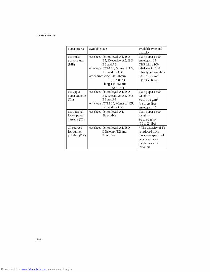
USER’S GUIDE
3–12
paper source available size available type andcapacity
the multi-purpose tray(MP)
cut sheet : letter, legal, A4, ISO B5, Executive, A5, ISO B6 and A6envelope: COM 10, Monarch, C5, DL and ISO B5other size: wide 90-216mm (3.5”-8.5”) long 148-356mm (5.8”-14”)
plain paper : 150envelope : 15OHP film : 100label stock : 100other type : weight =60 to 135 g/m2 (16 to 36 lbs)
the upperpaper cassette(T1)
cut sheet : letter, legal, A4, ISO B5, Executive, A5, ISO B6 and A6envelope :COM 10, Monarch, C5, DL and ISO B5
plain paper : 500weight =60 to 105 g/m2
(16 to 28 lbs)envelope : 40
the optionallower papercassette (T2)
cut sheet : letter, legal, A4, Executive
plain paper : 500weight =60 to 90 g/m2
(16 to 24 lbs)all sourcesfor duplexprinting (DX)
cut sheet : letter, legal, A4, ISO B5(except T2) and Executive
* The capacity of T1is reduced fromthe above specifiedcapacities withthe duplex unitinstalled.
Downloaded from www.Manualslib.com manuals search engine
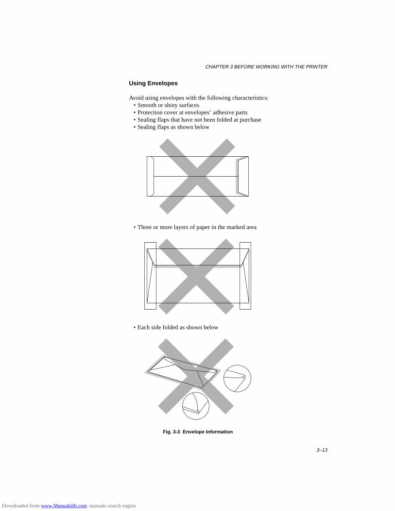
CHAPTER 3 BEFORE WORKING WITH THE PRINTER
3–13
Using Envelopes
Avoid using envelopes with the following characteristics: • Smooth or shiny surfaces • Protection cover at envelopes’ adhesive parts • Sealing flaps that have not been folded at purchase • Sealing flaps as shown below
• Three or more layers of paper in the marked area
• Each side folded as shown below
Fig. 3-3 Envelope Information
Downloaded from www.Manualslib.com manuals search engine
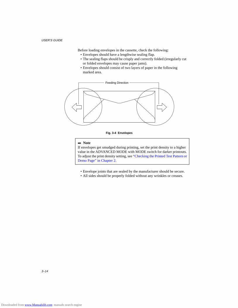
USER’S GUIDE
3–14
Before loading envelopes in the cassette, check the following: • Envelopes should have a lengthwise sealing flap. • The sealing flaps should be crisply and correctly folded (irregularly cut
or folded envelopes may cause paper jams). • Envelopes should consist of two layers of paper in the following
marked area.
Fig. 3-4 Envelopes
✒ NoteIf envelopes get smudged during printing, set the print density to a highervalue in the ADVANCED MODE with MODE switch for darker printouts.To adjust the print density setting, see “Checking the Printed Test Pattern orDemo Page” in Chapter 2.
• Envelope joints that are sealed by the manufacturer should be secure. • All sides should be properly folded without any wrinkles or creases.
Feeding Direction
Downloaded from www.Manualslib.com manuals search engine
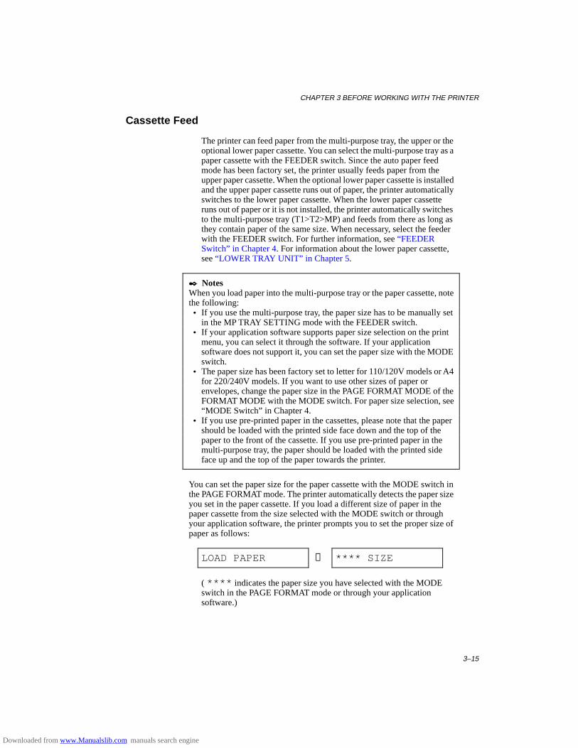
CHAPTER 3 BEFORE WORKING WITH THE PRINTER
3–15
Cassette Feed
The printer can feed paper from the multi-purpose tray, the upper or theoptional lower paper cassette. You can select the multi-purpose tray as apaper cassette with the FEEDER switch. Since the auto paper feedmode has been factory set, the printer usually feeds paper from theupper paper cassette. When the optional lower paper cassette is installedand the upper paper cassette runs out of paper, the printer automaticallyswitches to the lower paper cassette. When the lower paper cassetteruns out of paper or it is not installed, the printer automatically switchesto the multi-purpose tray (T1>T2>MP) and feeds from there as long asthey contain paper of the same size. When necessary, select the feederwith the FEEDER switch. For further information, see “FEEDERSwitch” in Chapter 4. For information about the lower paper cassette,see “LOWER TRAY UNIT” in Chapter 5.
✒ NotesWhen you load paper into the multi-purpose tray or the paper cassette, notethe following: • If you use the multi-purpose tray, the paper size has to be manually set
in the MP TRAY SETTING mode with the FEEDER switch. • If your application software supports paper size selection on the print
menu, you can select it through the software. If your applicationsoftware does not support it, you can set the paper size with the MODEswitch.
• The paper size has been factory set to letter for 110/120V models or A4for 220/240V models. If you want to use other sizes of paper orenvelopes, change the paper size in the PAGE FORMAT MODE of theFORMAT MODE with the MODE switch. For paper size selection, see“MODE Switch” in Chapter 4.
• If you use pre-printed paper in the cassettes, please note that the papershould be loaded with the printed side face down and the top of thepaper to the front of the cassette. If you use pre-printed paper in themulti-purpose tray, the paper should be loaded with the printed sideface up and the top of the paper towards the printer.
You can set the paper size for the paper cassette with the MODE switch inthe PAGE FORMAT mode. The printer automatically detects the paper sizeyou set in the paper cassette. If you load a different size of paper in thepaper cassette from the size selected with the MODE switch or throughyour application software, the printer prompts you to set the proper size ofpaper as follows:
LOAD PAPER ↔ **** SIZE
( **** indicates the paper size you have selected with the MODEswitch in the PAGE FORMAT mode or through your applicationsoftware.)
Downloaded from www.Manualslib.com manuals search engine
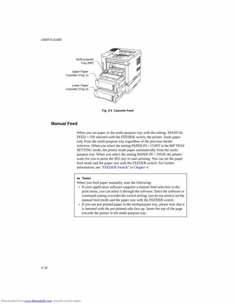
USER’S GUIDE
3–16
Fig. 3-5 Cassette Feed
Manual Feed
When you set paper in the multi-purpose tray with the setting MANUALFEED = ON selected with the FEEDER switch, the printer loads paperonly from the multi-purpose tray regardless of the previous feederselection. When you select the setting PAPER IN = CONT in the MP TRAYSETTING mode, the printer loads paper automatically from the multi-purpose tray. When you select the setting PAPER IN = STOP, the printerwaits for you to press the SEL key to start printing. You can set the paperfeed mode and the paper size with the FEEDER switch. For furtherinformation, see “FEEDER Switch” in Chapter 4.
✒ NotesWhen you feed paper manually, note the following: • If your application software supports a manual feed selection in the
print menu, you can select it through the software. Since the software orcommand setting overrides the switch setting, you do not need to set themanual feed mode and the paper size with the FEEDER switch.
• If you use pre-printed paper in the multipurpose tray, please note that itis inserted with the pre-printed side face up. Insert the top of the pagetowards the printer in the multi-purpose tray.
Multi-purposeTray (MP)
Upper PaperCassette (Tray 1)
Lower PaperCassette (Tray 2)
Downloaded from www.Manualslib.com manuals search engine
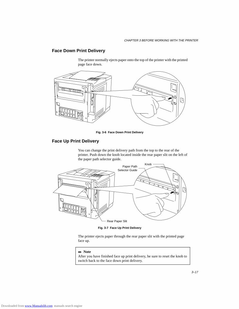
CHAPTER 3 BEFORE WORKING WITH THE PRINTER
3–17
Face Down Print Delivery
The printer normally ejects paper onto the top of the printer with the printedpage face down.
Fig. 3-6 Face Down Print Delivery
Face Up Print Delivery
You can change the print delivery path from the top to the rear of theprinter. Push down the knob located inside the rear paper slit on the left ofthe paper path selector guide.
Fig. 3-7 Face Up Print Delivery
The printer ejects paper through the rear paper slit with the printed pageface up.
✒ NoteAfter you have finished face up print delivery, be sure to reset the knob toswitch back to the face down print delivery.
Rear Paper Slit
KnobPaper Path
Selector Guide
Downloaded from www.Manualslib.com manuals search engine
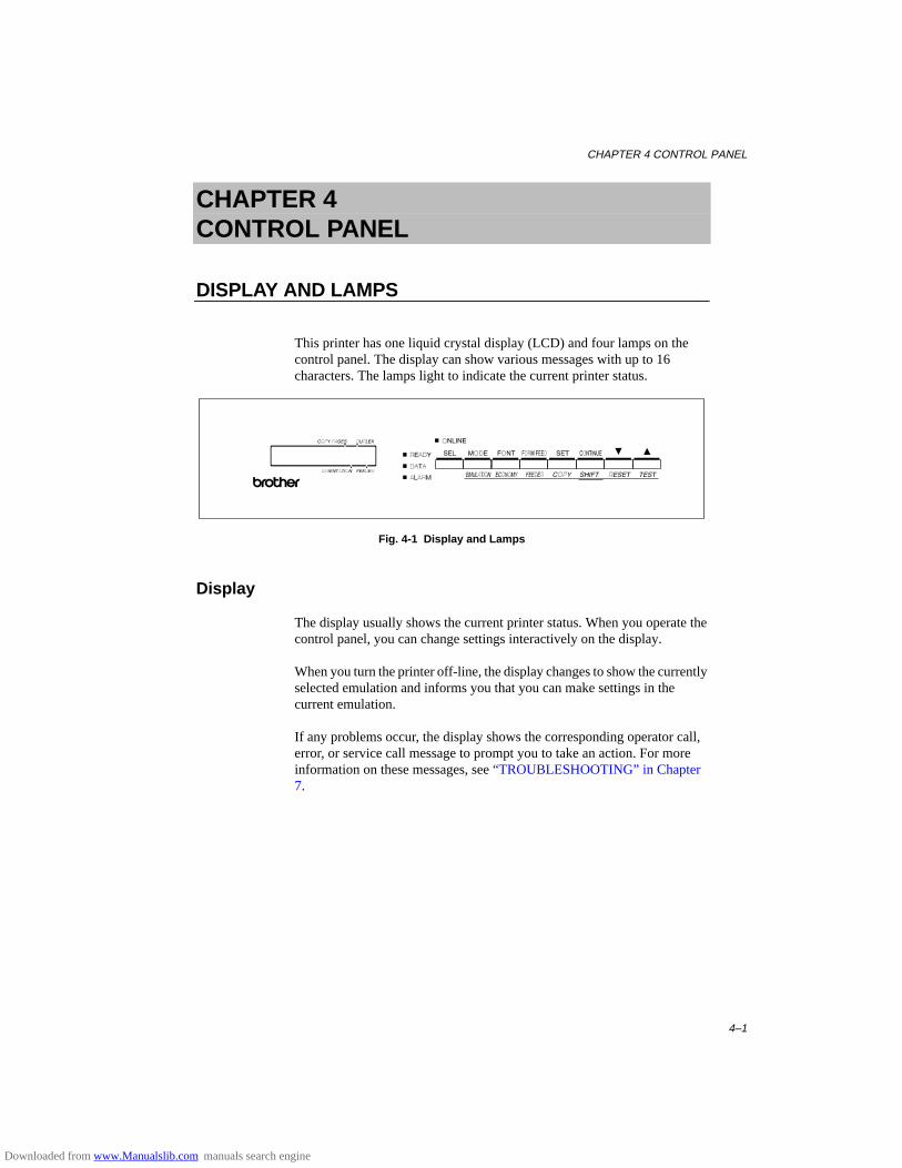
CHAPTER 4 CONTROL PANEL
4–1
CHAPTER 4CONTROL PANEL
DISPLAY AND LAMPS
This printer has one liquid crystal display (LCD) and four lamps on thecontrol panel. The display can show various messages with up to 16characters. The lamps light to indicate the current printer status.
Fig. 4-1 Display and Lamps
Display
The display usually shows the current printer status. When you operate thecontrol panel, you can change settings interactively on the display.
When you turn the printer off-line, the display changes to show the currentlyselected emulation and informs you that you can make settings in thecurrent emulation.
If any problems occur, the display shows the corresponding operator call,error, or service call message to prompt you to take an action. For moreinformation on these messages, see “TROUBLESHOOTING” in Chapter7.
Downloaded from www.Manualslib.com manuals search engine
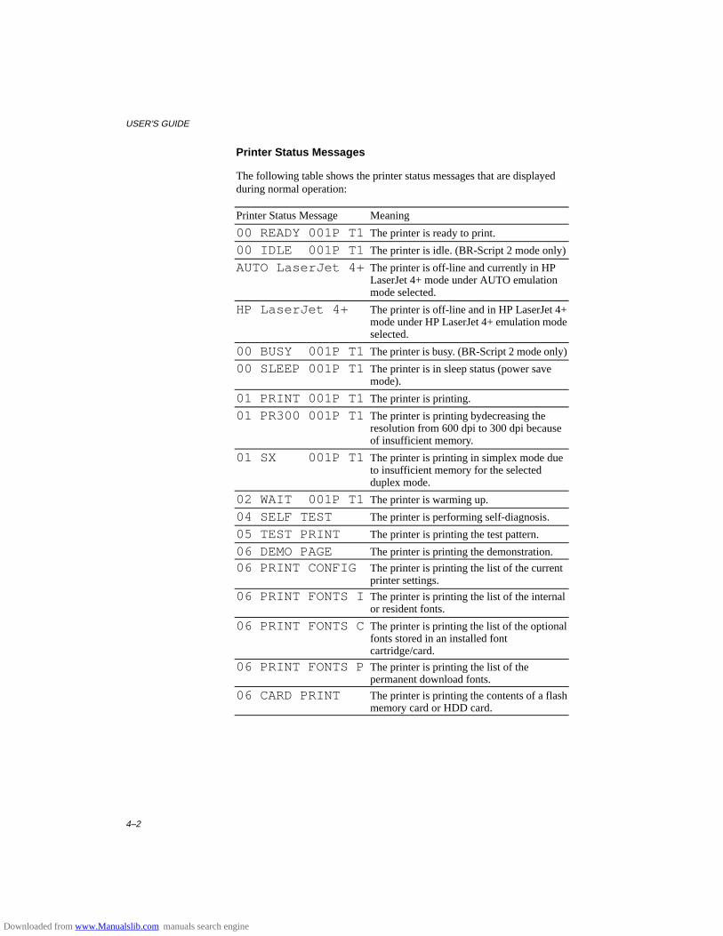
USER’S GUIDE
4–2
Printer Status Messages
The following table shows the printer status messages that are displayedduring normal operation:
Printer Status Message Meaning
00 READY 001P T1 The printer is ready to print.
00 IDLE 001P T1 The printer is idle. (BR-Script 2 mode only)
AUTO LaserJet 4+ The printer is off-line and currently in HPLaserJet 4+ mode under AUTO emulationmode selected.
HP LaserJet 4+ The printer is off-line and in HP LaserJet 4+mode under HP LaserJet 4+ emulation modeselected.
00 BUSY 001P T1 The printer is busy. (BR-Script 2 mode only)
00 SLEEP 001P T1 The printer is in sleep status (power savemode).
01 PRINT 001P T1 The printer is printing.
01 PR300 001P T1 The printer is printing bydecreasing theresolution from 600 dpi to 300 dpi becauseof insufficient memory.
01 SX 001P T1 The printer is printing in simplex mode dueto insufficient memory for the selectedduplex mode.
02 WAIT 001P T1 The printer is warming up.
04 SELF TEST The printer is performing self-diagnosis.
05 TEST PRINT The printer is printing the test pattern.
06 DEMO PAGE The printer is printing the demonstration.
06 PRINT CONFIG The printer is printing the list of the currentprinter settings.
06 PRINT FONTS I The printer is printing the list of the internalor resident fonts.
06 PRINT FONTS C The printer is printing the list of the optionalfonts stored in an installed fontcartridge/card.
06 PRINT FONTS P The printer is printing the list of thepermanent download fonts.
06 CARD PRINT The printer is printing the contents of a flashmemory card or HDD card.
Downloaded from www.Manualslib.com manuals search engine
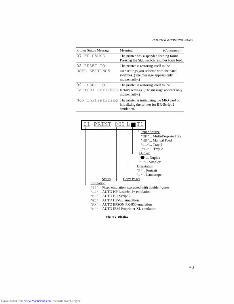
CHAPTER 4 CONTROL PANEL
4–3
Printer Status Message Meaning (Continued)
07 FF PAUSE The printer has suspended feeding forms.Pressing the SEL switch resumes form feed.
08 RESET TO The printer is restoring itself to the
USER SETTINGS user settings you selected with the panelswitches. (The message appears onlymomentarily.)
09 RESET TO The printer is restoring itself to the
FACTORY SETTINGSfactory settings. (The message appears onlymomentarily.)
Now initializing The printer is initializing the MIO card orinitializing the printer for BR-Script 2emulation.
01 PRINT 002 L ■ T1 Paper Source “MP” ... Multi-Purpose Tray “MN” ... Manual Feed “T1” ... Tray 2 “T2” ... Tray 2 Duplex “ ■” ... Duplex “ ” ... Simplex Orientation “P” ... Portrait “L” ... Landscape
Status Copy Pages Emulation “##” ... Fixed emulation expressed with double figures
“LJ” ... AUTO HP LaserJet 4+ emulation “BS” ... AUTO BR-Script 2 “GL” ... AUTO HP-GL emulation “FX” ... AUTO EPSON FX-850 emulation “PR” ... AUTO IBM Proprinter XL emulation
Fig. 4-2 Display
Downloaded from www.Manualslib.com manuals search engine
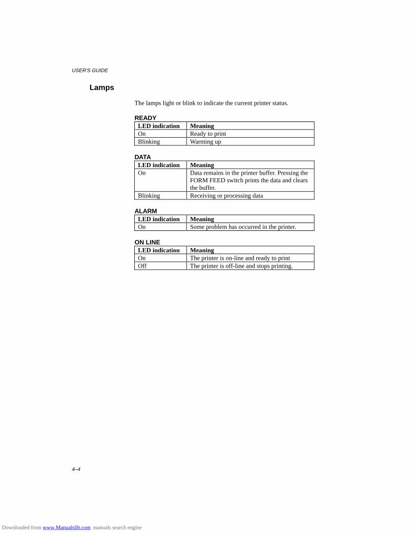
USER’S GUIDE
4–4
Lamps
The lamps light or blink to indicate the current printer status.
READYLED indication MeaningOn Ready to printBlinking Warming up
DATALED indication MeaningOn Data remains in the printer buffer. Pressing the
FORM FEED switch prints the data and clearsthe buffer.
Blinking Receiving or processing data
ALARMLED indication MeaningOn Some problem has occurred in the printer.
ON LINELED indication MeaningOn The printer is on-line and ready to printOff The printer is off-line and stops printing.
Downloaded from www.Manualslib.com manuals search engine
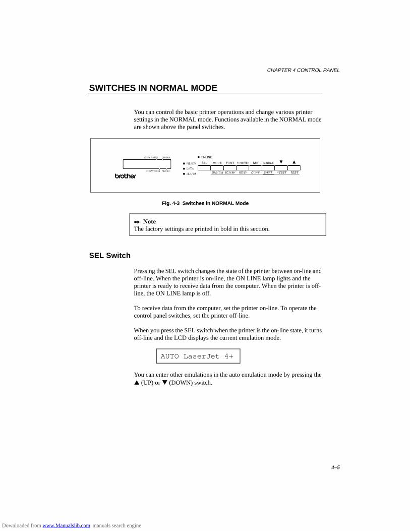
CHAPTER 4 CONTROL PANEL
4–5
SWITCHES IN NORMAL MODE
You can control the basic printer operations and change various printersettings in the NORMAL mode. Functions available in the NORMAL modeare shown above the panel switches.
Fig. 4-3 Switches in NORMAL Mode
✒ NoteThe factory settings are printed in bold in this section.
SEL Switch
Pressing the SEL switch changes the state of the printer between on-line andoff-line. When the printer is on-line, the ON LINE lamp lights and theprinter is ready to receive data from the computer. When the printer is off-line, the ON LINE lamp is off.
To receive data from the computer, set the printer on-line. To operate thecontrol panel switches, set the printer off-line.
When you press the SEL switch when the printer is the on-line state, it turnsoff-line and the LCD displays the current emulation mode.
AUTO LaserJet 4+
You can enter other emulations in the auto emulation mode by pressing the▲ (UP) or ▼ (DOWN) switch.
Downloaded from www.Manualslib.com manuals search engine
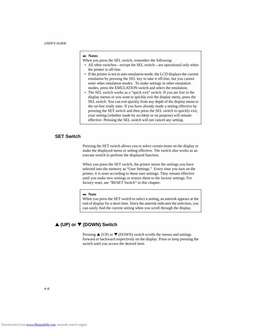
USER’S GUIDE
4–6
✒ NotesWhen you press the SEL switch, remember the following: • All other switches—except the SEL switch—are operational only when
the printer is off-line. • If the printer is not in auto emulation mode, the LCD displays the current
emulation by pressing the SEL key to take it off-line, but you cannotenter other emulation modes. To make settings in other emulationmodes, press the EMULATION switch and select the emulation.
• The SEL switch works as a “quick exit” switch. If you are lost in thedisplay menus or you want to quickly exit the display menu, press theSEL switch. You can exit quickly from any depth of the display menu tothe on-line ready state. If you have already made a setting effective bypressing the SET switch and then press the SEL switch to quickly exit,your setting (whether made by accident or on purpose) will remaineffective. Pressing the SEL switch will not cancel any setting.
SET Switch
Pressing the SET switch allows you to select certain items on the display ormake the displayed menu or setting effective. The switch also works as anexecute switch to perform the displayed function.
When you press the SET switch, the printer stores the settings you haveselected into the memory as “User Settings.” Every time you turn on theprinter, it is reset according to these user settings. They remain effectiveuntil you make new settings or restore them to the factory settings. Forfactory reset, see “RESET Switch” in this chapter.
✒ NoteWhen you press the SET switch to select a setting, an asterisk appears at theend of display for a short time. Since the asterisk indicates the selection, youcan easily find the current setting when you scroll through the display.
▲▲ (UP) or ▼▼ (DOWN) Switch
Pressing ▲ (UP) or ▼ (DOWN) switch scrolls the menus and settingsforward or backward respectively on the display. Press or keep pressing theswitch until you access the desired item.
Downloaded from www.Manualslib.com manuals search engine

CHAPTER 4 CONTROL PANEL
4–7
MODE Switch
Pressing the MODE switch allows you to enter modes where you changesettings. The mode menus and settings vary according to the currentemulation mode and options. For details, refer to the pages indicated inparentheses.
HP LaserJet 4+, EPSONFX-850, and IBM Proprinter XL Modes
BR-Script Mode HP-GL Mode
INTERFACE MODE INTERFACE MODE INTERFACE MODESet interface, parameters. (4-17) Set interface, parameters. (4-17) Set interface, parameters. (4-17)
FORMAT MODE FORMAT MODE FORMAT MODESet orientation, paper size, margins, &others. (4-20)
Set horizontal & vertical offsets. (4-20) Set orientation, paper size, margins, pensetting & others. (4-20)
RESOLUTION MODE RESOLUTION MODE RESOLUTION MODESet resolution & HRC. (4-28) Set resolution & HRC. (4-28) Set resolution & HRC. (4-28)
PAGE PROTECTION PAGE PROTECTIONProtect data on a page. (4-31) Not available. Protect data on a page. (4-31)
CARD OPERATION CARD OPERATION CARD OPERATIONSet a flash memory card or a HDD card inHP mode. (4-32)
Set a flash memory card or a HDD card.(4-32)
Set a flash memory card or a HDD card.(4-32)
ADVANCED MODE ADVANCED MODE ADVANCED MODESet network mode, print density, & others.(4-41)
Set network mode, print density, & others.(4-41)
Set network mode, print density, & others.(4-41)
PAGE COUNTER PAGE COUNTER PAGE COUNTERShow # of printed pages. (4-48) Show # of printed pages. (4-48) Show # of printed pages. (4-48)
exit MODE exit MODE exit MODEExit to off-line ready state. (4-48) Exit to off-line ready state. (4-48) Exit to off-line ready state. (4-48)
Downloaded from www.Manualslib.com manuals search engine
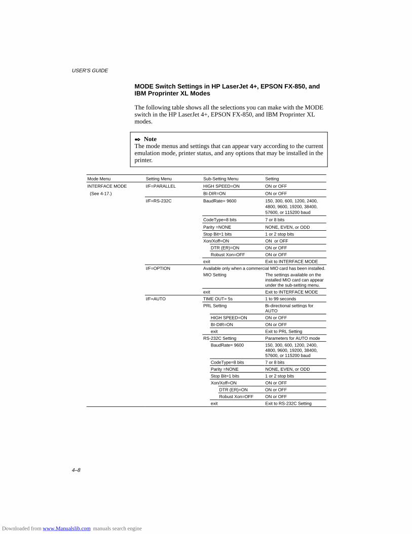
USER’S GUIDE
4–8
MODE Switch Settings in HP LaserJet 4+, EPSON FX-850, andIBM Proprinter XL Modes
The following table shows all the selections you can make with the MODEswitch in the HP LaserJet 4+, EPSON FX-850, and IBM Proprinter XLmodes.
✒ NoteThe mode menus and settings that can appear vary according to the currentemulation mode, printer status, and any options that may be installed in theprinter.
Mode Menu Setting Menu Sub-Setting Menu Setting
INTERFACE MODE I/F=PARALLEL HIGH SPEED=ON ON or OFF
(See 4-17.) BI-DIR=ON ON or OFF
I/F=RS-232C BaudRate= 9600 150, 300, 600, 1200, 2400,4800, 9600, 19200, 38400,57600, or 115200 baud
CodeType=8 bits 7 or 8 bits
Parity =NONE NONE, EVEN, or ODD
Stop Bit=1 bits 1 or 2 stop bits
Xon/Xoff=ON ON or OFF
DTR (ER)=ON ON or OFF
Robust Xon=OFF ON or OFF
exit Exit to INTERFACE MODE
I/F=OPTION Available only when a commercial MIO card has been installed.
MIO Setting The settings available on theinstalled MIO card can appearunder the sub-setting menu.
exit Exit to INTERFACE MODE
I/F=AUTO TIME OUT= 5s 1 to 99 seconds
PRL Setting Bi-directional settings forAUTO
HIGH SPEED=ON ON or OFF
BI-DIR=ON ON or OFF
exit Exit to PRL Setting
RS-232C Setting Parameters for AUTO mode
BaudRate= 9600 150, 300, 600, 1200, 2400,4800, 9600, 19200, 38400,57600, or 115200 baud
CodeType=8 bits 7 or 8 bits
Parity =NONE NONE, EVEN, or ODD
Stop Bit=1 bits 1 or 2 stop bits
Xon/Xoff=ON ON or OFF
DTR (ER)=ON ON or OFF
Robust Xon=OFF ON or OFF
exit Exit to RS-232C Setting
Downloaded from www.Manualslib.com manuals search engine

CHAPTER 4 CONTROL PANEL
4–9
Mode Menu (Continued) Setting Menu Sub-Setting Menu Setting
INTERFACE MODE
(Continued)
I/F AUTO
(Continued)
MIO Setting Available only when acommercial MIO card has beeninstalled. The settings availableon the installed MIO card canappear under the sub-settingmenu.
FORMAT MODE ORIENTATION ORI=PORTRAIT PORTRAIT or LANDSCAPE
(See 4-20.) AUTO MODE AUTO LF=OFF ON … LF + CR
OFF … CR only
AUTO CR=OFF ON … LF, FF, or VT + CR
OFF … LF, FF, or VT only
AUTO WRAP=OFF ON … Auto wrap on
OFF … Auto wrap off
AUTO SKIP=ON ON … Auto FF at bottom
margin
(HP mode) OFF … No FF at bottom
margin
AUTO MASK=OFF ON … Auto mask on
(EPSON & IBM modes) OFF … Auto mask off
exit Exit to AUTO MODE
PAGE FORMAT MODE PAPER =LETTER
(For 110/120V model)
PAPER =A4
(For 220/240V model)
LETTER, LEGAL, A4, A5,
A6, B5, B6, EXECUTIVE,
COM10, MONARCH, C5 and
DL
LEFT M = 0C 0 to 126 columns
RIGHT M = 80C
(Letter, Portrait)
10 to 136 columns
RIGHT M = 78C
(A4, Portrait)
10 to 136 columns
TOP M =0.5” (HP mode) 0, 0.33, 0.5, 1.0, 1.5, or 2.0”
BOTTOM M=0.5”
(HP mode)
0, 0.33, 0.5, 1.0, 1.5, or 2.0”
LINES = 60L
(HP, Letter, Portrait)
5 to 128 lines/page
LINES = 64L
(HP, A4, Portrait)
5 to 128 lines/page
X OFFSET= 0 -500 (left) to +500 (right) dots
Y OFFSET= 0 -500 (down) to +500 (up)
dots
exit Exit to PAGE FORMAT MODE
exit Exit to FORMAT MODE
RESOLUTION MODE RESOLUTION RESOLUTION 300 or 600 dpi
(See 4-28.) HRC SETTING HRC=MEDIUM OFF, LIGHT, MEDIUM, or DARK
exit Exit to RESOLUTION MODE
PAGE PROTECTION
(See 4-31.)
PROTECT=AUTO AUTO, OFF, LETTER, A4, orLEGAL
CARD OPERATION When the commercial flash memory card or the HDD card has not been formatted:
(HP mode only)
(See 4-32.)
FORMAT CARD Format the flash memory card or theHDD card.
exit Exit to CARD OPERATION
Downloaded from www.Manualslib.com manuals search engine
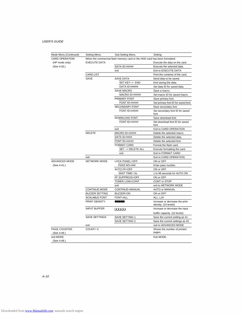
USER’S GUIDE
4–10
Mode Menu (Continued) Setting Menu Sub-Setting Menu Setting
CARD OPERATION When the commercial flash memory card or the HDD card has been formatted:
(HP mode only) EXECUTE DATA Execute the data on the card.
(See 4-32.) DATA ID=##### Execute the selected data.
exit Exit to EXECUTE DATA
CARD LIST Print the contents of the card.
SAVE SAVE DATA Send data to be saved.
SET KEY--> END End saving the data.
DATA ID=##### Set data ID for saved data.
SAVE MACRO Save a macro.
MACRO ID=##### Set macro ID for saved macro.
PRIMARY FONT Save primary font.
FONT ID=##### Set primary font ID for saved font.
SECONDARY FONT Save secondary font.
FONT ID=##### Set secondary font ID for savedfont.
DOWNLOAD FONT Save download font.
FONT ID=##### Set download font ID for savedfont.
exit Exit to CARD OPERATION
DELETE MACRO ID=##### Delete the selected macro.
DATA ID=#### Delete the selected data.
FONT ID=##### Delete the selected font.
FORMAT CARD Format the flash card.
SET –> DELETE ALL Execute formatting the card.
exit Exit to FORMAT CARD
exit Exit to CARD OPERATION
ADVANCED MODE NETWORK MODE LOCK PANEL=OFF ON or OFF
(See 4-41.) PASS NO=### Enter pass number.
AUTO FF=OFF ON or OFF
WAIT TIME= 5s 1 to 99 seconds for AUTO ON
FF SUPPRESS=OFF ON or OFF
TONER LOW=CONT CONT or STOP
exit exit to NETWORK MODE
CONTINUE MODE CONTINUE=MANUAL AUTO or MANUAL
BUZZER SETTING BUZZER=ON ON or OFF
SCALABLE FONT FONT=ALL ALL, LJ4
PRINT DENSITY ■■■■■ Increase or decrease the printdensity. (15 levels)
INPUT BUFFER ❏❏❏❏❏ Increase or decrease the input
buffer capacity. (15 levels)
SAVE SETTINGS SAVE SETTING 1 Save the current setting as #1
SAVE SETTING 2 Save the current settings as #2
exit exit to ADVANCED MODE
PAGE COUNTER
(See 4-48.)
COUNT= 0 Shows the number of printedpages.
exit MODE Exit MODE.
(See 4-48.)
Downloaded from www.Manualslib.com manuals search engine
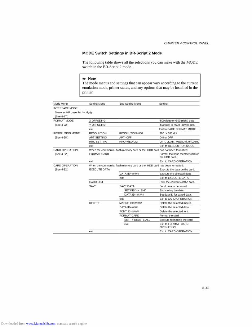
CHAPTER 4 CONTROL PANEL
4–11
MODE Switch Settings in BR-Script 2 Mode
The following table shows all the selections you can make with the MODEswitch in the BR-Script 2 mode.
✒ NoteThe mode menus and settings that can appear vary according to the currentemulation mode, printer status, and any options that may be installed in theprinter.
Mode Menu Setting Menu Sub-Setting Menu Setting
INTERFACE MODE
Same as HP LaserJet 4+ Mode
(See 4-17.)
FORMAT MODE X OFFSET=0 -500 (left) to +500 (right) dots
(See 4-22.) Y OFFSET=0 -500 (up) to +500 (down) dots
exit Exit to PAGE FORMAT MODE
RESOLUTION MODE RESOLUTION RESOLUTION=600 300 or 600 dpi
(See 4-28.) APT SETTING APT=OFF ON or OFF
HRC SETTING HRC=MEDIUM OFF, LIGHT, MEDIUM, or DARK
exit Exit to RESOLUTION MODE
CARD OPERATION When the commercial flash memory card or the HDD card has not been formatted:
(See 4-32.) FORMAT CARD Format the flash memory card orthe HDD card.
exit Exit to CARD OPERATION
CARD OPERATION When the commercial flash memory card or the HDD card has been formatted:
(See 4-32.) EXECUTE DATA Execute the data on the card.
DATA ID=##### Execute the selected data.
exit Exit to EXECUTE DATA
CARD LIST Print the contents of the card.
SAVE SAVE DATA Send data to be saved.
SET KEY--> END End saving the data.
DATA ID=##### Set data ID for saved data.
exit Exit to CARD OPERATION
DELETE MACRO ID=##### Delete the selected macro.
DATA ID=#### Delete the selected data.
FONT ID=##### Delete the selected font.
FORMAT CARD Format the card.
SET –> DELETE ALL Execute formatting the card.
exit Exit to FORMAT CARDOPERATION
exit Exit to CARD OPERATION
Downloaded from www.Manualslib.com manuals search engine
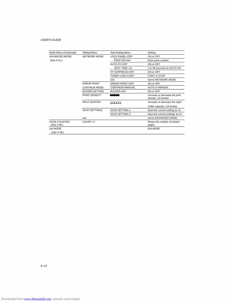
USER’S GUIDE
4–12
Mode Menu (Continued) Setting Menu Sub-Setting Menu Setting
ADVANCED MODE NETWORK MODE LOCK PANEL=OFF ON or OFF
(See 4-41.) PASS NO=### Enter pass number.
AUTO FF=OFF ON or OFF
WAIT TIME= 5s 1 to 99 seconds for AUTO ON
FF SUPPRESS=OFF ON or OFF
TONER LOW=CONT CONT or STOP
exit exit to NETWORK MODE
ERROR PRINT ERROR PRINT=OFF ON or OFF
CONTINUE MODE CONTINUE=MANUAL AUTO or MANUAL
BUZZER SETTING BUZZER=ON ON or OFF
PRINT DENSITY ■■■■■ Increase or decrease the printdensity. (15 levels)
INPUT BUFFER ❏❏❏❏❏ Increase or decrease the input
buffer capacity. (15 levels)
SAVE SETTINGS SAVE SETTING 1 Save the current setting as #1
SAVE SETTING 2 Save the current settings as #2
exit exit to ADVANCED MODE
PAGE COUNTER (See 4-48.)
COUNT= 0 Shows the number of printedpages.
exit MODE Exit MODE
(See 4-48.)
Downloaded from www.Manualslib.com manuals search engine
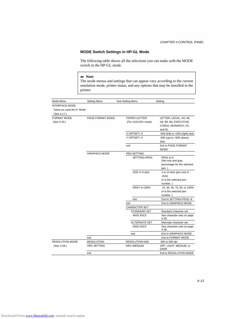
CHAPTER 4 CONTROL PANEL
4–13
MODE Switch Settings in HP-GL Mode
The following table shows all the selections you can make with the MODEswitch in the HP-GL mode.
✒ NoteThe mode menus and settings that can appear vary according to the currentemulation mode, printer status, and any options that may be installed in theprinter.
Mode Menu Setting Menu Sub-Setting Menu Setting
INTERFACE MODE
Same as LaserJet 4+ Mode
(See 4-17.)
FORMAT MODE
(See 4-20.)
PAGE FORMAT MODE PAPER=LETTER
(For 110/120V mode)
LETTER, LEGAL, A4, A5,
A6, B5, B6, EXECUTIVE,
COM10, MONARCH, C5,
and DL
X OFFSET= 0 -500 (left) to +500 (right) dots
Y OFFSET= 0 -500 (up) to +500 (down)
dots
exit Exit to PAGE FORMAT
MODE
GRAPHICS MODE PEN SETTING
SETTING=PEN1 PEN1 to 6 (Set size and gray percentage for the selected pen. )
SIZE #=3 dots 1 to 10 dots (pen size in dots) (# is the selected pen number. )
GRAY #=100% 15, 30, 45, 75, 90, or 100% (# is the selected pen number. )
exit Exit to SETTING=PEN1–6
exit Exit to GRAPHICS MODE
CHARACTER SET
STANDARD SET Standard character set
ANSI ASCII See character sets on page 4-28.
ALTERNATE SET Alternate character set
ANSI ASCII See character sets on page 4-28.
exit Exit to GRAPHICS MODE
exit Exit to FORMAT MODE
RESOLUTION MODE RESOLUTION RESOLUTION=600 300 or 600 dpi
(See 4-28.) HRC SETTING HRC=MEDIUM OFF, LIGHT, MEDIUM, orDARK
exit Exit to RESOLUTION MODE
Downloaded from www.Manualslib.com manuals search engine
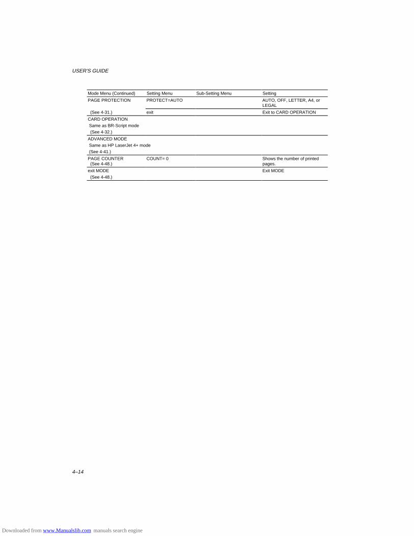
USER’S GUIDE
4–14
Mode Menu (Continued) Setting Menu Sub-Setting Menu Setting
PAGE PROTECTION PROTECT=AUTO AUTO, OFF, LETTER, A4, orLEGAL
(See 4-31.) exit Exit to CARD OPERATION
CARD OPERATION
Same as BR-Script mode
(See 4-32.)
ADVANCED MODE
Same as HP LaserJet 4+ mode
(See 4-41.)
PAGE COUNTER (See 4-48.)
COUNT= 0 Shows the number of printedpages.
exit MODE Exit MODE
(See 4-48.)
Downloaded from www.Manualslib.com manuals search engine
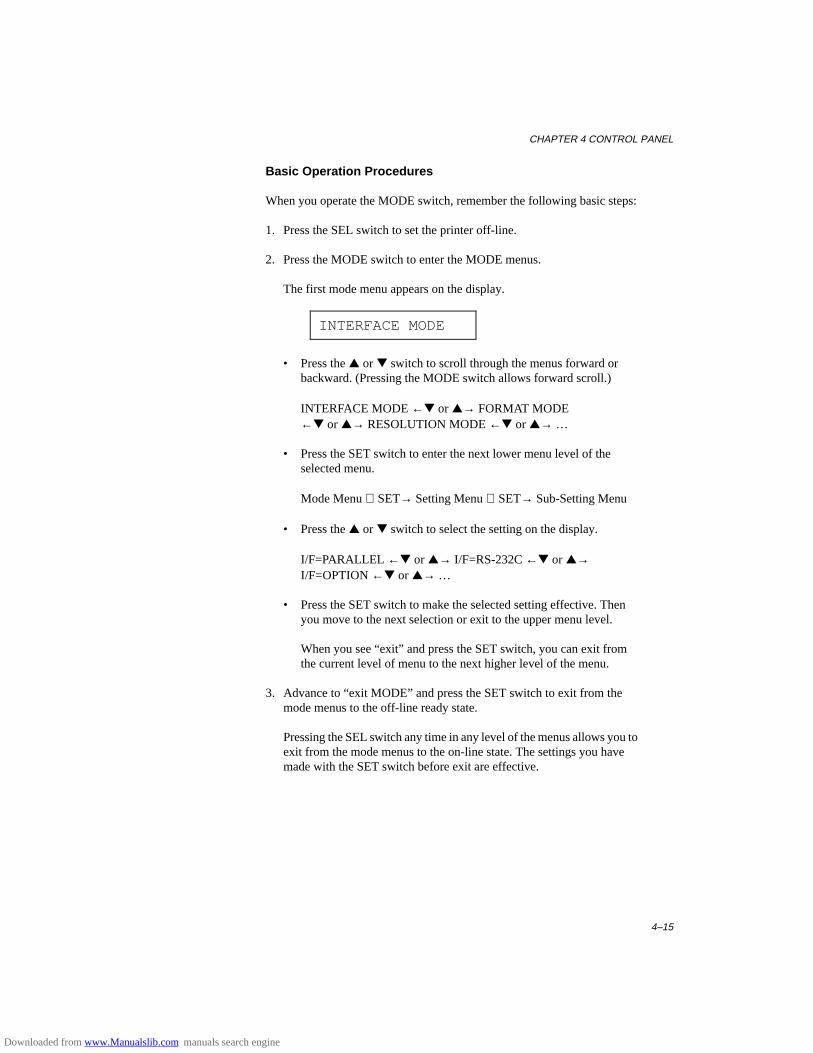
CHAPTER 4 CONTROL PANEL
4–15
Basic Operation Procedures
When you operate the MODE switch, remember the following basic steps:
1. Press the SEL switch to set the printer off-line.
2. Press the MODE switch to enter the MODE menus.
The first mode menu appears on the display.
INTERFACE MODE
• Press the ▲ or ▼ switch to scroll through the menus forward orbackward. (Pressing the MODE switch allows forward scroll.)
INTERFACE MODE ←▼ or ▲→ FORMAT MODE←▼ or ▲→ RESOLUTION MODE ←▼ or ▲→ …
• Press the SET switch to enter the next lower menu level of theselected menu.
Mode Menu SET→ Setting Menu SET→ Sub-Setting Menu
• Press the ▲ or ▼ switch to select the setting on the display.
I/F=PARALLEL ←▼ or ▲→ I/F=RS-232C ←▼ or ▲→I/F=OPTION ←▼ or ▲→ …
• Press the SET switch to make the selected setting effective. Thenyou move to the next selection or exit to the upper menu level.
When you see “exit” and press the SET switch, you can exit fromthe current level of menu to the next higher level of the menu.
3. Advance to “exit MODE” and press the SET switch to exit from themode menus to the off-line ready state.
Pressing the SEL switch any time in any level of the menus allows you toexit from the mode menus to the on-line state. The settings you havemade with the SET switch before exit are effective.
Downloaded from www.Manualslib.com manuals search engine
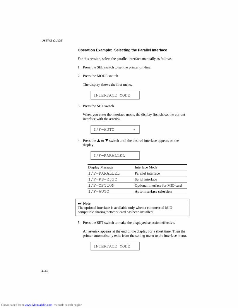
USER’S GUIDE
4–16
Operation Example: Selecting the Parallel Interface
For this session, select the parallel interface manually as follows:
1. Press the SEL switch to set the printer off-line.
2. Press the MODE switch.
The display shows the first menu.
INTERFACE MODE
3. Press the SET switch.
When you enter the interface mode, the display first shows the currentinterface with the asterisk.
I/F=AUTO *
4. Press the ▲ or ▼ switch until the desired interface appears on thedisplay.
I/F=PARALLEL
Display Message Interface Mode
I/F=PARALLEL Parallel interface
I/F=RS-232C Serial interface
I/F=OPTION Optional interface for MIO card
I/F=AUTO Auto interface selection
✒ NoteThe optional interface is available only when a commercial MIOcompatible sharing/network card has been installed.
5. Press the SET switch to make the displayed selection effective.
An asterisk appears at the end of the display for a short time. Then theprinter automatically exits from the setting menu to the interface menu.
INTERFACE MODE
Downloaded from www.Manualslib.com manuals search engine
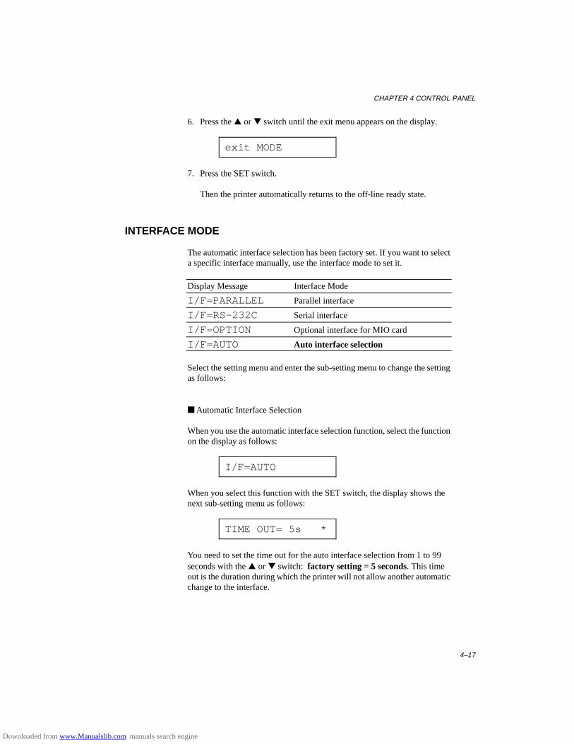
CHAPTER 4 CONTROL PANEL
4–17
6. Press the ▲ or ▼ switch until the exit menu appears on the display.
exit MODE
7. Press the SET switch.
Then the printer automatically returns to the off-line ready state.
INTERFACE MODE
The automatic interface selection has been factory set. If you want to selecta specific interface manually, use the interface mode to set it.
Display Message Interface Mode
I/F=PARALLEL Parallel interface
I/F=RS-232C Serial interface
I/F=OPTION Optional interface for MIO card
I/F=AUTO Auto interface selection
Select the setting menu and enter the sub-setting menu to change the settingas follows:
■ Automatic Interface Selection
When you use the automatic interface selection function, select the functionon the display as follows:
I/F=AUTO
When you select this function with the SET switch, the display shows thenext sub-setting menu as follows:
TIME OUT= 5s *
You need to set the time out for the auto interface selection from 1 to 99seconds with the ▲ or ▼ switch: factory setting = 5 seconds. This timeout is the duration during which the printer will not allow another automaticchange to the interface.
Downloaded from www.Manualslib.com manuals search engine
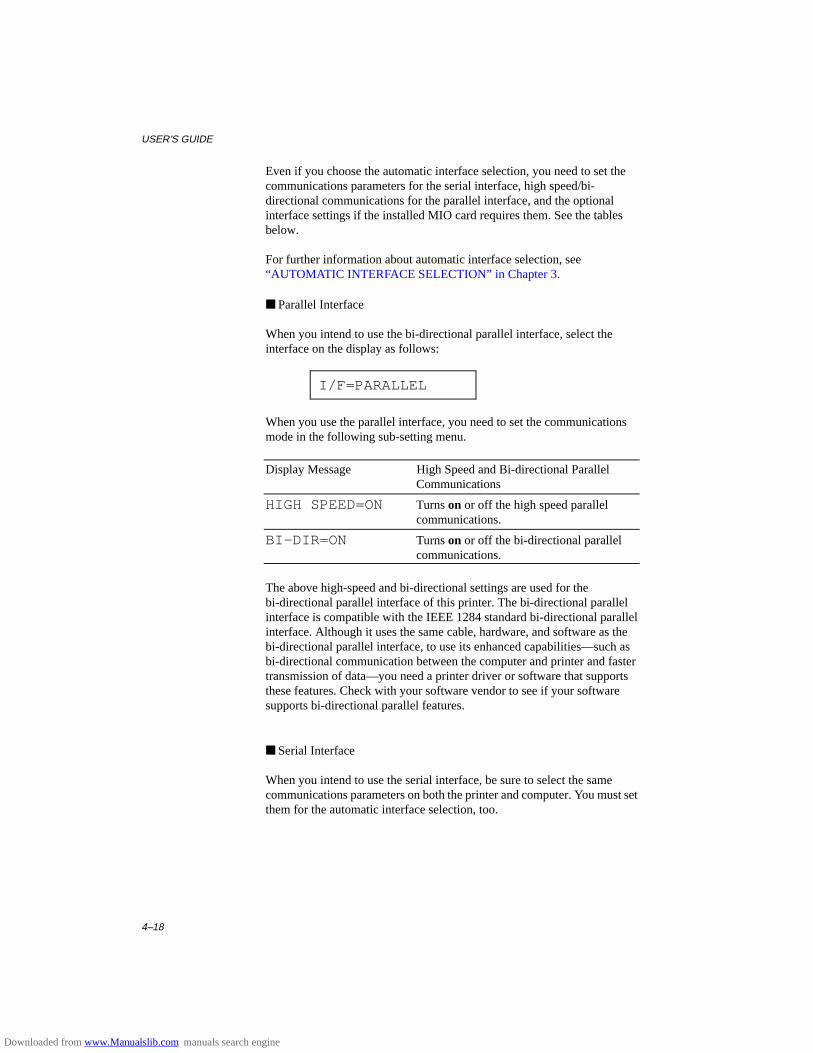
USER’S GUIDE
4–18
Even if you choose the automatic interface selection, you need to set thecommunications parameters for the serial interface, high speed/bi-directional communications for the parallel interface, and the optionalinterface settings if the installed MIO card requires them. See the tablesbelow.
For further information about automatic interface selection, see“AUTOMATIC INTERFACE SELECTION” in Chapter 3.
■ Parallel Interface
When you intend to use the bi-directional parallel interface, select theinterface on the display as follows:
I/F=PARALLEL
When you use the parallel interface, you need to set the communicationsmode in the following sub-setting menu.
Display Message High Speed and Bi-directional ParallelCommunications
HIGH SPEED=ON Turns on or off the high speed parallelcommunications.
BI-DIR=ON Turns on or off the bi-directional parallelcommunications.
The above high-speed and bi-directional settings are used for thebi-directional parallel interface of this printer. The bi-directional parallelinterface is compatible with the IEEE 1284 standard bi-directional parallelinterface. Although it uses the same cable, hardware, and software as thebi-directional parallel interface, to use its enhanced capabilities—such asbi-directional communication between the computer and printer and fastertransmission of data—you need a printer driver or software that supportsthese features. Check with your software vendor to see if your softwaresupports bi-directional parallel features.
■ Serial Interface
When you intend to use the serial interface, be sure to select the samecommunications parameters on both the printer and computer. You must setthem for the automatic interface selection, too.
Downloaded from www.Manualslib.com manuals search engine

CHAPTER 4 CONTROL PANEL
4–19
Display Message Parameters Settings
BaudRate= 9600 Baud rate(Data transfer speed)
150, 300, 600, 1200, 2400, 4800,9600, 19200, 38400, 57600, 115200baud
CodeType=8 bits Code type(Data length)
7 bits or 8 bits
Parity =NONE Parity(Data error check)
None, even, or odd
Stop Bit=1 bits Stop bits(Data separator)
1 or 2
Xon/Xoff=ON Xon/Xoff(Handshake protocol)
ON: DTR & Xon/Xoff handshakeOFF: DTR handshake only
DTR(ER) =ON(Effective when Xon/Xoff=ON)
Data terminal ready(ER)
ON: Makes DTR (ER) low whenthe buffer is full.
OFF: Does not make DTR (ER) low when the buffer is full.DTR(ER) goes low only when the printer is off-line.
Robust Xon =OFF(Effective when Xon/Xoff=ON)
Robust Xon ON: Sends Xon while waiting.OFF: Sends Xon once, when the
printer status changes from off-line to on-line.
■ Optional Interface
If you have installed a commercial modular input/output (MIO) card in theprinter, you can select the optional MIO interface in this mode. If theinstalled MIO card requires any optional interface settings, they appearunder this menu. Set them, referring to the manual of the MIO card.
I/F=OPTION
✒ NoteThis setting appears only when the MIO card has been installed. Forinstallation of the MIO card, see “MODULAR I/O CARD” in Chapter 5.
Downloaded from www.Manualslib.com manuals search engine
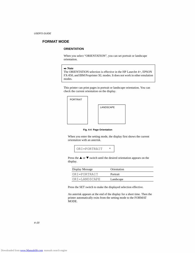
USER’S GUIDE
4–20
FORMAT MODE
ORIENTATION
When you select “ORIENTATION”, you can set portrait or landscapeorientation.
✒ NoteThe ORIENTATION selection is effective in the HP LaserJet 4+, EPSONFX-850, and IBM Proprinter XL modes. It does not work in other emulationmodes.
This printer can print pages in portrait or landscape orientation. You cancheck the current orientation on the display.
Fig. 4-4 Page Orientation
When you enter the setting mode, the display first shows the currentorientation with an asterisk.
ORI=PORTRAIT *
Press the ▲ or ▼ switch until the desired orientation appears on thedisplay.
Display Message Orientation
ORI=PORTRAIT Portrait
ORI=LANDSCAPE Landscape
Press the SET switch to make the displayed selection effective.
An asterisk appears at the end of the display for a short time. Then theprinter automatically exits from the setting mode to the FORMATMODE.
PORTRAIT
LANDSCAPE
Downloaded from www.Manualslib.com manuals search engine
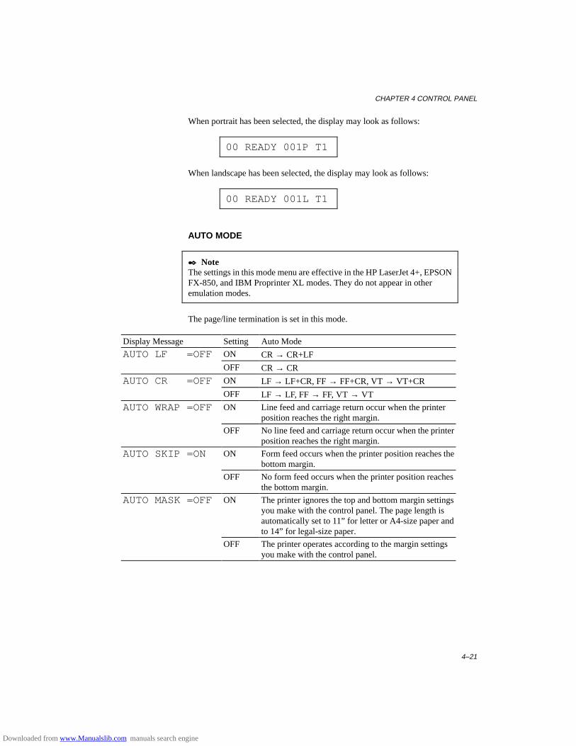
CHAPTER 4 CONTROL PANEL
4–21
When portrait has been selected, the display may look as follows:
00 READY 001P T1
When landscape has been selected, the display may look as follows:
00 READY 001L T1
AUTO MODE
✒ NoteThe settings in this mode menu are effective in the HP LaserJet 4+, EPSONFX-850, and IBM Proprinter XL modes. They do not appear in otheremulation modes.
The page/line termination is set in this mode.
Display Message Setting Auto Mode
AUTO LF =OFF ON CR → CR+LF
OFF CR → CR
AUTO CR =OFF ON LF → LF+CR, FF → FF+CR, VT → VT+CR
OFF LF → LF, FF → FF, VT → VT
AUTO WRAP =OFF ON Line feed and carriage return occur when the printerposition reaches the right margin.
OFF No line feed and carriage return occur when the printerposition reaches the right margin.
AUTO SKIP =ON ON Form feed occurs when the printer position reaches thebottom margin.
OFF No form feed occurs when the printer position reachesthe bottom margin.
AUTO MASK =OFF ON The printer ignores the top and bottom margin settingsyou make with the control panel. The page length isautomatically set to 11” for letter or A4-size paper andto 14” for legal-size paper.
OFF The printer operates according to the margin settingsyou make with the control panel.
Downloaded from www.Manualslib.com manuals search engine
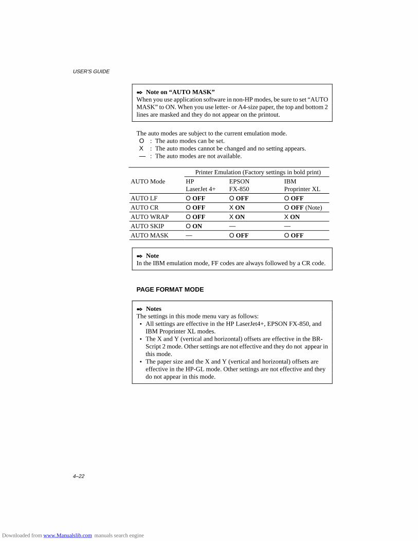
USER’S GUIDE
4–22
✒ Note on “AUTO MASK”When you use application software in non-HP modes, be sure to set “AUTOMASK” to ON. When you use letter- or A4-size paper, the top and bottom 2lines are masked and they do not appear on the printout.
The auto modes are subject to the current emulation mode.O : The auto modes can be set.X : The auto modes cannot be changed and no setting appears.— : The auto modes are not available.
Printer Emulation (Factory settings in bold print)
AUTO Mode HPLaserJet 4+
EPSONFX-850
IBMProprinter XL
AUTO LF O OFF O OFF O OFFAUTO CR O OFF X ON O OFF (Note)
AUTO WRAP O OFF X ON X ONAUTO SKIP O ON — —
AUTO MASK — O OFF O OFF
✒ NoteIn the IBM emulation mode, FF codes are always followed by a CR code.
PAGE FORMAT MODE
✒ NotesThe settings in this mode menu vary as follows: • All settings are effective in the HP LaserJet4+, EPSON FX-850, and
IBM Proprinter XL modes. • The X and Y (vertical and horizontal) offsets are effective in the BR-
Script 2 mode. Other settings are not effective and they do not appear inthis mode.
• The paper size and the X and Y (vertical and horizontal) offsets areeffective in the HP-GL mode. Other settings are not effective and theydo not appear in this mode.
Downloaded from www.Manualslib.com manuals search engine
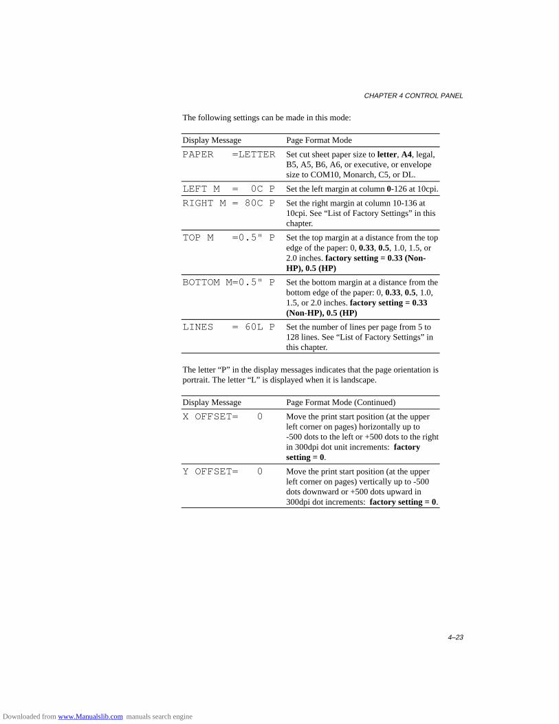
CHAPTER 4 CONTROL PANEL
4–23
The following settings can be made in this mode:
Display Message Page Format Mode
PAPER =LETTER Set cut sheet paper size to letter, A4, legal,B5, A5, B6, A6, or executive, or envelopesize to COM10, Monarch, C5, or DL.
LEFT M = 0C P Set the left margin at column 0-126 at 10cpi.
RIGHT M = 80C P Set the right margin at column 10-136 at10cpi. See “List of Factory Settings” in thischapter.
TOP M =0.5" P Set the top margin at a distance from the topedge of the paper: 0, 0.33, 0.5, 1.0, 1.5, or2.0 inches. factory setting = 0.33 (Non-HP), 0.5 (HP)
BOTTOM M=0.5" P Set the bottom margin at a distance from thebottom edge of the paper: 0, 0.33, 0.5, 1.0,1.5, or 2.0 inches. factory setting = 0.33(Non-HP), 0.5 (HP)
LINES = 60L P Set the number of lines per page from 5 to128 lines. See “List of Factory Settings” inthis chapter.
The letter “P” in the display messages indicates that the page orientation isportrait. The letter “L” is displayed when it is landscape.
Display Message Page Format Mode (Continued)
X OFFSET= 0 Move the print start position (at the upperleft corner on pages) horizontally up to-500 dots to the left or +500 dots to the rightin 300dpi dot unit increments: factorysetting = 0.
Y OFFSET= 0 Move the print start position (at the upperleft corner on pages) vertically up to -500dots downward or +500 dots upward in300dpi dot increments: factory setting = 0.
Downloaded from www.Manualslib.com manuals search engine
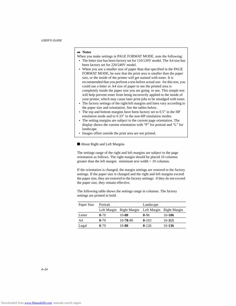
USER’S GUIDE
4–24
✒ NotesWhen you make settings in PAGE FORMAT MODE, note the following: • The letter size has been factory set for 110/120V model. The A4 size has
been factory set for 220/240V model. • When you use a smaller size of paper than that specified in the PAGE
FORMAT MODE, be sure that the print area is smaller than the papersize, or the inside of the printer will get stained with toner. It isrecommended that you perform a test before actual use: for this test, youcould use a letter or A4 size of paper to see the printed area iscompletely inside the paper size you are going to use. This simple testwill help prevent toner from being incorrectly applied to the inside ofyour printer, which may cause later print jobs to be smudged with toner.
• The factory settings of the right/left margins and lines vary according tothe paper size and orientation. See the tables below.
• The top and bottom margins have been factory set to 0.5” in the HPemulation mode and to 0.33” in the non-HP emulation modes.
• The setting margins are subject to the current page orientation. Thedisplay shows the current orientation with “P” for portrait and “L” forlandscape.
• Images offset outside the print area are not printed.
■ About Right and Left Margins
The settings range of the right and left margins are subject to the pageorientation as follows. The right margin should be placed 10 columnsgreater than the left margin: minimum text width = 10 columns.
If the orientation is changed, the margin settings are restored to the factorysettings. If the paper size is changed and the right and left margins exceedthe paper size, they are restored to the factory settings: if they do not exceedthe paper size, they remain effective.
The following table shows the settings range in columns. The factorysettings are printed in bold.
Paper Size Portrait Landscape
Left Margin Right Margin Left Margin Right Margin
Letter 0-70 10-80 0-96 10-106
A4 0-70 10-78-80 0-103 10-113
Legal 0-70 10-80 0-126 10-136
Downloaded from www.Manualslib.com manuals search engine
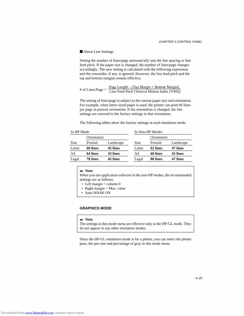
CHAPTER 4 CONTROL PANEL
4–25
■ About Line Settings
Setting the number of lines/page automatically sets the line spacing or linefeed pitch. If the paper size is changed, the number of lines/page changesaccordingly. The new setting is calculated with the following expressionand the remainder, if any, is ignored. However, the line feed pitch and thetop and bottom margins remain effective.
# of Lines/Page = Page Length – (Top Margin + Bottom Margin) Line Feed Pitch [Vertical Motion Index (VMI)]
The setting of lines/page is subject to the current paper size and orientation.For example, when letter-sized paper is used, the printer can print 60 linesper page in portrait orientation. If the orientation is changed, the linesettings are restored to the factory settings in that orientation.
The following tables show the factory settings in each emulation mode.
In HP Mode In Non-HP Modes
Orientation Orientation
Size Portrait Landscape Size Portrait Landscape
Letter 60 lines 45 lines Letter 62 lines 47 linesA4 64 lines 43 lines A4 66 lines 45 linesLegal 78 lines 45 lines Legal 80 lines 47 lines
✒ NoteWhen you use application software in the non-HP modes, the recommendedsettings are as follows: • Left margin = column 0 • Right margin = Max. value • Auto MASK ON
GRAPHICS MODE
✒ NoteThe settings in this mode menu are effective only in the HP-GL mode. Theydo not appear in any other emulation modes.
Since the HP-GL emulation mode is for a plotter, you can select the plotterpens, the pen size and percentage of gray in this mode menu.
Downloaded from www.Manualslib.com manuals search engine
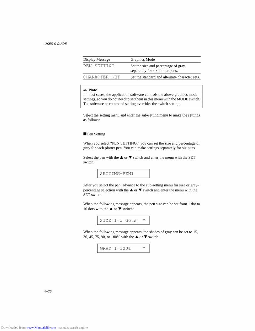
USER’S GUIDE
4–26
Display Message Graphics Mode
PEN SETTING Set the size and percentage of grayseparately for six plotter pens.
CHARACTER SET Set the standard and alternate character sets.
✒ NoteIn most cases, the application software controls the above graphics modesettings, so you do not need to set them in this menu with the MODE switch.The software or command setting overrides the switch setting.
Select the setting menu and enter the sub-setting menu to make the settingsas follows:
■ Pen Setting
When you select “PEN SETTING,” you can set the size and percentage ofgray for each plotter pen. You can make settings separately for six pens.
Select the pen with the ▲ or ▼ switch and enter the menu with the SETswitch.
SETTING=PEN1
After you select the pen, advance to the sub-setting menu for size or gray-percentage selection with the ▲ or ▼ switch and enter the menu with theSET switch.
When the following message appears, the pen size can be set from 1 dot to10 dots with the ▲ or ▼ switch:
SIZE 1=3 dots *
When the following message appears, the shades of gray can be set to 15,30, 45, 75, 90, or 100% with the ▲ or ▼ switch.
GRAY 1=100% *
Downloaded from www.Manualslib.com manuals search engine
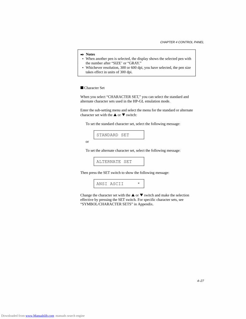
CHAPTER 4 CONTROL PANEL
4–27
✒ Notes • When another pen is selected, the display shows the selected pen with
the number after “SIZE’ or “GRAY.” • Whichever resolution, 300 or 600 dpi, you have selected, the pen size
takes effect in units of 300 dpi.
■ Character Set
When you select “CHARACTER SET,” you can select the standard andalternate character sets used in the HP-GL emulation mode.
Enter the sub-setting menu and select the menu for the standard or alternatecharacter set with the ▲ or ▼ switch:
To set the standard character set, select the following message:
STANDARD SET
or
To set the alternate character set, select the following message:
ALTERNATE SET
Then press the SET switch to show the following message:
ANSI ASCII *
Change the character set with the ▲ or ▼ switch and make the selectioneffective by pressing the SET switch. For specific character sets, see“SYMBOL/CHARACTER SETS” in Appendix.
Downloaded from www.Manualslib.com manuals search engine
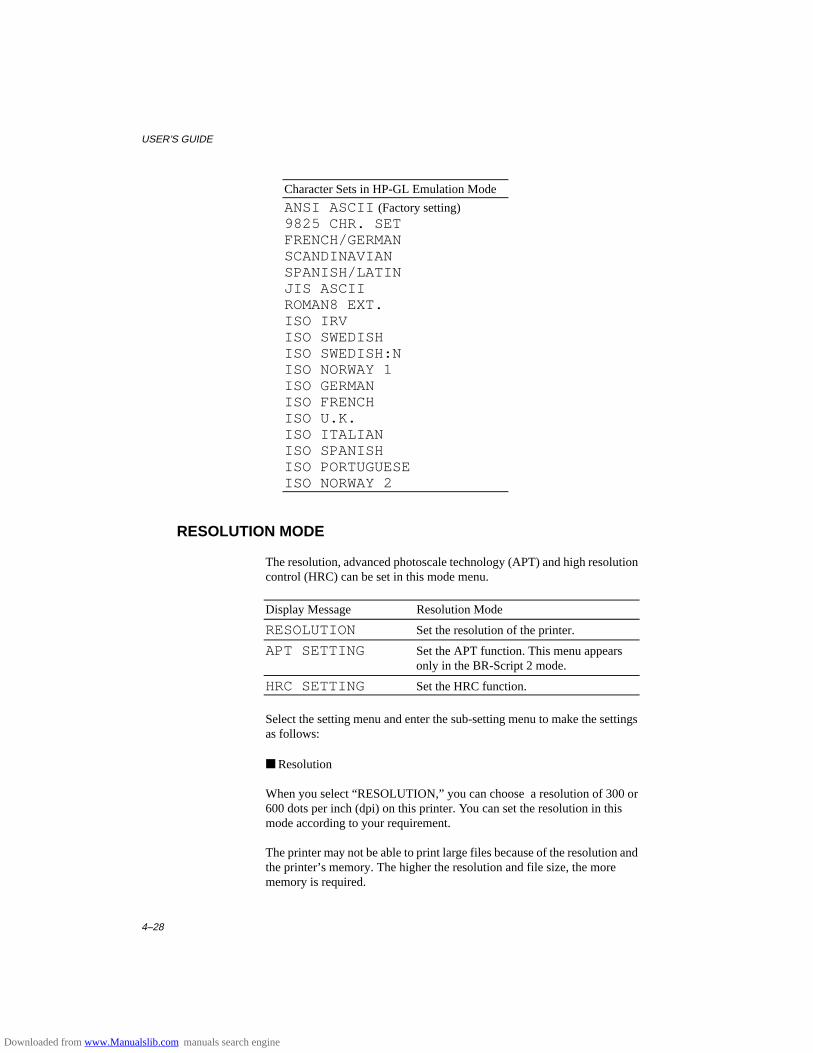
USER’S GUIDE
4–28
Character Sets in HP-GL Emulation Mode
ANSI ASCII (Factory setting)9825 CHR. SETFRENCH/GERMANSCANDINAVIANSPANISH/LATINJIS ASCIIROMAN8 EXT.ISO IRVISO SWEDISHISO SWEDISH:NISO NORWAY 1ISO GERMANISO FRENCHISO U.K.ISO ITALIANISO SPANISHISO PORTUGUESEISO NORWAY 2
RESOLUTION MODE
The resolution, advanced photoscale technology (APT) and high resolutioncontrol (HRC) can be set in this mode menu.
Display Message Resolution Mode
RESOLUTION Set the resolution of the printer.
APT SETTING Set the APT function. This menu appearsonly in the BR-Script 2 mode.
HRC SETTING Set the HRC function.
Select the setting menu and enter the sub-setting menu to make the settingsas follows:
■ Resolution
When you select “RESOLUTION,” you can choose a resolution of 300 or600 dots per inch (dpi) on this printer. You can set the resolution in thismode according to your requirement.
The printer may not be able to print large files because of the resolution andthe printer’s memory. The higher the resolution and file size, the morememory is required.
Downloaded from www.Manualslib.com manuals search engine
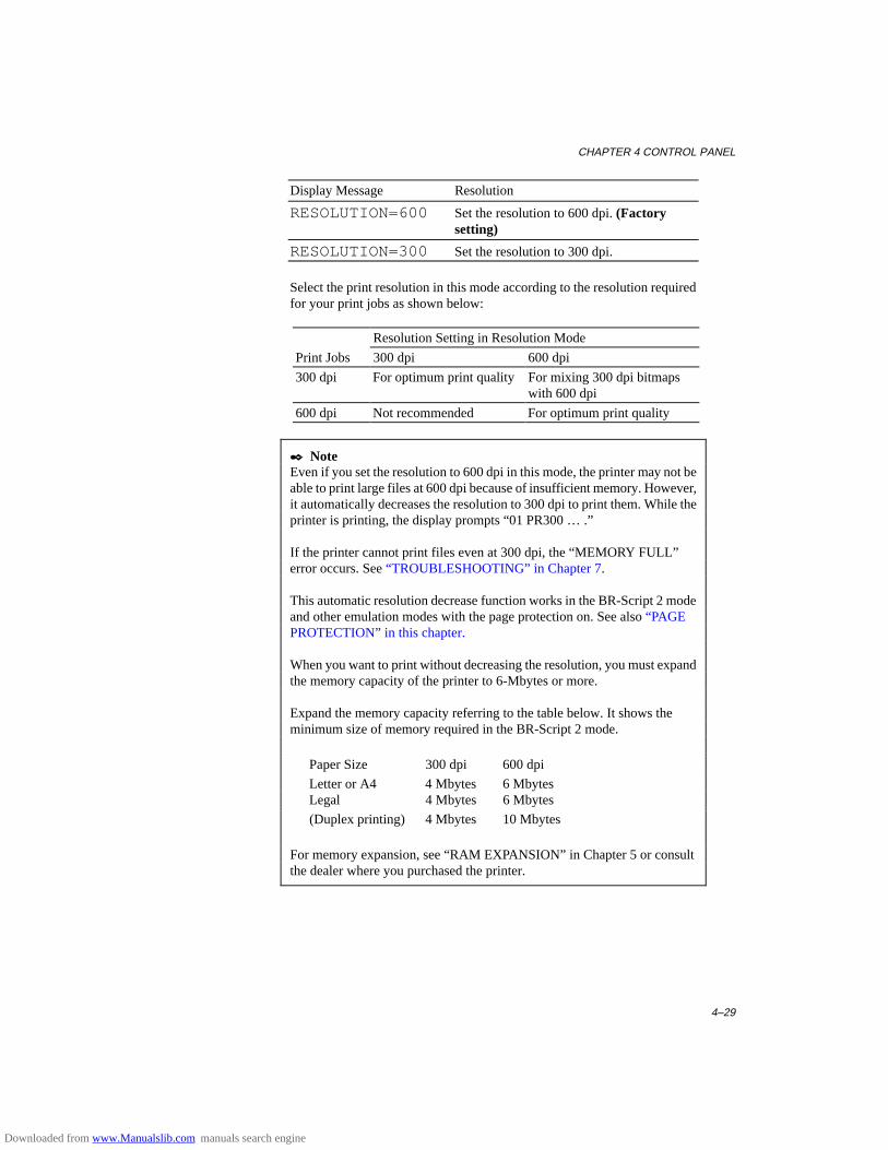
CHAPTER 4 CONTROL PANEL
4–29
Display Message Resolution
RESOLUTION=600 Set the resolution to 600 dpi. (Factorysetting)
RESOLUTION=300 Set the resolution to 300 dpi.
Select the print resolution in this mode according to the resolution requiredfor your print jobs as shown below:
Resolution Setting in Resolution Mode
Print Jobs 300 dpi 600 dpi
300 dpi For optimum print quality For mixing 300 dpi bitmapswith 600 dpi
600 dpi Not recommended For optimum print quality
✒ NoteEven if you set the resolution to 600 dpi in this mode, the printer may not beable to print large files at 600 dpi because of insufficient memory. However,it automatically decreases the resolution to 300 dpi to print them. While theprinter is printing, the display prompts “01 PR300 … .”
If the printer cannot print files even at 300 dpi, the “MEMORY FULL”error occurs. See “TROUBLESHOOTING” in Chapter 7.
This automatic resolution decrease function works in the BR-Script 2 modeand other emulation modes with the page protection on. See also “PAGEPROTECTION” in this chapter.
When you want to print without decreasing the resolution, you must expandthe memory capacity of the printer to 6-Mbytes or more.
Expand the memory capacity referring to the table below. It shows theminimum size of memory required in the BR-Script 2 mode.
Paper Size 300 dpi 600 dpi
Letter or A4 4 Mbytes 6 MbytesLegal 4 Mbytes 6 Mbytes
(Duplex printing) 4 Mbytes 10 Mbytes
For memory expansion, see “RAM EXPANSION” in Chapter 5 or consultthe dealer where you purchased the printer.
Downloaded from www.Manualslib.com manuals search engine
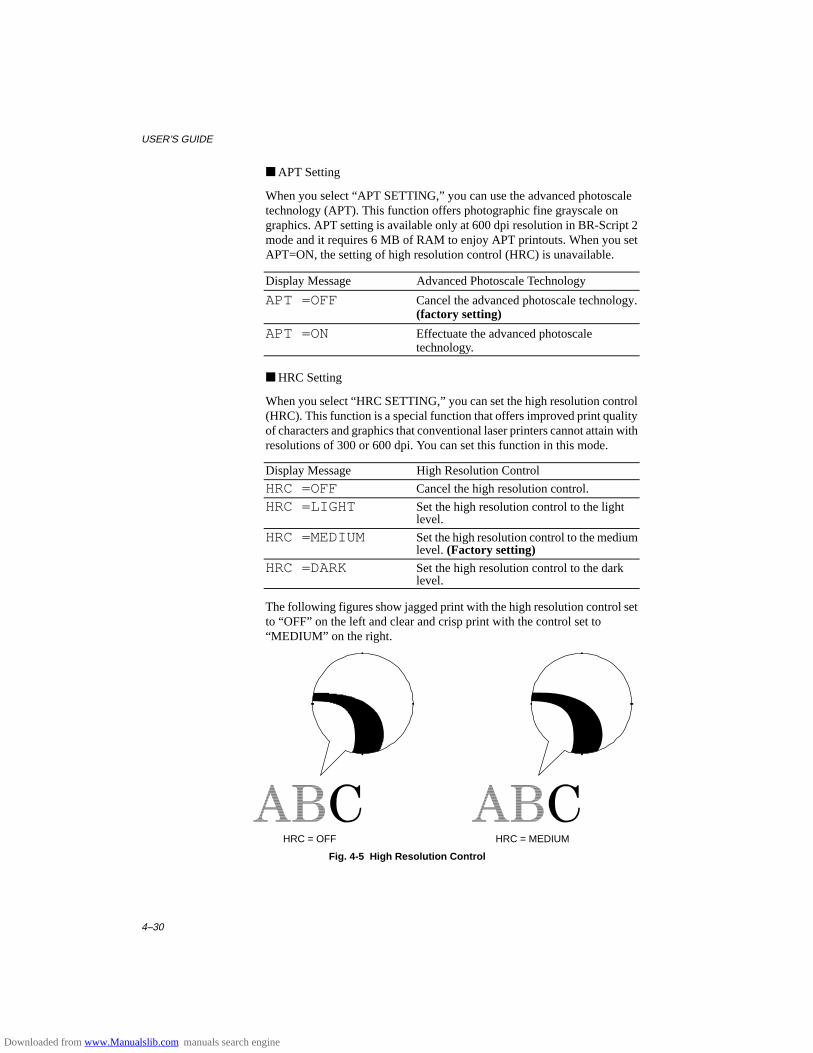
USER’S GUIDE
4–30
■ APT Setting
When you select “APT SETTING,” you can use the advanced photoscaletechnology (APT). This function offers photographic fine grayscale ongraphics. APT setting is available only at 600 dpi resolution in BR-Script 2mode and it requires 6 MB of RAM to enjoy APT printouts. When you setAPT=ON, the setting of high resolution control (HRC) is unavailable.
Display Message Advanced Photoscale Technology
APT =OFF Cancel the advanced photoscale technology.(factory setting)
APT =ON Effectuate the advanced photoscaletechnology.
■ HRC Setting
When you select “HRC SETTING,” you can set the high resolution control(HRC). This function is a special function that offers improved print qualityof characters and graphics that conventional laser printers cannot attain withresolutions of 300 or 600 dpi. You can set this function in this mode.
Display Message High Resolution Control
HRC =OFF Cancel the high resolution control.
HRC =LIGHT Set the high resolution control to the lightlevel.
HRC =MEDIUM Set the high resolution control to the mediumlevel. (Factory setting)
HRC =DARK Set the high resolution control to the darklevel.
The following figures show jagged print with the high resolution control setto “OFF” on the left and clear and crisp print with the control set to“MEDIUM” on the right.
HRC = OFF HRC = MEDIUM
Fig. 4-5 High Resolution Control
Downloaded from www.Manualslib.com manuals search engine
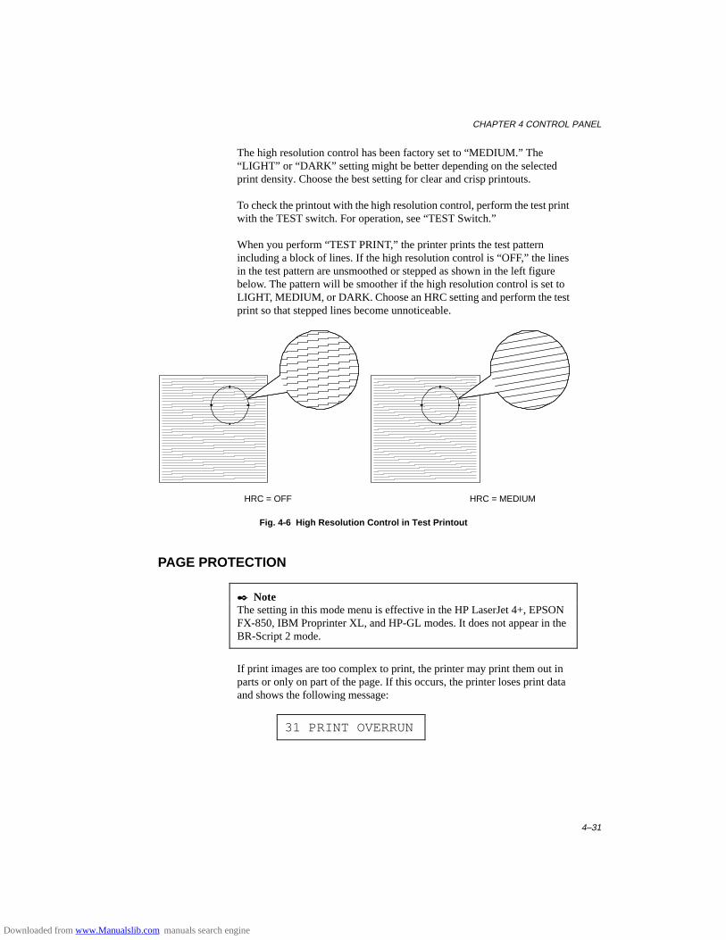
CHAPTER 4 CONTROL PANEL
4–31
The high resolution control has been factory set to “MEDIUM.” The“LIGHT” or “DARK” setting might be better depending on the selectedprint density. Choose the best setting for clear and crisp printouts.
To check the printout with the high resolution control, perform the test printwith the TEST switch. For operation, see “TEST Switch.”
When you perform “TEST PRINT,” the printer prints the test patternincluding a block of lines. If the high resolution control is “OFF,” the linesin the test pattern are unsmoothed or stepped as shown in the left figurebelow. The pattern will be smoother if the high resolution control is set toLIGHT, MEDIUM, or DARK. Choose an HRC setting and perform the testprint so that stepped lines become unnoticeable.
HRC = OFF HRC = MEDIUM
Fig. 4-6 High Resolution Control in Test Printout
PAGE PROTECTION
✒ NoteThe setting in this mode menu is effective in the HP LaserJet 4+, EPSONFX-850, IBM Proprinter XL, and HP-GL modes. It does not appear in theBR-Script 2 mode.
If print images are too complex to print, the printer may print them out inparts or only on part of the page. If this occurs, the printer loses print dataand shows the following message:
31 PRINT OVERRUN
Downloaded from www.Manualslib.com manuals search engine
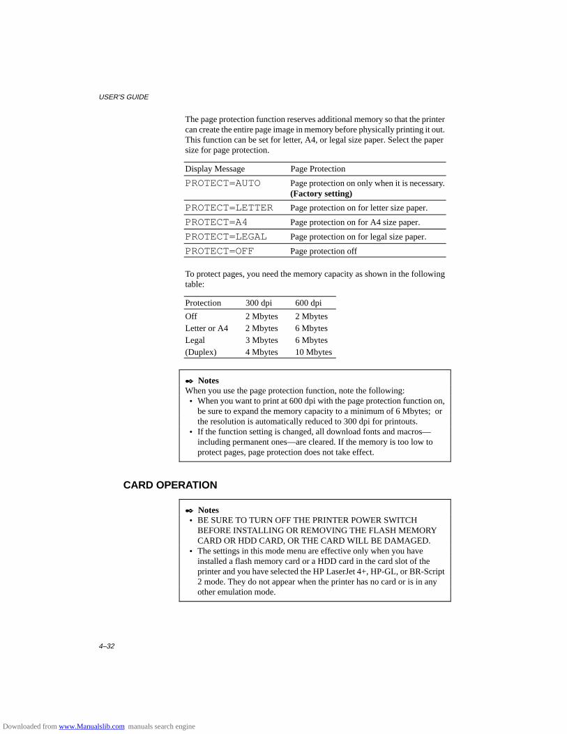
USER’S GUIDE
4–32
The page protection function reserves additional memory so that the printercan create the entire page image in memory before physically printing it out.This function can be set for letter, A4, or legal size paper. Select the papersize for page protection.
Display Message Page Protection
PROTECT=AUTO Page protection on only when it is necessary.(Factory setting)
PROTECT=LETTER Page protection on for letter size paper.
PROTECT=A4 Page protection on for A4 size paper.
PROTECT=LEGAL Page protection on for legal size paper.
PROTECT=OFF Page protection off
To protect pages, you need the memory capacity as shown in the followingtable:
Protection 300 dpi 600 dpi
Off 2 Mbytes 2 MbytesLetter or A4 2 Mbytes 6 MbytesLegal 3 Mbytes 6 Mbytes(Duplex) 4 Mbytes 10 Mbytes
✒ NotesWhen you use the page protection function, note the following: • When you want to print at 600 dpi with the page protection function on,
be sure to expand the memory capacity to a minimum of 6 Mbytes; orthe resolution is automatically reduced to 300 dpi for printouts.
• If the function setting is changed, all download fonts and macros—including permanent ones—are cleared. If the memory is too low toprotect pages, page protection does not take effect.
CARD OPERATION
✒ Notes • BE SURE TO TURN OFF THE PRINTER POWER SWITCH
BEFORE INSTALLING OR REMOVING THE FLASH MEMORYCARD OR HDD CARD, OR THE CARD WILL BE DAMAGED.
• The settings in this mode menu are effective only when you haveinstalled a flash memory card or a HDD card in the card slot of theprinter and you have selected the HP LaserJet 4+, HP-GL, or BR-Script2 mode. They do not appear when the printer has no card or is in anyother emulation mode.
Downloaded from www.Manualslib.com manuals search engine
CHAPTER 4 CONTROL PANEL
4–33
• If you turn the printer off or remove the flash memory card or the HDDcard while data is being written onto or deleted from the card, all thedata on the card may be lost.
• If the write protect switch of the flash memory card or the HDD card ison, this mode menu does not appear.
Be sure to install a commercial flash memory card or HDD card in the uppercard slot of the printer. For installation, see “FONT CARTRIDGE/CARD,FLASH MEMORY/HDD CARD” in Chapter 5.
When you are in this mode menu, you can save macros and fonts in theinstalled flash memory card or the HDD card.
The sub-setting menus displayed in this mode menu vary according to thestate of the installed card.
When the installed card is not formatted:
When you enter this mode menu with the flash memory card or the HDDcard installed but not formatted by this printer, you must first format thecard.
Display Message Card Operation
FORMAT CARD Format a new flash memory card or HDDcard.
exit Exit to CARD OPERATION
When the display shows “FORMAT CARD,” press the SET switch toformat the installed card.
After the printer finishes formatting the card, you exit to the “CARDOPERATION” menu.
✒ Notes • If the card is formatted, data that has been previously written is erased. • It takes ten or more seconds to format a 2-Mbyte flash memory card or
HDD card. The more the capacity of the card, the longer time it takes toformat the card.
Downloaded from www.Manualslib.com manuals search engine
USER’S GUIDE
4–34
When the installed flash memory card or HDD card is formatted:
When you enter this mode menu with the formatted flash memory card orHDD card installed, the display shows the following menus:
Display Message Flash Operation
EXECUTE DATA Select the data ID and execute the selecteddata. This menu appears only when any datahas been saved on the card.
CARD LIST Print out the contents of the flash memorycard or the HDD card. This menu appearsonly when anything has been saved in thecard.
SAVE Save received data, macros, and fonts.
DELETE Delete items from the card.
✒ NoteA common use of the flash memory is with FORMS software packages.With these commercially available software packages you have an option tosend a form to the printer without any data. After you send the form to theprinter, you may save the form in the flash memory as a Macro. Then thenext time you want to print this form, you would setup your FORMSsoftware package to SEND DATA ONLY - USE FORM IN PRINTER. Thisprocess would save you anything from 1 to 4 minutes per print job.
Select the setting menu and enter the sub-setting menu to change thesettings as follows:
■ Execute Data
✒ NoteThis menu appears only when data has been saved on the card.
When you select “EXECUTE DATA,” you can execute any of the datasaved in the SAVE DATA mode.
When you enter this sub-setting menu with the SET switch, the printerprompts you to select the ID of the data.
DATA ID=#####
Select the ID with the ▲ or ▼ switch and press the SET switch again, so thatthe printer executes the selected data.
Downloaded from www.Manualslib.com manuals search engine
CHAPTER 4 CONTROL PANEL
4–35
■ Card List
When you select “CARD LIST” and you press the SET switch, the printerautomatically loads paper and starts printing the contents of the installedflash memory card or HDD card. You can check the contents and the unusedcapacity of the card.
■ Save
When you select “SAVE” and you press the SET switch, you can enter thefollowing sub-setting menus to save the macros and fonts in the installedcard:
Display Message Save Menu
SAVE DATA Save data that the printer will receive and setits ID.
SAVE MACRO Save a macro. This menu appears only in theHP LaserJet 4+ emulation mode.
PRIMARY FONT Save the primary font selected with theFONT switch. This menu appears only in theHP LaserJet 4+ emulation mode.
SECONDARY FONT Save the secondary font selected with theFONT switch. This menu appears only in theHP LaserJet 4+ emulation mode.
DOWNLOAD FONT Save a download font. This menu appearsonly in the HP LaserJet 4+ emulation modeand BR-Script 2 mode.
✒ NoteIf the capacity of the card becomes low while macros and fonts are beingsaved, the display shows the “CARD FULL” error message and they cannotbe saved. Use a new card or delete unnecessary macros and fonts from thecard. The CARD LIST displays the contents and the used capacity.
Downloaded from www.Manualslib.com manuals search engine
USER’S GUIDE
4–36
• Save Data
You can send data and save it on the card. In this mode, any kind of datasuch as PCL data, BR-Script 2 data, and command strings can be saved.When you select “SAVE DATA” and you press the SET switch, the displayshows the following guide menus.
SET KEY --> END
This message prompts you to press the SET switch again so that the printerexits from the data reception status when you finish sending data.
Send data from your computer.
✒ NotesWhen you send data to be saved on the card, it is temporarily stored in theRAM of the printer. Note the following: • If the received data exceeds the RAM capacity, a memory full error
occurs. You can clear this error with the CONTINUE switch. When thiserror occurs, only part of the image has been stored in RAM, therefore,you cannot save the data to the card.
• The printer is reset to ensure as much capacity as possible in RAM. Ifany data remains, it is printed out first.
After you have finished sending data, press the SET switch again, so that theprinter exits from the data reception status.
When you exit from the data reception status, you see the followingmessage on the display:
DATA ID=#####
Select the data ID with the ▲ or ▼ switch and press the SET switch. Theprinter will then save the received data with the ID on the card.
✒ Notes • When you see an asterisk on the display, the ID number has been used
for other data or a macro. If you select the used ID number, the old dataor macro is erased and replaced with the new data.
• Once the data is saved, you can execute it with “EXECUTE DATA” orwith a data execution command.
• The data saved in the SAVE DATA mode can not be run with the macroexecution command in HP LaserJet 4+ emulation.
Downloaded from www.Manualslib.com manuals search engine
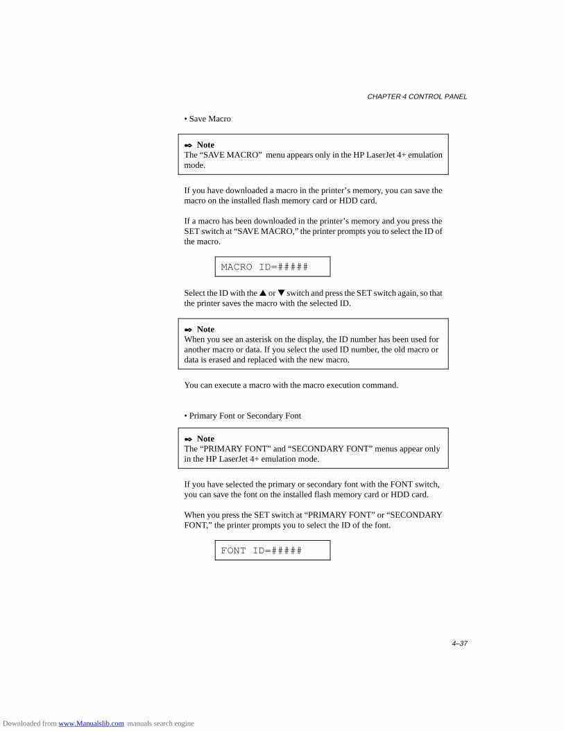
CHAPTER 4 CONTROL PANEL
4–37
• Save Macro
✒ NoteThe “SAVE MACRO” menu appears only in the HP LaserJet 4+ emulationmode.
If you have downloaded a macro in the printer’s memory, you can save themacro on the installed flash memory card or HDD card.
If a macro has been downloaded in the printer’s memory and you press theSET switch at “SAVE MACRO,” the printer prompts you to select the ID ofthe macro.
MACRO ID=#####
Select the ID with the ▲ or ▼ switch and press the SET switch again, so thatthe printer saves the macro with the selected ID.
✒ NoteWhen you see an asterisk on the display, the ID number has been used foranother macro or data. If you select the used ID number, the old macro ordata is erased and replaced with the new macro.
You can execute a macro with the macro execution command.
• Primary Font or Secondary Font
✒ NoteThe “PRIMARY FONT” and “SECONDARY FONT” menus appear onlyin the HP LaserJet 4+ emulation mode.
If you have selected the primary or secondary font with the FONT switch,you can save the font on the installed flash memory card or HDD card.
When you press the SET switch at “PRIMARY FONT” or “SECONDARYFONT,” the printer prompts you to select the ID of the font.
FONT ID=#####
Downloaded from www.Manualslib.com manuals search engine
USER’S GUIDE
4–38
Select the ID with the ▲ or ▼ switch and press the SET switch again, so thatthe printer saves the font with the selected ID.
✒ NoteWhen you see an asterisk on the display, the ID number has been used foranother font. If you select the used ID number, the old font is erased andreplaced with the new one.
Whatever font you have selected with the FONT switch, the printer savesthe font as a bitmapped font as long as the print size is no more than 24points, so that the printer can print it faster than when they are not saved. Itis recommended that you save the scalable font you frequently use for fasterprinting.
Since the flash memory card or the HDD card is in the upper card slot A ofthe printer and fonts stored in the card behave in the same way as theywould if they were in a dedicated Font Card, you can select the saved fontsas “SLOTFONT A” with the FONT switch or the font selection commandfrom your software. For font selection, see “FONT Switch” in Chapter 4.
You can check the saved fonts by printing the list of fonts with the TESTswitch. See “TEST Switch” in Chapter 4.
✒ NotesWhen you save the primary or secondary font, note the following: • The font is temporarily stored in the RAM of the printer before it is
saved on the card. If the font data exceeds the RAM capacity, a memoryfull error occurs. You can clear this error with the CONTINUE switch.As not all the font data has been stored in RAM, you cannot save the fontto the card. When the font data is saved, the printer is reset to ensure asmuch capacity as possible in RAM. If any data remains, it is printed out.
• If you have saved the font at 600-dpi resolution and change the printerresolution to 300 dpi, the printer cannot print the saved font.
Downloaded from www.Manualslib.com manuals search engine
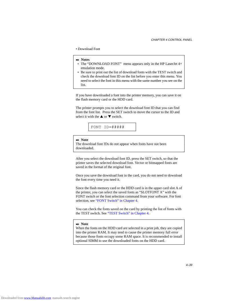
CHAPTER 4 CONTROL PANEL
4–39
• Download Font
✒ Notes • The “DOWNLOAD FONT” menu appears only in the HP LaserJet 4+
emulation mode. • Be sure to print out the list of download fonts with the TEST switch and
check the download font ID on the list before you enter this menu. Youneed to select the font in this menu with the same number you see on thelist.
If you have downloaded a font into the printer memory, you can save it onthe flash memory card or the HDD card.
The printer prompts you to select the download font ID that you can findfrom the font list. Press the SET switch to move the cursor to the ID andselect it with the ▲ or ▼ switch.
FONT ID=#####
✒ NoteThe download font IDs do not appear when fonts have not beendownloaded.
After you select the download font ID, press the SET switch, so that theprinter saves the selected download font. Vector or bitmapped fonts aresaved in the format of the original font.
Once you save the download font in the card, you do not need to downloadthe font every time you need it.
Since the flash memory card or the HDD card is in the upper card slot A ofthe printer, you can select the saved fonts as “SLOTFONT A” with theFONT switch or the font selection command from your software. For fontselection, see “FONT Switch” in Chapter 4.
You can check the fonts saved on the card by printing the list of fonts withthe TEST switch. See “TEST Switch” in Chapter 4.
✒ NoteWhen the fonts on the HDD card are selected in a print job, they are copiedinto the printer RAM. It may tend to cause the printer memory full errorbecause those fonts occupy some RAM space. It is recommended to installoptional SIMM to use the downloaded fonts on the HDD card.
Downloaded from www.Manualslib.com manuals search engine
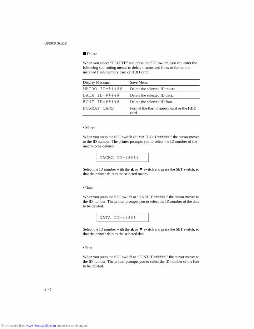
USER’S GUIDE
4–40
■ Delete
When you select “DELETE” and press the SET switch, you can enter thefollowing sub-setting menus to delete macros and fonts or format theinstalled flash memory card or HDD card:
Display Message Save Menu
MACRO ID=##### Delete the selected ID macro.
DATA ID=##### Delete the selected ID data.
FONT ID=##### Delete the selected ID font.
FORMAT CARD Format the flash memory card or the HDDcard.
• Macro
When you press the SET switch at “MACRO ID=#####,” the cursor movesto the ID number. The printer prompts you to select the ID number of themacro to be deleted.
MACRO ID=#####
Select the ID number with the ▲ or ▼ switch and press the SET switch, sothat the printer deletes the selected macro.
• Data
When you press the SET switch at “DATA ID=#####,” the cursor moves tothe ID number. The printer prompts you to select the ID number of the datato be deleted.
DATA ID=#####
Select the ID number with the ▲ or ▼ switch and press the SET switch, sothat the printer deletes the selected data.
• Font
When you press the SET switch at “FONT ID=#####,” the cursor moves tothe ID number. The printer prompts you to select the ID number of the fontto be deleted.
Downloaded from www.Manualslib.com manuals search engine
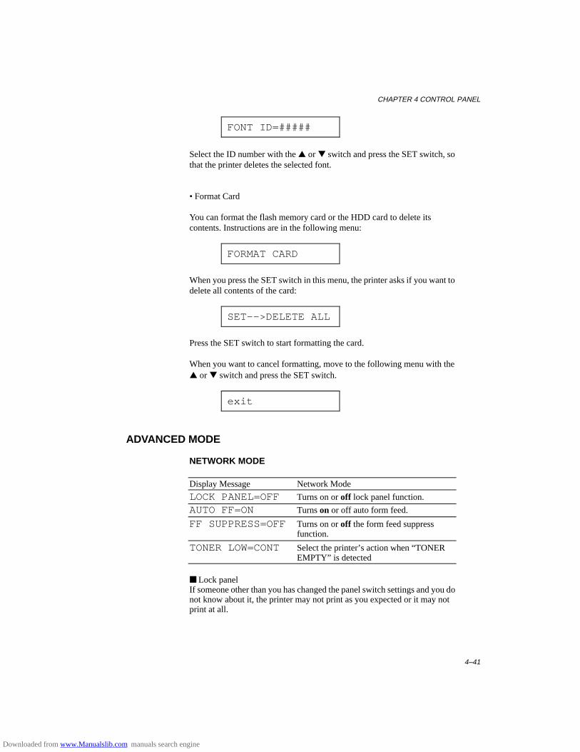
CHAPTER 4 CONTROL PANEL
4–41
FONT ID=#####
Select the ID number with the ▲ or ▼ switch and press the SET switch, sothat the printer deletes the selected font.
• Format Card
You can format the flash memory card or the HDD card to delete itscontents. Instructions are in the following menu:
FORMAT CARD
When you press the SET switch in this menu, the printer asks if you want todelete all contents of the card:
SET-->DELETE ALL
Press the SET switch to start formatting the card.
When you want to cancel formatting, move to the following menu with the▲ or ▼ switch and press the SET switch.
exit
ADVANCED MODE
NETWORK MODE
Display Message Network Mode
LOCK PANEL=OFF Turns on or off lock panel function.
AUTO FF=ON Turns on or off auto form feed.
FF SUPPRESS=OFF Turns on or off the form feed suppressfunction.
TONER LOW=CONT Select the printer’s action when “TONEREMPTY” is detected
■ Lock panelIf someone other than you has changed the panel switch settings and you donot know about it, the printer may not print as you expected or it may notprint at all.
Downloaded from www.Manualslib.com manuals search engine
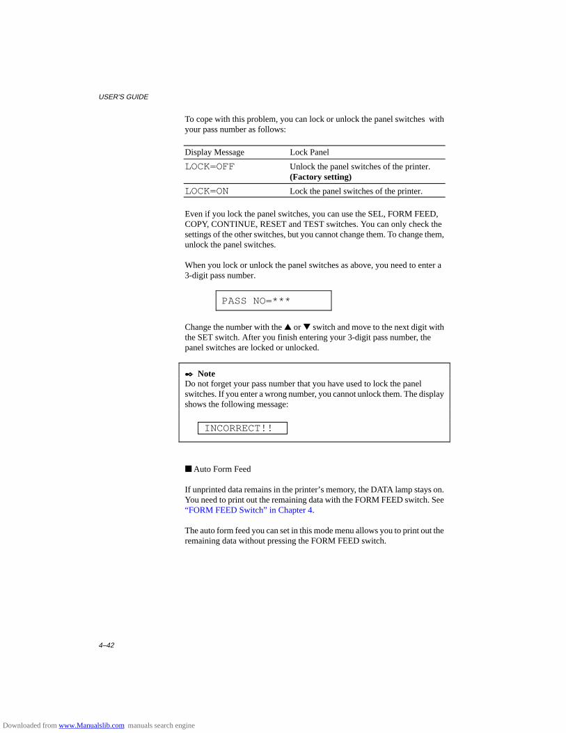
USER’S GUIDE
4–42
To cope with this problem, you can lock or unlock the panel switches withyour pass number as follows:
Display Message Lock Panel
LOCK=OFF Unlock the panel switches of the printer.(Factory setting)
LOCK=ON Lock the panel switches of the printer.
Even if you lock the panel switches, you can use the SEL, FORM FEED,COPY, CONTINUE, RESET and TEST switches. You can only check thesettings of the other switches, but you cannot change them. To change them,unlock the panel switches.
When you lock or unlock the panel switches as above, you need to enter a3-digit pass number.
PASS NO=***
Change the number with the ▲ or ▼ switch and move to the next digit withthe SET switch. After you finish entering your 3-digit pass number, thepanel switches are locked or unlocked.
✒ NoteDo not forget your pass number that you have used to lock the panelswitches. If you enter a wrong number, you cannot unlock them. The displayshows the following message:
INCORRECT!!
■ Auto Form Feed
If unprinted data remains in the printer’s memory, the DATA lamp stays on.You need to print out the remaining data with the FORM FEED switch. See“FORM FEED Switch” in Chapter 4.
The auto form feed you can set in this mode menu allows you to print out theremaining data without pressing the FORM FEED switch.
Downloaded from www.Manualslib.com manuals search engine
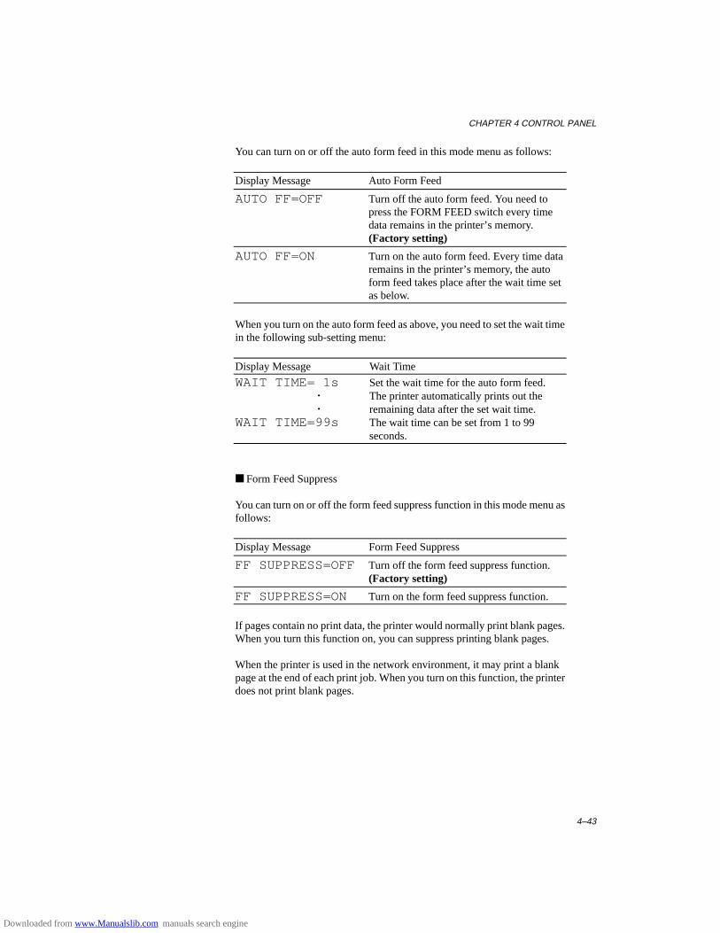
CHAPTER 4 CONTROL PANEL
4–43
You can turn on or off the auto form feed in this mode menu as follows:
Display Message Auto Form Feed
AUTO FF=OFF Turn off the auto form feed. You need topress the FORM FEED switch every timedata remains in the printer’s memory.(Factory setting)
AUTO FF=ON Turn on the auto form feed. Every time dataremains in the printer’s memory, the autoform feed takes place after the wait time setas below.
When you turn on the auto form feed as above, you need to set the wait timein the following sub-setting menu:
Display Message Wait Time
WAIT TIME= 1s Set the wait time for the auto form feed. . The printer automatically prints out the . remaining data after the set wait time.WAIT TIME=99s The wait time can be set from 1 to 99
seconds.
■ Form Feed Suppress
You can turn on or off the form feed suppress function in this mode menu asfollows:
Display Message Form Feed Suppress
FF SUPPRESS=OFF Turn off the form feed suppress function.(Factory setting)
FF SUPPRESS=ON Turn on the form feed suppress function.
If pages contain no print data, the printer would normally print blank pages.When you turn this function on, you can suppress printing blank pages.
When the printer is used in the network environment, it may print a blankpage at the end of each print job. When you turn on this function, the printerdoes not print blank pages.
Downloaded from www.Manualslib.com manuals search engine
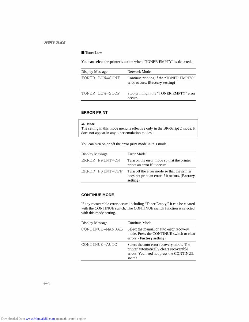
USER’S GUIDE
4–44
■ Toner Low
You can select the printer’s action when “TONER EMPTY” is detected.
Display Message Network Mode
TONER LOW=CONT Continue printing if the “TONER EMPTY”error occurs. (Factory setting)
TONER LOW=STOP Stop printing if the “TONER EMPTY” erroroccurs.
ERROR PRINT
✒ NoteThe setting in this mode menu is effective only in the BR-Script 2 mode. Itdoes not appear in any other emulation modes.
You can turn on or off the error print mode in this mode.
Display Message Error Mode
ERROR PRINT=ON Turn on the error mode so that the printerprints an error if it occurs.
ERROR PRINT=OFF Turn off the error mode so that the printerdoes not print an error if it occurs. (Factorysetting)
CONTINUE MODE
If any recoverable error occurs including “Toner Empty,” it can be clearedwith the CONTINUE switch. The CONTINUE switch function is selectedwith this mode setting.
Display Message Continue Mode
CONTINUE=MANUALSelect the manual or auto error recoverymode. Press the CONTINUE switch to clearerrors. (Factory setting)
CONTINUE=AUTO Select the auto error recovery mode. Theprinter automatically clears recoverableerrors. You need not press the CONTINUEswitch.
Downloaded from www.Manualslib.com manuals search engine
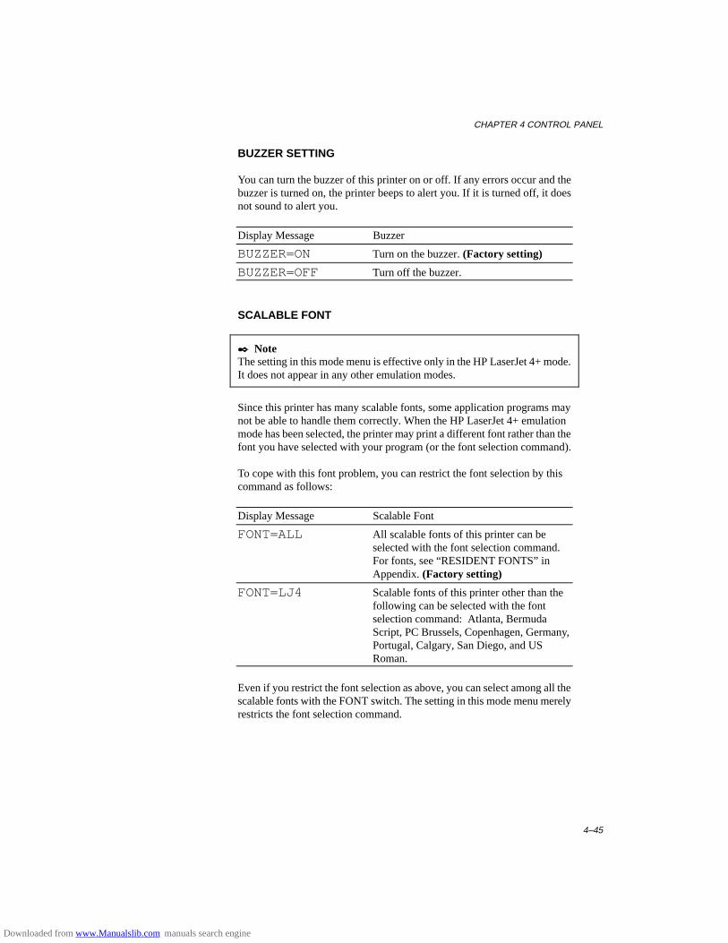
CHAPTER 4 CONTROL PANEL
4–45
BUZZER SETTING
You can turn the buzzer of this printer on or off. If any errors occur and thebuzzer is turned on, the printer beeps to alert you. If it is turned off, it doesnot sound to alert you.
Display Message Buzzer
BUZZER=ON Turn on the buzzer. (Factory setting)
BUZZER=OFF Turn off the buzzer.
SCALABLE FONT
✒ NoteThe setting in this mode menu is effective only in the HP LaserJet 4+ mode.It does not appear in any other emulation modes.
Since this printer has many scalable fonts, some application programs maynot be able to handle them correctly. When the HP LaserJet 4+ emulationmode has been selected, the printer may print a different font rather than thefont you have selected with your program (or the font selection command).
To cope with this font problem, you can restrict the font selection by thiscommand as follows:
Display Message Scalable Font
FONT=ALL All scalable fonts of this printer can beselected with the font selection command.For fonts, see “RESIDENT FONTS” inAppendix. (Factory setting)
FONT=LJ4 Scalable fonts of this printer other than thefollowing can be selected with the fontselection command: Atlanta, BermudaScript, PC Brussels, Copenhagen, Germany,Portugal, Calgary, San Diego, and USRoman.
Even if you restrict the font selection as above, you can select among all thescalable fonts with the FONT switch. The setting in this mode menu merelyrestricts the font selection command.
Downloaded from www.Manualslib.com manuals search engine
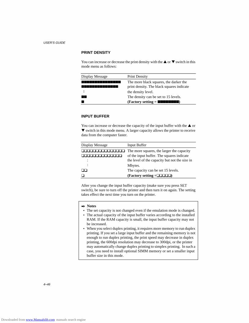
USER’S GUIDE
4–46
PRINT DENSITY
You can increase or decrease the print density with the ▲ or ▼ switch in thismode menu as follows:
Display Message Print Density
■■■■■■■■■■■■■■■ The more black squares, the darker the■■■■■■■■■■■■■■ print density. The black squares indicate : the density level.■■ The density can be set to 15 levels.■ (Factory setting = ■■■■■■■■■■■■■■■■)
INPUT BUFFER
You can increase or decrease the capacity of the input buffer with the ▲ or▼ switch in this mode menu. A larger capacity allows the printer to receivedata from the computer faster.
Display Message Input Buffer
❏❏❏❏❏❏❏❏❏❏❏❏❏❏❏ The more squares, the larger the capacity❏❏❏❏❏❏❏❏❏❏❏❏❏❏ of the input buffer. The squares indicate : the level of the capacity but not the size in : Mbytes.❏❏ The capacity can be set 15 levels.❏ (Factory setting =❏❏❏❏❏)
After you change the input buffer capacity (make sure you press SETswitch), be sure to turn off the printer and then turn it on again. The settingtakes effect the next time you turn on the printer.
✒ Notes • The set capacity is not changed even if the emulation mode is changed. • The actual capacity of the input buffer varies according to the installed
RAM. If the RAM capacity is small, the input buffer capacity may notbe increased.
• When you select duplex printing, it requires more memory to run duplexprinting. If you set a large input buffer and the remaining memory is notenough to run duplex printing, the print speed may decrease in duplexprinting, the 600dpi resolution may decrease to 300dpi, or the printermay automatically change duplex printing to simplex printing. In such acase, you need to install optional SIMM memory or set a smaller inputbuffer size in this mode.
Downloaded from www.Manualslib.com manuals search engine
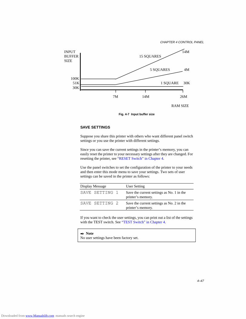
CHAPTER 4 CONTROL PANEL
4–47
INPUT 14MBUFFER 15 SQUARESSIZE
5 SQUARES 4M
100K 51K 1 SQUARE 30K
30K
7M 14M 26M
RAM SIZE
Fig. 4-7 Input buffer size
SAVE SETTINGS
Suppose you share this printer with others who want different panel switchsettings or you use the printer with different settings.
Since you can save the current settings in the printer’s memory, you caneasily reset the printer to your necessary settings after they are changed. Forresetting the printer, see “RESET Switch” in Chapter 4.
Use the panel switches to set the configuration of the printer to your needsand then enter this mode menu to save your settings. Two sets of usersettings can be saved in the printer as follows:
Display Message User Setting
SAVE SETTING 1 Save the current settings as No. 1 in theprinter’s memory.
SAVE SETTING 2 Save the current settings as No. 2 in theprinter’s memory.
If you want to check the user settings, you can print out a list of the settingswith the TEST switch. See “TEST Switch” in Chapter 4.
✒ NoteNo user settings have been factory set.
Downloaded from www.Manualslib.com manuals search engine
USER’S GUIDE
4–48
PAGE COUNTER
You can check the total number of printed pages with this mode. When youenter this mode, the display shows the number for a short time andautomatically moves to “exit MODE” menu.
COUNT= 861
EXIT MODE
When you finish setting your desired item in the mode menus, advance tothe following message:
exit MODE
Press the SET switch to exit from the mode menus to the off-line readystate.
✒ NoteRemember that you can exit from the mode menu any time with the SELswitch. After you make a setting effective with the SET switch, press theSEL switch. You will exit from the mode menu to the on-line ready state.The settings you have changed with the SET switch are effective after aquick exit.
Downloaded from www.Manualslib.com manuals search engine
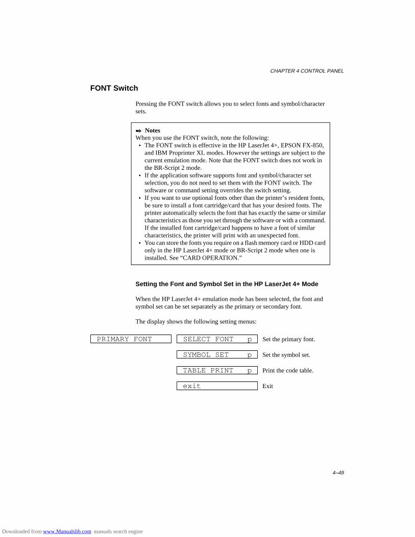
CHAPTER 4 CONTROL PANEL
4–49
FONT Switch
Pressing the FONT switch allows you to select fonts and symbol/charactersets.
✒ NotesWhen you use the FONT switch, note the following: • The FONT switch is effective in the HP LaserJet 4+, EPSON FX-850,
and IBM Proprinter XL modes. However the settings are subject to thecurrent emulation mode. Note that the FONT switch does not work inthe BR-Script 2 mode.
• If the application software supports font and symbol/character setselection, you do not need to set them with the FONT switch. Thesoftware or command setting overrides the switch setting.
• If you want to use optional fonts other than the printer’s resident fonts,be sure to install a font cartridge/card that has your desired fonts. Theprinter automatically selects the font that has exactly the same or similarcharacteristics as those you set through the software or with a command.If the installed font cartridge/card happens to have a font of similarcharacteristics, the printer will print with an unexpected font.
• You can store the fonts you require on a flash memory card or HDD cardonly in the HP LaserJet 4+ mode or BR-Script 2 mode when one isinstalled. See “CARD OPERATION.”
Setting the Font and Symbol Set in the HP LaserJet 4+ Mode
When the HP LaserJet 4+ emulation mode has been selected, the font andsymbol set can be set separately as the primary or secondary font.
The display shows the following setting menus:
PRIMARY FONT SELECT FONT p Set the primary font.
SYMBOL SET p Set the symbol set.
TABLE PRINT p Print the code table.
exit Exit
Downloaded from www.Manualslib.com manuals search engine
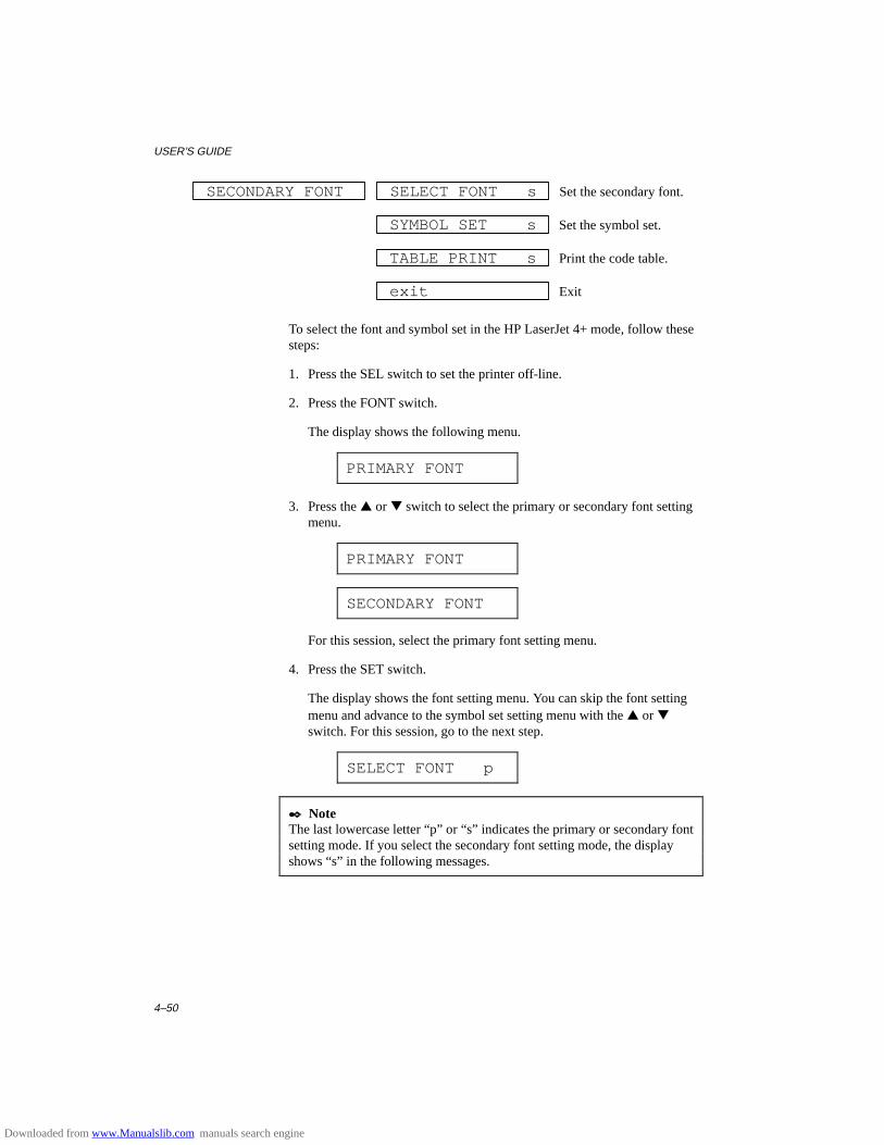
USER’S GUIDE
4–50
SECONDARY FONT SELECT FONT s Set the secondary font.
SYMBOL SET s Set the symbol set.
TABLE PRINT s Print the code table.
exit Exit
To select the font and symbol set in the HP LaserJet 4+ mode, follow thesesteps:
1. Press the SEL switch to set the printer off-line.
2. Press the FONT switch.
The display shows the following menu.
PRIMARY FONT
3. Press the ▲ or ▼ switch to select the primary or secondary font settingmenu.
PRIMARY FONT
SECONDARY FONT
For this session, select the primary font setting menu.
4. Press the SET switch.
The display shows the font setting menu. You can skip the font settingmenu and advance to the symbol set setting menu with the ▲ or ▼switch. For this session, go to the next step.
SELECT FONT p
✒ NoteThe last lowercase letter “p” or “s” indicates the primary or secondary fontsetting mode. If you select the secondary font setting mode, the displayshows “s” in the following messages.
Downloaded from www.Manualslib.com manuals search engine
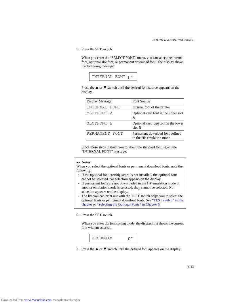
CHAPTER 4 CONTROL PANEL
4–51
5. Press the SET switch.
When you enter the “SELECT FONT” menu, you can select the internalfont, optional slot font, or permanent download font. The display showsthe following message.
INTERNAL FONT p*
Press the ▲ or ▼ switch until the desired font source appears on thedisplay.
Display Message Font Source
INTERNAL FONT Internal font of the printer
SLOTFONT A Optional card font in the upper slotA
SLOTFONT B Optional cartridge font in the lowerslot B
PERMANENT FONT Permanent download font definedin the HP emulation mode
Since these steps instruct you to select the standard font, select the“INTERNAL FONT” message.
✒ NotesWhen you select the optional fonts or permanent download fonts, note thefollowing: • If the optional font cartridge/card is not installed, the optional font
cannot be selected. No selection appears on the display. • If permanent fonts are not downloaded in the HP emulation mode or
another emulation mode is selected, they cannot be selected. Noselection appears on the display.
• The list you can print out with the TEST switch helps you to select theoptional fonts or permanent download fonts. See “TEST switch” in thischapter or “Selecting the Optional Fonts” in Chapter 5.
6. Press the SET switch.
When you enter the font setting mode, the display first shows the currentfont with an asterisk.
BROUGHAM p*
7. Press the ▲ or ▼ switch until the desired font appears on the display.
Downloaded from www.Manualslib.com manuals search engine
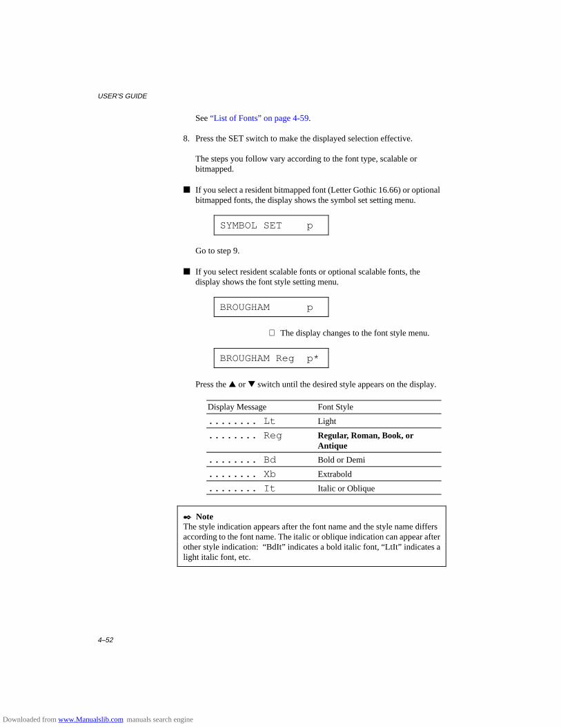
USER’S GUIDE
4–52
See “List of Fonts” on page 4-59.
8. Press the SET switch to make the displayed selection effective.
The steps you follow vary according to the font type, scalable orbitmapped.
■ If you select a resident bitmapped font (Letter Gothic 16.66) or optionalbitmapped fonts, the display shows the symbol set setting menu.
SYMBOL SET p
Go to step 9.
■ If you select resident scalable fonts or optional scalable fonts, thedisplay shows the font style setting menu.
BROUGHAM p
⇓ The display changes to the font style menu.
BROUGHAM Reg p*
Press the ▲ or ▼ switch until the desired style appears on the display.
Display Message Font Style
........ Lt Light
........ Reg Regular, Roman, Book, orAntique
........ Bd Bold or Demi
........ Xb Extrabold
........ It Italic or Oblique
✒ NoteThe style indication appears after the font name and the style name differsaccording to the font name. The italic or oblique indication can appear afterother style indication: “BdIt” indicates a bold italic font, “LtIt ” indicates alight italic font, etc.
Downloaded from www.Manualslib.com manuals search engine

CHAPTER 4 CONTROL PANEL
4–53
Press the SET switch to make the displayed selection effective, then thedisplay shows the font size setting menu.
✒ NoteWhen you have selected fixed-pitch fonts, you set the font size by thecharacter pitch (width). When you have selected proportional spacing fonts,you set the font size in points (height). The display shows “PITCH” or“POINT” accordingly. The following displays show “PITCH” to simplifyinstructions.
PITCH= 10.00 *
Press the ▲ or ▼ switch until the desired font size appears on thedisplay.
Press the SET switch to make the displayed selection effective.The blinking cursor then moves to the decimal part of the number.
Press the ▲ or ▼ switch until the desired decimal number appears onthe display.
PITCH= 16.66
Press the SET switch to make the displayed selection effective.The display then shows the symbol set setting menu.
SYMBOL SET p
9. Press the SET switch.
When you enter the symbol set setting mode, the display first shows thecurrent symbol set with an asterisk.
ROMAN 8 p*
10.Press the ▲ or ▼ switch until the desired symbol set appears on thedisplay.
See “List of Symbol/Character Sets” on page 4-60.
11. Press the SET switch to make the displayed selection effective.
The display then shows the next menu.
Downloaded from www.Manualslib.com manuals search engine

USER’S GUIDE
4–54
TABLE PRINT p
12. Press the SET switch to start printing the code table of the selected font,or press the ▲ or ▼ switch to skip this menu.
The display shows the exit menu.
exit
13. Press the SET switch to exit from the setting mode.
The printer returns to the off-line state.
Setting the Font and Character Set in the, EPSON FX-850, orIBM Proprinter XL Mode
When the EPSON FX-850 or IBM Proprinter XL mode has been selected,the font and character set can be selected.
The display shows the following setting menus.
SELECT FONT Select the font.
CHARACTER SET Select the character set.
TABLE PRINT Print the code table.
exit Exit
To select the font and character set in the EPSONFX-850 or IBM Proprinter XL mode, follow these steps:
1. Press the SEL switch to set the printer off-line.
2. Press the FONT switch.
The display shows the font setting menu. You can skip the font settingmenu and advance to the character set setting menu with the ▲ or ▼switch. For this session, go to the next step.
SELECT FONT
Downloaded from www.Manualslib.com manuals search engine
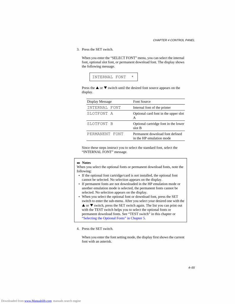
CHAPTER 4 CONTROL PANEL
4–55
3. Press the SET switch.
When you enter the “SELECT FONT” menu, you can select the internalfont, optional slot font, or permanent download font. The display showsthe following message.
INTERNAL FONT *
Press the ▲ or ▼ switch until the desired font source appears on thedisplay.
Display Message Font Source
INTERNAL FONT Internal font of the printer
SLOTFONT A Optional card font in the upper slotA
SLOTFONT B Optional cartridge font in the lowerslot B
PERMANENT FONT Permanent download font definedin the HP emulation mode
Since these steps instruct you to select the standard font, select the“INTERNAL FONT” message.
✒ NotesWhen you select the optional fonts or permanent download fonts, note thefollowing: • If the optional font cartridge/card is not installed, the optional font
cannot be selected. No selection appears on the display. • If permanent fonts are not downloaded in the HP emulation mode or
another emulation mode is selected, the permanent fonts cannot beselected. No selection appears on the display.
• When you select the optional font or download font, press the SETswitch to enter the sub-menu. After you select your desired one with the▲ or ▼ switch, press the SET switch again. The list you can print outwith the TEST switch helps you to select the optional fonts orpermanent download fonts. See “TEST switch” in this chapter or“Selecting the Optional Fonts” in Chapter 5.
4. Press the SET switch.
When you enter the font setting mode, the display first shows the currentfont with an asterisk.
Downloaded from www.Manualslib.com manuals search engine
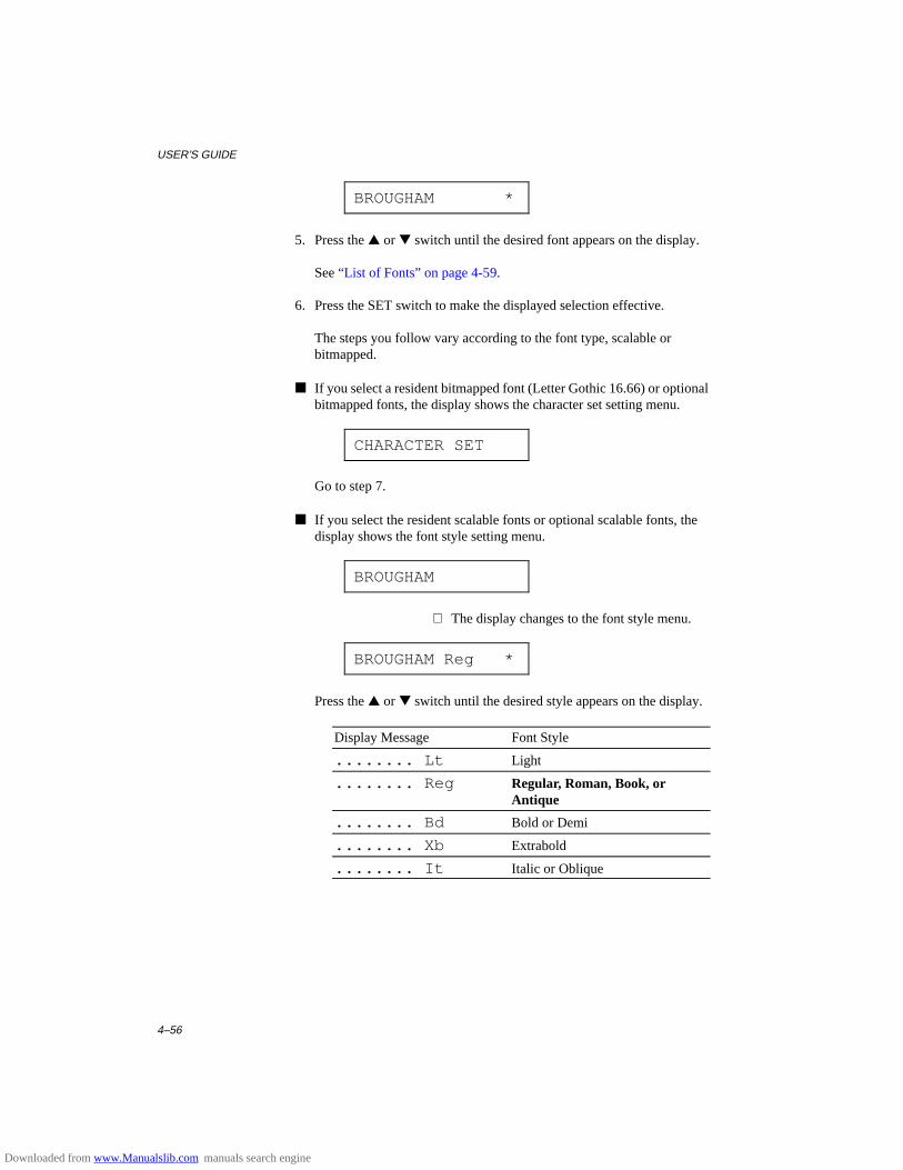
USER’S GUIDE
4–56
BROUGHAM *
5. Press the ▲ or ▼ switch until the desired font appears on the display.
See “List of Fonts” on page 4-59.
6. Press the SET switch to make the displayed selection effective.
The steps you follow vary according to the font type, scalable orbitmapped.
■ If you select a resident bitmapped font (Letter Gothic 16.66) or optionalbitmapped fonts, the display shows the character set setting menu.
CHARACTER SET
Go to step 7.
■ If you select the resident scalable fonts or optional scalable fonts, thedisplay shows the font style setting menu.
BROUGHAM
⇓ The display changes to the font style menu.
BROUGHAM Reg *
Press the ▲ or ▼ switch until the desired style appears on the display.
Display Message Font Style
........ Lt Light
........ Reg Regular, Roman, Book, orAntique
........ Bd Bold or Demi
........ Xb Extrabold
........ It Italic or Oblique
Downloaded from www.Manualslib.com manuals search engine
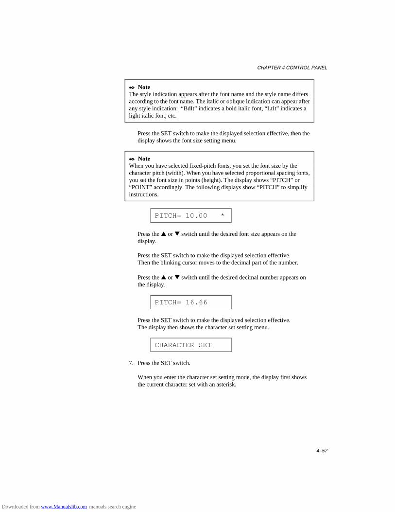
CHAPTER 4 CONTROL PANEL
4–57
✒ NoteThe style indication appears after the font name and the style name differsaccording to the font name. The italic or oblique indication can appear afterany style indication: “BdIt” indicates a bold italic font, “LtIt” indicates alight italic font, etc.
Press the SET switch to make the displayed selection effective, then thedisplay shows the font size setting menu.
✒ NoteWhen you have selected fixed-pitch fonts, you set the font size by thecharacter pitch (width). When you have selected proportional spacing fonts,you set the font size in points (height). The display shows “PITCH” or“POINT” accordingly. The following displays show “PITCH” to simplifyinstructions.
PITCH= 10.00 *
Press the ▲ or ▼ switch until the desired font size appears on thedisplay.
Press the SET switch to make the displayed selection effective.Then the blinking cursor moves to the decimal part of the number.
Press the ▲ or ▼ switch until the desired decimal number appears onthe display.
PITCH= 16.66
Press the SET switch to make the displayed selection effective.The display then shows the character set setting menu.
CHARACTER SET
7. Press the SET switch.
When you enter the character set setting mode, the display first showsthe current character set with an asterisk.
Downloaded from www.Manualslib.com manuals search engine
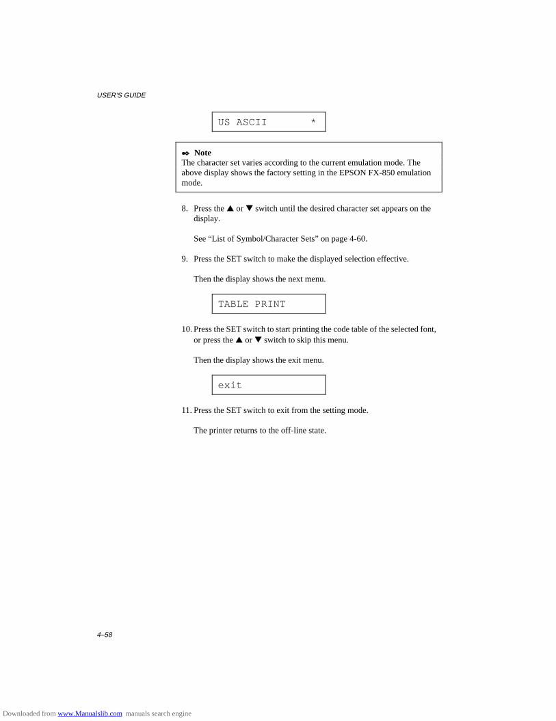
USER’S GUIDE
4–58
US ASCII *
✒ NoteThe character set varies according to the current emulation mode. Theabove display shows the factory setting in the EPSON FX-850 emulationmode.
8. Press the ▲ or ▼ switch until the desired character set appears on thedisplay.
See “List of Symbol/Character Sets” on page 4-60.
9. Press the SET switch to make the displayed selection effective.
Then the display shows the next menu.
TABLE PRINT
10. Press the SET switch to start printing the code table of the selected font,or press the ▲ or ▼ switch to skip this menu.
Then the display shows the exit menu.
exit
11. Press the SET switch to exit from the setting mode.
The printer returns to the off-line state.
Downloaded from www.Manualslib.com manuals search engine
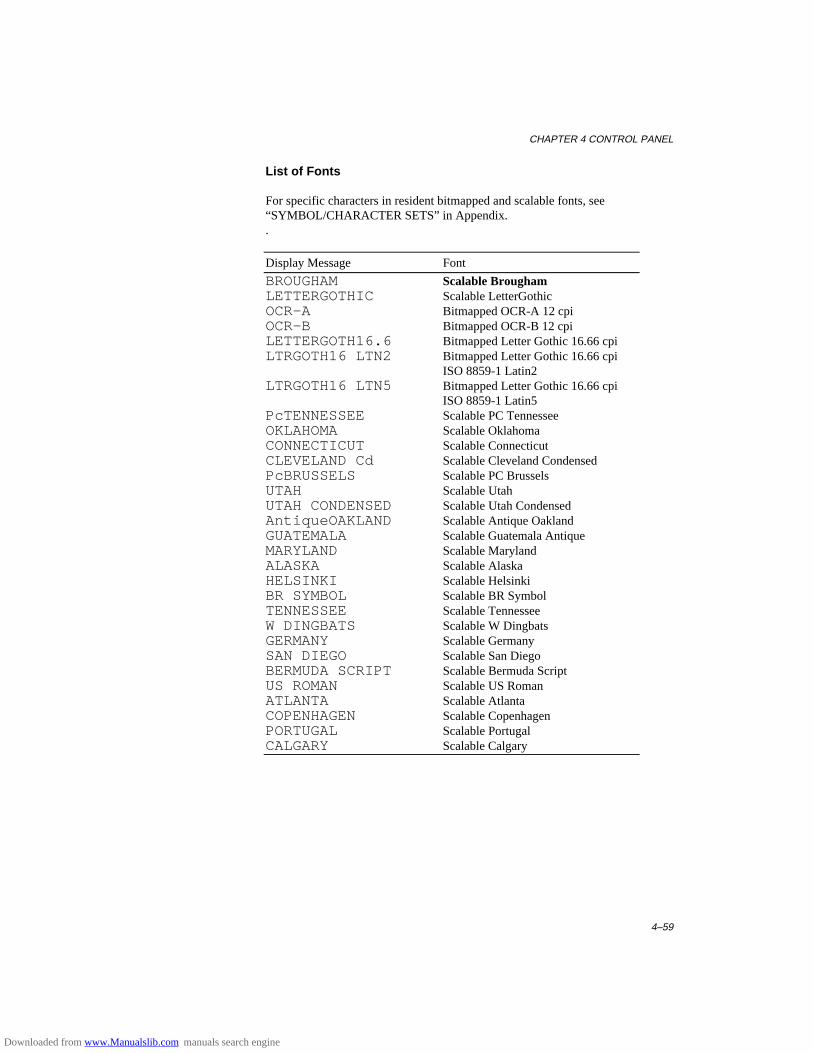
CHAPTER 4 CONTROL PANEL
4–59
List of Fonts
For specific characters in resident bitmapped and scalable fonts, see“SYMBOL/CHARACTER SETS” in Appendix..
Display Message Font
BROUGHAM Scalable BroughamLETTERGOTHIC Scalable LetterGothicOCR-A Bitmapped OCR-A 12 cpiOCR-B Bitmapped OCR-B 12 cpiLETTERGOTH16.6 Bitmapped Letter Gothic 16.66 cpiLTRGOTH16 LTN2 Bitmapped Letter Gothic 16.66 cpi
ISO 8859-1 Latin2LTRGOTH16 LTN5 Bitmapped Letter Gothic 16.66 cpi
ISO 8859-1 Latin5PcTENNESSEE Scalable PC TennesseeOKLAHOMA Scalable OklahomaCONNECTICUT Scalable ConnecticutCLEVELAND Cd Scalable Cleveland CondensedPcBRUSSELS Scalable PC BrusselsUTAH Scalable UtahUTAH CONDENSED Scalable Utah CondensedAntiqueOAKLAND Scalable Antique OaklandGUATEMALA Scalable Guatemala AntiqueMARYLAND Scalable MarylandALASKA Scalable AlaskaHELSINKI Scalable HelsinkiBR SYMBOL Scalable BR SymbolTENNESSEE Scalable TennesseeW DINGBATS Scalable W DingbatsGERMANY Scalable GermanySAN DIEGO Scalable San DiegoBERMUDA SCRIPT Scalable Bermuda ScriptUS ROMAN Scalable US RomanATLANTA Scalable AtlantaCOPENHAGEN Scalable CopenhagenPORTUGAL Scalable PortugalCALGARY Scalable Calgary
Downloaded from www.Manualslib.com manuals search engine

USER’S GUIDE
4–60
List of Symbol/Character Sets
The symbol sets and character sets are subject to the current emulationmode. For specific symbol/character sets, see “SYMBOL/CHARACTERSETS” in Appendix.
HP LaserJet 4+ EPSON IBM
ROMAN 8 * US ASCII * PC-8 *ISO LATIN1 GERMAN PC-8 D/NISO LATIN2 UK ASCII I PC-850ISO LATIN5 FRENCH I PC-852PC-8 DANISH I PC-860PC-8 D/N ITALY PC-863PC-850 SPANISH PC-865PC-852 SWEDISH PC-8 TURKISHPC-8 TURKISH JAPANESEWINDOWS LATIN1 NORWEGIANWINDOWS LATIN2 DANISH IIWINDOWS LATIN5 UK ASCII IILEGAL FRENCH IIISO 2 IRV DUTCHISO 4 UK SOUTH AFRICANISO 6 ASCII PC-8ISO10 SWE/FIN PC-8 D/NISO11 SWEDISH PC-850ISO14 JISASCII PC-852ISO15 ITALIAN PC-860ISO16 POR PC-863ISO17 SPANISH PC-865ISO21 GERMAN PC-8 TURKISHISO25 FRENCHISO57 CHINESEISO60 NOR v1ISO61 NOR v2ISO69 FRENCHISO84 PORISO85 SPANISHHP GERMANHP SPANISHVENTURA MATHVENTURA INTLVENTURA USPS MATHPS TEXTMATH-8PI FONTMS PUBLISHINGWINDOWS 3.0MC TEXTDESKTOP
✒ NoteThe factory settings are indicated by an asterisk “ * ” in the table above.
Downloaded from www.Manualslib.com manuals search engine
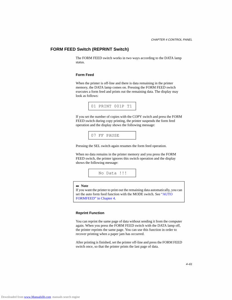
CHAPTER 4 CONTROL PANEL
4–61
FORM FEED Switch (REPRINT Switch)
The FORM FEED switch works in two ways according to the DATA lampstatus.
Form Feed
When the printer is off-line and there is data remaining in the printermemory, the DATA lamp comes on. Pressing the FORM FEED switchexecutes a form feed and prints out the remaining data. The display maylook as follows:
01 PRINT 001P T1
If you set the number of copies with the COPY switch and press the FORMFEED switch during copy printing, the printer suspends the form feedoperation and the display shows the following message:
07 FF PAUSE
Pressing the SEL switch again resumes the form feed operation.
When no data remains in the printer memory and you press the FORMFEED switch, the printer ignores this switch operation and the displayshows the following message:
No Data !!!
✒ NoteIf you want the printer to print out the remaining data automatically, you canset the auto form feed function with the MODE switch. See “AU TOFORMFEED” in Chapter 4.
Reprint Function
You can reprint the same page of data without sending it from the computeragain. When you press the FORM FEED switch with the DATA lamp off,the printer reprints the same page. You can use this function in order torecover printing when a paper jam has occurred.
After printing is finished, set the printer off-line and press the FORM FEEDswitch once, so that the printer prints the last page of data.
Downloaded from www.Manualslib.com manuals search engine

USER’S GUIDE
4–62
When you press the FORM FEED switch one or more times duringreprinting, you can set the number of pages to reprint. The printer reprintsthe same page the number of times you press the switch.
✒ NoteThe reprint data remains in the printer’s memory until the printer is reset orthe emulation, or some settings are changed. After you have reprintedconfidential data, be sure to reset the printer to clear it from the printer’smemory.
Downloaded from www.Manualslib.com manuals search engine

CHAPTER 4 CONTROL PANEL
4–63
CONTINUE Switch
If there is a problem with the printer, it automatically suspends printing andgoes off-line. Pressing the CONTINUE switch may ignore the error andresume printer operation.
The function of this switch varies according to the CONTINUE mode setwith the MODE switch.
Since the CONTINUE mode has been factory set to MANUAL , you need topress the CONTINUE switch to recover from a printer error message. If youset the mode to AUTO, the printer attempts to resume the operation withoutpressing the CONTINUE switch.
For further information, see “CONTINUE MODE” in Chapter 4.
✒ NoteThe CONTINUE switch is not a cure-all. The printer cannot recover fromsome errors. Take corrective action, referring to the error message. See“TROUBLESHOOTING” in Chapter 7.
Downloaded from www.Manualslib.com manuals search engine
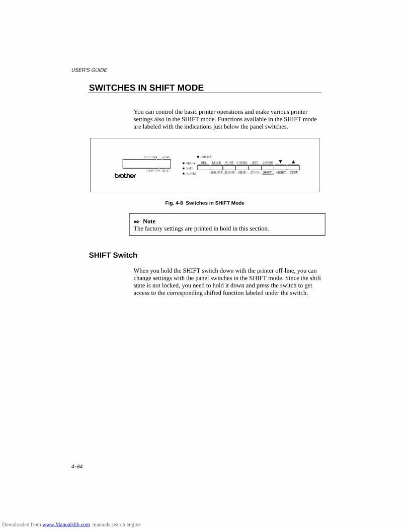
USER’S GUIDE
4–64
SWITCHES IN SHIFT MODE
You can control the basic printer operations and make various printersettings also in the SHIFT mode. Functions available in the SHIFT modeare labeled with the indications just below the panel switches.
Fig. 4-8 Switches in SHIFT Mode
✒ NoteThe factory settings are printed in bold in this section.
SHIFT Switch
When you hold the SHIFT switch down with the printer off-line, you canchange settings with the panel switches in the SHIFT mode. Since the shiftstate is not locked, you need to hold it down and press the switch to getaccess to the corresponding shifted function labeled under the switch.
Downloaded from www.Manualslib.com manuals search engine
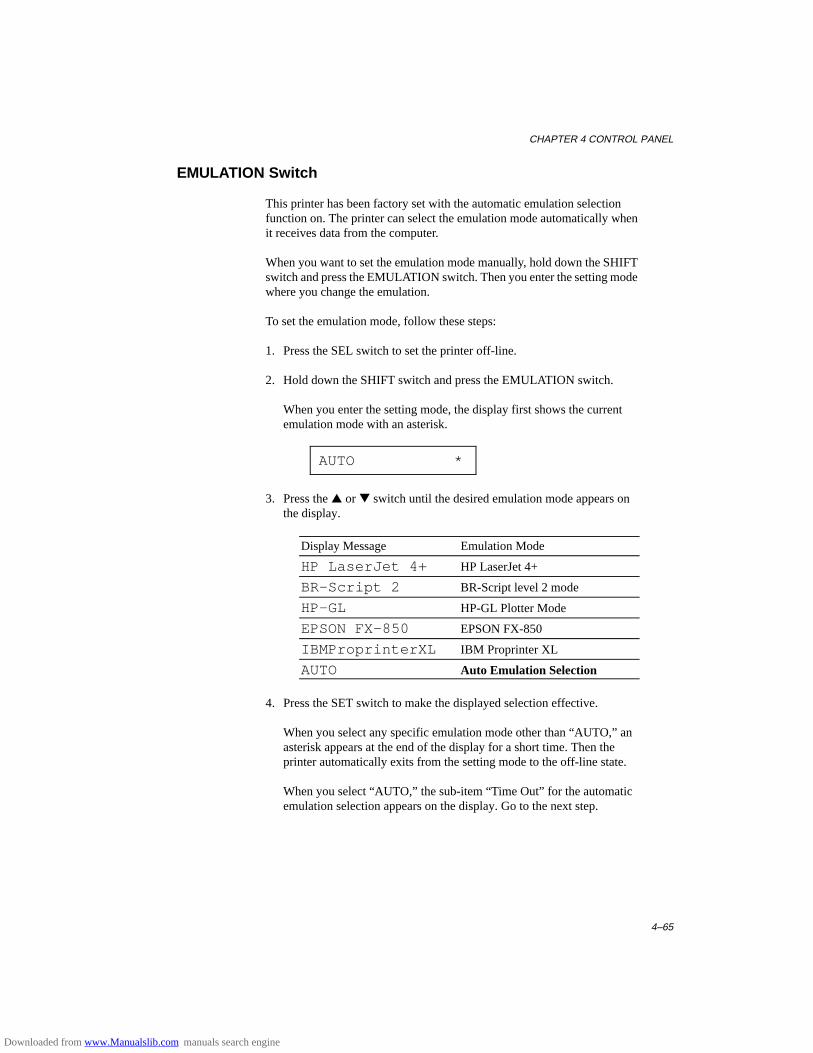
CHAPTER 4 CONTROL PANEL
4–65
EMULATION Switch
This printer has been factory set with the automatic emulation selectionfunction on. The printer can select the emulation mode automatically whenit receives data from the computer.
When you want to set the emulation mode manually, hold down the SHIFTswitch and press the EMULATION switch. Then you enter the setting modewhere you change the emulation.
To set the emulation mode, follow these steps:
1. Press the SEL switch to set the printer off-line.
2. Hold down the SHIFT switch and press the EMULATION switch.
When you enter the setting mode, the display first shows the currentemulation mode with an asterisk.
AUTO *
3. Press the ▲ or ▼ switch until the desired emulation mode appears onthe display.
Display Message Emulation Mode
HP LaserJet 4+ HP LaserJet 4+
BR-Script 2 BR-Script level 2 mode
HP-GL HP-GL Plotter Mode
EPSON FX-850 EPSON FX-850
IBMProprinterXL IBM Proprinter XL
AUTO Auto Emulation Selection
4. Press the SET switch to make the displayed selection effective.
When you select any specific emulation mode other than “AUTO,” anasterisk appears at the end of the display for a short time. Then theprinter automatically exits from the setting mode to the off-line state.
When you select “AUTO,” the sub-item “Time Out” for the automaticemulation selection appears on the display. Go to the next step.
Downloaded from www.Manualslib.com manuals search engine
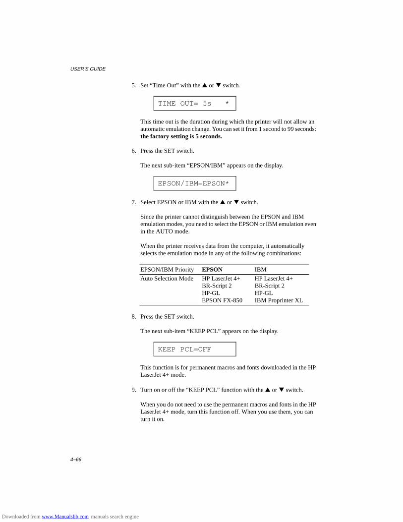
USER’S GUIDE
4–66
5. Set “Time Out” with the ▲ or ▼ switch.
TIME OUT= 5s *
This time out is the duration during which the printer will not allow anautomatic emulation change. You can set it from 1 second to 99 seconds:the factory setting is 5 seconds.
6. Press the SET switch.
The next sub-item “EPSON/IBM” appears on the display.
EPSON/IBM=EPSON*
7. Select EPSON or IBM with the ▲ or ▼ switch.
Since the printer cannot distinguish between the EPSON and IBMemulation modes, you need to select the EPSON or IBM emulation evenin the AUTO mode.
When the printer receives data from the computer, it automaticallyselects the emulation mode in any of the following combinations:
EPSON/IBM Priority EPSON IBM
Auto Selection Mode HP LaserJet 4+ HP LaserJet 4+BR-Script 2 BR-Script 2HP-GL HP-GLEPSON FX-850 IBM Proprinter XL
8. Press the SET switch.
The next sub-item “KEEP PCL” appears on the display.
KEEP PCL=OFF
This function is for permanent macros and fonts downloaded in the HPLaserJet 4+ mode.
9. Turn on or off the “KEEP PCL” function with the ▲ or ▼ switch.
When you do not need to use the permanent macros and fonts in the HPLaserJet 4+ mode, turn this function off. When you use them, you canturn it on.
Downloaded from www.Manualslib.com manuals search engine
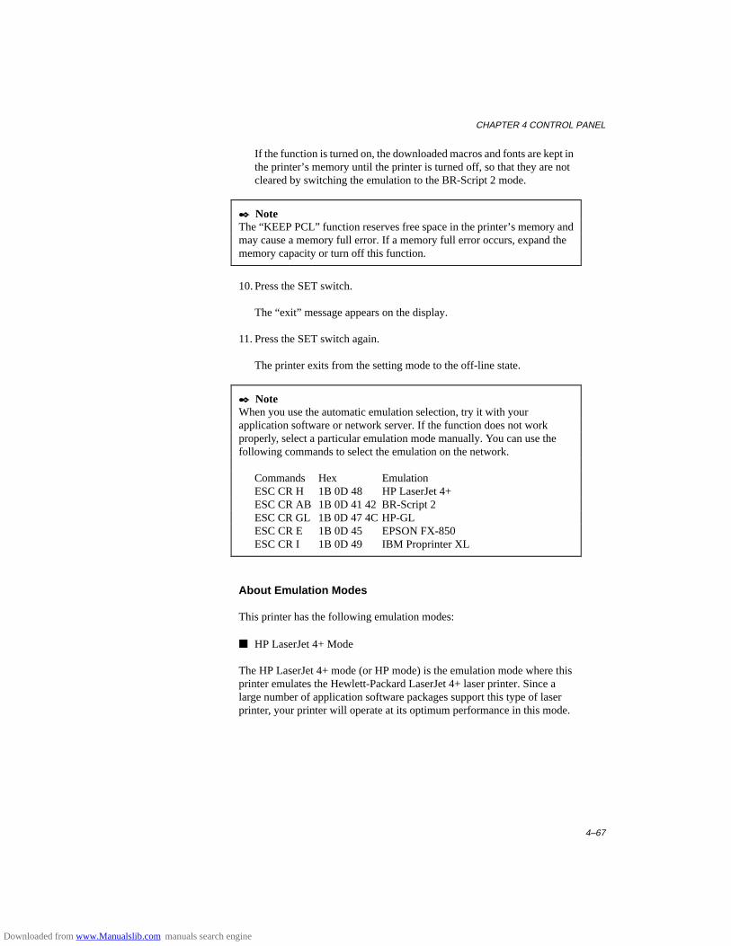
CHAPTER 4 CONTROL PANEL
4–67
If the function is turned on, the downloaded macros and fonts are kept inthe printer’s memory until the printer is turned off, so that they are notcleared by switching the emulation to the BR-Script 2 mode.
✒ NoteThe “KEEP PCL” function reserves free space in the printer’s memory andmay cause a memory full error. If a memory full error occurs, expand thememory capacity or turn off this function.
10. Press the SET switch.
The “exit” message appears on the display.
11. Press the SET switch again.
The printer exits from the setting mode to the off-line state.
✒ NoteWhen you use the automatic emulation selection, try it with yourapplication software or network server. If the function does not workproperly, select a particular emulation mode manually. You can use thefollowing commands to select the emulation on the network.
Commands Hex EmulationESC CR H 1B 0D 48 HP LaserJet 4+ESC CR AB 1B 0D 41 42 BR-Script 2ESC CR GL 1B 0D 47 4C HP-GLESC CR E 1B 0D 45 EPSON FX-850ESC CR I 1B 0D 49 IBM Proprinter XL
About Emulation Modes
This printer has the following emulation modes:
■ HP LaserJet 4+ Mode
The HP LaserJet 4+ mode (or HP mode) is the emulation mode where thisprinter emulates the Hewlett-Packard LaserJet 4+ laser printer. Since alarge number of application software packages support this type of laserprinter, your printer will operate at its optimum performance in this mode.
Downloaded from www.Manualslib.com manuals search engine

USER’S GUIDE
4–68
■ BR-Script 2 Mode
BR-Script is a Brother original page description language and it is aPostScript® language emulation interpreter. This printer supports level 2.The BR-Script interpreter of this printer can control text and graphics onpages completely and satisfactorily.
Average users do not need to know much about PostScript® language. Ifyou want to obtain technical information about PostScript® commands, seethe following commercial manuals:
• Adobe Systems Incorporated. PostScript® Language ReferenceManual, 2nd Edition. Menlo Park: Addison-Wesley PublishingCompany, Inc., 1990.
• Adobe Systems Incorporated. PostScript® Language Program Design.Menlo Park: Addison-Wesley Publishing Company, Inc., 1988.
• Adobe Systems Incorporated. PostScript® Language ReferenceManual. Menlo Park: Addison-Wesley Publishing Company, Inc., 1985.
• Adobe Systems Incorporated. PostScript® Language Tutorial andCookbook. Menlo Park: Addison-Wesley Publishing Company, Inc.,1985.
■ HP-GL Mode
The HP-GL mode is the emulation mode where this printer emulates theHewlett-Packard plotter model HP-7475A. Since many graphics and CADapplications support this type of plotter, you can get more out of this printerworking with your application software.
■ EPSON FX-850 and IBM Proprinter XL Mode
The EPSON FX-850 and IBM Proprinter XL modes are the emulationmodes where this printer emulates the industry-standard dot matrix printersof respective manufacturers. Since most applications support these printers,you do not have to be concerned about compatibility.
Downloaded from www.Manualslib.com manuals search engine
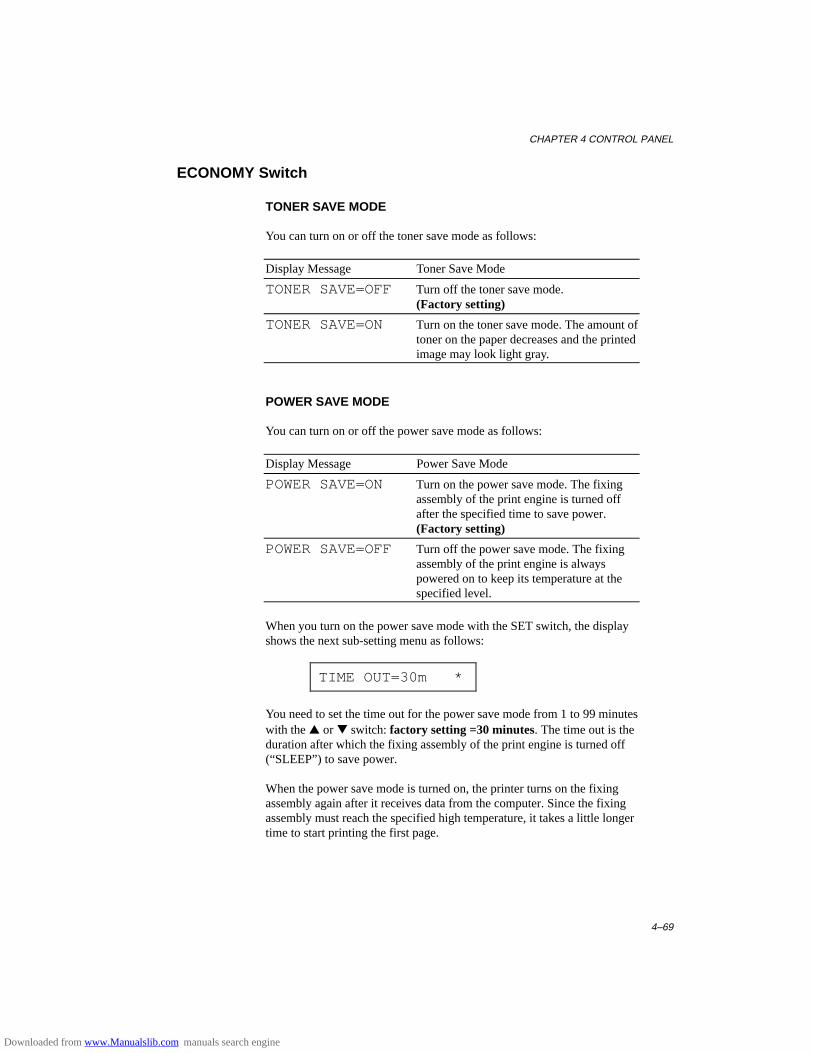
CHAPTER 4 CONTROL PANEL
4–69
ECONOMY Switch
TONER SAVE MODE
You can turn on or off the toner save mode as follows:
Display Message Toner Save Mode
TONER SAVE=OFF Turn off the toner save mode.(Factory setting)
TONER SAVE=ON Turn on the toner save mode. The amount oftoner on the paper decreases and the printedimage may look light gray.
POWER SAVE MODE
You can turn on or off the power save mode as follows:
Display Message Power Save Mode
POWER SAVE=ON Turn on the power save mode. The fixingassembly of the print engine is turned offafter the specified time to save power.(Factory setting)
POWER SAVE=OFF Turn off the power save mode. The fixingassembly of the print engine is alwayspowered on to keep its temperature at thespecified level.
When you turn on the power save mode with the SET switch, the displayshows the next sub-setting menu as follows:
TIME OUT=30m *
You need to set the time out for the power save mode from 1 to 99 minuteswith the ▲ or ▼ switch: factory setting =30 minutes. The time out is theduration after which the fixing assembly of the print engine is turned off(“SLEEP”) to save power.
When the power save mode is turned on, the printer turns on the fixingassembly again after it receives data from the computer. Since the fixingassembly must reach the specified high temperature, it takes a little longertime to start printing the first page.
Downloaded from www.Manualslib.com manuals search engine
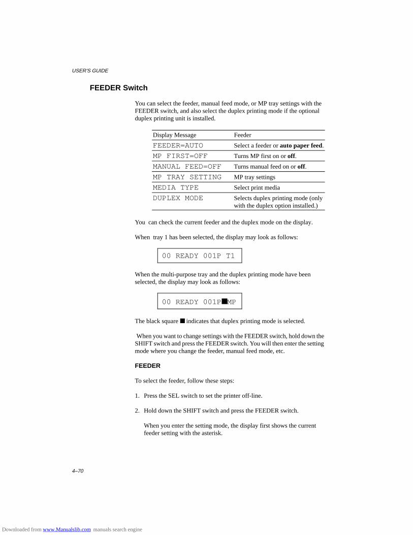
USER’S GUIDE
4–70
FEEDER Switch
You can select the feeder, manual feed mode, or MP tray settings with theFEEDER switch, and also select the duplex printing mode if the optionalduplex printing unit is installed.
Display Message Feeder
FEEDER=AUTO Select a feeder or auto paper feed.
MP FIRST=OFF Turns MP first on or off.
MANUAL FEED=OFF Turns manual feed on or off.
MP TRAY SETTING MP tray settings
MEDIA TYPE Select print media
DUPLEX MODE Selects duplex printing mode (onlywith the duplex option installed.)
You can check the current feeder and the duplex mode on the display.
When tray 1 has been selected, the display may look as follows:
00 READY 001P T1
When the multi-purpose tray and the duplex printing mode have beenselected, the display may look as follows:
00 READY 001P ■MP
The black square ■ indicates that duplex printing mode is selected.
When you want to change settings with the FEEDER switch, hold down theSHIFT switch and press the FEEDER switch. You will then enter the settingmode where you change the feeder, manual feed mode, etc.
FEEDER
To select the feeder, follow these steps:
1. Press the SEL switch to set the printer off-line.
2. Hold down the SHIFT switch and press the FEEDER switch.
When you enter the setting mode, the display first shows the currentfeeder setting with the asterisk.
Downloaded from www.Manualslib.com manuals search engine
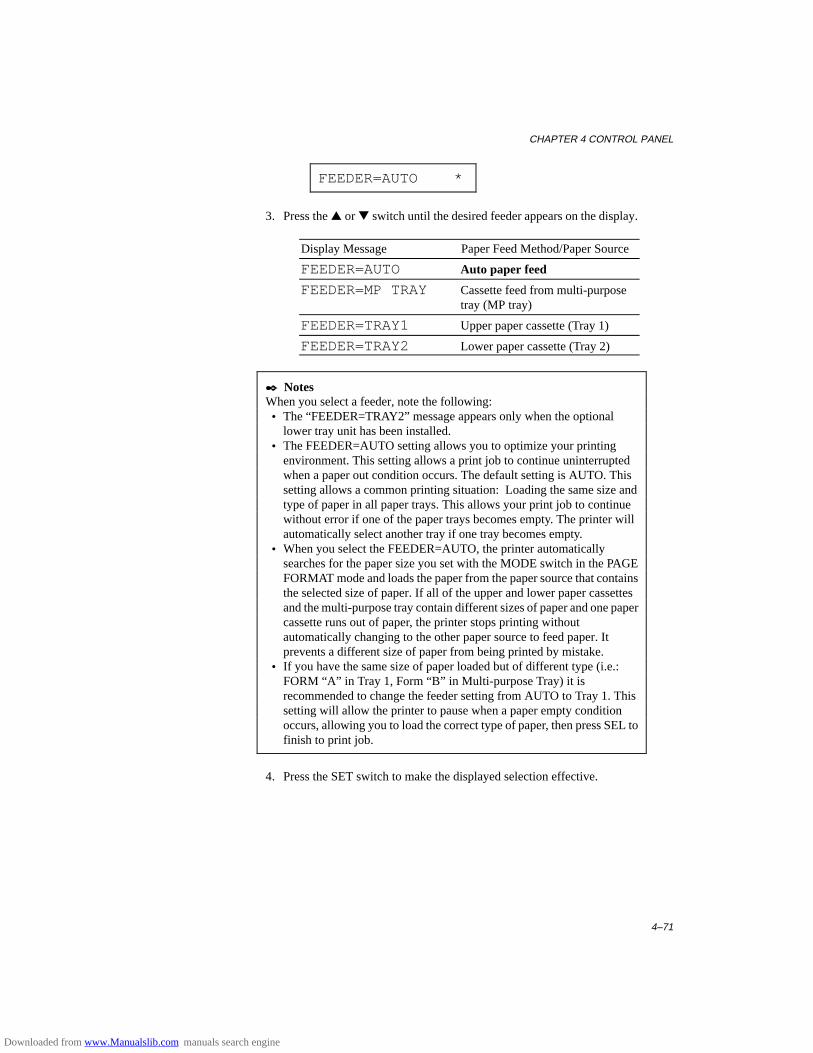
CHAPTER 4 CONTROL PANEL
4–71
FEEDER=AUTO *
3. Press the ▲ or ▼ switch until the desired feeder appears on the display.
Display Message Paper Feed Method/Paper Source
FEEDER=AUTO Auto paper feed
FEEDER=MP TRAY Cassette feed from multi-purposetray (MP tray)
FEEDER=TRAY1 Upper paper cassette (Tray 1)
FEEDER=TRAY2 Lower paper cassette (Tray 2)
✒ NotesWhen you select a feeder, note the following: • The “FEEDER=TRAY2” message appears only when the optional
lower tray unit has been installed. • The FEEDER=AUTO setting allows you to optimize your printing
environment. This setting allows a print job to continue uninterruptedwhen a paper out condition occurs. The default setting is AUTO. Thissetting allows a common printing situation: Loading the same size andtype of paper in all paper trays. This allows your print job to continuewithout error if one of the paper trays becomes empty. The printer willautomatically select another tray if one tray becomes empty.
• When you select the FEEDER=AUTO, the printer automaticallysearches for the paper size you set with the MODE switch in the PAGEFORMAT mode and loads the paper from the paper source that containsthe selected size of paper. If all of the upper and lower paper cassettesand the multi-purpose tray contain different sizes of paper and one papercassette runs out of paper, the printer stops printing withoutautomatically changing to the other paper source to feed paper. Itprevents a different size of paper from being printed by mistake.
• If you have the same size of paper loaded but of different type (i.e.:FORM “A” in Tray 1, Form “B” in Multi-purpose Tray) it isrecommended to change the feeder setting from AUTO to Tray 1. Thissetting will allow the printer to pause when a paper empty conditionoccurs, allowing you to load the correct type of paper, then press SEL tofinish to print job.
4. Press the SET switch to make the displayed selection effective.
Downloaded from www.Manualslib.com manuals search engine
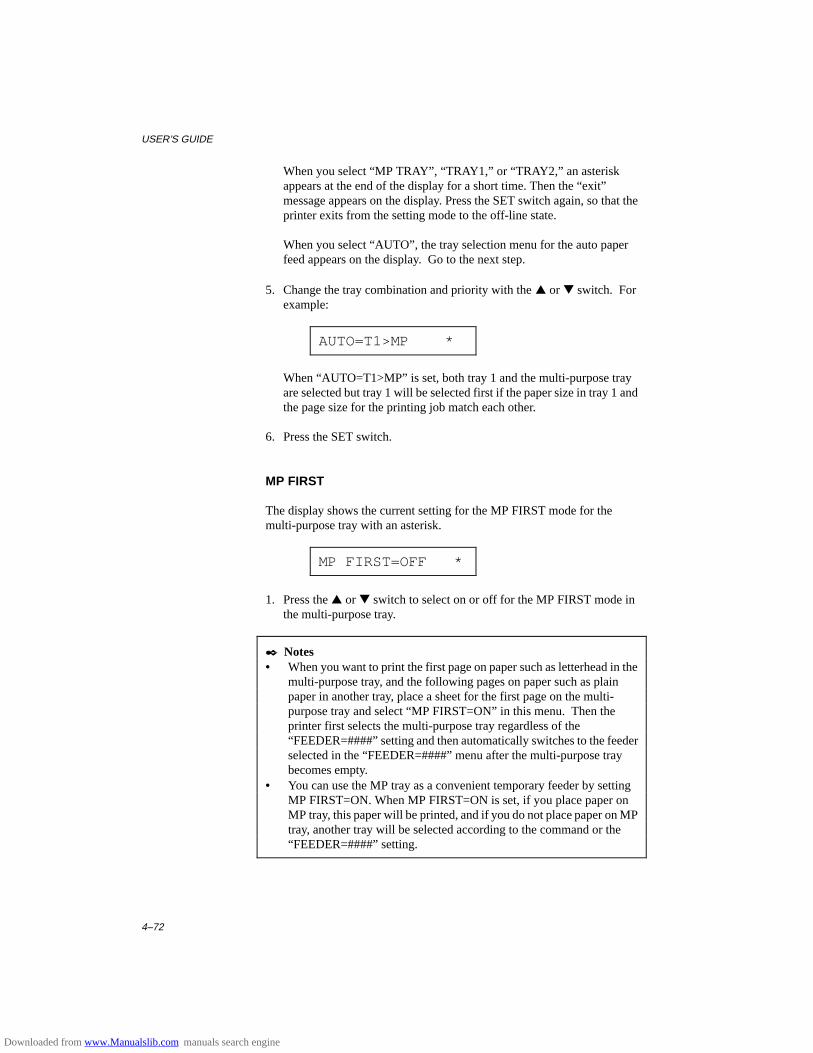
USER’S GUIDE
4–72
When you select “MP TRAY”, “TRAY1,” or “TRAY2,” an asteriskappears at the end of the display for a short time. Then the “exit”message appears on the display. Press the SET switch again, so that theprinter exits from the setting mode to the off-line state.
When you select “AUTO”, the tray selection menu for the auto paperfeed appears on the display. Go to the next step.
5. Change the tray combination and priority with the ▲ or ▼ switch. Forexample:
AUTO=T1>MP *
When “AUTO=T1>MP” is set, both tray 1 and the multi-purpose trayare selected but tray 1 will be selected first if the paper size in tray 1 andthe page size for the printing job match each other.
6. Press the SET switch.
MP FIRST
The display shows the current setting for the MP FIRST mode for themulti-purpose tray with an asterisk.
MP FIRST=OFF *
1. Press the ▲ or ▼ switch to select on or off for the MP FIRST mode inthe multi-purpose tray.
✒ Notes• When you want to print the first page on paper such as letterhead in the
multi-purpose tray, and the following pages on paper such as plainpaper in another tray, place a sheet for the first page on the multi-purpose tray and select “MP FIRST=ON” in this menu. Then theprinter first selects the multi-purpose tray regardless of the“FEEDER=####” setting and then automatically switches to the feederselected in the “FEEDER=####” menu after the multi-purpose traybecomes empty.
• You can use the MP tray as a convenient temporary feeder by settingMP FIRST=ON. When MP FIRST=ON is set, if you place paper onMP tray, this paper will be printed, and if you do not place paper on MPtray, another tray will be selected according to the command or the“FEEDER=####” setting.
Downloaded from www.Manualslib.com manuals search engine
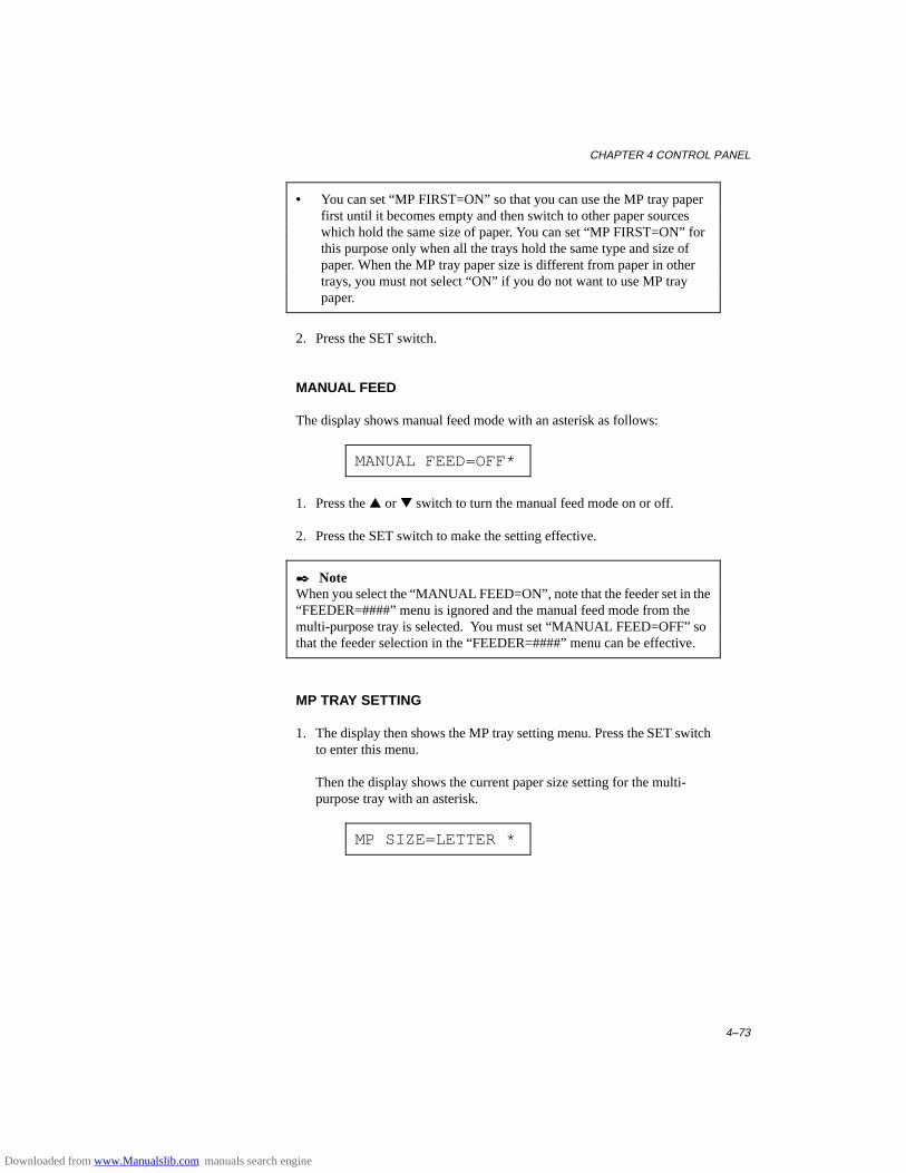
CHAPTER 4 CONTROL PANEL
4–73
• You can set “MP FIRST=ON” so that you can use the MP tray paperfirst until it becomes empty and then switch to other paper sourceswhich hold the same size of paper. You can set “MP FIRST=ON” forthis purpose only when all the trays hold the same type and size ofpaper. When the MP tray paper size is different from paper in othertrays, you must not select “ON” if you do not want to use MP traypaper.
2. Press the SET switch.
MANUAL FEED
The display shows manual feed mode with an asterisk as follows:
MANUAL FEED=OFF*
1. Press the ▲ or ▼ switch to turn the manual feed mode on or off.
2. Press the SET switch to make the setting effective.
✒ NoteWhen you select the “MANUAL FEED=ON”, note that the feeder set in the“FEEDER=####” menu is ignored and the manual feed mode from themulti-purpose tray is selected. You must set “MANUAL FEED=OFF” sothat the feeder selection in the “FEEDER=####” menu can be effective.
MP TRAY SETTING
1. The display then shows the MP tray setting menu. Press the SET switchto enter this menu.
Then the display shows the current paper size setting for the multi-purpose tray with an asterisk.
MP SIZE=LETTER *
Downloaded from www.Manualslib.com manuals search engine

USER’S GUIDE
4–74
2. Press the ▲ or ▼ switch to select the paper size in the multi-purposetray.
✒ NoteWhen you select the multi-purpose tray as a paper source, you must set the“MP SIZE” manually since the tray cannot sense the size automatically.
3. Press the SET switch to make the displayed setting effective.
Then the display shows the current “PAPER IN” setting with the asteriskas follows:
PAPER IN=CONT *
4. Press the ▲ or ▼ switch to select the printer action to continue or stopduring manual feed.
✒ NoteYou can select the printer action either to continue or to stop printing whenyou select the manual feed with this switch or by a command. When you set“PAPER IN=CONTINUE”, the printer feeds paper from the multi-purposetray. When you set “PAPER IN=STOP”, the printer stops feeding paperuntil the SEL key is pressed. If you want to place the paper on the multi-purpose tray after you make a print request from the PC, select the “PAPERIN=STOP” so that the printer waits for the paper.
5. Press the SET switch to make the setting effective.
MEDIA TYPE
When you use any paper other than ordinary plain paper, such as thick bondpaper, envelope, or transparency, the appropriate media type must beselected in the media type mode in order to get the best print quality.
To select a media type, follow these steps:
1. The display shows the following message:
MEDIA TYPE
Downloaded from www.Manualslib.com manuals search engine
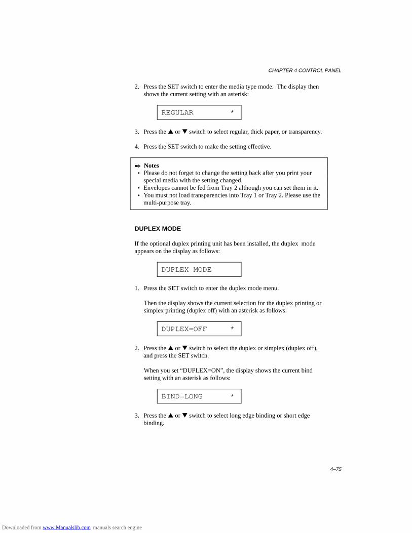
CHAPTER 4 CONTROL PANEL
4–75
2. Press the SET switch to enter the media type mode. The display thenshows the current setting with an asterisk:
REGULAR *
3. Press the ▲ or ▼ switch to select regular, thick paper, or transparency.
4. Press the SET switch to make the setting effective.
✒ Notes • Please do not forget to change the setting back after you print your
special media with the setting changed. • Envelopes cannot be fed from Tray 2 although you can set them in it. • You must not load transparencies into Tray 1 or Tray 2. Please use the
multi-purpose tray.
DUPLEX MODE
If the optional duplex printing unit has been installed, the duplex modeappears on the display as follows:
DUPLEX MODE
1. Press the SET switch to enter the duplex mode menu.
Then the display shows the current selection for the duplex printing orsimplex printing (duplex off) with an asterisk as follows:
DUPLEX=OFF *
2. Press the ▲ or ▼ switch to select the duplex or simplex (duplex off),and press the SET switch.
When you set “DUPLEX=ON”, the display shows the current bindsetting with an asterisk as follows:
BIND=LONG *
3. Press the ▲ or ▼ switch to select long edge binding or short edgebinding.
Downloaded from www.Manualslib.com manuals search engine
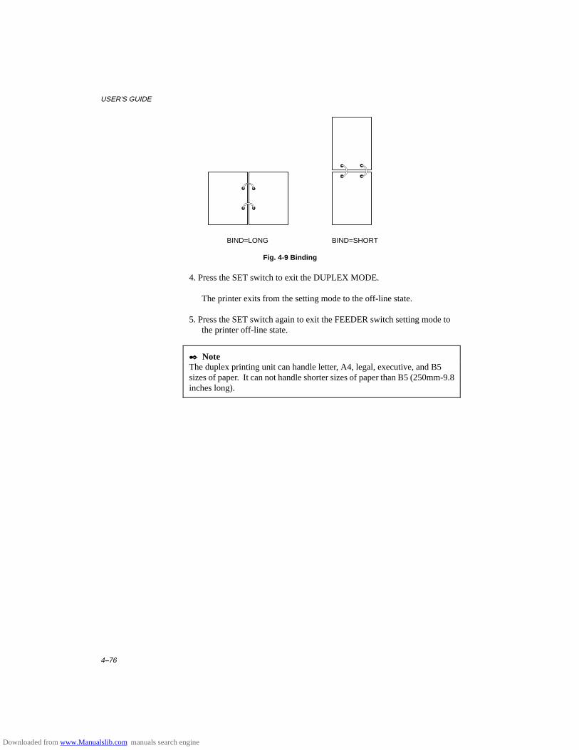
USER’S GUIDE
4–76
BIND=LONG BIND=SHORT
Fig. 4-9 Binding
4. Press the SET switch to exit the DUPLEX MODE.
The printer exits from the setting mode to the off-line state.
5. Press the SET switch again to exit the FEEDER switch setting mode tothe printer off-line state.
✒ NoteThe duplex printing unit can handle letter, A4, legal, executive, and B5sizes of paper. It can not handle shorter sizes of paper than B5 (250mm-9.8inches long).
Downloaded from www.Manualslib.com manuals search engine

CHAPTER 4 CONTROL PANEL
4–77
COPY Switch
You can set the number of copies to print of the same page with the COPYswitch. The computer will release from a printing job in a shorter time if youuse this feature than when you set the copy print quantity with yourapplication software. Check the current setting on the display.
When the number of copies has been set at 1, the display may look asfollows:
00 READY 001P T1
When the number of copies has been set at 3, the display may look asfollows:
00 READY 003P T1
✒ NoteIf you send too many pages to be stored in the printer memory, part or all ofthe set pages or copies may not be printed.
To set the number of copies, follow these steps:
1. Press the SEL switch to set the printer off-line.
2. Hold down the SHIFT switch and press the COPY switch.
When you enter the setting mode, the display first shows the currentsetting with the asterisk.
COPY PAGES= 1 *
3. Press the ▲ or ▼ switch until the desired number appears on the display.
Display Message # of Copies to Print Same Pages
COPY PAGES= 1 1 page
COPY PAGES= 2 2 pages
... . . .
COPY PAGES=999 999 pages (max.)
4. Press the SET switch to make the displayed selection effective.
An asterisk appears at the end of the display for a short time. Then theprinter automatically exits from the setting mode to the off-line state.
Downloaded from www.Manualslib.com manuals search engine
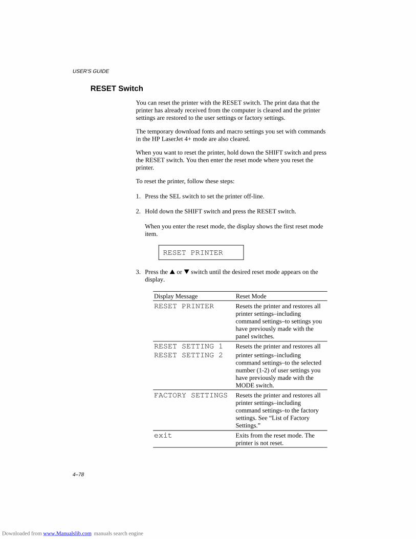
USER’S GUIDE
4–78
RESET Switch
You can reset the printer with the RESET switch. The print data that theprinter has already received from the computer is cleared and the printersettings are restored to the user settings or factory settings.
The temporary download fonts and macro settings you set with commandsin the HP LaserJet 4+ mode are also cleared.
When you want to reset the printer, hold down the SHIFT switch and pressthe RESET switch. You then enter the reset mode where you reset theprinter.
To reset the printer, follow these steps:
1. Press the SEL switch to set the printer off-line.
2. Hold down the SHIFT switch and press the RESET switch.
When you enter the reset mode, the display shows the first reset modeitem.
RESET PRINTER
3. Press the ▲ or ▼ switch until the desired reset mode appears on thedisplay.
Display Message Reset Mode
RESET PRINTER Resets the printer and restores allprinter settings–includingcommand settings–to settings youhave previously made with thepanel switches.
RESET SETTING 1 Resets the printer and restores all
RESET SETTING 2 printer settings–includingcommand settings–to the selectednumber (1-2) of user settings youhave previously made with theMODE switch.
FACTORY SETTINGS Resets the printer and restores allprinter settings–includingcommand settings–to the factorysettings. See “List of FactorySettings.”
exit Exits from the reset mode. Theprinter is not reset.
Downloaded from www.Manualslib.com manuals search engine
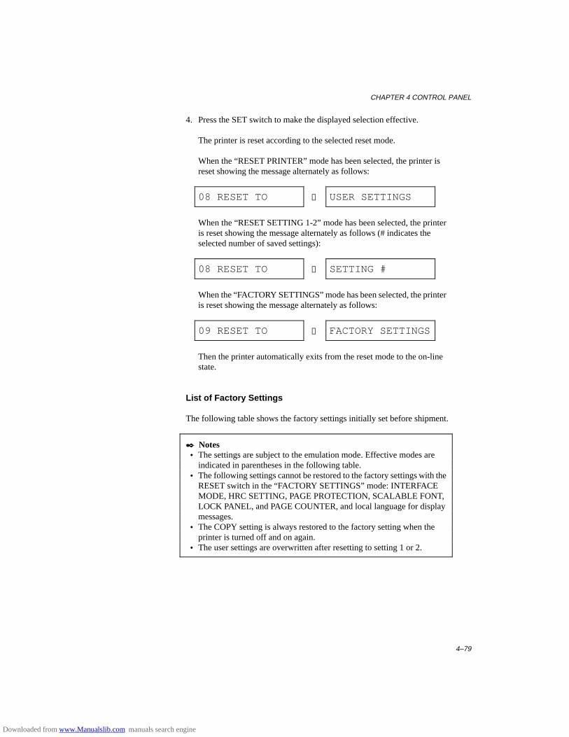
CHAPTER 4 CONTROL PANEL
4–79
4. Press the SET switch to make the displayed selection effective.
The printer is reset according to the selected reset mode.
When the “RESET PRINTER” mode has been selected, the printer isreset showing the message alternately as follows:
08 RESET TO → USER SETTINGS
When the “RESET SETTING 1-2” mode has been selected, the printeris reset showing the message alternately as follows (# indicates theselected number of saved settings):
08 RESET TO → SETTING #
When the “FACTORY SETTINGS” mode has been selected, the printeris reset showing the message alternately as follows:
09 RESET TO → FACTORY SETTINGS
Then the printer automatically exits from the reset mode to the on-linestate.
List of Factory Settings
The following table shows the factory settings initially set before shipment.
✒ Notes • The settings are subject to the emulation mode. Effective modes are
indicated in parentheses in the following table. • The following settings cannot be restored to the factory settings with the
RESET switch in the “FACTORY SETTINGS” mode: INTERFACEMODE, HRC SETTING, PAGE PROTECTION, SCALABLE FONT,LOCK PANEL, and PAGE COUNTER, and local language for displaymessages.
• The COPY setting is always restored to the factory setting when theprinter is turned off and on again.
• The user settings are overwritten after resetting to setting 1 or 2.
Downloaded from www.Manualslib.com manuals search engine

USER’S GUIDE
4–80
Switch Item Sub-Item Factory Setting
MODEINTERFACE MODE – I/F=AUTO
For AUTO mode
TIME OUT TIME OUT= 5s
For bi-directional PARALLEL interfaceHIGH SPEED HIGH SPEED=ONBI-DIR BI-DIR=ON
For RS-232C serial interfaceBaud Rate BaudRate= 9600
Code Type CodeType=8 bits
Parity Parity =NONE
Stop Bit Stop Bit= 1 bits
Xon/Xoff Xon/Xoff=ON
DTR (ER) DTR (ER)=ON
Robust Xon Robust Xon=OFF
FORMAT MODE ORIENTATION (Except for BR-Script 2)
ORI=PORTRAIT
AUTO MODE (HP LaserJet4)AUTO LF OFF
AUTO CR OFF
AUTO WRAP OFF
AUTO SKIP ON
AUTO MODE (EPSON)AUTO LF OFF
AUTO CR ON (No indication)
AUTO WRAP ON (No indication)
AUTO MASK OFF
AUTO MODE (IBM)AUTO LF OFF
AUTO CR OFF
AUTO WRAP ON (No indication)
AUTO MASK OFF
Downloaded from www.Manualslib.com manuals search engine
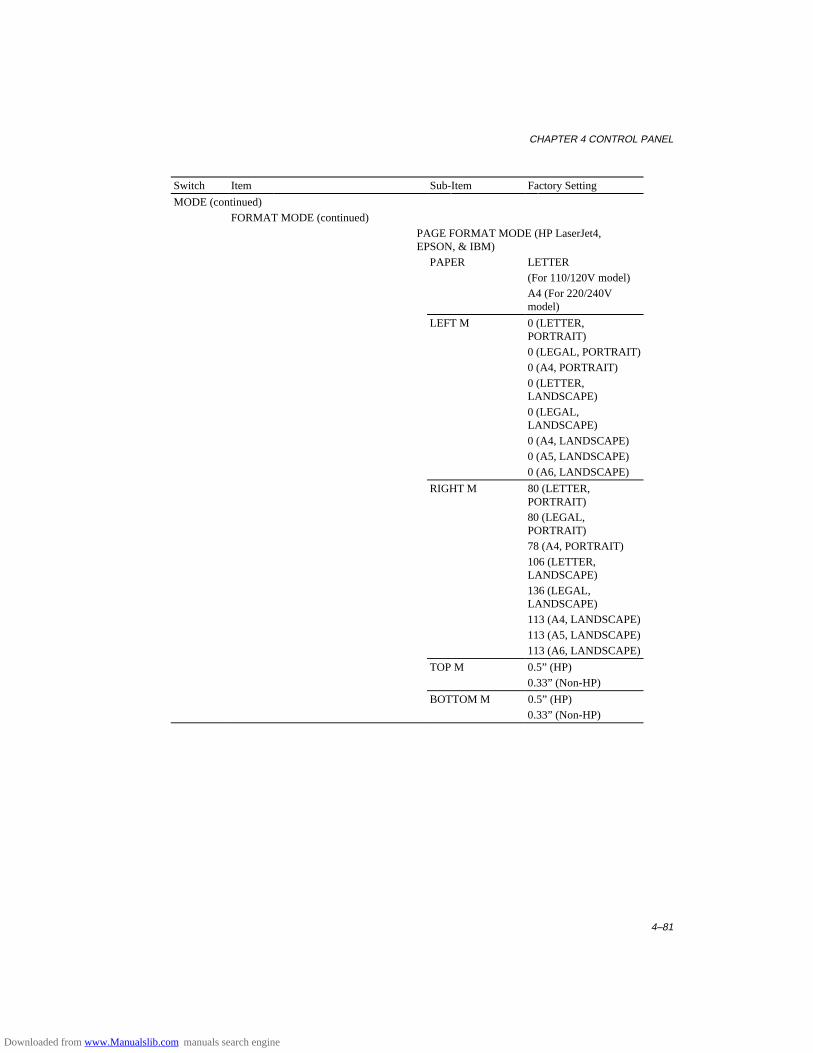
CHAPTER 4 CONTROL PANEL
4–81
Switch Item Sub-Item Factory Setting
MODE (continued)FORMAT MODE (continued)
PAGE FORMAT MODE (HP LaserJet4,EPSON, & IBM)
PAPER LETTER(For 110/120V model)A4 (For 220/240Vmodel)
LEFT M 0 (LETTER,PORTRAIT)0 (LEGAL, PORTRAIT)0 (A4, PORTRAIT)0 (LETTER,LANDSCAPE)0 (LEGAL,LANDSCAPE)0 (A4, LANDSCAPE)0 (A5, LANDSCAPE)0 (A6, LANDSCAPE)
RIGHT M 80 (LETTER,PORTRAIT)80 (LEGAL,PORTRAIT)78 (A4, PORTRAIT)106 (LETTER,LANDSCAPE)136 (LEGAL,LANDSCAPE)113 (A4, LANDSCAPE)113 (A5, LANDSCAPE)113 (A6, LANDSCAPE)
TOP M 0.5” (HP)0.33” (Non-HP)
BOTTOM M 0.5” (HP)0.33” (Non-HP)
Downloaded from www.Manualslib.com manuals search engine
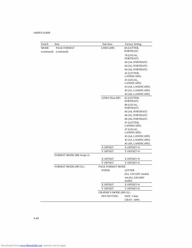
USER’S GUIDE
4–82
Switch Item Sub-Item Factory Setting
MODE(continued)
PAGE FORMAT(continued)
LINES (HP) 60 (LETTER,PORTRAIT)
78 (LEGAL,PORTRAIT)64 (A4, PORTRAIT)64 (A5, PORTRAIT)64 (A6, PORTRAIT)45 (LETTER,LANDSCAPE)45 (LEGAL,LANDSCAPE)43 (A4, LANDSCAPE)43 (A5, LANDSCAPE)43 (A6, LANDSCAPE)
LINES (Non-HP) 62 (LETTER,PORTRAIT)80 (LEGAL,PORTRAIT)66 (A4, PORTRAIT)66 (A5, PORTRAIT)66 (A6, PORTRAIT)47 (LETTER,LANDSCAPE)47 (LEGAL,LANDSCAPE)45 (A4, LANDSCAPE)45 (A5, LANDSCAPE)45 (A6, LANDSCAPE)
X OFFSET X OFFSET=0
Y OFFSET Y OFFSET=0
FORMAT MODE (BR-Script 2)X OFFSET X OFFSET=0
Y OFFSET Y OFFSET=0
FORMAT MODE (HP-GL) PAGE FORMAT MODEPAPER LETTER
(For 110/120V model)A4 (For 220/240Vmodel)
X OFFSET X OFFSET=0
Y OFFSET Y OFFSET=0
GRAPHICS MODE (HP-GL)PEN SETTING SIZE: 3 dots
GRAY: 100%
Downloaded from www.Manualslib.com manuals search engine

CHAPTER 4 CONTROL PANEL
4–83
Switch Item Sub-Item Factory Setting
MODE (continued)RESOLUTION MODE RESOLUTION RESOLUTION=600
APT SETTING APT=OFF
HRC SETTING HRC=MEDIUM
PAGE PROTECTION – PROTECT=AUTO(Non-BR-Script2)
ADVANCED MODENETWORK MODE
LOCK PANEL LOCK PANEL=OFF
AUTO FF AUTO FF=OFF
For AUTO FF=ONWAIT TIME
WAIT TIME= 5s
FF SUPPRESS FF SUPPRESS=OFF
TONER LOW TONER LOW=CONT
ERROR PRINT (BR-Script2) ERROR PRINT=OFF
CONTINUE MODE CONTINUE=MANUAL
BUZZER SETTING BUZZER=ON
SCALABLE FONT (HP, EPSON, & IBM) FONT=ALL
PRINT DENSITY ■■■■■■■■
For any interfacesINPUT BUFFER
❏❏❏❏❏
PAGE COUNTER – 0
FONT (HP)PRIMARY FONT SELECT FONT BROUGHAM
SYMBOL SET ROMAN8
SECONDARY FONT SELECT FONT BROUGHAM
SYMBOL SET ROMAN8
FONT (EPSON)FONT – BROUGHAM
CHARACTER SET – US ASCII
FONT (IBM)FONT – BROUGHAM
CHARACTER SET – PC-8
EMULATION– – AUTO
For AUTO mode TIME OUT TIME OUT= 5s
EPSON/IBM EPSON/IBM=EPSON
KEEP PCL KEEP PCL=OFF
Downloaded from www.Manualslib.com manuals search engine

USER’S GUIDE
4–84
Switch Item Sub-Item Factory Setting
ECONOMY –TONER SAVE MODE - TONER SAVE=OFFPOWER SAVE MODE - POWER SAVE=ON
For POWER SAVE=ONTIME OUT TIME OUT=30m
FEEDERFEEDER - FEEDER=AUTO
For FEEDER=AUTOAUTO=T1>T2>MP
MP FIRST MP FIRST=OFF
MANUAL FEED - MANUAL FEED=OFF
MP TRAY SETTING MP SIZE MP SIZE=LETTER (For 110/120V model)MP SIZE=A4 (For 220V/240V model)
PAPER IN PAPER IN=CONT
MEDIA TYPE - REGULAR
DUPLEX MODE DUPLEX DUPLEX=OFF
BIND BIND=LONG
COPY – – COPY PAGES=1
LANGUAGE (FORM FEED +POWER ON)
– LANG=ENGLISH
Downloaded from www.Manualslib.com manuals search engine
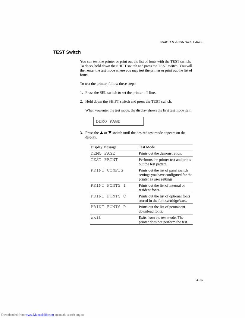
CHAPTER 4 CONTROL PANEL
4–85
TEST Switch
You can test the printer or print out the list of fonts with the TEST switch.To do so, hold down the SHIFT switch and press the TEST switch. You willthen enter the test mode where you may test the printer or print out the list offonts.
To test the printer, follow these steps:
1. Press the SEL switch to set the printer off-line.
2. Hold down the SHIFT switch and press the TEST switch.
When you enter the test mode, the display shows the first test mode item.
DEMO PAGE
3. Press the ▲ or ▼ switch until the desired test mode appears on thedisplay.
Display Message Test Mode
DEMO PAGE Prints out the demonstration.
TEST PRINT Performs the printer test and printsout the test pattern.
PRINT CONFIG Prints out the list of panel switchsettings you have configured for theprinter as user settings.
PRINT FONTS I Prints out the list of internal orresident fonts.
PRINT FONTS C Prints out the list of optional fontsstored in the font cartridge/card.
PRINT FONTS P Prints out the list of permanentdownload fonts.
exit Exits from the test mode. Theprinter does not perform the test.
Downloaded from www.Manualslib.com manuals search engine
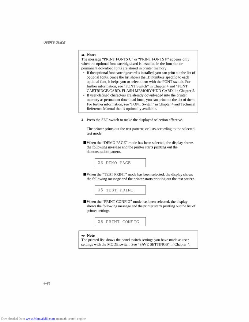
USER’S GUIDE
4–86
✒ NotesThe message “PRINT FONTS C” or “PRINT FONTS P” appears onlywhen the optional font cartridge/card is installed in the font slot orpermanent download fonts are stored in printer memory. • If the optional font cartridge/card is installed, you can print out the list of
optional fonts. Since the list shows the ID numbers specific to eachoptional font, it helps you to select them with the FONT switch. Forfurther information, see “FONT Switch” in Chapter 4 and “FONTCARTRIDGE/CARD, FLASH MEMORY/HDD CARD” in Chapter 5.
• If user-defined characters are already downloaded into the printermemory as permanent download fonts, you can print out the list of them.For further information, see “FONT Switch” in Chapter 4 and TechnicalReference Manual that is optionally available.
4. Press the SET switch to make the displayed selection effective.
The printer prints out the test patterns or lists according to the selectedtest mode.
■ When the “DEMO PAGE” mode has been selected, the display showsthe following message and the printer starts printing out thedemonstration pattern.
06 DEMO PAGE
■ When the “TEST PRINT” mode has been selected, the display showsthe following message and the printer starts printing out the test pattern.
05 TEST PRINT
■ When the “PRINT CONFIG” mode has been selected, the displayshows the following message and the printer starts printing out the list ofprinter settings.
06 PRINT CONFIG
✒ NoteThe printed list shows the panel switch settings you have made as usersettings with the MODE switch. See “SAVE SETTINGS” in Chapter 4.
Downloaded from www.Manualslib.com manuals search engine

CHAPTER 4 CONTROL PANEL
4–87
■ When the “PRINT FONTS” mode has been selected, the display showsthe selected mode and the printer starts printing out the font list. Thedisplay may look like this:
06 PRINT FONTS I
When the printer finishes printing, it automatically exits from the testmode to the off-line state.
Downloaded from www.Manualslib.com manuals search engine
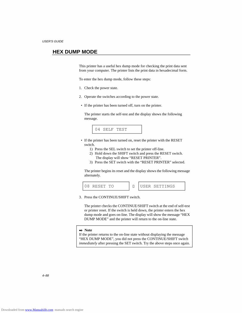
USER’S GUIDE
4–88
HEX DUMP MODE
This printer has a useful hex dump mode for checking the print data sentfrom your computer. The printer lists the print data in hexadecimal form.
To enter the hex dump mode, follow these steps:
1. Check the power state.
2. Operate the switches according to the power state.
• If the printer has been turned off, turn on the printer.
The printer starts the self-test and the display shows the followingmessage.
04 SELF TEST
• If the printer has been turned on, reset the printer with the RESETswitch.
1) Press the SEL switch to set the printer off-line.2) Hold down the SHIFT switch and press the RESET switch.
The display will show “RESET PRINTER”.3) Press the SET switch with the “RESET PRINTER” selected.
The printer begins its reset and the display shows the following messagealternately.
08 RESET TO → USER SETTINGS
3. Press the CONTINUE/SHIFT switch.
The printer checks the CONTINUE/SHIFT switch at the end of self-testor printer reset. If the switch is held down, the printer enters the hexdump mode and goes on-line. The display will show the message “HEXDUMP MODE” and the printer will return to the on-line state.
✒ NoteIf the printer returns to the on-line state without displaying the message“HEX DUMP MODE”, you did not press the CONTINUE/SHIFT switchimmediately after pressing the SET switch. Try the above steps once again.
Downloaded from www.Manualslib.com manuals search engine
CHAPTER 4 CONTROL PANEL
4–89
4. Send data from your computer.
When the printer receives data, it starts printing hexadecimal values ofthe received data.
To exit from the hex dump mode, follow these basic steps:
1. Press the SEL switch to set the printer off-line.
2. Reset the printer with the RESET switch.
Or turn off the printer, wait for a few seconds, and turn it on again.
Downloaded from www.Manualslib.com manuals search engine
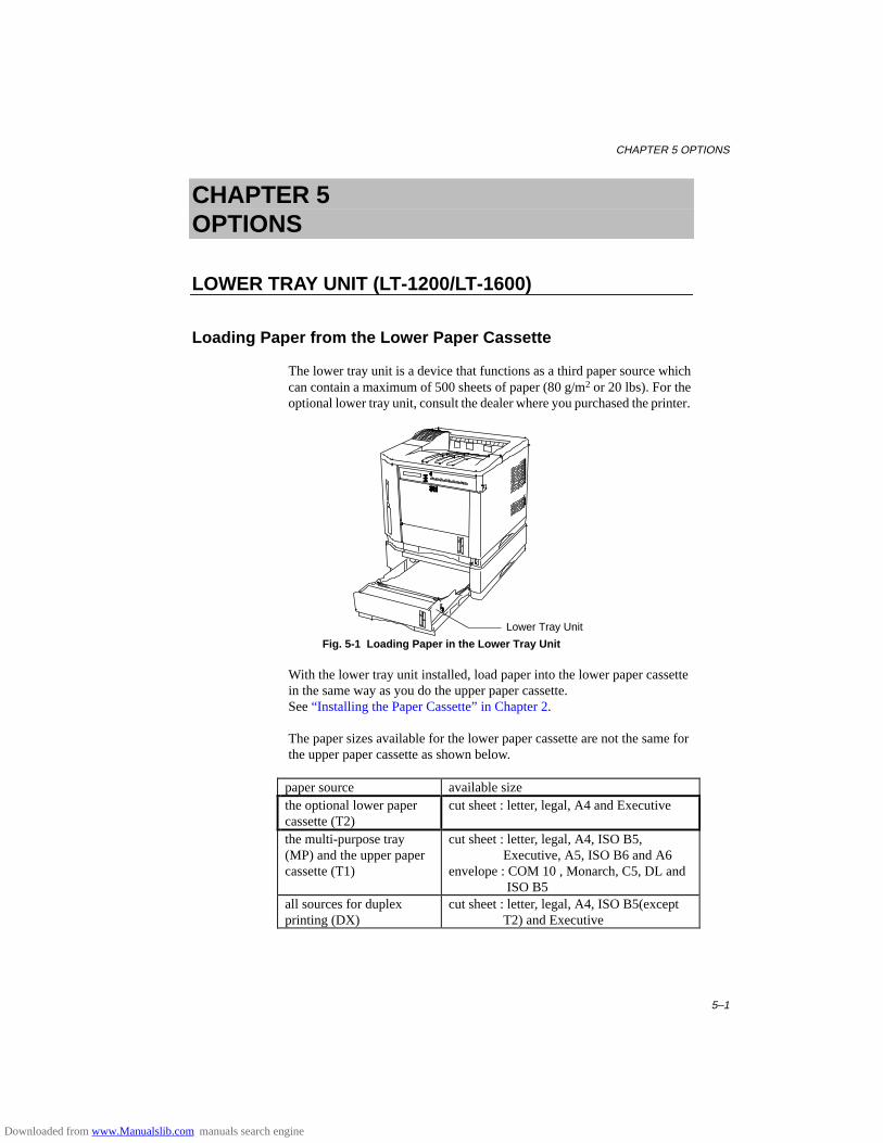
CHAPTER 5 OPTIONS
5–1
CHAPTER 5OPTIONS
LOWER TRAY UNIT (LT-1200/LT-1600)
Loading Paper from the Lower Paper Cassette
The lower tray unit is a device that functions as a third paper source whichcan contain a maximum of 500 sheets of paper (80 g/m2 or 20 lbs). For theoptional lower tray unit, consult the dealer where you purchased the printer.
Fig. 5-1 Loading Paper in the Lower Tray Unit
With the lower tray unit installed, load paper into the lower paper cassettein the same way as you do the upper paper cassette.See “ Installing the Paper Cassette” in Chapter 2.
The paper sizes available for the lower paper cassette are not the same forthe upper paper cassette as shown below.
paper source available sizethe optional lower papercassette (T2)
cut sheet : letter, legal, A4 and Executive
the multi-purpose tray(MP) and the upper papercassette (T1)
cut sheet : letter, legal, A4, ISO B5, Executive, A5, ISO B6 and A6envelope : COM 10 , Monarch, C5, DL and ISO B5
all sources for duplexprinting (DX)
cut sheet : letter, legal, A4, ISO B5(except T2) and Executive
Lower Tray Unit
Downloaded from www.Manualslib.com manuals search engine
USER’S GUIDE
5–2
FONT CARTRIDGE/CARD, FLASH MEMORY/HDD CARD
Installing a Font Cartridge/Card, Flash Memory Card and HDDCard
This printer has one slot for an optional font cartridge and one slot for anoptional font card, flash memory card or HDD card.
If you install the optional font cartridge/card, you can use the fonts stored inthem as well as resident fonts. For optional font cartridges/cards, consultthe dealer where you purchased the printer.
If you install the optional flash memory card or HDD card, you can savemacros and fonts on it. For flash memory card and HDD card operation andinformation, see “CARD OPERATION” in Chapter 4.
✒ Notes • Do not install or remove cards with the printer power on, or you may
lose all data from the card, or may seriously damage the card if you dothis.
• For more information about the cards, consult the dealer where youpurchased the printer.
Follow these steps to install or remove a cartridge/card:
1. Make sure that the printer is turned off.
If the printer is turned on, be sure to press the SEL switch to set theprinter off-line. If data remains in the printer memory, the DATA lampstays on. Press the FORM FEED switch to print out the remaining data,then the DATA lamp goes off. Turn off the printer.
2. Insert the font card, flash memory card or HDD card into the upper slotA and the font cartridge into the lower slot B with the cartridge/cardlabel facing to the left. Make sure they fit securely.
To remove the cartridge/card, pull them out of the slot with the printerturned off.
Downloaded from www.Manualslib.com manuals search engine
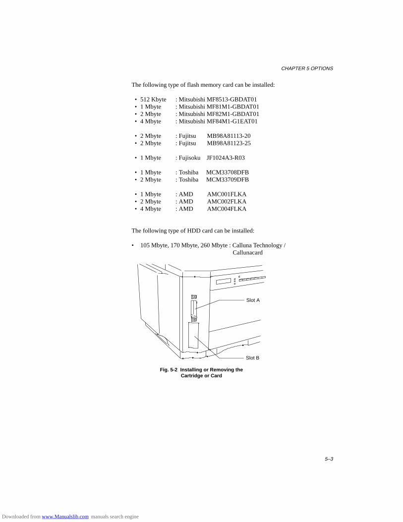
CHAPTER 5 OPTIONS
5–3
The following type of flash memory card can be installed:
• 512 Kbyte : Mitsubishi MF8513-GBDAT01 • 1 Mbyte : Mitsubishi MF81M1-GBDAT01 • 2 Mbyte : Mitsubishi MF82M1-GBDAT01 • 4 Mbyte : Mitsubishi MF84M1-G1EAT01
• 2 Mbyte : Fujitsu MB98A81113-20 • 2 Mbyte : Fujitsu MB98A81123-25
• 1 Mbyte : Fujisoku JF1024A3-R03
• 1 Mbyte : Toshiba MCM33708DFB • 2 Mbyte : Toshiba MCM33709DFB
• 1 Mbyte : AMD AMC001FLKA • 2 Mbyte : AMD AMC002FLKA • 4 Mbyte : AMD AMC004FLKA
The following type of HDD card can be installed:
• 105 Mbyte, 170 Mbyte, 260 Mbyte : Calluna Technology / Callunacard
A
B
Fig. 5-2 Installing or Removing theCartridge or Card
Slot A
Slot B
Downloaded from www.Manualslib.com manuals search engine
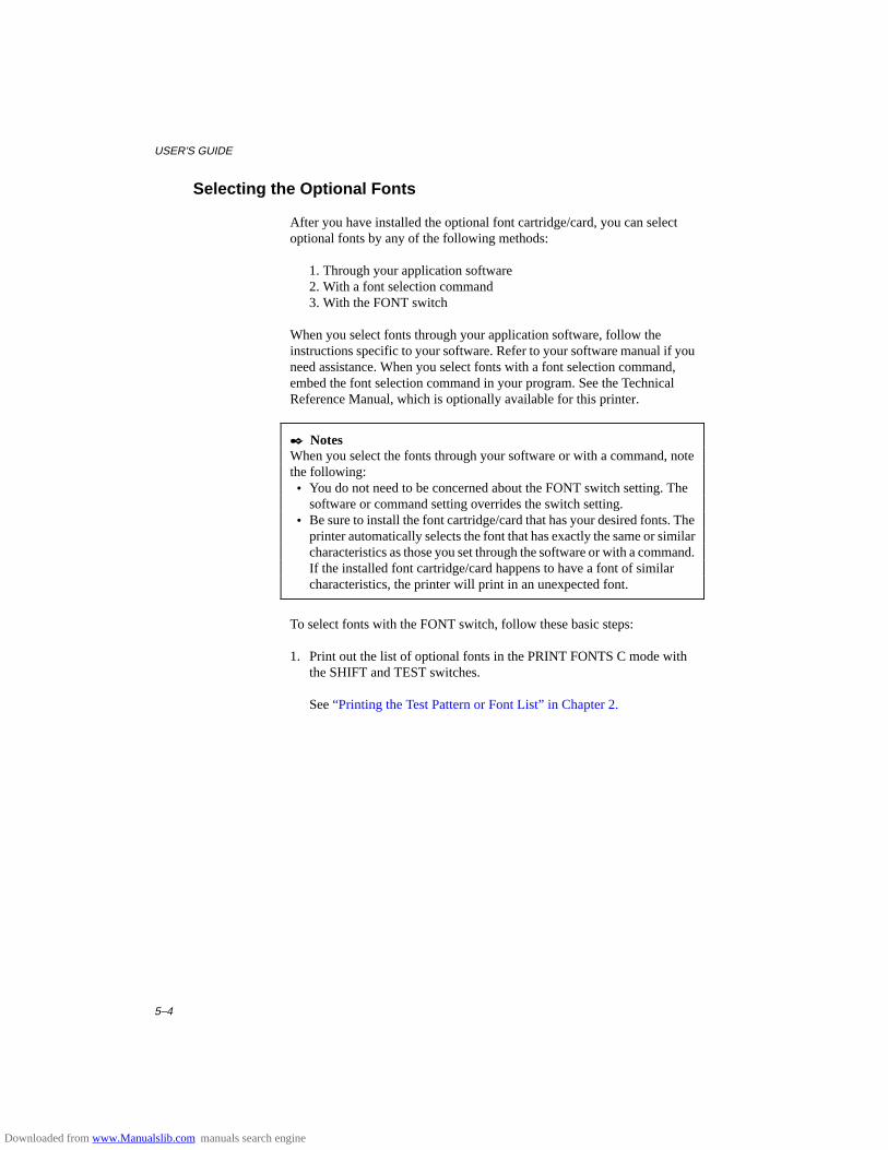
USER’S GUIDE
5–4
Selecting the Optional Fonts
After you have installed the optional font cartridge/card, you can selectoptional fonts by any of the following methods:
1. Through your application software2. With a font selection command3. With the FONT switch
When you select fonts through your application software, follow theinstructions specific to your software. Refer to your software manual if youneed assistance. When you select fonts with a font selection command,embed the font selection command in your program. See the TechnicalReference Manual, which is optionally available for this printer.
✒ NotesWhen you select the fonts through your software or with a command, notethe following: • You do not need to be concerned about the FONT switch setting. The
software or command setting overrides the switch setting. • Be sure to install the font cartridge/card that has your desired fonts. The
printer automatically selects the font that has exactly the same or similarcharacteristics as those you set through the software or with a command.If the installed font cartridge/card happens to have a font of similarcharacteristics, the printer will print in an unexpected font.
To select fonts with the FONT switch, follow these basic steps:
1. Print out the list of optional fonts in the PRINT FONTS C mode withthe SHIFT and TEST switches.
See “Printing the Test Pattern or Font List” in Chapter 2.
Downloaded from www.Manualslib.com manuals search engine
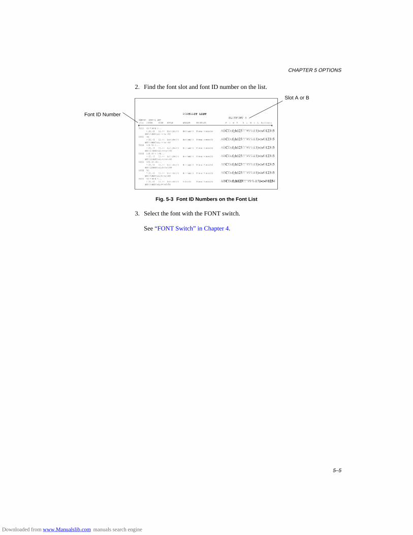
CHAPTER 5 OPTIONS
5–5
2. Find the font slot and font ID number on the list.
Fig. 5-3 Font ID Numbers on the Font List
3. Select the font with the FONT switch.
See “FONT Switch” in Chapter 4.
Slot A or B
Font ID Number
Downloaded from www.Manualslib.com manuals search engine

USER’S GUIDE
5–6
MODULAR I/O CARD
This printer has a modular input/output (MIO) interface slot on the rearpanel. This slot allows you to install a commercial MIO-compatiblesharing/network card.
For more information about MIO cards, consult the dealer where youpurchased this printer.
When you install the MIO card, follow these steps:
1. Turn off the printer and unplug the power cord from the wall socket.
✒ NoteBe sure to turn off the power to the printer before installing or removing theMIO card.
2. Remove the two screws and cover plate from the MIO interface slot.
3. Unpack the MIO card and hold it on its edge.
✒ NoteDo not touch the card surface. If static electricity collects, it damages thecard.
4. Insert the card until it is securely seated.
5 Secure the MIO card with the two captive screws on the card
6. Retain the cover plate and two screws removed in 2 in case you want toremove the MIO card later.
Fig. 5-4 Installing the MIO Card
MIO Card
MIO Interface Slot
Downloaded from www.Manualslib.com manuals search engine
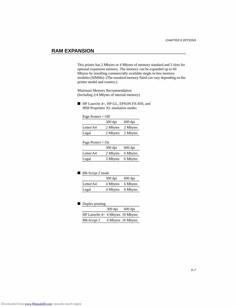
CHAPTER 5 OPTIONS
5–7
RAM EXPANSION
This printer has 2 Mbytes or 4 Mbytes of memory standard and 2 slots foroptional expansion memory. The memory can be expanded up to 66Mbytes by installing commercially available single in-line memorymodules (SIMMs). (The standard memory fitted can vary depending on theprinter model and country.)
Minimum Memory Recommendation(Including 2/4 Mbytes of internal memory)
■ HP LaserJet 4+, HP-GL, EPSON FX-850, andIBM Proprinter XL emulation modes
Page Protect = Off
300 dpi 600 dpi
Letter/A4 2 Mbytes 2 Mbytes
Legal 2 Mbytes 2 Mbytes
Page Protect = On
300 dpi 600 dpi
Letter/A4 2 Mbytes 6 Mbytes
Legal 3 Mbytes 6 Mbytes
■ BR-Script 2 mode
300 dpi 600 dpi
Letter/A4 4 Mbytes 6 Mbytes
Legal 4 Mbytes 6 Mbytes
■ Duplex printing
300 dpi 600 dpi
HP LaserJet 4+ 4 Mbytes 10 Mbytes
BR-Script 2 4 Mbytes 10 Mbytes
Downloaded from www.Manualslib.com manuals search engine

USER’S GUIDE
5–8
The following capacity of a SIMM can be installed: • 1 Mbyte HITACHI HB56D25632B-6A, -7A, -8A
MITSUBISHI MH25632BJ-7, -8 • 2 Mbyte HITACHI HB56D51232B-6A, -7A, -8A
MITSUBISHI MH51232BJ-7, -8 • 4 Mbyte HITACHI HB56A132BV-7A, -7AL, -7B, -7BL, -8AL, -8B,
-8BL MITSUBISHI MH1M32ADJ-7, -8
• 8 Mbyte HITACHI HB56A232BT-7A, -7AL, -7B, -7BL MITSUBISHI MH2M32EJ-7, -8, MH2M32DJ-7, -8
• 16 Mbyte TOSHIBA THM324000BSG-60, -70, -80 • 32 Mbyte TOSHIBA THM328020BSG-60, -70, -80
In general, the SIMM must have the following specifications:
Type: 72 pin and 32 bit or 36 bit outputAccess Time: 80 nsec. or lessCapacity: 1, 2, 4, 8, 16 or 32 MbyteHeight: 46mm (1.8 inches) or less
There are 40 bit output SIMMs for workstations. Such SIMMs do not fitthis printer.For SIMMs and installation, consult the dealer where you purchased theprinter.
When you install SIMMs, follow these steps:
1. Turn off the printer and unplug the power cord from the wall socket.
✒ NoteBe sure to turn off the power to the printer before installing or removing theSIMMs.
2. Open the top cover of the printer.
3. Push the tab located on the left inside the printer to unlock the left sidecover.
Fig. 5-5 Unlocking the Left Side Cover
Downloaded from www.Manualslib.com manuals search engine
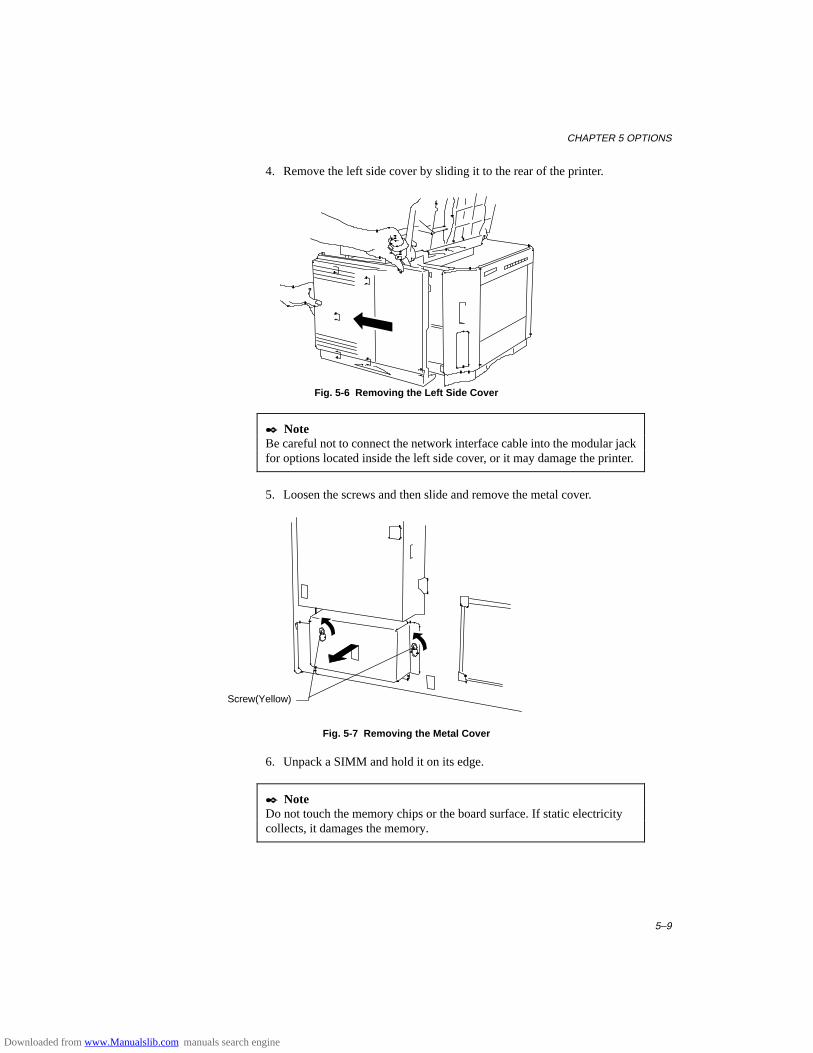
CHAPTER 5 OPTIONS
5–9
4. Remove the left side cover by sliding it to the rear of the printer.
Fig. 5-6 Removing the Left Side Cover
✒ NoteBe careful not to connect the network interface cable into the modular jackfor options located inside the left side cover, or it may damage the printer.
5. Loosen the screws and then slide and remove the metal cover.
Fig. 5-7 Removing the Metal Cover
6. Unpack a SIMM and hold it on its edge.
✒ NoteDo not touch the memory chips or the board surface. If static electricitycollects, it damages the memory.
Screw(Yellow)
Downloaded from www.Manualslib.com manuals search engine
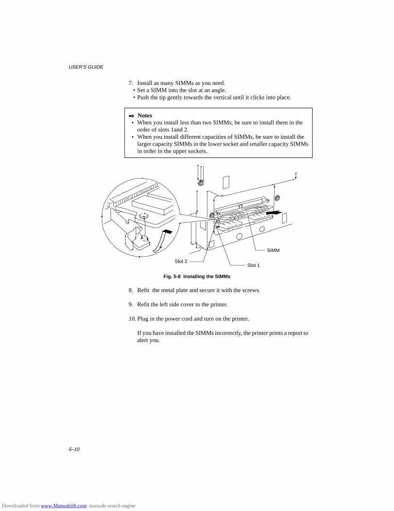
USER’S GUIDE
5–10
7. Install as many SIMMs as you need. • Set a SIMM into the slot at an angle. • Push the tip gently towards the vertical until it clicks into place.
✒ Notes • When you install less than two SIMMs, be sure to install them in the
order of slots 1and 2. • When you install different capacities of SIMMs, be sure to install the
larger capacity SIMMs in the lower socket and smaller capacity SIMMsin order in the upper sockets.
Fig. 5-8 Installing the SIMMs
8. Refit the metal plate and secure it with the screws.
9. Refit the left side cover to the printer.
10. Plug in the power cord and turn on the printer.
If you have installed the SIMMs incorrectly, the printer prints a report toalert you.
SIMM
Slot 1Slot 2
Downloaded from www.Manualslib.com manuals search engine
CHAPTER 5 OPTIONS
5–11
DUPLEX UNIT (DX-1200/DX-1600)
The duplex unit is an optional device that allows printing on both sides ofpages. When it is installed, you can select either duplex printing or simplexprinting from the control panel or by software command. For moreinformation about the control panel, see “FEEDER switch” in Chapter 4.Be sure to install the following capacity of RAM to enjoy duplex printing,or the printer cannot manage all the data for duplex printing at 600 dpiresolution and automatically switches to simplex printing or decrease theresolution from 600 dpi to 300 dpi.
■ Duplex printing
300 dpi 600 dpi
HP LaserJet 4+ 4 Mbytes 10 Mbytes
BR-Script 2 4 Mbytes 10 Mbytes
✒ Notes • The Duplex unit can handle cut sheet paper of the sizes shown below
[Weight = 60 to 90 g/m2 (16 to 24 lbs)]. • When the duplex unit is installed, the capacity of the upper paper
cassette decreases as shown below. • When the duplex unit is installed, legal size paper can not be loaded into
the upper paper cassette with the standard paper guide. Be sure toreplace it with the duplex paper guide for the both simplex and duplexprinting.
• When the printer automatically changes the setting to the 300 dpiresolution, the display temporarily shows “02 PR300” during printing.
• When the printer automatically changes the setting to the simplexprinting, the display temporarily shows “02 SX” during printing.
Downloaded from www.Manualslib.com manuals search engine
USER’S GUIDE
5–12
When the duplex unit is installed, paper handling and capacity of the upper paper cassette changes as follows:
For Duplex
paper source available sizeall sources for duplexprinting (DX)
cut sheet : letter, legal, A4, ISO B5(except T2) and Executive
The upper paper cassette with duplex installed
paper source available size capacitythe upper papercassette (T1)
cut sheet : letter, legal, A4, ISO B5, Executive A5 ISO B6 A6envelope : COM 10 Monarch C5 DL ISO B5
:250 sheets/27.5mm:250 sheets/27.5mm:200 sheets/24.5mm:140 sheets/17.5mm: 80 sheets/10.0mm: 15 sheets/20.5mm: 15 sheets/20.5mm: 15 sheets/20.5mm: 15 sheets/20.5mm: 15 sheets/20.5mm
Downloaded from www.Manualslib.com manuals search engine
CHAPTER 6 MAINTENANCE
6–1
CHAPTER 6MAINTENANCE
MAINTENANCE
Toner Cartridge
A new toner cartridge contains enough toner to print approximately 6,000A4/Letter-size single-sided pages at about 5% coverage (if the print densityis set at level 8).
You can check the current page count or the number of printed pages withthe MODE switch (PAGE COUNTER). For further information, see“MODE Switch” in Chapter 4.
✒ NotesToner consumption varies according to the image coverage on the page andthe print density setting. • The greater the image coverage, the greater the toner consumption. • If you change the print density setting for lighter or darker printing,
toner consumption varies accordingly. To adjust print density setting,see “Checking the Printed Test Pattern or Demo Page” in Chapter 2.
Toner Empty Message
Check printed pages, page counter, and display messages periodically. Ifthe display shows the following message, the printer has almost run out oftoner or the toner is not evenly distributed inside the cartridge.
16 TONER EMPTY
Although you can print between 30 and 100 additional pages after the tonerempty message first appears, be sure to replace the toner cartridge with anew one before it becomes completely empty.
You can select the printer’s action when the “TONER EMPTY” messageappears, whether to stop or continue printing. See “AD VANCED MODE”in Chapter 4.
Downloaded from www.Manualslib.com manuals search engine
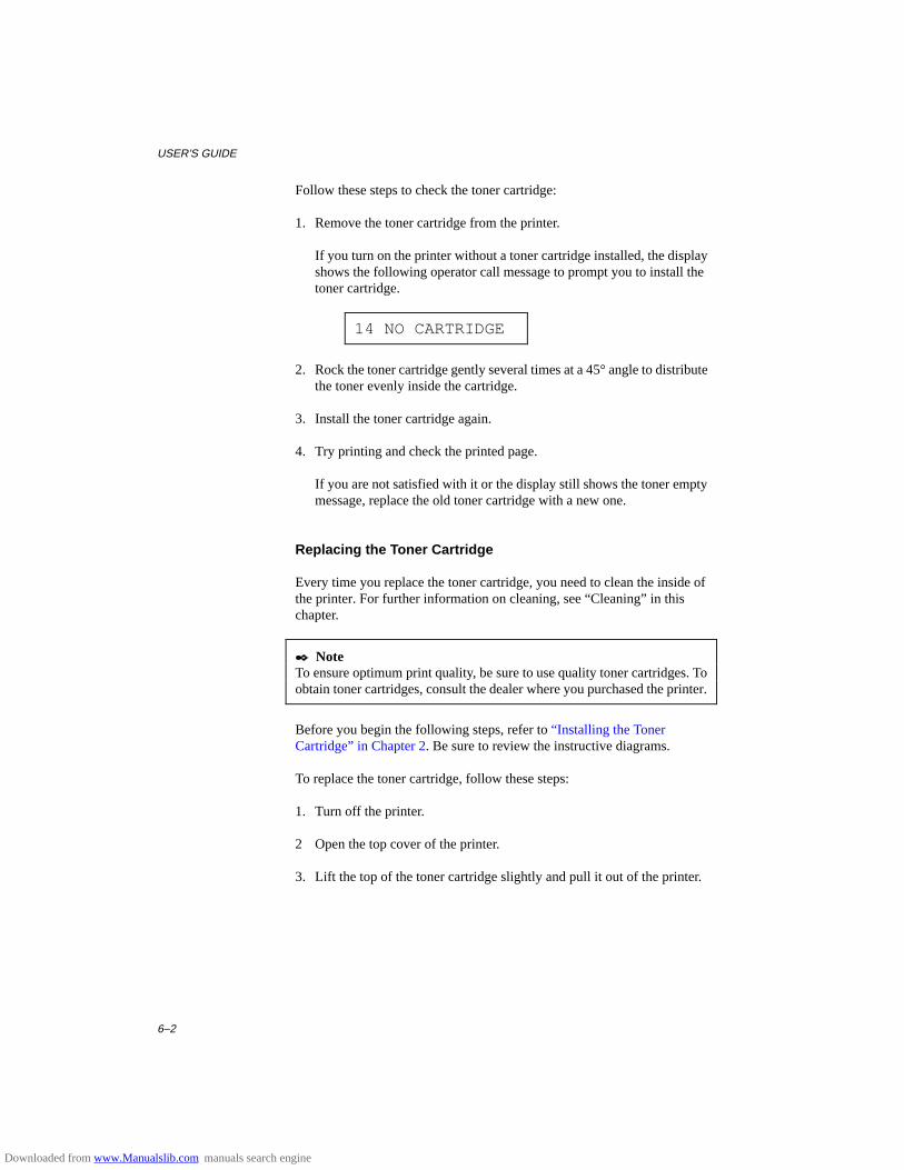
USER’S GUIDE
6–2
Follow these steps to check the toner cartridge:
1. Remove the toner cartridge from the printer.
If you turn on the printer without a toner cartridge installed, the displayshows the following operator call message to prompt you to install thetoner cartridge.
14 NO CARTRIDGE
2. Rock the toner cartridge gently several times at a 45° angle to distributethe toner evenly inside the cartridge.
3. Install the toner cartridge again.
4. Try printing and check the printed page.
If you are not satisfied with it or the display still shows the toner emptymessage, replace the old toner cartridge with a new one.
Replacing the Toner Cartridge
Every time you replace the toner cartridge, you need to clean the inside ofthe printer. For further information on cleaning, see “Cleaning” in thischapter.
✒ NoteTo ensure optimum print quality, be sure to use quality toner cartridges. Toobtain toner cartridges, consult the dealer where you purchased the printer.
Before you begin the following steps, refer to “Installing the TonerCartridge” in Chapter 2. Be sure to review the instructive diagrams.
To replace the toner cartridge, follow these steps:
1. Turn off the printer.
2 Open the top cover of the printer.
3. Lift the top of the toner cartridge slightly and pull it out of the printer.
Downloaded from www.Manualslib.com manuals search engine
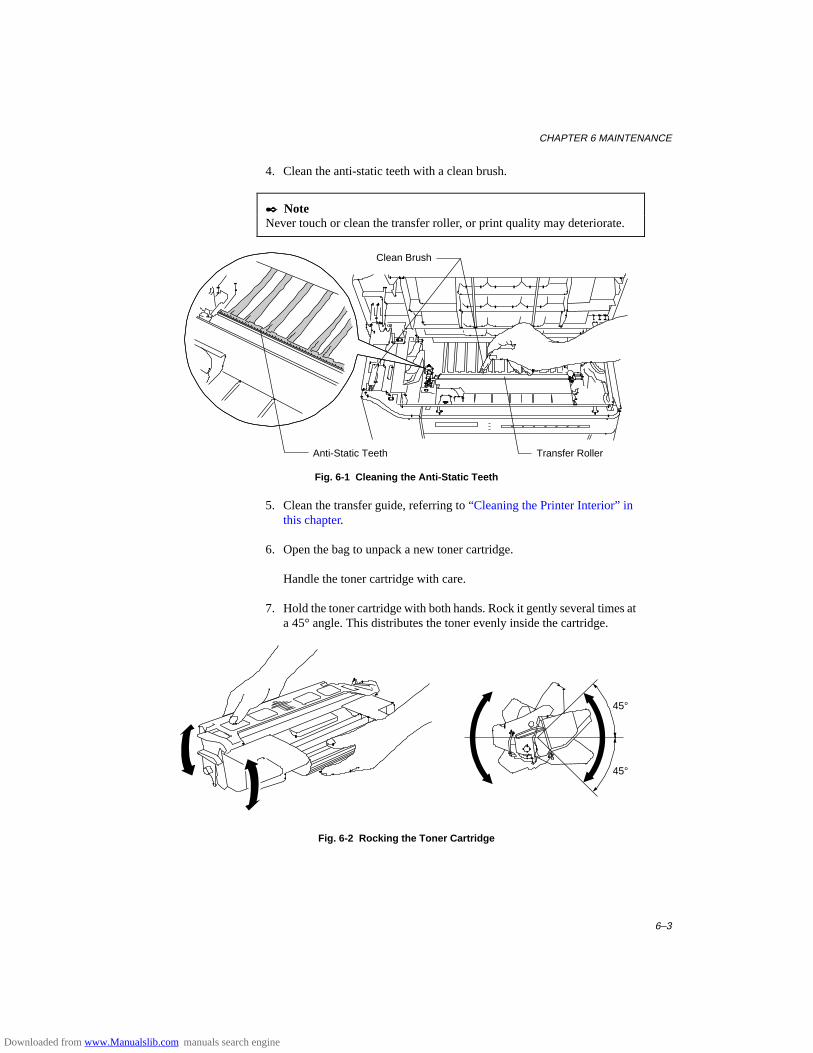
CHAPTER 6 MAINTENANCE
6–3
4. Clean the anti-static teeth with a clean brush.
✒ NoteNever touch or clean the transfer roller, or print quality may deteriorate.
Fig. 6-1 Cleaning the Anti-Static Teeth
5. Clean the transfer guide, referring to “Cleaning the Printer Interior” inthis chapter.
6. Open the bag to unpack a new toner cartridge.
Handle the toner cartridge with care.
7. Hold the toner cartridge with both hands. Rock it gently several times ata 45° angle. This distributes the toner evenly inside the cartridge.
45°
45°
Fig. 6-2 Rocking the Toner Cartridge
Clean Brush
Transfer RollerAnti-Static Teeth
Downloaded from www.Manualslib.com manuals search engine

USER’S GUIDE
6–4
8. Bend the tab up and down several times until it is detached from thetoner cartridge.
9. Hold the tab firmly and pull it until the sealing tape comes out all theway.
10. Insert the toner cartridge in the direction of the arrows engraved on thecartridge into the side guides until it stops securely in the cartridgeholder inside the printer.
✒ NotePush both sides of the toner cartridge gently until the cartridge is seatedcorrectly in place.
11. Close the top cover of the printer.
Downloaded from www.Manualslib.com manuals search engine
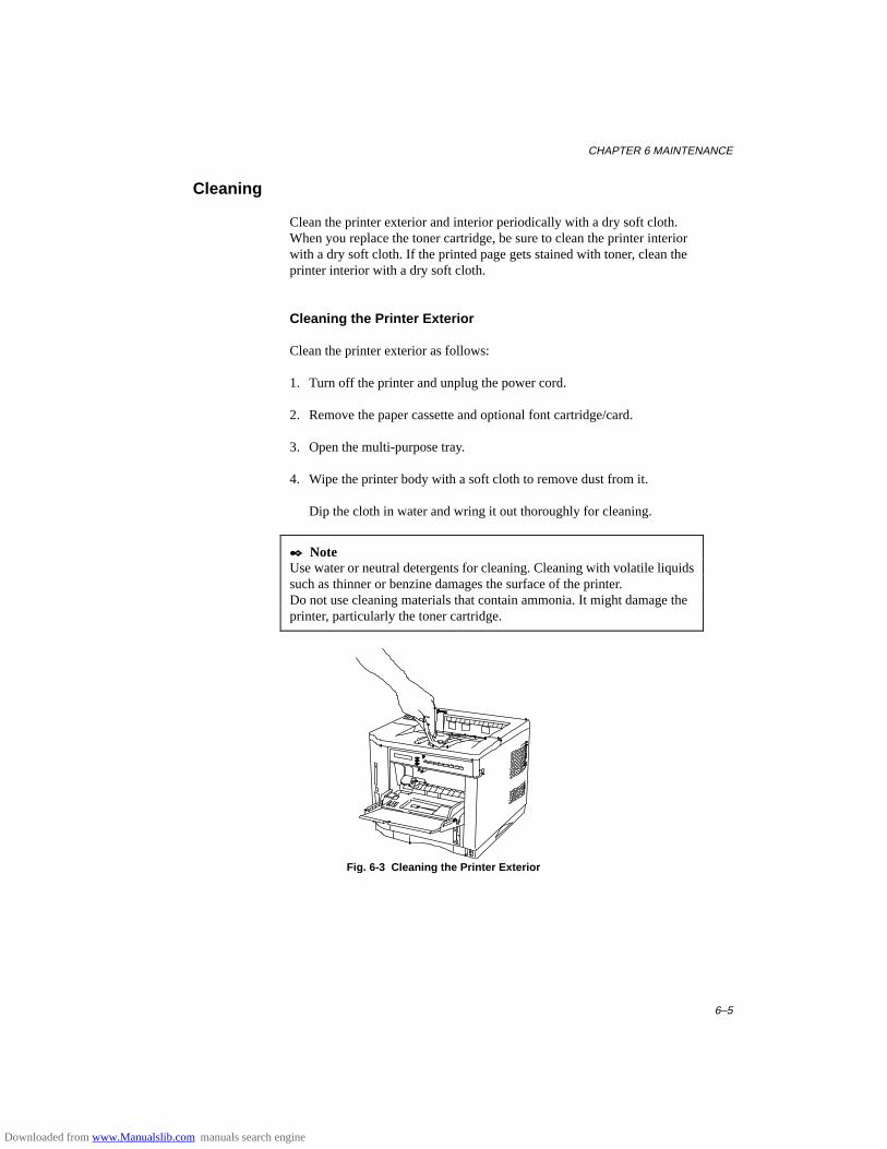
CHAPTER 6 MAINTENANCE
6–5
Cleaning
Clean the printer exterior and interior periodically with a dry soft cloth.When you replace the toner cartridge, be sure to clean the printer interiorwith a dry soft cloth. If the printed page gets stained with toner, clean theprinter interior with a dry soft cloth.
Cleaning the Printer Exterior
Clean the printer exterior as follows:
1. Turn off the printer and unplug the power cord.
2. Remove the paper cassette and optional font cartridge/card.
3. Open the multi-purpose tray.
4. Wipe the printer body with a soft cloth to remove dust from it.
Dip the cloth in water and wring it out thoroughly for cleaning.
✒ NoteUse water or neutral detergents for cleaning. Cleaning with volatile liquidssuch as thinner or benzine damages the surface of the printer.Do not use cleaning materials that contain ammonia. It might damage theprinter, particularly the toner cartridge.
Fig. 6-3 Cleaning the Printer Exterior
Downloaded from www.Manualslib.com manuals search engine
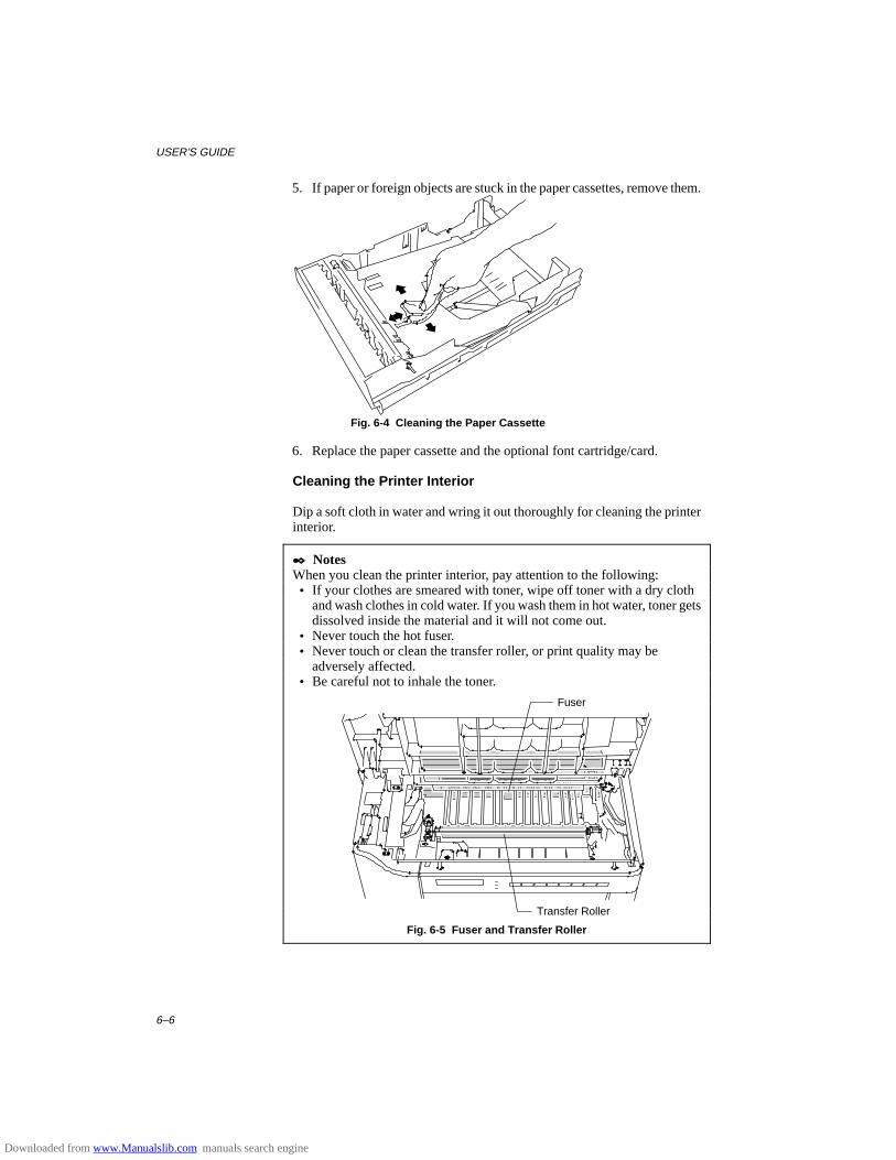
USER’S GUIDE
6–6
5. If paper or foreign objects are stuck in the paper cassettes, remove them.
Fig. 6-4 Cleaning the Paper Cassette
6. Replace the paper cassette and the optional font cartridge/card.
Cleaning the Printer Interior
Dip a soft cloth in water and wring it out thoroughly for cleaning the printerinterior.
✒ NotesWhen you clean the printer interior, pay attention to the following: • If your clothes are smeared with toner, wipe off toner with a dry cloth
and wash clothes in cold water. If you wash them in hot water, toner getsdissolved inside the material and it will not come out.
• Never touch the hot fuser. • Never touch or clean the transfer roller, or print quality may be
adversely affected. • Be careful not to inhale the toner.
Fig. 6-5 Fuser and Transfer Roller
Transfer Roller
Fuser
Downloaded from www.Manualslib.com manuals search engine
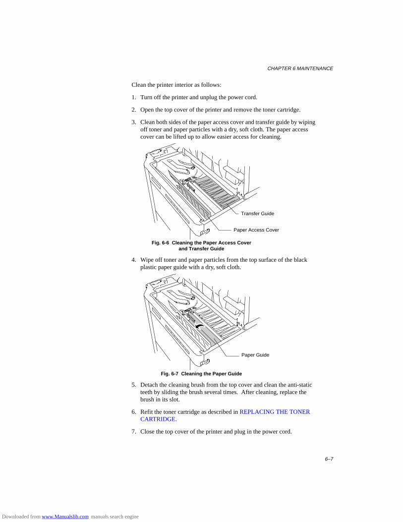
CHAPTER 6 MAINTENANCE
6–7
Clean the printer interior as follows:
1. Turn off the printer and unplug the power cord.
2. Open the top cover of the printer and remove the toner cartridge.
3. Clean both sides of the paper access cover and transfer guide by wipingoff toner and paper particles with a dry, soft cloth. The paper accesscover can be lifted up to allow easier access for cleaning.
Fig. 6-6 Cleaning the Paper Access Coverand Transfer Guide
4. Wipe off toner and paper particles from the top surface of the blackplastic paper guide with a dry, soft cloth.
Fig. 6-7 Cleaning the Paper Guide
5. Detach the cleaning brush from the top cover and clean the anti-staticteeth by sliding the brush several times. After cleaning, replace thebrush in its slot.
6. Refit the toner cartridge as described in REPLACING THE TONERCARTRIDGE.
7. Close the top cover of the printer and plug in the power cord.
Paper Access Cover
Transfer Guide
Paper Guide
Downloaded from www.Manualslib.com manuals search engine
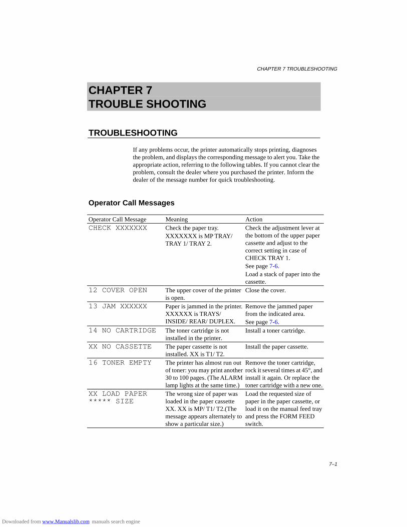
CHAPTER 7 TROUBLESHOOTING
7–1
CHAPTER 7TROUBLE SHOOTING
TROUBLESHOOTING
If any problems occur, the printer automatically stops printing, diagnosesthe problem, and displays the corresponding message to alert you. Take theappropriate action, referring to the following tables. If you cannot clear theproblem, consult the dealer where you purchased the printer. Inform thedealer of the message number for quick troubleshooting.
Operator Call Messages
Operator Call Message Meaning ActionCHECK XXXXXXX Check the paper tray.
XXXXXXX is M P TRAY/TRAY 1/ TRAY 2.
Check the adjustment lever atthe bottom of the upper papercassette and adjust to thecorrect setting in case ofCHECK TRAY 1.See page 7-6.Load a stack of paper into thecassette.
12 COVER OPEN The upper cover of the printeris open.
Close the cover.
13 JAM XXXXXX Paper is jammed in the printer.XXXXXX i s TRAYS/INSIDE/ REAR/ DUPLEX.
Remove the jammed paperfrom the indicated area.See page 7-6.
14 NO CARTRIDGE The toner cartridge is notinstalled in the printer.
Install a toner cartridge.
XX NO CASSETTE The paper cassette is notinstalled. XX is T1/ T2.
Install the paper cassette.
16 TONER EMPTY The printer has almost run outof toner: you may print another30 to 100 pages. (The ALARMlamp lights at the same time.)
Remove the toner cartridge,rock it several times at 45°, andinstall it again. Or replace thetoner cartridge with a new one.
XX LOAD PAPER***** SIZE
The wrong size of paper wasloaded in the paper cassetteXX. XX is MP/ T1/ T2.(Themessage appears alternately toshow a particular size.)
Load the requested size ofpaper in the paper cassette, orload it on the manual feed trayand press the FORM FEEDswitch.
Downloaded from www.Manualslib.com manuals search engine

USER’S GUIDE
7–2
Operator Call Message Meaning Action18 MANUAL FEED***** SIZE
The printer requests you toload paper manually. (Themessage appears alternately toshow a particular size.)
Load the requested size ofpaper on the multi-purposetray and press the SEL switch.
19 CHECK FONT An error occurred in theoptional font cartridge/card.
Turn off the printer, and re-install or replace the optionalfont cartridge/card.
20 FONT REMOVAL The font cartridge/card wasremoved while the printer ison-line.
Turn off the printer, install thefont cartridge/card, and turn onthe printer. The CONTINUEswitch will allow you totemporarily ignore thismessage.
27 NO DX UNIT The duplex unit is not installedwith the printer when theduplex printing mode isselected.
Install the duplex unitcorrectly. See the DX-1200/DX-1600 user’s guide.
27 NO DX TRAY The duplex paper guide tray isnot installed in T1 whenduplex printing mode isselected.
Install the duplex paper guidetray into T1. See the DX-1200/DX-1600 user’s guide.
27 DX OPEN The cover of the duplex unit isopen.
Close the cover. See the DX-1200/DX-1600 user’s guide.
Downloaded from www.Manualslib.com manuals search engine
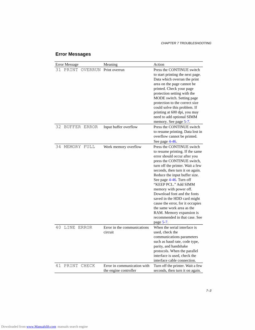
CHAPTER 7 TROUBLESHOOTING
7–3
Error Messages
Error Message Meaning Action31 PRINT OVERRUN Print overrun Press the CONTINUE switch
to start printing the next page.Data which overran the printarea on the page cannot beprinted. Check your pageprotection setting with theMODE switch. Setting pageprotection to the correct sizecould solve this problem. Ifprinting at 600 dpi, you mayneed to add optional SIMMmemory. See page 5-7.
32 BUFFER ERROR Input buffer overflow Press the CONTINUE switchto resume printing. Data lost inoverflow cannot be printed.See page 4-46.
34 MEMORY FULL Work memory overflow Press the CONTINUE switchto resume printing. If the sameerror should occur after youpress the CONTINUE switch,turn off the printer. Wait a fewseconds, then turn it on again.Reduce the input buffer size.See page 4-46. Turn off“KEEP PCL.” Add SIMMmemory with power off.Download font and the fontssaved in the HDD card mightcause the error, for it occupiesthe same work area as theRAM. Memory expansion isrecommended in that case. Seepage 5-7.
40 LINE ERROR Error in the communicationscircuit
When the serial interface isused, check thecommunications parameterssuch as baud rate, code type,parity, and handshakeprotocols. When the parallelinterface is used, check theinterface cable connection.
41 PRINT CHECK Error in communication withthe engine controller
Turn off the printer. Wait a fewseconds, then turn it on again.
Downloaded from www.Manualslib.com manuals search engine
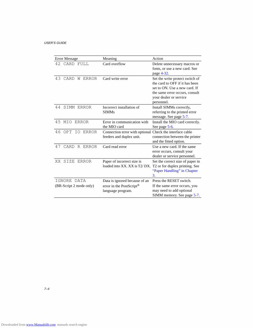
USER’S GUIDE
7–4
Error Message Meaning Action42 CARD FULL Card overflow Delete unnecessary macros or
fonts, or use a new card. Seepage 4-32.
43 CARD W ERROR Card write error Set the write protect switch ofthe card to OFF if it has beenset to ON. Use a new card. Ifthe same error occurs, consultyour dealer or servicepersonnel.
44 SIMM ERROR Incorrect installation ofSIMMs
Install SIMMs correctly,referring to the printed errormessage. See page 5-7.
45 MIO ERROR Error in communication withthe MIO card
Install the MIO card correctly.See page 5-6.
46 OPT IO ERROR Connection error with optionalfeeders and duplex unit.
Check the interface cableconnection between the printerand the fitted option.
47 CARD R ERROR Card read error Use a new card. If the sameerror occurs, consult yourdealer or service personnel.
XX SIZE ERROR Paper of incorrect size isloaded into XX. XX is T2/ DX.
Set the correct size of paper inT2 or for duplex printing. See“Paper Handling” in Chapter3.
IGNORE DATA(BR-Script 2 mode only)
Data is ignored because of anerror in the PostScript®
language program.
Press the RESET switch.If the same error occurs, youmay need to add optionalSIMM memory. See page 5-7.
Downloaded from www.Manualslib.com manuals search engine
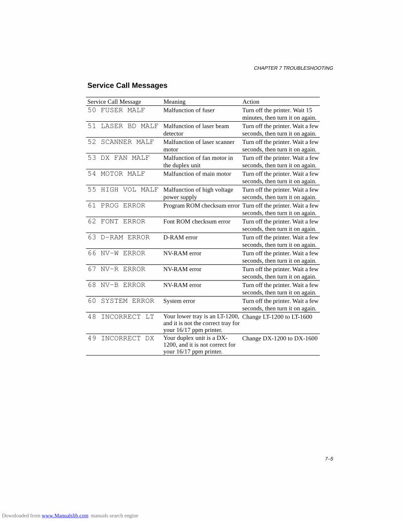
CHAPTER 7 TROUBLESHOOTING
7–5
Service Call Messages
Service Call Message Meaning Action50 FUSER MALF Malfunction of fuser Turn off the printer. Wait 15
minutes, then turn it on again.51 LASER BD MALF Malfunction of laser beam
detectorTurn off the printer. Wait a fewseconds, then turn it on again.
52 SCANNER MALF Malfunction of laser scannermotor
Turn off the printer. Wait a fewseconds, then turn it on again.
53 DX FAN MALF Malfunction of fan motor inthe duplex unit
Turn off the printer. Wait a fewseconds, then turn it on again.
54 MOTOR MALF Malfunction of main motor Turn off the printer. Wait a fewseconds, then turn it on again.
55 HIGH VOL MALF Malfunction of high voltagepower supply
Turn off the printer. Wait a fewseconds, then turn it on again.
61 PROG ERROR Program ROM checksum error Turn off the printer. Wait a fewseconds, then turn it on again.
62 FONT ERROR Font ROM checksum error Turn off the printer. Wait a fewseconds, then turn it on again.
63 D-RAM ERROR D-RAM error Turn off the printer. Wait a fewseconds, then turn it on again.
66 NV-W ERROR NV-RAM error Turn off the printer. Wait a fewseconds, then turn it on again.
67 NV-R ERROR NV-RAM error Turn off the printer. Wait a fewseconds, then turn it on again.
68 NV-B ERROR NV-RAM error Turn off the printer. Wait a fewseconds, then turn it on again.
60 SYSTEM ERROR System error Turn off the printer. Wait a fewseconds, then turn it on again.
48 INCORRECT LT Your lower tray is an LT-1200,and it is not the correct tray foryour 16/17 ppm printer.
Change LT-1200 to LT-1600
49 INCORRECT DX Your duplex unit is a DX-1200, and it is not correct foryour 16/17 ppm printer.
Change DX-1200 to DX-1600
Downloaded from www.Manualslib.com manuals search engine
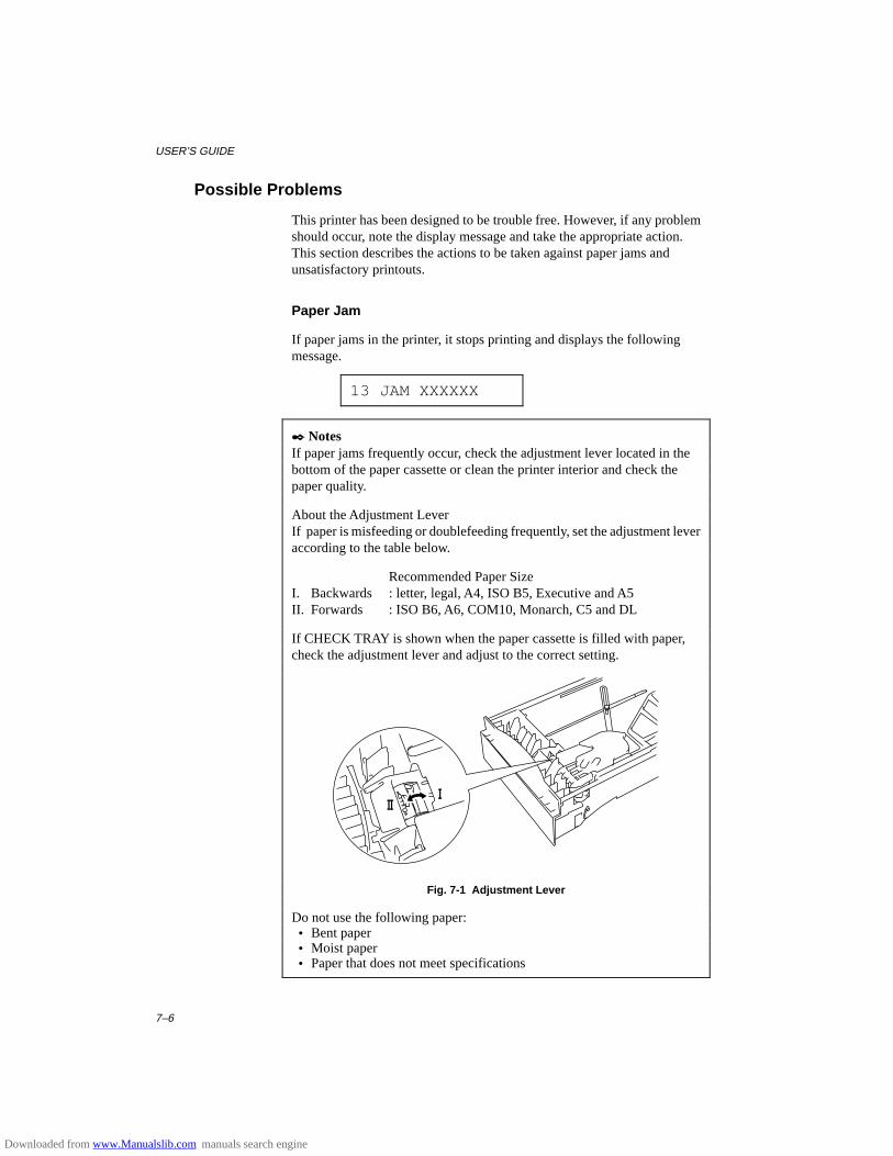
USER’S GUIDE
7–6
Possible Problems
This printer has been designed to be trouble free. However, if any problemshould occur, note the display message and take the appropriate action.This section describes the actions to be taken against paper jams andunsatisfactory printouts.
Paper Jam
If paper jams in the printer, it stops printing and displays the followingmessage.
13 JAM XXXXXX
✒ NotesIf paper jams frequently occur, check the adjustment lever located in thebottom of the paper cassette or clean the printer interior and check thepaper quality.
About the Adjustment LeverIf paper is misfeeding or doublefeeding frequently, set the adjustment leveraccording to the table below.
Recommended Paper SizeI. Backwards : letter, legal, A4, ISO B5, Executive and A5II. Forwards : ISO B6, A6, COM10, Monarch, C5 and DL
If CHECK TRAY is shown when the paper cassette is filled with paper,check the adjustment lever and adjust to the correct setting.
Fig. 7-1 Adjustment Lever
Do not use the following paper: • Bent paper • Moist paper • Paper that does not meet specifications
Downloaded from www.Manualslib.com manuals search engine
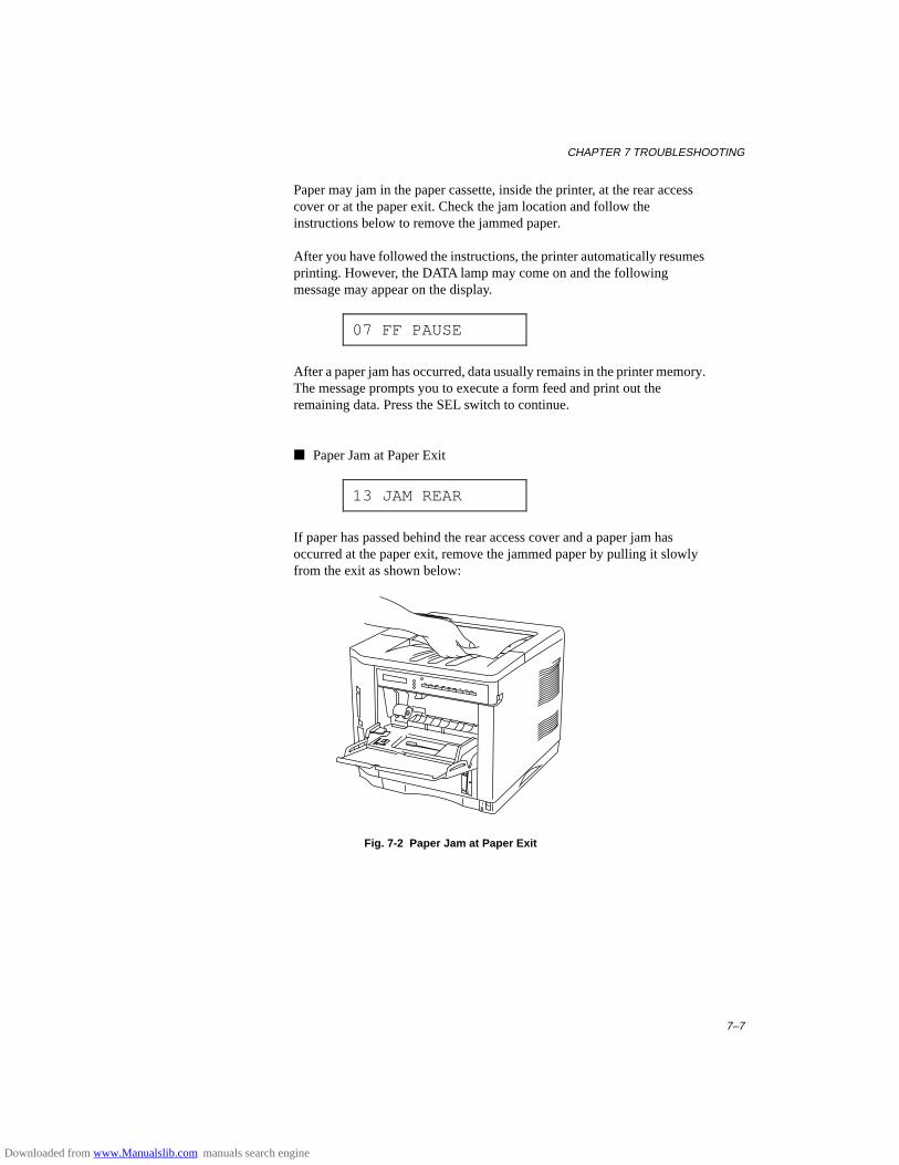
CHAPTER 7 TROUBLESHOOTING
7–7
Paper may jam in the paper cassette, inside the printer, at the rear accesscover or at the paper exit. Check the jam location and follow theinstructions below to remove the jammed paper.
After you have followed the instructions, the printer automatically resumesprinting. However, the DATA lamp may come on and the followingmessage may appear on the display.
07 FF PAUSE
After a paper jam has occurred, data usually remains in the printer memory.The message prompts you to execute a form feed and print out theremaining data. Press the SEL switch to continue.
■ Paper Jam at Paper Exit
13 JAM REAR
If paper has passed behind the rear access cover and a paper jam hasoccurred at the paper exit, remove the jammed paper by pulling it slowlyfrom the exit as shown below:
Fig. 7-2 Paper Jam at Paper Exit
Downloaded from www.Manualslib.com manuals search engine

USER’S GUIDE
7–8
■ Paper Jam at Rear Access Cover
13 JAM REAR
If a paper jam occurs behind the rear access cover before the paper exit,remove the jammed paper as follows:
1. Open the rear access cover.
2. Pull out the jammed paper slowly in direction A or B.
Fig. 7-3 Paper Jam at Rear Access Cover
3. Close the rear access cover.
Rear AccessCover Direction A
Direction B
Downloaded from www.Manualslib.com manuals search engine

CHAPTER 7 TROUBLESHOOTING
7–9
■ Paper Jam at Fixing Roller inside the printer
13 JAM INSIDE
If a paper jam occurs at the fixing roller, follow these steps to remove thejammed paper:
1. Open the top cover and remove the toner cartridge.
2. Remove the jammed paper by holding it with both hands and pulling itslowly towards you.
WarningThe fixing roller is extremely hot during operation. Remove the papercarefully.
! Caution • After having removed the jammed paper, if the printed paper has a
stain, print several pages before restarting your printing. • Remove the jammed paper carefully so as not to spread toner. • Take care not to stain your hands and clothes with toner. Wash toner
stains immediately with cold water. • Never touch the transfer roller.
Fig. 7-4 Paper Jam at Fixing Roller
3. Install the toner cartridge and close the top cover.
Fixing Roller
Downloaded from www.Manualslib.com manuals search engine
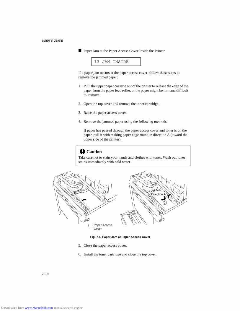
USER’S GUIDE
7–10
■ Paper Jam at the Paper Access Cover Inside the Printer
13 JAM INSIDE
If a paper jam occurs at the paper access cover, follow these steps toremove the jammed paper:
1. Pull the upper paper cassette out of the printer to release the edge of thepaper from the paper feed roller, or the paper might be torn and difficultto remove.
2. Open the top cover and remove the toner cartridge.
3. Raise the paper access cover.
4. Remove the jammed paper using the following methods:
If paper has passed through the paper access cover and toner is on thepaper, pull it with making paper edge round in direction A (toward theupper side of the printer).
! CautionTake care not to stain your hands and clothes with toner. Wash out tonerstains immediately with cold water.
Fig. 7-5 Paper Jam at Paper Access Cover
5. Close the paper access cover.
6. Install the toner cartridge and close the top cover.
Paper AccessCover
Direction A
Downloaded from www.Manualslib.com manuals search engine
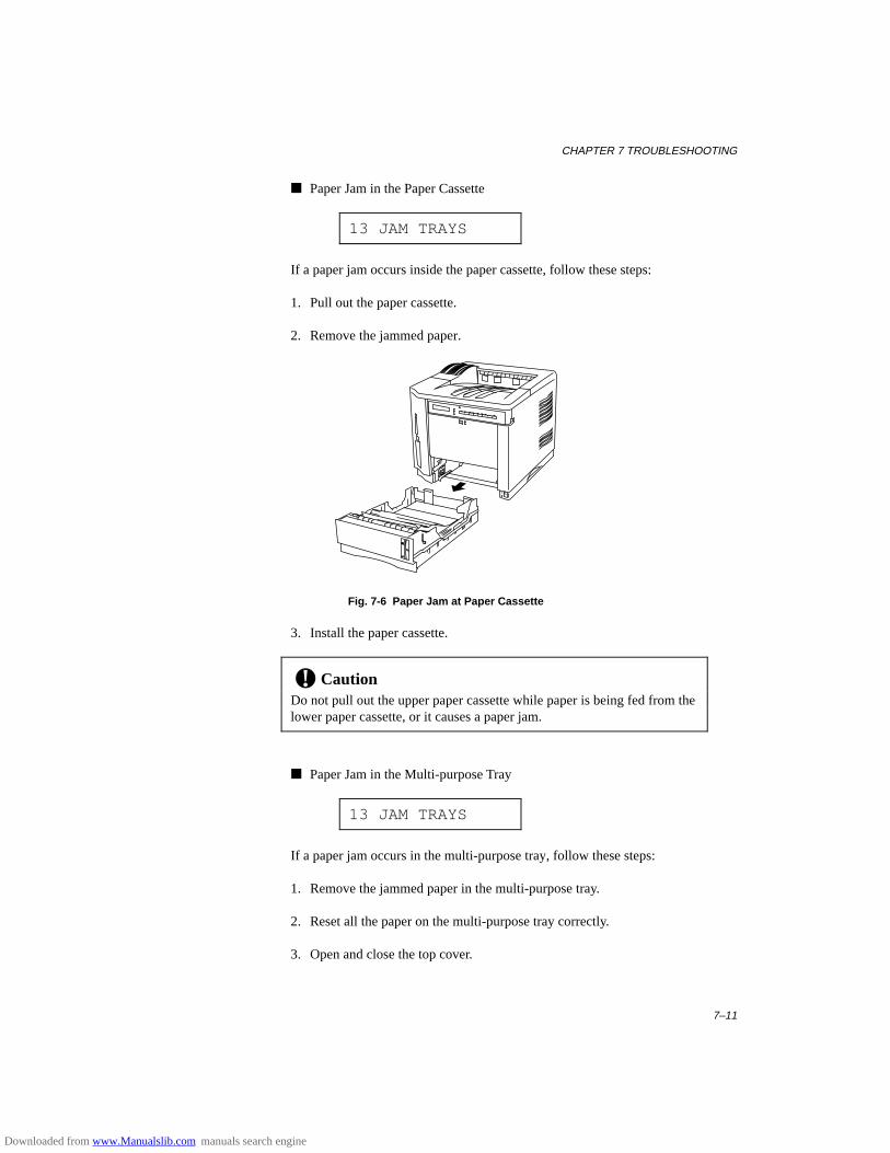
CHAPTER 7 TROUBLESHOOTING
7–11
■ Paper Jam in the Paper Cassette
13 JAM TRAYS
If a paper jam occurs inside the paper cassette, follow these steps:
1. Pull out the paper cassette.
2. Remove the jammed paper.
Fig. 7-6 Paper Jam at Paper Cassette
3. Install the paper cassette.
! CautionDo not pull out the upper paper cassette while paper is being fed from thelower paper cassette, or it causes a paper jam.
■ Paper Jam in the Multi-purpose Tray
13 JAM TRAYS
If a paper jam occurs in the multi-purpose tray, follow these steps:
1. Remove the jammed paper in the multi-purpose tray.
2. Reset all the paper on the multi-purpose tray correctly.
3. Open and close the top cover.
Downloaded from www.Manualslib.com manuals search engine
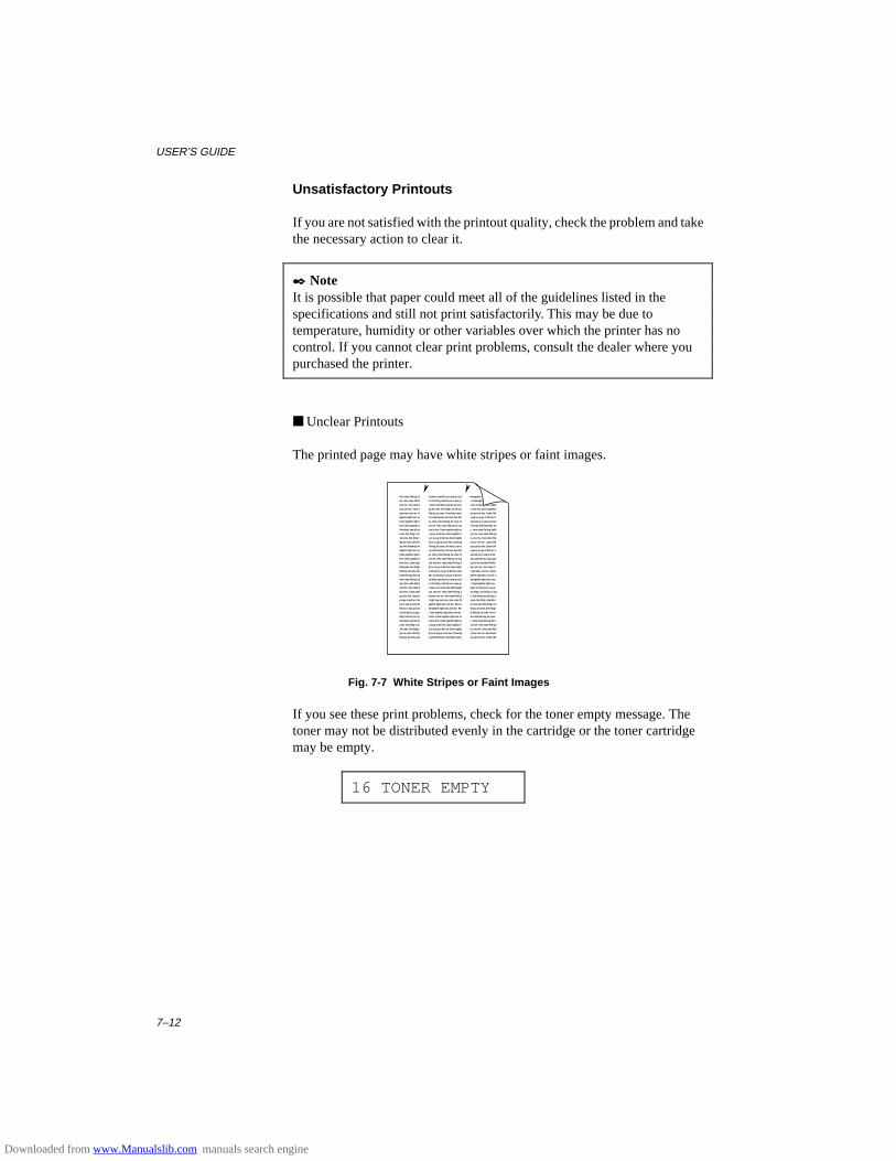
USER’S GUIDE
7–12
Unsatisfactory Printouts
If you are not satisfied with the printout quality, check the problem and takethe necessary action to clear it.
✒ NoteIt is possible that paper could meet all of the guidelines listed in thespecifications and still not print satisfactorily. This may be due totemperature, humidity or other variables over which the printer has nocontrol. If you cannot clear print problems, consult the dealer where youpurchased the printer.
■ Unclear Printouts
The printed page may have white stripes or faint images.
Here come Flat-top ,he come. One thing I can tell you is you go to be free. Come together right now, over
me. Here come Flat-top ,he come. One thing I can tell you is you go to be free. Come together right now,
over me. Here come Flat-top ,he come. One thing I can tell you is you go to be free. Come together rightA
now, over me. Here come Flat-top ,he come. One thing I can tell you is you go to be free. Come togetherA
right now, over me. Here come Flat-top ,he come. One thing I can tell you is you go to be free. Come AAA
together right now, over me. Here come Flat-top ,he come. One thing I can tell you is you go to be free. A
Come together right now, over me. Here come Flat-top ,he come. One thing I can tell you is you go to beA
free. Come together right now, over me. Here come Flat-top ,he come. Lucy in the sky with Diamonde. AA
One thing I can tell you is you go to be free. Come together right now, over me. Here come Flat-top ,heAA
come. One thing I can tell you is you go to be free. Come together right now, over me. Here come Flat-top
,he come. One thing I can tell you is you go to be free. Come together right now, over me. Here come Flat-
top ,he come. One thing I can tell you is you go to be free. Come together right now, over me. Lucy in the
sky with Diamonde. Here come Flat-top ,he come. One thing I can tell you is you go to be free. Come AAA
together right now, over me. Here come Flat-top ,he come. One thing I can tell you is you go to be free. A
Come together right now, over me. Here come Flat-top ,he come. One thing I can tell you is you go to be
free. Come together right now, over me. Here come Flat-top ,he come. One thing I can tell you is you goA
to be free. Come together right now, over me. Here come Flat-top ,he come. Lucy in the sky with AAAAA
Diamonde. One thing I can tell you is you go to be free. Come together right now, over me. Here come A
Flat-top ,he come. One thing I can tell you is you go to be free. Come together right now, over me. HereA
come Flat-top ,he come. One thing I can tell you is you go to be free. Come together right now, over me. A
Here come Flat-top ,he come. One thing I can tell you is you go to be free. Come together right now, over
me. Here come Flat-top ,he come. One thing I can tell you is you go to be free. Come together right now,
over me. Here come Flat-top ,he come. Lucy in the sky with Diamonde. One thing I can tell you is you go
to be free. Come together right now, over me. Here come Flat-top ,he come. One thing I can tell you is you
go to be free. Come together right now, over me. Here come Flat-top ,he come. One thing I can tell you is
you go to be free. Come together right now, over me. Here come Flat-top ,he come. One thing I can tell A
you is you go to be free. Come together right now, over me. Here come Flat-top ,he come. One thing I can
tell you is you go to be free. Come together right now, over me. Here come Flat-top ,he come. One thing I
can tell you is you go to be free. Come together right now, over me. Here come Flat-top ,he come. One A
thing I can tell you is you go to be free. Come together right now, over me. Here come Flat-top ,he come.
One thing I can tell you is you go to be free. Come together right now, over me. Here come Flat-top ,he A
come. One thing I can tell you is you go to be free. Come together right now, over me. Here come Flat-top
,he come. One thing I can tell you is you go to be free. Come together right now, over me. Here come Flat-
top ,he come. One thing I can tell you is you go to be free. Come together right now, over me. Here come
Flat-top ,he come. Lucy in the sky with Diamonde. One thing I can tell you is you go to be free. Come AAA
Fig. 7-7 White Stripes or Faint Images
If you see these print problems, check for the toner empty message. Thetoner may not be distributed evenly in the cartridge or the toner cartridgemay be empty.
16 TONER EMPTY
Downloaded from www.Manualslib.com manuals search engine
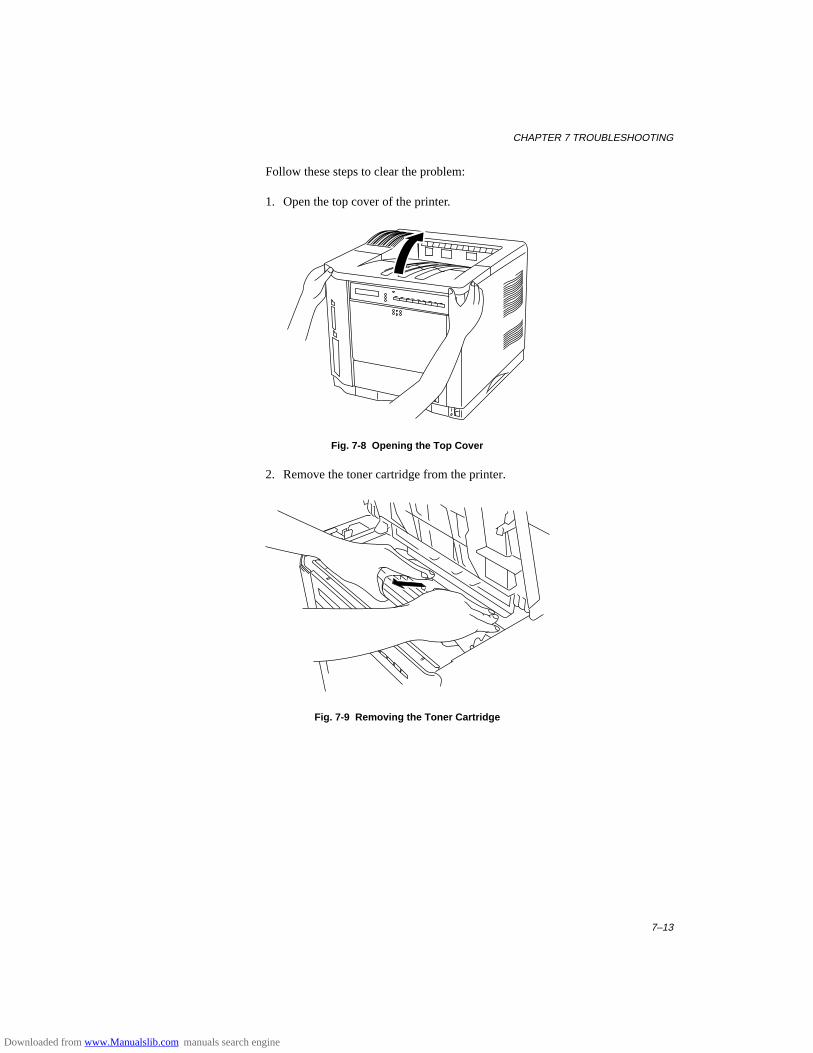
CHAPTER 7 TROUBLESHOOTING
7–13
Follow these steps to clear the problem:
1. Open the top cover of the printer.
Fig. 7-8 Opening the Top Cover
2. Remove the toner cartridge from the printer.
Fig. 7-9 Removing the Toner Cartridge
Downloaded from www.Manualslib.com manuals search engine
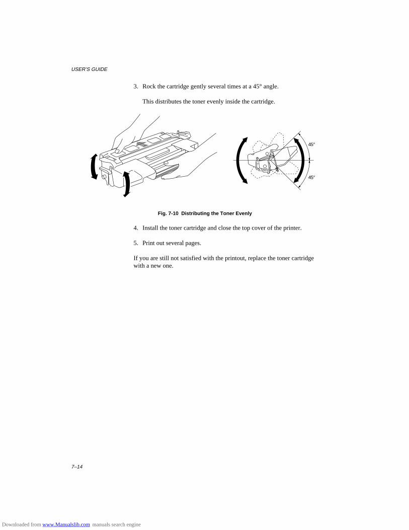
USER’S GUIDE
7–14
3. Rock the cartridge gently several times at a 45° angle.
This distributes the toner evenly inside the cartridge.
45°
45°
Fig. 7-10 Distributing the Toner Evenly
4. Install the toner cartridge and close the top cover of the printer.
5. Print out several pages.
If you are still not satisfied with the printout, replace the toner cartridgewith a new one.
Downloaded from www.Manualslib.com manuals search engine
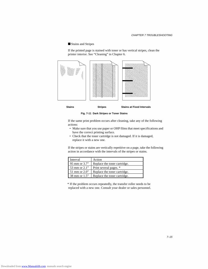
CHAPTER 7 TROUBLESHOOTING
7–15
■ Stains and Stripes
If the printed page is stained with toner or has vertical stripes, clean theprinter interior. See “Cleaning” in Chapter 6.
Here come Pat-top ,he come. One thing I can tell you is you go to be free. Come together right now, over
me. Here come Pat-top ,he come. One thing I can tell you is you go to be free. Come together right now,
over me. Here come Pat-top ,he come. One thing I can tell you is you go to be free. Come together rightA
now, over me. Here come Pat-top ,he come. One thing I can tell you is you go to be free. Come togetherA
right now, over me. Here come Pat-top ,he come. One thing I can tell you is you go to be free. Come AAA
together right now, over me. Here come Pat-top ,he come. One thing I can tell you is you go to be free. A
Come together right now, over me. Here come Pat-top ,he come. One thing I can tell you is you go to beA
free. Come together right now, over me. Here come Pat-top ,he come. Diamonde the skyLucky in with .
AA One thing I can tell you is you go to be free. Come in the sky right now, over me. Here come Pat-top
,heAA come. One thing I can tell you is you go to be free. Come together right now, over me. Here come
Pat-top ,he come. One thing I can tell you is you go to be free. Come in the sky right now, over me. Here
come Flat-top ,he come. One thing I can tell you is you go to be free. Come tin the sky right now, over me.
in the sky Lucy Diamonde with . Here come Pat-top ,he come. One thing I can tell you is you go to be free.
Come AAA together right now, over me. Here come Pat-top ,he come. One thing I can tell you is you go to
be free. A Come together right now, over me. Here come Pat-top ,he come. One thing I can tell you is you
go to be free. together Comeright now, over me. Here come Pat-top ,he come. One thing I can tell you is
you goA to be free. Come together right now, over me. Here come Pat-top ,he come. Lucky in the sky with
AAAAA Diamonde. One thing I can tell you is you go to be free. Come tin the sky right now, over me. Here
come A Pat-top ,he come. One thing I can tell you is you go to be free. Come in the sky right now, over
me. HereA come Pat-top ,he come. One thing I can tell you is you go to be free. Come tin the sky right
now, over me. A Here come Pat-top ,he come. One thing I can tell you is you go to be free. Come together
right now, over me. Here come Pat-top ,he come. One thing I can tell you is you go to be free. Come
together right now, over me. Here come v ,he come. Lucky Diamonde in the sky with . One thing I can tell
you is you go to be free. Come tin the skyright now, over me. Here come Pat-top ,he come. One thing I
can tell you is you go to be free. Come in the sky right now, over me. Here come Pat-top ,he come. One
thing I can tell you is you go to be free. Come in the sky right now, over me. Here come Pat-top ,he come.
One thing I can tell A you is you go to be free. Come in the sky right now, over me. Here come Pat-top ,he
come. One thing I can tell you is you go to be free. Come in the sky right now, over me. Here come Pat-
top ,he come. One thing I can tell you is you go to be free. Come in the sky right now, over me. Here come
Pat-top ,he come. One A thing I can tell you is you go to be free. Come in the sky right now, over me. Here
come Pat-top ,he come. One thing I can tell you is you go to be free. Come in the sky right now, over me.
Here come Pat-top ,he A come. One thing I can tell you is you go to be free. Come in the sky right now,
over me. Here come Pat-top ,he come. One thing I can tell you is you go to be free. Come together right
now, over me. Here come Flat-top ,he come. One thing I can tell you is you go to be free. Come tin the sky
right now, over me. Here come Pat-top ,he come. Lucy in the sky with Amesist. One thing I can tell you is
Stains Stripes Stains at Fixed Intervals
Fig. 7-11 Dark Stripes or Toner Stains
If the same print problem occurs after cleaning, take any of the followingactions: • Make sure that you use paper or OHP films that meet specifications and
have the correct printing surface. • Check that the toner cartridge is not damaged. If it is damaged,
replace it with a new one. If the stripes or stains are vertically repetitive on a page, take the followingaction in accordance with the intervals of the stripes or stains.
Interval Action95 mm or 3.7” Replace the toner cartridge.53 mm or 2.1” Print several pages. *51 mm or 2.0” Replace the toner cartridge.38 mm or 1.5” Replace the toner cartridge.
* If the problem occurs repeatedly, the transfer roller needs to be replaced with a new one. Consult your dealer or sales personnel.
Downloaded from www.Manualslib.com manuals search engine
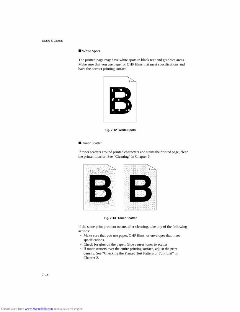
USER’S GUIDE
7–16
■ White Spots
The printed page may have white spots in black text and graphics areas.Make sure that you use paper or OHP films that meet specifications andhave the correct printing surface.
Fig. 7-12 White Spots
■ Toner Scatter
If toner scatters around printed characters and stains the printed page, cleanthe printer interior. See “Cleaning” in Chapter 6.
Fig. 7-13 Toner Scatter
If the same print problem occurs after cleaning, take any of the followingactions: • Make sure that you use paper, OHP films, or envelopes that meet
specifications. • Check for glue on the paper. Glue causes toner to scatter. • If toner scatters over the entire printing surface, adjust the print
density. See “Checking the Printed Test Pattern or Font List” in Chapter 2.
Downloaded from www.Manualslib.com manuals search engine
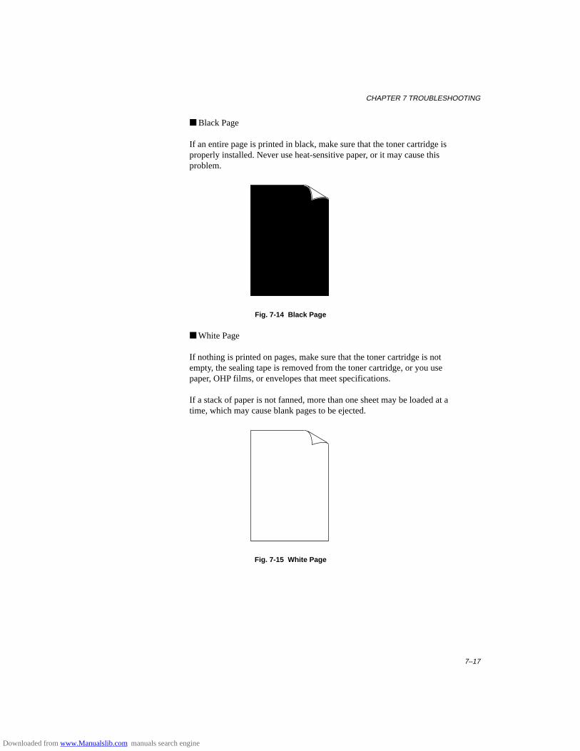
CHAPTER 7 TROUBLESHOOTING
7–17
■ Black Page
If an entire page is printed in black, make sure that the toner cartridge isproperly installed. Never use heat-sensitive paper, or it may cause thisproblem.
Fig. 7-14 Black Page
■ White Page
If nothing is printed on pages, make sure that the toner cartridge is notempty, the sealing tape is removed from the toner cartridge, or you usepaper, OHP films, or envelopes that meet specifications.
If a stack of paper is not fanned, more than one sheet may be loaded at atime, which may cause blank pages to be ejected.
Fig. 7-15 White Page
Downloaded from www.Manualslib.com manuals search engine
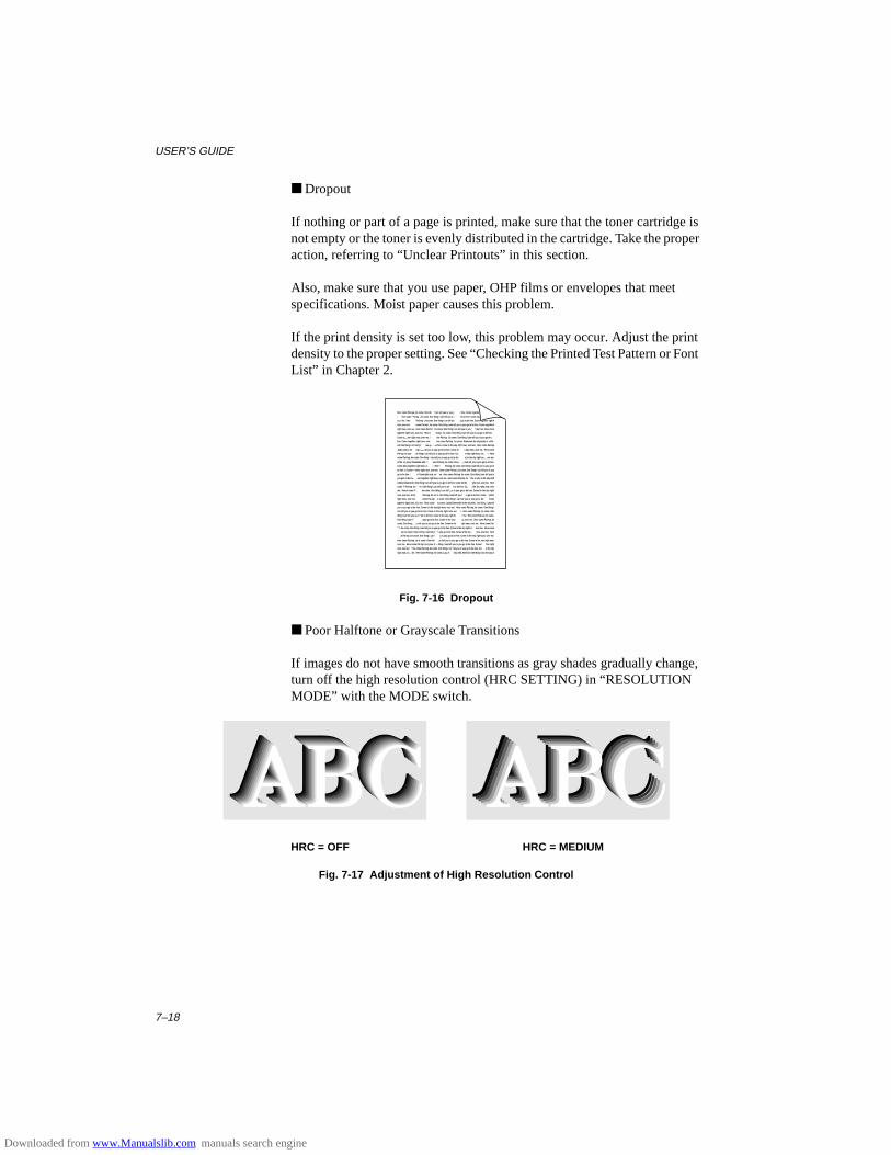
USER’S GUIDE
7–18
■ Dropout
If nothing or part of a page is printed, make sure that the toner cartridge isnot empty or the toner is evenly distributed in the cartridge. Take the properaction, referring to “Unclear Printouts” in this section.
Also, make sure that you use paper, OHP films or envelopes that meetspecifications. Moist paper causes this problem.
If the print density is set too low, this problem may occur. Adjust the printdensity to the proper setting. See “Checking the Printed Test Pattern or FontList” in Chapter 2.
Here come Pat-top ,he come. One thing I can tell you is you go to be free. Come together right now, over
me. Here come Pat-top ,he come. One thing I can tell you is you go to be free. Come together right now,
over me. Here come Pat-top ,he come. One thing I can tell you is you go to be free. Come together rightA
now, over me. Here come Pat-top ,he come. One thing I can tell you is you go to be free. Come togetherA
right now, over me. Here come Pat-top ,he come. One thing I can tell you is you go to be free. Come AAA
together right now, over me. Here come Pat-top ,he come. One thing I can tell you is you go to be free. A
Come together right now, over me. Here come Pat-top ,he come. One thing I can tell you is you go to beA
free. Come together right now, over me. Here come Pat-top ,he come. Diamonde the skyLucky in with .
AA One thing I can tell you is you go to be free. Come in the sky right now, over me. Here come Pat-top
,heAA come. One thing I can tell you is you go to be free. Come together right now, over me. Here come
Pat-top ,he come. One thing I can tell you is you go to be free. Come in the sky right now, over me. Here
come Flat-top ,he come. One thing I can tell you is you go to be free. Come tin the sky right now, over me.
in the sky Lucy Diamonde with . Here come Pat-top ,he come. One thing I can tell you is you go to be free.
Come AAA together right now, over me. Here come Pat-top ,he come. One thing I can tell you is you go to
be free. A Come together right now, over me. Here come Pat-top ,he come. One thing I can tell you is you
go to be free. together Comeright now, over me. Here come Pat-top ,he come. One thing I can tell you is
you goA to be free. Come together right now, over me. Here come Pat-top ,he come. Lucky in the sky with
AAAAA Diamonde. One thing I can tell you is you go to be free. Come tin the sky right now, over me. Here
come A Pat-top ,he come. One thing I can tell you is you go to be free. Come in the sky right now, over
me. HereA come Pat-top ,he come. One thing I can tell you is you go to be free. Come tin the sky right
now, over me. A Here come Pat-top ,he come. One thing I can tell you is you go to be free. Come together
right now, over me. Here come Pat-top ,he come. One thing I can tell you is you go to be free. Come
together right now, over me. Here come v ,he come. Lucky Diamonde in the sky with . One thing I can tell
you is you go to be free. Come tin the skyright now, over me. Here come Pat-top ,he come. One thing I
can tell you is you go to be free. Come in the sky right now, over me. Here come Pat-top ,he come. One
thing I can tell you is you go to be free. Come in the sky right now, over me. Here come Pat-top ,he come.
One thing I can tell A you is you go to be free. Come in the sky right now, over me. Here come Pat-top ,he
come. One thing I can tell you is you go to be free. Come in the sky right now, over me. Here come Pat-
top ,he come. One thing I can tell you is you go to be free. Come in the sky right now, over me. Here come
Pat-top ,he come. One A thing I can tell you is you go to be free. Come in the sky right now, over me. Here
come Pat-top ,he come. One thing I can tell you is you go to be free. Come in the sky right now, over me.
Here come Pat-top ,he A come. One thing I can tell you is you go to be free. Come in the sky right now,
over me. Here come Pat-top ,he come. One thing I can tell you is you go to be free. Come together right
now, over me. Here come Flat-top ,he come. One thing I can tell you is you go to be free. Come tin the sky
right now, over me. Here come Pat-top ,he come. Lucy in the sky with Amesist. One thing I can tell you is
Fig. 7-16 Dropout
■ Poor Halftone or Grayscale Transitions
If images do not have smooth transitions as gray shades gradually change,turn off the high resolution control (HRC SETTING) in “RESOLUTIONMODE” with the MODE switch.
HRC = OFF HRC = MEDIUM
Fig. 7-17 Adjustment of High Resolution Control
Downloaded from www.Manualslib.com manuals search engine

CHAPTER 7 TROUBLESHOOTING
7–19
! CautionOperation of the printer outside the specifications shall be deemed abuseand all repairs thereafter shall be the sole liability of the end user/purchaser.
(For USA & CANADA Only)
For technical and operational assistance, please call:
In USA 1-800-276-7746 (outside California) 714-859-9700 Ext. 329 (within California)
In CANADA 1-800-853-6660 514-685-6464 (within Montreal)
If you have comments or suggestions, please write us at:
In USA Printer Customer SupportBrother International Corporation15 MusickIrvine, CA 92718
In CANADA Brother International Corporation (Canada), Ltd.- Marketing Dept.1, rue Hôtel de VilleDollard-des-Ormeaux, PQ, Canada H9B 3H6
BBSFor downloading drivers from our Bulletin Board Service, call:In USA 1-714-859-2610In CANADA 1-514-685-2040Please log on to our BBS with your first name, last name and a four digit number foryour password. Our BBS supports modem speeds up to 14,400, 8 bits no parity, 1stop bit.
Fax-Back System (For USA only)Brother Customer Service has installed an easy to use Fax-Back System so you canget instant answers to common technical questions and product information for allBrother products. This is available 24 hours a day, 7 days a week. You can use thesystem to send the information to any fax machine, not just the one you are callingfrom.Please call 1-800-521-2846 and follow the voice prompts to receive faxed instructionson how to use the system and your index of Fax-Back subjects.
DEALERS/SERVICE CENTERS (USA only)For the name of an authorized dealer or service center, call 1-800-284-4357.
SERVICE CENTERS (Canada only)For service center addresses in Canada, call 1-800-853-6660
INTERNET ADDRESSFor technical questions and downloading drivers: http://www.brother.com
Downloaded from www.Manualslib.com manuals search engine
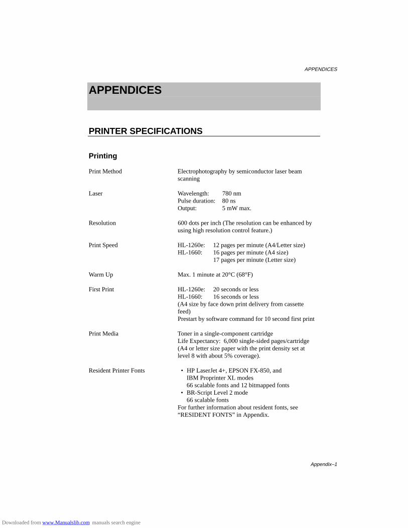
APPENDICES
Appendix–1
APPENDICES
PRINTER SPECIFICATIONS
Printing
Print Method Electrophotography by semiconductor laser beam scanning
Laser Wavelength: 780 nmPulse duration: 80 nsOutput: 5 mW max.
Resolution 600 dots per inch (The resolution can be enhanced by using high resolution control feature.)
Print Speed HL-1260e: 12 pages per minute (A4/Letter size)HL-1660: 16 pages per minute (A4 size)
17 pages per minute (Letter size)
Warm Up Max. 1 minute at 20°C (68°F)
First Print HL-1260e: 20 seconds or lessHL-1660: 16 seconds or less(A4 size by face down print delivery from cassette feed)Prestart by software command for 10 second first print
Print Media Toner in a single-component cartridgeLife Expectancy: 6,000 single-sided pages/cartridge (A4 or letter size paper with the print density set at level 8 with about 5% coverage).
Resident Printer Fonts • HP LaserJet 4+, EPSON FX-850, andIBM Proprinter XL modes66 scalable fonts and 12 bitmapped fonts
• BR-Script Level 2 mode66 scalable fonts
For further information about resident fonts, see“RESIDENT FONTS” in Appendix.
Downloaded from www.Manualslib.com manuals search engine
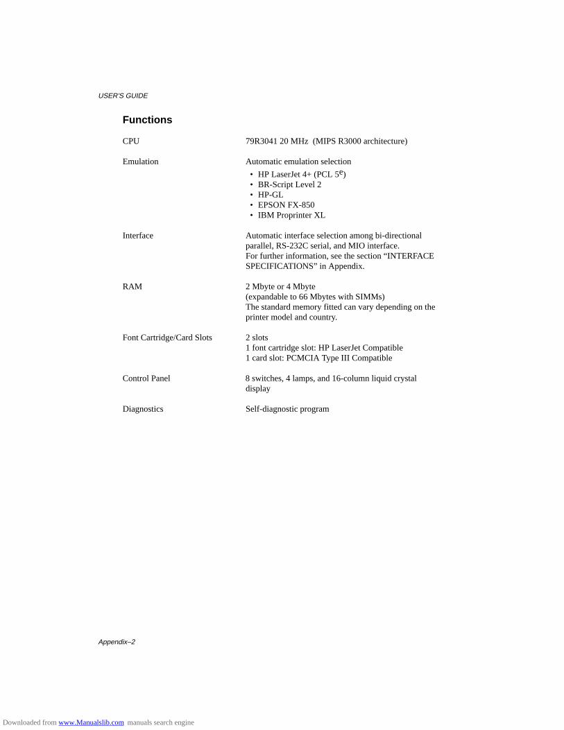
USER’S GUIDE
Appendix–2
Functions
CPU 79R3041 20 MHz (MIPS R3000 architecture)
Emulation Automatic emulation selection
• HP LaserJet 4+ (PCL 5e) • BR-Script Level 2 • HP-GL • EPSON FX-850 • IBM Proprinter XL
Interface Automatic interface selection among bi-directionalparallel, RS-232C serial, and MIO interface.For further information, see the section “INTERFACESPECIFICATIONS” in Appendix.
RAM 2 Mbyte or 4 Mbyte
(expandable to 66 Mbytes with SIMMs)The standard memory fitted can vary depending on the printer model and country.
Font Cartridge/Card Slots 2 slots1 font cartridge slot: HP LaserJet Compatible1 card slot: PCMCIA Type III Compatible
Control Panel 8 switches, 4 lamps, and 16-column liquid crystal display
Diagnostics Self-diagnostic program
Downloaded from www.Manualslib.com manuals search engine

APPENDICES
Appendix–3
Electrical and Mechanical
Power Source U.S.A. and Canada: AC 110 to 120 V, 60 HzEurope and Australia: AC 220 to 240 V, 50 Hz
Power Consumption <HL-1260e> Printing: 290 W or lessStand-by: 75 W or lessStand-by in sleep mode: 16 W or less
<HL-1660> Printing: 340 W or lessStand-by: 75 W or lessStand-by in sleep mode: 16 W or less
Noise <HL-1260e> Printing: 49 dB A or lessStand-by: 40 dB A or less
<HL-1660> Printing: 52 dB A or lessStand-by: 45 dB A or less
Temperature Operating: 10 to 32.5°C (50°F to 90.5°F)Storage: 0 to 35°C (38°F to 95°F)
Humidity Operating: 20 to 80% (without condensation)Storage: 10 to 80% (without condensation)
Dimensions (W x H x D) 371.6 x 326.5 x 393 mm (14.8 x 12.9 x 15.5 inches)371.6 x 446.5 x 393 mm (14.8 x 17.6 x 15.5 inches) with an optional lower tray unit fitted
Weight Approx. 15 kg (33 lbs.)Approx. 21.0 kg (46.3 lbs.) with optional lower trayunit and toner cartridge fitted .
Downloaded from www.Manualslib.com manuals search engine
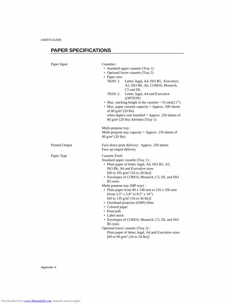
USER’S GUIDE
Appendix–4
PAPER SPECIFICATIONS
Paper Input Cassettes : • Standard upper cassette (Tray 1) • Optional lower cassette (Tray 2) • Paper size:
TRAY 1: Letter, legal, A4, ISO B5, Executive,A5, ISO B6, A6, COM10, Monarch,C5 and DL
TRAY 2: Letter, legal, A4 and Executive(OPTION)
• Max. stacking height in the cassette = 55 mm(2.1”) • Max. paper cassette capacity = Approx. 500 sheets
of 80 g/m2 (20 lbs)when duplex unit installed = Approx. 250 sheets of 80 g/m2 (20 lbs) A4/letter (Tray 1)
Multi-purpose tray :Multi-purpose tray capacity = Approx. 150 sheets of80 g/m2 (20 lbs)
Printed Output Face down print delivery: Approx. 250 sheetsFace up output delivery
Paper Type Cassette Feed:Standard upper cassette (Tray 1) : • Plain paper of letter, legal, A4, ISO B5, A5,
ISO B6, A6 and Executive sizes[60 to 105 g/m2 (16 to 28 lbs)]
• Envelopes of COM10, Monarch, C5, DL and ISOB5 sizes
Multi-purpose tray (MP tray) : • Plain paper from 90 x 148 mm to 216 x 356 mm
(from 3.5” x 5.8” to 8.5” x 14”)[60 to 135 g/m2 (16 to 36 lbs)]
• Overhead projector (OHP) films • Colored paper • Postcards • Label stock • Envelopes of COM10, Monarch, C5, DL and ISO
B5 sizesOptional lower cassette (Tray 2) :
Plain paper of letter, legal, A4 and Executive sizes[60 to 90 g/m2 (16 to 24 lbs)]
Downloaded from www.Manualslib.com manuals search engine
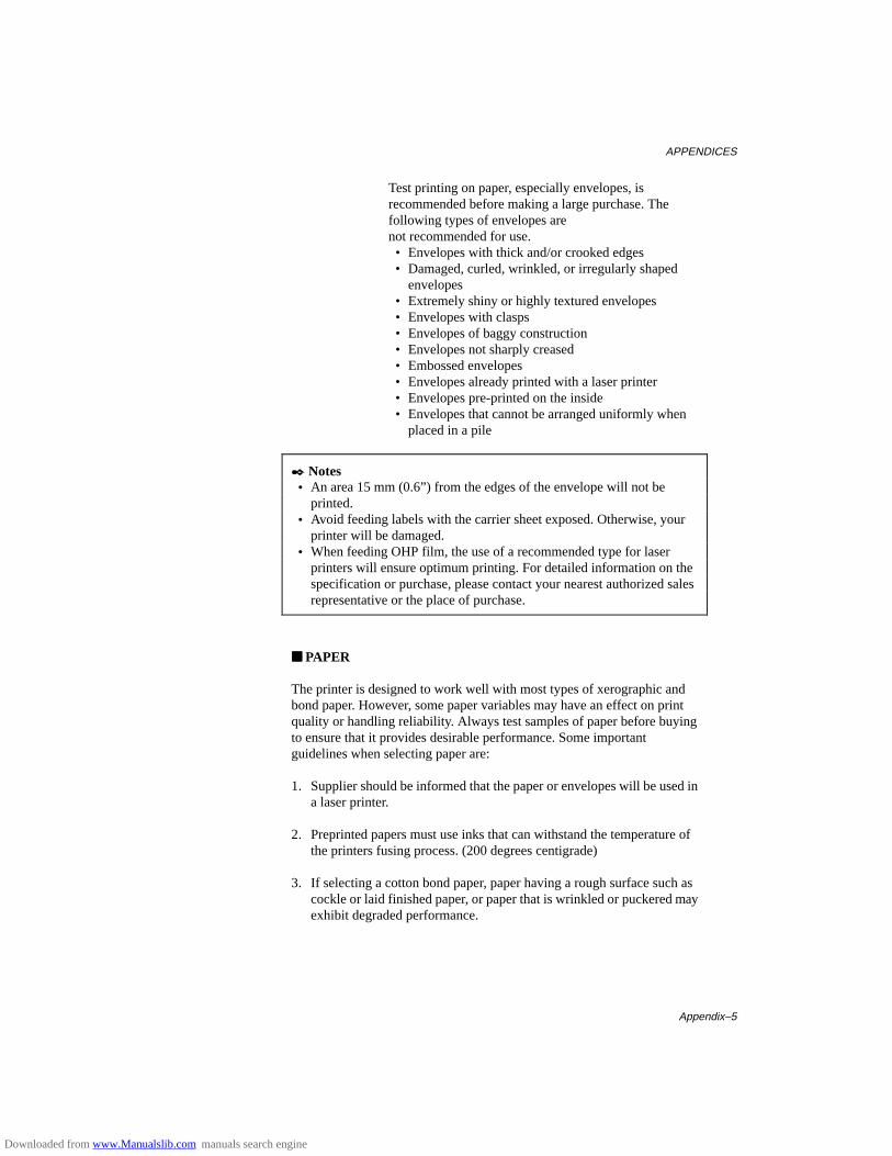
APPENDICES
Appendix–5
Test printing on paper, especially envelopes, isrecommended before making a large purchase. The following types of envelopes arenot recommended for use. • Envelopes with thick and/or crooked edges • Damaged, curled, wrinkled, or irregularly shaped
envelopes • Extremely shiny or highly textured envelopes • Envelopes with clasps • Envelopes of baggy construction • Envelopes not sharply creased • Embossed envelopes • Envelopes already printed with a laser printer • Envelopes pre-printed on the inside • Envelopes that cannot be arranged uniformly when
placed in a pile
✒ Notes • An area 15 mm (0.6”) from the edges of the envelope will not be
printed. • Avoid feeding labels with the carrier sheet exposed. Otherwise, your
printer will be damaged. • When feeding OHP film, the use of a recommended type for laser
printers will ensure optimum printing. For detailed information on thespecification or purchase, please contact your nearest authorized salesrepresentative or the place of purchase.
■■ PAPER
The printer is designed to work well with most types of xerographic andbond paper. However, some paper variables may have an effect on printquality or handling reliability. Always test samples of paper before buyingto ensure that it provides desirable performance. Some importantguidelines when selecting paper are:
1. Supplier should be informed that the paper or envelopes will be used ina laser printer.
2. Preprinted papers must use inks that can withstand the temperature ofthe printers fusing process. (200 degrees centigrade)
3. If selecting a cotton bond paper, paper having a rough surface such ascockle or laid finished paper, or paper that is wrinkled or puckered mayexhibit degraded performance.
Downloaded from www.Manualslib.com manuals search engine
USER’S GUIDE
Appendix–6
✒ NoteThe manufacturer neither warrants or recommends the use of any particularpaper. The operator is responsible for the quality of paper used with theprinter.
Paper Types to Avoid
Some types of paper might not perform well or may cause damage to yourprinter.
Types of paper to avoid are:
1. Highly textured paper.2. Smooth or shiny paper.3. Paper that is coated or has a chemical finish.4. Damaged, wrinkled or prefolded paper.5. Paper exceeding the recommend weight specification specified in the
manual.6. Paper with tabs and staples.7. Letterheads using low temperature dyes or thermography.8. Multipart or carbonless paper.
DAMAGE OR OTHER DEFECTS CAUSED BY THE USE OFPAPERS LISTED UNDER “PAPER TYPES TO AVOID” WILL NOTBE COVERED UNDER ANY WARRANTY OR SERVICEAGREEMENTS.
■■ ENVELOPES
Most envelopes will perform acceptably on your printer. However; someenvelopes will have feeding and print quality problems because of theirconstruction. A suitable envelope should have edges with a straight, wellcreased folds and should not have more than two thickness of paper alongthe lead edge. The envelope should lie flat and not have baggy or flimsyconstruction. Purchase quality envelopes only from a supplier whounderstands that the envelopes will be used in a laser printer. All envelopesshould be tested prior to use to ensure desirable print results.
Envelope Types to Avoid
1. Envelopes constructed with a paper with a weight that exceeds thepaper weight specifications for the printer.
2. Poorly manufactured envelopes with edges that are not straight orconsistently square.
3. Envelopes with “baggy” construction or folds that are not sharplycreased.
4. Envelopes with transparent windows, holes, cutouts or perforations.
Downloaded from www.Manualslib.com manuals search engine

APPENDICES
Appendix–7
5. Envelopes with clasps, snaps or tie strings.6. Envelopes made with smooth or shiny paper.7. Envelopes that are rough, highly textured, or deeply embossed.8. Envelopes which do not lie flat or that are curled, wrinkled, or
irregularly shaped.9. Envelopes having an open flap with an adhesive that seals the envelope.
USE OF ANY OF THE ENVELOPES LISTED ABOVE MAYCAUSE DAMAGE TO YOUR PRINTER. SUCH DAMAGE IS NOTCOVERED UNDER ANY WARRANTY OR SERVICEAGREEMENT.
✒ NoteThe manufacturer neither warrants nor recommends the use of a particularenvelope because envelope properties are subject to change by theenvelope manufacturer. The entire responsibility for the quality andperformance of the envelope lies with the customer.
■■ LABELS AND OVERHEAD TRANSPARENCIES
The printer will print on most type of labels and transparencies designed foruse with a laser printer. Labels should have an adhesive that is acrylic-basedsince such material is more stable at the high temperatures in the fusingunit. Adhesives should not come in contact with any part of the printer,because the label stock may stick to the drum or rollers and cause jams andprint quality problems. No adhesive should be exposed between the labels.Labels should be arranged so that they cover the entire page with the onlyexposed spaces being lengthwise down the sheet. Using labels with spacesmay result in labels peeling off and causing serious jam or print problems.
All labels and transparencies used in this printer must be able to withstand atemperature of 200 degrees centigrade (392 degrees Fahrenheit) for aperiod of 0.1 seconds.
Label and transparency sheets should not exceed the paper weightspecifications described in the User’s Guide. Labels and transparenciesexceeding this specification may not feed or print properly and causedamage to your printer.
The entire responsibility for the quality and performance of labels andtransparencies lies with the customer.
DAMAGE CAUSED BY THE USE OF UNSATISFACTORYLABELS OR TRANSPARENCIES IS NOT COVERED UNDERANY WARRANTY OR SERVICE AGREEMENTS.
Downloaded from www.Manualslib.com manuals search engine
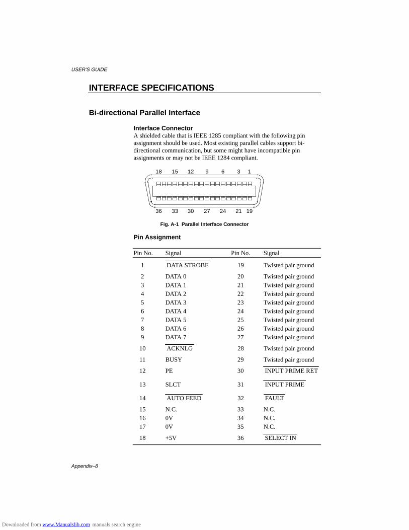
USER’S GUIDE
Appendix–8
INTERFACE SPECIFICATIONS
Bi-directional Parallel Interface
Interface ConnectorA shielded cable that is IEEE 1285 compliant with the following pinassignment should be used. Most existing parallel cables support bi-directional communication, but some might have incompatible pinassignments or may not be IEEE 1284 compliant.
18 15 12 9 6 3 1
36 33 30 27 24 21 19
Fig. A-1 Parallel Interface Connector
Pin Assignment
Pin No. Signal Pin No. Signal
1 DATA STROBE 19 Twisted pair ground
2 DATA 0 20 Twisted pair ground3 DATA 1 21 Twisted pair ground4 DATA 2 22 Twisted pair ground5 DATA 3 23 Twisted pair ground6 DATA 4 24 Twisted pair ground7 DATA 5 25 Twisted pair ground8 DATA 6 26 Twisted pair ground9 DATA 7 27 Twisted pair ground
10 ACKNLG 28 Twisted pair ground
11 BUSY 29 Twisted pair ground
12 PE 30 INPUT PRIME RET
13 SLCT 31 INPUT PRIME
14 AUTO FEED 32 FAULT
15 N.C. 33 N.C.16 0V 34 N.C.17 0V 35 N.C.
18 +5V 36 SELECT IN
Downloaded from www.Manualslib.com manuals search engine
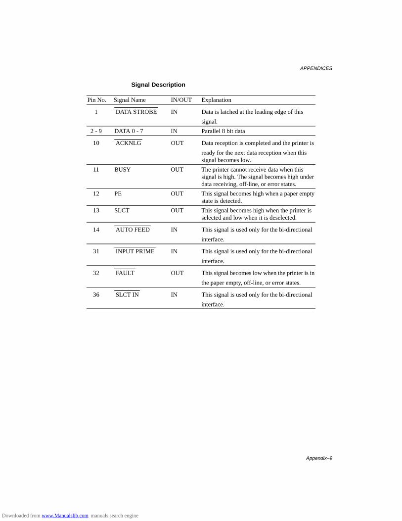
APPENDICES
Appendix–9
Signal Description
Pin No. Signal Name IN/OUT Explanation
1 DATA STROBE IN Data is latched at the leading edge of this
signal.
2 - 9 DATA 0 - 7 IN Parallel 8 bit data
10 ACKNLG OUT Data reception is completed and the printer is
ready for the next data reception when thissignal becomes low.
11 BUSY OUT The printer cannot receive data when thissignal is high. The signal becomes high underdata receiving, off-line, or error states.
12 PE OUT This signal becomes high when a paper emptystate is detected.
13 SLCT OUT This signal becomes high when the printer isselected and low when it is deselected.
14 AUTO FEED IN This signal is used only for the bi-directional
interface.
31 INPUT PRIME IN This signal is used only for the bi-directional
interface.
32 FAULT OUT This signal becomes low when the printer is in
the paper empty, off-line, or error states.
36 SLCT IN IN This signal is used only for the bi-directional
interface.
Downloaded from www.Manualslib.com manuals search engine
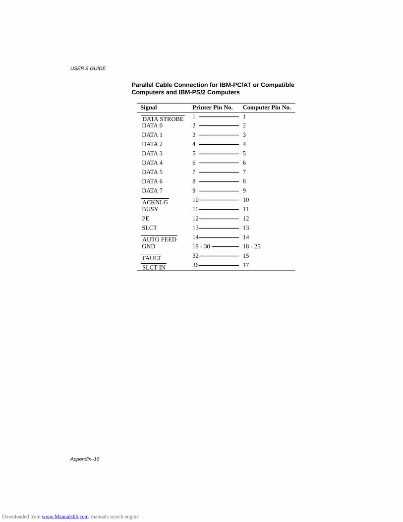
USER’S GUIDE
Appendix–10
Parallel Cable Connection for IBM-PC/AT or CompatibleComputers and IBM-PS/2 Computers
Signal Printer Pin No. Computer Pin No.
DATA STROBE 1 1
DATA 0 2 2
DATA 1 3 3
DATA 2 4 4
DATA 3 5 5
DATA 4 6 6
DATA 5 7 7
DATA 6 8 8
DATA 7 9 9
ACKNLG 10 10
BUSY 11 11
PE 12 12
SLCT 13 13
AUTO FEED 14 14
GND 19 - 30 18 - 25
FAULT 32 15
SLCT IN 36 17
Downloaded from www.Manualslib.com manuals search engine
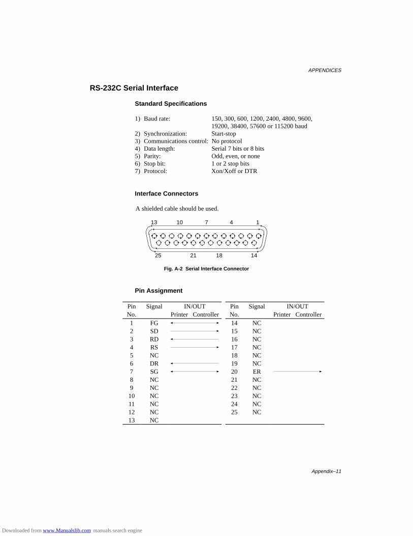
APPENDICES
Appendix–11
RS-232C Serial Interface
Standard Specifications
1) Baud rate: 150, 300, 600, 1200, 2400, 4800, 9600,19200, 38400, 57600 or 115200 baud
2) Synchronization: Start-stop3) Communications control: No protocol4) Data length: Serial 7 bits or 8 bits5) Parity: Odd, even, or none6) Stop bit: 1 or 2 stop bits7) Protocol: Xon/Xoff or DTR
Interface Connectors
A shielded cable should be used.
13 10 7 4 1
25 21 18 14
Fig. A-2 Serial Interface Connector
Pin Assignment
PinNo.
Signal IN/OUTPrinter Controller
PinNo.
Signal IN/OUTPrinter Controller
1 FG 14 NC2 SD 15 NC3 RD 16 NC4 RS 17 NC5 NC 18 NC6 DR 19 NC7 SG 20 ER8 NC 21 NC9 NC 22 NC10 NC 23 NC11 NC 24 NC12 NC 25 NC13 NC
Downloaded from www.Manualslib.com manuals search engine
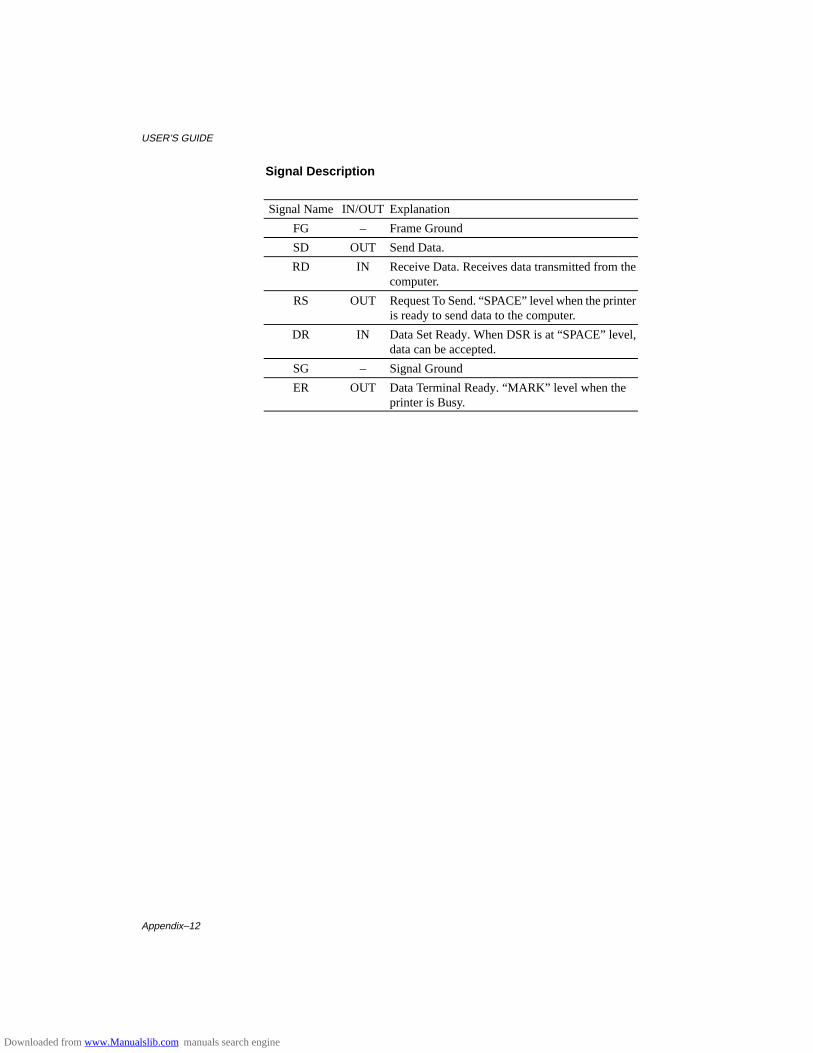
USER’S GUIDE
Appendix–12
Signal Description
Signal Name IN/OUT Explanation
FG – Frame Ground
SD OUT Send Data.
RD IN Receive Data. Receives data transmitted from thecomputer.
RS OUT Request To Send. “SPACE” level when the printeris ready to send data to the computer.
DR IN Data Set Ready. When DSR is at “SPACE” level,data can be accepted.
SG – Signal Ground
ER OUT Data Terminal Ready. “MARK” level when theprinter is Busy.
Downloaded from www.Manualslib.com manuals search engine
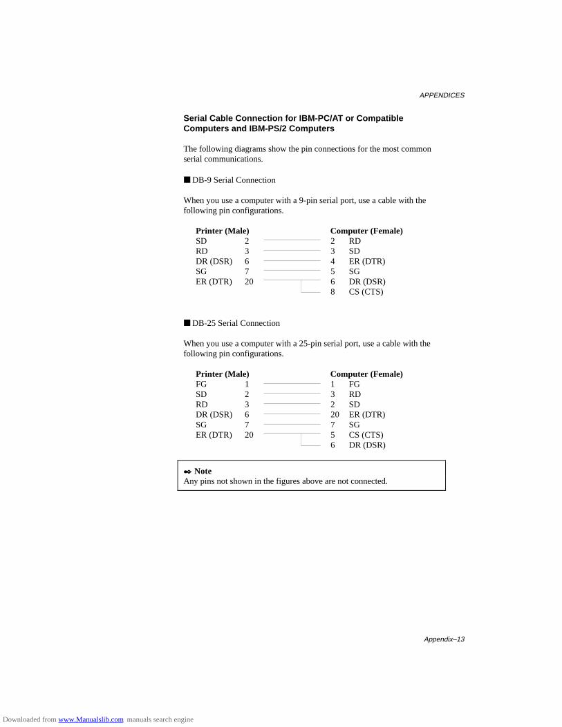
APPENDICES
Appendix–13
Serial Cable Connection for IBM-PC/AT or CompatibleComputers and IBM-PS/2 Computers
The following diagrams show the pin connections for the most commonserial communications.
■ DB-9 Serial Connection
When you use a computer with a 9-pin serial port, use a cable with thefollowing pin configurations.
Printer (Male) Computer (Female)SD 2 2 RDRD 3 3 SDDR (DSR) 6 4 ER (DTR)SG 7 5 SGER (DTR) 20 6
8DR (DSR)CS (CTS)
■ DB-25 Serial Connection
When you use a computer with a 25-pin serial port, use a cable with thefollowing pin configurations.
Printer (Male) Computer (Female)FG 1 1 FGSD 2 3 RDRD 3 2 SDDR (DSR) 6 20 ER (DTR)SG 7 7 SGER (DTR) 20 5
6CS (CTS)DR (DSR)
✒ NoteAny pins not shown in the figures above are not connected.
Downloaded from www.Manualslib.com manuals search engine
USER’S GUIDE
Appendix–14
SYMBOL/CHARACTER SETS
You can select the symbol and character sets with the FONT switch in theHP LaserJet 4+, EPSON FX-850, and IBM Proprinter XL emulationmodes. See “FONT Switch” in Chapter 4.
When you have selected the HP-GL emulation mode, you can select thestandard or alternate character set with the MODE switch. See“GRAPHICS MODE” in Chapter 4.
OCR Symbol Sets
When the OCR-A or OCR-B font is selected, the corresponding symbol setis always used.
OCR-AOCR-B
Downloaded from www.Manualslib.com manuals search engine

APPENDICES
Appendix–15
HP LaserJet 4+ Mode
Roman 8 (8U)ISO Latin1 (0N)ISO Latin2 (2N)ISO Latin5 (5N)
Downloaded from www.Manualslib.com manuals search engine

USER’S GUIDE
Appendix–16
PC-8 (10U)PC-8 D/N (11U)PC-850 (12U)PC-852 (17U)
Downloaded from www.Manualslib.com manuals search engine

APPENDICES
Appendix–17
PC-8 Turkish (9T)Windows Latin1 (19U)Windows Latin2 (9E)Windows Latin5 (5T)
Downloaded from www.Manualslib.com manuals search engine

USER’S GUIDE
Appendix–18
Legal (1U)Ventura Math (6M)Ventura Intl (13J)Ventura US (14J)
Downloaded from www.Manualslib.com manuals search engine

APPENDICES
Appendix–19
PS Math (5M)PS Text (10J)Math-8 (8M)Pi Font (15U)
Downloaded from www.Manualslib.com manuals search engine

USER’S GUIDE
Appendix–20
MS Publishing (6J)Windows 3.0 (9U)Desktop (7J)MC Text (12J)
Downloaded from www.Manualslib.com manuals search engine

APPENDICES
Appendix–21
Symbol (19M)Windings (579L)
The following table shows characters available only in the correspondingcharacter set. The numbers at the top of the table are hexadecimal codevalues with which characters are to be replaced in the Roman 8 characterset. For other characters, see the Roman 8 character set.
SYMBOL SET 23 24 40 5B 5C 5D 5E 60 7B 7C 7D 7EISO 2 IRVISO 4 UKISO 6 ASCIIISO10 SWE/FINISO11 SwedishISO14 JISASCIIISO15 ItalianISO16 PORISO17 SpanishISO21 GermanISO25 FrenchISO57 ChineseISO60 NOR v1ISO61 NOR v2ISO69 FrenchISO84 PORISO85 SpanishHP GermanHP Spanish
Downloaded from www.Manualslib.com manuals search engine

USER’S GUIDE
Appendix–22
EPSON Mode
US ASCII
The following table shows characters available only in the correspondingcharacter set. The numbers at the top of the table are hexadecimal codevalues with which characters are to be replaced in the US ASCII characterset. For other characters, see the US ASCII character set.
CHARACTER SET 23 24 40 5B 5C 5D 5E 60 7B 7C 7D 7EGermanUK ASCII IFrench IDanish IItalySpanishSwedishJapaneseNorwegianDanish IIUK ASCII IIFrench IIDutchSouth African
Downloaded from www.Manualslib.com manuals search engine

APPENDICES
Appendix–23
PC-8PC-8 D/NPC-850PC-852
Downloaded from www.Manualslib.com manuals search engine

USER’S GUIDE
Appendix–24
PC-860PC-863PC-865PC-8 Turkish
Downloaded from www.Manualslib.com manuals search engine

APPENDICES
Appendix–25
IBM Mode
PC-8PC-8 D/NPC-850PC-852
Downloaded from www.Manualslib.com manuals search engine

USER’S GUIDE
Appendix–26
PC-860PC-863PC-865PC-8 Turkish
Downloaded from www.Manualslib.com manuals search engine

APPENDICES
Appendix–27
HP-GL Mode
ANSI ASCII9825 CHR. SET
Downloaded from www.Manualslib.com manuals search engine

USER’S GUIDE
Appendix–28
FRENCH/GERMANSCANDINAVIANSPANISH/LATINJIS ASCII
Downloaded from www.Manualslib.com manuals search engine

APPENDICES
Appendix–29
ROMAN8 EXT.ISO IRVISO SWEDISHISO SWEDISH:N
Downloaded from www.Manualslib.com manuals search engine

USER’S GUIDE
Appendix–30
ISO NORWAY 1ISO GERMANISO FRENCHISO U.K.
Downloaded from www.Manualslib.com manuals search engine

APPENDICES
Appendix–31
ISO ITALIANISO SPANISHISO PORTUGUESEISO NORWAY 2
Downloaded from www.Manualslib.com manuals search engine
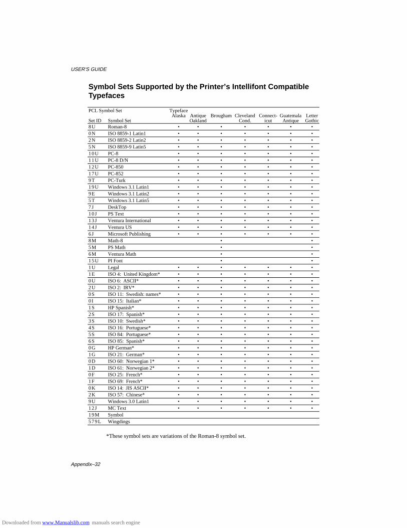
USER’S GUIDE
Appendix–32
Symbol Sets Supported by the Printer’s Intellifont CompatibleTypefaces
PCL Symbol Set TypefaceAlaska Antique Brougham Cleveland Connect- Guatemala Letter
Set ID Symbol Set Oakland Cond. icut Antique Gothic8U Roman-8 • • • • • • •0N ISO 8859-1 Latin1 • • • • • • •2N ISO 8859-2 Latin2 • • • • • • •5N ISO 8859-9 Latin5 • • • • • • •10U PC-8 • • • • • • •11U PC-8 D/N • • • • • • •12U PC-850 • • • • • • •17U PC-852 • • • • • • •9T PC-Turk • • • • • • •19U Windows 3.1 Latin1 • • • • • • •9E Windows 3.1 Latin2 • • • • • • •5T Windows 3.1 Latin5 • • • • • • •7J DeskTop • • • • • • •10J PS Text • • • • • • •13J Ventura International • • • • • • •14J Ventura US • • • • • • •6J Microsoft Publishing • • • • • • •8M Math-8 • •5M PS Math • •6M Ventura Math • •15U PI Font • •1U Legal • • • • • • •1E ISO 4: United Kingdom* • • • • • • •0U ISO 6: ASCII* • • • • • • •2U ISO 2: IRV* • • • • • • •0S ISO 11: Swedish: names* • • • • • • •0 I ISO 15: Italian* • • • • • • •1S HP Spanish* • • • • • • •2S ISO 17: Spanish* • • • • • • •3S ISO 10: Swedish* • • • • • • •4S ISO 16: Portuguese* • • • • • • •5S ISO 84: Portuguese* • • • • • • •6S ISO 85: Spanish* • • • • • • •0G HP German* • • • • • • •1G ISO 21: German* • • • • • • •0D ISO 60: Norwegian 1* • • • • • • •1D ISO 61: Norwegian 2* • • • • • • •0F ISO 25: French* • • • • • • •1F ISO 69: French* • • • • • • •0K ISO 14: JIS ASCII* • • • • • • •2K ISO 57: Chinese* • • • • • • •9U Windows 3.0 Latin1 • • • • • • •12J MC Text • • • • • • •19M Symbol579L Wingdings
*These symbol sets are variations of the Roman-8 symbol set.
Downloaded from www.Manualslib.com manuals search engine
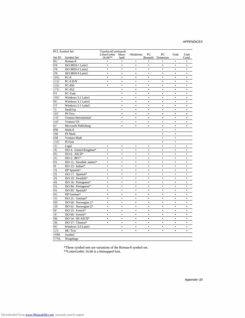
APPENDICES
Appendix–33
PCL Symbol Set Typeface(Continued)LetterGothic Mary- Oklahoma PC PC Utah Utah
Set ID Symbol Set 16.66** land Brussels Tennessee Cond.8U Roman-8 • • • • • • •0N ISO 8859-1 Latin1 • • • • • • •2N ISO 8859-2 Latin2 • • • • • • •5N ISO 8859-9 Latin5 • • • • • • •10U PC-8 • • • • • • •11U PC-8 D/N • • • • • • •12U PC-850 • • • • • • •17U PC-852 • • • • • •9T PC-Turk • • • • • •19U Windows 3.1 Latin1 • • • • • •9E Windows 3.1 Latin2 • • • • • •5T Windows 3.1 Latin5 • • • • • •7J DeskTop • • • • • •10J PS Text • • • • • •13J Ventura International • • • • • •14J Ventura US • • • • • •6J Microsoft Publishing • • • • • •8M Math-8 • •5M PS Math • •6M Ventura Math • •15U PI Font • •1U Legal • • • • • • •1E ISO 4: United Kingdom* • • • • • • •0U ISO 6: ASCII* • • • • • • •2U ISO 2: IRV* • • • • • • •0S ISO 11: Swedish: names* • • • • • • •0 I ISO 15: Italian* • • • • • • •1S HP Spanish* • • • • • • •2S ISO 17: Spanish* • • • • • • •3S ISO 10: Swedish* • • • • • • •4S ISO 16: Portuguese* • • • • • • •5S ISO 84: Portuguese* • • • • • • •6S ISO 85: Spanish* • • • • • • •0G HP German* • • • • • • •1G ISO 21: German* • • • • • • •0D ISO 60: Norwegian 1* • • • • • • •1D ISO 61: Norwegian 2* • • • • • • •0F ISO 25: French* • • • • • • •1F ISO 69: French* • • • • • • •0K ISO 14: JIS ASCII* • • • • • • •2K ISO 57: Chinese* • • • • • • •9U Windows 3.0 Latin1 • • • • • •12J MC Text • • • • • •19M Symbol579L Wingdings
*These symbol sets are variations of the Roman-8 symbol set.**LetterGothic 16.66 is a bitmapped font.
Downloaded from www.Manualslib.com manuals search engine
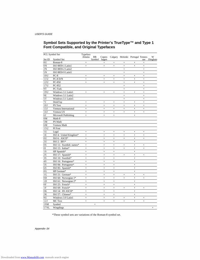
USER’S GUIDE
Appendix–34
Symbol Sets Supported by the Printer’s TrueType™ and Type 1Font Compatible, and Original Typefaces
PCL Symbol Set TypefaceAtlanta BR Copen- Calgary Helsinki Portugal Tennes- W
Set ID Symbol Set Symbol hagen seeDingbats8U Roman-8 • • • • • •0N ISO 8859-1 Latin1 • • • • • •2N ISO 8859-2 Latin2 • •5N ISO 8859-9 Latin5 • •10U PC-8 • • • • • •11U PC-8 D/N • • • • • •12U PC-850 • • • • • •17U PC-852 • •9T PC-Turk • •19U Windows 3.1 Latin1 • • • • • •9E Windows 3.1 Latin2 • •5T Windows 3.1 Latin5 • •7J DeskTop • • • • • •10J PS Text • • • • • •13J Ventura International • • • • • •14J Ventura US • • • • • •6J Microsoft Publishing • • • •8M Math-85M PS Math6M Ventura Math15U PI Font1U Legal • • • • • •1E ISO 4: United Kingdom* • • • • • •0U ISO 6: ASCII* • • • • • •2U ISO 2: IRV* • • • •0S ISO 11: Swedish: names* • • • • • •0 I ISO 15: Italian* • • • • • •1S HP Spanish* • • • •2S ISO 17: Spanish* • • • • • •3S ISO 10: Swedish* • • • •4S ISO 16: Portuguese* • • • •5S ISO 84: Portuguese* • • • •6S ISO 85: Spanish* • • • •0G HP German* • • • •1G ISO 21: German* • • • • • •0D ISO 60: Norwegian 1* • • • • • •1D ISO 61: Norwegian 2* • • • •0F ISO 25: French* • • • •1F ISO 69: French* • • • • • •0K ISO 14: JIS ASCII* • • • •2K ISO 57: Chinese* • • • •9U Windows 3.0 Latin1 • • • • • •12J MC Text • • • • • •19M Symbol •579L Wingdings •
*These symbol sets are variations of the Roman-8 symbol set.
Downloaded from www.Manualslib.com manuals search engine
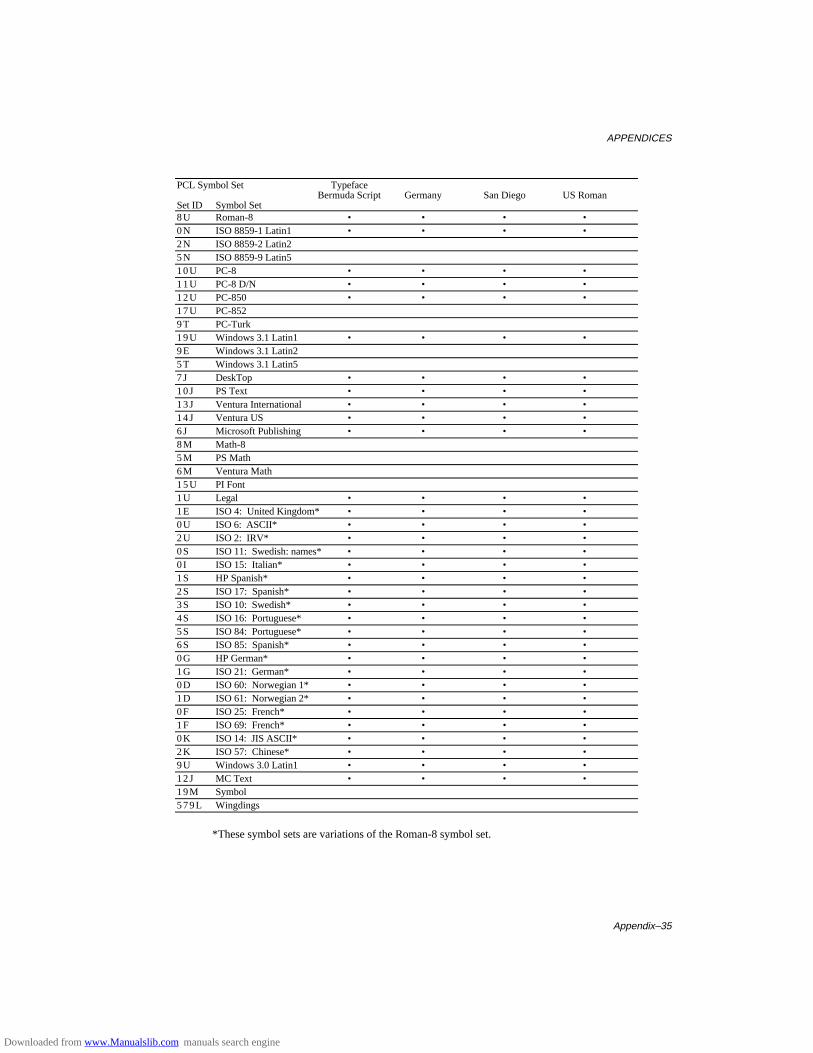
APPENDICES
Appendix–35
PCL Symbol Set TypefaceBermuda Script Germany San Diego US Roman
Set ID Symbol Set 8U Roman-8 • • • •0N ISO 8859-1 Latin1 • • • •2N ISO 8859-2 Latin25N ISO 8859-9 Latin510U PC-8 • • • •11U PC-8 D/N • • • •12U PC-850 • • • •17U PC-8529T PC-Turk19U Windows 3.1 Latin1 • • • •9E Windows 3.1 Latin25T Windows 3.1 Latin57J DeskTop • • • •10J PS Text • • • •13J Ventura International • • • •14J Ventura US • • • •6J Microsoft Publishing • • • •8M Math-85M PS Math6M Ventura Math15U PI Font1U Legal • • • •1E ISO 4: United Kingdom* • • • •0U ISO 6: ASCII* • • • •2U ISO 2: IRV* • • • •0S ISO 11: Swedish: names* • • • •0 I ISO 15: Italian* • • • •1S HP Spanish* • • • •2S ISO 17: Spanish* • • • •3S ISO 10: Swedish* • • • •4S ISO 16: Portuguese* • • • •5S ISO 84: Portuguese* • • • •6S ISO 85: Spanish* • • • •0G HP German* • • • •1G ISO 21: German* • • • •0D ISO 60: Norwegian 1* • • • •1D ISO 61: Norwegian 2* • • • •0F ISO 25: French* • • • •1F ISO 69: French* • • • •0K ISO 14: JIS ASCII* • • • •2K ISO 57: Chinese* • • • •9U Windows 3.0 Latin1 • • • •12J MC Text • • • •19M Symbol579L Wingdings
*These symbol sets are variations of the Roman-8 symbol set.
Downloaded from www.Manualslib.com manuals search engine
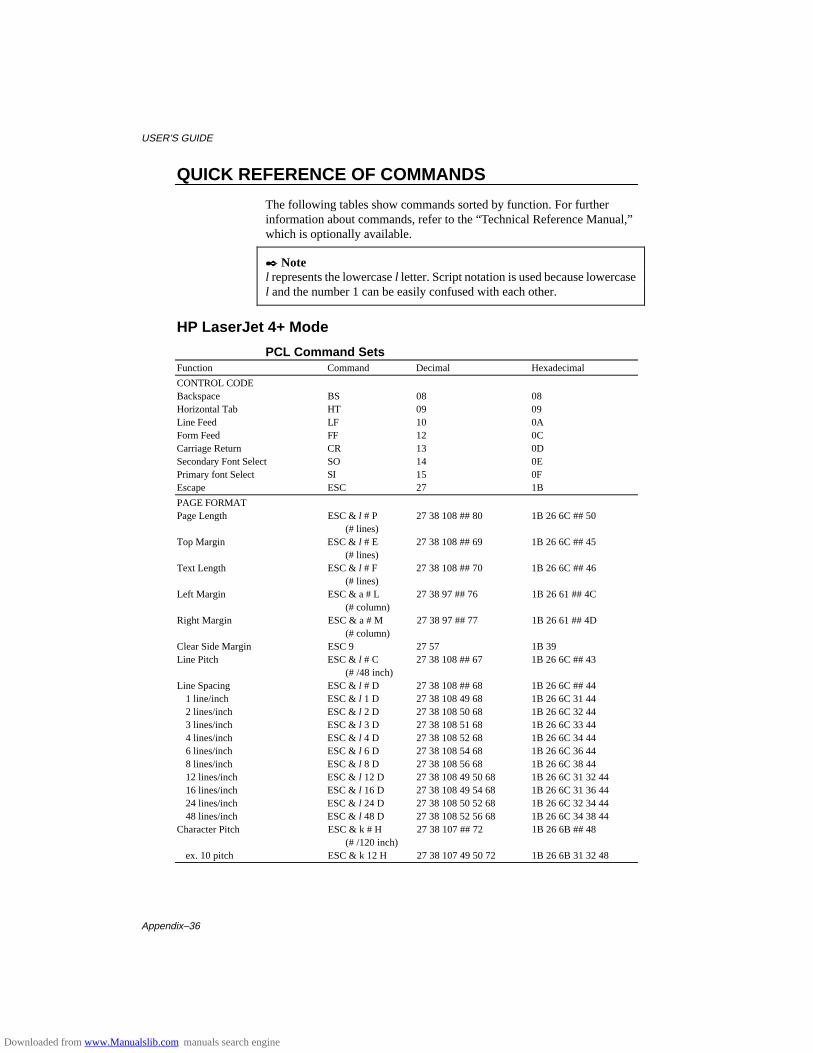
USER’S GUIDE
Appendix–36
QUICK REFERENCE OF COMMANDS
The following tables show commands sorted by function. For furtherinformation about commands, refer to the “Technical Reference Manual,”which is optionally available.
✒ Notel represents the lowercase l letter. Script notation is used because lowercasel and the number 1 can be easily confused with each other.
HP LaserJet 4+ Mode
PCL Command SetsFunction Command Decimal Hexadecimal
CONTROL CODEBackspace BS 08 08Horizontal Tab HT 09 09Line Feed LF 10 0AForm Feed FF 12 0CCarriage Return CR 13 0DSecondary Font Select SO 14 0EPrimary font Select SI 15 0FEscape ESC 27 1B
PAGE FORMATPage Length ESC & l # P 27 38 108 ## 80 1B 26 6C ## 50
(# lines)Top Margin ESC & l # E 27 38 108 ## 69 1B 26 6C ## 45
(# lines)Text Length ESC & l # F 27 38 108 ## 70 1B 26 6C ## 46
(# lines)Left Margin ESC & a # L 27 38 97 ## 76 1B 26 61 ## 4C
(# column)Right Margin ESC & a # M 27 38 97 ## 77 1B 26 61 ## 4D
(# column)Clear Side Margin ESC 9 27 57 1B 39Line Pitch ESC & l # C 27 38 108 ## 67 1B 26 6C ## 43
(# /48 inch)Line Spacing ESC & l # D 27 38 108 ## 68 1B 26 6C ## 44
1 line/inch ESC & l 1 D 27 38 108 49 68 1B 26 6C 31 442 lines/inch ESC & l 2 D 27 38 108 50 68 1B 26 6C 32 443 lines/inch ESC & l 3 D 27 38 108 51 68 1B 26 6C 33 444 lines/inch ESC & l 4 D 27 38 108 52 68 1B 26 6C 34 446 lines/inch ESC & l 6 D 27 38 108 54 68 1B 26 6C 36 448 lines/inch ESC & l 8 D 27 38 108 56 68 1B 26 6C 38 4412 lines/inch ESC & l 12 D 27 38 108 49 50 68 1B 26 6C 31 32 4416 lines/inch ESC & l 16 D 27 38 108 49 54 68 1B 26 6C 31 36 4424 lines/inch ESC & l 24 D 27 38 108 50 52 68 1B 26 6C 32 34 4448 lines/inch ESC & l 48 D 27 38 108 52 56 68 1B 26 6C 34 38 44
Character Pitch ESC & k # H 27 38 107 ## 72 1B 26 6B ## 48(# /120 inch)
ex. 10 pitch ESC & k 12 H 27 38 107 49 50 72 1B 26 6B 31 32 48
Downloaded from www.Manualslib.com manuals search engine
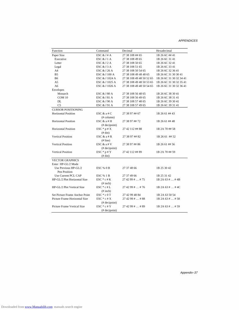
APPENDICES
Appendix–37
Function Command Decimal Hexadecimal
Paper Size ESC & l # A 27 38 108 ## 65 1B 26 6C ## 41Executive ESC & l 1 A 27 38 108 49 65 1B 26 6C 31 41Letter ESC & l 2 A 27 38 108 50 65 1B 26 6C 32 41Legal ESC & l 3 A 27 38 108 51 65 1B 26 6C 33 41A4 ESC & l 26 A 27 38 108 50 54 65 1B 26 6C 32 36 41B5 ESC & l 100 A 27 38 108 49 48 48 65 1B 26 6C 31 30 30 41B6 ESC & l 1024 A 27 38 108 49 48 50 52 65 1B 26 6C 31 30 32 34 41A5 ESC & l 1025 A 27 38 108 49 48 50 53 65 1B 26 6C 31 30 32 35 41A6 ESC & l 1026 A 27 38 108 49 48 50 54 65 1B 26 6C 31 30 32 36 41
EnvelopesMonarch ESC & l 80 A 27 38 108 56 48 65 1B 26 6C 38 30 41COM 10 ESC & l 81 A 27 38 108 56 49 65 1B 26 6C 38 31 41DL ESC & l 90 A 27 38 108 57 48 65 1B 26 6C 39 30 41C5 ESC & l 91 A 27 38 108 57 49 65 1B 26 6C 39 31 41
CURSOR POSITIONINGHorizontal Position ESC & a # C 27 38 97 ## 67 1B 26 61 ## 43
(# column)Horizontal Position ESC & a # H 27 38 97 ## 72 1B 26 61 ## 48
(# decipoint)Horizontal Position ESC * p # X 27 42 112 ## 88 1B 2A 70 ## 58
(# dot)Vertical Position ESC & a # R 27 38 97 ## 82 1B 26 61 ## 52
(# line)Vertical Position ESC & a # V 27 38 97 ## 86 1B 26 61 ## 56
(# decipoint)Vertical Position ESC * p # Y 27 42 112 ## 89 1B 2A 70 ## 59
(# dot)
VECTOR GRAPHICSEnter HP-GL/2 Mode
Use Previous HP-GL/2 ESC % 0 B 27 37 48 66 1B 25 30 42 Pen PositionUse Current PCL CAP ESC % 1 B 27 37 49 66 1B 25 31 42
HP-GL/2 Plot Horizontal Size ESC * c # K 27 42 99 # … # 75 1B 2A 63 # … # 4B(# inch)
HP-GL/2 Plot Vertical Size ESC * c # L 27 42 99 # … # 76 1B 2A 63 # … # 4C(# inch)
Set Picture Frame Anchor Point ESC * c 0 T 27 42 99 48 84 1B 2A 63 50 54Picture Frame Horizontal Size ESC * c # X 27 42 99 # … # 88 1B 2A 63 # … # 58
(# decipoint)Picture Frame Vertical Size ESC * c # Y 27 42 99 # … # 89 1B 2A 63 # … # 59
(# decipoint)
Downloaded from www.Manualslib.com manuals search engine
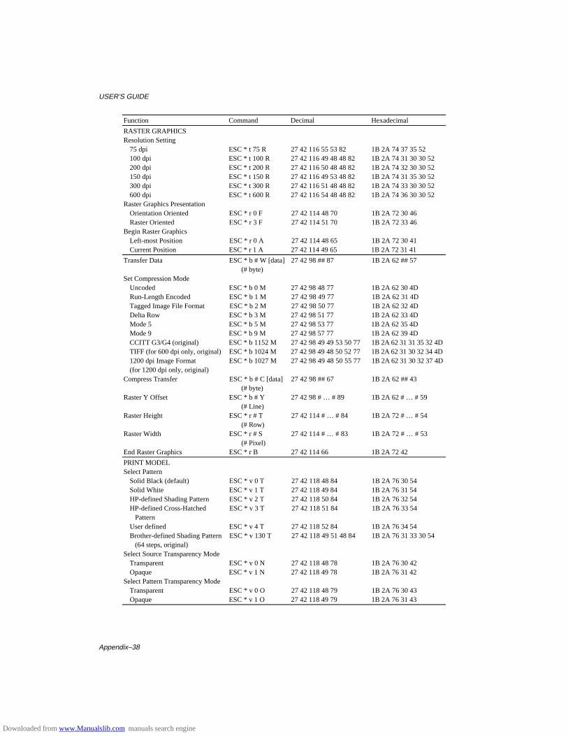
USER’S GUIDE
Appendix–38
Function Command Decimal Hexadecimal
RASTER GRAPHICSResolution Setting
75 dpi ESC * t 75 R 27 42 116 55 53 82 1B 2A 74 37 35 52100 dpi ESC * t 100 R 27 42 116 49 48 48 82 1B 2A 74 31 30 30 52200 dpi ESC * t 200 R 27 42 116 50 48 48 82 1B 2A 74 32 30 30 52150 dpi ESC * t 150 R 27 42 116 49 53 48 82 1B 2A 74 31 35 30 52300 dpi ESC * t 300 R 27 42 116 51 48 48 82 1B 2A 74 33 30 30 52600 dpi ESC * t 600 R 27 42 116 54 48 48 82 1B 2A 74 36 30 30 52
Raster Graphics PresentationOrientation Oriented ESC * r 0 F 27 42 114 48 70 1B 2A 72 30 46Raster Oriented ESC * r 3 F 27 42 114 51 70 1B 2A 72 33 46
Begin Raster GraphicsLeft-most Position ESC * r 0 A 27 42 114 48 65 1B 2A 72 30 41Current Position ESC * r 1 A 27 42 114 49 65 1B 2A 72 31 41
Transfer Data ESC * b # W [data] 27 42 98 ## 87 1B 2A 62 ## 57(# byte)
Set Compression ModeUncoded ESC * b 0 M 27 42 98 48 77 1B 2A 62 30 4DRun-Length Encoded ESC * b 1 M 27 42 98 49 77 1B 2A 62 31 4DTagged Image File Format ESC * b 2 M 27 42 98 50 77 1B 2A 62 32 4DDelta Row ESC * b 3 M 27 42 98 51 77 1B 2A 62 33 4DMode 5 ESC * b 5 M 27 42 98 53 77 1B 2A 62 35 4DMode 9 ESC * b 9 M 27 42 98 57 77 1B 2A 62 39 4DCCITT G3/G4 (original) ESC * b 1152 M 27 42 98 49 49 53 50 77 1B 2A 62 31 31 35 32 4DTIFF (for 600 dpi only, original) ESC * b 1024 M 27 42 98 49 48 50 52 77 1B 2A 62 31 30 32 34 4D1200 dpi Image Format ESC * b 1027 M 27 42 98 49 48 50 55 77 1B 2A 62 31 30 32 37 4D(for 1200 dpi only, original)
Compress Transfer ESC * b # C [data] 27 42 98 ## 67 1B 2A 62 ## 43(# byte)
Raster Y Offset ESC * b # Y 27 42 98 # … # 89 1B 2A 62 # … # 59(# Line)
Raster Height ESC * r # T 27 42 114 # … # 84 1B 2A 72 # … # 54(# Row)
Raster Width ESC * r # S 27 42 114 # … # 83 1B 2A 72 # … # 53(# Pixel)
End Raster Graphics ESC * r B 27 42 114 66 1B 2A 72 42
PRINT MODELSelect Pattern
Solid Black (default) ESC * v 0 T 27 42 118 48 84 1B 2A 76 30 54Solid White ESC * v 1 T 27 42 118 49 84 1B 2A 76 31 54HP-defined Shading Pattern ESC * v 2 T 27 42 118 50 84 1B 2A 76 32 54HP-defined Cross-Hatched ESC * v 3 T 27 42 118 51 84 1B 2A 76 33 54 PatternUser defined ESC * v 4 T 27 42 118 52 84 1B 2A 76 34 54Brother-defined Shading Pattern ESC * v 130 T 27 42 118 49 51 48 84 1B 2A 76 31 33 30 54 (64 steps, original)
Select Source Transparency ModeTransparent ESC * v 0 N 27 42 118 48 78 1B 2A 76 30 42Opaque ESC * v 1 N 27 42 118 49 78 1B 2A 76 31 42
Select Pattern Transparency ModeTransparent ESC * v 0 O 27 42 118 48 79 1B 2A 76 30 43Opaque ESC * v 1 O 27 42 118 49 79 1B 2A 76 31 43
Downloaded from www.Manualslib.com manuals search engine
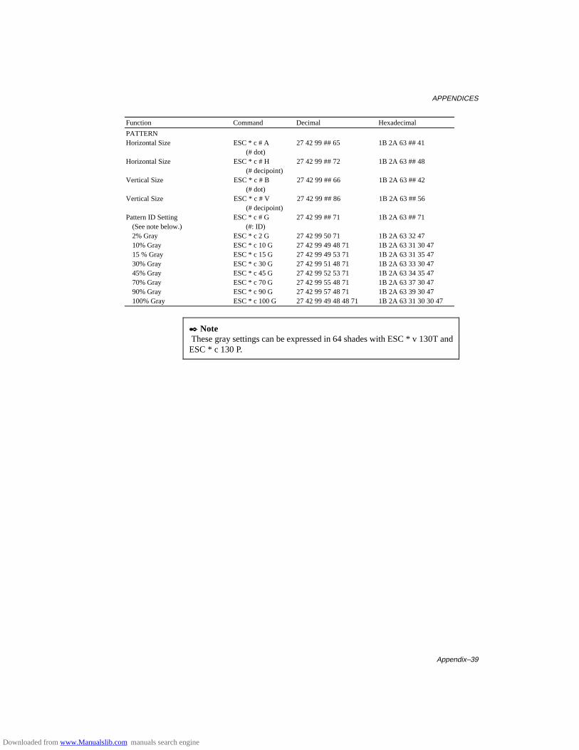
APPENDICES
Appendix–39
Function Command Decimal Hexadecimal
PATTERNHorizontal Size ESC * c # A 27 42 99 ## 65 1B 2A 63 ## 41
(# dot)Horizontal Size ESC * c # H 27 42 99 ## 72 1B 2A 63 ## 48
(# decipoint)Vertical Size ESC * c # B 27 42 99 ## 66 1B 2A 63 ## 42
(# dot)Vertical Size ESC * c # V 27 42 99 ## 86 1B 2A 63 ## 56
(# decipoint)Pattern ID Setting ESC * c # G 27 42 99 ## 71 1B 2A 63 ## 71
(See note below.) (#: ID)2% Gray ESC * c 2 G 27 42 99 50 71 1B 2A 63 32 4710% Gray ESC * c 10 G 27 42 99 49 48 71 1B 2A 63 31 30 4715 % Gray ESC * c 15 G 27 42 99 49 53 71 1B 2A 63 31 35 4730% Gray ESC * c 30 G 27 42 99 51 48 71 1B 2A 63 33 30 4745% Gray ESC * c 45 G 27 42 99 52 53 71 1B 2A 63 34 35 4770% Gray ESC * c 70 G 27 42 99 55 48 71 1B 2A 63 37 30 4790% Gray ESC * c 90 G 27 42 99 57 48 71 1B 2A 63 39 30 47100% Gray ESC * c 100 G 27 42 99 49 48 48 71 1B 2A 63 31 30 30 47
✒ Note These gray settings can be expressed in 64 shades with ESC * v 130T andESC * c 130 P.
Downloaded from www.Manualslib.com manuals search engine
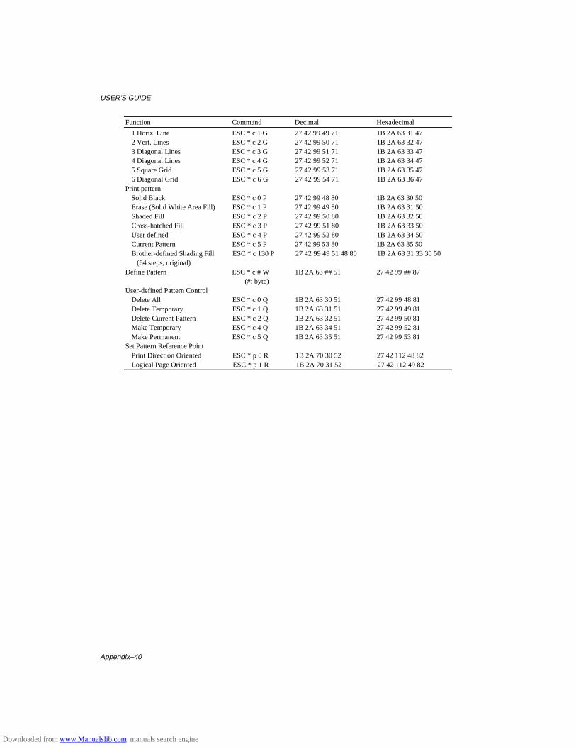
USER’S GUIDE
Appendix–40
Function Command Decimal Hexadecimal
1 Horiz. Line ESC * c 1 G 27 42 99 49 71 1B 2A 63 31 472 Vert. Lines ESC * c 2 G 27 42 99 50 71 1B 2A 63 32 473 Diagonal Lines ESC * c 3 G 27 42 99 51 71 1B 2A 63 33 474 Diagonal Lines ESC * c 4 G 27 42 99 52 71 1B 2A 63 34 475 Square Grid ESC * c 5 G 27 42 99 53 71 1B 2A 63 35 476 Diagonal Grid ESC * c 6 G 27 42 99 54 71 1B 2A 63 36 47
Print patternSolid Black ESC * c 0 P 27 42 99 48 80 1B 2A 63 30 50Erase (Solid White Area Fill) ESC * c 1 P 27 42 99 49 80 1B 2A 63 31 50Shaded Fill ESC * c 2 P 27 42 99 50 80 1B 2A 63 32 50Cross-hatched Fill ESC * c 3 P 27 42 99 51 80 1B 2A 63 33 50User defined ESC * c 4 P 27 42 99 52 80 1B 2A 63 34 50Current Pattern ESC * c 5 P 27 42 99 53 80 1B 2A 63 35 50Brother-defined Shading Fill ESC * c 130 P 27 42 99 49 51 48 80 1B 2A 63 31 33 30 50 (64 steps, original)
Define Pattern ESC * c # W 1B 2A 63 ## 51 27 42 99 ## 87(#: byte)
User-defined Pattern ControlDelete All ESC * c 0 Q 1B 2A 63 30 51 27 42 99 48 81Delete Temporary ESC * c 1 Q 1B 2A 63 31 51 27 42 99 49 81Delete Current Pattern ESC * c 2 Q 1B 2A 63 32 51 27 42 99 50 81Make Temporary ESC * c 4 Q 1B 2A 63 34 51 27 42 99 52 81Make Permanent ESC * c 5 Q 1B 2A 63 35 51 27 42 99 53 81
Set Pattern Reference PointPrint Direction Oriented ESC * p 0 R 1B 2A 70 30 52 27 42 112 48 82Logical Page Oriented ESC * p 1 R 1B 2A 70 31 52 27 42 112 49 82
Downloaded from www.Manualslib.com manuals search engine
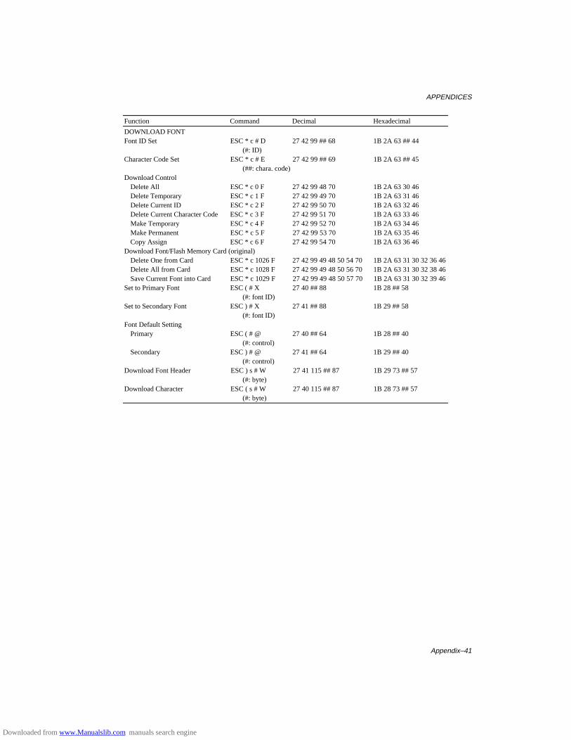
APPENDICES
Appendix–41
Function Command Decimal Hexadecimal
DOWNLOAD FONTFont ID Set ESC * c # D 27 42 99 ## 68 1B 2A 63 ## 44
(#: ID)Character Code Set ESC * c # E 27 42 99 ## 69 1B 2A 63 ## 45
(##: chara. code)Download Control
Delete All ESC * c 0 F 27 42 99 48 70 1B 2A 63 30 46Delete Temporary ESC * c 1 F 27 42 99 49 70 1B 2A 63 31 46Delete Current ID ESC * c 2 F 27 42 99 50 70 1B 2A 63 32 46Delete Current Character Code ESC * c 3 F 27 42 99 51 70 1B 2A 63 33 46Make Temporary ESC * c 4 F 27 42 99 52 70 1B 2A 63 34 46Make Permanent ESC * c 5 F 27 42 99 53 70 1B 2A 63 35 46Copy Assign ESC * c 6 F 27 42 99 54 70 1B 2A 63 36 46
Download Font/Flash Memory Card (original)Delete One from Card ESC * c 1026 F 27 42 99 49 48 50 54 70 1B 2A 63 31 30 32 36 46Delete All from Card ESC * c 1028 F 27 42 99 49 48 50 56 70 1B 2A 63 31 30 32 38 46Save Current Font into Card ESC * c 1029 F 27 42 99 49 48 50 57 70 1B 2A 63 31 30 32 39 46
Set to Primary Font ESC ( # X 27 40 ## 88 1B 28 ## 58(#: font ID)
Set to Secondary Font ESC ) # X 27 41 ## 88 1B 29 ## 58(#: font ID)
Font Default SettingPrimary ESC ( # @ 27 40 ## 64 1B 28 ## 40
(#: control)Secondary ESC ) # @ 27 41 ## 64 1B 29 ## 40
(#: control)Download Font Header ESC ) s # W 27 41 115 ## 87 1B 29 73 ## 57
(#: byte)Download Character ESC ( s # W 27 40 115 ## 87 1B 28 73 ## 57
(#: byte)
Downloaded from www.Manualslib.com manuals search engine
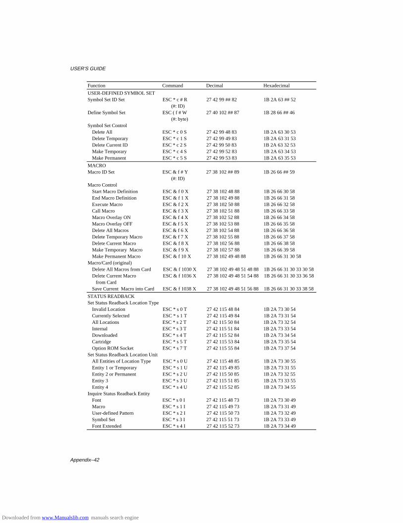
USER’S GUIDE
Appendix–42
Function Command Decimal Hexadecimal
USER-DEFINED SYMBOL SETSymbol Set ID Set ESC * c # R 27 42 99 ## 82 1B 2A 63 ## 52
(#: ID)Define Symbol Set ESC ( f # W 27 40 102 ## 87 1B 28 66 ## 46
(#: byte)Symbol Set Control
Delete All ESC * c 0 S 27 42 99 48 83 1B 2A 63 30 53Delete Temporary ESC * c 1 S 27 42 99 49 83 1B 2A 63 31 53Delete Current ID ESC * c 2 S 27 42 99 50 83 1B 2A 63 32 53Make Temporary ESC * c 4 S 27 42 99 52 83 1B 2A 63 34 53Make Permanent ESC * c 5 S 27 42 99 53 83 1B 2A 63 35 53
MACROMacro ID Set ESC & f # Y 27 38 102 ## 89 1B 26 66 ## 59
(#: ID)Macro Control
Start Macro Definition ESC & f 0 X 27 38 102 48 88 1B 26 66 30 58End Macro Definition ESC & f 1 X 27 38 102 49 88 1B 26 66 31 58Execute Macro ESC & f 2 X 27 38 102 50 88 1B 26 66 32 58Call Macro ESC & f 3 X 27 38 102 51 88 1B 26 66 33 58Macro Overlay ON ESC & f 4 X 27 38 102 52 88 1B 26 66 34 58Macro Overlay OFF ESC & f 5 X 27 38 102 53 88 1B 26 66 35 58Delete All Macros ESC & f 6 X 27 38 102 54 88 1B 26 66 36 58Delete Temporary Macro ESC & f 7 X 27 38 102 55 88 1B 26 66 37 58Delete Current Macro ESC & f 8 X 27 38 102 56 88 1B 26 66 38 58Make Temporary Macro ESC & f 9 X 27 38 102 57 88 1B 26 66 39 58Make Permanent Macro ESC & f 10 X 27 38 102 49 48 88 1B 26 66 31 30 58
Macro/Card (original)Delete All Macros from Card ESC & f 1030 X 27 38 102 49 48 51 48 88 1B 26 66 31 30 33 30 58Delete Current Macro ESC & f 1036 X 27 38 102 49 48 51 54 88 1B 26 66 31 30 33 36 58 from CardSave Current Macro into Card ESC & f 1038 X 27 38 102 49 48 51 56 88 1B 26 66 31 30 33 38 58
STATUS READBACKSet Status Readback Location Type
Invalid Location ESC * s 0 T 27 42 115 48 84 1B 2A 73 30 54Currently Selected ESC * s 1 T 27 42 115 49 84 1B 2A 73 31 54All Locations ESC * s 2 T 27 42 115 50 84 1B 2A 73 32 54Internal ESC * s 3 T 27 42 115 51 84 1B 2A 73 33 54Downloaded ESC * s 4 T 27 42 115 52 84 1B 2A 73 34 54Cartridge ESC * s 5 T 27 42 115 53 84 1B 2A 73 35 54Option ROM Socket ESC * s 7 T 27 42 115 55 84 1B 2A 73 37 54
Set Status Readback Location UnitAll Entities of Location Type ESC * s 0 U 27 42 115 48 85 1B 2A 73 30 55Entity 1 or Temporary ESC * s 1 U 27 42 115 49 85 1B 2A 73 31 55Entity 2 or Permanent ESC * s 2 U 27 42 115 50 85 1B 2A 73 32 55Entity 3 ESC * s 3 U 27 42 115 51 85 1B 2A 73 33 55Entity 4 ESC * s 4 U 27 42 115 52 85 1B 2A 73 34 55
Inquire Status Readback EntityFont ESC * s 0 I 27 42 115 48 73 1B 2A 73 30 49Macro ESC * s 1 I 27 42 115 49 73 1B 2A 73 31 49User-defined Pattern ESC * s 2 I 27 42 115 50 73 1B 2A 73 32 49Symbol Set ESC * s 3 I 27 42 115 51 73 1B 2A 73 33 49Font Extended ESC * s 4 I 27 42 115 52 73 1B 2A 73 34 49
Downloaded from www.Manualslib.com manuals search engine
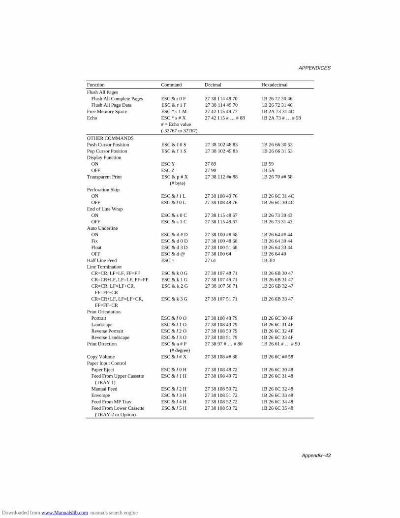
APPENDICES
Appendix–43
Function Command Decimal Hexadecimal
Flush All PagesFlush All Complete Pages ESC & r 0 F 27 38 114 48 70 1B 26 72 30 46Flush All Page Data ESC & r 1 F 27 38 114 49 70 1B 26 72 31 46
Free Memory Space ESC * s 1 M 27 42 115 49 77 1B 2A 73 31 4DEcho ESC * s # X 27 42 115 # … # 88 1B 2A 73 # … # 58
# = Echo value(-32767 to 32767)
OTHER COMMANDSPush Cursor Position ESC & f 0 S 27 38 102 48 83 1B 26 66 30 53Pop Cursor Position ESC & f 1 S 27 38 102 49 83 1B 26 66 31 53Display Function
ON ESC Y 27 89 1B 59OFF ESC Z 27 90 1B 5A
Transparent Print ESC & p # X 27 38 112 ## 88 1B 26 70 ## 58(# byte)
Perforation SkipON ESC & l 1 L 27 38 108 49 76 1B 26 6C 31 4COFF ESC & l 0 L 27 38 108 48 76 1B 26 6C 30 4C
End of Line WrapON ESC & s 0 C 27 38 115 48 67 1B 26 73 30 43OFF ESC & s 1 C 27 38 115 49 67 1B 26 73 31 43
Auto UnderlineON ESC & d # D 27 38 100 ## 68 1B 26 64 ## 44Fix ESC & d 0 D 27 38 100 48 68 1B 26 64 30 44Float ESC & d 3 D 27 38 100 51 68 1B 26 64 33 44OFF ESC & d @ 27 38 100 64 1B 26 64 40
Half Line Feed ESC = 27 61 1B 3DLine Termination
CR=CR, LF=LF, FF=FF ESC & k 0 G 27 38 107 48 71 1B 26 6B 30 47CR=CR+LF, LF=LF, FF=FF ESC & k 1 G 27 38 107 49 71 1B 26 6B 31 47CR=CR, LF=LF+CR, ESC & k 2 G 27 38 107 50 71 1B 26 6B 32 47 FF=FF+CRCR=CR+LF, LF=LF+CR, ESC & k 3 G 27 38 107 51 71 1B 26 6B 33 47 FF=FF+CR
Print OrientationPortrait ESC & l 0 O 27 38 108 48 79 1B 26 6C 30 4FLandscape ESC & l 1 O 27 38 108 49 79 1B 26 6C 31 4FReverse Portrait ESC & l 2 O 27 38 108 50 79 1B 26 6C 32 4FReverse Landscape ESC & l 3 O 27 38 108 51 79 1B 26 6C 33 4F
Print Direction ESC & a # P 27 38 97 # … # 80 1B 26 61 # … # 50(# degree)
Copy Volume ESC & l # X 27 38 108 ## 88 1B 26 6C ## 58Paper Input Control
Paper Eject ESC & l 0 H 27 38 108 48 72 1B 26 6C 30 48Feed From Upper Cassette ESC & l 1 H 27 38 108 49 72 1B 26 6C 31 48 (TRAY 1)Manual Feed ESC & l 2 H 27 38 108 50 72 1B 26 6C 32 48Envelope ESC & l 3 H 27 38 108 51 72 1B 26 6C 33 48Feed From MP Tray ESC & l 4 H 27 38 108 52 72 1B 26 6C 34 48Feed From Lower Cassette ESC & l 5 H 27 38 108 53 72 1B 26 6C 35 48 (TRAY 2 or Option)
Downloaded from www.Manualslib.com manuals search engine
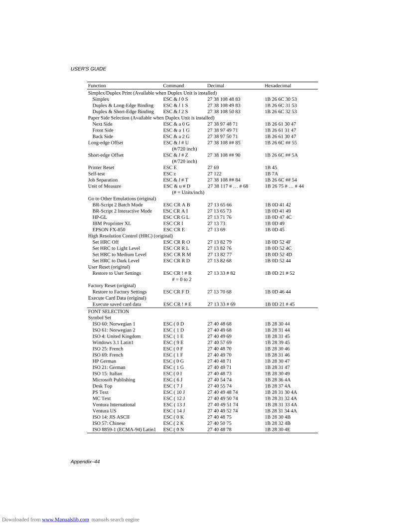
USER’S GUIDE
Appendix–44
Function Command Decimal Hexadecimal
Simplex/Duplex Print (Available when Duplex Unit is installed)Simplex ESC & l 0 S 27 38 108 48 83 1B 26 6C 30 53Duplex & Long-Edge Binding ESC & l 1 S 27 38 108 49 83 1B 26 6C 31 53Duplex & Short-Edge Binding ESC & l 2 S 27 38 108 50 83 1B 26 6C 32 53
Paper Side Selection (Available when Duplex Unit is installed)Next Side ESC & a 0 G 27 38 97 48 71 1B 26 61 30 47Front Side ESC & a 1 G 27 38 97 49 71 1B 26 61 31 47Back Side ESC & a 2 G 27 38 97 50 71 1B 26 61 30 47
Long-edge Offset ESC & l # U 27 38 108 ## 85 1B 26 6C ## 55(#/720 inch)
Short-edge Offset ESC & l # Z 27 38 108 ## 90 1B 26 6C ## 5A(#/720 inch)
Printer Reset ESC E 27 69 1B 45Self-test ESC z 27 122 1B 7AJob Separation ESC & l # T 27 38 108 ## 84 1B 26 6C ## 54Unit of Measure ESC & u # D 27 38 117 # … # 68 1B 26 75 # … # 44
(# = Units/inch)Go to Other Emulations (original)
BR-Script 2 Batch Mode ESC CR A B 27 13 65 66 1B 0D 41 42BR-Script 2 Interactive Mode ESC CR A I 27 13 65 73 1B 0D 41 49HP-GL ESC CR G L 27 13 71 76 1B 0D 47 4CIBM Proprinter XL ESC CR I 27 13 73 1B 0D 49EPSON FX-850 ESC CR E 27 13 69 1B 0D 45
High Resolution Control (HRC) (original)Set HRC Off ESC CR R O 27 13 82 79 1B 0D 52 4FSet HRC to Light Level ESC CR R L 27 13 82 76 1B 0D 52 4CSet HRC to Medium Level ESC CR R M 27 13 82 77 1B 0D 52 4DSet HRC to Dark Level ESC CR R D 27 13 82 68 1B 0D 52 44
User Reset (original)Restore to User Settings ESC CR ! # R 27 13 33 # 82 1B 0D 21 # 52
# = 0 to 2Factory Reset (original)
Restore to Factory Settings ESC CR F D 27 13 70 68 1B 0D 46 44Execute Card Data (original)
Execute saved card data ESC CR ! # E 27 13 33 # 69 1B 0D 21 # 45
FONT SELECTIONSymbol Set
ISO 60: Norwegian 1 ESC ( 0 D 27 40 48 68 1B 28 30 44ISO 61: Norwegian 2 ESC ( 1 D 27 40 49 68 1B 28 31 44ISO 4: United Kingdom ESC ( 1 E 27 40 49 69 1B 28 31 45Windows 3.1 Latin1 ESC ( 9 E 27 40 57 69 1B 28 39 45ISO 25: French ESC ( 0 F 27 40 48 70 1B 28 30 46ISO 69: French ESC ( 1 F 27 40 49 70 1B 28 31 46HP German ESC ( 0 G 27 40 48 71 1B 28 30 47ISO 21: German ESC ( 1 G 27 40 49 71 1B 28 31 47ISO 15: Italian ESC ( 0 I 27 40 48 73 1B 28 30 49Microsoft Publishing ESC ( 6 J 27 40 54 74 1B 28 36 4ADesk Top ESC ( 7 J 27 40 55 74 1B 28 37 4APS Text ESC ( 10 J 27 40 49 48 74 1B 28 31 30 4AMC Text ESC ( 12 J 27 40 49 50 74 1B 28 31 32 4AVentura International ESC ( 13 J 27 40 49 51 74 1B 28 31 33 4AVentura US ESC ( 14 J 27 40 49 52 74 1B 28 31 34 4AISO 14: JIS ASCII ESC ( 0 K 27 40 48 75 1B 28 30 4BISO 57: Chinese ESC ( 2 K 27 40 50 75 1B 28 32 4BISO 8859-1 (ECMA-94) Latin1 ESC ( 0 N 27 40 48 78 1B 28 30 4E
Downloaded from www.Manualslib.com manuals search engine
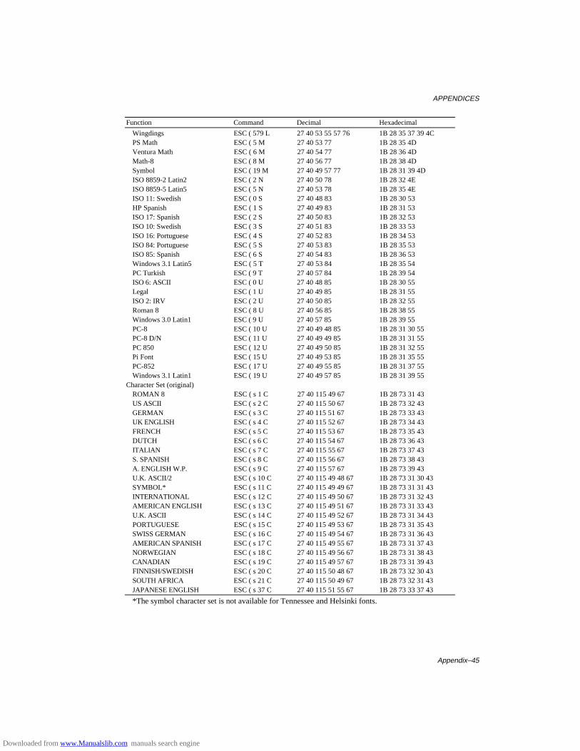
APPENDICES
Appendix–45
Function Command Decimal Hexadecimal
Wingdings ESC ( 579 L 27 40 53 55 57 76 1B 28 35 37 39 4CPS Math ESC ( 5 M 27 40 53 77 1B 28 35 4DVentura Math ESC ( 6 M 27 40 54 77 1B 28 36 4DMath-8 ESC ( 8 M 27 40 56 77 1B 28 38 4DSymbol ESC ( 19 M 27 40 49 57 77 1B 28 31 39 4DISO 8859-2 Latin2 ESC ( 2 N 27 40 50 78 1B 28 32 4EISO 8859-5 Latin5 ESC ( 5 N 27 40 53 78 1B 28 35 4EISO 11: Swedish ESC ( 0 S 27 40 48 83 1B 28 30 53HP Spanish ESC ( 1 S 27 40 49 83 1B 28 31 53ISO 17: Spanish ESC ( 2 S 27 40 50 83 1B 28 32 53ISO 10: Swedish ESC ( 3 S 27 40 51 83 1B 28 33 53ISO 16: Portuguese ESC ( 4 S 27 40 52 83 1B 28 34 53ISO 84: Portuguese ESC ( 5 S 27 40 53 83 1B 28 35 53ISO 85: Spanish ESC ( 6 S 27 40 54 83 1B 28 36 53Windows 3.1 Latin5 ESC ( 5 T 27 40 53 84 1B 28 35 54PC Turkish ESC ( 9 T 27 40 57 84 1B 28 39 54ISO 6: ASCII ESC ( 0 U 27 40 48 85 1B 28 30 55Legal ESC ( 1 U 27 40 49 85 1B 28 31 55ISO 2: IRV ESC ( 2 U 27 40 50 85 1B 28 32 55Roman 8 ESC ( 8 U 27 40 56 85 1B 28 38 55Windows 3.0 Latin1 ESC ( 9 U 27 40 57 85 1B 28 39 55PC-8 ESC ( 10 U 27 40 49 48 85 1B 28 31 30 55PC-8 D/N ESC ( 11 U 27 40 49 49 85 1B 28 31 31 55PC 850 ESC ( 12 U 27 40 49 50 85 1B 28 31 32 55Pi Font ESC ( 15 U 27 40 49 53 85 1B 28 31 35 55PC-852 ESC ( 17 U 27 40 49 55 85 1B 28 31 37 55Windows 3.1 Latin1 ESC ( 19 U 27 40 49 57 85 1B 28 31 39 55
Character Set (original)ROMAN 8 ESC ( s 1 C 27 40 115 49 67 1B 28 73 31 43US ASCII ESC ( s 2 C 27 40 115 50 67 1B 28 73 32 43GERMAN ESC ( s 3 C 27 40 115 51 67 1B 28 73 33 43UK ENGLISH ESC ( s 4 C 27 40 115 52 67 1B 28 73 34 43FRENCH ESC ( s 5 C 27 40 115 53 67 1B 28 73 35 43DUTCH ESC ( s 6 C 27 40 115 54 67 1B 28 73 36 43ITALIAN ESC ( s 7 C 27 40 115 55 67 1B 28 73 37 43S. SPANISH ESC ( s 8 C 27 40 115 56 67 1B 28 73 38 43A. ENGLISH W.P. ESC ( s 9 C 27 40 115 57 67 1B 28 73 39 43U.K. ASCII/2 ESC ( s 10 C 27 40 115 49 48 67 1B 28 73 31 30 43SYMBOL* ESC ( s 11 C 27 40 115 49 49 67 1B 28 73 31 31 43INTERNATIONAL ESC ( s 12 C 27 40 115 49 50 67 1B 28 73 31 32 43AMERICAN ENGLISH ESC ( s 13 C 27 40 115 49 51 67 1B 28 73 31 33 43U.K. ASCII ESC ( s 14 C 27 40 115 49 52 67 1B 28 73 31 34 43PORTUGUESE ESC ( s 15 C 27 40 115 49 53 67 1B 28 73 31 35 43SWISS GERMAN ESC ( s 16 C 27 40 115 49 54 67 1B 28 73 31 36 43AMERICAN SPANISH ESC ( s 17 C 27 40 115 49 55 67 1B 28 73 31 37 43NORWEGIAN ESC ( s 18 C 27 40 115 49 56 67 1B 28 73 31 38 43CANADIAN ESC ( s 19 C 27 40 115 49 57 67 1B 28 73 31 39 43FINNISH/SWEDISH ESC ( s 20 C 27 40 115 50 48 67 1B 28 73 32 30 43SOUTH AFRICA ESC ( s 21 C 27 40 115 50 49 67 1B 28 73 32 31 43JAPANESE ENGLISH ESC ( s 37 C 27 40 115 51 55 67 1B 28 73 33 37 43
*The symbol character set is not available for Tennessee and Helsinki fonts.
Downloaded from www.Manualslib.com manuals search engine

USER’S GUIDE
Appendix–46
Function Command Decimal HexadecimalPC-8 ESC ( s 25 C 27 40 115 50 53 67 1B 28 73 32 35 43PC-8 D/N ESC ( s 23 C 27 40 115 50 51 67 1B 28 73 32 33 43PC-850 ESC ( s 26 C 27 40 115 50 54 67 1B 28 73 32 36 43PC-860 ESC ( s 27 C 27 40 115 50 55 67 1B 28 73 32 37 43PC-863 ESC ( s 28 C 27 40 115 50 56 67 1B 28 73 32 38 43PC-865 ESC ( s 29 C 27 40 115 50 57 67 1B 28 73 32 39 43
Fixed Pitch or P.S.Fixed ESC ( s 0 P 27 40 115 48 80 1B 28 73 30 50P.S. ESC ( s 1 P 27 40 115 49 80 1B 28 73 31 50
Character Pitch Selection 1 ESC ( s # H 27 40 115 ## 72 1B 28 73 ## 48(#: char./inch)
Character Pitch Selection 210 Pitch ESC & k 0 S 27 38 107 48 83 1B 26 6B 30 5316.6 Pitch ESC & k 2 S 27 38 107 50 83 1B 26 6B 32 5312 Pitch ESC & k 4 S 27 38 107 52 83 1B 26 6B 34 53
Point Size ESC ( s # V 27 40 115 ## 86 1B 28 73 ## 56(#: point size)
Italics or uprightItalics ESC ( s 1 S 27 40 115 49 83 1B 28 73 31 53Upright ESC ( s 0 S 27 40 115 48 83 1B 28 73 30 53Condensed ESC ( s 4 S 27 40 115 52 83 1B 28 73 34 53Condensed Italic ESC ( s 5 S 27 40 115 53 83 1B 28 73 35 53Compressed (Extra Condensed) ESC ( s 8 S 27 40 115 56 83 1B 28 73 38 53Expanded ESC ( s 24 S 27 40 115 50 52 83 1B 28 73 32 34 53Outline ESC ( s 32 S 27 40 115 51 50 83 1B 28 73 33 32 53Inline ESC ( s 64 S 27 40 115 54 52 83 1B 28 73 36 34 53Shadowed ESC ( s 128 S 27 40 115 49 50 56 83 1B 28 73 31 32 38 53Outline Shadowed ESC ( s 160 S 27 40 115 49 54 48 83 1B 28 73 31 36 30 53
Stroke Weight ESC ( s # B 27 40 115 ## 66 1B 28 73 ## 42Ultra Thin ESC ( s-7B 27 40 115 2D 55 66 1B 28 73 45 37 42Extra Thin ESC ( s-6B 27 40 115 2D 54 66 1B 28 73 45 36 42Thin ESC ( s-5B 27 40 115 2D 53 66 1B 28 73 45 35 42Extra Light ESC ( s-4B 27 40 115 2D 52 66 1B 28 73 45 34 42Light ESC ( s-3B 27 40 115 2D 51 66 1B 28 73 45 33 42Demi Light ESC ( s-2B 27 40 115 2D 50 66 1B 28 73 45 32 42Semi Light ESC ( s-1B 27 40 115 2D 49 66 1B 28 73 45 31 42Medium (Normal) ESC ( s 0 B 27 40 115 48 66 1B 28 73 30 42Semi Bold ESC ( s 1 B 27 40 115 49 66 1B 28 73 31 42Demi Bold ESC ( s 2 B 27 40 115 50 66 1B 28 73 32 42Bold ESC ( s 3 B 27 40 115 51 66 1B 28 73 33 42Extra Bold ESC ( s 4 B 27 40 115 52 66 1B 28 73 34 42Black ESC ( s 5 B 27 40 115 53 66 1B 28 73 35 42Extra Black ESC ( s 6 B 27 40 115 54 66 1B 28 73 36 42Ultra Black ESC ( s 7 B 27 40 115 55 66 1B 28 73 37 42
Scalable Font Ratio (original)Set horizontal ratio ESC CR ! # H 27 13 33 # 72 1B 0D 21 # 48 (#=0.25 to 3 step 0.01)Set vertical ratio ESC CR ! # V 27 13 33 # 86 1B 0D 21 # 56
(#=0.25 to 3 step 0.01)
Downloaded from www.Manualslib.com manuals search engine
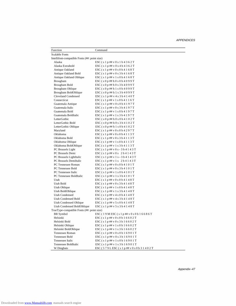
APPENDICES
Appendix–47
Function Command
Scalable FontsIntellifont-compatible Fonts (##: point size)
Alaska ESC ( s 1 p ## v 0 s 1 b 4 3 6 2 TAlaska Extrabold ESC ( s 1 p ## v 0 s 4 b 4 3 6 2 TAntique Oakland ESC ( s 1 p ## v 0 s 0 b 4 1 6 8 TAntique Oakland Bold ESC ( s 1 p ## v 0 s 3 b 4 1 6 8 TAntique Oakland Oblique ESC ( s 1 p ## v 1 s 0 b 4 1 6 8 TBrougham ESC ( s 0 p ## h 0 s 0 b 4 0 9 9 TBrougham Bold ESC ( s 0 p ## h 0 s 3 b 4 0 9 9 TBrougham Oblique ESC ( s 0 p ## h 1 s 0 b 4 0 9 9 TBrougham BoldOblique ESC ( s 0 p ## h 1 s 3 b 4 0 9 9 TCleveland Condensed ESC ( s 1 p ## v 4 s 3 b 4 1 4 0 TConnecticut ESC ( s 1 p ## v 1 s 0 b 4 1 1 6 TGuatemala Antique ESC ( s 1 p ## v 0 s 0 b 4 1 9 7 TGuatemala Italic ESC ( s 1 p ## v 0 s 3 b 4 1 9 7 TGuatemala Bold ESC ( s 1 p ## v 1 s 0 b 4 1 9 7 TGuatemala Boldltalic ESC ( s 1 p ## v 1 s 3 b 4 1 9 7 TLetterGothic ESC ( s 0 p ## h 0 s 0 b 4 1 0 2 TLetterGothic Bold ESC ( s 0 p ## h 0 s 3 b 4 1 0 2 TLetterGothic Oblique ESC ( s 0 p ## h 1 s 0 b 4 1 0 2 TMaryland ESC ( s 1 p ## v 0 s 0 b 4 2 9 7 TOklahoma ESC ( s 1 p ## v 0 s 0 b 4 1 1 3 TOklahoma Bold ESC ( s 1 p ## v 0 s 3 b 4 1 1 3 TOklahoma Oblique ESC ( s 1 p ## v 1 s 0 b 4 1 1 3 TOklahoma BoldOblique ESC ( s 1 p ## v 1 s 3 b 4 1 1 3 TPC Brussels Light ESC ( s 1 p ## v 0 s - 3 b 4 1 4 3 TPC Brussels Demi ESC ( s 1 p ## v 0 s 2 b 4 1 4 3 TPC Brussels LightItalic ESC ( s 1 p ## v 1 s - 3 b 4 1 4 3 TPC Brussels DemiItalic ESC ( s 1 p ## v 1 s 2 b 4 1 4 3 TPC Tennessee Roman ESC ( s 1 p ## v 0 s 0 b 4 1 0 1 TPC Tennessee Bold ESC ( s 1 p ## v 0 s 3 b 4 1 0 1 TPC Tennessee Italic ESC ( s 1 p ## v 1 s 0 b 4 1 0 1 TPC Tennessee BoldItalic ESC ( s 1 p ## v 1 s 3 b 4 1 0 1 TUtah ESC ( s 1 p ## v 0 s 0 b 4 1 4 8 TUtah Bold ESC ( s 1 p ## v 0 s 3 b 4 1 4 8 TUtah Oblique ESC ( s 1 p ## v 1 s 0 b 4 1 4 8 TUtah BoldOblique ESC ( s 1 p ## v 1 s 3 b 4 1 4 8 TUtah Condensed ESC ( s 1 p ## v 4 s 0 b 4 1 4 8 TUtah Condensed Bold ESC ( s 1 p ## v 4 s 3 b 4 1 4 8 TUtah Condensed Oblique ESC ( s 1 p ## v 5 s 0 b 4 1 4 8 TUtah Condensed BoldOblique ESC ( s 1 p ## v 5 s 3 b 4 1 4 8 T
TrueType-compatible Fonts (##: point size)BR Symbol ESC ( 1 9 M ESC ( s 1 p ## v 0 s 0 b 1 6 6 8 6 THelsinki ESC ( s 1 p ## v 0 s 0 b 1 6 6 0 2 THelsinki Bold ESC ( s 1 p ## v 0 s 3 b 1 6 6 0 2 THelsinki Oblique ESC ( s 1 p ## v 1 s 0 b 1 6 6 0 2 THelsinki BoldOblique ESC ( s 1 p ## v 1 s 3 b 1 6 6 0 2 TTennessee Roman ESC ( s 1 p ## v 0 s 0 b 1 6 9 0 1 TTennessee Bold ESC ( s 1 p ## v 0 s 3 b 1 6 9 0 1 TTennessee Italic ESC ( s 1 p ## v 1 s 0 b 1 6 9 0 1 TTennessee BoldItalic ESC ( s 1 p ## v 1 s 3 b 1 6 9 0 1 TW Dingbats ESC ( 5 7 9 L ESC ( s 1 p ## v 0 s 0 b 3 1 4 0 2 T
Downloaded from www.Manualslib.com manuals search engine

USER’S GUIDE
Appendix–48
Function Command
Type 1 Font Compatible Fonts (##: point size)Atlanta Book ESC ( s 1 p ## v 0 s 0 b 1 5 5 TAtlanta Demi ESC ( s 1 p ## v 0 s 3 b 1 5 5 TAtlanta BookOblique ESC ( s 1 p ## v 1 s 0 b 1 5 5 TAtlanta DemiOblique ESC ( s 1 p ## v 1 s 3 b 1 5 5 TCalgary MediumItalic ESC ( s 1 p ## v 1 s 0 b 1 5 9 TCopenhagen Roman ESC ( s 1 p ## v 0 s 0 b 1 5 7 TCopenhagen Bold ESC ( s 1 p ## v 0 s 3 b 1 5 7 TCopenhagen Italic ESC ( s 1 p ## v 1 s 0 b 1 5 7 TCopenhagen BoldItalic ESC ( s 1 p ## v 1 s 3 b 1 5 7 TPortugal Roman ESC ( s 1 p ## v 0 s 0 b 1 5 8 TPortugal Bold ESC ( s 1 p ## v 0 s 3 b 1 5 8 TPortugal Italic ESC ( s 1 p ## v 1 s 0 b 1 5 8 TPortugal BoldItalic ESC ( s 1 p ## v 1 s 3 b 1 5 8 T
Bitmapped FontsLetterGothic16.66 ESC ( s 0 p 16.67 h 8.5 v 0 s 0 b 1 3 0 TOCR-A ESC ( 0 O ESC ( s 0 p 10 h 12 v 0 s 0 b 1 0 4 TOCR-B ESC ( 1 O ESC ( s 0 p 10 h 12 v 0 s 0 b 1 1 0 T
Brother Original FontsBermuda Script ESC ( s 1 p ## v 0 s 3 b 1 3 4 TGermany ESC ( s 1 p ## v 0 s 3 b 1 3 2 TSan Diego ESC ( s 1 p ## v 0 s 5 b 1 3 3 TUS Roman ESC ( s 1 p ## v 0 s 0 b 1 3 5 T
Downloaded from www.Manualslib.com manuals search engine
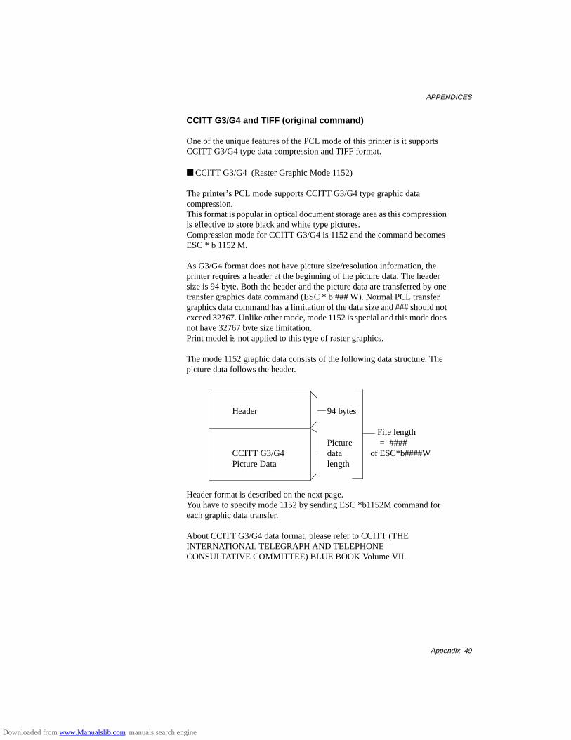
APPENDICES
Appendix–49
CCITT G3/G4 and TIFF (original command)
One of the unique features of the PCL mode of this printer is it supportsCCITT G3/G4 type data compression and TIFF format.
■ CCITT G3/G4 (Raster Graphic Mode 1152)
The printer’s PCL mode supports CCITT G3/G4 type graphic datacompression.This format is popular in optical document storage area as this compressionis effective to store black and white type pictures.Compression mode for CCITT G3/G4 is 1152 and the command becomesESC * b 1152 M.
As G3/G4 format does not have picture size/resolution information, theprinter requires a header at the beginning of the picture data. The headersize is 94 byte. Both the header and the picture data are transferred by onetransfer graphics data command (ESC * b ### W). Normal PCL transfergraphics data command has a limitation of the data size and ### should notexceed 32767. Unlike other mode, mode 1152 is special and this mode doesnot have 32767 byte size limitation.Print model is not applied to this type of raster graphics.
The mode 1152 graphic data consists of the following data structure. Thepicture data follows the header.
Header 94 bytes
File lengthPicture = ####
CCITT G3/G4 data of ESC*b####WPicture Data length
Header format is described on the next page.You have to specify mode 1152 by sending ESC *b1152M command foreach graphic data transfer.
About CCITT G3/G4 data format, please refer to CCITT (THEINTERNATIONAL TELEGRAPH AND TELEPHONECONSULTATIVE COMMITTEE) BLUE BOOK Volume VII.
Downloaded from www.Manualslib.com manuals search engine

USER’S GUIDE
Appendix–50
Mode 1152 graphic data header data structure
Position Data Description0-1 6E 6E ‘nn’ This is header ID.2-3 0A 00 reserved (Header Version)4-7 5E 00 00 00 Picture data start offset from header top8-11 File Length File length including 94 byte header. If file length is 65,536
byte, these 4 bytes become “00 00 01 00”.12-13 01 00 reserved14-15 01 00 reserved16-19 4A 00 00 00 reserved20-21 compression 02 00: Fax MH format
03 00: Fax MR format 04 00: Fax G4 format
22-55 00....00 All zero56-59 Picture Data Length
If picture data length is 65,442 (65,536 - 94) byte, these 4 bytes become “A2 FF 00 00”.
60-61 01 00 bit/pixel62-63 01 00 bit/pixel64-65 Pixels/line If picture dot width = 2400, these 2 bytes become “60 09”.66-67 Pixels/line Same as 64-6568-69 Lines/picture If picture line count = 3100, these 2 bytes become “1C 0C”.70-71 Lines/picture Same as 70-7172-73 00 00 reserved74-75 Photo metrics 00 00: data 0 = white 01 00: data 0 = black76-77 02 00 reserved (Endian format)78-79 Bit Fill Order 01 00: filled from MSB
02 00: filled from LSB80-81 01 00 reserved82-83 00 00 reserved (min. pixel value)84-85 01 00 reserved (max pixel value)86-87 horizontal resolution (200,300,400,600)
C8 00 00 00 : 200 dpi 2C 01 00 00 : 300 dpi 90 01 00 00 : 400 dpi 58 02 00 00 : 600 dpi 400 and 600 dpi are available when printer operates in 600 dpi.
88-89 vertical resolution (200,300,400,600) C8 00 00 00 : 200 dpi 2C 01 00 00 : 300 dpi 90 01 00 00 : 400 dpi 58 02 00 00 : 600 dpi The printer accepts different values for vertical and horizontal resolutions. 400/600 dpi are available when printer operates in 600 dpi.
90-91 02 00 reserved (resolution unit = inch)92-93 00 00 reserved (error code)
Downloaded from www.Manualslib.com manuals search engine
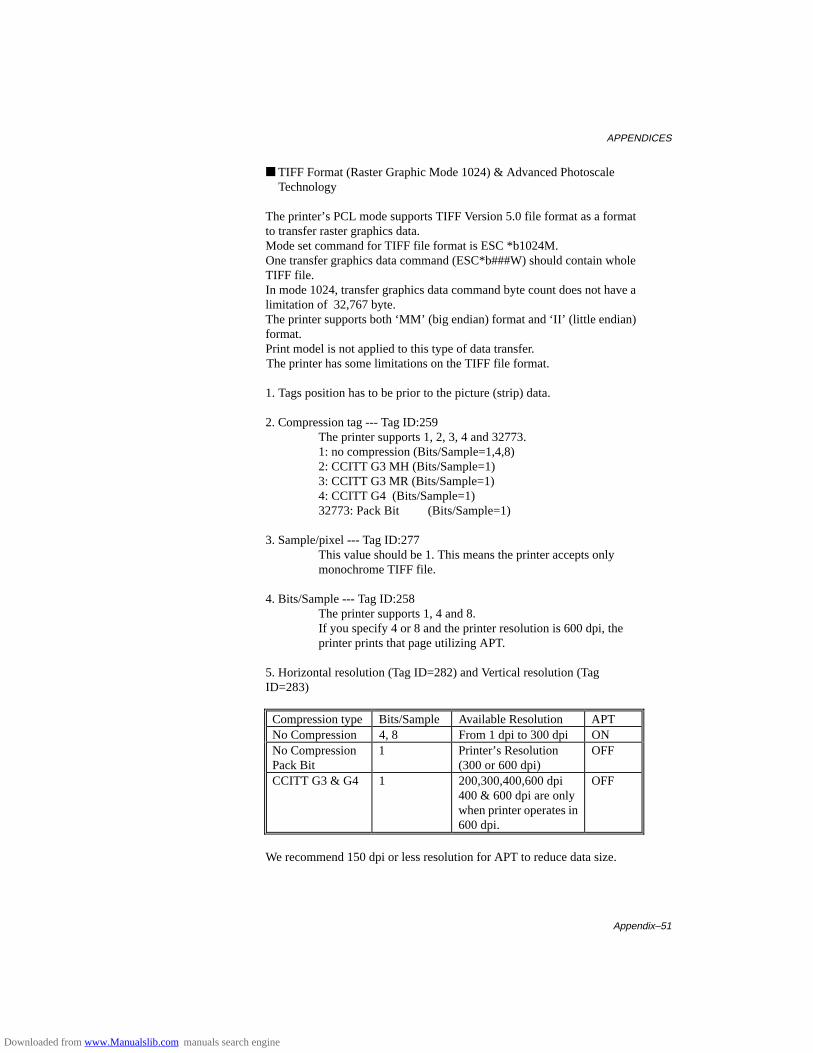
APPENDICES
Appendix–51
■ TIFF Format (Raster Graphic Mode 1024) & Advanced Photoscale Technology
The printer’s PCL mode supports TIFF Version 5.0 file format as a formatto transfer raster graphics data.Mode set command for TIFF file format is ESC *b1024M.One transfer graphics data command (ESC*b###W) should contain wholeTIFF file.In mode 1024, transfer graphics data command byte count does not have alimitation of 32,767 byte.The printer supports both ‘MM’ (big endian) format and ‘II’ (little endian)format.Print model is not applied to this type of data transfer.
The printer has some limitations on the TIFF file format.
1. Tags position has to be prior to the picture (strip) data.
2. Compression tag --- Tag ID:259The printer supports 1, 2, 3, 4 and 32773.1: no compression (Bits/Sample=1,4,8)2: CCITT G3 MH (Bits/Sample=1)3: CCITT G3 MR (Bits/Sample=1)4: CCITT G4 (Bits/Sample=1)32773: Pack Bit (Bits/Sample=1)
3. Sample/pixel --- Tag ID:277This value should be 1. This means the printer accepts only monochrome TIFF file.
4. Bits/Sample --- Tag ID:258The printer supports 1, 4 and 8.If you specify 4 or 8 and the printer resolution is 600 dpi, theprinter prints that page utilizing APT.
5. Horizontal resolution (Tag ID=282) and Vertical resolution (TagID=283)
Compression type Bits/Sample Available Resolution APTNo Compression 4, 8 From 1 dpi to 300 dpi ONNo CompressionPack Bit
1 Printer’s Resolution(300 or 600 dpi)
OFF
CCITT G3 & G4 1 200,300,400,600 dpi400 & 600 dpi are onlywhen printer operates in600 dpi.
OFF
We recommend 150 dpi or less resolution for APT to reduce data size.
Downloaded from www.Manualslib.com manuals search engine
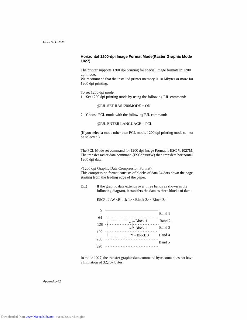
USER’S GUIDE
Appendix–52
Horizontal 1200-dpi Image Format Mode(Raster Graphic Mode1027)
The printer supports 1200 dpi printing for special image formats in 1200dpi mode.We recommend that the installed printer memory is 10 Mbytes or more for1200 dpi printing.
To set 1200 dpi mode,1. Set 1200 dpi printing mode by using the following PJL command:
@PJL SET RAS1200MODE = ON
2. Choose PCL mode with the following PJL command:
@PJL ENTER LANGUAGE = PCL
(If you select a mode other than PCL mode, 1200 dpi printing mode cannotbe selected.)
The PCL Mode set command for 1200 dpi Image Format is ESC *b1027M.The transfer raster data command (ESC*b###W) then transfers horizontal1200 dpi data.
<1200 dpi Graphic Data Compression Format>This compression format consists of blocks of data 64 dots down the pagestarting from the leading edge of the paper.
Ex.) If the graphic data extends over three bands as shown in the following diagram, it transfers the data as three blocks of data:
ESC*b##W <Block 1> <Block 2> <Block 3>
In mode 1027, the transfer graphic data command byte count does not havea limitation of 32,767 bytes.
0
64
128
192
256
320
Block 1
Block 3
Block 2
Band 1
Band 3
Band 4
Band 2
Band 5
Downloaded from www.Manualslib.com manuals search engine
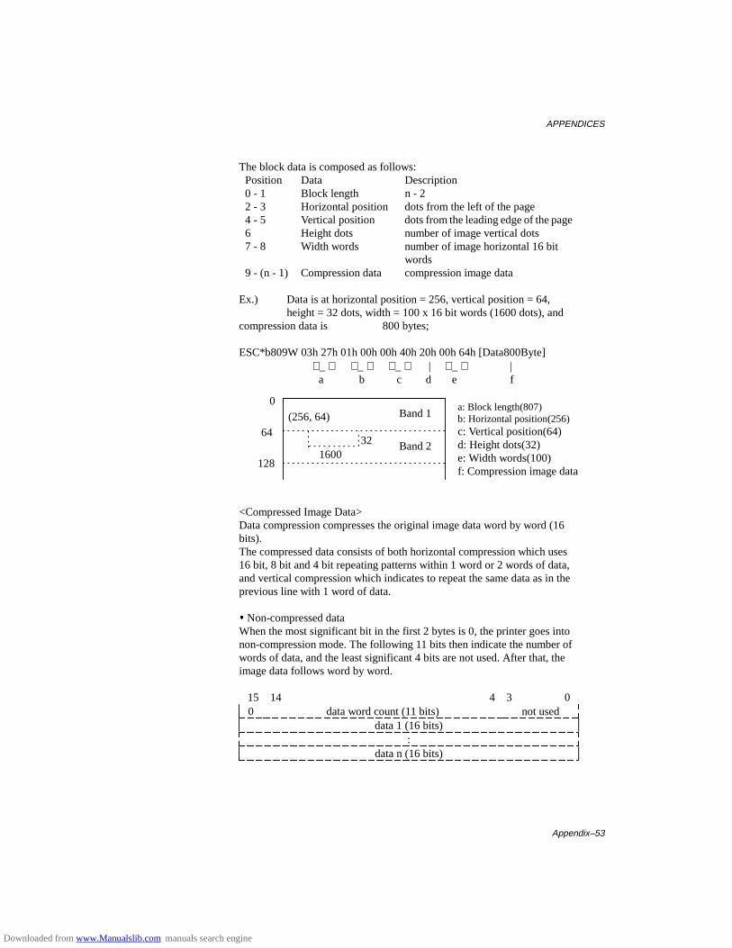
APPENDICES
Appendix–53
The block data is composed as follows:Position Data Description0 - 1 Block length n - 22 - 3 Horizontal position dots from the left of the page4 - 5 Vertical position dots from the leading edge of the page6 Height dots number of image vertical dots7 - 8 Width words number of image horizontal 16 bit
words9 - (n - 1) Compression data compression image data
Ex.) Data is at horizontal position = 256, vertical position = 64, height = 32 dots, width = 100 x 16 bit words (1600 dots), and
compression data is 800 bytes;
ESC*b809W 03h 27h 01h 00h 00h 40h 20h 00h 64h [Data800Byte] _ _ _ | _ |
a b c d e f
<Compressed Image Data>Data compression compresses the original image data word by word (16bits).The compressed data consists of both horizontal compression which uses16 bit, 8 bit and 4 bit repeating patterns within 1 word or 2 words of data,and vertical compression which indicates to repeat the same data as in theprevious line with 1 word of data.
y Non-compressed dataWhen the most significant bit in the first 2 bytes is 0, the printer goes intonon-compression mode. The following 11 bits then indicate the number ofwords of data, and the least significant 4 bits are not used. After that, theimage data follows word by word.
15 14 4 3 00 data word count (11 bits) not used
data 1 (16 bits):
data n (16 bits)
(256, 64)
321600
0
64
128
Band 1
Band 2
a: Block length(807)b: Horizontal position(256)c: Vertical position(64)d: Height dots(32)e: Width words(100)f: Compression image data
Downloaded from www.Manualslib.com manuals search engine
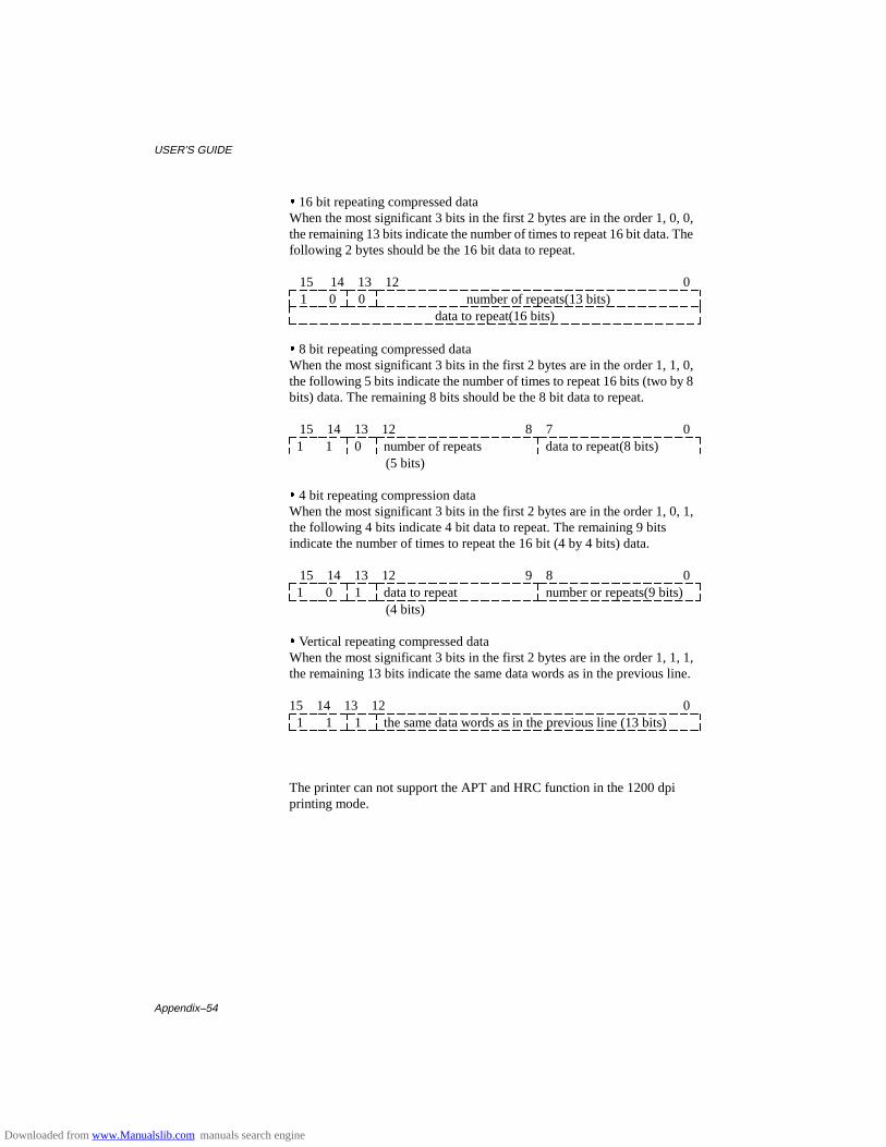
USER’S GUIDE
Appendix–54
y 16 bit repeating compressed dataWhen the most significant 3 bits in the first 2 bytes are in the order 1, 0, 0,the remaining 13 bits indicate the number of times to repeat 16 bit data. Thefollowing 2 bytes should be the 16 bit data to repeat.
15 14 13 12 01 0 0 number of repeats(13 bits)
data to repeat(16 bits)
y 8 bit repeating compressed dataWhen the most significant 3 bits in the first 2 bytes are in the order 1, 1, 0,the following 5 bits indicate the number of times to repeat 16 bits (two by 8bits) data. The remaining 8 bits should be the 8 bit data to repeat.
15 14 13 12 8 7 01 1 0 number of repeats data to repeat(8 bits)
(5 bits)
y 4 bit repeating compression dataWhen the most significant 3 bits in the first 2 bytes are in the order 1, 0, 1,the following 4 bits indicate 4 bit data to repeat. The remaining 9 bitsindicate the number of times to repeat the 16 bit (4 by 4 bits) data.
15 14 13 12 9 8 01 0 1 data to repeat number or repeats(9 bits)
(4 bits)
y Vertical repeating compressed dataWhen the most significant 3 bits in the first 2 bytes are in the order 1, 1, 1,the remaining 13 bits indicate the same data words as in the previous line.
15 14 13 12 01 1 1 the same data words as in the previous line (13 bits)
The printer can not support the APT and HRC function in the 1200 dpiprinting mode.
Downloaded from www.Manualslib.com manuals search engine
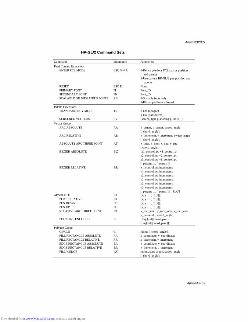
APPENDICES
Appendix–55
HP-GL/2 Command Sets
Command Mnemonic Parameters
Dual Context ExtensionsENTER PCL MODE ESC % # A 0-Retain previous PCL cursor position
and palette1-Use current HP-GL/2 pen position and palette
RESET ESC E NonePRIMARY FONT FI Font_IDSECONDARY FONT FN Font_IDSCALABLE OR BITMAPPED FONTS SB 0-Scalable fonts only
1-Bitmapped fonts allowed
Palette ExtensionsTRANSPARENCY MODE TR 0-Off (opaque)
1-On (transparent)SCREENED VECTORS SV [screen_type [, shading [, index]]]
Vector GroupARC ABSOLUTE AA x_center, y_center, sweep_angle
[, chord_angle];ARC RELATIVE AR x_increment, y_increment, sweep_angle
[, chord_angle];ABSOLUTE ARC THREE POINT AT x_inter, y_inter, x_end, y_end
[,chord_angle];BEZIER ABSOLUTE BZ x1_control_pt, y1_control_pt
x2_control_pt, y2_control_ptx3_control_pt, y3_control_pt[, params … [, parms ]].
BEZIER RELATIVE BR x1_control_pt_increments,y1_control_pt_increments,x2_control_pt_increments,y2_control_pt_increments,x3_control_pt_increments,y3_control_pt_increments[, params … [, parms ]];PLOT
ABSOLUTE PA [x, y … [, x, y]];PLOT RELATIVE PR [x, y … [, x, y]];PEN DOWN PD [x, y … [, x, y]];PEN UP PU [x, y … [, x, y]];RELATIVE ARC THREE POINT RT x_incr_inter, y_incr_inter, x_incr_end,
y_incr-end [, chord_angle];POLYLINE ENCODED PE [flag [val]|coord_pair …
[flag[val]|coord_pair ]];
Polygon GroupCIRCLE CI radius [, chord_angle];FILL RECTANGLE ABSOLUTE RA x_coordinate, y_coordinate;FILL RECTANGLE RELATIVE RR x_increment, y_increment;EDGE RECTANGLE ABSOLUTE EA x_coordinate, y_coordinate;EDGE RECTANGLE RELATIVE ER x_increment, y_increment;FILL WEDGE WG radius, start_angle, sweep_angle
[, chord_angle];
Downloaded from www.Manualslib.com manuals search engine
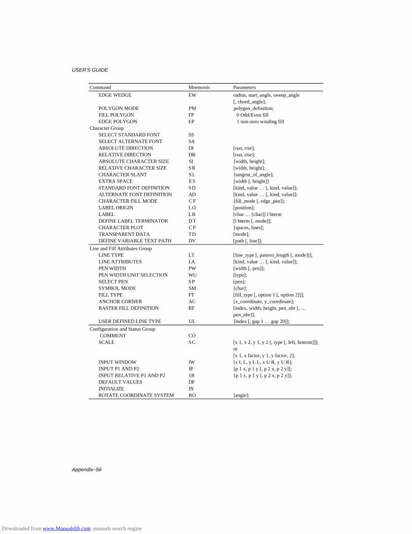
USER’S GUIDE
Appendix–56
Command Mnemonic Parameters
EDGE WEDGE EW radius, start_angle, sweep_angle[, chord_angle];
POLYGON MODE PM polygon_definition;FILL POLYGON FP 0 Odd/Even fillEDGE POLYGON EP 1 non-zero winding fill
Character GroupSELECT STANDARD FONT SSSELECT ALTERNATE FONT SAABSOLUTE DIRECTION DI [run, rise];RELATIVE DIRECTION DR [run, rise];ABSOLUTE CHARACTER SIZE SI [width, height];RELATIVE CHARACTER SIZE SR [width, height];CHARACTER SLANT SL [tangent_of_angle];EXTRA SPACE ES [width [, height]]STANDARD FONT DEFINITION SD [kind, value … [, kind, value]];ALTERNATE FONT DEFINITION AD [kind, value … [, kind, value]];CHARACTER FILL MODE CF [fill_mode [, edge_pen]];LABEL ORIGIN LO [position];LABEL LB [char … [char]] l btermDEFINE LABEL TERMINATOR DT [l bterm [, mode]];CHARACTER PLOT CP [spaces, lines];TRANSPARENT DATA TD [mode];DEFINE VARIABLE TEXT PATH DV [path [, line]];
Line and Fill Attributes GroupLINE TYPE LT [line_type [, pattern_length [, mode]]];LINE ATTRIBUTES LA [kind, value … [, kind, value]];PEN WIDTH PW [width [, pen]];PEN WIDTH UNIT SELECTION WU [type];SELECT PEN SP [pen];SYMBOL MODE SM [char];FILL TYPE FT [fill_type [, option 1 [, option 2]]];ANCHOR CORNER AC [x_coordinate, y_coordinate];RASTER FILL DEFINITION RF [index, width, height, pen_nbr [, …
pen_nbr]];USER DEFINED LINE TYPE UL [index [, gap 1 … gap 20]];
Configuration and Status Group COMMENT CO
SCALE SC [x 1, x 2, y 1, y 2 [, type [, left, bottom]]];or[x 1, x factor, y 1, y factor, 2];
INPUT WINDOW IW [x L L, y L L, x U R, y U R];INPUT P1 AND P2 IP [p 1 x, p 1 y [, p 2 x, p 2 y]];INPUT RELATIVE P1 AND P2 IR [p 1 x, p 1 y [, p 2 x, p 2 y]];DEFAULT VALUES DFINITIALIZE INROTATE COORDINATE SYSTEM RO [angle];
Downloaded from www.Manualslib.com manuals search engine

APPENDICES
Appendix–57
Printer Job Language Commands SyntaxCommand Function and Syntax
Syntax Rules[ ] Brackets indicate optional parameters.< > Indicates special characters and items
Special Characters and Items DEC. HEX.<HT> Horizontal Tab (element of white space) 09 09<LF> Line Feed (PJL command terminator) 10 0A<CR> Carriage Return (optional parameter) 13 0D<SP> Space (element of white space) 32 20<ESC> Escape (used only for UEL/SPJL) 27 1B<FF> Form Feed 12 0C
(terminator for multiple line reply)<WS> White Space<SP> or <HT> or combination of <SP> and <HT><PC> Printable Characters (character code 33 through 126, and
161 through 254)<Words> Beginning with <PC>, and combination of <PC> and <WS>
Printer Job Language Commands SyntaxCOMMENT @PJL COMMENT <Words> [<CR>] <LF>DEFAULT @PJL DEFAULT [LPARM: emulation] variable = value
[<CR>] <LF>DINQUIRE @PJL DINQUIRE [LPARM: emulation] variable [<CR>] <LF>Reply @PJL DINQUIRE [LPARM: emulation] variable <CR> <LF>
value <CR> <LF> <FF>ECHO @PJL ECHO [<Words>] [<CR>] <LF>Reply @PJL ECHO [<Words>] <CR> <LF> <FF>ENTER @PJL ENTER LANGUAGE = emulation [<CR>] <LF>EOJ @PJL EOJ [NAME = job name] [<CR>] <LF>INFO @PJL INFO read only variable [<CR>] <LF>Reply @PJL INFO read only variable <CR> <LF>
[1 or more lines of printable characters or <WS> followedby <CR> <LF>] <FF>
INITIALIZE @PJL INITIALIZE [<CR>] <LF>INQUIRE @PJL INQUIRE [LPARM: emulation] variable [<CR>] <LF>Reply @PJL INQUIRE [LPARM: emulation] variable <CR> <LF>
value <CR> <LF> <FF>JOB @PJL JOB [NAME = “job name”] [START = first page]
[END = last page] [<CR>] <LF>OPMSG @PJL OPMSG DISPLAY = “message” [<CR>] <LF>RDYMSG @PJL RDYMSG DISPLAY = “message” [<CR>] <LF>RESET @PJL RESET [<CR>] <LF>SET @PJL SET [LPARM: emulation] variable = value [<CR>] <LF>STMSG @PJL STMSG DISPLAY = “message” [<CR>] <LF>Reply @PJL STMSG DISPLAY = “message” <CR> <LF>
key <CR> <LF> <FF>Exit Current Emulation/Start PJL <ESC> % - 12345X(UEL/SPJL)USTATUS @PJL USTATUS variable = value [<CR>] <LF>Reply @PJL USTATUS variable <CR> <LF>
[1 or more lines of printable characters or <WS> followedby <CR> <LF>] <FF>
USTATUSOFF @PJL USTATUSOFF [<CR>] <LF>(No Operation) @PJL [<CR>] <LF>
Downloaded from www.Manualslib.com manuals search engine
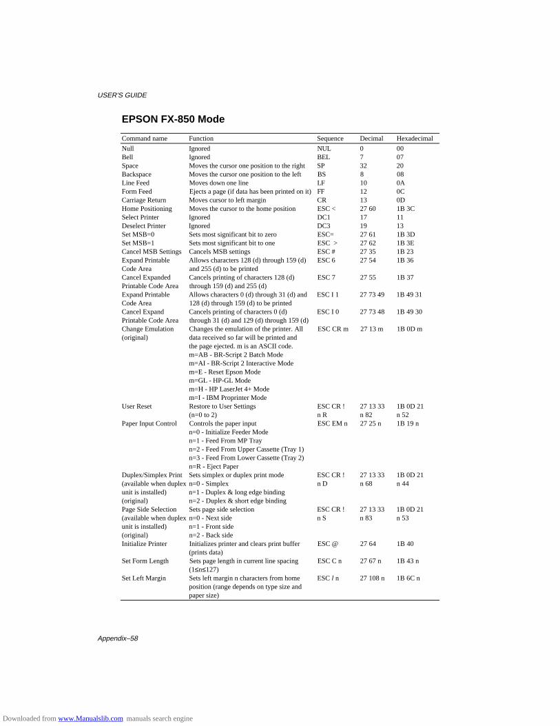
USER’S GUIDE
Appendix–58
EPSON FX-850 Mode
Command name Function Sequence Decimal Hexadecimal
Null Ignored NUL 0 00Bell Ignored BEL 7 07Space Moves the cursor one position to the right SP 32 20Backspace Moves the cursor one position to the left BS 8 08Line Feed Moves down one line LF 10 0AForm Feed Ejects a page (if data has been printed on it) FF 12 0CCarriage Return Moves cursor to left margin CR 13 0DHome Positioning Moves the cursor to the home position ESC < 27 60 1B 3CSelect Printer Ignored DC1 17 11Deselect Printer Ignored DC3 19 13Set MSB=0 Sets most significant bit to zero ESC= 27 61 1B 3DSet MSB=1 Sets most significant bit to one ESC > 27 62 1B 3ECancel MSB Settings Cancels MSB settings ESC # 27 35 1B 23Expand Printable Allows characters 128 (d) through 159 (d) ESC 6 27 54 1B 36Code Area and 255 (d) to be printedCancel Expanded Cancels printing of characters 128 (d) ESC 7 27 55 1B 37Printable Code Area through 159 (d) and 255 (d)Expand Printable Allows characters 0 (d) through 31 (d) and ESC I 1 27 73 49 1B 49 31Code Area 128 (d) through 159 (d) to be printedCancel Expand Cancels printing of characters 0 (d) ESC I 0 27 73 48 1B 49 30Printable Code Area through 31 (d) and 129 (d) through 159 (d)Change Emulation Changes the emulation of the printer. All ESC CR m 27 13 m 1B 0D m(original) data received so far will be printed and
the page ejected. m is an ASCII code.m=AB - BR-Script 2 Batch Modem=AI - BR-Script 2 Interactive Modem=E - Reset Epson Modem=GL - HP-GL Modem=H - HP LaserJet 4+ Modem=I - IBM Proprinter Mode
User Reset Restore to User Settings ESC CR ! 27 13 33 1B 0D 21(n=0 to 2) n R n 82 n 52
Paper Input Control Controls the paper input ESC EM n 27 25 n 1B 19 nn=0 - Initialize Feeder Moden=1 - Feed From MP Tray n=2 - Feed From Upper Cassette (Tray 1)n=3 - Feed From Lower Cassette (Tray 2)n=R - Eject Paper
Duplex/Simplex Print Sets simplex or duplex print mode ESC CR ! 27 13 33 1B 0D 21(available when duplex n=0 - Simplex n D n 68 n 44unit is installed) n=1 - Duplex & long edge binding(original) n=2 - Duplex & short edge bindingPage Side Selection Sets page side selection ESC CR ! 27 13 33 1B 0D 21(available when duplex n=0 - Next side n S n 83 n 53unit is installed) n=1 - Front side(original) n=2 - Back sideInitialize Printer Initializes printer and clears print buffer ESC @ 27 64 1B 40
(prints data)Set Form Length Sets page length in current line spacing ESC C n 27 67 n 1B 43 n
(1≤n≤127)Set Left Margin Sets left margin n characters from home ESC l n 27 108 n 1B 6C n
position (range depends on type size andpaper size)
Downloaded from www.Manualslib.com manuals search engine
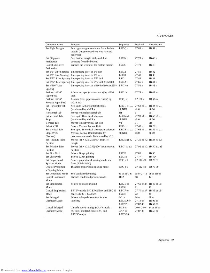
APPENDICES
Appendix–59
Command name Function Sequence Decimal Hexadecimal
Set Right Margin Sets right margin n columns from the left ESC Q n 27 81 n 1B 51 nmargin (range depends on type size andpaper size)
Set Skip-over Sets bottom margin at the n-th line, ESC N n 27 78 n 1B 4E nPerforation counting from the bottomCancel Skip-over Cancels the setting of the bottom margin ESC O 27 79 1B 4FPerforationSet 1/6” Line Spacing Line spacing is set to 1/6 inch ESC 2 27 50 1B 32Set 1/8” Line Spacing Line spacing is set to 1/8 inch ESC 0 27 48 1B 30Set 7/72” Line Spacing Line spacing is set to 7/72 inch ESC 1 27 49 1B 31Set n/72” Line Spacing Line spacing is set to n/72 inch (0≤n≤85) ESC A n 27 65 n 1B 41 nSet n/216” Line Line spacing is set to n/216 inch (0≤n≤255) ESC 3 n 27 51 n 1B 33 nSpacingPerform n/216” Advances paper (moves cursor) by n/216 ESC J n 27 74 n 1B 4A nPaper Feed inchPerform n/216” Reverse feeds paper (moves cursor) by ESC j n 27 106 n 1B 6A nReverse Paper Feed n/216 inchSet Horizontal Tab Sets up to 32 horizontal tab stops ESC D n1 … 27 68 n1 … 1B 44 n1 …Stops (terminated by a NUL) nk NUL nk 0 nk 00Horizontal Tab Moves to next horizontal tab HT 9 09Set Vertical Tab Sets up to 16 vertical tab stops ESC b n1 … 27 98 n1 … 1B 62 n1 …Stops (terminated by a NUL) nk NUL nk 0 nk 00Vertical Tab Moves to next vertical tab stop VT 11 0BSelect VFU Selects Vertical Format Unit ESC / n 27 47 n 1B 2F nSet Vertical Tab Sets up to 16 vertical tab stops in selected ESC B n1 … 27 66 n1 … 1B 42 n1 …Stops (VFU Vertical Format Unit (selected by nk NUL nk 0 nk 00Channel) previous command). Terminated by NULSet Absolute Print Moves (n1 + n2 x 256)/60” from left ESC $ n1 n2 27 36 n1 n2 1B 24 n1 n2Position marginSet Relative Print Moves (n1 + n2 x 256)/120” from current ESC \ n1 n2 27 92 n1 n2 1B 5C n1 n2Position positionSet Pica Pitch Selects 10 cpi printing ESC P 27 80 1B 50Set Elite Pitch Selects 12 cpi printing ESC M 27 77 1B 4DSet Proportional Selects proportional spacing mode and ESC p 1 27 112 49 1B 70 31Spacing Mode fonts (BS disabled)Disable Proportion- Disables proportional spacing mode ESC p 0 27 112 48 1B 70 30al Spacing ModeSet Condensed Mode Sets condensed printing SI or ESC SI 15 or 27 15 0F or 1B 0FCancel Condensed Cancels condensed printing mode DC2 18 12ModeSet Emphasized Selects boldface printing ESC E or 27 69 or 27 1B 45 or 1BMode ESC G 71 47Cancel Emphasized ESC F cancels ESC E boldface and ESC H ESC F or 27 70 or 27 1B 46 or 1BMode cancels ESC G boldface ESC H 72 48Set Enlarged Selects enlarged characters for one SO or 14 or 0E orCharacter Mode line only ESC SO or 27 14 or 1B 0E or
ESC W 1 27 87 49 1B 57 31Cancel Enlarged Cancels above settings (CAN cancels DC4 or 20 or 24 or 14 or 18 orCharacter Mode SO only, and DC4 cancels SO and CAN or 27 87 48 1B 57 30
ESC SO only) ESC W 0
Downloaded from www.Manualslib.com manuals search engine
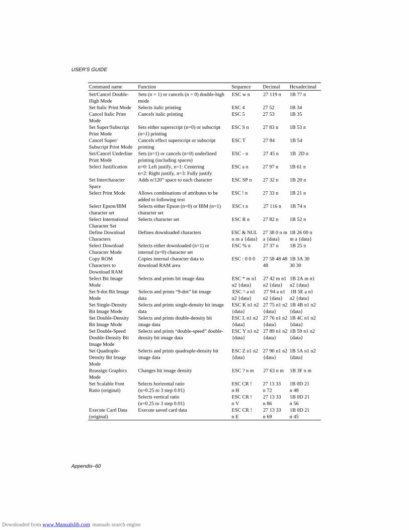
USER’S GUIDE
Appendix–60
Command name Function Sequence Decimal Hexadecimal
Set/Cancel Double- Sets (n = 1) or cancels (n = 0) double-high ESC w n 27 119 n 1B 77 nHigh Mode modeSet Italic Print Mode Selects italic printing ESC 4 27 52 1B 34Cancel Italic Print Cancels italic printing ESC 5 27 53 1B 35ModeSet Super/Subscript Sets either superscript (n=0) or subscript ESC S n 27 83 n 1B 53 nPrint Mode (n=1) printingCancel Super/ Cancels effect superscript or subscript ESC T 27 84 1B 54Subscript Print Mode printingSet/Cancel Underline Sets (n=1) or cancels (n=0) underlined ESC - n 27 45 n 1B 2D nPrint Mode printing (including spaces)Select Justification n=0: Left justify, n=1: Centering ESC a n 27 97 n 1B 61 n
n=2: Right justify, n=3: Fully justifySet Intercharacter Adds n/120” space to each character ESC SP n 27 32 n 1B 20 nSpaceSelect Print Mode Allows combinations of attributes to be ESC ! n 27 33 n 1B 21 n
added to following textSelect Epson/IBM Selects either Epson (n=0) or IBM (n=1) ESC t n 27 116 n 1B 74 ncharacter set character setSelect International Selects character set ESC R n 27 82 n 1B 52 nCharacter SetDefine Download Defines downloaded characters ESC & NUL 27 38 0 n m 1B 26 00 nCharacters n m a {data} a {data} m a {data}Select Download Selects either downloaded (n=1) or ESC % n 27 37 n 1B 25 nCharacter Mode internal (n=0) character setCopy ROM Copies internal character data to ESC : 0 0 0 27 58 48 48 1B 3A 30Characters to download RAM area 48 30 30Download RAMSelect Bit Image Selects and prints bit image data ESC * m n1 27 42 m n1 1B 2A m n1Mode n2 {data} n2 {data} n2 {data}Set 9-dot Bit Image Selects and prints “9-dot” bit image ESC ^ a n1 27 94 a n1 1B 5E a n1Mode data n2 {data} n2 {data} n2 {data}Set Single-Density Selects and prints single-density bit image ESC K n1 n2 27 75 n1 n2 1B 4B n1 n2Bit Image Mode data {data} {data} {data}Set Double-Density Selects and prints double-density bit ESC L n1 n2 27 76 n1 n2 1B 4C n1 n2Bit Image Mode image data {data} {data} {data}Set Double-Speed Selects and prints “double-speed” double- ESC Y n1 n2 27 89 n1 n2 1B 59 n1 n2Double-Density Bit density bit image data {data} {data} {data}Image ModeSet Quadruple- Selects and prints quadruple-density bit ESC Z n1 n2 27 90 n1 n2 1B 5A n1 n2Density Bit Image image data {data} {data} {data}ModeReassign Graphics Changes bit image density ESC ? n m 27 63 n m 1B 3F n mModeSet Scalable Font Selects horizontal ratio ESC CR ! 27 13 33 1B 0D 21Ratio (original) (n=0.25 to 3 step 0.01) n H n 72 n 48
Selects vertical ratio ESC CR ! 27 13 33 1B 0D 21(n=0.25 to 3 step 0.01) n V n 86 n 56
Execute Card Data Execute saved card data ESC CR ! 27 13 33 1B 0D 21(original) n E n 69 n 45
Downloaded from www.Manualslib.com manuals search engine
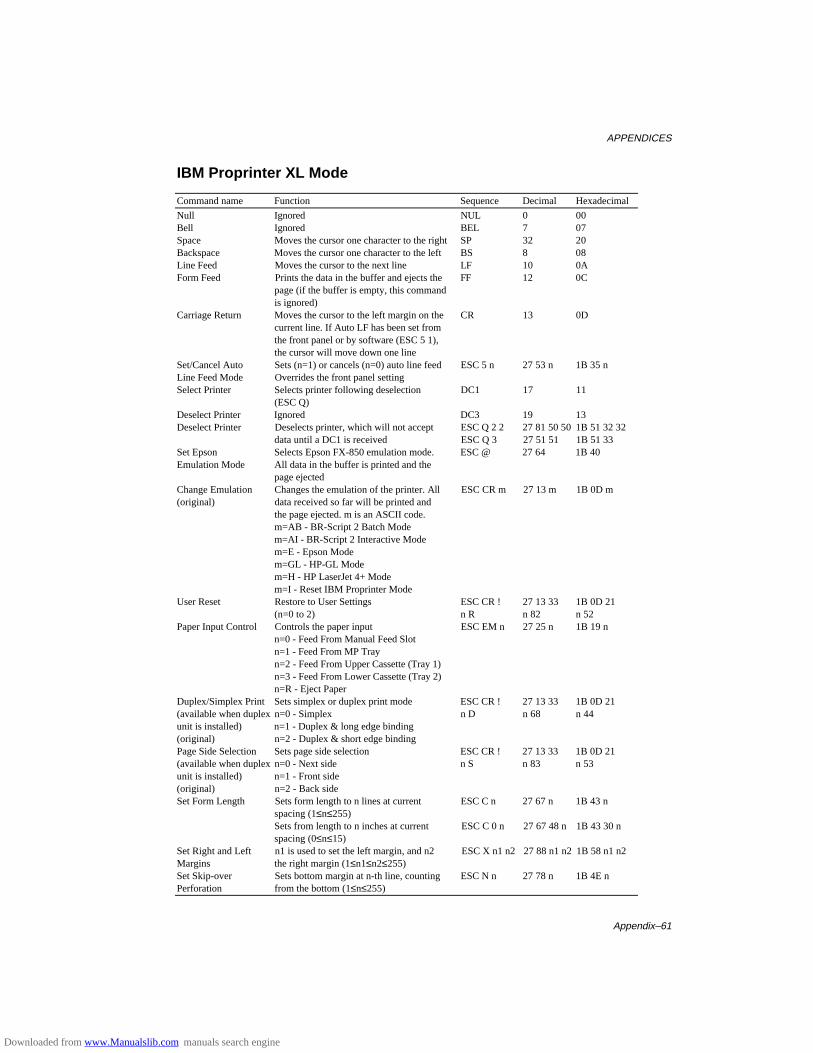
APPENDICES
Appendix–61
IBM Proprinter XL Mode
Command name Function Sequence Decimal Hexadecimal
Null Ignored NUL 0 00Bell Ignored BEL 7 07Space Moves the cursor one character to the right SP 32 20Backspace Moves the cursor one character to the left BS 8 08Line Feed Moves the cursor to the next line LF 10 0AForm Feed Prints the data in the buffer and ejects the FF 12 0C
page (if the buffer is empty, this commandis ignored)
Carriage Return Moves the cursor to the left margin on the CR 13 0Dcurrent line. If Auto LF has been set fromthe front panel or by software (ESC 5 1),the cursor will move down one line
Set/Cancel Auto Sets (n=1) or cancels (n=0) auto line feed ESC 5 n 27 53 n 1B 35 nLine Feed Mode Overrides the front panel settingSelect Printer Selects printer following deselection DC1 17 11
(ESC Q)Deselect Printer Ignored DC3 19 13Deselect Printer Deselects printer, which will not accept ESC Q 2 2 27 81 50 50 1B 51 32 32
data until a DC1 is received ESC Q 3 27 51 51 1B 51 33Set Epson Selects Epson FX-850 emulation mode. ESC @ 27 64 1B 40Emulation Mode All data in the buffer is printed and the
page ejectedChange Emulation Changes the emulation of the printer. All ESC CR m 27 13 m 1B 0D m(original) data received so far will be printed and
the page ejected. m is an ASCII code.m=AB - BR-Script 2 Batch Modem=AI - BR-Script 2 Interactive Modem=E - Epson Modem=GL - HP-GL Modem=H - HP LaserJet 4+ Modem=I - Reset IBM Proprinter Mode
User Reset Restore to User Settings ESC CR ! 27 13 33 1B 0D 21(n=0 to 2) n R n 82 n 52
Paper Input Control Controls the paper input ESC EM n 27 25 n 1B 19 nn=0 - Feed From Manual Feed Slotn=1 - Feed From MP Trayn=2 - Feed From Upper Cassette (Tray 1)n=3 - Feed From Lower Cassette (Tray 2)n=R - Eject Paper
Duplex/Simplex Print Sets simplex or duplex print mode ESC CR ! 27 13 33 1B 0D 21(available when duplex n=0 - Simplex n D n 68 n 44unit is installed) n=1 - Duplex & long edge binding(original) n=2 - Duplex & short edge bindingPage Side Selection Sets page side selection ESC CR ! 27 13 33 1B 0D 21(available when duplex n=0 - Next side n S n 83 n 53unit is installed) n=1 - Front side(original) n=2 - Back sideSet Form Length Sets form length to n lines at current ESC C n 27 67 n 1B 43 n
spacing (1≤n≤255)Sets from length to n inches at current ESC C 0 n 27 67 48 n 1B 43 30 nspacing (0≤n≤15)
Set Right and Left n1 is used to set the left margin, and n2 ESC X n1 n2 27 88 n1 n2 1B 58 n1 n2Margins the right margin (1≤n1≤n2≤255)Set Skip-over Sets bottom margin at n-th line, counting ESC N n 27 78 n 1B 4E nPerforation from the bottom (1≤n≤255)
Downloaded from www.Manualslib.com manuals search engine
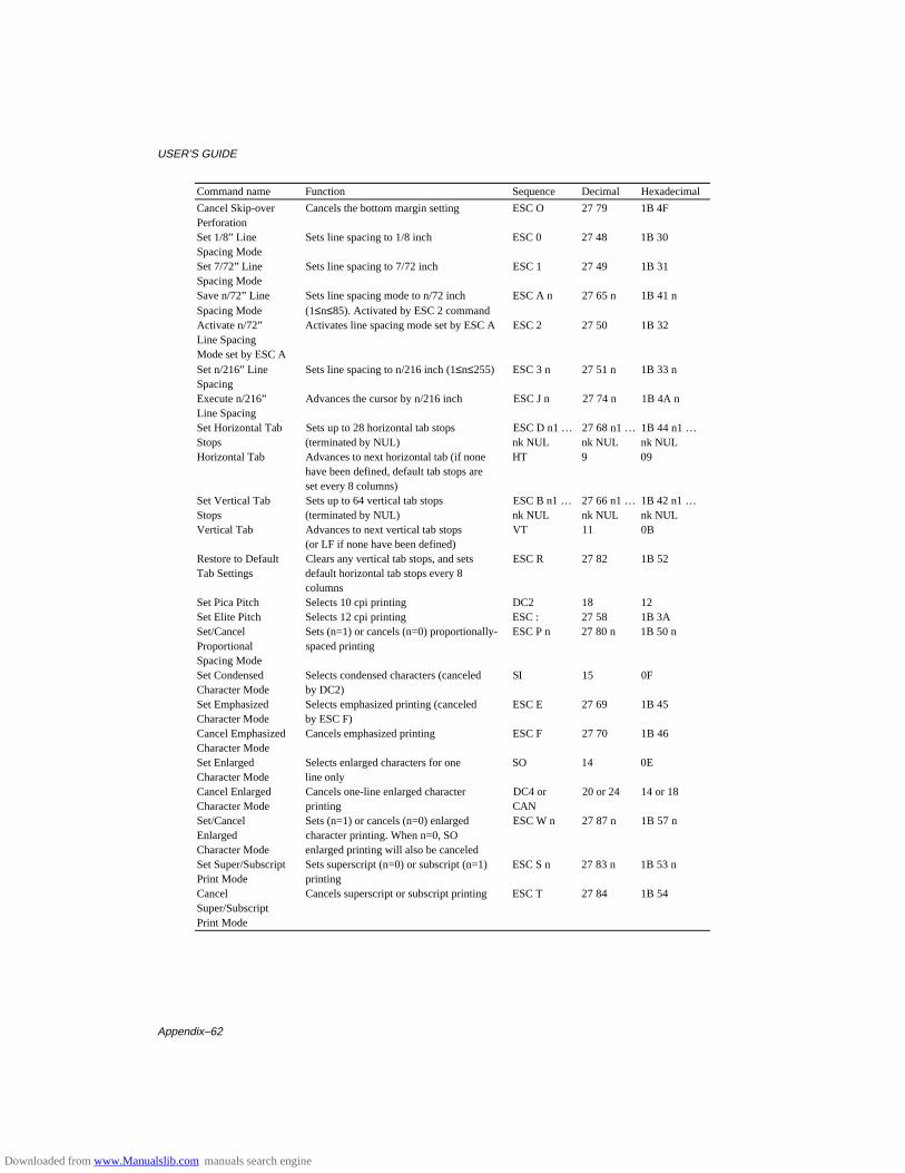
USER’S GUIDE
Appendix–62
Command name Function Sequence Decimal Hexadecimal
Cancel Skip-over Cancels the bottom margin setting ESC O 27 79 1B 4FPerforationSet 1/8” Line Sets line spacing to 1/8 inch ESC 0 27 48 1B 30Spacing ModeSet 7/72” Line Sets line spacing to 7/72 inch ESC 1 27 49 1B 31Spacing ModeSave n/72” Line Sets line spacing mode to n/72 inch ESC A n 27 65 n 1B 41 nSpacing Mode (1≤n≤85). Activated by ESC 2 commandActivate n/72” Activates line spacing mode set by ESC A ESC 2 27 50 1B 32Line SpacingMode set by ESC ASet n/216” Line Sets line spacing to n/216 inch (1≤n≤255) ESC 3 n 27 51 n 1B 33 nSpacingExecute n/216” Advances the cursor by n/216 inch ESC J n 27 74 n 1B 4A nLine SpacingSet Horizontal Tab Sets up to 28 horizontal tab stops ESC D n1 … 27 68 n1 … 1B 44 n1 …Stops (terminated by NUL) nk NUL nk NUL nk NULHorizontal Tab Advances to next horizontal tab (if none HT 9 09
have been defined, default tab stops areset every 8 columns)
Set Vertical Tab Sets up to 64 vertical tab stops ESC B n1 … 27 66 n1 … 1B 42 n1 …Stops (terminated by NUL) nk NUL nk NUL nk NULVertical Tab Advances to next vertical tab stops VT 11 0B
(or LF if none have been defined)Restore to Default Clears any vertical tab stops, and sets ESC R 27 82 1B 52Tab Settings default horizontal tab stops every 8
columnsSet Pica Pitch Selects 10 cpi printing DC2 18 12Set Elite Pitch Selects 12 cpi printing ESC : 27 58 1B 3ASet/Cancel Sets (n=1) or cancels (n=0) proportionally- ESC P n 27 80 n 1B 50 nProportional spaced printingSpacing ModeSet Condensed Selects condensed characters (canceled SI 15 0FCharacter Mode by DC2)Set Emphasized Selects emphasized printing (canceled ESC E 27 69 1B 45Character Mode by ESC F)Cancel Emphasized Cancels emphasized printing ESC F 27 70 1B 46Character ModeSet Enlarged Selects enlarged characters for one SO 14 0ECharacter Mode line onlyCancel Enlarged Cancels one-line enlarged character DC4 or 20 or 24 14 or 18Character Mode printing CANSet/Cancel Sets (n=1) or cancels (n=0) enlarged ESC W n 27 87 n 1B 57 nEnlarged character printing. When n=0, SOCharacter Mode enlarged printing will also be canceledSet Super/Subscript Sets superscript (n=0) or subscript (n=1) ESC S n 27 83 n 1B 53 nPrint Mode printingCancel Cancels superscript or subscript printing ESC T 27 84 1B 54Super/SubscriptPrint Mode
Downloaded from www.Manualslib.com manuals search engine
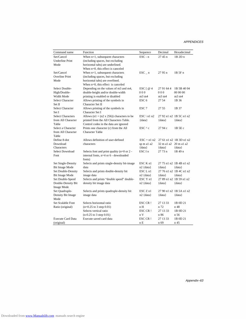
APPENDICES
Appendix–63
Command name Function Sequence Decimal Hexadecimal
Set/Cancel When n=1, subsequent characters ESC - n 27 45 n 1B 2D nUnderline Print (including spaces, but excludingMode horizontal tabs) are underlined.
When n=0, this effect is canceledSet/Cancel When n=1, subsequent characters ESC _ n 27 95 n 1B 5F nOverline Print (including spaces, but excludingMode horizontal tabs) are overlined.
When n=0, this effect is canceledSelect Double- Depending on the values of m3 and m4, ESC [ @ 4 27 91 64 4 1B 5B 40 04High/Double- double-height and/or double-width 0 0 0 0 0 0 00 00 00Width Mode printing is enabled or disabled m3 m4 m3 m4 m3 m4Select Character Allows printing of the symbols in ESC 6 27 54 1B 36Set II Character Set IISelect Character Allows printing of the symbols in ESC 7 27 55 1B 37Set I Character Set ISelect Characters Allows (n1 + (n2 x 256)) characters to be ESC \ n1 n2 27 92 n1 n2 1B 5C n1 n2from All Character printed from the All Characters Table. {data} {data} {data}Table Control codes in the data are ignoredSelect a Character Prints one character (c) from the All ESC ^ c 27 94 c 1B 5E cfrom All Character Character TableTableDefine 8-dot Allows definition of user-defined ESC = n1 n2 27 61 n1 n2 1B 3D n1 n2Download characters sp m a1 a2 32 m a1 a2 20 m a1 a2Characters {data} {data} {data}Select Download Selects font and print quality (n=0 or 2 - ESC I n 27 73 n 1B 49 nFont internal fonts, n=4 or 6 - downloaded
fonts)Set Single-Density Selects and prints single-density bit-image ESC K n1 27 75 n1 n2 1B 4B n1 n2Bit Image Mode data n2 {data} {data} {data}Set Double-Density Selects and prints double-density bit ESC L n1 27 76 n1 n2 1B 4C n1 n2Bit Image Mode image data n2 {data} {data} {data}Set Double-Speed Selects and prints “double speed” double- ESC Y n1 27 89 n1 n2 1B 59 n1 n2Double-Density Bit density bit image data n2 {data} {data} {data}Image ModeSet Quadruple- Selects and prints quadruple-density bit ESC Z n1 27 90 n1 n2 1B 5A n1 n2Density Bit Image image data n2 {data} {data} {data}ModeSet Scalable Font Selects horizontal ratio ESC CR ! 27 13 33 1B 0D 21Ratio (original) (n=0.25 to 3 step 0.01) n H n 72 n 48
Selects vertical ratio ESC CR ! 27 13 33 1B 0D 21(n-0.25 to 3 step 0.01) n V n 86 n 56
Execute Card Data Execute saved card data ESC CR ! 27 13 33 1B 0D 21(original) n E n 69 n 45
Downloaded from www.Manualslib.com manuals search engine
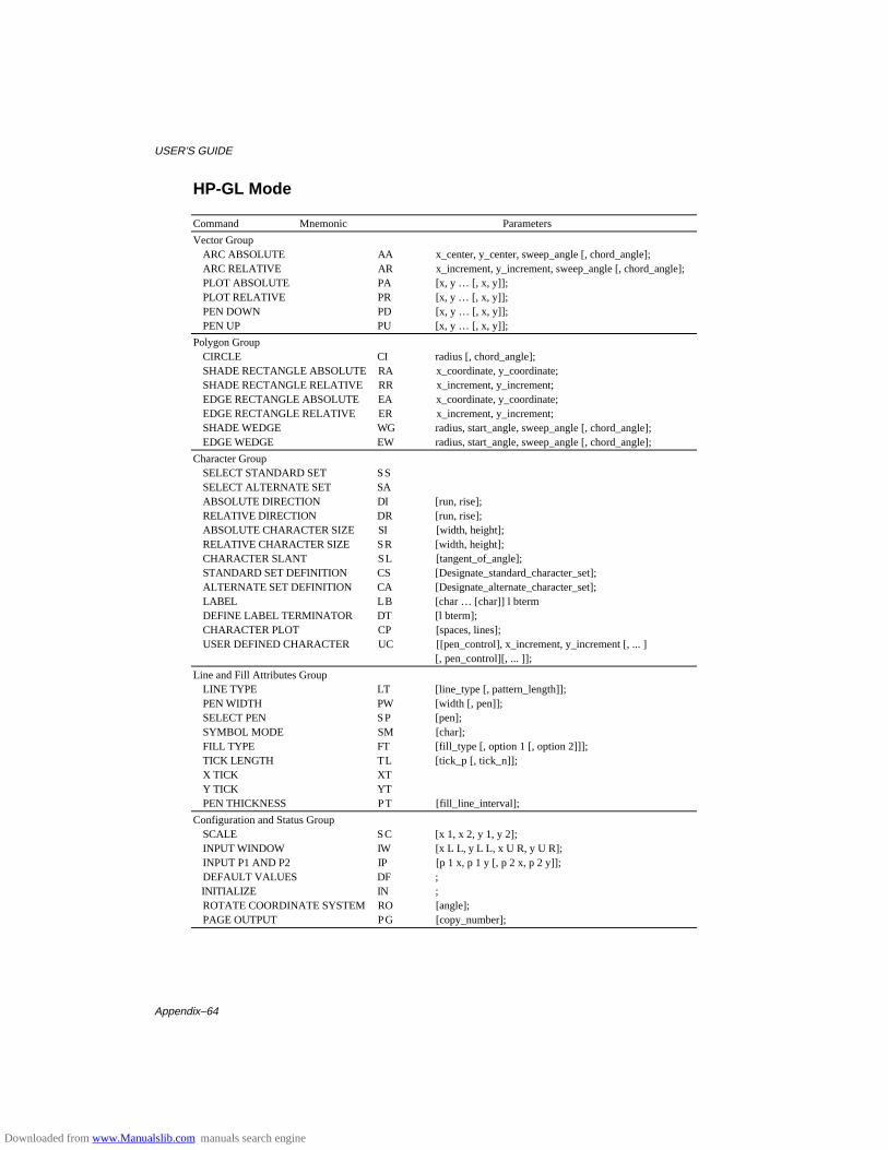
USER’S GUIDE
Appendix–64
HP-GL Mode
Command Mnemonic Parameters
Vector GroupARC ABSOLUTE AA x_center, y_center, sweep_angle [, chord_angle];ARC RELATIVE AR x_increment, y_increment, sweep_angle [, chord_angle];PLOT ABSOLUTE PA [x, y … [, x, y]];PLOT RELATIVE PR [x, y … [, x, y]];PEN DOWN PD [x, y … [, x, y]];PEN UP PU [x, y … [, x, y]];
Polygon GroupCIRCLE CI radius [, chord_angle];SHADE RECTANGLE ABSOLUTE RA x_coordinate, y_coordinate;SHADE RECTANGLE RELATIVE RR x_increment, y_increment;EDGE RECTANGLE ABSOLUTE EA x_coordinate, y_coordinate;EDGE RECTANGLE RELATIVE ER x_increment, y_increment;SHADE WEDGE WG radius, start_angle, sweep_angle [, chord_angle];EDGE WEDGE EW radius, start_angle, sweep_angle [, chord_angle];
Character GroupSELECT STANDARD SET SSSELECT ALTERNATE SET SAABSOLUTE DIRECTION DI [run, rise];RELATIVE DIRECTION DR [run, rise];ABSOLUTE CHARACTER SIZE SI [width, height];RELATIVE CHARACTER SIZE SR [width, height];CHARACTER SLANT SL [tangent_of_angle];STANDARD SET DEFINITION CS [Designate_standard_character_set];ALTERNATE SET DEFINITION CA [Designate_alternate_character_set];LABEL LB [char … [char]] l btermDEFINE LABEL TERMINATOR DT [l bterm];CHARACTER PLOT CP [spaces, lines];USER DEFINED CHARACTER UC [[pen_control], x_increment, y_increment [, ... ]
[, pen_control][, ... ]];
Line and Fill Attributes GroupLINE TYPE LT [line_type [, pattern_length]];PEN WIDTH PW [width [, pen]];SELECT PEN SP [pen];SYMBOL MODE SM [char];FILL TYPE FT [fill_type [, option 1 [, option 2]]];TICK LENGTH TL [tick_p [, tick_n]];X TICK XTY TICK YTPEN THICKNESS PT [fill_line_interval];
Configuration and Status GroupSCALE SC [x 1, x 2, y 1, y 2];INPUT WINDOW IW [x L L, y L L, x U R, y U R];INPUT P1 AND P2 IP [p 1 x, p 1 y [, p 2 x, p 2 y]];DEFAULT VALUES DF ;
INITIALIZE IN ;ROTATE COORDINATE SYSTEM RO [angle];PAGE OUTPUT PG [copy_number];
Downloaded from www.Manualslib.com manuals search engine
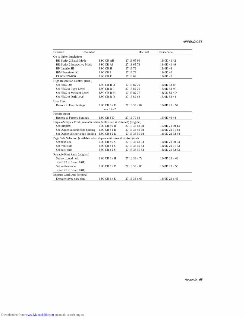
APPENDICES
Appendix–65
Function Command Decimal Hexadecimal
Go to Other EmulationsBR-Script 2 Batch Mode ESC CR AB 27 13 65 66 1B 0D 41 42BR-Script 2 Interactive Mode ESC CR AI 27 13 65 73 1B 0D 41 49HP LaserJet III ESC CR H 27 13 72 1B 0D 48IBM Proprinter XL ESC CR I 27 13 73 1B 0D 49EPSON FX-850 ESC CR E 27 13 69 1B 0D 45
High Resolution Control (HRC)Set HRC Off ESC CR R O 27 13 82 79 1B 0D 52 4FSet HRC to Light Level ESC CR R L 27 13 82 76 1B 0D 52 4CSet HRC to Medium Level ESC CR R M 27 13 82 77 1B 0D 52 4DSet HRC to Dark Level ESC CR R D 27 13 82 68 1B 0D 52 44
User ResetRestore to User Settings ESC CR ! n R 27 13 33 n 82 1B 0D 21 n 52
n = 0 to 2
Factory ResetRestore to Factory Settings ESC CR F D 27 13 70 68 1B 0D 46 44
Duplex/Simplex Print (available when duplex unit is installed) (original)Set Simplex ESC CR ! 0 D 27 13 33 48 68 1B 0D 21 30 44Set Duplex & long edge binding ESC CR ! 1 D 27 13 33 49 68 1B 0D 21 31 44Set Duplex & short edge binding ESC CR ! 2 D 27 13 33 50 68 1B 0D 21 32 44
Page Side Selection (available when duplex unit is installed) (original)Set next side ESC CR ! 0 S 27 13 33 48 83 1B 0D 21 30 53Set front side ESC CR ! 1 S 27 13 33 49 83 1B 0D 21 31 53Set back side ESC CR ! 2 S 27 13 33 50 83 1B 0D 21 32 53
Scalable Font Ratio (original)Set horizontal ratio ESC CR ! n H 27 13 33 n 72 1B 0D 21 n 48 (n=0.25 to 3 step 0.01)Set vertical ratio ESC CR ! n V 27 13 33 n 86 1B 0D 21 n 56
(n=0.25 to 3 step 0.01)
Execute Card Data (original)Execute saved card data ESC CR ! n E 27 13 33 n 69 1B 0D 21 n 45
Downloaded from www.Manualslib.com manuals search engine
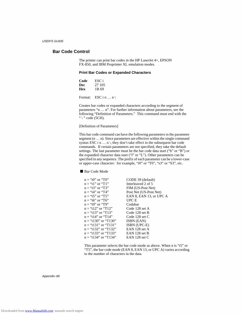
USER’S GUIDE
Appendix–66
Bar Code Control
The printer can print bar codes in the HP LaserJet 4+, EPSONFX-850, and IBM Proprinter XL emulation modes.
Print Bar Codes or Expanded Characters
Code ESC iDec 27 105Hex 1B 69
Format: ESC i n … n \
Creates bar codes or expanded characters according to the segment ofparameters “n … n”. For further information about parameters, see thefollowing “Definition of Parameters.” This command must end with the“ \ ” code (5CH).
[Definition of Parameters]
This bar code command can have the following parameters in the parametersegment (n … n). Since parameters are effective within the single commandsyntax ESC i n … n \, they don’t take effect in the subsequent bar codecommands. If certain parameters are not specified, they take the defaultsettings. The last parameter must be the bar code data start (“b” or “B”) orthe expanded character data start (“l” or “L”). Other parameters can bespecified in any sequence. The prefix of each parameter can be a lower-caseor upper-case character: for example, “t0” or “T0”, “s3” or “S3”, etc.
■ Bar Code Mode
n = “t0” or “T0” CODE 39 (default)n = “t1” or “T1” Interleaved 2 of 5n = “t3” or “T3” FIM (US-Post Net)n = “t4” or “T4” Post Net (US-Post Net)n = “t5” or “T5” EAN 8, EAN 13, or UPC An = “t6” or “T6” UPC En = “t9” or “T9” Codabarn = “t12” or “T12” Code 128 set An = “t13” or “T13” Code 128 set Bn = “t14” or “T14” Code 128 set Cn = “t130” or “T130” ISBN (EAN)n = “t131” or “T131” ISBN (UPC-E)n = “t132” or “T132” EAN 128 set An = “t133” or “T133” EAN 128 set Bn = “t134” or “T134” EAN 128 set C
This parameter selects the bar code mode as above. When n is “t5” or“T5”, the bar code mode (EAN 8, EAN 13, or UPC A) varies accordingto the number of characters in the data.
Downloaded from www.Manualslib.com manuals search engine
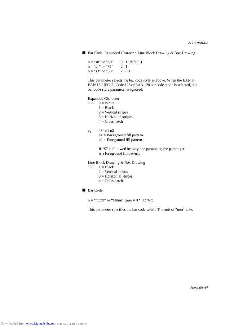
APPENDICES
Appendix–67
■ Bar Code, Expanded Character, Line Block Drawing & Box Drawing
n = “s0” or “S0” 3 : 1 (default)n = “s1” or “S1” 2 : 1n = “s3” or “S3” 2.5 : 1
This parameter selects the bar code style as above. When the EAN 8,EAN 13, UPC-A, Code 128 or EAN 128 bar code mode is selected, thisbar code style parameter is ignored.
Expanded Character“S” 0 = White
1 = Black2 = Vertical stripes3 = Horizontal stripes4 = Cross hatch
eg. “S” n1 n2n1 = Background fill patternn2 = Foreground fill pattern
If “S” is followed by only one parameter, the parameteris a foreground fill pattern.
Line Block Drawing & Box Drawing“S” 1 = Black
2 = Vertical stripes3 = Horizontal stripes4 = Cross hatch
■ Bar Code
n = “mnnn” or “Mnnn” (nnn = 0 ~ 32767)
This parameter specifies the bar code width. The unit of "nnn" is %.
Downloaded from www.Manualslib.com manuals search engine
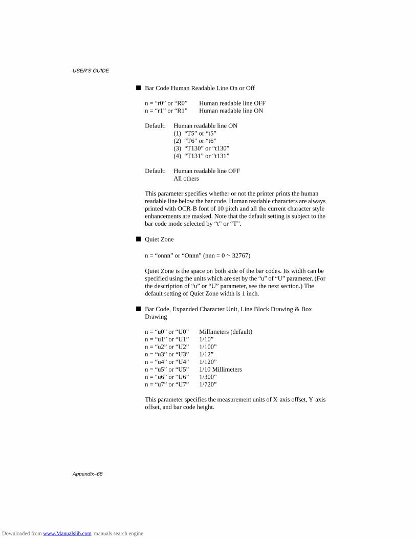
USER’S GUIDE
Appendix–68
■ Bar Code Human Readable Line On or Off
n = “r0” or “R0” Human readable line OFFn = “r1” or “R1” Human readable line ON
Default: Human readable line ON(1) “T5” or “t5”(2) “T6” or “t6”(3) “T130” or “t130”(4) “T131” or “t131”
Default: Human readable line OFFAll others
This parameter specifies whether or not the printer prints the humanreadable line below the bar code. Human readable characters are alwaysprinted with OCR-B font of 10 pitch and all the current character styleenhancements are masked. Note that the default setting is subject to thebar code mode selected by “t” or “T”.
■ Quiet Zone
n = “onnn” or “Onnn” (nnn = 0 ~ 32767)
Quiet Zone is the space on both side of the bar codes. Its width can bespecified using the units which are set by the “u” of “U” parameter. (Forthe description of “u” or “U” parameter, see the next section.) Thedefault setting of Quiet Zone width is 1 inch.
■ Bar Code, Expanded Character Unit, Line Block Drawing & BoxDrawing
n = “u0” or “U0” Millimeters (default)n = “u1” or “U1” 1/10”n = “u2” or “U2” 1/100”n = “u3” or “U3” 1/12”n = “u4” or “U4” 1/120”n = “u5” or “U5” 1/10 Millimetersn = “u6” or “U6” 1/300”n = “u7” or “U7” 1/720”
This parameter specifies the measurement units of X-axis offset, Y-axisoffset, and bar code height.
Downloaded from www.Manualslib.com manuals search engine
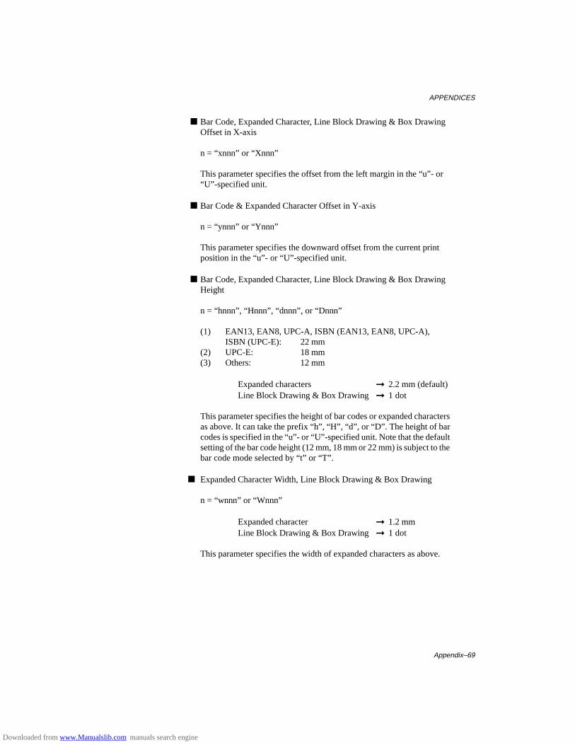
APPENDICES
Appendix–69
■ Bar Code, Expanded Character, Line Block Drawing & Box DrawingOffset in X-axis
n = “xnnn” or “Xnnn”
This parameter specifies the offset from the left margin in the “u”- or“U”-specified unit.
■ Bar Code & Expanded Character Offset in Y-axis
n = “ynnn” or “Ynnn”
This parameter specifies the downward offset from the current printposition in the “u”- or “U”-specified unit.
■ Bar Code, Expanded Character, Line Block Drawing & Box DrawingHeight
n = “hnnn”, “Hnnn”, “dnnn”, or “Dnnn”
(1) EAN13, EAN8, UPC-A, ISBN (EAN13, EAN8, UPC-A),ISBN (UPC-E): 22 mm
(2) UPC-E: 18 mm(3) Others: 12 mm
Expanded characters ➞ 2.2 mm (default)Line Block Drawing & Box Drawing ➞ 1 dot
This parameter specifies the height of bar codes or expanded charactersas above. It can take the prefix “h”, “H”, “d”, or “D”. The height of barcodes is specified in the “u”- or “U”-specified unit. Note that the defaultsetting of the bar code height (12 mm, 18 mm or 22 mm) is subject to thebar code mode selected by “t” or “T”.
■ Expanded Character Width, Line Block Drawing & Box Drawing
n = “wnnn” or “Wnnn”
Expanded character ➞ 1.2 mmLine Block Drawing & Box Drawing ➞ 1 dot
This parameter specifies the width of expanded characters as above.
Downloaded from www.Manualslib.com manuals search engine

USER’S GUIDE
Appendix–70
■ Expanded Character Rotation
n = “a0” or “A1” Upright (default)n = “a1” or “A1” Rotated 90 degreesn = “a2” or “A2” Upside down, rotated 180 degreesn = “a3” or “A3” Rotated 270 degrees
■ Bar Code Data Start
n = “b” or “B”
Data that follows “b” or “B” is read in as bar code data. Bar code datamust end with the “ \ ” code (5CH), which also terminates thiscommand. The acceptable bar code data is subject to the bar code modeselected by “t” or “T”.
• When CODE 39 is selected with the parameter “t0” or “T0”:
Forty three characters “0” to “9”, “A” to “Z”, “-”, “ . ”, “ (space)”, “$”,“ / ”, “+”, and “%” can be accepted as bar code data. Other characterscause data error. The number of characters for bar codes is not limited.The bar code data automatically starts and ends with an asterisk “ * ”(start character and stop character). If the received data has an asterisk“ * ” at its beginning or end, the asterisk is regarded as a start characteror stop character.
• When Interleaved 2 of 5 is selected with the parameter “t1” or “T1”:
Ten numerical characters “0” to “9” can be accepted as bar code data.Other characters cause data error. The number of characters for barcodes is not limited. Since this mode of bar codes require evencharacters, if the bar code data has odd characters, the zero character“0” is automatically added to the end of the bar code data.
• When FIM (US-Post Net) is selected with the parameter “t3” or “T3”:
Characters “A” to “D” are valid and 1 digit of data can be printed.Uppercase and lowercase alphabet characters can be accepted.
• When Post Net (US-Post Net) is selected with the parameter “t4” or“T4”:
Characters “0” to “9” can be data and it must be terminated by a checkdigit. “?” can be used in place of the check digit.
Downloaded from www.Manualslib.com manuals search engine

APPENDICES
Appendix–71
• When EAN 8, EAN 13, or UPC A is selected with the parameter “t5” or“T5”:
Ten numerical characters “0” to “9” can be accepted as bar code data.The number of characters for bar codes is limited as follows.
EAN 8: Total 8 digits (7 digits + 1 check digit)EAN 13: Total 13 digits (12 digits + 1 check digit)UPC A: Total 12 digits (11 digits + 1 check digit)
A number of characters other than above causes data error and the barcode data is printed as normal print data. If the check digit is incorrect,the printer calculates the correct check digit automatically so that thecorrect bar code data will be printed. When EAN13 is selected, adding“+” and a 2-or 5-digit number after the data can create an add-on code.
• When UPC-E is selected with the parameter “t6” or “T6”:
The numerical characters “0” to “9” can be accepted as bar code data.(1) 8 digits Standard format. The first character
must be “0” and the data must be terminated bya check digit.Total 8 digits = “0” + 6 digits + 1 check digit.
(2) 6 digits The first character and the lastcheck digit are removed from the 8 digit data.
*1: For 8 digits, “?” can be used in place of a check digit. *2: Adding “+” and 2- or 5-digit number after the data creates
an add-on code for all 6 and 8 digit formats.
• When Codabar is selected with the parameter “t9” or “T9”:
Characters “0” to “9”, “-”, “ . ”, “$”, “/”, “+”, “ : ” can be printed.Characters “A” to “D” can be printed as a start-stop code, which can beuppercase or lowercase. If there is no start-stop code, errors occur. Acheck digit cannot be added and using “?” causes errors.
• When Code 128 Set A, Set B, or Set C is selected with the parameter“t12” or “T12,” “t13” or “T13,” or “t14” or “T14” respectively:
Code 128 sets A, B and C are individually selectable. Set A encodescharacters Hex 00 … 5F. Set B encodes characters Hex 20 … 7F. Set Cencodes numeric pairs 00 … 99. Switching is allowed between the codesets by sending %A, %B, or %C. FNC 1, 2, 3, and 4 are producedwith %1, %2, %3, and %4. The SHIFT code, %S, allows temporaryswitching (for 1 character only) from set A to set B and vice versa. The“%” character can be encoded by sending it twice.
Downloaded from www.Manualslib.com manuals search engine
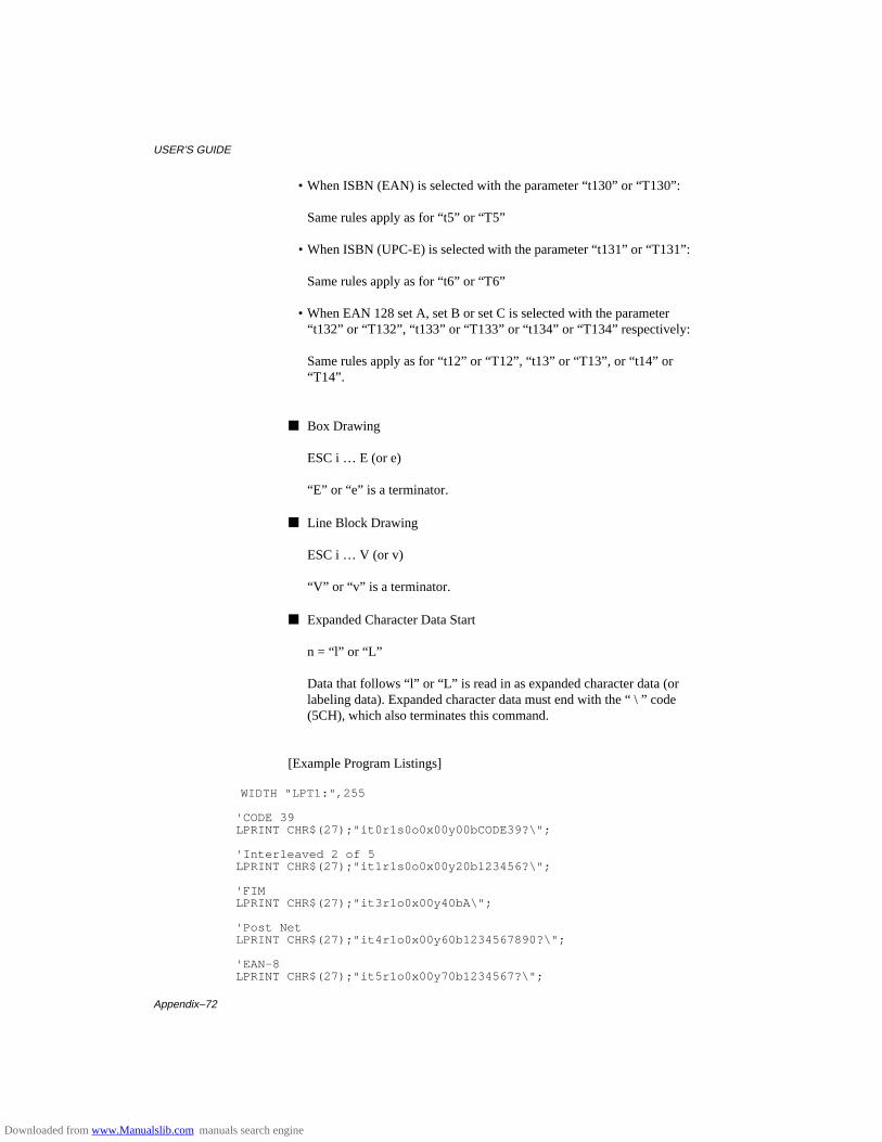
USER’S GUIDE
Appendix–72
• When ISBN (EAN) is selected with the parameter “t130” or “T130”:
Same rules apply as for “t5” or “T5”
• When ISBN (UPC-E) is selected with the parameter “t131” or “T131”:
Same rules apply as for “t6” or “T6”
• When EAN 128 set A, set B or set C is selected with the parameter“t132” or “T132”, “t133” or “T133” or “t134” or “T134” respectively:
Same rules apply as for “t12” or “T12”, “t13” or “T13”, or “t14” or“T14”.
■ Box Drawing
ESC i … E (or e)
“E” or “e” is a terminator.
■ Line Block Drawing
ESC i … V (or v)
“V” or “v” is a terminator.
■ Expanded Character Data Start
n = “l” or “L”
Data that follows “l” or “L” is read in as expanded character data (orlabeling data). Expanded character data must end with the “ \ ” code(5CH), which also terminates this command.
[Example Program Listings]
WIDTH "LPT1:",255
'CODE 39 LPRINT CHR$(27);"it0r1s0o0x00y00bCODE39?\";
'Interleaved 2 of 5 LPRINT CHR$(27);"it1r1s0o0x00y20b123456?\";
'FIM LPRINT CHR$(27);"it3r1o0x00y40bA\";
'Post Net LPRINT CHR$(27);"it4r1o0x00y60b1234567890?\";
'EAN-8 LPRINT CHR$(27);"it5r1o0x00y70b1234567?\";
Downloaded from www.Manualslib.com manuals search engine

APPENDICES
Appendix–73
'UPC-A LPRINT CHR$(27);"it5r1o0x50y70b12345678901?\";
'EAN-13 LPRINT CHR$(27);"it5r1o0x100y70b123456789012?\";
'UPC-E LPRINT CHR$(27);"it6r1o0x150y70b0123456?\";
'Codabar LPRINT CHR$(27);"it9r1s0o0x00y100bA123456A\";
'Code 128 set A LPRINT CHR$(27);"it12r1o0x00y120bCODE128A12345?\";
'Code 128 set B LPRINT CHR$(27);"it13r1o0x00y140bCODE128B12345?\";
'Code 128 set C LPRINT CHR$(27);"it14r1o0x00y160b";CHR$(1);CHR$(2);"?\";
'ISBN(EAN) LPRINTCHR$(27);"it130r1o0x00y180b123456789012?+12345\";
'EAN 128 set A LPRINT CHR$(27);"it132r1o0x00y210b1234567890?\";
LPRINT CHR$(12) END
Downloaded from www.Manualslib.com manuals search engine
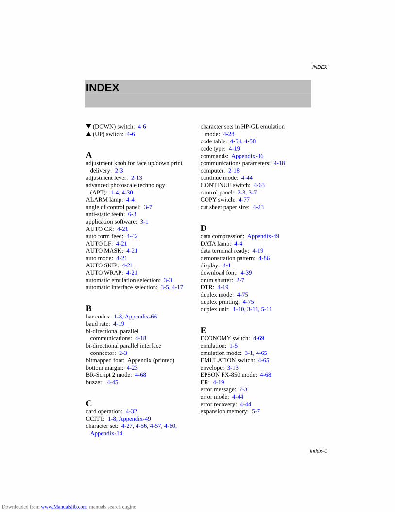
INDEX
Index–1
INDEX
▼ (DOWN) switch: 4-6▲ (UP) switch: 4-6
Aadjustment knob for face up/down print
delivery: 2-3adjustment lever: 2-13advanced photoscale technology
(APT): 1-4, 4-30ALARM lamp: 4-4angle of control panel: 3-7anti-static teeth: 6-3application software: 3-1AUTO CR: 4-21auto form feed: 4-42AUTO LF: 4-21AUTO MASK: 4-21auto mode: 4-21AUTO SKIP: 4-21AUTO WRAP: 4-21automatic emulation selection: 3-3automatic interface selection: 3-5, 4-17
Bbar codes: 1-8, Appendix-66baud rate: 4-19bi-directional parallel
communications: 4-18bi-directional parallel interface
connector: 2-3bitmapped font: Appendix (printed)bottom margin: 4-23BR-Script 2 mode: 4-68buzzer: 4-45
Ccard operation: 4-32CCITT: 1-8, Appendix-49character set: 4-27, 4-56, 4-57, 4-60,
Appendix-14
character sets in HP-GL emulationmode: 4-28
code table: 4-54, 4-58code type: 4-19commands: Appendix-36communications parameters: 4-18computer: 2-18continue mode: 4-44CONTINUE switch: 4-63control panel: 2-3, 3-7COPY switch: 4-77cut sheet paper size: 4-23
Ddata compression: Appendix-49DATA lamp: 4-4data terminal ready: 4-19demonstration pattern: 4-86display: 4-1download font: 4-39drum shutter: 2-7DTR: 4-19duplex mode: 4-75duplex printing: 4-75duplex unit: 1-10, 3-11, 5-11
EECONOMY switch: 4-69emulation: 1-5emulation mode: 3-1, 4-65EMULATION switch: 4-65envelope: 3-13EPSON FX-850 mode: 4-68ER: 4-19error message: 7-3error mode: 4-44error recovery: 4-44expansion memory: 5-7
Downloaded from www.Manualslib.com manuals search engine
USER’S GUIDE
Index–2
Fface down print delivery: 3-17face down print delivery tray: 2-3face up print delivery: 3-17factory settings: 3-10, 4-79FEEDER switch: 4-70fixing roller: 7-9flash memory card: 1-10, 5-2flash operation: 4-34floppy disk: 1-3fonts: 1-6, 4-59font card: 5-2font cartridge: 1-10, 5-2font cartridge slot: 2-3font/IC card slot: 2-3font ID number: 5-5font list: 4-87font size: 4-53, 4-57font source: 4-51, 4-55font style: 4-52, 4-56FONT switch: 4-49form feed: 4-61form feed suppress: 4-43FORM FEED switch: 4-61fuser: 6-6
GG3/G4: 1-8G3/G4 format: Appendix-49graphics mode: 4-26
HHDD card: 1-10, 5-2hex dump mode: 4-88high resolution control (HRC): 1-4, 4-30high speed parallel communications: 4-18HP-GL mode: 4-68HP LaserJet 4+ mode: 4-67HP mode: 4-67
IIBM Proprinter XL mode: 4-68input buffer: 4-46interface: 1-5interface mode: 4-17
KKEEP PCL function: 4-66
Llamps: 4-4landscape: 4-20language: 3-8LaserJet 4+ mode: 4-67left margin: 4-23left side cover: 5-8line feed pitch: 4-25line spacing: 4-25lines/page: 4-25lines per page: 4-23list of optional fonts: 4-85list of panel switch settings: 4-85list of permanent download fonts: 4-85list of resident fonts: 4-85lock panel: 4-42lock your settings: 1-8lower paper cassette: 3-11lower tray unit: 1-10, 5-1
Mmacro: 4-37manual feed: 3-16manual feed mode: 4-73margin: 4-24media type: 4-74memory: 1-6, 5-7memory modules: 1-10MIO card: 1-10, 4-19, 5-6MIO card slot: 2-3MIO interface: 1-5, 4-19MIO interface slot: 5-6MODE switch: 4-7modular input/output (MIO) interface: 5-6modular jack for options: 2-3MP FIRST mode: 4-72MP tray setting: 4-73multi-purpose tray: 2-3, 2-15, 3-11
Nnetwork mode: 4-41NORMAL mode: 3-9, 4-5number of copies: 4-77
Downloaded from www.Manualslib.com manuals search engine

INDEX
Index–3
number of printed pages: 4-48
Ooff-line: 4-5on-line: 4-5ON LINE lamp: 4-4operator call message: 7-1optional fonts: 5-4optional interface: 4-19options: 1-10orientation: 4-20
Ppage format mode: 4-23page protection: 4-32paper access cover: 6-7, 7-10paper capacity: 3-12paper cassette: 1-5, 2-11, 3-15paper exit: 7-7paper feed method: 4-71paper guide: 6-7PAPER IN setting: 4-74paper jam: 7-6paper path selector guide: 3-17paper size: 3-12paper source: 3-12, 4-71paper type: 3-12paper width guide: 2-15parallel interface: 1-5, 4-18parallel interface port: 2-18parity: 4-19pass number: 4-42PCMCIA-compatible flash memory
card: 1-9pen setting: 4-26pen size: 4-26portrait: 4-20PostScript® language emulation: 4-68power cord: 2-19power cord connector: 2-3power save mode: 4-69power saving mode: 1-8power switch: 2-3, 2-20primary font: 4-50print density: 4-46print start position: 4-23printer driver: 3-1
printer emulation: 3-1printer settings: 3-10, 4-86printer status message: 4-2printer test: 4-86protective parts: 2-6
Qquick exit switch: 4-6
RREADY lamp: 4-4rear access cover: 2-3, 7-8rear paper slit: 3-17reprint: 1-9, 4-61reset mode: 4-78RESET switch: 4-78resident fonts: Appendix (printed)resolution: 1-4, 4-29resolution mode: 4-28right margin: 4-23robust Xon: 4-19RS-232C interface: 1-5RS-232C serial interface connector: 2-3
Sscalable font: 4-45, Appendix (printed)secondary font: 4-50SEL switch: 4-5self-diagnosis: 2-20serial interface: 1-5, 4-18serial interface port: 2-18service call message: 7-5SET switch: 4-6shades of gray: 1-4, 4-26SHIFT mode: 3-9SHIFT switch: 4-64side paper stop: 2-13SIMM: 5-8simplex printing: 4-75single in-line memory modules
(SIMMs): 5-7sizes of paper: 3-11sleep: 4-69sliding guide: 2-14slot: 5-3software: 3-1
Downloaded from www.Manualslib.com manuals search engine
USER’S GUIDE
Index–4
spacers: 2-6stop bit: 4-19switch: 3-9symbol set: 4-60, Appendix-14
Ttable print: 4-54, 4-58technical reference manual: 1-10test mode: 4-85test pattern: 4-86TEST switch: 4-85TIFF Format: Appendix-51time out for the auto interface
selection: 4-17time out for the automatic emulation
change: 4-65time out for the power save mode: 4-69toner cartridge: 1-4, 2-2, 2-7, 6-1toner empty: 6-1toner low: 4-44toner save mode: 1-8, 4-69top cover: 2-3, 2-5top margin: 4-23transfer guide: 6-7transfer roller: 6-3tray 1: 3-16tray 2: 3-16
Uupper paper cassette: 2-3, 3-11user settings: 3-10, 4-47
Wwait time: 4-43Windows: 1-8
XX offset: 4-23Xon/Xoff: 4-19
YY offset: 4-23
Downloaded from www.Manualslib.com manuals search engine
Related Documents