Broadcom NetXtreme II® Network Adapter User Guide file:///C|/Users/Nalina_N_S/Documents/NetXtremeII/English/index.htm[9/5/2014 3:44:56 PM] Broadcom NetXtreme II ® Network Adapter User Guide The information below is provided by the supplier of the referenced device without independent verification by Dell and is subject to the Restrictions and Disclaimers noted below. Introduction Functionality and Features Teaming Virtual LANs (VLANs) Manageability Installing the Hardware Installing the Driver Software Broadcom Boot Agent Driver Software NDIS2 Driver Software Linux Driver Software Solaris Driver Software VMware Driver Software Installing Windows Drivers and Management Applications Linux Management Application Installation iSCSI Advanced Teaming Concepts NIC Partitioning Fibre Channel Over Ethernet Data Center Bridging SR-IOV Using Broadcom Advanced Control Suite User Diagnostics Specifications Regulatory Information Troubleshooting Information in this document is subject to change without notice. © 2014 Broadcom Corporation. All rights reserved. Trademarks used in this text: Broadcom, NetXtreme II, Ethernet@Wirespeed, LiveLink, and Smart Load Balancing are among the trademarks of Broadcom Corporation and/or its affiliates in the United States, certain other countries, and/or the EU. Dell and the DELL logo are trademarks of Dell Inc. Microsoft and Windows are trademarks of Microsoft Corporation. Linux is a trademark of Linus Torvalds. Intel is a trademark of Intel Corporation. Magic Packet is a trademark of Advanced Micro Devices, Inc. Red Hat is a trademark of Red Hat, Inc. PCI Express is a trademark of PCI-SIG. Any other trademarks or trade names mentioned are the property of their respective owners. Restrictions and Disclaimers The information contained in this document, including all instructions, cautions, and regulatory approvals and certifications, is provided by the supplier and has not been independently verified or tested by Dell, except where specifically noted. Dell

Welcome message from author
This document is posted to help you gain knowledge. Please leave a comment to let me know what you think about it! Share it to your friends and learn new things together.
Transcript

Broadcom NetXtreme II® Network Adapter User Guide
file:///C|/Users/Nalina_N_S/Documents/NetXtremeII/English/index.htm[9/5/2014 3:44:56 PM]
Broadcom NetXtreme II® Network Adapter User Guide
The information below is provided by the supplier of the referenced device without independent verification by Dell and issubject to the Restrictions and Disclaimers noted below.
Introduction
Functionality and Features
Teaming
Virtual LANs (VLANs)
Manageability
Installing the Hardware
Installing the Driver Software
Broadcom Boot Agent Driver Software
NDIS2 Driver Software
Linux Driver Software
Solaris Driver Software
VMware Driver Software
Installing Windows Drivers and Management Applications
Linux Management Application Installation
iSCSI
Advanced Teaming Concepts
NIC Partitioning
Fibre Channel Over Ethernet
Data Center Bridging
SR-IOV
Using Broadcom Advanced Control Suite
User Diagnostics
Specifications
Regulatory Information
Troubleshooting
Information in this document is subject to change without notice.© 2014 Broadcom Corporation. All rights reserved.
Trademarks used in this text: Broadcom, NetXtreme II, Ethernet@Wirespeed, LiveLink, and Smart Load Balancing are amongthe trademarks of Broadcom Corporation and/or its affiliates in the United States, certain other countries, and/or the EU. Delland the DELL logo are trademarks of Dell Inc. Microsoft and Windows are trademarks of Microsoft Corporation. Linux is atrademark of Linus Torvalds. Intel is a trademark of Intel Corporation. Magic Packet is a trademark of Advanced MicroDevices, Inc. Red Hat is a trademark of Red Hat, Inc. PCI Express is a trademark of PCI-SIG. Any other trademarks or tradenames mentioned are the property of their respective owners.
Restrictions and Disclaimers
The information contained in this document, including all instructions, cautions, and regulatory approvals and certifications, isprovided by the supplier and has not been independently verified or tested by Dell, except where specifically noted. Dell

Broadcom NetXtreme II® Network Adapter User Guide
file:///C|/Users/Nalina_N_S/Documents/NetXtremeII/English/index.htm[9/5/2014 3:44:56 PM]
cannot be responsible for damage caused as a result of either following or failing to follow these instructions. All statementsor claims regarding the properties, capabilities, speeds or qualifications of the part referenced in this document are made bythe supplier and not by Dell. Dell specifically disclaims knowledge of the accuracy, completeness or substantiation for anysuch statements. All questions or comments relating to such statements or claims should be directed to the supplier.
Export Regulations
Customer acknowledges that these Products, which may include technology and software, are subject to the customs andexport control laws and regulations of the United States ("U.S.") and may also be subject to the customs and export laws andregulations of the country in which the Products are manufactured and/or received. Customer agrees to abide by those lawsand regulations. Further, under U.S. law, the Products may not be sold, leased or otherwise transferred to restricted end-users or to restricted countries. In addition, the Products may not be sold, leased or otherwise transferred to, or utilized by anend-user engaged in activities related to weapons of mass destruction, including without limitation, activities related to thedesign, development, production or use of nuclear weapons, materials, or facilities, missiles or the support of missile projects,and chemical or biological weapons.
Initial release: December 2005
Last revised: March 2014
2CSINGSRVT710-CDUM100-R

Functionality and Features: Broadcom NetXtreme II® Network Adapter User Guide
file:///C|/Users/Nalina_N_S/Documents/NetXtremeII/English/features.htm[9/5/2014 3:44:57 PM]
Back to Contents Page
Functionality and Features: Broadcom NetXtreme II® NetworkAdapter User Guide
Functional Description
Features
Functional Description
The Broadcom NetXtreme II adapter is a new class of Gigabit Ethernet (GbE) and 10 GbE converged network interfacecontroller (C-NIC) that can simultaneously perform accelerated data networking and storage networking on a standardEthernet network. The C-NIC offers acceleration for popular protocols used in the data center, such as:
TCP Offload Engine (TOE) for accelerating TCP over 1 GbE and 10 GbE
Internet Small Computer Systems Interface (iSCSI) offload for accelerating network storage access featuringcentralized boot functionality (iSCSI boot)
Fibre Channel over Ethernet (FCoE) offload and acceleration for fibre channel block storage
NOTE: Not all adapters support each listed protocol. Refer to the specific product data sheet for protocol support.
NOTE: Separate licences are required for all offloading technologies.
Enterprise networks that use multiple protocols and multiple network fabrics benefit from the C-NICs ability to combine datacommunications, storage, and clustering over a single Ethernet fabric by boosting server CPU processing performance andmemory utilization while alleviating I/O bottlenecks.
The Broadcom NetXtreme II adapter includes a 10/100/1000-Mbps or 10-Gbps Ethernet MAC with both half-duplex and full-duplex capability and a 10/100/1000-Mbps or 10-Gbps PHY. The transceiver is fully compatible with the IEEE 802.3 standardfor auto-negotiation of speed.
Using the Broadcom teaming software, you can split your network into virtual LANs (VLANs) as well as group multiple networkadapters together into teams to provide network load balancing and fault tolerance functionality. See Configuring Teamingand Broadcom Gigabit Ethernet Teaming Services for detailed information about teaming. See Virtual LANs, for a descriptionof VLANs. See Configuring Teaming for instructions on configuring teaming and creating VLANs on Windows operatingsystems.
Features
The following is a list of the Broadcom NetXtreme II adapter features. Some features may not be available on all adapters.
TCP Offload Engine (TOE)
Internet Small Computer Systems Interface (iSCSI) offload
Fibre Channel over Ethernet (FCoE)
NIC Partitioning
Data Center Bridging (DCB)
Enhanced Transmission Selection (ETS; IEEE 802.1Qaz)
Priority-based Flow Control (PFC; IEEE 802.1Qbb)
Data Center Bridging Capability eXchange Protocol (DCBX; CEE version 1.01)
Single-chip solution
Integrated 10/100/1000BASE-T transceivers
Integrated 10GBASE-T transceivers
10/100/1000 triple-speed MAC
SerDes interface for optical transceiver connection

Functionality and Features: Broadcom NetXtreme II® Network Adapter User Guide
file:///C|/Users/Nalina_N_S/Documents/NetXtremeII/English/features.htm[9/5/2014 3:44:57 PM]
PCI Express 1.0a x4 (Gigabit Ethernet)
PCI Express Gen2 x8 (10 Gigabit Ethernet)
Full fast-path TCP offload
Zero copy capable hardware
Other performance features
TCP, IP, UDP checksum
TCP segmentation
Adaptive interrupts
Receive Side Scaling (RSS)
Manageability
Broadcom Advanced Control Suite diagnostic and configuration software suite
Supports PXE 2.0 specification (Linux Red Hat PXE Server, SUSE Linux Enterprise Server, Windows Server 2008,Windows Server 2008 R2, Windows Server 2012, Intel APITEST, DOS UNDI)
Wake on LAN support
Universal Management Port (UMP) support
Statistics for SNMP MIB II, Ethernet-like MIB, and Ethernet MIB (IEEE Std 802.3z, Clause 30)
SMBus controller
ACPI 1.1a compliant (multiple power modes)
IPMI support
Advanced network features
Jumbo frames (up to 9 KB). The OS and the link partner must support jumbo frames.
Virtual LANs
IEEE Std 802.3ad Teaming
Smart Load Balancing Teaming
Smart Load Balancing TOE Teaming (with the correct configuration)
Flow Control (IEEE Std 802.3x)
LiveLink™ (supported in both the 32-bit and 64-bit Windows operating systems)
Logical Link Control (IEEE Std 802.2)
Layer-2 Priority Encoding (IEEE Std 802.1p)
High-speed on-chip RISC processor
Up to 4 classes of service (CoS)
Up to 4 send rings and receive rings
Integrated 96 KB frame buffer memory
Quality of Service (QoS)
GMII/MII Management Interface
Four unique MAC unicast addresses
Support for multicast addresses via 128 bits hashing hardware function
Serial flash NVRAM memory
JTAG support
PCI Power Management Interface (v1.1)
64-bit BAR support
EM64T processor support
1.2 V core voltage, 0.13 µm process
iSCSI Boot support
Virtualization
Microsoft

Functionality and Features: Broadcom NetXtreme II® Network Adapter User Guide
file:///C|/Users/Nalina_N_S/Documents/NetXtremeII/English/features.htm[9/5/2014 3:44:57 PM]
VMware
Single Root I/O Virtualization (SRIOV)
TCP Offload Engine (TOE)
The TCP/IP protocol suite is used to provide transport services for a wide range of applications for the Internet, LAN, and forfile transfer. Without the TCP Offload Engine, the TCP/IP protocol suite runs on the host CPU, consuming a very highpercentage of its resources and leaving little resources for the applications. With the use of the Broadcom NetXtreme IIadapter, the TCP/IP processing can be moved to hardware, freeing the CPU for more important tasks such as applicationprocessing.
The Broadcom NetXtreme II adapter's TOE functionality allows simultaneous operation of up to 1024 fully offloaded TCPconnections for 1-Gbps network adapters and 1880 fully offloaded TCP connections for 10-Gbps network adapters. The TOEsupport on the adapter significantly reduces the host CPU utilization while preserving the implementation of the operatingsystem stack.
Internet Small Computer Systems Interface (iSCSI)
The IETF has standardized the Internet Small Computer Systems Interface (iSCSI). SCSI is a popular protocol that enablessystems to communicate with storage devices, using block-level transfer (i.e., address data stored on a storage device that isnot a whole file). iSCSI maps the SCSI request/response application protocols and its standardized command set over TCP/IPnetworks.
As iSCSI utilizes TCP as its sole transport protocol, it greatly benefits from hardware acceleration of the TCP processing (i.e.,use of a TOE). However, iSCSI as a Layer 5 protocol has additional mechanisms beyond the TCP layer. iSCSI processing canalso be offloaded, thereby reducing CPU utilization even further.
The Broadcom NetXtreme II adapter targets best-system performance, maintains system flexibility to changes, and supportscurrent and future OS convergence and integration. Therefore, the adapter's iSCSI offload architecture is unique as evident bythe split between hardware and host processing.
NOTES: The iSCSI offload feature is not available for all Broadcom network adapters.
Fibre Channel over Ethernet
FCoE (Fibre Channel Backbone-5 (FC-BB-5)) allows Fibre Channel protocol to be transferred over Ethernet. FCoE preservesexisting Fibre Channel infrastructure and capital investments. The following FCoE features are supported:
Full stateful hardware FCoE offload
Receiver classification of FCoE and FIP frames. FIP is the FCoE Initialization Protocol used to establish and maintainconnections.
Receiver CRC offload
Transmitter CRC offload
Dedicated queue set for Fibre Channel traffic
Data Center Bridging (DCB) provides lossless behavior with Priority Flow Control (PFC)
DCB allocates a share of link bandwidth to FCoE traffic with Enhanced Transmission Selection (ETS)
NOTES: FCoE is not available for all Broadcom network adapters.
Power Management
The adapter speed setting will link at the configured speed for WOL when the system is powered down.
NOTES:
Dell supports WOL on only one adapter in the system at a time.
For specific systems, see your system documentation for WOL support.
WOL is supported in Broadcom NetXtreme II BCM5708 devices with silicon revisions of B2 or later. For moreinformation, see Limitations.

Functionality and Features: Broadcom NetXtreme II® Network Adapter User Guide
file:///C|/Users/Nalina_N_S/Documents/NetXtremeII/English/features.htm[9/5/2014 3:44:57 PM]
Adaptive Interrupt Frequency
The adapter driver intelligently adjusts host interrupt frequency based on traffic conditions to increase overall applicationthroughput. When traffic is light, the adapter driver interrupts the host for each received packet, minimizing latency. Whentraffic is heavy, the adapter issues one host interrupt for multiple, back-to-back incoming packets, preserving host CPUcycles.
ASIC with Embedded RISC Processor
The core control for Broadcom NetXtreme II adapters resides in a tightly integrated, high-performance ASIC. The ASICincludes a RISC processor. This functionality provides the flexibility to add new features to the card and adapts it to futurenetwork requirements through software downloads. This functionality also enables the adapter drivers to exploit the built-inhost offload functions on the adapter as host operating systems are enhanced to take advantage of these functions.
Broadcom Advanced Control Suite
Broadcom Advanced Control Suite (BACS) is an integrated utility that provides useful information about each network adapterthat is installed in your system. The BACS utility also enables you to perform detailed tests, diagnostics, and analyses oneach adapter, as well as to modify property values and view traffic statistics for each adapter.
Supported Operating Environments
The Broadcom NetXtreme II adapter has software support for the following operating systems:
Microsoft® Windows® (32-bit and 64-bit extended)
Linux® (32-bit and 64-bit extended)
MS-DOS®
ESX and ESXi Server (VMware)
Oracle Solaris
SCO® UnixWare®
SCO OpenServer®
Network Link and Activity Indication
For copper-wire Ethernet connections, the state of the network link and activity is indicated by the LEDs on the RJ-45connector, as described in Table 1. For fiber optic Ethernet connections and SFP+, the state of the network link and activity isindicated by a single LED located adjacent to the port connector, as described in Table 2. Broadcom Advanced Control Suitealso provides information about the status of the network link and activity (see Viewing Vital Signs).
Table 1: Network Link and Activity Indicated by the RJ-45Port LEDs
Port LED LED Appearance Network State
Link LEDOff No link (cable disconnected)
Continuously illuminated Link
Activity LEDOff No network activity
Blinking Network activity
Table 2: Network Link and Activity Indicated bythe Port LED
LED Appearance Network State
Off No link (cable disconnected)
Continuously illuminated Link
Blinking Network activity

Functionality and Features: Broadcom NetXtreme II® Network Adapter User Guide
file:///C|/Users/Nalina_N_S/Documents/NetXtremeII/English/features.htm[9/5/2014 3:44:57 PM]
Please read all Restrictions and Disclaimers.
Back to Contents Page

Configuring Teaming in Windows Server: Broadcom NetXtreme II® Network Adapter User Guide
file:///C|/Users/Nalina_N_S/Documents/NetXtremeII/English/teaming.htm[9/5/2014 3:44:58 PM]
Back to Contents Page
Configuring Teaming in Windows Server: Broadcom NetXtremeII® Network Adapter User Guide
Broadcom Advanced Server Program Overview
Load Balancing and Fault Tolerance
NOTE: This chapter describes teaming for adapters in Windows Server systems. For more information on a similartechnology on Linux operating systems (called "Channel Bonding"), refer to your operating system documentation.
Broadcom Advanced Server Program Overview
Broadcom Advanced Server Program (BASP) is the Broadcom teaming software for the Windows family of operating systems.BASP settings are configured by Broadcom Advanced Control Suite (BACS) utility.
BASP provides heterogeneous support for adapter teaming to include all of the Broadcom NetXtreme and NetXtreme IIadapters as well as Dell-shipping Intel NIC adapters/LOMs.BASP provides support for TOE teaming only for NetXtreme IIadapters.
BASP supports four types of teams for Layer 2 teaming:
Smart Load Balancing and Failover
Link Aggregation (802.3ad)
Generic Trunking (FEC/GEC)/802.3ad-Draft Static
SLB (Auto-Fallback Disable)
BASP supports two types of teams for TOE teaming:
Smart Load Balancing and Failover
SLB (Auto-Fallback Disable)
For more information on network adapter teaming concepts, see Broadcom Gigabit Ethernet Teaming Services.
NOTE: Windows Server 2012 provides built-in teaming support, called NIC Teaming. It is not recommended that usersenable teams through NIC Teaming and BASP at the same time on the same adapters.
Load Balancing and Fault Tolerance
Teaming provides traffic load balancing and fault tolerance (redundant adapter operation in the event that a networkconnection fails). When multiple Gigabit Ethernet network adapters are installed in the same system, they can be groupedinto teams, creating a virtual adapter.
A team can consist of two to eight network interfaces, and each interface can be designated as a primary interface or astandby interface (standby interfaces can be used only in a Smart Load Balancing™ and Failover type of team, and only onestandby interface can be designated per SLB team). If traffic is not identified on any of the adapter team member connectionsdue to failure of the adapter, cable, switch port, or switch (where the teamed adapters are attached to separate switches),the load distribution is reevaluated and reassigned among the remaining team members. In the event that all of the primaryadapters are down, the hot standby adapter becomes active. Existing sessions are maintained and there is no impact on theuser.
NOTE: Although a team can be created with one adapter, it is not recommended since this defeats the purpose ofteaming. A team consisting of one adapter is automatically created when setting up VLANs on a single adapter, and thisshould be the only time when creating a team with one adapter.
Types of Teams
The available types of teams for the Windows family of operating systems are:

Configuring Teaming in Windows Server: Broadcom NetXtreme II® Network Adapter User Guide
file:///C|/Users/Nalina_N_S/Documents/NetXtremeII/English/teaming.htm[9/5/2014 3:44:58 PM]
Smart Load Balancing and Failover
Link Aggregation (802.3ad) (TOE is not applicable)
Generic Trunking (FEC/GEC)/802.3ad-Draft Static (TOE is not applicable)
SLB (Auto-Fallback Disable)
Smart Load Balancing™ and Failover
Smart Load Balancing™ and Failover is the Broadcom implementation of load balancing based on IP flow. This featuresupports balancing IP traffic across multiple adapters (team members) in a bidirectional manner. In this type of team, alladapters in the team have separate MAC addresses. This type of team provides automatic fault detection and dynamic failoverto other team member or to a hot standby member. This is done independently of Layer 3 protocol (IP, IPX, NetBEUI);rather, it works with existing Layer 2 and 3 switches. No switch configuration (such as trunk, link aggregation) is necessaryfor this type of team to work.
NOTES:
If you do not enable LiveLink™ when configuring SLB teams, disabling Spanning Tree Protocol (STP) or enablingPort Fast at the switch or port is recommended. This minimizes the downtime due to spanning tree loopdetermination when failing over. LiveLink mitigates such issues.
TCP/IP is fully balanced and IPX balances only on the transmit side of the team; other protocols are limited tothe primary adapter.
If a team member is linked at a higher speed than another, most of the traffic is handled by the adapter with thehigher speed rate.
Link Aggregation (802.3ad)
This mode supports link aggregation and conforms to the IEEE 802.3ad (LACP) specification. Configuration software allowsyou to dynamically configure which adapters you want to participate in a given team. If the link partner is not correctlyconfigured for 802.3ad link configuration, errors are detected and noted. With this mode, all adapters in the team areconfigured to receive packets for the same MAC address. The outbound load-balancing scheme is determined by our BASPdriver. The team link partner determines the load-balancing scheme for inbound packets. In this mode, at least one of thelink partners must be in active mode.
NOTE: Link Aggregation team type is not supported for TOE teaming.
Generic Trunking (FEC/GEC)/802.3ad-Draft Static
The Generic Trunking (FEC/GEC)/802.3ad-Draft Static type of team is very similar to the Link Aggregation (802.3ad) type ofteam in that all adapters in the team are configured to receive packets for the same MAC address. The Generic Trunking(FEC/GEC)/802.3ad-Draft Static) type of team, however, does not provide LACP or marker protocol support. This type of teamsupports a variety of environments in which the adapter link partners are statically configured to support a proprietarytrunking mechanism. For instance, this type of team could be used to support Lucent's OpenTrunk or Cisco's FastEtherChannel (FEC). Basically, this type of team is a light version of the Link Aggregation (802.3ad) type of team. Thisapproach is much simpler, in that there is not a formalized link aggregation control protocol (LACP). As with the other types ofteams, the creation of teams and the allocation of physical adapters to various teams is done statically through userconfiguration software.
The Generic Trunking (FEC/GEC/802.3ad-Draft Static) type of team supports load balancing and failover for both outboundand inbound traffic.
NOTE: Generic Trunking (FEC/GEC/802.3ad-Draft Static) team type is not supported for TOE teaming.
SLB (Auto-Fallback Disable)
The SLB (Auto-Fallback Disable) type of team is identical to the Smart Load Balancing and Failover type of team, with thefollowing exception—when the standby member is active, if a primary member comes back on line, the team continues usingthe standby member, rather than switching back to the primary member.
All primary interfaces in a team participate in load-balancing operations by sending and receiving a portion of the total traffic.Standby interfaces take over in the event that all primary interfaces have lost their links.

Configuring Teaming in Windows Server: Broadcom NetXtreme II® Network Adapter User Guide
file:///C|/Users/Nalina_N_S/Documents/NetXtremeII/English/teaming.htm[9/5/2014 3:44:58 PM]
Failover teaming provides redundant adapter operation (fault tolerance) in the event that a network connection fails. If theprimary adapter in a team is disconnected because of failure of the adapter, cable, or switch port, the secondary teammember becomes active, redirecting both inbound and outbound traffic originally assigned to the primary adapter. Sessionswill be maintained, causing no impact to the user.
Limitations of Smart Load Balancing and Failover/SLB (Auto-Fallback Disable) Typesof Teams
Smart Load Balancing™ (SLB) is a protocol-specific scheme. The level of support for IP, IPX, and NetBEUI protocols is listed inTable 1.
Table 1: Smart Load Balancing
Operating System Failover/Fallback — All Broadcom Failover/Fallback — Multivendor
Protocol IP IPX NetBEUI IP IPX NetBEUI
Windows Server 2008 Y Y N/S Y N N/S
Windows Server 2008 R2 Y Y N/S Y N N/S
Windows Server 2012 Y Y N/S Y N N/S
Operating System Load Balance — All Broadcom Load Balance — Multivendor
Protocol IP IPX NetBEUI IP IPX NetBEUI
Windows Server 2008 Y Y N/S Y N N/S
Windows Server 2008 R2 Y Y N/S Y N N/S
Windows Server 2012 Y Y N/S Y N N/S
Legend Y = yes
N = no
N/S = not supported
The Smart Load Balancing type of team works with all Ethernet switches without having to configure the switch ports to anyspecial trunking mode. Only IP traffic is load-balanced in both inbound and outbound directions. IPX traffic is load-balanced inthe outbound direction only. Other protocol packets are sent and received through one primary interface only. Failover fornon-IP traffic is supported only for Broadcom network adapters. The Generic Trunking type of team requires the Ethernetswitch to support some form of port trunking mode (for example, Cisco's Gigabit EtherChannel or other switch vendor's LinkAggregation mode). The Generic Trunking type of team is protocol-independent, and all traffic should be load-balanced andfault-tolerant.
NOTE: If you do not enable LiveLink™ when configuring SLB teams, disabling Spanning Tree Protocol (STP) or enablingPort Fast at the switch is recommended. This minimizes the downtime due to the spanning tree loop determination whenfailing over. LiveLink mitigates such issues.
Teaming and Large Send Offload/Checksum Offload Support
Large Send Offload (LSO) and Checksum Offload are enabled for a team only when all of the members support and areconfigured for the feature.
Please read all Restrictions and Disclaimers.
Back to Contents Page

Virtual LANs in Windows: Broadcom NetXtreme II® Network Adapter User Guide
file:///C|/Users/Nalina_N_S/Documents/NetXtremeII/English/vlan.htm[9/5/2014 3:44:58 PM]
Back to Contents Page
Virtual LANs in Windows: Broadcom NetXtreme II® NetworkAdapter User Guide
VLAN Overview
Adding VLANs to Teams
VLAN Overview
Virtual LANs (VLANs) allow you to split your physical LAN into logical parts, to create logical segmentation of workgroups, andto enforce security policies for each logical segment. Each defined VLAN behaves as its own separate network with its trafficand broadcasts isolated from the others, increasing bandwidth efficiency within each logical group. Up to 64 VLANs (63tagged and 1 untagged) can be defined for each Broadcom adapter on your server, depending on the amount of memoryavailable in your system.
VLANs can be added to a team to allow multiple VLANs with different VLAN IDs. A virtual adapter is created for each VLANadded.
Although VLANs are commonly used to create individual broadcast domains and/or separate IP subnets, it is sometimesuseful for a server to have a presence on more than one VLAN simultaneously. Broadcom adapters support multiple VLANs ona per-port or per-team basis, allowing very flexible network configurations.
Figure 1: Example of Servers Supporting Multiple VLANs with Tagging
Figure 1 shows an example network that uses VLANs. In this example network, the physical LAN consists of a switch, twoservers, and five clients. The LAN is logically organized into three different VLANs, each representing a different IP subnet.The features of this network are described in Table 1.
Table 1: Example VLAN Network Topology
Component Description
VLAN #1 An IP subnet consisting of the Main Server, PC #3, and PC #5. This subnet represents an engineering group.
VLAN #2 Includes the Main Server, PCs #1 and #2 via shared media segment, and PC #5. This VLAN is a softwaredevelopment group.
VLAN #3 Includes the Main Server, the Accounting Server and PC #4. This VLAN is an accounting group.
Main Server
A high-use server that needs to be accessed from all VLANs and IP subnets. The Main Server has a Broadcomadapter installed. All three IP subnets are accessed via the single physical adapter interface. The server isattached to one of the switch ports, which is configured for VLANs #1, #2, and #3. Both the adapter and theconnected switch port have tagging turned on. Because of the tagging VLAN capabilities of both devices, the

Virtual LANs in Windows: Broadcom NetXtreme II® Network Adapter User Guide
file:///C|/Users/Nalina_N_S/Documents/NetXtremeII/English/vlan.htm[9/5/2014 3:44:58 PM]
server is able to communicate on all three IP subnets in this network, but continues to maintain broadcastseparation between all of them.
AccountingServer
Available to VLAN #3 only. The Accounting Server is isolated from all traffic on VLANs #1 and #2. The switchport connected to the server has tagging turned off.
PCs #1 and#2
Attached to a shared media hub that is then connected to the switch. PCs #1 and #2 belong to VLAN #2 only,and are logically in the same IP subnet as the Main Server and PC #5. The switch port connected to thissegment has tagging turned off.
PC #3 A member of VLAN #1, PC #3 can communicate only with the Main Server and PC #5. Tagging is not enabledon PC #3 switch port.
PC #4 A member of VLAN #3, PC #4 can only communicate with the servers. Tagging is not enabled on PC #4 switchport.
PC #5 A member of both VLANs #1 and #2, PC #5 has an Broadcom adapter installed. It is connected to switch port#10. Both the adapter and the switch port are configured for VLANs #1 and #2 and have tagging enabled.
NOTE: VLAN tagging is only required to be enabled on switch ports that create trunk links to other switches, or on portsconnected to tag-capable end-stations, such as servers or workstations with Broadcom adapters.
Adding VLANs to Teams
Each team supports up to 64 VLANs (63 tagged and 1 untagged). Note that only Broadcom adapters and Alteon® AceNICadapters can be part of a team with VLANs. With multiple VLANs on an adapter, a server with a single adapter can have alogical presence on multiple IP subnets. With multiple VLANs in a team, a server can have a logical presence on multiple IPsubnets and benefit from load balancing and failover. For instructions on adding a VLAN to a team, see Adding a VLAN forWindows operating systems.
NOTE: Adapters that are members of a failover team can also be configured to support VLANs. Because VLANs are notsupported for an Intel LOM, if an Intel LOM is a member of a failover team, VLANs cannot be configured for that team.
Please read all Restrictions and Disclaimers.
Back to Contents Page

Manageability: Broadcom NetXtreme II® Network Adapter User Guide
file:///C|/Users/Nalina_N_S/Documents/NetXtremeII/English/manage.htm[9/5/2014 3:44:59 PM]
Back to Contents Page
Manageability: Broadcom NetXtreme II® Network Adapter UserGuide
CIM
SNMP
HBA API
CIM
The Common Information Model (CIM) is an industry standard defined by the Distributed Management Task Force (DMTF).Microsoft implements CIM on Windows server platforms. Broadcom support CIM on Windows Server and Linux platforms.
NOTE: For information on installing a CIM provider on Linux-based systems, see Linux Management ApplicationInstallation.
Broadcom's implementation of CIM will provide various classes to provide information to users through CIM client applications.Note that Broadcom CIM data provider will provide data only, and users can choose their preferred CIM client software tobrowse the information exposed by Broadcom CIM provider.
Broadcom CIM provider provides information through BRCM_NetworkAdapter and BRCM_ExtraCapacityGroup classes.BRCM_NetworkAdapter class provides network adapter information pertaining to a group of adapters including Broadcom andother vendors' controllers. BRCM_ExtraCapacityGroup class provides team configuration for the Broadcom Advanced ServerProgram. Current implementation will provide team information and information of physical network adapters in the team.
Broadcom Advanced Server Program provides events through event logs. Users can use the "Event Viewer" provided byWindows server platforms, or use CIM to inspect or monitor these events. Broadcom CIM provider will also provide eventinformation through the CIM generic event model. These events are __InstanceCreationEvent, __InstanceDeletionEvent and__InstanceModificationEvent, and are defined by CIM. CIM requires the client application to register the events from the clientapplication, using queries as examples shown below in order to receive events properly.
SELECT * FROM __InstanceModificationEvent where TargetInstance ISA "BRCM_NetworkAdapter"SELECT * FROM __InstanceModificationEvent where TargetInstance ISA "BRCM_ExtraCapacityGroup"SELECT * FROM __InstanceCreationEvent where TargetInstance ISA "BRCM_NetworkAdapter"SELECT * FROM __InstanceDeletionEvent where TargetInstance ISA "BRCM_NetworkAdapter"SELECT * FROM __InstanceCreationEvent where TargetInstance ISA "BRCM_ActsAsSpare"SELECT * FROM __InstanceDeletionEvent where TargetInstance ISA "BRCM_ActsAsSpare"
For detailed information about these events, see the CIM documentation athttp://www.dmtf.org/sites/default/files/standards/documents/DSP0004V2.3_final.pdf.
Broadcom also implements the Storage Management Initiative-Specification (SMI-S), which defines CIM management profilesfor storage systems.
SNMP
BASP Subagent
The BASP subagent, baspmgnt.dll, is designed for the Windows Server 2008 and Windows Server 2008 R2 SNMP service. It isrequired to install the SNMP service before installing the BASP subagent.
The BASP subagent allows an SNMP manager software to actively monitor the configurations and performance of theBroadcom Advanced Server features. The subagent also provides an alarm trap to an SNMP manager to inform the managerof any changes to the conditions of the BASP component.
The BASP subagent allows monitoring of the configurations and statistics for the BASP teams, the physical NIC adaptersparticipating in a team, and the virtual NIC adapters created as the result of teaming. Non-teamed NIC adapters are not

Manageability: Broadcom NetXtreme II® Network Adapter User Guide
file:///C|/Users/Nalina_N_S/Documents/NetXtremeII/English/manage.htm[9/5/2014 3:44:59 PM]
monitored at this time. The BASP configuration data includes information such as team IDs, physical/virtual/VLAN/teamadapter IDs, physical/virtual/VLAN/team/ adapter descriptions, and MAC addresses of the adapters.
The statistics include detailed information such as data packets transmitted and received for the physical/virtual/VLAN/teamadapters.
The alarm trap forwards information about the changes in configuration of the physical adapters participating in a team, suchas physical adapter link up/down, and adapter installed/removed events.
To monitor this information, an SNMP manager must load the Broadcom BASP MIB database files to allow monitoring of theinformation described above. These files, which are shown below, are included with the driver source media.
baspcfg.mib
baspstat.mib
basptrap.mib
HBA API
Broadcom supports the Storage Networking Industry Association (SNIA) Common HBA API on Windows and Linux operatingsystems. The Common HBA API is an application program interface for the management of Fibre Channel Host Bus Adapters.
BASP Extensible-Agent
The Broadcom NetXtreme II Gigabit Ethernet Controller Extended Information SNMP extensible-agent (bcmif.dll) is designedfor Windows Server 2008 SNMP service.
The extensible-agent allows the SNMP manager software to actively monitor the configurations of the Broadcom NetXtreme IIadapter. It is intended to supplement the information already provided by the standard SNMP Management Network Interfaceinformation.
The extensible-agent provides in-depth information about a Broadcom NetXtreme II adapter such as:
MAC address
Bound IP address
IP subnet mask
Physical link status
Adapter state
Line speed
Duplex mode
Memory range
Interrupt setting
Bus number
Device number
Function number
To monitor this information, a SNMP manager needs to load the Broadcom Extended information MIB file to allow monitoringof the information described above. This file, bcmif.mib, is included on the installation CD.
The monitored workstation requires the installation of the Broadcom Extended Information SNMP extensible-agent, bcmif.dll,and requires the Microsoft Windows Server 2008 SNMP service to be installed and loaded.
Please read all Restrictions and Disclaimers.
Back to Contents Page

Installing the Hardware: Broadcom NetXtreme II® Network Adapter User Guide
file:///C|/Users/Nalina_N_S/Documents/NetXtremeII/English/install.htm[9/5/2014 3:44:59 PM]
Back to Contents Page
Installing the Hardware: Broadcom NetXtreme II® NetworkAdapter User Guide
Overview
System Requirements
Safety Precautions
Preinstallation Checklist
Installation of the Add-In NIC
NOTE: Service Personnel: This product is intended only for installation in a Restricted Access Location (RAL).
Overview
This section applies to Broadcom NetXtreme II add-in network interface cards.
System Requirements
Before you install a Broadcom NetXtreme II adapter, verify that your system meets the following hardware and operatingsystem requirements:
Hardware Requirements
IA32- or EMT64-based computer that meets operating system requirements
One open PCI Express slot. Depending on the PCI Express support on your adapter, the slot may be of type PCI Express1.0a x1, PCI Express 1.0a x4, or PCI Express Gen2 x8.
128-MB RAM (minimum)
Operating System Requirements
General
PCI Express v1.0a, x1 (or greater) Host Interface
Microsoft Windows
One of the following versions of Microsoft Windows:
Windows Server 2008 family
Windows Server 2008 R2 family
Windows Server 2012 family
Linux
Although the adapter driver should work with many Linux kernel versions and distributions, it has only been tested on 2.4xkernels (starting from 2.4.24) and 2.6.x kernels. The driver may not compile on kernels older than 2.4.24. Testing isconcentrated on i386 and x86_64 architectures. Only limited testing has been done on other architectures. Minor changes tosome source files and Makefile may be needed on some kernels.
VMware ESX
VMware ESX

Installing the Hardware: Broadcom NetXtreme II® Network Adapter User Guide
file:///C|/Users/Nalina_N_S/Documents/NetXtremeII/English/install.htm[9/5/2014 3:44:59 PM]
VMware ESX 3.5
VMware ESX 4.0
VMware ESX 4.1
VMware ESXi 5.0
VMware ESXi 5.1
Safety Precautions
CAUTION! The adapter is being installed in a system that operates with voltages that can be lethal. Beforeyou open the case of your system, observe the following precautions to protect yourself and to prevent damageto the system components.
Remove any metallic objects or jewelry from your hands and wrists.
Make sure to use only insulated or nonconducting tools.
Verify that the system is powered OFF and is unplugged before you touch internal components.
Install or remove adapters in a static-free environment. The use of a properly grounded wrist strap or otherpersonal antistatic devices and an antistatic mat is strongly recommended.
Preinstallation Checklist
1. Verify that your system meets the hardware and software requirements listed under System Requirements.
2. Verify that your system is using the latest BIOS.
NOTE: If you acquired the adapter software on a disk or from the Dell support website (http://support.dell.com),verify the path to the adapter driver files.
3. If your system is active, shut it down.
4. When system shutdown is complete, turn off the power and unplug the power cord.
5. Remove the adapter from its shipping package and place it on an antistatic surface.
6. Check the adapter for visible signs of damage, particularly on the edge connector. Never attempt to install a damagedadapter.
Installation of the Add-In NIC
The following instructions apply to installing the Broadcom NetXtreme II adapter (add-in NIC) in most systems. Refer to themanuals that were supplied with your system for details about performing these tasks on your particular system.
Installing the Add-In NIC
1. Review Safety Precautions and Preinstallation Checklist. Before you install the adapter, ensure that the system power isOFF, the power cord is unplugged from the power outlet, and that you are following proper electrical groundingprocedures.
2. Open the system case and select the slot based on the adapter, which may be of type PCIe 1.0a x1, PCIe 1.0a x4, PCIeGen2 x8, or other appropriate slot. A lesser width adapter can be seated into a greater width slot (x1 in a x4), but agreater width adapter cannot be seated into a lesser width slot (x4 in a x1). If you do not know how to identify a PCIExpress slot, refer to your system documentation.
3. Remove the blank cover-plate from the slot that you selected.
4. Align the adapter connector edge with the PCI Express connector slot in the system.
5. Applying even pressure at both corners of the card, push the adapter card into the slot until it is firmly seated. Whenthe adapter is properly seated, the adapter port connectors are aligned with the slot opening, and the adapter faceplateis flush against the system chassis.
CAUTION! Do not use excessive force when seating the card, as this may damage the system or theadapter. If you have difficulty seating the adapter, remove it, realign it, and try again.
6. Secure the adapter with the adapter clip or screw.

Installing the Hardware: Broadcom NetXtreme II® Network Adapter User Guide
file:///C|/Users/Nalina_N_S/Documents/NetXtremeII/English/install.htm[9/5/2014 3:44:59 PM]
7. Close the system case and disconnect any personal antistatic devices.
Connecting the Network Cables
The Broadcom NetXtreme II adapter has either an RJ-45 connector used for attaching the system to an Ethernet copper-wiresegment or a fiber optic connector for attaching the system to an Ethernet fiber optic segment.
NOTE: This section does not apply to blade servers.
Copper Wire
NOTE: The Broadcom NetXtreme II adapter supports Automatic MDI Crossover (MDIX), which eliminates the need forcrossover cables when connecting machines back-to-back. A straight-through Category 5 cable allows the machines tocommunicate when connected directly together.
1. Select an appropriate cable. Table 1 lists the copper cable requirements for connecting to 10/100/1000BASE-T and10GBASE-T ports:
Table 1: 10/100/1000BASE-T and 10GBASE-T Cable Specifications
Port Type Connector Media Maximum Distance
10BASE-T RJ-45 Category 3, 4, or 5 unshielded twisted pairs (UTP) 100m (328 ft)
100/1000BASE-T1 RJ-45 Category 52 UTP 100m (328 ft)
10GBASE-T RJ-45 Category 63 UTPCategory 6A3 UTP
50m (164 ft)100m (328 ft)
1 1000BASE-T signaling requires four twisted pairs of Category 5 balanced cabling, as specified in ISO/IEC11801:2002 and ANSI/EIA/TIA-568-B.2 Category 5 is the minimum requirement. Category 5e and Category 6 are fully supported.3 10GBASE-T signaling requires four twisted pairs of Category 6 or Category 6A (augmented Category 6) balancedcabling, as specified in ISO/IEC 11801:2002 and ANSI/TIA/EIA-568-B.
2. Connect one end of the cable to the RJ-45 connector on the adapter.
3. Connect the other end of the cable to an RJ-45 Ethernet network port.
Please read all Restrictions and Disclaimers.
Back to Contents Page

Broadcom Boot Agent Driver Software: Broadcom NetXtreme II® Network Adapter User Guide
file:///C|/Users/Nalina_N_S/Documents/NetXtremeII/English/pxe.htm[9/5/2014 3:45:00 PM]
Back to Contents Page
Broadcom Boot Agent Driver Software: Broadcom NetXtreme II® NetworkAdapter User Guide
Overview
Setting Up MBA in a Client Environment
Setting Up MBA in a Server Environment
Overview
Broadcom NetXtreme II adapters support Preboot Execution Environment (PXE), Remote Program Load (RPL), iSCSI, and Bootstrap Protocol (BootP). Multi-Boot Agent (MBA) is a software module that allows your network computer to boot with the images provided by remote servers across the network. TheBroadcom MBA driver complies with the PXE 2.1 specification and is released with both monolithic and split binary images. This provides flexibility to users indifferent environments where the motherboard may or may not have built-in base code.
The MBA module operates in a client/server environment. A network consists of one or more boot servers that provide boot images to multiple computersthrough the network. The Broadcom implementation of the MBA module has been tested successfully in the following environments:
Linux Red Hat PXE Server. Broadcom PXE clients are able to remotely boot and use network resources (NFS mount, and so forth) and to performLinux installations. In the case of a remote boot, the Linux universal driver binds seamlessly with the Broadcom Universal Network Driver Interface(UNDI) and provides a network interface in the Linux remotely-booted client environment.
Intel APITEST. The Broadcom PXE driver passes all API compliance test suites.
MS-DOS UNDI. The MS-DOS Universal Network Driver Interface (UNDI) seamlessly binds with the Broadcom UNDI to provide a network adapter driverinterface specification (NDIS2) interface to the upper layer protocol stack. This allows computers to connect to network resources in an MS-DOSenvironment.
Windows Deployment Service (WDS). To extend functionalities beyond basic network connectivity when loading an operating system through WDS,see Using the NetXtreme II Monolithic Driver.
Automated Deployment Service (ADS). To extend functionalities beyond basic network connectivity when loading an operating system throughADS, see Using the NetXtreme II Monolithic Driver.
Setting Up MBA in a Client Environment
Setting up MBA in a client environment involves the following steps:
1. Enabling the MBA driver.
2. Configuring the MBA driver.
3. Setting up the BIOS for the boot order.
Enabling the MBA Driver
To enable or disable the MBA driver:
1. Insert an MS-DOS 6.22 or Dell Real Mode Kernel bootable disk containing the uxdiag.exe file (for 10/100/1000-Mbps network adapters) or uediag.exe(for 10-Gbps network adapters) in the removable disk drive and power up your system.
NOTE: The uxdiag.exe (or uediag.exe) file is on the installation CD or in the DOS Utilities package available from http://support.dell.com/.
1. Type:uxdiag -mba [ 0-disable | 1-enable ] -c devnum(or uediag -mba [ 0-disable | 1-enable ] -c devnum)
where
devnum is the specific device(s) number (0,1,2, ...) to be programmed.
Configuring the MBA Driver
This section pertains to configuring the MBA driver on add-in NIC models of the Broadcom network adapter. For configuring the MBA driver on LOM models ofthe Broadcom network adapter, check your system documentation.
NOTE: You can use Broadcom's Comprehensive Configuration Management (CCM) utility or the uEFI to configure the MBA driver one adapter at a time asdescribed below. Or you can use the MS-DOS based User Diagnostics application to simultaneously configure the MBA driver for multiple adapters.
Using CCM
1. Restart your system.
2. Press CTRL+s within 4 seconds after you are prompted to do so. A list of adapters displays.
a. Select the adapter to configure and press Enter. The Main Menu displays.
b. Select MBA Configuration to display the MBA Configuration menu.

Broadcom Boot Agent Driver Software: Broadcom NetXtreme II® Network Adapter User Guide
file:///C|/Users/Nalina_N_S/Documents/NetXtremeII/English/pxe.htm[9/5/2014 3:45:00 PM]
3. Use the UP ARROW and DOWN ARROW keys to move to the Boot Protocol menu item. Then use the RIGHT ARROW or LEFT ARROW key to select theboot protocol of choice if other boot protocols besides Preboot Execution Environment (PXE) are available. If available, other boot protocols includeRemote Program Load (RPL), iSCSI, and Bootstrap Protocol (BOOTP).
NOTE: For iSCSI boot-capable LOMs, the boot protocol is set via the BIOS. See your system documentation for more information.
NOTE: If you have multiple adapters in your system and you are unsure which adapter you are configuring, press CTRL+F6, which causes the portLEDs on the adapter to start blinking.
4. Use the UP ARROW, DOWN ARROW, LEFT ARROW, and RIGHT ARROW keys to move to and change the values for other menu items, as desired.
5. Press F4 to save your settings.
6. Press ESC when you are finished.
Using uEFI
1. Restart your system.
2. Enter the System Setup or Device Setting configuration menu.
3. Select the device on which you want to change MBA settings.
4. Select MBA Configuration Menu.
5. Use the drop-down menu to select the boot protocol of choice, if boot protocols other than Preboot Execution Environment (PXE) are available. Ifavailable, other boot protocols include iSCSI, FCoE, and Bootstrap Protocol (BOOTP).
NOTE: For iSCSI boot-capable LOMs, the boot protocol is set via the BIOS. See your system documentation for more information.
6. Use the UP ARROW, DOWN ARROW, LEFT ARROW, and RIGHT ARROW keys to move to and change the values for other menu items, as desired.
7. Select Back to go to Main menu
8. Select Finish to save and exit.
Setting Up the BIOS
To boot from the network with the MBA, make the MBA enabled adapter the first bootable device under the BIOS. This procedure depends on the system BIOSimplementation. Refer to the user manual for the system for instructions.
Setting Up MBA in a Server Environment
Red Hat Linux PXE Server
The Red Hat Enterprise Linux distribution has PXE Server support. It allows users to remotely perform a complete Linux installation over the network. Thedistribution comes with the boot images boot kernel (vmlinuz) and initial ram disk (initrd), which are located on the Red Hat disk#1:

Broadcom Boot Agent Driver Software: Broadcom NetXtreme II® Network Adapter User Guide
file:///C|/Users/Nalina_N_S/Documents/NetXtremeII/English/pxe.htm[9/5/2014 3:45:00 PM]
/images/pxeboot/vmlinuz/images/pxeboot/initrd.img
Refer to the Red Hat documentation for instructions on how to install PXE Server on Linux.
The Initrd.img file distributed with Red Hat Enterprise Linux, however, does not have a Linux network driver for the Broadcom NetXtreme II adapters. Thisversion requires a driver disk for drivers that are not part of the standard distribution. You can create a driver disk for the Broadcom NetXtreme II adapterfrom the image distributed with the installation CD. Refer to the Linux Readme.txt file for more information.
MS-DOS UNDI/Intel APITEST
To boot in MS-DOS mode and connect to a network for the MS-DOS environment, download the Intel PXE PDK from the Intel website. This PXE PDK comeswith a TFTP/ProxyDHCP/Boot server. The PXE PDK can be downloaded from Intel at http://downloadcenter.intel.com/SearchResult.aspx?lang=eng&ProductFamily=Network+Connectivity&ProductLine=Boot+Agent+Software&ProductProduct=Intel%c2%ae+Boot+Agent.
Please read all Restrictions and Disclaimers.
Back to Contents Page

NDIS2 Driver Software: Broadcom NetXtreme II® Network Adapter User Guide
file:///C|/Users/Nalina_N_S/Documents/NetXtremeII/English/ndis2.htm[9/5/2014 3:45:00 PM]
Back to Contents Page
NDIS2 Driver Software: Broadcom NetXtreme II® NetworkAdapter User Guide
Overview
Preinstallation Requirements
Installing the NDIS2 Driver Software for Use on MS-DOS Platforms
Using Keywords for the Drivers
Overview
Two drivers are discussed in this section:
BXND20X: Broadcom NetXtreme II Gigabit Ethernet driver
BNX2EV: Broadcom NetXtreme II 10 Gigabit Ethernet driver
The examples used in this section refer to the BXND20X driver, but also apply to the BNX2EV driver.
Preinstallation Requirements
Before you can successfully install the NDIS2 driver software, the Broadcom network adapter must be physically installed inthe server. Networking software that is appropriate to the operating system (such as Microsoft LAN Manager 2.2 for MS-DOS)must already be running on your server.
Installing the NDIS2 Driver Software for Use on MS-DOS Platforms
The NDIS2 driver software can be run from an MS-DOS startup disk using Microsoft Network Client 3.0 or from the hard diskusing Microsoft LAN Manager 2.2.
Creating a Startup Disk to Run Microsoft Network Client
To perform this installation you must have the following items
Windows NT Server 4.0 CD-ROM
A blank MS-DOS system disk (3.5" high-density floppy disk)
Access to the Broadcom NDIS2 driver file (BXND20X.dos). This file is located on the driver source media.
NOTES:
Windows NT Server 4.0 users. When running Setup for Microsoft Network Client v3.0 for MS-DOS, click anynetwork card from the list (NE2000 Compatible, for example) to create the startup disk.
After creating the startup disk, follow the instructions in Modifying the Startup Disk.
To create a startup disk
1. Create a folder called NCADMIN in the root of the C drive.
2. Copy the NCADMIN.CN_, NCADMIN.EX_, and NCADMIN.HL_ files from the I386 folder on the Windows NT Server 4.0CD-ROM.
3. Open a command prompt window and change the directory to C:\NCADMIN.
4. Type expand -r ncadmin.* and press ENTER.
5. Close the command prompt window by typing exit and then pressing ENTER.
6. Start Windows Explorer.
7. Open the NCADMIN folder and double-click ncadmin.exe.

NDIS2 Driver Software: Broadcom NetXtreme II® Network Adapter User Guide
file:///C|/Users/Nalina_N_S/Documents/NetXtremeII/English/ndis2.htm[9/5/2014 3:45:00 PM]
8. Follow the on-screen instructions to make the network startup disk (choose NE2000 Compatible from the list ofadapters).
Modifying the Startup Disk
To modify the startup disk
1. Edit A:\Net\Protocol.ini with Notepad or a similar text editor.
a. Change DriverName=$ to DriverName=BXND20X$.
b. Remove all other parameter entries under the [MS$NE2CLONE] or equivalent section such as IOBASE=0x300 orINTERRUPT=3, and so on.
Example Protocol.ini file for IP
[network.setup]version=0x3110netcard=ms$ne2clone,1,MS$NE2CLONE,1transport=tcpip,TCPIP lana0=ms$ne2clone,1,tcpip[MS$NE2CLONE]DriverName=BXND20X$[protman]DriverName=PROTMAN$PRIORITY=MS$NDISHLP[tcpip]NBSessions=6DefaultGateway=0SubNetMask=255 0 0 0IPAddress=192 168 0 1DisableDHCP=0DriverName=TCPIP$BINDINGS=MS$NE2CLONELANABASE=0
Example Protocol.ini file for IPX
[network.setup]version=0x3110netcard=ms$ne2clone,1,MS$NE2CLONE,1 transport=ms$ndishlp,MS$NDISHLP transport=ms$nwlink,MS$NWLINK lana0=ms$ne2clone,1,ms$nwlink lana1=ms$ne2clone,1,ms$ndishlp[MS$NE2CLONE]DriverName=BXND20X$ [protman]DriverName=PROTMAN$PRIORITY=MS$NDISHLP[MS$NDISHLP]DriverName=ndishlp$BINDINGS=ms$ne2clone[ms$nwlink]DriverName=nwlink$FRAME=Ethernet_802.2BINDINGS=MS$NE2CLONELANABASE=0
Example Protocol.ini file for NetBEUI
[network.setup]version=0x3110netcard=ms$ne2clone,1,MS$NE2CLONE,1transport=ms$ndishlp,MS$NDISHLPtransport=ms$netbeui,MS$NETBEUIlana0=ms$ne2clone,1,ms$ndishlplana1=ms$ne2clone,1,ms$netbeui[MS$NE2CLONE]DriverName=BXND20X$ [protman]DriverName=PROTMAN$PRIORITY=MS$NDISHLP[MS$NDISHLP]DriverName=ndishlp$BINDINGS=MS$NE2CLONE[MS$NETBEUI]DriverName=netbeui$SESSIONS=10NCBS=12BINDINGS=MS$NE2CLONELANABASE=0
2. Edit A:\Net\System.ini.
a. Change netcard= to netcard=BXND20X.dos.
b. Check for references to C:\NET and change C:\NET to A:\NET if necessary.
NDIS2 Driver Software: Broadcom NetXtreme II® Network Adapter User Guide
file:///C|/Users/Nalina_N_S/Documents/NetXtremeII/English/ndis2.htm[9/5/2014 3:45:00 PM]
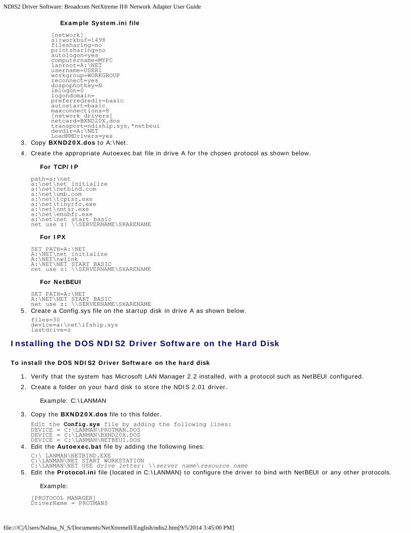
Example System.ini file
[network]sizworkbuf=1498filesharing=noprintsharing=noautologon=yescomputername=MYPClanroot=A:\NETusername=USER1workgroup=WORKGROUPreconnect=yesdospophotkey=Nlmlogon=0logondomain=preferredredir=basicautostart=basicmaxconnections=8[network drivers]netcard=BXND20X.dostransport=ndishlp.sys,*netbeuidevdir=A:\NETLoadRMDrivers=yes
3. Copy BXND20X.dos to A:\Net.
4. Create the appropriate Autoexec.bat file in drive A for the chosen protocol as shown below.
For TCP/IP
path=a:\neta:\net\net initializea:\net\netbind.coma:\net\umb.coma:\net\tcptsr.exea:\net\tinyrfc.exea:\net\nmtsr.exea:\net\emsbfr.exea:\net\net start basicnet use z: \\SERVERNAME\SHARENAME
For IPX
SET PATH=A:\NETA:\NET\net initializeA:\NET\nwlinkA:\NET\NET START BASICnet use z: \\SERVERNAME\SHARENAME
For NetBEUI
SET PATH=A:\NETA:\NET\NET START BASICnet use z: \\SERVERNAME\SHARENAME
5. Create a Config.sys file on the startup disk in drive A as shown below.files=30device=a:\net\ifshlp.syslastdrive=z
Installing the DOS NDIS2 Driver Software on the Hard Disk
To install the DOS NDIS2 Driver Software on the hard disk
1. Verify that the system has Microsoft LAN Manager 2.2 installed, with a protocol such as NetBEUI configured.
2. Create a folder on your hard disk to store the NDIS 2.01 driver.
Example: C:\LANMAN
3. Copy the BXND20X.dos file to this folder.
Edit the Config.sys file by adding the following lines: DEVICE = C:\LANMAN\PROTMAN.DOS DEVICE = C:\LANMAN\BXND20X.DOSDEVICE = C:\LANMAN\NETBEUI.DOS
4. Edit the Autoexec.bat file by adding the following lines:C:\ LANMAN\NETBIND.EXEC:\LANMAN\NET START WORKSTATION C:\LANMAN\NET USE drive letter: \\server name\resource name
5. Edit the Protocol.ini file (located in C:\LANMAN) to configure the driver to bind with NetBEUI or any other protocols.
Example:
[PROTOCOL MANAGER]DriverName = PROTMAN$

NDIS2 Driver Software: Broadcom NetXtreme II® Network Adapter User Guide
file:///C|/Users/Nalina_N_S/Documents/NetXtremeII/English/ndis2.htm[9/5/2014 3:45:00 PM]
[NETBEUI_XIF]DriverName = netbeui$BINDINGS = BXND20X[BXND20X]DriverName = "BXND20X$"
6. Restart the computer to complete the installation.
NOTE: The driver loads during system configuration and displays the Broadcom banner, controller name, MACaddress, IRQ number, detected line speed, and the controller BusNum and DevNum. If the driver fails to load, aninitialization fail message is displayed.
Using Keywords for the Drivers
The Protocol.ini file contains certain keywords that are used by the BXND20X.dos AND BXND20X.dos drivers. These keywordsare listed below:
BusNum. Specifies the number of the PCI bus on which the network adapter is located. Requires a decimal number having avalue ranging from 0 to 255.
DevNum. Specifies the device number assigned to the network adapter when it is configured by the PCI BIOS. Requires adecimal number having a value ranging from 0 to 255.
FuncNum or PortNum. Specifies the PCI function or port number assigned to the network controller. Requires a decimalnumber having a value ranging from 0 to 7.
NOTE: These keywords, BusNum, DevNum, and FuncNum (or PortNum) are needed when multiple adapters areinstalled in the server and when a specific controller must be loaded in a certain order. These keywords are used concurrentlyand are included for manufacturing purposes. Do not use them unless you are familiar with how to configure PCI devices. APCI device scan utility is needed to find this information.
LineSpeed. Specifies the speed of the network connection in Mbit/s. Requires the decimal number 10, 100, or 1000.Technically, a line speed of 1000 Mbit/s cannot be forced and is achievable only through auto-negotiation. For the sake ofsimplicity, the driver performs auto-negotiation when the line speed is set to a value of 1000.
NOTE: LineSpeed is not available with the Broadcom NetXtreme II 10 Gigabit Ethernet driver.
Duplex. Specifies the duplex mode of the network adapter. Requires a setting of either Half or Full. When this keyword isused, the LineSpeed keyword must also be used. If neither keyword is used, the network adapter defaults to auto-negotiation mode.
NOTE: LineSpeed is not available with the Broadcom NetXtreme II 10 Gigabit Ethernet driver.
NodeAddress. Specifies the network address used by the network adapter. If a multicast address or a broadcast address isspecified, the adapter uses the default MAC address.
Example:
[BXND20X] DriverName = "BXND20X$"BusNum = 3DevNum = 14PortNum = 2LineSpeed = 1000Duplex = FullNodeAddress = 001020304050
FixCheckSumOff. Turns off the driver's workaround for the TCP/IP stack to recognize the 1s complemented version of thechecksum.
AcceptAllMC. Informs the driver to deliver all multicast packets to the upper protocol.
Please read all Restrictions and Disclaimers.
Back to Contents Page

Linux Driver Software: Broadcom NetXtreme II® Network Adapter User Guide
file:///C|/Users/Nalina_N_S/Documents/NetXtremeII/English/linux.htm[9/5/2014 3:45:01 PM]
Back to Contents Page
Linux Driver Software: Broadcom NetXtreme II® NetworkAdapter User Guide
Introduction
Limitations
Packaging
Installing Linux Driver Software
Unloading/Removing the Linux Driver
Patching PCI Files (Optional)
Network Installations
Setting Values for Optional Properties
Driver Defaults
Driver Messages
Teaming with Channel Bonding
Remote PHY Support
Statistics
Linux iSCSI Offload
Introduction
This section discusses the Linux drivers for the Broadcom NetXtreme II network adapters.
Table 1: Broadcom NetXtreme II Linux Drivers
LinuxDriver Description
bnx2 Linux driver for the NetXtreme II 1 Gb network adapters.
bnx2x
Linux driver for the NetXtreme II 10 Gb network adapters. This driver directly controls the hardware and isresponsible for sending and receiving Ethernet packets on behalf of the Linux host networking stack. This driver alsoreceives and processes device interrupts, both on behalf of itself (for L2 networking) and on behalf of the bnx2fc(FCoE) and cnic drivers.
cnicThe cnic driver provides the interface between Broadcom's upper layer protocol (e.g., storage) drivers andBroadcom's NetXtreme II 1 Gb and 10 Gb network adapters. The CNIC module works with the bnx2 and bnx2xnetwork drives in the downstream and the bnx2fc (FCoE) and bnx2i (iSCSI) drivers in the upstream.
bnx2i Linux iSCSI HBA driver to enable iSCSI offload on the NetXtreme II 1 Gb and 10 Gb network adapters.
bnx2fcLinux FCoE kernel mode driver used to provide a translation layer between the Linux SCSI stack and the BroadcomFCoE firmware/hardware. In addition, the driver interfaces with the networking layer to transmit and receiveencapsulated FCoE frames on behalf of open-fcoe's libfc/libfcoe for FIP/device discovery.
Limitations
bnx2 Driver
bnx2x Driver
bnx2i Driver
bnx2 Driver

Linux Driver Software: Broadcom NetXtreme II® Network Adapter User Guide
file:///C|/Users/Nalina_N_S/Documents/NetXtremeII/English/linux.htm[9/5/2014 3:45:01 PM]
The current version of the driver has been tested on all 2.6.x kernels. Testing is concentrated on i386 and x86_64architectures. Only limited testing has been done on other architectures. Minor changes to some source files and Makefile maybe needed on some kernels. Additionally, the Makefile will not compile the cnic driver on kernels older than 2.6.16. iSCSIoffload is only supported on 2.6.16 and newer kernels.
NOTE: For Broadcom NetXtreme II BCM5708 devices with a silicon revision prior to B2, the open source bnx2 driver doesnot support the reporting and configuration of NetXtreme II WOL settings via ethtool. For silicon revisions of B2 or later, thebnx2 driver reports support for Magic Packet WOL via ethtool. Enabling support via ethtool is mandatory to successfully wakethe system. To determine the silicon revision of your Broadcom NetXtreme II device, use the lspci command, where "10" =revision B0, "11" = revision B1, and "12" = revision B2.
bnx2x Driver
The current version of the driver has been tested on 2.6.x kernels starting from 2.6.9. The driver may not compile on kernelsolder than 2.6.9. Testing is concentrated on i386 and x86_64 architectures. Only limited testing has been done on some otherarchitectures. Minor changes to some source files and Makefile may be needed on some kernels.
bnx2i Driver
The current version of the driver has been tested on 2.6.x kernels, starting from 2.6.18 kernel. The driver may not compileon older kernels. Testing is concentrated on i386 and x86_64 architectures, Red Hat EL5, and SUSE 11 SP1 distributions.
Packaging
The Linux drivers are released in the following packaging formats:
DKMS Packages
netxtreme2-version.dkms.noarch.rpm
netxtreme2-version.dkms.src.rpm
KMP Packages
SLES
broadcom-netxtreme2-kmp-[kernel]-version.i586.rpm
broadcom-netxtreme2-kmp-[kernel]-version.x86_64.rpm
Red Hat
kmod-kmp-netxtreme2-{kernel]-version.i686.rpm
kmod-kmp-netxtreme2-{kernel]-version.x86_64.rpm
The Broadcom Advanced Control Suite management utility is also distributed as an RPM package (BACS-{version}.{arch}.rpm). See Linux BACS Installation for information on installing Linux BACS.
Source Packages
Identical source files to build the driver are included in both RPM and TAR source packages. The supplemental tar file containsadditional utilities such as patches and driver diskette images for network installation.
The following is a list of included files:
netxtreme2-version.src.rpm: RPM package with NetXtreme II bnx2/bnx2x/cnic/bnx2fc/bnx2ilibfc/libfcoe driversource.
netxtreme2-version.tar.gz: tar zipped package with NetXtreme II bnx2/bnx2x/cnic/bnx2fc/bnx2i/libfc/libfcoe driversource.
iscsiuio-version.tar.gz: iSCSI user space management tool binary.
open-fcoe-*.brcm.<subvert>.<arch>.rpm: open-fcoe userspace management tool binary RPM for SLES11 SP2 andlegacy versions.
fcoe-utils-*.brcm.<subver>.<arch>.rpm: open-fcoe userspace management tool binary RPM for RHEL 6.4 andlegacy versions.

Linux Driver Software: Broadcom NetXtreme II® Network Adapter User Guide
file:///C|/Users/Nalina_N_S/Documents/NetXtremeII/English/linux.htm[9/5/2014 3:45:01 PM]
The Linux driver has a dependency on open-fcoe userspace management tools as the front-end to control FCoE interfaces.The package name of the open-fcoe tool is fcoe-utils for RHEL 6.4 and open-fcoe for SLES11 SP2 and legacy versions.
Installing Linux Driver Software
Installing the Source RPM Package
Building the Driver from the Source TAR File
Installing the Binary DKMS RPM Driver Package
Installing the Binary DKMS RPM Driver Package
NOTE: If a bnx2/bnx2x/bnx2i driver is loaded and the Linux kernel is updated, the driver module must be recompiled ifthe driver module was installed using the source RPM or the TAR package. This does not apply to the source DKMS RPM.
Installing the Source RPM Package
The following are guidelines for installing the driver source RPM Package.
Prerequisites:
Linux kernel source
C compiler
Procedure:
1. Install the source RPM package:rpm -ivh netxtreme2-<version>.src.rpm
2. Change the directory to the RPM path and build the binary RPM for your kernel:
For RHEL:
cd ~/rpmbuildrpmbuild -bb SPECS/netxtreme2.spec
For SLES:
cd /usr/src/packagesrpmbuild -bb SPECS/netxtreme2.spec
3. Install the newly compiled RPM:rpm -ivh RPMS/<arch>/netxtreme2-<version>.<arch>.rpm
Note that the --force option may be needed on some Linux distributions if conflicts are reported.
1. Install the open-fcoe utility.
For RHEL 6.4 and legacy versions, either of the following:
yum install fcoe-utils-<version>.rhel.64.brcm.<subver>.<arch>.rpm
-or-
rpm -ivh fcoe-utils-<version>.rhel.64.brcm.<subver>.<arch>.rpm
For SLES11 SP2:
rpm -ivh open-fcoe-<version>.sles.sp2.brcm.<subver>.<arch>.rpm
For RHEL 6.4 and SLES11 SP2 and legacy versions, the version of fcoe-utils/open-fcoe included in your distributionis sufficient and no out of box upgrades are provided.
Where available, installation with yum will automatically resolve dependencies. Otherwise, required dependenciescan be located on your O/S installation media.
2. For SLES, turn on the fcoe and lldpad services.
For SLES11 SP1:
chkconfig lldpad on

Linux Driver Software: Broadcom NetXtreme II® Network Adapter User Guide
file:///C|/Users/Nalina_N_S/Documents/NetXtremeII/English/linux.htm[9/5/2014 3:45:01 PM]
chkconfig fcoe on
For SLES11 SP2:
chkconfig boot.lldpad onchkconfig boot.fcoe on
3. Inbox drivers are included with all of the supported operating systems. The simplest means to ensure the newlyinstalled drivers are loaded is to reboot.
4. After rebooting, create configuration files for all FCoE ethX interfaces:cd /etc/fcoecp cfg-ethx cfg-<ethX FCoE interface name>
NOTE: Note that your distribution might have a different naming scheme for Ethernet devices. (i.e., pXpX or emXinstead of ethX).
5. Modify /etc/fcoe/cfg-<interface> by setting DCB_REQUIRED=yes to DCB_REQUIRED=no.
6. Turn on all ethX interfaces.ifconfig <ethX> up
7. For SLES, use YaST to configure your Ethernet interfaces to automatically start at boot by setting a static IP address orenabling DHCP on the interface.
8. Disable lldpad on Broadcom CNA interfaces. This is required because Broadcom utilizes an offloaded DCBX client.lldptool set-lldp –i <ethX> adminStatus=disasbled
9. Make sure /var/lib/lldpad/lldpad.conf is created and each <ethX> block does not specify "adminStatus" or ifspecified, it is set to 0 ("adminStatus=0") as below. lldp : { eth5 : { tlvid00000001 : { info = "04BC305B017B73"; }; tlvid00000002 : { info = "03BC305B017B73"; };};
10. Restart lldpad service to apply new settings
For SLES11 SP1, RHEL 6.4 and legacy versions:
service lldpad restart
For SLES11 SP2:
rclldpad restart11. Restart fcoe service to apply new settings
For SLES11 SP1, RHEL 6.4, and legacy versions:
service fcoe restart
For SLES11 SP2:
rcfcoe restart
Installing the KMP Package
NOTE: The examples in this procedure refer to the bnx2x driver, but also apply to the bnx2 and bnx2i drivers.
1. Install the KMP package:rpm -ivh <file>rmmod bnx2x
2. Load the driver:modprobe bnx2x
Building the Driver from the Source TAR File
NOTE: The examples used in this procedure refer to the bnx2 driver, but also apply to the bnx2x driver.
1. Create a directory and extract the TAR files to the directory:

Linux Driver Software: Broadcom NetXtreme II® Network Adapter User Guide
file:///C|/Users/Nalina_N_S/Documents/NetXtremeII/English/linux.htm[9/5/2014 3:45:01 PM]
tar xvzf netxtreme2-version.tar.gz2. Build the driver bnx2.ko (or bnx2i.ko) as a loadable module for the running kernel:
cd netxtreme2-versionmake
3. Test the driver by loading it (first unload the existing driver, if necessary):rmmod bnx2 (or bnx2x, or bnx2i)insmod bnx2/src/bnx2.ko (or bnx2x/src/bnx2x.ko, or bnx2i/src/bnx2i.ko)
Verify that your network adapter supports iSCSI by checking the message log. If the message "bnx2i: dev eth0does not support iSCSI" appears in the message log after loading the bnx2i driver, then iSCSI is not supported. Thismessage may not appear until the interface is opened, as with:
ifconfig eth0 up4. Load the cnic driver (if applicable):
insmod cnic.ko5. Install the driver and man page:
make install
NOTE: See the RPM instructions above for the location of the installed driver.
6. Install the user daemon (brcm_iscsiuio).
Refer to Load and Run Necessary iSCSI Software Components for instructions on loading the software components required touse the Broadcom iSCSI offload feature.
To configure the network protocol and address after building the driver, refer to the manuals supplied with your operatingsystem.
Installing the Binary DKMS RPM Driver Package
Dynamic Kernel Module Support (DKMS) is designed to simplify the rebuilding of modules whenever you upgrade the kernel.This is accomplished by creating a framework where a kernel-dependent module source can reside.
To install the binary DKMS RPM driver package
1. Download the binary DKMS RPM (dkms-version.noarch.rpm) from http://linux.dell.com/dkms/.
2. Install the binary DKMS RPM package:rpm -ivh dkms-version.noarch.rpm
3. Install the DKMS RPM driver package:rpm -ivh netxtreme2-version dkms.noarch.rpm
Verify that your network adapter supports iSCSI by checking the message log. If the message "bnx2i: dev eth0does not support iSCSI" appears in the message log after loading the bnx2i driver, then iSCSI is not supported. Thismessage may not appear until the interface is opened, as with:
ifconfig eth0 up4. To use Broadcom iSCSI, refer to Load and Run Necessary iSCSI Software Components to load the necessary software
components.
For more information, go to http://linux.dell.com.
Installing the Binary KMOD/KMP Driver Package
To install the binary KMOD/KMP driver package
1. Install the KMOD/KMP RPM driver package:
SUSE: rpm -ivh broadcom-netxtreme2-kmp-[kernel]-version.x86_64.rpm
Red Hat: kmod-kmp-netxtreme2-{kernel]-version.x86_64.rpm
Verify that your network adapter supports iSCSI by checking the message log. If the message "bnx2i: deveth0 does not support iSCSI" appears in the message log after loading the bnx2i driver, then iSCSI is notsupported. This message may not appear until the interface is opened, as with:
ifconfig eth0 up2. To use Broadcom iSCSI, refer to Load and Run Necessary iSCSI Software Components to load the necessary software
components.

Linux Driver Software: Broadcom NetXtreme II® Network Adapter User Guide
file:///C|/Users/Nalina_N_S/Documents/NetXtremeII/English/linux.htm[9/5/2014 3:45:01 PM]
For more information, go to http://linux.dell.com.
Load and Run Necessary iSCSI Software Components
The Broadcom iSCSI Offload software suite consists of three kernel modules and a user daemon. Required softwarecomponents can be loaded either manually or through system services.
1. Unload the existing driver, if necessary:
Manual:
rmmod bnx2i2. Load the iSCSI driver:
Manual:
insmod bnx2i.ko
or
modprobe bnx2i
Unloading/Removing the Linux Driver
Unloading/Removing the Driver from an RPM Installation
Removing the Driver from a TAR Installation
Unloading/Removing the Driver from an RPM Installation
NOTES:
The examples used in this procedure refer to the bnx2 driver, but also apply to the bnx2x driver.
On 2.6 kernels, it is not necessary to bring down the eth# interfaces before unloading the driver module.
If the cnic driver is loaded, unload the cnic driver before unloading the bnx2 driver.
Prior to unloading the bnx2i driver, disconnect all active iSCSI sessions to targets.
To unload the driver, use ifconfig to bring down all eth# interfaces opened by the driver, and then type the following:
rmmod bnx2
NOTE: The above command will also remove bnx2, bnx2x, and cnic modules.
If the driver was installed using RPM, do the following to remove it:
rpm -e netxtreme2
Removing the Driver from a TAR Installation
NOTE: The examples used in this procedure refer to the bnx2 driver, but also apply to the bnx2x and bnx2i drivers.
If the driver was installed using make install from the tar file, the bnx2.ko driver file has to be manually deleted from theoperating system. See Installing the Source RPM Package for the location of the installed driver.
Uninstalling BACS
RPM Package
Use the following command:
% rpm -e BACS

Linux Driver Software: Broadcom NetXtreme II® Network Adapter User Guide
file:///C|/Users/Nalina_N_S/Documents/NetXtremeII/English/linux.htm[9/5/2014 3:45:01 PM]
Patching PCI Files (Optional)
NOTE: The examples used in this procedure refer to the bnx2 driver, but also apply to the bnx2x and bnx2i drivers.
For hardware detection utilities such as Red Hat kudzu to properly identify bnx2 supported devices, a number of filescontaining PCI vendor and device information may need to be updated.
Apply the updates by running the scripts provided in the supplemental tar file. For example, on Red Hat Enterprise Linux,apply the updates by doing the following:
./patch_pcitbl.sh /usr/share/hwdata/pcitable pci.updates /usr/share/hwdata/pcitable.new bnx2./patch_pciids.sh /usr/share/hwdata/pci.ids pci.updates /usr/share/hwdata/pci.ids.new
Next, the old files can be backed up and the new files can be renamed for use.
cp /usr/share/hwdata/pci.ids /usr/share/hwdata/old.pci.idscp /usr/share/hwdata/pci.ids.new /usr/share/hwdata/pci.idscp /usr/share/hwdata/pcitable /usr/share/hwdata/old.pcitablecp /usr/share/hwdata/pcitable.new /usr/share/hwdata/pcitable
Network Installations
For network installations through NFS, FTP, or HTTP (using a network boot disk or PXE), a driver disk that contains thebnx2/bnx2x driver may be needed. The driver disk images for the most recent Red Hat and SuSE versions are included. Bootdrivers for other Linux versions can be compiled by modifying the Makefile and the make environment. Further information isavailable from the Red Hat website, http://www.redhat.com.
Setting Values for Optional Properties
Optional properties exist for the different drivers:
bnx2 Driver
bnx2x Driver
bnx2i Driver
bnx2 Driver
disable_msi
The disable_msi optional property can be supplied as a command line argument to the insmod or modprobe command. Theproperty can also be set in modprobe.conf. See the man page for more information. All other driver settings can be queriedand changed using the ethtool utility. See the ethtool man page for more information. The ethtool settings do not persistacross a reboot or module reload. The ethtool commands can be put in a startup script such as /etc/rc.local to preserve thesettings across a reboot.
NOTE: Some combinations of property values may conflict and result in failures. The driver cannot detect all suchconflicting combinations.
This property is used to disable Message Signal Interrupts (MSI), and the property is valid only on 2.6 kernels that supportMSI. By default, the driver enables MSI if it is supported by the kernel. It runs an interrupt test during initialization todetermine if MSI is working. If the test passes, the driver enables MSI. Otherwise, it uses legacy INTx mode.
insmod bnx2.ko disable_msi=1
or
modprobe bnx2 disable_msi=1
bnx2x Driver
disable_tpa
The disable_tpa parameter can be supplied as a command line argument to disable the Transparent Packet Aggregation

Linux Driver Software: Broadcom NetXtreme II® Network Adapter User Guide
file:///C|/Users/Nalina_N_S/Documents/NetXtremeII/English/linux.htm[9/5/2014 3:45:01 PM]
(TPA) feature. By default, the driver will aggregate TCP packets. Use disable_tpa to disable the advanced TPA feature.
Set the disable_tpa parameter to 1 as shown below to disable the TPA feature on all NetXtreme II network adapters in thesystem. The parameter can also be set in modprobe.conf. See the man page for more information.
insmod bnx2x.ko disable_tpa=1
or
modprobe bnx2x disable_tpa=1
int_mode
The int_mode parameter is used to force using an interrupt mode.
Set the int_mode parameter to 1 to force using the legacy INTx mode on all NetXtreme II adapters in the system.
insmod bnx2x.ko int_mode=1
or
modprobe bnx2x int_mode=1
Set the int_mode parameter to 2 to force using MSI mode on all NetXtreme II adapters in the system.
insmod bnx2x.ko int_mode=2
or
modprobe bnx2x int_mode=2
Set the int_mode parameter to 3 to force using MSI-X mode on all NetXtreme II adapters in the system.
dropless_fc
The dropless_fc parameter can be used to enable a complementary flow control mechanism on BCM57711/BCM57712adapters. The default flow control mechanism is to send pause frames when the on-chip buffer (BRB) is reaching a certainlevel of occupancy. This is a performance targeted flow control mechanism. On BCM57711/BCM57712 adapters, one canenable another flow control mechanism to send pause frames, where one of the host buffers (when in RSS mode) areexhausted.
This is a "zero packet drop" targeted flow control mechanism.
Set the dropless_fc parameter to 1 to enable the dropless flow control mechanism feature on all BCM57711/BCM57712NetXtreme II adapters in the system.
insmod bnx2x.ko dropless_fc=1
or
modprobe bnx2x dropless_fc=1
disable_iscsi_ooo
The disable_iscsi_ooo parameter is to disable the allocation of the iSCSI TCP Out-of-Order (OOO) reception resources,specifically for VMware for low-memory systems.
multi_mode
The optional parameter multi_mode is for use on systems that support multi-queue networking. Multi-queue networking onthe receive side depends only on MSI-X capability of the system, multi-queue networking on the transmit side is supportedonly on kernels starting from 2.6.27. By default, multi_mode parameter is set to 1. Thus, on kernels up to 2.6.26, the driverwill allocate on the receive side one queue per-CPU and on the transmit side only one queue. On kernels starting from 2.6.27,the driver will allocate on both receive and transmit sides, one queue per-CPU. In any case, the number of allocated queueswill be limited by number of queues supported by hardware.
The multi_mode optional parameter can also be used to enable SAFC (Service Aware Flow Control) by differentiating thetraffic to up to 3 CoS (Class of Service) in the hardware according to the VLAN PRI value or according to the IP DSCP value(least 3 bits).
num_queues
The optional parameter num_queues may be used to set the number of queues when multi_mode is set to 1 and interrupt

Linux Driver Software: Broadcom NetXtreme II® Network Adapter User Guide
file:///C|/Users/Nalina_N_S/Documents/NetXtremeII/English/linux.htm[9/5/2014 3:45:01 PM]
mode is MSI-X. If interrupt mode is different than MSI-X (see int_mode), the number of queues will be set to 1, discardingthe value of this parameter.
pri_map
The optional parameter pri_map is used to map the VLAN PRI value or the IP DSCP value to a different or same CoS in thehardware. This 32-bit parameter is evaluated by the driver as an 8 value of 4 bits each. Each nibble sets the desired hardwarequeue number for that priority. For example, set pri_map to 0x11110000 to map priority 0 to 3 to CoS 0 and map priority 4to 7 to CoS 1.
qs_per_cos
The optional parameter qs_per_cos is used to specify how many queues will share the same CoS. This parameter isevaluated by the driver up to 3 values of 8 bits each. Each byte sets the desired number of queues for that CoS. The totalnumber of queues is limited by the hardware limit. For example, set qs_per_cos to 0x10101 to create a total of threequeues, one per CoS. In another example, set qs_per_cos to 0x404 to create a total of 8 queues, divided into 2 CoS, 4queues in each CoS.
cos_min_rate
The optional parameter cos_min_rate is used to determine the weight of each CoS for round-robin scheduling intransmission. This parameter is evaluated by the driver as up to 3 values of 8 bits each. Each byte sets the desired weight forthat CoS. The weight ranges from 0 to 100. For example, set cos_min_rate to 0x101 for fair transmission rate between 2CoS. In another example, set the cos_min_rate to 0x30201 to give CoS the higher rate of transmission. To avoid using thefairness algorithm, omit setting cos_min_rate or set it to 0.
Set the multi_mode parameter to 2 as shown below to differentiate the traffic according to the VLAN PRI value.
insmod bnx2x.ko multi_mode=2 pri_map=0x11110000 qs_per_cos=0x404
or
modprobe bnx2x multi_mode=2 pri_map=0x11110000 qs_per_cos=0x404
Set the multi_mode parameter to 4 as shown below to differentiate the traffic according to the IP DSCP value.
insmod bnx2x.ko multi_mode=4 pri_map=0x22221100 qs_per_cos=0x10101 cos_min_rate=0x30201
or
modprobe bnx2x multi_mode=4 pri_map=0x22221100 qs_per_cos=0x10101 cos_min_rate=0x30201
bnx2i Driver
Optional parameters en_tcp_dack, error_mask1, and error_mask2 can be supplied as command line arguments to theinsmod or modprobe command for bnx2i.
error_mask1 and error_mask2
"Config FW iSCSI Error Mask #", use to configure certain iSCSI protocol violation to be treated either as a warning or a fatalerror. All fatal iSCSI protocol violations will result in session recovery (ERL 0). These are bit masks.
Defaults: All violations will be treated as errors.
CAUTION! Do not use error_mask if you are not sure about the consequences. These values are to be discussed withBroadcom development team on a case-by-case basis. This is just a mechanism to work around iSCSI implementation issueson the target side and without proper knowledge of iSCSI protocol details, users are advised not to experiment with theseparameters.
en_tcp_dack
"Enable TCP Delayed ACK", enables/disables TCP delayed ACK feature on offloaded iSCSI connections.
Defaults: TCP delayed ACK is ENABLED. For example:
insmod bnx2i.ko en_tcp_dack=0
or
modprobe bnx2i en_tcp_dack=0

Linux Driver Software: Broadcom NetXtreme II® Network Adapter User Guide
file:///C|/Users/Nalina_N_S/Documents/NetXtremeII/English/linux.htm[9/5/2014 3:45:01 PM]
time_stamps
"Enable TCP TimeStamps", enables/disables TCP time stamp feature on offloaded iSCSI connections.
Defaults: TCP time stamp option is DISABLED. For example:
insmod bnx2i.ko time_stamps=1
or
modprobe bnx2i time_stamps=1
sq_size
"Configure SQ size", used to choose send queue size for offloaded connections and SQ size determines the maximum SCSIcommands that can be queued. SQ size also has a bearing on the number of connections that can be offloaded; as QP sizeincreases, the number of connections supported will decrease. With the default values, the BCM5708 adapter can offload 28connections.
Defaults: 128
Range: 32 to 128
Note that Broadcom validation is limited to a power of 2; for example, 32, 64, 128.
rq_size
"Configure RQ size", used to choose the size of asynchronous buffer queue size per offloaded connections. RQ size is notrequired greater than 16 as it is used to place iSCSI ASYNC/NOP/REJECT messages and SCSI sense data.
Defaults: 16
Range: 16 to 32
Note that Broadcom validation is limited to a power of 2; for example, 16, 32.
event_coal_div
"Event Coalescing Divide Factor", performance tuning parameter used to moderate the rate of interrupt generation by theiscsi firmware.
Defaults: 1
Valid values: 1, 2, 4, 8
last_active_tcp_port
"Last active TCP port used", status parameter used to indicate the last TCP port number used in the iSCSI offload connection.
Defaults: N/A
Valid values: N/A
Note: This is a read-only parameter.
ooo_enable
"Enable TCP out-of-order feature", enables/disables TCP out-of-order rx handling feature on offloaded iSCSI connections.
Defaults: TCP out-of-order feature is ENABLED. For example:
insmod bnx2i.ko ooo_enable=1
or
modprobe bnx2i ooo_enable=1
Driver Defaults
bnx2 Driver
bnx2x Driver

Linux Driver Software: Broadcom NetXtreme II® Network Adapter User Guide
file:///C|/Users/Nalina_N_S/Documents/NetXtremeII/English/linux.htm[9/5/2014 3:45:01 PM]
bnx2 Driver
Speed: Autonegotiation with all speeds advertised
Flow Control: Autonegotiation with RX and TX advertised
MTU: 1500 (range is 46–9000)
RX Ring Size: 255 (range is 0–4080)
RX Jumbo Ring Size: 0 (range 0–16320) adjusted by the driver based on MTU and RX Ring Size
TX Ring Size: 255 (range is (MAX_SKB_FRAGS+1)–255). MAX_SKB_FRAGS varies on different kernels and differentarchitectures. On a 2.6 kernel for x86, MAX_SKB_FRAGS is 18.
Coalesce RX Microseconds: 18 (range is 0–1023)
Coalesce RX Microseconds IRQ: 18 (range is 0–1023)
Coalesce RX Frames: 6 (range is 0–255)
Coalesce RX Frames IRQ: 6 (range is 0–255)
Coalesce TX Microseconds: 80 (range is 0–1023)
Coalesce TX Microseconds IRQ: 80 (range is 0–1023)
Coalesce TX Frames: 20 (range is 0–255)
Coalesce TX Frames IRQ: 20 (range is 0–255)
Coalesce Statistics Microseconds: 999936 (approximately 1 second) (range is 0–16776960 in increments of 256)
MSI: Enabled (if supported by the 2.6 kernel and the interrupt test passes)
TSO: Enabled (on 2.6 kernels)
WoL: Initial setting based on NVRAM's setting
bnx2x Driver
Speed: Autonegotiation with all speeds advertised
Flow control: Autonegotiation with RX and TX advertised
MTU: 1500 (range is 46–9000)
RX Ring Size: 4078 (range is 0–4078)
TX Ring Size: 4078 (range is (MAX_SKB_FRAGS+4)–4078). MAX_SKB_FRAGS varies on different kernels and differentarchitectures. On a 2.6 kernel for x86, MAX_SKB_FRAGS is 18.
Coalesce RX Microseconds: 25 (range is 0–3000)
Coalesce TX Microseconds: 50 (range is 0–12288)
Coalesce Statistics Microseconds: 999936 (approximately 1 second) (range is 0–16776960 in increments of 256)
MSI-X: Enabled (if supported by the 2.6 kernel and the interrupt test passes)
TSO: Enabled
WoL: Disabled
Driver Messages
The following are the most common sample messages that may be logged in the /var/log/messages file. Use dmesg -n

Linux Driver Software: Broadcom NetXtreme II® Network Adapter User Guide
file:///C|/Users/Nalina_N_S/Documents/NetXtremeII/English/linux.htm[9/5/2014 3:45:01 PM]
<level> to control the level at which messages appear on the console. Most systems are set to level 6 by default. To see allmessages, set the level higher.
bnx2 and bnx2x Driver
bnx2i Driver
bnx2 and bnx2x Driver
NOTE: The examples used in this procedure refer to the bnx2 driver, but also apply to the bnx2x driver.
Driver Sign on
Broadcom NetXtreme II Gigabit Ethernet Driver bnx2 v1.6.3c (July 23, 2007)
CNIC Driver Sign on (bnx2 only)
Broadcom NetXtreme II cnic v1.1.19 (Sep 25, 2007)
NIC Detected
eth#: Broadcom NetXtreme II BCM5708 1000Base-T (B0) PCI-X 64-bit 133MHz found at mem f6000000, IRQ 16, node addr 0010180476aecnic: Added CNIC device: eth0
Link Up and Speed Indication
bnx2: eth# NIC Link is Up, 1000 Mbps full duplex
Link Down Indication
bnx2: eth# NIC Link is Down
MSI enabled successfully (bnx2 only)
bnx2: eth0: using MSI
MSI-X enabled successfully (bnx2x only)
bnx2x: eth0: using MSI-X
bnx2i Driver
BNX2I Driver signon
Broadcom NetXtreme II iSCSI Driver bnx2i v2.1.1D (May 12, 2010)
Network port to iSCSI transport name binding
bnx2i: netif=eth2, iscsi=bcm570x-050000bnx2i: netif=eth1, iscsi=bcm570x-030c00
Driver completes handshake with iSCSI offload-enabled CNIC device
bnx2i [05:00.00]: ISCSI_INIT passed
NOTE: This message is displayed only when the user attempts to make an iSCSI connection.
Driver detects iSCSI offload is not enabled on the CNIC device
bnx2i: iSCSI not supported, dev=eth3bnx2i: bnx2i: LOM is not enabled to offload iSCSI connections, dev=eth0bnx2i: dev eth0 does not support iSCSI
Exceeds maximum allowed iSCSI connection offload limit
bnx2i: alloc_ep: unable to allocate iscsi cidbnx2i: unable to allocate iSCSI context resources
Network route to target node and transport name binding are two different devices
bnx2i: conn bind, ep=0x... ($ROUTE_HBA) does not belong to hba $USER_CHOSEN_HBA
where ROUTE_HBA --> net device on which connection was offloaded based on route information USER_CHOSEN_HBA -->HBA to which target node is bound (using iscsi transport name)

Linux Driver Software: Broadcom NetXtreme II® Network Adapter User Guide
file:///C|/Users/Nalina_N_S/Documents/NetXtremeII/English/linux.htm[9/5/2014 3:45:01 PM]
Target cannot be reached on any of the CNIC devices
bnx2i: check route, cannot connect using cnic
Network route is assigned to network interface, which is down
bnx2i: check route, hba not found
Attempting to offload iSCSI connection onto a Jumbo Frame-enabled device
bnx2i: eth# network i/f mtu is set to #mtubnx2i: iSCSI HBA can support mtu of 1500
NOTE: Change mtu to 1500 using ifconfig and restart the interface in order to offload iSCSI connections.
SCSI-ML initiated host reset (session recovery)
bnx2i: attempting to reset host, #3
CNIC detects iSCSI protocol violation - Fatal errors
bnx2i: iscsi_error - wrong StatSN rcvdbnx2i: iscsi_error - hdr digest errbnx2i: iscsi_error - data digest errbnx2i: iscsi_error - wrong opcode rcvdbnx2i: iscsi_error - AHS len > 0 rcvdbnx2i: iscsi_error - invalid ITT rcvdbnx2i: iscsi_error - wrong StatSN rcvdbnx2i: iscsi_error - wrong DataSN rcvdbnx2i: iscsi_error - pend R2T violationbnx2i: iscsi_error - ERL0, UObnx2i: iscsi_error - ERL0, U1bnx2i: iscsi_error - ERL0, U2bnx2i: iscsi_error - ERL0, U3bnx2i: iscsi_error - ERL0, U4bnx2i: iscsi_error - ERL0, U5bnx2i: iscsi_error - ERL0, Ubnx2i: iscsi_error - invalid resi lenbnx2i: iscsi_error - MRDSL violationbnx2i: iscsi_error - F-bit not setbnx2i: iscsi_error - invalid TTTbnx2i: iscsi_error - invalid DataSNbnx2i: iscsi_error - burst len violationbnx2i: iscsi_error - buf offset violationbnx2i: iscsi_error - invalid LUN fieldbnx2i: iscsi_error - invalid R2TSN fieldbnx2i: iscsi_error - invalid cmd len1bnx2i: iscsi_error - invalid cmd len2bnx2i: iscsi_error - pend r2t exceeds MaxOutstandingR2T valuebnx2i: iscsi_error - TTT is rsvdbnx2i: iscsi_error - MBL violationbnx2i: iscsi_error - data seg len != 0bnx2i: iscsi_error - reject pdu len errorbnx2i: iscsi_error - async pdu len errorbnx2i: iscsi_error - nopin pdu len errorbnx2i: iscsi_error - pend r2t in cleanupbnx2i: iscsi_error - IP fragments rcvdbnx2i: iscsi_error - IP options errorbnx2i: iscsi_error - urgent flag error
CNIC detects iSCSI protocol violation - non-FATAL, warning
bnx2i: iscsi_warning - invalid TTTbnx2i: iscsi_warning - invalid DataSNbnx2i: iscsi_warning - invalid LUN field
NOTE: The driver needs to be configured to consider certain violation to treat as warning and not as a critical error.
Driver puts a session through recovery
conn_err - hostno 3 conn 03fbcd00, iscsi_cid 2 cid a1800
Reject iSCSI PDU received from the target
bnx2i - printing rejected PDU contents[0]: 1 ffffffa1 0 0 0 0 20 0[8]: 0 7 0 0 0 0 0 0[10]: 0 0 40 24 0 0 ffffff80 0[18]: 0 0 3 ffffff88 0 0 3 4b[20]: 2a 0 0 2 ffffffc8 14 0 0[28]: 40 0 0 0 0 0 0 0
Open-iSCSI daemon handing over session to driver
bnx2i: conn update - MBL 0x800 FBL 0x800MRDSL_I 0x800 MRDSL_T 0x2000

Linux Driver Software: Broadcom NetXtreme II® Network Adapter User Guide
file:///C|/Users/Nalina_N_S/Documents/NetXtremeII/English/linux.htm[9/5/2014 3:45:01 PM]
Teaming with Channel Bonding
With the Linux drivers, you can team adapters together using the bonding kernel module and a channel bonding interface. Formore information, see the Channel Bonding information in your operating system documentation.
Remote PHY Support
The bnx2 driver supports Remote PHY on blade servers that use the NetXtreme II BCM5708S or BCM5709s device, supportRemote PHY, and have Remote PHY enabled.
On Remote PHY-enabled systems, the bnx2 driver enables the NetXtreme II BCM5708S or BCM5709S device to takeadvantage of the features available in the blade chassis' copper twisted pair PHY. The bnx2 driver will indicate that it is usingRemote PHY twisted pair mode in ethtool output.
NOTE: bnx2 driver versions prior to 1.63d do not support Remote PHY and operating systems using these older driversmay behave differently than operating systems with Remote PHY driver support. Refer to your system and operating systemdocumentation for the status of Remote PHY support.
Configure the adapter using the standard ethtool commands.
Statistics
Detailed statistics and configuration information can be viewed using the ethtool utility. See the ethtool man page for moreinformation.
Linux iSCSI Offload
Open iSCSI User Applications
User Application - brcm_iscsiuio
Bind iSCSI Target to Broadcom NX2 iSCSI Transport Name
VLAN Configuration for iSCSI Offload (Linux)
Making Connections to iSCSI Targets
Maximum Offload iSCSI Connections
Linux iSCSI Offload FAQ
Open iSCSI User Applications
Install and run the inbox open-iscsi initiator programs from the DVD. Refer to Packaging for details.
User Application - brcm_iscsiuio
Install and run the brcm_iscsiuio daemon before attempting to create iSCSI connections. The driver will not be able toestablish connections to the iSCSI target without the daemon's assistance.
1. Install the brcm_iscsiuio source package# tar -xvzf iscsiuio-<version>.tar.gz
2. CD to the directory where iscsiuio is extracted# cd iscsiuio-<version>
3. Compile and install# ./configure# make# make install
4. Check the iscsiuio version matches with the source package# brcm_iscsiuio -v
5. Start brcm_iscsiuio# brcm_iscsiuio
Bind iSCSI Target to Broadcom NX2 iSCSI Transport Name

Linux Driver Software: Broadcom NetXtreme II® Network Adapter User Guide
file:///C|/Users/Nalina_N_S/Documents/NetXtremeII/English/linux.htm[9/5/2014 3:45:01 PM]
By default, the open-iscsi daemon connects to discovered targets using software initiator (transport name = 'tcp'). Users whowish to offload iSCSI connection onto CNIC device should explicitly change transport binding of the iSCSI iface. This can bedone using the iscsiadm CLI utility as follows,
iscsiadm -m iface -I <iface_file_name> -n iface.transport_name -v bnx2i -o update
where the iface file includes the following information for RHEL 5.4, RHEL 5.5, and SLES 11 SP1:
iface.net_ifacename = ethXiface.iscsi_ifacename = <name of the iface file>iface.hwaddress = XX:XX:XX:XX:XX:XXiface.ipaddress = XX.XX.XX.XXiface.transport_name = bnx2i
Ensure that the iface.hwaddress is in lower case format.
If you wish to switch back to use the software initiator, use the following:
iscsiadm -m iface -I <iface_file_name> -n iface.transport_name -v tcp -o update
where the iface file includes the following information:
iface.net_ifacename = ethXiface.iscsi_ifacename = <name of the iface file>iface.transport_name = tcp
VLAN Configuration for iSCSI Offload (Linux)
iSCSI traffic on the network may be isolated in a VLAN to segregate it from other traffic. When this is the case, you mustmake the iSCSI interface on the adapter a member of that VLAN.
Modifying the iSCSI iface File
To configure the iSCSI VLAN add the VLAN ID in the iface file for iSCSI. In the following example, the VLAN ID is set to 100.
#Begin Record 6.2.0-873.2.el6Iface.iscsi_ifacefile name = <>Iface.ipaddress = 0.0.0.0Iface.hwaddress = <>Iface.trasport_name = bnx2iIface.vlan_id = 100Iface.vlan_priority = 0Iface.iface_num = 100Iface.mtu = 0Iface.port = 0#END Record
NOTE: Although not strictly required, Broadcom recommends configuring the same VLAN ID on the iface.iface_num fieldfor iface file identification purposes.
Setting the VLAN ID on the Ethernet Interface
If using RHEL5.X versions of Linux, it is recommended that you configure the iSCSI VLAN on the Ethernet interface. InRHEL6.3, and sles11sp3, it is not necessary to set the VLAN on the Ethernet driver.
Execute the following commands to set the VLAN ID:
Vconfig add ethx <vlan number> — Creates an L2 VLAN interface.
Ifconfig eth.<VLANID> <static ip> up — Assigns and IP address to the VLAN interface.
Use the following command to get detailed information about VLAN interface:
# cat /proc/net/vlan/ethx.<vlanid>
Preserve the VLAN configuration across reboots by adding it to configuration files. Configure the VLAN interface configurationin /etc/sysconfig/network-scripts. The configuration filename has a specific format that includes the physical interface, acharacter, and the VLAN ID.
For example, if the VLAN ID is 100, and the physical interface is eth0, then the configuration filename should be ifcfg-eth0.100. The following are example settings in the configuration file.
"DEVICE=ethX.100"BOOTPROTO=static

Linux Driver Software: Broadcom NetXtreme II® Network Adapter User Guide
file:///C|/Users/Nalina_N_S/Documents/NetXtremeII/English/linux.htm[9/5/2014 3:45:01 PM]
"ONBOOT=yes"IPADDR=<>"NETMASK=<>"USERCTL=no"NETWORK=<>"VLAN=yes
Restart the networking service, in order for the changes to take effect, as follows:
"Service network restart"
Making Connections to iSCSI Targets
Refer to open-iscsi documentation for a comprehensive list of iscsiadm commands. This is a sample list of commands todiscovery targets and to create iscsi connections to a target.
Add static entry
iscsiadm -m node -p <ipaddr[:port]> -T iqn.2007-05.com.broadcom:target1 -o new -I <iface_file_name>
iSCSI target discovery using 'SendTargets'
iscsiadm -m discovery --type sendtargets -p <ipaddr[:port]> -I <iface_file_name>
Login to target using 'iscsiadm' command
iscsiadm --mode node --targetname <iqn.targetname> --portal <ipaddr[:port]> --login
List all drives active in the system
fdisk -l
Maximum Offload iSCSI Connections
With default driver parameters set, which includes 128 outstanding commands, bnx2i can offload the following number ofconnections:
BCM5708: 28
BCM5709: 43
BCM5771x: 128
This is not a hard limit, but just a simple on-chip resource allocation math. bnx2i will be able to offload > 28 connections on1G devices by reducing the shared queue size, which in turn limits the maximum outstanding tasks on a connection. SeeSetting Values for Optional Properties for information on sq_size and rq_size. The driver logs the following message to syslogwhen the maximum allowed connection offload limit is reached - "bnx2i: unable to allocate iSCSI context resources".
Linux iSCSI Offload FAQ
Not all Broadcom NetXtreme II adapters support iSCSI offload.
The iSCSI session will not recover after a hot remove and hot plug.
For MPIO to work properly, iSCSI nopout should be enabled on each iSCSI session. Refer to open-iscsi documentationfor procedures on setting up noop_out_interval and noop_out_timeout values.
In the scenario where multiple CNIC devices are in the system and the system is booted via Broadcom's iSCSI bootsolution, ensure that the iscsi node under /etc/iscsi/nodes for the boot target is bound to the NIC that is used forbooting.
Please read all Restrictions and Disclaimers.
Back to Contents Page

Solaris Driver Software: Broadcom NetXtreme II® Network Adapter User Guide
file:///C|/Users/Nalina_N_S/Documents/NetXtremeII/English/solaris.htm[9/5/2014 3:45:02 PM]
Back to Contents Page
Solaris Driver Software: Broadcom NetXtreme II® NetworkAdapter User Guide
Overview
Installing the Driver
Upgrading the Driver
Uninstalling Driver
Configuring the Driver
Memory Usage
Interrupt Management
FCoE Support
Overview
This file describes how to install the Solaris driver for Broadcom's NetXtreme II 10 Gigabit Ethernet network adapters. Refer tothe 'bnxe' manual page for details on how to configure the driver.
The Solaris driver is released in two formats:
BRCMbnxe-version.pkg: Datastream format
BRCMbnxe-version.tar.Z: Compressed TAR file system format.
NOTE: A DU image does not exist at this time because of driver size limitations. Solaris DU diskettes can be used toinstall the driver into the system both during system installation and/or after the system has been installed andbooted.
This driver only works with the GLDv3 Streams interface as it appears in Solaris 10 (Update 4) and later.
Installing the Driver
1. Change directory to where BRCMbnxe-version.pkg resides.
2. pkgadd -d BRCMbnxe-version.pkg
or
1. Copy BRCMbnxe-X.Y.Z.tar.Z to /tmp.
2. cd /tmp uncompress BRCMbnxe-version.tar.Z tar -xvf BRCMbnxe-version.tar pkgadd -d /tmp
3. Execute prtconf to determine instance numbers of the NIC.
4. ifconfig bnxe[instance_number] plumb
5. ifconfig bnxe[instance_number] ip_address netmask .... up
To make these changes permanent:
1. Use your favorite text editor and create a file named hostname.bnxe[instance_number] in the /etc directory. Add theIP address of the interface to this file, save, and exit.
2. Add a proper subnet mask to the file /etc/netmasks.
Upgrading the Driver

Solaris Driver Software: Broadcom NetXtreme II® Network Adapter User Guide
file:///C|/Users/Nalina_N_S/Documents/NetXtremeII/English/solaris.htm[9/5/2014 3:45:02 PM]
To upgrade the Broadcom driver package to the current version, you must first uninstall the previous driver version from thesystem. See Uninstalling Driver. Once the previous driver has been removed, you can follow any of the installation methodsin this document to install the new driver version.
NOTE: Do not install multiple instances of the driver on a single system.
Uninstalling Driver
1. ifconfig bnxe[instance_number] down
2. ifconfig bnxe[instance_number] unplumb
3. pkgrm BRCMbnxe
Configuring the Driver
The bnxe driver can be configured via the bnxe.conf file installed under /kernel/drv. When this config file is modified, thesystem must be either rebooted or the driver unloaded and reconfigured using the update_drv admin command.
All configuration can be specified per-instance. The format used is as follows and each line must end with a semicolon:
bnxe<#>_<config_item>=X;
So for adv_autoneg_cap, you would use the following:
bnxe0_adv_autoneg_cap=1;bnxe1_adv_autoneg_cap=0;bnxe2_adv_autoneg_cap=1;bnxe3_adv_autoneg_cap=1;
If a configuration item is not specified for a specific instance, then the default value will be used. The default value used by allinstances can be overridden using:
default_<config_item>=X;
For boolean values, 1 = TRUE and 0 = FALSE.
Memory Usage
The number of RX/TX buffer descriptors specified in the configuration file can have a detrimental affect on memory usage. Ifthe counts are too high, DMA allocations can fail, thereby affecting other drivers loaded on the system. If DMA allocations failduring system initialization and/or boot, then there is a chance the system will not boot. This behavior is an implementationconstraint of the Solaris OS. Additionally, it has been seen that the amount of DMA allocation space available on a systemrunning in 32-bit mode is less than when running as 64-bit.
For a single RX descriptor, the following is allocated:
1 DMA handle
1 DMA memory buffer that is MTU in size
1K memory overhead
For a single TX descriptor, the following is allocated:
9 DMA handles for sending chained mblks
1 DMA memory buffer that is MTU in size
1K memory overhead
NOTE: The number of DMA handles available in the system scales with the amount of RAM. With more RAM, thedescriptor counts can be safely increased.
The default number of RX/TX buffer descriptors is 2048 for each. When using a Broadcom BCM57711 network adapter inmultifunction mode, the number of configured descriptors is divided by four, ending up at 512. This is to keep the number ofDMA allocations at a minimum. After installation, it is suggested these descriptor counts be increased until stability isguaranteed and the desired performance is reached.
For example, using the default setting of 2048 for the number of both RX and TX descriptors, the approximate amount of

Solaris Driver Software: Broadcom NetXtreme II® Network Adapter User Guide
file:///C|/Users/Nalina_N_S/Documents/NetXtremeII/English/solaris.htm[9/5/2014 3:45:02 PM]
memory a single interface would consume is:
Single Function Mode
RX: 2048 DMA handles and 5M (MTU=1500) or 21M (MTU=9216) of memory
TX: 20480 DMA handles and 5M (MTU=1500) or 21M (MTU=9216) of memory
Total: 22528 DMA handles and 10M (MTU=1500) or 42M (MTU=9216) of memory
Multifunction Mode (#descs / 4)
RX: 512 DMA handles and 1M (MTU=1500) or 5M (MTU=9216) of memory
TX: 5120 DMA handles and 1M (MTU=1500) or 5M (MTU=9216) of memory
Total: 5335 DMA handles and 2M (MTU=1500) or 10M (MTU=9216) of memory
Interrupt Management
If you have a system with many interfaces, it is possible to reach the allocation limit of MSIX interrupts. By default, Solarislimits each driver to 2 MSIX allocations, and there is an issue with the pcplusmp module where only a maximum of 31 MSIXinterrupts are available per interrupt priority level.
If your system has four Broadcom BCM57711 network adapter ports, each running in multifunction mode, Solaris willenumerate 16 bnxe interfaces. The last interface attached will fail to allocate its second MSIX interrupt and revert to Fixed.This in turn can eventually expose an issue in the system regarding interrupt management resulting in interrupts never beingreceived on the interface that reverted back to Fixed.
To ensure all interfaces are able to allocate their two MSIX interrupts, the workaround is to change the priority levels ofspecific interfaces. Network drivers are automatically assigned an interrupt priority level of 6, so changing an interface'spriority level to 5 is common.
1. First read the driver.conf man page for a background primer.
2. Find out the driver instance paths assigned on your system.% grep bnxe /etc/path_to_inst"/pci@0,0/pci8086,2779@1/pci14e4,1650@0" 0 "bnxe""/pci@0,0/pci8086,2779@1/pci14e4,1650@0,1" 1 "bnxe"
3. Normally, the name of the driver is the last portion of the path, but you should use the most appropriate PCI ID foundin /etc/driver_aliases. Depending on how the hardware is layered, there are cases where the name identified inpath_to_inst will not work. To figure out which name to use, examine the output from prtconf -v and match againstthe IDs specified in the driver_aliases file.% grep bnxe /etc/driver_aliasesbnxe "pci14e4,164e"bnxe "pci14e4,164f"bnxe "pci14e4,1650"bnxe "pciex14e4,164e"bnxe "pciex14e4,164f"bnxe "pciex14e4,1650"
4. The parent of the driver is the entire path leading up to the name.
5. The unit-address is located after the final @ in the path.
6. Therefore, change both of the bnxe interfaces found in path_to_inst to interrupt priority 5 and use the following configlines to bnxe.conf:name = "pciex14e4,1650" parent = "/pci@0,0/pci8086,2779@1" unit-address = "0" interrupt-priorities = 5;name = "pciex14e4,1650" parent = "/pci@0,0/pci8086,2779@1" unit-address = "0,1" interrupt-priorities = 5;
7. After modifying the config, either reboot the system or unplumb all interfaces and run the update_drv command.
8. When the system has been reconfigured and the interfaces plumbed back up, verify the new interrupt priority settingsby running the following command as root:% echo "::interrupts -d" | mdb -k
FCoE Support
Overview
FCoE is supported on Solaris 11 with limited support on Solaris 10, Update 9. The following features are the differences inSolaris 10, Update 9 when compared to Solaris 11:

Solaris Driver Software: Broadcom NetXtreme II® Network Adapter User Guide
file:///C|/Users/Nalina_N_S/Documents/NetXtremeII/English/solaris.htm[9/5/2014 3:45:02 PM]
Support does not exist for NPIV in the Solaris 10 Update 9.
Some of the fcinfo(1M) options, which are available in Solaris 11, are not be available in Solaris 10, Update 9. For moreinformation, read the man page fcinfo(1M).
brcmfcoeadm(1M) feature is supported in both Solaris 10 Update 9 and Solaris 11. However, when "delete-fcoe-port" iscomplete, you need to issue the following two commands to unload the bnxef driver before you can re-issue "create-fcoe-port". There is a reaper thread in Solaris 11 that aggressively looks for unused driver modules and unloads thedriver. That thread does not exist in Solaris 10 Update 9. Therefore, you have to explicitly look for the driver module IDof the bnxef driver by issuing the following command.# modinfo | grep bnxef249 fffffffff8d63000 486b8 54 1 bnxef (6.4.13)
Then issue the modunload command to unload the module before "create-fcoe-port" is issued to create a new FCoEport.
# modunload -i 249
Any time "create-fcoe-port" needs to be issued, the driver must be unloaded, if it is already loaded. If not, the "create-fcoe-port" will fail indicating the driver is busy. This is true when you have two or more instances of bnxef loaded, in which case,you should first delete all FCoE ports and then unload the driver. Unloading will occur only when all the instances are deleted.
Supported FC/FCoE Devices
The bnxef Broadcom 10 Gb FCoE driver works with all the major FCoE fabric devices. It is also compatible with all known FCdisk devices and tape devices working through the FCoE fabric.
Unloading FCoE Driver
Delete all FCoE ports created across the various bnxe instances.
1. Delete all the NPIV ports created before deleting FCoE ports.
2. brcmfcoeadm delete-fcoe-port bnxe<instance_number>
3. modinfo | grep bnxef
The first column for the above command will give the module ID for the bnxef driver.
4. modunload -i <module id>
The procedure should unload the driver. However, if there are many instances of the FCoE ports created, all the FCoE portsmust be deleted before the unload can be attempted.
Configuring the FCoE Driver
The bnxef driver can be configured via the bnxef.conf file installed under /kernel/drv. When this config file is modified, thesystem must be either rebooted or use the update_drv(1M) command to update the driver configuration.
The details of the configurations parameters are detailed in the bnxef(7D) man page. The default parameters should work forall conditions.
Please read all Restrictions and Disclaimers.
Back to Contents Page

VMware Driver Software: Broadcom NetXtreme II® Network Adapter User Guide
file:///C|/Users/Nalina_N_S/Documents/NetXtremeII/English/vmware.htm[9/5/2014 3:45:03 PM]
Back to Contents Page
VMware Driver Software: Broadcom NetXtreme II® Network Adapter User Guide
Packaging
Networking Support
Drivers
FCoE Support
Packaging
The VMware driver is released in the packaging formats shown in Table 1.
Table 1: VMware Driver Packaging
Format Drivers
Compressed tar bnx2x-version.tar.gz
VMware VIB vmware-esx-drivers-net-bnx2x-version.x86_64.vib
Networking Support
This section describes the bnx2x VMware ESX driver for the Broadcom NetXtreme II PCIE 10 GbE network adapters.
Drivers
Download, Install, and Update Drivers
To download, install, or update the VMware ESX/ESXi driver for NetXtreme II 10 GbE network adapters, see http://www.vmware.com/support.
Driver Parameters
Several optional parameters can be supplied as a command line argument to the vmkload_mod command. These parameters can also be set via the esxcfg-modulecommand. See the man page for more information.
int_mode
The optional parameter int_mode is used to force using an interrupt mode other than MSI-X. By default, the driver will try to enable MSI-X if it is supported by thekernel. If MSI-X is not attainable, then the driver will try to enable MSI if it is supported by the kernel. If MSI is not attainable, then the driver will use the legacyINTx mode.
Set the int_mode parameter to 1 as shown below to force using the legacy INTx mode on all NetXtreme II network adapters in the system.
vmkload_mod bnx2x int_mode=1
Set the int_mode parameter to 2 as shown below to force using MSI mode on all NetXtreme II network adapters in the system.
vmkload_mod bnx2x int_mode=2
disable_tpa
The optional parameter disable_tpa can be used to disable the Transparent Packet Aggregation (TPA) feature. By default, the driver will aggregate TCP packets,but if you would like to disable this advanced feature, it can be done.
Set the disable_tpa parameter to 1 as shown below to disable the TPA feature on all NetXtreme II network adapters in the system.
vmkload_mod bnx2x.ko disable_tpa=1
Use ethtool to disable TPA (LRO) for a specific network adapter.
num_rx_queues
The optional parameter num_rx_queues may be used to set the number of Rx queues on kernels starting from 2.6.24 when multi_mode is set to 1 and interruptmode is MSI-X. Number of Rx queues must be equal to or greater than the number of Tx queues (see num_tx_queues parameter). If the interrupt mode isdifferent than MSI-X (see int_mode parameter), then then the number of Rx queues will be set to 1, discarding the value of this parameter.
num_tx_queues
The optional parameter num_tx_queues may be used to set the number of Tx queues on kernels starting from 2.6.27 when multi_mode is set to 1 and interruptmode is MSI-X. The number of Rx queues must be equal to or greater than the number of Tx queues (see num_rx_queues parameter). If the interrupt mode isdifferent than MSI-X (see int_mode parameter), then the number of Tx queues will be set to 1, discarding the value of this parameter.
pri_map
The optional parameter pri_map is used to map the VLAN PRI value or the IP DSCP value to a different or the same CoS in the hardware. This 32-bit parameter isevaluated by the driver as 8 values of 4 bits each. Each nibble sets the desired hardware queue number for that priority.
For example, set the pri_map parameter to 0x22221100 to map priority 0 and 1 to CoS 0, map priority 2 and 3 to CoS 1, and map priority 4 to 7 to CoS 2. Inanother example, set the pri_map parameter to 0x11110000 to map priority 0 to 3 to CoS 0, and map priority 4 to 7 to CoS 1.
qs_per_cos

VMware Driver Software: Broadcom NetXtreme II® Network Adapter User Guide
file:///C|/Users/Nalina_N_S/Documents/NetXtremeII/English/vmware.htm[9/5/2014 3:45:03 PM]
The optional parameter qs_per_cos is used to specify the number of queues that will share the same CoS. This parameter is evaluated by the driver up to 3 valuesof 8 bits each. Each byte sets the desired number of queues for that CoS. The total number of queues is limited by the hardware limit.
For example, set the qs_per_cos parameter to 0x10101 to create a total of three queues, one per CoS. In another example, set the qs_per_cos parameter to0x404 to create a total of 8 queues, divided into only 2 CoS, 4 queues in each CoS.
cos_min_rate
The optional parameter cos_min_rate is used to determine the weight of each CoS for Round-robin scheduling in transmission. This parameter is evaluated by thedriver up to 3 values of 8 bits each. Each byte sets the desired weight for that CoS. The weight ranges from 0 to 100.
For example, set the cos_min_rate parameter to 0x101 for fair transmission rate between two CoS. In another example, set the cos_min_rate parameter to0x30201 to give the higher CoS the higher rate of transmission. To avoid using the fairness algorithm, omit setting the optional parameter cos_min_rate or set itto 0.
dropless_fc
The optional parameter dropless_fc can be used to enable a complementary flow control mechanism on Broadcom network adapters. The default flow controlmechanism is to send pause frames when the on-chip buffer (BRB) is reaching a certain level of occupancy. This is a performance targeted flow control mechanism.On Broadcom network adapters, you can enable another flow control mechanism to send pause frames if one of the host buffers (when in RSS mode) is exhausted.This is a "zero packet drop" targeted flow control mechanism.
Set the dropless_fc parameter to 1 as shown below to enable the dropless flow control mechanism feature on all Broadcom network adapters in the system.
vmkload_mod bnx2x dropless_fc=1
Driver Defaults
Speed: Autonegotiation with all speeds advertised
Flow Control: Autonegotiation with rx and tx advertised
MTU: 1500 (range 46–9000)
Rx Ring Size: 4078 (range 0–4078)
Tx Ring Size: 4078 (range (MAX_SKB_FRAGS+4) - 4078). MAX_SKB_FRAGS varies on different kernels and different architectures. On a 2.6 kernel for x86,MAX_SKB_FRAGS is 18.
Coalesce RX Microseconds: 25 (range 0–3000)
Coalesce TX Microseconds: 50 (range 0–12288)
MSI-X: Enabled (if supported by 2.6 kernel)
TSO: Enabled
WoL: Disabled
Unloading and Removing Driver
To unload the driver, type the following:
vmkload_mod -u bnx2x
Driver Messages
The following are the most common sample messages that may be logged in the file /var/log/messages. Use dmesg -n <level> to control the level at whichmessages will appear on the console. Most systems are set to level 6 by default. To see all messages, set the level higher.
Driver Sign On
Broadcom NetXtreme II 5771x 10Gigabit Ethernet Driver bnx2x 0.40.15 ($DateTime: 2007/11/22 05:32:40 $)
NIC Detected
eth0: Broadcom NetXtreme II BCM57710 XGb (A1) PCI-E x8 2.5GHz found at mem e8800000, IRQ 16, node addr 001018360012
MSI-X Enabled Successfully
bnx2x: eth0: using MSI-X
Link Up and Speed Indication
bnx2x: eth0 NIC Link is Up, 10000 Mbps full duplex, receive & transmit flow control ON
Link Down Indication
bnx2x: eth0 NIC Link is Down
Memory Limitation
If you see messages in the log file that look like the following, then the ESX host is severely strained. To relieve this, disable NetQueue.
Dec 2 18:24:20 ESX4 vmkernel: 0:00:00:32.342 cpu2:4142)WARNING: Heap: 1435: Heap bnx2x already at its maximumSize. Cannot expand.Dec 2 18:24:20 ESX4 vmkernel: 0:00:00:32.342 cpu2:4142)WARNING: Heap: 1645: Heap_Align(bnx2x, 4096/4096 bytes, 4096 align) failed. caller: 0x41800187d654Dec 2 18:24:20 ESX4 vmkernel: 0:00:00:32.342 cpu2:4142)WARNING: vmklinux26: alloc_pages: Out of memory
Disable NetQueue by manually loading the bnx2x vmkernel module via the command.
vmkload_mod bnx2x multi_mode=0

VMware Driver Software: Broadcom NetXtreme II® Network Adapter User Guide
file:///C|/Users/Nalina_N_S/Documents/NetXtremeII/English/vmware.htm[9/5/2014 3:45:03 PM]
or to persist the settings across reboots via the command
esxcfg-module -s multi_mode=0 bnx2x
Reboot the machine for the settings to take place.
MultiQueue/NetQueue
The optional parameter num_queues may be used to set the number of Rx and Tx queues when multi_mode is set to 1 and interrupt mode is MSI-X. If interruptmode is different than MSI-X (see int_mode parameter), the number of Rx and Tx queues will be set to 1, discarding the value of this parameter.
If you would like the use of more then 1 queue, force the number of NetQueues to use via the following command:
esxcfg-module -s "multi_mode=1 num_queues=<num of queues>" bnx2x
Otherwise, allow the bnx2x driver to select the number of NetQueues to use via the following command:
esxcfg-module -s "multi_mode=1 num_queues=0" bnx2x
The optimal number is to have the number of NetQueues match the number of CPUs on the machine.
FCoE Support
This section describes the contents and procedures associated with installation of the VMware software package for supporting Broadcom FCoE C-NICs.
Drivers
Table 2: Broadcom NetXtreme II FCoE Drivers
Driver Description
bnx2x
This driver manages all PCI device resources (registers, host interface queues, etc.) and also acts as the Layer 2 VMware low-level network driver forBroadcom's NetXtreme II 10G device. This driver directly controls the hardware and is responsible for sending and receiving Ethernet packets on behalf ofthe VMware host networking stack. The bnx2x driver also receives and processes device interrupts, both on behalf of itself (for L2 networking) and onbehalf of the bnx2fc (FCoE protocol) and CNIC drivers.
bnx2fcThe Broadcom VMware FCoE driver is a kernel mode driver used to provide a translation layer between the VMware SCSI stack and the Broadcom FCoEfirmware/hardware. In addition, the driver interfaces with the networking layer to transmit and receive encapsulated FCoE frames on behalf of open-fcoe'slibfc/libfcoe for FIP/device discovery.
Supported Distributions
The FCoE/DCB feature set is supported on VMware ESXi 5.0 and above.
iSCSI Support
This following driver is provided to support iSCSI.
Table 3: Broadcom NetXtreme II iSCSI Driver
Driver Description
bnx2i The bnx2i driver is Broadcom VMware iSCSI HBA driver. Similar to bnx2fc, bnx2i is a kernel mode driver used to provide a translation layer between theVMware SCSI stack and the Broadcom iSCSI firmware/hardware. Bnx2i functions under the open-iscsi framework.
VLAN Configuration for iSCSI Offload (Linux)
iSCSI traffic on the network may be isolated in a VLAN to segregate it from other traffic. When this is the case, you must make the iSCSI interface on the adapter amember of that VLAN.
To configure the VLAN using the V-Sphere client (GUI):
1. Click the ESXi/ESX host.
2. Click the Configuration tab.
3. Click the Networking link and click Properties.
4. Click the virtual switch / portgroups in the Ports tab and click Edit.
5. Click the General tab.
6. Assign a VLAN number in VLAN ID (optional).

VMware Driver Software: Broadcom NetXtreme II® Network Adapter User Guide
file:///C|/Users/Nalina_N_S/Documents/NetXtremeII/English/vmware.htm[9/5/2014 3:45:03 PM]
7. Configure the VLAN on VMKernel.

VMware Driver Software: Broadcom NetXtreme II® Network Adapter User Guide
file:///C|/Users/Nalina_N_S/Documents/NetXtremeII/English/vmware.htm[9/5/2014 3:45:03 PM]
Enabling FCoE
To enable FCoE hardware offload on the C-NIC
1. Determine the ports that are FCoE-capable:# esxcli fcoe nic list
Output example:
vmnic4User Priority: 3Source MAC: FF:FF:FF:FF:FF:FFActive: falsePriority Settable: falseSource MAC Settable: falseVLAN Range Settable: false
1. Enable the FCoE interface:# esxcli fcoe nic discover -n vmnicX
Where X is the interface number gained from esxcli fcoe nic list.
2. Verify that the interface is working:# esxcli fcoe adapter list
Output example:
vmhba34Source MAC: bc:30:5b:01:82:39FCF MAC: 00:05:73:cf:2c:eaVNPort MAC: 0e:fc:00:47:04:04Physical NIC: vmnic7User Priority: 3VLAN id: 2008
The output of this command should show valid:
FCF MAC, VNPort MAC, Priority, and VLAN id for the Fabric that is connected to the C-NIC.
The following command can also be used to verify that the interface is working properly:
#esxcfg-scsidevs -a
Output example:
vmhba34 bnx2fc link-up fcoe.1000<mac address>:2000<mac address> () Software FCoEvmhba35 bnx2fc link-up fcoe.1000<mac address>:2000<mac address> () Software FCoE
NOTE: The label "Software FCoE" is a VMware term used to describe initiators that depend on the inbox FCoE libraries and utilities. Broadcom's FCoE solution isa fully state connection-based hardware offload solution designed to significantly reduce the CPU burden encumbered by a non-offload software initiator.
Installation Check
To verify the correct installation of the driver and to ensure that the host port is seen by the switch, follow the procedure below.
To verify the correct installation of the driver
1. Verify the host port shows up in the switch FLOGI database using the "show flogi database" command for the case of a Cisco FCF and "fcoe -loginshow"command for the case of a Brocade FCF.
2. If the Host WWPN does not appear in the FLOGI database, then provide driver log messages for review.
Limitations
NPIV is not currently supported with this release on ESX, due to lack of supporting inbox components.
Non-offload FCoE is not supported with offload-capable Broadcom devices. Only the full hardware offload path is supported.
Please read all Restrictions and Disclaimers.
Back to Contents Page

Windows Driver and Management Application Installation: Broadcom NetXtreme II® Network Adapter User Guide
file:///C|/Users/Nalina_N_S/Documents/NetXtremeII/English/umwindrv.htm[9/5/2014 3:45:04 PM]
Back to Contents Page
Windows Driver and Management Application Installation:Broadcom NetXtreme II® Network Adapter User Guide
Installing the Driver Software
Modifying the Driver Software
Repairing or Reinstalling the Driver Software
Removing the Device Drivers
Using the NetXtreme II Monolithic Driver
Inserting the NetXtreme II Monolithic Driver in a in a WinPE 2.0 or 3.1 Image
Configuring the Speed/Duplex Setting for the NetXtreme II Monolithic Driver
Viewing or Changing the Properties of the Adapter
Setting Power Management Options
Configuring the Communication Protocol To Use With BACS4
Installing the Driver Software
NOTE: These instructions are based on the assumption that your Broadcom NetXtreme II adapter was not factory installed.If your controller was installed at the factory, the driver software has been installed for you.
When Windows first starts after a hardware device (such as a Broadcom NetXtreme II Adapter) has been installed, or afterthe existing device driver has been removed, the operating system automatically detects the hardware and prompts you toinstall the driver software for that device.
Both a graphical interactive installation mode (see Using the Installer) and a command-line silent mode for unattendedinstallation (see Using Silent Installation) are available.
NOTES:
Before installing the driver software, verify that the Windows operating system has been upgraded to the latestversion with the latest service pack applied.
A network device driver must be physically installed before the Broadcom NetXtreme II Controller can be usedwith your Windows operating system. Drivers are located on the driver source media as well as at the Dellwebsite at http://support.dell.com.
To use the TCP/IP Offload Engine (TOE), you must have Windows Server 2008, Windows Server 2008 R2, orWindows Server 2012. You must also have a license key installed on the motherboard (for LOMs). For add-inNICs, the license key is preprogrammed in the hardware.
BACS is not supported on the Server Core installation option for Microsoft Windows Server 2008 R2.
Using the Installer
In addition to the Broadcom device drivers, the installer installs the management applications. The following are installedwhen running the installer:
Broadcom Device Drivers. Installs the Broadcom device drivers.
Control Suite. Broadcom Advanced Control Suite (BACS).
BASP. Installs Broadcom Advanced Server Program.
SNMP. Installs the Simple Network Management Protocol subagent.
CIM Provider. Installs the Common Information Model provider.
iSCSI Crash Dump Driver. Installs the driver needed for the iSCSI Crash Dump utility.

Windows Driver and Management Application Installation: Broadcom NetXtreme II® Network Adapter User Guide
file:///C|/Users/Nalina_N_S/Documents/NetXtremeII/English/umwindrv.htm[9/5/2014 3:45:04 PM]
NOTE: Although installing the BACS software and related management applications is optional, the Broadcom devicedrivers must be installed when you use the installer.
NOTE: BASP is not available on Windows Small Business Server (SBS) 2008.
To install the Broadcom NetXtreme II drivers and management applications
1. When the Found New Hardware Wizard appears, click Cancel.
2. Insert the Dell-provided CD into the CD or DVD drive or download the software driver package from the Dell website athttp://support.dell.com/.
3. On the driver source media, or from the location to which you downloaded the software driver package, open the folderfor your operating system, open the Driver_Management_Apps_Installer folder, and then double-click Setup.exe toopen the InstallShield Wizard.
4. Click Next to continue.
5. After you review the license agreement, click I accept the terms in the license agreement and then click Next tocontinue.
6. Select the features you want installed.
7. Select how you want to install the NetXtreme II drivers and then click Next.
8. Click Install.
9. Click Finish to close the wizard.
10. The installer will determine if a system restart is necessary. Follow the on-screen instructions.
To install the Microsoft iSCSI Software Initiator for iSCSI Crash Dump
If supported and if you will use the Broadcom iSCSI Crash Dump utility, it is important to follow the installation sequence:
Run the installer
Install the Microsoft iSCSI Software Initiator along with the patch (MS KB939875)
NOTE: If performing an upgrade of the device drivers from the installer, re-enable iSCSI Crash Dump from theAdvanced section of the BACS Configuration tab.
Perform this procedure after running the installer to install the device drivers and the management applications.
1. Install Microsoft iSCSI Software Initiator (version 2.06 or later) if not included in your OS. To determine when you needto install the Microsoft iSCSI Software Initiator, see Table 1. To download the iSCSI Software Initiator from Microsoft,go to http://www.microsoft.com/en-us/download/details.aspx?displaylang=en&id=18986.
2. Install Microsoft patch for iSCSI crash dump file generation (Microsoft KB939875) fromhttp://support.microsoft.com/kb/939875. To determine if you need to install the Microsoft patch, see Table 1.
Table 1: Windows Operating Systems and iSCSI Crash Dump
Operating System MS iSCSI Software Initiator Required Microsoft Patch (MS KB939875) Required
NDIS
Windows Server 2008 Yes (included in OS) No
Windows Server 2008 R2 Yes (included in OS) No
Windows Server 2012 Yes (included in OS) No
OIS
Windows Server 2008 No No
Windows Server 2008 R2 No No
Windows Server 2012 No No
Using Silent Installation
NOTES:
All commands are case sensitive.

Windows Driver and Management Application Installation: Broadcom NetXtreme II® Network Adapter User Guide
file:///C|/Users/Nalina_N_S/Documents/NetXtremeII/English/umwindrv.htm[9/5/2014 3:45:04 PM]
For detailed instructions and information about unattended installs, refer to the Silent.txt file in theDriver_Management_Apps_Installer folder.
To perform a silent install from within the installer source folder
Type the following:
setup /s /v/qn
To perform a silent upgrade from within the installer source folder
Type the following:
setup /s /v/qn
To perform a silent reinstall of the same installer
Type the following:
setup /s /v"/qn REINSTALL=ALL"
NOTE: The REINSTALL switch should only be used if the same installer is already installed on the system. If upgrading anearlier version of the installer, use setup /s /v/qn as listed above.
To perform a silent install by feature
Use the ADDSOURCE to include any of the features listed below.
Type the following according to platform:
IA32 platforms: setup /s /v"/qn ADDSOURCE=Driversi32,BACSi32,BASPi32,SNMPi32,CIMi32"
AMD/EM64T platforms: setup /s /v"/qn ADDSOURCE=Driversa64,BACSa64,BASPa64,SNMPa64,CIMa64"
The following command-line statement installs only the Broadcom drivers according to platform:
IA32 platforms: setup /s /v"/qn ADDSOURCE=Driversi32"
AMD64 platforms: setup /s /v"/qn ADDSOURCE=Driversa64"
NOTE: The Broadcom device drivers are a required feature and are always installed, even if you do not specifyADDSOURCE.
To perform a silent install from within a batch file
To perform a silent install from within a batch file and to wait for the install to complete before continuing with the nextcommand line, type the following:
start /wait setup /s /w /v/qn
To perform a silent install to force a downgrade (default is NO)
setup /s /v" /qn DOWNGRADE=Y"
Modifying the Driver Software
To modify the driver software
1. In Control Panel, double-click Add or Remove Programs.
2. Click Broadcom Drivers and Management Applications, and then click Change.
3. Click Next to continue.
4. Click Modify, Add, or Remove to change program features. This option does not install drivers for new adapters. Forinformation on installing drivers for new adapters, see Repairing or Reinstalling the Driver Software.
5. Click Next to continue.
6. Click on an icon to change how a feature is installed.
7. Click Next.

Windows Driver and Management Application Installation: Broadcom NetXtreme II® Network Adapter User Guide
file:///C|/Users/Nalina_N_S/Documents/NetXtremeII/English/umwindrv.htm[9/5/2014 3:45:04 PM]
8. Click Install.
9. Click Finish to close the wizard.
10. The installer will determine if a system restart is necessary. Follow the on-screen instructions.
Repairing or Reinstalling the Driver Software
To repair or reinstall the driver software
1. In Control Panel, double-click Add or Remove Programs.
2. Click Broadcom Drivers and Management Applications, and then click Change.
3. Click Next to continue.
4. Click Repair or Reinstall to repair errors or install drivers for new adapters.
5. Click Next to continue.
6. Click Install.
7. Click Finish to close the wizard.
8. The installer will determine if a system restart is necessary. Follow the on-screen instructions.
Removing the Device Drivers
When removing the device drivers, any management application that is installed is also removed.
NOTE: Windows Server 2008 and Windows Server 2008 R2 provide the Device Driver Rollback feature to replace a devicedriver with one that was previously installed. However, the complex software architecture of the NetXtreme II device maypresent problems if the rollback feature is used on one of the individual components. Therefore, we recommend that changesto driver versions be made only through the use of a driver installer.
To remove the device drivers
1. In Control Panel, double-click Add or Remove Programs.
2. Click Broadcom Drivers and Management Applications, and then click Remove. Follow the on-screen prompts.
3. Reboot your system to completely remove the drivers. If you fail to reboot your system, you will not be able tosuccessfully install the drivers.
Using the NetXtreme II Monolithic Driver
The NetXtreme II, based on its advanced functionalities, uses a software architecture that includes a Virtual Bus Device (VBD)to extend functionalities beyond basic network connectivity. Microsoft, however, does not currently support this architecturewhen loading an operating system through its Windows Deployment Services (WDS), which was previously known as RemoteInstallation Services (RIS), or for the deployment agent used in the Automated Deployment Services (ADS). Therefore, aseparate driver was created to accommodate these Microsoft deficiencies. This driver is known as the NetXtreme II monolithicdriver, but it is sometimes referred to as the "RIS" driver.
The NetXtreme II monolithic driver was developed to work only for the text mode portion of a WDS legacy installation and toestablish connectivity with a deployment agent for ADS. It is not intended to be used as a driver loaded in the running stateof an operating system. The exception to this would be when used for the Windows Preinstallation Environment (WinPE).
For WDS, this driver is used similarly to any other network adapter driver for supporting network connectivity after the PXEboot to the WDS server. When placed in the I386 or AMD64 directory (depending on the version of the operating systembeing deployed), the monolithic driver is called to establish that there is driver support for the NetXtreme II adapter includedin the WDS legacy image.
For ADS, the driver is placed in the PreSystem directory on the server running ADS to establish connectivity with thedeployment agent on remote systems with NetXtreme II adapters when booting from PXE.
While Windows PE 2005 natively supports the VBD architecture, it was found that using the "minint" switch in thestartnet.cmd file does not. The minint switch performs a limited scan of the system bus to identify network devices only and,therefore, does not support the VBD architecture. Since only network connectivity is required in Windows PE, the onlysupported driver is the monolithic driver for the NetXtreme II adapter in this environment as well. Place the b06nd.inf file inthe INF directory within the Windows PE image, and place the appropriate driver file (b06nd51a.sys for x64-based builds or

Windows Driver and Management Application Installation: Broadcom NetXtreme II® Network Adapter User Guide
file:///C|/Users/Nalina_N_S/Documents/NetXtremeII/English/umwindrv.htm[9/5/2014 3:45:04 PM]
b06nd51.sys for x86-based builds) in the driver's directory. If Windows PE is deployed as a flat image from a RIS or WDSserver, you must also place both the b06nd.inf and the appropriate driver file in the I386 or AMD64 directory containing theimage. If the RIS or WDS server is running Windows 2000 Server and deploying an x86 WinPE image, you may need to applythe following modification to the b06nd.inf file located in the I386 directory as follows:
1. Locate [Manufacturer] header within the file.
2. Review the line below it which reads: %brcm% = broadcom, ntx86, ntamd64, ntia64 or equivalent.
3. Modify that line to read: %brcm% = broadcom.ntx86, ntamd64, ntia64. The change made replaces the comma andspace after "broadcom" with a period.
4. Save the file.
5. Restart the RIS service (binlsvc) or WDS services (wdsserver).
Inserting the NetXtreme II Monolithic Driver in a in a WinPE 2.0 or 3.1Image
Follow these procedures for inserting the NetXtreme II monolithic driver into WinPE images. The instructions differ dependingon the WinPE version and the Windows Server OS version system being used.
WinPE 2.0
The Microsoft Windows Server 2008 method of inserting the NetXtreme II monolithic driver in a WinPe 2.0 image is differentfrom the Windows Server 2008 R2 method, as discussed below.
By default, the monolithic driver is not included in the boot.wim and install.wim files that come with either the MicrosoftWindows Server 2008 CD or the Windows Server 2008 R2 CD. Microsoft's Windows Automated Installation Kit (AIK) allowsyou to modify the default boot.wim and install.wim files, and create WinPE 2.0 images to include the NetXtreme II monolithicdriver in the Windows Server installation.
To insert the monolithic driver into a WinPE 2.0 boot image (Windows Server 2008)
To insert Broadcom's NetXtreme II monolithic driver in a WinPE 2.0 image, download AIK from http://www.microsoft.com/en-us/download/default.aspx and install.
After installing AIK, copy the latest monolithic driver to a directory on the local hard drive of the system you installed the AIK.Follow the procedure below to insert the monolithic driver into a WinPE 2.0 boot image.
1. From All Programs, open Windows AIK and select Windows PE Tools Command prompt.
2. At the command prompt, run the copype.cmd script. The script requires two arguments: hardware architecture anddestination location.copype.cmd <arch> <destination>
For example: copype x86 c:\VistaPEx86
NOTE: The directory structure c:\VistaPEx86 is used throughout this procedure.
3. Mount the base image to a local directory so that you can add or remove packages by typing:imagex /mountrw c:\VistaPEx86\winpe.wim 1 c:\VistaPEx86\mount
4. Place the monolithic driver and inf file in c:\drivers\x32\ by typing:peimg /inf=c:\Drivers\x32\b06nd.inf c:\VistaPEx86\mount\windows
AIK inserts the driver into the WinPE 2.0 image.
5. To complete the customization of the image, prepare the image for deployment, type:peimg /prep c:\VistaPEx86\mount\windows
6. When asked to continue and have the program prepare the image for deployment, type:yes
7. To commit the changes to the original image file (Winpe.wim), type:imagex /unmount c:\VistaPEx86\mount /commit
8. To replace the default Boot.wim file in the \ISO directory with your new custom image, type:copy c:\VistaPex86\winpe.wim c:\VistaPEx86\ISO\sources\boot.wim
To add a device driver to an offline Windows PE image (Windows Server 2008 R2)

Windows Driver and Management Application Installation: Broadcom NetXtreme II® Network Adapter User Guide
file:///C|/Users/Nalina_N_S/Documents/NetXtremeII/English/umwindrv.htm[9/5/2014 3:45:04 PM]
This procedure demonstrates how to use the Deployment Image Servicing and Management (DISM) tool to add a devicedriver (.inf) to an offline Windows PE image. Before running a DISM command, first mount the Windows PE image.
1. Mount the base image by using the DISM tool to a local Windows PE directory. For example:Dism /Mount-WIM /WimFile:c:\winpe_x86\winpe.wim /index:1 /MountDir:c:\winpe_x86\mount
NOTE: The directory structure c:\winpe_x86 is used throughout this procedure.
2. Add the .inf file to the base image by using the dism command with the /Add-Driver option. For example Driver.inf isthe Broadcom driver, evnd.inf is the driver for the 10 Gbps devices, and b06nd.inf is the driver for the 1 Gbps devices.Dism /image:<path_to_image> /Add-Driver /Driver:c:\winpe_x86\mount\Windows\driver.inf
3. Repeat steps 1 and 2 for each additional device driver.
4. Unmount the image after modifying it.dism /unmount-wim /Mountdir:c:\winpe_x86\mount /commit
5. After unmounting the image, burn it to the designated media.
To create a bootable CD-ROM
1. On your technician computer, at the command prompt, create an .iso file by typing:oscdimg -n -bc:\VistaPEx86\etfsboot.com c:\VistaPEx86\ISO C:\VistaPEx86\VistaPEx86.iso
2. Burn the iso image to a CD.
WinPE 3.1
To insert the NetXtreme II monolithic driver into a WinPE 3.1 boot image (Windows server 2008 R2 SP1)
1. Open the WinPE image and mount it:Dism /Mount-WIM /WimFile:c:\WinPEx64\winpe.wim /index:1 /MountDir:c:\WinPEx64\mount
2. Use the following commands to insert the Broadcom NetXtreme II drivers into the WinPE 3.1 image:
eVBD driver: Dism /image:c:\WinPEx64\mount /Add-Driver /Driver:c:\Drivers\x64\evbd.inf
NetXtreme I NDIS 5.1 driver: Dism /image:c:\WinPEx64\mount /Add-Driver /Driver:c:\Drivers\x64\b57amd64.inf
NetXtreme II NDIS driver:Dism /image:c:\WinPEx64\mount /Add-Driver /Driver:c:\Drivers\x64\bxnd.inf
NetXtreme I NDIS 6.0 driver:Dism /image:c:\WinPEx64\mount /Add-Driver /Driver:c:\Drivers\x64\b57nd60a.inf
NetXtreme II VBD driver:Dism /image:c:\WinPEx64\mount /Add-Driver /Driver:c:\Drivers\x64\bxvbd.inf
3. Close the WinPE image and unmount it:Dism /unmount-wim /Mountdir:c:\WinPEx64\mount /commit
WinPE 4.0
To insert the NetXtreme II monolithic driver into a WinPE 4.0 boot image (Windows server 2008 R2 SP1)
Configuring the Speed/Duplex Setting for the NetXtreme II MonolithicDriver
Since the typical environment where the NetXtreme II monolithic driver is used does not provide the means to configureadvanced network adapter properties, the driver file (b06nd.inf) was modified to include a section that allows it to beconfigured for a specific speed and/or duplex. This provides a more robust connection to the network as it allows the adapterto match the settings of its link partner (e.g., a switch, router, etc.).
To manually configure the speed and duplex
1. Open the b06nd.inf file with a text editor like Microsoft Notepad or WordPad.

Windows Driver and Management Application Installation: Broadcom NetXtreme II® Network Adapter User Guide
file:///C|/Users/Nalina_N_S/Documents/NetXtremeII/English/umwindrv.htm[9/5/2014 3:45:04 PM]
2. Perform a search on the file for "Registry parameters" to locate the section that will allow you to configure the adapterspeed/duplex.
3. Once located, notice the following information shown.[params_utp]hkr, , req_medium, 2, "0"[params_fiber]hkr, , req_medium, 2, "65283"
These make up two separate sections that can be configured: one for standard RJ-45 copper interfaces (params_utp) and onefor fiber devices (params_fiber).
1. As described in the file, replace the value above in quotation marks under the correct section, depending upon thenetwork adapter in your system. The available values are shown below.
Options for copper interfaces:
Auto (1 Gbps is enabled when that speed is supported) = "0"
10 Mbps Half Duplex = "65794"
10 Mbps Full Duplex = "258"
100 Mbps Half Duplex = "66050"
100 Mbps Full Duplex = "514"
Options for fiber interfaces:
Auto (1 Gbps is enabled when that speed is supported) = "0"
1 Gbps Full Duplex = "771"
Auto with 1 Gbps Fallback = "33539"
Hardware default = "65283"
An example is provided in the file showing how to configure a copper interface for a 10 Mbps Full Duplex connection. Theexample is shown below.
hkr, , req_medium, 2, "258"
Viewing or Changing the Properties of the Adapter
To view or change the properties of the Broadcom network adapter
1. In Control Panel, click Broadcom Control Suite 4.
2. Click the Advanced section of the Configurations tab.
Setting Power Management Options
You can set power management options to allow the operating system to turn off the controller to save power or to allow thecontroller to wake up the computer. If the device is busy doing something (servicing a call, for example) however, theoperating system will not shut down the device. The operating system attempts to shut down every possible device onlywhen the computer attempts to go into hibernation. To have the controller stay on at all times, do not click the Allow thecomputer to turn off the device to save power check box.
NOTE: Power management options are not available on blade servers.

Windows Driver and Management Application Installation: Broadcom NetXtreme II® Network Adapter User Guide
file:///C|/Users/Nalina_N_S/Documents/NetXtremeII/English/umwindrv.htm[9/5/2014 3:45:04 PM]
NOTES:
The Power Management tab is available only for servers that support power management.
To enable Wake on LAN (WOL) when the computer is on standby, click Allow the device to bring thecomputer out of standby box.
If you select Only allow management stations to bring the computer out of standby, the computer canbe brought out of standby only by Magic Packet.
CAUTION! Do not select Allow the computer to turn off the device to save power for any adapterthat is a member of a team.
Configuring the Communication Protocol To Use With BACS4
There are two main components of the BACS4 management application: the provider component and the client software. Aprovider is installed on a server, or managed host, that contains one or more CNAs. The provider collects information on theCNAs and makes it available for retrieval from a management PC on which the client software is installed. The client softwareenables viewing information from the providers and configuring the CNAs.The BACS client software includes a graphical userinterface (GUI) and a command line interface (CLI).
A communication protocol enables communication between the provider and the client software. Depending on the mix ofoperating systems (Linux, Windows, or both) on the clients and managed hosts in your network, you can choose anappropriate communication protocol to use. See Installing the Broadcom Advanced Control Suite in the "Linux ManagementApplication Installation" topic for a description of the available communication protocols for each network configuration.
The instructions in this chapter address only the scenario where Windows managed hosts are communicatingwith Windows clients. In these scenarios, you can use either the WMI or the WS-MAN (WinRM) communication protocols.When you use the driver installer described in this chapter to install both the driver and the management applications, theprovider for both WMI and WS-MAN is installed on the managed host. Additionally, the BACS4 utility is installed on the client.The following sections provide additional configuration steps for the communication protocol you select.
For Linux installations, the driver is installed separately from the management applications. See Linux Driver Software andsee Linux Management Application Installation for related instructions.

Windows Driver and Management Application Installation: Broadcom NetXtreme II® Network Adapter User Guide
file:///C|/Users/Nalina_N_S/Documents/NetXtremeII/English/umwindrv.htm[9/5/2014 3:45:04 PM]
Using WS-MAN
To use the WS-MAN communication protocol, follow the instructions in the following sections:
WS-MAN Windows Server Configuration
WS-MAN Windows Client Installation
WS-MAN Windows Server Configuration
Step 1: Install the WinRM Software Component on Server
On the following operating systems, WinRM 2.0 is preinstalled:
Windows 7
Windows 8
Windows 8.1
Windows Server 2008 R2
Windows Server 2012
Windows 2012 R2
For Windows XP and Windows Server, 2008, install Windows Management Framework Core, which includes WinRM 2.0 andWindows Powershell 2.0, from the following link:
http://www.microsoft.com/download/en/details.aspx?displaylang=en&id=11829
Step 2: Perform Basic Configuration on the Server
The Windows firewall must be enabled for WinRM to work properly. For detailed information about firewall configuration, seeStep 7: Additional Server Configuration. After the firewall is configured, open a command prompt and run the followingcommand to enable the remote management on the Windows server:
winrm quickconfig
You can use the following command to view the configuration information for the service:
winrm get winrm/config
Step 3: Perform User Configuration on the Server
To connect to WinRM, the account must be a member of the local administrators group on the local or remote computer. Theoutput of the get winrm/config command will be as follows:
RootSDDL = O:NSG:BAD:P(A;;GA;;;BA)S:P(AU;FA;GA;;;WD)(AU;SA;GWGX;;;WD)
BA stands for BUILTIN\Administrators.
To add another user group to the WinRM allowed connect list, you can modify the RootSDDL to include the new user group.You will need the SSDL ID for the new group. For example, the following command adds the new user group with SDDL ID S-1-5-21-1866529496-2433358402-1775838904-1021.
winrm set winrm/config/Service @{RootSDDL="O:NSG:BAD:P(A;GA;;;BA)(A;;GA;;;S-1-5-21-1866529496-2433358402-1775838904-1021)S:P(AU;FA;GA;;WD)(AU;SA;GWGX;;;WD)"}
Step 4: Perform HTTP Configuration on the Server
To use the BACS GUI, you must configure the HTTP protocol, as follows:
NOTE: The default HTTP port is 5985 for WinRM 2.0.
1. Click Start (or press the Windows logo key) and select Run.
2. Enter gpedit.msc to open the local Group Policy editor.

Windows Driver and Management Application Installation: Broadcom NetXtreme II® Network Adapter User Guide
file:///C|/Users/Nalina_N_S/Documents/NetXtremeII/English/umwindrv.htm[9/5/2014 3:45:04 PM]
3. Under Computer Configuration, open the Administrative Templates folder and then open the WindowsComponents folder.
4. Select Windows Remote Management (WinRM).
5. Under Windows Remote Management (WinRM), select WinRm Client.
6. Under WinRM Client, double-click Trusted Hosts.
7. In the TrustedHostsList, enter the host names of the clients. If all clients are trusted then enter an asterisk (*) only.
8. Select WinRM Service.
9. Enable Allow Basic Authentication.
10. Enable Allow unencrypted traffic.
11. Close the Group Policy wIndow.
12. From the command prompt, run the following command to configure WinRM with default settings:winrm qc or winrm quickconfig
13. When the tool displays "Make these changes[y/n]?", enter "y".
14. Enter one of the following commands to check whether an HTTP listener is created:winrm enumerate winrm/confg/listener
or
winrm e winrm/config/Listener15. Enter the following command from the command prompt to test locally.
winrm id
Step 5: Perform HTTPS Configuration on the Server (to use HTTPS rather than HTTP)
This step consists of two distinct processes: generating a self-signed certificate, if certificate does not exist, and importing itto a Windows server. If one does not already exist, you must configure a self-signed certificate on the Windows server toenable HTTPS/SSL communication with the BACS GUI on the Windows client. The Windows client also must be configured withthe self-signed certificate. See Perform HTTPS Configuration (if you plan to use HTTPS).
NOTE: The self-signed certificate can be created on any Windows server. The server does not require BACS to be installed.The self-signed certificate generated on any Windows server should be copied on the local drive of client.
1. Click Start (or press the Windows logo key) and select Run.
2. Enter gpedit.msc to open the local Group Policy editor.
3. Under Computer Configuration, open the Administrative Templates folder and then open the WindowsComponents folder.
4. Select Windows Remote Management (WinRM).
5. Under Windows Remote Management (WinRM), select WinRm Client.
6. Under WinRM Client, double-click Trusted Hosts.
7. In the TrustedHostsList, enter the host names of the clients. If all clients are trusted then enter an asterisk (*) only.
8. Select WinRM Service.
9. Enable Allow Basic Authentication.
To generate a self-signed certificate for the Windows Server:
Openssl on Windows can be used to generate the self-signed certificate, as follows:
NOTE: You can download and install openssl from http://gnuwin32.sourceforge.net/packages/openssl.htm.
1. Enter the following command to generate a private key:openssl genrsa -des3 -out server.key 1024
2. You are prompted to enter a passphrase. Be sure to remember the passphrase.
3. Use the following steps to generate a Certificate Signing Request (CSR).
During the generation of the CSR, you are prompted for several pieces of information. When prompted for the"Common Name", enter the Windows Server host name or IP address.
Enter the following command (sample responses are shown):

Windows Driver and Management Application Installation: Broadcom NetXtreme II® Network Adapter User Guide
file:///C|/Users/Nalina_N_S/Documents/NetXtremeII/English/umwindrv.htm[9/5/2014 3:45:04 PM]
openssl req -new -key server.key -out server.csr
If this command does not work, try the following:
openssl req –new –key server.key –out server.csr –config openssl.cnf
The openssl.cnf file should be placed in the same directory where openssl is placed. Openssl.cnf is located in thefolder C:\Program Files (x86)\GnuWin32\share.
The following information is requested:
Country Name (2 letter code) []:US
State or Province Name (full name) []: California
Locality Name (e.g., city) []: Irvine
Organization Name (e.g., company) []: Broadcom Corporation
Organizational Unit Name (e.g., section) []: Engineering
Common Name (e.g., YOUR name) []: Enter the host name or IP address of the Windows server. For iPv6, enterthe Common Name in the format [xyxy:xxx:....::xxx], including the brackets [ ].
(Optional) Email Address []:
Enter the following additional attributes to be sent with your certificate request:
A challenge password []:password1
An optional company name []:
4. Remove the passphrase from the key.
Enter the following commands:
cp server.key server.key.orgopenssl rsa -in server.key.org -out server.key
5. Generate a self-signed certificate:
To generate a self-signed certificate which is active for 365 days, enter the following command:
openssl x509 -req -days 365 -in server.csr -signkey server.key -out server.crt
The following output displays:
Signature oksubject=/C=US/ST=California/L=Irvine/O=Broadcom Corporation/OU=Engineering/CN=MGMTAPP- LAB3/emailAddress=Getting Private key
6. Enter the following command to verify the generated self-signed certificate.openssl verify server.crt
The following output displays:
server.crt:/C=US/ST=California/L=Irvine/O=Broadcom Corporation/OU=Engineering/CN=MGMTAPP- LAB3/emailAddress=error 18 at 0 depth lookup:self signed certificateOK
Ignore the error message "error 18 at 0 depth lookup:self signed certificate". This error indicates that this is a self-signed certificate.
7. Convert the certificate from "crt" to "pkcs12" format, as follows:
For a Windows server, the certificate should be in pkcs12 format. Enter the following command:
openssl pkcs12 -export -in server.crt -inkey server.key -out hostname.pfx
You will be prompted for the following:
Enter Export Password:Verifying - Enter Export Password:
Enter the password and be sure to remember it. The password is required when importing the certificate on theWindows server and client.
8. Make a copy of the certificate file server.crt and place it on the server where BACS will be installed, so that it can be

Windows Driver and Management Application Installation: Broadcom NetXtreme II® Network Adapter User Guide
file:///C|/Users/Nalina_N_S/Documents/NetXtremeII/English/umwindrv.htm[9/5/2014 3:45:04 PM]
imported. If you plan to use a Windows client to connect to the server running BACS, then the certificate also needs tobe transferred (copied and pasted) to the client system.
To instal the self-signed certificate on Windows server:
Transfer the file hostname.pfx you generated on the Windows server before you install the certificate:
1. Click Start (or press the Windows logo key) and select Run.
2. Enter MMC and click OK.
3. Click File > Add/Remove Snap-in.
4. Click Add.
5. Select Certificates and click Add.
6. Select Computer account.
7. Click Next and then click Finish.
8. Click Close, then click OK.
9. Open the Certificates (Local Computer) folder and then open the Personal folder.
10. Right-click Certificates, select All Tasks and then click Import.
11. Click Next to begin the Certificate Import Wizard.
12. Browse to select hostname.pfx.
13. When you are prompted for the password for the private key, enter the same password you created in To generate aself-signed certificate for the Windows Server:.
14. Follow the instructions, select the defaults, and continue.
The certificate is shown as installed on the right side of the window. The name will be the name you specified whilecreating a self-signed certificate.
15. Right-click on the certificate and select Properties.
A dialog box displays, as follows:

Windows Driver and Management Application Installation: Broadcom NetXtreme II® Network Adapter User Guide
file:///C|/Users/Nalina_N_S/Documents/NetXtremeII/English/umwindrv.htm[9/5/2014 3:45:04 PM]
16. Ensure that only Server Authentication is enabled, as shown in the figure.
17. Open Trusted Root Certification Authorities and then open Certificates.
18. Follow the instructions from Step 11. to Step 17.
NOTE: See Perform HTTPS Configuration (if you plan to use HTTPS) for instructions on importing the self-signedcertificate on a client.
Step 6: Configure WinRM HTTPS/SSL on the Server
1. Create WinRM Listener, as follows:
a. Click Start (or press the Windows logo key) and select Run.
b. Enter MMC and click OK.
c. Select the self-signed certificate from the Personal store.
For example, if the certificate is created with a host name, the host name will appear.
d. Double-click the certificate to open it.
e. Click the Details tab.
f. Scroll down and select the Thumbprint field.
g. Select and copy the thumbprint in the Details window so you can insert it in the next step.
h. Return to the command prompt.
i. Enter the following command: winrm create winrm/config/Listener?Address=*+Transport= HTTPS @{Hostname="<HostName or IPAddress>"; CertificateThumbprint="<paste from the previous step and remove the spaces>"}

Windows Driver and Management Application Installation: Broadcom NetXtreme II® Network Adapter User Guide
file:///C|/Users/Nalina_N_S/Documents/NetXtremeII/English/umwindrv.htm[9/5/2014 3:45:04 PM]
NOTES:
If the certificate was generated using the host name, enter the host name. If it was generatedusing the IP address, enter the IP address. For an IPv6 address, use brackets [ ] around theaddress.
If HTTPS is configured in your system, the listener must be deleted before creating a new HTTPSlistener. Use the following command:winrm delete winrm/config/Listener?Address=*+Transport=HTTPS
j. The above command creates a listener on the HTTPS port (5986) using any/all network address of the server,and my SelfSSL generated certificate.
k. You can use the winrm command to modify or set the HTTPS listener, as WinRM listeners can be configured onany user defined port.
l. From command prompt, run the following command to verify that the listener(s) that have been configured: winrm e winrm/config/listener
2. Test HTTPS/SSL connection on the server.
a. At the command prompt on the server, enter the following command: winrs -r:https://yourserver:5986 -u:username -p:password hostname
b. If setup correctly, the output of the command shows the server host name.
c. To check WinRM Service Configuration, run the following command: winrm get winrm/config/service
Step 7: Additional Server Configuration
If necessary, modify the firewall rules as follows:
Windows Server 2008 R2
1. From the Administrative Tools menu, open Windows Firewall with Advanced Security.
2. Right-click Inbound Rules and select New Rule.
The new rule wizard opens.
3. Select Port and click Next.
4. On the Protocol and Ports screen, select TCP and enter the specific port, for example, 5985 for HTTP or 5986 forHTTPS.
5. Click Next.
6. On the Action screen, select Allow the connection and click Next.
7. For Profile, you can select all three profiles if your server is in a workgroup.
8. Specify a name for the rule and click Finish.
9. Ensure that the new rule and is enabled (the green check box is selected).
Windows XP
1. Click Start > Control Panel, and then double-click Windows Firewall.
2. Click the Exceptions tab
3. Click Add Port.
4. Enter a meaningful Name, for example "WinRM rule" and port number, for example, 5985 for HTTP or 5986 for HTTPS.
5. Click OK.
Useful WinRM Commands
Command Description
winrm quickconfig or winrm qc Configures WinRM with default settings

Windows Driver and Management Application Installation: Broadcom NetXtreme II® Network Adapter User Guide
file:///C|/Users/Nalina_N_S/Documents/NetXtremeII/English/umwindrv.htm[9/5/2014 3:45:04 PM]
winrm enumerate winrm/config/Listener or winrm ewinrm/config/Listener
Helps to check which service listener are enabled and listening onwhich port and IP Address.
winrm get winrm/config/Service Checks WinRM Service Configuration.
winrm delete winrm/config/Listener?Address=*+Transport=HTTPS Deletes a Listener (in this case deleting a HTTPS listener).
Useful WinRM Websites
http://msdn.microsoft.com/en-us/library/aa384372%28v=vs.85%29.aspx
http://technet.microsoft.com/en-us/library/cc782312%28WS.10%29.aspx
http://msdn.microsoft.com/en-us/library/aa384295%28v=VS.85%29.aspx
The following articles on "http://support.microsoft.com:
"Configuring WINRM for HTTPS"
"Windows Management Framework (Windows PowerShell 2.0, WinRM 2.0, and BITS 4.0)"
WS-MAN Windows Client Installation
On the Windows client, perform following configuration steps.
1. Perform HTTP Configuration (if you plan to use HTTP)
a. Click Start (or press the Windows logo key) and select Run.
b. Enter gpedit.msc to open the local Group Policy editor.
c. Under Computer Configuration, open the Administrative Templates folder and then open the WindowsComponents folder.
d. Select Windows Remote Management (WinRM).
e. Under Windows Remote Management (WinRM), select WinRm Client.
f. Under WinRM Client, double-click Trusted Hosts.
g. In the TrustedHostsList, enter the host names of the clients and click OK. If all clients are trusted then enteran asterisk (*) only.
h. Select WinRM Service.
i. Enable Allow Basic Authentication and click OK.
j. Run the following command from the command prompt to test the connection: winrm id -remote:<remote machine Hostname or IP Address>
2. Perform HTTPS Configuration (if you plan to use HTTPS)
After you generate a self-signed certificate, as described in To generate a self-signed certificate for the WindowsServer:, you can import the certificate on the client to facilitate a connection between server and client. Ensure thatall steps mentioned in section To generate a self-signed certificate for the Windows Server: are completed, includingcopying hostname.pfx at the location from where client can access it, before you proceed with the following steps.
a. Click Start (or press the Windows logo key) and select Run.
b. Enter MMC and click OK.
c. Click File and select Add/Remove Snap-in.
d. Click Add.
e. Select Certificates and click Add.
f. Select Computer account and click Next.
g. Click Finish.
h. Click Close and then click OK.
i. Under Certificates (Local Computer), right-click on Trusted Root Certification Authorities, select AllTasks, and select Import.
j. Click Next to begin the Certificate Import Wizard.

Windows Driver and Management Application Installation: Broadcom NetXtreme II® Network Adapter User Guide
file:///C|/Users/Nalina_N_S/Documents/NetXtremeII/English/umwindrv.htm[9/5/2014 3:45:04 PM]
k. Browse to select the .pfx file you generated in To generate a self-signed certificate for the Windows Server:.Change the selection in the Files of type list to Personal Information Exchange (*.pfxas, *.p12), select thehostname.pfx file and click Open.
l. Enter the password you assigned to the private key and click Next.
3. Configure WinRM HTTPS/SSL
You can run winrm from a client to retrieve information from the server using WinRM HTTPS connection. Use thefollowing steps to test the WinRM HTTPS/SSL connection from client:
a. To retrieve the server operating system information, enter the following command. winrm e wmi/root/cimv2/Win32_OperatingSystem -r:https://yourservername -u:username -p:password -skipCAcheck
b. To retrieve the server WinRM identity information, enter the following command. winrm id -r:https://yourservername -u:username -p:password -skipCAcheck
c. To enumerate Windows services on the server, enter the following command. winrm e wmicimv2/Win32_service -r:https://yourservername -u:username -p:password - skipCAcheck
NOTE: It is important to use -skipCAcheck switch in the winrm command line testing, as the certificate isself-generated and not imported on the client. Otherwise, the following error message displays: WSManFault.
Using WMI
No special configuration is required to use WMI on the Windows client. Perform the steps in the following sections to configureWMI on the Windows server.
Step 1: Set up Namespace Security Using WMI Control
The WMI Control provides one way to manage namespace security. You can start the WMI Control from the command promptusing this command:
wmimgmt
On Windows 9x or Windows NT4 computers that have WMI installed, use this command instead:
wbemcntl.exe
Alternatively, you can access the WMI Control and the Security tab as follows:
1. Right-click on My Computer and click Manage.
2. Double-click Services and Applications and then double-click WMI Control.
3. Right-click WMI Control and then click Properties.
4. In WMI Control Properties, click the Security tab.
5. A folder named Root with a plus sign (+) next to it should now be visible. Expand this tree as necessary to locate thenamespace for which you want to set permissions.
6. Click Security.
A list of users and their permissions appears. If the user is on the list, modify the permissions as appropriate. If theuser is not on the list, click Add and add the user from the location (local machine, domain, etc.) where the accountresides.
NOTES: You can add these exports at the end of the .bash_profile. This file is located in the /root directory.
In order to view and set namespace security, the user must have Read Security and Edit Security permissions.Administrators have these permissions by default, and can assign the permissions to other user accounts asrequired.
If this user needs to access the namespace remotely, you must select the Remote Enable permission.
By default, user permissions set on a namespace apply only to that namespace. If you want the user to haveaccess to a namespace and all subnamespaces in the tree below it, or in subnamespaces only, click Advanced.Click Edit and specify the scope of access in the dialog box that displays.

Windows Driver and Management Application Installation: Broadcom NetXtreme II® Network Adapter User Guide
file:///C|/Users/Nalina_N_S/Documents/NetXtremeII/English/umwindrv.htm[9/5/2014 3:45:04 PM]
Step 2: Grant DCOM Remote Launch and Activate Permission
In the Windows domain environment, the Domain Administrator account has the necessary privilege level to access the WMIcomponent for BACS management and, therefore, no special configuration is needed. In a large enterprise, however, a userwho is accessing the local or remote host using the BACS4 client GUI may not always have the domain administrator accountprivilege. It is necessary to configure WMI security access on the remote host to allow the user to connect to it using theBACS4 client GUI.
This configuration can be easily done using the following procedure. If you do not have sufficient privileges to configuresecurity for WMI access, contact your Network Administrator.
1. Click Start (or press the Windows logo key) and select Run.
2. Enter DCOMCNFG, and then click OK.
3. The Component Services dialogue box displays.
4. Open Component Services and then open Computers.
5. Right-click My Computer and click Properties.
6. In My Computer Properties, click the COM Security tab.
7. Under Launch and Activation Permissions, click Edit Limits.
8. Follow these steps if your name or your group does not appear in the Groups or user names list.
a. In the Launch Permission dialog box, click Add.
b. In the Select Users, Computers, or Groups dialog box, add your name and the group in the Enter the objectnames to select box, and then click OK.
c. In the Launch Permission dialog box, select your user and group in the Group or user names list.
d. In the Permissions for User area, select Allow for Remote Launch and Remote Activation, and then clickOK.
Figure 1: Launch and Activation Permission
For more information, see Securing a Remote WMI Connection on the Microsoft Developer Network site.

Windows Driver and Management Application Installation: Broadcom NetXtreme II® Network Adapter User Guide
file:///C|/Users/Nalina_N_S/Documents/NetXtremeII/English/umwindrv.htm[9/5/2014 3:45:04 PM]
Special Configuration for WMI on Different Systems
On a Windows XP Pro computer, ensure that remote logons are not being coerced to the GUEST account (referred to as"ForceGuest", which is enabled by default on computers that are not attached to a domain). Open the Local SecurityPolicy editor by clicking Start > Run and entering secpol.msc. Open the Local Policies node and select SecurityOptions. Then, scroll down to the setting titled Network access: Sharing and security model for local accounts.If this is set to Guest only, change it to Classic and restart the computer.
In Windows Vista and Windows 7, in order to let all users in the administrator group connect using the WMInamespace, the user might need to change the LocalAccountTokenFilterPolicy as needed.
Please read all Restrictions and Disclaimers.
Back to Contents Page

Linux BACS Installation: Broadcom NetXtreme II® Network Adapter User Guide
file:///C|/Users/Nalina_N_S/Documents/NetXtremeII/English/lnx_bacs.htm[9/5/2014 3:45:05 PM]
Back to Contents Page
Linux BACS Installation: Broadcom NetXtreme II® NetworkAdapter User Guide
Overview
Installing WS-MAN or CIM-XML on Linux Server
Installing WS-MAN or CIM-XML on Linux Client
Installing the Broadcom Advanced Control Suite
Overview
The Broadcom Advanced Control Suite version 4 (BACS4) is a management application for configuring the NetXtreme II familyof adapters, also known as Converge Network Adapters (CNAs). BACS4 software operates on Windows and Linux server andclient operating systems. This chapter describes how to install the BACS4 management application.
This chapter describes how to install the BACS4 management application on Linux systems. For Windows systems,an installation program is provided which installs both the Windows drivers and the management applications, includingBACS4 (see Windows Driver and Management Application Installation for instructions).
There are two main components of the BACS4 utility: the provider component and the client software. A provider is installedon a server, or "managed host", that contains one or more CNAs. The provider collects information on the CNAs and makes itavailable for retrieval from a management PC on which the client software is installed. The client software enables viewinginformation from the providers and configuring the CNAs.The BACS client software includes a graphical user interface (GUI)and a command line interface (CLI).
Communication Protocols
A communication protocol enables exchanging information between provider and the client software. These are proprietary oropen-source implementations of the Web-Based Enterprise Management (WBEM) and Common Information Model (CIM)standards from the Distributed Management Task Force (DMTF). Network administrators can choose the best option based onthe prevailing standard on their network.
The following table shows the available options based on the operating systems installed on the managed host and the client.
If the client uses: And the managed host uses: BACS can use these communication protocols:
Windows Windows WMIWS-MAN (WinRM)
Windows Linux CIM-XML (OpenPegasus)WS-MAN (OpenPegasus)
Linux Windows WS-MAN (WinRM)
Linux Linux CIM-XML (OpenPegasus)WS-MAN (OpenPegasus)
WMI = Windows Management Instrumentation.
WS-MAN = Web Service-Management. WinRM is a Windows-based implementation and OpenPegasus is an open-source implementation of the that operates on Linux.
CIM-XML = An XML-based version of OpenPegasus.
If your network includes a mix of Windows and Linux clients accessing Windows and Linux servers, then WS-MAN is a suitablechoice. If Linux is the only OS installed on the servers, then CIM-XML is an option. If the network includes only Windowsservers and clients, WMI is an option. WMI is very simple to configure but is supported only on the Windows OS. (SeeWindows Driver and Management Application Installation for instructions on installing and configuring the Windows protocols.)
BACS installation includes installing the provider component on the managed host and the client software on the managementstation. The installation process differs based on the combination of operating systems installed on the client and managed

Linux BACS Installation: Broadcom NetXtreme II® Network Adapter User Guide
file:///C|/Users/Nalina_N_S/Documents/NetXtremeII/English/lnx_bacs.htm[9/5/2014 3:45:05 PM]
host and on the selected communication protocol.
Installing WS-MAN or CIM-XML on Linux Server
Step 1: Install OpenPegasus
On the Red Hat Linux OS, two installation options are available:
From the Inbox RPM (Red Hat Only)
From Source (Red Hat and SuSE)
On the SUSE Linux Enterprise Server 11 (SLES11) OS, you must use the source RPM.
NOTE: The Inbox RPM does not support the WS-MAN communication protocol. To use WS-MAN, you must installOpenPegasus from source.
From the Inbox RPM (Red Hat Only)
In Red Hat Linux, an Inbox OpenPegasus RPM is available as tog-pegasus-<version>.<arch>.rpm.
1. Use the following command to install tog-pegasus:rpm -ivh tog-openpegasus-<version>.<arch>.rpm
2. Use the following command to start Pegasus:/etc/init.d/tog-pegasus start
NOTE: If your system has "Red Hat Security Enhancement for tog-pegasus" enabled, disable it before connecting toBACS. See /usr/share/doc/tog-pegasus-2.5.2/README.RedHat.Security for details. To disable it, remove the line from/etc/pam.d/wbem.
NOTE: On SuSE Linux, the Inbox OpenPegasus RPM is not available. OpenPegasus must be installed form source, asdescribed in the following section.
Note that in inbox Pegasus, HTTP is not enabled by default. After Inbox OpenPegasus is installed successfully, if no furtherconfiguration is required, then follow the instructions in Step 4: Install Broadcom CMPI Provider. To enable HTTP, see EnableHTTP.
NOTE: After the server is rebooted, the CIM server must be manually restarted to enable the client to reconnect to theserver. This is a known limitation of Red Hat v6.2 Inbox RPM.
From Source (Red Hat and SuSE)
The OpenPegasus source can be downloaded from www.openpegasus.org.
NOTES:
If not already installed, download and install the openssl and libopenssl-devel rpm. This step is optional andrequired only if you are planning to use HTTPS to connect the client to the managed host.
In some cases, if OpenPegasus installation fails, openssl must be installed with the -fPIC option:./config no-threads --fPIC. This installs openssl and the include files to /usr/local/ssl. Set theOPENSSL_HOME path to /usr/local/ssl and continue with the OpenPegasus installation.
Set the Environment Variables
Set the environment variables for building OpenPegasus as follows.
Environment Variable Description
PEGASUS_ROOT The location of the Pegasus source tree
PEGASUS_HOMEThe location for the built executable, repository; e.g.,$PEGASUS_HOME/bin, PEGASUS_HOME/lib, $PEGAUS_HOME/repository,and $PEGASUS_HOME/mof subdirectories.

Linux BACS Installation: Broadcom NetXtreme II® Network Adapter User Guide
file:///C|/Users/Nalina_N_S/Documents/NetXtremeII/English/lnx_bacs.htm[9/5/2014 3:45:05 PM]
PATH $PATH:$PEGASUS_HOME/bin
PEGASUS_ENABLE_CMPI_PROVIDER_MANAGER True
PEGASUS_CIM_SCHEMA "CIM222"
PEGASUS_PLATFORM For Linux 32 bit systems: "LINUX_IX86_GNU"For Linux 64 bit systems: "LINUX_X86_64_GNU"
PEGASUS_HAS_SSL Optional. Set to "true" for HTTPS support.
PEGASUS_ENABLE_PROTOCOL_WSMAN Optional. Set to "true" for WSMAN protocol support.
Additional Settings
The $PEGASUS_HOME variable must be set up in the shell environment, and $PEGASUS_HOME/bin needs to be appended tothe $PATH environment.
Examples
export PEGASUS_PLATFORM="LINUX_X86_64_GNU"
export PEGASUS_CIM_SCHEMA="CIM222"
export PEGASUS_ENABLE_CMPI_PROVIDER_MANAGER=true
export PEGASUS_ROOT="/share/pegasus-2.10-src"
export PEGASUS_HOME="/pegasus"
export PATH=$PATH:$PEGASUS_HOME/bin
For SSL Support, add the following environment variable:
export PEGASUS_HAS_SSL=true
For WS-MAN Support, add the following environment variable:
export PEGASUS_ENABLE_PROTOCOL_WSMAN=true
CIM-XML and WSMAN in OpenPegasus use the same ports for HTTP or HTTPS. The default port numbers for HTTP and HTTPSare 5989 and 5989, respectively.
NOTE: You can add these exports at the end of the .bash_profile. This file is located in the /root directory.
The environment variables will be set when a user logs in using PuTTY.
On the Linux system itself, for each terminal where the environment variables are not set, run the followingcommand: source /root/.bash_profileWhen you logout and login, the environment variables will be set.
Build and install OpenPegasus
From $PEGASUS_ROOT (the location of the Pegasus source root directory), run the following:
make cleanmakemake repository
NOTE: Whenever OpenPegasus is built from source, all configurations are reset to the default values. If you are rebuildingOpenPegasus, you must redo the configuration as described in Step 3: Configure OpenPegasus on the Server.
Step 2: Start CIM Server on the Server
Use the cimserver command to start CIM server. To stop CIM server, use the command cimserver -s.
To check whether OpenPegasus has been installed properly, enter the following command:
cimcli ei -n root/PG_Interop PG_ProviderModule
NOTE: For OpenPegasus compiled from source, PEGASUS_HOME must be defined when you start CIM server. Otherwise,CIM server will not load the repository properly. Consider setting PEGASUS_HOME in the ".bash_profile" file.

Linux BACS Installation: Broadcom NetXtreme II® Network Adapter User Guide
file:///C|/Users/Nalina_N_S/Documents/NetXtremeII/English/lnx_bacs.htm[9/5/2014 3:45:05 PM]
Step 3: Configure OpenPegasus on the Server
Use the cimconfig command to configure OpenPegasus, as shown in the following table:
Command Description
cimconfig -l List all valid property names.
cimconfig -l -c List all valid property names and its value
cimconfig -g <property name> Query a particular property.
cimconfig -s <property name>=<value> -p Set a particular property.
cimconfig --help Find out more about the command.
CIM server must be started before running cimconfig, and must be restarted for configuration changes to take effect.
Enable Authentication
The following OpenPegasus properties have to be set as described in this section. Otherwise, the Broadcom CIM Provider willnot work properly. Ensure the following are set before launching BACS and connecting to the provider.
Start CIM server if it is not already started. Then, set the following:
cimconfig -s enableAuthentication=true -p
cimconfig -s enableNamespaceAuthorization=false -p
cimconfig -s httpAuthType=Basic -p
cimconfig -s passwordFilePath=cimserver.passwd -p
cimconfig -s forceProviderProcesses=false -p
If you want root user to connect remotely:
cimconfig -s enableRemotePrivilegedUserAccess=true -p
User configuration with privilege: The Linux system users are used for OpenPegasus authentication. The systems users haveto be added to OpenPegasus using cimuser to connect via BACS:
cimuser -a -u <username> -w <password>
Example: cimuser -a -u root -w linux1
Enable HTTP
1. If CIM server is not started, start it.
2. Use the following command to set up an HTTP port (optional):cimconfig -s httpPort=5988 -p
This property is not available for Inbox OpenPegasus.
3. Use the following command to enable HTTP connection:cimconfig -s enableHttpConnection=true -p
4. Use the cimserver -s and cimserver commands, respectively, to stop and restart CIM server for the newconfiguration to take effect.
Enable HTTPS
1. If CIM server is not started, start it.
2. Set up HTTPS port with the following command (optional):cimconfig -s httpsPort=5989 -p
This property is not available for inbox OpenPegasus.

Linux BACS Installation: Broadcom NetXtreme II® Network Adapter User Guide
file:///C|/Users/Nalina_N_S/Documents/NetXtremeII/English/lnx_bacs.htm[9/5/2014 3:45:05 PM]
1. Enable HTTPS connection with 'the following command:cimconfig -s enableHttpsConnection=true -p
2. Use the cimserver -s and cimserver commands, respectively, to stop and restart CIM server for the newconfiguration to take effect.
Step 4: Install Broadcom CMPI Provider
Ensure that OpenPegasus is installed properly before installing CMPI Provider.
Install
Enter following command to install Broadcom CMPI Provider.
% rpm -i BRCM_CMPIProvider-{version}.{arch}.rpm
Uninstall
Enter following command to uninstall Broadcom CMPI Provider:
% rpm -e BRCM_CMPIProvider
Step 5: Perform Linux Firewall Configuration, If Required
Follow these procedures to open the appropriate ports in the firewall:
RedHat
1. Click System, select Administration, and then select Firewall.
2. Select Other Ports.
3. In the Port and Protocol Dialog box, select User Defined.
4. In the Port/Port Range field, add the port number.
5. In the Protocol field, add the protocol as TCP or UDP, etc.
6. Click Apply for the firewall rules to take effect.
Example:
For CIM-XML over HTTP, the port number is 5988 and protocol is TCP.
For CIM-XML over HTTPS, the port number is 5989 and protocol is TCP.
SuSE
1. Click Compute and then click YaST.
2. Select Security & Users on the left pane.
3. On the right pane, double-click Firewall.
4. Select Custom Rules on the left pane.
5. On the right pane click Add.
6. Enter the following values:
Source Network: 0/0 (means all)
Protocol: TCP (or the appropriate protocol)
Destination Port: <Port Number> or <Range of Port Numbers>
Source Port: Leave blank.
7. Click Next and then click Finish for the firewall rules to take effect.
Example:
For CIM-XML, use the following values:

Linux BACS Installation: Broadcom NetXtreme II® Network Adapter User Guide
file:///C|/Users/Nalina_N_S/Documents/NetXtremeII/English/lnx_bacs.htm[9/5/2014 3:45:05 PM]
Source Network: 0/0 (means all)
Protocol: TCP
Destination Port: 5988:5989
Source Port: Leave blank.
Step 6: Install BACS and Related Management Applications
See Installing the Broadcom Advanced Control Suite.
Installing WS-MAN or CIM-XML on Linux Client
No special software components are required on the Linux client system to use the HTTP except installing the BACSmanagement application. However, for WS-MAN installations, you can optionally configure the HTTPS protocol for use withBACS.
Configure HTTPS on Linux Client
Import Self-Signed Certificate on Linux Client
On Linux distributions, make note of the following certificate directory:
For all SuSE versions, the certificate directory is /etc/ssl/certs.
For RedHat, the certificate directory can be different for each version. For some versions, it is /etc/ssl/certs or/etc/pki/tls/certs. For other versions, find out the certificate directory.
Copy the self-signed certificate filehostname.pem into the certificate directory of the Linux client. For example, if thecertificate directory is /etc/ssl/certs, copy hostname.pem to /etc/ssl/certs.
1. Change directory to /etc/ssl/certs.
2. Create a hash value by running the following command.openssl x509 -noout -hash -in hostname.pem
A value such as the following will be returned.
100940db3. Create a symbolic link to the hash value by running the following command:
ln -s hostname.pem 100940db.0
Test HTTPS/SSL Connection from Linux Client
Use the following command to test whether the certificate is installed correctly on Linux:
# curl -v --capath /etc/ssl/certs https://Hostname or IPAddress:5986/wsman
If this fails, then the certificate is not installed correctly and an error message displays, indicating to take corrective action.
Installing the Broadcom Advanced Control Suite
The Broadcom Advanced Control Suite (BACS) software can be installed on a Linux system using the Linux RPM package. Thisinstallation includes a BACS GUI and a CLI client.
Before you begin:
Ensure that the Broadcom network adapter(s) is physically installed and the appropriate device driver for the NIC isinstalled on the system to be managed by this utility.
Ensure that the CIM provider is installed properly on the system that is to be managed by this utility.
For managing iSCSI on Linux hosts, ensure that the open-iscsi and sg utilities are installed on the Linux host.
To install BACS

Linux BACS Installation: Broadcom NetXtreme II® Network Adapter User Guide
file:///C|/Users/Nalina_N_S/Documents/NetXtremeII/English/lnx_bacs.htm[9/5/2014 3:45:05 PM]
1. Download the latest BACS management application RPM package.
2. Install the RPM package using the following command:% rpm -i BACS-{version}.{arch}.rpm
To Use BACS
To use the GUI, on XWindow, double-click the BACS4 desktop icon, or access the BACS program from the task barunder System Tools.
To use BACS CLI, refer to the file BACSCLI_Readme.txt provided with the release files.
To remove BACS
To uninstall the RPM package, use the following command:
% rpm -e BACS
Back to Contents Page

iSCSI Protocol: Broadcom NetXtreme II® Network Adapter User Guide
file:///C|/Users/Nalina_N_S/Documents/NetXtremeII/English/iscsi.htm[9/5/2014 3:45:06 PM]
Back to Contents Page
iSCSI Protocol: Broadcom NetXtreme II® Network Adapter UserGuide
iSCSI Boot
iSCSI Crash Dump
iSCSI Offload in Windows Server
iSCSI Boot
Broadcom NetXtreme II Gigabit Ethernet adapters support iSCSI boot to enable network boot of operating systems to disklesssystems. iSCSI boot allows a Windows, Linux, or VMware operating system boot from an iSCSI target machine locatedremotely over a standard IP network.
For both Windows and Linux operating systems, iSCSI boot can be configured to boot with two distinctive paths: non-offload(also known as Microsoft/Open-iSCSI initiator) and offload (Broadcom's offload iSCSI driver or HBA). Configuration of thepath is set with the HBA Boot Mode option located on the General Parameters screen of the iSCSI Configuration utility.See Table 1 for more information on all General Parameters screen configuration options.
Supported Operating Systems for iSCSI Boot
The Broadcom NetXtreme II Gigabit Ethernet adapters support iSCSI boot on the following operating systems:
Windows Server 2008 and later 32-bit and 64-bit (supports offload and non-offload paths)
Linux RHEL 5.5 and later, SLES 11.1 and later (supports offload and non-offload paths)
SLES 10.x and SLES 11 (only supports non-offload path)
iSCSI Boot Setup
The iSCSI boot setup consists of:
Configuring the iSCSI Target
Configuring iSCSI Boot Parameters
Preparing the iSCSI Boot Image
Booting
Configuring the iSCSI Target
Configuring the iSCSI target varies by target vendors. For information on configuring the iSCSI target, refer to thedocumentation provided by the vendor. The general steps include:
1. Create an iSCSI target.
2. Create a virtual disk.
3. Map the virtual disk to the iSCSI target created in step 1.
4. Associate an iSCSI initiator with the iSCSI target.
5. Record the iSCSI target name, TCP port number, iSCSI Logical Unit Number (LUN), initiator Internet Qualified Name(IQN), and CHAP authentication details.
6. After configuring the iSCSI target, obtain the following:
Target IQN
Target IP address
Target TCP port number
Target LUN

iSCSI Protocol: Broadcom NetXtreme II® Network Adapter User Guide
file:///C|/Users/Nalina_N_S/Documents/NetXtremeII/English/iscsi.htm[9/5/2014 3:45:06 PM]
Initiator IQN
CHAP ID and secret
Configuring iSCSI Boot Parameters
Configure the Broadcom iSCSI boot software for either static or dynamic configuration. Refer to Table 1 for configurationoptions available from the General Parameters screen.
Table 1 lists parameters for both IPv4 and IPv6. Parameters specific to either IPv4 or IPv6 are noted.
NOTE: Availability of IPv6 iSCSI boot is platform/device dependent.
Table 1: Configuration Options
Option Description
TCP/IPparameters viaDHCP
This option is specific to IPv4. Controls whether the iSCSI boot host software acquires the IP addressinformation using DHCP (Enabled) or use a static IP configuration (Disabled).
IPAutoconfiguration
This option is specific to IPv6. Controls whether the iSCSI boot host software will configure a statelesslink-local address and/or stateful address if DHCPv6 is present and used (Enabled). Router Solicit packetsare sent out up to three times with 4 second intervals in between each retry. Or use a static IPconfiguration (Disabled).
iSCSIparameters viaDHCP
Controls whether the iSCSI boot host software acquires its iSCSI target parameters using DHCP (Enabled)or through a static configuration (Disabled). The static information is entered through the iSCSI InitiatorParameters Configuration screen.
CHAPAuthentication
Controls whether the iSCSI boot host software uses CHAP authentication when connecting to the iSCSItarget. If CHAP Authentication is enabled, the CHAP ID and CHAP Secret are entered through the iSCSIInitiator Parameters Configuration screen.
DHCP Vendor ID
Controls how the iSCSI boot host software interprets the Vendor Class ID field used during DHCP. If theVendor Class ID field in the DHCP Offer packet matches the value in the field, the iSCSI boot hostsoftware looks into the DHCP Option 43 fields for the required iSCSI boot extensions. If DHCP is disabled,this value does not need to be set.
Link Up DelayTime
Controls how long the iSCSI boot host software waits, in seconds, after an Ethernet link is establishedbefore sending any data over the network. The valid values are 0 to 255. As an example, a user mayneed to set a value for this option if a network protocol, such as Spanning Tree, is enabled on the switchinterface to the client system.
Use TCPTimestamp Controls if the TCP Timestamp option is enabled or disabled.
Target as FirstHDD Allows specifying that the iSCSI target drive will appear as the first hard drive in the system.
LUN Busy RetryCount
Controls the number of connection retries the iSCSI Boot initiator will attempt if the iSCSI target LUN isbusy.
IP Version This option specific to IPv6. Toggles between the IPv4 or IPv6 protocol. All IP settings will be lost whenswitching from one protocol version to another.
HBA Boot ModeSet to disable when the host OS is configured for software initiator mode and to enable for HBA mode.This option is available on NetXtreme II adapters. (Note: This parameter cannot be changed when theadapter is in Multi-Function mode.)
MBA Boot Protocol Configuration
To configure the boot protocol
1. Restart your system.
2. From the PXE banner, select CTRL+S. The MBA Configuration Menu appears (see Broadcom Boot Agent).
3. From the MBA Configuration Menu, use the UP ARROW or DOWN ARROW to move to the Boot Protocol option. Usethe LEFT ARROW or RIGHT ARROW to change the Boot Protocol option to iSCSI.
NOTE: For iSCSI boot-capable LOMs, the boot protocol is set via the BIOS. See your system documentation formore information.
4. Select iSCSI Boot Configuration from Main Menu.

iSCSI Protocol: Broadcom NetXtreme II® Network Adapter User Guide
file:///C|/Users/Nalina_N_S/Documents/NetXtremeII/English/iscsi.htm[9/5/2014 3:45:06 PM]
NOTE: If iSCSI boot firmware is not programmed in the NetXtreme II network adapter, selecting iSCSI BootConfiguration will not have any effect.
iSCSI Boot Configuration
Static iSCSI Boot Configuration
Dynamic iSCSI Boot Configuration
Static iSCSI Boot Configuration
In a static configuration, you must enter data for the system's IP address, the system's initiator IQN, and the targetparameters obtained in Configuring the iSCSI Target. For information on configuration options, see Table 1.
To configure the iSCSI boot parameters using static configuration
1. From the General Parameters Menu screen, set the following:
TCP/IP parameters via DHCP: Disabled. (For IPv4.)
IP Autoconfiguration: Disabled. (For IPv6, non-offload.)
iSCSI parameters via DHCP: Disabled
CHAP Authentication: Disabled
DHCP Vendor ID: BRCM ISAN
Link Up Delay Time: 0
Use TCP Timestamp: Enabled (for some targets such as the Dell/EMC AX100i, it is necessary to enable UseTCP Timestamp)
Target as First HDD: Disabled
LUN Busy Retry Count: 0
IP Version: IPv6. (For IPv6, non-offload.)
HBA Boot Mode: Disabled (Note: This parameter cannot be changed when the adapter is in Multi-Functionmode.)
2. Select ESC to return to the Main menu.
3. From the Main menu, select Initiator Parameters.
4. From the Initiator Parameters screen, type values for the following:
IP Address (unspecified IPv4 and IPv6 addresses should be "0.0.0.0" and "::", respectively)
Subnet Mask Prefix
Default Gateway
Primary DNS
Secondary DNS
iSCSI Name (corresponds to the iSCSI initiator name to be used by the client system)
NOTE: Carefully enter the IP address. There is no error-checking performed against the IP address to checkfor duplicates or incorrect segment/network assignment.
5. Select ESC to return to the Main menu.
6. From the Main menu, select 1st Target Parameters.
NOTE: For the initial setup, configuring a second target is not supported.
7. From the 1st Target Parameters screen, enable Connect to connect to the iSCSI target. Type values for thefollowing using the values used when configuring the iSCSI target:
IP Address
TCP Port
Boot LUN
iSCSI Name

iSCSI Protocol: Broadcom NetXtreme II® Network Adapter User Guide
file:///C|/Users/Nalina_N_S/Documents/NetXtremeII/English/iscsi.htm[9/5/2014 3:45:06 PM]
8. Select ESC to return to the Main menu.
9. Select ESC and select Exit and Save Configuration.
10. Select F4 to save your MBA configuration.
Dynamic iSCSI Boot Configuration
In a dynamic configuration, you only need to specify that the system's IP address and target/initiator information areprovided by a DHCP server (see IPv4 and IPv6 configurations in Configuring the DHCP Server to Support iSCSI Boot). ForIPv4, with the exception of the initiator iSCSI name, any settings on the Initiator Parameters, 1st Target Parameters, or 2ndTarget Parameters screens are ignored and do not need to be cleared. For IPv6, with the exception of the CHAP ID andSecret, any settings on the Initiator Parameters, 1st Target Parameters, or 2nd Target Parameters screens are ignored and donot need to be cleared. For information on configuration options, see Table 1.
NOTE: When using a DHCP server, the DNS server entries are overwritten by the values provided by the DHCP server.This occurs even if the locally provided values are valid and the DHCP server provides no DNS server information. When theDHCP server provides no DNS server information, both the primary and secondary DNS server values are set to 0.0.0.0. Whenthe Windows OS takes over, the Microsoft iSCSI initiator retrieves the iSCSI Initiator parameters and configures theappropriate registries statically. It will overwrite whatever is configured. Since the DHCP daemon runs in the Windowsenvironment as a user process, all TCP/IP parameters have to be statically configured before the stack comes up in the iSCSIBoot environment.
If DHCP Option 17 is used, the target information is provided by the DHCP server, and the initiator iSCSI name is retrievedfrom the value programmed from the Initiator Parameters screen. If no value was selected, then the controller defaults to thename:
iqn.1995-05.com.broadcom.<11.22.33.44.55.66>.iscsiboot
where the string 11.22.33.44.55.66 corresponds to the controller's MAC address.
If DHCP option 43 (IPv4 only) is used, then any settings on the Initiator Parameters, 1st Target Parameters, or 2nd TargetParameters screens are ignored and do not need to be cleared.
To configure the iSCSI boot parameters using dynamic configuration
1. From the General Parameters Menu screen, set the following:
TCP/IP parameters via DHCP: Enabled. (For IPv4.)
IP Autoconfiguration: Enabled. (For IPv6, non-offload.)
iSCSI parameters via DHCP: Enabled
CHAP Authentication: Disabled
DHCP Vendor ID: BRCM ISAN
Link Up Delay Time: 0
Use TCP Timestamp: Enabled (for some targets such as the Dell/EMC AX100i, it is necessary to enable UseTCP Timestamp)
Target as First HDD: Disabled
LUN Busy Retry Count: 0
IP Version: IPv6. (For IPv6, non-offload.)
HBA Boot Mode: Disabled. (Note: This parameter cannot be changed when the adapter is in Multi-Functionmode.)
2. Select ESC to return to the Main menu.
NOTE: Information on the Initiator Parameters, and 1st Target Parameters screens are ignored and do notneed to be cleared.
3. Select Exit and Save Configurations.
Enabling CHAP Authentication
Ensure that CHAP authentication is enabled on the target.
To enable CHAP authentication

iSCSI Protocol: Broadcom NetXtreme II® Network Adapter User Guide
file:///C|/Users/Nalina_N_S/Documents/NetXtremeII/English/iscsi.htm[9/5/2014 3:45:06 PM]
1. From the General Parameters screen, set CHAP Authentication to Enabled.
2. From the Initiator Parameters screen, type values for the following:
CHAP ID (up to 128 bytes)
CHAP Secret (if authentication is required, and must be 12 characters in length or longer)
3. Select ESC to return to the Main menu.
4. From the Main menu, select 1st Target Parameters.
5. From the 1st Target Parameters screen, type values for the following using the values used when configuring theiSCSI target:
CHAP ID (optional if two-way CHAP)
CHAP Secret (optional if two-way CHAP, and must be 12 characters in length or longer)
6. Select ESC to return to the Main menu.
7. Select ESC and select Exit and Save Configuration.
Configuring the DHCP Server to Support iSCSI Boot
The DHCP server is an optional component and it is only necessary if you will be doing a dynamic iSCSI Boot configurationsetup (see Dynamic iSCSI Boot Configuration).
Configuring the DHCP server to support iSCSI boot is different for IPv4 and IPv6.
DHCP iSCSI Boot Configurations for IPv4
DHCP iSCSI Boot Configuration for IPv6
DHCP iSCSI Boot Configurations for IPv4
The DHCP protocol includes a number of options that provide configuration information to the DHCP client. For iSCSI boot,Broadcom adapters support the following DHCP configurations:
DHCP Option 17, Root Path
DHCP Option 43, Vendor-Specific Information
DHCP Option 17, Root Path
Option 17 is used to pass the iSCSI target information to the iSCSI client.
The format of the root path as defined in IETC RFC 4173 is:
"iscsi:"<servername>":"<protocol>":"<port>":"<LUN>":"<targetname>"
The parameters are defined below.
Table 2: DHCP Option 17 Parameter Definition
Parameter Definition
"iscsi:" A literal string
<servername> The IP address or FQDN of the iSCSI target
":" Separator
<protocol> The IP protocol used to access the iSCSI target. Currently, only TCP is supported so the protocol is 6.
<port> The port number associated with the protocol. The standard port number for iSCSI is 3260.
<LUN>The Logical Unit Number to use on the iSCSI target. The value of the LUN must be represented inhexadecimal format. A LUN with an ID OF 64 would have to be configured as 40 within the option 17parameter on the DHCP server.
<targetname> The target name in either IQN or EUI format (refer to RFC 3720 for details on both IQN and EUI formats). Anexample IQN name would be "iqn.1995-05.com.broadcom:iscsi-target".
DHCP Option 43, Vendor-Specific Information
DHCP option 43 (vendor-specific information) provides more configuration options to the iSCSI client than DHCP option 17. Inthis configuration, three additional suboptions are provided that assign the initiator IQN to the iSCSI boot client along withtwo iSCSI target IQNs that can be used for booting. The format for the iSCSI target IQN is the same as that of DHCP

iSCSI Protocol: Broadcom NetXtreme II® Network Adapter User Guide
file:///C|/Users/Nalina_N_S/Documents/NetXtremeII/English/iscsi.htm[9/5/2014 3:45:06 PM]
option 17, while the iSCSI initiator IQN is simply the initiator's IQN.
NOTE: DHCP Option 43 is supported on IPv4 only.
The suboptions are listed below.
Table 3: DHCP Option 43 Suboption Definition
Suboption Definition
201 First iSCSI target information in the standard root path format"iscsi:"<servername>":"<protocol>":"<port>":"<LUN>":"<targetname>"
203 iSCSI initiator IQN
Using DHCP option 43 requires more configuration than DHCP option 17, but it provides a richer environment and providesmore configuration options. Broadcom recommends that customers use DHCP option 43 when performing dynamic iSCSI bootconfiguration.
Configuring the DHCP Server
Configure the DHCP server to support option 17 or option 43.
NOTE: If using Option 43, you also need to configure Option 60. The value of Option 60 should match the DHCP VendorID value. The DHCP Vendor ID value is BRCM ISAN, as shown in General Parameters of the iSCSI Boot Configurationmenu.
DHCP iSCSI Boot Configuration for IPv6
The DHCPv6 server can provide a number of options, including stateless or stateful IP configuration, as well s information tothe DHCPv6 client. For iSCSI boot, Broadcom adapters support the following DHCP configurations:
DHCPv6 Option 16, Vendor Class Option
DHCPv6 Option 17, Vendor-Specific Information
NOTE: The DHCPv6 standard Root Path option is not yet available. Broadcom suggests using Option 16 or Option 17for dynamic iSCSI Boot IPv6 support.
DHCPv6 Option 16, Vendor Class Option
DHCPv6 Option 16 (vendor class option) must be present and must contain a string that matches your configured DHCPVendor ID parameter. The DHCP Vendor ID value is BRCM ISAN, as shown in General Parameters of the iSCSI BootConfiguration menu.
The content of Option 16 should be <2-byte length> <DHCP Vendor ID>.
DHCPv6 Option 17, Vendor-Specific Information
DHCPv6 Option 17 (vendor-specific information) provides more configuration options to the iSCSI client. In this configuration,three additional suboptions are provided that assign the initiator IQN to the iSCSI boot client along with two iSCSI targetIQNs that can be used for booting.
The suboptions are listed below.
Table 4: DHCP Option 17 Suboption Definition
Suboption Definition
201 First iSCSI target information in the standard root path format"iscsi:"[<servername>]":"<protocol>":"<port>":"<LUN>":"<targetname>"
203 iSCSI initiator IQN
NOTE: In Table 4, the brackets [ ] are required for the IPv6 addresses.
The content of option 17 should be <2-byte Option Number 201|202|203> <2-byte length> <data>.
Configuring the DHCP Server

iSCSI Protocol: Broadcom NetXtreme II® Network Adapter User Guide
file:///C|/Users/Nalina_N_S/Documents/NetXtremeII/English/iscsi.htm[9/5/2014 3:45:06 PM]
Configure the DHCP server to support Option 16 and Option 17.
NOTE: The format of DHCPv6 Option 16 and Option 17 are fully defined in RFC 3315.
Preparing the iSCSI Boot Image
Windows Server 2008 R2 and SP2 iSCSI Boot Setup
Windows Server 2012 iSCSI Boot Setup
Linux iSCSI Boot Setup
Removing Inbox Drivers from Windows 2008/R2 OS Image
Removing Inbox Drivers from Windows 2012/R2 OS Image
Injecting (Slipstreaming) Broadcom Drivers into Windows Image Files
Windows Server 2008 R2 and SP2 iSCSI Boot Setup
Windows Server 2008 R2 and Windows Server 2008 SP2 support booting as well as installing in either the offload or non-offload paths.
The following procedure prepares the image for installation and booting in either the offload or non-offload path. The followingprocedure references Windows Server 2008 R2 but is common to both the Windows Server 2008 R2 and SP2.
Required CD/ISO image:
Windows Server 2008 R2 x64 with the Broadcom drivers injected. See Injecting (Slipstreaming) Broadcom Drivers intoWindows Image Files. Also refer to the Microsoft knowledge base topic KB974072 at support.microsoft.com.
NOTES:
The Microsoft procedure injects only the eVBD and NDIS drivers. Broadcom recommends that alldrivers (eVBD, VBD, BXND, OIS, FCoE, and NetXtreme I NDIS) be injected.
Refer to the silent.txt file for the specific driver installer application for instructions on how to extractthe individual Windows NetXtreme II drivers.
Other software required:
Bindview.exe (Windows Server 2008 R2 only; see KB976042)
Procedure:
1. Remove any local hard drives on the system to be booted (the "remote system").
2. Load the latest Broadcom MBA and iSCSI boot images onto NVRAM of the adapter.
3. Configure the BIOS on the remote system to have the Broadcom MBA as the first bootable device, and the CDROM asthe second device.
4. Configure the iSCSI target to allow a connection from the remote device. Ensure that the target has sufficient diskspace to hold the new O/S installation.
5. Boot up the remote system. When the Preboot Execution Environment (PXE) banner displays, press Ctrl+S to enterthe PXE menu.
6. At the PXE menu, set Boot Protocol to iSCSI.
7. Enter the iSCSI target parameters.
8. Set HBA Boot Mode to Enabled or Disabled. (Note: This parameter cannot be changed when the adapter is inMulti-Function mode.)
9. Save the settings and reboot the system.
The remote system should connect to the iSCSI target and then boot from the DVDROM device.
10. Boot to DVD and begin installation.
11. Answer all the installation questions appropriately (specify the Operating System you want to install, accept the licenseterms, etc.).

iSCSI Protocol: Broadcom NetXtreme II® Network Adapter User Guide
file:///C|/Users/Nalina_N_S/Documents/NetXtremeII/English/iscsi.htm[9/5/2014 3:45:06 PM]
When the Where do you want to install Windows? window appears, the target drive should be visible. This is adrive connected via the iSCSI boot protocol, located in the remote iSCSI target.
12. Select Next to proceed with Windows Server 2008 R2 installation.
A few minutes after the Windows Server 2008 R2 DVD installation process starts, a system reboot will follow. Afterthe reboot, the Windows Server 2008 R2 installation routine should resume and complete the installation.
13. Following another system restart, check and verify that the remote system is able to boot to the desktop.
14. After Windows Server 2008 R2 is booted up, load all drivers and run Bindview.exe.
a. Select All Services.
b. Under WFP Lightweight Filter you should see Binding paths for the AUT. Right-click and disable them. Whendone, close out of the application.
15. Verify that the OS and system are functional and can pass traffic by pinging a remote system's IP, etc.
Windows Server 2012 iSCSI Boot Setup
Windows Server 2012 supports booting as well as installing in either the offload or non-offload paths. Broadcom requires theuse of a "slipstream" DVD with the latest Broadcom drivers injected. See Injecting (Slipstreaming) Broadcom Drivers intoWindows Image Files. Also refer to the Microsoft knowledge base topic KB974072 at support.microsoft.com.
NOTE: The Microsoft procedure injects only the eVBD and NDIS drivers. Broadcom recommends that all drivers(eVBD, VBD, BXND, OIS, FCoE, and NetXtreme I NDIS) be injected.
The following procedure prepares the image for installation and booting in either the offload or non-offload path:
1. Remove any local hard drives on the system to be booted (the "remote system").
2. Load the latest Broadcom MBA and iSCSI boot images into the NVRAM of the adapter.
3. Configure the BIOS on the remote system to have the Broadcom MBA as the first bootable device and the CDROM asthe second device.
4. Configure the iSCSI target to allow a connection from the remote device. Ensure that the target has sufficient diskspace to hold the new O/S installation.
5. Boot up the remote system. When the Preboot Execution Environment (PXE) banner displays, press Ctrl+S to enterthe PXE menu.
6. At the PXE menu, set Boot Protocol to iSCSI.
7. Enter the iSCSI target parameters.
8. Set HBA Boot Mode to Enabled or Disabled. (Note: This parameter cannot be changed when the adapter is inMulti-Function mode.)
9. Save the settings and reboot the system.
The remote system should connect to the iSCSI target and then boot from the DVDROM device.
10. Boot from DVD and begin installation.
11. Answer all the installation questions appropriately (specify the Operating System you want to install, accept the licenseterms, etc.).
When the Where do you want to install Windows? window appears, the target drive should be visible. This is adrive connected via the iSCSI boot protocol, located in the remote iSCSI target.
12. Select Next to proceed with Windows Server 2012 installation.
A few minutes after the Windows Server 2012 DVD installation process starts, a system reboot will occur. After thereboot, the Windows Server 2012 installation routine should resume and complete the installation.
13. Following another system restart, check and verify that the remote system is able to boot to the desktop.
14. After Windows Server 2012 boots to the OS, Broadcom recommends running the driver installer to complete theBroadcom drivers and application installation.
Linux iSCSI Boot Setup

iSCSI Protocol: Broadcom NetXtreme II® Network Adapter User Guide
file:///C|/Users/Nalina_N_S/Documents/NetXtremeII/English/iscsi.htm[9/5/2014 3:45:06 PM]
Linux iSCSI boot is supported on Red Hat Enterprise Linux 5.5 and later and SUSE Linux Enterprise Server 11 SP1 and later inboth the offload and non-offload paths. Note that SLES 10.x and SLES 11 have support only for the non-offload path.
1. For driver update, obtain the latest Broadcom Linux driver CD.
2. Configure the iSCSI Boot Parameters for DVD direct install to target by disabling the Boot from target option on thenetwork adapter.
3. Configure to install via the non-offload path by setting HBA Boot Mode to Disabled in the NVRAM Configuration.(Note: This parameter cannot be changed when the adapter is in Multi-Function mode.). Note that, for RHEL6.2 andSLES11SP2 and newer, installation via the offload path is supported. For this case, set the HBA Boot Mode to Enabledin the NVRAM Configuration.
4. Change the boot order as follows:
a. Boot from the network adapter.
b. Boot from the CD/DVD driver.
5. Reboot the system.
6. System will connect to iSCSI target, then will boot from CD/DVD drive.
7. Follow the corresponding OS instructions.
a. RHEL 5.5 — Type "linux dd" at "boot:" prompt and press enter
b. SuSE 11.X — Choose installation and type withiscsi=1 netsetup=1 at the boot option. If driver update isdesired, choose YES for the F6 driver option.
8. If driver update is desired, follow the instructions to load the driver CD; otherwise skip this step.
9. At the "networking device" prompt, choose the desired network adapter port and press OK.
10. At "configure TCP/IP prompt", configure the way the system acquire IP address and press OK.
11. If static IP was chosen, you need to enter IP information for iscsi initiator.
12. (RHEL) Choose to "skip" media testing.
13. Continue installation as desired. A drive will be available at this point. After file copying is done, remove CD/DVD andreboot the system.
14. When the system reboots, enable "boot from target" in iSCSI Boot Parameters and continue with installation until it isdone.
At this stage, the initial installation phase is complete. The rest of the procedure pertains to creating a new customized initrdfor any new components update:
1. Update iscsi initiator if desired. You will first need to remove the existing initiator using rpm -e.
2. Make sure all runlevels of network service are on:chkconfig network on
3. Make sure 2,3 and 5 runlevels of iscsi service are on.chkconfig -level 235 iscsi on
4. For Red Hat 6.0, make sure Network Manager service is stopped and disabled.
5. Install iscsiuio if desired (not required for SuSE 10).
6. Install linux-nx2 package if desired.
7. Install bibt package.
8. Remove ifcfg-eth*.
9. Reboot.
10. For SUSE 11.1, follow the remote DVD installation workaround shown below.
11. After the system reboots, log in, change to the /opt/bcm/bibt folder, and run iscsi_setup.sh script to create the offloadand/or the non-offload initrd image.
12. Copy the initrd image(s), offload and/or non-offload, to the /boot folder.
13. Change the grub menu to point to the new initrd image.
14. To enable CHAP, you need to modify iscsid.conf (Red Hat only).
15. Reboot and change CHAP parameters if desired.
16. Continue booting into the iSCSI Boot image and select one of the images you created (non-offload or offload). Yourchoice should correspond with your choice in the iSCSI Boot parameters section. If HBA Boot Mode was enabled in the

iSCSI Protocol: Broadcom NetXtreme II® Network Adapter User Guide
file:///C|/Users/Nalina_N_S/Documents/NetXtremeII/English/iscsi.htm[9/5/2014 3:45:06 PM]
iSCSI Boot Parameters section, you have to boot the offload image. SLES 10.x and SLES 11 do not support offload.
17. For IPv6, you can now change the IP address for both the initiator and the target to the desired IPv6 address in theNVRAM configuration.
SUSE 11.1 Remote DVD installation workaround
1. Create a new file called boot.open-iscsi with the content shown below.
2. Copy the file you just created to /etc/init.d/ folder and overwrite the existing one.
Content of the new boot.open-iscsi file:
#!/bin/bash## /etc/init.d/iscsi#### BEGIN INIT INFO# Provides: iscsiboot# Required-Start:# Should-Start: boot.multipath# Required-Stop:# Should-Stop: $null# Default-Start: B# Default-Stop: # Short-Description: iSCSI initiator daemon root-fs support# Description: Starts the iSCSI initiator daemon if the# root-filesystem is on an iSCSI device# ### END INIT INFOISCSIADM=/sbin/iscsiadmISCSIUIO=/sbin/iscsiuioCONFIG_FILE=/etc/iscsid.confDAEMON=/sbin/iscsidARGS="-c $CONFIG_FILE"# Source LSB init functions. /etc/rc.status## This service is run right after booting. So all targets activated# during mkinitrd run should not be removed when the open-iscsi# service is stopped.#iscsi_load_iscsiuio(){ TRANSPORT=`$ISCSIADM -m session 2> /dev/null | grep "bnx2i"` if [ "$TRANSPORT" ] ; then echo -n "Launch iscsiuio " startproc $ISCSIUIO fi}iscsi_mark_root_nodes(){ $ISCSIADM -m session 2> /dev/null | while read t num i target ; do ip=${i%%:*} STARTUP=`$ISCSIADM -m node -p $ip -T $target 2> /dev/null | grep "node.conn\[0\].startup" | cut -d' ' -f3` if [ "$STARTUP" -a "$STARTUP" != "onboot" ] ; then $ISCSIADM -m node -p $ip -T $target -o update -n node.conn[0].startup -v onboot fi done}# Reset status of this servicerc_reset# We only need to start this for root on iSCSIif ! grep -q iscsi_tcp /proc/modules ; then if ! grep -q bnx2i /proc/modules ; then rc_failed 6 rc_exit fificase "$1" in start) echo -n "Starting iSCSI initiator for the root device: " iscsi_load_iscsiuio startproc $DAEMON $ARGS rc_status -v iscsi_mark_root_nodes ;; stop|restart|reload) rc_failed 0 ;; status) echo -n "Checking for iSCSI initiator service: " if checkproc $DAEMON ; then rc_status -v else rc_failed 3 rc_status -v fi ;; *) echo "Usage: $0 {start|stop|status|restart|reload}" exit 1

iSCSI Protocol: Broadcom NetXtreme II® Network Adapter User Guide
file:///C|/Users/Nalina_N_S/Documents/NetXtremeII/English/iscsi.htm[9/5/2014 3:45:06 PM]
;;esacrc_exit
Removing Inbox Drivers from Windows 2008/R2 OS Image
1. Create a temporary folder, such as D:\temp.
2. Create the following two subfolders in the temporary folder:
Win2008R2Copy
Win2008R2Mod
3. Copy all the contents from the DVD installation media into the Win2008R2Copy folder.
4. Open the Windows AIK command prompt in elevated mode from All program, and then run the following command:attrib -r D:\Temp\Win2008R2Copy\sources\boot.wim
5. Run the following command to mount the boot.wim image:dism /Mount-WIM /WimFile:D:\Temp\Win2008R2Copy\sources\boot.wim /index:1 /MountDir:D:\Temp\Win2008R2Mod
6. The Boot.wim image was mounted in the Win2008R2Mod folder. Find all the instances of the files listed below in thesubfolders of the Win2008R2Mod folder, and then delete them.
List of files to be deleted.
netevbda.inf
netevbda.pnf
evbda.sys
netbxnda.inf
netbxnda.pnf
bxnd60a.sys
bxvbda.sys
netbvbda.inf
netbvbda.pnf
To easily find all the instances of the files to be deleted, run the following command:
dir /s D:\Temp\Win2008R2Mod\filename7. Run the following command to unmount the Boot.wim image:
dism /unmount-wim /Mountdir:D:\Temp\Win2008R2Mod /commit8. Repeat steps 5 to 7, but set the index = 2 for the command in step 5.
In this example, index 2 is specified for the standard edition. For other editions, change the index accordingly.
Removing Inbox Drivers from Windows 2012/R2 OS Image
1. Create a temporary folder, such as D:\temp.
2. Create the following two subfolders in the temporary folder:
Win2012R2Copy
Win2012R2Mod
3. Copy all the contents from the DVD installation media into the Win2012R2Copy folder.
4. Open the Windows AIK command prompt in elevated mode from All program, and then run the following command:attrib -r D:\Temp\Win2012R2Copy\sources\boot.wim
5. Run the following command to mount the boot.wim image:dism /Mount-WIM /WimFile:D:\Temp\Win2012R2Copy\sources\boot.wim /index:2 /MountDir:D:\Temp\Win2012R2Mod
NOTE: You must always use "2" for the index value.
6. The Boot.wim image was mounted in the Win2012R2Mod folder.
7. Delete the files listed below, in the subfolders of the Win2012R2Mod folder.
List of files to be deleted in these two folders.

iSCSI Protocol: Broadcom NetXtreme II® Network Adapter User Guide
file:///C|/Users/Nalina_N_S/Documents/NetXtremeII/English/iscsi.htm[9/5/2014 3:45:06 PM]
INFs (e.g. D:\Temp\Win2012R2Mod\Windows\INF)
netevbda.inf
netbxnda.inf
netbvbda.inf
bxfcoe.inf
bxois.inf
Drivers (e.g. D:\Temp\Win2012R2Mod\Windows\System32\drivers)
bxfcoe.sys
bxois.sys
bnxcd.sys
bnxfcd.sys
bxvbda.sys
bxnd60a.sys
evbda.sys
8. Run the following command to unmount the Boot.wim image:dism /unmount-wim /Mountdir:D:\Temp\Win2012R2Mod /commit
Injecting (Slipstreaming) Broadcom Drivers into Windows Image Files
To inject Broadcom drivers into the Windows image files, you must obtain the following correct Broadcom driver packages forthe applicable Windows Server version (2008R2, 2008SP2, 2012, or 2012R2) from the following location:
http://www.broadcom.com/support/ethernet_nic/netxtremeii10.php
NOTE: Refer to the silent.txt file for the specific driver installer application for instructions on how to extract the individualWindows NetXtreme II drivers.
EVBDa
BXND60a
BXOIS
BXFCOE
Then, you place these driver packages to a working directory. For example, copy the driver packages to the followingdirectories:
C:\Temp\evbda
C:\Temp\bxnd60a
C:\Temp\bxois
C:\Temp\bxfcoe
Finally, you inject these drivers into the Windows Image (WIM) files and install the applicable Windows Server version fromthe updated images.
The detailed steps are provided below:
NOTE: The file and folder names used in this procedure are examples only. You can specify your own file and foldernames for your slipstream project.
1. For Windows Server 2008 R2 and SP2, install the Windows Automated Installation Kit (AIK).—or—For Windows Server 2012 and 2012 R2, install the Windows Assessment and Deployment Kit (ADK).
2. Use the following commands to create a temporary directory and set it as the current directory for all later steps:

iSCSI Protocol: Broadcom NetXtreme II® Network Adapter User Guide
file:///C|/Users/Nalina_N_S/Documents/NetXtremeII/English/iscsi.htm[9/5/2014 3:45:06 PM]
md C:\Temp\xcd /d C:\Temp\x
3. Use the following commands to create two subdirectories:md srcmd mnt
4. Use the following command to copy the original DVD into the src subdirectory.xcopy N:\ .\src /e /c /i /f /h /k /y /q
Note that in this example, the installation DVD is in the N: drive.
5. Open a Deployment and Imaging Tools command prompt in elevated mode. Then, set c:\Temp\x as the currentdirectory.
Note that you will use this command prompt window in all subsequent steps.
6. Enter the following commands:attrib -r .\src\sources\boot.wim attrib -r .\src\sources\install.wim
7. Enter run the following command to mount the boot.wim image:dism /mount-wim /wimfile:.\src\sources\boot.wim /index:2 /mountdir:.\mnt
Note that you must always use "2" for the index value.
8. Enter the following commands to add the below drivers to the currently mounted image:dism /image:.\mnt /add-driver /driver:C:\Temp\evbda\evbda.infdism /image:.\mnt /add-driver /driver:C:\Temp\bxnd60a\bxnd60a.infdism /image:.\mnt /add-driver /driver:C:\Temp\bxfcoe\bxfcoe.infdism /image:.\mnt /add-driver /driver:C:\Temp\bxois\bxois.inf
9. Enter the following command to unmount the boot.wim image:dism /unmount-wim /mountdir:.\mnt /commit
10. Enter the following command to determine the index of the desired SKU in the install.wim image:dism /get-wiminfo /wimfile:.\src\sources\install.wim
For example, in Windows Server 2012, index 2 is identified as "Windows Server 2012 SERVERSTANDARD."
11. Enter the following command to mount the install.wim image:dism /mount-wim /wimfile:.\src\sources\install.wim /index:X /mountdir:.\mnt
Note that X is a placeholder for the index value that you obtained in step 10.
12. Enter the following commands to add these drivers to the currently mounted image:dism /image:.\mnt /add-driver /driver:C:\Temp\evbd\evbd.infdism /image:.\mnt /add-driver /driver:C:\Temp\bxnd60a\bxnd60a.inf dism /image:.\mnt /add-driver /driver:C:\Temp\bxfcoe\bxfcoe.infdism /image:.\mnt /add-driver /driver:C:\Temp\bxois\bxois.inf
13. Enter the following command to unmount the install.wim image:dism /unmount-wim /mountdir:.\mnt /commit
14. Enter the following command to create an .iso file:oscdimg -e -h -m -n -lslipstream -bootdata:2#p0,e,b"c:\Program Files\WindowsAIK\Tools\PETools\amd64\boot\etfsboot.com"#pEF,e,b"c:\Program Files\WindowsAIK\Tools\PETools\amd64\boot\efisys.bin" c:\temp\x\src c:\temp\Win20xxMOD.iso
Note that Platform is a placeholder for the architecture of the operating system that you want to install, such asamd64 or x86. Also, xx in the file names is a placeholder for the Windows Server OS version (2012, 2008R2,2008SP2.)
15. Using a DVD-burning application, burn the .iso file you created to a DVD.
16. Use the DVD that you created in step 15 to install the applicable Windows Server version.
Booting
After that the system has been prepared for an iSCSI boot and the operating system is present on the iSCSI target, the laststep is to perform the actual boot. The system will boot to Windows or Linux over the network and operate as if it were alocal disk drive.
1. Reboot the server.
2. Select CTRL+S.
3. To boot through an offload path, set the HBA Boot Mode to Enabled. To boot through a non-offload path, set the HBABoot Mode to Disabled. (Note: This parameter cannot be changed when the adapter is in Multi-Function mode.)
iSCSI Protocol: Broadcom NetXtreme II® Network Adapter User Guide
file:///C|/Users/Nalina_N_S/Documents/NetXtremeII/English/iscsi.htm[9/5/2014 3:45:06 PM]
If CHAP authentication is needed, enable CHAP authentication after determining that booting is successful (see Enabling CHAPAuthentication).
Other iSCSI Boot Considerations
There are several other factors that should be considered when configuring a system for iSCSI boot.
Changing the Speed & Duplex Settings in Windows Environments
Changing the Speed & Duplex settings on the boot port using Windows Device Manager when performing iSCSI boot via theoffload path is not supported. Booting via the NDIS path is supported. The Speed & Duplex settings can be changed using theBACS management utility for iSCSI boot via the offload and NDIS paths.
Locally Administered Address
A user-defined MAC address assigned through the Locally Administered Address property of the Advanced section of the BACSConfigurations tab is not supported on iSCSI boot-enabled devices.
Virtual LANs
Virtual LAN (VLAN) tagging is not supported for iSCSI boot with the Microsoft iSCSI Software Initiator.
The 'dd' method of creating an iSCSI boot image
In the case when installation directly to a remote iSCSI target is not an option, an alternate way to create such an image is touse the `dd' method. With this method, you install the image directly to a local hard drive and then create an iSCSI bootimage for the subsequent boot:
1. Install Linux OS on your local hard drive and ensure that the Open-iSCSI initiator is up to date.
2. Ensure that all Runlevels of network service are on.
3. Ensure that the 2, 3, and 5 Runlevels of iSCSI service are on.
4. Update iscsiuio. You can get the iscsiuio package from the Broadcom CD. This step is not needed for SuSE 10.
5. Install the linux-nx2 package on your Linux system. You can get this package from Broadcom CD.
6. Install bibt package on you Linux system. You can get this package from Broadcom CD.
7. Delete all ifcfg-eth* files.
8. Configure one port of the network adapter to connect to iSCSI Target (for instructions, see Configuring the iSCSITarget).
9. Connect to the iSCSI Target.
10. Use the DD command to copy from the local hard drive to iSCSI Target.
11. When DD is done, execute the sync command a couple of times, log out, and then log in to iSCSI Target again.
12. Run the fsck command on all partitions created on the iSCSI Target.
13. Change to the /OPT/bcm/bibt folder and run the iscsi_setup.sh script to create the initrd images. Option 0 will create anon-offload image and option 1 will create an offload image. The Iscsi_script.sh script will create the non-offload imageonly on SuSE 10 as offload is not supported on SuSE 10.
14. Mount the /boot partition on the iSCSI Target.
15. Copy the initrd images you created in step 13 from your local hard drive to the partition mounted in step 14.
16. On the partition mounted in step 14, edit the grub menu to point to the new initrd images.
17. Unmount the /boot partition on the iSCSI Target.
18. (Red Hat Only) To enable CHAP, you need to modify the CHAP section of the iscsid.conf file on the iSCSI Target. Editthe iscsid.conf file with one-way or two-way CHAP information as desired.
19. Shut down the system and disconnect the local hard drive. Now you are ready to iSCSI boot the iSCSI Target.
20. Configure iSCSI Boot Parameters, including CHAP parameters if desired (see Configuring the iSCSI Target).
21. Continue booting into the iSCSI Boot image and choose one of the images you created (non-offload or offload). Yourchoice should correspond with your choice in the iSCSI Boot parameters section. If HBA Boot Mode was enabled in the
iSCSI Protocol: Broadcom NetXtreme II® Network Adapter User Guide
file:///C|/Users/Nalina_N_S/Documents/NetXtremeII/English/iscsi.htm[9/5/2014 3:45:06 PM]
iSCSI Boot Parameters section, you have to boot the offload image. SuSE 10.x and SLES 11 do not support offload.
Troubleshooting iSCSI Boot
The following troubleshooting tips are useful for iSCSI boot.
Problem: A system blue screen occurs when iSCSI boots Windows Server 2008 R2 through the adapter's NDIS path with theinitiator configured using a link-local IPv6 address and the target configured using a router-configured IPv6 address.Solution: This is a known Windows TCP/IP stack issue.
Problem: The Broadcom iSCSI Crash Dump utility will not work properly to capture a memory dump when the link speed foriSCSI boot is configured for 10 Mbps or 100 Mbps.Solution: The iSCSI Crash Dump utility is supported when the link speed for iSCSI boot is configured for 1 Gbps or 10 Gbps.10 Mbps or 100 Mbps is not supported.
Problem: An iSCSI target is not recognized as an installation target when you try to install Windows Server 2008 by using anIPv6 connection.Solution: This is a known third-party issue. See Microsoft Knowledge Base KB 971443,http://support.microsoft.com/kb/971443.
Problem: When switching iSCSI boot from the Microsoft standard path to Broadcom iSCSI offload, the booting fails tocomplete.Solution: Install or upgrade the Broadcom Virtual Bus Device (VBD) driver to 5.0.x, along with the OIS driver, prior toswitching the iSCSI boot path.
Problem: The iSCSI configuration utility will not run.Solution: Ensure that the iSCSI Boot firmware is installed in the NVRAM.
Problem: A system blue screen occurs when installing the Broadcom drivers through Windows Plug-and-Play (PnP).Solution: Install the drivers through the Setup installer.
Problem: For static IP configuration when switching from Layer 2 iSCSI boot to Broadcom iSCSI HBA, then you will receivean IP address conflict.Solution: Change the IP address of the network property in the OS.
Problem: After configuring the iSCSI boot LUN to 255, a system blue screen appears when performing iSCSI boot.Solution: Although Broadcom's iSCSI solution supports a LUN range from 0 to 255, the Microsoft iSCSI software initiatordoes not support a LUN of 255. Configure a LUN value from 0 to 254.
Problem: NDIS miniports with Code 31 yellow-bang after L2 iSCSI boot install.Solution: Run the T7.4 installer.
Problem: Unable to update inbox driver if a non-inbox hardware ID present.Solution: Create a custom slipstream DVD image with supported drivers present on the install media.
Problem: In Windows Server 2012, toggling between iSCSI HBA offload mode and iSCSI software initiator boot can leave themachine in a state where the HBA offload miniport bxois will not load.Solution: Manually edit [HKEY_LOCAL_MACHINE\SYSTEM\CurrentControlSet\Services\bxois\StartOverride] from 3 to 0. Modify the registry key before toggling back from NDIS to HBA path in CCM.
NOTE: Microsoft recommends against this method. Toggling the boot path from NDIS to HBA or vice versaafter installation is completed is not recommended.
Problem: The Xen hypervisor will not start when booting from an iSCSI image created with the RHEL 5.4 Xen kernel.Solution: This is a known third-party issue. To work around this issue, disable the Xen hypervisor's EDD feature by editingthe grub.conf file in the boot/grub folder to add the edd=off switch to the end of the kernel line. For example, kernel /xen.gz edd=off.
Problem: Unable to connect to an EqualLogic target using Windows Server 2008 and higher.Solution: Add an exception to your firewall to allow ICMP echo requests.
Problem: Installing Windows onto an iSCSI target via iSCSI boot fails when connecting to a 1 Gbps switch port. Solution: This is a limitation relating to adapters that use SFP+ as the physical connection. SFP+ defaults to 10 Gbpsoperation and does not support autonegotiation.

iSCSI Protocol: Broadcom NetXtreme II® Network Adapter User Guide
file:///C|/Users/Nalina_N_S/Documents/NetXtremeII/English/iscsi.htm[9/5/2014 3:45:06 PM]
Problem: SLES 11 SP3 - iSCSI remote installation on 1 Gbps port of the 57800 NIC adapter fails with inbox driver. Loadingthe external driver does not unload inbox bnx2x driver as well. Solution: Enter or append the following syntax bnx2x.num_vfs=0 in the command prompt at the initial installation in order toprevent the inbox bnx2x driver from loading. Example: at step 7b in the Linux iSCSI Boot Setup section, enter:withiscsi=1 netsetup=1 bnx2x.num_vfs=0
iSCSI Crash Dump
If you will use the Broadcom iSCSI Crash Dump utility, it is important to follow the installation procedure to install the iSCSICrash Dump driver. See Using the Installer for more information.
iSCSI Offload in Windows Server
iSCSI traffic may be segregated offload is a technology that offloads iSCSI protocol processing overhead from host processorsto the iSCSI host bus adapter to increase network performance and throughput while helping to optimize server processorutilization.
This section covers Broadcom's iSCSI offload feature for the NetXtreme II family of network adapters on Windows Serversystems. For Linux iSCSI offload, see Linux iSCSI Offload.
iSCSI Offload Limitations
The bnx2i driver for iSCSI does not operate on a stand-alone PCI device. It shares the same PCI device with the networkingdriver (bnx2 and bnx2x). The networking driver alone supports layer 2 networking traffic. Offloaded iSCSI operations requireboth the networking driver and the bnx2i driver.
iSCSI operations will be interrupted when the networking driver brings down or resets the device. This scenario requiresproper handling by the networking and bnx2i drivers, as well as the userspace iscsid daemon that keeps track of all iSCSIsessions. Offloaded iSCSI connections take up system and on-chip resources that must be freed up before the device can bereset. iscsid running in userspace is generally less predictable, as it can run slowly and take a long time to disconnect andreconnect iSCSI sessions during network reset, especially when the number of connections is large. Broadcom cannotguarantee that iSCSI sessions will always recover in every conceivable scenario when the networking device is repeatedlybeing reset. Broadcom recommends that administrator-administered network device resets, such as MTU change, ring sizechange, device shutdown, hot-unplug, and so forth, be kept at a minimum while there are active offloaded iSCSI sessionsrunning on that shared device. On the other hand, link-related changes do not require device reset and are safe to beperformed at any time.
To help alleviate some of the above issues, install the latest open-iscsi utilities by upgrading your Red Hat Networksubscription.
Configuring iSCSI Offload
With the proper iSCSI offload licensing, you can configure your iSCSI-capable NetXtreme II network adapter to offload iSCSIprocessing from the host processor. The following process enables your system to take advantage of Broadcom's iSCSIoffload feature.
Installing Broadcom Drivers and Management Applications
Installing the Microsoft iSCSI Initiator
Configuring Broadcom iSCSI Using BACS
Configure Microsoft Initiator to Use Broadcom's iSCSI Offload
Installing Broadcom Drivers and Management Applications
Install the Windows drivers and management applications. See Installing Windows Drivers and Management Applications.
Installing the Microsoft iSCSI Initiator
For Windows Server 2008 and later, the iSCSI initiator is included inbox. To download the iSCSI initiator from Microsoft, go tohttp://www.microsoft.com/en-us/download/details.aspx?displaylang=en&id=18986 and locate the direct link for your system.

iSCSI Protocol: Broadcom NetXtreme II® Network Adapter User Guide
file:///C|/Users/Nalina_N_S/Documents/NetXtremeII/English/iscsi.htm[9/5/2014 3:45:06 PM]
Configuring Broadcom iSCSI Using BACS
The Broadcom Advanced Control Suite (BACS) is used to manage all of Broadcom's network adapters and advanced features.For more information, see Using Broadcom Advanced Control Suite 4.
1. Open BACS.
2. Select the Broadcom NetXtreme II C-NIC iSCSI adapter. If the C-NIC iSCSI adapter is not present, then select the VBDdevice and enable iSCSI offload by selecting iSCSI Offload Engine from the Resource Reservations area of theConfiguration tab. See Viewing and Configuring Resource Reservations.
3. Select the Configuration tab.
4. DHCP is the default for IP address assignment, but this can be changed to static IP address assignment, if this is thepreferred method of IP address assignment.
NOTE: The IP address assignment method cannot be changed if the adapter was used for boot.
5. Select Apply and close BACS.
Configure Microsoft Initiator to Use Broadcom's iSCSI Offload
Now that the IP address has been configured for the iSCSI adapter, you need to use Microsoft Initiator to configure and add aconnection to the iSCSI target using Broadcom iSCSI adapter. See Microsoft's user guide for more details on MicrosoftInitiator.
1. Open Microsoft Initiator.
2. Configure the initiator IQN name according to your setup. To change, click on Change.
3. Enter the initiator IQN name.

iSCSI Protocol: Broadcom NetXtreme II® Network Adapter User Guide
file:///C|/Users/Nalina_N_S/Documents/NetXtremeII/English/iscsi.htm[9/5/2014 3:45:06 PM]
4. Select the Discovery tab and click Add to add a target portal.
5. Enter the IP address of the target and click Advanced.

iSCSI Protocol: Broadcom NetXtreme II® Network Adapter User Guide
file:///C|/Users/Nalina_N_S/Documents/NetXtremeII/English/iscsi.htm[9/5/2014 3:45:06 PM]
6. From the General tab, select Broadcom NetXtreme II C-NIC iSCSI Adapter from Local adapter.
7. Select the IP address for the adapter from Source IP.

iSCSI Protocol: Broadcom NetXtreme II® Network Adapter User Guide
file:///C|/Users/Nalina_N_S/Documents/NetXtremeII/English/iscsi.htm[9/5/2014 3:45:06 PM]
8. Click OK to close Advanced setting and then OK to add the target portal.

iSCSI Protocol: Broadcom NetXtreme II® Network Adapter User Guide
file:///C|/Users/Nalina_N_S/Documents/NetXtremeII/English/iscsi.htm[9/5/2014 3:45:06 PM]
9. From the Targets tab, select the target and click Log On to log into your iSCSI target using the Broadcom iSCSIadapter.

iSCSI Protocol: Broadcom NetXtreme II® Network Adapter User Guide
file:///C|/Users/Nalina_N_S/Documents/NetXtremeII/English/iscsi.htm[9/5/2014 3:45:06 PM]
10. Click on Advanced.
11. On the General tab, select the Broadcom NetXtreme Ii C-NIC iSCSI adapter from Local adapter.
12. Click OK to close Advanced settings.

iSCSI Protocol: Broadcom NetXtreme II® Network Adapter User Guide
file:///C|/Users/Nalina_N_S/Documents/NetXtremeII/English/iscsi.htm[9/5/2014 3:45:06 PM]
13. Click OK to close the Microsoft Initiator.
14. To format your iSCSI partition, use Disk Manager.
NOTES:
Teaming does not support iSCSI adapters.
Teaming does not support NDIS adapters that are in the boot path.
Teaming supports NDIS adapters that are not in the iSCSI boot path, but only for the SLB team type.
iSCSI Offload FAQs
Q: How do I assign an IP address for iSCSI offload?A: Use the Configurations tab in Broadcom Advanced Control Suite (BACS).
Q: What tools should be used to create the connection to the target?A: Use Microsoft iSCSI Software Initiator (version 2.08 or later).
Q: How do I know that the connection is offloaded?A: Use Microsoft iSCSI Software Initiator. From a command line, type iscsicli sessionlist. From Initiator Name, aniSCSI offloaded connection will display an entry beginning with "B06BDRV...". A non-offloaded connection will display an entrybeginning with "Root...".
Q: What configurations should be avoided?A: The IP address should not be the same as the LAN.
Q: Why does the install fail when attempting to complete an iSCSI offload install using Windows Server 2008 R2 for BCM5709(1 GbE) adapters?A: There is a conflict with the internal inbox driver.

iSCSI Protocol: Broadcom NetXtreme II® Network Adapter User Guide
file:///C|/Users/Nalina_N_S/Documents/NetXtremeII/English/iscsi.htm[9/5/2014 3:45:06 PM]
Event Log Messages
Table 5 lists the offload iSCSI driver event log messages.
Offload iSCSI (OIS) Driver
Table 5: Offload iSCSI (OIS) Driver Event Log Messages
MessageNumber Severity Message
1 Error Initiator failed to connect to the target. Target IP address and TCP Port number are given in dumpdata.
2 Error The initiator could not allocate resources for an iSCSI session.
3 ErrorMaximum command sequence number is not serially greater than expected command sequencenumber in login response. Dump data contains Expected Command Sequence number followed byMaximum Command Sequence number.
4 Error MaxBurstLength is not serially greater than FirstBurstLength. Dump data contains FirstBurstLengthfollowed by MaxBurstLength.
5 Error Failed to setup initiator portal. Error status is given in the dump data.
6 Error The initiator could not allocate resources for an iSCSI connection
7 Error The initiator could not send an iSCSI PDU. Error status is given in the dump data.
8 ErrorTarget or discovery service did not respond in time for an iSCSI request sent by the initiator. iSCSIFunction code is given in the dump data. For details about iSCSI Function code please refer to iSCSIUser's Guide.
9 Error Target did not respond in time for a SCSI request. The CDB is given in the dump data.
10 Error Login request failed. The login response packet is given in the dump data.
11 Error Target returned an invalid login response packet. The login response packet is given in the dumpdata.
12 Error Target provided invalid data for login redirect. Dump data contains the data returned by the target.
13 Error Target offered an unknown AuthMethod. Dump data contains the data returned by the target.
14 Error Target offered an unknown digest algorithm for CHAP. Dump data contains the data returned by thetarget.
15 Error CHAP challenge given by the target contains invalid characters. Dump data contains the challengegiven.
16 Error An invalid key was received during CHAP negotiation. The key=value pair is given in the dump data.
17 Error CHAP Response given by the target did not match the expected one. Dump data contains the CHAPresponse.
18 Error Header Digest is required by the initiator, but target did not offer it.
19 Error Data Digest is required by the initiator, but target did not offer it.
20 Error Connection to the target was lost. The initiator will attempt to retry the connection.
21 Error Data Segment Length given in the header exceeds MaxRecvDataSegmentLength declared by thetarget.
22 Error Header digest error was detected for the given PDU. Dump data contains the header and digest.
23 Error Target sent an invalid iSCSI PDU. Dump data contains the entire iSCSI header.
24 Error Target sent an iSCSI PDU with an invalid opcode. Dump data contains the entire iSCSI header.
25 Error Data digest error was detected. Dump data contains the calculated checksum followed by the givenchecksum.
26 Error Target trying to send more data than requested by the initiator.
27 Error Initiator could not find a match for the initiator task tag in the received PDU. Dump data contains theentire iSCSI header.
28 Error Initiator received an invalid R2T packet. Dump data contains the entire iSCSI header.
29 Error Target rejected an iSCSI PDU sent by the initiator. Dump data contains the rejected PDU.
30 Error Initiator could not allocate a work item for processing a request.
31 Error Initiator could not allocate resource for processing a request.

iSCSI Protocol: Broadcom NetXtreme II® Network Adapter User Guide
file:///C|/Users/Nalina_N_S/Documents/NetXtremeII/English/iscsi.htm[9/5/2014 3:45:06 PM]
32 Information Initiator received an asynchronous logout message. The Target name is given in the dump data.
33 Error Challenge size given by the target exceeds the maximum specified in iSCSI specification.
34 Information A connection to the target was lost, but Initiator successfully reconnected to the target. Dump datacontains the target name.
35 Error Target CHAP secret is smaller than the minimum size (12 bytes) required by the specification.
36 Error Initiator CHAP secret is smaller than the minimum size (12 bytes) required by the specification.Dump data contains the given CHAP secret.
37 Error FIPS service could not be initialized. Persistent logons will not be processed.
38 Error Initiator requires CHAP for logon authentication, but target did not offer CHAP.
39 Error Initiator sent a task management command to reset the target. The target name is given in thedump data.
40 Error Target requires logon authentication via CHAP, but Initiator is not configured to perform CHAP.
41 Error Target did not send AuthMethod key during security negotiation phase.
42 Error Target sent an invalid status sequence number for a connection. Dump data contains Expected StatusSequence number followed by the given status sequence number.
43 Error Target failed to respond in time for a login request.
44 Error Target failed to respond in time for a logout request.
45 Error Target failed to respond in time for a login request. This login request was for adding a newconnection to a session.
46 Error Target failed to respond in time for a SendTargets command.
47 Error Target failed to respond in time for a SCSI command sent through a WMI request.
48 Error Target failed to respond in time to a NOP request.
49 Error Target failed to respond in time to a Task Management request.
50 Error Target failed to respond in time to a Text Command sent to renegotiate iSCSI parameters.
51 Error Target failed to respond in time to a logout request sent in response to an asynchronous messagefrom the target.
52 Error Initiator Service failed to respond in time to a request to configure IPSec resources for an iSCSIconnection.
53 Error Initiator Service failed to respond in time to a request to release IPSec resources allocated for aniSCSI connection.
54 Error Initiator Service failed to respond in time to a request to encrypt or decrypt data.
55 Error Initiator failed to allocate resources to send data to target.
56 Error Initiator could not map an user virtual address to kernel virtual address resulting in I/O failure.
57 Error Initiator could not allocate required resources for processing a request resulting in I/O failure.
58 Error Initiator could not allocate a tag for processing a request resulting in I/O failure.
59 Error Target dropped the connection before the initiator could transition to Full Feature Phase.
60 Error Target sent data in SCSI Response PDU instead of Data_IN PDU. Only Sense Data can be sent inSCSI Response.
61 Error Target set DataPduInOrder to NO when initiator requested YES. Login will be failed.
62 Error Target set DataSequenceInOrder to NO when initiator requested YES. Login will be failed.
63 Error Cannot reset the target or LUN. Will attempt session recovery.
64 Information Attempt to bootstrap Windows using iSCSI NIC Boot (iBF).
65 Error Booting from iSCSI, but could not set any NIC in Paging Path.
66 Error Attempt to disable the Nagle Algorithm for iSCSI connection failed.
67 Information If Digest support selected for iSCSI Session, will use Processor support for Digest computation.
68 Error After receiving an async logout from the target, attempt to relogin the session failed. Error status isgiven in the dump data.
69 Error Attempt to recover an unexpected terminated session failed. Error status is given in the dump data.
70 Error Error occurred when processing iSCSI logon request. The request was not retried. Error status isgiven in the dump data.
71 Information Initiator did not start a session recovery upon receiving the request. Dump data contains the errorstatus.

iSCSI Protocol: Broadcom NetXtreme II® Network Adapter User Guide
file:///C|/Users/Nalina_N_S/Documents/NetXtremeII/English/iscsi.htm[9/5/2014 3:45:06 PM]
72 Error Unexpected target portal IP types. Dump data contains the expected IP type.
Please read all Restrictions and Disclaimers.
Back to Contents Page

Broadcom Teaming Services: Broadcom NetXtreme II® Network Adapter User Guide
file:///C|/Users/Nalina_N_S/Documents/NetXtremeII/English/teamsvcs.htm[9/5/2014 3:45:08 PM]
Back to Contents Page
Broadcom Teaming Services: Broadcom NetXtreme II® NetworkAdapter User Guide
NOTE: This chapter describes teaming for adapters in Windows Server systems. For more information on a similartechnologies on other operating systems (for example, Linux Channel Bonding), refer to your operating systemdocumentation.
Executive Summary
Teaming Mechanisms
Teaming and Other Advanced Networking Properties
General Network Considerations
Application Considerations
Troubleshooting Teaming Problems
Frequently Asked Questions
Appendix A: Event Log Messages
Executive Summary
Glossary
Teaming Concepts
Software Components
Hardware Requirements
Teaming Support by Processor
Configuring Teaming
Supported Features by Team Type
Selecting a Team Type
This section describes the technology and implementation considerations when working with the network teaming servicesoffered by the Broadcom software shipped with Dell's servers and storage products. The goal of Broadcom teaming services isto provide fault tolerance and link aggregation across a team of two or more adapters. The information in this document isprovided to assist IT professionals during the deployment and troubleshooting of system applications that require networkfault tolerance and load balancing.
Glossary
Table 1: Glossary
Item Definition
ARP Address Resolution Protocol
BACS Broadcom Advanced Control Suite
BASP Broadcom Advanced Server Program (intermediate driver)
DNS domain name service
G-ARP Gratuitous Address Resolution Protocol
Generic Trunking(FEC/GEC)/802.3ad-Draft Static
Switch-dependent load balancing and failover type of team in which the intermediate driver managesoutgoing traffic and the switch manages incoming traffic.

Broadcom Teaming Services: Broadcom NetXtreme II® Network Adapter User Guide
file:///C|/Users/Nalina_N_S/Documents/NetXtremeII/English/teamsvcs.htm[9/5/2014 3:45:08 PM]
HSRP Hot Standby Router Protocol
ICMP Internet Control Message Protocol
IGMP Internet Group Management Protocol
IP Internet Protocol
IPv6 Version 6 of the IP Protocol
iSCSI Internet Small Computer Systems Interface
L2 Layer 2. Used to describe network traffic that is not offloaded, and where hardware only performsLayer 2 operations on the traffic. Layer 3 (IP) and Layer 4 (TCP) protocols are processed in software.
L4 Layer 4. Used to describe network traffic that is heavily offloaded to the hardware, where much of theLayer 3 (IP) and Layer 4 (TCP) processing is done in the hardware to improve performance.
LACP Link Aggregation Control Protocol
Link Aggregation(802.3ad)
Switch-dependent load balancing and failover type of team with LACP in which the intermediate drivermanages outgoing traffic and the switch manages incoming traffic.
LOM LAN on Motherboard
MAC media access control
NDIS Network Driver Interface Specification
NLB Network Load Balancing (Microsoft)
PXE Preboot Execution Environment
RAID redundant array of inexpensive disks
Smart LoadBalancing™ andFailover
Switch-independent failover type of team in which the primary team member handles all incoming andoutgoing traffic while the standby team member is idle until a failover event (for example, loss of linkoccurs). The intermediate driver (BASP) manages incoming/outgoing traffic.
Smart LoadBalancing (SLB)
Switch-independent load balancing and failover type of team, in which the intermediate drivermanages outgoing/incoming traffic.
TCP Transmission Control Protocol
TOE TCP Offload Engine. This is the hardware that is capable of handling stateful fastpath offloading of TCPand IP processing.
UDP User Datagram Protocol
WINS Windows name service
WLBS Windows Load Balancing Service
Teaming Concepts
Network Addressing
Teaming and Network Addresses
Description of Teaming Types
TOE Teaming
The concept of grouping multiple physical devices to provide fault tolerance and load balancing is not new. It has been aroundfor years. Storage devices use RAID technology to group individual hard drives. Switch ports can be grouped together usingtechnologies such as Cisco Gigabit EtherChannel, IEEE 802.3ad Link Aggregation, Bay Network Multilink Trunking, andExtreme Network Load Sharing. Network interfaces on Dell servers can be grouped together into a team of physical portscalled a virtual adapter.
Network Addressing
To understand how teaming works, it is important to understand how node communications work in an Ethernet network. Thisdocument is based on the assumption that the reader is familiar with the basics of IP and Ethernet network communications.The following information provides a high-level overview of the concepts of network addressing used in an Ethernet network.Every Ethernet network interface in a host platform, such as a computer system, requires a globally unique Layer 2 addressand at least one globally unique Layer 3 address. Layer 2 is the Data Link Layer, and Layer 3 is the Network layer as definedin the OSI model. The Layer 2 address is assigned to the hardware and is often referred to as the MAC address or physicaladdress. This address is pre-programmed at the factory and stored in NVRAM on a network interface card or on the systemmotherboard for an embedded LAN interface. The Layer 3 addresses are referred to as the protocol or logical address

Broadcom Teaming Services: Broadcom NetXtreme II® Network Adapter User Guide
file:///C|/Users/Nalina_N_S/Documents/NetXtremeII/English/teamsvcs.htm[9/5/2014 3:45:08 PM]
assigned to the software stack. IP and IPX are examples of Layer 3 protocols. In addition, Layer 4 (Transport Layer) uses portnumbers for each network upper level protocol such as Telnet or FTP. These port numbers are used to differentiate trafficflows across applications. Layer 4 protocols such as TCP or UDP are most commonly used in today's networks. Thecombination of the IP address and the TCP port number is called a socket.
Ethernet devices communicate with other Ethernet devices using the MAC address, not the IP address. However, mostapplications work with a host name that is translated to an IP address by a Naming Service such as WINS and DNS.Therefore, a method of identifying the MAC address assigned to the IP address is required. The Address Resolution Protocolfor an IP network provides this mechanism. For IPX, the MAC address is part of the network address and ARP is not required.ARP is implemented using an ARP Request and ARP Reply frame. ARP Requests are typically sent to a broadcast address whilethe ARP Reply is typically sent as unicast traffic. A unicast address corresponds to a single MAC address or a single IPaddress. A broadcast address is sent to all devices on a network.
Teaming and Network Addresses
A team of adapters function as a single virtual network interface and does not appear any different to other network devicesthan a non-teamed adapter. A virtual network adapter advertises a single Layer 2 and one or more Layer 3 addresses. Whenthe teaming driver initializes, it selects one MAC address from one of the physical adapters that make up the team to be theTeam MAC address. This address is typically taken from the first adapter that gets initialized by the driver. When the systemhosting the team receives an ARP request, it selects one MAC address from among the physical adapters in the team to useas the source MAC address in the ARP Reply. In Windows operating systems, the IPCONFIG /all command shows the IP andMAC address of the virtual adapter and not the individual physical adapters. The protocol IP address is assigned to the virtualnetwork interface and not to the individual physical adapters.
For switch-independent teaming modes, all physical adapters that make up a virtual adapter must use the unique MACaddress assigned to them when transmitting data. That is, the frames that are sent by each of the physical adapters in theteam must use a unique MAC address to be IEEE compliant. It is important to note that ARP cache entries are not learnedfrom received frames, but only from ARP requests and ARP replies.
Description of Teaming Types
Smart Load Balancing and Failover
Generic Trunking
Link Aggregation (IEEE 802.3ad LACP)
SLB (Auto-Fallback Disable)
There are three methods for classifying the supported teaming types:
One is based on whether the switch port configuration must also match the adapter teaming type.
The second is based on the functionality of the team, whether it supports load balancing and failover or just failover.
The third is based on whether the Link Aggregation Control Protocol is used or not.
Table 2 shows a summary of the teaming types and their classification.
Table 2: Available Teaming Types
Teaming TypeSwitch-Dependent(Switch must supportspecific type of team)
Link Aggregation ControlProtocol Support Required onthe Switch
LoadBalancing Failover
Smart Load Balancing and Failover (withtwo to eight load balance teammembers)
SLB (Auto-Fallback Disable)
Link Aggregation (802.3ad)
Generic Trunking (FEC/GEC)/802.3ad-Draft Static

Broadcom Teaming Services: Broadcom NetXtreme II® Network Adapter User Guide
file:///C|/Users/Nalina_N_S/Documents/NetXtremeII/English/teamsvcs.htm[9/5/2014 3:45:08 PM]
Smart Load Balancing and Failover
The Smart Load Balancing™ and Failover type of team provides both load balancing and failover when configured for loadbalancing, and only failover when configured for fault tolerance. This type of team works with any Ethernet switch andrequires no trunking configuration on the switch. The team advertises multiple MAC addresses and one or more IP addresses(when using secondary IP addresses). The team MAC address is selected from the list of load balance members. When thesystem receives an ARP request, the software-networking stack will always send an ARP Reply with the team MAC address. Tobegin the load balancing process, the teaming driver will modify this ARP Reply by changing the source MAC address to matchone of the physical adapters.
Smart Load Balancing enables both transmit and receive load balancing based on the Layer 3/Layer 4 IP address andTCP/UDP port number. In other words, the load balancing is not done at a byte or frame level but on a TCP/UDP session basis.This methodology is required to maintain in-order delivery of frames that belong to the same socket conversation. Loadbalancing is supported on 2 to 8 ports. These ports can include any combination of add-in adapters and LAN on Motherboard(LOM) devices. Transmit load balancing is achieved by creating a hashing table using the source and destination IP addressesand TCP/UDP port numbers.The same combination of source and destination IP addresses and TCP/UDP port numbers willgenerally yield the same hash index and therefore point to the same port in the team. When a port is selected to carry all theframes of a given socket, the unique MAC address of the physical adapter is included in the frame, and not the team MACaddress. This is required to comply with the IEEE 802.3 standard. If two adapters transmit using the same MAC address, thena duplicate MAC address situation would occur that the switch could not handle.
NOTE: IPv6 addressed traffic will not be load balanced by SLB because ARP is not a feature of IPv6.
Receive load balancing is achieved through an intermediate driver by sending gratuitous ARPs on a client-by-client basisusing the unicast address of each client as the destination address of the ARP request (also known as a directed ARP). This isconsidered client load balancing and not traffic load balancing. When the intermediate driver detects a significant loadimbalance between the physical adapters in an SLB team, it will generate G-ARPs in an effort to redistribute incoming frames.The intermediate driver (BASP) does not answer ARP requests; only the software protocol stack provides the required ARPReply. It is important to understand that receive load balancing is a function of the number of clients that are connecting tothe system through the team interface.
SLB receive load balancing attempts to load balance incoming traffic for client machines across physical ports in the team. Ituses a modified gratuitous ARP to advertise a different MAC address for the team IP Address in the sender physical andprotocol address. This G-ARP is unicast with the MAC and IP Address of a client machine in the target physical and protocoladdress respectively. This causes the target client to update its ARP cache with a new MAC address map to the team IPaddress. G-ARPs are not broadcast because this would cause all clients to send their traffic to the same port. As a result, thebenefits achieved through client load balancing would be eliminated, and could cause out-of-order frame delivery. Thisreceive load balancing scheme works as long as all clients and the teamed system are on the same subnet or broadcastdomain.
When the clients and the system are on different subnets, and incoming traffic has to traverse a router, the received trafficdestined for the system is not load balanced. The physical adapter that the intermediate driver has selected to carry the IPflow carries all of the traffic. When the router sends a frame to the team IP address, it broadcasts an ARP request (if not inthe ARP cache). The server software stack generates an ARP reply with the team MAC address, but the intermediate drivermodifies the ARP reply and sends it over a particular physical adapter, establishing the flow for that session.
The reason is that ARP is not a routable protocol. It does not have an IP header and therefore, is not sent to the router ordefault gateway. ARP is only a local subnet protocol. In addition, since the G-ARP is not a broadcast packet, the router willnot process it and will not update its own ARP cache.
The only way that the router would process an ARP that is intended for another network device is if it has Proxy ARP enabledand the host has no default gateway. This is very rare and not recommended for most applications.
Transmit traffic through a router will be load balanced as transmit load balancing is based on the source and destination IPaddress and TCP/UDP port number. Since routers do not alter the source and destination IP address, the load balancingalgorithm works as intended.
Configuring routers for Hot Standby Routing Protocol (HSRP) does not allow for receive load balancing to occur in the adapterteam. In general, HSRP allows for two routers to act as one router, advertising a virtual IP and virtual MAC address. Onephysical router is the active interface while the other is standby. Although HSRP can also load share nodes (using differentdefault gateways on the host nodes) across multiple routers in HSRP groups, it always points to the primary MAC address ofthe team.
Generic Trunking

Broadcom Teaming Services: Broadcom NetXtreme II® Network Adapter User Guide
file:///C|/Users/Nalina_N_S/Documents/NetXtremeII/English/teamsvcs.htm[9/5/2014 3:45:08 PM]
Generic Trunking is a switch-assisted teaming mode and requires configuring ports at both ends of the link: server interfacesand switch ports. This is often referred to as Cisco Fast EtherChannel or Gigabit EtherChannel. In addition, generic trunkingsupports similar implementations by other switch OEMs such as Extreme Networks Load Sharing and Bay Networks or IEEE802.3ad Link Aggregation static mode. In this mode, the team advertises one MAC Address and one IP Address when theprotocol stack responds to ARP Requests. In addition, each physical adapter in the team uses the same team MAC addresswhen transmitting frames. This is possible since the switch at the other end of the link is aware of the teaming mode and willhandle the use of a single MAC address by every port in the team. The forwarding table in the switch will reflect the trunk as asingle virtual port.
In this teaming mode, the intermediate driver controls load balancing and failover for outgoing traffic only, while incomingtraffic is controlled by the switch firmware and hardware. As is the case for Smart Load Balancing, the BASP intermediatedriver uses the IP/TCP/UDP source and destination addresses to load balance the transmit traffic from the server. Mostswitches implement an XOR hashing of the source and destination MAC address.
NOTE: Generic Trunking is not supported on iSCSI offload adapters.
Link Aggregation (IEEE 802.3ad LACP)
Link Aggregation is similar to Generic Trunking except that it uses the Link Aggregation Control Protocol to negotiate theports that will make up the team. LACP must be enabled at both ends of the link for the team to be operational. If LACP is notavailable at both ends of the link, 802.3ad provides a manual aggregation that only requires both ends of the link to be in alink up state. Because manual aggregation provides for the activation of a member link without performing the LACP messageexchanges, it should not be considered as reliable and robust as an LACP negotiated link. LACP automatically determineswhich member links can be aggregated and then aggregates them. It provides for the controlled addition and removal ofphysical links for the link aggregation so that no frames are lost or duplicated. The removal of aggregate link members isprovided by the marker protocol that can be optionally enabled for Link Aggregation Control Protocol (LACP) enabledaggregate links.
The Link Aggregation group advertises a single MAC address for all the ports in the trunk. The MAC address of the Aggregatorcan be the MAC addresses of one of the MACs that make up the group. LACP and marker protocols use a multicast destinationaddress.
The Link Aggregation control function determines which links may be aggregated and then binds the ports to an Aggregatorfunction in the system and monitors conditions to determine if a change in the aggregation group is required. Linkaggregation combines the individual capacity of multiple links to form a high performance virtual link. The failure orreplacement of a link in an LACP trunk will not cause loss of connectivity. The traffic will simply be failed over to theremaining links in the trunk.
SLB (Auto-Fallback Disable)
This type of team is identical to the Smart Load Balance and Failover type of team, with the following exception—when thestandby member is active, if a primary member comes back on line, the team continues using the standby member ratherthan switching back to the primary member. This type of team is supported only for situations in which the network cable isdisconnected and reconnected to the network adapter. It is not supported for situations in which the adapter isremoved/installed through Device Manager or Hot-Plug PCI.
If any primary adapter assigned to a team is disabled, the team functions as a Smart Load Balancing and Failover type ofteam in which auto-fallback occurs.
TOE Teaming
All four basic teaming modes support failover of traffic from a failed adapter to other working adapters. All four teamingmodes also support bidirectional load-balancing of TCP/IP traffic. A primary difference between the modes is that the SLBmodes use a Broadcom proprietary algorithm to control how both inbound and outbound traffic is balanced across thenetwork interfaces in the team. This has several advantages. First, with Generic Trunking or Link Aggregation modes, theteam of network adapters must be connected to a switch that is specifically configured to support that particular mode ofteaming. Since there is a dependency between the switch and the host team configuration when Generic Trunking or LinkAggregation is used, it can often lead to configuration difficulties, because both ends must be configured correctly and besynchronized. Second, with Generic Trunking or Link Aggregation modes, the switch decides how inbound traffic to the teamis balanced across the adapters, while BASP only controls the balancing of outbound traffic. This is problematic for TOEenvironments, because in order for TOE to work, state information about a given TCP connection is stored in the hardware ona given offloaded adapter, but it is not stored in the hardware on every member of the team. So teaming and TOE cannot co-exist if the teaming software cannot steer incoming TCP/IP traffic to the adapter that contains and updates the state

Broadcom Teaming Services: Broadcom NetXtreme II® Network Adapter User Guide
file:///C|/Users/Nalina_N_S/Documents/NetXtremeII/English/teamsvcs.htm[9/5/2014 3:45:08 PM]
information for a given TCP connection.
Because Broadcom's SLB modes can control how both outbound and inbound packets are balanced across the adapters, theSLB modes are capable of ensuring that all offloaded TCP traffic for a given TCP connection goes in and out of a particularadapter. This architectural feature allows the SLB modes to also support load-balancing on adapters that have TOE enabled,since BASP is able to steer traffic on a particular TCP connection to the adapter hardware that contains offloaded stateinformation for that TCP connection. BASP can simultaneously use TCP offload in conjunction with the SLB modes of teaming.Other teaming modes (Generic Trunking or Link Aggregation) can still be used on TOE capable devices, but if those othermodes are enabled the TOE feature is disabled.
Since the TOE offloaded state is stored in only one member of a team, it might not be intuitive as to how BASP can supportfailover on TOE teams. When a TOE connection has been offloaded to a given adapter, and if that network interface fails insome way (that is, it loses its network link due to a cable disconnection), then BASP will detect the error and force an uploadof the offloaded TCP state for each previously offloaded TCP connection on that adapter to the host. Once all of the previouslyoffloaded state has been uploaded, BASP will rebalance the recently uploaded TCP connections and offload those connectionsevenly to the remaining members of the team. Basically, if there is a failure on a TOE-enabled adapter, any TCP connectionsthat had been offloaded to that adapter are migrated to the remaining nonfailed members in the team.
For Broadcom NetXtreme II adapters, there are no specific setup requirements in order for TCP Offload Engine (TOE) to workwith BASP. Once the individual adapters are configured to enable TOE, they can be added to a team and the offload istransparent to BASP. For information on configuring TOE, see Viewing and Configuring Resource Reservations.
Limitations of Teaming with Offloading
TOE is enabled for a team only when all of the members support and are configured for TOE.
TOE is only supported on SLB-type teams.
Each virtual BASP device advertises 1024 offload connections. If the number of virtual BASP devices in a team exceedsthe number of active physical members, the maximum offload connections for each virtual device may be lower.
Software Components
Teaming is implemented via an NDIS intermediate driver in the Windows Operating System environment. This softwarecomponent works with the miniport driver, the NDIS layer, and the protocol stack to enable the teaming architecture (seeFigure 2). The miniport driver controls the host LAN controller directly to enable functions such as sends, receives, andinterrupt processing. The intermediate driver fits between the miniport driver and the protocol layer multiplexing severalminiport driver instances, and creating a virtual adapter that looks like a single adapter to the NDIS layer. NDIS provides aset of library functions to enable the communications between either miniport drivers or intermediate drivers and the protocolstack. The protocol stack implements IP, IPX and ARP. A protocol address such as an IP address is assigned to each miniportdevice instance, but when an Intermediate driver is installed, the protocol address is assigned to the virtual team adapter andnot to the individual miniport devices that make up the team.
The Broadcom supplied teaming support is provided by three individual software components that work together and aresupported as a package. When one component is upgraded, all the other components must be upgraded to the supportedversions. Table 3 describes the four software components and their associated files for supported operating systems.
Table 3: Broadcom Teaming Software Component
SoftwareComponent Broadcom Name Network Adapter/Operating
SystemSystemArchitecture
Windows FileName
Virtual Bus Driver (VBD)
BCM5708, BCM5709 32-bit bxvbdx.sys
BCM5708, BCM5709 64-bit bxvbda.sys
BCM57710, BCM57711,BCM57712, BCM57840 32-bit evbdx.sys
BCM57710, BCM57711,BCM57712, BCM57840 64-bit evbda.sys
Miniport Driver Broadcom Base Driver
Windows Server 2008 (NDIS 6.0) 32-bit bxnd60x.sys
Windows Server 2008 (NDIS 6.0) 64-bit bxnd60a.sys
Windows Server 2008 R2 (NDIS6.0) 64-bit bxnd60a.sys
Windows Server 2012 64-bit bxnd60a.sys
Broadcom Advanced ServerWindows Server 2008 32-bit, 64-bit basp.sys

Broadcom Teaming Services: Broadcom NetXtreme II® Network Adapter User Guide
file:///C|/Users/Nalina_N_S/Documents/NetXtremeII/English/teamsvcs.htm[9/5/2014 3:45:08 PM]
Intermediate Driver Program (BASP) Windows Server 2008 R2 64-bit basp.sys
Windows Server 2012 64-bit basp.sys
Configuration UserInterface
Broadcom Advanced ControlSuite (BACS)
Windows Server 2008 – bacs.exe
Windows Server 2008 R2 – bacs.exe
Windows Server 2012 – bacs.exe
Hardware Requirements
Repeater Hub
Switching Hub
Router
The various teaming modes described in this document place certain restrictions on the networking equipment used toconnect clients to teamed systems. Each type of network interconnect technology has an effect on teaming as described in thefollowing sections.
Repeater Hub
A Repeater Hub allows a network administrator to extend an Ethernet network beyond the limits of an individual segment.The repeater regenerates the input signal received on one port onto all other connected ports, forming a single collisiondomain. This means that when a station attached to a repeater sends an Ethernet frame to another station, every stationwithin the same collision domain will also receive that message. If two stations begin transmitting at the same time, acollision occurs, and each transmitting station must retransmit its data after waiting a random amount of time.
The use of a repeater requires that each station participating within the collision domain operate in half-duplex mode.Although half-duplex mode is supported for Gigabit Ethernet adapters in the IEEE 802.3 specification, half-duplex mode is notsupported by the majority of Gigabit Ethernet adapter manufacturers. Therefore, half-duplex mode is not considered here.
Teaming across hubs is supported for troubleshooting purposes (such as connecting a network analyzer) for SLB teams only.
Switching Hub
Unlike a repeater hub, a switching hub (or more simply a switch) allows an Ethernet network to be broken into multiplecollision domains. The switch is responsible for forwarding Ethernet packets between hosts based solely on Ethernet MACaddresses. A physical network adapter that is attached to a switch may operate in half-duplex or full-duplex mode.
To support Generic Trunking and 802.3ad Link Aggregation, a switch must specifically support such functionality. If the switchdoes not support these protocols, it may still be used for Smart Load Balancing.
NOTE: All modes of network teaming are supported across switches when operating as a stackable switch.
Router
A router is designed to route network traffic based on Layer 3 or higher protocols, although it often also works as a Layer 2device with switching capabilities. The teaming of ports connected directly to a router is not supported.
Teaming Support by Processor
All team types are supported by the IA-32 and EM64T processors.
Configuring Teaming
The Broadcom Advanced Control Suite utility is used to configure teaming in the supported operating system environments.
The Broadcom Advanced Control Suite (BACS) utility is designed to run on 32-bit and 64-bit Windows family of operatingsystems. BACS is used to configure load balancing and fault tolerance teaming, and VLANs. In addition, it displays the MACaddress, driver version, and status information about each network adapter. BACS also includes a number of diagnostics toolssuch as hardware diagnostics, cable testing, and a network topology test.
Supported Features by Team Type

Broadcom Teaming Services: Broadcom NetXtreme II® Network Adapter User Guide
file:///C|/Users/Nalina_N_S/Documents/NetXtremeII/English/teamsvcs.htm[9/5/2014 3:45:08 PM]
Table 4 provides a feature comparison across the team types supported by Dell. Use this table to determine the best type ofteam for your application. The teaming software supports up to eight ports in a single team and up to 16 teams in a singlesystem. These teams can be any combination of the supported teaming types, but each team must be on a separate networkor subnet.
Table 4: Comparison of Team Types
Type of Team FaultTolerance
LoadBalancing
Switch-DependentStatic Trunking
Switch-Independent Dynamic LinkAggregation(IEEE802.3ad)
FunctionSLB withStandbya SLB Generic Trunking Link
Aggregation
Number of ports per team (same broadcast domain) 2–8 2–8 2–8 2–8
Number of teams 16 16 16 16
Adapter fault tolerance Yes Yes Yes Yes
Switch link fault tolerance (same broadcast domain) Yes Yes Switch-dependent Switch-dependent
TX load balancing No Yes Yes Yes
RX load balancing No Yes Yes (performed bythe switch)
Yes (performedby the switch)
Requires compatible switch No No Yes Yes
Heartbeats to check connectivity No No No No
Mixed media (adapters with different media) Yes Yes Yes (switch-dependent) Yes
Mixed speeds (adapters that do not support a commonspeed(s), but can operate at different speeds) Yes Yes No No
Mixed speeds (adapters that support a commonspeed(s), but can operate at different speeds) Yes Yes No (must be the
same speed) Yes
Load balances TCP/IP No Yes Yes Yes
Mixed vendor teaming Yesb Yesb Yesb Yesb
Load balances non-IP NoYes (IPXoutbound trafficonly)
Yes Yes
Same MAC address for all team members No No Yes Yes
Same IP address for all team members Yes Yes Yes Yes
Load balancing by IP address No Yes Yes Yes
Load balancing by MAC address No Yes (used forno-IP/IPX) Yes Yes
Allows TOE functionality to co-exist when all teammembers support TOEc Yes Yes No No
a SLB with one primary and one standby member.b Requires at least one Broadcom adapter in the team. c TOE functionality can only be achieved with SLB teams that consist of all Broadcom TOE-enabled adapters.
Selecting a Team Type
The following flow chart provides the decision flow when planning for Layer 2 teaming. For TOE teaming, only Smart LoadBalancing™ and Failover type team is supported. The primary rationale for teaming is the need for additional networkbandwidth and fault tolerance. Teaming offers link aggregation and fault tolerance to meet both of these requirements.Preference teaming should be selected in the following order: Link Aggregation as the first choice, Generic Trunking as thesecond choice, and SLB teaming as the third choice when using unmanaged switches or switches that do not support the firsttwo options. if switch fault tolerance is a requirement, then SLB is the only choice (see Figure 1).

Broadcom Teaming Services: Broadcom NetXtreme II® Network Adapter User Guide
file:///C|/Users/Nalina_N_S/Documents/NetXtremeII/English/teamsvcs.htm[9/5/2014 3:45:08 PM]
Figure 1: Process for Selecting a Team Type
Teaming Mechanisms
Architecture
Types of Teams
Attributes of the Features Associated with Each Type of Team
Speeds Supported for Each Type of Team
Architecture
The Broadcom Advanced Server Program is implemented as an NDIS intermediate driver (see Figure 2). It operates belowprotocol stacks such as TCP/IP and IPX and appears as a virtual adapter. This virtual adapter inherits the MAC Address of thefirst port initialized in the team. A Layer 3 address must also be configured for the virtual adapter. The primary function ofBASP is to balance inbound (for SLB) and outbound traffic (for all teaming modes) among the physical adapters installed on

Broadcom Teaming Services: Broadcom NetXtreme II® Network Adapter User Guide
file:///C|/Users/Nalina_N_S/Documents/NetXtremeII/English/teamsvcs.htm[9/5/2014 3:45:08 PM]
the system selected for teaming. The inbound and outbound algorithms are independent and orthogonal to each other. Theoutbound traffic for a particular session can be assigned to a given port while its corresponding inbound traffic can beassigned to a different port.
Figure 2: Intermediate Driver
Outbound Traffic Flow
The Broadcom Intermediate Driver manages the outbound traffic flow for all teaming modes. For outbound traffic, everypacket is first classified into a flow, and then distributed to the selected physical adapter for transmission. The flowclassification involves an efficient hash computation over known protocol fields. The resulting hash value is used to index intoan Outbound Flow Hash Table.The selected Outbound Flow Hash Entry contains the index of the selected physical adapterresponsible for transmitting this flow. The source MAC address of the packets will then be modified to the MAC address of theselected physical adapter. The modified packet is then passed to the selected physical adapter for transmission.

Broadcom Teaming Services: Broadcom NetXtreme II® Network Adapter User Guide
file:///C|/Users/Nalina_N_S/Documents/NetXtremeII/English/teamsvcs.htm[9/5/2014 3:45:08 PM]
The outbound TCP and UDP packets are classified using Layer 3 and Layer 4 header information. This scheme improves theload distributions for popular Internet protocol services using well-known ports such as HTTP and FTP. Therefore, BASPperforms load balancing on a TCP session basis and not on a packet-by-packet basis.
In the Outbound Flow Hash Entries, statistics counters are also updated after classification. The load-balancing engine usesthese counters to periodically distribute the flows across teamed ports. The outbound code path has been designed to achievebest possible concurrency where multiple concurrent accesses to the Outbound Flow Hash Table are allowed.
For protocols other than TCP/IP, the first physical adapter will always be selected for outbound packets. The exception isAddress Resolution Protocol (ARP), which is handled differently to achieve inbound load balancing.
Inbound Traffic Flow (SLB Only)
The Broadcom intermediate driver manages the inbound traffic flow for the SLB teaming mode. Unlike outbound loadbalancing, inbound load balancing can only be applied to IP addresses that are located in the same subnet as the load-balancing server. Inbound load balancing exploits a unique characteristic of Address Resolution Protocol (RFC0826), in whicheach IP host uses its own ARP cache to encapsulate the IP Datagram into an Ethernet frame. BASP carefully manipulates theARP response to direct each IP host to send the inbound IP packet to the desired physical adapter. Therefore, inbound loadbalancing is a plan-ahead scheme based on statistical history of the inbound flows. New connections from a client to theserver will always occur over the primary physical adapter (because the ARP Reply generated by the operating systemprotocol stack will always associate the logical IP address with the MAC address of the primary physical adapter).
Like the outbound case, there is an Inbound Flow Head Hash Table. Each entry inside this table has a singly linked list andeach link (Inbound Flow Entries) represents an IP host located in the same subnet.
When an inbound IP Datagram arrives, the appropriate Inbound Flow Head Entry is located by hashing the source IP addressof the IP Datagram. Two statistics counters stored in the selected entry are also updated. These counters are used in thesame fashion as the outbound counters by the load-balancing engine periodically to reassign the flows to the physicaladapter.
On the inbound code path, the Inbound Flow Head Hash Table is also designed to allow concurrent access. The link lists ofInbound Flow Entries are only referenced in the event of processing ARP packets and the periodic load balancing. There is noper packet reference to the Inbound Flow Entries. Even though the link lists are not bounded; the overhead in processingeach non-ARP packet is always a constant. The processing of ARP packets, both inbound and outbound, however, depends onthe number of links inside the corresponding link list.
On the inbound processing path, filtering is also employed to prevent broadcast packets from looping back through thesystem from other physical adapters.
Protocol Support
ARP and IP/TCP/UDP flows are load balanced. If the packet is an IP protocol only, such as ICMP or IGMP, then all data flowingto a particular IP address will go out through the same physical adapter. If the packet uses TCP or UDP for the L4 protocol,then the port number is added to the hashing algorithm, so two separate L4 flows can go out through two separate physicaladapters to the same IP address.
For example, assume the client has an IP address of 10.0.0.1. All IGMP and ICMP traffic will go out the same physical adapterbecause only the IP address is used for the hash. The flow would look something like this:
IGMP ------> PhysAdapter1 ------> 10.0.0.1
ICMP ------> PhysAdapter1 ------> 10.0.0.1
If the server also sends an TCP and UDP flow to the same 10.0.0.1 address, they can be on the same physical adapter asIGMP and ICMP, or on completely different physical adapters from ICMP and IGMP. The stream may look like this:
IGMP ------> PhysAdapter1 ------> 10.0.0.1
ICMP ------> PhysAdapter1 ------> 10.0.0.1
TCP------> PhysAdapter1 ------> 10.0.0.1
UDP------> PhysAdatper1 ------> 10.0.0.1
Or the streams may look like this:
IGMP ------> PhysAdapter1 ------> 10.0.0.1

Broadcom Teaming Services: Broadcom NetXtreme II® Network Adapter User Guide
file:///C|/Users/Nalina_N_S/Documents/NetXtremeII/English/teamsvcs.htm[9/5/2014 3:45:08 PM]
ICMP ------> PhysAdapter1 ------> 10.0.0.1
TCP------> PhysAdapter2 ------> 10.0.0.1
UDP------> PhysAdatper3 ------> 10.0.0.1
The actual assignment between adapters may change over time, but any protocol that is not TCP/UDP based goes over thesame physical adapter because only the IP address is used in the hash.
Performance
Modern network interface cards provide many hardware features that reduce CPU utilization by offloading certain CPUintensive operations (see Teaming and Other Advanced Networking Properties). In contrast, the BASP intermediate driver is apurely software function that must examine every packet received from the protocol stacks and react to its contents beforesending it out through a particular physical interface. Though the BASP driver can process each outgoing packet in nearconstant time, some applications that may already be CPU bound may suffer if operated over a teamed interface. Such anapplication may be better suited to take advantage of the failover capabilities of the intermediate driver rather than the loadbalancing features, or it may operate more efficiently over a single physical adapter that provides a particular hardwarefeature such as Large Send Offload.
Types of Teams
Switch-Independent
The Broadcom Smart Load Balancing type of team allows two to eight physical adapters to operate as a single virtual adapter.The greatest benefit of the SLB type of team is that it operates on any IEEE compliant switch and requires no specialconfiguration.
Smart Load Balancing and Failover
SLB provides for switch-independent, bidirectional, fault-tolerant teaming and load balancing. Switch independence impliesthat there is no specific support for this function required in the switch, allowing SLB to be compatible with all switches. UnderSLB, all adapters in the team have separate MAC addresses. The load-balancing algorithm operates on Layer 3 addresses ofthe source and destination nodes, which enables SLB to load balance both incoming and outgoing traffic.
The BASP intermediate driver continually monitors the physical ports in a team for link loss. In the event of link loss on anyport, traffic is automatically diverted to other ports in the team. The SLB teaming mode supports switch fault tolerance byallowing teaming across different switches- provided the switches are on the same physical network or broadcast domain.
Network Communications
The following are the key attributes of SLB:
Failover mechanism – Link loss detection.
Load Balancing Algorithm – Inbound and outbound traffic are balanced through a Broadcom proprietary mechanismbased on L4 flows.
Outbound Load Balancing using MAC Address - No.
Outbound Load Balancing using IP Address - Yes
Multivendor Teaming – Supported (must include at least one Broadcom Ethernet adapter as a team member).
Applications
The SLB algorithm is most appropriate in home and small business environments where cost is a concern or with commodityswitching equipment. SLB teaming works with unmanaged Layer 2 switches and is a cost-effective way of getting redundancyand link aggregation at the server. Smart Load Balancing also supports teaming physical adapters with differing linkcapabilities. In addition, SLB is recommended when switch fault tolerance with teaming is required.
Configuration Recommendations
SLB supports connecting the teamed ports to hubs and switches if they are on the same broadcast domain. It does notsupport connecting to a router or Layer 3 switches because the ports must be on the same subnet.
Switch-Dependent

Broadcom Teaming Services: Broadcom NetXtreme II® Network Adapter User Guide
file:///C|/Users/Nalina_N_S/Documents/NetXtremeII/English/teamsvcs.htm[9/5/2014 3:45:08 PM]
Generic Static Trunking
This mode supports a variety of environments where the adapter link partners are statically configured to support aproprietary trunking mechanism. This mode could be used to support Lucent's Open Trunk, Cisco's Fast EtherChannel (FEC),and Cisco's Gigabit EtherChannel (GEC). In the static mode, as in generic link aggregation, the switch administrator needs toassign the ports to the team, and this assignment cannot be altered by the BASP, as there is no exchange of the LinkAggregation Control Protocol (LACP) frame.
With this mode, all adapters in the team are configured to receive packets for the same MAC address. Trunking operates onLayer 2 addresses and supports load balancing and failover for both inbound and outbound traffic. The BASP driverdetermines the load-balancing scheme for outbound packets, using Layer 4 protocols previously discussed, whereas the teamlink partner determines the load-balancing scheme for inbound packets.
The attached switch must support the appropriate trunking scheme for this mode of operation. Both the BASP and the switchcontinually monitor their ports for link loss. In the event of link loss on any port, traffic is automatically diverted to other portsin the team.
Network Communications
The following are the key attributes of Generic Static Trunking:
Failover mechanism – Link loss detection
Load Balancing Algorithm – Outbound traffic is balanced through Broadcom proprietary mechanism based L4 flows.Inbound traffic is balanced according to a switch specific mechanism.
Outbound Load Balancing using MAC Address – No
Outbound Load Balancing using IP Address - Yes
Multivendor teaming – Supported (Must include at least one Broadcom Ethernet adapter as a team member)
Applications
Generic trunking works with switches that support Cisco Fast EtherChannel, Cisco Gigabit EtherChannel, Extreme NetworksLoad Sharing and Bay Networks or IEEE 802.3ad Link Aggregation static mode. Since load balancing is implemented on Layer2 addresses, all higher protocols such as IP, IPX, and NetBEUI are supported. Therefore, this is the recommended teamingmode when the switch supports generic trunking modes over SLB.
Configuration Recommendations
Static trunking supports connecting the teamed ports to switches if they are on the same broadcast domain and supportgeneric trunking. It does not support connecting to a router or Layer 3 switches since the ports must be on the same subnet.
Dynamic Trunking (IEEE 802.3ad Link Aggregation)
This mode supports link aggregation through static and dynamic configuration via the Link Aggregation Control Protocol(LACP). With this mode, all adapters in the team are configured to receive packets for the same MAC address. The MACaddress of the first adapter in the team is used and cannot be substituted for a different MAC address. The BASP driverdetermines the load-balancing scheme for outbound packets, using Layer 4 protocols previously discussed, whereas theteam's link partner determines the load-balancing scheme for inbound packets. Because the load balancing is implemented onLayer 2, all higher protocols such as IP, IPX, and NetBEUI are supported. The attached switch must support the 802.3ad LinkAggregation standard for this mode of operation. The switch manages the inbound traffic to the adapter while the BASPmanages the outbound traffic. Both the BASP and the switch continually monitor their ports for link loss. In the event of linkloss on any port, traffic is automatically diverted to other ports in the team.
Network Communications
The following are the key attributes of Dynamic Trunking:
Failover mechanism – Link loss detection
Load Balancing Algorithm – Outbound traffic is balanced through a Broadcom proprietary mechanism based on L4flows. Inbound traffic is balanced according to a switch specific mechanism.
Outbound Load Balancing using MAC Address - No
Outbound Load Balancing using IP Address - Yes

Broadcom Teaming Services: Broadcom NetXtreme II® Network Adapter User Guide
file:///C|/Users/Nalina_N_S/Documents/NetXtremeII/English/teamsvcs.htm[9/5/2014 3:45:08 PM]
Multivendor teaming – Supported (Must include at least one Broadcom Ethernet adapter as a team member)
Applications
Dynamic trunking works with switches that support IEEE 802.3ad Link Aggregation dynamic mode using LACP. Inbound loadbalancing is switch dependent. In general, the switch traffic is load balanced based on L2 addresses. In this case, all networkprotocols such as IP, IPX, and NetBEUI are load balanced. Therefore, this is the recommended teaming mode when the switchsupports LACP, except when switch fault tolerance is required. SLB is the only teaming mode that supports switch faulttolerance.
Configuration Recommendations
Dynamic trunking supports connecting the teamed ports to switches as long as they are on the same broadcast domain andsupports IEEE 802.3ad LACP trunking. It does not support connecting to a router or Layer 3 switches since the ports must beon the same subnet.
LiveLink™
LiveLink™ is a feature of BASP that is available for the Smart Load Balancing (SLB) and SLB (Auto-Fallback Disable) types ofteaming. The purpose of LiveLink is to detect link loss beyond the switch and to route traffic only through team members thathave a live link. This function is accomplished though the teaming software. The teaming software periodically probes (issuesa link packet from each team member) one or more specified target network device(s). The probe target(s) responds when itreceives the link packet. If a team member does not detect the response within a specified amount of time, this indicates thatthe link has been lost, and the teaming software discontinues passing traffic through that team member. Later, if that teammember begins to detect a response from a probe target, this indicates that the link has been restored, and the teamingsoftware automatically resumes passing traffic through that team member. LiveLink works only with TCP/IP.
LiveLink™ functionality is supported in both 32-bit and 64-bit Windows operating systems. For similar functionality in Linuxoperating systems, see the Channel Bonding information in your Red Hat documentation.
Attributes of the Features Associated with Each Type of Team
The attributes of the features associated with each type of team are summarized in Table 5.
Table 5: Attributes
Feature Attribute
Smart Load Balancing™
User interface Broadcom Advanced Control Suite (BACS)
Number of teams Maximum 16
Number of adapters per team Maximum 8
Hot replace Yes
Hot add Yes
Hot remove Yes
Link speed support Different speeds
Frame protocol IP
Incoming packet management BASP
Outgoing packet management BASP
LiveLink support Yes
Failover event Loss of link
Failover time <500 ms
Fallback time 1.5 sb (approximate)
MAC address Different
Multivendor teaming Yes
Generic Trunking
User interface Broadcom Advanced Control Suite (BACS)
Number of teams Maximum 16
Number of adapters per team Maximum 8
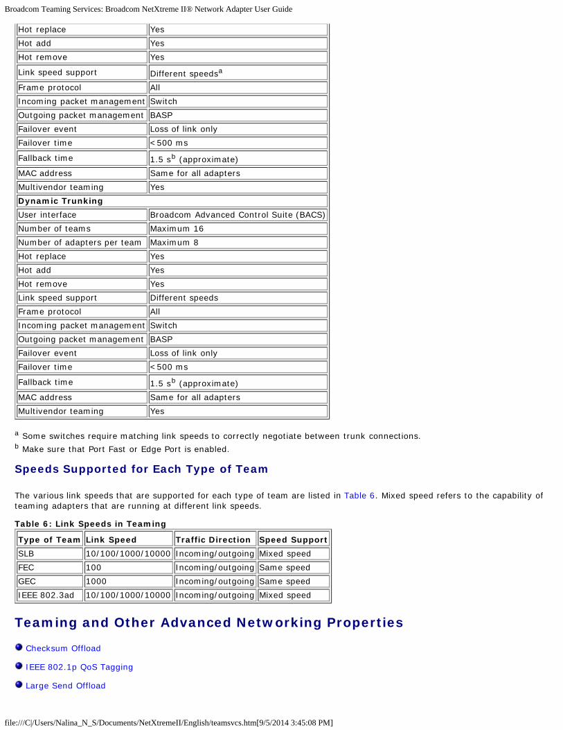
Broadcom Teaming Services: Broadcom NetXtreme II® Network Adapter User Guide
file:///C|/Users/Nalina_N_S/Documents/NetXtremeII/English/teamsvcs.htm[9/5/2014 3:45:08 PM]
Hot replace Yes
Hot add Yes
Hot remove Yes
Link speed support Different speedsa
Frame protocol All
Incoming packet management Switch
Outgoing packet management BASP
Failover event Loss of link only
Failover time <500 ms
Fallback time 1.5 sb (approximate)
MAC address Same for all adapters
Multivendor teaming Yes
Dynamic Trunking
User interface Broadcom Advanced Control Suite (BACS)
Number of teams Maximum 16
Number of adapters per team Maximum 8
Hot replace Yes
Hot add Yes
Hot remove Yes
Link speed support Different speeds
Frame protocol All
Incoming packet management Switch
Outgoing packet management BASP
Failover event Loss of link only
Failover time <500 ms
Fallback time 1.5 sb (approximate)
MAC address Same for all adapters
Multivendor teaming Yes
a Some switches require matching link speeds to correctly negotiate between trunk connections.b Make sure that Port Fast or Edge Port is enabled.
Speeds Supported for Each Type of Team
The various link speeds that are supported for each type of team are listed in Table 6. Mixed speed refers to the capability ofteaming adapters that are running at different link speeds.
Table 6: Link Speeds in Teaming
Type of Team Link Speed Traffic Direction Speed Support
SLB 10/100/1000/10000 Incoming/outgoing Mixed speed
FEC 100 Incoming/outgoing Same speed
GEC 1000 Incoming/outgoing Same speed
IEEE 802.3ad 10/100/1000/10000 Incoming/outgoing Mixed speed
Teaming and Other Advanced Networking Properties
Checksum Offload
IEEE 802.1p QoS Tagging
Large Send Offload

Broadcom Teaming Services: Broadcom NetXtreme II® Network Adapter User Guide
file:///C|/Users/Nalina_N_S/Documents/NetXtremeII/English/teamsvcs.htm[9/5/2014 3:45:08 PM]
TCP Offload Engine (TOE)
Jumbo Frames
IEEE 802.1Q VLANs
Wake On LAN
Preboot Execution Environment
Before creating a team, adding or removing team members, or changing advanced settings of a team member, make sureeach team member has been configured similarly. Settings to check include VLANs and QoS Packet Tagging, Jumbo Frames,and the various offloads. Advanced adapter properties and teaming support are listed in Table 7.
Table 7: Advanced Adapter Properties and Teaming Support
Adapter Properties Supported by Teaming Virtual Adapter
Checksum Offload Yes
IEEE 802.1p QoS Tagging No
Large Send Offload Yesa
TCP Offload Engine (TOE) Yesb, c
Jumbo Frames Yesb
IEEE 802.1Q VLANs Yesc
Wake on LAN Nod
Preboot Execution environment (PXE) Yese
a All adapters on the team must support this feature. Some adapters may not support this feature if ASF/IPMI is also enabled.b Must be supported by all adapters in the team.c Only for Broadcom adapters.d See Wake On LAN.e As a PXE sever only, not as a client.
A team does not necessarily inherit adapter properties; rather various properties depend on the specific capability. Forinstance, an example would be flow control, which is a physical adapter property and has nothing to do with BASP, and will beenabled on a particular adapter if the miniport driver for that adapter has flow control enabled.
NOTE: All adapters on the team must support the property listed in Table 7 in order for the team to support the property.
Checksum Offload
Checksum Offload is a property of the Broadcom network adapters that allows the TCP/IP/UDP checksums for send andreceive traffic to be calculated by the adapter hardware rather than by the host CPU. In high-traffic situations, this can allowa system to handle more connections more efficiently than if the host CPU were forced to calculate the checksums. Thisproperty is inherently a hardware property and would not benefit from a software-only implementation. An adapter thatsupports Checksum Offload advertises this capability to the operating system so that the checksum does not need to becalculated in the protocol stack. Checksum Offload is only supported for IPv4 at this time.
IEEE 802.1p QoS Tagging
The IEEE 802.1p standard includes a 3-bit field (supporting a maximum of 8 priority levels), which allows for trafficprioritization. The BASP intermediate driver does not support IEEE 802.1p QoS tagging.
Large Send Offload
Large Send Offload (LSO) is a feature provided by Broadcom network adapters that prevents an upper level protocol such asTCP from breaking a large data packet into a series of smaller packets with headers appended to them. The protocol stackneed only generate a single header for a data packet as large as 64 KB, and the adapter hardware breaks the data buffer intoappropriately-sized Ethernet frames with the correctly sequenced header (based on the single header originally provided).

Broadcom Teaming Services: Broadcom NetXtreme II® Network Adapter User Guide
file:///C|/Users/Nalina_N_S/Documents/NetXtremeII/English/teamsvcs.htm[9/5/2014 3:45:08 PM]
TCP Offload Engine (TOE)
The TCP/IP protocol suite is used to provide transport services for a wide range of applications for the Internet, LAN, and forfile transfer. Without the TCP Offload Engine, the TCP/IP protocol suite runs on the host CPU, consuming a very highpercentage of its resources and leaving little resources for the applications. With the use of the Broadcom NetXtreme IIadapter, the TCP/IP processing can be moved to hardware, freeing the CPU for more important tasks such as applicationprocessing.
The Broadcom NetXtreme II adapter's TOE functionality allows simultaneous operation of up to 1024 fully offloaded TCPconnections for 1-Gbps network adapters and 1880 fully offloaded TCP connections for 10-Gbps network adapters. The TOEsupport on the adapter significantly reduces the host CPU utilization while preserving the implementation of the operatingsystem stack.
Jumbo Frames
The use of jumbo frames was originally proposed by Alteon Networks, Inc. in 1998 and increased the maximum size of anEthernet frame to a maximum size of 9000 bytes. Though never formally adopted by the IEEE 802.3 Working Group, supportfor jumbo frames has been implemented in Broadcom NetXtreme II adapters. The BASP intermediate driver supports jumboframes, provided that all of the physical adapters in the team also support jumbo frames and the same size is set on alladapters in the team.
IEEE 802.1Q VLANs
In 1998, the IEEE approved the 802.3ac standard, which defines frame format extensions to support Virtual Bridged LocalArea Network tagging on Ethernet networks as specified in the IEEE 802.1Q specification. The VLAN protocol permits insertionof a tag into an Ethernet frame to identify the VLAN to which a frame belongs. If present, the 4-byte VLAN tag is inserted intothe Ethernet frame between the source MAC address and the length/type field. The first 2-bytes of the VLAN tag consist ofthe IEEE 802.1Q tag type, whereas the second 2 bytes include a user priority field and the VLAN identifier (VID). Virtual LANs(VLANs) allow the user to split the physical LAN into logical subparts. Each defined VLAN behaves as its own separatenetwork, with its traffic and broadcasts isolated from the others, thus increasing bandwidth efficiency within each logicalgroup. VLANs also enable the administrator to enforce appropriate security and quality of service (QoS) policies. The BASPsupports the creation of 64 VLANs per team or adapter: 63 tagged and 1 untagged. The operating system and systemresources, however, limit the actual number of VLANs. VLAN support is provided according to IEEE 802.1Q and is supported ina teaming environment as well as on a single adapter. Note that VLANs are supported only with homogeneous teaming andnot in a multivendor teaming environment. The BASP intermediate driver supports VLAN tagging. One or more VLANs may bebound to a single instance of the intermediate driver.
Wake On LAN
Wake on LAN (WOL) is a feature that allows a system to be awakened from a sleep state by the arrival of a specific packetover the Ethernet interface. Because a Virtual Adapter is implemented as a software only device, it lacks the hardwarefeatures to implement Wake on LAN and cannot be enabled to wake the system from a sleeping state via the Virtual Adapter.The physical adapters, however, support this property, even when the adapter is part of a team.
Preboot Execution Environment
The Preboot Execution Environment (PXE) allows a system to boot from an operating system image over the network. Bydefinition, PXE is invoked before an operating system is loaded, so there is no opportunity for the BASP intermediate driver toload and enable a team. As a result, teaming is not supported as a PXE client, though a physical adapter that participates in ateam when the operating system is loaded may be used as a PXE client. Whereas a teamed adapter cannot be used as a PXEclient, it can be used for a PXE server, which provides operating system images to PXE clients using a combination ofDynamic Host Control Protocol (DHCP) and the Trivial File Transfer Protocol (TFTP). Both of these protocols operate over IPand are supported by all teaming modes.
General Network Considerations
Teaming with Microsoft Virtual Server 2005
Teaming Across Switches
Spanning Tree Algorithm

Broadcom Teaming Services: Broadcom NetXtreme II® Network Adapter User Guide
file:///C|/Users/Nalina_N_S/Documents/NetXtremeII/English/teamsvcs.htm[9/5/2014 3:45:08 PM]
Layer 3 Routing/Switching
Teaming with Hubs (for troubleshooting purposes only)
Teaming with Microsoft NLB
Teaming with Microsoft Virtual Server 2005
The only supported BASP team configuration when using Microsoft Virtual Server 2005 is with a Smart Load Balancing (TM)team-type consisting of a single primary Broadcom adapter and a standby Broadcom adapter. Make sure to unbind ordeselect "Virtual Machine Network Services" from each team member prior to creating a team and prior to creating Virtualnetworks with Microsoft Virtual Server. Additionally, a virtual network should be created in this software and subsequentlybound to the virtual adapter created by a team. Directly binding a Guest operating system to a team virtual adapter may notrender the desired results.
NOTE: As of this writing, Windows Server 2008 is not a supported operating system for Microsoft Virtual Server 2005;thus, teaming may not function as expected with this combination.
Teaming Across Switches
SLB teaming can be configured across switches. The switches, however, must be connected together. Generic Trunking andLink Aggregation do not work across switches because each of these implementations requires that all physical adapters in ateam share the same Ethernet MAC address. It is important to note that SLB can only detect the loss of link between theports in the team and their immediate link partner. SLB has no way of reacting to other hardware failures in the switches andcannot detect loss of link on other ports.
Switch-Link Fault Tolerance
The diagrams below describe the operation of an SLB team in a switch fault tolerant configuration. We show the mapping ofthe ping request and ping replies in an SLB team with two active members. All servers (Blue, Gray and Red) have acontinuous ping to each other. Figure 3 is a setup without the interconnect cable in place between the two switches. Figure 4has the interconnect cable in place, and Figure 5 is an example of a failover event with the Interconnect cable in place. Thesescenarios describe the behavior of teaming across the two switches and the importance of the interconnect link.
The diagrams show the secondary team member sending the ICMP echo requests (yellow arrows) while the primary teammember receives the respective ICMP echo replies (blue arrows). This illustrates a key characteristic of the teaming software.The load balancing algorithms do not synchronize how frames are load balanced when sent or received. In other words,frames for a given conversation can go out and be received on different interfaces in the team. This is true for all types ofteaming supported by Broadcom. Therefore, an interconnect link must be provided between the switches that connect to portsin the same team.
In the configuration without the interconnect, an ICMP Request from Blue to Gray goes out port 82:83 destined for Gray port5E:CA, but the Top Switch has no way to send it there because it cannot go along the 5E:C9 port on Gray. A similar scenariooccurs when Gray attempts to ping Blue. An ICMP Request goes out on 5E:C9 destined for Blue 82:82, but cannot get there.Top Switch does not have an entry for 82:82 in its CAM table because there is no interconnect between the two switches.Pings, however, flow between Red and Blue and between Red and Gray.
Furthermore, a failover event would cause additional loss of connectivity. Consider a cable disconnect on the Top Switch port4. In this case, Gray would send the ICMP Request to Red 49:C9, but because the Bottom switch has no entry for 49:C9 in itsCAM Table, the frame is flooded to all its ports but cannot find a way to get to 49:C9.
Figure 3: Teaming Across Switches Without an Interswitch Link

Broadcom Teaming Services: Broadcom NetXtreme II® Network Adapter User Guide
file:///C|/Users/Nalina_N_S/Documents/NetXtremeII/English/teamsvcs.htm[9/5/2014 3:45:08 PM]
The addition of a link between the switches allows traffic from/to Blue and Gray to reach each other without any problems.Note the additional entries in the CAM table for both switches. The link interconnect is critical for the proper operation of theteam. As a result, it is highly advisable to have a link aggregation trunk to interconnect the two switches to ensure highavailability for the connection.
Figure 4: Teaming Across Switches With Interconnect

Broadcom Teaming Services: Broadcom NetXtreme II® Network Adapter User Guide
file:///C|/Users/Nalina_N_S/Documents/NetXtremeII/English/teamsvcs.htm[9/5/2014 3:45:08 PM]
Figure 5 represents a failover event in which the cable is unplugged on the Top Switch port 4. This is a successful failover withall stations pinging each other without loss of connectivity.
Figure 5: Failover Event
Spanning Tree Algorithm
Topology Change Notice (TCN)
Port Fast/Edge Port
In Ethernet networks, only one active path may exist between any two bridges or switches. Multiple active paths betweenswitches can cause loops in the network. When loops occur, some switches recognize stations on both sides of the switch.This situation causes the forwarding algorithm to malfunction allowing duplicate frames to be forwarded. Spanning treealgorithms provide path redundancy by defining a tree that spans all of the switches in an extended network and then forcescertain redundant data paths into a standby (blocked) state. At regular intervals, the switches in the network send and receivespanning tree packets that they use to identify the path. If one network segment becomes unreachable, or if spanning treecosts change, the spanning tree algorithm reconfigures the spanning tree topology and re-establishes the link by activatingthe standby path. Spanning tree operation is transparent to end stations, which do not detect whether they are connected toa single LAN segment or a switched LAN of multiple segments.
Spanning Tree Protocol (STP) is a Layer 2 protocol designed to run on bridges and switches. The specification for STP isdefined in IEEE 802.1d. The main purpose of STP is to ensure that you do not run into a loop situation when you haveredundant paths in your network. STP detects/disables network loops and provides backup links between switches or bridges.It allows the device to interact with other STP compliant devices in your network to ensure that only one path exists betweenany two stations on the network.
After a stable network topology has been established, all bridges listen for hello BPDUs (Bridge Protocol Data Units)transmitted from the root bridge. If a bridge does not get a hello BPDU after a predefined interval (Max Age), the bridgeassumes that the link to the root bridge is down. This bridge then initiates negotiations with other bridges to reconfigure thenetwork to re-establish a valid network topology. The process to create a new topology can take up to 50 seconds. Duringthis time, end-to-end communications are interrupted.
The use of Spanning Tree is not recommended for ports that are connected to end stations, because by definition, an endstation does not create a loop within an Ethernet segment. Additionally, when a teamed adapter is connected to a port withSpanning Tree enabled, users may experience unexpected connectivity problems. For example, consider a teamed adapter

Broadcom Teaming Services: Broadcom NetXtreme II® Network Adapter User Guide
file:///C|/Users/Nalina_N_S/Documents/NetXtremeII/English/teamsvcs.htm[9/5/2014 3:45:08 PM]
that has a lost link on one of its physical adapters. If the physical adapter were to be reconnected (also known as fallback),the intermediate driver would detect that the link has been reestablished and would begin to pass traffic through the port.Traffic would be lost if the port was temporarily blocked by the Spanning Tree Protocol.
Topology Change Notice (TCN)
A bridge/switch creates a forwarding table of MAC addresses and port numbers by learning the source MAC address thatreceived on a particular port. The table is used to forward frames to a specific port rather than flooding the frame to all ports.The typical maximum aging time of entries in the table is 5 minutes. Only when a host has been silent for 5 minutes would itsentry be removed from the table. It is sometimes beneficial to reduce the aging time. One example is when a forwarding linkgoes to blocking and a different link goes from blocking to forwarding. This change could take up to 50 seconds. At the end ofthe STP re-calculation a new path would be available for communications between end stations. However, because theforwarding table would still have entries based on the old topology, communications may not be reestablished until after 5minutes when the affected ports entries are removed from the table. Traffic would then be flooded to all ports and re-learned.In this case it is beneficial to reduce the aging time. This is the purpose of a topology change notice (TCN) BPDU. The TCN issent from the affected bridge/switch to the root bridge/switch. As soon as a bridge/switch detects a topology change (a linkgoing down or a port going to forwarding) it sends a TCN to the root bridge via its root port. The root bridge then advertisesa BPDU with a Topology Change to the entire network.This causes every bridge to reduce the MAC table aging time to 15seconds for a specified amount of time. This allows the switch to re-learn the MAC addresses as soon as STP re-converges.
Topology Change Notice BPDUs are sent when a port that was forwarding changes to blocking or transitions to forwarding. ATCN BPDU does not initiate an STP recalculation. It only affects the aging time of the forwarding table entries in the switch.Itwill not change the topology of the network or create loops. End nodes such as servers or clients trigger a topology changewhen they power off and then power back on.
Port Fast/Edge Port
To reduce the effect of TCNs on the network (for example, increasing flooding on switch ports), end nodes that are poweredon/off often should use the Port Fast or Edge Port setting on the switch port they are attached to. Port Fast or Edge Port is acommand that is applied to specific ports and has the following effects:
Ports coming from link down to link up will be put in the forwarding STP mode instead of going from listening tolearning and then to forwarding. STP is still running on these ports.
The switch does not generate a Topology Change Notice when the port is going up or down.
Layer 3 Routing/Switching
The switch that the teamed ports are connected to must not be a Layer 3 switch or router. The ports in the team must be inthe same network.
Teaming with Hubs (for troubleshooting purposes only)
Hub Usage in Teaming Network Configurations
SLB Teams
SLB Team Connected to a Single Hub
Generic and Dynamic Trunking (FEC/GEC/IEEE 802.3ad)
SLB teaming can be used with 10/100 hubs, but it is only recommended for troubleshooting purposes, such as connecting anetwork analyzer in the event that switch port mirroring is not an option.
Hub Usage in Teaming Network Configurations
Although the use of hubs in network topologies is functional in some situations, it is important to consider the throughputramifications when doing so. Network hubs have a maximum of 100 Mbps half-duplex link speed, which severely degradesperformance in either a Gigabit or 100 Mbps switched-network configuration. Hub bandwidth is shared among all connecteddevices; as a result, when more devices are connected to the hub, the bandwidth available to any single device connected tothe hub is reduced in direct proportion to the number of devices connected to the hub.
It is not recommended to connect team members to hubs; only switches should be used to connect to teamed ports. An SLBteam, however, can be connected directly to a hub for troubleshooting purposes. Other team types can result in a loss ofconnectivity if specific failures occur and should not be used with hubs.

Broadcom Teaming Services: Broadcom NetXtreme II® Network Adapter User Guide
file:///C|/Users/Nalina_N_S/Documents/NetXtremeII/English/teamsvcs.htm[9/5/2014 3:45:08 PM]
SLB Teams
SLB teams are the only teaming type not dependant on switch configuration. The server intermediate driver handles the loadbalancing and fault tolerance mechanisms with no assistance from the switch. These elements of SLB make it the only teamtype that maintains failover and fallback characteristics when team ports are connected directly to a hub.
SLB Team Connected to a Single Hub
SLB teams configured as shown in Figure 6 maintain their fault tolerance properties. Either server connection could potentiallyfail, and network functionality is maintained. Clients could be connected directly to the hub, and fault tolerance would still bemaintained; server performance, however, would be degraded.
Figure 6: Team Connected to a Single Hub
Generic and Dynamic Trunking (FEC/GEC/IEEE 802.3ad)
FEC/GEC and IEEE 802.3ad teams cannot be connected to any hub configuration. These team types must be connected to aswitch that has also been configured for this team type.
Teaming with Microsoft NLB
Teaming does not work in Microsoft's Network Load Balancing (NLB) unicast mode, only in multicast mode. Due to themechanism used by the NLB service, the recommended teaming configuration in this environment is Failover (SLB with astandby NIC) as load balancing is managed by NLB. The TOE functionality in teaming will not operate in NLB.
Application Considerations
Teaming and Clustering

Broadcom Teaming Services: Broadcom NetXtreme II® Network Adapter User Guide
file:///C|/Users/Nalina_N_S/Documents/NetXtremeII/English/teamsvcs.htm[9/5/2014 3:45:08 PM]
Teaming and Network Backup
Teaming and Clustering
Microsoft Cluster Software
High-Performance Computing Cluster
Oracle
Microsoft Cluster Software
Dell Server cluster solutions integrate Microsoft Cluster Services (MSCS) with PowerVault SCSI or Dell/EMC Fibre-Channelbased storage, Dell servers, storage adapters, storage switches and network adapters to provide high-availability (HA)solutions. HA clustering supports all adapters qualified on a supported Dell server.
In each cluster node, it is strongly recommended that customers install at least two network adapters (on-board adapters areacceptable). These interfaces serve two purposes. One adapter is used exclusively for intra-cluster heartbeat communications.This is referred to as the private adapter and usually resides on a separate private subnetwork. The other adapter is used forclient communications and is referred to as the public adapter.
Multiple adapters may be used for each of these purposes: private, intracluster communications and public, external clientcommunications. All Broadcom teaming modes are supported with Microsoft Cluster Software for the public adapter only.Private network adapter teaming is not supported. Microsoft indicates that the use of teaming on the private interconnect of aserver cluster is not supported because of delays that could possibly occur in the transmission and receipt of heartbeatpackets between the nodes. For best results, when you want redundancy for the private interconnect, disable teaming anduse the available ports to form a second private interconnect. This achieves the same end result and provides dual, robustcommunication paths for the nodes to communicate over.
For teaming in a clustered environment, customers are recommended to use the same brand of adapters.
Figure 7 shows a 2-node Fibre-Channel cluster with three network interfaces per cluster node: one private and two public. Oneach node, the two public adapters are teamed, and the private adapter is not. Teaming is supported across the same switchor across two switches. Figure 8 shows the same 2-node Fibre-Channel cluster in this configuration.
Figure 7: Clustering With Teaming Across One Switch

Broadcom Teaming Services: Broadcom NetXtreme II® Network Adapter User Guide
file:///C|/Users/Nalina_N_S/Documents/NetXtremeII/English/teamsvcs.htm[9/5/2014 3:45:08 PM]
NOTE: Microsoft Network Load Balancing is not supported with Microsoft Cluster Software.
High-Performance Computing Cluster
Gigabit Ethernet is typically used for the following three purposes in high-performance computing cluster (HPCC) applications:
Inter-Process Communications (IPC): For applications that do not require low-latency, high-bandwidth interconnects(such as Myrinet, InfiniBand), Gigabit Ethernet can be used for communication between the compute nodes.
I/O: Ethernet can be used for file sharing and serving the data to the compute nodes. This can be done simply using anNFS server or using parallel file systems such as PVFS.
Management & Administration: Ethernet is used for out-of-band (ERA) and in-band (OMSA) management of the nodesin the cluster. It can also be used for job scheduling and monitoring.
In our current HPCC offerings, only one of the on-board adapters is used. If Myrinet or IB is present, this adapter serves I/Oand administration purposes; otherwise, it is also responsible for IPC. In case of an adapter failure, the administrator can usethe Felix package to easily configure adapter 2. Adapter teaming on the host side is neither tested nor supported in HPCC.
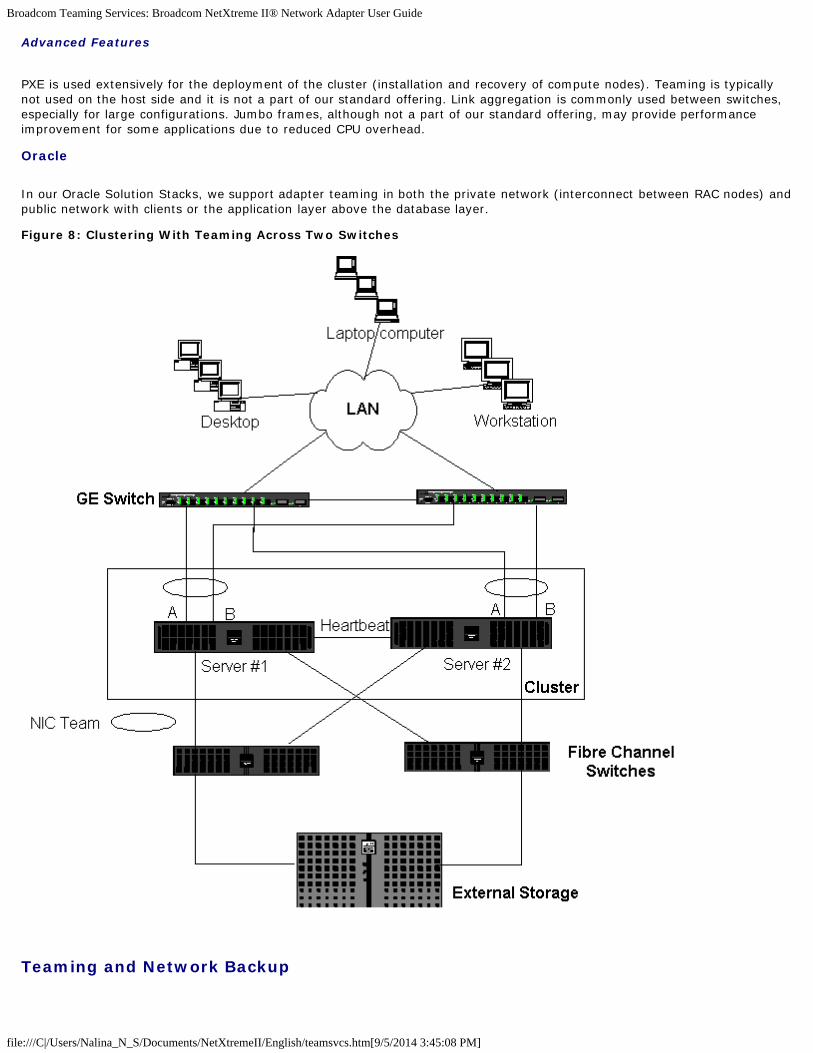
Broadcom Teaming Services: Broadcom NetXtreme II® Network Adapter User Guide
file:///C|/Users/Nalina_N_S/Documents/NetXtremeII/English/teamsvcs.htm[9/5/2014 3:45:08 PM]
Advanced Features
PXE is used extensively for the deployment of the cluster (installation and recovery of compute nodes). Teaming is typicallynot used on the host side and it is not a part of our standard offering. Link aggregation is commonly used between switches,especially for large configurations. Jumbo frames, although not a part of our standard offering, may provide performanceimprovement for some applications due to reduced CPU overhead.
Oracle
In our Oracle Solution Stacks, we support adapter teaming in both the private network (interconnect between RAC nodes) andpublic network with clients or the application layer above the database layer.
Figure 8: Clustering With Teaming Across Two Switches
Teaming and Network Backup

Broadcom Teaming Services: Broadcom NetXtreme II® Network Adapter User Guide
file:///C|/Users/Nalina_N_S/Documents/NetXtremeII/English/teamsvcs.htm[9/5/2014 3:45:08 PM]
Load Balancing and Failover
Fault Tolerance
When you perform network backups in a nonteamed environment, overall throughput on a backup server adapter can beeasily impacted due to excessive traffic and adapter overloading. Depending on the number of backup servers, data streams,and tape drive speed, backup traffic can easily consume a high percentage of the network link bandwidth, thus impactingproduction data and tape backup performance. Network backups usually consist of a dedicated backup server running withtape backup software such as NetBackup, Galaxy or Backup Exec. Attached to the backup server is either a direct SCSI tapebackup unit or a tape library connected through a fiber channel storage area network (SAN). Systems that are backed upover the network are typically called clients or remote servers and usually have a tape backup software agent installed.Figure 9 shows a typical 1 Gbps nonteamed network environment with tape backup implementation.
Figure 9: Network Backup without Teaming
Because there are four client servers, the backup server can simultaneously stream four backup jobs (one per client) to amultidrive autoloader. Because of the single link between the switch and the backup server; however, a 4-stream backup caneasily saturate the adapter and link. If the adapter on the backup server operates at 1 Gbps (125 MB/s), and each client isable to stream data at 20 MB/s during tape backup, the throughput between the backup server and switch will be at 80 MB/s(20 MB/s x 4), which is equivalent to 64% of the network bandwidth. Although this is well within the network bandwidthrange, the 64% constitutes a high percentage, especially if other applications share the same link.
Load Balancing and Failover
As the number of backup streams increases, the overall throughput increases. Each data stream, however, may not be able tomaintain the same performance as a single backup stream of 25 MB/s. In other words, even though a backup server canstream data from a single client at 25 MB/s, it is not expected that four simultaneously-running backup jobs will stream at100 MB/s (25 MB/s x 4 streams). Although overall throughput increases as the number of backup streams increases, eachbackup stream can be impacted by tape software or network stack limitations.

Broadcom Teaming Services: Broadcom NetXtreme II® Network Adapter User Guide
file:///C|/Users/Nalina_N_S/Documents/NetXtremeII/English/teamsvcs.htm[9/5/2014 3:45:08 PM]
For a tape backup server to reliably use adapter performance and network bandwidth when backing up clients, a networkinfrastructure must implement teaming such as load balancing and fault tolerance. Data centers will incorporate redundantswitches, link aggregation, and trunking as part of their fault tolerant solution. Although teaming device drivers willmanipulate the way data flows through teamed interfaces and failover paths, this is transparent to tape backup applicationsand does not interrupt any tape backup process when backing up remote systems over the network. Figure 10 shows anetwork topology that demonstrates tape backup in a Broadcom teamed environment and how smart load balancing can loadbalance tape backup data across teamed adapters.
There are four paths that the client-server can use to send data to the backup server, but only one of these paths will bedesignated during data transfer. One possible path that Client-Server Red can use to send data to the backup server is:
Example Path: Client-Server Red sends data through Adapter A, Switch 1, Backup Server Adapter A.
The designated path is determined by two factors:
Client-Server ARP cache; which points to the backup server MAC address. This is determined by the Broadcomintermediate driver inbound load balancing algorithm.
The physical adapter interface on Client-Server Red will be used to transmit the data. The Broadcom intermediatedriver outbound load balancing algorithm determines this (see Outbound Traffic Flow and Inbound Traffic Flow (SLBOnly).
The teamed interface on the backup server transmits a gratuitous address resolution protocol (G-ARP) to Client-Server Red,which in turn, causes the client server ARP cache to get updated with the Backup Server MAC address. The load balancingmechanism within the teamed interface determines the MAC address embedded in the G-ARP. The selected MAC address isessentially the destination for data transfer from the client server.On Client-Server Red, the SLB teaming algorithm willdetermine which of the two adapter interfaces will be used to transmit data. In this example, data from Client Server Red isreceived on the backup server Adapter A interface. To demonstrate the SLB mechanisms when additional load is placed on theteamed interface, consider the scenario when the backup server initiates a second backup operation: one to Client-ServerRed, and one to Client-Server Blue. The route that Client-Server Blue uses to send data to the backup server is dependant onits ARP cache, which points to the backup server MAC address. Because Adapter A of the backup server is already under loadfrom its backup operation with Client-Sever Red, the Backup Server invokes its SLB algorithm to inform Client-Server Blue(through an G-ARP) to update its ARP cache to reflect the backup server Adapter B MAC address. When Client-Server Blueneeds to transmit data, it uses either one of its adapter interfaces, which is determined by its own SLB algorithm. What isimportant is that data from Client-Server Blue is received by the Backup Server Adapter B interface, and not by its Adapter Ainterface. This is important because with both backup streams running simultaneously, the backup server must load balancedata streams from different clients. With both backup streams running, each adapter interface on the backup server isprocessing an equal load, thus load-balancing data across both adapter interfaces.
The same algorithm applies if a third and fourth backup operation is initiated from the backup server. The teamed interfaceon the backup server transmits a unicast G-ARP to backup clients to inform them to update their ARP cache. Each client thentransmits backup data along a route to the target MAC address on the backup server.
Fault Tolerance
If a network link fails during tape backup operations, all traffic between the backup server and client stops and backup jobsfail. If, however, the network topology was configured for both Broadcom SLB and switch fault tolerance, then this wouldallow tape backup operations to continue without interruption during the link failure. All failover processes within the networkare transparent to tape backup software applications. To understand how backup data streams are directed during networkfailover process, consider the topology in Figure 10. Client-Server Red is transmitting data to the backup server through Path1, but a link failure occurs between the backup server and the switch. Because the data can no longer be sent from Switch #1to the Adapter A interface on the backup server, the data is redirected from Switch #1 through Switch #2, to the Adapter Binterface on the backup server. This occurs without the knowledge of the backup application because all fault tolerantoperations are handled by the adapter team interface and trunk settings on the switches. From the client server perspective,it still operates as if it is transmitting data through the original path.
Figure 10: Network Backup With SLB Teaming Across Two Switches

Broadcom Teaming Services: Broadcom NetXtreme II® Network Adapter User Guide
file:///C|/Users/Nalina_N_S/Documents/NetXtremeII/English/teamsvcs.htm[9/5/2014 3:45:08 PM]
Troubleshooting Teaming Problems
Teaming Configuration Tips
Troubleshooting Guidelines
When running a protocol analyzer over a virtual adapter teamed interface, the MAC address shown in the transmitted framesmay not be correct. The analyzer does not show the frames as constructed by BASP and shows the MAC address of the teamand not the MAC address of the interface transmitting the frame. It is suggested to use the following process to monitor ateam:
Mirror all uplink ports from the team at the switch.
If the team spans two switches, mirror the interlink trunk as well.
Sample all mirror ports independently.
On the analyzer, use an adapter and driver that does not filter QoS and VLAN information.
Teaming Configuration Tips
When troubleshooting network connectivity or teaming functionality issues, ensure that the following information is true foryour configuration.
1. Although mixed-speed SLB teaming is supported by Dell, it is recommended that all adapters in a team be the samespeed (either all Gigabit Ethernet or all Fast Ethernet). For speeds of 10 Gbps, it is highly recommended that alladapters in a team be the same speed.
2. If LiveLink is not enabled, disable Spanning Tree Protocol or enable an STP mode that bypasses the initial phases (for

Broadcom Teaming Services: Broadcom NetXtreme II® Network Adapter User Guide
file:///C|/Users/Nalina_N_S/Documents/NetXtremeII/English/teamsvcs.htm[9/5/2014 3:45:08 PM]
example, Port Fast, Edge Port) for the switch ports connected to a team.
3. All switches that the team is directly connected to must have the same hardware revision, firmware revision, andsoftware revision to be supported.
4. To be teamed, adapters should be members of the same VLAN. In the event that multiple teams are configured, eachteam should be on a separate network.
5. Do not assign a Locally Administered Address on any physical adapter that is a member of a team.
6. Verify that power management is disabled on all physical members of any team.
7. Remove any static IP address from the individual physical team members before the team is built.
8. A team that requires maximum throughput should use LACP or GEC\FEC. In these cases, the intermediate driver is onlyresponsible for the outbound load balancing while the switch performs the inbound load balancing.
9. Aggregated teams (802.3ad \ LACP and GEC\FEC) must be connected to only a single switch that supports IEEE802.3a, LACP or GEC/FEC.
10. It is not recommended to connect any team to a hub, as hubs only support half duplex. Hubs should be connected to ateam for troubleshooting purposes only. Disabling the device driver of a network adapter participating in an LACP orGEC/FEC team may have adverse affects with network connectivity. Broadcom recommends that the adapter first bephysically disconnected from the switch before disabling the device driver in order to avoid a network connection loss.
11. Verify the base (Miniport) and team (intermediate) drivers are from the same release package. Dell does not test orsupport mixing base and teaming drivers from different releases.
12. Test the connectivity to each physical adapter prior to teaming.
13. Test the failover and fallback behavior of the team before placing into a production environment.
14. When moving from a nonproduction network to a production network, it is strongly recommended to test again forfailover and fallback.
15. Test the performance behavior of the team before placing into a production environment.
16. Network teaming is not supported when running iSCSI traffic via Microsoft iSCSI initiator or iSCSI offload. MPIO shouldbe used instead of Broadcom network teaming for these ports.
17. For information on iSCSI boot and iSCSI offload restrictions, see iSCSI Protocol.
Troubleshooting Guidelines
Before you call Dell support, make sure you have completed the following steps for troubleshooting network connectivityproblems when the server is using adapter teaming.
1. Make sure the link light is ON for every adapter and all the cables are attached.
2. Check that the matching base and intermediate drivers belong to the same Dell release and are loaded correctly.
3. Check for a valid IP Address using the Windows ipconfig command.
4. Check that STP is disabled or Edge Port/Port Fast is enabled on the switch ports connected to the team or that LiveLinkis being used.
5. Check that the adapters and the switch are configured identically for link speed and duplex.
6. If possible, break the team and check for connectivity to each adapter independently to confirm that the problem isdirectly associated with teaming.
7. Check that all switch ports connected to the team are on the same VLAN.
8. Check that the switch ports are configured properly for Generic Trunking (FEC/GEC)/802.3ad-Draft Static type ofteaming and that it matches the adapter teaming type. If the system is configured for an SLB type of team, make surethe corresponding switch ports are not configured for Generic Trunking (FEC/GEC)/802.3ad-Draft Static types of teams.
Frequently Asked Questions
Question: Under what circumstances is traffic not load balanced? Why is all traffic not load balanced evenly across the teammembers?Answer: The bulk of traffic does not use IP/TCP/UDP or the bulk of the clients are in a different network. The receive loadbalancing is not a function of traffic load, but a function of the number of clients that are connected to the server.
Question: What network protocols are load balanced when in a team?Answer: Broadcom's teaming software only supports IP/TCP/UDP traffic. All other traffic is forwarded to the primary adapter.

Broadcom Teaming Services: Broadcom NetXtreme II® Network Adapter User Guide
file:///C|/Users/Nalina_N_S/Documents/NetXtremeII/English/teamsvcs.htm[9/5/2014 3:45:08 PM]
Question: Which protocols are load balanced with SLB and which ones are not?Answer: Only IP/TCP/UDP protocols are load balanced in both directions: send and receive. IPX is load balanced on thetransmit traffic only.
Question: Can I team a port running at 100 Mbps with a port running at 1000 Mbps? Answer: Mixing link speeds within a team is only supported for Smart Load Balancing™ teams and 802.3ad teams.
Question: Can I team a fiber adapter with a copper Gigabit Ethernet adapter? Answer: Yes with SLB, and yes if the switch allows for it in FEC/GEC and 802.3ad.
Question: What is the difference between adapter load balancing and Microsoft's Network Load Balancing (NLB)? Answer: Adapter load balancing is done at a network session level, whereas NLB is done at the server application level.
Question: Can I connect the teamed adapters to a hub? Answer: Teamed ports can be connected to a hub for troubleshooting purposes only. However, this practice is notrecommended for normal operation because the performance would be degraded due to hub limitations. Connect the teamedports to a switch instead.
Question: Can I connect the teamed adapters to ports in a router? Answer: No. All ports in a team must be on the same network; in a router, however, each port is a separate network bydefinition. All teaming modes require that the link partner be a Layer 2 switch.
Question: Can I use teaming with Microsoft Cluster Services?Answer: Yes. Teaming is supported on the public network only, not on the private network used for the heartbeat link.
Question: Can PXE work over a virtual adapter (team)? Answer: A PXE client operates in an environment before the operating system is loaded; as a result, virtual adapters havenot been enabled yet. If the physical adapter supports PXE, then it can be used as a PXE client, whether or not it is part of avirtual adapter when the operating system loads. PXE servers may operate over a virtual adapter.
Question: Can WOL work over a virtual adapter (team)? Answer: Wake-on-LAN functionality operates in an environment before the operating system is loaded. WOL occurs when thesystem is off or in standby, so no team is configured.
Question: What is the maximum number of ports that can be teamed together? Answer: Up to eight ports can be assigned to a team.
Question: What is the maximum number of teams that can be configured on the same server? Answer: Up to 16teams can be configured on the same server.
Question: Why does my team loose connectivity for the first 30 to 50 seconds after the Primary adapter is restored(fallback)? Answer: Because Spanning Tree Protocol is bringing the port from blocking to forwarding. You must enable Port Fast or EdgePort on the switch ports connected to the team or use LiveLink to account for the STP delay.
Question: Can I connect a team across multiple switches? Answer: Smart Load Balancing can be used with multiple switches because each physical adapter in the system uses aunique Ethernet MAC address. Link Aggregation and Generic Trunking cannot operate across switches because they require allphysical adapters to share the same Ethernet MAC address.
Question: How do I upgrade the intermediate driver (BASP)? Answer: The intermediate driver cannot be upgraded through the Local Area Connection Properties. It must be upgradedusing the Setup installer.
Question: How can I determine the performance statistics on a virtual adapter (team)?Answer: In Broadcom Advanced Control Suite, click the Statistics tab for the virtual adapter.
Question: Can I configure NLB and teaming concurrently?Answer: Yes, but only when running NLB in a multicast mode (NLB is not supported with MS Cluster Services).
Question: Should both the backup server and client servers that are backed up be teamed?Answer: Because the backup server is under the most data load, it should always be teamed for link aggregation andfailover. A fully redundant network, however, requires that both the switches and the backup clients be teamed for faulttolerance and link aggregation.
Question: During backup operations, does the adapter teaming algorithm load balance data at a byte-level or a session-level?Answer: When using adapter teaming, data is only load balanced at a session level and not a byte level to prevent out-of-

Broadcom Teaming Services: Broadcom NetXtreme II® Network Adapter User Guide
file:///C|/Users/Nalina_N_S/Documents/NetXtremeII/English/teamsvcs.htm[9/5/2014 3:45:08 PM]
order frames. Adapter teaming load balancing does not work the same way as other storage load balancing mechanisms suchas EMC PowerPath.
Question: Is there any special configuration required in the tape backup software or hardware to work with adapter teaming?Answer: No special configuration is required in the tape software to work with teaming. Teaming is transparent to tapebackup applications.
Question: How do I know what driver I am currently using? Answer: In all operating systems, the most accurate method for checking the driver revision is to physically locate the driverfile and check the properties.
Question: Can SLB detect a switch failure in a Switch Fault Tolerance configuration?Answer: No. SLB can only detect the loss of link between the teamed port and its immediate link partner. SLB cannot detectlink failures on other ports.
Question: Where can I get the latest supported drivers?Answer: Go to Dell support at http://support.dell.com for driver package updates or support documents.
Question: Why does my team lose connectivity for the first 30 to 50 seconds after the primary adapter is restored (fall-backafter a failover)? Answer: During a fall-back event, link is restored causing Spanning Tree Protocol to configure the port for blocking until itdetermines that it can move to the forwarding state. You must enable Port Fast or Edge Port on the switch ports connected tothe team to prevent the loss of communications caused by STP.
Question: Where do I monitor real time statistics for an adapter team in a Windows server? Answer: Use the Broadcom Advanced Control Suite (BACS) to monitor general, IEEE 802.3 and custom counters.
Question: What features are not supported on a multivendor team?Answer: TOE, VLAN tagging, and RSS are not supported on a multivendor team.
Appendix A: Event Log Messages
Windows System Event Log Messages
Base Driver (Physical Adapter/Miniport)
Intermediate Driver (Virtual Adapter/Team)
Virtual Bus Driver (VBD)
Windows System Event Log Messages
The known base and intermediate Windows System Event Log status messages for the Broadcom NetXtreme II adapters arelisted in Table 8 and Table 9. As a Broadcom adapter driver loads, Windows places a status code in the system event viewer.There may be up to two classes of entries for these event codes depending on whether both drivers are loaded (one set forthe base or miniport driver and one set for the intermediate or teaming driver).
Base Driver (Physical Adapter/Miniport)
The base driver is identified by source L2ND. Table 8 lists the event log messages supported by the base driver, explains thecause for the message, and provides the recommended action.
Note: In Table 8, message numbers 1 through 17 apply to both NDIS 5.x and NDIS 6.x drivers, message numbers 18through 23 apply only to the NDIS 6.x driver.
Table 8: Base Driver Event Log Messages
MessageNumber Severity Message Cause Corrective Action
1 Error
Failed to allocatememory for the deviceblock. Check systemmemory resource
The driver cannot allocatememory from the operatingsystem.
Close running applications to free memory.

Broadcom Teaming Services: Broadcom NetXtreme II® Network Adapter User Guide
file:///C|/Users/Nalina_N_S/Documents/NetXtremeII/English/teamsvcs.htm[9/5/2014 3:45:08 PM]
usage.
2 Error Failed to allocate mapregisters.
The driver cannot allocatemap registers from theoperating system.
Unload other drivers that may allocate mapregisters.
3 Error
Failed to accessconfigurationinformation. Reinstallthe network driver.
The driver cannot access PCIconfiguration space registerson the adapter.
For add-in adapters: reseat the adapter inthe slot, move the adapter to another PCIslot, or replace the adapter.
4 Warning
The network link isdown. Check to makesure the networkcable is properlyconnected.
The adapter has lost itsconnection with its linkpartner.
Check that the network cable is connected,verify that the network cable is the righttype, and verify that the link partner (forexample, switch or hub) is working correctly.
5 Informational The network link isup.
The adapter has established alink. No action is required.
6 InformationalNetwork controllerconfigured for 10Mbhalf-duplex link.
The adapter has beenmanually configured for theselected line speed andduplex settings.
No action is required.
7 InformationalNetwork controllerconfigured for 10Mbfull-duplex link.
The adapter has beenmanually configured for theselected line speed andduplex settings.
No action is required.
8 InformationalNetwork controllerconfigured for 100Mbhalf-duplex link.
The adapter has beenmanually configured for theselected line speed andduplex settings.
No action is required.
9 InformationalNetwork controllerconfigured for 100Mbfull-duplex link.
The adapter has beenmanually configured for theselected line speed andduplex settings.
No action is required.
10 InformationalNetwork controllerconfigured for 1Gbhalf-duplex link.
The adapter has beenmanually configured for theselected line speed andduplex settings.
No action is required.
11 InformationalNetwork controllerconfigured for 1Gbfull-duplex link.
The adapter has beenmanually configured for theselected line speed andduplex settings.
No action is required.
12 InformationalNetwork controllerconfigured for 2.5Gbfull-duplex link.
The adapter has beenmanually configured for theselected line speed andduplex settings.
No action is required.
13 Error Medium notsupported.
The operating system doesnot support the IEEE 802.3medium.
Reboot the operating system, run a viruscheck, run a disk check (chkdsk), andreinstall the operating system.
14 ErrorUnable to register theinterrupt serviceroutine.
The device driver cannotinstall the interrupt handler.
Reboot the operating system; remove otherdevice drivers that may be sharing the sameIRQ.
15 Error Unable to map IOspace.
The device driver cannotallocate memory-mapped I/Oto access driver registers.
Remove other adapters from the system,reduce the amount of physical memoryinstalled, and replace the adapter.
16 Informational Driver initializedsuccessfully.
The driver has successfullyloaded. No action is required.
17 Informational NDIS is resetting theminiport driver.
The NDIS layer has detecteda problem sending/receivingpackets and is resetting thedriver to resolve the problem.
Run Broadcom Advanced Control Suitediagnostics; check that the network cable isgood.
18 Error
Unknown PHYdetected. Using adefault PHYinitialization routine.
The driver could not read thePHY ID. Replace the adapter.

Broadcom Teaming Services: Broadcom NetXtreme II® Network Adapter User Guide
file:///C|/Users/Nalina_N_S/Documents/NetXtremeII/English/teamsvcs.htm[9/5/2014 3:45:08 PM]
19 Error
This driver does notsupport this device.Upgrade to the latestdriver.
The driver does not recognizethe installed adapter.
Upgrade to a driver version that supportsthis adapter.
20 Error Driver initializationfailed.
Unspecified failure duringdriver initialization.
Reinstall the driver, update to a newerdriver, run Broadcom Advanced ControlSuite diagnostics, or replace the adapter.
21 InformationalNetwork controllerconfigured for 10Gbfull-duplex link.
The adapter has beenmanually configured for theselected line speed andduplex settings.
No action is required.
22 Error
Network controllerfailed initializationbecause it cannotallocate systemmemory.
Insufficient system memoryprevented the initialization ofthe driver.
Increase system memory.
23 Error
Network controllerfailed to exchange theinterface with the busdriver.
The driver and the bus driverare not compatible.
Update to the latest driver set, ensuring themajor and minor versions for both NDIS andthe bus driver are the same.
Intermediate Driver (Virtual Adapter/Team)
The intermediate driver is identified by source BLFM, regardless of the base driver revision. Table 9 lists the event logmessages supported by the intermediate driver, explains the cause for the message, and provides the recommended action.
Table 9: Intermediate Driver Event Log Messages
SystemEventMessageNumber
Severity Message Cause Corrective Action
1 InformationalEvent logging enabled forBroadcom AdvancedServer Program driver.
– No action is required.
2 Error Unable to register withNDIS.
The driver cannot registerwith the NDIS interface. Unload other NDIS drivers.
3 Error Unable to instantiate themanagement interface.
The driver cannot create adevice instance. Reboot the operating system.
4 ErrorUnable to create symboliclink for the managementinterface.
Another driver has created aconflicting device name.
Unload the conflicting device driver thatuses the name Blf.
5 InformationalBroadcom AdvancedServer Program Driver hasstarted.
The driver has started. No action is required.
6 InformationalBroadcom AdvancedServer Program Driver hasstopped.
The driver has stopped. No action is required.
7 ErrorCould not allocate memoryfor internal datastructures.
The driver cannot allocatememory from the operatingsystem.
Close running applications to freememory.
8 Warning Could not bind to adapter.The driver could not openone of the team physicaladapters.
Unload and reload the physical adapterdriver, install an updated physicaladapter driver, or replace the physicaladapter.
9 Informational Successfully bind toadapter.
The driver successfullyopened the physical adapter. No action is required.
10 Warning Network adapter isdisconnected.
The physical adapter is notconnected to the network (ithas not established link).
Check that the network cable isconnected, verify that the network cableis the right type, and verify that the linkpartner (switch or hub) is workingcorrectly.

Broadcom Teaming Services: Broadcom NetXtreme II® Network Adapter User Guide
file:///C|/Users/Nalina_N_S/Documents/NetXtremeII/English/teamsvcs.htm[9/5/2014 3:45:08 PM]
11 Informational Network adapter isconnected.
The physical adapter isconnected to the network (ithas established link).
No action is required.
12 Error
Broadcom AdvancedProgram Features Driver isnot designed to run on thisversion of OperatingSystem.
The driver does not supportthe operating system onwhich it is installed.
Consult the driver release notes andinstall the driver on a supportedoperating system or update the driver.
13 Informational
Hot-standby adapter isselected as the primaryadapter for a team withouta load balancing adapter.
A standby adapter has beenactivated. Replace the failed physical adapter.
14 Informational Network adapter does notsupport Advanced Failover.
The physical adapter doesnot support the BroadcomNIC Extension (NICE).
Replace the adapter with one that doessupport NICE.
15 InformationalNetwork adapter isenabled via managementinterface.
The driver has successfullyenabled a physical adapterthrough the managementinterface.
No action is required.
16 WarningNetwork adapter isdisabled via managementinterface.
The driver has successfullydisabled a physical adapterthrough the managementinterface.
No action is required.
17 Informational
Network adapter isactivated and isparticipating in networktraffic.
A physical adapter has beenadded to or activated in ateam.
No action is required.
18 Informational
Network adapter is de-activated and is no longerparticipating in networktraffic.
The driver does notrecognize the installedadapter.
No action is required.
19 InformationalThe LiveLink feature inBASP connected the linkfor the network adapter.
The connection with theremote target(s) for theLiveLink-enabled teammember has beenestablished or restored
No action is required.
20 InformationalThe LiveLink feature inBASP disconnected the linkfor the network adapter.
The LiveLink-enabled teammember is unable to connectwith the remote target(s).
No action is required.
Virtual Bus Driver (VBD)
Table 10: Virtual Bus Driver (VBD) Event Log Messages
MessageNumber Severity Message Cause Corrective Action
1 Error
Failed to allocatememory for the deviceblock. Check systemmemory resourceusage.
The driver cannotallocate memory fromthe operating system.
Close running applications to free memory.
2 Informational
The network link isdown. Check to makesure the network cableis properly connected.
The adapter has lost itsconnection with its linkpartner.
Check that the network cable is connected,verify that the network cable is the right type,and verify that the link partner (for example,switch or hub) is working correctly.
3 Informational The network link is up. The adapter hasestablished a link. No action is required.
4 InformationalNetwork controllerconfigured for 10Mbhalf-duplex link.
The adapter has beenmanually configured forthe selected line speedand duplex settings.
No action is required.
Network controller The adapter has been

Broadcom Teaming Services: Broadcom NetXtreme II® Network Adapter User Guide
file:///C|/Users/Nalina_N_S/Documents/NetXtremeII/English/teamsvcs.htm[9/5/2014 3:45:08 PM]
5 Informational configured for 10Mbfull-duplex link.
manually configured forthe selected line speedand duplex settings.
No action is required.
6 InformationalNetwork controllerconfigured for 100Mbhalf-duplex link.
The adapter has beenmanually configured forthe selected line speedand duplex settings.
No action is required.
7 InformationalNetwork controllerconfigured for 100Mbfull-duplex link.
The adapter has beenmanually configured forthe selected line speedand duplex settings.
No action is required.
8 InformationalNetwork controllerconfigured for 1Gb half-duplex link.
The adapter has beenmanually configured forthe selected line speedand duplex settings.
No action is required.
9 InformationalNetwork controllerconfigured for 1Gb full-duplex link.
The adapter has beenmanually configured forthe selected line speedand duplex settings.
No action is required.
10 ErrorUnable to register theinterrupt serviceroutine.
The device driver cannotinstall the interrupthandler.
Reboot the operating system; remove otherdevice drivers that may be sharing the sameIRQ.
11 Error Unable to map IOspace.
The device driver cannotallocate memory-mapped I/O to access driverregisters.
Remove other adapters from the system, reducethe amount of physical memory installed, andreplace the adapter.
12 Informational Driver initializedsuccessfully.
The driver hassuccessfully loaded. No action is required.
13 Error Driver initializationfailed.
Unspecified failure duringdriver initialization.
Reinstall the driver, update to a newer driver,run Broadcom Advanced Control Suitediagnostics, or replace the adapter.
14 Error
This driver does notsupport this device.Upgrade to the latestdriver.
The driver does notrecognize the installedadapter.
Upgrade to a driver version that supports thisadapter.
15 Error
This driver failsinitialization becausethe system is runningout of memory.
Insufficient systemmemory prevented theinitialization of thedriver.
Increase system memory.
Please read all Restrictions and Disclaimers.
Back to Contents Page

NIC Partitioning: Broadcom NetXtreme II® Network Adapter User Guide
file:///C|/Users/Nalina_N_S/Documents/NetXtremeII/English/nicpart.htm[9/5/2014 3:45:10 PM]
Back to Contents Page
NIC Partitioning: Broadcom NetXtreme II® Network AdapterUser Guide
Overview
Configuring for NIC Partitioning
Overview
NIC partitioning (NPAR) divides a Broadcom NetXtreme II 10 Gigabit Ethernet NIC into multiple virtual NICs by havingmultiple PCI physical functions per port. Each PCI function is associated with a different virtual NIC. To the OS and thenetwork, each physical function appears as a separate NIC port.
NOTE: Link speed cannot be configured for 1 Gbps when NPAR is enabled.
The number of partitions for each port is from one to four; thus, making a dual-port NIC capable of a maximum of eightpartitions. Each partition behaves as if it is an independent NIC port.
NOTE: On dual-port adapters:
The 1G ports do not support NPAR.
On 10G ports, only two functions per port are supported.
Benefits of a partitioned 10G NIC include:
Reduced cabling and ports when used to replace many 1G NICs.
Server segmentation with separate subnets/VLANs.
High server availability with NIC failover and NIC link bandwidth aggregation.
Server I/O virtualization with a virtual OS and monolithic OS support.
Changes to the OS is not required.
SLB type teaming is supported.
Supported Operating Systems for NIC Partitioning
The Broadcom NetXtreme II 10 Gigabit Ethernet adapters support NIC partitioning on the following operating systems:
Windows Server 2008 family
Windows Server 2012 family
Linux 64-bit, RHEL 5.5 and later, SLES11 SP1 and later
VMware ESX, ESXi 4.1, ESXi 5.0, and ESXi 5.1.
NOTE: 32-bit Linux operating systems have a limited amount of memory space available for Kernel data structures.Therefore, it is recommended that only 64-bit Linux be used when configuring NPAR.
Configuring for NIC Partitioning
When NIC partitioning is enabled on an adapter, by default, only TCP Offload Engine (TOE) offloads are configured on eachphysical function (PF). You must explicitly configure storage offloads on a PF to use FCoE and iSCSI offload functionality on anadapter.
NIC partitioning can be configured using Broadcom's Comprehensive Configuration Management (CCM) utility. Some vendorsprovide a proprietary utility to configure NPAR. If this is the case, refer to the vendor-provided documentation for informationon configuring NPAR on Broadcom NetXtreme II-10 Gigabit Ethernet adapters.

NIC Partitioning: Broadcom NetXtreme II® Network Adapter User Guide
file:///C|/Users/Nalina_N_S/Documents/NetXtremeII/English/nicpart.htm[9/5/2014 3:45:10 PM]
NOTE: In NPAR mode, SR-IOV cannot be enabled on any PF on which storage offload (FCoE or iSCSI) is configured. Thisdoes not apply to adapters in Single Function (SF) mode.
To configure a NIC for partitioning using the CCM utility
1. Select the NIC from Device List.
2. From the Main Menu, select Device Hardware Configuration.
3. Change the Multi-Function Mode to NPAR.
4. Configure the NIC parameters for your configuration based on the options shown in Table 1.
Table 1 lists the configuration parameters available from the NIC Partitioning Configuration screen.
Table 1: Configuration Options
Parameter Description Options
Flow Control Configures the Flow Control mode for this port.
Auto
TX Flow Control
RX Flow Control
TX/RX Flow Control
None
PF#0, PF#2, PF#4,PF#6
Displays the physical function (PF) information regarding the partition(s)on port 0. Select to configure.
See Table 2 forconfiguration options.
PF#1, PF#3, PF#5,PF#7
Displays the physical function (PF) information regarding the partition(s)on port 1. Select to configure.
See Table 2 forconfiguration options.
Reset Configurationto Default Resets the NIC partition configuration to the factory default settings.
Table 2 describes the functions available from the PF# X screen.
Table 2: Function Description
Function Description Option
EthernetProtocol Enables/disables Ethernet protocol.
Enable
Disable
iSCSIOffloadProtocol
Enables/disables iSCSI protocol.Enable
Disable
FCoEOffloadprotocol
Enables/disables FCoE protocol.Enable
Disable
BandwidthWeight
Configures the weight or importance of a particular function. There are fourfunctions per port and the weight is used to arbitrate between the functions incase of congestion.
The sum of all weights for thefour functions are either 0 or100.
MaximumBandwidth Configures the maximum bandwidth (in percentage) of the physical port link.
NetworkMACAddress
Displays the network MAC address.
iSCSIMACAddress
Displays the iSCSI MAC address.
FCoE FIPMACAddress
Displays the FCoE MAC address.
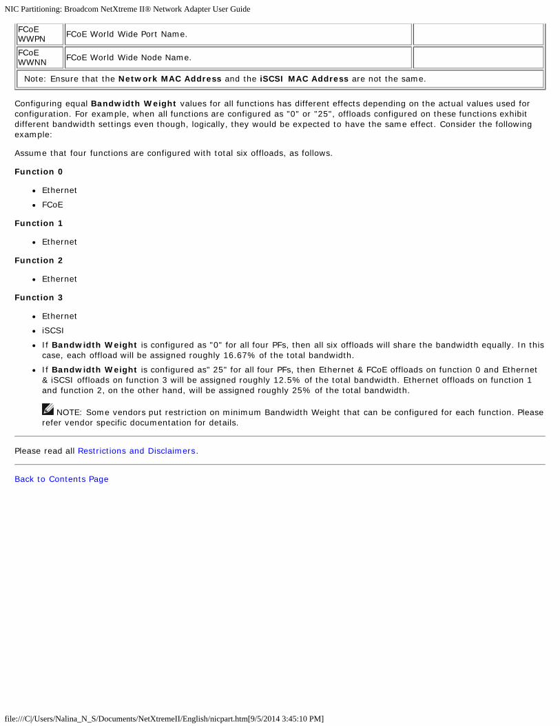
NIC Partitioning: Broadcom NetXtreme II® Network Adapter User Guide
file:///C|/Users/Nalina_N_S/Documents/NetXtremeII/English/nicpart.htm[9/5/2014 3:45:10 PM]
FCoEWWPN FCoE World Wide Port Name.
FCoEWWNN FCoE World Wide Node Name.
Note: Ensure that the Network MAC Address and the iSCSI MAC Address are not the same.
Configuring equal Bandwidth Weight values for all functions has different effects depending on the actual values used forconfiguration. For example, when all functions are configured as "0" or "25", offloads configured on these functions exhibitdifferent bandwidth settings even though, logically, they would be expected to have the same effect. Consider the followingexample:
Assume that four functions are configured with total six offloads, as follows.
Function 0
Ethernet
FCoE
Function 1
Ethernet
Function 2
Ethernet
Function 3
Ethernet
iSCSI
If Bandwidth Weight is configured as "0" for all four PFs, then all six offloads will share the bandwidth equally. In thiscase, each offload will be assigned roughly 16.67% of the total bandwidth.
If Bandwidth Weight is configured as" 25" for all four PFs, then Ethernet & FCoE offloads on function 0 and Ethernet& iSCSI offloads on function 3 will be assigned roughly 12.5% of the total bandwidth. Ethernet offloads on function 1and function 2, on the other hand, will be assigned roughly 25% of the total bandwidth.
NOTE: Some vendors put restriction on minimum Bandwidth Weight that can be configured for each function. Pleaserefer vendor specific documentation for details.
Please read all Restrictions and Disclaimers.
Back to Contents Page

Fibre Channel Over Ethernet: Broadcom NetXtreme II® Network Adapter User Guide
file:///C|/Users/Nalina_N_S/Documents/NetXtremeII/English/fcoe.htm[9/5/2014 3:45:12 PM]
Back to Contents Page
Fibre Channel Over Ethernet: Broadcom NetXtreme II® Network Adapter User Guide
Overview
FCoE Boot from SAN
Configuring FCoE
Overview
In today's data center, multiple networks, including network attached storage (NAS), management, IPC, and storage, are used to achieve the desired performance and versatility. Inaddition to iSCSI for storage solutions, Fibre Channel over Ethernet (FCoE) can now be used with capable Broadcom C-NICs. FCoE is a standard that allows Fibre Channel protocol to betransferred over Ethernet by preserving existing Fibre Channel infrastructures and capital investments by classifying received FCoE and FCoE Initialization Protocol (FIP) frames.
The following FCoE features are supported:
Receiver classification of FCoE and FIP frames. FIP is the FCoE Initialization Protocol used to establish and maintain connections.
Receiver CRC offload
Transmitter CRC offload
Dedicated queue set for Fibre Channel traffic
Data Center Bridging (DCB) provides lossless behavior with Priority Flow Control (PFC)
DCB allocates a share of link bandwidth to FCoE traffic with Enhanced Transmission Selection (ETS)
DCB supports storage, management, computing, and communications fabrics onto a single physical fabric that is simpler to deploy, upgrade, and maintain than in standard Ethernetnetworks. DCB technology allows the capable Broadcom C-NICs to provide lossless data delivery, lower latency, and standards-based bandwidth sharing of data center physical links. TheDCB supports FCoE, iSCSI, Network-Attached Storage (NAS), Management, and IPC traffic flows. For more information on DCB, see Using Data Center Bridging (DCB).
FCoE Boot from SAN
This section describes the install and boot procedures for the Windows, Linux, ESX, and Solaris operating systems.
NOTE: FCoE Boot from SAN is not supported on ESXi 5.0. ESX Boot from SAN is supported on ESXi 5.1 and above.
The following section details the BIOS setup and configuration of the boot environment prior to the OS install.
Preparing System BIOS for FCoE Build and Boot
Modify System Boot Order
The Broadcom initiator must be the first entry in the system boot order. The second entry must be the OS installation media. It is important that the boot order be set correctly or else theinstallation will not proceed correctly. Either the desired boot LUN will not be discovered or it will be discovered but marked offline.
Specify BIOS Boot Protocol (if required)
On some platforms, the The boot protocol must be configured through system BIOS configuration. On all other systems the boot protocol is specified through the BroadcomComprehensive Configuration Management (CCM), and for those systems this step is not required.
Prepare Broadcom Multiple Boot Agent for FCoE Boot
1. During POST, press CTRL+S at the Broadcom NetXtreme Ethernet Boot Agent banner to invoke the CCM utility.

Fibre Channel Over Ethernet: Broadcom NetXtreme II® Network Adapter User Guide
file:///C|/Users/Nalina_N_S/Documents/NetXtremeII/English/fcoe.htm[9/5/2014 3:45:12 PM]
2. Select the device through which boot is to be configured.
NOTE: IMPORTANT: When running in NIC Partitioning (NPAR) mode, FCoE boot is supported only when the first function on each port is assigned an FCoE personality. FCoE bootis not supported when the FCoE personality is assigned to any other function.
3. Ensure DCB/DCBX is enabled on the device. FCoE boot is only supported on DCBX capable configurations. As such, DCB/DCBX must be enabled, and the directly attached link peermust also be DCBX capable with parameters that allow for full DCBX synchronization.

Fibre Channel Over Ethernet: Broadcom NetXtreme II® Network Adapter User Guide
file:///C|/Users/Nalina_N_S/Documents/NetXtremeII/English/fcoe.htm[9/5/2014 3:45:12 PM]
4. On some platforms, you may need to set the boot protocol through system BIOS configuration in the integrated devices pane as described above.
For all other devices, set the Boot Protocol field to FCoE in the MBA Configuration Menu through CCM.
5. Configure the desired boot target and LUN. From the Target Information Menu, select the first available path.

Fibre Channel Over Ethernet: Broadcom NetXtreme II® Network Adapter User Guide
file:///C|/Users/Nalina_N_S/Documents/NetXtremeII/English/fcoe.htm[9/5/2014 3:45:12 PM]
6. Enable the Connect field. Enter the target WWPN and Boot LUN information for the target to be used for boot.

Fibre Channel Over Ethernet: Broadcom NetXtreme II® Network Adapter User Guide
file:///C|/Users/Nalina_N_S/Documents/NetXtremeII/English/fcoe.htm[9/5/2014 3:45:12 PM]
7. Press ESC until prompted to exit and save changes.
8. Proceed to OS installation once storage access has been provisioned in the SAN.
Provisioning Storage Access in the SAN
Storage access consists of zone provisioning and storage selective LUN presentation, each of which is commonly provisioned per initiator WWPN. Two main paths are available forapproaching storage access:
Pre-Provisioning
CTRL+R Method
Pre-Provisioning
With pre-provisioning, note the initiator WWPN and manually modify fabric zoning and storage selective LUN presentation to allow the appropriate access for the initiator.
The initiator WWPN can be seen at the bottom of the screen in the FCoE boot target configuration window.
The initiator WWPN can also be directly inferred from the FIP MAC address associated with the interface(s) planned for boot. Two MAC addresses are printed on stickers attached to theSFP+ cage on your adapter. The FIP MAC ends in an odd digit. The WWPN is 20:00: + <FIP MAC>. For example, if the FIP MAC is 00:10:18:11:22:33, then the WWPN will be20:00:00:10:18:11:22:33.
NOTE: The default WWPN is 20:00: + <FIP MAC>. The default WWNN is 10:00: + <FIP MAC>.
NOTE: In Dell FlexAddress configurations, the SAN/FIP MAC may be overridden by the blade chassis management system.
CTRL+R Method
The CTRL+R method allows you to use the boot initiator to bring up the link and login into all available fabrics and targets. Using this method, you can ensure that the initiator is loggedinto the fabric/target before making provisioning changes, and as such, can provision without manually typing in WWPNs.
1. Configure at least one boot target through CCM as described above.
2. Allow the system to attempt to boot through the selected initiator.
3. Once the initiator boot starts, it will commence with DCBX sync, FIP Discovery, Fabric Login, Target Login, and LUN readiness checks. As each of these phases completes, if theinitiator is unable to proceed to the next phase, MBA will present the option to press CTRL+R.
4. Once CTRL+R has been activated, the boot initiator will maintain a link in whatever phase has most recently succeeded and allow you time to make the necessary provisioningcorrections to proceed to the next phase.

Fibre Channel Over Ethernet: Broadcom NetXtreme II® Network Adapter User Guide
file:///C|/Users/Nalina_N_S/Documents/NetXtremeII/English/fcoe.htm[9/5/2014 3:45:12 PM]
5. If the initiator logs into the fabric, but is unable to log into the target, a CTRL+R will pause the boot process and allow you to configure fabric zoning.
6. Once zoning is complete, the initiator will automatically log into all visible targets. If the initiator is unable to discover the designated LUN on the designated target as provisioned instep 1, CTRL+R will pause the boot process and allow you to configure selective LUN presentation.
7. The boot initiator will periodically poll the LUN for readiness, and once the user has provisioned access to the LUN, the boot process will automatically proceed.
NOTE: This does not preclude the need to put the boot initiator into one-time disabled mode as described in One-Time Disabled.
One-Time Disabled
Broadcom's FCoE ROM is implemented as Boot Entry Vector (BEV). In this implementation, the Option ROM only connects to the target once it has been selected by BIOS as the chosenboot device. This is different from other implementations that will connect to the boot device even if another device has been selected by the system BIOS. For OS installation over theFCoE path, it is necessary to instruct the Option ROM to bypass FCoE and skip to CD/DVD installation media. As instructed earlier, the boot order must be configured with Broadcom bootfirst and installation media second. Furthermore, during OS installation, it is required to bypass the FCoE boot and pass through to the installation media for boot. It is required to do thisby one-time disabling the FCoE boot ROM from booting, and not by simply allowing the FCoE ROM to attempt to boot and allowing the BIOS to fail through and boot the installation media.Finally, it is required that the FCoE ROM successfully discover and test the readiness of the desired boot LUN in order for installation to proceed successfully. Failure to allow the boot ROMto discover the LUN and do a coordinated bypass will result in a failure to properly install the O/S to the LUN. In order to affect this coordinated bypass, there are two choices:
Once the FCoE boot ROM discovers a ready target LUN, it will prompt you to press CTRL+D within 4 seconds to Stop booting from the target. Press CTRL+D, and proceed toboot from the installation media.
From CCM, set the Option ROM setting under MBA settings to One Time Disabled. With this setting, the FCoE ROM will load once and automatically bypass once the ready LUN isdiscovered. On the subsequent reboot after installation, the option ROM will automatically revert to Enabled.
Wait through all option ROM banners. Once FCoE Boot is invoked, it will connect to the target, and provide a 4 second window to press CTRL+D to invoke the bypass. Press CTRL+D toproceed to installation.
Windows Server 2008 R2 and Windows Server 2008 SP2 FCoE Boot Installation
Ensure that no USB flash drive is attached before starting the OS installer. The EVBD and OFC/BXFOE drivers need to be loaded during installation. Go through the normal procedures forOS installation. When no disk devices are found, Windows will prompt you to load additional drivers. At this point, connect a USB flash drive containing the full contents of the providedEVBD and OFC boot driver folders. After all appropriate drivers are loaded, the setup show the target disk(s). Disconnect the USB flash drive before selecting the disk for installation.
1. Load the EVBD driver first.
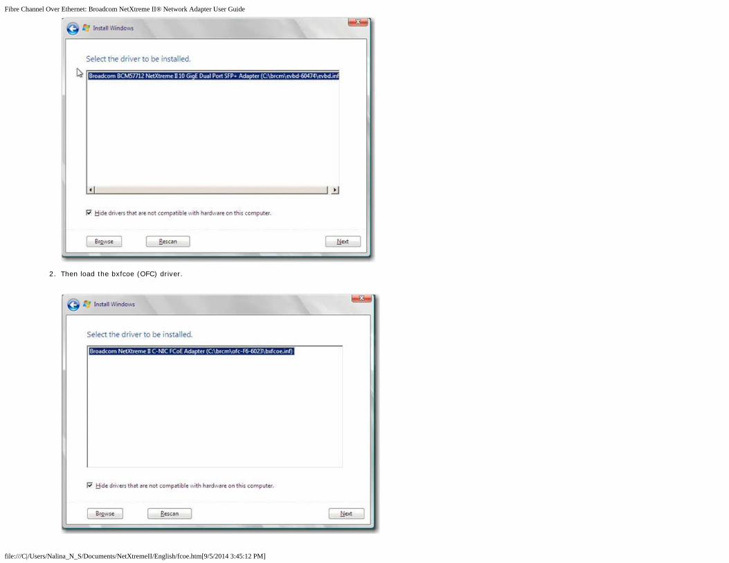
Fibre Channel Over Ethernet: Broadcom NetXtreme II® Network Adapter User Guide
file:///C|/Users/Nalina_N_S/Documents/NetXtremeII/English/fcoe.htm[9/5/2014 3:45:12 PM]
2. Then load the bxfcoe (OFC) driver.

Fibre Channel Over Ethernet: Broadcom NetXtreme II® Network Adapter User Guide
file:///C|/Users/Nalina_N_S/Documents/NetXtremeII/English/fcoe.htm[9/5/2014 3:45:12 PM]
3. Select the boot LUN to be installed:
4. Continue with the rest of the installation. After installation is complete and booted to SAN, execute the provided Windows driver installer and reboot. Installation is now complete.
NOTE: The boot initiator must be configured to point at the desired installation LUN, and the boot initiator must have successfully logged and determined the readiness of theLUN prior to starting installation. If these requirements are not met, the devices will still show up in the drive list above, but upon proceeding with installation Read/Write errors willoccur.
Windows Server 2012 FCoE Boot Installation
For Windows Server 2012 Boot from SAN installation, Broadcom requires the use of a "slipstream" DVD or iso image with the latest Broadcom drivers injected. See Injecting(Slipstreaming) Broadcom Drivers into Windows Image Files in the iSCSI chapter. Also, refer to the Microsoft Knowledge Base topic KB974072 at support.microsoft.com, which is helpful forWindows Server 2012 FCoE Boot from SAN also. Microsoft's procedure injects only the eVBD and NDIS drivers. Broadcom strongly recommends that all drivers, especially those bolded,are injected:
eVBD
VBD
BXND
OIS
FCoE
NetXtreme I NDIS
Once you have a properly slipstreamed iso, you can use that iso for normal Windows Server 2012 installation, without needing USB-provided drivers.
NOTE: Refer to the silent.txt file for the specific driver installer application for instructions on how to extract the individual Windows NetXtreme II drivers.
Linux FCoE Boot Installation
Configure the adapter boot parameters and Target Information (press CTRL+S and enter the CCM utility) as detailed in Preparing System BIOS for FCoE Build and Boot. Then, use theguidelines in the following sections for FCoE boot installation with the appropriate Linux version.
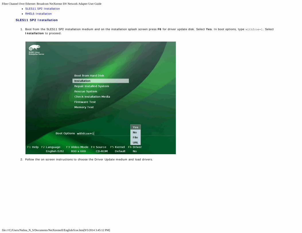
Fibre Channel Over Ethernet: Broadcom NetXtreme II® Network Adapter User Guide
file:///C|/Users/Nalina_N_S/Documents/NetXtremeII/English/fcoe.htm[9/5/2014 3:45:12 PM]
SLES11 SP2 Installation
RHEL6 Installation
SLES11 SP2 Installation
1. Boot from the SLES11 SP2 installation medium and on the installation splash screen press F6 for driver update disk. Select Yes. In boot options, type withfcoe=1. SelectInstallation to proceed.
2. Follow the on screen instructions to choose the Driver Update medium and load drivers.

Fibre Channel Over Ethernet: Broadcom NetXtreme II® Network Adapter User Guide
file:///C|/Users/Nalina_N_S/Documents/NetXtremeII/English/fcoe.htm[9/5/2014 3:45:12 PM]
3. Once the driver update is complete, select Next to continue with OS installation.
4. When requested, click Configure FCoE Interfaces.

Fibre Channel Over Ethernet: Broadcom NetXtreme II® Network Adapter User Guide
file:///C|/Users/Nalina_N_S/Documents/NetXtremeII/English/fcoe.htm[9/5/2014 3:45:12 PM]
5. Ensure FCoE Enable is set to yes on the 10GbE Broadcom initiator ports you wish to use as the SAN boot path(s).

Fibre Channel Over Ethernet: Broadcom NetXtreme II® Network Adapter User Guide
file:///C|/Users/Nalina_N_S/Documents/NetXtremeII/English/fcoe.htm[9/5/2014 3:45:12 PM]
6. For each interface to be enabled for FCoE boot, click Change Settings and ensure FCoE Enable and AUTO_VLAN are set to yes and DCB required is set to no.
7. For each interface to be enabled for FCoE boot, click on Create FCoE VLAN Interface. The VLAN interface creation dialog will launch. Click Yes to confirm. This will triggerautomatic FIP VLAN discovery. If successful, the VLAN will be displayed under FCoE VLAN Interface. If no VLAN is visible, check your connectivity and switch configuration.
8. Once complete with configuration of all interface, click OK to proceed.

Fibre Channel Over Ethernet: Broadcom NetXtreme II® Network Adapter User Guide
file:///C|/Users/Nalina_N_S/Documents/NetXtremeII/English/fcoe.htm[9/5/2014 3:45:12 PM]
9. Click Next to continue installation. YaST2 will prompt to activate multipath. Answer as appropriate.

Fibre Channel Over Ethernet: Broadcom NetXtreme II® Network Adapter User Guide
file:///C|/Users/Nalina_N_S/Documents/NetXtremeII/English/fcoe.htm[9/5/2014 3:45:12 PM]
10. Continue installation as usual.
11. Under the Expert tab on the Installation Settings screen, select Booting.
12. Select the Boot Loader Installation tab and then select Boot Loader Installation Details, make sure you have one boot loader entry here. Delete all redundant entries.
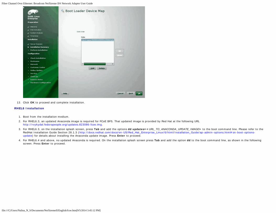
Fibre Channel Over Ethernet: Broadcom NetXtreme II® Network Adapter User Guide
file:///C|/Users/Nalina_N_S/Documents/NetXtremeII/English/fcoe.htm[9/5/2014 3:45:12 PM]
13. Click OK to proceed and complete installation.
RHEL6 Installation
1. Boot from the installation medium.
2. For RHEL6.3, an updated Anaconda image is required for FCoE BFS. That updated image is provided by Red Hat at the following URLhttp://rvykydal.fedorapeople.org/updates.823086-fcoe.img.
3. For RHEL6.3, on the installation splash screen, press Tab and add the options dd updates=<URL_TO_ANACONDA_UPDATE_IMAGE> to the boot command line. Please refer to theRedHat Installation Guide Section 28.1.3 (http://docs.redhat.com/docs/en-US/Red_Hat_Enterprise_Linux/6/html/Installation_Guide/ap-admin-options.html#sn-boot-options-update) for details about installing the Anaconda update image. Press Enter to proceed.
4. For RHEL6.4 and above, no updated Anaconda is required. On the installation splash screen press Tab and add the option dd to the boot command line, as shown in the followingscreen. Press Enter to proceed.

Fibre Channel Over Ethernet: Broadcom NetXtreme II® Network Adapter User Guide
file:///C|/Users/Nalina_N_S/Documents/NetXtremeII/English/fcoe.htm[9/5/2014 3:45:12 PM]
5. When prompted Do you have a driver disk, enter Yes. Note: RHEL does not allow driver update media to be loaded via the network when installing driver updates for networkdevices. Use local media.

Fibre Channel Over Ethernet: Broadcom NetXtreme II® Network Adapter User Guide
file:///C|/Users/Nalina_N_S/Documents/NetXtremeII/English/fcoe.htm[9/5/2014 3:45:12 PM]
6. Once drivers are loaded, proceed with installation.
7. Select Specialized Storage Devices when prompted.

Fibre Channel Over Ethernet: Broadcom NetXtreme II® Network Adapter User Guide
file:///C|/Users/Nalina_N_S/Documents/NetXtremeII/English/fcoe.htm[9/5/2014 3:45:12 PM]
8. Click Add Advanced Target.

Fibre Channel Over Ethernet: Broadcom NetXtreme II® Network Adapter User Guide
file:///C|/Users/Nalina_N_S/Documents/NetXtremeII/English/fcoe.htm[9/5/2014 3:45:12 PM]
9. Select Add FCoE SAN. and select Add drive.

Fibre Channel Over Ethernet: Broadcom NetXtreme II® Network Adapter User Guide
file:///C|/Users/Nalina_N_S/Documents/NetXtremeII/English/fcoe.htm[9/5/2014 3:45:12 PM]
10. For each interface intended for FCoE boot, select the interface, deselect Use DCB, select Use auto vlan, and then click Add FCoE Disk(s).

Fibre Channel Over Ethernet: Broadcom NetXtreme II® Network Adapter User Guide
file:///C|/Users/Nalina_N_S/Documents/NetXtremeII/English/fcoe.htm[9/5/2014 3:45:12 PM]
11. Repeat steps 8 through 10 for all initiator ports.
12. Confirm all FCoE visible disks are visible under Multipath Devices and/or Other SAN Devices.

Fibre Channel Over Ethernet: Broadcom NetXtreme II® Network Adapter User Guide
file:///C|/Users/Nalina_N_S/Documents/NetXtremeII/English/fcoe.htm[9/5/2014 3:45:12 PM]
13. Click Next to proceed.
14. Click Next and complete installation as usual.
Upon completion of installation, the system will reboot.
15. Once booted, ensure all boot path devices are set to start on boot. Set onboot=yes under each network interface config file in /etc/sysconfig/network-scripts.
16. On RHEL 6.4 only, edit /boot/grub/menu.lst.
a. Delete all "fcoe=<INTERFACE>:nodcb" parameters from the "kernel /vmlinuz ... " line. There should be as many fcoe= parameters as there were FCoE interfaces configuredduring installation.
b. Insert "fcoe=edd:nodcb" to the "kernel /vmlinuz ... " line.
Linux: Adding Additional Boot Paths
Both RHEL and SLES require updates to the network configuration when adding new boot through an FCoE initiator that was not configured during installation. The following sectionsdescribe this procedure for each supported operating system.
RHEL6.2 and Above
On RHEL6.2 and above, if the system is configured to boot through an initiator port that has not previously been configured in the OS, the system automatically boots successfully, but willencounter problems during shutdown. All new boot path initiator ports must be configured in the OS before updating pre-boot FCoE boot parameters.
1. Identify the network interface names for the newly added interfaces through ifconfig -a.
2. Edit /boot/grub/menu.lst.
a. Add ifname=<INTERFACE>:<MAC_ADDRESS> to the line kernel /vmlinuz ... for each new interface. The MAC address must be all lower case and separated by a colon. (e.g.,ifname=em1:00:00:00:00:00:00)
3. Create a /etc/fcoe/cfg-<INTERFACE> file for each new FCoE initiator by duplicating the /etc/fcoe/cfg-<INTERFACE> file that was already configured during initial installation.

Fibre Channel Over Ethernet: Broadcom NetXtreme II® Network Adapter User Guide
file:///C|/Users/Nalina_N_S/Documents/NetXtremeII/English/fcoe.htm[9/5/2014 3:45:12 PM]
4. Execute nm-connection-editor.
a. Open Network Connection and choose each new interface.
b. Configure each interface as desired, including DHCP settings.
c. Click Apply to save.
5. For each new interface, edit /etc/sysconfig/network-scripts/ifcfg-<INTERFACE> to add the line NM_CONTROLLED="no". Modifying these files automatically causes a restart tothe network service. This may cause the system to appear to hang briefly. It is best to ensure that redundant multipath paths are available before performing this operation.
SLES 11 SP2 and Above
On SLES11 SP2, if the system boots through an initiator that has not been configured as an FCoE interface during installation, the system will fail to boot. To add new boot paths, thesystem must boot up through the configured FCoE interface.
1. Configure a new FCoE interface that will be added as a new path so it can discover the boot LUN.
a. Create a /etc/fcoe/cfg-<INTERFACE> file for each new FCoE initiator by duplicating the /etc/fcoe/cfg-<INTERFACE> file that was already configured during initialinstallation.
b. Bring up the new interfaces: # ifconfig <INTERFACE> up
c. Restart FCoE service: # rcfcoe restart
2. Run multipath -l to make sure the system has a correct number of multipaths to the boot LUN, including new paths.
3. Create a /etc/sysconfig/network/ifcfg-<INTERFACE> file for each new interface by duplicating the /etc/sysconfig/network/ifcfg-<INTERFACE> file that was alreadyconfigured during initial installation.
4. Create a new ramdisk to update changes:# mkinitrd
VMware ESXi 5.1 FCoE Boot Installation
FCoE Boot from SAN requires that the latest Broadcom NetXtreme II async drivers be included into the ESXi 5.1 install image. Refer to Image_builder_doc.pdf from VMware on how toslipstream drivers.
1. Boot from the updated ESXi 5.1 installation image and select ESXi 5.1 installer when prompted.
2. Press Enter to continue.

Fibre Channel Over Ethernet: Broadcom NetXtreme II® Network Adapter User Guide
file:///C|/Users/Nalina_N_S/Documents/NetXtremeII/English/fcoe.htm[9/5/2014 3:45:12 PM]
3. Press F11 to accept the agreement and continue.
4. Select the boot LUN for installation and press Enter to continue.

Fibre Channel Over Ethernet: Broadcom NetXtreme II® Network Adapter User Guide
file:///C|/Users/Nalina_N_S/Documents/NetXtremeII/English/fcoe.htm[9/5/2014 3:45:12 PM]
5. Select the desired installation method.
6. Select the keyboard layout.
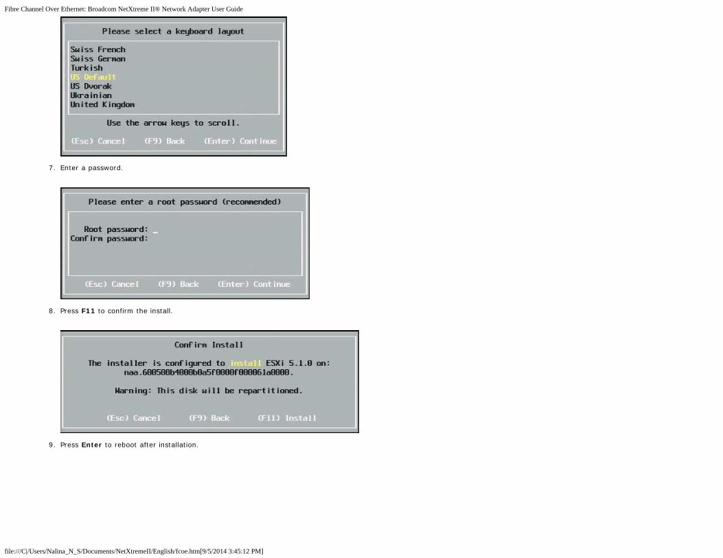
Fibre Channel Over Ethernet: Broadcom NetXtreme II® Network Adapter User Guide
file:///C|/Users/Nalina_N_S/Documents/NetXtremeII/English/fcoe.htm[9/5/2014 3:45:12 PM]
7. Enter a password.
8. Press F11 to confirm the install.
9. Press Enter to reboot after installation.

Fibre Channel Over Ethernet: Broadcom NetXtreme II® Network Adapter User Guide
file:///C|/Users/Nalina_N_S/Documents/NetXtremeII/English/fcoe.htm[9/5/2014 3:45:12 PM]
10. On 57800 and 57810 boards, the management network is not vmnic0. After booting, open the GUI console and display the configure management network > networkadapters screen to select the NIC to be used as the management network device.
11. For BCM57800 and BCM57810 boards, the FCoE boot devices need to have a separate vSwitch other than vSwith0. This allows DHCP to assign the IP address to the managementnetwork rather than to the FCoE boot device. To create a vSwitch for the FCoE boot devices, add the boot device vmnics in vSphere Client under Networking.

Fibre Channel Over Ethernet: Broadcom NetXtreme II® Network Adapter User Guide
file:///C|/Users/Nalina_N_S/Documents/NetXtremeII/English/fcoe.htm[9/5/2014 3:45:12 PM]
NOTE: ESXi 5.1 has a limitation in that a VLAN ID change for a boot device is not possible. It works only for non-boot devices.
Configuring FCoE Boot from SAN on VMware
Note that each host must have access only to its own boot LUN — not to the boot LUNs of other hosts. Use storage system software to ensure that the host accesses only the designatedLUNs.
Booting from SAN After Installation
Now that boot configuration and OS installation are complete, you can reboot and test the installation. On this and all future reboots, no other user interactivity is required. Ignore theCTRL+D prompt and allow the system to boot through to the FCoE SAN LUN.
At this time, if additional redundant failover paths are desired, you can configure those paths through CCM, and the MBA will automatically failover to secondary paths if the first path isnot available. Further, the redundant boot paths will yield redundant paths visible through host MPIO software allowing for a fault tolerant configuration.

Fibre Channel Over Ethernet: Broadcom NetXtreme II® Network Adapter User Guide
file:///C|/Users/Nalina_N_S/Documents/NetXtremeII/English/fcoe.htm[9/5/2014 3:45:12 PM]
Driver Upgrade on Linux Boot From SAN Systems
1. Remove the existing installed NetXtreme ll package. Log in as root. Query for the existing NetXtreme ll package and remove it using the following commands:# rpm -e <NetXtreme II package name>
For example:
rpm -e netxtreme2
or:
rpm -e netxtreme2-x.y.z-1.x86_642. Install the binary RPM containing the new driver version. Refer to the linux-nx2 package README for instructions on how to prepare a binary driver RPM.
3. Use the following command to update the ramdisk:
On RHEL 6.x systems, execute: dracut -force
On SLES11spX systems, execute: mkinitrd
4. If you are using different name for the initrd under /boot, be sure to overwrite it with the default, as dracut/mkinitrd updates the ramdisk with the default original name.
Also, verify that your appropriate entry for the boot from SAN setup uses the correct or updated intrd name in /boot/grub/menu.lst.
5. To complete your driver upgrade, reboot the system and select the modified grub boot entry that contains the updated initrd.
Errors During Windows FCoE Boot From SAN Installation
If any USB flash drive is connected while Windows setup is loading files for installation, an error message will appear when you provide the drivers and then select the SAN disk for theinstallation. The most common error message that Windows OS installer reports is "We couldn't create a new partition or locate an existing one. For more information, see the Setup logfiles."

Fibre Channel Over Ethernet: Broadcom NetXtreme II® Network Adapter User Guide
file:///C|/Users/Nalina_N_S/Documents/NetXtremeII/English/fcoe.htm[9/5/2014 3:45:12 PM]
In other cases, the error message may indicate a need to ensure that the disk's controller is enabled in the computer's BIOS menu.
To avoid any of the above error messages, it is necessary to ensure that there is no USB flash drive attached until the setup asks for the drivers. Once you load the drivers and see yourSAN disk(s), detach or disconnect the USB flash drive immediately before selecting the disk for further installation.
Configuring FCoE
By default, DCB is enabled on Broadcom NetXtreme II FCoE-, DCB-compatible C-NICs. Broadcom NetXtreme II FCoE requires a DCB-enabled interface. For Windows operating systems,use either Broadcom Advanced Control Suite (BACS) or Broadcom's Comprehensive Configuration Management (CCM) utility to configure the DCB parameters. See Using BroadcomAdvanced Control Suite for more information on BACS.
Please read all Restrictions and Disclaimers.
Back to Contents Page

Data Center Bridging (DCB): Broadcom NetXtreme II® Network Adapter User Guide
file:///C|/Users/Nalina_N_S/Documents/NetXtremeII/English/dcb.htm[9/5/2014 3:45:14 PM]
Back to Contents Page
Data Center Bridging (DCB): Broadcom NetXtreme II® NetworkAdapter User Guide
Overview
DCB Capabilities
Configuring DCB
DCB Conditions
Data Center Bridging in Windows Server 2012
Overview
Data Center Bridging (DCB) is a collection of IEEE specified standard extensions to Ethernet to provide lossless data delivery,low latency, and standards-based bandwidth sharing of data center physical links. DCB supports storage, management,computing, and communications fabrics onto a single physical fabric that is simpler to deploy, upgrade, and maintain than instandard Ethernet networks. DCB has a standards-based bandwidth sharing at its core, allowing multiple fabrics to coexist onthe same physical fabric. The various capabilities of DCB allow for LAN traffic (large number of flows and not latency-sensitive), SAN traffic (large packet sizes and requires lossless performance), and IPC (latency-sensitive messages) tobandwidth share the same physical converged connection and achieve the desired individual traffic performance.
DCB includes the following capabilities:
Enhanced Transmission Selection (ETS)
Priority-based Flow Control (PFC)
Data Center Bridging Capability eXchange Protocol (DCBX)
DCB Capabilities
Enhanced Transmission Selection (ETS)
Enhanced Transmission Selection (ETS) provides a common management framework for assignment of bandwidth to trafficclasses. Each traffic class or priority can be grouped in a Priority Group (PG), and it can be considered as a virtual link orvirtual interface queue. The transmission scheduler in the peer is responsible for maintaining the allocated bandwidth for eachPG. For example, a user can configure FCoE traffic to be in PG 0 and iSCSI traffic in PG 1. The user can then allocate eachgroup a certain bandwidth. For example, 60% to FCoE and 40% to iSCSI. The transmission scheduler in the peer will ensurethat in the event of congestion, the FCoE traffic will be able to use at least 60% of the link bandwidth and iSCSI to use 40%.See additional references at http://www.ieee802.org/1/pages/802.1az.html.
Priority Flow Control (PFC)
Priority Flow Control (PFC) provides a link-level flow control mechanism that can be controlled independently for each traffictype. The goal of this mechanism is to ensure zero loss due to congestion in DCB networks. Traditional IEEE 802.3 Ethernetdoes not guarantee that a packet transmitted on the network will reach its intended destination. Upper-level protocols areresponsible to maintain the reliability by way of acknowledgement and retransmission. In a network with multiple trafficclasses, it becomes very difficult to maintain the reliability of traffic in the absence of feedback. This is traditionally tackledwith the help of link-level Flow Control.
When PFC is used in a network with multiple traffic types, each traffic type can be encoded with a different priority value anda pause frame can refer to this priority value while instructing the transmitter to stop and restart the traffic. The value rangefor the priority field is from 0 to 7, allowing eight distinct types of traffic that can be individually stopped and started. Seeadditional references at http://www.ieee802.org/1/pages/802.1bb.html.
Data Center Bridging eXchange (DCBX)

Data Center Bridging (DCB): Broadcom NetXtreme II® Network Adapter User Guide
file:///C|/Users/Nalina_N_S/Documents/NetXtremeII/English/dcb.htm[9/5/2014 3:45:14 PM]
Data Center Bridging eXchange (DCBX) is a discovery and capability exchange protocol that is used for conveying capabilitiesand configuration of ETS and PFC between link partners to ensure consistent configuration across the network fabric. In orderfor two devices to exchange information, one device must be willing to adopt network configuration from the other device. Forexample, if a C-NIC is configured to willingly adopt ETS and PFC configuration information from a connected switch, and theswitch acknowledges the C-NIC's willingness, then the switch will send the C-NIC the recommended ETS and PFC parametersettings. The DCBX protocol uses the Link Level Discovery Protocol (LLDP) to exchange PFC and ETS configurations betweenlink partners.
Configuring DCB
By default, DCB is enabled on Broadcom NetXtreme II DCB-compatible C-NICs. DCB configuration is rarely required, as thedefault configuration should satisfy most scenarios. DCB parameters can be configured through BACS. See Using BroadcomAdvanced Control Suite for more information on BACS.
NOTE: FCoE operation depends on successful VLAN discovery. All switches that support FCoE support VLAN discovery, butsome switches may require specific configuration. Refer to the switch configuration guides for information on how to configurea port for successful VLAN discovery.
DCB Conditions
The following is a list of conditions that allow DCB technology to function on the network.
If DCB is enabled on the interface, DCBX is automatically enabled and carried out automatically once a link isestablished.
If DCBX fails to synchronize with a compatible peer, the adapter will automatically fall back to default NIC behavior (nopriority tagging, no PFC, no ETS).
By default, the port will advertise itself as willing, and as such, will accept all DCB settings as advertised by the switch.
If PFC is operational, PFC settings supersede link level flow control settings. If PFC is not operational, link level flowcontrol settings prevail
In NIC Partitioned enabled configurations, ETS (if operational) overrides the Bandwidth Weights assigned to eachfunction. Transmission selection weights are per protocol per ETS settings instead. Maximum bandwidths per functionare still honored in the presence of ETS.
In the absence of an iSCSI or FCoE application TLV advertised through the DCBX peer, the adapter will use the settingstaken from the local Admin MIB.
Data Center Bridging in Windows Server 2012
Windows Server 2012 introduces a new way of managing Quality Of Service (QoS) at the OS level. There are two mainaspects of Windows QoS:
A vendor-independent method for managing DCB settings on NICs, both individually and across an entire domain. Themanagement interface is provided by Windows PowerShell Cmdlets.
The ability to tag specific types of L2 networking traffic, such as SMB traffic, so that hardware bandwidth can bemanaged using ETS.
All Broadcom Converged Network Adapters that support DCB are capable of interoperating with Windows QoS.
To enable the QoS Windows feature, ensure that the Broadcom device is DCB-capable. Using either CCM or BACS4:
1. Enable Data Center Bridging.
2. Select the NDIS driver, display Advanced properties, and enable the Quality of Service property.
When QoS is enabled, administrative control over DCB-related settings is relinquished to the operating system (that is, BACS4can no longer be used for administrative control of the DCB). You can use PowerShell to configure and manage the QoSfeature. Using PowerShell Cmdlets, you can configure various QoS-related parameters, such as traffic classification, priorityflow control, and traffic class throughput scheduling.
For more information on using PowerShell Cmdlets, see the "DCB Windows PowerShell User Scripting Guide" in the MicrosoftTechnet Library.
To revert to standard BACS control over the Broadcom DCB feature set, uninstall the Microsoft QOS feature or disable Quality

Data Center Bridging (DCB): Broadcom NetXtreme II® Network Adapter User Guide
file:///C|/Users/Nalina_N_S/Documents/NetXtremeII/English/dcb.htm[9/5/2014 3:45:14 PM]
of Service in the NDIS advance properties page.
NOTE: Broadcom recommends that you do not install the DCB feature if SR-IOV will be used. If you install the DCBfeature, be aware that selecting Enable single-root I/O virtualization (SR-IOV) in Virtual Switch Manager will force theunderlying adapter into a DCB state in which OS DCB configuration will be ignored, and DCB configuration from BACS will bein effect with the exception that the user-configured Networking Priority value (non-zero) will not take effect, even thoughit appears that it is from BACS.
Please read all Restrictions and Disclaimers.
Back to Contents Page

SR-IOV: Broadcom NetXtreme II® Network Adapter User Guide
file:///C|/Users/Nalina_N_S/Documents/NetXtremeII/English/sr-iov.htm[9/5/2014 3:45:14 PM]
Back to Contents Page
SR-IOV: Broadcom NetXtreme II® Network Adapter User Guide
Overview
Enabling SR-IOV
Overview
Virtualization of network controllers allows users to consolidate their networking hardware resources and run multiple virtualmachines concurrently on consolidated hardware. Virtualization also provides the user a rich set of features such as I/Osharing, consolidation, isolation and migration, and simplified management with provisions for teaming and failover.
Virtualization can come at the cost of reduced performance due to hypervisor overhead. The PCI-SIG introduced the Single-Root I/O Virtualization (SR-IOV) specification to address these performance issues by creating a virtual function (VF), alightweight PCIe function that can be directly assigned to a virtual machine (VM), bypassing the hypervisor layer for the maindata movement.
Not all Broadcom adapters support SR-IOV; refer to your product documentation for details.
Enabling SR-IOV
Before attempting to enable SR-IOV, ensure that:
The adapter hardware supports SR-IOV.
SR-IOV is supported and enabled in the system BIOS.
To enable SR-IOV:
1. Enable the feature on the adapter:
In If using BACS:
a. Select the network adapter in the Explorer View pane. Select the Configuration tab and select SR-IOV GlobalEnable.
b. In the SR-IOV VFs per PF field, configure the number of SRIOV Virtual Functions (VFs) that the adapter cansupport per physical function, from 0 to 64 in increments of 8 (default = 16).
c. In the SR-IOV Max Chains per VF field, configure the maximum number of transmit and receive queues (suchas receive side scaling (RSS) queues) that can be used for each virtual function. The maximum is 16.
If using CCM:
d. Select the SR-IOV-capable adapter from the Device List. On the Main Menu, select Device HardwareConfiguration, then select SR-IOV Enabled.
e. To configure the number of VFs that the adapter can support:
If Multi-Function Mode to is set to SF (Single Function), then the "Number of VFs per PF" field displays,which you can set from 0 to 64 in increments of 8 (default = 16).
If Multi-Function Mode is set to NPAR, then display the Main Menu and select NIC PartitionConfiguration. Then, select the NPAR Function to configure and enter the appropriate value in theNumber of VFs per PF field.
2. In Virtual Switch Manager, create a virtual NIC. Ensure that Allow Management operating system to share thenetwork adapter is selected as you create the NIC.
3. In Virtual Switch Manager, select the virtual adapter and select Hardware Acceleration in the navigation pane. In theSingle-root I/O virtualization section, select Enable SR-IOV.
4. Install the Broadcom drivers for the adapters detected in the VM. Use the latest drivers available from your vendor forthe host OS (do not use the inbox drivers). The same driver version must be installed on the host and the VM.

SR-IOV: Broadcom NetXtreme II® Network Adapter User Guide
file:///C|/Users/Nalina_N_S/Documents/NetXtremeII/English/sr-iov.htm[9/5/2014 3:45:14 PM]
To verify that SR-IOV is operational
1. Start the VM.
2. In Hyper-V Manager, select the adapter and select the VM in the Virtual Machines list.
3. Select the Networking tab at the bottom of the window and view the adapter status.
SR-IOV and Storage Functionality
Storage functionality (FCoE or iSCSI) can be enabled on an SR-IOV-enabled adapter. However, if storage is used on an NPAR-enabled physical function (PF), then the number of virtual functions for that PF is set to zero; therefore, SR-IOV is disabled onthat PF.
This limitation applies only when the adapter is configured in NPAR mode. It is not relevant when the adapter is configured insingle-function mode.
SR-IOV and Jumbo Packets
If SR-IOV is enabled on a virtual function (VF) on the adapter, ensure that the same jumbo packet settings is configured onboth the VF and the Microsoft synthetic adapter. You can configure these values using Windows Device Manager > Advancedproperties.
If there is a mismatch in the values, the SRIOV function will be shown the the Degraded state in Hyper-V > NetworkingStatus.
Back to Contents Page

Using Broadcom Advanced Control Suite 4: Broadcom NetXtreme II® Network Adapter User Guide
file:///C|/Users/Nalina_N_S/Documents/NetXtremeII/English/bacs.htm[9/5/2014 3:45:16 PM]
Back to Contents Page
Using Broadcom Advanced Control Suite 4: Broadcom NetXtreme II®
Network Adapter User Guide
Broadcom Advanced Control Suite Overview
Starting Broadcom Advanced Control Suite
BACS Interface
Configuring Preferences in Windows
Connecting to a Host
Managing the Host
Managing the Network Adapter
Managing Ethernet Controller (Port)
Analyzing Cables in Windows
Managing the LAN Device
Viewing Resource Information
Configuring Teaming
Configuring With the Command Line Interface Utility
Troubleshooting BACS
Broadcom Advanced Control Suite Overview
Broadcom Advanced Control Suite (BACS) is an integrated utility that provides useful information about each network adapter that isinstalled in your system. BACS also enables you to perform detailed tests, diagnostics, and analyses on each adapter, as well as toview and modify property values and view traffic statistics for network objects. BACS operates on Windows and Linux operatingsystems.
Broadcom Advanced Server Program (BASP), which runs within Broadcom Advanced Control Suite, is used to configure teams forload balancing, fault tolerance, and virtual local area networks (VLANs). BASP functionality is available only on systems that use atleast one Broadcom network adapter. BASP operates on Windows operating systems only.
NOTE: Some features of BACS are relevant only to particular adapters or adapter families, such as NetXtreme I or NetXtreme IIadapters. Because a single instance of BACS can be used to communicate with multiple hosts and adapter types, this documentdescribes all BACS features.
The BACS application includes a graphical user interface and a command line interface (BACSCLI). BACS GUI and BACS CLI canoperate on the following operating system families:
Windows Server
Linux Server
For information on the latest supported OS versions, refer to the release documentation provided with your software distribution.
Starting Broadcom Advanced Control Suite
In Control Panel, click Broadcom Control Suite 4, or click the BACS icon in the taskbar located at the bottom of the Windows orWindows Server desktop.
On Linux systems, you can double-click the BACS4 desktop icon, or access the BACS program from the task bar under SystemTools. (If you are having difficulty launching BACS on a Linux system, see the related topic in Troubleshooting BACS.)
BACS Interface
The BACS interface is comprised of the following regions:
Explorer View pane
Context View selector
Context View pane
Menu bar
Description pane
By default, the Explorer View pane is docked and pinned on the left side of the main window, the Context View pane on the right, the

Using Broadcom Advanced Control Suite 4: Broadcom NetXtreme II® Network Adapter User Guide
file:///C|/Users/Nalina_N_S/Documents/NetXtremeII/English/bacs.htm[9/5/2014 3:45:16 PM]
Context View selector below the menu bar, and the Description pane below the Context View pane. Drag the splitter between anytwo panes to vary the size of the panes.
Explorer View Pane
You can dock and pin the Explorer View pane on the left side, right side, top, or bottom of the main window.
The Explorer View pane lists the objects that can be viewed, analyzed, tested, or configured by BACS. When an item is selected inthe Explorer View pane, the tabs showing the information and options that are available for the item appear in the Context Viewpane.
The organization of this panel is designed to present the manageable objects in the same hierarchical manner as drivers and itssubcomponents. This simplifies the management of various elements of the converged network interface controller (C-NIC). The toplevel of the hierarchy is the Host container, which lists all hosts managed by BACS. Below the hosts are the installed networkadapters, with the manageable elements, such as physical port, VBD, NDIS, FCoE, and iSCSI below the adapters.
The icon next to each device in the Explorer View pane shows its status. An icon next to a device name that appears normal meansthe device is connected and working.
X. A red "X" that appears on the device's icon indicates the device is currently not connected to the network.
Greyed out. A device icon that appears greyed out indicates the device is currently disabled.
Context View Selector
The Context View selector appears below the menu bar and includes the filter and tab categories. Although you can expand andcollapse the categories that appear on tabs in the Context View pane, you can alternatively display a category by selecting the boxnext to the category name.
Filter View
In a multiple-host environment using several C-NICs, there can be a large number of manageable elements per adapter that can bedifficult and cumbersome to view, configure, and manage all elements. Use the filter to select a particular device function. Possiblefilter views include:

Using Broadcom Advanced Control Suite 4: Broadcom NetXtreme II® Network Adapter User Guide
file:///C|/Users/Nalina_N_S/Documents/NetXtremeII/English/bacs.htm[9/5/2014 3:45:16 PM]
All
Team view
NDIS view
iSCSI view
FCoE view
iSCSI Target view
FCoE Target view
Context View Pane
The Context View pane displays all the parameters that you can view for the object selected in the Explorer View pane. Theparameters are grouped by tabs and categories, depending on the parameter type. The available tabs are Information, Configuration,Diagnostics, and Statistics. Because the BACS interface is context-sensitive, only the parameters that apply to the selected objectcan be viewed or configured in the Context View pane.
Menu Bar
The following appear on the menu bar, but because the menu items are context-sensitive, not all items will be available at all times:
File menu
Team Save As: Saves the current team configurations to a file.
Team Restore: Restores any saved team configuration from a file.
Action menu
Remove Host: Removes the selected host.
Refresh Host: Refreshes the selected host.
View menu
Explorer View: Displays/hides the Explorer View pane.
Tool Bar: Displays/hides the tool bar.
Status Bar: Displays/hides the status bar.
Broadcom Logo: Displays/hides the Broadcom Logo on BACS to optimize the maximum viewable space.
Tools menu
Options: Used for configuring BACS preferences.
Teams (Windows only)
Create Teams: Creates new teams with either the Teaming Wizard or in Advanced mode.
Manage Teams: Manages existing teams with either the Teaming Wizard or in Advanced mode.
iSCSI menu
Discovery Wizard: Locates targets and helps to configure the HBA.
Manage Targets Wizard: Manages targets.
Manage iSNS Servers: Manages Internet Storage Name Service (iSNS) servers to allow discovery, management, andconfiguration of iSCSI devices.
Manage Discovery Portals: Manages iSCSI discovery portals.
Discovery Wizard
The Discovery Wizard is available from the iSCSI menu. Follow the prompts in the wizard to discover iSCSI targets via theSendTargets method or the Internet Storage Name Service (iSNS) server.
Manage Targets Wizard
The Manage Targets Wizard is available from the iSCSI menu. Follow the prompts in the wizard to add and remove targets, and tologin or logout of a target.
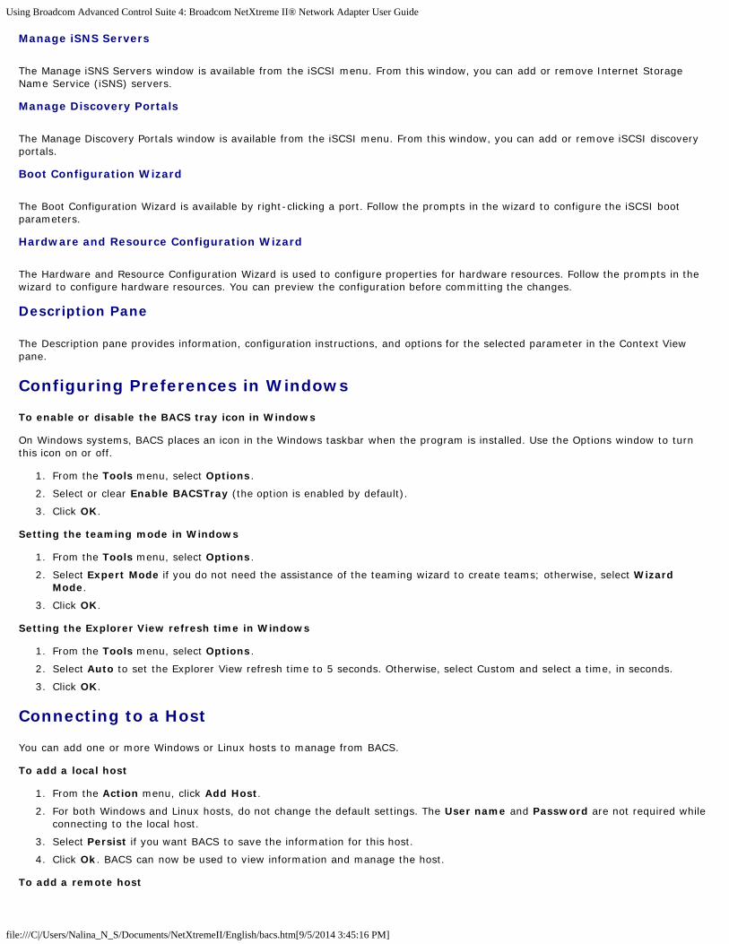
Using Broadcom Advanced Control Suite 4: Broadcom NetXtreme II® Network Adapter User Guide
file:///C|/Users/Nalina_N_S/Documents/NetXtremeII/English/bacs.htm[9/5/2014 3:45:16 PM]
Manage iSNS Servers
The Manage iSNS Servers window is available from the iSCSI menu. From this window, you can add or remove Internet StorageName Service (iSNS) servers.
Manage Discovery Portals
The Manage Discovery Portals window is available from the iSCSI menu. From this window, you can add or remove iSCSI discoveryportals.
Boot Configuration Wizard
The Boot Configuration Wizard is available by right-clicking a port. Follow the prompts in the wizard to configure the iSCSI bootparameters.
Hardware and Resource Configuration Wizard
The Hardware and Resource Configuration Wizard is used to configure properties for hardware resources. Follow the prompts in thewizard to configure hardware resources. You can preview the configuration before committing the changes.
Description Pane
The Description pane provides information, configuration instructions, and options for the selected parameter in the Context Viewpane.
Configuring Preferences in Windows
To enable or disable the BACS tray icon in Windows
On Windows systems, BACS places an icon in the Windows taskbar when the program is installed. Use the Options window to turnthis icon on or off.
1. From the Tools menu, select Options.
2. Select or clear Enable BACSTray (the option is enabled by default).
3. Click OK.
Setting the teaming mode in Windows
1. From the Tools menu, select Options.
2. Select Expert Mode if you do not need the assistance of the teaming wizard to create teams; otherwise, select WizardMode.
3. Click OK.
Setting the Explorer View refresh time in Windows
1. From the Tools menu, select Options.
2. Select Auto to set the Explorer View refresh time to 5 seconds. Otherwise, select Custom and select a time, in seconds.
3. Click OK.
Connecting to a Host
You can add one or more Windows or Linux hosts to manage from BACS.
To add a local host
1. From the Action menu, click Add Host.
2. For both Windows and Linux hosts, do not change the default settings. The User name and Password are not required whileconnecting to the local host.
3. Select Persist if you want BACS to save the information for this host.
4. Click Ok. BACS can now be used to view information and manage the host.
To add a remote host

Using Broadcom Advanced Control Suite 4: Broadcom NetXtreme II® Network Adapter User Guide
file:///C|/Users/Nalina_N_S/Documents/NetXtremeII/English/bacs.htm[9/5/2014 3:45:16 PM]
1. From the Action menu, click Add Host.
2. Type the remote host's name or IP address in the Host box.
3. Select the protocol from the Protocol list. The protocol options for Windows are WMI, WSMan, or Try All. The protocoloptions for Linux are CimXML, WSMan, or Try All. The Try All option forces the GUI client to try all options.
4. Select the HTTP scheme, or the HTTPS scheme for added security.
5. Type the Port Number value you used to configure the host, if it is different than the default value of 5985.
6. Type the User name and Password.
7. Select Persist if you want BACS to save the information for this host. The host will appear in the Explorer Pane whenever youreopen BACS, and you will not need to enter the host IP address or host name when connecting to the host. For securityreasons, you must enter the User name and Password every time.
8. Click OK.
Managing the Host
At the host level, you can view host information and configure parameters from the following tabs:
Information
Configuration
To view host information
Select the host in the Explorer View pane, and then select the Information tab to view host-level information.
Information Tab: Host Information
Host Name
Displays the name of the host.
OS Version Info

Using Broadcom Advanced Control Suite 4: Broadcom NetXtreme II® Network Adapter User Guide
file:///C|/Users/Nalina_N_S/Documents/NetXtremeII/English/bacs.htm[9/5/2014 3:45:16 PM]
Displays the operating system, including the version.
Platform
Displays the hardware architecture platform (for example, 32-bit or 64-bit)
Information Tab: iSCSI Initiator
The iSCSI Initiator section of the Information tab is available if iSCSI is enabled on the host.
Name
Displays the iSCSI initiator name in IQN format.
Portal List
Displays all iSCSI portal IP addresses configured on the selected host.
NOTE: Some information may not be available for all Broadcom network adapters.
To configure the host
Select the host in the Explorer View pane, and then select the Configuration tab to configure host-level parameters.
Configuration Tab: System Management
Chimney Offload State
Enable or disable chimney offload at the host level, rather than at the device level, and then click Apply.
Configuration Tab: iSCSI Initiator
Name

Using Broadcom Advanced Control Suite 4: Broadcom NetXtreme II® Network Adapter User Guide
file:///C|/Users/Nalina_N_S/Documents/NetXtremeII/English/bacs.htm[9/5/2014 3:45:16 PM]
The current IQN name is displayed. Click the IQN name to modify the host's iSCSI initiator name, and then click Apply.
Managing the Network Adapter
The installed network adapters appear one level below the host in the hierarchical tree in the Explorer View pane. At the adapterlevel, you can view information and configure parameters from the following tabs:
Information
Configuration
Viewing Adapter Information
Select the network adapter in the Explorer View pane, and then select the Information tab to view adapter-level information.
Viewing Resource Information
The Resources section of the Information tab displays information about connections and other essential functions for the selectednetwork adapter.
NOTE: Some information may not be available for all Broadcom network adapters.
Information Tab: Resources
Bus Type
The type of input/output (I/O) interconnect used by the adapter.
Bridge
The bridge type, which is the PCI-E to PCI-X bridge. This information is only available for Broadcom NetXtreme II adapters.
Bridge Lanes

Using Broadcom Advanced Control Suite 4: Broadcom NetXtreme II® Network Adapter User Guide
file:///C|/Users/Nalina_N_S/Documents/NetXtremeII/English/bacs.htm[9/5/2014 3:45:16 PM]
The number of PCI-E lanes connected to the bridge. This information is only available for Broadcom NetXtreme II adapters.
Bridge Speed
The clock speed on PCI-E bus. This information is only available for Broadcom NetXtreme II adapters.
Slot Number
The slot number on the system board occupied by the adapter. This item is not available for PCI Express type adapters.
Bus Speed
The bus clock signal frequency used by the adapter. This item is not available for PCI Express type adapters.
Bus Width
The number of bits that the bus can transfer at a single time to and from the adapter. This item is not available for PCI Express typeadapters.
Bus Number
Indicates the number of the bus where the adapter is installed.
Device Number
The number assigned to the adapter by the operating system.
Function Number
The port number of the adapter. For a single-port adapter, the function number is 0. For a two-port adapter, the function number forthe first port is 0, and the function number for the second port is 1.
Interrupt Request
The interrupt line number that is associated with the adapter. Valid numbers range from 2 to 25.
Memory Address
The memory mapped address that is assigned to the adapter. This value can never be 0.
MSI Version
This is the Message Signaled Interrupts (MSI) version being used. The option MSI corresponds to the PCI 2.2 specification thatsupports 32 messages and a single MSI address value. The option MSI-X corresponds to the PCI 3.0 specification that supports2,048 messages and an independent message address for each message.
Viewing Hardware Information
The Hardware section of the Information tab displays information about the hardware settings for the selected network adapter.
NOTE: Some information may not be available for all Broadcom network adapters.
Information Tab: Hardware
ASIC Version
The chip version of the Broadcom adapter (this information is not available for adapters made by others).
Firmware Version
The firmware version of the Broadcom adapter (this information is not available for adapters made by others). This information isonly available for Broadcom NetXtreme adapters.
Bootcode Version
The version of the boot code. This information is only available for Broadcom NetXtreme II adapters.

Using Broadcom Advanced Control Suite 4: Broadcom NetXtreme II® Network Adapter User Guide
file:///C|/Users/Nalina_N_S/Documents/NetXtremeII/English/bacs.htm[9/5/2014 3:45:16 PM]
Family Firmware Version
The global firmware version that represents all firmware on the device.
Management Firmware
The firmware version installed on the system.
Vendor ID
The vendor ID.
Device ID
The adapter ID.
Subsystem Vendor ID
The subsystem vendor ID.
Subsystem ID
The subsystem ID.
iSCSI Boot Version
The version of the iSCSI Boot software initiator.
External PHY Firmware Version
The external PHY firmware version.
Configuring Adapter Parameters
Select the network adapter in the Explorer View pane, and then select the Configuration tab to configure adapter-levelparameters.
Hardware and Resource Configuration Wizard: Port Configuration
Select a port to configure and then click Next.
Flow Control
The possible values are Auto, Tx Pause, Rx Pause, Tx/Rx pause, and Disable. The configuration is done at the port level and appliesto all functions under the port.The flow control value is a default value for the port. The effective configuration can be different basedon the switch port configuration and whether or not DCB/DCBX is enabled.
Link Speed
Configure the link speed. The default speed is 1Gb for 1Gb adapters and 10Gb for 10Gb adapters.
Managing Ethernet Controller (Port)
From BACS, you can group various traffic classes in to priority group and allocate bandwidth to each priority group.
When the Ethernet controller is selected in the Object Explorer panel, following four tabs will be displayed in the context view panel:
Information Tab
Configuration tab
Statistics Tab
Diagnostic Tab
Viewing Port Level Information
Selecting Ethernet controller in the object explorer will allow user to view various types of information at the port level.

Using Broadcom Advanced Control Suite 4: Broadcom NetXtreme II® Network Adapter User Guide
file:///C|/Users/Nalina_N_S/Documents/NetXtremeII/English/bacs.htm[9/5/2014 3:45:16 PM]
1. Select PortX (where X is either 0 or 1) below Adapter in the object explorer.
2. Various components of the port will be displayed below port in the object explorer. You can click on the "+" icon near Port toexpand or collapse the tree below.
3. Select Information tab in the context view panel on the right side.
Viewing Vital Signs
The Vital Signs section of the Information tab has useful information about the network adapters that are installed in your system,such as the link status of the adapter and general network connectivity.
To view Vital Signs information for any installed network adapter, select the name of the adapter listed in the Explorer View pane,then click the Information tab.
NOTES:
Information about Broadcom network adapters may be more comprehensive than information about network adaptersmade by others.
Some information may not be available for all Broadcom network adapters.
MAC Address
A physical MAC (media access control) address that is assigned to the adapter by the manufacturer. The physical address is never all0s.
Permanent MAC Address
The unique hardware address assigned to the network adapter.
iSCSI MAC Address
If an iSCSI network adapter is loaded onto the system, this parameter will display the iSCSI MAC address.

Using Broadcom Advanced Control Suite 4: Broadcom NetXtreme II® Network Adapter User Guide
file:///C|/Users/Nalina_N_S/Documents/NetXtremeII/English/bacs.htm[9/5/2014 3:45:16 PM]
IPv4 DHCP
The IP address is from a DHCP server if the value is Enable.
IP Address
The network address associated with the adapter. If the IP address is all 0s, the associated driver has not been bound with InternetProtocol (IP).
IPv6 DHCP
The IP address is from a DHCP server if the value is Enable.
IPv6 IP Address
The IPv6 network address associated with the adapter.
IPv6 Scope Id
Since local-use addresses can be reused, the Scope ID for link-local addresses specifies the link where the destination is located. TheScope ID for site-local addresses specifies the site where the destination is located. The Scope ID is relative to the sending host.
IPv6 Flow Info
The non-zero Flow Info is used to classify traffic flows. If Flow Info equals zero, then the packets are not a part of any flow.
Default Gateway
The default gateway value is the network address of the gateway that will be used by the management firmware for packets destinedfor hosts external to the local network segment.
Link Status
The status of the network link.
Up. A link is established.
Down. A link is not established.
Duplex
The adapter is operating in the indicated duplex mode.
Speed
The link speed of the adapter, in megabits per second.
Offload Capabilities
The offload capabilities supported by the adapter. This information is only available for Broadcom NetXtreme II adapters.
TOE. TCP Offload Engine (TOE) allows simultaneous operation of up to 1024 fully offloaded TCP connections for 1-Gbpsnetwork adapters and 1880 fully offloaded TCP connections for 10-Gbps network adapters to the hardware.
iSCSI. iSCSI offload for block-level transfer of data.
LSO. Large Send Offload (LSO) prevents an upper level protocol such as TCP from breaking a large data packet into a seriesof smaller packets with headers appended to them.
CO. Checksum Offload (CO) allows the TCP/IP/UDP checksums for send and receive traffic to be calculated by the adapterhardware rather than by the host CPU.
LiveLink IP Address
The network address of the LiveLink enabled adapter.
Local Connection
Identifies the module to which the blade server is attached.
Chassis SW. Chassis switch module

Using Broadcom Advanced Control Suite 4: Broadcom NetXtreme II® Network Adapter User Guide
file:///C|/Users/Nalina_N_S/Documents/NetXtremeII/English/bacs.htm[9/5/2014 3:45:16 PM]
Chassis PHY. Pass-through module
None. No modules attached
BASP State
Information about the status of the BASP application. This information is displayed only when there is a team (see ConfiguringTeaming).
Viewing NIC Partitioning Information
The NIC partitioning feature is available on Broadcom NetXtreme II adapters only.
The NIC Partitioning section of the Information tab displays information about the partitions for the selected network adapter.
To view NIC Partitioning for any installed network adapter, click the name of the adapter listed in the Explorer View pane, then clickthe Information tab.
NOTE: Some information may not be available for all Broadcom network adapters.
NIC partitioning divides a Broadcom NetXtreme II 10 Gigabit Ethernet NIC into multiple virtual NICs by having multiple PCI physicalfunctions per port. Each PCI function is associated with a different virtual NIC. To the OS and the network, each physical functionappears as a separate NIC port. For more information, see the NIC Partitioning topic in the Broadcom NetXtreme II Network AdapterUser Guide.
Number of Partitions
The number of partitions for the port. Each port can have from one to four partitions with each partition behaving as if it is anindependent NIC port.
Network MAC Address
The MAC address of the port.
iSCSI MAC Address
If an iSCSI adapter is loaded onto the system, the iSCSI MAC address will appear.
Flow Control
The flow control setting of the port.
Physical Link Speed
The physical link speed of the port, either 1G or 10G.
Relative Bandwidth Weight (%)
The relative bandwidth setting represents a weight or importance of a particular function. There are up to four functions perport. The weight is used to arbitrate between the functions in the event of congestion.
The sum of all weights for the functions on a single port is either 0 or 100.
A value of 0 for all functions means that each function will be able to transmit at 25% of the physical link speed, not to exceedthe Maximum Bandwidth setting.
A value for a function between 1 and 100 represent a percentage of the physical link speed and is used by an internalarbitration logic as a input value (weight). A higher value will cause this function to transmit relatively more data, compared toa function (on the same port) that has defined a lower value.
Maximum Bandwidth (%)
The maximum bandwidth setting defines an upper threshold value, ensuring that this limit will not be exceeded duringtransmission. The valid range for this value is between 1 and 100. The maximum bandwidth value is defined as a percentageof the physical link speed.
It is possible for the sum of all maximum bandwidth values across the four functions of a single port to exceed the physicallink speed value of either 10 Gbps or 1 Gbps. This case is considered as oversubscription. In a case where oversubscriptioncongestion occurs on transmit, the Relative Bandwidth Weight value comes into effect.
The Maximum Bandwidth setting is only valid in the context of Tx, but not Rx.
Testing the Network

Using Broadcom Advanced Control Suite 4: Broadcom NetXtreme II® Network Adapter User Guide
file:///C|/Users/Nalina_N_S/Documents/NetXtremeII/English/bacs.htm[9/5/2014 3:45:16 PM]
The Network Test option on the Diagnostics tab lets you verify IP network connectivity. This test verifies if the driver is installedcorrectly and tests connectivity to a gateway or other specified IP address on the same subnet.
The network test uses TCP/IP to send ICMP packets to remote systems, then waits for a response. If a gateway is configured, thetest automatically sends packets to that system. If a gateway is not configured or if the gateway is unreachable, the test prompts fora destination IP address.
NOTES:
The network test option is not available on adapters that are grouped into a team (see Configuring Teaming).
This feature can be used with Windows Server managed hosts only. It is not available for hosts operating on Linux orother OSes. You can, however use BACS on a Linux client to connect to a Windows Server host and run the networktest utility.
To run the network test using the BACS GUI
1. Click the name of the adapter to test in the Explorer View pane.
2. From the Select a test to run list, select Network Test.
3. To change the destination IP address, select IP address to ping, then click the browse button (...). In the Network Testwindow, enter a Destination IP address, then click OK.
4. Click Run.
The results of the network test are displayed in the Status field.
To run the network test using the BACS CLI
You can use the following CLI command to perform a network diagnostic test for the specified target. This command is available forNDIS and virtual adapters.
BACScli -t <target type> -f <target format> -i <target ID> networkdiag [-p <IP address>]
Examples:
1. The following command runs the network test for the current selected NDIS adapter.
BACScli -t NDIS -f mac -i 0010181a1b1c "networkdiag -p 192.168.1.5"
2. The following command runs the network test for the current selected virtual adapter. Since there is no IP address specified,BACScli will use gateway address for the test.
BACScli -t VNIC -f mac -i 0010181a1b1c "networkdiag"
In Interactive mode, use the list <view> and select <idx> commands to select the desired target device. Use networkdiag [-p<IP address>] to run the network diagnostics test for the selected target.
Examples:
1. The following command runs the network test for the currently selected NDIS adapter.
networkdiag -p 192.168.1.5
2. The following command runs the network test for the current selected virtual adapter.
networkdiag
Running Diagnostic Tests in Windows
The Diagnostic Tests option on the Diagnostics tab lets you check the state of the physical components on a Broadcom networkadapter. You can trigger the tests manually, or choose to have BACS continuously perform them. If the test are performedcontinuously, then the number of passes and fails in the Result field for each test increments every time the tests are performed.For example, if a test is performed four times and there are no fails, the value in the Result field for that test is 4/0. However, ifthere were 3 passes and 1 fail, the value in the Result field is 3/1.
NOTES:
This feature can be used with Windows Server managed hosts only. It is not available for hosts operating on Linux or
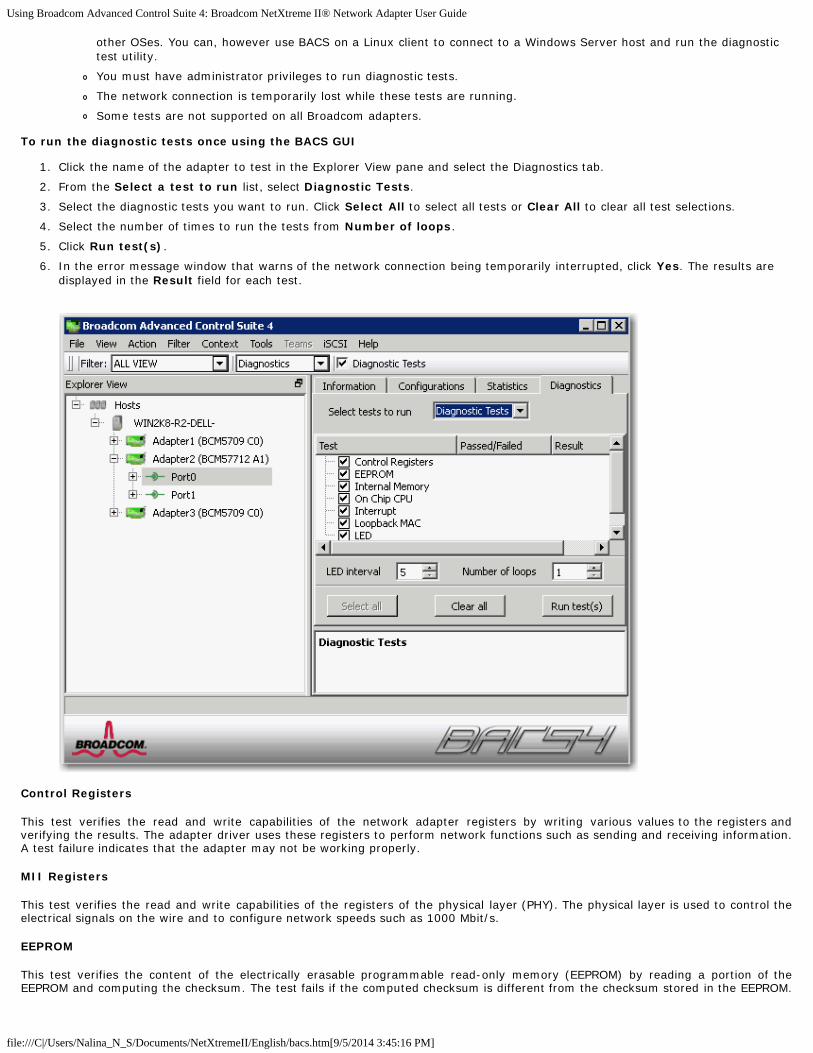
Using Broadcom Advanced Control Suite 4: Broadcom NetXtreme II® Network Adapter User Guide
file:///C|/Users/Nalina_N_S/Documents/NetXtremeII/English/bacs.htm[9/5/2014 3:45:16 PM]
other OSes. You can, however use BACS on a Linux client to connect to a Windows Server host and run the diagnostictest utility.
You must have administrator privileges to run diagnostic tests.
The network connection is temporarily lost while these tests are running.
Some tests are not supported on all Broadcom adapters.
To run the diagnostic tests once using the BACS GUI
1. Click the name of the adapter to test in the Explorer View pane and select the Diagnostics tab.
2. From the Select a test to run list, select Diagnostic Tests.
3. Select the diagnostic tests you want to run. Click Select All to select all tests or Clear All to clear all test selections.
4. Select the number of times to run the tests from Number of loops.
5. Click Run test(s).
6. In the error message window that warns of the network connection being temporarily interrupted, click Yes. The results aredisplayed in the Result field for each test.
Control Registers
This test verifies the read and write capabilities of the network adapter registers by writing various values to the registers andverifying the results. The adapter driver uses these registers to perform network functions such as sending and receiving information.A test failure indicates that the adapter may not be working properly.
MII Registers
This test verifies the read and write capabilities of the registers of the physical layer (PHY). The physical layer is used to control theelectrical signals on the wire and to configure network speeds such as 1000 Mbit/s.
EEPROM
This test verifies the content of the electrically erasable programmable read-only memory (EEPROM) by reading a portion of theEEPROM and computing the checksum. The test fails if the computed checksum is different from the checksum stored in the EEPROM.

Using Broadcom Advanced Control Suite 4: Broadcom NetXtreme II® Network Adapter User Guide
file:///C|/Users/Nalina_N_S/Documents/NetXtremeII/English/bacs.htm[9/5/2014 3:45:16 PM]
An EEPROM image upgrade does not require a code change for this test.
Internal Memory
This test verifies that the internal memory of the adapter is functioning properly. The test writes patterned values to the memory andreads back the results. The test fails if an erroneous value is read back. The adapter cannot function if its internal memory is notfunctioning properly.
On-Chip CPU
This test verifies the operation of the internal CPUs in the adapter.
Interrupt
This test verifies that the Network Device Driver Interface Specification (NDIS) driver is able to receive interrupts from the adapter.
Loopback MAC and Loopback PHY
These tests verify that the NDIS driver is able to send packets to and receive packets from the adapter.
Test LED
This test causes all of the port LEDs to blink 5 times for the purpose of identifying the adapter.
To run the diagnostic tests using the BACS CLI
You can use the following CLI command to run diagnostics tests on a specified target. This command is available for physical deviceports only:
BACScli -t <target type> -f <target format> -i <target ID> "diag {[-c REG ] [-c MII ] [-c EEP] [-c MEM] [-c CPU] [-c INT] [-c MACLB ] [-c PHYLB] [-c LED] | [-c ALL]} [-l <cnt> ] [ -v <LEDIntv> ]"
Examples:
1. The following command displays all the diagnostics tests available for the current selected target.
BACScli -t PHYPORTS -f bdf -i 01:00.00 "diag"
2. The following command runs the MII and LED tests for the selected target:
BACScli -t PHYPORTS -f bdf -i 01:00.00 "diag -c MII -c LED"
3. The following command runs all the tests five times with an LED test interval of 8 ms for the selected target:
BACScli -t PHYPORTS -f bdf -i 01:00.00 "diag -c all -l 5 -v 8"
In Interactive mode, use the list <view> and select <idx> commands to select the desired target device. Use the followingcommand to run diagnostic tests for the selected target:
diag {[-c REG ] [-c MII ] [-c EEP] [-c MEM] [-c CPU] [-c INT] [-c MACLB ] [-c PHYLB] [-c LED] | [-c ALL]} [-l <cnt> ] [ -v <LEDIntv> ]
Examples:
1. The following command displays all the diagnostics tests available for the current selected target.
diag
2. The following command runs the MII and LED test for the selected target.
diag -c MII -c LED
3. The following command runs all the tests five times, with an LED test interval of 8 ms for the selected target.
diag -c all -l 5 -v 8
Analyzing Cables in Windows
The Cable Analysis option on the Diagnostics tab lets you monitor the conditions of each wire pair in an Ethernet Category 5cable connection within an Ethernet network. The analysis measures the cable quality and compares it against the IEEE 802.3abspecification for compliance.

Using Broadcom Advanced Control Suite 4: Broadcom NetXtreme II® Network Adapter User Guide
file:///C|/Users/Nalina_N_S/Documents/NetXtremeII/English/bacs.htm[9/5/2014 3:45:16 PM]
NOTES:
This feature can be used with Windows Server managed hosts only. It is not available for hosts operating on Linux orother OSes. You can, however use BACS on a Linux client to connect to a Windows Server host and run the cableanalysis utility.
You must have administrator privileges to run the cable analysis test.
The network connection is temporarily lost during an analysis.
This option is not available for NetXtreme II 10 GbE network adapters.
This option is not available for all Broadcom network adapters.
This option is available for Broadcom NetXtreme II VBD drivers.
To run a cable analysis using BACS GUI
1. Connect the cable to a port on a switch where the port is set to Auto and the Speed & Duplex driver settings are also set toAuto.
2. Click the name of the adapter to test in the Explorer View pane.
NOTE: For Broadcom NetXtreme II adapters, select a VBD driver; for other adapters, select an NDIS driver.
3. From the Select a test to run list, select Cable Analysis.
4. Click Run.
5. In the error message window that warns of the network connection being temporarily interrupted, click Yes.
Distance

Using Broadcom Advanced Control Suite 4: Broadcom NetXtreme II® Network Adapter User Guide
file:///C|/Users/Nalina_N_S/Documents/NetXtremeII/English/bacs.htm[9/5/2014 3:45:16 PM]
The valid cable length in meters (except when the Noise result is returned).
Status
The result of the analysis for the indicated pair.
Good. Good cable/PCB signal paths, but no gigabit link.
Crossed. Pin short or crosstalk along two or more cable/PCB signal paths.
Open. One or both pins are open for a twisted pair.
Short. Two pins from the same twisted pair are shorted together.
Noise. Persistent noise present (most likely caused by Forced 10/100).
GB Link. Gigabit link is up and running.
N/A. Algorithm failed to reach a conclusion.
Link
The link connection speed and mode.
Status
The status after the test is run, either completed or failed.
There are several factors that could have an effect on the test results:
Link partner. Various switch and hub manufacturers implement different PHYs. Some PHYs are not IEEE compliant.
Cable quality. Category 3, 4, 5, and 6 may affect the test results.
Electrical interference. The testing environment may affect the test results.
To run a cable analysis using BACS CLI
You can use the following CLI commands to run cable analysis for the specified target. This command is available for physical deviceports only.
BACScli -t <target type> -f <target format> -i <target ID> cablediag
Example:
1. The following command runs the cable diagnostics test for the current selected target.
BACScli -t PHYPORTS -f bdf -i 01:00.00 "cablediag"
In Interactive mode, use the list <view> and select <idx> commands to select the desired target device. Use the cablediagcommand to run the cable analysis test for the selected target.
Example:
1. The following command runs the cable diagnostics test for the currently selected NDIS adapter.
cablediag
Managing the LAN Device
The LAN function represents the Ethernet (NDIS) functionality available under the PCI Function. User can view current values ofvarious NDIS driver parameters, configure NDIS driver parameters, view attached FCoE targets and LUN information by selectingFCoE object in object explorer panel.
The available tabs for the NDIS function are as follows:
At the NDIS level, you can view parameters, configure parameters, and run tests from the following tabs:
Information
Configuration
Diagnostics
Statistics

Using Broadcom Advanced Control Suite 4: Broadcom NetXtreme II® Network Adapter User Guide
file:///C|/Users/Nalina_N_S/Documents/NetXtremeII/English/bacs.htm[9/5/2014 3:45:16 PM]
Viewing NDIS Information
Select the NDIS driver in the Explorer View pane, and then select the Information tab to view NDIS-level information.
NOTES:
Information about Broadcom network adapters may be more comprehensive than information about network adaptersmade by others.
Some information may not be available for all Broadcom network adapters.
Viewing Driver Information
Information Tab: Driver Information
Driver Status
The status of the adapter driver.
Loaded. Normal operating mode. The adapter driver has been loaded by the OS and is functioning.
Not Loaded. The driver associated with the adapter has not been loaded by the OS.
Information Not Available. The value is not obtainable from the driver that is associated with the adapter.
Driver Name
The file name of the adapter driver.
Driver Version
The current version of the adapter driver.
Driver Date
The creation date of the adapter driver.

Using Broadcom Advanced Control Suite 4: Broadcom NetXtreme II® Network Adapter User Guide
file:///C|/Users/Nalina_N_S/Documents/NetXtremeII/English/bacs.htm[9/5/2014 3:45:16 PM]
Information Tab: Vital Signs
IP Address
The network address associated with the adapter. If the IP address is all 0s, the associated driver has not been bound with InternetProtocol (IP).
IPv6 IP Address
The IPv6 network address associated with the adapter.
MAC Address
A physical MAC (media access control) address that is assigned to the adapter by the manufacturer. The physical address is never all0s.
Permanent MAC Address
The unique hardware address assigned to the network adapter.
Offload Capabilities
The offload capabilities supported by the adapter. This information is only available for Broadcom NetXtreme II adapters.
TOE. TCP Offload Engine (TOE) allows simultaneous operation of up to 1024 fully offloaded TCP connections for 1-Gbpsnetwork adapters and 1880 fully offloaded TCP connections for 10-Gbps network adapters to the hardware.
iSCSI. iSCSI offload for block-level transfer of data.
LSO. Large Send Offload (LSO) prevents an upper level protocol such as TCP from breaking a large data packet into a seriesof smaller packets with headers appended to them.
CO. Checksum Offload (CO) allows the TCP/IP/UDP checksums for send and receive traffic to be calculated by the adapterhardware rather than by the host CPU.
Information Tab: SR-IOV Switch Information
Number of HW Available
Configure the number of available HW.
Number of Available VFs
Configure the number of available Virtual Functions (VF).
Max VF Chains Per VFs
Enter the number of maximum chains per Virtual Function (VF).
VF Chains Pool Size
Enter the pool size of Virtual Function (VF) chains.
Switch Friendly Name
Enter the switch-friendly name.
Configuring the NDIS Driver
Select the NDIS driver in the Explorer View pane, and then select the Configuration tab to configure NDIS-level parameters. Aftermaking changes, click Apply to confirm the changes to all properties. Click Reset to return the properties to their original values.Click Defaults to restore all settings to their default values.
NOTES:
Clicking Reset after clicking Defaults, but before clicking Apply, will purge all values.
Apply must be clicked to make changes go into effect.
Any changes to existing settings will be lost upon clicking Defaults.

Using Broadcom Advanced Control Suite 4: Broadcom NetXtreme II® Network Adapter User Guide
file:///C|/Users/Nalina_N_S/Documents/NetXtremeII/English/bacs.htm[9/5/2014 3:45:16 PM]
NOTES:
You must have administrator privileges to change the values for a property.
The list of available properties for your particular adapter may be different.
Some properties may not be available for all Broadcom network adapters.
If an adapter is included as a member of a team and you change any advanced property, then you must rebuild theteam to ensure that the team's advanced properties are properly set.
Configuration Tab: Advanced
Ethernet@Wirespeed
Enables a Gigabit Ethernet adapter to establish a link at a lower speed when only two pairs of wires are available in the cabling plant.The default setting for this property is Enabled.
Flow Control
Enables or disables the receipt or transmission of PAUSE frames. PAUSE frames allow the network adapter and a switch to controlthe transmit rate. The side that is receiving the PAUSE frame momentarily stops transmitting. By enabling TOE, networkperformance improves, but with the increased performance, TOE performance is more susceptible to packet loss when flow control isdisabled. Enable flow control to reduce the number of packets lost.
NOTE: If Jumbo Packet is set to 5000 bytes or greater on network adapters that support 10 Gbps link speed, ensure that FlowControl is set to Auto to prevent the system performance from performing at less than optimal levels. This limitation exists on aper-port basis.
Auto (default). Receive and transmit PAUSE frame functionality are optimized. This option indicates that the adapterautomatically adjusts the flow control settings for optimal performance, and its purpose is not enabling auto negotiation of theflow control parameters.
Disable. Receive and transmit PAUSE frame functionality are disabled.
Rx Enabled. Receive PAUSE frame is enabled.

Using Broadcom Advanced Control Suite 4: Broadcom NetXtreme II® Network Adapter User Guide
file:///C|/Users/Nalina_N_S/Documents/NetXtremeII/English/bacs.htm[9/5/2014 3:45:16 PM]
Rx & Tx Enabled. Receive and transmit PAUSE frame are enabled.
Tx Enabled. Transmit PAUSE frame is enabled.
IPv4 Checksum Offload
Normally, the checksum function is computed by the protocol stack. When you select one of the Checksum Offload property values(other than None), the checksum can be computed by the network adapter.
Rx Enabled. Enables receive TCP/IP/UDP checksum offload.
Tx Enabled. Enables transmit TCP/IP/UDP checksum offload.
Tx/Rx Enabled (default). Enables transmit and receive TCP/IP/UDP checksum offload.
None. Disables checksum offload.
IPv4 Large Send Offload
Normally, the TCP segmentation is done by the protocol stack. When you enable the Large Send Offload property, the TCPsegmentation can be done by the network adapter. The default setting for this property is Enabled. This property is only available forBroadcom NetXtreme II adapters.
IPv6 Checksum Offload
Normally, the checksum function is computed by the protocol stack. When you select one of the Checksum Offload property values(other than None), the checksum can be computed by the network adapter.
Rx Enabled. Enables receive TCP/IP/UDP checksum offload.
Tx Enabled. Enables transmit TCP/IP/UDP checksum offload.
Tx/Rx Enabled (default). Enables transmit and receive TCP/IP/UDP checksum offload.
None. Disables checksum offload.
IPv6 Large Send Offload
Normally, the TCP segmentation is done by the protocol stack. When you enable the Large Send Offload property, the TCPsegmentation can be done by the network adapter. The default setting for this property is Enabled. This property is only available forBroadcom NetXtreme II adapters.
Jumbo Packet
Enables the network adapter to transmit and receive oversized Ethernet frames that are greater than 1514 bytes, but less than orequal to 9000 bytes in length (9600 bytes for network adapters that operate at 10 Gbps). This property requires the presence of aswitch that is able to process jumbo frames. This property is only available for Broadcom NetXtreme II adapters.
Frame size is set at 1500 bytes by default. To increase the size of the received frames, raise the byte quantity in 500-byteincrements.
NOTE: If Jumbo Packet is set to 5000 bytes or greater on network adapters that support 10 Gbps link speed, ensure that FlowControl is set to Auto to prevent the system performance from performing at less than optimal levels. This limitation exists on aper-port basis.
NOTE: If SR-IOV is enabled on a virtual function (VF) on the adapter, ensure that the same jumbo packet settings is configuredon both the VF and the Microsoft synthetic adapter. You can configure these values using Windows Device Manager > Advancedproperties.
If there is a mismatch in the values, the SRIOV function will be shown the the Degraded state in Hyper-V > Networking Status.
LSO & Jumbo Frames
Enables the network adapter to transmit and receive oversized Ethernet frames that are greater than 1514 bytes, but less than 9000bytes in length. This property requires the presence of a switch that is able to process Jumbo frames. This information is available forsome Broadcom NetXtreme adapters and is not available for all Broadcom NetXtreme II adapters.
Frame size is set at 1500 bytes by default by selecting the LSO Enabled, Jumbo Off option.
NOTE: Jumbo Frames and Large Send Offload (LSO) are mutually-exclusive properties.
Normally, the TCP segmentation is done by the protocol stack. When you enable the Large Send Offload (LSO) property, the TCPsegmentation can be done by the network adapter.

Using Broadcom Advanced Control Suite 4: Broadcom NetXtreme II® Network Adapter User Guide
file:///C|/Users/Nalina_N_S/Documents/NetXtremeII/English/bacs.htm[9/5/2014 3:45:16 PM]
Both Disabled. LSO & Jumbo frames are both disabled.
LSO Enabled, Jumbo Off (default). LSO enabled and jumbo frames disabled.
LSO Off, Jumbo 3000. Frame size of 3000 bytes and LSO off.
LSO Off, Jumbo 4500. Frame size of 4500 bytes and LSO off.
LSO Off, Jumbo 6000. Frame size of 6000 bytes and LSO off.
LSO Off, Jumbo 7500. Frame size of 7500 bytes and LSO off.
LSO Off, Jumbo 9000. Frame size of 9000 bytes and LSO off.
Locally Administered Address
The Locally Administered Address is a user-defined MAC address that is used in place of the MAC address originally assigned to thenetwork adapter. Every adapter in the network must have its own unique MAC address. This locally administered address consists ofa 12-digit hexadecimal number.
Value. Assigns a unique node address for the adapter.
Not Present (default). Uses the factory-assigned node address on the adapter.
The appropriate assigned ranges and exceptions for the locally administered address include the following:
The range is 00:00:00:00:00:01 to FF:FF:FF:FF:FF:FD.
Do not use a multicast address (least significant bit of the high byte = 1).
Do not use all 0s or all Fs.
Do not assign a Locally Administered Address on any physical adapter that is a member of a team.
Do not assign a Locally Administered Address on any iSCSI boot-enabled device.
NOTE: In some cases, network devices will allow a different combination of hexadecimal and alphanumeric characters than whatis entered, which could result in an invalid MAC address. If you assign an address, confirm the assigned address using the ipconfigutility at the DOS prompt.
Receive Side Scaling
Allows configuring network load balancing across multiple CPUs. The default setting for this property is Enabled.
Switch Configuration.
Allows configuring of the connected switch for the network adapters.
NOTE: Switch Configuration only applies to blade configurations.
SW_Config_10G (default). Sets the switch speed to 10 Gbit/s.
SW_Config_1G. Sets the switch speed to 1 Gbit/s.
Speed & Duplex
The Speed & Duplex property sets the connection speed and mode to that of the network. Note that Full-Duplex mode allows theadapter to transmit and receive network data simultaneously.
10 Mb Full. Sets the speed at 10 Mbit/s and the mode to Full-Duplex.
10 Mb Half. Sets the speed at 10 Mbit/s and the mode to Half-Duplex.
100 Mb Full. Sets the speed at 100 Mbit/s and the mode to Full-Duplex.
100 Mb Half. Sets the speed at 100 Mbit/s and the mode to Half-Duplex.
1 Gb Full. Sets the speed at 1000 Mb Full-Duplex mode only. Not available for 1 Gb ports.
10 GB Full. Sets the speed to 10 Gbit/s and the mode to Full-Duplex. Not available for 1 Gb ports.
Auto (default). Sets the speed and mode for optimum network connection (recommended).
NOTES:
Auto is the recommended setting. This setting allows the network adapter to dynamically detect the line speed of thenetwork. Whenever the network capability changes, the network adapter automatically detects and adjusts to the newline speed and duplex mode. A speed of 1 Gbit/s is enabled by selecting Auto, when that speed is supported.
1 Gb Full Auto must be attached to a link partner that is also capable of a 1 Gb connection. Since the connection is

Using Broadcom Advanced Control Suite 4: Broadcom NetXtreme II® Network Adapter User Guide
file:///C|/Users/Nalina_N_S/Documents/NetXtremeII/English/bacs.htm[9/5/2014 3:45:16 PM]
limited to a 1 Gb connection only, the Ethernet@Wirespeed feature will be disabled. If the link partner supports a 1 Gbconnection only, the Wake on LAN feature may not work. Additionally, management traffic (IPMI or UMP) in the absenceof an operating system may also be affected.
10 Mb Half and 100 Mb Half settings force the network adapter to connect to the network in Half-Duplex mode. Notethat the network adapter may not function if the network is not configured to operate at the same mode.
10 Mb Full and 100 Mb Full settings force the network adapter to connect to the network in Full-Duplex mode. Thenetwork adapter may not function if the network is not configured to operate at the same mode.
1 Gb copper ports cannot be forced to 1 Gb.
Speed & Duplex (SerDes)
1 Gb Full. Forces the speed to 1 Gb Full based on a matching setting for its link partner.
Auto (default). Sets the speed to auto-negotiate with its link partner at the highest matching speed.
Auto with 1Gb Fallback Full. Sets the speed to auto-negotiate with its link partner, but if the attached link partner is forcedat 1 Gbit/s, it will fall back to this mode.
Hardware Default. Sets the speed to negotiate according to the setting specified by the manufacturer (see manufacturerdocumentation for more information).
Wake Up Capabilities
Enables the network adapter to wake up from a low-power mode when it receives a network wake-up frame. Two types of wake-upframes are possible: Magic Packet™ and Wake Up Frame. This property is only available for Broadcom NetXtreme adapters.
Both (default). Selects both Magic Packet and Wake Up Frame as wake-up frames.
Magic Packet. Selects Magic Packet as the wake-up frame.
None. Selects no wake-up frame.
Wake Up Frame. Selects Wake Up Frame as the wake-up frame and allows the network adapter to wake the system whenan event such as a ping or an Address Resolution Protocol (ARP) request is received. This option works in conjunction with theoperating system power mode saving and does not work if the Power Save setting does not enable WOL.
WOL Speed
Sets the speed at which the network adapter connects to the network while the network adapter is in Wake on LAN mode. By default,the WOL Speed property is set to Auto. This property is only available for Broadcom NetXtreme adapters.
10 Mb. Sets the speed to 10 Mbit/s. This is the network speed when the system is in a standby mode awaiting a wake-upframe.
100 Mb. Sets the speed to 100 Mbit/s.
Auto (default). Sets the speed for optimum network connection.
NOTES:
Wake on LAN is supported at 10 Mbit/s or 100 Mbit/s.
Wake on LAN is supported on only one adapter in the system at a time.
Priority & VLAN
Allows enabling both the prioritization of network traffic and VLAN tagging. VLAN tagging only occurs when the VLAN ID setting isconfigured with a value other than 0 (zero).
Priority & VLAN Enabled (default). Allows for packet prioritization and VLAN tagging.
Priority & VLAN Disabled. Prevents packet prioritization and VLAN tagging.
Priority Enabled. Allows packet prioritization only.
VLAN Enabled. Allows VLAN tagging only.
NOTE: If an intermediate driver is managing the network adapter for VLAN tagging, the Priority & VLAN Disabled andPriority Enabled settings should not be used. Use the Priority & VLAN Enabled setting and change the VLAN ID to 0(zero).
VLAN ID
Enables VLAN tagging and configures the VLAN ID when Priority & VLAN Enabled is selected as the Priority & VLAN setting. Therange for the VLAN ID is 1 to 4094 and must match the VLAN tag value on the connected switch. A value of 0 (default) in this field

Using Broadcom Advanced Control Suite 4: Broadcom NetXtreme II® Network Adapter User Guide
file:///C|/Users/Nalina_N_S/Documents/NetXtremeII/English/bacs.htm[9/5/2014 3:45:16 PM]
disables VLAN tagging.
Risk Assessment of VLAN Tagging through the NDIS Miniport Driver
Broadcom's NDIS 6.0 miniport driver provides the means to allow a system containing a Broadcom adapter to connect to a taggedVLAN. On Windows XP systems, this support was only provided through the use of an intermediate driver (e.g., BroadcomAdvanced Server Program - BASP). Unlike BASP, however, the NDIS 6 driver's support for VLAN participation is only for a singleVLAN ID.
Also unlike BASP, the NDIS 6.0 driver only provides VLAN tagging of the outbound packet, but does not provide filtering ofincoming packets based on VLAN ID membership. This is the default behavior of all miniport drivers. While the lack of filteringpackets based on VLAN membership may present a security issue, the following provides a risk assessment based on this driverlimitation for an IPv4 network:
A properly configured network that has multiple VLANs should maintain separate IP segments for each VLAN. This is necessarysince outbound traffic relies on the routing table to identify which adapter (virtual or physical) to pass traffic through and doesnot determine which adapter based on VLAN membership.
Since support for VLAN tagging on Broadcom's NDIS 6.0 driver is limited to transmit (Tx) traffic only, there is a risk of inboundtraffic (Rx) from a different VLAN being passed up to the operating system. However, based on the premise of a properlyconfigured network above, the IP segmentation and/or the switch VLAN configuration may provide additional filtration to limitthe risk.
In a back-to-back connection scenario, two computers on the same IP segment may be able to communicate regardless oftheir VLAN configuration since no filtration of VLAN membership is occurring. However, this scenario assumes that the securitymay already be breached since this connection type is not typical in a VLAN environment.
If the risk above is not desirable and filtering of VLAN ID membership is required, then support through an intermediate driverwould be necessary.
iSCSI Crash Dump
Crash dump is used to collect information on adapters that were booted remotely using iSCSI. To enable crash dump, set to Enableand reboot the system. If you perform an upgrade of the device drivers, re-enable iSCSI Crash Dump. If iSCSI Boot is configuredto boot in the HBA path, then this parameter cannot be changed.
Number of Receive Descriptors
The number of receive descriptors with options of Default, Minimum, and Maximum. Receive descriptors are data segments thatallow the network adapter to allocate receive packets to memory.
Number of Transmit Descriptors
The number of transmit descriptors with value options from 100 to 600 with 200 being the default value. Transmit descriptors aredata segments that allow the network adapter to monitor transmit packets in the system memory.
RSS Queues
Allows configuring RSS queues from 1 to 4. Options are RSS 1 Queue, RSS 2 Queue, and RSS 4 Queue.
Interrupt Moderation
Enables interrupt moderation, which limits the rate of interrupt to the CPU during packet transmission and packet reception. Thedisabled option allows one interrupt for every packet transmission and packet reception. Enable is the default option.
Number of RSS Queues
Allows configuring RSS queues. For 1 Gbps network adapters, the RSS queue options are Auto (default), 2, 4, and 8. For 10 Gbpsnetwork adapters, the RSS queue options are Auto (default), 2, 4, 8, and 16.
Receive Buffers
The number of receive buffers. Receive buffers are data segments that allow the network adapter to allocate receive packets tomemory. For 1 Gbps adapters, the range of valid receive buffers is 50 to 5000 in increments of 1 with 750 receive buffers as thedefault value.
Receive Buffers (0=Auto)
The number of receive buffers. Receive buffers are data segments that allow the network adapter to allocate receive packets tomemory. For 10 Gbps adapters, the range of valid receive buffers is 0 to 3000 in increments of 50 with 0 receive buffers as the

Using Broadcom Advanced Control Suite 4: Broadcom NetXtreme II® Network Adapter User Guide
file:///C|/Users/Nalina_N_S/Documents/NetXtremeII/English/bacs.htm[9/5/2014 3:45:16 PM]
default value.
Transmit Buffers (0=Auto)
The number of transmit buffers. Transmit buffers are data segments that allow the network adapter to monitor transmit packets inthe system memory. The range of valid transmit buffers is 0 to 5000 in increments of 1 with 250 transmit buffers as the defaultvalue.
TCP Connection Offload (IPv4)
Enables and disables TOE offload when using the IPv4 protocol. The default is Enabled.
TCP Connection Offload (IPv6)
Enables and disables TOE offload when using the IPv6 protocol. The default is Enabled.
Pause on Exhausted Host Ring
For BCM57711 and BCM57712 network adapters, there are two possible scenarios that can trigger pause frames to be generated: ahost ring buffer is exhausted or the on-chip buffers are depleted. With RSS enabled inside the system, it is possible to achieve betterEthernet throughput if no pause frames are being generated in a case where a host ring buffer (of multiple RSS rings) is exhausted.The default is Disabled.
Quality of Service
Enables Quality of Service (QoS) to provide different priorities to different applications.
Recv Segment Coalescing (IPv4)
Enable Receive Segment Coalescing (IPv4). Receive Segment Coalescing is an offload technology that reduces CPU utilization fornetwork processing on the receive side by offloading tasks from the CPU to a network adapter.
Recv Segment Coalescing (IPv6)
Enable Receive Segment Coalescing (IPv6). Receive Segment Coalescing is an offload technology that reduces CPU utilization fornetwork processing on the receive side by offloading tasks from the CPU to a network adapter.
SR-IOV
Enables Single Root I/O Virtualization (SR-IOV).
Viewing Resource Information
The Resources section of the Information tab displays information about connections and other essential functions for the selectednetwork adapter.
NOTE: Some information may not be available for all Broadcom network adapters.
Information Tab: Resources
Bus Type
The type of input/output (I/O) interconnect used by the adapter.
Adapters Supporting Remote PHY
The following properties are specific to blade servers using a NetXtreme II BCM5708S adapter that supports the Remote PHYfeature.
Chassis PHY Ethernet@Wirespeed
This property is the same as Ethernet@Wirespeed, and is only available when the blade server is attached to a pass-throughmodule.
Chassis PHY Flow Control
This property is the same as Flow Control, and is only available when the blade server is attached to a pass-through module.

Using Broadcom Advanced Control Suite 4: Broadcom NetXtreme II® Network Adapter User Guide
file:///C|/Users/Nalina_N_S/Documents/NetXtremeII/English/bacs.htm[9/5/2014 3:45:16 PM]
Chassis PHY Speed & Duplex
This property is the same as Speed & Duplex (excludes 1 Gb Full Auto), and is only available when the blade server is attached to apass-through module.
Chassis SW Flow Control
This property is the same as Flow Control, and is only available when the blade server is attached to a switch module.
Chassis SW Speed & Duplex
This property is the same as Speed & Duplex (SerDes), and is only available when the blade server is attached to a switch module.
Configuring System Settings
System Management on the Configurations tab allow you to view and change the values of the available properties for thesystem. The potentially available properties and their respective settings are described below.
Chimney Offload State
Enables TCP Offload Engine (TOE) for the entire system. On Windows Server 2008 operating systems, the options are Enable(default) and Disable. For Windows Server 2008 R2, the options are Enable, Disable, and Auto (default). If Chimney Offload State isconfigured for Auto, then a 10 Gbps network adapter will have TOE enabled, but not for a 1 Gbps network adapter.
To enable TOE for individual network adapters, configure Chimney Offload State to Enable and also enable TCP Connection Offload(IPv4) or TCP Connection Offload (IPv6) from the Advanced area of the Configuration tab.
Viewing Statistics
The information provided on the Statistics tab allows you to view traffic statistics for both Broadcom network adapters and networkadapters made by others. Statistical information and coverage are more comprehensive for Broadcom adapters.
To view Statistics information for any installed network adapter, click the name of the adapter listed in the Explorer View pane, thenclick the Statistics tab.
If any of the sections described below is not visible, then from the Context View tab on the right side of the window, selectStatistics and then select the name of the missing section.
Click Refresh to get the most recent values for each statistic. Click Reset to change all values to zero for the current BACS session.
NOTES:
Team statistics are not compiled for a Broadcom network adapter if it is disabled.
Some statistics may not be available for all Broadcom network adapters.

Using Broadcom Advanced Control Suite 4: Broadcom NetXtreme II® Network Adapter User Guide
file:///C|/Users/Nalina_N_S/Documents/NetXtremeII/English/bacs.htm[9/5/2014 3:45:16 PM]
General Statistics
General Statistics show the transmitted and received statistics to and from the adapter.
Frames Tx OK
A count of the frames that were successfully transmitted. This counter is incremented when the transmit status is reported asTransmit OK.
Frames Rx OK
A count of the frames that were successfully received. This does not include frames received with frame-too-long, frame checksequence (FCS), length, or alignment errors, nor frames lost due to internal MAC sublayer errors. This counter is incremented whenthe receive status is reported as Receive OK.
Directed Frames Tx
A count of directed data frames that were successfully transmitted.
Multicast Frames Tx
A count of frames that were successfully transmitted (as indicated by the status value Transmit OK) to a group destination addressother than a broadcast address.
Broadcast Frames Tx
A count of frames that were successfully transmitted (as indicated by the transmit status Transmit OK) to the broadcast address.Frames transmitted to multicast addresses are not broadcast frames and are excluded.
Directed Frames Rx
A count of directed data frames that were successfully received.
Multicast Frames Rx

Using Broadcom Advanced Control Suite 4: Broadcom NetXtreme II® Network Adapter User Guide
file:///C|/Users/Nalina_N_S/Documents/NetXtremeII/English/bacs.htm[9/5/2014 3:45:16 PM]
A count of frames that were successfully received and are directed to an active nonbroadcast group address. This does not includeframes received with frame-too-long, FCS, length, or alignment errors, nor frames lost because of internal MAC sublayer errors. Thiscounter is incremented as indicated by the Receive OK status.
Broadcast Frames Rx
A count of frames that were successfully received and are directed to a broadcast group address. This count does not include framesreceived with frame-too-long, FCS, length, or alignment errors, nor frames lost because of internal MAC sublayer errors. This counteris incremented as indicated by the Receive OK status.
Frames Rx with CRC Error
The number of frames received with CRC errors.
Initiator Login Statistics
iSCSI login enables a connection for iSCSI use between the initiator and the target and is used to authenticate parties, negotiate thesession's parameters, open security association protocol, and mark the connection as belonging to an iSCSI session.
Login Accept Responses
The number of login requests accepted by the target.
Login other failed Responses
The number of login requests that were not accepted by the target.
Login Redirect Responses
The number of responses that required further action by the initiator.
Login Authentication Failed Responses
The number of login requests that failed due to party authentication failure.
Login target authentication failure
The number of instances where the login could not authenticate the target.
Login target negotiation failure
The number of instances where the login could not negotiate the sessions parameters.
Normal logout command PDU
The number of normal logout commands issued by the initiator to remove a connection from a session or to close a session.
Other logout command PDU
The number of logout commands issued by the initiator for reasons other than to remove a connection from a session or to close asession.
Local Initiator login failures
The number of login failures likely caused by the initiator.
Initiator Instance Statistics
The statistics in this area pertain to all sessions.
Session digest errors
The number of sessions with errors due to an invalid payload or header.
Session connection timeout error
The number of sessions that were terminated due to any of the many timeout errors.

Using Broadcom Advanced Control Suite 4: Broadcom NetXtreme II® Network Adapter User Guide
file:///C|/Users/Nalina_N_S/Documents/NetXtremeII/English/bacs.htm[9/5/2014 3:45:16 PM]
Session format error
The number of sessions with errors due to inconsistent fields, reserved fields not 0, non-existent LUN, etc.
Sessions failed
The number of failed sessions.
Custom
Custom statistics.
Total Offload iSCSI Connections
The total number of offloaded iSCSI connections.
Session Statistics
The statistics in this area only pertain to the named session.
Session Name
The name used for the session between the initiator and the target.
Session Id
The identifier used for the session between the initiator and the target.
Bytes sent
The number of bytes sent for the named session.
Bytes received
The number of bytes received for the named session.
PDU sent
The number of iSCSI PDUs sent for the named session.
PDU received
The number of iSCSI PDUs received for the named session.
Digest errors
The number of errors due to an invalid payload or header for the named session.
Connection Timeout errors
The number of connection timeout errors for the named session.
Format errors
The number of errors due to inconsistent fields, reserved fields not 0, non-existent LUN, etc. for the named session.
IEEE 802.3 Statistics
Frames Rx with Alignment Error
A count of the frames that were not an integral number of octets in length and do not pass the FCS check. This counter isincremented when the receive status is reported as Alignment Error.
Frames Tx with one Collision
A count of the frames that were involved in a single collision and were subsequently transmitted successfully. This counter isincremented when the result of a transmission is reported as Transmit OK, and the attempt value is 2.
Frames Tx with more than one Collision

Using Broadcom Advanced Control Suite 4: Broadcom NetXtreme II® Network Adapter User Guide
file:///C|/Users/Nalina_N_S/Documents/NetXtremeII/English/bacs.htm[9/5/2014 3:45:16 PM]
A count of the frames that were involved in more than one collision and were subsequently transmitted successfully. This counter isincremented when the transmit status is reported as Transmit OK, and the value of the attempts variable is greater than 2 and lessthan or equal to the attempt limit.
Frames Tx after Deferral
A count of the frames that were delayed being transmitted on the first attempt because the medium was busy. The frames involvedin any collision are not counted.
Custom Statistics
NOTE: Custom statistics are available only for an enabled Broadcom network adapter.
Out of Recv. Buffer
The number of times the adapter ran out of Receive Buffer Descriptors. This information is only available for Broadcom NetXtreme IIadapters.
Frames size less than 64-byte with bad FCS
The number of frames with a size less than 64 bytes with bad FCS.
MAC Rx w/ Pause Command and Length = 0
MAC control frames with the pause command and a length equal to 0.
MAC Rx w/ Pause Command and Length greater than 0
MAC control frames with the pause command and a length greater than 0.
MAC Rx w/ no Pause Command
MAC control frames with no pause command.
MAC Sent X-on
MAC Transmit with X-on was on.
MAC Sent X-off
MAC Transmit with X-on was off.
Large Send Offload Transmit Requests
The number of times the adapter was requested to transmit a packet performing TCP segmentation.
Total Offload TCP Connections
The total number of offloaded TCP connections.
SR-IOV Switch Statistics
This area shows the statistics for SR-IOV switches.
Num of Active VFs
This shows the number of active Virtual Functions (VF).
Viewing and Configuring Resource Reservations
NOTES:
Resource Reservation information is only available for Broadcom NetXtreme II adapters and VBD drivers.
Not all offload technologies are available with all adapters.
Resource Reservation information is not available in BACS on Linux systems.
The Resource Reservations section shows the number of connections allocated to an offload technology: TOE and iSCSI.

Using Broadcom Advanced Control Suite 4: Broadcom NetXtreme II® Network Adapter User Guide
file:///C|/Users/Nalina_N_S/Documents/NetXtremeII/English/bacs.htm[9/5/2014 3:45:16 PM]
TCP Offload Engine (TOE) for accelerating TCP over 1 GbE and 10 GbE.
Internet Small Computer Systems Interface (iSCSI) offload for accelerating network storage access featuring centralized bootfunctionality (iSCSI boot).
You can also view the number of unlicensed resources and unallocated resources.
TOE and iSCSI can only be configured on certain adapters and require a license key. License keys are installed on the motherboardfor use with LOMs and are preprogrammed in add-in NICs. TOE is a technology best suited for long-term TCP connections. TOE usedin conjunction with applications that primarily deal with short-term connections may see suboptimal performance when compared tonot using TOE. A short-term connection is a TCP connection that is established for only a few seconds at most, often less than onesecond. The overhead of establishing and tearing down the TCP connection with short-term connections may diminish the benefitthat TOE provides. An example of an application that uses short-term connections is a web server that is not behind a load balancer.TCP connections for HTTP sessions are very short-lived and last only long enough to serve up a web page, after which the TCPconnection is terminated. On the other hand, the same web server behind a load balancer benefits greatly from TOE since the TCPconnections are long-lived between the web server and the load balancer. In contrast, a backup application is very likely to benefitfrom TOE since backup applications establish long-term connections between the server and the client.
To view resource reservations
1. Click the name of the Broadcom NetXtreme II system device in the Explorer View pane.
2. From the Resource Reservations section, select the property you want to set.
3. Click Apply to confirm the changes to all properties. Click Reset to return the properties to their original values.
To configure resource reservations
1. Select Reserved Resources for the Offload Configuration setting. Reservations allocate the minimum number of connectionsper technology. See Table 1 for the maximum number of connections available for various configurations.
2. Click First Come First Served to allow connections on a first-come-first-served basis to any enabled offload technology (TOEor iSCSI) as long as resources are available. Otherwise, click Reserved Resources to set the maximum number ofconnections for each offload technology. This option is not available for 10 Gbps network adapters.
3. If allocating TOE connections, select the TCP Offload Engine (TOE) check box and slide the bar or enter a number in thevalue box. This is the maximum number of connections available for TOE offload.
4. If allocating iSCSI connections, select the iSCSI check box and slide the bar or enter a number in the value box. This is themaximum number of connections available for iSCSI offload.
5. After the configurations are complete, click Apply to save the settings or click Reset to revert back to the previous settings.A chart of the resource allocations appears below the resource configurations.
6. If prompted, reboot the system.
Table 1: Maximum Number of Offload Connections
Offload First Come First Served Reserved Resources Maximum Number of Connections
TOE only Selected – 1024
TOE only – Selected 864
iSCSI only Selected – Between 7 and 100
iSCSI only – Selected 28
Configuring the IP Address for iSCSI Offload
For iSCSI-booted adapters, the Configurations tab is not available and you will not be able to perform this procedure.
To set the IP address of the iSCSI HBA for iSCSI offload
The iSCSI Management section of the Configurations tab allows you to set the IP address of the iSCSI HBA when using iSCSIprotocol to offload network processing from the CPU to the Broadcom network adapter.
1. Click the name of the Broadcom NetXtreme II iSCSI device in the SCSI controller section of the Explorer View pane.
2. Depending on the protocol you will be using, for IPv4 DHCP or IPv6 DHCP, select Enable (not available for iSCSI bootedadapters) to set the IP address dynamically using a DHCP server. Or select Disable to set the IP address using a static IPaddress. Enter the IP Address, Subnet Mask, and Default Gateway.
3. Configure the VLAN ID for the iSCSI HBA by entering a number for VLAN ID. The value must be between 1 and 4094.
4. After the configurations are complete, click Apply to save the settings or click Reset to revert back to the previous settings.
Viewing Licenses

Using Broadcom Advanced Control Suite 4: Broadcom NetXtreme II® Network Adapter User Guide
file:///C|/Users/Nalina_N_S/Documents/NetXtremeII/English/bacs.htm[9/5/2014 3:45:16 PM]
NOTES:
The Licenses section of the Configurations tab is only available for Broadcom NetXtreme II adapters and VBD drivers.
Not all offload technologies are available with all adapters.
The Licenses section shows the number of connections available for TOE and iSCSI offload technologies.
To view licenses
1. Click the name of the Broadcom NetXtreme II system device in the Explorer View pane.
Configuring Teaming
NOTE: BACS does not support teaming on Linux systems. Linux provides a similar built-in functionality called Channel Bonding.Refer to the Linux OS documentation for more information.
The teaming function allows you to group any available network adapters together to function as a team. Teaming is a method ofcreating a virtual NIC (a group of multiple adapters that functions as a single adapter). The benefit of this approach is that it enablesload balancing and failover. Teaming is done through the Broadcom Advanced Server Program (BASP) software. For a comprehensivedescription of the technology and implementation considerations of the teaming software, refer to the "Broadcom Gigabit EthernetTeaming Services" section of your Broadcom network adapter user guide.
Teaming can be accomplished by either of the following methods:
Using the Broadcom Teaming Wizard
Using Expert Mode
NOTES:
For further information regarding teaming protocols, see "Teaming" in your Broadcom network adapter user guide.
If you do not enable LiveLink™ when configuring teams, disabling Spanning Tree Protocol (STP) at the switch isrecommended. This minimizes the downtime due to spanning tree loop determination when failing over. LiveLinkmitigates such issues.
BASP is available only if a system has one or more Broadcom network adapters installed.
The TCP Offload Engine (TOE), Large Send Offload (LSO), and Checksum Offload properties are enabled for a team onlywhen all of the members support and are configured for the feature.
To physically remove a teamed NIC from a system, you must first delete the NIC from the team. Not doing this beforeshutting down the system could result in breaking the team on a subsequent reboot, which may result in unexpectedteam behavior.
If an adapter is included as a member of a team and you change any advanced property, then you must rebuild theteam to ensure that the team's advanced properties are properly set.
If an adapter with a TOE key is included as a member of a team and you remove the TOE key, then you must rebuildthe team to ensure that the team does not appear as a TOE-enabled team.
You must have administrator privileges to create or modify a team.
The load balance algorithm in a team environment in which members are connected at different speeds favors membersconnected with a Gigabit Ethernet link over members connected at lower speed links (100 Mbps or 10 Mbps) until athreshold is met. This is normal behavior.
In a GEC or 802.3ad type team, disabling the device driver(s) of a team member that has IPMI enabled may prevent asuccessful failover since IPMI maintains link with the attached switch.
Do not assign a Locally Administered Address on any physical adapter that is a member of a team.
Team Types
You can create four types of load balance teams:
Smart Load Balance and Failover
Link Aggregation (802.3ad) (TOE is not applicable)
Generic Trunking (FEC/GEC)/802.3ad-Draft Static (TOE is not applicable)
SLB (Auto-Fallback Disable) – The Auto-Fallback Disable feature is configured for Smart Load Balance and Failover type teamsin the Teaming Wizard.
NOTE: NetXtreme II network adapters with iSCSI enabled is supported only in an SLB team type.

Using Broadcom Advanced Control Suite 4: Broadcom NetXtreme II® Network Adapter User Guide
file:///C|/Users/Nalina_N_S/Documents/NetXtremeII/English/bacs.htm[9/5/2014 3:45:16 PM]
Smart Load Balance and Failover
In this type of team, a standby member handles the traffic if all of the load balance members fail (a failover event). All load balancemembers have to fail before the standby member takes over. When one or more of the load balance members is restored (fallback),the restored team member(s) resumes the handling of the traffic. The LiveLink feature is supported for this type of team.
Link Aggregation (802.3ad)
In this type of team, you can dynamically configure the network adapters that have been selected to participate in a given team. Ifthe link partner is not correctly configured for IEEE 802.3ad link configuration, errors are detected and noted. All adapters in theteam are configured to receive packets for the same MAC address. The outbound load balancing scheme is determined by the BASPdriver. The link partner of the team determines the load balancing scheme for inbound packets. In this mode, at least one of the linkpartners must be in active mode.
NOTE: TOE is not applicable for Link Aggregation team type. NetXtreme II network adapters with iSCSI enabled is not supportedfor Link Aggregation team type.
Generic Trunking (FEC/GEC)/802.3ad-Draft Static
This type of team is very similar to the link aggregation type, in that all adapters in the team must be configured to receive packetsfor the same MAC address. This mode does not provide link aggregation control protocol (LACP) or marker protocol support. Thismode supports a variety of environments where the link partners are statically configured to support a proprietary trunkingmechanism. Trunking supports load balancing and failover for both outbound and inbound traffic.
NOTE: TOE is not applicable for Generic Trunking (FEC/GEC)/802.3ad-Draft Static team type. NetXtreme II network adapters withiSCSI enabled is not supported for Generic Trunking (FEC/GEC)/802.3ad-Draft Static team type.
SLB (Auto-Fallback Disable)
This team is identical to Smart Load Balance and Failover, with the following exception: when the standby member is active, if aprimary member comes back online, the team continues using the standby member rather than switching back to the primarymember. This type of team is supported only for situations in which the network cable is disconnected and reconnected to thenetwork adapter. It is not supported for situations in which the adapter is removed/installed through Device Manager or Hot-PlugPCI. If any primary adapter assigned to a team is disabled, the team functions as a Smart Load Balancing and Failover type of teamin which auto-fallback occurs. The LiveLink feature is supported for this type of team.
Standby Team Member and Auto-Fallback Disable Mode
You can designate one team member in an SLB type of team to be the standby member. The standby member does not activelysend and receive normal network traffic while other adapters on the team are active. If all of the active adapters on the team fail orare disconnected, the standby member takes over the handling of the network activities.
In Auto-Fallback Disable mode, if a load balance member returns on line, the team continues using the standby member rather thanswitching back to using the load balance member. Consequently, the adapter that was initially designated a load balance memberremains in an inactive state and becomes the new standby member.
LiveLink
LiveLink is a feature of BASP that is available for the Smart Load Balancing (SLB) and SLB (Auto-Fallback Disable) type of teaming.The purpose of LiveLink is to detect link loss beyond the switch and to route traffic only through team members that have a live link.
Using the Broadcom Teaming Wizard
You can use the Broadcom Teaming Wizard to create a team, configure an existing team if a team has already been created, orcreate a VLAN.
1. Create or edit a team:
To create a new team, select Create a Team from the Team menu, or right-click one of the devices in the "UnassignedAdapters" section and select Create a Team. This option is not available if there are no devices listed in the "UnassignedAdapters" sections, which means all adapters are already assigned to teams.
To configure an existing team, right-click one of the teams in the list and select Edit Team. This option is only available ifa team has already been created and is listed in the Team Management pane.
NOTE: If you prefer to work without the wizard for now, click Expert Mode. If you want to always use Expert Mode tocreate a team, select Default to Expert Mode on next start. See Using Expert Mode.

Using Broadcom Advanced Control Suite 4: Broadcom NetXtreme II® Network Adapter User Guide
file:///C|/Users/Nalina_N_S/Documents/NetXtremeII/English/bacs.htm[9/5/2014 3:45:16 PM]
2. To continue using the wizard, click Next.
3. Type the team name and then click Next. If you want to review or change any of your settings, click Back. Click Cancel todiscard your settings and exit the wizard.
NOTE: The team name cannot exceed 39 characters, cannot begin with spaces, and cannot contain any of the followingcharacters: & \ / : * ? < > |

Using Broadcom Advanced Control Suite 4: Broadcom NetXtreme II® Network Adapter User Guide
file:///C|/Users/Nalina_N_S/Documents/NetXtremeII/English/bacs.htm[9/5/2014 3:45:16 PM]
4. Select the type of team you want to create.
5. Select Enable Hyper-V Mode if you want to enable Windows virtualization services. See "Microsoft Virtualization with Hyper-V" in the Troubleshooting topic in the NetXtreme II Network Adapter User Guide for more information about this feature.
6. If the team type is an SLB type team, click Next. If the team type is not an SLB type team, then a dialog box appears. Verifythat the network switch connected to the team members is configured correctly for the team type, click OK, and continue.
NOTE: NetXtreme II network adapters with iSCSI enabled is supported only in an SLB team type. To continue with thecreation of non-SLB team types, first disable iSCSI by deselecting iSCSI Offload Engine from the Resource Reservationsarea of the Configurations tab.

Using Broadcom Advanced Control Suite 4: Broadcom NetXtreme II® Network Adapter User Guide
file:///C|/Users/Nalina_N_S/Documents/NetXtremeII/English/bacs.htm[9/5/2014 3:45:16 PM]
7. From the Available Adapters list, click the adapter you want to add to the team and then click Add. Remove team membersfrom the Team Members list by clicking the adapter and then clicking Remove. Click Next.
NOTE: There must be at least one Broadcom network adapter assigned to the team.
NOTE: A team created with a single adapter will not have load balancing or failover capabilities.
The TCP Offload Engine (TOE), Large Send Offload (LSO) and Checksum Offload (CO) columns indicate if the TOE, LSO,Jumbo MTU, and/or the CO properties are supported for the adapter. The TOE, LSO, Jumbo MTU, and CO properties areenabled for a team only when all of the members support and are configured for the feature. If this is the case, then theteam offload capabilities appear on the bottom of the screen.
NOTES:
If an adapter is included as a member of a team and you change any advanced property, then you must rebuild theteam to ensure that the team's advanced properties are properly set.
If an adapter with a TOE key is included as a member of a team and you remove the TOE key, then you must rebuildthe team to ensure that the team does not appear as a TOE-enabled team.
Adding a network adapter to a team where its driver is disabled may negatively affect the offloading capabilities of theteam. This may have an impact on the team's performance. Therefore, it is recommended that only driver-enablednetwork adapters be added as members to a team.

Using Broadcom Advanced Control Suite 4: Broadcom NetXtreme II® Network Adapter User Guide
file:///C|/Users/Nalina_N_S/Documents/NetXtremeII/English/bacs.htm[9/5/2014 3:45:16 PM]
8. If you want to designate one of the adapters as a standby member (optional), select Use the following member as astandby member, then choose the standby member from the list of adapters.
9. The Auto-Fallback Disable mode feature allows the team to continue using the standby member rather than switching back tothe primary member if the primary member comes back online. To enable this feature, select Enable Auto-Fallback Disablemode. Click Next.

Using Broadcom Advanced Control Suite 4: Broadcom NetXtreme II® Network Adapter User Guide
file:///C|/Users/Nalina_N_S/Documents/NetXtremeII/English/bacs.htm[9/5/2014 3:45:16 PM]
10. If you want to configure LiveLink, select Yes, otherwise select No, then click Next.
11. Select the probe interval (the number of seconds between each retransmission of a link packet to the probe target) and themaximum number of probe retries (the number of consecutively missed responses from a probe target before a failover istriggered).
12. Set the Probe VLAN ID to allow for connectivity with probe targets residing on a tagged VLAN. The number set must matchthe VLAN ID of the probe targets as well as the port(s) on the switch to which the team is connected.
NOTE: Each LiveLink enabled team can only communicate with Probe Targets on a single VLAN. Also, VLAN ID 0 isequivalent to an untagged network. If the Probe VLAN ID is set to a value other than 0, then a VLAN must be created with anidentical VLAN tag value (see Step 18.).
13. Click the probe target at the top of the list, click Edit Target IP Address, type the target IP address in the IP Address boxfor one or all probe targets, and then click OK. Click Next.
NOTE: Only the first probe target is required. You can specify up to three additional probe targets to serve as backups byassigning IP addresses to the other probe targets.
14. Select a listed team member, click Edit Member IP Address, and then type the member IP address in the IP Address box.Repeat for all listed team members and then click OK. Click Next.
NOTE: All of the member IP addresses must be in the same subnet as the subnet of the probe targets.
15. If you want to create a VLAN on the team, select Add VLAN, or if you want to change the settings of an existing VLAN, selectEdit VLAN, then click Next. If you do not want to create or edit a VLAN, select Skip Manage VLAN, then click Next, andcontinue with the wizard from the Finish screen (see Step 20. of this procedure).
VLANs enable you to add multiple virtual adapters that are on different subnets. The benefit of this is that your system canhave one network adapter that can belong to multiple subnets.
NOTE: VLANs can only be created when all team members are Broadcom adapters.

Using Broadcom Advanced Control Suite 4: Broadcom NetXtreme II® Network Adapter User Guide
file:///C|/Users/Nalina_N_S/Documents/NetXtremeII/English/bacs.htm[9/5/2014 3:45:16 PM]
16. Type the VLAN name and then click Next.
NOTE: The team name cannot exceed 39 characters, cannot begin with spaces, and cannot contain any of the followingcharacters: & \ / : * ? < > |
17. To tag the VLAN, select Tagged and then click Next. Otherwise, click Untagged, click Next, and continue with the wizard to

Using Broadcom Advanced Control Suite 4: Broadcom NetXtreme II® Network Adapter User Guide
file:///C|/Users/Nalina_N_S/Documents/NetXtremeII/English/bacs.htm[9/5/2014 3:45:16 PM]
add additional VLANs (see Step 19. of this procedure).
18. Type the VLAN tag value and then click Next. The value must be between 1 and 4094.
19. Select Yes to add or manage another VLAN and then click Next. Repeat until you do not want to add or manage any

Using Broadcom Advanced Control Suite 4: Broadcom NetXtreme II® Network Adapter User Guide
file:///C|/Users/Nalina_N_S/Documents/NetXtremeII/English/bacs.htm[9/5/2014 3:45:16 PM]
additional VLANs.
NOTE: You can define up to 64 VLANs per team (63 VLANs that are tagged and 1 VLAN that is not tagged). Adding severalVLANS may slow down the reaction time of the Windows interface due to memory and processor time usage for each VLAN.The degree to which Windows performance may suffer depends on system configuration.
20. To apply and commit the changes to the team, select Commit changes to system and Exit the wizard. To apply yourchanges but continue using the wizard, select Save changes and continue to manage more teams. Click Finish.

Using Broadcom Advanced Control Suite 4: Broadcom NetXtreme II® Network Adapter User Guide
file:///C|/Users/Nalina_N_S/Documents/NetXtremeII/English/bacs.htm[9/5/2014 3:45:16 PM]
NOTE: At any point in the Broadcom Teaming Wizard procedure, click Preview to get a visual representation of what theteam will look like before committing any changes.
21. Click the team name in the Team Management pane to view the team's properties in the Information tab, transfer andreceive data in the Statistics tab, and team customization options in the Configurations tab.

Using Broadcom Advanced Control Suite 4: Broadcom NetXtreme II® Network Adapter User Guide
file:///C|/Users/Nalina_N_S/Documents/NetXtremeII/English/bacs.htm[9/5/2014 3:45:16 PM]
Using Expert Mode
Use Expert Mode to create a team, modify a team, add a VLAN, and configure LiveLink for a Smart Load Balance and Failover andSLB (Auto-Fallback Disable) team. To create a team using the wizard, see Using the Broadcom Teaming Wizard.
To set the default Teaming Mode, select Options from the Tools menu. In the Options window, click the General tab, then selectExpert Mode or Wizard Mode (the default is Wizard Mode).
Creating a Team
NOTE: Enabling Dynamic Host Configuration Protocol (DHCP) is not recommended for members of an SLB type of team.
1. From the Teams menu, select Create a Team, or right-click one of the devices in the "Unassigned Adapters" section andselect Create a Team. This option is not available if there are no devices listed in the "Unassigned Adapters" sections, whichmeans all adapters are already assigned to teams.
2. Click Expert Mode.
NOTE: If you want to always use Expert Mode to create a team, click Default to Expert Mode on next start.
3. Click the Create Team tab.

Using Broadcom Advanced Control Suite 4: Broadcom NetXtreme II® Network Adapter User Guide
file:///C|/Users/Nalina_N_S/Documents/NetXtremeII/English/bacs.htm[9/5/2014 3:45:16 PM]
NOTE: The Create Team tab appears only if there are teamable adapters available.
4. Click the Team Name field to enter a team name.
5. Click the Team Type field to select a team type.
6. Click Hyper-V Mode if you want to enable Windows virtualization services. See "Microsoft Virtualization with Hyper-V" in the"Troubleshooting" topic in the NetXtreme II Network Adapter User Guide for more information about this feature.
7. Assign any available adapter or adapters to the team by moving the adapter from the Available Adapters list to the LoadBalance Members list. There must be at least one adapter in the Load Balance Members list.
8. You can assign any other available adapter to be a standby member by selecting it from the Standby Member list.
NOTE: There must be at least one Broadcom network adapter assigned to the team.
NOTE: A team created with a single adapter will not have load balancing or failover capabilities.
The TCP Offload Engine (TOE), Large Send Offload (LSO), and Checksum Offload (CO) columns indicate if the TOE, LSO,and/or the CO properties are supported for the adapter. The TOE, LSO, and CO properties are enabled for a team onlywhen all of the members support and are configured for the feature. If this is the case, then the team offload capabilitiesappear on the bottom of the screen.
NOTES:
If an adapter is included as a member of a team and you change any advanced property, then you must rebuild theteam to ensure that the team's advanced properties are properly set.
If an adapter with a TOE key is included as a member of a team and you remove the TOE key, then you must rebuildthe team to ensure that the team does not appear as a TOE-enabled team.
Adding a network adapter to a team where its driver is disabled may negatively affect the offloading capabilities of theteam. This may have an impact on the team's performance. Therefore, it is recommended that only driver-enablednetwork adapters be added as members to a team.
9. Type the value for Team MTU.
10. Click Create to save the team information.
11. Repeat steps 4. through 10. to define additional teams. As teams are defined, they can be selected from the team list, butthey have not yet been created. Click the Preview tab to view the team structure before applying the changes.

Using Broadcom Advanced Control Suite 4: Broadcom NetXtreme II® Network Adapter User Guide
file:///C|/Users/Nalina_N_S/Documents/NetXtremeII/English/bacs.htm[9/5/2014 3:45:16 PM]
12. Click Apply/Exit to create all the teams you have defined and exit the Manage Teams window.
13. Click Yes when the message is displayed indicating that the network connection will be temporarily interrupted.
NOTES:
The team name cannot exceed 39 characters, cannot begin with spaces, and cannot contain any of the followingcharacters: & \ / : * ? < > |
Team names must be unique. If you attempt to use a team name more than once, an error message is displayedindicating that the name already exists.
The maximum number of team members is 8.
When team configuration has been correctly performed, a virtual team adapter driver is created for each configuredteam.
If you disable a virtual team and later want to reenable it, you must first disable and reenable all team members beforeyou reenable the virtual team.
When you create Generic Trunking and Link Aggregation teams, you cannot designate a standby member. Standbymembers work only with Smart Load Balancing and Failover and SLB (Auto-Fallback Disable) types of teams.
For an SLB (Auto-Fallback Disable) team, to restore traffic to the load balance members from the standby member,click the Fallback button on the Team Properties tab.
When configuring an SLB team, although connecting team members to a hub is supported for testing, it isrecommended to connect team members to a switch.
Not all network adapters made by others are supported or fully certified for teaming.
14. Configure the team IP address.
a. From Control Panel, double-click Network Connections.
b. Right-click the name of the team to be configured, and then click Properties.
c. On the General tab, click Internet Protocol (TCP/IP), and then click Properties.
d. Configure the IP address and any other necessary TCP/IP configuration for the team, and then click OK when finished.
Modifying a Team
After you have created a team, you can modify the team in the following ways:
Change the type of team
Change the members assigned to the team
Add a VLAN
Modify a VLAN (using Expert Mode)
Remove a team or a VLAN (using Expert Mode)
To modify a team
1. From the Team menu, click Edit Team, or right-click one of the teams in the list and select Edit Team. This option is onlyavailable if a team has already been created and is listed in the Team Management pane.
2. The wizard Welcome screen appears. Click Next to continue modifying a team using the wizard or click Expert Mode to workin Expert Mode.
NOTE: The Edit Team tab in Expert Mode appears only if there are teams configured on the system.
3. Click the Edit Team tab.

Using Broadcom Advanced Control Suite 4: Broadcom NetXtreme II® Network Adapter User Guide
file:///C|/Users/Nalina_N_S/Documents/NetXtremeII/English/bacs.htm[9/5/2014 3:45:16 PM]
4. Make the desired changes, and then click Update. The changes have not yet been applied; click the Preview tab to view theupdated team structure before applying the changes.
5. Click Apply/Exit to apply the updates and exit the Manage Teams window.
6. Click Yes when the message is displayed indicating that the network connection will be temporarily interrupted.
Adding a VLAN
You can add virtual LANs (VLANs) to a team. This enables you to add multiple virtual adapters that are on different subnets. Thebenefit of this is that your system can have one network adapter that can belong to multiple subnets. With a VLAN, you can couplethe functionality of load balancing for the load balance members, and you can employ a failover adapter.
You can define up to 64 VLANs per team (63 VLANs that are tagged and 1 VLAN that is not tagged). VLANs can only be createdwhen all teams members are Broadcom adapters. If you try to create a VLAN with a non-Broadcom adapter, an error message isdisplayed.
To configure a team with a VLAN
1. From the Teams menu, select Add VLAN.
2. The Welcome screen appears.
3. Click Expert Mode.
4. On the Create Team tab of the Manage Teams window, click Manage VLAN(s).
5. Type the VLAN name, then select the type and ID.
6. Click Create to save the VLAN information. As VLANs are defined, they can be selected from the Team Name list, but theyhave not yet been created.
7. Continue this process until all VLANs are defined, then click OK to create them.

Using Broadcom Advanced Control Suite 4: Broadcom NetXtreme II® Network Adapter User Guide
file:///C|/Users/Nalina_N_S/Documents/NetXtremeII/English/bacs.htm[9/5/2014 3:45:16 PM]
8. Click Yes when the message is displayed indicating that the network connection will be temporarily interrupted.
NOTE: To maintain optimum adapter performance, your system should have 64 MB of system memory for each of theeight VLANs created per adapter.
Viewing VLAN Properties and Statistics and Running VLAN Tests
To view VLAN properties and statistics and to run VLAN tests
1. Select one of the listed VLANs.
2. Click the Information tab to view the properties of the VLAN adapter.
3. Click the Statistics tab to view the statistics for the VLAN adapter.
4. Click the Diagnostics tab to run a network test on the VLAN adapter.
Deleting a VLAN
The procedure below applies when you are in Expert Mode.
To delete a VLAN
1. Select the VLAN to delete.
2. From the Teams menu, select Remove VLAN.
3. Click Apply.
4. Click Yes when the message is displayed indicating that the network connection will be temporarily interrupted.
NOTE: If you delete a team, any VLANs configured for that team are also deleted.
Configuring LiveLink for a Smart Load Balancing and Failover and SLB (Auto-Fallback Disable) Team
LiveLink is a feature of BASP that is available for the Smart Load Balancing (SLB) and SLB (Auto-Fallback Disable) type of teaming.The purpose of LiveLink is to detect link loss beyond the switch and to route traffic only through team members that have a live link.
Read the following notes before you attempt to configure LiveLink.
NOTES:
Before you begin configuring LiveLink™, review the description of LiveLink. Also verify that each probe target you planto specify is available and working. If the IP address of the probe target changes for any reason, LiveLink must bereconfigured. If the MAC address of the probe target changes for any reason, you must restart the team (see the"Troubleshooting" topic in the NetXtreme II Network Adapter User Guide).

Using Broadcom Advanced Control Suite 4: Broadcom NetXtreme II® Network Adapter User Guide
file:///C|/Users/Nalina_N_S/Documents/NetXtremeII/English/bacs.htm[9/5/2014 3:45:16 PM]
A probe target must be on the same subnet as the team, have a valid (not a broadcast, multicast, or unchaste),statically-assigned IP address, and be highly available (always on).
To ensure network connectivity to the probe target, ping the probe target from the team.
You can specify up to four probe targets.
The IP address assigned to either a probe target or team member cannot have a zero as the first or last octet.
To configure LiveLink
1. From the Teams menu, select Edit Team.
2. Click Expert Mode (to configure LiveLink using the Teaming Wizard, see Using the Broadcom Teaming Wizard).
3. In the Manage Teams window, click the Edit Team tab.
4. Select Enable LiveLink. The LiveLink Configuration options appear below.
5. It is recommended to accept the default values for Probe interval (the number of seconds between each retransmission of alink packet to the probe target) and Probe maximum retries (the number of consecutively missed responses from a probetarget before a failover is triggered). To specify different values, click the desired probe interval in the Probe interval(seconds) list and click the desired maximum number of probe retries in the Probe maximum retries list.
6. Set the Probe VLAN ID to correspond with the VLAN where the probe target(s) resides. This will apply the appropriate VLANtag to the link packet based on the shared configuration of the attached switch port(s).
NOTE: Each LiveLink enabled team can only communicate with Probe Targets on a single VLAN. Also, VLAN ID 0 isequivalent to an untagged network.
7. Select Probe Target 1 and type the target IP address for one or all probe targets.
NOTE: Only the first probe target is required. You can specify up to 3 additional probe targets to serve as backups byassigning IP addresses to the other probe targets.
8. Select one of the listed team members and type the member IP address.
NOTE: All of the member IP addresses must be in the same subnet as the probe targets.
9. Click Update. Repeat these steps for each of the other listed team members.
10. Click Apply/Exit.
Saving and Restoring a Team Configuration
To save a configuration
1. From the File menu, select Team Save As.
2. Type the path and file name of the new configuration file, and then click Save.
The configuration file is a text file that can be viewed by any text editor. The file contains information about both theadapter and the team configuration.
To restore a configuration
1. From the File menu, select Team Restore.
2. Click the name of the file to be restored, and then click Open.
NOTE: If necessary, go to the folder where the file is located.
3. Click Apply.
4. Click Yes when the message is displayed indicating that the network connection will be temporarily interrupted.
5. If a configuration is already loaded, a message is displayed that asks if you want to save your current configuration. Click Yesto save the current configuration. Otherwise, the configuration data that is currently loaded is lost.
Note: The team may take a very long time to restore if the team is configured with multiple VLANs and each VLAN isconfigured with one or more static IP addresses.
Viewing BASP Statistics
The Statistics section shows performance information about the network adapters that are on a team.
To view BASP Statistics information for any team member adapter or the team as a whole, click the name of the adapter or team

Using Broadcom Advanced Control Suite 4: Broadcom NetXtreme II® Network Adapter User Guide
file:///C|/Users/Nalina_N_S/Documents/NetXtremeII/English/bacs.htm[9/5/2014 3:45:16 PM]
listed in the Team Management pane, then click the Statistics tab.
Click Refresh to get the most recent values for each statistic. Click Reset to change all values to zero.
Configuring With the Command Line Interface Utility
An alternate method to BACS for configuring Broadcom network adapters is with BACSCLI, which is a Broadcom utility that allowsyou to view information and configure network adapters using a console in either a non-interactive command line interface (CLI)mode or an interactive mode. As with BACS, BACSCLI provides information about each network adapter, and enables you to performdetailed tests, run diagnostics, view statistics, and modify property values. BACSCLI also allows you the ability to team networkadapters together for load balancing and failover.
For a complete list of available commands and examples, see the BACSCLI ReadMe text file on the Dell-provided CD.
On a system with Broadcom NetXtreme I and NetXtreme II network adapters, BACSCLI is installed when BACS is installed with theinstaller.
Troubleshooting BACS
Problem: When attempting to open BACS on a Linux System, the following error message displays:
"Another instance of the BACS client appears to be running on this system. Only one instance of the BACS client can be runningat a time. If you are sure that no other BACS client is running, then a previous instance may have quit unexpectedly."
Solution: This message displays if you try to run a second instance of BACS. If you receive this message but are certain that noinstance of BACS is currently running, a previous instance of BACS may have quit unexpectedly. To clear that instance, remove thefile "/dev/shm/sem.Global-BACS-{C50398EE-84A7-4bc3-9F6E-25A69603B9C0}."
Back to Contents Page
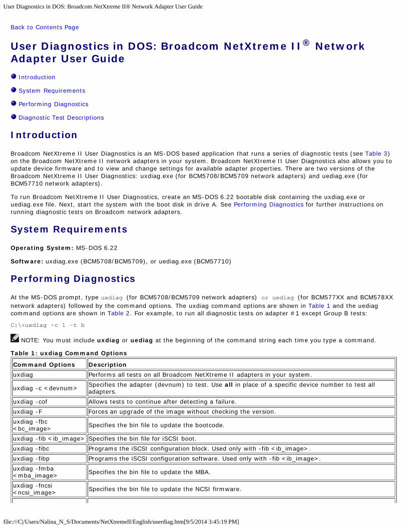
User Diagnostics in DOS: Broadcom NetXtreme II® Network Adapter User Guide
file:///C|/Users/Nalina_N_S/Documents/NetXtremeII/English/userdiag.htm[9/5/2014 3:45:19 PM]
Back to Contents Page
User Diagnostics in DOS: Broadcom NetXtreme II® NetworkAdapter User Guide
Introduction
System Requirements
Performing Diagnostics
Diagnostic Test Descriptions
Introduction
Broadcom NetXtreme II User Diagnostics is an MS-DOS based application that runs a series of diagnostic tests (see Table 3)on the Broadcom NetXtreme II network adapters in your system. Broadcom NetXtreme II User Diagnostics also allows you toupdate device firmware and to view and change settings for available adapter properties. There are two versions of theBroadcom NetXtreme II User Diagnostics: uxdiag.exe (for BCM5708/BCM5709 network adapters) and uediag.exe (forBCM57710 network adapters).
To run Broadcom NetXtreme II User Diagnostics, create an MS-DOS 6.22 bootable disk containing the uxdiag.exe oruediag.exe file. Next, start the system with the boot disk in drive A. See Performing Diagnostics for further instructions onrunning diagnostic tests on Broadcom network adapters.
System Requirements
Operating System: MS-DOS 6.22
Software: uxdiag.exe (BCM5708/BCM5709), or uediag.exe (BCM57710)
Performing Diagnostics
At the MS-DOS prompt, type uxdiag (for BCM5708/BCM5709 network adapters) or uediag (for BCM577XX and BCM578XXnetwork adapters) followed by the command options. The uxdiag command options are shown in Table 1 and the uediagcommand options are shown in Table 2. For example, to run all diagnostic tests on adapter #1 except Group B tests:
C:\>uxdiag -c 1 -t b
NOTE: You must include uxdiag or uediag at the beginning of the command string each time you type a command.
Table 1: uxdiag Command Options
Command Options Description
uxdiag Performs all tests on all Broadcom NetXtreme II adapters in your system.
uxdiag -c <devnum> Specifies the adapter (devnum) to test. Use all in place of a specific device number to test alladapters.
uxdiag -cof Allows tests to continue after detecting a failure.
uxdiag -F Forces an upgrade of the image without checking the version.
uxdiag -fbc<bc_image> Specifies the bin file to update the bootcode.
uxdiag -fib <ib_image> Specifies the bin file for iSCSI boot.
uxdiag -fibc Programs the iSCSI configuration block. Used only with -fib <ib_image>.
uxdiag -fibp Programs the iSCSI configuration software. Used only with -fib <ib_image>.
uxdiag -fmba<mba_image> Specifies the bin file to update the MBA.
uxdiag -fncsi<ncsi_image> Specifies the bin file to update the NCSI firmware.

User Diagnostics in DOS: Broadcom NetXtreme II® Network Adapter User Guide
file:///C|/Users/Nalina_N_S/Documents/NetXtremeII/English/userdiag.htm[9/5/2014 3:45:19 PM]
uxdiag -fnvm<raw_image> Programs the raw image into NVM.
uxdiag -fump<ump_image> Specifies the bin file to update UMP firmware.
uxdiag -help Displays the Broadcom NetXtreme II User Diagnostics (uxdiag) command options.
uxdiag -I <iterationnum> Specifies the number of iterations to run on the selected tests.
uxdiag -idmatch Enables matching of VID, DID, SVID, and SSID from the image file with device IDs. Used only with-fnvm <raw_image>.
uxdiag -log <file> Logs the test results to a specified log file.
uxdiag -mba <1/0>Enables/disables Multiple Boot Agent (MBA) protocol.1 = Enable0 = Disable
uxdiag -mbap <n>
Sets the MBA boot protocol.0 = PXE1 = RPL2 = BOOTP3 = iSCSI_Boot
uxdiag -mbas <n>
Sets the MBA/PXE speed.0 = Auto1 = 10H2 = 10F3 = 100H4 = 100F6 = 1000F
uxdiag -mbav <1|0>Enables/disables MBA VLAN.1 = Enable0 = Disable
uxdiag -mbavval <n> Sets MBA VLAN (<65536).
uxdiag -mfw <1/0>Enables/disables management firmware.1 = Enable0 = Disable
uxdiag -t<groups/tests> Disables certain groups/tests.
uxdiag -T<groups/tests> Enables certain groups/tests.
uxdiag -ver Displays the version of Broadcom NetXtreme II User Diagnostics (uxdiag) and all installed adapters.
uxdiag -wol <1/0>Enables/disables Magic Packet WOL.1 = Enable0 = Disable
Table 2: uediag Command Options
Command Options Description
uediag Performs all tests on all Broadcom NetXtreme II adapters in your system.
uediag -c <device#> Specifies the adapter (device#) to test. Similar to -dev (for backward compatibility).
uediag -cof Allows tests to continue after detecting a failure.
uediag -dev <device#> Specifies the adapter (device#) to test.
uediag -F Forces an upgrade of the image without checking the version.
uediag -fbc<bc_image> Specifies the bin file to update the bootcode.
uediag -fbc1<bc1_image> Specifies the bin file to update bootcode 1.
uediag -fbc2<bc2_image> Specifies the bin file to update bootcode 2.
uediag -fl2b<l2b_image> Specifies the bin file for L2B firmware.
uediag -fib <ib_image> Specifies the bin file for iSCSI boot.

User Diagnostics in DOS: Broadcom NetXtreme II® Network Adapter User Guide
file:///C|/Users/Nalina_N_S/Documents/NetXtremeII/English/userdiag.htm[9/5/2014 3:45:19 PM]
uediag -fibc Programs iSCSI configuration block 0. Used only with -fib <ib_image>.
uediag -fibc2 Programs iSCSI configuration block 1. Used only with -fib <ib_image>.
uediag -fibp Programs iSCSI configuration software. Used only with -fib <ib_image>.
uediag -fmba<mba_image> Specifies the bin file to update the MBA.
uediag -fnvm<raw_image> Programs the raw image into NVM.
uediag -fump<ump_image> Specifies the bin file to update UMP firmware.
uediag -help Displays the Broadcom NetXtreme II User Diagnostics (uediag) command options.
uediag -I <iteration#> Specifies the number of iterations to run on the selected tests.
uediag -idmatch Enables matching of VID, DID, SVID, and SSID from the image file with device IDs: Used only with-fnvm <raw_image>.
uediag -log <logfile> Logs the tests results to a specified log file.
uediag -mba <1/0>Enables/disables Multiple Boot Agent (MBA) protocol.1 = Enable0 = Disable
uediag -mbap <n>
Sets the MBA boot protocol.0 = PXE1 = RPL2 = BOOTP3 = iSCSI_Boot
uediag -mbav <1/0>Enables/disables MBA VLAN.1 = Enable0 = Disable
uediag -mbavval <n> Sets MBA VLAN (<65536).
uediag -mfw <1/0>Enables/disables management firmware.1 = Enable0 = Disable
uediag -t<groups/tests> Disables certain groups/tests.
uediag -T<groups/tests> Enables certain groups/tests.
uediag -ver Displays the version of Broadcom NetXtreme II User Diagnostics (uediag) and all installed adapters.
uediag -wol <1/0>Enables/disable Magic Packet WOL.1 = Enable0 = Disable
Diagnostic Test Descriptions
The diagnostic tests are divided into four groups: Basic Functional Tests (Group A), Memory Tests (Group B), Block Tests(Group C), and Ethernet Traffic Tests (Group D). The diagnostic tests are listed and described in Table 3.
Table 3: Diagnostic Tests
TestDescription
Number Name
Group A: Basic Functional Tests
A1 Register Verifies that registers accessible through the PCI/PCIe interface implement the expected read-onlyor read/write attributes by attempting to modify those registers.
A2 PCIConfiguration
Checks the functionality of the PCI Base Address Register (BAR) by varying the amount of memoryrequested by the BAR and verifying that the BAR actually requests the correct amount of memory(without actually mapping the BAR into system memory). Refer to PCI or PCI-E specifications fordetails on the BAR and its addressing space.
A3 Interrupt Generates a PCI interrupt and verifies that the system receives the interrupt and invokes the correctISR. A negative test is also performed to verify that a masked interrupt does not invoke the ISR.
Verifies that a Message Signaled Interrupt (MSI) causes an MSI message to be DMA'd to host

User Diagnostics in DOS: Broadcom NetXtreme II® Network Adapter User Guide
file:///C|/Users/Nalina_N_S/Documents/NetXtremeII/English/userdiag.htm[9/5/2014 3:45:19 PM]
A5 MSI memory. A negative test is also performed to verify that when an MSI is masked, it does not writean MSI message to host memory.
A6 Memory BIST Invokes the internal chip Built-In Self Test (BIST) command to test internal memory.
Group B: Memory Tests
B1 TXPScratchpad
The Group B tests verify all memory blocks of the Broadcom NetXtreme II adapter by writingvarious data patterns (0x55aa55aa, 0xaa55aa55, walking zeroes, walking ones, address, etc.) toeach memory location, reading back the data, and then comparing it to the value written. The fixeddata patterns are used to ensure that no memory bit is stuck high or low, while the walkingzeroes/ones and address tests are used to ensure that memory writes do not corrupt adjacentmemory locations.
B2 TPATScratchpad
B3 RXPScratchpad
B4 COMScratchpad
B5 CPScratchpad
B6 MCPScratchpad
B7 TAS HeaderBuffer
B8 TAS PayloadBuffer
B9 RBUF viaGRC
B10RBUF viaIndirectAccess
B11 RBUF ClusterList
B12 TSCH List
B13 CSCH List
B14 RV2PScratchpads
B15 TBDCMemory
B16 RBDCMemory
B17 CTX PageTable
B18 CTX Memory
Group C: Block Tests
C1CPU Logicand DMAInterface
Verifies the basic logic functionality of all the on-chip CPUs. It also exercises the DMA interfaceexposed to those CPUs. The internal CPU tries to initiate DMA activities (both read and write) tosystem memory and then compares the values to confirm that the DMA operation completedsuccessfully.
C2 RBUFAllocation
Verifies the RX buffer (RBUF) allocation interface by allocating and releasing buffers and checkingthat the RBUF block maintains an accurate count of the allocated and free buffers.
C3 CAM Access Verifies the content-addressable memory (CAM) block by performing read, write, add, modify, andcache hit tests on the CAM associative memory.
C4 TPAT Cracker
Verifies the packet cracking logic block (i.e., the ability to parse TCP, IP, and UDP headers within anEthernet frame) as well as the checksum/CRC offload logic. In this test, packets are submitted tothe chip as if they were received over Ethernet and the TPAT block cracks the frame (identifying theTCP, IP, and UDP header data structures) and calculates the checksum/CRC. The TPAT block resultsare compared with the values expected by Broadcom NetXtreme II User Diagnostics and any errorsare displayed.
C5 FIO Register The Fast IO (FIO) verifies the register interface that is exposed to the internal CPUs.
C6NVM Accessand Reset-Corruption
Verifies non-volatile memory (NVM) accesses (both read and write) initiated by one of the internalCPUs. It tests for appropriate access arbitration among multiple entities (CPUs). It also checks forpossible NVM corruption by issuing a chip reset while the NVM block is servicing data.

User Diagnostics in DOS: Broadcom NetXtreme II® Network Adapter User Guide
file:///C|/Users/Nalina_N_S/Documents/NetXtremeII/English/userdiag.htm[9/5/2014 3:45:19 PM]
C7 Core-ResetIntegrity
Verifies that the chip performs its reset operation correctly by resetting the chip multiple times,checking that the bootcode and the internal uxdiag driver loads/unloads correctly.
C8 DMA Engine
Verifies the functionality of the DMA engine block by performing numerous DMA read and writeoperations to various system and internal memory locations (and byte boundaries) with varyinglengths (from 1 byte to over 4 KB, crossing the physical page boundary) and different data patterns(incremental, fixed, and random). CRC checks are performed to ensure data integrity. The DMAwrite test also verifies that DMA writes do not corrupt the neighboring host memory.
C9 VPD
Exercises the Vital Product Data (VPD) interface using PCI configuration cycles and requires a properbootcode to be programmed into the non-volatile memory. If no VPD data is present (i.e., the VPDNVM area is all 0s), the test first initializes the VPD data area with non-zero data before starting thetest and restores the original data after the test completes.
C11 FIO EventsVerifies that the event bits in the CPU's Fast IO (FIO) interface are triggering correctly when aparticular chip events occur, such as a VPD request initiated by the host, an expansion ROM requestinitiated by the host, a timer event generated internally, toggling any GPIO bits, or accessing NVM.
Group D: Ethernet Traffic Tests
D1 MACLoopback
Enables MAC loopback mode in the adapter and transmits 5000 Layer 2 packets of various sizes. Asthe packets are received back by Broadcom NetXtreme II User Diagnostics, they are checked forerrors. Packets are returned through the MAC receive path and never reach the PHY. The adaptershould not be connected to a network.
D2 PHYLoopback
Enables PHY loopback mode in the adapter and transmits 5000 Layer 2 packets of various sizes. Asthe packets are received back by Broadcom NetXtreme II User Diagnostics, they are checked forerrors. Packets are returned through the PHY receive path and never reach the wire. The adaptershould not be connected to a network.
D4 LSO
Verifies the functionality of the adapter's Large Send Offload (LSO) support by enabling MACloopback mode and transmitting large TCP packets. As the packets are received back by BroadcomNetXtreme II User Diagnostics, they are checked for proper segmentation (according to the selectedMSS size) and any other errors. The adapter should not be connected to a network.
D5 EMACStatistics
Verifies that the basic statistics information maintained by the chip is correct by enabling MACloopback mode and sending Layer 2 packets of various sizes. The adapter should not be connectedto a network.
D6 RPC
Verifies the Receive Path Catch-up (RPC) block by sending packets to different transmit chains. Thepackets traverse the RPC logic (though not the entire MAC block) and return to the receive buffersas received packets. This is another loopback path that is used by Layer 4 and Layer 5 traffic withinthe MAC block. As packets are received back by Broadcom NetXtreme II User Diagnostics, they arechecked for errors. The adapter should not be connected to a network.
Please read all Restrictions and Disclaimers.
Back to Contents Page

Specifications: Broadcom NetXtreme II® Network Adapter User Guide
file:///C|/Users/Nalina_N_S/Documents/NetXtremeII/English/specs.htm[9/5/2014 3:45:19 PM]
Back to Contents Page
Specifications: Broadcom NetXtreme II® Network Adapter UserGuide
10/100/1000BASE-T and 10GBASE-T Cable Specifications
Interface Specifications
NIC Physical Characteristics
NIC Power Requirements
Wake On LAN Power Requirements
Environmental Specifications
10/100/1000BASE-T and 10GBASE-T Cable Specifications
Table 1: 10/100/1000BASE-T Cable Specifications
Port Type Connector Media Maximum Distance
10BASE-T RJ-45 Category 3, 4, or 5 unshielded twisted pairs (UTP) 100m (328 feet)
100/1000BASE-T1 RJ-45 Category 52 UTP 100m (328 feet)
1 1000BASE-T signaling requires four twisted pairs of Category 5 balanced cabling, as specified in ISO/IEC 11801:2002 andANSI/EIA/TIA-568-B.2 Category 5 is the minimum requirement. Category 5e and Category 6 are fully supported.
Table 2: 10GBASE-T Cable Specifications
Port Type Connector Media Maximum Distance
10GBASE-T RJ-45 Category 61 UTPCategory 6A1 UTP
50m (164 feet)100m (328 feet)
1 10GBASE-T signaling requires four twisted pairs of Category 6 or Category 6A (augmented Category 6) balanced cabling,as specified in ISO/IEC 11801:2002 and ANSI/TIA/EIA-568-B.
Supported SFP+ Modules Per NIC
Table 3: BCM57710 Supported Modules
Module Type Module Vendor Module Part Number
Optic Modules (SR)
Finisar Corp. FTLX8571D3BCL
Avago AFBR-707SDZ-D1
Avago AFBR-703SDZ-D1
Intel Corp. FTLX8571D3BCV-IT
Direct Attach Cables
Cisco-Molex Inc. 74752-9093
Cisco-Molex Inc. 74752-9094
Cisco-Molex Inc. 74752-9096
Cisco-Molex Inc. 74752-9098
Table 4: BCM57810 Supported Modules
Module Type and Dell Part Number Module Vendor Module Part Number
Optic Modules (SR)
p/n W365M Avago AFBR-703SDZ-D1

Specifications: Broadcom NetXtreme II® Network Adapter User Guide
file:///C|/Users/Nalina_N_S/Documents/NetXtremeII/English/specs.htm[9/5/2014 3:45:19 PM]
p/n N743D Finisar Corp. FTLX8571D3BCL
p/n R8H2FIntel Corp. AFBR-703SDZ-IN2
Intel Corp. FTLX8571D3BCV-IT
Direct Attach Cables
p/n K585N Cisco-Molex Inc. 74752-9093
p/n J564N Cisco-Molex Inc. 74752-9094
p/n H603N Cisco-Molex Inc. 74752-9096
p/n G840N Cisco-Molex Inc. 74752-9098
p/n 1539W Brocade 58-1000026-01
p/n V239T Brocade 58-1000027-01
p/n 48V40 Brocade 58-1000023-01
p/n C4D08 - Force10 1m DACAmphenol 599700002
Amphenol 616740001
p/n 53HVN - Force10 3m DACAmphenol 599700006
Amphenol 616740003
p/n 5CN56 - Force10 5m DACAmphenol 599700004
Amphenol 616740005
Table 5: BCM57840 Supported Modules
Module Type and Dell Part Number Module Vendor Module Part Number
Optic Modules (SR)
p/n R8H2FIntel Corp. AFBR-703SDZ-IN2
Intel Corp. FTLX8571D3BCV-IT
Direct Attach Cables
p/n K585N Cisco-Molex Inc. 74752-9093
p/n J564N Cisco-Molex Inc. 74752-9094
p/n H603N Cisco-Molex Inc. 74752-9096
p/n G840N Cisco-Molex Inc. 74752-9098
p/n 1539W Brocade 58-1000026-01
p/n V239T Brocade 58-1000027-01

Specifications: Broadcom NetXtreme II® Network Adapter User Guide
file:///C|/Users/Nalina_N_S/Documents/NetXtremeII/English/specs.htm[9/5/2014 3:45:19 PM]
p/n 48V40 Brocade 58-1000023-01
p/n C4D08 - Force10 1m DACAmphenol 599700002
Amphenol 616740001
p/n 53HVN - Force10 3m DACAmphenol 599700006
Amphenol 616740003
p/n 5CN56 - Force10 5m DACAmphenol 599700004
Amphenol 616740005
Interface Specifications
Table 6: 10/100/1000BASE-TPerformance Specifications
Feature Specification
PCI Express Interface x4 link width
10/100/1000BASE-T 10/100/1000 Mbps
Table 7: 10GBASE-T PerformanceSpecifications
Feature Specification
PCI Express Interface x8 link width
10GBASE-T 10 Gbps
NIC Physical Characteristics
PCI
Table 8: NIC Physical Characteristics
NIC Type NIC Length NIC Width
BCM5708 PCI Express 14.7 cm (5.79 inches) 6.4 cm (2.52 inches)
BCM5709/BCM5716 PCI Express x4 low-profile 11.9 cm (4.7 inches) 6.9 cm (2.7 inches)
BCM57710/BCM57711/BCM57712 PCI Express x8 low profile 16.8 cm (6.6 inches) 5.1 cm (2.0 inches)
BCM57810S PCI Express x8 low profile 16.8 cm (6.6 inches) 6.5 cm (2.54 inches)
BCM957840A4006G PCI Express x8 Mezzanine Card 14.4 cm (5.66 inches) 11.1 cm (4.370 inches)
BCM957840A4007G PCI Express x8 Mezzanine Card 10.9 cm (4.28 inches) 7.5 cm (2.97 inches)
NIC Power Requirements
Table 9: BCM5708C NIC Power Requirements
Link NIC 3.3V Current Draw (A) NIC Power (W)
Idle (no link) 1.44 4.75
1 Gbit 1.97 6.50
100 Mbit 1.60 5.28
10 Mbit 1.62 5.35
Table 10: BCM5709C/BCM5716 NIC Power Requirements
Link NIC 3.3V Current Draw (A) NIC Power (W)
Idle (no link) 1.01 3.32
1 Gbit 1.43 4.71
100 Mbit 1.16 3.81

Specifications: Broadcom NetXtreme II® Network Adapter User Guide
file:///C|/Users/Nalina_N_S/Documents/NetXtremeII/English/specs.htm[9/5/2014 3:45:19 PM]
10 Mbit 1.12 3.71
Table 11: BCM57710/BCM57711/BCM57712 NIC Power Requirements
Link NIC 12V Current Draw (A) NIC 3.3V Current Draw (A) NIC Power (W)1
Idle (no link) 0.60 0.28 8.12
Low power mode 0.50 0.35 7.16
10GBASE-T link 1.23 1.79 20.67
10GBASE-T traffic 1.24 1.95 21.32
Note: 1Power, measured in watts (W), is a direct calculation of total current draw (A) multiplied by voltage (V). Themaximum power consumption for the adapter will not exceed 30W.
Table 12: BCM957810A1006G NIC Power Requirements
Link NIC 12V Current Draw (A) NIC 3.3V Current Draw (A) NIC Power (W)1
10 SFP Module 1.37 0.004 16.41
1Power, measured in watts (W), is a direct calculation of total current draw (A) multiplied by voltage (V). The maximumpower consumption for the adapter will not exceed 30W.
Table 13: BCM957810A1008G NIC Power Requirements
Link NIC 12V Current Draw (A) NIC 3.3V Current Draw (A) NIC Power (W)1
Idle (no link) 0.58 0.004 6.88
100BASE-T link 0.67 0.004 8.07
1000BASE-T link 0.83 0.004 9.90
10GBASE-T link 1.37 0.004 16.41
1Power, measured in watts (W), is a direct calculation of total current draw (A) multiplied by voltage (V). The maximumpower consumption for the adapter will not exceed 30W.
Table 14: BCM957840A4006G Mezzanine Card PowerRequirements
Link Total Power (12V and 3.3VAUX) (W)1
Idle (no link) 7.206
PCIe Disable 6.634
Play Dead Mode 4.078
1000BASE-T link 8.53
10GBASE-T link 8.89
Standby WOL Enabled 4.7064
Standby WOL Disabled 0.4791W
1Power, measured in watts (W), is a direct calculation of total current draw (A) multiplied by voltage (V). The maximumpower consumption for the adapter will not exceed 30W.
Table 15: BCM957840A4007G MezzanineCard Power Requirements
Link Total Power (3.3V) (W)1
Idle (no link) 5.7
Standby mode 2.2
1000BASE-T link 6.2
10GBASE-T link 6.5
1Power, measured in watts (W), is a direct calculation of total current draw (A) multiplied by voltage (V). The maximumpower consumption for the adapter will not exceed 30W.

Specifications: Broadcom NetXtreme II® Network Adapter User Guide
file:///C|/Users/Nalina_N_S/Documents/NetXtremeII/English/specs.htm[9/5/2014 3:45:19 PM]
Wake On LAN Power Requirements
Nominal power:
BCM957810A1006G: 3.0W
BCM957810a1008G: 4.5W
The tables below show the Wake On LAN power requirements for 1G adapters.
Table 16: BCM5708C Wake On LAN Power Requirements (Nominal Conditions)
100 Mbit Link 10 Mbit Link
NIC 3.3V Current (mA) NIC Power (W) NIC 3.3V Current (mA) NIC Power (W)
236 0.78 150 0.5
Table 17: BCM5709C and BCM5716 Wake On LAN Power Requirements (NominalConditions)
100 Mbit Link 10 Mbit Link
NIC 3.3V Current (mA) NIC Power (W) NIC 3.3V Current (mA) NIC Power (W)
0 0.87 0 0.85
Environmental Specifications
Table 18: BCM5708 Environmental Specifications
Condition Operating Specification Storage Specification
Temperature 0°C to 55°C (+32°F to +131°F) –40°C to +85°C (–40°F to +185°F)
Relative humidity 5% to 85% (noncondensing)40°C, 16 hour dwells at extremes
5% to 95% (noncondensing)10°C/hour
Altitude Up to 10,000 ft. Up to 35,000 ft.
Shock 10g, 1/2 sine wave, 11 ms 60g, 1/2 sine wave, 11 ms
Vibration, peak to peak displacement 0.005 in. max (5 Hz to 32 Hz) 0.1 in. max (5 Hz to 17 Hz)
Vibration, peak acceleration 0.25g (5 Hz to 500 Hz)(Sweep Rate = 1 octave/min.)
0.25g (5 Hz to 500 Hz)(Sweep Rate = 1 octave/min.)
Table 19: BCM5709 and BCM5716 Environmental Specifications
Parameter Condition
Operating Temperature 0°C to 55°C
Air Flow Requirement (LFM) 0
Storage Temperature –40°C to +65°C
Storage Humidity 5% to 95% condensing
Vibration and Shock IEC 68, FCC Part 68.302, NSTA, 1A
Electrostatic/Electromagnetic Susceptibility EN 61000-4-2, EN 55024
Table 20: BCM957810A1006G Environmental Specifications
Parameter Condition
Operating Temperature 0°C to 55°C
Air Flow Requirement (LFM) 100
Storage Temperature –40°C to +65°C
Storage Humidity 5% to 95% condensing
Vibration and Shock IEC 68, FCC Part 68.302, NSTA, 1A
Electrostatic/Electromagnetic Susceptibility IEC 801-2, 3, 4, 5

Specifications: Broadcom NetXtreme II® Network Adapter User Guide
file:///C|/Users/Nalina_N_S/Documents/NetXtremeII/English/specs.htm[9/5/2014 3:45:19 PM]
Table 21: BCM957810A1008G Environmental Specifications
Parameter Condition
Operating Temperature 0°C to 55°C
Air Flow Requirement (LFM) 50
Storage Temperature –40°C to +65°C
Storage Humidity 5% to 95% condensing
Vibration and Shock IEC 68, FCC Part 68.302, NSTA, 1A
Electrostatic/Electromagnetic Susceptibility IEC 801-2, 3, 4, 5
Table 22: BCM957840A4006G Environmental Specifications
Parameter Condition
Operating Temperature 0°C to 60°C
Air Flow Requirement (LFM) 100
Storage Temperature –40°C to +65°C
Storage Humidity 5% to 95% condensing
Vibration and Shock IEC 68, FCC Part 68.302, NSTA, 1A
Electrostatic/Electromagnetic Susceptibility IEC 801-2, 3, 4, 5
Table 23: BCM957840A4007G Environmental Specifications
Parameter Condition
Operating Temperature 0°C to 65°C
Air Flow Requirement (LFM) 200
Storage Temperature –40°C to +65°C
Storage Humidity 5% to 95% condensing
Vibration and Shock IEC 68, FCC Part 68.302, NSTA, 1A
Electrostatic/Electromagnetic Susceptibility IEC 801-2, 3, 4, 5
Please read all Restrictions and Disclaimers.
Back to Contents Page

Regulatory Information: Broadcom NetXtreme II® Network Adapter User Guide
file:///C|/Users/Nalina_N_S/Documents/NetXtremeII/English/regs.htm[9/5/2014 3:45:21 PM]
Back to Contents Page
Regulatory Information: Broadcom NetXtreme II® NetworkAdapter User Guide
FCC Notice
VCCI Notice
CE Notice
Canadian Regulatory Information (Canada Only)
Korea Communications Commission (KCC) Notice (Republic of Korea Only)
BSMI
Certifications for BCM95709SA0908G, BCM957710A1023G, E02D001, and BCM957711A1123G (E03D001)
FCC Notice
FCC, Class B
Broadcom NetXtreme II Gigabit Ethernet Controller
BCM95708A0804F
BCM95709A0907G
BCM95709A0906G
BCM957810A1008G
Broadcom Corporation190 Mathilda PlaceSunnyvale, California 94086 USA
The equipment complies with Part 15 of the FCC Rules. Operation is subject to the following two conditions: 1) The devicemay not cause harmful interference, and 2) This equipment must accept any interference received, including interference thatmay cause undesired operation.
The equipment has been tested and found to comply with the limits for a Class B digital device, pursuant to Part 15 of theFCC Rules. These limits are designed to provide reasonable protection against harmful interference in a residential installation.The equipment generates, uses and can radiate radio-frequency energy and, if not installed and used in accordance with theinstructions, may cause harmful interference to radio communications. However, there is no guarantee that interference willnot occur in a particular installation. If the equipment does cause harmful interference to radio or television reception, whichcan be determined by turning the equipment off and on, the user is encouraged to try to correct the interference by one ormore of the following measures:
Reorient or relocate the receiving antenna.
Increase the separation between the equipment and the receiver.
Connect the equipment into an outlet on a circuit different from that to which the receiver is connected.
Consult the dealer or an experienced radio/TV technician for assistance.
Do not make mechanical or electrical modifications to the equipment.
NOTE: If the device is changed or modified without permission of Broadcom, the user may void his or her authority tooperate the equipment.
FCC, Class A
Broadcom NetXtreme II Gigabit Ethernet Controller

Regulatory Information: Broadcom NetXtreme II® Network Adapter User Guide
file:///C|/Users/Nalina_N_S/Documents/NetXtremeII/English/regs.htm[9/5/2014 3:45:21 PM]
BCM95709A0916G
Broadcom NetXtreme II 10 Gigabit Ethernet Controller
BCM957710A1022G
BCM957710A1021G
BCM957711A1113G
BCM957711A1102G
BCM957810A1006G
BCM957840A4006G
BCM957840A4007G
Broadcom Corporation190 Mathilda PlaceSunnyvale, California 94086 USA
This device complies with Part 15 of the FCC Rules. Operations is subject to the following two conditions: 1) This device maynot cause harmful interference, and 2) This device must accept any interference received, including interference that maycause undesired operation.
This product has been tested and found to comply with the limits for a Class A digital device pursuant to Part 15 of the FCCRules. These limits are designed to provide reasonable protection against harmful interference when the equipment isoperated in a commercial environment. This product generates, uses, and can radiate radio frequency energy and, if notinstalled and used in accordance with the manufacturer's instruction manual, may cause harmful interference with radiocommunications. Operation of this product in a residential area is likely to cause harmful interference, in which case you willbe required to correct the interference at your own expense.
These limits are designed to provide reasonable protection against harmful interference in a non-residential installation.However, there is no guarantee that interference will not occur in a particular installation. If this equipment does causeharmful interference with radio or television reception, which can be determined by turning the equipment off and on, you areencouraged to try to correct the interference by one or more of the following measures:
Reorient the receiving antenna.
Relocate the system with respect to the receiver.
Move the system away from the receiver.
Plug the system into a different outlet so that the system and receiver are on different branch circuits.
Do not make mechanical or electrical modifications to the equipment.
NOTE: If the device is changed or modified without permission of Broadcom, the user may void his or her authority tooperate the equipment.
VCCI Notice
Class B
Broadcom NetXtreme II Gigabit Ethernet Controller
BCM95708A0804F
BCM95709A0907G
BCM95709A0906G
BCM957810A1008G
Broadcom Corporation190 Mathilda PlaceSunnyvale, California 94086 USA
The equipment is a Class B product based on the standard of the Voluntary Control Council for Interference from InformationTechnology Equipment (VCCI). If used near a radio or television receiver in a domestic environment, it may cause radiointerference. Install and use the equipment according to the instruction manual.

Regulatory Information: Broadcom NetXtreme II® Network Adapter User Guide
file:///C|/Users/Nalina_N_S/Documents/NetXtremeII/English/regs.htm[9/5/2014 3:45:21 PM]
CAUTION! The potential exists for this equipment to become impaired in the presence of conducted radiofrequency energy between the frequency range of 59–66 MHz. Normal operation will return upon removal of theRF energy source.
VCCI Class B Statement (Japan)
Class A
Broadcom NetXtreme II Gigabit Ethernet Controller
BCM95709A0916G
Broadcom NetXtreme II 10 Gigabit Ethernet Controller
BCM957710A1022G
BCM957710A1021G
BCM957711A1113G
BCM957711A1102G
BCM957840A4006G
BCM957840A4007G
Broadcom Corporation190 Mathilda PlaceSunnyvale, California 94086 USA
This equipment is a Class A product based on the standard of the Voluntary Control Council for interference by InformationTechnology Equipment (VCCI). If used in a domestic environment, radio disturbance may arise. Install and use the equipmentaccording to the instruction manual.
VCCI Class A Statement (Japan)
CE Notice
Class C
BCM957810A1008G
Class B
Broadcom NetXtreme II Gigabit Ethernet Controller
BCM95708A0804F
BCM95709A0907G
BCM95709A0906G

Regulatory Information: Broadcom NetXtreme II® Network Adapter User Guide
file:///C|/Users/Nalina_N_S/Documents/NetXtremeII/English/regs.htm[9/5/2014 3:45:21 PM]
Class A
Broadcom NetXtreme II Gigabit Ethernet Controller
BCM95709A0916G
Broadcom NetXtreme II 10 Gigabit Ethernet Controller
BCM957710A1022G
BCM957710A1021G
BCM957711A1113G
BCM957711A1102G
BCM957840A4006G
BCM957840A4007G

Regulatory Information: Broadcom NetXtreme II® Network Adapter User Guide
file:///C|/Users/Nalina_N_S/Documents/NetXtremeII/English/regs.htm[9/5/2014 3:45:21 PM]

Regulatory Information: Broadcom NetXtreme II® Network Adapter User Guide
file:///C|/Users/Nalina_N_S/Documents/NetXtremeII/English/regs.htm[9/5/2014 3:45:21 PM]

Regulatory Information: Broadcom NetXtreme II® Network Adapter User Guide
file:///C|/Users/Nalina_N_S/Documents/NetXtremeII/English/regs.htm[9/5/2014 3:45:21 PM]

Regulatory Information: Broadcom NetXtreme II® Network Adapter User Guide
file:///C|/Users/Nalina_N_S/Documents/NetXtremeII/English/regs.htm[9/5/2014 3:45:21 PM]

Regulatory Information: Broadcom NetXtreme II® Network Adapter User Guide
file:///C|/Users/Nalina_N_S/Documents/NetXtremeII/English/regs.htm[9/5/2014 3:45:21 PM]
Canadian Regulatory Information (Canada Only)
Industry Canada, Class B
Broadcom NetXtreme II Gigabit Ethernet Controller
BCM95708A0804F
BCM95709A0907G
BCM95709A0906G
Broadcom Corporation190 Mathilda PlaceSunnyvale, California 94086 USA
This Class B digital apparatus complies with Canadian ICES-003.
Notice: The Industry Canada regulations provide that changes or modifications not expressly approved by Broadcom couldvoid your authority to operate this equipment.
Industry Canada, Class A
Broadcom NetXtreme II Gigabit Ethernet Controller
BCM95709A0916G
Broadcom NetXtreme II 10 Gigabit Ethernet Controller
BCM957710A1022G
BCM957710A1021G
BCM957711A1113G
BCM957711A1102G
BCM957810A1008G
BCM957840A4006G

Regulatory Information: Broadcom NetXtreme II® Network Adapter User Guide
file:///C|/Users/Nalina_N_S/Documents/NetXtremeII/English/regs.htm[9/5/2014 3:45:21 PM]
BCM957840A4007G
Broadcom Corporation190 Mathilda PlaceSunnyvale, California 94086 USA
This Class A digital apparatus complies with Canadian ICES-003.
Notice: The Industry Canada regulations provide that changes or modifications not expressly approved by Broadcom couldvoid your authority to operate this equipment.
Industry Canada, classe B
Broadcom NetXtreme II Gigabit Ethernet Controller
BCM95708A0804F
BCM95709A0907G
BCM95709A0906G
Broadcom Corporation190 Mathilda PlaceSunnyvale, California 94086 USA
Cet appareil numérique de la classe B est conforme à la norme canadienne ICES-003.
Avis : Dans le cadre des réglementations d'Industry Canada, vos droits d'utilisation de cet équipement peuvent être annuléssi des changements ou modifications non expressément approuvés par Broadcom y sont apportés.
Industry Canada, classe A
Broadcom NetXtreme II Gigabit Ethernet Controller
BCM95709A0916G
Broadcom NetXtreme II 10 Gigabit Ethernet Controller
BCM957710A1022G
BCM957710A1021G
BCM957711A1113G
BCM957711A1102G
BCM957810A1008G
BCM957840A4006G
BCM957840A4007G
Broadcom Corporation190 Mathilda PlaceSunnyvale, California 94086 USA
Cet appareil numérique de classe A est conforme à la norme canadienne ICES-003.
Avis : Dans le cadre des réglementations d'Industry Canada, vos droits d'utilisation de cet équipement peuvent être annuléssi des changements ou modifications non expressément approuvés par Broadcom y sont apportés.
Korea Communications Commission (KCC) Notice (Republic of KoreaOnly)
B Class Device

Regulatory Information: Broadcom NetXtreme II® Network Adapter User Guide
file:///C|/Users/Nalina_N_S/Documents/NetXtremeII/English/regs.htm[9/5/2014 3:45:21 PM]
Broadcom NetXtreme II Gigabit Ethernet Controller
BCM95708A0804F
BCM95709A0907G
BCM95709A0906G
Broadcom Corporation190 Mathilda PlaceSunnyvale, California 94086 USA
Note that this device has been approved for non-business purposes and may be used in any environment, including residentialareas.
A Class Device
Broadcom NetXtreme II Gigabit Ethernet Controller
BCM95709A0916G
Broadcom NetXtreme II 10 Gigabit Ethernet Controller
BCM957710A1022G
BCM957710A1021G

Regulatory Information: Broadcom NetXtreme II® Network Adapter User Guide
file:///C|/Users/Nalina_N_S/Documents/NetXtremeII/English/regs.htm[9/5/2014 3:45:21 PM]
BCM957711A1113G
BCM957711A1102G
BCM957810A1008G
BCM957840A4006G
BCM957840A4007G
Broadcom Corporation190 Mathilda PlaceSunnyvale, California 94086 USA
BSMI

Regulatory Information: Broadcom NetXtreme II® Network Adapter User Guide
file:///C|/Users/Nalina_N_S/Documents/NetXtremeII/English/regs.htm[9/5/2014 3:45:21 PM]
Certifications for BCM95709SA0908G, BCM957710A1023G, E02D001,and BCM957711A1123G (E03D001)
This section is included on behalf of Dell, and Broadcom is not responsible for the validity or accuracy of the information.
The BCM95709SA0908G Broadcom NetXtreme II Gigabit Ethernet Controller and the BCM957710A1023G, E02D001, andBCM957711A1123G (E03D001) Broadcom NetXtreme II 10 Gigabit Ethernet Controllers have received the following regulatorycompliance certifications:
FCC, Class A (USA)
VCCI, Class A (Japan)
CE, Class A (European Union)
Canadian Regulatory Information, Class A (Canada)
Korea Communications Commission (KCC) Notice (Republic of Korea)
FCC Notice
FCC, Class A
Broadcom NetXtreme II Gigabit Ethernet Controller
BCM95709SA0908G
Broadcom NetXtreme II 10 Gigabit Ethernet Controller
BCM957710A1023G
BCM957711A1123G (E03D001)
E02D001
Dell Inc.Worldwide Regulatory Compliance, Engineering and Environmental Affairs

Regulatory Information: Broadcom NetXtreme II® Network Adapter User Guide
file:///C|/Users/Nalina_N_S/Documents/NetXtremeII/English/regs.htm[9/5/2014 3:45:21 PM]
One Dell Way PS4-30Round Rock, Texas 78682, USA512-338-4400
This device complies with Part 15 of the FCC Rules. Operations is subject to the following two conditions: 1) This device maynot cause harmful interference, and 2) This device must accept any interference received, including interference that maycause undesired operation.
This product has been tested and found to comply with the limits for a Class A digital device pursuant to Part 15 of the FCCRules. These limits are designed to provide reasonable protection against harmful interference when the equipment isoperated in a commercial environment. This product generates, uses, and can radiate radio frequency energy and, if notinstalled and used in accordance with the manufacturer's instruction manual, may cause harmful interference with radiocommunications. Operation of this product in a residential area is likely to cause harmful interference, in which case you willbe required to correct the interference at your own expense.
These limits are designed to provide reasonable protection against harmful interference in a non-residential installation.However, there is no guarantee that interference will not occur in a particular installation. If this equipment does causeharmful interference with radio or television reception, which can be determined by turning the equipment off and on, you areencouraged to try to correct the interference by one or more of the following measures:
Reorient the receiving antenna.
Relocate the system with respect to the receiver.
Move the system away from the receiver.
Plug the system into a different outlet so that the system and receiver are on different branch circuits.
Do not make mechanical or electrical modifications to the equipment.
NOTE: If the device is changed or modified without permission of Dell Inc., the user may void his or her authority tooperate the equipment.
VCCI Notice
Class A
Broadcom NetXtreme II Gigabit Ethernet Controller
BCM95709SA0908G
Broadcom NetXtreme II 10 Gigabit Ethernet Controller
BCM957710A1023G
BCM957711A1123G (E03D001)
E02D001
Dell Inc.Worldwide Regulatory Compliance, Engineering and Environmental AffairsOne Dell Way PS4-30Round Rock, Texas 78682, USA512-338-4400
This equipment is a Class A product based on the standard of the Voluntary Control Council for interference by InformationTechnology Equipment (VCCI). If used in a domestic environment, radio disturbance may arise. Install and use the equipmentaccording to the instruction manual.
VCCI Class A Statement (Japan)

Regulatory Information: Broadcom NetXtreme II® Network Adapter User Guide
file:///C|/Users/Nalina_N_S/Documents/NetXtremeII/English/regs.htm[9/5/2014 3:45:21 PM]
CE Notice
Class A
Broadcom NetXtreme II Gigabit Ethernet Controller
BCM95709SA0908G
Broadcom NetXtreme II 10 Gigabit Ethernet Controller
BCM957710A1023G
BCM957711A1123G (E03D001)
E02D001
Dell Inc.Worldwide Regulatory Compliance, Engineering and Environmental AffairsOne Dell Way PS4-30Round Rock, Texas 78682, USA512-338-4400

Regulatory Information: Broadcom NetXtreme II® Network Adapter User Guide
file:///C|/Users/Nalina_N_S/Documents/NetXtremeII/English/regs.htm[9/5/2014 3:45:21 PM]

Regulatory Information: Broadcom NetXtreme II® Network Adapter User Guide
file:///C|/Users/Nalina_N_S/Documents/NetXtremeII/English/regs.htm[9/5/2014 3:45:21 PM]

Regulatory Information: Broadcom NetXtreme II® Network Adapter User Guide
file:///C|/Users/Nalina_N_S/Documents/NetXtremeII/English/regs.htm[9/5/2014 3:45:21 PM]

Regulatory Information: Broadcom NetXtreme II® Network Adapter User Guide
file:///C|/Users/Nalina_N_S/Documents/NetXtremeII/English/regs.htm[9/5/2014 3:45:21 PM]
Canadian Regulatory Information (Canada Only)
Industry Canada, Class A
Broadcom NetXtreme II Gigabit Ethernet Controller
BCM95709SA0908G
Broadcom NetXtreme II 10 Gigabit Ethernet Controller
BCM957710A1023G
BCM957711A1123G (E03D001)
E02D001
Dell Inc.Worldwide Regulatory Compliance, Engineering and Environmental AffairsOne Dell Way PS4-30Round Rock, Texas 78682, USA512-338-4400
This Class A digital apparatus complies with Canadian ICES-003.
Notice: The Industry Canada regulations provide that changes or modifications not expressly approved by Dell Inc. could voidyour authority to operate this equipment.
Industry Canada, classe A
Broadcom NetXtreme II Gigabit Ethernet Controller
BCM95709SA0908G
Broadcom NetXtreme II 10 Gigabit Ethernet Controller
BCM957710A1023G

Regulatory Information: Broadcom NetXtreme II® Network Adapter User Guide
file:///C|/Users/Nalina_N_S/Documents/NetXtremeII/English/regs.htm[9/5/2014 3:45:21 PM]
BCM957711A1123G (E03D001)
E02D001
Dell Inc.Worldwide Regulatory Compliance, Engineering and Environmental AffairsOne Dell Way PS4-30Round Rock, Texas 78682, USA512-338-4400
Cet appareil numérique de classe A est conforme à la norme canadienne ICES-003.
Avis : Dans le cadre des réglementations d'Industry Canada, vos droits d'utilisation de cet équipement peuvent être annuléssi des changements ou modifications non expressément approuvés par Dell Inc. y sont apportés.
Korea Communications Commission (KCC) Notice (Republic of Korea Only)
A Class Device
Broadcom NetXtreme II Gigabit Ethernet Controller
BCM95709SA0908G (5709s-mezz)
Broadcom NetXtreme II 10 Gigabit Ethernet Controller
BCM957710A1023G
BCM957711A1123G (E03D001)
E02D001
Dell Inc.Worldwide Regulatory Compliance, Engineering and Environmental AffairsOne Dell Way PS4-30Round Rock, Texas 78682, USA512-338-4400

Regulatory Information: Broadcom NetXtreme II® Network Adapter User Guide
file:///C|/Users/Nalina_N_S/Documents/NetXtremeII/English/regs.htm[9/5/2014 3:45:21 PM]
End of Dell-provided certification information. The remainder of this document conforms to the general Restrictions andDisclaimers listed at the beginning of this user guide.
Please read all Restrictions and Disclaimers.
Back to Contents Page
Troubleshooting: Broadcom NetXtreme II® Network Adapter User Guide
file:///C|/Users/Nalina_N_S/Documents/NetXtremeII/English/trouble.htm[9/5/2014 3:45:23 PM]
Back to Contents Page
Troubleshooting: Broadcom NetXtreme II® Network AdapterUser Guide
Hardware Diagnostics
Checking Port LEDs
Troubleshooting Checklist
Checking if Current Drivers are Loaded
Running a Cable Length Test
Testing Network Connectivity
Microsoft Virtualization with Hyper-V
Removing the Broadcom NetXtreme II Device Drivers
Upgrading Windows Operating Systems
Broadcom Boot Agent
Broadcom Advanced Server Program (BASP)
Linux
NPAR
Kernel Debugging over Ethernet
Miscellaneous
Hardware Diagnostics
Loopback diagnostic tests are available for testing the adapter hardware. These tests provide access to the adapterinternal/external diagnostics, where packet information is transmitted across the physical link (for instructions and informationon running tests in an MS-DOS environment, see User Diagnostics; for Windows environments, see Running Diagnostic Testsin Windows).
BACS Diagnostic Tests Failures
If any of the following tests fail while running the diagnostic tests from BACS, this may indicate a hardware issue with the NICor LOM that is installed in the system.
Control Registers
MII Registers
EEPROM
Internal Memory
On-Chip CPU
Interrupt
Loopback - MAC
Loopback - PHY
Test LED
Below are troubleshooting steps that may help correct the failure.
1. Remove the failing device and reseat it in the slot, ensuring the card is firmly seated in the slot from front to back.
2. Rerun the test.
Troubleshooting: Broadcom NetXtreme II® Network Adapter User Guide
file:///C|/Users/Nalina_N_S/Documents/NetXtremeII/English/trouble.htm[9/5/2014 3:45:23 PM]
3. If the card still fails, replace it with a different card of the same model and run the test. If the test passes on theknown good card, contact your hardware vendor for assistance on the failing device.
4. Power down the machine, remove AC power from the machine, and then reboot the system.
5. Remove and re-install the diagnostic software.
6. Contact your hardware vendor.
BACS Network Test Failures
Typically, the BACS Testing the Network failures are the result of a configuration problem on the network or with the IPaddresses. Below are common steps to perform when troubleshooting the network.
1. Verify that the cable is attached and you have proper link.
2. Verify that the drivers are loaded and enabled.
3. Replace the cable that is attached to the NIC/LOM.
4. Verify that the IP address is assigned correctly using the command "ipconfig" or by checking the OS IP assigning tool.
5. Verify that the IP address is correct for the network to which the adapter(s) is connected.
Checking Port LEDs
See Network Link and Activity Indication to check the state of the network link and activity.
Troubleshooting Checklist
CAUTION! Before you open the cabinet of your server to add or remove the adapter, review SafetyPrecautions.
The following checklist provides recommended actions to take to resolve problems installing the Broadcom NetXtreme IIadapter or running it in your system.
Inspect all cables and connections. Verify that the cable connections at the network adapter and the switch areattached properly. Verify that the cable length and rating comply with the requirements listed in Connecting theNetwork Cables.
Check the adapter installation by reviewing Installation of the Add-In NIC. Verify that the adapter is properly seated inthe slot. Check for specific hardware problems, such as obvious damage to board components or the PCI edgeconnector.
Check the configuration settings and change them if they are in conflict with another device.
Verify that your server is using the latest BIOS.
Try inserting the adapter in another slot. If the new position works, the original slot in your system may be defective.
Replace the failed adapter with one that is known to work properly. If the second adapter works in the slot where thefirst one failed, the original adapter is probably defective.
Install the adapter in another functioning system and run the tests again. If the adapter passed the tests in the newsystem, the original system may be defective.
Remove all other adapters from the system and run the tests again. If the adapter passes the tests, the other adaptersmay be causing contention.
Checking if Current Drivers are Loaded
Windows
See Viewing Vital Signs to view vital information about the adapter, link status, and network connectivity.
Linux
To verify that the bnx2.o driver is loaded properly, run:

Troubleshooting: Broadcom NetXtreme II® Network Adapter User Guide
file:///C|/Users/Nalina_N_S/Documents/NetXtremeII/English/trouble.htm[9/5/2014 3:45:23 PM]
lsmod | grep -i <module name>
If the driver is loaded, the output of this command shows the size of the driver in bytes and the number of adaptersconfigured and their names. The following example shows the drivers loaded for the bnx2 module:
[root@test1]# lsmod | grep -i bnx2bnx2 199238 0bnx2fc 133775 0libfcoe 39764 2 bnx2fc,fcoelibfc 108727 3 bnx2fc,fcoe,libfcoescsi_transport_fc 55235 3 bnx2fc,fcoe,libfcbnx2i 53488 11cnic 86401 6 bnx2fc,bnx2ilibiscsi 47617 8 be2iscsi,bnx2i,cxgb4i,cxgb3i,libcxgbi,ib_iser,iscsi_tcp,libiscsi_tcpscsi_transport_iscsi 53047 8 be2iscsi,bnx2i,libcxgbi,ib_iser,iscsi_tcp,libiscsibnx2x 1417947 0libcrc32c 1246 1 bnx2xmdio 4732 2 cxgb3,bnx2x
If you reboot after loading a new driver, you can use the following command to verify that the currently loaded driver is thecorrect version.
modinfo bnx2
[root@test1]# lsmod | grep -i bnx2
bnx2 199238 0
Or, you can use the following command:
[root@test1]# ethtool -i eth2driver: bnx2xversion: 1.78.07firmware-version: bc 7.8.6bus-info: 0000:04:00.2
if you loaded a new driver but have not yet booted, the modinfo command will not show the updated driver information.Instead, you can view the logs to verify that the proper driver is loaded and will be active upon reboot:
dmesg | grep -i "Broadcom" | grep -i "bnx2"
Running a Cable Length Test
For Windows operating systems, see Analyzing Cables in Windows for information on running a cable length test. Cableanalysis is not available for NetXtreme II 10 GbE network adapters.
Testing Network Connectivity
NOTE: When using forced link speeds, verify that both the adapter and the switch are forced to the same speed.
Windows
Network connectivity can be tested using the Testing the Network feature in Broadcom Advanced Control Suite.
An alternate method is to use the ping command to determine if the network connection is working.
1. Click Start, and then click Run.
2. Type cmd in the Open box, and then click OK.
3. Type ipconfig /all to view the network connection to be tested.
4. Type ping IP address, and then press ENTER.
The ping statistics that are displayed indicate whether the network connection is working or not.
Linux
To verify that the Ethernet interface is up and running, run ifconfig to check the status of the Ethernet interface. It is possibleto use netstat -i to check the statistics on the Ethernet interface. See Linux Driver Software for information on ifconfig andnetstat.
Ping an IP host on the network to verify connection has been established.

Troubleshooting: Broadcom NetXtreme II® Network Adapter User Guide
file:///C|/Users/Nalina_N_S/Documents/NetXtremeII/English/trouble.htm[9/5/2014 3:45:23 PM]
From the command line, type ping IP address, and then press ENTER.
The ping statistics that are displayed indicate whether or not the network connection is working.
Microsoft Virtualization with Hyper-V
Microsoft Virtualization is a hypervisor virtualization system for Windows Server 2008 and Windows Server 2008 R2. Thissection is intended for those who are familiar with Hyper-V, and it addresses issues that affect the configuration ofNetXtreme II network adapters and teamed network adapters when Hyper-V is used. For more information on Hyper-V, seehttp://www.microsoft.com/windowsserver2008/en/us/hyperv.aspx.
Table 1 identifies Hyper-V supported features that are configurable for NetXtreme II network adapters. This table is not an all-inclusive list of Hyper-V features.
Table 1: Configurable Network Adapter Hyper-V Features
Feature
Supported in WindowsServer Comments/Limitation
2008 2008 R2 2012
IPv4 Yes Yes Yes –
IPv6 Yes Yes Yes –
IPv4 Large Send Offload (LSO) (parent and childpartition) Yes Yes Yes –
IPv4 Checksum Offload (CO) (parent and childpartition) Yes Yes Yes –
IPv4 TCP Offload Engine (TOE) No* No* No* *OS limitation.
IPv6 LSO (parent and child partition) No* Yes Yes *When bound to a virtual network, OSlimitation.
IPv6 CO (parent and child partition) No* Yes Yes *When bound to a virtual network, OSlimitation.
IPv6 TOE No No No OS limitation.
Jumbo frames No* Yes Yes *OS limitation.
RSS No* No* Yes *OS limitation.
RSC No* No* Yes *OS limitation.
SRIOV No* No* Yes *OS limitation.
NOTE: Ensure that Integrated Services, which is a component of Hyper-V, is installed in the guest operating system (childpartition) for full functionality.
Single Network Adapter
Windows Server 2008
When configuring a NetXtreme II network adapter on a Hyper-V system, be aware of the following:
An adapter that is to be bound to a virtual network should not be configured for VLAN tagging through the driver'sadvanced properties. Instead, Hyper-V should manage VLAN tagging exclusively.
Since Hyper-V does not support Jumbo Frames, it is recommended that this feature not be used or connectivity issuesmay occur with the child partition.
The Locally Administered Address (LAA) set by Hyper-V takes precedence over the address set in the adapter'sadvanced properties.
A TOE-enabled network adapter that is bound to a Hyper-V virtual network will report TOE as an offload capability inBACS; however, TOE will not work. This is a limitation of Hyper-V. Hyper-V does not support TOE.
In an IPv6 network, a team that supports CO and/or LSO and is bound to a Hyper-V virtual network will report CO andLSO as an offload capability in BACS; however, CO and LSO will not work. This is a limitation of Hyper-V. Hyper-V doesnot support CO and LSO in an IPv6 network.

Troubleshooting: Broadcom NetXtreme II® Network Adapter User Guide
file:///C|/Users/Nalina_N_S/Documents/NetXtremeII/English/trouble.htm[9/5/2014 3:45:23 PM]
Windows Server 2008 R2 and 2012
When configuring a NetXtreme II network adapter on a Hyper-V system, be aware of the following:
An adapter that is to be bound to a virtual network should not be configured for VLAN tagging through the driver'sadvanced properties. Instead, Hyper-V should manage VLAN tagging exclusively.
The Locally Administered Address (LAA) set by Hyper-V takes precedence over the address set in the adapter'sadvanced properties.
The LSO and CO features in the guest OS are independent of the network adapter properties.
To allow jumbo frame functionality from the guest OS, both the network adapter and the virtual adapter must havejumbo frames enabled. The Jumbo MTU property for the network adapter must be set to allow traffic of large MTU fromwithin the guest OS. The jumbo packet of the virtual adapter must be set in order to segment the sent and receivedpackets.
Teamed Network Adapters
Table 2 identifies Hyper-V supported features that are configurable for NetXtreme II teamed network adapters. This table isnot an all-inclusive list of Hyper-V features.
Table 2: Configurable Teamed Network Adapter Hyper-V Features
Feature
Supported in WindowsServer Version Comments/Limitation
2008 2008 R2 2012
Smart Load Balancing and Failover (SLB)team type Yes Yes Yes
Multi-member SLB team allowed with latestBASP6 version.Note: VM MAC is not presented to externalswitches.
Link Aggregation (IEEE 802.3ad LACP) teamtype Yes Yes Yes –
Generic Trunking (FEC/GEC) 802.3ad DraftStatic team type Yes Yes Yes –
Failover Yes Yes Yes –
LiveLink Yes Yes Yes –
Large Send Offload (LSO) Limited* Yes Yes *Conforms to miniport limitations outlines inTable 1.
Checksum Offload (CO) Limited* Yes Yes *Conforms to miniport limitations outlines inTable 1.
TCP Offload Engine (TOE) No No No
Hyper-V VLAN over an adapter Yes Yes Yes –
Hyper-V VLAN over a teamed adapter Yes Yes Yes –
Hyper-V VLAN over a VLAN Limited* Limited* Limited* Only an untagged VLAN.
Hyper-V virtual switch over an adapter Yes Yes Yes –
Hyper-V virtual switch over a teamedadapter Yes Yes Yes –
Hyper-V virtual switch over a VLAN Yes Yes Yes –
iSCSI boot No No* No* *Remote boot to SAN is supported.
Virtual Machine Queue (VMQ) No Yes Yes See Configuring VMQ with SLB Teaming.
RSC No No Yes
Windows Server 2008
When configuring a team of NetXtreme II network adapters on a Hyper-V system, be aware of the following:
Create the team prior to binding the team to the Hyper-V virtual network.
Create a team only with an adapter that is not already assigned to a Hyper-V virtual network.

Troubleshooting: Broadcom NetXtreme II® Network Adapter User Guide
file:///C|/Users/Nalina_N_S/Documents/NetXtremeII/English/trouble.htm[9/5/2014 3:45:23 PM]
A TOE-enabled team that is bound to a Hyper-V virtual network will report TOE as an offload capability in BACS;however, TOE will not work. This is a limitation of Hyper-V. Hyper-V does not support TOE.
In an IPv6 network, a team that supports CO and/or LSO and is bound to a Hyper-V virtual network will report CO andLSO as an offload capability in BACS; however, CO and LSO will not work. This is a limitation of Hyper-V. Hyper-V doesnot support CO and LSO in an IPv6 network.
To successfully perform VLAN tagging for both the host (parent partition) and the guest (child partition) with the BASPteaming software, you must configure the team for tagging. Unlike VLAN tagging with a single adapter, tagging cannotbe managed by Hyper-V when using BASP software.
When making changes to a team or removing a team, remove the team's binding from all guest OSs that use any ofthe VNICs in the team, change the configuration, and then rebind the team's VNICs to the guest OS. This can be donein the Hyper-V Manager.
Windows Server 2008 R2
When configuring a team of NetXtreme II network adapters on a Hyper-V system, be aware of the following:
Create the team prior to binding the team to the Hyper-V virtual network.
Create a team only with an adapter that is not already assigned to a Hyper-V virtual network.
A BASP virtual adapter configured for VLAN tagging can be bound to a Hyper-V virtual network, and is a supportedconfiguration. However, the VLAN tagging capability of BASP cannot be combined with the VLAN capability of Hyper-V.In order to use the VLAN capability of Hyper-V, the BASP team must be untagged.
When making changes to a team or removing a team, remove the team's binding from all guest OSs that use any ofthe VNICs in the team, change the configuration, and then rebind the team's VNICs to the guest OS. This can be donein the Hyper-V Manager.
Configuring VMQ with SLB Teaming
When Hyper-V server is installed on a system configured to use Smart Load Balance and Failover (SLB) type teaming, youcan enable Virtual Machine Queueing (VMQ) to improve overall network performance. VMQ enables delivering packets from anexternal virtual network directly to virtual machines defined in the SLB team, eliminating the need to route these packetsand, thereby, reducing overhead.
To create a VMQ-capable SLB team:
1. Create an SLB team. If using the Teaming Wizard, when you select the SLB team type, also select Enable HyperVMode. If using Expert mode, enable the property in the Create Team or Edit Team tabs. See Configuring Teaming foradditional instructions on creating a team.
2. Follow these instructions to add the required registry entries in Windows:
http://technet.microsoft.com/en-us/library/gg162696%28v=ws.10%29.aspx
3. For each team member on which you want to enable VMQ, modify the following registry entry and configure a uniqueinstance number (in the following example, it is set to 0026):
[HKEY_LOCAL_MACHINE\SYSTEM\CurrentControlSet\Control\Class\ {4D36E972-E325-11CE-BFC1-08002BE10318}\0026]
"*RssOrVmqPreference"="1"
Removing the Broadcom NetXtreme II Device Drivers
Uninstall the Broadcom NetXtreme II device drivers from your system only through the InstallShield wizard. Uninstalling thedevice drivers with Device Manager or any other means may not provide a clean uninstall and may cause the system tobecome unstable. For information on uninstalling Broadcom NetXtreme II device drivers, see Removing the Device Drivers.When removing the device drivers, Broadcom Advanced Control Suite is also removed as well as all other managementapplications.
If you manually uninstalled the device drivers with Device Manager and attempted to reinstall the device drivers but could not,run the Repair option from the InstallShield wizard. For information on repairing Broadcom NetXtreme II device drivers, seeRepairing or Reinstalling the Driver Software.

Troubleshooting: Broadcom NetXtreme II® Network Adapter User Guide
file:///C|/Users/Nalina_N_S/Documents/NetXtremeII/English/trouble.htm[9/5/2014 3:45:23 PM]
Upgrading Windows Operating Systems
This section covers Windows upgrades for the following:
From Windows Server 2003 to Windows Server 2008
From Windows Server 2008 to Windows Server 2008 R2
From Windows Server 2008 R2 to Windows Server 2012
Prior to performing an OS upgrade when a Broadcom NetXtreme II adapter is installed on your system, Broadcomrecommends the procedure below.
1. Save all team and adapter IP information.
2. Uninstall all Broadcom drivers using the installer.
3. Perform the Windows upgrade.
4. Reinstall the latest Broadcom adapter drivers and the BACS application.
Broadcom Boot Agent
Problem: Unable to obtain network settings through DHCP using PXE.
Solution: For proper operation make sure that the Spanning Tree Protocol (STP) is disabled or that portfast mode (for Cisco)is enabled on the port to which the PXE client is connected. For instance, set spantree portfast 4/12 enable.
Broadcom Advanced Server Program (BASP)
Problem: After physically removing a NIC that was part of a team and then rebooting, the team did not perform asexpected.
Solution: To physically remove a teamed NIC from a system, you must first delete the NIC from the team. Not doing thisbefore shutting down could result in breaking the team on a subsequent reboot, which may result in unexpected teambehavior.
Problem: After deleting a team that uses IPv6 addresses and then re-creating the team, the IPv6 addresses from the oldteam are used for the re-created team.
Solution: This is a third-party issue. To remove the old team's IPv6 addresses, locate the General tab for the team's TCP/IPproperties from your system's Network Connections. Either delete the old addresses and type in new IPv6 addresses or selectthe option to automatically obtain IP addresses.
Problem: Adding an NLB-enabled NetXtreme II adapter to a team may cause unpredictable results.
Solution: Prior to creating the team, unbind NLB from the NetXtreme II adapter, create the team, and then bind NLB to theteam.
Problem: A system containing an 802.3ad team causes a Netlogon service failure in the system event log and prevents itfrom communicating with the domain controller during boot up.
Solution: Microsoft Knowledge Base Article 326152 (http://support.microsoft.com/kb/326152/en-us) indicates thatGigabit Ethernet adapters may experience problems with connectivity to a domain controller due to link fluctuation while thedriver initializes and negotiates link with the network infrastructure. The link negotiation is further affected when the Gigabitadapters are participating in an 802.3ad team due to the additional negotiation with a switch required for this team type. Assuggested in the Knowledge Base Article above, disabling media sense as described in a separate Knowledge Base Article938449 (http://support.microsoft.com/kb/938449) has shown to be a valid workaround when this problem occurs.
Problem: The 802.3ad team member links disconnect and reconnect continuously (applies to all operating systems).
Solution: This is a third-party issue. It is seen only when configuring an 802.3ad team with greater than two members onthe server and connecting an HP2524 switch, with LACP enabled as passive or active. The HP switch shows an LACP channelbeing brought up successfully with only two team members. All other team member links disconnect and reconnect. This doesnot occur with a Cisco Catalyst 6500.
Problem: A Generic Trunking (GEC/FEC) 802.3ad-Draft Static type of team may lose some network connectivity if the driverto a team member is disabled.

Troubleshooting: Broadcom NetXtreme II® Network Adapter User Guide
file:///C|/Users/Nalina_N_S/Documents/NetXtremeII/English/trouble.htm[9/5/2014 3:45:23 PM]
Solution: If a team member supports underlying management software (ASF/UMP) or Wake-On-LAN, the link may bemaintained on the switch for the adapter despite its driver being disabled. This may result in the switch continuing to passtraffic to the attached port rather than route the traffic to an active team member port. Disconnecting the disabled adapterfrom the switch will allow traffic to resume to the other active team members.
Problem: Large Send Offload (LSO) and Checksum Offload are not working on my team.
Solution: If one of the adapters on a team does not support LSO, LSO does not function for the team. Remove the adapterthat does not support LSO from the team, or replace it with one that does. The same applies to Checksum Offload.
Problem: The advanced properties of a team do not change after changing the advanced properties of an adapter that is amember of the team.
Solution: If an adapter is included as a member of a team and you change any advanced property, then you must rebuildthe team to ensure that the team's advanced properties are properly set.
Problem: The TOE offload capabilities of a team do not change after removing the TOE key from an adapter that is amember of the team.
Solution: If an adapter with a TOE key is included as a member of a team and you remove the TOE key, then you mustrebuild the team to ensure that the team does not appear to be TOE-enabled.
Linux
Problem: BCM5771x devices with SFP+ Flow Control default to Off rather than Rx/Tx Enable.
Solution: The Flow Control default setting for revision 1.6.x and newer has been changed to Rx Off and Tx Off because SFP+devices do not support Autonegotiation for Flow Control.
Problem: On kernels older than 2.6.16 when 16 partitions are created on a server containing two BCM57711 networkadapters, not all partitions would come up and an error indicating a shortage of space would display.
Solution: On architectures where the default vmalloc size is relatively small and not sufficient to load many interfaces, usevmalloc=<size> during boot to increase the size.
Problem: Routing does not work for NetXtreme II 10 GbE network adapters installed in Linux systems.
Solution: For NetXtreme II 10 GbE network adapters installed in systems with Linux kernels older than 2.6.26, disable TPAwith either ethtool (if available) or with the driver parameter (see disable_tpa). Use ethtool to disable TPA (LRO) for a specificNetXtreme II 10 GbE network adapter.
Problem: On a NetXtreme II 1 GbE network adapter in a CNIC environment, flow control does not work.
Solution: Flow control is working, but in a CNIC environment, it has the appearance that it is not. The network adapter iscapable of sending pause frames when the on-chip buffers are depleted, but the adapter also prevents the head-of-lineblocking of other receive queues. Since the head-of-line blocking causes the on-chip firmware to discard packets inside theon-chip receive buffers, in the case a particular host queue is depleted, the on-chip receive buffers will rarely be depleted,therefore, it may appear that flow control is not functioning.
Problem: A bnx2id error appears when installing SLES 10 SP3 SBUU build 36.
Solution: bnx2id is a user space component that needs to be compiled at the time the package is installed. See your OSdocumentation for properly installing a compiler.
Problem: How do I disable bnx2id service on a system that does not have iSCSI enabled?
Solution: Type service bnx2id stop. Change the bnx2id runlevels to off using chkconfig or via the GUI.
Problem: How do I rebuild the bnx2id daemon after installing a compiler?
Solution: Change the directory to /usr/src/netxtreme2-version/current/driver and type make install_usr.
Problem: Errors appear when compiling driver source code.
Solution: Some installations of Linux distributions do not install the development tools by default. Ensure the developmenttools for the Linux distribution you are using are installed before compiling driver source code.

Troubleshooting: Broadcom NetXtreme II® Network Adapter User Guide
file:///C|/Users/Nalina_N_S/Documents/NetXtremeII/English/trouble.htm[9/5/2014 3:45:23 PM]
NPAR
Problem: The following error message displays if the storage configurations are not consistent for all four ports of the devicein NPAR mode:
PXE-M1234: NPAR block contains invalid configuration during boot.
A software defect can cause the system to be unable to BFS boot to an iSCSI or FCoE target if an iSCSI personality is enabledon the first partition of one port, whereas an FCoE personality is enabled on the first partition of another port. The MBA driverperforms a check for this configuration and prompts the user when it is found.
Solution: If using the 7.6.x firmware and driver, to workaround this error, configure the NPAR block such that if iSCSI orFCoE is enabled on the first partition, the same must be enabled on all partitions of all four ports of that device.
Kernel Debugging over Ethernet
Problem: When attempting to perform kernel debugging over an Ethernet network on a Windows 8.0 or Windows Server2012 system, the system will not boot. This problem may occur with some adapters on systems where the Windows 8.0 orWindows Server 2012 OS is configured for UEFI mode. You may see a firmware error on screen, indicating that a NonMaskable Interrupt exception was encountered during the UEFI pre-boot environment.
Solution: Refer to the Microsoft knowledge base topic number 2920163, "Non Maskable Interrupt error during boot on asystem which has been configured for kernel debugging over Ethernet".
Miscellaneous
Problem: The BCM57810 10 GbE NIC does not support 10 Gbps or 1 Gbps WOL link speed.
Solution: The BCM57810 10 GbE NIC can only support 100 Mbps WOL link speed due to power consumption limitations.
Problem: When setting the Jumbo MTU property to 5000 bytes or greater and forcing Flow Control on network adaptersthat support a link speed of 10 Gbps, the system performance performs at less than optimal levels.
Solution: If Jumbo MTU is set to 5000 bytes or greater, ensure that Flow Control is set to Auto.
Problem: iSCSI Crash Dump is not working in Windows.
Solution: After upgrading the device drivers using the installer, the iSCSI crash dump driver is also upgraded, and iSCSICrash Dump must be re-enabled from the Advanced section of the BACS Configuration tab.
Problem: In Windows Server 2008 R2, if the OS is running as an iSCSI boot OS, the VolMgr error, "The system could notsuccessfully load the crash dump driver," appears in the event log.
Solution: Enable iSCSI Crash Dump from the Advanced section of the BACS Configuration tab.
Problem: The Broadcom NetXtreme II adapter may not perform at optimal level on some systems if it is added after thesystem has booted.
Solution: The system BIOS in some systems does not set the cache line size and the latency timer if the adapter is addedafter the system has booted. Reboot the system after the adapter has been added.
Problem: Cannot configure Resource Reservations in BACS after SNP is uninstalled.
Solution: Reinstall SNP. Prior to uninstalling SNP from the system, ensure that NDIS is enabled via the checkbox on theResource Configuration screen, available from the Resource Reservations section of the Configurations tab (see Viewing andConfiguring Resource Reservations). If NDIS is disabled and SNP is removed, there is no access to re-enable the device.
Problem: The TOE status in the Vital Sign area of the BACS Information tab is inconsistent with the TOE status in theResource Reservations tab when the TOE key is physically removed.
Solution: Reinstall the TOE key and navigate to the Resource Configuration screen from the Resource Reservations tab.Disable TOE from the Resource Configuration screen prior to removing the TOE key. The TOE status should be consistent inboth the Vital Sign tab and the Resource Reservations tab.
Problem: TOE performance is more susceptible to packet loss when flow control is disabled.

Troubleshooting: Broadcom NetXtreme II® Network Adapter User Guide
file:///C|/Users/Nalina_N_S/Documents/NetXtremeII/English/trouble.htm[9/5/2014 3:45:23 PM]
Solution: Enable flow control to reduce the number of packets lost.
Problem: A DCOM error message (event ID 10016) appears in the System Even Log during the installation of the Broadcomadapter drivers.
Solution: This is a Microsoft issue. For more information, see Microsoft knowledge base KB913119 athttp://support.microsoft.com/kb/913119.
Problem: Performance is degraded when multiple BCM57710 network adapters are used in a system.
Solution: Ensure that the system has at least 2 GB of main memory when using up to four network adapters and 4 GB ofmain memory when using four or more network adapters.
Problem: Remote installation of Windows Server 2008 to an iSCSI target via iSCSI offload fails to complete, and thecomputer restarts, repeatedly.
Solution: This is a Microsoft issue. For more information on applying the Microsoft hotfix, see Microsoft knowledge basearticle KB952942 at http://support.microsoft.com/kb/952942.
Problem: Performance drops when a BCM5709C network adapter is connected back-to-back to a switch, MTU = 9000, andTx and Rx Flow Control are enabled.
Solution: When enable_cu_rate_limiter is enabled, the device performs flow control in the catchup path to prevent catchupframes from dropping. The catchup path is used in processing iSCSI out-of-order PDUs. When enable_cu_rate_limiter isdisabled, there is a potential for some drops of iSCSI out-of-order PDUs, which reduces performance. This feature does notwork well when jumbo frame is enabled on any of the client devices. Enable_cu_rate_limiter should be set to disabled whenjumbo frame is enabled.
Problem: The network adapter has shut down and an error message appears indicating that the fan on the network adapterhas failed.
Solution: The network adapter was shut down to prevent permanent damage. Contact Dell Support for assistance.
Problem: When using a BCM57840 4-port adapter in a blade server, ports 3 and 4 show no link.
Solution: The I/O (switch) module must support 32 internal ports. If it does not, ports 3 and 4 cannot establish a link.
Problem: When using a BCM57840 4-port adapter in a blade server, ports 3 and 4 show no link.
Solution: The I/O (switch) module must support 32 internal ports. If it does not, ports 3 and 4 cannot establish a link.
Please read all Restrictions and Disclaimers.
Back to Contents Page
Related Documents


