qocID: 4UT04 75 Non - Responsive UNCLASSIFIED 86 UNCLASSIFIED pproved for Release by NSA on 08-15-2013, FOIA Case 70767 Broadband Planar Log-Periodic Feed for the Spherical Reflector Used at Arecibo Ionospheric Observatory BYE. V. MARSH Unclassified A broadband planar log-periodic feed with orthogonal polarization has been developed for use in large aperture spherical reflectors. The feed covers a frequency range from 80 to 2050 me. The back to front ratio of the feed is greater than 25 db. Model tests of the feed indicate that the primary beamwidths and side lobes are good over the band with the sidelobes being down by 25 db or better. Directivity patterns taken with the feed in the 1000 foot Arecibo spherical reflector produced beamwidths well within those predicted by theory. INTRODUCTION A spherical reflector provides a means of having a large aperture antenna available by keeping the reflector fixed and steering the an- tenna beam by moving the primary feed. The inherent spherical aberration can be corrected for by the use of a line feed. Line feeds are frequency limited, having a bandpass of about 1 or 2%. Ashmead and Pippard[l] and AI0[2] have considered the use of a point source feed in a spherical reflector. They have shown that the best focal point from which to illuminate the spherical reflector changes position as the frequency is changed. The full aperture of the reflector is not realized using a point source feed at the high frequencies; however, at low frequencies, for instance at 40.12 mc/s, the maximum usable aperture is 800 feet.[3] This loss in gain is offset by the wide frequency range of the antenna feed that is made available for im- mediate operation at a modest cost compared to a line feed. It is of interest to note that there are two carriage houses available for mounting of two separate antenna feeds at the Arecibo ionospheric facility; hence maximum use can be made of the full aperture of the reflector at a specific frequency in addition to having the wide fre- quency feed available. 87 UNCLASSIFIED

Welcome message from author
This document is posted to help you gain knowledge. Please leave a comment to let me know what you think about it! Share it to your friends and learn new things together.
Transcript

qocID: 4UT04 75
Non - Responsive
UNCLASSIFIED 86
UNCLASSIFIED
pproved for Release by NSA on 08-15-2013, FOIA Case 70767
Broadband Planar Log-Periodic Feed for the Spherical Reflector Used at Arecibo
Ionospheric Observatory
BYE. V. MARSH
Unclassified
A broadband planar log-periodic feed with orthogonal polarization has been developed for use in large aperture spherical reflectors. The feed covers a frequency range from 80 to 2050 me. The back to front ratio of the feed is greater than 25 db.
Model tests of the feed indicate that the primary beamwidths and side lobes are good over the band with the sidelobes being down by 25 db or better. Directivity patterns taken with the feed in the 1000 foot Arecibo spherical reflector produced beamwidths well within those predicted by theory.
INTRODUCTION
A spherical reflector provides a means of having a large aperture antenna available by keeping the reflector fixed and steering the antenna beam by moving the primary feed. The inherent spherical aberration can be corrected for by the use of a line feed. Line feeds are frequency limited, having a bandpass of about 1 or 2%.
Ashmead and Pippard[l] and AI0[2] have considered the use of a point source feed in a spherical reflector. They have shown that the best focal point from which to illuminate the spherical reflector changes position as the frequency is changed. The full aperture of the reflector is not realized using a point source feed at the high frequencies; however, at low frequencies, for instance at 40.12 mc/s, the maximum usable aperture is 800 feet.[3] This loss in gain is offset by the wide frequency range of the antenna feed that is made available for immediate operation at a modest cost compared to a line feed. It is of interest to note that there are two carriage houses available for mounting of two separate antenna feeds at the Arecibo ionospheric facility; hence maximum use can be made of the full aperture of the reflector at a specific frequency in addition to having the wide frequency feed available.
87 UNCLASSIFIED

DOCID: 4070475 UNCLASSiFiED ARECIBO SPHERICAL REFLECTOR
ANTENNA FEED PARAMETERS
Linear, Polarized, Planar, Log-Periodic Anf£nna Feed. The log-periodic antenna structure input impedance and radiation
patterns vary periodically with the logarithm of the !req~ency .. _The variation of the electrical characteristics over a penod is negligible; consequently, the result is an antenna for which the impedance and patterns are essentially independent of frequency over large band-
widths. The planar log-periodic antenna[ 4 J described here has. a reflector
plate which is set at a predetermined distance from it, nommally _x/_10. This serves two purposes: one is to shape the beam of the radiation pattern from the log periodic antenna; and two, its spacing p:o~ide~ an impedance match between the antenna and a 50-o?m ~ransmiss10~ !me.
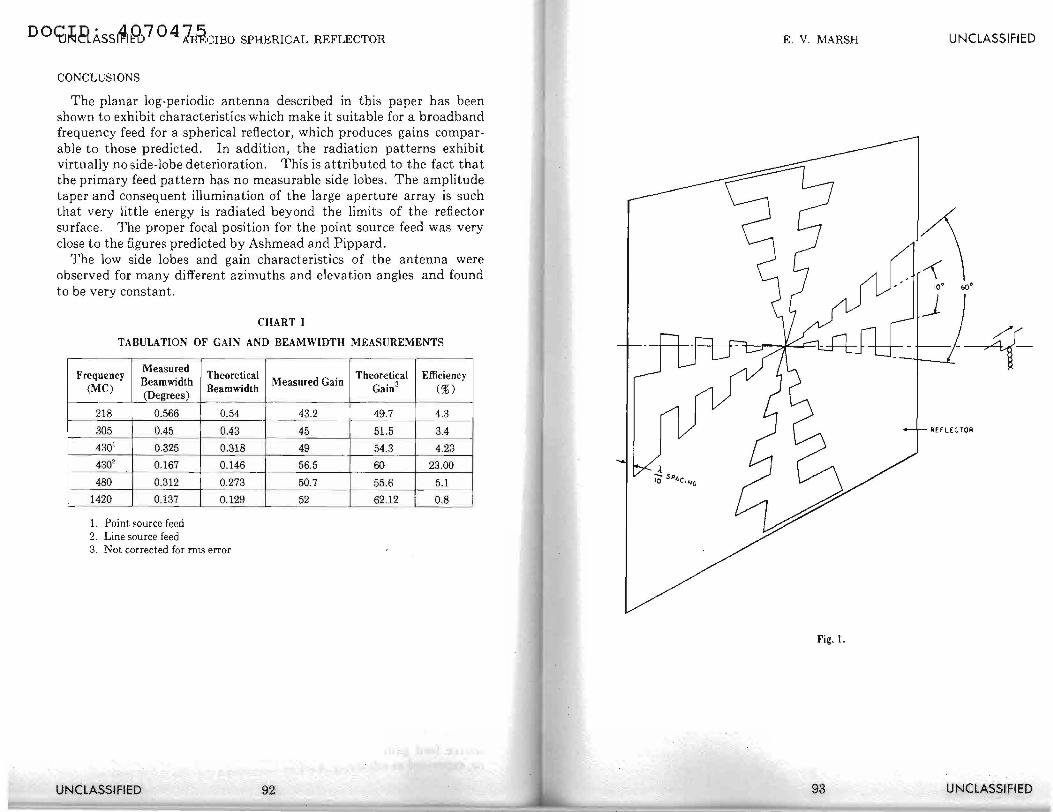
The logarithmically periodic element is shown m Fig. 1 and Fig. la. The terms are defined as follows : the logarithmic ratio (r) = 0.8, the conductor angle ({3) = 10° , and the tooth angle ( a: ) = 60° . .
Values were selected for logarithmic ratio and tooth angle to result m a feed that would present a reasonable antenna size, and also be such that the VSWR across the band was optimum. The antenna parameters were chosen also to obtain the beamwidth for optimum illumination and to permit the log-periodic elements to be mounted orthogonal to one another.
The position of the point source feed had to be varied in_ or?er to obtain the optimum focal point; therefore, both the log periodic and the reflector plate were made to be movable. Inasmuch as both elements were movable, the spacing of the two with respect to one another was adjusted for an optimum illumination pattern , and also to adjust the impedance of the antenna to 50 ohms. The antenna elements were excited by an inherent balun feed .
REFLECTOR A reflector was placed behind the log-periodic element t? ~btain a
unidirectional pattern. The introduction of the reflector limited the frequency range of the antenna to a very narrow ~an?. The reflector plate was adjusted for a spacing from the log periodic to be between 0.1to0.5 wavelengths.
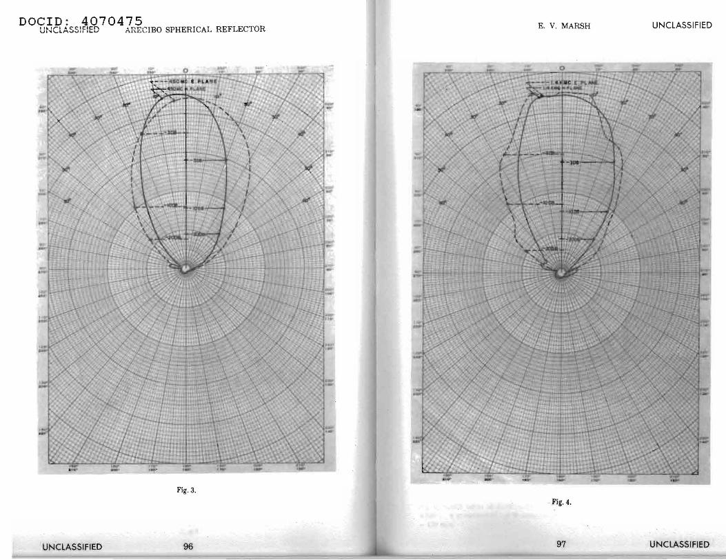
The radiation pattern from the antenna followed the results one would expect from a half-wave dipole above a reflecting _plane. [ 5 J The optimum spacing for the reflector plate wa_s a compromise ?etween the antenna pattern and the impedance desired. A be~mwidth of_ the primary feed of 75° at the 10 db taper point was decided on. F~g. 2 shows the beamwidth of the log feed model at the 10 db down pomts. Figures 3 and 4 show the primary radiation patterns at 430 and 1420 mes. The frequency range of the model was from 200 to 2000
UNCLASSIFIED 88
E. V. MARSH UNCLASSIFIED
mes. (Note· For optimum operation of this technique, it would have been desirable to have a large beamwidth illumination at the low frequency and a small beamwidth illumination at the high frequencies.)
Reflector surfaces other than plane were investigated in order to have a broader frequency bandwidth whereby the reflector could be mounted permanently, affixed with respect to the dipole.[6] However, time did not permit proper evaluation of this technique and it was discontinued.
ANTENNA FEED
An "inherent balun" was used to test the log-periodic element during the modeling phase. This feed arrangement, with no additional external circuitry, provides balanced feed voltages over the feed range of operation of the log-periodic antenna. This is obtained as a result of the attenuation of the currents on the antenna feeder beyond the effective radiation region.[7] The "inherent balun" consists of bonding the outer conductor of a coaxial line up the center of the log-periodic element and connecting the center conductor of the coaxial cable to the other arm at the feed point. The second antenna arm has a similar coax piece to preserve symmetry.
The impedance of the log-periodic antenna is high, being in the order of 180 ohms. When the reflector was placed from 0.1 to 0.5 wavelengths from it, the impedance of the antenna changed as would be expected. [ 8]
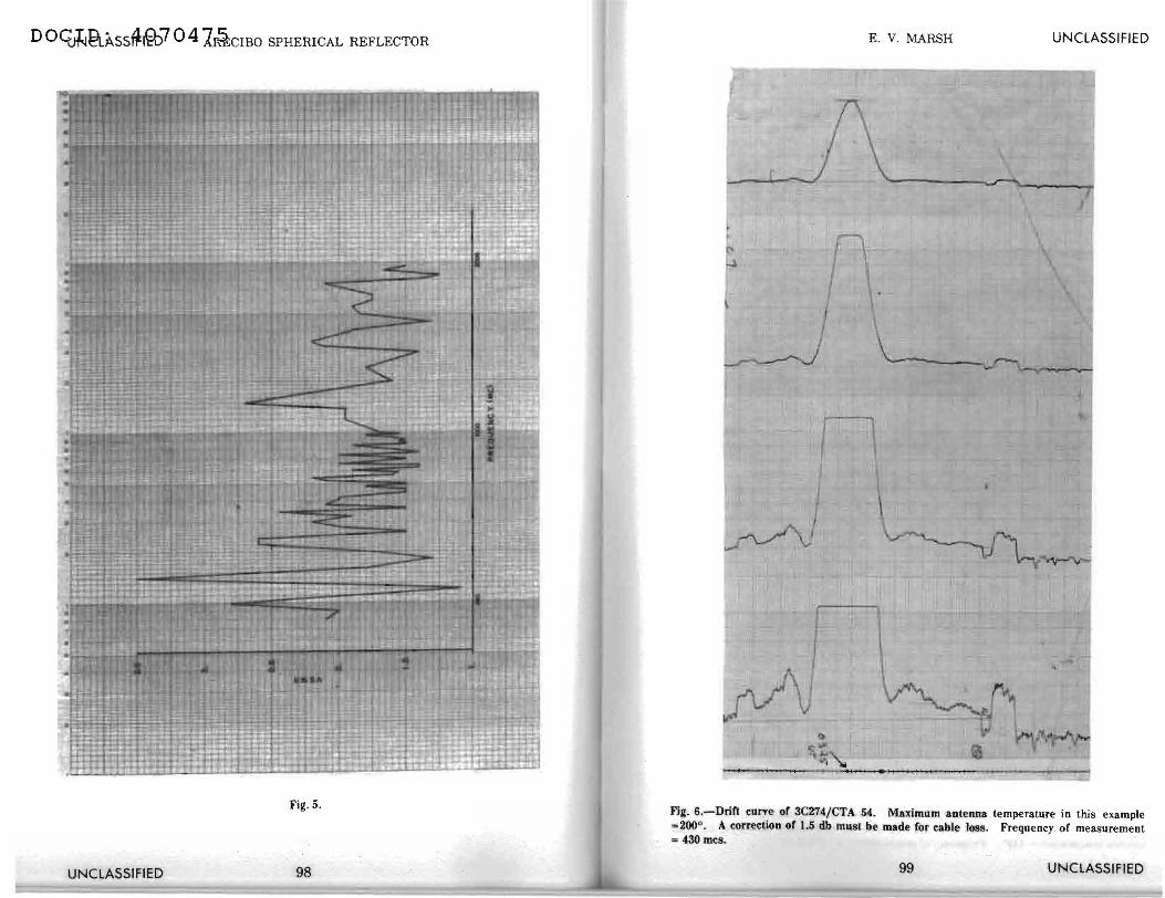
The antenna feed had been designed to be movable so as to provide adjustment for the optimum focal positioning; therefore, it was possible to adjust the spacing between the log periodic and the reflector plate for optimum impedance transformation from the antenna feed to a 50 ohm impedance line. (Refer to Illustration 1 for the complete antenna feed assembly.) With this technique, a VSWR of between Ll and 2.5 could be obtained while still maintaining a good primary radiation pattern. (See Fig. 5.)
PERFORMANCE
Aperture Efficiency.
Prior to designing the point source feed, a computer program had been written to obtain the mathematical expression for the far-field pattern using a point source feed with a spherical reflector, The results bbtained indicated that in principle the concept of using. a point source feed was feasible.
The measure of lrow successful the log-periodic feed was could only be properly evaluated by installing it as a feed in a spheri<:al reflector and measuring antenna gain and beamwidth. . · ·
89 UNCLASSIFIED

0 0ClJNat:AS9i=(Dfl Q 4 7.\liiflCIBO SPHERICAL REFLECTOR
In evaluating antennas, it is advantageous to speak in terms of effective aperture. This is especially true for microwave antennas, such as reflectors, since the effective aperture is usually directly related to the physical area of the antenna.
The effective aperture is defined by the equation,[9 J
A.2 A,= G
41!",
where G is the gain, A. the wavelength, and A. the effective aperture.
The effective area of an antenna A, is also given as the ratio of the available power Pa at the terminals of the antenna to the power flux density S of the incident wave. Thus,[10 J
A =Pa. ' s
It is assumed that the incident wave is polarized appropriately for a maximum power transfer. The polarization property of the antenna and the polarization of the incident wave must be matched for maximum power transfer. For discrete sources having solid angles smaller than the solid angle subtended by the major lobe of the antenna, a correction must be made accordingly.[11 J For discrete sources having solid angles smaller than the solid angle subtended by the major lobe of the antenna, the relation between apparent antenna temperature and the power flux density, S, of the sources is given by,[12]
T SA, "= 2K '
where Ta is the antenna temperature and K is Boltzmann's constant. The antenna temperature is the temperature of a matched resistor whose available noise power is equal to that of the antenna.
It can be shown that an equivalent way of stating the antenna power gain is
The gain of the antenna was measured at various zenith angles by allowing the source to drift through the antenna beam while maintaining the antenna in a fixed position.
Figures 6 and 7 show patterns obtained at two frequencies of operation; namely, 430 and 1420 mes. Measurements were made at other frequencies and the results are tabulated in Chart I along with other pertinent data.
*The value of 8 at430 mes was obtained from reference [ 13 ]. The value of S at 1420 mes was obtained from reference [ 14 ].
UNCLASSIFIED 90
E. V. MARSH UNCLASSIFIED
The loss due to the surface roughness of the reflector at smaller wavelengths has not been included in the theoretical gain calculations. However, it can be shown that it is on the order of 10 db at 1420 mes according to the following equation.[15]
where G' is the gain with errors.
is the gain without errors, where O" is the rms reflector error, 1'/ is efficiency. (This equation was derived for a parabolic reflector.)
For 1420 mes, the theoretical gain of the AlO Aperture = 61 db [ 16] where
therefore, O' = ± 0.1 ft 3
;
G' = 53.14 db. (Note: This gain is based on that portion of the circular aperture that is equivalent to a certain diameter parabolic as specified in the paper by Ashmead and Pippard.)
POINTING AND TRACKING
The pointing and tracking accuracy of the antenna was measured and found to be between 1.5' and 2' of arc. This is the same accuracy that is quoted for the line source feed used on the adjacent carriage house.[17]
APERTURE EFFICIENCY
The aperture efficiency is defined as follows: [ 18 J
GA.2 A, J"/ = 4A =A'
where G is the gain of the antenna and A is the physical area of the antenna.
The aperture efficiencies are listed on Chart I. It should be pointed out that high efficiencies are not to be expected as noted earlier in this paper due to the less than optimum illumination; however, it is nevertheless of interest to compare the efficiencies. The efficiency of a line source feed at 430 mes has been measured [19] and found to be 23% ± 3S'c . (56.5 ± 0.5 db antenna gain.) The log-periodic point source feed gain was measured at 430 mes and found to be 49.6 db, or, expressed as efficiency, 4 .23 %, .
91 UNCLASSlflED
D OCfi~tl.A.ss~~ 7 0 4 :l~crno SPHERICAL REFLECTOR
CONCLUSIONS
The planar log-periodic antenna described in this paper has been shown to exhibit characteristics which make it suitable for a broadband frequency feed for a spherical reflector, which produces gains comparable to those predicted. In addition, the radiation patterns exhibit virtually no side-lobe deterioration. This is attributed to the fact that the primary feed pattern has no measurable side lobes. The amplitude taper and consequent illumination of the large aperture array is such that very little energy is radiated beyond the limits of the reflector surface. The proper focal position for the point source feed was very close to the figures predicted by Ashmead and Pippard.
The low side lobes and gain characteristics of the antenna were observed for many different azimuths and elevation angles and found to be very constant.
CHART I
TABULATION OF GAIN AND BEAMWIDTH MEASUREMENTS
Frequency Measured
Theoretical Theoretical Efficiency (MC)
Beamwidth Beam width
Measured Gain Gain3 (%)
(Degrees)
218 0.566 0.54 43.2 49.7 4.3
305 0.45 0.43 45 51.5 3.4 - · 4301 0.325 0.318 49 54.3 4.23
430' 0.167 0.146 56.5 60 23.00 -·-·
480 0.312 I 0.273 50.7 55.6 5.1
1420 0.137 0.129 52 62.12 0.8 j
1. Point source feed 2. Line source feed 3. Not corrected for nns error
UNCLASSIFIED 92
E. V. l'v1ARSH LI NCLASSI FIED
Fig. I.
93 UNCLASSIFIED

D O<Dlllq),~SSl4l]))7 0 4 NRBCIBO SPHERICAL REFLECTOR
Fig. la.
UNCLASSIFIED 94
E. V. MARSH
Fig. 2 . .
95
UNCLASSIFIED
UNCLASSIFIED
DOCID: 4070475 UtKLASSfflED ARECIBO SPHERICAL REFLECTOR E. V. MARSH UNCLASSIFIED
Fig. 3.
. Fig. ~ -
UNCLASSIFIED 96 97 UNCLASSIFIED
D O~~ASS~1@:>7 Q 41i§:crno SPHERICAL REFLECTOR
Fig. 5.
UNCLASSIFIED 98
E. V. MARSH UNCLASSIFIED
\
Fig. 6~-Drin cun:e of 4C274/CTA 54. Mallimum .antenna temperature in this example =200 . A correction or 1.5 db must be made for cable -toss. Freguency. or measurement = 430 mes. ·
UNCLASSIFIED

D O<grt-RJ(ss1ifli@7 0 4A1~:rno SPHERICAL REFLECTOR
I
Fig. 7.-Drift curve o.f 3Cl44/CTA 36. Maximum antenna temperature = 70°. There was a 3 db cable Joss between the antenna feed and tbe radiometer; therefore, the true antenna temperature = 140°. Frequency of measurement= 142!) mes.
UNCLASSIFIED 100
E. V. MARSH UNCLASSIFIED
REFERENCES
[1] J. R. Ashmead and A. L. Pippard, "The Use of Spherical Reflectors as Microwave &anning Aerials," J.I.E.E., 93, Part III A, 1946 p. 627.
[2] Draft of Technical Memorandum, Cornell University, Arecibo Ionospheric Observatory.
[3] [2], p. 3. [4] R.H. DuHamel and E. D. Isbell, "Tech Report 19" Univ. of Illinois, May 1957.
[5] J. D. Kraus, Antennas, McGraw-Hill Book Co., New York, N. Y., 1950, p. 332.
[6] R. E. Franks and C. T. Elfving, Reflector-Type Periodic Broadband Antennas, Sylvania Electronic Defense Laboratory, Mountain View, California.
[7] H. Jasik and A. D. Bresler, Wideband Scanning Antenna Feed System, Interim Summary Report, U. S. Army Sig Res & Dev., Agency Contract Nr DA36-039 SC-85123.
[8] [5], p. 333. [9] J. L. Pawsey and R. N. Bracewell, Radio Astronomy, Oxford University Press,
London, 1955, p. 20. [10] H. C. Ko, On the Analysis of Radio Astronomical Obseroations Made With High
Resolution Radio Telescope Antennas, prepared under Contract Nr AF19(604)-4079 by Ohio State University, Feb. 61, p. 8.
[11] [10], p. 22. [12] Some Considerations in Satellite Communications Systems, DRTE 1122, Part II,
Defense Research Telecommunications Establishment, Jun. 64, p. 10.
[13] Cornell University Research Report, Summary Technical Report RS-56, Dec. 63, p. 4.
[14] A. R. Giddis, "Limitations of Communication Systems by Antenna Noise," Technical Report, Contract AF04(647)-532, 30 Nov. 61, pp. 3-4.
[15] J. Ruze, "Physical Limitations on Antennas," MIT Technical Report 248, Research Lab of Electronics, 30 Oct. 52.
[16] [12], Part III, p. 2.
[17] Cornell University Research Report, Summary Technical Report RS-59, June 1964, p. 9.
[18] [12], Part III, p. 2.
[191 [17], p. 17.
101 UNCLASSIFIED
Related Documents