TG789 Broadband Gateway Quick Setup Guide

Welcome message from author
This document is posted to help you gain knowledge. Please leave a comment to let me know what you think about it! Share it to your friends and learn new things together.
Transcript

TG789 Broadband Gateway
Quick Setup Guide

Before you get started Make sure you have an email or SMS from us advising that your
internet service is ACTIVE or ready to be activated.
Hello Finn,
Your iiNet Internet service is now active! Here are
some details about your account - you can use
them to log in to Toolbox at https://toolbox3.https://toolbox3.
iinet.net.auiinet.net.au and manange your account online.
Hello. Your iiNet service (username iiNetAcct) is now active! Please check your email for more details. Questions? Please call 13 22 58. Regards, iiNet.
2

What are you setting up today?
TYPE OF INTERNET TURN TO PAGE
NBN™ Fibre to the Node / Building Also known as NBN™ FTTN/B
6
NBN™ Fibre to the Curb Also known as NBN™ FTTC
7
NBN™ HFC Also known as NBN™ Cable
8
NBN™ Fibre to the Premises Also known as NBN™ FTTP
9
NBN™ Satellite Also known as NBN™ LTSS
10
NBN™ Wireless Also known as NBN™ Fixed Wireless
11
iiNet FTTB without a Network Termination Unit (NTU) 12
iiNet FTTB with a Network Termination Unit (NTU) 13
How to find out which type of internet you have Check your email and/or SMS from us about your internet order
Check the service details of your customer invoice
•
•
Just looking to customise your WiFi network?
Turn to page 18.
3

4
1 2 4 6 83 5 7 9 10
Status WAN Internet WPS Ethernet2.4GHz 5GHz USB Wireless Button
Phone
WiFi
Get to know your modem’s lights

Get to know your modem’s lights
Light State Meaning
STATUS Off Modem has no power.
Red Modem is offline.
Green Modem is online.
Orange Modem is rebooting or powering up. Flashes during firmware upgrade.
WAN Off No connection or modem has no power.
Green Modem has a connection. Flashes during connection activity.
Internet Off Modem has no power.
Red Modem is offline.
Green Modem is online. Flashes during connection activity.
Wireless 2.4GHz or 5GHz
Off WiFi off/disabled or modem has no power.
Green WiFi enabled. Flashes during WiFi activity and when rebooting.
Light State Meaning
WPS Off WPS not in use or modem has no power.
Red WPS connection failed - try again.
Green WPS connection successful.
Orange WPS search mode on or WPS connection in
progress. Flashes.
Ethernet Off Nothing connected to LAN ports or modem has no power.
Green Ethernet connection to any LAN port. Flashes during connection activity.
USB Off No USB device detected.
Green USB device detected. Flashes during connection activity.
Netphone Off VoIP disabled or modem has no power.
Green VoIP enabled. Flashes during calls.
WiFi Button N/A A button you can press to turn WiFi ability on/off.
5

Plug in for NBN™ FTTN/FTTB
1. Using the power cable supplied, connect your
modem’s Power port to a power outlet. Press the
Power button on the back of the modem to turn
it on.
2. Use the supplied Phone cable to connect your
modem’s grey DSL port directly to the phone
socket on the wall (Remove any phone or fax
devices). Do not use a line filter.
3. If you wish to use your VoIP phone service,
connect a phone handset to your modem’s
Phone1 port.
4. You can use an additional Ethernet cable to
connect your computer to any of your modem’s 4
LAN ports. Alternatively, follow the steps later in
this guide to connect devices via WiFi.
Turn to Page 14 to continue setup.
123 4
Power Cable Plug into a power outlet
Phone Cable Plug into handset
(Optional)
Phone Cable Plug into the phone socket on the wall
Ethernet Cable Plug into your computer’s Ethernet Port (Optional)
6

Plug in for NBN™ FTTC
Before you get started...
If you received a new NBN™ Connection Box along with your modem, please follow its setup guide to get it plugged in and turned on before you set up your modem.
1. Using the power cable supplied, connect your
modem’s Power port to a power outlet. Press the
Power button on the back of the modem to turn
it on.
2. Use the supplied Ethernet cable to connect your
modem’s red WAN port to the yellow GATEWAY port on your NBN™ Connection Device.
3. If you wish to use your VoIP phone service,
connect a phone handset to your modem’s
Phone1 port.
4. You can use an additional Ethernet cable to
connect your computer to any of your modem’s 4
LAN ports. Alternatively, follow the steps later in
this guide to connect devices via WiFi.
Turn to Page 14 to continue setup.
Ethernet Cable Plug into your computer’s Ethernet Port (Optional)
Phone Cable Plug into handset
(Optional)
Power Cables Plug into 2 power outlets
NBN™ Connection Device Connects to your modem via
Ethernet to the WAN Port
Phone Cable Plug into the phone socket on the wall
123 4
7
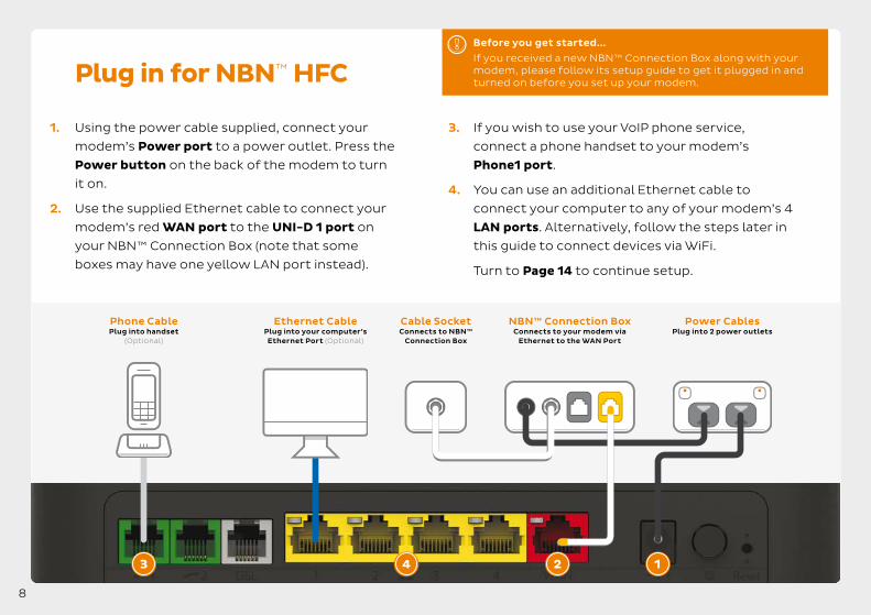
Plug in for NBN™ HFC
Before you get started...
If you received a new NBN™ Connection Box along with your modem, please follow its setup guide to get it plugged in and turned on before you set up your modem.
1. Using the power cable supplied, connect your
modem’s Power port to a power outlet. Press the
Power button on the back of the modem to turn
it on.
2. Use the supplied Ethernet cable to connect your
modem’s red WAN port to the UNI-D 1 port on
your NBN™ Connection Box (note that some
boxes may have one yellow LAN port instead).
3. If you wish to use your VoIP phone service,
connect a phone handset to your modem’s
Phone1 port.
4. You can use an additional Ethernet cable to
connect your computer to any of your modem’s 4
LAN ports. Alternatively, follow the steps later in
this guide to connect devices via WiFi.
Turn to Page 14 to continue setup.
Ethernet Cable Plug into your computer’s Ethernet Port (Optional)
Phone Cable Plug into handset
(Optional)
Power Cables Plug into 2 power outlets
Cable Socket Connects to NBN™
Connection Box
NBN™ Connection Box Connects to your modem via
Ethernet to the WAN Port
123 4
8

Plug in for NBN™ Fibre to the Premises
1. Using the power cable supplied, connect your
modem’s Power port to a power outlet. Press the
Power button on the back of the modem to turn
it on.
2. Use the supplied Ethernet cable to connect your
modem’s red WAN port to the UNI-D 1 port on
your NBN™ Connection Box. If UNI-D1 doesn’t
work, try each UNI-D port before contacting us
for a hand.
3. If you wish to use your Fibre Phone service,
connect a phone handset to the UNI-V 1 port on
your NBN™ Connection Box.
4. You can use an additional Ethernet cable to
connect your computer to any of your modem’s 4
LAN ports. Alternatively, follow the steps later in
this guide to connect devices via WiFi.
Turn to Page 14 to continue setup.
Ethernet Cable Plug into your computer’s Ethernet Port (Optional)
Phone Cable Plug into handset
(Optional)
P OWER
NBN™ Connection Box Connects to your modem via
Ethernet to the WAN Port
Power Cables Plug into 2 power outlets
12
3
4
9
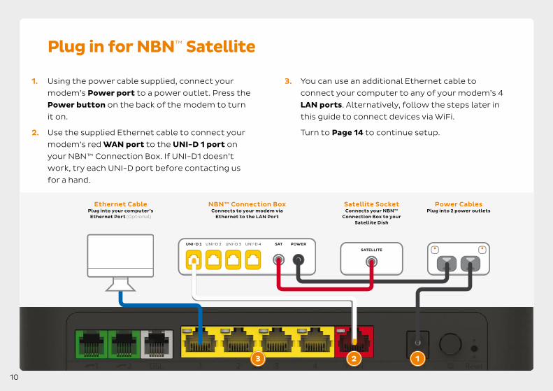
Plug in for NBN™ Satellite
1. Using the power cable supplied, connect your 3. You can use an additional Ethernet cable to
modem’s Power port to a power outlet. Press the connect your computer to any of your modem’s 4
Power button on the back of the modem to turn LAN ports. Alternatively, follow the steps later in
it on. this guide to connect devices via WiFi.
2. Use the supplied Ethernet cable to connect your Turn to Page 14 to continue setup.
modem’s red WAN port to the UNI-D 1 port on
your NBN™ Connection Box. If UNI-D1 doesn’t
work, try each UNI-D port before contacting us
for a hand.
NBN™ Connection Box Connects to your modem via
Ethernet to the LAN Port
Satellite Socket Connects your NBN™
Connection Box to your Satellite Dish
Ethernet Cable Plug into your computer’s Ethernet Port (Optional)
Power Cables Plug into 2 power outlets
P OW ER SAT
SATELLITE
123
10

Plug in for NBN™ Wireless
1. Using the power cable supplied, connect your 3. If you wish to use your VoIP phone service,
modem’s Power port to a power outlet. Press the connect a phone handset to your modem’s
Power button on the back of the modem to turn Phone1 port.
it on. 4. You can use an additional Ethernet cable to
2. Use the supplied Ethernet cable to connect your connect your computer to any of your modem’s 4
modem’s red WAN port to the UNI-D 1 port on LAN ports. Alternatively, follow the steps later in
your NBN™ Connection Box. If UNI-D1 doesn’t this guide to connect devices via WiFi.
work, try each UNI-D port before contacting us Turn to Page 14 to continue setup. for a hand.
P OWER
Ethernet Cable Plug into your computer’s Ethernet Port (Optional)
Phone Cable Plug into handset
(Optional)
Power Cables Plug into 2 power outlets
NBN™ Connection Box Connects to your modem via
Ethernet to the WAN Port
123 4
11
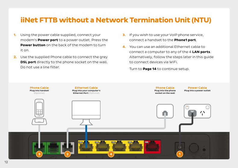
iiNet FTTB without a Network Termination Unit (NTU)
1. Using the power cable supplied, connect your
modem’s Power port to a power outlet. Press the
Power button on the back of the modem to turn
it on.
2. Use the supplied Phone cable to connect the grey
DSL port directly to the phone socket on the wall.
Do not use a line filter.
3. If you wish to use your VoIP phone service,
connect a handset to the Phone1 port.
4. You can use an additional Ethernet cable to
connect a computer to any of the 4 LAN ports.
Alternatively, follow the steps later in this guide
to connect devices via WiFi.
Turn to Page 14 to continue setup.
123 4
Power Cable Plug into a power outlet
Phone Cable Plug into handset
(Optional)
Phone Cable Plug into the phone socket on the wall
Ethernet Cable Plug into your computer’s Ethernet Port (Optional)
12
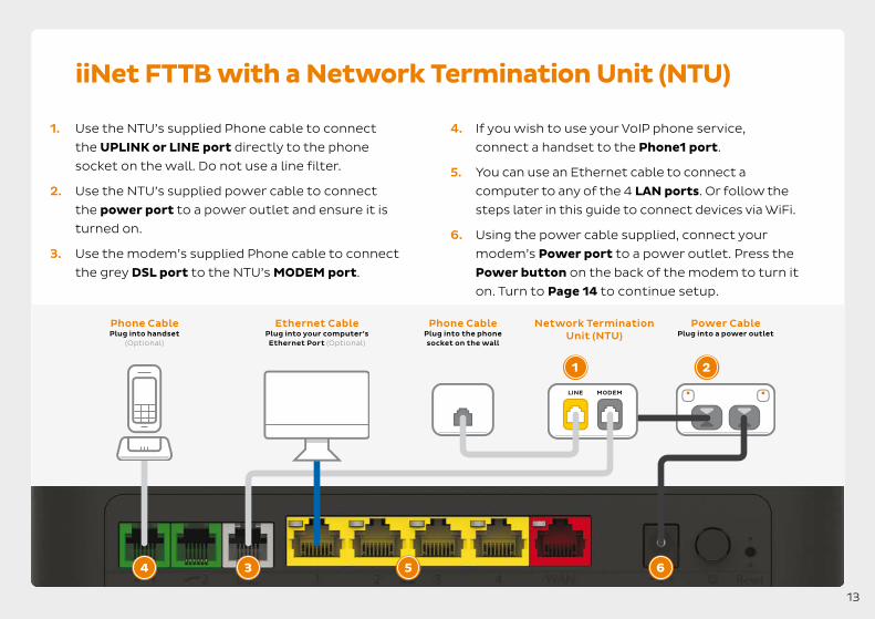
iiNet FTTB with a Network Termination Unit (NTU)
1. Use the NTU’s supplied Phone cable to connect
the UPLINK or LINE port directly to the phone
socket on the wall. Do not use a line filter.
2. Use the NTU’s supplied power cable to connect
the power port to a power outlet and ensure it is
turned on.
3. Use the modem’s supplied Phone cable to connect
the grey DSL port to the NTU’s MODEM port.
4. If you wish to use your VoIP phone service,
connect a handset to the Phone1 port.
5. You can use an Ethernet cable to connect a
computer to any of the 4 LAN ports. Or follow the
steps later in this guide to connect devices via WiFi.
6. Using the power cable supplied, connect your
modem’s Power port to a power outlet. Press the
Power button on the back of the modem to turn it
on. Turn to Page 14 to continue setup.
Power Cable Plug into a power outlet
Phone Cable Plug into the phone socket on the wall
Network Termination Unit (NTU)
Phone Cable Plug into handset
(Optional)
1 2
34 5
Ethernet Cable Plug into your computer’s Ethernet Port (Optional)
MODEM LINE
6
13

14
STATUS WAN INTERNET WPS
WiFi
ETHERNET 2.4GHz 5GHz USB WIRELESS BUTTON
PHONE
1 2
Automatic Configuration
By default, your broadband settings should
configure automatically once your internet
service is ready and your modem is powered on
for 15 minutes.
1. The Internet light on the front of your modem
should be green.
2. The Phone light on the front of your modem
should be solid green if you have an active VoIP
phone service and a handset connected to the
modem. See page 16 of this guide for more
details.
Is the internet light off?
Ensure that you received an email from us
advising that your internet service is ACTIVE or
ready to be activated.
• If you have, please turn to the next page to
attempt a manual configuration.
• If you haven’t received the email, your internet
connection isn't ready yet. Please check your
last email from us for advice on your connection
appointment. It will include a reference number in
case you need to call us with any concerns.

Connecting via WiFi
Your modem’s WiFi has been pre-configured. You’ll find the WiFi network name (SSID) and password (Wireless Key) printed on a sticker on the base of your modem.
1. Make sure that WiFi is enabled on your computer,
tablet, smartphone or other WiFi device.
2. View the list of available WiFi networks on your
WiFi device and select the network that matches
the network name on your modem’s sticker.
3. Enter the WiFi password (wireless key) exactly as
printed on the sticker.
TG789vac v2Wireless VoIP Smart Ultra Broadband Gateway
Wireless user codes2.4GHz Network name:
5GHz Network name:
Wireless Key:
internodeD1234F
internodeD1234F - 5G
3X4mple123
GUI Login: http://10.1.1.1Username: adminPassword: test01234
Your modem has 2 WiFi networks which share the same default password but broadcast on different frequencies. If your device(s) can’t connect to the latest 5GHz network, use the 2.4GHz one.
15

VoIP Phone Setup
By default, your VoIP phone service should set up automatically once your internet and VoIP services are active and your modem is online.
Simply plug a handset into your modem’s
Phone1 port as shown. If you have an NBN™
FTTP service, you’ll need to plug a handset into
the UNI-V1 port on your NBN™ Connection Box.
If this port does not work, try UNI-V2.
If you can’t use your VoIP phone service after
setting up, please use the contact details on
the back cover of this guide to call our Support
Team for assistance.
Porting your existing phone number to VoIP?
If you’ve asked us to convert your existing
phone number to a VoIP service, please allow
up to 7 days after your internet service is active
for this porting process to complete. We’ll send
you an email to confirm when your VoIP service
is active and ready to use.
Connect via Modem For customers connecting through their modem
Rear
Phone 1
Connect via NBN™ Connection Box Only applicable to FTTP customers with NBN™ Fibre Phone
UNI-V 1 Phone 1 UNI-D 1
16

Login & Manual setup
You can log into your modem’s interface to
customise your WiFi network settings or attempt
a manual setup.
1. On a computer or WiFi device that’s connected to
your modem, open your web browser and go to
http://10.1.1.1
2. Log in with the default username and password,
which can be found under “GUI Login” on your
modem’s barcode sticker.
3. Open the Setup Wizard and enter the settings for
your service as listed below.
4. Click Next. After connecting successfully, you may
wish to customize your WiFi network and/or GUI
Login details by following the steps on the next
page of this guide.
5. Can’t get online? Please use the details on the
back cover of this guide to call our Support Team.
TECHNOLOGY TYPE
NBN™ FTTN/B
NBN™ FTTC, HFC & Wireless
NBN™ FTTP & Satellite
iiNet FTTB
WAN INTERFACE VLAN ENABLED WAN TYPE
VDSL
Ethernet
Ethernet
VDSL
On
On
On
On
PPP over Ethernet
PPP over Ethernet
PPP over Ethernet
PPP over Ethernet
VLAN ID
2
2
2
2
17

WiFi Customisation
1. After logging into the modem interface (see steps
1—2 on previous page) you can customize your
WiFi network details as part of the Setup Wizard,
or by selecting the Wireless panel.
2. Your modem has 2 WiFi networks which share
the same default password but broadcast on
different frequencies. If your device(s) can’t
connect to the latest 5GHz network, use the
2.4GHz one.
3. Wireless 2.4GHz or Wireless 5GHz (WiFi) must be
turned ON. If SSID Broadcast is OFF, your network
name will not be visible to WiFi devices and you’ll
have to enter it manually to connect.
4. The 2.4/5GHz SSID Broadcast names are the
names of your WiFi networks. You can change
these to anything you’d like.
5. Security Key Type/Security Mode should be set to
WPA+WPA2 PSK.
6. Your 2.4/5GHz Security Keys/Wireless passwords are the passwords for your WiFi networks. Change
these to something that’s hard for others to
guess but easy for you to remember. Make sure
you write down your new WiFi details, otherwise
you may need to factory reset your modem if you
forget them.
7. Click Save. After changing your WiFi details, you
may need to reconnect your WiFi device(s) using
the new name/password.
18

Router Security Settings
Default username:
Internet address:
Default password:
admin
http://10.1.1.1
Printed on the sticker on
the base of your modem
TG789vac v2Wireless VoIP Smart Ultra Broadband Gateway
Wireless user codes2.4GHz Network name:
5GHz Network name:
Wireless Key:
internodeD1234F
internodeD1234F - 5G
3X4mple123
GUI Login: http://10.1.1.1Username: adminPassword: test01234
The Setup Wizard allows you to change the username
and password used to log in at http://10.1.1.1. This can
be handy if you have tenants or meddling teens and
you don’t want them to change your modem settings.
To keep the defaults, simply leave the boxes blank
and click Next. If you do set a custom username and/
or password, you should write it down and keep it
somewhere safe.
All done!
If you can’t get online, see the back cover of this guide
to contact our friendly Support Team.
If you ever forget your custom login details, you can
factory reset the modem to return it to the default
settings. However, you will also lose all other custom
settings, so you’ll need to set up your modem again.
19

Warranty Information
1. How to claim under the warranty and your rights
1.1 In order to claim under the warranty, you should contact
us to advise that you wish to claim under the warranty and
answer any questions we have. We will assess whether you
are eligible to claim under the warranty and determine, at our
option and in accordance with any specific terms that apply
to the relevant equipment, whether to repair or replace your
equipment, or provide a credit.
iiNet: • Phone: 13 22 58 • Email: [email protected]
Westnet: • Phone: 1300 786 068 • Email: [email protected]
1.2 If we determine that your equipment needs to be returned,
you will be sent replacement equipment and a return freight
bag in which to return the faulty equipment.
1.3 If the faulty equipment is not returned to us, with all cables,
accessories and components, within 21 days of you receiving
the replacement equipment and return freight bag, you will
be charged the full price for the purchase of the equipment
that we sent to you, plus any shipping costs relating to
the prepaid satchel that was sent to you. You will also still
be charged for the original equipment and if the original
equipment has already been paid for, you will not be entitled
to a refund.
1.4 The warranty does not apply to faults caused by any of the
following (Non Covered Events):
a) any equipment not supplied by us;
b) any interference with or modification to the equipment or a
failure to use it in accordance with instructions; or
c) damage caused by you or someone who has used the
equipment (for example misuse or exposure to liquid or
excessive heat); or
d) an external event (for example a fire or flood).
1.5 If on inspection of the returned equipment we determine
that the fault was caused by a Non Covered Event, you will
be charged for the original equipment (or if the original
equipment has already been paid for, you will not be entitled
to a refund) and the replacement equipment, unless:
a) you have not used the replacement equipment;
b) and you return it to us in its unopened packaging, in which
case, you will not be charged for the replacement equipment.
1.6 The repair or replacement of equipment may result in loss
of data (such as loss of telephone numbers stored on your
handset).
20

Warranty Information
1.7 Goods presented for repair may be replaced by refurbished
goods of the same type rather than being repaired.
Refurbished parts may be used to repair the goods. If your
equipment is replaced with refurbished equipment, the
warranty applies in relation to that refurbished equipment
from the remainder of the original Warranty Period or thirty
days, whichever is longer.
1.8 The benefits given to you by this warranty are in addition to
other rights and remedies you may have at law.
1.9 Our goods come with guarantees that cannot be excluded
under the Australian Consumer Law. You are entitled to a
replacement or refund for a major failure and compensation
for any other reasonably foreseeable loss or damage. You are
also entitled to have the goods repaired or replaced if the
goods fail to be of acceptable quality and the failure does not
amount to a major failure.
1.10 This warranty is given by iiNet Limited (ACN 068 628 937) of
1/502 Hay Street, Subiaco, WA, 6008. You can contact us on
13 22 58 or via email to [email protected] if you have any
questions regarding this warranty.
1.11 Latest Warranty Information: http://www.iinet.net.au/ about/legal/pdf/general-equipment-warranty.pdf
2. Warranty Period
Purchase: 24 Months Rental: For the lifetime of the Rental Contract
2.1 You must notify us of the fault with your equipment within
the applicable Warranty Period (beginning from the date you
purchased the equipment)
2.2 We will repair, replace or provide credit for faulty equipment
provided by us at no cost to you, if you notify us of the fault
within the applicable Warranty Period.
2.3 However, we will charge you for the repair or replacement of
faulty equipment, if the fault was caused by a Non Covered
Event.
2.4 If we decide to repair the equipment, you must give us
sufficient information to assess the fault, including allowing
us to test your personal computer.
21

Notes
22

23

Moving house?
Don’t leave your broadband behind! Call our movers team on 1300 541 714
Support
iiNet Support Westnet Support Available 24/7 Available 24/7
13 22 58 1300 786 068 [email protected] [email protected] ACN 068 628 937
Related Documents