#CLUS

Welcome message from author
This document is posted to help you gain knowledge. Please leave a comment to let me know what you think about it! Share it to your friends and learn new things together.
Transcript

#CLUS
© 2018 Cisco and/or its affiliates. All rights reserved. Cisco Public#CLUS
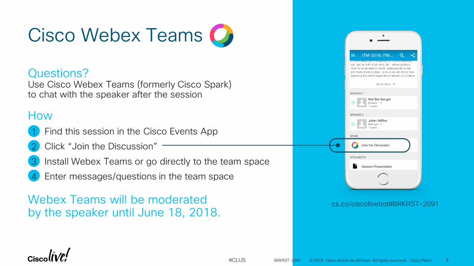
Cisco Webex Teams
Questions? Use Cisco Webex Teams (formerly Cisco Spark) to chat with the speaker after the session
Find this session in the Cisco Events App
Click “Join the Discussion”
Install Webex Teams or go directly to the team space
Enter messages/questions in the team space
How
Webex Teams will be moderated by the speaker until June 18, 2018.
cs.co/ciscolivebot#BRKRST-2091
© 2018 Cisco and/or its affiliates. All rights reserved. Cisco Public 2
1
2
3
4
BRKRST-2091 2
#CLUS
Brent ColwellBRKRST-2091
Branch and Data Center Integration Design
Cisco SD-WAN (Viptela)
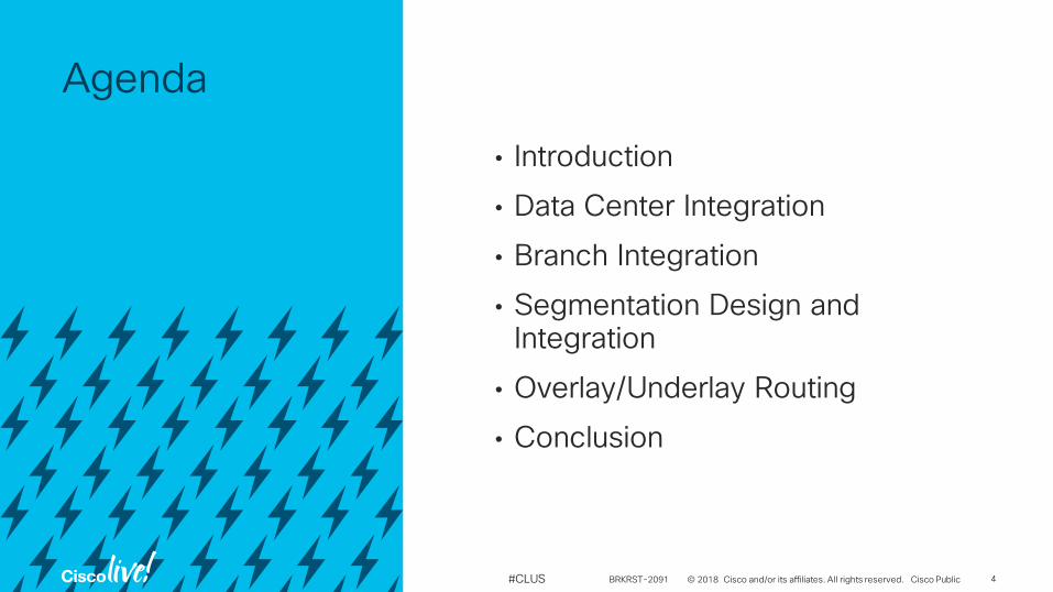
Agenda
© 2018 Cisco and/or its affiliates. All rights reserved. Cisco Public#CLUS
• Introduction
• Data Center Integration
• Branch Integration
• Segmentation Design and Integration
• Overlay/Underlay Routing
• Conclusion
BRKRST-2091 4
© 2018 Cisco and/or its affiliates. All rights reserved. Cisco Public#CLUS
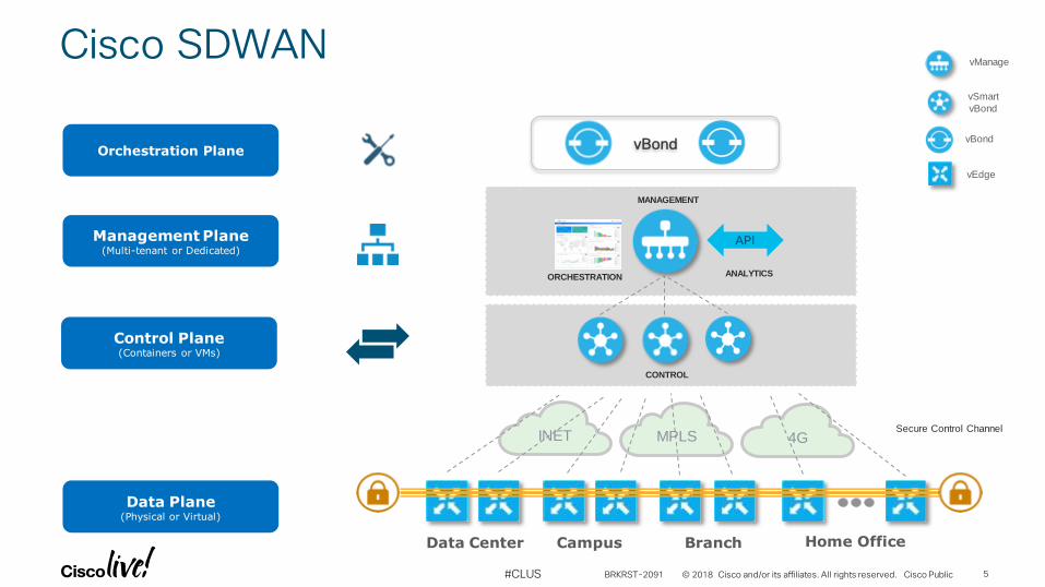
Management Plane(Multi-tenant or Dedicated)
Control Plane (Containers or VMs)
Data Plane(Physical or Virtual)
Orchestration Plane
Cisco SDWAN
Data Center Campus Branch Home Office
vManage
vSmart
vBond
vEdge
vBond
API
CONTROL
ANALYTICSORCHESTRATION
MANAGEMENT
INET MPLS 4GSecure Control Channel
vBond
BRKRST-2091 5
© 2018 Cisco and/or its affiliates. All rights reserved. Cisco Public#CLUS
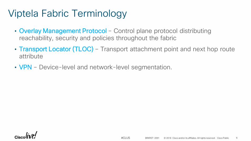
• Overlay Management Protocol – Control plane protocol distributing reachability, security and policies throughout the fabric
• Transport Locator (TLOC) – Transport attachment point and next hop route attribute
• VPN – Device-level and network-level segmentation.
Viptela Fabric Terminology
BRKRST-2091 6
© 2018 Cisco and/or its affiliates. All rights reserved. Cisco Public#CLUS
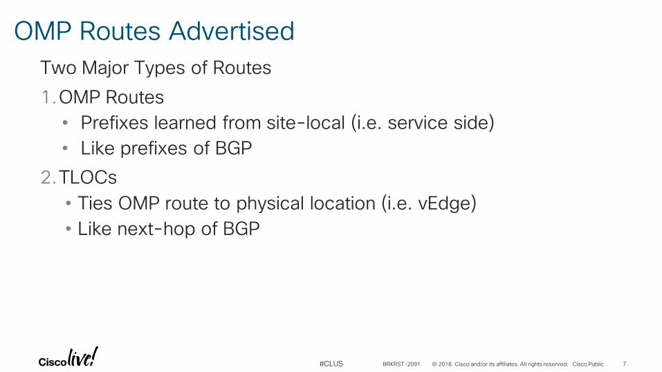
Two Major Types of Routes
1.OMP Routes
• Prefixes learned from site-local (i.e. service side)
• Like prefixes of BGP
2.TLOCs
• Ties OMP route to physical location (i.e. vEdge)
• Like next-hop of BGP
OMP Routes Advertised
BRKRST-2091 7
© 2018 Cisco and/or its affiliates. All rights reserved. Cisco Public#CLUS
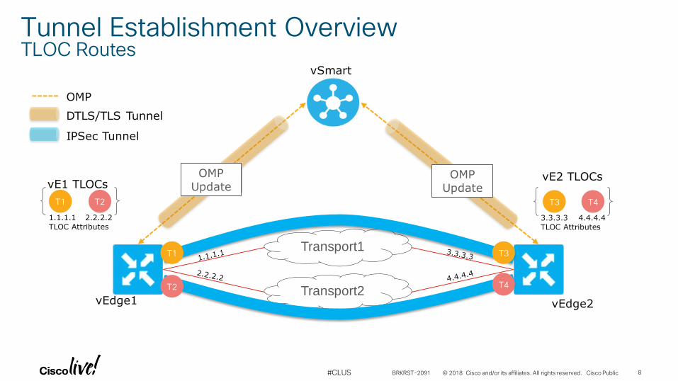
IPSec Tunnel
OMP
DTLS/TLS Tunnel
Transport1
Transport2
vSmart
vEdge1 vEdge2
Tunnel Establishment OverviewTLOC Routes
OMPUpdate
OMPUpdate
T1
T2
T3
T4
T1 T2
1.1.1.1
TLOC Attributes
2.2.2.2
vE1 TLOCs
T3 T4
3.3.3.3
TLOC Attributes
4.4.4.4
vE2 TLOCs
BRKRST-2091 8
© 2018 Cisco and/or its affiliates. All rights reserved. Cisco Public#CLUS
IPSec Tunnel
OMP
DTLS/TLS Tunnel
Transport1
Transport2
vSmart
vEdge1 vEdge2
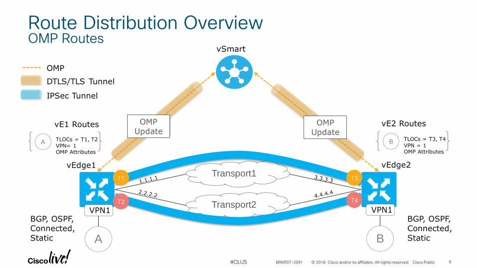
Route Distribution OverviewOMP Routes
OMPUpdate
OMPUpdate
T1
T2
T3
T4
A TLOCs = T1, T2
VPN= 1OMP Attributes
vE1 Routes
BGP, OSPF, Connected, Static
VPN1
A
VPN1
B
B TLOCs = T3, T4
VPN = 1OMP Attributes
vE2 Routes
BGP, OSPF, Connected, Static
BRKRST-2091 9
© 2018 Cisco and/or its affiliates. All rights reserved. Cisco Public#CLUS
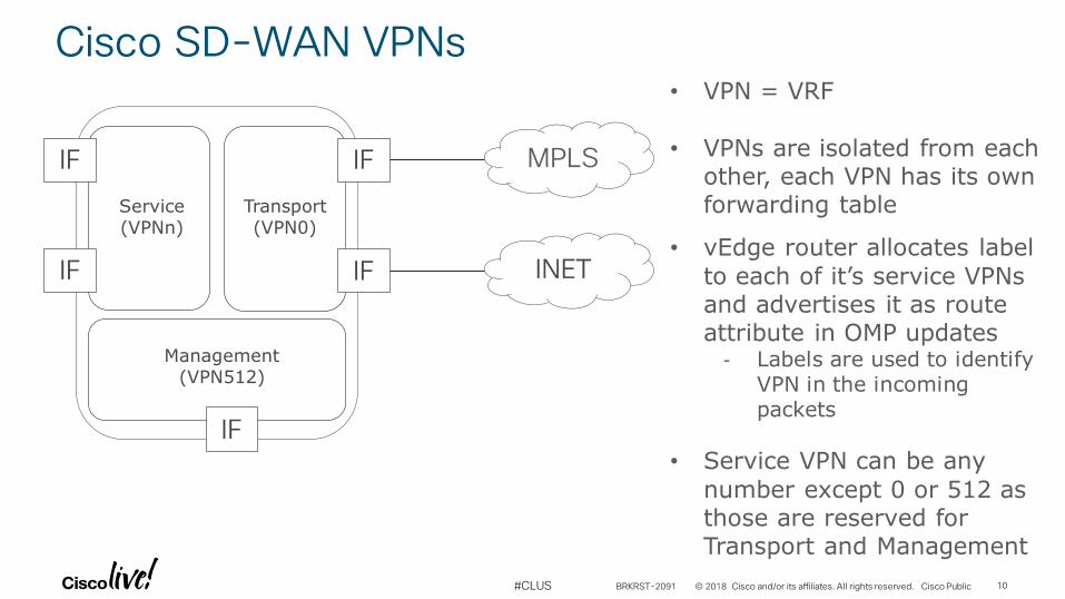
Cisco SD-WAN VPNs
MPLS
INET
Transport(VPN0)
IF
IF
Service(VPNn)
IF
IF
Management(VPN512)
IF
• VPN = VRF
• VPNs are isolated from each other, each VPN has its own forwarding table
• vEdge router allocates label
to each of it’s service VPNs and advertises it as route attribute in OMP updates
- Labels are used to identify VPN in the incoming packets
• Service VPN can be any
number except 0 or 512 as those are reserved for Transport and Management
BRKRST-2091 10
© 2018 Cisco and/or its affiliates. All rights reserved. Cisco Public#CLUS
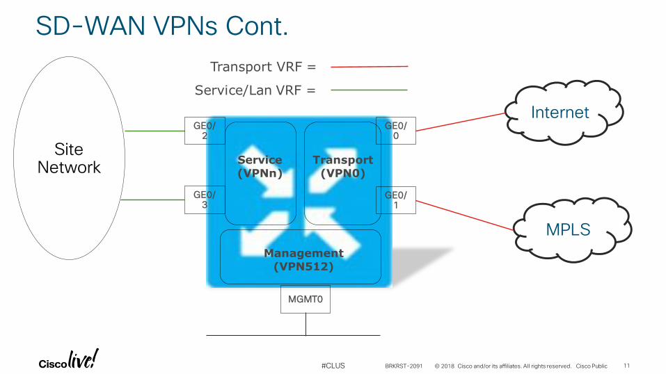
SD-WAN VPNs Cont.
MPLS
Internet
Transport(VPN0)
GE0/0
GE0/1
Service(VPNn)
GE0/2
GE0/3
Management(VPN512)
MGMT0
Site Network
Transport VRF =
Service/Lan VRF =
BRKRST-2091 11
© 2018 Cisco and/or its affiliates. All rights reserved. Cisco Public#CLUS
MPLS Internet
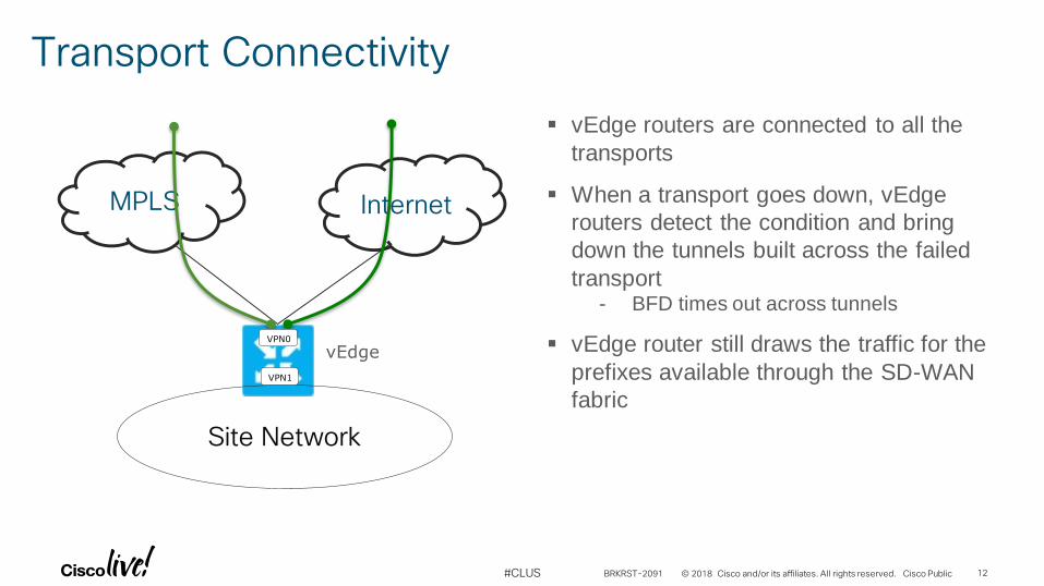
Transport Connectivity
vEdge routers are connected to all the
transports
When a transport goes down, vEdge
routers detect the condition and bring
down the tunnels built across the failed
transport- BFD times out across tunnels
vEdge router still draws the traffic for the
prefixes available through the SD-WAN
fabric
Site Network
vEdgeVPN0
VPN1
BRKRST-2091 12
© 2018 Cisco and/or its affiliates. All rights reserved. Cisco Public#CLUS
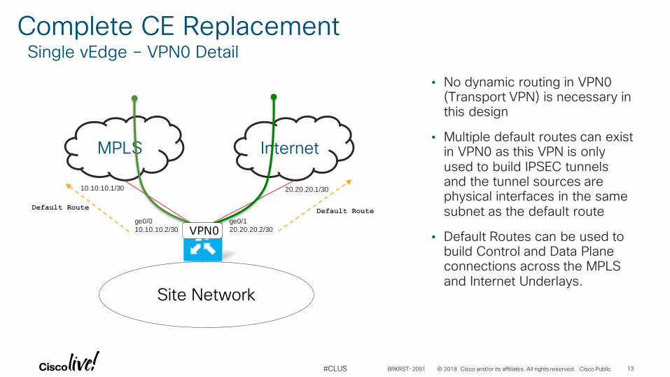
Complete CE ReplacementSingle vEdge – VPN0 Detail
MPLS Internet
ge0/1
20.20.20.2/30
ge0/0
10.10.10.2/30
10.10.10.1/30 20.20.20.1/30
• No dynamic routing in VPN0 (Transport VPN) is necessary in this design
• Multiple default routes can exist in VPN0 as this VPN is only used to build IPSEC tunnels and the tunnel sources are physical interfaces in the same subnet as the default route
• Default Routes can be used to build Control and Data Plane connections across the MPLS and Internet Underlays.
Site Network
Default RouteDefault Route
VPN0
BRKRST-2091 13
© 2018 Cisco and/or its affiliates. All rights reserved. Cisco Public#CLUS
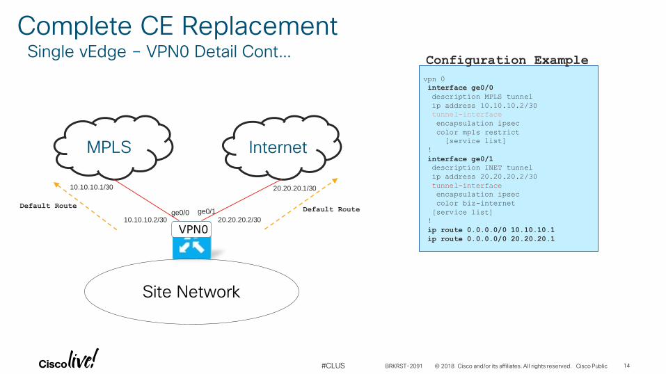
Complete CE ReplacementSingle vEdge – VPN0 Detail Cont…
MPLS Internet
20.20.20.2/3010.10.10.2/30
10.10.10.1/30 20.20.20.1/30
vpn 0
interface ge0/0
description MPLS tunnel
ip address 10.10.10.2/30
tunnel-interface
encapsulation ipsec
color mpls restrict
[service list]
!
interface ge0/1
description INET tunnel
ip address 20.20.20.2/30
tunnel-interface
encapsulation ipsec
color biz-internet
[service list]
!
ip route 0.0.0.0/0 10.10.10.1
ip route 0.0.0.0/0 20.20.20.1
Configuration Example
ge0/0 ge0/1
VPN0
Default RouteDefault Route
Site Network
BRKRST-2091 14
© 2018 Cisco and/or its affiliates. All rights reserved. Cisco Public#CLUS
MPLS
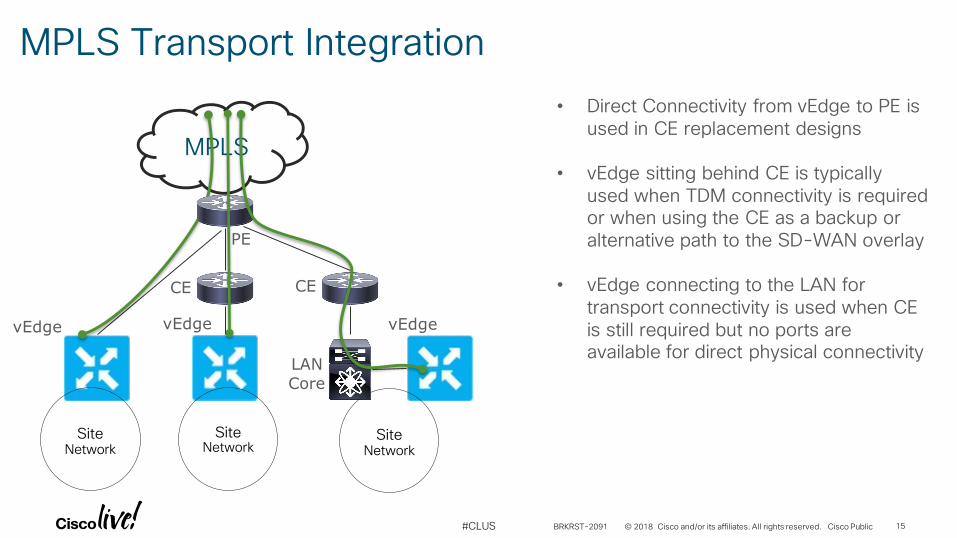
MPLS Transport Integration
• Direct Connectivity from vEdge to PE is used in CE replacement designs
• vEdge sitting behind CE is typically used when TDM connectivity is required or when using the CE as a backup or alternative path to the SD-WAN overlay
• vEdge connecting to the LAN for transport connectivity is used when CE is still required but no ports are available for direct physical connectivity
vEdge
Site Network
SiteNetwork
SiteNetwork
vEdge vEdge
CE CE
LANCore
PE
BRKRST-2091 15
© 2018 Cisco and/or its affiliates. All rights reserved. Cisco Public#CLUS
Internet
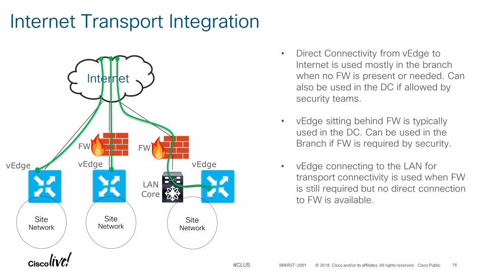
Internet Transport Integration
vEdge vEdge vEdge
FW FW
LANCore
Site Network
SiteNetwork
SiteNetwork
• Direct Connectivity from vEdge to Internet is used mostly in the branch when no FW is present or needed. Can also be used in the DC if allowed by security teams.
• vEdge sitting behind FW is typically used in the DC. Can be used in the Branch if FW is required by security.
• vEdge connecting to the LAN for transport connectivity is used when FW is still required but no direct connection to FW is available.
BRKRST-2091 16
© 2018 Cisco and/or its affiliates. All rights reserved. Cisco Public#CLUS
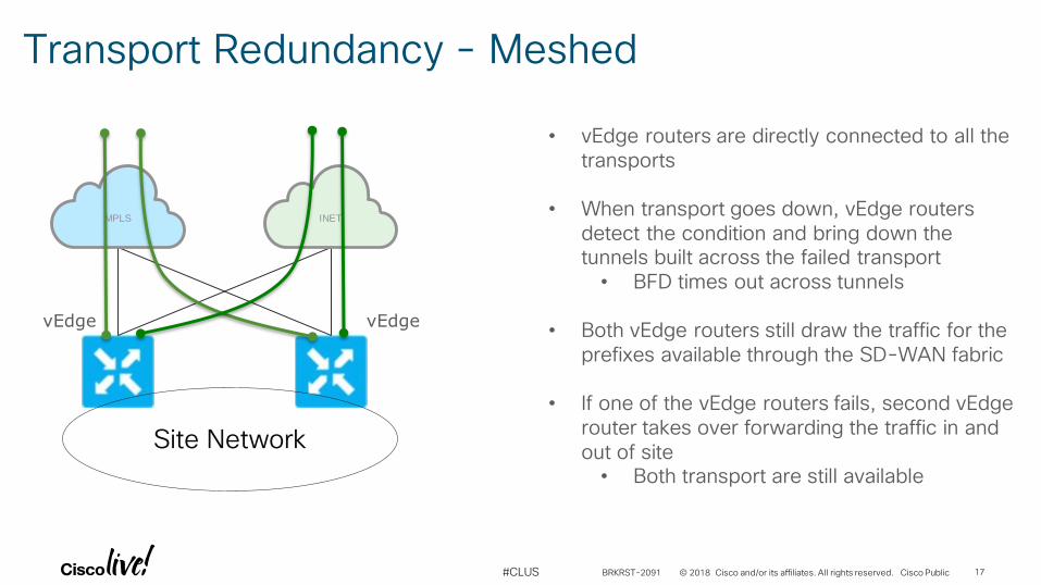
Transport Redundancy - Meshed
• vEdge routers are directly connected to all the transports
• When transport goes down, vEdge routers detect the condition and bring down the tunnels built across the failed transport• BFD times out across tunnels
• Both vEdge routers still draw the traffic for the prefixes available through the SD-WAN fabric
• If one of the vEdge routers fails, second vEdge router takes over forwarding the traffic in and out of site• Both transport are still available
Site Network
vEdgevEdge
MPLS INET
BRKRST-2091 17
© 2018 Cisco and/or its affiliates. All rights reserved. Cisco Public#CLUS
MPLS INET
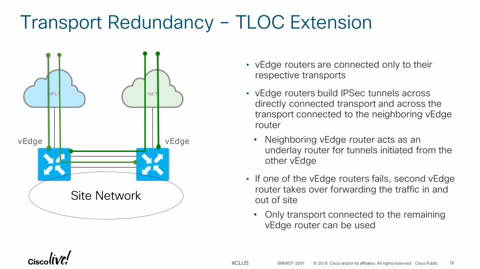
Transport Redundancy – TLOC Extension
Site Network
vEdgevEdge
• vEdge routers are connected only to their respective transports
• vEdge routers build IPSec tunnels across directly connected transport and across the transport connected to the neighboring vEdge router
• Neighboring vEdge router acts as an underlay router for tunnels initiated from the other vEdge
• If one of the vEdge routers fails, second vEdge router takes over forwarding the traffic in and out of site
• Only transport connected to the remaining vEdge router can be used
BRKRST-2091 18
© 2018 Cisco and/or its affiliates. All rights reserved. Cisco Public#CLUS
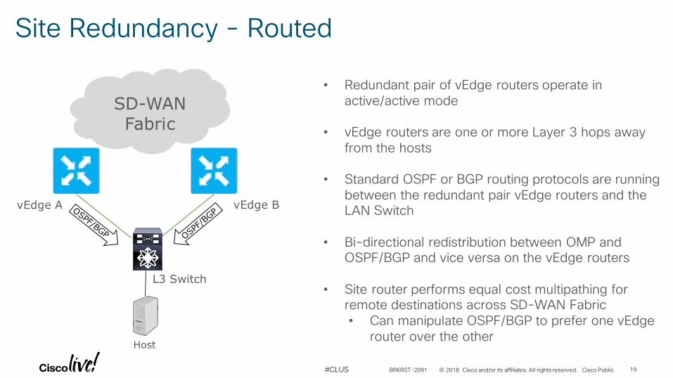
Site Redundancy - Routed
• Redundant pair of vEdge routers operate in active/active mode
• vEdge routers are one or more Layer 3 hops away from the hosts
• Standard OSPF or BGP routing protocols are running between the redundant pair vEdge routers and the LAN Switch
• Bi-directional redistribution between OMP and OSPF/BGP and vice versa on the vEdge routers
• Site router performs equal cost multipathing for remote destinations across SD-WAN Fabric• Can manipulate OSPF/BGP to prefer one vEdge
router over the other
vEdge A
Host
vEdge B
L3 Switch
SD-WANFabric
BRKRST-2091 19
© 2018 Cisco and/or its affiliates. All rights reserved. Cisco Public#CLUS
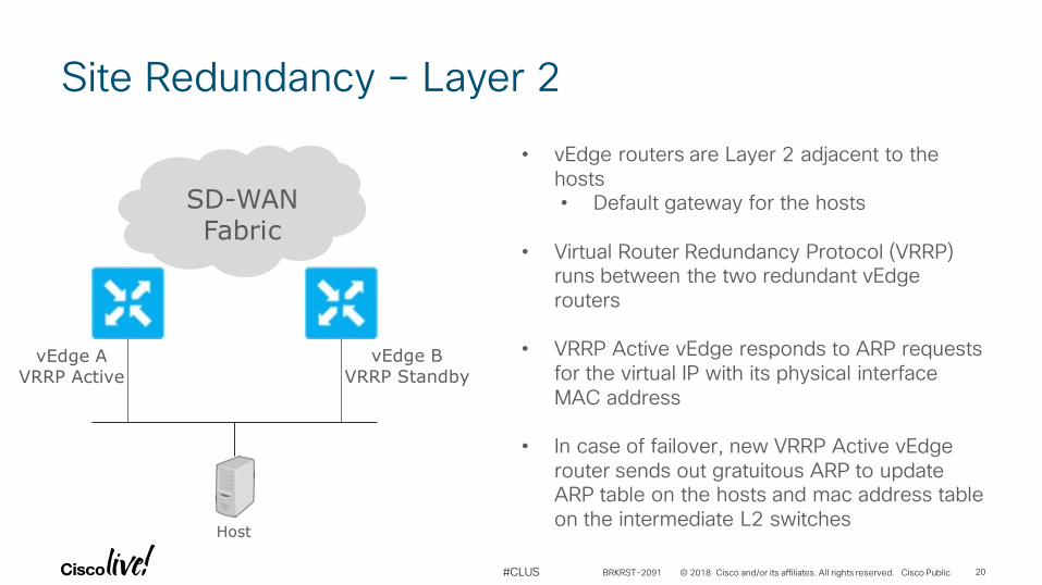
Site Redundancy – Layer 2
• vEdge routers are Layer 2 adjacent to the hosts• Default gateway for the hosts
• Virtual Router Redundancy Protocol (VRRP) runs between the two redundant vEdge routers
• VRRP Active vEdge responds to ARP requests for the virtual IP with its physical interface MAC address
• In case of failover, new VRRP Active vEdge router sends out gratuitous ARP to update ARP table on the hosts and mac address table on the intermediate L2 switches
vEdge AVRRP Active
Host
vEdge BVRRP Standby
SD-WANFabric
BRKRST-2091 20

Data Center Design
© 2018 Cisco and/or its affiliates. All rights reserved. Cisco Public#CLUS
Data Center Design Principals
• Do not impact normal traffic flows to/from Data Center for sites which have not converted to SD-WAN
• Integration should be transparent to the business
• Leverage BGP when possible OSPF when necessary
• Integrate routing with the Core or WAN Services Block if possible
• Integrate routing with Customer Edge when necessary
BRKRST-2091 22
© 2018 Cisco and/or its affiliates. All rights reserved. Cisco Public#CLUS
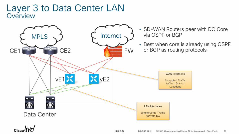
Layer 3 to Data Center LANOverview
MPLS Internet• SD-WAN Routers peer with DC Core
via OSPF or BGP
• Best when core is already using OSPF or BGP as routing protocols
LAN Interfaces
Unencrypted Traffic to/from DC
CE1 CE2
Data Center
vE1 vE2
FW
WAN Interfaces
Encrypted Traffic to/from Branch
Locations
BRKRST-2091 23
© 2018 Cisco and/or its affiliates. All rights reserved. Cisco Public#CLUS
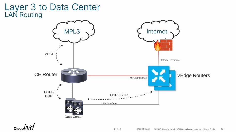
Internet
MPLS Interface
Internet Interface
eBGP
OSPF/BGP
Data Center
CE Router vEdge Routers
OSPF/
BGP
LAN Interface
MPLS
Layer 3 to Data CenterLAN Routing
BRKRST-2091 24
© 2018 Cisco and/or its affiliates. All rights reserved. Cisco Public#CLUS
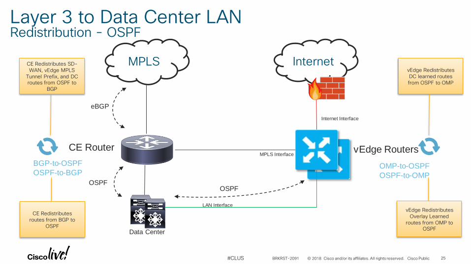
Internet
MPLS Interface
Internet Interface
eBGP
OSPF
Data Center
CE Router vEdge Routers
OSPF
LAN Interface
MPLS
OMP-to-OSPF
OSPF-to-OMP
BGP-to-OSPF
OSPF-to-BGP
Layer 3 to Data Center LANRedistribution - OSPF
CE Redistributes SD-WAN, vEdge MPLS
Tunnel Prefix, and DC routes from OSPF to
BGP
vEdge Redistributes DC learned routes from OSPF to OMP
CE Redistributes routes from BGP to
OSPF
vEdge Redistributes Overlay Learned
routes from OMP to OSPF
BRKRST-2091 25
© 2018 Cisco and/or its affiliates. All rights reserved. Cisco Public#CLUS
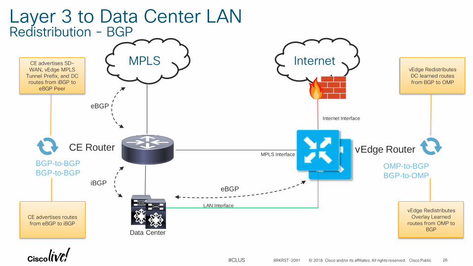
Internet
MPLS Interface
Internet Interface
eBGP
eBGP
Data Center
CE Router vEdge Router
iBGP
LAN Interface
MPLS
OMP-to-BGP
BGP-to-OMP
BGP-to-BGP
BGP-to-BGP
Layer 3 to Data Center LANRedistribution - BGP
CE advertises SD-WAN, vEdge MPLS
Tunnel Prefix, and DC routes from iBGP to
eBGP Peer
vEdge Redistributes DC learned routes from BGP to OMP
CE advertises routes from eBGP to iBGP
vEdge Redistributes Overlay Learned
routes from OMP to BGP
BRKRST-2091 26
© 2018 Cisco and/or its affiliates. All rights reserved. Cisco Public#CLUS
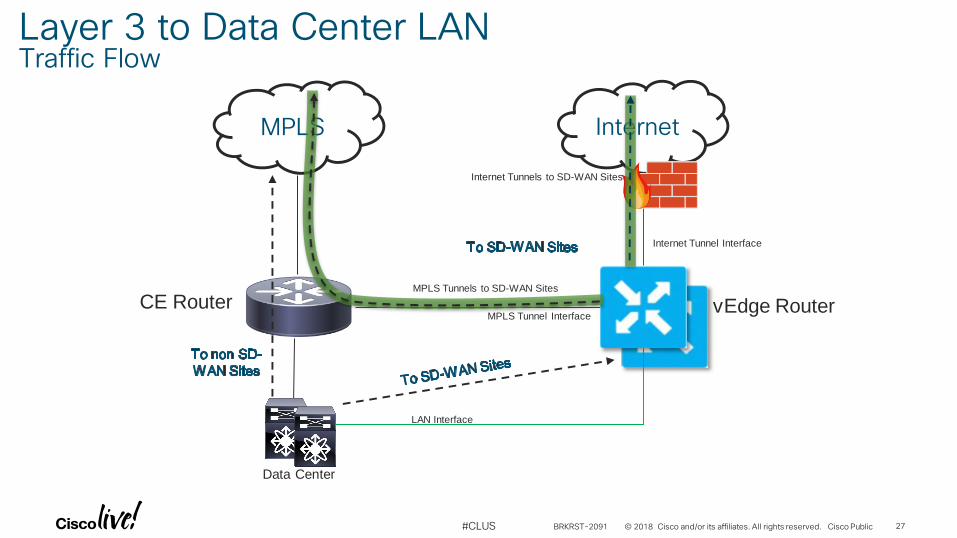
Internet
MPLS Tunnel Interface
Internet Tunnel Interface
Data Center
CE Router vEdge Router
LAN Interface
MPLS
Layer 3 to Data Center LANTraffic Flow
MPLS Tunnels to SD-WAN Sites
Internet Tunnels to SD-WAN Sites
BRKRST-2091 27
© 2018 Cisco and/or its affiliates. All rights reserved. Cisco Public#CLUS
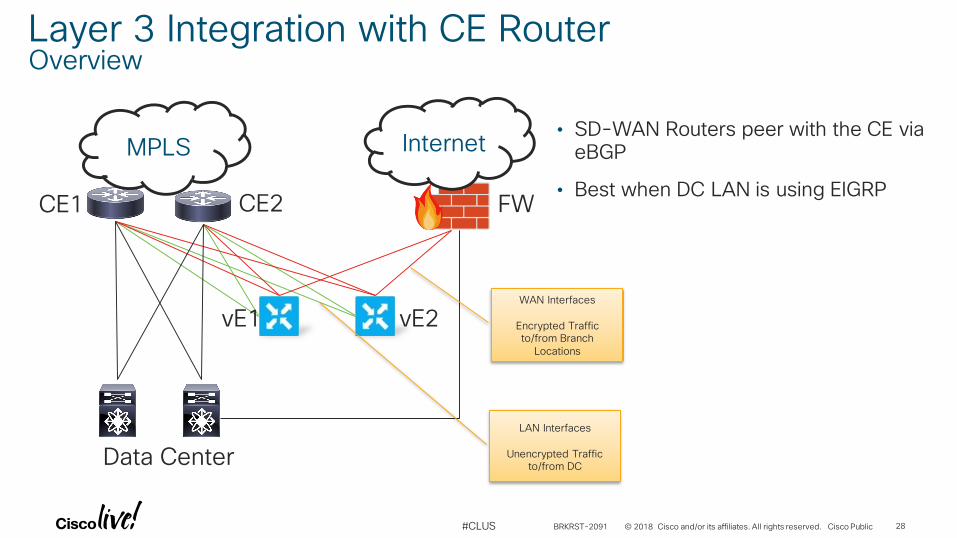
Layer 3 Integration with CE Router Overview
MPLS Internet
WAN Interfaces
Encrypted Traffic to/from Branch
Locations
LAN Interfaces
Unencrypted Traffic to/from DC
CE1 CE2
Data Center
vE1 vE2
FW
• SD-WAN Routers peer with the CE via eBGP
• Best when DC LAN is using EIGRP
BRKRST-2091 28
© 2018 Cisco and/or its affiliates. All rights reserved. Cisco Public#CLUS
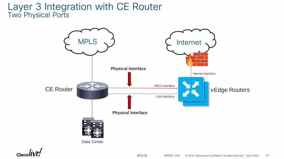
Layer 3 Integration with CE Router Two Physical Ports
Internet Interface
Data Center
CE Router vEdge Routers
Physical Interface
Physical Interface
MPLS Interface
LAN Interface
MPLS Internet
BRKRST-2091 29
© 2018 Cisco and/or its affiliates. All rights reserved. Cisco Public#CLUS
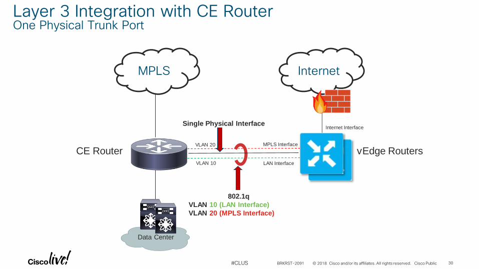
Internet Interface
Data Center
CE Router vEdge Routers
802.1q
VLAN 10 (LAN Interface)
VLAN 20 (MPLS Interface)
MPLS Interface
LAN Interface
MPLS Internet
Single Physical Interface
Layer 3 Integration with CE Router One Physical Trunk Port
VLAN 10
VLAN 20
BRKRST-2091 30
© 2018 Cisco and/or its affiliates. All rights reserved. Cisco Public#CLUS
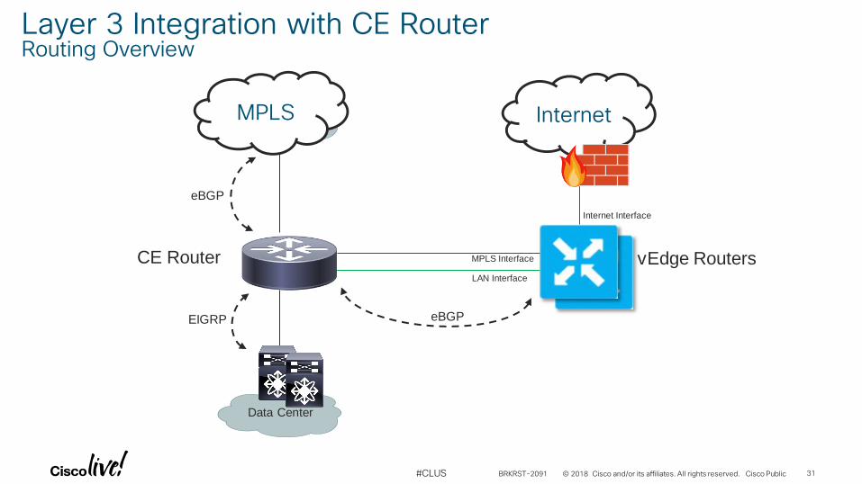
MPLS
MPLS Interface
Internet Interface
eBGP
eBGP
Data Center
CE Router vEdge RoutersLAN Interface
EIGRP
MPLS Internet
Layer 3 Integration with CE Router Routing Overview
BRKRST-2091 31
© 2018 Cisco and/or its affiliates. All rights reserved. Cisco Public#CLUS
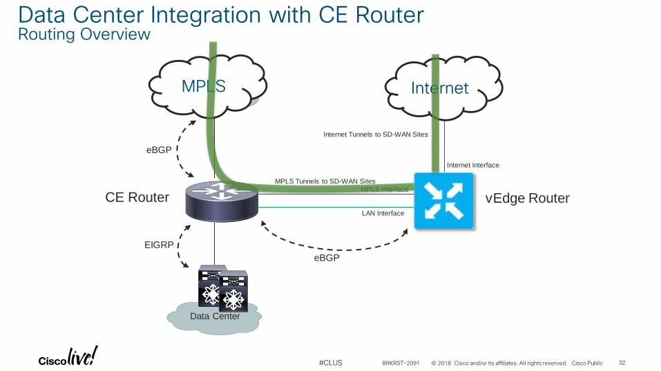
MPLS
MPLS Interface
Internet Interface
eBGP
eBGP
Data Center
CE Router vEdge RouterLAN Interface
EIGRP
MPLS Internet
Data Center Integration with CE RouterRouting Overview
MPLS Tunnels to SD-WAN Sites
Internet Tunnels to SD-WAN Sites
BRKRST-2091 32
© 2018 Cisco and/or its affiliates. All rights reserved. Cisco Public#CLUS
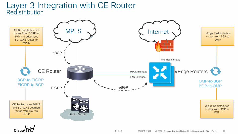
MPLS
MPLS Interface
Internet Interface
eBGP
eBGP
Data Center
CE Router vEdge RoutersLAN Interface
EIGRP
MPLS Internet
OMP-to-BGP
BGP-to-OMP
BGP-to-EIGRP
EIGRP-to-BGP
Layer 3 Integration with CE RouterRedistribution
CE Redistributes DC routes from EIGRP to BGP and advertises SD-WAN routes to
MPLS
vEdge Redistributes routes from BGP to
OMP
CE Redistributes MPLS and SD-WAN Learned
routes from BGP to EIGRP
vEdge Redistributes routes from OMP to
BGP
BRKRST-2091 33
© 2018 Cisco and/or its affiliates. All rights reserved. Cisco Public#CLUS
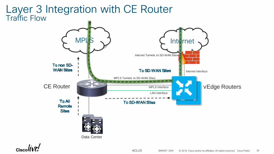
Internet Interface
InternetMPLS
MPLS Interface
Data Center
CE Router vEdge RoutersLAN Interface
MPLS
Layer 3 Integration with CE Router Traffic Flow
MPLS Tunnels to SD-WAN Sites
Internet Tunnels to SD-WAN Sites
BRKRST-2091 34
© 2018 Cisco and/or its affiliates. All rights reserved. Cisco Public#CLUS
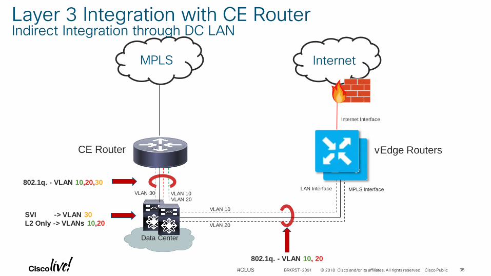
MPLS Interface
Internet Interface
Data Center
CE Router vEdge Routers
LAN Interface
802.1q. - VLAN 10, 20
802.1q. - VLAN 10,20,30
SVI -> VLAN 30
L2 Only -> VLANs 10,20
MPLS Internet
Layer 3 Integration with CE Router Indirect Integration through DC LAN
VLAN 10
VLAN 20
VLAN 30 VLAN 10VLAN 20
BRKRST-2091 35
© 2018 Cisco and/or its affiliates. All rights reserved. Cisco Public#CLUS
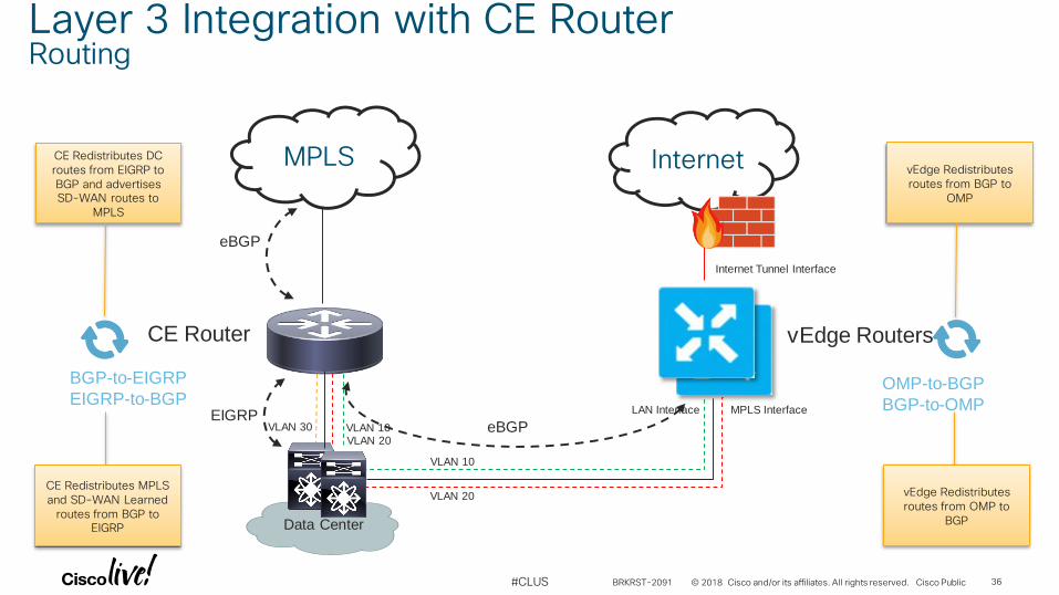
MPLS Interface
Internet Tunnel Interface
eBGP
eBGP
Data Center
CE Router vEdge Routers
EIGRP LAN Interface
MPLS Internet
OMP-to-BGP
BGP-to-OMP
BGP-to-EIGRP
EIGRP-to-BGP
Layer 3 Integration with CE Router Routing
CE Redistributes DC routes from EIGRP to BGP and advertises SD-WAN routes to
MPLS
vEdge Redistributes routes from BGP to
OMP
CE Redistributes MPLS and SD-WAN Learned
routes from BGP to EIGRP
vEdge Redistributes routes from OMP to
BGP
VLAN 10
VLAN 20
VLAN 30 VLAN 10VLAN 20
BRKRST-2091 36
© 2018 Cisco and/or its affiliates. All rights reserved. Cisco Public#CLUS
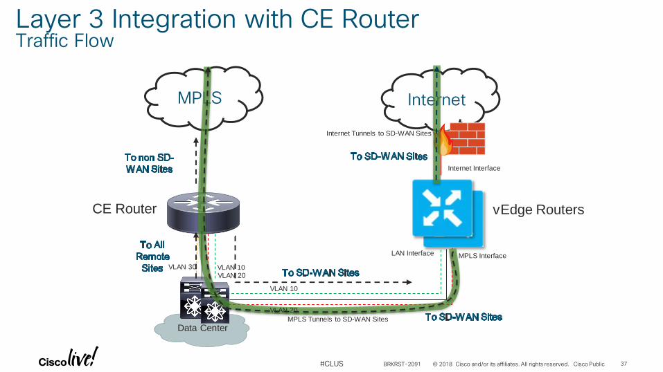
MPLS Interface
Internet Interface
Data Center
CE Router vEdge Routers
LAN Interface
MPLS Internet
Layer 3 Integration with CE Router Traffic Flow
MPLS Tunnels to SD-WAN Sites
Internet Tunnels to SD-WAN Sites
VLAN 10
VLAN 20
VLAN 30 VLAN 10VLAN 20
BRKRST-2091 37
© 2018 Cisco and/or its affiliates. All rights reserved. Cisco Public#CLUS
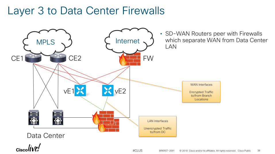
Layer 3 to Data Center Firewalls
MPLS Internet• SD-WAN Routers peer with Firewalls
which separate WAN from Data Center LAN
LAN Interfaces
Unencrypted Traffic to/from DC
CE1 CE2
Data Center
vE1 vE2
FW
WAN Interfaces
Encrypted Traffic to/from Branch
Locations
BRKRST-2091 38
© 2018 Cisco and/or its affiliates. All rights reserved. Cisco Public#CLUS
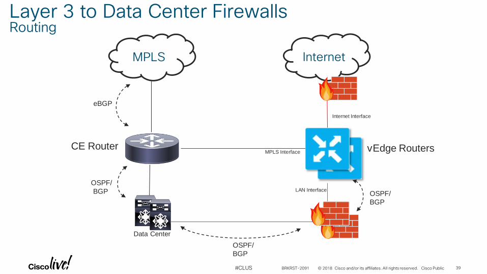
MPLS Interface
Internet Interface
eBGP
Data Center
CE Router vEdge Routers
OSPF/
BGP LAN Interface
MPLS Internet
Layer 3 to Data Center FirewallsRouting
OSPF/
BGP
OSPF/
BGP
BRKRST-2091 39
© 2018 Cisco and/or its affiliates. All rights reserved. Cisco Public#CLUS
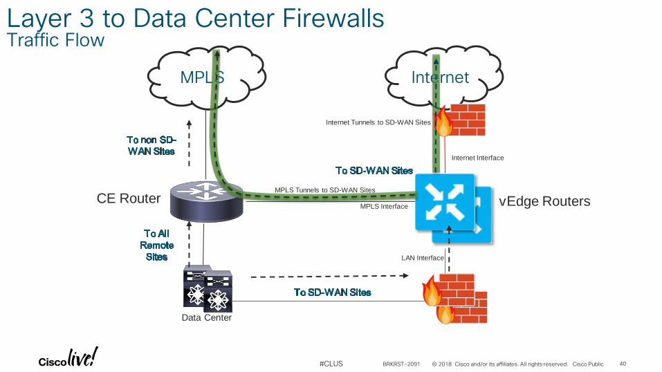
MPLS Interface
Internet Interface
Data Center
CE Router vEdge Routers
LAN Interface
MPLS Internet
Layer 3 to Data Center FirewallsTraffic Flow
MPLS Tunnels to SD-WAN Sites
Internet Tunnels to SD-WAN Sites
BRKRST-2091 40

Branch Design
© 2018 Cisco and/or its affiliates. All rights reserved. Cisco Public#CLUS
Branch Design Principals
• Keep it simple
• Leverage OSPF when possible BGP when necessary
• Integrate routing with the LAN Core if possible
• Integrate routing with Customer Edge when necessary
BRKRST-2091 42
© 2018 Cisco and/or its affiliates. All rights reserved. Cisco Public#CLUS
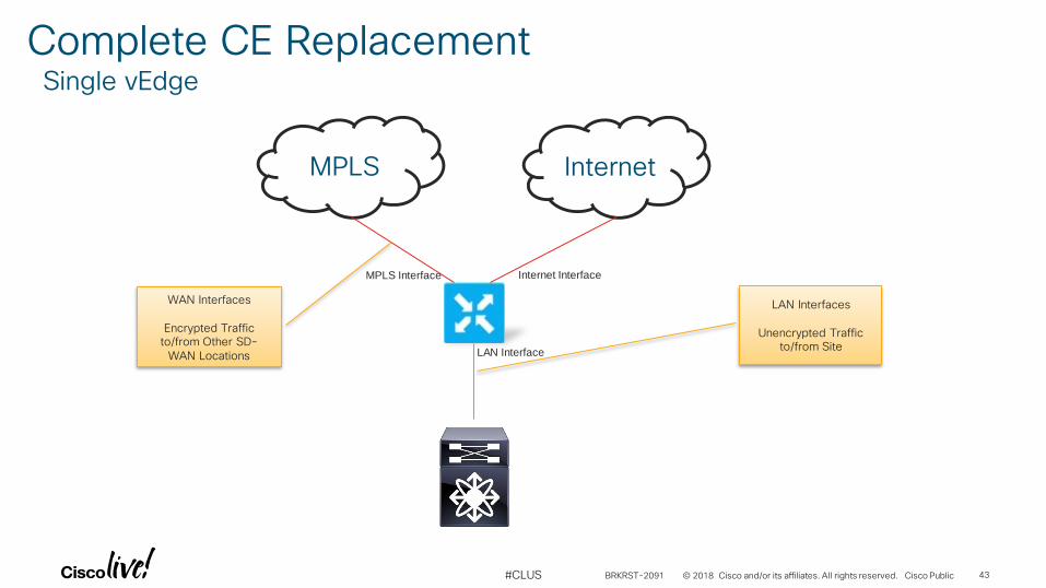
Complete CE ReplacementSingle vEdge
MPLS Internet
WAN Interfaces
Encrypted Traffic to/from Other SD-
WAN Locations
LAN Interfaces
Unencrypted Traffic to/from Site
Internet InterfaceMPLS Interface
LAN Interface
BRKRST-2091 43
© 2018 Cisco and/or its affiliates. All rights reserved. Cisco Public#CLUS
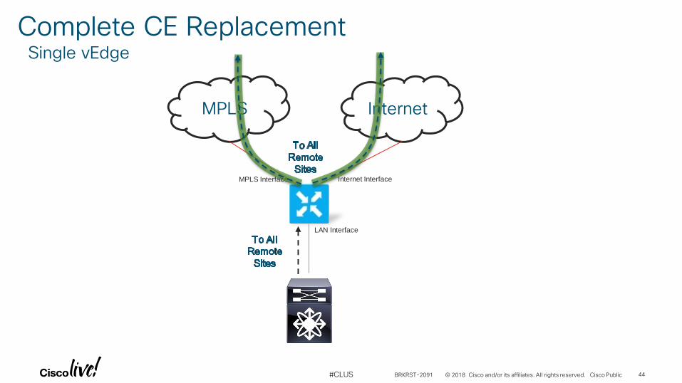
Complete CE ReplacementSingle vEdge
MPLS Internet
Internet InterfaceMPLS Interface
LAN Interface
BRKRST-2091 44
© 2018 Cisco and/or its affiliates. All rights reserved. Cisco Public#CLUS
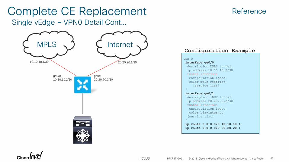
Complete CE ReplacementSingle vEdge – VPN0 Detail Cont…
MPLS Internet
ge0/1
20.20.20.2/30
ge0/0
10.10.10.2/30
10.10.10.1/30 20.20.20.1/30
vpn 0
interface ge0/0
description MPLS tunnel
ip address 10.10.10.2/30
tunnel-interface
encapsulation ipsec
color mpls restrict
[service list]
!
interface ge0/1
description INET tunnel
ip address 20.20.20.2/30
tunnel-interface
encapsulation ipsec
color biz-internet
[service list]
!
ip route 0.0.0.0/0 10.10.10.1
ip route 0.0.0.0/0 20.20.20.1
Configuration Example
Reference
BRKRST-2091 45
© 2018 Cisco and/or its affiliates. All rights reserved. Cisco Public#CLUS
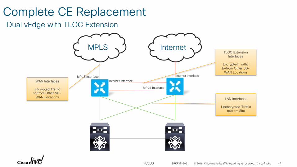
Complete CE ReplacementDual vEdge with TLOC Extension
MPLS Internet
WAN Interfaces
Encrypted Traffic to/from Other SD-
WAN LocationsLAN Interfaces
Unencrypted Traffic to/from Site
TLOC Extension Interfaces
Encrypted Traffic to/from Other SD-
WAN Locations
Internet Interface
MPLS Interface Internet Interface
MPLS Interface
BRKRST-2091 46
© 2018 Cisco and/or its affiliates. All rights reserved. Cisco Public#CLUS
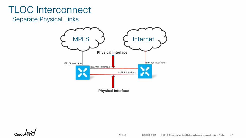
TLOC InterconnectSeparate Physical Links
MPLS Internet
Physical Interface
Physical Interface
Internet Interface
MPLS Interface Internet Interface
MPLS Interface
BRKRST-2091 47
© 2018 Cisco and/or its affiliates. All rights reserved. Cisco Public#CLUS
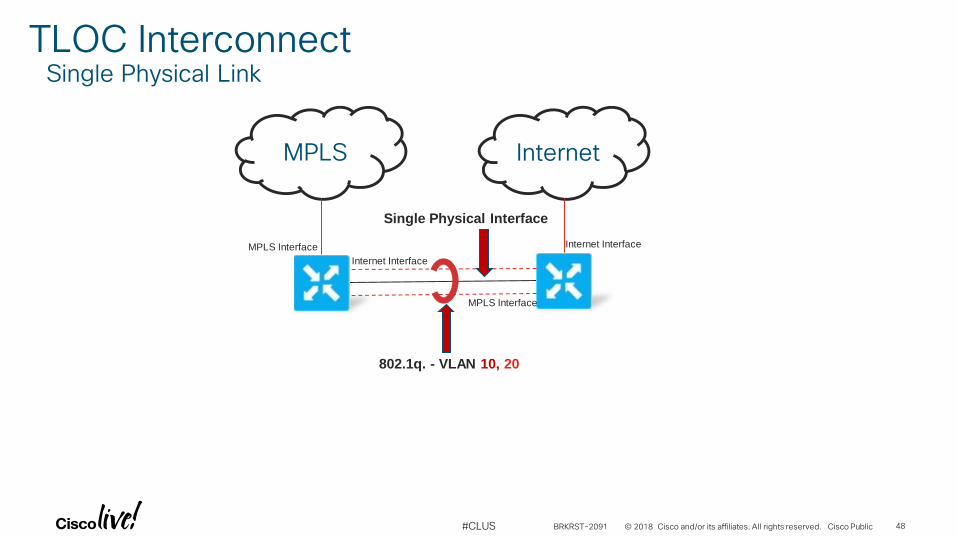
TLOC InterconnectSingle Physical Link
MPLS Internet
Single Physical Interface
802.1q. - VLAN 10, 20
Internet Interface
MPLS Interface Internet Interface
MPLS Interface
BRKRST-2091 48
© 2018 Cisco and/or its affiliates. All rights reserved. Cisco Public#CLUS
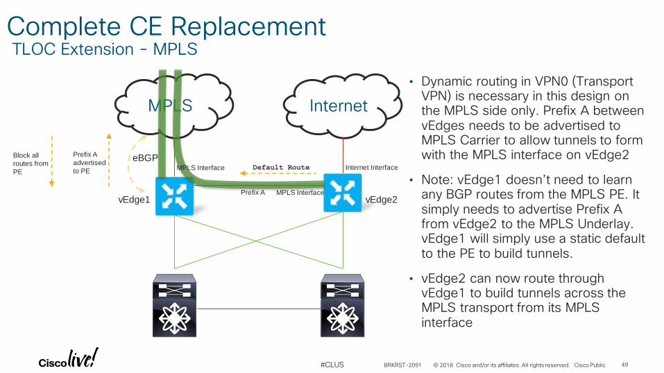
Complete CE ReplacementTLOC Extension - MPLS
MPLS Internet
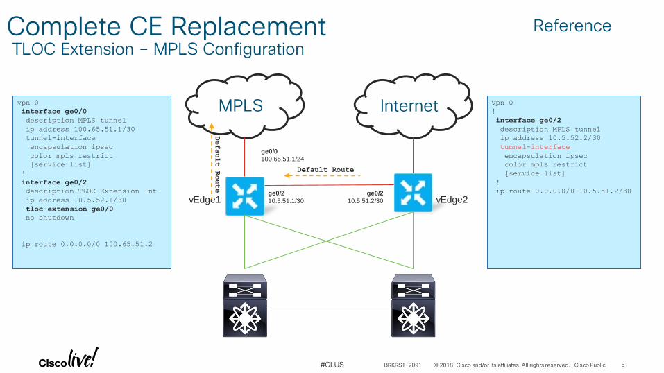
• Dynamic routing in VPN0 (Transport VPN) is necessary in this design on the MPLS side only. Prefix A between vEdges needs to be advertised to MPLS Carrier to allow tunnels to form with the MPLS interface on vEdge2
• Note: vEdge1 doesn’t need to learn any BGP routes from the MPLS PE. It simply needs to advertise Prefix A from vEdge2 to the MPLS Underlay. vEdge1 will simply use a static default to the PE to build tunnels.
• vEdge2 can now route through vEdge1 to build tunnels across the MPLS transport from its MPLS interface
eBGP
Prefix A
Prefix A
advertised
to PE
Block all
routes from
PE
vEdge1 vEdge2
Default RouteMPLS Interface Internet Interface
MPLS Interface
BRKRST-2091 49
© 2018 Cisco and/or its affiliates. All rights reserved. Cisco Public#CLUS
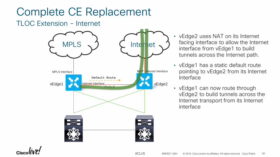
Complete CE ReplacementTLOC Extension - Internet
MPLS Internet
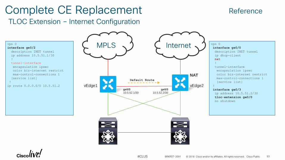
• vEdge2 uses NAT on its Internet facing interface to allow the Internet interface from vEdge1 to build tunnels across the Internet path.
• vEdge1 has a static default route pointing to vEdge2 from its Internet Interface
• vEdge1 can now route through vEdge2 to build tunnels across the Internet transport from its Internet interface
NAT
Prefix B vEdge1 vEdge2
Default Route
Internet Interface
MPLS Interface Internet Interface
BRKRST-2091 50
© 2018 Cisco and/or its affiliates. All rights reserved. Cisco Public#CLUS
Complete CE ReplacementTLOC Extension – MPLS Configuration
MPLS Internet
vEdge1 vEdge2ge0/2
10.5.51.1/30
ge0/0
100.65.51.1/24
ge0/2
10.5.51.2/30
vpn 0
interface ge0/0
description MPLS tunnel
ip address 100.65.51.1/30
tunnel-interface
encapsulation ipsec
color mpls restrict
[service list]
!
interface ge0/2
description TLOC Extension Int
ip address 10.5.52.1/30
tloc-extension ge0/0
no shutdown
ip route 0.0.0.0/0 100.65.51.2
vpn 0
!
interface ge0/2
description MPLS tunnel
ip address 10.5.52.2/30
tunnel-interface
encapsulation ipsec
color mpls restrict
[service list]
!
ip route 0.0.0.0/0 10.5.51.2/30
Default Route
Default Route
Reference
BRKRST-2091 51
© 2018 Cisco and/or its affiliates. All rights reserved. Cisco Public#CLUS
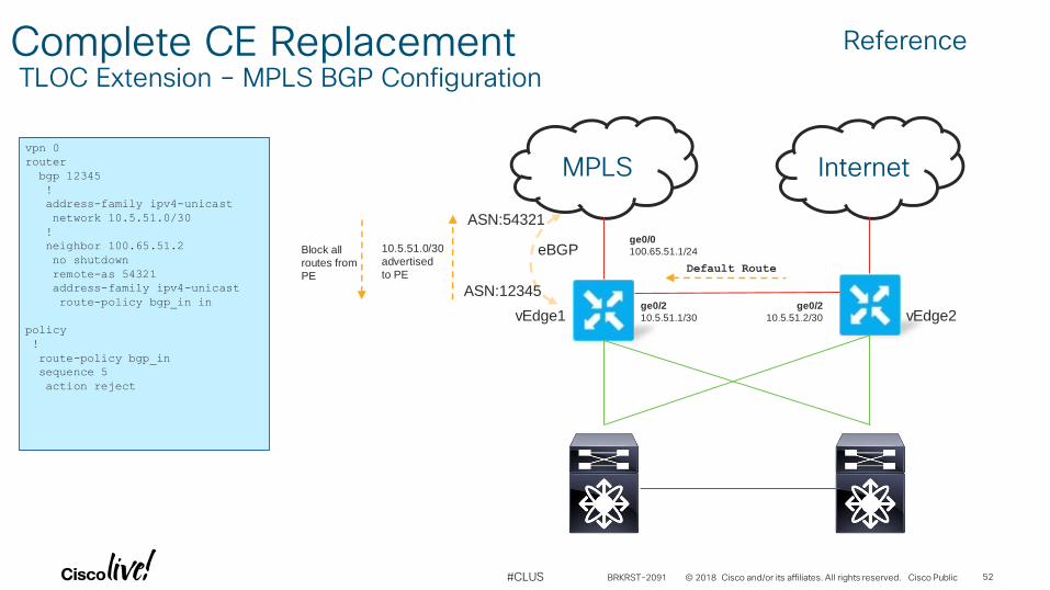
Complete CE ReplacementTLOC Extension – MPLS BGP Configuration
MPLS Internet
eBGP
vEdge1 vEdge2ge0/2
10.5.51.1/30
ge0/0
100.65.51.1/24
ge0/2
10.5.51.2/30
Default Route
vpn 0
router
bgp 12345
!
address-family ipv4-unicast
network 10.5.51.0/30
!
neighbor 100.65.51.2
no shutdown
remote-as 54321
address-family ipv4-unicast
route-policy bgp_in in
policy
!
route-policy bgp_in
sequence 5
action reject
10.5.51.0/30
advertised
to PE
Block all
routes from
PE
ASN:54321
ASN:12345
Reference
BRKRST-2091 52
© 2018 Cisco and/or its affiliates. All rights reserved. Cisco Public#CLUS
Complete CE ReplacementTLOC Extension – Internet Configuration
MPLS Internet
NAT
vEdge1 vEdge2
Default Route
vpn 0
interface ge0/2
description INET tunnel
ip address 10.5.51.1/30
!
tunnel-interface
encapsulation ipsec
color biz-internet restrict
max-control-connections 1
[service list]
!
ip route 0.0.0.0/0 10.5.51.2
vpn 0
interface ge0/0
description INET tunnel
ip dhcp-client
nat
!
tunnel-interface
encapsulation ipsec
color biz-internet restrict
max-control-connections 1
[service list]
!
interface ge0/3
ip address 10.5.51.2/30
tloc-extension ge0/0
no shutdown
ge0/3
10.5.52.1/30
ge0/3
10.5.52.2/30
Reference
BRKRST-2091 53
© 2018 Cisco and/or its affiliates. All rights reserved. Cisco Public#CLUS
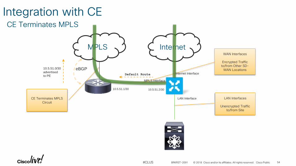
Integration with CECE Terminates MPLS
MPLS Internet
CE Terminates MPLS Circuit
LAN Interfaces
Unencrypted Traffic to/from Site
WAN Interfaces
Encrypted Traffic to/from Other SD-
WAN LocationseBGP10.5.51.0/30
advertised
to PE Default Route
10.5.51.1/30 10.5.51.2/30
Internet Interface
MPLS Interface
LAN Interface
BRKRST-2091 54
© 2018 Cisco and/or its affiliates. All rights reserved. Cisco Public#CLUS
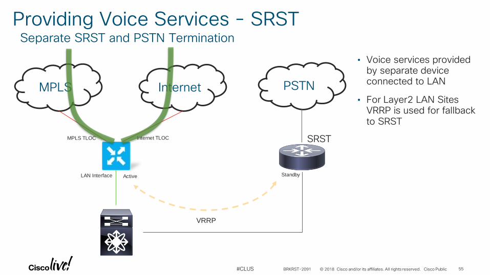
Providing Voice Services - SRSTSeparate SRST and PSTN Termination
MPLS Internet
Internet TLOCMPLS TLOC
LAN Interface
PSTN
SRST
VRRP
• Voice services provided by separate device connected to LAN
• For Layer2 LAN Sites VRRP is used for fallback to SRST
Active Standby
BRKRST-2091 55
© 2018 Cisco and/or its affiliates. All rights reserved. Cisco Public#CLUS
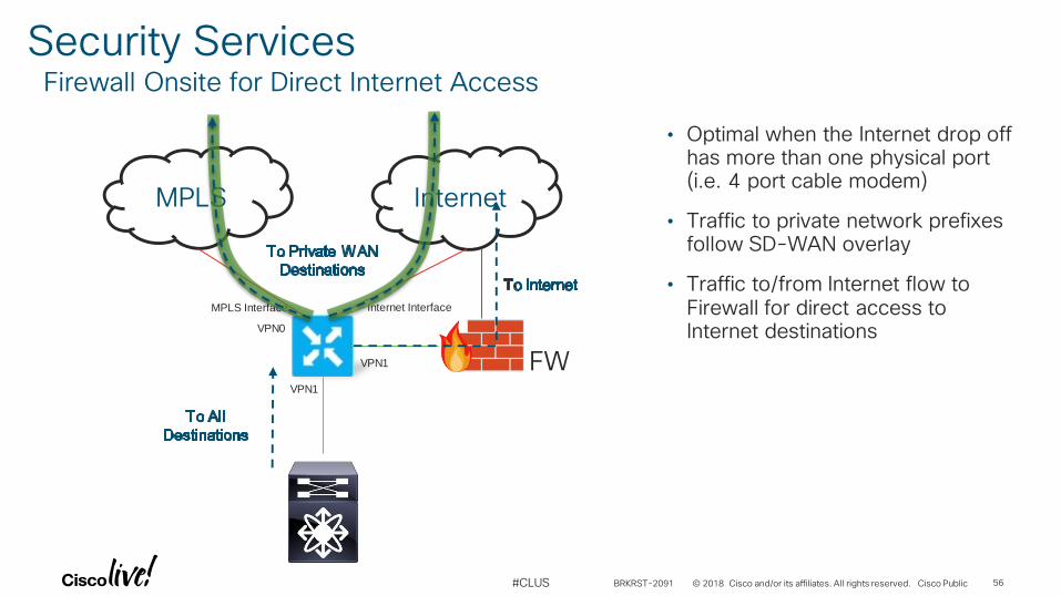
Security ServicesFirewall Onsite for Direct Internet Access
MPLS Internet
Internet InterfaceMPLS Interface
VPN1
• Optimal when the Internet drop off has more than one physical port (i.e. 4 port cable modem)
• Traffic to private network prefixes follow SD-WAN overlay
• Traffic to/from Internet flow to Firewall for direct access to Internet destinations
FWVPN1
VPN0
BRKRST-2091 56
© 2018 Cisco and/or its affiliates. All rights reserved. Cisco Public#CLUS
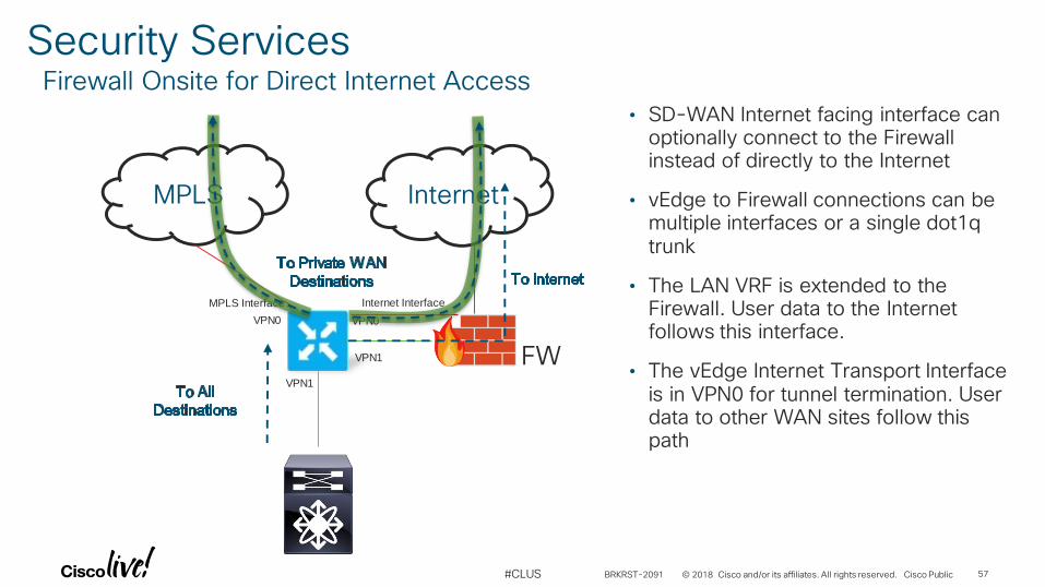
Security ServicesFirewall Onsite for Direct Internet Access
MPLS Internet
Internet InterfaceMPLS Interface
VPN1
• SD-WAN Internet facing interface can optionally connect to the Firewall instead of directly to the Internet
• vEdge to Firewall connections can be multiple interfaces or a single dot1q trunk
• The LAN VRF is extended to the Firewall. User data to the Internet follows this interface.
• The vEdge Internet Transport Interface is in VPN0 for tunnel termination. User data to other WAN sites follow this path
FWVPN1
VPN0 VPN0
BRKRST-2091 57
© 2018 Cisco and/or its affiliates. All rights reserved. Cisco Public#CLUS
Internet
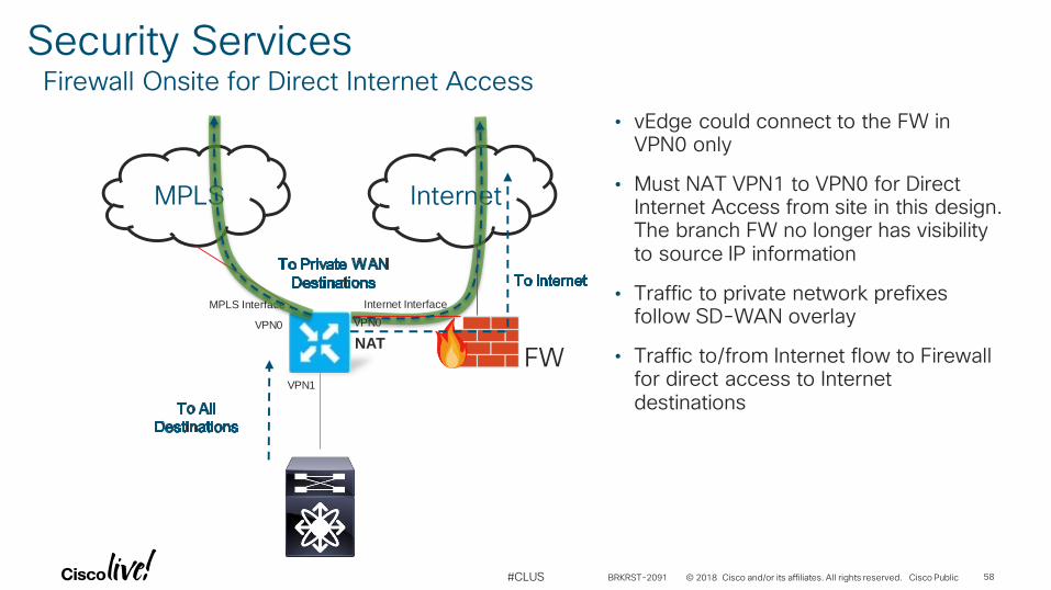
Security ServicesFirewall Onsite for Direct Internet Access
MPLS
Internet InterfaceMPLS Interface
VPN1
• vEdge could connect to the FW in VPN0 only
• Must NAT VPN1 to VPN0 for Direct Internet Access from site in this design. The branch FW no longer has visibility to source IP information
• Traffic to private network prefixes follow SD-WAN overlay
• Traffic to/from Internet flow to Firewall for direct access to Internet destinations
FW
VPN0 VPN0
NAT
BRKRST-2091 58
© 2018 Cisco and/or its affiliates. All rights reserved. Cisco Public#CLUS
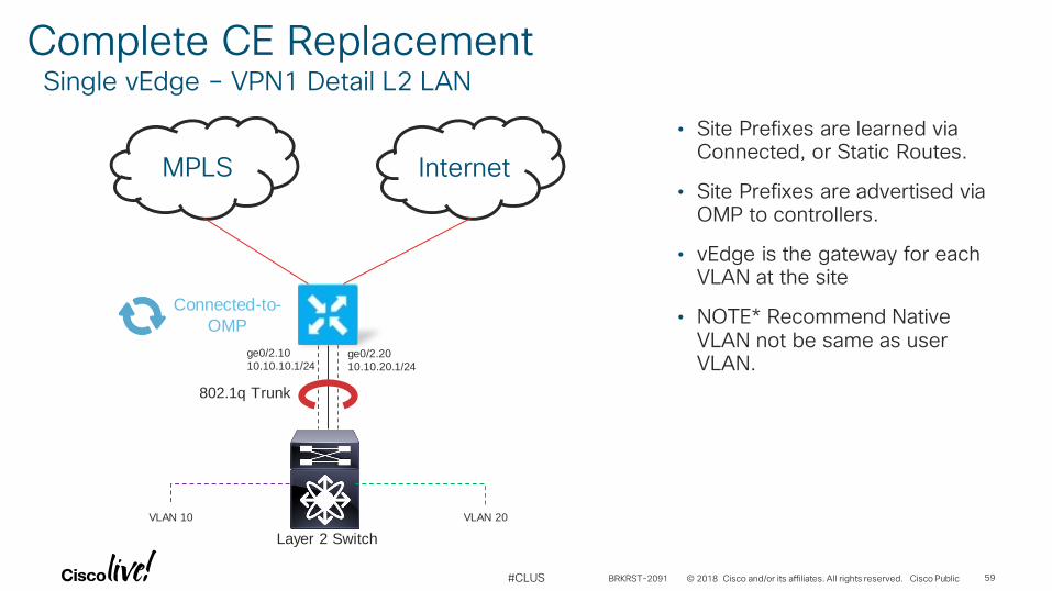
Complete CE ReplacementSingle vEdge – VPN1 Detail L2 LAN
MPLS Internet
ge0/2.20
10.10.20.1/24
• Site Prefixes are learned via Connected, or Static Routes.
• Site Prefixes are advertised via OMP to controllers.
• vEdge is the gateway for each VLAN at the site
• NOTE* Recommend Native VLAN not be same as user VLAN.
802.1q Trunk
Connected-to-
OMP
Layer 2 Switch
ge0/2.10
10.10.10.1/24
VLAN 10 VLAN 20
BRKRST-2091 59
© 2018 Cisco and/or its affiliates. All rights reserved. Cisco Public#CLUS
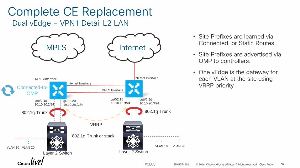
Complete CE ReplacementDual vEdge – VPN1 Detail L2 LAN
MPLS Internet
ge0/2.20
10.10.20.2/24
• Site Prefixes are learned via Connected, or Static Routes.
• Site Prefixes are advertised via OMP to controllers.
• One vEdge is the gateway for each VLAN at the site using VRRP priority
802.1q Trunk
Connected-to-
OMP
Layer 2 Switch
ge0/2.10
10.10.10.2/24
VLAN 10 VLAN 20
Internet Interface
MPLS Interface Internet Interface
MPLS Interface
ge0/2.20
10.10.20.3/24
802.1q Trunk
Layer 2 Switch
ge0/2.10
10.10.10.3/24
VLAN 10 VLAN 20
VRRP
802.1q Trunk or stack
BRKRST-2091 60
© 2018 Cisco and/or its affiliates. All rights reserved. Cisco Public#CLUS
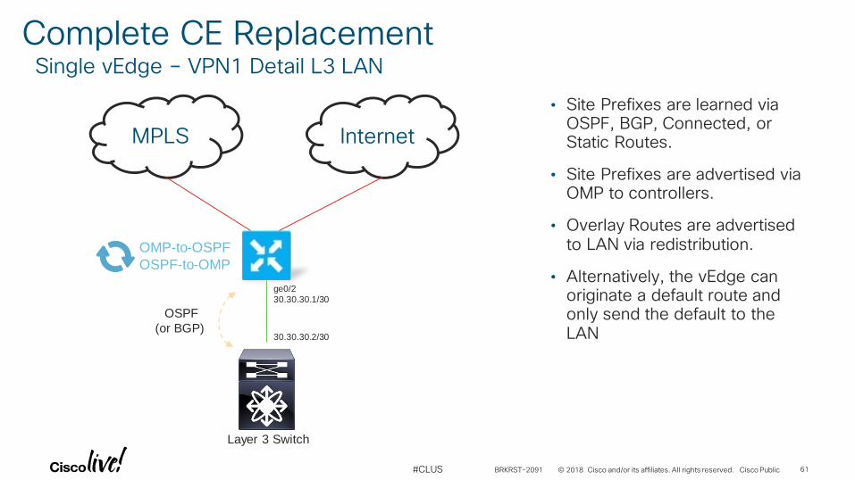
Complete CE ReplacementSingle vEdge – VPN1 Detail L3 LAN
MPLS Internet
ge0/2
30.30.30.1/30
30.30.30.2/30
• Site Prefixes are learned via OSPF, BGP, Connected, or Static Routes.
• Site Prefixes are advertised via OMP to controllers.
• Overlay Routes are advertised to LAN via redistribution.
• Alternatively, the vEdge can originate a default route and only send the default to the LAN
OSPF
(or BGP)
OMP-to-OSPF
OSPF-to-OMP
Layer 3 Switch
BRKRST-2091 61
© 2018 Cisco and/or its affiliates. All rights reserved. Cisco Public#CLUS
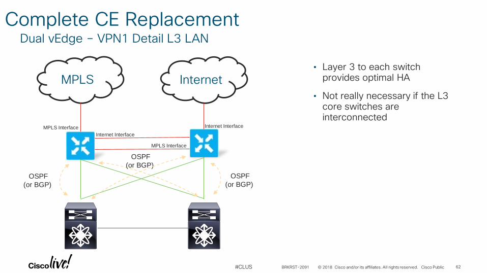
Complete CE Replacement
MPLS Internet
Internet Interface
MPLS Interface Internet Interface
MPLS Interface
Dual vEdge – VPN1 Detail L3 LAN
OSPF
(or BGP)
OSPF
(or BGP)
OSPF
(or BGP)
• Layer 3 to each switch provides optimal HA
• Not really necessary if the L3 core switches are interconnected
BRKRST-2091 62
© 2018 Cisco and/or its affiliates. All rights reserved. Cisco Public#CLUS
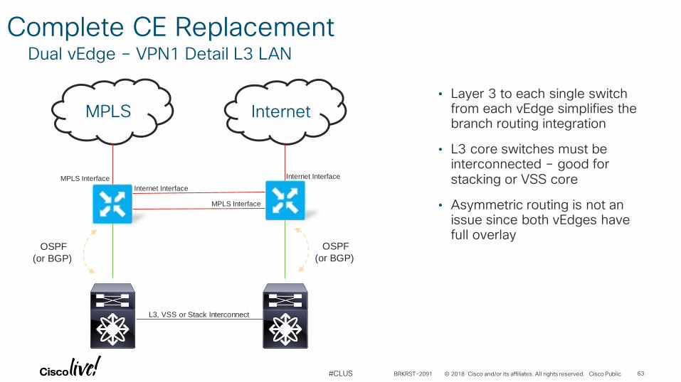
Complete CE Replacement
MPLS Internet
Internet Interface
MPLS Interface Internet Interface
MPLS Interface
Dual vEdge – VPN1 Detail L3 LAN
OSPF
(or BGP)
OSPF
(or BGP)
• Layer 3 to each single switch from each vEdge simplifies the branch routing integration
• L3 core switches must be interconnected – good for stacking or VSS core
• Asymmetric routing is not an issue since both vEdges have full overlay
L3, VSS or Stack Interconnect
BRKRST-2091 63
© 2018 Cisco and/or its affiliates. All rights reserved. Cisco Public#CLUS
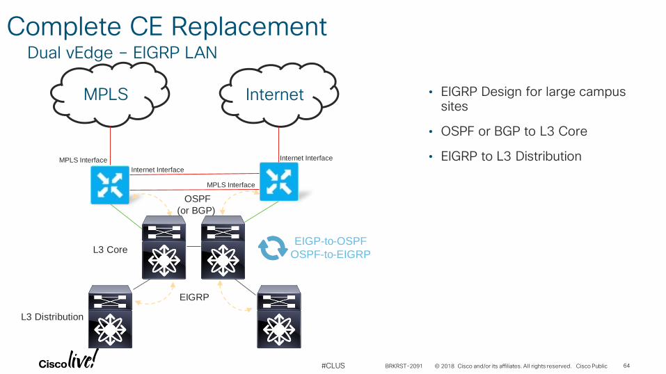
Complete CE Replacement
MPLS Internet
Internet Interface
MPLS Interface Internet Interface
MPLS Interface
Dual vEdge – EIGRP LAN
OSPF
(or BGP)
• EIGRP Design for large campus sites
• OSPF or BGP to L3 Core
• EIGRP to L3 Distribution
EIGRP
EIGP-to-OSPF
OSPF-to-EIGRPL3 Core
L3 Distribution
BRKRST-2091 64
© 2018 Cisco and/or its affiliates. All rights reserved. Cisco Public#CLUS
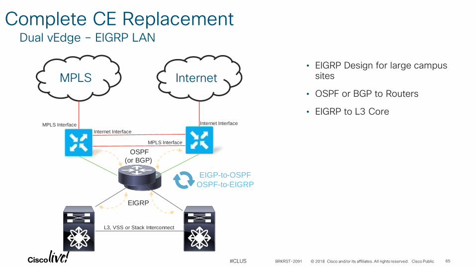
Complete CE Replacement
MPLS Internet
Internet Interface
MPLS Interface Internet Interface
MPLS Interface
Dual vEdge – EIGRP LAN
OSPF
(or BGP)
L3, VSS or Stack Interconnect
EIGRP
EIGP-to-OSPF
OSPF-to-EIGRP
• EIGRP Design for large campus sites
• OSPF or BGP to Routers
• EIGRP to L3 Core
BRKRST-2091 65
© 2018 Cisco and/or its affiliates. All rights reserved. Cisco Public#CLUS
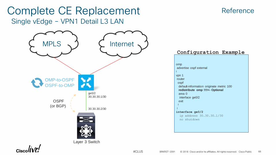
Complete CE ReplacementSingle vEdge – VPN1 Detail L3 LAN
MPLS Internet
ge0/2
30.30.30.1/30
30.30.30.2/30
OSPF
(or BGP)
OMP-to-OSPF
OSPF-to-OMP
omp
advertise ospf external
!vpn 1
router
ospf
default-information originate metric 100
redistribute omp !!!!<- Optional
area 0
interface ge0/2
exit
!!interface ge0/2
ip address 30.30.30.1/30
no shutdown
Configuration Example
Layer 3 Switch
Reference
BRKRST-2091 66
© 2018 Cisco and/or its affiliates. All rights reserved. Cisco Public#CLUS
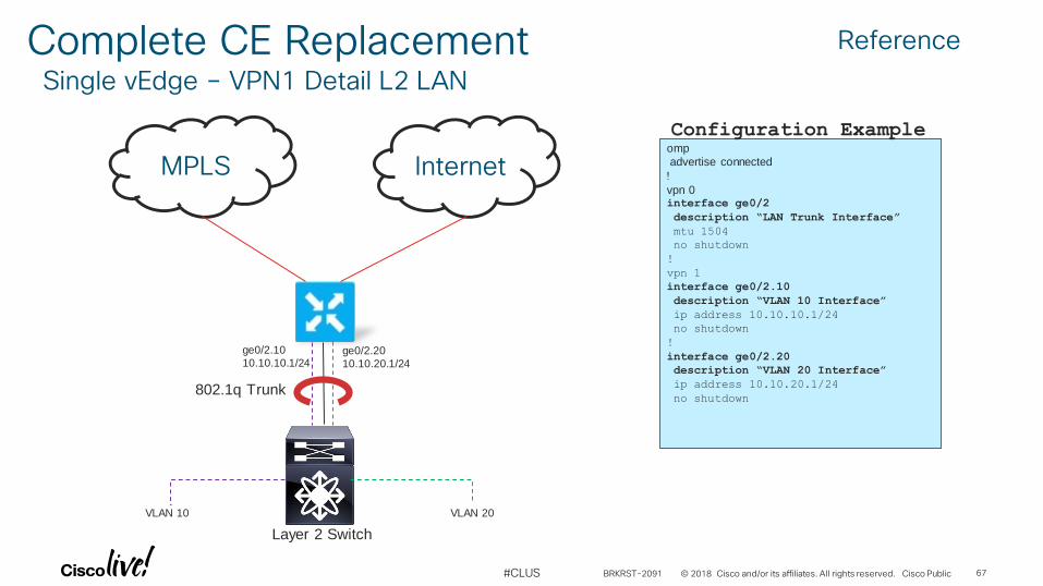
Complete CE ReplacementSingle vEdge – VPN1 Detail L2 LAN
MPLS Internetomp
advertise connected
!vpn 0interface ge0/2
description “LAN Trunk Interface”
mtu 1504
no shutdown
!
vpn 1
interface ge0/2.10
description “VLAN 10 Interface”
ip address 10.10.10.1/24
no shutdown
!
interface ge0/2.20
description “VLAN 20 Interface”
ip address 10.10.20.1/24
no shutdown
Configuration Example
ge0/2.20
10.10.20.1/24
802.1q Trunk
Layer 2 Switch
ge0/2.10
10.10.10.1/24
VLAN 10 VLAN 20
Reference
BRKRST-2091 67

Segmentation
© 2018 Cisco and/or its affiliates. All rights reserved. Cisco Public#CLUS
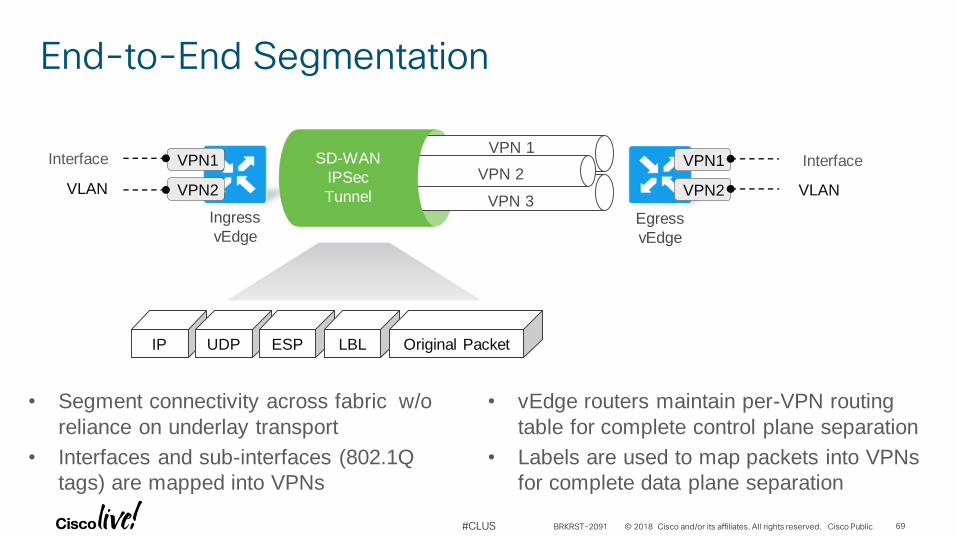
End-to-End Segmentation
Ingress
vEdge
VPN 3
VPN 1
VPN 2SD-WAN
IPSec
Tunnel
IP UDP ESP LBL Original Packet
Egress
vEdge
Interface
VLAN
• Segment connectivity across fabric w/o
reliance on underlay transport
• Interfaces and sub-interfaces (802.1Q
tags) are mapped into VPNs
• vEdge routers maintain per-VPN routing
table for complete control plane separation
• Labels are used to map packets into VPNs
for complete data plane separation
VPN1
VPN2
Interface
VLAN
VPN1
VPN2
BRKRST-2091 69
© 2018 Cisco and/or its affiliates. All rights reserved. Cisco Public#CLUS
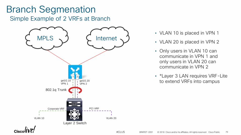
Branch SegmenationSimple Example of 2 VRFs at Branch
MPLS Internet
ge0/2.20
VPN 2
• VLAN 10 is placed in VPN 1
• VLAN 20 is placed in VPN 2
• Only users in VLAN 10 can communicate in VPN 1 and only users in VLAN 20 can communicate in VPN 2
• *Layer 3 LAN requires VRF-Lite to extend VRFs into campus
802.1q Trunk
Layer 2 Switch
ge0/2.10
VPN 1
VLAN 10 VLAN 20
Corporate VRF PCI VRF
1 2
BRKRST-2091 70
© 2018 Cisco and/or its affiliates. All rights reserved. Cisco Public#CLUS
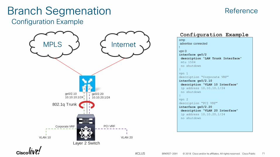
MPLS Internetomp
advertise connected
!vpn 0interface ge0/2
description “LAN Trunk Interface”
mtu 1504
no shutdown
!
vpn 1
description “Corporate VRF”
interface ge0/2.10
description “VLAN 10 Interface”
ip address 10.10.10.1/24
no shutdown
!
vpn 2
description “PCI VRF”
interface ge0/2.20
description “VLAN 20 Interface”
ip address 10.10.20.1/24
no shutdown
Configuration Example
ge0/2.20
10.10.20.1/24
802.1q Trunk
Layer 2 Switch
ge0/2.10
10.10.10.1/24
VLAN 10 VLAN 20
Reference
Corporate VRF PCI VRF
1 2
Branch SegmenationConfiguration Example
BRKRST-2091 71
© 2018 Cisco and/or its affiliates. All rights reserved. Cisco Public#CLUS
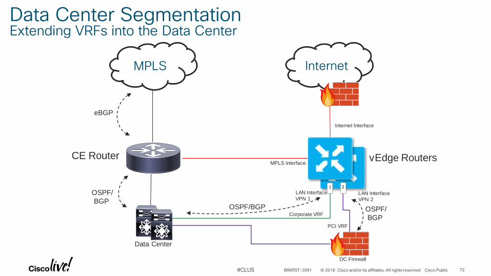
Internet
MPLS Interface
Internet Interface
eBGP
OSPF/BGP
Data Center
CE Router vEdge Routers
OSPF/
BGP
LAN Interface
VPN 1
MPLS
Data Center SegmentationExtending VRFs into the Data Center
LAN Interface
VPN 2
21
OSPF/
BGP
DC Firewall
PCI VRF
Corporate VRF
BRKRST-2091 72

Overlay/Underlay Routing
© 2018 Cisco and/or its affiliates. All rights reserved. Cisco Public#CLUS
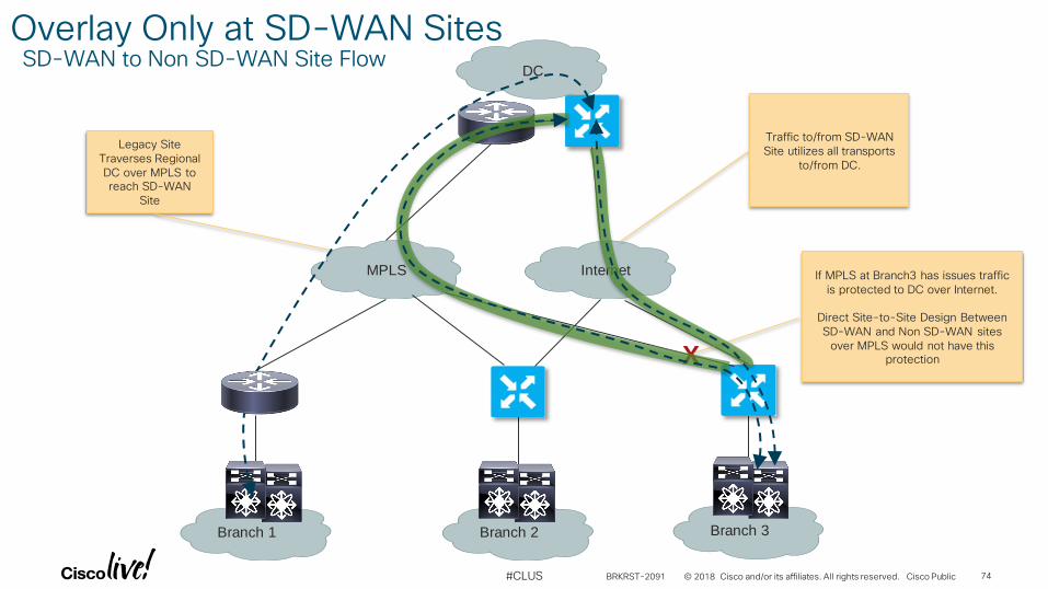
MPLS
Branch 1
Internet
Branch 2 Branch 3
DC
Legacy Site Traverses Regional DC over MPLS to reach SD-WAN
Site
Traffic to/from SD-WAN Site utilizes all transports
to/from DC.
X
If MPLS at Branch3 has issues traffic is protected to DC over Internet.
Direct Site-to-Site Design Between SD-WAN and Non SD-WAN sites
over MPLS would not have this protection
Overlay Only at SD-WAN SitesSD-WAN to Non SD-WAN Site Flow
BRKRST-2091 74
© 2018 Cisco and/or its affiliates. All rights reserved. Cisco Public#CLUS
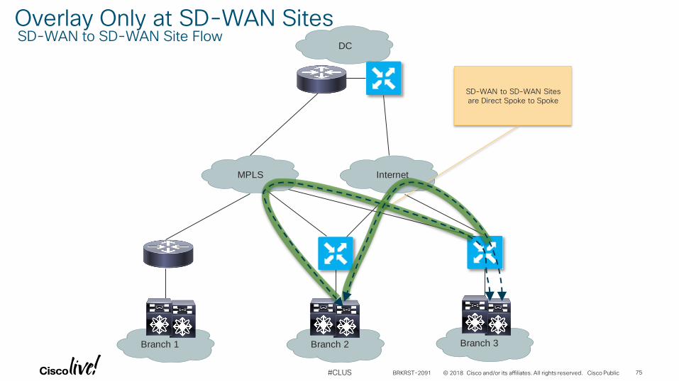
MPLS
Branch 1
Internet
Branch 2 Branch 3
DC
SD-WAN to SD-WAN Sites are Direct Spoke to Spoke
Overlay Only at SD-WAN SitesSD-WAN to SD-WAN Site Flow
BRKRST-2091 75
© 2018 Cisco and/or its affiliates. All rights reserved. Cisco Public#CLUS
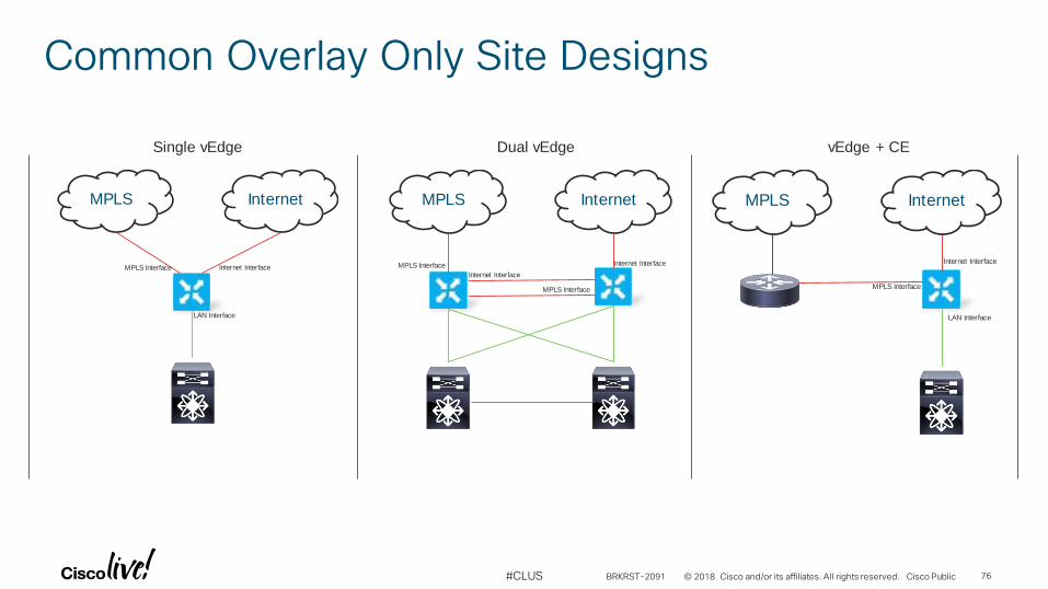
Common Overlay Only Site Designs
MPLS Internet
Internet InterfaceMPLS Interface
LAN Interface
MPLS Internet
Internet Interface
MPLS Interface Internet Interface
MPLS Interface
MPLS Internet
Internet Interface
MPLS Interface
LAN Interface
Single vEdge Dual vEdge vEdge + CE
BRKRST-2091 76
© 2018 Cisco and/or its affiliates. All rights reserved. Cisco Public#CLUS
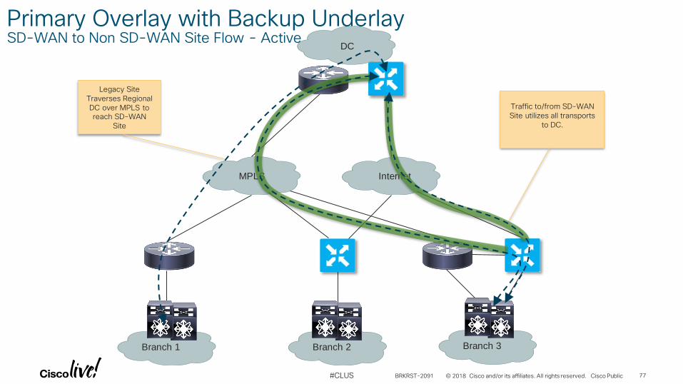
MPLS
Branch 1
Internet
Branch 2 Branch 3
DC
Legacy Site Traverses Regional DC over MPLS to reach SD-WAN
Site
Traffic to/from SD-WAN Site utilizes all transports
to DC.
Primary Overlay with Backup UnderlaySD-WAN to Non SD-WAN Site Flow - Active
BRKRST-2091 77
© 2018 Cisco and/or its affiliates. All rights reserved. Cisco Public#CLUS
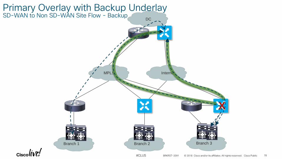
MPLS
Branch 1
Internet
Branch 2 Branch 3
DC
X
Primary Overlay with Backup UnderlaySD-WAN to Non SD-WAN Site Flow - Backup
BRKRST-2091 78
© 2018 Cisco and/or its affiliates. All rights reserved. Cisco Public#CLUS
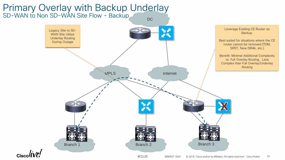
MPLS
Branch 1
Internet
Branch 2 Branch 3
DC
Legacy Site to SD-WAN Site Utilize Underlay Routing During Outage
Leverage Existing CE Router as Backup.
Best suited for situations where the CE router cannot be removed (TDM,
SRST, New ISR4k, etc.)
Benefit: Minimal Additional Complexity vs. Full Overlay Routing. Less
Complex than Full Overlay/Underlay Routing
X
Primary Overlay with Backup UnderlaySD-WAN to Non SD-WAN Site Flow - Backup
BRKRST-2091 79
© 2018 Cisco and/or its affiliates. All rights reserved. Cisco Public#CLUS
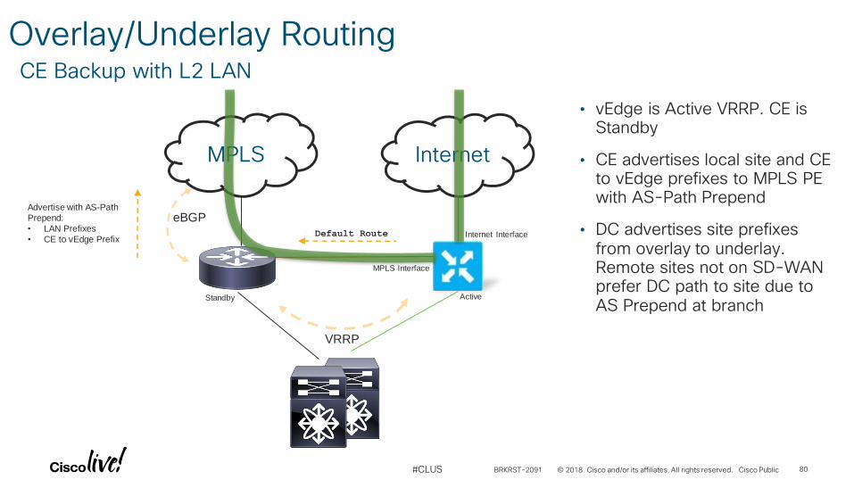
Overlay/Underlay RoutingCE Backup with L2 LAN
MPLS Internet
eBGPAdvertise with AS-Path
Prepend:
• LAN Prefixes
• CE to vEdge PrefixDefault Route Internet Interface
MPLS Interface
VRRP
Standby Active
• vEdge is Active VRRP. CE is Standby
• CE advertises local site and CE to vEdge prefixes to MPLS PE with AS-Path Prepend
• DC advertises site prefixes from overlay to underlay. Remote sites not on SD-WAN prefer DC path to site due to AS Prepend at branch
BRKRST-2091 80
© 2018 Cisco and/or its affiliates. All rights reserved. Cisco Public#CLUS
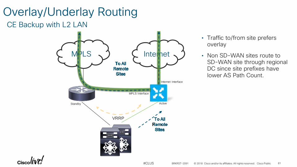
Overlay/Underlay RoutingCE Backup with L2 LAN
MPLS Internet
Internet Interface
MPLS Interface
VRRP
Standby Active
• Traffic to/from site prefers overlay
• Non SD-WAN sites route to SD-WAN site through regional DC since site prefixes have lower AS Path Count.
BRKRST-2091 81
© 2018 Cisco and/or its affiliates. All rights reserved. Cisco Public#CLUS
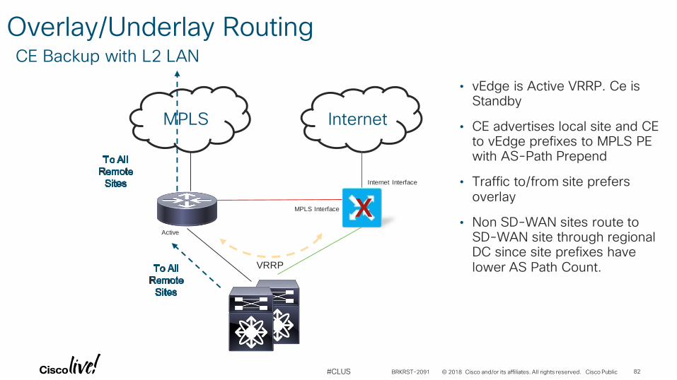
Overlay/Underlay RoutingCE Backup with L2 LAN
MPLS Internet
Internet Interface
MPLS Interface
VRRP
Active
• vEdge is Active VRRP. Ce is Standby
• CE advertises local site and CE to vEdge prefixes to MPLS PE with AS-Path Prepend
• Traffic to/from site prefers overlay
• Non SD-WAN sites route to SD-WAN site through regional DC since site prefixes have lower AS Path Count.
X
BRKRST-2091 82
© 2018 Cisco and/or its affiliates. All rights reserved. Cisco Public#CLUS
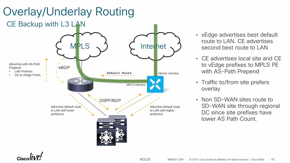
Overlay/Underlay RoutingCE Backup with L3 LAN
MPLS Internet
eBGPAdvertise with AS-Path
Prepend:
• LAN Prefixes
• CE to vEdge PrefixDefault Route Internet Interface
MPLS Interface
OSPF/BGP
Advertise default route
to LAN with lower
preferece
Advertise default route
to LAN with higher
preferece
• vEdge advertises best default route to LAN. CE advertises second best route to LAN
• CE advertises local site and CE to vEdge prefixes to MPLS PE with AS-Path Prepend
• Traffic to/from site prefers overlay
• Non SD-WAN sites route to SD-WAN site through regional DC since site prefixes have lower AS Path Count.
BRKRST-2091 83
© 2018 Cisco and/or its affiliates. All rights reserved. Cisco Public#CLUS
MPLS
eBGP
eBGP
Data Center
CE Router
vEdge Router
LAN Interface
EIGRP
MPLS
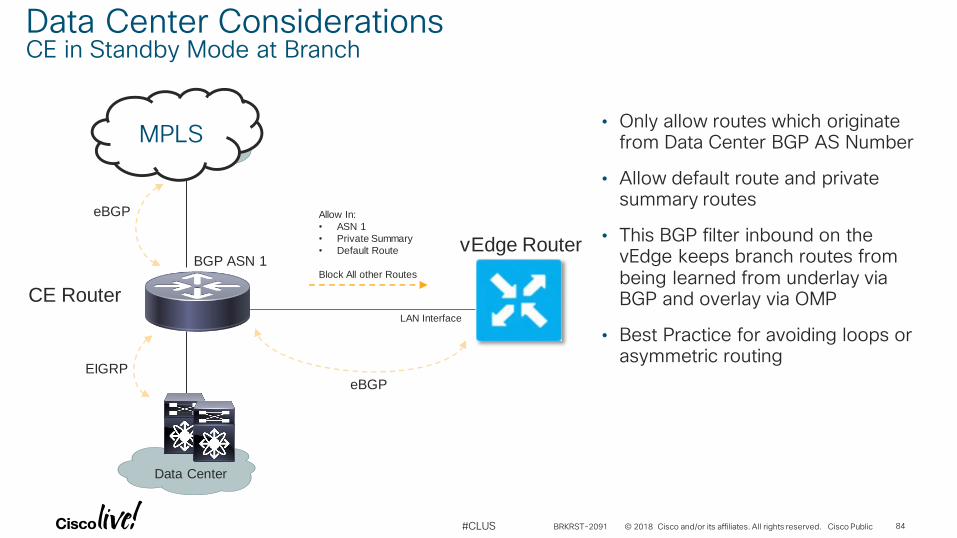
Data Center ConsiderationsCE in Standby Mode at Branch
• Only allow routes which originate from Data Center BGP AS Number
• Allow default route and private summary routes
• This BGP filter inbound on the vEdge keeps branch routes from being learned from underlay via BGP and overlay via OMP
• Best Practice for avoiding loops or asymmetric routing
Allow In:
• ASN 1
• Private Summary
• Default Route
Block All other Routes
BGP ASN 1
BRKRST-2091 84
© 2018 Cisco and/or its affiliates. All rights reserved. Cisco Public#CLUS
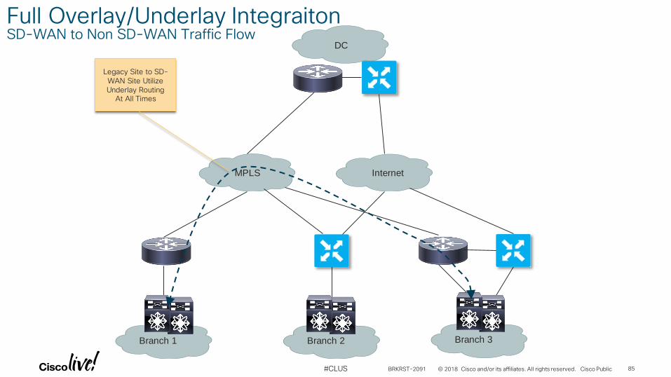
MPLS
Branch 1
Internet
Branch 2 Branch 3
DC
Legacy Site to SD-WAN Site Utilize Underlay Routing
At All Times
Full Overlay/Underlay IntegraitonSD-WAN to Non SD-WAN Traffic Flow
BRKRST-2091 85
© 2018 Cisco and/or its affiliates. All rights reserved. Cisco Public#CLUS
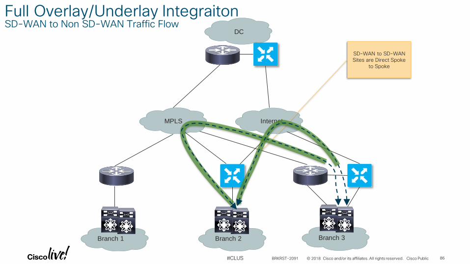
MPLS
Branch 1
Internet
Branch 2 Branch 3
DC
SD-WAN to SD-WAN Sites are Direct Spoke
to Spoke
Full Overlay/Underlay IntegraitonSD-WAN to Non SD-WAN Traffic Flow
BRKRST-2091 86
© 2018 Cisco and/or its affiliates. All rights reserved. Cisco Public#CLUS
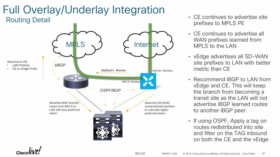
Full Overlay/Underlay IntegrationRouting Detail
MPLS Internet
eBGPAdvertise to PE:
• LAN Prefixes
• CE to vEdge PrefixDefault Route
OSPF/BGP
Advertise BGP learned
routes from MPLS to
LAN with less preferred
metric
Advertise SD-WAN
connected site prefixes
to LAN with higher
preferred metric
• CE continues to advertise site prefixes to MPLS PE
• CE continues to advertise all WAN prefixes learned from MPLS to the LAN
• vEdge advertises all SD-WAN site prefixes to LAN with better metric than CE
• Recommend iBGP to LAN from vEdge and CE. This will keep the branch from becoming a transit site as the LAN will not advertise iBGP learned routes to another iBGP peer.
• If using OSPF, Apply a tag on routes redistributed into site and filter on the TAG inbound on both the CE and the vEdge
Internet Interface
MPLS Interface
BRKRST-2091 87
© 2018 Cisco and/or its affiliates. All rights reserved. Cisco Public#CLUS
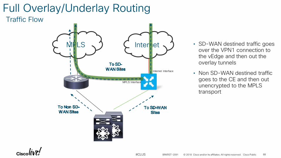
Full Overlay/Underlay RoutingTraffic Flow
MPLS Internet
Internet Interface
MPLS Interface
• SD-WAN destined traffic goes over the VPN1 connection to the vEdge and then out the overlay tunnels
• Non SD-WAN destined traffic goes to the CE and then out unencrypted to the MPLS transport
BRKRST-2091 88
© 2018 Cisco and/or its affiliates. All rights reserved. Cisco Public#CLUS
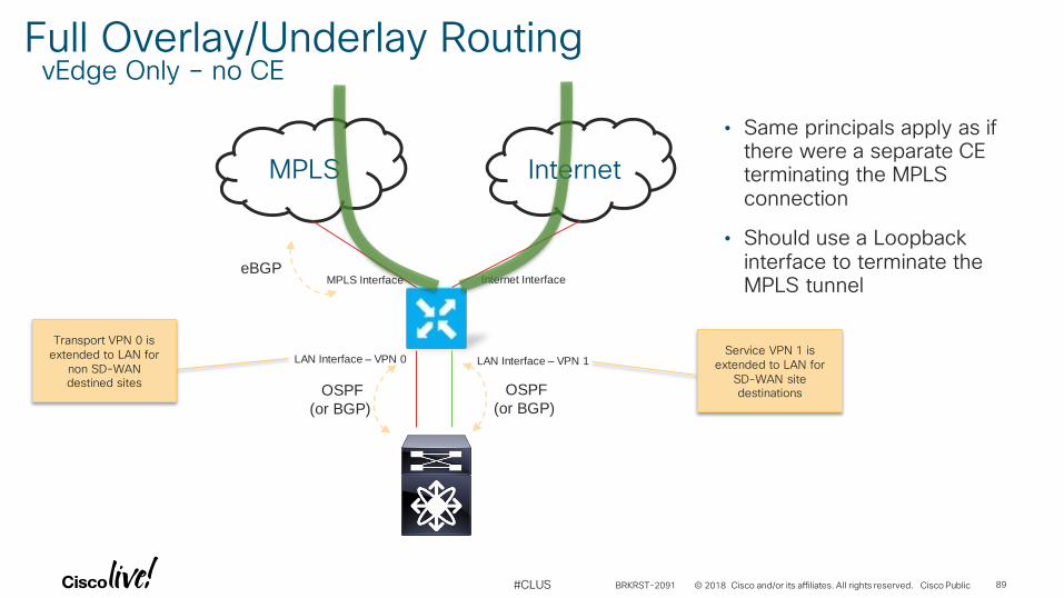
Full Overlay/Underlay RoutingvEdge Only – no CE
MPLS Internet
Internet InterfaceMPLS Interface
LAN Interface – VPN 1LAN Interface – VPN 0
OSPF
(or BGP)
OSPF
(or BGP)
eBGP
Transport VPN 0 is extended to LAN for
non SD-WAN destined sites
Service VPN 1 is extended to LAN for
SD-WAN site destinations
• Same principals apply as if there were a separate CE terminating the MPLS connection
• Should use a Loopback interface to terminate the MPLS tunnel
BRKRST-2091 89
© 2018 Cisco and/or its affiliates. All rights reserved. Cisco Public#CLUS
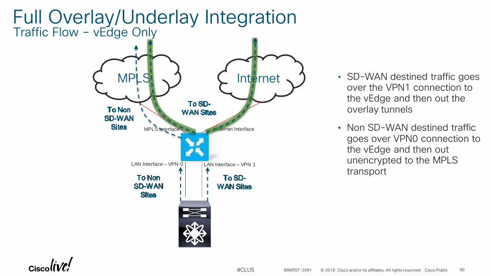
Full Overlay/Underlay IntegrationTraffic Flow – vEdge Only
MPLS Internet
Internet InterfaceMPLS Interface
LAN Interface – VPN 1LAN Interface – VPN 0
• SD-WAN destined traffic goes over the VPN1 connection to the vEdge and then out the overlay tunnels
• Non SD-WAN destined traffic goes over VPN0 connection to the vEdge and then out unencrypted to the MPLS transport
BRKRST-2091 90
© 2018 Cisco and/or its affiliates. All rights reserved. Cisco Public#CLUS
Conclusion
• Keep it simple
• SD-WAN in the DC should be transparent to the business
• Integration with the Network is via routing protocols
• Can completely replace the Branch CE in many cases
• Consider if Overlay and Underlay routing in the branch is necessary
• Easily extend segmentation across the WAN
BRKRST-2091 91
Complete your online session evaluation
© 2018 Cisco and/or its affiliates. All rights reserved. Cisco Public#CLUS
Give us your feedback to be entered into a Daily Survey Drawing.
Complete your session surveys through the Cisco Live mobile app or on www.CiscoLive.com/us.
Don’t forget: Cisco Live sessions will be available for viewing on demand after the event at www.CiscoLive.com/Online.
BRKRST-2091 92
Thank you
#CLUS
#CLUS
Related Documents